US9931981B2 - Methods and systems for blind spot monitoring with rotatable blind spot sensor - Google Patents
Methods and systems for blind spot monitoring with rotatable blind spot sensorDownload PDFInfo
- Publication number
- US9931981B2 US9931981B2US15/096,430US201615096430AUS9931981B2US 9931981 B2US9931981 B2US 9931981B2US 201615096430 AUS201615096430 AUS 201615096430AUS 9931981 B2US9931981 B2US 9931981B2
- Authority
- US
- United States
- Prior art keywords
- blind spot
- object data
- stagnating
- subject vehicle
- controller
- Prior art date
- Legal status (The legal status is an assumption and is not a legal conclusion. Google has not performed a legal analysis and makes no representation as to the accuracy of the status listed.)
- Active
Links
Images


Classifications
- B—PERFORMING OPERATIONS; TRANSPORTING
- B60—VEHICLES IN GENERAL
- B60W—CONJOINT CONTROL OF VEHICLE SUB-UNITS OF DIFFERENT TYPE OR DIFFERENT FUNCTION; CONTROL SYSTEMS SPECIALLY ADAPTED FOR HYBRID VEHICLES; ROAD VEHICLE DRIVE CONTROL SYSTEMS FOR PURPOSES NOT RELATED TO THE CONTROL OF A PARTICULAR SUB-UNIT
- B60W50/00—Details of control systems for road vehicle drive control not related to the control of a particular sub-unit, e.g. process diagnostic or vehicle driver interfaces
- B60W50/08—Interaction between the driver and the control system
- B60W50/14—Means for informing the driver, warning the driver or prompting a driver intervention
- B—PERFORMING OPERATIONS; TRANSPORTING
- B60—VEHICLES IN GENERAL
- B60Q—ARRANGEMENT OF SIGNALLING OR LIGHTING DEVICES, THE MOUNTING OR SUPPORTING THEREOF OR CIRCUITS THEREFOR, FOR VEHICLES IN GENERAL
- B60Q9/00—Arrangement or adaptation of signal devices not provided for in one of main groups B60Q1/00 - B60Q7/00, e.g. haptic signalling
- B60Q9/008—Arrangement or adaptation of signal devices not provided for in one of main groups B60Q1/00 - B60Q7/00, e.g. haptic signalling for anti-collision purposes
- B—PERFORMING OPERATIONS; TRANSPORTING
- B60—VEHICLES IN GENERAL
- B60R—VEHICLES, VEHICLE FITTINGS, OR VEHICLE PARTS, NOT OTHERWISE PROVIDED FOR
- B60R1/00—Optical viewing arrangements; Real-time viewing arrangements for drivers or passengers using optical image capturing systems, e.g. cameras or video systems specially adapted for use in or on vehicles
- B—PERFORMING OPERATIONS; TRANSPORTING
- B60—VEHICLES IN GENERAL
- B60R—VEHICLES, VEHICLE FITTINGS, OR VEHICLE PARTS, NOT OTHERWISE PROVIDED FOR
- B60R2300/00—Details of viewing arrangements using cameras and displays, specially adapted for use in a vehicle
- B60R2300/20—Details of viewing arrangements using cameras and displays, specially adapted for use in a vehicle characterised by the type of display used
- B60R2300/202—Details of viewing arrangements using cameras and displays, specially adapted for use in a vehicle characterised by the type of display used displaying a blind spot scene on the vehicle part responsible for the blind spot
- B—PERFORMING OPERATIONS; TRANSPORTING
- B60—VEHICLES IN GENERAL
- B60W—CONJOINT CONTROL OF VEHICLE SUB-UNITS OF DIFFERENT TYPE OR DIFFERENT FUNCTION; CONTROL SYSTEMS SPECIALLY ADAPTED FOR HYBRID VEHICLES; ROAD VEHICLE DRIVE CONTROL SYSTEMS FOR PURPOSES NOT RELATED TO THE CONTROL OF A PARTICULAR SUB-UNIT
- B60W50/00—Details of control systems for road vehicle drive control not related to the control of a particular sub-unit, e.g. process diagnostic or vehicle driver interfaces
- B60W50/08—Interaction between the driver and the control system
- B60W50/14—Means for informing the driver, warning the driver or prompting a driver intervention
- B60W2050/143—Alarm means
Definitions
- the present disclosurerelates to methods and systems for blind spot monitoring in a vehicle and, more particularly, blind sport monitoring that utilizes a rotatable blind spot sensor.
- the present teachingsadvantageously provide systems and methods for blind spot monitoring and informing a driver that an object, such as another vehicle, is in a blind spot of the vehicle.
- the present teachingsprovide for improved collision avoidance systems and methods as well.
- the present teachingsinclude systems and methods with a rotatable blind spot sensor that monitors a blind spot detection area of a subject vehicle, that generates first object data while positioned at a first angle relative to the subject vehicle and second object data while positioned at a second angle relative to the subject vehicle.
- the first and second object datacorrespond to an object detected by the rotatable blind spot sensor within the blind spot detection area of the subject vehicle.
- a controllerreceives the first object data and the second object data and determines whether the object is a secondary vehicle located within the blind spot detection area of the subject vehicle based on the first object data and the second object data.
- a driver alert systemgenerates an alert in response to the controller determining that the object is the secondary vehicle located within the blind spot detection area of the subject vehicle.
- FIG. 1illustrates a subject vehicle including a blind spot monitoring system according to the present teachings for informing a driver of the subject vehicle that an object is in a blind spot of the subject vehicle.
- FIG. 2illustrates the subject vehicle, a range of a blind spot sensor of the subject vehicle, and a first focus area within the range.
- FIG. 3illustrates the subject vehicle, the range of the blind spot sensor of the subject vehicle, and a second focus area within the range.
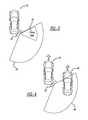
- FIG. 4illustrates the subject vehicle, a secondary vehicle, and a first range of the blind spot sensor at a first angle.
- FIG. 5illustrates the subject vehicle, the secondary vehicle, and a second range of the blind spot sensor at a second angle, rotated counterclockwise from the first angle.
- FIG. 6illustrates the subject vehicle and the first and second ranges of the blind spot sensor at the first and second angles.
- FIG. 7illustrates a block diagram of a system according to the present teachings for determining a directivity mode and an angle command for a blind spot monitoring system.
- FIG. 8illustrates a flow diagram for a method according to the present teachings for determining a directivity mode for a blind spot monitoring system.
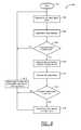
- FIG. 9illustrates a flow diagram for another method according to the present teachings for determining an angle command for a blind spot monitoring system.
- a vehicle 10 including a system 12is illustrated.
- vehicle 10is illustrated as an automobile in FIG. 1
- the present teachingsapply to any other suitable vehicle, such as a sport utility vehicle (SUV), a mass transit vehicle (such as a bus), or a military vehicle, as examples.
- the system 12is configured to inform a driver of the vehicle 10 (often referred to as the subject vehicle) that an object, such as a secondary vehicle, is in a blind spot of the subject vehicle 10 .
- the system 12generally includes one or more blind spot sensors 20 , a driver alert system 22 , a blind spot monitoring system 24 , a controller 26 , a global positioning system (GPS) 28 , and a vehicle speed sensor 70 .
- GPSglobal positioning system
- the controller 26can be any suitable controller for monitoring or controlling one or more of the blind spot sensors 20 , the driver alert system 22 , the blind spot monitoring system 24 , the GPS 28 , and/or the vehicle speed sensor 70 .
- the terms “controller” and “system”may refer to, be part of, or include processor hardware (shared, dedicated, or group) that executes code and memory hardware (shared, dedicated, or group) that stores code executed by the processor hardware.
- the codeis configured to provide the features of the controller and systems described herein.
- the blind spot sensors 20include one or more sensors configured to identify objects, such as other vehicles, in the blind spot of the subject vehicle 10 .
- the blind spot sensors 20can include any suitable sensors, such as any suitable radar, camera, ultrasonic, or other suitable sensors for detecting objects in a blind spot of the subject vehicle 10 .
- the blind spot sensors 20can be mounted at any suitable position on the vehicle 10 , such as near the back corners of the subject vehicle 10 or along the sides of the subject vehicle 10 .
- the blind spot sensors 20are rotatable and can be mechanically rotated to adjust the detection range of the blind spot sensors 20 .
- the blind spot sensors 20can be installed on a rotatable platform or housing that can be mechanically rotated.
- the blind spot sensors 20are operable in multiple directivity modes to adjust a focus area of the blind spot sensors 20 within a blind spot detection area of the subject vehicle.
- the blind spot sensors 20have an associated maximum potential range 30 .
- the blind spot sensors 20can be operated in a normal or first directivity mode to monitor a first focus area 32 within the associated maximum potential range 30 .
- the blind spot sensors 20can be operated at a first transmit power level to facilitate monitoring of the first focus area 32 .
- the blind spot sensors 20can be operated in a narrowed or second directivity mode to monitor a second focus area 34 within the associated maximum potential range 30 .
- the blind spot sensors 20can be operated at a second transmit power level to facilitate monitoring of the second focus area 34 .
- the first transmit power level for the first directivity modeis a stronger transmit power level than the second transmit power level for the second directivity mode.
- the first focus area 32 used in the first directivity modeis larger than the second focus area 34 used in the second directivity mode.
- FIGS. 2 and 3illustrate two focus areas 32 , 34
- the blind spot sensor 20can also be operated with additional focus areas that are any size between the first focus area 32 and the second focus area 34 .
- the system 12can determine the current level of traffic at the location of the subject vehicle 10 and adjust the directivity mode and the focus area of the blind spot sensors 20 within a blind spot detection area of the subject vehicle accordingly.
- the first directivity mode with the relatively larger focus area 32can be used in normal traffic situations to detect secondary vehicles from the rear side of the subject vehicle 10 or from secondary vehicles merging into a blind spot area of the subject vehicle 10 .
- the second directivity mode with the relatively smaller focus area 34can be used in heavy traffic situations, such as traffic jams. In this way, during heavy traffic situations, the focus area is reduced and the blind spot sensors 20 avoid detection of non-relevant objects. As such, the number of false detections and false alerts to the driver of the subject vehicle 10 can be reduced.
- the blind spot sensors 20are mechanically rotatable and operable at multiple angles.
- the blind spot sensor 20is shown at a first angle corresponding to a first detection range 44 .
- a secondary vehicle 40is partially located within the first detection range 44 , such that a back edge of the secondary vehicle 40 is located within the first detection range 44 while a front edge of the secondary vehicle 40 is located outside of the first detection range 44 .
- the blind spot sensor 20is rotated counterclockwise to a second angle corresponding to a second detection range 46 , which is likewise rotated counterclockwise relative to the first detection range 44 .
- the secondary vehicle 40is now entirely located within the second detection range 46 , such that both the front edge of the secondary vehicle 40 and the back edge of the secondary vehicle 40 are located within the second detection range.
- the overall potential detection range of the blind spot sensors 20is increased and includes both the first detection range 44 , when the blind spot sensor 20 is operated at the first angle, and the second detection range 46 , when the blind spot sensor 20 is operated at the second angle.
- FIGS. 4, 5, and 6illustrate operation of the blind spot sensor 20 at two angles, the blind spot sensor 20 can also be operated at any angle between the first and second angles.
- the system 12can determine the current level of traffic at the location of the subject vehicle 10 and adjust the angle of the blind spot sensors 20 accordingly. For example, when a stagnating object is detected within the first detection range 44 , the blind spot sensor 20 can be rotated counterclockwise to detect more of the stagnating object. In this way, the blind spot sensor 20 can detect whether the stagnating object has a front edge and the blind spot monitoring system 24 can determine whether the stagnating object is a vehicle. In this way, the system 12 can distinguish longer secondary vehicles, such as a truck or a vehicle towing a trailer, from a wall, a guard rail, or a static barrier.
- secondary vehiclessuch as a truck or a vehicle towing a trailer
- the driver alert system 22is configured to alert the driver of the subject vehicle 10 of the presence of a secondary vehicle 40 within a blind spot of the subject vehicle 10 .
- the driver alert system 22can be configured to provide any suitable alert to the driver of the subject vehicle 10 indicating the presence of the secondary vehicle 40 within the blind spot of the subject vehicle.
- the driver alert system 22can be configured to provide any suitable visual alert, audible alert, and/or haptic feedback alert.
- the visual alertcan be displayed to the driver on a heads-up display of the subject vehicle 10 , on a center stack display of the subject vehicle 10 , at the instrument cluster of the subject vehicle 10 , etc.
- the audible alertcan be any suitable alert tone, voice alert, etc.
- the haptic feedback alertcan be provided in any suitable manner.
- the haptic feedback alertcan be provided at the steering wheel and/or the driver's seat.
- the system 12includes the blind spot monitoring system 24 , which receives surrounding object data from the blind spot sensor(s) 20 and generates blind spot and surrounding object data that is communicated to the controller 26 .
- the blind spot datafor example, can include data indicating whether a secondary vehicle 40 is present in a blind spot of the subject vehicle 10 .
- the controller 26can also receive GPS/traffic data from the GPS 28 and vehicle speed data from the vehicle speed sensor 70 .
- the controller 26can output a directivity mode and an angle command for the blind spot monitoring system 24 .
- the blind spot monitoring system 24can then appropriately operate the blind spot sensors 20 based on the directivity mode and angle command outputted by the controller 26 .
- the controller 26can output an activation command to the driver alert system 22 to alert the driver of the subject vehicle 10 to the presence of a secondary vehicle 40 in a blind spot of the subject vehicle 10 .
- the method 800is configured to set a directivity mode for the blind spot monitoring system 24 .
- the method 800can be performed by the controller 26 or any other suitable control or processing device.
- the methodstarts at 802 .
- the controller 26receives GPS/traffic data from the GPS 28 .
- the GPS datamay include the current location of the subject vehicle 10 and the locations of any secondary vehicles 40 in the vicinity of the subject vehicle 10 .
- the traffic datamay include data indicating a current traffic condition at the location of the subject vehicle 10 .
- the traffic datamay indicate that the subject vehicle 10 is currently in normal traffic or heavy traffic.
- the controller 26receives vehicle speed data from the vehicle speed sensor 70 indicating the current speed of the subject vehicle 10 .
- the controller 26receives surrounding object data from the blind spot monitoring system 24 and/or the blind spot sensors 20 .
- the controller 26may also receive surrounding object data from additional vehicle sensors, such as sensors associated with lane change assist systems and/or accident avoidance systems.
- the controller 26determines the amount of traffic at the location of the subject vehicle. For example, when the traffic data indicates heavy traffic, the GPS data indicates that multiple secondary vehicles 40 are in the vicinity of the subject vehicle 10 , the vehicle speed data indicates that the subject vehicle 10 is moving slowly, and/or the surrounding object data indicates that multiple secondary vehicles 40 are in the vicinity of the subject vehicle 10 , the controller 26 may determine that the subject vehicle 10 is in heavy traffic.
- the controller 26may determine that the subject vehicle 10 is in normal traffic.
- the controller 26proceeds to 814 and outputs the normal or first directivity mode corresponding to the first focus area 32 , shown in FIG. 2 .
- the controller 26proceeds to 816 and outputs the narrowed or second directivity mode corresponding to the second focus area 32 , shown in FIG. 3 .
- the controller 26loops back to 804 and repeats the method 800 .
- the method 900is configured to set an angle command for rotation of the blind spot sensors 20 .
- the method 900can be performed by the controller 26 or any other suitable control or processing device.
- the methodstarts at 902 .
- the controller 26receives surrounding object data from the blind spot monitoring system 24 and/or the blind spot sensors 20 .
- the controller 26may also receive surrounding object data from additional vehicle sensors, such as sensors associated with lane change assist systems and/or accident avoidance systems.
- the controller 26determines the traffic situation surrounding the subject vehicle 10 , including whether a stagnating object is detected in a blind spot of the subject vehicle 10 .
- the stagnating objectfor example, can be an object detected in the blind spot of the subject vehicle 10 that does not appear to move relative to the subject vehicle 10 .
- the stagnating objectcould be a secondary vehicle 40 moving at approximately the same speed as the subject vehicle 10 .
- the stagnating objectcould also be a wall or barrier that is stationary but that appears at a fixed location in the blind spot detection area.
- the controllerloops back to 904 and repeats the method 900 .
- the controllerproceeds to 910 and outputs an angle command to the blind spot monitoring system 24 for rotating the blind spot sensor 20 .
- the blind spot sensor 20may initially be positioned at a first angle, as shown in FIG. 4 .
- the blind spot monitoring system 24may rotate the blind spot sensor 20 to a second angle, as shown in FIG. 5 .
- the controller 26receives blind spot data from the blind spot monitoring system 24 after rotation of the blind spot sensor 20 to the second angle.
- the blind spot monitoring system 24may be able to determine whether the stagnating object is a vehicle or not. For example, if the blind spot monitoring system 24 detects a front edge of a secondary vehicle 40 , as shown in FIG. 5 , the blind spot monitoring system 24 may determine that the stagnating object is a secondary vehicle 40 . If the blind spot monitoring system 24 does not detect a front edge of a secondary vehicle 40 , the blind spot monitoring system 24 may determine that the stagnating object is a stationary object, such as a wall, a guardrail, or a static barrier.
- the controllerproceeds to 918 and resets the angle command to rotate the blind spot sensor 20 back to the normal position, shown in FIG. 4 .
- the controllerproceeds to 916 and alerts the driver that a secondary vehicle 40 is in a blind spot of the subject vehicle 10 using the driver alert system 22 .
- the controllerresets the angle command to rotate the blind spot sensor 20 to the normal position, shown in FIG. 4 , and then loops back to 904 to repeat the method 900 .
- the present teachingsprovide a blind spot monitoring system 24 with blind spot sensors 20 that utilize different directivity modes and that are mounted on an adjustable and rotatable platform to adjust the angle of the blind spot monitoring area relative to the subject vehicle 10 .
- the present teachingsdynamically shift the radar directivity and mechanically rotate the blind spot sensor 20 when directivity shifting has reached its limit according to the traffic situation, surrounding object information (amount, position, relative speed, etc.), the speed of the subject vehicle 10 , and/or real-time traffic information provided by the GPS 28 .
- directivityfocuses on an approaching vehicle from the rear side or a merge-in vehicle from the side and has Null at a proper direction to reject roadside noise.
- directivityFor heavy traffic, such as a traffic jam situation, directivity focuses on the near side to distinguish stagnating or low speed vehicles and static objects, such as walls, guardrails, barriers, etc., to avoid receiving detections of non-relevant objects.
- the blind spot sensor 20can detect only part of a stagnating object and cannot make an accurate determination after shifting the directivity, the system 12 can mechanically rotate the blind spot sensor 20 to a different angle to get a better detection range covering all of the second vehicle 40 when the stagnating object is a secondary vehicle 40 .
- the rotatable blind spot sensor 20beneficially provides a larger overall potential detection range, shown in FIG. 6 , for the blind spot sensors 20 , as compared with the detection range of non-rotatable blind spot sensors.
- Example embodimentsare provided so that this disclosure will be thorough, and will fully convey the scope to those who are skilled in the art. Numerous specific details are set forth such as examples of specific components, devices, and methods, to provide a thorough understanding of embodiments of the present disclosure. It will be apparent to those skilled in the art that specific details need not be employed, that example embodiments may be embodied in many different forms, and that neither should be construed to limit the scope of the disclosure. In some example embodiments, well-known processes, well-known device structures, and well-known technologies are not described in detail.
- first, second, third, etc.may be used to describe various elements, components, regions, layers and/or sections, these elements, components, regions, layers and/or sections should not be limited by these terms. These terms may be only used to distinguish one element, component, region, layer or section from another region, layer or section. Terms such as “first,” “second,” and other numerical terms when used herein do not imply a sequence or order unless clearly indicated by the context. Thus, a first element, component, region, layer or section discussed below could be termed a second element, component, region, layer or section without departing from the teachings of the example embodiments.
- Spatially relative termssuch as “inner,” “outer,” “beneath,” “below,” “lower,” “above,” “upper,” and the like, may be used for ease of description to describe one element or feature's relationship to another element(s) or feature(s) as illustrated in the figures. Spatially relative terms may be intended to encompass different orientations of the device in use or operation in addition to the orientation depicted in the figures. For example, if the device in the figures is turned over, elements described as “below” or “beneath” other elements or features would then be oriented “above” the other elements or features. Thus, the example term “below” can encompass both an orientation of above and below. The device may be otherwise oriented (rotated 90 degrees or at other orientations) and the spatially relative descriptors used herein interpreted accordingly.
Landscapes
- Engineering & Computer Science (AREA)
- Mechanical Engineering (AREA)
- Human Computer Interaction (AREA)
- Automation & Control Theory (AREA)
- Transportation (AREA)
- Multimedia (AREA)
- Traffic Control Systems (AREA)
Abstract
Description
The present disclosure relates to methods and systems for blind spot monitoring in a vehicle and, more particularly, blind sport monitoring that utilizes a rotatable blind spot sensor.
This section provides background information related to the present disclosure, which is not necessarily prior art.
Although systems exist to help a driver of a vehicle locate objects, such as other vehicles, in a blind spot of the vehicle, and to generally assist with collision avoidance, such systems are subject to improvement. The present teachings advantageously provide systems and methods for blind spot monitoring and informing a driver that an object, such as another vehicle, is in a blind spot of the vehicle. The present teachings provide for improved collision avoidance systems and methods as well.
This section provides a general summary of the disclosure, and is not a comprehensive disclosure of its full scope or all of its features.
The present teachings include systems and methods with a rotatable blind spot sensor that monitors a blind spot detection area of a subject vehicle, that generates first object data while positioned at a first angle relative to the subject vehicle and second object data while positioned at a second angle relative to the subject vehicle. The first and second object data correspond to an object detected by the rotatable blind spot sensor within the blind spot detection area of the subject vehicle. A controller receives the first object data and the second object data and determines whether the object is a secondary vehicle located within the blind spot detection area of the subject vehicle based on the first object data and the second object data. A driver alert system generates an alert in response to the controller determining that the object is the secondary vehicle located within the blind spot detection area of the subject vehicle.
Further areas of applicability will become apparent from the description provided herein. The description and specific examples in this summary are intended for purposes of illustration only and are not intended to limit the scope of the present disclosure.
The drawings described herein are for illustrative purposes only of select embodiments and not all possible implementations, and are not intended to limit the scope of the present disclosure.
Corresponding reference numerals indicate corresponding parts throughout the several views of the drawings.
Example embodiments will now be described more fully with reference to the accompanying drawings.
With reference toFIG. 1 , avehicle 10 including asystem 12 according to the present teachings is illustrated. Although thevehicle 10 is illustrated as an automobile inFIG. 1 , the present teachings apply to any other suitable vehicle, such as a sport utility vehicle (SUV), a mass transit vehicle (such as a bus), or a military vehicle, as examples. Thesystem 12 is configured to inform a driver of the vehicle10 (often referred to as the subject vehicle) that an object, such as a secondary vehicle, is in a blind spot of thesubject vehicle 10. Thesystem 12 generally includes one or moreblind spot sensors 20, adriver alert system 22, a blindspot monitoring system 24, acontroller 26, a global positioning system (GPS)28, and avehicle speed sensor 70. Thecontroller 26 can be any suitable controller for monitoring or controlling one or more of theblind spot sensors 20, thedriver alert system 22, the blindspot monitoring system 24, theGPS 28, and/or thevehicle speed sensor 70. In this application, including the definitions below, the terms “controller” and “system” may refer to, be part of, or include processor hardware (shared, dedicated, or group) that executes code and memory hardware (shared, dedicated, or group) that stores code executed by the processor hardware. The code is configured to provide the features of the controller and systems described herein.
Theblind spot sensors 20 include one or more sensors configured to identify objects, such as other vehicles, in the blind spot of thesubject vehicle 10. Theblind spot sensors 20 can include any suitable sensors, such as any suitable radar, camera, ultrasonic, or other suitable sensors for detecting objects in a blind spot of thesubject vehicle 10. Theblind spot sensors 20 can be mounted at any suitable position on thevehicle 10, such as near the back corners of thesubject vehicle 10 or along the sides of thesubject vehicle 10. As discussed below, theblind spot sensors 20 are rotatable and can be mechanically rotated to adjust the detection range of theblind spot sensors 20. For example, theblind spot sensors 20 can be installed on a rotatable platform or housing that can be mechanically rotated.
With reference toFIGS. 2 and 3 , and as discussed in further detail below, theblind spot sensors 20 are operable in multiple directivity modes to adjust a focus area of theblind spot sensors 20 within a blind spot detection area of the subject vehicle. For example, theblind spot sensors 20 have an associated maximumpotential range 30. Further, as shown inFIG. 2 , theblind spot sensors 20 can be operated in a normal or first directivity mode to monitor afirst focus area 32 within the associated maximumpotential range 30. For example, theblind spot sensors 20 can be operated at a first transmit power level to facilitate monitoring of thefirst focus area 32. Additionally, as shown inFIG. 3 , theblind spot sensors 20 can be operated in a narrowed or second directivity mode to monitor asecond focus area 34 within the associated maximumpotential range 30. For example, theblind spot sensors 20 can be operated at a second transmit power level to facilitate monitoring of thesecond focus area 34. The first transmit power level for the first directivity mode is a stronger transmit power level than the second transmit power level for the second directivity mode. As such, thefirst focus area 32 used in the first directivity mode is larger than thesecond focus area 34 used in the second directivity mode. AlthoughFIGS. 2 and 3 illustrate twofocus areas blind spot sensor 20 can also be operated with additional focus areas that are any size between thefirst focus area 32 and thesecond focus area 34.
As discussed in further detail below, thesystem 12 can determine the current level of traffic at the location of thesubject vehicle 10 and adjust the directivity mode and the focus area of theblind spot sensors 20 within a blind spot detection area of the subject vehicle accordingly. For example, the first directivity mode with the relativelylarger focus area 32 can be used in normal traffic situations to detect secondary vehicles from the rear side of thesubject vehicle 10 or from secondary vehicles merging into a blind spot area of thesubject vehicle 10. Additionally, the second directivity mode with the relativelysmaller focus area 34 can be used in heavy traffic situations, such as traffic jams. In this way, during heavy traffic situations, the focus area is reduced and theblind spot sensors 20 avoid detection of non-relevant objects. As such, the number of false detections and false alerts to the driver of thesubject vehicle 10 can be reduced.
With reference toFIGS. 4, 5, and 6 , and as discussed in further detail below, theblind spot sensors 20 are mechanically rotatable and operable at multiple angles. For example, as shown inFIG. 4 , theblind spot sensor 20 is shown at a first angle corresponding to afirst detection range 44. In the example ofFIG. 4 , asecondary vehicle 40 is partially located within thefirst detection range 44, such that a back edge of thesecondary vehicle 40 is located within thefirst detection range 44 while a front edge of thesecondary vehicle 40 is located outside of thefirst detection range 44. As shown inFIG. 5 , theblind spot sensor 20 is rotated counterclockwise to a second angle corresponding to asecond detection range 46, which is likewise rotated counterclockwise relative to thefirst detection range 44. In the example ofFIG. 5 , thesecondary vehicle 40 is now entirely located within thesecond detection range 46, such that both the front edge of thesecondary vehicle 40 and the back edge of thesecondary vehicle 40 are located within the second detection range. As shown inFIG. 6 , the overall potential detection range of theblind spot sensors 20 is increased and includes both thefirst detection range 44, when theblind spot sensor 20 is operated at the first angle, and thesecond detection range 46, when theblind spot sensor 20 is operated at the second angle. AlthoughFIGS. 4, 5, and 6 illustrate operation of theblind spot sensor 20 at two angles, theblind spot sensor 20 can also be operated at any angle between the first and second angles.
As discussed in further detail below, thesystem 12 can determine the current level of traffic at the location of thesubject vehicle 10 and adjust the angle of theblind spot sensors 20 accordingly. For example, when a stagnating object is detected within thefirst detection range 44, theblind spot sensor 20 can be rotated counterclockwise to detect more of the stagnating object. In this way, theblind spot sensor 20 can detect whether the stagnating object has a front edge and the blindspot monitoring system 24 can determine whether the stagnating object is a vehicle. In this way, thesystem 12 can distinguish longer secondary vehicles, such as a truck or a vehicle towing a trailer, from a wall, a guard rail, or a static barrier.
Thedriver alert system 22 is configured to alert the driver of thesubject vehicle 10 of the presence of asecondary vehicle 40 within a blind spot of thesubject vehicle 10. Thedriver alert system 22 can be configured to provide any suitable alert to the driver of thesubject vehicle 10 indicating the presence of thesecondary vehicle 40 within the blind spot of the subject vehicle. For example, thedriver alert system 22 can be configured to provide any suitable visual alert, audible alert, and/or haptic feedback alert. For example, the visual alert can be displayed to the driver on a heads-up display of thesubject vehicle 10, on a center stack display of thesubject vehicle 10, at the instrument cluster of thesubject vehicle 10, etc. The audible alert can be any suitable alert tone, voice alert, etc. The haptic feedback alert can be provided in any suitable manner. For example, the haptic feedback alert can be provided at the steering wheel and/or the driver's seat.
With reference toFIG. 7 , a block diagram of asystem 12 according to the present teachings for determining a directivity mode and an angle command for a blindspot monitoring system 24. Thesystem 12 includes the blindspot monitoring system 24, which receives surrounding object data from the blind spot sensor(s)20 and generates blind spot and surrounding object data that is communicated to thecontroller 26. The blind spot data, for example, can include data indicating whether asecondary vehicle 40 is present in a blind spot of thesubject vehicle 10. Thecontroller 26 can also receive GPS/traffic data from theGPS 28 and vehicle speed data from thevehicle speed sensor 70. Based on the GPS/traffic data, the vehicle speed data, and the surrounding object data, thecontroller 26 can output a directivity mode and an angle command for the blindspot monitoring system 24. The blindspot monitoring system 24 can then appropriately operate theblind spot sensors 20 based on the directivity mode and angle command outputted by thecontroller 26. Additionally, based on the blind spot data, thecontroller 26 can output an activation command to thedriver alert system 22 to alert the driver of thesubject vehicle 10 to the presence of asecondary vehicle 40 in a blind spot of thesubject vehicle 10.
With reference toFIG. 8 , a flowchart for amethod 800 is shown. Themethod 800 is configured to set a directivity mode for the blindspot monitoring system 24. Themethod 800 can be performed by thecontroller 26 or any other suitable control or processing device. The method starts at802.
At804, thecontroller 26 receives GPS/traffic data from theGPS 28. For example, the GPS data may include the current location of thesubject vehicle 10 and the locations of anysecondary vehicles 40 in the vicinity of thesubject vehicle 10. In addition, the traffic data may include data indicating a current traffic condition at the location of thesubject vehicle 10. For example, the traffic data may indicate that thesubject vehicle 10 is currently in normal traffic or heavy traffic.
At806, thecontroller 26 receives vehicle speed data from thevehicle speed sensor 70 indicating the current speed of thesubject vehicle 10.
At808, thecontroller 26 receives surrounding object data from the blindspot monitoring system 24 and/or theblind spot sensors 20. In addition, thecontroller 26 may also receive surrounding object data from additional vehicle sensors, such as sensors associated with lane change assist systems and/or accident avoidance systems.
At810, based on the GPS/traffic data, the vehicle speed data, and the surrounding object data, thecontroller 26 determines the amount of traffic at the location of the subject vehicle. For example, when the traffic data indicates heavy traffic, the GPS data indicates that multiplesecondary vehicles 40 are in the vicinity of thesubject vehicle 10, the vehicle speed data indicates that thesubject vehicle 10 is moving slowly, and/or the surrounding object data indicates that multiplesecondary vehicles 40 are in the vicinity of thesubject vehicle 10, thecontroller 26 may determine that thesubject vehicle 10 is in heavy traffic. For further example, when the traffic data indicates normal traffic, the GPS data indicates that that there are a low number ofsecondary vehicles 40 in the vicinity of thesubject vehicle 10, the vehicle speed data indicates that thesubject vehicle 10 is moving at a normal speed, and/or the surrounding object data indicates that there are a low number ofsecondary vehicles 40 in the vicinity of thesubject vehicle 10, thecontroller 26 may determine that thesubject vehicle 10 is in normal traffic.
At812, when thecontroller 26 has determined that traffic is normal, thecontroller 26 proceeds to814 and outputs the normal or first directivity mode corresponding to thefirst focus area 32, shown inFIG. 2 . At812, when thecontroller 26 has determined that traffic is heavy, thecontroller 26 proceeds to816 and outputs the narrowed or second directivity mode corresponding to thesecond focus area 32, shown inFIG. 3 . After outputting the particular directivity mode, thecontroller 26 loops back to804 and repeats themethod 800.
With reference toFIG. 9 , a flowchart for anothermethod 900 is shown. Themethod 900 is configured to set an angle command for rotation of theblind spot sensors 20. Themethod 900 can be performed by thecontroller 26 or any other suitable control or processing device. The method starts at902.
At904, thecontroller 26 receives surrounding object data from the blindspot monitoring system 24 and/or theblind spot sensors 20. In addition, thecontroller 26 may also receive surrounding object data from additional vehicle sensors, such as sensors associated with lane change assist systems and/or accident avoidance systems.
At906, based on the surrounding object data, thecontroller 26 determines the traffic situation surrounding thesubject vehicle 10, including whether a stagnating object is detected in a blind spot of thesubject vehicle 10. The stagnating object, for example, can be an object detected in the blind spot of thesubject vehicle 10 that does not appear to move relative to thesubject vehicle 10. For example, the stagnating object could be asecondary vehicle 40 moving at approximately the same speed as thesubject vehicle 10. The stagnating object could also be a wall or barrier that is stationary but that appears at a fixed location in the blind spot detection area.
At908, when a stagnating object is not detected in a blind spot of thesubject vehicle 10, the controller loops back to904 and repeats themethod 900.
At908, when a stagnating object is detected in a blind spot of thesubject vehicle 10, the controller proceeds to910 and outputs an angle command to the blindspot monitoring system 24 for rotating theblind spot sensor 20. For example, theblind spot sensor 20 may initially be positioned at a first angle, as shown inFIG. 4 . Upon receiving the angle command, the blindspot monitoring system 24 may rotate theblind spot sensor 20 to a second angle, as shown inFIG. 5 .
At912, thecontroller 26 receives blind spot data from the blindspot monitoring system 24 after rotation of theblind spot sensor 20 to the second angle. Once theblind spot sensor 20 is rotated, the blindspot monitoring system 24 may be able to determine whether the stagnating object is a vehicle or not. For example, if the blindspot monitoring system 24 detects a front edge of asecondary vehicle 40, as shown inFIG. 5 , the blindspot monitoring system 24 may determine that the stagnating object is asecondary vehicle 40. If the blindspot monitoring system 24 does not detect a front edge of asecondary vehicle 40, the blindspot monitoring system 24 may determine that the stagnating object is a stationary object, such as a wall, a guardrail, or a static barrier.
At914, when the stagnating object in the blind spot of thesubject vehicle 10 is not asecondary vehicle 40, the controller proceeds to918 and resets the angle command to rotate theblind spot sensor 20 back to the normal position, shown inFIG. 4 . At914, when the stagnating object in the blind spot of the subject vehicle is asecondary vehicle 40, the controller proceeds to916 and alerts the driver that asecondary vehicle 40 is in a blind spot of thesubject vehicle 10 using thedriver alert system 22. At918, the controller resets the angle command to rotate theblind spot sensor 20 to the normal position, shown inFIG. 4 , and then loops back to904 to repeat themethod 900.
In this way, the present teachings provide a blindspot monitoring system 24 withblind spot sensors 20 that utilize different directivity modes and that are mounted on an adjustable and rotatable platform to adjust the angle of the blind spot monitoring area relative to thesubject vehicle 10. As described above, to enhance detection accuracy, the present teachings dynamically shift the radar directivity and mechanically rotate theblind spot sensor 20 when directivity shifting has reached its limit according to the traffic situation, surrounding object information (amount, position, relative speed, etc.), the speed of thesubject vehicle 10, and/or real-time traffic information provided by theGPS 28. As described above, for normal traffic situations, directivity focuses on an approaching vehicle from the rear side or a merge-in vehicle from the side and has Null at a proper direction to reject roadside noise. For heavy traffic, such as a traffic jam situation, directivity focuses on the near side to distinguish stagnating or low speed vehicles and static objects, such as walls, guardrails, barriers, etc., to avoid receiving detections of non-relevant objects. If theblind spot sensor 20 can detect only part of a stagnating object and cannot make an accurate determination after shifting the directivity, thesystem 12 can mechanically rotate theblind spot sensor 20 to a different angle to get a better detection range covering all of thesecond vehicle 40 when the stagnating object is asecondary vehicle 40. In addition, the rotatableblind spot sensor 20 beneficially provides a larger overall potential detection range, shown inFIG. 6 , for theblind spot sensors 20, as compared with the detection range of non-rotatable blind spot sensors.
Example embodiments are provided so that this disclosure will be thorough, and will fully convey the scope to those who are skilled in the art. Numerous specific details are set forth such as examples of specific components, devices, and methods, to provide a thorough understanding of embodiments of the present disclosure. It will be apparent to those skilled in the art that specific details need not be employed, that example embodiments may be embodied in many different forms, and that neither should be construed to limit the scope of the disclosure. In some example embodiments, well-known processes, well-known device structures, and well-known technologies are not described in detail.
The terminology used is for the purpose of describing particular example embodiments only and is not intended to be limiting. The singular forms “a,” “an,” and “the” may be intended to include the plural forms as well, unless the context clearly indicates otherwise. The terms “comprises,” “comprising,” “including,” and “having,” are inclusive and therefore specify the presence of stated features, integers, steps, operations, elements, and/or components, but do not preclude the presence or addition of one or more other features, integers, steps, operations, elements, components, and/or groups thereof. The method steps, processes, and operations described herein are not to be construed as necessarily requiring their performance in the particular order discussed or illustrated, unless specifically identified as an order of performance. It is also to be understood that additional or alternative steps may be employed.
When an element or layer is referred to as being “on,” “engaged to,” “connected to,” or “coupled to” another element or layer, it may be directly on, engaged, connected or coupled to the other element or layer, or intervening elements or layers may be present. In contrast, when an element is referred to as being “directly on,” “directly engaged to,” “directly connected to,” or “directly coupled to” another element or layer, there may be no intervening elements or layers present. Other words used to describe the relationship between elements should be interpreted in a like fashion (e.g., “between” versus “directly between,” “adjacent” versus “directly adjacent,” etc.). The term “and/or” includes any and all combinations of one or more of the associated listed items.
Although the terms first, second, third, etc. may be used to describe various elements, components, regions, layers and/or sections, these elements, components, regions, layers and/or sections should not be limited by these terms. These terms may be only used to distinguish one element, component, region, layer or section from another region, layer or section. Terms such as “first,” “second,” and other numerical terms when used herein do not imply a sequence or order unless clearly indicated by the context. Thus, a first element, component, region, layer or section discussed below could be termed a second element, component, region, layer or section without departing from the teachings of the example embodiments.
Spatially relative terms, such as “inner,” “outer,” “beneath,” “below,” “lower,” “above,” “upper,” and the like, may be used for ease of description to describe one element or feature's relationship to another element(s) or feature(s) as illustrated in the figures. Spatially relative terms may be intended to encompass different orientations of the device in use or operation in addition to the orientation depicted in the figures. For example, if the device in the figures is turned over, elements described as “below” or “beneath” other elements or features would then be oriented “above” the other elements or features. Thus, the example term “below” can encompass both an orientation of above and below. The device may be otherwise oriented (rotated 90 degrees or at other orientations) and the spatially relative descriptors used herein interpreted accordingly.
The foregoing description of the embodiments has been provided for purposes of illustration and description. It is not intended to be exhaustive or to limit the disclosure. Individual elements or features of a particular embodiment are generally not limited to that particular embodiment, but, where applicable, are interchangeable and can be used in a selected embodiment, even if not specifically shown or described. The same may also be varied in many ways. Such variations are not to be regarded as a departure from the disclosure, and all such modifications are intended to be included within the scope of the disclosure.
Claims (19)
1. A system comprising:
a rotatable blind spot sensor configured to monitor a blind spot detection area of a subject vehicle and generate first object data while positioned at a first angle relative to the subject vehicle and second object data while positioned at a second angle relative to the subject vehicle;
a controller configured to (i) receive the first object data when the rotatable blind spot sensor is positioned at the first angle, (ii) determine whether the first object data indicates that a stagnating object appears at a fixed location in the blind spot detection area, (iii) output an angle command to rotate the rotatable blind spot sensor from the first angle to the second angle in response to determining that the first object data indicates that the stagnating object appears at the fixed location in the blind spot detection area, (iv) receive the second object data when the rotatable blind spot sensor is positioned at the second angle, and (v) determine whether the stagnating object is a secondary vehicle located within the blind spot detection area of the subject vehicle based on the first object data and the second object data; and
a driver alert system configured to generate an alert in response to the controller determining that the stagnating object is the secondary vehicle located within the blind spot detection area of the subject vehicle.
2. The system ofclaim 1 , wherein the controller is configured to determine whether the stagnating object is the secondary vehicle by determining whether the second object data indicates an edge of the secondary vehicle.
3. The system ofclaim 1 , wherein the controller is configured to detect whether the stagnating object has a first edge indicated by the first object data, detect whether the stagnating object has a second edge indicated by the second object data, and determine whether the stagnating object is the secondary vehicle in response to detecting that the stagnating object has the first edge indicated by the first object data and the second edge indicated by the second object data.
4. The system ofclaim 1 , wherein the controller is configured to rotate the rotatable blind spot sensor back to the first angle after determining whether the stagnating object is the secondary vehicle located within the blind spot detection area of the subject vehicle.
5. The system ofclaim 1 , wherein the rotatable blind spot sensor includes at least one of a radar sensor, a camera, and an ultrasonic sensor.
6. The system ofclaim 1 , wherein the alert includes at least one of a visual alert, an audible alert, and a haptic alert to a driver of the subject vehicle.
7. The system ofclaim 1 , wherein the controller is configured to continue receiving the first object data with the rotatable blind spot sensor positioned at the first angle, without rotating the rotatable blind spot sensor to the second angle, in response to determining that the first object data does not indicate that the stagnating object appears at the fixed location in the blind spot detection area.
8. A method comprising:
monitoring, with a rotatable blind spot sensor, a blind spot detection area of a subject vehicle;
generating, with the rotatable blind spot sensor, first object data while the rotatable blind spot sensor is positioned at a first angle relative to the subject vehicle and second object data while the rotatable blind spot sensor is positioned at a second angle relative to the subject vehicle;
receiving, with a controller, the first object data when the rotatable blind spot sensor is positioned at the first angle;
determining, with the controller, whether the first object data indicates that a stagnating object appears at a fixed location in the blind spot detection area;
outputting, with the controller, an angle command to rotate the rotatable blind spot sensor from the first angle to the second angle in response to determining that the first object data indicates that the stagnating object appears at the fixed location in the blind spot detection area;
receiving, with the controller, the second object data when the rotatable blind spot sensor is positioned at the second angle;
determining, with the controller, whether the stagnating object is a secondary vehicle located within the blind spot detection area of the subject vehicle based on the first object data and the second object data; and
generating, with a driver alert system, an alert in response to the controller determining that the stagnating object is the secondary vehicle located within the blind spot detection area of the subject vehicle.
9. The method ofclaim 8 , wherein the controller determines whether the stagnating object is the secondary vehicle by determining whether the second object data indicates an edge of the secondary vehicle.
10. The method ofclaim 8 , further comprising:
detecting, with the controller, whether the stagnating object has a first edge indicated by the first object data;
and
detecting, with the controller, whether the stagnating object has a second edge indicated by the second object data;
wherein the controller determines whether the stagnating object is the secondary vehicle in response to detecting that the stagnating object has the first edge indicated by the first object data and the second edge indicated by the second object data.
11. The method ofclaim 8 , further comprising rotating, with the controller, the rotatable blind spot sensor back to the first angle after determining whether the stagnating object is the secondary vehicle located within the blind spot detection area of the subject vehicle.
12. The method ofclaim 8 , wherein the rotatable blind spot sensor includes at least one of a radar sensor, a camera, and an ultrasonic sensor.
13. The method ofclaim 8 , wherein the alert includes at least one of a visual alert, an audible alert, and a haptic alert to a driver of the subject vehicle.
14. The method ofclaim 8 , further comprising
continuing to receive, with the controller, the first object data with the rotatable blind spot sensor positioned at the first angle, without rotating the rotatable blind spot sensor to the second angle, in response to determining that the first object data does not indicate that the stagnating object appears at the fixed location in the blind spot detection area.
15. A system comprising:
a rotatable blind spot sensor configured to monitor a blind spot detection area of a subject vehicle;
a controller in communication with the rotatable blind spot sensor configured to receive first object data from the rotatable blind spot sensor while the rotatable blind spot sensor is positioned at a first angle relative to the subject vehicle, determine whether the first object data indicates that a stagnating object is located within the blind spot detection area and that the object does not appear to be moving relative to the subject vehicle, rotate the rotatable blind spot sensor to a second angle relative to the subject vehicle in response to determining that the first object data indicates that the stagnating object is located within the blind spot detection area and does not appear to be moving relative to the subject vehicle, receive second object data from the rotatable blind spot sensor while the rotatable blind spot sensor is positioned at a second angle relative to the subject vehicle, and determine whether the stagnating object is a secondary vehicle located within the blind spot detection area of the subject vehicle based on the first object data and the second object data; and
a driver alert system configured to generate an alert in response to the controller determining that the stagnating object is the secondary vehicle located within the blind spot detection area of the subject vehicle.
16. The system ofclaim 15 , wherein the controller determines whether the stagnating object is the secondary vehicle by determining whether the second object data indicates an edge of the secondary vehicle.
17. The system ofclaim 15 , wherein the controller is configured to rotate the rotatable blind spot sensor back to the first angle after determining whether the stagnating object is the secondary vehicle located within the blind spot detection area of the subject vehicle.
18. The system ofclaim 15 , wherein the rotatable blind spot sensor includes at least one of a radar sensor, a camera, and an ultrasonic sensor.
19. The system ofclaim 15 , wherein the alert includes at least one of a visual alert, an audible alert, and a haptic alert to a driver of the subject vehicle.
Priority Applications (1)
| Application Number | Priority Date | Filing Date | Title |
|---|---|---|---|
| US15/096,430US9931981B2 (en) | 2016-04-12 | 2016-04-12 | Methods and systems for blind spot monitoring with rotatable blind spot sensor |
Applications Claiming Priority (1)
| Application Number | Priority Date | Filing Date | Title |
|---|---|---|---|
| US15/096,430US9931981B2 (en) | 2016-04-12 | 2016-04-12 | Methods and systems for blind spot monitoring with rotatable blind spot sensor |
Publications (2)
| Publication Number | Publication Date |
|---|---|
| US20170291546A1 US20170291546A1 (en) | 2017-10-12 |
| US9931981B2true US9931981B2 (en) | 2018-04-03 |
Family
ID=59999956
Family Applications (1)
| Application Number | Title | Priority Date | Filing Date |
|---|---|---|---|
| US15/096,430ActiveUS9931981B2 (en) | 2016-04-12 | 2016-04-12 | Methods and systems for blind spot monitoring with rotatable blind spot sensor |
Country Status (1)
| Country | Link |
|---|---|
| US (1) | US9931981B2 (en) |
Families Citing this family (7)
| Publication number | Priority date | Publication date | Assignee | Title |
|---|---|---|---|---|
| SE539443C2 (en)* | 2016-02-10 | 2017-09-26 | Scania Cv Ab | System for reducing a blind spot for a vehicle |
| CN110509842B (en)* | 2019-08-15 | 2023-03-24 | 重庆长安汽车股份有限公司 | Vehicle low-speed section blind area detection and lane change auxiliary method and system |
| CN110988889A (en)* | 2019-11-01 | 2020-04-10 | 广西农业职业技术学院 | Automobile blind area monitoring method |
| CN111366192B (en)* | 2020-03-16 | 2022-05-13 | 华为技术有限公司 | Information acquisition method and device |
| KR20220089762A (en)* | 2020-12-21 | 2022-06-29 | 현대모비스 주식회사 | System and method for preventing vehice collision |
| JP2022142510A (en)* | 2021-03-16 | 2022-09-30 | パナソニックIpマネジメント株式会社 | Vehicle Perimeter Alert Device and Vehicle Perimeter Alert Method |
| US12398540B2 (en)* | 2022-08-12 | 2025-08-26 | Caterpillar Inc. | Monitoring system for work machine |
Citations (72)
| Publication number | Priority date | Publication date | Assignee | Title |
|---|---|---|---|---|
| US5689264A (en) | 1994-10-05 | 1997-11-18 | Mazda Motor Corporation | Obstacle detecting system for vehicles |
| US5781119A (en) | 1995-03-14 | 1998-07-14 | Toyota Jidosha Kabushiki Kaisha | Vehicle guiding system |
| US5899953A (en) | 1996-03-05 | 1999-05-04 | Mitsubishi Denki Kabushiki Kaisha | Running control device mounted in a vehicle |
| US6193380B1 (en) | 1999-04-20 | 2001-02-27 | Raymond A. Jacobs | Vehicle blind spot mirror |
| US20020057195A1 (en)* | 2000-09-22 | 2002-05-16 | Nissan Motor Co., Ltd. | Method and apparatus for estimating inter-vehicle distance using radar and camera |
| US20020126002A1 (en)* | 2001-01-15 | 2002-09-12 | 1138037 Ontario Ltd. ("Alirt") | Detecting device and method of using same |
| US6506969B1 (en) | 1998-09-24 | 2003-01-14 | Medal Sarl | Automatic music generating method and device |
| US20030016158A1 (en) | 2001-07-20 | 2003-01-23 | Aviation Communication & Surveillance Systems, Llc | Integrated surveillance display |
| US6560529B1 (en) | 1998-09-15 | 2003-05-06 | Robert Bosch Gmbh | Method and device for traffic sign recognition and navigation |
| US6561295B1 (en) | 1999-10-29 | 2003-05-13 | Honda Giken Kogyo Kabushiki Kaisha | Control system and method of hybrid vehicle |
| US20030109985A1 (en) | 2001-12-07 | 2003-06-12 | Kotzin Michael D. | Method for improving dispatch response time |
| US20040016870A1 (en)* | 2002-05-03 | 2004-01-29 | Pawlicki John A. | Object detection system for vehicle |
| US6744396B2 (en) | 2001-07-20 | 2004-06-01 | Aviation Communication & Surveillance Systems Llc | Surveillance and collision avoidance system with compound symbols |
| US20040119609A1 (en) | 2001-03-07 | 2004-06-24 | Lawrence Solomon | Traffic control system with road tariff depending on the congestion level |
| US20040229621A1 (en) | 2003-05-16 | 2004-11-18 | International Business Machines Corporation | Method and apparatus for load sharing in wireless access networks based on dynamic transmission power adjustment of access points |
| US20050015203A1 (en) | 2003-07-18 | 2005-01-20 | Nissan Motor Co., Ltd. | Lane-changing support system |
| US6853894B1 (en) | 2000-04-24 | 2005-02-08 | Usa Technologies, Inc. | Global network based vehicle safety and security telematics |
| US20050033497A1 (en) | 2003-08-06 | 2005-02-10 | Stopczynski Lawrence Gerard | Method of controlling an external object sensor for an automotive vehicle |
| US20050128061A1 (en) | 2003-12-10 | 2005-06-16 | Nissan Motor Co., Ltd. | Vehicular image display system and image display control method |
| US20060006988A1 (en) | 2004-07-07 | 2006-01-12 | Harter Joseph E Jr | Adaptive lighting display for vehicle collision warning |
| US20060155444A1 (en) | 2005-01-13 | 2006-07-13 | Lee Yong H | Automatic control of automotive rearview mirror |
| US20070018801A1 (en) | 2005-07-25 | 2007-01-25 | Novotny Steven J | Digital voice/visual warning, alert, and status system for vehicles utilizing laser sensors |
| US20070159355A1 (en) | 2006-01-10 | 2007-07-12 | Kelly Terence F | Combined personalized traffic and weather report and alert system and method |
| US20070182528A1 (en)* | 2000-05-08 | 2007-08-09 | Automotive Technologies International, Inc. | Vehicular Component Control Methods Based on Blind Spot Monitoring |
| US20080169938A1 (en) | 2007-01-17 | 2008-07-17 | Visteon Global Technologies, Inc. | Variable blind spot warning system |
| US20080252482A1 (en)* | 2007-04-11 | 2008-10-16 | Lawrence Gerard Stopczynski | System and method of modifying programmable blind spot detection sensor ranges with vision sensor input |
| US20080300755A1 (en) | 2007-05-30 | 2008-12-04 | Dinu Petre Madau | Side collision avoidance system |
| US20090045928A1 (en)* | 2007-08-16 | 2009-02-19 | Rao Manoharprasad K | System and method for combined blind spot detection and rear crossing path collision warning |
| US7504986B2 (en) | 2004-04-22 | 2009-03-17 | Continental Automotive Gmbh | Blind spot sensor system |
| US20090079553A1 (en) | 2007-09-26 | 2009-03-26 | Nissan Motor Co., Ltd. | Vehicle periphery monitoring apparatus and image displaying method |
| US20090244741A1 (en)* | 2008-03-31 | 2009-10-01 | Ford Global Technologies, Llc. | System, apparatus and method for active mirrors with blind spot detection |
| US20090243822A1 (en) | 2008-03-31 | 2009-10-01 | Hond Motor Co., Ltd. | Vehicle blind spot detection and indicator system |
| US7650227B2 (en) | 2004-03-17 | 2010-01-19 | Globis Data Inc. | System for using cellular phones as traffic probes |
| US20100045448A1 (en)* | 2005-06-27 | 2010-02-25 | Aisin Seiki Kabushiki Kaisha | Obstacle detection apparatus |
| US20100049393A1 (en) | 2008-08-21 | 2010-02-25 | International Business Machines Corporation | Automated dynamic vehicle blind spot determination |
| US20100238009A1 (en) | 2009-01-26 | 2010-09-23 | Bryon Cook | Driver Risk Assessment System and Method Employing Automated Driver Log |
| US20110010041A1 (en) | 2003-01-30 | 2011-01-13 | Smr Patents S.A.R.L. | Software for an automotive hazardous detection and information system |
| US20110084852A1 (en) | 2009-10-13 | 2011-04-14 | Gm Global Technology Operations, Inc. | Method and apparatus for communicatively changing interior illumination color in a vehicle |
| US20110187863A1 (en) | 2008-08-12 | 2011-08-04 | Continental Automotive Gmbh | Method for detecting expansive static objects |
| US20120116659A1 (en) | 2010-11-10 | 2012-05-10 | Honda Motor Co., Ltd. | Method of Retrieving Information for a Motor Vehicle |
| US8224370B2 (en) | 2009-07-10 | 2012-07-17 | Honda Motor Co., Ltd. | Method of controlling a communication system in a motor vehicle |
| US20120218124A1 (en) | 2011-02-25 | 2012-08-30 | Charles Lee | Driver assistance system |
| US20120245832A1 (en) | 2009-12-09 | 2012-09-27 | Urban Meis | Method for Supporting the Driver of a Road-Bound Vehicle in Guiding the Vehicle |
| JP2013002987A (en) | 2011-06-17 | 2013-01-07 | Toyota Motor Corp | Rear sideway obstacle detecting apparatus |
| US20130018545A1 (en) | 2011-07-11 | 2013-01-17 | Ford Global Technologies, Llc | Traffic density estimation |
| US20130051042A1 (en) | 2011-08-23 | 2013-02-28 | Stefan Nordbruch | Method for controlling a light emission of a headlight of a vehicle |
| US20130054086A1 (en) | 2011-08-31 | 2013-02-28 | Autorad Tech Co., Ltd | Adjusting Method and System of Intelligent Vehicle Imaging Device |
| WO2013081998A1 (en) | 2011-11-28 | 2013-06-06 | Robert Bosch Gmbh | Camera-assisted blind spot detection |
| US20130176145A1 (en) | 2012-01-10 | 2013-07-11 | Xiao Lin Yu | Automobile blind spot detection system and method |
| US20130181860A1 (en) | 2012-01-16 | 2013-07-18 | Ford Global Technologies, Llc | Radar based multifunctional safety system |
| US20130253810A1 (en) | 2012-03-21 | 2013-09-26 | Aisin Aw Co., Ltd | Traffic information creating device, traffic information creating method and program |
| US20130253811A1 (en) | 2012-03-21 | 2013-09-26 | Aisin Aw Co., Ltd. | Traffic information creating device, traffic information creating method and program |
| WO2014006919A1 (en) | 2012-07-06 | 2014-01-09 | 株式会社デンソー | Adjacent vehicle detection device |
| US8669857B2 (en) | 2010-01-13 | 2014-03-11 | Denso International America, Inc. | Hand-held device integration for automobile safety |
| US8775031B1 (en) | 2010-12-21 | 2014-07-08 | Dietrich Bankhead | Automatic interior rearview mirror positioning system |
| US8775073B2 (en) | 2008-05-30 | 2014-07-08 | Navteq B.V. | Data mining in a digital map database to identify insufficient merge lanes along roads and enabling precautionary actions in a vehicle |
| US20140191895A1 (en) | 2011-07-05 | 2014-07-10 | Thomas Binzer | Radar system for motor vehicles, and motor vehicle having a radar system |
| US8791802B2 (en) | 2011-09-09 | 2014-07-29 | Robert Bosch Gmbh | Driver assistance system for reducing blind-spot-detection false alerts |
| US20150100216A1 (en) | 2013-10-03 | 2015-04-09 | Robert Bosch Gmbh | Adaptive cruise control with on-ramp detection |
| US20150183430A1 (en)* | 2013-09-05 | 2015-07-02 | Robert Bosch Gmbh | Enhanced lane departure system |
| US20150193885A1 (en) | 2014-01-06 | 2015-07-09 | Harman International Industries, Incorporated | Continuous identity monitoring for classifying driving data for driving performance analysis |
| US20150195496A1 (en)* | 2012-07-27 | 2015-07-09 | Nissan Motor Co., Ltd. | Three-dimensional object detection device, and three-dimensional object detection method |
| US20150232021A1 (en) | 2014-02-20 | 2015-08-20 | Steven G. Downey | Blind spot warning apparatus, assembly and method |
| US20150232034A1 (en)* | 2000-03-02 | 2015-08-20 | Andrew D. Weller | Vision system for vehicle |
| US20150302586A1 (en) | 2012-02-23 | 2015-10-22 | Nissan Motor Co., Ltd. | Three-dimensional object detection device |
| US20150301182A1 (en)* | 2012-12-21 | 2015-10-22 | Valeo Schalter Und Sensoren Gmbh | Optical object-detection device having a mems and motor vehicle having such a detection device |
| US20150331098A1 (en) | 2012-12-19 | 2015-11-19 | Valeo Schalter Und Sensoren Gmbh | Method for setting a detection threshold for a received signal of a frequency-modulated continuous wave radar sensor of a motor vehicle on the basis of the noise level, radar sensor and motor vehicle |
| US20160090043A1 (en) | 2014-09-26 | 2016-03-31 | Hyundai Motor Company | Driver customizable blind spot display method and apparatus |
| US20160101730A1 (en) | 2014-10-08 | 2016-04-14 | Ford Global Technologies Llc | Vehicle blind spot system operation with trailer tow |
| US20160207466A1 (en) | 2005-07-06 | 2016-07-21 | Donnelly Corporation | Vehicle exterior rearview mirror system having an indicator |
| US20160232790A1 (en) | 2015-02-10 | 2016-08-11 | Ridar Systems LLC | Proximity Awareness System for Motor Vehicles |
| US20170154523A1 (en) | 2015-11-26 | 2017-06-01 | Mazda Motor Corporation | Traffic sign recognition system |
- 2016
- 2016-04-12USUS15/096,430patent/US9931981B2/enactiveActive
Patent Citations (77)
| Publication number | Priority date | Publication date | Assignee | Title |
|---|---|---|---|---|
| US5689264A (en) | 1994-10-05 | 1997-11-18 | Mazda Motor Corporation | Obstacle detecting system for vehicles |
| US5781119A (en) | 1995-03-14 | 1998-07-14 | Toyota Jidosha Kabushiki Kaisha | Vehicle guiding system |
| US5899953A (en) | 1996-03-05 | 1999-05-04 | Mitsubishi Denki Kabushiki Kaisha | Running control device mounted in a vehicle |
| US6560529B1 (en) | 1998-09-15 | 2003-05-06 | Robert Bosch Gmbh | Method and device for traffic sign recognition and navigation |
| US6506969B1 (en) | 1998-09-24 | 2003-01-14 | Medal Sarl | Automatic music generating method and device |
| US6193380B1 (en) | 1999-04-20 | 2001-02-27 | Raymond A. Jacobs | Vehicle blind spot mirror |
| US6561295B1 (en) | 1999-10-29 | 2003-05-13 | Honda Giken Kogyo Kabushiki Kaisha | Control system and method of hybrid vehicle |
| US20150232034A1 (en)* | 2000-03-02 | 2015-08-20 | Andrew D. Weller | Vision system for vehicle |
| US6853894B1 (en) | 2000-04-24 | 2005-02-08 | Usa Technologies, Inc. | Global network based vehicle safety and security telematics |
| US20070182528A1 (en)* | 2000-05-08 | 2007-08-09 | Automotive Technologies International, Inc. | Vehicular Component Control Methods Based on Blind Spot Monitoring |
| US20020057195A1 (en)* | 2000-09-22 | 2002-05-16 | Nissan Motor Co., Ltd. | Method and apparatus for estimating inter-vehicle distance using radar and camera |
| US20020126002A1 (en)* | 2001-01-15 | 2002-09-12 | 1138037 Ontario Ltd. ("Alirt") | Detecting device and method of using same |
| US20040119609A1 (en) | 2001-03-07 | 2004-06-24 | Lawrence Solomon | Traffic control system with road tariff depending on the congestion level |
| US6744396B2 (en) | 2001-07-20 | 2004-06-01 | Aviation Communication & Surveillance Systems Llc | Surveillance and collision avoidance system with compound symbols |
| US20030016158A1 (en) | 2001-07-20 | 2003-01-23 | Aviation Communication & Surveillance Systems, Llc | Integrated surveillance display |
| US20030109985A1 (en) | 2001-12-07 | 2003-06-12 | Kotzin Michael D. | Method for improving dispatch response time |
| US7038577B2 (en) | 2002-05-03 | 2006-05-02 | Donnelly Corporation | Object detection system for vehicle |
| US20040016870A1 (en)* | 2002-05-03 | 2004-01-29 | Pawlicki John A. | Object detection system for vehicle |
| US20110010041A1 (en) | 2003-01-30 | 2011-01-13 | Smr Patents S.A.R.L. | Software for an automotive hazardous detection and information system |
| US20040229621A1 (en) | 2003-05-16 | 2004-11-18 | International Business Machines Corporation | Method and apparatus for load sharing in wireless access networks based on dynamic transmission power adjustment of access points |
| US20050015203A1 (en) | 2003-07-18 | 2005-01-20 | Nissan Motor Co., Ltd. | Lane-changing support system |
| US20050033497A1 (en) | 2003-08-06 | 2005-02-10 | Stopczynski Lawrence Gerard | Method of controlling an external object sensor for an automotive vehicle |
| US20050128061A1 (en) | 2003-12-10 | 2005-06-16 | Nissan Motor Co., Ltd. | Vehicular image display system and image display control method |
| US7650227B2 (en) | 2004-03-17 | 2010-01-19 | Globis Data Inc. | System for using cellular phones as traffic probes |
| US7504986B2 (en) | 2004-04-22 | 2009-03-17 | Continental Automotive Gmbh | Blind spot sensor system |
| US20060006988A1 (en) | 2004-07-07 | 2006-01-12 | Harter Joseph E Jr | Adaptive lighting display for vehicle collision warning |
| US20060155444A1 (en) | 2005-01-13 | 2006-07-13 | Lee Yong H | Automatic control of automotive rearview mirror |
| US20100045448A1 (en)* | 2005-06-27 | 2010-02-25 | Aisin Seiki Kabushiki Kaisha | Obstacle detection apparatus |
| US20160207466A1 (en) | 2005-07-06 | 2016-07-21 | Donnelly Corporation | Vehicle exterior rearview mirror system having an indicator |
| US20070018801A1 (en) | 2005-07-25 | 2007-01-25 | Novotny Steven J | Digital voice/visual warning, alert, and status system for vehicles utilizing laser sensors |
| US20070159355A1 (en) | 2006-01-10 | 2007-07-12 | Kelly Terence F | Combined personalized traffic and weather report and alert system and method |
| US7602276B2 (en) | 2007-01-17 | 2009-10-13 | Visteon Global Technologies, Inc. | Variable blind spot warning system |
| US20080169938A1 (en) | 2007-01-17 | 2008-07-17 | Visteon Global Technologies, Inc. | Variable blind spot warning system |
| US7612658B2 (en) | 2007-04-11 | 2009-11-03 | Ford Global Technologies, Inc. | System and method of modifying programmable blind spot detection sensor ranges with vision sensor input |
| US20080252482A1 (en)* | 2007-04-11 | 2008-10-16 | Lawrence Gerard Stopczynski | System and method of modifying programmable blind spot detection sensor ranges with vision sensor input |
| US20080300755A1 (en) | 2007-05-30 | 2008-12-04 | Dinu Petre Madau | Side collision avoidance system |
| US20090045928A1 (en)* | 2007-08-16 | 2009-02-19 | Rao Manoharprasad K | System and method for combined blind spot detection and rear crossing path collision warning |
| US20090079553A1 (en) | 2007-09-26 | 2009-03-26 | Nissan Motor Co., Ltd. | Vehicle periphery monitoring apparatus and image displaying method |
| US20090244741A1 (en)* | 2008-03-31 | 2009-10-01 | Ford Global Technologies, Llc. | System, apparatus and method for active mirrors with blind spot detection |
| US20090243822A1 (en) | 2008-03-31 | 2009-10-01 | Hond Motor Co., Ltd. | Vehicle blind spot detection and indicator system |
| US8775073B2 (en) | 2008-05-30 | 2014-07-08 | Navteq B.V. | Data mining in a digital map database to identify insufficient merge lanes along roads and enabling precautionary actions in a vehicle |
| US20110187863A1 (en) | 2008-08-12 | 2011-08-04 | Continental Automotive Gmbh | Method for detecting expansive static objects |
| US20100049393A1 (en) | 2008-08-21 | 2010-02-25 | International Business Machines Corporation | Automated dynamic vehicle blind spot determination |
| US8489284B2 (en) | 2008-08-21 | 2013-07-16 | International Business Machines Corporation | Automated dynamic vehicle blind spot determination |
| US20100238009A1 (en) | 2009-01-26 | 2010-09-23 | Bryon Cook | Driver Risk Assessment System and Method Employing Automated Driver Log |
| US8224370B2 (en) | 2009-07-10 | 2012-07-17 | Honda Motor Co., Ltd. | Method of controlling a communication system in a motor vehicle |
| US20110084852A1 (en) | 2009-10-13 | 2011-04-14 | Gm Global Technology Operations, Inc. | Method and apparatus for communicatively changing interior illumination color in a vehicle |
| US20120245832A1 (en) | 2009-12-09 | 2012-09-27 | Urban Meis | Method for Supporting the Driver of a Road-Bound Vehicle in Guiding the Vehicle |
| US8669857B2 (en) | 2010-01-13 | 2014-03-11 | Denso International America, Inc. | Hand-held device integration for automobile safety |
| US20120116659A1 (en) | 2010-11-10 | 2012-05-10 | Honda Motor Co., Ltd. | Method of Retrieving Information for a Motor Vehicle |
| US8775031B1 (en) | 2010-12-21 | 2014-07-08 | Dietrich Bankhead | Automatic interior rearview mirror positioning system |
| US20120218124A1 (en) | 2011-02-25 | 2012-08-30 | Charles Lee | Driver assistance system |
| JP2013002987A (en) | 2011-06-17 | 2013-01-07 | Toyota Motor Corp | Rear sideway obstacle detecting apparatus |
| US20140191895A1 (en) | 2011-07-05 | 2014-07-10 | Thomas Binzer | Radar system for motor vehicles, and motor vehicle having a radar system |
| US20130018545A1 (en) | 2011-07-11 | 2013-01-17 | Ford Global Technologies, Llc | Traffic density estimation |
| US20130051042A1 (en) | 2011-08-23 | 2013-02-28 | Stefan Nordbruch | Method for controlling a light emission of a headlight of a vehicle |
| US20130054086A1 (en) | 2011-08-31 | 2013-02-28 | Autorad Tech Co., Ltd | Adjusting Method and System of Intelligent Vehicle Imaging Device |
| US8791802B2 (en) | 2011-09-09 | 2014-07-29 | Robert Bosch Gmbh | Driver assistance system for reducing blind-spot-detection false alerts |
| WO2013081998A1 (en) | 2011-11-28 | 2013-06-06 | Robert Bosch Gmbh | Camera-assisted blind spot detection |
| US20130176145A1 (en) | 2012-01-10 | 2013-07-11 | Xiao Lin Yu | Automobile blind spot detection system and method |
| US20130181860A1 (en) | 2012-01-16 | 2013-07-18 | Ford Global Technologies, Llc | Radar based multifunctional safety system |
| US20150302586A1 (en) | 2012-02-23 | 2015-10-22 | Nissan Motor Co., Ltd. | Three-dimensional object detection device |
| US20130253810A1 (en) | 2012-03-21 | 2013-09-26 | Aisin Aw Co., Ltd | Traffic information creating device, traffic information creating method and program |
| US20130253811A1 (en) | 2012-03-21 | 2013-09-26 | Aisin Aw Co., Ltd. | Traffic information creating device, traffic information creating method and program |
| US20150185319A1 (en) | 2012-07-06 | 2015-07-02 | Denso Corporation | Adjacent vehicle detection device |
| WO2014006919A1 (en) | 2012-07-06 | 2014-01-09 | 株式会社デンソー | Adjacent vehicle detection device |
| US20150195496A1 (en)* | 2012-07-27 | 2015-07-09 | Nissan Motor Co., Ltd. | Three-dimensional object detection device, and three-dimensional object detection method |
| US20150331098A1 (en) | 2012-12-19 | 2015-11-19 | Valeo Schalter Und Sensoren Gmbh | Method for setting a detection threshold for a received signal of a frequency-modulated continuous wave radar sensor of a motor vehicle on the basis of the noise level, radar sensor and motor vehicle |
| US20150301182A1 (en)* | 2012-12-21 | 2015-10-22 | Valeo Schalter Und Sensoren Gmbh | Optical object-detection device having a mems and motor vehicle having such a detection device |
| US20150183430A1 (en)* | 2013-09-05 | 2015-07-02 | Robert Bosch Gmbh | Enhanced lane departure system |
| US20150100216A1 (en) | 2013-10-03 | 2015-04-09 | Robert Bosch Gmbh | Adaptive cruise control with on-ramp detection |
| US20150193885A1 (en) | 2014-01-06 | 2015-07-09 | Harman International Industries, Incorporated | Continuous identity monitoring for classifying driving data for driving performance analysis |
| US20150232021A1 (en) | 2014-02-20 | 2015-08-20 | Steven G. Downey | Blind spot warning apparatus, assembly and method |
| US20160090043A1 (en) | 2014-09-26 | 2016-03-31 | Hyundai Motor Company | Driver customizable blind spot display method and apparatus |
| US20160101730A1 (en) | 2014-10-08 | 2016-04-14 | Ford Global Technologies Llc | Vehicle blind spot system operation with trailer tow |
| US20160232790A1 (en) | 2015-02-10 | 2016-08-11 | Ridar Systems LLC | Proximity Awareness System for Motor Vehicles |
| US20170154523A1 (en) | 2015-11-26 | 2017-06-01 | Mazda Motor Corporation | Traffic sign recognition system |
Also Published As
| Publication number | Publication date |
|---|---|
| US20170291546A1 (en) | 2017-10-12 |
Similar Documents
| Publication | Publication Date | Title |
|---|---|---|
| US9947226B2 (en) | Methods and systems for blind spot monitoring with dynamic detection range | |
| US9931981B2 (en) | Methods and systems for blind spot monitoring with rotatable blind spot sensor | |
| US9975480B2 (en) | Methods and systems for blind spot monitoring with adaptive alert zone | |
| US9994151B2 (en) | Methods and systems for blind spot monitoring with adaptive alert zone | |
| US10155515B2 (en) | Travel control device | |
| US7453374B2 (en) | Travel safety apparatus for vehicle | |
| US8552848B2 (en) | System and method for combined blind spot detection and rear crossing path collision warning | |
| US7298247B2 (en) | Vehicle periphery monitoring system | |
| EP2302412B1 (en) | System and method for evaluation of an automotive vehicle forward collision threat | |
| US8072352B2 (en) | Cross traffic alert with parking angle trajectory | |
| US10302760B2 (en) | Vehicle water detection system | |
| US20160209211A1 (en) | Method for determining misalignment of an object sensor | |
| JP4811343B2 (en) | Object detection device | |
| US20090212993A1 (en) | Collision detection apparatus, vehicle having same apparatus, and collision detection method | |
| US10031223B2 (en) | Vehicle control apparatus and vehicle | |
| US20150187217A1 (en) | Collision avoidance system and method for vehicles | |
| US9620019B1 (en) | Methods and systems for facilitating vehicle lane change | |
| US11891081B2 (en) | Warning apparatus | |
| US10507827B2 (en) | Vehicle backup assistance system | |
| JP2007232408A (en) | Structure shape estimation device, obstacle detection device, and structure shape estimation method | |
| US11192499B2 (en) | System and method of avoiding rear-cross traffic collision | |
| US10829122B2 (en) | Overtake acceleration aid for adaptive cruise control in vehicles | |
| US9904858B2 (en) | Obstacle detection apparatus | |
| CN210617998U (en) | Blind area detection equipment for freight transport and passenger transport vehicles | |
| KR101511864B1 (en) | An Active Cruise Control Apparatus and A Method for the same |
Legal Events
| Date | Code | Title | Description |
|---|---|---|---|
| AS | Assignment | Owner name:DENSO CORPORATION, JAPAN Free format text:ASSIGNMENT OF ASSIGNORS INTEREST;ASSIGNORS:LAI, TING-YU;SATO, MIKI;SUN, BO;REEL/FRAME:038252/0139 Effective date:20160407 Owner name:DENSO INTERNATIONAL AMERICA, INC., MICHIGAN Free format text:ASSIGNMENT OF ASSIGNORS INTEREST;ASSIGNORS:LAI, TING-YU;SATO, MIKI;SUN, BO;REEL/FRAME:038252/0139 Effective date:20160407 | |
| STCF | Information on status: patent grant | Free format text:PATENTED CASE | |
| CC | Certificate of correction | ||
| MAFP | Maintenance fee payment | Free format text:PAYMENT OF MAINTENANCE FEE, 4TH YEAR, LARGE ENTITY (ORIGINAL EVENT CODE: M1551); ENTITY STATUS OF PATENT OWNER: LARGE ENTITY Year of fee payment:4 | |
| MAFP | Maintenance fee payment | Free format text:PAYMENT OF MAINTENANCE FEE, 8TH YEAR, LARGE ENTITY (ORIGINAL EVENT CODE: M1552); ENTITY STATUS OF PATENT OWNER: LARGE ENTITY Year of fee payment:8 |