US9931447B2 - Quick-opening vent valve for phaco fluidics aspiration system - Google Patents
Quick-opening vent valve for phaco fluidics aspiration systemDownload PDFInfo
- Publication number
- US9931447B2 US9931447B2US14/571,374US201414571374AUS9931447B2US 9931447 B2US9931447 B2US 9931447B2US 201414571374 AUS201414571374 AUS 201414571374AUS 9931447 B2US9931447 B2US 9931447B2
- Authority
- US
- United States
- Prior art keywords
- vent valve
- opening
- valve
- flow channel
- vent
- Prior art date
- Legal status (The legal status is an assumption and is not a legal conclusion. Google has not performed a legal analysis and makes no representation as to the accuracy of the status listed.)
- Active, expires
Links
Images


Classifications
- A61M1/0058—
- F—MECHANICAL ENGINEERING; LIGHTING; HEATING; WEAPONS; BLASTING
- F16—ENGINEERING ELEMENTS AND UNITS; GENERAL MEASURES FOR PRODUCING AND MAINTAINING EFFECTIVE FUNCTIONING OF MACHINES OR INSTALLATIONS; THERMAL INSULATION IN GENERAL
- F16K—VALVES; TAPS; COCKS; ACTUATING-FLOATS; DEVICES FOR VENTING OR AERATING
- F16K5/00—Plug valves; Taps or cocks comprising only cut-off apparatus having at least one of the sealing faces shaped as a more or less complete surface of a solid of revolution, the opening and closing movement being predominantly rotary
- F16K5/04—Plug valves; Taps or cocks comprising only cut-off apparatus having at least one of the sealing faces shaped as a more or less complete surface of a solid of revolution, the opening and closing movement being predominantly rotary with plugs having cylindrical surfaces; Packings therefor
- F16K5/0407—Plug valves; Taps or cocks comprising only cut-off apparatus having at least one of the sealing faces shaped as a more or less complete surface of a solid of revolution, the opening and closing movement being predominantly rotary with plugs having cylindrical surfaces; Packings therefor with particular plug arrangements, e.g. particular shape or built-in means
- A—HUMAN NECESSITIES
- A61—MEDICAL OR VETERINARY SCIENCE; HYGIENE
- A61F—FILTERS IMPLANTABLE INTO BLOOD VESSELS; PROSTHESES; DEVICES PROVIDING PATENCY TO, OR PREVENTING COLLAPSING OF, TUBULAR STRUCTURES OF THE BODY, e.g. STENTS; ORTHOPAEDIC, NURSING OR CONTRACEPTIVE DEVICES; FOMENTATION; TREATMENT OR PROTECTION OF EYES OR EARS; BANDAGES, DRESSINGS OR ABSORBENT PADS; FIRST-AID KITS
- A61F9/00—Methods or devices for treatment of the eyes; Devices for putting in contact-lenses; Devices to correct squinting; Apparatus to guide the blind; Protective devices for the eyes, carried on the body or in the hand
- A61F9/007—Methods or devices for eye surgery
- A61F9/00736—Instruments for removal of intra-ocular material or intra-ocular injection, e.g. cataract instruments
- A61F9/00745—Instruments for removal of intra-ocular material or intra-ocular injection, e.g. cataract instruments using mechanical vibrations, e.g. ultrasonic
- A61M1/0033—
- A—HUMAN NECESSITIES
- A61—MEDICAL OR VETERINARY SCIENCE; HYGIENE
- A61M—DEVICES FOR INTRODUCING MEDIA INTO, OR ONTO, THE BODY; DEVICES FOR TRANSDUCING BODY MEDIA OR FOR TAKING MEDIA FROM THE BODY; DEVICES FOR PRODUCING OR ENDING SLEEP OR STUPOR
- A61M1/00—Suction or pumping devices for medical purposes; Devices for carrying-off, for treatment of, or for carrying-over, body-liquids; Drainage systems
- A61M1/71—Suction drainage systems
- A61M1/72—Cassettes forming partially or totally the fluid circuit
- A—HUMAN NECESSITIES
- A61—MEDICAL OR VETERINARY SCIENCE; HYGIENE
- A61M—DEVICES FOR INTRODUCING MEDIA INTO, OR ONTO, THE BODY; DEVICES FOR TRANSDUCING BODY MEDIA OR FOR TAKING MEDIA FROM THE BODY; DEVICES FOR PRODUCING OR ENDING SLEEP OR STUPOR
- A61M1/00—Suction or pumping devices for medical purposes; Devices for carrying-off, for treatment of, or for carrying-over, body-liquids; Drainage systems
- A61M1/71—Suction drainage systems
- A61M1/74—Suction control
- A61M1/742—Suction control by changing the size of a vent
- A—HUMAN NECESSITIES
- A61—MEDICAL OR VETERINARY SCIENCE; HYGIENE
- A61M—DEVICES FOR INTRODUCING MEDIA INTO, OR ONTO, THE BODY; DEVICES FOR TRANSDUCING BODY MEDIA OR FOR TAKING MEDIA FROM THE BODY; DEVICES FOR PRODUCING OR ENDING SLEEP OR STUPOR
- A61M1/00—Suction or pumping devices for medical purposes; Devices for carrying-off, for treatment of, or for carrying-over, body-liquids; Drainage systems
- A61M1/71—Suction drainage systems
- A61M1/77—Suction-irrigation systems
- A—HUMAN NECESSITIES
- A61—MEDICAL OR VETERINARY SCIENCE; HYGIENE
- A61M—DEVICES FOR INTRODUCING MEDIA INTO, OR ONTO, THE BODY; DEVICES FOR TRANSDUCING BODY MEDIA OR FOR TAKING MEDIA FROM THE BODY; DEVICES FOR PRODUCING OR ENDING SLEEP OR STUPOR
- A61M3/00—Medical syringes, e.g. enemata; Irrigators
- A61M3/02—Enemata; Irrigators
- A61M3/0201—Cassettes therefor
- F—MECHANICAL ENGINEERING; LIGHTING; HEATING; WEAPONS; BLASTING
- F16—ENGINEERING ELEMENTS AND UNITS; GENERAL MEASURES FOR PRODUCING AND MAINTAINING EFFECTIVE FUNCTIONING OF MACHINES OR INSTALLATIONS; THERMAL INSULATION IN GENERAL
- F16K—VALVES; TAPS; COCKS; ACTUATING-FLOATS; DEVICES FOR VENTING OR AERATING
- F16K27/00—Construction of housing; Use of materials therefor
- F16K27/06—Construction of housing; Use of materials therefor of taps or cocks
- F16K27/065—Construction of housing; Use of materials therefor of taps or cocks with cylindrical plugs
- F—MECHANICAL ENGINEERING; LIGHTING; HEATING; WEAPONS; BLASTING
- F16—ENGINEERING ELEMENTS AND UNITS; GENERAL MEASURES FOR PRODUCING AND MAINTAINING EFFECTIVE FUNCTIONING OF MACHINES OR INSTALLATIONS; THERMAL INSULATION IN GENERAL
- F16K—VALVES; TAPS; COCKS; ACTUATING-FLOATS; DEVICES FOR VENTING OR AERATING
- F16K5/00—Plug valves; Taps or cocks comprising only cut-off apparatus having at least one of the sealing faces shaped as a more or less complete surface of a solid of revolution, the opening and closing movement being predominantly rotary
- F16K5/08—Details
- F16K5/12—Arrangements for modifying the way in which the rate of flow varies during the actuation of the valve
- F—MECHANICAL ENGINEERING; LIGHTING; HEATING; WEAPONS; BLASTING
- F16—ENGINEERING ELEMENTS AND UNITS; GENERAL MEASURES FOR PRODUCING AND MAINTAINING EFFECTIVE FUNCTIONING OF MACHINES OR INSTALLATIONS; THERMAL INSULATION IN GENERAL
- F16K—VALVES; TAPS; COCKS; ACTUATING-FLOATS; DEVICES FOR VENTING OR AERATING
- F16K5/00—Plug valves; Taps or cocks comprising only cut-off apparatus having at least one of the sealing faces shaped as a more or less complete surface of a solid of revolution, the opening and closing movement being predominantly rotary
- F16K5/08—Details
- F16K5/14—Special arrangements for separating the sealing faces or for pressing them together
- F16K5/18—Special arrangements for separating the sealing faces or for pressing them together for plugs with cylindrical surfaces
- A—HUMAN NECESSITIES
- A61—MEDICAL OR VETERINARY SCIENCE; HYGIENE
- A61M—DEVICES FOR INTRODUCING MEDIA INTO, OR ONTO, THE BODY; DEVICES FOR TRANSDUCING BODY MEDIA OR FOR TAKING MEDIA FROM THE BODY; DEVICES FOR PRODUCING OR ENDING SLEEP OR STUPOR
- A61M39/00—Tubes, tube connectors, tube couplings, valves, access sites or the like, specially adapted for medical use
- A61M39/22—Valves or arrangement of valves
- A61M2039/229—Stopcocks
- A—HUMAN NECESSITIES
- A61—MEDICAL OR VETERINARY SCIENCE; HYGIENE
- A61M—DEVICES FOR INTRODUCING MEDIA INTO, OR ONTO, THE BODY; DEVICES FOR TRANSDUCING BODY MEDIA OR FOR TAKING MEDIA FROM THE BODY; DEVICES FOR PRODUCING OR ENDING SLEEP OR STUPOR
- A61M2205/00—General characteristics of the apparatus
- A61M2205/12—General characteristics of the apparatus with interchangeable cassettes forming partially or totally the fluid circuit
- A61M2205/128—General characteristics of the apparatus with interchangeable cassettes forming partially or totally the fluid circuit with incorporated valves
- A—HUMAN NECESSITIES
- A61—MEDICAL OR VETERINARY SCIENCE; HYGIENE
- A61M—DEVICES FOR INTRODUCING MEDIA INTO, OR ONTO, THE BODY; DEVICES FOR TRANSDUCING BODY MEDIA OR FOR TAKING MEDIA FROM THE BODY; DEVICES FOR PRODUCING OR ENDING SLEEP OR STUPOR
- A61M2205/00—General characteristics of the apparatus
- A61M2205/33—Controlling, regulating or measuring
- A61M2205/3331—Pressure; Flow
- A61M2205/3334—Measuring or controlling the flow rate
- A—HUMAN NECESSITIES
- A61—MEDICAL OR VETERINARY SCIENCE; HYGIENE
- A61M—DEVICES FOR INTRODUCING MEDIA INTO, OR ONTO, THE BODY; DEVICES FOR TRANSDUCING BODY MEDIA OR FOR TAKING MEDIA FROM THE BODY; DEVICES FOR PRODUCING OR ENDING SLEEP OR STUPOR
- A61M2210/00—Anatomical parts of the body
- A61M2210/06—Head
- A61M2210/0612—Eyes
Definitions
- the present disclosurerelates generally to aspiration systems used in phacoemulsification procedures, and more particularly, to aspiration systems employing quick-opening vent valves to improve operation.
- Typical surgical instruments suitable for phacoemulsification procedures on cataractous lensesinclude an ultrasonically driven phacoemulsification hand piece with a cutting needle and an irrigation sleeve, and a control console.
- the hand pieceis attached to the control console by an electric cable and flexible tubing.
- the flexible tubingsupplies irrigation fluid to the surgical site and carries aspiration fluid from the surgical site to a waste or discard reservoir.
- the tip of the cutting needle and the end of the irrigation sleeveare inserted into the anterior segment of the eye through a small incision in the eye's outer tissue.
- the surgeonbrings the tip of the cutting needle into contact with the lens of the eye, so that the vibrating tip fragments the lens.
- the resulting fragmentsare aspirated out of the eye through the interior bore of the cutting needle, along with irrigation fluid provided to the eye during the procedure.
- irrigating fluidis infused into the eye, passing between the irrigation sleeve and the cutting needle and exiting into the eye at the tip of the irrigation sleeve and/or from one or more ports or openings formed into the irrigation sleeve near its end.
- This irrigating fluidis critical, as it prevents collapse of the eye during the removal of the emulsified lens, protects the eye tissue from the heat generated by the vibrating of the ultrasonic cutting needle, and suspends the fragments of the emulsified lens for aspiration from the eye.
- the consolecontrols irrigation flow rates and aspiration flow rates to maintain a proper intra-ocular chamber pressure balance in an effort to maintain a relatively consistent fluid pressure at the surgical site in the eye.
- Aspiration flow rates of fluid from the eyeare typically regulated by an aspiration pump that creates a vacuum in the aspiration line.
- the aspiration flow and/or vacuumare set to achieve the desired working effect for the lens removal. While a consistent fluid pressure in the eye is desirable during the phacoemulsification procedure, common occurrences or complications create fluctuations or abrupt changes in fluid flow and pressure at the eye.
- Occlusion break surgeis an undesirable shallowing of the anterior chamber of the eye that results when vacuum is generated within the aspiration pathway due to a flow obstruction and then that obstruction is suddenly removed. This results in a high demand for fluid from the eye to relieve the vacuum, causing a sudden shallowing of the anterior chamber.
- the present disclosureis directed to addressing one or more of the deficiencies in the prior art.
- This disclosurerelates generally to, and encompasses, apparatuses and methods for providing a vent valve for venting vacuum in an aspirating system to mitigate the amount of occlusion break surge.
- a vent valve with improved openings for the flow channelis provided to improve an initial flow rate when the vent valve is in a near closed position.
- a phacoemulsification surgical systemmay be provided with an improved vent valve that provides increased initial flow rate when the vent valve initially opens.
- the phacoemulsification surgical systemmay include an irrigation system configured to provide an irrigating fluid to a surgical site and an aspiration system arranged to aspirate an aspirating fluid from the surgical site.
- the aspiration systemmay include an aspiration path configured to direct the aspirating fluid away from the surgical site to the aspirating fluid drain and a cassette disposed in the aspiration path.
- the cassettemay include a pump interface portion configured to pass the aspirating fluid along the aspiration path to the aspirating fluid drain.
- Itmay include a vent path connecting the aspiration path to a vent reservoir bypassing the pump interface portion, a valve chamber having a solid wall and a first opening in the solid wall, the first opening having a first edge portion between the solid wall and the first opening, and a vent valve disposed in the valve chamber configured to selectively rotate between an open position and a closed position, the valve chamber comprising a flow channel therethrough.
- the flow channelhas a second opening selectively alignable with the solid wall in the closed position to prevent fluid flow therethrough and alignable with the first opening in the open position to permit fluid flow therethrough.
- the second opening of the vent valvehas a second edge portion substantially complementary in shape to the first edge portion of the valve chamber. The first edge portion of the valve chamber and the second edge portion of the vent valve passes each other as the vent valve transitions from the closed position to the open position.
- the first opening of the valve chamberhas a circular shape
- the second edge portion of the flow channel of the vent valvehas a concave shape complementing the circular shape of the first opening of the valve chamber.
- the concave shape of the second edge portionhas a radius substantially the same as that of the circular shape of the first opening of the valve chamber.
- the second opening of the flow channelhas an hour-glass shape including the second edge portion as one of two concaving sides of the hour-glass shape. The complementing shapes of the first edge portion of the valve chamber and the second edge portion of the vent valve provide increased flow rate when the vent valve initially opens.
- FIG. 1is an illustration of an exemplary phacoemulsification surgical console according to one aspect of the present disclosure implementing the teachings and principles described herein.
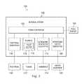
- FIG. 2is a block diagram of the phacoemulsification console of FIG. 1 showing various subsystems including a fluidics subsystem that drives aspiration according to the principles of the present disclosure.
- FIG. 3is a schematic of an exemplary fluidics subsystem usable with the phacoemulsification surgical console of FIGS. 1 and 2 according to one aspect of the present disclosure.
- FIG. 4is an exploded view of an exemplary cassette usable with the fluidics subsystem of FIG. 3 according to one aspect of the present disclosure.
- FIG. 5Ais a diagram showing an illustrative perspective view of a quick-opening vent valve according to one aspect of the present disclosure.
- FIG. 5Bis a diagram showing a top view of the quick-opening vent valve of FIG. 5A according to one aspect of the present disclosure.
- FIG. 5Cis a diagram showing a side view of the quick-opening vent valve of FIG. 5A according to one aspect of the present disclosure.
- FIG. 5Dis a diagram showing a cross-sectional view of the quick-opening vent valve of FIG. 5B taken along line A-A according to one aspect of the present disclosure.
- FIG. 5Eis a diagram showing a cross-sectional view of the quick-opening vent valve of FIG. 5D taken along line B-B according to one aspect of the present disclosure.
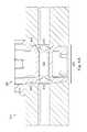
- FIG. 6Ais a diagram showing a cross-sectional view of the quick-opening vent valve of FIG. 5A installed in a valve chamber in an open position according to one aspect of the present disclosure.
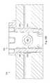
- FIG. 6Bis a diagram showing a cross-sectional view of the quick-opening vent valve of FIG. 5A rotated 90 degrees which is installed in the valve chamber of FIG. 6A in a closed position according to one aspect of the present disclosure.
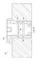
- FIG. 6Cis a diagram showing a cross-sectional view of the quick-opening vent valve of FIG. 5A which is installed in a valve chamber in a closed position and taken at a 90 degree section relative to FIG. 6B according to one aspect of the present disclosure.
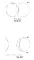
- FIGS. 7A and 7Bare diagrams showing a conventional vent valve transitioning from a closed position to a near-closed position according to one aspect of the present disclosure.
- FIGS. 7C and 7Dare diagrams showing a quick-open vent valve transitioning from a closed position to a near-closed position according to one aspect of the present disclosure.
- FIGS. 8A and 8Bare diagrams of overlapping areas of openings comparing initial flow areas of the conventional vent valve and the improved quick-open vent valve according to one aspect of the present disclosure.
- the present disclosurerelates to apparatuses, systems, and methods for rapid venting of vacuum to mitigate occlusion break surge within a phaco fluidics aspiration system.
- the aspiration systemmay utilize a positive displacement pump to generate flow and a vent valve to vent or moderate the pressure or vacuum level based on pressure sensor feedback detected within the eye and at the pump.
- Embodiments described hereinprovide a quick-opening vent valve that produces a quick-opening flow response upon angular rotation of the quick-opening vent valve.
- the flow performance at the quick-opening vent valveis improved by increasing the effective cross-sectional area of the valve at near-closed valve positions. In particular, the increase in area is achieved by incorporating two circular arcs with radii nearly equal to the barrel through hole.
- Similar embodimentscould be used to provide quick-opening flow response without departing from the general intent or teachings of the present disclosure.
- FIG. 1illustrates an exemplary emulsification surgical console, generally designated 100 .
- FIG. 2is a block diagram of the console 100 showing various subsystems that operate to perform a phacoemulsification procedure.
- the console 100includes a base housing 102 with a computer system 103 disposed therein and an associated display screen 104 showing data relating to system operation and performance during an emulsification surgical procedure.
- the console 100also includes a number of subsystems that are used together to perform an emulsification surgical procedure.
- the subsystemsinclude a foot pedal subsystem 106 including, for example, a foot pedal 108 , a fluidics subsystem 110 including an irrigation system and an aspiration system that deliver fluid to and aspirate fluid from the eye through flexible tubing 112 , an ultrasonic generator subsystem 116 including an ultrasonic oscillation hand piece 118 with a cutting needle, and a pneumatic vitrectomy cutter subsystem 120 including a vitrectomy hand piece 122 .
- a foot pedal subsystem 106including, for example, a foot pedal 108
- a fluidics subsystem 110including an irrigation system and an aspiration system that deliver fluid to and aspirate fluid from the eye through flexible tubing 112
- an ultrasonic generator subsystem 116including an ultrasonic oscillation hand piece 118 with a cutting needle
- a pneumatic vitrectomy cutter subsystem 120including a vitrectomy hand piece 122 .
- FIG. 3illustrates a schematic showing the fluidics subsystem 110 and the hand piece 118 .
- the fluidics subsystem 110includes an irrigation system 300 and an aspiration system 302 , each in communication with the hand piece 118 .
- the irrigation system 300includes an irrigation source 304 as a sterile solution reservoir, an irrigation valve 306 that regulates flow from the reservoir to the surgical site, a flexible irrigation tubing 308 , an irrigation path 310 in the hand piece 118 , and a sleeve 312 that may be considered a component of the hand piece 118 .
- the irrigation source 304may be a mechanically pressurized fluid source such as, for example, a clamping pressure system.
- the irrigation source 304may be a source suspended by a pole (e.g., an IV pole) which may or may not be adjustable. Other fluid sources also are contemplated.
- the irrigation system 300extends between the sterile solution reservoir 304 and the hand piece 118 , and carries fluid to the surgical site (labeled in FIG. 3 as an eye).
- the sterile fluidis a saline fluid, however, other fluids may be used.
- the flexible irrigation tubing 308may be formed in part of the flexible tubing 112 in FIG. 2 .
- the irrigation tubing 308is formed of multiple segments, with some segments being rigid and others being flexible.
- at least a portion of the irrigation system 300is formed in a cassette 314 that cooperates with the console 100 in FIG. 1 to provide fluid communication between the sterile solution reservoir 304 and the patient's eye.
- the irrigation sleeve 312is disposed about the cutting needle to provide irrigating fluid flow to the eye during the surgical procedure.
- the aspiration system 302includes an aspiration path 316 in the hand piece 118 , a handpiece pressure sensor (HPS) 365 located within the hand piece 118 , a small bore flexible aspiration tubing 318 , an aspiration pressure sensor (APS) 320 , a pump 322 , a vent valve 324 , a drain line reservoir 326 , and a drain reservoir 328 .
- the HPS 365may be disposed at the irrigation path of the hand piece 118 .
- the HPS 365may be disposed at aspiration path of the hand piece 118 .
- a hand piece connector 330connects the aspiration path 316 in the hand piece 118 to the small bore flexible aspiration tubing 318 .
- a cassette connector 332connects the flexible aspiration tubing 318 to the cassette aspiration line in the cassette 314 .
- the aspiration system 302extends from the surgical site (eye) to the drain reservoir 328 . It carries away fluid used to flush the eye as well as any emulsified particles.
- the small bore flexible aspiration tubing 318may be formed of the flexible tubing 112 .
- the aspiration system 302is formed of multiple segments, with some segments being rigid and others being flexible. Also, in some embodiments, at least a portion of the aspiration system 302 is formed in the cassette 314 that cooperates with the console 100 in FIG.
- the aspiration system 302including the aspiration fluid path 316 , is in fluid communication with the bore of the cutting tip (labeled 334 in FIG. 3 ) of the hand piece 118 and is used to aspirate fluid and emulsified particles through the needle bore and into the aspiration system 302 during the surgical procedure.
- the surgical system 102may detect the vacuum, or pressure difference, via pressure sensor 320 installed at the pump 322 and/or pressure sensor 365 installed in the hand piece 118 .
- the surgical system 102may control the vent valve 324 to open to relieve the vacuum in the aspiration pathway and to reduce the effect of occlusion break. This would reduce the magnitude of resulting surge and maintain a predetermined level of vacuum so as not to lessen the efficiency of lens removal.
- FIG. 4is an exploded view of an exemplary cassette 314 usable with the fluidics subsystem of FIG. 3 according to one aspect of the present disclosure.
- the body of cassette 314may be formed by an upper housing 410 and a lower housing 420 coupled to each other.
- the housings 410 and 420may be formed with rigid thermoplastic material, such as polycarbonate and/or polysulfone to provide rigidity and structure.
- a pump interface portion 450may be disposed in cassette 314 to engage pump 322 .
- Pump 322may be an elastomer pump configured to drive fluid flow in the aspiration flow path.
- a vent valve chamber 430 and an aspiration valve chamber 440also may be provided in the cassette. Vent valve chamber 430 may be configured to accommodate vent valve 324 . Aspiration valve chamber 440 may be configured to accommodate irrigation valve 306 .
- Vent valve chamber 430may be positioned in a vent path 350 , such that vent valve 324 may selectively close and open to allow vacuum venting via the vent path 350 .
- the vent valve 324is a rotary stopcock valve formed with high-density elastic polymer, such as polyethylene or acetal, such that vent valve 324 may be press-fit into vent valve chamber 430 .
- vent valve 324may rotate within the vent valve chamber 430 as driven by a valve motor 115 (e.g., a stepper motor or other motor type) with an angular position encoder to selectively open and close the vent path 350 , as shown in FIG. 3 .
- Vent valve 324typically may be in a closed position while performing a surgical procedure.
- the valve motor 115may be driven by a controller or computer system 103 to rotate vent valve 324 from the closed position to an open position to open the vent path 350 for vacuum venting.
- the response speed of vacuum ventingis important for minimizing the onset of occlusion surge. Although rotating the valve motor 115 faster could potentially achieve faster venting, this approach is limited by the motor speed and controller response time.
- the embodiments of the disclosureprovide improved vent valve structures for quick-opening and quick-closing flow characteristics at near-closed valve positions.
- FIG. 5Ais a diagram showing an illustrative perspective view of a quick-opening vent valve 324 according to one aspect of the present disclosure.
- Vent valve 324may include a motor engagement portion 510 and a body portion 520 .
- Motor engagement portion 510may include an axle interface 530 configured to engage a driving axle of a valve motor 115 .
- the axle interface 530may include a substantially cylindrical chamber 532 for receiving the driving axle of the valve motor 115 .
- Cross shape cutouts 534also may be provided at a top perimeter portion of the cylindrical chamber 532 to provide better torque engagement with the driving axle of the valve motor 115 during rotation.
- the valve motor for driving the vent valvemay engage the motor engagement portion 510 of the vent valve 324 installed in the cassette 314 .
- a driving axle of the valve motor 115may be inserted into the axle interface 530 of the vent valve 324 .
- the valve motor 115may rotate the vent valve 324 via the driving axle.
- Motor engagement portion 510may also include a rotation restriction portion 540 provided at certain perimeter portion of the motor engagement portion 510 .
- the rotation restriction portion 540may define a rotation range of the vent valve 324 in coordination with a rotation stopper 435 provided on a top portion of vent valve chamber 430 , as shown in FIG. 4 .
- the body portion 520 of the vent valve 324may be accommodated inside the vent valve chamber 430 while the motor engagement portion 510 of the vent valve 324 may protrude from the vent valve chamber 430 .
- the rotation restriction portion 540may rotatably slide along an outer perimeter surface of the vent valve chamber 430 .
- the rotationmay be stopped when the sliding of the rotation restriction portion 540 bumps into the rotation stopper 435 .
- the rotation restriction portion 540 and the rotation stopper 435 togethermay define the rotation range of the vent valve 324 .
- the rotation range of the vent valve 324may be defined based on an open position and a closed position of the vent valve 324 .
- the body portion 520 of the vent valve 324may have a cylindrical shape solid surface 570 including a flow channel 550 formed there through.
- the flow channel 550may have channel openings 560 .
- the flow channel 550may be configured to allow flow of aspiration fluid when the vent valve 324 is open.
- FIG. 5Ca side view of the quick-opening vent valve of FIG. 5A according to one aspect of the present disclosure, the flow channel 550 may have a substantially circular cross sectional shape.
- the flow channel 550may have a substantially square or rectangular shape.
- opening portions 560 of the flow channel 550have an hour-glass shape formed in the solid surface 570 . As shown in FIG.
- the hour-glass shapeis formed by a flat top side and a flat bottom side connected by two curved sides 562 .
- the curved sides 562may have a shape complementary or have an inverse shape to the shape of openings formed in the inner side walls of the vent valve chamber 430 .
- the radius of curvature of curved sides 562may substantially be the same as that of the radius of the circular opening formed in the inner side walls of the vent valve chamber 430 .
- FIG. 5Dis a diagram showing a cross-sectional view of the quick-opening vent valve 324 taken along line A-A in FIG. 5B according to one aspect of the present disclosure.
- the opening portions 560may have a larger cross-sectional area than that of the flow channel 550 .
- the hour-glass shape opening portions 560may gradually transition in a sloping manner to the circular shape flow channel 550 .
- the larger hour-glass shape openings 560may provide additional space that may serve as a dam to hold additional fluid within the vent valve 324 when the vent valve 324 is in the closed position.
- the additional fluid held in the dammay provide additional fluid volume when the vent valve 324 initially opens to provide quick flow response for vacuum venting.
- the flow channel 550may have a substantially circular cross sectional shape and may be formed in an inner circular pipe portion 552 .
- Inner circular pipe portion 552may be supported by bridge extensions 554 extending from the inner side walls of vent valve 324 .
- the flow channel 550may have a substantially rectangular or square cross sectional shape. Other cross sectional shapes are also contemplated for the flow channel 550 .
- FIG. 6Ais a diagram showing a cross-sectional view of the quick-opening vent valve taken along line A-A of FIG. 5A which is installed in a vent valve chamber 430 of a cassette in an open position according to one aspect of the present disclosure.
- Vent valve chamber 430may include openings 610 and 612 formed in the inner side of solid walls 620 across from each other to face each other. In the open position, one of openings 610 and 612 may lead to the vent reservoir side of the vent path 350 and the other may lead to the aspiration flow path. Based on the position of the vent valve 324 , the openings 610 and 612 may be selectively connected to each other via flow channel 550 of vent valve 324 . For example, as shown in FIG.
- vent valve 324when vent valve 324 is rotated such that the openings 560 of vent valve 324 's flow channel 550 correspond to or is aligned with the openings 610 and 612 of the valve chamber 430 , the vent valve 324 is in an open position and the vent path 350 is open to allow fluid flow or vacuum venting.
- vent valve 324when vent valve 324 is rotated such that the openings 560 of vent valves 324 's flow channel 550 is rotated away or offset from the openings 610 and 612 of the valve chamber 430 , the vent valve 324 is in a closed position and the vent path 350 is closed to stop vacuum venting.
- the openings 610 and 612may align with solid surface 570 of the vent valve 324 in the closed position to prevent fluid flow at the openings 610 and 612 .
- the openings 560 of vent valves 324 's flow channel 550are aligned with the inner surfaces of the solid walls 620 in the closed position to prevent fluid flow through the openings 560 and to stop vacuum venting.
- the pressure sensors 320 and 365may detect the vacuum buildup and the system may control the vent valve 324 to open to relieve the vacuum through the vent path 350 , as shown in FIG. 3 .
- a quick response timemay allow quick venting of vacuum to minimize occlusion break surge.
- the openings 560 of the flow channel 550 of the vent valve 324are improved to have shapes that are complementary to the openings 610 and 612 of the valve chamber 430 .
- the hour-glass shape of the openings 560 of flow channel 550have a concave edge portion to complement the circular shape of the openings 610 and 612 of the valve chamber 430 .
- the flow channel of a conventional vent valvehas circular shape openings.
- the openings formed in the inner side walls of the valve chamber 430also have circular shapes.
- FIG. 7Awhen the conventional vent valve is closed, the vent valve's circular opening is offset from the opening of the valve chamber 430 (shown in dashed line).
- the conventional vent valverotates to open, the circular opening of the conventional vent valve begins to move and overlap with the circular opening of the valve chamber 430 .
- the overlapping areais the cross sectional area through which the fluid may begin to flow to vent the vacuum.
- the overlapping area between the circular openingsis relatively small for the conventional vent valve at the initial opening position or at the near closed position.
- the improved vent valve 324is a quick-opening valve that allows for increased flow at the initial opening position or at the near closed position.
- the opening 560 of vent valve 324 's flow channel 550has an hour-glass shape.
- the side edge portion 562 of the opening 560has a concave shape with a radius substantially the same as that of the circular shape of valve chamber 430 's opening 610 .
- the side edge 562 of vent valve 324 's opening 560closely tracks or complements the circular edge portion of valve chamber 430 's opening 610 .
- vent valve 324When the vent valve 324 begins to rotate from the closed position to the open position, the side edge portion 562 of vent valve 342 's opening 560 begins to move pass a side edge portion of the opening 610 of valve chamber 430 . Because of the longer complementary edge portions between vent valve 324 's opening 560 and valve chamber 430 's opening 610 , the overlapping area is larger to provide greater flow at the initial opening position.
- the quick-opening vent valve 342 with the hour-glass shape openings 562may allow for up to five times more initial flow than the conventional vent valve with the circular openings.
- the greater initial flowallows faster vacuum venting response to the aspiration flow path.
- the improved opening shape at the vent valve 324also may allow faster response when closing the valve. Similar features also may be applied to the interface between opening 560 of vent valve 324 and opening 612 of valve chamber 430 .
- vent valve 324While the above embodiments are described in view of the vent valve 324 , similar features may be adapted for the irrigation valve 306 .
- the above embodimentsmay provide an hour-glass shape opening at the vent valve 324 to complement the circular shape opening at the valve chamber 430 .
- the openings at the vent valve 324may have circular shape while the openings at the valve chamber 430 have the complementary hour-glass shape.
- opening shapes at the vent valve 324may be modified based on the opening shape at the valve chamber 430 such that they complement each other, e.g., inverse shape.
- the valve chamber 430may have an oval opening shape.
- the vent valve 324may be modified to have concave side edges of different radius accordingly.
- the embodiments disclosed hereinprovide improved opening shapes for the vent valve to improve the initial flow rate.
- the increased initial flow ratemay improve the response time for venting the excessive vacuum in the aspiration flow path to minimize occlusion break surge. This may lead to better patient outcome and surgical results.
Landscapes
- Health & Medical Sciences (AREA)
- Engineering & Computer Science (AREA)
- Heart & Thoracic Surgery (AREA)
- General Engineering & Computer Science (AREA)
- Life Sciences & Earth Sciences (AREA)
- Veterinary Medicine (AREA)
- Public Health (AREA)
- General Health & Medical Sciences (AREA)
- Biomedical Technology (AREA)
- Animal Behavior & Ethology (AREA)
- Anesthesiology (AREA)
- Hematology (AREA)
- Vascular Medicine (AREA)
- Mechanical Engineering (AREA)
- Ophthalmology & Optometry (AREA)
- Pulmonology (AREA)
- Surgery (AREA)
- Nuclear Medicine, Radiotherapy & Molecular Imaging (AREA)
- External Artificial Organs (AREA)
- Compressors, Vaccum Pumps And Other Relevant Systems (AREA)
- Control Of Positive-Displacement Air Blowers (AREA)
Abstract
Description
Claims (13)
Priority Applications (14)
| Application Number | Priority Date | Filing Date | Title |
|---|---|---|---|
| US14/571,374US9931447B2 (en) | 2014-12-16 | 2014-12-16 | Quick-opening vent valve for phaco fluidics aspiration system |
| TW104140342ATW201630628A (en) | 2014-12-16 | 2015-12-02 | Quick-opening vent valve for phaco fluidics aspiration system |
| RU2017123153ARU2705945C2 (en) | 2014-12-16 | 2015-12-10 | Quick-opening vent valve for phaco fluidics aspiration system |
| BR112017012427-0ABR112017012427B1 (en) | 2014-12-16 | 2015-12-10 | SURGICAL SYSTEM FOR PHACOEMULSIFICATION, CASSETTE FOR USE IN AN ASPIRATION SYSTEM AND ROTATING EXHAUST VALVE FOR USE IN A CASSETTE |
| KR1020177015791AKR102524992B1 (en) | 2014-12-16 | 2015-12-10 | Quick-opening vent valve for phaco fluidics aspiration system |
| ES15813679TES2882079T3 (en) | 2014-12-16 | 2015-12-10 | Quick opening bleed valve for phacoemulsification fluid aspiration system |
| CA2966639ACA2966639C (en) | 2014-12-16 | 2015-12-10 | Quick-opening vent valve for phaco fluidics aspiration system |
| CN201580067818.8ACN106999641B (en) | 2014-12-16 | 2015-12-10 | Venting valve is opened fastly for ultrasonic emulsification fluid aspiration system |
| JP2017530620AJP6817206B2 (en) | 2014-12-16 | 2015-12-10 | Rapid opening vent valve for lens fluid engineering suction system |
| AU2015362964AAU2015362964B2 (en) | 2014-12-16 | 2015-12-10 | Quick-opening vent valve for phaco fluidics aspiration system |
| MX2017007979AMX2017007979A (en) | 2014-12-16 | 2015-12-10 | Quick-opening vent valve for phaco fluidics aspiration system. |
| PCT/US2015/064985WO2016100083A1 (en) | 2014-12-16 | 2015-12-10 | Quick-opening vent valve for phaco fluidics aspiration system |
| EP15813679.6AEP3233147B1 (en) | 2014-12-16 | 2015-12-10 | Quick-opening vent valve for phaco fluidics aspiration system |
| ARP150104065AAR102996A1 (en) | 2014-12-16 | 2015-12-14 | FAST OPENING VENTILATION VALVE FOR A FACO FLUID ASPIRATION SYSTEM |
Applications Claiming Priority (1)
| Application Number | Priority Date | Filing Date | Title |
|---|---|---|---|
| US14/571,374US9931447B2 (en) | 2014-12-16 | 2014-12-16 | Quick-opening vent valve for phaco fluidics aspiration system |
Publications (2)
| Publication Number | Publication Date |
|---|---|
| US20160166742A1 US20160166742A1 (en) | 2016-06-16 |
| US9931447B2true US9931447B2 (en) | 2018-04-03 |
Family
ID=54937404
Family Applications (1)
| Application Number | Title | Priority Date | Filing Date |
|---|---|---|---|
| US14/571,374Active2036-08-06US9931447B2 (en) | 2014-12-16 | 2014-12-16 | Quick-opening vent valve for phaco fluidics aspiration system |
Country Status (14)
| Country | Link |
|---|---|
| US (1) | US9931447B2 (en) |
| EP (1) | EP3233147B1 (en) |
| JP (1) | JP6817206B2 (en) |
| KR (1) | KR102524992B1 (en) |
| CN (1) | CN106999641B (en) |
| AR (1) | AR102996A1 (en) |
| AU (1) | AU2015362964B2 (en) |
| BR (1) | BR112017012427B1 (en) |
| CA (1) | CA2966639C (en) |
| ES (1) | ES2882079T3 (en) |
| MX (1) | MX2017007979A (en) |
| RU (1) | RU2705945C2 (en) |
| TW (1) | TW201630628A (en) |
| WO (1) | WO2016100083A1 (en) |
Cited By (24)
| Publication number | Priority date | Publication date | Assignee | Title |
|---|---|---|---|---|
| WO2020225643A1 (en) | 2019-05-06 | 2020-11-12 | Alcon Inc. | Ophthalmic fluidics system with eddy current pressure sensor |
| WO2021070037A1 (en) | 2019-10-08 | 2021-04-15 | Alcon Inc. | Peristaltic pumps with reduced pulsations |
| WO2021070038A1 (en) | 2019-10-08 | 2021-04-15 | Alcon Inc. | Aspiration systems and methods with multiple pumps and pressure sensor |
| WO2021094900A1 (en) | 2019-11-15 | 2021-05-20 | Alcon Inc. | Devices and methods for checking battery state of health |
| US11051978B2 (en) | 2016-05-10 | 2021-07-06 | Alcon Inc. | Automated aspiration throttling in vitreoretinal surgery |
| WO2021138641A1 (en) | 2020-01-03 | 2021-07-08 | Lensar, Inc. | Integrated systems for predetermined combination laser-phacoemulsification therapies |
| WO2021161152A1 (en) | 2020-02-12 | 2021-08-19 | Alcon Inc. | Ophthalmic surgical systems with graphical user interfaces based upon setup conditions |
| WO2021181229A1 (en) | 2020-03-10 | 2021-09-16 | Alcon Inc. | Systems and methods for controlled illumination of light-emitting diodes |
| WO2022097004A1 (en) | 2020-11-05 | 2022-05-12 | Johnson & Johnson Surgical Vision, Inc. | Controlling intraocular pressure during phacoemulsification procedures |
| US11432961B2 (en) | 2016-05-17 | 2022-09-06 | Alcon, Inc. | Automated viscous fluid control in vitreoretinal surgery |
| US11446424B2 (en) | 2017-10-04 | 2022-09-20 | Johnson & Johnson Surgical Vision, Inc. | Systems and methods for measuring fluid flow in a venturi based system |
| US11457937B2 (en) | 2014-09-02 | 2022-10-04 | Tenex Health, Inc. | Subcutaneous wound debridement |
| US11500400B2 (en)* | 2018-07-30 | 2022-11-15 | Fresenius Medical Care Holdings, Inc. | Valve actuation systems and related methods |
| WO2023062565A1 (en) | 2021-10-15 | 2023-04-20 | Alcon Inc. | Dynamic laser pulse control |
| US11666745B2 (en) | 2018-12-07 | 2023-06-06 | Fresenius Medical Care Holdings, Inc. | Rotary valves for managing fluid flows in medical systems |
| US11679194B2 (en) | 2021-04-27 | 2023-06-20 | Contego Medical, Inc. | Thrombus aspiration system and methods for controlling blood loss |
| WO2023218276A1 (en) | 2022-05-10 | 2023-11-16 | Alcon Inc. | Laser pulse control with sub-carrier modulation |
| WO2023218277A1 (en) | 2022-05-10 | 2023-11-16 | Alcon Inc. | Adjustable laser pulse control |
| WO2024047455A1 (en) | 2022-09-02 | 2024-03-07 | Alcon Inc. | Devices and methods for improved followability in laser-based ocular procedures |
| US12013050B2 (en) | 2018-07-31 | 2024-06-18 | Fresenius Medical Care Holdings, Inc. | Rotary valves for dialysis systems |
| US12201759B2 (en) | 2019-08-05 | 2025-01-21 | Fresenius Medical Care Holdings, Inc. | Conductivity control systems |
| US12285360B2 (en) | 2020-12-22 | 2025-04-29 | Johnson & Johnson Surgical Vision, Inc. | Reducing irrigation/aspiration valve response time in a phacoemulsification system |
| US12364623B2 (en) | 2021-10-08 | 2025-07-22 | Alcon Inc. | Efficient lasers for tissue disruption |
| WO2025181581A1 (en) | 2024-02-29 | 2025-09-04 | Alcon Inc. | Devices and methods for improved removal of cortical material |
Families Citing this family (12)
| Publication number | Priority date | Publication date | Assignee | Title |
|---|---|---|---|---|
| US9931447B2 (en) | 2014-12-16 | 2018-04-03 | Novartis Ag | Quick-opening vent valve for phaco fluidics aspiration system |
| FI130032B (en) | 2016-07-06 | 2022-12-30 | Serres Oy | An apparatus for collecting liquid from a patient and a manifold |
| CN108670547B (en)* | 2018-06-07 | 2020-12-04 | 河源光明眼科医院有限公司 | Cataract surgery device |
| US11712258B2 (en)* | 2018-12-10 | 2023-08-01 | Covidien Lp | Tissue resection systems including fluid outflow management |
| US11779694B2 (en) | 2019-04-24 | 2023-10-10 | Johnson & Johnson Surgical Vision, Inc. | Systems and methods for proportional pressure and vacuum control in surgical system |
| CN110338970B (en)* | 2019-07-23 | 2024-02-02 | 以诺康医疗科技(苏州)有限公司 | Ultrasonic emulsification handle with sensor and surge control system and method |
| WO2021124146A1 (en)* | 2019-12-17 | 2021-06-24 | Johnson & Johnson Surgical Vision, Inc. | Rotary valve configuration for a surgical cassette |
| KR20220133218A (en)* | 2020-01-30 | 2022-10-04 | 어시스트 메디칼 시스템즈, 인크. | valve assembly |
| US12259063B2 (en) | 2021-03-31 | 2025-03-25 | Amgis, Llc | Valve apparatus |
| CN113180912B (en)* | 2021-05-26 | 2023-07-04 | 以诺康医疗科技(苏州)有限公司 | Hydrops box for ultrasonic emulsification operation |
| WO2023170498A1 (en)* | 2022-03-08 | 2023-09-14 | Johnson & Johnson Surgical Vision, Inc. | Phacoemulsification system with automatic detection of extension tubing |
| US20250134710A1 (en)* | 2023-10-25 | 2025-05-01 | Johnson & Johnson Surgical Vision, Inc. | Phacoemulsification handpiece with integrated anti-vacuum surge module |
Citations (13)
| Publication number | Priority date | Publication date | Assignee | Title |
|---|---|---|---|---|
| US3998227A (en) | 1974-09-13 | 1976-12-21 | Medical Development Corporation | Regulator structure and system |
| US4453567A (en)* | 1982-03-29 | 1984-06-12 | Masco Corporation | Valve assembly |
| US5009393A (en) | 1990-06-13 | 1991-04-23 | Harper-Wyman Company | Linear flow turn down valve |
| DE19940471A1 (en) | 1999-08-26 | 2001-03-01 | Fischer Georg Rohrleitung | Stopcock for use in pipeline has inlet and outlet in ball which are of different shapes |
| US6731963B2 (en) | 1999-03-09 | 2004-05-04 | Orsense Ltd. | Device for enhancement and quality improvement of blood-related signals for use in a system for non-invasive measurements of blood-related signals |
| US6808162B2 (en) | 2001-09-19 | 2004-10-26 | Victory Controls, Llc | Rotary 2-way servovalve |
| US7565918B2 (en) | 2006-07-14 | 2009-07-28 | Johnson Controls Technology Company | Variable orifice rotary control valve |
| US20100152762A1 (en) | 2008-12-16 | 2010-06-17 | Mark Joseph L | Tissue removal system with multi-directional foot actuator assembly for neurosurgical and spinal surgery applications |
| WO2010080894A2 (en) | 2009-01-07 | 2010-07-15 | Enlighten Technologies, Inc. | Tissue removal devices, systems and methods |
| WO2013039742A2 (en) | 2011-09-16 | 2013-03-21 | Medlogics, Inc. | Tissue removal devices, systems and methods |
| US20130150782A1 (en)* | 2011-12-08 | 2013-06-13 | Alcon Research, Ltd. | Selectively Moveable Valve Elements for Aspiration and Irrigation Circuits |
| WO2016100083A1 (en) | 2014-12-16 | 2016-06-23 | Novartis Ag | Quick-opening vent valve for phaco fluidics aspiration system |
| US9549850B2 (en) | 2013-04-26 | 2017-01-24 | Novartis Ag | Partial venting system for occlusion surge mitigation |
Family Cites Families (8)
| Publication number | Priority date | Publication date | Assignee | Title |
|---|---|---|---|---|
| US5361739A (en)* | 1993-05-12 | 1994-11-08 | Coates George J | Spherical rotary valve assembly for use in a rotary valve internal combustion engine |
| KR20050077662A (en)* | 2004-01-30 | 2005-08-03 | 엘지전자 주식회사 | Stepping motor valve |
| US7942853B2 (en)* | 2006-01-11 | 2011-05-17 | Alcon, Inc. | Fluid chamber |
| US8273049B2 (en)* | 2007-02-27 | 2012-09-25 | Deka Products Limited Partnership | Pumping cassette |
| RU2434608C1 (en)* | 2010-06-02 | 2011-11-27 | Закрытое акционерное общество "Оптимедсервис" | Aspiration pump for ophthalmosurgical systems |
| WO2013142009A1 (en)* | 2012-03-17 | 2013-09-26 | Abbott Medical Optics, Inc. | Surgical cassette |
| US9119699B2 (en)* | 2012-10-22 | 2015-09-01 | Alcon Research, Ltd. | Pressure control in phacoemulsification system |
| US9962288B2 (en)* | 2013-03-07 | 2018-05-08 | Novartis Ag | Active acoustic streaming in hand piece for occlusion surge mitigation |
- 2014
- 2014-12-16USUS14/571,374patent/US9931447B2/enactiveActive
- 2015
- 2015-12-02TWTW104140342Apatent/TW201630628A/enunknown
- 2015-12-10WOPCT/US2015/064985patent/WO2016100083A1/enactiveApplication Filing
- 2015-12-10CNCN201580067818.8Apatent/CN106999641B/enactiveActive
- 2015-12-10MXMX2017007979Apatent/MX2017007979A/enunknown
- 2015-12-10EPEP15813679.6Apatent/EP3233147B1/enactiveActive
- 2015-12-10AUAU2015362964Apatent/AU2015362964B2/enactiveActive
- 2015-12-10KRKR1020177015791Apatent/KR102524992B1/enactiveActive
- 2015-12-10ESES15813679Tpatent/ES2882079T3/enactiveActive
- 2015-12-10BRBR112017012427-0Apatent/BR112017012427B1/enactiveIP Right Grant
- 2015-12-10RURU2017123153Apatent/RU2705945C2/enactive
- 2015-12-10JPJP2017530620Apatent/JP6817206B2/enactiveActive
- 2015-12-10CACA2966639Apatent/CA2966639C/enactiveActive
- 2015-12-14ARARP150104065Apatent/AR102996A1/enunknown
Patent Citations (15)
| Publication number | Priority date | Publication date | Assignee | Title |
|---|---|---|---|---|
| US3998227A (en) | 1974-09-13 | 1976-12-21 | Medical Development Corporation | Regulator structure and system |
| US4453567A (en)* | 1982-03-29 | 1984-06-12 | Masco Corporation | Valve assembly |
| US5009393A (en) | 1990-06-13 | 1991-04-23 | Harper-Wyman Company | Linear flow turn down valve |
| US6731963B2 (en) | 1999-03-09 | 2004-05-04 | Orsense Ltd. | Device for enhancement and quality improvement of blood-related signals for use in a system for non-invasive measurements of blood-related signals |
| DE19940471A1 (en) | 1999-08-26 | 2001-03-01 | Fischer Georg Rohrleitung | Stopcock for use in pipeline has inlet and outlet in ball which are of different shapes |
| US6808162B2 (en) | 2001-09-19 | 2004-10-26 | Victory Controls, Llc | Rotary 2-way servovalve |
| US7565918B2 (en) | 2006-07-14 | 2009-07-28 | Johnson Controls Technology Company | Variable orifice rotary control valve |
| US20100152762A1 (en) | 2008-12-16 | 2010-06-17 | Mark Joseph L | Tissue removal system with multi-directional foot actuator assembly for neurosurgical and spinal surgery applications |
| WO2010080894A2 (en) | 2009-01-07 | 2010-07-15 | Enlighten Technologies, Inc. | Tissue removal devices, systems and methods |
| WO2013039742A2 (en) | 2011-09-16 | 2013-03-21 | Medlogics, Inc. | Tissue removal devices, systems and methods |
| WO2013039742A3 (en) | 2011-09-16 | 2013-05-10 | Medlogics, Inc. | Tissue removal devices, systems and methods |
| US20130150782A1 (en)* | 2011-12-08 | 2013-06-13 | Alcon Research, Ltd. | Selectively Moveable Valve Elements for Aspiration and Irrigation Circuits |
| US9561321B2 (en) | 2011-12-08 | 2017-02-07 | Alcon Research, Ltd. | Selectively moveable valve elements for aspiration and irrigation circuits |
| US9549850B2 (en) | 2013-04-26 | 2017-01-24 | Novartis Ag | Partial venting system for occlusion surge mitigation |
| WO2016100083A1 (en) | 2014-12-16 | 2016-06-23 | Novartis Ag | Quick-opening vent valve for phaco fluidics aspiration system |
Non-Patent Citations (1)
| Title |
|---|
| Layser, Gregory S.; "Flow Control During Multi-Cavity Injection Molding Processes", Lehigh University Master Thesis, Apr./May 2004, Chapter 3, pp. 26-44. |
Cited By (38)
| Publication number | Priority date | Publication date | Assignee | Title |
|---|---|---|---|---|
| US11457937B2 (en) | 2014-09-02 | 2022-10-04 | Tenex Health, Inc. | Subcutaneous wound debridement |
| US11051978B2 (en) | 2016-05-10 | 2021-07-06 | Alcon Inc. | Automated aspiration throttling in vitreoretinal surgery |
| US11432961B2 (en) | 2016-05-17 | 2022-09-06 | Alcon, Inc. | Automated viscous fluid control in vitreoretinal surgery |
| US11446424B2 (en) | 2017-10-04 | 2022-09-20 | Johnson & Johnson Surgical Vision, Inc. | Systems and methods for measuring fluid flow in a venturi based system |
| US12314067B2 (en) | 2018-07-30 | 2025-05-27 | Fresenius Medical Care Holdings, Inc. | Valve actuation systems and related methods |
| US11500400B2 (en)* | 2018-07-30 | 2022-11-15 | Fresenius Medical Care Holdings, Inc. | Valve actuation systems and related methods |
| US12013050B2 (en) | 2018-07-31 | 2024-06-18 | Fresenius Medical Care Holdings, Inc. | Rotary valves for dialysis systems |
| US12194268B2 (en) | 2018-12-07 | 2025-01-14 | Fresenius Medical Care Holdings, Inc. | Rotary valves for managing fluid flows in medical systems |
| US11666745B2 (en) | 2018-12-07 | 2023-06-06 | Fresenius Medical Care Holdings, Inc. | Rotary valves for managing fluid flows in medical systems |
| WO2020225643A1 (en) | 2019-05-06 | 2020-11-12 | Alcon Inc. | Ophthalmic fluidics system with eddy current pressure sensor |
| US12070417B2 (en) | 2019-05-06 | 2024-08-27 | Alcon Inc. | Ophthalmic fluidics system with eddy current pressure sensor |
| US12201759B2 (en) | 2019-08-05 | 2025-01-21 | Fresenius Medical Care Holdings, Inc. | Conductivity control systems |
| US11602586B2 (en) | 2019-10-08 | 2023-03-14 | Alcon Inc. | Aspiration systems and methods with multiple pumps and pressure sensor |
| WO2021070038A1 (en) | 2019-10-08 | 2021-04-15 | Alcon Inc. | Aspiration systems and methods with multiple pumps and pressure sensor |
| US11873806B2 (en) | 2019-10-08 | 2024-01-16 | Alcon Inc. | Peristaltic pumps with reduced pulsations |
| WO2021070037A1 (en) | 2019-10-08 | 2021-04-15 | Alcon Inc. | Peristaltic pumps with reduced pulsations |
| WO2021094900A1 (en) | 2019-11-15 | 2021-05-20 | Alcon Inc. | Devices and methods for checking battery state of health |
| WO2021138641A1 (en) | 2020-01-03 | 2021-07-08 | Lensar, Inc. | Integrated systems for predetermined combination laser-phacoemulsification therapies |
| EP4389045A2 (en) | 2020-01-03 | 2024-06-26 | Lensar, Inc. | Methods and systems for combined sonic and laser applications for the eye |
| EP4218695A1 (en) | 2020-01-03 | 2023-08-02 | Lensar, Inc. | Integrated systems for predetermined combination laser-phacoemulsification therapies |
| EP4218694A1 (en) | 2020-01-03 | 2023-08-02 | Lensar, Inc. | Methods and systems for combined sonic and laser applications for the eye |
| WO2021161152A1 (en) | 2020-02-12 | 2021-08-19 | Alcon Inc. | Ophthalmic surgical systems with graphical user interfaces based upon setup conditions |
| US12004823B2 (en) | 2020-02-12 | 2024-06-11 | Alcon Inc. | Ophthalmic surgical systems with graphical user interfaces based upon setup conditions |
| US11350499B2 (en) | 2020-03-10 | 2022-05-31 | Alcon Inc. | Systems and methods for controlled illumination of light-emitting diodes |
| WO2021181229A1 (en) | 2020-03-10 | 2021-09-16 | Alcon Inc. | Systems and methods for controlled illumination of light-emitting diodes |
| WO2022097004A1 (en) | 2020-11-05 | 2022-05-12 | Johnson & Johnson Surgical Vision, Inc. | Controlling intraocular pressure during phacoemulsification procedures |
| US12285360B2 (en) | 2020-12-22 | 2025-04-29 | Johnson & Johnson Surgical Vision, Inc. | Reducing irrigation/aspiration valve response time in a phacoemulsification system |
| US11679194B2 (en) | 2021-04-27 | 2023-06-20 | Contego Medical, Inc. | Thrombus aspiration system and methods for controlling blood loss |
| US11717603B2 (en) | 2021-04-27 | 2023-08-08 | Contego Medical, Inc. | Thrombus aspiration system and methods for controlling blood loss |
| US11679195B2 (en) | 2021-04-27 | 2023-06-20 | Contego Medical, Inc. | Thrombus aspiration system and methods for controlling blood loss |
| US11931502B2 (en) | 2021-04-27 | 2024-03-19 | Contego Medical, Inc. | Thrombus aspiration system and methods for controlling blood loss |
| US12364623B2 (en) | 2021-10-08 | 2025-07-22 | Alcon Inc. | Efficient lasers for tissue disruption |
| WO2023062565A1 (en) | 2021-10-15 | 2023-04-20 | Alcon Inc. | Dynamic laser pulse control |
| US12427063B2 (en) | 2021-10-15 | 2025-09-30 | Alcon Inc. | Dynamic laser pulse control |
| WO2023218277A1 (en) | 2022-05-10 | 2023-11-16 | Alcon Inc. | Adjustable laser pulse control |
| WO2023218276A1 (en) | 2022-05-10 | 2023-11-16 | Alcon Inc. | Laser pulse control with sub-carrier modulation |
| WO2024047455A1 (en) | 2022-09-02 | 2024-03-07 | Alcon Inc. | Devices and methods for improved followability in laser-based ocular procedures |
| WO2025181581A1 (en) | 2024-02-29 | 2025-09-04 | Alcon Inc. | Devices and methods for improved removal of cortical material |
Also Published As
| Publication number | Publication date |
|---|---|
| KR102524992B1 (en) | 2023-04-21 |
| CN106999641A (en) | 2017-08-01 |
| AU2015362964A1 (en) | 2017-05-25 |
| BR112017012427A2 (en) | 2018-01-02 |
| RU2705945C2 (en) | 2019-11-12 |
| CA2966639A1 (en) | 2016-06-23 |
| MX2017007979A (en) | 2017-09-29 |
| KR20170095848A (en) | 2017-08-23 |
| EP3233147A1 (en) | 2017-10-25 |
| ES2882079T3 (en) | 2021-12-01 |
| JP6817206B2 (en) | 2021-01-20 |
| US20160166742A1 (en) | 2016-06-16 |
| RU2017123153A (en) | 2019-01-18 |
| BR112017012427B1 (en) | 2021-12-21 |
| TW201630628A (en) | 2016-09-01 |
| CN106999641B (en) | 2019-06-11 |
| AR102996A1 (en) | 2017-04-05 |
| AU2015362964B2 (en) | 2020-02-27 |
| RU2017123153A3 (en) | 2019-06-17 |
| JP2017538494A (en) | 2017-12-28 |
| EP3233147B1 (en) | 2021-06-23 |
| WO2016100083A1 (en) | 2016-06-23 |
| CA2966639C (en) | 2023-09-26 |
Similar Documents
| Publication | Publication Date | Title |
|---|---|---|
| US9931447B2 (en) | Quick-opening vent valve for phaco fluidics aspiration system | |
| US11877952B2 (en) | Selectively moveable valve elements for aspiration and irrigation circuits | |
| BR112015026633B1 (en) | Tissue removal device and system | |
| RU2773370C2 (en) | Selectively movable valves for aspiration and irrigation circuits |
Legal Events
| Date | Code | Title | Description |
|---|---|---|---|
| AS | Assignment | Owner name:NOVARTIS AG, SWITZERLAND Free format text:ASSIGNMENT OF ASSIGNORS INTEREST;ASSIGNOR:ALCON RESEARCH, LTD.;REEL/FRAME:035034/0414 Effective date:20150127 Owner name:ALCON RESEARCH, LTD., TEXAS Free format text:ASSIGNMENT OF ASSIGNORS INTEREST;ASSIGNORS:LAYSER, GREGORY S;WHITE, DANIEL G;SIGNING DATES FROM 20150129 TO 20150213;REEL/FRAME:035034/0389 | |
| AS | Assignment | Owner name:ALCON RESEARCH, LTD., TEXAS Free format text:ASSIGNMENT OF ASSIGNORS INTEREST;ASSIGNOR:YALAMANCHILI, SATISH;REEL/FRAME:037460/0715 Effective date:20150114 | |
| STCF | Information on status: patent grant | Free format text:PATENTED CASE | |
| AS | Assignment | Owner name:ALCON INC., SWITZERLAND Free format text:CONFIRMATORY DEED OF ASSIGNMENT EFFECTIVE APRIL 8, 2019;ASSIGNOR:NOVARTIS AG;REEL/FRAME:051454/0788 Effective date:20191111 | |
| MAFP | Maintenance fee payment | Free format text:PAYMENT OF MAINTENANCE FEE, 4TH YEAR, LARGE ENTITY (ORIGINAL EVENT CODE: M1551); ENTITY STATUS OF PATENT OWNER: LARGE ENTITY Year of fee payment:4 | |
| MAFP | Maintenance fee payment | Free format text:PAYMENT OF MAINTENANCE FEE, 8TH YEAR, LARGE ENTITY (ORIGINAL EVENT CODE: M1552); ENTITY STATUS OF PATENT OWNER: LARGE ENTITY Year of fee payment:8 |