US9925572B2 - Devices, systems, and processes for cleaning the interiors of frac tanks - Google Patents
Devices, systems, and processes for cleaning the interiors of frac tanksDownload PDFInfo
- Publication number
- US9925572B2 US9925572B2US14/796,043US201514796043AUS9925572B2US 9925572 B2US9925572 B2US 9925572B2US 201514796043 AUS201514796043 AUS 201514796043AUS 9925572 B2US9925572 B2US 9925572B2
- Authority
- US
- United States
- Prior art keywords
- pipe
- wand
- length
- washout
- pipes
- Prior art date
- Legal status (The legal status is an assumption and is not a legal conclusion. Google has not performed a legal analysis and makes no representation as to the accuracy of the status listed.)
- Active
Links
Images


Classifications
- B—PERFORMING OPERATIONS; TRANSPORTING
- B08—CLEANING
- B08B—CLEANING IN GENERAL; PREVENTION OF FOULING IN GENERAL
- B08B9/00—Cleaning hollow articles by methods or apparatus specially adapted thereto
- B08B9/08—Cleaning containers, e.g. tanks
- B08B9/093—Cleaning containers, e.g. tanks by the force of jets or sprays
- B—PERFORMING OPERATIONS; TRANSPORTING
- B05—SPRAYING OR ATOMISING IN GENERAL; APPLYING FLUENT MATERIALS TO SURFACES, IN GENERAL
- B05B—SPRAYING APPARATUS; ATOMISING APPARATUS; NOZZLES
- B05B13/00—Machines or plants for applying liquids or other fluent materials to surfaces of objects or other work by spraying, not covered by groups B05B1/00 - B05B11/00
- B05B13/06—Machines or plants for applying liquids or other fluent materials to surfaces of objects or other work by spraying, not covered by groups B05B1/00 - B05B11/00 specially designed for treating the inside of hollow bodies
- B05B13/0627—Arrangements of nozzles or spray heads specially adapted for treating the inside of hollow bodies
- B05B15/061—
- B—PERFORMING OPERATIONS; TRANSPORTING
- B05—SPRAYING OR ATOMISING IN GENERAL; APPLYING FLUENT MATERIALS TO SURFACES, IN GENERAL
- B05B—SPRAYING APPARATUS; ATOMISING APPARATUS; NOZZLES
- B05B15/00—Details of spraying plant or spraying apparatus not otherwise provided for; Accessories
- B05B15/60—Arrangements for mounting, supporting or holding spraying apparatus
- B05B15/62—Arrangements for supporting spraying apparatus, e.g. suction cups
- B—PERFORMING OPERATIONS; TRANSPORTING
- B08—CLEANING
- B08B—CLEANING IN GENERAL; PREVENTION OF FOULING IN GENERAL
- B08B3/00—Cleaning by methods involving the use or presence of liquid or steam
- B08B3/04—Cleaning involving contact with liquid
- B08B3/08—Cleaning involving contact with liquid the liquid having chemical or dissolving effect
- B—PERFORMING OPERATIONS; TRANSPORTING
- B05—SPRAYING OR ATOMISING IN GENERAL; APPLYING FLUENT MATERIALS TO SURFACES, IN GENERAL
- B05B—SPRAYING APPARATUS; ATOMISING APPARATUS; NOZZLES
- B05B13/00—Machines or plants for applying liquids or other fluent materials to surfaces of objects or other work by spraying, not covered by groups B05B1/00 - B05B11/00
- B05B13/02—Means for supporting work; Arrangement or mounting of spray heads; Adaptation or arrangement of means for feeding work
- B05B13/04—Means for supporting work; Arrangement or mounting of spray heads; Adaptation or arrangement of means for feeding work the spray heads being moved during spraying operation
- B05B13/0405—Means for supporting work; Arrangement or mounting of spray heads; Adaptation or arrangement of means for feeding work the spray heads being moved during spraying operation with reciprocating or oscillating spray heads
- B05B13/041—Means for supporting work; Arrangement or mounting of spray heads; Adaptation or arrangement of means for feeding work the spray heads being moved during spraying operation with reciprocating or oscillating spray heads with spray heads reciprocating along a straight line
- B05B13/0415—Means for supporting work; Arrangement or mounting of spray heads; Adaptation or arrangement of means for feeding work the spray heads being moved during spraying operation with reciprocating or oscillating spray heads with spray heads reciprocating along a straight line the angular position of the spray heads relative to the straight line being modified during the reciprocating movement
Definitions
- the present inventionrelates to devices, systems, and processes for cleaning the interiors of frac tanks. More particularly, the present invention relates to devices, systems, and processes that utilize a pair of pipes connected together and that have one or more washout nozzles disposed along the length of one of the pipes.
- Frac tanksare typically used for fracking wells in the oil and gas industry, and may be used to store a variety of fluids such as run-off water, diesel fuel, glycol, oils, waste products, crude oil, oil or water based drilling mud, crude based sludge, and flow back.
- FIGS. 1 and 2show perspective views of a typical frac tank 10 . It is desirable to keep these tanks clean to prevent cross contamination of fluids and to ensure sediments and residues do not build up within the Frac tank.
- Existing washing devices and systemsinclude U.S. Pat. Nos.
- Embodiments of the inventionprovide a device for cleaning the interior of a frac tank.
- the devicemay comprise a first pipe, a second pipe, positioned in parallel with the first pipe, one or more trusses connecting the first pipe and second pipe, and one or more washout nozzles disposed along the length of the first pipe.
- the second pipemay be positioned below the first pipe.
- the one or more trussesmay join the bottom of the first pipe with the top of the second pipe.
- the one or more trussesmay be arranged in pairs that support the sides of the first pipe and second pipe. The one or more trusses are joined to the pipes by welding or other similar securement methods.
- the second pipemay have a diameter that is smaller than the first pipe and the second pipe may comprise a spout protruding from its proximal or distal end or both.
- Embodiments of the devicemay further comprise a sealing bung surrounding the first pipe and second pipe at the device's proximal end.
- the first pipe and second pipemay be composed of a material of sufficient strength-to-weight ratio that the device can support its own weight along its length when held at its proximal end but free at its distal end. In one embodiment, the material is titanium.
- the pipesmay be approximately the same length, or the pipes may be of different lengths. For example, the first pipe can be longer than the second pipe, or the second pipe can be longer than the first pipe.
- Embodiments of the inventionalso provide for a system for cleaning the interior of a frac tank.
- the systemmay comprise a device of the invention and an apparatus configured to move the device, wherein a proximal end of the device is operably connected to the apparatus configured to move the device and a distal end of the device is free.
- the apparatus configured to move the devicemay comprise one or more actuators and one or more rails, and the one or more actuators may be configured to move the device along the one or more rails.
- the apparatus configured to move the devicemay comprise an actuator configured to pivot the device 180°, and/or may comprise an actuator at the end of the one or more rails that is configured to pivot the one or more rails 180°.
- the apparatus configured to move the devicemay comprise an actuator configured to move the device forward and backward and/or an actuator configured to move the device laterally (left and right) and/or an actuator configured to move the device up and down.
- the devicemay comprise a single actuator capable of this range of movements, or multiple actuators.
- the one or more actuatorsmay be configured to extend or retract the device and/or move the device laterally and/or up and down along the one or more rails.
- Embodiments of the inventionalso provide for a process for cleaning the interior of a frac tank.
- the processmay comprise providing a device of the invention, supporting the device at its proximal end while keeping its distal end free, moving or extending the distal end of the device into the frac tank through a manway port of a frac tank, and delivering a cleaning solution through the one or more washout nozzles and/or spouts.
- the device used in the processmay have any configuration described herein.
- Embodiments of the processmay also provide an apparatus configured to move the device that has any configuration described herein. In embodiments, the distal end may be moved into the frac tank by way of the actuator optionally along the one or more rails.
- the distal end of the devicemay be aligned with the manway port by way of lateral movement of the device with the actuator prior to moving the distal end of the device into the frac tank.
- the actuatormay move the device laterally or up and down along the one or more rails.
- the distal end of the deviceis moved substantially horizontally into the frac tank.
- FIG. 1is a schematic diagram showing a side, oblique perspective view of a frac tank suitable as an object of cleaning with a device, system or process of the invention.
- FIG. 2is a schematic diagram showing a front perspective view of a frac tank suitable as an object of cleaning with a device, system, or process of the invention.
- FIG. 3is a schematic diagram showing a side view of a washout device according to an embodiment of the invention.
- FIGS. 4A-Care schematic diagrams showing front, cross sectional views of a washout device according to embodiments of the invention with different truss support configurations.
- FIG. 4Ashows an embodiment wherein a truss or trusses join the bottom portion of the top pipe with the top portion of the bottom pipe
- FIG. 4Bshows an embodiment wherein one or more trusses join and support the sides of the two pipes
- FIG. 4Cshows an embodiment wherein trusses are disposed at multiple points on the two pipes.
- FIG. 5is a schematic diagram showing a front, oblique view of a washout device supported at one end according to an embodiment of an invention.
- FIG. 6is a schematic diagram showing a side, oblique view of the distal end of a washout device aligned with a manway port of a frac tank according to an embodiment of the invention.
- FIG. 7is a schematic diagram showing a side, oblique view of a washout device positioned within the interior of a frac tank according to an embodiment of the invention.
- FIG. 8is a schematic diagram showing a system comprising a washout device operably connected to an apparatus comprising one or more actuators configured for pivoting, retracting and extending, and/or moving the device left, right, up, and down according to an embodiment of the invention.
- Embodiments of the inventionprovide for a device for cleaning the interior of a frac tank.
- the deviceis configured as a washout device or wand that is configured to clean out the sides and bottom of frac tanks.
- the washout wandmay comprise a single pipe.
- the washout wantmay comprise more than one pipe (e.g., at least two pipes, at least three pipes, at least four pipes, at least five pipes, and so on).
- the number of pipes useddoes not matter so long as the washout wand is able to carry out its intended function (e.g., fit within a frac tank, wash a frac tank, etc.).
- the multiple pipesmay be connected together with braces or trusses between the pipes or along the pipe sides or both.
- the multiple pipesmay be configured in a circular arrangement so that spouts or washout nozzles disposed on the pipes are configured to project radially outward from the pipes and project in multiple directions.
- the bottom pipe(s) in the arrangementmay have spouts or washout nozzles disposed along the length of the pipe or on either end or both ends to clean the bottom of the tank.
- the multiple pipesmay be used to perform different cleaning functions. It is envisioned that one pipe may deliver cleaning agents/solvents (e.g., surfactants, acidic solutions, alkaline solutions, etc.) to clean the tank, another pipe may deliver an agent to rinse the cleaning agents/solvent (e.g. water) from the tank, and yet another pipe may deliver a gas (e.g., air, hot or cold, etc.) to dry the tank, or one or more of these functions can be performed by a single pipe.
- cleaning agents/solventse.g., surfactants, acidic solutions, alkaline solutions, etc.
- an agente.g. water
- a gase.g., air, hot or cold, etc.
- the washout wandcomprises two parallel pipes, each coupled to the other.
- the pipesneed not be exactly parallel, and can be disposed relative to one another at an angle for example ranging from 0-30 degrees.
- the pipesmay be approximately the same length or have approximately the same outside and/or inside diameter, or the pipes may be of different lengths or outside or inside diameters.
- the term “approximately” applied to a valuerefers to a value that is in the range of plus or minus 10% of that value. Thus, “approximately 10” refers to any value from 9 to 11. “Approximately the same length or diameter” indicates that the lengths or diameters differ by no more than 10% of any length or diameter value.
- the larger diameter pipeis longer than the smaller diameter pipe. In other embodiments, the smaller diameter pipe is longer than the larger diameter pipe.
- the diameter of one pipedetermines the diameter of the other pipe.
- the length of one pipedetermines the length of the other pipe.
- diameter of one pipedetermines the length of the other pipe.
- the length of one pipedetermines the diameter of the other pipe.
- the diameter of one pipedetermines the length of the washout wand.
- the length of one pipedetermines the length of the washout wand.
- the washout wandcomprises two pipes, connected together by one or more trusses or braces.
- the two parallel pipesare two pipes of different diameter.
- the two parallel pipesare two pipes of approximately the same diameter.
- the two parallel pipesare two pipes of different diameter and different lengths.
- the two parallel pipesare two pipes of different diameter and approximately the same length.
- the two parallel pipesare two pipes of approximately the same diameter and different lengths.
- the two parallel pipesare two pipes of approximately the same diameter and approximately the same length.
- the washout wandcomprises two parallel pipes, wherein the larger diameter pipe is positioned at the top of the smaller diameter pipe. In still a more particular aspect, the washout wand comprises two parallel pipes, wherein the larger diameter pipe is positioned below the smaller diameter pipe.
- one or more trussesconnect two parallel pipes along the length of the pipes.
- one or more pairs of bracesconnect the pipes along the sides of the pipes. Another embodiment may provide a combination of these configurations.
- the braces or trussesmay be joined with the pipes through welding or other similar securement methods.
- pipe connecting membersthat can be used include those disclosed in U.S. Pat. Nos. 8,398,034; 7,717,474; 6,488,314; 6,435,565; 5,454,662; and 2,375,513; as well as in U.S. Published Patent Application No. 2008/0129039; and European Patent No. 0041855.
- the washout wand of embodiments of the inventioncomprises at least one pipe, wherein the at least one pipe further comprise one or more washout nozzles (e.g., at least one washout nozzle, at least two washout nozzles, at least three washout nozzles, at least four washout nozzles, at least five washout nozzles, at least six washout nozzles, at least seven washout nozzles, at least eight washout nozzles, at least nine washout nozzles, at least ten washout nozzles, and so on) projecting from the pipe.
- one or more washout nozzlese.g., at least one washout nozzle, at least two washout nozzles, at least three washout nozzles, at least four washout nozzles, at least five washout nozzles, at least six washout nozzles, at least seven washout nozzles, at least eight washout nozzles, at least nine washout nozzles, at least ten washout nozzles, and so on
- the washout nozzles or spoutsare in operable communication with the pipe such that a washing fluid (e.g., water, brine, detergent, etc.) can be forced through the interior of the pipe at high pressure, into one or more of the nozzles and/or spouts, and sprayed within a container to be cleaned (e.g., a frac tank) at a desired pressure.
- a washing fluide.g., water, brine, detergent, etc.
- Valves in operable communication with one or more of the nozzles and/or spoutscan be used to turn on and off particular nozzles to achieve a desired spray pattern or arrangement.
- the one or more washout nozzlescan project from the top of the at least one pipe, the side of the at least one pipe, the bottom of the at least one pipe, the end of the at least one pipe, or combinations thereof.
- the one or more washout nozzlesproject from the top of the at least one pipe.
- the one or more washout nozzlesproject from the side of the at least one pipe.
- the one or more washout nozzlesproject from the bottom of the at least one pipe.
- the one or more washout nozzlesproject from the end of the at least one pipe.
- the one or more washout nozzlesproject from the top, the side, and the bottom of the at least one pipe.
- the washout wandcomprises two parallel pipes wherein at least one of the two parallel pipes further comprise one or more washout nozzles projecting from the pipe.
- the washout wandcomprises two parallel pipes wherein both of the two parallel pipes (i.e., the top pipe and the bottom pipe) further comprise one or more washout nozzles projecting from the pipe.
- the washout wandcomprises two parallel pipes wherein one of the two parallel pipes (i.e., either the top pipe or the bottom pipe) further comprises one or more washout nozzles projecting from the pipe.
- the washout wandcomprises two parallel pipes wherein the top pipe further comprises one or more washout nozzles projecting from the pipe.
- the washout wandcomprises two parallel pipes wherein the bottom pipe further comprises one or more washout nozzles projecting from the pipe.
- the top, or larger diameter pipemay comprise one or more washout nozzles (e.g., at least one washout nozzle, at least two washout nozzles, at least three washout nozzles, at least four washout nozzles, at least five washout nozzles, at least six washout nozzles, at least seven washout nozzles, at least eight washout nozzles, at least nine washout nozzles, at least ten washout nozzles, and so on) projecting from the top of the pipe.
- the top, or larger diameter pipemay accommodate one to ten washout nozzles.
- the washout nozzleis a patented water-powered device manufactured by GAMAJET under the trade names GAMAJET IV, GAMAJET EZ-8 AND GAMAJET 88 (see U.S. Pat. No. 8,133,328 B2, hereby incorporated by reference in its entirety) that rotates and spins 360° to guarantee complete coverage within the frac tank. It is envisioned, however, other types of washout nozzles may be used, and the washout nozzles may be interchangeable on the device.
- the bottom, or smaller diameter pipefurther comprises a spout at both ends for cleaning the bottom of the frac tanks.
- the washout wand devicemay include a sealing bung or gasket at its proximal end shaped and sized and configured for sealing with the manway port of a frac tank.
- the sealing bungmay have a vent for allowing vapor to escape the frac tank during cleaning.
- the sealing bungmay also act as a support or contribute to support of the washout wand during use when the sealing bung is in communication with the access port of the tank.
- the parallel pipes of the devicemay be made of a strong, lightweight metallurgical material that supports its own weight. Due to the strength of the material, the parallel pipes of the device may be inserted into the length of a frac tank with only support at the proximal end such that the length up to the distal end is supported by the strength of the material.
- the materialis titanium.
- the materialcan be any one or more of titanium, aluminum, gallium, germanium, carbon, molybdenum, vanadium, tantalum, niobium, manganese, iron, chromium, cobalt, nickel, copper, silicon, or some combination of these, such as an alloy containing any one or more of these, such as steel.
- the pipemay comprise a material having a tensile strength in the range of about 500-2,500 MPa and/or a density in the range of about 1.5-8 g/cm 3 and/or a breaking length in the range of about 15-35 km and/or a specific strength (tensile strength divided by density) in the range of about 150-500 kN ⁇ m/kg).
- the pipesmay comprise material with a specific strength of about 250-300 kN ⁇ m/kg and a breaking length in the range of about 20-35 km.
- Embodimentsmay also include a system for cleaning the interior of a frac tank.
- the systemmay include a device of the invention and an apparatus configured to move or control the positioning of the device that is operably connected to a proximal end of the device while the distal end is free.
- the apparatusmay comprise one or more actuators configured for inserting or retracting the device inside or outside a tank, as well as actuators that move the device laterally and up or down and/or pivot the device 180°.
- the actuatorsmay be hydraulic, electric, or pneumatic actuators.
- the actuatorsmay position the device through movement along one or more track or rail components of the apparatus.
- Embodimentsmay also include a process for cleaning the interior of a frac tank.
- the processmay comprise providing a device of the invention, supporting the device at its proximal end while keeping its distal end free, extending the distal end of the device into the frac tank through a manway port of a frac tank, and delivering a cleaning fluid, solution, or agent (such as water or brine) through the one or more washout nozzles, thereby cleaning the interior of the frac tank.
- a cleaning fluid, solution, or agentsuch as water or brine
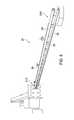
- FIG. 3shows an embodiment of a tank-cleaning device 20 according to the invention.
- Tank-cleaning device 20comprises upper pipe 28 and lower pipe 32 joined together through one or more trusses 30 spaced at selected intervals between pipes 28 , 32 to provide vertical stability.
- pipesmay be joined at the sides by one or more trusses 30 spaced at selected intervals to provide lateral stability.
- Upper pipe 28is preferably of larger diameter than lower pipe 32 and has washout nozzles 26 spaced at regular intervals along upper pipe.
- upper pipe 28has a three inch diameter and bottom pipe 32 has a two inch diameter.
- upper pipe 28has a diameter in the range of about 2 to 5 inches
- lower pipe 32has a diameter in the range of about 1 to 3 inches.
- Wall thickness of the pipesmay be schedule (SCH) 10. In other embodiments, wall thickness may be SCH 5, or may be SCH 20, SCH 30, SCH 40, SCH 60, SCH 80, or higher.
- Washout nozzles 26may be the type that are water-powered and rotate and spin to dispense cleaning fluid, such as water or brine, in all directions (360°) for cleaning all sides of the tank.
- lower pipe 32can have one or more water spouts 34 A and 34 B disposed at proximal end 21 A and/or distal end 21 B, respectively, for cleaning the front, back, or bottom of the tank sides.
- the Device 20can also include sealing bung 22 .
- the sealing bungis shaped and sized for sealing an access port of a tank when the washout wand is positioned in the tank.
- the sealing bungcan be configured to slide on shaft of pipes 28 , 32 .
- Sealing bung 22can include vent 24 for ventilating tank during use.
- FIGS. 4A-Cshow cross sectional views of the washout wand device according to embodiments of the invention with different truss support configurations.
- the devicemay take on a variety of configurations including where one or more truss 30 A joins the bottom portion of the top pipe 28 with the top portion of the bottom pipe 32 ( FIG. 4A ), and/or trusses 30 B and 30 C join and support the sides of the two pipes 28 and 32 ( FIG. 4B ), or a combination of these ( FIG. 4C ).
- the devicemay include other configurations not depicted here.
- the top and bottom pipecan be joined together at any distance from one another.
- the top pipe and bottom pipecan be joined at a distance of 0 inches from one another without any connecting structure, such as a truss, by welding or soldering the sides of the pipes together directly. If additional connecting structure is used to join the pipes together in parallel, the pipes can be spaced apart a distance between 0 and 10 inches. In embodiments, it is not critical how spaced apart the pipes are from one another, however, for cleaning frac tanks the spacing should be chosen such that the overall washout wand will fit into the access port of the frac tank.
- FIG. 5shows an embodiment of a tank cleaning device 20 according to the invention.
- tank cleaning device 20is held by a tractor but can be held by any mobile support, such as a vehicle.
- Pipes 28 and 32 of tank cleaning device 20may be made of titanium.
- Embodiments of tank cleaning device 20may have pipes 28 and 32 dimensioned to fit inside a frac tank of any size.
- a typical 21,000 gal (500 bbl) frac tankhas a length of approximately 40 to 50 feet, so in one embodiment, pipes 28 and 32 are approximately 40 to 50 feet in length.
- pipes 28 and 32can vary in length between them, such as pipe 28 may be 42 feet in length and pipe 32 may be 45 feet in length, or pipe 28 may be 48 feet in length and pipe 32 may be 45 feet in length, and vice versa.
- pipe 28 and pipe 32are sized to accommodate other sized tanks, and may be provided at lengths anywhere from 20 to 75 feet.
- FIG. 5shows that device 20 is self-supporting along its length by virtue of the strength of the titanium.
- the deviceis optimally designed such that it can support its own weight over very long spans with zero support other than at one end.
- Titaniumhas the ideal properties for this application, including corrosion resistance and an extremely high strength-to-weight ratio (otherwise referred to as specific strength).
- the washout wandcan have at least one pipe with a length (measured from a support at the proximal end to the distal end) ranging from about 30 to 45 feet, and an outside diameter of about 2-5 inches, and the diameter of the pipe is about 5% to 20% of the length of the pipe.
- the support at the proximal endcan be a sealing bung or gasket and the length of the pipe can be measured from the proximal side of the gasket to the distal end of the pipe, or from the distal side of the gasket to the distal end of the pipe, or from any point on the gasket, such as the point of communication between the gasket and access port of the tank during use, to the distal end of the pipe, or from a mid-point of the gasket to the distal end of the pipe.
- the length measuredis preferably the unsupported length of the wand.
- the pipescan be open or closed at one or both the proximal and distal ends.
- the proximal end(s)can be connected to a hose or other pipe configured to provide a cleaning agent, such as water or water and detergent or brine, or the fluid can enter the side of the pipe at the proximal end of the pipe.
- the fluidcan be provided at any level of pressure, with higher pressure being preferred for some applications.
- the pressure of fluid flow in the top and bottom pipescan be the same or different.
- the fluid pressure in the top pipecan be higher or lower than the pressure of the fluid in the bottom pipe.
- the top or bottom pipecan be open or closed at the distal end. In preferred embodiments, the top pipe has a higher fluid pressure than that of the bottom pipe.
- the top pipecan be closed at the distal end and connected to a fluid source at the proximal end, such that during use fluid enters the pipe at the proximal end and travels along the length of the pipe and is sprayed out through one or more nozzles under pressure.
- the bottom pipecan be connected to a fluid source at the proximal end of the pipe and the distal end can be open, such that during use fluid enters the bottom pipe at the proximal end and travels along the length of the pipe and is released at the distal end of the pipe, such as through a spout with or without a valve for closing the distal end of the pipe.
- a nozzle for spraying fluidcan instead be used in place of a spout.
- FIG. 6shows the distal end 21 B of device aligned with manway or access port 40 of frac tank 10
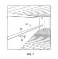
- FIG. 7shows device 20 positioned inside a frac tank. Shown in FIG. 7 are top pipe 28 with washout nozzle 26 spaced at regular intervals.
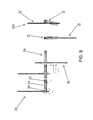
- FIG. 8shows embodiments of a system 100 of the invention.
- System 100comprises device 20 attached to an apparatus 55 configured for moving the device 20 at device's proximal end.
- Actuator apparatus 55includes actuator 50 capable of pivoting washout wand 20 , such as across a range of motion up to 180°, and/or capable of moving the washout wand laterally and/or up and down, and/or extending and retracting the device (forward and backward).
- Actuator apparatuscan also include one or more tracks or rails 54 which the device 20 moves along, laterally, up and down, and/or forward and backward.
- Actuator apparatuscan also comprise an additional actuator 52 at the end of the rails 54 capable of pivoting rails 54 up to 180°.
- Motion of the washout wand 20 in and out of the tankcan be controlled using hydraulic motors and wheels operably connected to rails 54 .
- the actuatorsmay control left and right or up and down motion as well as forward and backward motion to position the device 20 inside or outside a frac tank.
- the device 20may be used to clean a variety of frac tanks used in the oil and gas industry.
- a process for using the device 20may comprise providing a facility where frac tanks are cleaned that has one or more of the devices or systems described herein.
- the devices or systemsmay be provided on-site at a fracking location.
- the processmay comprise providing a frac tank, inserting a distal end 21 B of the washout wand 20 inside port 40 of tank 10 , advancing device 20 through port 40 until sealing bung 22 blocks port 40 , and administering cleaning solution, such as water, through pipes 28 , 32 such that the cleaning solution is emitted through one or more washout nozzles 26 disposed on and in operable communication with top pipe 28 and/or water spouts 34 A and/or 34 B disposed on and in operable communication with bottom pipe 32 .
- the distal end 21 B of the devicemay be aligned with port 40 or moved or extended into the tank 10 using an actuation system of the invention.
- the distal end of the devicecan be inserted into the tank substantially horizontally into the interior of the tank, which may include anywhere from a 0° to 30° deviation from horizontal.
- the distal end of the tankmay be inserted substantially parallel to the length of the frac tank, which may include anywhere from a 0° to 30° deviation from parallel.
- insertion of the device into the tank at an anglemay be desirable when extra cleaning of one of the sides or top or bottom is needed.
- the actuation systemcan be used to maneuver the washout wand into or within the tank according to such needs.
Landscapes
- Engineering & Computer Science (AREA)
- Mechanical Engineering (AREA)
- Chemical & Material Sciences (AREA)
- Chemical Kinetics & Catalysis (AREA)
- General Chemical & Material Sciences (AREA)
- Cleaning In General (AREA)
- Cleaning By Liquid Or Steam (AREA)
Abstract
Description
Claims (20)
Priority Applications (1)
| Application Number | Priority Date | Filing Date | Title |
|---|---|---|---|
| US14/796,043US9925572B2 (en) | 2015-07-10 | 2015-07-10 | Devices, systems, and processes for cleaning the interiors of frac tanks |
Applications Claiming Priority (1)
| Application Number | Priority Date | Filing Date | Title |
|---|---|---|---|
| US14/796,043US9925572B2 (en) | 2015-07-10 | 2015-07-10 | Devices, systems, and processes for cleaning the interiors of frac tanks |
Publications (2)
| Publication Number | Publication Date |
|---|---|
| US20170008046A1 US20170008046A1 (en) | 2017-01-12 |
| US9925572B2true US9925572B2 (en) | 2018-03-27 |
Family
ID=57730437
Family Applications (1)
| Application Number | Title | Priority Date | Filing Date |
|---|---|---|---|
| US14/796,043ActiveUS9925572B2 (en) | 2015-07-10 | 2015-07-10 | Devices, systems, and processes for cleaning the interiors of frac tanks |
Country Status (1)
| Country | Link |
|---|---|
| US (1) | US9925572B2 (en) |
Families Citing this family (1)
| Publication number | Priority date | Publication date | Assignee | Title |
|---|---|---|---|---|
| US11167324B2 (en)* | 2017-11-13 | 2021-11-09 | Oil States Energy Services, L.L.C. | Flowback tank cleaning system and method |
Citations (166)
| Publication number | Priority date | Publication date | Assignee | Title |
|---|---|---|---|---|
| US398068A (en) | 1889-02-19 | Coupling for parallel pipes | ||
| US1693885A (en) | 1927-09-15 | 1928-12-04 | Arthur B Butterworth | Tank-cleaning device |
| US1838634A (en) | 1928-08-08 | 1931-12-29 | Standard Oil Co | Tank cleaning device |
| US1857766A (en) | 1928-08-08 | 1932-05-10 | Joseph V Palmer | Tank cleaning device |
| US2116935A (en) | 1932-10-10 | 1938-05-10 | Pyrate Corp Of Nevada | Apparatus for cleaning tanks and the like |
| US2375513A (en) | 1943-09-30 | 1945-05-08 | William F Bach | Pipe hanger system |
| US2845091A (en) | 1954-01-18 | 1958-07-29 | Maryland Engineering Company | Tank cleaning apparatus |
| US2845934A (en) | 1953-04-29 | 1958-08-05 | Portland Company | Apparatus for use in cleaning the interiors of barrels |
| US2858836A (en) | 1957-08-14 | 1958-11-04 | Oakite Prod Inc | Tank cleaning apparatus |
| US3002468A (en) | 1958-06-18 | 1961-10-03 | Marion R Williams | Basket rack and conveyor mechanism therefor |
| US3022792A (en) | 1959-05-25 | 1962-02-27 | Warren K Price | Apparatus for gas-freeing and cleaning tankers |
| US3046163A (en) | 1960-04-06 | 1962-07-24 | Detrex Chem Ind | Method and apparatus for interiorly cleaning tanks and the like |
| US3104672A (en) | 1961-07-20 | 1963-09-24 | Holdren Brothers Inc | Spray cleaning device |
| US3182669A (en)* | 1963-03-30 | 1965-05-11 | Algonquin Shipping & Trading | Combined tanker service unit |
| US3394761A (en) | 1966-01-04 | 1968-07-30 | Rockwell Mfg Co | Parallel pipe suspension apparatus |
| US3420444A (en) | 1965-06-14 | 1969-01-07 | Salen & Wicander Ab | Apparatus for washing the cargo tanks of ships,particularly oil tankers |
| US3556407A (en) | 1968-11-06 | 1971-01-19 | Niikura Kogyo Co Ltd | Cleaning device well adapted for use in tanks and the like of oil tanker |
| US3599871A (en)* | 1969-07-08 | 1971-08-17 | Goodrich Co B F | Jet spray tank cleaner |
| US3645452A (en)* | 1970-04-27 | 1972-02-29 | Goodrich Co B F | Tank cleaner |
| US3741808A (en)* | 1970-08-12 | 1973-06-26 | Goodrich Co B F | Tank cleaner |
| US3746023A (en) | 1972-03-22 | 1973-07-17 | Gulf Oil Corp | Method for cleaning oil tanker holds |
| US3856334A (en) | 1970-12-02 | 1974-12-24 | H Lange | Apparatus for attaching a hot and cold water plumbing fixture to building water pipes |
| US4106950A (en) | 1977-10-28 | 1978-08-15 | Economics Laboratory, Inc. | Tank wagon cleaning method |
| US4144901A (en) | 1977-06-23 | 1979-03-20 | Terminator Products, Inc. | Probe system for containers |
| US4207965A (en) | 1976-04-27 | 1980-06-17 | Chiang Cheng Fu | Gliding cars and tracks type high building emergency escaping device |
| US4220170A (en) | 1979-07-30 | 1980-09-02 | Hebert Chris J | Apparatus for cleaning large tank interiors |
| US4244523A (en) | 1979-03-15 | 1981-01-13 | Looper Bruce T | Apparatus for cleaning tanks or vessels |
| EP0041855A1 (en) | 1980-06-10 | 1981-12-16 | Cambridge Store Systems Limited | A pipe clamp and a method of making a pipe clamp |
| US4351478A (en) | 1980-08-18 | 1982-09-28 | Looper Bruce T | Apparatus for cleaning tanks or vessels |
| US4413785A (en)* | 1981-09-14 | 1983-11-08 | Carroll D. Engelbert | Variable pressure fluid cleaning wand |
| US4453864A (en) | 1982-11-08 | 1984-06-12 | Conoco Inc. | Injection of solids into a high pressure slurry stream |
| US4557636A (en) | 1982-11-08 | 1985-12-10 | Conoco Inc. | Injection of solids into a high pressure slurry stream |
| US4574825A (en) | 1983-03-05 | 1986-03-11 | Uraca Pumpenfabrik Gmbh & Co. Kg | Tank cleaning apparatus |
| US4660678A (en) | 1984-09-27 | 1987-04-28 | Spider A/S | Service suspension basket arrangement |
| US4668358A (en) | 1986-05-14 | 1987-05-26 | Motor Wheel Corporation | Method and apparatus for use in surface treatment of conveyor supported workholders |
| US4672710A (en) | 1985-08-19 | 1987-06-16 | Industrial Innovations, Inc. | Single pressure vessel cleaning system |
| US4725362A (en) | 1985-11-18 | 1988-02-16 | Dugat John W | Treatment techniques for drill fluids, cuttings and other oil field wastes |
| US4751887A (en) | 1987-09-15 | 1988-06-21 | Environmental Pyrogenics Services, Inc. | Treatment of oil field wastes |
| US4753268A (en) | 1986-09-01 | 1988-06-28 | S.A. Des Establissements Staubli | Double coupling for removably joining twin pipes |
| US4941493A (en) | 1988-08-15 | 1990-07-17 | Carry Companies Of Illinois | Device for washing and drying the inside tank of a tanker truck |
| US4942929A (en) | 1989-03-13 | 1990-07-24 | Atlantic Richfield Company | Disposal and reclamation of drilling wastes |
| US4957188A (en) | 1988-09-27 | 1990-09-18 | Bavis Edward F | Conveyor system with stabilized conveyor basket |
| US5033490A (en) | 1990-02-23 | 1991-07-23 | Wade Jerry D | Car wash adjustable to car size |
| US5048775A (en) | 1990-06-18 | 1991-09-17 | Hungerford Charles S Jr | Device for supporting a plurality of pipes in parallel relationship within a defined space |
| US5058612A (en) | 1990-04-16 | 1991-10-22 | Winsted Billy C | Portable spray cleaning apparatus |
| WO1991016150A1 (en) | 1990-04-25 | 1991-10-31 | Toftejorg A/S | Cleaning equipment, especially for the cleaning of a tank |
| US5096047A (en) | 1989-05-17 | 1992-03-17 | Tsubakimoto Chain Co. | Basket in basket conveyor |
| US5107879A (en) | 1990-08-30 | 1992-04-28 | Butterworth Jetting System, Inc. | Rail tank car cleaning system |
| US5109933A (en) | 1990-08-17 | 1992-05-05 | Atlantic Richfield Company | Drill cuttings disposal method and system |
| US5129469A (en) | 1990-08-17 | 1992-07-14 | Atlantic Richfield Company | Drill cuttings disposal method and system |
| US5195548A (en) | 1990-06-11 | 1993-03-23 | Fcb | Washing device |
| US5226749A (en) | 1992-07-08 | 1993-07-13 | Atlantic Richfield Company | Waste disposal in hydraulically fractured earth formations |
| WO1993018864A1 (en) | 1992-03-17 | 1993-09-30 | Toftejorg Technology Aps | Method and apparatus for cleaning an oil tank |
| US5303786A (en) | 1992-09-16 | 1994-04-19 | Atlantic Richfield Company | Earth drilling cuttings processing system |
| US5337966A (en) | 1993-04-13 | 1994-08-16 | Fluid Mills, Inc. | Method and apparatus for the reduction and classification of solids particles |
| WO1994017922A1 (en) | 1993-02-15 | 1994-08-18 | Jan Berg Rasmussen | Tank cleaning system |
| US5344570A (en) | 1993-01-14 | 1994-09-06 | James E. McLachlan | Method and apparatus for removing solids from a liquid |
| US5352298A (en) | 1993-04-27 | 1994-10-04 | Moulder Jeffrey E | Tank car cleaning and stripping apparatus and method |
| US5361998A (en) | 1990-11-28 | 1994-11-08 | Gunnar Sirevag | Plant for treating drill cuttings |
| US5402857A (en) | 1994-02-17 | 1995-04-04 | Dietzen; Gary H. | Oil and gas well cuttings disposal system |
| US5405223A (en) | 1990-11-28 | 1995-04-11 | Sirevag; Gunnar | Method for treating drill cuttings during oil and gas drilling |
| US5419496A (en) | 1994-03-17 | 1995-05-30 | Novak, Jr.; Robert F. | Water wand apparatus |
| WO1995014543A1 (en) | 1993-11-29 | 1995-06-01 | Mobil Oil Corporation | A method for disposing of drilling wastes |
| US5421903A (en) | 1992-09-24 | 1995-06-06 | Taiho Industries Co., Ltd. | Method for washing a tank and for recovering and treating residual tank liquid |
| US5431236A (en) | 1994-08-19 | 1995-07-11 | Warren; Jasper N. | Method for processing solid material for disposal in an underground porous formation |
| WO1995022415A1 (en) | 1994-02-16 | 1995-08-24 | Hydropower Inc., Ltd. | Tank cleaning system |
| US5454662A (en) | 1993-11-23 | 1995-10-03 | Animal Enclosure Systems | Connector for coupling the pipes of a pipe corral |
| US5474097A (en)* | 1993-11-10 | 1995-12-12 | Atlantic Richfield Company | Scale removal and disposal system and method |
| US5518553A (en) | 1993-04-27 | 1996-05-21 | Moulder; Jeffrey E. | Storage tank cleaning and stripping apparatus and method |
| US5526562A (en) | 1993-03-29 | 1996-06-18 | Sumitomo Wiring Systems, Ltd. | Wiring harness assembly line |
| US5589603A (en) | 1994-08-22 | 1996-12-31 | Newpark Resources, Inc. | Method and apparatus for the injection disposal of solid and liquid waste materials from the drilling and production of oil and gas wells |
| WO1997000142A1 (en) | 1995-06-15 | 1997-01-03 | Toftejorg Technology A/S | A method and an apparatus for washing the interior surfaces of tanks and containers |
| US5638845A (en)* | 1995-11-08 | 1997-06-17 | Oliver; Michael A. | Scissor jet cleaning device |
| US5685411A (en) | 1995-01-13 | 1997-11-11 | Avtec Industries, Inc. | Article conveyor system |
| US5718382A (en) | 1994-10-24 | 1998-02-17 | Jaeger; Ben E. | Apparatus for cleaning vessels |
| US5720310A (en) | 1996-08-01 | 1998-02-24 | Moulder; Jeffrey Ernest | Tank car cleaning and rinsing apparatus and method |
| US5740821A (en) | 1996-07-09 | 1998-04-21 | Landry Service Co. Inc. | Tank cleaning using remotely controlled manway mounted robotic system |
| WO1998016717A1 (en) | 1996-10-15 | 1998-04-23 | M-I L.L.C. | Oil and gas well cuttings disposal system with continuous vacuum operation for sequentially filling disposal tanks |
| WO1999004134A1 (en) | 1997-07-17 | 1999-01-28 | Jeffrey Reddoch | Cuttings injection system |
| US5961438A (en) | 1994-08-22 | 1999-10-05 | Ballantine; W. Thomas | Method and apparatus for the injection disposal of solid and liquid waste materials into subpressured earth formations penetrated by a borehole |
| US5964304A (en) | 1998-05-08 | 1999-10-12 | Morrison, Jr.; Sidney Johnson | Method and apparatus for drill cuttings transfer |
| CN2350522Y (en) | 1998-10-16 | 1999-11-24 | 河南石油勘探局采油工艺研究所 | Negative pressure blow-off device |
| US6009959A (en) | 1994-02-17 | 2000-01-04 | M-I L.L.C. | Oil and gas well cuttings disposal system with continuous vacuum operation for sequentially filling disposal tanks |
| US6021793A (en) | 1996-08-01 | 2000-02-08 | Moulder; Jeffrey Ernest | Tank car cleaning and rinsing apparatus and method |
| US6106733A (en) | 1998-06-25 | 2000-08-22 | Tuboscope Vetco International, Inc. | Method for re-cycling wellbore cuttings |
| US6119779A (en) | 1998-11-09 | 2000-09-19 | Atlantic Richfield Company | Method and system for separating and disposing of solids from produced fluids |
| US6179070B1 (en) | 1994-02-17 | 2001-01-30 | M-I L.L.C. | Vacuum tank for use in handling oil and gas well cuttings |
| US6179071B1 (en) | 1994-02-17 | 2001-01-30 | M-I L.L.C. | Method and apparatus for handling and disposal of oil and gas well drill cuttings |
| US6189613B1 (en) | 1998-09-25 | 2001-02-20 | Pan Canadian Petroleum Limited | Downhole oil/water separation system with solids separation |
| US6192905B1 (en) | 1999-06-04 | 2001-02-27 | John W. Mincy | Scissor jet cleaning device with hose management system |
| US6206015B1 (en)* | 1999-01-28 | 2001-03-27 | Donald Ramsey | Interior tank cleaning apparatus |
| US6213135B1 (en) | 1999-05-25 | 2001-04-10 | Jeffrey Ernest Moulder | Linkage assembly for cleaning tankcars |
| US6213227B1 (en) | 1994-02-17 | 2001-04-10 | M-I, L.L.C. | Oil and gas well cuttings disposal system with continous vacuum operation for sequentially filling disposal tanks |
| US6213134B1 (en) | 1999-02-26 | 2001-04-10 | Econo Clean, Incorporated | Interior tank car cleaning apparatus |
| US6321754B1 (en) | 1998-01-21 | 2001-11-27 | Taiho Industries Co., Ltd. | Tank washing apparatus and method |
| WO2002005682A2 (en) | 2000-07-18 | 2002-01-24 | Kristine Costa | Wire basket system |
| US6345672B1 (en) | 1994-02-17 | 2002-02-12 | Gary Dietzen | Method and apparatus for handling and disposal of oil and gas well drill cuttings |
| US6378791B1 (en) | 2001-01-03 | 2002-04-30 | Marvin Wayne Perry | Spray wand for cleaning boat hulls |
| CA2366079A1 (en) | 2001-12-21 | 2002-05-20 | Robert Knowlton | Method and apparatus for cleaning oil storage tanks |
| WO2002044515A1 (en) | 2000-11-28 | 2002-06-06 | Apollo Services Uk Ltd. | Apparatus and method for transferring dry oil and gas well drill cuttings |
| US6435565B2 (en) | 2000-07-18 | 2002-08-20 | Bks Company Llc | Clamp for closely spaced pipes |
| US20020134554A1 (en) | 2000-07-25 | 2002-09-26 | Peter Schrenkel | System and method for removing solid particulates from a pumped wellbore fluid |
| US6488314B1 (en) | 1999-02-22 | 2002-12-03 | Raco S.P.A. | Coupling joint for a couple of pipes |
| US6553901B2 (en) | 1996-09-13 | 2003-04-29 | Jeffrey Reddoch | Drilling fluid recovery and cuttings processing system |
| WO2003059540A1 (en) | 2002-01-18 | 2003-07-24 | Ljubo Novkovic | 'dada' - fuel tank washer |
| US20030223850A1 (en) | 2002-06-03 | 2003-12-04 | Rob Hendriks | System for moving and hanging articles |
| KR20040037631A (en) | 2002-10-29 | 2004-05-07 | 주식회사 동명엔터프라이즈 | Vehicle for cleaning oil tanks |
| US20050077299A1 (en) | 2001-07-21 | 2005-04-14 | Hsi-Ming Cheng | Method for making mesh containers with a rail and mesh container formed therefrom |
| US20050109376A1 (en)* | 2003-11-20 | 2005-05-26 | Renew Systems, Inc. | Cleaning system and method of use |
| US6939218B1 (en) | 2004-01-27 | 2005-09-06 | William C. Holland | Method and apparatus of removing dead poultry from a poultry house |
| US20050199269A1 (en) | 2004-03-10 | 2005-09-15 | Scott Heil | Cleaning tanks |
| US6953097B2 (en) | 2003-08-01 | 2005-10-11 | Varco I/P, Inc. | Drilling systems |
| US20050229954A1 (en) | 2004-04-19 | 2005-10-20 | Hydro-Spray | Vehicle washing system |
| US6988677B2 (en) | 2002-09-11 | 2006-01-24 | Briggs & Stratton Power Products Group, Llc | Wand mounted nozzle holder |
| US20060065292A1 (en) | 2004-09-30 | 2006-03-30 | Moore Kenneth S | Automatic car wash with high pressure wand |
| US7089949B1 (en)* | 2003-04-17 | 2006-08-15 | The United States Of America As Represented By The Secretary Of The Navy | Apparatus for maneuvering a device within the interior of storage tanks |
| US7104220B1 (en) | 2004-06-04 | 2006-09-12 | Jerome Mack | Overhead livestock enclosure washing system |
| US7108143B1 (en) | 2005-03-11 | 2006-09-19 | Ruei-Hsing Lin | Sliding rail assembly for wire basket |
| US20070120665A1 (en) | 2005-11-28 | 2007-05-31 | Martin Michael C | Sensor assembly for tank cars |
| US7261109B2 (en) | 2004-09-14 | 2007-08-28 | Baker Hughes Incorporated | Remotely operated cleaning device, especially suitable for storage tanks on vessels |
| US7325629B2 (en) | 2005-09-08 | 2008-02-05 | Halliburton Energy Services, Inc. | Method and system for processing oil and gas well cuttings utilizing existing slurry processing equipment |
| US20080083566A1 (en) | 2006-10-04 | 2008-04-10 | George Alexander Burnett | Reclamation of components of wellbore cuttings material |
| US20080129039A1 (en) | 2006-12-04 | 2008-06-05 | Eric Gray | Pipe Coupling Adaptor |
| WO2008113070A2 (en) | 2007-03-15 | 2008-09-18 | Johnsondiversey Inc. | Cleaning system and method of use |
| CN201125043Y (en) | 2007-12-19 | 2008-10-01 | 武汉钢铁(集团)公司 | Vacuum pumping device for cleaning oil residue of large gasoline and diesel fuel tanks |
| US7455066B2 (en) | 2005-03-29 | 2008-11-25 | Whirlpool Corporation | Dishwasher utensil rack and utensil basket therefor |
| US20090078647A1 (en) | 2007-08-21 | 2009-03-26 | Frazier W Lynn | System and method for bioremediating oil field cuttings |
| US7523570B2 (en) | 2004-08-16 | 2009-04-28 | Non Stop Hydro Excavation Ltd. | Vacuum truck solids handling apparatus |
| US7575072B2 (en) | 2005-11-26 | 2009-08-18 | Reddoch Sr Jeffrey A | Method and apparatus for processing and injecting drill cuttings |
| US20100025497A1 (en) | 2008-07-30 | 2010-02-04 | Jeffrey Dale Ellenbecker | Fluid flush device with optional telescopic wand |
| US20100040439A1 (en) | 2006-09-08 | 2010-02-18 | Thermo Shandon Ltd. | Slide processing apparatus and method |
| US20100154828A1 (en) | 2008-12-18 | 2010-06-24 | Ted Joseph Green | Fuel tank cleaning method |
| US7798218B2 (en) | 2005-08-25 | 2010-09-21 | Environmental Technology As | Apparatus and a method of fragmenting hard particles |
| US20100282876A1 (en)* | 2008-01-15 | 2010-11-11 | Spraying Systems Co. | Adjustable lance spray assembly |
| WO2010143060A1 (en) | 2009-06-11 | 2010-12-16 | Samminiatese Pozzi Snc | A wire screen for a well and method for making it |
| CN201711322U (en) | 2010-05-24 | 2011-01-19 | 大庆油田有限责任公司 | Positive and negative pressure suction device for cleaning oil tank |
| CN201728211U (en) | 2010-02-13 | 2011-02-02 | 桐乡中欣化纤有限公司 | Oil tank-dedicated cleaning apparatus |
| US20110047743A1 (en) | 2009-09-03 | 2011-03-03 | John D. Shepherd | Fine solids recovery system, method and pick-up wand |
| US7905683B2 (en) | 2007-04-27 | 2011-03-15 | Enertech Environmental, Inc. | Disposal of slurry in underground geologic formations |
| US20110114138A1 (en) | 2008-05-02 | 2011-05-19 | Arcelik Anonim Sirketi | Dishwasher with a Device for Assembling the Basket to the Extracting Rail |
| US20110246162A1 (en) | 2010-03-30 | 2011-10-06 | Spraying Systems Co. | Tank wash system |
| US20120000495A1 (en) | 2010-06-24 | 2012-01-05 | Schmit Steve J | Oscillating fluid jet assembly |
| WO2012005889A1 (en) | 2010-06-30 | 2012-01-12 | Schlumberger Canada Limited | Downhole oil-water-solids separation |
| US8133328B2 (en) | 2008-09-03 | 2012-03-13 | Gamajet Cleaning Systems Inc. | Rotary apparatus and method for cleaning liquid storage tanks |
| US8133164B2 (en) | 2008-01-14 | 2012-03-13 | National Oilwell Varco L.P. | Transportable systems for treating drilling fluid |
| CN202162184U (en) | 2011-07-14 | 2012-03-14 | 彭祥林 | Oil storage tank cleaning mechanical device |
| CN202199558U (en) | 2011-08-25 | 2012-04-25 | 天津绿清管道科技发展有限公司 | Vacuum suction system for storage tank deposit |
| WO2012082216A1 (en) | 2010-12-17 | 2012-06-21 | Exxonmobil Upstream Research Company | Systems and methods for injecting a particulate mixture |
| EP1437184B1 (en) | 2003-01-13 | 2012-08-29 | Etablissements Magyar S.A. | Device for washing the inside of a tank, especially a truck tank, process for making such a device and tank equipped with such a device. |
| US20120247570A1 (en)* | 2011-04-01 | 2012-10-04 | Stoneage, Inc. | Apparatus for insertion in a tank and method thereof |
| US20120260945A1 (en) | 2011-04-12 | 2012-10-18 | Gwang-Sick Kim | Apparatus for cleaning an object and method of operating the same |
| US8316963B2 (en) | 2007-01-31 | 2012-11-27 | M-I Llc | Cuttings processing system |
| EP1686883B1 (en) | 2003-10-30 | 2012-11-28 | Arçelik Anonim Sirketi | A basket for dishwashers |
| US20130057132A1 (en) | 2011-09-02 | 2013-03-07 | Christopher Lynn Flowers | Basket Assembly For Dishwasher |
| US8398034B2 (en) | 2010-03-16 | 2013-03-19 | Supranergie Inc. | Pipe spacer |
| WO2013048252A2 (en) | 2011-09-28 | 2013-04-04 | Sustainable B.V. | Assembly and method for process assurance in tank cleaning |
| US8424784B1 (en) | 2012-07-27 | 2013-04-23 | MBJ Water Partners | Fracture water treatment method and system |
| EP2512958B1 (en) | 2010-06-08 | 2013-05-01 | Böhrer GmbH | Transport apparatus with moving trucks |
| US20130160989A1 (en) | 2011-12-21 | 2013-06-27 | Michael Durden | Cleaning of water from drilling and hydraulic fracturing operations |
| US20130213674A1 (en) | 2010-10-19 | 2013-08-22 | Dwight P. Williams | Focused stream, aerated foam projecting nozzle including fixed wand system and method as well as possibly portable center pointing nozzle |
| US20130247939A1 (en) | 2012-03-26 | 2013-09-26 | Turnkey Cleaning Services, Llc | Method for automated, closed loop cleaning of tanks |
| US8584749B2 (en) | 2010-12-17 | 2013-11-19 | Exxonmobil Upstream Research Company | Systems and methods for dual reinjection |
| WO2014023476A1 (en) | 2012-08-06 | 2014-02-13 | Alfa Laval Corporate Ab | Washing system for washing of tanks or the like |
| US8757320B2 (en) | 2011-09-29 | 2014-06-24 | Fu-Chang Liao | Suspending and moving device |
| US20140190517A1 (en) | 2013-01-08 | 2014-07-10 | Tradebe Environmental Services, Llc | System and method for removing sludge from a storage tank |
| US9204774B1 (en)* | 2013-03-20 | 2015-12-08 | Craig A. Jackson | Adjustable wand for cleaning apparatus |
- 2015
- 2015-07-10USUS14/796,043patent/US9925572B2/enactiveActive
Patent Citations (184)
| Publication number | Priority date | Publication date | Assignee | Title |
|---|---|---|---|---|
| US398068A (en) | 1889-02-19 | Coupling for parallel pipes | ||
| US1693885A (en) | 1927-09-15 | 1928-12-04 | Arthur B Butterworth | Tank-cleaning device |
| US1838634A (en) | 1928-08-08 | 1931-12-29 | Standard Oil Co | Tank cleaning device |
| US1857766A (en) | 1928-08-08 | 1932-05-10 | Joseph V Palmer | Tank cleaning device |
| US2116935A (en) | 1932-10-10 | 1938-05-10 | Pyrate Corp Of Nevada | Apparatus for cleaning tanks and the like |
| US2375513A (en) | 1943-09-30 | 1945-05-08 | William F Bach | Pipe hanger system |
| US2845934A (en) | 1953-04-29 | 1958-08-05 | Portland Company | Apparatus for use in cleaning the interiors of barrels |
| US2845091A (en) | 1954-01-18 | 1958-07-29 | Maryland Engineering Company | Tank cleaning apparatus |
| US2858836A (en) | 1957-08-14 | 1958-11-04 | Oakite Prod Inc | Tank cleaning apparatus |
| US3002468A (en) | 1958-06-18 | 1961-10-03 | Marion R Williams | Basket rack and conveyor mechanism therefor |
| US3022792A (en) | 1959-05-25 | 1962-02-27 | Warren K Price | Apparatus for gas-freeing and cleaning tankers |
| US3046163A (en) | 1960-04-06 | 1962-07-24 | Detrex Chem Ind | Method and apparatus for interiorly cleaning tanks and the like |
| US3104672A (en) | 1961-07-20 | 1963-09-24 | Holdren Brothers Inc | Spray cleaning device |
| US3182669A (en)* | 1963-03-30 | 1965-05-11 | Algonquin Shipping & Trading | Combined tanker service unit |
| US3420444A (en) | 1965-06-14 | 1969-01-07 | Salen & Wicander Ab | Apparatus for washing the cargo tanks of ships,particularly oil tankers |
| US3394761A (en) | 1966-01-04 | 1968-07-30 | Rockwell Mfg Co | Parallel pipe suspension apparatus |
| US3556407A (en) | 1968-11-06 | 1971-01-19 | Niikura Kogyo Co Ltd | Cleaning device well adapted for use in tanks and the like of oil tanker |
| US3599871A (en)* | 1969-07-08 | 1971-08-17 | Goodrich Co B F | Jet spray tank cleaner |
| US3645452A (en)* | 1970-04-27 | 1972-02-29 | Goodrich Co B F | Tank cleaner |
| US3741808A (en)* | 1970-08-12 | 1973-06-26 | Goodrich Co B F | Tank cleaner |
| US3856334A (en) | 1970-12-02 | 1974-12-24 | H Lange | Apparatus for attaching a hot and cold water plumbing fixture to building water pipes |
| US3746023A (en) | 1972-03-22 | 1973-07-17 | Gulf Oil Corp | Method for cleaning oil tanker holds |
| US4207965A (en) | 1976-04-27 | 1980-06-17 | Chiang Cheng Fu | Gliding cars and tracks type high building emergency escaping device |
| US4144901A (en) | 1977-06-23 | 1979-03-20 | Terminator Products, Inc. | Probe system for containers |
| US4106950A (en) | 1977-10-28 | 1978-08-15 | Economics Laboratory, Inc. | Tank wagon cleaning method |
| US4244523A (en) | 1979-03-15 | 1981-01-13 | Looper Bruce T | Apparatus for cleaning tanks or vessels |
| US4220170A (en) | 1979-07-30 | 1980-09-02 | Hebert Chris J | Apparatus for cleaning large tank interiors |
| EP0041855A1 (en) | 1980-06-10 | 1981-12-16 | Cambridge Store Systems Limited | A pipe clamp and a method of making a pipe clamp |
| US4351478A (en) | 1980-08-18 | 1982-09-28 | Looper Bruce T | Apparatus for cleaning tanks or vessels |
| US4413785A (en)* | 1981-09-14 | 1983-11-08 | Carroll D. Engelbert | Variable pressure fluid cleaning wand |
| US4453864A (en) | 1982-11-08 | 1984-06-12 | Conoco Inc. | Injection of solids into a high pressure slurry stream |
| US4557636A (en) | 1982-11-08 | 1985-12-10 | Conoco Inc. | Injection of solids into a high pressure slurry stream |
| US4574825A (en) | 1983-03-05 | 1986-03-11 | Uraca Pumpenfabrik Gmbh & Co. Kg | Tank cleaning apparatus |
| US4660678A (en) | 1984-09-27 | 1987-04-28 | Spider A/S | Service suspension basket arrangement |
| US4672710A (en) | 1985-08-19 | 1987-06-16 | Industrial Innovations, Inc. | Single pressure vessel cleaning system |
| US4725362A (en) | 1985-11-18 | 1988-02-16 | Dugat John W | Treatment techniques for drill fluids, cuttings and other oil field wastes |
| US4668358A (en) | 1986-05-14 | 1987-05-26 | Motor Wheel Corporation | Method and apparatus for use in surface treatment of conveyor supported workholders |
| US4753268A (en) | 1986-09-01 | 1988-06-28 | S.A. Des Establissements Staubli | Double coupling for removably joining twin pipes |
| US4751887A (en) | 1987-09-15 | 1988-06-21 | Environmental Pyrogenics Services, Inc. | Treatment of oil field wastes |
| US4941493A (en) | 1988-08-15 | 1990-07-17 | Carry Companies Of Illinois | Device for washing and drying the inside tank of a tanker truck |
| US4957188A (en) | 1988-09-27 | 1990-09-18 | Bavis Edward F | Conveyor system with stabilized conveyor basket |
| US4942929A (en) | 1989-03-13 | 1990-07-24 | Atlantic Richfield Company | Disposal and reclamation of drilling wastes |
| US5096047A (en) | 1989-05-17 | 1992-03-17 | Tsubakimoto Chain Co. | Basket in basket conveyor |
| US5033490A (en) | 1990-02-23 | 1991-07-23 | Wade Jerry D | Car wash adjustable to car size |
| US5058612A (en) | 1990-04-16 | 1991-10-22 | Winsted Billy C | Portable spray cleaning apparatus |
| WO1991016150A1 (en) | 1990-04-25 | 1991-10-31 | Toftejorg A/S | Cleaning equipment, especially for the cleaning of a tank |
| US5195548A (en) | 1990-06-11 | 1993-03-23 | Fcb | Washing device |
| US5048775A (en) | 1990-06-18 | 1991-09-17 | Hungerford Charles S Jr | Device for supporting a plurality of pipes in parallel relationship within a defined space |
| US5129469A (en) | 1990-08-17 | 1992-07-14 | Atlantic Richfield Company | Drill cuttings disposal method and system |
| US5109933A (en) | 1990-08-17 | 1992-05-05 | Atlantic Richfield Company | Drill cuttings disposal method and system |
| US5107879A (en) | 1990-08-30 | 1992-04-28 | Butterworth Jetting System, Inc. | Rail tank car cleaning system |
| US5361998A (en) | 1990-11-28 | 1994-11-08 | Gunnar Sirevag | Plant for treating drill cuttings |
| US5405223A (en) | 1990-11-28 | 1995-04-11 | Sirevag; Gunnar | Method for treating drill cuttings during oil and gas drilling |
| WO1993018864A1 (en) | 1992-03-17 | 1993-09-30 | Toftejorg Technology Aps | Method and apparatus for cleaning an oil tank |
| US5226749A (en) | 1992-07-08 | 1993-07-13 | Atlantic Richfield Company | Waste disposal in hydraulically fractured earth formations |
| US5303786A (en) | 1992-09-16 | 1994-04-19 | Atlantic Richfield Company | Earth drilling cuttings processing system |
| US5544669A (en) | 1992-09-24 | 1996-08-13 | Taiho Industries Co., Ltd. | System for washing a tank and recovering and treating residual tank liquid |
| US5421903A (en) | 1992-09-24 | 1995-06-06 | Taiho Industries Co., Ltd. | Method for washing a tank and for recovering and treating residual tank liquid |
| US5344570A (en) | 1993-01-14 | 1994-09-06 | James E. McLachlan | Method and apparatus for removing solids from a liquid |
| WO1994017922A1 (en) | 1993-02-15 | 1994-08-18 | Jan Berg Rasmussen | Tank cleaning system |
| US5526562A (en) | 1993-03-29 | 1996-06-18 | Sumitomo Wiring Systems, Ltd. | Wiring harness assembly line |
| US5337966A (en) | 1993-04-13 | 1994-08-16 | Fluid Mills, Inc. | Method and apparatus for the reduction and classification of solids particles |
| US5352298A (en) | 1993-04-27 | 1994-10-04 | Moulder Jeffrey E | Tank car cleaning and stripping apparatus and method |
| US5518553A (en) | 1993-04-27 | 1996-05-21 | Moulder; Jeffrey E. | Storage tank cleaning and stripping apparatus and method |
| US5474097A (en)* | 1993-11-10 | 1995-12-12 | Atlantic Richfield Company | Scale removal and disposal system and method |
| US5454662A (en) | 1993-11-23 | 1995-10-03 | Animal Enclosure Systems | Connector for coupling the pipes of a pipe corral |
| WO1995014543A1 (en) | 1993-11-29 | 1995-06-01 | Mobil Oil Corporation | A method for disposing of drilling wastes |
| WO1995022415A1 (en) | 1994-02-16 | 1995-08-24 | Hydropower Inc., Ltd. | Tank cleaning system |
| US6179071B1 (en) | 1994-02-17 | 2001-01-30 | M-I L.L.C. | Method and apparatus for handling and disposal of oil and gas well drill cuttings |
| US5839521A (en) | 1994-02-17 | 1998-11-24 | Dietzen; Gary H. | Oil and gas well cuttings disposal system |
| US6345672B1 (en) | 1994-02-17 | 2002-02-12 | Gary Dietzen | Method and apparatus for handling and disposal of oil and gas well drill cuttings |
| US5564509A (en) | 1994-02-17 | 1996-10-15 | Dietzen; Gary H. | Oil and gas well cuttings disposal system |
| US6213227B1 (en) | 1994-02-17 | 2001-04-10 | M-I, L.L.C. | Oil and gas well cuttings disposal system with continous vacuum operation for sequentially filling disposal tanks |
| US5402857A (en) | 1994-02-17 | 1995-04-04 | Dietzen; Gary H. | Oil and gas well cuttings disposal system |
| US6179070B1 (en) | 1994-02-17 | 2001-01-30 | M-I L.L.C. | Vacuum tank for use in handling oil and gas well cuttings |
| US6009959A (en) | 1994-02-17 | 2000-01-04 | M-I L.L.C. | Oil and gas well cuttings disposal system with continuous vacuum operation for sequentially filling disposal tanks |
| US5419496A (en) | 1994-03-17 | 1995-05-30 | Novak, Jr.; Robert F. | Water wand apparatus |
| US5431236A (en) | 1994-08-19 | 1995-07-11 | Warren; Jasper N. | Method for processing solid material for disposal in an underground porous formation |
| US5734988A (en) | 1994-08-22 | 1998-03-31 | Alexander; Albert H. D. | Method and apparatus for the injection disposal of solid and liquid waste materials into subpressured earth formations penetrated by a borehole |
| US5589603A (en) | 1994-08-22 | 1996-12-31 | Newpark Resources, Inc. | Method and apparatus for the injection disposal of solid and liquid waste materials from the drilling and production of oil and gas wells |
| US5961438A (en) | 1994-08-22 | 1999-10-05 | Ballantine; W. Thomas | Method and apparatus for the injection disposal of solid and liquid waste materials into subpressured earth formations penetrated by a borehole |
| US5718382A (en) | 1994-10-24 | 1998-02-17 | Jaeger; Ben E. | Apparatus for cleaning vessels |
| US5685411A (en) | 1995-01-13 | 1997-11-11 | Avtec Industries, Inc. | Article conveyor system |
| WO1997000142A1 (en) | 1995-06-15 | 1997-01-03 | Toftejorg Technology A/S | A method and an apparatus for washing the interior surfaces of tanks and containers |
| US5896871A (en) | 1995-06-15 | 1999-04-27 | Toftejorg Technology A/S | Method for washing the interior surfaces of tanks and containers |
| US5638845A (en)* | 1995-11-08 | 1997-06-17 | Oliver; Michael A. | Scissor jet cleaning device |
| US5740821A (en) | 1996-07-09 | 1998-04-21 | Landry Service Co. Inc. | Tank cleaning using remotely controlled manway mounted robotic system |
| US5720310A (en) | 1996-08-01 | 1998-02-24 | Moulder; Jeffrey Ernest | Tank car cleaning and rinsing apparatus and method |
| US6021793A (en) | 1996-08-01 | 2000-02-08 | Moulder; Jeffrey Ernest | Tank car cleaning and rinsing apparatus and method |
| US20030192439A1 (en) | 1996-09-13 | 2003-10-16 | Jeffrey Reddoch | Drilling fluid recovery and cuttings processing system |
| US6553901B2 (en) | 1996-09-13 | 2003-04-29 | Jeffrey Reddoch | Drilling fluid recovery and cuttings processing system |
| US6910411B2 (en) | 1996-09-13 | 2005-06-28 | Baker Hughes Incorporated | Drilling fluid recovery and cuttings processing system |
| WO1998016717A1 (en) | 1996-10-15 | 1998-04-23 | M-I L.L.C. | Oil and gas well cuttings disposal system with continuous vacuum operation for sequentially filling disposal tanks |
| US6321860B1 (en) | 1997-07-17 | 2001-11-27 | Jeffrey Reddoch | Cuttings injection system and method |
| WO1999004134A1 (en) | 1997-07-17 | 1999-01-28 | Jeffrey Reddoch | Cuttings injection system |
| US6321754B1 (en) | 1998-01-21 | 2001-11-27 | Taiho Industries Co., Ltd. | Tank washing apparatus and method |
| US5964304A (en) | 1998-05-08 | 1999-10-12 | Morrison, Jr.; Sidney Johnson | Method and apparatus for drill cuttings transfer |
| US6106733A (en) | 1998-06-25 | 2000-08-22 | Tuboscope Vetco International, Inc. | Method for re-cycling wellbore cuttings |
| US6189613B1 (en) | 1998-09-25 | 2001-02-20 | Pan Canadian Petroleum Limited | Downhole oil/water separation system with solids separation |
| CN2350522Y (en) | 1998-10-16 | 1999-11-24 | 河南石油勘探局采油工艺研究所 | Negative pressure blow-off device |
| US6119779A (en) | 1998-11-09 | 2000-09-19 | Atlantic Richfield Company | Method and system for separating and disposing of solids from produced fluids |
| US6206015B1 (en)* | 1999-01-28 | 2001-03-27 | Donald Ramsey | Interior tank cleaning apparatus |
| US6488314B1 (en) | 1999-02-22 | 2002-12-03 | Raco S.P.A. | Coupling joint for a couple of pipes |
| US6213134B1 (en) | 1999-02-26 | 2001-04-10 | Econo Clean, Incorporated | Interior tank car cleaning apparatus |
| US6213135B1 (en) | 1999-05-25 | 2001-04-10 | Jeffrey Ernest Moulder | Linkage assembly for cleaning tankcars |
| US6192905B1 (en) | 1999-06-04 | 2001-02-27 | John W. Mincy | Scissor jet cleaning device with hose management system |
| US6491173B1 (en) | 2000-07-18 | 2002-12-10 | Sidelines, Inc. | Wire basket system |
| US6435565B2 (en) | 2000-07-18 | 2002-08-20 | Bks Company Llc | Clamp for closely spaced pipes |
| WO2002005682A2 (en) | 2000-07-18 | 2002-01-24 | Kristine Costa | Wire basket system |
| US20020134554A1 (en) | 2000-07-25 | 2002-09-26 | Peter Schrenkel | System and method for removing solid particulates from a pumped wellbore fluid |
| WO2002044515A1 (en) | 2000-11-28 | 2002-06-06 | Apollo Services Uk Ltd. | Apparatus and method for transferring dry oil and gas well drill cuttings |
| US6378791B1 (en) | 2001-01-03 | 2002-04-30 | Marvin Wayne Perry | Spray wand for cleaning boat hulls |
| US20050077299A1 (en) | 2001-07-21 | 2005-04-14 | Hsi-Ming Cheng | Method for making mesh containers with a rail and mesh container formed therefrom |
| CA2366079A1 (en) | 2001-12-21 | 2002-05-20 | Robert Knowlton | Method and apparatus for cleaning oil storage tanks |
| WO2003059540A1 (en) | 2002-01-18 | 2003-07-24 | Ljubo Novkovic | 'dada' - fuel tank washer |
| US20030223850A1 (en) | 2002-06-03 | 2003-12-04 | Rob Hendriks | System for moving and hanging articles |
| US6988677B2 (en) | 2002-09-11 | 2006-01-24 | Briggs & Stratton Power Products Group, Llc | Wand mounted nozzle holder |
| KR20040037631A (en) | 2002-10-29 | 2004-05-07 | 주식회사 동명엔터프라이즈 | Vehicle for cleaning oil tanks |
| EP1437184B1 (en) | 2003-01-13 | 2012-08-29 | Etablissements Magyar S.A. | Device for washing the inside of a tank, especially a truck tank, process for making such a device and tank equipped with such a device. |
| US7089949B1 (en)* | 2003-04-17 | 2006-08-15 | The United States Of America As Represented By The Secretary Of The Navy | Apparatus for maneuvering a device within the interior of storage tanks |
| US6953097B2 (en) | 2003-08-01 | 2005-10-11 | Varco I/P, Inc. | Drilling systems |
| EP1686883B1 (en) | 2003-10-30 | 2012-11-28 | Arçelik Anonim Sirketi | A basket for dishwashers |
| US20050109376A1 (en)* | 2003-11-20 | 2005-05-26 | Renew Systems, Inc. | Cleaning system and method of use |
| US6939218B1 (en) | 2004-01-27 | 2005-09-06 | William C. Holland | Method and apparatus of removing dead poultry from a poultry house |
| US20050199269A1 (en) | 2004-03-10 | 2005-09-15 | Scott Heil | Cleaning tanks |
| US20050229954A1 (en) | 2004-04-19 | 2005-10-20 | Hydro-Spray | Vehicle washing system |
| US7104220B1 (en) | 2004-06-04 | 2006-09-12 | Jerome Mack | Overhead livestock enclosure washing system |
| US7523570B2 (en) | 2004-08-16 | 2009-04-28 | Non Stop Hydro Excavation Ltd. | Vacuum truck solids handling apparatus |
| US7261109B2 (en) | 2004-09-14 | 2007-08-28 | Baker Hughes Incorporated | Remotely operated cleaning device, especially suitable for storage tanks on vessels |
| US20060065292A1 (en) | 2004-09-30 | 2006-03-30 | Moore Kenneth S | Automatic car wash with high pressure wand |
| US7108143B1 (en) | 2005-03-11 | 2006-09-19 | Ruei-Hsing Lin | Sliding rail assembly for wire basket |
| US7455066B2 (en) | 2005-03-29 | 2008-11-25 | Whirlpool Corporation | Dishwasher utensil rack and utensil basket therefor |
| US7798218B2 (en) | 2005-08-25 | 2010-09-21 | Environmental Technology As | Apparatus and a method of fragmenting hard particles |
| US7325629B2 (en) | 2005-09-08 | 2008-02-05 | Halliburton Energy Services, Inc. | Method and system for processing oil and gas well cuttings utilizing existing slurry processing equipment |
| US7575072B2 (en) | 2005-11-26 | 2009-08-18 | Reddoch Sr Jeffrey A | Method and apparatus for processing and injecting drill cuttings |
| US7857077B2 (en) | 2005-11-26 | 2010-12-28 | Reddoch Sr Jeffrey A | Method and apparatus for processing and injecting drill cuttings |
| US20070120665A1 (en) | 2005-11-28 | 2007-05-31 | Martin Michael C | Sensor assembly for tank cars |
| US20100040439A1 (en) | 2006-09-08 | 2010-02-18 | Thermo Shandon Ltd. | Slide processing apparatus and method |
| US8533974B2 (en) | 2006-10-04 | 2013-09-17 | Varco I/P, Inc. | Reclamation of components of wellbore cuttings material |
| US8316557B2 (en) | 2006-10-04 | 2012-11-27 | Varco I/P, Inc. | Reclamation of components of wellbore cuttings material |
| US20080083566A1 (en) | 2006-10-04 | 2008-04-10 | George Alexander Burnett | Reclamation of components of wellbore cuttings material |
| WO2008041020A1 (en) | 2006-10-04 | 2008-04-10 | National Oilwell Varco, L.P. | Method and apparatus for preparing drill cuttings for reinjection into a well |
| US20130067762A1 (en) | 2006-10-04 | 2013-03-21 | Varco I/P, Inc. | Reclamation of components of wellbore cuttings material |
| US20080129039A1 (en) | 2006-12-04 | 2008-06-05 | Eric Gray | Pipe Coupling Adaptor |
| US7717474B2 (en) | 2006-12-04 | 2010-05-18 | Eric Gray | Pipe coupling adaptor |
| US8316963B2 (en) | 2007-01-31 | 2012-11-27 | M-I Llc | Cuttings processing system |
| WO2008113070A2 (en) | 2007-03-15 | 2008-09-18 | Johnsondiversey Inc. | Cleaning system and method of use |
| US7905683B2 (en) | 2007-04-27 | 2011-03-15 | Enertech Environmental, Inc. | Disposal of slurry in underground geologic formations |
| US8137030B2 (en) | 2007-04-27 | 2012-03-20 | Enertech Environmental, Inc. | Disposal of slurry in underground geologic formations |
| US20090078647A1 (en) | 2007-08-21 | 2009-03-26 | Frazier W Lynn | System and method for bioremediating oil field cuttings |
| CN201125043Y (en) | 2007-12-19 | 2008-10-01 | 武汉钢铁(集团)公司 | Vacuum pumping device for cleaning oil residue of large gasoline and diesel fuel tanks |
| US8133164B2 (en) | 2008-01-14 | 2012-03-13 | National Oilwell Varco L.P. | Transportable systems for treating drilling fluid |
| US20100282876A1 (en)* | 2008-01-15 | 2010-11-11 | Spraying Systems Co. | Adjustable lance spray assembly |
| US20110114138A1 (en) | 2008-05-02 | 2011-05-19 | Arcelik Anonim Sirketi | Dishwasher with a Device for Assembling the Basket to the Extracting Rail |
| US20100025497A1 (en) | 2008-07-30 | 2010-02-04 | Jeffrey Dale Ellenbecker | Fluid flush device with optional telescopic wand |
| US8133328B2 (en) | 2008-09-03 | 2012-03-13 | Gamajet Cleaning Systems Inc. | Rotary apparatus and method for cleaning liquid storage tanks |
| US20110284031A1 (en) | 2008-12-18 | 2011-11-24 | Ted Joseph Green | Fuel Tank Cleaning Method |
| US20100154828A1 (en) | 2008-12-18 | 2010-06-24 | Ted Joseph Green | Fuel tank cleaning method |
| WO2010143060A1 (en) | 2009-06-11 | 2010-12-16 | Samminiatese Pozzi Snc | A wire screen for a well and method for making it |
| US20110047743A1 (en) | 2009-09-03 | 2011-03-03 | John D. Shepherd | Fine solids recovery system, method and pick-up wand |
| CN201728211U (en) | 2010-02-13 | 2011-02-02 | 桐乡中欣化纤有限公司 | Oil tank-dedicated cleaning apparatus |
| US8398034B2 (en) | 2010-03-16 | 2013-03-19 | Supranergie Inc. | Pipe spacer |
| US20110246162A1 (en) | 2010-03-30 | 2011-10-06 | Spraying Systems Co. | Tank wash system |
| CN201711322U (en) | 2010-05-24 | 2011-01-19 | 大庆油田有限责任公司 | Positive and negative pressure suction device for cleaning oil tank |
| EP2512958B1 (en) | 2010-06-08 | 2013-05-01 | Böhrer GmbH | Transport apparatus with moving trucks |
| US20120000495A1 (en) | 2010-06-24 | 2012-01-05 | Schmit Steve J | Oscillating fluid jet assembly |
| WO2012005889A1 (en) | 2010-06-30 | 2012-01-12 | Schlumberger Canada Limited | Downhole oil-water-solids separation |
| US20130213674A1 (en) | 2010-10-19 | 2013-08-22 | Dwight P. Williams | Focused stream, aerated foam projecting nozzle including fixed wand system and method as well as possibly portable center pointing nozzle |
| WO2012082216A1 (en) | 2010-12-17 | 2012-06-21 | Exxonmobil Upstream Research Company | Systems and methods for injecting a particulate mixture |
| US8584749B2 (en) | 2010-12-17 | 2013-11-19 | Exxonmobil Upstream Research Company | Systems and methods for dual reinjection |
| US20120247570A1 (en)* | 2011-04-01 | 2012-10-04 | Stoneage, Inc. | Apparatus for insertion in a tank and method thereof |
| US20120260945A1 (en) | 2011-04-12 | 2012-10-18 | Gwang-Sick Kim | Apparatus for cleaning an object and method of operating the same |
| CN202162184U (en) | 2011-07-14 | 2012-03-14 | 彭祥林 | Oil storage tank cleaning mechanical device |
| CN202199558U (en) | 2011-08-25 | 2012-04-25 | 天津绿清管道科技发展有限公司 | Vacuum suction system for storage tank deposit |
| US20130057132A1 (en) | 2011-09-02 | 2013-03-07 | Christopher Lynn Flowers | Basket Assembly For Dishwasher |
| WO2013048252A2 (en) | 2011-09-28 | 2013-04-04 | Sustainable B.V. | Assembly and method for process assurance in tank cleaning |
| US8757320B2 (en) | 2011-09-29 | 2014-06-24 | Fu-Chang Liao | Suspending and moving device |
| US20130160989A1 (en) | 2011-12-21 | 2013-06-27 | Michael Durden | Cleaning of water from drilling and hydraulic fracturing operations |
| US20130247939A1 (en) | 2012-03-26 | 2013-09-26 | Turnkey Cleaning Services, Llc | Method for automated, closed loop cleaning of tanks |
| US8464971B1 (en) | 2012-07-27 | 2013-06-18 | MBJ Water Partners | Fracture water treatment method and system |
| US8424784B1 (en) | 2012-07-27 | 2013-04-23 | MBJ Water Partners | Fracture water treatment method and system |
| WO2014023476A1 (en) | 2012-08-06 | 2014-02-13 | Alfa Laval Corporate Ab | Washing system for washing of tanks or the like |
| US20140190517A1 (en) | 2013-01-08 | 2014-07-10 | Tradebe Environmental Services, Llc | System and method for removing sludge from a storage tank |
| US9204774B1 (en)* | 2013-03-20 | 2015-12-08 | Craig A. Jackson | Adjustable wand for cleaning apparatus |
Non-Patent Citations (3)
| Title |
|---|
| Co-Pending U.S. Appl. No. 14/796,006, filed Jul. 10, 2015. |
| Co-Pending U.S. Appl. No. 14/796,073, filed Jul. 10, 2015. |
| Co-Pending U.S. Appl. No. 15/214,550, filed Jul. 20, 2016. |
Also Published As
| Publication number | Publication date |
|---|---|
| US20170008046A1 (en) | 2017-01-12 |
Similar Documents
| Publication | Publication Date | Title |
|---|---|---|
| US8871033B2 (en) | Apparatus for insertion in a tank and method thereof | |
| EP3017885B1 (en) | Device for cleaning tubes | |
| US5301702A (en) | Tank power jet assembly | |
| CN208695836U (en) | Steel pipe inner wall cleaning equipment | |
| CN106573279B (en) | Spiral walking trolley and spiral walking washing machine | |
| JPH0372986A (en) | Device for cleaning vessel and method therefor | |
| US9975155B2 (en) | Cleaner | |
| US9925572B2 (en) | Devices, systems, and processes for cleaning the interiors of frac tanks | |
| CN107413782A (en) | A kind of new tube wall cleaning device | |
| DE19958290B4 (en) | Large cylindrical container with a device for cleaning and / or disinfecting | |
| US9925573B2 (en) | Systems and processes for cleaning tanker truck interiors | |
| EP2473292B1 (en) | Wash- and cleaning system for vessel treatment machines of the food industry and method | |
| EP2616384A1 (en) | Washing and cleaning system for container treatment machines | |
| CA2838445A1 (en) | Transportable water storage system | |
| DE10116854A1 (en) | Washing plant for crates for drinks bottles and similar has cleaning chamber connected vertically to horizontal crate feeder, and central transporter spindle with crate guides in chamber | |
| CN107876266A (en) | A kind of monitoring device for spraying and purifying air for intelligent piping lane | |
| RU2736952C2 (en) | Apparatus for container cleaning and method of cleaning | |
| AU2003286057B2 (en) | Scarifying apparatus for interior surface of pipeline | |
| US8839810B1 (en) | Manway cover with integrated cleaning system | |
| CN112439749A (en) | Pipe inner wall cleaning system and cleaning method | |
| CN213591295U (en) | A system for cleaning the inner wall of a pipe | |
| EP2908628A1 (en) | Agricultural spray apparatus | |
| US10974288B1 (en) | Wall-climbing pressure washing tool | |
| EP3170941A1 (en) | System for cleaning a septic tank of a vehicle and a method performing the same | |
| CN207076698U (en) | A kind of painting dressing automobiles purge chamber slip lance holder |
Legal Events
| Date | Code | Title | Description |
|---|---|---|---|
| AS | Assignment | Owner name:NGL SOLIDS SOLUTIONS, LLC, COLORADO Free format text:ASSIGNMENT OF ASSIGNORS INTEREST;ASSIGNORS:HARMAN, ROBERT;JACOBS, DEWAYNE;WHITE, JUSTIN;AND OTHERS;SIGNING DATES FROM 20150708 TO 20150709;REEL/FRAME:036056/0241 | |
| FEPP | Fee payment procedure | Free format text:ENTITY STATUS SET TO UNDISCOUNTED (ORIGINAL EVENT CODE: BIG.) | |
| STCF | Information on status: patent grant | Free format text:PATENTED CASE | |
| AS | Assignment | Owner name:NGL WATER SOLUTIONS PERMIAN, LLC, OKLAHOMA Free format text:MERGER;ASSIGNOR:NGL SOLIDS SOLUTIONS, LLC;REEL/FRAME:046484/0509 Effective date:20170831 | |
| AS | Assignment | Owner name:DEUTSCHE BANK TRUST COMPANY AMERICAS, NEW YORK Free format text:SECURITY INTEREST;ASSIGNORS:ANTICLINE DISPOSAL, LLC;NGL WATER SOLUTIONS PERMIAN, LLC;REEL/FRAME:050297/0272 Effective date:20190906 | |
| AS | Assignment | Owner name:JPMORGAN CHASE BANK, N.A,, AS COLLATERAL AGENT, ILLINOIS Free format text:PATENT SECURITY AGREEMENT (ABL);ASSIGNORS:NGL ENERGY OPERATING LLC;NGL ENERGY PARTNERS LP;HEP SHALEWATER SOLUTIONS, LLC;AND OTHERS;REEL/FRAME:055223/0725 Effective date:20210204 Owner name:U.S BANK NATIONAL ASSOCIATION, AS COLLATERAL AGENT, TEXAS Free format text:PATENT SECURITY AGREEMENT (BOND);ASSIGNORS:NGL ENERGY OPERATING LLC;NGL ENERGY PARTNERS LP;HEP SHALEWATER SOLUTIONS, LLC;AND OTHERS;REEL/FRAME:055223/0741 Effective date:20210204 | |
| AS | Assignment | Owner name:NGL WATER SOLUTIONS PERMIAN, LLC, OKLAHOMA Free format text:RELEASE BY SECURED PARTY;ASSIGNOR:DEUTSCHE BANK TRUST COMPANY AMERICAS;REEL/FRAME:055325/0783 Effective date:20210204 Owner name:ANTICLINE DISPOSAL, LLC, OKLAHOMA Free format text:RELEASE BY SECURED PARTY;ASSIGNOR:DEUTSCHE BANK TRUST COMPANY AMERICAS;REEL/FRAME:055325/0783 Effective date:20210204 Owner name:ANTICLINE DISPOSAL, LLC, OKLAHOMA Free format text:RELEASE BY SECURED PARTY;ASSIGNOR:DEUTSCHE BANK TRUST COMPANY AMERICAS;REEL/FRAME:055325/0834 Effective date:20210204 Owner name:NGL WATER SOLUTIONS PERMIAN, LLC, OKLAHOMA Free format text:RELEASE BY SECURED PARTY;ASSIGNOR:DEUTSCHE BANK TRUST COMPANY AMERICAS;REEL/FRAME:055325/0834 Effective date:20210204 | |
| MAFP | Maintenance fee payment | Free format text:PAYMENT OF MAINTENANCE FEE, 4TH YEAR, LARGE ENTITY (ORIGINAL EVENT CODE: M1551); ENTITY STATUS OF PATENT OWNER: LARGE ENTITY Year of fee payment:4 | |
| AS | Assignment | Owner name:U.S. BANK TRUST COMPANY, NATIONAL ASSOCIATION, AS COLLATERAL AGENT, TEXAS Free format text:PATENT SECURITY INTEREST AGENT AGREEMENT;ASSIGNOR:U.S. BANK NATIONAL ASSOCIATION, AS COLLATERAL AGENT;REEL/FRAME:060650/0977 Effective date:20220713 | |
| AS | Assignment | Owner name:U.S. BANK TRUST COMPANY, NATIONAL ASSOCIATION, TEXAS Free format text:SECURITY INTEREST;ASSIGNORS:NGL ENERGY PARTNERS LP;HILLSTONE ENVIRONMENTAL PARTNERS, LLC;ANTICLINE DISPOSAL, LLC;AND OTHERS;REEL/FRAME:066385/0698 Effective date:20240202 Owner name:HILLSTONE ENVIRONMENTAL PARTNERS, LLC (AS SUCCESSOR-BY-MERGER TO HEP SHALEWATER SOLUTIONS, LLC), OKLAHOMA Free format text:RELEASE BY SECURED PARTY;ASSIGNOR:U.S. BANK TRUST COMPANY, NATIONAL ASSOCIATION, IN ITS CAPACITY AS SUCCESSOR TO U.S. BANK NATIONAL ASSOCIATION;REEL/FRAME:066349/0743 Effective date:20240202 Owner name:NGL ENERGY OPERATING LLC, OKLAHOMA Free format text:RELEASE BY SECURED PARTY;ASSIGNOR:U.S. BANK TRUST COMPANY, NATIONAL ASSOCIATION, IN ITS CAPACITY AS SUCCESSOR TO U.S. BANK NATIONAL ASSOCIATION;REEL/FRAME:066349/0743 Effective date:20240202 Owner name:NGL ENERGY PARTNERS LP, OKLAHOMA Free format text:RELEASE BY SECURED PARTY;ASSIGNOR:U.S. BANK TRUST COMPANY, NATIONAL ASSOCIATION, IN ITS CAPACITY AS SUCCESSOR TO U.S. BANK NATIONAL ASSOCIATION;REEL/FRAME:066349/0743 Effective date:20240202 | |
| AS | Assignment | Owner name:TORONTO DOMINION (TEXAS) LLC, AS ADMINISTRATIVE AGENT AND COLLATERAL AGENT, NEW YORK Free format text:SECURITY INTEREST;ASSIGNORS:NGL ENERGY PARTNERS LP;NGL ENERGY OPERATING LLC;HILLSTONE ENVIRONMENTAL PARTNERS, LLC;AND OTHERS;REEL/FRAME:066391/0921 Effective date:20240202 |