US9925384B2 - Neural stimulator system - Google Patents
Neural stimulator systemDownload PDFInfo
- Publication number
- US9925384B2 US9925384B2US15/254,741US201615254741AUS9925384B2US 9925384 B2US9925384 B2US 9925384B2US 201615254741 AUS201615254741 AUS 201615254741AUS 9925384 B2US9925384 B2US 9925384B2
- Authority
- US
- United States
- Prior art keywords
- electrical pulses
- antenna
- electrodes
- signal
- neural stimulator
- Prior art date
- Legal status (The legal status is an assumption and is not a legal conclusion. Google has not performed a legal analysis and makes no representation as to the accuracy of the status listed.)
- Active
Links
Images


Classifications
- A—HUMAN NECESSITIES
- A61—MEDICAL OR VETERINARY SCIENCE; HYGIENE
- A61N—ELECTROTHERAPY; MAGNETOTHERAPY; RADIATION THERAPY; ULTRASOUND THERAPY
- A61N1/00—Electrotherapy; Circuits therefor
- A61N1/18—Applying electric currents by contact electrodes
- A61N1/32—Applying electric currents by contact electrodes alternating or intermittent currents
- A61N1/36—Applying electric currents by contact electrodes alternating or intermittent currents for stimulation
- A61N1/3605—Implantable neurostimulators for stimulating central or peripheral nerve system
- A—HUMAN NECESSITIES
- A61—MEDICAL OR VETERINARY SCIENCE; HYGIENE
- A61N—ELECTROTHERAPY; MAGNETOTHERAPY; RADIATION THERAPY; ULTRASOUND THERAPY
- A61N1/00—Electrotherapy; Circuits therefor
- A61N1/18—Applying electric currents by contact electrodes
- A61N1/32—Applying electric currents by contact electrodes alternating or intermittent currents
- A61N1/36—Applying electric currents by contact electrodes alternating or intermittent currents for stimulation
- A61N1/372—Arrangements in connection with the implantation of stimulators
- A61N1/37211—Means for communicating with stimulators
- A61N1/37235—Aspects of the external programmer
- A—HUMAN NECESSITIES
- A61—MEDICAL OR VETERINARY SCIENCE; HYGIENE
- A61N—ELECTROTHERAPY; MAGNETOTHERAPY; RADIATION THERAPY; ULTRASOUND THERAPY
- A61N1/00—Electrotherapy; Circuits therefor
- A61N1/02—Details
- A61N1/04—Electrodes
- A61N1/05—Electrodes for implantation or insertion into the body, e.g. heart electrode
- A61N1/0551—Spinal or peripheral nerve electrodes
- A—HUMAN NECESSITIES
- A61—MEDICAL OR VETERINARY SCIENCE; HYGIENE
- A61N—ELECTROTHERAPY; MAGNETOTHERAPY; RADIATION THERAPY; ULTRASOUND THERAPY
- A61N1/00—Electrotherapy; Circuits therefor
- A61N1/18—Applying electric currents by contact electrodes
- A61N1/32—Applying electric currents by contact electrodes alternating or intermittent currents
- A61N1/36—Applying electric currents by contact electrodes alternating or intermittent currents for stimulation
- A61N1/3605—Implantable neurostimulators for stimulating central or peripheral nerve system
- A61N1/3606—Implantable neurostimulators for stimulating central or peripheral nerve system adapted for a particular treatment
- A61N1/36067—Movement disorders, e.g. tremor or Parkinson disease
- A—HUMAN NECESSITIES
- A61—MEDICAL OR VETERINARY SCIENCE; HYGIENE
- A61N—ELECTROTHERAPY; MAGNETOTHERAPY; RADIATION THERAPY; ULTRASOUND THERAPY
- A61N1/00—Electrotherapy; Circuits therefor
- A61N1/18—Applying electric currents by contact electrodes
- A61N1/32—Applying electric currents by contact electrodes alternating or intermittent currents
- A61N1/36—Applying electric currents by contact electrodes alternating or intermittent currents for stimulation
- A61N1/3605—Implantable neurostimulators for stimulating central or peripheral nerve system
- A61N1/3606—Implantable neurostimulators for stimulating central or peripheral nerve system adapted for a particular treatment
- A61N1/36071—Pain
- A—HUMAN NECESSITIES
- A61—MEDICAL OR VETERINARY SCIENCE; HYGIENE
- A61N—ELECTROTHERAPY; MAGNETOTHERAPY; RADIATION THERAPY; ULTRASOUND THERAPY
- A61N1/00—Electrotherapy; Circuits therefor
- A61N1/18—Applying electric currents by contact electrodes
- A61N1/32—Applying electric currents by contact electrodes alternating or intermittent currents
- A61N1/36—Applying electric currents by contact electrodes alternating or intermittent currents for stimulation
- A61N1/3605—Implantable neurostimulators for stimulating central or peripheral nerve system
- A61N1/36125—Details of circuitry or electric components
- A—HUMAN NECESSITIES
- A61—MEDICAL OR VETERINARY SCIENCE; HYGIENE
- A61N—ELECTROTHERAPY; MAGNETOTHERAPY; RADIATION THERAPY; ULTRASOUND THERAPY
- A61N1/00—Electrotherapy; Circuits therefor
- A61N1/18—Applying electric currents by contact electrodes
- A61N1/32—Applying electric currents by contact electrodes alternating or intermittent currents
- A61N1/36—Applying electric currents by contact electrodes alternating or intermittent currents for stimulation
- A61N1/3605—Implantable neurostimulators for stimulating central or peripheral nerve system
- A61N1/36128—Control systems
- A61N1/36142—Control systems for improving safety
- A—HUMAN NECESSITIES
- A61—MEDICAL OR VETERINARY SCIENCE; HYGIENE
- A61N—ELECTROTHERAPY; MAGNETOTHERAPY; RADIATION THERAPY; ULTRASOUND THERAPY
- A61N1/00—Electrotherapy; Circuits therefor
- A61N1/18—Applying electric currents by contact electrodes
- A61N1/32—Applying electric currents by contact electrodes alternating or intermittent currents
- A61N1/36—Applying electric currents by contact electrodes alternating or intermittent currents for stimulation
- A61N1/3605—Implantable neurostimulators for stimulating central or peripheral nerve system
- A61N1/36128—Control systems
- A61N1/36146—Control systems specified by the stimulation parameters
- A61N1/3615—Intensity
- A61N1/36157—Current
- A—HUMAN NECESSITIES
- A61—MEDICAL OR VETERINARY SCIENCE; HYGIENE
- A61N—ELECTROTHERAPY; MAGNETOTHERAPY; RADIATION THERAPY; ULTRASOUND THERAPY
- A61N1/00—Electrotherapy; Circuits therefor
- A61N1/18—Applying electric currents by contact electrodes
- A61N1/32—Applying electric currents by contact electrodes alternating or intermittent currents
- A61N1/36—Applying electric currents by contact electrodes alternating or intermittent currents for stimulation
- A61N1/362—Heart stimulators
- A61N1/37—Monitoring; Protecting
- A61N1/3706—Pacemaker parameters
- A61N1/3708—Pacemaker parameters for power depletion
- A—HUMAN NECESSITIES
- A61—MEDICAL OR VETERINARY SCIENCE; HYGIENE
- A61N—ELECTROTHERAPY; MAGNETOTHERAPY; RADIATION THERAPY; ULTRASOUND THERAPY
- A61N1/00—Electrotherapy; Circuits therefor
- A61N1/18—Applying electric currents by contact electrodes
- A61N1/32—Applying electric currents by contact electrodes alternating or intermittent currents
- A61N1/36—Applying electric currents by contact electrodes alternating or intermittent currents for stimulation
- A61N1/372—Arrangements in connection with the implantation of stimulators
- A61N1/37211—Means for communicating with stimulators
- A61N1/37217—Means for communicating with stimulators characterised by the communication link, e.g. acoustic or tactile
- A61N1/37223—Circuits for electromagnetic coupling
- A—HUMAN NECESSITIES
- A61—MEDICAL OR VETERINARY SCIENCE; HYGIENE
- A61N—ELECTROTHERAPY; MAGNETOTHERAPY; RADIATION THERAPY; ULTRASOUND THERAPY
- A61N1/00—Electrotherapy; Circuits therefor
- A61N1/18—Applying electric currents by contact electrodes
- A61N1/32—Applying electric currents by contact electrodes alternating or intermittent currents
- A61N1/36—Applying electric currents by contact electrodes alternating or intermittent currents for stimulation
- A61N1/372—Arrangements in connection with the implantation of stimulators
- A61N1/37211—Means for communicating with stimulators
- A61N1/37235—Aspects of the external programmer
- A61N1/37241—Aspects of the external programmer providing test stimulations
- A—HUMAN NECESSITIES
- A61—MEDICAL OR VETERINARY SCIENCE; HYGIENE
- A61N—ELECTROTHERAPY; MAGNETOTHERAPY; RADIATION THERAPY; ULTRASOUND THERAPY
- A61N1/00—Electrotherapy; Circuits therefor
- A61N1/18—Applying electric currents by contact electrodes
- A61N1/32—Applying electric currents by contact electrodes alternating or intermittent currents
- A61N1/36—Applying electric currents by contact electrodes alternating or intermittent currents for stimulation
- A61N1/372—Arrangements in connection with the implantation of stimulators
- A61N1/37211—Means for communicating with stimulators
- A61N1/37235—Aspects of the external programmer
- A61N1/37247—User interfaces, e.g. input or presentation means
- A—HUMAN NECESSITIES
- A61—MEDICAL OR VETERINARY SCIENCE; HYGIENE
- A61N—ELECTROTHERAPY; MAGNETOTHERAPY; RADIATION THERAPY; ULTRASOUND THERAPY
- A61N1/00—Electrotherapy; Circuits therefor
- A61N1/18—Applying electric currents by contact electrodes
- A61N1/32—Applying electric currents by contact electrodes alternating or intermittent currents
- A61N1/36—Applying electric currents by contact electrodes alternating or intermittent currents for stimulation
- A61N1/372—Arrangements in connection with the implantation of stimulators
- A61N1/37211—Means for communicating with stimulators
- A61N1/37252—Details of algorithms or data aspects of communication system, e.g. handshaking, transmitting specific data or segmenting data
- A61N1/37258—Alerting the patient
- A—HUMAN NECESSITIES
- A61—MEDICAL OR VETERINARY SCIENCE; HYGIENE
- A61N—ELECTROTHERAPY; MAGNETOTHERAPY; RADIATION THERAPY; ULTRASOUND THERAPY
- A61N1/00—Electrotherapy; Circuits therefor
- A61N1/18—Applying electric currents by contact electrodes
- A61N1/32—Applying electric currents by contact electrodes alternating or intermittent currents
- A61N1/36—Applying electric currents by contact electrodes alternating or intermittent currents for stimulation
- A61N1/372—Arrangements in connection with the implantation of stimulators
- A61N1/37211—Means for communicating with stimulators
- A61N1/37252—Details of algorithms or data aspects of communication system, e.g. handshaking, transmitting specific data or segmenting data
- A61N1/3727—Details of algorithms or data aspects of communication system, e.g. handshaking, transmitting specific data or segmenting data characterised by the modulation technique
- A—HUMAN NECESSITIES
- A61—MEDICAL OR VETERINARY SCIENCE; HYGIENE
- A61N—ELECTROTHERAPY; MAGNETOTHERAPY; RADIATION THERAPY; ULTRASOUND THERAPY
- A61N1/00—Electrotherapy; Circuits therefor
- A61N1/18—Applying electric currents by contact electrodes
- A61N1/32—Applying electric currents by contact electrodes alternating or intermittent currents
- A61N1/36—Applying electric currents by contact electrodes alternating or intermittent currents for stimulation
- A61N1/372—Arrangements in connection with the implantation of stimulators
- A61N1/378—Electrical supply
- A61N1/3787—Electrical supply from an external energy source
- G—PHYSICS
- G16—INFORMATION AND COMMUNICATION TECHNOLOGY [ICT] SPECIALLY ADAPTED FOR SPECIFIC APPLICATION FIELDS
- G16H—HEALTHCARE INFORMATICS, i.e. INFORMATION AND COMMUNICATION TECHNOLOGY [ICT] SPECIALLY ADAPTED FOR THE HANDLING OR PROCESSING OF MEDICAL OR HEALTHCARE DATA
- G16H20/00—ICT specially adapted for therapies or health-improving plans, e.g. for handling prescriptions, for steering therapy or for monitoring patient compliance
- G16H20/30—ICT specially adapted for therapies or health-improving plans, e.g. for handling prescriptions, for steering therapy or for monitoring patient compliance relating to physical therapies or activities, e.g. physiotherapy, acupressure or exercising
- G—PHYSICS
- G16—INFORMATION AND COMMUNICATION TECHNOLOGY [ICT] SPECIALLY ADAPTED FOR SPECIFIC APPLICATION FIELDS
- G16H—HEALTHCARE INFORMATICS, i.e. INFORMATION AND COMMUNICATION TECHNOLOGY [ICT] SPECIALLY ADAPTED FOR THE HANDLING OR PROCESSING OF MEDICAL OR HEALTHCARE DATA
- G16H40/00—ICT specially adapted for the management or administration of healthcare resources or facilities; ICT specially adapted for the management or operation of medical equipment or devices
- G16H40/60—ICT specially adapted for the management or administration of healthcare resources or facilities; ICT specially adapted for the management or operation of medical equipment or devices for the operation of medical equipment or devices
- G16H40/63—ICT specially adapted for the management or administration of healthcare resources or facilities; ICT specially adapted for the management or operation of medical equipment or devices for the operation of medical equipment or devices for local operation
Definitions
- This descriptionis related to implanted neural stimulators.
- Neural modulation of neural tissue in the body by electrical stimulationhas become an important type of therapy for chronic disabling conditions, such as chronic pain, problems of movement initiation and control, involuntary movements, dystonia, urinary and fecal incontinence, sexual difficulties, vascular insufficiency, heart arrhythmia and more.
- Electrical stimulation of the spinal column and nerve bundles leaving the spinal cordwas the first approved neural modulation therapy and been used commercially since the 1970s.
- Implanted electrodesare used to pass pulsatile electrical currents of controllable frequency, pulse width and amplitudes. Two or more electrodes are in contact with neural elements, chiefly axons, and can selectively activate varying diameters of axons, with positive therapeutic benefits.
- a variety of therapeutic intra-body electrical stimulation techniquesare utilized to treat neuropathic conditions that utilize an implanted neural stimulator in the spinal column or surrounding areas, including the dorsal horn, dorsal root ganglia, dorsal roots, dorsal column fibers and peripheral nerve bundles leaving the dorsal column or brain, such as vagus-, occipital-, trigeminal, hypoglossal-, sacral-, and coccygeal nerves.
- an implantable neural stimulatorincludes one or more electrodes, a first antenna, and one or more circuits.
- the one or more electrodesconfigured to apply one or more electrical pulses to neural tissue.
- the first antennais a dipole antenna and is configured to receive, from a second antenna through electrical radiative coupling, an input signal containing electrical energy, the second antenna being physically separate from the implantable neural stimulator; and transmit, to the second antenna through electrical radiative coupling, one or more feedback signals.
- the one or more circuitsare connected to the dipole antenna and configured to create one or more electrical pulses suitable for stimulation of neural tissue using the electrical energy contained in the input signal; supply the one or more electrical pulses to the one or more electrodes such that the one or more electrodes apply the one or more electrical pulses to neural tissue; generate a stimulus feedback signal, the stimulus feedback signal indicating one or more parameters of the one or more electrical pulses applied to the neural tissue by the one or more electrodes; and send the stimulus feedback signal to the dipole antenna such that the dipole antenna transmits the stimulus feedback signal to the second antenna through electrical radiative coupling.
- the input signalmay also contain information encoding stimulus parameters for the one or more electrical pulses and the one or more circuits are configured to create the electrical pulses based on the information encoding stimulus parameters.
- the one or more parametersmay include an amplitude of the one or more electrical pulses or an impedance of the one or more electrodes.
- the one or more circuitsmay be configured such that a level of the input signal directly determines an amplitude of the one or more electrical pulses applied to the neural tissue by the one or more electrodes.
- the one or more circuitsmay be configured to limit a characteristic of the one or more electrical pulses applied to the neural tissue by the one or more electrodes so that a charge per phase resulting from the one or more electrical pulses remains below a threshold level; generate a limit feedback signal when the charge per phase resulting from the one or more electrical pulses would have exceeded the threshold level if the one or more circuits had not limited the characteristic of the one or more electrical pulses applied to the neural tissue by the one or more electrodes so that the charge per phase resulting from the one or more electrical pulses remained below the threshold level; and send the limit feedback signal to the dipole antenna such that the dipole antenna transmits the limit feedback signal to the second antenna through electrical radiative coupling.
- the characteristic of the one or more pulses applied to the neural tissue by the one or more electrodesmay be a current level and the threshold level may be a current threshold level.
- the one or more circuitsmay be configured to create the one or more electrical pulses such that the one or more electrical pulses result in a substantially zero net charge.
- the one or more circuitsmay include at least one capacitor in series with the one or more electrodes.
- the one or more circuitsmay include a waveform conditioning component to create the one or more electrical pulses suitable for stimulation of neural tissue using the electrical energy contained in the input signal; an electrode interface connected to the waveform conditioning circuit, the electrode interface being configured to receive the one or more electrical pulses from the waveform condition circuit and supply the one or more electrical pulses to the one or more electrodes; and a controller connected to the electrode interface, the controller being configured to generate the stimulus feedback signal and send the stimulus feedback signal to the dipole antenna.
- a waveform conditioning componentto create the one or more electrical pulses suitable for stimulation of neural tissue using the electrical energy contained in the input signal
- an electrode interfaceconnected to the waveform conditioning circuit, the electrode interface being configured to receive the one or more electrical pulses from the waveform condition circuit and supply the one or more electrical pulses to the one or more electrodes
- a controllerconnected to the electrode interface, the controller being configured to generate the stimulus feedback signal and send the stimulus feedback signal to the dipole antenna.
- the waveform conditioning componentmay include a rectifier connected to the dipole antenna, the rectifier configured to receive the input signal from the dipole antenna and generate a rectified electrical waveform based on the input signal; a charge balance component configured to create the one or more electrical pulses based on the rectified electrical waveform such that the one or more electrical pulses result in a substantially zero net charge at the one or more electrodes; and a charge limiter configured to limit a characteristic of the one or more electrical pulses so that a charge per phase resulting from the one or more electrical pulses remains below a threshold level, wherein the limited electrical pulses are sent to the electrode interface from the charge limiter.
- the one or more electrodesmay include a plurality of electrodes and the one or more circuits may be configured to selectively designate each of the electrodes to act as a stimulating electrode, act as a return electrode, or be inactive.
- the electrodes, the dipole antenna, and one or more circuitsmay be configured and geometrically arranged to be located at one of the following locations: epidural space of the spinal column, near, beneath or on the dura mater of the spinal column, in tissue in close proximity to the spinal column, in tissue located near the dorsal horn, dorsal root ganglia, dorsal roots, dorsal column fibers and/or peripheral nerve bundles leaving the dorsal column of the spine, abdominal, thoracic, and trigeminal ganglia, peripheral nerves, deep brain structures, cortical surface of the brain and sensory or motor nerves.
- the implantable neural stimulatormay not include an internal power source.
- the one or more circuitsmay include only passive components.
- the input signalmay have a carrier frequency in the range from about 300 MHz to about 8 GHz
- a systemin another aspect, includes a controller module.
- the controller moduleincludes a first antenna and one or more circuits.
- the first antennais configured to send an input signal containing electrical energy to a second antenna through electrical radiative coupling.
- the second antennais a dipole antenna and is located in an implantable neural stimulator that is configured to create one or more electrical pulses suitable for stimulation of neural tissue using the input signal, wherein the implantable neural stimulator is separate from the controller module.
- the first antennais also configured to receive one or more signals from the dipole antenna.
- the one or more circuitsare configured to generate the input signal and send the input signal to the dipole antenna; extract a stimulus feedback signal from one or more signals received by the first antenna, the stimulus feedback signal being sent by the implantable neural stimulator and indicating one or more parameters of the one or more electrical pulses; and adjust parameters of the input signal based on the stimulus feedback signal.
- Implementations of this and other aspectsmay include one or more of the following features.
- the one or more parameters of the electrical pulsesmay include an amplitude of the one or more electrical pulses as applied to the neural tissue and the one or more circuits are configured to adjust a power of the input signal based on the amplitude of the one or more electrical pulses.
- the one or more circuitsmay be configured to obtain a forward power signal that is reflective of an amplitude of a signal sent to the first antenna; obtain a reverse power signal that is reflective of an amplitude of a reflected portion of the signal sent to the first antenna; determine a mismatch value indicative of a magnitude of an impedance mismatch based on the forward power signal and the reverse power signal; and adjust parameters of the input signal based on the mismatch value.
- the systemmay include the implantable neural stimulator.
- the implantable neural stimulatormay include one or more electrodes configured to apply the one or more electrical pulses to neural tissue and one or more circuits.
- the one or more circuitsmay be configured to create the one or more electrical pulses; supply the one or more electrical pulses to the one or more electrodes such that the one or more electrodes apply the one or more electrical pulses to neural tissue; generate the stimulus feedback signal; and send the stimulus feedback signal to the dipole antenna such that the dipole antenna transmits the stimulus feedback signal to the first antenna through electrical radiative coupling.
- the input signalmay also contain information encoding stimulus parameters for the one or more electrical pulses and the implantable neural stimulator is configured to create the one or more electrical pulses based on the information encoding stimulus parameters.
- the one or more parameters of the one or more electrical pulsesmay include an amplitude of the one or more electrical pulses or an impedance of the one or more electrodes.
- the one or more circuits of the implantable neural stimulatormay be configured such that a level of the input signal directly determines an amplitude of the one or more electrical pulses applied to the neural tissue by the one or more electrodes.
- the one or more circuits of the implantable neural stimulatormay be configured to limit a characteristic of the one or more electrical pulses applied to the neural tissue by the one or more electrodes so that a charge per phase resulting from the one or more electrical pulses remain below a threshold level; generate a limit feedback signal when the charge per phase resulting from the one or more electrical pulses would have exceeded the threshold level if the one or more circuits had not limited the characteristic of the one or more electrical pulses applied to the neural tissue by the one or more electrodes so that the charge per phase resulting from the one or more electrical pulses remained below the threshold level; and send the limit feedback signal to the dipole antenna such that the dipole antenna transmits the limit feedback signal to the second antenna through electrical radiative coupling.
- the characteristic of the one or more pulses applied to the neural tissue by the one or more electrodesmay be a current level and the threshold level may be a current threshold level.
- the one or more circuits of the controller modulemay be configured to receive the limit feedback signal from the dipole antenna; and attenuate the input signal in response to receiving the limit feedback signal.
- the one or more circuitsmay be configured to create the one or more electrical pulses such that the one or more electrical pulses result in a substantially zero net charge.
- the one or more circuits of the implantable neural stimulatormay include at least one capacitor in series with the one or more electrodes.
- the one or more circuits of the implantable neural stimulatormay include a waveform conditioning component to create the one or more electrical pulses suitable for stimulation of neural tissue using electrical energy contained in the input signal; an electrode interface connected to the waveform conditioning circuit, the electrode interface being configured to receive the one or more electrical pulses from the waveform condition circuit and supply the one or more electrical pulses to the one or more electrodes; and a controller connected to the electrode interface, the controller being configured to generate the stimulus feedback signal and send the stimulus feedback signal to the dipole antenna.
- the waveform conditioning componentmay include a rectifier connected to the dipole antenna, the rectifier configured to receive the input signal from the dipole antenna and generate a rectified electrical waveform based on the input signal; a charge balance component configured to create the one or more electrical pulses based on the rectified electrical waveform such that the one or more electrical pulses result in a substantially zero net charge at the one or more electrodes; and a charge limiter configured to limit the a characteristic of the one or more electrical pulses so that a charge per phase resulting from the one or more electrical pulses remains below a threshold level, wherein the limited electrical pulses are sent to the electrode interface through the charge limiter.
- the implantable neural stimulatormay include a plurality of electrodes.
- the one or more circuits of the controller modulemay be configured to generate a control signal that designates which electrodes act as stimulating electrodes, which electrodes act as return electrodes, and which electrodes are inactive; and send the control signal to the first antenna such that the first antenna transmits the control signal to the dipole antenna through electrical radiative coupling.
- the one or more circuits of the implantable neural stimulatormay be configured to selectively designate each of the electrodes to act as a stimulating electrode, act as a return electrode, or be inactive based on the control signal.
- the implantable neural stimulatormay not include an internal power source.
- the one or more circuits of the implantable neural stimulatormay include only passive components.
- the input signalhas a carrier frequency in the range from about 300 MHz to about 8 GHz
- a methodin another aspect, includes implanting a neural stimulator within a patient's body such that one or more electrodes of the neural stimulator are positioned to apply electrical pulses to neural tissue.
- the neural stimulatorincludes a first antenna configured to receive an input signal containing electrical energy.
- the first antennais a dipole antenna.
- the neural stimulatoris configured to create one or more electrical pulses suitable for stimulation of the neural tissue using the electrical energy contained in the input signal; supply the one or more electrical pulses to the one or more electrodes such that the one or more electrodes apply the one or more electrical pulses to the neural tissue; generate a stimulus feedback signal, the stimulus feedback signal indicating one or more parameters of the one or more electrical pulses applied to the neural tissue by the one or more electrodes; and transmit the stimulus feedback signal from the dipole antenna to a second antenna through electrical radiative coupling.
- the methodalso includes positioning a controller module in proximity to the patient's body, wherein the controller module is connected to the second antenna; and operating the controller module such that the controller module generates the input signal and sends the input signal to the second antenna such that second antenna transmits the input signal to the dipole antenna within the implanted neutral stimulator through electrical radiative coupling; extracts the stimulus feedback signal from one or more signals received by the second antenna; and adjusts parameters of the input signal based on the stimulus feedback signal.
- Implementations of this and other aspectsmay include one or more of the following features.
- the parametersmay include an amplitude of the one or more electrical pulses or an impedance of the one or more electrodes.
- the neural stimulatormay be configured to create the one or more electrical pulses such that the one or more electrical pulses result in a substantially zero net charge within the patient's body.
- the neural stimulatormay be configured to selectively designate one or more electrodes to act as a stimulating electrode, act as a return electrode, or be inactive.
- Implanting the neural stimulatormay include implanting the neural stimulator at one of the following locations within the patient's body: epidural space of the spinal column, near, beneath or on the dura mater of the spinal column, in tissue in close proximity to the spinal column, in tissue located near the dorsal horn, dorsal root ganglia, dorsal roots, dorsal column fibers and/or peripheral nerve bundles leaving the dorsal column of the spine, abdominal, thoracic, and trigeminal ganglia, peripheral nerves, deep brain structures, cortical surface of the brain and sensory or motor nerves.
- the implanted neural stimulatormay not include an internal power source.
- the implanted neutral stimulatormay include at least one capacitor in series with the one or more electrodes.
- Implementations of the technology described hereinmay include one or more of the following advantages.
- implementationsmay avoid the numerous failure modes associated with implanted pulse generator modules that are connected to electrodes through physical leads, such as loss of electrical continuity due to mechanical flexure, mechanical dislodgement caused by natural motion of the body, impingement of the lead electrode assembly into tissue, infection, and uncomfortable irritation.
- Various implementationsmay be useful for neural modulation therapies involving the brain. Areas of the brain can be stimulated to help treat the symptoms of chronic pain, assist with movement disorders, clinical depression, control epilepsy and more.
- the cortex of the brainis a neural stimulation target where stimulating electrodes are positioned outside the dura mater.
- Various implementationsmay employ lead/electrode volume more than ten times less than electrodes currently being used for such stimulation. Such electrodes may require creation of a large hole in the skull, 1.0 sq mm or more in diameter.
- Some implementationscan be ejected from an extremely small injector lumen, such as a typical 22-gauge needle used in laparoscopic or endoscopic placements. Thus, some implementations may employ a hole in the skull much smaller than current devices. If several stimulators are to be inserted, a catheter can be placed through the hole, steered with a removable stylet, and the stimulators can be pushed out of the catheter placed at their respective locations.
- Deep brain stimulationis used to treat the symptoms arising from chronic pain, movement disorders, obsessive-compulsive disorders, and epilepsy.
- Target locations for electrode placement to treat chronic pain symptoms with DBSinclude the sensory thalamus and periventricular gray matter.
- Target locations in the brain for treatment of the symptoms of movement disorders, such as Parkinson'include ventral intermediate thalamus, subthalamic nucleus, and the globus pallidus.
- the hypothalamusis one target location for electrode placement to treat epileptic symptoms with DBS. Placement of various implementations deep in the brain may cause minimal acute trauma or chronic reactions due to the small size of the stimulator.
- Spinal cord stimulationis used to treat chronic neuropathic pain, especially low back pain and radiculopathy, vascular insufficiency in the feet or hands, angina, and more.
- Various implementations of the technologymay allows placement of electrodes in the epidural space, between the dura mater and arachnoid membranes, which is standard practice in the art, or subdurally in the intrathecal space, since significant reactions and scarring would be minimal.
- Insertion in any of these spacesmay be done by ejecting the device from a 22-gauge needle or out of a catheter steered to the proper position by a removable stylet. In some implementations, once in position, no further skin incisions or placement of extensions, receivers or implanted pulse generators are needed.
- Various implementations of the wireless neural modulation systemmay have significant advantages due to the small size and lack of extension wires for transfer of energy, allowing placement with minimal trauma and long term effective therapy in places where larger implantable devices could cause more scar tissue and tissue reactions that may affect efficacy and safety.
- Various implementationsmay be inherently low in cost compared to existing implantable neural modulation systems, and this may lead to wider adoption of neural modulation therapy for patients in need as well as reduction in overall cost to the healthcare system.
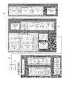
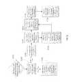
- FIG. 1depicts a high-level diagram of an example of a wireless neural stimulation system.
- FIG. 2depicts a detailed diagram of an example of the wireless neural stimulation system.
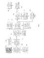
- FIG. 3is a flowchart showing an example of the operation of the wireless neural stimulator system.
- FIG. 4depicts a flow chart showing an example of the operation of the system when the current level at the electrodes is above the threshold limit.
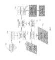
- FIG. 5is a diagram showing examples of signals that may be used to detect an impedance mismatch.
- FIG. 6is a diagram showing examples of signals that may be employed during operation of the wireless neural stimulator system.
- FIG. 7is a flow chart showing a process for the user to control the implantable wireless neural stimulator through an external programmer in an open loop feedback system.
- FIG. 8is another example flow chart of a process for the user to control the wireless stimulator with limitations on the lower and upper limits of current amplitude.
- FIG. 9is yet another example flow chart of a process for the user to control the wireless neural stimulator through preprogrammed parameter settings.
- FIG. 10is still another example flow chart of a process for a low battery state for the RF pulse generator module.
- FIG. 11is yet another example flow chart of a process for a Manufacturer's Representative to program the implanted wireless neural stimulator.
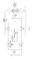
- FIG. 12is a circuit diagram showing an example of a wireless neural stimulator.
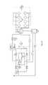
- FIG. 13is a circuit diagram of another example of a wireless neural stimulator.
- a neural stimulation systemmay be used to send electrical stimulation to targeted nerve tissue by using remote radio frequency (RF) energy with neither cables nor inductive coupling to power the passive implanted stimulator.
- the targeted nerve tissuesmay be, for example, in the spinal column including the spinothalamic tracts, dorsal horn, dorsal root ganglia, dorsal roots, dorsal column fibers, and peripheral nerves bundles leaving the dorsal column or brainstem, as well as any cranial nerves, abdominal, thoracic, or trigeminal ganglia nerves, nerve bundles of the cerebral cortex, deep brain and any sensory or motor nerves.
- RFradio frequency
- the neural stimulation systemmay include a controller module, such as an RF pulse generator module, and a passive implanted neural stimulator that contains one or more dipole antennas, one or more circuits, and one or more electrodes in contact with or in proximity to targeted neural tissue to facilitate stimulation.
- the RF pulse generator modulemay include an antenna and may be configured to transfer energy from the module antenna to the implanted antennas.
- the one or more circuits of the implanted neural stimulatormay be configured to generate electrical pulses suitable for neural stimulation using the transferred energy and to supply the electrical pulses to the electrodes so that the pulses are applied to the neural tissue.
- the one or more circuitsmay include wave conditioning circuitry that rectifies the received RF signal (for example, using a diode rectifier), transforms the RF energy to a low frequency signal suitable for the stimulation of neural tissue, and presents the resulting waveform to an electrode array.
- the one or more circuits of the implanted neural stimulatormay also include circuitry for communicating information back to the RF pulse generator module to facilitate a feedback control mechanism for stimulation parameter control.
- the implanted neural stimulatormay send to the RF pulse generator module a stimulus feedback signal that is indicative of parameters of the electrical pulses, and the RF pulse generator module may employ the stimulus feedback signal to adjust parameters of the signal sent to the neural stimulator.
- FIG. 1depicts a high-level diagram of an example of a neural stimulation system.
- the neural stimulation systemmay include four major components, namely, a programmer module 102 , a RF pulse generator module 106 , a transmit (TX) antenna 110 (for example, a patch antenna, slot antenna, or a dipole antenna), and an implanted wireless neural stimulator 114 .
- the programmer module 102may be a computer device, such as a smart phone, running a software application that supports a wireless connection 114 , such as Bluetooth®.
- the applicationcan enable the user to view the system status and diagnostics, change various parameters, increase/decrease the desired stimulus amplitude of the electrode pulses, and adjust feedback sensitivity of the RF pulse generator module 106 , among other functions.
- the RF pulse generator module 106may include communication electronics that support the wireless connection 104 , the stimulation circuitry, and the battery to power the generator electronics.
- the RF pulse generator module 106includes the TX antenna embedded into its packaging form factor while, in other implementations, the TX antenna is connected to the RF pulse generator module 106 through a wired connection 108 or a wireless connection (not shown).
- the TX antenna 110may be coupled directly to tissue to create an electric field that powers the implanted neural stimulator module 114 .
- the TX antenna 110communicates with the implanted neural stimulator module 114 through an RF interface. For instance, the TX antenna 110 radiates an RF transmission signal that is modulated and encoded by the RF pulse generator module 110 .
- the implanted wireless neural stimulator module 114contains one or more antennas, such as dipole antenna(s), to receive and transmit through RF interface 112 .
- the coupling mechanism between antenna 110 and the one or more antennas on the implanted neural stimulation module 114is electrical radiative coupling and not inductive coupling. In other words, the coupling is through an electric field rather than a magnetic field.
- the TX antenna 110can provide an input signal to the implanted neural stimulation module 114 .
- This input signalcontains energy and may contain information encoding stimulus waveforms to be applied at the electrodes of the implanted neural stimulator module 114 .
- the power level of this input signaldirectly determines an applied amplitude (for example, power, current, or voltage) of the one or more electrical pulses created using the electrical energy contained in the input signal.
- Within the implanted wireless neural stimulator 114are components for demodulating the RF transmission signal, and electrodes to deliver the stimulation to surrounding neuronal tissue.
- the RF pulse generator module 106can be implanted subcutaneously, or it can be worn external to the body. When external to the body, the RF generator module 106 can be incorporated into a belt or harness design to allow for electric radiative coupling through the skin and underlying tissue to transfer power and/or control parameters to the implanted neural stimulator module 114 , which can be a passive stimulator. In either event, receiver circuit(s) internal to the neural stimulator module 114 can capture the energy radiated by the TX antenna 110 and convert this energy to an electrical waveform. The receiver circuit(s) may further modify the waveform to create an electrical pulse suitable for the stimulation of neural tissue, and this pulse may be delivered to the tissue via electrode pads.
- the RF pulse generator module 106can remotely control the stimulus parameters (that is, the parameters of the electrical pulses applied to the neural tissue) and monitor feedback from the wireless neural stimulator module 114 based on RF signals received from the implanted wireless neural stimulator module 114 .
- a feedback detection algorithm implemented by the RF pulse generator module 106can monitor data sent wirelessly from the implanted wireless neural stimulator module 114 , including information about the energy that the implanted wireless neural stimulator module 114 is receiving from the RF pulse generator and information about the stimulus waveform being delivered to the electrode pads.
- the systemcan be tuned to provide the optimal amount of excitation or inhibition to the nerve fibers by electrical stimulation.
- a closed loop feedback control methodcan be used in which the output signals from the implanted wireless neural stimulator module 114 are monitored and used to determine the appropriate level of neural stimulation current for maintaining effective neuronal activation, or, in some cases, the patient can manually adjust the output signals in an open loop control method.
- FIG. 2depicts a detailed diagram of an example of the neural stimulation system.
- the programming module 102may comprise user input system 202 and communication subsystem 208 .
- the user input system 221may allow various parameter settings to be adjusted (in some cases, in an open loop fashion) by the user in the form of instruction sets.
- the communication subsystem 208may transmit these instruction sets (and other information) via the wireless connection 104 , such as Bluetooth or Wi-Fi, to the RF pulse generator module 106 , as well as receive data from module 106 .
- the programmer module 102which can be utilized for multiple users, such as a patient's control unit or clinician's programmer unit, can be used to send stimulation parameters to the RF pulse generator module 106 .
- the stimulation parameters that can be controlledmay include pulse amplitude, pulse frequency, and pulse width in the ranges shown in Table 1.
- pulserefers to the phase of the waveform that directly produces stimulation of the tissue; the parameters of the charge-balancing phase (described below) can similarly be controlled.
- the patient and/or the cliniciancan also optionally control overall duration and pattern of treatment.
- Pulse Amplitude0 to 20 mA Pulse Frequency: 0 to 2000 Hz Pulse Width: 0 to 2 ms
- the implantable neural stimulator module 114 or RF pulse generator module 114may be initially programmed to meet the specific parameter settings for each individual patient during the initial implantation procedure. Because medical conditions or the body itself can change over time, the ability to re-adjust the parameter settings may be beneficial to ensure ongoing efficacy of the neural modulation therapy.
- the programmer module 102may be functionally a smart device and associated application.
- the smart device hardwaremay include a CPU 206 and be used as a vehicle to handle touchscreen input on a graphical user interface (GUI) 204 , for processing and storing data.
- GUIgraphical user interface
- the RF pulse generator module 106may be connected via wired connection 108 to an external TX antenna 110 .
- both the antenna and the RF pulse generatorare located subcutaneously (not shown).
- the signals sent by RF pulse generator module 106 to the implanted stimulator 114may include both power and parameter-setting attributes in regards to stimulus waveform, amplitude, pulse width, and frequency.
- the RF pulse generator module 106can also function as a wireless receiving unit that receives feedback signals from the implanted stimulator module 114 .
- the RF pulse generator module 106may contain microelectronics or other circuitry to handle the generation of the signals transmitted to the stimulator module 114 as well as handle feedback signals, such as those from the stimulator module 114 .
- the RF pulse generator module 106may comprise controller subsystem 214 , high-frequency oscillator 218 , RF amplifier 216 , a RF switch, and a feedback subsystem 212 .
- the controller subsystem 214may include a CPU 230 to handle data processing, a memory subsystem 228 such as a local memory, communication subsystem 234 to communicate with programmer module 102 (including receiving stimulation parameters from programmer module), pulse generator circuitry 236 , and digital/analog (D/A) converters 232 .
- a CPU 230to handle data processing
- a memory subsystem 228such as a local memory
- communication subsystem 234to communicate with programmer module 102 (including receiving stimulation parameters from programmer module)
- pulse generator circuitry 236including receiving stimulation parameters from programmer module
- D/A converters 232digital/analog
- the controller subsystem 214may be used by the patient and/or the clinician to control the stimulation parameter settings (for example, by controlling the parameters of the signal sent from RF pulse generator module 106 to neural stimulator module 114 ). These parameter settings can affect, for example, the power, current level, or shape of the one or more electrical pulses.
- the programming of the stimulation parameterscan be performed using the programming module 102 , as described above, to set the repetition rate, pulse width, amplitude, and waveform that will be transmitted by RF energy to the receive (RX) antenna 238 , typically a dipole antenna (although other types may be used), in the wireless implanted neural stimulator module 214 .
- the clinicianmay have the option of locking and/or hiding certain settings within the programmer interface, thus limiting the patient's ability to view or adjust certain parameters because adjustment of certain parameters may require detailed medical knowledge of neurophysiology, neuroanatomy, protocols for neural modulation, and safety limits of electrical stimulation.
- the controller subsystem 214may store received parameter settings in the local memory subsystem 228 , until the parameter settings are modified by new input data received from the programming module 102 .
- the CPU 206may use the parameters stored in the local memory to control the pulse generator circuitry 236 to generate a stimulus waveform that is modulated by a high frequency oscillator 218 in the range from 300 MHz to 8 GHz.
- the resulting RF signalmay then be amplified by RF amplifier 226 and then sent through an RF switch 223 to the TX antenna 110 to reach through depths of tissue to the RX antenna 238 .
- the RF signal sent by TX antenna 110may simply be a power transmission signal used by stimulator module 114 to generate electric pulses.
- a telemetry signalmay also be transmitted to the stimulator module 114 to send instructions about the various operations of the stimulator module 114 .
- the telemetry signalmay be sent by the modulation of the carrier signal (through the skin if external, or through other body tissues if the pulse generator module 106 is implanted subcutaneously).
- the telemetry signalis used to modulate the carrier signal (a high frequency signal) that is coupled onto the implanted antenna(s) 238 and does not interfere with the input received on the same lead to power the implant.
- the telemetry signal and powering signalare combined into one signal, where the RF telemetry signal is used to modulate the RF powering signal, and thus the implanted stimulator is powered directly by the received telemetry signal; separate subsystems in the stimulator harness the power contained in the signal and interpret the data content of the signal.
- the RF switch 223may be a multipurpose device such as a dual directional coupler, which passes the relatively high amplitude, extremely short duration RF pulse to the TX antenna 110 with minimal insertion loss while simultaneously providing two low-level outputs to feedback subsystem 212 ; one output delivers a forward power signal to the feedback subsystem 212 , where the forward power signal is an attenuated version of the RF pulse sent to the TX antenna 110 , and the other output delivers a reverse power signal to a different port of the feedback subsystem 212 , where reverse power is an attenuated version of the reflected RF energy from the TX Antenna 110 .
- a multipurpose devicesuch as a dual directional coupler, which passes the relatively high amplitude, extremely short duration RF pulse to the TX antenna 110 with minimal insertion loss while simultaneously providing two low-level outputs to feedback subsystem 212 ; one output delivers a forward power signal to the feedback subsystem 212 , where the forward power signal is an attenuated version of the RF
- the RF switch 223is set to send the forward power signal to feedback subsystem.
- the RF switch 223can change to a receiving mode in which the reflected RF energy and/or RF signals from the stimulator module 114 are received to be analyzed in the feedback subsystem 212 .
- the feedback subsystem 212 of the RF pulse generator module 106may include reception circuitry to receive and extract telemetry or other feedback signals from the stimulator 114 and/or reflected RF energy from the signal sent by TX antenna 110 .
- the feedback subsystemmay include an amplifier 226 , a filter 224 , a demodulator 222 , and an A/D converter 220 .
- the feedback subsystem 212receives the forward power signal and converts this high-frequency AC signal to a DC level that can be sampled and sent to the controller subsystem 214 . In this way the characteristics of the generated RF pulse can be compared to a reference signal within the controller subsystem 214 . If a disparity (error) exists in any parameter, the controller subsystem 214 can adjust the output to the RF pulse generator 106 . The nature of the adjustment can be, for example, proportional to the computed error.
- the controller subsystem 214can incorporate additional inputs and limits on its adjustment scheme such as the signal amplitude of the reverse power and any predetermined maximum or minimum values for various pulse parameters.
- the reverse power signalcan be used to detect fault conditions in the RF-power delivery system.
- TX antenna 110has perfectly matched impedance to the tissue that it contacts, the electromagnetic waves generated from the RF pulse generator 106 pass unimpeded from the TX antenna 110 into the body tissue.
- a large degree of variabilitymay exist in the body types of users, types of clothing worn, and positioning of the antenna 110 relative to the body surface.
- the impedance of the antenna 110depends on the relative permittivity of the underlying tissue and any intervening materials, and also depends on the overall separation distance of the antenna from the skin, in any given application there can be an impedance mismatch at the interface of the TX antenna 110 with the body surface. When such a mismatch occurs, the electromagnetic waves sent from the RF pulse generator 106 are partially reflected at this interface, and this reflected energy propagates backward through the antenna feed.
- the dual directional coupler RF switch 223may prevent the reflected RF energy propagating back into the amplifier 226 , and may attenuate this reflected RF signal and send the attenuated signal as the reverse power signal to the feedback subsystem 212 .
- the feedback subsystem 212can convert this high-frequency AC signal to a DC level that can be sampled and sent to the controller subsystem 214 .
- the controller subsystem 214can then calculate the ratio of the amplitude of the reverse power signal to the amplitude of the forward power signal. The ratio of the amplitude of reverse power signal to the amplitude level of forward power may indicate severity of the impedance mismatch.
- the controller subsystem 214can measure the reflected-power ratio in real time, and according to preset thresholds for this measurement, the controller subsystem 214 can modify the level of RF power generated by the RF pulse generator 106 .
- the course of actioncan be for the controller subsystem 214 to increase the amplitude of RF power sent to the TX antenna 110 , as would be needed to compensate for slightly non-optimum but acceptable TX antenna coupling to the body.
- the course of actioncan be to prevent operation of the RF pulse generator 106 and set a fault code to indicate that the TX antenna 110 has little or no coupling with the body.
- This type of reflected-power fault conditioncan also be generated by a poor or broken connection to the TX antenna. In either case, it may be desirable to stop RF transmission when the reflected-power ratio is above a defined threshold, because internally reflected power can lead to unwanted heating of internal components, and this fault condition means the system cannot deliver sufficient power to the implanted wireless neural stimulator and thus cannot deliver therapy to the user.
- the controller 242 of the stimulator 114may transmit informational signals, such as a telemetry signal, through the antenna 238 to communicate with the RF pulse generator module 106 during its receive cycle.
- the telemetry signal from the stimulator 114may be coupled to the modulated signal on the dipole antenna(s) 238 , during the on and off state of the transistor circuit to enable or disable a waveform that produces the corresponding RF bursts necessary to transmit to the external (or remotely implanted) pulse generator module 106 .
- the antenna(s) 238may be connected to electrodes 254 in contact with tissue to provide a return path for the transmitted signal.
- An A/D (not shown) convertercan be used to transfer stored data to a serialized pattern that can be transmitted on the pulse modulated signal from the internal antenna(s) 238 of the neural stimulator.
- a telemetry signal from the implanted wireless neural stimulator module 114may include stimulus parameters such as the power or the amplitude of the current that is delivered to the tissue from the electrodes.
- the feedback signalcan be transmitted to the RF pulse generator module 116 to indicate the strength of the stimulus at the nerve bundle by means of coupling the signal to the implanted RX antenna 238 , which radiates the telemetry signal to the external (or remotely implanted) RF pulse generator module 106 .
- the feedback signalcan include either or both an analog and digital telemetry pulse modulated carrier signal. Data such as stimulation pulse parameters and measured characteristics of stimulator performance can be stored in an internal memory device within the implanted neural stimulator 114 , and sent on the telemetry signal.
- the frequency of the carrier signalmay be in the range of at 300 MHz to 8 GHz.
- the telemetry signalcan be down modulated using demodulator 222 and digitized by being processed through an analog to digital (A/D) converter 220 .
- the digital telemetry signalmay then be routed to a CPU 230 with embedded code, with the option to reprogram, to translate the signal into a corresponding current measurement in the tissue based on the amplitude of the received signal.
- the CPU 230 of the controller subsystem 214can compare the reported stimulus parameters to those held in local memory 228 to verify the stimulator(s) 114 delivered the specified stimuli to tissue.
- the power level from the RF pulse generator module 106can be increased so that the implanted neural stimulator 114 will have more available power for stimulation.
- the implanted neural stimulator 114can generate telemetry data in real time, for example, at a rate of 8 kbits per second. All feedback data received from the implanted lead module 114 can be logged against time and sampled to be stored for retrieval to a remote monitoring system accessible by the health care professional for trending and statistical correlations.
- the sequence of remotely programmable RF signals received by the internal antenna(s) 238may be conditioned into waveforms that are controlled within the implantable stimulator 114 by the control subsystem 242 and routed to the appropriate electrodes 254 that are placed in proximity to the tissue to be stimulated.
- the RF signal transmitted from the RF pulse generator module 106may be received by RX antenna 238 and processed by circuitry, such as waveform conditioning circuitry 240 , within the implanted wireless neural stimulator module 114 to be converted into electrical pulses applied to the electrodes 254 through electrode interface 252 .
- the implanted stimulator 114contains between two to sixteen electrodes 254 .
- the waveform conditioning circuitry 240may include a rectifier 244 , which rectifies the signal received by the RX antenna 238 .
- the rectified signalmay be fed to the controller 242 for receiving encoded instructions from the RF pulse generator module 106 .
- the rectifier signalmay also be fed to a charge balance component 246 that is configured to create one or more electrical pulses based such that the one or more electrical pulses result in a substantially zero net charge at the one or more electrodes (that is, the pulses are charge balanced).
- the charge balanced pulsesare passed through the current limiter 248 to the electrode interface 252 , which applies the pulses to the electrodes 254 as appropriate.
- the current limiter 248insures the current level of the pulses applied to the electrodes 254 is not above a threshold current level.
- an amplitude (for example, current level, voltage level, or power level) of the received RF pulsedirectly determines the amplitude of the stimulus.
- it is the charge per phase that should be limited for safetywhere the charge delivered by a stimulus phase is the integral of the current).
- the limiter 248acts as a charge limiter that limits a characteristic (for example, current or duration) of the electrical pulses so that the charge per phase remains below a threshold level (typically, a safe-charge limit).
- the current limiter 248can automatically limit or “clip” the stimulus phase to maintain the total charge of the phase within the safety limit.
- the current limiter 248may be a passive current limiting component that cuts the signal to the electrodes 254 once the safe current limit (the threshold current level) is reached. Alternatively, or additionally, the current limiter 248 may communicate with the electrode interface 252 to turn off all electrodes 254 to prevent tissue damaging current levels.
- a clipping eventmay trigger a current limiter feedback control mode.
- the action of clippingmay cause the controller to send a threshold power data signal to the pulse generator 106 .
- the feedback subsystem 212detects the threshold power signal and demodulates the signal into data that is communicated to the controller subsystem 214 .
- the controller subsystem 214 algorithmsmay act on this current-limiting condition by specifically reducing the RF power generated by the RF pulse generator, or cutting the power completely. In this way, the pulse generator 106 can reduce the RF power delivered to the body if the implanted wireless neural stimulator 114 reports it is receiving excess RF power.
- the controller 250 of the stimulator 205may communicate with the electrode interface 252 to control various aspects of the electrode setup and pulses applied to the electrodes 254 .
- the electrode interface 252may act as a multiplex and control the polarity and switching of each of the electrodes 254 .
- the wireless stimulator 106has multiple electrodes 254 in contact with tissue, and for a given stimulus the RF pulse generator module 106 can arbitrarily assign one or more electrodes to 1) act as a stimulating electrode, 2) act as a return electrode, or 3) be inactive by communication of assignment sent wirelessly with the parameter instructions, which the controller 250 uses to set electrode interface 252 as appropriate. It may be physiologically advantageous to assign, for example, one or two electrodes as stimulating electrodes and to assign all remaining electrodes as return electrodes.
- the controller 250may control the electrode interface 252 to divide the current arbitrarily (or according to instructions from pulse generator module 106 ) among the designated stimulating electrodes.
- This control over electrode assignment and current controlcan be advantageous because in practice the electrodes 254 may be spatially distributed along various neural structures, and through strategic selection of the stimulating electrode location and the proportion of current specified for each location, the aggregate current distribution in tissue can be modified to selectively activate specific neural targets. This strategy of current steering can improve the therapeutic effect for the patient.
- the time course of stimulimay be arbitrarily manipulated.
- a given stimulus waveformmay be initiated at a time T_start and terminated at a time T_final, and this time course may be synchronized across all stimulating and return electrodes; further, the frequency of repetition of this stimulus cycle may be synchronous for all the electrodes.
- controller 250on its own or in response to instructions from pulse generator 106 , can control electrode interface 252 to designate one or more subsets of electrodes to deliver stimulus waveforms with non-synchronous start and stop times, and the frequency of repetition of each stimulus cycle can be arbitrarily and independently specified.
- a stimulator having eight electrodesmay be configured to have a subset of five electrodes, called set A, and a subset of three electrodes, called set B.
- Set Amight be configured to use two of its electrodes as stimulating electrodes, with the remainder being return electrodes.
- Set Bmight be configured to have just one stimulating electrode.
- the controller 250could then specify that set A deliver a stimulus phase with 3 mA current for a duration of 200 us followed by a 400 us charge-balancing phase. This stimulus cycle could be specified to repeat at a rate of 60 cycles per second. Then, for set B, the controller 250 could specify a stimulus phase with 1 mA current for duration of 500 us followed by a 800 us charge-balancing phase.
- the repetition rate for the set-B stimulus cyclecan be set independently of set A, say for example it could be specified at 25 cycles per second. Or, if the controller 250 was configured to match the repetition rate for set B to that of set A, for such a case the controller 250 can specify the relative start times of the stimulus cycles to be coincident in time or to be arbitrarily offset from one another by some delay interval.
- the controller 250can arbitrarily shape the stimulus waveform amplitude, and may do so in response to instructions from pulse generator 106 .
- the stimulus phasemay be delivered by a constant-current source or a constant-voltage source, and this type of control may generate characteristic waveforms that are static, e.g. a constant-current source generates a characteristic rectangular pulse in which the current waveform has a very steep rise, a constant amplitude for the duration of the stimulus, and then a very steep return to baseline.
- the controller 250can increase or decrease the level of current at any time during the stimulus phase and/or during the charge-balancing phase.
- the controller 250can deliver arbitrarily shaped stimulus waveforms such as a triangular pulse, sinusoidal pulse, or Gaussian pulse for example.
- the charge-balancing phasecan be arbitrarily amplitude-shaped, and similarly a leading anodic pulse (prior to the stimulus phase) may also be amplitude-shaped.
- the stimulator 114may include a charge balancing component 246 .
- pulsesshould be charge balanced by having the amount of cathodic current should equal the amount of anodic current, which is typically called biphasic stimulation.
- Charge densityis the amount of current times the duration it is applied, and is typically expressed in the units uC/cm 2 .
- no net chargeshould appear at the electrode-electrolyte interface, and it is generally acceptable to have a charge density less than 30 uC/cm 2 .
- Biphasic stimulating current pulsesensure that no net charge appears at the electrode after each stimulation cycle and the electrochemical processes are balanced to prevent net dc currents.
- Neural stimulator 114may be designed to ensure that the resulting stimulus waveform has a net zero charge. Charge balanced stimuli are thought to have minimal damaging effects on tissue by reducing or eliminating electrochemical reaction products created at the electrode-tissue interface.
- the charge balance component 246uses a blocking capacitor(s) placed electrically in series with the stimulating electrodes and body tissue, between the point of stimulus generation within the stimulator circuitry and the point of stimulus delivery to tissue.
- a resistor-capacitor (RC) networkmay be formed.
- one charge-balance capacitor(s)may be used for each electrode or a centralized capacitor(s) may be used within the stimulator circuitry prior to the point of electrode selection.
- the RC networkcan block direct current (DC), however it can also prevent low-frequency alternating current (AC) from passing to the tissue.
- the frequency below which the series RC network essentially blocks signalsis commonly referred to as the cutoff frequency, and in one embodiment the design of the stimulator system may ensure the cutoff frequency is not above the fundamental frequency of the stimulus waveform.
- the wireless stimulatormay have a charge-balance capacitor with a value chosen according to the measured series resistance of the electrodes and the tissue environment in which the stimulator is implanted. By selecting a specific capacitance value the cutoff frequency of the RC network in this embodiment is at or below the fundamental frequency of the stimulus pulse.
- the cutoff frequencymay be chosen to be at or above the fundamental frequency of the stimulus, and in this scenario the stimulus waveform created prior to the charge-balance capacitor, called the drive waveform, may be designed to be non-stationary, where the envelope of the drive waveform is varied during the duration of the drive pulse.
- the initial amplitude of the drive waveformis set at an initial amplitude Vi, and the amplitude is increased during the duration of the pulse until it reaches a final value k*Vi.
- the shape of the stimulus waveform passed through the charge-balance capacitoris also modified. The shape of the stimulus waveform may be modified in this fashion to create a physiologically advantageous stimulus.
- the wireless neural stimulator module 114may create a drive-waveform envelope that follows the envelope of the RF pulse received by the receiving dipole antenna(s) 238 .
- the RF pulse generator module 106can directly control the envelope of the drive waveform within the wireless neural stimulator 114 , and thus no energy storage may be required inside the stimulator itself.
- the stimulator circuitrymay modify the envelope of the drive waveform or may pass it directly to the charge-balance capacitor and/or electrode-selection stage.
- the implanted neural stimulator 114may deliver a single-phase drive waveform to the charge balance capacitor or it may deliver multiphase drive waveforms.
- a single-phase drive waveformfor example, a negative-going rectangular pulse
- this pulsecomprises the physiological stimulus phase
- the charge-balance capacitoris polarized (charged) during this phase.
- the charge balancing functionis performed solely by the passive discharge of the charge-balance capacitor, where is dissipates its charge through the tissue in an opposite polarity relative to the preceding stimulus.
- a resistor within the stimulatorfacilitates the discharge of the charge-balance capacitor.
- the capacitormay allow virtually complete discharge prior to the onset of the subsequent stimulus pulse.
- the wireless stimulatormay perform internal switching to pass negative-going or positive-going pulses (phases) to the charge-balance capacitor.
- phasespositive-going pulses
- These pulsesmay be delivered in any sequence and with varying amplitudes and waveform shapes to achieve a desired physiological effect.
- the stimulus phasemay be followed by an actively driven charge-balancing phase, and/or the stimulus phase may be preceded by an opposite phase.
- Preceding the stimulus with an opposite-polarity phasefor example, can have the advantage of reducing the amplitude of the stimulus phase required to excite tissue.
- the amplitude and timing of stimulus and charge-balancing phasesis controlled by the amplitude and timing of RF pulses from the RF pulse generator module 106 , and in others this control may be administered internally by circuitry onboard the wireless stimulator 114 , such as controller 250 . In the case of onboard control, the amplitude and timing may be specified or modified by data commands delivered from the pulse generator module 106 .
- FIG. 3is a flowchart showing an example of an operation of the neural stimulator system.
- the wireless neural stimulator 114is implanted in proximity to nerve bundles and is coupled to the electric field produced by the TX antenna 110 . That is, the pulse generator module 106 and the TX antenna 110 are positioned in such a way (for example, in proximity to the patient) that the TX antenna 110 is electrically radiatively coupled with the implanted RX antenna 238 of the neural stimulator 114 .
- both the antenna 110 and the RF pulse generator 106are located subcutaneously. In other implementations, the antenna 110 and the RF pulse generator 106 are located external to the patient's body. In this case, the TX antenna 110 may be coupled directly to the patient's skin.
- Energy from the RF pulse generatoris radiated to the implanted wireless neural stimulator 114 from the antenna 110 through tissue, as shown in block 304 .
- the energy radiatedmay be controlled by the Patient/Clinician Parameter inputs in block 301 .
- the parameter settingscan be adjusted in an open loop fashion by the patient or clinician, who would adjust the parameter inputs in block 301 to the system.
- the wireless implanted stimulator 114uses the received energy to generate electrical pulses to be applied to the neural tissue through the electrodes 238 .
- the stimulator 114may contain circuitry that rectifies the received RF energy and conditions the waveform to charge balance the energy delivered to the electrodes to stimulate the targeted nerves or tissues, as shown in block 306 .
- the implanted stimulator 114communicates with the pulse generator 106 by using antenna 238 to send a telemetry signal, as shown in block 308 .
- the telemetry signalmay contain information about parameters of the electrical pulses applied to the electrodes, such as the impedance of the electrodes, whether the safe current limit has been reached, or the amplitude of the current that is presented to the tissue from the electrodes.
- the RF pulse generator 106detects amplifies, filters and modulates the received telemetry signal using amplifier 226 , filter 224 , and demodulator 222 , respectively.
- the A/D converter 230then digitizes the resulting analog signal, as shown in 312 .
- the digital telemetry signalis routed to CPU 230 , which determines whether the parameters of the signal sent to the stimulator 114 need to be adjusted based on the digital telemetry signal. For instance, in block 314 , the CPU 230 compares the information of the digital signal to a look-up table, which may indicate an appropriate change in stimulation parameters. The indicated change may be, for example, a change in the current level of the pulses applied to the electrodes. As a result, the CPU may change the output power of the signal sent to stimulator 114 so as to adjust the current applied by the electrodes 254 , as shown in block 316 .
- the CPU 230may adjust parameters of the signal sent to the stimulator 114 every cycle to match the desired current amplitude setting programmed by the patient, as shown in block 318 .
- the status of the stimulator systemmay be sampled in real time at a rate of 8 kbits per second of telemetry data. All feedback data received from the stimulator 114 can be maintained against time and sampled per minute to be stored for download or upload to a remote monitoring system accessible by the health care professional for trending and statistical correlations in block 318 .
- the stimulator system operationmay be reduced to just the functional elements shown in blocks 302 , 304 , 306 , and 308 , and the patient uses their judgment to adjust parameter settings rather than the closed looped feedback from the implanted device.
- FIG. 4depicts a flow chart showing an example of an operation of the system when the current level at the electrodes 254 is above a threshold limit.
- the implanted wireless neural stimulator 114may receive an input power signal with a current level above an established safe current limit, as shown in block 402 .
- the current limiter 248may determine the current is above an established tissue-safe limit of amperes, as shown in block 404 . If the current limiter senses that the current is above the threshold, it may stop the high-power signal from damaging surrounding tissue in contact with the electrodes as shown in block 406 , the operations of which are as described above in association with FIG. 2 .
- a capacitormay store excess power, as shown in block 408 .
- the controller 250may use the excess power available to transmit a small 2-bit data burst back to the RF pulse generator 106 , as shown in block 410 .
- the 2-bit data burstmay be transmitted through the implanted wireless neural stimulator's antenna(s) 238 during the RF pulse generator's receive cycle, as shown in block 412 .
- the RF pulse generator antenna 110may receive the 2-bit data burst during its receive cycle, as shown in block 414 , at a rate of 8 kbps, and may relay the data burst back to the RF pulse generator's feedback subsystem 212 which is monitoring all reverse power, as shown in block 416 .
- the CPU 230may analyze signals from feedback subsystem 202 , as shown in block 418 and if there is no data burst present, no changes may be made to the stimulation parameters, as shown in block 420 . If the data burst is present in the analysis, the CPU 230 can cut all transmission power for one cycle, as shown in block 422 .
- the RF pulse generator 106may push a “proximity power danger” notification to the application on the programmer module 102 , as shown in block 424 .
- This proximity danger notificationoccurs because the RF pulse generator has ceased its transmission of power. This notification means an unauthorized form of energy is powering the implant above safe levels.
- the applicationmay alert the user of the danger and that the user should leave the immediate area to resume neural modulation therapy, as shown in block 426 . If after one cycle the data burst has stopped, the RF pulse generator 106 may slowly ramp up the transmission power in increments, for example from 5% to 75% of previous current amplitude levels, as shown in block 428 .
- the RF pulse generator 106may notify the application of its progress and the application may notify the user that there was an unsafe power level and the system is ramping back up, as shown in block 430 .
- FIG. 5is a diagram showing examples of signals that may be used to detect an impedance mismatch.
- a forward power signal and a reverse power signalmay be used to detect an impedance mismatch.
- a RF pulse 502 generated by the RF pulse generatormay pass through a device such as a dual directional coupler to the TX antenna 110 .
- the TX antenna 110then radiates the RF signal into the body, where the energy is received by the implanted wireless neural stimulator 114 and converted into a tissue-stimulating pulse.
- the couplerpasses an attenuated version of this RF signal, forward power 510 , to feedback subsystem 212 .
- the feedback subsystem 212demodulates the AC signal and computes the amplitude of the forward RF power, and this data is passed to controller subsystem 214 .
- the dual directional coupler(or similar component) also receives RF energy reflected back from the TX antenna 110 and passes an attenuated version of this RF signal, reverse power 512 , to feedback subsystem 212 .
- the feedback subsystem 212demodulates the AC signal and computes the amplitude of the reflected RF power, and this data is passed to controller subsystem 214 .
- the TX antenna 110may be perfectly impedance-matched to the body so that the RF energy passes unimpeded across the interface of the TX antenna 110 to the body, and no RF energy is reflected at the interface.
- the reverse power 512may have close to zero amplitude as shown by signal 504 , and the ratio of reverse power 512 to forward power 510 is zero. In this circumstance, no error condition exists, and the controller 214 sets a system message that operation is optimal.
- the impedance match of the TX antenna 204 to the bodymay not be optimal, and some energy of the RF pulse 502 is reflected from the interface of the TX antenna 110 and the body. This can occur for example if the TX antenna 110 is held somewhat away from the skin by a piece of clothing. This non-optimal antenna coupling causes a small portion of the forward RF energy to be reflected at the interface, and this is depicted as signal 506 . In this case, the ratio of reverse power 512 to forward power 510 is small, but a small ratio implies that most of the RF energy is still radiated from the TX antenna 110 , so this condition is acceptable within the control algorithm.
- This determination of acceptable reflection ratiomay be made within controller subsystem 214 based upon a programmed threshold, and the controller subsystem 214 may generate a low-priority alert to be sent to the user interface.
- the controller subsystem 214 sensing the condition of a small reflection ratiomay moderately increase the amplitude of the RF pulse 502 to compensate for the moderate loss of forward energy transfer to the implanted wireless neural stimulator 114 .
- the TX antenna 110During daily operational use, the TX antenna 110 might be accidentally removed from the body entirely, in which case the TX antenna will have very poor coupling to the body (if any). In this or other circumstances, a relatively high proportion of the RF pulse energy is reflected as signal 508 from the TX antenna 110 and fed backward into the RF-powering system. Similarly, this phenomenon can occur if the connection to the TX antenna is physically broken, in which case virtually 100% of the RF energy is reflected backward from the point of the break. In such cases, the ratio of reverse power 512 to forward power 510 is very high, and the controller subsystem 214 will determine the ratio has exceeded the threshold of acceptance. In this case, the controller subsystem 214 may prevent any further RF pulses from being generated. The shutdown of the RF pulse generator module 106 may be reported to the user interface to inform the user that stimulation therapy cannot be delivered.
- FIG. 6is a diagram showing examples of signals that may be employed during operation of the neural stimulator system.
- the amplitude of the RF pulse 602 received by the implanted wireless neural stimulator 114can directly control the amplitude of the stimulus 630 delivered to tissue.
- the duration of the RF pulse 608corresponds to the specified pulse width of the stimulus 630 .
- the RF pulse generator module 106sends an RF pulse waveform 602 via TX antenna 110 into the body, and RF pulse waveform 608 may represent the corresponding RF pulse received by implanted wireless neural stimulator 114 .
- the received powerhas an amplitude suitable for generating a safe stimulus pulse 630 .
- the stimulus pulse 630is below the safety threshold 626 , and no error condition exists.
- the attenuation between the TX antenna 110 and the implanted wireless neural stimulator 114has been unexpectedly reduced, for example due to the user repositioning the TX antenna 110 . This reduced attenuation can lead to increased amplitude in the RF pulse waveform 612 being received at the neural stimulator 114 .
- the RF pulse 602is generated with the same amplitude as before, the improved RF coupling between the TX antenna 110 and the implanted wireless neural stimulator 114 can cause the received RF pulse 612 to be larger in amplitude.
- Implanted wireless neural stimulator 114 in this situationmay generate a larger stimulus 632 in response to the increase in received RF pulse 612 .
- the received power 612is capable of generating a stimulus 632 that exceeds the prudent safety limit for tissue.
- the current limiter feedback control modecan operate to clip the waveform of the stimulus pulse 632 such that the stimulus delivered is held within the predetermined safety limit 626 .
- the clipping event 628may be communicated through the feedback subsystem 212 as described above, and subsequently controller subsystem 214 can reduce the amplitude specified for the RF pulse.
- the current limiter feedback control modemay operate to reduce the RF power delivered to the body if the implanted wireless neural stimulator 114 receives excess RF power.
- the RF pulse waveform 606depicts a higher amplitude RF pulse generated as a result of user input to the user interface.
- the RF pulse 620 received by the implanted wireless neural stimulator 14is increased in amplitude, and similarly current limiter feedback mode operates to prevent stimulus 636 from exceeding safety limit 626 .
- this clipping event 628may be communicated through the feedback subsystem 212 , and subsequently controller subsystem 214 may reduce the amplitude of the RF pulse, thus overriding the user input.
- the reduced RF pulse 604can produce correspondingly smaller amplitudes of the received waveforms 616 , and clipping of the stimulus current may no longer be required to keep the current within the safety limit.
- the current limiter feedbackmay reduce the RF power delivered to the body if the implanted wireless neural stimulator 114 reports it is receiving excess RF power.
- FIG. 7is a flow chart showing a process for the user to control the implantable wireless neural stimulator through the programmer in an open loop feedback system.
- the userhas a wireless neural stimulator implanted in their body, the RF pulse generator 106 sends the stimulating pulse power wirelessly to the stimulator 114 , and an application on the programmer module 102 (for example, a smart device) is communicating with the RF pulse generator 106 .
- an application on the programmer module 102for example, a smart device
- the usermay open the application, as shown in block 704 .
- the applicationcan use Bluetooth protocols built into the smart device to interrogate the pulse generator, as shown in block 706 .
- the RF pulse generator 106may authenticate the identity of the smart device and serialized patient assigned secure iteration of the application, as shown in block 708 .
- the authentication processmay utilize a unique key to the patient specific RF pulse generator serial number.
- the applicationcan be customized with the patient specific unique key through the Manufacturer Representative who has programmed the initial patient settings for the stimulation system, as shown in block 720 . If the RF pulse generator rejects the authentication it may inform the application that the code is invalid, as shown in block 718 and needs the authentication provided by the authorized individual with security clearance from the device manufacturer, known as the “Manufacturer's Representative,” as shown in block 722 . In an implementation, only the Manufacturer's Representative can have access to the security code needed to change the application's stored RF pulse generator unique ID.
- the pulse generator module 106sends back all of the data that has been logged since the last sync, as shown in block 710 .
- the applicationmay then register the most current information and transmit the information to a 3rd party in a secure fashion, as shown in 712 .
- the applicationmay maintain a database that logs all system diagnostic results and values, the changes in settings by the user and the feedback system, and the global runtime history, as shown in block 714 .
- the applicationmay then display relevant data to the user, as shown in block 716 ; including the battery capacity, current program parameter, running time, pulse width, frequency, amplitude, and the status of the feedback system.
- FIG. 8is another example flow chart of a process for the user to control the wireless stimulator with limitations on the lower and upper limits of current amplitude.
- the userwants to change the amplitude of the stimulation signal, as shown in block 802 .
- the usermay open the application, as show in block 704 and the application may go through the process described in FIG. 7 to communicate with the RF pulse generator, authenticate successfully, and display the current status to the user, as shown in block 804 .
- the applicationdisplays the stimulation amplitude as the most prevalent changeable interface option and displays two arrows with which the user can adjust the current amplitude.
- the usermay make a decision based on their need for more or less stimulation in accordance with their pain levels, as shown in block 806 .
- the usermay press the up arrow on the application screen, as shown in block 808 .
- the applicationcan include safety maximum limiting algorithms, so if a request to increase current amplitude is recognized by the application as exceeding the preset safety maximum, as shown in block 810 , then the application will display an error message, as shown in block 812 and will not communicate with the RF pulse generator module 106 . If the user presses the up arrow, as shown in block 808 and the current amplitude request does not exceed the current amplitude maximum allowable value, then the application will send instructions to the RF pulse generator module 106 to increase amplitude, as shown in block 814 .
- the RF pulse generator module 106may then attempt to increase the current amplitude of stimulation, as shown in block 816 . If the RF pulse generator is successful at increasing the current amplitude, the RF pulse generator module 106 may perform a short vibration to physically confirm with the user that the amplitude is increased, as shown in block 818 . The RF pulse generator module 106 can also send back confirmation of increased amplitude to the application, as shown in block 820 , and then the application may display the updated current amplitude level, as shown in block 822 .
- the usercan press the down arrow on the application, as shown in block 828 . If the current amplitude level is already at zero, the application recognizes that the current amplitude cannot be decreased any further, as shown in block 830 and displays an error message to the user without communicating any data to the RF pulse generator, as shown in block 832 . If the current amplitude level is not at zero, the application can send instructions to the RF pulse generator module 106 to decrease current amplitude level accordingly, as shown in block 834 .
- the RF pulse generatormay then attempt to decrease current amplitude level of stimulation RF pulse generator module 106 and, if successful, the RF pulse generator module 106 may perform a short vibration to physically confirm to the user that the current amplitude level has been decreased, as shown in block 842 .
- the RF pulse generator module 106can send back confirmation of the decreased current amplitude level to the application, as shown in block 838 .
- the applicationthen may display the updated current amplitude level, as indicated by block 840 . If the current amplitude level decrease or increase fails, the RF pulse generator module 106 can perform a series of short vibrations to alert user, and send an error message to the application, as shown in block 824 .
- the applicationreceives the error and may display the data for the user's benefit, as shown in block 826 .
- FIG. 9is yet another example flow chart of a process for the user to control the wireless neural stimulator 114 through preprogrammed parameter settings.
- the userwants to change the parameter program, as indicated by block 902 .
- the Manufacturer's Representativemay determine and provide the patient/user RF pulse generator with preset programs that have different stimulation parameters that will be used to treat the user. The user will then able to switch between the various parameter programs as needed.
- the usercan open the application on their smart device, as indicated by block 704 , which first follows the process described in FIG.
- a tablecan be displayed to the user, as shown in block 908 and each row displays a program's codename and lists its basic parameter settings, as shown in block 910 , which includes but is not limited to: pulse width, frequency, cycle timing, pulse shape, duration, feedback sensitivity, as shown in block 912 .
- the usermay then select the row containing the desired parameter preset program to be used, as shown in block 912 .
- the applicationcan send instructions to the RF pulse generator module 106 to change the parameter settings, as shown in block 916 .
- the RF pulse generator module 106may attempt to change the parameter settings 154 . If the parameter settings are successfully changed, the RF pulse generator module 106 can perform a unique vibration pattern to physically confirm with the user that the parameter settings were changed, as shown in block 920 .
- the RF pulse generator module 106can send back confirmation to the application that the parameter change has been successful, as shown in block 922 , and the application may display the updated current program, as shown in block 924 . If the parameter program change has failed, the RF pulse generator module 106 may perform a series of short vibrations to alert the user, and send an error message to the application, as shown in block 926 , which receives the error and may display to the user, as shown in block 928 .
- FIG. 10is still another example flow chart of a process for a low battery state for the RF pulse generator module 106 .
- the RF pulse generator module's remaining battery power levelis recognized as low, as shown in block 1002 .
- the RF pulse generator module 106regularly interrogates the power supply battery subsystem 210 about the current power and the RF pulse generator microprocessor asks the battery if its remaining power is below threshold, as shown in block 1004 . If the battery's remaining power is above the threshold, the RF pulse generator module 106 may store the current battery status to be sent to the application during the next sync, as shown in block 1006 .
- the RF pulse generator module 106may push a low-battery notification to the application, as shown in block 1008 .
- the RF pulse generator module 106may always perform one sequence of short vibrations to alert the user of an issue and send the application a notification, as shown in block 1010 . If there continues to be no confirmation of the application receiving the notification then the RF pulse generator can continue to perform short vibration pulses to notify user, as shown in block 1010 . If the application successfully receives the notification, it may display the notification and may need user acknowledgement, as shown in block 1012 .
- the applicationinforms the RF pulse generator module 106 about lack of human acknowledgement, as shown in block 1014 , and the RF pulse generator module 106 may begin to perform the vibration pulses to notify the user, as shown in block 1010 .
- the applicationmay display a passive notification to switch the battery, as shown in block 1016 . If a predetermined amount of time passes, such as five minutes for example, without the battery being switched, the application can inform the RF pulse generator module 106 of the lack of human acknowledgement, as shown in block 1014 and the RF pulse generator module 106 may perform vibrations, as shown in block 1010 .
- the RF pulse generator module 106reboots and interrogates the battery to assess power remaining, as shown in block 1618 . If the battery's power remaining is below threshold, the cycle may begin again with the RF pulse generator module 106 pushing a notification to the application, as shown in block 1008 . If the battery's power remaining is above threshold the RF pulse generator module 106 may push a successful battery-change notification to the application, as shown in block 1620 . The application may then communicate with the RF pulse generator module 106 and displays current system status, as shown in block 1022 .
- FIG. 11is yet another example flow chart of a process for a Manufacturer's Representative to program the implanted wireless neural stimulator.
- a userwants the Manufacturer's Representative to set individual parameter programs from a remote location different than where the user is, for the user to use as needed, as shown in block 1102 .
- the Manufacturer's Representativecan gain access to the user's set parameter programs through a secure web based service.
- the Manufacturer's Representativecan securely log into the manufacturer's web service on a device connected to the Internet, as shown in block 1104 . If the Manufacturer's Representative is registering the user for the first time in their care they enter in the patient's basic information, the RF pulse generator's unique ID and the programming application's unique ID, as shown in block 1106 .
- the Manufacturer's Representativeaccesses the specific user's profile, as shown in block 1108 .
- the Manufacturer's Representativeis able to view the current allotted list of parameter programs for the specific user, as shown in block 1110 . This list may contain previous active and retired parameter preset programs, as shown in block 1112 .
- the Manufacturer's Representativeis able to activate/deactivate preset parameter programs by checking the box next to the appropriate row in the table displayed, as shown in block 1114 .
- the Manufacturer's Representativemay then submit and save the allotted new preset parameter programs, as shown in block 1116 .
- the user's programmer applicationmay receive the new preset parameter programs at the next sync with the manufacturer's database.
- FIG. 12is a circuit diagram showing an example of a wireless neural stimulator, such as stimulator 114 .
- This examplecontains paired electrodes, comprising cathode electrode(s) 1208 and anode electrode(s) 1210 , as shown. When energized, the charged electrodes create a volume conduction field of current density within the tissue.
- the wireless energyis received through a dipole antenna(s) 238 . At least four diodes are connected together to form a full wave bridge rectifier 1202 attached to the dipole antenna(s) 238 .
- Each diodeuses a junction potential to prevent the flow of negative electrical current, from cathode to anode, from passing through the device when said current does not exceed the reverse threshold.
- the natural inefficiency of the lossy materialmay lead to a low threshold voltage.
- a zero biased diode rectifierresults in a low output impedance for the device.
- a resistor 1204 and a smoothing capacitor 1206are placed across the output nodes of the bridge rectifier to discharge the electrodes to the ground of the bridge anode.
- the rectification bridge 1202includes two branches of diode pairs connecting an anode-to-anode and then cathode to cathode.
- the electrodes 1208 and 1210are connected to the output of the charge balancing circuit 246 .
- FIG. 13is a circuit diagram of another example of a wireless neural stimulator, such as stimulator 114 .
- the example shown in FIG. 13includes multiple electrode control and may employ full closed loop control.
- the stimulatorincludes an electrode array 254 in which the polarity of the electrodes can be assigned as cathodic or anodic, and for which the electrodes can be alternatively not powered with any energy.
- the charged electrodesWhen energized, create a volume conduction field of current density within the tissue.
- the wireless energyis received by the device through the dipole antenna(s) 238 .
- the electrode array 254is controlled through an on-board controller circuit 242 that sends the appropriate bit information to the electrode interface 252 in order to set the polarity of each electrode in the array, as well as power to each individual electrode. The lack of power to a specific electrode would set that electrode in a functional OFF position.
- the amount of current sent to each electrodeis also controlled through the controller 242 .
- the controller current, polarity and power state parameter data, shown as the controller output,is be sent back to the antenna(s) 238 for telemetry transmission back to the pulse generator module 106 .
- the controller 242also includes the functionality of current monitoring and sets a bit register counter so that the status of total current drawn can be sent back to the pulse generator module 106 .
- At least four diodescan be connected together to form a full wave bridge rectifier 302 attached to the dipole antenna(s) 238 .
- Each diodeup to 100 micrometers in length, uses a junction potential to prevent the flow of negative electrical current, from cathode to anode, from passing through the device when said current does not exceed the reverse threshold.
- the natural inefficiency of the lossy materialmay lead to a low threshold voltage.
- a zero biased diode rectifierresults in a low output impedance for the device.
- a resistor 1204 and a smoothing capacitor 1206are placed across the output nodes of the bridge rectifier to discharge the electrodes to the ground of the bridge anode.
- the rectification bridge 1202may include two branches of diode pairs connecting an anode-to-anode and then cathode to cathode.
- the electrode polarity outputs, both cathode 1208 and anode 1210are connected to the outputs formed by the bridge connection.
- Charge balancing circuitry 246 and current limiting circuitry 248are placed in series with the outputs.
Landscapes
- Health & Medical Sciences (AREA)
- Engineering & Computer Science (AREA)
- Life Sciences & Earth Sciences (AREA)
- General Health & Medical Sciences (AREA)
- Biomedical Technology (AREA)
- Public Health (AREA)
- Nuclear Medicine, Radiotherapy & Molecular Imaging (AREA)
- Radiology & Medical Imaging (AREA)
- Animal Behavior & Ethology (AREA)
- Veterinary Medicine (AREA)
- Neurosurgery (AREA)
- Neurology (AREA)
- Physics & Mathematics (AREA)
- Heart & Thoracic Surgery (AREA)
- Biophysics (AREA)
- Cardiology (AREA)
- Electromagnetism (AREA)
- Acoustics & Sound (AREA)
- Primary Health Care (AREA)
- Medical Informatics (AREA)
- Epidemiology (AREA)
- Human Computer Interaction (AREA)
- General Business, Economics & Management (AREA)
- Business, Economics & Management (AREA)
- Physical Education & Sports Medicine (AREA)
- Pain & Pain Management (AREA)
- Orthopedic Medicine & Surgery (AREA)
- Hospice & Palliative Care (AREA)
- Electrotherapy Devices (AREA)
Abstract
Description
| Stimulation Parameter Table 1 |
| Pulse Amplitude: | 0 to 20 mA | ||
| Pulse Frequency: | 0 to 2000 Hz | ||
| Pulse Width: | 0 to 2 ms | ||
Claims (14)
Priority Applications (2)
| Application Number | Priority Date | Filing Date | Title |
|---|---|---|---|
| US15/254,741US9925384B2 (en) | 2011-01-28 | 2016-09-01 | Neural stimulator system |
| US15/935,410US10471262B2 (en) | 2011-01-28 | 2018-03-26 | Neural stimulator system |
Applications Claiming Priority (5)
| Application Number | Priority Date | Filing Date | Title |
|---|---|---|---|
| US201161437561P | 2011-01-28 | 2011-01-28 | |
| PCT/US2012/023029WO2012103519A2 (en) | 2011-01-28 | 2012-01-27 | Neural stimulator system |
| US13/551,050US9409030B2 (en) | 2011-01-28 | 2012-07-17 | Neural stimulator system |
| US14/068,750US9566449B2 (en) | 2011-01-28 | 2013-10-31 | Neural stimulator system |
| US15/254,741US9925384B2 (en) | 2011-01-28 | 2016-09-01 | Neural stimulator system |
Related Parent Applications (1)
| Application Number | Title | Priority Date | Filing Date |
|---|---|---|---|
| US14/068,750ContinuationUS9566449B2 (en) | 2011-01-28 | 2013-10-31 | Neural stimulator system |
Related Child Applications (1)
| Application Number | Title | Priority Date | Filing Date |
|---|---|---|---|
| US15/935,410ContinuationUS10471262B2 (en) | 2011-01-28 | 2018-03-26 | Neural stimulator system |
Publications (2)
| Publication Number | Publication Date |
|---|---|
| US20160367825A1 US20160367825A1 (en) | 2016-12-22 |
| US9925384B2true US9925384B2 (en) | 2018-03-27 |
Family
ID=46581440
Family Applications (4)
| Application Number | Title | Priority Date | Filing Date |
|---|---|---|---|
| US13/551,050ActiveUS9409030B2 (en) | 2011-01-28 | 2012-07-17 | Neural stimulator system |
| US14/068,750ActiveUS9566449B2 (en) | 2011-01-28 | 2013-10-31 | Neural stimulator system |
| US15/254,741ActiveUS9925384B2 (en) | 2011-01-28 | 2016-09-01 | Neural stimulator system |
| US15/935,410ActiveUS10471262B2 (en) | 2011-01-28 | 2018-03-26 | Neural stimulator system |
Family Applications Before (2)
| Application Number | Title | Priority Date | Filing Date |
|---|---|---|---|
| US13/551,050ActiveUS9409030B2 (en) | 2011-01-28 | 2012-07-17 | Neural stimulator system |
| US14/068,750ActiveUS9566449B2 (en) | 2011-01-28 | 2013-10-31 | Neural stimulator system |
Family Applications After (1)
| Application Number | Title | Priority Date | Filing Date |
|---|---|---|---|
| US15/935,410ActiveUS10471262B2 (en) | 2011-01-28 | 2018-03-26 | Neural stimulator system |
Country Status (11)
| Country | Link |
|---|---|
| US (4) | US9409030B2 (en) |
| EP (4) | EP4424360A3 (en) |
| JP (1) | JP6076915B2 (en) |
| CN (2) | CN103796715B (en) |
| AU (1) | AU2012211055B2 (en) |
| BR (1) | BR112013018470B1 (en) |
| CA (1) | CA2831062A1 (en) |
| ES (1) | ES2988349T3 (en) |
| IL (1) | IL227210B (en) |
| MX (1) | MX340144B (en) |
| WO (1) | WO2012103519A2 (en) |
Cited By (12)
| Publication number | Priority date | Publication date | Assignee | Title |
|---|---|---|---|---|
| US10576305B2 (en) | 2016-07-07 | 2020-03-03 | The Regents Of The University Of California | Implants using ultrasonic backscatter for sensing physiological conditions |
| US10953228B2 (en) | 2011-04-04 | 2021-03-23 | Stimwave Technologies Incorporated | Implantable lead |
| US11033746B2 (en) | 2018-04-19 | 2021-06-15 | Iota Biosciences, Inc. | Implants using ultrasonic communication for neural sensing and stimulation |
| US11097111B1 (en) | 2014-05-29 | 2021-08-24 | Stimwave Technologies Incorporated | Stimulation with electrode arrays |
| US11467665B2 (en) | 2018-06-14 | 2022-10-11 | Meron Gribetz | Virtual user interface system and methods for use thereof |
| US11583683B2 (en) | 2012-12-26 | 2023-02-21 | Stimwave Technologies Incorporated | Wearable antenna assembly |
| US11745020B2 (en) | 2011-09-15 | 2023-09-05 | Curonix Llc | Relay module for implant |
| US11890474B2 (en) | 2018-04-19 | 2024-02-06 | Iota Biosciences, Inc. | Implants using ultrasonic communication for modulating splenic nerve activity |
| US11969596B2 (en) | 2018-08-29 | 2024-04-30 | Iota Biosciences, Inc. | Implantable closed-loop neuromodulation device, systems, and methods of use |
| US12115374B2 (en) | 2011-01-28 | 2024-10-15 | Curonix Llc | Microwave field stimulator |
| US12274877B2 (en) | 2019-10-17 | 2025-04-15 | Iota Biosciences, Inc. | Devices and methods for modulating immune system activity in a cancer patient and treating cancer |
| US12290371B2 (en) | 2019-02-07 | 2025-05-06 | Inner Cosmos Inc. | Intracalvarial BCI systems and methods for their making, implantation and use |
Families Citing this family (198)
| Publication number | Priority date | Publication date | Assignee | Title |
|---|---|---|---|---|
| US8361067B2 (en) | 2002-09-30 | 2013-01-29 | Relievant Medsystems, Inc. | Methods of therapeutically heating a vertebral body to treat back pain |
| US7258690B2 (en) | 2003-03-28 | 2007-08-21 | Relievant Medsystems, Inc. | Windowed thermal ablation probe |
| US6907884B2 (en) | 2002-09-30 | 2005-06-21 | Depay Acromed, Inc. | Method of straddling an intraosseous nerve |
| US9205261B2 (en) | 2004-09-08 | 2015-12-08 | The Board Of Trustees Of The Leland Stanford Junior University | Neurostimulation methods and systems |
| US20120277839A1 (en) | 2004-09-08 | 2012-11-01 | Kramer Jeffery M | Selective stimulation to modulate the sympathetic nervous system |
| EP1880298B1 (en) | 2005-02-17 | 2016-07-13 | Metacure Limited | Charger with data transfer capabilities |
| US11331488B2 (en) | 2007-03-09 | 2022-05-17 | Mainstay Medical Limited | Systems and methods for enhancing function of spine stabilization muscles associated with a spine surgery intervention |
| WO2008112178A1 (en) | 2007-03-09 | 2008-09-18 | Dan Sachs | Muscle stimulator |
| US11679261B2 (en) | 2007-03-09 | 2023-06-20 | Mainstay Medical Limited | Systems and methods for enhancing function of spine stabilization muscles associated with a spine surgery intervention |
| US9072897B2 (en) | 2007-03-09 | 2015-07-07 | Mainstay Medical Limited | Systems and methods for restoring muscle function to the lumbar spine |
| US11679262B2 (en) | 2007-03-09 | 2023-06-20 | Mainstay Medical Limited | Systems and methods for restoring muscle function to the lumbar spine |
| US10925637B2 (en) | 2010-03-11 | 2021-02-23 | Mainstay Medical Limited | Methods of implanting electrode leads for use with implantable neuromuscular electrical stimulator |
| US10028753B2 (en) | 2008-09-26 | 2018-07-24 | Relievant Medsystems, Inc. | Spine treatment kits |
| CA2737374C (en) | 2008-09-26 | 2017-03-28 | Relievant Medsystems, Inc. | Systems and methods for navigating an instrument through bone |
| US8706243B2 (en) | 2009-02-09 | 2014-04-22 | Rainbow Medical Ltd. | Retinal prosthesis techniques |
| US9008781B2 (en) | 2009-10-22 | 2015-04-14 | The Research Foundation Of The City University Of New York | Method and system for treatment of mobility dysfunction |
| US12097365B2 (en) | 2010-03-11 | 2024-09-24 | Mainstay Medical Limited | Electrical stimulator for the treatment of back pain and methods of use |
| US9950159B2 (en) | 2013-10-23 | 2018-04-24 | Mainstay Medical Limited | Systems and methods for restoring muscle function to the lumbar spine and kits for implanting the same |
| US9999763B2 (en) | 2012-06-13 | 2018-06-19 | Mainstay Medical Limited | Apparatus and methods for anchoring electrode leads adjacent to nervous tissue |
| EP2544759B1 (en) | 2010-03-11 | 2017-05-31 | Mainstay Medical Limited | Modular stimulator for treatment of back pain, implantable rf ablation system |
| US11684774B2 (en) | 2010-03-11 | 2023-06-27 | Mainstay Medical Limited | Electrical stimulator for treatment of back pain and methods of use |
| US11786725B2 (en) | 2012-06-13 | 2023-10-17 | Mainstay Medical Limited | Systems and methods for restoring muscle function to the lumbar spine and kits for implanting the same |
| CA2798961A1 (en) | 2010-05-10 | 2011-11-17 | Spinal Modulation, Inc. | Methods, systems and devices for reducing migration |
| CA2831062A1 (en) | 2011-01-28 | 2012-08-02 | Stimwave Technologies Incorporated | Neural stimulator system |
| US8571669B2 (en) | 2011-02-24 | 2013-10-29 | Nano-Retina, Inc. | Retinal prosthesis with efficient processing circuits |
| US9220897B2 (en) | 2011-04-04 | 2015-12-29 | Micron Devices Llc | Implantable lead |
| CN104080509B (en) | 2011-07-29 | 2017-09-08 | 米克伦设备有限责任公司 | Remote control for power or polarity selection of neurostimulators |
| US9079019B2 (en) | 2011-08-02 | 2015-07-14 | Mainstay Medical Limited | Apparatus and methods for anchoring electrode leads for use with implantable neuromuscular electrical stimulator |
| WO2013025632A1 (en) | 2011-08-12 | 2013-02-21 | Stimwave Technologies Incorporated | Microwave field stimulator |
| US8706240B2 (en)* | 2011-12-09 | 2014-04-22 | Boston Scientific Neuromodulation Corporation | Method for direct modulation of the spinothalamic tract |
| AU2012362524B2 (en) | 2011-12-30 | 2018-12-13 | Relievant Medsystems, Inc. | Systems and methods for treating back pain |
| US10195419B2 (en) | 2012-06-13 | 2019-02-05 | Mainstay Medical Limited | Electrode leads for use with implantable neuromuscular electrical stimulator |
| US10327810B2 (en) | 2016-07-05 | 2019-06-25 | Mainstay Medical Limited | Systems and methods for enhanced implantation of electrode leads between tissue layers |
| US9186501B2 (en) | 2012-06-13 | 2015-11-17 | Mainstay Medical Limited | Systems and methods for implanting electrode leads for use with implantable neuromuscular electrical stimulator |
| US9623253B2 (en) | 2012-07-17 | 2017-04-18 | Micron Devices, LLC | Devices and methods for treating urological disorders |
| WO2014153218A1 (en)* | 2013-03-14 | 2014-09-25 | Tyler Perryman Laura | Devices and methods for treating craniofacial pain |
| WO2014153223A1 (en)* | 2013-03-14 | 2014-09-25 | Perryman Laura Tyler | Treating inflammation, chronic pain and other disorders with neuromodulation |
| US9717921B2 (en) | 2012-07-17 | 2017-08-01 | Micron Devices, LLC | Treating inflammation, chronic pain and other disorders with neuromodulation |
| US10463858B2 (en) | 2012-07-17 | 2019-11-05 | Stimwave Technologies Incorporated | Devices and methods for treating craniofacial pain |
| EP2877239B1 (en) | 2012-07-26 | 2023-06-21 | Nyxoah SA | Electrical contacts on a medical device patch |
| US10588691B2 (en) | 2012-09-12 | 2020-03-17 | Relievant Medsystems, Inc. | Radiofrequency ablation of tissue within a vertebral body |
| WO2014071161A1 (en) | 2012-11-05 | 2014-05-08 | Relievant Medsystems, Inc. | System and methods for creating curved paths through bone and modulating nerves within the bone |
| US9720477B2 (en)* | 2012-11-21 | 2017-08-01 | Nano-Retina, Inc. | Weak power supply operation and control |
| US10121533B2 (en) | 2012-11-21 | 2018-11-06 | Nano-Retina, Inc. | Techniques for data retention in memory cells during power interruption |
| US10369369B2 (en)* | 2012-12-05 | 2019-08-06 | Stimwave Technologies Incorporated | Devices and methods for connecting implantable devices to wireless energy |
| WO2014089392A1 (en) | 2012-12-07 | 2014-06-12 | Medtronic, Inc. | Minimally invasive implantable neurostimulation system |
| JP2016516450A (en)* | 2012-12-14 | 2016-06-09 | ケース ウェスタン リザーブ ユニバーシティCase Western Reserve University | Method for treating disease states by collective coding of neural information |
| US9174049B2 (en)* | 2013-01-27 | 2015-11-03 | ElectroCore, LLC | Systems and methods for electrical stimulation of sphenopalatine ganglion and other branches of cranial nerves |
| EP2961477A4 (en)* | 2013-02-26 | 2016-12-07 | Univ California | FUNCTIONAL STIMULATION ELECTRIC LOAD BALANCING METHOD USING PRECISION PULSE WIDTH COMPENSATION |
| US8874233B2 (en) | 2013-03-05 | 2014-10-28 | The Charles Stark Draper Laboratory, Inc. | Distributed neuro-modulation system with auxiliary stimulation-recording control units |
| EP2964315B1 (en)* | 2013-03-07 | 2018-08-29 | Research Foundation Of The City University Of New York | System for treatment of neuromotor dysfunction |
| US9370417B2 (en) | 2013-03-14 | 2016-06-21 | Nano-Retina, Inc. | Foveated retinal prosthesis |
| BR112015022532B1 (en)* | 2013-03-14 | 2022-02-15 | Micron Devices, LLC | WIRELESS DEPLOYABLE POWER RECEIVER, SYSTEM, MEDICAL DEVICE SYSTEM AND METHOD FOR SUPPLYING ELECTRICAL SIGNALS TO POWER A MEDICAL MONITORING DEVICE OR STIMULUS |
| CA2903843C (en) | 2013-03-15 | 2019-03-05 | Alfred E. Mann Foundation For Scientific Research | Current sensing multiple output current stimulators with fast turn on time |
| US9433789B2 (en)* | 2013-03-15 | 2016-09-06 | Micron Devices Llc | Method, system and apparatus for remote neural modulation brain stimulation and feedback control |
| CA2913074C (en) | 2013-05-30 | 2023-09-12 | Graham H. Creasey | Topical neurological stimulation |
| US11229789B2 (en) | 2013-05-30 | 2022-01-25 | Neurostim Oab, Inc. | Neuro activator with controller |
| AU2014288938B2 (en) | 2013-06-17 | 2019-03-14 | Nyxoah SA | Dynamic modification of modulation throughout a therapy period |
| US9504842B2 (en)* | 2013-07-23 | 2016-11-29 | Ado Holding Sa | Electronic medical system with implantable medical device, having wireless power supply transfer |
| AU2014296322B2 (en) | 2013-07-29 | 2020-01-16 | Alfred E. Mann Foundation For Scientific Research | High efficiency magnetic link for implantable devices |
| US9780596B2 (en) | 2013-07-29 | 2017-10-03 | Alfred E. Mann Foundation For Scientific Research | Microprocessor controlled class E driver |
| US9724151B2 (en) | 2013-08-08 | 2017-08-08 | Relievant Medsystems, Inc. | Modulating nerves within bone using bone fasteners |
| EP3903876B1 (en) | 2013-09-16 | 2024-10-23 | The Board of Trustees of the Leland Stanford Junior University | Multi-element coupler for generation of electromagnetic energy |
| TWM498025U (en)* | 2014-10-01 | 2015-04-01 | Gimer Medical Co Ltd | High frequency electrical stimulator applied to dorsal root ganglion |
| US9205258B2 (en)* | 2013-11-04 | 2015-12-08 | ElectroCore, LLC | Nerve stimulator system |
| US8831747B1 (en) | 2013-11-19 | 2014-09-09 | Pacesetter, Inc. | Leadless neurostimulation device and method including the same |
| US9474902B2 (en) | 2013-12-31 | 2016-10-25 | Nano Retina Ltd. | Wearable apparatus for delivery of power to a retinal prosthesis |
| US10004913B2 (en) | 2014-03-03 | 2018-06-26 | The Board Of Trustees Of The Leland Stanford Junior University | Methods and apparatus for power conversion and data transmission in implantable sensors, stimulators, and actuators |
| US10092746B2 (en) | 2014-03-06 | 2018-10-09 | Biotronik Se & Co. Kg | Implantable device |
| WO2015196164A2 (en) | 2014-06-21 | 2015-12-23 | Accelemed, Llc | Method and apparatus for neuromodulation treatments of pain and other conditions |
| US10335596B2 (en) | 2014-03-14 | 2019-07-02 | Nalu Medical, Inc. | Method and apparatus for neuromodulation treatments of pain and other conditions |
| WO2015171213A1 (en) | 2014-05-09 | 2015-11-12 | The Board Of Trustees Of The Leland Stanford Junior University | Autofocus wireless power transfer to implantable devices in freely moving animals |
| CN110665114B (en) | 2014-05-12 | 2022-12-06 | 斯蒂维科技公司 | Remote RF power system with small size transmit antenna |
| EP3294173B1 (en) | 2014-05-18 | 2020-07-15 | Neuspera Medical Inc. | Midfield coupler |
| US20160336813A1 (en) | 2015-05-15 | 2016-11-17 | NeuSpera Medical Inc. | Midfield coupler |
| US9522270B2 (en) | 2014-07-10 | 2016-12-20 | Micron Devices, LLC | Circuit for an implantable device |
| US9662495B2 (en) | 2014-07-24 | 2017-05-30 | Boston Scientific Neuromodulation Corporation | Enhanced dorsal horn stimulation using multiple electrical fields |
| CA3208375A1 (en) | 2014-08-15 | 2016-02-18 | Axonics, Inc. | External pulse generator device and associated methods for trial nerve stimulation |
| AU2015301401B2 (en) | 2014-08-15 | 2020-01-16 | Axonics Modulation Technologies, Inc. | Electromyographic lead positioning and stimulation titration in a nerve stimulation system for treatment of overactive bladder |
| ES2782556T3 (en) | 2014-08-15 | 2020-09-15 | Axonics Modulation Tech Inc | System for neurostimulation electrode configurations based on neuronal location |
| CA2958210C (en) | 2014-08-15 | 2023-09-26 | Axonics Modulation Technologies, Inc. | Integrated electromyographic clinician programmer for use with an implantable neurostimulator |
| AU2015301398B2 (en) | 2014-08-15 | 2020-05-21 | Axonics Modulation Technologies, Inc. | Implantable lead affixation structure for nerve stimulation to alleviate bladder dysfunction and other indications |
| AU2015306670B2 (en)* | 2014-08-28 | 2017-12-14 | Cardiac Pacemakers, Inc. | Energy adaptive communication for medical devices |
| US10471268B2 (en) | 2014-10-16 | 2019-11-12 | Mainstay Medical Limited | Systems and methods for monitoring muscle rehabilitation |
| US10369365B2 (en) | 2014-11-26 | 2019-08-06 | Stimwave Technologies Incorporated | Controller interface for an implantable stimulator device |
| EP3241256A4 (en) | 2014-12-31 | 2018-08-01 | Micron Devices LLC | Patch antenna assembly |
| US10058705B2 (en) | 2014-12-31 | 2018-08-28 | Micron Devices Llc | Antenna assembly |
| CN107427675B (en)* | 2015-01-09 | 2021-10-26 | 艾克索尼克斯股份有限公司 | Patient remote control and associated method for use with a neurostimulation system |
| JP6751718B2 (en) | 2015-01-09 | 2020-09-09 | アクソニクス モジュレーション テクノロジーズ インコーポレイテッド | Mounting devices and related methods for use with neurostimulation charging devices |
| CA2973192C (en) | 2015-01-09 | 2023-04-04 | Axonics Modulation Technologies, Inc. | Improved antenna and methods of use for an implantable nerve stimulator |
| EP3247298A4 (en)* | 2015-01-21 | 2018-12-26 | Serene Medical, Inc. | Systems and devices to identify and limit nerve conduction |
| CA2975488C (en)* | 2015-02-06 | 2021-09-07 | Nalu Medical, Inc. | Medical apparatus including an implantable system and an external system |
| US10463861B2 (en) | 2015-02-11 | 2019-11-05 | Cardiac Pacemakers, Inc. | Managed pace recharge in a multipoint pacing system |
| US11077301B2 (en) | 2015-02-21 | 2021-08-03 | NeurostimOAB, Inc. | Topical nerve stimulator and sensor for bladder control |
| US10864367B2 (en) | 2015-02-24 | 2020-12-15 | Elira, Inc. | Methods for using an electrical dermal patch in a manner that reduces adverse patient reactions |
| US10765863B2 (en) | 2015-02-24 | 2020-09-08 | Elira, Inc. | Systems and methods for using a transcutaneous electrical stimulation device to deliver titrated therapy |
| US10118035B2 (en) | 2015-02-24 | 2018-11-06 | Elira, Inc. | Systems and methods for enabling appetite modulation and/or improving dietary compliance using an electro-dermal patch |
| US20220062621A1 (en) | 2015-02-24 | 2022-03-03 | Elira, Inc. | Electrical Stimulation-Based Weight Management System |
| US10376145B2 (en) | 2015-02-24 | 2019-08-13 | Elira, Inc. | Systems and methods for enabling a patient to achieve a weight loss objective using an electrical dermal patch |
| US9956393B2 (en) | 2015-02-24 | 2018-05-01 | Elira, Inc. | Systems for increasing a delay in the gastric emptying time for a patient using a transcutaneous electro-dermal patch |
| US10335302B2 (en) | 2015-02-24 | 2019-07-02 | Elira, Inc. | Systems and methods for using transcutaneous electrical stimulation to enable dietary interventions |
| US10149976B1 (en) | 2015-03-06 | 2018-12-11 | Micron Devices Llc | Placement of neural stimulators |
| US10092755B1 (en) | 2015-03-09 | 2018-10-09 | Micro Devices Llc | Neural stimulator placement |
| US10272239B1 (en) | 2015-03-10 | 2019-04-30 | Stimwave Technologies Incorporated | Neural stimulator placement |
| US20160331973A1 (en) | 2015-05-15 | 2016-11-17 | The Charles Stark Draper Laboratory, Inc. | Implantable hub and satellite system for neural recording and stimulation |
| DE102015108861A1 (en) | 2015-06-03 | 2016-12-08 | Cortec Gmbh | Method and apparatus for neurostimulation |
| US10973448B2 (en) | 2015-06-09 | 2021-04-13 | The Governing Council Of The University Of Toronto | System, methods and apparatuses for in situ electrochemical imaging |
| US10456073B2 (en) | 2015-06-09 | 2019-10-29 | The Governing Council Of The University Of Toronto | System, method and apparatus for rapid brief feedback intracerebral stimulation based on real-time desynchronization |
| EP3103508A1 (en)* | 2015-06-11 | 2016-12-14 | Micron Devices, LLC | Embedded fixation devices or leads |
| US9867994B2 (en) | 2015-06-19 | 2018-01-16 | Boston Scientific Neuromodulation Corporation | External powering of implantable medical device dependent on energy of provided therapy |
| WO2016209948A1 (en) | 2015-06-22 | 2016-12-29 | Perryman Laura Tyler | An earpiece assembly to interact with implantable neural stimulators |
| US10188866B2 (en) | 2015-06-24 | 2019-01-29 | Impulse Dynamics Nv | Simple control of complex bio-implants |
| AU2016291554B2 (en) | 2015-07-10 | 2021-01-07 | Axonics Modulation Technologies, Inc. | Implantable nerve stimulator having internal electronics without ASIC and methods of use |
| EP4293828A3 (en)* | 2015-09-11 | 2024-01-31 | Nalu Medical, Inc. | Apparatus for peripheral or spinal stimulation |
| WO2017049292A2 (en) | 2015-09-18 | 2017-03-23 | Board Of Trustees Of The University Of Arkansas | Electrode for peripheral nerve stimulation |
| EP3360232A4 (en)* | 2015-10-07 | 2019-05-22 | The Governing Council Of The University Of Toronto | WIRELESS POWER AND DATA TRANSMISSION SYSTEM FOR IMPLANTABLE AND PORTABLE DEVICES |
| CA3002841C (en) | 2015-10-21 | 2024-03-19 | NeuSpera Medical Inc. | Devices, systems, and methods for stimulation therapy |
| CN105233410B (en)* | 2015-11-12 | 2017-07-07 | 郑州雅晨生物科技有限公司 | A kind of device using compound wave treatment snore disease |
| US10420950B2 (en) | 2015-11-29 | 2019-09-24 | Boston Scientific Neuromodulation Corporation | Implantable pulse generator usable during a trial stimulation phase and externally powered by magnetic inductive coupling |
| US10576292B2 (en) | 2015-11-29 | 2020-03-03 | Boston Scientific Neuromodulation Corporation | Skull-mounted deep brain stimulator |
| US20170173345A1 (en)* | 2015-12-18 | 2017-06-22 | The Regents Of The University Of California | Multi-Tiered Wireless Powering System for Long-Term Implantable Medical Devices |
| WO2017124082A1 (en) | 2016-01-15 | 2017-07-20 | Richard Lebaron | An implantable relay module |
| JP6876363B2 (en) | 2016-01-29 | 2021-05-26 | アクソニクス モジュレーション テクノロジーズ インコーポレイテッド | Methods and systems for frequency adjustment that optimize the charging of implantable neurostimulators |
| WO2017139605A1 (en)* | 2016-02-12 | 2017-08-17 | Verily Life Sciences, LLC | Systems and methods for coordinated neurostimulation with distributed micro particles |
| WO2017139784A1 (en) | 2016-02-12 | 2017-08-17 | Axonics Modulation Technologies, Inc. | External pulse generator device and associated methods for trial nerve stimulation |
| KR101772663B1 (en)* | 2016-03-09 | 2017-08-29 | 서울대학교산학협력단 | Apparatus and method for cerebral nerve stimulus using microwave signal |
| WO2017165410A1 (en) | 2016-03-21 | 2017-09-28 | Nalu Medical, Inc. | Devices and methods for positioning external devices in relation to implanted devices |
| US10583284B2 (en) | 2016-04-01 | 2020-03-10 | William Beaumont Hospital | Methods for treating a tibial nerve-related condition |
| US10646164B1 (en) | 2016-05-24 | 2020-05-12 | Stimwave Technologies Incorporated | Pulse-density modulation to synthesize stimulation waveforms on an implantable device |
| US10632314B1 (en) | 2016-06-10 | 2020-04-28 | Stimwave Technologies Incorporated | User interface for a patient user to adjust settings on an implantable device |
| US10987514B2 (en) | 2016-07-15 | 2021-04-27 | Kenneth M. Peters | System and method for minimally invasive lead implantation for cavernosal nerve stimulation controlled and powered wirelessly from an external source |
| EP3484577B1 (en) | 2016-07-18 | 2025-06-18 | Nalu Medical, Inc. | Systems for treating pelvic disorders and pain conditions |
| EP3487578B1 (en) | 2016-07-20 | 2022-12-07 | The Governing Council of the University of Toronto | Neurostimulator for delivering a stimulation in response to a predicted or detected neurophysiological condition |
| US10541468B2 (en) | 2016-07-28 | 2020-01-21 | Stimwave Technologies Incorporated | Fabric antenna |
| US11357980B2 (en) | 2016-09-29 | 2022-06-14 | Theranica Bio-Electronics Ltd. | Apparatus for applying an electrical signal to a subject |
| EP3522981A4 (en)* | 2016-10-04 | 2020-06-03 | The Charles Stark Draper Laboratory, Inc. | Implantable wireless microstimulator for peripheral nerves |
| WO2018126062A1 (en) | 2016-12-30 | 2018-07-05 | Nalu Medical, Inc. | Stimulation apparatus |
| WO2018156953A1 (en) | 2017-02-24 | 2018-08-30 | Nalu Medical, Inc. | Apparatus with sequentially implanted stimulators |
| US10117580B1 (en) | 2017-05-06 | 2018-11-06 | Synerfuse, Inc. | Systems, devices and methods that affect neural tissue through the delivery of a pulsed radio frequency signal generated by an implantable medical device |
| AU2018265016B2 (en) | 2017-05-09 | 2023-01-05 | Nalu Medical, Inc. | Stimulation apparatus |
| CN107185109A (en)* | 2017-05-17 | 2017-09-22 | 苏州景昱医疗器械有限公司 | Self-adaptive control module and the implantable nerve stimulating system with it |
| US10694964B2 (en)* | 2017-09-05 | 2020-06-30 | International Business Machines Corporation | Neural spike scanning for high-density implantable neural recording systems |
| CN111601636A (en)* | 2017-11-07 | 2020-08-28 | Oab神经电疗科技公司 | Non-invasive neural activator with adaptive circuit |
| US11986645B2 (en) | 2017-11-07 | 2024-05-21 | Neurostim Technologies Llc | Restless legs syndrome treatment system |
| US11331500B1 (en) | 2017-11-20 | 2022-05-17 | Stimwave Technologies Incorporated | Systems and methods to locate an implantable stimulator device inside a subject |
| CN109806497B (en)* | 2017-11-20 | 2023-04-18 | 李顺裕 | Medical system with artificial intelligence and Internet of things functions |
| CN107961439A (en)* | 2017-11-21 | 2018-04-27 | 北京麦康医疗器械有限公司 | A kind of localization by ultrasonic peripheral nerve clump stimulator |
| US12357828B2 (en) | 2017-12-05 | 2025-07-15 | Ecole Polytechnique Federale De Lausanne (Epfl) | System for planning and/or providing neuromodulation |
| KR102099200B1 (en)* | 2017-12-18 | 2020-04-09 | 서울대학교산학협력단 | Apparatus for stimulating brain |
| EP3737456A1 (en) | 2018-01-11 | 2020-11-18 | Theranica Bio-Electronics Ltd. | Electrode patch |
| AU2019215179B2 (en) | 2018-02-01 | 2024-11-07 | Curonix Llc | Systems and methods to sense stimulation electrode tissue impedance |
| WO2019165108A1 (en) | 2018-02-22 | 2019-08-29 | Axonics Modulation Technologies, Inc. | Neurostimulation leads for trial nerve stimulation and methods of use |
| CN108464831A (en)* | 2018-04-19 | 2018-08-31 | 福州大学 | A kind of device and method of wearable muscular fatigue detection |
| US11266841B1 (en) | 2018-06-01 | 2022-03-08 | Stimwave Technologies Incorporated | Securing antennas to wearable articles |
| US11464964B2 (en)* | 2018-08-03 | 2022-10-11 | Brown University | Neural interrogation platform |
| US11547856B2 (en)* | 2018-09-11 | 2023-01-10 | Verily Life Sciences Llc | Differential charge-balancing during high-frequency neural stimulation |
| US11318330B2 (en) | 2018-09-26 | 2022-05-03 | General Electric Company | Neuromodulation techniques |
| US11202914B2 (en)* | 2018-12-21 | 2021-12-21 | Medtronic, Inc. | Passive propagation fractal antenna for intrabody transmissions |
| US12231354B1 (en)* | 2018-12-28 | 2025-02-18 | Marvell Asia Pte Ltd | Reducing power consumption in an electronic device |
| US11439832B2 (en) | 2019-01-09 | 2022-09-13 | Stimwave Technologies Incorporated | Implantable electronic devices |
| US20200222703A1 (en)* | 2019-01-10 | 2020-07-16 | Stimwave Technologies Incorporated | Wireless implantable pulse generators |
| US11672990B2 (en) | 2019-01-15 | 2023-06-13 | Stimwave Technologies Incorporated | Headsets for positioning electronic devices |
| US11642537B2 (en) | 2019-03-11 | 2023-05-09 | Axonics, Inc. | Charging device with off-center coil |
| CN110038217B (en)* | 2019-05-17 | 2024-02-13 | 杭州承诺医疗科技有限公司 | Wearable wireless intelligent post-tibial nerve electrical stimulation system |
| US11439829B2 (en) | 2019-05-24 | 2022-09-13 | Axonics, Inc. | Clinician programmer methods and systems for maintaining target operating temperatures |
| WO2020242900A1 (en) | 2019-05-24 | 2020-12-03 | Axonics Modulation Technologies, Inc. | Trainer device for a neurostimulator programmer and associated methods of use with a neurostimulation system |
| WO2020264214A1 (en) | 2019-06-26 | 2020-12-30 | Neurostim Technologies Llc | Non-invasive nerve activator with adaptive circuit |
| CN110327547B (en)* | 2019-07-17 | 2024-05-10 | 杭州承诺医疗科技有限公司 | Deep brain electric stimulation system with multiple channels and multiple stimulation sources |
| NL2023791B1 (en)* | 2019-09-06 | 2021-04-13 | Salvia Bioelectronics B V | An electrical stimulation device with two or more stimulation energy supplies |
| AU2020346827A1 (en) | 2019-09-12 | 2022-03-31 | Relievant Medsystems, Inc. | Systems and methods for tissue modulation |
| WO2021097342A1 (en) | 2019-11-13 | 2021-05-20 | Stimwave Technologies Incorporated | Manufacturing implantable tissue stimulators |
| EP3827875B1 (en)* | 2019-11-27 | 2023-07-05 | ONWARD Medical N.V. | Neuromodulation system |
| CN114728161A (en) | 2019-12-16 | 2022-07-08 | 神经科学技术有限责任公司 | Non-invasive neural activator with boosted charge delivery |
| CN111167012A (en)* | 2020-01-06 | 2020-05-19 | 哈尔滨理工大学 | Implantable neural stimulator system based on radio frequency energy power supply |
| EP3866684B1 (en)* | 2020-01-09 | 2022-10-26 | Synergia Medical | Active implantable stimulating device for on-demand stimulation of a vagus nerve |
| US11426588B2 (en) | 2020-04-22 | 2022-08-30 | Advanced Neuromodulation Systems, Inc. | Systems and methods for arbitrary current waveform generation |
| WO2021262861A1 (en)* | 2020-06-24 | 2021-12-30 | The Johns Hopkins University | Closed-loop peripheral nerve stimulation for restoration in chronic pain |
| KR102367866B1 (en) | 2020-07-02 | 2022-02-25 | 주식회사 루트로닉 | Electrical muscle stimulation pad |
| US12420103B1 (en) | 2020-08-20 | 2025-09-23 | Axonics, Inc. | Neurostimulation leads with reduced current leakage |
| AU2021331530A1 (en)* | 2020-08-31 | 2023-05-11 | Implantica Patent Ltd | Methods and devices for secure communication with and operation of an implant |
| US12082876B1 (en) | 2020-09-28 | 2024-09-10 | Relievant Medsystems, Inc. | Introducer drill |
| CN112618954B (en)* | 2020-12-17 | 2024-04-26 | 常州瑞神安医疗器械有限公司 | Method for positioning treatment target of spinal cord stimulator |
| EP4268150A4 (en) | 2020-12-22 | 2024-12-18 | Relievant Medsystems, Inc. | PREDICTION OF CANDIDATES FOR SPINAL NEUROMODULATION |
| CN112870037B (en)* | 2020-12-29 | 2023-06-23 | 常州市第二人民医院 | Spinal nerve rehabilitation training instrument |
| AU2022240593A1 (en)* | 2021-03-16 | 2023-10-26 | Nalu Medical, Inc. | Apparatus for delivering enhanced stimulation waveforms |
| GB2607441B (en)* | 2021-05-12 | 2024-07-03 | Steven Gerard Lenzie Robert | Supplying a neurostimulation signal |
| US12433668B1 (en) | 2021-11-08 | 2025-10-07 | Relievant Medsystems, Inc. | Impedance stoppage mitigation during radiofrequency tissue ablation procedures |
| CN114306933A (en)* | 2021-12-30 | 2022-04-12 | 北京品驰医疗设备有限公司 | A kind of potential signal acquisition method and implantable nerve stimulator |
| KR102770935B1 (en)* | 2022-02-25 | 2025-02-24 | 주식회사 지브레인 | Devices included in a wireless neural interface system |
| CN114768092A (en) | 2022-03-28 | 2022-07-22 | 北京领创医谷科技发展有限责任公司 | Capacitive coupling energy transfer nerve electrical stimulation system and in-vivo nerve electrical stimulator and in-vitro energy controller thereof |
| US11875043B1 (en) | 2022-08-29 | 2024-01-16 | Sandisk Technologies Llc | Loop dependent word line ramp start time for program verify of multi-level NAND memory |
| US12046314B2 (en) | 2022-08-29 | 2024-07-23 | SanDisk Technologies, Inc. | NAND memory with different pass voltage ramp rates for binary and multi-state memory |
| EP4382161A1 (en)* | 2022-12-07 | 2024-06-12 | Stichting IMEC Nederland | A stimulator circuit, a system for providing stimulation of a brain and/or nerve and a method for providing a compensated stimulation signal |
| CN117065210B (en)* | 2023-05-31 | 2024-06-21 | 上海杉翎医疗科技有限公司 | Device for stimulating peripheral nerves |
| WO2025046392A1 (en)* | 2023-08-30 | 2025-03-06 | Medtronic, Inc. | Systems and methods for adjusting a neuromodulation system based on system battery level |
| EP4548961A1 (en)* | 2023-11-03 | 2025-05-07 | Stichting IMEC Nederland | A stimulator circuit, a system for providing a stimulation of a brain and/or a nerve, and a method for providing a compensated stimulation signal |
| CN118750779B (en)* | 2024-09-05 | 2025-02-18 | 杭州神络医疗科技有限公司 | Implantable medical device and wireless energy transmission method |
| CN118903683B (en)* | 2024-09-11 | 2025-04-04 | 上海众诚汇海医疗科技有限公司 | A vagus nerve stimulation device |
Citations (199)
| Publication number | Priority date | Publication date | Assignee | Title |
|---|---|---|---|---|
| US2990547A (en) | 1959-07-28 | 1961-06-27 | Boeing Co | Antenna structure |
| US3662758A (en) | 1969-06-30 | 1972-05-16 | Mentor Corp | Stimulator apparatus for muscular organs with external transmitter and implantable receiver |
| US3663758A (en) | 1970-03-24 | 1972-05-16 | Teaching Complements Inc | Speech pattern recognition system |
| US3727616A (en) | 1971-06-15 | 1973-04-17 | Gen Dynamics Corp | Electronic system for the stimulation of biological systems |
| US4057069A (en) | 1974-08-30 | 1977-11-08 | Commissariat A L'energie Atomique | Method of nerve stimulation and a stimulator for the application of the method |
| US4102344A (en) | 1976-11-15 | 1978-07-25 | Mentor Corporation | Stimulator apparatus for internal body organ |
| US4223679A (en) | 1979-02-28 | 1980-09-23 | Pacesetter Systems, Inc. | Telemetry means for tissue stimulator system |
| US4494950A (en) | 1982-01-19 | 1985-01-22 | The Johns Hopkins University | Plural module medication delivery system |
| US4525774A (en) | 1981-11-24 | 1985-06-25 | Hitachi, Ltd. | Regulated AC-DC converter having saturation inductance in resonant circuit |
| US4524774A (en) | 1981-07-30 | 1985-06-25 | Deutsche Nemectron Gmbh | Apparatus and method for the stimulation of a human muscle |
| US4561443A (en) | 1983-03-08 | 1985-12-31 | The Johns Hopkins University | Coherent inductive communications link for biomedical applications |
| US4592359A (en) | 1985-04-02 | 1986-06-03 | The Board Of Trustees Of The Leland Stanford Junior University | Multi-channel implantable neural stimulator |
| US4612934A (en) | 1981-06-30 | 1986-09-23 | Borkan William N | Non-invasive multiprogrammable tissue stimulator |
| US4628933A (en) | 1985-07-23 | 1986-12-16 | Michelson Robin P | Method and apparatus for visual prosthesis |
| US4736752A (en) | 1986-11-28 | 1988-04-12 | Axelgaard Manufacturing Co., Ltd. | Transcutaneous medical electrode |
| US4741339A (en) | 1984-10-22 | 1988-05-03 | Cochlear Pty. Limited | Power transfer for implanted prostheses |
| US4750499A (en) | 1986-08-20 | 1988-06-14 | Hoffer Joaquin A | Closed-loop, implanted-sensor, functional electrical stimulation system for partial restoration of motor functions |
| US4793353A (en) | 1981-06-30 | 1988-12-27 | Borkan William N | Non-invasive multiprogrammable tissue stimulator and method |
| US4837049A (en) | 1986-06-17 | 1989-06-06 | Alfred E. Mann Foundation For Scientific Research | Method of making an electrode array |
| US4947844A (en) | 1984-09-07 | 1990-08-14 | The University Of Melbourne | Receiver/stimulator for hearing prosthesis |
| US5058581A (en) | 1990-02-20 | 1991-10-22 | Siemens-Pacesetter, Inc. | Telemetry apparatus and method for implantable tissue stimulator |
| US5070535A (en) | 1985-03-20 | 1991-12-03 | Hochmair Ingeborg | Transcutaneous power and signal transmission system and methods for increased signal transmission efficiency |
| US5193539A (en) | 1991-12-18 | 1993-03-16 | Alfred E. Mann Foundation For Scientific Research | Implantable microstimulator |
| US5262793A (en) | 1991-11-18 | 1993-11-16 | Winegard Company | Low profile television antenna for vehicles |
| US5314458A (en) | 1990-06-01 | 1994-05-24 | University Of Michigan | Single channel microstimulator |
| US5343766A (en) | 1992-02-25 | 1994-09-06 | C & J Industries, Inc. | Switched capacitor transducer |
| US5358514A (en) | 1991-12-18 | 1994-10-25 | Alfred E. Mann Foundation For Scientific Research | Implantable microdevice with self-attaching electrodes |
| US5411535A (en) | 1992-03-03 | 1995-05-02 | Terumo Kabushiki Kaisha | Cardiac pacemaker using wireless transmission |
| US5583510A (en) | 1994-11-16 | 1996-12-10 | International Business Machines Corporation | Planar antenna in the ISM band with an omnidirectional pattern in the horizontal plane |
| US5591217A (en) | 1995-01-04 | 1997-01-07 | Plexus, Inc. | Implantable stimulator with replenishable, high value capacitive power source and method therefor |
| US5626630A (en) | 1994-10-13 | 1997-05-06 | Ael Industries, Inc. | Medical telemetry system using an implanted passive transponder |
| US5735887A (en) | 1996-12-10 | 1998-04-07 | Exonix Corporation | Closed-loop, RF-coupled implanted medical device |
| US5861019A (en) | 1997-07-25 | 1999-01-19 | Medtronic Inc. | Implantable medical device microstrip telemetry antenna |
| US5991664A (en) | 1997-03-09 | 1999-11-23 | Cochlear Limited | Compact inductive arrangement for medical implant data and power transfer |
| US5995874A (en) | 1998-02-09 | 1999-11-30 | Dew Engineering And Development Limited | Transcutaneous energy transfer device |
| WO2000013585A1 (en) | 1998-09-04 | 2000-03-16 | Wolfe Research Pty. Ltd. | Medical implant system |
| US6141588A (en) | 1998-07-24 | 2000-10-31 | Intermedics Inc. | Cardiac simulation system having multiple stimulators for anti-arrhythmia therapy |
| US6164284A (en) | 1997-02-26 | 2000-12-26 | Schulman; Joseph H. | System of implantable devices for monitoring and/or affecting body parameters |
| US6175752B1 (en) | 1998-04-30 | 2001-01-16 | Therasense, Inc. | Analyte monitoring device and methods of use |
| US20010010662A1 (en) | 2000-01-28 | 2001-08-02 | Matsushita Electric Industrial Co., Ltd. | Antenna apparatus and wristwatch radio communication device using same |
| US6350335B1 (en) | 1999-02-16 | 2002-02-26 | Lucent Technologies Inc. | Microstrip phase shifters |
| US6415184B1 (en) | 1999-01-06 | 2002-07-02 | Ball Semiconductor, Inc. | Implantable neuro-stimulator with ball implant |
| US6445953B1 (en) | 2001-01-16 | 2002-09-03 | Kenergy, Inc. | Wireless cardiac pacing system with vascular electrode-stents |
| US6445955B1 (en) | 1999-07-08 | 2002-09-03 | Stephen A. Michelson | Miniature wireless transcutaneous electrical neuro or muscular-stimulation unit |
| US6458157B1 (en) | 1997-08-04 | 2002-10-01 | Suaning Gregg Joergen | Retinal stimulator |
| US6463336B1 (en) | 1999-04-01 | 2002-10-08 | Mmtc, Inc | Active bandage suitable for applying pulsed radio-frequencies or microwaves to the skin for medical purposes |
| USD466487S1 (en) | 2000-12-28 | 2002-12-03 | Seiko Instruments Inc. | Mobile phone |
| US6516227B1 (en) | 1999-07-27 | 2003-02-04 | Advanced Bionics Corporation | Rechargeable spinal cord stimulator system |
| USD474982S1 (en) | 2002-08-15 | 2003-05-27 | Nike, Inc. | Portion of a watch |
| US20030114899A1 (en) | 1999-07-27 | 2003-06-19 | Woods Carla Mann | Patient programmer for implantable devices |
| US20030114898A1 (en) | 2001-12-19 | 2003-06-19 | Von Arx Jeffrey A. | Telemetry duty cycle management system for an implantable medical device |
| US20030139782A1 (en) | 2002-01-21 | 2003-07-24 | Michael Duncan | FES stimulator |
| US6611715B1 (en) | 1998-10-26 | 2003-08-26 | Birinder R. Boveja | Apparatus and method for neuromodulation therapy for obesity and compulsive eating disorders using an implantable lead-receiver and an external stimulator |
| US6615081B1 (en) | 1998-10-26 | 2003-09-02 | Birinder R. Boveja | Apparatus and method for adjunct (add-on) treatment of diabetes by neuromodulation with an external stimulator |
| US20030169207A1 (en) | 2002-03-05 | 2003-09-11 | Precision Dynamics Corporation | Microstrip antenna for an identification appliance |
| US20030204224A1 (en) | 2002-04-26 | 2003-10-30 | Medtronic, Inc. | Programmable waveform pulses for an implantable medical device |
| US6647296B2 (en) | 1997-10-27 | 2003-11-11 | Neuropace, Inc. | Implantable apparatus for treating neurological disorders |
| US6662052B1 (en) | 2001-04-19 | 2003-12-09 | Nac Technologies Inc. | Method and system for neuromodulation therapy using external stimulator with wireless communication capabilites |
| WO2004000486A1 (en) | 2002-06-21 | 2003-12-31 | Montupet S.A. | Method for moulding light alloy cast parts, in particular cylinder blocks |
| US6684104B2 (en) | 1999-04-14 | 2004-01-27 | Transneuronix, Inc. | Gastric stimulator apparatus and method for installing |
| US6690974B2 (en) | 2000-04-05 | 2004-02-10 | Neuropace, Inc. | Stimulation signal generator for an implantable device |
| US20040059392A1 (en) | 2002-06-28 | 2004-03-25 | Jordi Parramon | Microstimulator having self-contained power source |
| US20040082979A1 (en) | 2002-10-23 | 2004-04-29 | Kai-Yu Tong | Functional electrical stimulation system |
| US20040127942A1 (en) | 2002-10-04 | 2004-07-01 | Yomtov Barry M. | Medical device for neural stimulation and controlled drug delivery |
| US20040138723A1 (en) | 2003-01-10 | 2004-07-15 | Crista Malick | Systems, devices, and methods of wireless intrabody communication |
| US20040167587A1 (en) | 2002-09-30 | 2004-08-26 | Medtronic, Inc. | Multi-mode programmer for medical device communication |
| US20040176803A1 (en) | 2003-03-06 | 2004-09-09 | Whelan Andrew J. | Electromagnetic therapy device and methods |
| US20040220621A1 (en) | 2003-04-30 | 2004-11-04 | Xiaohong Zhou | Methods and apparatus for the regulation of hormone release |
| US20040230263A1 (en) | 2003-05-14 | 2004-11-18 | Duke University | Non-invasive apparatus and method for providing RF energy-induced localized hyperthermia |
| US6889086B2 (en) | 2001-04-06 | 2005-05-03 | Cardiac Pacemakers, Inc. | Passive telemetry system for implantable medical device |
| US20050119716A1 (en) | 2002-06-28 | 2005-06-02 | Mcclure Kelly H. | Systems and methods for communicating with or providing power to an implantable stimulator |
| US20050137668A1 (en) | 2003-09-26 | 2005-06-23 | Advanced Neuromodulation Systems, Inc. | Electrical stimulation system including a device for partially shielding electrical energy emitted from one or more electrical stimulation leads implanted in a human's body |
| EP1588609A2 (en) | 2004-02-27 | 2005-10-26 | IC Services | Method and set for the identification of animals |
| US20050245994A1 (en) | 2004-04-12 | 2005-11-03 | Advanced Neuromodulation Systems, Inc. | Active discharge systems and methods |
| US6972727B1 (en) | 2003-06-10 | 2005-12-06 | Rockwell Collins | One-dimensional and two-dimensional electronically scanned slotted waveguide antennas using tunable band gap surfaces |
| US20060001583A1 (en) | 2004-07-02 | 2006-01-05 | Martin Bisig | Optimization of a loop antenna geometry embedded in a wristband portion of a watch |
| US20060003721A1 (en) | 2004-07-02 | 2006-01-05 | Martin Bisig | Interconnection circuit between two loop antennas embedded in a wristband of a wrist-carried wireless instrument |
| US7027874B1 (en) | 2000-11-16 | 2006-04-11 | Polyvalor S.E.C. | Body electronic implant and artificial vision system thereof |
| US20060085042A1 (en) | 2004-10-20 | 2006-04-20 | Hastings Roger N | Leadless cardiac stimulation systems |
| US20060085039A1 (en) | 2004-10-20 | 2006-04-20 | Hastings Roger N | Leadless cardiac stimulation systems |
| US7110823B2 (en) | 2002-06-11 | 2006-09-19 | Advanced Bionics Corporation | RF telemetry link for establishment and maintenance of communications with an implantable device |
| USD529402S1 (en) | 2006-02-13 | 2006-10-03 | Nike, Inc. | Portion of a watch |
| WO2006113802A2 (en) | 2005-04-19 | 2006-10-26 | Compex Technologies, Inc. | Device for administering electrode stimulation of back and abdominal muscles |
| US20060287686A1 (en) | 2003-07-03 | 2006-12-21 | Advanced Neuromodulation Systems, Inc. | System and method for implantable device with one or more stored treatment protocols and transmission to external device |
| US20060289528A1 (en) | 2003-03-26 | 2006-12-28 | Heng-Mao Chiu | Microwave antenna for medical ablation |
| US20070100935A1 (en) | 1999-11-14 | 2007-05-03 | Sony Corporation | Portable record and/or reproducing device, reproducing method, and recording/reproducing method |
| US20070100395A1 (en) | 2002-09-04 | 2007-05-03 | Ibrahim Ibrahim H | Method and apparatus for measurement of transmitter/receiver separation |
| US7214189B2 (en) | 2004-09-02 | 2007-05-08 | Proteus Biomedical, Inc. | Methods and apparatus for tissue activation and monitoring |
| US20070106337A1 (en) | 2005-11-10 | 2007-05-10 | Electrocore, Inc. | Methods And Apparatus For Treating Disorders Through Neurological And/Or Muscular Intervention |
| US20070112402A1 (en) | 2005-10-19 | 2007-05-17 | Duke University | Electrode systems and related methods for providing therapeutic differential tissue stimulation |
| US20070109208A1 (en) | 2005-11-16 | 2007-05-17 | Microsoft Corporation | Antenna in a shielded enclosure |
| WO2007059386A2 (en) | 2005-11-10 | 2007-05-24 | Medtronic, Inc. | Intravascular medical device |
| US20070156179A1 (en) | 2003-03-06 | 2007-07-05 | S E Karashurov | Multi-channel and multi dimensional system and method |
| US20070213773A1 (en) | 2001-10-26 | 2007-09-13 | Hill Michael R | Closed-Loop Neuromodulation for Prevention and Treatment of Cardiac Conditions |
| US20070213783A1 (en) | 2006-03-13 | 2007-09-13 | Neuropace, Inc. | Implantable system enabling responsive therapy for pain |
| US7277728B1 (en) | 2000-05-05 | 2007-10-02 | Nokia Corporation | Base station of a communication network, preferably of a mobile telecommunication network |
| US7283875B2 (en) | 2002-08-28 | 2007-10-16 | Maquet Critical Care Ab | Nerve stimulation device |
| US20070254632A1 (en) | 2006-04-27 | 2007-11-01 | Harris Corporation, Corporation Of The State Of Delaware | Intelligent asymmetric service denial system for mobile cellular devices and associated methods |
| US20070265543A1 (en) | 2003-12-17 | 2007-11-15 | Vansickle David P | Activeinvasive Eeg Device and Technique |
| US20070265690A1 (en) | 2006-05-12 | 2007-11-15 | Yoav Lichtenstein | Position tracking of passive resonance-based transponders |
| US20070288066A1 (en) | 2006-06-09 | 2007-12-13 | Christman Timothy J | Multi-antenna for an implantable medical device |
| US7317947B2 (en) | 2003-05-16 | 2008-01-08 | Medtronic, Inc. | Headset recharger for cranially implantable medical devices |
| US20080010358A1 (en) | 2005-04-30 | 2008-01-10 | Huawei Technologies Co., Ltd. | Configuration Management Method and System for Customer Premises Equipment |
| US20080046012A1 (en) | 2005-03-15 | 2008-02-21 | Alejandro Covalin | Method and system for modulating energy expenditure and neurotrophic factors |
| US20080077189A1 (en) | 2006-09-22 | 2008-03-27 | Cameron Health, Inc. | Method and device for implantable cardiac stimulus device lead impedance measurement |
| US20080077184A1 (en) | 2006-09-27 | 2008-03-27 | Stephen Denker | Intravascular Stimulation System With Wireless Power Supply |
| CN101185789A (en) | 2007-11-06 | 2008-05-28 | 浙江大学 | Implantable neural microstimulation and acquisition remote control chip |
| US20080154217A1 (en) | 2005-02-03 | 2008-06-26 | Vygon | Puncture Tips And Catheter Tubes |
| US7436752B2 (en) | 2005-11-17 | 2008-10-14 | Realtek Semiconductor Corp. | Method and apparatus for signal equalization in a light storage system |
| US20080266123A1 (en) | 2007-04-30 | 2008-10-30 | Thomas Michael Ales | Embedded antenna for sensing article |
| US20080281244A1 (en) | 2007-05-10 | 2008-11-13 | Cisco Technology, Inc. | Electronic bandage with flexible electronic controller |
| US7471257B2 (en) | 2005-10-11 | 2008-12-30 | Motorola, Inc. | Antenna assembly and method of operation thereof |
| US20090018599A1 (en) | 2006-09-13 | 2009-01-15 | Boston Scientific Scimed, Inc. | Cardiac Stimulation Using Leadless Electrode Assemblies |
| CN101352596A (en) | 2008-09-19 | 2009-01-28 | 清华大学 | Externally powered implantable medical devices |
| US7489248B2 (en) | 2003-03-24 | 2009-02-10 | Alien Technology Corporation | RFID tags and processes for producing RFID tags |
| US20090099405A1 (en) | 2007-08-05 | 2009-04-16 | Neostim, Inc. | Monophasic multi-coil arrays for trancranial magnetic stimulation |
| US20090105784A1 (en) | 2007-10-18 | 2009-04-23 | Integrated Sensing Systems, Inc. | Miniature wireless system for deep brain stimulation |
| US20090125091A1 (en) | 2005-08-19 | 2009-05-14 | Old Dominion University | Ultrawideband antenna for operation in tissue |
| US20090132002A1 (en) | 2007-05-11 | 2009-05-21 | Cvrx, Inc. | Baroreflex activation therapy with conditional shut off |
| US20090132003A1 (en) | 2005-10-21 | 2009-05-21 | Purdue Research Foundation | Wireless Electrical Stimulation of Neural Injury |
| US20090204170A1 (en) | 2008-02-07 | 2009-08-13 | Cardiac Pacemakers, Inc. | Wireless tissue electrostimulation |
| US20090200985A1 (en) | 2005-10-21 | 2009-08-13 | Regan Zane | Systems and Methods for Receiving and Managing Power in Wireless Devices |
| US20090248112A1 (en) | 2005-06-07 | 2009-10-01 | Josep Mumbru | Wireless Implantable Medical Device |
| US7616991B2 (en) | 2003-12-19 | 2009-11-10 | Pacesetter, Inc. | Method for digital cardiac rhythm management |
| US7620451B2 (en) | 2005-12-29 | 2009-11-17 | Ardian, Inc. | Methods and apparatus for pulsed electric field neuromodulation via an intra-to-extravascular approach |
| US7630771B2 (en) | 2007-06-25 | 2009-12-08 | Microtransponder, Inc. | Grooved electrode and wireless microtransponder system |
| US7664552B2 (en) | 2005-03-11 | 2010-02-16 | Medtronic, Inc. | Neurostimulation site screening |
| US20100053789A1 (en) | 2006-11-27 | 2010-03-04 | Nxp, B.V. | magnetic field sensor circuit |
| USD612543S1 (en) | 2008-02-22 | 2010-03-23 | Marseille Jean D | Wrist supporting device |
| WO2010051189A1 (en) | 2008-10-31 | 2010-05-06 | Medtronic, Inc. | High dielectric substrate antenna for implantable miniaturized wireless communications and method for forming the same |
| US20100114198A1 (en) | 2008-10-31 | 2010-05-06 | Medtronic, Inc. | Implantable medical device crosstalk evaluation and mitigation |
| WO2010053789A2 (en) | 2008-11-05 | 2010-05-14 | Incube Labs, Llc | Housing structure for a medical implant including a monolithic substrate |
| US20100125269A1 (en) | 2008-10-21 | 2010-05-20 | Microcube, Limited Liability Corporation | Microwave treatment devices and methods |
| WO2010057046A2 (en) | 2008-11-13 | 2010-05-20 | Proteus Biomedical, Inc. | Multiplexed multi-electrode neurostimulation devices |
| US20100137938A1 (en) | 2008-10-27 | 2010-06-03 | Eyad Kishawi | Selective stimulation systems and signal parameters for medical conditions |
| US7741734B2 (en) | 2005-07-12 | 2010-06-22 | Massachusetts Institute Of Technology | Wireless non-radiative energy transfer |
| US20100168818A1 (en) | 2008-12-31 | 2010-07-01 | Michael William Barror | External RF Telemetry Module for Implantable Medical Devices |
| US20100174340A1 (en) | 2006-04-18 | 2010-07-08 | Electrocore, Inc. | Methods and Apparatus for Applying Energy to Patients |
| CN101773701A (en) | 2010-01-11 | 2010-07-14 | 杭州诺尔康神经电子科技有限公司 | Nerve stimulator |
| US20100179449A1 (en) | 2009-01-12 | 2010-07-15 | Purdue Research Foundation | Miniature stent-based implantable wireless monitoring devices |
| US7765013B2 (en) | 2007-06-04 | 2010-07-27 | Wisconsin Alumni Research Foundation | Nano- and micro-scale wireless stimulating probe |
| US20100198307A1 (en) | 2003-10-02 | 2010-08-05 | Medtronic, Inc. | Medical device programmer |
| US20100198039A1 (en) | 2007-05-04 | 2010-08-05 | Arizona Board Of Regents For And On Behalf Of Arizona State University | Systems and Methods for Wireless Transmission of Biopotentials |
| WO2010104569A1 (en) | 2009-03-09 | 2010-09-16 | Neurds Inc. | System and method for wireless power transfer in implantable medical devices |
| US20100231382A1 (en) | 2009-03-12 | 2010-09-16 | Reza Tayrani | Wireless temperature sensor network |
| US20100234922A1 (en) | 2007-10-16 | 2010-09-16 | Peter Forsell | Method and apparatus for supplying energy to a medical device |
| US20100268298A1 (en) | 2009-04-16 | 2010-10-21 | Boston Scientific Neuromodulation Corporation | Deep brain stimulation current steering with split electrodes |
| US20100298742A1 (en) | 2009-03-24 | 2010-11-25 | David Perlman | Patient movement detection system and method |
| US7853333B2 (en) | 2002-04-08 | 2010-12-14 | Ardian, Inc. | Methods and apparatus for multi-vessel renal neuromodulation |
| CN201676401U (en) | 2010-04-09 | 2010-12-22 | 浙江大学 | A transdermal stimulator |
| US20100331934A1 (en) | 2009-06-29 | 2010-12-30 | Boston Scientific Neuromodulation Corporation | Multi-element contact assemblies for electrical stimulation systems and systems and methods of making and using |
| US7869885B2 (en) | 2006-04-28 | 2011-01-11 | Cyberonics, Inc | Threshold optimization for tissue stimulation therapy |
| US20110040350A1 (en) | 2005-05-05 | 2011-02-17 | Griffith Glen A | FSK telemetry for cochlear implant |
| US7904170B2 (en) | 2007-01-26 | 2011-03-08 | Medtronic, Inc. | Radio frequency transponder based implantable medical system |
| US7908014B2 (en) | 2006-05-05 | 2011-03-15 | Alfred E. Mann Foundation For Scientific Research | Antenna on ceramic case |
| US20110074342A1 (en) | 2009-09-30 | 2011-03-31 | Nellcor Puritan Bennett Llc | Wireless electricity for electronic devices |
| US20110077698A1 (en) | 2009-09-28 | 2011-03-31 | Kostas Tsampazis | Method and circuitry for measurement of stimulation current |
| US20110098583A1 (en) | 2009-09-15 | 2011-04-28 | Texas Instruments Incorporated | Heart monitors and processes with accelerometer motion artifact cancellation, and other electronic systems |
| US20110106220A1 (en) | 2009-10-05 | 2011-05-05 | The Regents Of The University Of California | Extracranial implantable devices, systems and methods for the treatment of neurological disorders |
| US7939346B2 (en) | 2007-05-25 | 2011-05-10 | Wisconsin Alumni Research Foundation | Nanomembranes for remote sensing |
| US20110120822A1 (en) | 2009-11-24 | 2011-05-26 | Yamaha Hatsudoki Kabushiki Kaisha | Automobile hydraulic shock absorber |
| US20110125214A1 (en) | 2009-11-25 | 2011-05-26 | Medtronic, Inc. | Medical electrical stimulation with external simulated case electrode |
| US20110121822A1 (en) | 2009-11-23 | 2011-05-26 | Harris Corporation | Planar communications antenna having an epicyclic structure and isotropic radiation, and associated methods |
| US20110130804A1 (en) | 2009-11-30 | 2011-06-02 | UniMed Investment Inc. | Implantable pulsed-radiofrequency micro-stimulation system |
| US20110144468A1 (en) | 2004-06-10 | 2011-06-16 | Medtronic Urinary Solutions, Inc. | Systems and methods of neuromodulation stimulation for the restoration of sexual function |
| WO2011079309A2 (en) | 2009-12-23 | 2011-06-30 | Setpoint Medical Corporation | Neural stimulation devices and systems for treatment of chronic inflammation |
| US20110172733A1 (en) | 2006-02-16 | 2011-07-14 | Imthera Medical, Inc. | Apparatus, system and method for therapeutic treatment of obstructive sleep apnea |
| US20110245892A1 (en) | 2010-04-05 | 2011-10-06 | Medtronic, Inc. | Flexible recharge coil techniques |
| US20120004709A1 (en) | 2010-07-01 | 2012-01-05 | Boston Scientific Neuromodulation Corporation | Charging System for an Implantable Medical Device Employing Magnetic and Electric Fields |
| USD658302S1 (en) | 2011-08-02 | 2012-04-24 | Nixon Amy H | Hand brace |
| US8170672B2 (en) | 2008-06-05 | 2012-05-01 | Biotronik Crm Patent Ag | Elongated implant having an external energy coupling |
| US20120158407A1 (en) | 2008-10-10 | 2012-06-21 | Milux Holding Sa | Voice control system for an implant |
| WO2012103519A2 (en) | 2011-01-28 | 2012-08-02 | Stimwave Technologies Incorporated | Neural stimulator system |
| US20120194399A1 (en) | 2010-10-15 | 2012-08-02 | Adam Bily | Surface scattering antennas |
| US8242968B2 (en) | 2008-11-12 | 2012-08-14 | Winegard Company | Mobile television antenna with integrated UHF digital booster |
| US20120215218A1 (en) | 2011-02-23 | 2012-08-23 | Lipani John D | System and Method for Electrical Stimulation of the Lumbar Vertebral Column |
| WO2012138782A1 (en) | 2011-04-04 | 2012-10-11 | Stimwave Technologies Incorporated | Implantable lead |
| US8320850B1 (en) | 2009-03-18 | 2012-11-27 | Rf Micro Devices, Inc. | Power control loop using a tunable antenna matching circuit |
| US8332040B1 (en) | 2008-03-10 | 2012-12-11 | Advanced Neuromodulation Systems, Inc. | External charging device for charging an implantable medical device and methods of regulating duty of cycle of an external charging device |
| US20120330384A1 (en) | 2011-01-28 | 2012-12-27 | Stimwave Technologies Incorporated | Remote control of power or polarity selection for a neural stimulator |
| US20130018439A1 (en) | 2011-07-14 | 2013-01-17 | Cyberonics, Inc. | Implantable nerve wrap for nerve stimulation configured for far field radiative powering |
| US20130016016A1 (en) | 2011-07-15 | 2013-01-17 | Chia-Hong Lin | Antenna structure for wearable electronic device and wearable wireless electronic device |
| WO2013025632A1 (en) | 2011-08-12 | 2013-02-21 | Stimwave Technologies Incorporated | Microwave field stimulator |
| WO2013040549A1 (en) | 2011-09-15 | 2013-03-21 | Stimwave Technologies Incorporated | Relay module for implant |
| US20130165991A1 (en) | 2004-09-08 | 2013-06-27 | Daniel H. Kim | Neurostimulation methods and systems |
| US20130310901A1 (en) | 2012-05-21 | 2013-11-21 | Neural Diabetes, Llc | Methods and devices for modulating excitable tissue of the exiting spinal nerves |
| US20140031837A1 (en) | 2011-04-04 | 2014-01-30 | Stimwave Technologies, Inc. | Implantable Lead |
| USD701504S1 (en) | 2013-03-15 | 2014-03-25 | Microsoft Corporation | Electronic band |
| USD703204S1 (en) | 2013-01-02 | 2014-04-22 | Tomtom International B.V. | Watch module |
| US20140169142A1 (en) | 2012-12-17 | 2014-06-19 | The Swatch Group Research And Development Ltd. | Portable electronic device and method of manufacturing the same |
| US20140266935A1 (en) | 2013-03-15 | 2014-09-18 | Senseonics, Incorporated | Mini flat antenna system |
| USD714288S1 (en) | 2013-03-15 | 2014-09-30 | Samsung Electronics Co., Ltd. | Electronic device |
| USD721701S1 (en) | 2014-08-25 | 2015-01-27 | Khalid Al-Nasser | Smart watch |
| USD725072S1 (en) | 2013-08-05 | 2015-03-24 | Lg Electronics Inc. | Mobile phone |
| USD725071S1 (en) | 2013-08-01 | 2015-03-24 | Lg Electronics Inc. | Mobile phone |
| USD725652S1 (en) | 2014-02-18 | 2015-03-31 | Kyocera Corporation | Portable terminal |
| USD734330S1 (en) | 2014-01-14 | 2015-07-14 | Compal Electronics, Inc. | Wearable device |
| US20150321017A1 (en) | 2014-05-12 | 2015-11-12 | Micron Devices Llc | Remote rf power system with low profile transmitting antenna |
| US9254393B2 (en) | 2012-12-26 | 2016-02-09 | Micron Devices Llc | Wearable antenna assembly |
Family Cites Families (31)
| Publication number | Priority date | Publication date | Assignee | Title |
|---|---|---|---|---|
| US4532930A (en) | 1983-04-11 | 1985-08-06 | Commonwealth Of Australia, Dept. Of Science & Technology | Cochlear implant system for an auditory prosthesis |
| US6442434B1 (en) | 1999-10-19 | 2002-08-27 | Abiomed, Inc. | Methods and apparatus for providing a sufficiently stable power to a load in an energy transfer system |
| US6364889B1 (en) | 1999-11-17 | 2002-04-02 | Bayer Corporation | Electronic lancing device |
| US6675045B2 (en) | 2001-01-16 | 2004-01-06 | Cardiac Pacemakers, Inc. | Split-can dipole antenna for an implantable medical device |
| WO2003026736A2 (en) | 2001-09-28 | 2003-04-03 | Northstar Neuroscience, Inc. | Methods and implantable apparatus for electrical therapy |
| US7317948B1 (en) | 2002-02-12 | 2008-01-08 | Boston Scientific Scimed, Inc. | Neural stimulation system providing auto adjustment of stimulus output as a function of sensed impedance |
| FR2839075B1 (en)* | 2002-04-25 | 2006-05-19 | Airbus France | PERFORATED ADHESIVE FILM AND METHOD FOR MANUFACTURING THE SAME |
| US7047079B2 (en) | 2002-07-26 | 2006-05-16 | Advanced Neuromodulation Systems, Inc. | Method and system for energy conservation in implantable stimulation devices |
| US6807446B2 (en) | 2002-09-03 | 2004-10-19 | Celsion Corporation | Monopole phased array thermotherapy applicator for deep tumor therapy |
| JP2006048833A (en)* | 2004-08-05 | 2006-02-16 | Hitachi Global Storage Technologies Netherlands Bv | Magnetic disk unit |
| WO2006045054A2 (en) | 2004-10-18 | 2006-04-27 | E-Soc | Device for neuromusclar, peripheral body stimulation and electrical stimulation (es) for wound healing using rf energy harvesting |
| WO2006128037A2 (en)* | 2005-05-26 | 2006-11-30 | Advanced Neuromodulation Systems, Inc. | Systems and methods for use in pulse generation |
| US7640059B2 (en) | 2005-09-08 | 2009-12-29 | Medtronic, Inc. | External presentation of electrical stimulation parameters |
| CN101371541A (en) | 2006-01-11 | 2009-02-18 | 鲍尔卡斯特公司 | Pulse transmission method |
| US7899542B2 (en)* | 2006-06-20 | 2011-03-01 | Ebr Systems, Inc. | Systems and methods for implantable leadless spine stimulation |
| US20080004601A1 (en)* | 2006-06-28 | 2008-01-03 | Abbott Diabetes Care, Inc. | Analyte Monitoring and Therapy Management System and Methods Therefor |
| EP1903000B1 (en) | 2006-09-25 | 2019-09-18 | Sorin CRM SAS | Implantable biocompatible component including an integrated active element such as a sensor for measuring a physiological parameter, electromechanical microsystem or electronic circuit |
| US20080103558A1 (en) | 2006-10-30 | 2008-05-01 | Stuart Wenzel | Focused electromagnetic-wave and ultrasonic-wave structures for tissue stimulation |
| CA2694498C (en)* | 2007-07-20 | 2014-12-02 | Boston Scientific Neuromodulation Corporation | Use of stimulation pulse shape to control neural recruitment order and clinical effect |
| US8366652B2 (en) | 2007-08-17 | 2013-02-05 | The Invention Science Fund I, Llc | Systems, devices, and methods including infection-fighting and monitoring shunts |
| US8702640B2 (en) | 2007-08-17 | 2014-04-22 | The Invention Science Fund I, Llc | System, devices, and methods including catheters configured to monitor and inhibit biofilm formation |
| US20100016881A1 (en)* | 2008-07-16 | 2010-01-21 | Cook Incorporated | Biodegradable filter |
| JP5156704B2 (en)* | 2008-07-29 | 2013-03-06 | パナソニック株式会社 | Image coding apparatus, image coding method, integrated circuit, and camera |
| US8255057B2 (en)* | 2009-01-29 | 2012-08-28 | Nevro Corporation | Systems and methods for producing asynchronous neural responses to treat pain and/or other patient conditions |
| US9444213B2 (en) | 2009-03-09 | 2016-09-13 | Nucurrent, Inc. | Method for manufacture of multi-layer wire structure for high efficiency wireless communication |
| US8046909B2 (en) | 2009-04-24 | 2011-11-01 | Advanced Neuromodulation Systems, Inc. | Method of fabricating stimulation lead |
| US8634928B1 (en) | 2009-06-16 | 2014-01-21 | The Board Of Trustees Of The Leland Stanford Junior University | Wireless power transmission for implantable medical devices |
| JP2011018855A (en)* | 2009-07-10 | 2011-01-27 | Sony Corp | Semiconductor laser |
| JP2011023843A (en)* | 2009-07-14 | 2011-02-03 | Sony Corp | Image processing apparatus and method |
| JP2011055912A (en) | 2009-09-07 | 2011-03-24 | Terumo Corp | Electric stimulator |
| WO2011016510A1 (en) | 2009-08-06 | 2011-02-10 | テルモ株式会社 | Electric stimulator |
- 2012
- 2012-01-27CACA2831062Apatent/CA2831062A1/ennot_activeAbandoned
- 2012-01-27EPEP24174594.2Apatent/EP4424360A3/enactivePending
- 2012-01-27WOPCT/US2012/023029patent/WO2012103519A2/enactiveApplication Filing
- 2012-01-27JPJP2013551396Apatent/JP6076915B2/enactiveActive
- 2012-01-27MXMX2013008690Apatent/MX340144B/enactiveIP Right Grant
- 2012-01-27EPEP19200181.6Apatent/EP3685880B1/enactiveActive
- 2012-01-27BRBR112013018470-1Apatent/BR112013018470B1/enactiveIP Right Grant
- 2012-01-27EPEP20209052.8Apatent/EP3821941B1/enactiveActive
- 2012-01-27CNCN201280006578.7Apatent/CN103796715B/enactiveActive
- 2012-01-27EPEP12740011.7Apatent/EP2667942B1/enactiveActive
- 2012-01-27CNCN201611007072.4Apatent/CN106902457B/enactiveActive
- 2012-01-27AUAU2012211055Apatent/AU2012211055B2/enactiveActive
- 2012-01-27ESES20209052Tpatent/ES2988349T3/enactiveActive
- 2012-07-17USUS13/551,050patent/US9409030B2/enactiveActive
- 2013
- 2013-06-27ILIL227210Apatent/IL227210B/enactiveIP Right Grant
- 2013-10-31USUS14/068,750patent/US9566449B2/enactiveActive
- 2016
- 2016-09-01USUS15/254,741patent/US9925384B2/enactiveActive
- 2018
- 2018-03-26USUS15/935,410patent/US10471262B2/enactiveActive
Patent Citations (226)
| Publication number | Priority date | Publication date | Assignee | Title |
|---|---|---|---|---|
| US2990547A (en) | 1959-07-28 | 1961-06-27 | Boeing Co | Antenna structure |
| US3662758A (en) | 1969-06-30 | 1972-05-16 | Mentor Corp | Stimulator apparatus for muscular organs with external transmitter and implantable receiver |
| US3663758A (en) | 1970-03-24 | 1972-05-16 | Teaching Complements Inc | Speech pattern recognition system |
| US3727616A (en) | 1971-06-15 | 1973-04-17 | Gen Dynamics Corp | Electronic system for the stimulation of biological systems |
| US4057069A (en) | 1974-08-30 | 1977-11-08 | Commissariat A L'energie Atomique | Method of nerve stimulation and a stimulator for the application of the method |
| US4102344A (en) | 1976-11-15 | 1978-07-25 | Mentor Corporation | Stimulator apparatus for internal body organ |
| US4223679A (en) | 1979-02-28 | 1980-09-23 | Pacesetter Systems, Inc. | Telemetry means for tissue stimulator system |
| US4612934A (en) | 1981-06-30 | 1986-09-23 | Borkan William N | Non-invasive multiprogrammable tissue stimulator |
| US4793353A (en) | 1981-06-30 | 1988-12-27 | Borkan William N | Non-invasive multiprogrammable tissue stimulator and method |
| US4524774A (en) | 1981-07-30 | 1985-06-25 | Deutsche Nemectron Gmbh | Apparatus and method for the stimulation of a human muscle |
| US4525774A (en) | 1981-11-24 | 1985-06-25 | Hitachi, Ltd. | Regulated AC-DC converter having saturation inductance in resonant circuit |
| US4494950A (en) | 1982-01-19 | 1985-01-22 | The Johns Hopkins University | Plural module medication delivery system |
| US4561443A (en) | 1983-03-08 | 1985-12-31 | The Johns Hopkins University | Coherent inductive communications link for biomedical applications |
| US4947844A (en) | 1984-09-07 | 1990-08-14 | The University Of Melbourne | Receiver/stimulator for hearing prosthesis |
| US4741339A (en) | 1984-10-22 | 1988-05-03 | Cochlear Pty. Limited | Power transfer for implanted prostheses |
| US5070535A (en) | 1985-03-20 | 1991-12-03 | Hochmair Ingeborg | Transcutaneous power and signal transmission system and methods for increased signal transmission efficiency |
| US4592359A (en) | 1985-04-02 | 1986-06-03 | The Board Of Trustees Of The Leland Stanford Junior University | Multi-channel implantable neural stimulator |
| US4628933A (en) | 1985-07-23 | 1986-12-16 | Michelson Robin P | Method and apparatus for visual prosthesis |
| US4837049A (en) | 1986-06-17 | 1989-06-06 | Alfred E. Mann Foundation For Scientific Research | Method of making an electrode array |
| US4750499A (en) | 1986-08-20 | 1988-06-14 | Hoffer Joaquin A | Closed-loop, implanted-sensor, functional electrical stimulation system for partial restoration of motor functions |
| US4736752A (en) | 1986-11-28 | 1988-04-12 | Axelgaard Manufacturing Co., Ltd. | Transcutaneous medical electrode |
| US5058581A (en) | 1990-02-20 | 1991-10-22 | Siemens-Pacesetter, Inc. | Telemetry apparatus and method for implantable tissue stimulator |
| US5314458A (en) | 1990-06-01 | 1994-05-24 | University Of Michigan | Single channel microstimulator |
| US5262793A (en) | 1991-11-18 | 1993-11-16 | Winegard Company | Low profile television antenna for vehicles |
| US5193539A (en) | 1991-12-18 | 1993-03-16 | Alfred E. Mann Foundation For Scientific Research | Implantable microstimulator |
| US5358514A (en) | 1991-12-18 | 1994-10-25 | Alfred E. Mann Foundation For Scientific Research | Implantable microdevice with self-attaching electrodes |
| US5343766A (en) | 1992-02-25 | 1994-09-06 | C & J Industries, Inc. | Switched capacitor transducer |
| US5411535A (en) | 1992-03-03 | 1995-05-02 | Terumo Kabushiki Kaisha | Cardiac pacemaker using wireless transmission |
| US5626630A (en) | 1994-10-13 | 1997-05-06 | Ael Industries, Inc. | Medical telemetry system using an implanted passive transponder |
| US5583510A (en) | 1994-11-16 | 1996-12-10 | International Business Machines Corporation | Planar antenna in the ISM band with an omnidirectional pattern in the horizontal plane |
| US5591217A (en) | 1995-01-04 | 1997-01-07 | Plexus, Inc. | Implantable stimulator with replenishable, high value capacitive power source and method therefor |
| US5769877A (en) | 1995-01-04 | 1998-06-23 | Plexus, Inc. | High value capacitive, replenishable power source |
| US5735887A (en) | 1996-12-10 | 1998-04-07 | Exonix Corporation | Closed-loop, RF-coupled implanted medical device |
| US6164284A (en) | 1997-02-26 | 2000-12-26 | Schulman; Joseph H. | System of implantable devices for monitoring and/or affecting body parameters |
| US6564807B1 (en) | 1997-02-26 | 2003-05-20 | Alfred E. Mann Foundation For Scientific Research | System of implantable devices for monitoring and/or affecting body parameters |
| US5991664A (en) | 1997-03-09 | 1999-11-23 | Cochlear Limited | Compact inductive arrangement for medical implant data and power transfer |
| US5861019A (en) | 1997-07-25 | 1999-01-19 | Medtronic Inc. | Implantable medical device microstrip telemetry antenna |
| US6458157B1 (en) | 1997-08-04 | 2002-10-01 | Suaning Gregg Joergen | Retinal stimulator |
| US6647296B2 (en) | 1997-10-27 | 2003-11-11 | Neuropace, Inc. | Implantable apparatus for treating neurological disorders |
| US5995874A (en) | 1998-02-09 | 1999-11-30 | Dew Engineering And Development Limited | Transcutaneous energy transfer device |
| US6175752B1 (en) | 1998-04-30 | 2001-01-16 | Therasense, Inc. | Analyte monitoring device and methods of use |
| US6141588A (en) | 1998-07-24 | 2000-10-31 | Intermedics Inc. | Cardiac simulation system having multiple stimulators for anti-arrhythmia therapy |
| WO2000013585A1 (en) | 1998-09-04 | 2000-03-16 | Wolfe Research Pty. Ltd. | Medical implant system |
| US20060161225A1 (en) | 1998-09-04 | 2006-07-20 | Wolfe Research Pty Ltd | Medical implant system |
| US6615081B1 (en) | 1998-10-26 | 2003-09-02 | Birinder R. Boveja | Apparatus and method for adjunct (add-on) treatment of diabetes by neuromodulation with an external stimulator |
| US6611715B1 (en) | 1998-10-26 | 2003-08-26 | Birinder R. Boveja | Apparatus and method for neuromodulation therapy for obesity and compulsive eating disorders using an implantable lead-receiver and an external stimulator |
| US6415184B1 (en) | 1999-01-06 | 2002-07-02 | Ball Semiconductor, Inc. | Implantable neuro-stimulator with ball implant |
| US6350335B1 (en) | 1999-02-16 | 2002-02-26 | Lucent Technologies Inc. | Microstrip phase shifters |
| US6463336B1 (en) | 1999-04-01 | 2002-10-08 | Mmtc, Inc | Active bandage suitable for applying pulsed radio-frequencies or microwaves to the skin for medical purposes |
| US6684104B2 (en) | 1999-04-14 | 2004-01-27 | Transneuronix, Inc. | Gastric stimulator apparatus and method for installing |
| US6445955B1 (en) | 1999-07-08 | 2002-09-03 | Stephen A. Michelson | Miniature wireless transcutaneous electrical neuro or muscular-stimulation unit |
| US20030114899A1 (en) | 1999-07-27 | 2003-06-19 | Woods Carla Mann | Patient programmer for implantable devices |
| US6895280B2 (en) | 1999-07-27 | 2005-05-17 | Advanced Bionics Corporation | Rechargeable spinal cord stimulator system |
| US6516227B1 (en) | 1999-07-27 | 2003-02-04 | Advanced Bionics Corporation | Rechargeable spinal cord stimulator system |
| US7177690B2 (en) | 1999-07-27 | 2007-02-13 | Advanced Bionics Corporation | Implantable system having rechargeable battery indicator |
| US20070100935A1 (en) | 1999-11-14 | 2007-05-03 | Sony Corporation | Portable record and/or reproducing device, reproducing method, and recording/reproducing method |
| US20010010662A1 (en) | 2000-01-28 | 2001-08-02 | Matsushita Electric Industrial Co., Ltd. | Antenna apparatus and wristwatch radio communication device using same |
| US6690974B2 (en) | 2000-04-05 | 2004-02-10 | Neuropace, Inc. | Stimulation signal generator for an implantable device |
| US7277728B1 (en) | 2000-05-05 | 2007-10-02 | Nokia Corporation | Base station of a communication network, preferably of a mobile telecommunication network |
| US7027874B1 (en) | 2000-11-16 | 2006-04-11 | Polyvalor S.E.C. | Body electronic implant and artificial vision system thereof |
| USD466487S1 (en) | 2000-12-28 | 2002-12-03 | Seiko Instruments Inc. | Mobile phone |
| US6445953B1 (en) | 2001-01-16 | 2002-09-03 | Kenergy, Inc. | Wireless cardiac pacing system with vascular electrode-stents |
| US6889086B2 (en) | 2001-04-06 | 2005-05-03 | Cardiac Pacemakers, Inc. | Passive telemetry system for implantable medical device |
| US6662052B1 (en) | 2001-04-19 | 2003-12-09 | Nac Technologies Inc. | Method and system for neuromodulation therapy using external stimulator with wireless communication capabilites |
| US20070213773A1 (en) | 2001-10-26 | 2007-09-13 | Hill Michael R | Closed-Loop Neuromodulation for Prevention and Treatment of Cardiac Conditions |
| US7738964B2 (en) | 2001-12-19 | 2010-06-15 | Cardiac Pacemakers, Inc. | Telemetry duty cycle management system for an implantable medical device |
| US20030114898A1 (en) | 2001-12-19 | 2003-06-19 | Von Arx Jeffrey A. | Telemetry duty cycle management system for an implantable medical device |
| US20030139782A1 (en) | 2002-01-21 | 2003-07-24 | Michael Duncan | FES stimulator |
| US20030169207A1 (en) | 2002-03-05 | 2003-09-11 | Precision Dynamics Corporation | Microstrip antenna for an identification appliance |
| US7853333B2 (en) | 2002-04-08 | 2010-12-14 | Ardian, Inc. | Methods and apparatus for multi-vessel renal neuromodulation |
| US20030204224A1 (en) | 2002-04-26 | 2003-10-30 | Medtronic, Inc. | Programmable waveform pulses for an implantable medical device |
| US7110823B2 (en) | 2002-06-11 | 2006-09-19 | Advanced Bionics Corporation | RF telemetry link for establishment and maintenance of communications with an implantable device |
| WO2004000486A1 (en) | 2002-06-21 | 2003-12-31 | Montupet S.A. | Method for moulding light alloy cast parts, in particular cylinder blocks |
| US20040059392A1 (en) | 2002-06-28 | 2004-03-25 | Jordi Parramon | Microstimulator having self-contained power source |
| US20050119716A1 (en) | 2002-06-28 | 2005-06-02 | Mcclure Kelly H. | Systems and methods for communicating with or providing power to an implantable stimulator |
| CN1678370A (en) | 2002-07-02 | 2005-10-05 | 特兰施钮罗尼克斯股份有限公司 | Gastric stimulator apparatus and method for installing |
| USD474982S1 (en) | 2002-08-15 | 2003-05-27 | Nike, Inc. | Portion of a watch |
| US7283875B2 (en) | 2002-08-28 | 2007-10-16 | Maquet Critical Care Ab | Nerve stimulation device |
| US20070100395A1 (en) | 2002-09-04 | 2007-05-03 | Ibrahim Ibrahim H | Method and apparatus for measurement of transmitter/receiver separation |
| US20040167587A1 (en) | 2002-09-30 | 2004-08-26 | Medtronic, Inc. | Multi-mode programmer for medical device communication |
| US20040127942A1 (en) | 2002-10-04 | 2004-07-01 | Yomtov Barry M. | Medical device for neural stimulation and controlled drug delivery |
| US20040082979A1 (en) | 2002-10-23 | 2004-04-29 | Kai-Yu Tong | Functional electrical stimulation system |
| US20040138723A1 (en) | 2003-01-10 | 2004-07-15 | Crista Malick | Systems, devices, and methods of wireless intrabody communication |
| US20040176803A1 (en) | 2003-03-06 | 2004-09-09 | Whelan Andrew J. | Electromagnetic therapy device and methods |
| US20070156179A1 (en) | 2003-03-06 | 2007-07-05 | S E Karashurov | Multi-channel and multi dimensional system and method |
| US7489248B2 (en) | 2003-03-24 | 2009-02-10 | Alien Technology Corporation | RFID tags and processes for producing RFID tags |
| US20060289528A1 (en) | 2003-03-26 | 2006-12-28 | Heng-Mao Chiu | Microwave antenna for medical ablation |
| US20040220621A1 (en) | 2003-04-30 | 2004-11-04 | Xiaohong Zhou | Methods and apparatus for the regulation of hormone release |
| US20040230263A1 (en) | 2003-05-14 | 2004-11-18 | Duke University | Non-invasive apparatus and method for providing RF energy-induced localized hyperthermia |
| US7317947B2 (en) | 2003-05-16 | 2008-01-08 | Medtronic, Inc. | Headset recharger for cranially implantable medical devices |
| US6972727B1 (en) | 2003-06-10 | 2005-12-06 | Rockwell Collins | One-dimensional and two-dimensional electronically scanned slotted waveguide antennas using tunable band gap surfaces |
| US20060287686A1 (en) | 2003-07-03 | 2006-12-21 | Advanced Neuromodulation Systems, Inc. | System and method for implantable device with one or more stored treatment protocols and transmission to external device |
| US20050137668A1 (en) | 2003-09-26 | 2005-06-23 | Advanced Neuromodulation Systems, Inc. | Electrical stimulation system including a device for partially shielding electrical energy emitted from one or more electrical stimulation leads implanted in a human's body |
| US20100198307A1 (en) | 2003-10-02 | 2010-08-05 | Medtronic, Inc. | Medical device programmer |
| US20070055324A1 (en) | 2003-11-26 | 2007-03-08 | Thompson David L | Multi-mode coordinator for medical device function |
| US20070265543A1 (en) | 2003-12-17 | 2007-11-15 | Vansickle David P | Activeinvasive Eeg Device and Technique |
| US7616991B2 (en) | 2003-12-19 | 2009-11-10 | Pacesetter, Inc. | Method for digital cardiac rhythm management |
| EP1588609A2 (en) | 2004-02-27 | 2005-10-26 | IC Services | Method and set for the identification of animals |
| US20050245994A1 (en) | 2004-04-12 | 2005-11-03 | Advanced Neuromodulation Systems, Inc. | Active discharge systems and methods |
| US20110144468A1 (en) | 2004-06-10 | 2011-06-16 | Medtronic Urinary Solutions, Inc. | Systems and methods of neuromodulation stimulation for the restoration of sexual function |
| US20060003721A1 (en) | 2004-07-02 | 2006-01-05 | Martin Bisig | Interconnection circuit between two loop antennas embedded in a wristband of a wrist-carried wireless instrument |
| US20060001583A1 (en) | 2004-07-02 | 2006-01-05 | Martin Bisig | Optimization of a loop antenna geometry embedded in a wristband portion of a watch |
| US7214189B2 (en) | 2004-09-02 | 2007-05-08 | Proteus Biomedical, Inc. | Methods and apparatus for tissue activation and monitoring |
| US20130165991A1 (en) | 2004-09-08 | 2013-06-27 | Daniel H. Kim | Neurostimulation methods and systems |
| US20060085042A1 (en) | 2004-10-20 | 2006-04-20 | Hastings Roger N | Leadless cardiac stimulation systems |
| US20060085039A1 (en) | 2004-10-20 | 2006-04-20 | Hastings Roger N | Leadless cardiac stimulation systems |
| JP2008528222A (en) | 2005-02-03 | 2008-07-31 | ヴィゴン | Improvement of puncture tip and catheter tube |
| US20080154217A1 (en) | 2005-02-03 | 2008-06-26 | Vygon | Puncture Tips And Catheter Tubes |
| US7664552B2 (en) | 2005-03-11 | 2010-02-16 | Medtronic, Inc. | Neurostimulation site screening |
| US20080046012A1 (en) | 2005-03-15 | 2008-02-21 | Alejandro Covalin | Method and system for modulating energy expenditure and neurotrophic factors |
| WO2006113802A2 (en) | 2005-04-19 | 2006-10-26 | Compex Technologies, Inc. | Device for administering electrode stimulation of back and abdominal muscles |
| US20080010358A1 (en) | 2005-04-30 | 2008-01-10 | Huawei Technologies Co., Ltd. | Configuration Management Method and System for Customer Premises Equipment |
| US20110040350A1 (en) | 2005-05-05 | 2011-02-17 | Griffith Glen A | FSK telemetry for cochlear implant |
| US20090248112A1 (en) | 2005-06-07 | 2009-10-01 | Josep Mumbru | Wireless Implantable Medical Device |
| US7741734B2 (en) | 2005-07-12 | 2010-06-22 | Massachusetts Institute Of Technology | Wireless non-radiative energy transfer |
| US20090125091A1 (en) | 2005-08-19 | 2009-05-14 | Old Dominion University | Ultrawideband antenna for operation in tissue |
| US7471257B2 (en) | 2005-10-11 | 2008-12-30 | Motorola, Inc. | Antenna assembly and method of operation thereof |
| US20070112402A1 (en) | 2005-10-19 | 2007-05-17 | Duke University | Electrode systems and related methods for providing therapeutic differential tissue stimulation |
| US20090132003A1 (en) | 2005-10-21 | 2009-05-21 | Purdue Research Foundation | Wireless Electrical Stimulation of Neural Injury |
| US20090200985A1 (en) | 2005-10-21 | 2009-08-13 | Regan Zane | Systems and Methods for Receiving and Managing Power in Wireless Devices |
| WO2007059386A2 (en) | 2005-11-10 | 2007-05-24 | Medtronic, Inc. | Intravascular medical device |
| US20070106337A1 (en) | 2005-11-10 | 2007-05-10 | Electrocore, Inc. | Methods And Apparatus For Treating Disorders Through Neurological And/Or Muscular Intervention |
| US20070109208A1 (en) | 2005-11-16 | 2007-05-17 | Microsoft Corporation | Antenna in a shielded enclosure |
| US7436752B2 (en) | 2005-11-17 | 2008-10-14 | Realtek Semiconductor Corp. | Method and apparatus for signal equalization in a light storage system |
| US7620451B2 (en) | 2005-12-29 | 2009-11-17 | Ardian, Inc. | Methods and apparatus for pulsed electric field neuromodulation via an intra-to-extravascular approach |
| USD529402S1 (en) | 2006-02-13 | 2006-10-03 | Nike, Inc. | Portion of a watch |
| US20110172733A1 (en) | 2006-02-16 | 2011-07-14 | Imthera Medical, Inc. | Apparatus, system and method for therapeutic treatment of obstructive sleep apnea |
| US7894905B2 (en) | 2006-03-13 | 2011-02-22 | Neuropace, Inc. | Implantable system enabling responsive therapy for pain |
| US20070213783A1 (en) | 2006-03-13 | 2007-09-13 | Neuropace, Inc. | Implantable system enabling responsive therapy for pain |
| US20100174340A1 (en) | 2006-04-18 | 2010-07-08 | Electrocore, Inc. | Methods and Apparatus for Applying Energy to Patients |
| US20070254632A1 (en) | 2006-04-27 | 2007-11-01 | Harris Corporation, Corporation Of The State Of Delaware | Intelligent asymmetric service denial system for mobile cellular devices and associated methods |
| US7869885B2 (en) | 2006-04-28 | 2011-01-11 | Cyberonics, Inc | Threshold optimization for tissue stimulation therapy |
| US7908014B2 (en) | 2006-05-05 | 2011-03-15 | Alfred E. Mann Foundation For Scientific Research | Antenna on ceramic case |
| US20070265690A1 (en) | 2006-05-12 | 2007-11-15 | Yoav Lichtenstein | Position tracking of passive resonance-based transponders |
| US20070288066A1 (en) | 2006-06-09 | 2007-12-13 | Christman Timothy J | Multi-antenna for an implantable medical device |
| US20090018599A1 (en) | 2006-09-13 | 2009-01-15 | Boston Scientific Scimed, Inc. | Cardiac Stimulation Using Leadless Electrode Assemblies |
| US20080077189A1 (en) | 2006-09-22 | 2008-03-27 | Cameron Health, Inc. | Method and device for implantable cardiac stimulus device lead impedance measurement |
| US20080077184A1 (en) | 2006-09-27 | 2008-03-27 | Stephen Denker | Intravascular Stimulation System With Wireless Power Supply |
| US20080077188A1 (en) | 2006-09-27 | 2008-03-27 | Stephen Denker | Intravascular stimulation system with wireless power supply |
| US20100053789A1 (en) | 2006-11-27 | 2010-03-04 | Nxp, B.V. | magnetic field sensor circuit |
| US7904170B2 (en) | 2007-01-26 | 2011-03-08 | Medtronic, Inc. | Radio frequency transponder based implantable medical system |
| US20080266123A1 (en) | 2007-04-30 | 2008-10-30 | Thomas Michael Ales | Embedded antenna for sensing article |
| US20100198039A1 (en) | 2007-05-04 | 2010-08-05 | Arizona Board Of Regents For And On Behalf Of Arizona State University | Systems and Methods for Wireless Transmission of Biopotentials |
| US20080281244A1 (en) | 2007-05-10 | 2008-11-13 | Cisco Technology, Inc. | Electronic bandage with flexible electronic controller |
| US20090132002A1 (en) | 2007-05-11 | 2009-05-21 | Cvrx, Inc. | Baroreflex activation therapy with conditional shut off |
| US7939346B2 (en) | 2007-05-25 | 2011-05-10 | Wisconsin Alumni Research Foundation | Nanomembranes for remote sensing |
| US7765013B2 (en) | 2007-06-04 | 2010-07-27 | Wisconsin Alumni Research Foundation | Nano- and micro-scale wireless stimulating probe |
| US7630771B2 (en) | 2007-06-25 | 2009-12-08 | Microtransponder, Inc. | Grooved electrode and wireless microtransponder system |
| US20090099405A1 (en) | 2007-08-05 | 2009-04-16 | Neostim, Inc. | Monophasic multi-coil arrays for trancranial magnetic stimulation |
| US20100234922A1 (en) | 2007-10-16 | 2010-09-16 | Peter Forsell | Method and apparatus for supplying energy to a medical device |
| US20090105784A1 (en) | 2007-10-18 | 2009-04-23 | Integrated Sensing Systems, Inc. | Miniature wireless system for deep brain stimulation |
| CN101185789A (en) | 2007-11-06 | 2008-05-28 | 浙江大学 | Implantable neural microstimulation and acquisition remote control chip |
| US20090234407A1 (en) | 2008-02-07 | 2009-09-17 | Roger Hastings | Multi-site atrial electrostimulation |
| US20090204170A1 (en) | 2008-02-07 | 2009-08-13 | Cardiac Pacemakers, Inc. | Wireless tissue electrostimulation |
| JP2011510787A (en) | 2008-02-07 | 2011-04-07 | カーディアック ペースメイカーズ, インコーポレイテッド | Wireless tissue electrical stimulation |
| USD612543S1 (en) | 2008-02-22 | 2010-03-23 | Marseille Jean D | Wrist supporting device |
| US8332040B1 (en) | 2008-03-10 | 2012-12-11 | Advanced Neuromodulation Systems, Inc. | External charging device for charging an implantable medical device and methods of regulating duty of cycle of an external charging device |
| US8170672B2 (en) | 2008-06-05 | 2012-05-01 | Biotronik Crm Patent Ag | Elongated implant having an external energy coupling |
| CN101352596A (en) | 2008-09-19 | 2009-01-28 | 清华大学 | Externally powered implantable medical devices |
| US20120158407A1 (en) | 2008-10-10 | 2012-06-21 | Milux Holding Sa | Voice control system for an implant |
| US20100125269A1 (en) | 2008-10-21 | 2010-05-20 | Microcube, Limited Liability Corporation | Microwave treatment devices and methods |
| US20100137938A1 (en) | 2008-10-27 | 2010-06-03 | Eyad Kishawi | Selective stimulation systems and signal parameters for medical conditions |
| US20100114198A1 (en) | 2008-10-31 | 2010-05-06 | Medtronic, Inc. | Implantable medical device crosstalk evaluation and mitigation |
| WO2010051189A1 (en) | 2008-10-31 | 2010-05-06 | Medtronic, Inc. | High dielectric substrate antenna for implantable miniaturized wireless communications and method for forming the same |
| WO2010053789A2 (en) | 2008-11-05 | 2010-05-14 | Incube Labs, Llc | Housing structure for a medical implant including a monolithic substrate |
| US8242968B2 (en) | 2008-11-12 | 2012-08-14 | Winegard Company | Mobile television antenna with integrated UHF digital booster |
| WO2010057046A2 (en) | 2008-11-13 | 2010-05-20 | Proteus Biomedical, Inc. | Multiplexed multi-electrode neurostimulation devices |
| US20100168818A1 (en) | 2008-12-31 | 2010-07-01 | Michael William Barror | External RF Telemetry Module for Implantable Medical Devices |
| US20100179449A1 (en) | 2009-01-12 | 2010-07-15 | Purdue Research Foundation | Miniature stent-based implantable wireless monitoring devices |
| WO2010104569A1 (en) | 2009-03-09 | 2010-09-16 | Neurds Inc. | System and method for wireless power transfer in implantable medical devices |
| US20100231382A1 (en) | 2009-03-12 | 2010-09-16 | Reza Tayrani | Wireless temperature sensor network |
| US8320850B1 (en) | 2009-03-18 | 2012-11-27 | Rf Micro Devices, Inc. | Power control loop using a tunable antenna matching circuit |
| US20100298742A1 (en) | 2009-03-24 | 2010-11-25 | David Perlman | Patient movement detection system and method |
| US20100268298A1 (en) | 2009-04-16 | 2010-10-21 | Boston Scientific Neuromodulation Corporation | Deep brain stimulation current steering with split electrodes |
| US20100331934A1 (en) | 2009-06-29 | 2010-12-30 | Boston Scientific Neuromodulation Corporation | Multi-element contact assemblies for electrical stimulation systems and systems and methods of making and using |
| US20110098583A1 (en) | 2009-09-15 | 2011-04-28 | Texas Instruments Incorporated | Heart monitors and processes with accelerometer motion artifact cancellation, and other electronic systems |
| US20110077698A1 (en) | 2009-09-28 | 2011-03-31 | Kostas Tsampazis | Method and circuitry for measurement of stimulation current |
| US20110074342A1 (en) | 2009-09-30 | 2011-03-31 | Nellcor Puritan Bennett Llc | Wireless electricity for electronic devices |
| US20110106220A1 (en) | 2009-10-05 | 2011-05-05 | The Regents Of The University Of California | Extracranial implantable devices, systems and methods for the treatment of neurological disorders |
| US20110121822A1 (en) | 2009-11-23 | 2011-05-26 | Harris Corporation | Planar communications antenna having an epicyclic structure and isotropic radiation, and associated methods |
| US20110120822A1 (en) | 2009-11-24 | 2011-05-26 | Yamaha Hatsudoki Kabushiki Kaisha | Automobile hydraulic shock absorber |
| US20110125214A1 (en) | 2009-11-25 | 2011-05-26 | Medtronic, Inc. | Medical electrical stimulation with external simulated case electrode |
| US20110130804A1 (en) | 2009-11-30 | 2011-06-02 | UniMed Investment Inc. | Implantable pulsed-radiofrequency micro-stimulation system |
| US20110190849A1 (en) | 2009-12-23 | 2011-08-04 | Faltys Michael A | Neural stimulation devices and systems for treatment of chronic inflammation |
| WO2011079309A2 (en) | 2009-12-23 | 2011-06-30 | Setpoint Medical Corporation | Neural stimulation devices and systems for treatment of chronic inflammation |
| CN101773701A (en) | 2010-01-11 | 2010-07-14 | 杭州诺尔康神经电子科技有限公司 | Nerve stimulator |
| US20110245892A1 (en) | 2010-04-05 | 2011-10-06 | Medtronic, Inc. | Flexible recharge coil techniques |
| CN201676401U (en) | 2010-04-09 | 2010-12-22 | 浙江大学 | A transdermal stimulator |
| US20120004709A1 (en) | 2010-07-01 | 2012-01-05 | Boston Scientific Neuromodulation Corporation | Charging System for an Implantable Medical Device Employing Magnetic and Electric Fields |
| US20120194399A1 (en) | 2010-10-15 | 2012-08-02 | Adam Bily | Surface scattering antennas |
| US8849412B2 (en) | 2011-01-28 | 2014-09-30 | Micron Devices Llc | Microwave field stimulator |
| US20140058480A1 (en) | 2011-01-28 | 2014-02-27 | Stimwave Technologies Incorporated | Remote control of power or polarity selection for a neural stimulator |
| US20120283800A1 (en) | 2011-01-28 | 2012-11-08 | Stimwave Technologies Incorporated | Neural Stimulator System |
| WO2012103519A2 (en) | 2011-01-28 | 2012-08-02 | Stimwave Technologies Incorporated | Neural stimulator system |
| US20120330384A1 (en) | 2011-01-28 | 2012-12-27 | Stimwave Technologies Incorporated | Remote control of power or polarity selection for a neural stimulator |
| US9199089B2 (en) | 2011-01-28 | 2015-12-01 | Micron Devices Llc | Remote control of power or polarity selection for a neural stimulator |
| US20140058481A1 (en) | 2011-01-28 | 2014-02-27 | Stimwave Technologies Incorporated | Neural stimulator system |
| US20140336727A1 (en) | 2011-01-28 | 2014-11-13 | Micron Devices Llc | Microwave Field Stimulator |
| US20130066400A1 (en) | 2011-01-28 | 2013-03-14 | Stimwave Technologies Incorporated | Microwave field stimulator |
| US20120215218A1 (en) | 2011-02-23 | 2012-08-23 | Lipani John D | System and Method for Electrical Stimulation of the Lumbar Vertebral Column |
| US9220897B2 (en) | 2011-04-04 | 2015-12-29 | Micron Devices Llc | Implantable lead |
| US20160101287A1 (en) | 2011-04-04 | 2016-04-14 | Micron Devices Llc | Implantable lead |
| WO2012138782A1 (en) | 2011-04-04 | 2012-10-11 | Stimwave Technologies Incorporated | Implantable lead |
| US20140031837A1 (en) | 2011-04-04 | 2014-01-30 | Stimwave Technologies, Inc. | Implantable Lead |
| US20130018439A1 (en) | 2011-07-14 | 2013-01-17 | Cyberonics, Inc. | Implantable nerve wrap for nerve stimulation configured for far field radiative powering |
| US20130016016A1 (en) | 2011-07-15 | 2013-01-17 | Chia-Hong Lin | Antenna structure for wearable electronic device and wearable wireless electronic device |
| WO2013019757A2 (en) | 2011-07-29 | 2013-02-07 | Stimwave Technologies Incorporated | Remote control of power or polarity selection for a neural stimulator |
| USD658302S1 (en) | 2011-08-02 | 2012-04-24 | Nixon Amy H | Hand brace |
| WO2013025632A1 (en) | 2011-08-12 | 2013-02-21 | Stimwave Technologies Incorporated | Microwave field stimulator |
| US20130079849A1 (en) | 2011-09-15 | 2013-03-28 | Stimwave Technologies Incorporated | Relay module for implant |
| WO2013040549A1 (en) | 2011-09-15 | 2013-03-21 | Stimwave Technologies Incorporated | Relay module for implant |
| US9242103B2 (en) | 2011-09-15 | 2016-01-26 | Micron Devices Llc | Relay module for implant |
| US20130310901A1 (en) | 2012-05-21 | 2013-11-21 | Neural Diabetes, Llc | Methods and devices for modulating excitable tissue of the exiting spinal nerves |
| US8903502B2 (en) | 2012-05-21 | 2014-12-02 | Micron Devices Llc | Methods and devices for modulating excitable tissue of the exiting spinal nerves |
| US20140169142A1 (en) | 2012-12-17 | 2014-06-19 | The Swatch Group Research And Development Ltd. | Portable electronic device and method of manufacturing the same |
| US9254393B2 (en) | 2012-12-26 | 2016-02-09 | Micron Devices Llc | Wearable antenna assembly |
| USD703204S1 (en) | 2013-01-02 | 2014-04-22 | Tomtom International B.V. | Watch module |
| USD701504S1 (en) | 2013-03-15 | 2014-03-25 | Microsoft Corporation | Electronic band |
| USD714288S1 (en) | 2013-03-15 | 2014-09-30 | Samsung Electronics Co., Ltd. | Electronic device |
| US20140266935A1 (en) | 2013-03-15 | 2014-09-18 | Senseonics, Incorporated | Mini flat antenna system |
| USD725071S1 (en) | 2013-08-01 | 2015-03-24 | Lg Electronics Inc. | Mobile phone |
| USD725072S1 (en) | 2013-08-05 | 2015-03-24 | Lg Electronics Inc. | Mobile phone |
| USD734330S1 (en) | 2014-01-14 | 2015-07-14 | Compal Electronics, Inc. | Wearable device |
| USD725652S1 (en) | 2014-02-18 | 2015-03-31 | Kyocera Corporation | Portable terminal |
| US20150321017A1 (en) | 2014-05-12 | 2015-11-12 | Micron Devices Llc | Remote rf power system with low profile transmitting antenna |
| USD721701S1 (en) | 2014-08-25 | 2015-01-27 | Khalid Al-Nasser | Smart watch |
Non-Patent Citations (64)
| Title |
|---|
| "Assembly, Wearable Antenna, 350-450 MHz," Retrieved from the Internet: <URL: http://www.pharad.com/pdf/UHF-Wearable-Antenna-2D.pdf>, Oct. 14, 2010, 1 page. |
| "Pharad at Forefront of LTE Antenna Innovation with Development of LTE Wearable Antenna," Wireless Design Mag [online] Aug. 12, 2013. Retrieved from the Internet: <URL:http://www.wirelessdesignmag.com/product-release/2013/08/pharad-forefront-lte-antenna-innovation-development-lte-wearable-antenna>, 3 pages. |
| Chinese Office Action in Application No. 201280006578.7, dated Dec. 8, 2014, 6 pages (with English translation). |
| Chinese Office Action in Application No. 201280006578.7, dated Jul. 29, 2014, 6 pages. |
| Chinese Office Action in Application No. 201280006578.7, dated Mar. 2, 2016, 5 pages. |
| Chinese Office Action in Application No. 201280017245, dated Mar. 2, 2016, 6 pages. |
| Chinese Office Action in Application No. 201280017245.4, dated Aug. 3, 2015, 16 pages (with English translation). |
| Chinese Office Action in Application No. 201280017245.4, dated Dec. 3, 2014, 6 pages (with English translation). |
| Chinese Office Action in Application No. 201280037814, dated May 6, 2015, 18 pages (with English translation). |
| Chinese Office action in Application No. 201280037814.1 dated Mar. 7, 2016, 13 pages. |
| Extended European Search report in Application No. 12740011.7, dated Sep. 9, 2015, 6 pages. |
| Extended European Search report in Application No. 12767575.9, dated Nov. 7, 2014, 7 pages. |
| Extended European Search report in Application No. 12819482.6, dated Apr. 28, 2015, 7 pages. |
| Extended European Search Report in Application No. 12824347.4, dated Apr. 22, 2015, 6 pages. |
| Extended European Search report in Application No. 12831083.6, dated Aug. 17, 2015, 9 pages. |
| Iannetta, "Nov. 2014 New Products: Wearable coil facilitates positioning during prostate MRI" Urology Times [online] Nov. 10, 2014 [retrieved Mar. 17, 2016]. Retrieved from the Internet: <URL: http://urologytimes.modernmedicine.com/urology-times/news/november-2014-new-products-wearable-coil-facilitates-positioning-during-prostate-mri?page=full>, 7 pages. |
| International Preliminary Report on Patentability and Written Opinion for PCT/US2012/032200 dated Oct. 8, 2013, 11 pages. |
| International Preliminary Report on Patentability and Written Opinion for PCT/US2012/048903, dated Mar. 25, 2014, 8 pages. |
| International Preliminary Report on Patentability for PCT/US2012/023029, dated Jan. 28, 2014, 9 pages. |
| International Preliminary Report on Patentability for PCT/US2013/077846, dated Jun. 30, 2015, 6 pages. |
| International Preliminary Report on Patentability issued in International Application No. PCT/US2012/050633, dated Feb. 18, 2014, 7 pages. |
| International Preliminary Report on Patentability issued in International Application No. PCT/US2012/055746, dated Mar. 18, 2014, 10 pages. |
| International Search Report and PCT Written Opinion of the International Searching Authority for application PCT/US2012/55746, dated Jan. 3, 2013, 11 pages. |
| International Search Report and the Written Opinion for Application No. PCTUS2012048903 dated Oct. 10, 2012, 10 pages. |
| International Search Report and Written Opinion for International Application No. PCT/US2013/077846 dated Apr. 21, 2014, 10 pages. |
| International Search Report and Written Opinion for PCT/US2012/023029, dated May 16, 2012, 11 pages. |
| International Search Report and Written Opinion for PCT/US2012/032200, dated Jul. 27, 2014, 13 pages. |
| International Search Report and Written Opinion in International Application No. PCT/US2015/030433, dated Sep. 29, 2015, 18 pages. |
| International Search Report and Written Opinion of Application No. PCTUS 1250633 dated Oct. 23, 2012, 8 pages. |
| Japanese Office Action in Application No. 2013-551396, dated Jan. 12, 2016, 7 pages (with English translations). |
| Japanese Office Action in Application No. 2014-503961, dated Mar. 30, 2016, 10 pages. |
| O'Driscoll et al., "A mm-Sized implantable power receiver with adaptive link compensation," ISSCC 2009, Session 17, TD: Energy-Aware Sensor Systems, 17.5, 2009, 3 pages. |
| Partial Supplementary European Search Report in Application No. 12831083.6, dated Mar. 24, 2015, 7 pages. |
| Poon et al., "Optimal frequency for wireless power transmission into dispersive tissue," IEEE Transactions on Antennas and Propagation, May 2010, 58(5):1739-1750. |
| U.S. Advisory Action for U.S. Appl. No. 13/551,050, dated Apr. 24, 2015, 3 pages. |
| U.S. Appl. No. 29/478,687, filed Jan. 7, 2014, Perryman et al. |
| U.S. Final Office Action for U.S. Appl. No. 13/551,050, dated Feb. 13, 2015, 18 pages. |
| U.S. Final Office Action for U.S. Appl. No. 13/562,221, dated Oct. 23, 2014, 22 pages. |
| U.S. Final Office Action for U.S. Appl. No. 13/584,618, dated Aug. 26, 2013, 13 pages. |
| U.S. Final Office Action for U.S. Appl. No. 13/621,530, dated Jan. 5, 2015, 32 pages. |
| U.S. Final Office Action for U.S. Appl. No. 14/068,750 dated Jul. 29, 2015, 13 pages. |
| U.S. Final Office Action for U.S. Appl. No. 14/141,197, dated Jul. 8, 2015, 11 pages. |
| U.S. Final Office Action in U.S. Appl. No. 14/445,159, dated Dec. 15, 2015, 7 pages. |
| U.S. Non-Final Office Action for U.S. Appl. No. 13/551,050 dated Mar. 4, 2014, 30 pages. |
| U.S. Non-Final Office Action for U.S. Appl. No. 13/551,050 dated Sep. 24, 2015, 16 pages. |
| U.S. Non-Final Office Action for U.S. Appl. No. 13/562,221, dated Jan. 29, 2014, 30 pages. |
| U.S. Non-Final Office Action for U.S. Appl. No. 13/584,618 dated Jun. 12, 2013, 15 pages. |
| U.S. Non-Final Office Action for U.S. Appl. No. 13/621,530, dated Apr. 11, 2014, 15 pages. |
| U.S. Non-Final Office Action for U.S. Appl. No. 13/897,427, dated Jan. 9, 2014, 24 pages. |
| U.S. Non-Final Office Action for U.S. Appl. No. 14/045,764 dated Apr. 1, 2015, 15 pages. |
| U.S. Non-Final Office Action for U.S. Appl. No. 14/045,764 dated Feb. 6, 2015, 14 pages. |
| U.S. Non-Final Office Action for U.S. Appl. No. 14/068,750 dated Jan. 9, 2015, 27 pages. |
| U.S. Non-Final Office Action for U.S. Appl. No. 14/141,197, dated Mar. 4, 2015, 11 pages. |
| U.S. Non-Final Office Action for U.S. Appl. No. 14/710,548, dated Dec. 18, 2015, 6 pages. |
| U.S. Non-Final Office Action for U.S. Appl. No. 29/478,687, dated Aug. 12, 2015, 8 pages. |
| U.S. Non-Final Office Action in U.S. Appl. No. 14/068,750, dated Jan. 4, 2016, 13 pages. |
| U.S. Notice of Allowance for U.S. Appl. No. 13/562,221, dated Jul. 21, 2015, 8 pages. |
| U.S. Notice of Allowance for U.S. Appl. No. 13/584,618, dated May 16, 2014, 8 pages. |
| U.S. Notice of Allowance for U.S. Appl. No. 13/621,530, dated Aug. 20, 2015, 9 pages. |
| U.S. Notice of Allowance for U.S. Appl. No. 13/621,530, dated Oct. 7, 2015, 4 pages. |
| U.S. Notice of Allowance for U.S. Appl. No. 13/897,427, dated Jul. 28, 2014, 8 pages. |
| U.S. Notice of Allowance for U.S. Appl. No. 13/897,427, dated Sep. 24, 2014, 4 pages. |
| U.S. Notice of Allowance for U.S. Appl. No. 14/045,764, dated Aug. 17, 2015, 8 pages. |
| US 5,197,469, 03/1993, Adams (withdrawn) |
Cited By (27)
| Publication number | Priority date | Publication date | Assignee | Title |
|---|---|---|---|---|
| US12115374B2 (en) | 2011-01-28 | 2024-10-15 | Curonix Llc | Microwave field stimulator |
| US11872400B2 (en) | 2011-04-04 | 2024-01-16 | Curonix Llc | Implantable lead |
| US10953228B2 (en) | 2011-04-04 | 2021-03-23 | Stimwave Technologies Incorporated | Implantable lead |
| US11745020B2 (en) | 2011-09-15 | 2023-09-05 | Curonix Llc | Relay module for implant |
| US11583683B2 (en) | 2012-12-26 | 2023-02-21 | Stimwave Technologies Incorporated | Wearable antenna assembly |
| US11857796B1 (en) | 2014-05-29 | 2024-01-02 | Curonix Llc | Stimulation with electrode arrays |
| US12296178B2 (en) | 2014-05-29 | 2025-05-13 | Curonix Llc | Stimulation with electrode arrays |
| US11097111B1 (en) | 2014-05-29 | 2021-08-24 | Stimwave Technologies Incorporated | Stimulation with electrode arrays |
| US12268463B2 (en) | 2016-07-07 | 2025-04-08 | The Regents Of The University Of California | Implants using ultrasonic backscatter for sensing electrical impedance of tissue |
| US12004840B2 (en) | 2016-07-07 | 2024-06-11 | The Regents Of The University Of California | Implants using ultrasonic waves for stimulating tissue |
| US11589748B2 (en) | 2016-07-07 | 2023-02-28 | The Regents Of The University Of California | Implants using ultrasonic backscatter for sensing physiological conditions |
| US11607128B2 (en) | 2016-07-07 | 2023-03-21 | The Regents Of The University Of California | Implants using ultrasonic backscatter for sensing electrical impedance of tissue |
| US10576305B2 (en) | 2016-07-07 | 2020-03-03 | The Regents Of The University Of California | Implants using ultrasonic backscatter for sensing physiological conditions |
| US10898736B2 (en) | 2016-07-07 | 2021-01-26 | The Regents Of The University Of California | Implants using ultrasonic waves for stimulating tissue |
| US11786124B2 (en) | 2016-07-07 | 2023-10-17 | The Regents Of The University Of California | Implants using ultrasonic backscatter for radiation detection and oncology |
| US10765865B2 (en) | 2016-07-07 | 2020-09-08 | The Regents Of The University Of California | Implants using ultrasonic waves for stimulating tissue |
| US10744347B2 (en) | 2016-07-07 | 2020-08-18 | The Regents Of The University Of California | Implants using ultrasonic waves for stimulating tissue |
| US12239408B2 (en) | 2016-07-07 | 2025-03-04 | The Regents Of The University Of California | Implants using ultrasonic backscatter for sensing physiological conditions |
| US10682530B2 (en) | 2016-07-07 | 2020-06-16 | The Regents Of The University Of California | Implants using ultrasonic backscatter for detecting electrophysiological signals |
| US11717689B2 (en) | 2018-04-19 | 2023-08-08 | Iota Biosciences, Inc. | Implants using ultrasonic communication for neural sensing and stimulation |
| US12226636B2 (en) | 2018-04-19 | 2025-02-18 | Iota Biosciences, Inc. | Implants using ultrasonic communication for modulating splenic nerve activity |
| US11890474B2 (en) | 2018-04-19 | 2024-02-06 | Iota Biosciences, Inc. | Implants using ultrasonic communication for modulating splenic nerve activity |
| US11033746B2 (en) | 2018-04-19 | 2021-06-15 | Iota Biosciences, Inc. | Implants using ultrasonic communication for neural sensing and stimulation |
| US11467665B2 (en) | 2018-06-14 | 2022-10-11 | Meron Gribetz | Virtual user interface system and methods for use thereof |
| US11969596B2 (en) | 2018-08-29 | 2024-04-30 | Iota Biosciences, Inc. | Implantable closed-loop neuromodulation device, systems, and methods of use |
| US12290371B2 (en) | 2019-02-07 | 2025-05-06 | Inner Cosmos Inc. | Intracalvarial BCI systems and methods for their making, implantation and use |
| US12274877B2 (en) | 2019-10-17 | 2025-04-15 | Iota Biosciences, Inc. | Devices and methods for modulating immune system activity in a cancer patient and treating cancer |
Also Published As
Similar Documents
| Publication | Publication Date | Title |
|---|---|---|
| US10471262B2 (en) | Neural stimulator system | |
| US10420947B2 (en) | Polarity reversing lead | |
| EP2741810B1 (en) | Microwave field stimulator | |
| US20220088398A1 (en) | Polarity Reversing Lead | |
| HK1240523B (en) | Neural stimulator system | |
| HK1240523A1 (en) | Neural stimulator system | |
| HK1197897A (en) | Neural stimulator system | |
| HK1197897B (en) | Neural stimulator system |
Legal Events
| Date | Code | Title | Description |
|---|---|---|---|
| AS | Assignment | Owner name:MICRON DEVICES LLC, FLORIDA Free format text:ASSIGNMENT OF ASSIGNORS INTEREST;ASSIGNOR:STIMWAVE TECHNOLOGIES INCORPORATED;REEL/FRAME:039818/0956 Effective date:20131001 | |
| AS | Assignment | Owner name:MICRON DEVICES LLC, FLORIDA Free format text:ASSIGNMENT OF ASSIGNORS INTEREST;ASSIGNORS:PERRYMAN, LAURA TYLER;LARSON, PATRICK;ANDRESEN, CHAD;SIGNING DATES FROM 20170525 TO 20170526;REEL/FRAME:043484/0704 | |
| AS | Assignment | Owner name:STIMWAVE TECHNOLOGIES INCORPORATED, FLORIDA Free format text:CORRECTIVE ASSIGNMENT TO CORRECT THE ASSIGNEE NAME PREVIOUSLY RECORDED AT REEL: 043484 FRAME: 0704. ASSIGNOR(S) HEREBY CONFIRMS THE ASSIGNMENT;ASSIGNORS:PERRYMAN, LAURA TYLER;LARSON, PATRICK;ANDRESEN, CHAD;SIGNING DATES FROM 20170525 TO 20170526;REEL/FRAME:043775/0417 | |
| STCF | Information on status: patent grant | Free format text:PATENTED CASE | |
| AS | Assignment | Owner name:STIMWAVE TECHNOLOGIES INCORPORATED, FLORIDA Free format text:ASSIGNMENT OF ASSIGNORS INTEREST;ASSIGNOR:MICRON DEVICES LLC;REEL/FRAME:047448/0808 Effective date:20181106 | |
| MAFP | Maintenance fee payment | Free format text:PAYMENT OF MAINTENANCE FEE, 4TH YR, SMALL ENTITY (ORIGINAL EVENT CODE: M2551); ENTITY STATUS OF PATENT OWNER: SMALL ENTITY Year of fee payment:4 | |
| AS | Assignment | Owner name:SWT SPV LLC, FLORIDA Free format text:ASSIGNMENT OF ASSIGNORS INTEREST;ASSIGNOR:STIMWAVE TECHNOLOGIES INCORPORATED;REEL/FRAME:063269/0506 Effective date:20221031 Owner name:CURONIX LLC, FLORIDA Free format text:CHANGE OF NAME;ASSIGNOR:SWT SPV LLC;REEL/FRAME:063283/0176 Effective date:20221208 | |
| MAFP | Maintenance fee payment | Free format text:PAYMENT OF MAINTENANCE FEE, 8TH YR, SMALL ENTITY (ORIGINAL EVENT CODE: M2552); ENTITY STATUS OF PATENT OWNER: SMALL ENTITY Year of fee payment:8 |