US9925068B2 - Bone harvester and bone marrow removal system and method - Google Patents
Bone harvester and bone marrow removal system and methodDownload PDFInfo
- Publication number
- US9925068B2 US9925068B2US14/724,072US201514724072AUS9925068B2US 9925068 B2US9925068 B2US 9925068B2US 201514724072 AUS201514724072 AUS 201514724072AUS 9925068 B2US9925068 B2US 9925068B2
- Authority
- US
- United States
- Prior art keywords
- bone
- channel
- bone marrow
- harvester
- stylet
- Prior art date
- Legal status (The legal status is an assumption and is not a legal conclusion. Google has not performed a legal analysis and makes no representation as to the accuracy of the status listed.)
- Active
Links
Images


Classifications
- A—HUMAN NECESSITIES
- A61—MEDICAL OR VETERINARY SCIENCE; HYGIENE
- A61F—FILTERS IMPLANTABLE INTO BLOOD VESSELS; PROSTHESES; DEVICES PROVIDING PATENCY TO, OR PREVENTING COLLAPSING OF, TUBULAR STRUCTURES OF THE BODY, e.g. STENTS; ORTHOPAEDIC, NURSING OR CONTRACEPTIVE DEVICES; FOMENTATION; TREATMENT OR PROTECTION OF EYES OR EARS; BANDAGES, DRESSINGS OR ABSORBENT PADS; FIRST-AID KITS
- A61F2/00—Filters implantable into blood vessels; Prostheses, i.e. artificial substitutes or replacements for parts of the body; Appliances for connecting them with the body; Devices providing patency to, or preventing collapsing of, tubular structures of the body, e.g. stents
- A61F2/02—Prostheses implantable into the body
- A61F2/30—Joints
- A61F2/46—Special tools for implanting artificial joints
- A61F2/4644—Preparation of bone graft, bone plugs or bone dowels, e.g. grinding or milling bone material
- A—HUMAN NECESSITIES
- A61—MEDICAL OR VETERINARY SCIENCE; HYGIENE
- A61B—DIAGNOSIS; SURGERY; IDENTIFICATION
- A61B10/00—Instruments for taking body samples for diagnostic purposes; Other methods or instruments for diagnosis, e.g. for vaccination diagnosis, sex determination or ovulation-period determination; Throat striking implements
- A61B10/02—Instruments for taking cell samples or for biopsy
- A61B10/0233—Pointed or sharp biopsy instruments
- A61B10/025—Pointed or sharp biopsy instruments for taking bone, bone marrow or cartilage samples
- A—HUMAN NECESSITIES
- A61—MEDICAL OR VETERINARY SCIENCE; HYGIENE
- A61B—DIAGNOSIS; SURGERY; IDENTIFICATION
- A61B17/00—Surgical instruments, devices or methods
- A61B17/32—Surgical cutting instruments
- A61B17/3205—Excision instruments
- A61B17/32053—Punch like cutting instruments, e.g. using a cylindrical or oval knife
- A—HUMAN NECESSITIES
- A61—MEDICAL OR VETERINARY SCIENCE; HYGIENE
- A61B—DIAGNOSIS; SURGERY; IDENTIFICATION
- A61B17/00—Surgical instruments, devices or methods
- A61B17/34—Trocars; Puncturing needles
- A61B17/3472—Trocars; Puncturing needles for bones, e.g. intraosseus injections
- A—HUMAN NECESSITIES
- A61—MEDICAL OR VETERINARY SCIENCE; HYGIENE
- A61M—DEVICES FOR INTRODUCING MEDIA INTO, OR ONTO, THE BODY; DEVICES FOR TRANSDUCING BODY MEDIA OR FOR TAKING MEDIA FROM THE BODY; DEVICES FOR PRODUCING OR ENDING SLEEP OR STUPOR
- A61M5/00—Devices for bringing media into the body in a subcutaneous, intra-vascular or intramuscular way; Accessories therefor, e.g. filling or cleaning devices, arm-rests
- A61M5/178—Syringes
- A61M5/31—Details
- A61M5/32—Needles; Details of needles pertaining to their connection with syringe or hub; Accessories for bringing the needle into, or holding the needle on, the body; Devices for protection of needles
- A61M5/34—Constructions for connecting the needle, e.g. to syringe nozzle or needle hub
- A61M5/343—Connection of needle cannula to needle hub, or directly to syringe nozzle without a needle hub
- A—HUMAN NECESSITIES
- A61—MEDICAL OR VETERINARY SCIENCE; HYGIENE
- A61B—DIAGNOSIS; SURGERY; IDENTIFICATION
- A61B10/00—Instruments for taking body samples for diagnostic purposes; Other methods or instruments for diagnosis, e.g. for vaccination diagnosis, sex determination or ovulation-period determination; Throat striking implements
- A61B10/02—Instruments for taking cell samples or for biopsy
- A61B10/0233—Pointed or sharp biopsy instruments
- A61B10/0283—Pointed or sharp biopsy instruments with vacuum aspiration, e.g. caused by retractable plunger or by connected syringe
- A—HUMAN NECESSITIES
- A61—MEDICAL OR VETERINARY SCIENCE; HYGIENE
- A61B—DIAGNOSIS; SURGERY; IDENTIFICATION
- A61B10/00—Instruments for taking body samples for diagnostic purposes; Other methods or instruments for diagnosis, e.g. for vaccination diagnosis, sex determination or ovulation-period determination; Throat striking implements
- A61B10/02—Instruments for taking cell samples or for biopsy
- A61B10/0233—Pointed or sharp biopsy instruments
- A61B10/025—Pointed or sharp biopsy instruments for taking bone, bone marrow or cartilage samples
- A61B2010/0258—Marrow samples
- A—HUMAN NECESSITIES
- A61—MEDICAL OR VETERINARY SCIENCE; HYGIENE
- A61B—DIAGNOSIS; SURGERY; IDENTIFICATION
- A61B17/00—Surgical instruments, devices or methods
- A61B2017/0042—Surgical instruments, devices or methods with special provisions for gripping
- A—HUMAN NECESSITIES
- A61—MEDICAL OR VETERINARY SCIENCE; HYGIENE
- A61B—DIAGNOSIS; SURGERY; IDENTIFICATION
- A61B17/00—Surgical instruments, devices or methods
- A61B2017/0042—Surgical instruments, devices or methods with special provisions for gripping
- A61B2017/00455—Orientation indicators, e.g. recess on the handle
- A—HUMAN NECESSITIES
- A61—MEDICAL OR VETERINARY SCIENCE; HYGIENE
- A61B—DIAGNOSIS; SURGERY; IDENTIFICATION
- A61B17/00—Surgical instruments, devices or methods
- A61B2017/00477—Coupling
- A—HUMAN NECESSITIES
- A61—MEDICAL OR VETERINARY SCIENCE; HYGIENE
- A61B—DIAGNOSIS; SURGERY; IDENTIFICATION
- A61B17/00—Surgical instruments, devices or methods
- A61B17/32—Surgical cutting instruments
- A61B2017/320064—Surgical cutting instruments with tissue or sample retaining means
- A—HUMAN NECESSITIES
- A61—MEDICAL OR VETERINARY SCIENCE; HYGIENE
- A61B—DIAGNOSIS; SURGERY; IDENTIFICATION
- A61B90/00—Instruments, implements or accessories specially adapted for surgery or diagnosis and not covered by any of the groups A61B1/00 - A61B50/00, e.g. for luxation treatment or for protecting wound edges
- A61B90/08—Accessories or related features not otherwise provided for
- A61B2090/0807—Indication means
- A—HUMAN NECESSITIES
- A61—MEDICAL OR VETERINARY SCIENCE; HYGIENE
- A61F—FILTERS IMPLANTABLE INTO BLOOD VESSELS; PROSTHESES; DEVICES PROVIDING PATENCY TO, OR PREVENTING COLLAPSING OF, TUBULAR STRUCTURES OF THE BODY, e.g. STENTS; ORTHOPAEDIC, NURSING OR CONTRACEPTIVE DEVICES; FOMENTATION; TREATMENT OR PROTECTION OF EYES OR EARS; BANDAGES, DRESSINGS OR ABSORBENT PADS; FIRST-AID KITS
- A61F2/00—Filters implantable into blood vessels; Prostheses, i.e. artificial substitutes or replacements for parts of the body; Appliances for connecting them with the body; Devices providing patency to, or preventing collapsing of, tubular structures of the body, e.g. stents
- A61F2/02—Prostheses implantable into the body
- A61F2/30—Joints
- A61F2/46—Special tools for implanting artificial joints
- A61F2/4644—Preparation of bone graft, bone plugs or bone dowels, e.g. grinding or milling bone material
- A61F2002/4649—Bone graft or bone dowel harvest sites
Definitions
- This disclosuregenerally relates to systems and methods for harvesting bone and/or obtaining bone marrow samples.
- materialcan be placed in apposition to bone to promote healing.
- various proceduressuch as a bone graft, utilize bone and/or bone marrow harvested from a patient to fill a void and/or to facilitate healing. Accordingly, in some instances, it can be beneficial to remove bone and/or bone marrow from an anatomical region to prepare a grafting material.
- grafting materialcan be used during a surgical procedure, such as a bone alignment, osteotomy, fusion procedure, fracture repair, and/or other procedures where one or more bones are to be set in a desired position and bone fusion is desired.
- a surgical procedurecan be performed, for example, on bones (e.g., adjacent bones separated by a joint or different portions of a single bone) in the foot or hand.
- a procedurecan be to correct an alignment between a metatarsal (e.g. a first metatarsal) and a cuneiform (e.g., a first/medial cuneiform), such as a bunion correction.
- a procedureis a lapidus procedure.
- the procedurecan be performed by modifying an alignment of a metatarsal (e.g. a first metatarsal).
- An example of such a procedureis a basilar metatarsal osteotomy procedure.
- this disclosureis directed to systems and methods for harvesting bone and/or obtaining a bone marrow sample.
- Some embodimentsallow for both harvesting of bone and obtaining bone marrow samples at a single location through an outer layer of tissue.
- Harvested bonecan be guided into an internal channel of a bone harvesting device, and the same bone harvesting device may be used to draw bone marrow.
- the systemmay include a bone harvester and a bone marrow sample connector.
- the bone harvestercan include a body having a distal portion and a proximal portion, with the body defining a channel extending longitudinally through the body from the distal portion to the proximal portion.
- the channel and the bone marrow sample connectormay be in fluid communication.
- the proximal portioncan be adapted to be rotationally driven, and the distal portion can include a cutting tip.
- the cutting tipmay have a first blade that includes a base on a first end of the first blade disposed at the distal portion of the body, where the base extends along the distal portion of the body defining the channel from a first edge of the base to a second edge of the base.
- the first bladecan also include an apex on a second end of the first blade substantially opposite the first end in a direction spaced from the distal portion of the body, where the apex extends radially inward relative to the distal portion of the body defining the channel over at least a portion of the channel.
- the methodmay include morselizing bone at a first incision by causing a bone harvester to be rotationally driven.
- the bone harvestercan include a body having a distal portion and a proximal portion, and the body may define a channel extending longitudinally through the body from the distal portion to the proximal portion.
- the methodcan also include drawing bone marrow at a bone marrow sample connector that is in fluid communication with the channel, where the bone marrow is also drawn at the first incision.
- a further embodimentincludes a bone harvester that includes a body having a distal portion and a proximal portion, where the body defines a channel extending longitudinally through the body from the distal portion to the proximal portion.
- the proximal portionmay be adapted to be rotationally driven.
- the bone harvestermay also include a stylet having a first portion disposed within the channel and a second portion extending out from the distal portion of the body, with the second portion of the stylet including a pointed tip.
- a cutting tipcan also be included, at the distal portion of the body, where the cutting tip includes a first blade.
- the first bladecan include a base on a first end of the first blade disposed at the distal portion of the body, with the base extending along the distal portion of the body defining the channel from a first edge of the base to a second edge of the base.
- the first bladecan also have an apex on a second end of the first blade substantially opposite the first end in a direction spaced from the distal portion of the body.
- An additional embodimentincludes a bone harvester and bone marrow removal system.
- the embodiment of the bone harvester and bone marrow removal systemcan include a bone harvester and a bone marrow needle disposed partially within the bone harvester.
- the bone harvestermay have a body defining a distal portion and a proximal portion as well as a channel extending longitudinally through the body from the distal portion to the proximal portion.
- the proximal portioncan be adapted to be rotationally driven.
- the distal portion of the bodycan have a cutting tip, where the cutting tip includes a first blade.
- the first blademay have a base on a first end of the first blade disposed at the distal portion of the body, with the base extending along the distal portion of the body defining the channel from a first edge of the base to a second edge of the base.
- the first blademay also have an apex on a second end of the first blade substantially opposite the first end in a direction spaced from the distal portion of the body.
- the bone marrow needlemay be disposed partially within the channel of the bone harvester.
- the bone marrow needlecan include a body having a proximal end and a distal end, where the body of the bone marrow needle defines a lumen extending longitudinally through the body of the bone marrow needle from the proximal end to the distal end.
- the bone marrow needlecan also have a cutting edge on the distal end of the body of the bone marrow needle, where the cutting edge extends out from the distal portion of the body of the bone harvester.
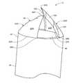
- FIG. 1Ais a side view of an embodiment of a bone harvester and bone marrow removal system.
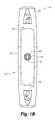
- FIG. 1Bis top view of a proximal portion of the bone harvester and bone marrow removal system of FIG. 1A .
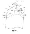
- FIG. 1Cis a perspective view of the bone harvester and bone marrow removal system of FIG. 1A showing an embodiment where a suction device is coupled to a bone marrow sample connector.
- FIG. 2Ais a side view of a distal portion of the bone harvester and bone marrow removal system of FIG. 1A showing a cutting tip.
- FIG. 2Bis a side view, rotated relative to the side view of FIG. 2A , of the distal portion of the bone harvester and bone marrow removal system of FIG. 1A showing the cutting tip.
- FIG. 2Cis a perspective view of the distal portion of the bone harvester and bone marrow removal system of FIG. 1A showing the cutting tip.
- FIG. 2Dis a cross-sectional view of a body of a bone harvester showing a blade of the cutting tip.
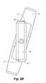
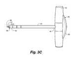
- FIG. 3Ais an exploded, perspective view of the bone harvester and bone marrow removal system of FIG. 1A including an embodiment of a stylet.
- FIG. 3Bis a top view of the stylet of FIG. 3A inserted within the bone harvester and bone marrow removal system of FIG. 3A .
- FIG. 3Cis a side view of the assembled bone harvester and bone marrow removal system of FIG. 3A including the stylet.
- FIG. 3Dis a cross-sectional view of FIG. 3C showing the assembled bone harvester and bone marrow removal system of FIG. 3A including the stylet.
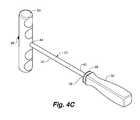
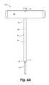
- FIG. 4Ais a perspective view of an embodiment of a sample removal device.
- FIG. 4Bis a perspective view of the sample removal device of FIG. 4A inserted into an embodiment of a bone harvester and bone marrow removal system from a first direction.
- FIG. 4Cis a perspective view of the sample removal device of FIG. 4A inserted into an embodiment of a bone harvester and bone marrow removal system from a second direction.
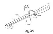
- FIG. 4Dis a perspective view of a second embodiment of a sample removal device and an embodiment of a bone harvester and bone marrow removal system.
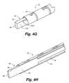
- FIG. 4Eis a perspective view of the sample removal device of FIG. 4D partially inserted into the bone harvester and bone marrow removal system of FIG. 4D .
- FIG. 4Fis a perspective view of the sample removal device of FIG. 4D fully inserted into the bone harvester and bone marrow removal system of FIG. 4D .
- FIG. 4Gis a perspective view of a tip of the sample removal device of FIG. 4D fully inserted into the bone harvester and bone marrow removal system of FIG. 4D .
- FIG. 4His a perspective cross-sectional view of the sample removal device of FIG. 4D fully inserted into the bone harvester and bone marrow removal system of FIG. 4D .
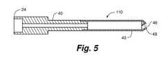
- FIG. 5is a cross-sectional view of another embodiment of a bone harvester device.
- FIG. 6Ais a plan view of an embodiment of a bone harvester with an integrated bone marrow needle.
- FIG. 6Bis a plan view of an embodiment of the bone marrow needle included in the bone harvester of FIG. 6A
- Some embodiments of the inventioninclude a bone harvester and bone marrow removal system.
- a bone harvester and bone marrow removal systemis useful for obtaining a sample of bone marrow, such as by aspiration, and harvesting bone during a medical procedure (e.g., a bone grafting or drilling procedure).
- a medical proceduree.g., a bone grafting or drilling procedure.
- Some embodimentscan allow a practitioner to obtain both bone and bone marrow samples making only one entrance through an outer layer of tissue.
- the systemallows for precise control and keeps components of the system concentric and aligned to the original and initial penetration hole.
- the systemallows for effective removal of a bone sample from the bone harvester.
- FIGS. 1A-1Cshow an embodiment of a bone harvester and bone marrow removal system 10 .
- FIG. 1Aillustrates a side view of the bone harvester and bone marrow removal system 10
- FIG. 1Billustrates a top view of a portion of the bone harvester and bone marrow removal system 10
- FIG. 1Cillustrates a perspective view of the bone harvester and bone marrow removal system 10 .
- the system 10can include a bone harvester device 20 with a port 24 adapted to receive a component.
- the componentis a bone marrow sample connector 30 .
- the bone harvester device 20includes a body 40 having a distal portion 42 and a proximal portion 44 .
- the distal and proximal portions 42 , 44can be integral or provided as separate joined members as desired.
- the body 40 of the bone harvester device 20can define a channel 46 (shown in FIG. 1B ) extending longitudinally through at least a portion of an interior of the body 40 . In the example shown, the channel 46 extends longitudinally through the body 40 from the distal portion 42 to the proximal portion 44 .
- the distal portion 42 of the body 40can include any tip useful for morselizing and/or removing bone.
- the distal portion 42includes a cutting tip 48 , which is shown and described in detail with reference to FIGS. 2A-D .
- the proximal portion 44 of the body 40may be adapted to be rotationally driven relative to bone, such as by manual or mechanical power. Such rotation may be oscillating or unidirectional.
- the proximal portion 44can include a driver 50 configured for rotatingly driving the body 40 relative to bone.
- the driver 50can be dimensioned to be gripped by a hand of a user (e.g., a handle, as shown).
- the driver 50 at the proximal portion 44can be adapted to be coupled to a mechanical driving device.
- the driver 50can be both dimensioned to be gripped by a hand of a user and adapted to be coupled to a mechanical driving device.
- the bone harvester devicemay be configured to receive various components (examples of which will be described herein). Such components may, in some applications, extend through port 24 .
- the portis aligned with the longitudinal axis of the body and the channel.
- componentscan be secured to the body 40 at the driver 50 .
- the driver 50 as shownincludes locking features 52 useful for securing a component to the body 40 at the driver 50 .
- Locking features 52are shaped so that the component can be rotatingly secured at the driver 50 by rotating the component in a first direction until an interference fit with the locking features 52 prevents further rotation of the component in the first direction.
- the componentmay be removed from the body 40 by rotating the component in a second direction, opposite the first direction, and thus away from the interference fit created by the locking features 52 .
- the driver 50can include, as is shown in FIG. 1B , symbols to indicate the direction of rotation of the component for unlocking the component from the driver 50 , and thus the body 40 .
- a component received and secured at the driver 50is further illustrated and described below with reference to FIGS. 3A-3E .
- the system 10may include a bone marrow sample connector 30 .
- the bone marrow sample connector 30can be in fluid communication with the channel 46 .
- the connector 30may be in fluid communication with the channel 46 at various locations along the body 40 to suit the environment in which the system 10 is desired to be used.
- the connector 30can be disposed at or near the proximal portion 44 of the body 40 .
- the connector 30is disposed at the driver 50 such that the connector 30 is in fluid communication with the channel 46 at the driver 50 .
- the connectoris aligned along a longitudinal axis of the body, which allows marrow to be drawn directly through the harvester to the connector.
- the connectorcan be engaged with the port 24 or be integrally formed with the bone harvester.
- the connector 30can in some embodiments include a threaded connector formed in the driver 50 .
- the bone marrow sample connector 30can include any structure useful for connecting an external device to the connector 30 , and thus also to the channel 46 .
- the connector 30can include a Luer-type connector.
- an external devicemay be coupled with the connector 30 to allow for an aspiration procedure as desired, such as drawing a bone marrow sample through the channel 46 from the proximal portion 42 to the external device coupled to the connector 30 .
- the external device coupled to the connector 30may be a suction device 54 useful for applying a vacuum (or suction force) within the channel 46 , such as a syringe.
- FIG. 1Cillustrates an example where the suction device 54 is connected to the connector 30 and in fluid communication with the channel 46 .
- pressure dropsare minimized as the marrow can be drawn directly from the bone into the suction device along a generally linear path.
- FIGS. 2A-2Dshow the cutting tip 48 of the bone harvester and bone marrow removal system 10 .
- FIG. 2Ais a side view of the distal portion 42 of the bone harvester and bone marrow removal system 10 showing the cutting tip 48 .
- FIG. 2Bis a side view, rotated approximately 90° relative to the side view of FIG. 2A , showing the cutting tip 48 .
- FIG. 2Cis a perspective view of the distal portion 42 showing the cutting tip 48 .
- FIG. 2Dis a cross-sectional view showing a blade of the cutting tip 48 .
- the cutting tip 48is included at the distal portion 42 of the body 40 and may be used for cutting bone. Embodiments of the cutting tip cut bone into particles and guide the particles through the channel and into the interior of the body where it is retained until it is removed for further use. In certain embodiments, the cutting tip can cut bone in both a single direction of rotation and an oscillating motion (e.g., +/ ⁇ 5 degrees to about +/ ⁇ 360 degrees). In the illustrated embodiment, the cutting tip 48 includes a first blade 60 A and a second blade 60 B, but in other embodiments the cutting tip 48 can include any number of blades as needed for a particular application.
- the blades 60 A and 60 Bmay be located on substantially opposite sides of the channel 46 from each other and may be mirror images of each other.
- the one or more blades 60 A, 60 Bmay be integral with the distal portion 42 of the body 40 , or in other embodiments the one or more blades 60 A, 60 B may be separately coupled to the distal portion 42 .
- Each blade 60 A, 60 Bcan include a respective base 62 A, 62 B, a respective apex 64 A, 64 B, and respective major inner surfaces 65 A, 65 B and major outer surfaces 67 A, 67 B. As shown, the major inner surfaces can be generally concave and the major outer surfaces can be generally convex.
- Each respective base 62 A, 62 Bmay be on a first end of each respective blade 60 A, 60 B, the first end being disposed at the distal portion 42 of the body 40 .
- Each base 62 A, 62 Bcan extend along a portion of a perimeter, defining the channel 46 , at the end of the distal portion 42 (e.g., a portion of a circumference at the end of the distal portion 42 where the body 40 defines a circular cross section) from a respective first edge 66 A, 66 B to a respective second edge 68 A, 68 B.
- one or more of such edgescan include a radius transition between the blade and the perimeter of the body.
- the perimeter of the distal portion 42can include one or more sections (e.g., two) without blades, such sections extending between bases 62 A, 62 B. In certain embodiments, such sections may include between about 10 and about 50% of the perimeter of the distal portion.
- Each respective apex 64 A, 64 Bmay be on a second end of each respective blade 60 A, 60 B, the second end being substantially opposite the first end in a distal direction spaced from the distal portion 42 .
- extending from each respective first edge 66 A, 66 B of each base 62 A, 62 B to a respective apex 64 A, 64 Bis a respective first surface 70 A, 70 B, which also interfaces with and extends between respective major inner surfaces 65 A, 65 B and respective major outer surfaces 67 A, 67 B.
- each respective second edge 68 A, 68 B of each base 62 A, 62 B to a respective apex 64 A, 64 Bis a respective second surface 72 A, 72 B, which also interfaces with and extends between respective major inner surfaces 65 A, 65 B and respective major outer surfaces 67 A, 67 B.
- each first surface 70 A, 70 Bincludes curvature in a direction from the respective first edge 66 A, 66 B toward the respective second edge 68 A, 68 B.
- Each respective apex 64 A, 64 Bcan be disposed aft, in a direction along the perimeter defining the channel 46 at the end of the distal portion 42 , of each respective first edge 66 A, 66 B.
- along at least a portion of each second surface 72 A, 72 Ba curvature is included in a direction aft of each respective second edge 68 A, 68 B.
- the respective apex 64 A, 64 Bcan also be disposed aft of the respective second edge 68 A, 68 B (shown, for example, in FIG. 2C ).
- each respective blade 60 A, 60 Bcan extend inwards towards a centerline of the channel in a direction from the respective base 62 A, 62 B to the respective apex 64 A, 64 B.
- the curvature of the major inner surface 65 A, 65 B, the curvature along the first surface 70 A, 70 B, and/or the curvature along the second surface 72 A, 72 Bcan be in a direction radially inward relative to the end of the distal portion 42 where the respective bases 62 A, 62 B are disposed such that the curvature extends in a radial direction over the channel 46 .
- each apex 64 A, 64 Bextends radially inward relative to the end of the distal portion 42 , where the respective bases 62 A, 62 B are disposed, defining the channel 46 such that the respective apex 64 A, 64 B extends over at least a portion of the channel 46 (shown, for example, in FIGS. 2A and 2C ).
- each apexmay extend from the perimeter of the distal portion 42 of the body 40 toward a centerline of the channel 46 at least 25 percent of the diameter of the channel.
- each surfacecan be useful for morselizing bone and/or guiding morselized bone into the channel.
- curvaturemay have a relatively constant radius of curvature across the surface or the radius of curvature may vary across the surface.
- the first surface 70 A, 70 B and/or the second surface 72 A, 72 Bcan include a discontinuity along the surface, such as where the surfaces changes from generally flat to concave or convex, from concave to convex, or from convex to concave.
- both first surfaces 70 A and 70 Binclude a depression section 74 A, 74 B along a portion of the first surfaces 70 A and 70 B, such depression being generally concave.
- lines of demarcationrepresent the transition between the planes of surfaces 70 B and 72 B, surface 70 B and section 74 B, and between surfaces 70 B, 72 B, section 74 B, and surface 65 B.
- outer edges 75 B and 77 Bcan be sharp cutting edges.
- outer edges 75 B and 77 Bare separated by apex 64 B and respectively extend from the apex 64 B to second edge 68 B and first edge 66 B.
- edge 75 Bmay include a curvature
- edge 77 Bmay include a compound curvature.
- the described configuration of the cutting tip 48can be useful in applications where the system 10 is to be used for cutting bone.
- the system 10can be placed in a manner to allow the distal portion, and in particular the cutting tip 48 , to contact bone at an incision.
- the system 10can be rotationally driven in a direction to cut bone. Rotation in this manner along with the described configuration of each blade 60 A, 60 B may useful for guiding portions of bone being cut (e.g. morselized bone) into the channel 46 .
- the channel 46can then be used to retain the morselized bone as additional bone continues to be cut at the incision as desired.
- morselized boneincludes a plurality of non-homogenous bone particles, and can be distinguished from homogenous bone core or plug samples.
- FIGS. 3A-3Dshow an embodiment of the bone harvester and bone marrow removal system 10 including an embodiment of a stylet 80 , as an example of one component.
- FIG. 3Ais an exploded, perspective view of the system 10 including an embodiment of the stylet 80 .
- FIG. 3Bis a plan view of the stylet 80 inserted within the system 10 .
- FIG. 3Cis side view of the assembled system 10 to include the stylet 80 .
- FIG. 3Dis a cross-sectional view of FIG. 3C showing the assembled system 10 including the stylet 80 .
- the stylet 80has a distal end 82 and a proximal end 84 .
- the distal end 82can include a pointed tip 86 and at least one cutting edge 87
- the proximal end 84can include a securing surface 88 .
- the pointed tipcan include a triangular shape useful for initially piercing the bone and cutting the bone with the at least one cutting edge as the pointed tip is rotated.
- the stylet 80can be adapted to be inserted within the body 40 .
- the stylet 80can be disposed at least partially within the channel 46 , such as by first inserting the distal end 82 through the port 24 and further inserting the stylet 80 within the channel 46 through the port 24 until the securing surface 88 at the proximal end 84 contacts the driver 50 .
- the securing surface 88can be locked in place at the driver 50 , and thus secured to the proximal portion 44 of body 40 , such as by rotating the securing surface 88 in a first direction so as to create an interference fit with the locking features 52 at the driver 50 .
- the securing surface 88may include locking features 89 adapted to mate with the locking features 52 of the driver 50 and create the interference fit in the first direction of rotation of the securing surface 88 .
- the proximal end 84may include threads for engaging corresponding threads of the port 24 for securing the stylet 80 to the body 40 . In this manner, the proximal end 84 of the style 80 is similarly secured to the proximal portion 44 of the body 40 .
- various other configurationsare also possible for securing the stylet 80 to the body 40 .
- the stylet 80can be received within and secured to the body 40 (e.g., via the port 24 ), such as at the proximal portion 44 via the driver 50 .
- the stylet 80is dimensioned such that when the stylet 80 is secured to the body 40 , and thus a portion of the stylet 80 is within the channel 46 , the pointed tip 86 of the stylet 80 extends out from the body 40 (and thus extends out from the channel 46 defined by the body 40 ).
- a distal end of the pointed tip 86 of the stylet 80can be configured to extend out from the distal portion 42 of the body 40 beyond the apex 64 A of the blade of the cutting tip 48 .
- the pointed tip 86 of the stylet 80can be the first point of contact with bone when the system 10 is positioned at an incision.
- the styletcan be received within depression sections 74 A, 74 B of each respective blade 60 A, 60 B (such sections being shown in FIGS. 2A and D).
- the styletcan be generally cylindrical, and a surface of the cylinder can contact sections 74 A and 74 B for stabilization of the stylet near its distal end 82 during piercing and cutting of bone.
- the stylet 80may be utilized in the system 10 during a portion of a procedure, such as during an initial insertion of the system 10 at an incision and prior to a bone marrow sample drawing portion of a procedure.
- the pointed tip 86can be used to make an initial piercing through bone, optionally rotated to cut bone, and after the stylet 80 has been advanced into the bone to a desired depth the stylet 80 may be unsecured from the body 40 and removed from the body 40 so as to open the channel 46 to allow portions of bone and/or bone marrow to pass into the channel 46 .
- the pointed tip 86 of the stylet 80can work in conjunction with the cutting tip 48 of the body 40 to anchor the system 10 at the desired location at the incision and resist undesired sliding movement of the system 10 with respect to the bone.
- the stylet 80can be unsecured from the body 40 and removed from the body 40 such that the channel 46 is open and able to receive portions of bone and/or bone marrow.
- FIG. 4Ashows a perspective view of an embodiment of a sample removal device 90 .
- the bone harvester and bone marrow removal systemcan cut bone and guide the morselized bone within the channel of the body of the system.
- the sample removal device 90may be useful for removing a sample, such as a bone sample, from within the body (e.g., retained in the channel).
- the device 90has a distal end 92 , a proximal end 94 , and a longitudinal axis L extending from the distal end 92 to the proximal end 94 .
- the distal end 92 of the device 90can include, in some embodiments, a contact surface 96 configured to engage with a sample and push it out from the body of the system.
- the contact surface 96can also be configured to avoid interference with the cutting tip of the body of the system.
- the contact surface 96may extend substantially perpendicular to the longitudinal axis L of the device 90 .
- the contact surface 96can still be inserted within the channel without interference from the one or more blades. Yet, the perpendicular configuration of the contact surface 96 still allows the contact surface 96 to contact substantially all of the sample along a width of the channel of the body so as to efficiently remove the sample.
- the proximal end 94 of the device 90can include a handle as shown.
- the device 90is also shown to include a disc 98 on the device 90 .
- the disc 98can be slidingly retained along the device 90 , such as along a shaft of the device 90 , allowing the disc 98 to be advanced along the device 90 during a sample removal procedure.
- FIGS. 4B and 4Cshow perspective views of the sample removal device 90 inserted into the bone harvester and bone marrow removal system 10 from opposite ends of the system 10 .
- FIG. 4Bshows the device 90 inserted at a proximal portion 44 of the body 40 .
- the device 90can be inserted at the proximal portion 44 through the bone marrow sample connector at the driver 50 and into the channel defined by the body 40 .
- the device 90may be dimensioned so as to have a length that allows the distal end 92 of the device 90 to extend out from the distal portion 42 of the body 40 when the device 90 is inserted within the body 40 .
- a sample retained within the channel of the body 40will be pushed through the channel as the device 90 is continually advanced through the body 40 from the proximal portion 44 to the distal portion 42 .
- the samplecan thus be pushed out from the body 40 at the distal portion 42 through the cutting tip 48 .
- the contact surface 96 on the distal end 92allows the distal end 92 to avoid interference with the blades at the cutting tip 48 so as to allow substantially all of the sample retained within the body 40 to be pushed out.
- FIG. 4Cshows the device 90 inserted at a distal portion 42 of the body 40 .
- the device 90can be inserted at the distal portion 42 of the body 40 through the cutting tip 48 as is shown.
- the contact surface 96may be configured to avoid interference with the blades at the cutting tip 48 .
- the contact surface 96can be advanced within the body 40 to push the sample retained within the body 40 (e.g., within the channel) from the distal portion 42 out the proximal portion 44 , such as at the bone marrow sample connector.
- the disc 98can slide along the device 90 as the device 90 is advanced within the body 40 , and may reduce undesired contact with the cutting tip 48 when the device 90 is inserted through the distal region 42 as shown in FIG. 4C .
- FIG. 4Dshows a perspective view of a second embodiment of a sample removal device 90 , which can also be used to remove a retained sample from a body 40 of a bone harvester 20 , as described with respect to the embodiment shown in FIGS. 4A-C .
- the device 90has a distal end 92 , a proximal end 94 , and a longitudinal axis L extending from the distal end 92 to the proximal end 94 .
- the distal end 92 of the device 90can include a contact surface 96 configured to engage with a sample and push it out from the bone harvester body 40 .
- the contact surface 96can also be configured to avoid interference with a cutting tip of the bone harvester.
- the contact surface 96may extend substantially perpendicular to the longitudinal axis L of the device 90 .
- the perpendicular configuration of the contact surface 96still allows the contact surface 96 to contact substantially all of the sample along a width of the channel of the body so as to efficiently remove the sample.
- the proximal end 94 of the device 90can include a handle as shown.
- corresponding radial alignment indicatorse.g., notches
- Such indicatorsprovide a visual guide to the user to facilitate radial alignment of the device 90 with respect to the bone harvester 20 during use to reduce interference between the contact surface 96 and blades of the bone harvester.
- FIG. 4Edepicts the device 90 partially inserted into the bone harvester 20
- FIG. 4Fdepicts the device 90 fully inserted into the bone harvester 20 , with the radial alignment indicators 100 A, 100 B aligned. As shown in FIG.
- a portion of the distal end 92extends out of the channel of the bone harvester body 40 and is radially aligned with respect to the body 40 to avoid interference with blades 60 A or 60 B ( 60 B not shown in FIG. 4F ).
- FIGS. 4G and 4Hshow a perspective view and a perspective cross-sectional view, respectively, of the distal end 92 of the device 90 fully inserted into a bone harvester 20 .
- the leading contact surface 96is part of a paddle 102 on the distal end 92 of the device 90 .
- the paddle 102has a portion that resides within the channel 46 and a portion that resides distally beyond the bone harvester 20 when the device 90 is fully inserted into the bone harvester. Such a paddle 102 is useful for reducing binding between the device 90 and bone harvester 20 during use.
- both a bone sample and a bone marrow samplecan be obtained at a single location (e.g., a single incision).
- a styletcan be inserted within at least a portion of the channel defined by the body prior to cutting bone at the incision.
- the styletcan be inserted within the channel such that a pointed tip of the stylet extends out from the channel at the distal portion of the body, allowing the pointed tip of the stylet to be the first point of contact with bone.
- the styletcan, for example, be used penetrate an outer cortex of a bone. Then, while the pointed tip of the stylet contacts bone, the distal portion of the body, including the cutting tip at the distal portion of the body, can be aligned at the incision.
- Bonecan then be cut (e.g., morselized) at the first incision, in embodiments with or without the stylet, by causing the bone harvester to be rotationally driven.
- the bone being cutcan be bone material surrounding an initial bone piercing caused by the stylet.
- the bonecan be morselized using the cutting tip at the distal portion of the body, and the morselized bone may be directed into the channel of the body using the blades of the cutting tip.
- the styletcan be removed once bone has begun to be cut so as to open the channel for receiving the morselized bone.
- This morselized bonecan be continually directed into the channel and retained within the channel during cutting.
- the morselized bone retained within the channelcan be removed from the body by inserting a sample removal device within the channel. The sample removal device can be used to push the retained bone out from the channel.
- the bone harvester and bone marrow removal systemcan also be used to draw a bone marrow sample at the single incision (the same location where the bone is cut). This can be done, in one instance, by advancing the cutting tip of the bone harvester to a desired depth via continual rotation of the body.
- the bone marrow samplecan be drawn after the morselized bone has been removed from the channel.
- the bone marrow samplecan be drawn from a bone marrow sample connector in fluid communication with the channel of the body.
- the bone marrow samplemay be, in one embodiment, on a proximal portion of the body opposite the cutting tip.
- the bone marrow samplecan be drawn, for instance, by connecting a suction device to the bone marrow sample connector such that the suction device is in fluid communication with the channel of the body allowing the bone marrow sample to be passed through at least a portion of the channel using the suction device.
- the morselized bone and the bone marrow sample from the incisioncan be mixed (e.g., to form a bone matrix compound) and introduced at a location spaced from the incision.
- some such embodimentscan include cutting bone at the location spaced from the incision using the bone harvester or any other suitable cutting device, and injecting the morselized bone and bone marrow mixture at the cut location spaced from the incision.
- a bone platecan be fixed at or near the location spaced from the incision where the bone is cut.
- FIG. 5illustrates a cross-section view of another embodiment of a bone harvester device 110 .
- the bone harvester device 110can have similar features as those described previously, except that the bone harvester device 110 does not have a bone marrow sample connector.
- the device 110can be used to cut bone similar to the manner described previously such that bone is morselized by the cutting tip 48 and morselized bone is directed into the interior channel 46 of the body 40 .
- the bone retained within the channel 46can similarly be removed using a sample removal device.
- FIGS. 6A-6Billustrate another embodiment of a bone harvester device 120 .
- FIG. 6Ashows a plan view of the bone harvester 120 including a bone marrow needle 130 disposed within a channel of the body
- FIG. 6Bshows a plan view of the bone marrow needle 130 in isolation.
- the bone harvester 120can have similar features to those described previously.
- the bone harvester 120can draw bone marrow from the same location (e.g., incision) where bone is cut using the bone harvester 120 by using the bone marrow needle 130 .
- the bone marrow needle 130can be disposed partially within the channel 46 defined by the body 40 .
- the bone marrow needle 130can have a body 140 with a proximal end 150 and a distal end 160 .
- the body 140can define a lumen 170 extending longitudinally within the body 140 from the proximal end 150 to the distal end 160 .
- the distal end 160 of the needle 130can include a cutting edge 180 .
- the needle 130can be dimensioned relative to the body 40 , of the bone harvester 20 , such that the cutting edge 180 on the distal end 160 extends out from the distal portion 42 of the body 40 .
- the needle 130can include a connector 190 for securing the needle 130 to the body 40 , such as at the proximal portion 44 , and in some examples at the driver 50 .
- the connector 170is a compression fit connector in the proximal portion 44 of the body 40 .
- the connector 170includes a compressible O-ring positioned about an exterior surface of the needle and in apposition to an aperture defined by the driver 50 .
- the channel 46 defined by the body 40can also facilitate centering and stabilization of the needle 130 .
- the needle 130can also include a connector 200 for coupling to an external device or a stylet similar to that described previously.
- the styletcan be disposed within the lumen 170 of the needle 130 , and the needle 130 can be disposed within the channel 46 of the body 40 . Furthermore, the stylet may be removed from the lumen 170 independent of the needle 130 .
- the stylet, needle 130 , and body 40can be dimensioned such that the distal end of the stylet extends out from the distal end 160 of the needle 130 , and the distal end 160 of the needle 130 extends out from the distal portion 42 of the body 40 .
- Embodiments of the inventionalso include a disposable, sterile kit that includes an embodiment of a bone harvester described herein.
- Other components that may be included within the sterile kitinclude a suction device, a stylet, a sample removal device, and/or a bone marrow needle.
- the needle 130can be used to draw a bone marrow sample from the incision where bone is cut, while the needle 130 is within the body 40 .
- the bone marrow samplecan be drawn at the cutting edge 180 up into the lumen 170 where the sample can be retained.
Landscapes
- Health & Medical Sciences (AREA)
- Life Sciences & Earth Sciences (AREA)
- Biomedical Technology (AREA)
- Veterinary Medicine (AREA)
- Heart & Thoracic Surgery (AREA)
- Engineering & Computer Science (AREA)
- Animal Behavior & Ethology (AREA)
- General Health & Medical Sciences (AREA)
- Public Health (AREA)
- Orthopedic Medicine & Surgery (AREA)
- Surgery (AREA)
- Vascular Medicine (AREA)
- Hematology (AREA)
- Medical Informatics (AREA)
- Molecular Biology (AREA)
- Transplantation (AREA)
- Pathology (AREA)
- Nuclear Medicine, Radiotherapy & Molecular Imaging (AREA)
- Anesthesiology (AREA)
- Physical Education & Sports Medicine (AREA)
- Cardiology (AREA)
- Oral & Maxillofacial Surgery (AREA)
- Immunology (AREA)
- Rheumatology (AREA)
- Surgical Instruments (AREA)
- Sampling And Sample Adjustment (AREA)
Abstract
Description
Claims (21)
Priority Applications (3)
| Application Number | Priority Date | Filing Date | Title |
|---|---|---|---|
| US14/724,072US9925068B2 (en) | 2014-05-30 | 2015-05-28 | Bone harvester and bone marrow removal system and method |
| US15/894,686US11020244B2 (en) | 2014-05-30 | 2018-02-12 | Bone harvester and bone marrow removal system and method |
| US17/335,046US12257163B2 (en) | 2014-05-30 | 2021-05-31 | Bone harvester and bone marrow removal system and method |
Applications Claiming Priority (4)
| Application Number | Priority Date | Filing Date | Title |
|---|---|---|---|
| US201462005693P | 2014-05-30 | 2014-05-30 | |
| US201462040210P | 2014-08-21 | 2014-08-21 | |
| US201462051499P | 2014-09-17 | 2014-09-17 | |
| US14/724,072US9925068B2 (en) | 2014-05-30 | 2015-05-28 | Bone harvester and bone marrow removal system and method |
Related Child Applications (1)
| Application Number | Title | Priority Date | Filing Date |
|---|---|---|---|
| US15/894,686DivisionUS11020244B2 (en) | 2014-05-30 | 2018-02-12 | Bone harvester and bone marrow removal system and method |
Publications (2)
| Publication Number | Publication Date |
|---|---|
| US20150342756A1 US20150342756A1 (en) | 2015-12-03 |
| US9925068B2true US9925068B2 (en) | 2018-03-27 |
Family
ID=54700475
Family Applications (3)
| Application Number | Title | Priority Date | Filing Date |
|---|---|---|---|
| US14/724,072ActiveUS9925068B2 (en) | 2014-05-30 | 2015-05-28 | Bone harvester and bone marrow removal system and method |
| US15/894,686Active2036-06-25US11020244B2 (en) | 2014-05-30 | 2018-02-12 | Bone harvester and bone marrow removal system and method |
| US17/335,046Active2037-10-30US12257163B2 (en) | 2014-05-30 | 2021-05-31 | Bone harvester and bone marrow removal system and method |
Family Applications After (2)
| Application Number | Title | Priority Date | Filing Date |
|---|---|---|---|
| US15/894,686Active2036-06-25US11020244B2 (en) | 2014-05-30 | 2018-02-12 | Bone harvester and bone marrow removal system and method |
| US17/335,046Active2037-10-30US12257163B2 (en) | 2014-05-30 | 2021-05-31 | Bone harvester and bone marrow removal system and method |
Country Status (1)
| Country | Link |
|---|---|
| US (3) | US9925068B2 (en) |
Cited By (11)
| Publication number | Priority date | Publication date | Assignee | Title |
|---|---|---|---|---|
| US11344321B2 (en) | 2017-06-05 | 2022-05-31 | Conmed Corporation | Multi-barrel drill guide |
| US11471173B2 (en) | 2017-06-05 | 2022-10-18 | Conmed Corporation | Multi-barrel drill guide and anchor deployment assembly |
| US11523834B1 (en) | 2022-06-20 | 2022-12-13 | University Of Utah Research Foundation | Cartilage and bone harvest and delivery system and methods |
| US11660194B1 (en) | 2022-06-20 | 2023-05-30 | University Of Utah Research Foundation | Cartilage and bone harvest and delivery system and methods |
| US12023047B1 (en) | 2023-07-14 | 2024-07-02 | University Of Utah Research Foundation | Cannulated trephine |
| US12208194B2 (en) | 2018-06-13 | 2025-01-28 | Stryker European Operations Limited | Bone fragment collector and processor |
| US12274629B2 (en) | 2019-12-18 | 2025-04-15 | Stryker European Operations Limited | Bone fragment collector and processor |
| US12364528B2 (en) | 2021-06-17 | 2025-07-22 | Wright Medical Technology, Inc. | Minimally invasive surgery osteotomy fragment shifter, stabilizer, and targeter |
| US12364523B2 (en) | 2017-10-27 | 2025-07-22 | Wright Medical Technology, Inc. | Implant with intramedullary portion and offset extramedullary portion |
| US12419673B2 (en) | 2012-03-01 | 2025-09-23 | Wright Medical Technology, Inc. | Surgical staple |
| US12433606B2 (en) | 2019-05-13 | 2025-10-07 | Wright Medical Technology, Inc. | Surgical tools and methods of use |
Families Citing this family (28)
| Publication number | Priority date | Publication date | Assignee | Title |
|---|---|---|---|---|
| US10912573B2 (en)* | 2015-03-20 | 2021-02-09 | Shukla Medical | Intramedullary canal reamer |
| WO2018075694A1 (en) | 2016-10-18 | 2018-04-26 | Piper Access, Llc | Intraosseous access devices, systems, and methods |
| EP3528723B1 (en) | 2016-10-27 | 2023-08-16 | C. R. Bard, Inc. | Intraosseous access device |
| EP3578121B1 (en)* | 2017-01-31 | 2022-05-04 | Transell Co., Ltd. | Puncturing instrument and puncturing device |
| JP7169982B2 (en) | 2017-03-07 | 2022-11-11 | パイパー・アクセス、エルエルシー | Safety shields for elongated instruments and related systems and methods |
| CA3050963A1 (en) | 2017-03-10 | 2018-09-13 | Piper Access, Llc. | Securement devices, systems, and methods |
| US11655454B1 (en)* | 2017-03-23 | 2023-05-23 | Elite IP, LLC | Method and apparatus for improved mesenchymal stem cell harvesting |
| US20180333542A1 (en)* | 2017-05-22 | 2018-11-22 | Sean Fitzsimmons | Joint aspiration device |
| ES2953372T3 (en) | 2018-02-20 | 2023-11-10 | Piper Access Llc | Drilling devices and related methods |
| CN109381226B (en)* | 2018-07-30 | 2021-01-26 | 郑州大学第一附属医院 | Bone marrow puncture and extraction device for hematology department |
| CA3141618A1 (en) | 2019-06-03 | 2020-12-10 | Great Plains Imaging Llc | Method of performing a minimally invasive carpal tunnel release using an interventional radiology procedure |
| WO2020247656A1 (en)* | 2019-06-04 | 2020-12-10 | Great Plains Imaging Llc | Medical instrument for interventional radiology procedure |
| EP4027922A4 (en) | 2019-09-13 | 2023-10-04 | MIOS Marketing LLC, DBA RedPoint Medical 3D | Patient-specific surgical methods and instrumentation |
| US11986251B2 (en) | 2019-09-13 | 2024-05-21 | Treace Medical Concepts, Inc. | Patient-specific osteotomy instrumentation |
| CN212879457U (en) | 2019-09-27 | 2021-04-06 | 巴德阿克塞斯系统股份有限公司 | Self-advancing intraosseous access device and intraosseous access device |
| US11759235B2 (en) | 2019-09-27 | 2023-09-19 | Bard Access Systems, Inc. | Constant-torque intraosseous access devices and methods thereof |
| WO2021062215A1 (en) | 2019-09-27 | 2021-04-01 | Bard Access Systems, Inc. | Step needle for intraosseous access device |
| CN212879505U (en) | 2019-09-27 | 2021-04-06 | 巴德阿克塞斯系统股份有限公司 | Intraosseous access device |
| CN113317840A (en) | 2020-02-28 | 2021-08-31 | 巴德阿克塞斯系统股份有限公司 | Flexible intra-osseous obturator |
| WO2021216521A1 (en) | 2020-04-21 | 2021-10-28 | Bard Access Systems , Inc. | Reusable push-activated intraosseous access device |
| CN113749724A (en) | 2020-06-03 | 2021-12-07 | 巴德阿克塞斯系统股份有限公司 | Intraosseous device including sensing obturator |
| CN216167681U (en) | 2020-07-17 | 2022-04-05 | 巴德阿克塞斯系统股份有限公司 | Safety mechanism |
| CN216628654U (en) | 2020-08-25 | 2022-05-31 | 巴德阿克塞斯系统股份有限公司 | Angled intraosseous access system |
| CN215839325U (en) | 2020-09-09 | 2022-02-18 | 巴德阿克塞斯系统股份有限公司 | Suction device for an intraosseous access system |
| CN217960227U (en) | 2021-02-08 | 2022-12-06 | 巴德阿克塞斯系统股份有限公司 | Intraosseous access system |
| CN114209366B (en)* | 2021-12-24 | 2024-04-26 | 宁波华科润生物科技有限公司 | Bone taking biopsy instrument |
| USD1036670S1 (en)* | 2022-02-21 | 2024-07-23 | Bionix, Llc | Curette tip |
| WO2023249964A1 (en)* | 2022-06-20 | 2023-12-28 | University Of Utah Research Foundation | Cartilage and bone harvest and delivery system and methods |
Citations (160)
| Publication number | Priority date | Publication date | Assignee | Title |
|---|---|---|---|---|
| US4543966A (en)* | 1981-06-10 | 1985-10-01 | Downs Surgical Plc | Biopsy needle |
| US5782835A (en)* | 1995-03-07 | 1998-07-21 | Innovasive Devices, Inc. | Apparatus and methods for articular cartilage defect repair |
| US6080115A (en) | 1999-02-24 | 2000-06-27 | Rubinstein; Alan I. | Bone marrow biopsy needle |
| CA2360867A1 (en) | 1999-02-03 | 2000-08-10 | James M. Green | Surgical reamer and method of using same |
| DE20010879U1 (en) | 2000-06-19 | 2000-10-19 | Peter Pflugbeil GmbH, 85604 Zorneding | Biopsy needle with removal system |
| DE20109331U1 (en) | 2000-05-27 | 2001-08-09 | Karl Storz GmbH & Co. KG, 78532 Tuttlingen | Device for removing cancellous bone from a bone |
| US6312394B1 (en) | 2000-04-25 | 2001-11-06 | Manan Medical Products, Inc. | Bone marrow biopsy device |
| DE10042035A1 (en) | 2000-08-26 | 2002-03-14 | Daum Gmbh I Ins | Bone marrow examination appliance comprises operating duct, swivel adjustment unit with external arm, and biopsy needle |
| EP1210911A2 (en) | 2000-11-23 | 2002-06-05 | Anwarul Islam | Bone marrow biopsy needle |
| US6416484B1 (en) | 2000-03-24 | 2002-07-09 | Promex, Inc. | Biopsy extractor |
| US6443910B1 (en) | 2000-04-18 | 2002-09-03 | Allegiance Corporation | Bone marrow biopsy needle |
| US6450973B1 (en) | 2000-06-16 | 2002-09-17 | Kieran P. J. Murphy | Biopsy gun |
| US6478751B1 (en) | 2000-04-18 | 2002-11-12 | Allegiance Corporation | Bone marrow aspiration needle |
| US20020169471A1 (en) | 2001-04-16 | 2002-11-14 | Kyphon Inc. | Insertion devices and method of use |
| US6554778B1 (en) | 2001-01-26 | 2003-04-29 | Manan Medical Products, Inc. | Biopsy device with removable handle |
| US20030236506A1 (en) | 2002-06-20 | 2003-12-25 | Eric Schofield | Dual outside diameter cannula for insertion into bone |
| EP1396230A1 (en) | 2002-09-09 | 2004-03-10 | Paolo Avaltroni | Improved needle instrument for taking osteomedullary bioptical samples |
| US20040073139A1 (en) | 2002-10-11 | 2004-04-15 | Hirsch Joshua A. | Cannula for extracting and implanting material |
| US6755793B2 (en) | 2000-07-29 | 2004-06-29 | Worldwide Medical Technologies | Bone marrow extraction tool |
| US20040127814A1 (en) | 2002-12-12 | 2004-07-01 | Carlos Negroni | Biopsy assembly |
| DE60101003T2 (en) | 2001-07-04 | 2004-07-15 | Zambelli, Flavio Augusto, Rho | Bone biopsy device and associated manufacturing method |
| US20040153005A1 (en) | 2002-01-03 | 2004-08-05 | Krueger John A. | Bone marrow aspiration device with curved tip |
| US6783533B2 (en) | 2001-11-21 | 2004-08-31 | Sythes Ag Chur | Attachable/detachable reaming head for surgical reamer |
| US6783532B2 (en) | 1999-02-02 | 2004-08-31 | Synthes (Usa) | Device for removing bone tissue |
| WO2004082484A1 (en) | 2003-03-18 | 2004-09-30 | Carlo Bianchini | Device for bone marrow biopsy |
| US6827692B2 (en) | 2000-07-24 | 2004-12-07 | Pietro Castellacci | Needle of the biopsy type or for taking other samples from human or animal organs |
| US20040267268A1 (en) | 1999-11-23 | 2004-12-30 | Nuvasive, Inc. | Bone graft harvester and related methods |
| GB2403419A (en) | 2003-07-04 | 2005-01-05 | Pa Holdings Ltd | Tissue extraction tool |
| US6849051B2 (en) | 2001-08-03 | 2005-02-01 | Stemsource Llc | Devices and methods for extraction of bone marrow |
| WO2005009246A1 (en) | 2003-07-28 | 2005-02-03 | Enrico Malagoli | Needle instrument for transcutaneous biopsy of bone marrow tissues |
| US6875219B2 (en) | 2003-02-14 | 2005-04-05 | Yves P. Arramon | Bone access system |
| US6875183B2 (en) | 1999-03-19 | 2005-04-05 | Paul Laurence Cervi | Biopsy needle |
| US6884245B2 (en) | 2002-04-22 | 2005-04-26 | Spranza, Iii Joseph John | Hardware for cutting bone cores |
| US6890308B2 (en) | 2003-06-03 | 2005-05-10 | Abul Bashar Mohammed Anwarul Islam | Bone marrow biopsy needle |
| US6916292B2 (en) | 2002-07-12 | 2005-07-12 | Depuy Spine, Inc. | Bone marrow aspirator |
| US20050256425A1 (en) | 2004-05-11 | 2005-11-17 | Inpro Biotechnology, Inc. | Device, system and method for extracting and preparing brain tissue |
| US20050267383A1 (en) | 2002-10-22 | 2005-12-01 | Groenke Gregory C | Biopsy device handle assembly |
| US20060058826A1 (en) | 2004-08-25 | 2006-03-16 | Evans Avery J | Tissue cavitation device |
| US7014614B2 (en) | 2000-07-20 | 2006-03-21 | H.S. Hospital Service S.P.A. | Device for transcutaneous biopsy |
| US7033324B2 (en) | 2000-12-28 | 2006-04-25 | H.S. Hospital Service S.P.A. | Apparatus for transcutaneous biopsy of rigid tissues in particular osteomedullary tissue |
| US7077846B2 (en) | 2001-03-26 | 2006-07-18 | C.G.M. S.P.A | Device for withdrawing flakes or shavings from a donor bone by scraping |
| US7081123B2 (en)* | 2002-06-18 | 2006-07-25 | Musculoskeletal Transplant Foundation | Bone marrow aspiration instrument |
| US7115100B2 (en) | 2002-11-15 | 2006-10-03 | Ethicon, Inc. | Tissue biopsy and processing device |
| US20060247552A1 (en) | 2001-08-09 | 2006-11-02 | Jimro Co., Ltd. | Bone marrow harvesting set and bone marrow harvesting needle |
| US20060276772A1 (en) | 2005-06-06 | 2006-12-07 | Sherwood Services Ag | Bayonet release of safety shield for needle tip |
| JP3877982B2 (en) | 2001-07-17 | 2007-02-07 | 株式会社八光 | Biomedical cement injection device with tissue collection function |
| US7179232B2 (en) | 2003-06-27 | 2007-02-20 | Depuy Acromed, Inc. | Controlled orifice sampling needle |
| US20070055263A1 (en) | 2005-07-29 | 2007-03-08 | X-Sten Corp. | Tools for Percutaneous Spinal Ligament Decompression and Device for Supporting Same |
| US20070055282A1 (en) | 2003-03-31 | 2007-03-08 | The Cleveland Clinic Foundation | Apparatus and method for harvesting bone marrow |
| US20070055264A1 (en) | 2005-08-05 | 2007-03-08 | C.G.M. S.P.A. | Surgical tool for scraping and collecting bone particles |
| US20070060935A1 (en) | 2005-07-11 | 2007-03-15 | Schwardt Jeffrey D | Apparatus and methods of tissue removal within a spine |
| US20070066987A1 (en) | 2005-09-09 | 2007-03-22 | Scanlan Donald L Jr | Bone navigation probes |
| US7201722B2 (en) | 2000-04-18 | 2007-04-10 | Allegiance Corporation | Bone biopsy instrument having improved sample retention |
| US20070100286A1 (en) | 2005-11-01 | 2007-05-03 | Eltahawy Hazem A | Needle assembly for radiating bioactive compounds through tissue |
| US7214059B2 (en) | 2001-03-06 | 2007-05-08 | Atsushi Takahashi | Bone collecting device |
| US7238189B2 (en) | 2003-03-18 | 2007-07-03 | Arthrex, Inc. | ACL reconstruction technique using retrodrill |
| US20070179459A1 (en) | 2006-01-18 | 2007-08-02 | Fred Geisler | Vertebral body aspirator |
| US20070198043A1 (en) | 2006-02-22 | 2007-08-23 | Cox Daniel L | Bone marrow aspiration device |
| US20070208348A1 (en) | 2006-03-02 | 2007-09-06 | C.G.M. S.P.A. | Surgical instrument for scraping and collecting bone particles |
| US7278972B2 (en) | 2002-01-24 | 2007-10-09 | Worldwide Medical Technologies, Llc | Combined bone marrow aspiration and core biopsy device |
| US7278970B2 (en) | 2003-07-29 | 2007-10-09 | Goldenberg Alec S | Biopsy needles |
| US7294132B2 (en) | 2002-10-03 | 2007-11-13 | Wright Medical Technology, Inc. | Radially ported needle for delivering bone graft material and method of use |
| US20070282220A1 (en) | 2006-06-01 | 2007-12-06 | Abernathie Dennis L | Device and method for button fusion |
| US20070293788A1 (en) | 2006-06-19 | 2007-12-20 | Vita Special Purpose Corporation | Bone harvest system |
| US7331930B2 (en) | 2001-10-30 | 2008-02-19 | Movdicé Holding, Inc. | Biopsy/access tool |
| US20080045965A1 (en)* | 2002-05-31 | 2008-02-21 | Miller Larry J | Apparatus and Methods for Biopsy and Aspiration of Bone Marrow |
| US20080058674A1 (en) | 2006-08-29 | 2008-03-06 | Lex Jansen | Tissue extraction device and method of using the same |
| US20080119821A1 (en) | 2006-11-17 | 2008-05-22 | Warsaw Orthopedic, Inc. | Multiport Cannula |
| US20080119759A1 (en) | 2006-11-21 | 2008-05-22 | The Cleveland Clinic Foundation | Method and apparatus for aspirating bone marrow |
| US20080139961A1 (en) | 2004-07-23 | 2008-06-12 | Borhane Slama | Osteomedullar Biopsy Trocar |
| US20080214957A1 (en) | 2003-06-12 | 2008-09-04 | Yvan Verra | Bone Marrow Aspiration Trocar |
| US20080221527A1 (en) | 2006-08-23 | 2008-09-11 | Arthrex, Inc. | Arthroscopic harvesting and therapeutic application of bone marrow aspirate |
| US20080243163A1 (en) | 2004-12-08 | 2008-10-02 | Thierry Masseglia | Perforating Trocar |
| US20080262383A1 (en) | 2007-04-17 | 2008-10-23 | Needletech Products, Inc. | Needle assembly with separable handle |
| US7445624B2 (en) | 2000-11-02 | 2008-11-04 | Richard Wolf Gmbh | Endoscopic sample taker for cartilage material |
| JP2009034190A (en) | 2007-07-31 | 2009-02-19 | Gc Corp | Cannula |
| US20090149774A1 (en) | 2007-12-06 | 2009-06-11 | Ebi, L.P. | bone marrow aspiration needle |
| US20090187116A1 (en) | 2004-04-05 | 2009-07-23 | Yasuharu Noishiki | Method for harvesting bone marrow and its medical apparatus |
| US20090209964A1 (en) | 2006-06-14 | 2009-08-20 | Jean-Claude Yeung | Trephine designed for removal of a bone core and equipped with a device guiding it inside the bone and combining a drill bit and tubular cutting tool |
| US20090216260A1 (en) | 2008-02-20 | 2009-08-27 | Souza Alison M | Interlocking handle |
| US20090228012A1 (en)* | 2006-02-16 | 2009-09-10 | Universite Libre De Bruxelles | Surgical boring tool set |
| US20090264888A1 (en) | 2008-04-22 | 2009-10-22 | Gebr. Brasseler Gmbh & Co. Kg | Bone graft drill |
| US7637910B2 (en) | 2006-03-21 | 2009-12-29 | Arthrex, Inc. | Method of ACL reconstruction using dual-sided rotary drill cutter |
| US7637872B1 (en) | 2003-04-07 | 2009-12-29 | William Casey Fox | Bone marrow aspiration and biomaterial mixing system |
| US20100030105A1 (en) | 2005-03-29 | 2010-02-04 | Yasuharu Noishiki | Double needle for medical treatment, bone puncture needle, and bone marrow harvesting device |
| US7662108B2 (en) | 2002-10-25 | 2010-02-16 | Somatex Medical Technologies Gmbh | Biopsy holder for a biopsy cannula |
| US20100069788A1 (en) | 2006-12-06 | 2010-03-18 | Dell Oca Marcello | Device for the sampling of tissues in biopsy procedures |
| US20100069786A1 (en) | 2006-06-29 | 2010-03-18 | Depuy Spine, Inc. | Integrated bone biopsy and therapy apparatus |
| WO2010046426A1 (en) | 2008-10-22 | 2010-04-29 | Hospital Clinic I Provincial De Barcelona | Trephine for extracting a bone graft and for placing said graft |
| US7731667B2 (en) | 2007-08-30 | 2010-06-08 | Goldenberg Alec S | Bone marrow biopsy needle |
| US20100210967A1 (en) | 2007-08-02 | 2010-08-19 | Sjunnesson Haakan | Surgical kits and methods |
| DE102009010520A1 (en) | 2009-02-25 | 2010-09-02 | Hügle, Thomas, Dr. med. | Instrument for production of synovial tissue by trochar, has tip, which lies distal to flap inserted in shaft, sharp side and front edges at rear side |
| US20100234761A1 (en) | 2007-09-07 | 2010-09-16 | Instituto Tecnologico Y De Estudios Superiores De Monterrey | Bone biopsy and bone marrow aspiration device |
| WO2010118831A1 (en) | 2009-04-15 | 2010-10-21 | Efs Eberle-Feinwerktechnische Systeme Gmbh & Co. Kg | Decomposable surgical instrument |
| US7819888B2 (en) | 2001-10-23 | 2010-10-26 | Innovasive Devices, Inc. | Method and apparatus for harvesting and implanting bone plugs |
| US20110071535A1 (en) | 2008-06-11 | 2011-03-24 | Giovanni Faccioli | Surgical device |
| US20110071430A1 (en) | 2009-09-18 | 2011-03-24 | National Yang Ming University | Biopsy Device and Method Thereof |
| US20110082425A1 (en) | 2009-10-02 | 2011-04-07 | Howmedica Osteonics Corp. | Bone Marrow Aspirator And Methods Therefor |
| US20110112436A1 (en) | 2009-11-06 | 2011-05-12 | SpineSmith Partners, LP | Distraction pins for fluid aspiration |
| US7988643B2 (en) | 2005-02-03 | 2011-08-02 | Lts Lohmann Therapie-Systeme Ag | Biopsy needle for the histological examination of body tissue |
| US7993282B2 (en) | 2005-10-11 | 2011-08-09 | Genetic Testing Laboratories | Tagging and retrieval of DNA from casualties |
| US8016834B2 (en) | 2005-08-03 | 2011-09-13 | Helmut Weber | Process and device for treating vertebral bodies |
| US20110245833A1 (en) | 2010-03-31 | 2011-10-06 | Wayne Anderson | Depth controllable and measurable medical driver devices and methods of use |
| US8043291B2 (en) | 2005-11-23 | 2011-10-25 | Joseph Accordino | Bone graft harvest device |
| WO2011135070A2 (en) | 2010-04-29 | 2011-11-03 | Mario Wieser | Bone biopsy cutter |
| US20110288438A1 (en) | 2008-11-18 | 2011-11-24 | Industry-Academic Corporation Foundation Wonkwang University | Bone marrow harvesting device |
| US8070689B2 (en) | 2007-06-08 | 2011-12-06 | Laurane Medical | Perforating trocar |
| US8070690B2 (en) | 2007-01-23 | 2011-12-06 | Jimro Co., Ltd. | Bone marrow harvesting drill |
| US8088081B2 (en)* | 2004-05-11 | 2012-01-03 | Inrad, Inc. | Core biopsy device |
| US20120022568A1 (en) | 2010-03-03 | 2012-01-26 | Orthovita, Inc. | Instrument for Use in Bone and Method of Use |
| US20120041395A1 (en) | 2003-07-15 | 2012-02-16 | Spinal Generations, Llc | Method and device for delivering medicine to bone |
| JP4918086B2 (en) | 2005-05-05 | 2012-04-18 | ザ リージェンツ オブ ザ ユニバーシティ オブ カリフォルニア | Diagnostic instrument for assessing bone |
| US20120109335A1 (en) | 2010-09-17 | 2012-05-03 | May Thomas C | Method and apparatus for restoring articular cartilage |
| US8177738B2 (en) | 2009-07-28 | 2012-05-15 | Arthrex, Inc. | Bone void filling tube and shear mechanism |
| US8182806B2 (en) | 2004-09-07 | 2012-05-22 | Johnson Lanny L | Synovial villi for use with tissue engineering |
| US20120129676A1 (en) | 2009-05-29 | 2012-05-24 | Neil Francis Duffy | Apparatus And Methods For Aspirating And Separating Components Of Different Densities From A Physiological Fluid Containing Cells |
| US20120172907A1 (en) | 2010-12-30 | 2012-07-05 | Kimberly-Clark, Inc. | Tissue Removal Apparatus |
| US8221423B2 (en) | 2006-03-28 | 2012-07-17 | Warsaw Orthopedic, Inc. | Osteochondral plug graft harvesting instrument and kit |
| US8241290B2 (en) | 1993-08-18 | 2012-08-14 | Michelson Gary K | Surgical rongeur |
| US20120323222A1 (en) | 2002-06-04 | 2012-12-20 | Daniel Kraft | Device and method for rapid aspiration and collection of body tissue from within an enclosed body space |
| US20120330241A1 (en) | 2006-05-04 | 2012-12-27 | Haddock Sean M | Method for using retractable stylet and cannula combination to form an opening in bone |
| US20130012946A1 (en) | 2011-07-05 | 2013-01-10 | Johan Janssens | Combination of a bone drill and a sleeve |
| US8357104B2 (en) | 2007-11-01 | 2013-01-22 | Coviden Lp | Active stylet safety shield |
| US8439846B2 (en) | 2009-02-06 | 2013-05-14 | Roberto Zambelli | Bone biopsy device |
| US20130123724A1 (en) | 2008-09-15 | 2013-05-16 | Biomet Biologics, Llc | Bone Marrow Aspiration Needle |
| US20130123662A1 (en) | 2010-06-01 | 2013-05-16 | Hipp Medical Ag | Joint biopsy needle for taking tissue samples |
| US20130131546A1 (en) | 2011-11-23 | 2013-05-23 | Harvest Technologies Corporation | System for collecting and processing bone marrow |
| US20130131545A1 (en) | 2011-11-23 | 2013-05-23 | Harvest Technologies Corporation | Bone marrow aspiration device and needle |
| US20130150752A1 (en) | 2011-12-12 | 2013-06-13 | Karl W. Swann | Apparatus for Bone Aspiration |
| US20130204160A1 (en) | 2011-02-23 | 2013-08-08 | Biologic Therapies, Inc. | System, method and apparatus for harvesting bone marrow |
| US8523809B2 (en) | 2005-07-11 | 2013-09-03 | Covidien Ag | Device for shielding a sharp tip of a cannula and method of using the same |
| US8568334B2 (en)* | 2004-05-11 | 2013-10-29 | Inrad, Inc. | Core biopsy device |
| US8585610B2 (en) | 2003-09-11 | 2013-11-19 | Depuy Mitek, Llc | Tissue extraction and maceration device |
| RU2012119245A (en) | 2009-10-20 | 2013-11-27 | Смит Энд Нефью, Инк. | CONNECTING SYSTEM |
| US8617085B2 (en) | 2008-08-14 | 2013-12-31 | Antonio Moran, JR. | Bone tissue extracting device and method |
| US8622953B2 (en) | 2002-01-02 | 2014-01-07 | Richard A. Hynes | Autogenous bone collection and delivery system |
| US20140031772A1 (en) | 2012-07-30 | 2014-01-30 | Next Healthcare, Inc. | System and method for collecting stem cells |
| WO2014022567A1 (en) | 2012-07-31 | 2014-02-06 | Safe Wire Holdings, Llc | Depth controlled jamshidi needle |
| WO2014026871A1 (en) | 2012-08-16 | 2014-02-20 | Apriomed Ab | Biopsy device |
| WO2014026875A1 (en) | 2012-08-16 | 2014-02-20 | Apriomed Ab | Biopsy assembly for obtaining a tissue sample |
| US20140127809A1 (en) | 2005-10-20 | 2014-05-08 | DePuy Synthes Products, LLC | Perfusion Device and Method |
| WO2014070804A1 (en) | 2012-10-29 | 2014-05-08 | Endocellutions, Inc. | Apparatus and methods for aspirating tissue |
| US20140148832A1 (en) | 2012-11-29 | 2014-05-29 | Chad Walton | Flexible, ultrasound-coupled devices and methods for aspirating biological tissue |
| US8740811B2 (en) | 2009-02-16 | 2014-06-03 | Dokter Yves Fortems Bvba | Biopsy device |
| US20140194880A1 (en) | 2005-11-10 | 2014-07-10 | Arthrex, Inc. | System for acl reconstruction using retrograde cutter |
| US8777944B2 (en) | 2007-06-29 | 2014-07-15 | Actuated Medical, Inc. | Medical tool for reduced penetration force with feedback means |
| US8790349B2 (en) | 2005-03-15 | 2014-07-29 | Atsushi Takahashi | Autologous bone collection device having enhanced suction efficiency |
| US20140257133A1 (en) | 2010-08-03 | 2014-09-11 | Biomet Biologics, Llc | Bone Marrow Aspiration Needle |
| US20140257134A1 (en) | 2000-11-06 | 2014-09-11 | Suros Surgical Systems, Inc. | Biopsy apparatus |
| US20140257483A1 (en) | 2013-03-05 | 2014-09-11 | Karl W. Swann | Method and device for cervical bone marrow aspiration for use in an anterior cervical discectomy and fusion procedure |
| US8834417B2 (en) | 2005-06-06 | 2014-09-16 | Covidien Ag | Needle assembly with removable depth stop |
| US20140277020A1 (en) | 2013-03-12 | 2014-09-18 | Arthrex, Inc. | Quadriceps tendon stripper/cutter |
| US20140276205A1 (en) | 2013-03-15 | 2014-09-18 | Larry J. Miller | Intraosseous Needle Sets and Kits |
| US20140276206A1 (en) | 2013-03-15 | 2014-09-18 | Vidacare Corporation | Intraosseous Device Couplers, Drivers, Kits, and Methods |
| US20140262408A1 (en) | 2013-03-15 | 2014-09-18 | Vidacare Corporation | Drivers and Drive System |
| US8840614B2 (en) | 2010-11-15 | 2014-09-23 | DePuy Synthes Products, LLC | Graft collection and containment system for bone defects |
| US20140288499A1 (en) | 2002-05-31 | 2014-09-25 | Vidacare Corporation | Apparatus and method to provide emergency access to bone marrow |
| US20140288534A1 (en) | 2007-03-30 | 2014-09-25 | Smith & Nephew, Inc. | Tissue harvesting |
| US8845584B2 (en) | 2001-03-15 | 2014-09-30 | Specialized Health Products, Inc. | Safety shield for medical needles |
| US8852119B2 (en) | 2010-10-05 | 2014-10-07 | DePuy Synthes Products, LLC | Bone marrow harvesting device having flexible needle |
Family Cites Families (3)
| Publication number | Priority date | Publication date | Assignee | Title |
|---|---|---|---|---|
| JPS4918086B1 (en) | 1967-10-23 | 1974-05-08 | ||
| US6022354A (en)* | 1998-12-04 | 2000-02-08 | Mercuri; Gregory M. | Bone harvesting collection and delivery system |
| US7951089B2 (en)* | 2002-05-31 | 2011-05-31 | Vidacare Corporation | Apparatus and methods to harvest bone and bone marrow |
- 2015
- 2015-05-28USUS14/724,072patent/US9925068B2/enactiveActive
- 2018
- 2018-02-12USUS15/894,686patent/US11020244B2/enactiveActive
- 2021
- 2021-05-31USUS17/335,046patent/US12257163B2/enactiveActive
Patent Citations (163)
| Publication number | Priority date | Publication date | Assignee | Title |
|---|---|---|---|---|
| US4543966A (en)* | 1981-06-10 | 1985-10-01 | Downs Surgical Plc | Biopsy needle |
| US8241290B2 (en) | 1993-08-18 | 2012-08-14 | Michelson Gary K | Surgical rongeur |
| US5782835A (en)* | 1995-03-07 | 1998-07-21 | Innovasive Devices, Inc. | Apparatus and methods for articular cartilage defect repair |
| US6783532B2 (en) | 1999-02-02 | 2004-08-31 | Synthes (Usa) | Device for removing bone tissue |
| CA2360867A1 (en) | 1999-02-03 | 2000-08-10 | James M. Green | Surgical reamer and method of using same |
| US6080115A (en) | 1999-02-24 | 2000-06-27 | Rubinstein; Alan I. | Bone marrow biopsy needle |
| US6875183B2 (en) | 1999-03-19 | 2005-04-05 | Paul Laurence Cervi | Biopsy needle |
| US20040267268A1 (en) | 1999-11-23 | 2004-12-30 | Nuvasive, Inc. | Bone graft harvester and related methods |
| US6416484B1 (en) | 2000-03-24 | 2002-07-09 | Promex, Inc. | Biopsy extractor |
| US6443910B1 (en) | 2000-04-18 | 2002-09-03 | Allegiance Corporation | Bone marrow biopsy needle |
| US6478751B1 (en) | 2000-04-18 | 2002-11-12 | Allegiance Corporation | Bone marrow aspiration needle |
| US7201722B2 (en) | 2000-04-18 | 2007-04-10 | Allegiance Corporation | Bone biopsy instrument having improved sample retention |
| US6312394B1 (en) | 2000-04-25 | 2001-11-06 | Manan Medical Products, Inc. | Bone marrow biopsy device |
| DE20109331U1 (en) | 2000-05-27 | 2001-08-09 | Karl Storz GmbH & Co. KG, 78532 Tuttlingen | Device for removing cancellous bone from a bone |
| US6450973B1 (en) | 2000-06-16 | 2002-09-17 | Kieran P. J. Murphy | Biopsy gun |
| DE20010879U1 (en) | 2000-06-19 | 2000-10-19 | Peter Pflugbeil GmbH, 85604 Zorneding | Biopsy needle with removal system |
| US7014614B2 (en) | 2000-07-20 | 2006-03-21 | H.S. Hospital Service S.P.A. | Device for transcutaneous biopsy |
| US6827692B2 (en) | 2000-07-24 | 2004-12-07 | Pietro Castellacci | Needle of the biopsy type or for taking other samples from human or animal organs |
| US6755793B2 (en) | 2000-07-29 | 2004-06-29 | Worldwide Medical Technologies | Bone marrow extraction tool |
| DE10042035A1 (en) | 2000-08-26 | 2002-03-14 | Daum Gmbh I Ins | Bone marrow examination appliance comprises operating duct, swivel adjustment unit with external arm, and biopsy needle |
| US7445624B2 (en) | 2000-11-02 | 2008-11-04 | Richard Wolf Gmbh | Endoscopic sample taker for cartilage material |
| US20140257134A1 (en) | 2000-11-06 | 2014-09-11 | Suros Surgical Systems, Inc. | Biopsy apparatus |
| EP1210911A2 (en) | 2000-11-23 | 2002-06-05 | Anwarul Islam | Bone marrow biopsy needle |
| US7033324B2 (en) | 2000-12-28 | 2006-04-25 | H.S. Hospital Service S.P.A. | Apparatus for transcutaneous biopsy of rigid tissues in particular osteomedullary tissue |
| US6554778B1 (en) | 2001-01-26 | 2003-04-29 | Manan Medical Products, Inc. | Biopsy device with removable handle |
| US7214059B2 (en) | 2001-03-06 | 2007-05-08 | Atsushi Takahashi | Bone collecting device |
| US8845584B2 (en) | 2001-03-15 | 2014-09-30 | Specialized Health Products, Inc. | Safety shield for medical needles |
| US7077846B2 (en) | 2001-03-26 | 2006-07-18 | C.G.M. S.P.A | Device for withdrawing flakes or shavings from a donor bone by scraping |
| US20020169471A1 (en) | 2001-04-16 | 2002-11-14 | Kyphon Inc. | Insertion devices and method of use |
| DE60101003T2 (en) | 2001-07-04 | 2004-07-15 | Zambelli, Flavio Augusto, Rho | Bone biopsy device and associated manufacturing method |
| JP3877982B2 (en) | 2001-07-17 | 2007-02-07 | 株式会社八光 | Biomedical cement injection device with tissue collection function |
| US6849051B2 (en) | 2001-08-03 | 2005-02-01 | Stemsource Llc | Devices and methods for extraction of bone marrow |
| US20060247552A1 (en) | 2001-08-09 | 2006-11-02 | Jimro Co., Ltd. | Bone marrow harvesting set and bone marrow harvesting needle |
| US7819888B2 (en) | 2001-10-23 | 2010-10-26 | Innovasive Devices, Inc. | Method and apparatus for harvesting and implanting bone plugs |
| US7331930B2 (en) | 2001-10-30 | 2008-02-19 | Movdicé Holding, Inc. | Biopsy/access tool |
| US6783533B2 (en) | 2001-11-21 | 2004-08-31 | Sythes Ag Chur | Attachable/detachable reaming head for surgical reamer |
| US8622953B2 (en) | 2002-01-02 | 2014-01-07 | Richard A. Hynes | Autogenous bone collection and delivery system |
| US20040153005A1 (en) | 2002-01-03 | 2004-08-05 | Krueger John A. | Bone marrow aspiration device with curved tip |
| US7278972B2 (en) | 2002-01-24 | 2007-10-09 | Worldwide Medical Technologies, Llc | Combined bone marrow aspiration and core biopsy device |
| US6884245B2 (en) | 2002-04-22 | 2005-04-26 | Spranza, Iii Joseph John | Hardware for cutting bone cores |
| US20080045965A1 (en)* | 2002-05-31 | 2008-02-21 | Miller Larry J | Apparatus and Methods for Biopsy and Aspiration of Bone Marrow |
| US20140288499A1 (en) | 2002-05-31 | 2014-09-25 | Vidacare Corporation | Apparatus and method to provide emergency access to bone marrow |
| US20120323222A1 (en) | 2002-06-04 | 2012-12-20 | Daniel Kraft | Device and method for rapid aspiration and collection of body tissue from within an enclosed body space |
| US7081123B2 (en)* | 2002-06-18 | 2006-07-25 | Musculoskeletal Transplant Foundation | Bone marrow aspiration instrument |
| US20030236506A1 (en) | 2002-06-20 | 2003-12-25 | Eric Schofield | Dual outside diameter cannula for insertion into bone |
| US6916292B2 (en) | 2002-07-12 | 2005-07-12 | Depuy Spine, Inc. | Bone marrow aspirator |
| EP1396230A1 (en) | 2002-09-09 | 2004-03-10 | Paolo Avaltroni | Improved needle instrument for taking osteomedullary bioptical samples |
| US7294132B2 (en) | 2002-10-03 | 2007-11-13 | Wright Medical Technology, Inc. | Radially ported needle for delivering bone graft material and method of use |
| US20040073139A1 (en) | 2002-10-11 | 2004-04-15 | Hirsch Joshua A. | Cannula for extracting and implanting material |
| US20050267383A1 (en) | 2002-10-22 | 2005-12-01 | Groenke Gregory C | Biopsy device handle assembly |
| US7662108B2 (en) | 2002-10-25 | 2010-02-16 | Somatex Medical Technologies Gmbh | Biopsy holder for a biopsy cannula |
| US7115100B2 (en) | 2002-11-15 | 2006-10-03 | Ethicon, Inc. | Tissue biopsy and processing device |
| US20040127814A1 (en) | 2002-12-12 | 2004-07-01 | Carlos Negroni | Biopsy assembly |
| US6875219B2 (en) | 2003-02-14 | 2005-04-05 | Yves P. Arramon | Bone access system |
| US7238189B2 (en) | 2003-03-18 | 2007-07-03 | Arthrex, Inc. | ACL reconstruction technique using retrodrill |
| WO2004082484A1 (en) | 2003-03-18 | 2004-09-30 | Carlo Bianchini | Device for bone marrow biopsy |
| US20070055282A1 (en) | 2003-03-31 | 2007-03-08 | The Cleveland Clinic Foundation | Apparatus and method for harvesting bone marrow |
| US7637872B1 (en) | 2003-04-07 | 2009-12-29 | William Casey Fox | Bone marrow aspiration and biomaterial mixing system |
| US6890308B2 (en) | 2003-06-03 | 2005-05-10 | Abul Bashar Mohammed Anwarul Islam | Bone marrow biopsy needle |
| US20080214957A1 (en) | 2003-06-12 | 2008-09-04 | Yvan Verra | Bone Marrow Aspiration Trocar |
| US7179232B2 (en) | 2003-06-27 | 2007-02-20 | Depuy Acromed, Inc. | Controlled orifice sampling needle |
| GB2403419A (en) | 2003-07-04 | 2005-01-05 | Pa Holdings Ltd | Tissue extraction tool |
| US20120041395A1 (en) | 2003-07-15 | 2012-02-16 | Spinal Generations, Llc | Method and device for delivering medicine to bone |
| EP1653862A1 (en) | 2003-07-28 | 2006-05-10 | Enrico Malagoli | Needle instrument for transcutaneous biopsy of bone marrow tissues |
| WO2005009246A1 (en) | 2003-07-28 | 2005-02-03 | Enrico Malagoli | Needle instrument for transcutaneous biopsy of bone marrow tissues |
| US7278970B2 (en) | 2003-07-29 | 2007-10-09 | Goldenberg Alec S | Biopsy needles |
| US8585610B2 (en) | 2003-09-11 | 2013-11-19 | Depuy Mitek, Llc | Tissue extraction and maceration device |
| US20090187116A1 (en) | 2004-04-05 | 2009-07-23 | Yasuharu Noishiki | Method for harvesting bone marrow and its medical apparatus |
| US20050256425A1 (en) | 2004-05-11 | 2005-11-17 | Inpro Biotechnology, Inc. | Device, system and method for extracting and preparing brain tissue |
| US8088081B2 (en)* | 2004-05-11 | 2012-01-03 | Inrad, Inc. | Core biopsy device |
| US8568334B2 (en)* | 2004-05-11 | 2013-10-29 | Inrad, Inc. | Core biopsy device |
| US20080139961A1 (en) | 2004-07-23 | 2008-06-12 | Borhane Slama | Osteomedullar Biopsy Trocar |
| US20060058826A1 (en) | 2004-08-25 | 2006-03-16 | Evans Avery J | Tissue cavitation device |
| US8182806B2 (en) | 2004-09-07 | 2012-05-22 | Johnson Lanny L | Synovial villi for use with tissue engineering |
| US20080243163A1 (en) | 2004-12-08 | 2008-10-02 | Thierry Masseglia | Perforating Trocar |
| US7988643B2 (en) | 2005-02-03 | 2011-08-02 | Lts Lohmann Therapie-Systeme Ag | Biopsy needle for the histological examination of body tissue |
| US8790349B2 (en) | 2005-03-15 | 2014-07-29 | Atsushi Takahashi | Autologous bone collection device having enhanced suction efficiency |
| US20100030105A1 (en) | 2005-03-29 | 2010-02-04 | Yasuharu Noishiki | Double needle for medical treatment, bone puncture needle, and bone marrow harvesting device |
| JP4918086B2 (en) | 2005-05-05 | 2012-04-18 | ザ リージェンツ オブ ザ ユニバーシティ オブ カリフォルニア | Diagnostic instrument for assessing bone |
| US8834417B2 (en) | 2005-06-06 | 2014-09-16 | Covidien Ag | Needle assembly with removable depth stop |
| US20060276772A1 (en) | 2005-06-06 | 2006-12-07 | Sherwood Services Ag | Bayonet release of safety shield for needle tip |
| US8523809B2 (en) | 2005-07-11 | 2013-09-03 | Covidien Ag | Device for shielding a sharp tip of a cannula and method of using the same |
| US20070060935A1 (en) | 2005-07-11 | 2007-03-15 | Schwardt Jeffrey D | Apparatus and methods of tissue removal within a spine |
| US20070055263A1 (en) | 2005-07-29 | 2007-03-08 | X-Sten Corp. | Tools for Percutaneous Spinal Ligament Decompression and Device for Supporting Same |
| US8016834B2 (en) | 2005-08-03 | 2011-09-13 | Helmut Weber | Process and device for treating vertebral bodies |
| US20070055264A1 (en) | 2005-08-05 | 2007-03-08 | C.G.M. S.P.A. | Surgical tool for scraping and collecting bone particles |
| US20070066987A1 (en) | 2005-09-09 | 2007-03-22 | Scanlan Donald L Jr | Bone navigation probes |
| US7993282B2 (en) | 2005-10-11 | 2011-08-09 | Genetic Testing Laboratories | Tagging and retrieval of DNA from casualties |
| US20140127809A1 (en) | 2005-10-20 | 2014-05-08 | DePuy Synthes Products, LLC | Perfusion Device and Method |
| US20070100286A1 (en) | 2005-11-01 | 2007-05-03 | Eltahawy Hazem A | Needle assembly for radiating bioactive compounds through tissue |
| US20140194880A1 (en) | 2005-11-10 | 2014-07-10 | Arthrex, Inc. | System for acl reconstruction using retrograde cutter |
| US8043291B2 (en) | 2005-11-23 | 2011-10-25 | Joseph Accordino | Bone graft harvest device |
| US20070179459A1 (en) | 2006-01-18 | 2007-08-02 | Fred Geisler | Vertebral body aspirator |
| US20090228012A1 (en)* | 2006-02-16 | 2009-09-10 | Universite Libre De Bruxelles | Surgical boring tool set |
| US20070198043A1 (en) | 2006-02-22 | 2007-08-23 | Cox Daniel L | Bone marrow aspiration device |
| US20070208348A1 (en) | 2006-03-02 | 2007-09-06 | C.G.M. S.P.A. | Surgical instrument for scraping and collecting bone particles |
| US7637910B2 (en) | 2006-03-21 | 2009-12-29 | Arthrex, Inc. | Method of ACL reconstruction using dual-sided rotary drill cutter |
| US8221423B2 (en) | 2006-03-28 | 2012-07-17 | Warsaw Orthopedic, Inc. | Osteochondral plug graft harvesting instrument and kit |
| US20120330241A1 (en) | 2006-05-04 | 2012-12-27 | Haddock Sean M | Method for using retractable stylet and cannula combination to form an opening in bone |
| US20070282220A1 (en) | 2006-06-01 | 2007-12-06 | Abernathie Dennis L | Device and method for button fusion |
| US20090209964A1 (en) | 2006-06-14 | 2009-08-20 | Jean-Claude Yeung | Trephine designed for removal of a bone core and equipped with a device guiding it inside the bone and combining a drill bit and tubular cutting tool |
| US20070293788A1 (en) | 2006-06-19 | 2007-12-20 | Vita Special Purpose Corporation | Bone harvest system |
| US20100069786A1 (en) | 2006-06-29 | 2010-03-18 | Depuy Spine, Inc. | Integrated bone biopsy and therapy apparatus |
| US8858560B2 (en) | 2006-08-23 | 2014-10-14 | Arthrex, Inc. | Arthroscopic harvesting and therapeutic application of bone marrow aspirate |
| US20080221527A1 (en) | 2006-08-23 | 2008-09-11 | Arthrex, Inc. | Arthroscopic harvesting and therapeutic application of bone marrow aspirate |
| US20080058674A1 (en) | 2006-08-29 | 2008-03-06 | Lex Jansen | Tissue extraction device and method of using the same |
| US20080119821A1 (en) | 2006-11-17 | 2008-05-22 | Warsaw Orthopedic, Inc. | Multiport Cannula |
| US20080119759A1 (en) | 2006-11-21 | 2008-05-22 | The Cleveland Clinic Foundation | Method and apparatus for aspirating bone marrow |
| US20100069788A1 (en) | 2006-12-06 | 2010-03-18 | Dell Oca Marcello | Device for the sampling of tissues in biopsy procedures |
| US8070690B2 (en) | 2007-01-23 | 2011-12-06 | Jimro Co., Ltd. | Bone marrow harvesting drill |
| US20140288534A1 (en) | 2007-03-30 | 2014-09-25 | Smith & Nephew, Inc. | Tissue harvesting |
| US20080262383A1 (en) | 2007-04-17 | 2008-10-23 | Needletech Products, Inc. | Needle assembly with separable handle |
| US8070689B2 (en) | 2007-06-08 | 2011-12-06 | Laurane Medical | Perforating trocar |
| US8777944B2 (en) | 2007-06-29 | 2014-07-15 | Actuated Medical, Inc. | Medical tool for reduced penetration force with feedback means |
| JP2009034190A (en) | 2007-07-31 | 2009-02-19 | Gc Corp | Cannula |
| US20100210967A1 (en) | 2007-08-02 | 2010-08-19 | Sjunnesson Haakan | Surgical kits and methods |
| US7731667B2 (en) | 2007-08-30 | 2010-06-08 | Goldenberg Alec S | Bone marrow biopsy needle |
| US20100234761A1 (en) | 2007-09-07 | 2010-09-16 | Instituto Tecnologico Y De Estudios Superiores De Monterrey | Bone biopsy and bone marrow aspiration device |
| US8357104B2 (en) | 2007-11-01 | 2013-01-22 | Coviden Lp | Active stylet safety shield |
| US20090149774A1 (en) | 2007-12-06 | 2009-06-11 | Ebi, L.P. | bone marrow aspiration needle |
| US20090216260A1 (en) | 2008-02-20 | 2009-08-27 | Souza Alison M | Interlocking handle |
| US20090264888A1 (en) | 2008-04-22 | 2009-10-22 | Gebr. Brasseler Gmbh & Co. Kg | Bone graft drill |
| US20110071535A1 (en) | 2008-06-11 | 2011-03-24 | Giovanni Faccioli | Surgical device |
| US8617085B2 (en) | 2008-08-14 | 2013-12-31 | Antonio Moran, JR. | Bone tissue extracting device and method |
| US20130123724A1 (en) | 2008-09-15 | 2013-05-16 | Biomet Biologics, Llc | Bone Marrow Aspiration Needle |
| WO2010046426A1 (en) | 2008-10-22 | 2010-04-29 | Hospital Clinic I Provincial De Barcelona | Trephine for extracting a bone graft and for placing said graft |
| US20110288438A1 (en) | 2008-11-18 | 2011-11-24 | Industry-Academic Corporation Foundation Wonkwang University | Bone marrow harvesting device |
| US8439846B2 (en) | 2009-02-06 | 2013-05-14 | Roberto Zambelli | Bone biopsy device |
| US8740811B2 (en) | 2009-02-16 | 2014-06-03 | Dokter Yves Fortems Bvba | Biopsy device |
| DE102009010520A1 (en) | 2009-02-25 | 2010-09-02 | Hügle, Thomas, Dr. med. | Instrument for production of synovial tissue by trochar, has tip, which lies distal to flap inserted in shaft, sharp side and front edges at rear side |
| WO2010118831A1 (en) | 2009-04-15 | 2010-10-21 | Efs Eberle-Feinwerktechnische Systeme Gmbh & Co. Kg | Decomposable surgical instrument |
| US20120129676A1 (en) | 2009-05-29 | 2012-05-24 | Neil Francis Duffy | Apparatus And Methods For Aspirating And Separating Components Of Different Densities From A Physiological Fluid Containing Cells |
| US8177738B2 (en) | 2009-07-28 | 2012-05-15 | Arthrex, Inc. | Bone void filling tube and shear mechanism |
| US20110071430A1 (en) | 2009-09-18 | 2011-03-24 | National Yang Ming University | Biopsy Device and Method Thereof |
| US20110082425A1 (en) | 2009-10-02 | 2011-04-07 | Howmedica Osteonics Corp. | Bone Marrow Aspirator And Methods Therefor |
| RU2012119245A (en) | 2009-10-20 | 2013-11-27 | Смит Энд Нефью, Инк. | CONNECTING SYSTEM |
| US20110112436A1 (en) | 2009-11-06 | 2011-05-12 | SpineSmith Partners, LP | Distraction pins for fluid aspiration |
| US20120022568A1 (en) | 2010-03-03 | 2012-01-26 | Orthovita, Inc. | Instrument for Use in Bone and Method of Use |
| US20110245833A1 (en) | 2010-03-31 | 2011-10-06 | Wayne Anderson | Depth controllable and measurable medical driver devices and methods of use |
| EP2563243A2 (en) | 2010-04-29 | 2013-03-06 | Mario Wieser | Bone biopsy cutter |
| WO2011135070A2 (en) | 2010-04-29 | 2011-11-03 | Mario Wieser | Bone biopsy cutter |
| US20130123662A1 (en) | 2010-06-01 | 2013-05-16 | Hipp Medical Ag | Joint biopsy needle for taking tissue samples |
| US20140257133A1 (en) | 2010-08-03 | 2014-09-11 | Biomet Biologics, Llc | Bone Marrow Aspiration Needle |
| US20120109335A1 (en) | 2010-09-17 | 2012-05-03 | May Thomas C | Method and apparatus for restoring articular cartilage |
| US8852119B2 (en) | 2010-10-05 | 2014-10-07 | DePuy Synthes Products, LLC | Bone marrow harvesting device having flexible needle |
| US8840614B2 (en) | 2010-11-15 | 2014-09-23 | DePuy Synthes Products, LLC | Graft collection and containment system for bone defects |
| US20120172907A1 (en) | 2010-12-30 | 2012-07-05 | Kimberly-Clark, Inc. | Tissue Removal Apparatus |
| US20130204160A1 (en) | 2011-02-23 | 2013-08-08 | Biologic Therapies, Inc. | System, method and apparatus for harvesting bone marrow |
| US20130012946A1 (en) | 2011-07-05 | 2013-01-10 | Johan Janssens | Combination of a bone drill and a sleeve |
| US20130131545A1 (en) | 2011-11-23 | 2013-05-23 | Harvest Technologies Corporation | Bone marrow aspiration device and needle |
| US20130131546A1 (en) | 2011-11-23 | 2013-05-23 | Harvest Technologies Corporation | System for collecting and processing bone marrow |
| US20130150752A1 (en) | 2011-12-12 | 2013-06-13 | Karl W. Swann | Apparatus for Bone Aspiration |
| US20140031772A1 (en) | 2012-07-30 | 2014-01-30 | Next Healthcare, Inc. | System and method for collecting stem cells |
| WO2014022567A1 (en) | 2012-07-31 | 2014-02-06 | Safe Wire Holdings, Llc | Depth controlled jamshidi needle |
| WO2014026875A1 (en) | 2012-08-16 | 2014-02-20 | Apriomed Ab | Biopsy assembly for obtaining a tissue sample |
| WO2014026871A1 (en) | 2012-08-16 | 2014-02-20 | Apriomed Ab | Biopsy device |
| WO2014070804A1 (en) | 2012-10-29 | 2014-05-08 | Endocellutions, Inc. | Apparatus and methods for aspirating tissue |
| US20140148832A1 (en) | 2012-11-29 | 2014-05-29 | Chad Walton | Flexible, ultrasound-coupled devices and methods for aspirating biological tissue |
| US20140257483A1 (en) | 2013-03-05 | 2014-09-11 | Karl W. Swann | Method and device for cervical bone marrow aspiration for use in an anterior cervical discectomy and fusion procedure |
| US20140277020A1 (en) | 2013-03-12 | 2014-09-18 | Arthrex, Inc. | Quadriceps tendon stripper/cutter |
| US20140276206A1 (en) | 2013-03-15 | 2014-09-18 | Vidacare Corporation | Intraosseous Device Couplers, Drivers, Kits, and Methods |
| US20140262408A1 (en) | 2013-03-15 | 2014-09-18 | Vidacare Corporation | Drivers and Drive System |
| US20140276205A1 (en) | 2013-03-15 | 2014-09-18 | Larry J. Miller | Intraosseous Needle Sets and Kits |
Cited By (13)
| Publication number | Priority date | Publication date | Assignee | Title |
|---|---|---|---|---|
| US12419673B2 (en) | 2012-03-01 | 2025-09-23 | Wright Medical Technology, Inc. | Surgical staple |
| US11471173B2 (en) | 2017-06-05 | 2022-10-18 | Conmed Corporation | Multi-barrel drill guide and anchor deployment assembly |
| US11344321B2 (en) | 2017-06-05 | 2022-05-31 | Conmed Corporation | Multi-barrel drill guide |
| US12364523B2 (en) | 2017-10-27 | 2025-07-22 | Wright Medical Technology, Inc. | Implant with intramedullary portion and offset extramedullary portion |
| US12419672B2 (en) | 2017-10-27 | 2025-09-23 | Wright Medical Technology, Inc. | Implant with intramedullary portion and offset extramedullary portion |
| US12208194B2 (en) | 2018-06-13 | 2025-01-28 | Stryker European Operations Limited | Bone fragment collector and processor |
| US12433606B2 (en) | 2019-05-13 | 2025-10-07 | Wright Medical Technology, Inc. | Surgical tools and methods of use |
| US12274629B2 (en) | 2019-12-18 | 2025-04-15 | Stryker European Operations Limited | Bone fragment collector and processor |
| US12364528B2 (en) | 2021-06-17 | 2025-07-22 | Wright Medical Technology, Inc. | Minimally invasive surgery osteotomy fragment shifter, stabilizer, and targeter |
| US12419675B2 (en) | 2021-06-17 | 2025-09-23 | Wright Medical Technology, Inc. | Minimally invasive surgery osteotomy fragment shifter, stabilizer, and targeter |
| US11660194B1 (en) | 2022-06-20 | 2023-05-30 | University Of Utah Research Foundation | Cartilage and bone harvest and delivery system and methods |
| US11523834B1 (en) | 2022-06-20 | 2022-12-13 | University Of Utah Research Foundation | Cartilage and bone harvest and delivery system and methods |
| US12023047B1 (en) | 2023-07-14 | 2024-07-02 | University Of Utah Research Foundation | Cannulated trephine |
Also Published As
| Publication number | Publication date |
|---|---|
| US20180161177A1 (en) | 2018-06-14 |
| US12257163B2 (en) | 2025-03-25 |
| US11020244B2 (en) | 2021-06-01 |
| US20210282940A1 (en) | 2021-09-16 |
| US20150342756A1 (en) | 2015-12-03 |
Similar Documents
| Publication | Publication Date | Title |
|---|---|---|
| US12257163B2 (en) | Bone harvester and bone marrow removal system and method | |
| CN110062605B (en) | Orthopedic break screw, tool for inserting such screw, and related systems and methods | |
| US10111690B2 (en) | Arthrodesis implant and buttressing apparatus and method | |
| EP2699181B1 (en) | Cannula and kit for evaluation and preparation of bone tissue | |
| US10568661B2 (en) | Bone marrow access device | |
| EP2911590B1 (en) | Apparatus for aspirating tissue | |
| CN102186430A (en) | Bone cement injection needle | |
| JP2011518020A (en) | Retrovertebral fixture and method of use | |
| CN103327918A (en) | Trochanteric femoral nail augmentable | |
| US12207805B2 (en) | Flexible tissue collection device | |
| EP2698116A1 (en) | Biopsy assembly for obtaining a tissue sample | |
| JP2003024339A (en) | Bio-medical cement injection device having tissue collecting function | |
| US9095354B2 (en) | Medical instrument for cutting off tissue and cartilage from a human or animal body | |
| KR20160037927A (en) | Perforating trocar | |
| US10448982B2 (en) | Reinforced cannulated screw assembly systems and methods | |
| EP3167828A1 (en) | Apparatus for use in conjunction with an intraosseous device | |
| US20160235435A1 (en) | Device and method for access to interior body regions | |
| US10307142B2 (en) | Biopsy needle | |
| EP2285301B1 (en) | Surgical device | |
| CN107041773A (en) | Pedicle of vertebral arch cropper | |
| US11890039B1 (en) | Multi-diameter K-wire for orthopedic applications | |
| WO2011082499A1 (en) | Cannula and kit for injection of bone cement | |
| US20220257220A1 (en) | Bone Access, Bone Capture, and Aspiration Devices | |
| US12076045B2 (en) | Surgical systems for percutaneously inserting surgical devices | |
| TW202504557A (en) | Medical instrument |
Legal Events
| Date | Code | Title | Description |
|---|---|---|---|
| AS | Assignment | Owner name:TREACE MEDICAL CONCEPTS, INC., FLORIDA Free format text:ASSIGNMENT OF ASSIGNORS INTEREST;ASSIGNORS:BAYS, F. BARRY;BRUMFIELD, DAVID L.;FERGUSON, JOE WILLIAM;AND OTHERS;SIGNING DATES FROM 20150527 TO 20150603;REEL/FRAME:035831/0847 | |
| AS | Assignment | Owner name:TREACE MEDICAL CONCEPTS, INC., FLORIDA Free format text:ASSIGNMENT OF ASSIGNORS INTEREST;ASSIGNOR:GIL, CARLOS EDUARDO;REEL/FRAME:040492/0305 Effective date:20161018 Owner name:TREACE MEDICAL CONCEPTS, INC., FLORIDA Free format text:ASSIGNMENT OF ASSIGNORS INTEREST;ASSIGNOR:FERGUSON, JOE WILLIAM;REEL/FRAME:040492/0277 Effective date:20161018 Owner name:TREACE MEDICAL CONCEPTS, INC., FLORIDA Free format text:ASSIGNMENT OF ASSIGNORS INTEREST;ASSIGNOR:BAYS, F. BARRY;REEL/FRAME:040492/0236 Effective date:20161018 | |
| AS | Assignment | Owner name:TREACE MEDICAL CONCEPTS, INC., FLORIDA Free format text:ASSIGNMENT OF ASSIGNORS INTEREST;ASSIGNOR:BRUMFIELD, DAVID L.;REEL/FRAME:040998/0462 Effective date:20161020 | |
| STCF | Information on status: patent grant | Free format text:PATENTED CASE | |
| AS | Assignment | Owner name:CRG SERVICING LLC, AS ADMINISTRATIVE AGENT, TEXAS Free format text:SECURITY INTEREST;ASSIGNOR:TREACE MEDICAL CONCEPTS, INC.;REEL/FRAME:053399/0190 Effective date:20200731 | |
| MAFP | Maintenance fee payment | Free format text:PAYMENT OF MAINTENANCE FEE, 4TH YR, SMALL ENTITY (ORIGINAL EVENT CODE: M2551); ENTITY STATUS OF PATENT OWNER: SMALL ENTITY Year of fee payment:4 | |
| AS | Assignment | Owner name:TREACE MEDICAL CONCEPTS, INC., FLORIDA Free format text:RELEASE BY SECURED PARTY;ASSIGNOR:CRG SERVICING LLC;REEL/FRAME:059713/0718 Effective date:20220429 | |
| AS | Assignment | Owner name:MIDCAP FINANCIAL TRUST, MARYLAND Free format text:SECURITY INTEREST (TERM);ASSIGNOR:TREACE MEDICAL CONCEPTS, INC.;REEL/FRAME:061792/0839 Effective date:20220429 Owner name:MIDCAP FUNDING IV TRUST, MARYLAND Free format text:SECURITY INTEREST (REVOLVING);ASSIGNOR:TREACE MEDICAL CONCEPTS, INC.;REEL/FRAME:061792/0913 Effective date:20220429 | |
| FEPP | Fee payment procedure | Free format text:ENTITY STATUS SET TO UNDISCOUNTED (ORIGINAL EVENT CODE: BIG.); ENTITY STATUS OF PATENT OWNER: LARGE ENTITY | |
| FEPP | Fee payment procedure | Free format text:ENTITY STATUS SET TO SMALL (ORIGINAL EVENT CODE: SMAL); ENTITY STATUS OF PATENT OWNER: SMALL ENTITY | |
| MAFP | Maintenance fee payment | Free format text:PAYMENT OF MAINTENANCE FEE, 8TH YR, SMALL ENTITY (ORIGINAL EVENT CODE: M2552); ENTITY STATUS OF PATENT OWNER: SMALL ENTITY Year of fee payment:8 |