US9925058B2 - Mesh spacer hybrid - Google Patents
Mesh spacer hybridDownload PDFInfo
- Publication number
- US9925058B2 US9925058B2US15/476,911US201715476911AUS9925058B2US 9925058 B2US9925058 B2US 9925058B2US 201715476911 AUS201715476911 AUS 201715476911AUS 9925058 B2US9925058 B2US 9925058B2
- Authority
- US
- United States
- Prior art keywords
- spacer body
- implant
- container
- intervertebral spacer
- intervertebral
- Prior art date
- Legal status (The legal status is an assumption and is not a legal conclusion. Google has not performed a legal analysis and makes no representation as to the accuracy of the status listed.)
- Active, expires
Links
Images


Classifications
- A—HUMAN NECESSITIES
- A61—MEDICAL OR VETERINARY SCIENCE; HYGIENE
- A61F—FILTERS IMPLANTABLE INTO BLOOD VESSELS; PROSTHESES; DEVICES PROVIDING PATENCY TO, OR PREVENTING COLLAPSING OF, TUBULAR STRUCTURES OF THE BODY, e.g. STENTS; ORTHOPAEDIC, NURSING OR CONTRACEPTIVE DEVICES; FOMENTATION; TREATMENT OR PROTECTION OF EYES OR EARS; BANDAGES, DRESSINGS OR ABSORBENT PADS; FIRST-AID KITS
- A61F2/00—Filters implantable into blood vessels; Prostheses, i.e. artificial substitutes or replacements for parts of the body; Appliances for connecting them with the body; Devices providing patency to, or preventing collapsing of, tubular structures of the body, e.g. stents
- A61F2/02—Prostheses implantable into the body
- A61F2/30—Joints
- A61F2/44—Joints for the spine, e.g. vertebrae, spinal discs
- A61F2/441—Joints for the spine, e.g. vertebrae, spinal discs made of inflatable pockets or chambers filled with fluid, e.g. with hydrogel
- A—HUMAN NECESSITIES
- A61—MEDICAL OR VETERINARY SCIENCE; HYGIENE
- A61F—FILTERS IMPLANTABLE INTO BLOOD VESSELS; PROSTHESES; DEVICES PROVIDING PATENCY TO, OR PREVENTING COLLAPSING OF, TUBULAR STRUCTURES OF THE BODY, e.g. STENTS; ORTHOPAEDIC, NURSING OR CONTRACEPTIVE DEVICES; FOMENTATION; TREATMENT OR PROTECTION OF EYES OR EARS; BANDAGES, DRESSINGS OR ABSORBENT PADS; FIRST-AID KITS
- A61F2/00—Filters implantable into blood vessels; Prostheses, i.e. artificial substitutes or replacements for parts of the body; Appliances for connecting them with the body; Devices providing patency to, or preventing collapsing of, tubular structures of the body, e.g. stents
- A61F2/02—Prostheses implantable into the body
- A61F2/28—Bones
- A61F2/2846—Support means for bone substitute or for bone graft implants, e.g. membranes or plates for covering bone defects
- A—HUMAN NECESSITIES
- A61—MEDICAL OR VETERINARY SCIENCE; HYGIENE
- A61F—FILTERS IMPLANTABLE INTO BLOOD VESSELS; PROSTHESES; DEVICES PROVIDING PATENCY TO, OR PREVENTING COLLAPSING OF, TUBULAR STRUCTURES OF THE BODY, e.g. STENTS; ORTHOPAEDIC, NURSING OR CONTRACEPTIVE DEVICES; FOMENTATION; TREATMENT OR PROTECTION OF EYES OR EARS; BANDAGES, DRESSINGS OR ABSORBENT PADS; FIRST-AID KITS
- A61F2/00—Filters implantable into blood vessels; Prostheses, i.e. artificial substitutes or replacements for parts of the body; Appliances for connecting them with the body; Devices providing patency to, or preventing collapsing of, tubular structures of the body, e.g. stents
- A61F2/02—Prostheses implantable into the body
- A61F2/30—Joints
- A61F2/44—Joints for the spine, e.g. vertebrae, spinal discs
- A61F2/442—Intervertebral or spinal discs, e.g. resilient
- A61F2/4425—Intervertebral or spinal discs, e.g. resilient made of articulated components
- A—HUMAN NECESSITIES
- A61—MEDICAL OR VETERINARY SCIENCE; HYGIENE
- A61F—FILTERS IMPLANTABLE INTO BLOOD VESSELS; PROSTHESES; DEVICES PROVIDING PATENCY TO, OR PREVENTING COLLAPSING OF, TUBULAR STRUCTURES OF THE BODY, e.g. STENTS; ORTHOPAEDIC, NURSING OR CONTRACEPTIVE DEVICES; FOMENTATION; TREATMENT OR PROTECTION OF EYES OR EARS; BANDAGES, DRESSINGS OR ABSORBENT PADS; FIRST-AID KITS
- A61F2/00—Filters implantable into blood vessels; Prostheses, i.e. artificial substitutes or replacements for parts of the body; Appliances for connecting them with the body; Devices providing patency to, or preventing collapsing of, tubular structures of the body, e.g. stents
- A61F2/02—Prostheses implantable into the body
- A61F2/30—Joints
- A61F2/44—Joints for the spine, e.g. vertebrae, spinal discs
- A61F2/4455—Joints for the spine, e.g. vertebrae, spinal discs for the fusion of spinal bodies, e.g. intervertebral fusion of adjacent spinal bodies, e.g. fusion cages
- A61F2/446—Joints for the spine, e.g. vertebrae, spinal discs for the fusion of spinal bodies, e.g. intervertebral fusion of adjacent spinal bodies, e.g. fusion cages having a circular or elliptical cross-section substantially parallel to the axis of the spine, e.g. cylinders or frustocones
- A—HUMAN NECESSITIES
- A61—MEDICAL OR VETERINARY SCIENCE; HYGIENE
- A61F—FILTERS IMPLANTABLE INTO BLOOD VESSELS; PROSTHESES; DEVICES PROVIDING PATENCY TO, OR PREVENTING COLLAPSING OF, TUBULAR STRUCTURES OF THE BODY, e.g. STENTS; ORTHOPAEDIC, NURSING OR CONTRACEPTIVE DEVICES; FOMENTATION; TREATMENT OR PROTECTION OF EYES OR EARS; BANDAGES, DRESSINGS OR ABSORBENT PADS; FIRST-AID KITS
- A61F2/00—Filters implantable into blood vessels; Prostheses, i.e. artificial substitutes or replacements for parts of the body; Appliances for connecting them with the body; Devices providing patency to, or preventing collapsing of, tubular structures of the body, e.g. stents
- A61F2/02—Prostheses implantable into the body
- A61F2/30—Joints
- A61F2/44—Joints for the spine, e.g. vertebrae, spinal discs
- A61F2/4455—Joints for the spine, e.g. vertebrae, spinal discs for the fusion of spinal bodies, e.g. intervertebral fusion of adjacent spinal bodies, e.g. fusion cages
- A61F2/447—Joints for the spine, e.g. vertebrae, spinal discs for the fusion of spinal bodies, e.g. intervertebral fusion of adjacent spinal bodies, e.g. fusion cages substantially parallelepipedal, e.g. having a rectangular or trapezoidal cross-section
- A—HUMAN NECESSITIES
- A61—MEDICAL OR VETERINARY SCIENCE; HYGIENE
- A61F—FILTERS IMPLANTABLE INTO BLOOD VESSELS; PROSTHESES; DEVICES PROVIDING PATENCY TO, OR PREVENTING COLLAPSING OF, TUBULAR STRUCTURES OF THE BODY, e.g. STENTS; ORTHOPAEDIC, NURSING OR CONTRACEPTIVE DEVICES; FOMENTATION; TREATMENT OR PROTECTION OF EYES OR EARS; BANDAGES, DRESSINGS OR ABSORBENT PADS; FIRST-AID KITS
- A61F2/00—Filters implantable into blood vessels; Prostheses, i.e. artificial substitutes or replacements for parts of the body; Appliances for connecting them with the body; Devices providing patency to, or preventing collapsing of, tubular structures of the body, e.g. stents
- A61F2/02—Prostheses implantable into the body
- A61F2/30—Joints
- A61F2/46—Special tools for implanting artificial joints
- A61F2/4603—Special tools for implanting artificial joints for insertion or extraction of endoprosthetic joints or of accessories thereof
- A—HUMAN NECESSITIES
- A61—MEDICAL OR VETERINARY SCIENCE; HYGIENE
- A61F—FILTERS IMPLANTABLE INTO BLOOD VESSELS; PROSTHESES; DEVICES PROVIDING PATENCY TO, OR PREVENTING COLLAPSING OF, TUBULAR STRUCTURES OF THE BODY, e.g. STENTS; ORTHOPAEDIC, NURSING OR CONTRACEPTIVE DEVICES; FOMENTATION; TREATMENT OR PROTECTION OF EYES OR EARS; BANDAGES, DRESSINGS OR ABSORBENT PADS; FIRST-AID KITS
- A61F2/00—Filters implantable into blood vessels; Prostheses, i.e. artificial substitutes or replacements for parts of the body; Appliances for connecting them with the body; Devices providing patency to, or preventing collapsing of, tubular structures of the body, e.g. stents
- A61F2/02—Prostheses implantable into the body
- A61F2/28—Bones
- A61F2002/2835—Bone graft implants for filling a bony defect or an endoprosthesis cavity, e.g. by synthetic material or biological material
- A—HUMAN NECESSITIES
- A61—MEDICAL OR VETERINARY SCIENCE; HYGIENE
- A61F—FILTERS IMPLANTABLE INTO BLOOD VESSELS; PROSTHESES; DEVICES PROVIDING PATENCY TO, OR PREVENTING COLLAPSING OF, TUBULAR STRUCTURES OF THE BODY, e.g. STENTS; ORTHOPAEDIC, NURSING OR CONTRACEPTIVE DEVICES; FOMENTATION; TREATMENT OR PROTECTION OF EYES OR EARS; BANDAGES, DRESSINGS OR ABSORBENT PADS; FIRST-AID KITS
- A61F2/00—Filters implantable into blood vessels; Prostheses, i.e. artificial substitutes or replacements for parts of the body; Appliances for connecting them with the body; Devices providing patency to, or preventing collapsing of, tubular structures of the body, e.g. stents
- A61F2/02—Prostheses implantable into the body
- A61F2/30—Joints
- A61F2002/30001—Additional features of subject-matter classified in A61F2/28, A61F2/30 and subgroups thereof
- A61F2002/30003—Material related properties of the prosthesis or of a coating on the prosthesis
- A61F2002/30004—Material related properties of the prosthesis or of a coating on the prosthesis the prosthesis being made from materials having different values of a given property at different locations within the same prosthesis
- A61F2002/30011—Material related properties of the prosthesis or of a coating on the prosthesis the prosthesis being made from materials having different values of a given property at different locations within the same prosthesis differing in porosity
- A61F2002/30013—
- A—HUMAN NECESSITIES
- A61—MEDICAL OR VETERINARY SCIENCE; HYGIENE
- A61F—FILTERS IMPLANTABLE INTO BLOOD VESSELS; PROSTHESES; DEVICES PROVIDING PATENCY TO, OR PREVENTING COLLAPSING OF, TUBULAR STRUCTURES OF THE BODY, e.g. STENTS; ORTHOPAEDIC, NURSING OR CONTRACEPTIVE DEVICES; FOMENTATION; TREATMENT OR PROTECTION OF EYES OR EARS; BANDAGES, DRESSINGS OR ABSORBENT PADS; FIRST-AID KITS
- A61F2/00—Filters implantable into blood vessels; Prostheses, i.e. artificial substitutes or replacements for parts of the body; Appliances for connecting them with the body; Devices providing patency to, or preventing collapsing of, tubular structures of the body, e.g. stents
- A61F2/02—Prostheses implantable into the body
- A61F2/30—Joints
- A61F2002/30001—Additional features of subject-matter classified in A61F2/28, A61F2/30 and subgroups thereof
- A61F2002/30003—Material related properties of the prosthesis or of a coating on the prosthesis
- A61F2002/30004—Material related properties of the prosthesis or of a coating on the prosthesis the prosthesis being made from materials having different values of a given property at different locations within the same prosthesis
- A61F2002/30014—Material related properties of the prosthesis or of a coating on the prosthesis the prosthesis being made from materials having different values of a given property at different locations within the same prosthesis differing in elasticity, stiffness or compressibility
- A—HUMAN NECESSITIES
- A61—MEDICAL OR VETERINARY SCIENCE; HYGIENE
- A61F—FILTERS IMPLANTABLE INTO BLOOD VESSELS; PROSTHESES; DEVICES PROVIDING PATENCY TO, OR PREVENTING COLLAPSING OF, TUBULAR STRUCTURES OF THE BODY, e.g. STENTS; ORTHOPAEDIC, NURSING OR CONTRACEPTIVE DEVICES; FOMENTATION; TREATMENT OR PROTECTION OF EYES OR EARS; BANDAGES, DRESSINGS OR ABSORBENT PADS; FIRST-AID KITS
- A61F2/00—Filters implantable into blood vessels; Prostheses, i.e. artificial substitutes or replacements for parts of the body; Appliances for connecting them with the body; Devices providing patency to, or preventing collapsing of, tubular structures of the body, e.g. stents
- A61F2/02—Prostheses implantable into the body
- A61F2/30—Joints
- A61F2002/30001—Additional features of subject-matter classified in A61F2/28, A61F2/30 and subgroups thereof
- A61F2002/30003—Material related properties of the prosthesis or of a coating on the prosthesis
- A61F2002/30004—Material related properties of the prosthesis or of a coating on the prosthesis the prosthesis being made from materials having different values of a given property at different locations within the same prosthesis
- A61F2002/30019—Material related properties of the prosthesis or of a coating on the prosthesis the prosthesis being made from materials having different values of a given property at different locations within the same prosthesis differing in mechanical expandability, e.g. in mechanical, self- or balloon expandability
- A—HUMAN NECESSITIES
- A61—MEDICAL OR VETERINARY SCIENCE; HYGIENE
- A61F—FILTERS IMPLANTABLE INTO BLOOD VESSELS; PROSTHESES; DEVICES PROVIDING PATENCY TO, OR PREVENTING COLLAPSING OF, TUBULAR STRUCTURES OF THE BODY, e.g. STENTS; ORTHOPAEDIC, NURSING OR CONTRACEPTIVE DEVICES; FOMENTATION; TREATMENT OR PROTECTION OF EYES OR EARS; BANDAGES, DRESSINGS OR ABSORBENT PADS; FIRST-AID KITS
- A61F2/00—Filters implantable into blood vessels; Prostheses, i.e. artificial substitutes or replacements for parts of the body; Appliances for connecting them with the body; Devices providing patency to, or preventing collapsing of, tubular structures of the body, e.g. stents
- A61F2/02—Prostheses implantable into the body
- A61F2/30—Joints
- A61F2002/30001—Additional features of subject-matter classified in A61F2/28, A61F2/30 and subgroups thereof
- A61F2002/30316—The prosthesis having different structural features at different locations within the same prosthesis; Connections between prosthetic parts; Special structural features of bone or joint prostheses not otherwise provided for
- A61F2002/30329—Connections or couplings between prosthetic parts, e.g. between modular parts; Connecting elements
- A61F2002/30476—Connections or couplings between prosthetic parts, e.g. between modular parts; Connecting elements locked by an additional locking mechanism
- A61F2002/30484—Mechanically expandable devices located on the first prosthetic part for locking into or onto the second prosthetic part
- A—HUMAN NECESSITIES
- A61—MEDICAL OR VETERINARY SCIENCE; HYGIENE
- A61F—FILTERS IMPLANTABLE INTO BLOOD VESSELS; PROSTHESES; DEVICES PROVIDING PATENCY TO, OR PREVENTING COLLAPSING OF, TUBULAR STRUCTURES OF THE BODY, e.g. STENTS; ORTHOPAEDIC, NURSING OR CONTRACEPTIVE DEVICES; FOMENTATION; TREATMENT OR PROTECTION OF EYES OR EARS; BANDAGES, DRESSINGS OR ABSORBENT PADS; FIRST-AID KITS
- A61F2/00—Filters implantable into blood vessels; Prostheses, i.e. artificial substitutes or replacements for parts of the body; Appliances for connecting them with the body; Devices providing patency to, or preventing collapsing of, tubular structures of the body, e.g. stents
- A61F2/02—Prostheses implantable into the body
- A61F2/30—Joints
- A61F2002/30001—Additional features of subject-matter classified in A61F2/28, A61F2/30 and subgroups thereof
- A61F2002/30316—The prosthesis having different structural features at different locations within the same prosthesis; Connections between prosthetic parts; Special structural features of bone or joint prostheses not otherwise provided for
- A61F2002/30329—Connections or couplings between prosthetic parts, e.g. between modular parts; Connecting elements
- A61F2002/30476—Connections or couplings between prosthetic parts, e.g. between modular parts; Connecting elements locked by an additional locking mechanism
- A61F2002/30485—Connections or couplings between prosthetic parts, e.g. between modular parts; Connecting elements locked by an additional locking mechanism plastically deformable
- A—HUMAN NECESSITIES
- A61—MEDICAL OR VETERINARY SCIENCE; HYGIENE
- A61F—FILTERS IMPLANTABLE INTO BLOOD VESSELS; PROSTHESES; DEVICES PROVIDING PATENCY TO, OR PREVENTING COLLAPSING OF, TUBULAR STRUCTURES OF THE BODY, e.g. STENTS; ORTHOPAEDIC, NURSING OR CONTRACEPTIVE DEVICES; FOMENTATION; TREATMENT OR PROTECTION OF EYES OR EARS; BANDAGES, DRESSINGS OR ABSORBENT PADS; FIRST-AID KITS
- A61F2/00—Filters implantable into blood vessels; Prostheses, i.e. artificial substitutes or replacements for parts of the body; Appliances for connecting them with the body; Devices providing patency to, or preventing collapsing of, tubular structures of the body, e.g. stents
- A61F2/02—Prostheses implantable into the body
- A61F2/30—Joints
- A61F2002/30001—Additional features of subject-matter classified in A61F2/28, A61F2/30 and subgroups thereof
- A61F2002/30316—The prosthesis having different structural features at different locations within the same prosthesis; Connections between prosthetic parts; Special structural features of bone or joint prostheses not otherwise provided for
- A61F2002/30535—Special structural features of bone or joint prostheses not otherwise provided for
- A61F2002/30581—Special structural features of bone or joint prostheses not otherwise provided for having a pocket filled with fluid, e.g. liquid
- A61F2002/30588—Special structural features of bone or joint prostheses not otherwise provided for having a pocket filled with fluid, e.g. liquid filled with solid particles
- A—HUMAN NECESSITIES
- A61—MEDICAL OR VETERINARY SCIENCE; HYGIENE
- A61F—FILTERS IMPLANTABLE INTO BLOOD VESSELS; PROSTHESES; DEVICES PROVIDING PATENCY TO, OR PREVENTING COLLAPSING OF, TUBULAR STRUCTURES OF THE BODY, e.g. STENTS; ORTHOPAEDIC, NURSING OR CONTRACEPTIVE DEVICES; FOMENTATION; TREATMENT OR PROTECTION OF EYES OR EARS; BANDAGES, DRESSINGS OR ABSORBENT PADS; FIRST-AID KITS
- A61F2/00—Filters implantable into blood vessels; Prostheses, i.e. artificial substitutes or replacements for parts of the body; Appliances for connecting them with the body; Devices providing patency to, or preventing collapsing of, tubular structures of the body, e.g. stents
- A61F2/02—Prostheses implantable into the body
- A61F2/30—Joints
- A61F2002/30001—Additional features of subject-matter classified in A61F2/28, A61F2/30 and subgroups thereof
- A61F2002/30316—The prosthesis having different structural features at different locations within the same prosthesis; Connections between prosthetic parts; Special structural features of bone or joint prostheses not otherwise provided for
- A61F2002/30535—Special structural features of bone or joint prostheses not otherwise provided for
- A61F2002/30593—Special structural features of bone or joint prostheses not otherwise provided for hollow
- A—HUMAN NECESSITIES
- A61—MEDICAL OR VETERINARY SCIENCE; HYGIENE
- A61F—FILTERS IMPLANTABLE INTO BLOOD VESSELS; PROSTHESES; DEVICES PROVIDING PATENCY TO, OR PREVENTING COLLAPSING OF, TUBULAR STRUCTURES OF THE BODY, e.g. STENTS; ORTHOPAEDIC, NURSING OR CONTRACEPTIVE DEVICES; FOMENTATION; TREATMENT OR PROTECTION OF EYES OR EARS; BANDAGES, DRESSINGS OR ABSORBENT PADS; FIRST-AID KITS
- A61F2/00—Filters implantable into blood vessels; Prostheses, i.e. artificial substitutes or replacements for parts of the body; Appliances for connecting them with the body; Devices providing patency to, or preventing collapsing of, tubular structures of the body, e.g. stents
- A61F2/02—Prostheses implantable into the body
- A61F2/30—Joints
- A61F2002/30001—Additional features of subject-matter classified in A61F2/28, A61F2/30 and subgroups thereof
- A61F2002/30316—The prosthesis having different structural features at different locations within the same prosthesis; Connections between prosthetic parts; Special structural features of bone or joint prostheses not otherwise provided for
- A61F2002/30535—Special structural features of bone or joint prostheses not otherwise provided for
- A61F2002/30604—Special structural features of bone or joint prostheses not otherwise provided for modular
- A61F2002/30607—Kits of prosthetic parts to be assembled in various combinations for forming different prostheses
- A—HUMAN NECESSITIES
- A61—MEDICAL OR VETERINARY SCIENCE; HYGIENE
- A61F—FILTERS IMPLANTABLE INTO BLOOD VESSELS; PROSTHESES; DEVICES PROVIDING PATENCY TO, OR PREVENTING COLLAPSING OF, TUBULAR STRUCTURES OF THE BODY, e.g. STENTS; ORTHOPAEDIC, NURSING OR CONTRACEPTIVE DEVICES; FOMENTATION; TREATMENT OR PROTECTION OF EYES OR EARS; BANDAGES, DRESSINGS OR ABSORBENT PADS; FIRST-AID KITS
- A61F2/00—Filters implantable into blood vessels; Prostheses, i.e. artificial substitutes or replacements for parts of the body; Appliances for connecting them with the body; Devices providing patency to, or preventing collapsing of, tubular structures of the body, e.g. stents
- A61F2/02—Prostheses implantable into the body
- A61F2/30—Joints
- A61F2002/30001—Additional features of subject-matter classified in A61F2/28, A61F2/30 and subgroups thereof
- A61F2002/30316—The prosthesis having different structural features at different locations within the same prosthesis; Connections between prosthetic parts; Special structural features of bone or joint prostheses not otherwise provided for
- A61F2002/30535—Special structural features of bone or joint prostheses not otherwise provided for
- A61F2002/30604—Special structural features of bone or joint prostheses not otherwise provided for modular
- A61F2002/30616—Sets comprising a plurality of prosthetic parts of different sizes or orientations
- A—HUMAN NECESSITIES
- A61—MEDICAL OR VETERINARY SCIENCE; HYGIENE
- A61F—FILTERS IMPLANTABLE INTO BLOOD VESSELS; PROSTHESES; DEVICES PROVIDING PATENCY TO, OR PREVENTING COLLAPSING OF, TUBULAR STRUCTURES OF THE BODY, e.g. STENTS; ORTHOPAEDIC, NURSING OR CONTRACEPTIVE DEVICES; FOMENTATION; TREATMENT OR PROTECTION OF EYES OR EARS; BANDAGES, DRESSINGS OR ABSORBENT PADS; FIRST-AID KITS
- A61F2/00—Filters implantable into blood vessels; Prostheses, i.e. artificial substitutes or replacements for parts of the body; Appliances for connecting them with the body; Devices providing patency to, or preventing collapsing of, tubular structures of the body, e.g. stents
- A61F2/02—Prostheses implantable into the body
- A61F2/30—Joints
- A61F2002/30001—Additional features of subject-matter classified in A61F2/28, A61F2/30 and subgroups thereof
- A61F2002/30621—Features concerning the anatomical functioning or articulation of the prosthetic joint
- A61F2002/30624—Hinged joint, e.g. with transverse axle restricting the movement
- A—HUMAN NECESSITIES
- A61—MEDICAL OR VETERINARY SCIENCE; HYGIENE
- A61F—FILTERS IMPLANTABLE INTO BLOOD VESSELS; PROSTHESES; DEVICES PROVIDING PATENCY TO, OR PREVENTING COLLAPSING OF, TUBULAR STRUCTURES OF THE BODY, e.g. STENTS; ORTHOPAEDIC, NURSING OR CONTRACEPTIVE DEVICES; FOMENTATION; TREATMENT OR PROTECTION OF EYES OR EARS; BANDAGES, DRESSINGS OR ABSORBENT PADS; FIRST-AID KITS
- A61F2/00—Filters implantable into blood vessels; Prostheses, i.e. artificial substitutes or replacements for parts of the body; Appliances for connecting them with the body; Devices providing patency to, or preventing collapsing of, tubular structures of the body, e.g. stents
- A61F2/02—Prostheses implantable into the body
- A61F2/30—Joints
- A61F2/44—Joints for the spine, e.g. vertebrae, spinal discs
- A61F2/442—Intervertebral or spinal discs, e.g. resilient
- A61F2/4425—Intervertebral or spinal discs, e.g. resilient made of articulated components
- A61F2002/443—Intervertebral or spinal discs, e.g. resilient made of articulated components having two transversal endplates and at least one intermediate component
- A61F2002/4475—
- A—HUMAN NECESSITIES
- A61—MEDICAL OR VETERINARY SCIENCE; HYGIENE
- A61F—FILTERS IMPLANTABLE INTO BLOOD VESSELS; PROSTHESES; DEVICES PROVIDING PATENCY TO, OR PREVENTING COLLAPSING OF, TUBULAR STRUCTURES OF THE BODY, e.g. STENTS; ORTHOPAEDIC, NURSING OR CONTRACEPTIVE DEVICES; FOMENTATION; TREATMENT OR PROTECTION OF EYES OR EARS; BANDAGES, DRESSINGS OR ABSORBENT PADS; FIRST-AID KITS
- A61F2/00—Filters implantable into blood vessels; Prostheses, i.e. artificial substitutes or replacements for parts of the body; Appliances for connecting them with the body; Devices providing patency to, or preventing collapsing of, tubular structures of the body, e.g. stents
- A61F2/02—Prostheses implantable into the body
- A61F2/30—Joints
- A61F2/44—Joints for the spine, e.g. vertebrae, spinal discs
- A61F2002/448—Joints for the spine, e.g. vertebrae, spinal discs comprising multiple adjacent spinal implants within the same intervertebral space or within the same vertebra, e.g. comprising two adjacent spinal implants
- A61F2002/4485—Joints for the spine, e.g. vertebrae, spinal discs comprising multiple adjacent spinal implants within the same intervertebral space or within the same vertebra, e.g. comprising two adjacent spinal implants comprising three or more adjacent spinal implants
- A—HUMAN NECESSITIES
- A61—MEDICAL OR VETERINARY SCIENCE; HYGIENE
- A61F—FILTERS IMPLANTABLE INTO BLOOD VESSELS; PROSTHESES; DEVICES PROVIDING PATENCY TO, OR PREVENTING COLLAPSING OF, TUBULAR STRUCTURES OF THE BODY, e.g. STENTS; ORTHOPAEDIC, NURSING OR CONTRACEPTIVE DEVICES; FOMENTATION; TREATMENT OR PROTECTION OF EYES OR EARS; BANDAGES, DRESSINGS OR ABSORBENT PADS; FIRST-AID KITS
- A61F2/00—Filters implantable into blood vessels; Prostheses, i.e. artificial substitutes or replacements for parts of the body; Appliances for connecting them with the body; Devices providing patency to, or preventing collapsing of, tubular structures of the body, e.g. stents
- A61F2/02—Prostheses implantable into the body
- A61F2/30—Joints
- A61F2/44—Joints for the spine, e.g. vertebrae, spinal discs
- A61F2002/4495—Joints for the spine, e.g. vertebrae, spinal discs having a fabric structure, e.g. made from wires or fibres
- A—HUMAN NECESSITIES
- A61—MEDICAL OR VETERINARY SCIENCE; HYGIENE
- A61F—FILTERS IMPLANTABLE INTO BLOOD VESSELS; PROSTHESES; DEVICES PROVIDING PATENCY TO, OR PREVENTING COLLAPSING OF, TUBULAR STRUCTURES OF THE BODY, e.g. STENTS; ORTHOPAEDIC, NURSING OR CONTRACEPTIVE DEVICES; FOMENTATION; TREATMENT OR PROTECTION OF EYES OR EARS; BANDAGES, DRESSINGS OR ABSORBENT PADS; FIRST-AID KITS
- A61F2/00—Filters implantable into blood vessels; Prostheses, i.e. artificial substitutes or replacements for parts of the body; Appliances for connecting them with the body; Devices providing patency to, or preventing collapsing of, tubular structures of the body, e.g. stents
- A61F2/02—Prostheses implantable into the body
- A61F2/30—Joints
- A61F2/46—Special tools for implanting artificial joints
- A61F2002/4688—Special tools for implanting artificial joints having operating or control means
- A61F2002/4692—Special tools for implanting artificial joints having operating or control means fluid
- A—HUMAN NECESSITIES
- A61—MEDICAL OR VETERINARY SCIENCE; HYGIENE
- A61F—FILTERS IMPLANTABLE INTO BLOOD VESSELS; PROSTHESES; DEVICES PROVIDING PATENCY TO, OR PREVENTING COLLAPSING OF, TUBULAR STRUCTURES OF THE BODY, e.g. STENTS; ORTHOPAEDIC, NURSING OR CONTRACEPTIVE DEVICES; FOMENTATION; TREATMENT OR PROTECTION OF EYES OR EARS; BANDAGES, DRESSINGS OR ABSORBENT PADS; FIRST-AID KITS
- A61F2210/00—Particular material properties of prostheses classified in groups A61F2/00 - A61F2/26 or A61F2/82 or A61F9/00 or A61F11/00 or subgroups thereof
- A61F2210/0061—Particular material properties of prostheses classified in groups A61F2/00 - A61F2/26 or A61F2/82 or A61F9/00 or A61F11/00 or subgroups thereof swellable
- A—HUMAN NECESSITIES
- A61—MEDICAL OR VETERINARY SCIENCE; HYGIENE
- A61F—FILTERS IMPLANTABLE INTO BLOOD VESSELS; PROSTHESES; DEVICES PROVIDING PATENCY TO, OR PREVENTING COLLAPSING OF, TUBULAR STRUCTURES OF THE BODY, e.g. STENTS; ORTHOPAEDIC, NURSING OR CONTRACEPTIVE DEVICES; FOMENTATION; TREATMENT OR PROTECTION OF EYES OR EARS; BANDAGES, DRESSINGS OR ABSORBENT PADS; FIRST-AID KITS
- A61F2250/00—Special features of prostheses classified in groups A61F2/00 - A61F2/26 or A61F2/82 or A61F9/00 or A61F11/00 or subgroups thereof
- A61F2250/0003—Special features of prostheses classified in groups A61F2/00 - A61F2/26 or A61F2/82 or A61F9/00 or A61F11/00 or subgroups thereof having an inflatable pocket filled with fluid, e.g. liquid or gas
Definitions
- the present inventiongenerally relates to a PEEK spacer/Mesh container hybrid for use in the spine. More particularly, the present invention relates to a PEEK spacer/Mesh container hybrid configured to be placed in the spine via a percutaneous or minimally invasive access opening.
- PEEK spacersare commonly used in spine surgery, particularly fusion surgery. Often bone graft or other fill material is used with a spacer to help promote bony fusion. It is desirable that the fill material contacts the vertebral endplates while the spacer provides structural support. In an attempt to minimize the size of spacers, traditional PEEK spacers lack adequate cavities for fill material insertion. As such, fill material is often packed around the spacer, rather than in the spacer. Uncontained fill material does pose a risk of migrating to surrounding anatomy which can lead to patient injury.
- the present inventioncomprises a modular implant for performing an intervertebral fusion on adjacent vertebral bodies in a patient.
- the implantincludes a first spacer portion, a second spacer and a container having a first end and a second end, the first end of the container constructed to operably engage a first spacer and the second end of the container constructed to operably engage the second spacer.
- FIG. 1depicts a perspective view of an embodiment of the present invention.
- FIG. 2depicts a perspective view of an embodiment of the present invention.
- FIG. 3depicts a perspective view of an embodiment of the present invention
- FIG. 4depicts a perspective view of an embodiment of the present invention
- FIG. 5depicts a perspective view of an embodiment of the present invention.
- FIG. 6depicts a perspective view of an embodiment of the present invention.
- FIG. 7depicts a perspective view of an embodiment of the present invention.
- FIG. 8depicts a perspective view of an embodiment of the present invention.
- FIG. 9depicts a perspective view of an embodiment of the present invention.
- FIG. 10depicts a perspective view of an embodiment of the present invention.
- FIG. 11depicts a perspective view of an embodiment of the present invention.
- FIG. 11 adepicts a top perspective view of the embodiment of the present invention depicted in FIG. 11 .
- FIG. 12depicts a perspective view of an embodiment of the present invention.
- FIG. 13depicts a perspective view of an embodiment of the present invention.
- FIG. 14depicts a perspective view of an embodiment of the present invention.
- FIG. 15depicts a perspective view of an embodiment of the present invention.
- FIG. 16depicts a perspective view of an embodiment of the present invention.
- FIG. 17depicts a perspective view of an embodiment of the present invention.
- FIG. 18depicts a perspective view of an embodiment of the present invention.
- FIG. 19depicts a perspective view of an embodiment of the present invention.
- an embodiment of the present inventionmay include a spacer body and a container attached or otherwise operably connected to the spacer body.
- the spacermay be comprised of PEEK or any other biocompatible material or combination thereof.
- Spacer bodymay provide structural support between the adjacent vertebrae.
- the containermay be comprised of PET or any other biocompatible material or combination thereof.
- the containermay be comprised of material such that the container is flexible and/or conformable to the patient's anatomy.
- the containermay contain bone graft, bone substitute or any other biocompatible fill material. Such fill material may promote bony fusion.
- the containermay be porous to allow the fill material to contact the vertebral endplates, promoting bony fusion.
- the spacer hybrid of the present inventionmay be inserted into an intervertebral disc space in a first unexpanded configuration and then the container portion of the device may be filled with fill material expanding the device to a second expanded configuration.
- mechanical toolsmay be used to open the device of the present invention from a first unexpanded configuration to a second expanded configuration. Expansion of the hybrid device may distract the adjacent vertebrae.
- FIG. 1depicts an embodiment of the hybrid device 1 of the present invention which may include a PEEK spacer portion 10 and a container portion 16 .
- PEEK portion 10may include a body 14 and arms 12 a and 12 b movably connected to body 14 .
- Container 16may be configured to receive and contain biocompatible fill material.
- Hybrid device 1 of this embodimentmay be inserted between two vertebrae in a collapsed state and expanded upon the introduction of fill material into container 16 and/or by mechanical tools.
- FIG. 2depicts another embodiment of a hybrid fusion device 2 according to the present invention.
- the embodiment depicted in FIG. 2may include a spacer portion 20 comprised of PEEK or other biocompatible material.
- Spacer portion 20may include at least one opening 24 .
- Hybrid device 2may also include a container 22 disposed therewithin.
- Container 22may be configured to receive and contain biocompatible fill material.
- FIG. 3depicts yet another embodiment of the hybrid device 3 of the present invention.
- Hybrid device 3may include spacer body portions 30 a and 30 b .
- container 32may be disposed between spacer body portions 30 a and 30 b .
- At least one of spacer body portions 30 a and 30 bmay include a fill opening or port to facilitate filling container 32 with fill material.
- Hybrid device 3may be inserted into an intervertebral space in an unexpanded position and expanded in situ by the insertion of fill material into container 32 and/or by mechanical tools.
- FIG. 4depicts a hybrid device 4 according to the present invention.
- Hybrid device 4may include a curved spacer body 40 configured to fit adjacent container 42 in an intervertebral space.
- FIG. 5depicts yet another hybrid device 5 according to the present invention.
- Hybrid device 5includes spacer body portions 50 a - d .
- Spacer body portions 50 a - dmay be movably connected to each other. Such movable connection may be a pivot or other desired connection.
- Hybrid device 5may include any desired number of body portions as such, the four body portions depicted in FIG. 5 is merely illustrative.
- Container 52may be disposed within spacer body portions such that container 52 may receive and contain fill material.
- Hybrid device 5may be inserted into an intervertebral space in an unexpanded position and expanded in situ by the insertion of fill material into container 52 and/or by mechanical tools.
- FIG. 6depicts another embodiment of a hybrid device 6 of the present invention.
- Hybrid device 6may include spacer portions 60 a and 60 b .
- Container 62may be disposed between spacer portions 60 a and 60 b .
- Spacer portions 60 a and 60 bmay be configured to contact adjacent vertebral endplates.
- Hybrid device 6may be inserted into an intervertebral space in an unexpanded position and expanded in situ by the insertion of fill material into container 62 and/or by mechanical tools.
- FIG. 7depicts an alternate embodiment of hybrid device 7 according to the present invention.
- Hybrid device 7may include spacer portions 70 a and 70 b and container portion 72 .
- container portion 72may be configured to facilitate the distraction of adjacent vertebrae.
- Container portion 72may be filled with fill material in situ. Upon filling, container 72 may exert pressure on spacer portions 70 a and 70 b thereby distracting and/or moving adjacent vertebral endplates.
- Hybrid device 7may be inserted into an intervertebral space in an unexpanded position and expanded in situ by the insertion of fill material into container 72 and/or by mechanical tools.
- FIG. 8depicts yet another hybrid device 8 according to the present invention.
- Device 8may include spacer 80 and container portion 82 .
- Container portion 82may be connected to spacer portion 80 such that upon filling, container portion 82 expands outwardly from spacer portion 80 .
- Hybrid device 8may be inserted into an intervertebral space in an unexpanded position and expanded in situ by the insertion of fill material into container 82 and/or by mechanical tools.
- FIG. 9is another view of an embodiment of a hybrid device 9 according to the present invention.
- Device 9includes a spacer portion 90 having movable arms 92 a and 92 b and body portion 94 .
- Container 96may be connected to spacer 90 such that container 96 may receive fill material upon insertion into the intervertebral space.
- Hybrid device 9may be inserted into an intervertebral space in an unexpanded position and expanded in situ by the insertion of fill material into container 92 and/or by mechanical tools.
- FIG. 10depicts an alternate view of hybrid device 10 according to the present invention.
- Hybrid device 10may include spacer portions 100 a and 100 b and container portion 102 . Once hybrid device 10 is placed in an intervertebral space, container portion 102 may be configured to facilitate the distraction of adjacent vertebrae. Container portion 102 may be filled with fill material in situ. Upon filling, container 102 may exert pressure on spacer portions 100 a and 100 b thereby distracting and/or moving adjacent vertebral endplates.
- Hybrid device 10may be inserted into an intervertebral space in an unexpanded position and expanded in situ by the insertion of fill material into container 102 and/or by mechanical tools.
- FIG. 11depicts yet another embodiment of the present invention.
- Device 11may include spacer portion 110 and container portion 112 .
- Hybrid device 11may be inserted into an intervertebral space in an unexpanded position and expanded in situ by the insertion of fill material into container 112 and/or by mechanical tools.
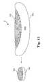
- FIG. 12depicts a hybrid device 12 according to the present invention.
- Hybrid device 12may include a curved spacer body 120 configured to fit adjacent container 122 in an intervertebral space.
- FIG. 12depicts an unexpanded container 122 and an expanded container 122 b .
- Hybrid device 12may be inserted into an intervertebral space in an unexpanded position and expanded in situ by the insertion of fill material into container 122 and/or by mechanical tools.
- FIG. 13depicts an expanded view of an embodiment of the present invention.
- Hybrid device 13may include spacer portions 130 a and 130 b .
- container 132may be disposed between spacer body portions 130 a and 130 b .
- At least one of spacer body portions 130 a and 130 bmay include a fill opening or port to facilitate filling container 132 with fill material.
- Hybrid device 13may be inserted into an intervertebral space in an unexpanded position and expanded in situ by the insertion of fill material into container 132 and/or by mechanical tools.
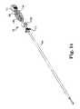
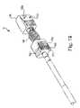
- FIG. 14-16depict an embodiment of the present invention, hybrid devices 14 - 16 respectively, wherein a first spacer body 140 is configured to receive a first end of container 144 and a second spacer body 142 a and 142 b is configured to receive a second end of container 144 .
- the first and second spacer bodiesmay be comprised of one or more parts.
- An insertion rod 146may insert the container into the first and second spacer bodies.
- Rod 146may include an anti-rotation locking ring 148 that engages with the distal tip of inner 150 . Once the locking ring 148 is engaged, the implant will not rotate. Ring 148 may be disengaged to allow implant rotation.
- Spacer bodies 140 and 142may include markings 152 a - d which may allow visualization of the implant upon imaging. Markings 152 a - d may project outward to engage the surrounding anatomy. Spacer bodies 140 and 142 may include other desired outward projections to engage the surrounding anatomy.
- Spacer bodies 140 and 142may include grooves on their inner diameters and utilize locking rings to receive and retain container 144 . Other retention mechanisms may be used.
- the implantmay be inserted into a prepared intervertebral cavity.
- the implantmay be inserted with an empty container such that the implant may be placed through a MIS or percutaneous approach.
- container 144may be filled with bone graft or any combination of desired fill materials.
- at least one of spacer bodies 140 and 142may include a fill opening or a fill port, such that fill material may be placed into container 144 .
- fill materialmay be placed directly into container 144 .
- first spacer body 140 and second spacer body 142may move apart creating an appropriate implant footprint for the particular patient's anatomy.
- First spacer body 140 and second spacer body 142may provide structural support on the strongest part of the adjacent vertebrae. While container 144 may provide graft and fill material containment and further may provide a scaffold for bone growth and fusion because container 144 is placed in the most vascular part of the adjacent vertebra.
- Hybrid devices 14 - 16may be inserted into an intervertebral space in an unexpanded position and expanded in situ by the insertion of fill material into container 144 and/or by mechanical tools.
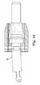
- FIG. 17depicts a hybrid device 17 according to another embodiment of the present invention.
- Hybrid device 17may include spacer body portions 170 and 172 .
- Container 174may be disposed between spacer body portions 170 and 172 .
- First spacer body 170is configured to receive a first end of container 174 and a second spacer body 172 is configured to receive a second end of container 174 .
- the first and second spacer bodiesmay be comprised of one or more parts.
- Hybrid device 17may further include at least one connecting rod 176 .
- Connecting rod 176may connect spacer 170 to spacer 172 .
- Connecting rod 176may lock container 174 into position within spacer bodies 170 and 172 .
- Connecting rod 176may include a fill opening 178 .
- Spacer bodies 170 and 172may include markings which may allow visualization of the implant upon imaging. Markings may project outward to engage the surrounding anatomy. Spacer bodies 170 and 172 may include other desired outward projections 182 to engage the surrounding anatomy.
- Spacer bodies 170 and 172may include grooves on their inner diameters and utilize locking rings to receive and retain container 174 . Other retention mechanisms may be used.
- the implantmay be inserted into a prepared intervertebral cavity.
- the implantmay be inserted with an empty container such that the implant may be placed through a MIS or percutaneous approach.
- container 174may be filled with bone graft or any combination of desired fill materials.
- at least one of spacer bodies 170 and 172may include a fill opening or a fill port 180 , such that fill material may be placed into container 174 .
- fill materialmay be placed directly into container 174 .
- first spacer body 170 and second spacer body 172may move apart creating an appropriate implant footprint for the particular patient's anatomy.
- First spacer body 170 and second spacer body 172may provide structural support on the strongest part of the adjacent vertebrae. While container 174 may provide graft and fill material containment and further may provide a scaffold for bone growth and fusion because container 174 is placed in the most vascular part of the adjacent vertebra.
- the devicemay include an angulation feature 182 that provides for angulation between first spacer body 170 and second spacer body 172 .
- Angulation feature 182allows device 18 to accommodate variations in a patient's anatomy and/or to accommodate the curvature at the L5-S1 junction.
- Angulation feature 182may be a mechanical connection such as depicted in FIG. 18 or a flexible material such as nitinol, as depicted in FIG. 19 or any other suitable angulation feature.
- Hybrid device 17may be inserted into an intervertebral space in an unexpanded position and expanded in situ by the insertion of fill material into container 174 and/or by mechanical tools.
Landscapes
- Health & Medical Sciences (AREA)
- Engineering & Computer Science (AREA)
- Biomedical Technology (AREA)
- Orthopedic Medicine & Surgery (AREA)
- Neurology (AREA)
- Transplantation (AREA)
- Heart & Thoracic Surgery (AREA)
- Oral & Maxillofacial Surgery (AREA)
- Cardiology (AREA)
- Vascular Medicine (AREA)
- Life Sciences & Earth Sciences (AREA)
- Animal Behavior & Ethology (AREA)
- General Health & Medical Sciences (AREA)
- Public Health (AREA)
- Veterinary Medicine (AREA)
- Chemical & Material Sciences (AREA)
- Dispersion Chemistry (AREA)
- Prostheses (AREA)
Abstract
Description
Claims (22)
Priority Applications (1)
| Application Number | Priority Date | Filing Date | Title |
|---|---|---|---|
| US15/476,911US9925058B2 (en) | 2012-07-25 | 2017-03-31 | Mesh spacer hybrid |
Applications Claiming Priority (5)
| Application Number | Priority Date | Filing Date | Title |
|---|---|---|---|
| US201261675668P | 2012-07-25 | 2012-07-25 | |
| US201361793923P | 2013-03-15 | 2013-03-15 | |
| US13/951,162US20140031939A1 (en) | 2012-07-25 | 2013-07-25 | Mesh spacer hybrid |
| US15/078,959US10111756B2 (en) | 2012-07-25 | 2016-03-23 | Mesh spacer hybrid |
| US15/476,911US9925058B2 (en) | 2012-07-25 | 2017-03-31 | Mesh spacer hybrid |
Related Parent Applications (1)
| Application Number | Title | Priority Date | Filing Date |
|---|---|---|---|
| US15/078,959ContinuationUS10111756B2 (en) | 2012-07-25 | 2016-03-23 | Mesh spacer hybrid |
Publications (2)
| Publication Number | Publication Date |
|---|---|
| US20170202677A1 US20170202677A1 (en) | 2017-07-20 |
| US9925058B2true US9925058B2 (en) | 2018-03-27 |
Family
ID=49995599
Family Applications (6)
| Application Number | Title | Priority Date | Filing Date |
|---|---|---|---|
| US13/951,162AbandonedUS20140031939A1 (en) | 2012-07-25 | 2013-07-25 | Mesh spacer hybrid |
| US15/078,959Active2033-09-24US10111756B2 (en) | 2012-07-25 | 2016-03-23 | Mesh spacer hybrid |
| US15/476,911Active2033-08-26US9925058B2 (en) | 2012-07-25 | 2017-03-31 | Mesh spacer hybrid |
| US16/173,727Active2033-11-13US11224520B2 (en) | 2012-07-25 | 2018-10-29 | Mesh spacer hybrid |
| US17/577,242Active2033-08-13US11833058B2 (en) | 2012-07-25 | 2022-01-17 | Mesh spacer hybrid |
| US18/528,766ActiveUS12303397B2 (en) | 2012-07-25 | 2023-12-04 | Mesh spacer hybrid |
Family Applications Before (2)
| Application Number | Title | Priority Date | Filing Date |
|---|---|---|---|
| US13/951,162AbandonedUS20140031939A1 (en) | 2012-07-25 | 2013-07-25 | Mesh spacer hybrid |
| US15/078,959Active2033-09-24US10111756B2 (en) | 2012-07-25 | 2016-03-23 | Mesh spacer hybrid |
Family Applications After (3)
| Application Number | Title | Priority Date | Filing Date |
|---|---|---|---|
| US16/173,727Active2033-11-13US11224520B2 (en) | 2012-07-25 | 2018-10-29 | Mesh spacer hybrid |
| US17/577,242Active2033-08-13US11833058B2 (en) | 2012-07-25 | 2022-01-17 | Mesh spacer hybrid |
| US18/528,766ActiveUS12303397B2 (en) | 2012-07-25 | 2023-12-04 | Mesh spacer hybrid |
Country Status (3)
| Country | Link |
|---|---|
| US (6) | US20140031939A1 (en) |
| EP (1) | EP2877129B1 (en) |
| WO (1) | WO2014018802A1 (en) |
Cited By (5)
| Publication number | Priority date | Publication date | Assignee | Title |
|---|---|---|---|---|
| US10441336B2 (en) | 2017-06-14 | 2019-10-15 | Osteoagra Llc | Stabilization of vertebral bodies with bone particle slurry |
| US11529236B2 (en) | 2021-03-04 | 2022-12-20 | OTS Medical Ltd. | Repair of shoulder-joint lesions |
| US12023257B2 (en) | 2021-10-05 | 2024-07-02 | Spineology Inc. | Mesh spacer hybrid spinal implant |
| US12102367B2 (en) | 2017-06-14 | 2024-10-01 | Osteoagra Llc | Method, composition, and apparatus for stabilization of vertebral bodies |
| US12433762B2 (en) | 2022-12-01 | 2025-10-07 | Percheron Spine, Llc | Spinal implant and delivery system |
Families Citing this family (25)
| Publication number | Priority date | Publication date | Assignee | Title |
|---|---|---|---|---|
| US20180228621A1 (en) | 2004-08-09 | 2018-08-16 | Mark A. Reiley | Apparatus, systems, and methods for the fixation or fusion of bone |
| US9949843B2 (en) | 2004-08-09 | 2018-04-24 | Si-Bone Inc. | Apparatus, systems, and methods for the fixation or fusion of bone |
| PL2124831T3 (en) | 2007-03-15 | 2017-03-31 | Ortho-Space Ltd. | Prosthetic devices |
| US9289307B2 (en) | 2011-10-18 | 2016-03-22 | Ortho-Space Ltd. | Prosthetic devices and methods for using same |
| US10363140B2 (en) | 2012-03-09 | 2019-07-30 | Si-Bone Inc. | Systems, device, and methods for joint fusion |
| US9044321B2 (en) | 2012-03-09 | 2015-06-02 | Si-Bone Inc. | Integrated implant |
| EP3818947B1 (en) | 2012-05-04 | 2023-08-30 | SI-Bone, Inc. | Fenestrated implant |
| WO2014145902A1 (en) | 2013-03-15 | 2014-09-18 | Si-Bone Inc. | Implants for spinal fixation or fusion |
| US11147688B2 (en) | 2013-10-15 | 2021-10-19 | Si-Bone Inc. | Implant placement |
| US9839448B2 (en) | 2013-10-15 | 2017-12-12 | Si-Bone Inc. | Implant placement |
| US10166033B2 (en) | 2014-09-18 | 2019-01-01 | Si-Bone Inc. | Implants for bone fixation or fusion |
| JP6542362B2 (en)* | 2014-09-18 | 2019-07-10 | エスアイ−ボーン・インコーポレイテッドSi−Bone, Inc. | Matrix implant |
| US10376206B2 (en) | 2015-04-01 | 2019-08-13 | Si-Bone Inc. | Neuromonitoring systems and methods for bone fixation or fusion procedures |
| WO2017046647A1 (en) | 2015-09-18 | 2017-03-23 | Ortho-Space Ltd. | Intramedullary fixated subacromial spacers |
| EP3573806A4 (en) | 2017-01-30 | 2019-12-11 | Ortho-Space Ltd. | Processing machine and methods for processing dip-molded articles |
| US11116519B2 (en) | 2017-09-26 | 2021-09-14 | Si-Bone Inc. | Systems and methods for decorticating the sacroiliac joint |
| ES3011907T3 (en) | 2018-03-28 | 2025-04-08 | Si Bone Inc | Threaded implants for use across bone segments |
| US11369419B2 (en) | 2019-02-14 | 2022-06-28 | Si-Bone Inc. | Implants for spinal fixation and or fusion |
| EP4613244A2 (en) | 2019-02-14 | 2025-09-10 | SI-Bone Inc. | Implants for spinal fixation and or fusion |
| JP7646654B2 (en) | 2019-11-21 | 2025-03-17 | エスアイ-ボーン・インコーポレイテッド | Rod coupling assembly for bone stabilization construct - Patent application |
| AU2020392121B2 (en) | 2019-11-27 | 2025-05-22 | Si-Bone, Inc. | Bone stabilizing implants and methods of placement across SI joints |
| EP4072452A4 (en) | 2019-12-09 | 2023-12-20 | SI-Bone, Inc. | Sacro-iliac joint stabilizing implants and methods of implantation |
| US11617663B2 (en) | 2020-10-15 | 2023-04-04 | Spineology Inc. | Surgical access system and method |
| EP4259015A4 (en) | 2020-12-09 | 2024-09-11 | SI-Bone, Inc. | SACROILIAC JOINT STABILIZATION IMPLANTS AND METHODS OF IMPLANTATION |
| WO2025038769A1 (en) | 2023-08-15 | 2025-02-20 | Si-Bone Inc. | Pelvic stabilization implants, methods of use and manufacture |
Citations (70)
| Publication number | Priority date | Publication date | Assignee | Title |
|---|---|---|---|---|
| US4961740A (en) | 1988-10-17 | 1990-10-09 | Surgical Dynamics, Inc. | V-thread fusion cage and method of fusing a bone joint |
| US5059193A (en) | 1989-11-20 | 1991-10-22 | Spine-Tech, Inc. | Expandable spinal implant and surgical method |
| US5192327A (en) | 1991-03-22 | 1993-03-09 | Brantigan John W | Surgical prosthetic implant for vertebrae |
| US5390683A (en) | 1991-02-22 | 1995-02-21 | Pisharodi; Madhavan | Spinal implantation methods utilizing a middle expandable implant |
| US5549679A (en) | 1994-05-20 | 1996-08-27 | Kuslich; Stephen D. | Expandable fabric implant for stabilizing the spinal motion segment |
| US5824093A (en) | 1994-10-17 | 1998-10-20 | Raymedica, Inc. | Prosthetic spinal disc nucleus |
| US6039761A (en) | 1997-02-12 | 2000-03-21 | Li Medical Technologies, Inc. | Intervertebral spacer and tool and method for emplacement thereof |
| US6176882B1 (en) | 1998-02-20 | 2001-01-23 | Biedermann Motech Gmbh | Intervertebral implant |
| US20010047207A1 (en) | 1998-10-30 | 2001-11-29 | Michelson Gary K. | Self-broaching, rotatable, push-in interbody spinal fusion implant and method for deployment thereof |
| US20020026243A1 (en) | 2000-05-30 | 2002-02-28 | Lin Paul S. | Implant for placement between cervical vertebrae |
| US20020058947A1 (en) | 2000-02-28 | 2002-05-16 | Stephen Hochschuler | Method and apparatus for treating a vertebral body |
| US20020068974A1 (en) | 2000-07-21 | 2002-06-06 | Kuslich Stephen D. | Expandable porous mesh bag device and methods of use for reduction, filling, fixation and supporting of bone |
| US6402784B1 (en) | 1997-07-10 | 2002-06-11 | Aberdeen Orthopaedic Developments Limited | Intervertebral disc nucleus prosthesis |
| US20020099444A1 (en) | 2001-01-22 | 2002-07-25 | Boyd Lawrence M. | Modular interbody fusion implant |
| US20020123750A1 (en) | 2001-02-28 | 2002-09-05 | Lukas Eisermann | Woven orthopedic implants |
| US6447543B1 (en)* | 1999-09-28 | 2002-09-10 | Sulzer Orthopedics Ltd. | Basket-like container for implanting bone tissue |
| US20020183848A1 (en) | 1999-04-05 | 2002-12-05 | Raymedica, Inc. | Prosthetic spinal disc nucleus having a shape change characteristic |
| US20030009222A1 (en) | 1966-03-14 | 2003-01-09 | Hans-Joachim Fruh | Synthetic threaded vertebral implant |
| US20030023311A1 (en) | 2000-08-30 | 2003-01-30 | Trieu Hai H. | Intervertebral disc nucleus implants and methods |
| US20030033017A1 (en) | 2001-06-29 | 2003-02-13 | The Regents Of The University Of California | Biodegradable/bioactive nucleus pulposus implant and method for treating degenerated intervertebral discs |
| US20030045939A1 (en)* | 2001-08-24 | 2003-03-06 | Simon Casutt | Artificial intervertebral disc |
| US6632235B2 (en) | 2001-04-19 | 2003-10-14 | Synthes (U.S.A.) | Inflatable device and method for reducing fractures in bone and in treating the spine |
| WO2003105673A2 (en) | 2002-06-17 | 2003-12-24 | Trimedyne, Inc. | Devices and methods for minimally invasive treatment of degenerated spinal discs |
| US6712853B2 (en) | 2000-12-15 | 2004-03-30 | Spineology, Inc. | Annulus-reinforcing band |
| US6743255B2 (en) | 1999-08-13 | 2004-06-01 | Bret Ferree | Spinal fusion cage with lordosis correction |
| US20040133280A1 (en)* | 2002-11-21 | 2004-07-08 | Trieu Hai H. | Systems and techniques for interbody spinal stabilization with expandable devices |
| US20040172019A1 (en) | 1999-10-08 | 2004-09-02 | Ferree Bret A. | Reinforcers for artificial disc replacement methods and apparatus |
| US20050027364A1 (en) | 2003-08-01 | 2005-02-03 | Kim Daniel H. | Prosthetic intervertebral disc and methods for using the same |
| US6852095B1 (en) | 1997-07-09 | 2005-02-08 | Charles D. Ray | Interbody device and method for treatment of osteoporotic vertebral collapse |
| US20050113919A1 (en)* | 2000-02-16 | 2005-05-26 | Cragg Andrew H. | Prosthetic nucleus apparatus |
| US20050113924A1 (en) | 2003-08-07 | 2005-05-26 | Dynamic Spine, Inc. | Apparatus and method for performing spinal surgery |
| US20050197702A1 (en) | 2002-08-15 | 2005-09-08 | Coppes Justin K. | Intervertebral disc implant |
| US20060079898A1 (en)* | 2003-10-23 | 2006-04-13 | Trans1 Inc. | Spinal motion preservation assemblies |
| US20060085075A1 (en) | 2004-10-04 | 2006-04-20 | Archus Orthopedics, Inc. | Polymeric joint complex and methods of use |
| US20060155297A1 (en) | 2003-10-23 | 2006-07-13 | Ainsworth Stephen D | Driver assembly for simultaneous axial delivery of spinal implants |
| US20060241767A1 (en) | 2005-04-22 | 2006-10-26 | Doty Keith L | Spinal disc prosthesis and methods of use |
| US20060293749A1 (en) | 2005-06-02 | 2006-12-28 | Zimmer Spine, Inc. | Interbody fusion ring and method of using the same |
| US20070067036A1 (en) | 2005-09-20 | 2007-03-22 | Zimmer Spine, Inc. | Hydrogel total disc prosthesis |
| US20070173940A1 (en) | 2006-01-18 | 2007-07-26 | Zimmer Spine, Inc. | Vertebral fusion device and method |
| US20070179621A1 (en) | 2006-01-25 | 2007-08-02 | Spinemedica Corporation | Spinal disc implants with flexible keels and methods of fabricating implants |
| US20070225809A1 (en) | 2006-03-27 | 2007-09-27 | Ray Charles D | System and device for filling a human implantable container with a filler material |
| US20070255415A1 (en) | 2006-05-01 | 2007-11-01 | Sdgi Holdings, Inc. | Expandable intervertebral spacers and methods of use |
| US20080021556A1 (en) | 2006-07-21 | 2008-01-24 | Edie Jason A | Expandable vertebral implant and methods of use |
| US20080154305A1 (en) | 2006-12-26 | 2008-06-26 | Warsaw Orthopedic, Inc. | Minimally invasive spinal distraction devices and methods |
| US20080154376A1 (en) | 2006-12-20 | 2008-06-26 | Bergeron Brian J | Surgical implant suitable for replacement of an intervertebral disc |
| US20080183292A1 (en) | 2007-01-29 | 2008-07-31 | Warsaw Orthopedic, Inc. | Compliant intervertebral prosthetic devices employing composite elastic and textile structures |
| US20080262502A1 (en) | 2006-10-24 | 2008-10-23 | Trans1, Inc. | Multi-membrane prosthetic nucleus |
| US7465318B2 (en) | 2004-04-15 | 2008-12-16 | Soteira, Inc. | Cement-directing orthopedic implants |
| US20090112323A1 (en) | 2007-10-29 | 2009-04-30 | Zimmer Spine, Inc. | Minimally invasive interbody device and method |
| US7534268B2 (en) | 2006-01-13 | 2009-05-19 | Zimmer Spine, Inc. | Devices and methods for disc replacement |
| US20090131939A1 (en) | 2006-05-24 | 2009-05-21 | Disc Dynamics, Inc. | Inflatable mold for maintaining posterior spinal elements in a desired alignment |
| US7608077B2 (en) | 2000-02-16 | 2009-10-27 | Trans1 Inc. | Method and apparatus for spinal distraction and fusion |
| US20100100185A1 (en) | 2008-10-22 | 2010-04-22 | Warsaw Orthopedic, Inc. | Intervertebral Disc Prosthesis Having Viscoelastic Properties |
| US7744630B2 (en) | 2005-11-15 | 2010-06-29 | Zimmer Spine, Inc. | Facet repair and stabilization |
| US20100286783A1 (en) | 2008-01-17 | 2010-11-11 | Synthes Usa, Llc | Expandable intervertebral implant and associated method of manufacturing the same |
| US20100318134A1 (en) | 2008-12-31 | 2010-12-16 | Karen Roche | System and method for performing percutaneous spinal interbody fusion |
| US8012211B2 (en) | 2002-11-05 | 2011-09-06 | Spineology, Inc. | Semi-biological intervertebral disc replacement system |
| US20110295370A1 (en) | 2010-06-01 | 2011-12-01 | Sean Suh | Spinal Implants and Methods of Use Thereof |
| US8100977B2 (en) | 2005-03-09 | 2012-01-24 | Vertebral Technologies, Inc. | Interlocked modular disc nucleus prosthesis |
| US20120022652A1 (en) | 2010-06-18 | 2012-01-26 | Roger Berger | Spine disc replacement with compliant articulating core |
| US8118873B2 (en) | 2008-01-16 | 2012-02-21 | Warsaw Orthopedic, Inc. | Total joint replacement |
| US20120046748A1 (en) | 2010-02-24 | 2012-02-23 | Mark Weiman | Expandable Intervertebral Spacer and Method of Posterior Insertion Thereof |
| US8167944B2 (en) | 2004-10-20 | 2012-05-01 | The Board Of Trustees Of The Leland Stanford Junior University | Systems and methods for posterior dynamic stabilization of the spine |
| US20120253466A1 (en) | 2011-03-31 | 2012-10-04 | Warsaw Orthopedic, Inc. | Methods and devices for the treatment of intervertebral discs disorders |
| US8361154B2 (en) | 2007-03-31 | 2013-01-29 | Spinal Kinetics Inc. | Temporarily bound prosthetic intervertebral discs implantable by minimally invasive surgical techniques |
| US8403987B2 (en)* | 2006-09-27 | 2013-03-26 | Spinal Kinetics Inc. | Prosthetic intervertebral discs having compressible core elements bounded by fiber-containing membranes |
| US8518115B2 (en) | 2007-11-16 | 2013-08-27 | DePuy Synthes Products, LLC | Porous containment device and associated method for stabilization of vertebral compression fractures |
| US8540771B2 (en) | 2004-09-09 | 2013-09-24 | University Of South Florida | Prostheses for spine discs having fusion capability |
| US20140031938A1 (en) | 2012-07-26 | 2014-01-30 | Beat Lechmann | Expandable Implant |
| US8747472B2 (en)* | 2009-08-14 | 2014-06-10 | Baxano Surgical, Inc. | Spinal therapy device with fixated distraction distance |
Family Cites Families (6)
| Publication number | Priority date | Publication date | Assignee | Title |
|---|---|---|---|---|
| US6761738B1 (en)* | 2000-09-19 | 2004-07-13 | Sdgi Holdings, Inc. | Reinforced molded implant formed of cortical bone |
| US6733531B1 (en)* | 2000-10-20 | 2004-05-11 | Sdgi Holdings, Inc. | Anchoring devices and implants for intervertebral disc augmentation |
| AU2004212942A1 (en)* | 2003-02-14 | 2004-09-02 | Depuy Spine, Inc. | In-situ formed intervertebral fusion device |
| US20070260314A1 (en)* | 2006-05-02 | 2007-11-08 | Ashok Biyani | Transforaminal lumbar interbody fusion cage |
| US8118837B2 (en) | 2008-07-03 | 2012-02-21 | Zimmer Spine, Inc. | Tapered-lock spinal rod connectors and methods for use |
| US9687356B1 (en)* | 2011-10-07 | 2017-06-27 | Nuvasive, Inc. | Spinal fusion implants and related methods |
- 2013
- 2013-07-25EPEP13823427.3Apatent/EP2877129B1/enactiveActive
- 2013-07-25WOPCT/US2013/052138patent/WO2014018802A1/enactiveApplication Filing
- 2013-07-25USUS13/951,162patent/US20140031939A1/ennot_activeAbandoned
- 2016
- 2016-03-23USUS15/078,959patent/US10111756B2/enactiveActive
- 2017
- 2017-03-31USUS15/476,911patent/US9925058B2/enactiveActive
- 2018
- 2018-10-29USUS16/173,727patent/US11224520B2/enactiveActive
- 2022
- 2022-01-17USUS17/577,242patent/US11833058B2/enactiveActive
- 2023
- 2023-12-04USUS18/528,766patent/US12303397B2/enactiveActive
Patent Citations (78)
| Publication number | Priority date | Publication date | Assignee | Title |
|---|---|---|---|---|
| US20030009222A1 (en) | 1966-03-14 | 2003-01-09 | Hans-Joachim Fruh | Synthetic threaded vertebral implant |
| US4961740B1 (en) | 1988-10-17 | 1997-01-14 | Surgical Dynamics Inc | V-thread fusion cage and method of fusing a bone joint |
| US4961740A (en) | 1988-10-17 | 1990-10-09 | Surgical Dynamics, Inc. | V-thread fusion cage and method of fusing a bone joint |
| US5059193A (en) | 1989-11-20 | 1991-10-22 | Spine-Tech, Inc. | Expandable spinal implant and surgical method |
| US5390683A (en) | 1991-02-22 | 1995-02-21 | Pisharodi; Madhavan | Spinal implantation methods utilizing a middle expandable implant |
| US5192327A (en) | 1991-03-22 | 1993-03-09 | Brantigan John W | Surgical prosthetic implant for vertebrae |
| US5571189A (en) | 1994-05-20 | 1996-11-05 | Kuslich; Stephen D. | Expandable fabric implant for stabilizing the spinal motion segment |
| US5549679A (en) | 1994-05-20 | 1996-08-27 | Kuslich; Stephen D. | Expandable fabric implant for stabilizing the spinal motion segment |
| US5824093A (en) | 1994-10-17 | 1998-10-20 | Raymedica, Inc. | Prosthetic spinal disc nucleus |
| US6039761A (en) | 1997-02-12 | 2000-03-21 | Li Medical Technologies, Inc. | Intervertebral spacer and tool and method for emplacement thereof |
| US6852095B1 (en) | 1997-07-09 | 2005-02-08 | Charles D. Ray | Interbody device and method for treatment of osteoporotic vertebral collapse |
| US6402784B1 (en) | 1997-07-10 | 2002-06-11 | Aberdeen Orthopaedic Developments Limited | Intervertebral disc nucleus prosthesis |
| US6176882B1 (en) | 1998-02-20 | 2001-01-23 | Biedermann Motech Gmbh | Intervertebral implant |
| US20010047207A1 (en) | 1998-10-30 | 2001-11-29 | Michelson Gary K. | Self-broaching, rotatable, push-in interbody spinal fusion implant and method for deployment thereof |
| US20020183848A1 (en) | 1999-04-05 | 2002-12-05 | Raymedica, Inc. | Prosthetic spinal disc nucleus having a shape change characteristic |
| US6743255B2 (en) | 1999-08-13 | 2004-06-01 | Bret Ferree | Spinal fusion cage with lordosis correction |
| US6447543B1 (en)* | 1999-09-28 | 2002-09-10 | Sulzer Orthopedics Ltd. | Basket-like container for implanting bone tissue |
| US20040172019A1 (en) | 1999-10-08 | 2004-09-02 | Ferree Bret A. | Reinforcers for artificial disc replacement methods and apparatus |
| US20050113919A1 (en)* | 2000-02-16 | 2005-05-26 | Cragg Andrew H. | Prosthetic nucleus apparatus |
| US7608077B2 (en) | 2000-02-16 | 2009-10-27 | Trans1 Inc. | Method and apparatus for spinal distraction and fusion |
| US7491236B2 (en) | 2000-02-16 | 2009-02-17 | Trans1, Inc. | Dual anchor prosthetic nucleus apparatus |
| US20020058947A1 (en) | 2000-02-28 | 2002-05-16 | Stephen Hochschuler | Method and apparatus for treating a vertebral body |
| US20040215343A1 (en) | 2000-02-28 | 2004-10-28 | Stephen Hochschuler | Method and apparatus for treating a vertebral body |
| US20020026243A1 (en) | 2000-05-30 | 2002-02-28 | Lin Paul S. | Implant for placement between cervical vertebrae |
| US20020068974A1 (en) | 2000-07-21 | 2002-06-06 | Kuslich Stephen D. | Expandable porous mesh bag device and methods of use for reduction, filling, fixation and supporting of bone |
| US7226481B2 (en) | 2000-07-21 | 2007-06-05 | Spineology, Inc. | Expandable porous mesh bag device and methods of use for reduction, filling, fixation, and supporting of bone |
| US20030023311A1 (en) | 2000-08-30 | 2003-01-30 | Trieu Hai H. | Intervertebral disc nucleus implants and methods |
| US6712853B2 (en) | 2000-12-15 | 2004-03-30 | Spineology, Inc. | Annulus-reinforcing band |
| US20020099444A1 (en) | 2001-01-22 | 2002-07-25 | Boyd Lawrence M. | Modular interbody fusion implant |
| US20020123750A1 (en) | 2001-02-28 | 2002-09-05 | Lukas Eisermann | Woven orthopedic implants |
| US6827743B2 (en) | 2001-02-28 | 2004-12-07 | Sdgi Holdings, Inc. | Woven orthopedic implants |
| US6632235B2 (en) | 2001-04-19 | 2003-10-14 | Synthes (U.S.A.) | Inflatable device and method for reducing fractures in bone and in treating the spine |
| US20030033017A1 (en) | 2001-06-29 | 2003-02-13 | The Regents Of The University Of California | Biodegradable/bioactive nucleus pulposus implant and method for treating degenerated intervertebral discs |
| US20030045939A1 (en)* | 2001-08-24 | 2003-03-06 | Simon Casutt | Artificial intervertebral disc |
| WO2003105673A2 (en) | 2002-06-17 | 2003-12-24 | Trimedyne, Inc. | Devices and methods for minimally invasive treatment of degenerated spinal discs |
| US20050197702A1 (en) | 2002-08-15 | 2005-09-08 | Coppes Justin K. | Intervertebral disc implant |
| US8012211B2 (en) | 2002-11-05 | 2011-09-06 | Spineology, Inc. | Semi-biological intervertebral disc replacement system |
| US20040133280A1 (en)* | 2002-11-21 | 2004-07-08 | Trieu Hai H. | Systems and techniques for interbody spinal stabilization with expandable devices |
| US20050027364A1 (en) | 2003-08-01 | 2005-02-03 | Kim Daniel H. | Prosthetic intervertebral disc and methods for using the same |
| US20050113924A1 (en) | 2003-08-07 | 2005-05-26 | Dynamic Spine, Inc. | Apparatus and method for performing spinal surgery |
| US20060155297A1 (en) | 2003-10-23 | 2006-07-13 | Ainsworth Stephen D | Driver assembly for simultaneous axial delivery of spinal implants |
| US20060079898A1 (en)* | 2003-10-23 | 2006-04-13 | Trans1 Inc. | Spinal motion preservation assemblies |
| US7465318B2 (en) | 2004-04-15 | 2008-12-16 | Soteira, Inc. | Cement-directing orthopedic implants |
| US8540771B2 (en) | 2004-09-09 | 2013-09-24 | University Of South Florida | Prostheses for spine discs having fusion capability |
| US20060085075A1 (en) | 2004-10-04 | 2006-04-20 | Archus Orthopedics, Inc. | Polymeric joint complex and methods of use |
| US8167944B2 (en) | 2004-10-20 | 2012-05-01 | The Board Of Trustees Of The Leland Stanford Junior University | Systems and methods for posterior dynamic stabilization of the spine |
| US8100977B2 (en) | 2005-03-09 | 2012-01-24 | Vertebral Technologies, Inc. | Interlocked modular disc nucleus prosthesis |
| US20060241767A1 (en) | 2005-04-22 | 2006-10-26 | Doty Keith L | Spinal disc prosthesis and methods of use |
| US20060293749A1 (en) | 2005-06-02 | 2006-12-28 | Zimmer Spine, Inc. | Interbody fusion ring and method of using the same |
| US20070067036A1 (en) | 2005-09-20 | 2007-03-22 | Zimmer Spine, Inc. | Hydrogel total disc prosthesis |
| US7744630B2 (en) | 2005-11-15 | 2010-06-29 | Zimmer Spine, Inc. | Facet repair and stabilization |
| US7534268B2 (en) | 2006-01-13 | 2009-05-19 | Zimmer Spine, Inc. | Devices and methods for disc replacement |
| US20070173940A1 (en) | 2006-01-18 | 2007-07-26 | Zimmer Spine, Inc. | Vertebral fusion device and method |
| US7799079B2 (en) | 2006-01-18 | 2010-09-21 | Zimmer Spine, Inc. | Vertebral fusion device and method |
| US20070179621A1 (en) | 2006-01-25 | 2007-08-02 | Spinemedica Corporation | Spinal disc implants with flexible keels and methods of fabricating implants |
| US20070225809A1 (en) | 2006-03-27 | 2007-09-27 | Ray Charles D | System and device for filling a human implantable container with a filler material |
| US20070255415A1 (en) | 2006-05-01 | 2007-11-01 | Sdgi Holdings, Inc. | Expandable intervertebral spacers and methods of use |
| US20090131939A1 (en) | 2006-05-24 | 2009-05-21 | Disc Dynamics, Inc. | Inflatable mold for maintaining posterior spinal elements in a desired alignment |
| US20080021556A1 (en) | 2006-07-21 | 2008-01-24 | Edie Jason A | Expandable vertebral implant and methods of use |
| US8403987B2 (en)* | 2006-09-27 | 2013-03-26 | Spinal Kinetics Inc. | Prosthetic intervertebral discs having compressible core elements bounded by fiber-containing membranes |
| US20080262502A1 (en) | 2006-10-24 | 2008-10-23 | Trans1, Inc. | Multi-membrane prosthetic nucleus |
| US20080154376A1 (en) | 2006-12-20 | 2008-06-26 | Bergeron Brian J | Surgical implant suitable for replacement of an intervertebral disc |
| US20080154305A1 (en) | 2006-12-26 | 2008-06-26 | Warsaw Orthopedic, Inc. | Minimally invasive spinal distraction devices and methods |
| US20080183292A1 (en) | 2007-01-29 | 2008-07-31 | Warsaw Orthopedic, Inc. | Compliant intervertebral prosthetic devices employing composite elastic and textile structures |
| US8361154B2 (en) | 2007-03-31 | 2013-01-29 | Spinal Kinetics Inc. | Temporarily bound prosthetic intervertebral discs implantable by minimally invasive surgical techniques |
| US20090112323A1 (en) | 2007-10-29 | 2009-04-30 | Zimmer Spine, Inc. | Minimally invasive interbody device and method |
| US8043381B2 (en) | 2007-10-29 | 2011-10-25 | Zimmer Spine, Inc. | Minimally invasive interbody device and method |
| US8518115B2 (en) | 2007-11-16 | 2013-08-27 | DePuy Synthes Products, LLC | Porous containment device and associated method for stabilization of vertebral compression fractures |
| US8118873B2 (en) | 2008-01-16 | 2012-02-21 | Warsaw Orthopedic, Inc. | Total joint replacement |
| US20100286783A1 (en) | 2008-01-17 | 2010-11-11 | Synthes Usa, Llc | Expandable intervertebral implant and associated method of manufacturing the same |
| US20100100185A1 (en) | 2008-10-22 | 2010-04-22 | Warsaw Orthopedic, Inc. | Intervertebral Disc Prosthesis Having Viscoelastic Properties |
| US20100318134A1 (en) | 2008-12-31 | 2010-12-16 | Karen Roche | System and method for performing percutaneous spinal interbody fusion |
| US8747472B2 (en)* | 2009-08-14 | 2014-06-10 | Baxano Surgical, Inc. | Spinal therapy device with fixated distraction distance |
| US20120046748A1 (en) | 2010-02-24 | 2012-02-23 | Mark Weiman | Expandable Intervertebral Spacer and Method of Posterior Insertion Thereof |
| US20110295370A1 (en) | 2010-06-01 | 2011-12-01 | Sean Suh | Spinal Implants and Methods of Use Thereof |
| US20120022652A1 (en) | 2010-06-18 | 2012-01-26 | Roger Berger | Spine disc replacement with compliant articulating core |
| US20120253466A1 (en) | 2011-03-31 | 2012-10-04 | Warsaw Orthopedic, Inc. | Methods and devices for the treatment of intervertebral discs disorders |
| US20140031938A1 (en) | 2012-07-26 | 2014-01-30 | Beat Lechmann | Expandable Implant |
Non-Patent Citations (2)
| Title |
|---|
| Extended European Search Report rendered by the European Patent Office (EPO) for PCT Application No. PCT/US2013/052138, dated Feb. 17, 2016, 7 pages. |
| International Search Report and Written Opinion rendered by the International Searching Authority for PCT Application No. PCT/US2013/052138, dated Oct. 24, 2013, 14 pages. |
Cited By (6)
| Publication number | Priority date | Publication date | Assignee | Title |
|---|---|---|---|---|
| US10441336B2 (en) | 2017-06-14 | 2019-10-15 | Osteoagra Llc | Stabilization of vertebral bodies with bone particle slurry |
| US12102367B2 (en) | 2017-06-14 | 2024-10-01 | Osteoagra Llc | Method, composition, and apparatus for stabilization of vertebral bodies |
| US11529236B2 (en) | 2021-03-04 | 2022-12-20 | OTS Medical Ltd. | Repair of shoulder-joint lesions |
| US11684477B2 (en) | 2021-03-04 | 2023-06-27 | OTS Medical Ltd. | Repair of shoulder-joint lesions |
| US12023257B2 (en) | 2021-10-05 | 2024-07-02 | Spineology Inc. | Mesh spacer hybrid spinal implant |
| US12433762B2 (en) | 2022-12-01 | 2025-10-07 | Percheron Spine, Llc | Spinal implant and delivery system |
Also Published As
| Publication number | Publication date |
|---|---|
| US20240173144A1 (en) | 2024-05-30 |
| US11224520B2 (en) | 2022-01-18 |
| EP2877129A4 (en) | 2016-03-16 |
| US20140031939A1 (en) | 2014-01-30 |
| US20190060084A1 (en) | 2019-02-28 |
| US12303397B2 (en) | 2025-05-20 |
| US10111756B2 (en) | 2018-10-30 |
| US20160199197A1 (en) | 2016-07-14 |
| US20220133487A1 (en) | 2022-05-05 |
| WO2014018802A1 (en) | 2014-01-30 |
| EP2877129B1 (en) | 2017-10-11 |
| EP2877129A1 (en) | 2015-06-03 |
| US11833058B2 (en) | 2023-12-05 |
| US20170202677A1 (en) | 2017-07-20 |
Similar Documents
| Publication | Publication Date | Title |
|---|---|---|
| US12303397B2 (en) | Mesh spacer hybrid | |
| US11439515B2 (en) | Variable lordotic angular expanding implant with centralized graft deployment channel | |
| US11696838B2 (en) | Systems and methods for inserting an expandable intervertebral device | |
| US20210196468A1 (en) | Methods and devices for bilaterally expanding intervertebral body fusion devices | |
| US9566167B2 (en) | Expandable spinal implant | |
| ES2300404T3 (en) | INTERSOMATIC CASE FOR BACK FUSION SURGERY OF THE LUMBAR COLUMN. | |
| US9844444B2 (en) | Far lateral spacer | |
| US8632593B2 (en) | Stabilizing vertebrae with expandable spacers | |
| EP3298990A1 (en) | Expandable intervertebral fusion implant | |
| US20140277501A1 (en) | Expanding interbody vertebral implant | |
| US20210085470A1 (en) | Spinal implant with surface projections | |
| US20240350278A1 (en) | Mesh spacer hybrid spinal implant | |
| CN115969585B (en) | Bidirectional expandable fusion device | |
| US20220133500A1 (en) | Intervertebral cage for fusion | |
| US20230041167A1 (en) | Fixated intervertebral mesh implant and method | |
| US20130218278A1 (en) | Device and method for performing spinal interbody fusion |
Legal Events
| Date | Code | Title | Description |
|---|---|---|---|
| AS | Assignment | Owner name:SPINEOLOGY INC., MINNESOTA Free format text:ASSIGNMENT OF ASSIGNORS INTEREST;ASSIGNORS:WOLFE, STEVE;BECKER, BRYAN;WALNOFER, TIM;AND OTHERS;SIGNING DATES FROM 20160314 TO 20160322;REEL/FRAME:041818/0932 Owner name:SPINEOLOGY INC., MINNESOTA Free format text:ASSIGNMENT OF ASSIGNORS INTEREST;ASSIGNOR:GANSKE, GARRETT;REEL/FRAME:041818/0952 Effective date:20160317 | |
| STCF | Information on status: patent grant | Free format text:PATENTED CASE | |
| AS | Assignment | Owner name:JPMORGAN CHASE BANK, N.A., ILLINOIS Free format text:SECURITY INTEREST;ASSIGNOR:SPINEOLOGY INC.;REEL/FRAME:046514/0267 Effective date:20180727 | |
| MAFP | Maintenance fee payment | Free format text:PAYMENT OF MAINTENANCE FEE, 4TH YR, SMALL ENTITY (ORIGINAL EVENT CODE: M2551); ENTITY STATUS OF PATENT OWNER: SMALL ENTITY Year of fee payment:4 | |
| AS | Assignment | Owner name:HORIZON TECHNOLOGY FINANCE CORPORATION, CONNECTICUT Free format text:SECURITY INTEREST;ASSIGNOR:SPINEOLOGY INC.;REEL/FRAME:057644/0286 Effective date:20210920 | |
| AS | Assignment | Owner name:SPINEOLOGY INC., MINNESOTA Free format text:RELEASE BY SECURED PARTY;ASSIGNOR:JPMORGAN CHASE BANK, N.A.;REEL/FRAME:065074/0545 Effective date:20230929 | |
| MAFP | Maintenance fee payment | Free format text:PAYMENT OF MAINTENANCE FEE, 8TH YR, SMALL ENTITY (ORIGINAL EVENT CODE: M2552); ENTITY STATUS OF PATENT OWNER: SMALL ENTITY Year of fee payment:8 |