US9924978B2 - Minimally invasive interspinous process spacer implants and methods - Google Patents
Minimally invasive interspinous process spacer implants and methodsDownload PDFInfo
- Publication number
- US9924978B2 US9924978B2US14/880,581US201514880581AUS9924978B2US 9924978 B2US9924978 B2US 9924978B2US 201514880581 AUS201514880581 AUS 201514880581AUS 9924978 B2US9924978 B2US 9924978B2
- Authority
- US
- United States
- Prior art keywords
- deployable
- implant
- spinal implant
- balloon
- iss
- Prior art date
- Legal status (The legal status is an assumption and is not a legal conclusion. Google has not performed a legal analysis and makes no representation as to the accuracy of the status listed.)
- Active
Links
- SOWHWYBEUXRMRF-ALCCZGGFSA-NCCCC1NC/C=C\CCCC1Chemical compoundCCCC1NC/C=C\CCCC1SOWHWYBEUXRMRF-ALCCZGGFSA-N0.000description1
Images


Classifications
- A—HUMAN NECESSITIES
- A61—MEDICAL OR VETERINARY SCIENCE; HYGIENE
- A61B—DIAGNOSIS; SURGERY; IDENTIFICATION
- A61B17/00—Surgical instruments, devices or methods
- A61B17/56—Surgical instruments or methods for treatment of bones or joints; Devices specially adapted therefor
- A61B17/58—Surgical instruments or methods for treatment of bones or joints; Devices specially adapted therefor for osteosynthesis, e.g. bone plates, screws or setting implements
- A61B17/68—Internal fixation devices, including fasteners and spinal fixators, even if a part thereof projects from the skin
- A61B17/70—Spinal positioners or stabilisers, e.g. stabilisers comprising fluid filler in an implant
- A61B17/7062—Devices acting on, attached to, or simulating the effect of, vertebral processes, vertebral facets or ribs ; Tools for such devices
- A61B17/7065—Devices with changeable shape, e.g. collapsible or having retractable arms to aid implantation; Tools therefor
- A—HUMAN NECESSITIES
- A61—MEDICAL OR VETERINARY SCIENCE; HYGIENE
- A61B—DIAGNOSIS; SURGERY; IDENTIFICATION
- A61B17/00—Surgical instruments, devices or methods
- A61B17/56—Surgical instruments or methods for treatment of bones or joints; Devices specially adapted therefor
- A61B17/58—Surgical instruments or methods for treatment of bones or joints; Devices specially adapted therefor for osteosynthesis, e.g. bone plates, screws or setting implements
- A61B17/68—Internal fixation devices, including fasteners and spinal fixators, even if a part thereof projects from the skin
- A61B17/70—Spinal positioners or stabilisers, e.g. stabilisers comprising fluid filler in an implant
- A61B17/7074—Tools specially adapted for spinal fixation operations other than for bone removal or filler handling
- A61B17/7076—Tools specially adapted for spinal fixation operations other than for bone removal or filler handling for driving, positioning or assembling spinal clamps or bone anchors specially adapted for spinal fixation
- A—HUMAN NECESSITIES
- A61—MEDICAL OR VETERINARY SCIENCE; HYGIENE
- A61F—FILTERS IMPLANTABLE INTO BLOOD VESSELS; PROSTHESES; DEVICES PROVIDING PATENCY TO, OR PREVENTING COLLAPSING OF, TUBULAR STRUCTURES OF THE BODY, e.g. STENTS; ORTHOPAEDIC, NURSING OR CONTRACEPTIVE DEVICES; FOMENTATION; TREATMENT OR PROTECTION OF EYES OR EARS; BANDAGES, DRESSINGS OR ABSORBENT PADS; FIRST-AID KITS
- A61F2/00—Filters implantable into blood vessels; Prostheses, i.e. artificial substitutes or replacements for parts of the body; Appliances for connecting them with the body; Devices providing patency to, or preventing collapsing of, tubular structures of the body, e.g. stents
- A61F2/02—Prostheses implantable into the body
- A61F2/30—Joints
- A61F2/44—Joints for the spine, e.g. vertebrae, spinal discs
- A—HUMAN NECESSITIES
- A61—MEDICAL OR VETERINARY SCIENCE; HYGIENE
- A61M—DEVICES FOR INTRODUCING MEDIA INTO, OR ONTO, THE BODY; DEVICES FOR TRANSDUCING BODY MEDIA OR FOR TAKING MEDIA FROM THE BODY; DEVICES FOR PRODUCING OR ENDING SLEEP OR STUPOR
- A61M29/00—Dilators with or without means for introducing media, e.g. remedies
- A—HUMAN NECESSITIES
- A61—MEDICAL OR VETERINARY SCIENCE; HYGIENE
- A61B—DIAGNOSIS; SURGERY; IDENTIFICATION
- A61B17/00—Surgical instruments, devices or methods
- A61B17/00234—Surgical instruments, devices or methods for minimally invasive surgery
- A61B2017/00292—Surgical instruments, devices or methods for minimally invasive surgery mounted on or guided by flexible, e.g. catheter-like, means
- A—HUMAN NECESSITIES
- A61—MEDICAL OR VETERINARY SCIENCE; HYGIENE
- A61B—DIAGNOSIS; SURGERY; IDENTIFICATION
- A61B17/00—Surgical instruments, devices or methods
- A61B2017/00535—Surgical instruments, devices or methods pneumatically or hydraulically operated
- A61B2017/00557—Surgical instruments, devices or methods pneumatically or hydraulically operated inflatable
- A—HUMAN NECESSITIES
- A61—MEDICAL OR VETERINARY SCIENCE; HYGIENE
- A61B—DIAGNOSIS; SURGERY; IDENTIFICATION
- A61B17/00—Surgical instruments, devices or methods
- A61B2017/00831—Material properties
- A61B2017/00867—Material properties shape memory effect
- A—HUMAN NECESSITIES
- A61—MEDICAL OR VETERINARY SCIENCE; HYGIENE
- A61B—DIAGNOSIS; SURGERY; IDENTIFICATION
- A61B90/00—Instruments, implements or accessories specially adapted for surgery or diagnosis and not covered by any of the groups A61B1/00 - A61B50/00, e.g. for luxation treatment or for protecting wound edges
- A61B90/39—Markers, e.g. radio-opaque or breast lesions markers
Definitions
- a human vertebraehas a rearwardly projecting portion known as a spinous process. Bending of the spine, particularly extension of the spine, can cause the spinous processes of adjacent vertebrae to move toward each other. This constricts the space in the spinal canal and foramina and may cause pain. Such pain may be exacerbated when the spinal canal or nerve roots exiting the canal are constricted by natural degeneration of the spine, such as by spinal stenosis or degenerative disc disease. Such pain may be treated by positioning an implant in a space between adjacent spinous processes to maintain a predetermined distance between the adjacent spinous processes, thereby providing a minimum amount of space between the spinous processes.
- spinal stenosisthere are two types of spinal stenosis: (1) hard or rigid spinal stenosis or (2) soft or dynamic spinal stenosis.
- spinal stenosismay be caused by excessive growth of tissue due to degeneration, loss of disc height, excessive load in a particular area of the spine as well disorders such as spondilolisthesis where the normal relative position and/or orientation of the adjacent vertebrae have been modified.
- a difference between the two types of spinal stenosisis that, generally, dynamic spinal stenosis may be treated with distraction of the vertebra at the affected level while hard stenosis generally requires removal of the tissue that obstructs the spinal canal or foramina at the affected level.
- tissue removalthe surgical treatment typically results in some loss of stability to the spine. Therefore, it is preferable to increase the stability of the spinal segment by inserting an interspinous process spacer (“ISS”) between the spinous processes of the adjacent vertebrae to increase the stiffness of the segment and/or to restrict motion of that segment.
- ISSinterspinous process spacer
- Some current implantsare made of separate pieces that require insertion from both sides of the spinous processes using a posterior approach that necessitates rather wide openings into a patient, cutting both left and right thoracolumbar fascia, as well as stripping the multifidus muscles from their attachments. It is desirable to provide an implant for insertion between the spinous processes of adjacent vertebrae which are inserted through a single opening in a minimal invasive approach and may be held firmly in position between the vertebrae. It is desirable for the surgical incision and surgical pathway to extend laterally into the space between the adjacent spinous processes, thereby preserving major ligaments and musculature of the spine at the impacted level.
- the present disclosurerelates generally to orthopedics. More specifically, the present disclosure relates to implants and methods for interspinous process spacing using a minimally invasive surgical technique, preferably using a preferred Interspinous Process Spacer (“ISS”).
- ISSInterspinous Process Spacer
- an interspinous process spacerfor implantation in an interspinous space between a superior spinous process and an inferior spinous process.
- the interspinous process spacermay include a balloon-like body having a distal end, a proximal end, and a longitudinal axis extending between the proximal and distal ends, the balloon-like body being arrangeable in an unexpanded configuration and an expanded configuration.
- the interspinous process spacermay further include a first deployable protrusion mounted proximate the proximal end and a second deployable protrusion mounted proximate the distal end.
- the first and second deployable protrusionsmay be oriented generally parallel to the longitudinal axis in the unexpanded configuration and generally perpendicular to the longitudinal axis in the expanded configuration.
- an interspinous process spacerfor implantation in an interspinous space between a superior spinous process and an inferior spinous process.
- the interspinous process spacermay include a symmetrical pre-shaped balloon-like body having a distal end, a proximal end, and a longitudinal axis extending between the proximal and distal ends, the balloon-like body being arrangeable in an unexpanded configuration and an expanded configuration.
- an interspinous process spacerfor implantation in an interspinous space between a superior spinous process and an inferior spinous process.
- the interspinous process spacermay include a central generally rigid rod member having a distal end, a proximal end, and a longitudinal axis extending between the proximal and distal ends, the generally rigid rod member being arrangeable in an unexpanded configuration and an expanded configuration.
- the interspinous process spacermay include an inflatable spacer portion disposed about the longitudinal axis, a first plurality of wires disposed axially about the proximal end, and a second plurality of wires disposed axially about the distal end.
- the first and second plurality of wiresmay be oriented generally parallel to the longitudinal axis in the unexpanded configuration and generally perpendicular to the longitudinal axis in the expanded configuration.
- a method of implanting an inflatable interspinous process spacer having deployable securing elements into an interspinous space between a superior spinous process and an inferior spinous processis described.
- the methodmay include inserting a guiding device into an interspinous ligament in the interspinous space, introducing the process spacer via the guiding device into the interspinous space, inflating the process spacer such that a first portion of the process spacer is positioned contralaterally of the interspinous space and a second portion of the process spacer is positioned ipsilaterally of the interspinous space, and deploying the deployable securing elements.
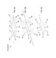
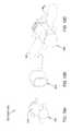
- FIG. 1illustrates a rear elevational view of an ISS implant in accordance with a first preferred embodiment of the present disclosure
- FIGS. 2A-2Cillustrate top perspective views of an ISS implant in accordance with a second preferred embodiment of the present disclosure in an unexpanded, partially expanded, and fully expanded configuration, respectively;
- FIG. 3Aillustrates a cross-sectional view of an ISS implant in accordance with a third preferred embodiment of the present disclosure in an unexpanded configuration
- FIGS. 3B and 3Cillustrate rear perspective views of an ISS implant in accordance with a third preferred embodiment of the present disclosure in a partially expanded ( FIG. 3B ) and fully expanded ( FIG. 3C ) configurations, respectively;
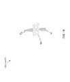
- FIGS. 4A-4Dillustrate rear elevational views of a variety of ISS implants in accordance with a fourth preferred embodiment of the present disclosure
- FIGS. 5A-5Dillustrate rear elevational views of an ISS implant in accordance with a fifth preferred embodiment of the present disclosure in unexpanded, first partially expanded, second partially expanded, and fully expanded configurations, respectively;
- FIGS. 6A and 6Billustrate rear elevational views of an ISS implant in accordance with a sixth preferred embodiment of the present disclosure in unexpanded and expanded configurations, respectively;
- FIGS. 7A and 7Billustrate rear elevational views of an ISS implant in accordance with a seventh preferred embodiment of the present disclosure in unexpanded and expanded configurations, respectively;
- FIGS. 8A and 8Billustrate rear elevational views of an ISS implant in accordance with an eighth preferred embodiment of the present disclosure in unexpanded and expanded configurations, respectively;
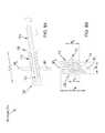
- FIG. 9Aillustrates a side elevational view of an un-inflated ISS implant in accordance with a ninth preferred embodiment of the present disclosure and a guide wire during its implantation.
- FIG. 9Billustrates a rear elevational view of the positioning of the guidewire prior to the insertion of the ISS implant of FIG. 9A ;
- FIG. 9Cillustrates a rear elevational view of an inflated ISS implant of FIG. 9A subsequent to its implantation
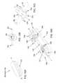
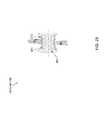
- FIG. 10illustrates a rear elevational view of an ISS implant in accordance with a tenth preferred embodiment of the present disclosure
- FIG. 11illustrates a rear elevational view of an ISS implant in accordance with an eleventh preferred embodiment of the present disclosure
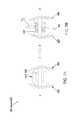
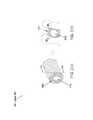
- FIGS. 12A and 12Billustrate side elevational views of an ISS implant in accordance with an twelfth preferred embodiment of the present disclosure in unexpanded and expanded configurations, respectively;
- FIG. 13Aillustrates a rear perspective view of an ISS implant in accordance with a thirteenth preferred embodiment of the present disclosure in an unexpanded configuration
- FIG. 13Billustrates a rear perspective view of the ISS implant of FIG. 13A in an unexpanded configuration with an implant body removed for clarity;
- FIG. 13Cillustrates a rear perspective view of the ISS implant of FIG. 13A in an expanded configuration with the implant body removed for clarity;
- FIG. 14Aillustrates a rear elevational view of an alternate embodiment of the ISS implant of FIGS. 12 and 13 , in which a shaft member includes longitudinal slots that allows wing pairs 1232 , 1234 , 1236 , 1238 to be formed as unitary elements;
- FIG. 14Billustrates a side perspective view of the ISS implant of FIG. 14A ;
- FIGS. 15A and 15Billustrate lateral cross-sectional views taken along line 15 - 15 of FIG. 14 of the ISS implant of FIGS. 13 and 14 , respectively, showing the ISS implant in an unexpanded configuration ( FIG. 15A ) and an expanded configuration ( FIG. 15B );
- FIG. 16Aillustrates a front perspective view of an ISS implant in accordance with a fourteenth preferred embodiment of the present disclosure in an unexpanded configuration
- FIG. 16Billustrates a side elevational view of the ISS implant of FIG. 16A in an expanded configuration
- FIG. 16Cillustrates a top perspective view of the ISS implant of FIG. 16A in an expanded configuration
- FIG. 16Dillustrates a top perspective view of the ISS implant of FIG. 16A in an unexpanded configuration with a portion of an implant body removed for clarity;
- FIG. 17Aillustrates a side perspective, partially exploded view of an ISS implant in accordance with a fifteenth preferred embodiment of the present disclosure in an unexpanded configuration
- FIG. 17Billustrates a side perspective view of the ISS implant of FIG. 17A in an expanded configuration with a distal turning wheel removed for clarity;
- FIG. 17Cillustrates a side perspective view of the ISS implant of FIG. 17A in an unexpanded configuration
- FIG. 17Dillustrates a side perspective view of the ISS implant of FIG. 17A in an expanded configuration
- FIG. 18Aillustrates top perspective views of an implant body element in an expanded configuration for use in an ISS implant in accordance with a sixteenth preferred embodiment
- FIG. 18Billustrates a balloon-type element for use with the implant body illustrated in FIG. 18A ;
- FIG. 18Cillustrates an assembled ISS implant including the implant body of FIG. 18A and the balloon-type element of FIG. 18B in an expanded configuration
- FIG. 19illustrates a rear cross-sectional view of an ISS implant in accordance with a seventeenth preferred embodiment of the present disclosure
- FIG. 20illustrates a rear cross-sectional view of an ISS implant in accordance with an eighteenth preferred embodiment of the present disclosure
- FIG. 21illustrates a rear cross-sectional view of an ISS implant in accordance with an nineteenth preferred embodiment of the present disclosure
- FIG. 22Aillustrates a side perspective view of an ISS implant in accordance with a twentieth preferred embodiment of the present disclosure
- FIG. 22Billustrates a cross-sectional view taken along line 22 B- 22 B of FIG. 22A ;
- FIG. 23illustrates a rear cross-sectional view of an ISS implant in accordance with a twenty-first preferred embodiment of the present disclosure
- FIG. 24Aillustrates a front perspective view of an ISS implant in accordance with a twenty-second preferred embodiment of the present disclosure in an expanded configuration
- FIG. 24Billustrates a side perspective view of the implant illustrated in FIG. 24A ;
- FIGS. 25A and 25Billustrates top perspective views of two method steps for inserting the ISS implant of FIG. 24 ;
- FIGS. 26A and 26Billustrate top perspective views of two additional method steps for inserting the ISS implant of FIG. 24 .
- an interspinous spacer (“ISS”) implant 100in accordance with a first preferred embodiment of the present disclosure includes an inflatable interior member 110 around which is disposed an exterior member 120 .
- the exterior member 120is preferably inflatable and includes first, second, third, and fourth protrusions 122 , 124 , 126 , 128 , respectively, which serve to limit lateral migration of the implant 100 when the first and third protrusions 122 , 126 are disposed on either side of a superior spinous process SP S and when the second and fourth protrusions 124 , 128 are disposed on either side of an inferior spinous process SP I .
- the exterior member 120is inflatable and the protrusions 122 , 124 , 126 , 128 may also be inflatable or may be formed from solid material.
- the exterior member 120is formed from a compliant or semi-compliant material, while the interior member 110 can be formed from compliant or non-compliant material.
- the protrusions 122 , 124 , 126 , 128are preferably relatively rigid in the expanded configuration ( FIG. 1 ) and may collapse such that the ISS implant 100 may be introduced between the superior and inferior spinous processes SP S , SP I through a relatively small diameter cannula (not shown) that is introduced laterally into the interspinous process space in a collapsed configuration (not shown).
- the interior and exterior members 110 , 120are not limited to being inflatable and may be configured to move from the unexpanded to the expanded configuration and back via a mechanical assembly or a combination of inflatable and mechanical mechanisms.
- the ISS implant 100is preferably inserted percutaneously between an adjacent pair of spinous processes via a lateral approach through a relatively small cannula in an unexpanded configuration.
- the inflatable member 110 and the exterior member 120are then inflated via a biocompatible pressurized fluid and/or gas until the desired spacing between the adjacent spinous processes SP S , SP I is achieved, wherein the interior member 110 serves as a spacer and the exterior member 120 serves as a securing agent due to the inclusion of the protrusions 122 , 124 , 126 , 128 and as a portion of the spacer.
- an ISS implant 200 in accordance with a second preferred embodimentincludes an inflatable member 210 having a longitudinal axis X-X extending between a proximal end and a distal end.
- First, second, third, and fourth deployable protrusion 222 , 224 , 226 , 228are disposed on the inflatable member 210 adjacent superior and inferior surfaces at proximal and distal ends of the inflatable member 210 , respectively.
- Each protrusion 222 , 224 , 226 , 228is preferably comprised of an elongated hollow semi-cylinder and is configured such that, when the inflatable member 210 is in its unexpanded, collapsed or un-inflated configuration, the third and fourth protrusions 226 , 228 extend distally along the longitudinal axis X-X and meet to form a cylindrical dilator portion 227 , whereas the first and second protrusions 222 , 224 extend proximally along the longitudinal axis X-X and meet to form a hollow cylinder portion 223 , respectively, which generally protects the inflatable member 210 during insertion.
- the protrusions 222 , 224 , 226 , 228Upon inflation of the inflatable member 210 , the protrusions 222 , 224 , 226 , 228 deploy to a configuration in which each is generally perpendicular to the longitudinal axis of the inflatable member 210 to thereby surround the adjacent spinous processes and limit lateral migration of the ISS implant 200 .
- the protrusions 222 , 224 , 226 , 228are no limited to extending generally perpendicularly relative to the longitudinal axis X-X in the expanded configuration and may pinch inwardly toward their tips to engage the spinous processes in the expanded configuration or may stop short of extending generally perpendicularly relative to the longitudinal axis X-X ( FIG. 2B ) in the expanded configuration.
- Such orientationsmay be driven by patient anatomy and/or design of the ISS implant 200 of the second preferred embodiment.
- the ISS implant 200is preferably inserted percutaneously between an adjacent pair of spinous process via a lateral approach corridor through a relatively small cannula.
- the undeployed third and fourth protrusions 226 , 228preferably form a cylinder at a proximal end of the implant and serve as a dilator for easing the ISS implant 200 into the desired location via the cylindrical dilator portion 227 .
- the inflatable member 210is preferably inflated once the ISS implant 200 is in a desired location with the first and second protrusions 222 , 224 located on one side of the adjacent spinous processes and the third and fourth protrusions 226 , 228 located on the opposite side of the adjacent spinous processes, forcing the protrusions 222 , 224 , 226 , 228 to shift from the unexpanded configuration in which their longitudinal axes are parallel to the longitudinal axis X-X, to the expanded configuration in which their longitudinal axes are perpendicular to the longitudinal axis X-X of the inflatable member 210 , such that lateral migration of the ISS implant 200 is limited.
- an ISS implant 300 in accordance with a third preferred embodimentincludes an inflatable member 310 having a longitudinal axis Y-Y extending between a proximal end and a distal end.
- a relatively solid superior member 320is disposed on a superior surface of the inflatable member 310 and has a first deployable protrusion 322 and a first bendable portion 321 adjacent the first deployable protrusion 322 , as well as a third deployable protrusion 326 and a third bendable portion 325 adjacent the third deployable protrusion 326 .
- a relatively solid inferior member 329is disposed on an inferior surface of the inflatable member 310 and has a second deployable protrusion 324 and a second bendable portion 323 adjacent the second deployable protrusion 324 , as well as a fourth deployable protrusion 328 and a fourth bendable portion 327 adjacent the fourth deployable protrusion 328 .
- the bendable portions 321 , 323 , 325 , 327may be formed by providing a thin portion of material on the superior and inferior members 320 , 329 adjacent to the deployable protrusions 322 , 324 , 326 , 328 , respectively, resulting in living hinges being formed at the bendable portions 321 , 323 , 325 , 327 .
- balloon pressureacts upon and deforms the bendable portions 321 , 323 , 325 , 327 to force the protrusions 222 , 224 , 226 , 228 to deploy from an unexpanded configuration in which they are positioned generally parallel to the longitudinal axis Y-Y of the inflatable member 310 to an expanded configuration in which each protrusion 222 , 224 , 226 , 228 is oriented generally perpendicular to the longitudinal axis Y-Y of the inflatable member 310 to contact or position themselves adjacent to sides of the spinous processes.
- the ISS implant 300is preferably inserted percutaneously between an adjacent pair of spinous process via a lateral approach corridor through a relatively small cannula or surgical pathway.
- the inflatable member 310is inflated once the ISS implant 300 is in a desired location, deforming the bendable portions 321 , 323 , 325 , 327 of the upper and lower members 320 , 329 , thereby forcing the protrusions 322 , 324 , 326 , 328 to shift from the unexpanded configuration in which their longitudinal axes are generally parallel to the longitudinal axis Y-Y of the inflatable member 310 , to the expanded configuration in which their longitudinal axes are generally perpendicular to the longitudinal axis Y-Y of the inflatable member 210 , such that lateral migration of the ISS implant 200 is limited.
- a variety of balloon-type ISS implants 410 , 420 , 430 , 440 in accordance with a fourth preferred embodiment of the present disclosureinclude a first U-shaped inflatable member 412 and a second inflatable U-shaped member 414 coupled to one another in a configuration that provides an H-shaped implant 410 in an expanded configuration.
- the first and second inflatable members 412 , 414can be inflated simultaneously or separately and may include a separate inlet port for each member 412 , 414 or a single inlet port with a communication passage between the first and second member 412 , 414 .
- FIG. 4Billustrates an ISS implant 420 that includes an inflatable member that assumes an X-shape in the expanded configuration for providing the desired spacing between adjacent spinous processes SP S , SP I while limiting lateral migration of the implant 420 when fully expanded.
- FIG. 4Cillustrates an ISS implant 430 that includes a U-shaped inflatable member 430 that is folded in an unexpanded configuration prior to implantation and inflation. Upon inflation, the ISS implant 430 assumes the shape of a lower case alpha ( ⁇ ) that is well-configured to limit lateral migration of the implant 430 relative to the adjacent spinous processes SP S , SP I .
- FIG. 4Cillustrates an ISS implant 430 that includes a U-shaped inflatable member 430 that is folded in an unexpanded configuration prior to implantation and inflation. Upon inflation, the ISS implant 430 assumes the shape of a lower case alpha ( ⁇ ) that is well-configured to limit lateral migration of the implant 430 relative to the adjacent spinous processes SP S ,
- FIG. 4Dillustrates an ISS implant 440 that includes a generally straight and cylindrical inflatable member 430 that is folded prior to implantation and inflation in an unexpanded configuration.
- the ISS implant 440assumes the shape of a lower case alpha ( ⁇ ) that is well-configured to limit lateral migration of the expanded implant 440 relative to the adjacent spinout processes SP S , SP I .
- the inflatable membercan be filled with either gas, such as oxygen or air, a biocompatible cement, or fluid, such as saline.
- the inflatable ISS implants 410 , 420 , 430 , 440can be compliant, semi-compliant, or noncompliant.
- the ISS implants 410 , 420 , 430 , 440may be inflated or moved from the unexpanded configuration to the expanded configuration utilizing nearly any biocompatible material that is able to generally fill the ISS implants 410 , 420 , 430 , 440 to reconfigure the implant 410 , 420 , 430 , 440 from the unexpanded configuration to the expanded configuration.
- an ISS implant 500 in accordance with a fifth preferred embodimentincludes three linearly-arranged inflatable members 510 , 520 , 530 , including a contralateral balloon 510 , a central balloon 520 , and an ipsalateral balloon 530 .
- Each inflatable member 510 , 520 , 530includes an inlet port that may extend through the center of one or more of the other inflatable members 510 , 520 , 530 .
- the contralateral balloon 510 and ipsalateral balloon 530preferably have a similar size and shape, resulting in an expanded height H E that extends beyond a height H I of the interspinous space in the expanded configuration and the central balloon 520 preferably has a height H C that provides a preferred anatomical distance between the adjacent spinous processes SP S , SP I in the implanted position.
- the ISS implant 500is inserted percutaneously through a lateral approach corridor with each of the inflatable members in a noninflated or unexpanded configuration.
- the implant 500is disposed in a desired position with respect to the adjacent spinous processes SP S , SP I , the contralateral balloon 510 , the central balloon 520 , and the ipsalateral balloon 530 are inflated independently of one another and in an order chosen by the user, for example, by inflating the contralateral balloon 510 first, followed by the central balloon 520 , and lastly, the ipsalateral balloon 530 , as shown in FIGS. 5A-5C .
- the usermay also select the filling material to be used with each of the inflatable members 510 , 520 , 530 , and one or more filling materials may be chosen for one or more of the inflatable members 510 , 520 , 530 .
- the usermay choose to provide some cushioning between the adjacent spinous processes SP S , SP I by filling the central balloon 520 with a hydrogel, or may provide a rigid central balloon 520 upon inflation of a noncompliant balloon with air.
- the contralateral and ipsalateral balloons 510 , 530are configured to extend vertically a greater distance than the central balloon 520 upon inflation such that lateral migration of the ISS implant 500 is limited.
- the ISS implant 500may include a three chamber single balloon as opposed to the preferred three separate inflatable members 510 , 520 , 530 .
- the inflatable members 510 , 510 , 530may be filled with variable stiffness materials to tailor the elasticity of the inflatable members 510 , 520 , 530 in the expanded configuration to provide a rigid stop between the spinous processes SP S , SP I or to provide compliance or damped motion between the spinous processes SP S , SP I .
- an ISS implant 600 in accordance with a sixth and seventh preferred embodimentincludes a central, generally rigid rod member 630 extending along a longitudinal axis Z-Z having a proximal end and a distal end and a spacer portion 610 , which may be an inflatable, semi-compliant balloon member 610 or a solid form of rigid, elastomeric, or dampening material 610 ′ disposed about the rod member 630 .
- the first and second plurality of nitinol wires 620 , 625include a pre-tensioned, insertion configuration ( FIG. 6A ), in which their longitudinal axes are generally parallel to the longitudinal axis Z-Z of the ISS implant 600 , and an untensioned, implanted configuration ( FIGS. 6B, 7A and 7B ), in which their longitudinal axes are generally perpendicular to the longitudinal axis Z-Z of the ISS implant 600 .
- the ISS implant 600is preferably housed within a cylindrical tube or cannula 605 during insertion, such that the longitudinal axes of the first and second plurality of nitinol wires 620 , 625 are generally parallel to the longitudinal axis Z-Z of the ISS implant 600 .
- the cylindrical tube 605is preferably, percutaneously inserted through a lateral approach corridor to a position between the adjacent spinous processes.
- the ISS implant 600may alternatively be implanted without the cannula 605 by urging the implant 600 directly through the patient's soft tissue to the implantation site.
- the cylindrical tube or cannula 605is removed from the patient, leaving the spacer portion 610 positioned between the adjacent spinous processes SP S , SP I .
- the first and second plurality of nitinol wires 620 , 625return to their unstressed or expanded configuration, in which their longitudinal axes are generally perpendicular to the longitudinal axis Z-Z of the ISS implant 600 , thereby limiting lateral migration of the ISS implant 600 with respect to the adjacent spinous processes SP S , SP I .
- the spacer portion 610In the case in which the spacer portion 610 is inflatable, it is then inflated with a gas, solid, or liquid material to provide the desired characteristic of the inflatable member 610 (rigid or elastic). If the spacer portion 610 ′ is not inflatable, the inflating step is generally unnecessary. In such an arrangement, the compliance of the spacer element 610 ′ can be influenced by both choice of material as well as the inclusion of an exemption 612 between a central rod member 630 ′ and the spacer portion 610 ′, as is best shown in FIGS. 7A and 7B .
- an ISS implant 700 in accordance with an eighth preferred embodimentincludes a central piston member 730 having a protruding distal stop surface 732 . Disposed about the central piston member 730 is a flexible cylindrical spacer portion 710 . Disposed about the central piston member 730 and adjacent to the flexible spacer portion 710 is a generally rigid tubular member 720 having a proximal stop surface 722 at its distal end. The flexible spacer member 710 is preferably sandwiched between the distal stop surface 732 and the proximal stop surface 722 and the rigid tubular member 720 is slidably translatable over the central piston member 730 . In an unexpanded configuration, the distal stop surface 732 and the proximal stop surface 722 are spaced at an unexpanded length L U that is typically at least as long as a length L F of the flexible spacer portion 710 .
- the ISS implant 700is preferably inserted percutaneously through a lateral approach corridor, preferably through a cannula, until the flexible spacer portion 710 is generally centered between the adjacent pair of spinous processes SP S , SP I .
- the central piston member 730is then retracted with respect to the rigid tubular member 720 , thereby reducing the unexpanded length L U such that the flexible spacer portion 710 is squeezed between the distal stop surface 732 and the proximal stop surface 722 and the flexible spacer portion is forced to fold over and surround the lateral aspects of the adjacent spinous processes SP S , SP I .
- the rigid tubular member 720is then locked with respect to the central piston member 730 such that the ISS implant 700 is limited from lateral migration relative to the spinous processes SP S , SP I .
- the distal stop surface 732 and the proximal stop surface 722are spaced at an expanded length L E that is smaller than the length L F of the flexible spacer portion 710 and the flexible spacer portion 710 has an expanded height H E that is greater than a height H S of the distal and proximal stop surfaces H D , H P .
- an ISS implant 800 in accordance with a ninth preferred embodimentis comprised of an inflatable balloon-type implant 800 having a central portion 800 a with a reduced size or height H C with respect to first and second enlarged end portions H EP in an expanded configuration.
- the ISS implant 800further includes a cannulated interior configured to slide over a guidewire 810 .
- the guidewire 810is inserted through the posterior of a patient and glides along the interspinous space between the adjacent spinous processes SP S , SP I , preferably without perforating the supraspinous ligament SSL.
- the interspinous ligament ISLis then preferably perforated by the guidewire 810 .
- the ISS implant 800is then inserted over the guidewire 810 into the interspinous space and inflated such that the enlarged portions 800 b of the ISS implant 800 are positioned contralaterally and ipsilaterally of the interspinous space to limit movement of the ISS implant 800 relative to the spinous processes SP S , SP I .
- an ISS implant 900 in accordance with a tenth preferred embodimentis comprised of an inflatable implant configured for percutaneous insertion over a guidewire 910 .
- the ISS implant 900includes a cannulated interior configured for delivering the ISS implant 900 over the guidewire 910 .
- the guidewire 910is preferably inserted laterally into the interspinous space between the adjacent spinous processes SP S , SP I and perforates the interspinous ligament.
- the ISS implant 900is then delivered over the guidewire 910 into position between the spinous processes SP S , SP I .
- the ISS implant 900preferably includes lateral inflatable members 902 that are preferably configured to expand to surround the lateral aspects of the spinous processes SP S , SP I such that lateral migration of the ISS implant 900 is limited.
- the lateral members 902may be mechanically deployable.
- the ISS implant 900also preferably includes a dampening member 904 generally centrally located on an exterior surface that contacts the adjacent spinous processes SP S , SP I in the implanted position.
- an ISS implant 1000 in accordance with an eleventh preferred embodimentincludes a rigid catheter 1010 around which is disposed a proximal expandable member 1020 , a central expandable member 1030 , and a distal expandable member 1040 .
- the proximal and distal expandable members 1020 , 1040may assume the form of a stent, a balloon-type expandable member, a self-expanding foam structure that expands when resistance provided by the catheter 1010 is removed, locking-stopping bumps or toruses, or members that are expandable by a pulling mechanism.
- the central expandable member 1030may assume the form of a balloon or a multi-lumen balloon having differing compliances, or a self-expanding foam structure.
- the ISS implant 1000is preferably inserted percutaneously from a lateral approach corridor and the proximal, central, and distal expandable members 1020 , 1030 , 1040 are expanded.
- the stent portions 1020 , 1040may be formed by removal of material and the formation of a stent-pattern in the catheter 1010 itself, or stent members may be applied over the catheter 1010 and around a portion that houses a deployable balloon 1030 for expanding the stent portions 1020 , 1040 .
- the expandable members 1020 , 1030 , 1040are enlarged by a pulling mechanism.
- an ISS implant 1100 in accordance with a twelfth preferred embodimentincludes a cross-section of circular, oval, or rectangular and is configured for insertion between the adjacent spinous processes SP S , SP I while enclosed within a tubular insertion sleeve 1111 .
- the ISS implant 1100includes a pair of proximal wings 1110 , 1112 and a pair of distal wings (not shown). Each pair of wings 1110 , 1112 is configured to be rotatable about a joint (not shown) in a plane that is generally parallel to the medial plane.
- a rod shaped element(not shown) is connected with a rotatable central shaft 1130 .
- the rod shaped element 1130forces the proximal and distal pairs of wings 1110 , 1112 to rotate about their joints and extend into a position in which they serve as lateral migration stops to limit movement of the ISS implant 1100 relative to the spinous processes SP S , SP I .
- an ISS implant 1200 of a thirteenth preferred embodimentincludes an implant body 1210 , a central rod 1220 having proximal and distal ends and a longitudinal axis M-M extending therebetween.
- a first wing 1232 and a second wing 1234are preferably coupled to the central rod 1220 near the proximal end, and a third wing 1236 and a fourth wing 1238 are preferably coupled to the rotatable central rod 1220 near the distal end.
- the wings 1232 , 1234 , 1236 , 1238are preferably formed of a resilient or deformable material and are configured to assume an undeployed state or configuration ( FIGS.
- FIGS. 13C-14Ba deployed state
- FIGS. 13C-14Ba deployed state
- the wings 1232 , 1234 , 1236 , 1238are deployed to extend away from the implant body 1210 through a first slot 1242 , a second slot 1244 , a third slot 1246 , and a fourth slot 1248 , respectively, formed through the outer surface of the implant body 1210 and positioned so as to accommodate the deployment of the wings 1232 , 1234 , 1236 , 1238 away from the outer surface of the implant body 1210 .
- the ISS implant 1200is preferably inserted percutaneously between the adjacent spinous processes SP S , SP I via a lateral approach corridor, typically through a cannula (not shown).
- An instrumentengages an engagement feature 1222 on the proximal end of the central rod 1220 and is rotated to turn the central rod 1210 and, thereby, undeform or unstress the wings 1232 , 1234 , 1236 , 1238 to thereby allow them to deploy through the slots 1242 , 1244 , 1246 , 1248 , respectively and serve as lateral migration stops for the positioning of the ISS implant 1200 with respect to the interspinous space and the adjacent spinous processes SP S , SP I .
- the shaft 1222 memberis formed to include longitudinal slots 1221 through an external sleeve 1223 that allow the wing pairs 1236 , 1238 , and the wing pairs 1232 , 1234 , to be formed as unitary elements and to be positioned generally within the bounds of the external sleeve 1223 in the undeployed configuration.
- an ISS implant 1300 in accordance with a fourteenth preferred embodimentincludes an implant body 1310 , a central shaft 1320 having a proximal end and a distal end, wherein the proximal end further includes an instrument engagement feature 1360 and the central shaft 1320 further includes a first worm gear 1322 disposed near its proximal end and operatively connected to a first pair of wings 1332 , 1334 and a second worm gear 1324 disposed at its distal end and operatively connected to a second pair of wings 1336 , 1338 .
- the first and second pairs of wings 1332 , 1334 , 1336 , 1338are operatively connected to the first and second worm gears 1322 , 1324 , respectively, via the inclusion at the base of each wing 1332 , 1334 , 1336 , 1338 of a snail gear 1352 , 1354 , 1356 , 1358 , respectively.
- the ISS implant 1300is preferably inserted percutaneously through a lateral approach corridor and placed between the spinous processes SP S , SP I .
- An instrumentengages and is turned to rotate the instrument engagement feature 1360 and thereby force the first and second worm gears 1322 , 1324 to engage the snail gears 1352 , 1354 , 1356 , 1358 to thereby deploy the wings 1332 , 1334 , 1336 , 1338 through a range of approximately ninety degrees (90°), from a position in which the longitudinal axes of the wings 1332 , 1334 , 1336 , 1338 are generally parallel to a longitudinal axis N-N of the implant body 1310 to a position in which the longitudinal axes of the wings 1332 , 1334 , 1336 , 1338 are generally perpendicular to the longitudinal axis N-N of the implant body 1310 .
- 90°ninety degrees
- an ISS implant 1400 in accordance with a fifteenth preferred embodimentincludes an implant body 1410 having a longitudinal axis O-O extending between a proximal end and a distal end and a central rod 1480 disposed through the center of the implant body 1410 that extends along the longitudinal axis O-O.
- the central rod 1480is operatively coupled at its proximal end to a proximal turning wheel 1450 and is operatively coupled at its distal end to a distal turning wheel 1460 such that, upon rotation of the proximal turning wheel 1450 , i.e., via the rotation of an instrument temporarily coupled to an instrument engagement feature (not shown) formed at the proximal end of the proximal turning wheel 1450 , the proximal turning wheel 1450 , the central rod 1480 , and the distal turning wheel 1460 are each forced to rotate with respect to the implant body 1410 .
- the distal turning wheel 1460includes a bullet nosed tip to ease the insertion of the ISS implant 1400 and/or apply distraction during the insertion of the ISS implant 1400 .
- a first proximal slot 1422 and a second proximal slot 1424are preferably formed adjacent the proximal end of the implant body 1410 and the longitudinal axes of the first and second proximal slots 1422 , 1424 are oriented generally perpendicular to the longitudinal axis O-O of the implant body 1410 .
- first distal slot 1426 and a second distal slot 1428are formed adjacent the distal end of the implant body 1410 and the longitudinal axes of the first and second distal slots 1426 , 1428 also generally oriented perpendicular to the longitudinal axis O-O of the implant body 1410 .
- First and second proximal wings 1432 , 1434 and first and second distal wings 1436 , 1438are positioned in the first and second proximal slots 1422 , 1424 and the first and second distal slots 1426 , 1428 , respectively.
- Each of the first and second proximal wings 1432 , 1434 and the first and second distal wings 1436 , 1438includes a post 1431 , 1433 , 1435 , 1437 , respectively, that protrudes into a slot 1462 , 1464 , 1466 , 1468 , respectively, formed on the interior surface of the proximal and distal turning wheels 1450 , 1460 .
- the wings 1432 , 1434 , 1436 , 1438are preferably generally contained within the slots 1462 , 1464 , 1466 , 1468 in the unexpanded configuration and extend from the slots 1462 , 1464 , 1466 , 1468 in the expanded configuration.
- the ISS implant 1400is preferably inserted percutaneously through a lateral approach corridor such that the implant body 1410 is positioned between the spinous processes SP S , SP I .
- An instrumentis coupled to the instrument engagement feature on the proximal turning wheel 1450 and is rotated, forcing the proximal turning wheel 1450 , the central rod 1480 , and the distal turning wheel 460 to rotate, preferably approximately ninety to one hundred degrees)(90-100°, with respect to the implant body 1410 .
- the posts 1431 , 1433 , 1435 , 1437are forced to interact with, preferably slide within, the rotating slots 1462 , 1464 , 1466 , 1468 formed on the interior surface of the proximal and distal turning wheels 1450 , 1460 , thereby forcing the wings 1432 , 1434 , 1436 , 1438 to translate within the first and second proximal slots 1422 , 1424 and the first and second distal slots 1426 , 1428 formed at the proximal and distal ends of the implant body 1410 , thereby deploying the wings 1432 , 1434 , 1436 , 1438 outwardly with respect to the exterior surface of the implant body 1410 to serve as lateral migration stops to limit migration of the ISS implant 1400 with respect to the spinous processes SP S , SP I .
- an ISS implant 1500 in accordance with a sixteenth preferred embodimentincludes a balloon-type element 1510 disposed about a mechanically expandable ISS implant 1400 such as that of the fifteenth preferred embodiment.
- the balloon-type element 1510may also be disposed about ISS implants 1300 , 1200 , 1100 that are similar to the twelfth, thirteenth and fourteenth preferred embodiments.
- the ISS implant 1500includes the balloon-type element 1510 and the ISS implant 1400 of the fifteenth preferred embodiment, but may assume a variety of different configurations.
- the inflatable balloon-type element 1510is disposed about the implant body 1410 in a position such that, upon implantation, the balloon-type element 1510 is positioned between the adjacent spinous processes SP S , SP I .
- the balloon-type element 1510may be pre-inflated prior to implantation of the ISS implant 1500 or may be inflated subsequent to insertion of the ISS implant 1500 between the adjacent spinous processes SP S , SP I .
- the inclusion of the balloon-type element 1510enables the ISS implant 1500 to achieve significant bony contact to the spinous processes SP S , SP I , resulting in a contact surface with generally equally distributed stress for the bone and a limitation of stress peaks or risers, which may in some cases lead to bone resorption and loss of spacer height, while at the same time absorbing a portion of the stress imparted to the implant body 1510 .
- the balloon-type element 1510may be filled with gas or liquid or solid dampening material. A liquid material that is chosen to cure to a hard material subsequent to implantation and inflation can maximize surface area of contact between the spinous processes SP S , SP I and the ISS implant 1500 .
- an ISS implant 1600 in accordance with a seventeenth preferred embodimentincludes two W-folded plates that serve as a dampening spacer between the adjacent spinous processes SP S , SP I .
- Features of the ISS implant 1600can further be combined with the ISS implants 1100 , 1200 , 1300 , 1400 twelfth, thirteenth, fourteenth and fifteenth preferred embodiments in that a form similar to the two W-folded plates can be formed into or replace the spacer bodies of the ISS implants 1100 , 1200 , 1300 , 1400 .
- an ISS implant 1700 in accordance with an eighteenth preferred embodimentincludes a spacer portion 1710 with a hard foam coating 1720 on at least the portions of the spacer portion 1710 that come into contact with the adjacent spinous processes SP S , SP I .
- the hard foam 1720is compressible such that the surface area of contact between the spinous processes SP S , SP I and the ISS implant 1700 is maximized to provide an anatomical fit and a generally equal distribution of stress to the spinous processes SP S , SP I in the implanted position.
- an ISS implant 1800 of a nineteenth preferred embodimentincludes a spacer portion 1810 and a flexible membrane 1820 filled with small granulae surrounding at least the portions of the spacer portion 1810 that come into contact with the adjacent spinous processes SP S , SP I .
- the granulae 1820can be formed using materials such as biocompatible polymers such as PEEK, PEKK, polyurethane, etc. Under load, the individual granules within the flexible membrane 1820 that experience the largest amount of force are displaced laterally such that the anatomy of the spinous processes SP S , SP I is accommodated and the surface area of contact between the spinous processes SP S , SP I and the ISS implant 1800 is maximized.
- the inclusion of a flexible membrane 1820 filled with granulaecan further be incorporated into the design of others of the preferred ISS implants, which were described above.
- an ISS implant 1900 in accordance with a twentieth preferred embodimentincludes a spacer portion 1810 and a flexible membrane filled with fiber-shaped material 1920 surrounding at least the portions of the spacer portion 1910 that come into contact with interspinous processes SP S , SP I .
- the fiber-shaped material 1920can be formed using materials such as biocompatible polymers such as PEEK, PEKK, and polyurethane. Under load, the individual fibers within the flexible membrane or fiber-shaped material 1920 that experience the largest amount of force are displaced laterally such that the precise anatomy of the spinous processes SP S , SP I is generally accommodated and the surface area of contact between the spinous processes SP S , SP I and the ISS implant 1900 is maximized.
- the inclusion of the flexible membrane filled with fiber-shaped material 1920can further be incorporated into the design of the ISS implants of the above-described preferred embodiments.
- an ISS implant 2000 in accordance with a twenty-first preferred embodimentincludes a rigid spacer portion 2010 and a flexible membrane 2020 that surrounds at least the portions of the spacer portion 2010 that come into contact with the adjacent spinous processes SP S , SP I .
- a sealed chamberis provided between the spacer portion 2010 and the flexible membrane 2020 that can be filled with bone cement 2030 upon insertion of the ISS implant 1900 between the spinous processes SP S , SP I .
- the cement 2030is distributed in such a way that the surface area of contact between the ISS implant 2000 and the spinous processes SP S , SP I is maximized.
- the flexible membrane 2020is configured to absorb some load and provide a dampening aspect to the ISS implant 2000 .
- the inclusion of a flexible membrane 2020 and a sealed chamber between the spacer portion 2010 and the flexible membrane 2020can further be incorporated into the design of ISS implants of nearly any of the above-described preferred embodiments.
- an ISS implant 2100 and corresponding method in accordance with a twenty-second preferred embodimentis comprised of an hourglass-shaped balloon-type member 2100 configured to be introduced percutaneously between the adjacent spinous processes SP S , SP I in a deflated or unexpanded configuration and, upon desired positioning with respect to the adjacent spinous processes SP S , SP I , filled with a hardening fluid to a point at which a middle portion 2100 a reaches a diameter d adequate to treat the indication or to generally recreate an anatomically accurate distance between the adjacent spinous processes SP S , SP I .
- An enlarged diameter D of lateral portions 2100 b of the ISS implant 2100serve as lateral migration stops to generally limit lateral movement of the ISS implant 2100 relative to the spinous processes SP S , SP I .
- a guidewire 2110is placed between the adjacent spinous processes SP S , SP I via a lateral approach corridor.
- a cannulated protection sleeve 2120is placed over the guidewire 2110 until the distal end of the cannulated protection sleeve 2120 advances distally past the interspinous space between the adjacent spinous processes SP S , SP I by approximately two centimeters (2 cm).
- the guidewire 2110is then removed.
- the ISS implant 2100in a folded and unexpanded configuration and attached to an implant cannula 2130 (shown in FIG.
- a hardening radiopaque material in a liquid phasesuch as liquid silicone, PMMA, or another liquid, is injected into the ISS implant 2100 through the implant cannula 2130 until a specific pressure is reached, such as a pressure at which it is known that the ISS implant 2100 is inflated to a specific size and in contact with a desired amount of surface area of the adjacent spinous processes SP S , SP I .
- a specific pressuresuch as a pressure at which it is known that the ISS implant 2100 is inflated to a specific size and in contact with a desired amount of surface area of the adjacent spinous processes SP S , SP I .
Landscapes
- Health & Medical Sciences (AREA)
- Orthopedic Medicine & Surgery (AREA)
- Neurology (AREA)
- Life Sciences & Earth Sciences (AREA)
- Surgery (AREA)
- Engineering & Computer Science (AREA)
- Biomedical Technology (AREA)
- General Health & Medical Sciences (AREA)
- Veterinary Medicine (AREA)
- Heart & Thoracic Surgery (AREA)
- Public Health (AREA)
- Animal Behavior & Ethology (AREA)
- Molecular Biology (AREA)
- Medical Informatics (AREA)
- Nuclear Medicine, Radiotherapy & Molecular Imaging (AREA)
- Anesthesiology (AREA)
- Hematology (AREA)
- Cardiology (AREA)
- Oral & Maxillofacial Surgery (AREA)
- Transplantation (AREA)
- Vascular Medicine (AREA)
- Prostheses (AREA)
- Surgical Instruments (AREA)
Abstract
Description
Claims (17)
Priority Applications (2)
| Application Number | Priority Date | Filing Date | Title |
|---|---|---|---|
| US14/880,581US9924978B2 (en) | 2009-11-06 | 2015-10-12 | Minimally invasive interspinous process spacer implants and methods |
| US15/935,734US10729476B2 (en) | 2009-11-06 | 2018-03-26 | Minimally invasive interspinous process spacer implants and methods |
Applications Claiming Priority (3)
| Application Number | Priority Date | Filing Date | Title |
|---|---|---|---|
| US25863209P | 2009-11-06 | 2009-11-06 | |
| US12/940,125US9155571B2 (en) | 2009-11-06 | 2010-11-05 | Minimally invasive interspinous process spacer implants and methods |
| US14/880,581US9924978B2 (en) | 2009-11-06 | 2015-10-12 | Minimally invasive interspinous process spacer implants and methods |
Related Parent Applications (1)
| Application Number | Title | Priority Date | Filing Date |
|---|---|---|---|
| US12/940,125ContinuationUS9155571B2 (en) | 2009-11-06 | 2010-11-05 | Minimally invasive interspinous process spacer implants and methods |
Related Child Applications (1)
| Application Number | Title | Priority Date | Filing Date |
|---|---|---|---|
| US15/935,734ContinuationUS10729476B2 (en) | 2009-11-06 | 2018-03-26 | Minimally invasive interspinous process spacer implants and methods |
Publications (2)
| Publication Number | Publication Date |
|---|---|
| US20160100865A1 US20160100865A1 (en) | 2016-04-14 |
| US9924978B2true US9924978B2 (en) | 2018-03-27 |
Family
ID=43447108
Family Applications (4)
| Application Number | Title | Priority Date | Filing Date |
|---|---|---|---|
| US12/940,130Active2031-12-10US8702757B2 (en) | 2009-11-06 | 2010-11-05 | Minimally invasive interspinous process spacer implants and methods |
| US12/940,125Expired - Fee RelatedUS9155571B2 (en) | 2009-11-06 | 2010-11-05 | Minimally invasive interspinous process spacer implants and methods |
| US14/880,581ActiveUS9924978B2 (en) | 2009-11-06 | 2015-10-12 | Minimally invasive interspinous process spacer implants and methods |
| US15/935,734Active2030-12-30US10729476B2 (en) | 2009-11-06 | 2018-03-26 | Minimally invasive interspinous process spacer implants and methods |
Family Applications Before (2)
| Application Number | Title | Priority Date | Filing Date |
|---|---|---|---|
| US12/940,130Active2031-12-10US8702757B2 (en) | 2009-11-06 | 2010-11-05 | Minimally invasive interspinous process spacer implants and methods |
| US12/940,125Expired - Fee RelatedUS9155571B2 (en) | 2009-11-06 | 2010-11-05 | Minimally invasive interspinous process spacer implants and methods |
Family Applications After (1)
| Application Number | Title | Priority Date | Filing Date |
|---|---|---|---|
| US15/935,734Active2030-12-30US10729476B2 (en) | 2009-11-06 | 2018-03-26 | Minimally invasive interspinous process spacer implants and methods |
Country Status (9)
| Country | Link |
|---|---|
| US (4) | US8702757B2 (en) |
| EP (2) | EP2496158A2 (en) |
| JP (2) | JP2013509959A (en) |
| KR (2) | KR20120100930A (en) |
| CN (2) | CN102596070B (en) |
| BR (2) | BR112012010594A2 (en) |
| CO (1) | CO6541582A2 (en) |
| RU (2) | RU2012123393A (en) |
| WO (2) | WO2011057045A2 (en) |
Cited By (20)
| Publication number | Priority date | Publication date | Assignee | Title |
|---|---|---|---|---|
| US10335286B2 (en)* | 2010-10-11 | 2019-07-02 | DePuy Synthes Products, Inc. | Expandable interspinous process spacer implant |
| US11344424B2 (en) | 2017-06-14 | 2022-05-31 | Medos International Sarl | Expandable intervertebral implant and related methods |
| US11426290B2 (en) | 2015-03-06 | 2022-08-30 | DePuy Synthes Products, Inc. | Expandable intervertebral implant, system, kit and method |
| US11432942B2 (en) | 2006-12-07 | 2022-09-06 | DePuy Synthes Products, Inc. | Intervertebral implant |
| US11446156B2 (en) | 2018-10-25 | 2022-09-20 | Medos International Sarl | Expandable intervertebral implant, inserter instrument, and related methods |
| US11446155B2 (en) | 2017-05-08 | 2022-09-20 | Medos International Sarl | Expandable cage |
| US11497619B2 (en) | 2013-03-07 | 2022-11-15 | DePuy Synthes Products, Inc. | Intervertebral implant |
| US11510788B2 (en) | 2016-06-28 | 2022-11-29 | Eit Emerging Implant Technologies Gmbh | Expandable, angularly adjustable intervertebral cages |
| US11596523B2 (en) | 2016-06-28 | 2023-03-07 | Eit Emerging Implant Technologies Gmbh | Expandable and angularly adjustable articulating intervertebral cages |
| US11602438B2 (en) | 2008-04-05 | 2023-03-14 | DePuy Synthes Products, Inc. | Expandable intervertebral implant |
| US11607321B2 (en) | 2009-12-10 | 2023-03-21 | DePuy Synthes Products, Inc. | Bellows-like expandable interbody fusion cage |
| US11612491B2 (en) | 2009-03-30 | 2023-03-28 | DePuy Synthes Products, Inc. | Zero profile spinal fusion cage |
| US11654033B2 (en) | 2010-06-29 | 2023-05-23 | DePuy Synthes Products, Inc. | Distractible intervertebral implant |
| US11737881B2 (en) | 2008-01-17 | 2023-08-29 | DePuy Synthes Products, Inc. | Expandable intervertebral implant and associated method of manufacturing the same |
| US11752009B2 (en) | 2021-04-06 | 2023-09-12 | Medos International Sarl | Expandable intervertebral fusion cage |
| US11806245B2 (en) | 2020-03-06 | 2023-11-07 | Eit Emerging Implant Technologies Gmbh | Expandable intervertebral implant |
| US11850160B2 (en) | 2021-03-26 | 2023-12-26 | Medos International Sarl | Expandable lordotic intervertebral fusion cage |
| US11872139B2 (en) | 2010-06-24 | 2024-01-16 | DePuy Synthes Products, Inc. | Enhanced cage insertion assembly |
| US11911287B2 (en) | 2010-06-24 | 2024-02-27 | DePuy Synthes Products, Inc. | Lateral spondylolisthesis reduction cage |
| USRE49973E1 (en) | 2013-02-28 | 2024-05-21 | DePuy Synthes Products, Inc. | Expandable intervertebral implant, system, kit and method |
Families Citing this family (45)
| Publication number | Priority date | Publication date | Assignee | Title |
|---|---|---|---|---|
| EP2142146A4 (en)* | 2007-05-01 | 2010-12-01 | Spinal Simplicity Llc | Interspinous implants and methods for implanting same |
| CN101854887B (en)* | 2007-05-01 | 2013-09-25 | 斯百诺辛普利斯提有限责任公司 | Interspinous implants and methods for implanting same |
| US8900307B2 (en) | 2007-06-26 | 2014-12-02 | DePuy Synthes Products, LLC | Highly lordosed fusion cage |
| CN102046106B (en)* | 2008-06-02 | 2012-12-26 | 斯恩蒂斯有限公司 | Inflatable interspinous spacer |
| US8945184B2 (en)* | 2009-03-13 | 2015-02-03 | Spinal Simplicity Llc. | Interspinous process implant and fusion cage spacer |
| US9861399B2 (en) | 2009-03-13 | 2018-01-09 | Spinal Simplicity, Llc | Interspinous process implant having a body with a removable end portion |
| US9757164B2 (en) | 2013-01-07 | 2017-09-12 | Spinal Simplicity Llc | Interspinous process implant having deployable anchor blades |
| JP2013509959A (en)* | 2009-11-06 | 2013-03-21 | ジンテス ゲゼルシャフト ミット ベシュレンクテル ハフツング | Minimally invasive interspinous spacer implant and method |
| WO2011111301A1 (en)* | 2010-03-09 | 2011-09-15 | 国立大学法人神戸大学 | Inter-spinous process implant |
| US8702756B2 (en)* | 2010-09-23 | 2014-04-22 | Alphatec Spine, Inc. | Clamping interspinous spacer apparatus and methods of use |
| JP5989548B2 (en)* | 2011-02-11 | 2016-09-07 | テルモ株式会社 | Interspinous process expansion device |
| US20120215262A1 (en)* | 2011-02-16 | 2012-08-23 | Interventional Spine, Inc. | Spinous process spacer and implantation procedure |
| US9149306B2 (en) | 2011-06-21 | 2015-10-06 | Seaspine, Inc. | Spinous process device |
| WO2013141150A1 (en)* | 2012-03-23 | 2013-09-26 | テルモ株式会社 | Interspinous implant |
| CN104582639A (en) | 2012-05-29 | 2015-04-29 | Nlt-脊椎有限公司 | Laterally deflectable implant |
| US12193948B2 (en) | 2013-03-13 | 2025-01-14 | Life Spine, Inc. | Expandable implant assembly |
| US10426632B2 (en) | 2013-03-13 | 2019-10-01 | Life Spine, Inc. | Expandable spinal interbody assembly |
| US9585761B2 (en) | 2013-03-14 | 2017-03-07 | DePuy Synthes Products, Inc. | Angulated rings and bonded foils for use with balloons for fusion and dynamic stabilization |
| US9358120B2 (en) | 2013-03-14 | 2016-06-07 | DePuy Synthes Products, Inc. | Expandable coil spinal implant |
| US9572676B2 (en)* | 2013-03-14 | 2017-02-21 | DePuy Synthes Products, Inc. | Adjustable multi-volume balloon for spinal interventions |
| US9480502B2 (en)* | 2013-05-16 | 2016-11-01 | Smokey Mountain Spine, Llc | Expansion interspinous fixation device and method |
| CN105682613B (en)* | 2013-06-14 | 2018-06-08 | 脊椎简易矫治有限责任公司 | Interspinous process implant with the engagement arm driven by pin |
| US10149770B2 (en) | 2013-07-09 | 2018-12-11 | Seaspine, Inc. | Orthopedic implant with adjustable angle between tissue contact surfaces |
| US9737411B2 (en)* | 2013-12-11 | 2017-08-22 | Nlt Spine Ltd. | Worm-gear actuated orthopedic implants and methods |
| US10492923B2 (en) | 2014-06-25 | 2019-12-03 | Seaspine, Inc. | Expanding implant with hinged arms |
| WO2016088058A2 (en)* | 2014-12-04 | 2016-06-09 | Giuseppe Calvosa | Intervertebral distractor |
| EP3302297B1 (en)* | 2015-05-28 | 2022-04-20 | 4Tech Inc. | Off-center tissue anchors with tension members |
| AU2016270984B2 (en)* | 2015-06-03 | 2021-02-25 | Intarcia Therapeutics, Inc. | Implant placement and removal systems |
| CN105559868B (en)* | 2015-12-15 | 2018-10-30 | 宁波华科润生物科技有限公司 | Fixed system between a kind of spinous process |
| US11896494B2 (en) | 2017-07-10 | 2024-02-13 | Life Spine, Inc. | Expandable implant assembly |
| WO2020070693A1 (en)* | 2018-10-03 | 2020-04-09 | Establishment Labs S.A. | Insertion devices and methods of use thereof |
| CN110025371B (en)* | 2019-05-09 | 2024-11-12 | 郝定均 | Vertebral bone filling support device |
| US11382764B2 (en) | 2019-06-10 | 2022-07-12 | Life Spine, Inc. | Expandable implant assembly with compression features |
| US12042395B2 (en) | 2019-06-11 | 2024-07-23 | Life Spine, Inc. | Expandable implant assembly |
| US11857432B2 (en) | 2020-04-13 | 2024-01-02 | Life Spine, Inc. | Expandable implant assembly |
| US11602439B2 (en) | 2020-04-16 | 2023-03-14 | Life Spine, Inc. | Expandable implant assembly |
| US12336917B2 (en) | 2020-05-15 | 2025-06-24 | Life Spine, Inc. | Steerable implant assembly |
| US11602440B2 (en) | 2020-06-25 | 2023-03-14 | Life Spine, Inc. | Expandable implant assembly |
| US11534310B2 (en) | 2020-08-20 | 2022-12-27 | Spinal Simplicity, Llc | Interspinous process implant |
| US11554020B2 (en) | 2020-09-08 | 2023-01-17 | Life Spine, Inc. | Expandable implant with pivoting control assembly |
| WO2023158581A1 (en)* | 2022-02-15 | 2023-08-24 | Boston Scientific Neuromodulation Corporation | Interspinous spacer and systems utilizing the interspinous spacer |
| US12090064B2 (en) | 2022-03-01 | 2024-09-17 | Medos International Sarl | Stabilization members for expandable intervertebral implants, and related systems and methods |
| US12133664B2 (en) | 2022-12-13 | 2024-11-05 | Spinal Simplicity, Llc | Medical implant |
| US12433646B2 (en) | 2023-02-21 | 2025-10-07 | Boston Scientific Neuromodulation Corporation | Interspinous spacer with actuator locking arrangements and methods and systems |
| US12390340B2 (en) | 2023-03-15 | 2025-08-19 | Boston Scientific Neuromodulation Corporation | Interspinous spacer with a range of deployment positions and methods and systems |
Citations (93)
| Publication number | Priority date | Publication date | Assignee | Title |
|---|---|---|---|---|
| US4364392A (en) | 1980-12-04 | 1982-12-21 | Wisconsin Alumni Research Foundation | Detachable balloon catheter |
| US4441495A (en) | 1982-08-16 | 1984-04-10 | Becton, Dickinson And Company | Detachable balloon catheter device and method of use |
| US4517979A (en) | 1983-07-14 | 1985-05-21 | Cordis Corporation | Detachable balloon catheter |
| US4545367A (en) | 1982-07-16 | 1985-10-08 | Cordis Corporation | Detachable balloon catheter and method of use |
| US20030195628A1 (en)* | 1994-05-06 | 2003-10-16 | Qi-Bin Bao | Method of making an intervertebral disc prosthesis |
| US6699247B2 (en)* | 1997-01-02 | 2004-03-02 | St. Francis Medical Technologies, Inc. | Spine distraction implant |
| US20040098017A1 (en)* | 2002-09-30 | 2004-05-20 | Advanced Polymers, Incorporated | Apparatus and methods for bone, tissue and duct dilatation |
| US20040260397A1 (en)* | 1999-08-18 | 2004-12-23 | Lambrecht Greg H. | Method of defect closure in anulus fibrosus |
| WO2005009300A1 (en) | 2003-07-24 | 2005-02-03 | Byung-Kwan Choi | Prosthesis for vertebra |
| US20050113928A1 (en)* | 2000-02-16 | 2005-05-26 | Cragg Andrew H. | Dual anchor prosthetic nucleus apparatus |
| US20050245937A1 (en) | 2004-04-28 | 2005-11-03 | St. Francis Medical Technologies, Inc. | System and method for insertion of an interspinous process implant that is rotatable in order to retain the implant relative to the spinous processes |
| US20050261768A1 (en) | 2004-05-21 | 2005-11-24 | Trieu Hai H | Interspinous spacer |
| US20060084988A1 (en) | 2004-10-20 | 2006-04-20 | The Board Of Trustees Of The Leland Stanford Junior University | Systems and methods for posterior dynamic stabilization of the spine |
| US20060084983A1 (en)* | 2004-10-20 | 2006-04-20 | The Board Of Trustees Of The Leland Stanford Junior University | Systems and methods for posterior dynamic stabilization of the spine |
| US20060084985A1 (en)* | 2004-10-20 | 2006-04-20 | The Board Of Trustees Of The Leland Stanford Junior University | Systems and methods for posterior dynamic stabilization of the spine |
| US20060149380A1 (en)* | 2004-12-01 | 2006-07-06 | Lotz Jeffrey C | Systems, devices and methods for treatment of intervertebral disorders |
| US20060264939A1 (en) | 2003-05-22 | 2006-11-23 | St. Francis Medical Technologies, Inc. | Interspinous process implant with slide-in distraction piece and method of implantation |
| US20060264938A1 (en) | 2005-03-21 | 2006-11-23 | St. Francis Medical Technologies, Inc. | Interspinous process implant having deployable wing and method of implantation |
| US20060271049A1 (en) | 2005-04-18 | 2006-11-30 | St. Francis Medical Technologies, Inc. | Interspinous process implant having deployable wings and method of implantation |
| US20070032790A1 (en) | 2005-08-05 | 2007-02-08 | Felix Aschmann | Apparatus for treating spinal stenosis |
| US20070142915A1 (en)* | 2004-10-20 | 2007-06-21 | Moti Altarac | Systems and methods for posterior dynamic stabilization of the spine |
| US20070161991A1 (en)* | 2004-10-20 | 2007-07-12 | Moti Altarac | Systems and methods for posterior dynamic stabilization of the spine |
| US20070225807A1 (en) | 2005-02-17 | 2007-09-27 | Phan Christopher U | Percutaneous spinal implants and methods |
| US20070233076A1 (en) | 2006-03-31 | 2007-10-04 | Sdgi Holdings, Inc. | Methods and instruments for delivering interspinous process spacers |
| US20070260245A1 (en) | 2005-02-17 | 2007-11-08 | Malandain Hugues F | Percutaneous Spinal Implants and Methods |
| US20070265623A1 (en)* | 2005-02-17 | 2007-11-15 | Malandain Hugues F | Percutaneous Spinal Implants and Methods |
| US20070270823A1 (en)* | 2006-04-28 | 2007-11-22 | Sdgi Holdings, Inc. | Multi-chamber expandable interspinous process brace |
| US20070276493A1 (en) | 2005-02-17 | 2007-11-29 | Malandain Hugues F | Percutaneous spinal implants and methods |
| US20070276373A1 (en)* | 2005-02-17 | 2007-11-29 | Malandain Hugues F | Percutaneous Spinal Implants and Methods |
| US20070276372A1 (en) | 2005-02-17 | 2007-11-29 | Malandain Hugues F | Percutaneous Spinal Implants and Methods |
| US20070276497A1 (en)* | 2006-05-23 | 2007-11-29 | Sdgi Holdings. Inc. | Surgical spacer |
| US20070282442A1 (en) | 2005-02-17 | 2007-12-06 | Malandain Hugues F | Percutaneous spinal implants and methods |
| US20070282340A1 (en) | 2005-02-17 | 2007-12-06 | Malandain Hugues F | Percutaneous spinal implants and methods |
| WO2008011378A1 (en) | 2006-07-20 | 2008-01-24 | Warsaw Orthopedic, Inc | Apparatus for insertion between anatomical structures and a procedure utilizing same |
| US20080039944A1 (en)* | 2005-02-17 | 2008-02-14 | Malandain Hugues F | Percutaneous Spinal Implants and Methods |
| US20080051892A1 (en) | 2005-02-17 | 2008-02-28 | Malandain Hugues F | Percutaneous spinal implants and methods |
| US20080058824A1 (en)* | 1994-01-26 | 2008-03-06 | Kyphon, Inc. | Systems and methods for treating bone using expandable bodies |
| US20080071380A1 (en)* | 2006-09-19 | 2008-03-20 | Thomas Sweeney | Systems and Methods for Percutaneous Placement of Interspinous Process Spacers |
| US20080082167A1 (en)* | 2005-02-17 | 2008-04-03 | Kyphon, Inc. | Percutaneous spinal implants and methods |
| US20080108990A1 (en) | 2006-11-02 | 2008-05-08 | St. Francis Medical Technologies, Inc. | Interspinous process implant having a fixed wing and a deployable wing and method of implantation |
| WO2008056237A2 (en) | 2006-11-08 | 2008-05-15 | Jean Taylor | Interspinous implant |
| US20080167657A1 (en)* | 2006-12-31 | 2008-07-10 | Stout Medical Group, L.P. | Expandable support device and method of use |
| US20080177306A1 (en)* | 2004-10-25 | 2008-07-24 | Lanx, Inc. | Spinal implants and methods |
| US20080177309A1 (en)* | 2004-10-04 | 2008-07-24 | Archus Orthopedics, Inc. | Polymeric joint complex and methods of use |
| WO2008088613A2 (en) | 2007-01-11 | 2008-07-24 | Lanx, Inc. | Spinous process implants and associated methods |
| US7410501B2 (en) | 2001-03-27 | 2008-08-12 | Warsaw Orthopedic, Inc. | Radially expanding interbody spinal fusion implants, instrumentation, and method of insertion |
| US20080195152A1 (en) | 2004-10-20 | 2008-08-14 | Moti Altarac | Interspinous spacer |
| US20080287997A1 (en) | 2004-10-20 | 2008-11-20 | Moti Altarac | Interspinous spacer |
| US20080319550A1 (en) | 2004-10-20 | 2008-12-25 | Moti Altarac | Interspinous spacer |
| US20090118833A1 (en)* | 2007-11-05 | 2009-05-07 | Zimmer Spine, Inc. | In-situ curable interspinous process spacer |
| US20090138055A1 (en) | 2004-10-20 | 2009-05-28 | Moti Altarac | Spacer insertion instrument |
| US20090138046A1 (en) | 2004-10-20 | 2009-05-28 | Moti Altarac | Interspinous spacer |
| US20090234389A1 (en) | 2008-03-11 | 2009-09-17 | Fong-Ying Chuang | Interspinous spinal fixation apparatus |
| US20090281628A1 (en)* | 2008-04-08 | 2009-11-12 | Jean-Francois Oglaza | Apparatus for restoration of the spine and methods of use thereof |
| US20090292316A1 (en) | 2007-05-01 | 2009-11-26 | Harold Hess | Interspinous process implants having deployable engagement arms |
| US20090299401A1 (en) | 2008-06-02 | 2009-12-03 | Loma Vista Medical, Inc. | Inflatable medical devices |
| US20090326581A1 (en)* | 2006-03-24 | 2009-12-31 | Geoffrey Harrison Galley | Expandable spacing means for insertion between spinous processes of adjacent vertebrae |
| US20100057130A1 (en) | 2008-08-27 | 2010-03-04 | Yue James J | Conical interspinous apparatus and a method of performing interspinous distraction |
| US20100106191A1 (en)* | 2008-08-27 | 2010-04-29 | Yue James J | Conical interspinous apparatus and a method of performing interspinous distraction |
| US20100152775A1 (en) | 2008-12-12 | 2010-06-17 | Seifert Jody L | Lateral Spinous Process Spacer With Deployable Wings |
| US20100222817A1 (en) | 2006-12-28 | 2010-09-02 | Mi4Spine, Llc | Interspinous process spacer device including a rotatable retaining member |
| US20100222816A1 (en) | 2008-12-22 | 2010-09-02 | Josef Gabelberger | Expandable interspinous process spacer |
| US20100228272A1 (en)* | 2005-10-03 | 2010-09-09 | Balbierz Daniel J | Endoscopic plication device and method |
| US20100234889A1 (en) | 2009-03-13 | 2010-09-16 | Harold Hess | Interspinous Process Implant and Fusion Cage Spacer |
| US20100249775A1 (en)* | 2001-03-26 | 2010-09-30 | Mederi Therapeutics, Inc. | Systems and methods employing a guidewire for positioning and stabilizing external instruments deployed within the body |
| US20100262240A1 (en)* | 2007-11-16 | 2010-10-14 | Kris Chavatte | Porous containment device and associated method for stabilization of vertebral compression fractures |
| US20100305611A1 (en) | 2002-10-29 | 2010-12-02 | Kyphon Sarl | Interspinous process apparatus and method with a selectably expandable spacer |
| US20110046674A1 (en) | 2008-02-07 | 2011-02-24 | Giuseppe Calvosa | Interspinous vertebral distractor for percutaneous implantation |
| US20110054531A1 (en) | 2007-01-11 | 2011-03-03 | Andrew Lamborne | Spinous process implants, instruments, and methods |
| US20110071568A1 (en) | 2009-09-24 | 2011-03-24 | Ginn Richard S | Spacer Devices Having Retainers And Systems For The Treatment Of Spinal Stenosis And Methods For Using The Same |
| US20110077686A1 (en) | 2009-09-29 | 2011-03-31 | Kyphon Sarl | Interspinous process implant having a compliant spacer |
| US20110160773A1 (en) | 2008-08-28 | 2011-06-30 | Synthes Usa, Llc | Bone-derived spacer assembly |
| US20110172710A1 (en)* | 2009-11-06 | 2011-07-14 | Synthes Usa, Llc | Minimally invasive interspinous process spacer implants and methods |
| US20110179573A1 (en)* | 2006-07-28 | 2011-07-28 | North Vaughn W | Suspended Back Pillow For Sustaining A Side Sleeping Position |
| US20110190816A1 (en) | 2010-02-04 | 2011-08-04 | Ebi, Llc | Interspinous spacer with deployable members and related method |
| US7998174B2 (en)* | 2005-02-17 | 2011-08-16 | Kyphon Sarl | Percutaneous spinal implants and methods |
| US8029567B2 (en)* | 2005-02-17 | 2011-10-04 | Kyphon Sarl | Percutaneous spinal implants and methods |
| US8038698B2 (en)* | 2005-02-17 | 2011-10-18 | Kphon Sarl | Percutaneous spinal implants and methods |
| US8075593B2 (en) | 2007-05-01 | 2011-12-13 | Spinal Simplicity Llc | Interspinous implants and methods for implanting same |
| US20110313458A1 (en) | 2010-06-16 | 2011-12-22 | Butler Michael S | Spinal Clips For Interspinous Decompression |
| US20120004729A1 (en)* | 2005-06-03 | 2012-01-05 | Zipnick Richard I | Minimally invasive apparatus to manipulate and revitalize spinal column disc |
| US8105358B2 (en) | 2008-02-04 | 2012-01-31 | Kyphon Sarl | Medical implants and methods |
| US20120078301A1 (en) | 2007-05-01 | 2012-03-29 | Spinal Simplicity Llc | Interspinous implants and methods for implanting same |
| US20120089185A1 (en) | 2010-10-11 | 2012-04-12 | Josef Gabelberger | Expandable interspinous process spacer implant |
| US20120136393A1 (en)* | 2010-02-26 | 2012-05-31 | Kyphon Sarl | Interspinous Process Spacer Diagnostic Parallel Balloon Catheter and Methods of Use |
| US8221462B2 (en) | 2005-08-01 | 2012-07-17 | Globus Medical, Inc. | Interspinous internal fixation/distraction device |
| US8231656B2 (en) | 2007-04-10 | 2012-07-31 | Life Spine, Inc. | Adjustable spine distraction implant |
| US20120209164A1 (en)* | 2002-11-01 | 2012-08-16 | Jonathan Kagan | Methods of replacing a gastrointestinal bypass sleeve for therapy adjustment |
| US8246655B2 (en) | 2009-01-09 | 2012-08-21 | Pioneer Surgical Technology, Inc. | Intervertebral implant devices and methods for insertion thereof |
| US8267970B2 (en) | 2005-10-25 | 2012-09-18 | Depuy Spine, Inc. | Laminar hook spring |
| US8277488B2 (en) | 2004-10-20 | 2012-10-02 | Vertiflex, Inc. | Interspinous spacer |
| US8317864B2 (en)* | 2004-10-20 | 2012-11-27 | The Board Of Trustees Of The Leland Stanford Junior University | Systems and methods for posterior dynamic stabilization of the spine |
| US20130165975A1 (en)* | 2004-10-20 | 2013-06-27 | Vertiflex, Inc. | Systems and methods for posterior dynamic stabilization of the spine |
Family Cites Families (3)
| Publication number | Priority date | Publication date | Assignee | Title |
|---|---|---|---|---|
| US20040010312A1 (en)* | 2002-07-09 | 2004-01-15 | Albert Enayati | Intervertebral prosthesis |
| US8328870B2 (en)* | 2009-08-06 | 2012-12-11 | Alphatec Spine, Inc. | Stand-alone interbody fixation system |
| EP3222232B1 (en)* | 2011-10-03 | 2022-08-10 | In Queue Innovations, LLC | Interspinous process fusion device |
- 2010
- 2010-11-05JPJP2012538019Apatent/JP2013509959A/enactivePending
- 2010-11-05BRBR112012010594Apatent/BR112012010594A2/ennot_activeIP Right Cessation
- 2010-11-05WOPCT/US2010/055568patent/WO2011057045A2/enactiveApplication Filing
- 2010-11-05KRKR1020127010066Apatent/KR20120100930A/ennot_activeWithdrawn
- 2010-11-05KRKR1020127011755Apatent/KR20120107943A/ennot_activeWithdrawn
- 2010-11-05CNCN201080050655.XApatent/CN102596070B/enactiveActive
- 2010-11-05USUS12/940,130patent/US8702757B2/enactiveActive
- 2010-11-05BRBR112012010592Apatent/BR112012010592A2/ennot_activeIP Right Cessation
- 2010-11-05RURU2012123393/14Apatent/RU2012123393A/enunknown
- 2010-11-05USUS12/940,125patent/US9155571B2/ennot_activeExpired - Fee Related
- 2010-11-05CNCN201080050653.0Apatent/CN102596069B/enactiveActive
- 2010-11-05WOPCT/US2010/055572patent/WO2011057046A2/enactiveApplication Filing
- 2010-11-05EPEP10776506Apatent/EP2496158A2/ennot_activeWithdrawn
- 2010-11-05EPEP10782740Apatent/EP2496159A2/ennot_activeWithdrawn
- 2010-11-05RURU2012123373/14Apatent/RU2012123373A/enunknown
- 2010-11-05JPJP2012538021Apatent/JP2013509960A/enactivePending
- 2012
- 2012-06-06COCO12095454Apatent/CO6541582A2/ennot_activeApplication Discontinuation
- 2015
- 2015-10-12USUS14/880,581patent/US9924978B2/enactiveActive
- 2018
- 2018-03-26USUS15/935,734patent/US10729476B2/enactiveActive
Patent Citations (135)
| Publication number | Priority date | Publication date | Assignee | Title |
|---|---|---|---|---|
| US4364392A (en) | 1980-12-04 | 1982-12-21 | Wisconsin Alumni Research Foundation | Detachable balloon catheter |
| US4545367A (en) | 1982-07-16 | 1985-10-08 | Cordis Corporation | Detachable balloon catheter and method of use |
| US4441495A (en) | 1982-08-16 | 1984-04-10 | Becton, Dickinson And Company | Detachable balloon catheter device and method of use |
| US4517979A (en) | 1983-07-14 | 1985-05-21 | Cordis Corporation | Detachable balloon catheter |
| US20080058824A1 (en)* | 1994-01-26 | 2008-03-06 | Kyphon, Inc. | Systems and methods for treating bone using expandable bodies |
| US20030195628A1 (en)* | 1994-05-06 | 2003-10-16 | Qi-Bin Bao | Method of making an intervertebral disc prosthesis |
| US20030220649A1 (en) | 1994-05-06 | 2003-11-27 | Qi-Bin Bao | Intervertebral disc prosthesis |
| US6699247B2 (en)* | 1997-01-02 | 2004-03-02 | St. Francis Medical Technologies, Inc. | Spine distraction implant |
| US20040260397A1 (en)* | 1999-08-18 | 2004-12-23 | Lambrecht Greg H. | Method of defect closure in anulus fibrosus |
| US20050113928A1 (en)* | 2000-02-16 | 2005-05-26 | Cragg Andrew H. | Dual anchor prosthetic nucleus apparatus |
| US20100249775A1 (en)* | 2001-03-26 | 2010-09-30 | Mederi Therapeutics, Inc. | Systems and methods employing a guidewire for positioning and stabilizing external instruments deployed within the body |
| US7410501B2 (en) | 2001-03-27 | 2008-08-12 | Warsaw Orthopedic, Inc. | Radially expanding interbody spinal fusion implants, instrumentation, and method of insertion |
| US20040098017A1 (en)* | 2002-09-30 | 2004-05-20 | Advanced Polymers, Incorporated | Apparatus and methods for bone, tissue and duct dilatation |
| US20100305611A1 (en) | 2002-10-29 | 2010-12-02 | Kyphon Sarl | Interspinous process apparatus and method with a selectably expandable spacer |
| US20120209164A1 (en)* | 2002-11-01 | 2012-08-16 | Jonathan Kagan | Methods of replacing a gastrointestinal bypass sleeve for therapy adjustment |
| US20060264939A1 (en) | 2003-05-22 | 2006-11-23 | St. Francis Medical Technologies, Inc. | Interspinous process implant with slide-in distraction piece and method of implantation |
| WO2005009300A1 (en) | 2003-07-24 | 2005-02-03 | Byung-Kwan Choi | Prosthesis for vertebra |
| US20050245937A1 (en) | 2004-04-28 | 2005-11-03 | St. Francis Medical Technologies, Inc. | System and method for insertion of an interspinous process implant that is rotatable in order to retain the implant relative to the spinous processes |
| US20050261768A1 (en) | 2004-05-21 | 2005-11-24 | Trieu Hai H | Interspinous spacer |
| WO2005115261A1 (en) | 2004-05-21 | 2005-12-08 | Sdgi Holdings, Inc. | Interspinous spacer |
| US20080177309A1 (en)* | 2004-10-04 | 2008-07-24 | Archus Orthopedics, Inc. | Polymeric joint complex and methods of use |
| US20080177308A1 (en) | 2004-10-04 | 2008-07-24 | Archus Orthopedics, Inc. | Polymeric joint complex and methods of use |
| US8123807B2 (en) | 2004-10-20 | 2012-02-28 | Vertiflex, Inc. | Systems and methods for posterior dynamic stabilization of the spine |
| US20130165975A1 (en)* | 2004-10-20 | 2013-06-27 | Vertiflex, Inc. | Systems and methods for posterior dynamic stabilization of the spine |
| US20070161991A1 (en)* | 2004-10-20 | 2007-07-12 | Moti Altarac | Systems and methods for posterior dynamic stabilization of the spine |
| US8273108B2 (en) | 2004-10-20 | 2012-09-25 | Vertiflex, Inc. | Interspinous spacer |
| US8277488B2 (en) | 2004-10-20 | 2012-10-02 | Vertiflex, Inc. | Interspinous spacer |
| US8167944B2 (en) | 2004-10-20 | 2012-05-01 | The Board Of Trustees Of The Leland Stanford Junior University | Systems and methods for posterior dynamic stabilization of the spine |
| US20060084988A1 (en) | 2004-10-20 | 2006-04-20 | The Board Of Trustees Of The Leland Stanford Junior University | Systems and methods for posterior dynamic stabilization of the spine |
| US8317864B2 (en)* | 2004-10-20 | 2012-11-27 | The Board Of Trustees Of The Leland Stanford Junior University | Systems and methods for posterior dynamic stabilization of the spine |
| US20130012998A1 (en) | 2004-10-20 | 2013-01-10 | Vertiflex, Inc. | Systems and methods for posterior dynamic stabilization of the spine |
| US20070142915A1 (en)* | 2004-10-20 | 2007-06-21 | Moti Altarac | Systems and methods for posterior dynamic stabilization of the spine |
| US20090138046A1 (en) | 2004-10-20 | 2009-05-28 | Moti Altarac | Interspinous spacer |
| US20090138055A1 (en) | 2004-10-20 | 2009-05-28 | Moti Altarac | Spacer insertion instrument |
| US20080319550A1 (en) | 2004-10-20 | 2008-12-25 | Moti Altarac | Interspinous spacer |
| US20080287997A1 (en) | 2004-10-20 | 2008-11-20 | Moti Altarac | Interspinous spacer |
| US20080221685A9 (en) | 2004-10-20 | 2008-09-11 | Moti Altarac | Systems and methods for posterior dynamic stabilization of the spine |
| US20080195152A1 (en) | 2004-10-20 | 2008-08-14 | Moti Altarac | Interspinous spacer |
| US20060084983A1 (en)* | 2004-10-20 | 2006-04-20 | The Board Of Trustees Of The Leland Stanford Junior University | Systems and methods for posterior dynamic stabilization of the spine |
| US20060084985A1 (en)* | 2004-10-20 | 2006-04-20 | The Board Of Trustees Of The Leland Stanford Junior University | Systems and methods for posterior dynamic stabilization of the spine |
| US20080177306A1 (en)* | 2004-10-25 | 2008-07-24 | Lanx, Inc. | Spinal implants and methods |
| US20060149380A1 (en)* | 2004-12-01 | 2006-07-06 | Lotz Jeffrey C | Systems, devices and methods for treatment of intervertebral disorders |
| US8007521B2 (en) | 2005-02-17 | 2011-08-30 | Kyphon Sarl | Percutaneous spinal implants and methods |
| US20070282340A1 (en) | 2005-02-17 | 2007-12-06 | Malandain Hugues F | Percutaneous spinal implants and methods |
| US20080058935A1 (en) | 2005-02-17 | 2008-03-06 | Malandain Hugues F | Percutaneous spinal implants and methods |
| US20080058934A1 (en) | 2005-02-17 | 2008-03-06 | Malandain Hugues F | Percutaneous spinal implants and methods |
| US8043335B2 (en) | 2005-02-17 | 2011-10-25 | Kyphon Sarl | Percutaneous spinal implants and methods |
| US20080082167A1 (en)* | 2005-02-17 | 2008-04-03 | Kyphon, Inc. | Percutaneous spinal implants and methods |
| US8038698B2 (en)* | 2005-02-17 | 2011-10-18 | Kphon Sarl | Percutaneous spinal implants and methods |
| US8034080B2 (en) | 2005-02-17 | 2011-10-11 | Kyphon Sarl | Percutaneous spinal implants and methods |
| US20080147192A1 (en) | 2005-02-17 | 2008-06-19 | Kyphon, Inc. | Percutaneous spinal implants and methods |
| US8029567B2 (en)* | 2005-02-17 | 2011-10-04 | Kyphon Sarl | Percutaneous spinal implants and methods |
| US20080051893A1 (en)* | 2005-02-17 | 2008-02-28 | Malandain Hugues F | Percutaneous spinal implants and methods |
| US20080051892A1 (en) | 2005-02-17 | 2008-02-28 | Malandain Hugues F | Percutaneous spinal implants and methods |
| US20070260245A1 (en) | 2005-02-17 | 2007-11-08 | Malandain Hugues F | Percutaneous Spinal Implants and Methods |
| US20080051891A1 (en) | 2005-02-17 | 2008-02-28 | Malandain Hugues F | Percutaneous spinal implants and methods |
| US20080039944A1 (en)* | 2005-02-17 | 2008-02-14 | Malandain Hugues F | Percutaneous Spinal Implants and Methods |
| US7998174B2 (en)* | 2005-02-17 | 2011-08-16 | Kyphon Sarl | Percutaneous spinal implants and methods |
| US20070299526A1 (en) | 2005-02-17 | 2007-12-27 | Malandain Hugues F | Percutaneous spinal implants and methods |
| US8221458B2 (en) | 2005-02-17 | 2012-07-17 | Kyphon Sarl | Percutaneous spinal implants and methods |
| US20070282442A1 (en) | 2005-02-17 | 2007-12-06 | Malandain Hugues F | Percutaneous spinal implants and methods |
| US20070276373A1 (en)* | 2005-02-17 | 2007-11-29 | Malandain Hugues F | Percutaneous Spinal Implants and Methods |
| US20070265623A1 (en)* | 2005-02-17 | 2007-11-15 | Malandain Hugues F | Percutaneous Spinal Implants and Methods |
| US20070276372A1 (en) | 2005-02-17 | 2007-11-29 | Malandain Hugues F | Percutaneous Spinal Implants and Methods |
| US20110144697A1 (en) | 2005-02-17 | 2011-06-16 | Kyphon Sarl | Percutaneous spinal implants and methods |
| US20080051894A1 (en)* | 2005-02-17 | 2008-02-28 | Malandain Hugues F | Percutaneous spinal implants and methods |
| US20070225807A1 (en) | 2005-02-17 | 2007-09-27 | Phan Christopher U | Percutaneous spinal implants and methods |
| US20070276493A1 (en) | 2005-02-17 | 2007-11-29 | Malandain Hugues F | Percutaneous spinal implants and methods |
| US8147516B2 (en) | 2005-02-17 | 2012-04-03 | Kyphon Sarl | Percutaneous spinal implants and methods |
| US20070010813A1 (en) | 2005-03-21 | 2007-01-11 | St. Francis Medical Technologies, Inc. | Interspinous process implant having deployable wing and method of implantation |
| US7931674B2 (en) | 2005-03-21 | 2011-04-26 | Kyphon Sarl | Interspinous process implant having deployable wing and method of implantation |
| US20060264938A1 (en) | 2005-03-21 | 2006-11-23 | St. Francis Medical Technologies, Inc. | Interspinous process implant having deployable wing and method of implantation |
| US20060271049A1 (en) | 2005-04-18 | 2006-11-30 | St. Francis Medical Technologies, Inc. | Interspinous process implant having deployable wings and method of implantation |
| US7959652B2 (en) | 2005-04-18 | 2011-06-14 | Kyphon Sarl | Interspinous process implant having deployable wings and method of implantation |
| US8109972B2 (en) | 2005-04-18 | 2012-02-07 | Kyphon Sarl | Interspinous process implant having deployable wings and method of implantation |
| US20120004729A1 (en)* | 2005-06-03 | 2012-01-05 | Zipnick Richard I | Minimally invasive apparatus to manipulate and revitalize spinal column disc |
| US8221462B2 (en) | 2005-08-01 | 2012-07-17 | Globus Medical, Inc. | Interspinous internal fixation/distraction device |
| US20070032790A1 (en) | 2005-08-05 | 2007-02-08 | Felix Aschmann | Apparatus for treating spinal stenosis |
| US20100228272A1 (en)* | 2005-10-03 | 2010-09-09 | Balbierz Daniel J | Endoscopic plication device and method |
| US8267970B2 (en) | 2005-10-25 | 2012-09-18 | Depuy Spine, Inc. | Laminar hook spring |
| US20090326581A1 (en)* | 2006-03-24 | 2009-12-31 | Geoffrey Harrison Galley | Expandable spacing means for insertion between spinous processes of adjacent vertebrae |
| US7985246B2 (en) | 2006-03-31 | 2011-07-26 | Warsaw Orthopedic, Inc. | Methods and instruments for delivering interspinous process spacers |
| US20070233076A1 (en) | 2006-03-31 | 2007-10-04 | Sdgi Holdings, Inc. | Methods and instruments for delivering interspinous process spacers |
| US20070270823A1 (en)* | 2006-04-28 | 2007-11-22 | Sdgi Holdings, Inc. | Multi-chamber expandable interspinous process brace |
| US20070276497A1 (en)* | 2006-05-23 | 2007-11-29 | Sdgi Holdings. Inc. | Surgical spacer |
| WO2008011378A1 (en) | 2006-07-20 | 2008-01-24 | Warsaw Orthopedic, Inc | Apparatus for insertion between anatomical structures and a procedure utilizing same |
| US20110179573A1 (en)* | 2006-07-28 | 2011-07-28 | North Vaughn W | Suspended Back Pillow For Sustaining A Side Sleeping Position |
| US20080071380A1 (en)* | 2006-09-19 | 2008-03-20 | Thomas Sweeney | Systems and Methods for Percutaneous Placement of Interspinous Process Spacers |
| US20080108990A1 (en) | 2006-11-02 | 2008-05-08 | St. Francis Medical Technologies, Inc. | Interspinous process implant having a fixed wing and a deployable wing and method of implantation |
| WO2008056237A2 (en) | 2006-11-08 | 2008-05-15 | Jean Taylor | Interspinous implant |
| US20100222817A1 (en) | 2006-12-28 | 2010-09-02 | Mi4Spine, Llc | Interspinous process spacer device including a rotatable retaining member |
| US20080167657A1 (en)* | 2006-12-31 | 2008-07-10 | Stout Medical Group, L.P. | Expandable support device and method of use |
| US20110054531A1 (en) | 2007-01-11 | 2011-03-03 | Andrew Lamborne | Spinous process implants, instruments, and methods |
| WO2008088613A2 (en) | 2007-01-11 | 2008-07-24 | Lanx, Inc. | Spinous process implants and associated methods |
| US20120296378A1 (en) | 2007-04-10 | 2012-11-22 | Life Spine, Inc. | Adjustable spine distraction implant |
| US8231656B2 (en) | 2007-04-10 | 2012-07-31 | Life Spine, Inc. | Adjustable spine distraction implant |
| US8142479B2 (en) | 2007-05-01 | 2012-03-27 | Spinal Simplicity Llc | Interspinous process implants having deployable engagement arms |
| US20090292316A1 (en) | 2007-05-01 | 2009-11-26 | Harold Hess | Interspinous process implants having deployable engagement arms |
| US20120078301A1 (en) | 2007-05-01 | 2012-03-29 | Spinal Simplicity Llc | Interspinous implants and methods for implanting same |
| US8075593B2 (en) | 2007-05-01 | 2011-12-13 | Spinal Simplicity Llc | Interspinous implants and methods for implanting same |
| US20120150229A1 (en) | 2007-05-01 | 2012-06-14 | Spinal Simplicity Llc | Interspinous process implants having deployable engagement arms |
| US20090118833A1 (en)* | 2007-11-05 | 2009-05-07 | Zimmer Spine, Inc. | In-situ curable interspinous process spacer |
| US20100262240A1 (en)* | 2007-11-16 | 2010-10-14 | Kris Chavatte | Porous containment device and associated method for stabilization of vertebral compression fractures |
| US8105358B2 (en) | 2008-02-04 | 2012-01-31 | Kyphon Sarl | Medical implants and methods |
| US20110046674A1 (en) | 2008-02-07 | 2011-02-24 | Giuseppe Calvosa | Interspinous vertebral distractor for percutaneous implantation |
| US20090234389A1 (en) | 2008-03-11 | 2009-09-17 | Fong-Ying Chuang | Interspinous spinal fixation apparatus |
| US20090281628A1 (en)* | 2008-04-08 | 2009-11-12 | Jean-Francois Oglaza | Apparatus for restoration of the spine and methods of use thereof |
| US20100152654A1 (en) | 2008-06-02 | 2010-06-17 | Loma Vista Medical, Inc. | Inflatable medical devices |
| US20090301643A1 (en) | 2008-06-02 | 2009-12-10 | Loma Vista Medical, Inc. | Inflatable medical devices |
| US20110198019A1 (en) | 2008-06-02 | 2011-08-18 | Loma Vista Medical, Inc. | Inflatable medical devices |
| US20090299401A1 (en) | 2008-06-02 | 2009-12-03 | Loma Vista Medical, Inc. | Inflatable medical devices |
| US20100241178A1 (en) | 2008-06-02 | 2010-09-23 | Loma Vista Medical, Inc. | Inflatable medical devices |
| US20090299374A1 (en)* | 2008-06-02 | 2009-12-03 | Loma Vista Medical, Inc. | Inflatable medical devices |
| US20100241153A1 (en) | 2008-06-02 | 2010-09-23 | Loma Vista Medical, Inc. | Inflatable medical devices |
| US20100241152A1 (en) | 2008-06-02 | 2010-09-23 | Loma Vista Medical, Inc. | Inflatable medical devices |
| US20090306589A1 (en) | 2008-06-02 | 2009-12-10 | Loma Vista Medical, Inc. | Inflatable medical devices |
| US8192466B2 (en) | 2008-08-27 | 2012-06-05 | Alphatec Spine, Inc. | Conical interspinous apparatus and a method of performing interspinous distraction |
| US8172878B2 (en) | 2008-08-27 | 2012-05-08 | Yue James J | Conical interspinous apparatus and a method of performing interspinous distraction |
| US20100106191A1 (en)* | 2008-08-27 | 2010-04-29 | Yue James J | Conical interspinous apparatus and a method of performing interspinous distraction |
| US20100057130A1 (en) | 2008-08-27 | 2010-03-04 | Yue James J | Conical interspinous apparatus and a method of performing interspinous distraction |
| US20110160773A1 (en) | 2008-08-28 | 2011-06-30 | Synthes Usa, Llc | Bone-derived spacer assembly |
| US20100152775A1 (en) | 2008-12-12 | 2010-06-17 | Seifert Jody L | Lateral Spinous Process Spacer With Deployable Wings |
| US8021393B2 (en) | 2008-12-12 | 2011-09-20 | Globus Medical, Inc. | Lateral spinous process spacer with deployable wings |
| US20120029565A1 (en) | 2008-12-12 | 2012-02-02 | Seifert Jody L | Lateral Spinous Process Spacer with Deployable Wings |
| US20100222816A1 (en) | 2008-12-22 | 2010-09-02 | Josef Gabelberger | Expandable interspinous process spacer |
| US8216278B2 (en) | 2008-12-22 | 2012-07-10 | Synthes Usa, Llc | Expandable interspinous process spacer |
| US8246655B2 (en) | 2009-01-09 | 2012-08-21 | Pioneer Surgical Technology, Inc. | Intervertebral implant devices and methods for insertion thereof |
| US20100234889A1 (en) | 2009-03-13 | 2010-09-16 | Harold Hess | Interspinous Process Implant and Fusion Cage Spacer |
| US20110071568A1 (en) | 2009-09-24 | 2011-03-24 | Ginn Richard S | Spacer Devices Having Retainers And Systems For The Treatment Of Spinal Stenosis And Methods For Using The Same |
| US20110077686A1 (en) | 2009-09-29 | 2011-03-31 | Kyphon Sarl | Interspinous process implant having a compliant spacer |
| US20110172710A1 (en)* | 2009-11-06 | 2011-07-14 | Synthes Usa, Llc | Minimally invasive interspinous process spacer implants and methods |
| US20110190816A1 (en) | 2010-02-04 | 2011-08-04 | Ebi, Llc | Interspinous spacer with deployable members and related method |
| US20120136393A1 (en)* | 2010-02-26 | 2012-05-31 | Kyphon Sarl | Interspinous Process Spacer Diagnostic Parallel Balloon Catheter and Methods of Use |
| US20110313458A1 (en) | 2010-06-16 | 2011-12-22 | Butler Michael S | Spinal Clips For Interspinous Decompression |
| US20120089185A1 (en) | 2010-10-11 | 2012-04-12 | Josef Gabelberger | Expandable interspinous process spacer implant |
Non-Patent Citations (2)
| Title |
|---|
| International Preliminary Report on Patentability and Written Opinion, dated May 8, 2012, received in connection with International Patent Application No. PCT/2010/055568. |
| International Search Report, dated Apr. 19, 2011, received in connection with International Patent Application No. PCT/US2010/055568. |
Cited By (33)
| Publication number | Priority date | Publication date | Assignee | Title |
|---|---|---|---|---|
| US11432942B2 (en) | 2006-12-07 | 2022-09-06 | DePuy Synthes Products, Inc. | Intervertebral implant |
| US11497618B2 (en) | 2006-12-07 | 2022-11-15 | DePuy Synthes Products, Inc. | Intervertebral implant |
| US11737881B2 (en) | 2008-01-17 | 2023-08-29 | DePuy Synthes Products, Inc. | Expandable intervertebral implant and associated method of manufacturing the same |
| US11712342B2 (en) | 2008-04-05 | 2023-08-01 | DePuy Synthes Products, Inc. | Expandable intervertebral implant |
| US12011361B2 (en) | 2008-04-05 | 2024-06-18 | DePuy Synthes Products, Inc. | Expandable intervertebral implant |
| US11701234B2 (en) | 2008-04-05 | 2023-07-18 | DePuy Synthes Products, Inc. | Expandable intervertebral implant |
| US11617655B2 (en) | 2008-04-05 | 2023-04-04 | DePuy Synthes Products, Inc. | Expandable intervertebral implant |
| US11602438B2 (en) | 2008-04-05 | 2023-03-14 | DePuy Synthes Products, Inc. | Expandable intervertebral implant |
| US12097124B2 (en) | 2009-03-30 | 2024-09-24 | DePuy Synthes Products, Inc. | Zero profile spinal fusion cage |
| US11612491B2 (en) | 2009-03-30 | 2023-03-28 | DePuy Synthes Products, Inc. | Zero profile spinal fusion cage |
| US11607321B2 (en) | 2009-12-10 | 2023-03-21 | DePuy Synthes Products, Inc. | Bellows-like expandable interbody fusion cage |
| US11911287B2 (en) | 2010-06-24 | 2024-02-27 | DePuy Synthes Products, Inc. | Lateral spondylolisthesis reduction cage |
| US11872139B2 (en) | 2010-06-24 | 2024-01-16 | DePuy Synthes Products, Inc. | Enhanced cage insertion assembly |
| US12318304B2 (en) | 2010-06-24 | 2025-06-03 | DePuy Synthes Products, Inc. | Lateral spondylolisthesis reduction cage |
| US11654033B2 (en) | 2010-06-29 | 2023-05-23 | DePuy Synthes Products, Inc. | Distractible intervertebral implant |
| US11452607B2 (en) | 2010-10-11 | 2022-09-27 | DePuy Synthes Products, Inc. | Expandable interspinous process spacer implant |
| US10335286B2 (en)* | 2010-10-11 | 2019-07-02 | DePuy Synthes Products, Inc. | Expandable interspinous process spacer implant |
| USRE49973E1 (en) | 2013-02-28 | 2024-05-21 | DePuy Synthes Products, Inc. | Expandable intervertebral implant, system, kit and method |
| US11850164B2 (en) | 2013-03-07 | 2023-12-26 | DePuy Synthes Products, Inc. | Intervertebral implant |
| US11497619B2 (en) | 2013-03-07 | 2022-11-15 | DePuy Synthes Products, Inc. | Intervertebral implant |
| US11426290B2 (en) | 2015-03-06 | 2022-08-30 | DePuy Synthes Products, Inc. | Expandable intervertebral implant, system, kit and method |
| US11596523B2 (en) | 2016-06-28 | 2023-03-07 | Eit Emerging Implant Technologies Gmbh | Expandable and angularly adjustable articulating intervertebral cages |
| US12433757B2 (en) | 2016-06-28 | 2025-10-07 | Eit Emerging Implant Technologies Gmbh | Expandable, angularly adjustable and articulating intervertebral cages |
| US12390343B2 (en) | 2016-06-28 | 2025-08-19 | Eit Emerging Implant Technologies Gmbh | Expandable, angularly adjustable intervertebral cages |
| US11596522B2 (en) | 2016-06-28 | 2023-03-07 | Eit Emerging Implant Technologies Gmbh | Expandable and angularly adjustable intervertebral cages with articulating joint |
| US11510788B2 (en) | 2016-06-28 | 2022-11-29 | Eit Emerging Implant Technologies Gmbh | Expandable, angularly adjustable intervertebral cages |
| US11446155B2 (en) | 2017-05-08 | 2022-09-20 | Medos International Sarl | Expandable cage |
| US12427031B2 (en) | 2017-05-08 | 2025-09-30 | Medos International Sarl | Expandable cage |
| US11344424B2 (en) | 2017-06-14 | 2022-05-31 | Medos International Sarl | Expandable intervertebral implant and related methods |
| US11446156B2 (en) | 2018-10-25 | 2022-09-20 | Medos International Sarl | Expandable intervertebral implant, inserter instrument, and related methods |
| US11806245B2 (en) | 2020-03-06 | 2023-11-07 | Eit Emerging Implant Technologies Gmbh | Expandable intervertebral implant |
| US11850160B2 (en) | 2021-03-26 | 2023-12-26 | Medos International Sarl | Expandable lordotic intervertebral fusion cage |
| US11752009B2 (en) | 2021-04-06 | 2023-09-12 | Medos International Sarl | Expandable intervertebral fusion cage |
Also Published As
| Publication number | Publication date |
|---|---|
| CN102596069A (en) | 2012-07-18 |
| EP2496159A2 (en) | 2012-09-12 |
| WO2011057045A2 (en) | 2011-05-12 |
| WO2011057046A2 (en) | 2011-05-12 |
| KR20120107943A (en) | 2012-10-04 |
| US8702757B2 (en) | 2014-04-22 |
| CN102596069B (en) | 2015-01-28 |
| US10729476B2 (en) | 2020-08-04 |
| JP2013509960A (en) | 2013-03-21 |
| RU2012123373A (en) | 2013-12-20 |
| BR112012010594A2 (en) | 2016-03-22 |
| US20110190817A1 (en) | 2011-08-04 |
| US20160100865A1 (en) | 2016-04-14 |
| CO6541582A2 (en) | 2012-10-16 |
| US9155571B2 (en) | 2015-10-13 |
| CN102596070B (en) | 2016-08-03 |
| KR20120100930A (en) | 2012-09-12 |
| EP2496158A2 (en) | 2012-09-12 |
| CN102596070A (en) | 2012-07-18 |
| US20110172710A1 (en) | 2011-07-14 |
| WO2011057045A3 (en) | 2011-06-30 |
| JP2013509959A (en) | 2013-03-21 |
| WO2011057046A3 (en) | 2011-06-30 |
| BR112012010592A2 (en) | 2016-03-22 |
| RU2012123393A (en) | 2013-12-20 |
| US20180344363A1 (en) | 2018-12-06 |
Similar Documents
| Publication | Publication Date | Title |
|---|---|---|
| US10729476B2 (en) | Minimally invasive interspinous process spacer implants and methods | |
| US10709481B2 (en) | Systems and methods for posterior dynamic stabilization of the spine | |
| US10258389B2 (en) | Systems and methods for posterior dynamic stabilization of the spine | |
| US10278744B2 (en) | Systems and methods for posterior dynamic stabilization of the spine | |
| EP2094195B1 (en) | Systems for posterior dynamic stabilization of the spine | |
| EP2328493B1 (en) | Inflatable interspinous spacer |
Legal Events
| Date | Code | Title | Description |
|---|---|---|---|
| AS | Assignment | Owner name:DEPUY SPINE, LLC, MASSACHUSETTS Free format text:ASSIGNMENT OF ASSIGNORS INTEREST;ASSIGNOR:SYNTHES USA, LLC;REEL/FRAME:037506/0026 Effective date:20121230 Owner name:HAND INNOVATIONS LLC, FLORIDA Free format text:ASSIGNMENT OF ASSIGNORS INTEREST;ASSIGNOR:DEPUY SPINE, LLC;REEL/FRAME:037460/0001 Effective date:20121230 Owner name:DEPUY SYNTHES PRODUCTS, LLC, MASSACHUSETTS Free format text:CHANGE OF NAME;ASSIGNOR:HAND INNOVATIONS LLC;REEL/FRAME:037470/0512 Effective date:20121231 Owner name:DEPUY SYNTHES PRODUCTS, INC., MASSACHUSETTS Free format text:CHANGE OF NAME;ASSIGNOR:DEPUY SYNTHES PRODUCTS, LLC;REEL/FRAME:037470/0515 Effective date:20141219 Owner name:SYNTHES USA, LLC, PENNSYLVANIA Free format text:ASSIGNMENT OF ASSIGNORS INTEREST;ASSIGNOR:SYNTHES GMBH;REEL/FRAME:037435/0888 Effective date:20110325 Owner name:SYNTHES GMBH, SWITZERLAND Free format text:ASSIGNMENT OF ASSIGNORS INTEREST;ASSIGNORS:THOMMEN, DANIEL;WEBER, MARKUS;TEISEN, JACQUES;AND OTHERS;SIGNING DATES FROM 20110315 TO 20110323;REEL/FRAME:037435/0875 | |
| STCF | Information on status: patent grant | Free format text:PATENTED CASE | |
| MAFP | Maintenance fee payment | Free format text:PAYMENT OF MAINTENANCE FEE, 4TH YEAR, LARGE ENTITY (ORIGINAL EVENT CODE: M1551); ENTITY STATUS OF PATENT OWNER: LARGE ENTITY Year of fee payment:4 | |
| MAFP | Maintenance fee payment | Free format text:PAYMENT OF MAINTENANCE FEE, 8TH YEAR, LARGE ENTITY (ORIGINAL EVENT CODE: M1552); ENTITY STATUS OF PATENT OWNER: LARGE ENTITY Year of fee payment:8 |