US9924636B2 - Crop harvesting machine - Google Patents
Crop harvesting machineDownload PDFInfo
- Publication number
- US9924636B2 US9924636B2US15/271,383US201615271383AUS9924636B2US 9924636 B2US9924636 B2US 9924636B2US 201615271383 AUS201615271383 AUS 201615271383AUS 9924636 B2US9924636 B2US 9924636B2
- Authority
- US
- United States
- Prior art keywords
- crop
- sensor arrangement
- sensor
- harvesting machine
- arrangement
- Prior art date
- Legal status (The legal status is an assumption and is not a legal conclusion. Google has not performed a legal analysis and makes no representation as to the accuracy of the status listed.)
- Active, expires
Links
Images


Classifications
- A—HUMAN NECESSITIES
- A01—AGRICULTURE; FORESTRY; ANIMAL HUSBANDRY; HUNTING; TRAPPING; FISHING
- A01D—HARVESTING; MOWING
- A01D90/00—Vehicles for carrying harvested crops with means for selfloading or unloading
- A01D90/10—Unloading means
- A—HUMAN NECESSITIES
- A01—AGRICULTURE; FORESTRY; ANIMAL HUSBANDRY; HUNTING; TRAPPING; FISHING
- A01B—SOIL WORKING IN AGRICULTURE OR FORESTRY; PARTS, DETAILS, OR ACCESSORIES OF AGRICULTURAL MACHINES OR IMPLEMENTS, IN GENERAL
- A01B69/00—Steering of agricultural machines or implements; Guiding agricultural machines or implements on a desired track
- A01B69/007—Steering or guiding of agricultural vehicles, e.g. steering of the tractor to keep the plough in the furrow
- A01B69/008—Steering or guiding of agricultural vehicles, e.g. steering of the tractor to keep the plough in the furrow automatic
- A—HUMAN NECESSITIES
- A01—AGRICULTURE; FORESTRY; ANIMAL HUSBANDRY; HUNTING; TRAPPING; FISHING
- A01D—HARVESTING; MOWING
- A01D41/00—Combines, i.e. harvesters or mowers combined with threshing devices
- A—HUMAN NECESSITIES
- A01—AGRICULTURE; FORESTRY; ANIMAL HUSBANDRY; HUNTING; TRAPPING; FISHING
- A01D—HARVESTING; MOWING
- A01D41/00—Combines, i.e. harvesters or mowers combined with threshing devices
- A01D41/04—Tractor-driven combines
- A—HUMAN NECESSITIES
- A01—AGRICULTURE; FORESTRY; ANIMAL HUSBANDRY; HUNTING; TRAPPING; FISHING
- A01D—HARVESTING; MOWING
- A01D43/00—Mowers combined with apparatus performing additional operations while mowing
- A01D43/08—Mowers combined with apparatus performing additional operations while mowing with means for cutting up the mown crop, e.g. forage harvesters
- A01D43/086—Mowers combined with apparatus performing additional operations while mowing with means for cutting up the mown crop, e.g. forage harvesters and means for collecting, gathering or loading mown material
- A01D43/087—Mowers combined with apparatus performing additional operations while mowing with means for cutting up the mown crop, e.g. forage harvesters and means for collecting, gathering or loading mown material with controllable discharge spout
Definitions
- the inventionis directed to a crop harvesting machine that comprises a machine body and a discharge spout attached to the machine body for over loading crop via a crop stream to a trailer, requiring that the crop stream be guided into a receiving area of the trailer, which mostly is defined by an upper, open side of the trailer.
- a spout drive arrangementis assigned to the discharge spout such that the discharge spout is displaced relative to the machine body by transmitting drive commands to the discharge spout drive arrangement.
- the crop harvesting machineis a self-propelled machine, which is followed by a combination of a tractor and a trailer.
- DE 10 2014 108 449 A1discloses an electronic spout control which is designed for generating drive commands to the discharge spout drive arrangement for automatically guiding the crop stream to a target hit point at the trailer.
- a first sensor arrangementis provided, which generates sensor information by optically identifying a reference feature at the trailer and by detecting the position of this reference feature.
- the known crop harvesting machineis provided with numerous sensors, for example, acceleration sensors, gyroscopes or the like, which seem to be provided for guiding the harvesting machine such.
- the present inventionovercomes the shortcomings of known arts, such as those mentioned above.
- the inventionimproves known crop harvesting machines such that the dynamic behavior of the electronic spout control is optimized in particular in view of a change in the driving direction of the crop harvesting machine.
- the inventionincludes a second sensor arrangement that provides sensor information by detecting a space orientation of the machine body and/or the discharge spout, where the electronic spout control generates its drive commands for guiding the crop stream not only based on the sensor information of the first sensor arrangement, but also based on the sensor information of the second sensor arrangement.
- the electronic spout controlit is possible for the electronic spout control to react on a change in space orientation of the machine body and/or the discharge spout such that the impact of this change in space orientation on the crop stream may be minimized.
- positionrepresents a point in space, which may be defined in Cartesian coordinates.
- space orientationrepresents the orientation of the respective component in this particular position.
- the space orientationmay be defined by a yaw angle, a pitch angle and a roll angle.
- the second sensor arrangementcomprises a mechanic or electronic gyroscope, which may well detect a change and/or a change rate in space orientation of the machine body and/or the discharge spout.
- the first sensor arrangementcomprises a camera arrangement or a laser sensor arrangement in order to identify the respective reference feature at the trailer.
- the proposed solutionshows another advantage. Due to the fact that optical sensor arrangements generally require a relatively long evaluation time, the update frequency of the sensor information provided to the electronic spout control is higher for the second sensor arrangement than for the first sensor arrangement. This means that a delay in acquiring the sensor information of the first sensor arrangement is compensated by the high update frequency of the sensor information for the second sensor arrangement.
- the drive track of the crop harvesting machineis determined.
- the first sensor arrangementnow only searches for the reference feature in a search area, which search area is defined by the drive track (preferably in the drive track), of the crop harvesting machine. This makes it possible to exclude the surrounding of the drive track from searching, which prevents erroneously identifying a contour in the surrounding of the drive track as the reference feature.
- the electronic spout controldetects the crop harvesting machine during into a curve by detecting an above noted yaw-rate. At least in a first part of the curve the electronic spout control applies the sensor information of the second sensor arrangement for guiding the crop stream to the target hit point.
- the same general principlemay be applied to the crop harvesting machine entering into an inclination.
- the electronic spout controlworks independently from a steering control of the crop harvesting machine. With this independence the electronic spout control together with the discharge spout drive arrangement add up to an autonomous system arranged on top of the machine body.
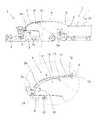
- FIG. 1depicts an inventive crop harvesting machine cooperating with a combination of a tractor and a trailer in a side view
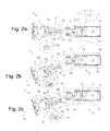
- FIG. 2 adepicts the arrangement according to FIG. 1 during normal operation
- FIG. 2 bdepicts the arrangement according to FIG. 1 in the very beginning of a curve
- FIG. 2 cdepicts the curve after deflecting the discharge spout based on the sensor information of the second sensor arrangement
- FIG. 3 adepicts the arrangement according to FIG. 1 a during normal operation
- FIG. 3 bdepicts the arrangement according to FIG. 1 a in the very beginning of an inclination
- FIG. 3 cthe arrangement according to FIG. 1 a during the inclination after deflecting the discharge spout based on the sensor information of the second sensor arrangement;
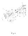
- FIG. 4depicts the arrangement according to FIGS. 2 a - c during the electronic spout control excluding the surrounding of the driving track from the search for a reference feature by the first sensor arrangement.
- the proposed crop harvesting machine 1may be of various designs, for example, a combine or a forage harvester. While those crop harvesting machines 1 are self-propelled machines, the invention may well be applicable to crop harvesting machines 1 , that are being pulled by a tractor or the like.
- the crop harvesting machine 1comprises a machine body 2 and a discharge spout 3 attached to the machine body 2 , which discharge spout 3 serves for overloading crop via a crop stream 4 to a trailer 5 .
- An electronic spout control 6 and a discharge spout drive arrangement 7are provided to displace the discharge spout 3 relative to the machine body 2 based on drive commands of the electronic spout control 6 .
- the drive commandsmay comprise a number of parameters describing the displacement of the discharge spout 3 . However, they may also comprise only the coordinates regarding the displacement of the discharge spout 3 .
- the generation of the drive commands by the electronic spout control 6serves for guiding the crop stream 4 to a target hit point 8 at the trailer 5 .
- the target hit point 8is an imaginary point at the trailer 5 which is intended to be hit by the end section 9 of the crop stream 4 .
- the target hit point 8has preferably been generated by the electronic spout control 6 based on an information regarding the geometry of the trailer 5 , which information may be retrieved from a data base or the like.
- a first sensor arrangement 10For an automatic guiding of the crop stream 4 to the target hit point 8 , a first sensor arrangement 10 is provided, which generates sensor information by optically identifying a reference feature 11 at the trailer 5 and by detecting the position at/or space orientation of the reference feature 11 .
- a possible reference feature 11is shown in the detailed view of FIG. 2 a . Here the reference feature 11 is part of the frame of the trailer 5 .
- a second sensor arrangement 12is provided, which generates sensor information by detecting a space orientation of the machine body 2 and/or the discharge spout 3 .
- the electronic spout control 6generates its drive commands for guiding the crop stream 4 based on the sensor information of the first sensor arrangement 10 at the sensor information of the second sensor arrangement 12 .
- even small changes in space orientation of the machine body 2 and/or the discharge spout 3lead to large and undesired displacements of the end section 9 of the crop stream 4 , which may even lead to the crop stream 4 missing the relevant area of the trailer 5 .
- the space orientationcomprises a yaw angle ⁇ , which may be taken from FIGS. 2 b , 2 c and 4 , a pitch angle ⁇ , which may be taken from FIG. 3 b, c and a roll angle ⁇ , which is only roughly indicated in FIG. 1 .
- the second sensor arrangement 12may be designed to detect the absolute space orientation of the machine body 2 and/or the discharge spout 3 . However, it may be advantageous to have the second sensor arrangement 12 detect a change and/or change rate in the respective space orientation. This may be explained in further detail later.
- FIG. 1shows the general concept of one preferred operation of the proposed crop harvesting machine 1 .
- the crop harvesting machine 1cooperates with the combination of a tractor 5 a and a trailer 5 , which is being pulled by the tractor 5 a .
- the combination of the tractor 5 a and the trailer 5may move behind the crop harvesting machine 1 , as shown in FIG. 1 .
- the combination of the tractor 5 a and the trailer 5may also move besides the crop harvesting machine 1 such that the crop stream 4 does not necessarily has to extent over the tractor 5 a.
- the discharge spout 3has a first section 3 a , which first section 3 a may be moved in an up and down direction V 1 by a first drive 7 a of the discharge spout drive arrangement 7 and which may be moved in a sidewise direction H 1 by a second drive 7 b of the spout drive arrangement 7 .
- the discharge spout 3comprises a second section 3 b attached to the first section 3 a , which second section 3 b may be moved by a third drive 7 c in an up and down direction V 2 relative to the first section 3 a of the discharge spout 3 .
- a third drive 7 cin an up and down direction V 2 relative to the first section 3 a of the discharge spout 3 .
- more than two sections of the discharge spout 3may be provided.
- the realization of the second sensor arrangement 12may be based on different sensor categories.
- the second sensor arrangement 12comprises a mechanic gyroscope or an electronic gyroscope. With this it is possible to measure changes in the space orientation with the second sensor arrangement 12 being of simple constructional design.
- the second sensor arrangement 12may be realized as an acceleration sensor or a compass, each possibly being of mechanic or electronic design. Other sensor categories may well be applied for the second sensor arrangement 12 .
- the first sensor arrangement 10for identifying the reference feature 11 at the trailer 5 , preferably comprises a camera arrangement, further preferably a 3D camera arrangement, which allows the application of a large number of standardized components.
- the first sensor arrangement 10may comprise a laser sensor arrangement, further preferably a laser scanner arrangement, for generation the respective sensor information.
- the reference feature 11which is to be identified by the first sensor arrangement 10 .
- the reference feature 11is defined by a crop receiving area 13 , in particular, a frame structure 14 of the crop receiving area 13 , of the trailer 5 .
- a trailer 5which comprises a box like container 15 , and again shows an open top providing the above noted crop receiving area 13 .
- the first sensor arrangement 10comprises an evaluation unit 16 , which is only indicated in the detailed view in FIG. 1 .
- the evaluation unit 16evaluates the sensor signals generated by the first sensor arrangement 10 in order to identify the above noted reference feature 11 .
- the update frequency of the resulting sensor information provided to the electronic spout control 6is higher for the second sensor arrangement 12 than for the first sensor arrangement 10 .
- the second sensor arrangement 12fills in the gap between two update cycles of the first sensor arrangement 10 such that the reaction time of the electronic spout control 6 to changes in the space orientation of the machine body 2 and/or the discharge spout 3 is relatively low.
- a pragmatic approach to improving the above noted reaction time of the electronic spout control 6is to configure the electronic spout control 6 to generate drive commands for giving the crop stream 4 to the target hit point 8 based on the sensor information of the first sensor arrangement 10 .
- the sensor information of the second sensor arrangement 12only comes into play for adjusting the drive commands of the first sensor arrangement 10 . This makes it possible to add the second sensor arrangement 12 to an existing electronic spout control 6 , which is originally guiding the crop stream 4 based on the sensor information generated by the first sensor arrangement 10 .
- the electronic spout control 6adjusts its drive commands based on the sensor information of the second sensor arrangement 12 if a change or change rate in space orientation of the machine body 2 and/or the discharge spout 3 has been detected by the second sensor arrangement 12 .
- this adjustmenthas been performed only if a change or change rate has been detected.
- the electronic spout control 6adjusts its drive commands based on the sensor information of the second sensor arrangement 12 if the detected change or change rate in space orientation of the machine body 2 and/or the discharge spout 3 exceeds a predefined critical value. Again, this adjustment is performed preferably only if the detected change or change rate exceeds the predefined critical value.
- FIGS. 2 a - c , 3 a - c and 4show preferred modes of operation of the proposed electronic spout control 6 , which may well be combined with each other.
- FIG. 4shows that the crop harvesting machine 1 drives in a curve 17 followed by the combination of tractor 5 a and trailer 5 .
- a second trailer 18is parked, which imposes a problem for the correct detection of the reference feature 11 at the first trailer 5 .
- the electronic spout control 6analyzes the sensor information of the second sensor arrangement 12 as follows: Based on the sensor information of the second sensor arrangement 12 , the electronic spout control 6 determines the drive track 19 of the crop harvesting machine 1 . With this information regarding the drive track 19 of the crop harvesting machine 1 it is possible for the electronic spout control 6 to exclude the area 20 outside of the drive track 19 from the search for the reference feature 11 .
- the first sensor arrangement 10for identifying the reference feature 11 , searches for the reference feature 11 in a search area, which search area is defined by the drive track 19 and is preferably within the drive track of the crop harvesting machine 1 .
- the first sensor arrangement 10explicitly excludes the area 20 outside the drive track 19 , such that erroneously identifying the second trailer 18 in FIG. 4 as part of the reference feature 11 is not possible any more.
- FIGS. 2 a - cAnother curve situation is shown in FIGS. 2 a - c .
- the electronic spout control 6based on the sensor information of the second sensor arrangement 12 , detects the crop harvesting machine 1 entering into the curve 17 .
- the electronic spout control 6guides the crop stream 4 to the target hit point 8 based on the sensor information of the second sensor arrangement 12 by moving, here and preferably pivoting, at least part of the discharge spout 3 , here and preferably the first section 3 a of the discharge spout 3 , in a sidewise direction H 1 by the discharge spout drive arrangement 7 .
- the crop harvesting machine 1 entering into the curve 17is shown in FIG. 2 b .
- the actual hit point 21is far off the target hit point 8 as the space orientation of the machine body 2 has changed by a yaw movement, while the first sensor arrangement 10 has not yet provided an updated sensor information regarding the position of the reference feature 11 .
- the electronic spout control 6based on the sensor information of the second sensor arrangement 12 , generates drive commands in order to compensate the yaw angle ⁇ by a corresponding displacement of the discharge spout 3 .
- FIG. 2 cHere, it becomes clear that it is the combination of the first sensor arrangement 10 and the second sensor arrangement 12 , which leads to low reaction times of the electronic spout control 6 even with dynamic changes in driving direction of the crop harvesting machine 1 .
- a similar effectmay be achieved with a proposed solution in the situation, in which the crop harvesting machine 1 enters into an inclination 22 , for example, a hump in a field.
- the electronic spout control 6based on the sensor information of the second sensor arrangement 12 , detects the crop harvesting machine 1 entering into the inclination 22 .
- the electronic spout control 6guides the crop stream 4 to the target hit point 8 based on the sensor information of the second sensor arrangement 12 by moving, here and preferably pivoting, at least part of the discharge spout 3 , here and preferably at least the first section 3 a of the discharge spout 3 , in an up and down direction V 1 by means of the discharge spout drive arrangement 7 .
- FIGS. 3 a and 3 bshow the crop harvesting machine 1 entering into the inclination 22 , thereby moving the actual hit point 21 far off from the target hit point 8 , as the sensor information of the first sensor arrangement 10 has not yet been updated.
- the pitch angle ⁇ performed by the crop harvesting machine 1is compensated by the electronic spout control 6 , as may be seen from FIG. 3 c.
- the agricultural crop harvesting machine 1also comprises a steering control and a steering drive arrangement for automatic steering of the crop harvesting machine 1 based on drive commands of the steering control.
- the arrangementis preferably such that the electronic spout control 6 and the steering control, independently from each other, generate drive commands for the steering drive and the discharge spout drive arrangement 7 respectively.
- the electronic spout control 6operates at least partly autonomously with respect to the steering control of the crop harvesting machine 1 . This makes it particularly easy to provide an existing crop harvesting machine 1 with the proposed solution.
Landscapes
- Life Sciences & Earth Sciences (AREA)
- Environmental Sciences (AREA)
- Engineering & Computer Science (AREA)
- Mechanical Engineering (AREA)
- Soil Sciences (AREA)
- Guiding Agricultural Machines (AREA)
- Combines (AREA)
Abstract
Description
- 1 crop harvesting machine
- 2 machine body
- 3 discharge spout
- 3afirst section
- 3bsecond section
- V1 up down direction
- V2 up down direction
- H1 sideways direction
- 4 crop stream
- 5 trailer
- 6 electronic spout control
- 7 discharge sprout drive arrangement
- 7afirst drive
- 7bsecond drive
- 7cthird drive
- 8 target hit point
- 9 end section crop stream
- 10 first sensor arrangement
- 11 reference feature
- 12 second sensor arrangement
- A yaw angle
- B pitch angle
- γ roll angle
- 13 crop receiving area
- 14 frame structure
- 15 container
- 16 evaluation unit
- 17 curve
- 18 second trailer
- 19 drive track
- 20 area outside
- 21 actual hit point
- 22 inclination
Claims (12)
Applications Claiming Priority (3)
| Application Number | Priority Date | Filing Date | Title |
|---|---|---|---|
| DE102015116570 | 2015-09-30 | ||
| DE102015116570.8 | 2015-09-30 | ||
| DE102015116570 | 2015-09-30 |
Publications (2)
| Publication Number | Publication Date |
|---|---|
| US20170086378A1 US20170086378A1 (en) | 2017-03-30 |
| US9924636B2true US9924636B2 (en) | 2018-03-27 |
Family
ID=56368851
Family Applications (1)
| Application Number | Title | Priority Date | Filing Date |
|---|---|---|---|
| US15/271,383Active2036-10-15US9924636B2 (en) | 2015-09-30 | 2016-09-21 | Crop harvesting machine |
Country Status (3)
| Country | Link |
|---|---|
| US (1) | US9924636B2 (en) |
| EP (1) | EP3150052B1 (en) |
| RU (1) | RU2719500C2 (en) |
Cited By (62)
| Publication number | Priority date | Publication date | Assignee | Title |
|---|---|---|---|---|
| US10371558B2 (en) | 2016-08-31 | 2019-08-06 | Deere & Company | System and method for measuring a bin level via an electromagnetic signal |
| US10481105B2 (en)* | 2016-08-31 | 2019-11-19 | Deere & Company | Measurement device and method for estimating yield of a harvested crop |
| US10863672B2 (en) | 2017-11-06 | 2020-12-15 | Deere & Company | Radio frequency measurement device for measuring harvested agricultural material |
| US10871458B2 (en) | 2017-11-06 | 2020-12-22 | Deere & Company | Radio frequency measurement device for measuring grain loss |
| US11079725B2 (en) | 2019-04-10 | 2021-08-03 | Deere & Company | Machine control using real-time model |
| US11178818B2 (en) | 2018-10-26 | 2021-11-23 | Deere & Company | Harvesting machine control system with fill level processing based on yield data |
| US11234366B2 (en) | 2019-04-10 | 2022-02-01 | Deere & Company | Image selection for machine control |
| US11240961B2 (en) | 2018-10-26 | 2022-02-08 | Deere & Company | Controlling a harvesting machine based on a geo-spatial representation indicating where the harvesting machine is likely to reach capacity |
| US20220110251A1 (en) | 2020-10-09 | 2022-04-14 | Deere & Company | Crop moisture map generation and control system |
| EP4046474A1 (en)* | 2021-02-18 | 2022-08-24 | Deere & Company | Harvester with feed forward control of filling mechanisms |
| US11467605B2 (en) | 2019-04-10 | 2022-10-11 | Deere & Company | Zonal machine control |
| US11474523B2 (en) | 2020-10-09 | 2022-10-18 | Deere & Company | Machine control using a predictive speed map |
| US11477940B2 (en) | 2020-03-26 | 2022-10-25 | Deere & Company | Mobile work machine control based on zone parameter modification |
| US11589509B2 (en) | 2018-10-26 | 2023-02-28 | Deere & Company | Predictive machine characteristic map generation and control system |
| US11592822B2 (en) | 2020-10-09 | 2023-02-28 | Deere & Company | Machine control using a predictive map |
| US11635765B2 (en) | 2020-10-09 | 2023-04-25 | Deere & Company | Crop state map generation and control system |
| US11641800B2 (en) | 2020-02-06 | 2023-05-09 | Deere & Company | Agricultural harvesting machine with pre-emergence weed detection and mitigation system |
| US11650587B2 (en) | 2020-10-09 | 2023-05-16 | Deere & Company | Predictive power map generation and control system |
| US11653588B2 (en) | 2018-10-26 | 2023-05-23 | Deere & Company | Yield map generation and control system |
| US11675354B2 (en) | 2020-10-09 | 2023-06-13 | Deere & Company | Machine control using a predictive map |
| US11672203B2 (en) | 2018-10-26 | 2023-06-13 | Deere & Company | Predictive map generation and control |
| US11711995B2 (en) | 2020-10-09 | 2023-08-01 | Deere & Company | Machine control using a predictive map |
| US11727680B2 (en) | 2020-10-09 | 2023-08-15 | Deere & Company | Predictive map generation based on seeding characteristics and control |
| US11778945B2 (en) | 2019-04-10 | 2023-10-10 | Deere & Company | Machine control using real-time model |
| US11825768B2 (en) | 2020-10-09 | 2023-11-28 | Deere & Company | Machine control using a predictive map |
| US11844311B2 (en) | 2020-10-09 | 2023-12-19 | Deere & Company | Machine control using a predictive map |
| US11845449B2 (en) | 2020-10-09 | 2023-12-19 | Deere & Company | Map generation and control system |
| US11849671B2 (en) | 2020-10-09 | 2023-12-26 | Deere & Company | Crop state map generation and control system |
| US11849672B2 (en) | 2020-10-09 | 2023-12-26 | Deere & Company | Machine control using a predictive map |
| US11864483B2 (en) | 2020-10-09 | 2024-01-09 | Deere & Company | Predictive map generation and control system |
| US11874669B2 (en) | 2020-10-09 | 2024-01-16 | Deere & Company | Map generation and control system |
| US11889787B2 (en) | 2020-10-09 | 2024-02-06 | Deere & Company | Predictive speed map generation and control system |
| US11889788B2 (en) | 2020-10-09 | 2024-02-06 | Deere & Company | Predictive biomass map generation and control |
| US11895948B2 (en) | 2020-10-09 | 2024-02-13 | Deere & Company | Predictive map generation and control based on soil properties |
| US11927459B2 (en) | 2020-10-09 | 2024-03-12 | Deere & Company | Machine control using a predictive map |
| US11946747B2 (en) | 2020-10-09 | 2024-04-02 | Deere & Company | Crop constituent map generation and control system |
| US11957072B2 (en) | 2020-02-06 | 2024-04-16 | Deere & Company | Pre-emergence weed detection and mitigation system |
| US11983009B2 (en) | 2020-10-09 | 2024-05-14 | Deere & Company | Map generation and control system |
| US12013245B2 (en) | 2020-10-09 | 2024-06-18 | Deere & Company | Predictive map generation and control system |
| US12035648B2 (en) | 2020-02-06 | 2024-07-16 | Deere & Company | Predictive weed map generation and control system |
| US12058951B2 (en) | 2022-04-08 | 2024-08-13 | Deere & Company | Predictive nutrient map and control |
| US12069978B2 (en) | 2018-10-26 | 2024-08-27 | Deere & Company | Predictive environmental characteristic map generation and control system |
| US12069986B2 (en) | 2020-10-09 | 2024-08-27 | Deere & Company | Map generation and control system |
| US12082531B2 (en) | 2022-01-26 | 2024-09-10 | Deere & Company | Systems and methods for predicting material dynamics |
| US12127500B2 (en) | 2021-01-27 | 2024-10-29 | Deere & Company | Machine control using a map with regime zones |
| US12178158B2 (en) | 2020-10-09 | 2024-12-31 | Deere & Company | Predictive map generation and control system for an agricultural work machine |
| US12225846B2 (en) | 2020-02-06 | 2025-02-18 | Deere & Company | Machine control using a predictive map |
| US12229886B2 (en) | 2021-10-01 | 2025-02-18 | Deere & Company | Historical crop state model, predictive crop state map generation and control system |
| US12245549B2 (en) | 2022-01-11 | 2025-03-11 | Deere & Company | Predictive response map generation and control system |
| US12250905B2 (en) | 2020-10-09 | 2025-03-18 | Deere & Company | Machine control using a predictive map |
| US12284934B2 (en) | 2022-04-08 | 2025-04-29 | Deere & Company | Systems and methods for predictive tractive characteristics and control |
| US12295288B2 (en) | 2022-04-05 | 2025-05-13 | Deere &Company | Predictive machine setting map generation and control system |
| US12298767B2 (en) | 2022-04-08 | 2025-05-13 | Deere & Company | Predictive material consumption map and control |
| US12302791B2 (en) | 2021-12-20 | 2025-05-20 | Deere & Company | Crop constituents, predictive mapping, and agricultural harvester control |
| US12310286B2 (en) | 2021-12-14 | 2025-05-27 | Deere & Company | Crop constituent sensing |
| US12329148B2 (en) | 2020-02-06 | 2025-06-17 | Deere & Company | Predictive weed map and material application machine control |
| US12329065B2 (en) | 2020-10-09 | 2025-06-17 | Deere & Company | Map generation and control system |
| US12329050B2 (en) | 2020-10-09 | 2025-06-17 | Deere & Company | Machine control using a predictive map |
| US12358493B2 (en) | 2022-04-08 | 2025-07-15 | Deere & Company | Systems and methods for predictive power requirements and control |
| US12386354B2 (en) | 2020-10-09 | 2025-08-12 | Deere & Company | Predictive power map generation and control system |
| US12419220B2 (en) | 2020-10-09 | 2025-09-23 | Deere & Company | Predictive map generation and control system |
| US12422847B2 (en) | 2020-10-09 | 2025-09-23 | Deere & Company | Predictive agricultural model and map generation |
Families Citing this family (3)
| Publication number | Priority date | Publication date | Assignee | Title |
|---|---|---|---|---|
| JP7473360B2 (en)* | 2020-02-27 | 2024-04-23 | 三菱マヒンドラ農機株式会社 | Automatic control device |
| EP4568467A1 (en) | 2022-08-11 | 2025-06-18 | Deere & Company | Systems and methods for predictive harvesting logistics |
| DE102023100539A1 (en) | 2023-01-11 | 2024-07-11 | Deere & Company | Arrangement for the automatic control of a transfer process from a harvesting machine to a transport vehicle taking into account crop properties |
Citations (11)
| Publication number | Priority date | Publication date | Assignee | Title |
|---|---|---|---|---|
| US4042132A (en)* | 1976-06-01 | 1977-08-16 | Sperry Rand Corporation | Spout control apparatus for agricultural machines |
| US4376609A (en)* | 1980-03-31 | 1983-03-15 | Sperry Corporation | Automatic spout control for agricultural machines |
| US4441846A (en)* | 1982-02-09 | 1984-04-10 | Deere & Company | Auto spout aimer with delay |
| US4529348A (en)* | 1983-04-06 | 1985-07-16 | Deere & Company | Spout aimer |
| EP2020174A1 (en) | 2007-08-03 | 2009-02-04 | AGROCOM GmbH & Co. Agrarsystem KG | Agricultural working machine |
| EP2301318A1 (en) | 2009-09-07 | 2011-03-30 | CLAAS Agrosystems GmbH & Co. KG | A control system of an agricultural vehicle with a goods carrier, an agricultural vehicle and a method of controlling a goods carrier of the agricultural vehicle |
| US20120215394A1 (en)* | 2011-02-18 | 2012-08-23 | Guoping Wang | System and method for synchronized control of a harvester and transport vehicle |
| DE102011052688A1 (en) | 2011-08-12 | 2013-02-14 | Andreas Reichhardt | Method for filling transport vehicles through crop harvesting or loading machine, involves evaluating signal generated by optical sensor and relative position of crop harvesting or loading machine and transport vehicle |
| EP2792229A1 (en) | 2013-04-02 | 2014-10-22 | Deere & Company | Control arrangement and method for controlling a position of a transfer device of a harvesting machine |
| GB2517049A (en) | 2013-07-28 | 2015-02-11 | Deere & Co | Artificial intelligence for detecting and filling void areas of agricultural commodity containers |
| US20160323519A1 (en)* | 2013-12-10 | 2016-11-03 | Cnh Industrial America Llc | Sensor Arrangement |
Family Cites Families (14)
| Publication number | Priority date | Publication date | Assignee | Title |
|---|---|---|---|---|
| DE19629618A1 (en) | 1996-07-23 | 1998-01-29 | Claas Ohg | Route planning system for agricultural work vehicles |
| DE19848127A1 (en)* | 1998-10-19 | 2000-04-20 | Claas Selbstfahr Erntemasch | Device for controlling a transfer device |
| DE10064862A1 (en) | 2000-12-23 | 2002-07-11 | Claas Selbstfahr Erntemasch | Device and method for coordinating and adjusting agricultural vehicles |
| DE10211706A1 (en) | 2002-03-16 | 2003-09-25 | Deere & Co | Discharge device for an agricultural harvesting machine |
| DE10242164A1 (en)* | 2002-09-10 | 2004-04-01 | Claas Selbstfahrende Erntemaschinen Gmbh | Method for controlling a transfer device |
| US6789014B1 (en) | 2003-05-09 | 2004-09-07 | Deere & Company | Direct modification of DGPS information with inertial measurement data |
| DE102007045846A1 (en) | 2007-09-26 | 2009-04-02 | Deere & Company, Moline | Agricultural machine and method for determining position |
| DE102009027245A1 (en) | 2009-06-26 | 2010-12-30 | Deere & Company, Moline | Control arrangement for controlling the transfer of agricultural crop from a harvester to a transport vehicle |
| DE102010017459A1 (en) | 2010-06-18 | 2011-12-22 | Claas Selbstfahrende Erntemaschinen Gmbh | Agricultural harvester |
| DE102011002071A1 (en) | 2011-04-15 | 2012-10-18 | Claas Selbstfahrende Erntemaschinen Gmbh | System and method for controlling crop overload |
| DE102011082052B4 (en) | 2011-09-02 | 2015-05-28 | Deere & Company | Arrangement and method for the automatic overloading of crop material from a harvester onto a transport vehicle |
| WO2013162673A2 (en) | 2012-02-10 | 2013-10-31 | Deere & Company | System and method of material handling using one or more imaging devices on the transferring vehicle to control the material distribution into the storage portion of the receiving vehicle |
| US9326444B2 (en) | 2013-02-08 | 2016-05-03 | Deere & Company | Method and stereo vision system for facilitating the unloading of agricultural material from a vehicle |
| GB2515172B (en) | 2013-04-22 | 2016-01-06 | Univ Carnegie Mellon | Methods for improving the robustness of an automated unloading system |
- 2016
- 2016-07-04EPEP16177681.0Apatent/EP3150052B1/ennot_activeRevoked
- 2016-09-19RURU2016137253Apatent/RU2719500C2/enactive
- 2016-09-21USUS15/271,383patent/US9924636B2/enactiveActive
Patent Citations (16)
| Publication number | Priority date | Publication date | Assignee | Title |
|---|---|---|---|---|
| US4042132A (en)* | 1976-06-01 | 1977-08-16 | Sperry Rand Corporation | Spout control apparatus for agricultural machines |
| US4376609A (en)* | 1980-03-31 | 1983-03-15 | Sperry Corporation | Automatic spout control for agricultural machines |
| US4441846A (en)* | 1982-02-09 | 1984-04-10 | Deere & Company | Auto spout aimer with delay |
| US4529348A (en)* | 1983-04-06 | 1985-07-16 | Deere & Company | Spout aimer |
| EP2020174A1 (en) | 2007-08-03 | 2009-02-04 | AGROCOM GmbH & Co. Agrarsystem KG | Agricultural working machine |
| US20090044505A1 (en) | 2007-08-03 | 2009-02-19 | Jochen Huster | Agricultural working machine |
| US9107344B2 (en) | 2009-09-07 | 2015-08-18 | Claas E-Systems Kgaa Mbh & Co Kg | Control system of agricultural vehicle with goods carrier, agricultural vehicle, and method of controlling goods carrier of agricultural vehicle |
| EP2301318A1 (en) | 2009-09-07 | 2011-03-30 | CLAAS Agrosystems GmbH & Co. KG | A control system of an agricultural vehicle with a goods carrier, an agricultural vehicle and a method of controlling a goods carrier of the agricultural vehicle |
| US20120215394A1 (en)* | 2011-02-18 | 2012-08-23 | Guoping Wang | System and method for synchronized control of a harvester and transport vehicle |
| DE102011052688A1 (en) | 2011-08-12 | 2013-02-14 | Andreas Reichhardt | Method for filling transport vehicles through crop harvesting or loading machine, involves evaluating signal generated by optical sensor and relative position of crop harvesting or loading machine and transport vehicle |
| EP2792229A1 (en) | 2013-04-02 | 2014-10-22 | Deere & Company | Control arrangement and method for controlling a position of a transfer device of a harvesting machine |
| US9313951B2 (en) | 2013-04-02 | 2016-04-19 | Deere & Company | Optical image capture for controlling a position of a harvester transfer device |
| US9532504B2 (en) | 2013-04-02 | 2017-01-03 | Carnegie Mellon University | Control arrangement and method for controlling a position of a transfer device of a harvesting machine |
| GB2517049A (en) | 2013-07-28 | 2015-02-11 | Deere & Co | Artificial intelligence for detecting and filling void areas of agricultural commodity containers |
| DE102014108449A1 (en) | 2013-07-28 | 2015-02-26 | Deere & Company | Artificial intelligence for collecting and filling empty areas in containers for agricultural goods |
| US20160323519A1 (en)* | 2013-12-10 | 2016-11-03 | Cnh Industrial America Llc | Sensor Arrangement |
Cited By (76)
| Publication number | Priority date | Publication date | Assignee | Title |
|---|---|---|---|---|
| US10371558B2 (en) | 2016-08-31 | 2019-08-06 | Deere & Company | System and method for measuring a bin level via an electromagnetic signal |
| US10481105B2 (en)* | 2016-08-31 | 2019-11-19 | Deere & Company | Measurement device and method for estimating yield of a harvested crop |
| US10863672B2 (en) | 2017-11-06 | 2020-12-15 | Deere & Company | Radio frequency measurement device for measuring harvested agricultural material |
| US10871458B2 (en) | 2017-11-06 | 2020-12-22 | Deere & Company | Radio frequency measurement device for measuring grain loss |
| US11672203B2 (en) | 2018-10-26 | 2023-06-13 | Deere & Company | Predictive map generation and control |
| US11178818B2 (en) | 2018-10-26 | 2021-11-23 | Deere & Company | Harvesting machine control system with fill level processing based on yield data |
| US11589509B2 (en) | 2018-10-26 | 2023-02-28 | Deere & Company | Predictive machine characteristic map generation and control system |
| US11240961B2 (en) | 2018-10-26 | 2022-02-08 | Deere & Company | Controlling a harvesting machine based on a geo-spatial representation indicating where the harvesting machine is likely to reach capacity |
| US12010947B2 (en) | 2018-10-26 | 2024-06-18 | Deere & Company | Predictive machine characteristic map generation and control system |
| US11653588B2 (en) | 2018-10-26 | 2023-05-23 | Deere & Company | Yield map generation and control system |
| US12069978B2 (en) | 2018-10-26 | 2024-08-27 | Deere & Company | Predictive environmental characteristic map generation and control system |
| US12178156B2 (en) | 2018-10-26 | 2024-12-31 | Deere & Company | Predictive map generation and control |
| US12171153B2 (en) | 2018-10-26 | 2024-12-24 | Deere & Company | Yield map generation and control system |
| US11650553B2 (en) | 2019-04-10 | 2023-05-16 | Deere & Company | Machine control using real-time model |
| US11467605B2 (en) | 2019-04-10 | 2022-10-11 | Deere & Company | Zonal machine control |
| US11829112B2 (en) | 2019-04-10 | 2023-11-28 | Deere & Company | Machine control using real-time model |
| US11234366B2 (en) | 2019-04-10 | 2022-02-01 | Deere & Company | Image selection for machine control |
| US11079725B2 (en) | 2019-04-10 | 2021-08-03 | Deere & Company | Machine control using real-time model |
| US11778945B2 (en) | 2019-04-10 | 2023-10-10 | Deere & Company | Machine control using real-time model |
| US11641800B2 (en) | 2020-02-06 | 2023-05-09 | Deere & Company | Agricultural harvesting machine with pre-emergence weed detection and mitigation system |
| US12035648B2 (en) | 2020-02-06 | 2024-07-16 | Deere & Company | Predictive weed map generation and control system |
| US12225846B2 (en) | 2020-02-06 | 2025-02-18 | Deere & Company | Machine control using a predictive map |
| US12329148B2 (en) | 2020-02-06 | 2025-06-17 | Deere & Company | Predictive weed map and material application machine control |
| US11957072B2 (en) | 2020-02-06 | 2024-04-16 | Deere & Company | Pre-emergence weed detection and mitigation system |
| US11477940B2 (en) | 2020-03-26 | 2022-10-25 | Deere & Company | Mobile work machine control based on zone parameter modification |
| US11927459B2 (en) | 2020-10-09 | 2024-03-12 | Deere & Company | Machine control using a predictive map |
| US12080062B2 (en) | 2020-10-09 | 2024-09-03 | Deere & Company | Predictive map generation based on seeding characteristics and control |
| US11844311B2 (en) | 2020-10-09 | 2023-12-19 | Deere & Company | Machine control using a predictive map |
| US11845449B2 (en) | 2020-10-09 | 2023-12-19 | Deere & Company | Map generation and control system |
| US11849671B2 (en) | 2020-10-09 | 2023-12-26 | Deere & Company | Crop state map generation and control system |
| US11849672B2 (en) | 2020-10-09 | 2023-12-26 | Deere & Company | Machine control using a predictive map |
| US11864483B2 (en) | 2020-10-09 | 2024-01-09 | Deere & Company | Predictive map generation and control system |
| US11874669B2 (en) | 2020-10-09 | 2024-01-16 | Deere & Company | Map generation and control system |
| US11871697B2 (en) | 2020-10-09 | 2024-01-16 | Deere & Company | Crop moisture map generation and control system |
| US11889787B2 (en) | 2020-10-09 | 2024-02-06 | Deere & Company | Predictive speed map generation and control system |
| US11889788B2 (en) | 2020-10-09 | 2024-02-06 | Deere & Company | Predictive biomass map generation and control |
| US11895948B2 (en) | 2020-10-09 | 2024-02-13 | Deere & Company | Predictive map generation and control based on soil properties |
| US11727680B2 (en) | 2020-10-09 | 2023-08-15 | Deere & Company | Predictive map generation based on seeding characteristics and control |
| US11946747B2 (en) | 2020-10-09 | 2024-04-02 | Deere & Company | Crop constituent map generation and control system |
| US11711995B2 (en) | 2020-10-09 | 2023-08-01 | Deere & Company | Machine control using a predictive map |
| US12422847B2 (en) | 2020-10-09 | 2025-09-23 | Deere & Company | Predictive agricultural model and map generation |
| US11983009B2 (en) | 2020-10-09 | 2024-05-14 | Deere & Company | Map generation and control system |
| US12013698B2 (en) | 2020-10-09 | 2024-06-18 | Deere & Company | Machine control using a predictive map |
| US11675354B2 (en) | 2020-10-09 | 2023-06-13 | Deere & Company | Machine control using a predictive map |
| US12013245B2 (en) | 2020-10-09 | 2024-06-18 | Deere & Company | Predictive map generation and control system |
| US11650587B2 (en) | 2020-10-09 | 2023-05-16 | Deere & Company | Predictive power map generation and control system |
| US12048271B2 (en) | 2020-10-09 | 2024-07-30 | Deere &Company | Crop moisture map generation and control system |
| US12419220B2 (en) | 2020-10-09 | 2025-09-23 | Deere & Company | Predictive map generation and control system |
| US11635765B2 (en) | 2020-10-09 | 2023-04-25 | Deere & Company | Crop state map generation and control system |
| US12069986B2 (en) | 2020-10-09 | 2024-08-27 | Deere & Company | Map generation and control system |
| US11825768B2 (en) | 2020-10-09 | 2023-11-28 | Deere & Company | Machine control using a predictive map |
| US12386354B2 (en) | 2020-10-09 | 2025-08-12 | Deere & Company | Predictive power map generation and control system |
| US12329050B2 (en) | 2020-10-09 | 2025-06-17 | Deere & Company | Machine control using a predictive map |
| US11592822B2 (en) | 2020-10-09 | 2023-02-28 | Deere & Company | Machine control using a predictive map |
| US12178158B2 (en) | 2020-10-09 | 2024-12-31 | Deere & Company | Predictive map generation and control system for an agricultural work machine |
| US11474523B2 (en) | 2020-10-09 | 2022-10-18 | Deere & Company | Machine control using a predictive speed map |
| US12193350B2 (en) | 2020-10-09 | 2025-01-14 | Deere & Company | Machine control using a predictive map |
| US12216472B2 (en) | 2020-10-09 | 2025-02-04 | Deere & Company | Map generation and control system |
| US12329065B2 (en) | 2020-10-09 | 2025-06-17 | Deere & Company | Map generation and control system |
| US20220110251A1 (en) | 2020-10-09 | 2022-04-14 | Deere & Company | Crop moisture map generation and control system |
| US12271196B2 (en) | 2020-10-09 | 2025-04-08 | Deere &Company | Machine control using a predictive map |
| US12250905B2 (en) | 2020-10-09 | 2025-03-18 | Deere & Company | Machine control using a predictive map |
| US12127500B2 (en) | 2021-01-27 | 2024-10-29 | Deere & Company | Machine control using a map with regime zones |
| US12256672B2 (en) | 2021-02-18 | 2025-03-25 | Deere &Company | Harvester with feed forward control of filling mechanisms |
| US11968927B2 (en) | 2021-02-18 | 2024-04-30 | Deere & Company | Harvester with feed forward control of filling mechanisms |
| EP4046474A1 (en)* | 2021-02-18 | 2022-08-24 | Deere & Company | Harvester with feed forward control of filling mechanisms |
| US12229886B2 (en) | 2021-10-01 | 2025-02-18 | Deere & Company | Historical crop state model, predictive crop state map generation and control system |
| US12310286B2 (en) | 2021-12-14 | 2025-05-27 | Deere & Company | Crop constituent sensing |
| US12302791B2 (en) | 2021-12-20 | 2025-05-20 | Deere & Company | Crop constituents, predictive mapping, and agricultural harvester control |
| US12245549B2 (en) | 2022-01-11 | 2025-03-11 | Deere & Company | Predictive response map generation and control system |
| US12082531B2 (en) | 2022-01-26 | 2024-09-10 | Deere & Company | Systems and methods for predicting material dynamics |
| US12295288B2 (en) | 2022-04-05 | 2025-05-13 | Deere &Company | Predictive machine setting map generation and control system |
| US12298767B2 (en) | 2022-04-08 | 2025-05-13 | Deere & Company | Predictive material consumption map and control |
| US12284934B2 (en) | 2022-04-08 | 2025-04-29 | Deere & Company | Systems and methods for predictive tractive characteristics and control |
| US12358493B2 (en) | 2022-04-08 | 2025-07-15 | Deere & Company | Systems and methods for predictive power requirements and control |
| US12058951B2 (en) | 2022-04-08 | 2024-08-13 | Deere & Company | Predictive nutrient map and control |
Also Published As
| Publication number | Publication date |
|---|---|
| RU2719500C2 (en) | 2020-04-20 |
| EP3150052B1 (en) | 2018-06-13 |
| EP3150052A1 (en) | 2017-04-05 |
| RU2016137253A (en) | 2018-03-26 |
| US20170086378A1 (en) | 2017-03-30 |
| RU2016137253A3 (en) | 2020-02-03 |
Similar Documents
| Publication | Publication Date | Title |
|---|---|---|
| US9924636B2 (en) | Crop harvesting machine | |
| US11001258B2 (en) | Lane keeping assist system and method for improving safety in preceding vehicle follower longitudinal control | |
| US10696301B2 (en) | Vehicle control device | |
| US20180099666A1 (en) | Vehicle control device | |
| US9510508B2 (en) | Monitoring system for controlling the position of an implement for an agricultural vehicle while taking the vehicle dynamics into account | |
| US8682540B2 (en) | Method for directing an unloading apparatus of a harvesting machine to a container | |
| US9092677B2 (en) | Apparatus and method for recognizing location of vehicle | |
| US20090037059A1 (en) | Control system for agricultural working vehicles | |
| EP3336582A1 (en) | Vision sensing compensation | |
| US11485413B2 (en) | Application of auxiliary lighting in automatic hitch operation | |
| JP3722486B1 (en) | Vehicle lane marking recognition device | |
| US9928606B2 (en) | Method for detecting interferences in a crop collection system | |
| EP3409097B1 (en) | Agricultural working machine | |
| US20210402994A1 (en) | Platooning control method and system | |
| US8548665B2 (en) | Movable body system | |
| KR101980277B1 (en) | accident prevention device for OHT | |
| WO2019176842A1 (en) | Work vehicle and deviation amount calculation program | |
| JP4263534B2 (en) | Vehicle travel support device | |
| KR101971444B1 (en) | Automatically driven vehicle | |
| US20220382290A1 (en) | Material Detection and Handling of Material Irregularities | |
| US12128900B2 (en) | Vehicle controller, and method and computer program for controlling vehicle | |
| US20240142238A1 (en) | Path Planning for an Agricultural Field Based on End of Swath Detection | |
| KR100559379B1 (en) | Device and method for generating steering angle data of vehicle through image tracking of preceding vehicle | |
| JP2006012191A (en) | Vehicle lane marking recognition device | |
| US20220137633A1 (en) | Method for an online calibration, and calibration device |
Legal Events
| Date | Code | Title | Description |
|---|---|---|---|
| AS | Assignment | Owner name:CLAAS E-SYSTEMS KGAA MBH & CO KG, GERMANY Free format text:ASSIGNMENT OF ASSIGNORS INTEREST;ASSIGNORS:LISOUSKI, PAVEL;KIRK, KRISTIAN;ANDERSEN, GERT LYSGAARD;AND OTHERS;SIGNING DATES FROM 20160817 TO 20160908;REEL/FRAME:040095/0268 | |
| AS | Assignment | Owner name:CLAAS E-SYSTEMS KGAA MBH & CO KG, GERMANY Free format text:CHANGE OF ADDRESS;ASSIGNOR:CLAAS E-SYSTEMS KGAA MBH & CO KG;REEL/FRAME:044557/0227 Effective date:20171101 | |
| STCF | Information on status: patent grant | Free format text:PATENTED CASE | |
| AS | Assignment | Owner name:CLAAS E-SYSTEMS GMBH, GERMANY Free format text:CHANGE OF NAME;ASSIGNOR:CLAAS E-SYSTEMS KGAA MBH & CO KG;REEL/FRAME:048228/0074 Effective date:20181115 | |
| AS | Assignment | Owner name:CLAAS E-SYSTEMS VERWALTUNGS GMBH, GERMANY Free format text:ASSIGNMENT OF ASSIGNORS INTEREST;ASSIGNOR:CLAAS E-SYSTEMS KGAA MBH & CO. KG;REEL/FRAME:048291/0401 Effective date:20181204 | |
| AS | Assignment | Owner name:CLAAS E-SYSTEMS GMBH, GERMANY Free format text:CHANGE OF NAME;ASSIGNOR:CLAAS E-SYSTEMS VERWALTUNGS GMBH;REEL/FRAME:048301/0413 Effective date:20181204 | |
| MAFP | Maintenance fee payment | Free format text:PAYMENT OF MAINTENANCE FEE, 4TH YEAR, LARGE ENTITY (ORIGINAL EVENT CODE: M1551); ENTITY STATUS OF PATENT OWNER: LARGE ENTITY Year of fee payment:4 | |
| MAFP | Maintenance fee payment | Free format text:PAYMENT OF MAINTENANCE FEE, 8TH YEAR, LARGE ENTITY (ORIGINAL EVENT CODE: M1552); ENTITY STATUS OF PATENT OWNER: LARGE ENTITY Year of fee payment:8 |