US9924609B2 - Modular protection cabinet with flexible backplane - Google Patents
Modular protection cabinet with flexible backplaneDownload PDFInfo
- Publication number
- US9924609B2 US9924609B2US15/216,537US201615216537AUS9924609B2US 9924609 B2US9924609 B2US 9924609B2US 201615216537 AUS201615216537 AUS 201615216537AUS 9924609 B2US9924609 B2US 9924609B2
- Authority
- US
- United States
- Prior art keywords
- enclosure
- rear base
- connectors
- electronic devices
- cavity
- Prior art date
- Legal status (The legal status is an assumption and is not a legal conclusion. Google has not performed a legal analysis and makes no representation as to the accuracy of the status listed.)
- Active
Links
Images


Classifications
- H—ELECTRICITY
- H05—ELECTRIC TECHNIQUES NOT OTHERWISE PROVIDED FOR
- H05K—PRINTED CIRCUITS; CASINGS OR CONSTRUCTIONAL DETAILS OF ELECTRIC APPARATUS; MANUFACTURE OF ASSEMBLAGES OF ELECTRICAL COMPONENTS
- H05K7/00—Constructional details common to different types of electric apparatus
- H05K7/14—Mounting supporting structure in casing or on frame or rack
- H05K7/1438—Back panels or connecting means therefor; Terminals; Coding means to avoid wrong insertion
- H05K7/1458—Active back panels; Back panels with filtering means
- G—PHYSICS
- G05—CONTROLLING; REGULATING
- G05F—SYSTEMS FOR REGULATING ELECTRIC OR MAGNETIC VARIABLES
- G05F1/00—Automatic systems in which deviations of an electric quantity from one or more predetermined values are detected at the output of the system and fed back to a device within the system to restore the detected quantity to its predetermined value or values, i.e. retroactive systems
Definitions
- the present inventionrelates to a sealed enclosure for protecting electronics.
- Enclosuresprotect electronics that filter signals sent to a host electronic device.
- the enclosureshave electronic circuit boards and wiring that connect, for example, the filter module to the host electronic device.
- the enclosuresuse discrete components and gas filter tubes that require a significant amount of wiring which results in difficulty in accessing and/or reconfiguring the different components.
- the electronic circuit boards that provide the connection between a filter module and a host electronic deviceare fixed within the enclosure. Therefore, the reconfiguration of the enclosure to add another filter module or switch to a different type of filter module may require significant rewiring and configuration changes to the circuitry. Moreover, when a filter module is inserted into the enclosure, the filter module may not directly align with the electronic circuit board within the enclosure.
- the enclosureincludes a rear base defining a cavity for holding one or more electronic devices.
- the enclosureincludes a front cover coupled to the rear base and movable between an open position and a closed position.
- the enclosureincludes a chassis mounted within the cavity of the rear base and a drawer chest having a multiple drawers within the cavity of the rear base.
- the drawer chestis connected to the chassis, and the multiple drawers are configured to receive the one or more electronic devices.
- the enclosureincludes one or more connectors that are exposed outward and provide a connection to a host electronic device.
- the front cover and the rear basemay be connected using a hinge.
- the hingemay have a pin which may allow the front cover to be uncoupled from the rear base when the pin is removed.
- the rear base of the enclosuremay have a rear surface which may have a recessed portion.
- the one or more connectorsmay be exposed outward from the recessed portion.
- the enclosuremay have a side mount for additional electronic devices to be mounted to the side surface of the rear base.
- the enclosuremay have a rain cover to protect the additional electronic device when the rain cover is closed and a mounting plate to connect the rain cover to the side surface.
- the enclosuremay have one or more connectors connected to a rear surface of the rear base.
- the one or more connectorsmay have a first end exposed within the cavity and a second end exposed outward from the rear surface.
- the enclosuremay have a flex backplane that has one or more printed circuit boards and one or more cables that connect the one or more connectors to the one or more printed circuit boards.
- the one or more cablesmay be routed along one or more paths.
- a flexible harnessmay electrically connect an inserted electronic device to at least one of the one or more connectors.
- the one or more electronic devicesmay include one or more interchangeable transient protection modules.
- the one or more interchangeable transient protection modulesmay include two to eight wire signal protection modules.
- the different signal types being protectedmay include analog, digital, loudspeaker, T1/E1, Digital Subscriber Line (DSL), Ethernet, Power over Ethernet (PoE) or various others.
- Each drawer of the multiple drawersmay define a cavity that holds an electronic device.
- the drawermay have two rail interfaces on opposite sides to receive a rail of the electronic device.
- the enclosuremay include a first slide plate connected to a back end of the drawer chest and a flex backplane connected to the first slide plate.
- the enclosuremay include a second slide plate connected to the flex backplane and a backplane support for guiding cables to the one or more connectors.
- the flex backplanemay have one or more printed circuit boards that connect to the one or more electronic devices when the one or more electronic devices are inserted into a drawer.
- the one or more printed circuit boardsmay have one or more connector lobes. Each connector lobe of the one or more connector lobes may be located at an end of a respective drawer and have one or more self-aligning connectors.
- Each connector lobemay float around a central longitudinal axis of the drawer so that the one or more self-aligning connectors align with one or more connectors of an electronic device when the electronic device is inserted into the drawer.
- the enclosuremay have a door stay connected to the front cover and an interior surface of the rear base. The door stay may prop the front cover open when in the open position.
- the subject matteris embodied in a flexible backplane for interfacing with electronic devices.
- the flexible backplaneincludes one or more printed circuit boards.
- a respective printed circuit board of the one or more printed circuit boardshas one or more connectors and a connector lobe.
- the flexible backplaneincludes a flexible accordion attachment connected to the connector lobe and configured to allow the connector lobe to float or move in a plurality of directions.
- the subject matteris embodied in an electronic device enclosure system for filtering signals.
- the electronic device enclosure systemincludes an enclosure.
- the enclosureincludes a rear base defining a cavity and a front cover coupled to the rear base and movable between an open position and a closed position.
- the enclosureincludes a chassis mounted within the cavity of the rear base and a drawer chest having multiple drawers within the cavity.
- the electronic device enclosure systemincludes multiple interchangeable transient protection modules being inserted into the cavity of the rear base. Each respective transient protection module being inserted into a respective drawer of the plurality of drawers.
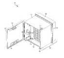
- FIG. 1is a front view of an enclosure system for providing signal filtering according to an aspect of the invention
- FIG. 2is a side view of the enclosure of FIG. 1 according to an aspect of the invention
- FIG. 3is a rear view of the enclosure of FIG. 1 according to an aspect of the invention.
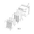
- FIG. 4is an exploded view of the interior of the enclosure of FIG. 1 according to an aspect of the invention.
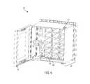
- FIG. 5is an inside view of the front of the enclosure of FIG. 1 according to an aspect of the invention.
- FIG. 6is an exploded view of the drawers of the drawer chest of the enclosure of FIG. 1 according to an aspect of the invention
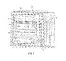
- FIG. 7is an interior view of the rear portion according to an aspect of the invention.
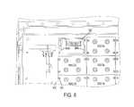
- FIG. 8is an interior view of the enclosure of FIG. 1 showing an interconnection of the signal devices to the input/output connectors according to an aspect of the invention
- FIG. 9is an exploded view of the one or more printed circuit boards according to an aspect of the invention.
- FIG. 10is a side view of the enclosure showing an additional connector according to an aspect of the invention.
- FIG. 11is an illustration of a four-post analog transient protection module according to an aspect of the invention.
- FIG. 12is an illustration of a loudspeaker two-post transient protection module according to an aspect of the invention.
- FIG. 13is an illustration of a four-post digital transient protection module according to an aspect of the invention.
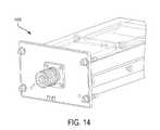
- FIG. 14is an illustration of a T1/E1 transient protection module according to an aspect of the invention.
- FIG. 15is an illustration of an Ethernet transient protection module according to an aspect of the invention.
- FIG. 16is a rear view of a transient protection module according to an embodiment of the present invention.
- An enclosuresuch as a Ground Communication Filter Unit (GCFU)
- GCFUGround Communication Filter Unit
- TPMstransient protection modules
- filter modulesfilters
- TPMstransient protection modules
- the enclosureis reconfigurable without interruption to the operation of the other inserted electronic devices. That is, the enclosure may be reconfigured to receive any number of electronic devices and/or different types of electronic devices.
- the modular designallows easy reconfiguration of the number and types of stored electronic devices.
- the electronic devicesmay be arranged in any number of configurations, e.g., vertically and/or horizontally, within the enclosure.
- TPMsmay be arranged in any number of rows and/or columns.
- the flexibilityallows for the number and arrangement of the electronic devices to be configured and reconfigured depending on the task. For example, a first task may require use of four analog filters. Upon completion of the first task, the enclosure may be easily reconfigured to support a second task requiring the use of four digital filters instead of the four analog filters without having to rewire the enclosure. Thus, the enclosure saves time and provides interoperability to perform different tasks that require different electronic devices.
- Other benefits and advantagesmay include the capability to connect to electronic devices that are mis-aligned. For example, if a connector of an electronic device does not align with the connectors on the printed circuit boards within the enclosure, the connectors on the printed circuit board may float about an axis to electrically connect with the electronic device. Moreover, aspects of the enclosure reduce wiring error within the enclosure and provide a connection to the external input/output interface. Thus, the enclosure assists in maintaining signal connectivity between an electronic device and the host electronic device.
- the modularity of the electronic devicesallows for easier removal and maintenance of the electronic devices for repair. Thus, service costs and time are reduced.
- FIG. 1is a front view of an enclosure system for providing signal filtering.
- the enclosure system 100includes an enclosure 101 that holds and protects one or more electronic devices 116 .
- the enclosure 101provides an interface between the one or more electronic devices 116 and a host electronic device.
- the enclosure 101may be mounted onto the host electronic device, wall or other surface.
- the enclosure 101protects the one or more electronic devices 116 from shock, dust, dirt, weather, water, heat and other environmental conditions or damage.
- the enclosure 101may meet or exceed one or more governmental requirements to withstand environmental conditions, such as vibration, shock or stress thresholds.
- the enclosure 101may have physical dimensions of approximately 16.5 inches by 18 inches by 18 inches, and the exposed surfaces of the enclosure 101 may be coated with a non-reflective coating.
- the one or more electronic devices 116 that are inserted into the enclosure 101may be one or more signal modules and/or one or more filter modules, e.g., one or more transient protection modules (TPMs).
- the one or more transient protection modulesprotect different signal types.
- the different signal types being protectedmay include analog, digital, loudspeaker, T1/E1, Digital Subscriber Line (DSL), Ethernet, Power over Ethernet (PoE) or various others.
- the TPMs that are stored and protected in the enclosure 101are described in U.S. Pat. No. 9,190,837, which is hereby incorporated by reference herein.
- the enclosure 101has a front cover 102 and a rear base 104 .
- the front cover 102may define an internal cavity 124 .
- the front cover 102may have a wind stop to protect the enclosure 101 from the wind.
- the rear base 104may define an internal cavity 114 .
- the one or more electronic devices 116are held within the internal cavities 114 , 124 of the enclosure 101 .
- the front cover 102is movable between an open position and a closed position.
- the front cover 102may have a lip 122 that covers the outer perimeter edge of the rear base 104 when the front cover 102 is in the closed position.
- the rear base 104 and/or front cover 102may have a gasket 118 that runs along the outer perimeter edge such that when the front cover 102 is in the closed position incoming cabling is protected from abrasion.
- the enclosure 101may have one or more latches 112 .
- the latch 112may snap or latch onto the front cover 102 when the front cover 102 is in the closed position to secure the front cover 102 to the rear base 104 .
- the enclosure 101may have a door stay 120 .
- the door stay 120may be connected to an inner surface of the rear base 104 and an inner surface of the front cover 102 .
- the door stay 120may be configured to prop the front cover 102 in the open position.
- the door stay 120may be a door-biasing mechanism. That is, the door stay 120 may have a locked position and an unlocked position, such that when the door stay 120 is in the locked position and the front cover 102 is in the open position, the door stay 120 props the front cover 102 open. But, when the front cover 102 is open and the door stay 120 is in the unlocked position, the front cover 102 may be moved into the closed position.
- the rear base 104may segregate the internal cavity 114 into an electrically dirty portion 106 and an electrically clean portion 108 .
- the dirty portion 106may be an area susceptible to electro-magnetic interference (EMI) and/or electro-magnetic conductance (EMC).
- the clean portion 108may be an area protected against EMI and/or EMC.
- the clean portion 108may house an inserted electronic device, such as a TPM.
- the inner surface of the clean portion 108may have an anodized coating, chromate conversion coating, or other protective (and preferably conductive) coating.
- the rear base 104may segregate the internal cavity 114 into the two portions using a dividing wall.
- the mounting flange 110forms an annular ring around the enclosure 101 that seals out EMI/EMC from the host electronic device.
- the mounting flange 110may have a gasket on the back side toward the host electronic device, i.e., the side toward the clean portion 108 .
- the mounting flange 110may be used to mount the enclosure 101 to the host electronic device.
- FIG. 2is a side view of the enclosure 101 .
- the front cover 102may use a securing mechanism, such as a hinge 202 , to swing between the open position and the closed position and secure the front cover 102 to the rear base 104 .
- the securing mechanismmay include the hinge 202 and a pin 204 .
- the hinge 202may be fastened to the front cover 102 and the rear base 104 and interconnect to secure the front cover 102 with the side surface of the rear base 104 when the pin 204 is inserted.
- the hinge 202may run vertically along a longitudinal axis that extends from a point near a top surface of the enclosure 101 to a point near the bottom surface of the enclosure 101 .
- the hinge 202extends along a portion of the perimeter of the outer surface of the front cover 102 and a portion of the outer side surface of the rear base 104 .
- the hinge 202has a central through-hole that extends along the longitudinal axis and receives the pin 204 .
- the hinge 202may run horizontally from a point near a side surface of the enclosure 101 to a point near an opposite side surface of the enclosure 101 on either the top surface of the enclosure 101 or the bottom surface of the enclosure 101 to open in a vertical direction.
- the pin 204has a top end and a bottom end.
- the top end of the pin 204may have a service handle 206 that allows a user to lift and remove the pin 204 and guide the pin 204 through the through-hole of the hinge 202 .
- a hairpin cotter pin, e-clip, or key ring at the bottom end of the pin 204may secure the pin 204 within the hinge 202 .
- the pin 204secures the front cover 102 to the rear base 104 when inserted. When the pin 204 is removed, the front cover 102 is removable from the rear base 104 .
- FIG. 3is a rear view of the enclosure 101 .
- the rear base 104has a rear surface 308 .
- the rear surfacehas a recessed region 310 .
- One or more input/output connectorse.g., input/output connectors 302 , 304 , and 306 , extend from within the cavity 114 of the rear base 104 outward through the rear surface 308 so that the one or more input/output connectors 302 , 304 and 306 are exposed outward from the rear surface 308 .
- the one or more input/output connectors 302 , 304 and 306may connect to the host electronic device and allow a signal inputted through the one or more electronic devices 116 to pass or filter through to the host electronic device.
- FIG. 4is an exploded view of the interior of the enclosure 101 .
- the interior of the enclosure 101includes a drawer chest 402 and a chassis 416 .
- the chassis 416 and the drawer chest 402may be brazed using an aluminum brazing process to provide EMI protection.
- the chassis 416may have a first slide plate 404 , a flex backplane 406 with one or more floating printed circuit boards 412 attached via flex harnesses and located within it, a second slide plate 408 , a backplane support 410 and/or a cover 414 .
- the enclosure 101 , the drawer chest 402 , and the backplane support 410may be made of aluminum or other metal.
- the slide plates 404 , 408are non-metal, such as Delrin® (acetal) or Teflon® (Polytetrafluoroethylene or PTFE).
- the enclosure 101has a monolithic backplane and instead of the slide plates 404 , 408 , has only a backplane support 410 .
- the backplane support 410would be non-metal, such as Delrin® (acetal) or Teflon® (PTFE).
- the drawer chest 402is further described below in reference to FIG. 5 .
- the first slide plate 404may be connected to a back end of the drawer chest 402 .
- the flex backplane 406may be connected to and in between the first slide plate 404 and the second slide plate 408 .
- the second slide plate 408may be connected to the backplane support 410 .
- the flex backplane 406may have one or more printed circuit boards 412 that connect to one or more connectors of at least one of the one or more electronic devices 116 , such as connectors 1604 a - d of the transient protection module 1600 as shown in FIG. 16 , when the at least one of the one or more electronic devices 116 is inserted into one of the drawers 502 .
- At least one of the first slide plate 404 , the second slide plate 408 , the backplane support 410 or the flex backplane 406may be configured to allow one or more printed circuit boards 412 to float.
- the one or more connectors on the printed circuit boards 412may be able to move or angle to maintain or establish the connection with the connectors on the corresponding electronic device 116 .
- Different types of the one or more electronic devices 116may connect to the one or more printed circuit boards 412 .
- any of the different types of TPMsincluding a 4-post analog transient protection module 1100 , a loudspeaker 2-post transient protection module 1200 , a 4-post digital transient protection module 1300 , a T1/E1 transient protection module 1400 , or an Ethernet transient protection module 1500 , as shown in FIGS. 11-15 respectively, may connect to the one or more printed circuit boards 412 .
- the enclosure 101may receive any one of the different types of the one or more electronic devices 116 in one of the multiple drawers 502 to connect to one of the one or more printed circuit boards 412 .
- a cover 414may connect in between the backplane support 410 and a flex harness 804 , as shown in FIG. 8 .
- the cover 414may protect one or more module guide pins that stick through the backplane support 410 from rubbing against the flex harness 804 .
- FIG. 5is an inside view of the front of the enclosure 101 with the front cover 102 open.
- a drawer chest 402is inside the enclosure 101 and within the cavity 114 .
- the drawer chest 402has multiple drawers 502 .
- the drawer chest 402may arrange the multiple drawers 502 in any number of rows and/or columns in any number of configurations.
- the enclosure 101has 6 rows and 3 columns of drawers for a total of 18 drawers.
- Any number of the one or more electronic devices 116may be placed in the drawers 502 in any configuration depending on the application and/or host electronic device. If no electronic device is inserted into an empty drawer, a cover plate would need to be installed in that position. For example, a first set of electronic devices may be inserted into the first column of drawers 502 .
- the first setmay then be removed and a second set of electronic devices may be inserted in the third row of drawers 502 .
- the modularity of the electronic devices 116provides flexibility in adding, removing and/or reconfiguring the placement of the electronic devices 116 which allows easy access to the electronic devices 116 and simplifies configuration of the electronic devices 116 for different applications.
- the multiple drawers 502have a cavity that extends along an axis from an opening of the cavity 114 to the rear of the rear base 104 .
- the cavity of the multiple drawers 502receives the one or more electronic devices 116 .
- the multiple drawers 502may receive different types of the one or more electronic devices 116 . For example, any of the different types of TPMs may be received within one of the multiple drawers 502 of the drawer chest 402 .
- Each of the drawers 502may have a sliding mechanism to receive an electronic device.
- the sliding mechanismmay be two rail interfaces, e.g., rail interfaces 604 a - b of FIG. 6 , that are on opposite sides of each of the drawers 502 .
- the rail interfaces 604 a - bmay receive the rails 1602 a - b of the transient protection module 1600 , as shown in FIG. 16 , when the transient protection module 1600 is inserted into one of the drawers 502 .
- Each of the drawers 502may have EMI Shielding surrounding the opening of the drawer to maintain the EM barrier of the enclosure, and may be mounted to the drawer chest 402 using one or more fasteners 602 , such as a screw.
- FIG. 7is an interior view of the rear portion of the enclosure 101 .
- the rear portionhas the one or more input/output connectors 302 , 304 and 306 that are exposed outward of the rear surface 308 .
- the one or more input/output connectors 302 , 304 and 306are housed within the rear base 104 and are exposed from the enclosure 101 from the recessed region 708 .
- Wires from the one or more printed circuit boards 412may be bundled behind the backplane support 410 into one or more cables 702 a - c to connect to the one or more input/output connectors 302 , 304 and 306 .
- the one or more cables 702 a - cmay be routed along one or more cable paths, such as the cable paths 704 and 706 .
- the one or more input/output connectors 302 , 304 and 306may connect to the host electronic device, for example, when the enclosure 101 is mounted onto the host electronic device.
- the one or more printed circuit boards 412are connected to the one or more input/output connectors 302 , 304 and 306 through a flex harness 804 , as shown in FIG. 8 .
- the flex harness 804connects to the input/output connectors 302 , 304 and 306 to provide external input/output.
- the flex harness 804reduces the potential for wiring error within the enclosure 101 .
- FIG. 9is an exploded view of the one or more printed circuit boards 412 .
- the one or more printed circuit boards 412 on the flex backplane 406may include one or more connectors 904 a - d .
- the one or more connectors 904 a - dmay be self-aligning.
- the one or more connectors 904 a - dmay be female connectors, male connectors or a combination of both.
- the one or more connectors 904 a - 904 dare configured to receive and/or insert into a corresponding connector of an inserted electronic device 116 .
- the one or more connectors 904 a - dmay receive a corresponding connector of multiple different types of electronic devices 116 .
- the different types of electronic devices 116may be interchangeable with each other.
- a first electronic devicesuch as a four-post analog transient protection module
- the first electronic devicemay then be removed and a second electronic device, such as a T1/E1 transient protection module, may be inserted and connected to the same printed circuit board.
- the one or more connectors 904 a - dmay be mounted on a connector lobe 902 .
- the connector lobe 902may be connected to a flexible accordion attachment 904 .
- the flexible accordion attachment 904may attach to the flex backplane 406 .
- the slide plates 404 , 408 and the flexible accordion attachment 904may allow the printed circuit board 412 to float or move vertically and/or horizontally so that the one or more connectors 904 a - d may self-align and minimize the stress with one or more mis-aligned connectors of an inserted electronic device 116 .
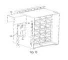
- FIG. 10is a side view of the enclosure 101 showing an additional filter module 1008 .
- the enclosure 101may have a side mount 1010 that is mounted on a side surface of the rear base 104 .
- the additional filter module 1008may be mounted using the side mount 1010 .
- a rain cover 1004is mounted to a mounting plate 1002 that is connected to the side mount 1010 .
- the rain cover 1004may be movable between a raised position (as shown) and a lowered position. When in the lowered position, the rain cover 1004 encloses the additional filter module 1008 and protects the additional filter module 1008 from rain ingress and/or other environmental conditions.
- FIG. 16is a rear view of a transient protection module 1600 .
- the transient protection module 1600has a housing 1608 , a front panel 1606 , and one or more connectors 1604 .
- the housing 1608may have a lid and may be made of aluminum.
- the front panel 1606may have one or more binding posts, e.g., binding posts 1102 a - d of FIG. 11 .
- the binding postsmay connect to a source signal that is to be filtered and may be surrounded with an insulator.
- the transient protection module 1600may have multiple guide rails, e.g., rails 1602 a - b , positioned on opposite sides of the transient protection module 1600 .
- the rails 1602 a - bmay interface and slide into the one or more rail interfaces 604 a - b of a drawer 502 .
- the one or more connectors 1604 a - d of the TPM 1600may engage the one or more connectors 904 a - d of the one or more printed circuit boards 412 .
- the one or more connectors 1604 a - dmay have a pin 1610 that engages the one or more connectors 904 a - d to guide and align the connector on the TPM with the connectors on the printed circuit boards 412 before the electrical contacts meet.
Landscapes
- Engineering & Computer Science (AREA)
- Microelectronics & Electronic Packaging (AREA)
- Physics & Mathematics (AREA)
- Electromagnetism (AREA)
- General Physics & Mathematics (AREA)
- Radar, Positioning & Navigation (AREA)
- Automation & Control Theory (AREA)
- Casings For Electric Apparatus (AREA)
Abstract
Description
Claims (20)
Priority Applications (3)
| Application Number | Priority Date | Filing Date | Title |
|---|---|---|---|
| US15/216,537US9924609B2 (en) | 2015-07-24 | 2016-07-21 | Modular protection cabinet with flexible backplane |
| US15/899,293US10356928B2 (en) | 2015-07-24 | 2018-02-19 | Modular protection cabinet with flexible backplane |
| US15/948,932US10588236B2 (en) | 2015-07-24 | 2018-04-09 | Modular protection cabinet with flexible backplane |
Applications Claiming Priority (2)
| Application Number | Priority Date | Filing Date | Title |
|---|---|---|---|
| US201562196837P | 2015-07-24 | 2015-07-24 | |
| US15/216,537US9924609B2 (en) | 2015-07-24 | 2016-07-21 | Modular protection cabinet with flexible backplane |
Related Child Applications (1)
| Application Number | Title | Priority Date | Filing Date |
|---|---|---|---|
| US15/899,293Continuation-In-PartUS10356928B2 (en) | 2015-07-24 | 2018-02-19 | Modular protection cabinet with flexible backplane |
Publications (2)
| Publication Number | Publication Date |
|---|---|
| US20170027068A1 US20170027068A1 (en) | 2017-01-26 |
| US9924609B2true US9924609B2 (en) | 2018-03-20 |
Family
ID=57837581
Family Applications (1)
| Application Number | Title | Priority Date | Filing Date |
|---|---|---|---|
| US15/216,537ActiveUS9924609B2 (en) | 2015-07-24 | 2016-07-21 | Modular protection cabinet with flexible backplane |
Country Status (1)
| Country | Link |
|---|---|
| US (1) | US9924609B2 (en) |
Cited By (1)
| Publication number | Priority date | Publication date | Assignee | Title |
|---|---|---|---|---|
| US11172585B1 (en)* | 2021-05-03 | 2021-11-09 | New Frontier Technologies LLC | Magnetic operator interface assembly |
Families Citing this family (14)
| Publication number | Priority date | Publication date | Assignee | Title |
|---|---|---|---|---|
| USD801335S1 (en)* | 2015-05-04 | 2017-10-31 | Siemens Aktiengesellschaft | Data transmission device |
| US10800141B2 (en) | 2016-09-23 | 2020-10-13 | Apple Inc. | Electronic device having a glass component with crack hindering internal stress regions |
| EP3811510A4 (en)* | 2018-06-25 | 2022-01-19 | ABB Schweiz AG | Protection device for switchgear assembly, switchgear assembly, and switchgear |
| CN108879345B (en)* | 2018-07-28 | 2024-05-14 | 河南森源电气股份有限公司 | Wiring structure of switch cabinet |
| US11856724B2 (en) | 2018-11-30 | 2023-12-26 | Ovh | System comprising a rack, with support members and components insertable in the rack and connectable via liquid connectors |
| PL3661339T3 (en) | 2018-11-30 | 2022-06-06 | Ovh | Rack adapted for receiving a component and system including the rack and the component |
| PL3697183T3 (en) | 2019-02-13 | 2021-09-06 | Ovh | Rack adapted for receiving a component, system including the rack and the component and method of delivering power to a component mounted in a rack |
| US11680010B2 (en) | 2019-07-09 | 2023-06-20 | Apple Inc. | Evaluation of transparent components for electronic devices |
| CN115955798A (en)* | 2020-03-28 | 2023-04-11 | 苹果公司 | Glass cover member for housing of electronic equipment |
| CN112469234A (en)* | 2020-11-19 | 2021-03-09 | 江门市新会区宏信科技有限公司 | Space-saving storage cabinet for network engineering |
| WO2022133136A1 (en) | 2020-12-17 | 2022-06-23 | Apple Inc. | Fluid forming a glass component for a portable electronic device |
| WO2022133133A1 (en) | 2020-12-17 | 2022-06-23 | Apple Inc. | Forming of glass components for portable electronic devices |
| US11945048B2 (en) | 2020-12-23 | 2024-04-02 | Apple Inc. | Laser-based cutting of transparent components for an electronic device |
| CN113966121B (en)* | 2021-11-02 | 2023-05-16 | 深圳智慧光迅信息技术有限公司 | Outdoor protection equipment of laying of router |
Citations (192)
| Publication number | Priority date | Publication date | Assignee | Title |
|---|---|---|---|---|
| US2030179A (en) | 1933-01-19 | 1936-02-11 | American Telephone & Telegraph | Electrical circuit arrangement |
| US2857558A (en)* | 1955-08-29 | 1958-10-21 | Paul E Fiske | Electronics package |
| US3167729A (en) | 1962-10-29 | 1965-01-26 | Sylvania Electric Prod | Microwave filter insertable within outer wall of coaxial line |
| US3323083A (en) | 1965-03-17 | 1967-05-30 | Amp Inc | Means and method for transmission line compensation |
| US3596165A (en) | 1969-07-24 | 1971-07-27 | Tektronix Inc | Converter circuit having a controlled output |
| US3619721A (en) | 1970-06-01 | 1971-11-09 | Gen Electric | Triggered vacuum gap keep-alive circuit |
| US3662225A (en)* | 1970-01-09 | 1972-05-09 | Qicsys Systems Inc | Multi-printed circuit assembly |
| US3663901A (en) | 1970-02-27 | 1972-05-16 | Amp Inc | Tuned coaxial device |
| US3731234A (en) | 1971-12-27 | 1973-05-01 | Bell Telephone Labor Inc | Combined voice frequency transmission and dc signaling circuit |
| US3750053A (en) | 1972-04-24 | 1973-07-31 | Plessey Inc | Coaxial transmission line rf switch |
| US3783178A (en) | 1972-08-03 | 1974-01-01 | Gen Signal Corp | Expansion joint for connecting rigid conduit with grounding continuity |
| US3831110A (en) | 1972-05-01 | 1974-08-20 | Cornell Res Foundation Inc | Multi-axis cavities for microwave semiconductors |
| US3832627A (en) | 1971-09-25 | 1974-08-27 | Sony Corp | Transistor circuit with slow voltage rise and fast voltage fall characteristic |
| US3845358A (en) | 1973-06-29 | 1974-10-29 | Gen Electric | Integrated polycrystalline varistor surge protective device for high frequency applications |
| US3921015A (en) | 1974-08-01 | 1975-11-18 | Branson Ultrasonics Corp | High voltage transient protection means as for piezoelectric transducers |
| US3944937A (en) | 1973-12-06 | 1976-03-16 | Matsushita Electric Industrial Co., Ltd. | Broad-band signal transmitting device using transformer |
| US3956717A (en) | 1974-08-01 | 1976-05-11 | Wideband Services, Inc. | Hybrid diplexing filter |
| US3980976A (en) | 1974-03-28 | 1976-09-14 | Sony Corporation | Coaxial connector |
| US4021759A (en) | 1976-01-19 | 1977-05-03 | The United States Of America As Represented By The Secretary Of The Army | EMP line filter using MOV devices |
| US4047120A (en) | 1976-07-15 | 1977-09-06 | The United States Of America As Represented By The Secretary Of The Navy | Transient suppression circuit for push-pull switching amplifiers |
| US4046451A (en) | 1976-07-08 | 1977-09-06 | Andrew Corporation | Connector for coaxial cable with annularly corrugated outer conductor |
| US4112395A (en) | 1977-06-10 | 1978-09-05 | Cincinnati Electronics Corp. | Method of and apparatus for matching a load circuit to a drive circuit |
| US4262317A (en) | 1979-03-22 | 1981-04-14 | Reliable Electric Company | Line protector for a communications circuit |
| US4287764A (en)* | 1979-03-02 | 1981-09-08 | Hartmann & Braun Aktiengesellschaft | Fluid analyzer construction and housing |
| US4356360A (en) | 1981-02-26 | 1982-10-26 | Amf Incorporated | Pull-to-turn switch |
| US4359764A (en) | 1980-04-08 | 1982-11-16 | Block Roger R | Connector for electromagnetic impulse suppression |
| US4384331A (en) | 1979-04-23 | 1983-05-17 | Nissan Motor Company, Limited | Noise suppressor for vehicle digital system |
| US4409637A (en) | 1980-04-08 | 1983-10-11 | Block Roger R | Connector for electromagnetic impulse suppression |
| US4481641A (en) | 1982-09-30 | 1984-11-06 | Ford Motor Company | Coaxial cable tap coupler for a data transceiver |
| US4554608A (en) | 1982-11-15 | 1985-11-19 | Block Roger R | Connector for electromagnetic impulse suppression |
| US4563720A (en) | 1984-04-17 | 1986-01-07 | General Semiconductor Industries, Inc. | Hybrid AC line transient suppressor |
| US4586104A (en) | 1983-12-12 | 1986-04-29 | Rit Research Corp. | Passive overvoltage protection devices, especially for protection of computer equipment connected to data lines |
| US4679121A (en)* | 1985-01-24 | 1987-07-07 | Ant Nachrichtentechnik Gmbh | Assembly system for communications device having plug-in circuit boards connected in multiple stages |
| US4689713A (en) | 1985-06-12 | 1987-08-25 | Les Cables De Lyon | High voltage surge protection for electrical power line |
| US4698721A (en) | 1983-11-07 | 1987-10-06 | Puroflow Corp. | Power line filter for transient and continuous noise suppression |
| US4727350A (en) | 1986-04-28 | 1988-02-23 | Hitoshi Ohkubo | Surge absorber |
| US4901183A (en) | 1988-08-29 | 1990-02-13 | World Products, Inc. | Surge protection device |
| US4952173A (en) | 1986-09-05 | 1990-08-28 | Raychem Pontoise | Circuit protection device |
| CH675933A5 (en) | 1989-07-27 | 1990-11-15 | Huber+Suhner Ag | Triaxial electromagnetic pulse conductor - has inner conductor and two screening conductors with unit to maintain contact with overload conductor |
| US4984146A (en) | 1990-03-27 | 1991-01-08 | International Business Machines Corporation | Suppression of radiated EMI for power supplies |
| US4985800A (en) | 1989-10-30 | 1991-01-15 | Feldman Nathan W | Lighting protection apparatus for RF equipment and the like |
| US5053910A (en) | 1989-10-16 | 1991-10-01 | Perma Power Electronics, Inc. | Surge suppressor for coaxial transmission line |
| US5057964A (en) | 1986-12-17 | 1991-10-15 | Northern Telecom Limited | Surge protector for telecommunications terminals |
| US5093759A (en)* | 1988-12-13 | 1992-03-03 | Honeywell, Inc. | Replaceable electronics box |
| US5102818A (en) | 1989-09-21 | 1992-04-07 | Deutsche Itt Industries Gmbh | Method for the smooth fine classification of varactor diodes |
| US5122921A (en) | 1990-04-26 | 1992-06-16 | Industrial Communication Engineers, Ltd. | Device for electromagnetic static and voltage suppression |
| US5124873A (en) | 1989-10-30 | 1992-06-23 | Efi Corporation | Surge suppression circuit for high frequency communication networks |
| US5142429A (en) | 1990-05-07 | 1992-08-25 | Telefonaktiebolaget L M Ericsson | Overvoltage and overcurrent protective circuit with high earth balance |
| US5166855A (en) | 1991-02-27 | 1992-11-24 | Semitron Industries Ltd. | Surge protector with thermal failsafe |
| US5170151A (en) | 1991-02-21 | 1992-12-08 | Hochstein Peter A | Method and assembly for disconnecting a battery from its operating system |
| US5278720A (en) | 1991-09-20 | 1994-01-11 | Atlantic Scientific Corp. | Printed circuit-mounted surge suppressor matched to characteristic impedance of high frequency transmission line |
| US5321573A (en) | 1992-07-16 | 1994-06-14 | Dale Electronics, Inc. | Monolythic surge suppressor |
| US5325270A (en)* | 1992-05-29 | 1994-06-28 | Telco Systems, Inc. | Modular backplane |
| US5353189A (en) | 1992-11-02 | 1994-10-04 | Tomlinson John C | Surge protector for vehicular traffic monitoring equipment |
| WO1995010116A1 (en) | 1993-10-07 | 1995-04-13 | Andrew Corporation | Surge protector connector |
| US5412526A (en) | 1993-02-10 | 1995-05-02 | Square D Company | Surge arrester circuit and housing therefor |
| US5442330A (en) | 1993-12-27 | 1995-08-15 | Motorola, Inc. | Coupled line filter with improved out-of-band rejection |
| JPH0866037A (en) | 1994-06-09 | 1996-03-08 | Fuji Electric Co Ltd | Power supply |
| US5534768A (en) | 1994-02-09 | 1996-07-09 | Harris Corporation | Regulated power supply having wide input AC/DC voltage range |
| US5537044A (en) | 1994-09-30 | 1996-07-16 | The United States Of America As Represented By The Secretary Of The Navy | Surge voltage generator for pulsing grounded and ungrounded electrical equipment |
| US5584396A (en)* | 1995-05-17 | 1996-12-17 | Dell Usa Lp | Sliding pivoting storage apparatus |
| US5611224A (en) | 1993-10-29 | 1997-03-18 | The Eastern Company | Handle operable rotary latch and lock |
| US5617284A (en) | 1994-08-05 | 1997-04-01 | Paradise; Rick | Power surge protection apparatus and method |
| US5625521A (en) | 1994-07-22 | 1997-04-29 | Pacusma Co.,Ltd. | Surge protection circuitry |
| US5667298A (en) | 1996-01-16 | 1997-09-16 | Cedarapids, Inc. | Portable concrete mixer with weigh/surge systems |
| US5721662A (en) | 1992-07-29 | 1998-02-24 | Act Communications, Inc. | Floating ground isolator for a communications cable locating system |
| US5781844A (en) | 1995-03-22 | 1998-07-14 | Scientific-Atlanta, Inc. | Method and apparatus for distributing a power signal and an RF signal |
| US5790361A (en) | 1997-03-31 | 1998-08-04 | The Whitaker Corporation | Coaxial surge protector with impedance matching |
| US5844766A (en) | 1997-09-09 | 1998-12-01 | Forem S.R.L. | Lightning supression system for tower mounted antenna systems |
| US5854730A (en) | 1997-09-15 | 1998-12-29 | Mitchell; Dennis | Transient and voltage surge protection system and method for preventing damage to electrical equipment |
| US5863211A (en)* | 1996-12-12 | 1999-01-26 | International Business Machines Corporation | Inter-book-package mechanical and electrical connection system |
| JPH1137400A (en) | 1997-07-18 | 1999-02-12 | Tokyo Gas Co Ltd | Pipeline surge current monitoring method |
| US5889650A (en)* | 1995-04-20 | 1999-03-30 | Telefonaktiebolaget Lm Ericsson | Stand arrangement |
| US5943225A (en) | 1996-11-22 | 1999-08-24 | Samsung Electronics Co., Ltd. | Circuit for removing a peak reverse voltage generated from a power supply source |
| US5953195A (en) | 1997-02-26 | 1999-09-14 | Reltec Corporation | Coaxial protector |
| US5959839A (en)* | 1997-01-02 | 1999-09-28 | At&T Corp | Apparatus for heat removal using a flexible backplane |
| US5963407A (en) | 1997-02-19 | 1999-10-05 | Sgs-Thomson Microelectronics S.R.L. | Overvoltage protection device for the protection of a power transistor having a MOS control terminal |
| US5966283A (en) | 1995-08-18 | 1999-10-12 | Act Communications, Inc. | Surge suppression for radio frequency transmission lines |
| US5973918A (en)* | 1997-06-16 | 1999-10-26 | Compaq Computer Corporation | Aligned pivoting power supply tray and guided input/output tray for connection of the power supply and input/output to the computer motherboard |
| US5986869A (en) | 1998-02-05 | 1999-11-16 | Polyphaser Corporation | Grounding panel |
| US5984720A (en)* | 1997-10-17 | 1999-11-16 | Hubbell Incorporated | Angled interconnect panel assembly for telecommunications applications |
| US6026458A (en) | 1997-10-14 | 2000-02-15 | International Business Machines Corporation | System with pluggable adapter card and hot-swap interface controller |
| US6031705A (en) | 1997-07-05 | 2000-02-29 | Robert Bosch Gmbh | Surge protection circuit, in particular for inputs of integrated circuits |
| US6054905A (en) | 1998-01-21 | 2000-04-25 | General Instrument Coporation | User configurable CATV power inserter |
| US6061223A (en) | 1997-10-14 | 2000-05-09 | Polyphaser Corporation | Surge suppressor device |
| US6060182A (en) | 1997-06-09 | 2000-05-09 | Teikoku Piston Ring Co., Ltd. | Hard coating material, sliding member covered with hard coating material and manufacturing method thereof |
| US6076906A (en)* | 1999-02-08 | 2000-06-20 | Royal; Keith | Entertainment center for storing electronic components |
| US6086544A (en) | 1999-03-31 | 2000-07-11 | Ethicon Endo-Surgery, Inc. | Control apparatus for an automated surgical biopsy device |
| US6137352A (en) | 1997-01-27 | 2000-10-24 | Huber And Suhner Ag | Circuit arrangement for protection of HF-input-circuit on telecommunications devices |
| US6141194A (en) | 1998-09-22 | 2000-10-31 | Simmonds Precision Products, Inc. | Aircraft fuel tank protective barrier and method |
| US6177849B1 (en) | 1998-11-18 | 2001-01-23 | Oneline Ag | Non-saturating, flux cancelling diplex filter for power line communications |
| US6195493B1 (en)* | 1999-05-21 | 2001-02-27 | Scientific-Atlanta, Inc. | Universal chassis for CATV headends or telecommunications company central office for optical electronic equipment |
| US6226166B1 (en) | 1997-11-28 | 2001-05-01 | Erico Lighting Technologies Pty Ltd | Transient overvoltage and lightning protection of power connected equipment |
| US6243247B1 (en) | 1998-09-22 | 2001-06-05 | Polyphaser Corporation | Stripline transient protection device |
| US6252755B1 (en) | 1999-08-11 | 2001-06-26 | Advanced Micro Devices, Inc. | Apparatus and method for implementing a home network using customer-premises power lines |
| US6281690B1 (en) | 1996-07-19 | 2001-08-28 | Lockheed Martin Corporation | Coaxial radio frequency test probe |
| US6285563B1 (en)* | 1999-03-31 | 2001-09-04 | Emc Corporation | Support bracket for a printed circuit board connectable to daughter boards |
| US6342998B1 (en) | 1998-11-13 | 2002-01-29 | Leviton Manufacturing Co., Inc. | Data surge protection module |
| US6381283B1 (en) | 1998-10-07 | 2002-04-30 | Controlnet, Inc. | Integrated socket with chip carrier |
| US6385030B1 (en) | 1999-09-02 | 2002-05-07 | Marconi Communications, Inc. | Reduced signal loss surge protection circuit |
| US6388879B1 (en)* | 1994-03-17 | 2002-05-14 | Fujitsu Limited | Circuit board packaging structure |
| US6390831B2 (en)* | 1998-10-26 | 2002-05-21 | Fujitsu Limited | Shelf-type telecommunications device including main and sub back wired boards connected by relay connectors |
| US6394122B1 (en) | 2000-09-21 | 2002-05-28 | Pacific Seismic Products, Inc. | Shock actuated sensor for fluid valve |
| US6421220B2 (en) | 1998-05-29 | 2002-07-16 | Porta Systems Corporation | Low capacitance surge protector for high speed data transmission |
| US20020167302A1 (en) | 2001-05-09 | 2002-11-14 | Gallavan Michael F. | Surge current measurement |
| US6483029B1 (en)* | 2001-03-12 | 2002-11-19 | General Bandwidth Inc. | Convertible telecommunication chassis and method for converting same |
| US20020191360A1 (en) | 2001-05-22 | 2002-12-19 | Enrico Colombo | Current detector for surge arrester diagnostic and overvoltage assessment in high voltage substations |
| US6502599B1 (en) | 2000-09-21 | 2003-01-07 | Pacific Seismic Products, Inc. | Shock actuated responsive mechanism for vertical fluid valve assemblies |
| US6527004B1 (en) | 2000-09-21 | 2003-03-04 | Pacific Seismic Products, Inc. | Shock actuated responsive mechanism for vertical fluid valve assemblies |
| JP2003070156A (en) | 2001-08-27 | 2003-03-07 | Nittan Co Ltd | Lighting rod system and unit |
| US6535369B1 (en) | 2000-06-16 | 2003-03-18 | Teal Electronics Corporation | Adaptive surge suppressor |
| JP2003111270A (en) | 2001-09-28 | 2003-04-11 | Okaya Electric Ind Co Ltd | Surge protector |
| US20030072121A1 (en) | 2001-10-12 | 2003-04-17 | Polyphaser Corporation | Rf surge protection device |
| US20030151870A1 (en) | 2001-03-14 | 2003-08-14 | Roman Gronbach | Device for voltage transformation |
| US20030161130A1 (en)* | 2002-02-28 | 2003-08-28 | Fujitsu Limited | Electronic device and system composed of a plurality of electronic devices |
| US20030179533A1 (en) | 2002-03-21 | 2003-09-25 | Polyphaser Corporation | Isolated shield coaxial surge suppressor |
| KR20030081041A (en) | 2002-04-09 | 2003-10-17 | 후지 덴키 가부시끼가이샤 | Overvoltage protection circuit |
| US20030211782A1 (en) | 2002-05-07 | 2003-11-13 | Mr. Joseph Lorenzo De Guzman | Filtered RJ11 connector module with LED indicators and method of manufacturing |
| US20040057224A1 (en)* | 2002-07-25 | 2004-03-25 | Kiko Frederick J. | High density electronics assembly and method |
| US6721155B2 (en) | 2001-08-23 | 2004-04-13 | Andrew Corp. | Broadband surge protector with stub DC injection |
| US20040100751A1 (en) | 2000-10-25 | 2004-05-27 | Bruno Ammann | Surge protection filter and lighting conductor system |
| US6754060B2 (en) | 2000-07-06 | 2004-06-22 | George M. Kauffman | Protective device |
| US20040121648A1 (en) | 2002-07-26 | 2004-06-24 | V-Squared Networks | Network device for communicating information |
| US6757152B2 (en) | 2001-09-05 | 2004-06-29 | Avx Corporation | Cascade capacitor |
| US20040145849A1 (en) | 2002-11-15 | 2004-07-29 | Chang Byung-Ho | Surge protection device and method |
| US20040156179A1 (en)* | 2003-02-11 | 2004-08-12 | Hockett John E. | Electronics box having internal circuit cards interconnected to external connectors sans motherboard |
| US6789560B1 (en) | 2000-09-21 | 2004-09-14 | Pacific Seismic Products, Inc. | Shock actuated responsive mechanism with improved safety means to prevent over-rotation of the valve reset mechanism |
| US6814100B1 (en) | 2000-09-21 | 2004-11-09 | Pacific Seismic Products, Inc. | Shock actuated responsive mechanism with means to enable a remote detecting means to determine that the valve assembly has been closed |
| US6816348B2 (en) | 2001-05-18 | 2004-11-09 | Compal Electronics, Inc. | Input protection circuit of a handheld electric device |
| US20040264087A1 (en) | 2003-06-30 | 2004-12-30 | Bishop Roger S | Transient protector for wireless communications equipment |
| US20050030721A1 (en)* | 2002-08-09 | 2005-02-10 | Tsutomu Shimada | Electronic apparatus and information processing apparatus |
| US20050036262A1 (en) | 2003-07-09 | 2005-02-17 | Siebenthall Fred Mac | DC Voltage surge suppressor with distributed capacitance EMI filtering and impedance matching |
| US20050044858A1 (en) | 2003-08-26 | 2005-03-03 | Kenneth Hooker | Two stage solenoid control valve |
| US20050176275A1 (en) | 2004-02-05 | 2005-08-11 | Panamax | Modular signal and power connection device |
| US20050185354A1 (en) | 2004-02-25 | 2005-08-25 | Hoopes Gerald B. | Protection of A/V components |
| US6940730B1 (en)* | 2001-02-28 | 2005-09-06 | Adc Telecommunications, Inc. | Telecommunications chassis and card |
| US20050206482A1 (en) | 2004-03-17 | 2005-09-22 | Dutoit Nicolaas | Electronically tunable switched-resonator filter bank |
| US6968852B1 (en) | 2000-09-21 | 2005-11-29 | Pacific Seismic Products, Inc. | Shock actuated responsive mechanism with improved dual safety means to prevent over-rotation of the valve reset mechanism and to provide easy access to the reset knob |
| US20060044076A1 (en) | 2004-09-02 | 2006-03-02 | Law Robinson P S | Serial signal injection using capacitive and transformer couplings for power line communications |
| US20060082946A1 (en) | 2004-10-14 | 2006-04-20 | Rain Bird Corporation | Power surge protection in an irrigation controller |
| US20060120005A1 (en) | 2004-11-15 | 2006-06-08 | Van Sickle Robert J | Transient voltage surge suppression systems |
| US20060139832A1 (en) | 2004-12-29 | 2006-06-29 | Hewlett-Packard Development Company, L.P. | Common mode surge protection filter |
| US20060146458A1 (en) | 2005-01-03 | 2006-07-06 | Huberag | Surge suppressor with increased surge current capability |
| US7075796B1 (en)* | 2005-09-06 | 2006-07-11 | Hewlett-Packard Development Company, L.P. | Cage for printed circuit board |
| US7082022B2 (en) | 2002-05-31 | 2006-07-25 | Polyphaser Corporation | Circuit for diverting surges and transient impulses |
| US20060171133A1 (en)* | 2005-02-03 | 2006-08-03 | Fujitsu Network Communications, Inc. | Grow as you go equipment shelf |
| US7106572B1 (en) | 1999-09-17 | 2006-09-12 | Adee Electronic (Societe A Responsabilite Limitee) | Device for protecting against voltage surges |
| US7130103B2 (en) | 2004-03-08 | 2006-10-31 | Seiko Epson Corporation | Optical modulator and manufacturing method of optical modulator |
| US7159236B2 (en) | 2000-06-30 | 2007-01-02 | Kabushiki Kaisha Toshiba | Transmission/reception integrated radio-frequency apparatus |
| US20070053130A1 (en) | 2005-09-01 | 2007-03-08 | Andrew Corporation | Offset Planar Coil Coaxial Surge Suppressor |
| US20070139850A1 (en) | 2005-12-15 | 2007-06-21 | Raycap Corporation | Overvoltage protection devices including wafer of varistor material |
| US7250829B2 (en) | 2001-09-14 | 2007-07-31 | Matsushita Electric Industrial Co., Ltd. | High frequency switch |
| US20070202753A1 (en)* | 2002-09-19 | 2007-08-30 | Masakazu Murakami | Joint connector |
| US20070232089A1 (en)* | 2006-03-31 | 2007-10-04 | Nortel Networks Limited | Bridge modules for connecting plural groups of electronic modules |
| US7352576B2 (en)* | 2006-04-19 | 2008-04-01 | Tyan Computer Corporation | Multi-processor system and tubelike computer module thereof |
| US20080170346A1 (en) | 2007-01-17 | 2008-07-17 | Andrew Corporation | Folded Surface Capacitor In-line Assembly |
| US7430103B2 (en) | 2003-09-19 | 2008-09-30 | Sharp Kabushiki Kaisha | Static electricity protective circuit and high-frequency circuit apparatus incorporating the same |
| US7453268B2 (en) | 2005-06-29 | 2008-11-18 | Delphi Technologies, Inc. | Input power protected ratiometric output sensor circuit |
| US20080298035A1 (en)* | 2006-02-24 | 2008-12-04 | Fujitsu Limitd | Printed circuit board unit |
| US7471172B2 (en) | 2003-05-02 | 2008-12-30 | Lgp Allgon Ab | Microwave transmission unit including lightning protection |
| KR20090018497A (en) | 2007-08-17 | 2009-02-20 | 주식회사 텔콘 | RF surge protector |
| US7507105B1 (en) | 2007-07-17 | 2009-03-24 | Ventek, Llc | Hazardous area coupler device |
| US20090103226A1 (en) | 2007-10-18 | 2009-04-23 | Polyphaser Corporation | Surge suppression device having one or more rings |
| US20090109584A1 (en) | 2007-10-30 | 2009-04-30 | Polyphaser Corporation | Surge protection circuit for passing dc and rf signals |
| US20090284888A1 (en) | 2008-05-19 | 2009-11-19 | Polyphaser Corporation | Dc and rf pass broadband surge suppressor |
| US7623332B2 (en) | 2008-01-31 | 2009-11-24 | Commscope, Inc. Of North Carolina | Low bypass fine arrestor |
| US20090296430A1 (en) | 2008-05-29 | 2009-12-03 | Airbus France | Pre-charging device for a chopping converter, and an assembly and aircraft comprising it |
| US7675726B2 (en) | 2003-07-28 | 2010-03-09 | Siemens Aktiengesellschaft | Device for protecting electronic modules in a multi-voltage on-board electrical system against short circuits |
| US7808752B2 (en) | 2004-08-17 | 2010-10-05 | Semiconductor Components Industries, Llc | Integrated passive filter incorporating inductors and ESD protectors |
| US7817398B1 (en) | 2007-11-14 | 2010-10-19 | Sprint Communications Company L.P. | Surge arrestor mounting system |
| US20100271793A1 (en)* | 2009-04-24 | 2010-10-28 | Sun Microsystems, Inc. | Printed circuit board with optimized mounting holes and alignment pins |
| US20100320187A1 (en)* | 2009-06-17 | 2010-12-23 | Drs Test & Energy Management, Llc | Heat Sink and Thermal Plate Apparatus for Electronic Components |
| US20110058324A1 (en)* | 2009-09-09 | 2011-03-10 | Huang Pai Ching | I/o shield structure and motherboard module thereof |
| US20110080683A1 (en) | 2009-10-02 | 2011-04-07 | Jones Jonathan L | Rf coaxial surge protectors with non-linear protection devices |
| US20110090633A1 (en)* | 2002-09-23 | 2011-04-21 | Josef Rabinovitz | Modular sata data storage device assembly |
| US20110159727A1 (en) | 2009-12-28 | 2011-06-30 | Matt Howard | Power distribution device |
| WO2011119723A2 (en) | 2010-03-26 | 2011-09-29 | Transtector Systems, Inc. | Ethernet surge protector |
| US20110279943A1 (en) | 2010-05-11 | 2011-11-17 | Transtector Systems, Inc. | Dc pass rf protector having a surge suppression module |
| US8081422B2 (en)* | 2008-10-02 | 2011-12-20 | Fujitsu Limited | Power distribution system |
| US8112873B2 (en)* | 2009-02-09 | 2012-02-14 | Fujitsu Limited | Backplane wiring for an input-output panel used for front or rear access |
| US20120243160A1 (en)* | 2011-03-21 | 2012-09-27 | NCS Technologies, Inc. | Adaptive computing system with modular control, switching, and power supply architecture |
| KR101189670B1 (en) | 2011-04-27 | 2012-10-11 | (주)기가레인 | Connecter for connecting between coaxial cables |
| US20130064506A1 (en)* | 2011-09-12 | 2013-03-14 | Tyco Electronics Corporation | Flexible lensed optical interconnect device for signal distribution |
| US8458958B2 (en)* | 2009-01-09 | 2013-06-11 | Gregory Cress | Device for insertion between door and frame to hold door open |
| US20140102626A1 (en)* | 2012-10-17 | 2014-04-17 | James E. Clayton | Method for making an electrical circuit |
| US20150002006A1 (en)* | 2012-06-25 | 2015-01-01 | Panduit Corp. | Electronics Cabinet |
| US20150056865A1 (en)* | 2013-08-21 | 2015-02-26 | Hon Hai Precision Industry Co., Ltd. | Receptacle connector flexibly connected to a mother board |
| US20150268702A1 (en)* | 2014-03-18 | 2015-09-24 | HGST Netherlands B.V. | Shaped backplane for receiving electrical components |
| US20150351233A1 (en)* | 2005-11-21 | 2015-12-03 | Hewlett-Packard Development Company, L.P. | Flexible Midplane And Architecture For A Multi-Processor Computer System |
| US20160100497A1 (en)* | 2014-10-07 | 2016-04-07 | Aker Subsea Limited | Apparatus with wired electrical communication |
| US20160205800A1 (en)* | 2012-12-21 | 2016-07-14 | Nathan R. Roberts | Storage and charging station system for portable electronic devices |
| US20170054175A1 (en)* | 2014-03-19 | 2017-02-23 | Intelligent Energy Limited | Flexible fuel cell power system |
- 2016
- 2016-07-21USUS15/216,537patent/US9924609B2/enactiveActive
Patent Citations (202)
| Publication number | Priority date | Publication date | Assignee | Title |
|---|---|---|---|---|
| US2030179A (en) | 1933-01-19 | 1936-02-11 | American Telephone & Telegraph | Electrical circuit arrangement |
| US2857558A (en)* | 1955-08-29 | 1958-10-21 | Paul E Fiske | Electronics package |
| US3167729A (en) | 1962-10-29 | 1965-01-26 | Sylvania Electric Prod | Microwave filter insertable within outer wall of coaxial line |
| US3323083A (en) | 1965-03-17 | 1967-05-30 | Amp Inc | Means and method for transmission line compensation |
| US3596165A (en) | 1969-07-24 | 1971-07-27 | Tektronix Inc | Converter circuit having a controlled output |
| US3662225A (en)* | 1970-01-09 | 1972-05-09 | Qicsys Systems Inc | Multi-printed circuit assembly |
| US3663901A (en) | 1970-02-27 | 1972-05-16 | Amp Inc | Tuned coaxial device |
| US3619721A (en) | 1970-06-01 | 1971-11-09 | Gen Electric | Triggered vacuum gap keep-alive circuit |
| US3832627A (en) | 1971-09-25 | 1974-08-27 | Sony Corp | Transistor circuit with slow voltage rise and fast voltage fall characteristic |
| US3731234A (en) | 1971-12-27 | 1973-05-01 | Bell Telephone Labor Inc | Combined voice frequency transmission and dc signaling circuit |
| US3750053A (en) | 1972-04-24 | 1973-07-31 | Plessey Inc | Coaxial transmission line rf switch |
| US3831110A (en) | 1972-05-01 | 1974-08-20 | Cornell Res Foundation Inc | Multi-axis cavities for microwave semiconductors |
| US3783178A (en) | 1972-08-03 | 1974-01-01 | Gen Signal Corp | Expansion joint for connecting rigid conduit with grounding continuity |
| US3845358A (en) | 1973-06-29 | 1974-10-29 | Gen Electric | Integrated polycrystalline varistor surge protective device for high frequency applications |
| US3944937A (en) | 1973-12-06 | 1976-03-16 | Matsushita Electric Industrial Co., Ltd. | Broad-band signal transmitting device using transformer |
| US3980976A (en) | 1974-03-28 | 1976-09-14 | Sony Corporation | Coaxial connector |
| US3921015A (en) | 1974-08-01 | 1975-11-18 | Branson Ultrasonics Corp | High voltage transient protection means as for piezoelectric transducers |
| US3956717A (en) | 1974-08-01 | 1976-05-11 | Wideband Services, Inc. | Hybrid diplexing filter |
| US4021759A (en) | 1976-01-19 | 1977-05-03 | The United States Of America As Represented By The Secretary Of The Army | EMP line filter using MOV devices |
| US4046451A (en) | 1976-07-08 | 1977-09-06 | Andrew Corporation | Connector for coaxial cable with annularly corrugated outer conductor |
| US4047120A (en) | 1976-07-15 | 1977-09-06 | The United States Of America As Represented By The Secretary Of The Navy | Transient suppression circuit for push-pull switching amplifiers |
| US4112395A (en) | 1977-06-10 | 1978-09-05 | Cincinnati Electronics Corp. | Method of and apparatus for matching a load circuit to a drive circuit |
| US4287764A (en)* | 1979-03-02 | 1981-09-08 | Hartmann & Braun Aktiengesellschaft | Fluid analyzer construction and housing |
| US4262317A (en) | 1979-03-22 | 1981-04-14 | Reliable Electric Company | Line protector for a communications circuit |
| US4384331A (en) | 1979-04-23 | 1983-05-17 | Nissan Motor Company, Limited | Noise suppressor for vehicle digital system |
| US4409637A (en) | 1980-04-08 | 1983-10-11 | Block Roger R | Connector for electromagnetic impulse suppression |
| US4359764A (en) | 1980-04-08 | 1982-11-16 | Block Roger R | Connector for electromagnetic impulse suppression |
| US4356360A (en) | 1981-02-26 | 1982-10-26 | Amf Incorporated | Pull-to-turn switch |
| US4481641A (en) | 1982-09-30 | 1984-11-06 | Ford Motor Company | Coaxial cable tap coupler for a data transceiver |
| US4554608A (en) | 1982-11-15 | 1985-11-19 | Block Roger R | Connector for electromagnetic impulse suppression |
| US4698721A (en) | 1983-11-07 | 1987-10-06 | Puroflow Corp. | Power line filter for transient and continuous noise suppression |
| US4586104A (en) | 1983-12-12 | 1986-04-29 | Rit Research Corp. | Passive overvoltage protection devices, especially for protection of computer equipment connected to data lines |
| US4563720A (en) | 1984-04-17 | 1986-01-07 | General Semiconductor Industries, Inc. | Hybrid AC line transient suppressor |
| US4679121A (en)* | 1985-01-24 | 1987-07-07 | Ant Nachrichtentechnik Gmbh | Assembly system for communications device having plug-in circuit boards connected in multiple stages |
| US4689713A (en) | 1985-06-12 | 1987-08-25 | Les Cables De Lyon | High voltage surge protection for electrical power line |
| US4727350A (en) | 1986-04-28 | 1988-02-23 | Hitoshi Ohkubo | Surge absorber |
| US4727350B1 (en) | 1986-04-28 | 1994-02-01 | Ohkubo Hitoshi | Surge absorber |
| US4952173A (en) | 1986-09-05 | 1990-08-28 | Raychem Pontoise | Circuit protection device |
| US5057964A (en) | 1986-12-17 | 1991-10-15 | Northern Telecom Limited | Surge protector for telecommunications terminals |
| US4901183A (en) | 1988-08-29 | 1990-02-13 | World Products, Inc. | Surge protection device |
| US5093759A (en)* | 1988-12-13 | 1992-03-03 | Honeywell, Inc. | Replaceable electronics box |
| CH675933A5 (en) | 1989-07-27 | 1990-11-15 | Huber+Suhner Ag | Triaxial electromagnetic pulse conductor - has inner conductor and two screening conductors with unit to maintain contact with overload conductor |
| US5102818A (en) | 1989-09-21 | 1992-04-07 | Deutsche Itt Industries Gmbh | Method for the smooth fine classification of varactor diodes |
| US5053910A (en) | 1989-10-16 | 1991-10-01 | Perma Power Electronics, Inc. | Surge suppressor for coaxial transmission line |
| US5124873A (en) | 1989-10-30 | 1992-06-23 | Efi Corporation | Surge suppression circuit for high frequency communication networks |
| US4985800A (en) | 1989-10-30 | 1991-01-15 | Feldman Nathan W | Lighting protection apparatus for RF equipment and the like |
| US4984146A (en) | 1990-03-27 | 1991-01-08 | International Business Machines Corporation | Suppression of radiated EMI for power supplies |
| US5122921A (en) | 1990-04-26 | 1992-06-16 | Industrial Communication Engineers, Ltd. | Device for electromagnetic static and voltage suppression |
| US5142429A (en) | 1990-05-07 | 1992-08-25 | Telefonaktiebolaget L M Ericsson | Overvoltage and overcurrent protective circuit with high earth balance |
| US5170151A (en) | 1991-02-21 | 1992-12-08 | Hochstein Peter A | Method and assembly for disconnecting a battery from its operating system |
| US5166855A (en) | 1991-02-27 | 1992-11-24 | Semitron Industries Ltd. | Surge protector with thermal failsafe |
| US5278720A (en) | 1991-09-20 | 1994-01-11 | Atlantic Scientific Corp. | Printed circuit-mounted surge suppressor matched to characteristic impedance of high frequency transmission line |
| US5325270A (en)* | 1992-05-29 | 1994-06-28 | Telco Systems, Inc. | Modular backplane |
| US5321573A (en) | 1992-07-16 | 1994-06-14 | Dale Electronics, Inc. | Monolythic surge suppressor |
| US5721662A (en) | 1992-07-29 | 1998-02-24 | Act Communications, Inc. | Floating ground isolator for a communications cable locating system |
| US6292344B1 (en) | 1992-07-29 | 2001-09-18 | Act Communications, Inc. | Floating ground isolator for a communications cable locating system |
| US5353189A (en) | 1992-11-02 | 1994-10-04 | Tomlinson John C | Surge protector for vehicular traffic monitoring equipment |
| US5412526A (en) | 1993-02-10 | 1995-05-02 | Square D Company | Surge arrester circuit and housing therefor |
| WO1995010116A1 (en) | 1993-10-07 | 1995-04-13 | Andrew Corporation | Surge protector connector |
| US5982602A (en) | 1993-10-07 | 1999-11-09 | Andrew Corporation | Surge protector connector |
| US5611224A (en) | 1993-10-29 | 1997-03-18 | The Eastern Company | Handle operable rotary latch and lock |
| US5442330A (en) | 1993-12-27 | 1995-08-15 | Motorola, Inc. | Coupled line filter with improved out-of-band rejection |
| US5534768A (en) | 1994-02-09 | 1996-07-09 | Harris Corporation | Regulated power supply having wide input AC/DC voltage range |
| US6388879B1 (en)* | 1994-03-17 | 2002-05-14 | Fujitsu Limited | Circuit board packaging structure |
| JPH0866037A (en) | 1994-06-09 | 1996-03-08 | Fuji Electric Co Ltd | Power supply |
| US5625521A (en) | 1994-07-22 | 1997-04-29 | Pacusma Co.,Ltd. | Surge protection circuitry |
| US5617284A (en) | 1994-08-05 | 1997-04-01 | Paradise; Rick | Power surge protection apparatus and method |
| US5537044A (en) | 1994-09-30 | 1996-07-16 | The United States Of America As Represented By The Secretary Of The Navy | Surge voltage generator for pulsing grounded and ungrounded electrical equipment |
| US5781844A (en) | 1995-03-22 | 1998-07-14 | Scientific-Atlanta, Inc. | Method and apparatus for distributing a power signal and an RF signal |
| US5889650A (en)* | 1995-04-20 | 1999-03-30 | Telefonaktiebolaget Lm Ericsson | Stand arrangement |
| US5584396A (en)* | 1995-05-17 | 1996-12-17 | Dell Usa Lp | Sliding pivoting storage apparatus |
| US5966283A (en) | 1995-08-18 | 1999-10-12 | Act Communications, Inc. | Surge suppression for radio frequency transmission lines |
| US5667298A (en) | 1996-01-16 | 1997-09-16 | Cedarapids, Inc. | Portable concrete mixer with weigh/surge systems |
| US6281690B1 (en) | 1996-07-19 | 2001-08-28 | Lockheed Martin Corporation | Coaxial radio frequency test probe |
| US5943225A (en) | 1996-11-22 | 1999-08-24 | Samsung Electronics Co., Ltd. | Circuit for removing a peak reverse voltage generated from a power supply source |
| US5863211A (en)* | 1996-12-12 | 1999-01-26 | International Business Machines Corporation | Inter-book-package mechanical and electrical connection system |
| US5959839A (en)* | 1997-01-02 | 1999-09-28 | At&T Corp | Apparatus for heat removal using a flexible backplane |
| US6137352A (en) | 1997-01-27 | 2000-10-24 | Huber And Suhner Ag | Circuit arrangement for protection of HF-input-circuit on telecommunications devices |
| US5963407A (en) | 1997-02-19 | 1999-10-05 | Sgs-Thomson Microelectronics S.R.L. | Overvoltage protection device for the protection of a power transistor having a MOS control terminal |
| US5953195A (en) | 1997-02-26 | 1999-09-14 | Reltec Corporation | Coaxial protector |
| US5790361A (en) | 1997-03-31 | 1998-08-04 | The Whitaker Corporation | Coaxial surge protector with impedance matching |
| US6060182A (en) | 1997-06-09 | 2000-05-09 | Teikoku Piston Ring Co., Ltd. | Hard coating material, sliding member covered with hard coating material and manufacturing method thereof |
| US5973918A (en)* | 1997-06-16 | 1999-10-26 | Compaq Computer Corporation | Aligned pivoting power supply tray and guided input/output tray for connection of the power supply and input/output to the computer motherboard |
| US6031705A (en) | 1997-07-05 | 2000-02-29 | Robert Bosch Gmbh | Surge protection circuit, in particular for inputs of integrated circuits |
| JPH1137400A (en) | 1997-07-18 | 1999-02-12 | Tokyo Gas Co Ltd | Pipeline surge current monitoring method |
| US5844766A (en) | 1997-09-09 | 1998-12-01 | Forem S.R.L. | Lightning supression system for tower mounted antenna systems |
| US5854730A (en) | 1997-09-15 | 1998-12-29 | Mitchell; Dennis | Transient and voltage surge protection system and method for preventing damage to electrical equipment |
| US6026458A (en) | 1997-10-14 | 2000-02-15 | International Business Machines Corporation | System with pluggable adapter card and hot-swap interface controller |
| US6115227A (en) | 1997-10-14 | 2000-09-05 | Polyphaser Corporation | Surge suppressor device |
| US6061223A (en) | 1997-10-14 | 2000-05-09 | Polyphaser Corporation | Surge suppressor device |
| US6236551B1 (en) | 1997-10-14 | 2001-05-22 | Polyphaser Corporation | Surge suppressor device |
| US5984720A (en)* | 1997-10-17 | 1999-11-16 | Hubbell Incorporated | Angled interconnect panel assembly for telecommunications applications |
| US6226166B1 (en) | 1997-11-28 | 2001-05-01 | Erico Lighting Technologies Pty Ltd | Transient overvoltage and lightning protection of power connected equipment |
| US6054905A (en) | 1998-01-21 | 2000-04-25 | General Instrument Coporation | User configurable CATV power inserter |
| US5986869A (en) | 1998-02-05 | 1999-11-16 | Polyphaser Corporation | Grounding panel |
| US6421220B2 (en) | 1998-05-29 | 2002-07-16 | Porta Systems Corporation | Low capacitance surge protector for high speed data transmission |
| US6243247B1 (en) | 1998-09-22 | 2001-06-05 | Polyphaser Corporation | Stripline transient protection device |
| US6141194A (en) | 1998-09-22 | 2000-10-31 | Simmonds Precision Products, Inc. | Aircraft fuel tank protective barrier and method |
| US6381283B1 (en) | 1998-10-07 | 2002-04-30 | Controlnet, Inc. | Integrated socket with chip carrier |
| US6390831B2 (en)* | 1998-10-26 | 2002-05-21 | Fujitsu Limited | Shelf-type telecommunications device including main and sub back wired boards connected by relay connectors |
| US6342998B1 (en) | 1998-11-13 | 2002-01-29 | Leviton Manufacturing Co., Inc. | Data surge protection module |
| US6177849B1 (en) | 1998-11-18 | 2001-01-23 | Oneline Ag | Non-saturating, flux cancelling diplex filter for power line communications |
| US6076906A (en)* | 1999-02-08 | 2000-06-20 | Royal; Keith | Entertainment center for storing electronic components |
| US6285563B1 (en)* | 1999-03-31 | 2001-09-04 | Emc Corporation | Support bracket for a printed circuit board connectable to daughter boards |
| US6086544A (en) | 1999-03-31 | 2000-07-11 | Ethicon Endo-Surgery, Inc. | Control apparatus for an automated surgical biopsy device |
| US6195493B1 (en)* | 1999-05-21 | 2001-02-27 | Scientific-Atlanta, Inc. | Universal chassis for CATV headends or telecommunications company central office for optical electronic equipment |
| US6252755B1 (en) | 1999-08-11 | 2001-06-26 | Advanced Micro Devices, Inc. | Apparatus and method for implementing a home network using customer-premises power lines |
| US6385030B1 (en) | 1999-09-02 | 2002-05-07 | Marconi Communications, Inc. | Reduced signal loss surge protection circuit |
| US7106572B1 (en) | 1999-09-17 | 2006-09-12 | Adee Electronic (Societe A Responsabilite Limitee) | Device for protecting against voltage surges |
| US6535369B1 (en) | 2000-06-16 | 2003-03-18 | Teal Electronics Corporation | Adaptive surge suppressor |
| US7159236B2 (en) | 2000-06-30 | 2007-01-02 | Kabushiki Kaisha Toshiba | Transmission/reception integrated radio-frequency apparatus |
| US6754060B2 (en) | 2000-07-06 | 2004-06-22 | George M. Kauffman | Protective device |
| US6527004B1 (en) | 2000-09-21 | 2003-03-04 | Pacific Seismic Products, Inc. | Shock actuated responsive mechanism for vertical fluid valve assemblies |
| US6394122B1 (en) | 2000-09-21 | 2002-05-28 | Pacific Seismic Products, Inc. | Shock actuated sensor for fluid valve |
| US6502599B1 (en) | 2000-09-21 | 2003-01-07 | Pacific Seismic Products, Inc. | Shock actuated responsive mechanism for vertical fluid valve assemblies |
| US6814100B1 (en) | 2000-09-21 | 2004-11-09 | Pacific Seismic Products, Inc. | Shock actuated responsive mechanism with means to enable a remote detecting means to determine that the valve assembly has been closed |
| US6789560B1 (en) | 2000-09-21 | 2004-09-14 | Pacific Seismic Products, Inc. | Shock actuated responsive mechanism with improved safety means to prevent over-rotation of the valve reset mechanism |
| US6968852B1 (en) | 2000-09-21 | 2005-11-29 | Pacific Seismic Products, Inc. | Shock actuated responsive mechanism with improved dual safety means to prevent over-rotation of the valve reset mechanism and to provide easy access to the reset knob |
| US20040100751A1 (en) | 2000-10-25 | 2004-05-27 | Bruno Ammann | Surge protection filter and lighting conductor system |
| US6940730B1 (en)* | 2001-02-28 | 2005-09-06 | Adc Telecommunications, Inc. | Telecommunications chassis and card |
| US6483029B1 (en)* | 2001-03-12 | 2002-11-19 | General Bandwidth Inc. | Convertible telecommunication chassis and method for converting same |
| US20030151870A1 (en) | 2001-03-14 | 2003-08-14 | Roman Gronbach | Device for voltage transformation |
| US20020167302A1 (en) | 2001-05-09 | 2002-11-14 | Gallavan Michael F. | Surge current measurement |
| US6816348B2 (en) | 2001-05-18 | 2004-11-09 | Compal Electronics, Inc. | Input protection circuit of a handheld electric device |
| US20020191360A1 (en) | 2001-05-22 | 2002-12-19 | Enrico Colombo | Current detector for surge arrester diagnostic and overvoltage assessment in high voltage substations |
| US6721155B2 (en) | 2001-08-23 | 2004-04-13 | Andrew Corp. | Broadband surge protector with stub DC injection |
| JP2003070156A (en) | 2001-08-27 | 2003-03-07 | Nittan Co Ltd | Lighting rod system and unit |
| US6757152B2 (en) | 2001-09-05 | 2004-06-29 | Avx Corporation | Cascade capacitor |
| US7250829B2 (en) | 2001-09-14 | 2007-07-31 | Matsushita Electric Industrial Co., Ltd. | High frequency switch |
| JP2003111270A (en) | 2001-09-28 | 2003-04-11 | Okaya Electric Ind Co Ltd | Surge protector |
| US20030072121A1 (en) | 2001-10-12 | 2003-04-17 | Polyphaser Corporation | Rf surge protection device |
| US6785110B2 (en) | 2001-10-12 | 2004-08-31 | Polyphaser Corporation | Rf surge protection device |
| US20030161130A1 (en)* | 2002-02-28 | 2003-08-28 | Fujitsu Limited | Electronic device and system composed of a plurality of electronic devices |
| US6975496B2 (en) | 2002-03-21 | 2005-12-13 | Polyphaser Corporation | Isolated shield coaxial surge suppressor |
| US20030179533A1 (en) | 2002-03-21 | 2003-09-25 | Polyphaser Corporation | Isolated shield coaxial surge suppressor |
| KR20030081041A (en) | 2002-04-09 | 2003-10-17 | 후지 덴키 가부시끼가이샤 | Overvoltage protection circuit |
| US20030211782A1 (en) | 2002-05-07 | 2003-11-13 | Mr. Joseph Lorenzo De Guzman | Filtered RJ11 connector module with LED indicators and method of manufacturing |
| US7082022B2 (en) | 2002-05-31 | 2006-07-25 | Polyphaser Corporation | Circuit for diverting surges and transient impulses |
| US20040057224A1 (en)* | 2002-07-25 | 2004-03-25 | Kiko Frederick J. | High density electronics assembly and method |
| US20040121648A1 (en) | 2002-07-26 | 2004-06-24 | V-Squared Networks | Network device for communicating information |
| US20050030721A1 (en)* | 2002-08-09 | 2005-02-10 | Tsutomu Shimada | Electronic apparatus and information processing apparatus |
| US20070202753A1 (en)* | 2002-09-19 | 2007-08-30 | Masakazu Murakami | Joint connector |
| US20110090633A1 (en)* | 2002-09-23 | 2011-04-21 | Josef Rabinovitz | Modular sata data storage device assembly |
| US7221550B2 (en) | 2002-11-15 | 2007-05-22 | Samsung Electronics Co., Ltd. | Surge protection device and method |
| US20040145849A1 (en) | 2002-11-15 | 2004-07-29 | Chang Byung-Ho | Surge protection device and method |
| US20040156179A1 (en)* | 2003-02-11 | 2004-08-12 | Hockett John E. | Electronics box having internal circuit cards interconnected to external connectors sans motherboard |
| US7471172B2 (en) | 2003-05-02 | 2008-12-30 | Lgp Allgon Ab | Microwave transmission unit including lightning protection |
| US20040264087A1 (en) | 2003-06-30 | 2004-12-30 | Bishop Roger S | Transient protector for wireless communications equipment |
| US20050036262A1 (en) | 2003-07-09 | 2005-02-17 | Siebenthall Fred Mac | DC Voltage surge suppressor with distributed capacitance EMI filtering and impedance matching |
| US7675726B2 (en) | 2003-07-28 | 2010-03-09 | Siemens Aktiengesellschaft | Device for protecting electronic modules in a multi-voltage on-board electrical system against short circuits |
| US20050044858A1 (en) | 2003-08-26 | 2005-03-03 | Kenneth Hooker | Two stage solenoid control valve |
| US7104282B2 (en) | 2003-08-26 | 2006-09-12 | Honeywell International, Inc. | Two stage solenoid control valve |
| US7430103B2 (en) | 2003-09-19 | 2008-09-30 | Sharp Kabushiki Kaisha | Static electricity protective circuit and high-frequency circuit apparatus incorporating the same |
| US20050176275A1 (en) | 2004-02-05 | 2005-08-11 | Panamax | Modular signal and power connection device |
| US20050185354A1 (en) | 2004-02-25 | 2005-08-25 | Hoopes Gerald B. | Protection of A/V components |
| US7130103B2 (en) | 2004-03-08 | 2006-10-31 | Seiko Epson Corporation | Optical modulator and manufacturing method of optical modulator |
| US20050206482A1 (en) | 2004-03-17 | 2005-09-22 | Dutoit Nicolaas | Electronically tunable switched-resonator filter bank |
| US7808752B2 (en) | 2004-08-17 | 2010-10-05 | Semiconductor Components Industries, Llc | Integrated passive filter incorporating inductors and ESD protectors |
| US20060044076A1 (en) | 2004-09-02 | 2006-03-02 | Law Robinson P S | Serial signal injection using capacitive and transformer couplings for power line communications |
| US20060082946A1 (en) | 2004-10-14 | 2006-04-20 | Rain Bird Corporation | Power surge protection in an irrigation controller |
| US20060120005A1 (en) | 2004-11-15 | 2006-06-08 | Van Sickle Robert J | Transient voltage surge suppression systems |
| US20060139832A1 (en) | 2004-12-29 | 2006-06-29 | Hewlett-Packard Development Company, L.P. | Common mode surge protection filter |
| US20060146458A1 (en) | 2005-01-03 | 2006-07-06 | Huberag | Surge suppressor with increased surge current capability |
| US20060171133A1 (en)* | 2005-02-03 | 2006-08-03 | Fujitsu Network Communications, Inc. | Grow as you go equipment shelf |
| US7453268B2 (en) | 2005-06-29 | 2008-11-18 | Delphi Technologies, Inc. | Input power protected ratiometric output sensor circuit |
| US20070053130A1 (en) | 2005-09-01 | 2007-03-08 | Andrew Corporation | Offset Planar Coil Coaxial Surge Suppressor |
| US7075796B1 (en)* | 2005-09-06 | 2006-07-11 | Hewlett-Packard Development Company, L.P. | Cage for printed circuit board |
| US20150351233A1 (en)* | 2005-11-21 | 2015-12-03 | Hewlett-Packard Development Company, L.P. | Flexible Midplane And Architecture For A Multi-Processor Computer System |
| US20070139850A1 (en) | 2005-12-15 | 2007-06-21 | Raycap Corporation | Overvoltage protection devices including wafer of varistor material |
| US20080298035A1 (en)* | 2006-02-24 | 2008-12-04 | Fujitsu Limitd | Printed circuit board unit |
| US20070232089A1 (en)* | 2006-03-31 | 2007-10-04 | Nortel Networks Limited | Bridge modules for connecting plural groups of electronic modules |
| US7352576B2 (en)* | 2006-04-19 | 2008-04-01 | Tyan Computer Corporation | Multi-processor system and tubelike computer module thereof |
| US20080170346A1 (en) | 2007-01-17 | 2008-07-17 | Andrew Corporation | Folded Surface Capacitor In-line Assembly |
| US7507105B1 (en) | 2007-07-17 | 2009-03-24 | Ventek, Llc | Hazardous area coupler device |
| KR20090018497A (en) | 2007-08-17 | 2009-02-20 | 주식회사 텔콘 | RF surge protector |
| US20090103226A1 (en) | 2007-10-18 | 2009-04-23 | Polyphaser Corporation | Surge suppression device having one or more rings |
| US20090109584A1 (en) | 2007-10-30 | 2009-04-30 | Polyphaser Corporation | Surge protection circuit for passing dc and rf signals |
| US20110141646A1 (en) | 2007-10-30 | 2011-06-16 | Jones Jonathan L | Surge protection circuit for passing dc and rf signals |
| US7817398B1 (en) | 2007-11-14 | 2010-10-19 | Sprint Communications Company L.P. | Surge arrestor mounting system |
| US7623332B2 (en) | 2008-01-31 | 2009-11-24 | Commscope, Inc. Of North Carolina | Low bypass fine arrestor |
| US20090284888A1 (en) | 2008-05-19 | 2009-11-19 | Polyphaser Corporation | Dc and rf pass broadband surge suppressor |
| US20090296430A1 (en) | 2008-05-29 | 2009-12-03 | Airbus France | Pre-charging device for a chopping converter, and an assembly and aircraft comprising it |
| US8081422B2 (en)* | 2008-10-02 | 2011-12-20 | Fujitsu Limited | Power distribution system |
| US8458958B2 (en)* | 2009-01-09 | 2013-06-11 | Gregory Cress | Device for insertion between door and frame to hold door open |
| US8112873B2 (en)* | 2009-02-09 | 2012-02-14 | Fujitsu Limited | Backplane wiring for an input-output panel used for front or rear access |
| US20100271793A1 (en)* | 2009-04-24 | 2010-10-28 | Sun Microsystems, Inc. | Printed circuit board with optimized mounting holes and alignment pins |
| US20100320187A1 (en)* | 2009-06-17 | 2010-12-23 | Drs Test & Energy Management, Llc | Heat Sink and Thermal Plate Apparatus for Electronic Components |
| US20110058324A1 (en)* | 2009-09-09 | 2011-03-10 | Huang Pai Ching | I/o shield structure and motherboard module thereof |
| US20110080683A1 (en) | 2009-10-02 | 2011-04-07 | Jones Jonathan L | Rf coaxial surge protectors with non-linear protection devices |
| US20110159727A1 (en) | 2009-12-28 | 2011-06-30 | Matt Howard | Power distribution device |
| WO2011119723A2 (en) | 2010-03-26 | 2011-09-29 | Transtector Systems, Inc. | Ethernet surge protector |
| US20110279943A1 (en) | 2010-05-11 | 2011-11-17 | Transtector Systems, Inc. | Dc pass rf protector having a surge suppression module |
| US20120243160A1 (en)* | 2011-03-21 | 2012-09-27 | NCS Technologies, Inc. | Adaptive computing system with modular control, switching, and power supply architecture |
| KR101189670B1 (en) | 2011-04-27 | 2012-10-11 | (주)기가레인 | Connecter for connecting between coaxial cables |
| US20130064506A1 (en)* | 2011-09-12 | 2013-03-14 | Tyco Electronics Corporation | Flexible lensed optical interconnect device for signal distribution |
| US20150002006A1 (en)* | 2012-06-25 | 2015-01-01 | Panduit Corp. | Electronics Cabinet |
| US20140102626A1 (en)* | 2012-10-17 | 2014-04-17 | James E. Clayton | Method for making an electrical circuit |
| US20160205800A1 (en)* | 2012-12-21 | 2016-07-14 | Nathan R. Roberts | Storage and charging station system for portable electronic devices |
| US20150056865A1 (en)* | 2013-08-21 | 2015-02-26 | Hon Hai Precision Industry Co., Ltd. | Receptacle connector flexibly connected to a mother board |
| US20150268702A1 (en)* | 2014-03-18 | 2015-09-24 | HGST Netherlands B.V. | Shaped backplane for receiving electrical components |
| US20170054175A1 (en)* | 2014-03-19 | 2017-02-23 | Intelligent Energy Limited | Flexible fuel cell power system |
| US20160100497A1 (en)* | 2014-10-07 | 2016-04-07 | Aker Subsea Limited | Apparatus with wired electrical communication |
Cited By (3)
| Publication number | Priority date | Publication date | Assignee | Title |
|---|---|---|---|---|
| US11172585B1 (en)* | 2021-05-03 | 2021-11-09 | New Frontier Technologies LLC | Magnetic operator interface assembly |
| US20220354010A1 (en)* | 2021-05-03 | 2022-11-03 | New Frontier Technologies LLC | Magnetic operator interface assembly |
| US11553615B2 (en)* | 2021-05-03 | 2023-01-10 | New Frontier Technologies LLC | Magnetic operator interface assembly |
Also Published As
| Publication number | Publication date |
|---|---|
| US20170027068A1 (en) | 2017-01-26 |
Similar Documents
| Publication | Publication Date | Title |
|---|---|---|
| US9924609B2 (en) | Modular protection cabinet with flexible backplane | |
| US10257955B2 (en) | Cable backplane system having individually removable cable connector assemblies | |
| US7495931B2 (en) | Patch panel chassis | |
| US4758924A (en) | Electronic equipment housing | |
| US9099826B2 (en) | Electrical bridge | |
| US11837856B2 (en) | Bushing housing | |
| US20140362549A1 (en) | Spacers for a cable backplane system | |
| US8320126B2 (en) | Shelf unit for use in a communication network | |
| US9412496B2 (en) | Cable assembly for a cable backplane system | |
| US10588236B2 (en) | Modular protection cabinet with flexible backplane | |
| US11760283B2 (en) | Modular packaging for rugged electronics enclosures | |
| US12388239B2 (en) | Network element equipment shelf with configurable power location | |
| US9603251B1 (en) | Apparatus and method of midplane panel connections | |
| US10356928B2 (en) | Modular protection cabinet with flexible backplane | |
| US6115263A (en) | Panel having fingers adapted to retain printed circuit board modular device carrier assembly | |
| US20060158866A1 (en) | Electronic system cabinet having a lower panel with an opening to receive cables | |
| US7915544B1 (en) | Cable seal apparatus and techniques for outside plant telecommunications housings | |
| US6751096B2 (en) | Modular electronic housing | |
| US20170295665A1 (en) | Pre-terminated overvoltage protection module for electronics cabinet | |
| KR100303177B1 (en) | Device for connecting the circuit board to the connector plane | |
| JPS63140599A (en) | Communication equipment cabinet | |
| US7736185B2 (en) | Connector shield termination in limited clearance installations | |
| US20050135769A1 (en) | Optical connector | |
| RU120310U1 (en) | MULTI-SECTION INSERT MODULE | |
| US9253916B2 (en) | Cable backplane system having a cable tray guide and support system |
Legal Events
| Date | Code | Title | Description |
|---|---|---|---|
| AS | Assignment | Owner name:TRANSTECTOR SYSTEMS, INC., IDAHO Free format text:ASSIGNMENT OF ASSIGNORS INTEREST;ASSIGNORS:DANE, KELLY A.;MAGEE, WILLIAM K.;BOKMA, PETER R.;SIGNING DATES FROM 20160721 TO 20160727;REEL/FRAME:039569/0004 | |
| AS | Assignment | Owner name:ANTARES CAPITAL LP, AS ADMINISTRATIVE AGENT, ILLIN Free format text:SECURITY INTEREST;ASSIGNOR:TRANSTECTOR SYSTEMS, INC.;REEL/FRAME:042191/0680 Effective date:20170501 Owner name:ANTARES CAPITAL LP, AS ADMINISTRATIVE AGENT, ILLIN Free format text:SECURITY INTEREST;ASSIGNOR:TRANSTECTOR SYSTEMS, INC.;REEL/FRAME:042192/0095 Effective date:20170501 | |
| STCF | Information on status: patent grant | Free format text:PATENTED CASE | |
| AS | Assignment | Owner name:PASTERNACK ENTERPRISES, INC., CALIFORNIA Free format text:MERGER;ASSIGNOR:TRANSTECTOR SYSTEMS, INC.;REEL/FRAME:055432/0880 Effective date:20180319 Owner name:INFINITE ELECTRONICS INTERNATIONAL, INC., CALIFORNIA Free format text:CHANGE OF NAME;ASSIGNOR:PASTERNACK ENTERPRISES, INC.;REEL/FRAME:055437/0581 Effective date:20180319 | |
| AS | Assignment | Owner name:INFINITE ELECTRONICS INTERNATIONAL, INC., CALIFORNIA Free format text:PATENT RELEASE;ASSIGNOR:ANTARES CAPITAL LP, AS ADMINISTRATIVE AGENT;REEL/FRAME:055488/0714 Effective date:20210302 Owner name:JEFFERIES FINANCE LLC, NEW YORK Free format text:SECOND LIEN PATENT SECURITY AGREEMENT;ASSIGNOR:INFINITE ELECTRONICS INTERNATIONAL, INC.;REEL/FRAME:055526/0931 Effective date:20210302 Owner name:JEFFERIES FINANCE LLC, NEW YORK Free format text:FIRST LIEN PATENT SECURITY AGREEMENT;ASSIGNOR:INFINITE ELECTRONICS INTERNATIONAL, INC.;REEL/FRAME:055526/0898 Effective date:20210302 | |
| AS | Assignment | Owner name:INFINITE ELECTRONICS INTERNATIONAL, INC., CALIFORNIA Free format text:PATENT RELEASE 2L;ASSIGNOR:ANTARES CAPITAL LP, AS ADMINISTRATIVE AGENT;REEL/FRAME:055850/0538 Effective date:20210302 | |
| MAFP | Maintenance fee payment | Free format text:PAYMENT OF MAINTENANCE FEE, 4TH YEAR, LARGE ENTITY (ORIGINAL EVENT CODE: M1551); ENTITY STATUS OF PATENT OWNER: LARGE ENTITY Year of fee payment:4 | |
| MAFP | Maintenance fee payment | Free format text:PAYMENT OF MAINTENANCE FEE, 8TH YEAR, LARGE ENTITY (ORIGINAL EVENT CODE: M1552); ENTITY STATUS OF PATENT OWNER: LARGE ENTITY Year of fee payment:8 |