US9921276B2 - Simulated bone or tissue manipulation - Google Patents
Simulated bone or tissue manipulationDownload PDFInfo
- Publication number
- US9921276B2 US9921276B2US14/032,195US201314032195AUS9921276B2US 9921276 B2US9921276 B2US 9921276B2US 201314032195 AUS201314032195 AUS 201314032195AUS 9921276 B2US9921276 B2US 9921276B2
- Authority
- US
- United States
- Prior art keywords
- markers
- bone
- orientation
- image
- tissue
- Prior art date
- Legal status (The legal status is an assumption and is not a legal conclusion. Google has not performed a legal analysis and makes no representation as to the accuracy of the status listed.)
- Active, expires
Links
Images


Classifications
- G—PHYSICS
- G01—MEASURING; TESTING
- G01R—MEASURING ELECTRIC VARIABLES; MEASURING MAGNETIC VARIABLES
- G01R33/00—Arrangements or instruments for measuring magnetic variables
- G01R33/20—Arrangements or instruments for measuring magnetic variables involving magnetic resonance
- G01R33/28—Details of apparatus provided for in groups G01R33/44 - G01R33/64
- G01R33/285—Invasive instruments, e.g. catheters or biopsy needles, specially adapted for tracking, guiding or visualization by NMR
- A—HUMAN NECESSITIES
- A61—MEDICAL OR VETERINARY SCIENCE; HYGIENE
- A61B—DIAGNOSIS; SURGERY; IDENTIFICATION
- A61B17/00—Surgical instruments, devices or methods
- A61B17/56—Surgical instruments or methods for treatment of bones or joints; Devices specially adapted therefor
- A61B17/58—Surgical instruments or methods for treatment of bones or joints; Devices specially adapted therefor for osteosynthesis, e.g. bone plates, screws or setting implements
- A61B17/88—Osteosynthesis instruments; Methods or means for implanting or extracting internal or external fixation devices
- A—HUMAN NECESSITIES
- A61—MEDICAL OR VETERINARY SCIENCE; HYGIENE
- A61B—DIAGNOSIS; SURGERY; IDENTIFICATION
- A61B34/00—Computer-aided surgery; Manipulators or robots specially adapted for use in surgery
- A61B34/20—Surgical navigation systems; Devices for tracking or guiding surgical instruments, e.g. for frameless stereotaxis
- A—HUMAN NECESSITIES
- A61—MEDICAL OR VETERINARY SCIENCE; HYGIENE
- A61B—DIAGNOSIS; SURGERY; IDENTIFICATION
- A61B5/00—Measuring for diagnostic purposes; Identification of persons
- A61B5/0033—Features or image-related aspects of imaging apparatus, e.g. for MRI, optical tomography or impedance tomography apparatus; Arrangements of imaging apparatus in a room
- A61B5/0036—Features or image-related aspects of imaging apparatus, e.g. for MRI, optical tomography or impedance tomography apparatus; Arrangements of imaging apparatus in a room including treatment, e.g., using an implantable medical device, ablating, ventilating
- A—HUMAN NECESSITIES
- A61—MEDICAL OR VETERINARY SCIENCE; HYGIENE
- A61B—DIAGNOSIS; SURGERY; IDENTIFICATION
- A61B5/00—Measuring for diagnostic purposes; Identification of persons
- A61B5/05—Detecting, measuring or recording for diagnosis by means of electric currents or magnetic fields; Measuring using microwaves or radio waves
- A61B5/055—Detecting, measuring or recording for diagnosis by means of electric currents or magnetic fields; Measuring using microwaves or radio waves involving electronic [EMR] or nuclear [NMR] magnetic resonance, e.g. magnetic resonance imaging
- A—HUMAN NECESSITIES
- A61—MEDICAL OR VETERINARY SCIENCE; HYGIENE
- A61B—DIAGNOSIS; SURGERY; IDENTIFICATION
- A61B5/00—Measuring for diagnostic purposes; Identification of persons
- A61B5/48—Other medical applications
- A61B5/4836—Diagnosis combined with treatment in closed-loop systems or methods
- A—HUMAN NECESSITIES
- A61—MEDICAL OR VETERINARY SCIENCE; HYGIENE
- A61B—DIAGNOSIS; SURGERY; IDENTIFICATION
- A61B5/00—Measuring for diagnostic purposes; Identification of persons
- A61B5/74—Details of notification to user or communication with user or patient; User input means
- A61B5/7405—Details of notification to user or communication with user or patient; User input means using sound
- A—HUMAN NECESSITIES
- A61—MEDICAL OR VETERINARY SCIENCE; HYGIENE
- A61B—DIAGNOSIS; SURGERY; IDENTIFICATION
- A61B6/00—Apparatus or devices for radiation diagnosis; Apparatus or devices for radiation diagnosis combined with radiation therapy equipment
- A61B6/02—Arrangements for diagnosis sequentially in different planes; Stereoscopic radiation diagnosis
- A61B6/03—Computed tomography [CT]
- A61B6/032—Transmission computed tomography [CT]
- A—HUMAN NECESSITIES
- A61—MEDICAL OR VETERINARY SCIENCE; HYGIENE
- A61B—DIAGNOSIS; SURGERY; IDENTIFICATION
- A61B6/00—Apparatus or devices for radiation diagnosis; Apparatus or devices for radiation diagnosis combined with radiation therapy equipment
- A61B6/52—Devices using data or image processing specially adapted for radiation diagnosis
- A—HUMAN NECESSITIES
- A61—MEDICAL OR VETERINARY SCIENCE; HYGIENE
- A61B—DIAGNOSIS; SURGERY; IDENTIFICATION
- A61B8/00—Diagnosis using ultrasonic, sonic or infrasonic waves
- A61B8/08—Clinical applications
- A61B8/0833—Clinical applications involving detecting or locating foreign bodies or organic structures
- A61B8/0841—Clinical applications involving detecting or locating foreign bodies or organic structures for locating instruments
- A—HUMAN NECESSITIES
- A61—MEDICAL OR VETERINARY SCIENCE; HYGIENE
- A61B—DIAGNOSIS; SURGERY; IDENTIFICATION
- A61B8/00—Diagnosis using ultrasonic, sonic or infrasonic waves
- A61B8/52—Devices using data or image processing specially adapted for diagnosis using ultrasonic, sonic or infrasonic waves
- A—HUMAN NECESSITIES
- A61—MEDICAL OR VETERINARY SCIENCE; HYGIENE
- A61B—DIAGNOSIS; SURGERY; IDENTIFICATION
- A61B90/00—Instruments, implements or accessories specially adapted for surgery or diagnosis and not covered by any of the groups A61B1/00 - A61B50/00, e.g. for luxation treatment or for protecting wound edges
- A61B90/36—Image-producing devices or illumination devices not otherwise provided for
- A—HUMAN NECESSITIES
- A61—MEDICAL OR VETERINARY SCIENCE; HYGIENE
- A61B—DIAGNOSIS; SURGERY; IDENTIFICATION
- A61B90/00—Instruments, implements or accessories specially adapted for surgery or diagnosis and not covered by any of the groups A61B1/00 - A61B50/00, e.g. for luxation treatment or for protecting wound edges
- A61B90/39—Markers, e.g. radio-opaque or breast lesions markers
- A—HUMAN NECESSITIES
- A61—MEDICAL OR VETERINARY SCIENCE; HYGIENE
- A61C—DENTISTRY; APPARATUS OR METHODS FOR ORAL OR DENTAL HYGIENE
- A61C19/00—Dental auxiliary appliances
- A61C19/04—Measuring instruments specially adapted for dentistry
- G—PHYSICS
- G01—MEASURING; TESTING
- G01R—MEASURING ELECTRIC VARIABLES; MEASURING MAGNETIC VARIABLES
- G01R33/00—Arrangements or instruments for measuring magnetic variables
- G01R33/20—Arrangements or instruments for measuring magnetic variables involving magnetic resonance
- G01R33/44—Arrangements or instruments for measuring magnetic variables involving magnetic resonance using nuclear magnetic resonance [NMR]
- G01R33/48—NMR imaging systems
- G01R33/54—Signal processing systems, e.g. using pulse sequences ; Generation or control of pulse sequences; Operator console
- G01R33/56—Image enhancement or correction, e.g. subtraction or averaging techniques, e.g. improvement of signal-to-noise ratio and resolution
- G01R33/5608—Data processing and visualization specially adapted for MR, e.g. for feature analysis and pattern recognition on the basis of measured MR data, segmentation of measured MR data, edge contour detection on the basis of measured MR data, for enhancing measured MR data in terms of signal-to-noise ratio by means of noise filtering or apodization, for enhancing measured MR data in terms of resolution by means for deblurring, windowing, zero filling, or generation of gray-scaled images, colour-coded images or images displaying vectors instead of pixels
- G06F19/3437—
- G—PHYSICS
- G16—INFORMATION AND COMMUNICATION TECHNOLOGY [ICT] SPECIALLY ADAPTED FOR SPECIFIC APPLICATION FIELDS
- G16H—HEALTHCARE INFORMATICS, i.e. INFORMATION AND COMMUNICATION TECHNOLOGY [ICT] SPECIALLY ADAPTED FOR THE HANDLING OR PROCESSING OF MEDICAL OR HEALTHCARE DATA
- G16H50/00—ICT specially adapted for medical diagnosis, medical simulation or medical data mining; ICT specially adapted for detecting, monitoring or modelling epidemics or pandemics
- G16H50/50—ICT specially adapted for medical diagnosis, medical simulation or medical data mining; ICT specially adapted for detecting, monitoring or modelling epidemics or pandemics for simulation or modelling of medical disorders
- A—HUMAN NECESSITIES
- A61—MEDICAL OR VETERINARY SCIENCE; HYGIENE
- A61B—DIAGNOSIS; SURGERY; IDENTIFICATION
- A61B34/00—Computer-aided surgery; Manipulators or robots specially adapted for use in surgery
- A61B34/20—Surgical navigation systems; Devices for tracking or guiding surgical instruments, e.g. for frameless stereotaxis
- A61B2034/2046—Tracking techniques
- A61B2034/2063—Acoustic tracking systems, e.g. using ultrasound
- A—HUMAN NECESSITIES
- A61—MEDICAL OR VETERINARY SCIENCE; HYGIENE
- A61B—DIAGNOSIS; SURGERY; IDENTIFICATION
- A61B90/00—Instruments, implements or accessories specially adapted for surgery or diagnosis and not covered by any of the groups A61B1/00 - A61B50/00, e.g. for luxation treatment or for protecting wound edges
- A61B90/36—Image-producing devices or illumination devices not otherwise provided for
- A61B90/37—Surgical systems with images on a monitor during operation
- A61B2090/374—NMR or MRI
- A—HUMAN NECESSITIES
- A61—MEDICAL OR VETERINARY SCIENCE; HYGIENE
- A61B—DIAGNOSIS; SURGERY; IDENTIFICATION
- A61B90/00—Instruments, implements or accessories specially adapted for surgery or diagnosis and not covered by any of the groups A61B1/00 - A61B50/00, e.g. for luxation treatment or for protecting wound edges
- A61B90/36—Image-producing devices or illumination devices not otherwise provided for
- A61B90/37—Surgical systems with images on a monitor during operation
- A61B2090/376—Surgical systems with images on a monitor during operation using X-rays, e.g. fluoroscopy
- A61B2090/3762—Surgical systems with images on a monitor during operation using X-rays, e.g. fluoroscopy using computed tomography systems [CT]
- A—HUMAN NECESSITIES
- A61—MEDICAL OR VETERINARY SCIENCE; HYGIENE
- A61B—DIAGNOSIS; SURGERY; IDENTIFICATION
- A61B90/00—Instruments, implements or accessories specially adapted for surgery or diagnosis and not covered by any of the groups A61B1/00 - A61B50/00, e.g. for luxation treatment or for protecting wound edges
- A61B90/39—Markers, e.g. radio-opaque or breast lesions markers
- A61B2090/3904—Markers, e.g. radio-opaque or breast lesions markers specially adapted for marking specified tissue
- A61B2090/3912—Body cavities
- A—HUMAN NECESSITIES
- A61—MEDICAL OR VETERINARY SCIENCE; HYGIENE
- A61B—DIAGNOSIS; SURGERY; IDENTIFICATION
- A61B90/00—Instruments, implements or accessories specially adapted for surgery or diagnosis and not covered by any of the groups A61B1/00 - A61B50/00, e.g. for luxation treatment or for protecting wound edges
- A61B90/39—Markers, e.g. radio-opaque or breast lesions markers
- A61B2090/3925—Markers, e.g. radio-opaque or breast lesions markers ultrasonic
- A61B2090/3929—Active markers
- A—HUMAN NECESSITIES
- A61—MEDICAL OR VETERINARY SCIENCE; HYGIENE
- A61B—DIAGNOSIS; SURGERY; IDENTIFICATION
- A61B90/00—Instruments, implements or accessories specially adapted for surgery or diagnosis and not covered by any of the groups A61B1/00 - A61B50/00, e.g. for luxation treatment or for protecting wound edges
- A61B90/39—Markers, e.g. radio-opaque or breast lesions markers
- A61B2090/3954—Markers, e.g. radio-opaque or breast lesions markers magnetic, e.g. NMR or MRI
- A61B2090/3958—Markers, e.g. radio-opaque or breast lesions markers magnetic, e.g. NMR or MRI emitting a signal
- A—HUMAN NECESSITIES
- A61—MEDICAL OR VETERINARY SCIENCE; HYGIENE
- A61B—DIAGNOSIS; SURGERY; IDENTIFICATION
- A61B90/00—Instruments, implements or accessories specially adapted for surgery or diagnosis and not covered by any of the groups A61B1/00 - A61B50/00, e.g. for luxation treatment or for protecting wound edges
- A61B90/39—Markers, e.g. radio-opaque or breast lesions markers
- A61B2090/3966—Radiopaque markers visible in an X-ray image
- A—HUMAN NECESSITIES
- A61—MEDICAL OR VETERINARY SCIENCE; HYGIENE
- A61B—DIAGNOSIS; SURGERY; IDENTIFICATION
- A61B90/00—Instruments, implements or accessories specially adapted for surgery or diagnosis and not covered by any of the groups A61B1/00 - A61B50/00, e.g. for luxation treatment or for protecting wound edges
- A61B90/39—Markers, e.g. radio-opaque or breast lesions markers
- A61B2090/3983—Reference marker arrangements for use with image guided surgery
- A—HUMAN NECESSITIES
- A61—MEDICAL OR VETERINARY SCIENCE; HYGIENE
- A61B—DIAGNOSIS; SURGERY; IDENTIFICATION
- A61B90/00—Instruments, implements or accessories specially adapted for surgery or diagnosis and not covered by any of the groups A61B1/00 - A61B50/00, e.g. for luxation treatment or for protecting wound edges
- A61B90/39—Markers, e.g. radio-opaque or breast lesions markers
- A61B2090/3987—Applicators for implanting markers
- A—HUMAN NECESSITIES
- A61—MEDICAL OR VETERINARY SCIENCE; HYGIENE
- A61B—DIAGNOSIS; SURGERY; IDENTIFICATION
- A61B34/00—Computer-aided surgery; Manipulators or robots specially adapted for use in surgery
- A61B34/10—Computer-aided planning, simulation or modelling of surgical operations
Definitions
- the inventionrelates generally to orthopedics. More specifically, the invention relates to a system and method of performing bone or tissue manipulation.
- surgeonsmay compare the treated limb's length and rotation to the corresponding uninjured limb, the goal being symmetry and balance. Surgeons may also use x-ray data, particularly intra-operative fluoroscopy, to monitor the position and/or orientation of the bone fragments and determine when adequate reduction is achieved.
- Computer navigation systemsmay also be used to aid surgeons in fracture reduction and fracture fixation.
- surgeonscan monitor the position and/or orientation of fixation devices and/or implants within the bone and also monitor the position and/or orientation of the bone fragments relative to one another.
- Other navigation systemsutilize electromagnetic fields to accomplish similar objectives.
- Drawbacks associated with these technologiesare the expense and cumbersome nature of the equipment required to use them. Their use in the operating room is particularly challenging because the operating room is generally a very restrictive environment. Operating rooms often lack the necessary space for large equipment and working around the sterile field poses many constraints on freedom to use equipment. For example, with optical navigation systems, the equipment in the operating room is generally large and imposing, and the surgical staff must be mindful of standing in the way of the line-of-sight of the equipment for it to properly function.
- the present inventionis directed to a system and method for performing tissue, and more specifically bone, manipulation.
- the system and methodseeks to improve the accuracy of bone or tissue manipulation and enable surgeons and/or doctors to verify that the desired pre-operative plan for the patient is being achieved.
- the method of performing bone or tissue manipulationmay include implanting at least one marker on opposite sides of one or more bone, tissue or bone fragments, wherein the position of the markers is preferably capable of being determined.
- the methodmay include capturing an image of the bone, tissue or bone fragments with the markers attached.
- the surgeon and/or doctormay then manipulate the image of the bone, tissue or bone fragments in a virtual or simulated environment to a desired restored orientation.
- the orientation of the markers in the desired restored orientationis preferably determined.
- the surgeon and/or doctormay then manipulate the bone, tissue or bone fragments until an indicator signal is generated indicating that the desired restored orientation has been substantially achieved.
- the method of performing bone or tissue manipulationmay include implanting at least one marker on opposite sides of one or more bone, tissue or bone fragments, wherein the position of the markers is preferably capable of being determined.
- the methodmay include capturing an image of the bone, tissue or bone fragments with the markers attached. The surgeon and/or doctor may then manipulate the image of the bone, tissue or bone fragments in a virtual or simulated environment to a desired restored orientation.
- the orientation of the markers in the desired restored orientationmay be determined.
- the methodmay also include providing an indicator signal when the bone, tissue or bone fragments have been manipulated such that the position of the markers on the bone, tissue or bone fragments substantially corresponds to or matches the position of the markers in the desired restored orientation.
- the method of performing bone or tissue manipulationmay include implanting and associating at least one marker on opposite sides of a bone, tissue or bone fragments, wherein the markers are capable of communicating a signal with an external device, the signal containing information as to the markers orientation and/or position.
- the markersmay be passive markers.
- the markersmay be capable of one or more of the following: (i) transmitting a signal to an external device; (ii) receiving a signal from an external device; (iii) both transmitting and receiving a signal; and/or (iv) communicating with one another in order to determine their relative orientation.
- the markersmay also be programmable so that the implanted markers can be programmed before manipulating the bone, tissue or bone fragments, the makers may be programmed with the desired restored orientation.
- the method for performing bone or tissue manipulationmay also incorporate an external device, the external device being capable of one or more of the following: (i) detecting the positions of the markers; (ii) monitoring the positions of the markers; (iii) both detecting and monitoring the positions of the markers; (iv) communicating with the markers; (v) being programmed with the orientation and/or position of the markers and/or (vi) generating an indicator signal upon determining that the position of the implanted markers have been manipulated so that they substantially correspond with the position of the virtual markers in the desired restored orientation.
- an external devicebeing capable of one or more of the following: (i) detecting the positions of the markers; (ii) monitoring the positions of the markers; (iii) both detecting and monitoring the positions of the markers; (iv) communicating with the markers; (v) being programmed with the orientation and/or position of the markers and/or (vi) generating an indicator signal upon determining that the position of the implanted markers have been manipulated so that they substantially correspond with the position of the virtual markers in
- the method of performing bone or tissuemay further include implanting at least one fracture fixation device to the bone, tissue or bone fragments.
- one or more of the steps of implanting the markers, capturing the image of the bone fragments, manipulating the image of the bone fragments, determining the orientation of the markers, and/or manipulating the bone, tissue or bone fragmentsoccurs outside of the operating room setting.
- the system and method of performing bone or tissue manipulationmay include implanting markers on opposite sides of a bone, tissue or bone fragments.
- the position of the markersare preferably capable of being detected by an external device so that the external device can determine the relative relationship of the markers.
- the markersmay be passive or active. If active, the markers may be configured to transmit a signal to and optionally receive a signal from the external device.
- the markersmay also be capable of transmitting and optionally receiving signals with respect to one another.
- the method of performing bone or tissue manipulationmay also include capturing an image of the bone, tissue or bone fragments and optionally the attached markers. From the captured image, the position and/or orientation of each marker relative to the bone, tissue or bone fragments may be determined. Next, the captured image may be manipulated in a virtual or simulated environment until a desired restored orientation has been achieved. The position and/or orientation of the markers in the desired restored orientation may then be determined and/or calculated.
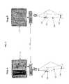
- FIG. 1illustrates a fractured bone to which markers have been attached, FIG. 1 further illustrates a two-way line of communication between the markers;
- FIG. 2illustrates a flow chart describing an exemplary method for performing bone or tissue manipulation
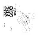
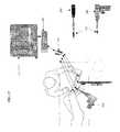
- FIG. 3illustrates an exemplary method for performing bone or tissue manipulation
- FIG. 4illustrates two ways in which data may be generated in accordance with the exemplary embodiment of FIG. 3 ;
- FIG. 5illustrates three ways in which the acquired data may be used in accordance with the exemplary embodiment of FIG. 3 ;
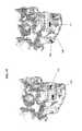
- FIG. 6illustrates an exemplary method for performing bone or tissue manipulation
- FIG. 7further illustrates the exemplary method for performing bone or tissue manipulation of FIG. 6 ;
- FIG. 8further illustrates the exemplary method for performing bone or tissue manipulation of FIG. 6 ;
- FIG. 9further illustrates the exemplary method for performing bone or tissue manipulation of FIG. 6 ;
- FIG. 10further illustrates the exemplary method for performing bone or tissue manipulation of FIG. 6 ;
- FIG. 11further illustrates the exemplary method for performing bone or tissue manipulation of FIG. 6 ;
- FIG. 12illustrates the exemplary method for performing bone or tissue manipulation of FIG. 6 ;
- FIG. 13illustrates a top and cross-sectional view of a signal receiving and/or transmitting platform
- FIG. 14illustrates one exemplary method for transmitting the signal in accordance with one exemplary embodiment of the method for performing bone or tissue manipulation
- FIG. 15illustrates another exemplary method for transmitting the signal in accordance with another exemplary embodiment of the method for performing bone or tissue manipulation
- FIG. 16illustrates another exemplary method for transmitting the signal in accordance with another exemplary embodiment of the method for performing bone or tissue manipulation
- FIG. 17illustrates the incorporation of markers onto intra-operative surgical instruments and fixation devices/implants according to another aspect of the exemplary embodiment of the method for performing bone or tissue manipulation
- FIG. 18illustrates exemplary marker placements
- FIG. 19illustrates exemplary marker placements
- FIG. 20illustrates exemplary marker placements
- FIG. 21illustrates the use of a portable data storage according to one aspect of the exemplary embodiment of the method for performing bone or tissue manipulation.
- FIG. 22illustrates the use of a hospital network according to another aspect of the exemplary embodiment of the method for performing bone or tissue manipulation.
- system and/or method for performing bone or tissue manipulationis not limited in use to repairing bone fractures. Rather, the system and/or method for performing bone or tissue manipulation may be used for manipulating bone, manipulating tissue, manipulating bone fragments caused by, for example, injury, deformation, degeneration, disease, etc.
- the system and/or method for performing bone or tissue manipulationis not limited to any particular type of fracture and, in fact, may be used even where no fracture exists.
- the system and/or method for bone or tissue manipulationonly requires desired relative movement or manipulation of bone, bone fragments, tissue, etc.
- the system and/or method for performing bone or tissue manipulationmay be used in connection with bone markers.
- the system and/or methodmay include implanting markers on opposite sides of a fractured bone.
- the implantation of the markersmay be used to facilitate in-situ closed fracture reduction.
- the system and/or methodpreferably enables one or more steps of the fracture reduction procedure to occur substantially outside of the operating room setting. For example, preferably one or more of the steps of implanting the markers, capturing the image of the bone fragments, manipulating the image of the bone fragments, determining the orientation of the markers, programming the implanted markers, and/or manipulating the fracture bone may occur outside of the operating room setting.
- the markersmay be passive (e.g., incapable of transmitting and/or receiving a signal, for example, a radiopaque marker) or active (e.g. a transmitter capable of sending a signal).
- the markersmay incorporate electronic transmitters or receivers.
- the markersmay incorporate both receivers and transmitters so that the markers can receive and transmit a signal.
- the markersmay be capable of receiving and sending signals with an external device, such as, for example, a detection device, which will be described in greater detail below.
- the markersmay be capable of receiving and sending signals with respect to one another in order to determine their relative orientation.
- the signalpreferably contains information as to the position and/or orientation (collectively referred to herein as orientation) of the markers and hence the attached bone fragments.
- one of the markersmay incorporate a transmitter while the other marker may incorporate a receiver.
- both markersmay be configured to receive and transmit signals.
- the markersmay be nonprogrammable and the detection device, which will be described in greater detail below, may be programmable such that the detection device is capable of determining when the markers have arrived at the desired restored orientation with respect to the planned fracture reduction, which will also be described in greater detail below.
- the markersmay be programmable while the other marker(s) may be nonprogrammable, while in an alternate embodiment, both or all of the markers may be programmable so that the markers themselves are capable of determining when they have arrived at the desired restored orientation.
- one of the markersmay function in a master mode while the other marker(s) may function in a slave mode.
- the markersmay also be anchored to the bone by any means known in the art including but not limited to pins, nails, barbs, threads, screws, adhesive, etc.
- the markersare preferably capable of being fixedly secured with respect to the bone to which they are being attached so that the orientation of the markers with respect to the bone is fixed.
- the markerspreferably are small enough so that they may be inserted into the patient's body and attached to a patient's bone through a small incision, such as for example a stab incision. Alternatively, the markers may be inserted into the patient's body by any means including but not limited to, an open incision, an injection, etc.
- a function of the markersis that the position of the marker should be detectable. It should be understood that the system and/or method for performing bone or tissue manipulation is not limited in use to any particular type of marker.
- the position of the markersmay be detected by any means known in the art including but not limited to the detection device.
- the detection devicemay detect the position of the markers by any means known in the art including, but not limited to, visual, sound, radio waves, infrared, electromagnetic, electrical, x-rays, reflective, ultrasound, mechanical waves, GPS systems or chips, magnetic, transducer, etc.
- the markersmay be capable of sending a signal to the detection device and the detection device may determine the relative relationship of the markers.
- the detection devicemay also be capable of generating and transmitting an indicator signal when the desired restored orientation of the fractured bone has been achieved, as will be described in greater detail below.
- an indicator devicewhich may be a separate and distinct device from the detection device may generate and transmit an indicator signal when the desired restored orientation of the tissue, bone or bone fragments has been achieved.
- the detection devicecan be any known device capable of detecting the position of the markers.
- the detection devicemay be a computer console, x-ray machine, computed tomography (CT) scan, a receiver specifically designed for such purpose, etc. It should be understood that the system and/or method for performing bone or tissue manipulation is not limited in use to any particular type of detection device.
- an exemplary system and/or method for performing bone or tissue manipulationwill be described in connection with a mid-shaft fracture of a long bone 100 .
- the surgeon and/or doctorpreferably places a single marker 102 , 104 on each side of the fracture 106 . Although more than one marker may be placed on either side of the fracture if desired and/or required.
- the markers 102 , 104are preferably positioned in locations that will not interfere with any surgical instruments that may be required to complete the fracture reduction.
- the markers 102 , 104are preferably positioned in locations that will not interfere with placement of any fixation devices and/or implants that may be implanted.
- the markers 102 , 104are preferably secured to the fractured bone on either side of the fracture 106 as close as possible to the bone ends opposite the bone fracture 106 .
- the placement of the markers 102 , 104preferably occurs prior to the fracture fixation surgery so that the placement of the markers 102 , 104 may occur outside of the operating room, in advance of the surgeon's pre-operative planning. For example, a radiologist may implant the markers 102 , 104 prior to image acquisition.
- a scanmay be taken of the fractured bone 100 and markers 102 , 106 .
- the scanmay be any scan known in the art including but not limited to a computed tomography (CT) scan, a three dimensional (3D) image capture, a set of at least two non-parallel two dimensional (2D) images, which allows for 3D reconstruction of the image data, etc.
- CTcomputed tomography
- 3Dthree dimensional
- 2Dnon-parallel two dimensional
- the orientation of each marker 102 , 104 relative to the bone fragment to which it is attachedmay be determined.
- the markers 102 , 104may essentially serve as a surgeon-applied landmark.
- the surgeoncan manipulate the captured image or software-generated model, preferably 3D solid model, of the bone fragments in a simulated or virtual environment until a desired restored orientation has been achieved.
- the orientation of the markers 102 , 104 in their new, desired restored orientationmay be determined and/or calculated.
- the desired restored orientation of the markers 102 , 104may then be programmed into the detection device.
- the markers 102 , 104are capable of receiving and transmitting a signal, the desired restored orientation of the markers 102 , 104 may be programmed into the markers 102 , 104 themselves.
- actual physical reduction of the fracturemay begin.
- the actual physical reduction of the fracturemay be performed by any means including but not limited to surgeon applied distractive forces via a reduction frame, fracture table, etc.
- the orientation of the markers 102 , 104may be monitored, preferably continuously, by, for example, the detection device.
- the markers 102 , 104may signal to one another their relative orientation.
- the markers 102 , 104may communicate with one another and/or with the detection device by any means including, but not limited to, via hard wire, wirelessly such as by radio frequency or other electromagnetic signals, via acoustic signals, etc.
- an indicator signalis preferably generated and transmitted to indicate that the desired restored orientation has been achieved.
- the fixation proceduremay proceed as is normally performed in order to fix the relative orientation of the bone fragments.
- the orientation of the bone fragmentsmay be fixed by any means known in the art including, but not limited to, a plate and screw construct, a rod and screw construct, external fixator, IM rod, etc.
- the indicator signalmay be any indicator signal known in the art including, but not limited to, visual cues such as, for example, color changes or alignment of articulating lines on a computer screen, sounds, flashes of light, etc.
- the indicator signalmay be generated by the detection device.
- the indicator signalmay be generated by an indicator device specifically designed for such purpose.
- the indicator signalmay be generated by one or more of the markers 102 , 104 , a marker transponder or receiver (which will be described in greater detail below), etc.
- the markers 102 , 104may be removed from the patient's body.
- the markers 102 , 104may be made from a resorbable or partially resorbable material.
- the use of resorbable markerseliminates the need for subsequent surgical removal of the markers 102 , 104 .
- an exemplary method for performing bone or tissue manipulationmay include implanting one or more markers 102 , 104 on either side of a fracture 106 of a long bone 100 .
- an image of the fractured bone 100 and markers 102 , 104may be taken using, for example, an x-ray machine 110 or any other suitable imaging device.
- Imaging datamay be provided via a marker transponder or receiver (e.g., a signal receiving and/or transmitting unit) 108 so that the marker transponder or receiver 108 can transmit the data to the detection device 114 , which may be optionally connected to another marker transponder or receiver 108 ′ so that the detection device 114 can transmit and/or receive data.
- the detection device 114may integrally incorporate the marker transponder or receiver 108 ′.
- the image of the fractured bone 100 and bone markers 102 , 104may be displayed on a monitor 112 .
- the image of the fractured bone 100may be sent via a marker transponder or receiver 108 ′′ to an intra-operative bone and marker monitor 113 so that the image may be viewed in the operating room.
- the intra-operative bone and marker monitor 113may be connected to a marker transponder or receiver 108 ′′ so that the intra-operative bone and marker monitor 113 can receive and/or transmit data.
- the intra-operative bone and marker monitor 113may integrally incorporate the intra-operative bone and marker monitor 113 ′′.
- the marker transponder or receivermay enable the data to be sent wirelessly.
- the datamay be sent via wire leads 118 or any other methods.
- data relating to the relative orientation of the markers 102 , 104may be generated primarily for two reasons.
- data relating to the relative orientation of the markers 102 , 104may be generated in order to acquire images of the fractured bone 100 and to define the orientation of the markers 102 , 104 relative to the actual image generated by the x-ray or other similar machine 110 .
- data relating to the relative orientation of the markers 102 , 104may be generated to define the desired orientation of the markers 102 , 104 relative to the newly edited image.
- the data acquiredmay be used primarily for three reasons.
- the data acquiredmay be used to intra-operatively monitor and optionally display the attached bone fragments in order to show the doctor and/or surgeon the orientation of the bone fragments during re-alignment.
- the data acquiredmay be used to intra-operatively monitor and optionally display the attached bone fragments so that the doctor and/or surgeon can manipulate the bone fragments aided by the system.
- the data acquiredmay be used to intra-operatively monitor and optionally display the attached bone fragments so that the doctor and/or surgeon can navigate surgical instruments 200 and/or fixation devices/implants (as will be described in greater detail below).
- the system or method for performing bone or tissue manipulationmay include implantation of at least one marker 102 , 104 onto the fractured bone 100 on either side of the fracture 106 .
- the markers 102 , 104are preferably secured to the fractured bone on either side of the fracture as close as possible to the bone ends opposite the fracture 106 .
- a marker 102 , 104may be placed only on the far ends of the fractured bone 100 being reduced. Alternatively, however, a marker 102 , 104 may be installed on each or most of the bone fragments.
- an image of the fractured bone 100may be acquired using, for example, an x-ray 110 or any other suitable imaging device such as but not limited to 3D x-ray, a computed tomography (CT) scan, a magnetic resonance imaging (MRI), an ultrasound, etc.
- CTcomputed tomography
- MRImagnetic resonance imaging
- ultrasoundetc.
- the imagemay be merged with the orientation data obtained from the markers 102 , 104 via, for example, the detection device 114 .
- the image of the fractured bone 100may be overlapped and/or calibrated with the orientation data obtained by, for example, the detection device 114 , so that the orientation of each markers 102 , 104 is accurately reflected relative to each other at the time the image was captured.
- the pre-operative fracture reduction of the imagemay be preferably performed by the doctor and/or surgeon, aided by the image of the fractured bone displayed on, for example, a computer monitor 112 , which may be based on the bone images and marker orientation.
- the virtual or simulated fracture reductionmay be software based or any other means.
- the data regarding the desired orientation of the markers 102 , 104may be stored in, for example, the detection device 114 .
- the data regarding the desired orientation of the markers 102 , 104may be stored in one or more marker transponder or receivers, the markers themselves, or any other storage unit known in the art, such as, for example, a portable data storage unit as shown in FIG.
- the detection device 114may be programmed with the desired restored orientation of the bone fragments.
- the system and methodis preferably capable of automatically recognizing the actual orientation of the markers 102 , 104 as they are being manipulated so that, for example, the detection device 114 can inform the doctor and/or surgeon via an indicator signal when the bone fracture has been properly reduced to the desired restored orientation.
- the marker transponder or receiver and/or the markersthemselves may be programmed with the desired restored orientation of the bone fragments. Moreover, the marker transponder or receiver and/or the markers themselves may be capable of producing the indicator signal when the bone fracture has been properly reduced to the desired restored orientation. Alternatively and/or in addition, the method of performing bone or tissue manipulation may include an indicator device for transmitting the indicator signal.
- the manipulation and orientation of the markers and hence of the bone fragmentsmay be continuously tracked and displayed in real time on a monitor 113 to aid the doctor and/or surgeon in reducing the fracture to the appropriate orientation.
- fixation of the fractured bonemay be completed and reconfirmation and/or monitoring of the fracture can be performed with the aid of the image displayed on the monitor 113 .
- the system and method for performing and optionally verifying bone or tissue manipulationmay include a signal receiving and/or transmitting platform 144 .
- the signal receiving and/or transmitting platform 144may be in the form of a table, a frame, a board, a bed or any other support system that will accommodate the fractured bone 100 so that the markers 102 , 104 can be monitored via the signal receiving and/or transmitting platform 144 .
- the signal receiving and/or transmitting platform 144may include one or more sensors 140 capable of detecting the orientation of the markers 102 , 104 .
- the system and method for performing and optionally verifying bone or tissue manipulationpreferably detects and preferably transmits signals containing the data on the orientation of the markers 102 , 104 wirelessly 116 .
- the wireless signal 116may be received and/or transmitted by the various marker transponder or receivers 108 .
- the wireless signal 116may then be displayed on monitors 113 .
- the markers 102 , 104may be capable of both transmitting signals and/or receiving signals so that the markers 102 , 104 can directly exchange signals regarding their orientation with respect to one another.
- the markers 102 , 104are also preferably capable of transmitting signals to one or more marker transponder or receivers 108 .
- the signalsmay then be transmitted to, for example, the detection device, a display unit (e.g. a monitor), etc.
- the signalsmay then be transmitted by any means known in the art including by way of wires 118 , wirelessly 116 , etc.
- the markers 102 , 104may include a wire that exits the patient through the stab incisions and which connects to, for example, the detection device (e.g. computer console), enabling both communication between the markers 102 , 104 , as well as communication between the markers 102 , 104 and the detection device used to alert the surgeon that a desired restored orientation has been achieved.
- the detection devicee.g. computer console
- the marker technologymay also be incorporated into surgical instruments and/or fixation devices/implants to help facilitate accurate placement of the surgical instruments and/or fixation devices/implants.
- surgical instruments 200 and/or surgical implants 208can be equipped with one or more markers 102 .
- the surgical instruments 200 and/or fixation devices/implants 208may then be navigated based on pre-operative determination of the desired restored orientation of the bone fragments. Similar to the markers used in connection with the reduction procedure, the surgical instrument and/or fixation device/implant marker can be calibrated and predefined to a specific instrument or implant.
- markers and systemmay be used for fixation of other parts of the body such as, for example, in the spine (as best shown in FIG. 19 ) for correction or movement of vertebra, for cranio-facial and mandible reconstruction (as best shown in FIG. 20 ), joints, bones in the hand, face, feet, extremities, etc.
- the system and method for performing and verifying fracture reductionmay also be useful in complex fractures, such as for example, those shown in FIG. 18 .
- the embodiments described hereininclude not only pairs of markers, but also a system or a plurality of markers. This may be particularly useful for situations where multiple fragments are to be brought together or in the spine, where correction involves multiple, distinct vertebrae that require individual tracking.
- the systemmay allow for selective communication between the markers via channels or distinct frequencies.
- the markers described hereincan have many applications.
- the markersmay be applied on a short-term basis such as, for example, for no more than one or two days.
- the markersmay be implanted for a long-term period.
- the markersmay be useful in monitoring the progress of deformity correction procedures where distraction osteogenesis takes place over a period of weeks or months.
- the markerscould be used to provide biomechanical data related to the success of fracture healing. The markers could be used to develop a better understanding of the strain seen by a bone.
- surgeonsmay prefer to use the markers in a more “on-the-fly” manner, without pre-op planning, or reliance on 3D imaging.
- the markersmay be used to limit the patient's exposure to radiation by reducing the use of intra-operative fluoroscopy.
- the surgeonmay implant the markers as described above and may take a perpendicular pair, for example an anterior/posterior view and a lateral view, of 2D images inclusive of the markers. The surgeon then “tags” or registers each marker to the 2D image of the bone fragment to which it is anchored, designating one bone fragment in the image to be stationary.
- the mobile 2D bone fragment representationmoves on-screen in both views, tracking the motion that the markers communicate to the external signaling device such that the surgeon has an on-screen estimation of what the actual images would look like if they were taken live.
- the limbpreferably is maintained absolutely stationary during imaging and tagging prior to any reduction maneuver.
- the imaging and tagging proceduremay be repeated mid-reduction to get a refreshed true image if there is concern that the estimated image is inaccurate due to inadvertent motion during the capture and tagging procedure, or due to a rotational component of the reduction maneuver.
Landscapes
- Health & Medical Sciences (AREA)
- Life Sciences & Earth Sciences (AREA)
- Engineering & Computer Science (AREA)
- Surgery (AREA)
- Medical Informatics (AREA)
- General Health & Medical Sciences (AREA)
- Public Health (AREA)
- Biomedical Technology (AREA)
- Animal Behavior & Ethology (AREA)
- Veterinary Medicine (AREA)
- Heart & Thoracic Surgery (AREA)
- Molecular Biology (AREA)
- Pathology (AREA)
- Physics & Mathematics (AREA)
- Nuclear Medicine, Radiotherapy & Molecular Imaging (AREA)
- Biophysics (AREA)
- Radiology & Medical Imaging (AREA)
- Oral & Maxillofacial Surgery (AREA)
- High Energy & Nuclear Physics (AREA)
- Computer Vision & Pattern Recognition (AREA)
- Epidemiology (AREA)
- Orthopedic Medicine & Surgery (AREA)
- Condensed Matter Physics & Semiconductors (AREA)
- General Physics & Mathematics (AREA)
- Optics & Photonics (AREA)
- Robotics (AREA)
- Data Mining & Analysis (AREA)
- Databases & Information Systems (AREA)
- Primary Health Care (AREA)
- Dentistry (AREA)
- Signal Processing (AREA)
- Artificial Intelligence (AREA)
- Pulmonology (AREA)
- Theoretical Computer Science (AREA)
- Surgical Instruments (AREA)
- Apparatus For Radiation Diagnosis (AREA)
Abstract
Description
Claims (11)
Priority Applications (4)
| Application Number | Priority Date | Filing Date | Title |
|---|---|---|---|
| US14/032,195US9921276B2 (en) | 2006-08-11 | 2013-09-19 | Simulated bone or tissue manipulation |
| US14/743,895US10048330B2 (en) | 2006-08-11 | 2015-06-18 | Simulated bone or tissue manipulation |
| US15/908,764US10641844B2 (en) | 2006-08-11 | 2018-02-28 | Simulated bone or tissue manipulation |
| US16/828,510US11474171B2 (en) | 2006-08-11 | 2020-03-24 | Simulated bone or tissue manipulation |
Applications Claiming Priority (3)
| Application Number | Priority Date | Filing Date | Title |
|---|---|---|---|
| US83719306P | 2006-08-11 | 2006-08-11 | |
| US11/838,093US8565853B2 (en) | 2006-08-11 | 2007-08-13 | Simulated bone or tissue manipulation |
| US14/032,195US9921276B2 (en) | 2006-08-11 | 2013-09-19 | Simulated bone or tissue manipulation |
Related Parent Applications (1)
| Application Number | Title | Priority Date | Filing Date |
|---|---|---|---|
| US11/838,093ContinuationUS8565853B2 (en) | 2006-08-11 | 2007-08-13 | Simulated bone or tissue manipulation |
Related Child Applications (1)
| Application Number | Title | Priority Date | Filing Date |
|---|---|---|---|
| US14/743,895ContinuationUS10048330B2 (en) | 2006-08-11 | 2015-06-18 | Simulated bone or tissue manipulation |
Publications (2)
| Publication Number | Publication Date |
|---|---|
| US20140051980A1 US20140051980A1 (en) | 2014-02-20 |
| US9921276B2true US9921276B2 (en) | 2018-03-20 |
Family
ID=39051721
Family Applications (5)
| Application Number | Title | Priority Date | Filing Date |
|---|---|---|---|
| US11/838,093Active2029-12-05US8565853B2 (en) | 2006-08-11 | 2007-08-13 | Simulated bone or tissue manipulation |
| US14/032,195Active2029-07-02US9921276B2 (en) | 2006-08-11 | 2013-09-19 | Simulated bone or tissue manipulation |
| US14/743,895ActiveUS10048330B2 (en) | 2006-08-11 | 2015-06-18 | Simulated bone or tissue manipulation |
| US15/908,764ActiveUS10641844B2 (en) | 2006-08-11 | 2018-02-28 | Simulated bone or tissue manipulation |
| US16/828,510ActiveUS11474171B2 (en) | 2006-08-11 | 2020-03-24 | Simulated bone or tissue manipulation |
Family Applications Before (1)
| Application Number | Title | Priority Date | Filing Date |
|---|---|---|---|
| US11/838,093Active2029-12-05US8565853B2 (en) | 2006-08-11 | 2007-08-13 | Simulated bone or tissue manipulation |
Family Applications After (3)
| Application Number | Title | Priority Date | Filing Date |
|---|---|---|---|
| US14/743,895ActiveUS10048330B2 (en) | 2006-08-11 | 2015-06-18 | Simulated bone or tissue manipulation |
| US15/908,764ActiveUS10641844B2 (en) | 2006-08-11 | 2018-02-28 | Simulated bone or tissue manipulation |
| US16/828,510ActiveUS11474171B2 (en) | 2006-08-11 | 2020-03-24 | Simulated bone or tissue manipulation |
Country Status (1)
| Country | Link |
|---|---|
| US (5) | US8565853B2 (en) |
Cited By (1)
| Publication number | Priority date | Publication date | Assignee | Title |
|---|---|---|---|---|
| US11224484B2 (en) | 2018-01-12 | 2022-01-18 | Globus Medical Inc. | Surgical sensor anchor system |
Families Citing this family (37)
| Publication number | Priority date | Publication date | Assignee | Title |
|---|---|---|---|---|
| US8565853B2 (en) | 2006-08-11 | 2013-10-22 | DePuy Synthes Products, LLC | Simulated bone or tissue manipulation |
| US8549888B2 (en) | 2008-04-04 | 2013-10-08 | Nuvasive, Inc. | System and device for designing and forming a surgical implant |
| US20120046536A1 (en)* | 2010-08-20 | 2012-02-23 | Manhattan Technologies, Llc | Surgical Instrument Navigation Systems and Methods |
| US20120316486A1 (en)* | 2010-08-20 | 2012-12-13 | Andrew Cheung | Surgical Component Navigation Systems And Methods |
| US9167989B2 (en)* | 2011-09-16 | 2015-10-27 | Mako Surgical Corp. | Systems and methods for measuring parameters in joint replacement surgery |
| US11207132B2 (en) | 2012-03-12 | 2021-12-28 | Nuvasive, Inc. | Systems and methods for performing spinal surgery |
| US9241742B2 (en) | 2013-03-14 | 2016-01-26 | DePuy Synthes Products, Inc. | Methods and devices for polyaxial screw alignment |
| US9844324B2 (en) | 2013-03-14 | 2017-12-19 | X-Nav Technologies, LLC | Image guided navigation system |
| US9968408B1 (en) | 2013-03-15 | 2018-05-15 | Nuvasive, Inc. | Spinal balance assessment |
| US9848922B2 (en) | 2013-10-09 | 2017-12-26 | Nuvasive, Inc. | Systems and methods for performing spine surgery |
| US10709509B2 (en) | 2014-06-17 | 2020-07-14 | Nuvasive, Inc. | Systems and methods for planning, performing, and assessing spinal correction during surgery |
| US9274187B2 (en)* | 2014-07-13 | 2016-03-01 | Case Western Reserve University | Magnetic resonance imaging (MRI) scan plane control device |
| US9993177B2 (en) | 2014-08-28 | 2018-06-12 | DePuy Synthes Products, Inc. | Systems and methods for intraoperatively measuring anatomical orientation |
| US9402691B2 (en) | 2014-09-16 | 2016-08-02 | X-Nav Technologies, LLC | System for determining and tracking movement during a medical procedure |
| US9943374B2 (en) | 2014-09-16 | 2018-04-17 | X-Nav Technologies, LLC | Image guidance system for detecting and tracking an image pose |
| US10433893B1 (en) | 2014-10-17 | 2019-10-08 | Nuvasive, Inc. | Systems and methods for performing spine surgery |
| KR102477470B1 (en)* | 2014-11-21 | 2022-12-13 | 씽크 써지컬, 인크. | Visible light communication system for transmitting data between visual tracking systems and tracking markers |
| US10350008B2 (en) | 2014-12-02 | 2019-07-16 | X-Nav Technologies, LLC | Visual guidance display for surgical procedure |
| GB2534359A (en)* | 2015-01-15 | 2016-07-27 | Corin Ltd | System and method for patient implant alignment |
| US10695099B2 (en) | 2015-02-13 | 2020-06-30 | Nuvasive, Inc. | Systems and methods for planning, performing, and assessing spinal correction during surgery |
| US9554411B1 (en) | 2015-12-30 | 2017-01-24 | DePuy Synthes Products, Inc. | Systems and methods for wirelessly powering or communicating with sterile-packed devices |
| US10335241B2 (en) | 2015-12-30 | 2019-07-02 | DePuy Synthes Products, Inc. | Method and apparatus for intraoperative measurements of anatomical orientation |
| WO2017139556A1 (en) | 2016-02-12 | 2017-08-17 | Medos International Sarl | Systems and methods for intraoperatively measuring anatomical orientation |
| WO2017151949A1 (en) | 2016-03-02 | 2017-09-08 | Nuvasive, Inc. | Systems and methods for spinal correction surgical planning |
| KR102299132B1 (en)* | 2016-08-30 | 2021-09-08 | 마코 서지컬 코포레이션 | Intraoperative pelvic registration systems and methods |
| US10820835B2 (en) | 2016-09-12 | 2020-11-03 | Medos International Sarl | Systems and methods for anatomical alignment |
| AU2017340607B2 (en) | 2016-10-05 | 2022-10-27 | Nuvasive, Inc. | Surgical navigation system and related methods |
| CN110177492A (en)* | 2016-11-18 | 2019-08-27 | 斯特赖克公司 | Method and apparatus for treating joint hits the treatment that the clamp type femur acetabular bone in disease and hip joint hits disease including the cam type femur acetabular bone in hip joint |
| US11089975B2 (en) | 2017-03-31 | 2021-08-17 | DePuy Synthes Products, Inc. | Systems, devices and methods for enhancing operative accuracy using inertial measurement units |
| US20190059832A1 (en)* | 2017-08-28 | 2019-02-28 | Qualcomm Incorporated | Indicators for radiological placement of implants |
| US11464569B2 (en) | 2018-01-29 | 2022-10-11 | Stryker Corporation | Systems and methods for pre-operative visualization of a joint |
| US11612440B2 (en) | 2019-09-05 | 2023-03-28 | Nuvasive, Inc. | Surgical instrument tracking devices and related methods |
| CN111739395B (en)* | 2020-08-10 | 2024-08-16 | 上海交通大学医学院附属第九人民医院 | Fracture manipulation resetting training device, preparation method and training method |
| WO2022086455A1 (en)* | 2020-10-21 | 2022-04-28 | Meticuly Company Limited | Bone fixation system for human bone, method of designing and manufacturing thereof |
| US12256996B2 (en) | 2020-12-15 | 2025-03-25 | Stryker Corporation | Systems and methods for generating a three-dimensional model of a joint from two-dimensional images |
| CN116370076A (en)* | 2023-03-02 | 2023-07-04 | 北京维卓致远医疗科技发展有限责任公司 | Path navigation method, path navigation device, computer equipment, storage medium and program product |
| WO2025015173A1 (en)* | 2023-07-11 | 2025-01-16 | Rowan University | Devices, systems, and methods of positioning bone segments |
Citations (97)
| Publication number | Priority date | Publication date | Assignee | Title |
|---|---|---|---|---|
| US3367326A (en) | 1965-06-15 | 1968-02-06 | Calvin H. Frazier | Intra spinal fixation rod |
| US4289123A (en) | 1980-03-31 | 1981-09-15 | Dunn Harold K | Orthopedic appliance |
| US5233639A (en) | 1990-11-29 | 1993-08-03 | Marks Lloyd A | Stereoscopic fluoroscopy apparatus and method of producing stereoscopic X-ray images |
| US5249581A (en) | 1991-07-15 | 1993-10-05 | Horbal Mark T | Precision bone alignment |
| US5402801A (en) | 1991-06-13 | 1995-04-04 | International Business Machines Corporation | System and method for augmentation of surgery |
| US5509919A (en) | 1993-09-24 | 1996-04-23 | Young; Merry A. | Apparatus for guiding a reaming instrument |
| WO1996011624A2 (en) | 1994-10-07 | 1996-04-25 | St. Louis University | Surgical navigation systems including reference and localization frames |
| US5546942A (en) | 1994-06-10 | 1996-08-20 | Zhang; Zhongman | Orthopedic robot and method for reduction of long-bone fractures |
| US5595193A (en) | 1993-02-12 | 1997-01-21 | Walus; Richard L. | Tool for implanting a fiducial marker |
| US5622170A (en) | 1990-10-19 | 1997-04-22 | Image Guided Technologies, Inc. | Apparatus for determining the position and orientation of an invasive portion of a probe inside a three-dimensional body |
| US5682886A (en)* | 1995-12-26 | 1997-11-04 | Musculographics Inc | Computer-assisted surgical system |
| US5693054A (en) | 1994-05-04 | 1997-12-02 | Durham; Alfred A. | Device and method for reducing fractures in long bones |
| WO1998004203A2 (en) | 1996-07-25 | 1998-02-05 | Renata De Luise | Orthopaedic system allowing alignment of bones or fracture reduction |
| US5772594A (en) | 1995-10-17 | 1998-06-30 | Barrick; Earl F. | Fluoroscopic image guided orthopaedic surgery system with intraoperative registration |
| US5792147A (en) | 1994-03-17 | 1998-08-11 | Roke Manor Research Ltd. | Video-based systems for computer assisted surgery and localisation |
| US5807252A (en) | 1995-02-23 | 1998-09-15 | Aesculap Ag | Method and apparatus for determining the position of a body part |
| DE19709960A1 (en) | 1997-03-11 | 1998-09-24 | Aesculap Ag & Co Kg | Method and device for preoperatively determining the position data of endoprosthesis parts |
| US5819737A (en) | 1995-10-13 | 1998-10-13 | Picker International, Inc. | Magnetic resonance methods and apparatus |
| GB2324038A (en) | 1997-04-11 | 1998-10-14 | Univ Keele | Fracture reduction device |
| US5833608A (en) | 1993-10-06 | 1998-11-10 | Biosense, Inc. | Magnetic determination of position and orientation |
| IT1290368B1 (en) | 1996-07-25 | 1998-12-03 | Luise Renata De | Device for centering bolts within a well-defined region of bone structure under fluoroscopy |
| US5868673A (en) | 1995-03-28 | 1999-02-09 | Sonometrics Corporation | System for carrying out surgery, biopsy and ablation of a tumor or other physical anomaly |
| US5891034A (en) | 1990-10-19 | 1999-04-06 | St. Louis University | System for indicating the position of a surgical probe within a head on an image of the head |
| US5935171A (en) | 1997-11-17 | 1999-08-10 | John E. Schneider | Apparatus for, and method of, detecting dislocations and material wear in hip replacements |
| US6025725A (en) | 1996-12-05 | 2000-02-15 | Massachusetts Institute Of Technology | Electrically active resonant structures for wireless monitoring and control |
| US6111520A (en) | 1997-04-18 | 2000-08-29 | Georgia Tech Research Corp. | System and method for the wireless sensing of physical properties |
| US6167145A (en) | 1996-03-29 | 2000-12-26 | Surgical Navigation Technologies, Inc. | Bone navigation system |
| US6241735B1 (en) | 1997-10-28 | 2001-06-05 | MARMULLA RüDIGER | System and method for bone segment navigation |
| US6245109B1 (en) | 1999-11-18 | 2001-06-12 | Intellijoint Systems, Ltd. | Artificial joint system and method utilizing same for monitoring wear and displacement of artificial joint members |
| US6278379B1 (en) | 1998-04-02 | 2001-08-21 | Georgia Tech Research Corporation | System, method, and sensors for sensing physical properties |
| WO2002032328A2 (en) | 2000-10-18 | 2002-04-25 | Cees Van Rij | Marker, indikator, guide and method for bone resection |
| DE10057023A1 (en) | 2000-11-17 | 2002-06-06 | Siemens Ag | Method and appliance for identifying correct alignment of fractured bones by superimposition of templates on images of those bones |
| US6434415B1 (en) | 1990-10-19 | 2002-08-13 | St. Louis University | System for use in displaying images of a body part |
| US6447448B1 (en) | 1998-12-31 | 2002-09-10 | Ball Semiconductor, Inc. | Miniature implanted orthopedic sensors |
| US20020133175A1 (en)* | 2001-02-27 | 2002-09-19 | Carson Christopher P. | Surgical navigation systems and processes for unicompartmental knee arthroplasty |
| US20020143357A1 (en) | 1998-05-14 | 2002-10-03 | Krag David N. | System and method for bracketing and removing tissue |
| US20020147416A1 (en) | 2000-05-01 | 2002-10-10 | Southwest Research Institute | Passive and wireless displacement measuring device |
| US6470207B1 (en) | 1999-03-23 | 2002-10-22 | Surgical Navigation Technologies, Inc. | Navigational guidance via computer-assisted fluoroscopic imaging |
| US6477400B1 (en) | 1998-08-20 | 2002-11-05 | Sofamor Danek Holdings, Inc. | Fluoroscopic image guided orthopaedic surgery system with intraoperative registration |
| US20020193685A1 (en) | 2001-06-08 | 2002-12-19 | Calypso Medical, Inc. | Guided Radiation Therapy System |
| US6498944B1 (en)* | 1996-02-01 | 2002-12-24 | Biosense, Inc. | Intrabody measurement |
| US6499488B1 (en) | 1999-10-28 | 2002-12-31 | Winchester Development Associates | Surgical sensor |
| US20030004518A1 (en) | 1999-11-15 | 2003-01-02 | Stephan Perren | Method and device for the determination of reduction parameters for the subsequent reduction of a fractured bone |
| US20030023161A1 (en) | 1999-03-11 | 2003-01-30 | Assaf Govari | Position sensing system with integral location pad and position display |
| US20030040806A1 (en) | 2001-08-22 | 2003-02-27 | Macdonald Stuart G. | Prosthetic implants having enhanced utility |
| US6533737B1 (en)* | 1998-05-28 | 2003-03-18 | Orthosoft, Inc. | Interactive computer-assisted surgical system and method thereof |
| WO2003041611A2 (en) | 2001-11-14 | 2003-05-22 | White Michael R | Apparatus and methods for making intraoperative orthopedic measurements |
| EP1321097A2 (en) | 2001-12-21 | 2003-06-25 | Biosense, Inc. | Wireless position sensor |
| DE10161787A1 (en) | 2001-12-15 | 2003-07-10 | Ruediger Marmulla | Positioning of passive markers used in surgical interventions and suitable for localization and navigation of body parts, organs, vessels, bones, etc., by a template device is used to precisely position the markers |
| WO2003068090A1 (en) | 2002-02-11 | 2003-08-21 | Smith & Nephew, Inc. | Image-guided fracture reduction |
| US6662036B2 (en) | 1991-01-28 | 2003-12-09 | Sherwood Services Ag | Surgical positioning system |
| EP1374793A1 (en) | 2002-06-17 | 2004-01-02 | Biosense, Inc. | Invasive medical device with position sensing and display |
| US20040019263A1 (en) | 2002-07-25 | 2004-01-29 | Orthosoft Inc. | Multiple bone tracking |
| US6711432B1 (en) | 2000-10-23 | 2004-03-23 | Carnegie Mellon University | Computer-aided orthopedic surgery |
| US20040068263A1 (en) | 2002-10-04 | 2004-04-08 | Benoit Chouinard | CAS bone reference with articulated support |
| WO2004046754A2 (en) | 2002-11-14 | 2004-06-03 | General Electric Medical Systems Global Technology Company, Llc | Interchangeable localizing devices for use with tracking systems |
| US20040111024A1 (en) | 2001-02-07 | 2004-06-10 | Guoyan Zheng | Method for establishing a three-dimensional representation of a bone from image data |
| US20040171924A1 (en) | 2003-01-30 | 2004-09-02 | Mire David A. | Method and apparatus for preplanning a surgical procedure |
| WO2004075768A2 (en) | 2003-02-25 | 2004-09-10 | Image-Guided Neurologics, Inc. | Fiducial marker devices, tools, and methods |
| US20040243148A1 (en) | 2003-04-08 | 2004-12-02 | Wasielewski Ray C. | Use of micro- and miniature position sensing devices for use in TKA and THA |
| GB2402883A (en) | 2003-06-21 | 2004-12-22 | Ravi Kumar Khetrapal | Apparatus for assisted percutaneous fracture fixation |
| US20050003757A1 (en) | 2003-07-01 | 2005-01-06 | Anderson Peter Traneus | Electromagnetic tracking system and method using a single-coil transmitter |
| WO2005006246A2 (en) | 2003-07-02 | 2005-01-20 | Ge Medical Systems Global Technology Company, Llc | Wireless electromagnetic tracking system using a nonlinear passive transponder |
| US6856828B2 (en) | 2002-10-04 | 2005-02-15 | Orthosoft Inc. | CAS bone reference and less invasive installation method thereof |
| WO2005023128A1 (en) | 2003-09-05 | 2005-03-17 | Depuy International Limited | Flexible image guided surgery marker |
| EP1530947A1 (en) | 2003-11-11 | 2005-05-18 | Biosense Webster, Inc. | Digital wireless position sensor |
| GB2408805A (en) | 2003-11-14 | 2005-06-08 | Ge Med Sys Global Tech Co Llc | Wireless electromagnetic position tracking |
| DE10352027A1 (en) | 2003-11-07 | 2005-06-09 | Schreiber, Ulrich, Dipl.-Ing. | Navigated bone screw and method for insertion, using reinforcing inner element after removal of wire |
| EP1570781A1 (en) | 2004-03-05 | 2005-09-07 | Biosense Webster, Inc. | Position sensing system for orthopedic applications |
| EP1570782A2 (en) | 2004-03-05 | 2005-09-07 | Biosense Webster, Inc. | Position sensing system for orthopaedic applications |
| WO2005084541A1 (en) | 2004-03-05 | 2005-09-15 | Depuy International Ltd | Pelvis registration method and apparatus |
| WO2005084572A2 (en) | 2004-03-05 | 2005-09-15 | Depuy International Ltd | Implantable marker, instruments and methods |
| WO2005084544A1 (en) | 2004-03-05 | 2005-09-15 | Depuy International Ltd | Orthopaedic monitoring system, methods and apparatus |
| JP2005253970A (en) | 2004-03-08 | 2005-09-22 | Zimmer Technology Inc | Orthopedic guide with navigation, surgical operation system, method for performing orthopedic surgery procedure and method for performing orthopedic surgery |
| WO2005087125A2 (en) | 2004-03-10 | 2005-09-22 | Depuy International Ltd | Orthopaedic operating systems, methods, implants and instruments |
| US20050215887A1 (en) | 1996-02-01 | 2005-09-29 | Shlomo Ben-Haim | Medical system using implantable sensor in bone for determining position coordinates |
| US20070043354A1 (en) | 2005-08-03 | 2007-02-22 | Koo Terry K | Bone reposition device, method and system |
| US20070057794A1 (en) | 2001-09-14 | 2007-03-15 | Calypso Medical Technologies, Inc. | Miniature resonating marker assembly |
| WO2007041678A2 (en) | 2005-10-04 | 2007-04-12 | Ascension Technology Corporation | Dc magnetic-based position and orientation monitoring system for tracking medical instruments |
| WO2007061890A2 (en) | 2005-11-17 | 2007-05-31 | Calypso Medical Technologies, Inc. | Apparatus and methods for using an electromagnetic transponder in orthopedic procedures |
| DE60032312T2 (en) | 1999-10-28 | 2007-07-12 | Northern Digital Inc., Waterloo | System for determining the spatial position and / or position of one or more objects |
| US20070173815A1 (en) | 2003-02-12 | 2007-07-26 | Tsuyoshi Murase | Method, members, system and program for bone correction |
| WO2007117951A2 (en) | 2006-03-29 | 2007-10-18 | Stryker Corporation | Shielded surgical navigation system that determines the position and orientation of the tracked object with real and virtual dipoles |
| US20080039717A1 (en) | 2006-08-11 | 2008-02-14 | Robert Frigg | Simulated bone or tissue manipulation |
| DE102006048451A1 (en) | 2006-10-11 | 2008-04-17 | Siemens Ag | Object e.g. implant, virtual adjustment method for e.g. leg, of patient, involves automatically adjusting object relative to body part in smooth manner for long time, until tolerance dimension achieves desired threshold value |
| EP1923015A1 (en) | 2006-10-17 | 2008-05-21 | BrainLAB AG | Navigation system with markers for obtaining and depicting said markers' position |
| US20080208055A1 (en) | 2007-02-07 | 2008-08-28 | Michael Bertram | Method and Device for the Sonographic Navigated Repositioning of Bone Fragments |
| US20080287781A1 (en) | 2004-03-05 | 2008-11-20 | Depuy International Limited | Registration Methods and Apparatus |
| US7580027B2 (en) | 2004-11-04 | 2009-08-25 | Canon Kabushiki Kaisha | Method and apparatus for processing information |
| US7618419B2 (en) | 2005-01-18 | 2009-11-17 | Universite Joseph Fourier | Method and system of computer assistance for the reduction of a fracture |
| US7636459B2 (en) | 2000-10-31 | 2009-12-22 | Centre National De La Recherche Scientifique (C.N.R.S.) | High precision modeling of a body part using a 3D imaging system |
| US7715602B2 (en) | 2002-01-18 | 2010-05-11 | Orthosoft Inc. | Method and apparatus for reconstructing bone surfaces during surgery |
| US7760909B2 (en) | 2005-01-12 | 2010-07-20 | Brainlab Ag | Video tracking and registering |
| US7758617B2 (en) | 2005-04-27 | 2010-07-20 | Globus Medical, Inc. | Percutaneous vertebral stabilization system |
| US7769429B2 (en) | 2000-07-06 | 2010-08-03 | Ao Technology Ag | Method and device for impingement detection |
| US7797030B2 (en) | 2003-11-13 | 2010-09-14 | Medtronic, Inc. | Clinical tool for structure localization |
| US7955355B2 (en) | 2003-09-24 | 2011-06-07 | Stryker Spine | Methods and devices for improving percutaneous access in minimally invasive surgeries |
Family Cites Families (3)
| Publication number | Priority date | Publication date | Assignee | Title |
|---|---|---|---|---|
| US5880976A (en)* | 1997-02-21 | 1999-03-09 | Carnegie Mellon University | Apparatus and method for facilitating the implantation of artificial components in joints |
| WO2005112563A2 (en)* | 2004-04-13 | 2005-12-01 | The University Of Georgia Research Foundation, Inc. | Virtual surgical system and methods |
| JP4874970B2 (en)* | 2004-06-07 | 2012-02-15 | ジンテス ゲゼルシャフト ミット ベシュレンクテル ハフツング | Orthopedic implant with sensor |
- 2007
- 2007-08-13USUS11/838,093patent/US8565853B2/enactiveActive
- 2013
- 2013-09-19USUS14/032,195patent/US9921276B2/enactiveActive
- 2015
- 2015-06-18USUS14/743,895patent/US10048330B2/enactiveActive
- 2018
- 2018-02-28USUS15/908,764patent/US10641844B2/enactiveActive
- 2020
- 2020-03-24USUS16/828,510patent/US11474171B2/enactiveActive
Patent Citations (113)
| Publication number | Priority date | Publication date | Assignee | Title |
|---|---|---|---|---|
| US3367326A (en) | 1965-06-15 | 1968-02-06 | Calvin H. Frazier | Intra spinal fixation rod |
| US4289123A (en) | 1980-03-31 | 1981-09-15 | Dunn Harold K | Orthopedic appliance |
| US5891034A (en) | 1990-10-19 | 1999-04-06 | St. Louis University | System for indicating the position of a surgical probe within a head on an image of the head |
| US6434415B1 (en) | 1990-10-19 | 2002-08-13 | St. Louis University | System for use in displaying images of a body part |
| US5622170A (en) | 1990-10-19 | 1997-04-22 | Image Guided Technologies, Inc. | Apparatus for determining the position and orientation of an invasive portion of a probe inside a three-dimensional body |
| US5987349A (en) | 1990-10-19 | 1999-11-16 | Image Guided Technologies, Inc. | Method for determining the position and orientation of two moveable objects in three-dimensional space |
| US5233639A (en) | 1990-11-29 | 1993-08-03 | Marks Lloyd A | Stereoscopic fluoroscopy apparatus and method of producing stereoscopic X-ray images |
| US6662036B2 (en) | 1991-01-28 | 2003-12-09 | Sherwood Services Ag | Surgical positioning system |
| US5402801A (en) | 1991-06-13 | 1995-04-04 | International Business Machines Corporation | System and method for augmentation of surgery |
| US5249581A (en) | 1991-07-15 | 1993-10-05 | Horbal Mark T | Precision bone alignment |
| US5595193A (en) | 1993-02-12 | 1997-01-21 | Walus; Richard L. | Tool for implanting a fiducial marker |
| US5920395A (en) | 1993-04-22 | 1999-07-06 | Image Guided Technologies, Inc. | System for locating relative positions of objects in three dimensional space |
| US6442416B1 (en) | 1993-04-22 | 2002-08-27 | Image Guided Technologies, Inc. | Determination of the position and orientation of at least one object in space |
| US5509919A (en) | 1993-09-24 | 1996-04-23 | Young; Merry A. | Apparatus for guiding a reaming instrument |
| US5833608A (en) | 1993-10-06 | 1998-11-10 | Biosense, Inc. | Magnetic determination of position and orientation |
| US5792147A (en) | 1994-03-17 | 1998-08-11 | Roke Manor Research Ltd. | Video-based systems for computer assisted surgery and localisation |
| US5693054A (en) | 1994-05-04 | 1997-12-02 | Durham; Alfred A. | Device and method for reducing fractures in long bones |
| US5546942A (en) | 1994-06-10 | 1996-08-20 | Zhang; Zhongman | Orthopedic robot and method for reduction of long-bone fractures |
| WO1996011624A2 (en) | 1994-10-07 | 1996-04-25 | St. Louis University | Surgical navigation systems including reference and localization frames |
| EP0869745A2 (en) | 1994-10-07 | 1998-10-14 | St. Louis University | Surgical navigation systems including reference and localization frames |
| US5807252A (en) | 1995-02-23 | 1998-09-15 | Aesculap Ag | Method and apparatus for determining the position of a body part |
| US5868673A (en) | 1995-03-28 | 1999-02-09 | Sonometrics Corporation | System for carrying out surgery, biopsy and ablation of a tumor or other physical anomaly |
| US5819737A (en) | 1995-10-13 | 1998-10-13 | Picker International, Inc. | Magnetic resonance methods and apparatus |
| US5772594A (en) | 1995-10-17 | 1998-06-30 | Barrick; Earl F. | Fluoroscopic image guided orthopaedic surgery system with intraoperative registration |
| US5682886A (en)* | 1995-12-26 | 1997-11-04 | Musculographics Inc | Computer-assisted surgical system |
| US6498944B1 (en)* | 1996-02-01 | 2002-12-24 | Biosense, Inc. | Intrabody measurement |
| US20050215887A1 (en) | 1996-02-01 | 2005-09-29 | Shlomo Ben-Haim | Medical system using implantable sensor in bone for determining position coordinates |
| US6996431B2 (en) | 1996-02-01 | 2006-02-07 | Shlomo Ben-Haim | Method for alignment of bone using position sensors |
| US6167145A (en) | 1996-03-29 | 2000-12-26 | Surgical Navigation Technologies, Inc. | Bone navigation system |
| IT1290368B1 (en) | 1996-07-25 | 1998-12-03 | Luise Renata De | Device for centering bolts within a well-defined region of bone structure under fluoroscopy |
| EP0977514A2 (en) | 1996-07-25 | 2000-02-09 | Renata De Luise | Orthopaedic system allowing alignment of bones or fructure reduction |
| WO1998004203A2 (en) | 1996-07-25 | 1998-02-05 | Renata De Luise | Orthopaedic system allowing alignment of bones or fracture reduction |
| US6025725A (en) | 1996-12-05 | 2000-02-15 | Massachusetts Institute Of Technology | Electrically active resonant structures for wireless monitoring and control |
| DE19709960A1 (en) | 1997-03-11 | 1998-09-24 | Aesculap Ag & Co Kg | Method and device for preoperatively determining the position data of endoprosthesis parts |
| US7033360B2 (en) | 1997-03-11 | 2006-04-25 | Aesculap Ag & Co. Kg | Process and device for the preoperative determination of the positioning data endoprosthetic parts |
| GB2324038A (en) | 1997-04-11 | 1998-10-14 | Univ Keele | Fracture reduction device |
| US6111520A (en) | 1997-04-18 | 2000-08-29 | Georgia Tech Research Corp. | System and method for the wireless sensing of physical properties |
| US6241735B1 (en) | 1997-10-28 | 2001-06-05 | MARMULLA RüDIGER | System and method for bone segment navigation |
| US5935171A (en) | 1997-11-17 | 1999-08-10 | John E. Schneider | Apparatus for, and method of, detecting dislocations and material wear in hip replacements |
| US6278379B1 (en) | 1998-04-02 | 2001-08-21 | Georgia Tech Research Corporation | System, method, and sensors for sensing physical properties |
| US20020143357A1 (en) | 1998-05-14 | 2002-10-03 | Krag David N. | System and method for bracketing and removing tissue |
| US6533737B1 (en)* | 1998-05-28 | 2003-03-18 | Orthosoft, Inc. | Interactive computer-assisted surgical system and method thereof |
| US6477400B1 (en) | 1998-08-20 | 2002-11-05 | Sofamor Danek Holdings, Inc. | Fluoroscopic image guided orthopaedic surgery system with intraoperative registration |
| US6447448B1 (en) | 1998-12-31 | 2002-09-10 | Ball Semiconductor, Inc. | Miniature implanted orthopedic sensors |
| US20030023161A1 (en) | 1999-03-11 | 2003-01-30 | Assaf Govari | Position sensing system with integral location pad and position display |
| US6470207B1 (en) | 1999-03-23 | 2002-10-22 | Surgical Navigation Technologies, Inc. | Navigational guidance via computer-assisted fluoroscopic imaging |
| US20100041985A1 (en) | 1999-03-23 | 2010-02-18 | Surgical Navigation Technologies, Inc. | Navigational Guidance Via Computer-Assisted Fluoroscopic Imaging |
| US7606613B2 (en) | 1999-03-23 | 2009-10-20 | Medtronic Navigation, Inc. | Navigational guidance via computer-assisted fluoroscopic imaging |
| US20030066538A1 (en) | 1999-10-28 | 2003-04-10 | Martinelli Michael A. | Surgical sensor |
| US6499488B1 (en) | 1999-10-28 | 2002-12-31 | Winchester Development Associates | Surgical sensor |
| DE60032312T2 (en) | 1999-10-28 | 2007-07-12 | Northern Digital Inc., Waterloo | System for determining the spatial position and / or position of one or more objects |
| US20030004518A1 (en) | 1999-11-15 | 2003-01-02 | Stephan Perren | Method and device for the determination of reduction parameters for the subsequent reduction of a fractured bone |
| US6245109B1 (en) | 1999-11-18 | 2001-06-12 | Intellijoint Systems, Ltd. | Artificial joint system and method utilizing same for monitoring wear and displacement of artificial joint members |
| US20020147416A1 (en) | 2000-05-01 | 2002-10-10 | Southwest Research Institute | Passive and wireless displacement measuring device |
| US7769429B2 (en) | 2000-07-06 | 2010-08-03 | Ao Technology Ag | Method and device for impingement detection |
| WO2002032328A2 (en) | 2000-10-18 | 2002-04-25 | Cees Van Rij | Marker, indikator, guide and method for bone resection |
| US6711432B1 (en) | 2000-10-23 | 2004-03-23 | Carnegie Mellon University | Computer-aided orthopedic surgery |
| US7636459B2 (en) | 2000-10-31 | 2009-12-22 | Centre National De La Recherche Scientifique (C.N.R.S.) | High precision modeling of a body part using a 3D imaging system |
| DE10057023A1 (en) | 2000-11-17 | 2002-06-06 | Siemens Ag | Method and appliance for identifying correct alignment of fractured bones by superimposition of templates on images of those bones |
| US20040111024A1 (en) | 2001-02-07 | 2004-06-10 | Guoyan Zheng | Method for establishing a three-dimensional representation of a bone from image data |
| US20020133175A1 (en)* | 2001-02-27 | 2002-09-19 | Carson Christopher P. | Surgical navigation systems and processes for unicompartmental knee arthroplasty |
| US20020193685A1 (en) | 2001-06-08 | 2002-12-19 | Calypso Medical, Inc. | Guided Radiation Therapy System |
| US20030040806A1 (en) | 2001-08-22 | 2003-02-27 | Macdonald Stuart G. | Prosthetic implants having enhanced utility |
| US20070057794A1 (en) | 2001-09-14 | 2007-03-15 | Calypso Medical Technologies, Inc. | Miniature resonating marker assembly |
| WO2003041611A2 (en) | 2001-11-14 | 2003-05-22 | White Michael R | Apparatus and methods for making intraoperative orthopedic measurements |
| DE10161787A1 (en) | 2001-12-15 | 2003-07-10 | Ruediger Marmulla | Positioning of passive markers used in surgical interventions and suitable for localization and navigation of body parts, organs, vessels, bones, etc., by a template device is used to precisely position the markers |
| KR20030053039A (en) | 2001-12-21 | 2003-06-27 | 바이오센스, 인코포레이티드 | Wireless position sensor |
| EP1321097A2 (en) | 2001-12-21 | 2003-06-25 | Biosense, Inc. | Wireless position sensor |
| US7715602B2 (en) | 2002-01-18 | 2010-05-11 | Orthosoft Inc. | Method and apparatus for reconstructing bone surfaces during surgery |
| WO2003068090A1 (en) | 2002-02-11 | 2003-08-21 | Smith & Nephew, Inc. | Image-guided fracture reduction |
| EP1474054A1 (en) | 2002-02-11 | 2004-11-10 | Smith & Nephew, Inc. | Image-guided fracture reduction |
| US7237556B2 (en) | 2002-02-11 | 2007-07-03 | Smith & Nephew, Inc. | Image-guided fracture reduction |
| US20030181918A1 (en) | 2002-02-11 | 2003-09-25 | Crista Smothers | Image-guided fracture reduction |
| US20070169782A1 (en) | 2002-02-11 | 2007-07-26 | Crista Smothers | Image-guided fracture reduction |
| EP1374793A1 (en) | 2002-06-17 | 2004-01-02 | Biosense, Inc. | Invasive medical device with position sensing and display |
| EP1374791A1 (en) | 2002-06-17 | 2004-01-02 | Biosense, Inc. | Position sensing system with integral location pad and position display |
| US20040019263A1 (en) | 2002-07-25 | 2004-01-29 | Orthosoft Inc. | Multiple bone tracking |
| US6856828B2 (en) | 2002-10-04 | 2005-02-15 | Orthosoft Inc. | CAS bone reference and less invasive installation method thereof |
| US20040068263A1 (en) | 2002-10-04 | 2004-04-08 | Benoit Chouinard | CAS bone reference with articulated support |
| WO2004046754A2 (en) | 2002-11-14 | 2004-06-03 | General Electric Medical Systems Global Technology Company, Llc | Interchangeable localizing devices for use with tracking systems |
| US20040171924A1 (en) | 2003-01-30 | 2004-09-02 | Mire David A. | Method and apparatus for preplanning a surgical procedure |
| US20070173815A1 (en) | 2003-02-12 | 2007-07-26 | Tsuyoshi Murase | Method, members, system and program for bone correction |
| WO2004075768A2 (en) | 2003-02-25 | 2004-09-10 | Image-Guided Neurologics, Inc. | Fiducial marker devices, tools, and methods |
| US20040243148A1 (en) | 2003-04-08 | 2004-12-02 | Wasielewski Ray C. | Use of micro- and miniature position sensing devices for use in TKA and THA |
| GB2402883A (en) | 2003-06-21 | 2004-12-22 | Ravi Kumar Khetrapal | Apparatus for assisted percutaneous fracture fixation |
| US20050003757A1 (en) | 2003-07-01 | 2005-01-06 | Anderson Peter Traneus | Electromagnetic tracking system and method using a single-coil transmitter |
| WO2005006246A2 (en) | 2003-07-02 | 2005-01-20 | Ge Medical Systems Global Technology Company, Llc | Wireless electromagnetic tracking system using a nonlinear passive transponder |
| WO2005023128A1 (en) | 2003-09-05 | 2005-03-17 | Depuy International Limited | Flexible image guided surgery marker |
| US7955355B2 (en) | 2003-09-24 | 2011-06-07 | Stryker Spine | Methods and devices for improving percutaneous access in minimally invasive surgeries |
| DE10352027A1 (en) | 2003-11-07 | 2005-06-09 | Schreiber, Ulrich, Dipl.-Ing. | Navigated bone screw and method for insertion, using reinforcing inner element after removal of wire |
| EP1530947A1 (en) | 2003-11-11 | 2005-05-18 | Biosense Webster, Inc. | Digital wireless position sensor |
| US7797030B2 (en) | 2003-11-13 | 2010-09-14 | Medtronic, Inc. | Clinical tool for structure localization |
| GB2408805A (en) | 2003-11-14 | 2005-06-08 | Ge Med Sys Global Tech Co Llc | Wireless electromagnetic position tracking |
| EP1570782A2 (en) | 2004-03-05 | 2005-09-07 | Biosense Webster, Inc. | Position sensing system for orthopaedic applications |
| WO2005084544A1 (en) | 2004-03-05 | 2005-09-15 | Depuy International Ltd | Orthopaedic monitoring system, methods and apparatus |
| WO2005084572A2 (en) | 2004-03-05 | 2005-09-15 | Depuy International Ltd | Implantable marker, instruments and methods |
| US20080287781A1 (en) | 2004-03-05 | 2008-11-20 | Depuy International Limited | Registration Methods and Apparatus |
| WO2005084541A1 (en) | 2004-03-05 | 2005-09-15 | Depuy International Ltd | Pelvis registration method and apparatus |
| EP1570781A1 (en) | 2004-03-05 | 2005-09-07 | Biosense Webster, Inc. | Position sensing system for orthopedic applications |
| JP2005253970A (en) | 2004-03-08 | 2005-09-22 | Zimmer Technology Inc | Orthopedic guide with navigation, surgical operation system, method for performing orthopedic surgery procedure and method for performing orthopedic surgery |
| WO2005087125A2 (en) | 2004-03-10 | 2005-09-22 | Depuy International Ltd | Orthopaedic operating systems, methods, implants and instruments |
| US7580027B2 (en) | 2004-11-04 | 2009-08-25 | Canon Kabushiki Kaisha | Method and apparatus for processing information |
| US7760909B2 (en) | 2005-01-12 | 2010-07-20 | Brainlab Ag | Video tracking and registering |
| US7618419B2 (en) | 2005-01-18 | 2009-11-17 | Universite Joseph Fourier | Method and system of computer assistance for the reduction of a fracture |
| US7758617B2 (en) | 2005-04-27 | 2010-07-20 | Globus Medical, Inc. | Percutaneous vertebral stabilization system |
| US20070043354A1 (en) | 2005-08-03 | 2007-02-22 | Koo Terry K | Bone reposition device, method and system |
| WO2007041678A2 (en) | 2005-10-04 | 2007-04-12 | Ascension Technology Corporation | Dc magnetic-based position and orientation monitoring system for tracking medical instruments |
| WO2007061890A2 (en) | 2005-11-17 | 2007-05-31 | Calypso Medical Technologies, Inc. | Apparatus and methods for using an electromagnetic transponder in orthopedic procedures |
| WO2007117951A2 (en) | 2006-03-29 | 2007-10-18 | Stryker Corporation | Shielded surgical navigation system that determines the position and orientation of the tracked object with real and virtual dipoles |
| US20080039717A1 (en) | 2006-08-11 | 2008-02-14 | Robert Frigg | Simulated bone or tissue manipulation |
| DE102006048451A1 (en) | 2006-10-11 | 2008-04-17 | Siemens Ag | Object e.g. implant, virtual adjustment method for e.g. leg, of patient, involves automatically adjusting object relative to body part in smooth manner for long time, until tolerance dimension achieves desired threshold value |
| EP1923015A1 (en) | 2006-10-17 | 2008-05-21 | BrainLAB AG | Navigation system with markers for obtaining and depicting said markers' position |
| US20080208055A1 (en) | 2007-02-07 | 2008-08-28 | Michael Bertram | Method and Device for the Sonographic Navigated Repositioning of Bone Fragments |
Non-Patent Citations (3)
| Title |
|---|
| Lavallee et al.; "Building a Hybrid Patient's Model for Augmented Reality in Surgery: a Registration Problem"; 1995; Comput. Biol. Med.; vol. 25, No. 2; pp. 149-164. |
| Maurer et al.; "Registration of 3-D Images Using Weighted Geometrical Features"; Dec. 1996; IEEE Transactions on Medical Imaging; vol. 15, No. 6; pp. 836-849. |
| Wallis et al.; "Use of Volume-Rendered Images in Registration of Nuclear Medicine Studies"; 1995; pp. 1429-1432. |
Cited By (1)
| Publication number | Priority date | Publication date | Assignee | Title |
|---|---|---|---|---|
| US11224484B2 (en) | 2018-01-12 | 2022-01-18 | Globus Medical Inc. | Surgical sensor anchor system |
Also Published As
| Publication number | Publication date |
|---|---|
| US8565853B2 (en) | 2013-10-22 |
| US10048330B2 (en) | 2018-08-14 |
| US10641844B2 (en) | 2020-05-05 |
| US20140051980A1 (en) | 2014-02-20 |
| US20180203079A1 (en) | 2018-07-19 |
| US20150282892A1 (en) | 2015-10-08 |
| US11474171B2 (en) | 2022-10-18 |
| US20080039717A1 (en) | 2008-02-14 |
| US20200225299A1 (en) | 2020-07-16 |
Similar Documents
| Publication | Publication Date | Title |
|---|---|---|
| US11474171B2 (en) | Simulated bone or tissue manipulation | |
| US11707363B2 (en) | Method and apparatus for post-operative tuning of a spinal implant | |
| US20200390503A1 (en) | Systems and methods for surgical navigation and orthopaedic fixation | |
| US20210169504A1 (en) | Surgical targeting systems and methods | |
| US10973580B2 (en) | Method and system for planning and performing arthroplasty procedures using motion-capture data | |
| CA2857183C (en) | A method and a device for computer assisted surgery | |
| US9554868B2 (en) | Method and apparatus for reducing malalignment of fractured bone fragments | |
| US20140031668A1 (en) | Surgical and Medical Instrument Tracking Using a Depth-Sensing Device | |
| US20170156800A1 (en) | Surgical Targeting Systems and Methods | |
| Schep et al. | Computer assisted orthopaedic and trauma surgery: State of the art and future perspectives | |
| US20070233156A1 (en) | Surgical instrument | |
| US20080119725A1 (en) | Systems and Methods for Visual Verification of CT Registration and Feedback | |
| JP2005516724A (en) | Image guided fracture reduction | |
| US20080208055A1 (en) | Method and Device for the Sonographic Navigated Repositioning of Bone Fragments | |
| WO2012033739A2 (en) | Surgical and medical instrument tracking using a depth-sensing device | |
| US10463435B2 (en) | Surgical instrument positioning system, apparatus and method of use as a noninvasive anatomical reference | |
| CN116035832A (en) | Apparatus and method for registering live and scanned images | |
| US12376913B2 (en) | Three-dimensional dual fiducial-sensor trackable device and method of use | |
| Gao et al. | Computer-Assisted Orthopedic Surgery | |
| Langlotz et al. | Computer-assisted Minimally Invasive Spine Surgery: State of the Art | |
| Zheng et al. | Technical principles of computer assisted orthopaedic surgery |
Legal Events
| Date | Code | Title | Description |
|---|---|---|---|
| AS | Assignment | Owner name:HAND INNOVATIONS LLC, MASSACHUSETTS Free format text:ASSIGNMENT OF ASSIGNORS INTEREST;ASSIGNOR:DEPUY SPINE, LLC;REEL/FRAME:031441/0549 Effective date:20121230 Owner name:DEPUY SPINE, LLC, MASSACHUSETTS Free format text:ASSIGNMENT OF ASSIGNORS INTEREST;ASSIGNOR:SYNTHES USA, LLC;REEL/FRAME:031441/0492 Effective date:20121230 Owner name:SYNTHES USA, LLC, PENNSYLVANIA Free format text:CHANGE OF NAME;ASSIGNOR:SYNTHES (U.S.A.);REEL/FRAME:031441/0487 Effective date:20081231 Owner name:SYNTHES (U.S.A.), PENNSYLVANIA Free format text:ASSIGNMENT OF ASSIGNORS INTEREST;ASSIGNORS:FRIGG, ROBERT;WEIKEL, STUART;SCHWER, STEFAN;AND OTHERS;SIGNING DATES FROM 20070928 TO 20071011;REEL/FRAME:031441/0341 Owner name:DEPUY SYNTHES PRODUCTS, LLC, MASSACHUSETTS Free format text:CHANGE OF NAME;ASSIGNOR:HAND INNOVATIONS LLC;REEL/FRAME:031441/0634 Effective date:20121231 | |
| AS | Assignment | Owner name:DEPUY SYNTHES PRODUCTS, INC., MASSACHUSETTS Free format text:CHANGE OF NAME;ASSIGNOR:DEPUY SYNTHES PRODUCTS, LLC;REEL/FRAME:035074/0647 Effective date:20141219 | |
| STCF | Information on status: patent grant | Free format text:PATENTED CASE | |
| CC | Certificate of correction | ||
| MAFP | Maintenance fee payment | Free format text:PAYMENT OF MAINTENANCE FEE, 4TH YEAR, LARGE ENTITY (ORIGINAL EVENT CODE: M1551); ENTITY STATUS OF PATENT OWNER: LARGE ENTITY Year of fee payment:4 | |
| MAFP | Maintenance fee payment | Free format text:PAYMENT OF MAINTENANCE FEE, 8TH YEAR, LARGE ENTITY (ORIGINAL EVENT CODE: M1552); ENTITY STATUS OF PATENT OWNER: LARGE ENTITY Year of fee payment:8 |