US9919173B2 - Man-rated fire suppression system and related methods - Google Patents
Man-rated fire suppression system and related methodsDownload PDFInfo
- Publication number
- US9919173B2 US9919173B2US13/792,903US201313792903AUS9919173B2US 9919173 B2US9919173 B2US 9919173B2US 201313792903 AUS201313792903 AUS 201313792903AUS 9919173 B2US9919173 B2US 9919173B2
- Authority
- US
- United States
- Prior art keywords
- gas
- generators
- gas generant
- solid
- suppression system
- Prior art date
- Legal status (The legal status is an assumption and is not a legal conclusion. Google has not performed a legal analysis and makes no representation as to the accuracy of the status listed.)
- Expired - Lifetime, expires
Links
Images


Classifications
- A—HUMAN NECESSITIES
- A62—LIFE-SAVING; FIRE-FIGHTING
- A62C—FIRE-FIGHTING
- A62C99/00—Subject matter not provided for in other groups of this subclass
- A62C99/0009—Methods of extinguishing or preventing the spread of fire by cooling down or suffocating the flames
- A62C99/0018—Methods of extinguishing or preventing the spread of fire by cooling down or suffocating the flames using gases or vapours that do not support combustion, e.g. steam, carbon dioxide
- A—HUMAN NECESSITIES
- A62—LIFE-SAVING; FIRE-FIGHTING
- A62D—CHEMICAL MEANS FOR EXTINGUISHING FIRES OR FOR COMBATING OR PROTECTING AGAINST HARMFUL CHEMICAL AGENTS; CHEMICAL MATERIALS FOR USE IN BREATHING APPARATUS
- A62D1/00—Fire-extinguishing compositions; Use of chemical substances in extinguishing fires
- A62D1/06—Fire-extinguishing compositions; Use of chemical substances in extinguishing fires containing gas-producing, chemically-reactive components
- A—HUMAN NECESSITIES
- A62—LIFE-SAVING; FIRE-FIGHTING
- A62C—FIRE-FIGHTING
- A62C13/00—Portable extinguishers which are permanently pressurised or pressurised immediately before use
- A62C13/02—Portable extinguishers which are permanently pressurised or pressurised immediately before use with pressure gas produced by chemicals
- A62C13/22—Portable extinguishers which are permanently pressurised or pressurised immediately before use with pressure gas produced by chemicals with incendiary substances producing pressure gas
- A—HUMAN NECESSITIES
- A62—LIFE-SAVING; FIRE-FIGHTING
- A62C—FIRE-FIGHTING
- A62C5/00—Making of fire-extinguishing materials immediately before use
- A62C5/006—Extinguishants produced by combustion
Definitions
- the present inventionrelates to a fire suppression system. More specifically, the present invention relates to a fire suppression system suitable for use in human-occupied or clean environments.
- a fireinvolves a chemical reaction between oxygen and a fuel that is raised to its ignition temperature by heat. The fire is extinguished by removing oxygen, reducing a temperature of the fire, separating the oxygen and the fuel, or interrupting chemical reactions of the combustion.
- Halogen-containing agentssuch as Halon agents
- Halon agentsare chemical agents that have been effectively used to suppress or extinguish fires. These halogen-containing agents generate chemically reactive halogen radicals that interfere with combustion processes in the fire.
- Halon agentssuch as Halon 1211, Halon 1301, and Halon 2402, have been suggested to contribute to the destruction of stratospheric ozone in the atmosphere, which has led many countries to ban their use. Therefore, effective fire fighting replacements for Halon agents are being developed.
- fire suppression systemshave been recently developed to extinguish fires in enclosed spaces that introduce a flow of inert gas into the enclosed space to extinguish the fire.
- Some fire suppression systemsuse a source of compressed gas as the inert gas.
- the compressed gasrequires a large storage area, which adds additional bulk and hardware to the fire suppression system.
- fire suppression systemshave utilized a propellant to generate the inert gas.
- the propellantis ignited to generate the inert gas, which is then used to extinguish the fire.
- the inert gastypically includes nitrogen, carbon dioxide (CO 2 ), or water.
- CO 2carbon dioxide
- Some propellants used in fire suppression systemsproduce up to 20% by volume of CO 2 . While CO 2 is a nonflammable gas that effectively extinguishes fires, propellants that generate copious amounts of CO 2 cannot be used to extinguish fires in a human-occupied space because CO 2 is physiologically harmful.
- CO 2has an Immediately Harmful to Life or Health (IDLH) value of a concentration of 4% by volume and causes the human breathing rate to quadruple at levels from 4% by volume to 5% by volume, loss of consciousness within minutes at levels from 5% by volume to 10% by volume, and death by asphyxiation with prolonged exposure at these or higher levels.
- IDLHImmediately Harmful to Life or Health
- CO 2it is difficult to produce CO 2 by combustion without producing significant amounts of carbon monoxide (CO), which has an IDLH of 0.12% by volume (i.e., 1200 parts per million (ppm)).
- NH 3ammonia
- NOnitric oxide
- NO 2nitrogen dioxide
- NO xnitrogen oxides
- CO 2 , CO, NH 3 , and NO xare toxic to people and, therefore, producing these gases is undesirable, especially if the fire suppression system is to be used in a human-occupied space.
- many of these propellantsproduce particulate matter when they are combusted.
- a chemically active fire suppression compositionthat includes an oxidizer, a fuel, and a chemical fire suppressant and produces CO 2 , nitrogen, and water when combusted.
- the compositionalso undesirably produces smoke and particulate matter upon combustion.
- NaN 3sodium azide
- combusting the NaN 3 propellantproduces corrosive and toxic combustion products, in the form of smoke, that are very difficult to collect or neutralize before the nitrogen is used to extinguish the fire.
- a nonazide-based fire suppression systemis disclosed in U.S. Pat. No. 5,957,210 to Cohrt et al.
- ammoniais reacted with atmospheric air or compressed air to produce nitrogen and water vapor.
- the ammonia and airare reacted in a combustion chamber of a gas turbine to produce combustion gases that are exhausted into a mixing chamber before being introduced into an enclosed space.
- Wateris sprayed into the combustion chamber to cool the combustion gases.
- the introduction of the combustion gases into the enclosed spacereduces its oxygen content and extinguishes the fire.
- an apparatus for extinguishing firesincludes a gas generant and a vaporizable liquid.
- the gas generantWhen ignited, the gas generant produces CO 2 , nitrogen, or water vapor at an elevated temperature.
- the hot gasesinteract with the vaporizable liquid to convert the liquid to a gas, which is used to extinguish the fire.
- the present inventionrelates to a fire suppression system that comprises a gas generant and a heat management system.
- the gas generantmay be formed into a pellet that is housed in a combustion chamber of the fire suppression system. Upon combustion, the gas generant pyrotechnically produces an inert gas mixture that may be used to extinguish a fire.
- the gas generantmay produce at least one gaseous combustion product and at least one solid combustion product when combusted.
- the gas generantmay be formulated to produce minimal amounts of toxic gases, particulates, or smoke when combusted.
- the inert gas mixturemay comprise nitrogen and water and be dispersed from the fire suppression system within from approximately 20 seconds to approximately 60 seconds after ignition of the gas generant.
- the fire suppression systemmay also include an igniter composition that is present in powdered, granulated, or pelletized form. The igniter composition may be formed into a pellet with the gas generant.
- the fire suppression systemalso comprises an ignition train, a combustion chamber, and an effluent train that includes the heat management system.
- the heat management systemcools the temperature of the inert gas mixture before the inert gas mixture exits the fire suppression system.
- the inert gas mixturemay be cooled by flowing the inert gas mixture over a heat sink or a phase change material.
- the igniter compositionWhen ignited, the igniter composition may produce gaseous combustion products and solid combustion products that provide sufficient heat to ignite the gas generant.
- the igniter compositionmay be a composition including from approximately 15% to approximately 30% boron and from approximately 70% to approximately 85% potassium nitrate (known in the art as “B/KNO 3 ”), a composition including strontium nitrate, magnesium, and a binder (“Mg/Sr(NO 3 ) 2 /binder”), or mixtures thereof.
- the gas generantmay be a composition that includes hexa(ammine)cobalt(III)-nitrate (“HACN”), cupric oxide (CuO), titanium dioxide (TiO 2 ) and polyacrylamide ([CH 2 CH(CONH 2 ] n ) or a composition that includes HACN, cuprous oxide (Cu 2 O), and TiO 2 .
- HACNhexa(ammine)cobalt(III)-nitrate
- CuOcupric oxide
- TiO 2titanium dioxide
- polyacrylamide[CH 2 CH(CONH 2 ] n
- At least one of an inorganic binder, an organic binder, or a high-surface area conductive materialmay also be used in the gas generant.
- the present inventionalso relates to a method of extinguishing a fire in a space.
- the methodcomprises igniting a gas generant to produce an inert gas mixture comprising a minimal amount of carbon monoxide, carbon dioxide, ammonia, or nitrogen oxides.
- the inert gas mixtureis then introduced into the space to extinguish the fire.
- the gas generantmay include a nonazide gas generant composition that produces gaseous combustion products and solid combustion products. Substantially all of the gaseous combustion products produced by the gas generant may form the inert gas mixture, which includes nitrogen and water.
- the gaseous combustion productsmay be produced within from approximately 20 seconds to approximately 60 seconds after ignition of the gas generant.
- the solid combustion productsmay form a solid mass, reducing particulates and smoke formed by combustion of the gas generant.
- the firemay be extinguished by reducing an oxygen content in the space to approximately 13% by volume.
- the gas generantmay be a composition that includes HACN, CuO, TiO 2 , and polyacrylamide or a composition that includes HACN, Cu 2 O, and TiO 2 .
- At least one of an inorganic binder, an organic binder, or a high-surface area conductive materialmay also be used in the gas generant.
- An igniter compositionmay be used to combust the gas generant, such as a B/KNO 3 composition, a composition of Mg/Sr(NO 3 ) 2 /binder, or mixtures thereof.
- a fire suppression systemincludes at least two gas generators wherein each gas generator includes a solid gas generant composition and is configured to generate a flow of gas into a defined space upon ignition of their respective solid gas generant compositions.
- the at least two gas generatorsare configured to ignite their respective gas generant compositions in a predetermined, time-ordered sequence.
- the gas generatormay ignite its gas generant composition at a first time while remaining gas generators may sequentially ignite their gas generant compositions at specified time intervals of, for example, one or more seconds.
- a method of suppressing a fire in a defined spaceincludes providing a plurality of gas generators, each having a solid gas generant composition and arranging the plurality of gas generators within the defined space.
- the gas generant composition of each gas generatoris ignited in a predetermined time-based sequence that provides predicted control of one or more flow characteristics of the generated gas within the defined space.
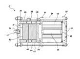
- FIGS. 1 and 2are schematic illustrations of an embodiment of a fire suppression system of the present invention
- FIGS. 3 a and 3 bare schematic illustrations of a gas generant pellet, optionally including an igniter, usable in the fire suppression system of the present invention
- FIG. 4is a schematic illustration of an embodiment of the fire suppression system of the present invention.
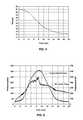
- FIG. 5shows the calculated mole percent of oxygen in a 100 cubic foot room
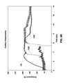
- FIGS. 6 and 7show pressure and temperature traces of Test A and Test B
- FIG. 8is a perspective view of a fire suppression system as utilized in a defined space in accordance with one embodiment of the present invention.
- FIGS. 9A through 9Eare graphs showing various performance characteristics associated with the operation of the system shown in FIG. 8 .
- a fire suppression system including a gas-generating deviceis disclosed.
- the gas-generating deviceproduces an inert gas mixture that is introduced into a space having a fire.
- the term “space”refers to a confined space or protected enclosure.
- the spacemay be a room or a vehicle that is occupied by humans, animals, or other living beings, or by electronic equipment.
- the spacemay be a room in a residential building, a commercial building, a military installation, or other building.
- the spacemay also be a vehicle or other mode of transportation, such as an automobile, an aircraft, a space shuttle, a ship, a motor boat, a train or subway, or a race car. Since the fire suppression system may be used in a space occupied by people, the fire suppression system is “man-rated.”
- the fire suppression systemmay also be used in a clean environment, such as a room or vehicle that is used to store or house electronic equipment.
- the inert gas mixturemay be generated pyrotechnically by igniting a gas generant that produces gaseous combustion products.
- the gaseous combustion productsmay include gases that do not contribute to ozone depletion or global warming. As such, these gases may be used in the inert gas mixture.
- the gaseous combustion productsmay include minimal, nonhazardous amounts of noxious gases, such as NH 3 , CO, NO x , or mixtures thereof.
- the gas generantproduces significantly less than the respective IDLH of each of these gases and less than 1% of an original weight of the gas generant in particulates or smoke.
- the gas generantmay also produce minimal amounts of other carbon-containing gases, such as CO 2 .
- the gas generantproduces less than approximately 4% by volume of CO 2 .
- the gas generantmay be formulated to produce minimal carbon dioxide, particulates, or smoke when combusted and to produce a physiologically acceptable balance of toxic gases produced under fuel-rich (CO and NH 3 ) or fuel-lean (NO x ) conditions. Solid combustion products are ultimately produced upon combustion of the gas generant and may be essentially free of products that vaporize at the flame temperature of the gas generant and may solidify upon cooling to produce particulates and smoke that are respirable.
- the inert gas mixtureis generated in a short time frame, so that the fire may be extinguished quickly.
- the gas generantmay be ignited, produce the inert gas mixture, and the inert gas mixture dispersed into the space within a time frame ranging from approximately 20 seconds to approximately 60 seconds.
- the inert gas mixturemay decrease the oxygen content in the space so that oxygen-promoted combustion reactions in the fire may be suppressed or extinguished.
- the inert gas mixturemay also decrease the oxygen content by creating an overpressure in the space, which causes oxygen-containing gases that were present in the space to exit by a positive pressure venting system and be replaced by the inert gas mixture.
- the positive pressure venting system for a given spacemay be designed to prevent a significant overpressure in the room.
- a fire suppression system 2may include a gas generator 70 having a gas generant 8 disposed in a combustion chamber 4 and an effluent train 6 .
- the fire suppression system 2may be formed from a material and construction design having sufficient strength to withstand pressures generated by the gas generant 8 .
- the pressures generated in the fire suppression system 2may range from approximately 100 pounds per square inch (“psi”) to approximately 1,000 psi. In one embodiment, such pressures range, more specifically, from approximately 600 psi to approximately 800 psi. In another embodiment, such pressures range from approximately 400 psi to approximately 800 psi. As will be appreciated by those of skill in the art, such pressures may differ depending, for example, on the type of gas generant 8 being used, the volume of gas to be produced thereby, the volume of the space being protected and other similar factors.
- an outer surface of the combustion chamber 4 and the effluent train 6may be formed, for example, from a metal, such as steel or another suitable metal or metal alloy.
- the ignition train(including an initiating device 12 ) may be electrically activated, as known in the art.
- the gas generant 8 and an igniter composition 14may be housed in the combustion chamber 4 .
- the gas generant 8may be present in the combustion chamber 4 as a pellet 16 or the gas generant 8 and the igniter composition 14 may be pelletized, as described in more detail below. Embodiments of the pellet 16 are illustrated in FIGS. 3 a and 3 b and are described in more detail below.
- the gas generant 8 in the combustion chamber 4may be ignited to produce the gaseous combustion products of the inert gas mixture by an ignition train using sensors that are configured to detect the presence of the fire in the space.
- the sensorsmay initiate an electrical impulse in the ignition train.
- Such sensorsare conventional and, as such, are not discussed in detail herein.
- the electrical impulsemay then ignite an initiating device 12 , such as a squib, semiconductor bridge, or other conventional initiating device. Heat flux from the initiating device 12 may be used to ignite the igniter composition 14 , which, in turn, ignites the gas generant 8 .
- the igniter composition 14 and the gas generant 8are described in more detail below. When ignited or combusted, the igniter composition 14 may produce an amount of heat sufficient to ignite the gas generant 8 .
- the initiating device 12may be used to directly ignite the gas generant 8 .
- the igniter composition 14produces solid combustion products, with minimal production of gaseous combustion products.
- the combustion products produced by this igniter composition 14may include a minimal amount of carbon-containing combustion products.
- the combustion chamber 4may house the igniter composition 14 and the gas generant 8 .
- the gas generant 8may be formed into a pellet 16 for use in the fire suppression system 2 .
- the pellet 16may include the gas generant 8 and the igniter composition 14 , with the igniter composition 14 present predominantly on an outer surface of the pellet 16 .
- the gas generant 8may be a nonazide gas generant composition that produces gaseous combustion products and solid combustion products.
- the gaseous combustion productsmay be substantially free of carbon-containing gases or NO x .
- Effluents produced by the combustion of the gas generant 8may be substantially free of NO 2 and may have less than 100 parts per million (“ppm”) of other effluents, such as CO or NH 3 .
- the gas generant 8may produce nitrogen and water as its gaseous combustion products. At least a portion of the gaseous combustion products produced by combustion of the gas generant 8 may form the inert gas mixture. In one embodiment, substantially all of the gaseous combustion products form the inert gas mixture so that a mass of the gas generant 8 used in the pellet 16 may remain as small as possible but yet still produce an effective amount of the inert gas mixture to extinguish the fire.
- a catalystmay also be present in the gas generant 8 to convert undesirable, toxic gases into less toxic, inert gases that may be used in fire suppression.
- the gaseous combustion productsmay be generated within a short amount of time after the gas generant 8 is ignited. For instance, the gas generant 8 may produce the gaseous combustion products within approximately 20 seconds to approximately 60 seconds after its ignition so that the inert gas mixture may be dispersed and the fire extinguished within approximately 30 seconds to approximately 60 seconds.
- the solid combustion productsmay produce a slag, which includes metallic elements, metal oxides, or combinations thereof.
- the slagmay fuse on or near a burning surface of the pellet 16 when the gas generant 8 is combusted, producing a porous, monolithic frit. Since the slag fuses into a porous mass at or near the surface of the pellet 16 as it combusts, particulates produced during combustion of the pellet 16 may be minimized.
- the gas generant 8is an HACN composition, as disclosed in U.S. Pat. Nos. 5,439,537 and 6,039,820, both to Hinshaw et al., the disclosure of each of which patents is incorporated by reference herein.
- the HACN used in the gas generant 8may be recrystallized and include less than approximately 0.1% activated charcoal or carbon. By maintaining a low amount of carbon in the gas generant 8 , the amount of carbon-containing gases, such as CO, CO 2 , or mixtures thereof, may be minimized upon combustion of the gas generant 8 .
- the HACNmay be unrecrystallized and include less than approximately 0.1% activated charcoal.
- Such an HACN compositionis commercially available from Autoliv Inc.
- HACNhydroxycellulose
- conventional gas generants 8that produce gaseous combustion products that do not include carbon-containing gases or NO x may also be used.
- the HACN composition, or other gas generants 8may include additional ingredients, such as at least one of an oxidizing agent, ignition enhancer, ballistic modifier, slag-enhancing agent, cooling agent, chemical fire suppressant, inorganic binder, or an organic binder.
- additional ingredientssuch as at least one of an oxidizing agent, ignition enhancer, ballistic modifier, slag-enhancing agent, cooling agent, chemical fire suppressant, inorganic binder, or an organic binder.
- Many additives used in the gas generant 8may have multiple purposes.
- an additive used as an oxidizermay provide cooling, ballistic modifying, or slag-enhancing properties to the gas generant 8 .
- the oxidizing agentmay be used to promote oxidation of the activated charcoal present in the HACN or of the ammonia groups coordinated to the cobalt in the HACN.
- the oxidizing agentmay be an ammonium nitrate, an alkali metal nitrate, an alkaline earth nitrate, an ammonium perchlorate, an alkali metal perchlorate, an alkaline earth perchlorate, an ammonium peroxide, an alkali metal peroxide, or an alkaline earth peroxide.
- the oxidizing agentmay also be a transition metal-based oxidizer, such as a copper-based oxidizer, that includes, but is not limited to, basic copper nitrate ([Cu 2 (OH) 3 NO 3 ]) (“BCN”), Cu 2 O, or CuO.
- the copper-based oxidizermay act as a coolant, a ballistic modifier, or a slag-enhancing agent.
- the copper-based oxidizermay produce copper-containing combustion products, such as copper metal and cuprous oxide, which are miscible with cobalt combustion products, such as cobalt metal and cobaltous oxide. These combustion products produce a molten slag, which fuses at or near the burning surface of the pellet 16 and prevents particulates from being formed.
- the copper-based oxidizermay also lower the pressure exponent of the gas generant 8 , decreasing the pressure dependence of the burn rate.
- HACN-containing gas generants 8that include copper-based oxidizers ignite more readily and burn more rapidly at or near atmospheric pressure. However, due to the lower pressure dependence, they burn less rapidly at extremely high pressures, such as those greater than approximately 3000 psi.
- the ignition enhancermay be used to promote ignition of the gas generant 8 at a low positive pressure, such as from approximately 14 psi to approximately 500 psi.
- the ignition enhancermay be a conductive material having a large surface area.
- the ignition enhancermay include, but is not limited to, amorphous technical grade boron, high surface area flaked copper, or flaked bronze.
- the ballistic modifiermay be used to decrease the burn rate pressure exponent of the gas generant. For instance, if the gas generant 8 includes cupric oxide and submicron particle size titanium dioxide, the gas generant may have a pressure exponent of less than approximately 0.3.
- Another ballistic modifier that may be used in the gas generant 8is high surface area iron oxide.
- the ballistic modifiermay also promote ignition of the gas generant 8 .
- Additives that are able to provide ballistic modifying and ignition-enhancing propertiesmay include, but are not limited to, high surface area transition metal oxides and related species, such as basic copper nitrate and flaked metal
- the cooling agentmay be used to lower the flame temperature of the gaseous combustion products. Since high flame temperatures contribute to the formation of toxic gases, such as NO and CO, cooling the gaseous combustion products is desirable. In addition, by using the cooling agent in the gas generant 8 , less cooling of the gaseous combustion products may be necessary in the effluent train 6 .
- the cooling agentmay absorb heat due to its intrinsic heat capacity and, potentially, from an endothermic phase change, such as from a solid to a liquid, or an endothermic reaction, such as a decomposition of metal carbonates or metal hydroxides to metal oxides and carbon dioxide or water, respectively. Many of the additives previously described, such as the oxidizing agent, the ignition enhancer, and the ballistic modifier, may act as the cooling agent.
- the cooling agentmay be a metal oxide, non-metal oxide, metal hydroxide, metal carbonate, or a hydrate thereof. However, desirably, the cooling agent is not a strong oxidizing or reducing agent.
- the slag-enhancing agentmay be used to meld the combustion products of the gas generant 8 into a cohesive solid, but porous, mass. Upon combustion of the gas generant 8 , the slag-enhancing agent may melt or produce molten combustion products that adhere to the solid combustion products and join the solid combustion products into the solid mass. Since the solid combustion products are melded together, the amount of smoke or particulates produced may be reduced. Silicon dioxide (SiO 2 ), titanium oxide, magnesium oxide, or copper-containing compounds may be used as the slag-enhancing agent. Desirably, titanium oxide or magnesium oxide is used because they produce low levels of NO x upon combustion of the gas generant 8 .
- the concentration of NO x in the gaseous combustion productsmay also be reduced by including a catalyst for NO x in the gas generant 8 .
- the catalystmay be tungsten oxide, which converts NO x to nitrogen in the presence of ammonia.
- the chemical fire suppressant or chemical fire retardantmay also be used in the gas generant 8 .
- the chemical fire suppressantmay be a compound or a mixture of compounds that affects flames of the fire, such as a compound that delays ignition and reduces the spread of the flames in the space.
- the chemical fire suppressantmay trap radicals, such as H, OH, O, or HO 2 radicals, which are important to oxidation in the vapor phase.
- the chemical fire suppressantmay be a halogenated organic compound, a halogenated inorganic compound, or mixtures thereof.
- the inorganic bindermay provide enhanced pellet integrity when the pellet 16 is subjected to mechanical or thermal shock.
- the inorganic bindermay be soluble in a solvent that is used to process the gas generant 8 , such as water. As the solvent evaporates, the inorganic binder may coat solid particles of the gas generant 8 , which enhances crush strength of granules and pellets 16 produced with the gas generant 8 .
- carbon-containing gasessuch as CO or CO 2 , may not be produced when the gas generant is combusted.
- the inorganic bindermay include, but is not limited to, a silicate, a borate, boric acid, or a mixture thereof.
- sodium silicatesodium metasilicate (Na 2 SiO 3 .5H 2 O), sodium borosilicate, magnesium silicate, calcium silicate, aluminosilicate, aluminoborosilicate, or sodium borate may be used as the inorganic binder.
- HACNmay act as the inorganic binder.
- an organic bindermay also be used in the gas generant 8 as long as minimal amounts of CO or CO 2 are produced during combustion. Gas generants 8 that include even a small amount of organic binder may have improved crush strength in pellet form compared to gas generants 8 that are free of organic binders.
- the organic bindermay be present in the gas generant 8 from approximately 0.5% to approximately 2.0%.
- the organic bindermay be a synthetic or naturally occurring polymer that dissolves or swells in water including, but not limited to, guar gum, polyacrylamide, and copolymers of polyacrylamide and sodium polyacrylate.
- the organic binder, in powder form,may be blended with dry ingredient(s) prior to the addition of water to promote dispersion of the organic binder.
- a sufficient amount of watermay be added during mixing to produce a thick paste, which is subsequently dried and granulated prior to pelletization.
- Organic binders that dissolve or swell in organic solventsmay also be used, such as ethyl cellulose, which dissolves or swells in ethanol.
- Gas generants 8 that include ethyl cellulosemay be dry blended prior to mixing in the ethanol. The resulting thick paste may be subsequently dried and pressed into pellets 16 .
- Curable polymeric resinsmay also be used as organic binders in the gas generant 8 .
- the curable polymeric resinmay be blended with the gas generant 8 and a curative in the absence of solvent or in the presence of a small amount of solvent to promote dispersion of the small amounts of the curable polymeric resin and the curative.
- the resulting powdermay be pressed into a pellet 16 and allowed to cure at elevated temperature, such as at a temperature of approximately 135° F.
- the curable polymeric resinmay include, but is not limited to, epoxy-cured polyesters and hydrosilylation-cured vinylsilicones.
- the organic bindermay also include water-soluble, organic compounds that have a low carbon content, such as guanidine nitrate. If guanidine nitrate is used as the organic binder, it may be present in the gas generant 8 from approximately 1.0% to approximately 5.0%.
- the gas generant 8may further include organic or inorganic fibers. As with other ingredients discussed hereinabove, such fibers may be used to enhance the mechanical integrity, the ignition properties, the ballistic properties or any combination of such properties of the gas generant 8 or pellets 16 formed therefrom. If organic fibers are used, it may be desirable to use a material that does not combust so as to prevent, or at least minimize, the likelihood of any additional carbon oxides being present in the gas generated by the fire suppression system 2 .
- the gas generant 8 used in the fire suppression system 2includes recrystallized HACN, cupric oxide (CuO), titanium dioxide (TiO 2 ), and high molecular weight polyacrylamide ([CH 2 CH(CONH 2 ] n ).
- the gas generant 8includes recrystallized HACN, CuO, silicon dioxide (SiO 2 ), TiO 2 , and polyacrylamide.
- the gas generant 8includes recrystallized HACN, cuprous oxide (Cu 2 O), and TiO 2 .
- the gas generant 8may be produced by a variety of methods, such as by using a vertical mixer, a muller mixer, a slurry reactor, by dry blending, by extruding, or by spray drying the ingredients of the composition.
- the solid ingredients of the gas generant 8may be mixed in a solution that includes HACN dissolved in from approximately 15% by weight to approximately 45% by weight water. Ignitability and ease of combusting the gas generant 8 may increase when high concentrations of HACN are dissolved during the mixing process.
- the watermay be heated to 165° F. to increase the solubility of the HACN.
- gas generant 8at high water content (greater than approximately 35% by weight) and warm temperature (greater than approximately 145° F.) dissolves at least a portion of the HACN and coats the additional ingredients.
- a high shear mixersuch as a dispersator, may be used to completely wet the high surface area solid ingredients before adding them to the vertical mixer or the high surface area solid ingredients may be preblended in a dry state.
- a powdered bindermay be blended with the HACN prior to addition of water or another appropriate solvent. The slurry may be dried in a convection oven.
- a muller mixeris used to disperse the curable polymeric resin and the curative into the powdered ingredients of the gas generant 8 .
- a small amount of solventmay also be added to promote dispersal of the curable polymeric resin and the curative.
- the gas generant 8 including the curable polymeric resinis allowed to cure once it has been pressed into the pellet 16 .
- the HACNmay be completely dissolved in water at a temperature of approximately 180° F. If technical grade HACN is used, any activated charcoal in the heated HACN solution may be removed, such as by filtration or another process.
- the heated HACN solutionmay be added to a cool, rapidly mixed suspension of the solid ingredients of the gas generant 8 .
- a predispersed slurry of the solid ingredientsmay be slowly added to the rapidly stirred, HACN solution as it cools. Either of these methods may promote the formation of HACN crystallites on the insoluble solid ingredients of the gas generant 8 .
- the HACNmay be mixed with the other ingredients of the gas generant 8 using a v-shell, rotary cone, or Forberg blender. A small amount of moisture may be added to the mixture to minimize dusting. The mixture may then be dried before pelletization.
- the HACN and other ingredientsare mixed into a powder blend.
- the dry blendis then metered into an extruder along with a controlled flow of water.
- the generant 8is mixed in the extruder and either exits as wet granules or is extruded through a die to form a desired shape as will be appreciated by those of ordinary skill in the art.
- the granules or the extruded shapesmay then be dried prior to further processing or use thereof in the fire suppression system 2 .
- the HACN and other ingredientsare mixed with water to form a slurry.
- the slurryis pumped into an air heated spray drying chamber through an atomizing device.
- the atomized slurryis then flash dried by the heated air to form dry granules.
- the dried granulesare removed from the air stream by a separating device such as, for example, a cyclone or a bag filter, and then collected.
- the granulesmay then be pressed into pellets 16 .
- the gas generant 8 or the igniter composition 14 and the gas generant 8may be formed into the pellet 16 .
- the pellet 16may be formed by compressing the gas generant 8 or the igniter composition 14 and the gas generant 8 together to form a cylindrically shaped pellet 16 , as illustrated in FIG. 3 a .
- the geometry of the gas generant 8 used in the fire suppression system 2may depend on a desired ballistic performance of the gas generant 8 , such as a desired burn rate or rate of evolution of the inert gas mixture as a function of time. Burn rates are typically categorized as a progressive burn, a regressive burn, or a neutral burn. A progressive burn is provided when the burning surface of the pellet 16 increases gradually as the pellet 16 burns.
- the rate of evolution of the inert gas mixtureincreases as a function of time.
- a regressive burnis provided when the burning surface of the pellet 16 decreases gradually as the pellet 16 burns.
- the rate of evolution of the inert gas mixtureis initially high and decreases as a function of time. If the burning surface of the pellet 16 burns at a constant rate, a neutral burn is provided.
- the gas generant 8is formed into a pellet 16 having a center-perforated grain geometry, as illustrated in FIG. 3 b .
- the center-perforated grain geometryhas a high surface area, burns rapidly, and provides a neutral burn.
- the pellet 16may also be formed into other shapes that provide a neutral burn as opposed to a regressive or progressive burn.
- the center-perforated pellet 16may be produced using an appropriately designed die or by drilling a hole into a cylindrical pellet 16 , using appropriate safety precautions.
- the pellets 16may be pressed or otherwise formed to exhibit one or more surface features 17 , such as protrusions on one or more end surfaces 19 .
- Such surface features 17act as stand-offs when the pellets 16 are stacked end-to-end and provide an air gap between adjacent pellets 16 or between the end of a pellet 16 and another surface of the combustion chamber 4 .
- the air gap defined between pellets 16enables a combustion flame to more efficiently spread to all of the pellets in a combustion chamber 4 .
- the pellets 16may be stacked in a retaining structure, such as a wire mesh cage, to maintain the pellets in a desired stack arrangement.
- the pellet 16may include at least one layer of the igniter composition 14 in contact with one or more surfaces of the gas generant 8 .
- a configuration of the igniter composition 14 used in the fire suppression system 2may depend on the geometry of the gas generant 8 .
- the pellet 16may include a layer of the igniter composition 14 above a layer of the gas generant 8 .
- a layer of the igniter composition 14may be present below the gas generant 8 or may be present on multiple surfaces of the pellet 16 .
- the igniter composition 14may also be pressed on the surface of the pellet 16 .
- the igniter composition 14may be powdered, granulated, or pelletized and housed in a metal foil packet or other pouch that is placed on or near the surface of the pellet 16 .
- the metallic foil packetmay include steel wool or another conductive material that absorbs heat from the igniter composition 14 and transfers it to the surface of the gas generant 8 .
- the igniter composition 14may also be placed in a perforated flash tube within the center-perforation of the pellet 16 . If the igniter composition 14 is granular or powdered, the perforated flash tube may be lined internally or externally with a metal foil or the igniter composition 14 may be inserted into the perforated flash tube in preloaded foil packets.
- the organic binder used in the igniter composition 14may be soluble in organic solvents.
- ethyl cellulose or polyvinylacetatemay also be used as the organic binder.
- the Mg/Sr(NO 3 ) 2 /binder compositionmay be formed by conventional techniques.
- the igniter composition 14may also include mixtures of B/KNO 3 and Mg/Sr(NO 3 ) 2 /binder.
- the igniter compositions disclosed in U.S. Pat. No. 6,086,693, the disclosure of which patent is incorporated by reference herein in its entirety,may also be used as the igniter composition 14 .
- the pellet 16may be formed by layering the granules of the igniter composition 14 above or below the layer of the gas generant 8 in a die so that the igniter composition 14 and the gas generant 8 are in contact with one another.
- a pressure of approximately 8,000 psimay be used to form the pellet 16 , which has a porosity ranging from approximately 5% to approximately 20%.
- the igniter composition 14 and the gas generant 8may be compressed into the pellet 16 using a metal sleeve or a metal can, which provides support while the pellet 16 is being produced, handled, or stored.
- the metal can or the metal sleevemay also be used to inhibit burning of surfaces of the pellet 16 that are enclosed by the metal sheathing.
- the pellet 16may burn at a controlled rate so that the amount of inert gas mixture produced during the burn remains constant as a function of time.
- at least one surface of the pellet 16may be covered or inhibited by the metal can or metal sleeve so that these surfaces do not burn.
- An inner surface of the metal sheathingmay also be painted with an inert inorganic material, such as sodium silicate or a suspension of magnesium oxide in sodium silicate, to inhibit the surfaces of the pellet 16 .
- the pellets 16may be housed in the combustion chamber 4 and have a total mass that is sufficient to produce an amount of the inert gas mixture sufficient for extinguishing the fire in the space.
- the gas generant 8may have a total mass of approximately 40 pounds.
- the inert gas mixture produced by the combustion of the gas generant 8may lower the oxygen concentration in the space to a level that sustains human life for a limited duration of time. For instance, the oxygen concentration in the space may be lowered to approximately 13% by volume for approximately five minutes.
- the combustion chamber 4may be configured to house multiple pellets 16 of the gas generant 8 or the igniter composition 14 and the gas generant 8 . Therefore, the fire suppression system 2 of the present invention may be easily configured for use in spaces of various sizes. For instance, the fire suppression system 2 may include one pellet 16 if the fire suppression system 2 is to be used in a small space. However, if the fire suppression system 2 is to be used in a larger space, the combustion chamber 4 may include two or more pellets 16 so that the sufficient amount of the inert gas mixture may be produced.
- pellets 16having a 5.8 inch outer diameter, a 2.6 inch height, and a weight of 4.44 pounds may be used, while eight of these pellets 16 may be used in a 1,000 cubic foot space.
- two gas generators 70each containing eight pellets 16 , may be strategically positioned.
- the pellets 16may have an effective burning surface area so that the inert gas mixture may be produced within a short time period after initiation of the gas generant 8 . For instance, the inert gas mixture may be produced with approximately 20 seconds to approximately 60 seconds after initiation of the gas generant 8 .
- the pellets 16may be ignited so that they are combusted simultaneously to provide a sufficient amount of the inert gas mixture to extinguish the fire. Alternatively, the pellets 16 may be ignited sequentially so that the inert gas mixture is produced at staggered intervals.
- the ignition trainincludes a squib, which, when electrically activated, ignites a granular or pelletized composition of B/KNO 3 in an ignition chamber.
- the hot effluents produced by combustion of the B/KNO 3 compositionpass into the combustion chamber 4 and ignite the secondary ignition or igniter composition 14 , which may be located in the metallic foil packet or other pouch, pressed or painted on the surface of the pellet 16 , or placed in the perforated flash tube positioned in the center-perforation of the pellet 16 .
- the fire suppression system 2may be designed in various configurations depending on the size of the space in which the fire is to be extinguished.
- Example configurations of the fire suppression system 2include, but are not limited to, those illustrated in FIGS. 1 and 4 .
- the fire suppression system 2may have a tower configuration having a plurality of gas generators 70 .
- a group or cluster of the gas generators 70may be utilized to generate a sufficient amount of the inert gas mixture, which is delivered to the space in which the fire is to be suppressed.
- the number of gas generators 70 in the cluster, and a controllable sequence in which the gas generators 70 are initiated,enables the ballistic performance of the fire suppression system 2 to be tailored to provide a sufficient amount of the inert gas mixture to the space.
- the number of gas generators 70may also be adjusted to provide a desired mass flow rate history and action time of the inert gas mixture to the space.
- gas generators 70may be added to or removed from the tower cluster.
- the fire sequencing used to initiate the gas generators 70may be accomplished by controlling the timing of the electrical impulse to the initiating device 12 or by utilizing a pyrotechnic fuse. A column length of the pyrotechnic fuse may be selected to determine the time of initiation of the gas generator 70 .
- the gas generator 70may house the gas generant 8 , which is illustrated in FIG. 4 as having a center-perforated grain geometry. However, the gas generator 70 may accommodate other geometries of the gas generant 8 depending on the desired ballistic performance of the gas generant 8 .
- the geometry of the igniter composition 14 used in the fire suppression system 2may depend on the grain geometry of the gas generant 8 . For instance, the igniter composition 14 may be loaded into the metallic foil packets or other pouches and placed on the surfaces of the gas generant 8 . Alternatively, the igniter composition 14 may be placed in the perforated flash tube (not shown), which extends down the length of a center-perforated pellet 16 of the gas generant 8 .
- the igniter composition 14is ignited, which in turn combusts the gas generant 8 and produces the gaseous combustion products.
- the gaseous combustion productsform the inert gas mixture, which then passes through a filter 18 and a controlling orifice 20 into a diffuser chamber 72 .
- the filter 18may be a screen mesh, a series of screen meshes, or a conventional filter device that removes particulates from the inert gas mixture.
- the filter 18may also provide cooling of the inert gas mixture.
- the controlling orifice 20controls the mass flow out of the gas generator 70 and, therefore, controls the flow rate of the inert gas mixture and the pressure within the gas generator 70 .
- the controlling orifice 20may be used to maintain a desired combustion pressure in the fire suppression system 2 .
- the pressure in the gas generator 70may be maintained at a level sufficient to promote ignition and to increase the burn rate of the gas generant 8 .
- the pressuremay also promote the reaction of reduced toxic gases, such as CO and NH 3 , with gases that are oxidized, such as NO x , which significantly reduces the concentration of these gases in the effluent gases.
- the controlling orifice 20may be of a sufficient size to produce a combustion pressure ranging, for example, from approximately 600 psi to approximately 800 psi in the combustion chamber 4 of the gas generator 70 .
- the controlling orifice 20may be of a sufficient size to produce a combustion pressure ranging, for example, from approximately 400 psi to approximately 600 psi in the combustion chamber 4 of the gas generator 70 . Therefore, the combustion chamber walls 22 of the gas generator 70 , as well as other portions of the fire suppression system 2 , may be formed from a material that is capable of withstanding the maximum working pressure at the operating temperatures with appropriate engineering safety factors. In the presently described tower configuration, high pressures of the fire suppression system 2 are restricted to the small diameter, combustion chamber 4 volumes, while the remainder of the fire suppression system 2 operates at low pressures, which results in cost and weight savings.
- the flow deflector 74recirculates the inert gas mixture and results in a more uniform flow through a perforated diffuser plate or first diffuser plate 24 .
- the first diffuser plate 24may disperse the inert gas mixture so that it does not exit the gas generator 70 as a high velocity jet.
- the inert gas mixturethen passes through a heat management system 26 that includes cooling media or effluent scavenging media.
- the heat management system 26may reduce the temperature of the inert gas mixture to a temperature that is appropriate to suppress the fire.
- the inert gas mixturemay be cooled before it is introduced into the space.
- the heat released from a gas generant 8 combusted in a 2,000 cubic foot spacemay be approximately 40,000 British Thermal Units (“BTU”).
- the heat management system 26is a heat sink.
- the heat sinkmay be formed from conventional materials that are shaped into beds, beads, or tube clusters.
- the materials used in the heat sinkmay include, but are not limited to, metal, graphite, or ceramics.
- the material used in the heat sink and the geometry of the heat sinkmay be selected by one of ordinary skill in the art so that the heat sink provides the appropriate heat transfer surface, thermal conductivity, heat capacity, and thermal mass for the intended application.
- the cooled, inert gas mixturemay then be dispersed into the space through at least one final orifice 32 , which reduces the pressure of the inert gas mixture relative to the pressure in the gas generator 70 .
- the geometry of the final orifice(s) 32may be selected based on the geometry of the space and the placement of the fire suppression system 2 in the space.
- a flow diverter 76may be positioned at the final orifice to direct the flow in a specific direction as it enters into the space being protected by the fire suppression system 2 . It is noted that, since the inert gas mixture is generated pyrotechnically, high-pressure gas storage tanks and accompanying hardware to disperse the inert gas mixture may not be needed in the fire suppression system 2 of the present invention.
- FIG. 1Another configuration of the fire suppression system 2 is shown in FIG. 1 .
- the inert gas mixtureincluding nitrogen and water vapor, may be passed through the filter 18 to remove any particulates that are produced upon combustion of the gas generant 8 .
- the inert gas mixturemay then be flowed through the controlling orifice 20 located at the exit of the combustion chamber 4 of the gas generator 70 .
- the controlling orifice 20may control the mass flow out of the combustion chamber 4 and, therefore, may control the pressure within the combustion chamber 4 .
- the controlling orifice 20may be used to maintain a desired combustion pressure in the fire suppression system 2 .
- the controlling orifice 20may be of a sufficient size to produce a combustion pressure ranging from approximately 400 psi to approximately 600 psi in the combustion chamber 4 . Therefore, walls 22 of the combustion chamber 4 and of the effluent train 6 may be formed from a material capable of withstanding the maximum working pressure at the operating temperatures with appropriate engineering safety factors.
- the combustion chamber 4may also include the first diffuser plate 24 that disperses or diffuses the inert gas mixture into the heat management system 26 of the effluent train 6 .
- the first diffuser plate 24may disperse the inert gas mixture so that it does not exit the combustion chamber 4 as a high velocity jet. Rather, a laminar flow of the inert gas mixture may enter the effluent train 6 .
- the effluent train 6may include the heat management system 26 or a gas coolant material to reduce the temperature of the inert gas mixture to a temperature appropriate to suppress the fire.
- the heat management system 26is a heat sink, as previously described.
- the heat management system 26includes a PCM 28 .
- the PCM 28removes thermal energy from the inert gas mixture by utilizing the PCM's latent heat of fusion and stores the thermal energy.
- the PCM 28may be an inert material that does not react with the inert gas mixture including, but not limited to, a carbonate, phosphate, or nitrate salt.
- the PCM 28may be lithium nitrate, sodium nitrate, potassium nitrate, or mixtures thereof.
- the PCM 28 used in the heat management system 26may be selected by one of ordinary skill in the art based on its phase change temperature, latent heat of fusion, or thermal properties, such as thermal conductivity, burn rate, heat capacity, density, or transition or melting temperature.
- the material selected as the PCM 28may be dependent on the amount of time that is needed to ignite the gas generant 8 and produce the gaseous combustion products of the inert gas mixture.
- a tube cluster 30may be embedded in, or surrounded by, the PCM 28 .
- the tube cluster 30may be formed from metal tubes that are capable of conducting heat, such as steel or copper tubes.
- the length, inner diameter, and outer diameter of the metal tubesmay be selected by one of ordinary skill in the art depending on the amount of time required for the heat produced by the gas generant 8 to be conducted from the inert gas mixture to the PCM 28 .
- the geometry of the tube cluster 30 in relation to the PCM 28may be selected by one of ordinary skill in the art based on the amount of time necessary to ignite the gas generant 8 and produce gaseous combustion products and the amount of heat produced by the gas generant 8 .
- heat flux from the inert gas mixturemay be transferred through the tube cluster 30 and into the PCM 28 .
- the PCM 28When the PCM 28 is heated to its phase change temperature, it may begin to absorb its latent heat of fusion. Once the PCM 28 has absorbed its latent heat of fusion, an interface boundary temperature differential of the PCM 28 remains constant, which may enhance heat conduction from the surface of the tube cluster 30 to the PCM. Thermal energy may be stored in the PCM 28 based on the heat capacity of its liquid state once the PCM 28 has absorbed its latent heat of fusion.
- the heat management system 26may also be doped with a selective catalytic reduction (“SCR”) catalyst or a non-selective catalytic reduction (“NSCR”) catalyst to convert any undesirable gases that are produced as gaseous combustion products into gases that may be used in the inert gas mixture.
- SCRselective catalytic reduction
- NSCRnon-selective catalytic reduction
- the SCR and NSCR catalystsmay be used to convert ammonia or nitrogen oxides into nitrogen and water, which may then be used in the inert gas mixture.
- the inert gas mixturemay pass through a final orifice 32 , which reduces the pressure of the inert gas mixture relative to the pressure in the combustion chamber 4 .
- the inert gas mixturemay then pass through a second diffuser plate 34 to uniformly disperse the inert gas mixture throughout the space.
- flow diverters or other structuresmay also be used to direct to the flow of gas in a desired manner as it exits the fire suppression system 2 .
- high-pressure gas storage tanks and accompanying hardware to disperse the inert gas mixturemay not be needed in the fire suppression system 2 of the present invention.
- FIG. 8an example of a fire suppression system 102 is shown as used in a defined space 104 that exhibits a volume of approximately 1,000 cubic feet.
- the systemincludes four towers 106 spaced apart from one another throughout the defined space 104 .
- One or more vents 108may be provided in the defined space 104 to accommodate the venting of overpressures which may occur during the combustion of gas generants 8 .
- a total cross sectional vent area of 288 square incheswas used in the presently described embodiment.
- fires 110were provided at one or more locations within the defined space 104 .
- the generantincluded a composition having 78% HACN (unrecrystallized and containing less than 0.1% activated charcoal obtained from Autliv), 18% Chemet UP13600FM cupric oxide, 2% DeGussa P-25 titanium dioxide, 1% Cytec Cyanamer N-300 polyacrylamide and 1% 1/32′′ Fiber Glast #38 glass fibers.
- the gas generants 8 of the generators 70were ignited at intervals of approximately 1.5 to 2.5 seconds. The sequential ignition of individual gas generants 8 provided a moderated flow of gas over a desired time period while preventing unacceptable temperatures and unacceptable levels of over pressurization within the defined space 104 .
- each generator 70i.e., within the combustion chamber 4
- a thick line 120shows the predicted pressure curve of a gas generator 70
- pressure curves 120 A- 120 Dshow actual pressure curves associated with the sequential firing of the generators 70 within the towers 106 at approximately 2.5 second intervals.
- the spikese.g., spike 122
- the peak or maximum combustion pressures 124 A- 124 Dare seen to be maintained between approximately 500 psi and approximately 600 psi.
- First curve 130shows a predicted outflow temperature curve while curves 130 B and 130 C show the actual temperature curves. It is noted that the peak outflow temperature was maintained between approximately 150° F. and 200° F.
- First curve 140is the predicted temperature within the defined space 104 .
- Curve 142represents the temperature of the defined space 104 at an upper elevation thereof.
- Curve 144represents the temperature of the defined space 104 at a mid elevation thereof.
- Curve 146represents the temperature of the defined space 104 at a lower elevation thereof. Temperatures of the room peaked at approximately 120° F. and 130° F.
- a graphis shown of the percentage of oxygen (O 2 ) within the defined space with respect to time.
- Curve 150shows the predicted percentage of O 2 within the defined space 104 while curve 152 shows the actual percentage of O 2 measured within the defined space 104 .
- the actual O 2 content of the air within the defined space 104dropped several percent during the sequential ignition of the gas generators 70 .
- the change in pressure within the defined space 104is shown with respect to time during the sequential ignition of the gas generators 70 .
- the change in pressureis less than approximately 1.6 inches of water (in H 2 O) or approximately 0.06 psi.
- each of the towers 106may include multiple gas generators 70 , such as has been described with respect to the towers depicted in FIG. 4 .
- each individual gas generator 70could be sequentially ignited.
- other patterns of ignitionmay be used.
- two (or more) gas generatorscould be ignited at substantially the same time followed by the time-spaced ignition of two (or more) additional generators.
- the gas generatorscould be ignited not only in a time-based pattern, but in a specified geometrical or spatial pattern (e.g., clockwise, counterclockwise, a crossing or star pattern or a zig-zag pattern) to provide a desired mass flow pattern within the defined space 104 .
- a specified geometrical or spatial patterne.g., clockwise, counterclockwise, a crossing or star pattern or a zig-zag pattern
- various time-based and spatial patternsmay be utilized depending, for example, on the configuration of the defined space and the type and volume of gas generant 8 being utilized.
- gas generant compositions and igniter compositionsfor use within the scope of the present invention. These examples are merely illustrative and are not meant to limit the scope of the present invention in any way.
- a gas generant including HACN, BCN, and Fe 2 O 3was produced in the slurry reactor.
- a 10 liter baffled slurry tankwas filled with 4,900 grams of distilled water and stirred with a three blade stationary impeller at 600 revolutions per minute (“rpm”).
- a glycol heating bathwas used to heat the water to 180° F. After the water temperature reached 180° F., 586.1 g of technical grade HACN was added to the mixer and stirred at 600 rpm for 10 minutes to allow the HACN to dissolve.
- 111.64 g of BCN and 18.56 g of Fe 2 O 3were dry blended together in a NALGENE® quart container.
- Cooling with icewas continued after this addition.
- a third addition of 58 g of BCN/Fe 2 O 3 /waterwas then injected slowly into the mix bowl with a 30 cc syringe while mixing rapidly. Cooling with ice was continued after this addition.
- 56.2 g (the remainder of the suspension) of BCN/Fe 2 O 3 /waterwas injected slowly into the mix bowl with a 30 cc syringe while mixing rapidly. Cooling with ice was continued after this addition until the temperature reached 75.4° F.
- the impellarwas stopped and the material was transferred out of the mix bowl and into a five-gallon bucket.
- the mixwas then filtered in a vacuum Erlenmeyer flask with a 1- ⁇ m paper filter.
- the mixed gas generantwas then placed onto a glass tray and dried at 165° F. overnight to remove any moisture.
- a five-gallon BAKER PERKINS® vertical mixerwas filled with 10,857 g of distilled water and stirred at 482 rpm. The mix bowl was heated to 165° F. After the water temperature reached 165° F., 3,160.0 g of recrystallized HACN was added into the mixer and stirred slowly at 482 rpm for 15 minutes to allow the HACN to partially dissolve and break up any clumps. 1,800 g of Cu 2 O and 720 g of TiO 2 were then dry blended by sealing a five-gallon bucket and shaking it. The mixer was stopped and the walls and blades were scraped down to incorporate any material that may have migrated up the mix blades.
- the blend of Cu 2 O and TiO 2was added to the mix bowl and mixed for 15 minutes at 482 rpm.
- the mixerwas stopped and the walls and blades were scraped down to incorporate any material that may have migrated up the mix blades.
- 3,160 g of recrystallized HACNwas added into the mix bowl and mixed for 15 minutes at 482 rpm.
- the mixerwas stopped and the walls and blades were scraped down.
- the mixturewas mixed for 30 minutes at 1,760 rpm.
- the mixerwas stopped and the walls and blades were scraped.
- the mixturewas mixed for 30 minutes at 1,760 rpm.
- the mixturewas loaded onto velo-stat-lined trays and dried at 165° F. After drying, the coarse, granular material was granulated to a consistent small granule size using a Stokes granulator.
- a polymer preblendwas prepared by mixing 82 g of Crompton Corp. Fomrez F17-80 polyester resin with 17.4 g of Vantico Inc. Araldite MY0510 multifunctional epoxy resin and 0.6 g of powdered magnesium carbonate. To a 12′′ diameter muller mixer, 10 g of the polymer preblend and 1,636 g of recrystallized HACN were added. This was blended for 10 minutes and the mixing surfaces were scraped down. Then, 294 g of American Chemet Corp. UP13600FM cupric oxide and 60 g of DeGussa P-25 titanium dioxide were added and the composition was mixed for 5 minutes. The mixer was again scraped down and the composition was blended for another 10 minutes. The composition was placed in a freezer and allowed to warm to room temperature immediately before pressing it into a pellet.
- Pellets formed from the gas generants described in Examples 1, 2, or 4were produced. To press the pellets, a 1.13 inch die assembly was used. A mold release agent, polytetrafluoroethylene (“PTFE”), was liberally applied to the die anvil and foot to minimize material sticking during the press cycle. 1.5 g of an igniter composition having a mixture of 60% B/KNO 3 and 40% Mg/Sr(NO 3 ) 2 /binder was added to the die and leveled off with a spatula. The igniter composition was produced by blending together granules of the B/KNO 3 and Mg/Sr(NO 3 ) 2 /binder. 10 g of the gas generant described in Examples 1, 2, or 4 was added to the die.
- PTFEpolytetrafluoroethylene
- the press footwas inserted into the top of the die assembly and twisted to ensure proper alignment.
- the pelletwas pressed for 60 seconds at 8,000 lb f (8,000 psi). After pressing, the anvil was removed from the assembly and the pellet was pressed out of the die into a padded cup to minimize damage.
- Sleeved pellets formed from the gas generants described in Examples 1, 2, or 4were produced.
- the press anvil and foot of the diewere liberally sprayed with PTFE.
- a 1.05 inch internal diameter (“ID”) steel ringwas placed on the press anvil.
- 1.2 g of an igniter composition having a mixture of 60% B/KNO 3 and 40% Mg/Sr(NO 3 ) 2 /binderwas then added inside the steel ring.
- the surface of the igniter compositionwas then leveled with a spatula to ensure an even layer of the igniter composition on one surface of the pellet.
- An alignment sleevewas placed on top of the steel sleeve and 14.5 g of the gas generant described in Examples 1 or 2 was poured inside the alignment tool.
- a 1.00 inch outer diameter (“OD”) press footwas inserted into the die.
- the sleeved pelletwas pressed for 60 seconds at 6,900 lb f (8,000 psi). After pressing, the top surface of the sleeved pellet matched the top layer of the steel ring. Therefore, no post pressing process was required to remove the pellet from the press die. Instead, the anvil and alignment piece pulled off easily, leaving a filled steel ring of the gas generant.
- Sleeved pelletswere also pressed with embedded hot wires by running a loop of tungsten wire having a 0.010 inch OD through two holes on the press anvil.
- the wire leadswere rolled up and stored in the labeled opening on the underside of the press anvil. After installing the hot wire in the pressing fixture, the procedure for sleeved pellets (described in Example 7) was followed.
- 3.3 pound pelletswere pressed using a 150-ton hydraulic press.
- the anvil and press footwere sprayed liberally with PTFE.
- the anvilwas then inserted into the die walls.
- 39.6 g of the igniter composition(40% B/KNO 3 and 60% Mg/Sr(NO 3 ) 2 /binder) was added to the die by slowly pouring the material in a circular coil pattern starting at the center of the anvil and moving outward toward the die wall.
- the igniter compositionwas then leveled on top of the press anvil with a spatula. After ensuring an even layer of the igniter composition, 1,500 g of the gas generant described in Examples 1, 2, or 4 was added to the die.
- the press footwas then carefully inserted into the die.
- the press footwas spun around to ensure that no gas generant was trapped between the die walls and press foot. After alignment, the pellet was pressed at 211,000 lb f (8,000 psi) for 60 seconds. To remove the pellet, the press anvil was removed and the die walls were positioned on top of a 6.0 inch inner diameter (“ID”) knockout cup. A slight amount of force was applied to the press foot to push the pellet out of the 5.8 inch die walls.
- ID6.0 inch inner diameter
- the gas generant (737 g) described in Example 4was added to a carbon steel can having an OD of 6.0 inches, an ID of 5.8 inches, a height of 2.15 inches, and a depth of 2.06 inches and pressed using a 150-ton hydraulic press to a maximum pressure of 8,042 psi. Pressure was maintained at or above 8,000 psi for one minute.
- a second addition of 740 g of the gas generantwas added to the press die along with a 59.4 g blend of an igniter composition that included 11% B/KNO 3 and 89% Mg/Sr(NO 3 ) 2 /binder. The igniter composition was spread evenly on the top surface of the gas generant. The remaining gas generant and the igniter composition were then pressed at 8,197 psi for one minute. The total height of the gas generant and igniter composition after the final press cycle was 2.01 inches.
- a subscale system of the fire suppression system 2was produced, as shown in FIG. 2 .
- the gas generant 8 used in the subscale systemincluded a composition of HACN, Cu 2 O, and TiO 2 , which was prepared as previously described.
- the igniter composition 14included 1 g of 60% B/KNO 3 and 40% Mg/Sr(NO 3 ) 2 /binder.
- the subscale systemincluded an igniter cover 36 , an inner case 40 , an outer case 42 , a base 44 , a perforated tube 46 , a screen retainer 48 , a cover fabrication 50 , an inner barrier 52 , a tie rod 54 , a perforated baffle 56 , a boss 58 , and a baffle 60 .
- An inhibitor 62formed from Krylon/Tape, was applied to the bottom of the gas generant pellet 16 , which came in contact with a spacer 64 in the combustion chamber 4 .
- the perforated tube 46prevents the escape of particulates from the ignition chamber.
- the mass of the gas generant 8 in the fire suppression system 2was selected so that when the inert gas mixture was vented into a 100 cubic foot enclosure, atmospheric oxygen was displaced and removed to a level low enough to extinguish combustion in the enclosure.
- a 3.3 lb pellet having the gas generant 8was used in the subscale system. Upon combustion of the pellet, the oxygen content in the 100 cubic foot enclosure was reduced to below approximately 13% oxygen, as shown in FIG. 5 .
- test Aa cylindrical pellet 16 was tested.
- the pressure generated in the combustion chamber 4 and the temperature of the gas in the aft of the combustion chamber 4were measured.
- the maximum pressure in the fire suppression system 2was slightly more than 300 psi at approximately 9 seconds after ignition of the gas generant 8 .
- the maximum temperature in the fire suppression system 2was less than 500° F. at approximately 9 seconds after ignition of the gas generant 8 .
- test Ba cylindrical pellet that was pressed into a metal cylinder and inhibited on one end was tested.
- the maximum pressure in the fire suppression system 2was approximately 650 psi at approximately 18 seconds after ignition of the gas generant 8 .
- the maximum temperature in the fire suppression system 2was less than approximately 550° F. at approximately 19 seconds after ignition of the gas generant 8 .
- a mini-generator developed for use in airbag researchwas used to test pellets of the igniter composition 14 and gas generant 8 described in Examples 6 or 7.
- the mini-generatoris a conventional device that consists of reuseable hardware and is a simplified prototype of a driver-side airbag inflator.
- Pellets 16 having a mass of from approximately 20 g to approximately 25 gwere ignited in the mini-generator.
- the gaseous combustion products (or effluent gases) of the pellets 16were transferred into gas-impermeable bags and tested to determine the contents of the gaseous combustion products.
- the gaseous combustion productswere tested using a conventional, colorimetric assay, i.e., the Draeger Tube System, which is known in the art.
- CO levelsdecreased from 2,000 parts per million (“ppm”) to 50 ppm.
- NO x levelsdecreased from 2,000 ppm to 150 ppm.
- a tough, unitary slagwas produced.
- Example 10The pellets 16 described in Example 10 were tested in the subscale fire suppression system described in Example 11, which was attached vertically to an assembly plate near the bottom of a 100 cubic foot test tank equipped with pressure transducers, thermocouples, a video camera, and an oxygen sensor.
- the tankwas designed with a vent to eliminate significant overpressure.
- a Thiokol ES013 squibwas electronically activated and the hot effluents produced by the squib ignited 6 grams of B/KNO 3 in the ignition chamber, which in turn ignited the igniter composition 14 that was pressed onto the top surface of the gas generant 8 .
- the igniter composition 14then ignited the gas generant 8 .
- the pressure in the combustion chamber 4reached a maximum pressure of 650 psi in about 18 seconds.
- the pressure in the combustion chamber 4decreased to 50 psi 25 seconds after ignition. Maximum pressure in the 100 cubic foot tank was 0.024 psig. After the test, ammonia, carbon monoxide, NO x , and nitrogen dioxide were measured using appropriate Draeger tubes at 48 ppm, 170 ppm, 105 ppm and 9 ppm, respectively.
- a pellet 16was pressed into a can similarly to that described in Example 10, except that the igniter composition 14 was not pressed onto the top surface of the gas generant 8 .
- the Thiokol ES013 squibignited 1 g of B/KNO 3 in the ignition chamber which, in turn, ignited a 59.4 g blend of the igniter composition (11% B/KNO 3 and 89% Mg/Sr(NO 3 ) 2 /binder) assembled in an aluminum foil packet placed on the top surface of the gas generant 8 . Ignition was enhanced over that obtained in Example 13 because the maximum pressure of 900 psi in the combustion chamber was reached at 16 seconds after ignition.
- Two 10 g, 1.1-OD cylindrical pellets 16were pressed at 8,000 psi.
- One pellet 16included the gas generant 8 described in Example 4.
- the other pellet 16included 90% by weight of the gas generant 8 described in Example 4 blended with 10% by weight of Warner-Bronz finely divided bronze flakes, produced by Warner Electric Co., Inc.
- On the top surface of each pellet 160.5 g of granular Mg/Sr(NO 3 ) 2 /binder was present.
- the igniter composition 14 on each pellet 16was ignited by a hot wire.
- the pellet 16 that included the finely divided bronze flakesignited more smoothly, combusted more rapidly, and produced a stiffer slag once combusted compared to the pellet 16 without the finely divided bronze flakes.
- HACN gas generant compositionswere mixed similarly to those described in Examples 2, 3, 4, and 5. For each composition, three 0.5 inch diameter, 4.0 g pellets were pressed at 2,000 lb force for 20 seconds. In addition, three 1.1 inch diameter, 15.0 g pellets were pressed at 10,000 lb force for 20 seconds. The pellets were analyzed for crush strength at a 0.125 in/min compression rate. The 0.5 inch pellets were used to determine axial crush strength and the 1.1 inch diameter pellets were analyzed for radial crush strength. The data are summarized in Table 1 and show that pellets 16 having the organic binder or inorganic binder had improved axial crush strength compared to those compositions having no binder. In addition, many of the pellets 16 had improved radial crush strength compared to those compositions having no binder.
- Gas-generator hardware larger in scale than that used in Example 17was used to test 1.42 inch diameter pellets 16 of formulations selected from Table 1.
- the 1.42 inch diameter pelletswere produced by pressing 58.0 g of the gas generant at 16,000 lb force for 60 seconds. Behind a protective shield, a hole was drilled into the center of each of the pellets 16 using a 0.3015 inch OD drill bit to produce a center-perforation in the pellets.
- the gas generator hardwarewas attached to a 60-liter tank. The pellets were then ignited and combustion analyses were performed on the gaseous combustion products. After combustion, dilution of the air in the 60-liter tank by combustion gases produced by the gas generant 8 was sufficient to decrease oxygen content in the tank to approximately 13%. Results of these combustion analyses are summarized in Table 2.
Landscapes
- Business, Economics & Management (AREA)
- Emergency Management (AREA)
- Health & Medical Sciences (AREA)
- Public Health (AREA)
- Chemical & Material Sciences (AREA)
- Chemical Kinetics & Catalysis (AREA)
- General Chemical & Material Sciences (AREA)
- Air Bags (AREA)
- Fire-Extinguishing Compositions (AREA)
- Feeding, Discharge, Calcimining, Fusing, And Gas-Generation Devices (AREA)
Abstract
Description
| TABLE 1 |
| Crush Strength of HACN Gas Generantsaas a Function of Binder. |
| Axial | Radial | |||||
| Mix | Pellet | Crush | Crush | |||
| % | % | Method | Density | Strength | Strength | |
| Binder | HACN | CuO | (Ex. #) | (g/cc) | (lb) | (lb) |
| None | 86.0 | 11.0 | 4 | 1.751 | 319 | 65 |
| None | 86.0 | 11.0 | 2 | 1.753 | 296 | 123 |
| 0.5% cured | 81.8 | 14.7 | 5 | 1.841 | 417 | 121 |
| polyester | ||||||
| 1.0% cured | 77.7 | 18.3 | 5 | 1.900 | 610 | 182 |
| polyester | ||||||
| 2.0% cured | 69.3 | 25.7 | 5 | 2.020 | 795 | 253 |
| polyester | ||||||
| 3.0% cured | 61.0 | 33.0 | 5 | 2.17 | 1059 | 365 |
| polyester | ||||||
| 2.0% guar | 74.5 | 20.5 | 5 | 1.812 | 757 | 178 |
| 1.0% | 78.0 | 18.0 | 4 | 1.751 | 507 | 220 |
| polyacrylamide | ||||||
| 1.5% | 74.1 | 21.4 | 4 | 1.789 | 574 | 210 |
| polyacrylamide | ||||||
| 2.0% | 70.1 | 24.3 | 4 | 1.819 | 586 | 245.7 |
| polyacrylamide | ||||||
| 1.5% copoly- | 78.0 | 17.5 | 4 | 1.792 | 672 | 232 |
| merb | ||||||
| 4.0% guanidine | 79.2 | 13.8 | 4 | 1.762 | 373 | 149 |
| nitrate | ||||||
| 1.0% ethyl | 77.0 | 19.0 | 4 | 1.836 | 609 | 181 |
| cellulose | ||||||
| 1.5% cured | 71.4 | 23.8 | 5 | 1.949 | 336 | 46 |
| silicone | ||||||
| 2.5% sodium | 84.1 | 10.4 | 4 | 1.725 | 403 | 217 |
| silicate | ||||||
| aAll formulations include 3% titanium dioxide. | ||||||
| bThe copolymer includes 90% sodium acrylate and 10% acrylamide monomers, respectively. | ||||||
| TABLE 2 |
| Combustion Analysis of Small Center-Perforated Gas Generant Pellets |
| Pellet | Rise | |||||||
| Test | Density | Maximum | Time | NH3 | NOx | CO | NO2 | |
| Binder | Info1 | (g/cc) | Pressure (psi) | (sec) | (ppm) | (ppm) | (ppm) | (ppm) |
| dry blended, | 1a | 1.664 | 690.4 | 1.10 | 7 | 55 | 230 | 17 |
| no binder | ||||||||
| dry blended, | 2a | 1.728 | 688.5 | 2.16 | 86 | 85 | 12 | |
| no binder | ||||||||
| wet mixed, | 1a | 1.668 | 584.0 | 1.28 | 85 | 80 | 220 | 17 |
| no binder | ||||||||
| 1% | 1a | 1.764 | 402.3 | 2.21 | 5 | 105 | 850 | 60 |
| polyacrylamide | ||||||||
| 1% | 2a | 1.762 | 528.3 | 1.00 | 83 | 90 | 850 | 28 |
| polyacrylamide | ||||||||
| 2% guar | 1b | 1.674 | 637.7 | 0.92 | 170 | 55 | 1900 | 2 |
| 1% cured | 1a | 1.875 | 800.8 | 1.50 | 40 | 85 | 680 | 60 |
| polyester | ||||||||
| 1% ethyl | 1a | 1.829 | 390.6 | 1.97 | 10 | 150 | 1200 | 85 |
| cellulose | ||||||||
| 1% copolymer2 | 1a | 1.769 | 254.9 | 3.76 | 23 | 300 | 1200 | 150 |
| 4% guanidine | 2a | 1.737 | 752.9 | 1.05 | 58 | 70 | 1700 | 12 |
| nitrate | ||||||||
| 2.5% sodium | 2b | 1.706 | 1299.8 | 11.63 | 340 | 125 | 380 | 40 |
| silicate | ||||||||
| 1.5% silicone | 2a | 1.945 | 1391.6 | 10.14 | 1100 | |||
| 1Signifies the use of 1 g of B/KNO3in the ignition chamber, 1 g of Mg/Sr(NO3)2/binder in an aluminum foil packet on top of the pellet, and 1 g of Mg/Sr(NO3)2/binder in the pellet's center perforation;2Signifies the use of 1 g of B/KNO3in the ignition chamber and 2 g of Mg/Sr(NO3)2/binder in an aluminum foil packet on top of the pellet; (a) Signifies the combustion chamber limiting orifice diameter of 0.086″; (b) Signifies an orifice diameter of 0.0785″. | ||||||||
| 2The copolymer includes 90% sodium acrylate and 10% acrylamide monomers, respectively. | ||||||||
| TABLE 3 |
| Larger Scale Gas Generant Combustion Analysis Tests1. |
| Limiting | ||||||||
| Orifice | Pellet | Rise | ||||||
| Diameter | Density | Maximum | Time | NH3 | NOx | CO2 | CO | |
| Binder | (in) | (g/cc) | Pressure (psi) | (sec) | (ppm) | (ppm) | (%) | (ppm) |
| dry blended, no | 9/32 | 1.7922 | 913.0 | 2.70 | 35 | 33 | 29 | |
| binder | ||||||||
| wet mixed, no binder | 9/32 | — | 787.0 | 2.50 | 40 | 40 | 23 | |
| 0.5% cured polyester | 9/32 | 1.827 | 684.0 | 3.37 | 48 | 45 | 0.22 | 175 |
| 4.0 | 5/16 | 1.732 | 657.7 | 18 | 42 | 0.32 | 300 | |
| nitrate | ||||||||
| 4.0 | 5/16 | 1.719 | 553.7 | 3.33 | 35 | 47 | 0.28 | 300 |
| nitrate | ||||||||
| 1.0% | 9/32 | 1.724 | 543.0 | 2.68 | 8 | 25 | 0.30 | 270 |
| polyacrylamide | ||||||||
| 1.0% | 9/32 | 1.727 | 542.0 | 2.50 | 7 | 23 | 265 | |
| polyacrylamide | ||||||||
| 1.0% | 9/32 | 1.750 | 484.9 | 2.61 | 9 | 45 | 840 | |
| polyacrylamide | ||||||||
| using HACN | ||||||||
| co-crystallized with | ||||||||
| 0.9% charcoal (tech. | ||||||||
| grade HACN)3 | ||||||||
| 0.5% | 9/32 | 1.735 | 572.0 | 2.50 | 11 | 60 | 0.62 | 670 |
| polyacrylamide | ||||||||
| using tech. grade | ||||||||
| HACN4 | ||||||||
| 1.0% | 9/32 | 1.865 | 412.0 | 3.60 | 11 | 45 | 0.61 | 670 |
| polyacrylamide | ||||||||
| using 50% tech. | ||||||||
| grade HACN5 | ||||||||
| 1Nitrogen dioxide was not detected in these tests using Draeger tubes and, thus, nitrogen dioxide is assumed to be less than 1 ppm. Unless noted otherwise, recrystallized HACN was used in the compositions tested. | ||||||||
| 2Pellet pressed at 11,000 psi. | ||||||||
| 3Formulation includes 71% tech. grade HACN, 25% cupric oxide and 3% titanium dioxide. | ||||||||
| 4Formulation includes 74.5% tech. grade HACN, 22% cupric oxide and 3% titanium dioxide. | ||||||||
| 5Formulation includes 37.2% carbon-free HACN, 37.2% tech. grade HACN, 21.6% cupric oxide and 3% titanium dioxide. | ||||||||
Claims (32)
Priority Applications (1)
| Application Number | Priority Date | Filing Date | Title |
|---|---|---|---|
| US13/792,903US9919173B2 (en) | 2003-12-02 | 2013-03-11 | Man-rated fire suppression system and related methods |
Applications Claiming Priority (3)
| Application Number | Priority Date | Filing Date | Title |
|---|---|---|---|
| US10/727,088US20050115721A1 (en) | 2003-12-02 | 2003-12-02 | Man-rated fire suppression system |
| US11/409,257US8408322B2 (en) | 2003-12-02 | 2006-04-21 | Man-rated fire suppression system and related methods |
| US13/792,903US9919173B2 (en) | 2003-12-02 | 2013-03-11 | Man-rated fire suppression system and related methods |
Related Parent Applications (1)
| Application Number | Title | Priority Date | Filing Date |
|---|---|---|---|
| US11/409,257ContinuationUS8408322B2 (en) | 2003-12-02 | 2006-04-21 | Man-rated fire suppression system and related methods |
Publications (2)
| Publication Number | Publication Date |
|---|---|
| US20130175059A1 US20130175059A1 (en) | 2013-07-11 |
| US9919173B2true US9919173B2 (en) | 2018-03-20 |
Family
ID=34620559
Family Applications (5)
| Application Number | Title | Priority Date | Filing Date |
|---|---|---|---|
| US10/727,088AbandonedUS20050115721A1 (en) | 2003-12-02 | 2003-12-02 | Man-rated fire suppression system |
| US11/409,257Expired - Fee RelatedUS8408322B2 (en) | 2003-12-02 | 2006-04-21 | Man-rated fire suppression system and related methods |
| US13/149,541AbandonedUS20110226493A1 (en) | 2003-12-02 | 2011-05-31 | Man rated fire suppression system and related methods |
| US13/792,903Expired - LifetimeUS9919173B2 (en) | 2003-12-02 | 2013-03-11 | Man-rated fire suppression system and related methods |
| US14/031,493AbandonedUS20140048291A1 (en) | 2003-12-02 | 2013-09-19 | Man rated fire suppression system and related methods |
Family Applications Before (3)
| Application Number | Title | Priority Date | Filing Date |
|---|---|---|---|
| US10/727,088AbandonedUS20050115721A1 (en) | 2003-12-02 | 2003-12-02 | Man-rated fire suppression system |
| US11/409,257Expired - Fee RelatedUS8408322B2 (en) | 2003-12-02 | 2006-04-21 | Man-rated fire suppression system and related methods |
| US13/149,541AbandonedUS20110226493A1 (en) | 2003-12-02 | 2011-05-31 | Man rated fire suppression system and related methods |
Family Applications After (1)
| Application Number | Title | Priority Date | Filing Date |
|---|---|---|---|
| US14/031,493AbandonedUS20140048291A1 (en) | 2003-12-02 | 2013-09-19 | Man rated fire suppression system and related methods |
Country Status (6)
| Country | Link |
|---|---|
| US (5) | US20050115721A1 (en) |
| EP (1) | EP1691896B1 (en) |
| JP (1) | JP4562735B2 (en) |
| AU (1) | AU2004296775B2 (en) |
| CA (1) | CA2545245C (en) |
| WO (1) | WO2005056116A2 (en) |
Cited By (1)
| Publication number | Priority date | Publication date | Assignee | Title |
|---|---|---|---|---|
| US10281248B2 (en)* | 2015-11-11 | 2019-05-07 | Northrop Grumman Innovation Systems, Inc. | Gas generators, launch tube assemblies including gas generators, and related systems and methods |
Families Citing this family (59)
| Publication number | Priority date | Publication date | Assignee | Title |
|---|---|---|---|---|
| CA2499963C (en)* | 2002-09-28 | 2011-02-15 | N2 Towers Inc. | System and method for suppressing fires |
| US7337856B2 (en)* | 2003-12-02 | 2008-03-04 | Alliant Techsystems Inc. | Method and apparatus for suppression of fires |
| US20050115721A1 (en) | 2003-12-02 | 2005-06-02 | Blau Reed J. | Man-rated fire suppression system |
| US8172966B2 (en)* | 2006-03-07 | 2012-05-08 | Alliant Techsystems Inc. | Non-lethal payloads |
| US20130333815A1 (en) | 2012-06-13 | 2013-12-19 | Alliant Techsystems Inc. | Non-lethal payloads and methods of producing same |
| WO2008057139A2 (en)* | 2006-04-10 | 2008-05-15 | Fireaway Llc | Aerosol fire-retarding delivery device |
| US7758709B2 (en)* | 2006-06-21 | 2010-07-20 | Autoliv Asp, Inc. | Monolithic gas generant grains |
| US20080135266A1 (en)* | 2006-12-11 | 2008-06-12 | Richardson Adam T | Sodium azide based suppression of fires |
| US8413732B2 (en)* | 2006-12-11 | 2013-04-09 | N2 Towers Inc. | System and method for sodium azide based suppression of fires |
| US9193639B2 (en)* | 2007-03-27 | 2015-11-24 | Autoliv Asp, Inc. | Methods of manufacturing monolithic generant grains |
| US8815029B2 (en)* | 2008-04-10 | 2014-08-26 | Autoliv Asp, Inc. | High performance gas generating compositions |
| EP2318779A2 (en)* | 2008-07-10 | 2011-05-11 | Infinia Corporation | Thermal energy storage device |
| NL2001917C (en)* | 2008-08-25 | 2010-03-10 | Newproducts B V | FIRE EXTINGUISHING DEVICE AND FIRE MANAGEMENT SYSTEM. |
| US8808476B2 (en)* | 2008-11-12 | 2014-08-19 | Autoliv Asp, Inc. | Gas generating compositions having glass fibers |
| US8672348B2 (en)* | 2009-06-04 | 2014-03-18 | Alliant Techsystems Inc. | Gas-generating devices with grain-retention structures and related methods and systems |
| CN201529338U (en)* | 2009-06-08 | 2010-07-21 | 陕西坚瑞消防股份有限公司 | Hand-held type aerosol fire extinguishing device |
| BRPI1007772A2 (en)* | 2009-06-08 | 2016-02-23 | Shaanxi J&R Fire Fighting Co Ltd | portable aerosol sprinkler |
| CN101637637B (en)* | 2009-06-08 | 2011-12-07 | 陕西坚瑞消防股份有限公司 | Condensed aerosol fire extinguishing device |
| CN201445721U (en)* | 2009-06-08 | 2010-05-05 | 陕西坚瑞消防股份有限公司 | Miniature automatic condensed aerosol fire extinguishing device |
| JP5306460B2 (en)* | 2009-07-02 | 2013-10-02 | 三菱電機株式会社 | Access authority changing method, core network device, base station and terminal |
| JP5266172B2 (en)* | 2009-09-17 | 2013-08-21 | ホーチキ株式会社 | Aerosol fire extinguishing system |
| JP5350952B2 (en)* | 2009-09-17 | 2013-11-27 | ホーチキ株式会社 | Aerosol fire extinguishing system |
| JP5350951B2 (en)* | 2009-09-17 | 2013-11-27 | ホーチキ株式会社 | Aerosol fire extinguishing system |
| JP5350969B2 (en)* | 2009-10-07 | 2013-11-27 | ホーチキ株式会社 | Aerosol fire extinguishing system |
| CN201643492U (en)* | 2010-01-26 | 2010-11-24 | 陕西坚瑞消防股份有限公司 | Novel hand-held aerosol fire extinguishing device |
| CN102179026B (en)* | 2010-09-16 | 2012-06-27 | 陕西坚瑞消防股份有限公司 | Fire extinguishing composition generating extinguishant by pyrolysis |
| CN102179024B (en)* | 2010-09-16 | 2012-06-27 | 陕西坚瑞消防股份有限公司 | Fire extinguishing composition for generating fire extinguishing substance through chemical reaction among components at high temperature |
| CN102179023B (en)* | 2010-09-16 | 2012-06-27 | 陕西坚瑞消防股份有限公司 | Novel fire extinguishing method |
| CN102179027B (en)* | 2010-09-16 | 2012-06-27 | 陕西坚瑞消防股份有限公司 | Ferrocene extinguishing composition |
| CN102179025B (en)* | 2010-09-16 | 2012-06-27 | 陕西坚瑞消防股份有限公司 | Fire extinguishing composition generating extinguishant by high-temperature sublimation |
| US8939225B2 (en)* | 2010-10-07 | 2015-01-27 | Alliant Techsystems Inc. | Inflator-based fire suppression |
| US8733463B2 (en)* | 2011-01-23 | 2014-05-27 | The Boeing Company | Hybrid cargo fire-suppression agent distribution system |
| CN103842032B (en)* | 2011-10-06 | 2016-04-27 | 阿利安特技术系统公司 | Gas generator and gas generating method |
| US8616128B2 (en)* | 2011-10-06 | 2013-12-31 | Alliant Techsystems Inc. | Gas generator |
| US8967284B2 (en) | 2011-10-06 | 2015-03-03 | Alliant Techsystems Inc. | Liquid-augmented, generated-gas fire suppression systems and related methods |
| CN103170084B (en)* | 2011-12-20 | 2016-04-06 | 西安坚瑞安全应急设备有限责任公司 | A kind of metal-carbonyl fire-extinguishing composite |
| GB201200829D0 (en)* | 2012-01-18 | 2012-02-29 | Albertelli Aldino | Fire suppression system |
| FR2992575B1 (en)* | 2012-06-29 | 2015-07-17 | Herakles | DEVICE FOR SPRAYING A LIQUID |
| CN102836515B (en)* | 2012-09-12 | 2015-06-17 | 山东长星集团有限公司 | Environment-friendly fire extinguishing agent |
| CN102824715A (en)* | 2012-09-21 | 2012-12-19 | 陕西坚瑞消防股份有限公司 | Phosphate fire extinguishing composition |
| US9051223B2 (en) | 2013-03-15 | 2015-06-09 | Autoliv Asp, Inc. | Generant grain assembly formed of multiple symmetric pieces |
| FR3007659B1 (en)* | 2013-06-28 | 2017-03-24 | Herakles | METHOD FOR DELIVERING A PRESSURIZED LIQUID FROM THE COMBUSTION GASES OF AT LEAST ONE PYROTECHNIC LOAD |
| JP6231876B2 (en)* | 2013-12-27 | 2017-11-15 | 日本工機株式会社 | Aerosol fire extinguishing device for moving body and aerosol fire extinguishing agent used therefor |
| EP2949444A1 (en)* | 2014-05-30 | 2015-12-02 | Airbus Operations S.L. | Safety system for autoclaves |
| JP6563773B2 (en)* | 2015-10-20 | 2019-08-21 | 株式会社ダイセル | Smoke screen generator |
| KR20190027822A (en)* | 2016-06-16 | 2019-03-15 | 아츄크 엔바이론멘탈 솔루션스 피브이티. 엘티디. | Composition for package |
| WO2018045374A1 (en) | 2016-09-02 | 2018-03-08 | Regents Of The University Of Minnesota | Systems and methods for body-proximate recoverable capture of mercury vapor during cremation |
| US10722741B2 (en)* | 2017-12-01 | 2020-07-28 | International Business Machines Corporation | Automatically generating fire-fighting foams to combat Li-ion battery failures |
| US10912963B2 (en)* | 2017-12-01 | 2021-02-09 | International Business Machines Corporation | Automatically generating fire-fighting foams to combat Li-ion battery failures |
| RU2669170C1 (en)* | 2018-02-01 | 2018-10-08 | Общество с ограниченной ответственностью "Эпотос-К" | Device for pulsed delivery of fire extinguishing powder |
| US11241599B2 (en)* | 2018-05-09 | 2022-02-08 | William A. Enk | Fire suppression system |
| RU2694773C1 (en)* | 2018-09-21 | 2019-07-16 | Естиконде Инвестмент Лимитед | Nitrogen-generating composition for fire extinguishing and method for its production |
| GB201818260D0 (en)* | 2018-11-09 | 2018-12-26 | Kidde Tech Inc | Fire extinguishing composition |
| US11291876B2 (en) | 2019-04-19 | 2022-04-05 | Kidde Technologies, Inc. | Fire suppression agent composition |
| US11326998B2 (en)* | 2019-04-19 | 2022-05-10 | Kidde Technologies, Inc. | System and method for monitoring a fire suppression blend |
| WO2021034747A1 (en)* | 2019-08-16 | 2021-02-25 | Lightning Master Corporation | Fire suppression system for tanks |
| CN110947120B (en)* | 2019-10-21 | 2021-07-13 | 中车大连机车研究所有限公司 | Locomotive fire prevention and control system |
| RU2755335C1 (en)* | 2020-12-01 | 2021-09-15 | Общество с ограниченной ответственностью «ЗОЛА» | Multi-barrel universal module |
| RU2763575C1 (en)* | 2021-04-15 | 2021-12-30 | Общество с ограниченной ответственностью «ЗОЛА» (ООО «ЗОЛА») | Pulsed spray block of barrels on the tank chassis |
Citations (189)
| Publication number | Priority date | Publication date | Assignee | Title |
|---|---|---|---|---|
| US1839658A (en) | 1929-10-30 | 1932-01-05 | Gas Fire Extinguisher Corp Du | Method of extinguishing fires |
| US2744816A (en) | 1947-10-10 | 1956-05-08 | Ici Ltd | Solid gas-generating charges |
| US2841227A (en) | 1955-05-31 | 1958-07-01 | Minimax Ag | Apparatus for extinguishing fires |
| US3255824A (en) | 1963-12-11 | 1966-06-14 | Fire Guard Corp | Fire extinguisher with side mounted cartridge |
| US3524506A (en) | 1968-08-26 | 1970-08-18 | Mc Donnell Douglas Corp | Fire extinguishing apparatus |
| GB1219363A (en) | 1968-02-06 | 1971-01-13 | Mini Of Technology | Improvements in or relating to the control and extinction of fires |
| US3641935A (en) | 1969-06-23 | 1972-02-15 | Dynamit Nobel Ag | Pressure cartridge containing solid fuel propellant charge |
| US3701256A (en) | 1971-09-13 | 1972-10-31 | Thiokol Chemical Corp | Demand, solid-propellant gas generator |
| US3741585A (en) | 1971-06-29 | 1973-06-26 | Thiokol Chemical Corp | Low temperature nitrogen gas generating composition |
| US3806461A (en) | 1972-05-09 | 1974-04-23 | Thiokol Chemical Corp | Gas generating compositions for inflating safety crash bags |
| US3836076A (en) | 1972-10-10 | 1974-09-17 | Delavan Manufacturing Co | Foam generating nozzle |
| US3889757A (en) | 1971-04-05 | 1975-06-17 | Byron G Dunn | Commercial cooking unit fire extinguisher |
| US3972820A (en) | 1973-12-20 | 1976-08-03 | The Dow Chemical Company | Fire extinguishing composition |
| US3972545A (en) | 1975-03-10 | 1976-08-03 | Thiokol Corporation | Multi-level cool gas generator |
| US4064944A (en) | 1976-04-09 | 1977-12-27 | Mcclure William F | Apparatus for fire extinguishing system for floating-roof tanks |
| US4067392A (en) | 1976-05-24 | 1978-01-10 | The United States Of America As Represented By The Secretary Of The Navy | Toxic gas control for RF absorber fires |
| US4113019A (en) | 1975-08-13 | 1978-09-12 | Georgy Georgievich Sobolev | Inert gas generator based on air jet engine |
| EP0009346A1 (en) | 1978-09-18 | 1980-04-02 | Sperry Limited | Fluid supply systems |
| US4224994A (en) | 1979-06-21 | 1980-09-30 | Deere & Company | Single control for gas actuated fire extinguishers |
| US4448577A (en) | 1981-01-29 | 1984-05-15 | Glowny Instytut Gornictwa | Device for production of inert gases |
| US4505336A (en) | 1979-10-06 | 1985-03-19 | Heckler & Koch Gmbh | Fire extinguisher and liquid dispensing apparatus |
| US4601344A (en) | 1983-09-29 | 1986-07-22 | The United States Of America As Represented By The Secretary Of The Navy | Pyrotechnic fire extinguishing method |
| US4616694A (en) | 1984-10-22 | 1986-10-14 | Hsieh Shih Yung | Fireproof cabinet system for electronic equipment |
| US4807706A (en) | 1987-07-31 | 1989-02-28 | Air Products And Chemicals, Inc. | Breathable fire extinguishing gas mixtures |
| US4817828A (en) | 1986-10-03 | 1989-04-04 | Trw Automotive Products Inc. | Inflatable restraint system |
| US4890860A (en) | 1988-01-13 | 1990-01-02 | Morton Thiokol, Inc. | Wafer grain gas generator |
| US4909549A (en) | 1988-12-02 | 1990-03-20 | Automotive Systems Laboratory, Inc. | Composition and process for inflating a safety crash bag |
| US4931111A (en) | 1989-11-06 | 1990-06-05 | Automotive Systems Laboratory, Inc. | Azide gas generating composition for inflatable devices |
| US4998751A (en) | 1990-03-26 | 1991-03-12 | Morton International, Inc. | Two-stage automotive gas bag inflator using igniter material to delay second stage ignition |
| US5035757A (en) | 1990-10-25 | 1991-07-30 | Automotive Systems Laboratory, Inc. | Azide-free gas generant composition with easily filterable combustion products |
| US5039347A (en) | 1989-06-29 | 1991-08-13 | Outokumpu Oy | Method for cleaning the filter plates of a suction drier |
| US5038866A (en) | 1986-11-21 | 1991-08-13 | Santa Barbara Research Center | Powder discharge apparatus |
| US5060867A (en) | 1987-04-16 | 1991-10-29 | Luminis Pty. Ltd. | Controlling the motion of a fluid jet |
| US5109772A (en) | 1991-01-22 | 1992-05-05 | Morton International, Inc. | Flash ignition system |
| US5172445A (en) | 1990-07-25 | 1992-12-22 | Jean-Pierre Orset | Cleaner device for swimming pools and the like |
| US5197758A (en) | 1991-10-09 | 1993-03-30 | Morton International, Inc. | Non-azide gas generant formulation, method, and apparatus |
| WO1993015793A1 (en) | 1992-02-11 | 1993-08-19 | Unipas, Inc. | Fire extinguishing method and apparatus |
| WO1995000205A1 (en) | 1993-06-24 | 1995-01-05 | Olin Corporation | Apparatus and method for suppressing a fire |
| US5425886A (en) | 1993-06-23 | 1995-06-20 | The United States Of America As Represented By The Secretary Of The Navy | On demand, non-halon, fire extinguishing systems |
| US5429691A (en) | 1993-08-10 | 1995-07-04 | Thiokol Corporation | Thermite compositions for use as gas generants comprising basic metal carbonates and/or basic metal nitrates |
| US5439537A (en) | 1993-08-10 | 1995-08-08 | Thiokol Corporation | Thermite compositions for use as gas generants |
| US5441114A (en) | 1993-02-16 | 1995-08-15 | Spectronix Ltd. | Portable system for extinguishing a fire |
| JPH07237520A (en) | 1994-03-02 | 1995-09-12 | Daicel Chem Ind Ltd | Gas generator for air bag |
| US5449041A (en) | 1993-06-24 | 1995-09-12 | Olin Corporation | Apparatus and method for suppressing a fire |
| US5495893A (en) | 1994-05-10 | 1996-03-05 | Ada Technologies, Inc. | Apparatus and method to control deflagration of gases |
| US5520826A (en) | 1994-05-16 | 1996-05-28 | The United States Of America As Represented By The Secretary Of The Navy | Flame extinguishing pyrotechnic and explosive composition |
| US5531941A (en) | 1993-08-04 | 1996-07-02 | Automotive Systems Laboratory, Inc | Process for preparing azide-free gas generant composition |
| US5538568A (en) | 1994-05-31 | 1996-07-23 | Morton International, Inc. | Extrudable gas generant for hybrid air bag inflation system |
| US5542704A (en) | 1994-09-20 | 1996-08-06 | Oea, Inc. | Automotive inflatable safety system propellant with complexing agent |
| US5544687A (en) | 1993-12-10 | 1996-08-13 | Morton International, Inc. | Gas generant compositions using dicyanamide salts as fuel |
| JP3031800U (en) | 1995-05-30 | 1996-12-03 | モートン インターナショナル,インコーポレイティド | Airbag system gas generator and pyrogen igniter |
| DE19546528A1 (en) | 1995-12-13 | 1997-06-19 | Dynamit Nobel Ag | Aerosol generating fire extinguisher generator |
| EP0784998A2 (en) | 1996-01-17 | 1997-07-23 | Morton International, Inc. | Water mist fire suppression device |
| DE19602695A1 (en) | 1996-01-26 | 1997-07-31 | Temic Bayern Chem Airbag Gmbh | Specially cooled airbag gas generator |
| US5660236A (en) | 1994-07-21 | 1997-08-26 | Kidde Technologies, Inc. | Discharging fire and explosion suppressants |
| EP0792777A1 (en) | 1996-03-01 | 1997-09-03 | Morton International, Inc. | Airbag inflator with venturi effect cooling and gas supplement |
| US5673935A (en) | 1994-01-19 | 1997-10-07 | Thiokol Corporation | Metal complexes for use as gas generants |
| DE19717044A1 (en) | 1996-04-24 | 1997-10-30 | Zakrytoe Akcionernoe Obscestvo | Indoor fire extinguisher with housing and opening |
| EP0804945A2 (en) | 1996-04-30 | 1997-11-05 | R-Amtech International, Inc. | Method and device for extinguishing fires in an enclosed space |
| US5712445A (en) | 1993-05-04 | 1998-01-27 | Alliant Techsystems Inc. | Propellant system |
| US5725699A (en) | 1994-01-19 | 1998-03-10 | Thiokol Corporation | Metal complexes for use as gas generants |
| US5739460A (en) | 1996-05-14 | 1998-04-14 | Talley Defense Systems, Inc. | Method of safely initiating combustion of a gas generant composition using an autoignition composition |
| US5762145A (en) | 1996-12-03 | 1998-06-09 | Bennett; Joseph Michael | Highway vehicle fuel tank fire protection device |
| US5772243A (en) | 1995-12-04 | 1998-06-30 | Green; David J. | Igniter for gas bag inflator |
| US5783773A (en) | 1992-04-13 | 1998-07-21 | Automotive Systems Laboratory Inc. | Low-residue azide-free gas generant composition |
| WO1998046529A1 (en) | 1997-04-15 | 1998-10-22 | Cordant Technologies, Inc. | Process for the production of hexaammine cobalt nitrate |
| US5845933A (en) | 1996-12-24 | 1998-12-08 | Autoliv Asp, Inc. | Airbag inflator with consumable igniter tube |
| US5845716A (en) | 1997-10-08 | 1998-12-08 | The United States Of America As Represented By The Secretary Of The Army | Method and apparatus for dispensing liquid with gas |
| US5848652A (en) | 1997-08-27 | 1998-12-15 | The United States Of America As Represented By The Secretary Of The Air Force | Engine fire extinguishment system |
| WO1999001180A2 (en) | 1997-07-02 | 1999-01-14 | Federalny Tsentr Dvoinykh Tekhnology 'sojuz' | Method and system for extinguishing a fire and fire extinguishing generator therefor. |
| US5861106A (en) | 1997-11-13 | 1999-01-19 | Universal Propulsion Company, Inc. | Compositions and methods for suppressing flame |
| US5876062A (en) | 1997-07-29 | 1999-03-02 | Autoliv Asp, Inc. | Airbag inflator with direct electrical ignition for small sized gas generant bodies |
| US5882036A (en) | 1997-09-10 | 1999-03-16 | Autoliv Asp, Inc. | Hybrid inflator with reduced solid emissions |
| US5884710A (en) | 1997-07-07 | 1999-03-23 | Autoliv Asp, Inc. | Liquid pyrotechnic fire extinguishing composition producing a large amount of water vapor |
| US5918679A (en) | 1997-10-14 | 1999-07-06 | Cramer; Frank B. | Fire safety system |
| US5957210A (en) | 1996-06-26 | 1999-09-28 | Daimlerchrysler Aerospace Ag | Method and apparatus for fire fighting |
| US5985060A (en) | 1998-07-25 | 1999-11-16 | Breed Automotive Technology, Inc. | Gas generant compositions containing guanidines |
| EP0956883A1 (en) | 1998-05-15 | 1999-11-17 | Snpe | Fire extinguishing device with thermochemical gas generator |
| US5992530A (en) | 1996-09-05 | 1999-11-30 | Sundholm; Goeran | Installation for fighting fire |
| US5992881A (en) | 1997-07-01 | 1999-11-30 | Trw Vehicle Safety Systems Inc. | Vehicle occupant protection apparatus with multiple stage inflator |
| US5992528A (en) | 1997-04-17 | 1999-11-30 | Autoliv Asp, Inc. | Inflator based fire suppression system |
| US5996699A (en) | 1996-09-05 | 1999-12-07 | Sundholm; Goeran | Installation for fighting fire |
| US6016874A (en) | 1998-09-22 | 2000-01-25 | Bennett; Joseph Michael | Compact affordable inert gas fire extinguishing system |
| US6019861A (en) | 1997-10-07 | 2000-02-01 | Breed Automotive Technology, Inc. | Gas generating compositions containing phase stabilized ammonium nitrate |
| WO2000006424A1 (en) | 1998-07-30 | 2000-02-10 | Autoliv Asp, Inc. | Treatment of airbag inflation gases |
| US6024889A (en) | 1998-01-29 | 2000-02-15 | Primex Technologies, Inc. | Chemically active fire suppression composition |
| US6039820A (en) | 1997-07-24 | 2000-03-21 | Cordant Technologies Inc. | Metal complexes for use as gas generants |
| WO2000015305A1 (en) | 1998-09-11 | 2000-03-23 | Pyrogen Corporation Sdn Bhd | Fire extinguishing aerosol forming means |
| US6045638A (en) | 1998-10-09 | 2000-04-04 | Atlantic Research Corporation | Monopropellant and propellant compositions including mono and polyaminoguanidine dinitrate |
| US6045637A (en) | 1998-07-28 | 2000-04-04 | Mainstream Engineering Corporation | Solid-solid hybrid gas generator compositions for fire suppression |
| US6065774A (en) | 1998-10-15 | 2000-05-23 | Breed Automotive Technology, Inc. | Filtration system for gas generators |
| US6077372A (en) | 1999-02-02 | 2000-06-20 | Autoliv Development Ab | Ignition enhanced gas generant and method |
| US6076468A (en) | 1998-03-26 | 2000-06-20 | Atlantic Research Corporation | Solid propellant/water type hybrid gas generator |
| US6082464A (en) | 1997-07-22 | 2000-07-04 | Primex Technologies, Inc. | Dual stage fire extinguisher |
| US6086693A (en) | 1999-02-02 | 2000-07-11 | Autoliv Asp, Inc. | Low particulate igniter composition for a gas generant |
| US6089326A (en) | 1998-07-30 | 2000-07-18 | R-Amtech International, Inc. | Method and apparatus for extinguishing fires |
| US6093269A (en) | 1997-12-18 | 2000-07-25 | Atlantic Research Corporation | Pyrotechnic gas generant composition including high oxygen balance fuel |
| US6095559A (en) | 1998-07-23 | 2000-08-01 | Autoliv Asp, Inc. | Chemical cooling of airbag inflation gases |
| US6096147A (en) | 1998-07-30 | 2000-08-01 | Autoliv Asp, Inc. | Ignition enhanced gas generant and method |
| US6116348A (en) | 1998-07-17 | 2000-09-12 | R-Amtech International, Inc. | Method and apparatus for fire extinguishing |
| US6123359A (en) | 1998-07-25 | 2000-09-26 | Breed Automotive Technology, Inc. | Inflator for use with gas generant compositions containing guanidines |
| US6132480A (en) | 1999-04-22 | 2000-10-17 | Autoliv Asp, Inc. | Gas forming igniter composition for a gas generant |
| US6136114A (en) | 1997-09-30 | 2000-10-24 | Teledyne Industries, Inc. | Gas generant compositions methods of production of the same and devices made therefrom |
| US6143104A (en) | 1998-02-20 | 2000-11-07 | Trw Inc. | Cool burning gas generating composition |
| US6149193A (en)* | 1999-08-06 | 2000-11-21 | Breed Automotive Technology, Inc. | Variable output inflator |
| US6164383A (en) | 1999-08-17 | 2000-12-26 | Thomas; Orrett H. | Fire extinguishing system for automotive vehicles |
| US6196583B1 (en) | 1997-06-20 | 2001-03-06 | Trw Airbag Systems Gmbh & Co. Kg | Gas generator with cooling device |
| US6202755B1 (en) | 1999-06-03 | 2001-03-20 | Fidelity Holdings Inc. | Fire extinguishing agent and method of preparation and use thereof |
| US6217788B1 (en) | 1999-02-19 | 2001-04-17 | Primex Aerospace Company | Fire suppression composition and device |
| US6224099B1 (en) | 1997-07-22 | 2001-05-01 | Cordant Technologies Inc. | Supplemental-restraint-system gas generating device with water-soluble polymeric binder |
| US6250072B1 (en) | 1999-07-02 | 2001-06-26 | Quoin, Inc. | Multi-ignition controllable solid-propellant gas generator |
| US6257341B1 (en) | 1998-09-22 | 2001-07-10 | Joseph Michael Bennett | Compact affordable inert gas fire extinguishing system |
| US6287400B1 (en) | 1999-03-01 | 2001-09-11 | Automotive Systems Laboratory, Inc. | Gas generant composition |
| JP2001276273A (en) | 2000-03-29 | 2001-10-09 | Kohjin Co Ltd | Thermosensitive gelling water composition for extinguishing fire and method for extinguishing fire |
| US6314754B1 (en) | 2000-04-17 | 2001-11-13 | Igor K. Kotliar | Hypoxic fire prevention and fire suppression systems for computer rooms and other human occupied facilities |
| US6328906B1 (en) | 1997-12-18 | 2001-12-11 | Atlantic Research Corporation | Chemical delivery systems for fire suppression |
| JP2001346898A (en) | 2000-06-08 | 2001-12-18 | Koatsu Co Ltd | Extinguishing apparatus |
| US20020007886A1 (en) | 1999-08-09 | 2002-01-24 | Jamie B. Neidert | Gas generator for expelling halon replacements |
| US20020020536A1 (en) | 2000-08-15 | 2002-02-21 | Bennett Joseph Michael | Method of extinguishing vehicle fires |
| US6357355B1 (en) | 2000-02-10 | 2002-03-19 | Trw Inc. | Pyrotechnic igniter with radio frequency filter |
| US6371384B1 (en) | 2000-05-16 | 2002-04-16 | The United States Of America As Represented By The Secretary Of The Navy | Aqueous foam generating system and method for generating foam having long wet-to-dry transition times |
| US6371213B1 (en) | 2000-02-15 | 2002-04-16 | Autoliv Asp, Inc. | Liquid or foam fire retardant delivery device with pyrotechnic actuation and aeration |
| JP2002160992A (en) | 2000-09-12 | 2002-06-04 | Nippon Kayaku Co Ltd | Gas generating agent |
| US6401487B1 (en) | 2000-04-17 | 2002-06-11 | Igor K. Kotliar | Hypoxic fire prevention and fire suppression systems with breathable fire extinguishing compositions for human occupied environments |
| US6416599B1 (en) | 1996-12-28 | 2002-07-09 | Nippon Kayaku Kabushiki-Kaisha | Gas-generating agent for air bag |
| US20020137875A1 (en) | 1999-01-11 | 2002-09-26 | Russell Reed | Fire suppressing gas generator composition |
| JP2002291939A (en) | 2001-03-29 | 2002-10-08 | Kohjin Co Ltd | Extinguishing agent, composition for fire extinguishing water, preparation method and fire extinguishing method using the same |
| US6474684B1 (en) | 1997-04-24 | 2002-11-05 | Talley Defense Systems, Inc. | Dual stage inflator |
| US6481748B1 (en) | 1999-07-30 | 2002-11-19 | Komatsu Ltd. | Counterweight for construction vehicle |
| US20020195181A1 (en) | 2001-06-04 | 2002-12-26 | Lundstrom Norman H. | Solid smokeless propellants and pyrotechnic compositions for rocket and gas generation systems |
| US6502421B2 (en) | 2000-12-28 | 2003-01-07 | Igor K. Kotliar | Mobile firefighting systems with breathable hypoxic fire extinguishing compositions for human occupied environments |
| US6513602B1 (en) | 2000-09-13 | 2003-02-04 | Universal Propolsion Company | Gas generating device |
| WO2003024534A1 (en) | 2001-09-21 | 2003-03-27 | Universal Propulsion Company, Inc. | Fire suppression system and solid propellant aerosol generator for use therein |
| US6557374B2 (en) | 2000-12-28 | 2003-05-06 | Igor K. Kotliar | Tunnel fire suppression system and methods for selective delivery of breathable fire suppressant directly to fire site |
| US6560991B1 (en) | 2000-12-28 | 2003-05-13 | Kotliar Igor K | Hyperbaric hypoxic fire escape and suppression systems for multilevel buildings, transportation tunnels and other human-occupied environments |
| US6599380B2 (en) | 2000-06-07 | 2003-07-29 | Trw Airbag Systems Gmbh & Co. Kg | Guanidine-thermite igniter composition for use in gas generators |
| US6601653B2 (en) | 2000-10-18 | 2003-08-05 | Airbus Deutschland Gmbh | Method and system for extinguishing fire in an enclosed space |
| US6605233B2 (en) | 2001-03-02 | 2003-08-12 | Talley Defense Systems, Inc. | Gas generant composition with coolant |
| US6612243B1 (en) | 2001-02-27 | 2003-09-02 | Aerojet - General Corporation | Fire extinguisher |
| US6634433B2 (en) | 2000-11-30 | 2003-10-21 | Korea Institute Of Machinery And Materials | Inert gas generator for fire suppressing |
| US20030222445A1 (en) | 2002-03-26 | 2003-12-04 | Patterson Donald B. | Multiple chamber dual stage inflator |
| WO2004028642A1 (en) | 2002-09-28 | 2004-04-08 | N2 Towers Inc. | System and method for suppressing fires |
| US20040089460A1 (en) | 2002-11-01 | 2004-05-13 | Richardson Adam Tartar | System and method for suppressing fires |
| US20040089383A1 (en) | 2003-02-06 | 2004-05-13 | Mendenhall Ivan V. | Gas generant igniter coating materials and methods |
| US6739399B2 (en) | 1998-03-18 | 2004-05-25 | Ernst Werner Wagner | Inerting method and apparatus for preventing and extinguishing fires in enclosed spaces |
| US20040145166A1 (en) | 2003-01-24 | 2004-07-29 | Smith Bradley W. | Adaptive output, toroidal-shaped pyrotechnic inflator |
| US20040173922A1 (en) | 2003-03-04 | 2004-09-09 | Barnes Michael W. | Method for preparing pyrotechnics oxidized by basic metal nitrate |
| WO2004091729A1 (en) | 2003-04-15 | 2004-10-28 | Aerojet-General Corporation | Vehicle fire extinguisher |
| JP2004321272A (en) | 2003-04-22 | 2004-11-18 | Kohjin Co Ltd | Aqueous fire-extinguishing agent and small-size fire extinguisher using aqueous fire-extinguishing agent |
| CN2661989Y (en) | 2003-12-05 | 2004-12-08 | 福州大学 | Self-locking hydraulic cylinder |
| US20050081419A1 (en) | 2001-12-10 | 2005-04-21 | Raphael Fleischhauer | Hand-held firing device comprising several cartridges |
| WO2005039893A2 (en) | 2003-10-21 | 2005-05-06 | Automotive Systems Laboratory, Inc. | Pressurized gas release mechanism |
| US20050115721A1 (en) | 2003-12-02 | 2005-06-02 | Blau Reed J. | Man-rated fire suppression system |
| US6935433B2 (en) | 2002-07-31 | 2005-08-30 | The Boeing Company | Helium gas total flood fire suppression system |
| US6942249B2 (en) | 1997-12-26 | 2005-09-13 | Daicel Chemical Industries, Ltd. | Airbag gas generator and an airbag apparatus |
| US20050235863A1 (en) | 2004-01-28 | 2005-10-27 | Stevens Bruce A | Auto igniting pyrotechnic booster |
| CN1695750A (en) | 2005-07-11 | 2005-11-16 | 北京理工大学 | Pyrotechnic aerosol, dry powder fire extinguishing agent composite fire extinguishing device |
| US20050257866A1 (en) | 2004-03-29 | 2005-11-24 | Williams Graylon K | Gas generant and manufacturing method thereof |
| US6981555B2 (en) | 2002-02-11 | 2006-01-03 | Smith Bradley W | Modular fire detection and extinguishing system |
| US6990905B1 (en) | 2003-06-30 | 2006-01-31 | The United States Of America As Represented By The Secretary Of The Army | Marker projectile |
| US7059633B2 (en) | 2003-05-05 | 2006-06-13 | Chung Shan Institute Of Science & Technology | Hybrid gas inflator |
| US7073820B2 (en) | 2003-12-17 | 2006-07-11 | Automotive Systems Laboratory, Inc. | Inflator |
| US7156184B2 (en) | 2001-01-11 | 2007-01-02 | Wagner Alarm—und Sicherungssysteme GmbH | Inert rendering method with a nitrogen buffer |
| EP1767248A1 (en) | 1999-03-31 | 2007-03-28 | Aerojet-General Corporation | Hybrid fire extinguisher |
| JP2007252731A (en) | 2006-03-24 | 2007-10-04 | Dainippon Ink & Chem Inc | Fire extinguishing agent |
| JP2007528322A (en) | 2004-03-10 | 2007-10-11 | オートモーティブ システムズ ラボラトリィ、 インク. | Inflator |
| US7337856B2 (en) | 2003-12-02 | 2008-03-04 | Alliant Techsystems Inc. | Method and apparatus for suppression of fires |
| WO2008034805A1 (en) | 2006-09-20 | 2008-03-27 | Autoliv Development Ab | Pyrotechnic generator with two combustion chambers |
| US20080128145A1 (en) | 2006-10-20 | 2008-06-05 | Butz James R | Fine water mist multiple orientation discharge fire extinguisher |
| US7451829B2 (en) | 2005-03-22 | 2008-11-18 | Ford Global Technologies, Llc | Automotive fire suppression system with a composite reservoir having a combination lower closure and propellant base |
| WO2008140441A1 (en) | 2007-05-08 | 2008-11-20 | Autoliv Asp, Inc. | Axial flow inflator device for inflatable restraint installations |
| US7455119B2 (en) | 2005-03-22 | 2008-11-25 | Ford Global Technologies, Llc | Automotive onboard fire suppression system reservoir with pressure-configurable orifices |
| JP2009072594A (en) | 2007-09-21 | 2009-04-09 | Hanwha Corp | Extinguishing agent for aerosol fire extinguisher and method for producing extinguishing agent for aerosol fire extinguisher |
| WO2009050443A2 (en) | 2007-10-16 | 2009-04-23 | Qinetiq Limited | Hydrogen generator |
| US7597153B2 (en) | 2005-03-22 | 2009-10-06 | Ford Global Technologies, Llc | Automotive onboard fire suppression system reservoir having multifunction control valve |
| US20100013201A1 (en) | 2008-07-17 | 2010-01-21 | Autoliv Asp, Inc. | Liquid cooled hybrid |
| CN101700427A (en) | 2009-11-20 | 2010-05-05 | 陕西坚瑞消防股份有限公司 | Hot aerosol fire extinguisher with thermostable ablative-insulative layer and manufacture method |
| US20100116384A1 (en) | 2008-11-12 | 2010-05-13 | Autoliv Asp, Inc. | Gas generating compositions having glass fibers |
| US20100170684A1 (en) | 2006-12-11 | 2010-07-08 | Richardson Adam T | System and method for sodium azide based suppression of fires |
| US20100194085A1 (en) | 2009-02-04 | 2010-08-05 | Mayville Brian A | Gas generating system |
| US20100230942A1 (en) | 2009-03-16 | 2010-09-16 | Arc Automotive, Inc. | Solid propellant/liquid type hybrid gas generator |
| US20100307775A1 (en) | 2009-06-04 | 2010-12-09 | Alliant Techsystems Inc. | Gas-generating devices with grain-retention structures and related methods and systems |
| CN101915311A (en) | 2010-09-26 | 2010-12-15 | 河北宣化工程机械股份有限公司 | Low-pressure reciprocating mechanism of engineering machinery chassis |
| US7887091B1 (en) | 2010-03-12 | 2011-02-15 | Autoliv Asp, Inc. | Additives for liquid-cooled inflators |
| JP2011116229A (en) | 2009-12-03 | 2011-06-16 | Takata Corp | Coolant releasing device for airbag and airbag device |
| CN201871153U (en) | 2010-11-25 | 2011-06-22 | 杭州华神消防科技有限公司 | Temperature reducer for aerosol fire distinguishing |
| US8047569B2 (en) | 2010-03-12 | 2011-11-01 | Autoliv Asp, Inc. | Multi-stage inflator |
| US20120085556A1 (en) | 2010-10-07 | 2012-04-12 | Autoliv Asp, Inc. | Inflator-based fire suppression |
| US8162350B1 (en) | 2010-10-07 | 2012-04-24 | Autoliv Asp, Inc. | Gas generator |
Family Cites Families (3)
| Publication number | Priority date | Publication date | Assignee | Title |
|---|---|---|---|---|
| US3664315A (en)* | 1970-03-16 | 1972-05-23 | Allied Chem | Lp-gas ram-air charger |
| JP2002521296A (en)* | 1998-07-20 | 2002-07-16 | コーニング インコーポレイテッド | Method for producing mesoporous carbon using pore former |
| US6484746B2 (en)* | 2001-04-12 | 2002-11-26 | Theodore J. Tine, Jr. | Fuel valves |
- 2003
- 2003-12-02USUS10/727,088patent/US20050115721A1/ennot_activeAbandoned
- 2004
- 2004-12-02WOPCT/US2004/040248patent/WO2005056116A2/ennot_activeApplication Discontinuation
- 2004-12-02EPEP04812700.5Apatent/EP1691896B1/ennot_activeExpired - Lifetime
- 2004-12-02JPJP2006542719Apatent/JP4562735B2/ennot_activeExpired - Lifetime
- 2004-12-02AUAU2004296775Apatent/AU2004296775B2/ennot_activeCeased
- 2004-12-02CACA2545245Apatent/CA2545245C/ennot_activeExpired - Lifetime
- 2006
- 2006-04-21USUS11/409,257patent/US8408322B2/ennot_activeExpired - Fee Related
- 2011
- 2011-05-31USUS13/149,541patent/US20110226493A1/ennot_activeAbandoned
- 2013
- 2013-03-11USUS13/792,903patent/US9919173B2/ennot_activeExpired - Lifetime
- 2013-09-19USUS14/031,493patent/US20140048291A1/ennot_activeAbandoned
Patent Citations (219)
| Publication number | Priority date | Publication date | Assignee | Title |
|---|---|---|---|---|
| US1839658A (en) | 1929-10-30 | 1932-01-05 | Gas Fire Extinguisher Corp Du | Method of extinguishing fires |
| US2744816A (en) | 1947-10-10 | 1956-05-08 | Ici Ltd | Solid gas-generating charges |
| US2841227A (en) | 1955-05-31 | 1958-07-01 | Minimax Ag | Apparatus for extinguishing fires |
| US3255824A (en) | 1963-12-11 | 1966-06-14 | Fire Guard Corp | Fire extinguisher with side mounted cartridge |
| GB1219363A (en) | 1968-02-06 | 1971-01-13 | Mini Of Technology | Improvements in or relating to the control and extinction of fires |
| US3524506A (en) | 1968-08-26 | 1970-08-18 | Mc Donnell Douglas Corp | Fire extinguishing apparatus |
| US3641935A (en) | 1969-06-23 | 1972-02-15 | Dynamit Nobel Ag | Pressure cartridge containing solid fuel propellant charge |
| US3889757A (en) | 1971-04-05 | 1975-06-17 | Byron G Dunn | Commercial cooking unit fire extinguisher |
| US3741585A (en) | 1971-06-29 | 1973-06-26 | Thiokol Chemical Corp | Low temperature nitrogen gas generating composition |
| US3701256A (en) | 1971-09-13 | 1972-10-31 | Thiokol Chemical Corp | Demand, solid-propellant gas generator |
| US3806461A (en) | 1972-05-09 | 1974-04-23 | Thiokol Chemical Corp | Gas generating compositions for inflating safety crash bags |
| US3836076A (en) | 1972-10-10 | 1974-09-17 | Delavan Manufacturing Co | Foam generating nozzle |
| US3972820A (en) | 1973-12-20 | 1976-08-03 | The Dow Chemical Company | Fire extinguishing composition |
| US3972545A (en) | 1975-03-10 | 1976-08-03 | Thiokol Corporation | Multi-level cool gas generator |
| US4113019A (en) | 1975-08-13 | 1978-09-12 | Georgy Georgievich Sobolev | Inert gas generator based on air jet engine |
| US4064944A (en) | 1976-04-09 | 1977-12-27 | Mcclure William F | Apparatus for fire extinguishing system for floating-roof tanks |
| US4067392A (en) | 1976-05-24 | 1978-01-10 | The United States Of America As Represented By The Secretary Of The Navy | Toxic gas control for RF absorber fires |
| EP0009346A1 (en) | 1978-09-18 | 1980-04-02 | Sperry Limited | Fluid supply systems |
| US4224994A (en) | 1979-06-21 | 1980-09-30 | Deere & Company | Single control for gas actuated fire extinguishers |
| US4505336A (en) | 1979-10-06 | 1985-03-19 | Heckler & Koch Gmbh | Fire extinguisher and liquid dispensing apparatus |
| US4448577A (en) | 1981-01-29 | 1984-05-15 | Glowny Instytut Gornictwa | Device for production of inert gases |
| US4601344A (en) | 1983-09-29 | 1986-07-22 | The United States Of America As Represented By The Secretary Of The Navy | Pyrotechnic fire extinguishing method |
| US4616694A (en) | 1984-10-22 | 1986-10-14 | Hsieh Shih Yung | Fireproof cabinet system for electronic equipment |
| US4817828A (en) | 1986-10-03 | 1989-04-04 | Trw Automotive Products Inc. | Inflatable restraint system |
| US5038866A (en) | 1986-11-21 | 1991-08-13 | Santa Barbara Research Center | Powder discharge apparatus |
| US5060867A (en) | 1987-04-16 | 1991-10-29 | Luminis Pty. Ltd. | Controlling the motion of a fluid jet |
| US4807706A (en) | 1987-07-31 | 1989-02-28 | Air Products And Chemicals, Inc. | Breathable fire extinguishing gas mixtures |
| US4890860A (en) | 1988-01-13 | 1990-01-02 | Morton Thiokol, Inc. | Wafer grain gas generator |
| US4909549A (en) | 1988-12-02 | 1990-03-20 | Automotive Systems Laboratory, Inc. | Composition and process for inflating a safety crash bag |
| US5039347A (en) | 1989-06-29 | 1991-08-13 | Outokumpu Oy | Method for cleaning the filter plates of a suction drier |
| US4931111A (en) | 1989-11-06 | 1990-06-05 | Automotive Systems Laboratory, Inc. | Azide gas generating composition for inflatable devices |
| US4998751A (en) | 1990-03-26 | 1991-03-12 | Morton International, Inc. | Two-stage automotive gas bag inflator using igniter material to delay second stage ignition |
| US5172445A (en) | 1990-07-25 | 1992-12-22 | Jean-Pierre Orset | Cleaner device for swimming pools and the like |
| US5035757A (en) | 1990-10-25 | 1991-07-30 | Automotive Systems Laboratory, Inc. | Azide-free gas generant composition with easily filterable combustion products |
| US5109772A (en) | 1991-01-22 | 1992-05-05 | Morton International, Inc. | Flash ignition system |
| US5197758A (en) | 1991-10-09 | 1993-03-30 | Morton International, Inc. | Non-azide gas generant formulation, method, and apparatus |
| WO1993015793A1 (en) | 1992-02-11 | 1993-08-19 | Unipas, Inc. | Fire extinguishing method and apparatus |
| US5783773A (en) | 1992-04-13 | 1998-07-21 | Automotive Systems Laboratory Inc. | Low-residue azide-free gas generant composition |
| US5588493A (en) | 1993-02-16 | 1996-12-31 | Spectronix Ltd. | Fire extinguishing methods and systems |
| US5610359A (en) | 1993-02-16 | 1997-03-11 | Spector; Yechiel | Method of generating non-toxic smoke |
| US5441114A (en) | 1993-02-16 | 1995-08-15 | Spectronix Ltd. | Portable system for extinguishing a fire |
| US5712445A (en) | 1993-05-04 | 1998-01-27 | Alliant Techsystems Inc. | Propellant system |
| US5425886A (en) | 1993-06-23 | 1995-06-20 | The United States Of America As Represented By The Secretary Of The Navy | On demand, non-halon, fire extinguishing systems |
| US5609210A (en) | 1993-06-24 | 1997-03-11 | Olin Corporation | Apparatus and method for suppressing a fire |
| JPH09500296A (en) | 1993-06-24 | 1997-01-14 | オリン コーポレイション | Equipment and methods for extinguishing fires |
| US5465795A (en) | 1993-06-24 | 1995-11-14 | Olin Corporation | Fire suppressing apparatus for generating steam from a water-ice mixture |
| US5449041A (en) | 1993-06-24 | 1995-09-12 | Olin Corporation | Apparatus and method for suppressing a fire |
| US5423384A (en) | 1993-06-24 | 1995-06-13 | Olin Corporation | Apparatus for suppressing a fire |
| US5613562A (en) | 1993-06-24 | 1997-03-25 | Olin Aerospace Company | Apparatus for suppressing a fire |
| WO1995000205A1 (en) | 1993-06-24 | 1995-01-05 | Olin Corporation | Apparatus and method for suppressing a fire |
| US5531941A (en) | 1993-08-04 | 1996-07-02 | Automotive Systems Laboratory, Inc | Process for preparing azide-free gas generant composition |
| US5429691A (en) | 1993-08-10 | 1995-07-04 | Thiokol Corporation | Thermite compositions for use as gas generants comprising basic metal carbonates and/or basic metal nitrates |
| US5439537A (en) | 1993-08-10 | 1995-08-08 | Thiokol Corporation | Thermite compositions for use as gas generants |
| US5544687A (en) | 1993-12-10 | 1996-08-13 | Morton International, Inc. | Gas generant compositions using dicyanamide salts as fuel |
| US5735118A (en) | 1994-01-19 | 1998-04-07 | Thiokol Corporation | Using metal complex compositions as gas generants |
| US5725699A (en) | 1994-01-19 | 1998-03-10 | Thiokol Corporation | Metal complexes for use as gas generants |
| US6481746B1 (en) | 1994-01-19 | 2002-11-19 | Alliant Techsystems Inc. | Metal hydrazine complexes for use as gas generants |
| US5673935A (en) | 1994-01-19 | 1997-10-07 | Thiokol Corporation | Metal complexes for use as gas generants |
| JPH07237520A (en) | 1994-03-02 | 1995-09-12 | Daicel Chem Ind Ltd | Gas generator for air bag |
| US5495893A (en) | 1994-05-10 | 1996-03-05 | Ada Technologies, Inc. | Apparatus and method to control deflagration of gases |
| US5520826A (en) | 1994-05-16 | 1996-05-28 | The United States Of America As Represented By The Secretary Of The Navy | Flame extinguishing pyrotechnic and explosive composition |
| US5538568A (en) | 1994-05-31 | 1996-07-23 | Morton International, Inc. | Extrudable gas generant for hybrid air bag inflation system |
| US5660236A (en) | 1994-07-21 | 1997-08-26 | Kidde Technologies, Inc. | Discharging fire and explosion suppressants |
| US5542704A (en) | 1994-09-20 | 1996-08-06 | Oea, Inc. | Automotive inflatable safety system propellant with complexing agent |
| JP3031800U (en) | 1995-05-30 | 1996-12-03 | モートン インターナショナル,インコーポレイティド | Airbag system gas generator and pyrogen igniter |
| US5772243A (en) | 1995-12-04 | 1998-06-30 | Green; David J. | Igniter for gas bag inflator |
| DE19546528A1 (en) | 1995-12-13 | 1997-06-19 | Dynamit Nobel Ag | Aerosol generating fire extinguisher generator |
| EP0784998A2 (en) | 1996-01-17 | 1997-07-23 | Morton International, Inc. | Water mist fire suppression device |
| DE19602695A1 (en) | 1996-01-26 | 1997-07-31 | Temic Bayern Chem Airbag Gmbh | Specially cooled airbag gas generator |
| EP0792777A1 (en) | 1996-03-01 | 1997-09-03 | Morton International, Inc. | Airbag inflator with venturi effect cooling and gas supplement |
| US5820160A (en) | 1996-03-01 | 1998-10-13 | Autoliv Asp, Inc. | Airbag inflator with venturi effect cooling and gas supplement |
| DE19717044A1 (en) | 1996-04-24 | 1997-10-30 | Zakrytoe Akcionernoe Obscestvo | Indoor fire extinguisher with housing and opening |
| EP0804945A2 (en) | 1996-04-30 | 1997-11-05 | R-Amtech International, Inc. | Method and device for extinguishing fires in an enclosed space |
| US5865257A (en) | 1996-04-30 | 1999-02-02 | R-Amtech International, Inc. | Method and apparatus for extinguishing fires in enclosed spaces |
| US5739460A (en) | 1996-05-14 | 1998-04-14 | Talley Defense Systems, Inc. | Method of safely initiating combustion of a gas generant composition using an autoignition composition |
| US5957210A (en) | 1996-06-26 | 1999-09-28 | Daimlerchrysler Aerospace Ag | Method and apparatus for fire fighting |
| US5996699A (en) | 1996-09-05 | 1999-12-07 | Sundholm; Goeran | Installation for fighting fire |
| US5992530A (en) | 1996-09-05 | 1999-11-30 | Sundholm; Goeran | Installation for fighting fire |
| US5762145A (en) | 1996-12-03 | 1998-06-09 | Bennett; Joseph Michael | Highway vehicle fuel tank fire protection device |
| US5845933A (en) | 1996-12-24 | 1998-12-08 | Autoliv Asp, Inc. | Airbag inflator with consumable igniter tube |
| US6416599B1 (en) | 1996-12-28 | 2002-07-09 | Nippon Kayaku Kabushiki-Kaisha | Gas-generating agent for air bag |
| JP2001518046A (en) | 1997-04-15 | 2001-10-09 | コーダント・テクノロジーズ・インコーポレーテッド | Production method of hexaammine cobalt nitrate |
| WO1998046529A1 (en) | 1997-04-15 | 1998-10-22 | Cordant Technologies, Inc. | Process for the production of hexaammine cobalt nitrate |
| US5992528A (en) | 1997-04-17 | 1999-11-30 | Autoliv Asp, Inc. | Inflator based fire suppression system |
| US6474684B1 (en) | 1997-04-24 | 2002-11-05 | Talley Defense Systems, Inc. | Dual stage inflator |
| US6196583B1 (en) | 1997-06-20 | 2001-03-06 | Trw Airbag Systems Gmbh & Co. Kg | Gas generator with cooling device |
| US5992881A (en) | 1997-07-01 | 1999-11-30 | Trw Vehicle Safety Systems Inc. | Vehicle occupant protection apparatus with multiple stage inflator |
| WO1999001180A2 (en) | 1997-07-02 | 1999-01-14 | Federalny Tsentr Dvoinykh Tekhnology 'sojuz' | Method and system for extinguishing a fire and fire extinguishing generator therefor. |
| US5884710A (en) | 1997-07-07 | 1999-03-23 | Autoliv Asp, Inc. | Liquid pyrotechnic fire extinguishing composition producing a large amount of water vapor |
| US6082464A (en) | 1997-07-22 | 2000-07-04 | Primex Technologies, Inc. | Dual stage fire extinguisher |
| US6224099B1 (en) | 1997-07-22 | 2001-05-01 | Cordant Technologies Inc. | Supplemental-restraint-system gas generating device with water-soluble polymeric binder |
| US6039820A (en) | 1997-07-24 | 2000-03-21 | Cordant Technologies Inc. | Metal complexes for use as gas generants |
| US5876062A (en) | 1997-07-29 | 1999-03-02 | Autoliv Asp, Inc. | Airbag inflator with direct electrical ignition for small sized gas generant bodies |
| US5848652A (en) | 1997-08-27 | 1998-12-15 | The United States Of America As Represented By The Secretary Of The Air Force | Engine fire extinguishment system |
| US5882036A (en) | 1997-09-10 | 1999-03-16 | Autoliv Asp, Inc. | Hybrid inflator with reduced solid emissions |
| US6136114A (en) | 1997-09-30 | 2000-10-24 | Teledyne Industries, Inc. | Gas generant compositions methods of production of the same and devices made therefrom |
| US6019861A (en) | 1997-10-07 | 2000-02-01 | Breed Automotive Technology, Inc. | Gas generating compositions containing phase stabilized ammonium nitrate |
| US5845716A (en) | 1997-10-08 | 1998-12-08 | The United States Of America As Represented By The Secretary Of The Army | Method and apparatus for dispensing liquid with gas |
| US5918679A (en) | 1997-10-14 | 1999-07-06 | Cramer; Frank B. | Fire safety system |
| US6012533A (en) | 1997-10-14 | 2000-01-11 | Cramer; Frank B. | Fire safety system |
| US5861106A (en) | 1997-11-13 | 1999-01-19 | Universal Propulsion Company, Inc. | Compositions and methods for suppressing flame |
| US6019177A (en) | 1997-11-13 | 2000-02-01 | Universal Propulsion Co., Inc. | Methods for suppressing flame |
| US6328906B1 (en) | 1997-12-18 | 2001-12-11 | Atlantic Research Corporation | Chemical delivery systems for fire suppression |
| US6435552B1 (en) | 1997-12-18 | 2002-08-20 | Atlantic Research Corporation | Method for the gas-inflation articles |
| US6093269A (en) | 1997-12-18 | 2000-07-25 | Atlantic Research Corporation | Pyrotechnic gas generant composition including high oxygen balance fuel |
| US6942249B2 (en) | 1997-12-26 | 2005-09-13 | Daicel Chemical Industries, Ltd. | Airbag gas generator and an airbag apparatus |
| US6024889A (en) | 1998-01-29 | 2000-02-15 | Primex Technologies, Inc. | Chemically active fire suppression composition |
| US6143104A (en) | 1998-02-20 | 2000-11-07 | Trw Inc. | Cool burning gas generating composition |
| US6739399B2 (en) | 1998-03-18 | 2004-05-25 | Ernst Werner Wagner | Inerting method and apparatus for preventing and extinguishing fires in enclosed spaces |
| US6076468A (en) | 1998-03-26 | 2000-06-20 | Atlantic Research Corporation | Solid propellant/water type hybrid gas generator |
| EP0956883A1 (en) | 1998-05-15 | 1999-11-17 | Snpe | Fire extinguishing device with thermochemical gas generator |
| US6116348A (en) | 1998-07-17 | 2000-09-12 | R-Amtech International, Inc. | Method and apparatus for fire extinguishing |
| US6095559A (en) | 1998-07-23 | 2000-08-01 | Autoliv Asp, Inc. | Chemical cooling of airbag inflation gases |
| US6123359A (en) | 1998-07-25 | 2000-09-26 | Breed Automotive Technology, Inc. | Inflator for use with gas generant compositions containing guanidines |
| US5985060A (en) | 1998-07-25 | 1999-11-16 | Breed Automotive Technology, Inc. | Gas generant compositions containing guanidines |
| US6045637A (en) | 1998-07-28 | 2000-04-04 | Mainstream Engineering Corporation | Solid-solid hybrid gas generator compositions for fire suppression |
| WO2000006424A1 (en) | 1998-07-30 | 2000-02-10 | Autoliv Asp, Inc. | Treatment of airbag inflation gases |
| US6096147A (en) | 1998-07-30 | 2000-08-01 | Autoliv Asp, Inc. | Ignition enhanced gas generant and method |
| US6089326A (en) | 1998-07-30 | 2000-07-18 | R-Amtech International, Inc. | Method and apparatus for extinguishing fires |
| WO2000015305A1 (en) | 1998-09-11 | 2000-03-23 | Pyrogen Corporation Sdn Bhd | Fire extinguishing aerosol forming means |
| US6257341B1 (en) | 1998-09-22 | 2001-07-10 | Joseph Michael Bennett | Compact affordable inert gas fire extinguishing system |
| US6016874A (en) | 1998-09-22 | 2000-01-25 | Bennett; Joseph Michael | Compact affordable inert gas fire extinguishing system |
| US6045638A (en) | 1998-10-09 | 2000-04-04 | Atlantic Research Corporation | Monopropellant and propellant compositions including mono and polyaminoguanidine dinitrate |
| US6065774A (en) | 1998-10-15 | 2000-05-23 | Breed Automotive Technology, Inc. | Filtration system for gas generators |
| US20020137875A1 (en) | 1999-01-11 | 2002-09-26 | Russell Reed | Fire suppressing gas generator composition |
| US6086693A (en) | 1999-02-02 | 2000-07-11 | Autoliv Asp, Inc. | Low particulate igniter composition for a gas generant |
| US6077372A (en) | 1999-02-02 | 2000-06-20 | Autoliv Development Ab | Ignition enhanced gas generant and method |
| US6217788B1 (en) | 1999-02-19 | 2001-04-17 | Primex Aerospace Company | Fire suppression composition and device |
| US6287400B1 (en) | 1999-03-01 | 2001-09-11 | Automotive Systems Laboratory, Inc. | Gas generant composition |
| EP1767248A1 (en) | 1999-03-31 | 2007-03-28 | Aerojet-General Corporation | Hybrid fire extinguisher |
| US6132480A (en) | 1999-04-22 | 2000-10-17 | Autoliv Asp, Inc. | Gas forming igniter composition for a gas generant |
| US6202755B1 (en) | 1999-06-03 | 2001-03-20 | Fidelity Holdings Inc. | Fire extinguishing agent and method of preparation and use thereof |
| US6250072B1 (en) | 1999-07-02 | 2001-06-26 | Quoin, Inc. | Multi-ignition controllable solid-propellant gas generator |
| US6481748B1 (en) | 1999-07-30 | 2002-11-19 | Komatsu Ltd. | Counterweight for construction vehicle |
| US6149193A (en)* | 1999-08-06 | 2000-11-21 | Breed Automotive Technology, Inc. | Variable output inflator |
| US20020007886A1 (en) | 1999-08-09 | 2002-01-24 | Jamie B. Neidert | Gas generator for expelling halon replacements |
| US6164383A (en) | 1999-08-17 | 2000-12-26 | Thomas; Orrett H. | Fire extinguishing system for automotive vehicles |
| US6357355B1 (en) | 2000-02-10 | 2002-03-19 | Trw Inc. | Pyrotechnic igniter with radio frequency filter |
| US6371213B1 (en) | 2000-02-15 | 2002-04-16 | Autoliv Asp, Inc. | Liquid or foam fire retardant delivery device with pyrotechnic actuation and aeration |
| JP2001276273A (en) | 2000-03-29 | 2001-10-09 | Kohjin Co Ltd | Thermosensitive gelling water composition for extinguishing fire and method for extinguishing fire |
| US6314754B1 (en) | 2000-04-17 | 2001-11-13 | Igor K. Kotliar | Hypoxic fire prevention and fire suppression systems for computer rooms and other human occupied facilities |
| US6418752B2 (en) | 2000-04-17 | 2002-07-16 | Igor K. Kotliar | Hypoxic fire prevention and fire suppression systems and breathable fire extinguishing compositions for human occupied environments |
| US6334315B1 (en) | 2000-04-17 | 2002-01-01 | Igor K. Kotliar | Hypoxic fire prevention and fire suppression systems for computer cabinets and fire-hazardous industrial containers |
| US6401487B1 (en) | 2000-04-17 | 2002-06-11 | Igor K. Kotliar | Hypoxic fire prevention and fire suppression systems with breathable fire extinguishing compositions for human occupied environments |
| US6371384B1 (en) | 2000-05-16 | 2002-04-16 | The United States Of America As Represented By The Secretary Of The Navy | Aqueous foam generating system and method for generating foam having long wet-to-dry transition times |
| US6599380B2 (en) | 2000-06-07 | 2003-07-29 | Trw Airbag Systems Gmbh & Co. Kg | Guanidine-thermite igniter composition for use in gas generators |
| JP2001346898A (en) | 2000-06-08 | 2001-12-18 | Koatsu Co Ltd | Extinguishing apparatus |
| US20020020536A1 (en) | 2000-08-15 | 2002-02-21 | Bennett Joseph Michael | Method of extinguishing vehicle fires |
| JP2002160992A (en) | 2000-09-12 | 2002-06-04 | Nippon Kayaku Co Ltd | Gas generating agent |
| US6513602B1 (en) | 2000-09-13 | 2003-02-04 | Universal Propolsion Company | Gas generating device |
| US6601653B2 (en) | 2000-10-18 | 2003-08-05 | Airbus Deutschland Gmbh | Method and system for extinguishing fire in an enclosed space |
| US6634433B2 (en) | 2000-11-30 | 2003-10-21 | Korea Institute Of Machinery And Materials | Inert gas generator for fire suppressing |
| US6560991B1 (en) | 2000-12-28 | 2003-05-13 | Kotliar Igor K | Hyperbaric hypoxic fire escape and suppression systems for multilevel buildings, transportation tunnels and other human-occupied environments |
| US6557374B2 (en) | 2000-12-28 | 2003-05-06 | Igor K. Kotliar | Tunnel fire suppression system and methods for selective delivery of breathable fire suppressant directly to fire site |
| US6502421B2 (en) | 2000-12-28 | 2003-01-07 | Igor K. Kotliar | Mobile firefighting systems with breathable hypoxic fire extinguishing compositions for human occupied environments |
| US7156184B2 (en) | 2001-01-11 | 2007-01-02 | Wagner Alarm—und Sicherungssysteme GmbH | Inert rendering method with a nitrogen buffer |
| US6612243B1 (en) | 2001-02-27 | 2003-09-02 | Aerojet - General Corporation | Fire extinguisher |
| US6605233B2 (en) | 2001-03-02 | 2003-08-12 | Talley Defense Systems, Inc. | Gas generant composition with coolant |
| JP2002291939A (en) | 2001-03-29 | 2002-10-08 | Kohjin Co Ltd | Extinguishing agent, composition for fire extinguishing water, preparation method and fire extinguishing method using the same |
| US20020195181A1 (en) | 2001-06-04 | 2002-12-26 | Lundstrom Norman H. | Solid smokeless propellants and pyrotechnic compositions for rocket and gas generation systems |
| WO2003024534A1 (en) | 2001-09-21 | 2003-03-27 | Universal Propulsion Company, Inc. | Fire suppression system and solid propellant aerosol generator for use therein |
| US6851483B2 (en) | 2001-09-21 | 2005-02-08 | Universal Propulsion Company, Inc. | Fire suppression system and solid propellant aerosol generator for use therein |
| US20050081419A1 (en) | 2001-12-10 | 2005-04-21 | Raphael Fleischhauer | Hand-held firing device comprising several cartridges |
| US6981555B2 (en) | 2002-02-11 | 2006-01-03 | Smith Bradley W | Modular fire detection and extinguishing system |
| US20030222445A1 (en) | 2002-03-26 | 2003-12-04 | Patterson Donald B. | Multiple chamber dual stage inflator |
| US6935433B2 (en) | 2002-07-31 | 2005-08-30 | The Boeing Company | Helium gas total flood fire suppression system |
| US7455120B2 (en) | 2002-09-28 | 2008-11-25 | N2 Towers Inc. | System and method for suppressing fires |
| WO2004028642A1 (en) | 2002-09-28 | 2004-04-08 | N2 Towers Inc. | System and method for suppressing fires |
| US20050139365A1 (en) | 2002-09-28 | 2005-06-30 | N2 Towers Inc. | System and method for suppressing fires |
| US20050189123A1 (en) | 2002-09-28 | 2005-09-01 | Richardson Adam T. | System and method for suppressing fires |
| US20040089460A1 (en) | 2002-11-01 | 2004-05-13 | Richardson Adam Tartar | System and method for suppressing fires |
| US7028782B2 (en) | 2002-11-01 | 2006-04-18 | Nz Towers Inc. | System and method for suppressing fires |
| US20040145166A1 (en) | 2003-01-24 | 2004-07-29 | Smith Bradley W. | Adaptive output, toroidal-shaped pyrotechnic inflator |
| US20040089383A1 (en) | 2003-02-06 | 2004-05-13 | Mendenhall Ivan V. | Gas generant igniter coating materials and methods |
| US20040173922A1 (en) | 2003-03-04 | 2004-09-09 | Barnes Michael W. | Method for preparing pyrotechnics oxidized by basic metal nitrate |
| WO2004091729A1 (en) | 2003-04-15 | 2004-10-28 | Aerojet-General Corporation | Vehicle fire extinguisher |
| JP2004321272A (en) | 2003-04-22 | 2004-11-18 | Kohjin Co Ltd | Aqueous fire-extinguishing agent and small-size fire extinguisher using aqueous fire-extinguishing agent |
| US7059633B2 (en) | 2003-05-05 | 2006-06-13 | Chung Shan Institute Of Science & Technology | Hybrid gas inflator |
| US6990905B1 (en) | 2003-06-30 | 2006-01-31 | The United States Of America As Represented By The Secretary Of The Army | Marker projectile |
| WO2005039893A2 (en) | 2003-10-21 | 2005-05-06 | Automotive Systems Laboratory, Inc. | Pressurized gas release mechanism |
| US7845423B2 (en) | 2003-12-02 | 2010-12-07 | Alliant Techsystems Inc. | Method and apparatus for suppression of fires |
| US20060278409A1 (en) | 2003-12-02 | 2006-12-14 | Blau Reed J | Man-rated fire suppression system and related methods |
| US20050115721A1 (en) | 2003-12-02 | 2005-06-02 | Blau Reed J. | Man-rated fire suppression system |
| US20110226493A1 (en) | 2003-12-02 | 2011-09-22 | Alliant Techsystems Inc. | Man rated fire suppression system and related methods |
| US7337856B2 (en) | 2003-12-02 | 2008-03-04 | Alliant Techsystems Inc. | Method and apparatus for suppression of fires |
| CN2661989Y (en) | 2003-12-05 | 2004-12-08 | 福州大学 | Self-locking hydraulic cylinder |
| US7073820B2 (en) | 2003-12-17 | 2006-07-11 | Automotive Systems Laboratory, Inc. | Inflator |
| US20050235863A1 (en) | 2004-01-28 | 2005-10-27 | Stevens Bruce A | Auto igniting pyrotechnic booster |
| JP2007528322A (en) | 2004-03-10 | 2007-10-11 | オートモーティブ システムズ ラボラトリィ、 インク. | Inflator |
| US20050257866A1 (en) | 2004-03-29 | 2005-11-24 | Williams Graylon K | Gas generant and manufacturing method thereof |
| US7597153B2 (en) | 2005-03-22 | 2009-10-06 | Ford Global Technologies, Llc | Automotive onboard fire suppression system reservoir having multifunction control valve |
| US7455119B2 (en) | 2005-03-22 | 2008-11-25 | Ford Global Technologies, Llc | Automotive onboard fire suppression system reservoir with pressure-configurable orifices |
| US7451829B2 (en) | 2005-03-22 | 2008-11-18 | Ford Global Technologies, Llc | Automotive fire suppression system with a composite reservoir having a combination lower closure and propellant base |
| CN1695750A (en) | 2005-07-11 | 2005-11-16 | 北京理工大学 | Pyrotechnic aerosol, dry powder fire extinguishing agent composite fire extinguishing device |
| JP2007252731A (en) | 2006-03-24 | 2007-10-04 | Dainippon Ink & Chem Inc | Fire extinguishing agent |
| WO2008034805A1 (en) | 2006-09-20 | 2008-03-27 | Autoliv Development Ab | Pyrotechnic generator with two combustion chambers |
| US20080128145A1 (en) | 2006-10-20 | 2008-06-05 | Butz James R | Fine water mist multiple orientation discharge fire extinguisher |
| US20100170684A1 (en) | 2006-12-11 | 2010-07-08 | Richardson Adam T | System and method for sodium azide based suppression of fires |
| WO2008140441A1 (en) | 2007-05-08 | 2008-11-20 | Autoliv Asp, Inc. | Axial flow inflator device for inflatable restraint installations |
| JP2009072594A (en) | 2007-09-21 | 2009-04-09 | Hanwha Corp | Extinguishing agent for aerosol fire extinguisher and method for producing extinguishing agent for aerosol fire extinguisher |
| WO2009050443A2 (en) | 2007-10-16 | 2009-04-23 | Qinetiq Limited | Hydrogen generator |
| US7770924B2 (en) | 2008-07-17 | 2010-08-10 | Autoliv Asp, Inc. | Liquid cooled hybrid |
| US20100013201A1 (en) | 2008-07-17 | 2010-01-21 | Autoliv Asp, Inc. | Liquid cooled hybrid |
| US8808476B2 (en) | 2008-11-12 | 2014-08-19 | Autoliv Asp, Inc. | Gas generating compositions having glass fibers |
| US20100116384A1 (en) | 2008-11-12 | 2010-05-13 | Autoliv Asp, Inc. | Gas generating compositions having glass fibers |
| US20100194085A1 (en) | 2009-02-04 | 2010-08-05 | Mayville Brian A | Gas generating system |
| US20100230942A1 (en) | 2009-03-16 | 2010-09-16 | Arc Automotive, Inc. | Solid propellant/liquid type hybrid gas generator |
| US20110101662A1 (en) | 2009-03-16 | 2011-05-05 | Arc Automotive, Inc. | Solid propellant/liquid type hybrid gas generator |
| US20100307775A1 (en) | 2009-06-04 | 2010-12-09 | Alliant Techsystems Inc. | Gas-generating devices with grain-retention structures and related methods and systems |
| CN101700427A (en) | 2009-11-20 | 2010-05-05 | 陕西坚瑞消防股份有限公司 | Hot aerosol fire extinguisher with thermostable ablative-insulative layer and manufacture method |
| JP2011116229A (en) | 2009-12-03 | 2011-06-16 | Takata Corp | Coolant releasing device for airbag and airbag device |
| US8047569B2 (en) | 2010-03-12 | 2011-11-01 | Autoliv Asp, Inc. | Multi-stage inflator |
| US7887091B1 (en) | 2010-03-12 | 2011-02-15 | Autoliv Asp, Inc. | Additives for liquid-cooled inflators |
| CN101915311A (en) | 2010-09-26 | 2010-12-15 | 河北宣化工程机械股份有限公司 | Low-pressure reciprocating mechanism of engineering machinery chassis |
| US20120085556A1 (en) | 2010-10-07 | 2012-04-12 | Autoliv Asp, Inc. | Inflator-based fire suppression |
| US8162350B1 (en) | 2010-10-07 | 2012-04-24 | Autoliv Asp, Inc. | Gas generator |
| CN103153401A (en) | 2010-10-07 | 2013-06-12 | 奥托里夫Asp股份有限公司 | Inflator-based fire suppression |
| US8939225B2 (en) | 2010-10-07 | 2015-01-27 | Alliant Techsystems Inc. | Inflator-based fire suppression |
| CN201871153U (en) | 2010-11-25 | 2011-06-22 | 杭州华神消防科技有限公司 | Temperature reducer for aerosol fire distinguishing |
Non-Patent Citations (38)
| Title |
|---|
| "Water Mist-Fire-Suppression Experiment," NASA Glenn Research Center, Dec. 2001, 3 pages. |
| Annex to Form PCT/ISA/206, Communication Relating to the Results of the Partial International Search, dated Jun. 24, 2005. |
| Bennett, Joseph Michael, U.S. Appl. No. 60/414,157, filed Sep. 28, 2002, entitled "In-Room Gas Generator Fire Protection System.". |
| Berezovsky, "Pyrogen, A Revolution in Fire Suppression Technology?", Fire Safety Engineering, vol. 5, No. 5, Oct. 1998, pp. 30-32. |
| Communication pursuant to Article 94(3) EPC for European Patent Application No. 04812700.5, dated Apr. 21 2015, 4 pages. |
| Concurrently filed co-pending patent Application, David W. Parksinson et al., titled "Gas Generator,". |
| Co-pending U.S. Appl. No. 12/723,275, Additives for Liquid Cooled Inflators Filed Mar. 12, 2010. |
| Co-Pending U.S. Appl. No. 12/723,331, "Multi-Stage Inflator," Filed Mar. 12, 2010. |
| Ebeling, Hans, et al., "Development of Gas Generators for Fire Extinguishing," Propellants, Explosives, Pyrotechnics, vol. 22, pp. 170-175, 1997. |
| Engelen, K., et al., "Pyrotechnic Propellant for Nitrogen Gas Generator," Bull. Soc. Chim Belg., vol. 106, No. 6, pp. 349-354, 1997. |
| Environmental Protection Agency (EPA) Significant New Alternatives Policy (SNAP). Federal Register, Rules and Regulations vol. 74, No. 1, (Jan. 2, 2009), pp. 21-29. |
| European Search Report for European Application No. EP1 0163294, dated Mar. 11, 2014, 2 pages. |
| Fallis, Stephen, et al., "Advanced Propellant/Additive Development for Fire Suppressing Gas Generators: Development + Test," Proceedings of HOTWC-2002 12th Halon Options Technical Working Conference, Albuquerque, NM, Apr. 20-May 2, 2002, National Institute of Standards and Technology Special Publication 984. |
| Fletcher M., "Fighting Fire with Fire," Eureka (Inc. Engineering Materials and Design), Findlay Publications, Horton Kirby, Kent, GB, vol. 20, No. 1, Jan. 2000, p. 17, XP000877927, ISSN: 0261-2097 (Downloaded online version). |
| FLETCHER M.: "FIGHTING FIRE WITH FIRE.", EUREKA., FINDLAY PUBLICATIONS LTD., DARTFORD., GB, vol. 20., no. 01., 1 January 2000 (2000-01-01), GB, pages 17., XP000877927, ISSN: 0261-2097 |
| hittp://www.navair.navy.mil/techTrans/index.cfm?map=local.ccms.view.aB&doc=paper.4, pyrotechnic Fire ExtinguishersNavair-T2 Technology Transfer, printed May 18, 2009. |
| Holland, G. et al., Sustainable Fire Protection for Military Vehicle and aircraft Applications Suppression and Detection Research and Applications A Technical Working Conference, Orlando, Florida, Mar. 11-13, 2008 (12 Pages). |
| International Preliminary Examination Report for International Application No. PCT/CA03/01525 dated Jan. 17, 2005, 10 pages. (formerly cited as International Preliminary Examination Report, dated Jan. 17, 2005). |
| Kim, A. "Advances in Fire Suppression Systems," National Research Council Canada, Construction Technology Update No. 75, (Mar. 2011), pp. 1-6. |
| Kim, A. "Overview of Recent Progress in Fire Suppression Technology"National Research Council Canada-45690, 2nd NRIFD Symposium, Proceedings, Tokyo, Japan, (Jul. 2002), pp. 1-13 (15 pages). |
| Mitchell, Robert M., Olin Aerospace Company, Report on Advanced Fire Suppression Technology (AFST) Research and Development Program, 52 pages, Report Date Sep. 1994. |
| Notification of the First Office Action, State Intellectual Property Office of the People's Republic of China, Application No. CN 201180048185.8, Sep. 3, 2014, eight (8) pages (from 12296). |
| Office Action and Search Report for Chinese Patent Application No. 201180073596.2, dated Jul. 10, 2015, 24 pages. |
| Owens, J. "Physical and Environmental Properties of a Next Generation Extinguishing Agent," HOTWC 12th Proceedings (May 2002), 11 pages. |
| Palaszewski, Bryan A., NASA Glenn Research Center, Safer Aircraft Possible with Nitrogen Generation, 2 pages, Mar. 2001. |
| PCT International Preliminary Examination Report, for PCT/CA 03/01525, dated Jan. 17, 2005, 10 pages. |
| PCT International Search Report for PCT/US2004/040248, dated Nov. 23, 2006, 6 pages. |
| PCT International Search Report for PCT/US2004/040258, dated Mar. 17, 2005, 3 pages. |
| Pyrogen, "The new revolution in fire suppression technology," International Aircraft Systems, Fire Protection Working Group, Atlantic City, NJ. Aug. 29, 2000, 43 pages. |
| Reason for Rejection (Office Action) from the Japanese Patent Office, Japanese Patent Application No. 2012-532847, dated Aug. 12, 2014, three (3) pages (from 12296). |
| Reason for Rejection (Office Action) from the Japanese Patent Office, Japanese Patent Application No. 2012-532847, dated Jun. 17, 2015, seven (7) pages (from 12296). |
| Saito, Naoshi, et al., "Flame-extinguishing Concentrations and Peak Concentrations of N2, Ar, Cot and their Mixtures for Hydrocarbon Fuels," Fire Safety Journal, vol. 27, pp. 185-200, 1996. |
| Sampson, et al. "Extinguishing Mechanism for Solid Propellant Based Gas Generator Fire Suppression System," 2011 Suppression, Detection and Signaling Research and Applications—A Technical Working Conference (Mar. 2011), pp. 1-14. |
| Sampson, W. "Development of a 100% Solid Propellant Based Gas Generator Fire Suppression System," Halon options Technical Working Conference (HOTWC) 16th Proceedings (May 2006), pp. 1-11. |
| Schmid, Helmut, et al., "Gas Generator Development for Fire Protection Purpose," Propellants, Explosives, Pyrotechnics, vol. 24, pp. 144-148, 1999. |
| TNO Defence, Security and Safety, "Solid Propellant Cool Gas Generators," 2 pages, prior to 2007. |
| U.S. Appl. No. 60/414,157, filed Sep. 28, 2002, to Joseph Michael Bennett, entitled, "In-Room Gas Generator Fire Protection System.". |
| Yang, Jiann C., et al., "Solid Propellant Gas Generators: An Overview and Their Application to Fire Suppression," International Conference on Fire Research and Engineering, Sep. 10-15, 1995, Orlando, FL, 3 pages. |
Cited By (1)
| Publication number | Priority date | Publication date | Assignee | Title |
|---|---|---|---|---|
| US10281248B2 (en)* | 2015-11-11 | 2019-05-07 | Northrop Grumman Innovation Systems, Inc. | Gas generators, launch tube assemblies including gas generators, and related systems and methods |
Also Published As
| Publication number | Publication date |
|---|---|
| JP4562735B2 (en) | 2010-10-13 |
| US20110226493A1 (en) | 2011-09-22 |
| US20140048291A1 (en) | 2014-02-20 |
| US8408322B2 (en) | 2013-04-02 |
| JP2007521111A (en) | 2007-08-02 |
| US20060278409A1 (en) | 2006-12-14 |
| CA2545245C (en) | 2013-03-19 |
| WO2005056116A2 (en) | 2005-06-23 |
| AU2004296775A1 (en) | 2005-06-23 |
| WO2005056116A3 (en) | 2007-04-19 |
| EP1691896A2 (en) | 2006-08-23 |
| EP1691896B1 (en) | 2018-04-04 |
| US20130175059A1 (en) | 2013-07-11 |
| US20050115721A1 (en) | 2005-06-02 |
| AU2004296775B2 (en) | 2010-07-29 |
| CA2545245A1 (en) | 2005-06-23 |
Similar Documents
| Publication | Publication Date | Title |
|---|---|---|
| US9919173B2 (en) | Man-rated fire suppression system and related methods | |
| ES2206698T3 (en) | FIRE EXTINGUISHING PROCEDURE AND FIRE FIGHTING SYSTEM. | |
| JP3766685B2 (en) | Fire extinguishing method and system | |
| EP0561035A1 (en) | Fire extinguishing method | |
| US8967284B2 (en) | Liquid-augmented, generated-gas fire suppression systems and related methods | |
| US20070163787A1 (en) | Fire suppression device | |
| JPH11256165A (en) | Chemically active extinguishing composition | |
| US8616128B2 (en) | Gas generator | |
| EP2763750B1 (en) | Gas generator and method of gas generation | |
| CA2849009C (en) | Liquid-augmented, generated-gas fire suppression systems and related methods | |
| CA2250325C (en) | Fire-extinguishing composition, fire extinguishing method and apparatus | |
| AU2012201214B2 (en) | System and apparatus for suppression of fires | |
| CN119325404A (en) | Gas fire fighting device (optional) and gas generating composition thereof | |
| MX2008006801A (en) | Fire suppression device | |
| IL104758A (en) | Fire extinguishing methods and systems |
Legal Events
| Date | Code | Title | Description |
|---|---|---|---|
| AS | Assignment | Owner name:BANK OF AMERICA, N.A., CALIFORNIA Free format text:INTELLECTUAL PROPERTY SECURITY AGREEMENT SUPPLEMENT;ASSIGNOR:ALLIANT TECHSYSTEMS INC.;REEL/FRAME:030426/0757 Effective date:20130331 | |
| AS | Assignment | Owner name:BANK OF AMERICA, N.A., CALIFORNIA Free format text:SECURITY AGREEMENT;ASSIGNORS:ALLIANT TECHSYSTEMS INC.;CALIBER COMPANY;EAGLE INDUSTRIES UNLIMITED, INC.;AND OTHERS;REEL/FRAME:031731/0281 Effective date:20131101 | |
| AS | Assignment | Owner name:WELLS FARGO BANK, NATIONAL ASSOCIATION, AS ADMINISTRATIVE AGENT, NORTH CAROLINA Free format text:SECURITY AGREEMENT;ASSIGNORS:ORBITAL ATK, INC.;ORBITAL SCIENCES CORPORATION;REEL/FRAME:036732/0170 Effective date:20150929 Owner name:WELLS FARGO BANK, NATIONAL ASSOCIATION, AS ADMINIS Free format text:SECURITY AGREEMENT;ASSIGNORS:ORBITAL ATK, INC.;ORBITAL SCIENCES CORPORATION;REEL/FRAME:036732/0170 Effective date:20150929 | |
| AS | Assignment | Owner name:ORBITAL ATK, INC. (F/K/A ALLIANT TECHSYSTEMS INC.), VIRGINIA Free format text:RELEASE BY SECURED PARTY;ASSIGNOR:BANK OF AMERICA, N.A.;REEL/FRAME:036816/0624 Effective date:20150929 Owner name:FEDERAL CARTRIDGE CO., MINNESOTA Free format text:RELEASE BY SECURED PARTY;ASSIGNOR:BANK OF AMERICA, N.A.;REEL/FRAME:036816/0624 Effective date:20150929 Owner name:EAGLE INDUSTRIES UNLIMITED, INC., MISSOURI Free format text:RELEASE BY SECURED PARTY;ASSIGNOR:BANK OF AMERICA, N.A.;REEL/FRAME:036816/0624 Effective date:20150929 Owner name:ALLIANT TECHSYSTEMS INC., VIRGINIA Free format text:RELEASE BY SECURED PARTY;ASSIGNOR:BANK OF AMERICA, N.A.;REEL/FRAME:036816/0624 Effective date:20150929 Owner name:AMMUNITION ACCESSORIES, INC., ALABAMA Free format text:RELEASE BY SECURED PARTY;ASSIGNOR:BANK OF AMERICA, N.A.;REEL/FRAME:036816/0624 Effective date:20150929 Owner name:ORBITAL ATK, INC. (F/K/A ALLIANT TECHSYSTEMS INC.) Free format text:RELEASE BY SECURED PARTY;ASSIGNOR:BANK OF AMERICA, N.A.;REEL/FRAME:036816/0624 Effective date:20150929 | |
| STCF | Information on status: patent grant | Free format text:PATENTED CASE | |
| AS | Assignment | Owner name:ORBITAL ATK, INC., VIRGINIA Free format text:TERMINATION AND RELEASE OF SECURITY INTEREST IN PATENTS;ASSIGNOR:WELLS FARGO BANK, NATIONAL ASSOCIATION, AS ADMINISTRATIVE AGENT;REEL/FRAME:046477/0874 Effective date:20180606 | |
| AS | Assignment | Owner name:NORTHROP GRUMMAN INNOVATION SYSTEMS, INC., MINNESOTA Free format text:CHANGE OF NAME;ASSIGNOR:ORBITAL ATK, INC.;REEL/FRAME:047400/0381 Effective date:20180606 Owner name:NORTHROP GRUMMAN INNOVATION SYSTEMS, INC., MINNESO Free format text:CHANGE OF NAME;ASSIGNOR:ORBITAL ATK, INC.;REEL/FRAME:047400/0381 Effective date:20180606 | |
| AS | Assignment | Owner name:NORTHROP GRUMMAN INNOVATION SYSTEMS LLC, MINNESOTA Free format text:CHANGE OF NAME;ASSIGNOR:NORTHROP GRUMMAN INNOVATION SYSTEMS, INC.;REEL/FRAME:055223/0425 Effective date:20200731 | |
| AS | Assignment | Owner name:NORTHROP GRUMMAN SYSTEMS CORPORATION, MINNESOTA Free format text:ASSIGNMENT OF ASSIGNORS INTEREST;ASSIGNOR:NORTHROP GRUMMAN INNOVATION SYSTEMS LLC;REEL/FRAME:055256/0892 Effective date:20210111 | |
| MAFP | Maintenance fee payment | Free format text:PAYMENT OF MAINTENANCE FEE, 4TH YEAR, LARGE ENTITY (ORIGINAL EVENT CODE: M1551); ENTITY STATUS OF PATENT OWNER: LARGE ENTITY Year of fee payment:4 |