US9918823B2 - Reinforcing ring - Google Patents
Reinforcing ringDownload PDFInfo
- Publication number
- US9918823B2 US9918823B2US13/377,453US201013377453AUS9918823B2US 9918823 B2US9918823 B2US 9918823B2US 201013377453 AUS201013377453 AUS 201013377453AUS 9918823 B2US9918823 B2US 9918823B2
- Authority
- US
- United States
- Prior art keywords
- wire
- reinforcing ring
- loops
- ring
- circular
- Prior art date
- Legal status (The legal status is an assumption and is not a legal conclusion. Google has not performed a legal analysis and makes no representation as to the accuracy of the status listed.)
- Active, expires
Links
Images


Classifications
- A—HUMAN NECESSITIES
- A61—MEDICAL OR VETERINARY SCIENCE; HYGIENE
- A61F—FILTERS IMPLANTABLE INTO BLOOD VESSELS; PROSTHESES; DEVICES PROVIDING PATENCY TO, OR PREVENTING COLLAPSING OF, TUBULAR STRUCTURES OF THE BODY, e.g. STENTS; ORTHOPAEDIC, NURSING OR CONTRACEPTIVE DEVICES; FOMENTATION; TREATMENT OR PROTECTION OF EYES OR EARS; BANDAGES, DRESSINGS OR ABSORBENT PADS; FIRST-AID KITS
- A61F2/00—Filters implantable into blood vessels; Prostheses, i.e. artificial substitutes or replacements for parts of the body; Appliances for connecting them with the body; Devices providing patency to, or preventing collapsing of, tubular structures of the body, e.g. stents
- A61F2/02—Prostheses implantable into the body
- A61F2/04—Hollow or tubular parts of organs, e.g. bladders, tracheae, bronchi or bile ducts
- A61F2/06—Blood vessels
- A61F2/07—Stent-grafts
- A—HUMAN NECESSITIES
- A61—MEDICAL OR VETERINARY SCIENCE; HYGIENE
- A61F—FILTERS IMPLANTABLE INTO BLOOD VESSELS; PROSTHESES; DEVICES PROVIDING PATENCY TO, OR PREVENTING COLLAPSING OF, TUBULAR STRUCTURES OF THE BODY, e.g. STENTS; ORTHOPAEDIC, NURSING OR CONTRACEPTIVE DEVICES; FOMENTATION; TREATMENT OR PROTECTION OF EYES OR EARS; BANDAGES, DRESSINGS OR ABSORBENT PADS; FIRST-AID KITS
- A61F2/00—Filters implantable into blood vessels; Prostheses, i.e. artificial substitutes or replacements for parts of the body; Appliances for connecting them with the body; Devices providing patency to, or preventing collapsing of, tubular structures of the body, e.g. stents
- A61F2/82—Devices providing patency to, or preventing collapsing of, tubular structures of the body, e.g. stents
- A61F2/86—Stents in a form characterised by the wire-like elements; Stents in the form characterised by a net-like or mesh-like structure
- A61F2/89—Stents in a form characterised by the wire-like elements; Stents in the form characterised by a net-like or mesh-like structure the wire-like elements comprising two or more adjacent rings flexibly connected by separate members
- A—HUMAN NECESSITIES
- A61—MEDICAL OR VETERINARY SCIENCE; HYGIENE
- A61F—FILTERS IMPLANTABLE INTO BLOOD VESSELS; PROSTHESES; DEVICES PROVIDING PATENCY TO, OR PREVENTING COLLAPSING OF, TUBULAR STRUCTURES OF THE BODY, e.g. STENTS; ORTHOPAEDIC, NURSING OR CONTRACEPTIVE DEVICES; FOMENTATION; TREATMENT OR PROTECTION OF EYES OR EARS; BANDAGES, DRESSINGS OR ABSORBENT PADS; FIRST-AID KITS
- A61F2/00—Filters implantable into blood vessels; Prostheses, i.e. artificial substitutes or replacements for parts of the body; Appliances for connecting them with the body; Devices providing patency to, or preventing collapsing of, tubular structures of the body, e.g. stents
- A61F2/02—Prostheses implantable into the body
- A61F2/04—Hollow or tubular parts of organs, e.g. bladders, tracheae, bronchi or bile ducts
- A61F2/06—Blood vessels
- A61F2002/061—Blood vessels provided with means for allowing access to secondary lumens
- A—HUMAN NECESSITIES
- A61—MEDICAL OR VETERINARY SCIENCE; HYGIENE
- A61F—FILTERS IMPLANTABLE INTO BLOOD VESSELS; PROSTHESES; DEVICES PROVIDING PATENCY TO, OR PREVENTING COLLAPSING OF, TUBULAR STRUCTURES OF THE BODY, e.g. STENTS; ORTHOPAEDIC, NURSING OR CONTRACEPTIVE DEVICES; FOMENTATION; TREATMENT OR PROTECTION OF EYES OR EARS; BANDAGES, DRESSINGS OR ABSORBENT PADS; FIRST-AID KITS
- A61F2/00—Filters implantable into blood vessels; Prostheses, i.e. artificial substitutes or replacements for parts of the body; Appliances for connecting them with the body; Devices providing patency to, or preventing collapsing of, tubular structures of the body, e.g. stents
- A61F2/02—Prostheses implantable into the body
- A61F2/04—Hollow or tubular parts of organs, e.g. bladders, tracheae, bronchi or bile ducts
- A61F2/06—Blood vessels
- A61F2/07—Stent-grafts
- A61F2002/075—Stent-grafts the stent being loosely attached to the graft material, e.g. by stitching
- A—HUMAN NECESSITIES
- A61—MEDICAL OR VETERINARY SCIENCE; HYGIENE
- A61F—FILTERS IMPLANTABLE INTO BLOOD VESSELS; PROSTHESES; DEVICES PROVIDING PATENCY TO, OR PREVENTING COLLAPSING OF, TUBULAR STRUCTURES OF THE BODY, e.g. STENTS; ORTHOPAEDIC, NURSING OR CONTRACEPTIVE DEVICES; FOMENTATION; TREATMENT OR PROTECTION OF EYES OR EARS; BANDAGES, DRESSINGS OR ABSORBENT PADS; FIRST-AID KITS
- A61F2220/00—Fixations or connections for prostheses classified in groups A61F2/00 - A61F2/26 or A61F2/82 or A61F9/00 or A61F11/00 or subgroups thereof
- A61F2220/0025—Connections or couplings between prosthetic parts, e.g. between modular parts; Connecting elements
- A61F2220/0075—Connections or couplings between prosthetic parts, e.g. between modular parts; Connecting elements sutured, ligatured or stitched, retained or tied with a rope, string, thread, wire or cable
- Y—GENERAL TAGGING OF NEW TECHNOLOGICAL DEVELOPMENTS; GENERAL TAGGING OF CROSS-SECTIONAL TECHNOLOGIES SPANNING OVER SEVERAL SECTIONS OF THE IPC; TECHNICAL SUBJECTS COVERED BY FORMER USPC CROSS-REFERENCE ART COLLECTIONS [XRACs] AND DIGESTS
- Y10—TECHNICAL SUBJECTS COVERED BY FORMER USPC
- Y10T—TECHNICAL SUBJECTS COVERED BY FORMER US CLASSIFICATION
- Y10T428/00—Stock material or miscellaneous articles
- Y10T428/21—Circular sheet or circular blank
Definitions
- This inventionrelates to a medical device and more particularly to a reinforcing ring used in stent graft device.
- Stent graftsare used to bridge a defect in the vasculature of a patient and can be deployed into the vasculature endovascularly. This requires that the device can be constrained into a small delivery device and be able to expand or be expanded when release within the vasculature.
- a fenestrationan aperture in the stent graft, known as a fenestration, to enable access from a deployed stent graft to that side branch.
- a fenestrationmay be reinforced with a peripheral circular ring stitched to the graft material around the fenestration. It is also desirable in some situations to provide a side branch stent graft extending through the fenestration and into the side branch.
- an inflatable ballooncan be used to expand the branch stent graft into the fenestration and for this purpose the reinforcing ring must be able to resist expansion of its diameter.
- the ringmust be resilient so that it can be distorted into its deployment configuration but when released expand back to its circular configuration.
- resilient when used in relation to a wire used to manufacture a reinforcing ringrefers to a wire which is substantially inextensible but which has a spring function so that when distorted and released returns to its original configuration.
- such a reinforcing ringsis manufactured from a metal known as a superelastic metal such as, but not restricted, to a nickel titanium alloy known as Nitinol.
- a superelastic metalsuch as, but not restricted, to a nickel titanium alloy known as Nitinol.
- Nitinola nickel titanium alloy
- the desired final shapeis formed from a wire on a former and then the wire on the former is heated above a temperature which sets the wire in the new shape. Upon cooling the ring holds it formed shape and can be distorted and resiliently returns to the formed shape.
- the reinforcing rings discussed in PCT Publication WO 2005/034808 mentioned above when formed from a resilient wireeach have substantially circular loops at the terminal ends of the wire. These loops prevent the sharp end of the wire puncturing the vasculature into which the stent graft is deployed.
- electropolish rings incorporating these prior art loopsit is necessary to straighten out the ring but the prior art loops do not permit efficient electropolishing because parts of the loops touch the wire of the ring.
- the inventionis said to reside in a reinforcing ring for a fenestration of a stent graft, the reinforcing ring comprising a plurality of turns of a substantially inextensible resilient wire in a circular two dimensional shape and terminal ends at each end of the wire, the terminal ends each comprising a loop and a tail folded back and extending around the circular shape whereby the reinforcing ring can be straightened out for subsequent surface treatment with substantially no part of the circular shape, the loops or tails touching each other.
- the substantially inextensible resilient wirecan be a superelastic wire such as a wire formed from a nickel titanium alloy such as Nitinol.
- the forming of the loopprovides an end which is less likely to potentially damage the vasculature or a graft material.
- the provision of the tail which is folded back and extending around the circular shapeenables the subsequent surface treatment to be carried out on all of the surfaces of the wire after it has been straightened out in a substantially linear manner.
- terminal loops at each end of the wirecan overlap or be spaced apart either past each other or nearly reaching each other.
- terminal loops at each end of the wirecan extend out of the plane of the circular shape at approximately right angles thereto.
- each of the tails of the terminal loopscomprises an enlarged end.
- the enlarged endcan be in the form of a ball of solder or the like.
- the subsequent surface treatmentsuch may be polishing, passivation or coating.
- the polishingmay be electropolishing, mechanical polishing or chemical polishing. According to the present invention these processes can be carried out on the entire surface of the reinforcing ring of the present invention because when it is straightened out no part of the loops or tails touch each other.
- passivationin relation to a nickel titanium alloy is intended to provide a protective nickel-depleted titanium rich oxide layer for good biocompatibility. Passivation also improves the corrosion resistance of the surface.
- Electropolishingalso referred to as electrochemical polishing, is an electrochemical process that removes material from a metallic workpiece. It is used to polish, passivate and deburr metal parts. It is often described as the reverse of electroplating. It differs from anodizing in that the purpose of anodizing is to grow a thick, protective oxide layer on the surface of a material (usually aluminum) rather than polish.
- Electrolytes used for electropolishingare most often concentrated acid solutions having a high viscosity such as mixtures of sulfuric acid and phosphoric acid. Other electropolishing electrolytes reported in the literature include mixtures of perchlorates with acetic anhydride and methanolic solutions of sulfuric acid.
- anodic levelingis achieved by applying a specific electrochemical condition, most often involving a mass transport limited dissolution reaction.
- a second condition for achieving polishingis that surface heterogeneities due to crystal orientation in a polycrystalline material are suppressed and that no pitting occurs.
- the reinforcing ring after it has been formed and suitably heat treated, as discussed above, so that it will return to its circular ring shapecan be stretched out into a linear form so that no part of the ring touches another and then can be electrochemically polished or have some other surface treatment applied. Upon being released from its straightened out condition the ring will return to its circular ring shape.
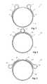
- FIG. 1shows a first embodiment of a reinforcing ring of the present invention
- FIG. 2shows an alternative embodiment of a reinforcing ring of the present invention
- FIG. 3shows an alternative embodiment of a reinforcing ring of the present invention
- FIG. 4shows a reinforcing ring according to the embodiment shown in FIG. 2 stitched into a portion of graft material
- FIG. 5shows a reinforcing ring according to the embodiments shown in FIGS. 1 to 3 stretched out for electropolishing
- FIG. 6shows a stent graft incorporating fenestrations and a reinforcing ring according to the present invention
- FIG. 7shows an alternative embodiment of the invention.
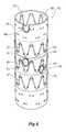
- FIG. 8shows a leg extension stent graft incorporating a ring reinforcement of the embodiment of FIG. 7 .
- the reinforcing ring 2is formed into a two dimensional circular shape of a superelastic wire 4 .
- the ringhas a diameter of from 5 to 15 mm when it is used as a reinforcing ring for a fenestration and from 10 to 40 mm when it is used as an end reinforcement for a tubular stent graft.
- the ring 2is formed from a superelastic metal wire such as a nickel titanium alloy such as Nitinol.
- the wirecan have a diameter of from 0.1 mm to 1 mm and preferably a diameter of from 0.15 mm to 0.3 mm.
- the ringhas nearly two turns of the wire 4 and each end of the wire terminates in a loop 6 and a tail 8 .
- the loop 6is generally of a diameter through which can be passed a needle during stitching of the reinforcing ring into a graft material. Typically the loops may have a diameter of from 1 mm to 2 mm.
- the tail 8extends back around the periphery of the reinforcing ring and when the wire is stretched out for passivation and/or electropolishing the tails are slightly spaced away from it (see FIG. 5 ). After electropolishing or other surface treatment and when the reinforcing ring is stitched into a stent graft there is no problem with the parts of the ring touching each other.
- Each of the tails 8ends in an enlarged end 9 .
- the enlarged end 9can be for instance in the form of a ball formed from solder, fused material of the ring of the like.
- the enlarged endis provided to protect the fabric of a stent graft unto which the reinforcing ring is mounted from the sharp points at the ends of the wire and to assist the sewing of the end of the wire as a stitch can be added next to the ball which stitch can engage against the enlarged end or ball and prevents the wire from being pulled in one direction.
- FIG. 2shows an alternative embodiment of reinforcing ring according to the invention.
- the reinforcing ring 10is formed into a two dimensional circular shape of a superelastic wire 12 .
- the ring 10has two turns of the wire 12 and each end of the wire terminates in a loop 14 and a tail 16 .
- the loops 14overlap each other.
- the tails 16extend back around the periphery of the reinforcing ring and when the wire is stretched out for passivation and/or electropolishing the tails are slightly spaced away from it (see FIG. 5 ).
- Each of the tails 16ends in an enlarged end 17 .
- FIG. 3shows an alternative embodiment of reinforcing ring according to the invention.
- the reinforcing ring 20is formed into a two dimensional circular shape of a superelastic wire 22 .
- the ring 20has two complete turns and a little more of the wire 22 and each end of the wire terminates in a loop 24 and a tail 26 .
- the tails 26extend back towards each other.
- the tails 26extend back around the periphery of the reinforcing ring and when the wire is stretched out for passivation and/or electropolishing the tails are slightly spaced away from it (see FIG. 5 ).
- Each of the tails 26ends in an enlarged end 27 .
- FIG. 4shows a reinforcing ring according to the embodiment shown in FIG. 2 stitched into a portion of graft material.
- the graft material 30has a fenestration 32 and around the fenestration is a reinforcing ring 10 retained in place by blanket type stitching 36 .
- the reinforcing ring 10is of the type shown in FIG. 2 and the loops 14 overlap and two of the stitches of the stitching pass through the loops 14 .
- These extra stitches 37are provided into the loops 14 and through the graft material.
- the tails 16are also retained within the stitches 36 . It will be noted in particular that the stitch 36 a engages against the enlarged end or ball 17 .
- FIG. 5shows a reinforcing ring according to the embodiments shown in FIGS. 1 to 3 stretched out for passivation and/or electropolishing.
- the wire 40is stretched essentially by pulling upon the tails 42 at each end out so that no portion of the rings, loops or tails touch another. It will be particularly noted that when stretched out the tail 42 does not touch the wire 40 thereby ensuring good electropolishing all over the wire.
- FIG. 6shows a stent graft incorporating fenestrations and a reinforcing ring according to the present invention.
- a stent graft 50comprises a tubular wall body portion 53 .
- the tubular wall body portionis a biocompatible graft material such as Dacron, Thoralon, expanded PTFE material or a naturally occurring biomaterial, such as an extracellular matrix, such as small intestinal submucosa or other suitable material.
- Gianturco style zig zag Z stents 55are provided inside the graft material at each end and on the central tubular wall body portion Gianturco style zig zag Z stents 57 are provided on the outside of the graft material. There may be further Gianturco style zig zag Z stents than those illustrated depending upon the overall length of the stent graft 50 . Other forms of stent may also be used.
- tubular wall body portion 53there are two substantially circular fenestrations or apertures 59 on the tubular wall of the stent graft.
- fenestrations or apertures 59are substantially circular.
- Radiopaque markers 61are provided at each end of the fenestration 59 to assist a physician to locate the fenestration 59 in respect to a side vessel extending from a main vessel.
- the radiopaque markers 61may be gold or other convenient material.
- a reinforcement ring 62 of the present inventionis provided around the periphery of the fenestration 59 to give good dimensional stability to the fenestration 59 .
- the reinforcing ringis manufactured from Nitinol wire.
- the ring 62may be formed from stainless steel or any other convenient material.
- Stitching 63is provided to retain the ring 62 around the periphery of the fenestration 59 .
- FIG. 6there is shown a scalloped fenestration 65 which opens to the end 67 of the stent graft.
- FIG. 7shows an alternative embodiment of the invention.
- the reinforcing ring 70has nearly two full turns of Nitinol wire 72 and each end of the wire terminates in a loop 74 .
- Each of the loopsextend out of the plane of the circular shape at approximately right angles thereto.
- the tails 76 of the loopsextend around the periphery of the circular shape and each of the tails 76 ends in an enlarged end 78 .
- the reinforcement ring of this embodimentis useful as a reinforcing ring at the end of a tubular body of graft material such as an arm or leg of a stent graft where the ring is stitched around the end of the tubular body and the loops at right angles to the plane of the ring extend along the tubular body and can be stitched thereto.
- FIG. 8shows a leg extension stent graft incorporating a ring reinforcement of the embodiment of FIG. 7 .
- the leg extension 80has a tubular body 82 of a graft material and a reinforcement ring 70 at its proximal end 84 .
- the ringhas loops 74 which extend out of the plane of the circular shape of the ring at approximately right angles and along the side of the tubular body.
- Stitching 86fastens the ring to the tubular body and also some of the stitches pass through the loops 74 and over the tails 76 .
Landscapes
- Health & Medical Sciences (AREA)
- Engineering & Computer Science (AREA)
- Biomedical Technology (AREA)
- Heart & Thoracic Surgery (AREA)
- Oral & Maxillofacial Surgery (AREA)
- Transplantation (AREA)
- Cardiology (AREA)
- Vascular Medicine (AREA)
- Life Sciences & Earth Sciences (AREA)
- Animal Behavior & Ethology (AREA)
- General Health & Medical Sciences (AREA)
- Public Health (AREA)
- Veterinary Medicine (AREA)
- Pulmonology (AREA)
- Gastroenterology & Hepatology (AREA)
- Prostheses (AREA)
Abstract
Description
Claims (9)
Applications Claiming Priority (3)
| Application Number | Priority Date | Filing Date | Title |
|---|---|---|---|
| AU2009202301AAU2009202301B8 (en) | 2009-06-10 | 2009-06-10 | Reinforcing ring |
| AU2009202301 | 2009-06-10 | ||
| PCT/US2010/025606WO2010144162A1 (en) | 2009-06-10 | 2010-02-26 | Reinforcing ring |
Publications (2)
| Publication Number | Publication Date |
|---|---|
| US20120123523A1 US20120123523A1 (en) | 2012-05-17 |
| US9918823B2true US9918823B2 (en) | 2018-03-20 |
Family
ID=40935101
Family Applications (2)
| Application Number | Title | Priority Date | Filing Date |
|---|---|---|---|
| US12/713,988AbandonedUS20100316830A1 (en) | 2009-06-10 | 2010-02-26 | Reinforcing ring |
| US13/377,453Active2033-03-28US9918823B2 (en) | 2009-06-10 | 2010-02-26 | Reinforcing ring |
Family Applications Before (1)
| Application Number | Title | Priority Date | Filing Date |
|---|---|---|---|
| US12/713,988AbandonedUS20100316830A1 (en) | 2009-06-10 | 2010-02-26 | Reinforcing ring |
Country Status (5)
| Country | Link |
|---|---|
| US (2) | US20100316830A1 (en) |
| EP (1) | EP2440156B1 (en) |
| JP (1) | JP5481645B2 (en) |
| AU (1) | AU2009202301B8 (en) |
| WO (1) | WO2010144162A1 (en) |
Cited By (1)
| Publication number | Priority date | Publication date | Assignee | Title |
|---|---|---|---|---|
| US20180116783A1 (en)* | 2016-10-27 | 2018-05-03 | Cook Medical Technologies Llc | Prosthesis with branched portion |
Families Citing this family (22)
| Publication number | Priority date | Publication date | Assignee | Title |
|---|---|---|---|---|
| AU2010210022B1 (en)* | 2010-08-05 | 2011-09-08 | Cook Incorporated | Stent graft having a marker and a reinforcing and marker ring |
| DK2836162T3 (en)* | 2012-04-12 | 2016-09-05 | Sanford Health | AORTABUESTENT GRAFT WITH DOUBLE-CROSSED MAIN BODIES AND METHODS OF USE |
| US10357353B2 (en) | 2012-04-12 | 2019-07-23 | Sanford Health | Combination double-barreled and debranching stent grafts and methods for use |
| US20130274861A1 (en) | 2012-04-12 | 2013-10-17 | Sanford Health | Debranching Stent Graft Limb and Methods for Use |
| CN105030372B (en)* | 2015-08-31 | 2017-03-01 | 东华大学 | Partial gradient structural vessel support overlay film towards orthotopic fenestration and preparation method thereof |
| CN108261254B (en)* | 2016-12-31 | 2024-05-28 | 先健科技(深圳)有限公司 | Bifurcated stent graft |
| WO2018156850A1 (en) | 2017-02-24 | 2018-08-30 | Bolton Medical, Inc. | Stent graft with fenestration lock |
| WO2018156854A1 (en) | 2017-02-24 | 2018-08-30 | Bolton Medical, Inc. | Radially adjustable stent graft delivery system |
| EP3534837A1 (en) | 2017-02-24 | 2019-09-11 | Bolton Medical, Inc. | Constrainable stent graft, delivery system and methods of use |
| WO2018156851A1 (en) | 2017-02-24 | 2018-08-30 | Bolton Medical, Inc. | Vascular prosthesis with moveable fenestration |
| ES2863978T3 (en) | 2017-02-24 | 2021-10-13 | Bolton Medical Inc | System for radially constricting a stent graft |
| ES2954897T3 (en) | 2017-02-24 | 2023-11-27 | Bolton Medical Inc | Constrained Wrap Stent Graft Delivery System |
| WO2018156849A1 (en)* | 2017-02-24 | 2018-08-30 | Bolton Medical, Inc. | Vascular prosthesis with fenestration ring and methods of use |
| WO2018156848A1 (en) | 2017-02-24 | 2018-08-30 | Bolton Medical, Inc. | Vascular prosthesis with crimped adapter and methods of use |
| WO2018156847A1 (en) | 2017-02-24 | 2018-08-30 | Bolton Medical, Inc. | Delivery system and method to radially constrict a stent graft |
| CN110121319B (en) | 2017-10-31 | 2023-05-09 | 波顿医疗公司 | Distal torque component, delivery system, and method of use thereof |
| IL319705A (en) | 2020-02-06 | 2025-05-01 | Laplace Interventional Inc | Transcatheter heart valve prosthesis assembled inside heart chambers or blood vessels |
| GB202102612D0 (en) | 2021-02-24 | 2021-04-07 | Cook Medical Technologies Llc | Closure mechanism |
| US11510777B1 (en) | 2022-02-10 | 2022-11-29 | Laplace Interventional Inc. | Prosthetic heart valves |
| US11712336B1 (en) | 2022-07-20 | 2023-08-01 | Laplace Interventional Inc. | Prosthetic heart valves |
| CN119632735A (en)* | 2024-11-08 | 2025-03-18 | 常州市第一人民医院 | A meniscus implant |
| US12376963B1 (en) | 2025-02-11 | 2025-08-05 | Laplace Interventional Inc. | Prosthetic heart valves |
Citations (20)
| Publication number | Priority date | Publication date | Assignee | Title |
|---|---|---|---|---|
| US4907336A (en) | 1987-03-13 | 1990-03-13 | Cook Incorporated | Method of making an endovascular stent and delivery system |
| US5554181A (en)* | 1994-05-04 | 1996-09-10 | Regents Of The University Of Minnesota | Stent |
| US5653743A (en) | 1994-09-09 | 1997-08-05 | Martin; Eric C. | Hypogastric artery bifurcation graft and method of implantation |
| US6030414A (en) | 1997-11-13 | 2000-02-29 | Taheri; Syde A. | Variable stent and method for treatment of arterial disease |
| US6355052B1 (en)* | 1996-02-09 | 2002-03-12 | Pfm Produkte Fur Die Medizin Aktiengesellschaft | Device for closure of body defect openings |
| WO2002039926A2 (en) | 2000-11-14 | 2002-05-23 | Advanced Cardiovascular Systems, Inc. | Stent and catheter assembly and method for treating bifurcated vessels |
| US6395018B1 (en) | 1998-02-09 | 2002-05-28 | Wilfrido R. Castaneda | Endovascular graft and process for bridging a defect in a main vessel near one of more branch vessels |
| US6565581B1 (en)* | 1996-09-16 | 2003-05-20 | Origin Medsystems, Inc. | Apparatus and method for performing an anastomosis |
| US20050070934A1 (en)* | 2003-09-30 | 2005-03-31 | Tanaka Don A. | Anastomosis wire ring device |
| WO2005034808A1 (en) | 2003-10-10 | 2005-04-21 | William A. Cook Australia Pty. Ltd. | Fenestrated stent grafts |
| US20050102021A1 (en) | 2003-10-10 | 2005-05-12 | Cook Incorporated | Stretchable prosthesis fenestration |
| WO2007084537A2 (en) | 2006-01-18 | 2007-07-26 | William A. Cook Australia Pty. Ltd. | Self expanding stent |
| US20070219621A1 (en)* | 2006-02-13 | 2007-09-20 | William A. Cook Australia Pty Ltd. | Side branch stent graft construction |
| US7645298B2 (en)* | 2003-10-10 | 2010-01-12 | William A. Cook Australia Pty. Ltd. | Stent graft fenestration |
| WO2010030370A1 (en) | 2008-09-12 | 2010-03-18 | William A. Cook Australia Pty. Ltd. | Radiopaque reinforcing member |
| US7766861B2 (en)* | 2002-12-02 | 2010-08-03 | Gi Dynamics, Inc. | Anti-obesity devices |
| US20100268319A1 (en)* | 2009-04-17 | 2010-10-21 | Medtronic Vascular, Inc. | Mobile External Coupling for Branch Vessel Connection |
| US8043357B2 (en) | 2003-10-10 | 2011-10-25 | Cook Medical Technologies Llc | Ring stent |
| US20120290068A1 (en)* | 2011-05-13 | 2012-11-15 | Cook Medical Technologies Llc | Steerable iliac branch device |
| US8337546B2 (en)* | 2010-04-29 | 2012-12-25 | Medtronic Vascular, Inc. | Mobile external coupling for branch vessel connection |
Family Cites Families (3)
| Publication number | Priority date | Publication date | Assignee | Title |
|---|---|---|---|---|
| US5713948A (en)* | 1995-07-19 | 1998-02-03 | Uflacker; Renan | Adjustable and retrievable graft and graft delivery system for stent-graft system |
| US7520881B2 (en)* | 2002-12-02 | 2009-04-21 | Wilson-Cook Medical Incorporated | Loop tip wire guide |
| US20070021828A1 (en)* | 2005-05-23 | 2007-01-25 | Jeff Krolik | Mechanically actuated stents and apparatus and methods for delivering them |
- 2009
- 2009-06-10AUAU2009202301Apatent/AU2009202301B8/enactiveActive
- 2010
- 2010-02-26USUS12/713,988patent/US20100316830A1/ennot_activeAbandoned
- 2010-02-26USUS13/377,453patent/US9918823B2/enactiveActive
- 2010-02-26WOPCT/US2010/025606patent/WO2010144162A1/enactiveApplication Filing
- 2010-02-26EPEP10708038.4Apatent/EP2440156B1/enactiveActive
- 2010-02-26JPJP2012514951Apatent/JP5481645B2/enactiveActive
Patent Citations (25)
| Publication number | Priority date | Publication date | Assignee | Title |
|---|---|---|---|---|
| US4907336A (en) | 1987-03-13 | 1990-03-13 | Cook Incorporated | Method of making an endovascular stent and delivery system |
| US5554181A (en)* | 1994-05-04 | 1996-09-10 | Regents Of The University Of Minnesota | Stent |
| US5653743A (en) | 1994-09-09 | 1997-08-05 | Martin; Eric C. | Hypogastric artery bifurcation graft and method of implantation |
| US6355052B1 (en)* | 1996-02-09 | 2002-03-12 | Pfm Produkte Fur Die Medizin Aktiengesellschaft | Device for closure of body defect openings |
| US6565581B1 (en)* | 1996-09-16 | 2003-05-20 | Origin Medsystems, Inc. | Apparatus and method for performing an anastomosis |
| US6030414A (en) | 1997-11-13 | 2000-02-29 | Taheri; Syde A. | Variable stent and method for treatment of arterial disease |
| US6395018B1 (en) | 1998-02-09 | 2002-05-28 | Wilfrido R. Castaneda | Endovascular graft and process for bridging a defect in a main vessel near one of more branch vessels |
| WO2002039926A2 (en) | 2000-11-14 | 2002-05-23 | Advanced Cardiovascular Systems, Inc. | Stent and catheter assembly and method for treating bifurcated vessels |
| US7766861B2 (en)* | 2002-12-02 | 2010-08-03 | Gi Dynamics, Inc. | Anti-obesity devices |
| US7608086B2 (en) | 2003-09-30 | 2009-10-27 | Ethicon Endo-Surgery, Inc. | Anastomosis wire ring device |
| US20050070934A1 (en)* | 2003-09-30 | 2005-03-31 | Tanaka Don A. | Anastomosis wire ring device |
| US20050102021A1 (en) | 2003-10-10 | 2005-05-12 | Cook Incorporated | Stretchable prosthesis fenestration |
| US7413573B2 (en) | 2003-10-10 | 2008-08-19 | William A. Cook Australia Pty. Ltd. | Fenestrated stent grafts |
| US20080312732A1 (en)* | 2003-10-10 | 2008-12-18 | Cook Incorporated | Fenestrated stent grafts |
| US7645298B2 (en)* | 2003-10-10 | 2010-01-12 | William A. Cook Australia Pty. Ltd. | Stent graft fenestration |
| WO2005034808A1 (en) | 2003-10-10 | 2005-04-21 | William A. Cook Australia Pty. Ltd. | Fenestrated stent grafts |
| US8043357B2 (en) | 2003-10-10 | 2011-10-25 | Cook Medical Technologies Llc | Ring stent |
| WO2007084537A2 (en) | 2006-01-18 | 2007-07-26 | William A. Cook Australia Pty. Ltd. | Self expanding stent |
| US7914572B2 (en) | 2006-02-13 | 2011-03-29 | William A. Cook Australia Pty. Ltd. | Side branch stent graft construction |
| US20070219621A1 (en)* | 2006-02-13 | 2007-09-20 | William A. Cook Australia Pty Ltd. | Side branch stent graft construction |
| WO2010030370A1 (en) | 2008-09-12 | 2010-03-18 | William A. Cook Australia Pty. Ltd. | Radiopaque reinforcing member |
| US20110190868A1 (en)* | 2008-09-12 | 2011-08-04 | Werner Dieter Ducke | Radiopaque reinforcing member |
| US20100268319A1 (en)* | 2009-04-17 | 2010-10-21 | Medtronic Vascular, Inc. | Mobile External Coupling for Branch Vessel Connection |
| US8337546B2 (en)* | 2010-04-29 | 2012-12-25 | Medtronic Vascular, Inc. | Mobile external coupling for branch vessel connection |
| US20120290068A1 (en)* | 2011-05-13 | 2012-11-15 | Cook Medical Technologies Llc | Steerable iliac branch device |
Non-Patent Citations (4)
| Title |
|---|
| International Search Report-PCT/US2010/025606; dated May 26, 2010, 4 pages. |
| International Search Report—PCT/US2010/025606; dated May 26, 2010, 4 pages. |
| International Written Opinion-PCT/US2010/025606; dated May 26, 2010, 6 pages. |
| International Written Opinion—PCT/US2010/025606; dated May 26, 2010, 6 pages. |
Cited By (5)
| Publication number | Priority date | Publication date | Assignee | Title |
|---|---|---|---|---|
| US20180116783A1 (en)* | 2016-10-27 | 2018-05-03 | Cook Medical Technologies Llc | Prosthesis with branched portion |
| US10537419B2 (en)* | 2016-10-27 | 2020-01-21 | Cook Medical Technologies Llc | Prosthesis with branched portion |
| US11464619B2 (en) | 2016-10-27 | 2022-10-11 | Cook Medical Technologies Llc | Prosthesis with branched portion |
| US11517418B2 (en) | 2016-10-27 | 2022-12-06 | Cook Medical Technologies Llc | Prosthesis with branched portion |
| US12239526B2 (en) | 2016-10-27 | 2025-03-04 | Cook Medical Technologies Llc | Prosthesis with branched portion |
Also Published As
| Publication number | Publication date |
|---|---|
| JP5481645B2 (en) | 2014-04-23 |
| AU2009202301B8 (en) | 2009-12-03 |
| EP2440156B1 (en) | 2014-01-22 |
| US20120123523A1 (en) | 2012-05-17 |
| US20100316830A1 (en) | 2010-12-16 |
| JP2012529341A (en) | 2012-11-22 |
| AU2009202301B1 (en) | 2009-07-30 |
| WO2010144162A1 (en) | 2010-12-16 |
| EP2440156A1 (en) | 2012-04-18 |
Similar Documents
| Publication | Publication Date | Title |
|---|---|---|
| US9918823B2 (en) | Reinforcing ring | |
| EP2872679B1 (en) | Methods for passivating metallic implantable medical devices including radiopaque markers | |
| US6387123B1 (en) | Stent with radiopaque core | |
| CA2711176C (en) | Stent and method of making a stent | |
| US6652579B1 (en) | Radiopaque stent | |
| US20070055299A1 (en) | Temporary stents and stent-grafts | |
| EP1301224A1 (en) | Radiopaque stent composed of a binary alloy | |
| IL129065A (en) | Metallicvascular support which is degradable in vivo | |
| CN214018001U (en) | Support frame | |
| CN105189832A (en) | Electropolishing of cobalt-based alloys containing platinum | |
| US20100049310A1 (en) | Method for coating a stent | |
| US8747649B2 (en) | Electrochemical formation of foil-shaped stent struts | |
| AU2010205768C1 (en) | Method and solution for electropolishing stents made of high strength medical alloys | |
| JP2003260142A (en) | Stent for intracranial blood vessel treatment, and production method | |
| JPWO2018143115A1 (en) | Bioabsorbable stent | |
| EP2407582B1 (en) | Method and electrolytic solution for electropolishing stents made of high strength medical alloys |
Legal Events
| Date | Code | Title | Description |
|---|---|---|---|
| AS | Assignment | Owner name:WILLIAM A. COOK AUSTRALIA PTY. LTD., AUSTRALIA Free format text:ASSIGNMENT OF ASSIGNORS INTEREST;ASSIGNORS:HARTLEY, DAVID ERNEST;MILLS, EDWARD GRAHAM;SIGNING DATES FROM 20091203 TO 20091215;REEL/FRAME:027643/0502 Owner name:COOK INCORPORATED, INDIANA Free format text:ASSIGNMENT OF ASSIGNORS INTEREST;ASSIGNORS:HARTLEY, DAVID ERNEST;MILLS, EDWARD GRAHAM;SIGNING DATES FROM 20091203 TO 20091215;REEL/FRAME:027643/0502 | |
| AS | Assignment | Owner name:COOK MEDICAL TECHNOLOGIES LLC, INDIANA Free format text:ASSIGNMENT OF ASSIGNORS INTEREST;ASSIGNOR:COOK INCORPORATED;REEL/FRAME:027646/0212 Effective date:20120109 | |
| AS | Assignment | Owner name:COOK MEDICAL TECHNOLOGIES LLC, INDIANA Free format text:ASSIGNMENT OF ASSIGNORS INTEREST;ASSIGNOR:WILLIAM A. COOK AUSTRALIA PTY, LTD.;REEL/FRAME:044753/0356 Effective date:20180129 | |
| STCF | Information on status: patent grant | Free format text:PATENTED CASE | |
| MAFP | Maintenance fee payment | Free format text:PAYMENT OF MAINTENANCE FEE, 4TH YEAR, LARGE ENTITY (ORIGINAL EVENT CODE: M1551); ENTITY STATUS OF PATENT OWNER: LARGE ENTITY Year of fee payment:4 | |
| AS | Assignment | Owner name:WILMINGTON TRUST, NATIONAL ASSOCIATION, AS COLLATERAL AGENT, DELAWARE Free format text:SECURITY INTEREST;ASSIGNOR:COOK MEDICAL TECHNOLOGIES LLC;REEL/FRAME:066700/0277 Effective date:20240227 | |
| MAFP | Maintenance fee payment | Free format text:PAYMENT OF MAINTENANCE FEE, 8TH YEAR, LARGE ENTITY (ORIGINAL EVENT CODE: M1552); ENTITY STATUS OF PATENT OWNER: LARGE ENTITY Year of fee payment:8 |