US9918766B2 - Devices, methods and systems for affixing an access device to a vertebral body for the insertion of bone cement - Google Patents
Devices, methods and systems for affixing an access device to a vertebral body for the insertion of bone cementDownload PDFInfo
- Publication number
- US9918766B2 US9918766B2US13/841,380US201313841380AUS9918766B2US 9918766 B2US9918766 B2US 9918766B2US 201313841380 AUS201313841380 AUS 201313841380AUS 9918766 B2US9918766 B2US 9918766B2
- Authority
- US
- United States
- Prior art keywords
- access device
- opening
- anchoring
- bone
- tube
- Prior art date
- Legal status (The legal status is an assumption and is not a legal conclusion. Google has not performed a legal analysis and makes no representation as to the accuracy of the status listed.)
- Active, expires
Links
Images


Classifications
- A—HUMAN NECESSITIES
- A61—MEDICAL OR VETERINARY SCIENCE; HYGIENE
- A61B—DIAGNOSIS; SURGERY; IDENTIFICATION
- A61B17/00—Surgical instruments, devices or methods
- A61B17/56—Surgical instruments or methods for treatment of bones or joints; Devices specially adapted therefor
- A61B17/58—Surgical instruments or methods for treatment of bones or joints; Devices specially adapted therefor for osteosynthesis, e.g. bone plates, screws or setting implements
- A61B17/88—Osteosynthesis instruments; Methods or means for implanting or extracting internal or external fixation devices
- A61B17/8802—Equipment for handling bone cement or other fluid fillers
- A61B17/8805—Equipment for handling bone cement or other fluid fillers for introducing fluid filler into bone or extracting it
- A61B17/8811—Equipment for handling bone cement or other fluid fillers for introducing fluid filler into bone or extracting it characterised by the introducer tip, i.e. the part inserted into or onto the bone
- A—HUMAN NECESSITIES
- A61—MEDICAL OR VETERINARY SCIENCE; HYGIENE
- A61B—DIAGNOSIS; SURGERY; IDENTIFICATION
- A61B17/00—Surgical instruments, devices or methods
- A61B17/56—Surgical instruments or methods for treatment of bones or joints; Devices specially adapted therefor
- A61B17/58—Surgical instruments or methods for treatment of bones or joints; Devices specially adapted therefor for osteosynthesis, e.g. bone plates, screws or setting implements
- A61B17/88—Osteosynthesis instruments; Methods or means for implanting or extracting internal or external fixation devices
- A61B17/8802—Equipment for handling bone cement or other fluid fillers
- A61B17/8805—Equipment for handling bone cement or other fluid fillers for introducing fluid filler into bone or extracting it
- A61B17/8808—Equipment for handling bone cement or other fluid fillers for introducing fluid filler into bone or extracting it with sealing collar for bone cavity
- A—HUMAN NECESSITIES
- A61—MEDICAL OR VETERINARY SCIENCE; HYGIENE
- A61B—DIAGNOSIS; SURGERY; IDENTIFICATION
- A61B17/00—Surgical instruments, devices or methods
- A61B17/56—Surgical instruments or methods for treatment of bones or joints; Devices specially adapted therefor
- A61B17/58—Surgical instruments or methods for treatment of bones or joints; Devices specially adapted therefor for osteosynthesis, e.g. bone plates, screws or setting implements
- A61B17/88—Osteosynthesis instruments; Methods or means for implanting or extracting internal or external fixation devices
- A61B17/8802—Equipment for handling bone cement or other fluid fillers
- A61B17/8805—Equipment for handling bone cement or other fluid fillers for introducing fluid filler into bone or extracting it
- A61B17/8816—Equipment for handling bone cement or other fluid fillers for introducing fluid filler into bone or extracting it characterised by the conduit, e.g. tube, along which fluid flows into the body or by conduit connections
Definitions
- Posterior fixationas is commonly used to help stabilize the treated spine constructs for various degenerative and traumatic spine conditions and can also be an adjunct to interbody fusion.
- Posterior fixationoften includes the use of a pedicle screw and rod system, where the pedicle screw is anchored into a vertebra pedicle and vertebral body. A rod is then attached between heads of at least two adjacent pedicle screws that are located ipsilaterally on the pedicle or vertebral body. This configuration helps to immobilize the treated spine construct and aid in the interbody fusion. In instances where the bone quality is poor the pedicle screw can loosen after surgery, requiring a revision surgery to replace or re-stabilize the loosened screw.
- MISminimally invasive surgery
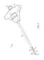
- FIG. 1shows a first variation of an access instrument for use in applying cement as described herein.
- FIGS. 2A to 2Cillustrate the working end of the access device shown in FIG. 1 .
- FIGS. 2D and 2Eillustrate additional variations of ramp-like features.
- FIGS. 3A and 3Bshow cross sectional views of the access device shown in FIG. 1 to illustrate the mechanism that permits advancement and retraction of the middle tube.
- FIG. 4shows another variation of an access device.
- FIG. 5illustrates a state of the device of FIG. 4 where the stylet knob is removed from the device.
- FIGS. 6A and 6Billustrate the state of the access device of FIG. 4 where the shuttle knob is used to withdraw the outer tube.
- FIG. 7shows another variation of a working end of a device.
- FIGS. 8A to 8Killustrate an example of a surgical technique to apply bone cement to a site where the bone cement assists in anchoring of an implant such as a pedicle screw.
- FIG. 8Lshows an example of positioning implants within pilot holed filled with bone cement as discussed herein.
- the present disclosureincludes devices and methods for device for delivering a pressurized substance to an opening in bone within a vertebral column.
- Any of the devices and method used hereincan be used for applications on or in the vertebral column (e.g., vertebral bodies, the sacrum, the coccyx, etc.) Additional variations of the device and methods allow for use anywhere in bone or other hard tissue.
- a variation of a medical device described hereinincludes a handle portion having a proximal port; an inner member coupled to the handle portion and having a proximal end and a distal working end; a working lumen extending through the inner member; a bone engaging section located about a distal portion of the inner member, the bone engaging section configured to expand radially away from the inner member and maintain an expansion three against the opening to prevent dislodgement of the working lumen from the bone; a shuttle member mechanically coupled to the handle portion and the bone engaging section, where actuation of the shuttle member drives the bone engaging section in a radially outward direction.
- the devicecan further comprise an outer member and an intermediate member located between the outer member and inner member, where the bone engaging section comprises a slotted distal portion of the intermediate member.
- Another variationincludes a medical device further comprising a radially offset surface located on a distal portion of the inner member, where the intermediate member is coupled to the shuttle member such that actuation of the shuttle member drives the slotted distal portion of the intermediate member over the radially offset surface resulting in divergence of at the slotted distal portion in the radially outward direction.
- the radially offset surfacecan include any surface that deflects or expands the slotted portion.
- such surfacescan be selected from the group consisting of a ramp, a protrusion, and a collar.
- the outer memberis coupled to the shuttle and where actuation of the shuttle member causes relative movement between the outer member and intermediate member such that when slotted distal portion of intermediate member is exposed the slotted distal portion self-expands in the radially outward direction.
- the slotted distal portioncan comprise a plurality of tines and where the outer member causes collapse of the tines onto the inner member upon withdrawal of the slotted distal portion within the outer member.
- the slotted distal portioncomprises a plurality of tines where a distal end of the tines extends in the radially outward direction.
- a distal end of the inner memberis coupled to a distal end of the intermediate member, where the shuttle member is coupled to the inner member and the intermediate member is coupled to the handle portion, where actuation of the shuttle member moves the distal end of the intermediate member relative to the handle portion to cause expansion of the slotted distal portion in the radially outward direction.
- One example of a shuttle membercomprises a threaded knob coupled to a threaded hub, where the threaded knob coupled can be coupled to one of the inner member, intermediate member, and the outer member.
- the medical device described hereincan further include a stylet extending in the working lumen of the inner tube, where a proximal end of the stylet is releasably coupled to the proximal port.
- the styletcan further include a guidewire lumen.
- the disclosurealso includes methods for delivering a substance to an opening located in a bone of a vertebral column.
- One variation of the methodcomprises advancing an access device to the bone, where the access device includes a delivery lumen extending from a proximal opening to a distal port; and positioning an anchoring portion of the access device within the opening in the bone; anchoring the access device to the bone by engaging the anchoring portion against a wall portion of the bone surrounding the opening such that the delivery lumen creates a fluid path from the proximal opening through the distal port and into the opening; and delivering the substance through the delivery lumen into the opening where the anchoring portion prevents rearward movement of the access device from the opening during delivery.
- Variations of the methodcan include advancing the access device to the bone comprises advancing the access device over a guide wire, where the guide wire is positioned within the opening in bone.
- the anchoring portioncomprises an expandable structure such that anchoring the access device comprises forcing the expandable structure against a wall of the hole secure the access device within the hole.
- the expandable portioncomprises a slotted portion of a slidable tube
- the access devicefurther comprises a radially offset portion
- anchoring the access devicecomprises advancing the slidable tube over the radially offset portion to cause the slotted, portion to expand against the wall portion of the opening.
- Another variation of the methodincludes where the delivery lumen extends through an inner tube and where the expandable portion comprises slotted portion of a slidable tube located over the inner tube, and where the inner tube is affixed to the slidable tube at a distal location, wherein anchoring the access device comprises moving the inner tube relative to the the slidable tube to cause the slotted portion to expand against the wall portion of the opening.
- the disclosurealso includes methods of temporarily securing an access device to an opening within a portion of bone in a vertebral column.
- a methodcan include advancing an access device to the bone, where the access device includes a delivery lumen extending from a proximal opening to a distal port; positioning a working end of the access device into the opening; and displacing an anchoring portion of the access device against a wall of the opening while maintaining the working end within the opening, wherein the anchoring portion mechanically engages the wall of the opening to releasably secure the access device to the opening.
- Another methodincludes securing an implant within a portion of a bone in a vertebral column.
- Such a variationcan include advancing an access device to the bone, where the access device includes a delivery lumen extending from a proximal opening to a distal port; and positioning a working end of the access device into an opening in the bone; displacing an anchoring portion of the access device against a wall of the opening while maintaining the working end within the opening, wherein the anchoring portion mechanically engages the wall of the opening to releasably secure the access device to the opening; delivering a bone cement through the delivery lumen into the opening; disengaging the anchoring portion of the access device from the wall of the opening and removing the access device from the bone; and inserting an implant into the opening.
- the devices and method discussed hereincan accommodate the various MIS pedicle screw and rod systems placement.
- the devices and methodsprovide access to the pedicle and vertebral body so that bone cement (or any substances) can be delivered through a lumen or portal.
- the lumencan be used to insert a separate instrument for delivery of bone cement.
- the devices and method described hereinallow for use of a guide wire or a k-wire to locate the pedicle via a MIS approach.
- the instrument's working endcan expand so to accommodate pilot holes of various sizes so that the access device can be temporarily affixed within the pilot hole and securely anchored within the pedicle or vertebral body.
- the anchored instrumentaids in the controlled and safe delivery of bone cement into the vertebral body and pedicle.
- the nature of the systems and devicesalso allow for the access device to be easily removed from the pedicle/vertebral body when the procedure is completed.
- FIG. 1shows a first variation of an access instrument 100 for use in applying cement as described herein.
- the access instrument 100includes an inner tube located within a middle tube 104 and outer tube 108 .
- the inner tube 102can act as a working cannula to allow various instruments to be positioned therethrough.
- the inner tube 102can optionally include a ramp feature 103 located at a distal end and described in detail further below.
- the middle tube 104can optionally include a slotted feature 106 or other structure to allow it to advance over the ramp feature 103 to cause expansion of the middle tube 104 .
- the ramp feature 103can include any feature that causes expansion of the middle tube 104 .
- Alternate variationsinclude a middle tube that can expand (e.g., having a shape set or similar feature) that permits expansion of the middle tube 104 as it advances without the need for a ramp feature 103 on the inner tube.
- the access device 100can also include an actuation mechanism 110 that shuttles the middle tube in a distal/proximal direction.
- the device 100can also include a stylet knob coupled to a removable cannulated stylet 116 .
- the stylet 116can optionally include features to allow the stylet to advance over a k-wire.
- FIGS. 2A to 2Cillustrate the working end of the access device 100 shown in FIG. 1 .
- FIG. 2Aillustrates the inner tube 102 having a lumen 118 that allows it to function as a working cannula. As shown, the stylet 116 is positioned through the lumen 118 .
- FIG. 2Ashows the working end or the access device 100 in an unexpanded state where the middle tube 106 is advanced out of the outer tube 108 prior to expansion over the ramp feature 103 .
- FIG. 2Bshows the state of the access device 100 where the cannulated stylet 116 is withdrawn or otherwise removed, from the lumen 118 to allow for additional devices to be advanced therethrough or to allow for delivery of bone cement through the access device 100 .
- FIG. 2Cshows the state of the device 100 where the middle tube 105 is actuated to advance in a distal direction over the ramp feature 103 of the inner tube. Because the middle tube 104 includes one or more slots 106 , the distal portion of the middle tube 104 expands as shown as it advances over the ramp feature 103 . After or during the procedure, a physician can withdraw the middle tube 104 by causing proximal movement.
- the middle tube 104As the middle tube 104 is moved proximally away from the ramp feature 103 , the expanded portion of the middle tube 104 begins to assume its reduced profile. The proximal movement of the middle tube 104 within the outer tube 108 causes the slotted section of the middle tube to further collapse.
- FIGS. 2D and 2Eshow additional variations of ramp type features 103 on the device 100 .
- FIG. 2Dillustrates collar placed about the inner member 102 .
- the collar 103can have a rounded proximal end to allow the slotted portion 104 to expand or diverge when advanced relative to the collar.
- FIG. 2Eillustrates a number of protrusions 103 forming the ramp feature. Any number of ramp features 103 can be used in the device.
- FIG. 3Ashows a cross sectional view of the access device 100 shown in FIG. 1 to illustrate the mechanism that permits advancement and retraction of the middle tube.
- the handle 112includes a shuttle mechanism 110 (e.g., a knob) that is in threaded engagement with a threaded hub 120 .
- the threaded hub 120is attached to or otherwise affixed to the middle tube 104 . Accordingly, the shuttle mechanism 110 can translate the middle tube 104 in either a distal or proximal direction through movement of the threaded hub 120 .
- the threaded hubcan be keyed into the handle such that it prevents rotational movement of the hub relative to the handle.
- Such keyed featurecan be mating flats between handle and hub, or pin in a slot.
- the handle 112also includes an anchoring structure 122 that is attached to the inner tube 102 that prevents the inner tube 102 from moving as the middle tube 104 advances in a distal direction over the ramp feature.
- the handle 112can also include an outer tube anchoring structure 124 at one or more points as shown in FIG. 3A . Again, the anchoring structure 124 prevents movement of the outer tube 108 as the middle tube 104 translates in a distal/proximal direction.
- FIG. 3Aalso illustrates a threaded cap or knob 114 that is affixed to the stylet 116 . This threaded knob 114 can be affixed or attached to the stylet 116 so that the stylet 116 can be removed from the device 100 .
- FIG. 3Bshows a variation of the device with the shuttle mechanism 110 coupled to the outer tube 108 . In such a case, the inner tube and intermediate tube can be coupled to the handle.
- FIG. 4shows another variation of an access device 100 .
- the access device 100includes an inner tube 102 that functions as a working cannula that can deliver various instruments or cement through its lumen 118 .
- the inner tube 102is housed within a middle tube (not shown in FIG. 4 ) that is located within outer tube 108 .
- the outer tube 108can be actuated using a shuttle mechanism 110 .
- the access device 100can also include a removable cannulated stylet 116 within the lumen 118 of the inner tube 102 .
- FIG. 5illustrates a state of the device 100 of FIG. 4 where the stylet knob 114 can be removed from the device 100 .
- the stylet knob 114is internally threaded to engage a threaded fitting 126 on the handle 112 . As shown, removal of the stylet knob 114 permits removal of the stylet 116 from the device 100 . Once removed, the device 100 can be coupled to any number of cement deployment systems, including those provided by DFine, Inc., San Jose, Calif.
- FIGS. 6A and 6Billustrate the state of the access device 100 of FIG. 4 where the shuttle knob 110 is used to withdraw the outer tube 108 .
- the middle tube 104includes one or more expandable section 128 that, when unconstrained by the inner tube 108 , expand as shown.
- FIG. 6Billustrates a magnified view of the working end of FIG. 6A , where the stylet 116 is still positioned within the inner tube 102 and the outer tube 108 moves proximally to release the constraint of the expandable sections 128 of the middle tube 104 .
- the knob 110can be used to extend the outer tube 108 over the expandable section 128 or tines of the middle tube 104 .
- FIG. 7shows another variation of a working end of a device.
- the inner tube 102can be used to cause expansion of an expandable section 130 (in this variation expandable tines) on a middle tube 104 .
- the inner tube 102is affixed to an expandable middle tube 104 so that proximal and distal movement of the inner tube 102 cause respective expansion and contraction of the expandable section 130 of the middle tube 104 .
- the systems and devices described hereincan be used in any situation where the application of bone cement or another substance is required.
- FIGS. 8A to 8Killustrate an example of a surgical technique to apply bone cement to a site where the bone cement assists in anchoring of an implant such as a pedicle screw.
- FIG. 8Aillustrates a vertebral body 200 with a pilot hole 202 in a pedicle 204 created by a physician in preparation for placement of a pedicle screw system.
- FIG. 8Bshows a guide wire 206 (e.g., a 1.5 mm guide wire) placed in the pilot hole 202 using a typically preferred instrument exchange method.
- FIG. 8Cshows an access device 100 as described herein advanced over the guide wire 206 so that the working end of the access device 100 enters the pilot hole 202 .
- FIG. 8Cillustrates the distal end of the guide wire 206 extending into the cavity of the pilot hole 202 .
- FIG. 8Dshows a magnified view of the working end of the access device located within the cavity 210 of the pilot hole.
- the physiciancan deploy the expandable section 128 so that there is a tight fit between the walls of the pilot hole cavity 210 and the expandable section 128 of the access instrument 100 .
- this tight fitsecures the access instrument 100 to the pedicle and/or vertebral body.
- FIG. 8Fshows the access device 100 secured to the vertebral body where the guidewire and stylet are removed.
- the lumen of the inner tubecreates an access path into the cavity 210 of the pilot hole 202 .
- a source of bone cement 230can be temporarily affixed to the handle 112 of the access device 100 (e.g., by coupling to the threaded fitting 126 discussed above. The physician can then deliver the desired amount of bone cement or other substance into the cavity 210 of the pilot hole 202 .
- the physicianremoves the source of the cement from access device 100 and inserts a guide wire 212 into the lumen of the access device 100 where the guidewire is advanced into the hone cement in the cavity 210 .
- FIGS. 8I and 8Jshow a magnified view of the cavity 210 having bone cement 232 located therein. As shown in FIG. 8I the expandable section 128 of the middle tube 204 is still secured to the walls of the cavity 210 . FIG. 8J shows the state of the device 100 after the expandable section is retracted as discussed above.
- FIG. 8Kshows the state of the procedure where the access device 100 is removed from the vertebral body 200 and pilot hole 202 leaving the bone cement (not shown) still within the cavity.
- the guidewire 212can remain within the pilot hole 202 to allow for placement of a pedicle screw using preferred minimally invasive surgical techniques.
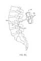
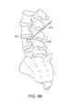
- FIG. 8Lillustrates a state of the lower portion of a vertebral column where the devices, methods and processes described herein provided cement to a number of sites within various structures in the vertebral column.
- implantssuch as pedicle screws 180 placed within the hole (not shown in FIG. 8L ) so that ultimately rods 184 and other implant supporting devices 182 can be positioned as needed.
- the devices, methods, and processes described, hereincan be used for treatment of a vertebral pedicle.
- the devices, methods, and processescan be used for any bone structure in the vertebral column such as the pedicle 204 , vertebral body 207 , sacrum 205 or even the coccyx 209 .
Landscapes
- Health & Medical Sciences (AREA)
- Life Sciences & Earth Sciences (AREA)
- Orthopedic Medicine & Surgery (AREA)
- Surgery (AREA)
- Medical Informatics (AREA)
- Engineering & Computer Science (AREA)
- Biomedical Technology (AREA)
- Heart & Thoracic Surgery (AREA)
- Nuclear Medicine, Radiotherapy & Molecular Imaging (AREA)
- Molecular Biology (AREA)
- Animal Behavior & Ethology (AREA)
- General Health & Medical Sciences (AREA)
- Public Health (AREA)
- Veterinary Medicine (AREA)
- Surgical Instruments (AREA)
- Prostheses (AREA)
Abstract
Description
Claims (12)
Priority Applications (4)
| Application Number | Priority Date | Filing Date | Title |
|---|---|---|---|
| US13/841,380US9918766B2 (en) | 2012-12-12 | 2013-03-15 | Devices, methods and systems for affixing an access device to a vertebral body for the insertion of bone cement |
| PCT/US2013/074760WO2014093673A1 (en) | 2012-12-12 | 2013-12-12 | Devices, methods and systems for affixing an access device to a vertebral body for the insertion of bone cement |
| EP13862396.2AEP2931144B1 (en) | 2012-12-12 | 2013-12-12 | Devices and systems for affixing an access device to a vertebral body for the insertion of bone cement |
| HK16102005.1AHK1214110B (en) | 2012-12-12 | 2013-12-12 | Devices and systems for affixing an access device to a vertebral body for the insertion of bone cement |
Applications Claiming Priority (2)
| Application Number | Priority Date | Filing Date | Title |
|---|---|---|---|
| US201261736522P | 2012-12-12 | 2012-12-12 | |
| US13/841,380US9918766B2 (en) | 2012-12-12 | 2013-03-15 | Devices, methods and systems for affixing an access device to a vertebral body for the insertion of bone cement |
Publications (2)
| Publication Number | Publication Date |
|---|---|
| US20140163566A1 US20140163566A1 (en) | 2014-06-12 |
| US9918766B2true US9918766B2 (en) | 2018-03-20 |
Family
ID=50881767
Family Applications (1)
| Application Number | Title | Priority Date | Filing Date |
|---|---|---|---|
| US13/841,380Active2035-12-07US9918766B2 (en) | 2012-12-12 | 2013-03-15 | Devices, methods and systems for affixing an access device to a vertebral body for the insertion of bone cement |
Country Status (3)
| Country | Link |
|---|---|
| US (1) | US9918766B2 (en) |
| EP (1) | EP2931144B1 (en) |
| WO (1) | WO2014093673A1 (en) |
Families Citing this family (19)
| Publication number | Priority date | Publication date | Assignee | Title |
|---|---|---|---|---|
| US8758349B2 (en) | 2008-10-13 | 2014-06-24 | Dfine, Inc. | Systems for treating a vertebral body |
| JP5575777B2 (en) | 2008-09-30 | 2014-08-20 | ディファイン, インコーポレイテッド | System used to treat vertebral fractures |
| US20100298832A1 (en) | 2009-05-20 | 2010-11-25 | Osseon Therapeutics, Inc. | Steerable curvable vertebroplasty drill |
| US10058336B2 (en) | 2010-04-08 | 2018-08-28 | Dfine, Inc. | System for use in treatment of vertebral fractures |
| US9526507B2 (en) | 2010-04-29 | 2016-12-27 | Dfine, Inc. | System for use in treatment of vertebral fractures |
| CN102985015B (en) | 2010-04-29 | 2016-08-03 | Dfine有限公司 | System for treating vertebral fractures |
| US9125671B2 (en) | 2010-04-29 | 2015-09-08 | Dfine, Inc. | System for use in treatment of vertebral fractures |
| ES2626256T3 (en) | 2010-11-22 | 2017-07-24 | Dfine, Inc. | System to use in the treatment of vertebral fractures |
| US20130072941A1 (en)* | 2011-09-16 | 2013-03-21 | Francisca Tan-Malecki | Cement Injector and Cement Injector Connectors, and Bone Cement Injector Assembly |
| CA2868869C (en) | 2012-03-27 | 2021-01-12 | Dfine, Inc. | Methods and systems for use in controlling tissue ablation volume by temperature monitoring |
| US9901392B2 (en) | 2015-05-11 | 2018-02-27 | Dfine, Inc. | System for use in treatment of vertebral fractures |
| JP2019534130A (en)* | 2016-10-27 | 2019-11-28 | ディーファイン,インコーポレイティド | Articulated osteotome with cement delivery channel |
| WO2018097992A2 (en) | 2016-11-22 | 2018-05-31 | Dfine, Inc. | Swivel hub |
| CA3041114A1 (en) | 2016-11-28 | 2018-05-31 | Dfine, Inc. | Tumor ablation devices and related methods |
| US10470781B2 (en) | 2016-12-09 | 2019-11-12 | Dfine, Inc. | Medical devices for treating hard tissues and related methods |
| US10660656B2 (en) | 2017-01-06 | 2020-05-26 | Dfine, Inc. | Osteotome with a distal portion for simultaneous advancement and articulation |
| US11937864B2 (en) | 2018-11-08 | 2024-03-26 | Dfine, Inc. | Ablation systems with parameter-based modulation and related devices and methods |
| US11660134B2 (en) | 2019-06-13 | 2023-05-30 | Medos International Sarl | Instruments and methods for delivering bone cement to a bone screw |
| US11986229B2 (en) | 2019-09-18 | 2024-05-21 | Merit Medical Systems, Inc. | Osteotome with inflatable portion and multiwire articulation |
Citations (89)
| Publication number | Priority date | Publication date | Assignee | Title |
|---|---|---|---|---|
| US3140623A (en) | 1961-08-29 | 1964-07-14 | Pendleton Tool Ind Inc | Predetermined torque release wrench |
| US4411266A (en) | 1980-09-24 | 1983-10-25 | Cosman Eric R | Thermocouple radio frequency lesion electrode |
| US4456017A (en) | 1982-11-22 | 1984-06-26 | Cordis Corporation | Coil spring guide with deflectable tip |
| US4476861A (en) | 1979-11-06 | 1984-10-16 | Christos Dimakos | Instrument for removal of a bone cement tube in an artificial femur head reimplantation |
| US4595006A (en) | 1982-08-16 | 1986-06-17 | Burke Dennis W | Apparatus for cemented implantation of prostheses |
| WO1993004634A1 (en) | 1991-09-12 | 1993-03-18 | Surgical Dynamics, Inc. | Bendable dissectomy probe and steerable cannula |
| US5282821A (en) | 1993-01-26 | 1994-02-01 | Donahue John R | Adjustable surgical instrument |
| US5284128A (en) | 1992-01-24 | 1994-02-08 | Applied Medical Resources Corporation | Surgical manipulator |
| US5322505A (en) | 1990-02-07 | 1994-06-21 | Smith & Nephew Dyonics, Inc. | Surgical instrument |
| US5449351A (en) | 1993-09-09 | 1995-09-12 | Zohmann; Walter A. | Atraumatic needle for lumbar puncture |
| US5458597A (en) | 1993-11-08 | 1995-10-17 | Zomed International | Device for treating cancer and non-malignant tumors and methods |
| US5599346A (en) | 1993-11-08 | 1997-02-04 | Zomed International, Inc. | RF treatment system |
| US5620447A (en) | 1993-01-29 | 1997-04-15 | Smith & Nephew Dyonics Inc. | Surgical instrument |
| US5628771A (en) | 1993-05-12 | 1997-05-13 | Olympus Optical Co., Ltd. | Electromagnetic-wave thermatological device |
| US5662680A (en) | 1991-10-18 | 1997-09-02 | Desai; Ashvin H. | Endoscopic surgical instrument |
| US5695513A (en) | 1996-03-01 | 1997-12-09 | Metagen, Llc | Flexible cutting tool and methods for its use |
| US5697536A (en) | 1992-01-07 | 1997-12-16 | Arthrocare Corporation | System and method for electrosurgical cutting and ablation |
| US5810804A (en) | 1995-08-15 | 1998-09-22 | Rita Medical Systems | Multiple antenna ablation apparatus and method with cooling element |
| US5833632A (en) | 1995-12-07 | 1998-11-10 | Sarcos, Inc. | Hollow guide wire apparatus catheters |
| US5851212A (en) | 1997-06-11 | 1998-12-22 | Endius Incorporated | Surgical instrument |
| US5902251A (en) | 1996-05-06 | 1999-05-11 | Vanhooydonk; Neil C. | Transcervical intrauterine applicator for intrauterine hyperthermia |
| US5921956A (en) | 1997-09-24 | 1999-07-13 | Smith & Nephew, Inc. | Surgical instrument |
| US5928239A (en) | 1998-03-16 | 1999-07-27 | University Of Washington | Percutaneous surgical cavitation device and method |
| US5944715A (en) | 1996-06-20 | 1999-08-31 | Gyrus Medical Limited | Electrosurgical instrument |
| US6073051A (en) | 1996-08-13 | 2000-06-06 | Oratec Interventions, Inc. | Apparatus for treating intervertebal discs with electromagnetic energy |
| US6106524A (en) | 1995-03-03 | 2000-08-22 | Neothermia Corporation | Methods and apparatus for therapeutic cauterization of predetermined volumes of biological tissue |
| US6123702A (en) | 1998-09-10 | 2000-09-26 | Scimed Life Systems, Inc. | Systems and methods for controlling power in an electrosurgical probe |
| US6135999A (en) | 1997-02-12 | 2000-10-24 | Oratec Internationals, Inc. | Concave probe for arthroscopic surgery |
| US6231615B1 (en) | 1997-10-14 | 2001-05-15 | Parallax Medical, Inc. | Enhanced visibility materials for implantation in hard tissue |
| US6280441B1 (en) | 1997-12-15 | 2001-08-28 | Sherwood Services Ag | Apparatus and method for RF lesioning |
| US20020026197A1 (en) | 2000-08-11 | 2002-02-28 | Foley Kevin T. | Surgical instrumentation and method for treatment of the spine |
| US6409722B1 (en) | 1998-07-07 | 2002-06-25 | Medtronic, Inc. | Apparatus and method for creating, maintaining, and controlling a virtual electrode used for the ablation of tissue |
| US6440138B1 (en) | 1998-04-06 | 2002-08-27 | Kyphon Inc. | Structures and methods for creating cavities in interior body regions |
| US6447506B1 (en) | 1993-10-15 | 2002-09-10 | Ep Technologies, Inc. | Systems and methods for creating long, thin lesions in body tissue |
| US20020133148A1 (en) | 2001-01-11 | 2002-09-19 | Daniel Steven A. | Bone-treatment instrument and method |
| US6464683B1 (en) | 1997-04-25 | 2002-10-15 | Schneider (Usa) Inc. | Trilayer, extruded medical tubing and medical devices incorporating such tubbing |
| US6478793B1 (en) | 1999-06-11 | 2002-11-12 | Sherwood Services Ag | Ablation treatment of bone metastases |
| US20030014094A1 (en) | 2001-07-13 | 2003-01-16 | Radiant Medical, Inc. | Catheter system with on-board temperature probe |
| US20030130664A1 (en) | 1998-08-14 | 2003-07-10 | Kyphon Inc. | Systems and methods for treating vertebral bodies |
| US6602248B1 (en) | 1995-06-07 | 2003-08-05 | Arthro Care Corp. | Methods for repairing damaged intervertebral discs |
| US20030212394A1 (en) | 2001-05-10 | 2003-11-13 | Rob Pearson | Tissue ablation apparatus and method |
| US20030212395A1 (en) | 2000-05-12 | 2003-11-13 | Arthrocare Corporation | Systems and methods for electrosurgery |
| WO2003101308A1 (en) | 2002-06-04 | 2003-12-11 | Office Of Technology Licensing Stanford University | Device and method for rapid aspiration and collection of body tissue from within an enclosed body space |
| US20040087936A1 (en) | 2000-11-16 | 2004-05-06 | Barrx, Inc. | System and method for treating abnormal tissue in an organ having a layered tissue structure |
| JP2004242936A (en) | 2003-02-14 | 2004-09-02 | Terumo Corp | Puncture needle |
| US20050055030A1 (en)* | 2003-09-05 | 2005-03-10 | Falahee Mark H. | Cement/biologics inserter and method for bone-fastener fixation augmentation |
| US20050090852A1 (en)* | 2000-04-07 | 2005-04-28 | Kyphon Inc. | Insertion devices and method of use |
| US20050177210A1 (en) | 2002-03-05 | 2005-08-11 | Baylis Medical Company Inc. | Electrosurgical tissue treatment method |
| US20050216018A1 (en) | 2004-03-29 | 2005-09-29 | Sennett Andrew R | Orthopedic surgery access devices |
| US20060025763A1 (en) | 2000-08-21 | 2006-02-02 | Dale Nelson | Ablation catheter with cooled linear electrode |
| US7022133B2 (en) | 1997-11-14 | 2006-04-04 | Scimed Life Systems, Inc. | Multi-sheath delivery catheter |
| US20060085009A1 (en)* | 2004-08-09 | 2006-04-20 | Csaba Truckai | Implants and methods for treating bone |
| US20060264819A1 (en) | 2005-05-05 | 2006-11-23 | Brian Fischer | Deflectable catheter steering and locking system |
| CN2841051Y (en) | 2005-08-24 | 2006-11-29 | 汤枧根 | The umbrella shape therapeutic electrode |
| US7156843B2 (en) | 2003-09-08 | 2007-01-02 | Medtronic, Inc. | Irrigated focal ablation tip |
| US7186234B2 (en) | 1995-11-22 | 2007-03-06 | Arthrocare Corporation | Electrosurgical apparatus and methods for treatment and removal of tissue |
| US20070055281A1 (en) | 1994-01-26 | 2007-03-08 | Kyphon Inc. | Methods for treating a fractured and/or diseased vertebral body by incremental introduction of bone filling material |
| US20070156130A1 (en) | 2005-12-29 | 2007-07-05 | Boston Scientific Scimed, Inc. | Low-profile, expanding single needle ablation probe |
| US7267683B2 (en) | 1996-08-13 | 2007-09-11 | Oratec Interventions, Inc. | Method for treating intervertebral discs |
| US20080033422A1 (en) | 2006-08-04 | 2008-02-07 | Turner Paul F | Microwave applicator with margin temperature sensing element |
| US20080058821A1 (en) | 2004-02-04 | 2008-03-06 | Tissuelink Medical, Inc. | Fluid-assisted medical devices and methods |
| WO2008076330A1 (en) | 2006-12-15 | 2008-06-26 | Soteira, Inc. | Drills and methods for vertebrostenting |
| US20080163165A1 (en) | 2006-12-28 | 2008-07-03 | Sap Ag. | method and framework for object code testing |
| WO2008084479A2 (en) | 2007-01-09 | 2008-07-17 | Nonlinear Technologies Ltd. | Devices for forming curved or closed-loop structures |
| US20080208255A1 (en) | 2004-08-11 | 2008-08-28 | Tzony Siegal | Devices For Introduction Into A Body Via A Substantially Straight Conduit To Form A Predefined Curved Configuration, And Methods Employing Same |
| US20080228192A1 (en) | 2005-09-28 | 2008-09-18 | Disc-O-Tech Medical Technologies, Ltd. | Cannula |
| US20080249525A1 (en) | 2005-11-08 | 2008-10-09 | U & I Corporation | Radio Frequency Ablation Electrode for Selected Tissue Removal |
| US20080294166A1 (en)* | 2007-05-21 | 2008-11-27 | Mark Goldin | Extendable cutting member |
| US20090131948A1 (en) | 2007-11-16 | 2009-05-21 | Osseon Therapeutics, Inc. | Steerable vertebroplasty system |
| US7560054B2 (en) | 2005-09-27 | 2009-07-14 | Samsung Electro-Mechanics Co., Ltd. | Carboxylic ester dispersant and sulfide phosphor paste composition having same |
| US7595634B2 (en) | 2006-04-12 | 2009-09-29 | Valeo Vision | Method of determining the angular position of a headlight by several magnetic field measurement means |
| US20090264892A1 (en) | 2003-06-17 | 2009-10-22 | Depuy Spine, Inc. | Methods, Materials and Apparatus for Treating Bone or Other Tissue |
| US7625364B2 (en) | 2003-05-27 | 2009-12-01 | Cardia, Inc. | Flexible center connection for occlusion device |
| US20090299282A1 (en) | 2007-11-16 | 2009-12-03 | Osseon Therapeutics, Inc. | Steerable vertebroplasty system with a plurality of cavity creation elements |
| US20100082033A1 (en) | 2008-09-30 | 2010-04-01 | Dfine, Inc. | System for use in treatment of vertebral fractures |
| US20100152724A1 (en) | 2008-12-12 | 2010-06-17 | Arthrocare Corporation | Systems and methods for limiting joint temperature |
| WO2010081187A1 (en) | 2009-01-15 | 2010-07-22 | Cathrx Ltd | Steerable stylet |
| US20100211076A1 (en) | 2008-10-13 | 2010-08-19 | Dfine, Inc. | Systems for treating a vertebral body |
| US20110034884A9 (en) | 2002-09-30 | 2011-02-10 | Relievant Medsystems, Inc. | Systems and methods for navigating an instrument through bone |
| US7905884B2 (en) | 2006-04-27 | 2011-03-15 | Warsaw Orthopedic, Inc. | Method for use of dilating stylet and cannula |
| US20110160737A1 (en) | 2008-07-15 | 2011-06-30 | Thomas Steffen | Bone cement injection device |
| US20110251615A1 (en) | 2010-04-08 | 2011-10-13 | Dfine, Inc. | System for use in treatment of vertebral fractures |
| WO2011137377A1 (en) | 2010-04-29 | 2011-11-03 | Dfine, Inc. | System for use in treatment of vertebral fractures |
| WO2011137357A1 (en) | 2010-04-29 | 2011-11-03 | Dfine, Inc. | System for use in treatment of vertebral fractures |
| US20110301590A1 (en) | 2010-06-03 | 2011-12-08 | Tyco Healthcare Group Lp | Specific Absorption Rate Measurement and Energy-Delivery Device Characterization Using Image Analysis |
| US20120130381A1 (en) | 2010-11-22 | 2012-05-24 | Dfine, Inc. | System for use in treatment of vertebral fractures |
| US8246627B2 (en) | 2008-08-07 | 2012-08-21 | Stryker Corporation | Cement delivery device for introducing cement into tissue, the device having a cavity creator |
| US20120330180A1 (en) | 2010-01-07 | 2012-12-27 | Relievant Medsystems, Inc. | Vertebral bone channeling systems |
| US20130261621A1 (en) | 2012-03-27 | 2013-10-03 | Dfine, Inc. | Methods and systems for use in controlling tissue ablation volume by temperature monitoring |
Family Cites Families (1)
| Publication number | Priority date | Publication date | Assignee | Title |
|---|---|---|---|---|
| US7431722B1 (en)* | 1995-02-27 | 2008-10-07 | Warsaw Orthopedic, Inc. | Apparatus including a guard member having a passage with a non-circular cross section for providing protected access to the spine |
- 2013
- 2013-03-15USUS13/841,380patent/US9918766B2/enactiveActive
- 2013-12-12EPEP13862396.2Apatent/EP2931144B1/enactiveActive
- 2013-12-12WOPCT/US2013/074760patent/WO2014093673A1/enactiveApplication Filing
Patent Citations (102)
| Publication number | Priority date | Publication date | Assignee | Title |
|---|---|---|---|---|
| US3140623A (en) | 1961-08-29 | 1964-07-14 | Pendleton Tool Ind Inc | Predetermined torque release wrench |
| US4476861A (en) | 1979-11-06 | 1984-10-16 | Christos Dimakos | Instrument for removal of a bone cement tube in an artificial femur head reimplantation |
| US4411266A (en) | 1980-09-24 | 1983-10-25 | Cosman Eric R | Thermocouple radio frequency lesion electrode |
| US4595006A (en) | 1982-08-16 | 1986-06-17 | Burke Dennis W | Apparatus for cemented implantation of prostheses |
| US4456017A (en) | 1982-11-22 | 1984-06-26 | Cordis Corporation | Coil spring guide with deflectable tip |
| US5322505A (en) | 1990-02-07 | 1994-06-21 | Smith & Nephew Dyonics, Inc. | Surgical instrument |
| WO1993004634A1 (en) | 1991-09-12 | 1993-03-18 | Surgical Dynamics, Inc. | Bendable dissectomy probe and steerable cannula |
| US5662680A (en) | 1991-10-18 | 1997-09-02 | Desai; Ashvin H. | Endoscopic surgical instrument |
| US5697536A (en) | 1992-01-07 | 1997-12-16 | Arthrocare Corporation | System and method for electrosurgical cutting and ablation |
| US5284128A (en) | 1992-01-24 | 1994-02-08 | Applied Medical Resources Corporation | Surgical manipulator |
| US5282821A (en) | 1993-01-26 | 1994-02-01 | Donahue John R | Adjustable surgical instrument |
| US5620447A (en) | 1993-01-29 | 1997-04-15 | Smith & Nephew Dyonics Inc. | Surgical instrument |
| US5628771A (en) | 1993-05-12 | 1997-05-13 | Olympus Optical Co., Ltd. | Electromagnetic-wave thermatological device |
| US5449351A (en) | 1993-09-09 | 1995-09-12 | Zohmann; Walter A. | Atraumatic needle for lumbar puncture |
| US6447506B1 (en) | 1993-10-15 | 2002-09-10 | Ep Technologies, Inc. | Systems and methods for creating long, thin lesions in body tissue |
| US5458597A (en) | 1993-11-08 | 1995-10-17 | Zomed International | Device for treating cancer and non-malignant tumors and methods |
| US5599346A (en) | 1993-11-08 | 1997-02-04 | Zomed International, Inc. | RF treatment system |
| US20070055281A1 (en) | 1994-01-26 | 2007-03-08 | Kyphon Inc. | Methods for treating a fractured and/or diseased vertebral body by incremental introduction of bone filling material |
| US6106524A (en) | 1995-03-03 | 2000-08-22 | Neothermia Corporation | Methods and apparatus for therapeutic cauterization of predetermined volumes of biological tissue |
| US6602248B1 (en) | 1995-06-07 | 2003-08-05 | Arthro Care Corp. | Methods for repairing damaged intervertebral discs |
| US5810804A (en) | 1995-08-15 | 1998-09-22 | Rita Medical Systems | Multiple antenna ablation apparatus and method with cooling element |
| US7270661B2 (en) | 1995-11-22 | 2007-09-18 | Arthocare Corporation | Electrosurgical apparatus and methods for treatment and removal of tissue |
| US7186234B2 (en) | 1995-11-22 | 2007-03-06 | Arthrocare Corporation | Electrosurgical apparatus and methods for treatment and removal of tissue |
| US5833632A (en) | 1995-12-07 | 1998-11-10 | Sarcos, Inc. | Hollow guide wire apparatus catheters |
| US5695513A (en) | 1996-03-01 | 1997-12-09 | Metagen, Llc | Flexible cutting tool and methods for its use |
| US5902251A (en) | 1996-05-06 | 1999-05-11 | Vanhooydonk; Neil C. | Transcervical intrauterine applicator for intrauterine hyperthermia |
| US5944715A (en) | 1996-06-20 | 1999-08-31 | Gyrus Medical Limited | Electrosurgical instrument |
| US6073051A (en) | 1996-08-13 | 2000-06-06 | Oratec Interventions, Inc. | Apparatus for treating intervertebal discs with electromagnetic energy |
| US7267683B2 (en) | 1996-08-13 | 2007-09-11 | Oratec Interventions, Inc. | Method for treating intervertebral discs |
| US6135999A (en) | 1997-02-12 | 2000-10-24 | Oratec Internationals, Inc. | Concave probe for arthroscopic surgery |
| US6464683B1 (en) | 1997-04-25 | 2002-10-15 | Schneider (Usa) Inc. | Trilayer, extruded medical tubing and medical devices incorporating such tubbing |
| US5851212A (en) | 1997-06-11 | 1998-12-22 | Endius Incorporated | Surgical instrument |
| US5921956A (en) | 1997-09-24 | 1999-07-13 | Smith & Nephew, Inc. | Surgical instrument |
| US6231615B1 (en) | 1997-10-14 | 2001-05-15 | Parallax Medical, Inc. | Enhanced visibility materials for implantation in hard tissue |
| US7022133B2 (en) | 1997-11-14 | 2006-04-04 | Scimed Life Systems, Inc. | Multi-sheath delivery catheter |
| US6280441B1 (en) | 1997-12-15 | 2001-08-28 | Sherwood Services Ag | Apparatus and method for RF lesioning |
| US5928239A (en) | 1998-03-16 | 1999-07-27 | University Of Washington | Percutaneous surgical cavitation device and method |
| US6863672B2 (en) | 1998-04-06 | 2005-03-08 | Kyphon Inc. | Structures and methods for creating cavities in interior body regions |
| US6440138B1 (en) | 1998-04-06 | 2002-08-27 | Kyphon Inc. | Structures and methods for creating cavities in interior body regions |
| US6409722B1 (en) | 1998-07-07 | 2002-06-25 | Medtronic, Inc. | Apparatus and method for creating, maintaining, and controlling a virtual electrode used for the ablation of tissue |
| US20030130664A1 (en) | 1998-08-14 | 2003-07-10 | Kyphon Inc. | Systems and methods for treating vertebral bodies |
| US6123702A (en) | 1998-09-10 | 2000-09-26 | Scimed Life Systems, Inc. | Systems and methods for controlling power in an electrosurgical probe |
| US6478793B1 (en) | 1999-06-11 | 2002-11-12 | Sherwood Services Ag | Ablation treatment of bone metastases |
| US7480533B2 (en) | 1999-06-11 | 2009-01-20 | Covidien Ag | Ablation treatment of bone metastases |
| US6881214B2 (en) | 1999-06-11 | 2005-04-19 | Sherwood Services Ag | Ablation treatment of bone metastases |
| US20050090852A1 (en)* | 2000-04-07 | 2005-04-28 | Kyphon Inc. | Insertion devices and method of use |
| US20080004615A1 (en) | 2000-05-12 | 2008-01-03 | Arthrocare Corporation | Systems and methods for electrosurgical spine surgery |
| US20030212395A1 (en) | 2000-05-12 | 2003-11-13 | Arthrocare Corporation | Systems and methods for electrosurgery |
| US20020026197A1 (en) | 2000-08-11 | 2002-02-28 | Foley Kevin T. | Surgical instrumentation and method for treatment of the spine |
| US20060025763A1 (en) | 2000-08-21 | 2006-02-02 | Dale Nelson | Ablation catheter with cooled linear electrode |
| US20040087936A1 (en) | 2000-11-16 | 2004-05-06 | Barrx, Inc. | System and method for treating abnormal tissue in an organ having a layered tissue structure |
| US20020133148A1 (en) | 2001-01-11 | 2002-09-19 | Daniel Steven A. | Bone-treatment instrument and method |
| US6622731B2 (en) | 2001-01-11 | 2003-09-23 | Rita Medical Systems, Inc. | Bone-treatment instrument and method |
| US7108696B2 (en) | 2001-01-11 | 2006-09-19 | Rita Medical Systems, Inc. | Bone-treatment instrument and method |
| US20030212394A1 (en) | 2001-05-10 | 2003-11-13 | Rob Pearson | Tissue ablation apparatus and method |
| US20030014094A1 (en) | 2001-07-13 | 2003-01-16 | Radiant Medical, Inc. | Catheter system with on-board temperature probe |
| US20050177210A1 (en) | 2002-03-05 | 2005-08-11 | Baylis Medical Company Inc. | Electrosurgical tissue treatment method |
| WO2003101308A1 (en) | 2002-06-04 | 2003-12-11 | Office Of Technology Licensing Stanford University | Device and method for rapid aspiration and collection of body tissue from within an enclosed body space |
| US20110034884A9 (en) | 2002-09-30 | 2011-02-10 | Relievant Medsystems, Inc. | Systems and methods for navigating an instrument through bone |
| JP2004242936A (en) | 2003-02-14 | 2004-09-02 | Terumo Corp | Puncture needle |
| US7625364B2 (en) | 2003-05-27 | 2009-12-01 | Cardia, Inc. | Flexible center connection for occlusion device |
| US20090264892A1 (en) | 2003-06-17 | 2009-10-22 | Depuy Spine, Inc. | Methods, Materials and Apparatus for Treating Bone or Other Tissue |
| US20050055030A1 (en)* | 2003-09-05 | 2005-03-10 | Falahee Mark H. | Cement/biologics inserter and method for bone-fastener fixation augmentation |
| US7156843B2 (en) | 2003-09-08 | 2007-01-02 | Medtronic, Inc. | Irrigated focal ablation tip |
| US20080058821A1 (en) | 2004-02-04 | 2008-03-06 | Tissuelink Medical, Inc. | Fluid-assisted medical devices and methods |
| US20050216018A1 (en) | 2004-03-29 | 2005-09-29 | Sennett Andrew R | Orthopedic surgery access devices |
| US20060085009A1 (en)* | 2004-08-09 | 2006-04-20 | Csaba Truckai | Implants and methods for treating bone |
| US7503920B2 (en) | 2004-08-11 | 2009-03-17 | Tzony Siegal | Spinal surgery system and method |
| US20080208255A1 (en) | 2004-08-11 | 2008-08-28 | Tzony Siegal | Devices For Introduction Into A Body Via A Substantially Straight Conduit To Form A Predefined Curved Configuration, And Methods Employing Same |
| US20060264819A1 (en) | 2005-05-05 | 2006-11-23 | Brian Fischer | Deflectable catheter steering and locking system |
| CN2841051Y (en) | 2005-08-24 | 2006-11-29 | 汤枧根 | The umbrella shape therapeutic electrode |
| US7560054B2 (en) | 2005-09-27 | 2009-07-14 | Samsung Electro-Mechanics Co., Ltd. | Carboxylic ester dispersant and sulfide phosphor paste composition having same |
| US20080228192A1 (en) | 2005-09-28 | 2008-09-18 | Disc-O-Tech Medical Technologies, Ltd. | Cannula |
| US20080249525A1 (en) | 2005-11-08 | 2008-10-09 | U & I Corporation | Radio Frequency Ablation Electrode for Selected Tissue Removal |
| US20070156130A1 (en) | 2005-12-29 | 2007-07-05 | Boston Scientific Scimed, Inc. | Low-profile, expanding single needle ablation probe |
| US7595634B2 (en) | 2006-04-12 | 2009-09-29 | Valeo Vision | Method of determining the angular position of a headlight by several magnetic field measurement means |
| US7905884B2 (en) | 2006-04-27 | 2011-03-15 | Warsaw Orthopedic, Inc. | Method for use of dilating stylet and cannula |
| US20080033422A1 (en) | 2006-08-04 | 2008-02-07 | Turner Paul F | Microwave applicator with margin temperature sensing element |
| WO2008076330A1 (en) | 2006-12-15 | 2008-06-26 | Soteira, Inc. | Drills and methods for vertebrostenting |
| US20080163165A1 (en) | 2006-12-28 | 2008-07-03 | Sap Ag. | method and framework for object code testing |
| WO2008084479A2 (en) | 2007-01-09 | 2008-07-17 | Nonlinear Technologies Ltd. | Devices for forming curved or closed-loop structures |
| US20080294166A1 (en)* | 2007-05-21 | 2008-11-27 | Mark Goldin | Extendable cutting member |
| US20090299282A1 (en) | 2007-11-16 | 2009-12-03 | Osseon Therapeutics, Inc. | Steerable vertebroplasty system with a plurality of cavity creation elements |
| US20090131948A1 (en) | 2007-11-16 | 2009-05-21 | Osseon Therapeutics, Inc. | Steerable vertebroplasty system |
| US20110160737A1 (en) | 2008-07-15 | 2011-06-30 | Thomas Steffen | Bone cement injection device |
| US8246627B2 (en) | 2008-08-07 | 2012-08-21 | Stryker Corporation | Cement delivery device for introducing cement into tissue, the device having a cavity creator |
| WO2010039894A1 (en) | 2008-09-30 | 2010-04-08 | Dfine, Inc. | System for use in treatment of vertebral fractures |
| US20100082033A1 (en) | 2008-09-30 | 2010-04-01 | Dfine, Inc. | System for use in treatment of vertebral fractures |
| US20100211076A1 (en) | 2008-10-13 | 2010-08-19 | Dfine, Inc. | Systems for treating a vertebral body |
| US20100152724A1 (en) | 2008-12-12 | 2010-06-17 | Arthrocare Corporation | Systems and methods for limiting joint temperature |
| WO2010081187A1 (en) | 2009-01-15 | 2010-07-22 | Cathrx Ltd | Steerable stylet |
| US20120330301A1 (en) | 2010-01-07 | 2012-12-27 | Relievant Medsystems, Inc. | Vertebral bone navigation systems |
| US20120330180A1 (en) | 2010-01-07 | 2012-12-27 | Relievant Medsystems, Inc. | Vertebral bone channeling systems |
| US20110251615A1 (en) | 2010-04-08 | 2011-10-13 | Dfine, Inc. | System for use in treatment of vertebral fractures |
| US20110295262A1 (en) | 2010-04-29 | 2011-12-01 | Dfine, Inc. | System for use in treatment of vertebral fractures |
| US20110295261A1 (en) | 2010-04-29 | 2011-12-01 | Dfine, Inc. | System for use in treatment of vertebral fractures |
| WO2011137357A1 (en) | 2010-04-29 | 2011-11-03 | Dfine, Inc. | System for use in treatment of vertebral fractures |
| WO2011137377A1 (en) | 2010-04-29 | 2011-11-03 | Dfine, Inc. | System for use in treatment of vertebral fractures |
| US20110301590A1 (en) | 2010-06-03 | 2011-12-08 | Tyco Healthcare Group Lp | Specific Absorption Rate Measurement and Energy-Delivery Device Characterization Using Image Analysis |
| US20120130381A1 (en) | 2010-11-22 | 2012-05-24 | Dfine, Inc. | System for use in treatment of vertebral fractures |
| US20130261621A1 (en) | 2012-03-27 | 2013-10-03 | Dfine, Inc. | Methods and systems for use in controlling tissue ablation volume by temperature monitoring |
| US20130261615A1 (en) | 2012-03-27 | 2013-10-03 | Dfine, Inc. | Methods and systems for use in controlling tissue ablation volume by temperature monitoring |
Non-Patent Citations (1)
| Title |
|---|
| European Examination Report dated May 10, 2017 for EP138623962. |
Also Published As
| Publication number | Publication date |
|---|---|
| EP2931144B1 (en) | 2020-10-07 |
| HK1214110A1 (en) | 2016-07-22 |
| EP2931144A1 (en) | 2015-10-21 |
| WO2014093673A1 (en) | 2014-06-19 |
| US20140163566A1 (en) | 2014-06-12 |
| EP2931144A4 (en) | 2016-10-26 |
Similar Documents
| Publication | Publication Date | Title |
|---|---|---|
| US9918766B2 (en) | Devices, methods and systems for affixing an access device to a vertebral body for the insertion of bone cement | |
| US20230089601A1 (en) | Method of placing an implant between bone portions | |
| US11813172B2 (en) | Facet screw and delivery device | |
| US20130267989A1 (en) | Tissue dilator and protector | |
| AU2015261589B2 (en) | System for sacro-iliac stabilization | |
| US7097648B1 (en) | Expandable element delivery system | |
| KR101564559B1 (en) | Nested expandable sleeve implant | |
| US10045803B2 (en) | Sacroiliac joint fusion screw and method | |
| US9937052B2 (en) | Methods and apparatus for implanting an interbody device | |
| EP2224864A2 (en) | Threaded access cannula and methods of using the same | |
| JP2002501784A (en) | Intervertebral body fixation device and method | |
| US20250099144A1 (en) | Rib Fracture Fixation Device and Methods for Use Thereof | |
| EP3119301B1 (en) | Kit for balloon-assisted augmentation and fusion of adjacent vertebral bodies | |
| EP3503817B1 (en) | Minimally invasive surgical system | |
| HK1214110B (en) | Devices and systems for affixing an access device to a vertebral body for the insertion of bone cement | |
| CN108135625B (en) | Access Components for Anterior and Lateral Spine Surgery |
Legal Events
| Date | Code | Title | Description |
|---|---|---|---|
| AS | Assignment | Owner name:DFINE, INC., CALIFORNIA Free format text:ASSIGNMENT OF ASSIGNORS INTEREST;ASSIGNORS:PHAN, CHRISTOPHER U.;KOHM, ANDREW;POSER, ROBERT;AND OTHERS;SIGNING DATES FROM 20130315 TO 20130318;REEL/FRAME:031056/0410 | |
| AS | Assignment | Owner name:WELLS FARGO BANK, NATIONAL ASSOCIATION, AS ADMINISTRATIVE AGENT, NORTH CAROLINA Free format text:SECURITY INTEREST;ASSIGNOR:DFINE, INC.;REEL/FRAME:039481/0260 Effective date:20160706 Owner name:WELLS FARGO BANK, NATIONAL ASSOCIATION, AS ADMINIS Free format text:SECURITY INTEREST;ASSIGNOR:DFINE, INC.;REEL/FRAME:039481/0260 Effective date:20160706 | |
| STCF | Information on status: patent grant | Free format text:PATENTED CASE | |
| AS | Assignment | Owner name:WELLS FARGO BANK, NATIONAL ASSOCIATION, AS ADMINISTRATIVE AGENT, NORTH CAROLINA Free format text:SECURITY INTEREST;ASSIGNOR:DFINE, INC.;REEL/FRAME:046503/0088 Effective date:20180727 Owner name:WELLS FARGO BANK, NATIONAL ASSOCIATION, AS ADMINIS Free format text:SECURITY INTEREST;ASSIGNOR:DFINE, INC.;REEL/FRAME:046503/0088 Effective date:20180727 | |
| MAFP | Maintenance fee payment | Free format text:PAYMENT OF MAINTENANCE FEE, 4TH YEAR, LARGE ENTITY (ORIGINAL EVENT CODE: M1551); ENTITY STATUS OF PATENT OWNER: LARGE ENTITY Year of fee payment:4 | |
| MAFP | Maintenance fee payment | Free format text:PAYMENT OF MAINTENANCE FEE, 8TH YEAR, LARGE ENTITY (ORIGINAL EVENT CODE: M1552); ENTITY STATUS OF PATENT OWNER: LARGE ENTITY Year of fee payment:8 |