US9917359B2 - Repeater with multimode antenna - Google Patents
Repeater with multimode antennaDownload PDFInfo
- Publication number
- US9917359B2 US9917359B2US15/242,514US201615242514AUS9917359B2US 9917359 B2US9917359 B2US 9917359B2US 201615242514 AUS201615242514 AUS 201615242514AUS 9917359 B2US9917359 B2US 9917359B2
- Authority
- US
- United States
- Prior art keywords
- antenna
- antenna sub
- sub
- server
- donor
- Prior art date
- Legal status (The legal status is an assumption and is not a legal conclusion. Google has not performed a legal analysis and makes no representation as to the accuracy of the status listed.)
- Active
Links
Images


Classifications
- H—ELECTRICITY
- H01—ELECTRIC ELEMENTS
- H01Q—ANTENNAS, i.e. RADIO AERIALS
- H01Q1/00—Details of, or arrangements associated with, antennas
- H01Q1/52—Means for reducing coupling between antennas; Means for reducing coupling between an antenna and another structure
- H01Q1/521—Means for reducing coupling between antennas; Means for reducing coupling between an antenna and another structure reducing the coupling between adjacent antennas
- B—PERFORMING OPERATIONS; TRANSPORTING
- B65—CONVEYING; PACKING; STORING; HANDLING THIN OR FILAMENTARY MATERIAL
- B65D—CONTAINERS FOR STORAGE OR TRANSPORT OF ARTICLES OR MATERIALS, e.g. BAGS, BARRELS, BOTTLES, BOXES, CANS, CARTONS, CRATES, DRUMS, JARS, TANKS, HOPPERS, FORWARDING CONTAINERS; ACCESSORIES, CLOSURES, OR FITTINGS THEREFOR; PACKAGING ELEMENTS; PACKAGES
- B65D88/00—Large containers
- B65D88/54—Large containers characterised by means facilitating filling or emptying
- B65D88/64—Large containers characterised by means facilitating filling or emptying preventing bridge formation
- B65D88/70—Large containers characterised by means facilitating filling or emptying preventing bridge formation using fluid jets
- B65D88/703—Air blowing devices, i.e. devices for the sudden introduction of compressed air into the container
- H—ELECTRICITY
- H01—ELECTRIC ELEMENTS
- H01Q—ANTENNAS, i.e. RADIO AERIALS
- H01Q1/00—Details of, or arrangements associated with, antennas
- H01Q1/12—Supports; Mounting means
- H01Q1/22—Supports; Mounting means by structural association with other equipment or articles
- H01Q1/24—Supports; Mounting means by structural association with other equipment or articles with receiving set
- H01Q1/241—Supports; Mounting means by structural association with other equipment or articles with receiving set used in mobile communications, e.g. GSM
- H01Q1/242—Supports; Mounting means by structural association with other equipment or articles with receiving set used in mobile communications, e.g. GSM specially adapted for hand-held use
- H01Q1/243—Supports; Mounting means by structural association with other equipment or articles with receiving set used in mobile communications, e.g. GSM specially adapted for hand-held use with built-in antennas
- H—ELECTRICITY
- H01—ELECTRIC ELEMENTS
- H01Q—ANTENNAS, i.e. RADIO AERIALS
- H01Q19/00—Combinations of primary active antenna elements and units with secondary devices, e.g. with quasi-optical devices, for giving the antenna a desired directional characteristic
- H01Q19/10—Combinations of primary active antenna elements and units with secondary devices, e.g. with quasi-optical devices, for giving the antenna a desired directional characteristic using reflecting surfaces
- H—ELECTRICITY
- H01—ELECTRIC ELEMENTS
- H01Q—ANTENNAS, i.e. RADIO AERIALS
- H01Q3/00—Arrangements for changing or varying the orientation or the shape of the directional pattern of the waves radiated from an antenna or antenna system
- H—ELECTRICITY
- H01—ELECTRIC ELEMENTS
- H01Q—ANTENNAS, i.e. RADIO AERIALS
- H01Q3/00—Arrangements for changing or varying the orientation or the shape of the directional pattern of the waves radiated from an antenna or antenna system
- H01Q3/26—Arrangements for changing or varying the orientation or the shape of the directional pattern of the waves radiated from an antenna or antenna system varying the relative phase or relative amplitude of energisation between two or more active radiating elements; varying the distribution of energy across a radiating aperture
- H01Q3/2605—Array of radiating elements provided with a feedback control over the element weights, e.g. adaptive arrays
- H01Q3/2611—Means for null steering; Adaptive interference nulling
- H—ELECTRICITY
- H01—ELECTRIC ELEMENTS
- H01Q—ANTENNAS, i.e. RADIO AERIALS
- H01Q9/00—Electrically-short antennas having dimensions not more than twice the operating wavelength and consisting of conductive active radiating elements
- H01Q9/04—Resonant antennas
- H01Q9/0407—Substantially flat resonant element parallel to ground plane, e.g. patch antenna
- H01Q9/0421—Substantially flat resonant element parallel to ground plane, e.g. patch antenna with a shorting wall or a shorting pin at one end of the element
Definitions
- the degrees of freedom that can be utilizedare not limited to polarization.
- Other orthogonal optionsmay be used as well.
- the donor and server antennascould each have multiple orthogonal beam patterns such as the beam patterns that can be achieved using a circular array antenna. The system could then search through all the combinations of donor and server antenna patterns to find the one that will yield the biggest isolation between donor and server and therefore the highest system gain.
- the donor antenna sub-systemwill include a cost function that will adapt the antennas to null out interfering base stations. This action will improve the signal to noise ratio of the donor signal.
- the server antennacan then be adapted to optimize the isolation to provide maximum coverage of the best quality donor signal from the server antenna.
- the active multimode antenna(“modal antenna”) provides an optimal antenna solution where radiation modes are selected for the donor antenna to maximize signal strength from a desired base station or SINR to minimize interference from other base stations while the radiation modes of the modal antenna used for the server antenna can be selected to optimize isolation between donor and server antennas.
- FIG. 2is a flow diagram of an exemplary antenna optimization method 123 A for optimizing gain in the system of FIG. 1 , as executed by a processor.
- the method 123 A in FIG. 2accepts a start state, as in 205 , and iterates through antenna sub-system configurations until a configuration that optimizes the cost function is found. From the initial, or start, state 205 , the method 123 A tunes to the donor or server antenna's operating frequency, as in 210 . From there, the repeater ( 120 in FIG. 1 ) measures the inputs to the cost function, and the method 123 A receives those input values, as in 215 .
- the inputs to the cost functionmay include the transmitting and receiving power levels, such as in dBm.
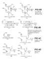
- FIG. 4A - FIG. 4Dare schematics showing various exemplary donor antenna ( 105 A, 105 B, 105 C, 105 D) and server antenna ( 110 A, 110 B, 110 C, 110 D) sub-systems for use with a system for optimizing gain.
- one or both of the donor and server antennasmay individually comprise an active multimode antenna (or “modal antenna”).
Landscapes
- Engineering & Computer Science (AREA)
- Computer Networks & Wireless Communication (AREA)
- Mechanical Engineering (AREA)
- Variable-Direction Aerials And Aerial Arrays (AREA)
Abstract
Description
Claims (10)
Priority Applications (5)
| Application Number | Priority Date | Filing Date | Title |
|---|---|---|---|
| US15/242,514US9917359B2 (en) | 2008-03-05 | 2016-08-20 | Repeater with multimode antenna |
| US15/917,101US10263326B2 (en) | 2008-03-05 | 2018-03-09 | Repeater with multimode antenna |
| US16/380,222US10770786B2 (en) | 2008-03-05 | 2019-04-10 | Repeater with multimode antenna |
| US17/012,446US11942684B2 (en) | 2008-03-05 | 2020-09-04 | Repeater with multimode antenna |
| US18/348,968US20230352826A1 (en) | 2008-03-05 | 2023-07-07 | Repeater with Multimode Antenna |
Applications Claiming Priority (6)
| Application Number | Priority Date | Filing Date | Title |
|---|---|---|---|
| US12/043,090US7911402B2 (en) | 2008-03-05 | 2008-03-05 | Antenna and method for steering antenna beam direction |
| US13/029,564US8362962B2 (en) | 2008-03-05 | 2011-02-17 | Antenna and method for steering antenna beam direction |
| US13/726,477US8648755B2 (en) | 2008-03-05 | 2012-12-24 | Antenna and method for steering antenna beam direction |
| US14/144,461US9240634B2 (en) | 2007-08-17 | 2013-12-30 | Antenna and method for steering antenna beam direction |
| US14/965,881US9748637B2 (en) | 2008-03-05 | 2015-12-10 | Antenna and method for steering antenna beam direction for wifi applications |
| US15/242,514US9917359B2 (en) | 2008-03-05 | 2016-08-20 | Repeater with multimode antenna |
Related Parent Applications (1)
| Application Number | Title | Priority Date | Filing Date |
|---|---|---|---|
| US14/965,881Continuation-In-PartUS9748637B2 (en) | 2008-03-05 | 2015-12-10 | Antenna and method for steering antenna beam direction for wifi applications |
Related Child Applications (1)
| Application Number | Title | Priority Date | Filing Date |
|---|---|---|---|
| US15/917,101ContinuationUS10263326B2 (en) | 2008-03-05 | 2018-03-09 | Repeater with multimode antenna |
Publications (2)
| Publication Number | Publication Date |
|---|---|
| US20170133759A1 US20170133759A1 (en) | 2017-05-11 |
| US9917359B2true US9917359B2 (en) | 2018-03-13 |
Family
ID=58663819
Family Applications (5)
| Application Number | Title | Priority Date | Filing Date |
|---|---|---|---|
| US15/242,514ActiveUS9917359B2 (en) | 2008-03-05 | 2016-08-20 | Repeater with multimode antenna |
| US15/917,101ActiveUS10263326B2 (en) | 2008-03-05 | 2018-03-09 | Repeater with multimode antenna |
| US16/380,222ActiveUS10770786B2 (en) | 2008-03-05 | 2019-04-10 | Repeater with multimode antenna |
| US17/012,446ActiveUS11942684B2 (en) | 2008-03-05 | 2020-09-04 | Repeater with multimode antenna |
| US18/348,968PendingUS20230352826A1 (en) | 2008-03-05 | 2023-07-07 | Repeater with Multimode Antenna |
Family Applications After (4)
| Application Number | Title | Priority Date | Filing Date |
|---|---|---|---|
| US15/917,101ActiveUS10263326B2 (en) | 2008-03-05 | 2018-03-09 | Repeater with multimode antenna |
| US16/380,222ActiveUS10770786B2 (en) | 2008-03-05 | 2019-04-10 | Repeater with multimode antenna |
| US17/012,446ActiveUS11942684B2 (en) | 2008-03-05 | 2020-09-04 | Repeater with multimode antenna |
| US18/348,968PendingUS20230352826A1 (en) | 2008-03-05 | 2023-07-07 | Repeater with Multimode Antenna |
Country Status (1)
| Country | Link |
|---|---|
| US (5) | US9917359B2 (en) |
Cited By (1)
| Publication number | Priority date | Publication date | Assignee | Title |
|---|---|---|---|---|
| US20190237864A1 (en)* | 2008-03-05 | 2019-08-01 | Ethertronics, Inc. | Repeater With Multimode Antenna |
Families Citing this family (4)
| Publication number | Priority date | Publication date | Assignee | Title |
|---|---|---|---|---|
| US9979460B2 (en)* | 2014-02-18 | 2018-05-22 | Nextivity, Inc. | System for maximizing gain in a repeater |
| KR102780521B1 (en) | 2020-01-21 | 2025-03-12 | 삼성전자주식회사 | An antenna and an electronic device including the same |
| IL293723A (en)* | 2020-03-12 | 2022-08-01 | Kyocera Avx Components San Diego Inc | System and method for removing channel quality indicator (cqi) data associated with a multimode antenna |
| US11329714B1 (en)* | 2021-02-01 | 2022-05-10 | Qualcomm Incorporated | Antenna polarization configuration for repeaters |
Citations (22)
| Publication number | Priority date | Publication date | Assignee | Title |
|---|---|---|---|---|
| US20060205343A1 (en) | 2005-03-11 | 2006-09-14 | Runyon Donald L | Wireless repeater with feedback suppression features |
| US7274677B1 (en) | 2001-04-16 | 2007-09-25 | Cisco Technology, Inc. | Network management architecture |
| US20100248729A1 (en) | 2009-03-27 | 2010-09-30 | Samsung Electronics Co., Ltd. | Apparatus and method for bidirectional relaying in a relay wireless communication system |
| US20100284446A1 (en) | 2009-05-06 | 2010-11-11 | Fenghao Mu | Method and Apparatus for MIMO Repeater Chains in a Wireless Communication Network |
| US20110250928A1 (en) | 2010-04-13 | 2011-10-13 | Schlub Robert W | Adjustable wireless circuitry with antenna-based proximity detector |
| US20110300814A1 (en) | 2010-06-03 | 2011-12-08 | Broadcom Corporation | Front end module with tone injection |
| US20120015608A1 (en)* | 2010-07-14 | 2012-01-19 | Qualcomm Incorporated | Method in a wireless repeater employing an antenna array for interference reduction |
| US20120178386A1 (en) | 2011-01-07 | 2012-07-12 | Mattia Pascolini | Methods for adjusting radio-frequency circuitry to mitigate interference effects |
| US20120188919A1 (en) | 2008-05-16 | 2012-07-26 | Redline Communications Inc. | Isolation measurement and self oscillation prevention in tdd-ofdm repeater for wireless broadband distribution to shadowed areas |
| US20130122836A1 (en) | 2011-09-09 | 2013-05-16 | Ethertronics, Inc. | Pre-optimization of transmit circuits |
| US20130143483A1 (en) | 2011-12-06 | 2013-06-06 | Qualcomm Incorporated | Maintaining repeater stability in a multi-repeater scenario |
| US20130183895A1 (en) | 2012-01-13 | 2013-07-18 | Qualcomm Incorporated | System, apparatus, and method for facilitating multi-antenna diversity for repeaters in wireless communication systems |
| US20140100004A1 (en) | 2012-10-08 | 2014-04-10 | Apple Inc. | Tunable Multiband Antenna with Dielectric Carrier |
| US8886115B2 (en) | 2009-05-11 | 2014-11-11 | Qualcomm Incorporated | Gain control metric pruning in a wireless repeater |
| US8988298B1 (en)* | 2013-09-27 | 2015-03-24 | Qualcomm Incorporated | Collocated omnidirectional dual-polarized antenna |
| US9077066B1 (en)* | 2012-03-14 | 2015-07-07 | Amazon Technologies, Inc. | Wideband tapered antenna with parasitic grounding element |
| US20150236776A1 (en)* | 2014-02-18 | 2015-08-20 | Nextivity, Inc. | System for maximizing gain in a repeater |
| US20150310995A1 (en) | 2008-02-28 | 2015-10-29 | Peregrine Semiconductor Corporation | Method and Apparatus for use in Digitally Tuning a Capacitor in an Integrated Circuit Device |
| US9306276B2 (en)* | 2011-07-13 | 2016-04-05 | Qualcomm Incorporated | Wideband antenna system with multiple antennas and at least one parasitic element |
| US9356336B1 (en)* | 2012-06-13 | 2016-05-31 | Amazon Technologies Inc. | Dual-folded monopole antenna (DFMA) |
| US9368862B2 (en)* | 2014-01-21 | 2016-06-14 | Nvidia Corporation | Wideband antenna and an electronic device including the same |
| US20160197643A1 (en) | 2013-09-17 | 2016-07-07 | Murata Manufacturing Co., Ltd. | High-frequency module and communication device |
Family Cites Families (107)
| Publication number | Priority date | Publication date | Assignee | Title |
|---|---|---|---|---|
| NL61755C (en) | 1938-04-28 | |||
| US2318516A (en) | 1940-12-14 | 1943-05-04 | Philco Radio & Television Corp | High frequency antenna system |
| US2433804A (en) | 1943-04-23 | 1947-12-30 | Rca Corp | Frequency-modulated pulse radio locating system |
| US2761134A (en) | 1952-01-18 | 1956-08-28 | Bendix Aviat Corp | Means for operating antennas |
| US2938208A (en) | 1955-01-05 | 1960-05-24 | Itt | Omnirange beacon antenna having rotating parasitic conductive elements |
| US3419869A (en) | 1967-10-02 | 1968-12-31 | New Tronics Corp | Remotely tuned radio antenna |
| US3971031A (en) | 1975-10-31 | 1976-07-20 | Burke Emmett F | Loaded quad antenna |
| US5165109A (en) | 1989-01-19 | 1992-11-17 | Trimble Navigation | Microwave communication antenna |
| US5485167A (en) | 1989-12-08 | 1996-01-16 | Hughes Aircraft Company | Multi-frequency band phased-array antenna using multiple layered dipole arrays |
| FR2666178A1 (en) | 1990-08-21 | 1992-02-28 | Etudes Realis Protect Electron | HIGH FREQUENCY EMITTING OR RECEIVING ANTENNA DEVICE. |
| DE69319689T2 (en)* | 1992-10-28 | 1999-02-25 | Atr Optical And Radio Communications Research Laboratories, Kyoto | Device and method for controlling a group antenna with a plurality of antenna elements |
| CA2129139C (en) | 1992-12-07 | 2003-02-11 | Koichi Tsunekawa | Antenna devices |
| US20050192727A1 (en) | 1994-05-09 | 2005-09-01 | Automotive Technologies International Inc. | Sensor Assemblies |
| JP3243130B2 (en)* | 1994-10-31 | 2002-01-07 | 松下電器産業株式会社 | Receiver with adaptive antenna |
| US5598169A (en) | 1995-03-24 | 1997-01-28 | Lucent Technologies Inc. | Detector and modulator circuits for passive microwave links |
| US6104349A (en) | 1995-08-09 | 2000-08-15 | Cohen; Nathan | Tuning fractal antennas and fractal resonators |
| US5784032A (en) | 1995-11-01 | 1998-07-21 | Telecommunications Research Laboratories | Compact diversity antenna with weak back near fields |
| US5777581A (en) | 1995-12-07 | 1998-07-07 | Atlantic Aerospace Electronics Corporation | Tunable microstrip patch antennas |
| US5943016A (en) | 1995-12-07 | 1999-08-24 | Atlantic Aerospace Electronics, Corp. | Tunable microstrip patch antenna and feed network therefor |
| JP3296189B2 (en) | 1996-06-03 | 2002-06-24 | 三菱電機株式会社 | Antenna device |
| US5872547A (en)* | 1996-07-16 | 1999-02-16 | Metawave Communications Corporation | Conical omni-directional coverage multibeam antenna with parasitic elements |
| US5874919A (en) | 1997-01-09 | 1999-02-23 | Harris Corporation | Stub-tuned, proximity-fed, stacked patch antenna |
| US6429818B1 (en) | 1998-01-16 | 2002-08-06 | Tyco Electronics Logistics Ag | Single or dual band parasitic antenna assembly |
| US5999138A (en) | 1998-03-30 | 1999-12-07 | Ponce De Leon; Lorenzo A. | Low power switched diversity antenna system |
| SE9904256D0 (en) | 1999-02-10 | 1999-11-24 | Allgon Ab | An antenna device and a radio communication device including an antenna device |
| US6456249B1 (en) | 1999-08-16 | 2002-09-24 | Tyco Electronics Logistics A.G. | Single or dual band parasitic antenna assembly |
| US6339402B1 (en) | 1999-12-22 | 2002-01-15 | Rangestar Wireless, Inc. | Low profile tunable circularly polarized antenna |
| US6480155B1 (en) | 1999-12-28 | 2002-11-12 | Nokia Corporation | Antenna assembly, and associated method, having an active antenna element and counter antenna element |
| US6326921B1 (en) | 2000-03-14 | 2001-12-04 | Telefonaktiebolaget Lm Ericsson (Publ) | Low profile built-in multi-band antenna |
| AU2001276826A1 (en) | 2000-06-14 | 2001-12-24 | Bae Systems Information And Electronic Systems Integration, Inc. | Narrowband/wideband dual mode antenna |
| AU2001271193A1 (en) | 2000-08-07 | 2002-02-18 | Telefonaktiebolaget Lm Ericsson | Antenna |
| US6836248B2 (en) | 2001-03-15 | 2004-12-28 | Matsushita Electric Industrial Co., Ltd. | Antenna device |
| WO2002078124A1 (en) | 2001-03-22 | 2002-10-03 | Telefonaktiebolaget L M Ericsson (Publ) | Mobile communication device |
| US6466170B2 (en)* | 2001-03-28 | 2002-10-15 | Motorola, Inc. | Internal multi-band antennas for mobile communications |
| US6456243B1 (en) | 2001-06-26 | 2002-09-24 | Ethertronics, Inc. | Multi frequency magnetic dipole antenna structures and methods of reusing the volume of an antenna |
| US6906667B1 (en)* | 2002-02-14 | 2005-06-14 | Ethertronics, Inc. | Multi frequency magnetic dipole antenna structures for very low-profile antenna applications |
| US6650294B2 (en) | 2001-11-26 | 2003-11-18 | Telefonaktiebolaget Lm Ericsson (Publ) | Compact broadband antenna |
| TWI258246B (en) | 2002-03-14 | 2006-07-11 | Sony Ericsson Mobile Comm Ab | Flat built-in radio antenna |
| KR100483043B1 (en) | 2002-04-11 | 2005-04-18 | 삼성전기주식회사 | Multi band built-in antenna |
| US6987493B2 (en) | 2002-04-15 | 2006-01-17 | Paratek Microwave, Inc. | Electronically steerable passive array antenna |
| AU2003233060A1 (en) | 2002-05-02 | 2003-11-17 | Sony Ericsson Mobile Communications Ab | A printed built-in antenna for use in a portable electronic communication apparatus |
| US6765536B2 (en) | 2002-05-09 | 2004-07-20 | Motorola, Inc. | Antenna with variably tuned parasitic element |
| US6717549B2 (en) | 2002-05-15 | 2004-04-06 | Harris Corporation | Dual-polarized, stub-tuned proximity-fed stacked patch antenna |
| JP2004096341A (en) | 2002-08-30 | 2004-03-25 | Fujitsu Ltd | Antenna device including inverted F-type antenna with variable resonance frequency |
| CN1669182A (en) | 2002-09-10 | 2005-09-14 | 弗拉克托斯股份有限公司 | Coupled Multiband Antennas |
| US7619562B2 (en) | 2002-09-30 | 2009-11-17 | Nanosys, Inc. | Phased array systems |
| US6734825B1 (en) | 2002-10-28 | 2004-05-11 | The National University Of Singapore | Miniature built-in multiple frequency band antenna |
| US6900773B2 (en) | 2002-11-18 | 2005-05-31 | Ethertronics, Inc. | Active configurable capacitively loaded magnetic diploe |
| JP2004201278A (en) | 2002-12-06 | 2004-07-15 | Sharp Corp | Pattern antenna |
| US6903686B2 (en) | 2002-12-17 | 2005-06-07 | Sony Ericsson Mobile Communications Ab | Multi-branch planar antennas having multiple resonant frequency bands and wireless terminals incorporating the same |
| US6919857B2 (en) | 2003-01-27 | 2005-07-19 | Ethertronics, Inc. | Differential mode capacitively loaded magnetic dipole antenna |
| FI115574B (en) | 2003-04-15 | 2005-05-31 | Filtronic Lk Oy | Adjustable multiband antenna |
| US7068234B2 (en) | 2003-05-12 | 2006-06-27 | Hrl Laboratories, Llc | Meta-element antenna and array |
| WO2004109857A1 (en) | 2003-06-09 | 2004-12-16 | Matsushita Electric Industrial Co., Ltd. | Antenna and electronic equipment |
| US7446601B2 (en) | 2003-06-23 | 2008-11-04 | Astronix Research, Llc | Electron beam RF amplifier and emitter |
| JP4426531B2 (en)* | 2003-09-18 | 2010-03-03 | ソニー・エリクソン・モバイルコミュニケーションズ株式会社 | Mobile communication terminal |
| US8306574B2 (en)* | 2003-10-29 | 2012-11-06 | Robert Warner | Method and system for an adaptive wireless communication system optimized for economic benefit |
| US7075485B2 (en) | 2003-11-24 | 2006-07-11 | Hong Kong Applied Science And Technology Research Institute Co., Ltd. | Low cost multi-beam, multi-band and multi-diversity antenna systems and methods for wireless communications |
| FI121037B (en)* | 2003-12-15 | 2010-06-15 | Pulse Finland Oy | Adjustable multiband antenna |
| JP3805772B2 (en) | 2004-01-13 | 2006-08-09 | 株式会社東芝 | ANTENNA DEVICE AND PORTABLE RADIO COMMUNICATION DEVICE |
| JP2005252366A (en) | 2004-03-01 | 2005-09-15 | Sony Corp | Inverted-f antenna |
| JP4195403B2 (en) | 2004-03-01 | 2008-12-10 | 株式会社国際電気通信基礎技術研究所 | Antenna structure and television receiver |
| JP4063833B2 (en) | 2004-06-14 | 2008-03-19 | Necアクセステクニカ株式会社 | Antenna device and portable radio terminal |
| WO2006015121A2 (en) | 2004-07-29 | 2006-02-09 | Interdigital Technology Corporation | Multi-mode input impedance matching for smart antennas and associated methods |
| US7333057B2 (en) | 2004-07-31 | 2008-02-19 | Harris Corporation | Stacked patch antenna with distributed reactive network proximity feed |
| US7330156B2 (en) | 2004-08-20 | 2008-02-12 | Nokia Corporation | Antenna isolation using grounded microwave elements |
| US7596352B2 (en)* | 2004-08-23 | 2009-09-29 | Samsung Electronics Co., Ltd. | Apparatus and method for channel estimation and echo cancellation in a wireless repeater |
| US7834813B2 (en) | 2004-10-15 | 2010-11-16 | Skycross, Inc. | Methods and apparatuses for adaptively controlling antenna parameters to enhance efficiency and maintain antenna size compactness |
| US7119748B2 (en)* | 2004-12-31 | 2006-10-10 | Nokia Corporation | Internal multi-band antenna with planar strip elements |
| US20060220966A1 (en) | 2005-03-29 | 2006-10-05 | Ethertronics | Antenna element-counterpoise arrangement in an antenna |
| US7132989B1 (en) | 2005-05-04 | 2006-11-07 | Kyocera Wireless Corp. | Apparatus, system, and method for adjusting antenna characteristics using tunable parasitic elements |
| US8380132B2 (en)* | 2005-09-14 | 2013-02-19 | Delphi Technologies, Inc. | Self-structuring antenna with addressable switch controller |
| US7903034B2 (en) | 2005-09-19 | 2011-03-08 | Fractus, S.A. | Antenna set, portable wireless device, and use of a conductive element for tuning the ground-plane of the antenna set |
| US7405701B2 (en) | 2005-09-29 | 2008-07-29 | Sony Ericsson Mobile Communications Ab | Multi-band bent monopole antenna |
| CN102594422B (en) | 2005-12-20 | 2014-12-03 | 华为技术有限公司 | sending control method, base station and mobile radio station |
| US7616163B2 (en) | 2006-01-25 | 2009-11-10 | Sky Cross, Inc. | Multiband tunable antenna |
| US7696928B2 (en) | 2006-02-08 | 2010-04-13 | Hong Kong Applied Science And Technology Research Institute Co., Ltd. | Systems and methods for using parasitic elements for controlling antenna resonances |
| US7847740B2 (en) | 2006-02-13 | 2010-12-07 | Kyocera Corporation | Antenna system having receiver antenna diversity and configurable transmission antenna and method of management thereof |
| US7265724B1 (en) | 2006-03-28 | 2007-09-04 | Motorola Inc. | Communications assembly and antenna assembly with a switched tuning line |
| US7432860B2 (en) | 2006-05-17 | 2008-10-07 | Sony Ericsson Mobile Communications Ab | Multi-band antenna for GSM, UMTS, and WiFi applications |
| TW200746546A (en) | 2006-06-09 | 2007-12-16 | Advanced Connectek Inc | Multi-frequency antenna with dual loops |
| US7755547B2 (en) | 2006-06-30 | 2010-07-13 | Nokia Corporation | Mechanically tunable antenna for communication devices |
| US7848654B2 (en)* | 2006-09-28 | 2010-12-07 | Corning Cable Systems Llc | Radio-over-fiber (RoF) wireless picocellular system with combined picocells |
| US7265720B1 (en) | 2006-12-29 | 2007-09-04 | Motorola, Inc. | Planar inverted-F antenna with parasitic conductor loop and device using same |
| US7764236B2 (en) | 2007-01-04 | 2010-07-27 | Apple Inc. | Broadband antenna for handheld devices |
| US7911402B2 (en) | 2008-03-05 | 2011-03-22 | Ethertronics, Inc. | Antenna and method for steering antenna beam direction |
| US8581789B2 (en) | 2007-08-20 | 2013-11-12 | Ethertronics, Inc. | Active self-reconfigurable multimode antenna system |
| US7830320B2 (en) | 2007-08-20 | 2010-11-09 | Ethertronics, Inc. | Antenna with active elements |
| US7619574B1 (en) | 2007-09-27 | 2009-11-17 | Rockwell Collins, Inc. | Tunable antenna |
| US8175459B2 (en)* | 2007-10-12 | 2012-05-08 | Corning Cable Systems Llc | Hybrid wireless/wired RoF transponder and hybrid RoF communication system using same |
| KR100954879B1 (en) | 2007-12-04 | 2010-04-28 | 삼성전기주식회사 | Antenna-embedded printed circuit board |
| US8604988B2 (en) | 2008-03-05 | 2013-12-10 | Ethertronics, Inc. | Multi-function array for access point and mobile wireless systems |
| US9917359B2 (en)* | 2008-03-05 | 2018-03-13 | Ethertronics, Inc. | Repeater with multimode antenna |
| US8159399B2 (en) | 2008-06-03 | 2012-04-17 | Apple Inc. | Antenna diversity systems for portable electronic devices |
| US8144072B2 (en) | 2009-08-04 | 2012-03-27 | Auden Techno Corp. | Multi-band antenna for notebook computer |
| PH12012501770A1 (en) | 2010-04-26 | 2012-12-10 | Ericsson Telefon Ab L M | A communication system node with improved interference situation |
| US8354967B2 (en) | 2010-05-11 | 2013-01-15 | Sony Ericsson Mobile Communications Ab | Antenna array with capacitive coupled upper and lower antenna elements and a peak radiation pattern directed toward the lower antenna element |
| US8446318B2 (en) | 2010-06-22 | 2013-05-21 | Shirook Ali | Controlling a beamforming antenna using reconfigurable parasitic elements |
| US8577289B2 (en) | 2011-02-17 | 2013-11-05 | Apple Inc. | Antenna with integrated proximity sensor for proximity-based radio-frequency power control |
| JP5301608B2 (en) | 2011-05-24 | 2013-09-25 | レノボ・シンガポール・プライベート・リミテッド | Antenna for wireless terminal equipment |
| TWI448697B (en) | 2011-08-02 | 2014-08-11 | Jieng Tai Internat Electric Corp | Antenna device and signal processing device |
| US8934398B2 (en)* | 2011-10-07 | 2015-01-13 | Qualcomm Incorporated | System, apparatus, and method for repeater pilot signal generation in wireless communication systems |
| US9231669B2 (en) | 2012-01-24 | 2016-01-05 | Ethertronics, Inc. | Modal cognitive diversity for mobile communication MIMO systems |
| IL217982A (en)* | 2012-02-07 | 2016-10-31 | Elta Systems Ltd | Multiple antenna system |
| CN102710275A (en) | 2012-05-11 | 2012-10-03 | 中兴通讯股份有限公司 | Method for intelligently switching on/off mobile terminal antenna and corresponding mobile terminal |
| US9742060B2 (en)* | 2014-08-06 | 2017-08-22 | Michael Clyde Walker | Ceiling assembly with integrated repeater antenna |
| US20200021354A1 (en)* | 2018-07-10 | 2020-01-16 | Wilson Electronics, Llc | Emergency responder install method |
- 2016
- 2016-08-20USUS15/242,514patent/US9917359B2/enactiveActive
- 2018
- 2018-03-09USUS15/917,101patent/US10263326B2/enactiveActive
- 2019
- 2019-04-10USUS16/380,222patent/US10770786B2/enactiveActive
- 2020
- 2020-09-04USUS17/012,446patent/US11942684B2/enactiveActive
- 2023
- 2023-07-07USUS18/348,968patent/US20230352826A1/enactivePending
Patent Citations (24)
| Publication number | Priority date | Publication date | Assignee | Title |
|---|---|---|---|---|
| US7274677B1 (en) | 2001-04-16 | 2007-09-25 | Cisco Technology, Inc. | Network management architecture |
| US20060205343A1 (en) | 2005-03-11 | 2006-09-14 | Runyon Donald L | Wireless repeater with feedback suppression features |
| US20150310995A1 (en) | 2008-02-28 | 2015-10-29 | Peregrine Semiconductor Corporation | Method and Apparatus for use in Digitally Tuning a Capacitor in an Integrated Circuit Device |
| US20120188919A1 (en) | 2008-05-16 | 2012-07-26 | Redline Communications Inc. | Isolation measurement and self oscillation prevention in tdd-ofdm repeater for wireless broadband distribution to shadowed areas |
| US20100248729A1 (en) | 2009-03-27 | 2010-09-30 | Samsung Electronics Co., Ltd. | Apparatus and method for bidirectional relaying in a relay wireless communication system |
| US20100284446A1 (en) | 2009-05-06 | 2010-11-11 | Fenghao Mu | Method and Apparatus for MIMO Repeater Chains in a Wireless Communication Network |
| US8886115B2 (en) | 2009-05-11 | 2014-11-11 | Qualcomm Incorporated | Gain control metric pruning in a wireless repeater |
| US20110250928A1 (en) | 2010-04-13 | 2011-10-13 | Schlub Robert W | Adjustable wireless circuitry with antenna-based proximity detector |
| US20110300814A1 (en) | 2010-06-03 | 2011-12-08 | Broadcom Corporation | Front end module with tone injection |
| US20120015608A1 (en)* | 2010-07-14 | 2012-01-19 | Qualcomm Incorporated | Method in a wireless repeater employing an antenna array for interference reduction |
| US8989672B2 (en) | 2011-01-07 | 2015-03-24 | Apple Inc. | Methods for adjusting radio-frequency circuitry to mitigate interference effects |
| US20120178386A1 (en) | 2011-01-07 | 2012-07-12 | Mattia Pascolini | Methods for adjusting radio-frequency circuitry to mitigate interference effects |
| US9306276B2 (en)* | 2011-07-13 | 2016-04-05 | Qualcomm Incorporated | Wideband antenna system with multiple antennas and at least one parasitic element |
| US20130122836A1 (en) | 2011-09-09 | 2013-05-16 | Ethertronics, Inc. | Pre-optimization of transmit circuits |
| US20130143483A1 (en) | 2011-12-06 | 2013-06-06 | Qualcomm Incorporated | Maintaining repeater stability in a multi-repeater scenario |
| US20130183895A1 (en) | 2012-01-13 | 2013-07-18 | Qualcomm Incorporated | System, apparatus, and method for facilitating multi-antenna diversity for repeaters in wireless communication systems |
| US9077066B1 (en)* | 2012-03-14 | 2015-07-07 | Amazon Technologies, Inc. | Wideband tapered antenna with parasitic grounding element |
| US9356336B1 (en)* | 2012-06-13 | 2016-05-31 | Amazon Technologies Inc. | Dual-folded monopole antenna (DFMA) |
| US20140100004A1 (en) | 2012-10-08 | 2014-04-10 | Apple Inc. | Tunable Multiband Antenna with Dielectric Carrier |
| US20160197643A1 (en) | 2013-09-17 | 2016-07-07 | Murata Manufacturing Co., Ltd. | High-frequency module and communication device |
| US8988298B1 (en)* | 2013-09-27 | 2015-03-24 | Qualcomm Incorporated | Collocated omnidirectional dual-polarized antenna |
| US9368862B2 (en)* | 2014-01-21 | 2016-06-14 | Nvidia Corporation | Wideband antenna and an electronic device including the same |
| US20150236776A1 (en)* | 2014-02-18 | 2015-08-20 | Nextivity, Inc. | System for maximizing gain in a repeater |
| US20170041062A1 (en) | 2014-02-18 | 2017-02-09 | Nextivity, Inc. | System for maximizing gain in a repeater |
Cited By (3)
| Publication number | Priority date | Publication date | Assignee | Title |
|---|---|---|---|---|
| US20190237864A1 (en)* | 2008-03-05 | 2019-08-01 | Ethertronics, Inc. | Repeater With Multimode Antenna |
| US10770786B2 (en)* | 2008-03-05 | 2020-09-08 | Ethertronics, Inc. | Repeater with multimode antenna |
| US11942684B2 (en) | 2008-03-05 | 2024-03-26 | KYOCERA AVX Components (San Diego), Inc. | Repeater with multimode antenna |
Also Published As
| Publication number | Publication date |
|---|---|
| US10263326B2 (en) | 2019-04-16 |
| US10770786B2 (en) | 2020-09-08 |
| US20170133759A1 (en) | 2017-05-11 |
| US20180198200A1 (en) | 2018-07-12 |
| US20240055756A9 (en) | 2024-02-15 |
| US20190237864A1 (en) | 2019-08-01 |
| US20230352826A1 (en) | 2023-11-02 |
| US11942684B2 (en) | 2024-03-26 |
| US20200399055A1 (en) | 2020-12-24 |
Similar Documents
| Publication | Publication Date | Title |
|---|---|---|
| US11942684B2 (en) | Repeater with multimode antenna | |
| US9065496B2 (en) | Method and system for switched combined diversity with a modal antenna | |
| US7312750B2 (en) | Adaptive beam-forming system using hierarchical weight banks for antenna array in wireless communication system | |
| US6314305B1 (en) | Transmitter/receiver for combined adaptive array processing and fixed beam switching | |
| US9160074B2 (en) | Modal antenna with correlation management for diversity applications | |
| US8604988B2 (en) | Multi-function array for access point and mobile wireless systems | |
| JP3211445U (en) | Modal antenna with correlation adjustment for diversity applications | |
| US20120299765A1 (en) | Compact smart antenna for mobile wireless communications | |
| US20020008672A1 (en) | Adaptive antenna for use in wireless communication systems | |
| US20040157645A1 (en) | System and method of operation an array antenna in a distributed wireless communication network | |
| KR20060016749A (en) | Antenna Diversity System for Mobile Phones | |
| US9793605B1 (en) | Modal antenna array for interference mitigation | |
| US9793974B2 (en) | System for maximizing gain in a repeater | |
| WO2004082070A1 (en) | System and method of operation of an array antenna in a distributed wireless communication network | |
| US10944456B1 (en) | Wireless communication device | |
| US11211706B2 (en) | Wireless range extender | |
| JP2006060756A (en) | Antenna for mobile equipment |
Legal Events
| Date | Code | Title | Description |
|---|---|---|---|
| AS | Assignment | Owner name:ETHERTRONICS, INC., CALIFORNIA Free format text:ASSIGNMENT OF ASSIGNORS INTEREST;ASSIGNORS:SINGH, ABHISHEK;DESCLOS, LAURENT;ROWSON, SEBASTIAN;AND OTHERS;REEL/FRAME:039500/0844 Effective date:20160822 | |
| AS | Assignment | Owner name:NH EXPANSION CREDIT FUND HOLDINGS LP, NEW YORK Free format text:SECURITY INTEREST;ASSIGNOR:ETHERTRONICS, INC.;REEL/FRAME:040464/0245 Effective date:20161013 | |
| AS | Assignment | Owner name:SILICON VALLEY BANK, CALIFORNIA Free format text:SECURITY INTEREST;ASSIGNOR:ETHERTRONICS, INC.;REEL/FRAME:044106/0829 Effective date:20080911 | |
| FEPP | Fee payment procedure | Free format text:ENTITY STATUS SET TO UNDISCOUNTED (ORIGINAL EVENT CODE: BIG.) | |
| AS | Assignment | Owner name:ETHERTRONICS, INC., CALIFORNIA Free format text:RELEASE BY SECURED PARTY;ASSIGNOR:NH EXPANSION CREDIT FUND HOLDINGS LP;REEL/FRAME:045210/0725 Effective date:20180131 | |
| STCF | Information on status: patent grant | Free format text:PATENTED CASE | |
| MAFP | Maintenance fee payment | Free format text:PAYMENT OF MAINTENANCE FEE, 4TH YEAR, LARGE ENTITY (ORIGINAL EVENT CODE: M1551); ENTITY STATUS OF PATENT OWNER: LARGE ENTITY Year of fee payment:4 | |
| AS | Assignment | Owner name:KYOCERA AVX COMPONENTS (SAN DIEGO), INC., CALIFORNIA Free format text:CHANGE OF NAME;ASSIGNOR:AVX ANTENNA, INC.;REEL/FRAME:063543/0302 Effective date:20211001 | |
| AS | Assignment | Owner name:AVX ANTENNA, INC., CALIFORNIA Free format text:CHANGE OF NAME;ASSIGNOR:ETHERTRONICS, INC.;REEL/FRAME:063549/0336 Effective date:20180206 | |
| MAFP | Maintenance fee payment | Free format text:PAYMENT OF MAINTENANCE FEE, 8TH YEAR, LARGE ENTITY (ORIGINAL EVENT CODE: M1552); ENTITY STATUS OF PATENT OWNER: LARGE ENTITY Year of fee payment:8 |