US9917195B2 - High doped III-V source/drain junctions for field effect transistors - Google Patents
High doped III-V source/drain junctions for field effect transistorsDownload PDFInfo
- Publication number
- US9917195B2 US9917195B2US14/812,425US201514812425AUS9917195B2US 9917195 B2US9917195 B2US 9917195B2US 201514812425 AUS201514812425 AUS 201514812425AUS 9917195 B2US9917195 B2US 9917195B2
- Authority
- US
- United States
- Prior art keywords
- iii
- gate
- fin
- semiconductor device
- layer
- Prior art date
- Legal status (The legal status is an assumption and is not a legal conclusion. Google has not performed a legal analysis and makes no representation as to the accuracy of the status listed.)
- Expired - Fee Related, expires
Links
Images


Classifications
- H—ELECTRICITY
- H10—SEMICONDUCTOR DEVICES; ELECTRIC SOLID-STATE DEVICES NOT OTHERWISE PROVIDED FOR
- H10D—INORGANIC ELECTRIC SEMICONDUCTOR DEVICES
- H10D62/00—Semiconductor bodies, or regions thereof, of devices having potential barriers
- H10D62/10—Shapes, relative sizes or dispositions of the regions of the semiconductor bodies; Shapes of the semiconductor bodies
- H10D62/17—Semiconductor regions connected to electrodes not carrying current to be rectified, amplified or switched, e.g. channel regions
- H10D62/213—Channel regions of field-effect devices
- H10D62/221—Channel regions of field-effect devices of FETs
- H10D62/235—Channel regions of field-effect devices of FETs of IGFETs
- H01L29/7851—
- H—ELECTRICITY
- H01—ELECTRIC ELEMENTS
- H01L—SEMICONDUCTOR DEVICES NOT COVERED BY CLASS H10
- H01L21/00—Processes or apparatus adapted for the manufacture or treatment of semiconductor or solid state devices or of parts thereof
- H01L21/02—Manufacture or treatment of semiconductor devices or of parts thereof
- H01L21/04—Manufacture or treatment of semiconductor devices or of parts thereof the devices having potential barriers, e.g. a PN junction, depletion layer or carrier concentration layer
- H01L21/18—Manufacture or treatment of semiconductor devices or of parts thereof the devices having potential barriers, e.g. a PN junction, depletion layer or carrier concentration layer the devices having semiconductor bodies comprising elements of Group IV of the Periodic Table or AIIIBV compounds with or without impurities, e.g. doping materials
- H01L21/30—Treatment of semiconductor bodies using processes or apparatus not provided for in groups H01L21/20 - H01L21/26
- H01L21/302—Treatment of semiconductor bodies using processes or apparatus not provided for in groups H01L21/20 - H01L21/26 to change their surface-physical characteristics or shape, e.g. etching, polishing, cutting
- H01L21/306—Chemical or electrical treatment, e.g. electrolytic etching
- H01L21/30604—Chemical etching
- H01L21/30612—Etching of AIIIBV compounds
- H01L21/30621—Vapour phase etching
- H01L29/0847—
- H01L29/1029—
- H01L29/66522—
- H01L29/6656—
- H01L29/66795—
- H—ELECTRICITY
- H10—SEMICONDUCTOR DEVICES; ELECTRIC SOLID-STATE DEVICES NOT OTHERWISE PROVIDED FOR
- H10D—INORGANIC ELECTRIC SEMICONDUCTOR DEVICES
- H10D30/00—Field-effect transistors [FET]
- H10D30/01—Manufacture or treatment
- H10D30/021—Manufacture or treatment of FETs having insulated gates [IGFET]
- H10D30/024—Manufacture or treatment of FETs having insulated gates [IGFET] of fin field-effect transistors [FinFET]
- H—ELECTRICITY
- H10—SEMICONDUCTOR DEVICES; ELECTRIC SOLID-STATE DEVICES NOT OTHERWISE PROVIDED FOR
- H10D—INORGANIC ELECTRIC SEMICONDUCTOR DEVICES
- H10D30/00—Field-effect transistors [FET]
- H10D30/60—Insulated-gate field-effect transistors [IGFET]
- H10D30/62—Fin field-effect transistors [FinFET]
- H10D30/6211—Fin field-effect transistors [FinFET] having fin-shaped semiconductor bodies integral with the bulk semiconductor substrates
- H—ELECTRICITY
- H10—SEMICONDUCTOR DEVICES; ELECTRIC SOLID-STATE DEVICES NOT OTHERWISE PROVIDED FOR
- H10D—INORGANIC ELECTRIC SEMICONDUCTOR DEVICES
- H10D30/00—Field-effect transistors [FET]
- H10D30/60—Insulated-gate field-effect transistors [IGFET]
- H10D30/62—Fin field-effect transistors [FinFET]
- H10D30/6219—Fin field-effect transistors [FinFET] characterised by the source or drain electrodes
- H—ELECTRICITY
- H10—SEMICONDUCTOR DEVICES; ELECTRIC SOLID-STATE DEVICES NOT OTHERWISE PROVIDED FOR
- H10D—INORGANIC ELECTRIC SEMICONDUCTOR DEVICES
- H10D30/00—Field-effect transistors [FET]
- H10D30/60—Insulated-gate field-effect transistors [IGFET]
- H10D30/751—Insulated-gate field-effect transistors [IGFET] having composition variations in the channel regions
- H—ELECTRICITY
- H10—SEMICONDUCTOR DEVICES; ELECTRIC SOLID-STATE DEVICES NOT OTHERWISE PROVIDED FOR
- H10D—INORGANIC ELECTRIC SEMICONDUCTOR DEVICES
- H10D62/00—Semiconductor bodies, or regions thereof, of devices having potential barriers
- H10D62/01—Manufacture or treatment
- H10D62/021—Forming source or drain recesses by etching e.g. recessing by etching and then refilling
- H—ELECTRICITY
- H10—SEMICONDUCTOR DEVICES; ELECTRIC SOLID-STATE DEVICES NOT OTHERWISE PROVIDED FOR
- H10D—INORGANIC ELECTRIC SEMICONDUCTOR DEVICES
- H10D62/00—Semiconductor bodies, or regions thereof, of devices having potential barriers
- H10D62/80—Semiconductor bodies, or regions thereof, of devices having potential barriers characterised by the materials
- H10D62/85—Semiconductor bodies, or regions thereof, of devices having potential barriers characterised by the materials being Group III-V materials, e.g. GaAs
- H—ELECTRICITY
- H10—SEMICONDUCTOR DEVICES; ELECTRIC SOLID-STATE DEVICES NOT OTHERWISE PROVIDED FOR
- H10D—INORGANIC ELECTRIC SEMICONDUCTOR DEVICES
- H10D64/00—Electrodes of devices having potential barriers
- H10D64/01—Manufacture or treatment
- H10D64/017—Manufacture or treatment using dummy gates in processes wherein at least parts of the final gates are self-aligned to the dummy gates, i.e. replacement gate processes
- H—ELECTRICITY
- H10—SEMICONDUCTOR DEVICES; ELECTRIC SOLID-STATE DEVICES NOT OTHERWISE PROVIDED FOR
- H10D—INORGANIC ELECTRIC SEMICONDUCTOR DEVICES
- H10D30/00—Field-effect transistors [FET]
- H10D30/01—Manufacture or treatment
- H10D30/021—Manufacture or treatment of FETs having insulated gates [IGFET]
- H—ELECTRICITY
- H10—SEMICONDUCTOR DEVICES; ELECTRIC SOLID-STATE DEVICES NOT OTHERWISE PROVIDED FOR
- H10D—INORGANIC ELECTRIC SEMICONDUCTOR DEVICES
- H10D64/00—Electrodes of devices having potential barriers
- H10D64/01—Manufacture or treatment
- H10D64/021—Manufacture or treatment using multiple gate spacer layers, e.g. bilayered sidewall spacers
Definitions
- the present inventiongenerally relates to semiconductor devices, and more specifically, to source-drain contacts in semiconductor devices.
- CMOScomplementary metal-oxide semiconductor
- Semiconducting III-V compounds and materialse.g., indium-gallium-arsenic (InGaAs) and indium-gallium-antimony (InGaSb), are attractive channel materials in metal-oxide-semiconductor field-effect transistors (MOSFETs) due to their low band gaps and high carrier mobility properties.
- MOSFETsmetal-oxide-semiconductor field-effect transistors
- the fin-type field effect transistoris a type of MOSFET.
- the FinFetis a double-gate silicon-on-insulator (SOI) device that mitigates the effects of short channels and reduces drain-induced barrier lowering.
- SOIsilicon-on-insulator
- the “fin”refers to the narrow channel between source and drain regions.
- a thin insulating oxide layer on either side of the finseparates the fin from the gate.
- a semiconductor devicein one embodiment, includes a fin patterned in a substrate; a gate disposed over and substantially perpendicular to the fin; a pair of epitaxial contacts including a III-V material over the fin and on opposing sides of the gate; and a channel region between the pair of epitaxial contacts under the gate comprising an undoped III-V material between doped III-V materials, the doped III-V materials including a dopant in an amount in a range from about 1e 18 to about 1e 20 atoms/cm 3 and contacting the epitaxial contacts.
- a method of making a semiconductor deviceincludes depositing a layer of a first doped III-V material onto a substrate, the first doped III-V material including a dopant in an amount in a range from about 1e 18 to about 1e 20 atoms/cm 3 ; patterning a fin in the first doped III-V material and the substrate; forming a gate structure over and substantially perpendicular to the fin; growing by an epitaxial process a pair of epitaxial contacts including a second doped III-V material over the fin and on opposing sides of the gate structure; etching to remove the first doped III-V material from a portion of the channel region beneath the gate structure; filling the portion of channel region with an undoped III-V material to form a channel including the undoped III-V material between remaining portions of the first doped III-V material; and filling the gate structure with a conductive gate metal.
- a method of making a semiconductor deviceincludes depositing a layer of a doped III-V material onto a substrate, the doped III-V material including a dopant in an amount in a range from about 1e 18 to about 1e 20 atoms/cm 3 ; patterning a fin in the doped III-V material and the substrate; forming a gate structure over and substantially perpendicular to the fin; growing by an epitaxial process a pair of epitaxial contacts including a III-V material over the fin and on opposing sides of the gate; etching to remove the doped III-V material from a portion of a channel region beneath the gate structure; building up the channel region by filling the gate structure and the channel region with an undoped III-V material; performing a timed etching process to remove the undoped III-V material from the gate structure and leave the undoped III-V material between remaining portions of the doped III-V material; and filling the gate structure with a conductive gate metal.
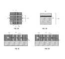
- FIG. 1Aillustrates a top view of a semiconductor device comprising a gate disposed over fins
- FIGS. 1B, 1C, and 1Dillustrate cross-sectional side views through the XX′, YY′, and ZZ′ planes, respectively, of FIG. 1A and show fins patterned in a substrate;
- FIGS. 2A, 2B, and 2Care cross-sectional side views through the XX′, YY′, and ZZ′ planes, respectively, after depositing an oxide layer, a removable gate material layer, and a hard mask layer over the fins;
- FIGS. 2D, 2E, and 2Fare cross-sectional side views through the XX′, YY′, and ZZ′ planes, respectively, after performing a reactive ion etch (RIE) process to form a replacement gate with spacers along the gate sidewalls;
- RIEreactive ion etch
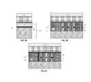
- FIGS. 3A, 3B, and 3Care cross-sectional side views through the XX′, YY′, and ZZ′ planes, respectively, after performing an epitaxial growth process to form epitaxial contacts;
- FIGS. 4A, 4B, and 4Care cross-sectional side views through the XX′, YY′, and ZZ′ planes, respectively, after depositing a low-k dielectric oxide layer over the epitaxial contacts;
- FIGS. 5A, 5B, and 5Care cross-sectional side views through the XX′, YY′, and ZZ′ planes, respectively, after removing the removable gate material;
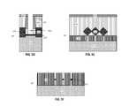
- FIGS. 5D, 5E, and 5Fare cross-sectional side views through the XX′, YY′, and ZZ′ planes, respectively, after forming a fin recess to expose the buffer layer beneath;
- FIGS. 6A, 6B, and 6Care cross-sectional side views through the XX′, YY′, and ZZ′ planes, respectively, after performing a replacement fin growth process;
- FIGS. 6D, 6E, and 6Fare cross-sectional side views through the XX′, YY′, and ZZ′ planes, respectively, after planarizing the replacement fin material;
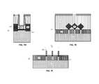
- FIGS. 7A, 7B, and 7Care cross-sectional side views through the XX′, YY′, and ZZ′ planes, respectively, after recessing the fins;
- FIGS. 7D, 7E, and 7Fare cross-sectional side views through the XX′, YY′, and ZZ′ planes, respectively, after removing surrounding low-k dielectric oxide to expose the final fins;
- FIGS. 8A, 8B, and 8Care cross-sectional side views though the XX′, YY′, and ZZ′ planes, respectively, after filling the gate with a high-k material and a metal gate material;
- FIG. 8Dis a top view of the conductive metal gate disposed over the final fins and channel region.
- FinFETsare more scalable to smaller dimensions than planar MOSFETs, aggressive scaling of fin widths can lead to high series resistance.
- a sharp and heavily doped junction between the channel region and the source and drain regionsis desirable to provide lower resistance in the channel junction.
- III-V channelsWhile a sharp and heavily doped channel junction is desired, there are however strict constraints on the thermal budgets in devices with III-V channels. In particular, ion-implantation and annealing used for forming III-V channels may exceed the allowed temperature. Further, regrowth of highly doped source and drain regions may not reduce the resistance under the gate spacers. Such regrowth processes also may be above the allowed thermal budget on the channel.
- embodiments of the present inventionprovide a semiconductor device and methods for forming devices with a sharp channel junction that provides reduced resistance. Specifically, embodiments of the present invention provide a replacement fin channel approach to form a sharp and heavily doped source and drain contact. It is noted that like reference numerals refer to like elements across different embodiments.
- compositionscomprising, “comprising,” “includes,” “including,” “has,” “having,” “contains” or “containing,” or any other variation thereof, are intended to cover a non-exclusive inclusion.
- a composition, a mixture, process, method, article, or apparatus that comprises a list of elementsis not necessarily limited to only those elements but can include other elements not expressly listed or inherent to such composition, mixture, process, method, article, or apparatus.
- inventionor “present invention” are non-limiting terms and not intended to refer to any single aspect of the particular invention but encompass all possible aspects as described in the specification and the claims.
- the term “about” modifying the quantity of an ingredient, component, or reactant of the invention employedrefers to variation in the numerical quantity that can occur, for example, through typical measuring and liquid handling procedures used for making concentrates or solutions. Furthermore, variation can occur from inadvertent error in measuring procedures, differences in the manufacture, source, or purity of the ingredients employed to make the compositions or carry out the methods, and the like.
- the term “about”means within 10% of the reported numerical value.
- the term “about”means within 5% of the reported numerical value.
- the term “about”means within 10, 9, 8, 7, 6, 5, 4, 3, 2, or 1% of the reported numerical value.
- III-V materialmeans a material or compound including at least one III element and at least one V element.
- III elementmeans aluminum (Al), boron (B), gallium (Ga), indium (In), or any combination thereof.
- V elementmeans nitrogen (N), phosphorous (P), arsenic (As), antimony (Sb), or any combination thereof.
- FIG. 1Ais shown for orientation purposes and illustrates an initial top view of a semiconductor gate region 121 to be subsequently disposed over fins 110 .
- the fins 110are surrounded by shallow trench isolation (STI) regions, described below.
- STIshallow trench isolation
- FIGS. 1B, 1C, and 1Dillustrate cross-sectional side views through the XX′, YY′, and ZZ′ planes, respectively, of FIG. 1A .
- FIGS. 1B, 1C, and 1Dshow the fins 110 patterned in a substrate 111 . Note that FIG. 1D looks the same as FIG. 1C upon initial fin 110 and STI region 120 formation, or in the “starting substrate.”
- the substrate 111includes any suitable substrate material.
- suitable substrate materialsinclude p-type materials, n-type materials, neutral-type materials, silicon, germanium, gallium silicon, germanium arsenide, silicon germanium, silicon-on-insulator (SOI), or any combination thereof.
- the thickness of the substrate 111is not intended to be limited. In one aspect, the thickness of the substrate 111 is in a range from about 2 to about 5 micrometers ( ⁇ m). In another aspect, the thickness of the substrate 111 is in a range from about 0.05 ⁇ m to about 0.10 ⁇ m.
- a buffer layer 112is disposed onto the substrate 111 .
- the buffer layer 112includes, for example, carbon doped silicon.
- suitable materials for the buffer layer 112include AlN, InGaAs, AlGaAs, or any combination thereof.
- the buffer layer 112forms a diffusion prevention layer that prevents diffusion of the dopants in heavily doped III-V material layer 113 , which is described below.
- the buffer layer 112is optional.
- the thickness of the buffer layer 112is in a range from about 100 to about 150 nm.
- the thickness of the buffer layer 112is in a range from about 30 to about 50 nm.
- the thickness of the buffer layer 112is about or in any range from about 30, 40, 50, 60, 70, 80, 90, 100, 110, 120, 130, 140, and 150 nm.
- a heavily doped III-V material layer 113is formed over the buffer layer 112 , which forms the topmost surface of the fin 110 .
- the heavily doped III-V material layer 113includes a III-V material.
- suitable III-V compoundsinclude GaAs, InGaAs, AlGaInP, or any combination thereof.
- the III-V materialis heavily doped with an n-type dopant (e.g., Group IV or VI elements) or a p-type dopant (e.g., Group II or IV elements), depending on the type of transistor. Doping is performed by an in-situ doping process (not implantation).
- the III-V materialis doped to a dopant concentration in a range from about 1e 18 to about 1e 19 atoms/cm 3 . In one aspect, the III-V material is doped to a dopant concentration in a range from about 1e 18 to about 1e 20 atoms/cm 3 .
- Lithographycan include forming a photoresist (not shown) on the heavily doped III-V material layer 113 , exposing the photoresist to a desired pattern of radiation, and then developing the exposed photoresist with a resist developer to provide a patterned photoresist on top of the heavily doped III-V material layer 113 .
- At least one etchis the employed to transfer the pattern from the patterned photoresist through the heavily doped III-V material layer 113 , through the buffer layer 112 , and partially into the substrate 111 .
- the etching processmay be a dry etch (e.g., reactive ion etching, plasma etching, ion beam etching, or laser ablation).
- the etching processmay be a wet chemical etch (e.g., potassium hydroxide (KOH)). Both dry etching and wet chemical etching processes may be used.
- the patterned photoresistis removed utilizing resist stripping processes, for example, ashing.
- a shallow trench isolation (STI) processis performed to form the STI regions.
- the STI regions 120are formed by depositing an oxide over the fins 110 and polishing to the top of the heavily doped III-V material layer 113 .
- FIGS. 2A, 2B, and 2Care cross-sectional side views through the XX′, YY′, and ZZ′ planes, respectively, after depositing an oxide layer 210 , a removable gate material layer 212 (e.g., polysilicon/amorphous silicon), and a hard mask layer 214 over the fins 110 .
- the oxide layer 210 and the removable gate material layer 212will form dummy gates 240 over the fins 110 , as shown in FIG. 3A described below.
- a non-limiting example of a suitable material for the oxide layer 210is silicon oxide.
- the thickness of the oxide layer 210is not intended to be limited. In one aspect, the thickness of the oxide layer 210 is in a range from about 10 to about 20 nm. In another aspect, the thickness of the oxide layer 210 is about or in any range from about 10, 12, 14, 16, 18, and 20 nm.
- Non-limiting examples of suitable materials for the hard mask layer 214include SiN, SiOCN, SiBCN, or any combination thereof.
- the thickness of the hard mask layer 214is not intended to be limited. In one aspect, the thickness of the hard mask layer 214 is in a range from about 30 to about 50 nm. In another aspect, the thickness of the hard mask layer 214 is in a range from about 35 to about 45 nm.
- FIGS. 2D, 2E, and 2Fare cross-sectional side views through the XX′, YY′, and ZZ′ planes, respectively, after performing a RIE process to form the replacement gate 240 .
- a spacer materialis then deposited and etched.
- the spacer materialcan be any dielectric spacer material.
- suitable materials for the spacers 220include dielectric oxides (e.g., silicon oxide), dielectric nitrides (e.g., silicon nitride), dielectric oxynitrides, or any combination thereof.
- the spacer materialis deposited by a deposition process, for example, chemical vapor deposition (CVD) or physical vapor deposition (PVD).
- the spacer 220 materialmay be etched by a dry etch process, for example, a RIE process.
- FIGS. 3A, 3B, and 3Care cross-sectional side views through the XX′, YY′, and ZZ′ planes, respectively, after performing an epitaxial growth process to form epitaxial contacts 310 on opposing sides of the replacement gate 240 .
- the epitaxial contacts 310form the source and drain regions.
- a wet etching processis performed to selectively remove the STI region 120 material surrounding the fins (see FIG. 3B ). Then, a wet etching process is performed to remove the buffer layer 112 and the heavily doped III-V material layer 113 on opposing sides of the replacement gate 240 . Etching is performed through the substrate 111 to form recesses where the epitaxial contacts 310 are grown.
- the epitaxial contacts 310 formed on opposing sides of the replacement gate 240include a III-V material, which can be the same or different than that of the heavily doped III-V material layer 113 under the dummy gate 240 .
- the III-V materials forming the epitaxial contacts 310are doped with n-type dopants or p-type dopants as described above for the heavily doped III-V layer 113 .
- the concentration of the dopant in the III-V material of the epitaxial contactsis the same or different than the concentration in the heavily doped III-V material layer 113 . In one aspect, the concentration of the dopant is in a range from about 1e 18 to about 1e 19 atoms/cm 3 . In one aspect, the concentration of the dopant is in a range from about 1e 18 to about 1e 20 atoms/cm 3 .
- FIGS. 4A, 4B, and 4Care cross-sectional side views through the XX′, YY′, and ZZ′ planes, respectively, after depositing a low-k dielectric oxide layer 410 over the epitaxial contacts 310 and around the replacement gate 240 .
- the low-k dielectric oxide layer 410can include, but is not limited to, a spin-on-glass, a flowable oxide, a high density plasma oxide, borophosphosilicate glass (BPSG), or any combination thereof.
- the low-k dielectric oxide layer 410is deposited by a deposition process, including, but not limited to, molecular beam epitaxy (MBE), CVD, PVD, plasma enhanced CVD, atomic layer deposition (ALD), evaporation, chemical solution deposition, or like processes.
- MBEmolecular beam epitaxy
- CVDchemical vapor deposition
- PVDphysical vapor deposition
- ALDatomic layer deposition
- evaporationchemical solution deposition, or like processes.
- the low-k dielectric oxide layer 410is planarized, for example, by chemical mechanical planarization (CMP).
- CMPchemical mechanical planarization
- the thickness of the low-k dielectric oxide layer 410is not intended to be limited. In one aspect, the thickness of the low-k dielectric oxide layer 410 is in a range from about 70 to about 100 nm. In another aspect, the thickness of the low-k dielectric oxide layer 410 is in a range from about 80 to about 90 nm.
- a hard mask layer 420is deposited onto the low-k dielectric oxide layer 410 and planarized, by, for example, CMP, down to the level of the dummy gate material layer 212 .
- the spacers 220are also polished away.
- suitable materials for the hard mask layer 420include SiN, SiOCN, SiBCN, or any combination thereof.
- the thickness of the hard mask layer 420is not intended to be limited. In one aspect, the thickness of the hard mask layer 420 is in a range from about 20 to about 30 nm. In another aspect, the thickness of the hard mask layer 420 is in a range from about 22 to about 28 nm.
- FIGS. 5A, 5B, and 5Care cross-sectional side views through the XX′, YY′, and ZZ′ planes, respectively, after removing the removable gate material layer 212 to exposed the heavily doped III-V material layer 113 in the channel region.
- a dry etch processis performed to anisotropically remove the gate material.
- a wet etch processis performed to remove the removable gate material layer 212 and buffer layer 210 from between the spacers 220 and expose the channel region 501 beneath the gate.
- FIGS. 5D, 5E, and 5Fare cross-sectional side views through the XX′, YY′, and ZZ′ planes, respectively, after forming a fin recess 502 .
- the fin recess 502is formed by performing an etching process through the heavily doped III-V material layer 113 in the channel region and down to the buffer layer 112 .
- a dry etching processmay be employed, e.g., a dry etch with Cl based etch chemistry.
- the buffer layer 112functions as an etch stop and prevents etching through to the substrate 111 .
- FIGS. 6A, 6B, and 6Care cross-sectional side views through the XX′, YY′, and ZZ′ planes, respectively, after performing a replacement fin growth process.
- the open gate region and the finsare filled with an undoped III-V material 601 , which forms an undoped III-V channel region 602 .
- the undoped III-V material 601can be the same III-V material as either the highly doped III-V material layer 113 or the epitaxial contacts 310 .
- the undoped III-V material 601is grown using a metal organic chemical vapor deposition (MOCVD) selective growth process.
- MOCVDmetal organic chemical vapor deposition
- FIGS. 6D, 6E, and 6Fare cross-sectional side views through the XX′, YY′, and ZZ′ planes, respectively, after performing a CMP process to planarize the undoped III-V material 601 .
- FIGS. 7A, 7B, and 7Care cross-sectional side views through the XX′, YY′, and ZZ′ planes, respectively, after recessing the fins.
- a dry etching processis performed to remove the undoped III-V material 601 from within the gate structure while leaving the undoped III-V material 601 in the channel region beneath the gate.
- the dry etching processis timed to provide a suitable channel height.
- the resulting channel region 602includes the undoped III-V material between regions of heavily doped III-V material layers 113 .
- the thickness of the undoped III-V material 601 in channel region 602can be tailored and is not intended to be limited. In one aspect, the thickness of the undoped III-V material 601 in the channel region 602 is in a range from about 30 to about 50 nm. In another aspect, the thickness of the undoped III-V material 601 in the channel region 602 is in a range from about 35 to about 45 nm.
- FIGS. 7D, 7E, and 7Fare cross-sectional side views through the XX′, YY′, and ZZ′ planes, respectively, after removing the surrounding low-k dielectric oxide layer 120 to expose the final fins 701 beneath the gate. The remaining areas of the final fins 701 remain covered in the hard mask layer 420 .
- FIGS. 8A, 8B, and 8Care cross-sectional side views though the XX′, YY′, and ZZ′ planes, respectively, after filling the gate with a high-k material and a metal gate material to form the final high-k metal gate 801 .
- FIG. 8Dis a top view of the final gate disposed over the final fins 701 after removing the hard mask layer 420 .
- the high-k materialcan be a dielectric material having a dielectric constant greater than 4.0, 7.0, or 10.0.
- suitable materials for the high-k dielectric materialinclude oxides, nitrides, oxynitrides, silicates (e.g., metal silicates), aluminates, titanates, nitrides, or any combination thereof.
- Other non-limiting examples of suitable high-k dielectric materialsinclude HfO 2 , ZrO2, Al 2 O 3 , TiO 2 , La 2 O 3 , SrTiO 3 , LaAlO 3 , Y 2 O 3 , a pervoskite oxide, or any combination thereof.
- the high-k dielectric material layermay be formed by known deposition processes, for example, MBE, CVD, PECVD, ALD, evaporation, PVD, chemical solution deposition, or other like processes.
- the thickness of the high-k dielectric materialmay vary depending on the deposition process as well as the composition and number of high-k dielectric materials used.
- the high-k dielectric material layermay have a thickness in a range from about 0.5 to about 20 nm.
- a conductive metalis deposited over the high-k dielectric material.
- suitable conductive metalsinclude Al, Pt, Au, W, Ti, or any combination thereof.
- the conductive metalmay be deposited by a known deposition process, for example, CVD, PECVD, PVD, plating, thermal or e-beam evaporation, and sputtering.
- the channel regionis defined by three clearly defined and different regions (the undoped III-V material 601 , the heavily doped III-V material layer 113 , and the epitaxial contacts 310 ).
- the undoped III-V material 601defines a sharp junction with the heavily doped III-V material layer 113 beneath the spacers 220 .
- the epitaxial contacts 310which can include the same materials and dopants as the heavily doped material layer 113 , provide a structure with a sharply defined boundary at heavily doped source drain regions in a semiconductor structure.
- the present invention described aboveprovides a semiconductor device and methods for forming a sharp channel junction that provides reduced resistance. Specifically, the present invention provides a replacement fin channel approach to form a sharp and heavily doped source and drain contact.
Landscapes
- Engineering & Computer Science (AREA)
- General Physics & Mathematics (AREA)
- General Chemical & Material Sciences (AREA)
- Physics & Mathematics (AREA)
- Chemical Kinetics & Catalysis (AREA)
- Condensed Matter Physics & Semiconductors (AREA)
- Chemical & Material Sciences (AREA)
- Manufacturing & Machinery (AREA)
- Computer Hardware Design (AREA)
- Microelectronics & Electronic Packaging (AREA)
- Power Engineering (AREA)
- Insulated Gate Type Field-Effect Transistor (AREA)
- Thin Film Transistor (AREA)
Abstract
Description
Claims (8)
Priority Applications (4)
| Application Number | Priority Date | Filing Date | Title |
|---|---|---|---|
| US14/812,425US9917195B2 (en) | 2015-07-29 | 2015-07-29 | High doped III-V source/drain junctions for field effect transistors |
| US15/181,843US10355086B2 (en) | 2015-07-29 | 2016-06-14 | High doped III-V source/drain junctions for field effect transistors |
| US15/396,743US9935201B2 (en) | 2015-07-29 | 2017-01-02 | High doped III-V source/drain junctions for field effect transistors |
| US15/890,880US10256304B2 (en) | 2015-07-29 | 2018-02-07 | High doped III-V source/drain junctions for field effect transistors |
Applications Claiming Priority (1)
| Application Number | Priority Date | Filing Date | Title |
|---|---|---|---|
| US14/812,425US9917195B2 (en) | 2015-07-29 | 2015-07-29 | High doped III-V source/drain junctions for field effect transistors |
Related Child Applications (2)
| Application Number | Title | Priority Date | Filing Date |
|---|---|---|---|
| US15/181,843DivisionUS10355086B2 (en) | 2015-07-29 | 2016-06-14 | High doped III-V source/drain junctions for field effect transistors |
| US15/396,743ContinuationUS9935201B2 (en) | 2015-07-29 | 2017-01-02 | High doped III-V source/drain junctions for field effect transistors |
Publications (2)
| Publication Number | Publication Date |
|---|---|
| US20170033221A1 US20170033221A1 (en) | 2017-02-02 |
| US9917195B2true US9917195B2 (en) | 2018-03-13 |
Family
ID=57886081
Family Applications (4)
| Application Number | Title | Priority Date | Filing Date |
|---|---|---|---|
| US14/812,425Expired - Fee RelatedUS9917195B2 (en) | 2015-07-29 | 2015-07-29 | High doped III-V source/drain junctions for field effect transistors |
| US15/181,843Expired - Fee RelatedUS10355086B2 (en) | 2015-07-29 | 2016-06-14 | High doped III-V source/drain junctions for field effect transistors |
| US15/396,743Expired - Fee RelatedUS9935201B2 (en) | 2015-07-29 | 2017-01-02 | High doped III-V source/drain junctions for field effect transistors |
| US15/890,880Expired - Fee RelatedUS10256304B2 (en) | 2015-07-29 | 2018-02-07 | High doped III-V source/drain junctions for field effect transistors |
Family Applications After (3)
| Application Number | Title | Priority Date | Filing Date |
|---|---|---|---|
| US15/181,843Expired - Fee RelatedUS10355086B2 (en) | 2015-07-29 | 2016-06-14 | High doped III-V source/drain junctions for field effect transistors |
| US15/396,743Expired - Fee RelatedUS9935201B2 (en) | 2015-07-29 | 2017-01-02 | High doped III-V source/drain junctions for field effect transistors |
| US15/890,880Expired - Fee RelatedUS10256304B2 (en) | 2015-07-29 | 2018-02-07 | High doped III-V source/drain junctions for field effect transistors |
Country Status (1)
| Country | Link |
|---|---|
| US (4) | US9917195B2 (en) |
Cited By (3)
| Publication number | Priority date | Publication date | Assignee | Title |
|---|---|---|---|---|
| US20190035897A1 (en)* | 2016-04-01 | 2019-01-31 | Intel Corporation | Dopant diffusion barrier for source/drain to curb dopant atom diffusion |
| US10355086B2 (en) | 2015-07-29 | 2019-07-16 | International Business Machines Corporation | High doped III-V source/drain junctions for field effect transistors |
| US11749740B2 (en)* | 2019-12-06 | 2023-09-05 | United Microelectronics Corp. | High electron mobility transistor and method for fabricating the same |
Families Citing this family (1)
| Publication number | Priority date | Publication date | Assignee | Title |
|---|---|---|---|---|
| WO2018063248A1 (en)* | 2016-09-29 | 2018-04-05 | Intel Corporation | Group iii-v material transistors employing nitride-based dopant diffusion barrier layer |
Citations (26)
| Publication number | Priority date | Publication date | Assignee | Title |
|---|---|---|---|---|
| US7271455B2 (en) | 2004-07-14 | 2007-09-18 | International Business Machines Corporation | Formation of fully silicided metal gate using dual self-aligned silicide process |
| US20080290470A1 (en)* | 2005-07-01 | 2008-11-27 | Synopsys, Inc. | Integrated Circuit On Corrugated Substrate |
| US20100200917A1 (en)* | 2003-06-27 | 2010-08-12 | Hareland Scott A | Nonplanar device with stress incorporation layer and method of fabrication |
| US7807523B2 (en)* | 2005-07-01 | 2010-10-05 | Synopsys, Inc. | Sequential selective epitaxial growth |
| US20120211808A1 (en)* | 2011-02-22 | 2012-08-23 | Globalfoundries Inc. | Fin-transistor formed on a patterned sti region by late fin etch |
| US20120261754A1 (en) | 2011-04-14 | 2012-10-18 | International Business Machines Corporation | MOSFET with Recessed channel FILM and Abrupt Junctions |
| US20130099282A1 (en) | 2011-10-20 | 2013-04-25 | Taiwan Semiconductor Manufacturing Company, Ltd. | FinFET Device And Method Of Manufacturing Same |
| US20130200454A1 (en) | 2012-02-07 | 2013-08-08 | International Business Machines Corporation | Replacement-gate finfet structure and process |
| US20130228864A1 (en) | 2012-03-02 | 2013-09-05 | Semiconductor Manufacturing International Corp. | Fin field effect transistor and fabrication method |
| US8587068B2 (en) | 2012-01-26 | 2013-11-19 | International Business Machines Corporation | SRAM with hybrid FinFET and planar transistors |
| US20140151761A1 (en)* | 2012-12-04 | 2014-06-05 | Taiwan Semiconductor Manufacturing Company, Ltd. | Fin-Like Field Effect Transistor (FinFET) Channel Profile Engineering Method And Associated Device |
| US20140162424A1 (en)* | 2011-05-13 | 2014-06-12 | United Microelectronics Corp. | Method for fabricating semiconductor device |
| US8866188B1 (en)* | 2012-03-08 | 2014-10-21 | Taiwan Semiconductor Manufacturing Company, Ltd. | Semiconductor devices and methods of manufacture thereof |
| US8883623B2 (en) | 2012-10-18 | 2014-11-11 | Globalfoundries Inc. | Facilitating gate height uniformity and inter-layer dielectric protection |
| US20140374800A1 (en) | 2013-06-21 | 2014-12-25 | International Business Machines Corporation | Overlapped iii-v finfet with doped semiconductor extensions |
| US20150011056A1 (en)* | 2013-07-05 | 2015-01-08 | Gold Standard Simulations Ltd. | Variation Resistant MOSFETs with Superior Epitaxial Properties |
| US9041060B2 (en) | 2013-07-25 | 2015-05-26 | International Business Machines Corporation | III-V FET device with overlapped extension regions using gate last |
| US20150162405A1 (en)* | 2013-12-09 | 2015-06-11 | Qualcomm Incorporated | Transistor with a diffusion barrier |
| US20150206974A1 (en)* | 2014-01-23 | 2015-07-23 | Ha-Jin Lim | Semiconductor device and method of fabricating the same |
| US9147696B2 (en)* | 2013-10-01 | 2015-09-29 | Globalfoundries Inc. | Devices and methods of forming finFETs with self aligned fin formation |
| US20150318398A1 (en)* | 2014-05-01 | 2015-11-05 | Globalfoundries Inc. | Methods of forming epi semiconductor material in a trench formed above a semiconductor device and the resulting devices |
| US9214538B2 (en)* | 2011-05-16 | 2015-12-15 | Eta Semiconductor Inc. | High performance multigate transistor |
| US20150364578A1 (en)* | 2014-06-17 | 2015-12-17 | Stmicroelectronics, Inc. | Method of forming a reduced resistance fin structure |
| US9263586B2 (en)* | 2014-06-06 | 2016-02-16 | Taiwan Semiconductor Manufacturing Company, Ltd. | Quantum well fin-like field effect transistor (QWFinFET) having a two-section combo QW structure |
| US20160099343A1 (en)* | 2014-10-01 | 2016-04-07 | Globalfoundries Inc. | Tunneling field effect transistor and methods of making such a transistor |
| US9337307B2 (en)* | 2005-06-15 | 2016-05-10 | Intel Corporation | Method for fabricating transistor with thinned channel |
Family Cites Families (35)
| Publication number | Priority date | Publication date | Assignee | Title |
|---|---|---|---|---|
| JPS5918870B2 (en)* | 1977-05-15 | 1984-05-01 | 財団法人半導体研究振興会 | semiconductor integrated circuit |
| US5391895A (en)* | 1992-09-21 | 1995-02-21 | Kobe Steel Usa, Inc. | Double diamond mesa vertical field effect transistor |
| US6232641B1 (en)* | 1998-05-29 | 2001-05-15 | Kabushiki Kaisha Toshiba | Semiconductor apparatus having elevated source and drain structure and manufacturing method therefor |
| KR100604870B1 (en)* | 2004-06-16 | 2006-07-31 | 삼성전자주식회사 | Field effect transistor and its manufacturing method which can improve the interruption of junction area |
| US7393733B2 (en)* | 2004-12-01 | 2008-07-01 | Amberwave Systems Corporation | Methods of forming hybrid fin field-effect transistor structures |
| US7494933B2 (en)* | 2006-06-16 | 2009-02-24 | Synopsys, Inc. | Method for achieving uniform etch depth using ion implantation and a timed etch |
| US20080285350A1 (en)* | 2007-05-18 | 2008-11-20 | Chih Chieh Yeh | Circuit and method for a three dimensional non-volatile memory |
| US8513637B2 (en)* | 2007-07-13 | 2013-08-20 | Macronix International Co., Ltd. | 4F2 self align fin bottom electrodes FET drive phase change memory |
| CN102473642B (en)* | 2009-07-08 | 2014-11-12 | 株式会社东芝 | Semiconductor device and method for manufacturing the semiconductor device |
| TWI419324B (en)* | 2009-11-27 | 2013-12-11 | Univ Nat Chiao Tung | Semiconductor device having three-five-group channel and four-group source drain and manufacturing method thereof |
| US9087725B2 (en)* | 2009-12-03 | 2015-07-21 | Taiwan Semiconductor Manufacturing Company, Ltd. | FinFETs with different fin height and EPI height setting |
| US8334184B2 (en)* | 2009-12-23 | 2012-12-18 | Intel Corporation | Polish to remove topography in sacrificial gate layer prior to gate patterning |
| KR101865754B1 (en)* | 2011-07-01 | 2018-06-12 | 삼성전자주식회사 | Semiconductor device and method for fabricating the device |
| US8716072B2 (en)* | 2011-07-25 | 2014-05-06 | International Business Machines Corporation | Hybrid CMOS technology with nanowire devices and double gated planar devices |
| US9076817B2 (en)* | 2011-08-04 | 2015-07-07 | International Business Machines Corporation | Epitaxial extension CMOS transistor |
| WO2013095651A1 (en)* | 2011-12-23 | 2013-06-27 | Intel Corporation | Non-planar gate all-around device and method of fabrication thereof |
| US9171925B2 (en)* | 2012-01-24 | 2015-10-27 | Taiwan Semiconductor Manufacturing Company, Ltd. | Multi-gate devices with replaced-channels and methods for forming the same |
| US8809139B2 (en)* | 2012-11-29 | 2014-08-19 | Taiwan Semiconductor Manufacturing Company, Ltd. | Fin-last FinFET and methods of forming same |
| US8822290B2 (en)* | 2013-01-25 | 2014-09-02 | Taiwan Semiconductor Manufacturing Company, Ltd. | FinFETs and methods for forming the same |
| US9362386B2 (en)* | 2013-02-27 | 2016-06-07 | Taiwan Semiconductor Manufacturing Company, Ltd. | FETs and methods for forming the same |
| KR102068980B1 (en)* | 2013-08-01 | 2020-01-22 | 삼성전자 주식회사 | Semiconductor device and method for fabricating the same |
| US20150171206A1 (en)* | 2013-12-18 | 2015-06-18 | Taiwan Semiconductor Manufacturing Company, Ltd. | Epitaxially Growing III-V Contact Plugs for MOSFETs |
| US9401310B2 (en)* | 2014-02-03 | 2016-07-26 | Applied Materials, Inc. | Method to form trench structure for replacement channel growth |
| KR102178827B1 (en)* | 2014-02-13 | 2020-11-13 | 삼성전자 주식회사 | MOSFET(Metal-Oxide Semiconductor Field Effect Transistor), method for fabricating the same and semiconductor apparatus comprising the same |
| US9159812B1 (en)* | 2014-03-26 | 2015-10-13 | Taiwan Semiconductor Manufacturing Co., Ltd. | Fin sidewall removal to enlarge epitaxial source/drain volume |
| US9553174B2 (en)* | 2014-03-28 | 2017-01-24 | Applied Materials, Inc. | Conversion process utilized for manufacturing advanced 3D features for semiconductor device applications |
| US9209095B2 (en)* | 2014-04-04 | 2015-12-08 | International Business Machines Corporation | III-V, Ge, or SiGe fin base lateral bipolar transistor structure and method |
| US9450079B2 (en)* | 2014-04-09 | 2016-09-20 | International Business Machines Corporation | FinFET having highly doped source and drain regions |
| US9929154B2 (en)* | 2014-11-13 | 2018-03-27 | United Microelectronics Corp. | Fin shape structure |
| US9627508B2 (en)* | 2015-04-14 | 2017-04-18 | Globalfoundries Inc. | Replacement channel TFET |
| US9520394B1 (en)* | 2015-05-21 | 2016-12-13 | International Business Machines Corporation | Contact structure and extension formation for III-V nFET |
| US9647071B2 (en)* | 2015-06-15 | 2017-05-09 | Taiwan Semiconductor Manufacturing Company, Ltd. | FINFET structures and methods of forming the same |
| US9496401B1 (en)* | 2015-06-30 | 2016-11-15 | International Business Machines Corpoartion | III-V device structure with multiple threshold voltage |
| US9818872B2 (en)* | 2015-06-30 | 2017-11-14 | Taiwan Semiconductor Manufacturing Company, Ltd. | Multi-gate device and method of fabrication thereof |
| US9917195B2 (en) | 2015-07-29 | 2018-03-13 | International Business Machines Corporation | High doped III-V source/drain junctions for field effect transistors |
- 2015
- 2015-07-29USUS14/812,425patent/US9917195B2/ennot_activeExpired - Fee Related
- 2016
- 2016-06-14USUS15/181,843patent/US10355086B2/ennot_activeExpired - Fee Related
- 2017
- 2017-01-02USUS15/396,743patent/US9935201B2/ennot_activeExpired - Fee Related
- 2018
- 2018-02-07USUS15/890,880patent/US10256304B2/ennot_activeExpired - Fee Related
Patent Citations (26)
| Publication number | Priority date | Publication date | Assignee | Title |
|---|---|---|---|---|
| US20100200917A1 (en)* | 2003-06-27 | 2010-08-12 | Hareland Scott A | Nonplanar device with stress incorporation layer and method of fabrication |
| US7271455B2 (en) | 2004-07-14 | 2007-09-18 | International Business Machines Corporation | Formation of fully silicided metal gate using dual self-aligned silicide process |
| US9337307B2 (en)* | 2005-06-15 | 2016-05-10 | Intel Corporation | Method for fabricating transistor with thinned channel |
| US20080290470A1 (en)* | 2005-07-01 | 2008-11-27 | Synopsys, Inc. | Integrated Circuit On Corrugated Substrate |
| US7807523B2 (en)* | 2005-07-01 | 2010-10-05 | Synopsys, Inc. | Sequential selective epitaxial growth |
| US20120211808A1 (en)* | 2011-02-22 | 2012-08-23 | Globalfoundries Inc. | Fin-transistor formed on a patterned sti region by late fin etch |
| US20120261754A1 (en) | 2011-04-14 | 2012-10-18 | International Business Machines Corporation | MOSFET with Recessed channel FILM and Abrupt Junctions |
| US20140162424A1 (en)* | 2011-05-13 | 2014-06-12 | United Microelectronics Corp. | Method for fabricating semiconductor device |
| US9214538B2 (en)* | 2011-05-16 | 2015-12-15 | Eta Semiconductor Inc. | High performance multigate transistor |
| US20130099282A1 (en) | 2011-10-20 | 2013-04-25 | Taiwan Semiconductor Manufacturing Company, Ltd. | FinFET Device And Method Of Manufacturing Same |
| US8587068B2 (en) | 2012-01-26 | 2013-11-19 | International Business Machines Corporation | SRAM with hybrid FinFET and planar transistors |
| US20130200454A1 (en) | 2012-02-07 | 2013-08-08 | International Business Machines Corporation | Replacement-gate finfet structure and process |
| US20130228864A1 (en) | 2012-03-02 | 2013-09-05 | Semiconductor Manufacturing International Corp. | Fin field effect transistor and fabrication method |
| US8866188B1 (en)* | 2012-03-08 | 2014-10-21 | Taiwan Semiconductor Manufacturing Company, Ltd. | Semiconductor devices and methods of manufacture thereof |
| US8883623B2 (en) | 2012-10-18 | 2014-11-11 | Globalfoundries Inc. | Facilitating gate height uniformity and inter-layer dielectric protection |
| US20140151761A1 (en)* | 2012-12-04 | 2014-06-05 | Taiwan Semiconductor Manufacturing Company, Ltd. | Fin-Like Field Effect Transistor (FinFET) Channel Profile Engineering Method And Associated Device |
| US20140374800A1 (en) | 2013-06-21 | 2014-12-25 | International Business Machines Corporation | Overlapped iii-v finfet with doped semiconductor extensions |
| US20150011056A1 (en)* | 2013-07-05 | 2015-01-08 | Gold Standard Simulations Ltd. | Variation Resistant MOSFETs with Superior Epitaxial Properties |
| US9041060B2 (en) | 2013-07-25 | 2015-05-26 | International Business Machines Corporation | III-V FET device with overlapped extension regions using gate last |
| US9147696B2 (en)* | 2013-10-01 | 2015-09-29 | Globalfoundries Inc. | Devices and methods of forming finFETs with self aligned fin formation |
| US20150162405A1 (en)* | 2013-12-09 | 2015-06-11 | Qualcomm Incorporated | Transistor with a diffusion barrier |
| US20150206974A1 (en)* | 2014-01-23 | 2015-07-23 | Ha-Jin Lim | Semiconductor device and method of fabricating the same |
| US20150318398A1 (en)* | 2014-05-01 | 2015-11-05 | Globalfoundries Inc. | Methods of forming epi semiconductor material in a trench formed above a semiconductor device and the resulting devices |
| US9263586B2 (en)* | 2014-06-06 | 2016-02-16 | Taiwan Semiconductor Manufacturing Company, Ltd. | Quantum well fin-like field effect transistor (QWFinFET) having a two-section combo QW structure |
| US20150364578A1 (en)* | 2014-06-17 | 2015-12-17 | Stmicroelectronics, Inc. | Method of forming a reduced resistance fin structure |
| US20160099343A1 (en)* | 2014-10-01 | 2016-04-07 | Globalfoundries Inc. | Tunneling field effect transistor and methods of making such a transistor |
Non-Patent Citations (5)
| Title |
|---|
| Cai, Xiuyu, et al.; "High Doped III-V Source/Drain Junctions for Field Effect Transistors"; U.S. Appl. No. 15/181,843, filed Jun. 14, 2016. |
| Egard, M., et al.; "High Transconductance Self-Aligned Gate-Last Surface CHannel In0.53Ga0.47As MOSFET"; IEEE; p. 13.2.1-13.2.4; 2011. |
| List of IBM Patents or Patent Applications Treated as Related-Date Filed: Jun. 29, 2016; 1 page. |
| List of IBM Patents or Patent Applications Treated as Related—Date Filed: Jun. 29, 2016; 1 page. |
| Zhang, Xingui, et al.; "A Gate-Last In0.53Ga0.47As Channel FinFET with Molybdenum Source/Drain Contacts"; IEEE; p. 177-180; 2012. |
Cited By (4)
| Publication number | Priority date | Publication date | Assignee | Title |
|---|---|---|---|---|
| US10355086B2 (en) | 2015-07-29 | 2019-07-16 | International Business Machines Corporation | High doped III-V source/drain junctions for field effect transistors |
| US20190035897A1 (en)* | 2016-04-01 | 2019-01-31 | Intel Corporation | Dopant diffusion barrier for source/drain to curb dopant atom diffusion |
| US10529808B2 (en)* | 2016-04-01 | 2020-01-07 | Intel Corporation | Dopant diffusion barrier for source/drain to curb dopant atom diffusion |
| US11749740B2 (en)* | 2019-12-06 | 2023-09-05 | United Microelectronics Corp. | High electron mobility transistor and method for fabricating the same |
Also Published As
| Publication number | Publication date |
|---|---|
| US10355086B2 (en) | 2019-07-16 |
| US20170033221A1 (en) | 2017-02-02 |
| US20170033197A1 (en) | 2017-02-02 |
| US20180175202A1 (en) | 2018-06-21 |
| US10256304B2 (en) | 2019-04-09 |
| US9935201B2 (en) | 2018-04-03 |
| US20170110583A1 (en) | 2017-04-20 |
Similar Documents
| Publication | Publication Date | Title |
|---|---|---|
| US10062615B2 (en) | Stacked nanowire devices | |
| US9368569B1 (en) | Punch through stopper for semiconductor device | |
| CN104112665B (en) | Semiconductor device and method for manufacturing the same | |
| US9711416B2 (en) | Fin field effect transistor including a strained epitaxial semiconductor shell | |
| US20160087062A1 (en) | Semiconductor devices and methods for manufacturing the same | |
| US10256161B2 (en) | Dual work function CMOS devices | |
| US10263099B2 (en) | Self-aligned finFET formation | |
| US9917089B2 (en) | III-V semiconductor CMOS FinFET device | |
| US10256304B2 (en) | High doped III-V source/drain junctions for field effect transistors | |
| US9882028B2 (en) | Pitch split patterning for semiconductor devices | |
| US9704859B1 (en) | Forming semiconductor fins with self-aligned patterning | |
| US10002925B2 (en) | Strained semiconductor device | |
| US10615267B2 (en) | Semiconductor device strain relaxation buffer layer | |
| US9362177B1 (en) | Nanowire semiconductor device | |
| US9443977B1 (en) | FinFET with reduced source and drain resistance | |
| CN106558553A (en) | CMOS manufacturing method | |
| WO2016037398A1 (en) | Finfet structure and manufacturing method therefor |
Legal Events
| Date | Code | Title | Description |
|---|---|---|---|
| AS | Assignment | Owner name:INTERNATIONAL BUSINESS MACHINES CORPORATION, NEW Y Free format text:ASSIGNMENT OF ASSIGNORS INTEREST;ASSIGNOR:YEH, CHUN-CHEN;REEL/FRAME:036210/0753 Effective date:20150722 Owner name:STMICROELECTRONICS, INC., TEXAS Free format text:ASSIGNMENT OF ASSIGNORS INTEREST;ASSIGNOR:LIU, QING;REEL/FRAME:036210/0762 Effective date:20150724 Owner name:GLOBALFOUNDRIES, INC., CAYMAN ISLANDS Free format text:ASSIGNMENT OF ASSIGNORS INTEREST;ASSIGNORS:CAI, XIUYU;WANG, KEJIA;XIE, RUILONG;SIGNING DATES FROM 20150721 TO 20150729;REEL/FRAME:036210/0765 | |
| STCF | Information on status: patent grant | Free format text:PATENTED CASE | |
| AS | Assignment | Owner name:WILMINGTON TRUST, NATIONAL ASSOCIATION, DELAWARE Free format text:SECURITY AGREEMENT;ASSIGNOR:GLOBALFOUNDRIES INC.;REEL/FRAME:049490/0001 Effective date:20181127 | |
| AS | Assignment | Owner name:GLOBALFOUNDRIES U.S. INC., CALIFORNIA Free format text:ASSIGNMENT OF ASSIGNORS INTEREST;ASSIGNOR:GLOBALFOUNDRIES INC.;REEL/FRAME:054633/0001 Effective date:20201022 | |
| AS | Assignment | Owner name:GLOBALFOUNDRIES INC., CAYMAN ISLANDS Free format text:RELEASE BY SECURED PARTY;ASSIGNOR:WILMINGTON TRUST, NATIONAL ASSOCIATION;REEL/FRAME:054636/0001 Effective date:20201117 | |
| AS | Assignment | Owner name:GLOBALFOUNDRIES U.S. INC., NEW YORK Free format text:RELEASE BY SECURED PARTY;ASSIGNOR:WILMINGTON TRUST, NATIONAL ASSOCIATION;REEL/FRAME:056987/0001 Effective date:20201117 | |
| FEPP | Fee payment procedure | Free format text:MAINTENANCE FEE REMINDER MAILED (ORIGINAL EVENT CODE: REM.); ENTITY STATUS OF PATENT OWNER: LARGE ENTITY | |
| LAPS | Lapse for failure to pay maintenance fees | Free format text:PATENT EXPIRED FOR FAILURE TO PAY MAINTENANCE FEES (ORIGINAL EVENT CODE: EXP.); ENTITY STATUS OF PATENT OWNER: LARGE ENTITY | |
| STCH | Information on status: patent discontinuation | Free format text:PATENT EXPIRED DUE TO NONPAYMENT OF MAINTENANCE FEES UNDER 37 CFR 1.362 | |
| FP | Lapsed due to failure to pay maintenance fee | Effective date:20220313 |