US9916436B2 - Intelligent accessories for medical devices - Google Patents
Intelligent accessories for medical devicesDownload PDFInfo
- Publication number
- US9916436B2 US9916436B2US14/523,727US201414523727AUS9916436B2US 9916436 B2US9916436 B2US 9916436B2US 201414523727 AUS201414523727 AUS 201414523727AUS 9916436 B2US9916436 B2US 9916436B2
- Authority
- US
- United States
- Prior art keywords
- accessory
- medical device
- recited
- authentication
- connector
- Prior art date
- Legal status (The legal status is an assumption and is not a legal conclusion. Google has not performed a legal analysis and makes no representation as to the accuracy of the status listed.)
- Active, expires
Links
Images


Classifications
- G—PHYSICS
- G06—COMPUTING OR CALCULATING; COUNTING
- G06F—ELECTRIC DIGITAL DATA PROCESSING
- G06F21/00—Security arrangements for protecting computers, components thereof, programs or data against unauthorised activity
- G06F21/30—Authentication, i.e. establishing the identity or authorisation of security principals
- G06F21/44—Program or device authentication
- G06F21/445—Program or device authentication by mutual authentication, e.g. between devices or programs
- A—HUMAN NECESSITIES
- A61—MEDICAL OR VETERINARY SCIENCE; HYGIENE
- A61N—ELECTROTHERAPY; MAGNETOTHERAPY; RADIATION THERAPY; ULTRASOUND THERAPY
- A61N1/00—Electrotherapy; Circuits therefor
- A61N1/18—Applying electric currents by contact electrodes
- A61N1/32—Applying electric currents by contact electrodes alternating or intermittent currents
- A61N1/36—Applying electric currents by contact electrodes alternating or intermittent currents for stimulation
- A61N1/372—Arrangements in connection with the implantation of stimulators
- A61N1/37211—Means for communicating with stimulators
- A61N1/37235—Aspects of the external programmer
- A—HUMAN NECESSITIES
- A61—MEDICAL OR VETERINARY SCIENCE; HYGIENE
- A61N—ELECTROTHERAPY; MAGNETOTHERAPY; RADIATION THERAPY; ULTRASOUND THERAPY
- A61N1/00—Electrotherapy; Circuits therefor
- A61N1/18—Applying electric currents by contact electrodes
- A61N1/32—Applying electric currents by contact electrodes alternating or intermittent currents
- A61N1/38—Applying electric currents by contact electrodes alternating or intermittent currents for producing shock effects
- A61N1/39—Heart defibrillators
- A61N1/3925—Monitoring; Protecting
Definitions
- the disclosed subject matterpertains to the area of medical devices, and more specifically to the area of medical devices and accessories for medical devices.
- field-deployed medical devicessuch as portable defibrillators
- Such devicesare used to help provide critical medical treatment to patients as close to the time of need as possible.
- medical devicesare subject to regulatory approval.
- Such medical devicesare designed, tested, and approved as a system.
- some of the medical devicesmay include consumable components or components that have a limited life and must be replaced. Because proper operation and regulatory approval is contingent upon the system being configured properly, it may be important that such components be replaced with authorized replacements that are proper for the medical device.
- a medical device accessoryis configured with an onboard processor, which performs computations to authenticate the accessory to the host medical device.
- the onboard processormay evaluate and report other characteristics of the accessory to ensure that it is the proper accessory for the host medical device.
- FIG. 1is a diagram of a scene where an external defibrillator is used to try and save the life of a person in accordance with an embodiment.
- FIG. 2is a functional block diagram illustrating components of an embodiment of a self-authenticating accessory for a medical device.
- FIG. 3illustrates a table that includes a number of possible secrets that have been assigned by a manufacturer, in accordance with an embodiment.
- FIG. 4a functional block diagram generally illustrating an embodiment in which an accessory 401 is configured to authenticate itself to a host medical device.
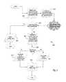
- FIG. 5is a flow chart illustrating a method for performing a verification using the secure challenge and response process of the embodiment illustrated in FIG. 4 .
- FIG. 6is a flow chart illustrating another method for performing a verification using the secure challenge and response process of the embodiment illustrated in FIG. 4 .
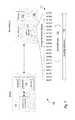
- FIG. 7is a functional block diagram generally illustrating an embodiment in which an accessory is configured to authenticate itself to a host medical device.
- embodimentsare directed to an accessory for a host medical device that is capable of authenticating itself to the host medical device.
- the accessoryincludes an onboard facility for authenticating the accessory to the host medical device.
- Various embodiments of the accessoryenable it to validate itself to the host medical device without the host medical device reading any stored information from the accessory.
- FIG. 1is a diagram of a defibrillation scene.
- a person 82is lying supine. Person 82 could be a patient in a hospital, or someone found unconscious and turned on his or her back. Person 82 is experiencing a condition in their heart 85 , which could be Ventricular Fibrillation (VF).
- VFVentricular Fibrillation
- a portable external defibrillator 100has been brought close to person 82 .
- At least two defibrillation electrodes 104 , 108are usually provided with external defibrillator 100 .
- Electrodes 104 , 108are coupled with external defibrillator 100 via respective electrode leads 105 , 109 .
- a rescuer(not shown) has attached electrodes 104 , 108 to the skin of person 82 .
- Defibrillator 100is administering, via electrodes 104 , 108 , a brief, strong electric pulse 111 through the body of person 82 .
- Pulse 111includes a defibrillation shock, goes also through a heart 85 , in an attempt to restart it, for saving the life of person 82 .
- Defibrillator 100can be one of different types, each with different sets of features and capabilities. The set of capabilities of defibrillator 100 is determined by planning who would use it, and what training a user would be
- the electrodes 104 , 105may be perishable items with a limited shelf life, which is shorter than the shelf life of the defibrillator 100 . For that and other reasons, there may come a time when the electrodes 104 , 108 require replacement. However, defibrillator 100 is approved for use only in conjunction with the proper accessories, such as the proper electrodes 104 , 108 . Accordingly, a mechanism is implemented to confirm that new accessories, such as electrodes 104 , 108 are approved for use with the defibrillator 100 .
- FIG. 2is a functional block diagram generally illustrating an embodiment 200 in which an accessory 201 is configured to authenticate itself to a host medical device 221 .
- accessory 201include electrode, probe, point of care labs, video laryngoscope or other device which may be connected to a medical device.
- Examples of a host medical device 221include a defibrillator, a monitor, CPR assist device, or the like.
- the accessory attachment to the hostmay be either wired or non-wired.
- the accessory attachmentmay be wired.
- the accessorymay be self-powered.
- the accessory 201includes an authenticator 203 and a memory 205 .
- the memory 205further includes a “secret” 207 .
- the authenticator 203may be a special purpose component configured to perform a secure authentication to a remote device, such as host medical device 221 .
- the authenticator 203is configured to perform a challenge/response type authentication using a shared secret.
- the secret 207 stored within memory 205may be a lengthy binary number, hexadecimal number, or other alphanumeric value sufficiently distinct that it is computationally difficult to predict.
- the host medical device 221includes a controller 223 , which further includes a processor 225 and a central memory 227 .
- the controller 223operates in an ordinary manner to perform the normal operations of host medical device 221 .
- processor 225retrieves and stores information from and to the central memory 227 in furtherance of the operation of the host medical device 221 .
- the host medical device 221also includes an authenticator co-processor 231 and an authenticator memory 235 .
- the authenticator co-processor 231 in this embodimentfurther includes a random number generator (RNG) 233 .
- RNGrandom number generator
- the authenticatoris configured to perform a secure challenge/response type authentication with a remote device, such as accessory 201 , using a shared secret.
- the authenticator memory 235includes a data store 237 of one or more secrets.
- the secret(s)may each be a lengthy binary number, hexadecimal number, or other alphanumeric value sufficiently distinct that it is computationally difficult to predict.
- this embodimentcould be implemented using, for example, a “DeepCover Secure Authenticator with SHA-256 Coprocessor and 1-Wire Master Function” (part number DS2465) as the authenticator co-processor 231 , and a “DeepCover Secure Authenticator with 1-Wire SHA-256 and 4 Kb User EEPROM” (part number DS28E25) as the accessory authenticator 203 .
- Both partsare available from Maxim Integrated Products, Inc. of San Jose, Calif.
- One advantage realized by these specific componentsis the ability to avoid including an additional power connector and to rely on a simple one-wire interface.
- Another advantage of using a dedicated authentication co-processor on the host medical device 221is that it reduces the processing overhead on the main processor 225 .
- each of the host 221 and accessory 201is preprogrammed with at least one shared secret.
- the accessory 201when the accessory 201 is manufactured, it is programmed with a given “secret” value (secret 207 ).
- secret 207could be a value unique to only that one specific accessory 201 , or it could be a value unique to a particular model of accessory, or it could simply be a value assigned by the manufacturer and known only to the manufacturer.
- the secretcan be associated with a date or date range so that the manufacturer could discern when the accessory was created by knowing the particular secret programmed into the accessory 201 . It should be appreciated that although conceivably possible through extraordinary means, as a practical matter the secret 207 cannot be directly retrieved or read from the accessory 201 .
- each secret assigned by the manufacturercould also be associated with a feature set for an accessory.
- the host medical device 221when the host medical device 221 is manufactured, it is programmed with at least one, and likely many, authentication secrets. More specifically, as noted above, a manufacturer may assign numerous secrets to numerous accessories (the “possible secrets”). Each possible secret is associated with a particular date or date range and may also be associated with a feature set for a particular accessory.
- each secretis simply a value assigned by the manufacturer to indicate that any accessory containing that value is an authentic product from the manufacturer.
- each secretis also associated with at least one date, such as a date of manufacture or a date of expiration.
- each particular secretmay also correspond to a particular model of accessory and perhaps even a feature set of that model. For instance, the secret found in row 301 of table 300 may be associated with accessory model 0001, having feature set XYZ, and expiration date of October, 2014.
- the secret found in row 302also corresponds to accessory model 0001; however, the expiration date for the secret in row 302 is November, 2014 and the feature set is DCU. Thus, an accessory bearing the secret in row 301 will expire roughly one month later than an accessory bearing the secret in row 302 .
- table 300may be preprogrammed at the time of the manufacture of the host medical device 221 with sufficient secrets to last the expected lifetime of the host medical device.
- the host medical device 221may have a smaller table 300 and a communication capability such as wired Internet connectivity, cellular or Wi-Fi connectivity, etc.
- the host medical device 221can determine the current date and based on the expected lifetime of the accessories retrieve additional secrets as needed via the communication capability.
- the host medical device 221may include a port such as a USB or Firewire port and be configured to allow manual updates of the table 300 via the port during periodic maintenance of the medical device.
- a set of possible secretsis stored in the authentication memory 227 of the host medical device 221 .
- the set that is stored in the host medical device 221corresponds to accessories that are approved replacements for use with the host medical device 221 (the “valid secrets”).
- the secrets found in rows 307 and 308may be omitted from the set of valid secrets stored in the authentication memory 227 of the host medical device 221 .
- the secret found in row 302may also be excluded from the set of valid secrets stored in the authentication memory 227 .
- the accessory 201authenticates itself to the host medical device 221 .
- such authenticationoccurs as a challenge/response secure authentication between the authenticator 203 of the accessory 201 and the authenticator co-processor 231 of the host medical device 221 .
- the accessory 201is connected to the host medical device 221 , the authenticator co-processor 231 initiates the authentication by providing to the authenticator 203 some seed value, such as a pseudo random value generated by random number generator 233 .
- the seedis considered pseudo random because it may be created in such a manner that it cannot be recreated later.
- the pseudo random valuemay be generated in such a way that it would not be a valid value if created at a later date (e.g., by being partially based on the current date).
- Such a featurehelps reduce the possibility that the challenge/response authentication scheme could be copied and reproduced later by an unauthorized device.
- the host medical device 221provides the seed value to the authenticator 203 of the accessory.
- the authenticator 203then creates a Message Authentication Code (“MAC”) value based on the seed value from the host in combination with the accessory's stored secret 207 .
- the MAC valueis created using a hashing algorithm (e.g., the SHA-256 hashing algorithm) on a combination of the seed value and the accessory's stored secret 207 .
- a hashing algorithmcreates a unique hash value for every different input data.
- a hash of the stored secret 207will always return the same hash value provided the same hashing algorithm is used.
- MAChash value
- the authenticator 203returns the MAC to the host medical device 221 .
- the authenticator co-processor 231then performs its own hash of the seed value (which the host created) with each of the valid secrets 237 stored in the authentication memory 235 . Again, because the authenticator co-processor 231 uses the same hashing algorithm as the authenticator 203 , the authenticator co-processor 231 will be able to recreate the same MAC by hashing the known seed in combination with the stored valid secrets 237 . If a comparison of the MAC returned from the accessory 201 results in a match with any MAC locally created by the authenticator co-processor 231 from valid stored secrets, then the host medical device 221 accepts that the accessory 201 is an authorized accessory 201 .
- the host medical device 221rejects the accessory 201 as being unauthorized.
- unauthorizedcould mean that the accessory is simply out of date (expired).
- unauthorizedcould mean that the accessory 201 was not manufactured by an authorized manufacturer.
- the authenticator 203could initiate the authentication scheme by volunteering to the host both a seed value which is pseudo randomly generated on the accessory (rather than on the host) with the MAC so that the host need not generate the seed value first.
- the seed valuemay be completely randomly generated without regard to repeatability.
- the host medical device 221can confirm that the accessory 201 is an appropriate replacement without directly reading any stored information on the accessory 201 . Rather, the entire authentication process is performed securely and in a way that is not easily spoofed by counterfeiters. In addition, substantially more information (e.g., accessory model number and/or feature set) can be discerned about the accessory based on nothing more than a priori knowledge that corresponds with each stored secret.
- the accessorydoes not include a memory for storing data accessible by a host, but rather the accessory can include a register or other mechanism to store the secret.
- the secretcan be programmed directly into the authenticator in a tamper-resistant manner.
- Another potential advantage of this embodimentis that it would be difficult for an unauthorized dealer to take an expired accessory and modify the secret in the accessory to make the expired accessory appear unexpired. In medical device applications, preventing use of expired accessories can be an important safety concern.
- FIG. 4is a functional block diagram generally illustrating an embodiment 400 in which an accessory 401 is configured to authenticate itself to a host medical device 421 .
- the accessory 401is essentially “smarter” than the accessory 201 of the embodiment illustrated in FIG. 2 by virtue of a microprocessor 411 included directly in the accessory 401 in addition to an authenticator 403 .
- the embodiment 400may perform a challenge/response authentication in the manner described above.
- the addition of the microprocessor 411 directly on the accessory 401enables enhanced functionality beyond (or in addition to) the functionality described in connection with the embodiment 200 shown in FIG. 2 .
- FIG. 4Shown in FIG. 4 is an optional wireless connection facility embodied as a host wireless connection 439 and an accessory wireless connection 419 . These two connections may operate in tandem to enable the host medical device 421 and the accessory 401 to communicate without a wired interface.
- the wireless connectionscan operate using any wireless technology, such as Wi-Fi, Bluetooth, cellular (e.g., HSPA or LTE), or the like. Although shown only in FIG. 4 , it should be appreciated that the wireless connection facility could equally be implemented in any other embodiment.
- the enhanced processing capability of the microprocessor 411enables intelligent communication between the host medical device 421 and the accessory 401 .
- a simpler authentication between the host medical device 421 and the accessory 401may be used merely to confirm the authenticity of the accessory 401 to establish a trusted relationship between the two.
- the accessory 401may perform onboard computations and interact with the host medical device 421 intelligently. For example, a large number of shared secrets that burden the host medical device 421 would not be required. Rather, as few as one shared secret would be necessary to establish that the accessory 401 was in fact authentic and made by or for the manufacturer. Once so authenticated, information received by the host medical device 421 from the accessory 401 could be trusted implicitly, eliminating any need to overload the shared secret with other ancillary information.
- the accessory 401could simply verify whether it was expired or if it were an appropriate accessory for the host medical device 421 . For instance, to verify expiry, the host medical device 421 could simply provide the current date to the processor 411 of the accessory 401 . The processor 401 could then query information, such as date of expiration or date of manufacture, stored in a memory 413 on the accessory 401 . With that comparison done on the accessory 401 , the processor could simply return a yes/no result to the host medical device 421 to confirm whether the accessory 401 has expired or the number of days remaining until expiration. Since the accessory 401 has already been authenticated, the response from the accessory can be trusted by the host medical device 421 .
- FIG. 5a method 500 is shown to illustrate one example verification, which may be performed using the secure challenge and response process of this embodiment.
- hostauthenticates electrode using secure challenge/response process
- accessorycompares current date to expiration date
- accessoryresponds appropriately, such as “expired”, “unexpired”, the remaining days of “life”, etc.
- the hostinitiates an authentication with the accessory and computes a message authentication code (MAC) based on data and a secret (step 501 ). If host cannot verify the MAC (step 503 ), the authentication fails and the user may be notified (step 505 ). If the accessory is deemed authentic (step 503 ) the host will send to the accessory the current date (step 507 ). The accessory then determines whether the accessory is expired by comparing (step 509 ) the current date (from the host) with stored information about when it expires or, perhaps, when the accessory was created together with information about how long the accessory is valid. Based on whether the accessory has expired (step 511 ) or has not expired (step 513 ), the accessory will report the proper response to the host.
- MACmessage authentication code
- the hostcan notify the user whether the accessory is authentic, expired (if applicable) and other useful data such as, perhaps, preprocessed functionality (step 515 ).
- the host medical devicemay optionally disable certain or all operations that would otherwise make use of the accessory.
- FIG. 6another method 600 is shown to illustrate another example verification, which may be performed using the secure challenge and response process of this embodiment.
- This method 600differs from the method 500 shown in FIG. 5 in that at least part of the authentication is performed remotely, such as in the “cloud” or at a remote network location.
- the hostinitiates an authentication with the accessory and computes a message authentication code (MAC) based on data and a secret (step 601 ).
- the hosttransmits the MAC to a cloud-based service to perform the authentication (step 602 ).
- the hostreceives a response from the cloud-based service indicating either that the MAC is authorized or not (step 603 ). If the response indicates that the authentication fails the user may be notified (step 605 ). If the response indicates that the accessory is deemed authentic (step 603 ) the host will send to the accessory the current date (step 607 ).
- the accessorydetermines whether the accessory is expired by comparing (step 609 ) the current date (from the host) with stored information about when it expires or, perhaps, when the accessory was created together with information about how long the accessory is valid. Based on whether the accessory has expired (step 611 ) or has not expired (step 613 ), the accessory will report the proper response to the host. The host can notify the user whether the accessory is authentic, expired (if applicable) and other useful data such as, perhaps, preprocessed functionality (step 615 ).
- FIG. 7is a functional block diagram generally illustrating a further embodiment 700 in which an accessory 701 is configured to authenticate itself to a host medical device 721 .
- the accessory 701generally operates in a manner similar to either the embodiment 200 shown in FIG. 2 or the embodiment 400 shown in FIG. 4 to authenticate itself to the host medical device 721 .
- the host medical device 721 and the accessory 701employ a form of address decoder 715 to determine whether the accessory 701 is expired. More specifically, once authenticated such that responses returned to the host medical device 721 from the accessory 701 are trusted, the host medical device 721 (via controller 723 ) posts a pseudo “address” to the address decoder 715 .
- the “address”may be a value (e.g., binary or hexadecimal) that decodes into a virtual address space wherein the virtual address locations correspond to particular information.
- Virtual address space mappinggenerally, is well known in the art.
- the address decoder 715maps the “address” provided by the host medical device 721 into a virtual address space 717 .
- the entire range of addresses in the virtual address space 717constitutes the range of possible or available addresses 718 that could be identified by the host medical device 721 .
- only a sub space (valid addresses 719 ) of the available addresses 718correspond to data which is valid for the accessory 701 .
- a memory 705may include the data which corresponds to valid addresses 719 .
- the data stored in memory 705may constitute a range of dates through which the accessory 701 may properly be used.
- the available addresses 718 within the virtual address space 717could represent a range of dates from some given start date until a date in the distant future.
- the valid addresses 719may correspond to only those dates for which the accessory 701 is unexpired.
- the host medical device 721may post an address value to the address decoder where that address value corresponds to the current date.
- the address decoder 715decodes the address value into the virtual address space 717 to determine whether it maps into the valid addresses 718 .
- the accessory 701If not, then the accessory 701 returns an error or other code indicating that the accessory 701 is not valid given the current date. Alternatively, the accessory 701 could compute the difference between the current date and the extent of the valid addresses 718 (i.e., the final valid date) to determine the remaining life of the accessory 701 .
- One potential advantage of this embodimentis that when combined with a conventional authentication scheme, it would be difficult for an unauthorized dealer to take an expired accessory and modify the address decoder 715 to change the expiration date to make the expired accessory appear unexpired. In medical device applications, preventing use of expired accessories can be an important safety concern.
Landscapes
- Engineering & Computer Science (AREA)
- Health & Medical Sciences (AREA)
- Public Health (AREA)
- Veterinary Medicine (AREA)
- Biomedical Technology (AREA)
- Nuclear Medicine, Radiotherapy & Molecular Imaging (AREA)
- Radiology & Medical Imaging (AREA)
- Life Sciences & Earth Sciences (AREA)
- Animal Behavior & Ethology (AREA)
- General Health & Medical Sciences (AREA)
- Theoretical Computer Science (AREA)
- Computer Security & Cryptography (AREA)
- Software Systems (AREA)
- Heart & Thoracic Surgery (AREA)
- Computer Hardware Design (AREA)
- Physics & Mathematics (AREA)
- General Engineering & Computer Science (AREA)
- General Physics & Mathematics (AREA)
- Cardiology (AREA)
- Measurement Of The Respiration, Hearing Ability, Form, And Blood Characteristics Of Living Organisms (AREA)
- Medical Treatment And Welfare Office Work (AREA)
- Infusion, Injection, And Reservoir Apparatuses (AREA)
Abstract
Description
Claims (28)
Priority Applications (2)
| Application Number | Priority Date | Filing Date | Title |
|---|---|---|---|
| US14/523,727US9916436B2 (en) | 2014-10-24 | 2014-10-24 | Intelligent accessories for medical devices |
| US15/918,888US10839068B2 (en) | 2014-10-24 | 2018-03-12 | Medical devices with intelligent accessories |
Applications Claiming Priority (1)
| Application Number | Priority Date | Filing Date | Title |
|---|---|---|---|
| US14/523,727US9916436B2 (en) | 2014-10-24 | 2014-10-24 | Intelligent accessories for medical devices |
Related Child Applications (1)
| Application Number | Title | Priority Date | Filing Date |
|---|---|---|---|
| US15/918,888ContinuationUS10839068B2 (en) | 2014-10-24 | 2018-03-12 | Medical devices with intelligent accessories |
Publications (2)
| Publication Number | Publication Date |
|---|---|
| US20160117496A1 US20160117496A1 (en) | 2016-04-28 |
| US9916436B2true US9916436B2 (en) | 2018-03-13 |
Family
ID=55792216
Family Applications (2)
| Application Number | Title | Priority Date | Filing Date |
|---|---|---|---|
| US14/523,727Active2034-11-26US9916436B2 (en) | 2014-10-24 | 2014-10-24 | Intelligent accessories for medical devices |
| US15/918,888Active2035-05-16US10839068B2 (en) | 2014-10-24 | 2018-03-12 | Medical devices with intelligent accessories |
Family Applications After (1)
| Application Number | Title | Priority Date | Filing Date |
|---|---|---|---|
| US15/918,888Active2035-05-16US10839068B2 (en) | 2014-10-24 | 2018-03-12 | Medical devices with intelligent accessories |
Country Status (1)
| Country | Link |
|---|---|
| US (2) | US9916436B2 (en) |
Cited By (3)
| Publication number | Priority date | Publication date | Assignee | Title |
|---|---|---|---|---|
| US20210146147A1 (en)* | 2019-11-19 | 2021-05-20 | Physio-Control, Inc. | Electrode connector |
| US11331506B2 (en) | 2020-01-17 | 2022-05-17 | Physio-Control, Inc. | Transfer of cardiac arrest data between defibrillators |
| US11490855B2 (en) | 2019-12-27 | 2022-11-08 | Physio-Control, LLC | Methods and systems for monitoring and delivering therapy to a patient including a detachable adaptor for a monitor module |
Families Citing this family (9)
| Publication number | Priority date | Publication date | Assignee | Title |
|---|---|---|---|---|
| US10367803B2 (en)* | 2015-04-12 | 2019-07-30 | Gropper Adrian | Managed open source medical devices |
| CN109196300B (en)* | 2016-05-13 | 2021-05-28 | 均胜安全系统收购有限责任公司 | Intelligent detonator assembly |
| US10395231B2 (en)* | 2016-06-27 | 2019-08-27 | Altria Client Services Llc | Methods, systems, apparatuses, and non-transitory computer readable media for validating encoded information |
| US20240180499A1 (en)* | 2017-01-04 | 2024-06-06 | Hill-Rom Services, Inc. | Patient support apparatus having vital signs monitoring and alerting |
| DE102020106631A1 (en)* | 2020-03-11 | 2021-09-16 | Hoya Corporation | Lock function for a mobile device |
| US12189832B2 (en)* | 2020-08-20 | 2025-01-07 | Micron Technology, Inc. | Safety and security for memory |
| WO2023065268A1 (en)* | 2021-10-22 | 2023-04-27 | 碧波庭国际有限公司 | Massage apparatus and verification method therefor |
| US20230131744A1 (en)* | 2021-10-27 | 2023-04-27 | Biboting International Co., Ltd. | Massage apparatus and authentication method thereof |
| CN114780947A (en)* | 2022-05-11 | 2022-07-22 | 深圳市联普医疗科技有限公司 | Anti-counterfeiting system for medical product accessories |
Citations (39)
| Publication number | Priority date | Publication date | Assignee | Title |
|---|---|---|---|---|
| US5321392A (en) | 1991-10-18 | 1994-06-14 | Baxter International Inc. | Infusion pump with battery back-up |
| US5697955A (en) | 1996-05-10 | 1997-12-16 | Survivalink Corporation | Defibrillator electrodes and date code detector circuit |
| US5702431A (en) | 1995-06-07 | 1997-12-30 | Sulzer Intermedics Inc. | Enhanced transcutaneous recharging system for battery powered implantable medical device |
| US5721482A (en) | 1996-01-16 | 1998-02-24 | Hewlett-Packard Company | Intelligent battery and method for providing an advance low battery warning for a battery powered device such as a defibrillator |
| US5939856A (en) | 1997-05-30 | 1999-08-17 | Motorola, Inc. | Battery and charging system using switchable coding devices |
| US6072229A (en) | 1994-10-19 | 2000-06-06 | Telefonaktiebolaget Lm Ericsson | Leadframe for an encapsulated optocomponent |
| US6072299A (en) | 1998-01-26 | 2000-06-06 | Medtronic Physio-Control Manufacturing Corp. | Smart battery with maintenance and testing functions |
| US6101413A (en) | 1996-06-04 | 2000-08-08 | Survivalink Corporation | Circuit detectable pediatric defibrillation electrodes |
| US6127063A (en) | 1998-01-26 | 2000-10-03 | Physio-Control Manufacturing Corporation | Intelligent battery and well interface |
| US6181102B1 (en) | 1998-11-13 | 2001-01-30 | Agilent Technologies, Inc. | Battery pack chemistry detection and identification system and method |
| US6223077B1 (en) | 1998-01-26 | 2001-04-24 | Physio-Control Manufacturing Corporation | Automatic power switching in a defibrillator |
| US6246907B1 (en) | 1999-12-01 | 2001-06-12 | Cardiacscience, Inc. | Automatic external cardioverter/defibrillator with cardiac rate detector and method of operating the same |
| US6249105B1 (en) | 1998-11-13 | 2001-06-19 | Neal Andrews | System and method for detecting performance components of a battery pack |
| US6291966B1 (en) | 1999-01-27 | 2001-09-18 | Telefonaktiebolaget Lm Ericsson | Method and an apparatus for storing and communicating battery information |
| US6397104B1 (en) | 1999-07-16 | 2002-05-28 | Koninklijke Philips Electronics N.V. | Defibrillation system having defibrillator with replaceable supply module |
| US6438415B1 (en) | 1999-10-01 | 2002-08-20 | Daniel J Powers | Method and apparatus for controlling the operation and functionality of an electrotherapy device |
| US6560485B2 (en) | 2001-03-27 | 2003-05-06 | Koninklijke Philips Electronics N.V. | Four contact identification defibrillator electrode system |
| US20030195581A1 (en) | 1999-07-30 | 2003-10-16 | Meadows Paul M. | Implantable devices using rechargeable zero-volt technology lithium-ion batteries |
| US6639381B2 (en) | 2001-10-26 | 2003-10-28 | Medtronic Physio-Control Corp. | Defibrillator with replaceable and rechargeable power packs |
| US6690959B2 (en) | 2000-09-01 | 2004-02-10 | Medtronic, Inc. | Skin-mounted electrodes with nano spikes |
| US20040039257A1 (en) | 2002-05-16 | 2004-02-26 | Scott Laboratories, Inc. And Pto | User authorization system and method for a sedation and analgesia system |
| US20040049685A1 (en)* | 2001-03-14 | 2004-03-11 | Laszlo Jaloveczki | Authorisation method for a user of a limited access system having an authorisation centre |
| KR20040095307A (en) | 2002-03-22 | 2004-11-12 | 코닌클리케 필립스 일렉트로닉스 엔.브이. | Automated external defibrillator with a plurality of power sources |
| US6873133B1 (en) | 2002-09-11 | 2005-03-29 | Medtronic Physio-Control Manufacturing Corporation | Defibrillator with a reconfigurable battery module |
| US20050113877A1 (en)* | 2003-03-31 | 2005-05-26 | Medtronic, Inc. | Method, system and device for treating disorders of the pelvic floor by means of electrical stimulation of the pudenal and associated nerves, and the optional delivery of drugs in association therewith |
| US6972542B2 (en) | 2003-08-11 | 2005-12-06 | Motorola, Inc. | System and method for battery verification |
| US20060178170A1 (en) | 2005-02-08 | 2006-08-10 | Samsung Electronics Co., Ltd. | Wireless communication device having battery authentication, and associated method |
| WO2006102420A2 (en) | 2005-03-21 | 2006-09-28 | Defibtech, Llc | Pcb blade connector system and method |
| CN1859946A (en) | 2003-09-30 | 2006-11-08 | 皇家飞利浦电子股份有限公司 | Identification system for defibrillator electrode package |
| US20070143864A1 (en) | 2005-12-15 | 2007-06-21 | Symbol Technologies, Inc. | Methods and apparatus for power source authentication |
| US7250612B2 (en) | 2005-09-28 | 2007-07-31 | General Electric Company | Devices and methods capable of authenticating batteries |
| US20080077185A1 (en) | 2003-12-17 | 2008-03-27 | Christopher Pearce | Defibrillator/Monitor System Having a Pod with Leads Capable of Wirelessly Communicating |
| US20080140163A1 (en) | 2006-12-06 | 2008-06-12 | Keacher Jeffrey T | Telemetry device for a medical device programmer |
| US7728548B2 (en) | 2008-06-02 | 2010-06-01 | Physio-Control, Inc. | Defibrillator battery authentication system |
| US20100198287A1 (en) | 2008-06-02 | 2010-08-05 | Physio-Control, Inc. | Selective recharging of medical device depending on authentication of power adapter system |
| US20100198286A1 (en) | 2008-06-02 | 2010-08-05 | Physio-Control, Inc. | Selective powering of medical device depending on authentication of power adapter system |
| US8229562B2 (en) | 2006-10-25 | 2012-07-24 | Codman NeuroSciences Sárl | Universal external control device for use by multiple conditional access users with varying access to functionality of an implantable medical device |
| US20120197324A1 (en)* | 2008-06-02 | 2012-08-02 | Physio-Control, Inc. | Medical device adjusting operation when used with non-authenticated patient parameter collecting accessory |
| US8265748B2 (en) | 2008-03-13 | 2012-09-11 | Shenzhen Mindray Bio-Medical Electronics Co., Ltd. | Defibrillator with a normalized electrode interface and defibrillating electrode |
- 2014
- 2014-10-24USUS14/523,727patent/US9916436B2/enactiveActive
- 2018
- 2018-03-12USUS15/918,888patent/US10839068B2/enactiveActive
Patent Citations (54)
| Publication number | Priority date | Publication date | Assignee | Title |
|---|---|---|---|---|
| US5321392A (en) | 1991-10-18 | 1994-06-14 | Baxter International Inc. | Infusion pump with battery back-up |
| US6072229A (en) | 1994-10-19 | 2000-06-06 | Telefonaktiebolaget Lm Ericsson | Leadframe for an encapsulated optocomponent |
| US5702431A (en) | 1995-06-07 | 1997-12-30 | Sulzer Intermedics Inc. | Enhanced transcutaneous recharging system for battery powered implantable medical device |
| US5721482A (en) | 1996-01-16 | 1998-02-24 | Hewlett-Packard Company | Intelligent battery and method for providing an advance low battery warning for a battery powered device such as a defibrillator |
| US5697955A (en) | 1996-05-10 | 1997-12-16 | Survivalink Corporation | Defibrillator electrodes and date code detector circuit |
| US6101413A (en) | 1996-06-04 | 2000-08-08 | Survivalink Corporation | Circuit detectable pediatric defibrillation electrodes |
| US5939856A (en) | 1997-05-30 | 1999-08-17 | Motorola, Inc. | Battery and charging system using switchable coding devices |
| US6223077B1 (en) | 1998-01-26 | 2001-04-24 | Physio-Control Manufacturing Corporation | Automatic power switching in a defibrillator |
| US6072299A (en) | 1998-01-26 | 2000-06-06 | Medtronic Physio-Control Manufacturing Corp. | Smart battery with maintenance and testing functions |
| US6127063A (en) | 1998-01-26 | 2000-10-03 | Physio-Control Manufacturing Corporation | Intelligent battery and well interface |
| US6249105B1 (en) | 1998-11-13 | 2001-06-19 | Neal Andrews | System and method for detecting performance components of a battery pack |
| US6181102B1 (en) | 1998-11-13 | 2001-01-30 | Agilent Technologies, Inc. | Battery pack chemistry detection and identification system and method |
| US6291966B1 (en) | 1999-01-27 | 2001-09-18 | Telefonaktiebolaget Lm Ericsson | Method and an apparatus for storing and communicating battery information |
| US6397104B1 (en) | 1999-07-16 | 2002-05-28 | Koninklijke Philips Electronics N.V. | Defibrillation system having defibrillator with replaceable supply module |
| US20030195581A1 (en) | 1999-07-30 | 2003-10-16 | Meadows Paul M. | Implantable devices using rechargeable zero-volt technology lithium-ion batteries |
| US6438415B1 (en) | 1999-10-01 | 2002-08-20 | Daniel J Powers | Method and apparatus for controlling the operation and functionality of an electrotherapy device |
| US6246907B1 (en) | 1999-12-01 | 2001-06-12 | Cardiacscience, Inc. | Automatic external cardioverter/defibrillator with cardiac rate detector and method of operating the same |
| US6690959B2 (en) | 2000-09-01 | 2004-02-10 | Medtronic, Inc. | Skin-mounted electrodes with nano spikes |
| US20040049685A1 (en)* | 2001-03-14 | 2004-03-11 | Laszlo Jaloveczki | Authorisation method for a user of a limited access system having an authorisation centre |
| US6560485B2 (en) | 2001-03-27 | 2003-05-06 | Koninklijke Philips Electronics N.V. | Four contact identification defibrillator electrode system |
| US6639381B2 (en) | 2001-10-26 | 2003-10-28 | Medtronic Physio-Control Corp. | Defibrillator with replaceable and rechargeable power packs |
| US7095210B2 (en) | 2001-10-26 | 2006-08-22 | Medtronic Emergency Response Systems, Inc. | Defibrillator power source with replaceable and rechargeable power packs |
| KR20040095307A (en) | 2002-03-22 | 2004-11-12 | 코닌클리케 필립스 일렉트로닉스 엔.브이. | Automated external defibrillator with a plurality of power sources |
| US20040039257A1 (en) | 2002-05-16 | 2004-02-26 | Scott Laboratories, Inc. And Pto | User authorization system and method for a sedation and analgesia system |
| US6873133B1 (en) | 2002-09-11 | 2005-03-29 | Medtronic Physio-Control Manufacturing Corporation | Defibrillator with a reconfigurable battery module |
| US20050113877A1 (en)* | 2003-03-31 | 2005-05-26 | Medtronic, Inc. | Method, system and device for treating disorders of the pelvic floor by means of electrical stimulation of the pudenal and associated nerves, and the optional delivery of drugs in association therewith |
| US6972542B2 (en) | 2003-08-11 | 2005-12-06 | Motorola, Inc. | System and method for battery verification |
| US7689278B2 (en) | 2003-09-30 | 2010-03-30 | Koninklijke Philips Electronics, N.V. | Identification system for defibrillator electrode package |
| CN1859946A (en) | 2003-09-30 | 2006-11-08 | 皇家飞利浦电子股份有限公司 | Identification system for defibrillator electrode package |
| US20070112389A1 (en) | 2003-09-30 | 2007-05-17 | Koninklijke Philips Electronics N.V. | Identification system for defibrillator electrode package |
| US20080077185A1 (en) | 2003-12-17 | 2008-03-27 | Christopher Pearce | Defibrillator/Monitor System Having a Pod with Leads Capable of Wirelessly Communicating |
| US20060178170A1 (en) | 2005-02-08 | 2006-08-10 | Samsung Electronics Co., Ltd. | Wireless communication device having battery authentication, and associated method |
| US20130066389A1 (en) | 2005-03-21 | 2013-03-14 | Gintaras A. Vaisnys | PCB Blade Connector System and Method |
| US8774916B2 (en) | 2005-03-21 | 2014-07-08 | Defibtech, Llc | PCB blade connector system and method |
| US20060259081A1 (en) | 2005-03-21 | 2006-11-16 | Defibtech, Llc | PCB blade connector system and method |
| US7912543B2 (en) | 2005-03-21 | 2011-03-22 | Defibtech, Llc | PCB blade connector system and method |
| US20090187225A1 (en) | 2005-03-21 | 2009-07-23 | Defibtech, Llc | PCB blade connector system and method |
| US20090233458A1 (en) | 2005-03-21 | 2009-09-17 | Defibtech, Llc | PCB blade connector system and method |
| WO2006102420A2 (en) | 2005-03-21 | 2006-09-28 | Defibtech, Llc | Pcb blade connector system and method |
| US8280506B2 (en) | 2005-03-21 | 2012-10-02 | Defibtech, Llc | PCB blade connector system and method |
| US20100168811A1 (en) | 2005-03-21 | 2010-07-01 | Defibtech, Llc | Identifying the Usage Status of a Defibrillation Pad Assembly |
| US20100174332A1 (en) | 2005-03-21 | 2010-07-08 | Defibtech, Llc | Automatic external defibrillator with defibrillator pad assembly usage memory |
| US8185197B2 (en) | 2005-03-21 | 2012-05-22 | Defibtech, Llc | Identifying the usage status of a defibrillation pad assembly |
| US8185196B2 (en) | 2005-03-21 | 2012-05-22 | Defibtech, Llc | PCB blade connector system and method |
| US7250612B2 (en) | 2005-09-28 | 2007-07-31 | General Electric Company | Devices and methods capable of authenticating batteries |
| US20070143864A1 (en) | 2005-12-15 | 2007-06-21 | Symbol Technologies, Inc. | Methods and apparatus for power source authentication |
| US8229562B2 (en) | 2006-10-25 | 2012-07-24 | Codman NeuroSciences Sárl | Universal external control device for use by multiple conditional access users with varying access to functionality of an implantable medical device |
| US20080140163A1 (en) | 2006-12-06 | 2008-06-12 | Keacher Jeffrey T | Telemetry device for a medical device programmer |
| US8265748B2 (en) | 2008-03-13 | 2012-09-11 | Shenzhen Mindray Bio-Medical Electronics Co., Ltd. | Defibrillator with a normalized electrode interface and defibrillating electrode |
| US8406874B2 (en) | 2008-03-13 | 2013-03-26 | Shenzhen Mindray Bio-Medical Electronics Co., Ltd. | Defibrillator with a normalized electrode interface and defibrillating electrode |
| US20100198286A1 (en) | 2008-06-02 | 2010-08-05 | Physio-Control, Inc. | Selective powering of medical device depending on authentication of power adapter system |
| US20100198287A1 (en) | 2008-06-02 | 2010-08-05 | Physio-Control, Inc. | Selective recharging of medical device depending on authentication of power adapter system |
| US20120197324A1 (en)* | 2008-06-02 | 2012-08-02 | Physio-Control, Inc. | Medical device adjusting operation when used with non-authenticated patient parameter collecting accessory |
| US7728548B2 (en) | 2008-06-02 | 2010-06-01 | Physio-Control, Inc. | Defibrillator battery authentication system |
Non-Patent Citations (4)
| Title |
|---|
| International Preliminary Report on Patentability, Patent Cooperation Treaty, dated Dec. 2, 2010, 11 pages, PCT/US2009/045943, European Patent Office. |
| International Search Report, Patent Cooperation Treaty, May 3, 2010, 4 pages, PCT/US2009/045943, European Office Patent. |
| Response to Written Opinion for PCT/US2009/045943 filed Aug. 2, 2010. |
| Written Opinion, Patent Cooperation Treaty, Dec. 2, 2010, 6 pages, PCT/US2009/045943, European Patent Office. |
Cited By (5)
| Publication number | Priority date | Publication date | Assignee | Title |
|---|---|---|---|---|
| US20210146147A1 (en)* | 2019-11-19 | 2021-05-20 | Physio-Control, Inc. | Electrode connector |
| US12208274B2 (en)* | 2019-11-19 | 2025-01-28 | Physio-Control, Inc. | Electrode connector |
| US11490855B2 (en) | 2019-12-27 | 2022-11-08 | Physio-Control, LLC | Methods and systems for monitoring and delivering therapy to a patient including a detachable adaptor for a monitor module |
| US11331506B2 (en) | 2020-01-17 | 2022-05-17 | Physio-Control, Inc. | Transfer of cardiac arrest data between defibrillators |
| US11759648B2 (en) | 2020-01-17 | 2023-09-19 | Physio-Control, Inc. | Transfer of cardiac arrest data between defibrillators |
Also Published As
| Publication number | Publication date |
|---|---|
| US20180203993A1 (en) | 2018-07-19 |
| US20160117496A1 (en) | 2016-04-28 |
| US10839068B2 (en) | 2020-11-17 |
Similar Documents
| Publication | Publication Date | Title |
|---|---|---|
| US10839068B2 (en) | Medical devices with intelligent accessories | |
| JP7190238B2 (en) | Delivery and data sharing of clinical data in equipment management | |
| US20250049375A1 (en) | Platform for secure communications with medical device | |
| US12233273B2 (en) | Permission-based control of interfacing components with a medical device | |
| US8347365B2 (en) | System and method for confirming identity and authority by a patient medical device | |
| US8588912B2 (en) | System and method for remotely programming a patient medical device | |
| US20150089590A1 (en) | Methods for secure control of and secure data extraction from implantable medical devices using smartphones or other mobile devices | |
| CN113396599A (en) | Establishing a secure communication link between an implanted device and one or more external devices | |
| ES2700476T3 (en) | Procedure for the control, which requires authorizations referred to the user, of an apparatus through a mobile terminal | |
| US11683690B2 (en) | Methods and systems for secure operation of implantable devices | |
| US11524168B2 (en) | Self-contained, connected automated external defibrillator systems and methods of use | |
| CN112328989A (en) | Network identity authentication method, system and storage medium based on biological characteristics | |
| EP4140534B1 (en) | System and method for implantable medical device remote programming | |
| CN106598661B (en) | Method and system for dynamically updating plug-in | |
| JP2022083990A (en) | Secure communication over the internet between implantable biomedical devices and authorized parties | |
| CN112995146B (en) | Communication verification method and device for implantable electrical stimulation device and external equipment | |
| JP7741699B2 (en) | Secure communication between implantable biomedical devices and authorized parties over the Internet | |
| JP2022083989A (en) | Secure communication over the internet between implantable biomedical devices and authorized parties | |
| CN108969888A (en) | Use the wearable cardioverter-defibrillators system of safety label upload configuration data | |
| CN115086950A (en) | Terminal encryption method, system and storage medium | |
| Ninglekhu | Securing implantable cardioverter defibrillators using smartphones | |
| Römers et al. | Erroneous magnet positioning leads to failure of inhibition of inappropriate shock during fast conducting atrial fibrillation episodes | |
| US20250023728A1 (en) | Secure BYOD Programmer | |
| US20240129141A1 (en) | System and method for providing authenticated access between an implanted medical device and an external device | |
| CN112469019B (en) | Method and device for safely modifying treatment parameters of WCD (WCD) |
Legal Events
| Date | Code | Title | Description |
|---|---|---|---|
| AS | Assignment | Owner name:CITIBANK, N.A., AS COLLATERAL AGENT, NEW YORK Free format text:FIRST LIEN SECURITY AGREEMENT;ASSIGNORS:PHYSIO-CONTROL, INC.;PHYSIO-CONTROL INTERNATIONAL, INC.;REEL/FRAME:037532/0828 Effective date:20150605 | |
| AS | Assignment | Owner name:CITIBANK, N.A., AS COLLATERAL AGENT, NEW YORK Free format text:SECOND LIEN SECURITY AGREEMENT;ASSIGNORS:PHYSIO-CONTROL, INC.;PHYSIO-CONTROL INTERNATIONAL, INC.;REEL/FRAME:037559/0601 Effective date:20150605 | |
| AS | Assignment | Owner name:CITIBANK, N.A., AS COLLATERAL AGENT, NEW YORK Free format text:ABL SECURITY AGREEMENT;ASSIGNORS:PHYSIO-CONTROL, INC.;PHYSIO-CONTROL INTERNATIONAL, INC.;REEL/FRAME:037564/0902 Effective date:20150605 | |
| AS | Assignment | Owner name:PHYSIO-CONTROL, INC., WASHINGTON Free format text:RELEASE BY SECURED PARTY;ASSIGNOR:CITIBANK, N.A.;REEL/FRAME:038378/0001 Effective date:20160405 Owner name:PHYSIO-CONTROL INTERNATIONAL, INC., WASHINGTON Free format text:RELEASE BY SECURED PARTY;ASSIGNOR:CITIBANK, N.A.;REEL/FRAME:038378/0001 Effective date:20160405 Owner name:PHYSIO-CONTROL INTERNATIONAL, INC., WASHINGTON Free format text:RELEASE BY SECURED PARTY;ASSIGNOR:CITIBANK, N.A.;REEL/FRAME:038378/0028 Effective date:20160405 Owner name:PHYSIO-CONTROL, INC., WASHINGTON Free format text:RELEASE BY SECURED PARTY;ASSIGNOR:CITIBANK, N.A.;REEL/FRAME:038379/0001 Effective date:20160405 Owner name:PHYSIO-CONTROL INTERNATIONAL, INC., WASHINGTON Free format text:RELEASE BY SECURED PARTY;ASSIGNOR:CITIBANK, N.A.;REEL/FRAME:038379/0001 Effective date:20160405 Owner name:PHYSIO-CONTROL, INC., WASHINGTON Free format text:RELEASE BY SECURED PARTY;ASSIGNOR:CITIBANK, N.A.;REEL/FRAME:038378/0028 Effective date:20160405 | |
| AS | Assignment | Owner name:PHYSIO-CONTROL, INC., WASHINGTON Free format text:ASSIGNMENT OF ASSIGNORS INTEREST;ASSIGNOR:BIELSTEIN, MATTHEW L.;REEL/FRAME:044692/0741 Effective date:20180122 | |
| STCF | Information on status: patent grant | Free format text:PATENTED CASE | |
| CC | Certificate of correction | ||
| MAFP | Maintenance fee payment | Free format text:PAYMENT OF MAINTENANCE FEE, 4TH YEAR, LARGE ENTITY (ORIGINAL EVENT CODE: M1551); ENTITY STATUS OF PATENT OWNER: LARGE ENTITY Year of fee payment:4 | |
| MAFP | Maintenance fee payment | Free format text:PAYMENT OF MAINTENANCE FEE, 8TH YEAR, LARGE ENTITY (ORIGINAL EVENT CODE: M1552); ENTITY STATUS OF PATENT OWNER: LARGE ENTITY Year of fee payment:8 |