US9915823B1 - Lightguide optical combiner for head wearable display - Google Patents
Lightguide optical combiner for head wearable displayDownload PDFInfo
- Publication number
- US9915823B1 US9915823B1US14/271,083US201414271083AUS9915823B1US 9915823 B1US9915823 B1US 9915823B1US 201414271083 AUS201414271083 AUS 201414271083AUS 9915823 B1US9915823 B1US 9915823B1
- Authority
- US
- United States
- Prior art keywords
- display light
- eye
- component
- folding
- display
- Prior art date
- Legal status (The legal status is an assumption and is not a legal conclusion. Google has not performed a legal analysis and makes no representation as to the accuracy of the status listed.)
- Active
Links
- 230000003287optical effectEffects0.000titleclaimsabstractdescription36
- 230000002093peripheral effectEffects0.000claimsabstractdescription10
- 239000000463materialSubstances0.000claimsdescription12
- 230000000295complement effectEffects0.000claimsdescription3
- 208000013057hereditary mucoepithelial dysplasiaDiseases0.000description9
- 238000013461designMethods0.000description8
- 230000003190augmentative effectEffects0.000description6
- 238000005516engineering processMethods0.000description4
- 239000003973paintSubstances0.000description4
- 238000000576coating methodMethods0.000description3
- 239000011521glassSubstances0.000description3
- 239000004033plasticSubstances0.000description3
- 229920003023plasticPolymers0.000description3
- 230000004075alterationEffects0.000description2
- 239000011248coating agentSubstances0.000description2
- 238000000034methodMethods0.000description2
- 238000012986modificationMethods0.000description2
- 230000004048modificationEffects0.000description2
- 230000000007visual effectEffects0.000description2
- RZVHIXYEVGDQDX-UHFFFAOYSA-N9,10-anthraquinoneChemical compoundC1=CC=C2C(=O)C3=CC=CC=C3C(=O)C2=C1RZVHIXYEVGDQDX-UHFFFAOYSA-N0.000description1
- XUIMIQQOPSSXEZ-UHFFFAOYSA-NSiliconChemical compound[Si]XUIMIQQOPSSXEZ-UHFFFAOYSA-N0.000description1
- -1Zeonex E-48R)Substances0.000description1
- 239000000853adhesiveSubstances0.000description1
- 230000001070adhesive effectEffects0.000description1
- 239000006117anti-reflective coatingSubstances0.000description1
- 238000013459approachMethods0.000description1
- 230000000712assemblyEffects0.000description1
- 238000000429assemblyMethods0.000description1
- 230000009286beneficial effectEffects0.000description1
- 238000012937correctionMethods0.000description1
- 230000002939deleterious effectEffects0.000description1
- 230000009977dual effectEffects0.000description1
- 210000005069earsAnatomy0.000description1
- 238000002347injectionMethods0.000description1
- 239000007924injectionSubstances0.000description1
- 239000004973liquid crystal related substanceSubstances0.000description1
- 230000010287polarizationEffects0.000description1
- 238000002310reflectometryMethods0.000description1
- 229910052710siliconInorganic materials0.000description1
- 239000010703siliconSubstances0.000description1
- 238000001931thermographyMethods0.000description1
- 230000032258transportEffects0.000description1
Images


Classifications
- G—PHYSICS
- G02—OPTICS
- G02B—OPTICAL ELEMENTS, SYSTEMS OR APPARATUS
- G02B27/00—Optical systems or apparatus not provided for by any of the groups G02B1/00 - G02B26/00, G02B30/00
- G02B27/01—Head-up displays
- G02B27/017—Head mounted
- G02B27/0172—Head mounted characterised by optical features
- G—PHYSICS
- G02—OPTICS
- G02B—OPTICAL ELEMENTS, SYSTEMS OR APPARATUS
- G02B5/00—Optical elements other than lenses
- G02B5/04—Prisms
- G—PHYSICS
- G02—OPTICS
- G02B—OPTICAL ELEMENTS, SYSTEMS OR APPARATUS
- G02B27/00—Optical systems or apparatus not provided for by any of the groups G02B1/00 - G02B26/00, G02B30/00
- G02B27/01—Head-up displays
- G02B27/017—Head mounted
- G02B27/0172—Head mounted characterised by optical features
- G02B2027/0174—Head mounted characterised by optical features holographic
- G—PHYSICS
- G02—OPTICS
- G02B—OPTICAL ELEMENTS, SYSTEMS OR APPARATUS
- G02B27/00—Optical systems or apparatus not provided for by any of the groups G02B1/00 - G02B26/00, G02B30/00
- G02B27/01—Head-up displays
- G02B27/017—Head mounted
- G02B2027/0178—Eyeglass type
Definitions
- This disclosurerelates generally to the field of optics, and in particular but not exclusively, relates to eyepieces for head wearable displays.
- a head mounted display (“HMD”) or head wearable displayis a display device worn on or about the head.
- HMDsusually incorporate some sort of near-to-eye optical system to create a magnified virtual image placed a few meters in front of the user.
- Single eye displaysare referred to as monocular HMDs while dual eye displays are referred to as binocular HMDs.
- Some HMDsdisplay only a computer generated image (“CGI”), while other types of HMDs are capable of superimposing CGI over a real-world view.
- CGIcomputer generated image
- This latter type of HMDtypically includes some form of see-through eyepiece and can serve as the hardware platform for realizing augmented reality.
- augmented realitythe viewer's image of the world is augmented with an overlaying CGI, also referred to as a heads-up display (“HUD”).
- HUDheads-up display
- HMDshave numerous practical and leisure applications. Aerospace applications permit a pilot to see vital flight control information without taking their eye off the flight path. Public safety applications include tactical displays of maps and thermal imaging. Other application fields include video games, transportation, and telecommunications. There is certain to be new found practical and leisure applications as the technology evolves; however, many of these applications are limited due to the cost, size, weight, field of view, eye box, and efficiency of conventional optical systems used to implemented existing HMDs.
- FIGS. 1A and 1Bare cross-sectional views of an eyepiece for use with a head wearable display, in accordance with an embodiment of the disclosure.
- FIGS. 2A and 2Bare cross-sectional views of an eyepiece for use with a head wearable display, in accordance with another embodiment of the disclosure.
- FIG. 3Ais a cross-sectional view of an eyepiece including an alcove notched into a lightguide component to accommodate a camera module within a temple housing, in accordance with an embodiment of the disclosure.
- FIG. 3Bis a perspective view of an eyepiece including an alcove notched into a lightguide component to accommodate a camera module within a temple housing, in accordance with an embodiment of the disclosure.
- FIGS. 4A and 4Billustrate a demonstrative head wearable display using an eyepiece including a lightguide optical combiner, in accordance with an embodiment of the disclosure.
- Embodiments of a system and apparatus that integrates a total internal reflection (“TIR”) based lightguide and optical combiner into an eyepiece for a head wearable displayare described herein.
- TIRtotal internal reflection
- numerous specific detailsare set forth to provide a thorough understanding of the embodiments.
- One skilled in the relevant artwill recognize, however, that the techniques described herein can be practiced without one or more of the specific details, or with other methods, components, materials, etc.
- well-known structures, materials, or operationsare not shown or described in detail to avoid obscuring certain aspects.
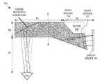
- FIGS. 1A and 1Bare cross-sectional views of an eyepiece 100 for use with a head wearable display, in accordance with an embodiment of the disclosure.
- the illustrated embodiment of eyepiece 100includes a lightguide component 105 and a see-through add-on component 110 .
- the illustrated embodiment of lightguide component 105includes an input surface 115 , a first folding surface 120 , a second folding surface 125 , an eye-ward facing surface 130 , a curved reflective surface 135 , and an end surface 140 .
- See-through add-on component 110includes an interface surface 145 , an external scene facing surface 147 , and an end surface 150 .
- a diffusor 155is coated over end surfaces 140 and 150 .
- Display source 160is aligned to inject display light 165 into lightguide component 105 through input surface 115 .
- Display source 160is located at a peripheral location (proximal end), which is offset from a viewing region 170 near the distal end of eyepiece 100 .
- Display light 165is emitted from lightguide component 105 in viewing region 170 along an eye-ward direction for viewing by a user.
- lightguide component 105operates as a lightguide that transports display light 165 from a peripheral location outside of the user's center of vision to viewing region 170 located nearer to the user's central or foveal vision.
- Eyepiece 100can be implemented in a see-through or non-see-through version, and as such see-through add-on component 110 is an optional component.
- curved reflective surface 135is layered with a partially reflective element (e.g., beam splitter coating, polarizing beam splitter coating, diffractive reflector, etc.).
- the partial reflectivity of curved reflective surface 135permits ambient scene light 175 to pass through viewing region 170 and combine with display light 165 emitted out through viewing region 170 .
- see-through add-on component 110defeats the optical power associated with curved reflective surfaced 135 for the ambient scene light 175 passing through.
- interface surface 145 of see-through add-on component 110has a size and curvature that mates to and complements the curvature of curved reflective surface 135 of lightguide component 105 .
- external scene facing surface 147is complementary to eye-ward facing surface 130 in viewing region 170 to ensure ambient scene light 175 experiences substantially no optical power.
- curved reflective surface 135may implemented as a mirror surface with or without add-on component 110 according to industrial design choice.
- lightguide component 105 and add-on component 110are fabricated as two independent pieces that are bonded together along interface surface 145 and curved reflective surface 135 using a clear adhesive.
- Lightguide component 105 and add-on component 110may be fabricated of two different materials having the same index of refraction, or both of the same material.
- lightguide component 105 and add-on component 110may be fabricated of optical grade plastic (e.g., Zeonex E-48R), glass, or otherwise.
- the componentsare injection molded to shape, processed to add various optical coatings/layers discussed below, and then bonded together along interface surface 145 and curved reflective surface 135 .
- lightguide component 105 and add-on component 110are fabricated of a material having a higher index of refraction than air to induce total interface reflection (“TIR”) at first folding surface 120 , second folding surface 125 , and eye-ward facing surface 130 .
- TIRtotal interface reflection
- the splitting ratiomay be selected according to design needs, but in one embodiment may be implemented as a 50/50 beam splitter.
- curved reflective surface 135is implemented using a polarizing beam splitter (“PBS”)
- PBSpolarizing beam splitter
- display source 160would output polarized light with a polarization selected to substantially reflect off of the PBS material.
- a PBS designcan serve to increase the efficiency of the optical system.
- LCD or liquid crystal on silicon (“LCoS”)are example display technologies that output polarized light.
- external polarizing filmsmay be used in connection with other non-polarized display technologies.
- lightguide component 105may be fabricated of low stress plastics, glass, or other low stress optical grade materials.
- lightguide component 105 and add-on component 110are fabricated of optically transmissive materials (e.g., clear plastic) that permit at least a portion of external scene light 175 to pass through viewing region 170 to the user's eye.
- eyepiece 100operates as an optical combiner combining external scene light 175 with display light 165 emitted out through eye-ward facing surface 130 in viewing region 170 along an eye-ward direction into the eye. In this way, eyepiece 100 is capable of displaying an augmented reality to the user.
- display source 160emits display light 165 from a peripheral location offset from viewing region 170 into lightguide component 105 .
- Display source 120may be implemented using a variety of different display technologies including LCD displays, LCoS displays, organic light emitting diode (“OLED”) displays, or otherwise.
- Display light 165may include computer generated images.
- Display light 165is incident into lightguide component 105 through input surface 115 .
- Input surface 115is a curved surface with optical power.
- input surface 115is a cylindrical lensing surface that in connection with the other lensing surfaces can be adjusted to correct aberrations and distortions in the optical system.
- input surface 115is a cylindrical convex surface (as viewed from display source 160 ) having its center axis of symmetry in the plane of the page running parallel to the line drawn as input surface 115 .
- first folding surface 120After display light 165 enters into lightguide component 105 through input surface 115 , it is incident upon first folding surface 120 , which is disposed proximate to input surface 115 .
- First folding surface 120operates to reflect display light 165 towards second folding surface 125 .
- first folding surface 120is also a curved surface with reflective optical power.
- first folding surface 120may be implemented as a cylindrical surface with optical power to aid in correction of aberrations and distortions in the optical system.
- first folding surface 120is a cylindrical concave surface (as viewed external to lightguide component 105 ) having its center axis of symmetry in the plane of the page running parallel to the line drawn as first folding surface 120 .
- second folding surface 125is a planar surface without optical power; however, in other embodiments, second folding surface 125 may also have curvature to impart optical power.
- Eye-ward facing surface 130is a planar surface without optical power that is opposite, but parallel to second folding surface 125 .
- Eye-ward facing surface 130 and first folding surface 120are non-coplanar surfaces off-set from each other.
- Curved reflective surface 135is implemented as an off-axis aspheric lens that provides reflective optical power to collimate or nearly collimate display light 165 emitted from eyepiece 100 .
- display light 165may be virtually displaced to appear to 2 m to 3 m in front of the user.
- other amounts of collimationmay be implemented.
- display light 165is directed back to eye-ward facing surface 130 in viewing region 170 where display light 165 is emitted out of eyepiece 100 along an eye-ward direction.
- the second encounter with eye-ward facing surface 130does not result in TIR, since the angle of incidence is steeper than the required critical angle for TIR.
- Eyepiece 100provides a relatively large eye box (e.g., 8.5 mm horizontal and 6.2 mm vertical) due to its inherent design. This large eye box is due in part to the close proximity of curved reflective surface 135 to the user's eye. Additionally, the relatively shallow oblique angle of curved reflective surface 135 projects a large horizontal eye box area onto eye-ward facing surface 130 in viewing region 170 , which also contributes to the eye box size. A large eye box accommodates larger inter-pupillary deviations, thereby providing a larger cross-section of the population with an improved user experience.
- This large eye boxis due in part to the close proximity of curved reflective surface 135 to the user's eye. Additionally, the relatively shallow oblique angle of curved reflective surface 135 projects a large horizontal eye box area onto eye-ward facing surface 130 in viewing region 170 , which also contributes to the eye box size.
- a large eye boxaccommodates larger inter-pupillary deviations, thereby providing a larger cross-section of the population with an improved user experience.
- first folding surface 120 , second folding surface 125 , and eye-ward facing surface 130are clear surfaces that reflect display light 165 via TIR and careful design control over the incident angles of the light path followed by display light 165 .
- TIRfor the reflections off of the folding surfaces
- eyepiece 100achieves desirable industrial design characteristics, since eyepiece 100 will appear as a clear eyepiece to external observers.
- TIR reflectionsare highly efficient.
- curved reflective surface 135is a 50/50 beam splitter
- embodiments of eyepiece 100can approach near 50% efficiency.
- first folding surface 120 and second folding surface 125may be coated with reflecting films to reflect display light 165 without need of TIR.
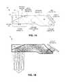
- FIG. 1Billustrates example optical paths through eyepiece 100 by a number of ray trace bundles of display light 165 output from display source 160 .
- diffusor 155is coated over the distal ends 140 and 150 of lightguide component 105 and add-on component 110 , respectively. Diffusor 155 operates to absorb incident light to reduce deleterious back reflections. Diffusor 155 may be implemented as a dark diffusive paint (e.g., matte black paint), and in some embodiments, further includes an anti-reflective coating under the dark diffusive paint. In one embodiment, diffusor 155 includes an opening to permit a portion of display light 165 to bleed out the distal end of eyepiece 200 as a sort of indicator light. The indicator light provides third persons a visual cue that display source 160 is turned on. In one embodiment, the opening may be an image or logo stenciled into the dark diffusive paint and may include a transparent diffusive element under the stenciled image/logo to diffuse the display light emitted as a visual cue.
- a dark diffusive painte.g., matte black paint
- diffusor 155includes an opening to permit a portion of display light
- FIGS. 2A and 2Bare cross-sectional views of an eyepiece 200 for use with a head wearable display, in accordance with another embodiment of the disclosure.
- the illustrated embodiment of eyepiece 200includes a lightguide component 205 and a see-through add-on component 210 .
- the illustrated embodiment of lightguide component 205includes an input surface 215 , notch surfaces 217 and 218 , a first folding surface 220 , a second folding surface 225 , an eye-ward facing surface 230 , curved reflective surface 235 , and an end surface 240 .
- See-through add-on component 210includes an interface surface 245 , an external scene facing surface 247 , and an end surface 250 .
- a diffusor 255is coated over end surfaces 240 and 250 .
- Eyepiece 200is similar to eyepiece 100 except that notch surfaces 217 and 218 proximal to input surface 215 form an alcove 219 suitably sized to house a camera module or other optical/electrical systems. Furthermore, first folding surface 220 is tilted towards display source 160 and lengthened to extend between (and directly interface with) input surface 215 and eye-ward facing surface 230 .
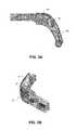
- FIGS. 3A and 3Billustrate an example housing configuration for eyepiece 200 , in accordance with an embodiment of the disclosure.
- FIG. 3Ais a cross-sectional view while FIG. 3B is a perspective view of the same.
- the proximal end of eyepiece 200inserts into a housing 305 .
- Housing 305is shaped for mounting to a temple region of an eyewear-like frame for wearing on a head of user (e.g., see FIGS. 4A and 4B ).
- Frame 305positions display source 160 peripherally to the user's central vision.
- alcove 219provides a convenient location for additional circuitry or optical components, such as for example, a forward facing camera module 310 .
- eyepiece 200delivers display light 265 with a 15 degree field of view having a 16:9 aspect ratio (e.g., 13 degree horizontal and 7.35 degrees vertical) and a resolution of approximately 4 arc mins based upon display source 160 having a 640 ⁇ 360 pixel display and 7.5 um pixel size.
- Eyepiece 200is also capable of providing a relatively large eye box (e.g., 8.5 mm horizontal by 6.2 mm vertical) for similar reasons as discussed above in connection with eyepiece 100 .
- a relatively large eye boxe.g., 8.5 mm horizontal by 6.2 mm vertical
- these dimensionsare merely demonstrative and alternative dimensions may be implemented.
- curved reflective surface 235is an off-axis asphere with a sag equation:
- the local coordinate system of curved reflective surface 235 for the sag equation provided aboveis offset compared to the center of viewing region 270 by ⁇ 43.52 mm in X, 2.4 mm in Y, and 11.32 mm in Z.
- the local coordinate system of curved reflective surface 235is further rotated in the Y-Z plane by ⁇ 3.7 degrees, and in the X-Z plane ⁇ 8.95 degrees.
- first folding surface 220is an off axis toroid with a sag equation:
- first folding surface 220is a cylinder having an orientation that is similar to that described above in connection with first folding surface 120 .
- input surface 215is a cylinder with a convex radius of ⁇ 7.175 mm and an angle of 70 degrees to eye-ward facing surface 230 .
- these curvatures, positions, and anglesare merely demonstrative and alternative curvatures, positions, and angles may be implemented.
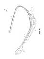
- FIGS. 4A and 4Billustrate a monocular head wearable display 400 using a eyepiece 401 , in accordance with an embodiment of the disclosure.
- FIG. 4Ais a perspective view of head wearable display 400
- FIG. 4Bis a top view of the same.
- Eyepiece 401may be implemented with embodiments of eyepieces 100 or 200 as discussed above.
- Eyepiece 401is mounted to a frame assembly, which includes a nose bridge 405 , left ear arm 410 , and right ear arm 415 .
- Housings 420 and 425may contain various electronics including a microprocessor, interfaces, one or more wireless transceivers, a battery, a camera, a speaker, etc.
- FIGS. 4A and 4Billustrate a monocular embodiment
- head wearable display 400may also be implemented as a binocular display with two eyepieces 401 each aligned with a respective eye of the user when display 400 is worn.
- Eyepiece 401is secured into an eye glass arrangement or head wearable display that can be worn on the head of a user.
- the left and right ear arms 410 and 415rest over the user's ears while nose bridge 405 rests over the user's nose.
- the frame assemblyis shaped and sized to position the viewing region in front of an eye of the user.
- Other frame assemblies having other shapesmay be used (e.g., traditional eyeglasses frame, a single contiguous headset member, a headband, goggles type eyewear, etc.).
- head wearable display 400is capable of displaying an augmented reality to the user.
- a see-through embodimentpermits the user to see a real world image via ambient scene light 175 .
- Left and right (binocular embodiment) display light 480may be generated by display sources 160 mounted in peripheral corners outside the user's central vision.
- Display light 480is seen by the user as a virtual image superimposed over ambient scene light 175 as an augmented reality.
- ambient scene light 175may be fully, partially, or selectively blocked to provide sun shading characteristics and increase the contrast of display light 480 .
Landscapes
- Physics & Mathematics (AREA)
- General Physics & Mathematics (AREA)
- Optics & Photonics (AREA)
Abstract
Description
This disclosure relates generally to the field of optics, and in particular but not exclusively, relates to eyepieces for head wearable displays.
A head mounted display (“HMD”) or head wearable display is a display device worn on or about the head. HMDs usually incorporate some sort of near-to-eye optical system to create a magnified virtual image placed a few meters in front of the user. Single eye displays are referred to as monocular HMDs while dual eye displays are referred to as binocular HMDs. Some HMDs display only a computer generated image (“CGI”), while other types of HMDs are capable of superimposing CGI over a real-world view. This latter type of HMD typically includes some form of see-through eyepiece and can serve as the hardware platform for realizing augmented reality. With augmented reality the viewer's image of the world is augmented with an overlaying CGI, also referred to as a heads-up display (“HUD”).
HMDs have numerous practical and leisure applications. Aerospace applications permit a pilot to see vital flight control information without taking their eye off the flight path. Public safety applications include tactical displays of maps and thermal imaging. Other application fields include video games, transportation, and telecommunications. There is certain to be new found practical and leisure applications as the technology evolves; however, many of these applications are limited due to the cost, size, weight, field of view, eye box, and efficiency of conventional optical systems used to implemented existing HMDs.
Non-limiting and non-exhaustive embodiments of the invention are described with reference to the following figures, wherein like reference numerals refer to like parts throughout the various views unless otherwise specified. The drawings are not necessarily to scale, emphasis instead being placed upon illustrating the principles being described.
Embodiments of a system and apparatus that integrates a total internal reflection (“TIR”) based lightguide and optical combiner into an eyepiece for a head wearable display are described herein. In the following description numerous specific details are set forth to provide a thorough understanding of the embodiments. One skilled in the relevant art will recognize, however, that the techniques described herein can be practiced without one or more of the specific details, or with other methods, components, materials, etc. In other instances, well-known structures, materials, or operations are not shown or described in detail to avoid obscuring certain aspects.
Reference throughout this specification to “one embodiment” or “an embodiment” means that a particular feature, structure, or characteristic described in connection with the embodiment is included in at least one embodiment of the present invention. Thus, the appearances of the phrases “in one embodiment” or “in an embodiment” in various places throughout this specification are not necessarily all referring to the same embodiment. Furthermore, the particular features, structures, or characteristics may be combined in any suitable manner in one or more embodiments.
Eyepiece100 can be implemented in a see-through or non-see-through version, and as such see-through add-oncomponent 110 is an optional component. In see-through embodiments, curvedreflective surface 135 is layered with a partially reflective element (e.g., beam splitter coating, polarizing beam splitter coating, diffractive reflector, etc.). The partial reflectivity of curvedreflective surface 135 permitsambient scene light 175 to pass throughviewing region 170 and combine withdisplay light 165 emitted out throughviewing region 170. When indexed matched tolightguide component 105, see-through add-oncomponent 110 defeats the optical power associated with curved reflective surfaced135 for theambient scene light 175 passing through. Accordingly,interface surface 145 of see-through add-oncomponent 110 has a size and curvature that mates to and complements the curvature of curvedreflective surface 135 oflightguide component 105. Correspondingly, externalscene facing surface 147 is complementary to eye-ward facing surface 130 inviewing region 170 to ensureambient scene light 175 experiences substantially no optical power.
In non-see-through embodiments, curvedreflective surface 135 may implemented as a mirror surface with or without add-oncomponent 110 according to industrial design choice.
In one embodiment,lightguide component 105 and add-oncomponent 110 are fabricated as two independent pieces that are bonded together alonginterface surface 145 and curvedreflective surface 135 using a clear adhesive.Lightguide component 105 and add-oncomponent 110 may be fabricated of two different materials having the same index of refraction, or both of the same material. For example,lightguide component 105 and add-oncomponent 110 may be fabricated of optical grade plastic (e.g., Zeonex E-48R), glass, or otherwise. In one embodiment, the components are injection molded to shape, processed to add various optical coatings/layers discussed below, and then bonded together alonginterface surface 145 and curvedreflective surface 135. In one embodiment,lightguide component 105 and add-oncomponent 110 are fabricated of a material having a higher index of refraction than air to induce total interface reflection (“TIR”) atfirst folding surface 120,second folding surface 125, and eye-ward facing surface 130.
In an embodiment wherein curvedreflective surface 135 is coated with a partially reflective material, the splitting ratio may be selected according to design needs, but in one embodiment may be implemented as a 50/50 beam splitter. In embodiments where curvedreflective surface 135 is implemented using a polarizing beam splitter (“PBS”),display source 160 would output polarized light with a polarization selected to substantially reflect off of the PBS material. A PBS design can serve to increase the efficiency of the optical system. For example, LCD or liquid crystal on silicon (“LCoS”) are example display technologies that output polarized light. Of course, external polarizing films may be used in connection with other non-polarized display technologies. When operating with polarized light, it can be beneficial to use low stress materials to reduce the influence of birefringence on the optical design. Accordingly, in some embodiments,lightguide component 105 may be fabricated of low stress plastics, glass, or other low stress optical grade materials.
In see-through embodiments,lightguide component 105 and add-oncomponent 110 are fabricated of optically transmissive materials (e.g., clear plastic) that permit at least a portion ofexternal scene light 175 to pass throughviewing region 170 to the user's eye. As such,eyepiece 100 operates as an optical combiner combining external scene light175 with display light165 emitted out through eye-ward facing surface 130 inviewing region 170 along an eye-ward direction into the eye. In this way,eyepiece 100 is capable of displaying an augmented reality to the user.
During operation,display source 160 emits display light165 from a peripheral location offset from viewingregion 170 intolightguide component 105. Displaysource 120 may be implemented using a variety of different display technologies including LCD displays, LCoS displays, organic light emitting diode (“OLED”) displays, or otherwise. Display light165 may include computer generated images.
Afterdisplay light 165 enters intolightguide component 105 throughinput surface 115, it is incident uponfirst folding surface 120, which is disposed proximate to inputsurface 115. First foldingsurface 120 operates to reflect display light165 towardssecond folding surface 125. In the illustrated embodiment,first folding surface 120 is also a curved surface with reflective optical power. For example,first folding surface 120 may be implemented as a cylindrical surface with optical power to aid in correction of aberrations and distortions in the optical system. In the illustrated embodiment,first folding surface 120 is a cylindrical concave surface (as viewed external to lightguide component105) having its center axis of symmetry in the plane of the page running parallel to the line drawn asfirst folding surface 120.
After folding (e.g., reflecting) andlensing display light 165 atfirst folding surface 120,display light 165 is directed towardssecond folding surface 125 wheredisplay light 125 is once again redirected back acrosslightguide component 105 to eye-ward facing surface 130. In the illustrated embodiment,second folding surface 125 is a planar surface without optical power; however, in other embodiments,second folding surface 125 may also have curvature to impart optical power.
Display light165 incident upon eye-ward facing surface 130 for the first time is reflected to curvedreflective surface 135. In one embodiment, eye-ward facing surface 130 is a planar surface without optical power that is opposite, but parallel tosecond folding surface 125. Eye-ward facing surface 130 andfirst folding surface 120 are non-coplanar surfaces off-set from each other.
Curvedreflective surface 135 is implemented as an off-axis aspheric lens that provides reflective optical power to collimate or nearly collimate display light165 emitted fromeyepiece 100. For example, display light165 may be virtually displaced to appear to 2 m to 3 m in front of the user. Of course other amounts of collimation may be implemented. After reflection off of curvedreflective surface 135,display light 165 is directed back to eye-ward facing surface 130 inviewing region 170 wheredisplay light 165 is emitted out ofeyepiece 100 along an eye-ward direction. The second encounter with eye-ward facing surface 130 does not result in TIR, since the angle of incidence is steeper than the required critical angle for TIR.
In one embodiment,first folding surface 120,second folding surface 125, and eye-ward facing surface 130 are clear surfaces that reflectdisplay light 165 via TIR and careful design control over the incident angles of the light path followed bydisplay light 165. By using TIR for the reflections off of the folding surfaces,eyepiece 100 achieves desirable industrial design characteristics, sinceeyepiece 100 will appear as a clear eyepiece to external observers. Furthermore, TIR reflections are highly efficient. In an example where curvedreflective surface 135 is a 50/50 beam splitter, embodiments ofeyepiece 100 can approach near 50% efficiency. In other embodiments,first folding surface 120 andsecond folding surface 125 may be coated with reflecting films to reflectdisplay light 165 without need of TIR.FIG. 1B illustrates example optical paths througheyepiece 100 by a number of ray trace bundles of display light165 output fromdisplay source 160.
In the illustrated embodiment,diffusor 155 is coated over the distal ends140 and150 oflightguide component 105 and add-oncomponent 110, respectively.Diffusor 155 operates to absorb incident light to reduce deleterious back reflections.Diffusor 155 may be implemented as a dark diffusive paint (e.g., matte black paint), and in some embodiments, further includes an anti-reflective coating under the dark diffusive paint. In one embodiment,diffusor 155 includes an opening to permit a portion of display light165 to bleed out the distal end ofeyepiece 200 as a sort of indicator light. The indicator light provides third persons a visual cue that displaysource 160 is turned on. In one embodiment, the opening may be an image or logo stenciled into the dark diffusive paint and may include a transparent diffusive element under the stenciled image/logo to diffuse the display light emitted as a visual cue.
In one embodiment,eyepiece 200 delivers display light265 with a 15 degree field of view having a 16:9 aspect ratio (e.g., 13 degree horizontal and 7.35 degrees vertical) and a resolution of approximately 4 arc mins based upondisplay source 160 having a 640×360 pixel display and 7.5 um pixel size. Additional design specification of such an embodiment include an eye relief (D1) of 18 mm and approximate lightguide component dimensions including: D2=7.2 mm, D3=25 mm, D4=15 mm, and rectangular cross sectional dimensions along line A-A′ of 7.2 mm×10 mm.Eyepiece 200 is also capable of providing a relatively large eye box (e.g., 8.5 mm horizontal by 6.2 mm vertical) for similar reasons as discussed above in connection witheyepiece 100. Of course, these dimensions are merely demonstrative and alternative dimensions may be implemented. In one embodiment, curvedreflective surface 235 is an off-axis asphere with a sag equation:
where R=−81.62, k=−3.63, β3=−5.00 E−05, and β4=−3.81 E−08. In one embodiment,
where R=−7.113, a=0.061, k=0.00, and a radius of rotation of 1468. In this embodiment, the center of the radius of rotation is offset −453.77 mm in X, 0 mm in Y and 1401.06 mm in Z relative to the center of the
The illustrated embodiment of headwearable display 400 is capable of displaying an augmented reality to the user. A see-through embodiment permits the user to see a real world image viaambient scene light 175. Left and right (binocular embodiment)display light 480 may be generated bydisplay sources 160 mounted in peripheral corners outside the user's central vision.Display light 480 is seen by the user as a virtual image superimposed over ambient scene light175 as an augmented reality. In some embodiments, ambient scene light175 may be fully, partially, or selectively blocked to provide sun shading characteristics and increase the contrast ofdisplay light 480.
The above description of illustrated embodiments of the invention, including what is described in the Abstract, is not intended to be exhaustive or to limit the invention to the precise forms disclosed. While specific embodiments of, and examples for, the invention are described herein for illustrative purposes, various modifications are possible within the scope of the invention, as those skilled in the relevant art will recognize.
These modifications can be made to the invention in light of the above detailed description. The terms used in the following claims should not be construed to limit the invention to the specific embodiments disclosed in the specification. Rather, the scope of the invention is to be determined entirely by the following claims, which are to be construed in accordance with established doctrines of claim interpretation.
Claims (16)
1. An eyepiece for a head wearable display, the eyepiece comprising:
a lightguide component for guiding display light received at a peripheral location offset from a viewing region and emitting the display light at the viewing region, the light guide component including:
an input surface oriented to receive the display light into the lightguide component at the peripheral location;
a first folding surface disposed to receive the display light from the input surface without reflection and to reflect the received display light;
a second folding surface disposed to face the first folding surface and to reflect the display light received from the first folding surface without an intervening reflection, wherein the input surface and the second folding surface are non-coplanar;
an eye-ward facing surface disposed to face the second folding surface and to reflect the display light received from the second folding surface, wherein the eye-ward facing surface is positioned as an emission surface for emitting the display light out of the lightguide component, wherein the first folding surface and the eye-ward facing surface are non-coplanar surfaces of the lightguide component that do not directly interface with each other by making contact, wherein the second folding surface and the eye-ward facing surface are non-coplanar, parallel surfaces that are both flat and both without optical power; and
a curved reflective surface having reflective optical power disposed at the viewing region to receive the display light reflected from the eye-ward facing surface and to reflect the display light for emission out through the eye-ward facing surface.
2. The eyepiece ofclaim 1 , wherein the first folding surface, the second folding surface, and the eye-ward facing surface are clear surfaces that are oriented relative to each other to reflect the display light via total internal reflection.
3. The eyepiece ofclaim 1 , wherein the input surface is a cylindrical surface that imparts optical power to the display light received into the lightguide component.
4. The eyepiece ofclaim 1 , wherein the first folding surface is a cylindrical surface that imparts optical power to the display light reflected internally to the lightguide component.
5. The eyepiece ofclaim 1 , wherein the curved reflective surface comprises a partially reflective surface that partially reflects the display light and transmits ambient scene light through the viewing region and operates to optically combine the ambient scene light with the display light.
6. The eyepiece ofclaim 5 , further comprising:
a see-through add-on component mounted to the lightguide component along the curved reflective surface in the viewing region,
wherein the see-through add-on component is at least partially transparent to ambient scene light travelling along an eye-ward direction and is formed of a material having an index of refraction substantially equivalent to that of the lightguide component.
7. The eyepiece ofclaim 6 , wherein the see-through add-on component includes:
an interface surface having a size and a curvature that mates to and complements the curved reflective surface of the lightguide component; and
an external scene facing surface that is complementary to the eye-ward facing surface in the viewing region such that the ambient scene light that passes through the see-through add-on component and the lightguide in the viewing region experiences substantially no optical power.
8. The eyepiece ofclaim 7 , a diffusor coated onto end surfaces of the lightguide component and the see-through add-on component distal to the input surface to reduce back reflections down the lightguide component.
9. A head wearable display for displaying an image to a user, the head wearable display comprising:
a display source to generate display light;
a lightguide component for guiding display light received at a peripheral location offset from a viewing region and emitting the display light at the viewing region, the light guide component including:
an input surface to receive the display light into the lightguide component;
a first folding surface disposed to reflect the display light received through the input surface;
a second folding surface disposed to face the first folding surface and to reflect the display light received from the first folding surface without an intervening reflection, wherein the input surface and the second folding surface are non-coplanar;
an eye-ward facing surface disposed to face the second folding surface and to reflect the display light received from the second folding surface, wherein the eye-ward facing surface is positioned as an emission surface for emitting the display light out of the lightguide component, wherein the first folding surface and the eye-ward facing surface are non-coplanar surfaces of the lightguide component, wherein the second folding surface and the eye-ward facing surface are non-coplanar surfaces;
a curved reflective surface having reflective optical power disposed at the viewing region to receive the display light reflected from the eye-ward facing surface and to reflect the display light for emission out through the eye-ward facing surface;
a first notch surface that directly interfaces by contact with the input surface; and
a second notch surface that directly interfaces by contact with both the second folding surface and the first notch surface, wherein the first and second notch surfaces are non-coplanar with each other and non-coplanar with the input surface, the first folding surface, and the second folding surface;
wherein the first and second notch surfaces form an alcove in the lightguide component adjacent to the input surface;
a camera module disposed in the alcove, wherein a lens of the camera module faces outward from the lightguide component away from the eye-ward facing surface; and
a frame assembly to support the lightguide component and the display source for wearing on a head of the user with the viewing region positioned in front of the eye of the user.
10. The head wearable display ofclaim 9 , wherein the first folding surface, the second folding surface, and the eye-ward facing surface are clear surfaces that are oriented relative to each other to reflect the display light via total internal reflection.
11. The head wearable display ofclaim 9 , wherein the input surface and the first folding surface are cylindrical surfaces that impart optical power to the display light received into the lightguide component.
12. The head wearable display ofclaim 11 , wherein the second folding surface and the eye-ward facing surface are planar surfaces with no optical power.
13. The head wearable display ofclaim 9 , wherein the curved reflective surface comprises a partially reflective surface that partially reflects the display light and transmits ambient scene light through the viewing region and operates to optically combine the ambient scene light with the display light.
14. The head wearable display ofclaim 13 , further comprising:
a see-through add-on component mounted to the lightguide component along the curved reflective surface in the viewing region,
wherein the see-through add-on component is at least partially transparent to ambient scene light and is formed of a material having an index of refraction substantially equivalent to that of the lightguide component.
15. The head wearable display ofclaim 14 , wherein the see-through add-on component includes:
an interface surface having a size and a curvature that mates to and complements the curved reflective surface of the lightguide component; and
an external scene facing surface that is complementary to the eye-ward facing surface in the viewing region such that the ambient scene light that passes through the see-through add-on component and the lightguide in the viewing region experiences substantially no optical power.
16. An eyepiece for a head wearable display, the eyepiece comprising:
a lightguide component for guiding display light received at a peripheral location offset from a viewing region and emitting the display light at the viewing region, the light guide component including:
an input surface oriented to receive the display light into the lightguide component at the peripheral location;
a first folding surface disposed to receive the display light from the input surface without reflection and to reflect the received display light;
a second folding surface disposed to face the first folding surface and to reflect the display light received from the first folding surface without an intervening reflection, wherein the input surface and the second folding surface are non-coplanar;
an eye-ward facing surface disposed to face the second folding surface and to reflect the display light received from the second folding surface, wherein the eye-ward facing surface is positioned as an emission surface for emitting the display light out of the lightguide component, wherein the first folding surface and the eye-ward facing surface are non-coplanar surfaces of the lightguide component, wherein the second folding surface and the eye-ward facing surface are non-coplanar surfaces and wherein the first folding surface is a continuous surface that directly interfaces by contact to both the eye-ward facing surface and the input surface; and
a curved reflective surface having reflective optical power disposed at the viewing region to receive the display light reflected from the eye-ward facing surface and to reflect the display light for emission out through the eye-ward facing surface.
Priority Applications (2)
| Application Number | Priority Date | Filing Date | Title |
|---|---|---|---|
| US14/271,083US9915823B1 (en) | 2014-05-06 | 2014-05-06 | Lightguide optical combiner for head wearable display |
| US15/878,751US20190271844A1 (en) | 2014-05-06 | 2018-01-24 | Lightguide optical combiner for head wearable display |
Applications Claiming Priority (1)
| Application Number | Priority Date | Filing Date | Title |
|---|---|---|---|
| US14/271,083US9915823B1 (en) | 2014-05-06 | 2014-05-06 | Lightguide optical combiner for head wearable display |
Related Child Applications (1)
| Application Number | Title | Priority Date | Filing Date |
|---|---|---|---|
| US15/878,751ContinuationUS20190271844A1 (en) | 2014-05-06 | 2018-01-24 | Lightguide optical combiner for head wearable display |
Publications (1)
| Publication Number | Publication Date |
|---|---|
| US9915823B1true US9915823B1 (en) | 2018-03-13 |
Family
ID=61525545
Family Applications (2)
| Application Number | Title | Priority Date | Filing Date |
|---|---|---|---|
| US14/271,083ActiveUS9915823B1 (en) | 2014-05-06 | 2014-05-06 | Lightguide optical combiner for head wearable display |
| US15/878,751AbandonedUS20190271844A1 (en) | 2014-05-06 | 2018-01-24 | Lightguide optical combiner for head wearable display |
Family Applications After (1)
| Application Number | Title | Priority Date | Filing Date |
|---|---|---|---|
| US15/878,751AbandonedUS20190271844A1 (en) | 2014-05-06 | 2018-01-24 | Lightguide optical combiner for head wearable display |
Country Status (1)
| Country | Link |
|---|---|
| US (2) | US9915823B1 (en) |
Cited By (14)
| Publication number | Priority date | Publication date | Assignee | Title |
|---|---|---|---|---|
| US20170045745A1 (en)* | 2014-07-11 | 2017-02-16 | Samsung Electronics Co., Ltd. | Lightguide structure, optical device and imaging system |
| US20180231783A1 (en)* | 2017-02-16 | 2018-08-16 | Coretronic Corporation | Optical waveguide element and display device |
| US20190101757A1 (en)* | 2017-10-02 | 2019-04-04 | Google Inc. | Eye tracking using light guide with faceted combiner |
| US10261322B2 (en)* | 2015-12-25 | 2019-04-16 | Seiko Epson Corporation | Virtual image display apparatus |
| US10302835B2 (en)* | 2017-02-22 | 2019-05-28 | Lumus Ltd. | Light guide optical assembly |
| US20190204600A1 (en)* | 2017-12-29 | 2019-07-04 | Letinar Co., Ltd. | Augmented reality optics system with pinpoint mirror |
| US20190271844A1 (en)* | 2014-05-06 | 2019-09-05 | Google Llc | Lightguide optical combiner for head wearable display |
| US10558044B2 (en) | 2016-03-30 | 2020-02-11 | Coretronic Corporation | Optical waveguide device and head-mounted display apparatus using the same |
| US10591734B2 (en)* | 2017-03-28 | 2020-03-17 | Seiko Epson Corporation | Display apparatus |
| CN112236716A (en)* | 2018-10-26 | 2021-01-15 | 谷歌有限责任公司 | Optical device comprising a light guide for a head-mounted display |
| US11300789B2 (en)* | 2018-01-02 | 2022-04-12 | Beijing Boe Optoelectronics Technology Co., Ltd. | Augmented reality glasses |
| EP4063937A1 (en)* | 2021-03-22 | 2022-09-28 | Samsung Electronics Co., Ltd. | Display apparatus including combiner having asymmetric magnification |
| WO2023099675A1 (en) | 2021-12-03 | 2023-06-08 | Almer Technologies Ag | Ar glasses |
| US20230213762A1 (en)* | 2021-12-31 | 2023-07-06 | Beijing Ned+Ar Display Technology Co., Ltd. | Ultra-thin lens, virtual image display device using same, and near-eye display |
Families Citing this family (4)
| Publication number | Priority date | Publication date | Assignee | Title |
|---|---|---|---|---|
| US10600352B1 (en)* | 2018-12-04 | 2020-03-24 | Facebook Technologies, Llc | Display device with a switchable window and see-through pancake lens assembly |
| US10955675B1 (en) | 2019-04-30 | 2021-03-23 | Facebook Technologies, Llc | Variable resolution display device with switchable window and see-through pancake lens assembly |
| CN112230435A (en)* | 2020-11-19 | 2021-01-15 | 维沃移动通信有限公司 | Optical Systems and Wearables |
| CN113204119A (en)* | 2021-04-30 | 2021-08-03 | 歌尔股份有限公司 | Cemented lens group and head-mounted display device |
Citations (161)
| Publication number | Priority date | Publication date | Assignee | Title |
|---|---|---|---|---|
| US4218111A (en) | 1978-07-10 | 1980-08-19 | Hughes Aircraft Company | Holographic head-up displays |
| US4220400A (en) | 1977-02-22 | 1980-09-02 | Honeywell Inc. | Display apparatus with reflective separated structure |
| US4560233A (en) | 1983-02-09 | 1985-12-24 | The Secretary Of State For Defence In Her Britannic Majesty's Government Of The United Kingdom Of Great Britain And Northern Ireland | Color head up display system |
| US4711512A (en) | 1985-07-12 | 1987-12-08 | Environmental Research Institute Of Michigan | Compact head-up display |
| US4799765A (en) | 1986-03-31 | 1989-01-24 | Hughes Aircraft Company | Integrated head-up and panel display unit |
| US4968117A (en) | 1983-09-02 | 1990-11-06 | Hughes Aircraft Company | Graded index asperhic combiners and display system utilizing same |
| US5050966A (en) | 1988-07-06 | 1991-09-24 | Kaiser Aerospace & Electronics Corporation | Optical combiner collimating apparatus |
| US5076664A (en) | 1989-05-23 | 1991-12-31 | Thomson-Csf | Optical device enabling the introduction of a collimated image in an observer's field of vision |
| US5093567A (en) | 1989-07-14 | 1992-03-03 | Gec-Marconi Limited | Helmet systems with eyepiece and eye position sensing means |
| US5237455A (en) | 1991-12-06 | 1993-08-17 | Delco Electronics Corporation | Optical combiner with integral support arm |
| US5257133A (en) | 1991-09-11 | 1993-10-26 | Hughes Aircraft Company | Re-imaging optical system employing refractive and diffractive optical elements |
| GB2272980A (en) | 1992-11-26 | 1994-06-01 | Electro Optics Ind Ltd | Optical beam splitting lens |
| US5453877A (en)* | 1988-10-21 | 1995-09-26 | Thomson-Csf | Optical system of collimation notably for helmet display unit |
| WO1996005533A1 (en) | 1994-08-10 | 1996-02-22 | Lawrence Vandewalle | Method and apparatus for direct retinal projection |
| US5537253A (en) | 1993-02-01 | 1996-07-16 | Honeywell Inc. | Head mounted display utilizing diffractive optical elements |
| US5539422A (en) | 1993-04-12 | 1996-07-23 | Virtual Vision, Inc. | Head mounted display system |
| US5654827A (en) | 1992-11-26 | 1997-08-05 | Elop Electrooptics Industries Ltd. | Optical system |
| US5694230A (en) | 1995-06-07 | 1997-12-02 | Digital Optics Corp. | Diffractive optical elements as combiners |
| US5696521A (en) | 1994-06-22 | 1997-12-09 | Astounding Technologies (M) Sdn. Bhd. | Video headset |
| US5715337A (en) | 1996-09-19 | 1998-02-03 | The Mirco Optical Corporation | Compact display system |
| US5771124A (en) | 1996-07-02 | 1998-06-23 | Siliscape | Compact display system with two stage magnification and immersed beam splitter |
| US5815126A (en) | 1993-10-22 | 1998-09-29 | Kopin Corporation | Monocular portable communication and display system |
| US5821911A (en) | 1993-09-07 | 1998-10-13 | Motorola | Miniature virtual image color display |
| US5844530A (en) | 1994-12-09 | 1998-12-01 | Kabushiki Kaisha Sega Enterprises | Head mounted display, and head mounted video display system |
| US5880888A (en)* | 1989-01-23 | 1999-03-09 | Hughes Aircraft Company | Helmet mounted display system |
| US5886822A (en) | 1996-10-08 | 1999-03-23 | The Microoptical Corporation | Image combining system for eyeglasses and face masks |
| US5896232A (en) | 1997-08-07 | 1999-04-20 | International Business Machines Corporation | Highly efficient and compact frontlighting for polarization-based reflection light valves |
| US5909325A (en)* | 1995-06-26 | 1999-06-01 | Olympus Optical Co., Ltd. | Image display apparatus |
| US5923476A (en) | 1998-01-16 | 1999-07-13 | Hewlett-Packard Company | Optical viewer with an aperture transformer |
| US5943171A (en) | 1998-06-03 | 1999-08-24 | International Business Machines Corporation | Head mounted displays utilizing reflection light valves |
| US5949583A (en) | 1992-02-07 | 1999-09-07 | I-O Display Systems Llc | Head-mounted display with image generator, fold mirror and mirror for transmission to the eye position of the user |
| US5995071A (en) | 1997-11-21 | 1999-11-30 | Hewlett-Packard Company | Reflective display utilizing fresnel micro-reflectors |
| US6023372A (en) | 1997-10-30 | 2000-02-08 | The Microoptical Corporation | Light weight, compact remountable electronic display device for eyeglasses or other head-borne eyewear frames |
| EP0898726B1 (en) | 1996-05-15 | 2000-03-08 | Commissariat A L'energie Atomique | Aperture-synthesis diffractive optical device and laser cutting device comprising same |
| US6057966A (en) | 1997-05-09 | 2000-05-02 | Via, Inc. | Body-carryable display devices and systems using E.G. coherent fiber optic conduit |
| US6091546A (en) | 1997-10-30 | 2000-07-18 | The Microoptical Corporation | Eyeglass interface system |
| US6094241A (en) | 1997-12-10 | 2000-07-25 | Mixed Reality Systems Laboratory, Inc. | Composite display apparatus using an LCD, optical path separator, and CCD |
| US6111701A (en) | 1999-07-14 | 2000-08-29 | Rockwell Collins, Inc. | Chromatic aberration corrected multi-color head-up display system |
| US6147807A (en) | 1999-05-04 | 2000-11-14 | Honeywell, Inc. | High brightness see-through head-mounted display |
| US6172657B1 (en) | 1996-02-26 | 2001-01-09 | Seiko Epson Corporation | Body mount-type information display apparatus and display method using the same |
| US6201629B1 (en) | 1997-08-27 | 2001-03-13 | Microoptical Corporation | Torsional micro-mechanical mirror system |
| JP2001066543A (en) | 1999-08-25 | 2001-03-16 | Canon Inc | Composite optical device |
| US6204975B1 (en) | 1998-12-22 | 2001-03-20 | Virtual Vision, Inc. | Reflective micro-display system |
| US6204974B1 (en) | 1996-10-08 | 2001-03-20 | The Microoptical Corporation | Compact image display system for eyeglasses or other head-borne frames |
| US6222677B1 (en)* | 1999-04-12 | 2001-04-24 | International Business Machines Corporation | Compact optical system for use in virtual display applications |
| US6236511B1 (en) | 2000-03-20 | 2001-05-22 | Rockwell Collins, Inc. | Beam combining optical element |
| EP0995145B1 (en) | 1997-07-18 | 2001-09-19 | Commissariat A L'energie Atomique | Diffractive optics with synthetic aperture and variable focal length and laser cutting device incorporating such an optics |
| US6330118B1 (en) | 1999-04-08 | 2001-12-11 | Aerial Imaging Corporation | Dual focus lens with extended depth of focus |
| US6349004B1 (en) | 1999-07-16 | 2002-02-19 | Optics 1, Inc. | Head mounted display viewing optics with improved optical performance |
| US6353503B1 (en) | 1999-06-21 | 2002-03-05 | The Micropitical Corporation | Eyeglass display lens system employing off-axis optical design |
| US6396639B1 (en) | 1999-02-04 | 2002-05-28 | Olympus Optical Co., Ltd. | Viewing optical system and image display apparatus using the same |
| US6462882B2 (en) | 2001-03-01 | 2002-10-08 | Raytheon Company | Light-weight head-mounted display |
| US6466471B1 (en) | 2001-05-29 | 2002-10-15 | Hewlett-Packard Company | Low power MRAM memory array |
| US20020186179A1 (en) | 2001-06-07 | 2002-12-12 | Knowles Gary R. | Optical display device |
| US20030090439A1 (en) | 2001-09-07 | 2003-05-15 | Spitzer Mark B. | Light weight, compact, remountable face-supported electronic display |
| US20030107816A1 (en) | 2001-11-14 | 2003-06-12 | Akinari Takagi | Display optical system, image display apparatus, image taking optical system, and image taking apparatus |
| US6618099B1 (en) | 1999-06-21 | 2003-09-09 | The Microoptical Corporation | Display device with eyepiece assembly and display on opto-mechanical support |
| US6690516B2 (en)* | 2000-01-31 | 2004-02-10 | Fujitsu Limited | Head mount type display device |
| US6701038B2 (en) | 2001-03-05 | 2004-03-02 | The Microoptical Corporation | Micro-electromechanical optical switch assembly for optical data networks |
| US6724354B1 (en) | 1999-06-21 | 2004-04-20 | The Microoptical Corporation | Illumination systems for eyeglass and facemask display systems |
| US6738535B2 (en) | 2001-01-31 | 2004-05-18 | International Business Machines Corporation | Head-mounted display content transformer |
| US6747611B1 (en) | 2000-07-27 | 2004-06-08 | International Business Machines Corporation | Compact optical system and packaging for head mounted display |
| US6760169B2 (en) | 1997-05-07 | 2004-07-06 | Olympus Corporation | Prism optical element, image observation apparatus and image display apparatus |
| US6785060B2 (en)* | 1995-02-28 | 2004-08-31 | Canon Kabushiki Kaisha | Reflecting type optical system |
| US20040190150A1 (en) | 2000-08-01 | 2004-09-30 | Olympus Optical Co., Ltd. | Light weight head mounted image display device |
| US6829095B2 (en) | 2000-06-05 | 2004-12-07 | Lumus, Ltd. | Substrate-guided optical beam expander |
| US6842280B2 (en)* | 1997-08-04 | 2005-01-11 | Canon Kabushiki Kaisha | Optical element and optical apparatus |
| US6847488B2 (en) | 2001-04-07 | 2005-01-25 | Cambridge Flat Projection Displays Limited | Far-field display |
| US6879443B2 (en) | 2003-04-25 | 2005-04-12 | The Microoptical Corporation | Binocular viewing system |
| US6880931B2 (en)* | 2002-01-11 | 2005-04-19 | Essilor International | Ophthalmic lens having a projection insert |
| US6890081B2 (en)* | 1998-09-25 | 2005-05-10 | Canon Kabushiki Kaisha | Optical element and optical system having the same |
| US6903876B2 (en)* | 2001-12-05 | 2005-06-07 | Fujitsu Limited | Display |
| US6919976B2 (en)* | 2000-03-17 | 2005-07-19 | Minolta Co., Ltd. | Information display device |
| US6961162B2 (en) | 2000-09-29 | 2005-11-01 | Olympus Corporation | Observation optical system using volume hologram |
| US7021777B2 (en) | 2003-09-10 | 2006-04-04 | Lumus Ltd. | Optical devices particularly for remote viewing applications |
| US7057814B2 (en) | 2000-01-31 | 2006-06-06 | 3M Innovative Properties Company | Illumination system for reflective displays |
| US7081999B2 (en)* | 2000-09-27 | 2006-07-25 | Canon Kabushiki Kaisha | Image display apparatus and head mounted display using it |
| US7095562B1 (en) | 2004-09-27 | 2006-08-22 | Rockwell Collins, Inc. | Advanced compact head up display |
| US20060192306A1 (en) | 2005-02-25 | 2006-08-31 | The Microoptical Corporation | Manufacturing methods for embedded optical system |
| US20060192307A1 (en) | 2005-02-25 | 2006-08-31 | Eugene Giller | Method for producing high quality optical parts by casting |
| US20060215244A1 (en) | 2003-12-02 | 2006-09-28 | Jacob Yosha | Vehicle display system |
| US7119965B1 (en) | 2003-02-24 | 2006-10-10 | University Of Central Florida Research Foundation, Inc. | Head mounted projection display with a wide field of view |
| US7145726B2 (en) | 2002-08-12 | 2006-12-05 | Richard Geist | Head-mounted virtual display apparatus for mobile activities |
| US7158096B1 (en) | 1999-06-21 | 2007-01-02 | The Microoptical Corporation | Compact, head-mountable display device with suspended eyepiece assembly |
| US20070070859A1 (en) | 2004-05-17 | 2007-03-29 | Nikon Corporation | Optical elements and combiner optical systems and image-display units comprising same |
| US7205960B2 (en) | 2003-02-19 | 2007-04-17 | Mirage Innovations Ltd. | Chromatic planar optic display system |
| US7210803B2 (en) | 2003-01-31 | 2007-05-01 | Canon Kabushiki Kaisha | Optical system, display optical system and image-taking optical system |
| US7230766B2 (en) | 2003-05-22 | 2007-06-12 | Optical Research Associates | Optical combiner designs and head mounted displays |
| WO2007065995A1 (en) | 2005-12-06 | 2007-06-14 | Universite Louis Pasteur, U.L.P. | System for securing by diffractively digitally encoding optical discs |
| US7242527B2 (en) | 2005-03-22 | 2007-07-10 | The Microoptical Corporation | Optical system using total internal reflection images |
| EP1930762A1 (en) | 2006-12-04 | 2008-06-11 | LG Electronics Inc. | Head up display device |
| US7391573B2 (en) | 2003-09-10 | 2008-06-24 | Lumus Ltd. | Substrate-guided optical devices |
| US7411637B2 (en) | 2002-02-15 | 2008-08-12 | Elop Electro-Optics Industries Ltd. | System and method for varying the reflectance or transmittance of light |
| US20080219025A1 (en) | 2007-03-07 | 2008-09-11 | Spitzer Mark B | Bi-directional backlight assembly |
| US7450310B2 (en) | 2005-05-03 | 2008-11-11 | Optical Research Associates | Head mounted display devices |
| US7457040B2 (en) | 2002-03-21 | 2008-11-25 | Lumus Ltd. | Light guide optical device |
| US7477453B2 (en)* | 2005-12-29 | 2009-01-13 | C.R.F. Societa Consortile Per Azioni | Optical system for image transmission, particularly for projection devices of the head-mounted type |
| US20090067057A1 (en) | 2007-09-10 | 2009-03-12 | Microvision, Inc. | Buried numerical aperture expander having transparent properties |
| US20090122414A1 (en) | 2005-02-10 | 2009-05-14 | Lumus Ltd. | Substrate-Guided Optical Device Utilzing Thin Transparent Layer |
| US7542209B2 (en) | 2004-09-01 | 2009-06-02 | Optical Research Associates | Compact head mounted display devices with tilted/decentered lens element |
| US7566863B2 (en) | 2006-10-16 | 2009-07-28 | Chang Christopher C | Optical encoder with diffractive encoder member |
| US7577326B2 (en) | 2004-08-05 | 2009-08-18 | Lumus Ltd. | Optical device for light coupling |
| US7586686B1 (en) | 2006-04-14 | 2009-09-08 | Oasys Technology Llc | Eyepiece for head mounted display system and method of fabrication |
| US7595933B2 (en) | 2006-10-13 | 2009-09-29 | Apple Inc. | Head mounted display system |
| US7595480B2 (en) | 2006-10-16 | 2009-09-29 | Arcus Technology, Inc. | Optical encoder with encoder member having one or more digital diffractive optic regions |
| WO2009153446A2 (en) | 2008-06-12 | 2009-12-23 | Universite De Strasbourg | Device for projecting structured light using vcsels and phase diffractive optical components |
| US7637617B2 (en) | 2004-02-10 | 2009-12-29 | Laster | Method and device for generating retinal images using the stigmatism of the two foci of a substantially elliptical sight |
| US7643214B2 (en) | 2004-06-17 | 2010-01-05 | Lumus Ltd. | Substrate-guided optical device with wide aperture |
| US7663805B2 (en) | 2007-10-09 | 2010-02-16 | Myvu Corporation | Eyewear display and media device interconnection system |
| US20100046075A1 (en) | 2008-08-19 | 2010-02-25 | Microvision, Inc. | Embedded relay lens for head-up displays or the like |
| US20100046070A1 (en) | 2008-08-21 | 2010-02-25 | Sony Corporation | Head-mounted display |
| US20100079356A1 (en) | 2008-09-30 | 2010-04-01 | Apple Inc. | Head-mounted display apparatus for retaining a portable electronic device with display |
| US7699473B2 (en)* | 2004-03-08 | 2010-04-20 | Sony Corporation | Image display apparatus with relaying optical system, reflective optical component and phase difference optical component |
| US20100103078A1 (en) | 2008-10-23 | 2010-04-29 | Sony Corporation | Head-mounted display apparatus |
| US20100149073A1 (en) | 2008-11-02 | 2010-06-17 | David Chaum | Near to Eye Display System and Appliance |
| US7751122B2 (en) | 2005-02-10 | 2010-07-06 | Lumus Ltd. | Substrate-guided optical device particularly for vision enhanced optical systems |
| WO2010097439A1 (en) | 2009-02-25 | 2010-09-02 | Carl Zeiss Ag | Beam combiner for use in a head-mounted display device and beam splitter |
| US7821715B2 (en) | 2005-02-22 | 2010-10-26 | Nikon Corporation | Diffractive optical element |
| US20100278480A1 (en) | 2009-04-21 | 2010-11-04 | Vasylyev Sergiy V | Light collection and illumination systems employing planar waveguide |
| US7884985B2 (en) | 2003-09-10 | 2011-02-08 | Lumus Ltd. | High brightness optical device |
| US7900068B2 (en) | 2006-09-14 | 2011-03-01 | Hon Hai Precision Industry Co., Ltd. | Mobile multi-media interface and power pack for portable entertainment devices |
| US20110175799A1 (en)* | 2008-09-17 | 2011-07-21 | Konica Minolta Holdings, Inc. | Image display device and head-mounted display |
| US20110193814A1 (en) | 2008-11-28 | 2011-08-11 | Gregory Gay | Optical system and display |
| US8000020B2 (en) | 2006-02-14 | 2011-08-16 | Lumus Ltd. | Substrate-guided imaging lens |
| US20110213664A1 (en) | 2010-02-28 | 2011-09-01 | Osterhout Group, Inc. | Local advertising content on an interactive head-mounted eyepiece |
| US20110221656A1 (en) | 2010-02-28 | 2011-09-15 | Osterhout Group, Inc. | Displayed content vision correction with electrically adjustable lens |
| US8098439B2 (en) | 2004-06-17 | 2012-01-17 | Lumus Ltd. | High brightness optical device |
| US8125716B2 (en) | 2009-10-14 | 2012-02-28 | The United States Of America As Represented By The Secretary Of The Army | Near eye display prism optic assembly |
| US8174569B2 (en) | 2006-05-26 | 2012-05-08 | Konica Minolta Holdings, Inc. | Image display apparatus |
| US8189263B1 (en)* | 2011-04-01 | 2012-05-29 | Google Inc. | Image waveguide with mirror arrays |
| US8212859B2 (en) | 2006-10-13 | 2012-07-03 | Apple Inc. | Peripheral treatment for head-mounted displays |
| US20120212399A1 (en) | 2010-02-28 | 2012-08-23 | Osterhout Group, Inc. | See-through near-eye display glasses wherein image light is transmitted to and reflected from an optically flat film |
| US20120212398A1 (en) | 2010-02-28 | 2012-08-23 | Osterhout Group, Inc. | See-through near-eye display glasses including a partially reflective, partially transmitting optical element |
| US20120249797A1 (en) | 2010-02-28 | 2012-10-04 | Osterhout Group, Inc. | Head-worn adaptive display |
| US8294994B1 (en) | 2011-08-12 | 2012-10-23 | Google Inc. | Image waveguide having non-parallel surfaces |
| US8310764B2 (en) | 2008-10-06 | 2012-11-13 | Konica Minolta Holdings, Inc. | Image display device and head mount display |
| US20120293548A1 (en) | 2011-05-20 | 2012-11-22 | Microsoft Corporation | Event augmentation with real-time information |
| US20120300311A1 (en) | 2010-01-25 | 2012-11-29 | Bae Systems Plc | Projection display |
| US8336333B2 (en) | 2007-03-28 | 2012-12-25 | Canon Kabushiki Kaisha | Diffractive optical element and optical system using the same |
| US20130033756A1 (en) | 2011-08-02 | 2013-02-07 | Google Inc. | Method and apparatus for a near-to-eye display |
| US8384999B1 (en) | 2012-01-09 | 2013-02-26 | Cerr Limited | Optical modules |
| US20130070338A1 (en) | 2011-09-21 | 2013-03-21 | Google Inc. | Lightweight eyepiece for head mounted display |
| US8405573B2 (en) | 2007-06-04 | 2013-03-26 | Lumus Ltd. | Distributed head-mounted display system |
| US8411365B2 (en) | 2009-10-15 | 2013-04-02 | Canon Kabushiki Kaisha | Image-pickup display device having optical element provided with diffraction element portion |
| US8432614B2 (en) | 2005-02-10 | 2013-04-30 | Lumus Ltd. | Substrate-guide optical device utilizing polarization beam splitters |
| US20130113973A1 (en) | 2011-11-04 | 2013-05-09 | Google Inc. | Adaptive brightness control of head mounted display |
| US8446340B2 (en) | 2006-03-08 | 2013-05-21 | Lumus Ltd. | Device and method for alignment of binocular personal display |
| US8471967B2 (en) | 2011-07-15 | 2013-06-25 | Google Inc. | Eyepiece for near-to-eye display with multi-reflectors |
| US8488246B2 (en) | 2010-02-28 | 2013-07-16 | Osterhout Group, Inc. | See-through near-eye display glasses including a curved polarizing film in the image source, a partially reflective, partially transmitting optical element and an optically flat film |
| WO2013112705A1 (en) | 2012-01-24 | 2013-08-01 | The Arizona Board Of Regents On Behalf Of The University Of Arizona | Compact eye-tracked head-mounted display |
| US20130207887A1 (en) | 2012-02-15 | 2013-08-15 | Google Inc. | Heads-up display including eye tracking |
| US8520310B2 (en) | 2008-09-26 | 2013-08-27 | Konica Minolta Opto, Inc. | Image display device, head-mounted display and head-up display |
| US20130222896A1 (en)* | 2012-02-24 | 2013-08-29 | Seiko Epson Corporation | Virtual image display apparatus |
| US20130229712A1 (en) | 2012-03-02 | 2013-09-05 | Google Inc. | Sandwiched diffractive optical combiner |
| US20130235191A1 (en) | 2012-03-08 | 2013-09-12 | Google Inc. | Near-to-eye display with an integrated out-looking camera |
| US20130242405A1 (en) | 2012-03-19 | 2013-09-19 | Google Inc. | Optical beam tilt for offset head mounted display |
| US8643948B2 (en) | 2007-04-22 | 2014-02-04 | Lumus Ltd. | Collimating optical device and system |
| US20140036361A1 (en) | 2012-05-18 | 2014-02-06 | Reald Inc. | Directionally illuminated waveguide arrangement |
| US20140071539A1 (en) | 2012-09-11 | 2014-03-13 | Magic Leap, Inc. | Ergonomic head mounted display device and optical system |
| US20150177519A1 (en) | 2013-12-19 | 2015-06-25 | Google Inc. | See-through eyepiece for head wearable display |
| US20150260992A1 (en) | 2014-03-13 | 2015-09-17 | Google Inc. | Eyepiece with switchable reflector for head wearable display |
Family Cites Families (7)
| Publication number | Priority date | Publication date | Assignee | Title |
|---|---|---|---|---|
| JP2005202060A (en)* | 2004-01-14 | 2005-07-28 | Olympus Corp | Observation optical system |
| US8976086B2 (en)* | 2010-12-03 | 2015-03-10 | Esight Corp. | Apparatus and method for a bioptic real time video system |
| US9285592B2 (en)* | 2011-08-18 | 2016-03-15 | Google Inc. | Wearable device with input and output structures |
| JP2014219468A (en)* | 2013-05-02 | 2014-11-20 | セイコーエプソン株式会社 | Virtual image display device |
| JP6369017B2 (en)* | 2013-12-03 | 2018-08-08 | セイコーエプソン株式会社 | Virtual image display device |
| JP6402444B2 (en)* | 2013-12-26 | 2018-10-10 | セイコーエプソン株式会社 | Virtual image display device |
| US9915823B1 (en)* | 2014-05-06 | 2018-03-13 | Google Llc | Lightguide optical combiner for head wearable display |
- 2014
- 2014-05-06USUS14/271,083patent/US9915823B1/enactiveActive
- 2018
- 2018-01-24USUS15/878,751patent/US20190271844A1/ennot_activeAbandoned
Patent Citations (179)
| Publication number | Priority date | Publication date | Assignee | Title |
|---|---|---|---|---|
| US4220400A (en) | 1977-02-22 | 1980-09-02 | Honeywell Inc. | Display apparatus with reflective separated structure |
| US4218111A (en) | 1978-07-10 | 1980-08-19 | Hughes Aircraft Company | Holographic head-up displays |
| US4560233A (en) | 1983-02-09 | 1985-12-24 | The Secretary Of State For Defence In Her Britannic Majesty's Government Of The United Kingdom Of Great Britain And Northern Ireland | Color head up display system |
| US4968117A (en) | 1983-09-02 | 1990-11-06 | Hughes Aircraft Company | Graded index asperhic combiners and display system utilizing same |
| US4711512A (en) | 1985-07-12 | 1987-12-08 | Environmental Research Institute Of Michigan | Compact head-up display |
| US4799765A (en) | 1986-03-31 | 1989-01-24 | Hughes Aircraft Company | Integrated head-up and panel display unit |
| US5050966A (en) | 1988-07-06 | 1991-09-24 | Kaiser Aerospace & Electronics Corporation | Optical combiner collimating apparatus |
| US5453877A (en)* | 1988-10-21 | 1995-09-26 | Thomson-Csf | Optical system of collimation notably for helmet display unit |
| US5880888A (en)* | 1989-01-23 | 1999-03-09 | Hughes Aircraft Company | Helmet mounted display system |
| US5076664A (en) | 1989-05-23 | 1991-12-31 | Thomson-Csf | Optical device enabling the introduction of a collimated image in an observer's field of vision |
| US5093567A (en) | 1989-07-14 | 1992-03-03 | Gec-Marconi Limited | Helmet systems with eyepiece and eye position sensing means |
| US5257133A (en) | 1991-09-11 | 1993-10-26 | Hughes Aircraft Company | Re-imaging optical system employing refractive and diffractive optical elements |
| US5237455A (en) | 1991-12-06 | 1993-08-17 | Delco Electronics Corporation | Optical combiner with integral support arm |
| US5949583A (en) | 1992-02-07 | 1999-09-07 | I-O Display Systems Llc | Head-mounted display with image generator, fold mirror and mirror for transmission to the eye position of the user |
| US5654827A (en) | 1992-11-26 | 1997-08-05 | Elop Electrooptics Industries Ltd. | Optical system |
| GB2272980A (en) | 1992-11-26 | 1994-06-01 | Electro Optics Ind Ltd | Optical beam splitting lens |
| US5537253A (en) | 1993-02-01 | 1996-07-16 | Honeywell Inc. | Head mounted display utilizing diffractive optical elements |
| US5539422A (en) | 1993-04-12 | 1996-07-23 | Virtual Vision, Inc. | Head mounted display system |
| US5821911A (en) | 1993-09-07 | 1998-10-13 | Motorola | Miniature virtual image color display |
| US5815126A (en) | 1993-10-22 | 1998-09-29 | Kopin Corporation | Monocular portable communication and display system |
| US5696521A (en) | 1994-06-22 | 1997-12-09 | Astounding Technologies (M) Sdn. Bhd. | Video headset |
| WO1996005533A1 (en) | 1994-08-10 | 1996-02-22 | Lawrence Vandewalle | Method and apparatus for direct retinal projection |
| US5844530A (en) | 1994-12-09 | 1998-12-01 | Kabushiki Kaisha Sega Enterprises | Head mounted display, and head mounted video display system |
| US6785060B2 (en)* | 1995-02-28 | 2004-08-31 | Canon Kabushiki Kaisha | Reflecting type optical system |
| US5694230A (en) | 1995-06-07 | 1997-12-02 | Digital Optics Corp. | Diffractive optical elements as combiners |
| US6005714A (en) | 1995-06-07 | 1999-12-21 | Digital Optics Corporation | Two layer optical elements |
| US5909325A (en)* | 1995-06-26 | 1999-06-01 | Olympus Optical Co., Ltd. | Image display apparatus |
| US6172657B1 (en) | 1996-02-26 | 2001-01-09 | Seiko Epson Corporation | Body mount-type information display apparatus and display method using the same |
| EP0898726B1 (en) | 1996-05-15 | 2000-03-08 | Commissariat A L'energie Atomique | Aperture-synthesis diffractive optical device and laser cutting device comprising same |
| US6236509B1 (en) | 1996-05-15 | 2001-05-22 | Commissariat A L'energie Atomique | Diffractive optical system with synthetic opening and laser cutting device incorporating this system |
| US5771124A (en) | 1996-07-02 | 1998-06-23 | Siliscape | Compact display system with two stage magnification and immersed beam splitter |
| US5715337A (en) | 1996-09-19 | 1998-02-03 | The Mirco Optical Corporation | Compact display system |
| US6204974B1 (en) | 1996-10-08 | 2001-03-20 | The Microoptical Corporation | Compact image display system for eyeglasses or other head-borne frames |
| US6384982B1 (en) | 1996-10-08 | 2002-05-07 | The Microoptical Corporation | Compact image display system for eyeglasses or other head-borne frames |
| US5886822A (en) | 1996-10-08 | 1999-03-23 | The Microoptical Corporation | Image combining system for eyeglasses and face masks |
| US6356392B1 (en) | 1996-10-08 | 2002-03-12 | The Microoptical Corporation | Compact image display system for eyeglasses or other head-borne frames |
| US6760169B2 (en) | 1997-05-07 | 2004-07-06 | Olympus Corporation | Prism optical element, image observation apparatus and image display apparatus |
| US6057966A (en) | 1997-05-09 | 2000-05-02 | Via, Inc. | Body-carryable display devices and systems using E.G. coherent fiber optic conduit |
| EP0995145B1 (en) | 1997-07-18 | 2001-09-19 | Commissariat A L'energie Atomique | Diffractive optics with synthetic aperture and variable focal length and laser cutting device incorporating such an optics |
| US6842280B2 (en)* | 1997-08-04 | 2005-01-11 | Canon Kabushiki Kaisha | Optical element and optical apparatus |
| US5896232A (en) | 1997-08-07 | 1999-04-20 | International Business Machines Corporation | Highly efficient and compact frontlighting for polarization-based reflection light valves |
| US6353492B2 (en) | 1997-08-27 | 2002-03-05 | The Microoptical Corporation | Method of fabrication of a torsional micro-mechanical mirror system |
| US6201629B1 (en) | 1997-08-27 | 2001-03-13 | Microoptical Corporation | Torsional micro-mechanical mirror system |
| US6538799B2 (en) | 1997-08-27 | 2003-03-25 | The Microoptical Corporation | Magnetically actuated torsional micro-mechanical mirror system |
| US6349001B1 (en) | 1997-10-30 | 2002-02-19 | The Microoptical Corporation | Eyeglass interface system |
| US6023372A (en) | 1997-10-30 | 2000-02-08 | The Microoptical Corporation | Light weight, compact remountable electronic display device for eyeglasses or other head-borne eyewear frames |
| US6091546A (en) | 1997-10-30 | 2000-07-18 | The Microoptical Corporation | Eyeglass interface system |
| US5995071A (en) | 1997-11-21 | 1999-11-30 | Hewlett-Packard Company | Reflective display utilizing fresnel micro-reflectors |
| US6094241A (en) | 1997-12-10 | 2000-07-25 | Mixed Reality Systems Laboratory, Inc. | Composite display apparatus using an LCD, optical path separator, and CCD |
| US5923476A (en) | 1998-01-16 | 1999-07-13 | Hewlett-Packard Company | Optical viewer with an aperture transformer |
| US5943171A (en) | 1998-06-03 | 1999-08-24 | International Business Machines Corporation | Head mounted displays utilizing reflection light valves |
| US6890081B2 (en)* | 1998-09-25 | 2005-05-10 | Canon Kabushiki Kaisha | Optical element and optical system having the same |
| US6204975B1 (en) | 1998-12-22 | 2001-03-20 | Virtual Vision, Inc. | Reflective micro-display system |
| US6396639B1 (en) | 1999-02-04 | 2002-05-28 | Olympus Optical Co., Ltd. | Viewing optical system and image display apparatus using the same |
| EP1465003B1 (en) | 1999-04-02 | 2008-12-31 | Olympus Corporation | Viewing optical system and image display apparatus using the same |
| US6330118B1 (en) | 1999-04-08 | 2001-12-11 | Aerial Imaging Corporation | Dual focus lens with extended depth of focus |
| US6222677B1 (en)* | 1999-04-12 | 2001-04-24 | International Business Machines Corporation | Compact optical system for use in virtual display applications |
| US6147807A (en) | 1999-05-04 | 2000-11-14 | Honeywell, Inc. | High brightness see-through head-mounted display |
| US6724354B1 (en) | 1999-06-21 | 2004-04-20 | The Microoptical Corporation | Illumination systems for eyeglass and facemask display systems |
| US7843403B2 (en) | 1999-06-21 | 2010-11-30 | Myvu Corporation | Compact, head-mountable display device with suspended eyepiece assembly |
| US6618099B1 (en) | 1999-06-21 | 2003-09-09 | The Microoptical Corporation | Display device with eyepiece assembly and display on opto-mechanical support |
| US6353503B1 (en) | 1999-06-21 | 2002-03-05 | The Micropitical Corporation | Eyeglass display lens system employing off-axis optical design |
| US7158096B1 (en) | 1999-06-21 | 2007-01-02 | The Microoptical Corporation | Compact, head-mountable display device with suspended eyepiece assembly |
| US6111701A (en) | 1999-07-14 | 2000-08-29 | Rockwell Collins, Inc. | Chromatic aberration corrected multi-color head-up display system |
| US6349004B1 (en) | 1999-07-16 | 2002-02-19 | Optics 1, Inc. | Head mounted display viewing optics with improved optical performance |
| JP2001066543A (en) | 1999-08-25 | 2001-03-16 | Canon Inc | Composite optical device |
| US7057814B2 (en) | 2000-01-31 | 2006-06-06 | 3M Innovative Properties Company | Illumination system for reflective displays |
| US6690516B2 (en)* | 2000-01-31 | 2004-02-10 | Fujitsu Limited | Head mount type display device |
| US6919976B2 (en)* | 2000-03-17 | 2005-07-19 | Minolta Co., Ltd. | Information display device |
| US6236511B1 (en) | 2000-03-20 | 2001-05-22 | Rockwell Collins, Inc. | Beam combining optical element |
| US6829095B2 (en) | 2000-06-05 | 2004-12-07 | Lumus, Ltd. | Substrate-guided optical beam expander |
| US6747611B1 (en) | 2000-07-27 | 2004-06-08 | International Business Machines Corporation | Compact optical system and packaging for head mounted display |
| US20040190150A1 (en) | 2000-08-01 | 2004-09-30 | Olympus Optical Co., Ltd. | Light weight head mounted image display device |
| US7081999B2 (en)* | 2000-09-27 | 2006-07-25 | Canon Kabushiki Kaisha | Image display apparatus and head mounted display using it |
| US6961162B2 (en) | 2000-09-29 | 2005-11-01 | Olympus Corporation | Observation optical system using volume hologram |
| US6738535B2 (en) | 2001-01-31 | 2004-05-18 | International Business Machines Corporation | Head-mounted display content transformer |
| US6462882B2 (en) | 2001-03-01 | 2002-10-08 | Raytheon Company | Light-weight head-mounted display |
| US6701038B2 (en) | 2001-03-05 | 2004-03-02 | The Microoptical Corporation | Micro-electromechanical optical switch assembly for optical data networks |
| US6847488B2 (en) | 2001-04-07 | 2005-01-25 | Cambridge Flat Projection Displays Limited | Far-field display |
| US6466471B1 (en) | 2001-05-29 | 2002-10-15 | Hewlett-Packard Company | Low power MRAM memory array |
| US20020186179A1 (en) | 2001-06-07 | 2002-12-12 | Knowles Gary R. | Optical display device |
| US20030090439A1 (en) | 2001-09-07 | 2003-05-15 | Spitzer Mark B. | Light weight, compact, remountable face-supported electronic display |
| US20030107816A1 (en) | 2001-11-14 | 2003-06-12 | Akinari Takagi | Display optical system, image display apparatus, image taking optical system, and image taking apparatus |
| US6903876B2 (en)* | 2001-12-05 | 2005-06-07 | Fujitsu Limited | Display |
| US6880931B2 (en)* | 2002-01-11 | 2005-04-19 | Essilor International | Ophthalmic lens having a projection insert |
| US7411637B2 (en) | 2002-02-15 | 2008-08-12 | Elop Electro-Optics Industries Ltd. | System and method for varying the reflectance or transmittance of light |
| US7724441B2 (en) | 2002-03-21 | 2010-05-25 | Lumus Ltd. | Light guide optical device |
| US7457040B2 (en) | 2002-03-21 | 2008-11-25 | Lumus Ltd. | Light guide optical device |
| US8004765B2 (en) | 2002-03-21 | 2011-08-23 | Lumus Ltd. | Light guide optical device |
| US7576916B2 (en) | 2002-03-21 | 2009-08-18 | Lumus Ltd. | Light guide optical device |
| US7145726B2 (en) | 2002-08-12 | 2006-12-05 | Richard Geist | Head-mounted virtual display apparatus for mobile activities |
| US7210803B2 (en) | 2003-01-31 | 2007-05-01 | Canon Kabushiki Kaisha | Optical system, display optical system and image-taking optical system |
| US7205960B2 (en) | 2003-02-19 | 2007-04-17 | Mirage Innovations Ltd. | Chromatic planar optic display system |
| US7119965B1 (en) | 2003-02-24 | 2006-10-10 | University Of Central Florida Research Foundation, Inc. | Head mounted projection display with a wide field of view |
| US20050174651A1 (en) | 2003-04-25 | 2005-08-11 | The Microoptical Corporation | Binocular viewing system |
| US6879443B2 (en) | 2003-04-25 | 2005-04-12 | The Microoptical Corporation | Binocular viewing system |
| US7230766B2 (en) | 2003-05-22 | 2007-06-12 | Optical Research Associates | Optical combiner designs and head mounted displays |
| US7021777B2 (en) | 2003-09-10 | 2006-04-04 | Lumus Ltd. | Optical devices particularly for remote viewing applications |
| US7724442B2 (en) | 2003-09-10 | 2010-05-25 | Lumus Ltd. | Substrate-guided optical devices |
| US7672055B2 (en) | 2003-09-10 | 2010-03-02 | Lumus Ltd. | Substrate-guided optical devices |
| US7391573B2 (en) | 2003-09-10 | 2008-06-24 | Lumus Ltd. | Substrate-guided optical devices |
| US7884985B2 (en) | 2003-09-10 | 2011-02-08 | Lumus Ltd. | High brightness optical device |
| US20060215244A1 (en) | 2003-12-02 | 2006-09-28 | Jacob Yosha | Vehicle display system |
| US7637617B2 (en) | 2004-02-10 | 2009-12-29 | Laster | Method and device for generating retinal images using the stigmatism of the two foci of a substantially elliptical sight |
| US7699473B2 (en)* | 2004-03-08 | 2010-04-20 | Sony Corporation | Image display apparatus with relaying optical system, reflective optical component and phase difference optical component |
| US20070070859A1 (en) | 2004-05-17 | 2007-03-29 | Nikon Corporation | Optical elements and combiner optical systems and image-display units comprising same |
| US7643214B2 (en) | 2004-06-17 | 2010-01-05 | Lumus Ltd. | Substrate-guided optical device with wide aperture |
| US8098439B2 (en) | 2004-06-17 | 2012-01-17 | Lumus Ltd. | High brightness optical device |
| US7577326B2 (en) | 2004-08-05 | 2009-08-18 | Lumus Ltd. | Optical device for light coupling |
| US7542209B2 (en) | 2004-09-01 | 2009-06-02 | Optical Research Associates | Compact head mounted display devices with tilted/decentered lens element |
| US7095562B1 (en) | 2004-09-27 | 2006-08-22 | Rockwell Collins, Inc. | Advanced compact head up display |
| US20090122414A1 (en) | 2005-02-10 | 2009-05-14 | Lumus Ltd. | Substrate-Guided Optical Device Utilzing Thin Transparent Layer |
| US7724443B2 (en) | 2005-02-10 | 2010-05-25 | Lumus Ltd. | Substrate-guided optical device utilizing thin transparent layer |
| US7751122B2 (en) | 2005-02-10 | 2010-07-06 | Lumus Ltd. | Substrate-guided optical device particularly for vision enhanced optical systems |
| US8432614B2 (en) | 2005-02-10 | 2013-04-30 | Lumus Ltd. | Substrate-guide optical device utilizing polarization beam splitters |
| US7821715B2 (en) | 2005-02-22 | 2010-10-26 | Nikon Corporation | Diffractive optical element |
| US20060192306A1 (en) | 2005-02-25 | 2006-08-31 | The Microoptical Corporation | Manufacturing methods for embedded optical system |
| US20060192307A1 (en) | 2005-02-25 | 2006-08-31 | Eugene Giller | Method for producing high quality optical parts by casting |
| US7242527B2 (en) | 2005-03-22 | 2007-07-10 | The Microoptical Corporation | Optical system using total internal reflection images |
| US7450310B2 (en) | 2005-05-03 | 2008-11-11 | Optical Research Associates | Head mounted display devices |
| WO2007065995A1 (en) | 2005-12-06 | 2007-06-14 | Universite Louis Pasteur, U.L.P. | System for securing by diffractively digitally encoding optical discs |
| US7477453B2 (en)* | 2005-12-29 | 2009-01-13 | C.R.F. Societa Consortile Per Azioni | Optical system for image transmission, particularly for projection devices of the head-mounted type |
| US8000020B2 (en) | 2006-02-14 | 2011-08-16 | Lumus Ltd. | Substrate-guided imaging lens |
| US8446340B2 (en) | 2006-03-08 | 2013-05-21 | Lumus Ltd. | Device and method for alignment of binocular personal display |
| US7586686B1 (en) | 2006-04-14 | 2009-09-08 | Oasys Technology Llc | Eyepiece for head mounted display system and method of fabrication |
| US8174569B2 (en) | 2006-05-26 | 2012-05-08 | Konica Minolta Holdings, Inc. | Image display apparatus |
| US7900068B2 (en) | 2006-09-14 | 2011-03-01 | Hon Hai Precision Industry Co., Ltd. | Mobile multi-media interface and power pack for portable entertainment devices |
| US8212859B2 (en) | 2006-10-13 | 2012-07-03 | Apple Inc. | Peripheral treatment for head-mounted displays |
| US7595933B2 (en) | 2006-10-13 | 2009-09-29 | Apple Inc. | Head mounted display system |
| US7595480B2 (en) | 2006-10-16 | 2009-09-29 | Arcus Technology, Inc. | Optical encoder with encoder member having one or more digital diffractive optic regions |
| US7566863B2 (en) | 2006-10-16 | 2009-07-28 | Chang Christopher C | Optical encoder with diffractive encoder member |
| EP1930762A1 (en) | 2006-12-04 | 2008-06-11 | LG Electronics Inc. | Head up display device |
| US20080219025A1 (en) | 2007-03-07 | 2008-09-11 | Spitzer Mark B | Bi-directional backlight assembly |
| US8336333B2 (en) | 2007-03-28 | 2012-12-25 | Canon Kabushiki Kaisha | Diffractive optical element and optical system using the same |
| US8643948B2 (en) | 2007-04-22 | 2014-02-04 | Lumus Ltd. | Collimating optical device and system |
| US8405573B2 (en) | 2007-06-04 | 2013-03-26 | Lumus Ltd. | Distributed head-mounted display system |
| US7715103B2 (en) | 2007-09-10 | 2010-05-11 | Microvision, Inc. | Buried numerical aperture expander having transparent properties |
| US20090067057A1 (en) | 2007-09-10 | 2009-03-12 | Microvision, Inc. | Buried numerical aperture expander having transparent properties |
| US7663805B2 (en) | 2007-10-09 | 2010-02-16 | Myvu Corporation | Eyewear display and media device interconnection system |
| WO2009153446A2 (en) | 2008-06-12 | 2009-12-23 | Universite De Strasbourg | Device for projecting structured light using vcsels and phase diffractive optical components |
| US20100046075A1 (en) | 2008-08-19 | 2010-02-25 | Microvision, Inc. | Embedded relay lens for head-up displays or the like |
| US20100046070A1 (en) | 2008-08-21 | 2010-02-25 | Sony Corporation | Head-mounted display |
| US8638483B2 (en) | 2008-09-17 | 2014-01-28 | Konica Minolta Holdings, Inc. | Image display device and head-mounted display |
| US20110175799A1 (en)* | 2008-09-17 | 2011-07-21 | Konica Minolta Holdings, Inc. | Image display device and head-mounted display |
| US8520310B2 (en) | 2008-09-26 | 2013-08-27 | Konica Minolta Opto, Inc. | Image display device, head-mounted display and head-up display |
| US20100079356A1 (en) | 2008-09-30 | 2010-04-01 | Apple Inc. | Head-mounted display apparatus for retaining a portable electronic device with display |
| US8310764B2 (en) | 2008-10-06 | 2012-11-13 | Konica Minolta Holdings, Inc. | Image display device and head mount display |
| US20100103078A1 (en) | 2008-10-23 | 2010-04-29 | Sony Corporation | Head-mounted display apparatus |
| US20100149073A1 (en) | 2008-11-02 | 2010-06-17 | David Chaum | Near to Eye Display System and Appliance |
| US20110193814A1 (en) | 2008-11-28 | 2011-08-11 | Gregory Gay | Optical system and display |
| WO2010097439A1 (en) | 2009-02-25 | 2010-09-02 | Carl Zeiss Ag | Beam combiner for use in a head-mounted display device and beam splitter |
| US20100278480A1 (en) | 2009-04-21 | 2010-11-04 | Vasylyev Sergiy V | Light collection and illumination systems employing planar waveguide |
| US8125716B2 (en) | 2009-10-14 | 2012-02-28 | The United States Of America As Represented By The Secretary Of The Army | Near eye display prism optic assembly |
| US8411365B2 (en) | 2009-10-15 | 2013-04-02 | Canon Kabushiki Kaisha | Image-pickup display device having optical element provided with diffraction element portion |
| US20120300311A1 (en) | 2010-01-25 | 2012-11-29 | Bae Systems Plc | Projection display |
| US20120212399A1 (en) | 2010-02-28 | 2012-08-23 | Osterhout Group, Inc. | See-through near-eye display glasses wherein image light is transmitted to and reflected from an optically flat film |
| US20110213664A1 (en) | 2010-02-28 | 2011-09-01 | Osterhout Group, Inc. | Local advertising content on an interactive head-mounted eyepiece |
| US20120249797A1 (en) | 2010-02-28 | 2012-10-04 | Osterhout Group, Inc. | Head-worn adaptive display |
| US20120212398A1 (en) | 2010-02-28 | 2012-08-23 | Osterhout Group, Inc. | See-through near-eye display glasses including a partially reflective, partially transmitting optical element |
| US20110221656A1 (en) | 2010-02-28 | 2011-09-15 | Osterhout Group, Inc. | Displayed content vision correction with electrically adjustable lens |
| US8488246B2 (en) | 2010-02-28 | 2013-07-16 | Osterhout Group, Inc. | See-through near-eye display glasses including a curved polarizing film in the image source, a partially reflective, partially transmitting optical element and an optically flat film |
| US8189263B1 (en)* | 2011-04-01 | 2012-05-29 | Google Inc. | Image waveguide with mirror arrays |
| US20120293548A1 (en) | 2011-05-20 | 2012-11-22 | Microsoft Corporation | Event augmentation with real-time information |
| US8471967B2 (en) | 2011-07-15 | 2013-06-25 | Google Inc. | Eyepiece for near-to-eye display with multi-reflectors |
| US20130033756A1 (en) | 2011-08-02 | 2013-02-07 | Google Inc. | Method and apparatus for a near-to-eye display |
| US8294994B1 (en) | 2011-08-12 | 2012-10-23 | Google Inc. | Image waveguide having non-parallel surfaces |
| US20130070338A1 (en) | 2011-09-21 | 2013-03-21 | Google Inc. | Lightweight eyepiece for head mounted display |
| US20130113973A1 (en) | 2011-11-04 | 2013-05-09 | Google Inc. | Adaptive brightness control of head mounted display |
| US8384999B1 (en) | 2012-01-09 | 2013-02-26 | Cerr Limited | Optical modules |
| WO2013112705A1 (en) | 2012-01-24 | 2013-08-01 | The Arizona Board Of Regents On Behalf Of The University Of Arizona | Compact eye-tracked head-mounted display |
| US20130207887A1 (en) | 2012-02-15 | 2013-08-15 | Google Inc. | Heads-up display including eye tracking |
| US20130222896A1 (en)* | 2012-02-24 | 2013-08-29 | Seiko Epson Corporation | Virtual image display apparatus |
| US20130229712A1 (en) | 2012-03-02 | 2013-09-05 | Google Inc. | Sandwiched diffractive optical combiner |
| US20130235191A1 (en) | 2012-03-08 | 2013-09-12 | Google Inc. | Near-to-eye display with an integrated out-looking camera |
| US20130242405A1 (en) | 2012-03-19 | 2013-09-19 | Google Inc. | Optical beam tilt for offset head mounted display |
| US20140036361A1 (en) | 2012-05-18 | 2014-02-06 | Reald Inc. | Directionally illuminated waveguide arrangement |
| US20140071539A1 (en) | 2012-09-11 | 2014-03-13 | Magic Leap, Inc. | Ergonomic head mounted display device and optical system |
| US20150177519A1 (en) | 2013-12-19 | 2015-06-25 | Google Inc. | See-through eyepiece for head wearable display |
| US20150260992A1 (en) | 2014-03-13 | 2015-09-17 | Google Inc. | Eyepiece with switchable reflector for head wearable display |
Non-Patent Citations (13)
| Title |
|---|
| Cakmakci, O. et al. "Design of a Freeform Single-Element Head-Worn Display", Proc. of SPIE vol. 7618, 761803, 2010, 6 pages. |
| Cakmakci, O. et al., "Eyepiece for Head Wearable Display Using Partial and Total Internal Reflections", U.S. Appl. No. 14/139,277, filed Dec. 23, 2013, whole document. |
| Cakmakci, O. et al., "Head-Worn Displays: A Review", IEEE, Journal of Display Technology, vol. 2, No. 3, Sep. 2006, pp. 199-216. |
| Kent Optronics, Inc., Liquid Crystals for Photonics, "Liquid Crystal Switchable Mirror", 2 pages, http://www.kentoptronics.com , prior to Mar. 12, 2014. |
| Kent Optronics, Liquid Crystal for Photonics, "Switchable Mirror/Switchable Glass", retrieved from Internet Dec. 16, 2013, 1 page, http://www.kentoptronics.com/switchable.html. |
| Kress, B. et al., "Applied Digital Optics: From Micro-optics to Nanophotonics, Chapter 12: Digital Optics Fabrication Techniques", 74 pages, 2009, John Wiley & Sons, Ltd. |
| Kress, B. et al., "Applied Digital Optics: From Micro-optics to Nanophotonics, Chapter 14: Replication Techniques for Digital Optics", 27 pages, 2009, John Wiley & Sons, Ltd. |
| Kress, B. et al., "Applied Digital Optics: From Micro-optics to Nanophotonics, Chapter 16: Digital Optics Application Pools", 60 pages, 2009, John Wiley & Sons, Ltd. |
| Kress, B. et al., "Applied Digital Optics: From Micro-optics to Nanophotonics, Chapter 5: Digital . Diffractive Optics: Analytic Type", 40 pages, 2009, John Wiley & Sons, Ltd. |
| Kress, B. et al., "Digital combiner achieves low cost and high reliability for head-up display applications", SPIE Newsroom. DOI: 10.1117/2.1200904.1599, May 2009, 3 pages. |
| Kress, B. et al., "Low Cost Replicable Plastic HUD combiner element", Photonics in the Transportation Industry: Auto to Aerospace II, Proc. SPIE vol. 7314, 73140I, Apr. 2009, 8 pages. |
| Levola, T., "Diffractive Optics for Virtual Reality Displays," Academic Dissertation, Joensuu 2005, University of Joensuu, Department of Physics, Vaisala Laboratory, 26 pages. |
| Mukawa, H. et al., "8.4: Distinguished Paper: A Full Color Eyewear Display using Holographic Planar Waveguides", SID Symposium Digest of Technical Papers, May 2008, vol. 39, Issue 1, pp. 89-92. |
Cited By (22)
| Publication number | Priority date | Publication date | Assignee | Title |
|---|---|---|---|---|
| US20190271844A1 (en)* | 2014-05-06 | 2019-09-05 | Google Llc | Lightguide optical combiner for head wearable display |
| US10656421B2 (en)* | 2014-07-11 | 2020-05-19 | Samsung Electronics Co., Ltd. | Lightguide structure, optical device and imaging system |
| US20170045745A1 (en)* | 2014-07-11 | 2017-02-16 | Samsung Electronics Co., Ltd. | Lightguide structure, optical device and imaging system |
| US10261322B2 (en)* | 2015-12-25 | 2019-04-16 | Seiko Epson Corporation | Virtual image display apparatus |
| US10558044B2 (en) | 2016-03-30 | 2020-02-11 | Coretronic Corporation | Optical waveguide device and head-mounted display apparatus using the same |
| US20180231783A1 (en)* | 2017-02-16 | 2018-08-16 | Coretronic Corporation | Optical waveguide element and display device |
| US10437068B2 (en)* | 2017-02-16 | 2019-10-08 | Coretronic Corporation | Optical waveguide element and display device |
| US10302835B2 (en)* | 2017-02-22 | 2019-05-28 | Lumus Ltd. | Light guide optical assembly |
| US10591734B2 (en)* | 2017-03-28 | 2020-03-17 | Seiko Epson Corporation | Display apparatus |
| US20190101757A1 (en)* | 2017-10-02 | 2019-04-04 | Google Inc. | Eye tracking using light guide with faceted combiner |
| US10627627B2 (en)* | 2017-10-02 | 2020-04-21 | Google Llc | Eye tracking using light guide with faceted combiner |
| US20190204600A1 (en)* | 2017-12-29 | 2019-07-04 | Letinar Co., Ltd. | Augmented reality optics system with pinpoint mirror |
| US10989921B2 (en)* | 2017-12-29 | 2021-04-27 | Letinar Co., Ltd. | Augmented reality optics system with pinpoint mirror |
| US11300789B2 (en)* | 2018-01-02 | 2022-04-12 | Beijing Boe Optoelectronics Technology Co., Ltd. | Augmented reality glasses |
| CN112236716A (en)* | 2018-10-26 | 2021-01-15 | 谷歌有限责任公司 | Optical device comprising a light guide for a head-mounted display |
| CN112236716B (en)* | 2018-10-26 | 2022-11-11 | 谷歌有限责任公司 | Optical device comprising a light guide for a head-mounted display |
| US11550095B2 (en) | 2018-10-26 | 2023-01-10 | Google Llc | Curved optical see-through thin freeform lightguide with large field of view in eyewear formfactor |
| EP4063937A1 (en)* | 2021-03-22 | 2022-09-28 | Samsung Electronics Co., Ltd. | Display apparatus including combiner having asymmetric magnification |
| US12352969B2 (en) | 2021-03-22 | 2025-07-08 | Samsung Electronics Co., Ltd. | Display apparatus including combiner having asymmetric magnification |
| WO2023099675A1 (en) | 2021-12-03 | 2023-06-08 | Almer Technologies Ag | Ar glasses |
| US20230213762A1 (en)* | 2021-12-31 | 2023-07-06 | Beijing Ned+Ar Display Technology Co., Ltd. | Ultra-thin lens, virtual image display device using same, and near-eye display |
| US11966058B2 (en)* | 2021-12-31 | 2024-04-23 | Beijing Ned+Ar Display Technology Co., Ltd. | Ultra-thin lens, virtual image display device using same, and near-eye display |
Also Published As
| Publication number | Publication date |
|---|---|
| US20190271844A1 (en) | 2019-09-05 |
Similar Documents
| Publication | Publication Date | Title |
|---|---|---|
| US9915823B1 (en) | Lightguide optical combiner for head wearable display | |
| US9671614B2 (en) | See-through eyepiece for head wearable display | |
| US9366869B2 (en) | Thin curved eyepiece for see-through head wearable display | |
| US10754160B2 (en) | See-through curved eyepiece with patterned optical combiner | |
| US10162180B2 (en) | Efficient thin curved eyepiece for see-through head wearable display | |
| EP2828703B1 (en) | Optical beam tilt for offset head mounted display | |
| US8094377B2 (en) | Head-mounted optical apparatus using an OLED display | |
| US8867139B2 (en) | Dual axis internal optical beam tilt for eyepiece of an HMD | |
| EP2740004B1 (en) | Method and apparatus for a near-to-eye display | |
| US9389422B1 (en) | Eyepiece for head wearable display using partial and total internal reflections | |
| US20160062120A1 (en) | Compact architecture for near-to-eye display system | |
| EP4010750B1 (en) | Near-eye optical system implementing a waveguide with an output viewer element having a refractive beam-splitting convex lens | |
| US9086569B1 (en) | Head mounted display with color correcting doublet eyepiece | |
| US20200041798A1 (en) | Head wearable display using powerless optical combiner | |
| US10866412B2 (en) | Compact head-mounted display system |
Legal Events
| Date | Code | Title | Description |
|---|---|---|---|
| AS | Assignment | Owner name:GOOGLE INC., CALIFORNIA Free format text:ASSIGNMENT OF ASSIGNORS INTEREST;ASSIGNORS:KRESS, BERNARD C.;SAEEDI, EHSAN;NORTON, ADAM E.;AND OTHERS;SIGNING DATES FROM 20140430 TO 20140505;REEL/FRAME:032834/0640 | |
| AS | Assignment | Owner name:GOOGLE LLC, CALIFORNIA Free format text:CHANGE OF NAME;ASSIGNOR:GOOGLE INC.;REEL/FRAME:044567/0001 Effective date:20170929 | |
| AS | Assignment | Owner name:GOOGLE LLC, CALIFORNIA Free format text:CHANGE OF NAME;ASSIGNOR:GOOGLE INC.;REEL/FRAME:044960/0957 Effective date:20170929 | |
| STCF | Information on status: patent grant | Free format text:PATENTED CASE | |
| MAFP | Maintenance fee payment | Free format text:PAYMENT OF MAINTENANCE FEE, 4TH YEAR, LARGE ENTITY (ORIGINAL EVENT CODE: M1551); ENTITY STATUS OF PATENT OWNER: LARGE ENTITY Year of fee payment:4 |