US9914028B1 - Golf club with movable weight - Google Patents
Golf club with movable weightDownload PDFInfo
- Publication number
- US9914028B1 US9914028B1US15/257,692US201615257692AUS9914028B1US 9914028 B1US9914028 B1US 9914028B1US 201615257692 AUS201615257692 AUS 201615257692AUS 9914028 B1US9914028 B1US 9914028B1
- Authority
- US
- United States
- Prior art keywords
- weight
- weight member
- rail
- locking
- golf club
- Prior art date
- Legal status (The legal status is an assumption and is not a legal conclusion. Google has not performed a legal analysis and makes no representation as to the accuracy of the status listed.)
- Active
Links
Images


Classifications
- A—HUMAN NECESSITIES
- A63—SPORTS; GAMES; AMUSEMENTS
- A63B—APPARATUS FOR PHYSICAL TRAINING, GYMNASTICS, SWIMMING, CLIMBING, OR FENCING; BALL GAMES; TRAINING EQUIPMENT
- A63B53/00—Golf clubs
- A63B53/04—Heads
- A63B53/0466—Heads wood-type
- A—HUMAN NECESSITIES
- A63—SPORTS; GAMES; AMUSEMENTS
- A63B—APPARATUS FOR PHYSICAL TRAINING, GYMNASTICS, SWIMMING, CLIMBING, OR FENCING; BALL GAMES; TRAINING EQUIPMENT
- A63B53/00—Golf clubs
- A63B53/04—Heads
- A63B53/0408—Heads characterised by specific dimensions, e.g. thickness
- A—HUMAN NECESSITIES
- A63—SPORTS; GAMES; AMUSEMENTS
- A63B—APPARATUS FOR PHYSICAL TRAINING, GYMNASTICS, SWIMMING, CLIMBING, OR FENCING; BALL GAMES; TRAINING EQUIPMENT
- A63B53/00—Golf clubs
- A63B53/04—Heads
- A63B53/0433—Heads with special sole configurations
- A—HUMAN NECESSITIES
- A63—SPORTS; GAMES; AMUSEMENTS
- A63B—APPARATUS FOR PHYSICAL TRAINING, GYMNASTICS, SWIMMING, CLIMBING, OR FENCING; BALL GAMES; TRAINING EQUIPMENT
- A63B60/00—Details or accessories of golf clubs, bats, rackets or the like
- A63B60/02—Ballast means for adjusting the centre of mass
- A63B60/04—Movable ballast means
- A—HUMAN NECESSITIES
- A63—SPORTS; GAMES; AMUSEMENTS
- A63B—APPARATUS FOR PHYSICAL TRAINING, GYMNASTICS, SWIMMING, CLIMBING, OR FENCING; BALL GAMES; TRAINING EQUIPMENT
- A63B60/00—Details or accessories of golf clubs, bats, rackets or the like
- A63B60/52—Details or accessories of golf clubs, bats, rackets or the like with slits
- A63B2053/0433—
- A—HUMAN NECESSITIES
- A63—SPORTS; GAMES; AMUSEMENTS
- A63B—APPARATUS FOR PHYSICAL TRAINING, GYMNASTICS, SWIMMING, CLIMBING, OR FENCING; BALL GAMES; TRAINING EQUIPMENT
- A63B53/00—Golf clubs
- A63B53/04—Heads
- A63B2053/0491—Heads with added weights, e.g. changeable, replaceable
- A—HUMAN NECESSITIES
- A63—SPORTS; GAMES; AMUSEMENTS
- A63B—APPARATUS FOR PHYSICAL TRAINING, GYMNASTICS, SWIMMING, CLIMBING, OR FENCING; BALL GAMES; TRAINING EQUIPMENT
- A63B53/00—Golf clubs
- A63B53/04—Heads
- A63B2053/0491—Heads with added weights, e.g. changeable, replaceable
- A63B2053/0495—Heads with added weights, e.g. changeable, replaceable moving on impact, slidable, spring or otherwise elastically biased
- A—HUMAN NECESSITIES
- A63—SPORTS; GAMES; AMUSEMENTS
- A63B—APPARATUS FOR PHYSICAL TRAINING, GYMNASTICS, SWIMMING, CLIMBING, OR FENCING; BALL GAMES; TRAINING EQUIPMENT
- A63B53/00—Golf clubs
- A63B53/04—Heads
- A63B53/06—Heads adjustable
Definitions
- This present technologygenerally relates to systems, devices, and methods related to golf clubs, and more specifically to golf club heads having movable weights.
- the trend of lengthening golf courses to increase their difficultyhas resulted in a high percentage of amateur golfers constantly searching for ways to achieve more distance from their golf shots.
- the golf industryhas responded by providing golf clubs specifically designed with distance and accuracy in mind.
- the size of wood-type golf club headshas generally been increased while multi-material construction and reduced wall thicknesses have been included to provide more mass available for selective placement through the head.
- the discretionary mass placementhas allowed the club to possess a higher moment of inertia (MOI), which translates to a greater ability to resist twisting during off-center ball impacts and less of a distance penalty for those off-center ball impacts.
- discretionary mass placementhas allowed the club to more optimally locate the center of gravity (CG) of the golf club head, and sometimes make that CG location adjustable through the use of adjustable and/or movable weights.
- CGcenter of gravity
- the present inventionis directed to an improved weighting system for golf clubs that increases the club's playability.
- the present inventionis directed to an improved weighting system for golf clubs that increases the club's playability.
- a golf club headincluding: a body having a face, a sole, a crown, and a skirt joining the face, sole and crown; a hollow golf club interior within the body; the body having an exterior surface opposite the hollow golf club interior; the body having a coordinate system with an x-axis located horizontal to the club face, a y-axis located vertical to the club face, and a z-axis located through the club face; the body having a center of gravity; wherein the body comprises an elongate weight receptacle, the weight receptacle including: a first locking rail extending from the exterior surface of the body, the first locking rail running along a first side of the weight receptacle; a second locking rail extending from an exterior surface of the body, the second locking rail running along a second side of the weight receptacle, the first locking rail spaced from the second locking rail; wherein the first locking rail comprises a first rail angle, the first rail angle measured between a first
- An additional non-limiting embodiment of the present technologyincludes a golf club head, including: a body having a face, a sole, a crown, and a skirt joining the face, sole and crown; a hollow golf club interior within the body; the body having an exterior surface opposite the hollow golf club interior; the body having a coordinate system with an x-axis located horizontal to the club face, a y-axis located vertical to the club face, and a z-axis located through the club face; the body having a center of gravity; wherein the body comprises an elongate weight receptacle, the weight receptacle including: a first locking rail extending from the exterior surface of the body, the first locking rail running along a first side of the weight receptacle; a second locking rail extending from an exterior surface of the body, the second locking rail running along a second side of the weight receptacle, the first locking rail spaced from the second locking rail; a weight member located in the weight receptacle; wherein the weight member is
- the weight membercomprises a first portion and a second portion, wherein the first portion is slideably affixed to the second portion such that the first portion slides towards the second portion when the weight member is locked in place.
- the weight membercomprises a third member; and wherein the width of the weight member decreases as the third member is rotated in a first direction.
- the first membercomprises a first engagement member
- the second membercomprises a second engagement member
- the first engagement memberengages the first locking rail and the second engagement member engages the second locking rail when the weight member is in a locked position.
- the first membercomprises a first engagement member
- the second membercomprises a second engagement member
- the first engagement memberengages the first locking surface of the first locking rail and the second engagement member engages the second locking surface of the second locking rail when the weight member is in a locked position.
- the weight memberforces the first locking rail towards the second locking rail when the weight member is locked in place.
- the weight receptacleis located on the sole.
- the first locking railcomprises a first rail angle, the first rail angle measured between a first rail locking surface and the exterior surface of the body
- the second locking railcomprises a second rail angle, the second rail angle measured between a second rail locking surface and the exterior of the body, wherein the first rail angle and the second rail angle are between 85 degrees and 15 degrees.
- first rail angle and the second rail angleare between 75 degrees and 25 degrees.
- first rail angle and the second rail angleare between 65 degrees and 35 degrees.
- An additional non-limiting embodiment of the present technologyincludes a golf club head, including: a body having a face, a sole, a crown, and a skirt joining the face, sole and crown; a hollow golf club interior within the body; the body having an exterior surface opposite the hollow golf club interior; the body having a coordinate system with an x-axis located horizontal to the club face, a y-axis located vertical to the club face, and a z-axis located through the club face; the body having a center of gravity; wherein the body comprises an elongate weight receptacle, the weight receptacle including: a locking rail extending from the exterior surface of the body, the first locking rail running along a first side of the weight receptacle; a weight member slideably affixed to the locking rail; wherein the weight member is configured to slide along the weight receptacle when the weight member is in an unlocked position and the weight member is configured to lock in place in the weight receptacle when the weight member is in
- the weight membercomprises a first portion and a second portion, wherein the first portion is slideably affixed to the second portion such that the first portion slides towards the second portion when the weight member is locked in place.
- the weight membercomprises a third member; and wherein the width of the weight member decreases as the third member is rotated in a first direction.
- rotation of the third member in a first directionforces the first member and the second member to squeeze the locking rail.
- the weight receptacleis located on the sole.
- the locking railcomprises a locking rail angle, the locking rail angle measured between a rail locking surface and the exterior surface of the body, wherein the locking rail angle is between 85 degrees and 15 degrees.
- first rail angle and the second rail angleare between 75 degrees and 25 degrees.
- first rail angle and the second rail angleare between 65 degrees and 35 degrees.
- the third membercomprises female threads configured to engage the second portion, wherein the third member comprises a tapered surface configured to engage the first portion, wherein rotation of the third member in a first direction forces the third member towards the golf club head and the first member, the tapered surface forcing the first member towards the locking rail.
- FIG. 1illustrates a perspective view of a golf club head.
- FIG. 2illustrates a perspective view of the sole of the golf club head of FIG. 1 .
- FIG. 3illustrates a perspective view of the sole of an additional embodiment of a golf club head.
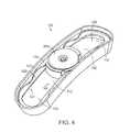
- FIG. 4illustrates a perspective view of an additional embodiment of a weight receptacle and weight member.
- FIG. 5illustrates a perspective view of the weight member of FIG. 4 .
- FIG. 6illustrates a perspective view of the second portion of the weight member of FIG. 5 .
- FIG. 7illustrates a perspective of the first portion of the weight member of FIG. 5 .
- FIG. 8illustrates a cross-sectional view of the weight receptacle and weight member of FIG. 4 .
- FIG. 9illustrates an additional cross-sectional view of the weight receptacle and weight member of FIG. 4 .
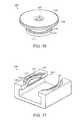
- FIG. 10illustrates perspective view of an additional embodiment of a weight receptacle and a weight member.
- FIG. 11illustrates a perspective view of the weight member of FIG. 10 .
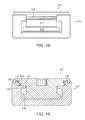
- FIG. 12illustrates an end view of the weight receptacle and a weight member of FIG. 10 .
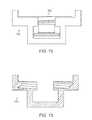
- FIG. 13illustrates a cross sectional view of the weight receptacle of FIG. 10 .
- FIG. 14illustrates a perspective view of an additional embodiment of a weight receptacle.
- FIG. 15illustrates a perspective view of an additional embodiment of a weight receptacle.
- FIG. 16illustrates a perspective view of an additional embodiment of a weight member.
- FIG. 17illustrates a perspective view of a portion of an additional embodiment of a weight receptacle.
- FIG. 18illustrates an end view of the weight member 200 of FIG. 16 and the weight receptacle of FIG. 17 .
- FIG. 19illustrates a cross-sectional view of the weight member and weight receptacle of FIG. 18 .
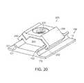
- FIG. 20illustrates a partial perspective view of additional embodiments of a weight receptacle and a weight member.
- FIG. 21illustrates a perspective view of the weight member of FIG. 20 .
- FIG. 22illustrates a cross-sectional view of the weight member of FIG. 20 .
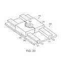
- FIG. 23illustrates a partial perspective view of additional embodiments of a weight receptacle and a weight member.
- FIG. 24illustrates a perspective view of the weight member of FIG. 23 .
- FIG. 25illustrates a cross-sectional view of the weight member of FIG. 24 .
- FIG. 26illustrates a cross-sectional view of an additional embodiment of a weight receptacle and a weight member.
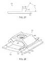
- FIG. 27illustrates an end view of the weight receptacle of FIG. 26 .
- FIG. 28illustrates a perspective view of an additional embodiment of the weight receptacle and a weight member of FIG. 20 .
- Embodiments described hereingenerally relate to systems, devices, and methods related to golf club heads having movable weight members.
- the golf club heads discussed hereinare generally hollow metal wood type golf club heads, but may include any club head type, such as iron-type golf club heads.
- the inventive golf club headsgenerally include a movable weight member, the movable weight configured to be selectively locked into a plurality of positions in order to manipulate the location of the center of gravity of the golf club head to better suit a golfer's swing characteristics and optimize ball flight.
- the embodiments described hereinare generally illustrated so that the weight member is attached at least partially to the sole for convenience, but one skilled in the art will appreciate that the weight member could be attached to other portions of the golf club head, which may include for example, the crown, the skirt, etc.
- FIG. 1illustrates a perspective view of a golf club head 10 .
- Golf club head 10includes a body 12 having a striking face 14 , a sole 16 , a crown 18 , a skirt 20 , and a hosel 22 .
- the body 12defines a hollow interior volume.
- the bodyalso has an exterior surface 13 , opposite the interior volume.
- FIG. 2illustrates a perspective view of the sole 16 of the golf club head 10 of FIG. 1 .
- FIG. 3illustrates a perspective view of the sole 16 of an additional embodiment of a golf club head 10 .
- the sole 16generally provides the lower surface of the golf club head 10 when the golf club head 10 is placed in an address position.
- the golf club head 10includes a weight receptacle 100 configured to receive and retain a weight member 200 (not illustrated in FIG. 2 ).
- the weight receptacle 100is configured to selectively lock a weight member 200 in one of a plurality of lock positions 110 , depending on where the golfer would prefer the weight member 200 to be located within the weight receptacle 100 .
- the weight member 200 and weight receptacle 100are configured to enable a golfer to alter the location of the CG of the golf club head 10 by manipulating the location of the weight member 200 within the weight receptacle 100 .
- weight receptacles 100are at least partially located on the sole 16 for convenience.
- weight receptacles 100 having the same structures as those described hereinmay be located on any portion of the golf club head 10 , such as the crown 18 and/or skirt 20 .
- many embodiments of weight receptacles described hereinare illustrated separate from the golf club head for convenience.
- weight receptacles 100 described hereinare intended to be affixed to the golf club head 10 or formed integrally with the golf club head 10 .
- the weight receptacles 100could be affixed to the golf club head 10 in a variety of ways, which may include, for example, welding, brazing, adhesives, mechanical locks, fasteners, etc.
- FIG. 4illustrates a perspective view of an additional embodiment of a weight receptacle 100 . Also illustrated in FIG. 4 is a weight member 200 locked into one of the plurality of locking positions 110 .
- FIG. 5illustrates a perspective view of the weight member 200 of FIG. 4 .
- FIG. 6illustrates a perspective view of the second portion 220 of the weight member 200 of FIG. 5 .
- FIG. 7illustrates a perspective of the first portion 210 of the weight member 200 of FIG. 5 .
- the weight member 200is able to slide along the weight receptacle 100 when the weight member 200 is unlocked and can be locked into any of the lock positions 110 by rotating a portion of the weight member 200 with a tool.
- the first portion 210is formed separately from the second portion 220 , and the second portion 220 is configured to rotate relative to the first portion 210 .
- the weight member 200is configured to lock to the weight receptacle 100 by rotating the second portion 220 in a first direction relative to the first portion 210 .
- the first portionincludes a flange 216 and a pair of engagement members 212 extending up from the flange 216 .
- the flangeincludes an abutment surface 218 configured to abut a portion of the weight receptacle 100 .
- the engagement members 212are configured to engage the second portion 220 to lock the weight member 200 in the weight receptacle 100 .
- the engagement members 212include a threaded portion 213 configured to engage the second portion 220 of the weight member 200 .
- the second portionincludes a threaded portion 224 configured to engage the first portion 210 and lock the weight member 200 in the weight receptacle 100 .
- the second portion 220also includes a tool engagement feature 222 configured to receive a tool (not illustrated) so that the user can rotate the second portion 220 relative to the first portion 210 .
- FIG. 8illustrates a cross-sectional view of the weight receptacle 100 and weight member 200 of FIG. 4 .
- FIG. 9illustrates an additional cross-sectional view of the weight receptacle 100 and weight member 200 of FIG. 4 .
- the weight receptacle 100includes a first locking rail 121 , on a first side of the weight receptacle 100 , which runs along the length of the weight receptacle 100 and a second locking rail 122 , on a second side of the weight receptacle 100 , which runs along the length of the weight receptacle 100 .
- the first locking rail 121 and second locking rail 122are configured to releasably couple the weight member 200 to the weight receptacle 100 .
- the weight member 200is configured to lock to the weight receptacle 100 by engaging the first locking rail 121 and the second locking rail 122 . At least a portion of the weight member 200 is configured to reside between the first locking rail 121 and the second locking rail 122 .
- the second portion 220 of the weight member 200is configured to rotate relative to the first portion 210 , and as the second portion 220 rotates, the threaded portion 224 engages the threaded portion 213 of the first portion, causing the second portion 220 to translate towards the abutment surface 218 of the first portion.
- the first portion 210 of the weight memberincludes slide walls 214 configured to slide along the weight receptacle 100 and prevent the first portion 210 of the weight member 200 from rotating relative to the weight receptacle 100 .
- the flange portion 216 of the weight member 200is configured to have a width greater than that of the channel 129 created between the first locking rail 121 and the second locking rail 122 of the weight receptacle 200 .
- the flange portion 216prevents the weight member 200 from falling out of the weight receptacle 200 even when the weight member 200 is unlocked by rotating the second member 220 in a second direction, opposite the first direction. This conveniently retains the weight member 200 in the weight receptacle 100 but allows the user to slide the weight member 200 along the weight receptacle 100 to a different lock position 110 when the weight member 200 is unlocked.
- the locking rails 121 , 122also include a plurality of locking recesses 125 located adjacent each locking position 110 configured to aid in locking the weight member 200 in place in the weight receptacle 100 .
- the locking recesses 125are regions of the locking rails 121 , 122 which have reduced thickness, creating thin portions 123 and thick portions 124 of the locking rails 121 , 122 .
- the locking recesses 125create a locking wall 126 which the weight member 200 abuts when locked into the locking position 110 , preventing the weight member from sliding within the weight receptacle 100 when the weight member 200 is in a locked position. As illustrated in FIGS.
- the second portion 220 of the weight member 200can reside in the locking recess 125 when the weight member 200 is in a locked position.
- the user wants to unlock the weight member 200they can rotate the second member in a second direction, moving the second portion 220 away from the first portion 210 and out of the locking recess 125 , allowing the weight member 200 to slide along the weight receptacle 100 to a different lock position 110 .
- FIG. 10illustrates perspective view of an additional embodiment of a weight receptacle 100 and a weight member 200 .
- FIG. 11illustrates a perspective view of the weight member 200 of FIG. 10 .
- FIG. 12illustrates an end view of the weight receptacle 100 and a weight member 200 of FIG. 10 .
- FIG. 13illustrates a cross sectional view of the weight receptacle 100 of FIG. 10 .
- the weight receptacle 100 and weight member 200are similar to the embodiments illustrated in FIGS. 4-9 but include a few key differences.
- the weight member 200includes a second portion 220 which includes a threaded portion 224 , which is configured to engage the weight receptacle 100 .
- the weight member 200also includes a first portion 210 including a flange 216 located below the second portion 220 and affixed to the second portion 220 via an extension member 217 .
- the first portion 210is either formed integrally with the second portion 220 or permanently affixed such that they rotate together.
- the weight receptacle 100includes a plurality of lock positions 110 .
- the weight receptaclealso includes a first locking rail 121 and a second locking rail 122 .
- Each locking rail 121 , 122includes locking recesses 125 at each lock position 110 .
- the locking recesses 125create thin portions 123 and thick portions 124 of the locking rails 121 , 122 .
- the locking recesses 125create a locking wall 126 , which as illustrated in FIGS. 10 and 13 , are threaded to engage the threaded portion 224 of the weight member 200 .
- the weight member 200can be locked into the weight receptacle 200 by rotating the weight member 200 in a first direction so that the threaded portion 224 engages the threaded locking wall 126 of the weight receptacle 100 and the second portion 220 of the weight member abuts the thin portion 123 of the locking rails 121 , 122 .
- the flangecould abut the lower surface of the weight receptacle 100 .
- the flange 216is configured to have a width greater than the channel formed between the first locking rail 121 and the second locking rail 122 .
- the flange portion 216prevents the weight member 200 from falling out of the weight receptacle 200 even when the weight member 200 is unlocked.
- the extension member 217includes enough length such that the weight member 200 can be unlocked to disengage the threaded portion 224 from the threaded locking wall 126 of the weight receptacle and allow the weight member 200 to slide along the weight receptacle 100 to another lock position 110 .
- FIG. 14illustrates a perspective view of an additional embodiment of a weight receptacle 100 .
- FIG. 15illustrates a perspective view of an additional embodiment of a weight receptacle 100 .
- the weight receptaclecan allow for the weight member 200 to be moved along more than one axis, providing even more capability for adjustment of the location of the CG of the golf club head.
- FIG. 16illustrates a perspective view of an additional embodiment of a weight member 200 .
- FIG. 17illustrates a perspective view of a portion of an additional embodiment of a weight receptacle 100 .
- FIG. 18illustrates an end view of the weight member 200 of FIG. 16 and the weight receptacle 100 of FIG. 17 .
- FIG. 19illustrates a cross-sectional view of the weight member 200 and weight receptacle 100 of FIG. 18 .
- the weight receptacle 100 and weight member 200are similar to the embodiments illustrated in FIGS. 10-13 , but include a few key differences.
- the locking rails 121 , 122include retention rails 131 , 132 which extend upwards, substantially parallel to the axis of rotation of the weight member 200 .
- the weight member 200includes an engagement member 230 configured to extend around and abut the retention rails 131 , 132 .
- One challenge with weight receptaclescan be the tendency of the weight receptacle to flex or deform when the golf club head strikes a golf ball.
- the weight member 200generally prevents the first locking rail 121 from deflecting towards the second locking rail 121 , since it is lodged between the two locking rails 121 , 122 .
- the golf club headcan flex and cause the first locking rail 121 to deform away from the second locking rail 122 .
- the engagement member 230can engage the retention rails 131 , 132 , and the weight member 200 can limit the amount the first locking rail 121 can travel away from the second locking rail 122 .
- FIG. 20illustrates a partial perspective view of additional embodiments of a weight receptacle 100 and a weight member 200 .
- FIG. 21illustrates a perspective view of the weight member 200 of FIG. 20 .
- FIG. 22illustrates a cross-sectional view of the weight member 200 of FIG. 20 .
- the weight receptacle 200includes a first locking rail 121 and a second locking rail 122 , each running the length of the weight receptacle, the locking rails 121 , 122 configured to engage the weight member 200 and lock it in place.
- the locking rails 121 , 122also perform the role of the retention rails 131 , 132 described above.
- the locking rails 121 , 122are capable of not only slideably retaining the weight member 200 when it is in an unlocked position and locking the weight member 200 to the weight receptacle 100 when the weight member 200 is in a locked position, but they also engage the weight member 200 when the weight member 200 is in a locked position in order to limit deformation of the weight receptacle 100 during golf ball impact.
- the locking rails 121 , 122can be substantially linear as illustrated in FIGS. 20 and 22 . Additionally, the locking rails 121 can be formed at an angle as illustrated in FIGS. 20 and 22 .
- the weight member 200includes a first member 240 , a second member 250 , and a third member 260 .
- the first member 240includes an engagement member 242 configured to engage the first locking rail 121 when the weight member 200 is in a locked position.
- the second member 250includes an engagement member 252 configured to engage the second locking rail 122 when the weight member 200 is in a locked position.
- the first member 240includes an angled abutment surface 245 configured to engage the second member 250 .
- the second member 255includes an angled abutment surface 255 configured to engage the first member 240 .
- the first member 240includes a threaded bore 280 .
- the second member 250includes a through bore 270 .
- the third member 260can be a threaded fastener configured to pass through the through bore 280 and engage the threaded bore 280 . To lock the weight member 200 in place, the third member 260 is rotated in a first direction, the third member 260 compressing the second member 250 toward the second member 240 along the axis of rotation of the third member.
- the angled abutment surfaces 245 , 255are configured such that the first member 240 moves towards the second locking rail 122 and the second member moves towards the first locking rail 121 as the third member is rotated in a first direction, allowing the first engagement member 242 to engage the first locking rail 121 and the second engagement member 252 to engage the second locking rail 122 , locking the weight member 200 in place in the weight receptacle 100 .
- the weight memberhas a width W, when the weight member 200 is in a locked position the width W is smaller than when said weight member 200 is in an unlocked position.
- the weight member 200engages the locking rails 121 , 122 in such a manner that it limits the weight receptacle from deforming and forcing the first locking rail 121 away from the second locking rail 122 , minimizing chances of the weight member 200 from incidentally coming unlocked due to the golf club head impacting a golf ball. It is also worth noting that the through bore 270 has a larger diameter than the third member 260 to allow the first member 240 to translate relative to the second member 250 .
- FIG. 23illustrates a partial perspective view of additional embodiments of a weight receptacle 100 and a weight member 200 .
- FIG. 24illustrates a perspective view of the weight member 200 of FIG. 23 .
- FIG. 25illustrates a cross-sectional view of the weight member 200 of FIG. 24 .
- the weight receptacle 100 and weight member 200are similar to the embodiments illustrated in FIGS. 20-22 but include a few key differences.
- the locking rails 121 , 122 in the present embodimentare L-shaped rather than substantially linear and angled like in FIGS. 20-22 . Accordingly, the engagement members 242 , 252 are shaped and configured to engage the locking rails 121 , 122 .
- the second member 250includes a threaded bore 280 configured to engage the third member 260 .
- the first member 240includes an angled abutment surface 245 configured to engage the third member 260 .
- the third member 260 in the present embodimentis a set screw with a tapered end configured to engage the angled abutment surface 245 of the first member. As the third member 260 is rotated in a first direction, it translates along its axis of rotation towards weight receptacle 100 .
- the taper of the third member 260engages the angled abutment surface 245 of the first member 240 , causing the first member to translate towards the second locking rail 122 and the second member 250 to translate towards the first locking rail 121 .
- rotating the third member 260 in the first directioncauses the first engagement member 242 to engage the first locking rail 121 and the second engagement member 252 to engage the second locking arm 122 , locking the weight member 200 in place in the weight receptacle 100 .
- FIGS. 20-22could include the locking rails 121 , 122 of FIGS. 23-25 . Additionally the embodiments illustrated in FIGS. 23-25 20 - 22 could include the locking rails 121 , 122 of FIGS. 20-22 . Furthermore, the embodiments illustrated in FIGS. 20-22 could include the abutment surfaces and third member of FIGS. 23-25 . Additionally, the embodiments illustrated in FIGS. 23-25 could include the abutment surfaces and third member of FIGS. 20-22 . Most importantly, any of the features described herein in any of the embodiments could be applied to any of the other embodiments described herein without departing from the scope of this disclosure.
- FIG. 26illustrates a cross-sectional view of an additional embodiment of a weight receptacle 100 and a weight member 100 .
- this weight receptacle 100only includes a single locking rail.
- the locking rail 122is tapered in thickness.
- the third member 260is rotated in a first direction and engaged the angled abutment surface 245 of the first member, causing the first member to translate towards the locking rail 122 and the first member 240 and the engagement member 252 to compress towards the locking rail 122 , locking the weight member 200 in place to the weight receptacle 100 .
- FIG. 27illustrates an end view of the weight receptacle 100 of FIG. 26 .
- the locking rail 132includes a rail locking surface 133 configured to abut the engagement member 252 of the weight member 200 .
- the rail locking surface 133can be angled relative to the bottom of the weight receptacle, which in some embodiments, and as illustrated in FIG. 27 may be a portion of the sole 16 , and in other embodiments may be another exterior surface 13 of the golf club head.
- the rail angle A between the locking surface and the exterior surface 13is between 85 and 15 degrees.
- the rail angle A between the locking surface 133 and the exterior surface 13is between 75 and 25 degrees.
- the rail angle A between the locking surface and the exterior surface 13is between 65 and 35 degrees.
- the rail angle A between the locking surface and the exterior surface 13is between 55 and 45 degrees.
- FIG. 28illustrates a perspective view of an additional embodiment of the weight receptacle 100 and a weight member 200 of FIG. 20 .
- This embodimentincludes a plurality of protrusions 134 extending outwards from the locking surface 133 of the locking rail 132 configured to engage the weight member 200 . These protrusions can help to limit movement of the weight member 200 when the weight member is in a locked position.
- the engagement member 252can also include complimentary recesses (not illustrated) configured to engage the protrusions.
- the locking rail 132can include recesses and the engagement member can include protrusions configured to engage the recesses when the weight member 200 is in a locked position.
Landscapes
- Health & Medical Sciences (AREA)
- General Health & Medical Sciences (AREA)
- Physical Education & Sports Medicine (AREA)
- Life Sciences & Earth Sciences (AREA)
- Engineering & Computer Science (AREA)
- Wood Science & Technology (AREA)
- Golf Clubs (AREA)
Abstract
Description
Claims (20)
Priority Applications (4)
| Application Number | Priority Date | Filing Date | Title |
|---|---|---|---|
| US15/257,692US9914028B1 (en) | 2016-09-06 | 2016-09-06 | Golf club with movable weight |
| US15/282,854US9975019B2 (en) | 2015-12-22 | 2016-09-30 | Golf club with movable weight |
| US15/365,471US10035051B2 (en) | 2015-12-22 | 2016-11-30 | Golf club with movable weight |
| US16/046,789US10391368B2 (en) | 2015-12-22 | 2018-07-26 | Golf club with movable weight |
Applications Claiming Priority (1)
| Application Number | Priority Date | Filing Date | Title |
|---|---|---|---|
| US15/257,692US9914028B1 (en) | 2016-09-06 | 2016-09-06 | Golf club with movable weight |
Related Parent Applications (1)
| Application Number | Title | Priority Date | Filing Date |
|---|---|---|---|
| US14/979,151Continuation-In-PartUS9744415B2 (en) | 2015-12-22 | 2015-12-22 | Golf club having removable weight |
Related Child Applications (2)
| Application Number | Title | Priority Date | Filing Date |
|---|---|---|---|
| US14/979,151Continuation-In-PartUS9744415B2 (en) | 2015-12-22 | 2015-12-22 | Golf club having removable weight |
| US15/282,854Continuation-In-PartUS9975019B2 (en) | 2015-12-22 | 2016-09-30 | Golf club with movable weight |
Publications (2)
| Publication Number | Publication Date |
|---|---|
| US20180065005A1 US20180065005A1 (en) | 2018-03-08 |
| US9914028B1true US9914028B1 (en) | 2018-03-13 |
Family
ID=61282372
Family Applications (1)
| Application Number | Title | Priority Date | Filing Date |
|---|---|---|---|
| US15/257,692ActiveUS9914028B1 (en) | 2015-12-22 | 2016-09-06 | Golf club with movable weight |
Country Status (1)
| Country | Link |
|---|---|
| US (1) | US9914028B1 (en) |
Cited By (27)
| Publication number | Priority date | Publication date | Assignee | Title |
|---|---|---|---|---|
| US10159880B1 (en)* | 2017-07-25 | 2018-12-25 | Mizuno Corporation | Adjustable metal wood golf club head with moveable weight structure |
| US10183203B1 (en)* | 2017-12-22 | 2019-01-22 | Acushnet Company | Golf club having movable weight |
| US10188916B2 (en)* | 2017-06-05 | 2019-01-29 | Taylor Made Golf Company, Inc. | Golf club head |
| US10213665B1 (en)* | 2015-07-13 | 2019-02-26 | Cobra Golf Incorporated | Golf club head with adjustable weight |
| US20190192928A1 (en)* | 2017-12-22 | 2019-06-27 | Acushnet Company | Golf club having movable weight and cover |
| US10369437B1 (en) | 2018-08-20 | 2019-08-06 | Acushnet Company | Wood-type golf club including center of gravity adjustment |
| US10376756B2 (en) | 2016-10-31 | 2019-08-13 | Acushnet Company | Golf club having removable weight |
| US10518145B2 (en) | 2016-10-31 | 2019-12-31 | Acushnet Company | Golf club having removable weight |
| US10525314B2 (en) | 2016-10-31 | 2020-01-07 | Acushnet Company | Golf club having removable weight |
| US10786713B2 (en) | 2016-10-31 | 2020-09-29 | Acushnet Company | Golf club having removable weight |
| US10835791B1 (en)* | 2020-03-02 | 2020-11-17 | Callaway Golf Company | Golf club head with adjustable sole weight |
| US11013966B2 (en) | 2016-10-31 | 2021-05-25 | Acushnet Company | Golf club having removable weight |
| US11020637B2 (en)* | 2016-06-29 | 2021-06-01 | Karsten Manufacturing Corporation | Golf club head having an adjustable weighting system |
| TWI732714B (en)* | 2020-11-16 | 2021-07-01 | 明安國際企業股份有限公司 | Counterweight component and golf club head with the counterweight component |
| US11207577B1 (en)* | 2020-03-04 | 2021-12-28 | Cobra Golf Incorporated | Systems and methods for a weighted golf club head |
| US20220134197A1 (en)* | 2018-12-13 | 2022-05-05 | Acushnet Company | Golf club head with improved inertia performance |
| US11331548B2 (en) | 2015-08-14 | 2022-05-17 | Taylor Made Golf Company, Inc. | Golf club head |
| US20220203183A1 (en)* | 2020-12-28 | 2022-06-30 | Taylor Made Golf Company, Inc. | Golf club heads |
| US20220203184A1 (en)* | 2020-12-28 | 2022-06-30 | Taylor Made Golf Company, Inc. | Golf club heads |
| US11541283B1 (en) | 2020-03-04 | 2023-01-03 | Cobra Golf Incorporated | Systems and methods for a weighted golf club head |
| US11654336B2 (en) | 2010-12-28 | 2023-05-23 | Taylor Made Golf Company, Inc. | Golf club head |
| US11684830B2 (en)* | 2020-03-24 | 2023-06-27 | Sumitomo Rubber Industries, Ltd. | Golf club head with sliding weight and cover |
| US20240009870A1 (en)* | 2022-07-06 | 2024-01-11 | Benchmade Knife Co., Inc. | Adjustable weighting system in knife handles |
| US20240017137A1 (en)* | 2022-07-12 | 2024-01-18 | Acushnet Company | Golf club having an adjustable weight assembly |
| US20240017138A1 (en)* | 2022-07-12 | 2024-01-18 | Acushnet Company | Golf club having an adjustable weight assembly |
| US20240066365A1 (en)* | 2022-08-24 | 2024-02-29 | Karsten Manufacturing Corporation | Golf club heads with dynamic back weights |
| US12440732B2 (en) | 2023-04-17 | 2025-10-14 | Taylor Made Golf Company, Inc. | Golf club head |
Families Citing this family (13)
| Publication number | Priority date | Publication date | Assignee | Title |
|---|---|---|---|---|
| US20220379180A1 (en)* | 2019-04-18 | 2022-12-01 | Acushnet Company | Golf club having an adjustable weight assembly |
| US11090536B2 (en) | 2019-04-18 | 2021-08-17 | Acushnet Company | Golf club having an adjustable weight assembly |
| US20230233912A1 (en)* | 2019-04-18 | 2023-07-27 | Acushnet Company | Golf club having an adjustable weight assembly |
| US20220347530A1 (en) | 2019-04-18 | 2022-11-03 | Acushnet Company | Golf club having an adjustable weight assembly |
| US12415120B2 (en)* | 2019-04-18 | 2025-09-16 | Acushnet Company | Golf club having an adjustable weight assembly |
| US20220111263A1 (en)* | 2019-04-18 | 2022-04-14 | Acushnet Company | Golf club having an adjustable weight assembly |
| US11497974B2 (en)* | 2019-04-18 | 2022-11-15 | Acushnet Company | Golf club having an adjustable weight assembly |
| US20230330499A1 (en)* | 2020-04-08 | 2023-10-19 | Acushnet Company | Modular golf club including an adjustable weight assembly |
| JP2023128177A (en)* | 2022-03-03 | 2023-09-14 | 住友ゴム工業株式会社 | golf club head |
| US11794082B1 (en)* | 2022-06-03 | 2023-10-24 | Mizuno Corporation | Golf club head with sole side features |
| JP7180025B1 (en)* | 2022-06-03 | 2022-11-29 | グローブライド株式会社 | golf club head |
| US20240066368A1 (en)* | 2022-08-30 | 2024-02-29 | Acushnet Company | Golf club including swivelable weight |
| US20240066366A1 (en)* | 2022-08-30 | 2024-02-29 | Acushnet Company | Golf club head with adjustable viewable weighting |
Citations (191)
| Publication number | Priority date | Publication date | Assignee | Title |
|---|---|---|---|---|
| US80435A (en) | 1868-07-28 | John a | ||
| US996937A (en) | 1910-07-20 | 1911-07-04 | William Redford Mulock | Fountain-pen. |
| US1133129A (en) | 1913-03-06 | 1915-03-23 | James Govan | Golf-club. |
| US1167106A (en) | 1914-06-11 | 1916-01-04 | Oliver M Palmer | Golf-club. |
| US1320163A (en) | 1919-10-28 | Oole-cltjb attachment | ||
| US1322182A (en) | 1918-12-13 | 1919-11-18 | Alexander Duncan | Golf-club. |
| US1534600A (en) | 1921-07-21 | 1925-04-21 | Crawford Mcgregor & Canby Co | Golf club |
| US2155830A (en) | 1938-09-24 | 1939-04-25 | John J Howard | Golf club |
| US2171383A (en) | 1938-10-12 | 1939-08-29 | William L Wettlaufer | Golf club head |
| US2214356A (en) | 1938-04-20 | 1940-09-10 | William L Wettlaufer | Testing apparatus for golf clubs |
| US2517245A (en) | 1947-03-31 | 1950-08-01 | Julian M Scott | Golf club |
| US2545045A (en) | 1945-03-12 | 1951-03-13 | Rosan Joseph | Threaded insert protector |
| US2592013A (en) | 1950-07-07 | 1952-04-08 | Thomas F Curley | Golf club |
| US2652256A (en) | 1951-09-14 | 1953-09-15 | Wilbur H Thomas | Whip action device for the head of golf clubs |
| US3064980A (en) | 1959-12-29 | 1962-11-20 | James V Steiner | Variable golf club head |
| US3212783A (en) | 1962-05-21 | 1965-10-19 | Jackson D Bradley | Golf club head |
| US3220733A (en) | 1963-07-11 | 1965-11-30 | James H Saleeby | Putter with attached weight |
| US3259404A (en) | 1963-10-23 | 1966-07-05 | Parker Hannifin Corp | Sealed joint and gasket therefor |
| US3466047A (en) | 1966-10-03 | 1969-09-09 | Frank J Rodia | Golf club having adjustable weights |
| US3556533A (en) | 1968-08-29 | 1971-01-19 | Bancroft Racket Co | Sole plate secured to club head by screws of different specific gravities |
| US3604755A (en) | 1969-07-24 | 1971-09-14 | Cincinnati Mine Machinery Co | Cutter bar, cutter chain and sprocket assembly |
| US3652094A (en) | 1969-10-21 | 1972-03-28 | Cecil C Glover | Golf club with adjustable weighting plugs |
| US3692306A (en) | 1971-02-18 | 1972-09-19 | Cecil C Glover | Golf club having integrally formed face and sole plate with weight means |
| US3979123A (en) | 1973-11-28 | 1976-09-07 | Belmont Peter A | Golf club heads and process |
| US4026183A (en) | 1976-05-17 | 1977-05-31 | Illinois Tool Works Inc. | Sealing washer |
| US4027881A (en) | 1973-07-05 | 1977-06-07 | Paul Francis Marcel Hufenus | Tennis racket with variable balance and weight |
| US4043563A (en) | 1972-08-03 | 1977-08-23 | Roy Alexander Churchward | Golf club |
| US4052075A (en) | 1976-01-08 | 1977-10-04 | Daly C Robert | Golf club |
| US4085934A (en) | 1972-08-03 | 1978-04-25 | Roy Alexander Churchward | Golf club |
| US4194547A (en) | 1978-08-17 | 1980-03-25 | Sidor Edward J | Golf club holder |
| US4340230A (en) | 1981-02-06 | 1982-07-20 | Churchward Roy A | Weighted golf iron |
| US4423874A (en) | 1981-02-06 | 1984-01-03 | Stuff Jr Alfred O | Golf club head |
| US4443145A (en) | 1981-02-13 | 1984-04-17 | Firma Carl Freudenberg | Self-sealing washer |
| US4450904A (en) | 1978-03-31 | 1984-05-29 | Phillips Petroleum Company | Heat exchanger having means for supporting the tubes in spaced mutually parallel relation and suppressing vibration |
| GB2133295A (en) | 1983-01-12 | 1984-07-25 | Fujiro Kamifuku | A golf club having an adjustably weighted head |
| US4538790A (en) | 1983-03-24 | 1985-09-03 | Whitey Co. | Valve stem packing assembly |
| US4602787A (en) | 1984-01-11 | 1986-07-29 | Ryobi Limited | Hollow metal golf club head |
| US4795159A (en) | 1986-07-11 | 1989-01-03 | Yamaha Corporation | Wood-type golf club head |
| US4867458A (en) | 1987-07-17 | 1989-09-19 | Yamaha Corporation | Golf club head |
| US4869507A (en) | 1986-06-16 | 1989-09-26 | Players Golf, Inc. | Golf club |
| US4895371A (en) | 1988-07-29 | 1990-01-23 | Bushner Gerald F | Golf putter |
| US4958970A (en) | 1988-08-17 | 1990-09-25 | The United States Of America As Represented By The Secretary Of The Navy | Graduated-load spring washer system for screws and threaded fasteners |
| US5050879A (en) | 1990-01-22 | 1991-09-24 | Cipa Manufacturing Corporation | Golf driver with variable weighting for changing center of gravity |
| US5154424A (en) | 1991-01-07 | 1992-10-13 | Lo Kun Nan | Head of a golf club |
| US5168767A (en) | 1990-06-04 | 1992-12-08 | Nippon Thompson Co., Ltd. | Compact ball screw assembly |
| US5230509A (en) | 1992-04-13 | 1993-07-27 | Chavez Angel R | Versatile putter |
| US5236164A (en) | 1991-07-03 | 1993-08-17 | Davide Iorizzo | Suspension device for use on fabric structures |
| US5297794A (en) | 1993-01-14 | 1994-03-29 | Lu Clive S | Golf club and golf club head |
| US5316305A (en) | 1992-07-02 | 1994-05-31 | Wilson Sporting Goods Co. | Golf clubhead with multi-material soleplate |
| US5320005A (en) | 1993-11-05 | 1994-06-14 | Hsiao Chia Yuan | Bicycle pedal crank dismantling device |
| JPH06238022A (en) | 1993-02-12 | 1994-08-30 | Takehiko Oda | Putter of golf |
| US5518243A (en) | 1995-01-25 | 1996-05-21 | Zubi Golf Company | Wood-type golf club head with improved adjustable weight configuration |
| US5547326A (en) | 1994-02-25 | 1996-08-20 | Teckentrup Gmbh & Co. Kg | Spring washer for the securing of screws, nuts, or the like |
| US5571053A (en) | 1995-08-14 | 1996-11-05 | Lane; Stephen P. | Cantilever-weighted golf putter |
| US5683309A (en) | 1995-10-11 | 1997-11-04 | Reimers; Eric W. | Adjustable balance weighting system for golf clubs |
| US5688189A (en) | 1995-11-03 | 1997-11-18 | Bland; Bertram Alvin | Golf putter |
| US5720674A (en) | 1996-04-30 | 1998-02-24 | Taylor Made Golf Co. | Golf club head |
| JPH10137374A (en) | 1996-11-07 | 1998-05-26 | Injietsukusu:Kk | Golf club head and golf club |
| US5769737A (en) | 1997-03-26 | 1998-06-23 | Holladay; Brice R. | Adjustable weight golf club head |
| US5795245A (en) | 1996-12-18 | 1998-08-18 | Sung Ling Golf & Casting Co., Ltd. | Neck weighting structure for golf clubs |
| JPH10234902A (en) | 1997-02-24 | 1998-09-08 | Daiwa Seiko Inc | Golf club head and mounting of weight member to be mounted at the head |
| JPH10248964A (en) | 1997-03-13 | 1998-09-22 | Daiwa Seiko Inc | Golf club head, and method for attaching weight to the same |
| US5860779A (en) | 1997-11-26 | 1999-01-19 | Mcdonnell Douglas Corporation | Locking nut |
| US5904460A (en) | 1996-06-27 | 1999-05-18 | Opg Company Ltd. | Nut having frustum disc spring and washer for fastening wooden articles |
| US5916042A (en) | 1995-10-11 | 1999-06-29 | Reimers; Eric W. | Adjustable balance weighting system for golf clubs |
| US5935019A (en) | 1996-09-20 | 1999-08-10 | The Yokohama Rubber Co., Ltd. | Metallic hollow golf club head |
| US5947840A (en) | 1997-01-24 | 1999-09-07 | Ryan; William H. | Adjustable weight golf club |
| US5967905A (en) | 1997-02-17 | 1999-10-19 | The Yokohama Rubber Co., Ltd. | Golf club head and method for producing the same |
| JPH11319167A (en) | 1998-05-01 | 1999-11-24 | Shinsho Son | Golf club |
| JP2000005350A (en) | 1998-06-24 | 2000-01-11 | Yokohama Rubber Co Ltd:The | Golf club head and its production |
| US6015354A (en) | 1998-03-05 | 2000-01-18 | Ahn; Stephen C. | Golf club with adjustable total weight, center of gravity and balance |
| US6017177A (en) | 1997-10-06 | 2000-01-25 | Mcgard, Inc. | Multi-tier security fastener |
| US6056649A (en) | 1997-10-21 | 2000-05-02 | Daiwa Seiko, Inc. | Golf club head |
| JP2000176059A (en) | 1998-12-21 | 2000-06-27 | Yamaha Corp | Fixing structure and fixing method of head weight of golf club |
| US6089994A (en) | 1998-09-11 | 2000-07-18 | Sun; Donald J. C. | Golf club head with selective weighting device |
| US6123627A (en) | 1998-05-21 | 2000-09-26 | Antonious; Anthony J. | Golf club head with reinforcing outer support system having weight inserts |
| US6162132A (en) | 1999-02-25 | 2000-12-19 | Yonex Kabushiki Kaisha | Golf club head having hollow metal shell |
| JP2001000606A (en) | 1999-06-22 | 2001-01-09 | Daido Steel Co Ltd | Golf putter |
| JP2001149514A (en) | 1999-11-30 | 2001-06-05 | Daiwa Seiko Inc | Golf club head |
| US6277032B1 (en) | 1999-07-29 | 2001-08-21 | Vigor C. Smith | Movable weight golf clubs |
| US6296574B1 (en) | 1999-03-08 | 2001-10-02 | Alexis G. Kaldis | Golf swing improvement device |
| US6306048B1 (en) | 1999-01-22 | 2001-10-23 | Acushnet Company | Golf club head with weight adjustment |
| JP2002011124A (en) | 2000-05-23 | 2002-01-15 | Callaway Golf Co | Weight member for golf club head |
| US6348014B1 (en) | 2000-08-15 | 2002-02-19 | Chih Hung Chiu | Golf putter head and weight adjustable arrangement |
| US6379264B1 (en) | 1998-12-17 | 2002-04-30 | Richard Forzano | Putter |
| US6436142B1 (en) | 1998-12-14 | 2002-08-20 | Phoenix Biomedical Corp. | System for stabilizing the vertebral column including deployment instruments and variable expansion inserts therefor |
| US6458044B1 (en) | 2001-06-13 | 2002-10-01 | Taylor Made Golf Company, Inc. | Golf club head and method for making it |
| US20030148818A1 (en) | 2002-01-18 | 2003-08-07 | Myrhum Mark C. | Golf club woods with wood club head having a selectable center of gravity and a selectable shaft |
| US6719510B2 (en) | 2001-05-23 | 2004-04-13 | Huck Patents, Inc. | Self-locking fastener with threaded swageable collar |
| US6773360B2 (en) | 2002-11-08 | 2004-08-10 | Taylor Made Golf Company, Inc. | Golf club head having a removable weight |
| US6811496B2 (en) | 2000-12-01 | 2004-11-02 | Taylor Made Golf Company, Inc. | Golf club head |
| US6860818B2 (en) | 2002-06-17 | 2005-03-01 | Callaway Golf Company | Golf club head with peripheral weighting |
| US6881158B2 (en) | 2003-07-24 | 2005-04-19 | Fu Sheng Industrial Co., Ltd. | Weight number for a golf club head |
| JP3109501U (en) | 2004-12-21 | 2005-05-19 | 幸華 陳 | Golf club head with adjustable weight |
| JP2005160947A (en) | 2003-12-05 | 2005-06-23 | Bridgestone Sports Co Ltd | Golf club head |
| JP2005296582A (en) | 2004-04-15 | 2005-10-27 | Shiro Katagiri | Golf putter head having sliding balance implement |
| JP2005323978A (en) | 2004-05-17 | 2005-11-24 | Shiro Katagiri | Golf putter head with sliding type balance moving instrument |
| JP2006000435A (en) | 2004-06-18 | 2006-01-05 | Mizuno Corp | Golf club head |
| US20060058112A1 (en) | 2004-09-16 | 2006-03-16 | Greg Haralason | Golf club head with a weighting system |
| JP2006081862A (en) | 2004-09-20 | 2006-03-30 | Fu Sheng Industrial Co Ltd | Combination structure of golf club head and weight |
| US20060100029A1 (en) | 2004-11-09 | 2006-05-11 | Lai-Fa Lo | Golf club head with damping member |
| JP2006122334A (en) | 2004-10-28 | 2006-05-18 | Fu Sheng Industrial Co Ltd | Vibration absorbing structure of golf club head |
| US20060122004A1 (en) | 2004-12-06 | 2006-06-08 | Hsin-Hua Chen | Weight adjustable golf club head |
| JP2006187489A (en) | 2005-01-07 | 2006-07-20 | Koji Sakinaka | Golf club head |
| JP2006198251A (en) | 2005-01-21 | 2006-08-03 | Ota Precision Industry Co Ltd | Club head |
| JP2006239154A (en) | 2005-03-03 | 2006-09-14 | Nelson Precision Casting Co Ltd | Adjustment structure of composite material of golf club head |
| US20060217216A1 (en) | 2004-12-06 | 2006-09-28 | Macgregor Golf Company | Fairway wood with titanium face member |
| US7121956B2 (en) | 2004-10-26 | 2006-10-17 | Fu Sheng Industrial Co., Ltd. | Golf club head with weight member assembly |
| US20060240908A1 (en) | 2005-02-25 | 2006-10-26 | Adams Edwin H | Golf club head |
| JP2006320493A (en) | 2005-05-18 | 2006-11-30 | Sri Sports Ltd | Golf club head |
| US7147573B2 (en) | 2005-02-07 | 2006-12-12 | Callaway Golf Company | Golf club head with adjustable weighting |
| US7153220B2 (en) | 2004-11-16 | 2006-12-26 | Fu Sheng Industrial Co., Ltd. | Golf club head with adjustable weight member |
| US7166041B2 (en) | 2005-01-28 | 2007-01-23 | Callaway Golf Company | Golf clubhead with adjustable weighting |
| US7179034B2 (en) | 2002-10-16 | 2007-02-20 | Whitesell International Corporation | Torque resistant fastening element |
| US7186190B1 (en) | 2002-11-08 | 2007-03-06 | Taylor Made Golf Company, Inc. | Golf club head having movable weights |
| US7189169B2 (en) | 2002-01-10 | 2007-03-13 | Dogleg Right Corporation | Customizable center-of-gravity golf club head |
| US7201669B2 (en) | 2003-12-23 | 2007-04-10 | Nike, Inc. | Golf club head having a bridge member and a weight positioning system |
| US20070135231A1 (en) | 2005-12-09 | 2007-06-14 | Fu Sheng Industrial Co. Ltd. | Golf club head |
| US20070155534A1 (en) | 2005-12-29 | 2007-07-05 | Advanced International Multitech Co., Ltd. | Golf club head with dual weighted parties having fixing structure |
| US20070178988A1 (en) | 2006-02-01 | 2007-08-02 | Nike, Inc. | Golf clubs and golf club heads including cellular structure metals and other materials |
| US7294065B2 (en) | 2005-02-04 | 2007-11-13 | Fu Sheng Industrial Co., Ltd. | Weight assembly for golf club head |
| JP2007313304A (en) | 2006-04-26 | 2007-12-06 | Yasuyuki Kanamori | Golf putter |
| US20080020861A1 (en) | 2006-07-18 | 2008-01-24 | Huffy Sports Delaware, Inc. | Adjustable weight golf clubs |
| US7326472B2 (en) | 2002-05-16 | 2008-02-05 | Bridgestone Sports Co., Ltd. | Golf club head |
| US20080039229A1 (en) | 2006-08-09 | 2008-02-14 | Fu Sheng Industrial Co., Ltd. | Golf club head having removable weight |
| US7351161B2 (en) | 2005-01-10 | 2008-04-01 | Adam Beach | Scientifically adaptable driver |
| US20080132353A1 (en) | 2006-12-01 | 2008-06-05 | Pen-Long Hsiao | Weight adjustable golf club head |
| US7404772B2 (en) | 2005-08-24 | 2008-07-29 | Niigata Tlo Corporation | Golf putter |
| US7407447B2 (en) | 2002-11-08 | 2008-08-05 | Taylor Made Golf Company, Inc. | Movable weights for a golf club head |
| US7419441B2 (en) | 2002-11-08 | 2008-09-02 | Taylor Made Golf Company, Inc. | Golf club head weight reinforcement |
| US20080261715A1 (en) | 2006-08-03 | 2008-10-23 | Carter Vandette B | Golf club with adjustable center of gravity head |
| US7452286B2 (en) | 2006-05-09 | 2008-11-18 | O-Ta Precision Industry Co., Ltd. | Golf club head |
| US7520820B2 (en) | 2006-12-12 | 2009-04-21 | Callaway Golf Company | C-shaped golf club head |
| US7530901B2 (en) | 2004-10-20 | 2009-05-12 | Bridgestone Sports Co., Ltd. | Golf club head |
| WO2009102661A1 (en) | 2008-02-12 | 2009-08-20 | Nike, Inc. | Golf clubs and golf club heads heaving adjustable weight members |
| US7604548B2 (en) | 2005-03-01 | 2009-10-20 | Karsten Manufacturing Corporation | Weighted club heads and methods for forming the same |
| US7611424B2 (en) | 2007-02-12 | 2009-11-03 | Mizuno Usa, Inc. | Golf club head and golf club |
| US7628711B2 (en) | 2007-11-20 | 2009-12-08 | Advanced International Multitech Co., Ltd. | Golf club head |
| US7628707B2 (en) | 2002-11-08 | 2009-12-08 | Taylor Made Golf Company, Inc. | Golf club information system and methods |
| US20100075773A1 (en) | 2006-03-09 | 2010-03-25 | Power Golf Corporation | Sporting Article With Adjustable Weight Configuration |
| USD617858S1 (en) | 2009-07-07 | 2010-06-15 | Mizuno Usa, Inc. | Driver-type golf club head |
| US7744484B1 (en) | 2002-11-08 | 2010-06-29 | Taylor Made Golf Company, Inc. | Movable weights for a golf club head |
| US7758452B2 (en) | 2008-11-03 | 2010-07-20 | Acushnet Company | Golf club having removable sole weight |
| US7771290B2 (en) | 2008-05-30 | 2010-08-10 | Acushnet Company | Golf club head and removable weight |
| US7775905B2 (en) | 2006-12-19 | 2010-08-17 | Taylor Made Golf Company, Inc. | Golf club head with repositionable weight |
| US7927231B2 (en) | 2009-06-26 | 2011-04-19 | Bridgestone Sports Co., Ltd. | Golf club head |
| US8016694B2 (en) | 2007-02-12 | 2011-09-13 | Mizuno Usa | Golf club head and golf clubs |
| US8043167B2 (en) | 2008-12-18 | 2011-10-25 | Nike, Inc. | Golf clubs and golf club heads having interchangeable rear body members |
| JP2011229914A (en) | 2010-04-09 | 2011-11-17 | Sato Yoshikazu | Golf club |
| US8092316B2 (en) | 2006-11-27 | 2012-01-10 | Acushnet Company | Golf club having removable sole weight using custom and interchangeable panels |
| US8192302B2 (en) | 2008-05-30 | 2012-06-05 | Acushnet Company | Golf club head and removable weight |
| US8192303B2 (en) | 2008-09-19 | 2012-06-05 | Bridgestone Sports Co., Ltd. | Golf club head |
| US8202175B2 (en) | 2008-12-25 | 2012-06-19 | Bridgestone Sports Co., Ltd. | Golf club head |
| US8206243B2 (en) | 2009-08-26 | 2012-06-26 | Nike, Inc. | Golf clubs and golf club heads having a movable weight |
| US8308583B2 (en) | 2003-08-11 | 2012-11-13 | Cobra Golf Incorporated | Golf club head with alignment system |
| US8388465B2 (en) | 2008-11-03 | 2013-03-05 | Acushnet Company | Golf club having removeable sole weight |
| US8435135B2 (en) | 2010-05-28 | 2013-05-07 | Nike, Inc. | Golf club head or other ball striking device having removable or interchangeable body member |
| US8540589B2 (en) | 2008-05-30 | 2013-09-24 | Acushnet Company | Golf club head and removable weight |
| US8684863B2 (en) | 2011-12-27 | 2014-04-01 | Acushnet Company | Golf club having removable weight |
| US8696491B1 (en) | 2012-11-16 | 2014-04-15 | Callaway Golf Company | Golf club head with adjustable center of gravity |
| US20140113741A1 (en) | 2011-12-27 | 2014-04-24 | Acushnet Company | Golf Club Having Removable Weight |
| USD709572S1 (en) | 2013-06-13 | 2014-07-22 | Taylor Made Golf Company, Inc. | Golf club head |
| USD709571S1 (en) | 2013-06-13 | 2014-07-22 | Taylor Made Golf Company, Inc. | Golf club head |
| US8790195B1 (en) | 2012-12-27 | 2014-07-29 | Callaway Golf Company | Golf club head with adjustable characteristics |
| US8834294B1 (en) | 2012-06-08 | 2014-09-16 | Callaway Golf Company | Golf club head with center of gravity adjustability |
| US8888607B2 (en) | 2010-12-28 | 2014-11-18 | Taylor Made Golf Company, Inc. | Fairway wood center of gravity projection |
| US8894506B1 (en) | 2012-11-16 | 2014-11-25 | Callaway Golf Company | Golf club head with adjustable center of gravity |
| US8900069B2 (en) | 2010-12-28 | 2014-12-02 | Taylor Made Golf Company, Inc. | Fairway wood center of gravity projection |
| US8968116B1 (en) | 2012-12-27 | 2015-03-03 | Callaway Golf Company | Golf club head with adjustable characteristics |
| US9084921B1 (en) | 2012-11-16 | 2015-07-21 | Callaway Golf Company | Golf club head with adjustable center of gravity |
| US20150306475A1 (en) | 2014-04-25 | 2015-10-29 | Cobra Golf Incorporated | Golf club head with internal cap |
| US20150306474A1 (en) | 2014-04-25 | 2015-10-29 | Cobra Golf Incorporated | Golf club with adjustable weight assembly |
| US9174096B2 (en) | 2009-12-23 | 2015-11-03 | Taylor Made Golf Company, Inc. | Golf club head |
| US9180349B1 (en)* | 2012-06-08 | 2015-11-10 | Callaway Golf Company | Golf club head with adjustable center of gravity |
| US20150321055A1 (en)* | 2014-05-07 | 2015-11-12 | Acushnet Company | Metal wood club |
| US9211453B1 (en) | 2012-11-16 | 2015-12-15 | Callaway Golf Company | Golf club head with adjustable center of gravity |
| US9220953B2 (en) | 2010-12-28 | 2015-12-29 | Taylor Made Golf Company, Inc. | Fairway wood center of gravity projection |
| US9220957B1 (en) | 2012-12-27 | 2015-12-29 | Callaway Golf Company | Golf club head with adjustable characteristics |
| US20160001146A1 (en) | 2009-12-23 | 2016-01-07 | Taylor Made Golf Company, Inc. | Golf club head |
| US9238162B2 (en) | 2014-04-25 | 2016-01-19 | Cobra Golf Incorporated | Golf club with adjustable weight assembly |
| US9259627B1 (en) | 2012-06-08 | 2016-02-16 | Callaway Golf Company | Golf club head with adjustable center of gravity |
| US20160059093A1 (en) | 2009-12-23 | 2016-03-03 | Taylor Made Golf Company, Inc. | Golf club head |
| US20160059094A1 (en) | 2010-12-28 | 2016-03-03 | Taylor Made Golf Company, Inc. | Golf club |
| US9289660B1 (en) | 2012-11-16 | 2016-03-22 | Callaway Golf Company | Golf club head with adjustable center of gravity |
| US9308423B1 (en) | 2012-06-08 | 2016-04-12 | Callaway Golf Company | Golf club head with center of gravity adjustability |
| US20160129323A1 (en) | 2012-11-16 | 2016-05-12 | Callaway Golf Company | Golf club head with adjustable center of gravity |
| US9364728B1 (en) | 2012-11-16 | 2016-06-14 | Callaway Golf Company | Golf club head with adjustable center of gravity |
| US9387376B1 (en) | 2012-11-16 | 2016-07-12 | Callaway Golf Company | Slidable weight assembly |
| US20160375326A1 (en)* | 2013-10-21 | 2016-12-29 | Callaway Golf Company | Golf Club Head With Adjustable Center of Gravity |
| US9623294B1 (en)* | 2014-01-24 | 2017-04-18 | Callaway Golf Company | Golf club head with adjustable weighting |
| US9682298B1 (en)* | 2014-01-24 | 2017-06-20 | Callaway Golf Company | Golf club head with adjustable weighting |
- 2016
- 2016-09-06USUS15/257,692patent/US9914028B1/enactiveActive
Patent Citations (246)
| Publication number | Priority date | Publication date | Assignee | Title |
|---|---|---|---|---|
| US80435A (en) | 1868-07-28 | John a | ||
| US1320163A (en) | 1919-10-28 | Oole-cltjb attachment | ||
| US996937A (en) | 1910-07-20 | 1911-07-04 | William Redford Mulock | Fountain-pen. |
| US1133129A (en) | 1913-03-06 | 1915-03-23 | James Govan | Golf-club. |
| US1167106A (en) | 1914-06-11 | 1916-01-04 | Oliver M Palmer | Golf-club. |
| US1322182A (en) | 1918-12-13 | 1919-11-18 | Alexander Duncan | Golf-club. |
| US1534600A (en) | 1921-07-21 | 1925-04-21 | Crawford Mcgregor & Canby Co | Golf club |
| US2214356A (en) | 1938-04-20 | 1940-09-10 | William L Wettlaufer | Testing apparatus for golf clubs |
| US2155830A (en) | 1938-09-24 | 1939-04-25 | John J Howard | Golf club |
| US2171383A (en) | 1938-10-12 | 1939-08-29 | William L Wettlaufer | Golf club head |
| US2545045A (en) | 1945-03-12 | 1951-03-13 | Rosan Joseph | Threaded insert protector |
| US2517245A (en) | 1947-03-31 | 1950-08-01 | Julian M Scott | Golf club |
| US2592013A (en) | 1950-07-07 | 1952-04-08 | Thomas F Curley | Golf club |
| US2652256A (en) | 1951-09-14 | 1953-09-15 | Wilbur H Thomas | Whip action device for the head of golf clubs |
| US3064980A (en) | 1959-12-29 | 1962-11-20 | James V Steiner | Variable golf club head |
| US3212783A (en) | 1962-05-21 | 1965-10-19 | Jackson D Bradley | Golf club head |
| US3220733A (en) | 1963-07-11 | 1965-11-30 | James H Saleeby | Putter with attached weight |
| US3259404A (en) | 1963-10-23 | 1966-07-05 | Parker Hannifin Corp | Sealed joint and gasket therefor |
| US3466047A (en) | 1966-10-03 | 1969-09-09 | Frank J Rodia | Golf club having adjustable weights |
| US3556533A (en) | 1968-08-29 | 1971-01-19 | Bancroft Racket Co | Sole plate secured to club head by screws of different specific gravities |
| US3604755A (en) | 1969-07-24 | 1971-09-14 | Cincinnati Mine Machinery Co | Cutter bar, cutter chain and sprocket assembly |
| US3652094A (en) | 1969-10-21 | 1972-03-28 | Cecil C Glover | Golf club with adjustable weighting plugs |
| US3692306A (en) | 1971-02-18 | 1972-09-19 | Cecil C Glover | Golf club having integrally formed face and sole plate with weight means |
| US4043563A (en) | 1972-08-03 | 1977-08-23 | Roy Alexander Churchward | Golf club |
| US4085934A (en) | 1972-08-03 | 1978-04-25 | Roy Alexander Churchward | Golf club |
| US4027881A (en) | 1973-07-05 | 1977-06-07 | Paul Francis Marcel Hufenus | Tennis racket with variable balance and weight |
| US3979123A (en) | 1973-11-28 | 1976-09-07 | Belmont Peter A | Golf club heads and process |
| US4052075A (en) | 1976-01-08 | 1977-10-04 | Daly C Robert | Golf club |
| US4026183A (en) | 1976-05-17 | 1977-05-31 | Illinois Tool Works Inc. | Sealing washer |
| US4450904A (en) | 1978-03-31 | 1984-05-29 | Phillips Petroleum Company | Heat exchanger having means for supporting the tubes in spaced mutually parallel relation and suppressing vibration |
| US4194547A (en) | 1978-08-17 | 1980-03-25 | Sidor Edward J | Golf club holder |
| US4340230A (en) | 1981-02-06 | 1982-07-20 | Churchward Roy A | Weighted golf iron |
| US4423874A (en) | 1981-02-06 | 1984-01-03 | Stuff Jr Alfred O | Golf club head |
| US4443145A (en) | 1981-02-13 | 1984-04-17 | Firma Carl Freudenberg | Self-sealing washer |
| GB2133295A (en) | 1983-01-12 | 1984-07-25 | Fujiro Kamifuku | A golf club having an adjustably weighted head |
| US4538790A (en) | 1983-03-24 | 1985-09-03 | Whitey Co. | Valve stem packing assembly |
| US4602787A (en) | 1984-01-11 | 1986-07-29 | Ryobi Limited | Hollow metal golf club head |
| US4869507A (en) | 1986-06-16 | 1989-09-26 | Players Golf, Inc. | Golf club |
| US4795159A (en) | 1986-07-11 | 1989-01-03 | Yamaha Corporation | Wood-type golf club head |
| US4867458A (en) | 1987-07-17 | 1989-09-19 | Yamaha Corporation | Golf club head |
| US4895371A (en) | 1988-07-29 | 1990-01-23 | Bushner Gerald F | Golf putter |
| US4958970A (en) | 1988-08-17 | 1990-09-25 | The United States Of America As Represented By The Secretary Of The Navy | Graduated-load spring washer system for screws and threaded fasteners |
| US5050879A (en) | 1990-01-22 | 1991-09-24 | Cipa Manufacturing Corporation | Golf driver with variable weighting for changing center of gravity |
| US5168767A (en) | 1990-06-04 | 1992-12-08 | Nippon Thompson Co., Ltd. | Compact ball screw assembly |
| US5154424A (en) | 1991-01-07 | 1992-10-13 | Lo Kun Nan | Head of a golf club |
| US5236164A (en) | 1991-07-03 | 1993-08-17 | Davide Iorizzo | Suspension device for use on fabric structures |
| US5230509A (en) | 1992-04-13 | 1993-07-27 | Chavez Angel R | Versatile putter |
| US5316305A (en) | 1992-07-02 | 1994-05-31 | Wilson Sporting Goods Co. | Golf clubhead with multi-material soleplate |
| US5297794A (en) | 1993-01-14 | 1994-03-29 | Lu Clive S | Golf club and golf club head |
| JPH06238022A (en) | 1993-02-12 | 1994-08-30 | Takehiko Oda | Putter of golf |
| US5320005A (en) | 1993-11-05 | 1994-06-14 | Hsiao Chia Yuan | Bicycle pedal crank dismantling device |
| US5547326A (en) | 1994-02-25 | 1996-08-20 | Teckentrup Gmbh & Co. Kg | Spring washer for the securing of screws, nuts, or the like |
| US5518243A (en) | 1995-01-25 | 1996-05-21 | Zubi Golf Company | Wood-type golf club head with improved adjustable weight configuration |
| US5571053A (en) | 1995-08-14 | 1996-11-05 | Lane; Stephen P. | Cantilever-weighted golf putter |
| US5683309A (en) | 1995-10-11 | 1997-11-04 | Reimers; Eric W. | Adjustable balance weighting system for golf clubs |
| US5916042A (en) | 1995-10-11 | 1999-06-29 | Reimers; Eric W. | Adjustable balance weighting system for golf clubs |
| US5688189A (en) | 1995-11-03 | 1997-11-18 | Bland; Bertram Alvin | Golf putter |
| US5720674A (en) | 1996-04-30 | 1998-02-24 | Taylor Made Golf Co. | Golf club head |
| US6217461B1 (en) | 1996-04-30 | 2001-04-17 | Taylor Made Golf Company, Inc. | Golf club head |
| US5904460A (en) | 1996-06-27 | 1999-05-18 | Opg Company Ltd. | Nut having frustum disc spring and washer for fastening wooden articles |
| US5935019A (en) | 1996-09-20 | 1999-08-10 | The Yokohama Rubber Co., Ltd. | Metallic hollow golf club head |
| JPH10137374A (en) | 1996-11-07 | 1998-05-26 | Injietsukusu:Kk | Golf club head and golf club |
| US5795245A (en) | 1996-12-18 | 1998-08-18 | Sung Ling Golf & Casting Co., Ltd. | Neck weighting structure for golf clubs |
| US5947840A (en) | 1997-01-24 | 1999-09-07 | Ryan; William H. | Adjustable weight golf club |
| US5967905A (en) | 1997-02-17 | 1999-10-19 | The Yokohama Rubber Co., Ltd. | Golf club head and method for producing the same |
| JPH10234902A (en) | 1997-02-24 | 1998-09-08 | Daiwa Seiko Inc | Golf club head and mounting of weight member to be mounted at the head |
| JPH10248964A (en) | 1997-03-13 | 1998-09-22 | Daiwa Seiko Inc | Golf club head, and method for attaching weight to the same |
| US5769737A (en) | 1997-03-26 | 1998-06-23 | Holladay; Brice R. | Adjustable weight golf club head |
| US6017177A (en) | 1997-10-06 | 2000-01-25 | Mcgard, Inc. | Multi-tier security fastener |
| US6056649A (en) | 1997-10-21 | 2000-05-02 | Daiwa Seiko, Inc. | Golf club head |
| US5860779A (en) | 1997-11-26 | 1999-01-19 | Mcdonnell Douglas Corporation | Locking nut |
| US6015354A (en) | 1998-03-05 | 2000-01-18 | Ahn; Stephen C. | Golf club with adjustable total weight, center of gravity and balance |
| JPH11319167A (en) | 1998-05-01 | 1999-11-24 | Shinsho Son | Golf club |
| US6123627A (en) | 1998-05-21 | 2000-09-26 | Antonious; Anthony J. | Golf club head with reinforcing outer support system having weight inserts |
| JP2000005350A (en) | 1998-06-24 | 2000-01-11 | Yokohama Rubber Co Ltd:The | Golf club head and its production |
| US6089994A (en) | 1998-09-11 | 2000-07-18 | Sun; Donald J. C. | Golf club head with selective weighting device |
| US6436142B1 (en) | 1998-12-14 | 2002-08-20 | Phoenix Biomedical Corp. | System for stabilizing the vertebral column including deployment instruments and variable expansion inserts therefor |
| US6749523B1 (en) | 1998-12-17 | 2004-06-15 | Richard J. Forzano | Putter |
| US6379264B1 (en) | 1998-12-17 | 2002-04-30 | Richard Forzano | Putter |
| US6379265B1 (en) | 1998-12-21 | 2002-04-30 | Yamaha Corporation | Structure and method of fastening a weight body to a golf club head |
| JP2000176059A (en) | 1998-12-21 | 2000-06-27 | Yamaha Corp | Fixing structure and fixing method of head weight of golf club |
| US6306048B1 (en) | 1999-01-22 | 2001-10-23 | Acushnet Company | Golf club head with weight adjustment |
| US6162132A (en) | 1999-02-25 | 2000-12-19 | Yonex Kabushiki Kaisha | Golf club head having hollow metal shell |
| US6296574B1 (en) | 1999-03-08 | 2001-10-02 | Alexis G. Kaldis | Golf swing improvement device |
| JP2001000606A (en) | 1999-06-22 | 2001-01-09 | Daido Steel Co Ltd | Golf putter |
| US6277032B1 (en) | 1999-07-29 | 2001-08-21 | Vigor C. Smith | Movable weight golf clubs |
| JP2001149514A (en) | 1999-11-30 | 2001-06-05 | Daiwa Seiko Inc | Golf club head |
| US6409612B1 (en) | 2000-05-23 | 2002-06-25 | Callaway Golf Company | Weighting member for a golf club head |
| JP2002011124A (en) | 2000-05-23 | 2002-01-15 | Callaway Golf Co | Weight member for golf club head |
| US6348014B1 (en) | 2000-08-15 | 2002-02-19 | Chih Hung Chiu | Golf putter head and weight adjustable arrangement |
| US6811496B2 (en) | 2000-12-01 | 2004-11-02 | Taylor Made Golf Company, Inc. | Golf club head |
| US6719510B2 (en) | 2001-05-23 | 2004-04-13 | Huck Patents, Inc. | Self-locking fastener with threaded swageable collar |
| US6648772B2 (en) | 2001-06-13 | 2003-11-18 | Taylor Made Golf Company, Inc. | Golf club head and method for making it |
| US6458044B1 (en) | 2001-06-13 | 2002-10-01 | Taylor Made Golf Company, Inc. | Golf club head and method for making it |
| US7189169B2 (en) | 2002-01-10 | 2007-03-13 | Dogleg Right Corporation | Customizable center-of-gravity golf club head |
| US20030148818A1 (en) | 2002-01-18 | 2003-08-07 | Myrhum Mark C. | Golf club woods with wood club head having a selectable center of gravity and a selectable shaft |
| US7326472B2 (en) | 2002-05-16 | 2008-02-05 | Bridgestone Sports Co., Ltd. | Golf club head |
| US6860818B2 (en) | 2002-06-17 | 2005-03-01 | Callaway Golf Company | Golf club head with peripheral weighting |
| US6988960B2 (en) | 2002-06-17 | 2006-01-24 | Callaway Golf Company | Golf club head with peripheral weighting |
| US7179034B2 (en) | 2002-10-16 | 2007-02-20 | Whitesell International Corporation | Torque resistant fastening element |
| US7186190B1 (en) | 2002-11-08 | 2007-03-06 | Taylor Made Golf Company, Inc. | Golf club head having movable weights |
| US7963861B2 (en) | 2002-11-08 | 2011-06-21 | Taylor Made Golf Company, Inc. | Golf club head having movable weights |
| US8562457B2 (en) | 2002-11-08 | 2013-10-22 | Taylor Made Golf Company, Inc. | Golf club head having movable weights |
| US7846041B2 (en) | 2002-11-08 | 2010-12-07 | Taylor Made Golf Company, Inc. | Movable weights for a golf club head |
| US7744484B1 (en) | 2002-11-08 | 2010-06-29 | Taylor Made Golf Company, Inc. | Movable weights for a golf club head |
| US7717804B2 (en) | 2002-11-08 | 2010-05-18 | Taylor Made Golf Company, Inc. | Golf club head having movable weights |
| US7717805B2 (en) | 2002-11-08 | 2010-05-18 | Taylor Made Golf Company, Inc. | Golf club head having movable weights |
| US7713142B2 (en) | 2002-11-08 | 2010-05-11 | Taylor Made Golf Company, Inc. | Golf club head weight reinforcement |
| US7632194B2 (en) | 2002-11-08 | 2009-12-15 | Taylor Made Golf Company, Inc. | Movable weights for a golf club head |
| US7628707B2 (en) | 2002-11-08 | 2009-12-08 | Taylor Made Golf Company, Inc. | Golf club information system and methods |
| US7621823B2 (en) | 2002-11-08 | 2009-11-24 | Taylor Made Golf Company, Inc. | Golf club head having movable weights |
| US7591738B2 (en) | 2002-11-08 | 2009-09-22 | Taylor Made Golf Company, Inc. | Golf club head having movable weights |
| US7578753B2 (en) | 2002-11-08 | 2009-08-25 | Taylor Made Golf Company, Inc. | Golf club head having movable weights |
| US7568985B2 (en) | 2002-11-08 | 2009-08-04 | Taylor Made Golf Company, Inc. | Golf club head having movable weights |
| US7540811B2 (en) | 2002-11-08 | 2009-06-02 | Taylor Made Golf Company, Inc. | Golf club head having movable weights |
| US7530904B2 (en) | 2002-11-08 | 2009-05-12 | Taylor Made Golf Company, Inc. | Golf club head having movable weights |
| US7452285B2 (en) | 2002-11-08 | 2008-11-18 | Taylor Made Golf Company, Inc. | Weight kit for golf club head |
| US7448963B2 (en) | 2002-11-08 | 2008-11-11 | Taylor Made Golf Company, Inc. | Golf club head having movable weights |
| US7419441B2 (en) | 2002-11-08 | 2008-09-02 | Taylor Made Golf Company, Inc. | Golf club head weight reinforcement |
| US7166040B2 (en) | 2002-11-08 | 2007-01-23 | Taylor Made Golf Company, Inc. | Removable weight and kit for golf club head |
| US7410425B2 (en) | 2002-11-08 | 2008-08-12 | Taylor Made Golf Company, Inc. | Golf club head having removable weight |
| US7410426B2 (en) | 2002-11-08 | 2008-08-12 | Taylor Made Golf Company, Inc. | Golf club head having removable weight |
| US7407447B2 (en) | 2002-11-08 | 2008-08-05 | Taylor Made Golf Company, Inc. | Movable weights for a golf club head |
| US6773360B2 (en) | 2002-11-08 | 2004-08-10 | Taylor Made Golf Company, Inc. | Golf club head having a removable weight |
| US7223180B2 (en) | 2002-11-08 | 2007-05-29 | Taylor Made Golf Company, Inc. | Golf club head |
| US6881158B2 (en) | 2003-07-24 | 2005-04-19 | Fu Sheng Industrial Co., Ltd. | Weight number for a golf club head |
| US8308583B2 (en) | 2003-08-11 | 2012-11-13 | Cobra Golf Incorporated | Golf club head with alignment system |
| US7806781B2 (en) | 2003-12-05 | 2010-10-05 | Bridgestone Sports Co., Ltd. | Golf club head |
| JP2005160947A (en) | 2003-12-05 | 2005-06-23 | Bridgestone Sports Co Ltd | Golf club head |
| US7704163B2 (en) | 2003-12-23 | 2010-04-27 | Nike, Inc. | Golf club head having a bridge member and a weight positioning system |
| US8066584B2 (en) | 2003-12-23 | 2011-11-29 | Nike, Inc. | Golf club head having a bridge member and a weight positioning system |
| US8435136B2 (en) | 2003-12-23 | 2013-05-07 | Nike, Inc. | Golf club head having a bridge member and a weight positioning system |
| US7201669B2 (en) | 2003-12-23 | 2007-04-10 | Nike, Inc. | Golf club head having a bridge member and a weight positioning system |
| JP2005296582A (en) | 2004-04-15 | 2005-10-27 | Shiro Katagiri | Golf putter head having sliding balance implement |
| JP2005323978A (en) | 2004-05-17 | 2005-11-24 | Shiro Katagiri | Golf putter head with sliding type balance moving instrument |
| JP2006000435A (en) | 2004-06-18 | 2006-01-05 | Mizuno Corp | Golf club head |
| US20060058112A1 (en) | 2004-09-16 | 2006-03-16 | Greg Haralason | Golf club head with a weighting system |
| JP2006081862A (en) | 2004-09-20 | 2006-03-30 | Fu Sheng Industrial Co Ltd | Combination structure of golf club head and weight |
| US7530901B2 (en) | 2004-10-20 | 2009-05-12 | Bridgestone Sports Co., Ltd. | Golf club head |
| US7121956B2 (en) | 2004-10-26 | 2006-10-17 | Fu Sheng Industrial Co., Ltd. | Golf club head with weight member assembly |
| JP2006122334A (en) | 2004-10-28 | 2006-05-18 | Fu Sheng Industrial Co Ltd | Vibration absorbing structure of golf club head |
| US20060100029A1 (en) | 2004-11-09 | 2006-05-11 | Lai-Fa Lo | Golf club head with damping member |
| US7153220B2 (en) | 2004-11-16 | 2006-12-26 | Fu Sheng Industrial Co., Ltd. | Golf club head with adjustable weight member |
| US20060122004A1 (en) | 2004-12-06 | 2006-06-08 | Hsin-Hua Chen | Weight adjustable golf club head |
| US20060217216A1 (en) | 2004-12-06 | 2006-09-28 | Macgregor Golf Company | Fairway wood with titanium face member |
| JP3109501U (en) | 2004-12-21 | 2005-05-19 | 幸華 陳 | Golf club head with adjustable weight |
| JP2006187489A (en) | 2005-01-07 | 2006-07-20 | Koji Sakinaka | Golf club head |
| US7351161B2 (en) | 2005-01-10 | 2008-04-01 | Adam Beach | Scientifically adaptable driver |
| JP2006198251A (en) | 2005-01-21 | 2006-08-03 | Ota Precision Industry Co Ltd | Club head |
| US7166041B2 (en) | 2005-01-28 | 2007-01-23 | Callaway Golf Company | Golf clubhead with adjustable weighting |
| US7294065B2 (en) | 2005-02-04 | 2007-11-13 | Fu Sheng Industrial Co., Ltd. | Weight assembly for golf club head |
| US7147573B2 (en) | 2005-02-07 | 2006-12-12 | Callaway Golf Company | Golf club head with adjustable weighting |
| US20060240908A1 (en) | 2005-02-25 | 2006-10-26 | Adams Edwin H | Golf club head |
| US7604548B2 (en) | 2005-03-01 | 2009-10-20 | Karsten Manufacturing Corporation | Weighted club heads and methods for forming the same |
| JP2006239154A (en) | 2005-03-03 | 2006-09-14 | Nelson Precision Casting Co Ltd | Adjustment structure of composite material of golf club head |
| JP2006320493A (en) | 2005-05-18 | 2006-11-30 | Sri Sports Ltd | Golf club head |
| US7404772B2 (en) | 2005-08-24 | 2008-07-29 | Niigata Tlo Corporation | Golf putter |
| US20070135231A1 (en) | 2005-12-09 | 2007-06-14 | Fu Sheng Industrial Co. Ltd. | Golf club head |
| US20070155534A1 (en) | 2005-12-29 | 2007-07-05 | Advanced International Multitech Co., Ltd. | Golf club head with dual weighted parties having fixing structure |
| US20070178988A1 (en) | 2006-02-01 | 2007-08-02 | Nike, Inc. | Golf clubs and golf club heads including cellular structure metals and other materials |
| US20100075773A1 (en) | 2006-03-09 | 2010-03-25 | Power Golf Corporation | Sporting Article With Adjustable Weight Configuration |
| JP2007313304A (en) | 2006-04-26 | 2007-12-06 | Yasuyuki Kanamori | Golf putter |
| US7452286B2 (en) | 2006-05-09 | 2008-11-18 | O-Ta Precision Industry Co., Ltd. | Golf club head |
| US20080020861A1 (en) | 2006-07-18 | 2008-01-24 | Huffy Sports Delaware, Inc. | Adjustable weight golf clubs |
| US20080261715A1 (en) | 2006-08-03 | 2008-10-23 | Carter Vandette B | Golf club with adjustable center of gravity head |
| US7670235B2 (en) | 2006-08-09 | 2010-03-02 | Fu Sheng Industrial Co., Ltd. | Golf club head having removable weight |
| US20080039229A1 (en) | 2006-08-09 | 2008-02-14 | Fu Sheng Industrial Co., Ltd. | Golf club head having removable weight |
| US8105175B2 (en) | 2006-11-27 | 2012-01-31 | Acushnet Company | Golf club having removable sole weight using custom and interchangeable panels |
| US8092316B2 (en) | 2006-11-27 | 2012-01-10 | Acushnet Company | Golf club having removable sole weight using custom and interchangeable panels |
| US20080132353A1 (en) | 2006-12-01 | 2008-06-05 | Pen-Long Hsiao | Weight adjustable golf club head |
| US7520820B2 (en) | 2006-12-12 | 2009-04-21 | Callaway Golf Company | C-shaped golf club head |
| US7717803B2 (en) | 2006-12-12 | 2010-05-18 | Callaway Golf Company | C-shaped golf club head |
| US8734271B2 (en) | 2006-12-19 | 2014-05-27 | Taylor Made Gold Company, Inc. | Golf club head with repositionable weight |
| US8444505B2 (en) | 2006-12-19 | 2013-05-21 | Taylor Made Golf Company, Inc. | Golf club head with repositionable weight |
| US20150038258A1 (en) | 2006-12-19 | 2015-02-05 | Taylor Made Golf Company, Inc. | Golf club head with repositionable weight |
| US8870678B2 (en) | 2006-12-19 | 2014-10-28 | Taylor Made Golf Company, Inc. | Golf club head with repositionable weight |
| US7775905B2 (en) | 2006-12-19 | 2010-08-17 | Taylor Made Golf Company, Inc. | Golf club head with repositionable weight |
| US7611424B2 (en) | 2007-02-12 | 2009-11-03 | Mizuno Usa, Inc. | Golf club head and golf club |
| US8016694B2 (en) | 2007-02-12 | 2011-09-13 | Mizuno Usa | Golf club head and golf clubs |
| US7628711B2 (en) | 2007-11-20 | 2009-12-08 | Advanced International Multitech Co., Ltd. | Golf club head |
| US7806782B2 (en) | 2008-02-12 | 2010-10-05 | Nike, Inc. | Golf clubs and golf club heads having adjustable weight members |
| US8690706B2 (en) | 2008-02-12 | 2014-04-08 | Nike, Inc. | Golf clubs and golf club heads having adjustable weight members |
| US8298096B2 (en) | 2008-02-12 | 2012-10-30 | Nike, Inc. | Golf clubs and golf club heads having adjustable weight members |
| WO2009102661A1 (en) | 2008-02-12 | 2009-08-20 | Nike, Inc. | Golf clubs and golf club heads heaving adjustable weight members |
| US8182363B2 (en) | 2008-05-30 | 2012-05-22 | Acushnet Company | Golf club head and removeable weight |
| US8192302B2 (en) | 2008-05-30 | 2012-06-05 | Acushnet Company | Golf club head and removable weight |
| US7771290B2 (en) | 2008-05-30 | 2010-08-10 | Acushnet Company | Golf club head and removable weight |
| US8540589B2 (en) | 2008-05-30 | 2013-09-24 | Acushnet Company | Golf club head and removable weight |
| US8192303B2 (en) | 2008-09-19 | 2012-06-05 | Bridgestone Sports Co., Ltd. | Golf club head |
| US7758452B2 (en) | 2008-11-03 | 2010-07-20 | Acushnet Company | Golf club having removable sole weight |
| US8292757B2 (en) | 2008-11-03 | 2012-10-23 | Acushnet Company | Golf club having removable sole weight |
| US8388465B2 (en) | 2008-11-03 | 2013-03-05 | Acushnet Company | Golf club having removeable sole weight |
| US8043167B2 (en) | 2008-12-18 | 2011-10-25 | Nike, Inc. | Golf clubs and golf club heads having interchangeable rear body members |
| US8202175B2 (en) | 2008-12-25 | 2012-06-19 | Bridgestone Sports Co., Ltd. | Golf club head |
| US7927231B2 (en) | 2009-06-26 | 2011-04-19 | Bridgestone Sports Co., Ltd. | Golf club head |
| USD617858S1 (en) | 2009-07-07 | 2010-06-15 | Mizuno Usa, Inc. | Driver-type golf club head |
| US8206243B2 (en) | 2009-08-26 | 2012-06-26 | Nike, Inc. | Golf clubs and golf club heads having a movable weight |
| US20160136490A1 (en) | 2009-12-23 | 2016-05-19 | Taylor Made Golf Company, Inc. | Golf club head |
| US9278262B2 (en) | 2009-12-23 | 2016-03-08 | Taylor Made Golf Company, Inc. | Golf club head |
| US20160059093A1 (en) | 2009-12-23 | 2016-03-03 | Taylor Made Golf Company, Inc. | Golf club head |
| US9259625B2 (en) | 2009-12-23 | 2016-02-16 | Taylor Made Golf Company, Inc. | Golf club head |
| US20160008687A1 (en) | 2009-12-23 | 2016-01-14 | Taylor Made Golf Company, Inc. | Golf club head |
| US20160001146A1 (en) | 2009-12-23 | 2016-01-07 | Taylor Made Golf Company, Inc. | Golf club head |
| US9174096B2 (en) | 2009-12-23 | 2015-11-03 | Taylor Made Golf Company, Inc. | Golf club head |
| JP2011229914A (en) | 2010-04-09 | 2011-11-17 | Sato Yoshikazu | Golf club |
| US8435135B2 (en) | 2010-05-28 | 2013-05-07 | Nike, Inc. | Golf club head or other ball striking device having removable or interchangeable body member |
| US9220953B2 (en) | 2010-12-28 | 2015-12-29 | Taylor Made Golf Company, Inc. | Fairway wood center of gravity projection |
| US20160023060A1 (en) | 2010-12-28 | 2016-01-28 | Taylor Made Golf Company, Inc. | Golf club |
| US20160059094A1 (en) | 2010-12-28 | 2016-03-03 | Taylor Made Golf Company, Inc. | Golf club |
| US8900069B2 (en) | 2010-12-28 | 2014-12-02 | Taylor Made Golf Company, Inc. | Fairway wood center of gravity projection |
| US9211447B2 (en) | 2010-12-28 | 2015-12-15 | Taylor Made Golf Company, Inc. | Golf club |
| US9186560B2 (en) | 2010-12-28 | 2015-11-17 | Taylor Made Golf Company, Inc. | Golf club |
| US8888607B2 (en) | 2010-12-28 | 2014-11-18 | Taylor Made Golf Company, Inc. | Fairway wood center of gravity projection |
| US8684863B2 (en) | 2011-12-27 | 2014-04-01 | Acushnet Company | Golf club having removable weight |
| US20140113741A1 (en) | 2011-12-27 | 2014-04-24 | Acushnet Company | Golf Club Having Removable Weight |
| US8834294B1 (en) | 2012-06-08 | 2014-09-16 | Callaway Golf Company | Golf club head with center of gravity adjustability |
| US9180349B1 (en)* | 2012-06-08 | 2015-11-10 | Callaway Golf Company | Golf club head with adjustable center of gravity |
| US20160175668A1 (en) | 2012-06-08 | 2016-06-23 | Callaway Golf Company | Golf club head with center of gravity adjustability |
| US9308423B1 (en) | 2012-06-08 | 2016-04-12 | Callaway Golf Company | Golf club head with center of gravity adjustability |
| US9259627B1 (en) | 2012-06-08 | 2016-02-16 | Callaway Golf Company | Golf club head with adjustable center of gravity |
| US9364728B1 (en) | 2012-11-16 | 2016-06-14 | Callaway Golf Company | Golf club head with adjustable center of gravity |
| US8696491B1 (en) | 2012-11-16 | 2014-04-15 | Callaway Golf Company | Golf club head with adjustable center of gravity |
| US9387377B2 (en) | 2012-11-16 | 2016-07-12 | Callaway Golf Company | Golf club head with adjustable center of gravity |
| US9364729B2 (en) | 2012-11-16 | 2016-06-14 | Callaway Golf Company | Golf club head with adjustable center of gravity |
| US20160129323A1 (en) | 2012-11-16 | 2016-05-12 | Callaway Golf Company | Golf club head with adjustable center of gravity |
| US9199145B1 (en) | 2012-11-16 | 2015-12-01 | Callaway Golf Company | Golf club head with adjustable center of gravity |
| US9084921B1 (en) | 2012-11-16 | 2015-07-21 | Callaway Golf Company | Golf club head with adjustable center of gravity |
| US9289660B1 (en) | 2012-11-16 | 2016-03-22 | Callaway Golf Company | Golf club head with adjustable center of gravity |
| US20160051869A1 (en) | 2012-11-16 | 2016-02-25 | Callaway Golf Company | Golf club head with adjustable center of gravity |
| US9211453B1 (en) | 2012-11-16 | 2015-12-15 | Callaway Golf Company | Golf club head with adjustable center of gravity |
| US8894506B1 (en) | 2012-11-16 | 2014-11-25 | Callaway Golf Company | Golf club head with adjustable center of gravity |
| US9387376B1 (en) | 2012-11-16 | 2016-07-12 | Callaway Golf Company | Slidable weight assembly |
| US9220957B1 (en) | 2012-12-27 | 2015-12-29 | Callaway Golf Company | Golf club head with adjustable characteristics |
| US8968116B1 (en) | 2012-12-27 | 2015-03-03 | Callaway Golf Company | Golf club head with adjustable characteristics |
| US8790195B1 (en) | 2012-12-27 | 2014-07-29 | Callaway Golf Company | Golf club head with adjustable characteristics |
| US9375618B2 (en) | 2012-12-27 | 2016-06-28 | Callaway Golf Company | Golf club head with adjustable characteristics |
| USD709572S1 (en) | 2013-06-13 | 2014-07-22 | Taylor Made Golf Company, Inc. | Golf club head |
| USD709571S1 (en) | 2013-06-13 | 2014-07-22 | Taylor Made Golf Company, Inc. | Golf club head |
| US20160375326A1 (en)* | 2013-10-21 | 2016-12-29 | Callaway Golf Company | Golf Club Head With Adjustable Center of Gravity |
| US9682298B1 (en)* | 2014-01-24 | 2017-06-20 | Callaway Golf Company | Golf club head with adjustable weighting |
| US9623294B1 (en)* | 2014-01-24 | 2017-04-18 | Callaway Golf Company | Golf club head with adjustable weighting |
| US20160089583A1 (en) | 2014-04-25 | 2016-03-31 | Cobra Golf Incorporated | Golf club with adjustable weight assembly |
| US20150306474A1 (en) | 2014-04-25 | 2015-10-29 | Cobra Golf Incorporated | Golf club with adjustable weight assembly |
| US20150306475A1 (en) | 2014-04-25 | 2015-10-29 | Cobra Golf Incorporated | Golf club head with internal cap |
| US9238162B2 (en) | 2014-04-25 | 2016-01-19 | Cobra Golf Incorporated | Golf club with adjustable weight assembly |
| US20150321055A1 (en)* | 2014-05-07 | 2015-11-12 | Acushnet Company | Metal wood club |
Cited By (47)
| Publication number | Priority date | Publication date | Assignee | Title |
|---|---|---|---|---|
| US11654336B2 (en) | 2010-12-28 | 2023-05-23 | Taylor Made Golf Company, Inc. | Golf club head |
| US12434108B2 (en) | 2010-12-28 | 2025-10-07 | Taylor Made Golf Company, Inc. | Golf club head |
| US10213665B1 (en)* | 2015-07-13 | 2019-02-26 | Cobra Golf Incorporated | Golf club head with adjustable weight |
| US12239890B2 (en) | 2015-08-14 | 2025-03-04 | Taylor Made Golf Company, Inc. | Golf club head |
| US11331548B2 (en) | 2015-08-14 | 2022-05-17 | Taylor Made Golf Company, Inc. | Golf club head |
| US11020637B2 (en)* | 2016-06-29 | 2021-06-01 | Karsten Manufacturing Corporation | Golf club head having an adjustable weighting system |
| US11602678B2 (en) | 2016-06-29 | 2023-03-14 | Karsten Manufacturing Corporation | Golf club head having an adjustable weighting system |
| US12145032B2 (en) | 2016-06-29 | 2024-11-19 | Karsten Manufacturing Corporation | Golf club head having an adjustable weighting system |
| US11541289B2 (en) | 2016-10-31 | 2023-01-03 | Acushnet Company | Golf club having removable weight |
| US10518145B2 (en) | 2016-10-31 | 2019-12-31 | Acushnet Company | Golf club having removable weight |
| US12296240B2 (en) | 2016-10-31 | 2025-05-13 | Acushnet Company | Golf club having removable weight |
| US10786713B2 (en) | 2016-10-31 | 2020-09-29 | Acushnet Company | Golf club having removable weight |
| US10376756B2 (en) | 2016-10-31 | 2019-08-13 | Acushnet Company | Golf club having removable weight |
| US11013966B2 (en) | 2016-10-31 | 2021-05-25 | Acushnet Company | Golf club having removable weight |
| US10525314B2 (en) | 2016-10-31 | 2020-01-07 | Acushnet Company | Golf club having removable weight |
| US11813491B2 (en) | 2016-10-31 | 2023-11-14 | Acushnet Company | Golf club having removable weight |
| US10188916B2 (en)* | 2017-06-05 | 2019-01-29 | Taylor Made Golf Company, Inc. | Golf club head |
| US10159880B1 (en)* | 2017-07-25 | 2018-12-25 | Mizuno Corporation | Adjustable metal wood golf club head with moveable weight structure |
| US10183203B1 (en)* | 2017-12-22 | 2019-01-22 | Acushnet Company | Golf club having movable weight |
| US10576337B2 (en)* | 2017-12-22 | 2020-03-03 | Acushnet Company | Golf club having movable weight and cover |
| US20190192928A1 (en)* | 2017-12-22 | 2019-06-27 | Acushnet Company | Golf club having movable weight and cover |
| US10646759B2 (en) | 2018-08-20 | 2020-05-12 | Acushnet Company | Wood-type golf club including center of gravity adjustment |
| US10369437B1 (en) | 2018-08-20 | 2019-08-06 | Acushnet Company | Wood-type golf club including center of gravity adjustment |
| US20220134197A1 (en)* | 2018-12-13 | 2022-05-05 | Acushnet Company | Golf club head with improved inertia performance |
| US20230158378A1 (en)* | 2018-12-13 | 2023-05-25 | Acushnet Company | Golf club head with improved inertia performance |
| US11083939B1 (en)* | 2020-03-02 | 2021-08-10 | Callaway Golf Company | Golf club head with adjustable sole weight |
| US10835791B1 (en)* | 2020-03-02 | 2020-11-17 | Callaway Golf Company | Golf club head with adjustable sole weight |
| US11541283B1 (en) | 2020-03-04 | 2023-01-03 | Cobra Golf Incorporated | Systems and methods for a weighted golf club head |
| US11207577B1 (en)* | 2020-03-04 | 2021-12-28 | Cobra Golf Incorporated | Systems and methods for a weighted golf club head |
| US11679310B1 (en) | 2020-03-04 | 2023-06-20 | Cobra Golf Incorporated | Systems and methods for a weighted golf club head |
| US12434110B2 (en) | 2020-03-24 | 2025-10-07 | Sumitomo Rubber Industries, Ltd. | Golf club head with sliding weight and cover |
| US11684830B2 (en)* | 2020-03-24 | 2023-06-27 | Sumitomo Rubber Industries, Ltd. | Golf club head with sliding weight and cover |
| TWI732714B (en)* | 2020-11-16 | 2021-07-01 | 明安國際企業股份有限公司 | Counterweight component and golf club head with the counterweight component |
| US11406881B2 (en)* | 2020-12-28 | 2022-08-09 | Taylor Made Golf Company, Inc. | Golf club heads |
| US11759685B2 (en)* | 2020-12-28 | 2023-09-19 | Taylor Made Golf Company, Inc. | Golf club heads |
| US20220203183A1 (en)* | 2020-12-28 | 2022-06-30 | Taylor Made Golf Company, Inc. | Golf club heads |
| US20240058664A1 (en)* | 2020-12-28 | 2024-02-22 | Taylor Made Golf Company, Inc. | Golf club heads |
| US20220203184A1 (en)* | 2020-12-28 | 2022-06-30 | Taylor Made Golf Company, Inc. | Golf club heads |
| US12390703B2 (en)* | 2020-12-28 | 2025-08-19 | Taylor Made Golf Company, Inc. | Golf club heads |
| US11975248B2 (en)* | 2020-12-28 | 2024-05-07 | Taylor Made Golf Company, Inc. | Golf club heads |
| US20220370867A1 (en)* | 2020-12-28 | 2022-11-24 | Taylor Made Golf Company, Inc. | Golf club heads |
| US20240009870A1 (en)* | 2022-07-06 | 2024-01-11 | Benchmade Knife Co., Inc. | Adjustable weighting system in knife handles |
| US20240017137A1 (en)* | 2022-07-12 | 2024-01-18 | Acushnet Company | Golf club having an adjustable weight assembly |
| US11925841B2 (en)* | 2022-07-12 | 2024-03-12 | Acushnet Company | Golf club having an adjustable weight assembly |
| US20240017138A1 (en)* | 2022-07-12 | 2024-01-18 | Acushnet Company | Golf club having an adjustable weight assembly |
| US20240066365A1 (en)* | 2022-08-24 | 2024-02-29 | Karsten Manufacturing Corporation | Golf club heads with dynamic back weights |
| US12440732B2 (en) | 2023-04-17 | 2025-10-14 | Taylor Made Golf Company, Inc. | Golf club head |
Also Published As
| Publication number | Publication date |
|---|---|
| US20180065005A1 (en) | 2018-03-08 |
Similar Documents
| Publication | Publication Date | Title |
|---|---|---|
| US9914028B1 (en) | Golf club with movable weight | |
| US10376757B2 (en) | Metal wood club | |
| US9975019B2 (en) | Golf club with movable weight | |
| US10391368B2 (en) | Golf club with movable weight | |
| US9744415B2 (en) | Golf club having removable weight | |
| US10398952B1 (en) | Golf club having movable weight | |
| KR102643928B1 (en) | Golf club head having an adjustable weighting system | |
| US10576337B2 (en) | Golf club having movable weight and cover | |
| US10646759B2 (en) | Wood-type golf club including center of gravity adjustment | |
| US9827470B2 (en) | Golf club with improved weight distribution | |
| US9421421B2 (en) | Golf club with improved weight distribution | |
| US7654914B2 (en) | Golf club head with undercut | |
| US10166444B1 (en) | Golf club with removable face | |
| US9844709B2 (en) | Golf club striking surface | |
| US9504884B2 (en) | Golf club having removable weight | |
| JP2005515046A (en) | Golf club wood with wood club head having selectable center of gravity and selectable shaft | |
| US9750992B2 (en) | Metal wood club | |
| US10137339B1 (en) | Golf club having removable face | |
| US10695626B2 (en) | Metal wood club | |
| US9937397B2 (en) | Golf club with improved weight distribution | |
| US9744413B2 (en) | Metal wood club | |
| ITMI20130236A1 (en) | GOLF STICK |
Legal Events
| Date | Code | Title | Description |
|---|---|---|---|
| AS | Assignment | Owner name:ACUSHNET COMPANY, MASSACHUSETTS Free format text:ASSIGNMENT OF ASSIGNORS INTEREST;ASSIGNORS:CLEGHORN, RICHARD L.;GALVAN, DARRYL C.;REEL/FRAME:039642/0695 Effective date:20160906 | |
| STCF | Information on status: patent grant | Free format text:PATENTED CASE | |
| AS | Assignment | Owner name:WELLS FARGO BANK, N.A., AS ADMINISTRATIVE AGENT, CALIFORNIA Free format text:SECURITY INTEREST;ASSIGNOR:ACUSHNET COMPANY;REEL/FRAME:051618/0777 Effective date:20200114 | |
| MAFP | Maintenance fee payment | Free format text:PAYMENT OF MAINTENANCE FEE, 4TH YEAR, LARGE ENTITY (ORIGINAL EVENT CODE: M1551); ENTITY STATUS OF PATENT OWNER: LARGE ENTITY Year of fee payment:4 | |
| AS | Assignment | Owner name:JPMORGAN CHASE BANK, N.A., AS SUCCESSOR ADMINISTRATIVE AGENT, ILLINOIS Free format text:ASSIGNMENT OF SECURITY INTEREST IN PATENTS (ASSIGNS 051618-0777);ASSIGNOR:WELLS FARGO BANK, NATIONAL ASSOCIATION, AS RESIGNING ADMINISTRATIVE AGENT;REEL/FRAME:061069/0731 Effective date:20220802 Owner name:JPMORGAN CHASE BANK, N.A., AS ADMINISTRATIVE AGENT, ILLINOIS Free format text:SECURITY INTEREST;ASSIGNOR:ACUSHNET COMPANY;REEL/FRAME:061099/0236 Effective date:20220802 | |
| MAFP | Maintenance fee payment | Free format text:PAYMENT OF MAINTENANCE FEE, 8TH YEAR, LARGE ENTITY (ORIGINAL EVENT CODE: M1552); ENTITY STATUS OF PATENT OWNER: LARGE ENTITY Year of fee payment:8 |