US9913636B2 - Multiple portal guide - Google Patents
Multiple portal guideDownload PDFInfo
- Publication number
- US9913636B2 US9913636B2US14/593,592US201514593592AUS9913636B2US 9913636 B2US9913636 B2US 9913636B2US 201514593592 AUS201514593592 AUS 201514593592AUS 9913636 B2US9913636 B2US 9913636B2
- Authority
- US
- United States
- Prior art keywords
- cannula
- surgical device
- longitudinal axis
- hole
- guide
- Prior art date
- Legal status (The legal status is an assumption and is not a legal conclusion. Google has not performed a legal analysis and makes no representation as to the accuracy of the status listed.)
- Active
Links
Images


Classifications
- A—HUMAN NECESSITIES
- A61—MEDICAL OR VETERINARY SCIENCE; HYGIENE
- A61B—DIAGNOSIS; SURGERY; IDENTIFICATION
- A61B17/00—Surgical instruments, devices or methods
- A61B17/02—Surgical instruments, devices or methods for holding wounds open, e.g. retractors; Tractors
- A61B17/025—Joint distractors
- A—HUMAN NECESSITIES
- A61—MEDICAL OR VETERINARY SCIENCE; HYGIENE
- A61B—DIAGNOSIS; SURGERY; IDENTIFICATION
- A61B17/00—Surgical instruments, devices or methods
- A61B17/16—Instruments for performing osteoclasis; Drills or chisels for bones; Trepans
- A61B17/17—Guides or aligning means for drills, mills, pins or wires
- A61B17/1739—Guides or aligning means for drills, mills, pins or wires specially adapted for particular parts of the body
- A61B17/1742—Guides or aligning means for drills, mills, pins or wires specially adapted for particular parts of the body for the hip
- A61B17/175—Guides or aligning means for drills, mills, pins or wires specially adapted for particular parts of the body for the hip for preparing the femur for hip prosthesis insertion
- A—HUMAN NECESSITIES
- A61—MEDICAL OR VETERINARY SCIENCE; HYGIENE
- A61B—DIAGNOSIS; SURGERY; IDENTIFICATION
- A61B17/00—Surgical instruments, devices or methods
- A61B17/16—Instruments for performing osteoclasis; Drills or chisels for bones; Trepans
- A61B17/17—Guides or aligning means for drills, mills, pins or wires
- A61B17/1714—Guides or aligning means for drills, mills, pins or wires for applying tendons or ligaments
- A—HUMAN NECESSITIES
- A61—MEDICAL OR VETERINARY SCIENCE; HYGIENE
- A61B—DIAGNOSIS; SURGERY; IDENTIFICATION
- A61B17/00—Surgical instruments, devices or methods
- A61B17/16—Instruments for performing osteoclasis; Drills or chisels for bones; Trepans
- A61B17/17—Guides or aligning means for drills, mills, pins or wires
- A61B17/1739—Guides or aligning means for drills, mills, pins or wires specially adapted for particular parts of the body
- A—HUMAN NECESSITIES
- A61—MEDICAL OR VETERINARY SCIENCE; HYGIENE
- A61B—DIAGNOSIS; SURGERY; IDENTIFICATION
- A61B17/00—Surgical instruments, devices or methods
- A61B17/02—Surgical instruments, devices or methods for holding wounds open, e.g. retractors; Tractors
- A61B17/025—Joint distractors
- A61B2017/0275—Joint distractors for the hip
- A—HUMAN NECESSITIES
- A61—MEDICAL OR VETERINARY SCIENCE; HYGIENE
- A61B—DIAGNOSIS; SURGERY; IDENTIFICATION
- A61B90/00—Instruments, implements or accessories specially adapted for surgery or diagnosis and not covered by any of the groups A61B1/00 - A61B50/00, e.g. for luxation treatment or for protecting wound edges
- A61B90/10—Instruments, implements or accessories specially adapted for surgery or diagnosis and not covered by any of the groups A61B1/00 - A61B50/00, e.g. for luxation treatment or for protecting wound edges for stereotaxic surgery, e.g. frame-based stereotaxis
- A61B90/11—Instruments, implements or accessories specially adapted for surgery or diagnosis and not covered by any of the groups A61B1/00 - A61B50/00, e.g. for luxation treatment or for protecting wound edges for stereotaxic surgery, e.g. frame-based stereotaxis with guides for needles or instruments, e.g. arcuate slides or ball joints
Definitions
- the present disclosurerelates to medical devices for use in surgery and, more specifically, a guide for use in creating multiple portals during surgery.
- the joint areas of the bodysuch as the hip, knee, shoulder, and other joint areas, are approached via the use of an endoscope.
- Some jointsare harder to access than others.
- the hip jointdiffers from other joints in that a much thicker layer of soft tissue, known as the hip capsule, surrounds it. This thick layer makes changing the trajectory of instruments placed into the joint difficult and the importance of placing portals, or tissue passages, more critical than other joints.
- fluoroscopyis used to place the portals that house the endoscope and the other instruments used during surgery.
- Multiple x-raysare taken while the surgeon tries various approaches to the joint using a thin needle that may be reinserted several times until the ideal portal placement is found.
- This processexposes the surgical team to radiation, is time consuming, and can lead to trauma, particularly to the delicate articular cartilage and, in the case of the hip joint, the acetabular labrum.
- the present disclosurerelates to a guide assembly including a guide having a body and a joint including at least one through hole, wherein the joint is configured for sliding along a length of the body, and a first surgical device.
- the guideis coupled to the first surgical device and a longitudinal axis of the through hole is co-radial with an end of the first surgical device.
- the guide assemblyfurther includes a mechanism for locking the joint in a position along the body.
- the guide assemblyfurther includes a second surgical device, such as a second cannula, disposed within the through hole, wherein the second surgical device includes a longitudinal axis that is co-radial with the end of the first surgical device.
- the first surgical deviceis disposed within a first cannula such that the end of the first surgical device protrudes through an end of the first cannula.
- the longitudinal axis of the through holeis co-radial with a point that is offset a distance, about 1 cm, from the end of the first surgical device.
- the first surgical devicemay include an endoscope, wherein the point is offset a distance, about 1 cm, in a direction of view of the endoscope.
- the guideis coupled to the first cannula.
- the end of the first cannulaincludes a pointed tip offset a distance, about 1 cm, from the end of the first surgical device.
- the first surgical deviceincludes an endoscope, wherein the pointed tip is offset a distance, about 1 cm, in a direction of view from the endoscope.
- the second surgical deviceincludes a second cannula.
- the second cannulaincludes a needle, wherein the needle includes a first end and a second end and is slidably disposed within the second cannula.
- the needleincludes a first end, which may have a depth stop, and a second end that intersects an end of the first surgical device.
- the second end of the needledoes not advance past the end of the first surgical device.
- the bodyincludes a first attachment portion located at a first end of the body and a second attachment portion located near a second end of the body, wherein the first attachment portion and the second attachment portion are configured for coupling the body to the first surgical device.
- the second end of the bodydoes not extend beyond a plane located between the second attachment portion and a longitudinal axis of the first surgical device.
- an angle ⁇which may be about 60°, exists between the longitudinal axis of the first surgical device and the plane.
- the first attachment portionincludes a lever arm configured for coupling of the first surgical device to the first attachment portion.
- the lever armis movable between a first position and a second position with respect to the first attachment portion, wherein the first surgical device is coupled to the first attachment portion when the lever arm is in a second position.
- a longitudinal axis of the through holeis co-radial with a point that is offset a distance, about 1 cm, from the end of the first surgical device.
- the first surgical deviceincludes an endoscope, wherein the point offset a distance, about 1 cm, in a direction of view of the endoscope.
- the present disclosurerelates to a guide assembly including a guide having a body with at least one through hole and a first surgical device, wherein the guide is coupled to the first surgical device and a longitudinal axis of the through hole is co-radial with an end of the first surgical device.
- the bodyincludes multiple through holes and each through hole includes a longitudinal axis that is co-radial with the end of the first surgical device.
- the first surgical deviceis disposed within a first cannula such that the end of the first surgical device protrudes through an end of the first cannula.
- the end of the first cannulaincludes a pointed tip offset a distance, about 1 cm, from the end of the first surgical device.
- the first surgical deviceincludes an endoscope, wherein the pointed tip is offset a distance, about 1 cm, in a direction of view of the endoscope.
- the first surgical deviceincludes an aimer arm.
- the aimer armrotates about a longitudinal axis of the aimer arm.
- a second surgical deviceis disposed within the through hole, wherein the second surgical device includes a longitudinal axis that is co-radial with a distal end of the aimer.
- the second surgical deviceincludes a second cannula, wherein the second cannula includes a depth stop coupled to the second cannula.
- a needleis disposed within the second cannula and an end of the needle does not advance past the end of the first surgical device.
- the present disclosurerelates to a method of creating multiple portals during surgery.
- the methodincludes creating a first portal in tissue; inserting a first surgical device through the first portal; coupling a guide to a first end of the first surgical device, the guide including a body having at least one through hole, wherein a longitudinal axis of the through hole is co-radial with an end of the first surgical device; and inserting a second surgical device through the hole and into the tissue to create a second portal.
- the second surgical deviceis co-radial with the end of the first surgical device.
- the bodyincludes multiple through holes.
- each through holeincludes a longitudinal axis that is co-radial with the end of the first surgical device.
- the first surgical deviceis disposed within a first cannula such that the end of the first surgical device protrudes through an end of the first cannula.
- the end of the first cannulaincludes a pointed tip, wherein the pointed tip is offset a distance, about 1 cm, in a direction of view of the endoscope.
- the first surgical deviceincludes an endoscope, wherein the pointed tip is offset a distance in a direction of view of the endoscope.
- a longitudinal axis of the through holeis co-radial with the pointed tip.
- the first surgical deviceincludes an endoscope, wherein a longitudinal axis of the through hole is co-radial with a point that is offset a distance, about 1 cm, from the end of the endoscope.
- the second surgical deviceincludes a second cannula.
- the second cannulaincludes a depth stop coupled to the second cannula.
- the first surgical deviceincludes an aimer arm, the aimer arm having a distal end.
- the aimer armrotates about a longitudinal axis of the aimer arm.
- the second surgical deviceincludes a longitudinal axis that is co-radial with a distal end of the aimer arm.
- a needleis disposed within the second cannula and an end of the needle does not advance past the end of the first surgical device.
- the present disclosurerelates to a method of creating multiple portals during surgery.
- the methodincludes creating a first portal in tissue; inserting a first surgical device through the first portal; coupling a guide to a first end of the first surgical device, the guide including a body and a joint including at least one through hole wherein a longitudinal axis of the through hole is co-radial with an end of the first surgical device; and inserting a second surgical device through the hole and into the tissue to create a second portal.
- the guideincludes a mechanism for locking the joint in a position along the body, the method further including sliding the joint along the body to the position and locking the joint in the position before creating the second portal.
- FIGS. 1-4show front views of a first guide assembly of the present disclosure.
- FIG. 5shows a front view of a second guide assembly of the present disclosure.
- FIG. 6shows a front view of a third guide assembly of the present disclosure.
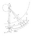
- FIG. 7shows a front view of a fourth guide assembly of the present disclosure.
- FIG. 8shows an isometric view of the fourth guide assembly of the present disclosure.
- FIG. 9Ashows a top view of the lever arm, of the fourth guide assembly, in a first position.
- FIG. 9Bshows a top view of the lever arm, of the fourth guide assembly, in a second position.
- FIG. 10shows a perspective view of the second attachment portion of the fourth guide assembly.
- FIGS. 11A-11Dshow perspective views of methods for attaching the guides of the present disclosure to an endoscope cannula.
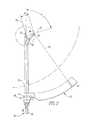
- FIG. 12shows a front view of the first guide of the present disclosure coupled to an aimer arm.
- FIG. 1shows a guide 10 that includes a body 11 having a first end 12 , a second end 13 , an arc along a length L of the body 11 , and at least one through hole 14 .
- a first surgical instrument 20such as an endoscope
- the second end 13 of the guide 10is coupled to the first end 21 of the endoscope 20 , via a cannula 40 , as further described below, and a longitudinal axis 15 of the through hole 14 intersects, or is co-radial with, the second end 22 of the endoscope 20 .
- the body 11may include multiple through holes 14 , each of which includes a longitudinal axis 15 that intersects, or is co-radial with, the second end 22 of the endoscope 20 .
- a first portal 31is created in a relatively safe position, within a patient's body 32 , where damage to internal structures is minimized.
- the portal 31may be created via the use of fluoroscopy, as described above, or another method known to one of ordinary skill in the art.
- the first cannula 40 and endoscope 20are then inserted through the portal 31 , so that a clear view of the inside of the patient's body 32 , especially the area 35 where surgery is to be performed (i.e. the hip joint and the capsule surrounding the joint), can be seen by the surgeon. This view also shows the surgeon the anatomy that must be avoided and where a safe area for placing other portals is.
- the endoscope 20is disposed within the first cannula 40 such that the second end 22 of the endoscope 20 protrudes through a second end 42 of the cannula 40 .
- the guide 10is coupled to the first end 21 of the endoscope 20 , via the cannula, and the second portal ( FIG. 4, 33 ) is placed relative to the second end 22 of the endoscope 20 by inserting a second surgical device ( FIG. 4, 34 ), such as a second cannula, through one of the through holes 14 and into the patient's body 32 .
- a second surgical deviceFIG. 4, 34
- the second cannula 34would also be co-radial with the second end 22 of the endoscope 20 . Furthermore, and as will be described below, this co-radial relationship between the second cannula 34 and the second end 22 of the endoscope 20 allows a needle or other surgical instrument that may be placed within the second cannula 34 and used in the area 35 described above, to intersect the second end 22 of the endoscope 20 .
- Having multiple through holes 14 in the guide 10allows for flexibility in the placement of the second portal 33 so that damage to internal structures can be minimized.
- a guide 10 having only one through hole 14may be used.
- FIG. 2shows the endoscope 20 disposed within the first cannula 40 , as described above, such that the second end 22 of the endoscope 20 protrudes through a second end 42 of the cannula 40 .
- the guide 10is coupled to a first end 41 of the first cannula 40 .
- the cannula 40has a pointed tip 43 , located at the second end 42 , which is offset a distance d from the endoscope 20 or in a direction of view 37 of the endoscope 20 . As shown in FIG. 2 and in subsequent figures, as described below, the distance d is measured from the optical center 23 of the endoscope 20 .
- the direction of view 37 of the endoscope 20is located at an angle ⁇ , about 70°, relative to a longitudinal axis 26 of the endoscope 20 .
- the anatomy of the bodyprevents the second end 22 of the endoscope 20 from being positioned in the area 36 , such as the inner surface of the hip capsule as described above, where the surgeon wishes the second portal ( FIG. 4, 33 ) to be placed.
- the cannula 40 with the pointed tip 43can be used to identify this area 36 and a longitudinal axis 15 of the guide through hole 14 could be made to intersect, or be co-radial with, the pointed tip 43 .
- the endoscope 20could be fitted with a pointed tip similar to the pointed tip 43 of the cannula 40 .
- the endoscope 20 and pointed tipcould be introduced into the patient's body via a slotted cannula.
- FIG. 3is similar to FIG. 2 in that a longitudinal axis 15 of the through hole 14 intersects with an area 36 that is offset a distance d from the endoscope 20 or in a direction of view 37 of the endoscope 20 .
- the average distance d between the endoscope 20 and the point of intersection with area 36is determined and an offset, equal to that average distance d, is built into the guide 10 so that a longitudinal axis 15 of the through hole 14 intersects with this area 36 .
- the hip anatomymay prevent the second end 22 of the endoscope 20 from being brought up against the inner surface 36 of the hip capsule. Since the endoscope 20 may be a distance from the capsule inner surface 36 , an error where the needle penetrates the capsule would result.
- the pointed tip 43 or the built-in offset dcould be used.
- the distance dis about 1 cm. However, the distance d will vary based on the location of the endoscope 20 relative to area 36 .
- FIG. 4shows the second cannula 34 disposed within the through hole 14 and second portal 33 .
- the cannula 34includes a depth stop 38 that substantially reduces the possibility of a first end 39 a of a needle 39 or other surgical instrument, disposed within the cannula 34 , from advancing past the second end 22 of the endoscope 20 by having a second end 39 b of the needle 39 abut a second end 38 b of the depth stop 38 .
- the depth stop 38may be part of the second cannula 34 or separate from the second cannula 34 . This allows the second cannula 34 to be positioned to any depth within the through hole 14 , yet still have a fixed depth stop relative to the guide 10 .
- FIG. 5shows a guide 60 that includes a body 61 having a first end 62 , a second end 63 , and an arc along a length L of the body 61 .
- the guide 60also includes a joint 64 configured for sliding along the length L of the body 61 .
- the joint 64includes at least one through hole 65 .
- guide 60is also coupled to a first surgical device 20 , such as an endoscope.
- the endoscope 20may be disposed within a first cannula 40 , similar to the first cannula disclosed in FIG. 2 and described above, such that the second end 22 of the endoscope 20 protrudes through a second end 42 of the cannula 40 .
- the cannula 40has a pointed tip 43 similar to the pointed tip shown in FIG. 2 and described above.
- a second surgical device 34similar to the second surgical device shown in FIG. 4 , is disposed within the through hole 65 .
- a longitudinal axis 66 of the through hole 65and therefore of the second surgical device 34 , intersects, or is co-radial with, the pointed tip 43 .
- the longitudinal axis 66could be made to intersect, or be co-radial with, the second end 22 of the endoscope 20 or with an area 36 that is offset a distance d from the endoscope 20 , as shown in FIGS. 1 and 3 .
- the joint 64may be slid along the length L of the body 61 to decide where to place the second portal 33 so that damage to internal structures can be minimized. Since the longitudinal axis 66 of the through hole 65 and the second surgical device 34 is co-radial with the pointed tip 43 , a needle or other surgical instrument disposed within the second surgical device 34 , will intersect the pointed tip 43 , regardless of where the second portal 33 is placed.
- the joint 64 and the body 61may include openings 67 to make the guide 60 lightweight and ensure that the joint 64 and body 61 cool quickly after autoclaving.
- FIG. 6shows a guide 70 that includes a body 71 having a first end 72 , and a second end 73 .
- the guide 70also includes a joint 74 configured for sliding along the body 71 .
- the joint 74includes at least one through hole 75 .
- guide 70is also coupled to a first surgical device 20 , such as an endoscope, via a cannula 40 .
- a second surgical device 34is disposed within the through hole 75 .
- a longitudinal axis 76 of the through hole 75and therefore of the second surgical device 34 , intersects, or is co-radial with, an area 36 that is offset a distance d from the endoscope 20 .
- the longitudinal axis 76could be made to intersect, or be co-radial with, a pointed tip 43 of the cannula 40 or the second end 22 of the endoscope 20 , as shown in FIGS. 2, 5, 1 and 4 .
- the joint 74may be slid along the body 71 to vary the distance d based upon the distance between the second end 22 of the endoscope 20 and the capsule inner surface 36 . Since the second surgical device 34 is co-radial with the area 36 , a needle or other surgical instrument disposed within the second surgical device 34 , will intersect the area 36 , regardless of where the second portal 33 is placed.
- the guide 70also includes a mechanism 77 , such as a locking nut, for engaging the joint 74 and holding it in a position along the body 71 . Once the surgeon has determined the position of the second portal 33 , the locking nut 77 will be tightened to engage the joint 74 and hold it in a position along the body 71 . The second surgical device 34 will then be inserted into the through hole 75 and through the patient's body 32 to make the second portal 33 .
- the guide 80 shown in FIG. 7includes a body 81 having a first end 81 a , a second end 81 b , and an arc along a length L of the body 81 .
- the guide 80also includes a joint 84 configured for sliding along a length L of the body 81 .
- the joint 84includes at least one through hole 85 .
- guide 80is also coupled to a first surgical device 20 , such as an endoscope via the first end 21 of the endoscope 20 and the first end 41 of the cannula 40 .
- a second surgical device 34similar to the second surgical device shown in FIGS.
- a longitudinal axis 86 of the through hole 85and therefore of the second surgical device 34 , intersects, or is co-radial with, the second end 22 of the endoscope 20 .
- the longitudinal axis 86could be made to intersect, or be co-radial with, a pointed tip 43 of the cannula 40 or an area 36 that is offset a distance d from the endoscope 20 , as shown in FIGS. 4, 5, and 3 .
- the joint 84may be slid along the length L of the body 81 to decide where to place a second portal so that damage to internal structures can be minimized. Since the second surgical device 34 is co-radial with the second end 22 of the endoscope 20 , a needle 90 or other surgical instrument disposed within the second surgical device 34 , will intersect the second end 22 , regardless of where the second portal is placed.
- the body 80includes a slot 81 c that runs the entire length L of the body 80 and that houses the joint 84 .
- the guide 80includes a mechanism 87 , such as a locking nut, for engaging the joint 84 and holding it in a position along the body 81 .
- the needle 90may be inserted through the cannula 34 for use in performing a surgical procedure.
- the needle 90which intersects, or is co-radial with, the second end 22 of the endoscope 20 , may include a depth stop 90 c , at a first end 90 a of the needle 90 , that abuts a first end 34 a of the cannula 34 to substantially reduce the possibility of the second end 90 b of the needle 90 from advancing past the second end 22 of the endoscope 20 .
- the guide 80includes a first attachment portion 88 and a second attachment portion 89 , both of which are configured for coupling the body 81 to the first surgical device 20 via the first surgical device 20 and the cannula 40 .
- the first attachment portion 88which includes an anti-rotation lock, is located at the first end 81 a of the body 81 and extends substantially perpendicular to the axis 26 of the endoscope 20 .
- the anti-rotation lock 88includes a lever arm 88 c located between a top surface 88 a and bottom surface 88 b of the anti-rotation lock 88 .
- the lever arm 88 cis coupled to the surfaces 88 a,b via a pivot pin or screw 88 d and a spring 88 e .
- the lever arm 88 cis in a first position, as shown in FIG. 9A , such that the spring 88 e is in a relaxed state.
- the lever arm 88 cis in a second position, as shown in FIG.
- the second attachment portion 89is located near the second end 81 b of the body 81 and extends substantially perpendicular to the longitudinal axis 26 of the endoscope 20 .
- the portion 89includes two prongs 89 a,b , both of which extend longitudinally from the portion 89 , and an opening 89 c , located between the prongs 89 a,b that extends longitudinally into the portion 89 .
- the cannula 40includes a coupling portion 45 configured for coupling of the second attachment portion 89 to the cannula 40 .
- the coupling portion 45includes two holes 45 a and a projection 45 b that extends longitudinally from the coupling portion 45 .
- the second attachment portion 89is coupled to the coupling portion 45 such that the prongs 89 a,b are disposed within the holes 45 a and the projection 45 b is disposed within the opening 89 c.
- the second end 81 b of the body 81does not extend beyond a plane 90 , located between the second attachment portion 89 and a longitudinal axis 26 of the first surgical device 20 , and that forms an angle ⁇ , about 60°, with the longitudinal axis 26 .
- FIGS. 11A-11Dshow methods for coupling the second end 13 of the guide 10 to the first end 41 of the cannula 40 .
- the second end 13includes a first arm 13 a , a second arm 13 b , and a slot 13 c located between the first and second arms 13 a,b .
- the first end 41 of the cannula 40includes a coupling portion 46 , similar to the coupling portion 45 shown in FIG. 10 albeit with channels 46 a instead of holes 45 a .
- the second end 13 of the guide 10is coupled to the first end 41 of the cannula 40 such that the first and second arms 13 a,b are housed within the channels 46 a and the projection 46 b is housed within the slot 13 c .
- Both arms 13 a,binclude an edge 13 a ′, 13 b ′, wherein each edge 13 a ′, 13 b ′ is configured for attaching to the backside 46 c of the coupling portion 46 when the guide 10 is coupled to the coupling portion 46 , therefore creating a snap-fit connection between the arms 13 a,b and the coupling portion 46 .
- the second end 13 of the guide 10includes a first arm 13 a and a second arm 13 b .
- the first end 41 of the cannula 40includes an adaptor 47 that has been slid over the cannula 40 .
- the first and second arms 13 a,b of the guide 10are coupled to the adaptor 47 such that an interference fit, or a clip-on connection, is created between the arms 13 a,b and the adaptor 47 .
- the second end 13 of the guide 10includes a base portion 13 d that partially surrounds the first end 41 of the cannula 40 and includes a hook 13 e that is placed on the irrigation extender 50 , which is coupled to the cannula 40 .
- FIG. 11DShown in FIG. 11D is a guide 10 that includes a second end 13 having an arm 13 f including an opening 13 f ′′ and a slot 13 f ′ formed in the arm 13 f .
- the first end 41 of the cannula 40includes a coupling portion 49 , similar to the coupling portions 45 , 46 shown in FIGS. 10 and 11A , albeit without holes or channels.
- the second end 13 of the guide 10is coupled to the first end 41 of the cannula 40 such that the first end 41 of the cannula 40 is disposed within the opening 13 f ′′ and the projection (not shown) is housed within the slot 13 f .
- the guide 10may be placed onto the first end 41 by placing the opening 13 f ′′ over the first end 41 and sliding the arm 13 f around the coupling portion 49 , so as to create a snap-fit connection between the arm 13 f and the first end 41 .
- Other methods of coupling the guide to the cannulamay also be used.
- a guide 100is coupled to a first surgical device 200 , such as an aimer arm, that includes a distal end 200 b in the shape of a hook.
- the distal end 200 b of the aimer arm 200is positioned in the posterior region 300 b of the hip joint 300 .
- a second surgical device 400such as a cannula, is disposed within the through hole 104 of the guide 100 .
- a longitudinal axis 401 of the cannula 400is co-radial with the tip 200 c on the distal end 200 b of the aimer arm 200 .
- the aimer arm 200may be introduced into the body 32 in the same manner as the endoscope 20 is introduced, as described above, or another manner known to one of ordinary skill in the art.
- the guide 100may be coupled to the aimer arm 200 in the same manner as guide 80 is coupled to the cannula 40 in FIG. 7 , in the same manner as guide 10 is coupled to the cannula 40 in FIGS. 11A-11D , or another manner known to one of ordinary skill in the art.
- the aimer arm 200may rotate around a longitudinal axis 201 of the aimer arm 200 via a rotational coupling (not shown) located at the proximal end 200 a of the aimer arm 200 .
- a manual or automatic milling machineis used to create the through holes of the guides described above.
- Other apparatuses and methods of creating the through holesmay also be used.
- the guidesare manufactured from a metal material, such as stainless steel or titanium, but may be manufactured from another material known to one of ordinary skill in the art.
- the first and second cannulas and the aimer arm described aboveare manufactured from a biocompatible metal material, such as stainless steel, but may be manufactured from another biocompatible material known to one of ordinary skill in the art.
- the guidesinclude a body having an arc along the length of the body, but an arc is not necessary and the body may be straight or incorporate any other shapes known to one of ordinary skill in the art.
Landscapes
- Health & Medical Sciences (AREA)
- Surgery (AREA)
- Life Sciences & Earth Sciences (AREA)
- Biomedical Technology (AREA)
- Medical Informatics (AREA)
- Veterinary Medicine (AREA)
- Public Health (AREA)
- Engineering & Computer Science (AREA)
- General Health & Medical Sciences (AREA)
- Heart & Thoracic Surgery (AREA)
- Nuclear Medicine, Radiotherapy & Molecular Imaging (AREA)
- Molecular Biology (AREA)
- Animal Behavior & Ethology (AREA)
- Dentistry (AREA)
- Oral & Maxillofacial Surgery (AREA)
- Orthopedic Medicine & Surgery (AREA)
- Endoscopes (AREA)
- Surgical Instruments (AREA)
Abstract
Description
This application claims the benefit of U.S. Provisional Application No. 61/015,811, filed Dec. 21, 2007, the disclosure of which is incorporated by reference herein in its entirety.
Field of the Invention
The present disclosure relates to medical devices for use in surgery and, more specifically, a guide for use in creating multiple portals during surgery.
Related Art
During arthroscopic surgery, the joint areas of the body, such as the hip, knee, shoulder, and other joint areas, are approached via the use of an endoscope. Some joints are harder to access than others. For example, the hip joint differs from other joints in that a much thicker layer of soft tissue, known as the hip capsule, surrounds it. This thick layer makes changing the trajectory of instruments placed into the joint difficult and the importance of placing portals, or tissue passages, more critical than other joints.
Presently, fluoroscopy is used to place the portals that house the endoscope and the other instruments used during surgery. Multiple x-rays are taken while the surgeon tries various approaches to the joint using a thin needle that may be reinserted several times until the ideal portal placement is found. This process exposes the surgical team to radiation, is time consuming, and can lead to trauma, particularly to the delicate articular cartilage and, in the case of the hip joint, the acetabular labrum.
There is a need for an apparatus and method that would allow for the creation of multiple portals while substantially reducing the possible harmful effects and the amount of time that is required of the present methods.
In one aspect, the present disclosure relates to a guide assembly including a guide having a body and a joint including at least one through hole, wherein the joint is configured for sliding along a length of the body, and a first surgical device. The guide is coupled to the first surgical device and a longitudinal axis of the through hole is co-radial with an end of the first surgical device.
In an embodiment, the guide assembly further includes a mechanism for locking the joint in a position along the body. In another embodiment, the guide assembly further includes a second surgical device, such as a second cannula, disposed within the through hole, wherein the second surgical device includes a longitudinal axis that is co-radial with the end of the first surgical device. In yet another embodiment, the first surgical device is disposed within a first cannula such that the end of the first surgical device protrudes through an end of the first cannula. In yet a further embodiment, the longitudinal axis of the through hole is co-radial with a point that is offset a distance, about 1 cm, from the end of the first surgical device. The first surgical device may include an endoscope, wherein the point is offset a distance, about 1 cm, in a direction of view of the endoscope. In an embodiment, the guide is coupled to the first cannula. In another embodiment, the end of the first cannula includes a pointed tip offset a distance, about 1 cm, from the end of the first surgical device. In yet another embodiment, the first surgical device includes an endoscope, wherein the pointed tip is offset a distance, about 1 cm, in a direction of view from the endoscope.
In another embodiment, the second surgical device includes a second cannula. In an embodiment, the second cannula includes a needle, wherein the needle includes a first end and a second end and is slidably disposed within the second cannula. In another embodiment, the needle includes a first end, which may have a depth stop, and a second end that intersects an end of the first surgical device. In an embodiment, the second end of the needle does not advance past the end of the first surgical device. In a further embodiment, the body includes a first attachment portion located at a first end of the body and a second attachment portion located near a second end of the body, wherein the first attachment portion and the second attachment portion are configured for coupling the body to the first surgical device. In yet a further embodiment, the second end of the body does not extend beyond a plane located between the second attachment portion and a longitudinal axis of the first surgical device. In yet a further embodiment, an angle β, which may be about 60°, exists between the longitudinal axis of the first surgical device and the plane.
In yet an even further embodiment, the first attachment portion includes a lever arm configured for coupling of the first surgical device to the first attachment portion. The lever arm is movable between a first position and a second position with respect to the first attachment portion, wherein the first surgical device is coupled to the first attachment portion when the lever arm is in a second position.
In yet a further embodiment, a longitudinal axis of the through hole is co-radial with a point that is offset a distance, about 1 cm, from the end of the first surgical device. In an embodiment, the first surgical device includes an endoscope, wherein the point offset a distance, about 1 cm, in a direction of view of the endoscope.
In another aspect, the present disclosure relates to a guide assembly including a guide having a body with at least one through hole and a first surgical device, wherein the guide is coupled to the first surgical device and a longitudinal axis of the through hole is co-radial with an end of the first surgical device. In an embodiment, the body includes multiple through holes and each through hole includes a longitudinal axis that is co-radial with the end of the first surgical device. In another embodiment, the first surgical device is disposed within a first cannula such that the end of the first surgical device protrudes through an end of the first cannula. In yet another embodiment, the end of the first cannula includes a pointed tip offset a distance, about 1 cm, from the end of the first surgical device. In a further embodiment, the first surgical device includes an endoscope, wherein the pointed tip is offset a distance, about 1 cm, in a direction of view of the endoscope. In yet a further embodiment, the first surgical device includes an aimer arm. In an embodiment, the aimer arm rotates about a longitudinal axis of the aimer arm. In another embodiment, a second surgical device is disposed within the through hole, wherein the second surgical device includes a longitudinal axis that is co-radial with a distal end of the aimer. In yet another embodiment, the second surgical device includes a second cannula, wherein the second cannula includes a depth stop coupled to the second cannula. In a further embodiment, a needle is disposed within the second cannula and an end of the needle does not advance past the end of the first surgical device.
In yet another aspect, the present disclosure relates to a method of creating multiple portals during surgery. The method includes creating a first portal in tissue; inserting a first surgical device through the first portal; coupling a guide to a first end of the first surgical device, the guide including a body having at least one through hole, wherein a longitudinal axis of the through hole is co-radial with an end of the first surgical device; and inserting a second surgical device through the hole and into the tissue to create a second portal.
In an embodiment, the second surgical device is co-radial with the end of the first surgical device. In another embodiment, the body includes multiple through holes. In yet another embodiment, each through hole includes a longitudinal axis that is co-radial with the end of the first surgical device. In a further embodiment, the first surgical device is disposed within a first cannula such that the end of the first surgical device protrudes through an end of the first cannula. In yet a further embodiment, the end of the first cannula includes a pointed tip, wherein the pointed tip is offset a distance, about 1 cm, in a direction of view of the endoscope. In an embodiment, the first surgical device includes an endoscope, wherein the pointed tip is offset a distance in a direction of view of the endoscope. In another embodiment, a longitudinal axis of the through hole is co-radial with the pointed tip. In yet another embodiment, the first surgical device includes an endoscope, wherein a longitudinal axis of the through hole is co-radial with a point that is offset a distance, about 1 cm, from the end of the endoscope.
In yet another embodiment, the second surgical device includes a second cannula. In a further embodiment, the second cannula includes a depth stop coupled to the second cannula. In yet a further embodiment, the first surgical device includes an aimer arm, the aimer arm having a distal end. In an embodiment, the aimer arm rotates about a longitudinal axis of the aimer arm. In another embodiment, the second surgical device includes a longitudinal axis that is co-radial with a distal end of the aimer arm. In yet another embodiment, a needle is disposed within the second cannula and an end of the needle does not advance past the end of the first surgical device.
In yet another aspect, the present disclosure relates to a method of creating multiple portals during surgery. The method includes creating a first portal in tissue; inserting a first surgical device through the first portal; coupling a guide to a first end of the first surgical device, the guide including a body and a joint including at least one through hole wherein a longitudinal axis of the through hole is co-radial with an end of the first surgical device; and inserting a second surgical device through the hole and into the tissue to create a second portal.
In an embodiment, the guide includes a mechanism for locking the joint in a position along the body, the method further including sliding the joint along the body to the position and locking the joint in the position before creating the second portal.
Further areas of applicability of the present disclosure will become apparent from the detailed description provided hereinafter. It should be understood that the detailed description and specific examples, while indicating the preferred embodiment of the disclosure, are intended for purposes of illustration only and are not intended to limit the scope of the disclosure.
The accompanying drawings, which are incorporated in and form a part of the specification, illustrate the embodiments of the present disclosure and together with the written description serve to explain the principles, characteristics, and features of the disclosure. In the drawings:
The following description of the preferred embodiment(s) is merely exemplary in nature and is in no way intended to limit the disclosure, its application, or uses.
During arthroscopic surgery, especially hip arthroscopy, afirst portal 31 is created in a relatively safe position, within a patient'sbody 32, where damage to internal structures is minimized. The portal31 may be created via the use of fluoroscopy, as described above, or another method known to one of ordinary skill in the art. Thefirst cannula 40 andendoscope 20 are then inserted through the portal31, so that a clear view of the inside of the patient'sbody 32, especially thearea 35 where surgery is to be performed (i.e. the hip joint and the capsule surrounding the joint), can be seen by the surgeon. This view also shows the surgeon the anatomy that must be avoided and where a safe area for placing other portals is. As will be further discussed below, theendoscope 20 is disposed within thefirst cannula 40 such that thesecond end 22 of theendoscope 20 protrudes through asecond end 42 of thecannula 40. After positioning thesecond end 22 of theendoscope 20 at anarea 36 where the surgeon wishes a second portal (FIG. 4, 33 ) to be placed, such as the inner surface of the hip capsule, theguide 10 is coupled to thefirst end 21 of theendoscope 20, via the cannula, and the second portal (FIG. 4, 33 ) is placed relative to thesecond end 22 of theendoscope 20 by inserting a second surgical device (FIG. 4, 34 ), such as a second cannula, through one of the throughholes 14 and into the patient'sbody 32. Since thelongitudinal axis 15 of the throughhole 14 intersects, or is co-radial with, thesecond end 22 of theendoscope 20, thesecond cannula 34 would also be co-radial with thesecond end 22 of theendoscope 20. Furthermore, and as will be described below, this co-radial relationship between thesecond cannula 34 and thesecond end 22 of theendoscope 20 allows a needle or other surgical instrument that may be placed within thesecond cannula 34 and used in thearea 35 described above, to intersect thesecond end 22 of theendoscope 20.
Having multiple throughholes 14 in theguide 10 allows for flexibility in the placement of thesecond portal 33 so that damage to internal structures can be minimized. However, aguide 10 having only one throughhole 14 may be used.
The joint64 may be slid along the length L of thebody 61 to decide where to place thesecond portal 33 so that damage to internal structures can be minimized. Since thelongitudinal axis 66 of the throughhole 65 and the secondsurgical device 34 is co-radial with the pointedtip 43, a needle or other surgical instrument disposed within the secondsurgical device 34, will intersect the pointedtip 43, regardless of where thesecond portal 33 is placed. The joint64 and thebody 61 may includeopenings 67 to make theguide 60 lightweight and ensure that the joint64 andbody 61 cool quickly after autoclaving.
Similar to theguide 60 shown inFIG. 5 ,FIG. 6 shows aguide 70 that includes abody 71 having afirst end 72, and asecond end 73. Theguide 70 also includes a joint74 configured for sliding along thebody 71. The joint74 includes at least one throughhole 75. Similar to theguide 10 disclosed inFIGS. 1-4 , guide70 is also coupled to a firstsurgical device 20, such as an endoscope, via acannula 40. A secondsurgical device 34, similar to the second surgical device shown inFIG. 4 , is disposed within the throughhole 75. Alongitudinal axis 76 of the throughhole 75, and therefore of the secondsurgical device 34, intersects, or is co-radial with, anarea 36 that is offset a distance d from theendoscope 20. However, thelongitudinal axis 76 could be made to intersect, or be co-radial with, apointed tip 43 of thecannula 40 or thesecond end 22 of theendoscope 20, as shown inFIGS. 2, 5, 1 and 4 .
As also shown inFIG. 5 and described above, the joint74 may be slid along thebody 71 to vary the distance d based upon the distance between thesecond end 22 of theendoscope 20 and the capsuleinner surface 36. Since the secondsurgical device 34 is co-radial with thearea 36, a needle or other surgical instrument disposed within the secondsurgical device 34, will intersect thearea 36, regardless of where thesecond portal 33 is placed. Theguide 70 also includes amechanism 77, such as a locking nut, for engaging the joint74 and holding it in a position along thebody 71. Once the surgeon has determined the position of thesecond portal 33, the lockingnut 77 will be tightened to engage the joint74 and hold it in a position along thebody 71. The secondsurgical device 34 will then be inserted into the throughhole 75 and through the patient'sbody 32 to make thesecond portal 33.
Similar to theguides FIGS. 5 and 6 , theguide 80 shown inFIG. 7 includes abody 81 having afirst end 81a, asecond end 81b, and an arc along a length L of thebody 81. Theguide 80 also includes a joint84 configured for sliding along a length L of thebody 81. The joint84 includes at least one throughhole 85. Similar to theguide FIGS. 1-6 , guide80 is also coupled to a firstsurgical device 20, such as an endoscope via thefirst end 21 of theendoscope 20 and thefirst end 41 of thecannula 40. A secondsurgical device 34, similar to the second surgical device shown inFIGS. 4-6 , is disposed within the throughhole 85. Alongitudinal axis 86 of the throughhole 85, and therefore of the secondsurgical device 34, intersects, or is co-radial with, thesecond end 22 of theendoscope 20. However, thelongitudinal axis 86 could be made to intersect, or be co-radial with, apointed tip 43 of thecannula 40 or anarea 36 that is offset a distance d from theendoscope 20, as shown inFIGS. 4, 5, and 3 .
As also shown inFIG. 7 and described above, the joint84 may be slid along the length L of thebody 81 to decide where to place a second portal so that damage to internal structures can be minimized. Since the secondsurgical device 34 is co-radial with thesecond end 22 of theendoscope 20, aneedle 90 or other surgical instrument disposed within the secondsurgical device 34, will intersect thesecond end 22, regardless of where the second portal is placed. Thebody 80 includes aslot 81cthat runs the entire length L of thebody 80 and that houses the joint84. In addition, similar to theguide 70 ofFIG. 6 , theguide 80 includes amechanism 87, such as a locking nut, for engaging the joint84 and holding it in a position along thebody 81. During surgery, use of the lockingnut 87 in creating a second portal occurs in the same manner as described above. After the secondsurgical device 34, or second cannula, has been inserted into the patient's body, theneedle 90, or other instrument, may be inserted through thecannula 34 for use in performing a surgical procedure. Theneedle 90 which intersects, or is co-radial with, thesecond end 22 of theendoscope 20, may include adepth stop 90c, at a first end90aof theneedle 90, that abuts afirst end 34aof thecannula 34 to substantially reduce the possibility of thesecond end 90bof theneedle 90 from advancing past thesecond end 22 of theendoscope 20.
As shown inFIGS. 7 and 8 , theguide 80 includes afirst attachment portion 88 and asecond attachment portion 89, both of which are configured for coupling thebody 81 to the firstsurgical device 20 via the firstsurgical device 20 and thecannula 40. Thefirst attachment portion 88, which includes an anti-rotation lock, is located at thefirst end 81aof thebody 81 and extends substantially perpendicular to theaxis 26 of theendoscope 20. As shown inFIGS. 9A and9B, theanti-rotation lock 88 includes alever arm 88clocated between atop surface 88aandbottom surface 88bof theanti-rotation lock 88. Thelever arm 88cis coupled to thesurfaces 88a,bvia a pivot pin or screw88dand aspring 88e. When theendoscope 20 is not coupled to theanti-rotation lock 88, thelever arm 88cis in a first position, as shown inFIG. 9A , such that thespring 88eis in a relaxed state. However, when theendoscope 20 is coupled to theanti-rotation lock 88, thelever arm 88cis in a second position, as shown inFIG. 9B , such that thelever arm 88cis pushed against thelight post 24 of theendoscope 20, and substantially reduces the possibility of rotation of thelight post 24 in a direction that would uncouple thecannula 40 from theendoscope 20.
As shown inFIGS. 7 and 8 , thesecond attachment portion 89 is located near thesecond end 81bof thebody 81 and extends substantially perpendicular to thelongitudinal axis 26 of theendoscope 20. Theportion 89 includes twoprongs 89a,b, both of which extend longitudinally from theportion 89, and anopening 89c, located between theprongs 89a,bthat extends longitudinally into theportion 89. As shown inFIG. 10 , thecannula 40 includes acoupling portion 45 configured for coupling of thesecond attachment portion 89 to thecannula 40. Thecoupling portion 45 includes twoholes 45aand aprojection 45bthat extends longitudinally from thecoupling portion 45. Thesecond attachment portion 89 is coupled to thecoupling portion 45 such that theprongs 89a,bare disposed within theholes 45aand theprojection 45bis disposed within theopening 89c.
As shown inFIG. 7 , thesecond end 81bof thebody 81 does not extend beyond aplane 90, located between thesecond attachment portion 89 and alongitudinal axis 26 of the firstsurgical device 20, and that forms an angle β, about 60°, with thelongitudinal axis 26.
As shown in11B, thesecond end 13 of theguide 10 includes afirst arm 13aand asecond arm 13b. Thefirst end 41 of thecannula 40 includes anadaptor 47 that has been slid over thecannula 40. The first andsecond arms 13a,bof theguide 10 are coupled to theadaptor 47 such that an interference fit, or a clip-on connection, is created between thearms 13a,band theadaptor 47.
As shown in11C, thesecond end 13 of theguide 10 includes abase portion 13dthat partially surrounds thefirst end 41 of thecannula 40 and includes ahook 13ethat is placed on theirrigation extender 50, which is coupled to thecannula 40. Shown inFIG. 11D is aguide 10 that includes asecond end 13 having anarm 13fincluding anopening 13f″ and aslot 13f′ formed in thearm 13f. Thefirst end 41 of thecannula 40 includes acoupling portion 49, similar to thecoupling portions FIGS. 10 and 11A , albeit without holes or channels. Thesecond end 13 of theguide 10 is coupled to thefirst end 41 of thecannula 40 such that thefirst end 41 of thecannula 40 is disposed within theopening 13f″ and the projection (not shown) is housed within theslot 13f. Theguide 10 may be placed onto thefirst end 41 by placing theopening 13f″ over thefirst end 41 and sliding thearm 13faround thecoupling portion 49, so as to create a snap-fit connection between thearm 13fand thefirst end 41. Other methods of coupling the guide to the cannula may also be used.
As shown inFIG. 12 , aguide 100, similar to theguide 10 inFIGS. 1-4 , is coupled to a firstsurgical device 200, such as an aimer arm, that includes a distal end200bin the shape of a hook. The distal end200bof theaimer arm 200 is positioned in theposterior region 300bof thehip joint 300. A secondsurgical device 400, such as a cannula, is disposed within the throughhole 104 of theguide 100. Alongitudinal axis 401 of thecannula 400 is co-radial with thetip 200con the distal end200bof theaimer arm 200. This co-radial relationship allows access to theposterior region 300bof thehip joint 300, via thefemoral neck 300a, by a surgical tool, such as a drill (not shown), disposed within thecannula 400. Theaimer arm 200 may be introduced into thebody 32 in the same manner as theendoscope 20 is introduced, as described above, or another manner known to one of ordinary skill in the art. Likewise, theguide 100 may be coupled to theaimer arm 200 in the same manner asguide 80 is coupled to thecannula 40 inFIG. 7 , in the same manner asguide 10 is coupled to thecannula 40 inFIGS. 11A-11D , or another manner known to one of ordinary skill in the art. Theaimer arm 200 may rotate around alongitudinal axis 201 of theaimer arm 200 via a rotational coupling (not shown) located at the proximal end200aof theaimer arm 200.
For the purposes of this disclosure, a manual or automatic milling machine is used to create the through holes of the guides described above. Other apparatuses and methods of creating the through holes may also be used. The guides are manufactured from a metal material, such as stainless steel or titanium, but may be manufactured from another material known to one of ordinary skill in the art. In addition, the first and second cannulas and the aimer arm described above are manufactured from a biocompatible metal material, such as stainless steel, but may be manufactured from another biocompatible material known to one of ordinary skill in the art. Furthermore, for the purposes of this disclosure, the guides include a body having an arc along the length of the body, but an arc is not necessary and the body may be straight or incorporate any other shapes known to one of ordinary skill in the art. Although the present disclosure relates to the use of the above described guides for the placement of portals during hip arthroscopy, the basic principles and methods may also be applied to other joint areas of the body.
As various modifications could be made to the exemplary embodiments, as described above with reference to the corresponding illustrations, without departing from the scope of the disclosure, it is intended that all matter contained in the foregoing description and shown in the accompanying drawings shall be interpreted as illustrative rather than limiting. Thus, the breadth and scope of the present disclosure should not be limited by any of the above-described exemplary embodiments, but should be defined only in accordance with the following claims appended hereto and their equivalents.
Claims (16)
1. A method of creating multiple portals during surgery, the method comprising:
creating a first portal to a surgical site;
inserting a first cannula through the first portal such that a distal end of the cannula is positioned in the surgical site, the first cannula defining a longitudinal axis;
disposing a first surgical device within the first cannula after the cannula is inserted through the first portal such that a distal end of the first surgical device protrudes out of the first cannula along the first longitudinal axis and into the surgical site;
securing a guide to the first cannula at a proximal end of the first cannula, the guide including a through hole, the through hole defining a longitudinal axis different from the longitudinal axis of the first cannula, wherein the longitudinal axis of the through hole intersects the protruding distal end of the first surgical device; and
inserting a second surgical device through the through hole along the longitudinal axis thereof and into the surgical site,
wherein the guide includes a body and a joint slidable along a length of the body, wherein the body is secured to the first cannula and the joint defines the through hole, wherein the guide is configured such that the longitudinal axis of the through hole intersects a same point at the protruding distal end of the first surgical device when sliding the joint between different positions along the length of the body, the method further comprising sliding the joint along the length of the body to a first position and locking the joint in the first position before inserting the second surgical device into the surgical site.
2. The method ofclaim 1 wherein the second surgical device comprises a second cannula.
3. The method ofclaim 1 wherein the longitudinal axis of the through hole and the longitudinal axis of the first cannula define a plane when the joint is in the first position, wherein the guide is configured such that the longitudinal axis of the through hole remains substantially in the plane when sliding the joint between different positions along the length of the body.
4. A method of creating multiple portals during surgery, the method comprising:
creating a first portal to a surgical site;
inserting a first cannula through the first portal such that a distal end of the cannula is positioned in the surgical site, the first cannula defining a longitudinal axis;
disposing a first surgical device within the first cannula after the cannula is inserted through the first portal such that a distal end of the first surgical device protrudes out of the first cannula along the first longitudinal axis and into the surgical site;
securing a guide to the first cannula at a proximal end of the first cannula, the guide including a through hole, the through hole defining a longitudinal axis different from the longitudinal axis of the first cannula, wherein the longitudinal axis of the through hole intersects the protruding distal end of the first surgical device; and
inserting a second surgical device through the through hole along the longitudinal axis thereof and into the surgical site;
wherein the second surgical device comprises a second cannula, the second cannula includes a depth stop coupled to the second cannula the depth stop configured for preventing a surgical instrument disposed in the second cannula from advancing past the protruding distal end of the first surgical device.
5. A method of creating multiple portals during surgery, the method comprising:
creating a first portal to a surgical site;
inserting a first cannula through the first portal such that a distal end of the cannula is positioned in the surgical site, the first cannula defining a longitudinal axis;
disposing a first surgical device within the first cannula after the cannula is inserted through the first portal such that a distal end of the first surgical device protrudes out of the first cannula along the first longitudinal axis and into the surgical site;
securing a guide to the first cannula at a proximal end of the first cannula, the guide including a through hole, the through hole defining a longitudinal axis different from the longitudinal axis of the first cannula, wherein the longitudinal axis of the through hole one of (i) intersects the protruding distal end of the first surgical device or (ii) does not intersect with any region of the first surgical device and is offset from the protruding distal end of the first surgical device; and
inserting a second surgical device through the through hole along the longitudinal axis thereof and into the surgical site
wherein the guide is directly attached to the first surgical device at a first attachment portion and directly attached at a second attachment portion to the first cannula.
6. The method ofclaim 5 wherein the guide includes multiple through holes each through hole defining a longitudinal axis different from the longitudinal axes of the other through holes and of the first cannula, wherein the longitudinal axes of the through holes are co-radial with respect to a same point.
7. The method ofclaim 5 wherein a distal end of the first cannula includes a pointed tip, the pointed tip offset a predetermined distance from the protruding distal end of the first surgical device.
8. The method ofclaim 7 wherein the first surgical device includes an endoscope, the pointed tip offset a distance in a direction of view of the endoscope.
9. The method ofclaim 7 wherein the longitudinal axis of the through hole intersects the pointed tip.
10. The method ofclaim 7 wherein the distance is about 1 cm.
11. The method ofclaim 5 wherein the first surgical device includes an endoscope, the longitudinal axis of the through hole intersecting a point along an axis defined by a field of view of the endoscope that is offset a predetermined distance from the end of the endoscope along the axis defined by the field of view of the endoscope.
12. The method ofclaim 11 wherein the distance is about 1 cm.
13. The method ofclaim 5 wherein the first attachment portion includes a lever arm configured to contact a surface of the first surgical device that is perpendicular to the longitudinal axis of the first surgical device to attach the first surgical device to the first attachment portion.
14. A method of creating multiple portals during hip surgery, the method comprising:
creating a first portal to a surgical site in a hip joint;
inserting a first surgical device including an elongated body defining a longitudinal axis through the first portal such that a distal end of the first surgical device is positioned in the surgical site, the distal end of the first surgical device defining a curved surface, the curved surface configured to correspond with a curvature of a femoral head of the hip joint so as to enable engaging the curved surface with the femoral head;
engaging the curved surface of the first surgical device with the femoral head;
securing a guide to the first surgical device at a proximal end of the first surgical device, the guide including a through hole, the through hole defining a longitudinal axis different from the longitudinal axis of the first surgical device, wherein the longitudinal axis of the through hole intersects the distal end of the first surgical device; and
inserting a second surgical device through the through hole along the longitudinal axis thereof and into the surgical site.
15. The method ofclaim 14 wherein the longitudinal axis of the through hole intersects the distal end of the first surgical device at a tip of the curved surface.
16. The method ofclaim 14 wherein the longitudinal axis of the through hole is configured to guide axis of the second surgical device to the surgical site via a femoral neck of the hip joint when the first surgical device is engaged with the femoral head.
Priority Applications (1)
| Application Number | Priority Date | Filing Date | Title |
|---|---|---|---|
| US14/593,592US9913636B2 (en) | 2007-12-21 | 2015-01-09 | Multiple portal guide |
Applications Claiming Priority (3)
| Application Number | Priority Date | Filing Date | Title |
|---|---|---|---|
| US1581107P | 2007-12-21 | 2007-12-21 | |
| US12/032,168US8956278B2 (en) | 2007-12-21 | 2008-02-15 | Multiple portal guide |
| US14/593,592US9913636B2 (en) | 2007-12-21 | 2015-01-09 | Multiple portal guide |
Related Parent Applications (1)
| Application Number | Title | Priority Date | Filing Date |
|---|---|---|---|
| US12/032,168DivisionUS8956278B2 (en) | 2007-12-21 | 2008-02-15 | Multiple portal guide |
Publications (2)
| Publication Number | Publication Date |
|---|---|
| US20150126817A1 US20150126817A1 (en) | 2015-05-07 |
| US9913636B2true US9913636B2 (en) | 2018-03-13 |
Family
ID=39743797
Family Applications (2)
| Application Number | Title | Priority Date | Filing Date |
|---|---|---|---|
| US12/032,168Active2031-05-30US8956278B2 (en) | 2007-12-21 | 2008-02-15 | Multiple portal guide |
| US14/593,592ActiveUS9913636B2 (en) | 2007-12-21 | 2015-01-09 | Multiple portal guide |
Family Applications Before (1)
| Application Number | Title | Priority Date | Filing Date |
|---|---|---|---|
| US12/032,168Active2031-05-30US8956278B2 (en) | 2007-12-21 | 2008-02-15 | Multiple portal guide |
Country Status (5)
| Country | Link |
|---|---|
| US (2) | US8956278B2 (en) |
| EP (1) | EP2231035B1 (en) |
| JP (1) | JP5818438B2 (en) |
| AU (1) | AU2008341062B2 (en) |
| WO (1) | WO2009082497A1 (en) |
Families Citing this family (22)
| Publication number | Priority date | Publication date | Assignee | Title |
|---|---|---|---|---|
| JP3124618B2 (en) | 1992-04-06 | 2001-01-15 | 株式会社リコー | Method and apparatus for producing sheet-shaped duplication mold by electroforming |
| US9826992B2 (en) | 2007-12-21 | 2017-11-28 | Smith & Nephew, Inc. | Multiple portal guide |
| US8956278B2 (en) | 2007-12-21 | 2015-02-17 | Smith & Nephew, Inc. | Multiple portal guide |
| FR2958841B1 (en)* | 2010-04-14 | 2012-05-18 | Pierre Imbert | ANCILLARY SYSTEM FOR THE INSTALLATION OF A LIGAMENTARY TRANSPLANT USING PINS |
| MX2013003496A (en) | 2010-09-27 | 2013-12-02 | Smith & Nephew Inc | Device and methods for use during arthroscopic surgery. |
| WO2012061639A1 (en) | 2010-11-03 | 2012-05-10 | Smith & Nephew, Inc. | Drill guide |
| US8979826B2 (en) | 2010-12-29 | 2015-03-17 | Boston Scientific Scimed, Inc. | Instrument holder |
| US8690885B2 (en)* | 2011-01-28 | 2014-04-08 | Smith & Nephew, Inc. | Surgical aiming device |
| MX348238B (en)* | 2011-03-09 | 2017-05-29 | Smith & Nephew Inc | Multiple portal guide. |
| US9498232B2 (en)* | 2012-10-23 | 2016-11-22 | Arthrex, Inc. | Articulating drill guide |
| US20140277450A1 (en)* | 2013-03-14 | 2014-09-18 | Mark J. Warburton | Apparatus and methods for aol and drl reconstruction of cmc joints |
| WO2014194216A1 (en)* | 2013-05-30 | 2014-12-04 | Merit Medical Systems, Inc. | Devices for creation of multiple vascular access sites |
| US10045789B2 (en) | 2014-09-30 | 2018-08-14 | Medos International Sàrl | Universal surgical guide systems and methods |
| US10307173B2 (en) | 2014-09-30 | 2019-06-04 | Medos International Sàrl | Gage for limiting distal travel of drill pin |
| US10098646B2 (en) | 2014-09-30 | 2018-10-16 | Medos International Sàrl | Surgical guide for use in ligament repair procedures |
| US10010333B2 (en) | 2014-09-30 | 2018-07-03 | Medos International Sàrl | Side-loading carriage for use in surgical guide |
| GB201613058D0 (en)* | 2016-07-28 | 2016-09-14 | Depuy (Ireland) | An instrument assembly |
| KR102720986B1 (en) | 2018-10-12 | 2024-10-22 | 콘메드 코포레이션 | Drill guide assembly |
| DE102019114352B4 (en)* | 2019-05-28 | 2022-02-24 | Karl Storz Se & Co. Kg | positioning system |
| CN112237482A (en)* | 2019-07-16 | 2021-01-19 | 东莞市中医院 | Locator and location piercing depth |
| US20250195102A1 (en)* | 2023-12-19 | 2025-06-19 | Amplify Surgical, Inc. | Multi-portal surgical marking guides and access instruments |
| US12433710B1 (en)* | 2024-06-17 | 2025-10-07 | Ohio State Innovation Foundation | Device to restrain opening of an off-the-shelf surgical instrument |
Citations (219)
| Publication number | Priority date | Publication date | Assignee | Title |
|---|---|---|---|---|
| US86016A (en) | 1869-01-19 | Silas j | ||
| US3299883A (en) | 1963-11-08 | 1967-01-24 | Engelhard Hanovia Inc | Gynecologic instrument |
| US3347234A (en) | 1964-08-05 | 1967-10-17 | Joseph A Voss | Hygienic devices |
| US3604487A (en) | 1969-03-10 | 1971-09-14 | Richard S Gilbert | Orthopedic screw driving means |
| US3867932A (en) | 1974-01-18 | 1975-02-25 | Donald R Huene | Assembly for inserting rigid shafts into fractured bones |
| US4039266A (en) | 1976-07-19 | 1977-08-02 | Connell John W O | Combination stop collar and cutting tool |
| US4159716A (en) | 1977-10-17 | 1979-07-03 | Borchers Clinton H | Method of compressing and realigning bone structures to correct splay foot |
| US4254762A (en) | 1979-10-23 | 1981-03-10 | Inbae Yoon | Safety endoscope system |
| US4363250A (en) | 1980-04-04 | 1982-12-14 | Asakichi Suga | Device for driving screw, pin, rivet or the like |
| US4580563A (en) | 1983-10-24 | 1986-04-08 | Gross R Michael | Arthroscopic surgical instrument and method |
| US4708139A (en) | 1986-02-24 | 1987-11-24 | Dunbar Iv William H | Arthroscopic drill guide |
| US4712547A (en) | 1985-06-07 | 1987-12-15 | Ludwig Bonnet | Instrument for slitting stenoses in bodily passages |
| US4721116A (en) | 1985-06-04 | 1988-01-26 | Schintgen Jean Marie | Retractable needle biopsy forceps and improved control cable therefor |
| WO1988000458A1 (en) | 1986-07-14 | 1988-01-28 | Fischell Robert | A pullback atherectomy catheter system |
| US4722331A (en) | 1985-09-03 | 1988-02-02 | Fox James M | Orthopaedic tool guide |
| US4739751A (en) | 1986-10-03 | 1988-04-26 | Temple University | Apparatus and method for reconstructive surgery |
| US4896663A (en) | 1988-10-14 | 1990-01-30 | Boehringer Mannheim Corporation | Self centering femoral drill jig |
| US4899756A (en) | 1988-07-18 | 1990-02-13 | Sonek Jiri D | Articulated needle guide for ultrasound imaging and method of using same |
| GB2230453A (en) | 1989-04-18 | 1990-10-24 | Neoligaments Ltd | Instrument for use in knee surgery |
| US5112337A (en)* | 1991-02-05 | 1992-05-12 | Depuy Du Pont Orthopaedics | Variable angle, selective length tibial drill guide |
| US5152790A (en) | 1991-03-21 | 1992-10-06 | American Cyanamid Company | Ligament reconstruction graft anchor apparatus |
| US5163940A (en) | 1991-03-04 | 1992-11-17 | American Cyanamid Company | Surgical drill guide for tibia |
| US5176515A (en) | 1991-05-10 | 1993-01-05 | Andrews Lawrence F | Dental treatment method and apparatus |
| CN1069644A (en) | 1991-08-27 | 1993-03-10 | 上海市伤骨科研究所 | Contact type arthroscopic laser scalpel |
| US5197971A (en) | 1990-03-02 | 1993-03-30 | Bonutti Peter M | Arthroscopic retractor and method of using the same |
| US5231989A (en) | 1991-02-15 | 1993-08-03 | Raychem Corporation | Steerable cannula |
| US5250055A (en) | 1992-06-08 | 1993-10-05 | Orthopedic Systems Inc. | Method and apparatus for tying suture to bone |
| USRE34502E (en) | 1988-11-18 | 1994-01-11 | Webster, Jr.; Wilton W. | Steerable catheter |
| US5289963A (en) | 1991-10-18 | 1994-03-01 | United States Surgical Corporation | Apparatus and method for applying surgical staples to attach an object to body tissue |
| US5292330A (en) | 1990-05-31 | 1994-03-08 | Linvatec Corporation | Retractable surgical instrument with curved operative element |
| US5320626A (en) | 1992-02-19 | 1994-06-14 | Arthrex Inc. | Endoscopic drill guide |
| US5330468A (en)* | 1993-10-12 | 1994-07-19 | Burkhart Stephen S | Drill guide device for arthroscopic surgery |
| US5350383A (en) | 1992-02-20 | 1994-09-27 | Arthrex, Inc. | Adjustable drill guide with interchangeable marking hooks |
| US5356064A (en) | 1991-10-18 | 1994-10-18 | United States Surgical Corporation | Apparatus and method for applying surgical staples to attach an object to body tissue |
| EP0643945A2 (en) | 1993-08-20 | 1995-03-22 | United States Surgical Corporation | Apparatus and method for applying and adjusting an anchoring device |
| US5409490A (en) | 1993-08-16 | 1995-04-25 | Depuy Inc. | Shoulder separation reconstruction |
| FR2716364A1 (en) | 1994-02-22 | 1995-08-25 | Bahuaud Jacques | Viewing probe for knee ligament reconstruction surgery |
| US5458602A (en) | 1994-01-11 | 1995-10-17 | Mitek Surgical Products, Inc. | Surgical drill guide |
| US5484095A (en) | 1992-03-31 | 1996-01-16 | United States Surgical Corporation | Apparatus for endoscopically applying staples individually to body tissue |
| US5497933A (en) | 1991-10-18 | 1996-03-12 | United States Surgical Corporation | Apparatus and method for applying surgical staples to attach an object to body tissue |
| US5514144A (en) | 1993-12-20 | 1996-05-07 | Bolton; Carl W. | Drill guide device for the arthroscopic anatomic placement of a straight tibio-femoral bone tunnel for ACL reconstruction |
| US5545175A (en) | 1993-06-18 | 1996-08-13 | Leonard Bloom | Disposable quarded finger scalpel for inserting a line in a patent and lock off therefor |
| US5562664A (en)* | 1992-02-20 | 1996-10-08 | Arthrex Inc. | Drill guide with target PCL-oriented marking hook |
| US5584839A (en) | 1994-12-12 | 1996-12-17 | Gieringer; Robert E. | Intraarticular drill guide and arthroscopic methods |
| US5601550A (en) | 1994-10-25 | 1997-02-11 | Esser; Rene D. | Pelvic pin guide system for insertion of pins into iliac bone |
| US5609596A (en) | 1995-03-09 | 1997-03-11 | Smith & Nephew Richards Inc. | Guide rod holder for manipulating surgical wires and pins |
| US5613971A (en) | 1995-08-11 | 1997-03-25 | Depuy Inc. | Ratcheting tibial and femoral guide |
| US5637112A (en) | 1992-06-08 | 1997-06-10 | Orthopedic Systems, Inc. | Apparatus for attaching suture to bone |
| US5643273A (en) | 1995-02-17 | 1997-07-01 | Clark; Ron | ACL bone tunnel projection drill guide and method for its use |
| US5645549A (en) | 1995-04-24 | 1997-07-08 | Danek Medical, Inc. | Template for positioning interbody fusion devices |
| US5665072A (en) | 1991-11-27 | 1997-09-09 | Yoon; Inbae | Safety needle instrument with movable cannula and needle |
| US5667509A (en) | 1995-03-02 | 1997-09-16 | Westin; Craig D. | Retractable shield apparatus and method for a bone drill |
| US5667513A (en) | 1995-06-07 | 1997-09-16 | Smith & Nephew Dyonics Inc. | Soft tissue anchor delivery apparatus |
| US5681320A (en) | 1991-12-13 | 1997-10-28 | Mcguire; David A. | Bone-cutting guide |
| US5688284A (en) | 1996-09-20 | 1997-11-18 | Medicinelodge, Inc. | Variable angle drill guide and ligament fixation method |
| US5720753A (en) | 1991-03-22 | 1998-02-24 | United States Surgical Corporation | Orthopedic fastener |
| JPH10174689A (en) | 1996-10-04 | 1998-06-30 | Charles H Klieman | Surgical tool for endoscope |
| US5776075A (en) | 1996-08-09 | 1998-07-07 | Symbiosis Corporation | Endoscopic bioptome jaw assembly having three or more jaws and an endoscopic instrument incorporating same |
| US5820630A (en) | 1996-10-22 | 1998-10-13 | Annex Medical, Inc. | Medical forceps jaw assembly |
| US5829444A (en) | 1994-09-15 | 1998-11-03 | Visualization Technology, Inc. | Position tracking and imaging system for use in medical applications |
| US5843108A (en) | 1997-10-23 | 1998-12-01 | Samuels; Shaun Laurence Wilkie | Over the wire scapel |
| US5865361A (en) | 1997-09-23 | 1999-02-02 | United States Surgical Corporation | Surgical stapling apparatus |
| US5885300A (en) | 1996-04-01 | 1999-03-23 | Asahi Kogaku Kogyo Kabushiki Kaisha | Guide apparatus of intervertebral implant |
| US5891150A (en) | 1996-12-04 | 1999-04-06 | Chan; Kwan-Ho | Apparatus and method for fixing a ligament in a bone tunnel |
| WO1999029237A1 (en) | 1997-12-05 | 1999-06-17 | Smith & Nephew, Inc. | Guide for positioning a tibial tunnel |
| WO1999056628A1 (en) | 1998-05-07 | 1999-11-11 | Benny Gaber | Uterine tissue collector |
| US6004332A (en) | 1997-05-01 | 1999-12-21 | Yoon; Inbae | Suturing instrument with multiple rotatably mounted offset needle holders and method of using the same |
| US6019767A (en)* | 1990-07-16 | 2000-02-01 | Arthrotek | Tibial guide |
| US6024708A (en) | 1990-05-10 | 2000-02-15 | Symbiosis Corporation | Radial jaw biopsy forceps |
| US6048354A (en) | 1999-02-01 | 2000-04-11 | Lawrence; Jeffrey M. | Sliding knife and needle assembly for making a portal for endoscopic or arthroscopic surgery |
| US6120511A (en) | 1997-11-18 | 2000-09-19 | Chan; Kwan-Ho | Drill guide assembly and method for producing a bone tunnel |
| US6123678A (en) | 1996-05-02 | 2000-09-26 | Symbiosis Corporation | Endoscopic bioptome with a hard stop to control biting force |
| US6129683A (en) | 1996-05-07 | 2000-10-10 | Spectrascience, Inc. | Optical biopsy forceps |
| US6132368A (en) | 1996-12-12 | 2000-10-17 | Intuitive Surgical, Inc. | Multi-component telepresence system and method |
| US6136010A (en) | 1999-03-04 | 2000-10-24 | Perclose, Inc. | Articulating suturing device and method |
| US6200322B1 (en) | 1999-08-13 | 2001-03-13 | Sdgi Holdings, Inc. | Minimal exposure posterior spinal interbody instrumentation and technique |
| US6216029B1 (en) | 1995-07-16 | 2001-04-10 | Ultraguide Ltd. | Free-hand aiming of a needle guide |
| US6254606B1 (en) | 1999-10-13 | 2001-07-03 | William P. Carney | Laser aiming device for performing anterior cruciate ligament reconstruction surgery and method for using same |
| US6267763B1 (en) | 1999-03-31 | 2001-07-31 | Surgical Dynamics, Inc. | Method and apparatus for spinal implant insertion |
| US20010012967A1 (en) | 1996-06-14 | 2001-08-09 | Raphael Mosseri | Total hip prosthesis adapted to be implanted endo-articularly and its auxiliary device |
| US20010016746A1 (en) | 1992-02-19 | 2001-08-23 | Mcguire David A | Femoral Guide and Methods of Precisely Forming Bone Tunnels in Cruciate Ligament Reconstruction of the Knee |
| WO2001082838A2 (en) | 2000-04-28 | 2001-11-08 | Smith & Nephew, Inc. | Cartilage grafting |
| US6342057B1 (en) | 2000-04-28 | 2002-01-29 | Synthes (Usa) | Remotely aligned surgical drill guide |
| US20020019649A1 (en) | 1999-12-02 | 2002-02-14 | Smith & Nephew, Inc., Delaware Corporation | Closure device and method for tissue repair |
| JP2002102236A (en) | 2000-10-02 | 2002-04-09 | Koseki Ika Kk | Drill guide for patella |
| WO2002036020A1 (en) | 2000-11-02 | 2002-05-10 | Smith & Nephew, Inc. | Closure device and method for tissue repair |
| US6450948B1 (en) | 1999-11-02 | 2002-09-17 | Vista Medical Technologies, Inc. | Deflecting tip for surgical cannula |
| US20020133165A1 (en) | 2001-03-13 | 2002-09-19 | Whittaker Gregory R. | Method and apparatus for fixing a graft in a bone tunnel |
| US20020143354A1 (en) | 1999-09-21 | 2002-10-03 | Dieter Lang | Medical instrument |
| US20020143341A1 (en) | 2001-03-27 | 2002-10-03 | Lutz Biedermann | Anchoring element |
| US20020156376A1 (en) | 2001-03-16 | 2002-10-24 | U-Systems, Inc. | Guide and position monitor for invasive medical instrument |
| US20020173849A1 (en) | 2001-03-13 | 2002-11-21 | Mckernan Daniel J. | Method and apparatus for fixing a graft in a bone tunnel |
| US6490467B1 (en) | 1990-10-19 | 2002-12-03 | Surgical Navigation Technologies, Inc. | Surgical navigation systems including reference and localization frames |
| US6508496B1 (en) | 2002-04-11 | 2003-01-21 | Tsung-Chi Huang | Manually-operated device for picking up objects |
| US20030083695A1 (en) | 2001-08-06 | 2003-05-01 | Morris John K. | Compact suture punch with malleable needle |
| US20030093093A1 (en) | 1999-03-04 | 2003-05-15 | Modesitt D. Bruce | Articulating suturing device and method |
| US6582451B1 (en) | 1999-03-16 | 2003-06-24 | The University Of Sydney | Device for use in surgery |
| US20030208206A1 (en) | 2002-05-01 | 2003-11-06 | Norm Gitis | Multiportal device and method for percutaneous surgery |
| US20030216742A1 (en) | 2002-02-13 | 2003-11-20 | Merrick Wetzler | Surgical drill guide |
| US6656205B1 (en) | 1996-07-11 | 2003-12-02 | Karl Storz Gmbh & Co. Kg | Instrument with two independent forceps |
| US20040015170A1 (en) | 2000-05-01 | 2004-01-22 | Tallarida Steven J. | System and method for joint resurface repair |
| US6701812B1 (en) | 1999-11-11 | 2004-03-09 | Katurou J Sawamura | Screw catcher for power driven screwdrivers |
| US20040049195A1 (en) | 2002-05-15 | 2004-03-11 | Wamis Singhatat | Cross-pin graft fixation instruments and method |
| US6716228B2 (en) | 2000-09-30 | 2004-04-06 | Yale University | Surgical access device |
| US20040073227A1 (en) | 2002-09-04 | 2004-04-15 | Dreyfuss Peter J. | Offset drill guide and arthroscopic method |
| US20040147932A1 (en) | 2002-10-15 | 2004-07-29 | Brian Burkinshaw | Device for performing automated microfracture |
| EP1444959A1 (en) | 2003-02-07 | 2004-08-11 | DSM IP Assets B.V. | Bone fixing device |
| US20040181246A1 (en) | 2003-03-11 | 2004-09-16 | Heppler J. Scott | Wire guides for a scalpel |
| US20040193172A1 (en) | 2003-03-24 | 2004-09-30 | Ross Herbert Earl | Device and method to assist in arthroscopic repair of detached connective tissue |
| US20040220588A1 (en) | 2003-05-01 | 2004-11-04 | James Kermode | Guide assembly |
| US20040267276A1 (en) | 2003-06-30 | 2004-12-30 | Camino Thomas S. | Slide and kit for delivering implants |
| US20050027299A1 (en) | 2003-07-28 | 2005-02-03 | Robert Metzger | Method and apparatus for minimally invasive distal femoral resection |
| US20050033365A1 (en) | 2003-07-10 | 2005-02-10 | Olivier Courage | Cannulated instrument with curved shaft for passing suture through tissue |
| RU44642U1 (en) | 2004-10-22 | 2005-03-27 | Закрытое акционерное общество "СВАРОГ" | BOTTLE |
| WO2005037065A2 (en) | 2003-10-14 | 2005-04-28 | Hfsc Company | Surgical drill guide |
| WO2005037150A1 (en) | 2003-10-16 | 2005-04-28 | Osteotech, Inc. | System and method for flexible correction of bony motion segment |
| US20050113841A1 (en) | 2003-11-20 | 2005-05-26 | Wright Medical Technology, Inc. | Guide clamp for guiding placement of a guide wire in a femur |
| CN1625370A (en) | 2002-04-09 | 2005-06-08 | 库尔斯恩蒂斯股份公司 | Device for guiding loop tying |
| US20050149045A1 (en) | 2004-01-02 | 2005-07-07 | Elliott Eric M. | Combination targeting guide and driver instrument for use in orthopaedic surgical procedures |
| US20050165420A1 (en) | 2003-12-19 | 2005-07-28 | Cha Charles W. | Dissecting high speed burr for spinal surgery |
| US20050177179A1 (en) | 2004-02-10 | 2005-08-11 | Baynham Bret O. | Surgical cable system |
| US6929647B2 (en) | 2001-02-21 | 2005-08-16 | Howmedica Osteonics Corp. | Instrumentation and method for implant insertion |
| US20050222601A1 (en) | 2004-04-06 | 2005-10-06 | Martin Erhard | Laparoscopic instrument |
| US20050228399A1 (en) | 2004-04-12 | 2005-10-13 | Toshikazu Kubo | Guiding device for use in anterior cruciate knee ligament reconstruction |
| US20050245924A1 (en) | 2004-04-30 | 2005-11-03 | Medtronic, Inc. | Ion eluting tuna device |
| US20050245934A1 (en) | 2004-03-09 | 2005-11-03 | Finsbury (Development) Limited | Tool |
| US20050261692A1 (en) | 2004-05-21 | 2005-11-24 | Scimed Life Systems, Inc. | Articulating tissue removal probe and methods of using the same |
| US7001400B1 (en) | 1999-03-04 | 2006-02-21 | Abbott Laboratories | Articulating suturing device and method |
| US20060041263A1 (en) | 2004-08-19 | 2006-02-23 | Scimed Life Systems | Suturing instrument |
| US20060069394A1 (en) | 2004-09-29 | 2006-03-30 | Andreas Weiler | Device for guiding a drilling tool |
| US20060085006A1 (en) | 2002-12-03 | 2006-04-20 | Ek Steven W | System and method for retrograde procedure |
| EP1649818A2 (en) | 2004-10-22 | 2006-04-26 | Ethicon Endo-Surgery, Inc. | Surgical device guide for use with an imaging system |
| US20060106398A1 (en) | 2004-11-18 | 2006-05-18 | Carl Lauryssen | Cervical bone preparation tool and implant guide systems |
| US20060119014A1 (en) | 2004-12-04 | 2006-06-08 | Towers Christopher R | Method of producing a container |
| WO2006074321A2 (en) | 2003-11-20 | 2006-07-13 | Arthrosurface, Inc. | System and method for retrograde procedure |
| US7090680B2 (en) | 2003-02-12 | 2006-08-15 | Bonati Alfred O | Method for removing orthopaedic hardware |
| WO2006088452A2 (en) | 2005-02-11 | 2006-08-24 | Innovative Spinal Design | Surgical cable system |
| US20060195106A1 (en) | 2005-02-02 | 2006-08-31 | Jones Bryan S | Ultrasonic cutting device |
| US20060271059A1 (en)* | 2005-05-16 | 2006-11-30 | Arthrocare Corporation | Convergent tunnel guide apparatus and method |
| US7235087B2 (en) | 1999-03-04 | 2007-06-26 | Abbott Park | Articulating suturing device and method |
| US20070152014A1 (en) | 2005-12-30 | 2007-07-05 | Ethicon Endo-Surgery, Inc. | Surgical instrument with bending articulation controlled articulation pivot joint |
| US20070179340A1 (en) | 2005-12-20 | 2007-08-02 | Medicept, Inc. | Method and devices for minimally invasive arthroscopic procedures |
| US20070191852A1 (en) | 2006-01-27 | 2007-08-16 | Sdgi Holdings, Inc. | Osteochondral implant fixation method |
| US7264622B2 (en) | 1993-06-10 | 2007-09-04 | Warsaw Orthopedic, Inc. | System for radial bone displacement |
| US20070233151A1 (en) | 2006-02-02 | 2007-10-04 | Chudik Steven C | Universal anterior cruciate ligament repair and reconstruction system |
| US20070233136A1 (en) | 2006-01-30 | 2007-10-04 | Finsbury (Development) Limited. | Tool |
| US20070233128A1 (en) | 2005-11-10 | 2007-10-04 | Reinhold Schmieding | Method and apparatus for ACL reconstruction using retrograde cutter |
| US20070233241A1 (en) | 2006-03-20 | 2007-10-04 | Smith & Nephew, Inc. | Tissue Graft Fixation |
| US20070244508A1 (en) | 2006-04-14 | 2007-10-18 | Ethicon Endo-Surgery, Inc. | Endoscopic device |
| US20070276370A1 (en) | 2004-10-20 | 2007-11-29 | Vertiflex, Inc. | Minimally invasive tooling for delivery of interspinous spacer |
| FR2901465A1 (en) | 2006-05-24 | 2007-11-30 | Fournitures Hospitalieres Ind | View finder for knee desmoid surgery, has two circular arc portions that are articulated to allow angular displacement of guide pin with respect to sighting device according to intersection axis of two planes defined by portions |
| US20070282358A1 (en) | 2006-05-19 | 2007-12-06 | Stan Remiszewski | Steerable medical instrument |
| EP1882456A2 (en) | 2006-07-27 | 2008-01-30 | Karl Storz GmbH & Co. KG | Partial target device for targeting an arthroscopic operation point for surgery |
| US20080027435A1 (en) | 2006-06-22 | 2008-01-31 | St. Francis Medical Technologies, Inc. | System and method for strengthening a spinous process |
| US7341564B2 (en) | 2001-05-03 | 2008-03-11 | Boston Scientific Scimed, Inc. | Biopsy forceps device with transparent outer sheath |
| US7351201B2 (en) | 2003-12-19 | 2008-04-01 | Pentax Corporation | Treatment instrument for endoscope |
| US20080097453A1 (en) | 2006-09-22 | 2008-04-24 | Arthrotek, Inc. | Method for forming a tunnel in a bone |
| US20080103506A1 (en) | 2006-10-30 | 2008-05-01 | Depuy Mitek, Inc. | Methods and devices for ligament repair |
| US20080188859A1 (en) | 2006-12-06 | 2008-08-07 | Cliff-Georg Reitzig | Surgical instrument for implanting a wire, preferably into a bone |
| US7422594B2 (en) | 2003-06-20 | 2008-09-09 | Stryker Trauma Gmbh | Drilling tool guide wire alignment device |
| US20080221581A1 (en) | 2007-03-05 | 2008-09-11 | Mazor Surgical Technologies, Ltd. | Bone drilling cannula |
| US20080306487A1 (en) | 2007-06-06 | 2008-12-11 | Rickey Hart | Drill Guide And Method For Placing A Fixation Device Hole |
| US20080306485A1 (en) | 2002-05-24 | 2008-12-11 | Zimmer Technology, Inc. | Instruments for knee surgery and method uf use |
| US20090018654A1 (en) | 2007-06-29 | 2009-01-15 | Reinhold Schmieding | Double socket acl reconstruction |
| FR2918554A1 (en) | 2007-07-09 | 2009-01-16 | Amplitude Soc Par Actions Simp | Adjustable drilling jig for drilling posterolateral beam inserting femoral tunnel, has plate whose axis is inclined with respect to arm plane, so that axis of plate is coincidence with large axis of insertion zone in lateral condyle of knee |
| CN201182625Y (en) | 2008-02-24 | 2009-01-21 | 杨建军 | Pressure directional bit arbor for orthopaedics |
| US7488327B2 (en) | 2004-04-12 | 2009-02-10 | Synthes (U.S.A.) | Free hand drill guide |
| US20090048673A1 (en) | 2005-12-22 | 2009-02-19 | Creaspine | Assembly comprising an implant for replacing a vertebral body and a spinal distraction tool |
| DE102007057075A1 (en) | 2007-11-23 | 2009-05-28 | Karl Storz Gmbh & Co. Kg | Tibial target device for the dual channel technique |
| US20090157110A1 (en) | 2007-12-18 | 2009-06-18 | Rudolph Muto | Surgical instrument assembly |
| US20090157081A1 (en) | 2007-12-17 | 2009-06-18 | Bradley Michael Homan | Surgical Drill For Providing Holes At An Angle |
| US20090163935A1 (en) | 2007-12-21 | 2009-06-25 | Smith & Nephew, Inc. | Surgical Aimer |
| US20090163766A1 (en) | 2007-12-21 | 2009-06-25 | Smith & Nephew, Inc. | Multiple Portal Guide |
| US20090171355A1 (en) | 2006-03-23 | 2009-07-02 | Imperial Innovations Ltd | Reconstruction of Anterior Cruciate Ligaments |
| US20090171360A1 (en) | 1997-02-12 | 2009-07-02 | Whelan Jeffery M | Apparatus for loading tendons into the knee |
| US20090216243A1 (en) | 2008-02-21 | 2009-08-27 | Paul Re | Guide for creating femoral tunnel during acl reconstruction |
| US20090216236A1 (en) | 2008-02-21 | 2009-08-27 | Paul Re | Device for orienting the tibial tunnel position during an acl reconstruction |
| US20090222013A1 (en) | 2008-03-03 | 2009-09-03 | Smith & Nephew, Inc. | Tap Guide |
| US20090228031A1 (en) | 2008-03-10 | 2009-09-10 | Zimmer Orthobiologics, Inc. | Instruments and methods used when repairing a defect on a tissue surface |
| US7594917B2 (en) | 2001-03-13 | 2009-09-29 | Ethicon, Inc. | Method and apparatus for fixing a graft in a bone tunnel |
| US20090254093A1 (en) | 2006-06-09 | 2009-10-08 | Biomet Manufacturing Corp. | Patient-Specific Alignment Guide |
| JP2009261812A (en) | 2008-04-29 | 2009-11-12 | Hiroshima Univ | Blood clot removing device |
| US20090281545A1 (en) | 2008-03-05 | 2009-11-12 | Allston J. Stubbs | Method and Apparatus for Arthroscopic Assisted Arthroplasty of the Hip Joint |
| US7624902B2 (en) | 2007-08-31 | 2009-12-01 | Tyco Healthcare Group Lp | Surgical stapling apparatus |
| US7625378B2 (en) | 2002-09-30 | 2009-12-01 | Warsaw Orthopedic, Inc. | Devices and methods for securing a bone plate to a bony segment |
| US20090306675A1 (en) | 2008-05-30 | 2009-12-10 | Wright Medical Technology, Inc. | Drill guide assembly |
| US20100016984A1 (en) | 2008-07-21 | 2010-01-21 | Harutaro Trabish | Acetabulum Surgical Resurfacing Aid |
| US20100030029A1 (en) | 2008-08-04 | 2010-02-04 | Markham Harold A | Instrument for endoscopic surgery with knee in shaft and shaft stable handpiece |
| US20100030116A1 (en) | 2006-09-19 | 2010-02-04 | Gursharan Singh Chana | Targeting device |
| US20100042106A1 (en) | 2008-08-12 | 2010-02-18 | Bryant Mark A | Surgical cable tensioning apparatus and method |
| US20100049200A1 (en) | 2008-02-21 | 2010-02-25 | Tyco Healthcare Group Lp | Femoral guide for acl repair having adjustable offset |
| US20100049201A1 (en) | 2008-02-21 | 2010-02-25 | Tyco Healthcare Group Lp | Femoral guide for acl repair having multiple lumen |
| US20100057077A1 (en) | 2008-09-02 | 2010-03-04 | Wilson-Cook Medical Inc. | Fep pre-curved distal tip sphincterotome |
| US20100137924A1 (en) | 2008-12-03 | 2010-06-03 | Finsbury (Development) Limited | Tool |
| US20100137872A1 (en) | 2008-12-03 | 2010-06-03 | Linvatec Corporation | Drill guide for cruciate ligament repair |
| JP2010527705A (en) | 2007-05-21 | 2010-08-19 | エーオーアイ メディカル インコーポレイテッド | Bending type cavity forming device |
| US20100241106A1 (en) | 2007-12-21 | 2010-09-23 | Smith & Nephew, Inc. | Multiple Portal Guide |
| US20100256645A1 (en) | 2009-04-02 | 2010-10-07 | Zajac Eric S | Dovetail method of allograft transplantation |
| CN201612662U (en) | 2009-12-30 | 2010-10-27 | 南京大学医学院附属鼓楼医院 | Cruciate ligament avulsion fracture reduction drill positioning guide |
| US20100292743A1 (en) | 2006-10-03 | 2010-11-18 | Biomet Uk Limited | Surgical instrument |
| US7871422B2 (en) | 2004-05-24 | 2011-01-18 | Hoya Corporation | Forceps unit for endoscope |
| US20110087258A1 (en) | 2009-10-14 | 2011-04-14 | Sluss Robert K | Cannulated arthroscopic knife |
| US7985239B2 (en) | 2001-09-25 | 2011-07-26 | Olympus Corporation | Medical instrument |
| US20110251621A1 (en) | 2010-04-13 | 2011-10-13 | Arthrex, Inc. | Drill shaft with offset guide |
| US20110282350A1 (en) | 2010-05-17 | 2011-11-17 | Markus Kowarsch | Tibial cross-pin fixation techniques and instrumentation |
| US20120059382A1 (en) | 2008-04-30 | 2012-03-08 | Paulos Lonnie E | Guide systems and methods for ligament reconstruction |
| US20120059469A1 (en) | 2009-03-31 | 2012-03-08 | Medicinelodge, Inc. Dba Imds Co-Innovation | Double bundle acl repair system |
| JP2012075604A (en) | 2010-09-30 | 2012-04-19 | Olympus Corp | Therapeutic instrument |
| US20120109136A1 (en) | 2010-10-25 | 2012-05-03 | Smith & Nephew, Inc. | Oval tibia guide |
| US20120116402A1 (en) | 2009-01-23 | 2012-05-10 | Biomet Sports Medicine, Llc | Apparatus and Method for Arthroscopic Transhumeral Rotator Cuff Repair |
| US20120150301A1 (en) | 2010-09-23 | 2012-06-14 | Thomas Gamache | Novel Implant Inserter Having a Laterally-Extending Dovetail Engagement Feature |
| US20120197261A1 (en) | 2011-01-28 | 2012-08-02 | Mirko Rocci | Reamer guide systems and methods of use |
| WO2012103535A1 (en) | 2011-01-28 | 2012-08-02 | Smith & Nephew, Inc. | Surgical aiming device |
| US8317862B2 (en) | 2008-10-10 | 2012-11-27 | Marcus Troger | Method for replacing a ligament in a knee |
| US20130085494A1 (en) | 2011-09-30 | 2013-04-04 | Ethicon Endo-Surgery, Inc. | Laparoscopic device with three jaws |
| US8685033B2 (en) | 2011-06-27 | 2014-04-01 | Smith & Nephew, Inc. | Anatomic femoral guide |
| US20140107657A1 (en) | 2012-10-15 | 2014-04-17 | Biomet Sports Medicine, Llc | Self-Centering Drill Guide |
| WO2014107729A2 (en) | 2013-01-07 | 2014-07-10 | Pivot Medical, Inc. | Flexible drill bit and angled drill guide for use with the same |
| US8790352B2 (en) | 2011-10-03 | 2014-07-29 | Smith & Nephew, Inc. | Ovoid tunnel guide and method of ACL reconstruction |
Family Cites Families (5)
| Publication number | Priority date | Publication date | Assignee | Title |
|---|---|---|---|---|
| US4022A (en)* | 1845-05-01 | Improvement in machines for hackling and cleaning hemp and flax | ||
| US4019A (en)* | 1845-05-01 | Pianoforte | ||
| US4781182A (en)* | 1986-10-03 | 1988-11-01 | Purnell Mark L | Apparatus and method for use in performing a surgical operation |
| JPH0518511U (en)* | 1991-08-26 | 1993-03-09 | 株式会社マツク | Arthroscopic drill guide device |
| US5154720A (en)* | 1992-02-19 | 1992-10-13 | Linvatec Corporation | Surgical drill guide |
- 2008
- 2008-02-15USUS12/032,168patent/US8956278B2/enactiveActive
- 2008-02-15JPJP2010539524Apatent/JP5818438B2/ennot_activeExpired - Fee Related
- 2008-02-15AUAU2008341062Apatent/AU2008341062B2/ennot_activeCeased
- 2008-02-15EPEP08729966.5Apatent/EP2231035B1/enactiveActive
- 2008-02-15WOPCT/US2008/054079patent/WO2009082497A1/enactiveApplication Filing
- 2015
- 2015-01-09USUS14/593,592patent/US9913636B2/enactiveActive
Patent Citations (271)
| Publication number | Priority date | Publication date | Assignee | Title |
|---|---|---|---|---|
| US86016A (en) | 1869-01-19 | Silas j | ||
| US3299883A (en) | 1963-11-08 | 1967-01-24 | Engelhard Hanovia Inc | Gynecologic instrument |
| US3347234A (en) | 1964-08-05 | 1967-10-17 | Joseph A Voss | Hygienic devices |
| US3604487A (en) | 1969-03-10 | 1971-09-14 | Richard S Gilbert | Orthopedic screw driving means |
| US3867932A (en) | 1974-01-18 | 1975-02-25 | Donald R Huene | Assembly for inserting rigid shafts into fractured bones |
| US4039266A (en) | 1976-07-19 | 1977-08-02 | Connell John W O | Combination stop collar and cutting tool |
| US4159716A (en) | 1977-10-17 | 1979-07-03 | Borchers Clinton H | Method of compressing and realigning bone structures to correct splay foot |
| US4254762A (en) | 1979-10-23 | 1981-03-10 | Inbae Yoon | Safety endoscope system |
| US4363250A (en) | 1980-04-04 | 1982-12-14 | Asakichi Suga | Device for driving screw, pin, rivet or the like |
| US4580563A (en) | 1983-10-24 | 1986-04-08 | Gross R Michael | Arthroscopic surgical instrument and method |
| US4721116A (en) | 1985-06-04 | 1988-01-26 | Schintgen Jean Marie | Retractable needle biopsy forceps and improved control cable therefor |
| US4712547A (en) | 1985-06-07 | 1987-12-15 | Ludwig Bonnet | Instrument for slitting stenoses in bodily passages |
| US4722331A (en) | 1985-09-03 | 1988-02-02 | Fox James M | Orthopaedic tool guide |
| US4708139A (en) | 1986-02-24 | 1987-11-24 | Dunbar Iv William H | Arthroscopic drill guide |
| WO1988000458A1 (en) | 1986-07-14 | 1988-01-28 | Fischell Robert | A pullback atherectomy catheter system |
| US4739751A (en) | 1986-10-03 | 1988-04-26 | Temple University | Apparatus and method for reconstructive surgery |
| US4899756A (en) | 1988-07-18 | 1990-02-13 | Sonek Jiri D | Articulated needle guide for ultrasound imaging and method of using same |
| US4896663A (en) | 1988-10-14 | 1990-01-30 | Boehringer Mannheim Corporation | Self centering femoral drill jig |
| USRE34502E (en) | 1988-11-18 | 1994-01-11 | Webster, Jr.; Wilton W. | Steerable catheter |
| GB2230453A (en) | 1989-04-18 | 1990-10-24 | Neoligaments Ltd | Instrument for use in knee surgery |
| US5197971A (en) | 1990-03-02 | 1993-03-30 | Bonutti Peter M | Arthroscopic retractor and method of using the same |
| US6024708A (en) | 1990-05-10 | 2000-02-15 | Symbiosis Corporation | Radial jaw biopsy forceps |
| US5292330A (en) | 1990-05-31 | 1994-03-08 | Linvatec Corporation | Retractable surgical instrument with curved operative element |
| US6019767A (en)* | 1990-07-16 | 2000-02-01 | Arthrotek | Tibial guide |
| US6490467B1 (en) | 1990-10-19 | 2002-12-03 | Surgical Navigation Technologies, Inc. | Surgical navigation systems including reference and localization frames |
| US5112337A (en)* | 1991-02-05 | 1992-05-12 | Depuy Du Pont Orthopaedics | Variable angle, selective length tibial drill guide |
| US5231989A (en) | 1991-02-15 | 1993-08-03 | Raychem Corporation | Steerable cannula |
| US5345937A (en) | 1991-02-15 | 1994-09-13 | Raychem Corporation | Steerable cannula |
| US5163940A (en) | 1991-03-04 | 1992-11-17 | American Cyanamid Company | Surgical drill guide for tibia |
| US5152790A (en) | 1991-03-21 | 1992-10-06 | American Cyanamid Company | Ligament reconstruction graft anchor apparatus |
| US5720753A (en) | 1991-03-22 | 1998-02-24 | United States Surgical Corporation | Orthopedic fastener |
| US5176515A (en) | 1991-05-10 | 1993-01-05 | Andrews Lawrence F | Dental treatment method and apparatus |
| CN1069644A (en) | 1991-08-27 | 1993-03-10 | 上海市伤骨科研究所 | Contact type arthroscopic laser scalpel |
| US5366479A (en) | 1991-10-18 | 1994-11-22 | United States Surgical Corporation | Surgical staple for attaching an object to body tissue |
| US5817109A (en) | 1991-10-18 | 1998-10-06 | United States Surgical Corporation | Apparatus and method for applying surgical staples to attach an object to body tissue |
| US5364002A (en) | 1991-10-18 | 1994-11-15 | United States Surgical Corporation | Apparatus and method for applying surgical staples to attach an object to body tissue |
| US7624903B2 (en) | 1991-10-18 | 2009-12-01 | Green David T | Apparatus for applying surgical fastners to body tissue |
| US7681772B2 (en) | 1991-10-18 | 2010-03-23 | Green David T | Apparatus for applying surgical fasteners to body tissue |
| US7828187B2 (en) | 1991-10-18 | 2010-11-09 | Tyco Healthcare Group Lp | Apparatus for applying surgical fasteners to body tissue |
| US20020117534A1 (en) | 1991-10-18 | 2002-08-29 | Green David T. | Apparatus and method for applying surgical staples to attach an object to body tissue |
| US5289963A (en) | 1991-10-18 | 1994-03-01 | United States Surgical Corporation | Apparatus and method for applying surgical staples to attach an object to body tissue |
| US5356064A (en) | 1991-10-18 | 1994-10-18 | United States Surgical Corporation | Apparatus and method for applying surgical staples to attach an object to body tissue |
| US5497933A (en) | 1991-10-18 | 1996-03-12 | United States Surgical Corporation | Apparatus and method for applying surgical staples to attach an object to body tissue |
| US5665072A (en) | 1991-11-27 | 1997-09-09 | Yoon; Inbae | Safety needle instrument with movable cannula and needle |
| US5681320A (en) | 1991-12-13 | 1997-10-28 | Mcguire; David A. | Bone-cutting guide |
| US5320626A (en) | 1992-02-19 | 1994-06-14 | Arthrex Inc. | Endoscopic drill guide |
| US20010016746A1 (en) | 1992-02-19 | 2001-08-23 | Mcguire David A | Femoral Guide and Methods of Precisely Forming Bone Tunnels in Cruciate Ligament Reconstruction of the Knee |
| US5562664A (en)* | 1992-02-20 | 1996-10-08 | Arthrex Inc. | Drill guide with target PCL-oriented marking hook |
| US5350383A (en) | 1992-02-20 | 1994-09-27 | Arthrex, Inc. | Adjustable drill guide with interchangeable marking hooks |
| US5484095A (en) | 1992-03-31 | 1996-01-16 | United States Surgical Corporation | Apparatus for endoscopically applying staples individually to body tissue |
| US5250055A (en) | 1992-06-08 | 1993-10-05 | Orthopedic Systems Inc. | Method and apparatus for tying suture to bone |
| US5637112A (en) | 1992-06-08 | 1997-06-10 | Orthopedic Systems, Inc. | Apparatus for attaching suture to bone |
| US7264622B2 (en) | 1993-06-10 | 2007-09-04 | Warsaw Orthopedic, Inc. | System for radial bone displacement |
| US5545175A (en) | 1993-06-18 | 1996-08-13 | Leonard Bloom | Disposable quarded finger scalpel for inserting a line in a patent and lock off therefor |
| US5409490A (en) | 1993-08-16 | 1995-04-25 | Depuy Inc. | Shoulder separation reconstruction |
| US5562689A (en) | 1993-08-20 | 1996-10-08 | United States Surgical Corporation | Apparatus and method for applying and adjusting an anchoring device |
| EP0643945A2 (en) | 1993-08-20 | 1995-03-22 | United States Surgical Corporation | Apparatus and method for applying and adjusting an anchoring device |
| US5549617A (en) | 1993-08-20 | 1996-08-27 | United States Surgical Corporation | Apparatus and method for applying and adjusting an anchoring device |
| US5330468A (en)* | 1993-10-12 | 1994-07-19 | Burkhart Stephen S | Drill guide device for arthroscopic surgery |
| US5514144A (en) | 1993-12-20 | 1996-05-07 | Bolton; Carl W. | Drill guide device for the arthroscopic anatomic placement of a straight tibio-femoral bone tunnel for ACL reconstruction |
| US5458602A (en) | 1994-01-11 | 1995-10-17 | Mitek Surgical Products, Inc. | Surgical drill guide |
| FR2716364A1 (en) | 1994-02-22 | 1995-08-25 | Bahuaud Jacques | Viewing probe for knee ligament reconstruction surgery |
| US5829444A (en) | 1994-09-15 | 1998-11-03 | Visualization Technology, Inc. | Position tracking and imaging system for use in medical applications |
| US5601550A (en) | 1994-10-25 | 1997-02-11 | Esser; Rene D. | Pelvic pin guide system for insertion of pins into iliac bone |
| US5584839A (en) | 1994-12-12 | 1996-12-17 | Gieringer; Robert E. | Intraarticular drill guide and arthroscopic methods |
| US5643273A (en) | 1995-02-17 | 1997-07-01 | Clark; Ron | ACL bone tunnel projection drill guide and method for its use |
| US5667509A (en) | 1995-03-02 | 1997-09-16 | Westin; Craig D. | Retractable shield apparatus and method for a bone drill |
| US5609596A (en) | 1995-03-09 | 1997-03-11 | Smith & Nephew Richards Inc. | Guide rod holder for manipulating surgical wires and pins |
| US5645549A (en) | 1995-04-24 | 1997-07-08 | Danek Medical, Inc. | Template for positioning interbody fusion devices |
| US5667513A (en) | 1995-06-07 | 1997-09-16 | Smith & Nephew Dyonics Inc. | Soft tissue anchor delivery apparatus |
| US6216029B1 (en) | 1995-07-16 | 2001-04-10 | Ultraguide Ltd. | Free-hand aiming of a needle guide |
| US5613971A (en) | 1995-08-11 | 1997-03-25 | Depuy Inc. | Ratcheting tibial and femoral guide |
| US5885300A (en) | 1996-04-01 | 1999-03-23 | Asahi Kogaku Kogyo Kabushiki Kaisha | Guide apparatus of intervertebral implant |
| US6123678A (en) | 1996-05-02 | 2000-09-26 | Symbiosis Corporation | Endoscopic bioptome with a hard stop to control biting force |
| US6129683A (en) | 1996-05-07 | 2000-10-10 | Spectrascience, Inc. | Optical biopsy forceps |
| US20010012967A1 (en) | 1996-06-14 | 2001-08-09 | Raphael Mosseri | Total hip prosthesis adapted to be implanted endo-articularly and its auxiliary device |
| US6656205B1 (en) | 1996-07-11 | 2003-12-02 | Karl Storz Gmbh & Co. Kg | Instrument with two independent forceps |
| US5776075A (en) | 1996-08-09 | 1998-07-07 | Symbiosis Corporation | Endoscopic bioptome jaw assembly having three or more jaws and an endoscopic instrument incorporating same |
| US5688284A (en) | 1996-09-20 | 1997-11-18 | Medicinelodge, Inc. | Variable angle drill guide and ligament fixation method |
| JPH10174689A (en) | 1996-10-04 | 1998-06-30 | Charles H Klieman | Surgical tool for endoscope |
| US5820630A (en) | 1996-10-22 | 1998-10-13 | Annex Medical, Inc. | Medical forceps jaw assembly |
| US5891150A (en) | 1996-12-04 | 1999-04-06 | Chan; Kwan-Ho | Apparatus and method for fixing a ligament in a bone tunnel |
| US6132368A (en) | 1996-12-12 | 2000-10-17 | Intuitive Surgical, Inc. | Multi-component telepresence system and method |
| US20090171360A1 (en) | 1997-02-12 | 2009-07-02 | Whelan Jeffery M | Apparatus for loading tendons into the knee |
| US6004332A (en) | 1997-05-01 | 1999-12-21 | Yoon; Inbae | Suturing instrument with multiple rotatably mounted offset needle holders and method of using the same |
| US7565993B2 (en) | 1997-09-23 | 2009-07-28 | Milliman Keith L | Surgical stapling apparatus |
| US6241139B1 (en) | 1997-09-23 | 2001-06-05 | Keith L. Milliman | Surgical stapling apparatus |
| US6953139B2 (en) | 1997-09-23 | 2005-10-11 | United States Surgical Corporation | Surgical stapling apparatus |
| US6079606A (en) | 1997-09-23 | 2000-06-27 | United States Surgical Corporation | Surgical stapling apparatus |
| US6669073B2 (en) | 1997-09-23 | 2003-12-30 | United States Surgical Corporation | Surgical stapling apparatus |
| US6330965B1 (en) | 1997-09-23 | 2001-12-18 | United States Surgical Corporation | Surgical stapling apparatus |
| US7303107B2 (en) | 1997-09-23 | 2007-12-04 | United States Surgical Corporation | Surgical stapling apparatus |
| US20020117533A1 (en) | 1997-09-23 | 2002-08-29 | Milliman Keith L. | Surgical stapling apparatus |
| US5865361A (en) | 1997-09-23 | 1999-02-02 | United States Surgical Corporation | Surgical stapling apparatus |
| US5843108A (en) | 1997-10-23 | 1998-12-01 | Samuels; Shaun Laurence Wilkie | Over the wire scapel |
| US6120511A (en) | 1997-11-18 | 2000-09-19 | Chan; Kwan-Ho | Drill guide assembly and method for producing a bone tunnel |
| US5968050A (en) | 1997-12-05 | 1999-10-19 | Smith & Nephew, Inc. | Positioning a tibial tunnel |
| US6187011B1 (en) | 1997-12-05 | 2001-02-13 | Smith & Nephew, Inc. | Positioning a tibial tunnel |
| WO1999029237A1 (en) | 1997-12-05 | 1999-06-17 | Smith & Nephew, Inc. | Guide for positioning a tibial tunnel |
| WO1999056628A1 (en) | 1998-05-07 | 1999-11-11 | Benny Gaber | Uterine tissue collector |
| US6491645B1 (en) | 1998-05-07 | 2002-12-10 | Benny Gaber | Uterine tissue collector |
| US6048354A (en) | 1999-02-01 | 2000-04-11 | Lawrence; Jeffrey M. | Sliding knife and needle assembly for making a portal for endoscopic or arthroscopic surgery |
| US7235087B2 (en) | 1999-03-04 | 2007-06-26 | Abbott Park | Articulating suturing device and method |
| US20030093093A1 (en) | 1999-03-04 | 2003-05-15 | Modesitt D. Bruce | Articulating suturing device and method |
| US7001400B1 (en) | 1999-03-04 | 2006-02-21 | Abbott Laboratories | Articulating suturing device and method |
| US6964668B2 (en) | 1999-03-04 | 2005-11-15 | Abbott Laboratories | Articulating suturing device and method |
| US6136010A (en) | 1999-03-04 | 2000-10-24 | Perclose, Inc. | Articulating suturing device and method |
| US6582451B1 (en) | 1999-03-16 | 2003-06-24 | The University Of Sydney | Device for use in surgery |
| US6267763B1 (en) | 1999-03-31 | 2001-07-31 | Surgical Dynamics, Inc. | Method and apparatus for spinal implant insertion |
| US6200322B1 (en) | 1999-08-13 | 2001-03-13 | Sdgi Holdings, Inc. | Minimal exposure posterior spinal interbody instrumentation and technique |
| US20020143354A1 (en) | 1999-09-21 | 2002-10-03 | Dieter Lang | Medical instrument |
| US6840932B2 (en) | 1999-09-21 | 2005-01-11 | Karl Storz Gmbh & Co. Kg | Medical instrument |
| US6254606B1 (en) | 1999-10-13 | 2001-07-03 | William P. Carney | Laser aiming device for performing anterior cruciate ligament reconstruction surgery and method for using same |
| US6450948B1 (en) | 1999-11-02 | 2002-09-17 | Vista Medical Technologies, Inc. | Deflecting tip for surgical cannula |
| US6701812B1 (en) | 1999-11-11 | 2004-03-09 | Katurou J Sawamura | Screw catcher for power driven screwdrivers |
| US20020019649A1 (en) | 1999-12-02 | 2002-02-14 | Smith & Nephew, Inc., Delaware Corporation | Closure device and method for tissue repair |
| US6375658B1 (en) | 2000-04-28 | 2002-04-23 | Smith & Nephew, Inc. | Cartilage grafting |
| US6342057B1 (en) | 2000-04-28 | 2002-01-29 | Synthes (Usa) | Remotely aligned surgical drill guide |
| US7192431B2 (en) | 2000-04-28 | 2007-03-20 | Smith & Nephew, Inc. | Cartilage grafting |
| US20020143342A1 (en) | 2000-04-28 | 2002-10-03 | Smith & Nephew, Inc. A Delaware Corporation | Cartilage grafting |
| JP2003531676A (en) | 2000-04-28 | 2003-10-28 | スミス アンド ネフュー インコーポレーテッド | Cartilage transplantation |
| WO2001082838A2 (en) | 2000-04-28 | 2001-11-08 | Smith & Nephew, Inc. | Cartilage grafting |
| US20040015170A1 (en) | 2000-05-01 | 2004-01-22 | Tallarida Steven J. | System and method for joint resurface repair |
| US6716228B2 (en) | 2000-09-30 | 2004-04-06 | Yale University | Surgical access device |
| JP2002102236A (en) | 2000-10-02 | 2002-04-09 | Koseki Ika Kk | Drill guide for patella |
| WO2002036020A1 (en) | 2000-11-02 | 2002-05-10 | Smith & Nephew, Inc. | Closure device and method for tissue repair |
| US6929647B2 (en) | 2001-02-21 | 2005-08-16 | Howmedica Osteonics Corp. | Instrumentation and method for implant insertion |
| US20020173849A1 (en) | 2001-03-13 | 2002-11-21 | Mckernan Daniel J. | Method and apparatus for fixing a graft in a bone tunnel |
| US6958067B2 (en)* | 2001-03-13 | 2005-10-25 | Ethicon, Inc. | Method and apparatus for fixing a graft in a bone tunnel |
| US20020133165A1 (en) | 2001-03-13 | 2002-09-19 | Whittaker Gregory R. | Method and apparatus for fixing a graft in a bone tunnel |
| US7594917B2 (en) | 2001-03-13 | 2009-09-29 | Ethicon, Inc. | Method and apparatus for fixing a graft in a bone tunnel |
| US20020156376A1 (en) | 2001-03-16 | 2002-10-24 | U-Systems, Inc. | Guide and position monitor for invasive medical instrument |
| US20020143341A1 (en) | 2001-03-27 | 2002-10-03 | Lutz Biedermann | Anchoring element |
| US7341564B2 (en) | 2001-05-03 | 2008-03-11 | Boston Scientific Scimed, Inc. | Biopsy forceps device with transparent outer sheath |
| US20030083695A1 (en) | 2001-08-06 | 2003-05-01 | Morris John K. | Compact suture punch with malleable needle |
| US7112208B2 (en) | 2001-08-06 | 2006-09-26 | Morris John K | Compact suture punch with malleable needle |
| US7985239B2 (en) | 2001-09-25 | 2011-07-26 | Olympus Corporation | Medical instrument |
| WO2003037163A2 (en) | 2001-10-26 | 2003-05-08 | Ethicon, Inc. | Method and apparatus for fixing a graft in a bone tunnel |
| JP2005507697A (en) | 2001-10-26 | 2005-03-24 | ダニエル・ジェイ・マッカーナン | Method and apparatus for securing a graft to a bone tunnel |
| US20030216742A1 (en) | 2002-02-13 | 2003-11-20 | Merrick Wetzler | Surgical drill guide |
| US20050177171A1 (en) | 2002-02-13 | 2005-08-11 | Merrick Wetzler | Surgical drill guide |
| CN1625370A (en) | 2002-04-09 | 2005-06-08 | 库尔斯恩蒂斯股份公司 | Device for guiding loop tying |
| US6508496B1 (en) | 2002-04-11 | 2003-01-21 | Tsung-Chi Huang | Manually-operated device for picking up objects |
| US20030208206A1 (en) | 2002-05-01 | 2003-11-06 | Norm Gitis | Multiportal device and method for percutaneous surgery |
| US20040049195A1 (en) | 2002-05-15 | 2004-03-11 | Wamis Singhatat | Cross-pin graft fixation instruments and method |
| US20080306485A1 (en) | 2002-05-24 | 2008-12-11 | Zimmer Technology, Inc. | Instruments for knee surgery and method uf use |
| US7204839B2 (en) | 2002-09-04 | 2007-04-17 | Arthrex, Inc. | Method of using offset drill guide in arthroscopic surgery |
| US20040073227A1 (en) | 2002-09-04 | 2004-04-15 | Dreyfuss Peter J. | Offset drill guide and arthroscopic method |
| US7625378B2 (en) | 2002-09-30 | 2009-12-01 | Warsaw Orthopedic, Inc. | Devices and methods for securing a bone plate to a bony segment |
| US20040147932A1 (en) | 2002-10-15 | 2004-07-29 | Brian Burkinshaw | Device for performing automated microfracture |
| US20060085006A1 (en) | 2002-12-03 | 2006-04-20 | Ek Steven W | System and method for retrograde procedure |
| US20060195112A1 (en) | 2002-12-03 | 2006-08-31 | Ek Steven W | System and method for retrograde procedure |
| EP1444959A1 (en) | 2003-02-07 | 2004-08-11 | DSM IP Assets B.V. | Bone fixing device |
| US7090680B2 (en) | 2003-02-12 | 2006-08-15 | Bonati Alfred O | Method for removing orthopaedic hardware |
| US7341596B2 (en) | 2003-03-11 | 2008-03-11 | Heppler J Scott | Wire guides for a scalpel |
| US20040181246A1 (en) | 2003-03-11 | 2004-09-16 | Heppler J. Scott | Wire guides for a scalpel |
| US20040193172A1 (en) | 2003-03-24 | 2004-09-30 | Ross Herbert Earl | Device and method to assist in arthroscopic repair of detached connective tissue |
| US7201756B2 (en) | 2003-03-24 | 2007-04-10 | Herbert Earl Ross | Device and method to assist in arthroscopic repair of detached connective tissue |
| US20040220588A1 (en) | 2003-05-01 | 2004-11-04 | James Kermode | Guide assembly |
| US7422594B2 (en) | 2003-06-20 | 2008-09-09 | Stryker Trauma Gmbh | Drilling tool guide wire alignment device |
| US20040267276A1 (en) | 2003-06-30 | 2004-12-30 | Camino Thomas S. | Slide and kit for delivering implants |
| US20050033365A1 (en) | 2003-07-10 | 2005-02-10 | Olivier Courage | Cannulated instrument with curved shaft for passing suture through tissue |
| US20050027299A1 (en) | 2003-07-28 | 2005-02-03 | Robert Metzger | Method and apparatus for minimally invasive distal femoral resection |
| WO2005037065A2 (en) | 2003-10-14 | 2005-04-28 | Hfsc Company | Surgical drill guide |
| WO2005037150A1 (en) | 2003-10-16 | 2005-04-28 | Osteotech, Inc. | System and method for flexible correction of bony motion segment |
| US20050113841A1 (en) | 2003-11-20 | 2005-05-26 | Wright Medical Technology, Inc. | Guide clamp for guiding placement of a guide wire in a femur |
| WO2006074321A3 (en) | 2003-11-20 | 2007-01-25 | Arthrosurface Inc | System and method for retrograde procedure |
| WO2006074321A2 (en) | 2003-11-20 | 2006-07-13 | Arthrosurface, Inc. | System and method for retrograde procedure |
| US7351201B2 (en) | 2003-12-19 | 2008-04-01 | Pentax Corporation | Treatment instrument for endoscope |
| US20050165420A1 (en) | 2003-12-19 | 2005-07-28 | Cha Charles W. | Dissecting high speed burr for spinal surgery |
| US20050149045A1 (en) | 2004-01-02 | 2005-07-07 | Elliott Eric M. | Combination targeting guide and driver instrument for use in orthopaedic surgical procedures |
| US20050177179A1 (en) | 2004-02-10 | 2005-08-11 | Baynham Bret O. | Surgical cable system |
| US20050245934A1 (en) | 2004-03-09 | 2005-11-03 | Finsbury (Development) Limited | Tool |
| US20050222601A1 (en) | 2004-04-06 | 2005-10-06 | Martin Erhard | Laparoscopic instrument |
| US7488327B2 (en) | 2004-04-12 | 2009-02-10 | Synthes (U.S.A.) | Free hand drill guide |
| US20050228399A1 (en) | 2004-04-12 | 2005-10-13 | Toshikazu Kubo | Guiding device for use in anterior cruciate knee ligament reconstruction |
| US20050245924A1 (en) | 2004-04-30 | 2005-11-03 | Medtronic, Inc. | Ion eluting tuna device |
| US20050261692A1 (en) | 2004-05-21 | 2005-11-24 | Scimed Life Systems, Inc. | Articulating tissue removal probe and methods of using the same |
| US7871422B2 (en) | 2004-05-24 | 2011-01-18 | Hoya Corporation | Forceps unit for endoscope |
| US20060041263A1 (en) | 2004-08-19 | 2006-02-23 | Scimed Life Systems | Suturing instrument |
| US20060069394A1 (en) | 2004-09-29 | 2006-03-30 | Andreas Weiler | Device for guiding a drilling tool |
| US20070276370A1 (en) | 2004-10-20 | 2007-11-29 | Vertiflex, Inc. | Minimally invasive tooling for delivery of interspinous spacer |
| RU44642U1 (en) | 2004-10-22 | 2005-03-27 | Закрытое акционерное общество "СВАРОГ" | BOTTLE |
| EP1649818A2 (en) | 2004-10-22 | 2006-04-26 | Ethicon Endo-Surgery, Inc. | Surgical device guide for use with an imaging system |
| US20060106398A1 (en) | 2004-11-18 | 2006-05-18 | Carl Lauryssen | Cervical bone preparation tool and implant guide systems |
| US20060119014A1 (en) | 2004-12-04 | 2006-06-08 | Towers Christopher R | Method of producing a container |
| US20060195106A1 (en) | 2005-02-02 | 2006-08-31 | Jones Bryan S | Ultrasonic cutting device |
| WO2006088452A2 (en) | 2005-02-11 | 2006-08-24 | Innovative Spinal Design | Surgical cable system |
| US20060271059A1 (en)* | 2005-05-16 | 2006-11-30 | Arthrocare Corporation | Convergent tunnel guide apparatus and method |
| US7842042B2 (en) | 2005-05-16 | 2010-11-30 | Arthrocare Corporation | Convergent tunnel guide apparatus and method |
| US20070233128A1 (en) | 2005-11-10 | 2007-10-04 | Reinhold Schmieding | Method and apparatus for ACL reconstruction using retrograde cutter |
| US20070179340A1 (en) | 2005-12-20 | 2007-08-02 | Medicept, Inc. | Method and devices for minimally invasive arthroscopic procedures |
| US20090048673A1 (en) | 2005-12-22 | 2009-02-19 | Creaspine | Assembly comprising an implant for replacing a vertebral body and a spinal distraction tool |
| US20070152014A1 (en) | 2005-12-30 | 2007-07-05 | Ethicon Endo-Surgery, Inc. | Surgical instrument with bending articulation controlled articulation pivot joint |
| US7481824B2 (en) | 2005-12-30 | 2009-01-27 | Ethicon Endo-Surgery, Inc. | Surgical instrument with bending articulation controlled articulation pivot joint |
| US20070191852A1 (en) | 2006-01-27 | 2007-08-16 | Sdgi Holdings, Inc. | Osteochondral implant fixation method |
| US20070233136A1 (en) | 2006-01-30 | 2007-10-04 | Finsbury (Development) Limited. | Tool |
| US20070233151A1 (en) | 2006-02-02 | 2007-10-04 | Chudik Steven C | Universal anterior cruciate ligament repair and reconstruction system |
| US20070233241A1 (en) | 2006-03-20 | 2007-10-04 | Smith & Nephew, Inc. | Tissue Graft Fixation |
| US20090171355A1 (en) | 2006-03-23 | 2009-07-02 | Imperial Innovations Ltd | Reconstruction of Anterior Cruciate Ligaments |
| US20070244508A1 (en) | 2006-04-14 | 2007-10-18 | Ethicon Endo-Surgery, Inc. | Endoscopic device |
| US20070282358A1 (en) | 2006-05-19 | 2007-12-06 | Stan Remiszewski | Steerable medical instrument |
| FR2901465A1 (en) | 2006-05-24 | 2007-11-30 | Fournitures Hospitalieres Ind | View finder for knee desmoid surgery, has two circular arc portions that are articulated to allow angular displacement of guide pin with respect to sighting device according to intersection axis of two planes defined by portions |
| US20090254093A1 (en) | 2006-06-09 | 2009-10-08 | Biomet Manufacturing Corp. | Patient-Specific Alignment Guide |
| US20080027435A1 (en) | 2006-06-22 | 2008-01-31 | St. Francis Medical Technologies, Inc. | System and method for strengthening a spinous process |
| US20080027457A1 (en) | 2006-07-27 | 2008-01-31 | Michael Dienst | Partial Aiming Device For Targeting An Arthroscopic Operation Site For A Medical Intervention |
| EP1882456A2 (en) | 2006-07-27 | 2008-01-30 | Karl Storz GmbH & Co. KG | Partial target device for targeting an arthroscopic operation point for surgery |
| US20100030116A1 (en) | 2006-09-19 | 2010-02-04 | Gursharan Singh Chana | Targeting device |
| US20080097453A1 (en) | 2006-09-22 | 2008-04-24 | Arthrotek, Inc. | Method for forming a tunnel in a bone |
| US8197482B2 (en) | 2006-09-22 | 2012-06-12 | Biomet Sports Medicine, Llc | Apparatus for forming a tunnel in a bone |
| US20100292743A1 (en) | 2006-10-03 | 2010-11-18 | Biomet Uk Limited | Surgical instrument |
| US20080103506A1 (en) | 2006-10-30 | 2008-05-01 | Depuy Mitek, Inc. | Methods and devices for ligament repair |
| US20080188859A1 (en) | 2006-12-06 | 2008-08-07 | Cliff-Georg Reitzig | Surgical instrument for implanting a wire, preferably into a bone |
| US20080221581A1 (en) | 2007-03-05 | 2008-09-11 | Mazor Surgical Technologies, Ltd. | Bone drilling cannula |
| JP2010527705A (en) | 2007-05-21 | 2010-08-19 | エーオーアイ メディカル インコーポレイテッド | Bending type cavity forming device |
| US20080306487A1 (en) | 2007-06-06 | 2008-12-11 | Rickey Hart | Drill Guide And Method For Placing A Fixation Device Hole |
| US20090018654A1 (en) | 2007-06-29 | 2009-01-15 | Reinhold Schmieding | Double socket acl reconstruction |
| FR2918554A1 (en) | 2007-07-09 | 2009-01-16 | Amplitude Soc Par Actions Simp | Adjustable drilling jig for drilling posterolateral beam inserting femoral tunnel, has plate whose axis is inclined with respect to arm plane, so that axis of plate is coincidence with large axis of insertion zone in lateral condyle of knee |
| US7624902B2 (en) | 2007-08-31 | 2009-12-01 | Tyco Healthcare Group Lp | Surgical stapling apparatus |
| US20090143784A1 (en) | 2007-11-23 | 2009-06-04 | Wolf Petersen | Tibial Aiming Device For The Double Channel Technique |
| DE102007057075A1 (en) | 2007-11-23 | 2009-05-28 | Karl Storz Gmbh & Co. Kg | Tibial target device for the dual channel technique |
| US8771273B2 (en) | 2007-12-17 | 2014-07-08 | Karl Storz Gmbh & Co. Kg | Surgical drill for providing holes at an angle |
| US20090157081A1 (en) | 2007-12-17 | 2009-06-18 | Bradley Michael Homan | Surgical Drill For Providing Holes At An Angle |
| US20090157110A1 (en) | 2007-12-18 | 2009-06-18 | Rudolph Muto | Surgical instrument assembly |
| WO2009082497A1 (en) | 2007-12-21 | 2009-07-02 | Smith & Nephew, Inc. | Multiple portal guide |
| US20100241106A1 (en) | 2007-12-21 | 2010-09-23 | Smith & Nephew, Inc. | Multiple Portal Guide |
| JP2011520475A (en) | 2007-12-21 | 2011-07-21 | スミス アンド ネフュー インコーポレーテッド | Many portal guides |
| JP2011507639A (en) | 2007-12-21 | 2011-03-10 | スミス アンド ネフュー インコーポレーテッド | Surgical drill sight |
| US20090163935A1 (en) | 2007-12-21 | 2009-06-25 | Smith & Nephew, Inc. | Surgical Aimer |
| US20090163766A1 (en) | 2007-12-21 | 2009-06-25 | Smith & Nephew, Inc. | Multiple Portal Guide |
| US8282647B2 (en) | 2008-02-21 | 2012-10-09 | Tyco Healthcare Group Lp | Femoral guide for ACL repair having adjustable offset |
| US20100049200A1 (en) | 2008-02-21 | 2010-02-25 | Tyco Healthcare Group Lp | Femoral guide for acl repair having adjustable offset |
| US20100049201A1 (en) | 2008-02-21 | 2010-02-25 | Tyco Healthcare Group Lp | Femoral guide for acl repair having multiple lumen |
| US20090216243A1 (en) | 2008-02-21 | 2009-08-27 | Paul Re | Guide for creating femoral tunnel during acl reconstruction |
| US20090216236A1 (en) | 2008-02-21 | 2009-08-27 | Paul Re | Device for orienting the tibial tunnel position during an acl reconstruction |
| JP2009195705A (en) | 2008-02-21 | 2009-09-03 | Tyco Healthcare Group Lp | Guide for creating femoral tunnel during acl reconstruction |
| CN201182625Y (en) | 2008-02-24 | 2009-01-21 | 杨建军 | Pressure directional bit arbor for orthopaedics |
| US20090222013A1 (en) | 2008-03-03 | 2009-09-03 | Smith & Nephew, Inc. | Tap Guide |
| US20090281545A1 (en) | 2008-03-05 | 2009-11-12 | Allston J. Stubbs | Method and Apparatus for Arthroscopic Assisted Arthroplasty of the Hip Joint |
| US20090228031A1 (en) | 2008-03-10 | 2009-09-10 | Zimmer Orthobiologics, Inc. | Instruments and methods used when repairing a defect on a tissue surface |
| JP2009261812A (en) | 2008-04-29 | 2009-11-12 | Hiroshima Univ | Blood clot removing device |
| US20120059382A1 (en) | 2008-04-30 | 2012-03-08 | Paulos Lonnie E | Guide systems and methods for ligament reconstruction |
| US20090306675A1 (en) | 2008-05-30 | 2009-12-10 | Wright Medical Technology, Inc. | Drill guide assembly |
| US20100016984A1 (en) | 2008-07-21 | 2010-01-21 | Harutaro Trabish | Acetabulum Surgical Resurfacing Aid |
| US20100030029A1 (en) | 2008-08-04 | 2010-02-04 | Markham Harold A | Instrument for endoscopic surgery with knee in shaft and shaft stable handpiece |
| US20100042106A1 (en) | 2008-08-12 | 2010-02-18 | Bryant Mark A | Surgical cable tensioning apparatus and method |
| US20100057077A1 (en) | 2008-09-02 | 2010-03-04 | Wilson-Cook Medical Inc. | Fep pre-curved distal tip sphincterotome |
| US8317862B2 (en) | 2008-10-10 | 2012-11-27 | Marcus Troger | Method for replacing a ligament in a knee |
| US20100137924A1 (en) | 2008-12-03 | 2010-06-03 | Finsbury (Development) Limited | Tool |
| US20100137872A1 (en) | 2008-12-03 | 2010-06-03 | Linvatec Corporation | Drill guide for cruciate ligament repair |
| US20120116402A1 (en) | 2009-01-23 | 2012-05-10 | Biomet Sports Medicine, Llc | Apparatus and Method for Arthroscopic Transhumeral Rotator Cuff Repair |
| US20120059469A1 (en) | 2009-03-31 | 2012-03-08 | Medicinelodge, Inc. Dba Imds Co-Innovation | Double bundle acl repair system |
| US20100256645A1 (en) | 2009-04-02 | 2010-10-07 | Zajac Eric S | Dovetail method of allograft transplantation |
| EP2311394A1 (en) | 2009-10-14 | 2011-04-20 | Arthrex, Inc. | Cannulated arthroscopic knife |
| US20110087258A1 (en) | 2009-10-14 | 2011-04-14 | Sluss Robert K | Cannulated arthroscopic knife |
| CN201612662U (en) | 2009-12-30 | 2010-10-27 | 南京大学医学院附属鼓楼医院 | Cruciate ligament avulsion fracture reduction drill positioning guide |
| US20110251621A1 (en) | 2010-04-13 | 2011-10-13 | Arthrex, Inc. | Drill shaft with offset guide |
| US20110282350A1 (en) | 2010-05-17 | 2011-11-17 | Markus Kowarsch | Tibial cross-pin fixation techniques and instrumentation |
| WO2011153094A1 (en) | 2010-06-04 | 2011-12-08 | Smith & Nephew, Inc. | Multiple portal guide |
| US20120150301A1 (en) | 2010-09-23 | 2012-06-14 | Thomas Gamache | Novel Implant Inserter Having a Laterally-Extending Dovetail Engagement Feature |
| JP2012075604A (en) | 2010-09-30 | 2012-04-19 | Olympus Corp | Therapeutic instrument |
| US20120109136A1 (en) | 2010-10-25 | 2012-05-03 | Smith & Nephew, Inc. | Oval tibia guide |
| US20120197261A1 (en) | 2011-01-28 | 2012-08-02 | Mirko Rocci | Reamer guide systems and methods of use |
| WO2012103535A1 (en) | 2011-01-28 | 2012-08-02 | Smith & Nephew, Inc. | Surgical aiming device |
| US8690885B2 (en) | 2011-01-28 | 2014-04-08 | Smith & Nephew, Inc. | Surgical aiming device |
| US8685033B2 (en) | 2011-06-27 | 2014-04-01 | Smith & Nephew, Inc. | Anatomic femoral guide |
| US20130085494A1 (en) | 2011-09-30 | 2013-04-04 | Ethicon Endo-Surgery, Inc. | Laparoscopic device with three jaws |
| US8790352B2 (en) | 2011-10-03 | 2014-07-29 | Smith & Nephew, Inc. | Ovoid tunnel guide and method of ACL reconstruction |
| US20140303635A1 (en) | 2011-10-03 | 2014-10-09 | Smith & Nephew, Inc. | Ovoid tunnel guide and method of acl reconstruction |
| US20140107657A1 (en) | 2012-10-15 | 2014-04-17 | Biomet Sports Medicine, Llc | Self-Centering Drill Guide |
| WO2014107729A2 (en) | 2013-01-07 | 2014-07-10 | Pivot Medical, Inc. | Flexible drill bit and angled drill guide for use with the same |
Non-Patent Citations (43)
| Title |
|---|
| Communication from related EP Application No. 08729966.5-1659 dated Jul. 7, 2017. |
| Communication from related European Application No. 11727002.5-1664 dated Feb. 6, 2017. |
| Communication of Substantive Examination Report for related Mexican Application No. MX/a/2013/010271 dated Nov. 12, 2015. |
| Communication of the Substantive Examination Report for related Mexican Application No. MX/a/2013/010271 dated Jun. 16, 2015. |
| Communication pursuant to Article 94(3) EPC dated Feb. 3, 2015. |
| Communication pursuant to Article 94(3) EPC for related European Application No. 12712462.6 dated Feb. 22, 2016. |
| Decision for Rejection for Japanese Patent Application No. 2010-539524, dated Jun. 2, 2014. |
| Decision of Rejection from related Japanese Application No. 2013-513252 dated Sep. 14, 2015. |
| Decision of Rejection from related Japanese Application No. 2013-557915 dated Jun. 6, 2016. |
| First Office Action for Chinese application 201180038188.3, dated Sep. 28, 2014. |
| First Office Action from related Chinese Application No. 201280012304 dated Jul. 13, 2015. |
| International Preliminary Report on Patentability for International Application No. PCT/US2011/1038351, dated Dec. 4, 2012. |
| International Search Report and Written Opinion for International Application No. PCT/US2012/028537, dated May 25, 2012. |
| International Search Report and Written Opinion for International Patent Application PCT/US2011/038351 dated Oct. 24, 2011. |
| JW. Thomas Byrd, MD., "Hip Arthroscopy Principles and Application", Smith & Nephew Hip Series Technique Guide © 2001. |
| JW. Thomas Byrd, MD., et al, Hip Arthroscopy: An Anatomic Study of Portal Placement and Relationship to the Extra-Articular Structures, Arthroscopy: The Journal of Arthroscopic and Related Surgery, vol. 11, No. 4 (Aug. 1995): pp. 418-423. |
| Kayvani, K., "Analysis and Esign of Cable Supported Roof Structures," <https://books.google.com/booksd?id=xlgyl_U1ITkC&pg=PA59&lpg=PA59&dq=high+tensile+strangth+steel+characteristics+flexibility&source=bl&ots=I2WZYv2_LR&sig=wdmKuugAPuSRTQjyvuqJ7AKqutl&hl=en&sa=X&ei=Ke0eVYS4G8z3sAWPvYC4CA&ved=0CE4Q6AEwBw#v=one page&q&f=true> accessed May 14, 2015. |
| Matsuda, D.K.,"FAI: An emerging problem in orthopedics," Orthopedics Today, Jul. 2009, Retrieved from www.healio.com on Jan. 11, 2013. |
| Michael Dienst, MD., et al, "Safe Arthroscopic Access to the Central Compartment of the Hip", Arthroscopy: The Journal of Arthoscopic and Related Surgery, vol. 21, No. 12 (Dec. 2005): pp. 1510-1514. |
| Notice of Reasons for Rejection for Japanese Application No. 2010-539524, dated Oct. 9, 2012. |
| Notice of Reasons for Rejection for Japanese Application No. 2013-513252, dated Feb. 9, 2015. |
| Notice of Reasons for Rejection from related Japanese Application No. 2016-12398 dated Jul. 14, 2017. |
| Office Action for U.S. Appl. No. 12/032,168, dated Aug. 15, 2011. |
| Office Action for U.S. Appl. No. 12/032,168, dated Jan. 9, 2012. |
| Office Action for U.S. Appl. No. 12/794,142, dated Jan. 16, 2013. |
| Office Action for U.S. Appl. No. 12/794,142,dated Aug. 3, 2012. |
| Office Action from related Mexican Application No. MX/a/2013/003496 dated Jun. 6, 2017. |
| Office Action from related Russian Application No. 2013144962/14(069528) dated Feb. 3, 2016. |
| Patent Examination Report from related Australian Application No. 2015201256 dated Jun. 22, 2016. |
| Patent Examination Report No. 1 for Australian Patent Application No. 2008341062, dated Mar. 20, 2013. |
| Patent Examination Report No. 1 from related Austrailian Application No. 2012225353 dated Jul. 30, 2015. |
| Patent Examination Report No. 2 for related Australian Patent Application No. 2012225323 dated Feb. 17, 2016. |
| Patent Examination Report No. 2 in related Australian Application No. 2011261677 dated Jan. 20, 2016. |
| Patent Examination Report No. 3 for related Australian Patent Application No. 2012225323 dated Mar. 8, 2016. |
| Second Office Action for Chinese Application No. 201180038188.3 dated May 21, 2015. |
| Second Office Action for Japanese Patent Application No. 2010-539524, dated Apr. 16, 2013. |
| Second Office Action from related Chinese Application No. 201280012304.9 dated Apr. 19, 2016. |
| Substantive Examination Report from related Mexican Application No. MX/a/2013/010271 dated Jan. 18, 2016. |
| Substantive Examination Report from related Mexican Application No. MX/a/2013/010271 dated Jul. 14, 2016. |
| Third Office Action for Japanese Patent Application No. 2010-539524, dated Nov. 26, 2013. |
| Thomas G. Sampson, MD., "Arthroscopic Treatment of Femoracetabular Impingement," Smith & Nephew Hip Series Technique Guide © 2006. |
| Victor M. Ilizaliturri, Jr., MD., et al, "An Aiming Guide for Anterior Portal Placement in Hip Arthroscopy", Arthroscopy: The Journal of Arthroscopic and Related Surgery, vol. 19, No. 9 (Nov. 2003): E77. |
| Victor M. Illizaliturri. Jr., MD., "Hip Arthroscopy Using the Smith & Nephew Hip Access System", Smith & Nephew Hip Series Technique Guide © 2004. |
Also Published As
| Publication number | Publication date |
|---|---|
| WO2009082497A1 (en) | 2009-07-02 |
| US20090163766A1 (en) | 2009-06-25 |
| AU2008341062A1 (en) | 2009-07-02 |
| JP2011520475A (en) | 2011-07-21 |
| EP2231035B1 (en) | 2019-08-07 |
| AU2008341062B2 (en) | 2014-12-18 |
| US8956278B2 (en) | 2015-02-17 |
| JP5818438B2 (en) | 2015-11-18 |
| US20150126817A1 (en) | 2015-05-07 |
| EP2231035A1 (en) | 2010-09-29 |
Similar Documents
| Publication | Publication Date | Title |
|---|---|---|
| US9913636B2 (en) | Multiple portal guide | |
| US9826992B2 (en) | Multiple portal guide | |
| US12171502B2 (en) | Tool assembly, systems, and methods for manipulating tissue | |
| US10918410B2 (en) | Endoscopic surgical blade and use thereof | |
| US20220151643A1 (en) | Screw guide and tissue retractor instrument | |
| US10231744B2 (en) | Flexible ACL instrumentation, kit and method | |
| US11844704B2 (en) | Instruments and method for ankle replacement surgery | |
| US8282647B2 (en) | Femoral guide for ACL repair having adjustable offset | |
| US20150351615A1 (en) | Surgical adapter assembly for use with endoscope | |
| US11759197B2 (en) | Systems and methods for anchor placement | |
| JP2012501775A (en) | angle gauge | |
| US8608747B2 (en) | Bur guide attachment and method of use | |
| US20100049220A1 (en) | Insertion system for implanting a medical device and surgical methods | |
| AU2015201256A1 (en) | Multiple portal guide |
Legal Events
| Date | Code | Title | Description |
|---|---|---|---|
| AS | Assignment | Owner name:SMITH & NEPHEW, INC, TENNESSEE Free format text:ASSIGNMENT OF ASSIGNORS INTEREST;ASSIGNORS:TORRIE, PAUL ALEXANDER;VILLAR, RICHARD;ILIZALITURRI, VICTOR;SIGNING DATES FROM 20071010 TO 20160711;REEL/FRAME:041413/0868 | |
| STCF | Information on status: patent grant | Free format text:PATENTED CASE | |
| MAFP | Maintenance fee payment | Free format text:PAYMENT OF MAINTENANCE FEE, 4TH YEAR, LARGE ENTITY (ORIGINAL EVENT CODE: M1551); ENTITY STATUS OF PATENT OWNER: LARGE ENTITY Year of fee payment:4 |