US9912079B2 - Distributed omni-dual-band antenna system for a Wi-Fi access point - Google Patents
Distributed omni-dual-band antenna system for a Wi-Fi access pointDownload PDFInfo
- Publication number
- US9912079B2 US9912079B2US14/792,574US201514792574AUS9912079B2US 9912079 B2US9912079 B2US 9912079B2US 201514792574 AUS201514792574 AUS 201514792574AUS 9912079 B2US9912079 B2US 9912079B2
- Authority
- US
- United States
- Prior art keywords
- dual
- band
- antennas
- omni
- directional
- Prior art date
- Legal status (The legal status is an assumption and is not a legal conclusion. Google has not performed a legal analysis and makes no representation as to the accuracy of the status listed.)
- Active, expires
Links
Images


Classifications
- H—ELECTRICITY
- H01—ELECTRIC ELEMENTS
- H01Q—ANTENNAS, i.e. RADIO AERIALS
- H01Q21/00—Antenna arrays or systems
- H01Q21/30—Combinations of separate antenna units operating in different wavebands and connected to a common feeder system
- H—ELECTRICITY
- H01—ELECTRIC ELEMENTS
- H01Q—ANTENNAS, i.e. RADIO AERIALS
- H01Q1/00—Details of, or arrangements associated with, antennas
- H01Q1/12—Supports; Mounting means
- H01Q1/22—Supports; Mounting means by structural association with other equipment or articles
- H01Q1/2291—Supports; Mounting means by structural association with other equipment or articles used in bluetooth or WI-FI devices of Wireless Local Area Networks [WLAN]
- H—ELECTRICITY
- H01—ELECTRIC ELEMENTS
- H01Q—ANTENNAS, i.e. RADIO AERIALS
- H01Q21/00—Antenna arrays or systems
- H01Q21/06—Arrays of individually energised antenna units similarly polarised and spaced apart
- H01Q21/20—Arrays of individually energised antenna units similarly polarised and spaced apart the units being spaced along or adjacent to a curvilinear path
- H01Q21/205—Arrays of individually energised antenna units similarly polarised and spaced apart the units being spaced along or adjacent to a curvilinear path providing an omnidirectional coverage
- H—ELECTRICITY
- H01—ELECTRIC ELEMENTS
- H01Q—ANTENNAS, i.e. RADIO AERIALS
- H01Q19/00—Combinations of primary active antenna elements and units with secondary devices, e.g. with quasi-optical devices, for giving the antenna a desired directional characteristic
- H01Q19/10—Combinations of primary active antenna elements and units with secondary devices, e.g. with quasi-optical devices, for giving the antenna a desired directional characteristic using reflecting surfaces
- H—ELECTRICITY
- H01—ELECTRIC ELEMENTS
- H01Q—ANTENNAS, i.e. RADIO AERIALS
- H01Q9/00—Electrically-short antennas having dimensions not more than twice the operating wavelength and consisting of conductive active radiating elements
- H01Q9/04—Resonant antennas
- H01Q9/30—Resonant antennas with feed to end of elongated active element, e.g. unipole
- H01Q9/42—Resonant antennas with feed to end of elongated active element, e.g. unipole with folded element, the folded parts being spaced apart a small fraction of the operating wavelength
Definitions
- the present inventionrelates generally to antenna systems utilized in Wi-Fi devices, and more particularly, to a distributed omni-directional dual-band antenna system for use in smaller Wi-Fi devices.
- Wi-FiWireless Fidelity
- Wi-Fi data networksalso provide performance that makes Wi-Fi a suitable alternative to a wired data network for many business and home users.
- Wi-Fi networksoperate by employing wireless access points that provide users, having wireless (or “client”) devices in proximity to the access point, with access to varying types of data networks such as, for example, an Ethernet network or the Internet.
- the wireless access pointsmay include one or more radios that operate according to one of three standards specified in different sections of the IEEE 802.11 specification.
- radios in the access pointscommunicate with client devices by utilizing omni-directional antennas that allow the radios to communicate with client devices in any direction.
- the access pointsare then connected (by hardwired connections) to a data network system that completes the access of the client device to the data network.
- IEEE 802.11awhich operates on the 5 GHz frequency band with data rates of up to 54 Mbs;
- IEEE 802.11bwhich operates on the 2.4 GHz frequency band with data rates of up to 11 Mbs;
- IEEE 802.11gwhich operates on the 2.4 GHz frequency band with data rates of up to 54 Mbs.
- the 802.11b and 802.11g standardsprovide for some degree of interoperability. Devices that conform to the 802.11b standard may communicate with 802.11g access points. This interoperability comes at a cost as access points will switch to the lower data rate of 802.11b if any 802.11b devices are connected. Devices that conform to the 802.11a standard may not communicate with either 802.11b or 802.11g access points. In addition, while the 802.11a standard provides for higher overall performance, 802.11a access points have a more limited range of approximately 60 feet compared with the approximate 300 feet range offered by 802.11b or 802.11g access points.
- Each standarddefines ‘channels’ that wireless devices, or clients, use when communicating with an access point.
- the 802.11b and 802.11g standardseach allow for 14 channels.
- the 802.11a standardallows for 23 channels.
- the 14 channels provided by the 802.11b and 802.11g standardsinclude only 3 channels that are not overlapping.
- the 12 channels provided by the 802.11a standardare non-overlapping channels.
- Access pointsprovide service to a limited number of users. Access points are assigned a channel on which to communicate. Each channel allows a recommended maximum of 64 clients to communicate with the access point. In addition, access points must be spaced apart strategically to reduce the chance of interference, either between access points tuned to the same channel, or to overlapping channels. In addition, channels are shared. Only one user may occupy the channel at any given time. As users are added to a channel, each user must wait longer for access to the channel thereby degrading throughput.
- radiosmay be utilized as access points (i.e., each radio communicates with a different client device) or one radio may function as the access point while the other radio functions as a backhaul, i.e., a communication channel from the access point to a network backbone, central site, and/or other access point.
- a backhauli.e., a communication channel from the access point to a network backbone, central site, and/or other access point.
- the interference resulting from the different antennas utilized with these radioslimits the total throughput available and, as a result, reduces traffic efficiency at the access point.
- the distributed broadband omni-directional dual-band antenna systemmay include an antenna array that includes 4, 6, or 8 antennas arranged in a circular array fashion along the perimeter of the Wi-Fi AP.
- Each antennamay be associated with a single Wi-Fi radio of the AP, and each of the antennas for the different radios are interleaved in order to provide omni-directional coverage with minimal distortion; that is, each antenna of the AP is alternated with antennas for different radios.
- Each antenna element in the arraymay be a broadband (3.5 to 7 GHz) dual-band (2.4 and 5-6 GHz) antenna and may also be semi-directional.
- This monopole antennais forward looking, that is, its main beam is more energy-focused along its main axis.
- This forward looking featureincreases the isolation between the antennas and thus indirectly the isolation between the radios.
- the antenna gain in the 2.4 and 5 GHz bandsmay be 2-5 dB.
- the isolation between any antenna element in the arrayis high, reaching, for example, approximately 40 dB at the 5 GHz band. This high isolation between the antennas enables the two radios in the AP to coexist with each other.
- the antenna elementmay be a dual-band monopole antenna mounted on a ground plane.
- the ground planemay deflect the pattern down by about 10 degrees maximizing coverage below the antenna.
- the monopole elementmay also have a reflector behind it to enhance its directivity.
- the reflectormay be a continuous metallic wall or a single wire reflector.
- the APmay be an integrated assembly and by properly designing its printed circuit board (PCB), antenna performance will not be affected by the presence of other components of the AP.
- PCBprinted circuit board
- An improved design of a compact broadband microstrip-fed printed monopole antenna for use in the distributed omni-directional dual-band antenna systemis also disclosed.
- the shape of the radiating elements of the microstrip-fed printed monopole antennamay be described as “a flared notch with folded stub.”
- This monopole antennagenerates a directional beam where the peak of the gain is along the main axis of the antenna where the peak gain may be 5.0 dBi and 2.8 dBi at 2.45 and 5 GHz, respectively.
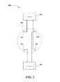
- FIG. 1is a schematic view of a two-radio architecture in a 3 ⁇ 3 access point (AP).
- FIG. 2is a schematic view of a two-radio architecture in a 2 ⁇ 2 AP.
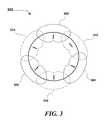
- FIG. 3is a top view of an example radiation pattern of the azimuth coverage for the two-radio interleaved 3 ⁇ 3 AP architecture of FIG. 1 .
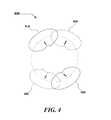
- FIG. 4is a top view of an example radiation pattern of the azimuth coverage for the two-radio interleaved 2 ⁇ 2 AP architecture of FIG. 1 .
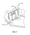
- FIG. 5is a perspective side view of an example dual-band monopole antenna element in accordance with the present invention mounted on a printed circuit board.
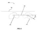
- FIG. 6is a section side view of an example radiation pattern of the elevation coverage for the APs shown in FIGS. 1 and 2 when mounted on a ceiling.
- FIG. 7is a sketch showing a perspective top view of a ground plane having an dual-band monopole antenna in accordance with the present invention together with a wire reflector.
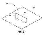
- FIG. 8is sketch showing a perspective top view of a ground plane having an dual-band monopole antenna in accordance with the present invention together with a sheet reflector.
- FIG. 9is perspective top view of an access point in accordance with the present invention comprising a printed circuit board mounted on a plastic enclosure, having six dual-band monopole antennas in accordance with the present invention mounted on the printed circuit board.
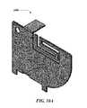
- FIG. 10Ais a perspective side view of an example of an implementation of an dual-band monopole antenna in accordance with the present invention.
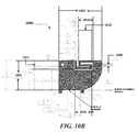
- FIG. 10Bis a side view, with dimensions, of the dual-band monopole antenna shown in FIG. 10A .
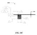
- FIG. 10Cis a top view, with selected dimensions, of the dual-band monopole antenna shown in FIG. 10A .
- the distributed omni-directional dual-band antenna systemincludes an antenna array that may include 4, 6, or 8 antennas arranged in a circular array fashion along the Wi-Fi access point. Each antenna may be associated with a different Wi-Fi radio. The antennas for the different radios are interleaved (see FIGS. 1 and 2 ) in order to provide omni-directional coverage with minimal distortion. Each antenna element in the array may be dual-band one may also be semi-directional.
- FIGS. 1 and 2show schematic views of a two radio architecture 100 in a 3 ⁇ 3 access point (AP) and a 2 ⁇ 2 AP, respectively, with two radios each.
- radio 104is associated with three antennas 124 , 126 , and 128
- radio 106is associated with three antennas 114 , 116 , and 118 .
- Antennas 114 , 116 , 118 , 124 , 126 , and 128are all dual-band monopole antennas in accordance with the present invention, and are mounted at the perimeter of ground plane 102 .
- Each of the antennas 114 , 116 , 118 , 124 , 126 , and 128is mounted width-wise on a radius of the ground plane 102 at equi-distances along the perimeter of the ground plane 102 , and are interleaved, that is, antennas associated with each of the two radios are affixed in alternate positions around the perimeter.
- radio 204is associated with two antennas 224 and 226
- radio 206is also associated with two antennas 214 and 216
- Antennas 214 , 216 , 224 , and 226are all dual-band monopole antennas in accordance with the present invention, and are mounted on ground plane 202 .
- Each of the antennas 214 , 216 , 224 , and 226is mounted width-wise on a radius of the ground plane 202 at equi-distances along the perimeter of the printed circuit board 102 , and are also interleaved.
- FIG. 3shows a top view of an example radiation pattern of the azimuth coverage 300 for the two-radio interleaved 3 ⁇ 3 AP shown in FIG. 1 .
- Radiation patterns 302 , 304 , and 306are the azimuth plots for antennas 128 , 124 , and 126 , respectively, that are shown in FIG. 1 .
- radiation patterns 312 , 316 , and 314are the azimuth plots for antennas 114 , 118 , and 116 , respectively, that are shown in FIG. 1 . Together, these radiation patterns illustrate the omni-directional characteristics of the interleaved 3 ⁇ 3 AP described in FIG. 1 .
- FIG. 4a top view of an example radiation pattern of the azimuth coverage 400 for the two-radio interleaved 2 ⁇ 2 AP shown in FIG. 2 .
- Radiation patterns 402 and 406are the azimuth plots for antennas 214 and 216 , respectively, that are shown in FIG. 2 .
- radiation patterns 404 and 408are the azimuth plots for antennas 224 and 226 , respectively, that are shown in FIG. 2 .
- these radiation patternsillustrate the distributed omni-directional characteristics of the interleaved 2 ⁇ 2 AP described in FIG. 2 .
- FIG. 5is a top perspective side view 500 of an example dual-band monopole antenna element 502 in accordance with the present invention mounted on a printed circuit board 504 .
- the printed circuit board 504may include a conductive ground plane (not shown), which may be a large area of copper foil on the printed circuit board 504 , connected to a power supply ground terminal.
- the dual-band monopole antenna element 502(which is described in more detail below with reference to FIGS. 10B and 10C ) is affixed to the printed circuit board 504 at its perimeter as shown in FIG. 5 and additional dual-band monopole antenna elements may be likewise affixed to the printed circuit board 504 as shown in FIG. 9 .
- FIG. 6is a sectional side view 600 of an example radiation pattern of the elevation coverage for the APs shown in FIGS. 1 and 2 when mounted on a ceiling 602 .
- the APsmay include a ground plane 604 positioned above a dual-band monopole antenna element 608 affixed to a printed circuit board (not shown).
- the use of the ground plane 604may deflect the radiation patterns 608 and 610 down by about 5-25 degrees, as shown by angle 620 , thus maximizing coverage below the antennas of the AP.
- the radiation pattern of the elevation coverage of the antenna elementis dependent on the size and shape of the ground plane, which may vary based on design requirements.
- the monopole elementsmay also have a reflector behind it to enhance its directivity.
- the reflectorcould be a continuous metallic wall or a single wire reflector (see FIGS. 7 and 8 , respectively).
- FIG. 7is a sketch showing a perspective top view of a ground plane 702 having a dual-band monopole antenna 704 in accordance with the present invention together with a single wire reflector 706 .
- FIG. 8is sketch showing a perspective top view of a ground plane 802 having a dual-band monopole antenna 704 in accordance with the present invention together with a metallic sheet reflector 806 .
- FIG. 9is perspective top view of an access point 900 in accordance with the present invention comprising a printed circuit board 902 mounted on a plastic enclosure 904 , having six dual-band monopole antennas 904 in accordance with the present invention mounted on the printed circuit board 902 .
- the APis an integrated assembly, and this embodiment is designed for mounting on a ceiling, as shown in FIG. 6 , wherein the plastic support 910 assists in stabilizing the access point 900 against the ceiling.
- FIG. 10Ais a perspective side view of an example of an implementation of a dual-band monopole antenna 1000 in accordance with the present invention.
- this dual-band monopole antenna 1000is roughly rectangular in shape.
- One portion of the dual-band monopole antennamay be formed as a convex curve that forms a tapered slot antenna having a broad bandwidth that includes the 5 GHz WiFi band.
- Another portion of the antenna elementmay be formed into an S-shaped folded stub that creates a resonance at the 2.4 GHz WiFi band.
- the dual-band monopole antennamay be printed on a FR4 substrate of relative permittivity 4.4 and thickness 1.6 mm as shown in thickness 1050 of FIG. 10C .
- a 50-Ohm microstrip linemay be used for the excitation, with a strip width of 3.06 mm, same as that of the width of the microstrip feed line.
- this particular embodiment of a dual-band monopole antenna 1000has a width 1002 of 25.448 mm and a length 1004 of 17.166 mm.
- This dual-band monopole antenna 1000comprises a folded stub including three horizontal radiating elements and one vertical radiating element, as shown in FIG. 10B .
- the shape of the radiating elements of the folded stub when connectedlooks like the letter “S” with the vertical radiating element perpendicular to the open end of the bottom-most third horizontal radiating element.
- the first horizontal radiating elementhas a length 1010 of 8.652 mm; the second horizontal radiating element has a length 1012 of 8.002 mm; the third horizontal radiating element has a length 1014 of 10.023 mm; and the vertical radiating element has a length 1016 of 5.741 mm.
- the width 1040 of the radiating elementsis 1.016 mm.
- the first horizontal radiating element and the second horizontal radiating elementare connected by a first connecting element having a length of 1.143 mm, and the second horizontal radiating element and the third horizontal radiating element are connected by a second connecting element having a length of 0.800 mm.
- the antenna gainmay be in the 2.4 and 5 GHz bands may 2-5 dB.
- the isolation between any antenna in the array of antennasis high, reaching, for example, approximately 40 dB at the 5 GHz band.
- the high isolation between these antennasenables the two radios in the AP to coexist with each other. By having the antennas interleaved, it creates an effect of distributed omni-coverage, where the two or three antennas connected to a specific radio forms an omni-directional coverage.
Landscapes
- Engineering & Computer Science (AREA)
- Computer Networks & Wireless Communication (AREA)
- Variable-Direction Aerials And Aerial Arrays (AREA)
- Signal Processing (AREA)
Abstract
Description
Claims (10)
Priority Applications (1)
| Application Number | Priority Date | Filing Date | Title |
|---|---|---|---|
| US14/792,574US9912079B2 (en) | 2014-07-03 | 2015-07-06 | Distributed omni-dual-band antenna system for a Wi-Fi access point |
Applications Claiming Priority (2)
| Application Number | Priority Date | Filing Date | Title |
|---|---|---|---|
| US201462020856P | 2014-07-03 | 2014-07-03 | |
| US14/792,574US9912079B2 (en) | 2014-07-03 | 2015-07-06 | Distributed omni-dual-band antenna system for a Wi-Fi access point |
Publications (2)
| Publication Number | Publication Date |
|---|---|
| US20160043478A1 US20160043478A1 (en) | 2016-02-11 |
| US9912079B2true US9912079B2 (en) | 2018-03-06 |
Family
ID=55268136
Family Applications (1)
| Application Number | Title | Priority Date | Filing Date |
|---|---|---|---|
| US14/792,574Active2035-09-27US9912079B2 (en) | 2014-07-03 | 2015-07-06 | Distributed omni-dual-band antenna system for a Wi-Fi access point |
Country Status (1)
| Country | Link |
|---|---|
| US (1) | US9912079B2 (en) |
Cited By (1)
| Publication number | Priority date | Publication date | Assignee | Title |
|---|---|---|---|---|
| US20190306723A1 (en)* | 2018-04-02 | 2019-10-03 | Charter Communications Operating, Llc | Dynamic configuration and use of wireless base stations in a network |
Families Citing this family (117)
| Publication number | Priority date | Publication date | Assignee | Title |
|---|---|---|---|---|
| US9525524B2 (en) | 2013-05-31 | 2016-12-20 | At&T Intellectual Property I, L.P. | Remote distributed antenna system |
| US9999038B2 (en) | 2013-05-31 | 2018-06-12 | At&T Intellectual Property I, L.P. | Remote distributed antenna system |
| US8897697B1 (en) | 2013-11-06 | 2014-11-25 | At&T Intellectual Property I, Lp | Millimeter-wave surface-wave communications |
| US9768833B2 (en) | 2014-09-15 | 2017-09-19 | At&T Intellectual Property I, L.P. | Method and apparatus for sensing a condition in a transmission medium of electromagnetic waves |
| US10063280B2 (en) | 2014-09-17 | 2018-08-28 | At&T Intellectual Property I, L.P. | Monitoring and mitigating conditions in a communication network |
| US9615269B2 (en) | 2014-10-02 | 2017-04-04 | At&T Intellectual Property I, L.P. | Method and apparatus that provides fault tolerance in a communication network |
| US9685992B2 (en) | 2014-10-03 | 2017-06-20 | At&T Intellectual Property I, L.P. | Circuit panel network and methods thereof |
| US9503189B2 (en) | 2014-10-10 | 2016-11-22 | At&T Intellectual Property I, L.P. | Method and apparatus for arranging communication sessions in a communication system |
| US9973299B2 (en) | 2014-10-14 | 2018-05-15 | At&T Intellectual Property I, L.P. | Method and apparatus for adjusting a mode of communication in a communication network |
| US9577306B2 (en) | 2014-10-21 | 2017-02-21 | At&T Intellectual Property I, L.P. | Guided-wave transmission device and methods for use therewith |
| US9653770B2 (en) | 2014-10-21 | 2017-05-16 | At&T Intellectual Property I, L.P. | Guided wave coupler, coupling module and methods for use therewith |
| US9769020B2 (en) | 2014-10-21 | 2017-09-19 | At&T Intellectual Property I, L.P. | Method and apparatus for responding to events affecting communications in a communication network |
| US9312919B1 (en) | 2014-10-21 | 2016-04-12 | At&T Intellectual Property I, Lp | Transmission device with impairment compensation and methods for use therewith |
| US9780834B2 (en) | 2014-10-21 | 2017-10-03 | At&T Intellectual Property I, L.P. | Method and apparatus for transmitting electromagnetic waves |
| US9627768B2 (en) | 2014-10-21 | 2017-04-18 | At&T Intellectual Property I, L.P. | Guided-wave transmission device with non-fundamental mode propagation and methods for use therewith |
| US9544006B2 (en) | 2014-11-20 | 2017-01-10 | At&T Intellectual Property I, L.P. | Transmission device with mode division multiplexing and methods for use therewith |
| US10340573B2 (en) | 2016-10-26 | 2019-07-02 | At&T Intellectual Property I, L.P. | Launcher with cylindrical coupling device and methods for use therewith |
| US9954287B2 (en) | 2014-11-20 | 2018-04-24 | At&T Intellectual Property I, L.P. | Apparatus for converting wireless signals and electromagnetic waves and methods thereof |
| US9461706B1 (en) | 2015-07-31 | 2016-10-04 | At&T Intellectual Property I, Lp | Method and apparatus for exchanging communication signals |
| US10009067B2 (en) | 2014-12-04 | 2018-06-26 | At&T Intellectual Property I, L.P. | Method and apparatus for configuring a communication interface |
| US10243784B2 (en) | 2014-11-20 | 2019-03-26 | At&T Intellectual Property I, L.P. | System for generating topology information and methods thereof |
| US9997819B2 (en) | 2015-06-09 | 2018-06-12 | At&T Intellectual Property I, L.P. | Transmission medium and method for facilitating propagation of electromagnetic waves via a core |
| US9800327B2 (en) | 2014-11-20 | 2017-10-24 | At&T Intellectual Property I, L.P. | Apparatus for controlling operations of a communication device and methods thereof |
| US9742462B2 (en) | 2014-12-04 | 2017-08-22 | At&T Intellectual Property I, L.P. | Transmission medium and communication interfaces and methods for use therewith |
| US9876570B2 (en) | 2015-02-20 | 2018-01-23 | At&T Intellectual Property I, Lp | Guided-wave transmission device with non-fundamental mode propagation and methods for use therewith |
| US9749013B2 (en) | 2015-03-17 | 2017-08-29 | At&T Intellectual Property I, L.P. | Method and apparatus for reducing attenuation of electromagnetic waves guided by a transmission medium |
| US10224981B2 (en) | 2015-04-24 | 2019-03-05 | At&T Intellectual Property I, Lp | Passive electrical coupling device and methods for use therewith |
| US9705561B2 (en) | 2015-04-24 | 2017-07-11 | At&T Intellectual Property I, L.P. | Directional coupling device and methods for use therewith |
| US9793954B2 (en) | 2015-04-28 | 2017-10-17 | At&T Intellectual Property I, L.P. | Magnetic coupling device and methods for use therewith |
| US9490869B1 (en) | 2015-05-14 | 2016-11-08 | At&T Intellectual Property I, L.P. | Transmission medium having multiple cores and methods for use therewith |
| US9748626B2 (en) | 2015-05-14 | 2017-08-29 | At&T Intellectual Property I, L.P. | Plurality of cables having different cross-sectional shapes which are bundled together to form a transmission medium |
| US9871282B2 (en) | 2015-05-14 | 2018-01-16 | At&T Intellectual Property I, L.P. | At least one transmission medium having a dielectric surface that is covered at least in part by a second dielectric |
| US10650940B2 (en) | 2015-05-15 | 2020-05-12 | At&T Intellectual Property I, L.P. | Transmission medium having a conductive material and methods for use therewith |
| US9917341B2 (en) | 2015-05-27 | 2018-03-13 | At&T Intellectual Property I, L.P. | Apparatus and method for launching electromagnetic waves and for modifying radial dimensions of the propagating electromagnetic waves |
| US10812174B2 (en) | 2015-06-03 | 2020-10-20 | At&T Intellectual Property I, L.P. | Client node device and methods for use therewith |
| US9866309B2 (en) | 2015-06-03 | 2018-01-09 | At&T Intellectual Property I, Lp | Host node device and methods for use therewith |
| US9912381B2 (en) | 2015-06-03 | 2018-03-06 | At&T Intellectual Property I, Lp | Network termination and methods for use therewith |
| US9913139B2 (en) | 2015-06-09 | 2018-03-06 | At&T Intellectual Property I, L.P. | Signal fingerprinting for authentication of communicating devices |
| US9820146B2 (en) | 2015-06-12 | 2017-11-14 | At&T Intellectual Property I, L.P. | Method and apparatus for authentication and identity management of communicating devices |
| US9509415B1 (en) | 2015-06-25 | 2016-11-29 | At&T Intellectual Property I, L.P. | Methods and apparatus for inducing a fundamental wave mode on a transmission medium |
| US9640850B2 (en) | 2015-06-25 | 2017-05-02 | At&T Intellectual Property I, L.P. | Methods and apparatus for inducing a non-fundamental wave mode on a transmission medium |
| US9865911B2 (en) | 2015-06-25 | 2018-01-09 | At&T Intellectual Property I, L.P. | Waveguide system for slot radiating first electromagnetic waves that are combined into a non-fundamental wave mode second electromagnetic wave on a transmission medium |
| US9853342B2 (en) | 2015-07-14 | 2017-12-26 | At&T Intellectual Property I, L.P. | Dielectric transmission medium connector and methods for use therewith |
| US10148016B2 (en) | 2015-07-14 | 2018-12-04 | At&T Intellectual Property I, L.P. | Apparatus and methods for communicating utilizing an antenna array |
| US9847566B2 (en) | 2015-07-14 | 2017-12-19 | At&T Intellectual Property I, L.P. | Method and apparatus for adjusting a field of a signal to mitigate interference |
| US10205655B2 (en) | 2015-07-14 | 2019-02-12 | At&T Intellectual Property I, L.P. | Apparatus and methods for communicating utilizing an antenna array and multiple communication paths |
| US9882257B2 (en) | 2015-07-14 | 2018-01-30 | At&T Intellectual Property I, L.P. | Method and apparatus for launching a wave mode that mitigates interference |
| US10044409B2 (en) | 2015-07-14 | 2018-08-07 | At&T Intellectual Property I, L.P. | Transmission medium and methods for use therewith |
| US9628116B2 (en) | 2015-07-14 | 2017-04-18 | At&T Intellectual Property I, L.P. | Apparatus and methods for transmitting wireless signals |
| US10090606B2 (en) | 2015-07-15 | 2018-10-02 | At&T Intellectual Property I, L.P. | Antenna system with dielectric array and methods for use therewith |
| US9912027B2 (en) | 2015-07-23 | 2018-03-06 | At&T Intellectual Property I, L.P. | Method and apparatus for exchanging communication signals |
| US9749053B2 (en) | 2015-07-23 | 2017-08-29 | At&T Intellectual Property I, L.P. | Node device, repeater and methods for use therewith |
| US9871283B2 (en) | 2015-07-23 | 2018-01-16 | At&T Intellectual Property I, Lp | Transmission medium having a dielectric core comprised of plural members connected by a ball and socket configuration |
| US9948333B2 (en) | 2015-07-23 | 2018-04-17 | At&T Intellectual Property I, L.P. | Method and apparatus for wireless communications to mitigate interference |
| US9735833B2 (en) | 2015-07-31 | 2017-08-15 | At&T Intellectual Property I, L.P. | Method and apparatus for communications management in a neighborhood network |
| US9967173B2 (en) | 2015-07-31 | 2018-05-08 | At&T Intellectual Property I, L.P. | Method and apparatus for authentication and identity management of communicating devices |
| US9904535B2 (en) | 2015-09-14 | 2018-02-27 | At&T Intellectual Property I, L.P. | Method and apparatus for distributing software |
| US9769128B2 (en) | 2015-09-28 | 2017-09-19 | At&T Intellectual Property I, L.P. | Method and apparatus for encryption of communications over a network |
| US9729197B2 (en) | 2015-10-01 | 2017-08-08 | At&T Intellectual Property I, L.P. | Method and apparatus for communicating network management traffic over a network |
| US9876264B2 (en) | 2015-10-02 | 2018-01-23 | At&T Intellectual Property I, Lp | Communication system, guided wave switch and methods for use therewith |
| US10355367B2 (en) | 2015-10-16 | 2019-07-16 | At&T Intellectual Property I, L.P. | Antenna structure for exchanging wireless signals |
| US9860075B1 (en) | 2016-08-26 | 2018-01-02 | At&T Intellectual Property I, L.P. | Method and communication node for broadband distribution |
| US10374316B2 (en) | 2016-10-21 | 2019-08-06 | At&T Intellectual Property I, L.P. | System and dielectric antenna with non-uniform dielectric |
| US10811767B2 (en) | 2016-10-21 | 2020-10-20 | At&T Intellectual Property I, L.P. | System and dielectric antenna with convex dielectric radome |
| US10312567B2 (en) | 2016-10-26 | 2019-06-04 | At&T Intellectual Property I, L.P. | Launcher with planar strip antenna and methods for use therewith |
| US10224634B2 (en) | 2016-11-03 | 2019-03-05 | At&T Intellectual Property I, L.P. | Methods and apparatus for adjusting an operational characteristic of an antenna |
| US10225025B2 (en) | 2016-11-03 | 2019-03-05 | At&T Intellectual Property I, L.P. | Method and apparatus for detecting a fault in a communication system |
| US10291334B2 (en) | 2016-11-03 | 2019-05-14 | At&T Intellectual Property I, L.P. | System for detecting a fault in a communication system |
| US10498044B2 (en) | 2016-11-03 | 2019-12-03 | At&T Intellectual Property I, L.P. | Apparatus for configuring a surface of an antenna |
| US10090594B2 (en) | 2016-11-23 | 2018-10-02 | At&T Intellectual Property I, L.P. | Antenna system having structural configurations for assembly |
| US10340601B2 (en) | 2016-11-23 | 2019-07-02 | At&T Intellectual Property I, L.P. | Multi-antenna system and methods for use therewith |
| US10340603B2 (en) | 2016-11-23 | 2019-07-02 | At&T Intellectual Property I, L.P. | Antenna system having shielded structural configurations for assembly |
| US10535928B2 (en) | 2016-11-23 | 2020-01-14 | At&T Intellectual Property I, L.P. | Antenna system and methods for use therewith |
| US10178445B2 (en) | 2016-11-23 | 2019-01-08 | At&T Intellectual Property I, L.P. | Methods, devices, and systems for load balancing between a plurality of waveguides |
| US10305190B2 (en) | 2016-12-01 | 2019-05-28 | At&T Intellectual Property I, L.P. | Reflecting dielectric antenna system and methods for use therewith |
| US10361489B2 (en) | 2016-12-01 | 2019-07-23 | At&T Intellectual Property I, L.P. | Dielectric dish antenna system and methods for use therewith |
| US10439675B2 (en) | 2016-12-06 | 2019-10-08 | At&T Intellectual Property I, L.P. | Method and apparatus for repeating guided wave communication signals |
| US10135145B2 (en) | 2016-12-06 | 2018-11-20 | At&T Intellectual Property I, L.P. | Apparatus and methods for generating an electromagnetic wave along a transmission medium |
| US10755542B2 (en) | 2016-12-06 | 2020-08-25 | At&T Intellectual Property I, L.P. | Method and apparatus for surveillance via guided wave communication |
| US10020844B2 (en) | 2016-12-06 | 2018-07-10 | T&T Intellectual Property I, L.P. | Method and apparatus for broadcast communication via guided waves |
| US9927517B1 (en) | 2016-12-06 | 2018-03-27 | At&T Intellectual Property I, L.P. | Apparatus and methods for sensing rainfall |
| US10637149B2 (en) | 2016-12-06 | 2020-04-28 | At&T Intellectual Property I, L.P. | Injection molded dielectric antenna and methods for use therewith |
| US10326494B2 (en) | 2016-12-06 | 2019-06-18 | At&T Intellectual Property I, L.P. | Apparatus for measurement de-embedding and methods for use therewith |
| US10382976B2 (en) | 2016-12-06 | 2019-08-13 | At&T Intellectual Property I, L.P. | Method and apparatus for managing wireless communications based on communication paths and network device positions |
| US10819035B2 (en) | 2016-12-06 | 2020-10-27 | At&T Intellectual Property I, L.P. | Launcher with helical antenna and methods for use therewith |
| US10694379B2 (en) | 2016-12-06 | 2020-06-23 | At&T Intellectual Property I, L.P. | Waveguide system with device-based authentication and methods for use therewith |
| US10727599B2 (en) | 2016-12-06 | 2020-07-28 | At&T Intellectual Property I, L.P. | Launcher with slot antenna and methods for use therewith |
| US9893795B1 (en) | 2016-12-07 | 2018-02-13 | At&T Intellectual Property I, Lp | Method and repeater for broadband distribution |
| US10446936B2 (en) | 2016-12-07 | 2019-10-15 | At&T Intellectual Property I, L.P. | Multi-feed dielectric antenna system and methods for use therewith |
| US10359749B2 (en) | 2016-12-07 | 2019-07-23 | At&T Intellectual Property I, L.P. | Method and apparatus for utilities management via guided wave communication |
| US10139820B2 (en) | 2016-12-07 | 2018-11-27 | At&T Intellectual Property I, L.P. | Method and apparatus for deploying equipment of a communication system |
| US10547348B2 (en) | 2016-12-07 | 2020-01-28 | At&T Intellectual Property I, L.P. | Method and apparatus for switching transmission mediums in a communication system |
| US10168695B2 (en) | 2016-12-07 | 2019-01-01 | At&T Intellectual Property I, L.P. | Method and apparatus for controlling an unmanned aircraft |
| US10027397B2 (en) | 2016-12-07 | 2018-07-17 | At&T Intellectual Property I, L.P. | Distributed antenna system and methods for use therewith |
| US10243270B2 (en) | 2016-12-07 | 2019-03-26 | At&T Intellectual Property I, L.P. | Beam adaptive multi-feed dielectric antenna system and methods for use therewith |
| US10389029B2 (en) | 2016-12-07 | 2019-08-20 | At&T Intellectual Property I, L.P. | Multi-feed dielectric antenna system with core selection and methods for use therewith |
| US10916969B2 (en) | 2016-12-08 | 2021-02-09 | At&T Intellectual Property I, L.P. | Method and apparatus for providing power using an inductive coupling |
| US10938108B2 (en) | 2016-12-08 | 2021-03-02 | At&T Intellectual Property I, L.P. | Frequency selective multi-feed dielectric antenna system and methods for use therewith |
| US10601494B2 (en) | 2016-12-08 | 2020-03-24 | At&T Intellectual Property I, L.P. | Dual-band communication device and method for use therewith |
| US9998870B1 (en) | 2016-12-08 | 2018-06-12 | At&T Intellectual Property I, L.P. | Method and apparatus for proximity sensing |
| US10411356B2 (en) | 2016-12-08 | 2019-09-10 | At&T Intellectual Property I, L.P. | Apparatus and methods for selectively targeting communication devices with an antenna array |
| US10389037B2 (en) | 2016-12-08 | 2019-08-20 | At&T Intellectual Property I, L.P. | Apparatus and methods for selecting sections of an antenna array and use therewith |
| US10530505B2 (en) | 2016-12-08 | 2020-01-07 | At&T Intellectual Property I, L.P. | Apparatus and methods for launching electromagnetic waves along a transmission medium |
| US10069535B2 (en) | 2016-12-08 | 2018-09-04 | At&T Intellectual Property I, L.P. | Apparatus and methods for launching electromagnetic waves having a certain electric field structure |
| US10103422B2 (en) | 2016-12-08 | 2018-10-16 | At&T Intellectual Property I, L.P. | Method and apparatus for mounting network devices |
| US9911020B1 (en) | 2016-12-08 | 2018-03-06 | At&T Intellectual Property I, L.P. | Method and apparatus for tracking via a radio frequency identification device |
| US10326689B2 (en) | 2016-12-08 | 2019-06-18 | At&T Intellectual Property I, L.P. | Method and system for providing alternative communication paths |
| US10777873B2 (en) | 2016-12-08 | 2020-09-15 | At&T Intellectual Property I, L.P. | Method and apparatus for mounting network devices |
| US10340983B2 (en) | 2016-12-09 | 2019-07-02 | At&T Intellectual Property I, L.P. | Method and apparatus for surveying remote sites via guided wave communications |
| US10264586B2 (en) | 2016-12-09 | 2019-04-16 | At&T Mobility Ii Llc | Cloud-based packet controller and methods for use therewith |
| US9838896B1 (en) | 2016-12-09 | 2017-12-05 | At&T Intellectual Property I, L.P. | Method and apparatus for assessing network coverage |
| US9973940B1 (en) | 2017-02-27 | 2018-05-15 | At&T Intellectual Property I, L.P. | Apparatus and methods for dynamic impedance matching of a guided wave launcher |
| US10298293B2 (en) | 2017-03-13 | 2019-05-21 | At&T Intellectual Property I, L.P. | Apparatus of communication utilizing wireless network devices |
| CN110915253B (en)* | 2017-03-17 | 2024-07-05 | 迈克尔·王 | Accurate positioning system and use method thereof |
| US11609300B2 (en)* | 2017-03-17 | 2023-03-21 | SIRL, Inc. | Precise positioning system enabled product location method |
| US10971803B2 (en)* | 2019-08-14 | 2021-04-06 | Cisco Technology, Inc. | Omnidirectional antenna system for macro-macro cell deployment with concurrent band operation |
| TW202308221A (en)* | 2021-08-04 | 2023-02-16 | 立端科技股份有限公司 | Wi-fi antenna and wireless communication device having the same |
Citations (3)
| Publication number | Priority date | Publication date | Assignee | Title |
|---|---|---|---|---|
| US20040027309A1 (en)* | 2000-08-01 | 2004-02-12 | Govind Swarup | Preloaded parabolic dish antenna and the method of making it |
| US20060109067A1 (en)* | 2004-11-22 | 2006-05-25 | Ruckus Wireless, Inc. | Circuit board having a pereipheral antenna apparatus with selectable antenna elements and selectable phase shifting |
| US20100119002A1 (en)* | 2008-11-12 | 2010-05-13 | Xirrus, Inc. | Mimo antenna system |
- 2015
- 2015-07-06USUS14/792,574patent/US9912079B2/enactiveActive
Patent Citations (3)
| Publication number | Priority date | Publication date | Assignee | Title |
|---|---|---|---|---|
| US20040027309A1 (en)* | 2000-08-01 | 2004-02-12 | Govind Swarup | Preloaded parabolic dish antenna and the method of making it |
| US20060109067A1 (en)* | 2004-11-22 | 2006-05-25 | Ruckus Wireless, Inc. | Circuit board having a pereipheral antenna apparatus with selectable antenna elements and selectable phase shifting |
| US20100119002A1 (en)* | 2008-11-12 | 2010-05-13 | Xirrus, Inc. | Mimo antenna system |
Cited By (3)
| Publication number | Priority date | Publication date | Assignee | Title |
|---|---|---|---|---|
| US20190306723A1 (en)* | 2018-04-02 | 2019-10-03 | Charter Communications Operating, Llc | Dynamic configuration and use of wireless base stations in a network |
| US10979911B2 (en)* | 2018-04-02 | 2021-04-13 | Charter Communications Operating, Llc | Dynamic configuration and use of wireless base stations in a network |
| US11671848B2 (en) | 2018-04-02 | 2023-06-06 | Charter Communications Operating, Llc | Dynamic configuration and use of wireless base stations in a network |
Also Published As
| Publication number | Publication date |
|---|---|
| US20160043478A1 (en) | 2016-02-11 |
Similar Documents
| Publication | Publication Date | Title |
|---|---|---|
| US9912079B2 (en) | Distributed omni-dual-band antenna system for a Wi-Fi access point | |
| US11303016B2 (en) | Multi-sector antennas | |
| US12316014B2 (en) | Multi-band antenna array devices having a tubular configuration | |
| CN109149131B (en) | Dipole antenna and associated multiband antenna | |
| US9729213B2 (en) | MIMO antenna system | |
| US8963792B2 (en) | Wireless local area network antenna array | |
| ATE264009T1 (en) | ROUND BEAM ANTENNA WITH ASYMMETRIC DOUBLE CONE AS A PASSIVE FEED ELEMENT FOR A RADIATOR ELEMENT | |
| JP2002330026A (en) | Antenna array | |
| US20160028166A1 (en) | Dual-Feed Dual-Polarized Antenna Element and Method for Manufacturing Same | |
| CN115769436A (en) | Antenna radiator with pre-configured shielding to achieve dense layout of radiators for multiple frequency bands | |
| KR101541374B1 (en) | Dual Polarization Dipole Antenna for Multi-Band and System including the same | |
| US7064725B2 (en) | Conical beam cross-slot antenna | |
| EP3460904A1 (en) | Capacitively-coupled dual-band antenna | |
| US11411321B2 (en) | Broadband antenna system | |
| EP3692601B1 (en) | Ultra compact radiating element | |
| JP2017092663A (en) | Broadband non-directional antenna | |
| JP2017139686A (en) | Antenna and base station | |
| US10971803B2 (en) | Omnidirectional antenna system for macro-macro cell deployment with concurrent band operation | |
| US9923278B2 (en) | Diversity antenna arrangement for WLAN, and WLAN communication unit having such a diversity antenna arrangement, and device having such a WLAN communication unit | |
| KR20150120194A (en) | Multiple antenna | |
| US20230136811A1 (en) | Antenna device, array of antenna devices, and base station | |
| JP2009111661A (en) | Array antenna | |
| KR20080026720A (en) | Multiband Flatbed Monopole Antenna with Self-Similar Fan-shaped Grooves | |
| JP2008099310A (en) | Antenna with one or more openings | |
| Desai et al. | Antenna types for small cells base stations |
Legal Events
| Date | Code | Title | Description |
|---|---|---|---|
| AS | Assignment | Owner name:XIRRUS INC., CALIFORNIA Free format text:ASSIGNMENT OF ASSIGNORS INTEREST;ASSIGNOR:HARTENSTEIN, ABRAHAM;REEL/FRAME:036923/0569 Effective date:20151020 | |
| AS | Assignment | Owner name:XIRRUS, INC., CALIFORNIA Free format text:ASSIGNMENT OF ASSIGNORS INTEREST;ASSIGNOR:HARTENSTEIN, ABRAHAM;REEL/FRAME:038037/0166 Effective date:20151020 | |
| AS | Assignment | Owner name:SILICON VALLEY BANK, CALIFORNIA Free format text:SECURITY INTEREST;ASSIGNOR:XIRRUS, INC.;REEL/FRAME:038662/0731 Effective date:20120530 | |
| AS | Assignment | Owner name:TRIPLEPOINT VENTURE GROWTH BDC CORP, CALIFORNIA Free format text:SECURITY INTEREST;ASSIGNOR:XIRRUS, INC.;REEL/FRAME:040183/0427 Effective date:20160331 | |
| AS | Assignment | Owner name:XIRRUS, INC., CALIFORNIA Free format text:RELEASE OF INTELLECTUAL PROPERTY SECURITY AGREEMENT RECORDED AT REEL 038662/FRAME 0731;ASSIGNOR:SILICON VALLEY BANK;REEL/FRAME:042388/0079 Effective date:20170421 Owner name:XIRRUS, INC., CALIFORNIA Free format text:RELEASE OF SECURITY INTEREST RECORDED AT REEL 040183/FRAME 0427;ASSIGNOR:TRIPLEPOINT VENTURE GROWTH BDC CORP., AS ASSIGNEE OF TRIPLEPOINT CAPITAL LLC;REEL/FRAME:042388/0799 Effective date:20170424 | |
| FEPP | Fee payment procedure | Free format text:ENTITY STATUS SET TO UNDISCOUNTED (ORIGINAL EVENT CODE: BIG.) | |
| STCF | Information on status: patent grant | Free format text:PATENTED CASE | |
| AS | Assignment | Owner name:XIRRUS LLC, CALIFORNIA Free format text:CONVERSION TO LIMITED LIABILITY COMPANY;ASSIGNOR:XIRRUS, INC.;REEL/FRAME:047100/0874 Effective date:20170601 | |
| AS | Assignment | Owner name:RIVERBED TECHNOLOGY, INC., CALIFORNIA Free format text:ASSIGNMENT OF ASSIGNORS INTEREST;ASSIGNOR:XIRRUS LLC;REEL/FRAME:047706/0936 Effective date:20180814 | |
| AS | Assignment | Owner name:MORGAN STANLEY SENIOR FUNDING, INC., AS COLLATERAL Free format text:PATENT SECURITY AGREEMENT;ASSIGNOR:RIVERBED TECHNOLOGY, INC.;REEL/FRAME:049720/0808 Effective date:20190703 Owner name:MORGAN STANLEY SENIOR FUNDING, INC., AS COLLATERAL AGENT, MARYLAND Free format text:PATENT SECURITY AGREEMENT;ASSIGNOR:RIVERBED TECHNOLOGY, INC.;REEL/FRAME:049720/0808 Effective date:20190703 | |
| AS | Assignment | Owner name:RIVERBED TECHNOLOGY, INC., CALIFORNIA Free format text:RELEASE OF SECURITY INTEREST IN CERTAIN PATENTS;ASSIGNOR:MORGAN STANLEY SENIOR FUNDING, INC.;REEL/FRAME:050016/0600 Effective date:20190807 | |
| AS | Assignment | Owner name:CAMBIUM NETWORKS, LTD., UNITED KINGDOM Free format text:ASSIGNMENT OF ASSIGNORS INTEREST;ASSIGNOR:RIVERBED TECHNOLOGY, INC.;REEL/FRAME:051894/0194 Effective date:20190805 | |
| MAFP | Maintenance fee payment | Free format text:PAYMENT OF MAINTENANCE FEE, 4TH YEAR, LARGE ENTITY (ORIGINAL EVENT CODE: M1551); ENTITY STATUS OF PATENT OWNER: LARGE ENTITY Year of fee payment:4 | |
| MAFP | Maintenance fee payment | Free format text:PAYMENT OF MAINTENANCE FEE, 8TH YEAR, LARGE ENTITY (ORIGINAL EVENT CODE: M1552); ENTITY STATUS OF PATENT OWNER: LARGE ENTITY Year of fee payment:8 |