US9910466B1 - Memory module mounting system - Google Patents
Memory module mounting systemDownload PDFInfo
- Publication number
- US9910466B1 US9910466B1US15/082,670US201615082670AUS9910466B1US 9910466 B1US9910466 B1US 9910466B1US 201615082670 AUS201615082670 AUS 201615082670AUS 9910466 B1US9910466 B1US 9910466B1
- Authority
- US
- United States
- Prior art keywords
- assembly
- memory module
- system board
- screw
- bracket
- Prior art date
- Legal status (The legal status is an assumption and is not a legal conclusion. Google has not performed a legal analysis and makes no representation as to the accuracy of the status listed.)
- Active
Links
Images


Classifications
- G—PHYSICS
- G06—COMPUTING OR CALCULATING; COUNTING
- G06F—ELECTRIC DIGITAL DATA PROCESSING
- G06F1/00—Details not covered by groups G06F3/00 - G06F13/00 and G06F21/00
- G06F1/16—Constructional details or arrangements
- G06F1/18—Packaging or power distribution
- G06F1/183—Internal mounting support structures, e.g. for printed circuit boards, internal connecting means
- G06F1/185—Mounting of expansion boards
- H—ELECTRICITY
- H05—ELECTRIC TECHNIQUES NOT OTHERWISE PROVIDED FOR
- H05K—PRINTED CIRCUITS; CASINGS OR CONSTRUCTIONAL DETAILS OF ELECTRIC APPARATUS; MANUFACTURE OF ASSEMBLAGES OF ELECTRICAL COMPONENTS
- H05K7/00—Constructional details common to different types of electric apparatus
- H05K7/02—Arrangements of circuit components or wiring on supporting structure
- H05K7/12—Resilient or clamping means for holding component to structure
- H—ELECTRICITY
- H05—ELECTRIC TECHNIQUES NOT OTHERWISE PROVIDED FOR
- H05K—PRINTED CIRCUITS; CASINGS OR CONSTRUCTIONAL DETAILS OF ELECTRIC APPARATUS; MANUFACTURE OF ASSEMBLAGES OF ELECTRICAL COMPONENTS
- H05K7/00—Constructional details common to different types of electric apparatus
- H05K7/14—Mounting supporting structure in casing or on frame or rack
- H05K7/1417—Mounting supporting structure in casing or on frame or rack having securing means for mounting boards, plates or wiring boards
- H05K7/1418—Card guides, e.g. grooves
- H—ELECTRICITY
- H05—ELECTRIC TECHNIQUES NOT OTHERWISE PROVIDED FOR
- H05K—PRINTED CIRCUITS; CASINGS OR CONSTRUCTIONAL DETAILS OF ELECTRIC APPARATUS; MANUFACTURE OF ASSEMBLAGES OF ELECTRICAL COMPONENTS
- H05K7/00—Constructional details common to different types of electric apparatus
- H05K7/14—Mounting supporting structure in casing or on frame or rack
- H05K7/1417—Mounting supporting structure in casing or on frame or rack having securing means for mounting boards, plates or wiring boards
- H05K7/142—Spacers not being card guides
Definitions
- This disclosurerelates to IT components and, more particularly, to systems for mounting storage devices within IT components.
- primary serversmay be supported by backup servers; primary switches may be supported by backup switches; primary power supplies may be supported by backup power supplies; and primary storage systems may be supported by backup storage systems.
- a memory module mounting systemincludes a bracket assembly configured to engage a system board.
- the bracket assemblyincludes: a standoff assembly that is configured to position a memory module a desired distance from the system board, and an alignment pin assembly configured to position the bracket assembly on the system board.
- a tether assemblyis flexibly coupled to the bracket assembly.
- a screw assemblyis held captive by the tether assembly and configured to pass though the bracket assembly and releasably engage the system board.
- the screw assemblymay be an electrically conductive screw assembly.
- the screw assemblymay be configured to engage a ground plane of the memory module.
- the screw assemblymay be configured to engage a ground plane of the system board.
- the screw assemblymay be a toolless screw assembly.
- the screw assemblymay be configured to releasably engage a nut assembly coupled to the system board.
- the tether assemblymay be constructed of a flexible, non-conductive material.
- the bracket assemblymay be constructed of a non-conductive material.
- the alignment pin assemblymay be configured to releasably engage an alignment hole within the system board.
- the memory modulemay be a non-volatile memory module.
- the memory modulemay be an M.2 memory module.
- a memory module mounting systemincludes a bracket assembly configured to engage a system board.
- the bracket assemblyincludes: a standoff assembly that is configured to position a memory module a desired distance from the system board, and an alignment pin assembly configured to position the bracket assembly on the system board.
- a tether assemblyis flexibly coupled to the bracket assembly, wherein the tether assembly is constructed of a flexible, non-conductive material.
- An electrically conductive screw assemblyis held captive by the tether assembly and configured to pass though the bracket assembly and releasably engage the system board.
- the screw assemblymay be configured to engage a ground plane of the memory module.
- the screw assemblymay be configured to engage a ground plane of the system board.
- the screw assemblymay be configured to releasably engage a nut assembly coupled to the system board.
- the alignment pin assemblymay be configured to releasably engage an alignment hole within the system board.
- the bracket assemblymay be constructed of a non-conductive material.
- a memory module mounting systemin another implementation, includes a bracket assembly configured to engage a system board.
- the bracket assemblyincludes a standoff assembly that is configured to position an M.2 memory module a desired distance from the system board.
- An alignment pin assemblyis configured to position the bracket assembly on the system board.
- a tether assemblyis flexibly coupled to the bracket assembly.
- An electrically conductive screw assemblyis held captive by the tether assembly and configured to pass though the bracket assembly and releasably engage the system board.
- the screw assemblyis configured to engage a ground plane of the M.2 memory module and a ground plane of the system board.
- the screw assemblymay be a toolless screw assembly.
- the alignment pin assemblymay be configured to releasably engage an alignment hole within the system board.
- FIG. 1is a perspective view of an IT rack and an IT component
- FIG. 2Ais a perspective view of the IT component of FIG. 1 ;
- FIG. 2Bis a front view of the IT component of FIG. 1 ;
- FIG. 3is a diagrammatic view of a system board of the IT component of FIG. 1 ;
- FIG. 4is a detail view of a portion of the system board of FIG. 3 ;
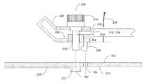
- FIG. 5is a memory module mounting system for use with the system board of FIG. 3 .
- IT racksmay be utilized to store and organize IT components.
- IT rack 10may be placed within a computer room and various IT components (e.g., IT component 12 ) may be attached to rails (e.g., NEMA rails 14 , 16 ) included within IT rack 10 , wherein these rails (e.g., NEMA rails 14 , 16 ) may have a standard and defined spacing between them (e.g., 19′′).
- railse.g., NEMA rails 14 , 16
- these railse.g., NEMA rails 14 , 16
- these railse.g., NEMA rails 14 , 16
- IT components that are configured to fit within IT rack 10may be described as rack-mountable IT components.
- IT componentse.g., IT component 12
- IT rack 10examples of the various IT components (e.g., IT component 12 ) mountable within IT rack 10 may include but are not limited to: server systems, disk array systems, storage processor systems, storage processor/disk systems, and battery backup systems.
- IT rack 10may include frame 18 (which may include one or more vertical supports, horizontal supports, and cross braces) to which NEMA rails 14 , 16 may be attached.
- NEMA rails 14 , 16may include a plurality of evenly spaced holes that may be configured for mounting the various IT components within IT rack 10 . By standardizing the spacing between NEMA rails 14 , 16 , the various IT devices that fit within a first IT rack may also fit within a second IT rack.
- IT component 12may be available in standardized heights based upon the number of rack units (U's). Examples of such standardized heights may include but are not limited to 1 U IT components, 2 U IT components, 3 U IT components, and 4 U IT components, wherein a 1 U IT component is half as high as a 2 U IT component, which is half as high as a 4 U IT component.
- IT racksmay be available in various heights, which are capable of accommodating a defined number of rack units (U's).
- U'srack units
- the number of rack units available within a particular IT rackmay be rigidly defined by the height of the IT rack
- the number of IT components mountable within that IT rackmay vary depending upon the height in rack units (U's) of the particular IT components being mounted within that IT rack. Therefore, by reducing the number of rack units utilized by a particular IT component within an IT rack, additional IT components may be mounted within the IT rack.
- IT component 12there is shown the internal components of one implementation of IT component 12 , wherein IT component 12 is shown to include chassis assembly 100 , system board 102 , and one or more storage devices 104 , 106 , 108 , 110 , 112 , 114 .
- FIG. 3there is shown one implementation of system board 102 .
- system board 102is shown to include various components such as one or more processors (e.g., processor 150 , 152 ), volatile memory (e.g., RAM modules 154 , 156 , 158 , 160 ), memory controller 162 , I/O controller 164 , expansion slots 166 , 168 , 170 , and data connectors 172 , 174 .
- system board 102may include one or more memory modules (e.g., memory modules 176 , 178 ). Examples of memory modules 176 , 178 may include non-volatile memory modules that may e.g., store the content of cache memory in the event of a failure of IT component 12 , function as cache memory itself, or store licensing information for installed software.
- Memory modules 176 , 178may be interfaced with system board 102 using various interfaces, such as PCIe, eSATA, SAS, or USB. Additionally, memory modules 176 , 178 may be configured in various form factors, such as an M.2 memory module. As is known in the art, M.2 is a specification for internally mounted computer expansion cards and associated connectors.
- M.2 modulesare available in different lengths, such as 40 mm, 60 mm, 80 mm and 110 mm, wherein the length of the M.2 memory module may vary depending upon the quantity of memory included within the memory module.
- System board 102may be configured to accommodate these varying length modules.
- system board 102may include connector 180 that is used for all modules (regardless of length). Additionally, system board 102 may include separate mounting points for 40 mm modules, 60 mm modules, 80 mm modules and 110 mm modules. Specifically, system board 102 may include: mounting screw hole 182 and alignment hole 184 for 40 mm modules; mounting screw hole 186 and alignment hole 188 for 60 mm modules; mounting screw hole 190 and alignment hole 192 for 80 mm modules; and mounting screw hole 194 and alignment hole 196 for 110 mm modules.
- Memory module mounting system 200may include bracket assembly 202 configured to engage system board 102 .
- Bracket assembly 202may include standoff assembly 204 that may be configured to position the memory module (e.g., memory modules 176 , 178 ) a desired distance (e.g., “x”) from system board 102 .
- Bracket assembly 202may be constructed of a non-conductive material, examples of which may include but are not limited to nylon and polyester.
- Memory module mounting system 200may include alignment pin assembly 206 configured to position bracket assembly 202 on system board 102 .
- Alignment pin assembly 206may be configured to releasably engage an alignment hole (e.g., alignment hole 184 ) within system board 102 .
- Memory module mounting system 200may include tether assembly 208 flexibly coupled to bracket assembly 202 .
- Tether assembly 208may be constructed of a flexible, non-conductive material, examples of which may include but are not limited to nylon and polyester.
- Memory module mounting system 200may include screw assembly 210 held captive by tether assembly 208 and configured to pass though bracket assembly 202 and releasably engage system board 102 .
- a nut assemblye.g., nut assembly 212
- screw assembly 210may be mounted onto lower surface 214 of system board 102 , wherein screw assembly 210 may pass through passage 216 within bracket assembly 202 and mounting screw hole 182 within system board 102 and releasably engage nut assembly 212 .
- An example of screw assembly 210may include but is not limited to a toolless screw assembly (e.g., a knurled screw), thus allowing for the disengagement of screw assembly 210 from nut assembly 212 included within system board 102 without the need for tools.
- screw assembly 210Since tether assembly 208 is flexible, upon screw assembly 210 being unscrewed from nut assembly 212 , screw assembly 210 may be swung out of the way, thus allowing for memory module 176 / 178 to be removed (in the direction of arrow 224 ). And since screw assembly 210 is held captive by tether assembly 208 , the likelihood of screw assembly 210 being lost is reduced.
- memory module mounting system 200may be remove from system board 102 and repositioned on system board 102 using a different set of mounting holes (e.g., moving memory module mounting system 200 from mounting screw hole 182 /alignment hole 184 for 40 mm module) to mounting screw hole 190 /alignment hole 192 for 80 mm modules).
- Screw assembly 210may be an electrically-conductive screw assembly that is configured to engage ground plane 218 of memory module 176 / 178 and ground plane 220 of system board 102 .
- screw assembly 210may be configured to clamp tongue assembly 222 of memory module 176 / 178 between the lower surface of screw assembly 210 and standoff assembly 204 , thus resulting in screw assembly 210 making electrical contact with ground plane 218 of memory module 176 / 178 .
- nut assembly 212may be electrically coupled to ground plane 220 of system board 102 . Accordingly and through the use of screw assembly 210 , ground plane 218 of memory module 176 / 178 is electrically coupled to ground plane 220 of system board 102 .
Landscapes
- Engineering & Computer Science (AREA)
- Microelectronics & Electronic Packaging (AREA)
- Theoretical Computer Science (AREA)
- Computer Hardware Design (AREA)
- Power Engineering (AREA)
- Human Computer Interaction (AREA)
- Physics & Mathematics (AREA)
- General Engineering & Computer Science (AREA)
- General Physics & Mathematics (AREA)
- Mounting Of Printed Circuit Boards And The Like (AREA)
Abstract
Description
Claims (17)
Priority Applications (1)
| Application Number | Priority Date | Filing Date | Title |
|---|---|---|---|
| US15/082,670US9910466B1 (en) | 2016-03-28 | 2016-03-28 | Memory module mounting system |
Applications Claiming Priority (1)
| Application Number | Priority Date | Filing Date | Title |
|---|---|---|---|
| US15/082,670US9910466B1 (en) | 2016-03-28 | 2016-03-28 | Memory module mounting system |
Publications (1)
| Publication Number | Publication Date |
|---|---|
| US9910466B1true US9910466B1 (en) | 2018-03-06 |
Family
ID=61257209
Family Applications (1)
| Application Number | Title | Priority Date | Filing Date |
|---|---|---|---|
| US15/082,670ActiveUS9910466B1 (en) | 2016-03-28 | 2016-03-28 | Memory module mounting system |
Country Status (1)
| Country | Link |
|---|---|
| US (1) | US9910466B1 (en) |
Cited By (4)
| Publication number | Priority date | Publication date | Assignee | Title |
|---|---|---|---|---|
| US10711817B2 (en) | 2016-06-14 | 2020-07-14 | EMC IP Holding Company LLC | Rod for use in rack and holding device for use in cooperation with rack |
| US11166393B1 (en) | 2020-04-30 | 2021-11-02 | EMC IP Holding Company LLC | Storage device and an array of disks, and an apparatus for arranging disk |
| US20220030730A1 (en)* | 2020-07-27 | 2022-01-27 | Kang Yang Hardware Enterprises Co., Ltd. | Fastener for use in electronic device |
| US20240053891A1 (en)* | 2022-08-12 | 2024-02-15 | Advanced Micro Devices, Inc. | Chipset Attached Random Access Memory |
Citations (14)
| Publication number | Priority date | Publication date | Assignee | Title |
|---|---|---|---|---|
| US3996500A (en)* | 1975-06-16 | 1976-12-07 | Richco Plastic Company | Chassis connector and circuit board clip |
| US4969065A (en)* | 1989-02-28 | 1990-11-06 | Petri Hector D | Spacer for circuit boards and circuit board assembly including same |
| US5281149A (en)* | 1992-07-06 | 1994-01-25 | Petri Hector D | Grounding circuit board standoff |
| US5964625A (en)* | 1998-04-28 | 1999-10-12 | Hart Scientific, Inc. | Spring loaded combination electrical binding post |
| US6344972B2 (en)* | 1999-12-14 | 2002-02-05 | Alstom | Electronic equipment |
| US6493233B1 (en)* | 2001-08-21 | 2002-12-10 | Intel Corporation | PCB-to-chassis mounting schemes |
| US20080018351A1 (en)* | 2006-07-20 | 2008-01-24 | International Business Machines Corporation | Toolless method for alignment, retention, connection, termination and test on printed circuit boards |
| US20100165592A1 (en)* | 2008-12-26 | 2010-07-01 | Fujitsu Limited | Attachment device and electronic apparatus |
| US20100328835A1 (en)* | 2009-06-25 | 2010-12-30 | Samsung Electronics Co., Ltd. | Memory module for preventing electrostatic discharge (ESD) and system including the same |
| US20120103031A1 (en)* | 2010-11-02 | 2012-05-03 | Invue Security Products, Inc. | Security system for merchandise shelf |
| US8228299B1 (en)* | 2005-01-27 | 2012-07-24 | Singleton Technology, Llc | Transaction automation and archival system using electronic contract and disclosure units |
| US20130072038A1 (en)* | 2011-09-15 | 2013-03-21 | Chih-Ping Chen | Circuit board device and a combined circuit board and electronic card assembly |
| US20160149323A1 (en)* | 2014-11-25 | 2016-05-26 | Tyco Electronics Corporation | Connector assembly for electrically coupling a module card to a circuit board |
| US20160294087A1 (en)* | 2013-11-26 | 2016-10-06 | Hewlett Packard Enterprise Development Lp | Electrical connector adapter |
- 2016
- 2016-03-28USUS15/082,670patent/US9910466B1/enactiveActive
Patent Citations (14)
| Publication number | Priority date | Publication date | Assignee | Title |
|---|---|---|---|---|
| US3996500A (en)* | 1975-06-16 | 1976-12-07 | Richco Plastic Company | Chassis connector and circuit board clip |
| US4969065A (en)* | 1989-02-28 | 1990-11-06 | Petri Hector D | Spacer for circuit boards and circuit board assembly including same |
| US5281149A (en)* | 1992-07-06 | 1994-01-25 | Petri Hector D | Grounding circuit board standoff |
| US5964625A (en)* | 1998-04-28 | 1999-10-12 | Hart Scientific, Inc. | Spring loaded combination electrical binding post |
| US6344972B2 (en)* | 1999-12-14 | 2002-02-05 | Alstom | Electronic equipment |
| US6493233B1 (en)* | 2001-08-21 | 2002-12-10 | Intel Corporation | PCB-to-chassis mounting schemes |
| US8228299B1 (en)* | 2005-01-27 | 2012-07-24 | Singleton Technology, Llc | Transaction automation and archival system using electronic contract and disclosure units |
| US20080018351A1 (en)* | 2006-07-20 | 2008-01-24 | International Business Machines Corporation | Toolless method for alignment, retention, connection, termination and test on printed circuit boards |
| US20100165592A1 (en)* | 2008-12-26 | 2010-07-01 | Fujitsu Limited | Attachment device and electronic apparatus |
| US20100328835A1 (en)* | 2009-06-25 | 2010-12-30 | Samsung Electronics Co., Ltd. | Memory module for preventing electrostatic discharge (ESD) and system including the same |
| US20120103031A1 (en)* | 2010-11-02 | 2012-05-03 | Invue Security Products, Inc. | Security system for merchandise shelf |
| US20130072038A1 (en)* | 2011-09-15 | 2013-03-21 | Chih-Ping Chen | Circuit board device and a combined circuit board and electronic card assembly |
| US20160294087A1 (en)* | 2013-11-26 | 2016-10-06 | Hewlett Packard Enterprise Development Lp | Electrical connector adapter |
| US20160149323A1 (en)* | 2014-11-25 | 2016-05-26 | Tyco Electronics Corporation | Connector assembly for electrically coupling a module card to a circuit board |
Cited By (6)
| Publication number | Priority date | Publication date | Assignee | Title |
|---|---|---|---|---|
| US10711817B2 (en) | 2016-06-14 | 2020-07-14 | EMC IP Holding Company LLC | Rod for use in rack and holding device for use in cooperation with rack |
| US11166393B1 (en) | 2020-04-30 | 2021-11-02 | EMC IP Holding Company LLC | Storage device and an array of disks, and an apparatus for arranging disk |
| US20220030730A1 (en)* | 2020-07-27 | 2022-01-27 | Kang Yang Hardware Enterprises Co., Ltd. | Fastener for use in electronic device |
| US11445629B2 (en)* | 2020-07-27 | 2022-09-13 | Kang Yang Hardware Enterprises Co., Ltd. | Fastener for use in electronic device |
| US20240053891A1 (en)* | 2022-08-12 | 2024-02-15 | Advanced Micro Devices, Inc. | Chipset Attached Random Access Memory |
| US12379843B2 (en)* | 2022-08-12 | 2025-08-05 | Advanced Micro Devices, Inc. | Chipset attached random access memory |
Similar Documents
| Publication | Publication Date | Title |
|---|---|---|
| US9910466B1 (en) | Memory module mounting system | |
| US8897017B2 (en) | Serviceable hard disk drive trays for a server rack | |
| US8911250B2 (en) | Floating bus bar connector | |
| US6816388B2 (en) | Daughter card service position | |
| US9257804B1 (en) | Pitch agnostic bus-bar with pitch agnostic blind mate connector | |
| US10324504B2 (en) | Storage device mounting system | |
| US6185093B1 (en) | Expansion card carrier and method for a computer system | |
| US10462925B1 (en) | Mass storage device retainer assembly | |
| US9178288B2 (en) | Spring plate for attaching bus bar to a printed circuit board | |
| US9172165B1 (en) | Memory module connector assembly | |
| US9603251B1 (en) | Apparatus and method of midplane panel connections | |
| US8717752B2 (en) | Drive enclosures for tool-less removable mounting of solid state drives onto printed circuit board devices | |
| US20130039002A1 (en) | Server rack assembly | |
| US20230269897A1 (en) | Ssd card adapter bracket and circuit board assembly | |
| US9992903B1 (en) | Modular rack-mountable IT device | |
| US10939572B2 (en) | Circuit board assembly | |
| US9131624B1 (en) | Rack-mountable IT device | |
| US20180063985A1 (en) | Modularized server | |
| US10149402B1 (en) | Rack-mountable IT device | |
| US20100134989A1 (en) | Expansion Card Retention Apparatus, Systems and Methods | |
| US20140273556A1 (en) | High-density multidirectional midplane | |
| US9357666B1 (en) | Field-serviceable IT device | |
| EP3266286B1 (en) | Adapter assemblies | |
| US6252766B1 (en) | Computer with peripheral device mounting assembly | |
| US20150043150A1 (en) | Electronic device with data storage device holder |
Legal Events
| Date | Code | Title | Description |
|---|---|---|---|
| AS | Assignment | Owner name:EMC CORPORATION, MASSACHUSETTS Free format text:ASSIGNMENT OF ASSIGNORS INTEREST;ASSIGNORS:STRICKLAND, STEPHEN E.;LEONE, JASON J.;BOUDREAU, MAIDA;SIGNING DATES FROM 20160321 TO 20160328;REEL/FRAME:038114/0757 | |
| AS | Assignment | Owner name:THE BANK OF NEW YORK MELLON TRUST COMPANY, N.A., AS NOTES COLLATERAL AGENT, TEXAS Free format text:SECURITY AGREEMENT;ASSIGNORS:ASAP SOFTWARE EXPRESS, INC.;AVENTAIL LLC;CREDANT TECHNOLOGIES, INC.;AND OTHERS;REEL/FRAME:040136/0001 Effective date:20160907 Owner name:CREDIT SUISSE AG, CAYMAN ISLANDS BRANCH, AS COLLATERAL AGENT, NORTH CAROLINA Free format text:SECURITY AGREEMENT;ASSIGNORS:ASAP SOFTWARE EXPRESS, INC.;AVENTAIL LLC;CREDANT TECHNOLOGIES, INC.;AND OTHERS;REEL/FRAME:040134/0001 Effective date:20160907 Owner name:THE BANK OF NEW YORK MELLON TRUST COMPANY, N.A., A Free format text:SECURITY AGREEMENT;ASSIGNORS:ASAP SOFTWARE EXPRESS, INC.;AVENTAIL LLC;CREDANT TECHNOLOGIES, INC.;AND OTHERS;REEL/FRAME:040136/0001 Effective date:20160907 Owner name:CREDIT SUISSE AG, CAYMAN ISLANDS BRANCH, AS COLLAT Free format text:SECURITY AGREEMENT;ASSIGNORS:ASAP SOFTWARE EXPRESS, INC.;AVENTAIL LLC;CREDANT TECHNOLOGIES, INC.;AND OTHERS;REEL/FRAME:040134/0001 Effective date:20160907 | |
| AS | Assignment | Owner name:EMC IP HOLDING COMPANY LLC, MASSACHUSETTS Free format text:ASSIGNMENT OF ASSIGNORS INTEREST;ASSIGNOR:EMC CORPORATION;REEL/FRAME:040203/0001 Effective date:20160906 | |
| STCF | Information on status: patent grant | Free format text:PATENTED CASE | |
| AS | Assignment | Owner name:THE BANK OF NEW YORK MELLON TRUST COMPANY, N.A., T Free format text:SECURITY AGREEMENT;ASSIGNORS:CREDANT TECHNOLOGIES, INC.;DELL INTERNATIONAL L.L.C.;DELL MARKETING L.P.;AND OTHERS;REEL/FRAME:049452/0223 Effective date:20190320 Owner name:THE BANK OF NEW YORK MELLON TRUST COMPANY, N.A., TEXAS Free format text:SECURITY AGREEMENT;ASSIGNORS:CREDANT TECHNOLOGIES, INC.;DELL INTERNATIONAL L.L.C.;DELL MARKETING L.P.;AND OTHERS;REEL/FRAME:049452/0223 Effective date:20190320 | |
| AS | Assignment | Owner name:THE BANK OF NEW YORK MELLON TRUST COMPANY, N.A., TEXAS Free format text:SECURITY AGREEMENT;ASSIGNORS:CREDANT TECHNOLOGIES INC.;DELL INTERNATIONAL L.L.C.;DELL MARKETING L.P.;AND OTHERS;REEL/FRAME:053546/0001 Effective date:20200409 | |
| MAFP | Maintenance fee payment | Free format text:PAYMENT OF MAINTENANCE FEE, 4TH YEAR, LARGE ENTITY (ORIGINAL EVENT CODE: M1551); ENTITY STATUS OF PATENT OWNER: LARGE ENTITY Year of fee payment:4 | |
| AS | Assignment | Owner name:WYSE TECHNOLOGY L.L.C., CALIFORNIA Free format text:RELEASE BY SECURED PARTY;ASSIGNOR:CREDIT SUISSE AG, CAYMAN ISLANDS BRANCH;REEL/FRAME:058216/0001 Effective date:20211101 Owner name:SCALEIO LLC, MASSACHUSETTS Free format text:RELEASE BY SECURED PARTY;ASSIGNOR:CREDIT SUISSE AG, CAYMAN ISLANDS BRANCH;REEL/FRAME:058216/0001 Effective date:20211101 Owner name:MOZY, INC., WASHINGTON Free format text:RELEASE BY SECURED PARTY;ASSIGNOR:CREDIT SUISSE AG, CAYMAN ISLANDS BRANCH;REEL/FRAME:058216/0001 Effective date:20211101 Owner name:MAGINATICS LLC, CALIFORNIA Free format text:RELEASE BY SECURED PARTY;ASSIGNOR:CREDIT SUISSE AG, CAYMAN ISLANDS BRANCH;REEL/FRAME:058216/0001 Effective date:20211101 Owner name:FORCE10 NETWORKS, INC., CALIFORNIA Free format text:RELEASE BY SECURED PARTY;ASSIGNOR:CREDIT SUISSE AG, CAYMAN ISLANDS BRANCH;REEL/FRAME:058216/0001 Effective date:20211101 Owner name:EMC IP HOLDING COMPANY LLC, TEXAS Free format text:RELEASE BY SECURED PARTY;ASSIGNOR:CREDIT SUISSE AG, CAYMAN ISLANDS BRANCH;REEL/FRAME:058216/0001 Effective date:20211101 Owner name:EMC CORPORATION, MASSACHUSETTS Free format text:RELEASE BY SECURED PARTY;ASSIGNOR:CREDIT SUISSE AG, CAYMAN ISLANDS BRANCH;REEL/FRAME:058216/0001 Effective date:20211101 Owner name:DELL SYSTEMS CORPORATION, TEXAS Free format text:RELEASE BY SECURED PARTY;ASSIGNOR:CREDIT SUISSE AG, CAYMAN ISLANDS BRANCH;REEL/FRAME:058216/0001 Effective date:20211101 Owner name:DELL SOFTWARE INC., CALIFORNIA Free format text:RELEASE BY SECURED PARTY;ASSIGNOR:CREDIT SUISSE AG, CAYMAN ISLANDS BRANCH;REEL/FRAME:058216/0001 Effective date:20211101 Owner name:DELL PRODUCTS L.P., TEXAS Free format text:RELEASE BY SECURED PARTY;ASSIGNOR:CREDIT SUISSE AG, CAYMAN ISLANDS BRANCH;REEL/FRAME:058216/0001 Effective date:20211101 Owner name:DELL MARKETING L.P., TEXAS Free format text:RELEASE BY SECURED PARTY;ASSIGNOR:CREDIT SUISSE AG, CAYMAN ISLANDS BRANCH;REEL/FRAME:058216/0001 Effective date:20211101 Owner name:DELL INTERNATIONAL, L.L.C., TEXAS Free format text:RELEASE BY SECURED PARTY;ASSIGNOR:CREDIT SUISSE AG, CAYMAN ISLANDS BRANCH;REEL/FRAME:058216/0001 Effective date:20211101 Owner name:DELL USA L.P., TEXAS Free format text:RELEASE BY SECURED PARTY;ASSIGNOR:CREDIT SUISSE AG, CAYMAN ISLANDS BRANCH;REEL/FRAME:058216/0001 Effective date:20211101 Owner name:CREDANT TECHNOLOGIES, INC., TEXAS Free format text:RELEASE BY SECURED PARTY;ASSIGNOR:CREDIT SUISSE AG, CAYMAN ISLANDS BRANCH;REEL/FRAME:058216/0001 Effective date:20211101 Owner name:AVENTAIL LLC, CALIFORNIA Free format text:RELEASE BY SECURED PARTY;ASSIGNOR:CREDIT SUISSE AG, CAYMAN ISLANDS BRANCH;REEL/FRAME:058216/0001 Effective date:20211101 Owner name:ASAP SOFTWARE EXPRESS, INC., ILLINOIS Free format text:RELEASE BY SECURED PARTY;ASSIGNOR:CREDIT SUISSE AG, CAYMAN ISLANDS BRANCH;REEL/FRAME:058216/0001 Effective date:20211101 | |
| AS | Assignment | Owner name:SCALEIO LLC, MASSACHUSETTS Free format text:RELEASE OF SECURITY INTEREST IN PATENTS PREVIOUSLY RECORDED AT REEL/FRAME (040136/0001);ASSIGNOR:THE BANK OF NEW YORK MELLON TRUST COMPANY, N.A., AS NOTES COLLATERAL AGENT;REEL/FRAME:061324/0001 Effective date:20220329 Owner name:EMC IP HOLDING COMPANY LLC (ON BEHALF OF ITSELF AND AS SUCCESSOR-IN-INTEREST TO MOZY, INC.), TEXAS Free format text:RELEASE OF SECURITY INTEREST IN PATENTS PREVIOUSLY RECORDED AT REEL/FRAME (040136/0001);ASSIGNOR:THE BANK OF NEW YORK MELLON TRUST COMPANY, N.A., AS NOTES COLLATERAL AGENT;REEL/FRAME:061324/0001 Effective date:20220329 Owner name:EMC CORPORATION (ON BEHALF OF ITSELF AND AS SUCCESSOR-IN-INTEREST TO MAGINATICS LLC), MASSACHUSETTS Free format text:RELEASE OF SECURITY INTEREST IN PATENTS PREVIOUSLY RECORDED AT REEL/FRAME (040136/0001);ASSIGNOR:THE BANK OF NEW YORK MELLON TRUST COMPANY, N.A., AS NOTES COLLATERAL AGENT;REEL/FRAME:061324/0001 Effective date:20220329 Owner name:DELL MARKETING CORPORATION (SUCCESSOR-IN-INTEREST TO FORCE10 NETWORKS, INC. AND WYSE TECHNOLOGY L.L.C.), TEXAS Free format text:RELEASE OF SECURITY INTEREST IN PATENTS PREVIOUSLY RECORDED AT REEL/FRAME (040136/0001);ASSIGNOR:THE BANK OF NEW YORK MELLON TRUST COMPANY, N.A., AS NOTES COLLATERAL AGENT;REEL/FRAME:061324/0001 Effective date:20220329 Owner name:DELL PRODUCTS L.P., TEXAS Free format text:RELEASE OF SECURITY INTEREST IN PATENTS PREVIOUSLY RECORDED AT REEL/FRAME (040136/0001);ASSIGNOR:THE BANK OF NEW YORK MELLON TRUST COMPANY, N.A., AS NOTES COLLATERAL AGENT;REEL/FRAME:061324/0001 Effective date:20220329 Owner name:DELL INTERNATIONAL L.L.C., TEXAS Free format text:RELEASE OF SECURITY INTEREST IN PATENTS PREVIOUSLY RECORDED AT REEL/FRAME (040136/0001);ASSIGNOR:THE BANK OF NEW YORK MELLON TRUST COMPANY, N.A., AS NOTES COLLATERAL AGENT;REEL/FRAME:061324/0001 Effective date:20220329 Owner name:DELL USA L.P., TEXAS Free format text:RELEASE OF SECURITY INTEREST IN PATENTS PREVIOUSLY RECORDED AT REEL/FRAME (040136/0001);ASSIGNOR:THE BANK OF NEW YORK MELLON TRUST COMPANY, N.A., AS NOTES COLLATERAL AGENT;REEL/FRAME:061324/0001 Effective date:20220329 Owner name:DELL MARKETING L.P. (ON BEHALF OF ITSELF AND AS SUCCESSOR-IN-INTEREST TO CREDANT TECHNOLOGIES, INC.), TEXAS Free format text:RELEASE OF SECURITY INTEREST IN PATENTS PREVIOUSLY RECORDED AT REEL/FRAME (040136/0001);ASSIGNOR:THE BANK OF NEW YORK MELLON TRUST COMPANY, N.A., AS NOTES COLLATERAL AGENT;REEL/FRAME:061324/0001 Effective date:20220329 Owner name:DELL MARKETING CORPORATION (SUCCESSOR-IN-INTEREST TO ASAP SOFTWARE EXPRESS, INC.), TEXAS Free format text:RELEASE OF SECURITY INTEREST IN PATENTS PREVIOUSLY RECORDED AT REEL/FRAME (040136/0001);ASSIGNOR:THE BANK OF NEW YORK MELLON TRUST COMPANY, N.A., AS NOTES COLLATERAL AGENT;REEL/FRAME:061324/0001 Effective date:20220329 | |
| AS | Assignment | Owner name:SCALEIO LLC, MASSACHUSETTS Free format text:RELEASE OF SECURITY INTEREST IN PATENTS PREVIOUSLY RECORDED AT REEL/FRAME (045455/0001);ASSIGNOR:THE BANK OF NEW YORK MELLON TRUST COMPANY, N.A., AS NOTES COLLATERAL AGENT;REEL/FRAME:061753/0001 Effective date:20220329 Owner name:EMC IP HOLDING COMPANY LLC (ON BEHALF OF ITSELF AND AS SUCCESSOR-IN-INTEREST TO MOZY, INC.), TEXAS Free format text:RELEASE OF SECURITY INTEREST IN PATENTS PREVIOUSLY RECORDED AT REEL/FRAME (045455/0001);ASSIGNOR:THE BANK OF NEW YORK MELLON TRUST COMPANY, N.A., AS NOTES COLLATERAL AGENT;REEL/FRAME:061753/0001 Effective date:20220329 Owner name:EMC CORPORATION (ON BEHALF OF ITSELF AND AS SUCCESSOR-IN-INTEREST TO MAGINATICS LLC), MASSACHUSETTS Free format text:RELEASE OF SECURITY INTEREST IN PATENTS PREVIOUSLY RECORDED AT REEL/FRAME (045455/0001);ASSIGNOR:THE BANK OF NEW YORK MELLON TRUST COMPANY, N.A., AS NOTES COLLATERAL AGENT;REEL/FRAME:061753/0001 Effective date:20220329 Owner name:DELL MARKETING CORPORATION (SUCCESSOR-IN-INTEREST TO FORCE10 NETWORKS, INC. AND WYSE TECHNOLOGY L.L.C.), TEXAS Free format text:RELEASE OF SECURITY INTEREST IN PATENTS PREVIOUSLY RECORDED AT REEL/FRAME (045455/0001);ASSIGNOR:THE BANK OF NEW YORK MELLON TRUST COMPANY, N.A., AS NOTES COLLATERAL AGENT;REEL/FRAME:061753/0001 Effective date:20220329 Owner name:DELL PRODUCTS L.P., TEXAS Free format text:RELEASE OF SECURITY INTEREST IN PATENTS PREVIOUSLY RECORDED AT REEL/FRAME (045455/0001);ASSIGNOR:THE BANK OF NEW YORK MELLON TRUST COMPANY, N.A., AS NOTES COLLATERAL AGENT;REEL/FRAME:061753/0001 Effective date:20220329 Owner name:DELL INTERNATIONAL L.L.C., TEXAS Free format text:RELEASE OF SECURITY INTEREST IN PATENTS PREVIOUSLY RECORDED AT REEL/FRAME (045455/0001);ASSIGNOR:THE BANK OF NEW YORK MELLON TRUST COMPANY, N.A., AS NOTES COLLATERAL AGENT;REEL/FRAME:061753/0001 Effective date:20220329 Owner name:DELL USA L.P., TEXAS Free format text:RELEASE OF SECURITY INTEREST IN PATENTS PREVIOUSLY RECORDED AT REEL/FRAME (045455/0001);ASSIGNOR:THE BANK OF NEW YORK MELLON TRUST COMPANY, N.A., AS NOTES COLLATERAL AGENT;REEL/FRAME:061753/0001 Effective date:20220329 Owner name:DELL MARKETING L.P. (ON BEHALF OF ITSELF AND AS SUCCESSOR-IN-INTEREST TO CREDANT TECHNOLOGIES, INC.), TEXAS Free format text:RELEASE OF SECURITY INTEREST IN PATENTS PREVIOUSLY RECORDED AT REEL/FRAME (045455/0001);ASSIGNOR:THE BANK OF NEW YORK MELLON TRUST COMPANY, N.A., AS NOTES COLLATERAL AGENT;REEL/FRAME:061753/0001 Effective date:20220329 Owner name:DELL MARKETING CORPORATION (SUCCESSOR-IN-INTEREST TO ASAP SOFTWARE EXPRESS, INC.), TEXAS Free format text:RELEASE OF SECURITY INTEREST IN PATENTS PREVIOUSLY RECORDED AT REEL/FRAME (045455/0001);ASSIGNOR:THE BANK OF NEW YORK MELLON TRUST COMPANY, N.A., AS NOTES COLLATERAL AGENT;REEL/FRAME:061753/0001 Effective date:20220329 | |
| AS | Assignment | Owner name:DELL MARKETING L.P. (ON BEHALF OF ITSELF AND AS SUCCESSOR-IN-INTEREST TO CREDANT TECHNOLOGIES, INC.), TEXAS Free format text:RELEASE OF SECURITY INTEREST IN PATENTS PREVIOUSLY RECORDED AT REEL/FRAME (053546/0001);ASSIGNOR:THE BANK OF NEW YORK MELLON TRUST COMPANY, N.A., AS NOTES COLLATERAL AGENT;REEL/FRAME:071642/0001 Effective date:20220329 Owner name:DELL INTERNATIONAL L.L.C., TEXAS Free format text:RELEASE OF SECURITY INTEREST IN PATENTS PREVIOUSLY RECORDED AT REEL/FRAME (053546/0001);ASSIGNOR:THE BANK OF NEW YORK MELLON TRUST COMPANY, N.A., AS NOTES COLLATERAL AGENT;REEL/FRAME:071642/0001 Effective date:20220329 Owner name:DELL PRODUCTS L.P., TEXAS Free format text:RELEASE OF SECURITY INTEREST IN PATENTS PREVIOUSLY RECORDED AT REEL/FRAME (053546/0001);ASSIGNOR:THE BANK OF NEW YORK MELLON TRUST COMPANY, N.A., AS NOTES COLLATERAL AGENT;REEL/FRAME:071642/0001 Effective date:20220329 Owner name:DELL USA L.P., TEXAS Free format text:RELEASE OF SECURITY INTEREST IN PATENTS PREVIOUSLY RECORDED AT REEL/FRAME (053546/0001);ASSIGNOR:THE BANK OF NEW YORK MELLON TRUST COMPANY, N.A., AS NOTES COLLATERAL AGENT;REEL/FRAME:071642/0001 Effective date:20220329 Owner name:EMC CORPORATION, MASSACHUSETTS Free format text:RELEASE OF SECURITY INTEREST IN PATENTS PREVIOUSLY RECORDED AT REEL/FRAME (053546/0001);ASSIGNOR:THE BANK OF NEW YORK MELLON TRUST COMPANY, N.A., AS NOTES COLLATERAL AGENT;REEL/FRAME:071642/0001 Effective date:20220329 Owner name:DELL MARKETING CORPORATION (SUCCESSOR-IN-INTEREST TO FORCE10 NETWORKS, INC. AND WYSE TECHNOLOGY L.L.C.), TEXAS Free format text:RELEASE OF SECURITY INTEREST IN PATENTS PREVIOUSLY RECORDED AT REEL/FRAME (053546/0001);ASSIGNOR:THE BANK OF NEW YORK MELLON TRUST COMPANY, N.A., AS NOTES COLLATERAL AGENT;REEL/FRAME:071642/0001 Effective date:20220329 Owner name:EMC IP HOLDING COMPANY LLC, TEXAS Free format text:RELEASE OF SECURITY INTEREST IN PATENTS PREVIOUSLY RECORDED AT REEL/FRAME (053546/0001);ASSIGNOR:THE BANK OF NEW YORK MELLON TRUST COMPANY, N.A., AS NOTES COLLATERAL AGENT;REEL/FRAME:071642/0001 Effective date:20220329 | |
| MAFP | Maintenance fee payment | Free format text:PAYMENT OF MAINTENANCE FEE, 8TH YEAR, LARGE ENTITY (ORIGINAL EVENT CODE: M1552); ENTITY STATUS OF PATENT OWNER: LARGE ENTITY Year of fee payment:8 |