US9910102B2 - Methods, systems, and computer readable media for monitoring and management of a power distribution system - Google Patents
Methods, systems, and computer readable media for monitoring and management of a power distribution systemDownload PDFInfo
- Publication number
- US9910102B2 US9910102B2US14/549,515US201414549515AUS9910102B2US 9910102 B2US9910102 B2US 9910102B2US 201414549515 AUS201414549515 AUS 201414549515AUS 9910102 B2US9910102 B2US 9910102B2
- Authority
- US
- United States
- Prior art keywords
- power distribution
- fault identification
- distribution system
- data
- power
- Prior art date
- Legal status (The legal status is an assumption and is not a legal conclusion. Google has not performed a legal analysis and makes no representation as to the accuracy of the status listed.)
- Active, expires
Links
Images


Classifications
- G—PHYSICS
- G01—MEASURING; TESTING
- G01R—MEASURING ELECTRIC VARIABLES; MEASURING MAGNETIC VARIABLES
- G01R31/00—Arrangements for testing electric properties; Arrangements for locating electric faults; Arrangements for electrical testing characterised by what is being tested not provided for elsewhere
- G01R31/40—Testing power supplies
- G—PHYSICS
- G01—MEASURING; TESTING
- G01R—MEASURING ELECTRIC VARIABLES; MEASURING MAGNETIC VARIABLES
- G01R31/00—Arrangements for testing electric properties; Arrangements for locating electric faults; Arrangements for electrical testing characterised by what is being tested not provided for elsewhere
- G01R31/50—Testing of electric apparatus, lines, cables or components for short-circuits, continuity, leakage current or incorrect line connections
- H—ELECTRICITY
- H02—GENERATION; CONVERSION OR DISTRIBUTION OF ELECTRIC POWER
- H02J—CIRCUIT ARRANGEMENTS OR SYSTEMS FOR SUPPLYING OR DISTRIBUTING ELECTRIC POWER; SYSTEMS FOR STORING ELECTRIC ENERGY
- H02J13/00—Circuit arrangements for providing remote indication of network conditions, e.g. an instantaneous record of the open or closed condition of each circuitbreaker in the network; Circuit arrangements for providing remote control of switching means in a power distribution network, e.g. switching in and out of current consumers by using a pulse code signal carried by the network
- H02J13/00006—Circuit arrangements for providing remote indication of network conditions, e.g. an instantaneous record of the open or closed condition of each circuitbreaker in the network; Circuit arrangements for providing remote control of switching means in a power distribution network, e.g. switching in and out of current consumers by using a pulse code signal carried by the network characterised by information or instructions transport means between the monitoring, controlling or managing units and monitored, controlled or operated power network element or electrical equipment
- G—PHYSICS
- G01—MEASURING; TESTING
- G01R—MEASURING ELECTRIC VARIABLES; MEASURING MAGNETIC VARIABLES
- G01R15/00—Details of measuring arrangements of the types provided for in groups G01R17/00 - G01R29/00, G01R33/00 - G01R33/26 or G01R35/00
- G01R15/14—Adaptations providing voltage or current isolation, e.g. for high-voltage or high-current networks
- G01R15/142—Arrangements for simultaneous measurements of several parameters employing techniques covered by groups G01R15/14 - G01R15/26
- H—ELECTRICITY
- H02—GENERATION; CONVERSION OR DISTRIBUTION OF ELECTRIC POWER
- H02G—INSTALLATION OF ELECTRIC CABLES OR LINES, OR OF COMBINED OPTICAL AND ELECTRIC CABLES OR LINES
- H02G1/00—Methods or apparatus specially adapted for installing, maintaining, repairing or dismantling electric cables or lines
- H02G1/02—Methods or apparatus specially adapted for installing, maintaining, repairing or dismantling electric cables or lines for overhead lines or cables
- H—ELECTRICITY
- H02—GENERATION; CONVERSION OR DISTRIBUTION OF ELECTRIC POWER
- H02J—CIRCUIT ARRANGEMENTS OR SYSTEMS FOR SUPPLYING OR DISTRIBUTING ELECTRIC POWER; SYSTEMS FOR STORING ELECTRIC ENERGY
- H02J13/00—Circuit arrangements for providing remote indication of network conditions, e.g. an instantaneous record of the open or closed condition of each circuitbreaker in the network; Circuit arrangements for providing remote control of switching means in a power distribution network, e.g. switching in and out of current consumers by using a pulse code signal carried by the network
- H02J13/00032—Systems characterised by the controlled or operated power network elements or equipment, the power network elements or equipment not otherwise provided for
- H02J13/00034—Systems characterised by the controlled or operated power network elements or equipment, the power network elements or equipment not otherwise provided for the elements or equipment being or involving an electric power substation
- H02J13/0013—
- Y—GENERAL TAGGING OF NEW TECHNOLOGICAL DEVELOPMENTS; GENERAL TAGGING OF CROSS-SECTIONAL TECHNOLOGIES SPANNING OVER SEVERAL SECTIONS OF THE IPC; TECHNICAL SUBJECTS COVERED BY FORMER USPC CROSS-REFERENCE ART COLLECTIONS [XRACs] AND DIGESTS
- Y02—TECHNOLOGIES OR APPLICATIONS FOR MITIGATION OR ADAPTATION AGAINST CLIMATE CHANGE
- Y02E—REDUCTION OF GREENHOUSE GAS [GHG] EMISSIONS, RELATED TO ENERGY GENERATION, TRANSMISSION OR DISTRIBUTION
- Y02E60/00—Enabling technologies; Technologies with a potential or indirect contribution to GHG emissions mitigation
- Y02E60/7807—
- Y—GENERAL TAGGING OF NEW TECHNOLOGICAL DEVELOPMENTS; GENERAL TAGGING OF CROSS-SECTIONAL TECHNOLOGIES SPANNING OVER SEVERAL SECTIONS OF THE IPC; TECHNICAL SUBJECTS COVERED BY FORMER USPC CROSS-REFERENCE ART COLLECTIONS [XRACs] AND DIGESTS
- Y04—INFORMATION OR COMMUNICATION TECHNOLOGIES HAVING AN IMPACT ON OTHER TECHNOLOGY AREAS
- Y04S—SYSTEMS INTEGRATING TECHNOLOGIES RELATED TO POWER NETWORK OPERATION, COMMUNICATION OR INFORMATION TECHNOLOGIES FOR IMPROVING THE ELECTRICAL POWER GENERATION, TRANSMISSION, DISTRIBUTION, MANAGEMENT OR USAGE, i.e. SMART GRIDS
- Y04S40/00—Systems for electrical power generation, transmission, distribution or end-user application management characterised by the use of communication or information technologies, or communication or information technology specific aspects supporting them
- Y04S40/12—Systems for electrical power generation, transmission, distribution or end-user application management characterised by the use of communication or information technologies, or communication or information technology specific aspects supporting them characterised by data transport means between the monitoring, controlling or managing units and monitored, controlled or operated electrical equipment
Definitions
- the subject matter described hereinrelates to the management and maintenance of power utility distribution systems via the use of mobile inspection devices. More particularly, the subject matter described herein relates to methods, systems, and computer readable media for monitoring and management of a power distribution system.
- a significant amount of outage management information received by power utilitiesis typically derived from trouble calls originating from customers.
- field techniciansare typically deployed by the power utility to the reported area(s) to conduct an inspection of the distribution lines and other distribution system elements.
- the related inspection data gathered by the utilityis generally segregated from a central outage management system or other communication-based utility field systems (e.g., supervisory control and data acquisition (SCADA) systems) configured to utilize the data.
- SCADAsupervisory control and data acquisition
- the mobile inspection devices or systems presently employed by utilities to inspect the distribution linesare typically provisioned with a communications means that is unable to provide the aforementioned management systems prompt access to the captured inspection data. Accordingly, there exists a need for providing enhanced monitoring and management of a power distribution system.
- the subject matter described hereinrelates to, methods, systems, and computer readable media for monitoring and management of a power distribution system.
- the methodincludes receiving sensory measurement data captured by a mobile inspection device during an inspection of power distribution system elements in a power distribution system.
- the methodfurther includes processing the received sensory measurement data to derive fault identification data that indicates a fault condition existing in one or more of the power distribution system elements and utilizing the derived fault identification data to update a network model of the power distribution system.
- the subject matter described hereincan be implemented in software in combination with hardware and/or firmware.
- the subject matter described hereincan be implemented in software executed by a processor.
- the subject matter described hereincan be implemented using a non-transitory computer readable medium having stored thereon computer executable instructions that when executed by the processor of a computer control the computer to perform steps.
- Exemplary computer readable media suitable for implementing the subject matter described hereininclude non-transitory computer-readable media, such as disk memory devices, chip memory devices, programmable logic devices, and application specific integrated circuits.
- a computer readable medium that implements the subject matter described hereinmay be located on a single device or computing platform or may be distributed across multiple devices or computing platforms.
- FIG. 1is a block diagram illustrating an exemplary system for monitoring and management of a power distribution system according to an embodiment of the subject matter described herein;
- FIG. 2is an illustration of a screen display of a distribution system network model according to an embodiment of the subject matter described herein;
- FIG. 3is a flow chart illustrating an exemplary process for monitoring and management of a power distribution system according to an embodiment of the subject matter described herein;
- FIG. 4is a high level block diagram of an exemplary general purpose computer system suitable for use in performing the functions described herein.
- the disclosed subject matteris directed to an end-to-end automated data analysis and communications system where inspection data is processed and transmitted to a central utility control center for updating a power distribution system network model (e.g., a network model of a power grid).
- a power distribution system network modele.g., a network model of a power grid.
- the prompt identification of power outage locations afforded by the disclosed subject mattermay enhance safety conditions for field technicians and customers alike, which is especially important in storm situations where distribution line outages are increasingly prevalent.
- CBMcondition-based maintenance
- post-storm damage assessmenta robot-assisted inspection approach safely facilitates the energized circuit inspection data gathering and analysis process.
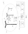
- FIG. 1is a block diagram illustrating an exemplary electricity network system 100 for providing enhanced monitoring and management of a power distribution system according to an embodiment of the subject matter described herein.
- system 100includes a power distribution system 102 that comprises, among other system components, distribution lines 104 supported by a plurality of utility poles 106 a - c .
- each of distribution lines 104may comprise any type of distribution conductor line that is capable of conducting electricity among residential areas, substations, and power plants/farms.
- each of distribution lines 104may comprise any transmission line capable of carrying a communication signals (e.g., radio frequency signal currents) without departing from the scope of the disclosed subject matter.
- a communication signalse.g., radio frequency signal currents
- system 100also includes a central utility control center 118 comprising a backend communications system (BCS) 120 , a distribution management system (DMS) 122 , an outage management system (OMS) 124 , a trouble call system 126 (and/or an advanced metering infrastructure (AMI) system), and a work management system 128 , each of which are described in more detail below.
- BCSbackend communications system
- DMSdistribution management system
- OMSoutage management system
- AMIadvanced metering infrastructure
- work management system 128each of systems 120 - 128 may comprise a software module that is supported by one or more host computer servers included in utility control center 118 .
- each of systems 120 - 128 described hereinmay constitute a special purpose computer that improves the technological field of power utility systems by providing a mechanism for monitoring and communicating outage data between a power distribution system and a central utility control system.
- any other industrye.g., cable television
- FIG. 1depicts two distribution lines 104 and three utility poles 106 a - c
- any number of distribution lines and utility polesmay be positioned throughout power distribution system 102 (e.g., a power network) without departing from the scope of the disclosed subject matter.
- power distribution system 102may further include a mobile inspection device 108 and a mobile control station 110 , each of which may be utilized by a field technician to inspect and assess the operational status of power distribution system 102 .
- mobile control station 110can include a laptop computer, a computer tablet, a mobile smartphone, a local control station (e.g., a laptop computer equipped with a high power antenna), or any other like computing device that is capable of wirelessly communicating with both mobile inspection device 108 and a central utility control center 118 (as described below).
- mobile control station 110may be provisioned with a wireless communication module 130 that enables mobile control station 110 to wirelessly communicate with both mobile inspection device 108 and utility control center 118 (via BCS 120 ).
- wireless communication module 130may comprise any chipset and/or software component that allows mobile control station 110 to transmit and receive wireless signal data (e.g., cellular data, WiFi data, or other RF data).
- mobile inspection device 108may include any robotic or mechanized mobile device that is utilized to conduct inspections of distribution lines 104 by using attached data capture equipment and/or detection device(s) 114 .
- One exemplary mobile inspection deviceincludes a distribution line inspection robot (e.g., a mobile line “crawling” robot) that is configured to traverse an overhead distribution wire 104 and wire junctions at utility poles 106 a - c as depicted in FIG. 1 .
- a line crawling robotmay be found in U.S. Pat. No. 8,505,461, which is herein incorporated by reference in its entirety.
- mobile inspection device 108may include a quadcopter or drone device that is controlled or programmed (e.g., using GPS coordinates) to fly over and/or proximate to distribution lines 104 .
- mobile inspection device 108can be equipped with one or more detection devices 114 such as a standard definition camera, a high definition (HD) camera, a video camera, an infrared and/or thermal sensor device or camera, an acoustic signal capturing device, multi-meter device, and the like.
- detection devices 114such as a standard definition camera, a high definition (HD) camera, a video camera, an infrared and/or thermal sensor device or camera, an acoustic signal capturing device, multi-meter device, and the like.
- detection device(s) 114may be configured to capture sensory measurement data comprising image data, video data, thermal image data, and sound data corresponding to the power distribution system elements (e.g., conductor lines, transformers, arresters, etc.) while mounted or incorporated within mobile inspection device 108 .
- the sensory measurement data captured by detection device(s) 114may reveal compromises to the physical integrity of the distribution line caused by electrical, mechanical, and/or thermal stress factors.
- Exemplary complications experienced by the distribution linesmay include insulation material degradation, conductor wire material degradation, breakage or disconnection of the conductor line (e.g., caused by material degradation, fallen tree limbs, ice accumulation, and/or fallen utility poles).
- detection device 114can also be equipped with a multi-meter device that is adapted to measure any number of electrical parameters, such as voltage and/or current, associated with the distribution line.
- a detection device 114 included in mobile inspection device 108may be configured capture voltage and/or current measurement data either by contact or via a contactless manner.
- irregular voltage and/or current measurementsmay serve as an indication of a degraded or compromised electrical component.
- mobile inspection device 108may also be equipped with a global positioning system (GPS) module 116 that is configured to receive satellite data signals from GPS satellites and determine the GPS latitude and longitude coordinates of its current position. Such capability may be useful for applications where mobile inspection device 108 is programmed to follow a designated path (e.g., quadcopter path programming) or where mobile inspection device 108 needs to be directed (e.g., via mobile control station 110 ) to locate a particular utility pole 106 that is mapped/associated with known GPS coordinates.
- GPS module 116may be utilized by detection device(s) 114 to “geo-tag” each captured sensory measurement.
- mobile inspection device 108may utilize a communications module (not shown) configured to wirelessly transmit the gathered sensory measurement data to mobile control station 110 .
- mobile inspection device 108may be configured to utilize the communications module to wirelessly transmit the sensory measurement data directly to BCS 120 in utility control center 118 for subsequent distribution and processing.
- mobile inspection device 108may be utilized by a field technician to inspect the condition of distribution lines 104 (e.g., in response to a customer outage report).
- the field technicianmay utilize a line-crawling mobile inspection device 108 to physically traverse distribution lines 104 as well as the junctions of utility poles 106 in order to conduct an inspection of the distribution line components.
- mobile inspection device 108While traversing the conductor lines 104 , mobile inspection device 108 may be configured to utilize detection device(s) 114 to conduct an inspection of the distribution line and other distribution system elements.
- mobile inspection device 108may use detection device(s) 114 to capture images and/or videos that may reveal one or more compromises to the physical integrity of distribution lines 104 .
- mobile inspection device 108may initially inspect the power distribution system elements, such as overhead distribution power lines via high definition and infrared cameras and other sensors (e.g., audio sensors configured to detect electrical resonances, hums, or vibrations).
- each of the sensory measurements captured by mobile inspection device 108may be date/time-stamped by the respective detection device 114 or by some other component on board mobile inspection device 108 .
- GPS module 116may be configured to geo-tag each sensory measurement taken by detection device(s) 114 using determined GPS coordinates corresponding to the mobile inspection device's position at the time sensory measurement data is captured.
- the sensory measurement data and any associated metadatamay be transmitted via a wireless communication medium to mobile control station 110 (e.g., laptop, tablet, or local control station).
- mobile control station 110e.g., laptop, tablet, or local control station.
- the acquired sensory measurement datamay be processed by mobile control station 110 .
- mobile control station 110can utilize fault identification module 112 , which may comprise intelligent algorithms configured to determine a current status (e.g., operational status, integrity status, etc.) associated with any power distribution system element (e.g., each of conductor lines 104 and associated components) being inspected by mobile inspection device 108 .
- fault identification module 112may be configured to use the captured sensory measurement data as input to generate fault identification data (e.g., pertinent outage information) that may indicate, for example, whether a circuit component (e.g., an overhead conductor) is energized, indicate whether a mechanical failure or electrical failure exists, or indicate whether a pending failure due to a variety of stress factors leading to insulation degradation or other breakdown issues exists.
- fault identification module 112may further utilize the derived fault identification data to perform condition-based maintenance prioritization, predict incipient failure, identify system or component fault types, identify system or component fault locations, identify system or component fault causes, and the like.
- the processed sensory measurement datamay also be displayed on a screen of mobile control station 110 for visual inspection, interpretation, and analysis by a field technician.
- mobile control station 110may transmit the fault identification data via a wireless communication medium to BCS 120 .
- BCS 120may represent any centralized supervisory control center, such as a utility SCADA system, which is communicatively connected to mobile control stations and/or mobile inspection devices in distribution system 102 .
- mobile control station 110can be provisioned with wireless communications module 130 that enables mobile control station 110 to communicate fault identification data to BCS 120 via a cellular service channel or any other wireless communications mode (e.g., WiFi, satellite, etc.).
- the fault identification datamay be transferred to each of DMS 122 and OMS 124 .
- BCS 120may instead receive sensory measurement data directly from mobile inspection device 108 and subsequently derive the fault identification data locally (e.g., using an optional FIM 132 and thereby bypassing the use of a local FIM 112 in mobile control station 110 ).
- DMS 122may include any system or device that is configured to support and manage a network model of power distribution system 102 that includes current outage information and the updated status of each distribution system element.
- DMS 122may utilize the received fault identification data to update the operational status of the power distribution system elements (e.g., a most recent operational status of grid component devices and conductor lines) in the network model that is representative of power distribution system 102 .
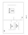
- FIG. 2depicts an exemplary network model screen display 200 that may be generated by DMS 122 and subsequently displayed on tablets and computer devices utilized by field technicians.
- display 200depicts the screen of a tablet computer or laptop computer screen displaying a network model of the distribution system 102 .
- Display 200also exhibits current power outage locations.
- the current power outage locations shown on display 200may be based on the received fault identification data in conjunction with trouble call information received from local customers.
- user interface elements 202 and 204 of display 200respectively indicate that outage area “A” is caused by an insulation failure and outage area “B” is caused by a vegetation issue.
- display 200may be utilizing fault identification information derived by mobile control station 110 (or processed locally at central utility control center 118 if mobile control station 110 is bypassed).
- user interface element 206 of display 200visually indicates that the cause of the outage in area “C” is unknown.
- Such an indicationmay have originated by a customer outage report call and/or visual confirmation by a field technician.
- the collaborative outage network model displayed by display 200uses the fault identification data received from mobile inspection devices 108 and data received from customer report calls to provide a more comprehensive assessment with respect to the operational status of power distribution system 102 .
- BCS 120may also be configured in some embodiments to provide the fault identification data to health and maintenance systems (not shown) to conduct a system-based operational assessment.
- the fault identification informationmay be selectively provided by BCS 120 to assist the health and maintenance systems conduct condition-based maintenance optimization measures and resource allocation.
- the health and maintenance systemsmay be configured to store and archive the fault identification information for subsequent management optimization tasks.
- the archived fault identification datareceived from one or more mobile inspection devices 108 (e.g.
- BCS 120may be subsequently utilized by the health and maintenance systems to determine and assign a higher maintenance priority to customer areas that historically demonstrate a propensity to faults and disturbances (e.g., problematic customer areas including excessive foliage/trees or older infrastructure equipment).
- BCS 120may also be configured to provide the fault identification data to OMS 124 .
- OMS 124may include any system or network device that serves to identify current power outages based on trouble call data accumulated and provided by trouble call center 126 .
- FIG. 1depicts trouble call center 126
- utility control center 118may instead include an advanced metering infrastructure (AMI) system that operates along with or in lieu of trouble call center 126 without departing from the scope of the present subject matter.
- AMIadvanced metering infrastructure
- an AMI systemmay be configured to utilize smart meter devices to measure, collect, and analyze energy usage data as well as subsequently communicate said energy usage data to utility control center 118 .
- the smart meters utilized by an AMI systemmay also be configured to autonomously communicate a notification or alarm to utility control center 118 should an outage or other problematic scenario arise.
- the fault identification datacan be linked, by the DMS 122 , to outage data generated by OMS 124 in the event power outages occur due to disturbances, such as overhead line faults and storms. More specifically, the fault identification data may be used to complement trouble call data obtained from trouble call center 126 .
- OMS 124may be configured to receive and process i) power outage identification information supplied by trouble call center 126 and/or AMI systems and ii) fault identification information provided by DMS 122 .
- the utilization of information acquired by multiple sourcesenables OMS 124 to create a comprehensive overview map that effectively identifies all reported outages and faults.
- OMS 124can expedite the manner in which a power utility can conduct damage assessments and, more importantly, expedite critical post-storm restoration efforts.
- OMS 124may forward the fault identification data and/or mapping information to WMS 120 for subsequent task management (e.g., task assignment, prioritization, updating, etc.).
- WMS 120may then be configured to supply this data to utility maintenance technician crews as visual map information (e.g., via display 200 in FIG. 2 ) and/or listed tasks for completion (e.g., identified insulation failure at site A, problematic vegetation issue at site B, etc.).
- FIG. 3is a flow chart illustrating an exemplary method 300 for providing enhanced monitoring and management of a power distribution system according to an embodiment of the subject matter described herein.
- sensory measurement datais captured during the inspection of one or more power distribution system elements.
- mobile inspection device 108gathers sensory measurement data that includes, but not limited to, video data, image data, thermal data, and/or audio data of overhead distribution lines 104 and associated system components, such as transformers, arresters, cable vaults, insulators, and the like.
- the sensory measurement datais received from the mobile inspection device.
- mobile control station 110is configured to receive the sensory measurement data captured by mobile inspection device 108 via a wireless transmission (e.g., within WiFi range or some other radio frequency wireless range).
- mobile inspection device 108may be configured with a communications module that is configured to use cellular communications or some other high powered radio transmission to communicate the sensory measurement data directly to BCS 120 in the utility control center system.
- the sensory measurement datais utilized to derive fault identification data.
- the captured sensory measurement datais processed by fault identification module 112 in mobile control station 110 to derive fault identification data.
- the software algorithms of fault identification module 112may generate fault identification data that provides an indication of an existing failure or an impending failure of at least one distribution system element, such as a distribution line 104 or an associated component (e.g., transformer, arrester, cable vault, insulator, and the like).
- fault identification module 112may be further configured to record the failure type, the physical location of the failure (e.g., using GPS coordinates), the cause of the failure, and any other relevant information.
- BCS 120may be equipped with fault identification module 132 in order to locally process the sensory measurement data into fault identification data (e.g., if mobile control station 110 is not used or bypassed).
- fault identification module 132is depicted as residing in BCS 120 in FIG. 1 , fault identification module 132 may also reside in either DMS 122 or OMS 124 without departing from the scope of the disclosed subject matter.
- step 308fault identification data is provided to the utility control center.
- mobile control station 110may be configured to use wireless communications module 130 to communicate the fault identification data to BCS 120 via a wireless communication media (e.g., cellular, WiFi, or wireless broadband communications systems).
- a wireless communication mediae.g., cellular, WiFi, or wireless broadband communications systems.
- the fault identification datais utilized to upgrade a network model of the power distribution system.
- BCS 120may be configured to send the fault identification data to DMS 122 and OMS 124 .
- the received fault identification datamay be utilized by DMS 122 to display the location of each current and pending outage on the distribution system network model (e.g., see display 200 in FIG. 2 ).
- backend communications system 120may be configured to send the derived fault identification data to WMS 128 .
- WMS 128may then process this data (alone or in conjunction with outage information received from OMS 126 ) to create and/or revise maintenance tasks assigned to service technicians deployed in the field.
- fault identification datamay be utilized to update grid network model of the power distribution system and assign work orders to maintenance crews via WMS 128 .
- FIG. 4depicts a high level block diagram of a general purpose computer system suitable for use in performing the functions described herein.
- system 400includes a processor 402 , a memory 404 , and a storage device 406 communicatively connected via a system bus 408 .
- processor 402can include a microprocessor, central processing unit (CPU), or any other like hardware based processing unit.
- a fault identification module 410can be stored in memory 404 , which can include random access memory (RAM), read only memory (ROM), optical read/write memory, cache memory, magnetic read/write memory, flash memory, or any other non-transitory computer readable medium.
- processor 402 and memory 404can be used to execute and manage the operation of fault identification module 410 .
- storage device 406can include any storage medium or storage unit that is configured to store data accessible by processor 402 via system bus 408 .
- Exemplary storage devicescan include one or more local databases hosted by system 400 .
Landscapes
- Engineering & Computer Science (AREA)
- Power Engineering (AREA)
- Physics & Mathematics (AREA)
- General Physics & Mathematics (AREA)
- Remote Monitoring And Control Of Power-Distribution Networks (AREA)
- Automation & Control Theory (AREA)
Abstract
Description
Claims (21)
Priority Applications (4)
| Application Number | Priority Date | Filing Date | Title |
|---|---|---|---|
| US14/549,515US9910102B2 (en) | 2014-11-20 | 2014-11-20 | Methods, systems, and computer readable media for monitoring and management of a power distribution system |
| SE1551351ASE539054C2 (en) | 2014-11-20 | 2015-10-20 | Methods, systems, and computer readable media for monitoringand management of a power distribution system |
| DE102015221600.4ADE102015221600A1 (en) | 2014-11-20 | 2015-11-04 | METHODS, SYSTEMS AND COMPUTER READABLE MEDIA FOR MONITORING AND MANAGING A POWER DISTRIBUTION SYSTEM |
| CN201510799824.4ACN105631576A (en) | 2014-11-20 | 2015-11-19 | Methods, systems, and computer readable media for monitoring and management of a power distribution system |
Applications Claiming Priority (1)
| Application Number | Priority Date | Filing Date | Title |
|---|---|---|---|
| US14/549,515US9910102B2 (en) | 2014-11-20 | 2014-11-20 | Methods, systems, and computer readable media for monitoring and management of a power distribution system |
Publications (2)
| Publication Number | Publication Date |
|---|---|
| US20160147209A1 US20160147209A1 (en) | 2016-05-26 |
| US9910102B2true US9910102B2 (en) | 2018-03-06 |
Family
ID=55914418
Family Applications (1)
| Application Number | Title | Priority Date | Filing Date |
|---|---|---|---|
| US14/549,515Active2035-11-01US9910102B2 (en) | 2014-11-20 | 2014-11-20 | Methods, systems, and computer readable media for monitoring and management of a power distribution system |
Country Status (4)
| Country | Link |
|---|---|
| US (1) | US9910102B2 (en) |
| CN (1) | CN105631576A (en) |
| DE (1) | DE102015221600A1 (en) |
| SE (1) | SE539054C2 (en) |
Cited By (6)
| Publication number | Priority date | Publication date | Assignee | Title |
|---|---|---|---|---|
| US20160259357A1 (en)* | 2015-03-03 | 2016-09-08 | Leidos, Inc. | System and Method For Big Data Geographic Information System Discovery |
| US10242349B1 (en)* | 2017-09-29 | 2019-03-26 | International Business Machines Corporation | Efficient scheduling of maintenance for power distribution systems |
| US10566835B2 (en)* | 2016-07-22 | 2020-02-18 | International Business Machines Corporation | Detecting power outages using smartphone sensors |
| US11233591B1 (en) | 2020-08-19 | 2022-01-25 | FPL Smart Services, LLC | Vegetation growth detection via radio propagation |
| US12117974B2 (en) | 2020-05-29 | 2024-10-15 | Constellation Energy Generation, Llc | Methods and systems for construct identification and analysis |
| US12278490B2 (en) | 2018-11-05 | 2025-04-15 | General Electric Company | Power system measurement based model calibration with enhanced optimization |
Families Citing this family (17)
| Publication number | Priority date | Publication date | Assignee | Title |
|---|---|---|---|---|
| US10215736B2 (en)* | 2015-10-23 | 2019-02-26 | International Business Machines Corporation | Acoustic monitor for power transmission lines |
| CN106296864A (en)* | 2016-08-05 | 2017-01-04 | 国网山东省电力公司电力科学研究院 | A kind of distribution line intelligent inspection system based on vehicle mobile terminals and method |
| RU2677498C1 (en)* | 2016-11-08 | 2019-01-17 | Федеральное государственное бюджетное образовательное учреждение высшего образования "Волгоградский государственный технический университет" (ВолгГТУ) | Overhead power transmission lines condition monitoring device |
| US10229577B2 (en) | 2017-02-01 | 2019-03-12 | Florida Power & Light Company | Proactive power outage alerts management system and methods |
| FI128017B (en)* | 2017-04-03 | 2019-08-15 | Nordic 24/7 Services Oy | Method and apparatus for controlling power supply |
| CN108761352A (en)* | 2018-06-24 | 2018-11-06 | 兰州金利达电子技术有限公司 | A kind of power supply monitoring system |
| EP3699603A1 (en) | 2019-02-21 | 2020-08-26 | Siemens Aktiengesellschaft | Method for monitoring a power line |
| CN111130009B (en)* | 2019-12-26 | 2021-05-04 | 智洋创新科技股份有限公司 | A method for determining the operation status of visual image equipment of transmission line channels |
| US12320834B2 (en)* | 2020-02-10 | 2025-06-03 | Darryl Mendivil | Real-time fault detection and infrared inspection system |
| US11346874B2 (en)* | 2020-04-27 | 2022-05-31 | Schweitzer Engineering Laboratories, Inc. | Controlling power distribution devices using wearable voltage detection devices |
| CN111540077B (en)* | 2020-05-12 | 2022-04-19 | 中国电建集团福建省电力勘测设计院有限公司 | Three-dimensional model coordinate positioning-based converter station valve hall mobile intelligent inspection method |
| US11928975B2 (en) | 2020-11-19 | 2024-03-12 | Enphase Energy, Inc. | Methods and apparatus for servicing distributed energy generation systems using an unmanned aerial vehicle |
| CN112803585B (en)* | 2020-12-23 | 2023-03-03 | 深圳供电局有限公司 | Monitoring method and device for low-voltage contact cabinet, computer equipment and storage medium |
| CN113301142B (en)* | 2021-05-21 | 2022-05-31 | 广州科技贸易职业学院 | Network security monitoring method and system based on Internet of things |
| CN114649865B (en)* | 2021-11-05 | 2024-12-24 | 国网辽宁省电力有限公司 | A method and system for analyzing power network communication |
| CN116088454B (en)* | 2023-03-08 | 2023-06-09 | 广东技术师范大学 | Intelligent manufacturing management system based on data fusion |
| CN117333960B (en)* | 2023-11-04 | 2024-06-11 | 南京关宁电子信息科技有限公司 | Infrared temperature measurement intelligent digital inspection system and method |
Citations (14)
| Publication number | Priority date | Publication date | Assignee | Title |
|---|---|---|---|---|
| US4661308A (en)* | 1983-09-16 | 1987-04-28 | Mitsubishi Denki Kabushiki Kaisha | Remote-controlled mobile inspecting and monitoring system |
| US4818990A (en)* | 1987-09-11 | 1989-04-04 | Fernandes Roosevelt A | Monitoring system for power lines and right-of-way using remotely piloted drone |
| US4904996A (en)* | 1988-01-19 | 1990-02-27 | Fernandes Roosevelt A | Line-mounted, movable, power line monitoring system |
| US6002260A (en)* | 1997-09-23 | 1999-12-14 | Pacific Gas & Electric Company | Fault sensor suitable for use in heterogenous power distribution systems |
| US6259972B1 (en)* | 1998-01-16 | 2001-07-10 | Enghouse Systems Usa, Inc. | Method for processing and disseminating utility outage information |
| US6909942B2 (en)* | 2002-02-25 | 2005-06-21 | General Electric Company | Method for power distribution system components identification, characterization and rating |
| US20070213956A1 (en)* | 2006-03-10 | 2007-09-13 | Edsa Micro Corporation | Systems and methods for real-time protective device evaluation in an electrical power distribution system |
| US20070270114A1 (en)* | 2006-05-19 | 2007-11-22 | Kesler James R | Apparatus and system for adjusting settings of a power system device using a magnetically coupled actuator |
| US20080284585A1 (en)* | 2007-05-18 | 2008-11-20 | Schweitzer Iii Edmund O | System and method for communicating power system information through a radio frequency device |
| US7543780B1 (en)* | 2004-10-04 | 2009-06-09 | The United States Of America As Represented By The Secretary Of The Air Force | Unmanned air vehicle transmission line docking surveillance |
| US20090234512A1 (en)* | 2007-12-28 | 2009-09-17 | Server Technology, Inc. | Power distribution, management, and monitoring systems and methods |
| US20110192315A1 (en)* | 2010-02-10 | 2011-08-11 | Electric Power Research Institute, Inc. | Line inspection robot and system |
| US8000913B2 (en)* | 2008-01-21 | 2011-08-16 | Current Communications Services, Llc | System and method for providing power distribution system information |
| US8077049B2 (en)* | 2008-01-20 | 2011-12-13 | Current Technologies, Llc | Method and apparatus for communicating power distribution event and location |
Family Cites Families (6)
| Publication number | Priority date | Publication date | Assignee | Title |
|---|---|---|---|---|
| CN104101812B (en)* | 2013-04-09 | 2017-02-22 | 北京映翰通网络技术股份有限公司 | Single-phase grounding fault detection and positioning method and system for low-current grounding power distribution network |
| CN203444465U (en)* | 2013-08-24 | 2014-02-19 | 国家电网公司 | Integrated intelligent monitoring system of wire |
| CN103439904A (en)* | 2013-08-27 | 2013-12-11 | 国家电网公司 | Intelligent control communication device used for network distribution system |
| CN203445696U (en)* | 2013-09-06 | 2014-02-19 | 云南电网公司普洱供电局 | Power distribution line online monitoring system |
| CN103558818B (en)* | 2013-10-28 | 2016-08-17 | 国家电网公司 | The long-range Monitoring and control system of cable 10kV high-voltage ring main unit |
| CN103698657B (en)* | 2013-12-19 | 2016-02-24 | 湖南大学 | Distribution network failure based on information completion and correction locates fault-tolerance approach |
- 2014
- 2014-11-20USUS14/549,515patent/US9910102B2/enactiveActive
- 2015
- 2015-10-20SESE1551351Apatent/SE539054C2/enunknown
- 2015-11-04DEDE102015221600.4Apatent/DE102015221600A1/enactivePending
- 2015-11-19CNCN201510799824.4Apatent/CN105631576A/enactivePending
Patent Citations (16)
| Publication number | Priority date | Publication date | Assignee | Title |
|---|---|---|---|---|
| US4661308A (en)* | 1983-09-16 | 1987-04-28 | Mitsubishi Denki Kabushiki Kaisha | Remote-controlled mobile inspecting and monitoring system |
| US4818990A (en)* | 1987-09-11 | 1989-04-04 | Fernandes Roosevelt A | Monitoring system for power lines and right-of-way using remotely piloted drone |
| US4904996A (en)* | 1988-01-19 | 1990-02-27 | Fernandes Roosevelt A | Line-mounted, movable, power line monitoring system |
| US6002260A (en)* | 1997-09-23 | 1999-12-14 | Pacific Gas & Electric Company | Fault sensor suitable for use in heterogenous power distribution systems |
| US6259972B1 (en)* | 1998-01-16 | 2001-07-10 | Enghouse Systems Usa, Inc. | Method for processing and disseminating utility outage information |
| US6909942B2 (en)* | 2002-02-25 | 2005-06-21 | General Electric Company | Method for power distribution system components identification, characterization and rating |
| US7543780B1 (en)* | 2004-10-04 | 2009-06-09 | The United States Of America As Represented By The Secretary Of The Air Force | Unmanned air vehicle transmission line docking surveillance |
| US20070213956A1 (en)* | 2006-03-10 | 2007-09-13 | Edsa Micro Corporation | Systems and methods for real-time protective device evaluation in an electrical power distribution system |
| US20070270114A1 (en)* | 2006-05-19 | 2007-11-22 | Kesler James R | Apparatus and system for adjusting settings of a power system device using a magnetically coupled actuator |
| US20080284585A1 (en)* | 2007-05-18 | 2008-11-20 | Schweitzer Iii Edmund O | System and method for communicating power system information through a radio frequency device |
| US20090234512A1 (en)* | 2007-12-28 | 2009-09-17 | Server Technology, Inc. | Power distribution, management, and monitoring systems and methods |
| US8077049B2 (en)* | 2008-01-20 | 2011-12-13 | Current Technologies, Llc | Method and apparatus for communicating power distribution event and location |
| US8000913B2 (en)* | 2008-01-21 | 2011-08-16 | Current Communications Services, Llc | System and method for providing power distribution system information |
| US20110270550A1 (en)* | 2008-01-21 | 2011-11-03 | Kreiss David G | System and Method for Providing Power Distribution System Information |
| US20110192315A1 (en)* | 2010-02-10 | 2011-08-11 | Electric Power Research Institute, Inc. | Line inspection robot and system |
| US8505461B2 (en)* | 2010-02-10 | 2013-08-13 | Electric Power Research Institute, Inc. | Line inspection robot and system |
Non-Patent Citations (7)
| Title |
|---|
| Brendan Gates, A power Line inspection device, May 2013, University of Maine, p. 1-117.* |
| Brown et al., Failure Rate Modeling Using Equipment Inspection Data, May 2, 2004, IEEE, vol. 19, No. 2, p. 782-787.* |
| Decision to Grant for Swedish Patent Application No. 1551351-8 (dated Feb. 28, 2017) |
| Deng etal. , Unmanned Aerial Vehicles for power Line Inspection: A Cooperative Way in Platforms and Communications, Sep. 2014, Sichuan University, p. 687-692.* |
| Luis et al. , Power Line Inspection Via an UnmannedAerial System Based on the Quadrotor Helicopter, Apr. 16, 2014, Luis Enrique Gonzalez-Jimenez, pp. 393-397.* |
| Miguel et al., Wireless Distributed Control For Power Line Inspection Robot, 2014, Robotics, pp. 517-524.* |
| Notice of Allowance for Swedish Patent Application No. 1551351-8 (dated Oct. 19, 2016). |
Cited By (9)
| Publication number | Priority date | Publication date | Assignee | Title |
|---|---|---|---|---|
| US20160259357A1 (en)* | 2015-03-03 | 2016-09-08 | Leidos, Inc. | System and Method For Big Data Geographic Information System Discovery |
| US10331156B2 (en)* | 2015-03-03 | 2019-06-25 | Leidos, Inc. | System and method for big data geographic information system discovery |
| US10566835B2 (en)* | 2016-07-22 | 2020-02-18 | International Business Machines Corporation | Detecting power outages using smartphone sensors |
| US10242349B1 (en)* | 2017-09-29 | 2019-03-26 | International Business Machines Corporation | Efficient scheduling of maintenance for power distribution systems |
| US10600037B2 (en)* | 2017-09-29 | 2020-03-24 | International Business Machines Corporation | Efficient scheduling of maintenance for power distribution systems |
| US12278490B2 (en) | 2018-11-05 | 2025-04-15 | General Electric Company | Power system measurement based model calibration with enhanced optimization |
| US12117974B2 (en) | 2020-05-29 | 2024-10-15 | Constellation Energy Generation, Llc | Methods and systems for construct identification and analysis |
| US11233591B1 (en) | 2020-08-19 | 2022-01-25 | FPL Smart Services, LLC | Vegetation growth detection via radio propagation |
| US11984938B2 (en) | 2020-08-19 | 2024-05-14 | FPL Smart Services, LLC | Vegetation growth detection via radio propagation |
Also Published As
| Publication number | Publication date |
|---|---|
| US20160147209A1 (en) | 2016-05-26 |
| SE539054C2 (en) | 2017-03-28 |
| DE102015221600A1 (en) | 2016-05-25 |
| CN105631576A (en) | 2016-06-01 |
| SE1551351A1 (en) | 2016-05-21 |
Similar Documents
| Publication | Publication Date | Title |
|---|---|---|
| US9910102B2 (en) | Methods, systems, and computer readable media for monitoring and management of a power distribution system | |
| US11121537B2 (en) | System and method for locating faults and communicating network operational status to a utility crew using an intelligent fuse | |
| EP3469387B1 (en) | A method and system for dynamic fault detection in an electric grid | |
| US11416119B2 (en) | Locating a power line event downstream from a power line branch point | |
| CN106408209A (en) | Positioning and line inspection detection system and method in electric power field | |
| CN104581087A (en) | Intelligent remote monitoring system of power transmission line on basis of internet of things | |
| US10489019B2 (en) | Identifying and presenting related electrical power distribution system events | |
| CN102494737A (en) | Oil level monitoring method and system of oil immersed type transformer | |
| US10852341B2 (en) | Composite fault mapping | |
| US20150099531A1 (en) | Inspecting equipment of a power system | |
| KR101452979B1 (en) | Fault recorder having fault localization function using accident data of both ends in power system line, fault localization system comprising the same and method for controlling the same | |
| US20180364294A1 (en) | Composite fault mapping | |
| KR101485517B1 (en) | Smart distribution line monitoring apparatus and method thereof | |
| AU2020218296B2 (en) | A node, system and method for detecting local anomalies in an overhead power grid | |
| CN108663970B (en) | Electric power operation safety monitoring system | |
| CN202501904U (en) | Oil level monitoring system of oil-immersed transformer | |
| US20180283955A1 (en) | Method of assessing multiple distribution transformer loading conditions in one area using an autonomous drone | |
| Carvalho et al. | Monitoring system for vegetation encroachment detection in power lines based on wireless sensor networks | |
| CN105652119A (en) | Method, device and system for acquiring fault information | |
| CN204948234U (en) | A kind of remote viewing camera on-line condition monitoring warning system | |
| JP7331336B2 (en) | Facility management system | |
| US20250246882A1 (en) | Infrastructure monitoring and inspection | |
| JP7566646B2 (en) | Information processing system, information processing device, and information processing program | |
| JP7424006B2 (en) | Fallen tree monitoring device and program | |
| CN119109217A (en) | Equipment inspection system and equipment inspection method |
Legal Events
| Date | Code | Title | Description |
|---|---|---|---|
| AS | Assignment | Owner name:ABB TECHNOLOGY AG, SWITZERLAND Free format text:ASSIGNMENT OF ASSIGNORS INTEREST;ASSIGNORS:STOUPIS, JAMES D.;MOUSAVI, MIRRASOUL J.;REEL/FRAME:034300/0401 Effective date:20141118 | |
| AS | Assignment | Owner name:ABB SCHWEIZ AG, SWITZERLAND Free format text:MERGER;ASSIGNOR:ABB TECHNOLOGY LTD.;REEL/FRAME:040621/0929 Effective date:20160509 | |
| STCF | Information on status: patent grant | Free format text:PATENTED CASE | |
| AS | Assignment | Owner name:ABB POWER GRIDS SWITZERLAND AG, SWITZERLAND Free format text:ASSIGNMENT OF ASSIGNORS INTEREST;ASSIGNOR:ABB SCHWEIZ AG;REEL/FRAME:052916/0001 Effective date:20191025 | |
| MAFP | Maintenance fee payment | Free format text:PAYMENT OF MAINTENANCE FEE, 4TH YEAR, LARGE ENTITY (ORIGINAL EVENT CODE: M1551); ENTITY STATUS OF PATENT OWNER: LARGE ENTITY Year of fee payment:4 | |
| AS | Assignment | Owner name:HITACHI ENERGY SWITZERLAND AG, SWITZERLAND Free format text:CHANGE OF NAME;ASSIGNOR:ABB POWER GRIDS SWITZERLAND AG;REEL/FRAME:058666/0540 Effective date:20211006 | |
| AS | Assignment | Owner name:ABB SCHWEIZ AG, SWITZERLAND Free format text:CORRECTIVE ASSIGNMENT TO CORRECT THE CONVEYING PARTY NAME PREVIOUSLY RECORDED AT REEL: 040621 FRAME: 0929. ASSIGNOR(S) HEREBY CONFIRMS THE MERGER;ASSIGNOR:ABB TECHNOLOGY AG;REEL/FRAME:060378/0488 Effective date:20160509 | |
| AS | Assignment | Owner name:HITACHI ENERGY LTD, SWITZERLAND Free format text:MERGER;ASSIGNOR:HITACHI ENERGY SWITZERLAND AG;REEL/FRAME:065549/0576 Effective date:20231002 | |
| MAFP | Maintenance fee payment | Free format text:PAYMENT OF MAINTENANCE FEE, 8TH YEAR, LARGE ENTITY (ORIGINAL EVENT CODE: M1552); ENTITY STATUS OF PATENT OWNER: LARGE ENTITY Year of fee payment:8 |