US9908215B1 - Systems, methods and assemblies for processing superabrasive materials - Google Patents
Systems, methods and assemblies for processing superabrasive materialsDownload PDFInfo
- Publication number
- US9908215B1 US9908215B1US14/754,660US201514754660AUS9908215B1US 9908215 B1US9908215 B1US 9908215B1US 201514754660 AUS201514754660 AUS 201514754660AUS 9908215 B1US9908215 B1US 9908215B1
- Authority
- US
- United States
- Prior art keywords
- processing agent
- processing
- superabrasive
- polycrystalline diamond
- agent
- Prior art date
- Legal status (The legal status is an assumption and is not a legal conclusion. Google has not performed a legal analysis and makes no representation as to the accuracy of the status listed.)
- Active, expires
Links
Images


Classifications
- B—PERFORMING OPERATIONS; TRANSPORTING
- B24—GRINDING; POLISHING
- B24D—TOOLS FOR GRINDING, BUFFING OR SHARPENING
- B24D3/00—Physical features of abrasive bodies, or sheets, e.g. abrasive surfaces of special nature; Abrasive bodies or sheets characterised by their constituents
- B24D3/02—Physical features of abrasive bodies, or sheets, e.g. abrasive surfaces of special nature; Abrasive bodies or sheets characterised by their constituents the constituent being used as bonding agent
- B24D3/04—Physical features of abrasive bodies, or sheets, e.g. abrasive surfaces of special nature; Abrasive bodies or sheets characterised by their constituents the constituent being used as bonding agent and being essentially inorganic
- B24D3/06—Physical features of abrasive bodies, or sheets, e.g. abrasive surfaces of special nature; Abrasive bodies or sheets characterised by their constituents the constituent being used as bonding agent and being essentially inorganic metallic or mixture of metals with ceramic materials, e.g. hard metals, "cermets", cements
- B24D3/10—Physical features of abrasive bodies, or sheets, e.g. abrasive surfaces of special nature; Abrasive bodies or sheets characterised by their constituents the constituent being used as bonding agent and being essentially inorganic metallic or mixture of metals with ceramic materials, e.g. hard metals, "cermets", cements for porous or cellular structure, e.g. for use with diamonds as abrasives
- B—PERFORMING OPERATIONS; TRANSPORTING
- B01—PHYSICAL OR CHEMICAL PROCESSES OR APPARATUS IN GENERAL
- B01J—CHEMICAL OR PHYSICAL PROCESSES, e.g. CATALYSIS OR COLLOID CHEMISTRY; THEIR RELEVANT APPARATUS
- B01J19/00—Chemical, physical or physico-chemical processes in general; Their relevant apparatus
- B01J19/16—Preventing evaporation or oxidation of non-metallic liquids by applying a floating layer, e.g. of microballoons
- B—PERFORMING OPERATIONS; TRANSPORTING
- B01—PHYSICAL OR CHEMICAL PROCESSES OR APPARATUS IN GENERAL
- B01J—CHEMICAL OR PHYSICAL PROCESSES, e.g. CATALYSIS OR COLLOID CHEMISTRY; THEIR RELEVANT APPARATUS
- B01J19/00—Chemical, physical or physico-chemical processes in general; Their relevant apparatus
- B01J19/24—Stationary reactors without moving elements inside
- B—PERFORMING OPERATIONS; TRANSPORTING
- B24—GRINDING; POLISHING
- B24D—TOOLS FOR GRINDING, BUFFING OR SHARPENING
- B24D18/00—Manufacture of grinding tools or other grinding devices, e.g. wheels, not otherwise provided for
- C—CHEMISTRY; METALLURGY
- C23—COATING METALLIC MATERIAL; COATING MATERIAL WITH METALLIC MATERIAL; CHEMICAL SURFACE TREATMENT; DIFFUSION TREATMENT OF METALLIC MATERIAL; COATING BY VACUUM EVAPORATION, BY SPUTTERING, BY ION IMPLANTATION OR BY CHEMICAL VAPOUR DEPOSITION, IN GENERAL; INHIBITING CORROSION OF METALLIC MATERIAL OR INCRUSTATION IN GENERAL
- C23F—NON-MECHANICAL REMOVAL OF METALLIC MATERIAL FROM SURFACE; INHIBITING CORROSION OF METALLIC MATERIAL OR INCRUSTATION IN GENERAL; MULTI-STEP PROCESSES FOR SURFACE TREATMENT OF METALLIC MATERIAL INVOLVING AT LEAST ONE PROCESS PROVIDED FOR IN CLASS C23 AND AT LEAST ONE PROCESS COVERED BY SUBCLASS C21D OR C22F OR CLASS C25
- C23F1/00—Etching metallic material by chemical means
- C23F1/02—Local etching
- C—CHEMISTRY; METALLURGY
- C23—COATING METALLIC MATERIAL; COATING MATERIAL WITH METALLIC MATERIAL; CHEMICAL SURFACE TREATMENT; DIFFUSION TREATMENT OF METALLIC MATERIAL; COATING BY VACUUM EVAPORATION, BY SPUTTERING, BY ION IMPLANTATION OR BY CHEMICAL VAPOUR DEPOSITION, IN GENERAL; INHIBITING CORROSION OF METALLIC MATERIAL OR INCRUSTATION IN GENERAL
- C23F—NON-MECHANICAL REMOVAL OF METALLIC MATERIAL FROM SURFACE; INHIBITING CORROSION OF METALLIC MATERIAL OR INCRUSTATION IN GENERAL; MULTI-STEP PROCESSES FOR SURFACE TREATMENT OF METALLIC MATERIAL INVOLVING AT LEAST ONE PROCESS PROVIDED FOR IN CLASS C23 AND AT LEAST ONE PROCESS COVERED BY SUBCLASS C21D OR C22F OR CLASS C25
- C23F1/00—Etching metallic material by chemical means
- C23F1/10—Etching compositions
- C23F1/14—Aqueous compositions
- C23F1/16—Acidic compositions
- C23F1/28—Acidic compositions for etching iron group metals
- F—MECHANICAL ENGINEERING; LIGHTING; HEATING; WEAPONS; BLASTING
- F16—ENGINEERING ELEMENTS AND UNITS; GENERAL MEASURES FOR PRODUCING AND MAINTAINING EFFECTIVE FUNCTIONING OF MACHINES OR INSTALLATIONS; THERMAL INSULATION IN GENERAL
- F16C—SHAFTS; FLEXIBLE SHAFTS; ELEMENTS OR CRANKSHAFT MECHANISMS; ROTARY BODIES OTHER THAN GEARING ELEMENTS; BEARINGS
- F16C33/00—Parts of bearings; Special methods for making bearings or parts thereof
- F16C33/02—Parts of sliding-contact bearings
- F16C33/04—Brasses; Bushes; Linings
- F16C33/043—Sliding surface consisting mainly of ceramics, cermets or hard carbon, e.g. diamond like carbon [DLC]
- F—MECHANICAL ENGINEERING; LIGHTING; HEATING; WEAPONS; BLASTING
- F16—ENGINEERING ELEMENTS AND UNITS; GENERAL MEASURES FOR PRODUCING AND MAINTAINING EFFECTIVE FUNCTIONING OF MACHINES OR INSTALLATIONS; THERMAL INSULATION IN GENERAL
- F16C—SHAFTS; FLEXIBLE SHAFTS; ELEMENTS OR CRANKSHAFT MECHANISMS; ROTARY BODIES OTHER THAN GEARING ELEMENTS; BEARINGS
- F16C33/00—Parts of bearings; Special methods for making bearings or parts thereof
- F16C33/02—Parts of sliding-contact bearings
- F16C33/04—Brasses; Bushes; Linings
- F16C33/26—Brasses; Bushes; Linings made from wire coils; made from a number of discs, rings, rods, or other members
- B—PERFORMING OPERATIONS; TRANSPORTING
- B01—PHYSICAL OR CHEMICAL PROCESSES OR APPARATUS IN GENERAL
- B01J—CHEMICAL OR PHYSICAL PROCESSES, e.g. CATALYSIS OR COLLOID CHEMISTRY; THEIR RELEVANT APPARATUS
- B01J2219/00—Chemical, physical or physico-chemical processes in general; Their relevant apparatus
- B01J2219/00049—Controlling or regulating processes
- B01J2219/00051—Controlling the temperature
- B—PERFORMING OPERATIONS; TRANSPORTING
- B01—PHYSICAL OR CHEMICAL PROCESSES OR APPARATUS IN GENERAL
- B01J—CHEMICAL OR PHYSICAL PROCESSES, e.g. CATALYSIS OR COLLOID CHEMISTRY; THEIR RELEVANT APPARATUS
- B01J2219/00—Chemical, physical or physico-chemical processes in general; Their relevant apparatus
- B01J2219/24—Stationary reactors without moving elements inside
- F—MECHANICAL ENGINEERING; LIGHTING; HEATING; WEAPONS; BLASTING
- F16—ENGINEERING ELEMENTS AND UNITS; GENERAL MEASURES FOR PRODUCING AND MAINTAINING EFFECTIVE FUNCTIONING OF MACHINES OR INSTALLATIONS; THERMAL INSULATION IN GENERAL
- F16C—SHAFTS; FLEXIBLE SHAFTS; ELEMENTS OR CRANKSHAFT MECHANISMS; ROTARY BODIES OTHER THAN GEARING ELEMENTS; BEARINGS
- F16C17/00—Sliding-contact bearings for exclusively rotary movement
- F16C17/02—Sliding-contact bearings for exclusively rotary movement for radial load only
- F—MECHANICAL ENGINEERING; LIGHTING; HEATING; WEAPONS; BLASTING
- F16—ENGINEERING ELEMENTS AND UNITS; GENERAL MEASURES FOR PRODUCING AND MAINTAINING EFFECTIVE FUNCTIONING OF MACHINES OR INSTALLATIONS; THERMAL INSULATION IN GENERAL
- F16C—SHAFTS; FLEXIBLE SHAFTS; ELEMENTS OR CRANKSHAFT MECHANISMS; ROTARY BODIES OTHER THAN GEARING ELEMENTS; BEARINGS
- F16C17/00—Sliding-contact bearings for exclusively rotary movement
- F16C17/04—Sliding-contact bearings for exclusively rotary movement for axial load only
Definitions
- PCDpolycrystalline diamond
- a conventional cutting elementtypically includes a superabrasive layer or table, such as a PCD table.
- the PCD tableis formed and bonded to a substrate using an ultra-high pressure, ultra-high temperature (“HPHT”) process.
- HPHTultra-high pressure, ultra-high temperature
- the cutting elementmay be brazed, press-fit, or otherwise secured into a preformed pocket, socket, or other receptacle formed in the rotary drill bit.
- the substratemay be brazed or otherwise joined to an attachment member such as a stud or a cylindrical backing.
- a rotary drill bitmay include one or more PCD cutting elements affixed to a bit body of the rotary drill bit.
- a conventional bearing elementtypically includes a superabrasive layer or table, such as a PCD table, bonded to a substrate.
- One or more bearing elementsmay be mounted to a bearing rotor or stator by press-fitting, brazing, or through other suitable methods of attachment.
- bearing elements mounted to a bearing rotorhave superabrasive faces configured to contact corresponding superabrasive faces of bearing elements mounted to an adjacent bearing stator.
- Superabrasive elements having a PCD tableare typically fabricated by placing a cemented carbide substrate, such as a cobalt-cemented tungsten carbide substrate, into a container or cartridge with a volume of diamond particles positioned on a surface of the cemented carbide substrate. A number of such cartridges may be loaded into a HPHT press. The substrates and diamond particles may then be processed under HPHT conditions in the presence of a catalyst material that causes the diamond particles to bond to one another to form a diamond table having a matrix of bonded diamond crystals.
- the catalyst materialis often a metal-solvent catalyst, such as cobalt, nickel, and/or iron that facilitates intergrowth and bonding of the diamond crystals.
- a constituent of the cemented-carbide substratesuch as cobalt from a cobalt-cemented tungsten carbide substrate, liquefies and sweeps from a region adjacent to the volume of diamond particles into interstitial regions between the diamond particles during the HPHT process.
- the cobaltacts as a catalyst to facilitate the formation of bonded diamond crystals.
- a metal-solvent catalystmay be mixed with diamond particles prior to subjecting the diamond particles and substrate to the HPHT process. The metal-solvent catalyst may dissolve carbon from the diamond particles and portions of the diamond particles that graphitize due to the high temperatures used in the HPHT process.
- the solubility of the stable diamond phase in the metal-solvent catalystmay be lower than that of the metastable graphite phase under HPHT conditions.
- the graphitetends to dissolve into the metal-solvent catalyst and the diamond tends to deposit onto existing diamond particles to form diamond-to-diamond bonds.
- diamond grainsmay become mutually bonded to form a matrix of polycrystalline diamond, with interstitial regions defined between the bonded diamond grains being occupied by the metal-solvent catalyst.
- the metal-solvent catalystmay also carry tungsten and/or tungsten carbide from the substrate into the PCD layer. Following HPHT sintering, the tungsten and/or tungsten carbide may remain in interstitial regions defined between the bonded diamond grains.
- the presence of the solvent catalyst in the diamond tablemay reduce the thermal stability of the diamond table at elevated temperatures.
- the difference in thermal expansion coefficient between the diamond grains and the solvent catalystis believed to lead to chipping or cracking in the PCD table of a cutting element during drilling or cutting operations.
- the chipping or cracking in the PCD tablemay degrade the mechanical properties of the cutting element or lead to failure of the cutting element.
- diamond grainsmay undergo a chemical breakdown or back-conversion in the presence of the metal-solvent catalyst. At extremely high temperatures, portions of diamond grains may transform to carbon monoxide, carbon dioxide, graphite, or combinations thereof, thereby degrading the mechanical properties of the PCD material.
- Chemical leachingis often used to dissolve and remove various materials from the PCD layer.
- chemical leachingmay be used to remove metal-solvent catalysts, such as cobalt, from regions of a PCD layer that may experience elevated temperatures during drilling, such as regions adjacent to the working surfaces of the PCD layer.
- a method of processing a polycrystalline diamond materialmay comprise exposing at least a portion of a polycrystalline diamond material to a volume of processing agent for processing at least a portion of a catalyst material from interstitial spaces within the polycrystalline diamond material.
- the processing agentmay comprise, for example, a leaching agent for leaching a catalyst material from interstitial spaces within at least the portion of the polycrystalline diamond material.
- the processing agentmay comprise a cleaning agent for cleaning the portion of the polycrystalline diamond material.
- the methodmay further comprise applying an elevated body force to the volume of processing agent while at least the portion of the polycrystalline diamond material is exposed to the volume of processing agent, and applying a selected temperature to at least one of the volume of processing agent and at least the portion of the polycrystalline diamond material exposed to the volume of processing agent during application of the elevated body force to the volume of processing agent.
- the body forcemay comprise at least one of a gravitational body force and a centrifugal body force.
- the processing agentmay comprise a liquid solution and the elevated body force may comprise a body force sufficient to prevent a phase change of the liquid solution at a selected temperature.
- the temperaturemay comprise a temperature greater than or less than a temperature required for a phase change of the liquid solution under atmospheric conditions.
- applying the elevated body forcemay comprise rotating the volume of processing agent and the polycrystalline diamond material about a rotational axis.
- applying the elevated body forcemay comprise disposing another volume of fluid adjacent to the volume of processing agent.
- the other volume of fluidmay have a density greater than the density of the processing agent.
- the other volume of fluidmay have a height substantially greater than the height of the volume of processing agent.
- the other volume of fluidmay contact the volume of processing agent.
- the other volume of fluidmay also be open to atmospheric surroundings.
- the methodmay further comprise disposing a barrier around a portion of the polycrystalline diamond material.
- the polycrystalline diamond materialmay comprise a polycrystalline diamond body bonded to a substrate.
- an assembly for processing a polycrystalline diamond bodymay comprise a processing container and at least one polycrystalline diamond body disposed in the processing container, the at least one polycrystalline diamond body comprising a catalyst material disposed in interstitial spaces within a polycrystalline diamond material.
- the assemblymay also comprise a volume of processing agent disposed in the processing container, at least a portion of the polycrystalline diamond body being exposed to the volume of processing agent.
- the processing agentmay leach at least a portion of the catalyst material from the polycrystalline diamond body.
- the assemblymay further include a body force application portion for applying an elevated body force to the volume of processing agent while at least the portion of the polycrystalline diamond body is exposed to the volume of processing agent, and a heat application element for increasing the temperature to at least one of the volume of processing agent and at least the portion of the polycrystalline diamond body exposed to the volume of processing agent during application of the elevated body force to the volume of processing agent.
- the processing agentmay comprise a liquid solution and the elevated body force may be sufficient to prevent a phase change of the liquid solution at the selected temperature.
- the body force application portionmay comprise a centrifugal device for rotating the processing container about a rotational axis.
- the body force application portionmay comprise a fluid conduit containing another volume of fluid disposed gravitationally above the volume of processing agent.
- the fluid conduitmay comprise, for example, a vertical column.
- the other volume of fluidmay have a density greater than the density of the processing agent.
- the other volume of fluidmay have a height substantially greater than the height of the volume of the processing agent.
- an end of the fluid conduit disposed apart from the processing containermay comprise an opening such that the other volume of fluid is open to atmospheric surroundings.
- a protective barriermay be disposed around a portion of the polycrystalline diamond body.
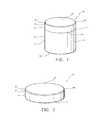
- FIG. 1is a perspective view of an exemplary superabrasive element according to at least one embodiment.
- FIG. 2is a perspective view of an exemplary superabrasive disc according to at least one embodiment.
- FIG. 3Ais a cross-sectional side view of a portion of a superabrasive table according to at least one embodiment.
- FIG. 3Bis a cross-sectional side view of the superabrasive disc according to at least one embodiment.
- FIG. 4is a magnified cross-sectional side view of a portion of the superabrasive table according to at least one embodiment.
- FIG. 5is a cross-sectional side view of an exemplary superabrasive element that is at least partially surrounded by a protective layer according to at least one embodiment.
- FIG. 6Ais a cross-sectional side view of an exemplary superabrasive material processing assembly according to at least one embodiment.
- FIG. 6Bis a cross-sectional side view of another exemplary superabrasive material processing assembly according to at least one embodiment.
- FIG. 6Cis a cross-sectional side view of another exemplary superabrasive material processing assembly according to at least one embodiment.
- FIG. 7Ais a cross-sectional side view of an exemplary superabrasive material processing assembly according to at least one embodiment.
- FIG. 7Bis a cross-sectional side view of another exemplary superabrasive material processing assembly according to at least one embodiment.
- FIG. 8is a cross-sectional side view of another exemplary superabrasive material processing assembly according to at least one embodiment.
- FIG. 9is a cross-sectional side view of another exemplary superabrasive material processing assembly according to at least one embodiment.
- FIG. 10is a cross-sectional side view of another exemplary superabrasive material processing assembly according to at least one embodiment.
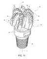
- FIG. 11is a perspective view of an exemplary drill bit according to at least one embodiment.
- FIG. 12is a partial cut-away perspective view of an exemplary thrust bearing apparatus according to at least one embodiment.
- FIG. 13is a partial cut-away perspective view of an exemplary radial bearing apparatus according to at least one embodiment.
- FIG. 14is a partial cut-away perspective view of an exemplary subterranean drilling system according to at least one embodiment.
- FIG. 15is a flow diagram of an exemplary method of processing a polycrystalline superabrasive material according to at least one embodiment.
- the instant disclosureis directed to leaching systems, methods and assemblies for processing superabrasive elements, such as superabrasive cutting elements, superabrasive bearings, and superabrasive discs.
- superabrasive elementsmay be used as cutting elements for use in a variety of applications, such as drilling tools, machining equipment, cutting tools, and other apparatuses, without limitation.
- superabrasive elements, as disclosed hereinmay also be used as bearing elements in a variety of bearing applications, such as thrust bearings, radial bearings, and other bearing apparatuses, without limitation.
- the terms “superabrasive” and “superhard”may refer to materials exhibiting a hardness that is at least equal to a hardness of tungsten carbide.
- a superabrasive articlemay represent an article of manufacture, at least a portion of which may exhibit a hardness that is equal to or greater than the hardness of tungsten carbide.
- solventmay refer to a single solvent compound, a mixture of two or more solvent compounds, (e.g., an alloy), and/or a mixture of one or more solvent compounds and one or more dissolved compounds.
- a solvent catalystmay be cobalt, nickel, iron, any Group VIII element, or any alloy or combination thereof.
- the word “cutting”may refer broadly to machining processes, drilling processes, boring processes, or any other material removal process utilizing a cutting element.
- FIG. 1is a perspective view of an exemplary superabrasive element 10 according to at least one embodiment.
- superabrasive element 10may comprise a superabrasive layer or table 14 affixed to or formed upon a substrate 12 .
- Superabrasive table 14may be affixed to substrate 12 at interface 26 , which may be a planar or nonplanar interface.
- Superabrasive element 10may comprise a rear surface 18 , a superabrasive face 20 , and a peripheral surface 15 .
- peripheral surface 15may include a substrate side surface 16 formed by substrate 12 and a superabrasive side surface 22 formed by superabrasive table 14 .
- Rear surface 18may be formed by substrate 12 .
- Superabrasive element 10may also comprise a chamfer 24 (i.e., sloped or angled) formed by superabrasive table 14 .
- Chamfer 24may comprise an angular and/or rounded edge formed at the intersection of superabrasive side surface 22 and superabrasive face 20 .
- Any other suitable surface shapemay also be formed at the intersection of superabrasive side surface 22 and superabrasive face 20 , including, without limitation, an arcuate surface (e.g., a radius, an ovoid shape, or any other rounded shape), a sharp edge, multiple chamfers/radii, a honed edge, and/or combinations of the foregoing.
- At least one edgemay be formed at the intersection of chamfer 24 and superabrasive face 20 and/or at the intersection of chamfer 24 and superabrasive side surface 22 .
- cutting element 10may comprise one or more cutting edges, such as an edge 25 and/or or an edge 27 .
- Edge 25 and/or or an edge 27may be formed adjacent to chamfer 24 and may be configured to be exposed to and/or in contact with a mining formation during drilling.
- superabrasive element 10may be utilized as a cutting element for a drill bit, in which chamfer 24 acts as a cutting edge.
- the phrase “cutting edge”may refer, without limitation, to a portion of a cutting element that is configured to be exposed to and/or in contact with a subterranean formation during drilling.
- superabrasive element 10may be utilized as a bearing element (e.g., with superabrasive face 20 acting as a bearing surface) configured to contact oppositely facing bearing elements.
- superabrasive element 10may also comprise a substrate chamfer formed by substrate 12 .
- a chamfercomprising an angular and/or rounded edge may be formed by substrate 12 at the intersection of substrate side surface 16 and rear surface 18 .
- Any other suitable surface shapemay also be formed at the intersection of substrate side surface 16 and rear surface 18 , including, without limitation, an arcuate surface (e.g., a radius, an ovoid shape, or any other rounded shape), a sharp edge, multiple chamfers/radii, a honed edge, and/or combinations of the foregoing.
- Substrate 12may comprise any suitable material on which superabrasive table 14 may be formed.
- substrate 12may comprise a cemented carbide material, such as a cobalt-cemented tungsten carbide material and/or any other suitable material.
- substrate 12may include a suitable metal-solvent catalyst material, such as, for example, cobalt, nickel, iron, and/or alloys thereof.
- Substrate 12may also include any suitable material including, without limitation, cemented carbides such as titanium carbide, niobium carbide, tantalum carbide, vanadium carbide, chromium carbide, and/or combinations of any of the preceding carbides cemented with iron, nickel, cobalt, and/or alloys thereof.
- Superabrasive table 14may be formed of any suitable superabrasive and/or superhard material or combination of materials, including, for example PCD. According to additional embodiments, superabrasive table 14 may comprise cubic boron nitride, silicon carbide, polycrystalline diamond, and/or mixtures or composites including one or more of the foregoing materials, without limitation.
- FIG. 2is a perspective view of an exemplary superabrasive disc 28 according to at least one embodiment.
- Superabrasive disc 28may be formed using any suitable technique.
- superabrasive disc 28may comprise a PCD superabrasive table 14 fabricated by subjecting a plurality of diamond particles to an HPHT sintering process in the presence of a metal-solvent catalyst (e.g., cobalt, nickel, iron, or alloys thereof) to facilitate intergrowth between the diamond particles and form a PCD body comprised of bonded diamond grains that exhibit diamond-to-diamond bonding therebetween.
- a metal-solvent catalyste.g., cobalt, nickel, iron, or alloys thereof
- the metal-solvent catalystmay be mixed with the diamond particles, infiltrated from a metal-solvent catalyst foil or powder adjacent to the diamond particles, infiltrated from a metal-solvent catalyst present in a cemented carbide substrate, or combinations of the foregoing.
- the bonded diamond grainse.g., sp 3 -bonded diamond grains
- so-formed by HPHT sintering the diamond particlesdefine interstitial regions with the metal-solvent catalyst disposed within the interstitial regions of the as-sintered PCD body.
- the diamond particlesmay exhibit a selected diamond particle size distribution.
- Polycrystalline diamond elementssuch as those disclosed in U.S. Pat. Nos. 7,866,418 and 8,297,382, the disclosure of each of which is incorporated herein, in its entirety, by this reference, may have magnetic properties in at least some regions as disclosed therein and leached regions in other regions as disclosed herein.
- superabrasive disc 28may be created by first forming a superabrasive element 10 that includes a substrate 12 and a superabrasive table 14 , as detailed above in reference to FIG. 1 . Once superabrasive element 10 has been produced, superabrasive table 14 may be separated from substrate 12 to form superabrasive disc 28 . For example, prior to or following leaching, superabrasive table 14 may be separated and/or finished from substrate 12 using any number of suitable processes, including a lapping process, a grinding process, electrical-discharge machining (e.g., wire EDM) process, and/or any other suitable material-removal process, without limitation.
- a lapping processincluding a grinding process, electrical-discharge machining (e.g., wire EDM) process, and/or any other suitable material-removal process, without limitation.
- wire EDMelectrical-discharge machining
- the plurality of diamond particles used to form superabrasive table 14 comprising the PCD materialmay exhibit one or more selected sizes.
- the one or more selected sizesmay be determined, for example, by passing the diamond particles through one or more sizing sieves or by any other method.
- the plurality of diamond particlesmay include a relatively larger size and at least one relatively smaller size.
- the phrases “relatively larger” and “relatively smaller”refer to particle sizes determined by any suitable method, which differ by at least a factor of two (e.g., 40 ⁇ m and 20 ⁇ m).
- the plurality of diamond particlesmay include a portion exhibiting a relatively larger size (e.g., 100 ⁇ m, 90 ⁇ m, 80 ⁇ m, 70 ⁇ m, 60 ⁇ m, 50 ⁇ m, 40 ⁇ m, 30 ⁇ m, 20 ⁇ m, 15 ⁇ m, 12 ⁇ m, 10 ⁇ m, 8 ⁇ m) and another portion exhibiting at least one relatively smaller size (e.g., 30 ⁇ m, 20 ⁇ m, 15 ⁇ m, 12 ⁇ m, 10 ⁇ m, 8 ⁇ m, 4 ⁇ m, 2 ⁇ m, 1 ⁇ m, 0.5 ⁇ m, less than 0.5 ⁇ m, 0.1 ⁇ m, less than 0.1 ⁇ m).
- a relatively larger sizee.g., 100 ⁇ m, 90 ⁇ m, 80 ⁇ m, 70 ⁇ m, 60 ⁇ m, 50 ⁇ m, 40 ⁇ m, 30 ⁇ m, 20 ⁇ m, 15 ⁇ m, 12 ⁇ m, 10 ⁇ m, 8
- the plurality of diamond particlesmay include a portion exhibiting a relatively larger size between about 40 ⁇ m and about 15 ⁇ m and another portion exhibiting a relatively smaller size between about 12 ⁇ m and 2 ⁇ m.
- the plurality of diamond particlesmay also include three or more different sizes (e.g., one relatively larger size and two or more relatively smaller sizes), without limitation.
- Different sizes of diamond particlemay be disposed in different locations within a polycrystalline diamond volume, without limitation. According to at least one embodiment, disposing different sizes of diamond particles in different locations may facilitate control of a leach depth, as will be described in greater detail below.
- FIG. 3Ais a cross-sectional side view of a portion of an exemplary superabrasive table 14 , such as the superabrasive tables 14 illustrated in FIGS. 1 and 2 .
- Superabrasive table 14may comprise a composite material, such as a PCD material.
- a PCD materialmay include a matrix of bonded diamond grains and interstitial regions defined between the bonded diamond grains. Such interstitial regions may be at least partially filled with various materials.
- a metal-solvent catalystmay be disposed in at least some or a portion of the interstitial regions in superabrasive table 14 .
- Tungsten and/or tungsten carbidemay also be present in at least some or a portion of the interstitial regions.
- materialsmay be deposited in or infiltrated into interstitial regions during processing of superabrasive table 14 .
- material components of substrate 12may migrate into a mass of diamond particles used to form a superabrasive table 14 during HPHT sintering.
- a metal-solvent catalystmay melt and flow from substrate 12 into the mass of diamond particles.
- the metal-solventflows into superabrasive table 14 , it may dissolve and/or carry additional materials, such as tungsten and/or tungsten carbide, from substrate 12 into the mass of diamond particles.
- the metal-solvent catalystAs the metal-solvent catalyst flows into the mass of diamond particles, the metal-solvent catalyst, and any dissolved and/or undissolved materials, may at least partially fill spaces between the diamond particles.
- the metal-solvent catalystmay facilitate bonding of adjacent diamond particles to form a PCD layer.
- any materialssuch as, for example, the metal-solvent catalyst, tungsten, and/or tungsten carbide, may remain in interstitial regions within superabrasive table 14 .
- Such materials in the interstitial regionsmay reduce the thermal stability of superabrasive table 14 at elevated temperatures.
- differences in thermal expansion coefficients between diamond grains in the as-sintered PCD body and a metal-solvent catalyst in interstitial regions between the diamond grainsmay weaken portions of superabrasive table 14 that are exposed to elevated temperatures, such as temperatures developed during drilling and/or cutting operations. The weakened portions of superabrasive table 14 may be excessively worn and/or damaged during the drilling and/or cutting operations.
- a metal-solvent catalystsuch as cobalt
- tungsten and/or tungsten carbidemay be removed from at least a portion of superabrasive table 14 .
- Removing a metal-solvent catalyst from the as-sintered PCD bodymay reduce damage to the PCD material of superabrasive table 14 caused by expansion of the metal-solvent catalyst.
- At least a portion of a metal-solvent catalyst, such as cobalt, as well as other materialsmay be removed from at least a portion of the as-sintered PCD body using any suitable technique, without limitation.
- chemical leachingmay be used to remove a metal-solvent catalyst from the as-sintered PCD body up to a depth D from a surface of superabrasive table 14 , as illustrated in FIG. 3A .
- depth Dmay be measured relative to an external surface of superabrasive table 14 , such as superabrasive face 20 , superabrasive side surface 22 , and/or chamfer 24 .
- a metal-solvent catalystmay be removed from superabrasive table 14 up to a depth D from the top of the PCD to through the whole disc or to the interface.
- a metal-solvent catalystmay be removed from superabrasive table 14 up to a depth D of between approximately 100 and 2500 ⁇ m.
- the as-sintered PCD bodymay be leached by immersion in an acid or acid solution, such as aqua regia, nitric acid, hydrofluoric acid, or subjected to another suitable process to remove at least a portion of the metal-solvent catalyst from the interstitial regions of the PCD body and form superabrasive table 14 comprising a PCD table.
- the as-sintered PCD bodymay be immersed in an acid solution for about 2 to about 7 days (e.g., about 3, 5, or 7 days) or for a few weeks (e.g., about 4 weeks), depending on the process employed.
- only selected portions of the as-sintered PCD bodymay be leached, leaving remaining portions of resulting superabrasive table 14 unleached.
- some portions of one or more surfaces of the as-sintered PCD bodymay be masked or otherwise protected from exposure to a leaching agent and/or gas mixture while other portions of one or more surfaces of the as-sintered PCD body may be exposed to the leaching agent and/or gas mixture.
- U.S. Pat. Nos. 4,224,380 and 7,972,395disclose leaching solutions that may be used for processing superabrasive elements as disclosed herein.
- Suitable techniquesmay be used for removing a metal-solvent catalyst and/or other materials from the as-sintered PCD body or may be used to accelerate a chemical leaching process.
- exposing the as-sintered PCD body to heat, pressure, electric field/current, microwave radiation, and/or ultrasoundmay be employed to leach or to accelerate a chemical leaching process, without limitation.
- superabrasive table 14may comprise a volume of PCD material that is at least partially free or substantially free of a metal-solvent catalyst.
- superabrasive table 14may comprise a first volume 30 that is substantially free of a metal-solvent catalyst. However, small amounts of catalyst may remain within interstices that are inaccessible to the leaching process.
- First volume 30may extend from one or more surfaces of superabrasive table 14 (e.g., superabrasive face 20 , superabrasive side surface 22 , and/or chamfer 24 ) to a depth D from the one or more surfaces.
- First volume 30may be located adjacent one or more surfaces of superabrasive table 14 .
- superabrasive tablemay also comprise a second volume 31 that contains a metal-solvent catalyst.
- An amount of metal-solvent catalyst in second volume 31may be substantially the same prior to and following leaching.
- second volume 31may be remote from one or more exposed surfaces of superabrasive table 14 .
- an amount of metal-solvent catalyst in first volume 30 and/or second volume 31may vary at different depths in superabrasive table 14 .
- superabrasive table 14may include a transition region 29 between first volume 30 and second volume 31 .
- Transition region 29may include amounts of metal-solvent catalyst varying between an amount of metal-solvent catalyst in first volume 30 and an amount of metal-solvent catalyst in second volume 31 .
- transition region 29may comprise a relatively narrow region between first volume 30 and second volume 31 .
- FIG. 3Bis a cross-sectional side view of a superabrasive disc 28 , such as the superabrasive disc 28 illustrated in FIG. 2 .
- superabrasive disc 28may comprise a superabrasive table 14 having a superabrasive face 20 , a superabrasive side surface 22 , a rear superabrasive face 23 , and chamfer 24 .
- a metal-solvent catalyst, as well as other materialsmay be removed from at least a portion of superabrasive disc 28 .
- superabrasive disc 28may comprise a first volume 30 that is substantially free of a metal-solvent catalyst and a second volume 31 that contains a metal-solvent catalyst. As described above, small amounts of catalyst may remain within interstices that are inaccessible to the leaching process in first volume 30 .
- first volume 30may extend around a substantial exterior portion of superabrasive disc 28 .
- superabrasive disc 28may be submerged in or exposed to a leaching agent so that superabrasive face 20 , superabrasive side surface 22 , rear superabrasive face 23 , and chamfers 24 are exposed to the leaching agent, resulting in a first volume 30 that extends substantially around superabrasive disc 28 .
- only a portion of superabrasive disc 28may be exposed to a leaching agent, resulting in a first volume 30 that extends around only a portion of superabrasive disc 28 .
- FIG. 4is a magnified cross-sectional side view of a portion of the superabrasive table 14 illustrated in FIG. 3A .
- superabrasive table 14may comprise grains 32 and interstitial regions 34 between grains 32 defined by grain surfaces 36 .
- Grains 32may comprise grains formed of any suitable superabrasive material, including, for example, diamond grains. At least some of grains 32 may be bonded to one or more adjacent grains 32 , forming a polycrystalline diamond matrix.
- Interstitial material 38may be disposed in at least some of interstitial regions 34 .
- Interstitial material 38may comprise, for example, a metal-solvent catalyst, tungsten, and/or tungsten carbide. As shown in FIG. 4 , interstitial material 38 may not be present in at least some of interstitial regions 34 . At least a portion of interstitial material 38 may be removed from at least some of interstitial regions 34 during a leaching procedure. For example, a substantial portion of interstitial material 38 may be removed from first volume 30 during a leaching procedure. Additionally, interstitial material 38 may remain in a second volume 31 following a leaching procedure.
- interstitial material 38may be removed from table 14 to a depth that improves the performance and heat resistance of a surface of superabrasive table 14 to a desired degree. In some embodiments, interstitial material 38 may be removed from superabrasive table 14 to a practical limit. In order to remove interstitial material 38 from superabrasive table 14 to a depth beyond the practical limit, for example, significantly more time, temperature, and/or body force may be required. In some embodiments, interstitial material 38 may be removed from superabrasive table 14 to a practical limit where interstitial material remains in at least a portion of superabrasive table 14 .
- superabrasive table 14may be fully leached so that interstitial material 38 is substantially removed from a substantial portion of superabrasive table 14 .
- interstitial material 38may be leached from a superabrasive material, such as a PCD material in superabrasive table 14 , by exposing the superabrasive material to a suitable leaching agent.
- Interstitial material 38may include a metal-solvent catalyst, such as cobalt. Relatively less concentrated and corrosive solutions may be inhibited from leaching a PCD article at a sufficient rate.
- At least a portion of a superabrasive material and/or the leaching agentmay be heated (e.g., a temperature greater than approximately 50° C.) during leaching.
- at least a portion of a superabrasive material and a leaching agentmay be exposed to at least one of an electric current, microwave radiation, and/or ultrasonic energy.
- the rate at which the superabrasive material is leached and/or the depth to which the superabrasive material is leachedmay be increased.
- FIG. 5is a cross-sectional side view of an exemplary superabrasive element 10 that is at least partially surrounded by a protective layer 40 according to at least one embodiment. As shown in FIG. 5 , at least a portion of superabrasive element 10 , including substrate 12 , may be surrounded by protective layer 40 .
- protective layer 40may comprise an inert cup, a protective coating, and/or any other suitable protective layer that inhibits or prevents a leaching agent, a cleaning agent, and/or any other desired processing agent from contacting at least a portion of the superabrasive element 10 .
- Protective layer 40may prevent or inhibit a leaching agent from chemically damaging certain portions of superabrasive element 10 , such as, for example, substrate 12 , a portion of superabrasive table 14 , or both, during leaching.
- Protective layer 40may be selectively formed over substrate 12 and/or a selected portion of superabrasive table 14 in any pattern, design, or as otherwise desired, without limitation. Such a configuration may provide selective leaching of superabrasive table 14 , which may be beneficial. Following leaching of superabrasive table 14 , protective layer 40 may be removed from superabrasive element 10 .
- FIG. 6Ais a cross-sectional side view of an exemplary superabrasive material processing assembly 50 for processing a superabrasive element 10 according to at least one embodiment.
- the processing of superabrasive element 10may include, for example, leaching, cleaning, and/or rinsing superabrasive element 10 , without limitation.
- a cleaning agentmay include any material suitable for cleaning the leaching agent and other compounds, such as dissolved compounds including a catalyst material, from interstitial spaces in superabrasive element 10 after completion of the leaching process.
- Superabrasive element 10may be exposed to the cleaning agent in any suitable manner, such as, for example, by submerging at least a portion of the polycrystalline diamond material in the cleaning agent. As shown in FIG.
- a superabrasive element 10may be positioned within a processing container 52 .
- Processing assembly 50 and/or any of the other processing assembly embodiments illustrated hereinmay additionally or alternatively be used to leach, clean, or otherwise process any other type of superabrasive body, including, for example, PDC, a PDC insert, a superabrasive element, or a disc (e.g., superabrasive disc 28 illustrated in FIG. 2 ) that is not coupled to a substrate.
- processing container 52may have a rear wall 56 and a side wall 54 defining a cavity 58 .
- Rear wall 56 and side wall 54may have any suitable shape, without limitation.
- Cavity 58may contain a processing agent 60 that at least partially surrounds superabrasive element 10 such that at least a portion of superabrasive element 10 is exposed to processing agent 60 .
- a first volume 61 of processing agent 60may be disposed adjacent superabrasive element 10 .
- First volume 61represents a volume of fluid that is positioned adjacent to superabrasive element 10 and upon which a body force is exerted (e.g., due to its own mass, the mass of another fluid, and/or by any other mechanism described herein for generating and/or exerting a body force, without limitation).
- Superabrasive element 10may be positioned in first volume 61 so that superabrasive element 10 contacts rear wall 56 of processing container 52 .
- superabrasive element 10may be positioned and/or secured within processing container 52 using any suitable mechanism, without limitation.
- Processing agent 60may be a leaching agent, a cleaning agent, a rinsing agent, and/or any other suitable agent for processing superabrasive element 10 .
- a protective layermay at least partially surround superabrasive element 10 to prevent processing agent 60 from contacting at least a portion of superabrasive element 10 .
- protective layer 40may surround a substrate 12 , while at least portions of superabrasive table 14 , including superabrasive face 20 , chamfer 24 , and/or superabrasive side surface 22 remain exposed to processing agent 60 .
- portions of superabrasive element 10such as substrate 12 , can be selectively inhibited or prevented from contacting processing agent 60 during processing.
- superabrasive element 10 or any other suitable superabrasive bodye.g., superabrasive disc 28 shown in FIG. 2
- a body force on processing agent 60 and superabrasive element 10may be developed through other mechanisms.
- processing container 52may be spun in a centrifuge in order to develop a body force in processing agent 60 and/or superabrasive element 10 , (as will also be described in more detail below with reference to FIGS. 7A and 7B ).
- a second fluid having a different density than processing agent 60may be placed adjacent to processing agent 60 in order exert a body force on processing agent 60 (as will be discussed in greater detail below with reference to FIGS. 9 and 10 ).
- processing agent 60 and/or superabrasive element 10may be heated during processing.
- a heating element 64may be disposed around at least a portion of processing container 52 .
- heating element 64may at least partially surround a portion of processing container 52 adjacent first volume 61 of processing agent 60 and/or superabrasive element 10 in order to generate and/or apply heat to processing agent 60 and/or superabrasive element 10 .
- Heating of processing agent 60 and/or superabrasive element 10may additionally or alternatively be accomplished by any other suitable means, such as, for example, resistance-based heating, inductive heating, convection heating, dielectric heating, and/or combustion source heating, without limitation.
- heating elementsmay be placed in different positions, such as, for example, within processing container 52 , within side wall 54 and/or within rear wall 56 of processing container 52 . Additionally or alternatively, processing agent 60 and/or superabrasive element 10 may be heated directly by applying an electric current and/or field or microwaves thereto, or a pre-heated processing agent 60 may be injected into first volume 61 of processing container 52 .
- a superabrasive materialmay be exposed to a processing agent 60 , such as a leaching agent, in order to remove various materials from the interstitial regions in the superabrasive material.
- a processing agent 60such as a leaching agent
- Certain techniquesmay be utilized to accelerate leaching of superabrasive element 10 . For example, adding heat to increase the temperature of processing agent 60 and/or superabrasive element 10 may increase the leaching efficiency and/or decrease an amount of time required to complete the leaching process.
- the amount of interstitial materials removed from superabrasive table 14 , the depth D to which the materials are removed from superabrasive table 14 , and/or the amount of materials remaining in the interstitial regions of superabrasive table 14may be controlled.
- processing agent 60 and/or superabrasive element 10are exposed to a temperature that is close to, at, below, or above a temperature required for a phase change to the gas phase under standard conditions (e.g., standard temperature and pressure).
- processing agent 60 and/or superabrasive element 10may be heated to temperatures greater than approximately 50° C.
- processing agent 60 and/or superabrasive element 10may be heated to temperatures ranging from approximately 50° C. up to, or in excess of 500° C.
- leachingmay be improved if processing agent 60 is kept from changing to a gas phase.
- reducing or preventing phase change, and/or excessive evaporation of processing agent 60may prevent loss of processing agent 60 and/or one or more components of processing agent 60 from processing container 52 .
- Preventing phase change, and/or excessive evaporation of processing agent 60may also ensure consistent submersion and orientation of superabrasive element 10 in processing agent 60 .
- a sufficient body forcemay be exerted on first volume 61 of processing agent 60 .
- processing assembly 50may additionally include a second volume 62 comprising processing agent 60 and/or another fluid composition disposed within processing container 52 .
- second volume 62 of processing agent 60may be disposed adjacent to first volume 61 .
- Boundary line 47 illustrated in FIG. 6Arepresents a boundary between first volume 61 and second volume 62 .
- first volume 61represents a volume of fluid that is positioned adjacent to superabrasive element 10 and upon which a body force is exerted (e.g., due to its own mass, by second volume 62 , and/or by any other mechanism described herein for generating and/or exerting a body force, without limitation).
- Second volume 62 of processing agent 60may exert a body force on first volume 61 of processing agent 60 , thereby facilitating processing of superabrasive element 10 , as will be described in further detail below.
- a body force on processing agent 60 and superabrasive element 10may be developed through other mechanisms.
- processing container 52may be spun in a centrifuge in order to develop a body force in processing agent 60 and/or superabrasive element 10 , (as will also be described in more detail below with reference to FIGS. 7A and 7B ).
- a second fluid having a different density than processing agent 60may be placed adjacent to processing agent 60 in order exert a body force on processing agent 60 (as will be discussed in greater detail below with reference to FIGS. 9 and 10 ).
- processing assembly 50may additionally include a resilient seal 41 (e.g., a V-seal or an O-ring) surrounding at least a portion of superabrasive element 10 .
- Resilient seal 41may be made of any suitable material for protecting at least a portion of superabrasive element 10 from processing agent 60 , without limitation.
- resilient seal 41may comprise an elastic polymeric material.
- Superabrasive element 10 and resilient seal 41may be placed in cavity 58 of processing container 52 so that resilient seal 41 contacts side wall 54 of processing container 52 and surrounds at least a portion of side surface 22 of superabrasive table 14 and/or side surface 16 of substrate 12 .
- resilient seal 41may be placed around superabrasive element 10 prior to placing superabrasive element 10 into cavity 58 of processing container 52 .
- a sealed cavity 49may be defined by resilient seal 41 , side surface 16 of substrate 12 , side wall 54 of processing container 52 , and rear wall 56 of processing container 52 .
- Processing agent 60may be disposed in processing container 52 adjacent to superabrasive element 10 and resilient seal 41 such that processing agent 60 is prevented or inhibited from entering sealed cavity 49 .
- Resilient seal 41may isolate substrate 12 and/or at least a portion of superabrasive table 14 from processing agent 60 so as to prevent and/or inhibit substrate 12 and/or at least a portion of superabrasive table 14 from contacting processing agent 60 .
- Resilient seal 41may prevent or inhibit processing agent 60 from chemically damaging certain portions of superabrasive element 10 , such as, for example, substrate 12 , a portion of superabrasive table 14 , or both, during leaching. Such a configuration may further provide selective leaching of superabrasive table 14 .
- resilient seal 41may have a substantially V-shaped cross section. This cross section may allow resilient seal 41 to be compressed by processing agent 60 .
- resilient seal 41may be compressed by the weight and/or centrifugal force of a processing agent 60 causing a body force to be applied to resilient seal 41 in direction 43 .
- Resilient seal 41may further be compressed due to an increased body force acting on processing agent 60 due rotation in a centrifuge, as described with respect to FIGS. 7A and 7B below, or due to a second fluid exerting an added force on processing agent 60 as described with respect to FIGS. 9-10 below. Compression of resilient seal 41 due to a body force applied by processing agent 60 may cause resilient seal 41 to expand between side surface 16 and side wall 54 .
- resilient seal 41may exert an inward force against side surfaces 22 and/or 16 of superabrasive element 10 , thus tightening the seal around superabrasive element 10 and preventing or inhibiting processing agent 60 from contacting substrate 12 .
- resilient seal 41may optionally have a circular cross-section, a rectangular cross-section, or any other suitable cross-sectional shape for creating a seal between superabrasive element 10 and side wall 54 of processing container 52 .
- FIG. 7Ais a cross-sectional side view of an exemplary superabrasive material processing assembly 150 according to at least one embodiment.
- a processing assembly for processing a superabrasive element 10may use high-speed rotation of processing chamber 152 to develop a centrifugal body force in processing agent 60 .
- processing assembly 150may include a centrifuge 166 that rotates processing containers 152 at high speed about rotational axis 168 in rotational direction Di.
- One or more processing containers 152may be coupled to centrifuge 166 .
- two processing containers 152may be coupled to centrifuge 166 as shown in FIG. 7A .
- each processing chamber 152may have a rear wall 156 and a side wall 154 defining a cavity 158 within processing chamber 152 .
- Cavity 158 of each processing chamber 152may be open to atmospheric surroundings through an opening 159 defined in a portion of processing chamber 152 that is disposed apart from superabrasive element 10 and/or first volume 161 .
- Cavity 158may contain a processing agent 60 that at least partially surrounds superabrasive element 10 such that at least a portion of superabrasive element 10 is exposed to processing agent 60 .
- a first volume 161 of processing agent 60may be disposed adjacent superabrasive element 10 .
- a second volume 162 of processing agent 60may be disposed within processing chamber 152 adjacent to first volume 161 at boundary line 147 .
- Superabrasive element 10may be positioned in first volume 161 so that superabrasive element 10 contacts rear wall 156 of processing chamber 152 .
- superabrasive element 10may be positioned and/or secured within processing chamber 152 using any suitable mechanism, without limitation.
- Processing agent 60may be a leaching agent, a cleaning agent, a rinsing agent, and/or any other suitable agent for processing superabrasive element 10 .
- At least a portion of superabrasive element 10 and processing agent 60may be heated to a temperature that is at, close to, below, or above the temperature for phase change of processing agent 60 under standard conditions (e.g., standard temperature and pressure). Heating of processing agent 60 may be accomplished by any suitable means, such as, for example, resistance-based heating, inductive heating, dielectric heating, and/or combustion source heating, without limitation. Additionally, heating elements may be placed in different positions, such as, for example, within cavity 158 of processing chamber 152 , within side wall 154 and/or rear wall 156 of processing chamber 152 .
- processing agent 60 and/or superabrasive element 10may be heated directly by applying an electric current or field thereto, or to the side wall 154 and/or rear wall 156 of processing chamber 152 , or a pre-heated processing agent 60 may be injected into first volume 161 of processing chamber 152 .
- phase change, and/or excessive evaporation of processing agent 60may further facilitate leaching of superabrasive element 10 by preventing loss of processing agent 60 and/or one or more components of processing agent 60 from processing chamber 152 .
- a phase changemay be prevented or inhibited by developing a sufficient centrifugal body force on first volume 161 of processing agent 60 by spinning processing chamber 152 within centrifuge 166 during processing of superabrasive element 10 .
- Centrifuge 166may be spun in rotational direction Di at a rotational frequency sufficient to exert a centrifugal body force on first volume 161 of processing agent 60 that is sufficient to prevent or inhibit processing agent 60 from changing phase and/or excessively evaporating at an elevated temperature.
- a centrifuge 166 having a rotational radius R 1 of 20 cmmight be spun at a rotational frequency of approximately 7,000, 8,000, 9,000, or 10,000 RPM or more, thereby subjecting first volume 161 to an acceleration level of approximately 14,000; 16,000; 17,000; 18,000; 19,000; 20,000 g n or more where g is 9.81 m/s 2 .
- rotational radius R 1is measured from rotational axis 168 to a portion of first volume 161 of processing agent 160 .
- Centrifuge 166may have any suitable rotational radius R 1 and may be rotated at any suitable rotational frequency, without limitation.
- the RPM required to exert a desired centrifugal body forcemay vary based on the rotational radius R 1 of centrifuge 166 as well as the height and density of processing agent 160 .
- a centrifuge 166 with a larger radiuse.g., R 1
- a centrifuge 166 with a smaller radiuswill require a lower rotational frequency (i.e., lower RPM) to produce the required centrifugal body force on the processing agent 60
- a centrifuge with a smaller radiuswill require a higher rotational frequency (i.e., higher RPM) to produce the required force.
- centrifugal body force required to prevent or inhibit a phase change and/or excessive evaporation of processing agent 60may vary depending on the phase change temperature of the particular processing agent 60 used. Each different processing agent 60 may have a different composition and/or phase change temperature when compared to other processing agents and would, therefore, require a different centrifugal body force to prevent or inhibit a phase change of the processing agent 60 during processing of the superabrasive element 10 .
- processing assembly 150may optionally include a piston element 167 disposed within processing chamber 152 adjacent to first volume 161 of processing agent 60 at boundary line 147 .
- piston element 167may be at least partially surrounded by a seal element 169 (e.g. an O-ring) to seal processing agent 60 within first volume 161 .
- seal element 169e.g. an O-ring
- Piston element 167may exert a force on processing agent 60 due to high speed rotation of centrifuge 166 .
- preventing or inhibiting phase change and/or excessive evaporation of processing agent 60may further facilitate leaching of superabrasive element 10 by preventing or inhibiting loss of processing agent 60 and/or one or more components of processing agent 60 from processing chamber 152 .
- a phase changemay be prevented or inhibited by developing a sufficient centrifugal body force on first volume 161 of processing agent 60 by spinning processing chamber 152 within centrifuge 166 during processing of superabrasive element 10 .
- a lower rotational frequencyi.e., lower RPM
- a higher rotational frequencymay be required to produce the required centrifugal body force on processing agent 60 to prevent or inhibit a phase change and/or excessive evaporation of processing agent 60 during processing of the superabrasive element 10 .
- FIGS. 7A and 7Billustrate superabrasive element 10 at least partially protected from processing agent 60 using protective layer 40
- superabrasive element 10may optionally be at least partially protected from contact with processing agent 60 using a resilient seal (e.g., resilient seal 41 illustrated in FIG. 6C ) and/or any other suitable protection from processing agent 60 , without limitation.
- a resilient seale.g., resilient seal 41 illustrated in FIG. 6C
- FIG. 8is a cross-sectional side view of an exemplary superabrasive material processing assembly 250 according to at least one embodiment.
- processing assembly 250may include a processing container 252 comprising any suitable fluid conduit, such as, for example, substantially a vertical column. Side wall 254 and rear wall 256 of processing container 252 may define a cavity 258 within the processing container 252 .
- a first volume 261 of processing agent 60may be disposed adjacent superabrasive element 10 and a second volume 262 may be disposed within processing container 252 adjacent to first volume 261 such that second volume 262 exerts a gravitational body force on first volume 261 .
- Second volume 262may be adjacent to first volume 261 at boundary line 247
- first volume 261 and second volume 262may have heights of height H 1 and height H 2 , respectively. As shown in FIG. 8 , a height H 2 of second volume 262 may be greater than a height H 1 of first volume 261 .
- Cavity 258 of processing container 252may be open to atmospheric surroundings through an opening 259 defined in a portion of processing container 252 (e.g., a vertically upper end) that is disposed apart from superabrasive element 10 and/or first volume 261 .
- Second volume 262may include processing agent 60 and/or may include another fluid having a density different than processing agent 60 .
- Fluid in second volume 262may push gravitationally downward (i.e., in the direction G of gravitational acceleration) on first volume 261 so as to exert a body force on processing agent 60 sufficient to prevent or inhibit a phase change of processing agent 60 during processing of superabrasive element 10 .
- Processing container 252may have a longitudinal height accommodating a height H 2 of fluid that exerts a gravitational body force on first volume 261 of processing agent 60 that is sufficient to prevent or inhibit processing agent 60 from changing phase, and/or excessively evaporating even if it is heated.
- Height H 2 of second volume 262may be significantly greater than height H 1 of first volume 261 so as to exert a sufficient body force on first volume 261 .
- height H 2may be one or more orders of magnitude greater than height H 1 .
- FIG. 9is a cross-sectional side view of an exemplary superabrasive material processing assembly 350 according to at least one embodiment.
- side wall 354 and rear wall 356 of processing container 352may define a cavity 358 within the processing container 352 .
- a first volume 361 of processing agent 60may be disposed adjacent superabrasive element 10 .
- a second volume 362may be disposed within processing container 352 adjacent to first volume 361 such that second volume 362 exerts a body force (e.g., gravitational and/or centrifugal) on first volume 361 .
- Second volume 362may be adjacent to first volume 361 at boundary line 347 .
- a partial or substantial portion of second volume 362may comprise a second fluid 372 in addition to or excluding processing agent 60 .
- Fluid in second volume 362may exert a body force on processing agent 60 sufficient to prevent or inhibit a phase change of processing agent 60 during processing of superabrasive element 10 .
- Superabrasive element 10may be positioned and/or secured within processing container 352 using any suitable mechanism, without limitation.
- Processing agent 60may be a leaching agent, a cleaning agent, a rinsing agent, or any other suitable agent for processing a superabrasive element 10 .
- Cavity 358 of processing container 352may be open to atmospheric surroundings through an opening 359 at or near the top of the processing container 352 .
- At least a portion of superabrasive element 10 and processing agent 60may exhibit a temperature that is close to, at, below, or above a phase change temperature of processing agent 60 under standard conditions (e.g., standard temperature and pressure).
- Heating of processing agent 60may be accomplished by any suitable means, such as, for example, resistance-based heating, inductive heating, microwave heating, dielectric heating, and/or combustion source heating, without limitation. Additionally, heating elements may be placed in different positions, such as, for example, within cavity 358 of processing container 352 and/or within the walls of processing container 352 .
- processing agent 60 and/or superabrasive element 10may be heated by applying an electric current or field thereto, to any of the walls of processing container 352 , or a pre-heated processing agent 60 may be injected into first volume 361 of processing container 352 .
- preventing or inhibiting phase change and/or excessive evaporation of processing agent 60may further facilitate leaching and/or cleaning of superabrasive element 10 by preventing or inhibiting loss of processing agent 60 and/or one or more components of processing agent 60 from processing container 352 .
- Second fluid 362may be disposed gravitationally above processing agent 60 so as to exert a sufficient gravitational body force on first volume 361 of processing agent 60 to prevent or inhibit a phase change, and/or excessive evaporation during processing of superabrasive element 10 .
- second fluid 372may have a different density (e.g., a lower density) than processing agent 60 and may be disposed adjacent to processing agent 60 in order to exert a gravitational body force on processing agent 60 in first volume 361 so as to prevent or inhibit a phase change of processing agent 60 during processing of superabrasive element 10 .
- Second fluid 372may comprise any suitable fluid composition, without limitation.
- Processing agent 60 and second fluid 372may comprise separate fluid compositions that are substantially insoluble with respect to each other in order to maintain separation between processing agent 60 and second fluid 372 .
- second fluid 372may act as an evaporation barrier inhibiting or preventing evaporation of processing agent 60 .
- second fluid 372may comprise a fluid having a density less than that of processing agent 60 .
- Second fluid 372which may be disposed gravitationally above processing agent 60 inside processing container 352 , may exert a downward gravitational body force on processing agent 60 as second fluid 372 pushes gravitationally downward (i.e., in the direction G of gravitational acceleration) against processing agent 60 at fluid interface 386 .
- the amount of gravitational body force exerted on processing agent 60 under standard conditionsis related to the density of second fluid 372 and the height of second fluid 372 relative to processing agent 60 .
- Second fluid 372may have a height H 4 that is much greater than a height H 3 of processing agent 60 so as to exert a sufficient gravitational body force on processing agent 60 and prevent or inhibit a phase change and/or excessive evaporation of processing agent 60 during processing of superabrasive element 10 .
- FIG. 10is a cross-sectional side view of an exemplary superabrasive material processing assembly 450 according to at least one embodiment.
- container walls 454 and divider 483 of processing container 452may define a cavity 458 within processing container 452 .
- Container walls 454 of processing container 452may define an elongated portion 482 , a transition portion 480 , and a processing portion 484 of processing assembly 450 .
- Elongated portion 482may include an opening 459 at or near one end. Another end of elongated portion 482 may be adjacent to transition portion 480 .
- Transition portion 480may extend from elongated portion 482 to processing portion 484 .
- transition portion 480may be bent so as to connect elongated portion 482 to processing portion 484 .
- Divider 483may be positioned between elongated portion 482 and processing portion 484 such that processing portion 484 is open to elongated portion 482 via transition portion 480 .
- Divider 483may comprise a wall and/or other feature disposed between elongated portion 482 and processing portion 484 of processing container 452 .
- Superabrasive element 10 and a first volume 461 comprising processing agent 60may be disposed within processing portion 484 of processing container 452 .
- Superabrasive element 10may be positioned and/or secured within processing container 452 using any suitable mechanism, without limitation.
- Processing agent 60may comprise a leaching agent, a cleaning agent, a rinsing agent, and/or any other suitable agent for processing a superabrasive element 10 .
- Cavity 458 of the processing assembly 450may be open to atmospheric surroundings through an opening 459 at the top of the processing container 452 .
- a second volume 462may be disposed within elongated portion 482 and transition portion 480 .
- Second volume 462may comprise a portion of second fluid 472 that is disposed gravitationally higher than first volume 461 comprising processing agent 60 .
- a transition volume 481may extend from second volume 462 to first volume 461 .
- Transition volume 481may be adjacent to second volume 462 at boundary line 449 and may be adjacent to first volume 461 at boundary line 447 . At least a portion of transition volume 481 may comprise second fluid 472 . Additionally, at least a portion of transition volume 481 adjacent to first volume 461 may comprise processing agent 60 .
- At least a portion of superabrasive element 10 and processing agent 60may be exposed to a temperature that is close to or above a phase change temperature of processing agent 60 under standard conditions (e.g., standard temperature and pressure).
- Heating of processing agent 60may be accomplished by any suitable means, such as, for example, resistance-based heating, inductive heating, microwave heating, dielectric heating, and/or combustion source heating, without limitation. Additionally, heating elements may be placed in different positions, such as, for example, within cavity 458 of processing container 452 and/or within the walls of processing container 452 .
- processing agent 60 and/or superabrasive element 10may be heated by applying an electric current or field thereto, to any of the walls of processing container 452 , or a pre-heated processing agent 60 may be injected into first volume 461 of processing container 452 .
- preventing or inhibiting phase change and/or excessive evaporation of processing agent 60may further facilitate leaching and/or cleaning of superabrasive element 10 by preventing or inhibiting loss of processing agent 60 and/or one or more components of processing agent 60 from processing container 452 .
- Second fluid 462may be disposed gravitationally above processing agent 60 so as to exert a sufficient gravitational body force on first volume 461 of processing agent 60 to prevent or inhibit a phase change and/or excessive evaporation during processing of superabrasive element 10 .
- second fluid 472may have a different density (e.g., a greater density) than processing agent 60 and may be disposed adjacent to first volume 461 .
- second fluid 472may comprise a fluid composition that is denser than processing agent 60 .
- Second fluid 472may comprise any suitable fluid composition, without limitation.
- Processing agent 60 and second fluid 472may comprise separate fluid compositions that are substantially insoluble with respect to each other in order to maintain separation between processing agent 60 and second fluid 472 .
- second fluid 472may act as an evaporation barrier inhibiting or preventing evaporation of processing agent 60 .
- Processing assembly 450may facilitate the use of a second fluid 472 to exert a gravitational body force on first volume 461 of processing agent 60 , particularly when second fluid 472 is more dense than processing agent 60 .
- first volume 461 of processing agent 60may be disposed within processing portion 484 of processing container 452 at a position that is gravitationally above an adjacent portion of second fluid 472 .
- second fluid 472 in elongated portion 482may exert a body force on first volume 461 of processing agent 60 since second fluid 472 rises within elongated portion 482 to a height H 5 gravitationally above first volume 461 disposed in processing portion 484 .
- the body forcemay be exerted on first volume 461 of processing agent 60 via second fluid 472 of transition volume 481 disposed in transition portion 480 .
- the body forcemay be exerted by second fluid 472 on processing agent 60 as second fluid 472 pushes gravitationally upward (i.e., opposite the direction G of gravitational acceleration) against processing agent 60 (e.g., at fluid interface 486 when second fluid 472 has a greater density than processing agent 60 ).
- the gravitational body force exerted on processing agent 60may prevent or inhibit a phase change and/or excessive evaporation of processing agent 60 during processing of superabrasive element 10 .
- the amount of gravitational body force exerted on the processing agent 60 under standard conditionsmay be dependent, at least in part, on the density of second fluid 472 and the height H 5 of second fluid 472 in elongated portion 482 of processing container 452 .
- FIG. 11is a perspective view of an exemplary drill bit 42 according to at least one embodiment.
- Drill bit 42may represent any type or form of earth-boring or drilling tool, including, for example, a rotary drill bit.
- drill bit 42may comprise a bit body 44 having a longitudinal axis 51 .
- Bit body 44may define a leading end structure for drilling into a subterranean formation by rotating bit body 44 about longitudinal axis 51 and applying weight to bit body 44 .
- Bit body 44may include radially and longitudinally extending blades 46 with leading faces 48 and a threaded pin connection 50 for connecting bit body 44 to a drill string.
- At least one cutting element 57may be coupled to bit body 44 .
- a plurality of cutting elements 57may be coupled to blades 46 .
- Cutting elements 57may comprise any suitable superabrasive cutting elements, without limitation.
- cutting elements 57may be configured according to previously described superabrasive element 10 and/or superabrasive disc 28 .
- each cutting element 57may include a superabrasive table 65 , such as a PCD table, bonded to a substrate 67 .
- Circumferentially adjacent blades 46may define so-called junk slots 53 therebetween.
- Junk slots 53may be configured to channel debris, such as rock or formation cuttings, away from cutting elements 57 during drilling.
- Rotary drill bit 42may also include a plurality of nozzle cavities 55 for communicating drilling fluid from the interior of rotary drill bit 42 to cutting elements 57 .
- FIG. 11depicts an example of a rotary drill bit 42 that employs at least one cutting element 57 comprising a superabrasive table 65 fabricated, structured, or processed in accordance with the disclosed embodiments, without limitation.
- Rotary drill bit 42may additionally represent any number of earth-boring tools or drilling tools, including, for example, core bits, roller-cone bits, fixed-cutter bits, eccentric bits, bicenter bits, reamers, reamer wings, or any other downhole tool including superabrasive cutting elements and discs, without limitation.
- superabrasive elements and discs disclosed hereinmay also be utilized in applications other than cutting technology.
- embodiments of superabrasive elements disclosed hereinmay also form all or part of heat sinks, wire dies, bearing elements, cutting elements, cutting inserts (e.g., on a roller cone type drill bit), machining inserts, or any other article of manufacture as known in the art.
- superabrasive elements and discs, as disclosed hereinmay be employed in any suitable article of manufacture that includes a superabrasive element, disc, or layer.
- Other examples of articles of manufacture that may incorporate superabrasive elements as disclosed hereinmay be found in U.S. Pat. Nos.
- a rotor and a statormay each include at least one superabrasive element according to the embodiments disclosed herein.
- a rotor and a statormay each include at least one superabrasive element according to the embodiments disclosed herein.
- U.S. Pat. Nos. 4,410,054; 4,560,014; 5,364,192; 5,368,398; and 5,480,233disclose subterranean drilling systems that include bearing apparatuses utilizing superabrasive elements as disclosed herein.
- FIG. 12is partial cross-sectional perspective view of an exemplary thrust-bearing apparatus 63 according to at least one embodiment.
- Thrust-bearing apparatus 63may utilize any of the disclosed superabrasive element embodiments (e.g., superabrasive elements processed according to the instant disclosure) as bearing elements 70 .
- Thrust-bearing apparatus 63may also include bearing assemblies 66 .
- Each bearing assembly 66may include a support ring 68 fabricated from a material, such as steel, stainless steel, or any other suitable material, without limitation.
- Each support ring 68may include a plurality of recesses 69 configured to receive corresponding bearing elements 70 .
- Each bearing element 70may be mounted to a corresponding support ring 68 within a corresponding recess 69 by brazing, welding, press-fitting, using fasteners, or any another suitable mounting technique, without limitation.
- One or more of bearing elements 70may be configured in accordance with any of the disclosed superabrasive element embodiments.
- each bearing element 70may include a substrate 72 and a superabrasive table 74 comprising a PCD material.
- Each superabrasive table 74may form a bearing surface 76 .
- Bearing surfaces 76 of one bearing assembly 66may bear against opposing bearing surfaces 76 of a corresponding bearing assembly 66 in thrust-bearing apparatus 63 , as illustrated in FIG. 12 .
- a first bearing assembly 66 of thrust-bearing apparatus 63may be termed a “rotor.”
- the rotormay be operably coupled to a rotational shaft.
- a second bearing assembly 66 of thrust-bearing apparatus 63may be held substantially stationary relative to the first bearing assembly 66 and may be termed a “stator.”
- FIG. 13is a partial cross-sectional perspective view of a radial bearing apparatus 78 according to another embodiment.
- Radial bearing apparatus 78may utilize any of the disclosed superabrasive element embodiments (e.g., superabrasive elements processed according to the instant disclosure) as bearing elements 84 and 86 .
- Radial bearing apparatus 78may include an inner race 80 positioned generally within an outer race 82 .
- Inner race 80may include a plurality of bearing elements 84 affixed thereto, and outer race 80 may include a plurality of corresponding bearing elements 86 affixed thereto.
- One or more of bearing elements 84 and 86may be configured in accordance with any of the superabrasive element embodiments disclosed herein.
- Inner race 80may be positioned generally within outer race 82 .
- inner race 80 and outer race 82may be configured such that bearing surfaces 85 defined by bearing elements 84 and bearing surfaces 87 defined by bearing elements 86 may at least partially contact one another and move relative to one another as inner race 80 and outer race 82 rotate relative to each other.
- thrust-bearing apparatus 63 and/or radial bearing apparatus 78may be incorporated into a subterranean drilling system.
- FIG. 14is a partial cross-sectional perspective view of an exemplary subterranean drilling system 88 that includes a thrust-bearing apparatus 63 , as shown in FIG. 12 , according to at least one embodiment.
- Subterranean drilling system 88may include a housing 90 enclosing a downhole drilling motor 92 (i.e., a motor, turbine, or any other suitable device capable of rotating an output shaft, without limitation) that is operably connected to an output shaft 94 .
- a downhole drilling motor 92i.e., a motor, turbine, or any other suitable device capable of rotating an output shaft, without limitation
- the thrust-bearing apparatus 63 shown in FIG. 12may be operably coupled to downhole drilling motor 92 .
- a rotary drill bit 96such as a rotary drill bit configured to engage a subterranean formation and drill a borehole, may be connected to output shaft 94 .
- rotary drill bit 96may be a roller cone bit comprising a plurality of roller cones 98 .
- rotary drill bit 96may comprise any suitable type of rotary drill bit, such as, for example, a so-called fixed-cutter drill bit.
- pipe sectionsmay be connected to subterranean drilling system 88 to form a drill string capable of progressively drilling the borehole to a greater depth within a subterranean formation.
- a first thrust-bearing assembly 66 in thrust-bearing apparatus 63may be configured as a rotor that is attached to output shaft 94 and a second thrust-bearing assembly 66 in thrust-bearing apparatus 63 may be configured as a stator.
- the rotormay rotate in conjunction with output shaft 94 and the stator may remain substantially stationary relative to the rotor.
- drilling fluidmay be circulated through downhole drilling motor 92 to generate torque and effect rotation of output shaft 94 and rotary drill bit 96 attached thereto so that a borehole may be drilled.
- a portion of the drilling fluidmay also be used to lubricate opposing bearing surfaces of bearing elements 70 on thrust-bearing assemblies 66 .
- FIG. 15illustrates an exemplary method 1500 for processing a polycrystalline diamond material according to at least one embodiment.
- the method for processing a polycrystalline diamond materialmay include exposing at least a portion of the polycrystalline diamond material to a processing agent for removing at least a portion of an interstitial material from interstitial spaces within the polycrystalline diamond material (step 1502 ).
- the polycrystalline diamond materialmay be exposed to the processing agent in any suitable manner, such as, for example, by submerging at least a portion of the polycrystalline diamond material in the processing agent.
- a polycrystalline diamond materialmay comprise at least a portion of any suitable polycrystalline diamond article.
- the polycrystalline materialmay comprise a superabrasive table attached to a tungsten carbide substrate in a superabrasive element or a superabrasive disc (e.g., superabrasive element 10 and superabrasive disc 28 in FIGS. 1 and 2 , respectively).
- the polycrystalline diamond materialmay include bonded diamond grains and interstitial regions between the bonded diamond grains (e.g., grains 32 and interstitial regions 34 in FIG. 4 ).
- the interstitial materialmay be a metal-solvent catalyst, such as cobalt, nickel, iron, and/or any suitable group VIII element, may be disposed in at least some of the interstitial regions between the bonded diamond grains.
- the processing agentmay comprise a leaching agent that removes at least a portion of an interstitial material from the polycrystalline diamond material to form a volume in the polycrystalline diamond material from which an interstitial material has been substantially removed (e.g., first volume 30 in FIG. 3A ).
- the volume of processing agentmay comprise a cleaning agent for cleaning the polycrystalline diamond material.
- a cleaning agentmay be utilized for removing an interstitial material from the polycrystalline diamond material.
- a leaching agent and compounds (e.g., dissolved therein) or other interstitial materialsmay be removed from a polycrystalline diamond material after a leaching process by exposing at least a portion of the polycrystalline diamond material to a cleaning agent.
- Such a cleaning agentmay include any material suitable for removing the leaching agent and/or other compounds from interstitial spaces within the polycrystalline diamond material.
- the polycrystalline diamond materialmay be exposed to the cleaning agent in any suitable manner, such as, for example, by submerging at least a portion of the polycrystalline diamond material in the cleaning agent.
- the methodmay further include applying a body force to the processing agent while at least the portion of the polycrystalline diamond material is exposed to the processing agent (step 1504 ).
- the body forcemay be applied to the processing agent in any suitable manner. For example, a centrifugal body force may be exerted on the processing agent as the polycrystalline diamond material and processing agent are rotated at high speed in a centrifuge. Additionally, a gravitational body force may be exerted on processing agent by, for example, a second volume of fluid.
- the second volume of fluidmay comprise, for example, the processing agent and/or another fluid composition having the same or different density than the processing agent.
- the methodmay additionally include heating at least one of the processing agent and at least the portion of polycrystalline diamond material exposed to the processing agent during application of the elevated body force (step 1506 ).
- At least a portion of superabrasive element 10 and processing agent 60may exhibit a temperature that is close to, at, below, or above a phase change temperature of the processing agent 60 under standard conditions (e.g., standard temperature and pressure).
- processing agent 60 and/or superabrasive element 10may be heated to temperatures greater than approximately 50° C.
- processing agent 60 and/or superabrasive element 10may be heated to temperatures ranging from approximately 50° C. up to, or in excess of 500° C.
Landscapes
- Engineering & Computer Science (AREA)
- Chemical & Material Sciences (AREA)
- Mechanical Engineering (AREA)
- General Engineering & Computer Science (AREA)
- Ceramic Engineering (AREA)
- Chemical Kinetics & Catalysis (AREA)
- Organic Chemistry (AREA)
- Inorganic Chemistry (AREA)
- Manufacturing & Machinery (AREA)
- General Chemical & Material Sciences (AREA)
- Materials Engineering (AREA)
- Metallurgy (AREA)
- Polishing Bodies And Polishing Tools (AREA)
Abstract
Description
Claims (22)
Priority Applications (1)
| Application Number | Priority Date | Filing Date | Title |
|---|---|---|---|
| US14/754,660US9908215B1 (en) | 2014-08-12 | 2015-06-29 | Systems, methods and assemblies for processing superabrasive materials |
Applications Claiming Priority (2)
| Application Number | Priority Date | Filing Date | Title |
|---|---|---|---|
| US201462036613P | 2014-08-12 | 2014-08-12 | |
| US14/754,660US9908215B1 (en) | 2014-08-12 | 2015-06-29 | Systems, methods and assemblies for processing superabrasive materials |
Publications (1)
| Publication Number | Publication Date |
|---|---|
| US9908215B1true US9908215B1 (en) | 2018-03-06 |
Family
ID=61257563
Family Applications (1)
| Application Number | Title | Priority Date | Filing Date |
|---|---|---|---|
| US14/754,660Active2036-04-14US9908215B1 (en) | 2014-08-12 | 2015-06-29 | Systems, methods and assemblies for processing superabrasive materials |
Country Status (1)
| Country | Link |
|---|---|
| US (1) | US9908215B1 (en) |
Cited By (1)
| Publication number | Priority date | Publication date | Assignee | Title |
|---|---|---|---|---|
| GB2627566A (en)* | 2022-12-31 | 2024-08-28 | Element Six Uk Ltd | Method of processing a body of polycrystalline diamond material |
Citations (185)
| Publication number | Priority date | Publication date | Assignee | Title |
|---|---|---|---|---|
| US3136615A (en) | 1960-10-03 | 1964-06-09 | Gen Electric | Compact of abrasive crystalline material with boron carbide bonding medium |
| US3141746A (en) | 1960-10-03 | 1964-07-21 | Gen Electric | Diamond compact abrasive |
| US3233988A (en) | 1964-05-19 | 1966-02-08 | Gen Electric | Cubic boron nitride compact and method for its production |
| US3745623A (en) | 1971-12-27 | 1973-07-17 | Gen Electric | Diamond tools for machining |
| GB1349385A (en) | 1970-04-08 | 1974-04-03 | Gen Electric | Diamond tools for machining |
| US4108614A (en) | 1976-04-14 | 1978-08-22 | Robert Dennis Mitchell | Zirconium layer for bonding diamond compact to cemented carbide backing |
| US4151686A (en) | 1978-01-09 | 1979-05-01 | General Electric Company | Silicon carbide and silicon bonded polycrystalline diamond body and method of making it |
| US4224380A (en) | 1978-03-28 | 1980-09-23 | General Electric Company | Temperature resistant abrasive compact and method for making same |
| GB2048927A (en) | 1979-03-19 | 1980-12-17 | De Beers Ind Diamond | Abrasive compacts |
| US4255165A (en) | 1978-12-22 | 1981-03-10 | General Electric Company | Composite compact of interleaved polycrystalline particles and cemented carbide masses |
| US4268276A (en) | 1978-04-24 | 1981-05-19 | General Electric Company | Compact of boron-doped diamond and method for making same |
| US4288248A (en) | 1978-03-28 | 1981-09-08 | General Electric Company | Temperature resistant abrasive compact and method for making same |
| US4303442A (en) | 1978-08-26 | 1981-12-01 | Sumitomo Electric Industries, Ltd. | Diamond sintered body and the method for producing the same |
| US4311490A (en) | 1980-12-22 | 1982-01-19 | General Electric Company | Diamond and cubic boron nitride abrasive compacts using size selective abrasive particle layers |
| US4373593A (en) | 1979-03-16 | 1983-02-15 | Christensen, Inc. | Drill bit |
| US4387287A (en) | 1978-06-29 | 1983-06-07 | Diamond S.A. | Method for a shaping of polycrystalline synthetic diamond |
| US4410054A (en) | 1981-12-03 | 1983-10-18 | Maurer Engineering Inc. | Well drilling tool with diamond radial/thrust bearings |
| US4412980A (en) | 1979-06-11 | 1983-11-01 | Sumitomo Electric Industries, Ltd. | Method for producing a diamond sintered compact |
| JPS5935066A (en) | 1982-08-18 | 1984-02-25 | 住友電気工業株式会社 | Diamond sintered body for tools |
| US4468138A (en) | 1981-09-28 | 1984-08-28 | Maurer Engineering Inc. | Manufacture of diamond bearings |
| US4481016A (en) | 1978-08-18 | 1984-11-06 | Campbell Nicoll A D | Method of making tool inserts and drill bits |
| US4486286A (en) | 1982-09-28 | 1984-12-04 | Nerken Research Corp. | Method of depositing a carbon film on a substrate and products obtained thereby |
| JPS59219500A (en) | 1983-05-24 | 1984-12-10 | Sumitomo Electric Ind Ltd | Diamond sintered body and treatment thereof |
| US4504519A (en) | 1981-10-21 | 1985-03-12 | Rca Corporation | Diamond-like film and process for producing same |
| US4522633A (en) | 1982-08-05 | 1985-06-11 | Dyer Henry B | Abrasive bodies |
| US4525179A (en) | 1981-07-27 | 1985-06-25 | General Electric Company | Process for making diamond and cubic boron nitride compacts |
| US4534773A (en) | 1983-01-10 | 1985-08-13 | Cornelius Phaal | Abrasive product and method for manufacturing |
| US4556403A (en) | 1983-02-08 | 1985-12-03 | Almond Eric A | Diamond abrasive products |
| US4560014A (en) | 1982-04-05 | 1985-12-24 | Smith International, Inc. | Thrust bearing assembly for a downhole drill motor |
| US4570726A (en) | 1982-10-06 | 1986-02-18 | Megadiamond Industries, Inc. | Curved contact portion on engaging elements for rotary type drag bits |
| US4572722A (en) | 1982-10-21 | 1986-02-25 | Dyer Henry B | Abrasive compacts |
| JPS6167740A (en) | 1984-09-08 | 1986-04-07 | Sumitomo Electric Ind Ltd | Diamond sintered body for tools and its manufacturing method |
| JPS61125739A (en) | 1984-11-21 | 1986-06-13 | Sumitomo Electric Ind Ltd | Diamond sintered article for tool and manufacture thereof |
| US4604106A (en) | 1984-04-16 | 1986-08-05 | Smith International Inc. | Composite polycrystalline diamond compact |
| US4605343A (en) | 1984-09-20 | 1986-08-12 | General Electric Company | Sintered polycrystalline diamond compact construction with integral heat sink |
| US4606738A (en) | 1981-04-01 | 1986-08-19 | General Electric Company | Randomly-oriented polycrystalline silicon carbide coatings for abrasive grains |
| EP0196777A1 (en) | 1985-03-01 | 1986-10-08 | Reed Tool Company Limited | Improvements in or relating to cutting elements for rotary drill bits |
| US4621031A (en) | 1984-11-16 | 1986-11-04 | Dresser Industries, Inc. | Composite material bonded by an amorphous metal, and preparation thereof |
| US4636253A (en) | 1984-09-08 | 1987-01-13 | Sumitomo Electric Industries, Ltd. | Diamond sintered body for tools and method of manufacturing same |
| US4645977A (en) | 1984-08-31 | 1987-02-24 | Matsushita Electric Industrial Co., Ltd. | Plasma CVD apparatus and method for forming a diamond like carbon film |
| US4662348A (en) | 1985-06-20 | 1987-05-05 | Megadiamond, Inc. | Burnishing diamond |
| US4664705A (en) | 1985-07-30 | 1987-05-12 | Sii Megadiamond, Inc. | Infiltrated thermally stable polycrystalline diamond |
| US4670025A (en) | 1984-08-13 | 1987-06-02 | Pipkin Noel J | Thermally stable diamond compacts |
| US4707384A (en) | 1984-06-27 | 1987-11-17 | Santrade Limited | Method for making a composite body coated with one or more layers of inorganic materials including CVD diamond |
| US4726718A (en) | 1984-03-26 | 1988-02-23 | Eastman Christensen Co. | Multi-component cutting element using triangular, rectangular and higher order polyhedral-shaped polycrystalline diamond disks |
| JPS6355161A (en) | 1987-07-17 | 1988-03-09 | 住友電気工業株式会社 | Manufacture of industrial diamond sintered body |
| US4731296A (en) | 1986-07-03 | 1988-03-15 | Mitsubishi Kinzoku Kabushiki Kaisha | Diamond-coated tungsten carbide-base sintered hard alloy material for insert of a cutting tool |
| JPS6369971A (en) | 1986-09-11 | 1988-03-30 | Toshiba Tungaloy Co Ltd | Production of diamond coated sintered body |
| US4738322A (en) | 1984-12-21 | 1988-04-19 | Smith International Inc. | Polycrystalline diamond bearing system for a roller cone rock bit |
| US4766040A (en) | 1987-06-26 | 1988-08-23 | Sandvik Aktiebolag | Temperature resistant abrasive polycrystalline diamond bodies |
| US4776861A (en) | 1983-08-29 | 1988-10-11 | General Electric Company | Polycrystalline abrasive grit |
| US4784023A (en) | 1985-12-05 | 1988-11-15 | Diamant Boart-Stratabit (Usa) Inc. | Cutting element having composite formed of cemented carbide substrate and diamond layer and method of making same |
| US4792001A (en) | 1986-03-27 | 1988-12-20 | Shell Oil Company | Rotary drill bit |
| US4793828A (en) | 1984-03-30 | 1988-12-27 | Tenon Limited | Abrasive products |
| US4797241A (en) | 1985-05-20 | 1989-01-10 | Sii Megadiamond | Method for producing multiple polycrystalline bodies |
| EP0300699A2 (en) | 1987-07-24 | 1989-01-25 | Smith International, Inc. | Bearings for rock bits |
| US4802539A (en) | 1984-12-21 | 1989-02-07 | Smith International, Inc. | Polycrystalline diamond bearing system for a roller cone rock bit |
| US4807402A (en) | 1988-02-12 | 1989-02-28 | General Electric Company | Diamond and cubic boron nitride |
| US4811801A (en) | 1988-03-16 | 1989-03-14 | Smith International, Inc. | Rock bits and inserts therefor |
| US4828582A (en) | 1983-08-29 | 1989-05-09 | General Electric Company | Polycrystalline abrasive grit |
| US4844185A (en) | 1986-11-11 | 1989-07-04 | Reed Tool Company Limited | Rotary drill bits |
| US4854405A (en) | 1988-01-04 | 1989-08-08 | American National Carbide Company | Cutting tools |
| US4861350A (en) | 1985-08-22 | 1989-08-29 | Cornelius Phaal | Tool component |
| EP0329954A2 (en) | 1988-02-22 | 1989-08-30 | General Electric Company | Brazed thermally-stable polycrystalline diamond compact workpieces and their fabrication |
| US4871377A (en) | 1986-07-30 | 1989-10-03 | Frushour Robert H | Composite abrasive compact having high thermal stability and transverse rupture strength |
| US4913247A (en) | 1988-06-09 | 1990-04-03 | Eastman Christensen Company | Drill bit having improved cutter configuration |
| US4919220A (en) | 1984-07-19 | 1990-04-24 | Reed Tool Company, Ltd. | Cutting structures for steel bodied rotary drill bits |
| US4940180A (en) | 1988-08-04 | 1990-07-10 | Martell Trevor J | Thermally stable diamond abrasive compact body |
| US4943488A (en) | 1986-10-20 | 1990-07-24 | Norton Company | Low pressure bonding of PCD bodies and method for drill bits and the like |
| US4944772A (en) | 1988-11-30 | 1990-07-31 | General Electric Company | Fabrication of supported polycrystalline abrasive compacts |
| US4976324A (en) | 1989-09-22 | 1990-12-11 | Baker Hughes Incorporated | Drill bit having diamond film cutting surface |
| US5011514A (en) | 1988-07-29 | 1991-04-30 | Norton Company | Cemented and cemented/sintered superabrasive polycrystalline bodies and methods of manufacture thereof |
| US5016718A (en) | 1989-01-26 | 1991-05-21 | Geir Tandberg | Combination drill bit |
| US5027912A (en) | 1988-07-06 | 1991-07-02 | Baker Hughes Incorporated | Drill bit having improved cutter configuration |
| US5030276A (en) | 1986-10-20 | 1991-07-09 | Norton Company | Low pressure bonding of PCD bodies and method |
| US5092687A (en) | 1991-06-04 | 1992-03-03 | Anadrill, Inc. | Diamond thrust bearing and method for manufacturing same |
| US5096465A (en) | 1989-12-13 | 1992-03-17 | Norton Company | Diamond metal composite cutter and method for making same |
| US5116568A (en) | 1986-10-20 | 1992-05-26 | Norton Company | Method for low pressure bonding of PCD bodies |
| US5120327A (en) | 1991-03-05 | 1992-06-09 | Diamant-Boart Stratabit (Usa) Inc. | Cutting composite formed of cemented carbide substrate and diamond layer |
| US5127923A (en) | 1985-01-10 | 1992-07-07 | U.S. Synthetic Corporation | Composite abrasive compact having high thermal stability |
| US5135061A (en) | 1989-08-04 | 1992-08-04 | Newton Jr Thomas A | Cutting elements for rotary drill bits |
| EP0500253A1 (en) | 1991-02-18 | 1992-08-26 | Sumitomo Electric Industries, Limited | Diamond- or diamond-like carbon coated hard materials |
| US5154245A (en) | 1990-04-19 | 1992-10-13 | Sandvik Ab | Diamond rock tools for percussive and rotary crushing rock drilling |
| US5176720A (en) | 1989-09-14 | 1993-01-05 | Martell Trevor J | Composite abrasive compacts |
| US5186725A (en) | 1989-12-11 | 1993-02-16 | Martell Trevor J | Abrasive products |
| US5199832A (en) | 1984-03-26 | 1993-04-06 | Meskin Alexander K | Multi-component cutting element using polycrystalline diamond disks |
| US5205684A (en) | 1984-03-26 | 1993-04-27 | Eastman Christensen Company | Multi-component cutting element using consolidated rod-like polycrystalline diamond |
| US5213248A (en) | 1992-01-10 | 1993-05-25 | Norton Company | Bonding tool and its fabrication |
| US5238074A (en) | 1992-01-06 | 1993-08-24 | Baker Hughes Incorporated | Mosaic diamond drag bit cutter having a nonuniform wear pattern |
| US5264283A (en) | 1990-10-11 | 1993-11-23 | Sandvik Ab | Diamond tools for rock drilling, metal cutting and wear part applications |
| WO1993023204A1 (en) | 1992-05-15 | 1993-11-25 | Tempo Technology Corporation | Diamond compact |
| GB2268768A (en) | 1992-07-16 | 1994-01-19 | Baker Hughes Inc | Drill bit having diamond film cutting elements |
| EP0585631A1 (en) | 1992-08-05 | 1994-03-09 | Takeda Chemical Industries, Ltd. | Platelet-increasing agent |
| EP0595630A1 (en) | 1992-10-28 | 1994-05-04 | Csir | Diamond bearing assembly |
| EP0612868A1 (en) | 1993-02-22 | 1994-08-31 | Sumitomo Electric Industries, Ltd. | Single crystal diamond and process for producing the same |
| EP0617207A2 (en) | 1993-03-26 | 1994-09-28 | De Beers Industrial Diamond Division (Proprietary) Limited | Bearing assembly |
| US5355969A (en) | 1993-03-22 | 1994-10-18 | U.S. Synthetic Corporation | Composite polycrystalline cutting element with improved fracture and delamination resistance |
| US5368398A (en) | 1992-10-28 | 1994-11-29 | Csir | Diamond bearing assembly |
| US5370195A (en) | 1993-09-20 | 1994-12-06 | Smith International, Inc. | Drill bit inserts enhanced with polycrystalline diamond |
| US5379853A (en) | 1993-09-20 | 1995-01-10 | Smith International, Inc. | Diamond drag bit cutting elements |
| JPH0762468A (en) | 1991-03-18 | 1995-03-07 | Sumitomo Electric Ind Ltd | Method for manufacturing diamond sintered body for tool |
| RU2034937C1 (en) | 1991-05-22 | 1995-05-10 | Кабардино-Балкарский государственный университет | Method for electrochemical treatment of products |
| JPH07156003A (en) | 1993-12-07 | 1995-06-20 | Sumitomo Electric Ind Ltd | Polycrystalline diamond tool and manufacturing method thereof |
| US5439492A (en) | 1992-06-11 | 1995-08-08 | General Electric Company | Fine grain diamond workpieces |
| US5447208A (en) | 1993-11-22 | 1995-09-05 | Baker Hughes Incorporated | Superhard cutting element having reduced surface roughness and method of modifying |
| US5460233A (en) | 1993-03-30 | 1995-10-24 | Baker Hughes Incorporated | Diamond cutting structure for drilling hard subterranean formations |
| US5464068A (en) | 1992-11-24 | 1995-11-07 | Najafi-Sani; Mohammad | Drill bits |
| US5468268A (en) | 1993-05-27 | 1995-11-21 | Tank; Klaus | Method of making an abrasive compact |
| US5480233A (en) | 1994-10-14 | 1996-01-02 | Cunningham; James K. | Thrust bearing for use in downhole drilling systems |
| US5496639A (en) | 1994-05-04 | 1996-03-05 | The United States Of America As Represented By The Administrator Of The National Aeronautics And Space Administration | Poly(arylene ether imidazole) surfacing films for flat and parabolic structures |
| US5505748A (en) | 1993-05-27 | 1996-04-09 | Tank; Klaus | Method of making an abrasive compact |
| US5510193A (en) | 1994-10-13 | 1996-04-23 | General Electric Company | Supported polycrystalline diamond compact having a cubic boron nitride interlayer for improved physical properties |
| US5524719A (en) | 1995-07-26 | 1996-06-11 | Dennis Tool Company | Internally reinforced polycrystalling abrasive insert |
| US5544713A (en) | 1993-08-17 | 1996-08-13 | Dennis Tool Company | Cutting element for drill bits |
| WO1996034131A1 (en) | 1995-04-24 | 1996-10-31 | Toyo Kohan Co., Ltd. | Articles with diamond coating formed thereon by vapor-phase synthesis |
| US5607024A (en) | 1995-03-07 | 1997-03-04 | Smith International, Inc. | Stability enhanced drill bit and cutting structure having zones of varying wear resistance |
| US5620302A (en) | 1995-08-31 | 1997-04-15 | Fasco Industries, Inc. | Dynamic condensate evacuator for high efficiency gas furnaces |
| US5620382A (en) | 1996-03-18 | 1997-04-15 | Hyun Sam Cho | Diamond golf club head |
| US5645617A (en) | 1995-09-06 | 1997-07-08 | Frushour; Robert H. | Composite polycrystalline diamond compact with improved impact and thermal stability |
| EP0787820A2 (en) | 1996-01-11 | 1997-08-06 | Saint-Gobain/Norton Industrial Ceramics Corporation | Methods of preparing cutting tool substrates for coating with diamond and products resulting therefrom |
| US5667028A (en) | 1995-08-22 | 1997-09-16 | Smith International, Inc. | Multiple diamond layer polycrystalline diamond composite cutters |
| US5718948A (en) | 1990-06-15 | 1998-02-17 | Sandvik Ab | Cemented carbide body for rock drilling mineral cutting and highway engineering |
| US5722497A (en) | 1996-03-21 | 1998-03-03 | Dresser Industries, Inc. | Roller cone gage surface cutting elements with multiple ultra hard cutting surfaces |
| US5722499A (en) | 1995-08-22 | 1998-03-03 | Smith International, Inc. | Multiple diamond layer polycrystalline diamond composite cutters |
| US5759216A (en) | 1994-11-30 | 1998-06-02 | Sumitomo Electric Industries, Ltd. | Diamond sintered body having high strength and high wear-resistance and manufacturing method thereof |
| US5776615A (en) | 1992-11-09 | 1998-07-07 | Northwestern University | Superhard composite materials including compounds of carbon and nitrogen deposited on metal and metal nitride, carbide and carbonitride |
| EP0860515A1 (en) | 1997-02-20 | 1998-08-26 | De Beers Industrial Diamond Division (Proprietary) Limited | Diamond-coated body |
| GB2323398A (en) | 1997-02-14 | 1998-09-23 | Baker Hughes Inc | Superabrasive cutting element |
| US5833021A (en) | 1996-03-12 | 1998-11-10 | Smith International, Inc. | Surface enhanced polycrystalline diamond composite cutters |
| US5875862A (en) | 1995-07-14 | 1999-03-02 | U.S. Synthetic Corporation | Polycrystalline diamond cutter with integral carbide/diamond transition layer |
| US5897942A (en) | 1993-10-29 | 1999-04-27 | Balzers Aktiengesellschaft | Coated body, method for its manufacturing as well as its use |
| US5944129A (en) | 1997-11-28 | 1999-08-31 | U.S. Synthetic Corporation | Surface finish for non-planar inserts |
| JPH11245103A (en) | 1998-03-02 | 1999-09-14 | Sumitomo Electric Ind Ltd | Diamond sintered body tool and manufacturing method thereof |
| US5954147A (en) | 1997-07-09 | 1999-09-21 | Baker Hughes Incorporated | Earth boring bits with nanocrystalline diamond enhanced elements |
| US5979578A (en) | 1997-06-05 | 1999-11-09 | Smith International, Inc. | Multi-layer, multi-grade multiple cutting surface PDC cutter |
| US6009963A (en) | 1997-01-14 | 2000-01-04 | Baker Hughes Incorporated | Superabrasive cutting element with enhanced stiffness, thermal conductivity and cutting efficiency |
| JP2000087112A (en) | 1998-09-10 | 2000-03-28 | Sumitomo Electric Ind Ltd | Diamond sintered body tool with excellent welding resistance and method of manufacturing the same |
| US6063333A (en) | 1996-10-15 | 2000-05-16 | Penn State Research Foundation | Method and apparatus for fabrication of cobalt alloy composite inserts |
| WO2000028106A1 (en) | 1998-11-10 | 2000-05-18 | Kennametal Inc. | Polycrystalline diamond member and method of making the same |
| US6123612A (en) | 1998-04-15 | 2000-09-26 | 3M Innovative Properties Company | Corrosion resistant abrasive article and method of making |
| US6126741A (en) | 1998-12-07 | 2000-10-03 | General Electric Company | Polycrystalline carbon conversion |
| US6193001B1 (en) | 1998-03-25 | 2001-02-27 | Smith International, Inc. | Method for forming a non-uniform interface adjacent ultra hard material |
| US6234261B1 (en) | 1999-03-18 | 2001-05-22 | Camco International (Uk) Limited | Method of applying a wear-resistant layer to a surface of a downhole component |
| US6248447B1 (en) | 1999-09-03 | 2001-06-19 | Camco International (Uk) Limited | Cutting elements and methods of manufacture thereof |
| US6269894B1 (en) | 1999-08-24 | 2001-08-07 | Camco International (Uk) Limited | Cutting elements for rotary drill bits |
| US6290726B1 (en) | 2000-01-30 | 2001-09-18 | Diamicron, Inc. | Prosthetic hip joint having sintered polycrystalline diamond compact articulation surfaces |
| US6315065B1 (en) | 1999-04-16 | 2001-11-13 | Smith International, Inc. | Drill bit inserts with interruption in gradient of properties |
| US6332503B1 (en) | 1992-01-31 | 2001-12-25 | Baker Hughes Incorporated | Fixed cutter bit with chisel or vertical cutting elements |
| EP1190791A2 (en) | 2000-09-20 | 2002-03-27 | Camco International (UK) Limited | Polycrystalline diamond cutters with working surfaces having varied wear resistance while maintaining impact strength |
| US6367568B2 (en) | 1997-09-04 | 2002-04-09 | Smith International, Inc. | Steel tooth cutter element with expanded crest |
| US6410085B1 (en) | 2000-09-20 | 2002-06-25 | Camco International (Uk) Limited | Method of machining of polycrystalline diamond |
| US6528159B1 (en) | 1998-03-02 | 2003-03-04 | Sumitomo Electric Industries, Ltd. | Sintered diamond tool and method for manufacturing the same |
| US6544308B2 (en) | 2000-09-20 | 2003-04-08 | Camco International (Uk) Limited | High volume density polycrystalline diamond with working surfaces depleted of catalyzing material |
| US6550556B2 (en) | 2000-12-07 | 2003-04-22 | Smith International, Inc | Ultra hard material cutter with shaped cutting surface |
| WO2004040095A1 (en) | 2002-10-30 | 2004-05-13 | Element Six (Proprietary) Limited | Tool insert |
| US6793681B1 (en) | 1994-08-12 | 2004-09-21 | Diamicron, Inc. | Prosthetic hip joint having a polycrystalline diamond articulation surface and a plurality of substrate layers |
| WO2004106004A1 (en) | 2003-05-27 | 2004-12-09 | Element Six (Pty) Ltd | Polycrystalline diamond abrasive elements |
| US6904984B1 (en) | 2003-06-20 | 2005-06-14 | Rock Bit L.P. | Stepped polycrystalline diamond compact insert |
| US20050139397A1 (en) | 2003-12-11 | 2005-06-30 | Achilles Roy D. | Polycrystalline diamond abrasive elements |
| US6935444B2 (en) | 2003-02-24 | 2005-08-30 | Baker Hughes Incorporated | Superabrasive cutting elements with cutting edge geometry having enhanced durability, method of producing same, and drill bits so equipped |
| US20050230156A1 (en) | 2003-12-05 | 2005-10-20 | Smith International, Inc. | Thermally-stable polycrystalline diamond materials and compacts |
| US6962214B2 (en) | 2001-04-02 | 2005-11-08 | Schlumberger Wcp Ltd. | Rotary seal for directional drilling tools |
| US20050263328A1 (en) | 2004-05-06 | 2005-12-01 | Smith International, Inc. | Thermally stable diamond bonded materials and compacts |
| US6991049B2 (en) | 1998-06-24 | 2006-01-31 | Smith International, Inc. | Cutting element |
| GB2418215A (en) | 2004-09-21 | 2006-03-22 | Smith International | Thermally stable polycrystalline diamond constructions |
| US20060060390A1 (en) | 2004-09-21 | 2006-03-23 | Smith International, Inc. | Thermally stable diamond polycrystalline diamond constructions |
| US20060060391A1 (en) | 2004-09-21 | 2006-03-23 | Smith International, Inc. | Thermally stable diamond polycrystalline diamond constructions |
| US20060086540A1 (en) | 2004-10-23 | 2006-04-27 | Griffin Nigel D | Dual-Edge Working Surfaces for Polycrystalline Diamond Cutting Elements |
| GB2422394A (en) | 2005-01-25 | 2006-07-26 | Smith International | Cutting element with a region devoid of catalyst |
| US20060266558A1 (en)* | 2005-05-26 | 2006-11-30 | Smith International, Inc. | Thermally stable ultra-hard material compact construction |
| US20070039762A1 (en) | 2004-05-12 | 2007-02-22 | Achilles Roy D | Cutting tool insert |
| US20070187155A1 (en) | 2006-02-09 | 2007-08-16 | Smith International, Inc. | Thermally stable ultra-hard polycrystalline materials and compacts |
| US7493973B2 (en) | 2005-05-26 | 2009-02-24 | Smith International, Inc. | Polycrystalline diamond materials having improved abrasion resistance, thermal stability and impact resistance |
| US7506698B2 (en) | 2006-01-30 | 2009-03-24 | Smith International, Inc. | Cutting elements and bits incorporating the same |
| GB2465260A (en)* | 2008-10-20 | 2010-05-19 | Smith International | A method of making a thermally-stable cutting element |
| US7757785B2 (en) | 2004-04-30 | 2010-07-20 | Smith International, Inc. | Modified cutters and a method of drilling with modified cutters |
| US7866418B2 (en) | 2008-10-03 | 2011-01-11 | Us Synthetic Corporation | Rotary drill bit including polycrystalline diamond cutting elements |
| US20110023375A1 (en) | 2008-10-30 | 2011-02-03 | Us Synthetic Corporation | Polycrystalline diamond compacts, and related methods and applications |
| US20110056141A1 (en) | 2009-09-08 | 2011-03-10 | Us Synthetic Corporation | Superabrasive Elements and Methods for Processing and Manufacturing the Same Using Protective Layers |
| US7972395B1 (en) | 2009-04-06 | 2011-07-05 | Us Synthetic Corporation | Superabrasive articles and methods for removing interstitial materials from superabrasive materials |
| WO2012145586A1 (en) | 2011-04-20 | 2012-10-26 | Halliburton Energy Services, Inc. | Selectively leached cutter |
| US8297382B2 (en) | 2008-10-03 | 2012-10-30 | Us Synthetic Corporation | Polycrystalline diamond compacts, method of fabricating same, and various applications |
| US8323367B1 (en) | 2006-10-10 | 2012-12-04 | Us Synthetic Corporation | Superabrasive elements, methods of manufacturing, and drill bits including same |
| US8328891B2 (en) | 2006-05-09 | 2012-12-11 | Smith International, Inc. | Methods of forming thermally stable polycrystalline diamond cutters |
| US8596387B1 (en) | 2009-10-06 | 2013-12-03 | Us Synthetic Corporation | Polycrystalline diamond compact including a non-uniformly leached polycrystalline diamond table and applications therefor |
- 2015
- 2015-06-29USUS14/754,660patent/US9908215B1/enactiveActive
Patent Citations (232)
| Publication number | Priority date | Publication date | Assignee | Title |
|---|---|---|---|---|
| US3141746A (en) | 1960-10-03 | 1964-07-21 | Gen Electric | Diamond compact abrasive |
| US3136615A (en) | 1960-10-03 | 1964-06-09 | Gen Electric | Compact of abrasive crystalline material with boron carbide bonding medium |
| US3233988A (en) | 1964-05-19 | 1966-02-08 | Gen Electric | Cubic boron nitride compact and method for its production |
| GB1349385A (en) | 1970-04-08 | 1974-04-03 | Gen Electric | Diamond tools for machining |
| US3745623A (en) | 1971-12-27 | 1973-07-17 | Gen Electric | Diamond tools for machining |
| US4108614A (en) | 1976-04-14 | 1978-08-22 | Robert Dennis Mitchell | Zirconium layer for bonding diamond compact to cemented carbide backing |
| US4151686A (en) | 1978-01-09 | 1979-05-01 | General Electric Company | Silicon carbide and silicon bonded polycrystalline diamond body and method of making it |
| US4224380A (en) | 1978-03-28 | 1980-09-23 | General Electric Company | Temperature resistant abrasive compact and method for making same |
| US4288248A (en) | 1978-03-28 | 1981-09-08 | General Electric Company | Temperature resistant abrasive compact and method for making same |
| US4268276A (en) | 1978-04-24 | 1981-05-19 | General Electric Company | Compact of boron-doped diamond and method for making same |
| US4387287A (en) | 1978-06-29 | 1983-06-07 | Diamond S.A. | Method for a shaping of polycrystalline synthetic diamond |
| US4481016A (en) | 1978-08-18 | 1984-11-06 | Campbell Nicoll A D | Method of making tool inserts and drill bits |
| US4303442A (en) | 1978-08-26 | 1981-12-01 | Sumitomo Electric Industries, Ltd. | Diamond sintered body and the method for producing the same |
| US4255165A (en) | 1978-12-22 | 1981-03-10 | General Electric Company | Composite compact of interleaved polycrystalline particles and cemented carbide masses |
| US4373593A (en) | 1979-03-16 | 1983-02-15 | Christensen, Inc. | Drill bit |
| GB2048927A (en) | 1979-03-19 | 1980-12-17 | De Beers Ind Diamond | Abrasive compacts |
| US4412980A (en) | 1979-06-11 | 1983-11-01 | Sumitomo Electric Industries, Ltd. | Method for producing a diamond sintered compact |
| US4311490A (en) | 1980-12-22 | 1982-01-19 | General Electric Company | Diamond and cubic boron nitride abrasive compacts using size selective abrasive particle layers |
| US4606738A (en) | 1981-04-01 | 1986-08-19 | General Electric Company | Randomly-oriented polycrystalline silicon carbide coatings for abrasive grains |
| US4525179A (en) | 1981-07-27 | 1985-06-25 | General Electric Company | Process for making diamond and cubic boron nitride compacts |
| US4468138A (en) | 1981-09-28 | 1984-08-28 | Maurer Engineering Inc. | Manufacture of diamond bearings |
| US4504519A (en) | 1981-10-21 | 1985-03-12 | Rca Corporation | Diamond-like film and process for producing same |
| US4410054A (en) | 1981-12-03 | 1983-10-18 | Maurer Engineering Inc. | Well drilling tool with diamond radial/thrust bearings |
| US4560014A (en) | 1982-04-05 | 1985-12-24 | Smith International, Inc. | Thrust bearing assembly for a downhole drill motor |
| US4522633A (en) | 1982-08-05 | 1985-06-11 | Dyer Henry B | Abrasive bodies |
| JPS5935066A (en) | 1982-08-18 | 1984-02-25 | 住友電気工業株式会社 | Diamond sintered body for tools |
| US4486286A (en) | 1982-09-28 | 1984-12-04 | Nerken Research Corp. | Method of depositing a carbon film on a substrate and products obtained thereby |
| US4570726A (en) | 1982-10-06 | 1986-02-18 | Megadiamond Industries, Inc. | Curved contact portion on engaging elements for rotary type drag bits |
| US4572722A (en) | 1982-10-21 | 1986-02-25 | Dyer Henry B | Abrasive compacts |
| US4534773A (en) | 1983-01-10 | 1985-08-13 | Cornelius Phaal | Abrasive product and method for manufacturing |
| US4556403A (en) | 1983-02-08 | 1985-12-03 | Almond Eric A | Diamond abrasive products |
| JPS59219500A (en) | 1983-05-24 | 1984-12-10 | Sumitomo Electric Ind Ltd | Diamond sintered body and treatment thereof |
| US4828582A (en) | 1983-08-29 | 1989-05-09 | General Electric Company | Polycrystalline abrasive grit |
| US4776861A (en) | 1983-08-29 | 1988-10-11 | General Electric Company | Polycrystalline abrasive grit |
| US5199832A (en) | 1984-03-26 | 1993-04-06 | Meskin Alexander K | Multi-component cutting element using polycrystalline diamond disks |
| US5205684A (en) | 1984-03-26 | 1993-04-27 | Eastman Christensen Company | Multi-component cutting element using consolidated rod-like polycrystalline diamond |
| US4726718A (en) | 1984-03-26 | 1988-02-23 | Eastman Christensen Co. | Multi-component cutting element using triangular, rectangular and higher order polyhedral-shaped polycrystalline diamond disks |
| US4793828A (en) | 1984-03-30 | 1988-12-27 | Tenon Limited | Abrasive products |
| US4604106A (en) | 1984-04-16 | 1986-08-05 | Smith International Inc. | Composite polycrystalline diamond compact |
| US4707384A (en) | 1984-06-27 | 1987-11-17 | Santrade Limited | Method for making a composite body coated with one or more layers of inorganic materials including CVD diamond |
| US4919220A (en) | 1984-07-19 | 1990-04-24 | Reed Tool Company, Ltd. | Cutting structures for steel bodied rotary drill bits |
| US4670025A (en) | 1984-08-13 | 1987-06-02 | Pipkin Noel J | Thermally stable diamond compacts |
| US4645977A (en) | 1984-08-31 | 1987-02-24 | Matsushita Electric Industrial Co., Ltd. | Plasma CVD apparatus and method for forming a diamond like carbon film |
| US4636253A (en) | 1984-09-08 | 1987-01-13 | Sumitomo Electric Industries, Ltd. | Diamond sintered body for tools and method of manufacturing same |
| JPS6167740A (en) | 1984-09-08 | 1986-04-07 | Sumitomo Electric Ind Ltd | Diamond sintered body for tools and its manufacturing method |
| US4605343A (en) | 1984-09-20 | 1986-08-12 | General Electric Company | Sintered polycrystalline diamond compact construction with integral heat sink |
| US4621031A (en) | 1984-11-16 | 1986-11-04 | Dresser Industries, Inc. | Composite material bonded by an amorphous metal, and preparation thereof |
| JPS61125739A (en) | 1984-11-21 | 1986-06-13 | Sumitomo Electric Ind Ltd | Diamond sintered article for tool and manufacture thereof |
| US4802539A (en) | 1984-12-21 | 1989-02-07 | Smith International, Inc. | Polycrystalline diamond bearing system for a roller cone rock bit |
| US4738322A (en) | 1984-12-21 | 1988-04-19 | Smith International Inc. | Polycrystalline diamond bearing system for a roller cone rock bit |
| US5127923A (en) | 1985-01-10 | 1992-07-07 | U.S. Synthetic Corporation | Composite abrasive compact having high thermal stability |
| EP0196777A1 (en) | 1985-03-01 | 1986-10-08 | Reed Tool Company Limited | Improvements in or relating to cutting elements for rotary drill bits |
| US4797241A (en) | 1985-05-20 | 1989-01-10 | Sii Megadiamond | Method for producing multiple polycrystalline bodies |
| US4662348A (en) | 1985-06-20 | 1987-05-05 | Megadiamond, Inc. | Burnishing diamond |
| US4664705A (en) | 1985-07-30 | 1987-05-12 | Sii Megadiamond, Inc. | Infiltrated thermally stable polycrystalline diamond |
| US4861350A (en) | 1985-08-22 | 1989-08-29 | Cornelius Phaal | Tool component |
| US4784023A (en) | 1985-12-05 | 1988-11-15 | Diamant Boart-Stratabit (Usa) Inc. | Cutting element having composite formed of cemented carbide substrate and diamond layer and method of making same |
| US4792001A (en) | 1986-03-27 | 1988-12-20 | Shell Oil Company | Rotary drill bit |
| US4731296A (en) | 1986-07-03 | 1988-03-15 | Mitsubishi Kinzoku Kabushiki Kaisha | Diamond-coated tungsten carbide-base sintered hard alloy material for insert of a cutting tool |
| US4871377A (en) | 1986-07-30 | 1989-10-03 | Frushour Robert H | Composite abrasive compact having high thermal stability and transverse rupture strength |
| JPS6369971A (en) | 1986-09-11 | 1988-03-30 | Toshiba Tungaloy Co Ltd | Production of diamond coated sintered body |
| US4943488A (en) | 1986-10-20 | 1990-07-24 | Norton Company | Low pressure bonding of PCD bodies and method for drill bits and the like |
| US5116568A (en) | 1986-10-20 | 1992-05-26 | Norton Company | Method for low pressure bonding of PCD bodies |
| US5030276A (en) | 1986-10-20 | 1991-07-09 | Norton Company | Low pressure bonding of PCD bodies and method |
| US4844185A (en) | 1986-11-11 | 1989-07-04 | Reed Tool Company Limited | Rotary drill bits |
| US4766040A (en) | 1987-06-26 | 1988-08-23 | Sandvik Aktiebolag | Temperature resistant abrasive polycrystalline diamond bodies |
| JPS6355161A (en) | 1987-07-17 | 1988-03-09 | 住友電気工業株式会社 | Manufacture of industrial diamond sintered body |
| EP0300699A2 (en) | 1987-07-24 | 1989-01-25 | Smith International, Inc. | Bearings for rock bits |
| US4854405A (en) | 1988-01-04 | 1989-08-08 | American National Carbide Company | Cutting tools |
| US4807402A (en) | 1988-02-12 | 1989-02-28 | General Electric Company | Diamond and cubic boron nitride |
| US4899922A (en) | 1988-02-22 | 1990-02-13 | General Electric Company | Brazed thermally-stable polycrystalline diamond compact workpieces and their fabrication |
| EP0329954A2 (en) | 1988-02-22 | 1989-08-30 | General Electric Company | Brazed thermally-stable polycrystalline diamond compact workpieces and their fabrication |
| US4811801A (en) | 1988-03-16 | 1989-03-14 | Smith International, Inc. | Rock bits and inserts therefor |
| US4913247A (en) | 1988-06-09 | 1990-04-03 | Eastman Christensen Company | Drill bit having improved cutter configuration |
| US5027912A (en) | 1988-07-06 | 1991-07-02 | Baker Hughes Incorporated | Drill bit having improved cutter configuration |
| US5011514A (en) | 1988-07-29 | 1991-04-30 | Norton Company | Cemented and cemented/sintered superabrasive polycrystalline bodies and methods of manufacture thereof |
| US4940180A (en) | 1988-08-04 | 1990-07-10 | Martell Trevor J | Thermally stable diamond abrasive compact body |
| US4944772A (en) | 1988-11-30 | 1990-07-31 | General Electric Company | Fabrication of supported polycrystalline abrasive compacts |
| US5016718A (en) | 1989-01-26 | 1991-05-21 | Geir Tandberg | Combination drill bit |
| US5135061A (en) | 1989-08-04 | 1992-08-04 | Newton Jr Thomas A | Cutting elements for rotary drill bits |
| US5176720A (en) | 1989-09-14 | 1993-01-05 | Martell Trevor J | Composite abrasive compacts |
| US4976324A (en) | 1989-09-22 | 1990-12-11 | Baker Hughes Incorporated | Drill bit having diamond film cutting surface |
| US5186725A (en) | 1989-12-11 | 1993-02-16 | Martell Trevor J | Abrasive products |
| US5096465A (en) | 1989-12-13 | 1992-03-17 | Norton Company | Diamond metal composite cutter and method for making same |
| US5154245A (en) | 1990-04-19 | 1992-10-13 | Sandvik Ab | Diamond rock tools for percussive and rotary crushing rock drilling |
| US5718948A (en) | 1990-06-15 | 1998-02-17 | Sandvik Ab | Cemented carbide body for rock drilling mineral cutting and highway engineering |
| US5496638A (en) | 1990-10-11 | 1996-03-05 | Sandvik Ab | Diamond tools for rock drilling, metal cutting and wear part applications |
| US5264283A (en) | 1990-10-11 | 1993-11-23 | Sandvik Ab | Diamond tools for rock drilling, metal cutting and wear part applications |
| US5624068A (en) | 1990-10-11 | 1997-04-29 | Sandvik Ab | Diamond tools for rock drilling, metal cutting and wear part applications |
| EP0500253A1 (en) | 1991-02-18 | 1992-08-26 | Sumitomo Electric Industries, Limited | Diamond- or diamond-like carbon coated hard materials |
| US5120327A (en) | 1991-03-05 | 1992-06-09 | Diamant-Boart Stratabit (Usa) Inc. | Cutting composite formed of cemented carbide substrate and diamond layer |
| JPH0762468A (en) | 1991-03-18 | 1995-03-07 | Sumitomo Electric Ind Ltd | Method for manufacturing diamond sintered body for tool |
| RU2034937C1 (en) | 1991-05-22 | 1995-05-10 | Кабардино-Балкарский государственный университет | Method for electrochemical treatment of products |
| US5092687A (en) | 1991-06-04 | 1992-03-03 | Anadrill, Inc. | Diamond thrust bearing and method for manufacturing same |
| US5238074A (en) | 1992-01-06 | 1993-08-24 | Baker Hughes Incorporated | Mosaic diamond drag bit cutter having a nonuniform wear pattern |
| US5213248A (en) | 1992-01-10 | 1993-05-25 | Norton Company | Bonding tool and its fabrication |
| US6332503B1 (en) | 1992-01-31 | 2001-12-25 | Baker Hughes Incorporated | Fixed cutter bit with chisel or vertical cutting elements |
| WO1993023204A1 (en) | 1992-05-15 | 1993-11-25 | Tempo Technology Corporation | Diamond compact |
| US5439492A (en) | 1992-06-11 | 1995-08-08 | General Electric Company | Fine grain diamond workpieces |
| US5523121A (en) | 1992-06-11 | 1996-06-04 | General Electric Company | Smooth surface CVD diamond films and method for producing same |
| US5337844A (en) | 1992-07-16 | 1994-08-16 | Baker Hughes, Incorporated | Drill bit having diamond film cutting elements |
| GB2268768A (en) | 1992-07-16 | 1994-01-19 | Baker Hughes Inc | Drill bit having diamond film cutting elements |
| EP0585631A1 (en) | 1992-08-05 | 1994-03-09 | Takeda Chemical Industries, Ltd. | Platelet-increasing agent |
| US5368398A (en) | 1992-10-28 | 1994-11-29 | Csir | Diamond bearing assembly |
| US5364192A (en) | 1992-10-28 | 1994-11-15 | Damm Oliver F R A | Diamond bearing assembly |
| EP0595630A1 (en) | 1992-10-28 | 1994-05-04 | Csir | Diamond bearing assembly |
| US5776615A (en) | 1992-11-09 | 1998-07-07 | Northwestern University | Superhard composite materials including compounds of carbon and nitrogen deposited on metal and metal nitride, carbide and carbonitride |
| US5464068A (en) | 1992-11-24 | 1995-11-07 | Najafi-Sani; Mohammad | Drill bits |
| EP0612868A1 (en) | 1993-02-22 | 1994-08-31 | Sumitomo Electric Industries, Ltd. | Single crystal diamond and process for producing the same |
| US5355969A (en) | 1993-03-22 | 1994-10-18 | U.S. Synthetic Corporation | Composite polycrystalline cutting element with improved fracture and delamination resistance |
| EP0617207A2 (en) | 1993-03-26 | 1994-09-28 | De Beers Industrial Diamond Division (Proprietary) Limited | Bearing assembly |
| US5560716A (en) | 1993-03-26 | 1996-10-01 | Tank; Klaus | Bearing assembly |
| US5460233A (en) | 1993-03-30 | 1995-10-24 | Baker Hughes Incorporated | Diamond cutting structure for drilling hard subterranean formations |
| US5468268A (en) | 1993-05-27 | 1995-11-21 | Tank; Klaus | Method of making an abrasive compact |
| US5505748A (en) | 1993-05-27 | 1996-04-09 | Tank; Klaus | Method of making an abrasive compact |
| US5544713A (en) | 1993-08-17 | 1996-08-13 | Dennis Tool Company | Cutting element for drill bits |
| US5379853A (en) | 1993-09-20 | 1995-01-10 | Smith International, Inc. | Diamond drag bit cutting elements |
| US5370195A (en) | 1993-09-20 | 1994-12-06 | Smith International, Inc. | Drill bit inserts enhanced with polycrystalline diamond |
| US5897942A (en) | 1993-10-29 | 1999-04-27 | Balzers Aktiengesellschaft | Coated body, method for its manufacturing as well as its use |
| US5447208A (en) | 1993-11-22 | 1995-09-05 | Baker Hughes Incorporated | Superhard cutting element having reduced surface roughness and method of modifying |
| US6145608A (en) | 1993-11-22 | 2000-11-14 | Baker Hughes Incorporated | Superhard cutting structure having reduced surface roughness and bit for subterranean drilling so equipped |
| US5967250A (en) | 1993-11-22 | 1999-10-19 | Baker Hughes Incorporated | Modified superhard cutting element having reduced surface roughness and method of modifying |
| US5653300A (en) | 1993-11-22 | 1997-08-05 | Baker Hughes Incorporated | Modified superhard cutting elements having reduced surface roughness method of modifying, drill bits equipped with such cutting elements, and methods of drilling therewith |
| JPH07156003A (en) | 1993-12-07 | 1995-06-20 | Sumitomo Electric Ind Ltd | Polycrystalline diamond tool and manufacturing method thereof |
| US5496639A (en) | 1994-05-04 | 1996-03-05 | The United States Of America As Represented By The Administrator Of The National Aeronautics And Space Administration | Poly(arylene ether imidazole) surfacing films for flat and parabolic structures |
| US6793681B1 (en) | 1994-08-12 | 2004-09-21 | Diamicron, Inc. | Prosthetic hip joint having a polycrystalline diamond articulation surface and a plurality of substrate layers |
| US5510193A (en) | 1994-10-13 | 1996-04-23 | General Electric Company | Supported polycrystalline diamond compact having a cubic boron nitride interlayer for improved physical properties |
| US5480233A (en) | 1994-10-14 | 1996-01-02 | Cunningham; James K. | Thrust bearing for use in downhole drilling systems |
| US5759216A (en) | 1994-11-30 | 1998-06-02 | Sumitomo Electric Industries, Ltd. | Diamond sintered body having high strength and high wear-resistance and manufacturing method thereof |
| US5607024A (en) | 1995-03-07 | 1997-03-04 | Smith International, Inc. | Stability enhanced drill bit and cutting structure having zones of varying wear resistance |
| WO1996034131A1 (en) | 1995-04-24 | 1996-10-31 | Toyo Kohan Co., Ltd. | Articles with diamond coating formed thereon by vapor-phase synthesis |
| US5875862A (en) | 1995-07-14 | 1999-03-02 | U.S. Synthetic Corporation | Polycrystalline diamond cutter with integral carbide/diamond transition layer |
| US5524719A (en) | 1995-07-26 | 1996-06-11 | Dennis Tool Company | Internally reinforced polycrystalling abrasive insert |
| US5722499A (en) | 1995-08-22 | 1998-03-03 | Smith International, Inc. | Multiple diamond layer polycrystalline diamond composite cutters |
| US5667028A (en) | 1995-08-22 | 1997-09-16 | Smith International, Inc. | Multiple diamond layer polycrystalline diamond composite cutters |
| US5620302A (en) | 1995-08-31 | 1997-04-15 | Fasco Industries, Inc. | Dynamic condensate evacuator for high efficiency gas furnaces |
| US5645617A (en) | 1995-09-06 | 1997-07-08 | Frushour; Robert H. | Composite polycrystalline diamond compact with improved impact and thermal stability |
| EP0787820A2 (en) | 1996-01-11 | 1997-08-06 | Saint-Gobain/Norton Industrial Ceramics Corporation | Methods of preparing cutting tool substrates for coating with diamond and products resulting therefrom |
| US5833021A (en) | 1996-03-12 | 1998-11-10 | Smith International, Inc. | Surface enhanced polycrystalline diamond composite cutters |
| US5620382A (en) | 1996-03-18 | 1997-04-15 | Hyun Sam Cho | Diamond golf club head |
| US5722497A (en) | 1996-03-21 | 1998-03-03 | Dresser Industries, Inc. | Roller cone gage surface cutting elements with multiple ultra hard cutting surfaces |
| US6063333A (en) | 1996-10-15 | 2000-05-16 | Penn State Research Foundation | Method and apparatus for fabrication of cobalt alloy composite inserts |
| US6009963A (en) | 1997-01-14 | 2000-01-04 | Baker Hughes Incorporated | Superabrasive cutting element with enhanced stiffness, thermal conductivity and cutting efficiency |
| GB2323398A (en) | 1997-02-14 | 1998-09-23 | Baker Hughes Inc | Superabrasive cutting element |
| EP0860515A1 (en) | 1997-02-20 | 1998-08-26 | De Beers Industrial Diamond Division (Proprietary) Limited | Diamond-coated body |
| US5979578A (en) | 1997-06-05 | 1999-11-09 | Smith International, Inc. | Multi-layer, multi-grade multiple cutting surface PDC cutter |
| US5954147A (en) | 1997-07-09 | 1999-09-21 | Baker Hughes Incorporated | Earth boring bits with nanocrystalline diamond enhanced elements |
| US6367568B2 (en) | 1997-09-04 | 2002-04-09 | Smith International, Inc. | Steel tooth cutter element with expanded crest |
| US5944129A (en) | 1997-11-28 | 1999-08-31 | U.S. Synthetic Corporation | Surface finish for non-planar inserts |
| US6528159B1 (en) | 1998-03-02 | 2003-03-04 | Sumitomo Electric Industries, Ltd. | Sintered diamond tool and method for manufacturing the same |
| JPH11245103A (en) | 1998-03-02 | 1999-09-14 | Sumitomo Electric Ind Ltd | Diamond sintered body tool and manufacturing method thereof |
| US6193001B1 (en) | 1998-03-25 | 2001-02-27 | Smith International, Inc. | Method for forming a non-uniform interface adjacent ultra hard material |
| US6892836B1 (en) | 1998-03-25 | 2005-05-17 | Smith International, Inc. | Cutting element having a substrate, a transition layer and an ultra hard material layer |
| US6123612A (en) | 1998-04-15 | 2000-09-26 | 3M Innovative Properties Company | Corrosion resistant abrasive article and method of making |
| US6991049B2 (en) | 1998-06-24 | 2006-01-31 | Smith International, Inc. | Cutting element |
| JP2000087112A (en) | 1998-09-10 | 2000-03-28 | Sumitomo Electric Ind Ltd | Diamond sintered body tool with excellent welding resistance and method of manufacturing the same |
| US6344149B1 (en) | 1998-11-10 | 2002-02-05 | Kennametal Pc Inc. | Polycrystalline diamond member and method of making the same |
| WO2000028106A1 (en) | 1998-11-10 | 2000-05-18 | Kennametal Inc. | Polycrystalline diamond member and method of making the same |
| US6126741A (en) | 1998-12-07 | 2000-10-03 | General Electric Company | Polycrystalline carbon conversion |
| US6234261B1 (en) | 1999-03-18 | 2001-05-22 | Camco International (Uk) Limited | Method of applying a wear-resistant layer to a surface of a downhole component |
| US6315065B1 (en) | 1999-04-16 | 2001-11-13 | Smith International, Inc. | Drill bit inserts with interruption in gradient of properties |
| US6269894B1 (en) | 1999-08-24 | 2001-08-07 | Camco International (Uk) Limited | Cutting elements for rotary drill bits |
| US6248447B1 (en) | 1999-09-03 | 2001-06-19 | Camco International (Uk) Limited | Cutting elements and methods of manufacture thereof |
| US6290726B1 (en) | 2000-01-30 | 2001-09-18 | Diamicron, Inc. | Prosthetic hip joint having sintered polycrystalline diamond compact articulation surfaces |
| US6878447B2 (en) | 2000-09-20 | 2005-04-12 | Reedhycalog Uk Ltd | Polycrystalline diamond partially depleted of catalyzing material |
| US6410085B1 (en) | 2000-09-20 | 2002-06-25 | Camco International (Uk) Limited | Method of machining of polycrystalline diamond |
| US6544308B2 (en) | 2000-09-20 | 2003-04-08 | Camco International (Uk) Limited | High volume density polycrystalline diamond with working surfaces depleted of catalyzing material |
| US6562462B2 (en) | 2000-09-20 | 2003-05-13 | Camco International (Uk) Limited | High volume density polycrystalline diamond with working surfaces depleted of catalyzing material |
| US6585064B2 (en) | 2000-09-20 | 2003-07-01 | Nigel Dennis Griffin | Polycrystalline diamond partially depleted of catalyzing material |
| US6589640B2 (en) | 2000-09-20 | 2003-07-08 | Nigel Dennis Griffin | Polycrystalline diamond partially depleted of catalyzing material |
| US6592985B2 (en) | 2000-09-20 | 2003-07-15 | Camco International (Uk) Limited | Polycrystalline diamond partially depleted of catalyzing material |
| US6601662B2 (en) | 2000-09-20 | 2003-08-05 | Grant Prideco, L.P. | Polycrystalline diamond cutters with working surfaces having varied wear resistance while maintaining impact strength |
| EP1190791A2 (en) | 2000-09-20 | 2002-03-27 | Camco International (UK) Limited | Polycrystalline diamond cutters with working surfaces having varied wear resistance while maintaining impact strength |
| US6739214B2 (en) | 2000-09-20 | 2004-05-25 | Reedhycalog (Uk) Limited | Polycrystalline diamond partially depleted of catalyzing material |
| US6749033B2 (en) | 2000-09-20 | 2004-06-15 | Reedhyoalog (Uk) Limited | Polycrystalline diamond partially depleted of catalyzing material |
| US6481511B2 (en) | 2000-09-20 | 2002-11-19 | Camco International (U.K.) Limited | Rotary drill bit |
| US6797326B2 (en) | 2000-09-20 | 2004-09-28 | Reedhycalog Uk Ltd. | Method of making polycrystalline diamond with working surfaces depleted of catalyzing material |
| US20050129950A1 (en) | 2000-09-20 | 2005-06-16 | Griffin Nigel D. | Polycrystalline Diamond Partially Depleted of Catalyzing Material |
| US20050115744A1 (en) | 2000-09-20 | 2005-06-02 | Griffin Nigel D. | High Volume Density Polycrystalline Diamond With Working Surfaces Depleted Of Catalyzing Material |
| US6861098B2 (en) | 2000-09-20 | 2005-03-01 | Reedhycalog Uk Ltd | Polycrystalline diamond partially depleted of catalyzing material |
| US6435058B1 (en) | 2000-09-20 | 2002-08-20 | Camco International (Uk) Limited | Rotary drill bit design method |
| US6550556B2 (en) | 2000-12-07 | 2003-04-22 | Smith International, Inc | Ultra hard material cutter with shaped cutting surface |
| US6962214B2 (en) | 2001-04-02 | 2005-11-08 | Schlumberger Wcp Ltd. | Rotary seal for directional drilling tools |
| WO2004040095A1 (en) | 2002-10-30 | 2004-05-13 | Element Six (Proprietary) Limited | Tool insert |
| US6935444B2 (en) | 2003-02-24 | 2005-08-30 | Baker Hughes Incorporated | Superabrasive cutting elements with cutting edge geometry having enhanced durability, method of producing same, and drill bits so equipped |
| US8020642B2 (en) | 2003-05-27 | 2011-09-20 | Brett Lancaster | Polycrystalline diamond abrasive elements |
| WO2004106003A1 (en) | 2003-05-27 | 2004-12-09 | Element Six (Pty) Ltd | Polycrystalline diamond abrasive elements |
| WO2004106004A1 (en) | 2003-05-27 | 2004-12-09 | Element Six (Pty) Ltd | Polycrystalline diamond abrasive elements |
| US20070181348A1 (en) | 2003-05-27 | 2007-08-09 | Brett Lancaster | Polycrystalline diamond abrasive elements |
| US8469121B2 (en) | 2003-05-27 | 2013-06-25 | Baker Hughes Incorporated | Polycrystalline diamond abrasive elements |
| US6904984B1 (en) | 2003-06-20 | 2005-06-14 | Rock Bit L.P. | Stepped polycrystalline diamond compact insert |
| US20050230156A1 (en) | 2003-12-05 | 2005-10-20 | Smith International, Inc. | Thermally-stable polycrystalline diamond materials and compacts |
| US20050139397A1 (en) | 2003-12-11 | 2005-06-30 | Achilles Roy D. | Polycrystalline diamond abrasive elements |
| US7757785B2 (en) | 2004-04-30 | 2010-07-20 | Smith International, Inc. | Modified cutters and a method of drilling with modified cutters |
| US20050263328A1 (en) | 2004-05-06 | 2005-12-01 | Smith International, Inc. | Thermally stable diamond bonded materials and compacts |
| US8172012B2 (en) | 2004-05-12 | 2012-05-08 | Baker Hughes Incorporated | Cutting tool insert and drill bit so equipped |
| US7730977B2 (en) | 2004-05-12 | 2010-06-08 | Baker Hughes Incorporated | Cutting tool insert and drill bit so equipped |
| US20070039762A1 (en) | 2004-05-12 | 2007-02-22 | Achilles Roy D | Cutting tool insert |
| US7754333B2 (en) | 2004-09-21 | 2010-07-13 | Smith International, Inc. | Thermally stable diamond polycrystalline diamond constructions |
| US7608333B2 (en) | 2004-09-21 | 2009-10-27 | Smith International, Inc. | Thermally stable diamond polycrystalline diamond constructions |
| GB2418215A (en) | 2004-09-21 | 2006-03-22 | Smith International | Thermally stable polycrystalline diamond constructions |
| US20070284152A1 (en)* | 2004-09-21 | 2007-12-13 | Smith International, Inc. | Thermally stable diamond polycrystalline diamond constructions |
| US20120247029A1 (en) | 2004-09-21 | 2012-10-04 | Smith International, Inc. | Thermally stable diamond polycrystalline diamond constructions |
| US20060060390A1 (en) | 2004-09-21 | 2006-03-23 | Smith International, Inc. | Thermally stable diamond polycrystalline diamond constructions |
| US8147572B2 (en) | 2004-09-21 | 2012-04-03 | Smith International, Inc. | Thermally stable diamond polycrystalline diamond constructions |
| US20060060391A1 (en) | 2004-09-21 | 2006-03-23 | Smith International, Inc. | Thermally stable diamond polycrystalline diamond constructions |
| US7517589B2 (en) | 2004-09-21 | 2009-04-14 | Smith International, Inc. | Thermally stable diamond polycrystalline diamond constructions |
| US20100266816A1 (en) | 2004-09-21 | 2010-10-21 | Smith International, Inc. | Thermally stable diamond polycrystalline diamond constructions |
| US7740673B2 (en) | 2004-09-21 | 2010-06-22 | Smith International, Inc. | Thermally stable diamond polycrystalline diamond constructions |
| US20060086540A1 (en) | 2004-10-23 | 2006-04-27 | Griffin Nigel D | Dual-Edge Working Surfaces for Polycrystalline Diamond Cutting Elements |
| US7568534B2 (en) | 2004-10-23 | 2009-08-04 | Reedhycalog Uk Limited | Dual-edge working surfaces for polycrystalline diamond cutting elements |
| US7350601B2 (en) | 2005-01-25 | 2008-04-01 | Smith International, Inc. | Cutting elements formed from ultra hard materials having an enhanced construction |
| US20060162969A1 (en) | 2005-01-25 | 2006-07-27 | Smith International, Inc. | Cutting elements formed from ultra hard materials having an enhanced construction |
| GB2422394A (en) | 2005-01-25 | 2006-07-26 | Smith International | Cutting element with a region devoid of catalyst |
| US7757791B2 (en) | 2005-01-25 | 2010-07-20 | Smith International, Inc. | Cutting elements formed from ultra hard materials having an enhanced construction |
| US7493973B2 (en) | 2005-05-26 | 2009-02-24 | Smith International, Inc. | Polycrystalline diamond materials having improved abrasion resistance, thermal stability and impact resistance |
| US7377341B2 (en) | 2005-05-26 | 2008-05-27 | Smith International, Inc. | Thermally stable ultra-hard material compact construction |
| US20060266558A1 (en)* | 2005-05-26 | 2006-11-30 | Smith International, Inc. | Thermally stable ultra-hard material compact construction |
| US8309050B2 (en) | 2005-05-26 | 2012-11-13 | Smith International, Inc. | Polycrystalline diamond materials having improved abrasion resistance, thermal stability and impact resistance |
| US20090152016A1 (en) | 2006-01-30 | 2009-06-18 | Smith International, Inc. | Cutting elements and bits incorporating the same |
| US7506698B2 (en) | 2006-01-30 | 2009-03-24 | Smith International, Inc. | Cutting elements and bits incorporating the same |
| US20070187155A1 (en) | 2006-02-09 | 2007-08-16 | Smith International, Inc. | Thermally stable ultra-hard polycrystalline materials and compacts |
| US8328891B2 (en) | 2006-05-09 | 2012-12-11 | Smith International, Inc. | Methods of forming thermally stable polycrystalline diamond cutters |
| US8323367B1 (en) | 2006-10-10 | 2012-12-04 | Us Synthetic Corporation | Superabrasive elements, methods of manufacturing, and drill bits including same |
| US7866418B2 (en) | 2008-10-03 | 2011-01-11 | Us Synthetic Corporation | Rotary drill bit including polycrystalline diamond cutting elements |
| US8297382B2 (en) | 2008-10-03 | 2012-10-30 | Us Synthetic Corporation | Polycrystalline diamond compacts, method of fabricating same, and various applications |
| GB2465260A (en)* | 2008-10-20 | 2010-05-19 | Smith International | A method of making a thermally-stable cutting element |
| US20110023375A1 (en) | 2008-10-30 | 2011-02-03 | Us Synthetic Corporation | Polycrystalline diamond compacts, and related methods and applications |
| US7972395B1 (en) | 2009-04-06 | 2011-07-05 | Us Synthetic Corporation | Superabrasive articles and methods for removing interstitial materials from superabrasive materials |
| US20110056141A1 (en) | 2009-09-08 | 2011-03-10 | Us Synthetic Corporation | Superabrasive Elements and Methods for Processing and Manufacturing the Same Using Protective Layers |
| US8596387B1 (en) | 2009-10-06 | 2013-12-03 | Us Synthetic Corporation | Polycrystalline diamond compact including a non-uniformly leached polycrystalline diamond table and applications therefor |
| WO2012145586A1 (en) | 2011-04-20 | 2012-10-26 | Halliburton Energy Services, Inc. | Selectively leached cutter |
Non-Patent Citations (2)
| Title |
|---|
| Hong, S. et al.; "Dissolution Behavior of Fine Particles of Diamond Under High Pressure Sintering Conditions;" Journal of Material Science Letters 10; pp. 164-166; 1991. |
| Nakamura, T. et al.; Study on th eHeat Deterioration Mechanism of Sintered Diamond; Program and Abstracts of the 27th High Pressure Conference of Japan; Oct. 13-15, 1986; Sapporo. |
Cited By (1)
| Publication number | Priority date | Publication date | Assignee | Title |
|---|---|---|---|---|
| GB2627566A (en)* | 2022-12-31 | 2024-08-28 | Element Six Uk Ltd | Method of processing a body of polycrystalline diamond material |
Similar Documents
| Publication | Publication Date | Title |
|---|---|---|
| US12037291B2 (en) | Leached diamond elements and leaching systems, methods and assemblies for processing diamond elements | |
| US7972395B1 (en) | Superabrasive articles and methods for removing interstitial materials from superabrasive materials | |
| US11383217B1 (en) | Protective leaching cups, leaching trays, and methods for processing superabrasive elements using protective leaching cups and leaching trays | |
| US10307891B2 (en) | Attack inserts with differing surface finishes, assemblies, systems including same, and related methods | |
| US8821604B2 (en) | Polycrystalline diamond compact and method of making same | |
| US8080074B2 (en) | Polycrystalline diamond compacts, and related methods and applications | |
| US8979956B2 (en) | Polycrystalline diamond compact | |
| US12043549B2 (en) | Leaching assemblies, systems, and methods for processing superabrasive elements | |
| US20080023231A1 (en) | Superabrasive element comprising ultra-dispersed diamond grain structures, structures utilizing same, and methods of manufacture | |
| US10435952B2 (en) | Polycrystalline diamond compact, and related methods and applications | |
| US11192218B1 (en) | Methods of processing a polycrystalline diamond element | |
| US12023782B2 (en) | Leached superabrasive elements and systems, methods and assemblies for processing superabrasive materials | |
| US20170057877A1 (en) | Methods of selective nanoparticle diffusion into a polycrystalline diamond body and so formed polycrystalline diamond compacts | |
| US20160263727A1 (en) | Methods of fabricating a polycrystalline diamond compact including gaseous leaching of a polycrystalline diamond body | |
| US10107043B1 (en) | Superabrasive elements, drill bits, and bearing apparatuses | |
| US12233510B1 (en) | Leached polycrystalline diamond elements | |
| US9908215B1 (en) | Systems, methods and assemblies for processing superabrasive materials | |
| US12296435B2 (en) | Leached superabrasive elements and systems, methods and assemblies for processing superabrasive materials |
Legal Events
| Date | Code | Title | Description |
|---|---|---|---|
| AS | Assignment | Owner name:US SYNTHETIC CORPORATION, UTAH Free format text:ASSIGNMENT OF ASSIGNORS INTEREST;ASSIGNORS:VAIL, MICHAEL A.;SCHAEFER, HEATHER MARIE;ZIEGENFELDER, ADAM M.;SIGNING DATES FROM 20140808 TO 20140811;REEL/FRAME:035943/0634 | |
| STCF | Information on status: patent grant | Free format text:PATENTED CASE | |
| AS | Assignment | Owner name:JPMORGAN CHASE BANK, N.A., NEW YORK Free format text:SECURITY AGREEMENT;ASSIGNORS:APERGY (DELAWARE) FORMATION, INC.;APERGY BMCS ACQUISITION CORP.;APERGY ENERGY AUTOMATION, LLC;AND OTHERS;REEL/FRAME:046117/0015 Effective date:20180509 | |
| AS | Assignment | Owner name:BANK OF AMERICA, N.A., NORTH CAROLINA Free format text:SECURITY INTEREST;ASSIGNORS:ACE DOWNHOLE, LLC;APERGY BMCS ACQUISITION CORP.;HARBISON-FISCHER, INC.;AND OTHERS;REEL/FRAME:053790/0001 Effective date:20200603 | |
| MAFP | Maintenance fee payment | Free format text:PAYMENT OF MAINTENANCE FEE, 4TH YEAR, LARGE ENTITY (ORIGINAL EVENT CODE: M1551); ENTITY STATUS OF PATENT OWNER: LARGE ENTITY Year of fee payment:4 | |
| AS | Assignment | Owner name:WINDROCK, INC., TEXAS Free format text:RELEASE BY SECURED PARTY;ASSIGNOR:BANK OF AMERICA, N.A.;REEL/FRAME:060305/0001 Effective date:20220607 Owner name:US SYNTHETIC CORPORATION, TEXAS Free format text:RELEASE BY SECURED PARTY;ASSIGNOR:BANK OF AMERICA, N.A.;REEL/FRAME:060305/0001 Effective date:20220607 Owner name:NORRISEAL-WELLMARK, INC., TEXAS Free format text:RELEASE BY SECURED PARTY;ASSIGNOR:BANK OF AMERICA, N.A.;REEL/FRAME:060305/0001 Effective date:20220607 Owner name:APERGY BMCS ACQUISITION CORP., TEXAS Free format text:RELEASE BY SECURED PARTY;ASSIGNOR:BANK OF AMERICA, N.A.;REEL/FRAME:060305/0001 Effective date:20220607 Owner name:THETA OILFIELD SERVICES, INC., TEXAS Free format text:RELEASE BY SECURED PARTY;ASSIGNOR:BANK OF AMERICA, N.A.;REEL/FRAME:060305/0001 Effective date:20220607 Owner name:SPIRIT GLOBAL ENERGY SOLUTIONS, INC., TEXAS Free format text:RELEASE BY SECURED PARTY;ASSIGNOR:BANK OF AMERICA, N.A.;REEL/FRAME:060305/0001 Effective date:20220607 Owner name:QUARTZDYNE, INC., TEXAS Free format text:RELEASE BY SECURED PARTY;ASSIGNOR:BANK OF AMERICA, N.A.;REEL/FRAME:060305/0001 Effective date:20220607 Owner name:PCS FERGUSON, INC., TEXAS Free format text:RELEASE BY SECURED PARTY;ASSIGNOR:BANK OF AMERICA, N.A.;REEL/FRAME:060305/0001 Effective date:20220607 Owner name:NORRIS RODS, INC., TEXAS Free format text:RELEASE BY SECURED PARTY;ASSIGNOR:BANK OF AMERICA, N.A.;REEL/FRAME:060305/0001 Effective date:20220607 Owner name:HARBISON-FISCHER, INC., TEXAS Free format text:RELEASE BY SECURED PARTY;ASSIGNOR:BANK OF AMERICA, N.A.;REEL/FRAME:060305/0001 Effective date:20220607 Owner name:ACE DOWNHOLE, LLC, TEXAS Free format text:RELEASE BY SECURED PARTY;ASSIGNOR:BANK OF AMERICA, N.A.;REEL/FRAME:060305/0001 Effective date:20220607 | |
| AS | Assignment | Owner name:CHAMPIONX LLC, TEXAS Free format text:RELEASE OF SECURITY INTEREST IN PATENTS;ASSIGNOR:JPMORGAN CHASE BANK, N.A.;REEL/FRAME:072004/0019 Effective date:20250716 Owner name:APERGY ESP SYSTEMS, LLC, TEXAS Free format text:RELEASE OF SECURITY INTEREST IN PATENTS;ASSIGNOR:JPMORGAN CHASE BANK, N.A.;REEL/FRAME:072004/0019 Effective date:20250716 Owner name:APERGY BMCS ACQUISITION CORP, TEXAS Free format text:RELEASE OF SECURITY INTEREST IN PATENTS;ASSIGNOR:JPMORGAN CHASE BANK, N.A.;REEL/FRAME:072004/0019 Effective date:20250716 Owner name:HARBISON-FISCHER, INC., TEXAS Free format text:RELEASE OF SECURITY INTEREST IN PATENTS;ASSIGNOR:JPMORGAN CHASE BANK, N.A.;REEL/FRAME:072004/0019 Effective date:20250716 Owner name:NORRIS RODS, INC.,, TEXAS Free format text:RELEASE OF SECURITY INTEREST IN PATENTS;ASSIGNOR:JPMORGAN CHASE BANK, N.A.;REEL/FRAME:072004/0019 Effective date:20250716 Owner name:NORRISEAL-WELLMARK, INC., TEXAS Free format text:RELEASE OF SECURITY INTEREST IN PATENTS;ASSIGNOR:JPMORGAN CHASE BANK, N.A.;REEL/FRAME:072004/0019 Effective date:20250716 Owner name:PCS FERGUSON, INC., TEXAS Free format text:RELEASE OF SECURITY INTEREST IN PATENTS;ASSIGNOR:JPMORGAN CHASE BANK, N.A.;REEL/FRAME:072004/0019 Effective date:20250716 Owner name:QUARTZDYNE, INC., TEXAS Free format text:RELEASE OF SECURITY INTEREST IN PATENTS;ASSIGNOR:JPMORGAN CHASE BANK, N.A.;REEL/FRAME:072004/0019 Effective date:20250716 Owner name:US SYNTHETIC CORPORATION, TEXAS Free format text:RELEASE OF SECURITY INTEREST IN PATENTS;ASSIGNOR:JPMORGAN CHASE BANK, N.A.;REEL/FRAME:072004/0019 Effective date:20250716 |