US9907703B2 - Apparatuses and methods for negative pressure wound therapy - Google Patents
Apparatuses and methods for negative pressure wound therapyDownload PDFInfo
- Publication number
- US9907703B2 US9907703B2US14/403,036US201314403036AUS9907703B2US 9907703 B2US9907703 B2US 9907703B2US 201314403036 AUS201314403036 AUS 201314403036AUS 9907703 B2US9907703 B2US 9907703B2
- Authority
- US
- United States
- Prior art keywords
- layer
- wound
- dressing
- absorbent
- negative pressure
- Prior art date
- Legal status (The legal status is an assumption and is not a legal conclusion. Google has not performed a legal analysis and makes no representation as to the accuracy of the status listed.)
- Active
Links
- 0C(*1)C2C1*CC2Chemical compoundC(*1)C2C1*CC20.000description2
- BSKOLJVTLRLTHE-UHFFFAOYSA-NCCC1C(C)CCC1Chemical compoundCCC1C(C)CCC1BSKOLJVTLRLTHE-UHFFFAOYSA-N0.000description1
Images


Classifications
- A—HUMAN NECESSITIES
- A61—MEDICAL OR VETERINARY SCIENCE; HYGIENE
- A61F—FILTERS IMPLANTABLE INTO BLOOD VESSELS; PROSTHESES; DEVICES PROVIDING PATENCY TO, OR PREVENTING COLLAPSING OF, TUBULAR STRUCTURES OF THE BODY, e.g. STENTS; ORTHOPAEDIC, NURSING OR CONTRACEPTIVE DEVICES; FOMENTATION; TREATMENT OR PROTECTION OF EYES OR EARS; BANDAGES, DRESSINGS OR ABSORBENT PADS; FIRST-AID KITS
- A61F13/00—Bandages or dressings; Absorbent pads
- A61F13/05—Bandages or dressings; Absorbent pads specially adapted for use with sub-pressure or over-pressure therapy, wound drainage or wound irrigation, e.g. for use with negative-pressure wound therapy [NPWT]
- A61F13/00068—
- A61F13/0216—
- A—HUMAN NECESSITIES
- A61—MEDICAL OR VETERINARY SCIENCE; HYGIENE
- A61F—FILTERS IMPLANTABLE INTO BLOOD VESSELS; PROSTHESES; DEVICES PROVIDING PATENCY TO, OR PREVENTING COLLAPSING OF, TUBULAR STRUCTURES OF THE BODY, e.g. STENTS; ORTHOPAEDIC, NURSING OR CONTRACEPTIVE DEVICES; FOMENTATION; TREATMENT OR PROTECTION OF EYES OR EARS; BANDAGES, DRESSINGS OR ABSORBENT PADS; FIRST-AID KITS
- A61F13/00—Bandages or dressings; Absorbent pads
- A61F13/02—Adhesive bandages or dressings
- A61F13/0203—Adhesive bandages or dressings with fluid retention members
- A61F13/022—Adhesive bandages or dressings with fluid retention members having more than one layer with different fluid retention characteristics
- A61M1/0056—
- A61M1/0086—
- A61M1/0088—
- A—HUMAN NECESSITIES
- A61—MEDICAL OR VETERINARY SCIENCE; HYGIENE
- A61M—DEVICES FOR INTRODUCING MEDIA INTO, OR ONTO, THE BODY; DEVICES FOR TRANSDUCING BODY MEDIA OR FOR TAKING MEDIA FROM THE BODY; DEVICES FOR PRODUCING OR ENDING SLEEP OR STUPOR
- A61M1/00—Suction or pumping devices for medical purposes; Devices for carrying-off, for treatment of, or for carrying-over, body-liquids; Drainage systems
- A61M1/64—Containers with integrated suction means
- A—HUMAN NECESSITIES
- A61—MEDICAL OR VETERINARY SCIENCE; HYGIENE
- A61M—DEVICES FOR INTRODUCING MEDIA INTO, OR ONTO, THE BODY; DEVICES FOR TRANSDUCING BODY MEDIA OR FOR TAKING MEDIA FROM THE BODY; DEVICES FOR PRODUCING OR ENDING SLEEP OR STUPOR
- A61M1/00—Suction or pumping devices for medical purposes; Devices for carrying-off, for treatment of, or for carrying-over, body-liquids; Drainage systems
- A61M1/71—Suction drainage systems
- A61M1/79—Filters for solid matter
- A—HUMAN NECESSITIES
- A61—MEDICAL OR VETERINARY SCIENCE; HYGIENE
- A61M—DEVICES FOR INTRODUCING MEDIA INTO, OR ONTO, THE BODY; DEVICES FOR TRANSDUCING BODY MEDIA OR FOR TAKING MEDIA FROM THE BODY; DEVICES FOR PRODUCING OR ENDING SLEEP OR STUPOR
- A61M1/00—Suction or pumping devices for medical purposes; Devices for carrying-off, for treatment of, or for carrying-over, body-liquids; Drainage systems
- A61M1/84—Drainage tubes; Aspiration tips
- A61M1/86—Connectors between drainage tube and handpiece, e.g. drainage tubes detachable from handpiece
- A—HUMAN NECESSITIES
- A61—MEDICAL OR VETERINARY SCIENCE; HYGIENE
- A61M—DEVICES FOR INTRODUCING MEDIA INTO, OR ONTO, THE BODY; DEVICES FOR TRANSDUCING BODY MEDIA OR FOR TAKING MEDIA FROM THE BODY; DEVICES FOR PRODUCING OR ENDING SLEEP OR STUPOR
- A61M1/00—Suction or pumping devices for medical purposes; Devices for carrying-off, for treatment of, or for carrying-over, body-liquids; Drainage systems
- A61M1/90—Negative pressure wound therapy devices, i.e. devices for applying suction to a wound to promote healing, e.g. including a vacuum dressing
- A61M1/91—Suction aspects of the dressing
- A61M1/912—Connectors between dressing and drainage tube
- A61M1/913—Connectors between dressing and drainage tube having a bridging element for transferring the reduced pressure from the connector to the dressing
- A—HUMAN NECESSITIES
- A61—MEDICAL OR VETERINARY SCIENCE; HYGIENE
- A61M—DEVICES FOR INTRODUCING MEDIA INTO, OR ONTO, THE BODY; DEVICES FOR TRANSDUCING BODY MEDIA OR FOR TAKING MEDIA FROM THE BODY; DEVICES FOR PRODUCING OR ENDING SLEEP OR STUPOR
- A61M1/00—Suction or pumping devices for medical purposes; Devices for carrying-off, for treatment of, or for carrying-over, body-liquids; Drainage systems
- A61M1/90—Negative pressure wound therapy devices, i.e. devices for applying suction to a wound to promote healing, e.g. including a vacuum dressing
- A61M1/91—Suction aspects of the dressing
- A61M1/915—Constructional details of the pressure distribution manifold
- A—HUMAN NECESSITIES
- A61—MEDICAL OR VETERINARY SCIENCE; HYGIENE
- A61M—DEVICES FOR INTRODUCING MEDIA INTO, OR ONTO, THE BODY; DEVICES FOR TRANSDUCING BODY MEDIA OR FOR TAKING MEDIA FROM THE BODY; DEVICES FOR PRODUCING OR ENDING SLEEP OR STUPOR
- A61M1/00—Suction or pumping devices for medical purposes; Devices for carrying-off, for treatment of, or for carrying-over, body-liquids; Drainage systems
- A61M1/90—Negative pressure wound therapy devices, i.e. devices for applying suction to a wound to promote healing, e.g. including a vacuum dressing
- A61M1/98—Containers specifically adapted for negative pressure wound therapy
- A61M1/984—Containers specifically adapted for negative pressure wound therapy portable on the body
- A61M1/985—Containers specifically adapted for negative pressure wound therapy portable on the body the dressing itself forming the collection container
- A—HUMAN NECESSITIES
- A61—MEDICAL OR VETERINARY SCIENCE; HYGIENE
- A61F—FILTERS IMPLANTABLE INTO BLOOD VESSELS; PROSTHESES; DEVICES PROVIDING PATENCY TO, OR PREVENTING COLLAPSING OF, TUBULAR STRUCTURES OF THE BODY, e.g. STENTS; ORTHOPAEDIC, NURSING OR CONTRACEPTIVE DEVICES; FOMENTATION; TREATMENT OR PROTECTION OF EYES OR EARS; BANDAGES, DRESSINGS OR ABSORBENT PADS; FIRST-AID KITS
- A61F13/00—Bandages or dressings; Absorbent pads
- A61F2013/00089—Wound bandages
- A61F2013/00238—Wound bandages characterised by way of knitting or weaving
- A61M1/008—
- A—HUMAN NECESSITIES
- A61—MEDICAL OR VETERINARY SCIENCE; HYGIENE
- A61M—DEVICES FOR INTRODUCING MEDIA INTO, OR ONTO, THE BODY; DEVICES FOR TRANSDUCING BODY MEDIA OR FOR TAKING MEDIA FROM THE BODY; DEVICES FOR PRODUCING OR ENDING SLEEP OR STUPOR
- A61M1/00—Suction or pumping devices for medical purposes; Devices for carrying-off, for treatment of, or for carrying-over, body-liquids; Drainage systems
- A61M1/90—Negative pressure wound therapy devices, i.e. devices for applying suction to a wound to promote healing, e.g. including a vacuum dressing
- A61M1/96—Suction control thereof
- A61M1/962—Suction control thereof having pumping means on the suction site, e.g. miniature pump on dressing or dressing capable of exerting suction
- A—HUMAN NECESSITIES
- A61—MEDICAL OR VETERINARY SCIENCE; HYGIENE
- A61M—DEVICES FOR INTRODUCING MEDIA INTO, OR ONTO, THE BODY; DEVICES FOR TRANSDUCING BODY MEDIA OR FOR TAKING MEDIA FROM THE BODY; DEVICES FOR PRODUCING OR ENDING SLEEP OR STUPOR
- A61M1/00—Suction or pumping devices for medical purposes; Devices for carrying-off, for treatment of, or for carrying-over, body-liquids; Drainage systems
- A61M1/90—Negative pressure wound therapy devices, i.e. devices for applying suction to a wound to promote healing, e.g. including a vacuum dressing
- A61M1/98—Containers specifically adapted for negative pressure wound therapy
- A61M1/982—Containers specifically adapted for negative pressure wound therapy with means for detecting level of collected exudate
- A—HUMAN NECESSITIES
- A61—MEDICAL OR VETERINARY SCIENCE; HYGIENE
- A61M—DEVICES FOR INTRODUCING MEDIA INTO, OR ONTO, THE BODY; DEVICES FOR TRANSDUCING BODY MEDIA OR FOR TAKING MEDIA FROM THE BODY; DEVICES FOR PRODUCING OR ENDING SLEEP OR STUPOR
- A61M2205/00—General characteristics of the apparatus
- A61M2205/58—Means for facilitating use, e.g. by people with impaired vision
- A61M2205/583—Means for facilitating use, e.g. by people with impaired vision by visual feedback
- A—HUMAN NECESSITIES
- A61—MEDICAL OR VETERINARY SCIENCE; HYGIENE
- A61M—DEVICES FOR INTRODUCING MEDIA INTO, OR ONTO, THE BODY; DEVICES FOR TRANSDUCING BODY MEDIA OR FOR TAKING MEDIA FROM THE BODY; DEVICES FOR PRODUCING OR ENDING SLEEP OR STUPOR
- A61M2205/00—General characteristics of the apparatus
- A61M2205/75—General characteristics of the apparatus with filters
- A61M2205/7536—General characteristics of the apparatus with filters allowing gas passage, but preventing liquid passage, e.g. liquophobic, hydrophobic, water-repellent membranes
Definitions
- Embodiments of the present inventionrelate generally to the treatment of wounds using negative pressure wound therapy, and more specifically to an improved apparatus and method thereof.
- Negative pressure wound therapy (NPWT) systemscurrently known in the art commonly involve placing a cover that is impermeable or semi-permeable to fluids over the wound, using various means to seal the cover to the tissue of the patient surrounding the wound, and connecting a source of negative pressure (such as a vacuum pump) to the cover in a manner so that negative pressure is created and maintained under the cover. It is believed that such negative pressures promote wound healing by facilitating the formation of granulation tissue at the wound site and assisting the body's normal inflammatory process while simultaneously removing excess fluid, which may contain adverse cytokines bacteria.
- further improvements in NPWTare needed to fully realize the benefits of treatment.
- wound dressingsare known for aiding in NPWT systems. These different types of wound dressings include many different types of materials and layers, for example, gauze, pads, foam pads or multi-layer wound dressings.
- the wound dressingmay be sealed to a suction port providing connection to a length of tubing, which may be used to pump fluid out of the dressing and also to transmit negative pressure from a pump to the wound dressing.
- Wound exudate and other potentially harmful materialis extracted from the wound region and must be stored for later disposal.
- a problem associated with many known techniquesis that a separate canister must be provided for storage of such exudate. Provision of such canisters is costly and bulky and prone to failure.
- a liquid impermeable moisture vapor permeable cover layercan be utilized as an uppermost cover layer for the wound dressing.
- the air impermeable nature of the cover layerprovides a sealing layer over the wound site so that negative pressure can be established below the dressing in the region of the wound.
- the moisture vapor permeability of this covering layeris selected so that liquid can constantly evaporate away from the top of the dressing. This means that as therapy is continued the dressing does not have to take up and hold all liquid exuding from the wound. Rather, some liquid is constantly escaping in the form of moisture vapor from the upper environs of the dressing.
- the stiffness of the suction port in such close proximity to the wound sitecan adversely affect the healing process.
- Patient movement or pressure onto the wound dressingmay bring the healing wound into contact with the inflexible suction port of the dressing.
- Such forcecan cause disturbance of a wound bed which can damage a wound site. This can potentially cause delays in healing of the wound site and discomfort for the patient.
- tubing connected to the suction portis prone to obstruction.
- the tubingmay become obstructed by movement of the patient, which may cause the tube to bend and form a kink or may place pressure onto the tubing, substantially or fully blocking the flow of fluid through the tubing. This can reduce or eliminate the negative pressure being transmitted to the wound site, and in embodiments employing a separate canister for fluid collection it can also result in accumulation of excess wound exudate at the wound site.
- Embodiments of the invention disclosed hereinare directed to a negative pressure appliance and methods of treatment using a negative pressure appliance, and may be useful in the treatment of wounds using negative pressure. It is an aim of certain embodiments of the present invention to at least partly mitigate the above-mentioned problems.
- Certain embodiments of the inventionemploy a wound dressing capable of absorbing and storing wound exudate in conjunction with a pump. Some wound dressing embodiments further comprise a transmission layer configured to transmit wound exudates to an absorbent layer disposed in the wound dressing. Additionally, some embodiments provide for fluidic connectors and/or suction adapters for connecting a source of negative pressure to a dressing positioned over a wound site. These fluidic connectors and/or suction adapters offer advantages over the prior art. For example and for illustrative purposes only, some of the embodiments may offer a softer, kink-free fluidic connector for connecting a wound site to a source of negative pressure for treatment. Such a fluidic connector and/or suction adapter is faster to apply, requiring fewer steps compared to prior art connectors, and offers greater patient comfort and safety by being soft and conformable, thereby avoiding pressure ulcers and other complications caused by harder connectors.
- Certain embodimentsprovide the advantage that a wound dressing can be used to collect wound exudate generated during a negative pressure therapy process, whilst extending the useful lifetime of the dressing by transpiring a water component of the wound exudate.
- a pump remote from the wound dressingcan be connected to the wound dressing and reused whilst the wound dressing itself is used to collect wound exudate and may then be disposed of after use.
- Certain embodimentsprovide a wound dressing and/or method of applying topical negative pressure in which a flowpath through a wound dressing is kept open so that therapy can be continued for as long as desired by a care giver.
- solid materialwhich may cause a blockage, is prevented from entering a flowpath region in the wound dressing by using a layer of the dressing to act as a bar to such material.
- Some embodimentsprevent build-up of solid material in a flowpath region of a wound dressing by ensuring that any solid material that enters into that flowpath region can always escape into a further region of the dressing.
- Certain embodiments of the inventionemploy fluidic connectors and/or suction adapters for connecting a source of negative pressure to a dressing positioned over a wound site.
- These fluidic connectors and/or suction adaptersoffer advantages over the prior art. For example and for illustrative purposes only, some of the embodiments may offer a softer, kink-free fluidic connector for connecting a wound site to a source of negative pressure for treatment.
- Such a fluidic connector and/or suctionoffers greater patient comfort and safety by being soft and conformable, thereby avoiding pressure ulcers and other complications caused by harder connectors.
- a wound treatment apparatuscomprises:
- a wound dressingcomprising:
- a suction adaptercomprising:
- the bridgefurther comprises a second fluid passage positioned above the first fluid passage, and wherein the at least one flexible film layer is configured to surround the first and second fluid passages. In some embodiments, the second fluid passage is connected to an air leak.
- a wound dressingcomprising:
- applying negative pressure to the wound sitecomprises applying negative pressure from a pump through a connector at the distal end of the suction adapter, the connector comprising a fluidic connector, the negative pressure being transmitted through the second 3D fabric material of the suction adapter to the transmission layer through the orifice in the cover layer.
- an apparatus to provide suction to a wound sitecomprises:
- the distal end of the spacer layermay be enlarged relative to a width of the elongate middle portion and a width of the proximal end.
- the filtermay be positioned between the distal end of the spacer layer and the bottom layer. The filter may be below the bottom layer.
- the spacer layermay comprise one of a 3D knitted or 3D fabric material, foam, a porous material and non-woven material.
- the proximal end of spacer layermay be folded.
- the conduitmay extend into an opening in the spacer layer.
- the openingmay comprise an elongated slot.
- the openingmay comprise a channel extending to the proximal end of the spacer layer.
- the conduitmay extend proximally from the proximal end of the spacer layer, with a portion of the conduit extending between the top and bottom layers.
- the conduitmay have one or more circumferential ribs to facilitate connection to the top and bottom layers.
- a distal end of the bottom layermay comprise adhesive.
- an elongate middle portion of the bottom layermay comprise adhesive.
- the distal end of the bottom layermay be adhered to a wound dressing with the aperture in the bottom layer being positioned over an opening in the wound dressing.
- Some embodimentsmay further comprise an extension conduit configured to be removably connected to the conduit in fluid communication with the proximal end of the spacer layer.
- the top layermay be adhered to the bottom layer to form an elongate channel holding the spacer layer therein.
- the filtermay have a perimeter shape corresponding in shape to the distal end of the spacer layer.
- the distal end of the spacer layermay have a circular shape.
- the distal ends of the top and bottom layersmay have an enlarged distal end similar in shape to an enlarged distal end of the spacer layer.
- the spacer layermay have a substantially rectangular cross-sectional dimension. In some embodiments, spacer layer may be adhered to at least one of the top and bottom layers.
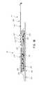
- FIG. 1Aillustrates an embodiment of a negative pressure wound treatment dressing capable of absorbing and storing wound exudate with a flexible suction adapter
- FIG. 1Billustrates a cross section of an embodiment of a negative pressure wound treatment dressing capable of absorbing and storing wound exudate with a flexible suction adapter
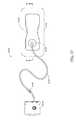
- FIG. 2illustrates an embodiment of a negative pressure wound treatment system employing a wound dressing capable of absorbing and storing wound exudate and a flexible suction adapter;
- FIG. 3A-Cillustrate various embodiments of the enlarged end of a flexible suction adapter
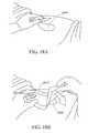
- FIGS. 4A-Dillustrate the use and application of an embodiment of a wound treatment system onto a patient
- FIG. 5Aillustrates a top view of an embodiment of a flexible port
- FIG. 5Billustrates a bottom view of an embodiment of a flexible port
- FIG. 5Cillustrates a perspective exploded view of an embodiment of a flexible port
- FIG. 6illustrates an embodiment of a flexible port attached to a wound dressing
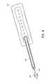
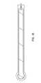
- FIG. 7Aillustrates a perspective view of an embodiment of a flexible port
- FIG. 7Billustrates a close up view of an embodiment of the proximal end of the flexible port of FIG. 7A ;
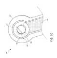
- FIG. 7Cillustrates a close up view of the bottom of the distal end of the flexible port of FIG. 7A ;
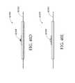
- FIGS. 8A-Billustrate various embodiments of the distal end of a conduit which may be part of a flexible port
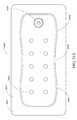
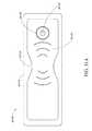
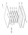
- FIG. 9illustrates a perspective top view of an ornamental design of one embodiment of a flexible port as disclosed herein;
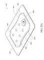
- FIG. 10illustrates a top plan view of the flexible port of FIG. 9 ;
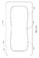
- FIG. 11illustrates a bottom view of the flexible port of FIG. 9 ;
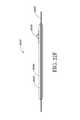
- FIG. 12is a far side view of the flexible port of FIG. 9 ;
- FIG. 13is a near side view of the flexible port of FIG. 9 ;
- FIG. 14is a front view of the flexible port of FIG. 9 ;
- FIG. 15is a rear view of the flexible port of FIG. 9 ;
- FIG. 16is an exploded view of the flexible port of FIG. 9 ;
- FIG. 17illustrates an embodiment of a wound treatment system
- FIGS. 18A-Dillustrate the use and application of an embodiment of a wound treatment system onto a patient
- FIG. 19Aillustrates an embodiment of a wound dressing in cross-section
- FIG. 19Billustrates another embodiment of a wound dressing in cross-section
- FIG. 19Cillustrates another embodiment of a wound dressing in cross-section
- FIGS. 20A-Cillustrate a top view of an embodiment of a wound dressing with a narrow central portion
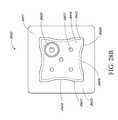
- FIGS. 21A-F - 28 A-Fillustrate a perspective view, a top view, a bottom view, a front view, a back view, and a side view, respectively, of embodiments of a wound dressing including an obscuring layer and viewing windows;
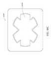
- FIGS. 29A-B and 30illustrate a top view of an embodiment of a wound dressing including a cross-shaped viewing window
- FIGS. 31A-Billustrate a top view of an embodiment of a wound dressing including slits in the wound dressing
- FIG. 32illustrates an embodiment of a dressing comprising a viewing window in the shape of a trademarked brand name
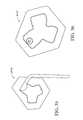
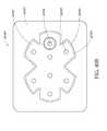
- FIG. 33illustrates a top view of an embodiment of a three-lobe configuration of a wound dressing and a dot pattern of viewing windows
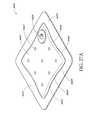
- FIG. 34illustrates a top view of an embodiment of a three-lobe configuration of a wound dressing and viewing windows in the shape of a logo
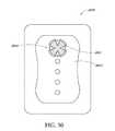
- FIG. 35illustrates a top view of an embodiment of a three-lobe wound dressing
- FIG. 36illustrates a top view of an embodiment of a three-lobe wound dressing with flared ends on each lobe
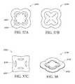
- FIG. 37Aillustrates a top view of an embodiment of a four-lobe wound dressing with crescent shaped cut-outs as viewing windows;
- FIG. 37Billustrates a top view of an embodiment of a four-lobe wound dressing with an array of dots at viewing windows
- FIG. 37Cillustrates a top view of an embodiment of a four-lobe wound dressing with viewing windows
- FIG. 38illustrates a perspective view of an embodiment of a four-lobe wound dressing
- FIG. 39A-Billustrate embodiments of white and colored fluidic connectors, respectively
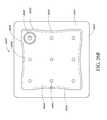
- FIGS. 40A-Fillustrate a perspective view, a top view, a bottom view, a front view, a back view, and a side view, respectively, of an embodiment of an oval-shaped wound dressing
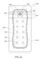
- FIGS. 41-48illustrate embodiments of a wound dressing including an obscuring layer and viewing windows including an orifice viewing window
- FIGS. 49A-Billustrate embodiments of an oval-shaped wound dressing comprising an obscuring layer and an orifice viewing window
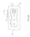
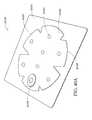
- FIG. 50Aillustrates an exploded view of an embodiment of a wound dressing
- FIG. 50Billustrates a cross sectional view of an embodiment of a wound dressing
- FIG. 51illustrates an exploded view of an embodiment of a soft or flexible port for transmitting negative pressure to a wound dressing
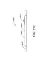
- FIG. 52illustrates an embodiment of a soft or flexible port attached to a wound dressing
- FIG. 53Aillustrates a perspective view of a wound dressing
- FIG. 53Billustrates a bottom view of the wound dressing of FIG. 53A ;
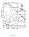
- FIG. 54illustrates a CIE chromacity scale.
- woundrefers to wound therapy for a human or animal body. Therefore, any reference to a wound herein can refer to a wound on a human or animal body, and any reference to a body herein can refer to a human or animal body.
- woundincludes any body part of a patient that may be treated using negative pressure. Wounds include, but are not limited to, open wounds, incisions, lacerations, abrasions, contusions, burns, diabetic ulcers, pressure ulcers, stoma, surgical wounds, trauma and venous ulcers or the like.
- Treatment of such woundscan be performed using negative pressure wound therapy, wherein a reduced or negative pressure can be applied to the wound to facilitate and promote healing of the wound. It will also be appreciated that the negative pressure systems and methods as disclosed herein may be applied to other parts of the body, and are not necessarily limited to treatment of wounds.
- treatment of a wound with negative pressureuses a wound dressing 10 capable of absorbing and storing wound exudate in conjunction with a flexible suction adapter 12 .
- the wound siteit may be preferable for the wound site to be filled partially or completely with a wound packing material.
- This wound packing materialis optional, but may be desirable in certain wounds, for example deeper wounds.
- the wound packing materialcan be used in addition to the wound dressing 10 .
- the wound packing materialgenerally may comprise a porous and conformable material, for example foam (including reticulated foams), and gauze.
- the wound packing materialis sized or shaped to fit within the wound site so as to fill any empty spaces.
- the wound dressing 10may then be placed over the wound site and wound packing material overlying the wound site.
- a wound packing materialWhen a wound packing material is used, once the wound dressing 10 is sealed over the wound site, negative pressure may be transmitted from a pump or other source of negative pressure through a flexible tubing 14 via the suction adapter 12 to the wound dressing 10 , through the wound packing material, and finally to the wound site. This negative pressure draws wound exudate and other fluids or secretions away from the wound site.
- the suction adapter 12preferably comprises a head 11 that is in fluidic communication with the dressing 10 as will be described in further detail below.
- the head 11is illustrated here as being positioned at a corner of the dressing 10 , but may also be positioned at any location on the dressing. For example, some embodiments may provide for a centrally or off-centered location not on an edge or corner of the dressing 10 .
- the dressing 10may comprise two or more suction adapters 12 , each comprising one or more heads 11 , in fluidic communication therewith.
- the head 11may measure 30 mm along its widest edge.
- certain embodiments of the wound dressing 10may comprise a plurality of layers.
- a wound contact layer 203 with an upper surface 202 and a lower surface 200may be configured to carry an adhesive on its lower surface 200 for sealing the wound dressing 10 to the wound site.
- a porous transmission layer 222 overlying the wound contact layer 203may comprise a 3D knitted or 3D fabric material, and the transmission layer 222 may be configured to remain open upon application of negative pressure to the wound dressing. This facilitates fluid flow 204 through the transmission layer 222 , although the transmission layer 222 does not retain a substantial amount of the fluid.
- An absorbent layer 220 overlying the transmission layer 222may be configured for absorbing wound exudate.
- a moisture vapor permeable cover layer 218overlays the absorbent layer 220 .
- the wound contact layer 203can be a polyurethane layer or polyethylene layer or other flexible layer which is perforated, for example via a hot pin process, laser ablation process, ultrasound process or in some other way or otherwise made permeable to liquid and gas.
- the perforations 104are through holes in the wound contact layer which enables fluid to flow through the layer.
- the wound contact layer 203may help prevent tissue ingrowth into the other material of the wound dressing 10 .
- the perforationsare small enough to meet this requirement but still allow fluid through. For example, perforations formed as slits or holes having a size ranging from 0.025 mm to 1.2 mm are considered small enough to help prevent tissue ingrowth into the wound dressing while allowing wound exudate to flow into the dressing.
- the wound contact layer 203may help hold the whole wound dressing together and helps to create an air tight seal around the absorbent pad in order to maintain negative pressure at the wound.
- the wound contact layer 230may also act as a carrier for an optional lower and upper adhesive layer (not shown).
- a lower pressure sensitive adhesivemay be provided on the underside surface 200 of the wound dressing whilst an upper pressure sensitive adhesive layer may be provided on the upper surface 202 of the wound contact layer.
- the pressure sensitive adhesivewhich may be a silicone, hot melt, hydrocolloid or acrylic based adhesive or other such adhesives, may be formed on both sides or optionally on a selected one or none of the sides of the wound contact layer. When a lower pressure sensitive adhesive layer is utilized this may help adhere the wound dressing 10 to the skin around a wound site.
- the layer 222 of porous materialis located above the wound contact layer 203 .
- This porous layer, or transmission layer, 222preferably allows transmission of fluid including liquid and gas away from a wound site into upper layers of the wound dressing.
- the transmission layer 222ensures that an open air channel can be maintained to communicate negative pressure over the wound area even when the absorbent layer 220 has absorbed substantial amounts of exudates.
- the layershould remain open under the typical pressures that will be applied during negative pressure wound therapy as described above, so that the whole wound site sees an equalized negative pressure.
- the layer 222is preferably formed of a material having a three dimensional structure.
- the transmission layer 222may also comprise materials such foams, including open-cell foams such as polyethylene or polyurethane foam, meshes, non-woven materials, and fluid channels.
- the transmission layer 222comprises a 3D polyester spacer fabric layer including a top layer (that is to say, a layer distal from the wound-bed in use) which is a 84/144 textured polyester, and a bottom layer (that is to say, a layer which lies proximate to the wound bed in use) which is a 10 denier flat polyester and a third layer formed sandwiched between these two layers which is a region defined by a knitted polyester viscose, cellulose or the like monofilament fiber. Other materials and other linear mass densities of fiber could of course be used.
- top spacer fabricthus has more filaments in a yarn used to form it than the number of filaments making up the yarn used to form the bottom spacer fabric layer.
- This differential between filament counts in the spaced apart layershelps control moisture flow across the transmission layer.
- the top layeris made from a yarn having more filaments than the yarn used in the bottom layer, liquid tends to be wicked along the top layer more than the bottom layer.
- this differentialtends to draw liquid away from the wound bed and into a central region of the dressing where the absorbent layer 220 helps lock the liquid away or itself wicks the liquid onwards towards the cover layer where it can be transpired.
- the 3D fabricmay be treated with a dry cleaning agent (such as, but not limited to, Perchloro Ethylene) to help remove any manufacturing products such as mineral oils, fats and/or waxes used previously which might interfere with the hydrophilic capabilities of the transmission layer.
- a dry cleaning agentsuch as, but not limited to, Perchloro Ethylene
- an additional manufacturing stepcan subsequently be carried in which the 3D spacer fabric is washed in a hydrophilic agent (such as, but not limited to, Feran Ice 30 g/l available from the Rudolph Group). This process step helps ensure that the surface tension on the materials is so low that liquid such as water can enter the fabric as soon as it contacts the 3D knit fabric. This also aids in controlling the flow of the liquid insult component of any exudates.
- the layer 220 of absorbent materialis provided above the transmission layer 222 .
- the absorbent materialwhich may be a foam or non-woven natural or synthetic material and which may optionally include or be super-absorbent material forms a reservoir for fluid, particularly liquid, removed from the wound site and draws those fluids towards a cover layer 218 .
- the material of the absorbent layer 220also prevents liquid collected in the wound dressing from flowing in a sloshing manner.
- the absorbent layer 220also helps distribute fluid throughout the layer via a wicking action so that fluid is drawn from the wound site and stored throughout the absorbent layer 220 . This helps prevent agglomeration in areas of the absorbent layer.
- the capacity of the absorbent materialmust be sufficient to manage the exudates flow rate of a wound when negative pressure is applied. Since in use the absorbent layer 220 experiences negative pressures the material of the absorbent layer 220 is chosen to absorb liquid under such circumstances. A number of materials exist that are able to absorb liquid when under negative pressure, for example superabsorber material.
- the absorbent layer 220may typically be manufactured from ALLEVYNTM foam, Freudenberg 114-224-4 and/or Chem-PositeTM11C-450.
- the absorbent layer 220is a layer of non-woven cellulose fibers having super-absorbent material in the form of dry particles dispersed throughout.
- Use of the cellulose fibersintroduces fast wicking elements which help quickly and evenly distribute liquid taken up by the dressing.
- the juxtaposition of multiple strand-like fibersleads to strong capillary action in the fibrous pad which helps distribute liquid. In this way, the super-absorbent material is efficiently supplied with liquid.
- the wicking actionalso assists in bringing liquid into contact with the upper cover layer 218 to aid increase transpiration rates of the dressing.
- the wicking actionalso assists in delivering liquid downwards towards the wound bed when exudation slows or halts. This delivery process helps maintain the transmission layer and lower wound bed region in a moist state which helps prevent crusting within the dressing (which could lead to blockage) and helps maintain an environment optimized for wound healing.
- the absorbent layer 220may be an air-laid material.
- Heat fusible fibersmay optionally be used to assist in holding the structure of the pad together. It will be appreciated that rather than using super-absorbing particles or in addition to such use, super-absorbing fibers may be utilized according to certain embodiments of the present invention.
- An example of a suitable materialis the Product Chem-PositeTM 11 C available from Emerging Technologies Inc. (ETi) in the USA.
- the absorbent layer 220may include synthetic stable fibers and/or bi-component stable fibers and/or natural stable fibers and/or super-absorbent fibers. Fibers in the absorbent layer 220 may be secured together by latex bonding or thermal bonding or hydrogen bonding or a combination of any bonding technique or other securing mechanism.
- the absorbent layer 220is formed by fibers which operate to lock super-absorbent particles within the absorbent layer 220 . This helps ensure that super-absorbent particles do not move external to the absorbent layer 220 and towards an underlying wound bed.
- the absorbent layer 220may comprise a layer of multiple fibers.
- the fibersare strand-like and made from cellulose, polyester, viscose or the like.
- dry absorbent particlesare distributed throughout the absorbent layer ready for use.
- the absorbent layer 220comprises a pad of cellulose fibers and a plurality of super absorbent particles.
- the absorbent layeris a non-woven layer of randomly orientated cellulose fibers.
- Super-absorber particles/fibersmay be, for example, sodium polyacrylate or carbomethoxycellulose materials or the like or any material capable of absorbing many times its own weight in liquid.
- the materialcan absorb more than five times its own weight of 0.9% W/W saline, etc.
- the materialcan absorb more than 15 times its own weight of 0.9% W/W saline, etc.
- the materialis capable of absorbing more than 20 times its own weight of 0.9% W/W saline, etc.
- the materialis capable of absorbing more than 30 times its own weight of 0.9% W/W saline, etc.
- the particles of superabsorberare very hydrophilic and grab the fluid as it enters the dressing, swelling up on contact. Equilibrium is set up within the dressing core whereby moisture passes from the superabsorber into the dryer surrounding area and as it hits the top film the film switches and the fluid vapor starts to be transpired. A moisture gradient is established within the dressing to continually remove fluid from the wound bed and ensure the dressing does not become heavy with exudate.
- suction adapter 12preferred embodiments comprise a sealing surface 216 , a bridge 211 with a proximal end and a distal end, and a filter 214 .
- the sealing surface 216may be configured for sealing the suction adapter to the cover layer 218 of the wound dressing, and may comprise an adhesive or weld.
- the sealing surface 216may be placed over an orifice in the cover layer with spacer elements 215 configured to create a gap between the filter 214 and the transmission layer 222 .
- the sealing surface 216may be positioned over an orifice in the cover layer 218 and an aperture in the absorbent layer 220 , permitting the suction adapter 12 to provide air flow 206 through the transmission layer 222 .
- the bridge 211may comprise a first fluid passage 212 in communication with a source of negative pressure, the first fluid passage 212 comprising a porous material, such as a 3D knitted material, which may be the same or different than the porous layer 222 described previously.
- the bridge 211is preferably encapsulated by at least one flexible film layer 208 , 210 having a proximal and distal end and configured to surround the first fluid passage 212 , the distal end of the flexible film being connected the sealing surface 216 .
- the filter 214is configured to substantially prevent wound exudate from entering the bridge, and spacer elements 215 are configured to prevent the suction adapter from contacting the transmission layer 222 .
- Some embodimentsmay further comprise an optional second fluid passage positioned above the first fluid passage 212 .
- some embodimentsmay provide for an air leak may be disposed at the proximal end of the top layer that is configured to provide an air path into the first fluid passage 212 and dressing 10 .
- the fluid passage 212is constructed from a compliant material that is flexible and that also permits fluid to pass through it if the spacer is kinked or folded over.
- Suitable materials for the fluid passage 212include without limitation foams, including open-cell foams such as polyethylene or polyurethane foam, meshes, 3D knitted fabrics, non-woven materials, and fluid channels.
- the fluid passage 212may be constructed from materials similar to those described above in relation to the transmission layer 222 .
- such materials used in the fluid passage 212not only permit greater patient comfort, but may also provide greater kink resistance, such that the fluid passage 212 is still able to transfer fluid from the wound toward the source of negative pressure while being kinked or bent.
- the fluid passage 212may be comprised of a wicking fabric, for example a knitted or woven spacer fabric (such as a knitted polyester 3D fabric, Baltex 7970®, or Gehring 879®) or a nonwoven fabric. These materials selected are preferably suited to channeling wound exudate away from the wound and for transmitting negative pressure and/or vented air to the wound site, and may also confer a degree of kinking or occlusion resistance to the fluid passage 212 .
- the wicking fabricmay have a three-dimensional structure, which in some cases may aid in wicking fluid or transmitting negative pressure.
- the wicking fabricmay comprise several layers of material stacked or layered over each other, which may in some cases be useful in preventing the fluid passage 212 from collapsing under the application of negative pressure.
- the wicking fabric used in the fluid passage 212may be between 1.5 mm and 6 mm; more preferably, the wicking fabric may be between 3 mm and 6 mm thick, and may be comprised of either one or several individual layers of wicking fabric.
- the fluid passage 212may be between 1.2-3 mm thick, and preferably thicker than 1.5 mm.
- a suction adapter used with a dressing which retains liquid such as wound exudatemay employ hydrophobic layers in the fluid passage 212 , and only gases may travel through the fluid passage 212 .
- the materials used in the systemare preferably conformable and soft, which may help to avoid pressure ulcers and other complications which may result from a wound treatment system being pressed against the skin of a patient.
- the absorbent layer 220includes at least one area 246 , such as an edge or through hole, located so as to underlie the suction adapter 12 where the absorbent layer 220 is removed or not provided. It will be appreciated that multiple openings could alternatively be utilized. As shown in FIG. 1A , this area 246 preferably underlies the point where the head 11 is in fluidic communication with the dressing. Additionally, should more than one suction adapter 12 be utilized according to certain embodiments, one or multiple openings may be made in the super-absorbent layer 220 in registration with each respective suction adapter. Although not essential to certain embodiments of the present invention the use of through holes in the super-absorbent layer 220 provide a fluid flow pathway which is particularly unhindered and this is useful in certain circumstances.
- the thickness of the layer itselfwill act as a stand-off separating any overlying layer from the upper surface (that is to say the surface facing away from a wound in use) of the transmission layer 222 .
- An advantage of thisis that the filter 214 is thus decoupled from the material of the transmission layer 222 . This helps reduce the likelihood that the filter will be wetted out and thus will occlude and block further operation.
- each opening in the absorbent layerprovides a fluid pathway between the transmission layer directly to the wound facing surface of the filter and then onwards into the interior of the suction adapter.
- the cover layer 218extends across the width of the wound dressing, and is preferably gas impermeable, but moisture vapor permeable.
- the cover layer 218which may for example be a polyurethane film (for example, Elastollan SP9109) having a pressure sensitive adhesive on one side, is preferably impermeable to gas and this layer thus operates to cover the wound and to seal a wound cavity over which the wound dressing is placed. In this way an effective chamber is made between the cover layer and a wound site where a negative pressure can be established.
- the cover layer 218may for example be sealed to the wound contact layer 203 in a border region 200 around the circumference of the dressing, ensuring that no air is drawn in through the border area, for example via adhesive or welding techniques.
- the cover layer 218protects the wound from external bacterial contamination (bacterial barrier) and allows liquid from wound exudates to be transferred through the layer and evaporated from the film outer surface.
- the cover layer 218typically comprises two layers; a polyurethane film and an adhesive pattern spread onto the film.
- the polyurethane filmis moisture vapor permeable and may be manufactured from a material that has an increased water transmission rate when wet.
- the absorbent layer 220may be of a greater area than the transmission layer 222 , such that the absorbent layer overlaps the edges of the transmission layer 222 , thereby ensuring that the transmission layer does not contact the cover layer 218 .
- Thisprovides an outer channel of the absorbent layer 220 that is in direct contact with the wound contact layer 203 , which aids more rapid absorption of exudates to the absorbent layer. Furthermore, this outer channel ensures that no liquid is able to pool around the circumference of the wound cavity, which may otherwise seep through the seal around the perimeter of the dressing leading to the formation of leaks.
- the transmission layer 222In order to ensure that the air channel remains open when a vacuum is applied to the wound cavity, the transmission layer 222 must be sufficiently strong and non-compliant to resist the force due to the pressure differential. However, if this layer comes into contact with the relatively delicate cover layer 218 , it may cause the formation of tears, holes, or pin-hole openings in the cover layer 218 which allow air to leak into the wound cavity. This may be a particular problem when a switchable type polyurethane film is used that becomes weaker when wet.
- the absorbent layer 220is generally formed of a relatively soft, non-abrasive material compared to the material of the transmission layer 222 and therefore does not cause the formation of pin-hole openings in the cover layer.
- the absorbent layer 220is positioned in fluid contact with the cover layer 218 .
- the exudateis drawn towards the cover layer 218 , bringing the water component of the exudate into contact with the moisture vapor permeable cover layer.
- This water componentis drawn into the cover layer itself and then evaporates from the top surface of the dressing.
- the water content of the wound exudatecan be transpired from the dressing, reducing the volume of the remaining wound exudate that is to be absorbed by the absorbent layer 220 , and increasing the time before the dressing becomes full and must be changed. This process of transpiration occurs even when negative pressure has been applied to the wound cavity, and it has been found that the pressure difference across the cover layer when a negative pressure is applied to the wound cavity has negligible impact on the moisture vapor transmission rate across the cover layer.
- An orifice 245is provided in the cover film 218 to allow a negative pressure to be applied to the dressing 10 .
- a suction adapter 12may be sealed to the top of the cover film 218 over the orifice 245 , and communicates negative pressure through the orifice 245 .
- a length of tubing 14may be coupled at a first end to the suction adapter 12 and at a second end to a pump unit (not shown) to allow fluids to be pumped out of the dressing.
- the suction adapter 12may be adhered and sealed to the cover film 218 using an adhesive such as an acrylic, cyanoacrylate, epoxy, LTV curable or hot melt adhesive.
- the suction adapter 12may be separately attached to the cover film 218 , while other embodiments may provide for the dressing 10 to be provided with the suction adapter 12 already attached to the cover film 218 .
- the suction adapter 12may be formed from a soft polymer, for example a polyethylene, a polyvinyl chloride, a silicone or polyurethane having a hardness of 30 to 90 on the Shore A scale.
- the area or through-hole 246may be provided in the absorbent layer 220 beneath the orifice 245 such that the orifice is connected directly to the transmission layer 222 .
- Thisallows the negative pressure applied to the suction adapter 12 to be communicated to the transmission layer 222 without passing through the absorbent layer 220 .
- Thisensures that the negative pressure applied to the wound site is not inhibited by the absorbent layer as it absorbs wound exudates.
- no aperturemay be provided in the absorbent layer 220 , or alternatively a plurality of apertures underlying the orifice 245 may be provided.
- one embodiment of the wound dressing 10comprises an aperture 246 in the absorbent layer 10 situated underneath the suction adapter 12 .
- a wound facing portion of the suction adapter 12may thus come into contact with the transmission layer 222 , which can thus aid in transmitting negative pressure to the wound site even when the absorbent layer 220 is filled with wound fluids.
- Some embodimentsmay have the cover layer 218 be at least partly adhered to the transmission layer 222 .
- the aperture 246is at least 1-2 mm larger than the diameter of the wound facing portion of the suction adapter 12 , or the orifice 245 .
- the filter element 214is impermeable to liquids, but permeable to gases, and is provided to act as a liquid barrier and to ensure that no liquids are able to escape from the wound dressing 10 .
- the filter element 214may also function as a bacterial barrier.
- the pore sizeis 0.2 ⁇ m.
- Suitable materials for the filter material of the filter element 214include 0.2 micron GoreTM expanded PTFE from the MMT range, PALL VersaporeTM 200R, and DonaldsonTM TX6628. Larger pore sizes can also be used but these may require a secondary filter layer to ensure full bioburden containment.
- the filter elementcan be attached or sealed to the port and/or the cover film 218 over the orifice 245 .
- the filter element 214may be molded into the suction adapter 12 , or may be adhered to one or both of the top of the cover layer 218 and bottom of the suction adapter 12 using an adhesive such as, but not limited to, a UV cured adhesive.
- filter element 214More generally a microporous membrane can be used which is a thin, flat sheet of polymeric material, this contains billions of microscopic pores. Depending upon the membrane chosen these pores can range in size from 0.01 to more than 10 micrometers. Microporous membranes are available in both hydrophilic (water filtering) and hydrophobic (water repellent) forms.
- filter element 214comprises a support layer and an acrylic co-polymer membrane formed on the support layer.
- the wound dressing 10according to certain embodiments of the present invention uses microporous hydrophobic membranes (MHMs). Numerous polymers may be employed to form MHMs.
- the MHMsmay be formed from one or more of PTFE, polypropylene, PVDF and acrylic copolymer. All of these optional polymers can be treated in order to obtain specific surface characteristics that can be both hydrophobic and oleophobic. As such these will repel liquids with low surface tensions such as multi-vitamin infusions, lipids, surfactants, oils and organic solvents.
- MHMsblock liquids whilst allowing air to flow through the membranes. They are also highly efficient air filters eliminating potentially infectious aerosols and particles. A single piece of MHM is well known as an option to replace mechanical valves or vents. Incorporation of MHMs can thus reduce product assembly costs improving profits and costs/benefit ratio to a patient.
- the filter element 214may also include an odor absorbent material, for example activated charcoal, carbon fiber cloth or Vitec Carbotec-RT Q2003073 foam, or the like.
- an odor absorbent materialmay form a layer of the filter element 214 or may be sandwiched between microporous hydrophobic membranes within the filter element. The filter element 214 thus enables gas to be exhausted through the orifice 245 . Liquid, particulates and pathogens however are contained in the dressing.
- the wound dressing 10may comprise spacer elements 215 in conjunction with the suction adapter 12 and the filter 214 . With the addition of such spacer elements 215 the suction adapter 12 and filter 214 may be supported out of direct contact with the absorbent layer 220 and/or the transmission layer 222 .
- the absorbent layer 220may also act as an additional spacer element to keep the filter 214 from contacting the transmission layer 222 . Accordingly, with such a configuration contact of the filter 214 with the transmission layer 222 and wound fluids during use may thus be minimized.
- the suction adapter 12 and through hole 246may be located in an off-center position as illustrated in FIGS. 1A-B . Such a location may permit the dressing 10 to be positioned onto a patient such that the suction adapter 12 is raised in relation to the remainder of the dressing 10 . So positioned, the suction adapter 12 and the filter 214 may be less likely to come into contact with wound fluids that could prematurely occlude the filter 214 so as to impair the transmission of negative pressure to the wound site.
- FIG. 2illustrates an embodiment of a negative pressure wound treatment system 5501 employing a wound dressing 5500 in conjunction with a flexible suction adapter 5512 .
- the wound dressing 5500may be similar to the dressings illustrated in FIGS. 1A-B .
- the flexible suction adapter 5512may comprise a bridge 5502 having a proximal end 5503 and a distal end 5505 and an applicator 5504 at the distal end 5505 of the bridge 5502 .
- a connector 5504is preferably disposed at the proximal end 5503 of the bridge 5502 .
- a cap 5536may be provided with the system 5501 (and can in some cases, as illustrated, be attached to the connector 5504 ).
- the cap 5536can be useful in preventing fluids from leaking out of the proximal end 5503 .
- the system 5501may include a source of negative pressure such as a pump or negative pressure unit 5534 capable of supplying negative pressure.
- the pumpalso preferably comprises a canister or other container for the storage of wound exudates and other fluids that may be removed from the wound.
- this pump 5534can be a PICOTM pump, as sold by Smith & Nephew.
- the pump 5534may be connected to the connector 5504 via a tube 5540 .
- the dressing 5500is placed over a suitably-prepared wound, which may in some cases be filled with a wound packing material such as foam or gauze. Subsequently, with the pump 5534 connected via the tube 5540 to the connector 5504 , the pump is activated, thereby supplying negative pressure to the wound. Application of negative pressure may be applied until a desired level of healing of the wound 5530 is achieved.
- FIGS. 3A-Cillustrate various embodiments of the head 11 of the suction adapter 12 .
- the suction adapter 12 illustrated in FIGS. 1A-Cis enlarged at the distal end to be placed over the orifice in the cover layer 218 and the aperture in the absorbent layer 220 , and may form a “teardrop” or other enlarged shape.
- FIG. 3Aillustrates a suction adapter 12 with a substantially triangular head 11 .
- FIG. 3Billustrates a suction adapter 12 with a substantially pentagonal head 11 .
- FIG. 3Aillustrates a suction adapter 12 with a substantially circular head 11 .
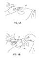
- FIGS. 4A-Dillustrate the use of an embodiment of a negative pressure therapy wound treatment system being used to treat a wound site on a patient.
- FIG. 4Ashows a wound site 490 being cleaned and prepared for treatment.
- the healthy skin surrounding the wound site 490is preferably cleaned and excess hair removed or shaved.
- the wound site 490may also be irrigated with sterile saline solution if necessary.
- a skin protectantmay be applied to the skin surrounding the wound site 490 .
- a wound packing materialsuch as foam or gauze, may be placed in the wound site 490 . This may be preferable if the wound site 490 is a deeper wound.
- the wound dressing 400may be positioned and placed over the wound site 490 .
- the wound dressing 400may be similar to the wound dressing 10 described above in relation to FIGS. 1A-B .
- the wound dressing 400is placed with the wound contact layer 203 (illustrated in FIGS. 1A-B ) over and/or in contact with the wound site 490 .
- an adhesive layeris provided on the lower surface 200 of the wound contact layer 203 , which may in some cases be protected by an optional release layer to be removed prior to placement of the wound dressing 400 over the wound site 490 .
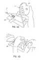
- the dressing 400is positioned such that the suction adapter 12 is in a raised position with respect to the remainder of the dressing 400 so as to avoid fluid pooling around the port.
- the dressing 400is positioned so that the suction adapter 12 is not directly overlying the wound, and is level with or at a higher point than the wound.
- the edges of the dressing 400are preferably smoothed over to avoid creases or folds.
- the dressing 400is connected to the pump 420 .
- the pump 420is configured to apply negative pressure to the wound site via the dressing 400 , and typically through a conduit.
- a connectormay be used to join the conduit from the dressing 400 to the pump 420 .
- the dressing 400may in some embodiments partially collapse and present a wrinkled appearance as a result of the evacuation of some or all of the air underneath the dressing 400 .
- the pump 420may be configured to detect if any leaks are present in the dressing 400 , such as at the interface between the dressing 400 and the skin surrounding the wound site 490 . Should a leak be found, such leak is preferably remedied prior to continuing treatment.
- fixation strips 495may also be attached around the edges of the dressing 400 .
- fixation strips 495may be advantageous in some situations so as to provide additional sealing against the skin of the patient surrounding the wound site 490 .
- the fixation strips 495may provide additional sealing for when a patient is more mobile.
- the fixation strips 495may be used prior to activation of the pump 420 , particularly if the dressing 400 is placed over a difficult to reach or contoured area.
- Treatment of the wound site 490preferably continues until the wound has reached a desired level of healing.
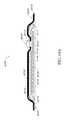
- FIGS. 5A-Billustrate an embodiment of a flexible port or fluidic connector 500 .
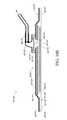
- FIG. 5Cillustrates a perspective exploded view the fluidic connector 500 that may be used to connect a wound dressing to a source of negative pressure.
- the port 500comprises a top layer 510 , a spacer layer 520 , a filter element 530 , a bottom layer 540 , and a conduit 550 .
- the conduitoptionally comprises a connector 560 .
- the distal end of the port 500(the end connectable to the dressing) is depicted as having an enlarged circular shape, although it will be appreciated that any suitable shape may be used and that the distal end need not be enlarged.
- the distal endcan have any of the shapes shown in FIGS. 3A-3C above.
- the distal endcan also have the shape shown in FIGS. 39A and 39B , discussed below.
- the bottom layer 540may comprise an elongate bridge portion 544 , an enlarged (e.g., rounded or circular) sealing portion 545 , and an orifice 541 .
- a plurality of orificesmay be provided in the bottom layer.
- Some embodiments of the rounded sealing portion 545may comprise a layer of adhesive, for example a pressure sensitive adhesive, on the lower surface for use in sealing the port 500 to a dressing.
- the portmay be sealed to a cover layer of the dressing.
- the orifice 541 in the bottom layer 540 of the port 500may be aligned with an orifice in the cover layer of the dressing in order to transmit negative pressure through the dressing and into a wound site.
- the top layer 515may be substantially the same shape as the bottom layer in that it comprises an elongate bridge 514 and an enlarged (e.g., rounded or circular) portion 545 .
- the top layer 515 and the bottom layer 545may be sealed together, for example by heat welding.
- the bottom layer 545may be substantially flat and the top layer 515 may be slightly larger than the bottom layer 545 in order to accommodate the height of the spacer layer 520 and seal to the bottom layer 545 .
- the top layer 515 and bottom layer 3145may be substantially the same size, and the layers may be sealed together approximately at the middle of the height of the spacer layer 520 .
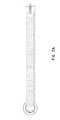
- the elongate bridge portions 544 , 514may have a length of 10 cm (or about 10 cm) or more, more preferably a length of 20 cm (or about 20 cm) or more and in some embodiments, may be about 69 cm (or 27 cm) long.
- Some embodiments of the entire flexible port, from a proximalmost edge of the top and bottom layers to a distalmost edge of the top and bottom layers,may be between 20 cm and 80 cm (or about 20 cm to about 80 cm) long, more preferably about 60 cm and 80 cm (or between about 60 cm and about 80 cm) long, for example about 70 cm long.
- the elongate bridge portionsmay have a width of between 1 cm and 4 cm (or between about 1 cm and about 4 cm), and in one embodiment, is about 2.5 cm wide.
- the ratio of the length of the elongate bridge portions 544 , 514 to their widthsmay in some embodiments exceed 6:1, and may more preferably exceed 8:1 or even 10:1.
- the diameter of the circular portion 545 , 515may be about 3.5 cm in some embodiments.
- the bottom and top layersmay comprise at least one layer of a flexible film, and in some embodiments may be transparent. Some embodiments of the bottom layer 540 and top layer 515 may be polyurethane, and may be liquid impermeable.
- the port 500may comprise a spacer layer 520 , such as the 3D fabric discussed above, positioned between the lower layer 540 and the top layer 510 .
- the spacer layer 520may be made of any suitable material, for example material resistant to collapsing in at least one direction, thereby enabling effective transmission of negative pressure therethrough.
- some embodiments of the spacer layer 520may comprise a fabric configured for lateral wicking of fluid, which may comprise viscose, polyester, polypropylene, cellulose, or a combination of some or all of these, and the material may be needle-punched.
- spacer layer 520may comprise polyethylene in the range of 40-160 grams per square meter (gsm) (or about 40 to about 160 gsm), for example 80 (or about 80) gsm. Such materials may be constructed so as to resist compression under the levels of negative pressure commonly applied during negative pressure therapy.
- the spacer layer 520may comprise an elongate bridge portion 524 , an enlarged (e.g., rounded or circular) portion 525 , and may optionally include a fold 521 .
- the elongate bridge portionmay have dimensions in the same ranges as the bridge portions of the upper and lower layers described above though slightly smaller, and in one embodiment is about 25.5 cm long and 1.5 cm wide.
- the diameter of the circular portion 525may be slightly smaller than the diameters of the enlarged ends 545 , 515 , and in one embodiment is about 2 cm.
- the spacer layer 520may have adhesive on one or both of its proximal and distal ends (e.g., one or more dabs of adhesive) in order to secure the spacer layer 520 to the top layer 510 and/or the bottom layer 540 .
- Adhesivemay also be provided along a portion or the entire length of the spacer layer.
- the spacer layer 520may be freely movable within the sealed chamber of the top and bottom layers.
- the fold 521 of the spacer layermay make the end of the port 500 softer and therefore more comfortable for a patient, and may also help prevent the conduit 550 from blockage.
- the fold 521may further protect the end of the conduit 550 from being occluded by the top or bottom layers.
- the fold 521may, in some embodiments, be between 1 cm and 3 cm (or between about 1 cm and about 3 cm) long, and in one embodiment is 2 cm (or about 2 cm) long.
- the spacer layermay be folded underneath itself, that is toward the bottom layer 540 , and in other embodiments may be folded upward toward the top layer 510 .
- Other embodiments of the spacer layer 520may contain no fold.
- a slot or channel 522may extend perpendicularly away from the proximal end of the fold 521 , and the conduit 550 may rest in the slot or channel 522 .
- the slot 522may extend through one layer of the fold, and in others it may extend through both layers of the fold.
- the slot 522may, in some embodiments, be 1 cm (or about 1 cm) long.
- Some embodimentsmay instead employ a circular or elliptical hole in the fold 521 . The hole may face proximally so that the conduit 550 may be inserted into the hole and rest between the folded layers of spacer fabric.
- the conduit 550may be adhered to the material of the fold 3521 , while in other embodiments it may not.
- the port 500may have a filter element 530 located adjacent the orifice 541 , and as illustrated is located between the lower layer 540 and the spacer layer 520 .
- the filter element 530is impermeable to liquids, but permeable to gases.
- the filter elementmay be similar to the element described above with respect to FIG. 1B , and as illustrated may have a round or disc shape.
- the filter element 530can act as a liquid barrier, to substantially prevent or inhibit liquids from escaping from the wound dressing, as well as an odor barrier.
- the filter element 530may also function as a bacterial barrier.
- the pore size of the filter element 530can be approximately 0.2 ⁇ m.
- Suitable materials for the filter material of the filter elementinclude 0.2 micron GoreTM expanded PTFE from the MMT range, PALL VersaporeTM 200R, and DonaldsonTM TX6628.
- the filter element 530thus enables gas to be exhausted through the orifice. Liquid, particulates and pathogens however are contained in the dressing. Larger pore sizes can also be used but these may require a secondary filter layer to ensure full bioburden containment.
- the filter element 530may be adhered to one or both of top surface of the bottom layer 540 and the bottom surface of the spacer layer 520 using an adhesive such as, but not limited to, a LTV cured adhesive. In other embodiments, the filter 530 may be welded to the inside of the spacer layer 520 and to the top surface of the bottom layer 540 . The filter may also be provided adjacent the orifice on a lower surface of the bottom layer 540 . Other possible details regarding the filter are disclosed in U.S. Patent Pub. No. 2011/0282309 and incorporated by reference herein.
- the proximal end of the port 500may be connected to the distal end of a conduit 550 .
- the conduit 550may comprise one or more circular ribs 551 .
- the ribs 551may be formed in the conduit 550 by grooves in a mold during the manufacturing of the conduit. During heat welding of the upper and lower layers 515 , 545 melted material from those layers may flow around the ribs 551 , advantageously providing a stronger connection between the conduit 550 and the layers. As a result, it may be more difficult to dislodge the conduit 550 out from between the layers during use of the port 500 .
- the proximal end of the conduit 550may be optionally attached to a connector 560 .
- the connector 560may be used to connect the port 500 to a source of negative pressure, or in some embodiments to an extension conduit which may in turn be connected to a source of negative pressure.
- the proximal end of the conduit 550which is inserted into the spacer fabric 520 , may be shaped in such a way to reduce the possibility of occlusion.
- some embodimentsmay have a triangular portion cut out of the end of the conduit, and other embodiments may have a plurality of holes therethrough.
- FIG. 6illustrates an embodiment of a wound dressing 610 with a flexible port 620 such as described above with respect to FIGS. 5A-C attached to the dressing.
- the port 620may be the port described above in FIGS. 5A-C .
- the port 620may comprise a conduit 630 and a connector 640 for connecting the port to a source of negative pressure or to an extension conduit. Although in this depiction the port 620 is connected over a circular window in the obscuring layer of the dressing 610 , in other embodiments the port 620 may be connected over a maltese cross in the obscuring layer.
- the maltese crossmay be of a larger diameter than the port 620 and may be at least partially viewable after the port 620 is attached to the dressing 610 . Further details regarding the dressing 610 and other dressings to which the port can be connected are described in Provisional Application Ser. No. 61/785,054, filed Mar. 14, 2013, incorporated by reference herein and described further below in the section entitled “Other Negative Pressure Therapy Apparatuses, Dressings and Methods.”
- FIG. 7Adepicts a perspective view of a flexible port 700 of the same design as shown with respect to FIGS. 5A-C .
- the port 700comprises spacer fabric 710 , wherein the proximal end of spacer fabric 710 comprises a fold 720 , at least one layer of flexible film 740 , an enlarged rounded distal end 715 , a conduit 760 , and a connector 780 .
- the components of port 700may have similar properties to the components of FIGS. 5A-C , described above.
- FIG. 7Billustrates a close up view of an embodiment of the proximal end of the flexible port 700 .
- the port 700comprises spacer fabric 710 inside a sealed chamber 770 between layers of flexible film 740 .
- the end of the spacer fabric 710comprises a fold 720 .
- At the proximal end of the foldthere may be a hole 730 through the fabric for inserting the conduit 760 .
- the conduit 760may rest between the folded portions of the spacer fabric.
- the conduit 760comprises a plurality of ribs 750 , which may, as described above with respect to FIGS. 5A-C , act to secure the conduit 760 between the layers of flexible film 740 .
- FIG. 7Cillustrates a close up view of the bottom of the distal end of the flexible port 700 .
- the bottom of the port 700comprises an orifice 792 for transmitting negative pressure to a dressing to which the port may be attached.
- the port 700comprises a filter 790 , which may have similar properties to the filters described above with respect to FIGS. 1B and 5A -C.
- the filter 790may have a portion 795 which is adhered to the flexible film 740 around the perimeter of the orifice 795 , thereby substantially maintaining the seal of chamber 770 .
- FIGS. 8A and 8Billustrate embodiments of the distal end of a conduit 800 which may be part of any of the port embodiments described above.
- the distal endmay be shaped in such a way to reduce the possibility of occlusion.
- the embodiment of FIG. 8Amay have a triangular portion 810 cut out of the end of the conduit, and other embodiments may have a plurality of holes therethrough.
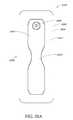
- FIGS. 9-16depict various views of an ornamental design of one embodiment of a flexible port as described herein.
- functionally equivalent alternative designs of such a flexible portare available, and the configuration of the design illustrated in FIGS. 9-16 was at least in part the result of aesthetic and ornamental considerations.
- the solid linesindicate the incorporation of the entire structure as part of one embodiment of an ornamental design for the flexible port.
- any number of the solid linesmay instead be depicted as broken lines to indicate that a component illustrated in broken lines is not part of that embodiment of the ornamental design.
- a wound treatment apparatus for treatment of a wound sitecomprises: a wound dressing comprising: an absorbent layer configured to retain fluid, a backing layer above the absorbent layer, and an obscuring layer configured to at least partly visually obscure fluid within the absorbent layer; and a fluidic connector configured to transmit negative pressure from a negative pressure source to the wound dressing for the application of topical negative pressure at the wound site.
- the obscuring layeris above or below the backing layer.
- the obscuring layermay configured to at least partially visually obscure fluid contained within the absorbent layer.
- the obscuring layermay comprise at least one viewing window configured to allow a visual determination of the saturation level of the absorbent layer.
- the at least one viewing windowmay comprise at least one aperture made through the obscuring layer.
- the at least one viewing windowmay comprise at least one uncolored region of the obscuring layer.
- the viewing windowmay comprise an array of dots.
- the array of dotsmay be distributed in a straight line of dots, the straight line of dots being positioned on a center line along a length of the absorbent layer.
- the straight line of dotsmay comprise an array of three dots.
- the straight line of dotsmay comprise an array of five dots.
- the straight line of dotsmay comprise an array of eight dots.
- the array of dotsmay be distributed in two straight lines of dots, the two straight lines of dots positioned to be an equal distance from a center line along a length of the absorbent layer, the two straight lines of dots having an equal number of dots.
- the two straight lines of dotsmay comprise an array of three dots.
- the two straight lines of dotsmay comprise an array of five dots.
- the array of dotsmay be distributed regularly over the obscuring layer to enable assessment of wound exudate spread.
- the viewing windowmay be selected from the group consisting of a graphical element or a typographical element.
- the obscuring layermay comprise an auxiliary compound, wherein the auxiliary compound may comprise activated charcoal configured to absorb odors and configured to color or tint the obscuring layer.
- the fluidic connectormay comprise an obscuring element configured to substantially visually obscure wound exudate.
- Some embodimentsmay further comprise an acquisition distribution layer between the wound contact layer and the absorbent material.
- the absorbent layermay comprise cellulose fibers and between 40% and 80% (or between about 40% and about 80%) superabsorbent particles.
- the obscuring layer, in a dry statemay be configured to yield a CIE y value of 0.4 or less and a CIE x value of 0.5 or less on a CIE x, y chromacity diagram.
- the obscuring layer, in a dry statemay have a color of Bg, gB, B, pB, bP, P, rP, pPk, RP, O, rO, or yO on a CIE x, y chromacity diagram.
- the wound dressingfurther comprises an orifice in the backing layer, the orifice configured to communicate negative pressure to the wound site.
- the orificemay comprise at least one orifice viewing window configured to be positioned adjacent to the orifice in the backing layer, the orifice viewing window configured to allow a visual determination of the saturation level of the absorbent layer adjacent to the orifice.
- the orifice viewing windowmay be cross-shaped.
- the wound dressingmay comprise a first length corresponding to a first edge of a wound dressing and a first width corresponding to a second edge of the wound dressing, a first x axis runs along the first width and a first y axis runs along the first length, wherein the first x axis and the first y axis are in a perpendicular alignment.
- the viewing windowmay comprise a first arm and a second arm, the first arm of the viewing window define a second length and the second arm defines a second width, a second x axis runs along the second width and a second y axis runs along the second length, wherein the second x axis and the second y axis are in a perpendicular alignment.
- the second x axis and second y axis of the viewing windowis offset from the first x axis and the first y axis of the absorbent layer.
- the second x axis and second y axis of the viewing windowmay be aligned with the first x axis and the first y axis of the absorbent layer.
- the cross-shaped transparent layermay comprise flared ends.
- the fluidic connectormay be configured to transmit air.
- the fluidic connectormay comprise a filter, the filter configured to block fluid transport past itself.
- the fluidic connectormay comprise a secondary air leak channel, the secondary air leak channel configured to allow a flow of ambient air to the wound site.
- the secondary air leak channelmay comprise a filter.
- the fluidic connectormay comprise a soft fluidic connector.
- the soft fluidic connectormay comprise a three dimensional fabric.
- the three dimensional fabricis configured to transmit therapeutic levels of negative pressure while an external pressure up to 2 kg/cm 2 is applied thereto.
- the soft fluidic connectormay be configured to be connected to a tube in fluid communication with the vacuum source.
- the soft fluidic connectormay be configured to be connected directly to the vacuum source.
- the soft fluidic connectormay comprise an enlarged distal end, the enlarged distal end configured to be connected to the wound dressing.
- the apparatusmay further comprise a tube connected to the fluidic connector.
- the apparatusmay further comprise a pump in fluid communication with the fluidic connector.
- the absorbent layercomprises two or more lobes.
- a wound treatment apparatus for treatment of a wound sitecomprises: a wound dressing configured to be positioned over a wound site, the wound dressing comprising: a backing layer having an upper surface and a lower surface and defining a perimeter configured to be positioned over skin surrounding the wound site, the backing layer including an opening; a wound contact layer adhered to the lower surface of the backing layer, the wound contact layer comprising an adhesive on a lower surface thereof; an absorbent material positioned between the backing layer and the wound contact layer, wherein the absorbent material comprises a vertical hole positioned below the opening in the backing layer; an obscuring layer positioned at least partially over the absorbent material, wherein the obscuring layer comprises a vertical hole positioned between the opening in the backing layer and the vertical hole in the absorbent material; one or more viewing windows extending through the obscuring layer configured to allow visualization of wound exudate in the absorbent material; and a port positioned over the opening in the backing layer configured to transmit negative pressure through the port for the application of topical negative pressure at the wound site.
- the backing layeris transparent or translucent.
- the backing layermay define a perimeter with a rectangular or a square shape.
- the wound contact layermay be adhered to the lower surface of the backing layer along the perimeter of the backing layer.
- the hole in the obscuring layermay have a different diameter than the hole in the absorbent material or the opening in the backing layer.
- the one or more viewing windowsmay be arranged in a repeating pattern across the obscuring layer.
- the one or more viewing windowsmay have a circular shape.
- Some embodimentsmay further comprise an acquisition distribution layer between the wound contact layer and the absorbent material.
- the absorbent layermay comprise cellulose fibers and between 40% and 80% (or between about 40% and about 80%) superabsorbent particles.
- the obscuring layer, in a dry state,may be configured to yield a color of Bg, gB, B, pB, bP, P, rP, pPk, RP, O, rO, or yO on the CIE x, y chromacity diagram.
- Some embodimentsfurther comprise a transmission layer between the absorbent material and the wound contact layer.
- the apparatusfurther comprises a hydrophobic filter positioned in or below the port.
- the absorbent materialmay have a longitudinal length and a transverse width, wherein the length is greater than the width, and wherein the width of the absorbent material narrows in a central portion along the longitudinal length of the absorbent material.
- the obscuring layermay have substantially the same perimeter shape as the absorbent material.
- the apparatusmay further comprise a pump
- a wound treatment apparatus for treatment of a wound sitecomprises: a wound dressing configured to be conformable to a nonplanar wound comprising: an absorbent layer comprising a contoured shape, the contoured shape comprising a substantially rectangular body with a waisted portion, and a backing layer above the absorbent layer; and a fluidic connector configured to transmit negative pressure from a negative pressure source to the wound dressing for the application of topical negative pressure at a wound site.
- Some embodimentsmay further comprise a wound contact layer.
- the backing layermay be rectangular.
- the negative pressure sourceis a pump.
- the wound dressinghas a longer axis and a shorter axis, and wherein the waisted portion configured to be on the longer axis.
- the apparatusmay further comprise an obscuring layer configured to at least partly visually obscure fluid within the absorbent layer.
- the obscuring layermay comprise at least one viewing window configured to allow a visual determination of the saturation level of the absorbent layer.
- the viewing windowmay comprise an array of dots.
- the fluidic connectormay be located along a side or corner of the rectangular body.
- Some embodimentsmay further comprise an acquisition distribution layer between the wound contact layer and the absorbent material.
- the absorbent layermay comprise cellulose fibers and 40%-80% (or about 40% to about 80%) superabsorbent particles.
- the obscuring layer, in a dry state,may be configured to yield a color of Bg, gB, B, pB, bP, P, rP, pPk, RP, O, rO, or yO on the CIE x, y chromacity diagram.
- an apparatus for dressing a wound for the application of topical negative pressure at a wound sitecomprises: an absorbent layer having one or more slits extending at least partially across the width of the absorbent layer; and a backing layer above the absorbent layer, the backing layer having an orifice for communicating negative pressure to the wound site, wherein the orifice is positioned over a portion of the absorbent layer having no slits.
- the one or more slitscomprise one or more concentric arcs.
- a wound treatment apparatuscomprises: a wound dressing configured to be conformable to a nonplanar wound comprising: an absorbent layer above the contact layer, the absorbent layer comprising a contoured shape, the contoured shape comprising two or more lobes, and a backing layer above the absorbent layer.
- the wound treatment apparatuscomprises a pump.
- the wound dressingmay comprise a fluidic connector configured to transmit negative pressure from a pump to the wound dressing for the application of topical negative pressure at a wound site.
- the wound dressingmay also comprise a wound-facing contact layer.
- the contoured shapemay comprise three lobes.
- the contoured shapemay comprise four lobes.
- the two or more lobesmay comprise rounded projections.
- the apparatusmay comprise two or more lobes flared lobes.
- the contoured shapemay be oval-shaped.
- the contoured shapemay comprise six lobes.
- the apparatusmay further comprise an obscuring layer disposed so as to obscure the absorbent layer.
- the apparatusmay further comprise an obscuring layer configured to at least partly visually obscure fluid within the absorbent layer.
- the obscuring layermay comprise at least one viewing window configured to allow a visual determination of the saturation level of the absorbent layer.
- the viewing windowmay comprise an array of dots.
- an apparatus for dressing a wound for the application of topical negative pressure at a wound sitecomprises: a wound contact layer; an acquisition distribution layer above the transmission layer; an absorbent layer over the acquisition and distribution layer, the absorbent layer comprising a matrix and superabsorbing particles within the matrix; and a backing layer above the absorbent layer.
- Some embodiments of the apparatusmay further comprise a transmission layer between the wound contact layer and the acquisition distribution layer.
- the acquisition distribution layermay comprise viscose, polyester, polypropylene, cellulose, polyethylene or a combination of some or all of these materials.
- the absorbent layermay comprise between 30% and 40% (or between about 30% and about 40%) cellulose matrix and between 60% and 70% (or between about 60% and about 70%) superabsorbing polymers.
- the backing layermay be transparent or translucent.
- Some embodimentsmay further comprise an obscuring layer between the absorbent layer and the backing layer.
- Theremay be one or more viewing windows in the obscuring layer.
- At least the obscuring layermay be shaped with a narrowed central portion along its length.
- the obscuring layermay comprise two rows of three viewing windows, one row of three viewing windows, one row of eight viewing windows, two rows of five viewing windows, or one row of five viewing windows.
- At least the obscuring layermay be shaped with a narrowed central portion along both its width and its length.
- the obscuring layermay comprise a 3 ⁇ 3 array of viewing window or a quincunx array of viewing windows.
- at least the obscuring layermay comprise a six-lobed shape.
- the absorbent layer and acquisition distribution layermay be substantially the same shape as the obscuring layer.
- the obscuring layermay further comprise a cross or maltese cross shaped hole over which a fluidic connector for transmitting negative pressure may be connected.
- the apparatusmay further comprise a fluidic connector configured to connect the backing layer to a source of negative pressure.
- an apparatus for dressing a wound for the application of topical negative pressure at a wound sitecomprises: an absorbent layer configured to retain fluid, a backing layer above the absorbent layer, and an obscuring layer configured to at least partly visually obscure fluid within the absorbent layer, wherein the obscuring layer, in a dry state, is configured to yield a color of Bg, gB, B, pB, bP, P, rP, pPk, RP, O, rO, or yO on the CIE x, y chromacity diagram.
- Some embodimentsmay further comprise one or more viewing windows in the backing layer.
- At least the obscuring layermay be shaped with a narrowed central portion along its length.
- the obscuring layermay comprise a 3 ⁇ 3 array of viewing window or a quincunx array of viewing windows.
- at least the obscuring layermay comprise a six-lobed shape.
- the absorbent layer and acquisition distribution layermay be substantially the same shape as the obscuring layer.
- the obscuring layermay further comprise a cross or maltese cross shaped hole over which a fluidic connector for transmitting negative pressure may be connected.
- the apparatusmay further comprise a fluidic connector configured to connect the backing layer to a source of negative pressure.
- FIG. 17illustrates an embodiment of a TNP wound treatment system B 100 comprising a wound dressing B 110 in combination with a pump B 150 .
- the wound dressing B 110can be any wound dressing embodiment disclosed herein including without limitation dressing embodiment or have any combination of features of any number of wound dressing embodiments disclosed herein.
- the dressing B 110may be placed over a wound as described previously, and a conduit B 130 may then be connected to the port B 120 , although in some embodiments the dressing B 101 may be provided with at least a portion of the conduit B 130 preattached to the port B 120 .
- the dressing B 110is provided as a single article with all wound dressing elements (including the port B 120 ) pre-attached and integrated into a single unit.
- the wound dressing B 110may then be connected, via the conduit B 130 , to a source of negative pressure such as the pump B 150 .
- the pump B 150can be miniaturized and portable, although larger conventional pumps may also be used with the dressing B 110 .
- the pump B 150may be attached or mounted onto or adjacent the dressing B 110 .
- a connector B 140may also be provided so as to permit the conduit B 130 leading to the wound dressing B 110 to be disconnected from the pump, which may be useful for example during dressing changes.
- FIGS. 18A-Dillustrate the use of an embodiment of a TNP wound treatment system being used to treat a wound site on a patient.
- FIG. 18Ashows a wound site B 200 being cleaned and prepared for treatment.
- the healthy skin surrounding the wound site B 200is preferably cleaned and excess hair removed or shaved.
- the wound site B 200may also be irrigated with sterile saline solution if necessary.
- a skin protectantmay be applied to the skin surrounding the wound site B 200 .
- a wound packing materialsuch as foam or gauze, may be placed in the wound site B 200 . This may be preferable if the wound site B 200 is a deeper wound.
- the wound dressing B 110may be positioned and placed over the wound site B 200 .
- the wound dressing B 110is placed with the wound contact layer B 2102 over and/or in contact with the wound site B 200 .
- an adhesive layeris provided on the lower surface B 2101 of the wound contact layer B 2102 , which may in some cases be protected by an optional release layer to be removed prior to placement of the wound dressing B 110 over the wound site B 200 .
- the dressing B 110is positioned such that the port B 2150 is in a raised position with respect to the remainder of the dressing B 110 so as to avoid fluid pooling around the port.
- the dressing B 110is positioned so that the port B 2150 is not directly overlying the wound, and is level with or at a higher point than the wound.
- the edges of the dressing B 110are preferably smoothed over to avoid creases or folds.
- the dressing B 110is connected to the pump B 150 .
- the pump B 150is configured to apply negative pressure to the wound site via the dressing B 110 , and typically through a conduit.
- a connectormay be used to join the conduit from the dressing B 110 to the pump B 150 .
- the dressing B 110may, in some embodiments, partially collapse and present a wrinkled appearance as a result of the evacuation of some or all of the air underneath the dressing B 110 .
- the pump B 150may be configured to detect if any leaks are present in the dressing B 110 , such as at the interface between the dressing B 110 and the skin surrounding the wound site B 200 . Should a leak be found, such leak is preferably remedied prior to continuing treatment.
- fixation strips B 210may also be attached around the edges of the dressing B 110 .
- Such fixation strips B 210may be advantageous in some situations so as to provide additional sealing against the skin of the patient surrounding the wound site B 200 .
- the fixation strips B 210may provide additional sealing for when a patient is more mobile.
- the fixation strips B 210may be used prior to activation of the pump B 150 , particularly if the dressing B 110 is placed over a difficult to reach or contoured area.
- Treatment of the wound site B 200preferably continues until the wound has reached a desired level of healing.
- FIGS. 19A-Cillustrate cross-sections through a wound dressing B 2100 similar to the wound dressing of FIG. 17 according to an embodiment of the disclosure.
- a view from above the wound dressing B 2100is illustrated in FIG. 17 with the line A-A indicating the location of the cross-section shown in FIGS. 19A and 19B .
- the wound dressing B 2100which can alternatively be any wound dressing embodiment disclosed herein including without limitation wound dressing B 110 or any combination of features of any number of wound dressing embodiments disclosed herein, can be located over a wound site to be treated.
- the dressing B 2100may be placed to as to form a sealed cavity over the wound site.
- the dressing B 2100comprises a backing layer B 2140 attached to a wound contact layer B 2102 , both of which are described in greater detail below.
- These two layers B 2140 , B 2102are preferably joined or sealed together so as to define an interior space or chamber.
- This interior space or chambermay comprise additional structures that may be adapted to distribute or transmit negative pressure, store wound exudate and other fluids removed from the wound, and other functions which will be explained in greater detail below. Examples of such structures, described below, include a transmission layer B 2105 and an absorbent layer B 2110 .
- a lower surface B 2101 of the wound dressing B 2100may be provided with an optional wound contact layer B 2102 .
- the wound contact layer B 2102can be a polyurethane layer or polyethylene layer or other flexible layer which is perforated, for example via a hot pin process, laser ablation process, ultrasound process or in some other way or otherwise made permeable to liquid and gas.
- the wound contact layer B 2102has a lower surface B 2101 and an upper surface B 2103 .
- the perforations B 2104preferably comprise through holes in the wound contact layer B 2102 which enable fluid to flow through the layer B 2102 .
- the wound contact layer B 2102helps prevent tissue ingrowth into the other material of the wound dressing.
- the perforationsare small enough to meet this requirement while still allowing fluid to flow therethrough.
- perforations formed as slits or holes having a size ranging from 0.025 mm to 1.2 mmare considered small enough to help prevent tissue ingrowth into the wound dressing while allowing wound exudate to flow into the dressing.
- the wound contact layer B 2102may help maintain the integrity of the entire dressing B 2100 while also creating an air tight seal around the absorbent pad in order to maintain negative pressure at the wound.
- the wound contact layer B 2102may also act as a carrier for an optional lower and upper adhesive layer (not shown).
- a lower pressure sensitive adhesivemay be provided on the lower surface B 2101 of the wound dressing B 2100 whilst an upper pressure sensitive adhesive layer may be provided on the upper surface B 2103 of the wound contact layer.
- the pressure sensitive adhesivewhich may be a silicone, hot melt, hydrocolloid or acrylic based adhesive or other such adhesives, may be formed on both sides or optionally on a selected one or none of the sides of the wound contact layer. When a lower pressure sensitive adhesive layer is utilized may be helpful to adhere the wound dressing B 2100 to the skin around a wound site.
- the wound contact layermay comprise perforated polyurethane film.
- the lower surface of the filmmay be provided with a silicone pressure sensitive adhesive and the upper surface may be provided with an acrylic pressure sensitive adhesive, which may help the dressing maintain its integrity.
- a polyurethane film layermay be provided with an adhesive layer on both its upper surface and lower surface, and all three layers may be perforated together.
- a layer B 2105 of porous materialcan be located above the wound contact layer B 2102 .
- This porous layer, or transmission layer, B 2105allows transmission of fluid including liquid and gas away from a wound site into upper layers of the wound dressing.
- the transmission layer B 2105preferably ensures that an open air channel can be maintained to communicate negative pressure over the wound area even when the absorbent layer has absorbed substantial amounts of exudates.
- the layer B 2105should preferably remain open under the typical pressures that will be applied during negative pressure wound therapy as described above, so that the whole wound site sees an equalized negative pressure.
- the layer B 2105may be formed of a material having a three dimensional structure. For example, a knitted or woven spacer fabric (for example Baltex 7970 weft knitted polyester) or a non-woven fabric could be used.
- a layer B 2110 of absorbent materialis provided above the transmission layer B 2105 .
- the absorbent materialwhich comprise a foam or non-woven natural or synthetic material, and which may optionally comprise a super-absorbent material, forms a reservoir for fluid, particularly liquid, removed from the wound site.
- the layer B 2100may also aid in drawing fluids towards the backing layer B 2140 .
- a masking or obscuring layer B 2107can be positioned beneath at least a portion of the backing layer B 2140 .
- the obscuring layer B 2107can have any of the same features, materials, or other details of any of the other embodiments of the obscuring layers disclosed herein, including but not limited to having any viewing windows or holes.
- the obscuring layer B 2107can be positioned adjacent to the backing layer, or can be positioned adjacent to any other dressing layer desired.
- the obscuring layer B 2107can be adhered to or integrally formed with the backing layer.
- the obscuring layer B 2107is configured to have approximately the same size and shape as the absorbent layer B 2110 so as to overlay it. As such, in these embodiments the obscuring layer B 2107 will be of a smaller area than the backing layer B 2140 .
- the material of the absorbent layer B 2110may also prevent liquid collected in the wound dressing B 2100 from flowing freely within the dressing, and preferably acts so as to contain any liquid collected within the absorbent layer B 2110 .
- the absorbent layer B 2110also helps distribute fluid throughout the layer via a wicking action so that fluid is drawn from the wound site and stored throughout the absorbent layer. This helps prevent agglomeration in areas of the absorbent layer.
- the capacity of the absorbent materialmust be sufficient to manage the exudates flow rate of a wound when negative pressure is applied. Since in use the absorbent layer experiences negative pressures the material of the absorbent layer is chosen to absorb liquid under such circumstances. A number of materials exist that are able to absorb liquid when under negative pressure, for example superabsorber material.
- the absorbent layer B 2110may typically be manufactured from ALLEVYNTM foam, Freudenberg 114-224-4 and/or ChemPositeTM11C-450.
- the absorbent layer B 2110may comprise a composite comprising superabsorbent powder, fibrous material such as cellulose, and bonding fibers.
- the compositeis an airlaid, thermally-bonded composite.
- An orifice B 2145is preferably provided in the backing layer B 2140 to allow a negative pressure to be applied to the dressing B 2100 .
- a suction port B 2150is preferably attached or sealed to the top of the backing layer B 2140 over an orifice B 2145 made into the dressing B 2100 , and communicates negative pressure through the orifice B 2145 .
- a length of tubing B 2220may be coupled at a first end to the suction port B 2150 and at a second end to a pump unit (not shown) to allow fluids to be pumped out of the dressing.
- the portmay be adhered and sealed to the backing layer B 2140 using an adhesive such as an acrylic, cyanoacrylate, epoxy, LTV curable or hot melt adhesive.
- the port B 2150is formed from a soft polymer, for example a polyethylene, a polyvinyl chloride, a silicone or polyurethane having a hardness of 30 to 90 on the Shore A scale.
- the port B 2150may be made from a soft or conformable material, for example using the embodiments described below in FIGS. 39A-B .
- the absorbent layer B 2110 and the obscuring layer B 2107include at least one through hole B 2146 located so as to underlie the port B 2150 .
- the through hole B 2146while illustrated here as being larger than the hole through the obscuring layer B 2107 and backing layer B 2140 , may in some embodiments be bigger or smaller than either.
- the respective holes through these various layers B 2107 , B 2140 , and B 2110may be of different sizes with respect to each other.
- a single through holecan be used to produce an opening underlying the port B 2150 . It will be appreciated that multiple openings could alternatively be utilized.
- one or multiple openingsmay be made in the absorbent layer and the obscuring layer in registration with each respective port.
- the use of through holes in the super-absorbent layermay provide a fluid flow pathway which remains unblocked in particular when the absorbent layer B 2100 is near saturation.
- the aperture or through-hole B 2146is preferably provided in the absorbent layer B 2110 and the obscuring layer B 2107 beneath the orifice B 2145 such that the orifice is connected directly to the transmission layer B 2105 .
- no aperturemay be provided in the absorbent layer B 2110 and/or the obscuring layer B 2107 , or alternatively a plurality of apertures underlying the orifice B 2145 may be provided.
- the backing layer B 2140is preferably gas impermeable, but moisture vapor permeable, and can extend across the width of the wound dressing B 2100 .
- the backing layer B 2140which may for example be a polyurethane film (for example, Elastollan SP9109) having a pressure sensitive adhesive on one side, is impermeable to gas and this layer thus operates to cover the wound and to seal a wound cavity over which the wound dressing is placed. In this way an effective chamber is made between the backing layer B 2140 and a wound site where a negative pressure can be established.
- the backing layer B 2140is preferably sealed to the wound contact layer B 2102 in a border region B 2200 around the circumference of the dressing, ensuring that no air is drawn in through the border area, for example via adhesive or welding techniques.
- the backing layer B 2140protects the wound from external bacterial contamination (bacterial barrier) and allows liquid from wound exudates to be transferred through the layer and evaporated from the film outer surface.
- the backing layer B 2140preferably comprises two layers; a polyurethane film and an adhesive pattern spread onto the film.
- the polyurethane filmis preferably moisture vapor permeable and may be manufactured from a material that has an increased water transmission rate when wet.
- the absorbent layer B 2110may be of a greater area than the transmission layer B 2105 , such that the absorbent layer overlaps the edges of the transmission layer B 2105 , thereby ensuring that the transmission layer does not contact the backing layer B 2140 .
- Thisprovides an outer channel B 2115 of the absorbent layer B 2110 that is in direct contact with the wound contact layer B 2102 , which aids more rapid absorption of exudates to the absorbent layer.
- this outer channel B 2115ensures that no liquid is able to pool around the circumference of the wound cavity, which may otherwise seep through the seal around the perimeter of the dressing leading to the formation of leaks.
- one embodiment of the wound dressing B 2100comprises an aperture B 2146 in the absorbent layer B 2110 situated underneath the port B 2150 .
- a wound facing portion of the port B 150may thus come into contact with the transmission layer B 2105 , which can thus aid in transmitting negative pressure to the wound site even when the absorbent layer B 2110 is filled with wound fluids.
- Some embodimentsmay have the backing layer B 2140 be at least partly adhered to the transmission layer B 2105 .
- the aperture B 2146is at least 1-2 mm larger than the diameter of the wound facing portion of the port B 2150 , or the orifice B 2145 .
- a filter element B 2130that is impermeable to liquids, but permeable to gases is provided to act as a liquid barrier, and to ensure that no liquids are able to escape from the wound dressing.
- the filter elementmay also function as a bacterial barrier.
- the pore sizeis 0.2 ⁇ m.
- Suitable materials for the filter material of the filter element B 2130include 0.2 micron GoreTM expanded PTFE from the MMT range, PALL VersaporeTM B200R, and DonaldsonTM TX6628. Larger pore sizes can also be used but these may require a secondary filter layer to ensure full bioburden containment.
- the filter elementcan be attached or sealed to the port and/or the backing layer B 2140 over the orifice B 2145 .
- the filter element B 2130may be molded into the port B 2150 , or may be adhered to both the top of the backing layer B 2140 and bottom of the port B 2150 using an adhesive such as, but not limited to, a LTV cured adhesive.
- FIG. 19Ban embodiment of the wound dressing B 2100 is illustrated which comprises spacer elements B 2152 , B 2153 in conjunction with the port B 2150 and the filter B 2130 .
- the port B 2150 and filter B 2130may be supported out of direct contact with the absorbent layer B 2110 and/or the transmission layer B 2105 .
- the absorbent layer B 2110may also act as an additional spacer element to keep the filter B 2130 from contacting the transmission layer B 2105 . Accordingly, with such a configuration contact of the filter B 2130 with the transmission layer B 2105 and wound fluids during use may thus be minimized.
- FIG. 19Ban embodiment of the wound dressing B 2100 is illustrated which comprises spacer elements B 2152 , B 2153 in conjunction with the port B 2150 and the filter B 2130 .
- the aperture B 2146 through the absorbent layer B 2110 and the obscuring layer B 2107may not necessarily need to be as large or larger than the port B 2150 , and would thus only need to be large enough such that an air path can be maintained from the port to the transmission layer B 2105 when the absorbent layer B 2110 is saturated with wound fluids.
- the embodiment illustrated herecomprises the backing layer B 2140 , masking layer B 2107 , and absorbent layer B 2110 , all of which have a cut or opening made therethrough which communicate directly to the transmission layer B 2105 so as to form the orifice B 2145 .
- the suction port B 2150is preferably situated above it and communicates with the orifice B 2145 .
- the port B 2150 and through holemay be located in an off-center position as illustrated in FIGS. 19A-C and in FIG. 17 .
- Such a locationmay permit the dressing B 2100 to be positioned onto a patient such that the port B 2150 is raised in relation to the remainder of the dressing B 2100 . So positioned, the port B 2150 and the filter B 2130 may be less likely to come into contact with wound fluids that could prematurely occlude the filter B 2130 so as to impair the transmission of negative pressure to the wound site.
- FIGS. 20A-Cillustrate embodiments of wound dressings B 300 similar to the embodiments described above and provided with a narrowed central portion in various lengths and widths.
- FIG. 20Aillustrates an embodiment of a wound dressing B 300 with a narrowed central portion or a waisted middle portion.
- the wound dressing B 300has a backing layer B 301 .
- the backing layer B 301can have a rectangular or square shaped perimeter and can be a transparent or translucent material.
- the backing layer B 301can have a lower surface B 305 and an upper surface B 306 .
- the lower surface of the backing layer B 301can be configured to be placed on the skin surface surrounding the wound site as discussed previously with reference to FIGS. 19A-C .
- the lower surface B 305can have a wound contact layer.
- the wound contact layercan have all the features and embodiments described herein, including without limitation wound dressing embodiments described in reference to FIGS. 19A-C .
- the wound contact layercan be adhered to the perimeter of the lower surface B 305 of the backing layer B 301 .
- the wound contact layercan comprise an adhesive or any other method of attachment that allows attachment of the wound dressing to the skin surface as previously described.
- the wound dressing B 300can have a port B 304 offset from the center of the dressing as described previously.
- the port B 304can be a domed port or a soft fluidic connector (described in detail below).
- the port B 304can be placed in a central location on the dressing, it is preferably offset from the center of the dressing to a particular side or edge. As such, the orientation of the port B 304 , when placed on the body, may thus permit the port B 304 to be situated in an elevated position, thereby increasing the amount of time that the dressing B 300 may be used before coming into contact with fluids.
- the port B 304may have an orifice for the connection of a tube or conduit thereto; this orifice may be angled away from the center of the dressing B 300 so as to permit the tube or conduit to extend away from the dressing B 300 .
- the port B 304comprises an orifice that permits the tube or conduit inserted therein to be approximately parallel to the top surface of the backing layer B 301 .
- the wound dressing B 300can have an absorbent material B 302 .
- the absorbent material B 302can be accompanied by the additional components within the wound dressing as described with reference to the wound dressing cross-section in FIG. 19A-B , such as a transmission layer and a masking or obscuring layer (not shown).
- the wound dressing B 300can have an absorbent material B 302 with a central portion B 308 .
- the absorbent material B 302can have a longitudinal length and a transverse width. In some embodiments, the longitudinal length is greater than the transverse width. In some embodiments, the longitudinal length and the transverse width are of equal size. In various embodiments, the absorbent material B 302 can have a contoured shape with a substantially rectangular body.
- the central portion B 308 of the absorbent material B 302may comprise a waisted portion B 303 .
- the waisted portion B 303can be defined by the transverse width of the absorbent material B 302 narrowing at the central portion B 308 of the longitudinal length.
- the waisted portion B 303can be a narrow width at the central portion B 308 of the absorbent material B 302 , as illustrated in FIGS. 20A-C . Additional embodiments of the waisted portion B 303 are possible including those described herein.
- the shape of the accompanying components within the wound dressing as described with reference to FIGS. 19A-Ccan be formed to the same contoured shape of the absorbent material including the waisted portion.
- the waisted portion B 303can increase the flexibility of the wound dressing and can allow enhanced compatibility of the wound dressing to the patient's body.
- the narrow central regionmay allow for improved contact and adhesion of the wound dressing to the skin surface when the wound dressing is used on non-planar surfaces and/or wrapped around an arm or leg. Further, the narrow central portion provides increased compatibility with the patient's body and patient movement.
- embodiments of wound dressingsmay comprise various configurations of slits (described in detail below) so as to further enhance conformability of the dressing in non-planar wounds.
- the absorbent layersmay be colored or obscured with an obscuring layer, and optionally provided with one or more viewing windows.
- the domed portsmay also be replaced with one or more fluidic connectors of the type described below in FIGS. 39A-B .
- the wound dressing B 300can comprise all designs or embodiments herein described or have any combination of features of any number of wound dressing embodiments disclosed herein.
- FIG. 20Billustrates an embodiment of a wound dressing B 300 with a waisted portion.
- a wound dressing B 300 as illustrated in FIG. 20Bcan have the features and embodiments as described above with reference to FIG. 20A .
- FIG. 20Billustrates an embodiment with a shorter longitudinal length with respect to the transverse width.
- FIG. 20Cillustrates an additional embodiment of a wound dressing B 300 with a waisted portion.
- the wound dressingcan have a longitudinal length and a transverse width that are not substantially different in size, as opposed to a longitudinal length that is substantially longer than the transverse width of the wound dressing as shown in the embodiments illustrated in FIGS. 20A and 20B .
- the embodiments of a wound dressing illustrated in FIGS. 20B and 20Ccan include all features and embodiments described herein for wound dressings including those embodiments of the waisted portion B 303 described with reference to FIGS. B4A .
- FIGS. 20A-F , 22 A-F, 23 A-F, 24 A-F, 25 A-F, 26 A-F, 27 A-F, 28 A-F, and 30illustrate additional embodiments of wound dressings.
- a waisted portion B 408is located inwardly with reference to an edge B 409 of the absorbent layer B 402 .
- the contour of the absorbent layer B 402is curved from the edge B 409 to the waisted portion B 408 , so as to form a smooth contour.
- FIGS. 21A-Fillustrate multiple views of an embodiment of a wound dressing with a waisted portion, obscuring layer, and viewing windows.
- FIG. 21Aillustrates a perspective view of an embodiment of a wound dressing B 400 .
- the wound dressing B 400preferably comprises a port B 406 .
- the port B 406is preferably configured to be in fluid communication with a pump as described with reference to FIG. 17 , and may include a tube or conduit pre-attached to the port.
- negative pressurecan be supplied to the wound dressing through other suitable fluidic connectors, including but not limited to the fluidic connectors of the type described below in FIGS. 39A-B .
- the wound dressing B 400can be constructed similar to the embodiments of FIGS. 19A and 19B above, and may comprise an absorbent material B 402 underneath or within a backing layer B 405 .
- a wound contact layer and a transmission layermay also be provided as part of the wound dressing B 400 as described above.
- the absorbent material B 402can contain a narrowed central or waisted portion B 408 , as described previously to increase flexibility and conformability of the wound dressing to the skin surface.
- the backing layer B 405may have a border region B 401 that extends beyond the periphery of the absorbent material B 402 .
- the backing layer B 405may be a translucent or transparent backing layer, such that the border region B 401 created from the backing layer B 405 can be translucent or transparent.
- the area of the border region B 401 of the backing layer B 405can be approximately equal around the perimeter of the entire dressing with the exception of the narrowed central portion, where the area of the border region is larger.
- the size of the border region B 401will depend on the full dimensions of the dressing and any other design choices.
- an obscuring layer B 404that optionally has one or more viewing windows B 403 .
- the obscuring layer B 404may partially or completely obscure contents (such as fluids) contained within the wound dressing B 400 and/or the absorbent material (i.e., within the absorbent material B 402 or under the backing layer B 405 ).
- the obscuring layermay be a colored portion of the absorbent material, or may be a separate layer that covers the absorbent material.
- the absorbent material B 402may be hidden (partially or completely), colored, or tinted, via the obscuring layer B 404 , so as to provide cosmetic and/or aesthetic enhancements, in a similar manner to what is described above.
- the obscuring layeris preferably provided between the topmost backing layer B 405 and the absorbent material B 402 , although other configurations are possible.
- the cross-sectional view in FIGS. 19A and 19Billustrates this arrangement with respect to the masking or obscuring layer B 2107 .
- Other layers and other wound dressing componentscan be incorporated into the dressing as herein described.
- the obscuring layer B 404can be positioned at least partially over the absorbent material B 402 . In some embodiments, the obscuring layer B 404 can be positioned adjacent to the backing layer, or can be positioned adjacent to any other dressing layer desired. In some embodiments, the obscuring layer B 404 can be adhered to or integrally formed with the backing layer and/or the absorbent material.
- the obscuring layer B 404can have substantially the same perimeter shape and size as the absorbent material B 402 .
- the obscuring layer B 404 and absorbent material B 402can be of equal size so that the entirety of the absorbent material B 402 can be obscured by the obscuring layer B 404 .
- the obscuring layer B 404may allow for obscuring of wound exudate, blood, or other matter released from a wound. Further, the obscuring layer B 404 can be completely or partially opaque having cut-out viewing windows or perforations.
- the obscuring layer B 404can help to reduce the unsightly appearance of a dressing during use, by using materials that impart partial obscuring or masking of the dressing surface.
- the obscuring layer B 404in one embodiment only partially obscures the dressing, to allow clinicians to access the information they require by observing the spread of exudate across the dressing surface.
- the partial masking nature of this embodiment of the obscuring layerenables a skilled clinician to perceive a different color caused by exudate, blood, by-products etc. in the dressing allowing for a visual assessment and monitoring of the extent of spread across the dressing.
- the change in color of the dressing from its clean state to a state containing exudateis only a slight change, the patient is unlikely to notice any aesthetic difference. Reducing or eliminating a visual indicator of wound exudate from a patient's wound is likely to have a positive effect on their health, reducing stress for example.
- the obscuring layercan be formed from a non-woven fabric (for example, polypropylene), and may be thermally bonded using a diamond pattern with 19% bond area.
- the obscuring layercan be hydrophobic or hydrophilic.
- a hydrophilic obscuring layermay provide added moisture vapor permeability.
- hydrophobic obscuring layersmay still provide sufficient moisture vapor permeability (i.e., through appropriate material selection, thickness of the obscuring layer), while also permitting better retention of dye or color in the obscuring layer. As such, dye or color may be trapped beneath the obscuring layer.
- thismay permit the obscuring layer to be colored in lighter colors or in white.
- the obscuring layeris hydrophobic.
- the obscuring layer materialcan be sterilizable using ethylene oxide. Other embodiments may be sterilized using gamma irradiation, an electron beam, steam or other alternative sterilization methods.
- the obscuring layercan colored or pigmented, e.g., in medical blue.
- the obscuring layermay also be constructed from multiple layers, including a colored layer laminated or fused to a stronger uncolored layer.
- the obscuring layeris odorless and exhibits minimal shedding of fibers.
- the absorbent layer B 402itself may be colored or tinted in some embodiments, however, so that an obscuring layer is not necessary.
- the dressingmay optionally include a means of partially obscuring the top surface. This could also be achieved using a textile (knitted, woven, or non-woven) layer without openings, provided it still enables fluid evaporation from the absorbent structure. It could also be achieved by printing an obscuring pattern on the top film, or on the top surface of the uppermost pad component, using an appropriate ink or colored pad component (yarn, thread, coating) respectively. Another way of achieving this would be to have a completely opaque top surface, which could be temporarily opened by the clinician for inspection of the dressing state (for example through a window), and closed again without compromising the environment of the wound.
- FIG. 21Aillustrates an embodiment of the wound dressing including one or more viewing windows B 403 .
- the one or more viewing windows B 403preferably extend through the obscuring layer B 404 . These viewing windows B 403 may allow visualization by a clinician or patient of the wound exudate in the absorbent material below the obscuring layer.
- FIG. 21Aillustrates an array of dots (e.g., in one or more parallel rows) that can serve as viewing windows B 403 in the obscuring layer B 404 of the wound dressing.
- two or more viewing windows B 403may be parallel with one or more sides of the dressing B 400 .
- the one or more viewing windowsmay measure between 0.1 mm and 20 mm, preferably 0.4 mm to 10 mm, and even more preferably, 1 mm to 4 mm
- the viewing windows B 403may be cut through the obscuring layer B 404 or may be part of an uncolored area of the obscuring layer B 404 and therefore may allow visualization of the absorbent material B 402 .
- the one or more viewing windows B 403can be arranged in a repeating pattern across the obscuring layer B 404 or can be arranged at random across the obscuring layer. Additionally, the one or more viewing windows can be a circular shape or dots.
- the one or more viewing windows B 403are configured so as to permit not only the degree of saturation, but also the progression or spread of fluid toward the fluid port B 406 , as in some embodiments, dressing performance may be adversely affected when the level of fluid has saturated the fluid proximate the port B 406 .
- a “starburst” array of viewing windows B 403 emanating around the port B 406may be suitable to show this progression, although of course other configurations are possible.
- the viewing windows B 403correspond to the area of the absorbent material B 402 that is not covered by the obscuring layer B 404 .
- the absorbent material B 402is directly adjacent the backing layer B 405 in this area.
- the obscuring layer B 404acts as a partial obscuring layer, the viewing windows B 403 may be used by a clinician or other trained user to assess the spread of wound exudate throughout the dressing.
- the viewing windows B 403can comprise an array of dots or crescent shaped cut-outs. For example, an array of dots as viewing windows B 403 are illustrated in FIGS.
- the dot patterncan be distributed evenly throughout the obscuring layer and across the entire or substantially the entire surface of the obscuring layer.
- the viewing windows B 403may be distributed randomly throughout the obscuring layer.
- the area of the obscuring layer B 404 uncovered by the one or more viewing windows B 403is balanced to as to minimize the appearance of exudate while permitting the inspection of the dressing B 400 and/or absorbent material B 402 .
- the area exposed by the one or more viewing windows B 403does not exceed 20% of the area of the obscuring layer B 404 , preferably 10%, and even more preferably 5%.
- the viewing windows B 403may take several configurations, as will be discussed in relation to FIGS. 32-34 .
- the viewing windows B 403may comprise an array of regularly spaced uncolored dots (holes) made into the obscuring layer B 404 . While the dots illustrated here are in a particular pattern, the dots may be arranged in different configurations, or at random.
- the viewing windows B 403are preferably configured so as to permit a patient or caregiver to ascertain the status of the absorbent layer, in particular to determine its saturation level, as well as the color of the exudate (e.g., whether excessive blood is present).
- the status of the absorbent layercan be determined in an unobtrusive manner that is not aesthetically unpleasing to a patient. Because a large portion of the absorbent layer may be obscured, the total amount of exudate may therefore be hidden. As such, the status and saturation level of the absorbent layer B 402 may therefore present a more discreet external appearance so as to reduce patient embarrassment and visibility and thereby enhance patient comfort.
- the one or more viewing windows B 403may be used to provide a numerical assessment of the degree of saturation of the dressing B 400 . This may be done electronically (e.g., via a digital photograph assessment), or manually. For example, the degree of saturation may be monitored by counting the number of viewing windows B 403 which may be obscured or tinted by exudate or other wound fluids.
- the absorbent layer B 402 or the obscuring layer B 404may comprise (or be colored because of) the presence of an auxiliary compound.
- the auxiliary compoundmay in some embodiments be activated charcoal, which can act to absorb odors. The use of antimicrobial, antifungal, anti-inflammatory, and other such therapeutic compounds is also possible.
- the colormay change as a function of time (e.g., to indicate when the dressing needs to be changed), if the dressing is saturated, or if the dressing has absorbed a certain amount of a harmful substance (e.g., to indicate the presence of infectious agents).
- the one or more viewing windows B 403may be monitored electronically, and may be used in conjunction with a computer program or system to alert a patient or physician to the saturation level of the dressing B 400 .
- FIG. 32illustrates an embodiment of a dressing containing a viewing window in the shape of a trademarked brand name (“PICO”).
- FIG. 34illustrates an embodiment of a dressing comprising a viewing window in the shape of a logo, here, the Smith & Nephew logo.
- logohere, the Smith & Nephew logo.
- the graphical or textual elements present in the viewing windowmay also be, for example, instructional in nature.
- instructionsmay be given to change the wound dressing when the exudate reaches a predetermined distance from the edge of the wound dressing, such as 5 mm from the wound dressing edge or 7 mm from the wound dressing edge, etc.
- a ‘traffic light’ systemmay be implemented whereby an electronic indicator shows green, amber or red light to indicate the spread of exudate in the wound dressing.
- another suitable indicatormay be used for indicating the spread of exudate over the dressing.
- FIGS. 21A-Fillustrate multiple views of the wound dressing B 400 .
- FIG. 21Aillustrates a perspective view of a wound dressing with the dimensions of 300 mm ⁇ 150 mm
- FIGS. 21B and 21Cillustrate a top view and bottom view of the embodiment of a wound dressing described in FIG. 21A .
- FIGS. 21D and 21Eillustrate a front and back view respectively of the wound dressing B 400 described in FIG. 21A .
- FIG. 21Fillustrates a side view of the wound dressing as described in FIG. 21A .
- Embodiments of the wound dressings described hereinmay be arranged such that each embodiment may have enhanced compatibility with body movement. This can be achieved by using a different shape for different wound types or areas of the body.
- Wound dressing embodimentscan be of any suitable shape or form or size as illustrated in FIGS. 21A-F , 22 A-F, 23 A-F, 24 A-F, 25 A-F, 26 A-F, 27 A-F, 28 A-F, and 40 A-F.
- 21A-F , 22 A-F, 23 A-F, 24 A-F, 25 A-F, 26 A-F, 27 A-F, 28 A-Fmay be, for example but without limitation, 300 mm ⁇ 150 mm, 200 mm ⁇ 150 mm, 400 mm ⁇ 100 mm, 300 mm ⁇ 100 mm, 200 mm ⁇ 100 mm, 250 mm ⁇ 250 mm, 200 mm ⁇ 200 mm, and 150 mm ⁇ 150 mm, respectively, although any total size may be used, and the size may be determined to match particular wound sizes.
- 40A-Fmay, in some embodiments, measure 190 mm ⁇ 230 mm, or 145.5mm ⁇ 190 mm.
- the preceding embodiments illustrated in FIGS. 21A-F , 22 A-F, 23 A-F, 24 A-F, 25 A-F, 26 A-F, 27 A-F and 28 A-Fmay comprise a waisted portion B 408 located inwardly with reference to an edge B 409 of the absorbent layer B 402 .
- the contour of the absorbent layer to the waisted portion B 408is preferably rounded and smooth.
- the inward distance between the edge B 409 and the waisted portion B 408may range from 1 mm, 5 mm, 10 mm, 15 mm, 20 mm, and 30 mm Preferably, the inward distance is 10 mm. In the embodiments of FIGS. 26A-F , 27 A-F, and 28 A-F the inward distance between the edge B 409 and the waisted portion B 408 may range from 5 mm, 10 mm, 20 mm, 30 mm, 40 mm, 45 mm, 50 mm, 60 mm, and 75 mm FIGS.
- FIGS. 22A-Fillustrate a perspective view, a top view, a bottom view, a front view, a back view, and a side view, respectively, of an embodiment of a wound dressing B 400 .
- the dressingmay measure 200 mm ⁇ 150 mm.
- the wound dressing B 400 of FIGS. 22A-Fcan have a similar configuration and components as described above for FIGS. 21A-F , except the embodiments of FIG. 22A-F are of a smaller size.
- the embodiment of FIGS. 22A-Fcomprises a viewing window configuration comprising a 3 ⁇ 2 array of dots.
- FIGS. 23A-Fillustrate a perspective view, a top view, a bottom view, a front view, a back view, and a side view, respectively, of an embodiment of a wound dressing B 400 .
- the dressingmay measure 400 mm ⁇ 100 mm.
- the wound dressing B 400 of FIGS. 23A-Fcan have a similar configuration and components as described above for FIGS. 21A-F , except the embodiments of FIG. 23A-F are of a different size.
- the embodiment of FIGS. 23A-Fcomprises a viewing window configuration comprising an 8 ⁇ 1 array of dots.
- FIGS. 24A-Fillustrate a perspective view, a top view, a bottom view, a front view, a back view, and a side view, respectively, of an embodiment of a wound dressing B 400 .
- the dressingmay measure 300 mm ⁇ 100 mm.
- the wound dressing B 400 of FIGS. 24A-Fcan have a similar configuration and components as described above for FIGS. 21A-F , except the embodiments of FIG. 24A-F are of a different size.
- the embodiment of FIGS. 24A-Fcomprises a viewing window configuration comprising a 5 ⁇ 1 array of dots.
- FIGS. 25A-Fillustrate a perspective view, a top view, a bottom view, a front view, a back view, and a side view, respectively, of an embodiment of a wound dressing B 400 .
- the dressingmay measure 200 mm ⁇ 100 mm.
- the wound dressing B 400 of FIGS. 25A-Fcan have a similar configuration and components as described above for FIGS. 21A-F , except the embodiments of FIG. 25A-F are of a different size.
- the embodiment of FIGS. 25A-Fcomprises a viewing window configuration comprising a 3 ⁇ 1 array of dots.
- FIGS. 28A-Fillustrate a perspective view, a top view, a bottom view, a front view, a back view, and a side view, respectively, of an embodiment of a wound dressing B 400 .
- the dressingmay measure 150 mm ⁇ 150 mm.
- the wound dressing B 400 of FIGS. 28A-Fcan have a similar configuration and components as described above for FIGS. 21A-F , except the embodiments of FIGS. 25A-F are of a different size.
- the embodiment of FIGS. 28A-Fcomprises a viewing window configuration comprising a quincunx array of dots.
- the quincunx array of dots configurationconsists of five dots arranged in a cross, with four of the dots forming a square or rectangle where one dot is positioned at each of the four corners of the square or rectangle shaped wound dressing and a fifth dot in the center.
- one corner of the wound dressingpreferably has the fluidic connector or port B 406 in place of a dot in the quincunx dot array.
- FIGS. 26A-Fillustrate a perspective view, a top view, a bottom view, a front view, a back view, and a side view, respectively, of an embodiment of a wound dressing B 400 .
- the dressingmay measure 250 mm ⁇ 250 mm.
- the wound dressing B 400 of FIGS. 26A-Fcan have a similar configuration and components as described above for FIGS. 21A-F , except the embodiments of FIG. 26A-F are of a different size.
- the embodiment of FIGS. 26A-Fcomprises a viewing window configuration comprising a 3 ⁇ 3 array of dots with an absent dot at a corner position of the wound dressing and in its place is a domed port or a fluidic connector B 406 completing the 3 ⁇ 3 array.
- FIGS. 27A-Fillustrate a perspective view, a top view, a bottom view, a front view, a back view, and a side view, respectively, of an embodiment of a wound dressing B 400 .
- the dressingmay measure 200 mm ⁇ 200 mm.
- the wound dressing B 400 of FIGS. 27A-Fcan have a similar configuration and components as described above for FIGS. 21A-F , except the embodiments of FIGS. 27A-F are of a different size.
- the embodiment of FIGS. 27A-Fcomprises a viewing window configuration comprising a 3 ⁇ 3 array of dots with an absent dot at a corner position of the wound dressing and in its place is a domed port or a fluidic connector completing the 3 ⁇ 3 array.
- FIGS. 21A-F , 22 A-F, 26 A-F, 24 A-F, 25 A-F, 26 A-F, 27 A-F, 28 A-F, and 40may incorporate the waisted portion B 408 , obscuring layer B 404 , viewing windows B 403 , and other components and embodiments described herein.
- FIGS. 29A, 29B, and 30illustrate embodiments of a dressing B 500 comprising one or more orifice viewing windows B 502 at, near, or adjacent to the port.
- the orifice viewing windows B 502can be provided at, near, adjacent to the port B 504 in the backing layer for viewing of the absorbent material B 503 present in proximity to the port B 504 .
- the orifice viewing windows B 502can have the same structure and/or function as the viewing windows herein described.
- the orifice viewing window B 502can be formed from a cross-shaped or Maltese-cross-shaped aperture or cut-out B 501 in the obscuring layer.
- the arms of the cross-shaped cut-out B 501can be aligned with the longitudinal length and transverse width of the absorbent material B 503 as shown in FIG. 29A .
- the arms of the cross-shaped cut-out B 501can be offset from the longitudinal length and transverse width of the absorbent material, at an angle, for example, a 45° angle, as illustrated in FIG. 29B .
- the arms of the cross-shaped cut-outmay span a larger dimension than a hole in the absorbent material below the cut-out B 501 .
- the armsmay span a dimension of about 25 mm, while the through-hole in the absorbent material may have a diameter of 10 mm
- FIG. 30illustrates an embodiment of a wound dressing B 600 in which the arms of the cross-shaped aperture can have flared edges B 601 .
- the orifice viewing windows B 502 at, near, or adjacent to the port B 604may be used to indicate that fluid is approaching the port B 604 or that the dressing B 600 is otherwise becoming saturated. This can assist the clinician or patient in maintaining the wound dressing and determining when to change the dressing, because once fluid contacts the center of the port, such fluid contact may at least partially occlude the hydrophobic filter that may be contained therein so as to interrupt or at least partially block the application of negative pressure.
- the orifice viewing windows B 502can be used with the fluidic connector as well as the domed port or any other suitable connector.
- the wound dressingmay also be provided with one or more slits B 2150 to aid the dressing in conforming to a non-planar area.
- FIG. 31Aillustrates an embodiment of a wound dressing B 2100 with a narrowed central portion or waisted portion B 2120 and concentric slits B 2150 . This embodiment may be useful for the treatment of wounds on non-planar surfaces or otherwise contoured wounds, including, for example, feet, knees, sacral regions, or other such areas.
- the wound dressing B 2100may provide for one or more slits B 2150 cut into the dressing, preferably into the absorbent layer, that may enhance the conformability of the dressing.
- the slits B 2150are cut in concentric ovoid arcs, although other configurations (as discussed below) are possible.
- the area under the port B 2130 or fluidic connector disposed at the top of the deviceis free from the slits B 2150 , as this may interfere with fluid transfer from the dressing.
- the slits B 2150may be formed as part of, in addition to, or instead of baffles that may be present within the absorbent layer so as to may aid in distribution of wound exudate.
- a domed connectoris shown attached to the dressing, this may be interchanged with any other suitable connector, including for example embodiments of the fluidic connectors described in FIGS. 39A and 39B (as described below).
- FIG. 31Billustrates an embodiment of a wound dressing B 2100 with a narrow central portion B 2120 .
- one or more slits B 2150 extending across the width of the dressingmay be present.
- these slits B 2150do not extend entirely across the width of the dressing, in order to promote fluid transfer within the absorbent layer.
- the slits B 2150may enhance conformability of the dressing, possibly in conjunction with the waisted configuration of the dressing, when applied to a non-planar or contoured wound area.
- such a dressing B 2100may be useful when applied so as to wrap around an arm or a leg.
- FIGS. 39A and 39Billustrate embodiments of white and black fluidic connectors B 2410 , B 2420 , respectively, that may be used to connect an embodiment of a wound dressing described herein to a source of negative pressure.
- the domed port used in other embodiments discussed hereine.g., as illustrated above in FIG. 17
- the fluidic connector B 2410 , B 2420may be flexible and/or enhance the comfort of the patient.
- the fluidic connector B 2410 , B 2420preferably comprises a fluidic connector body configured to transmit fluid through itself, including, for example, negative pressure and/or wound exudate.
- the fluidic connector bodyis preferably encapsulated within one or more layers of fluid-impermeable material.
- the fluid-impermeable materialis heat-sealed together to enclose the fluid connector body.
- the body of the fluidic connector B 2410is preferably be constructed from a material configured to transmit fluids therethrough, including fabrics such as 3D fabric.
- the thickness of the fluidic connector bodymay measure between 0.5 to 4 mm, preferably 0.7 to 3 mm, and even more preferably between 1 and 2 mm; in a preferred embodiment the fluid connector body is 1.5 mm thick.
- Suitable materials that may be used for the fluidic connector body, including the 3D fabric,are disclosed in U.S. application Ser. No. 13/381,885, filed Dec.
- Use of the 3D fabric in the fluidic connector bodymay help alleviate fluid blockage when the connector is kinked, and may further provide for a soft fluidic connector that alleviates contact pressure onto a patient, for example when the patient's weight is pressed against the fluidic connector. This may enhance patient comfort and reduce the likelihood of pressure ulcers.
- embodiments of the fluidic connectors described hereincan transmit therapeutic levels of negative pressure (i.e., in an amount sufficient to heal a wound) while a weight is pressed down thereupon.
- embodimentsare preferably able to transmit therapeutic levels of negative pressure while an external pressure applied on the dressing and/or 3D fabric of up to 1 kg/cm 2 , preferably up to 2 kg/cm 2 , and even more preferably up to 4 kg/cm 2 .
- Certain embodiments, as described below,have been tested as being capable of transmitting therapeutic levels of negative pressure while an external pressure applied on the dressing and/or 3D fabric is above 6 kg/cm 2 .
- a 400 ml wound cavitywas used, and pressure was measured both at the wound and at the pump.
- Embodiments of a fluidic connector comprising 3D fabricwere tested when laid flat with a weight placed thereupon. Testing indicated that when no pressure was applied to the fluidic connector, the pressure differential between the pressure at the pump and at the cavity was approximately 2 mmHg.
- Various different weightswere applied, ranging between 2 and 12 kg/cm 2 , in 2 kg increments, and the resulting pressure difference was approximately linear, with the pressure difference at 12 kg/cm 2 being calculated at 33 mmHg, while the pressure difference at 2 kg/cm 2 being only 16 mmHg.
- the relation between the pressure difference in mmHgwas found to equal approximately 4.5 times the applied load in kg/cm 2 . Testing also indicated that the relative pressure difference between the pressure at the pump and the pressure at the wound after five minutes was less than 10 mmHg when measured at the pump for loads under 4 kg/cm 2 , and under 20 mmHg when measured at the wound for loads under 4 kg/cm 2 .
- the maximum negative pressure that could be applied using 3D fabric measuring 1, 1.25, 1.5, 1.75, and 2 cm in widthwas found to be between 85 and 92 mmHg, respectively.
- the maximum negative pressure applied for a 1 cm-width embodimentdropped to 75 mmHg, while the 1.25 and 1.5 cm-width embodiments were essentially unchanged, exhibiting pressures between 85 and 90 mmHg.
- using wider and/or thicker 3D fabricmay permit improved air flow, together with greater pressure and kink resistance in some context; this may be useful especially if higher absolute negative pressure need to be applied to the wound.
- the greater kink and pressure resistancemay need to be balanced with other concerns such as perceived bulk and size of the fluidic connector, aesthetics, and comfort, which may require use of a thinner 3D fabric.
- the proximal end B 2411 of the fluidic connector B 2410is configured to be connected to a tube or other conduit that is in fluid communication with a source of negative pressure via the fluid connector body, although some embodiments may provide for the fluidic connector B 2410 to be directly connectable to a source of negative pressure without needing a conventional tube.
- the distal end B 2412 of the fluidic connector B 2410may be enlarged, and is configured to be attached and/or adhered to a dressing, for example via an aperture in the backing layer of the dressing and/or in the fluidic connector B 2410 , so that the fluid connector body is in fluid communication therewith.
- the distal end B 2412 of the fluidic connector B 2410may be convex on one side and flat on the opposite side. As illustrated in FIGS. 32-34 below, the flat side may be aligned with the edge of the absorbent layer with the convex side extending over the aperture in the backing layer.
- the fluidic connector B 2410may be provided preattached to the dressing portion, or may be provided in an unattached format so as to be connectable to the dressing portion by the patient or caregiver.
- the enlarged distal end B 2412may aid in providing a larger area capable of transmitting negative pressure to the dressing, although the distal end may be provided without any enlargement.
- the fluidic connector B 2410are used in dressings that contain substantially all wound exudate within the absorbent material, such that the fluidic connector transmits essentially only air
- some embodiments of the fluidic connectormay be configured so as to transfer exudate in addition to air.
- the distal end of the fluidic connectoris preferably provided with a filter configured to block fluid transport beyond itself, such as a hydrophobic filter.
- a filterconfigured to block fluid transport beyond itself, such as a hydrophobic filter.
- the fluidic connectormay be provided with a secondary air leak channel configured to provide a flow of ambient air to the wound site.
- the secondary air leak channelis provided with a filter to prevent contamination of the wound.
- FIG. 39Bthis figure shows an embodiment similar to FIG. 39A , but where the fluidic connector B 2420 may appear colored, for example as a result of an obscuring layer similar to that previously described.
- obscuring colorationmay be provided by dyeing the material used in the fluidic connector B 2420 , for example the 3D fabric that may be used therein.
- the obscuring layermay be placed above the 3D fabric, either above or below the fluid-impermeable material.
- the encapsulating fluid-impermeable materialmay be colored or tinted.
- Coloring the fluidic connector B 2420may enhance the aesthetic appeal of the device, help in disguising or making the device less obtrusive (in particular when the fluidic connector is visible to others), and, when the fluidic connector is used to transfer exudates away from the wound, may hide the presence of the exudates therein.
- the fluidic connector bodymay be colored as a result of an auxiliary compound such as activated charcoal.
- some embodimentsmay provide for text or images to be printed thereon, for example for instructional or advertising purposes. Such improvements may enhance patient comfort and minimize embarrassment, thereby increasing patient compliance and satisfaction with the device.
- the obscuring layer in the fluidic connectorcan have all features described with reference to the obscuring layer of the wound dressing as herein described.
- FIG. 33illustrates an embodiment of a wound dressing B 720 that comprises a hexagonal backing layer and a three-lobed configuration for the absorbent material and the obscuring layer.
- This wound dressing B 720may be advantageously applied to wounds or areas surrounding wounds that are located in non-planar areas.
- the embodiment illustrated heremay be particularly advantageous when applied to protruding body portions, for example elbows and heels.
- FIG. 34illustrates a wound dressing B 730 with a three-lobed configuration similar in some respects to the embodiment illustrated in FIG. 33 .
- the dressingis smaller and comprises more rounded projections.
- FIGS. 32-34illustrate a fluidic connector B 721 , B 731 similar to those described in FIGS. 39A and 39B attached to the device, with the flat end aligned with the edge of the absorbent material and the convex end extending over an aperture in the backing layer.
- This fluidic connectormay enhance comfort and prevent pressure ulcers or other complications that may result from extended pressure of a conventional tube onto the wound or skin surrounding the wound (as described above).
- different connectorsmay be used, such as the domed port illustrated in FIG. 17 .
- FIGS. 35-36also illustrate additional embodiments of wound dressings B 740 , B 750 with three-lobed configurations for the absorbent material and a hexagonal backing layer.
- the wound dressing B 750 illustrated in FIG. 36is larger where the lobes of the absorbent material comprises flared ends, while the wound dressing B 740 illustrated in FIG. 35 is smaller and the absorbent material does not have flared ends.
- All suitable fluidic connectors or conduitsmay be used, and the domed port connector of FIG. 36 may be used in place of the fluidic connector of FIG. 35 , and vice versa.
- the absorbent layersmay be colored or obscured, and one or more slits may be formed onto the absorbent layers to enhance conformability to non-planar surfaces. It will be appreciated that in the embodiments of FIGS. 33-36 , the number of lobes may be varied, and the backing layer can have other shapes, and is not limited to being hexagonal.
- FIGS. 37A-C and 38illustrate embodiments of a wound dressing B 760 , B 770 , B 780 , B 790 that comprises a four-lobed configuration. Although these embodiments are illustrated without a port or fluidic connector attached thereto, it will of course be understood that such ports and fluidic connectors are envisioned and may be attached in a similar fashion as described previously herein.
- FIGS. 37A-Ccomprise embodiments of a four-lobed wound dressing comprising an obscuring layer and viewing windows extending through the obscuring layer. The viewing windows can be used as discussed above for visualization of wound exudate in the absorbent layer. Examples of such viewing windows are illustrated in FIGS. 37A and 37B .
- FIG. 37Aincludes an obscuring layer B 762 and crescent-shaped viewing windows B 764 provided in the obscuring layer to extend through the obscuring layer allowing visibility of the dressing therebelow.
- the dressing B 770 of FIG. 37Bincludes an obscuring layer B 772 and a number of holes B 774 therethrough acting as viewing windows for viewing the state of the dressing therebelow.
- FIG. 37Cshows another dressing B 780 including an obscuring layer B 782 with viewing windows B 784 .
- FIG. 38illustrates a perspective view of an embodiment of a wound dressing B 790 according to an embodiment of the four-lobe configuration.
- FIG. 38shows a possible four-lobe configuration of a dressing, useful for enhanced compatibility with body movement, where each layer is shaped to reduce the incident angle of the pad edge, and to provide somewhat independently moving sub-sections of the dressing.
- the dressing borderincluding the wound contact layer B 791 and the backing layer B 792 can also comprise slits, provided to further enhance the conformability on application by allowing the borders to overlap if needed.
- FIGS. 40A-Fillustrate an embodiment of a wound dressing B 2300 with an oval shaped absorbent layer B 2308 having multiple lobes B 2301 .
- FIGS. 40A-Fillustrate, respectively, perspective, top, bottom, left, right, and side views of an embodiment of the dressing B 2300 .
- the absorbent layer B 2308can have six lobes.
- two or more lobes B 2301e.g., six lobes
- the wound dressing B 2300are provided on the wound dressing B 2300 ; the lobes B 2301 , and specifically, the gaps between the lobes B 2301 , aid the wound dressing B 2300 in conforming to nonplanar wounds.
- the dressing B 2300can have a rectangular or square shaped backing layer B 2302 , and in some embodiments, the overall dressing B 2300 may measure 190 mm ⁇ 230 mm, or 145.5 mm ⁇ 190 mm
- a fluidic connectorsuch as a port B 2306 is attached to the dressing B 2300 , although it will of be recognized that the fluidic connector of FIGS. 39A-B may be used instead or in addition.
- the dressing B 2300can have an obscuring layer B 2304 and one or more viewing windows B 2303 similar to that described for other embodiments herein.
- FIG. 40Aillustrates a perspective view of the dressing B 2300
- FIG. 40Billustrates a top view, 40 C a bottom view, and 40 D-F represent views of the four sides of the dressing B 2300 .
- FIG. 41illustrates an embodiment similar in shape and overall configuration to the embodiments illustrated above in FIGS. 23A-F .
- the dressing B 500comprises an orifice viewing window B 502 similar to that described in relation to FIGS. 29A-B and 30 .
- the orifice viewing window B 502is preferably formed from a cross-shaped or Maltese-cross shaped aperture or cutout B 501 in the obscuring layer B 506 .
- the backing layer B 510 provided over the obscuring layerpreferably has an orifice B 504 located at the center of the orifice viewing window B 502 .
- Reference number B 504can also be considered to designate a port that may be provided in or over the backing layer B 510 to provide a connection to a source of negative pressure, for example, a port provided over the orifice in the backing layer as described above.
- a smaller orifice B 505may be located in the absorbent layer B 503 that is provided below the obscuring layer B 506 .
- the dressing B 500may comprise one or more viewing windows B 507 ; here, eight viewing windows B 507 are provided in a linear arrangement.
- the bottom side of the dressing B 500optionally comprises a layer of adhesive, over which a release layer B 513 may be placed. Lines B 512 illustrate possible locations where breaks in the release liner B 513 may be provided.
- the dressing B 500 illustrated herehas a longitudinal length of approximately 400 mm, and a transverse width of approximately 100 mm.
- the central axis of each arm of the cutout B 501 of the orifice viewing window B 502is preferably offset from the longitudinal length and transverse width of the absorbent material, at an angle, for example, a 45° angle, as illustrated.
- the spacing between each arm of the cutout B 501may be, as illustrated here, 72°, although it will of course be recognized that other angles and configurations are possible.
- Lines B 512indicating possible locations where breaks in the release liner B 513 may be provided, can be located, for example, at 80 mm, 40 ⁇ 4 mm, and 25 ⁇ 4 mm from each of the top and bottom edges of the dressing B 500 .
- the orifice or port B 504 (and cutout B 501 )are preferably centered on the transverse midline of the dressing B 500 , and situated approximately 52-55 mm from the top edge of the dressing B 500 .
- the locationmay be changed, it may be preferable to locate the port B 504 near or along a side, edge, or corner of the dressing B 500 , which is then preferably elevated with respect to the remainder of the dressing. This configuration may extend the life of the dressing, as fluid would be slower in saturating the absorbent layer below or near the orifice or port B 504 .
- FIG. 42illustrates an embodiment similar in shape and overall configuration to the embodiments illustrated above in FIGS. 24A-F .
- the dressing B 500comprises an orifice viewing window B 502 and cutout B 501 , with for example five linearly arranged viewing windows B 507 , among other parts, that are similar to that described above in relation to FIG. 21 .
- the dressing B 500 illustrated herehas a longitudinal length of approximately 300 mm, and a transverse width of approximately 100 mm.
- the spacing between each arm of the cutout B 501may be, as illustrated here, 72°, although it will of course be recognized that other angles and configurations are possible.
- Lines B 512indicating possible locations where breaks in the release liner B 513 may be provided, can be located, for example, at 80 mm, 40 ⁇ 4 mm, and 25 ⁇ 4 mm from each of the top and bottom edges of the dressing B 500 .
- the orifice or port B 504 (and cutout B 501 )are preferably centered on the transverse midline of the dressing B 500 , and situated approximately 52-55 mm from the top edge of the dressing B 500 .
- FIG. 43illustrates an embodiment similar in shape and overall configuration to the embodiments illustrated above in FIGS. 25A-F .
- the dressing B 500comprises an orifice viewing window B 502 and cutout B 501 , with for example three linearly arranged viewing windows B 507 , among other parts, that are similar to that described above in relation to FIG. 41 .
- the dressing B 500 illustrated herehas a longitudinal length of approximately 200 mm, and a transverse width of approximately 100 mm.
- the spacing between each arm of the cutout B 501may be, as illustrated here, 72°, although it will of course be recognized that other angles and configurations are possible.
- Lines B 512indicating possible locations where breaks in the release liner B 513 may be provided, can be located, for example, at 80 mm, 40 ⁇ 4 mm, and 25 ⁇ 4 mm from each of the top and bottom edges of the dressing B 500 .
- the orifice or port B 504 (and cutout B 501 )are preferably centered on the transverse midline of the dressing B 500 , and situated approximately 52-55 mm from the top edge of the dressing B 500 .
- FIG. 44illustrates an embodiment similar in shape and overall configuration to the embodiments illustrated above in FIGS. 21A-F .
- the dressing B 500comprises an orifice viewing window B 502 and cutout B 501 , with for example two rows of five linearly arranged viewing windows B 507 , among other parts, that are similar to that described above in relation to FIG. 41 .
- the dressing B 500 illustrated herehas a longitudinal length of approximately 300 mm, and a transverse width of approximately 150 mm.
- the spacing between each arm of the cutout B 501may be, as illustrated here, 72°, although it will of course be recognized that other angles and configurations are possible.
- Lines B 512indicating possible locations where breaks in the release liner B 513 may be provided, can be located, for example, at 80 mm, 40 ⁇ 4 mm, and 25 ⁇ 4 mm from each of the top and bottom edges of the dressing B 500 .
- the orifice or port B 504 (and cutout B 501 )are preferably centered on the transverse midline of the dressing B 500 , and situated approximately 52-55 mm from the top edge of the dressing B 500 .
- FIG. 45illustrates an embodiment similar in shape and overall configuration to the embodiments illustrated above in FIGS. 22A-F .
- the dressing B 500comprises an orifice viewing window B 502 and cutout B 501 , with for example two rows of three linearly arranged viewing windows B 507 , among other parts, that are similar to that described above in relation to FIG. 41 .
- the dressing B 500 illustrated herehas a longitudinal length of approximately 300 mm, and a transverse width of approximately 100 mm.
- the spacing between each arm of the cutout B 501may be, as illustrated here, 72°, although it will of course be recognized that other angles and configurations are possible.
- Lines B 512indicating possible locations where breaks in the release liner B 513 may be provided, can be located, for example, at 80 mm, 40 ⁇ 4 mm, and 25 ⁇ 4 mm from each of the top and bottom edges of the dressing B 500 .
- the orifice or port B 504 (and cutout B 501 )are preferably centered on the transverse midline of the dressing B 500 , and situated approximately 52-55 mm from the top edge of the dressing B 500 .
- FIG. 46illustrates an embodiment similar in shape and overall configuration to the embodiments illustrated above in FIGS. 26A-F .
- the dressing B 500comprises an orifice viewing window B 502 and cutout B 501 , with a 3 ⁇ 3 array of viewing windows absent a viewing window at a corner position of the wound dressing, among other parts, that are similar to that described above in relation to FIG. B25 but located in a corner of the dressing B 500 .
- the dressing B 500 illustrated hereis approximately square, with each side measuring approximately 250 mm.
- the spacing between each arm of the cutout B 501may be, as illustrated here, 72°, although it will of course be recognized that other angles and configurations are possible.
- Lines B 512indicating possible locations where breaks in the release liner B 513 may be provided, can be located, for example, at 80 mm, 40 ⁇ 4 mm, and 25 ⁇ 4 mm from each of the top and bottom edges of the dressing B 500 .
- the orifice or port B 504 (and cutout B 501 )are preferably centered on a corner of the dressing B 500 , and situated approximately 52-55 mm from the top edge of the dressing B 500 .
- FIG. 47illustrates an embodiment similar in shape and overall configuration to the embodiments illustrated above in FIGS. 27A-F .
- the dressing B 500comprises an orifice viewing window B 502 and cutout B 501 , with a 3 ⁇ 3 array of viewing windows absent a viewing window at a corner position of the wound dressing, among other parts, that are similar to that described above in relation to FIG. 41 but located in a corner of the dressing B 500 .
- the dressing B 500 illustrated hereis approximately square, with each side measuring approximately 200 mm.
- the spacing between each arm of the cutout B 501may be, as illustrated here, 72°, although it will of course be recognized that other angles and configurations are possible.
- Lines B 512indicating possible locations where breaks in the release liner B 513 may be provided, can be located, for example, at 80 mm, 40 ⁇ 4 mm, and 25 ⁇ 4 mm from each of the top and bottom edges of the dressing B 500 .
- the orifice or port B 504 (and cutout B 501 )are preferably centered on a corner of the dressing B 500 , and situated approximately 52-55 mm from the top edge of the dressing B 500 .
- FIG. 48illustrates an embodiment similar in shape and overall configuration to the embodiments illustrated above in FIGS. 28A-F .
- the dressing B 500comprises an orifice viewing window B 502 and cutout B 501 , with a quincunx array of viewing windows absent a viewing window at a corner position of the wound dressing, among other parts, that are similar to that described above in relation to FIG. B25 but located in a corner of the dressing B 500 .
- the dressing B 500 illustrated hereis approximately square, with each side measuring approximately 150 mm.
- the spacing between each arm of the cutout B 501may be, as illustrated here, 72°, although it will of course be recognized that other angles and configurations are possible.
- Lines B 512indicating possible locations where breaks in the release liner B 513 may be provided, can be located, for example, at 80 mm, B40 ⁇ 4 mm, and 25 ⁇ 4 mm from each of the top and bottom edges of the dressing B 500 .
- the port B 504 (and cutout B 501 )are preferably centered on a corner of the dressing B 500 , and situated approximately 52-55 mm from the top edge of the dressing B 500 .
- FIG. 49A-Billustrates an embodiment somewhat similar in shape and overall configuration to the embodiments illustrated above in FIGS. 40A-F .
- the oval-shaped dressing B 500comprises an orifice viewing window B 502 and cutout B 501 , among other parts, that are similar to that described above in relation to FIG. 41 . Viewing windows are not shown, but may be provided as in one embodiment as described above.
- the dressing B 500 illustrated in FIG. 49Ahas a longitudinal length of approximately 250 mm, and a transverse width of approximately 200 mm.
- the longitudinal length of the absorbent layer B 503 (and corresponding obscuring layer, if so provided)measures approximately 200 mm, with a transverse width of approximately 150 mm.
- the embodiment of the dressing B 500 illustrated in FIG. 49Bhas a longitudinal length of approximately 200 mm, and a transverse width of approximately 150 mm.
- the longitudinal length of the absorbent layer B 503(and corresponding obscuring layer, if so provided) measures approximately 150 mm, with a transverse width of approximately 100 mm
- no viewing windows B 507are illustrated, it will of course be understood that one or more such windows B 507 may be provided on the dressing B 500 .
- the spacing between each arm of the cutout B 501may be 72°, although it will of course be recognized that other angles and configurations are possible.
- the orifice or port B 504 (and cutout B 501 )are preferably centered on the transverse midline of the dressing B 500 , and situated approximately 52-55 mm from the top edge of the dressing B 500 .
- FIG. 50Aillustrates an exploded view of a dressing B 3400 for use in negative pressure wound therapy.
- the dressing B 3400comprises a release layer B 3480 , wound contact layer B 3460 , a transmission layer B 3450 , an acquisition distribution layer B 3440 , an absorbent layer B 3430 , an obscuring layer B 3420 , and a backing layer B 3410 .
- the dressing B 3400may be connected to a port, such as described below with respect to FIGS. 51 and 52 .
- At least the wound contact layer B 3460 , transmission layer B 3450 , absorbent layer B 3430 , obscuring layer B 3420 , and backing layer B 3410may have properties as described with respect to particular embodiments above, such as the embodiments of FIGS. 19A-38, and 40A-49B , as well as or instead of the properties described below.
- the dressing B 3400may comprise a wound contact layer B 3460 for sealing the dressing B 3400 to the healthy skin of a patient surrounding a wound area.
- Certain embodiments of the wound contact layermay comprise three layers: a polyurethane film layer, a lower adhesive layer and an upper adhesive layer.
- the upper adhesive layermay assist in maintaining the integrity of the dressing B 3400
- the lower adhesive layermay be employed for sealing the dressing B 3400 to the healthy skin of a patient around a wound site.
- some embodiments of the polyurethane film layermay be perforated.
- Some embodiments of the polyurethane film layer and upper and lower adhesive layersmay be perforated together after the adhesive layers have been applied to the polyurethane film.
- a pressure sensitive adhesivewhich may be a silicone, hot melt, hydrocolloid or acrylic based adhesive or other such adhesives, may be formed on both sides or optionally on a selected one side of the wound contact layer.
- the upper adhesive layermay comprise an acrylic pressure sensitive adhesive
- the lower adhesive layermay comprise a silicone pressure sensitive adhesive.
- the wound contact layer B 3460may not be provided with adhesive.
- the wound contact layer B 3460may be transparent or translucent.
- the film layer of the wound contact layer B 3460may define a perimeter with a rectangular or a square shape.
- a release layer B 3480may be removably attached to the underside of the wound contact layer B 3460 , for example covering the lower adhesive layer, and may be peeled off using flaps B 3481 . Some embodiments of the release layer B 3480 may have a plurality of flaps extending along the length of the layer B 3480 .
- the dressing B 3400may comprise an optional spacer or transmission layer B 3450 .
- the transmission layer B 3450may comprise a porous material or 3D fabric configured to allow for the passage of fluids therethrough away from the wound site and into the upper layers of the dressing B 3400 .
- the transmission layer B 3450can ensure that an open air channel can be maintained to communicate negative pressure over the wound area even when the absorbent layer B 3430 has absorbed substantial amounts of exudates.
- the transmission layer B 3450should remain open under the typical pressures that will be applied during negative pressure wound therapy as described above, so that the whole wound site sees an equalized negative pressure.
- the transmission layer B 3450may be formed of a material having a three dimensional structure.
- a knitted or woven spacer fabricfor example Baltex 7970 weft knitted polyester
- a non-woven fabriccan be used.
- the transmission layer B 3450can have a 3D polyester spacer fabric layer. This layer can have a top layer which is a 84/144 textured polyester, and a bottom layer which can be a 100 denier flat polyester and a third layer formed sandwiched between these two layers which is a region defined by a knitted polyester viscose, cellulose or the like monofilament fiber.
- this differential between filament counts in the spaced apart layerstends to draw liquid away from the wound bed and into a central region of the dressing B 3400 where the absorbent layer B 3430 helps lock the liquid away or itself wicks the liquid onwards towards the cover layer B 3410 where it can be transpired.
- Other materialscan be utilized, and examples of such materials are described in U.S. Patent Pub. No. 2011/0282309, which are hereby incorporated by reference and made part of this disclosure.
- the transmission layer B 3450may be optional, and for example may be optional in embodiments of the dressing B 3400 which comprise the acquisition distribution layer B 3440 , described below.
- Some embodimentsmay comprise a wicking or acquisition distribution layer (ADL) B 3440 to horizontally wick fluid such as wound exudate as it is absorbed upward through the layers of the dressing B 3400 . Lateral wicking of fluid may allow maximum distribution of the fluid through the absorbent layer B 3430 and may enable the absorbent layer B 3430 to reach its full holding capacity. This may advantageously increase moisture vapor permeation and efficient delivery of negative pressure to the wound site.
- Some embodiments of the ADL B 3440may comprise viscose, polyester, polypropylene, cellulose, or a combination of some or all of these, and the material may be needle-punched.
- Some embodiments of the ADL B 3440may comprise polyethylene in the range of 40-150 grams per square meter (gsm).
- the dressing B 3400may further comprise an absorbent or superabsorbent layer B 3430 .
- the absorbent layercan be manufactured from ALLEVYNTM foam, Freudenberg 114-224-4 and/or Chem-PositeTM11C-450, or any other suitable material.
- the absorbent layer B 3430can be a layer of non-woven cellulose fibers having super-absorbent material in the form of dry particles dispersed throughout. Use of the cellulose fibers introduces fast wicking elements which help quickly and evenly distribute liquid taken up by the dressing. The juxtaposition of multiple strand-like fibers leads to strong capillary action in the fibrous pad which helps distribute liquid.
- the absorbent layer B 3430may comprise a layered construction of an upper layer of non-woven cellulose fibers, superabsorbent particles (SAP), and a lower layer of cellulose fibers with 40-80% SAP.
- the absorbent layer B 3430may be an air-laid material. Heat fusible fibers can optionally be used to assist in holding the structure of the pad together.
- Some embodimentsmay combine cellulose fibers and air-laid materials, and may further comprise up to 60% SAP. Some embodiments may comprise 60% SAP and 40% cellulose.
- Other embodiments of the absorbent layermay comprise between 60% and 90% (or between about 60% and about 90%) cellulose matrix and between 10% and 40% (or between about 10% and about 40%) superabsorbent particles.
- the absorbent layermay have about 20% superabsorbent material and about 80% cellulose fibers. It will be appreciated that rather than using super-absorbing particles or in addition to such use, super-absorbing fibers can be utilized according to some embodiments of the present invention.
- An example of a suitable materialis the Product Chem-PositeTM 11 C available from Emerging Technologies Inc (ETi) in the USA.
- Super-absorber particles/fiberscan be, for example, sodium polyacrylate or carbomethoxycellulose materials or the like or any material capable of absorbing many times its own weight in liquid.
- the materialcan absorb more than five times its own weight of 0.9% W/W saline, etc.
- the materialcan absorb more than 15 times its own weight of 0.9% W/W saline, etc.
- the materialis capable of absorbing more than 20 times its own weight of 0.9% W/W saline, etc.
- the materialis capable of absorbing more than 30 times its own weight of 0.9% W/W saline, etc.
- the absorbent layer B 3430can have one or more through holes B 3431 located so as to underlie the suction port.
- Some embodiments of the present disclosuremay employ a masking or obscuring layer B 3420 to help reduce the unsightly appearance of a dressing B 3400 during use due to the absorption of wound exudate.
- the obscuring layer B 3420may be a colored portion of the absorbent material, or may be a separate layer that covers the absorbent material.
- the obscuring layer B 3420may be one of a variety of colors such as blue, orange, yellow, green, or any color suitable for masking the presence of wound exudate in the dressing B 3400 .
- a blue obscuring layer B 3420may be a shade of blue similar to the shade of blue commonly used for the material of medical gowns, scrubs, and drapes.
- Some embodiments of the obscuring layer B 3420may comprise polypropylene spunbond material. Further, some embodiments of the obscuring layer B 3420 may comprise a hydrophobic additive or coating. Other embodiments may comprise a thin fibrous sheet of B60, 70, or 80 gsm.
- the obscuring layermay comprise at least one viewing window B 3422 configured to allow a visual determination of the saturation level of the absorbent layer.
- the at least one viewing window B 3422may comprise at least one aperture made through the obscuring layer.
- the at least one viewing window B 3422may comprise at least one uncolored region of the obscuring layer.
- Some embodiments of the obscuring layermay comprise a plurality of viewing windows or an array of viewing windows, as discussed above with respect to FIGS. 41-48 .
- the masking capabilities of the obscuring layer B 3420should preferably only be partial, to allow clinicians to access the information they require by observing the spread of exudate across the dressing surface.
- An obscuring layer B 3420may be partial due to material properties allowing wound exudate to slightly alter the appearance of the dressing or due to the presence of at least one viewing window B 3422 in a completely obscuring material.
- the partial masking nature of the obscuring layer B 3420enables a skilled clinician to perceive a different colour caused by exudate, blood, by-products etc. in the dressing allowing for a visual assessment and monitoring of the extent of spread across the dressing.
- Tests performed upon various dressings with respect to the transmittance properties of the dressingindicate the ability of various samples to mask colour.
- the ability to mask colourmay be calculated, for example, by measuring the reduction in absorption of light radiation at particular wavelengths.
- the testsutilized a UV-Vis spectrophotometer Jasco with integrating sphere, with a scanning range 340 to 800 nm, bandwidth 5 nm and B1000 nm/sec scanning speed.
- the data labelled black backgroundrepresents the extreme of exudate colour (the most colour an exudate might have)—the highest level of radiation absorbed and the least amount of radiation reflected from the sample.
- the data for white backgroundrepresents the upper limit for total masking—generally the lowest level of radiation absorbed and the highest level of reflection.
- Sample 1was a tinted polymer film placed over a black background, which was judged not to sufficiently mask the black background (representing wound exudate) satisfactorily.
- Sample 2was a sheet of 3-dimensional spacer fabric (Baltex 3D) placed over a black background, and was judged to provide adequate masking of the black background.
- Sample 3was a sheet of non-woven material dyed green placed over a black background, and provided complete masking of the black background.
- Wound exudatemay have dark yellow, red and/or brown tones. Therefore, to appropriately mask these colours, an obscuring layer B 3420 would preferably shield light wavelengths of below 600 nm
- Ais the absorption of light radiation at the particular wavelength.
- a complete masking elementwould preferably require a means for a clinician to judge the spread of wound exudate in the dressing below the obscuring layer B 3420 , e.g. the masking element not completely covering the entire dressing.
- a plurality of viewing windowsmay be provided in the obscuring layer B 3420 such that the spread of exudate in the dressing below may be adequately assessed.
- a partial masking elementmay allow a clinician to judge the spread of exudate in the dressing below without additional means.
- Samples 1 , 2 and 3were also tested for their masking properties by measuring CIE L*a*b* values (a known 3-dimensional model for representing colour space).
- the analysisemployed Jasco software using the range 380 to 780 nm, stard observed 2(deg), lightsource D65, colour matching JIS Z8701-1999.
- Table 4shows the L*a*b* values found when Samples 1 , 2 and 3 were respectively placed over a black background. The results for the black background alone and a white background are also shown.
- completely opaque masking layerssuch as for example a tinted polymeric film, may cover the area to be masked with a darker tone altogether, in which case the measure of L* is not relevant.
- the color of the obscuring layer B 3420may affect the masking ability of the layer.
- various colorsare suitable for masking the usual colors of wound exudate, while other colors may not provide optimal masking of the exudate.
- some embodiments of the obscuring layer, in a dry statemay be configured to yield a CIE y value of 0.4 or less and a CIE ⁇ value of 0.5 or less.
- Some embodiments of the obscuring layer, in a dry statemay have a color of Bg, gB, B, pB, bP, P, rP, pPk, RP, O, rO, or yO on the CIE x, y chromacity diagram. It will be appreciated that liquid impermeable embodiments of the obscuring layer may be configured with any color.
- the obscuring layer B 3420can have one or more through holes located so as to underlie the suction port.
- Some embodimentsmay have a maltese cross B 3421 or other shaped cutout underlying the suction port, wherein the diameter of the maltese cross B 3421 is greater than the diameter of the port. This may allow a clinician to easily assess the amount of wound exudate absorbed into the layers beneath the port.
- the dressing B 3400may also comprise a backing layer, or cover layer B 3410 extending across the width of the wound dressing.
- the cover layer B 3410may be gas impermeable but moisture vapor permeable.
- Some embodimentsmay employ a polyurethane film (for example, Elastollan SP9109) or any other suitable material.
- certain embodimentsmay comprise translucent or transparent 30 gsm EU33 film.
- the cover layer B 3410may have a pressure sensitive adhesive on the lower side, thereby creating a substantially sealed enclosure over the wound in which negative pressure may be established.
- the cover layercan protect the wound as a bacterial barrier from external contamination, and may allow liquid from wound exudates to be transferred through the layer and evaporated from the film outer surface.
- the cover layer B 3410can have an orifice B 3411 located so as to underlie the suction port.
- the orifice B 3411may allow transmission of negative pressure through the cover layer B 3410 to the wound enclosure.
- the portmay be adhered and sealed to the cover film using an adhesive such as an acrylic, cyanoacrylate, epoxy, LTV curable or hot melt adhesive.
- Some embodimentsmay have a plurality of orifices for the attachment of multiple ports or other sources of negative pressure or other mechanisms for distributing fluid.
- FIG. 50Billustrates a cross sectional view of the wound dressing B 3400 , displaying an embodiment of the relative thicknesses of layers of the dressing B 3400 .
- the wound contact layer B 3460may be flat and the top film layer B 3410 may be contoured over the inner layers of the dressing B 3400 .
- the spacer layer B 3450may be half as thick as the acquisition distribution layer B 3440 in some embodiments.
- the absorbent layer B 3430may be about 1.5 times thicker than the spacer layer B 3450 .
- the obscuring layer B 3420may be about half the thickness of the spacer layer B 3450 .
- FIG. 51illustrates a perspective exploded view of an embodiment of a flexible port or fluidic connector B 3500 that may be used to connect any of the wound dressings described herein to a source of negative pressure.
- the port B 3500comprises a top layer B 3510 , a spacer layer B 3520 , a filter element B 3530 , a bottom layer B 3540 , and a conduit B 3550 .
- the conduitoptionally comprises a connector B 3560 .
- the distal end of the port B 3500(the end connectable to the dressing B 3400 ) is depicted as having an enlarged circular shape, although it will be appreciated that any suitable shape may be used and that the distal end need not be enlarged.
- the distal endcan have any of the shapes shown in FIGS. 39A and 39B above.
- the distal endcan also have the shape shown in FIGS. 19A-19C above.
- the bottom layer B 3540may comprise an elongate bridge portion B 3544 , an enlarged (e.g., rounded or circular) sealing portion B 3545 , and an orifice B 3541 .
- a plurality of orificesmay be provided in the bottom layer.
- Some embodiments of the rounded sealing portion B 3545may comprise a layer of adhesive, for example a pressure sensitive adhesive, on the lower surface for use in sealing the port B 3500 to a dressing.
- the portmay be sealed to the cover layer B 3410 of the dressing in FIG. 50 .
- the orifice B 3541 in the bottom layer B 3540 of the port B 3500may be aligned with the orifice B 3411 in the cover layer B 3410 of the dressing B 3400 in order to transmit negative pressure through the dressing B 3400 and into a wound site.
- the top layer B 3515may be substantially the same shape as the bottom layer in that it comprises an elongate bridge B 3514 and an enlarged (e.g., rounded or circular) portion B 3515 .
- the top layer B 3515 and the bottom layer B 3545may be sealed together, for example by heat welding.
- the bottom layer B 3545may be substantially flat and the top layer B 3515 may be slightly larger than the bottom layer B 3545 in order to accommodate the height of the spacer layer B 3520 and seal to the bottom layer B 3545 .
- the top layer B 3515 and bottom layer B 3545may be substantially the same size, and the layers may be sealed together approximately at the middle of the height of the spacer layer B 3520 .
- the elongate bridge portions B 3544 , B 3514may have a length of 10 cm (or about 10 cm) or more, more preferably a length of 20 cm (or about 20 cm) or more and in some embodiments, may be about 27 cm long. In some embodiments, the elongate bridge portions may have a width of between 1 cm and 4 cm (or between about 1 cm and about 4 cm), and in one embodiment, is about 2.5 cm wide. The ratio of the length of the elongate bridge portions B 3544 , B 3514 to their widths may in some embodiments exceed 6:1, and may more preferably exceed 8:1 or even 10:1. The diameter of the circular portion B 3545 , B 3515 may be about 3.5 cm in some embodiments.
- the bottom and top layersmay comprise at least one layer of a flexible film, and in some embodiments may be transparent. Some embodiments of the bottom layer B 3540 and top layer B 3515 may be polyurethane, and may be liquid impermeable.
- the port B 3500may comprise a spacer layer B 3520 , such as the 3D fabric discussed above, positioned between the lower layer B 3540 and the top layer B 3510 .
- the spacer layer B 3520may be made of any suitable material, for example material resistant to collapsing in at least one direction, thereby enabling effective transmission of negative pressure therethrough.
- the spacer layer B 3520may comprise an enlarged (e.g., rounded or circular) portion B 3525 , and may optionally include a fold B 3521 .
- the elongate bridge portionmay have dimensions in the same ranges as the bridge portions of the upper and lower layers described above though slightly smaller, and in one embodiment is about 25.5 cm long and 1.5 cm wide.
- the diameter of the circular portion B 3525may be slightly smaller than the diameters of the enlarged ends B 3545 , B 3515 , and in one embodiment is about 2 cm.
- Some embodiments of the spacer layer B 3520may have adhesive on one or both of its proximal and distal ends (e.g., one or more dabs of adhesive) in order to secure the spacer layer B 3520 to the top layer B 3510 and/or the bottom layer B 3540 . Adhesive may also be provided along a portion or the entire length of the spacer layer. In other embodiments, the spacer layer B 3520 may be freely movable within the sealed chamber of the top and bottom layers.
- the fold B 3521 of the spacer fabricmay make the end of the port B 3500 softer and therefore more comfortable for a patient, and may also help prevent the conduit B 3550 from blockage.
- the fold B 3521may further protect the end of the conduit B 3550 from being occluded by the top or bottom layers.
- the fold B 3521may, in some embodiments, be between 1 cm and 3 cm (or between about 1 cm and about 3 cm) long, and in one embodiment is 2 cm (or about 2 cm) long.
- the spacer fabricmay be folded underneath itself, that is toward the bottom layer B 3540 , and in other embodiments may be folded upward toward the top layer B 3510 .
- Other embodiments of the spacer layer B 3520may contain no fold.
- a slot or channel 3522may extend perpendicularly away from the proximal end of the fold B 3521 , and the conduit B 3550 may rest in the slot or channel B 3522 .
- the slot B 3522may extend through one layer of the fold, and in others it may extend through both layers of the fold.
- the slot B 3522may, in some embodiments, be 1 cm (or about 1 cm) long.
- Some embodimentsmay instead employ a circular or elliptical hole in the fold B 3521 . The hole may face proximally so that the conduit B 3550 may be inserted into the hole and rest between the folded layers of spacer fabric.
- the conduit B 3550may be adhered to the material of the fold B 3521 , while in other embodiments it may not.
- the port B 3500may have a filter element B 3530 located adjacent the orifice B 3541 , and as illustrated is located between the lower layer B 3540 and the spacer layer B 3520 .
- the filter element B 3530may have a round or disc shape.
- the filter element B 3530is impermeable to liquids, but permeable to gases.
- the filter element B 3530can act as a liquid barrier, to substantially prevent or inhibit liquids from escaping from the wound dressing, as well as an odor barrier.
- the filter element B 3530may also function as a bacterial barrier.
- the pore size of the filter element B 3530can be approximately 0.2 ⁇ m.
- Suitable materials for the filter material of the filter elementinclude 0.2 micron GoreTM expanded PTFE from the MMT range, PALL VersaporeTM B200R, and DonaldsonTM TX6628.
- the filter element B 3530thus enables gas to be exhausted through the orifice. Liquid, particulates and pathogens however are contained in the dressing. Larger pore sizes can also be used but these may require a secondary filter layer to ensure full bioburden containment.
- the filter element B 3530may be adhered to one or both of top surface of the bottom layer B 3540 and the bottom surface of the spacer layer B 3520 using an adhesive such as, but not limited to, a UV cured adhesive. In other embodiments, the filter B 3530 may be welded to the inside of the spacer layer B 3520 and to the top surface of the bottom layer B 3540 . The filter may also be provided adjacent the orifice on a lower surface of the bottom layer B 3540 . Other possible details regarding the filter are disclosed in U.S. Patent Pub. No. 2011/0282309 and incorporated by reference herein.
- the proximal end of the port B 3500may be connected to the distal end of a conduit B 3550 .
- the conduit B 3550may comprise one or more circular ribs B 3551 .
- the ribs B 3551may be formed in the conduit B 3550 by grooves in a mold during the manufacturing of the conduit. During heat welding of the upper and lower layers B 3515 , B 3545 melted material from those layers may flow around the ribs B 3551 , advantageously providing a stronger connection between the conduit B 3550 and the layers. As a result, it may be more difficult to dislodge the conduit B 3550 out from between the layers during use of the port B 3500 .
- the proximal end of the conduit B 3550may be optionally attached to a connector B 3560 .
- the connector B 3560may be used to connect the port B 3500 to a source of negative pressure, or in some embodiments to an extension conduit which may in turn be connected to a source of negative pressure.
- the distal end of the conduit B 3550which is inserted into the spacer layer B 3520 , may be shaped in such a way to reduce the possibility of occlusion.
- FIG. 52illustrates an embodiment of a wound dressing B 3610 with a flexible port B 3620 such as described with respect to FIG. 51 attached.
- the port B 3620comprises a conduit 3630 and a connector 3640 for connecting the port to a source of negative pressure or to an extension conduit.
- the dressing B 3610comprises an obscuring layer with one row of eight holes in a linear arrangement, and is described above in more detail with respect to FIG. 41 .
- the port B 3620may be connected over a maltese cross in the obscuring layer.
- the maltese crossmay be of a larger diameter than the port and may be at least partially viewable after the port is attached to the dressing.
- FIG. 53Aillustrates a perspective view of an embodiment of the dressing.
- the configuration as depictedis similar to the embodiment of FIG. 29B , the dressing can have any of the constructions of different layers previously described.
- Conduit B 3710is connected to the dressing B 3700 via port B 3720 , however other embodiments of ports may be connected to the dressing, for example the flexible port of FIG. 51 .
- FIG. 53Billustrates a bottom view of the dressing B 3700 .
- the viewillustrates a transmission layer B 3730 and an acquisition distribution layer B 3740 , which may be similar to the transmission layer B 3450 and acquisition distribution layer B 3440 of FIGS. 50A and 50B .
- the perimeter of the transmission layer B 3730may be slightly smaller than the perimeter of the acquisition distribution layer B 3740 .
- the viewalso illustrates one embodiment of a release layer B 3750 similar to release layer B 3480 previously described for use in protecting the adhesive side of the wound contact layer.
- the release layer B 3750 as illustratedis made of two separate layers of material that can be removed from the adhesive side of the wound contact layer by pulling on flaps attached to the release layer.
- these embodimentsmay also comprise various configurations of slits, described previously, so as to enhance conformability of the dressing in non-planar wounds.
- the absorbent layers of these embodimentsmay be colored or obscured with an obscuring layer, and optionally provided with one or more viewing windows.
- the domed ports of these embodimentsmay also be replaced with one or more fluidic connectors of the type described below in FIGS. 39A-B , and vice versa.
- all features and structures described for wound dressings with the waisted portion configurationcan be incorporated into any shape or dressing configuration as described herein.
Landscapes
- Health & Medical Sciences (AREA)
- Heart & Thoracic Surgery (AREA)
- Public Health (AREA)
- Veterinary Medicine (AREA)
- Vascular Medicine (AREA)
- Life Sciences & Earth Sciences (AREA)
- Animal Behavior & Ethology (AREA)
- General Health & Medical Sciences (AREA)
- Engineering & Computer Science (AREA)
- Biomedical Technology (AREA)
- Anesthesiology (AREA)
- Hematology (AREA)
- Surgery (AREA)
- Media Introduction/Drainage Providing Device (AREA)
- Materials For Medical Uses (AREA)
- External Artificial Organs (AREA)
Abstract
Description
- a wound contact layer configured to carry a pressure sensitive adhesive;
- a transmission layer comprising a first 3D fabric material configured to remain open upon application of negative pressure to the wound dressing, the transmission layer overlying the wound contact layer;
- an absorbent layer for absorbing wound exudate, the absorbent layer overlying the transmission layer and comprising an aperture;
- a cover layer overlying the absorbent layer and comprising an orifice, wherein the cover layer is moisture vapor permeable; and
- a sealing surface for sealing the suction adapter to the cover layer of the wound dressing, the sealing surface comprising an adhesive or weld;
- wherein the sealing surface is positioned over the orifice in the cover layer; and
- wherein the aperture in the absorbent layer is configured to permit the suction adapter to be in fluidic communication with the transmission layer; and
- a bridge having a proximal end and a distal end, the bridge comprising:
- a first fluid passage in fluid communication with a source of negative pressure, the first fluid passage comprising a second 3D fabric material; and
- at least one flexible film layer having a proximal and distal end and configured to surround the first fluid passage, the distal end of the flexible film connected to the upper surface of the sealing surface.
- a transmission layer comprising a first 3D fabric material;
- an absorbent layer for absorbing wound exudate, the absorbent layer overlying the transmission layer;
- a cover layer overlying the absorbent layer and comprising an orifice, wherein the cover layer is moisture vapor permeable;
- providing a flexible suction adapter comprising:
- a top layer constructed from a liquid impermeable material;
- a bottom layer constructed from a liquid impermeable material;
- a second 3D fabric material located between the top and bottom layers;
- an aperture in the bottom layer in fluid communication with the second 3D fabric material; and
- an elongate channel extending between the top and bottom layers containing the second 3D fabric material, wherein the top layer, the bottom layer, and the second 3D knitted or 3D fabric material include enlarged distal ends with the channel extending in a proximal direction away from the enlarged distal ends, and wherein the enlarged distal ends comprise a sealing surface for securing the suction adapter to the cover layer of the dressing;
- attaching the flexible suction adapter in fluid communication with the dressing;
- positioning the dressing over a wound site to form a sealed cavity over the wound site; and
- applying negative pressure to the wound site to draw fluid through the transmission layer into the absorbent layer.
- a spacer layer comprising a proximal end, an elongate middle portion and a distal end;
- a top layer constructed from a liquid impermeable material provided over the spacer layer;
- a bottom layer constructed from a liquid impermeable material provided below the spacer layer, wherein the top layer and the bottom layer substantially enclose the spacer layer;
- one or more apertures in the bottom layer beneath the distal end of the spacer layer;
- a filter positioned below the distal end of the spacer layer adjacent the one or more apertures; and
- a conduit in fluid communication with the proximal end of the spacer layer.
% reduction=(Abackground−Asample placed on background)/(Abackground)×100
| TABLE 3 | ||||
| Absorption reduction | Appropriate masking | |||
| Sample | at 460 nm | observed | ||
| Sample 1 | 34% | No | ||
| Sample 2 | 77% | Yes - partial | ||
| Sample 3 | 69% | Yes - complete | ||
| TABLE 4 | |||
| Appropriate | |||
| CIE L*a*b* values recorded | masking | ||
| Sample | L* | a* | b* | observed? |
| Black | 0 | 0 | 0 | n/a |
| background | ||||
| Sample 1 (on | 36.59 | 3.76 | −1.80 | No |
| black) | ||||
| Sample 2 (on | 71.76 | −0.20 | −1.08 | Yes - partial |
| black) | ||||
| Sample 3 (on | 70.64 | −0.25 | −1.23 | Yes - complete |
| black) | ||||
| White | 100 | 0 | 0 | n/a |
| background | ||||
Claims (22)
Priority Applications (6)
| Application Number | Priority Date | Filing Date | Title |
|---|---|---|---|
| US14/403,036US9907703B2 (en) | 2012-05-23 | 2013-05-22 | Apparatuses and methods for negative pressure wound therapy |
| US29/581,835USD806256S1 (en) | 2012-05-23 | 2016-10-21 | Medical dressing |
| US29/581,843USD806243S1 (en) | 2012-05-23 | 2016-10-21 | Flexible port used to connect a wound dressing to a source of negative pressure |
| US29/581,840USD806242S1 (en) | 2012-05-23 | 2016-10-21 | Flexible port used to connect a wound dressing to a source of negative pressure |
| US29/581,839USD820990S1 (en) | 2012-05-23 | 2016-10-21 | Medical dressing |
| US29/630,908USD866756S1 (en) | 2012-05-23 | 2017-12-22 | Flexible port used to connect a wound dressing to a source of negative pressure |
Applications Claiming Priority (4)
| Application Number | Priority Date | Filing Date | Title |
|---|---|---|---|
| US201261650904P | 2012-05-23 | 2012-05-23 | |
| US201361785927P | 2013-03-14 | 2013-03-14 | |
| PCT/IB2013/001469WO2013175306A2 (en) | 2012-05-23 | 2013-05-22 | Apparatuses and methods for negative pressure wound therapy |
| US14/403,036US9907703B2 (en) | 2012-05-23 | 2013-05-22 | Apparatuses and methods for negative pressure wound therapy |
Related Parent Applications (1)
| Application Number | Title | Priority Date | Filing Date |
|---|---|---|---|
| PCT/IB2013/001469A-371-Of-InternationalWO2013175306A2 (en) | 2012-05-23 | 2013-05-22 | Apparatuses and methods for negative pressure wound therapy |
Related Child Applications (5)
| Application Number | Title | Priority Date | Filing Date |
|---|---|---|---|
| US29/581,843ContinuationUSD806243S1 (en) | 2012-05-23 | 2016-10-21 | Flexible port used to connect a wound dressing to a source of negative pressure |
| US29/581,835ContinuationUSD806256S1 (en) | 2012-05-23 | 2016-10-21 | Medical dressing |
| US29/581,839ContinuationUSD820990S1 (en) | 2012-05-23 | 2016-10-21 | Medical dressing |
| US29/581,840ContinuationUSD806242S1 (en) | 2012-05-23 | 2016-10-21 | Flexible port used to connect a wound dressing to a source of negative pressure |
| US15/890,218ContinuationUS10507141B2 (en) | 2012-05-23 | 2018-02-06 | Apparatuses and methods for negative pressure wound therapy |
Publications (2)
| Publication Number | Publication Date |
|---|---|
| US20150141941A1 US20150141941A1 (en) | 2015-05-21 |
| US9907703B2true US9907703B2 (en) | 2018-03-06 |
Family
ID=48795844
Family Applications (9)
| Application Number | Title | Priority Date | Filing Date |
|---|---|---|---|
| US14/403,036ActiveUS9907703B2 (en) | 2012-05-23 | 2013-05-22 | Apparatuses and methods for negative pressure wound therapy |
| US29/581,840ActiveUSD806242S1 (en) | 2012-05-23 | 2016-10-21 | Flexible port used to connect a wound dressing to a source of negative pressure |
| US29/581,839ActiveUSD820990S1 (en) | 2012-05-23 | 2016-10-21 | Medical dressing |
| US29/581,843ActiveUSD806243S1 (en) | 2012-05-23 | 2016-10-21 | Flexible port used to connect a wound dressing to a source of negative pressure |
| US29/581,835ActiveUSD806256S1 (en) | 2012-05-23 | 2016-10-21 | Medical dressing |
| US29/630,908ActiveUSD866756S1 (en) | 2012-05-23 | 2017-12-22 | Flexible port used to connect a wound dressing to a source of negative pressure |
| US15/890,218ActiveUS10507141B2 (en) | 2012-05-23 | 2018-02-06 | Apparatuses and methods for negative pressure wound therapy |
| US16/169,810Active2036-04-17US11590029B2 (en) | 2012-05-23 | 2018-10-24 | Apparatuses and methods for negative pressure wound therapy |
| US18/114,769PendingUS20230310221A1 (en) | 2012-05-23 | 2023-02-27 | Apparatuses and methods for negative pressure wound therapy |
Family Applications After (8)
| Application Number | Title | Priority Date | Filing Date |
|---|---|---|---|
| US29/581,840ActiveUSD806242S1 (en) | 2012-05-23 | 2016-10-21 | Flexible port used to connect a wound dressing to a source of negative pressure |
| US29/581,839ActiveUSD820990S1 (en) | 2012-05-23 | 2016-10-21 | Medical dressing |
| US29/581,843ActiveUSD806243S1 (en) | 2012-05-23 | 2016-10-21 | Flexible port used to connect a wound dressing to a source of negative pressure |
| US29/581,835ActiveUSD806256S1 (en) | 2012-05-23 | 2016-10-21 | Medical dressing |
| US29/630,908ActiveUSD866756S1 (en) | 2012-05-23 | 2017-12-22 | Flexible port used to connect a wound dressing to a source of negative pressure |
| US15/890,218ActiveUS10507141B2 (en) | 2012-05-23 | 2018-02-06 | Apparatuses and methods for negative pressure wound therapy |
| US16/169,810Active2036-04-17US11590029B2 (en) | 2012-05-23 | 2018-10-24 | Apparatuses and methods for negative pressure wound therapy |
| US18/114,769PendingUS20230310221A1 (en) | 2012-05-23 | 2023-02-27 | Apparatuses and methods for negative pressure wound therapy |
Country Status (13)
| Country | Link |
|---|---|
| US (9) | US9907703B2 (en) |
| EP (3) | EP2852418B1 (en) |
| JP (3) | JP6400570B2 (en) |
| CN (3) | CN107049603B (en) |
| AU (2) | AU2013264934B2 (en) |
| BR (1) | BR112014029100A2 (en) |
| CA (1) | CA2874509C (en) |
| DK (2) | DK2852418T3 (en) |
| ES (2) | ES2769298T3 (en) |
| HU (1) | HUE047600T2 (en) |
| RU (1) | RU2014151468A (en) |
| WO (1) | WO2013175306A2 (en) |
| ZA (1) | ZA201408505B (en) |
Cited By (23)
| Publication number | Priority date | Publication date | Assignee | Title |
|---|---|---|---|---|
| US10660994B2 (en) | 2012-03-12 | 2020-05-26 | Smith & Nephew Plc | Reduced pressure apparatus and methods |
| USD898925S1 (en) | 2018-09-13 | 2020-10-13 | Smith & Nephew Plc | Medical dressing |
| US11096831B2 (en) | 2016-05-03 | 2021-08-24 | Smith & Nephew Plc | Negative pressure wound therapy device activation and control |
| US11123471B2 (en) | 2017-03-08 | 2021-09-21 | Smith & Nephew Plc | Negative pressure wound therapy device control in presence of fault condition |
| US11160915B2 (en) | 2017-05-09 | 2021-11-02 | Smith & Nephew Plc | Redundant controls for negative pressure wound therapy systems |
| US11173240B2 (en) | 2016-05-03 | 2021-11-16 | Smith & Nephew Plc | Optimizing power transfer to negative pressure sources in negative pressure therapy systems |
| US11305047B2 (en) | 2016-05-03 | 2022-04-19 | Smith & Nephew Plc | Systems and methods for driving negative pressure sources in negative pressure therapy systems |
| US20220192886A1 (en)* | 2011-05-17 | 2022-06-23 | Smith & Nephew Plc | Tissue healing |
| US11439741B2 (en) | 2013-05-10 | 2022-09-13 | Smith & Nephew Plc | Fluidic connector for irrigation and aspiration of wounds |
| US11497653B2 (en) | 2017-11-01 | 2022-11-15 | Smith & Nephew Plc | Negative pressure wound treatment apparatuses and methods with integrated electronics |
| US11554203B2 (en) | 2017-11-01 | 2023-01-17 | Smith & Nephew Plc | Negative pressure wound treatment apparatuses and methods with integrated electronics |
| US11564845B2 (en) | 2017-09-13 | 2023-01-31 | Smith & Nephew Plc | Negative pressure wound treatment apparatuses and methods with integrated electronics |
| US11564847B2 (en) | 2016-09-30 | 2023-01-31 | Smith & Nephew Plc | Negative pressure wound treatment apparatuses and methods with integrated electronics |
| US11590029B2 (en) | 2012-05-23 | 2023-02-28 | Smith & Nephew Plc | Apparatuses and methods for negative pressure wound therapy |
| US11607346B2 (en) | 2017-11-01 | 2023-03-21 | Smith & Nephew Plc | Dressing for negative pressure wound therapy with filter |
| US11701265B2 (en) | 2017-09-13 | 2023-07-18 | Smith & Nephew Plc | Negative pressure wound treatment apparatuses and methods with integrated electronics |
| US11707564B2 (en) | 2017-11-01 | 2023-07-25 | Smith & Nephew Plc | Safe operation of integrated negative pressure wound treatment apparatuses |
| US11819386B2 (en) | 2018-07-12 | 2023-11-21 | T.J.Smith And Nephew, Limited | Apparatuses and methods for negative pressure wound therapy |
| US12005182B2 (en) | 2019-05-31 | 2024-06-11 | T.J.Smith And Nephew, Limited | Systems and methods for extending operational time of negative pressure wound treatment apparatuses |
| US12005181B2 (en) | 2016-12-12 | 2024-06-11 | Smith & Nephew Plc | Pressure wound therapy status indication via external device |
| US12016993B2 (en) | 2020-01-15 | 2024-06-25 | T.J.Smith And Nephew, Limited | Fluidic connectors for negative pressure wound therapy |
| US12064579B2 (en) | 2007-12-06 | 2024-08-20 | Smith & Nephew Plc | Apparatus for topical negative pressure therapy |
| US12083263B2 (en) | 2019-03-20 | 2024-09-10 | Smith & Nephew Plc | Negative pressure wound treatment apparatuses and methods with integrated electronics |
Families Citing this family (169)
| Publication number | Priority date | Publication date | Assignee | Title |
|---|---|---|---|---|
| WO2009067711A2 (en)* | 2007-11-21 | 2009-05-28 | T.J. Smith & Nephew, Limited | Suction device and dressing |
| EP2214612B1 (en) | 2007-11-21 | 2019-05-01 | Smith & Nephew PLC | Wound dressing |
| US20130096518A1 (en)* | 2007-12-06 | 2013-04-18 | Smith & Nephew Plc | Wound filling apparatuses and methods |
| US8377017B2 (en)* | 2008-01-03 | 2013-02-19 | Kci Licensing, Inc. | Low-profile reduced pressure treatment system |
| AU2009221772B2 (en) | 2008-03-05 | 2015-01-22 | Solventum Intellectual Properties Company | Dressing and method for applying reduced pressure to and collecting and storing fluid from a tissue site |
| GB0808376D0 (en) | 2008-05-08 | 2008-06-18 | Bristol Myers Squibb Co | Wound dressing |
| GB0817796D0 (en) | 2008-09-29 | 2008-11-05 | Convatec Inc | wound dressing |
| US8791315B2 (en) | 2010-02-26 | 2014-07-29 | Smith & Nephew, Inc. | Systems and methods for using negative pressure wound therapy to manage open abdominal wounds |
| US8814842B2 (en) | 2010-03-16 | 2014-08-26 | Kci Licensing, Inc. | Delivery-and-fluid-storage bridges for use with reduced-pressure systems |
| GB201020236D0 (en) | 2010-11-30 | 2011-01-12 | Convatec Technologies Inc | A composition for detecting biofilms on viable tissues |
| US10207031B2 (en) | 2010-12-08 | 2019-02-19 | Convatec Technologies Inc. | Integrated system for assessing wound exudates |
| ES2748519T3 (en) | 2010-12-08 | 2020-03-17 | Convatec Technologies Inc | Wound exudate system accessory |
| WO2012078724A1 (en) | 2010-12-08 | 2012-06-14 | Convatec Technologies Inc. | Apparatus and method for applying pressure to a wound site |
| CN107252383A (en) | 2011-07-14 | 2017-10-17 | 史密夫及内修公开有限公司 | Wound dressing and treatment method |
| GB201115182D0 (en) | 2011-09-02 | 2011-10-19 | Trio Healthcare Ltd | Skin contact material |
| GB2497406A (en) | 2011-11-29 | 2013-06-12 | Webtec Converting Llc | Dressing with a perforated binder layer |
| GB201120693D0 (en) | 2011-12-01 | 2012-01-11 | Convatec Technologies Inc | Wound dressing for use in vacuum therapy |
| US10940047B2 (en) | 2011-12-16 | 2021-03-09 | Kci Licensing, Inc. | Sealing systems and methods employing a hybrid switchable drape |
| CN103987348B (en) | 2011-12-16 | 2016-05-11 | 凯希特许有限公司 | Releasable Medical Drapes |
| CN108186200B (en) | 2012-08-01 | 2021-08-10 | 史密夫及内修公开有限公司 | Wound dressing |
| WO2014020440A1 (en) | 2012-08-01 | 2014-02-06 | Smith & Nephew Plc | Wound dressing |
| AU2013344686B2 (en) | 2012-11-16 | 2018-06-21 | Solventum Intellectual Properties Company | Medical drape with pattern adhesive layers and method of manufacturing same |
| JP2016507663A (en) | 2012-12-20 | 2016-03-10 | コンバテック・テクノロジーズ・インコーポレイテッドConvatec Technologies Inc | Processing of chemically modified cellulosic fibers |
| JP2016512064A (en)* | 2013-03-14 | 2016-04-25 | ケーシーアイ ライセンシング インコーポレイテッド | Absorbent dressing and method for producing the same |
| CN105407932A (en) | 2013-03-15 | 2016-03-16 | 史密夫及内修公开有限公司 | Wound dressing and method of treatment |
| US10946124B2 (en) | 2013-10-28 | 2021-03-16 | Kci Licensing, Inc. | Hybrid sealing tape |
| US9956120B2 (en) | 2013-10-30 | 2018-05-01 | Kci Licensing, Inc. | Dressing with sealing and retention interface |
| EP3527237B1 (en) | 2013-10-30 | 2020-09-09 | KCI Licensing, Inc. | Absorbent conduit and system |
| AU2014342903B2 (en) | 2013-10-30 | 2018-09-20 | Solventum Intellectual Properties Company | Dressing with differentially sized perforations |
| EP3062751B1 (en) | 2013-10-30 | 2017-08-09 | KCI Licensing, Inc. | Condensate absorbing and dissipating system |
| EP3110379B1 (en) | 2014-02-28 | 2019-04-03 | KCI Licensing, Inc. | Hybrid drape having a gel-coated perforated mesh |
| US11026844B2 (en)* | 2014-03-03 | 2021-06-08 | Kci Licensing, Inc. | Low profile flexible pressure transmission conduit |
| WO2015168681A1 (en) | 2014-05-02 | 2015-11-05 | Kci Licensing, Inc. | Fluid storage devices, systems, and methods |
| JP6640748B2 (en) | 2014-06-05 | 2020-02-05 | ケーシーアイ ライセンシング インコーポレイテッド | Dressing with fluid acquisition and dispensing features |
| US11309080B2 (en) | 2014-10-14 | 2022-04-19 | Kci Licensing, Inc. | System for monitoring compliant usage of negative pressure wound therapy |
| WO2016100098A1 (en) | 2014-12-17 | 2016-06-23 | Kci Licensing, Inc. | Dressing with offloading capability |
| EP3237032B1 (en) | 2014-12-22 | 2024-08-07 | Smith & Nephew plc | Negative pressure wound therapy apparatus |
| DK3288508T3 (en)* | 2015-04-27 | 2020-03-09 | Smith & Nephew | REDUCED PRESSURE DEVICES |
| EP3574877B1 (en) | 2015-05-08 | 2022-08-17 | 3M Innovative Properties Company | Low-acuity dressing with integral pump |
| US10076594B2 (en)* | 2015-05-18 | 2018-09-18 | Smith & Nephew Plc | Fluidic connector for negative pressure wound therapy |
| EP3741335B1 (en) | 2015-09-01 | 2023-05-24 | KCI Licensing, Inc. | Dressing with increased apposition force |
| EP3349807B1 (en) | 2015-09-17 | 2021-02-24 | 3M Innovative Properties Company | Hybrid silicone and acrylic adhesive cover for use with wound treatment |
| GB2543544A (en) | 2015-10-21 | 2017-04-26 | Brightwake Ltd | Wound dressing |
| US12274823B2 (en) | 2015-11-20 | 2025-04-15 | Solventum Intellectual Properties Company | Medical system and dressing for use under compression |
| WO2017087163A1 (en) | 2015-11-20 | 2017-05-26 | Kci Licensing, Inc. | Medical system with flexible fluid storage bridge |
| US11090196B2 (en) | 2015-12-30 | 2021-08-17 | Smith & Nephew Plc | Absorbent negative pressure wound therapy dressing |
| US11364150B2 (en) | 2015-12-30 | 2022-06-21 | Smith & Nephew Plc | Negative pressure wound therapy apparatus |
| WO2017148824A1 (en) | 2016-03-04 | 2017-09-08 | Smith & Nephew Plc | Negative pressure wound therapy apparatus for post breast surgery wounds |
| EP3426206B1 (en) | 2016-03-07 | 2023-05-10 | Smith & Nephew plc | Wound treatment apparatuses and methods with negative pressure source integrated into wound dressing |
| US20190076298A1 (en) | 2016-03-14 | 2019-03-14 | Smith & Nephew Plc | Wound dressing apparatus with flexible display |
| PL3435941T3 (en) | 2016-03-30 | 2022-05-09 | Convatec Technologies Inc. | Detecting microbial infections in wounds |
| AU2017243601A1 (en) | 2016-03-30 | 2018-11-22 | Acib Gmbh | Detecting microbial infection in wounds |
| CA3022184A1 (en)* | 2016-04-26 | 2017-11-02 | Smith & Nephew Plc | Wound dressings and methods of use with integrated negative pressure source having a fluid ingress inhibition component |
| GB201608099D0 (en)* | 2016-05-09 | 2016-06-22 | Convatec Technologies Inc | Negative pressure wound dressing |
| CA3023772A1 (en) | 2016-05-13 | 2017-11-16 | Smith & Nephew Plc | Sensor enabled wound monitoring and therapy apparatus |
| MX2019000232A (en) | 2016-07-08 | 2019-11-12 | Convatec Technologies Inc | Fluid flow sensing. |
| EP3481348A4 (en) | 2016-07-08 | 2020-02-26 | ConvaTec Technologies Inc. | Fluid collection apparatus |
| DK3481349T3 (en) | 2016-07-08 | 2021-07-12 | Convatec Technologies Inc | Flexible vacuum system |
| USD835272S1 (en)* | 2016-07-14 | 2018-12-04 | Karl Storz Gmbh & Co. Kg | Sterile cover |
| USD812761S1 (en)* | 2016-07-14 | 2018-03-13 | Karl Storz Gmbh & Co. Kg | Sterile cover |
| US20190151156A1 (en)* | 2016-07-21 | 2019-05-23 | Kci Licensing, Inc. | Highly Portable Negative-Pressure Wound Closure System |
| WO2018037075A1 (en) | 2016-08-25 | 2018-03-01 | Smith & Nephew Plc | Absorbent negative pressure wound therapy dressing |
| AU2017336305B2 (en) | 2016-09-30 | 2023-01-19 | Smith & Nephew Plc | Negative pressure wound treatment apparatuses and methods with integrated electronics |
| GB2555584B (en) | 2016-10-28 | 2020-05-27 | Smith & Nephew | Multi-layered wound dressing and method of manufacture |
| JP7231227B2 (en) | 2017-02-22 | 2023-03-01 | コーネル ユニヴァーシティー | Mechanical vacuum dressing for mechanical management, protection and aspiration of small incisions |
| GB201800057D0 (en) | 2018-01-03 | 2018-02-14 | Smith & Nephew Inc | Component Positioning And stress Relief For Sensor Enabled Wound Dressings |
| EP3635733A1 (en) | 2017-05-15 | 2020-04-15 | Smith & Nephew plc | Negative pressure wound therapy system using eulerian video magnification |
| AU2018269112B2 (en) | 2017-05-15 | 2024-05-02 | Smith & Nephew Plc | Wound analysis device and method |
| WO2018212849A1 (en)* | 2017-05-16 | 2018-11-22 | Kci Licensing, Inc. | An absorbent negative-pressure dressing system for use with post-surgical breast wounds |
| WO2018226691A1 (en) | 2017-06-07 | 2018-12-13 | Kci Licensing, Inc. | Methods for manufacturing and assembling dual material tissue interface for negative-pressure therapy |
| AU2018282188A1 (en) | 2017-06-07 | 2019-12-19 | 3M Innovative Properties Company | Tissue contact interface |
| WO2018226744A1 (en) | 2017-06-07 | 2018-12-13 | Kci Licensing, Inc. | Peel and place dressing for negative -pressure treatment |
| EP3634334B1 (en) | 2017-06-07 | 2023-05-24 | 3M Innovative Properties Company | Multi-layer wound filler for extended wear time |
| JP7204685B2 (en) | 2017-06-07 | 2023-01-16 | スリーエム イノベイティブ プロパティズ カンパニー | A composite dressing that promotes granulation formation and reduces maceration in negative pressure therapy |
| WO2018226707A1 (en) | 2017-06-07 | 2018-12-13 | Kci Licensing, Inc. | Composite dressings for improved granulation reduced maceration with negative-pressure treatment |
| WO2018226650A1 (en) | 2017-06-07 | 2018-12-13 | Kci Licensing, Inc. | Systems, apparatuses, and methods for negative-pressure treatment with reduced tissue in-growth |
| AU2018282159A1 (en) | 2017-06-07 | 2019-12-19 | 3M Innovative Properties Company | Composite dressings for improved granulation and reduced maceration with negative-pressure treatment |
| US10695227B2 (en) | 2017-06-07 | 2020-06-30 | Kci Licensing, Inc. | Methods for manufacturing and assembling dual material tissue interface for negative-pressure therapy |
| JP7155162B2 (en)* | 2017-06-14 | 2022-10-18 | ティージェイ スミス アンド ネフュー リミテッド | Negative pressure wound therapy unit |
| JP7189159B2 (en) | 2017-06-23 | 2022-12-13 | スミス アンド ネフュー ピーエルシー | Sensor placement for sensor-enabled wound monitoring or therapy |
| US10751212B2 (en)* | 2017-06-26 | 2020-08-25 | Maryam Raza | Multilayer dressing device and method for preventing and treating pressure ulcers and chronic wounds |
| EP3644914A1 (en) | 2017-06-30 | 2020-05-06 | T J Smith & Nephew Limited | Negative pressure wound therapy apparatus |
| CN110753531B (en) | 2017-06-30 | 2022-04-12 | T.J.史密夫及内修有限公司 | Spacer layer for wound dressing |
| WO2019007874A1 (en) | 2017-07-07 | 2019-01-10 | Smith & Nephew Plc | Wound therapy system and dressing for delivering oxygen to a wound |
| GB201711183D0 (en) | 2017-07-12 | 2017-08-23 | Smith & Nephew | Antimicrobial or wound care materials, devices and uses |
| GB201803496D0 (en) | 2018-03-05 | 2018-04-18 | Smith & Nephew | Skewing pads for impedance measurement |
| GB201809007D0 (en) | 2018-06-01 | 2018-07-18 | Smith & Nephew | Restriction of sensor-monitored region for sensor-enabled wound dressings |
| GB201804502D0 (en) | 2018-03-21 | 2018-05-02 | Smith & Nephew | Biocompatible encapsulation and component stress relief for sensor enabled negative pressure wound therapy dressings |
| SG11202000913XA (en) | 2017-08-10 | 2020-02-27 | Smith & Nephew | Positioning of sensors for sensor enabled wound monitoring or therapy |
| GB201804971D0 (en) | 2018-03-28 | 2018-05-09 | Smith & Nephew | Electrostatic discharge protection for sensors in wound therapy |
| CN111093477B (en) | 2017-09-10 | 2023-09-12 | 史密夫及内修公开有限公司 | Systems and methods for inspecting packages and components in sensor-equipped wound dressings |
| USD862709S1 (en)* | 2017-09-20 | 2019-10-08 | Covidien Lp | Medical sensor |
| WO2019063481A1 (en) | 2017-09-27 | 2019-04-04 | Smith & Nephew Plc | Ph sensing for sensor enabled negative pressure wound monitoring and therapy apparatuses |
| WO2019072531A1 (en) | 2017-09-28 | 2019-04-18 | Smith & Nephew Plc | Neurostimulation and monitoring using sensor enabled wound monitoring and therapy apparatus |
| GB201718851D0 (en) | 2017-11-15 | 2017-12-27 | Smith & Nephew | Flocked conformable circuit boards for sensor enabled wound therapy dressings and systems |
| US11432967B2 (en)* | 2017-10-23 | 2022-09-06 | Kci Licensing, Inc. | Fluid bridge for simultaneous application of negative pressure to multiple tissue sites |
| US12127916B2 (en) | 2017-10-23 | 2024-10-29 | Solventum Intellectual Properties Company | High-density evaporative bridge dressing |
| WO2019084006A1 (en)* | 2017-10-23 | 2019-05-02 | Kci Licensing, Inc. | Low profile distribution components for wound therapy |
| CN111836655A (en)* | 2017-11-16 | 2020-10-27 | 康沃特克有限公司 | fluid collection equipment |
| CA3084180A1 (en)* | 2017-12-06 | 2019-06-13 | Cornell University | Manually-operated negative pressure wound therapy (npwt) bandage with improved pump efficiency, automatic pressure indicator and automatic pressure limiter |
| GB201813282D0 (en) | 2018-08-15 | 2018-09-26 | Smith & Nephew | System for medical device activation and opertion |
| JP7606347B2 (en)* | 2018-03-12 | 2024-12-25 | スリーエム イノベイティブ プロパティズ カンパニー | Dressing with different surface features used in compartmentalized spaces |
| EP3773385B1 (en)* | 2018-03-26 | 2025-02-12 | DeRoyal Industries, Inc. | Multi-lumen bridge for negative pressure wound therapy system |
| GB201814011D0 (en) | 2018-08-29 | 2018-10-10 | Smith & Nephew | Componet positioning and encapsulation for sensor enabled wound dressings |
| EP3849401A1 (en) | 2018-09-12 | 2021-07-21 | Smith & Nephew plc | Device, apparatus and method of determining skin perfusion pressure |
| EP3622975A1 (en)* | 2018-09-13 | 2020-03-18 | Absorbest AB | Absorbent tube and apparatus for negative pressure wound therapy |
| WO2020064937A1 (en) | 2018-09-28 | 2020-04-02 | T.J.Smith And Nephew,Limited | Optical fibers for optically sensing through wound dressings |
| GB201816838D0 (en) | 2018-10-16 | 2018-11-28 | Smith & Nephew | Systems and method for applying biocompatible encapsulation to sensor enabled wound monitoring and therapy dressings |
| GB2592805B (en) | 2018-10-18 | 2023-04-12 | Smith & Nephew | Tissue treatment device |
| GB201817052D0 (en) | 2018-10-19 | 2018-12-05 | Smith & Nephew | Tissue treatment device |
| USD961782S1 (en) | 2018-10-23 | 2022-08-23 | Kci Licensing, Inc. | Low-profile fluid conductor for tissue therapy |
| USD884195S1 (en)* | 2018-10-25 | 2020-05-12 | Kci Licensing, Inc. | Therapy device |
| USD888255S1 (en)* | 2018-10-25 | 2020-06-23 | Kci Licensing, Inc. | Therapy device |
| GB201820927D0 (en) | 2018-12-21 | 2019-02-06 | Smith & Nephew | Wound therapy systems and methods with supercapacitors |
| GB201900015D0 (en) | 2019-01-02 | 2019-02-13 | Smith & Nephew | Negative pressure wound therapy apparatus |
| US20220143297A1 (en) | 2019-01-30 | 2022-05-12 | Smith & Nephew Plc | Sensor integrated dressings and systems |
| GB201901242D0 (en) | 2019-01-30 | 2019-03-20 | Smith & Nephew | Optical sensing systems and methods for sensing enabled wound dressings and systems |
| US20220226536A1 (en)* | 2019-02-04 | 2022-07-21 | T.J.Smith And Nephew,Limited | Wound contact layer and dressing for iodine delivery |
| USD907216S1 (en)* | 2019-02-07 | 2021-01-05 | Kci Licensing, Inc. | Therapy device |
| JP7529681B2 (en) | 2019-03-18 | 2024-08-06 | スミス アンド ネフュー ピーエルシー | Design rules for sensor integrated boards |
| WO2020187643A1 (en) | 2019-03-19 | 2020-09-24 | Smith & Nephew Plc | Systems and methods for measuring tissue impedance |
| GB201903778D0 (en) | 2019-03-20 | 2019-05-01 | Smith & Nephew | Exhaust blockage detection for negative pressure wound treatment apparatuses |
| JP7664174B2 (en)* | 2019-04-08 | 2025-04-17 | スリーエム イノベイティブ プロパティズ カンパニー | Low profile infusion and negative pressure bridge |
| EP4295869A3 (en) | 2019-06-03 | 2024-03-20 | Convatec Limited | Methods and devices to disrupt and contain pathogens |
| GB201909947D0 (en) | 2019-07-11 | 2019-08-28 | Smith & Nephew | Sensor sheet with digital distributed data acquisition for wound monitoring and treatment |
| CA3150619A1 (en) | 2019-10-03 | 2021-04-08 | Norman C. FURBUSH | MEDICAL DEVICE, METHOD OF USE AND ASSOCIATED MANUFACTURING |
| GB201914443D0 (en) | 2019-10-07 | 2019-11-20 | Smith & Nephew | Sensor enabled negative pressure wound monitoring apparatus with different impedances inks |
| GB201914725D0 (en) | 2019-10-11 | 2019-11-27 | Smith & Nephew | Apparatuses and methods for negative pressure wound therapy |
| GB201914706D0 (en) | 2019-10-11 | 2019-11-27 | Smith & Nephew | Apparatuses and methods for negative pressure wound therapy with switcheable fluid management |
| GB201914710D0 (en)* | 2019-10-11 | 2019-11-27 | Smith & Nephew | Apparatuses and methods for negative pressure wound therapy |
| CN114786636A (en)* | 2019-10-22 | 2022-07-22 | 护医简易股份有限公司 | Negative Pressure Wound Therapy (NPWT) Bandages |
| GB201916148D0 (en) | 2019-11-06 | 2019-12-18 | Smith & Nephew | Wound contact layer testing apparatus and method |
| GB201918856D0 (en) | 2019-12-19 | 2020-02-05 | Smith & Nephew | Sensor integrated dressings and systems |
| USD884906S1 (en)* | 2019-12-23 | 2020-05-19 | Kci Licensing, Inc. | Wound dressing |
| US11771819B2 (en) | 2019-12-27 | 2023-10-03 | Convatec Limited | Low profile filter devices suitable for use in negative pressure wound therapy systems |
| US11331221B2 (en) | 2019-12-27 | 2022-05-17 | Convatec Limited | Negative pressure wound dressing |
| GB202003203D0 (en) | 2020-03-05 | 2020-04-22 | Smith & Nephew | Sensor integrated dressings and systems |
| GB202003586D0 (en) | 2020-03-12 | 2020-04-29 | Smith & Nephew | Device, apparatus and method of determining skin perfusion pressure |
| GB202004812D0 (en) | 2020-04-01 | 2020-05-13 | Smith & Nephew | Apparatuses and methods for negative pressure wound therapy |
| GB202004868D0 (en) | 2020-04-02 | 2020-05-20 | Smith & Nephew | Wound care compositions and methods of preparation thereof |
| WO2021198461A1 (en) | 2020-04-02 | 2021-10-07 | T.J.Smith And Nephew,Limited | Wound dressing control and activation |
| US20230136007A1 (en) | 2020-04-02 | 2023-05-04 | T.J.Smith And Nephew,Limited | Wound dressing |
| GB202005867D0 (en) | 2020-04-22 | 2020-06-03 | Smith & Nephew | Tissue treatment device |
| GB202006305D0 (en) | 2020-04-29 | 2020-06-10 | Smith & Nephew | Apparatures and methods for negative pressure wound therapy |
| USD945629S1 (en)* | 2020-09-08 | 2022-03-08 | Kci Manufacturing Unlimited Company | Therapy device |
| WO2022084771A1 (en)* | 2020-10-21 | 2022-04-28 | Kci Manufacturing Unlimited Company | Customizable dressing with integrated bridge |
| CN116710157A (en)* | 2020-11-11 | 2023-09-05 | 凯希制造无限公司 | Low profile discharge fluid and pressure conduit |
| US11430562B2 (en)* | 2021-01-04 | 2022-08-30 | Healthy.Io Ltd. | Selective reaction to failure to complete medical action |
| EP4294340B1 (en)* | 2021-02-18 | 2024-10-09 | KCI Manufacturing Unlimited Company | Negative-pressure therapy dressing with fluid transport features |
| USD1088225S1 (en)* | 2021-08-02 | 2025-08-12 | Fisher & Paykel Healthcare Limited | Surgical gas diffuser |
| GB202114298D0 (en) | 2021-10-06 | 2021-11-17 | Smith & Nephew | Wound dressing with one or more composite layers |
| GB202114294D0 (en) | 2021-10-06 | 2021-11-17 | Smith & Nephew | Wound dressing apparatuses and methods for nitric oxide delivery |
| GB202114307D0 (en) | 2021-10-06 | 2021-11-17 | Smith & Nephew | Wound dressing compositions and methods of use and preparation therof |
| USD973104S1 (en) | 2022-02-01 | 2022-12-20 | Therabody, Inc. | Console for pneumatic compression device |
| GB202202788D0 (en) | 2022-03-01 | 2022-04-13 | Smith & Nephew | Oxygen delivery to a wound |
| USD1095846S1 (en) | 2022-08-17 | 2025-09-30 | Fisher & Paykel Healthcare Limited | Tissue care device |
| WO2024100406A1 (en) | 2022-11-10 | 2024-05-16 | Convatec Limited | A wound dressing |
| WO2024100404A1 (en) | 2022-11-10 | 2024-05-16 | Convatec Limited | A wound dressing |
| WO2024100409A1 (en) | 2022-11-10 | 2024-05-16 | Convatec Limited | A wound dressing |
| EP4615383A1 (en) | 2022-11-10 | 2025-09-17 | ConvaTec Limited | A wound dressing |
| CN120344219A (en) | 2022-11-10 | 2025-07-18 | 康沃特克有限公司 | Wound Dressing |
| CN115837100A (en)* | 2022-12-02 | 2023-03-24 | 安徽龙纪元生物科技有限公司 | A Micro-dynamic Cell Membrane Lipid Repair and Tissue Regeneration Device |
| DE102022133928A1 (en) | 2022-12-19 | 2024-06-20 | Paul Hartmann Ag | Connection device for the vacuum-tight fluidic connection of a negative pressure wound dressing with a negative pressure source, negative pressure wound therapy kit and negative pressure wound therapy system |
| WO2024147008A1 (en)* | 2023-01-04 | 2024-07-11 | Convatec Limited | An airway for a wound therapy device |
| GB202305320D0 (en) | 2023-04-12 | 2023-05-24 | Smith & Nephew | Wound dressing compositions with colocalized components and methods of use and preparation thereof |
| GB202305333D0 (en) | 2023-04-12 | 2023-05-24 | Smith & Nephew | Wound dressing with combinable nitric oxide generating components |
| USD1094725S1 (en) | 2023-07-11 | 2025-09-23 | Fisher & Paykel Healthcare Limited | Tissue care device |
| GB202317124D0 (en) | 2023-11-08 | 2023-12-20 | Smith & Nephew | Wound dressing with embeded composite layer |
| USD1089678S1 (en)* | 2024-03-14 | 2025-08-19 | Zhengzhou Le Cheng Network TechnologyCo. Ltd. | Castor oil pack |
Citations (282)
| Publication number | Priority date | Publication date | Assignee | Title |
|---|---|---|---|---|
| US3568675A (en) | 1968-08-30 | 1971-03-09 | Clyde B Harvey | Fistula and penetrating wound dressing |
| US3935863A (en)* | 1974-07-19 | 1976-02-03 | Kliger Herbert L | Surgical sponge |
| GB2099306A (en) | 1981-06-01 | 1982-12-08 | Kendall & Co | Drainage Sponge |
| US4605399A (en) | 1984-12-04 | 1986-08-12 | Complex, Inc. | Transdermal infusion device |
| US4846164A (en) | 1987-08-07 | 1989-07-11 | Martz Joel D | Vapor permeable dressing |
| EP0392640A2 (en) | 1989-04-13 | 1990-10-17 | The Kendall Company | Vented absorbent dressing |
| US4969880A (en) | 1989-04-03 | 1990-11-13 | Zamierowski David S | Wound dressing and treatment method |
| EP0441418A2 (en) | 1990-01-05 | 1991-08-14 | The Kendall Company | Vented wound dressing |
| US5100396A (en) | 1989-04-03 | 1992-03-31 | Zamierowski David S | Fluidic connection system and method |
| DE9017289U1 (en) | 1990-12-21 | 1992-04-23 | Wolter, Dietmar, Prof. Dr.med., 21033 Hamburg | Device for covering a wound in case of skin perforation by an elongated object |
| US5115801A (en) | 1990-05-02 | 1992-05-26 | Ndm Acquisition Corp. | Hydrogel burn dressing product |
| US5160328A (en) | 1991-08-07 | 1992-11-03 | Ndm Acquisition Corp. | Hydrogel bandage |
| US5197945A (en) | 1988-05-31 | 1993-03-30 | Minnesota Mining And Manufacturing Company | Alginate wound dressing of good integrity |
| EP0541251A1 (en) | 1991-11-01 | 1993-05-12 | Ferris Mfg., Corp. | A flexible wound dressing |
| US5261893A (en) | 1989-04-03 | 1993-11-16 | Zamierowski David S | Fastening system and method |
| US5336219A (en) | 1993-03-23 | 1994-08-09 | Medi-Flex Hospital Products, Inc. | Skin closure system |
| US5354261A (en) | 1992-06-22 | 1994-10-11 | Clark Francis S | Fluid-retentive bandage |
| EP0620720A1 (en) | 1991-11-14 | 1994-10-26 | Wake Forest University | Apparatus for treating tissue damage |
| WO1994023677A2 (en) | 1993-04-13 | 1994-10-27 | Nicholas John Mills | Thermal coverings/wound dressings |
| US5364381A (en) | 1992-01-28 | 1994-11-15 | Uni-Charm Corporation | Air-permeable and liquid-impermeable backsheet for use in body fluid absorbent articles, and its manufacturing method |
| US5380294A (en) | 1991-01-25 | 1995-01-10 | Procter & Gamble Hygien Aktiebolag | Windowed vein catheter dressing |
| WO1995004511A1 (en) | 1993-08-11 | 1995-02-16 | Michael John Smith | Improvements in and relating to dressings |
| WO1995014451A1 (en) | 1993-11-27 | 1995-06-01 | Smith & Nephew Plc. | Dressing |
| US5447492A (en) | 1993-12-20 | 1995-09-05 | New Dimensions In Medicine, Inc. | External fixation dressing for accommodating a retaining pin |
| US5456660A (en) | 1993-11-15 | 1995-10-10 | Reich; Marshall P. | Wound dressing support device |
| EP0688189A1 (en) | 1993-03-09 | 1995-12-27 | Wake Forest University | Wound treatment employing reduced pressure |
| US5480377A (en) | 1991-08-07 | 1996-01-02 | New Dimensions In Medicine, Inc. | Wound dressing having a roll configuration |
| US5497788A (en) | 1993-07-16 | 1996-03-12 | Tecnol Medical Products, Inc. | Wound closure device for viewing a wound and method |
| EP0708620A1 (en) | 1994-03-30 | 1996-05-01 | Khouri Biomedical Research, Inc. | Method and apparatus for promoting soft tissue enlargement and wound healing |
| US5527293A (en) | 1989-04-03 | 1996-06-18 | Kinetic Concepts, Inc. | Fastening system and method |
| WO1996021410A1 (en) | 1995-01-14 | 1996-07-18 | Giltech Limited | Self-adhesive laminate |
| US5538500A (en) | 1995-02-08 | 1996-07-23 | Peterson; Donald A. | Postoperative wound dressing |
| US5549584A (en) | 1994-02-14 | 1996-08-27 | The Kendall Company | Apparatus for removing fluid from a wound |
| US5562107A (en) | 1995-09-27 | 1996-10-08 | Hollister Incorporated | Reclosable wound cover |
| US5579765A (en) | 1995-05-30 | 1996-12-03 | Cox; Danny L. | Monitor to detect bleeding |
| EP0751757A1 (en) | 1994-03-23 | 1997-01-08 | Smith & Nephew, Inc. | Dressings |
| US5599289A (en) | 1993-07-20 | 1997-02-04 | Bristol-Myers Squibb Co. | Medical dressing with semi-peripheral delivery system |
| US5603946A (en) | 1993-10-08 | 1997-02-18 | Bristol-Myers Squibb Company | Wound dressing |
| WO1997011658A1 (en) | 1995-09-26 | 1997-04-03 | Smith & Nephew Plc | Conformable absorbent dressing |
| GB2307180A (en) | 1995-11-14 | 1997-05-21 | Kci Medical Ltd | Portable pump for draining fluid from a wound dressing |
| US5637080A (en) | 1993-05-04 | 1997-06-10 | Geng; Lisa F. | Wound dressing |
| EP0777504A1 (en) | 1994-08-22 | 1997-06-11 | Kinetic Concepts, Inc. | Wound drainage equipment |
| US5662599A (en) | 1996-02-20 | 1997-09-02 | No Mulligans, Llc | Disposable wound dressing and support unit |
| US5678564A (en) | 1992-08-07 | 1997-10-21 | Bristol Myers Squibb | Liquid removal system |
| US5702356A (en) | 1993-12-23 | 1997-12-30 | Hathman; Johnnie L. | Disposable wound dressing permitting non-invasive examination |
| US5704905A (en) | 1995-10-10 | 1998-01-06 | Jensen; Ole R. | Wound dressing having film-backed hydrocolloid-containing adhesive layer with linear depressions |
| US5713384A (en) | 1993-09-13 | 1998-02-03 | Unilever N.V. | Tableted detergent, method of manufacture and use |
| US5795584A (en) | 1993-01-27 | 1998-08-18 | United States Surgical Corporation | Post-surgical anti-adhesion device |
| US5827213A (en) | 1995-10-19 | 1998-10-27 | Ole R. Jensen | Heel and elbow dressing |
| US5840052A (en) | 1995-01-27 | 1998-11-24 | Bertek, Inc. | Adhesive dressing applicator |
| US5843025A (en) | 1995-04-25 | 1998-12-01 | Shaari; Christopher M. | Bandage with external anchor |
| CN1212613A (en) | 1996-01-12 | 1999-03-31 | 史密夫及内修公开有限公司 | Wound dressing |
| US5897541A (en) | 1994-09-30 | 1999-04-27 | Kimberly-Clark Worldwide, Inc. | Laminate material and absorbent garment comprising same |
| WO1999039671A1 (en) | 1998-02-05 | 1999-08-12 | The Procter & Gamble Company | Absorbent article comprising topsheet with masking capabilities |
| EP0941726A1 (en) | 1998-03-12 | 1999-09-15 | Coloplast A/S | A dressing |
| WO2000007653A1 (en) | 1998-08-07 | 2000-02-17 | Hill-Rom, Inc. | Wound treatment apparatus |
| EP0982015A2 (en) | 1994-11-21 | 2000-03-01 | Augustine Medical, Inc. | A wound cover |
| US6040493A (en) | 1998-04-24 | 2000-03-21 | Replication Medical, Inc. | Bioreactor wound dressing |
| DE19844355A1 (en) | 1998-09-28 | 2000-04-06 | Rainer E Sachse | Adhesive wound dressing of flexible, membrane like material penetrable by air comprises integrated device which drains wound secretions or produces reduced pressure, or can be connected to an external suction system |
| EP0993317A1 (en) | 1997-07-03 | 2000-04-19 | Polymedics N.V. | A drainage system to be used with an open wound, an element which is used thereby for placing a drainage tube or hose, and a method of using said drainage system |
| US6071267A (en) | 1998-02-06 | 2000-06-06 | Kinetic Concepts, Inc. | Medical patient fluid management interface system and method |
| US6075177A (en) | 1993-01-22 | 2000-06-13 | Acordis Fibres (Holdings) Limited | Wound dressing |
| EP1018967A1 (en) | 1997-09-12 | 2000-07-19 | KCI Medical Ltd. | Surgical drape and suction head for wound treatment |
| WO2000042957A1 (en) | 1999-01-20 | 2000-07-27 | Neopress Limited | Bandage |
| US6124521A (en) | 1999-03-10 | 2000-09-26 | Tri-State Hospital Supply Corporation | Dermal wound window dressing securement system |
| US6124520A (en) | 1997-08-25 | 2000-09-26 | Tri-State Hospital Supply Corporation | Window dressing |
| US6297423B1 (en) | 1996-05-24 | 2001-10-02 | Colorlast A/S | Permanently deformable dressing |
| US20010051178A1 (en) | 2000-03-10 | 2001-12-13 | 3M Innovative Properties Company | Medical dressings with multiple adhesives and methods of manufacturing |
| EP1169071A1 (en) | 1999-04-09 | 2002-01-09 | KCI Licensing, Inc. | Wound therapy device |
| EP1171065A1 (en) | 1999-04-22 | 2002-01-16 | KCI Medical Ltd. | Wound treatment apparatus employing reduced pressure |
| US20020019602A1 (en) | 2000-03-07 | 2002-02-14 | Geng Lisa Fernandez | Wound dressing |
| WO2002017840A1 (en) | 2000-08-28 | 2002-03-07 | Merrild Bente Kaethe Yonne | Bandage for treatment of pressure sores, bedsores and similar ailments |
| US6362390B1 (en) | 1997-12-18 | 2002-03-26 | The Procter & Gamble Company | Use of stain masking backsheets in absorbent articles |
| WO2002026180A1 (en) | 2000-09-29 | 2002-04-04 | Johnson & Johnson Medical Limited | Adaptable dressings |
| WO2002038096A2 (en) | 2000-10-24 | 2002-05-16 | Velcro Industries B.V. | Wound covering |
| EP1227853A1 (en) | 1999-11-09 | 2002-08-07 | KCI Medical Ltd. | Wound suction device with multi-lumen connector |
| US20020110672A1 (en) | 2001-02-12 | 2002-08-15 | Joanne Muratore-Pallatino | Cosmetic skin tattoo |
| EP1233808A2 (en) | 1999-11-29 | 2002-08-28 | Hill-Rom, Inc. | Wound treatment apparatus |
| WO2002076379A2 (en) | 2000-11-16 | 2002-10-03 | Chris Lipper | Medicated tattoos |
| US20020169405A1 (en) | 2001-05-10 | 2002-11-14 | Tri-State Hospital Supply Corporation | Window dressing |
| US20030009122A1 (en) | 2001-11-02 | 2003-01-09 | Veras Harry George | Visi-band |
| US6506175B1 (en) | 1999-03-26 | 2003-01-14 | Samuel A. Goldstein | Therapeutic bandage |
| EP1284777A1 (en) | 2000-05-09 | 2003-02-26 | KCI Licensing, Inc. | Abdominal wound dressing |
| US6528696B1 (en) | 2000-01-11 | 2003-03-04 | Christine M. Ireland | Pliable contact bandage |
| US20030045825A1 (en) | 2001-06-12 | 2003-03-06 | Etheredge Robert W. | Wound dressing and method of making |
| US20030069563A1 (en) | 2000-05-18 | 2003-04-10 | Johnson David James | Medical dressing assembly and associated method of using the same |
| US20030114818A1 (en) | 2001-08-03 | 2003-06-19 | Benecke Herman P. | Color masking component for use with feminine sanitary pad and the like |
| US6586653B2 (en) | 2001-04-03 | 2003-07-01 | Mcneil-Ppc, Inc. | Discrete absorbent article |
| WO2003057070A2 (en) | 2001-12-26 | 2003-07-17 | Hill-Rom Services Inc. | Vented vacuum bandage and method |
| US6613953B1 (en) | 2002-03-22 | 2003-09-02 | Dan Altura | Insulator-conductor device for maintaining a wound near normal body temperature |
| EP1339366A2 (en) | 2000-11-29 | 2003-09-03 | Hill-Rom Services, Inc. | Vacuum therapy and cleansing dressing for wounds |
| US20030180341A1 (en) | 2002-03-04 | 2003-09-25 | Gooch Jan W. | Biocompatible hydrophilic films from polymeric mini-emulsions for application to skin |
| WO2003086232A2 (en) | 2002-04-10 | 2003-10-23 | Hill-Rom Services, Inc. | Access openings in vacuum bandage |
| US20030199800A1 (en) | 2002-04-17 | 2003-10-23 | Levin John M. | Bandage including perforated gel |
| US20030212359A1 (en) | 2002-03-07 | 2003-11-13 | Butler Charles E. | Conformable bi-laminate compression bolster and method for using same |
| US6648862B2 (en) | 2001-11-20 | 2003-11-18 | Spheric Products, Ltd. | Personally portable vacuum desiccator |
| US6706940B2 (en) | 2001-02-22 | 2004-03-16 | George Medical, L.L.C. | Transparent film dressing and a method for applying and making the same |
| US6719742B1 (en) | 1998-12-30 | 2004-04-13 | Kimberly-Clark Worldwide, Inc. | Pattern embossed multilayer microporous films |
| US20040078011A1 (en) | 2002-10-22 | 2004-04-22 | Stevens Robert C. | Irrigation dressing |
| US20040106888A1 (en) | 2002-12-02 | 2004-06-03 | Lutri Thomas P. | Surgical bandage and methods for treating open wounds |
| US6762337B2 (en) | 2002-01-24 | 2004-07-13 | Stanley Boukanov | Pressure bandages for wounds |
| US20040138602A1 (en) | 2002-10-30 | 2004-07-15 | Rossen Joel S | Simplified one-handed preemptive medical procedure site dressing to prevent sharps injuries and exposure to bloodborne pathogens |
| US6764459B1 (en) | 1998-09-03 | 2004-07-20 | Bid Instruments Ltd | Eye protector |
| US6776769B2 (en) | 2001-03-05 | 2004-08-17 | Joseph Smith | Anatomically configured tubular body of woven or knitted fabric for pressure support of articulating joint |
| US20040162512A1 (en) | 2003-02-19 | 2004-08-19 | 3M Innovative Properties Company | Conformable wound dressing |
| EP1448261A1 (en) | 2001-11-27 | 2004-08-25 | Hill-Rom Services, Inc. | Vacuum therapy and cleansing dressing for wounds |
| EP1452156A1 (en) | 2003-02-27 | 2004-09-01 | Catherine Dufour | Flexible adhesive multilayer membrane made of non-woven and medical silicones |
| WO2004073566A1 (en) | 2003-02-21 | 2004-09-02 | Menicon Co., Ltd. | Coating material for medical use |
| US6787682B2 (en) | 2001-11-05 | 2004-09-07 | Hollister Incorporated | Absorbent foam wound dressing |
| EP1476217A2 (en) | 2001-12-26 | 2004-11-17 | Hill-Rom Services, Inc. | Vacuum bandage packing |
| US20040243042A1 (en) | 2003-05-20 | 2004-12-02 | Lipman Roger D. A. | Facial masks for managing skin wounds |
| EP1487389A1 (en) | 2002-02-28 | 2004-12-22 | Hill-Rom Services, Inc. | External catheter access to vacuum bandage |
| US20050015036A1 (en) | 2003-07-17 | 2005-01-20 | Lutri Thomas Placido | Surgical bandage for use with tissue adhesives and other medicaments |
| WO2005016179A2 (en) | 2003-08-08 | 2005-02-24 | Advance Wound Systems, Llc | Friction reducing devices |
| EP1513478A2 (en) | 2002-04-30 | 2005-03-16 | KCI Licensing, Inc. | Wound therapy and tissue treatment management system and method with fluid differentiation |
| WO2005061025A1 (en) | 2003-12-22 | 2005-07-07 | Medela Holding Ag | Drainage apparatus and method |
| US6936037B2 (en) | 2002-12-31 | 2005-08-30 | Kci Licensing, Inc. | Tissue closure treatment system, patient interface and method |
| EP1578477A2 (en) | 2002-12-31 | 2005-09-28 | KCI Licensing, Inc. | Tissue closure treatment system and method with externally-applied patient interface |
| US20060003604A1 (en) | 2001-03-15 | 2006-01-05 | Ltn Servotechnik Gmbh: | Slip ring unit with a printed circuit board |
| US20060020234A1 (en) | 2004-07-21 | 2006-01-26 | Lin-Shing Chou | Absorbent sac wound dressing |
| US6998511B2 (en) | 2003-05-03 | 2006-02-14 | George Medical | Dressing and a method for applying the same |
| US7004915B2 (en) | 2001-08-24 | 2006-02-28 | Kci Licensing, Inc. | Negative pressure assisted tissue treatment system |
| US20060079852A1 (en) | 2002-12-31 | 2006-04-13 | Bubb Stephen K | Externally-applied patient interface system and method |
| US20060100586A1 (en) | 2004-11-08 | 2006-05-11 | Boehringer Laboratories, Inc. | Tube attachment device for wound treatment |
| WO2006052745A2 (en) | 2004-11-08 | 2006-05-18 | Boehringer Laboratories, Inc. | Apparatus and method for suction-assisted wound healing |
| US7049478B1 (en) | 2004-03-16 | 2006-05-23 | Patricia Ann Smith | Tri-lobe planar heel wound dressing |
| US20060122548A1 (en) | 2004-12-06 | 2006-06-08 | Leonard Abrams | Devices and methods of treatment of wounds and burns and related impaired blood circulation problems |
| US7070584B2 (en) | 2001-02-20 | 2006-07-04 | Kci Licensing, Inc. | Biocompatible wound dressing |
| US20060206047A1 (en) | 2005-03-14 | 2006-09-14 | Lampe John K | Bandage with splint |
| US7118545B2 (en) | 2003-10-14 | 2006-10-10 | Boyde Sandra M | Wound dressing retainer and fastening device |
| CN1874806A (en) | 2003-10-28 | 2006-12-06 | 史密夫及内修公开有限公司 | Wound cleansing apparatus in-situ |
| WO2007006306A2 (en) | 2005-07-08 | 2007-01-18 | Coloplast A/S | An access port |
| WO2007013049A1 (en) | 2005-07-24 | 2007-02-01 | Carmeli Adahan | Wound closure and drainage system |
| WO2007013064A1 (en) | 2005-07-24 | 2007-02-01 | Carmeli Adahan | Suctioning system, method and kit |
| WO2007016590A2 (en) | 2005-07-29 | 2007-02-08 | Diadexus, Inc. | Ovr232v3 antibody compositions and methods of use |
| WO2007019038A2 (en) | 2005-08-08 | 2007-02-15 | Innovative Therapies, Inc. | Wound irrigation device pressure monitoring and control system |
| US7198046B1 (en) | 1991-11-14 | 2007-04-03 | Wake Forest University Health Sciences | Wound treatment employing reduced pressure |
| US20070078467A1 (en) | 2005-09-13 | 2007-04-05 | Mullen Gary J | Surgical depilatory device |
| US20070100308A1 (en) | 2003-12-02 | 2007-05-03 | Daio Paper Corporation | Absorbent article |
| WO2007085396A1 (en) | 2006-01-25 | 2007-08-02 | Birgit Riesinger | Prefabricated wound dressing with superabsorber |
| WO2007092397A2 (en) | 2006-02-06 | 2007-08-16 | Kci Licensing, Inc. | Systems and methods for improved connection to wound dressings in conjunction with reduced pressure wound treatment systems |
| WO2007095180A2 (en) | 2006-02-13 | 2007-08-23 | Adel Aali | Wound shield |
| GB2435422A (en) | 2006-02-22 | 2007-08-29 | Chou Chang-Tsung | Slow release agent absorbent dressing |
| WO2007106591A2 (en) | 2006-03-14 | 2007-09-20 | Kci Licensing Inc. | System and method for purging a reduced pressure apparatus during the administration of reduced pressure treatment |
| WO2007106590A2 (en) | 2006-03-14 | 2007-09-20 | Kci Licensing Inc. | System for administering reduced pressure treatment having a manifold with a primary flow passage and a blockage prevention member |
| US7294751B2 (en) | 2005-08-23 | 2007-11-13 | Tri-State Hospital Supply Corporation | Window dressing |
| US7294752B1 (en) | 2006-06-27 | 2007-11-13 | Tri-State Hospital Supply Corporation | Window dressing having integral anchor |
| US20070282236A1 (en) | 2006-06-06 | 2007-12-06 | Lagreca Alfred J | Reclosable Wound Dressing System |
| WO2008008032A1 (en) | 2006-07-11 | 2008-01-17 | Mölnlycke Health Care Ab | Irrigation dressing and method of applying such an irrigating dressing |
| WO2008012278A1 (en) | 2006-07-24 | 2008-01-31 | Coloplast A/S | Canister, suction device and system for vacuum treatment securing a fixed treatment pressure |
| US20080058691A1 (en) | 2006-08-31 | 2008-03-06 | Bradford Tyler Sorensen | Bullet plug gunshot wound first aid, open operation device |
| WO2008027449A2 (en) | 2006-08-30 | 2008-03-06 | Southeastern Medical Technologies | Methods, compositions and apparatuses to treat wounds with pressures altered from atmospheric |
| EP1905465A1 (en) | 2006-09-28 | 2008-04-02 | Tyco Healthcare Group LP | Portable wound therapy system |
| WO2008043067A2 (en) | 2006-10-05 | 2008-04-10 | Innovative Therapies, Inc. | Device for active treatment and regeneration of tissues such as wounds |
| WO2008049277A1 (en) | 2006-10-25 | 2008-05-02 | Jiangsu Yenssen Biotech Co., Ltd. | Transparent film-isolating paper for water-proof wound dressing |
| US20080167592A1 (en) | 2006-10-26 | 2008-07-10 | Greer Steven E | Preventing or treating wounds with a collodion barrier incorporating active agents |
| US20080195017A1 (en) | 2007-02-09 | 2008-08-14 | Timothy Mark Robinson | Breathable interface system for topical reduced pressure |
| WO2008100446A2 (en) | 2007-02-09 | 2008-08-21 | Kci Licensing Inc. | Apparatus and method for administering reduced pressure treatment to a tissue site |
| WO2008100440A1 (en) | 2007-02-09 | 2008-08-21 | Kci Licensing Inc. | System and method for managing reduced pressure at a tissue site |
| US7429689B2 (en) | 1998-10-02 | 2008-09-30 | Kimberly-Clark Worldwide, Inc. | Absorbent article with center fill performance |
| US7438705B2 (en) | 2005-07-14 | 2008-10-21 | Boehringer Technologies, L.P. | System for treating a wound with suction and method detecting loss of suction |
| WO2008131895A1 (en) | 2007-04-29 | 2008-11-06 | Iskia Gmbh & Co. Kg | Flat drainage system for wound treatment |
| WO2008135997A2 (en) | 2007-05-07 | 2008-11-13 | Carmeli Adahan | Suction system |
| WO2008141470A1 (en) | 2007-05-22 | 2008-11-27 | Medela Holding Ag | Drainage tube unit |
| WO2009002260A1 (en) | 2007-06-27 | 2008-12-31 | Mölnlycke Health Care Ab | A device for treatment of wounds with reduced pressure |
| US7476205B2 (en) | 2005-06-10 | 2009-01-13 | Alfons Erdmann | Apparatus for treatment of patients who suffer from lesions distributed on the surface of their skin and body cover |
| US20090054855A1 (en)* | 2004-04-28 | 2009-02-26 | Smith & Nephew, Plc | Apparatus for aspirating, irrigating and/or cleansing of wounds |
| US7503910B2 (en) | 2006-02-01 | 2009-03-17 | Carmeli Adahan | Suctioning system, method and kit |
| US7511187B2 (en) | 2004-03-12 | 2009-03-31 | Mcneil - Ppc Inc. | Absorbent article having stain masking characteristics |
| EP2051675A1 (en) | 2006-08-04 | 2009-04-29 | IP Randwyck B.V. | Wound-stimulating unit |
| US20090124988A1 (en) | 2007-02-09 | 2009-05-14 | Richard Daniel John Coulthard | Delivery tube, system, and method for storing liquid from a tissue site |
| US20090126103A1 (en) | 2007-11-20 | 2009-05-21 | Uwe Dietrich | Back mount for wall-mounted plumbing fixture |
| WO2009068665A1 (en) | 2007-11-30 | 2009-06-04 | Coloplast A/S | Tube assembly for use in a wound drainage system |
| WO2009088925A1 (en) | 2008-01-03 | 2009-07-16 | Kci Licensing Inc. | Low-profile reduced pressure treatment system |
| WO2009086580A1 (en) | 2008-01-07 | 2009-07-16 | Cerulean Medical Pty Ltd | Negative pressure treatment device |
| US7563940B2 (en) | 2003-06-26 | 2009-07-21 | Zuiko Corporation | Wound dressing and wound dressing kit |
| US7569742B2 (en) | 2005-09-07 | 2009-08-04 | Tyco Healthcare Group Lp | Self contained wound dressing with micropump |
| US7576256B2 (en) | 2004-12-10 | 2009-08-18 | Abigo Medical Ab | Wound dressing with a bacterial adsorbing composition |
| US20090227968A1 (en) | 2008-03-07 | 2009-09-10 | Tyco Healthcare Group Lp | Wound dressing port and associated wound dressing |
| US20090227935A1 (en) | 2005-12-23 | 2009-09-10 | Andrea Zanella | Dressing support |
| WO2009111655A2 (en) | 2008-03-05 | 2009-09-11 | Kcl Licensing Inc. | Dressing and method for applying reduced pressure to and collecting and storing fluid from a tissue site |
| US7605298B2 (en) | 2004-01-09 | 2009-10-20 | Bio-Gate Ag | Wound covering |
| WO2009137194A2 (en) | 2008-04-01 | 2009-11-12 | Ohio Medical Corporation | Wound treatment system |
| WO2009140376A1 (en) | 2008-05-13 | 2009-11-19 | Kci Licensing, Inc. | Catheter/filament style device and methods for treatment of wounds beneath the surface of the skin |
| US7622629B2 (en) | 2005-12-15 | 2009-11-24 | Aalnex, Inc. | Wound shield for exudate management |
| US20090299249A1 (en) | 2008-05-30 | 2009-12-03 | Robert Peyton Wilkes | Reduced-pressure, compression systems and apparatuses for use on a curved body part |
| WO2009145894A1 (en) | 2008-05-27 | 2009-12-03 | Kalypto Medical, Inc. | Negative pressure wound therapy device |
| US20090299303A1 (en) | 2008-05-30 | 2009-12-03 | Charles Alan Seegert | Reduced-pressure, linear wound closing bolsters and systems |
| CN101600464A (en) | 2006-10-17 | 2009-12-09 | 蓝天医疗集团有限公司 | Assisted powered negative pressure wound therapy device and method |
| US7645269B2 (en) | 2001-04-30 | 2010-01-12 | Kci Licensing, Inc. | Gradient wound treatment system and method |
| WO2010014177A2 (en) | 2008-08-01 | 2010-02-04 | Milliken & Company | Composite article suitable for use as a wound dressing |
| US20100036334A1 (en) | 2008-08-08 | 2010-02-11 | Tyco Healthcare Group Lp | Wound Dressing of Continuous Fibers |
| US20100055158A1 (en) | 2008-08-28 | 2010-03-04 | Tyco Healthcare Group Lp | Environmentally Activated Compositions, Articles and Methods |
| EP2161011A1 (en) | 2008-09-03 | 2010-03-10 | Gert Pistor | Wound protection |
| US20100069850A1 (en) | 2006-10-03 | 2010-03-18 | Molnlycke Health Care Ab | Wound dressing having pressure-distributing tube inlet |
| US20100069885A1 (en) | 2008-09-18 | 2010-03-18 | Eric Stevenson | Systems and methods for controlling inflammatory response |
| WO2010033769A1 (en) | 2008-09-18 | 2010-03-25 | Kci Licensing, Inc. | A system and method for delivering reduced pressure to subcutaneous tissue |
| US7686785B2 (en) | 2006-07-13 | 2010-03-30 | Boehringer Laboratories, Incorporated | Medical suction control with isolation characteristics |
| US20100084074A1 (en) | 2008-10-06 | 2010-04-08 | Tatuyou, Llc | Transparent breathable polyurethane film for tattoo aftercare and method |
| US20100106120A1 (en) | 2008-10-24 | 2010-04-29 | 3M Innovative Properties Company | Wound dressing |
| US20100106121A1 (en) | 2008-10-24 | 2010-04-29 | 3M Innovative Properties Company | Conformable wound dressing |
| WO2010051073A1 (en) | 2008-10-29 | 2010-05-06 | Kci Licensing, Inc. | Reduced-pressure, abdominal treatment systems and methods |
| US20100125234A1 (en) | 2008-11-18 | 2010-05-20 | Smith Patricia A | Sacral wound dressing and method of use |
| US7723561B2 (en) | 2005-09-09 | 2010-05-25 | Centurion Medical Products Corporation | PIV dressing assembly |
| WO2010059730A2 (en) | 2008-11-19 | 2010-05-27 | Kci Licensing, Inc. | Dynamic, reduced-pressure treatment systems and methods |
| US7749531B2 (en) | 2005-06-08 | 2010-07-06 | Indicator Systems International | Apparatus and method for detecting bacterial growth beneath a wound dressing |
| WO2010078166A2 (en) | 2008-12-31 | 2010-07-08 | Kci Licensing, Inc. | Sleeves, manifolds, systems, and methods for applying reduced pressure to a subcutaneous tissue site |
| US20100185163A1 (en) | 2009-01-20 | 2010-07-22 | Tyco Healthcare Group Lp | Method and Apparatus for Bridging From a Dressing in Negative Pressure Wound Therapy |
| WO2010082872A1 (en) | 2009-01-16 | 2010-07-22 | Nyberg Ragnhild Klum | Headbandage |
| WO2010089448A1 (en) | 2009-02-05 | 2010-08-12 | Finnomedo Oy | Product package |
| US7775998B2 (en) | 2004-11-02 | 2010-08-17 | Birgit Riesinger | Multi-component dressing for treating wounds of the human or animal body using a reduced pressure |
| US20100217177A1 (en) | 2009-02-24 | 2010-08-26 | Cali Lawrence J | Oxygen-Producing Bandage With Releasable Oxygen Source |
| US20100262091A1 (en) | 2007-11-13 | 2010-10-14 | Medela Holding Ag | Wound drainage dressing |
| WO2010139926A1 (en) | 2009-05-18 | 2010-12-09 | Lnotec Amd Limited | Hyperbaric dressing and method of manufacturing |
| US20100318052A1 (en) | 2009-06-16 | 2010-12-16 | 3M Innovative Properties Company | Conformable medical dressing with self supporting substrate |
| WO2010147533A1 (en) | 2009-06-15 | 2010-12-23 | Mölnlycke Health Care Ab | Wound dressing with high liquid handling capacity |
| WO2010147592A1 (en) | 2009-06-18 | 2010-12-23 | Tyco Healthcare Group Lp | Apparatus for vacuum bridging and/or exudate collection |
| US7862718B2 (en) | 2004-08-11 | 2011-01-04 | Vlaamse Instelling Voor Technologisch Onderzoek (Vito) | Integrated permeate channel membrane |
| US20110004172A1 (en) | 2009-07-06 | 2011-01-06 | Paul Hartmann Ag | Device for vacuum therapy of wounds |
| US20110052664A1 (en) | 2009-09-02 | 2011-03-03 | Hyprotek, Inc. | Antimicrobial Medical Dressings and Protecting Wounds and Catheter Sites |
| WO2011023650A1 (en) | 2009-08-24 | 2011-03-03 | Birgit Riesinger | Wound care article comprising an active element that can be plastically deformed or moulded |
| US7922703B2 (en) | 2004-11-24 | 2011-04-12 | Birgit Riesinger | Drainage device for treating wounds using a reduced pressure |
| US20110098621A1 (en) | 2007-12-18 | 2011-04-28 | Molnlycke Health Care Ab | Transparent film dressing |
| WO2011049562A1 (en) | 2009-10-20 | 2011-04-28 | Kci Licensing, Inc. | Dressing reduced-pressure indicators, systems, and methods |
| US7935066B2 (en) | 2005-08-30 | 2011-05-03 | Mayo Foundation For Medical Education And Research | Inflatable compression dressing |
| US20110130712A1 (en) | 2008-05-21 | 2011-06-02 | Moris Topaz | Wound healing device |
| US20110137222A1 (en) | 2006-01-18 | 2011-06-09 | Masini Michael A | Healing wound bandaging kit and method |
| US20110178375A1 (en) | 2010-01-19 | 2011-07-21 | Avery Dennison Corporation | Remote physiological monitoring |
| WO2011087871A2 (en) | 2009-12-22 | 2011-07-21 | Smith & Nephew, Inc. | Apparatuses and methods for negative pressure wound therapy |
| US7988673B2 (en) | 2005-07-14 | 2011-08-02 | Venetec International, Inc. | Protective dressing and methods of use thereof |
| WO2011100851A1 (en) | 2010-02-16 | 2011-08-25 | Medela Holding Ag | Coupling part of a drainage tube unit |
| US20110218509A1 (en) | 2010-03-04 | 2011-09-08 | Kalliope Dontas | Enclosing bandage for providing comfortable wound care and limiting fluid leakage |
| US8021347B2 (en) | 2008-07-21 | 2011-09-20 | Tyco Healthcare Group Lp | Thin film wound dressing |
| EP2366721A1 (en) | 2010-03-17 | 2011-09-21 | Aesculap Ag | Medical kit for use during negative pressure wound therapy |
| US20110230849A1 (en)* | 2010-03-16 | 2011-09-22 | Richard Daniel John Coulthard | Delivery-and-fluid-storage bridges for use with reduced-pressure systems |
| US20110245788A1 (en) | 2009-05-20 | 2011-10-06 | Marquez Canada Juan | vacuum dressing applicable as post-operative compression treatment |
| US20110247636A1 (en) | 2010-04-12 | 2011-10-13 | Pollack Larry H | Nipple/Areola Protective Cover |
| WO2011128651A1 (en) | 2010-04-15 | 2011-10-20 | Systagenix Wound Management Ip Co. B.V. | Leakage-reducing dressing |
| WO2011135285A1 (en) | 2010-04-27 | 2011-11-03 | Smith & Nephew Plc | Wound dressing |
| US20110282309A1 (en)* | 2010-04-27 | 2011-11-17 | Smith & Nephew Plc | Wound dressing and method of use |
| US8083712B2 (en) | 2007-03-20 | 2011-12-27 | Neogen Technologies, Inc. | Flat-hose assembly for wound drainage system |
| US8092436B2 (en) | 2008-10-17 | 2012-01-10 | Sterigear LLC | Bodily fluid drainage assembly |
| WO2012009370A2 (en) | 2010-07-12 | 2012-01-19 | Martin Long Medical Products, Llc | Protective wound shield |
| EP2413858A1 (en) | 2009-04-01 | 2012-02-08 | Aalnex, Inc. | Systems and methods for wound protection and exudate management |
| US20120065664A1 (en) | 2010-09-14 | 2012-03-15 | Tyco Healthcare Group Lp | Compression sleeve with improved position retention |
| US8152785B2 (en) | 2008-03-13 | 2012-04-10 | Tyco Healthcare Group Lp | Vacuum port for vacuum wound therapy |
| US8158844B2 (en) | 2008-10-08 | 2012-04-17 | Kci Licensing, Inc. | Limited-access, reduced-pressure systems and methods |
| US20120095426A1 (en) | 2010-10-15 | 2012-04-19 | Ronald Bosman Visscher | Absorbent Article Having Surface Visual Texture |
| US20120101465A1 (en) | 2010-10-25 | 2012-04-26 | Mcguire Jr James E | Wound Compression Dressing |
| US20120123311A1 (en) | 2010-11-11 | 2012-05-17 | Weidemann-Hendrickson Linda A | Multipurpose medical wrap |
| WO2012074512A1 (en) | 2010-11-30 | 2012-06-07 | Kimberly-Clark Worldwide, Inc. | Absorbent article having asymmetric printed patterns for providing a functional cue |
| US8212101B2 (en) | 2009-02-03 | 2012-07-03 | Centurion Medical Products Corporation | Window dressing having integral anchor |
| US20120172778A1 (en) | 2011-01-02 | 2012-07-05 | Omnitek Partners Llc | Shape and Pressure Adjustable Dressing |
| US20120203145A1 (en) | 2009-10-20 | 2012-08-09 | Molnlycke Health Care Ab | Green article for use in wound treatment |
| US8252971B2 (en) | 2009-07-16 | 2012-08-28 | Aalnex, Inc. | Systems and methods for protecting incisions |
| US20120232502A1 (en) | 2009-06-10 | 2012-09-13 | Systagenix Wound Management (Us), Inc. | Hydrogel wound dressing for use with suction |
| US20120238932A1 (en) | 2009-12-03 | 2012-09-20 | Pharmaplast Sae | Wound dressing, and method and production line of producing the wound dressing |
| WO2012142002A1 (en) | 2011-04-12 | 2012-10-18 | Kci Licensing, Inc. | Evaporative fluid pouch and systems for use with body fluids |
| US8298200B2 (en) | 2009-06-01 | 2012-10-30 | Tyco Healthcare Group Lp | System for providing continual drainage in negative pressure wound therapy |
| WO2012146656A1 (en) | 2011-04-26 | 2012-11-01 | Birgit Riesinger | Wound care article having a pattern of incisions and/or punchings |
| WO2012150235A1 (en) | 2011-05-02 | 2012-11-08 | Birgit Riesinger | Wound care article |
| US8314283B2 (en) | 2002-12-16 | 2012-11-20 | Velcro Industries B.V. | Medical wraps |
| US20120302976A1 (en) | 2011-05-27 | 2012-11-29 | Kci Licensing, Inc. | Systems and methods for delivering fluid to a wound therapy dressing |
| EP2529766A2 (en) | 2011-06-01 | 2012-12-05 | Suzric Enterprise Co., Ltd | Wound drainage equipment, conduit, connector and wound cover |
| US8328858B2 (en) | 2010-04-26 | 2012-12-11 | Solar Light Company, Inc. | Infrared wound healing unit |
| EP2545946A2 (en) | 2002-08-21 | 2013-01-16 | KCI Medical Resources | Wound packing for preventing wound closure |
| WO2013016239A1 (en) | 2011-07-26 | 2013-01-31 | Kci Licensing, Inc. | Systems and methods for treating a tissue site with reduced pressure involving a reduced-pressure interface having a multi-lumen conduit for contacting a manifold |
| WO2013019438A1 (en) | 2011-08-03 | 2013-02-07 | Kci Licensing, Inc. | Reduced-pressure wound dressings |
| US8382731B2 (en) | 2008-04-09 | 2013-02-26 | Molnlycke Health Care Ab | Device for treatment of wound using reduced pressure |
| US8403899B2 (en) | 2008-07-08 | 2013-03-26 | Monarch Labs Llc | Maggot debridement therapy dressings and methods |
| US8404921B2 (en) | 2007-06-06 | 2013-03-26 | Convatec Technologies, Inc. | Wound dressing |
| WO2013043972A1 (en) | 2011-09-23 | 2013-03-28 | Avery Dennison Corporation | Negative pressure wound therapy apparatus including a fluid port and methods |
| US8444611B2 (en) | 2003-07-22 | 2013-05-21 | Kci Licensing, Inc. | Negative pressure wound treatment dressing |
| EP2628500A1 (en) | 2012-02-16 | 2013-08-21 | Lohmann & Rauscher GmbH | Wound treatment assembly |
| WO2013123005A1 (en) | 2012-02-13 | 2013-08-22 | Integrated Healing Technologies | Wound dressing apparatus |
| US8535296B2 (en) | 2002-10-28 | 2013-09-17 | Smith & Nephew Plc | Apparatus for aspirating, irrigating and cleansing wounds |
| WO2014043238A2 (en) | 2012-09-12 | 2014-03-20 | Kci Licensing, Inc. | Systems and methods for collecting exudates in reduced-pressure therapy |
| US8791316B2 (en) | 2009-02-13 | 2014-07-29 | Smith & Nephew Plc | Wound packing |
| US8795247B2 (en) | 2010-08-12 | 2014-08-05 | Oakwell Distribution, Inc. | Integrated contoured negative pressure bandages |
| WO2014158526A1 (en) | 2013-03-14 | 2014-10-02 | Kci Licensing, Inc. | Negative pressure therapy with dynamic profile capability |
| US20150174304A1 (en) | 2012-03-12 | 2015-06-25 | Smith & Nephew, Plc | Reduced pressure apparatus and methods |
| US9220822B2 (en) | 2007-11-21 | 2015-12-29 | Smith & Nephew Plc | Wound dressing |
Family Cites Families (746)
| Publication number | Priority date | Publication date | Assignee | Title |
|---|---|---|---|---|
| US2331271A (en) | 1938-07-09 | 1943-10-05 | John E Gilchrist | Catamenial bandage |
| US2613696A (en) | 1948-11-01 | 1952-10-14 | John A Macintyre | Acoustical cloth |
| US2727382A (en) | 1950-03-13 | 1955-12-20 | Sudbau Suddeutsche Bautechnik | Hollow frangible block |
| US2682873A (en) | 1952-07-30 | 1954-07-06 | Johnson & Johnson | General purpose protective dressing |
| US2889039A (en) | 1956-05-02 | 1959-06-02 | Johnson & Johnson | Adhesive bandage |
| US2877765A (en) | 1956-07-13 | 1959-03-17 | Bunyan John | Surgical dressings, bandages and the like |
| FR1163907A (en) | 1956-10-25 | 1958-10-02 | Skin care devices | |
| US2905174A (en) | 1957-09-27 | 1959-09-22 | Johnson & Johnson | Adhesive bandage |
| US3073304A (en) | 1960-08-08 | 1963-01-15 | Kendall & Co | Perforated adhesive tape and bandage formed therewith |
| US3285245A (en) | 1964-07-06 | 1966-11-15 | Minnesota Mining & Mfg | Absorbent wound dressing |
| US3342183A (en) | 1964-08-13 | 1967-09-19 | Johnson & Johnson | Absorbent adhesive patch impregnated with a vasoconstrictor |
| CS161842B2 (en) | 1968-03-09 | 1975-06-10 | ||
| US3943734A (en) | 1969-02-26 | 1976-03-16 | Vepa Ag | Apparatus for the continuous treatment of textile material |
| US4029598A (en) | 1969-03-14 | 1977-06-14 | E. Merck A. G. | Non-bleeding indicator and dyes therefor |
| US3687136A (en) | 1971-05-14 | 1972-08-29 | Raymond Lee Organization Inc | Bandage |
| US3929135A (en) | 1974-12-20 | 1975-12-30 | Procter & Gamble | Absorptive structure having tapered capillaries |
| US3964039A (en) | 1974-12-24 | 1976-06-15 | Monsanto Company | Luminescent solid state status indicators |
| US3972328A (en) | 1975-07-28 | 1976-08-03 | E. R. Squibb & Sons, Inc. | Surgical bandage |
| JPS5230463U (en) | 1975-08-22 | 1977-03-03 | ||
| FR2342716A1 (en) | 1976-02-18 | 1977-09-30 | Biotrol Sa Lab | BODILY EXCRETIONS DRAINAGE AND COLLECTION DEVICE |
| US4093277A (en) | 1977-01-21 | 1978-06-06 | Hollister Incorporated | Assembly for preparing inserts for hospital identification bracelets |
| US4224941A (en) | 1978-11-15 | 1980-09-30 | Stivala Oscar G | Hyperbaric treatment apparatus |
| USD267510S (en) | 1980-06-03 | 1983-01-04 | Key Pharmaceuticals, Incorporated | Bandage |
| NZ199071A (en) | 1980-12-08 | 1984-05-31 | Johnson & Johnson Prod Inc | Surgical dressing activated charcoal impregnated with anti-microbial agent |
| EP0086773A1 (en) | 1981-08-26 | 1983-08-31 | TOWSEND, Marvin S | Disposable article with non-leachable saline water indicator |
| US4487606A (en) | 1983-01-31 | 1984-12-11 | Becton, Dickinson And Company | Suction canister with shut-off valve and smoke filter |
| DE3464326D1 (en) | 1983-04-06 | 1987-07-30 | Smith & Nephew Ass | Dressing |
| US4624656A (en) | 1983-07-25 | 1986-11-25 | Hospitak, Inc. | Hyperbaric gas treatment device |
| DE3344335A1 (en) | 1983-12-08 | 1985-06-13 | Lohmann Gmbh & Co Kg, 5450 Neuwied | LAMINATE SECTIONS WITH COVER AND REMOVAL AID THEREFOR |
| DK149601C (en) | 1984-01-23 | 1987-02-02 | Coloplast As | PRESSURELY BANDAGE |
| US5296290A (en) | 1984-01-26 | 1994-03-22 | Johnson & Johnson | Absorbent laminates |
| US4564010A (en) | 1984-04-18 | 1986-01-14 | Daubert Coated Products Inc. | Pressure sensitive adhesive film for medical use |
| USD292826S (en) | 1984-08-16 | 1987-11-17 | Sproles Ronnie R | Medicine dispensing bandage |
| DE3441891A1 (en) | 1984-11-16 | 1986-05-28 | Walter Beck | METHOD AND DEVICE FOR SUCTIONING SECRETARY LIQUID FROM A Wound |
| DE3443101A1 (en) | 1984-11-27 | 1986-05-28 | Artur 6230 Frankfurt Beudt | Covering device for open wounds |
| US4690134A (en) | 1985-07-01 | 1987-09-01 | Snyders Robert V | Ventricular assist device |
| US4627429A (en) | 1986-02-28 | 1986-12-09 | American Home Products Corporation | Storage-stable transdermal adhesive patch |
| JPH0788131B2 (en) | 1986-06-24 | 1995-09-27 | 日本発条株式会社 | Vehicle suspension |
| DE3721595A1 (en) | 1986-07-05 | 1988-01-14 | Aso Pharmaceutical | FIRST AID LIABILITY |
| US4834735A (en) | 1986-07-18 | 1989-05-30 | The Proctor & Gamble Company | High density absorbent members having lower density and lower basis weight acquisition zones |
| US4728499A (en) | 1986-08-13 | 1988-03-01 | Fehder Carl G | Carbon dioxide indicator device |
| US4813942A (en) | 1987-03-17 | 1989-03-21 | Bioderm, Inc. | Three step wound treatment method and dressing therefor |
| US4770187A (en) | 1987-06-29 | 1988-09-13 | Md Engineering | Surgical aspirator and monitor |
| US5061258A (en)* | 1987-08-07 | 1991-10-29 | Martz Joel D | Vapor permeable dressing with releasable medication |
| US4798603A (en) | 1987-10-16 | 1989-01-17 | Kimberly-Clark Corporation | Absorbent article having a hydrophobic transport layer |
| US4973325A (en) | 1987-11-20 | 1990-11-27 | Kimberly-Clark Corporation | Absorbent article having a fluid transfer member |
| US5176663A (en) | 1987-12-02 | 1993-01-05 | Pal Svedman | Dressing having pad with compressibility limiting elements |
| US5018515A (en) | 1987-12-14 | 1991-05-28 | The Kendall Company | See through absorbent dressing |
| US5383869A (en) | 1988-03-31 | 1995-01-24 | The Procter & Gamble Company | Thin, flexible sanitary napkin |
| CA1334926C (en) | 1988-04-28 | 1995-03-28 | Masao Yafuso | Composition, apparatus and method for sensing ionic components |
| US4886697A (en) | 1988-04-29 | 1989-12-12 | Weyerhaeuser Company | Thermoplastic material containing absorbent pad or other article |
| JP2768494B2 (en) | 1988-05-05 | 1998-06-25 | スミス アンド ネフュー ピーエルシー | Dressing system |
| US4988344A (en) | 1988-05-24 | 1991-01-29 | The Procter & Gamble Company | Absorbent articles with multiple layer absorbent layers |
| US4988345A (en) | 1988-05-24 | 1991-01-29 | The Procter & Gamble Company | Absorbent articles with rapid acquiring absorbent cores |
| US4921492A (en) | 1988-05-31 | 1990-05-01 | Laser Technologies Group, Inc. | End effector for surgical plume evacuator |
| US5266371A (en) | 1988-08-11 | 1993-11-30 | Nitto Denko Corporation | Adhesive dressing sheet |
| US4917112A (en) | 1988-08-22 | 1990-04-17 | Kalt Medical Corp. | Universal bandage with transparent dressing |
| US5000741A (en) | 1988-08-22 | 1991-03-19 | Kalt Medical Corporation | Transparent tracheostomy tube dressing |
| US5151091A (en) | 1988-10-24 | 1992-09-29 | Mcneil-Ppc, Inc. | Absorbent structure having multiple canals |
| JPH02131432U (en) | 1989-04-04 | 1990-11-01 | ||
| US4968181A (en) | 1989-04-07 | 1990-11-06 | Goldman Jerome L | Shock absorber and method for offshore jack-up rigs |
| US4985467A (en) | 1989-04-12 | 1991-01-15 | Scotfoam Corporation | Highly absorbent polyurethane foam |
| US5271987A (en) | 1989-04-17 | 1993-12-21 | Weyerhaeuser Company | Unitary absorbent structure |
| CA2014203C (en) | 1989-05-08 | 2000-03-21 | Margaret Gwyn Latimer | Absorbent structure having improved fluid surge management and product incorporating same |
| US5124197A (en) | 1989-07-28 | 1992-06-23 | Kimberly-Clark Corporation | Inflated cellulose fiber web possessing improved vertical wicking properties |
| US5374260A (en) | 1989-08-04 | 1994-12-20 | Johnson & Johnson Inc. | Unitized sanitary napkin |
| US5106629A (en) | 1989-10-20 | 1992-04-21 | Ndm Acquisition Corp. | Transparent hydrogel wound dressing |
| US5264218A (en) | 1989-10-25 | 1993-11-23 | C. R. Bard, Inc. | Modifiable, semi-permeable, wound dressing |
| US5181905A (en) | 1989-11-28 | 1993-01-26 | Eric Flam | Method of monitoring the condition of the skin or wound |
| US5065600A (en) | 1989-11-30 | 1991-11-19 | Guilford Mills, Inc. | Textile fabric with opposed absorbent and non-absorbent layers and method of fabricating same |
| US5021050A (en) | 1989-12-11 | 1991-06-04 | Weyerhaeuser Company | Absorbent panel structure |
| US5152757A (en) | 1989-12-14 | 1992-10-06 | Brigham And Women's Hospital | System for diagnosis and treatment of wounds |
| US5217445A (en) | 1990-01-23 | 1993-06-08 | The Procter & Gamble Company | Absorbent structures containing superabsorbent material and web of wetlaid stiffened fibers |
| ES2108043T3 (en) | 1990-01-23 | 1997-12-16 | Procter & Gamble | ABSORBENT STRUCTURES CONTAINING A LAYER OF RIGIDIZED FIBERS THERMICALLY UNITED AND A LAYER OF SUPER ABSORBENT MATERIAL. |
| US5360420A (en) | 1990-01-23 | 1994-11-01 | The Procter & Gamble Company | Absorbent structures containing stiffened fibers and superabsorbent material |
| GB9001917D0 (en) | 1990-01-27 | 1990-03-28 | Smith & Nephew | Hygienic absorbent products |
| US5052381A (en) | 1990-03-19 | 1991-10-01 | The B. F. Goodrich Company | Adhesive wound dressing and perforated shield |
| US5149334A (en) | 1990-04-02 | 1992-09-22 | The Procter & Gamble Company | Absorbent articles containing interparticle crosslinked aggregates |
| US5037409A (en) | 1990-07-12 | 1991-08-06 | Kimberly-Clark Corporation | Absorbent article having a hydrophilic flow-modulating layer |
| JP2810772B2 (en) | 1990-08-01 | 1998-10-15 | 花王株式会社 | Absorbent articles |
| DE4030465C2 (en) | 1990-09-26 | 1994-06-01 | Ruschke Mona | band Aid |
| US5591149A (en) | 1992-10-07 | 1997-01-07 | The Procter & Gamble Company | Absorbent article having meltblown components |
| US5382245A (en) | 1991-07-23 | 1995-01-17 | The Procter & Gamble Company | Absorbent articles, especially catamenials, having improved fluid directionality |
| US5314743A (en) | 1990-12-17 | 1994-05-24 | Kimberly-Clark Corporation | Nonwoven web containing shaped fibers |
| US5257982A (en) | 1990-12-26 | 1993-11-02 | Hercules Incorporated | Fluid absorbing article utilizing a flow control cover sheet |
| US5486167A (en) | 1991-01-03 | 1996-01-23 | The Procter & Gamble Company | Absorbent article having blended multi-layer absorbent structure with improved integrity |
| US5242435A (en) | 1991-01-04 | 1993-09-07 | Johnson & Johnson Inc. | Highly absorbent and flexible cellulosic pulp fluff sheet |
| US5171391A (en) | 1991-02-26 | 1992-12-15 | Weyerhaeuser Company | Method of making an absorbent product |
| US5175046A (en) | 1991-03-04 | 1992-12-29 | Chicopee | Superabsorbent laminate structure |
| GB9105995D0 (en) | 1991-03-21 | 1991-05-08 | Smith & Nephew | Wound dressing |
| US5080661A (en) | 1991-04-18 | 1992-01-14 | Hollister Incorporated | Fixation pin entry site dressing and method |
| US5180375A (en) | 1991-05-02 | 1993-01-19 | Feibus Miriam H | Woven surgical drain and woven surgical sponge |
| US5358492A (en) | 1991-05-02 | 1994-10-25 | Feibus Miriam H | Woven surgical drain and method of making |
| CA2065220C (en) | 1991-06-11 | 2003-03-18 | Shmuel Dabi | Method of forming a unitized absorbent product with a density gradient |
| GR920100221A (en) | 1991-07-19 | 1993-05-24 | Johnson & Johnson Inc | Flexible absorbent sheet. |
| NZ242994A (en) | 1991-07-19 | 1995-06-27 | Johnson & Johnson Inc | Absorbent structure - peat moss reservoir layer has a basis weight of from 100g/m2 to 300g/m2 |
| CA2092204C (en) | 1991-07-23 | 1997-12-23 | Robb Eric Olsen | Absorbent article fastener pattern |
| JP3452568B2 (en) | 1991-07-23 | 2003-09-29 | クレムソン、ユニバーシティ、リサーチ、ファンデーション | Absorbent articles, especially menstrual zones, etc. with improved fluid orientation |
| CA2073815C (en) | 1991-07-23 | 1998-05-05 | Clemson University Research Foundation | Absorbent articles, especially catamenials, having improved fluid directionality, comfort and fit |
| CA2073849C (en) | 1991-07-23 | 1997-12-23 | Clemson University Research Foundation | Fluid handling structure for use in absorbent articles |
| SK7894A3 (en) | 1991-07-23 | 1994-11-09 | Procter & Gamble | Absorbent product |
| GR1002212B (en) | 1991-07-26 | 1996-03-28 | Mcneil Ppc Inc | Clean dry facing needled composite. |
| US5366451A (en) | 1991-08-02 | 1994-11-22 | Johnson & Johnson Inc. | Disposable absorbent product |
| US5147345A (en) | 1991-08-12 | 1992-09-15 | The Procter & Gamble Company | High efficiency absorbent articles for incontinence management |
| CA2076945C (en) | 1991-09-11 | 2002-10-08 | Shannon Kathleen Byerly | Absorbent composites and absorbent articles containing same |
| DK0612232T3 (en) | 1991-11-06 | 1999-11-08 | Bioderm Inc | Closing wound dressing and applicator |
| AU658251B2 (en) | 1991-11-11 | 1995-04-06 | Procter & Gamble Company, The | Absorbent article with comfortable and rapid acquisition topsheet |
| DE69211708T3 (en) | 1991-11-11 | 2003-04-17 | The Procter & Gamble Company, Cincinnati | ABSORBENT ARTICLE WITH CLIP DISTRIBUTION STRIPS |
| US5669895A (en) | 1991-11-11 | 1997-09-23 | The Procter & Gamble Company | Absorbent article having rapid distribution strip |
| US6103953A (en) | 1991-12-17 | 2000-08-15 | The Procter & Gamble Company | Absorbent article having fused layers |
| CA2125645C (en) | 1991-12-17 | 1998-11-24 | James William Cree | Hygienic absorbent article having meltblown components |
| US5514120A (en) | 1991-12-18 | 1996-05-07 | Minnesota Mining And Manufacturing Company | Liquid management member for absorbent articles |
| US5342336A (en) | 1991-12-19 | 1994-08-30 | Kimberly-Clark Corporation | Absorbent structure for masking and distributing a liquid |
| US5267952A (en) | 1991-12-24 | 1993-12-07 | Novamedix, Ltd. | Bandage with transverse slits |
| DE69312918T2 (en) | 1992-04-02 | 1997-12-18 | The Procter & Gamble Co., Cincinnati, Ohio | ABSORPTIONAL HYGIENE PRODUCT WITH A NON-WOVEN LAYER WITH LIQUID-RESISTANT ZONES |
| US5330456A (en) | 1992-04-09 | 1994-07-19 | Paragon Trade Brands, Inc. | Disposable absorbent panel assembly |
| CA2079140C (en) | 1992-05-29 | 2002-05-14 | Joseph Dipalma | An absorbent article having a non-absorbent, resilient layer |
| US5947914A (en) | 1995-02-21 | 1999-09-07 | Augustine Medical, Inc. | Wound covering |
| US5238732A (en) | 1992-07-16 | 1993-08-24 | Surface Coatings, Inc. | Waterproof breathable polyurethane membranes and porous substrates protected therewith |
| JPH08500075A (en) | 1992-08-11 | 1996-01-09 | イー・カショーギ・インダストリーズ | Hydrating cohesive container |
| USH1511H (en) | 1992-09-10 | 1995-12-05 | Chappell; Charles W. | Absorbent articles having improved longitudinal fluid movement |
| US5368926A (en) | 1992-09-10 | 1994-11-29 | The Procter & Gamble Company | Fluid accepting, transporting, and retaining structure |
| IT1257101B (en) | 1992-09-16 | 1996-01-05 | Gianfranco Palumbo | ABSORBENT ITEM WITH CONTROLLED DISTRIBUTION OF THE LIQUID. |
| SE509037C2 (en) | 1992-11-17 | 1998-11-30 | Sca Hygiene Prod Ab | Absorbent structure and method of manufacture |
| SE508961C2 (en) | 1992-11-17 | 1998-11-23 | Sca Hygiene Prod Ab | Absorbent structure and absorbent articles containing the structure in question |
| USD362505S (en) | 1992-11-18 | 1995-09-19 | Fabricant Foot Health Products Inc. (Fl. Corp.) | Corn pad for toe |
| US5843064A (en) | 1992-11-20 | 1998-12-01 | Peaudouce | Non woven material and hygienic absorbent article comprising such material |
| GB2272645B8 (en) | 1992-11-23 | 2010-02-10 | Johnson & Johnson Medical | Wound dressing |
| US5294478A (en) | 1992-12-18 | 1994-03-15 | Kimberly-Clark Corporation | Multi-layer absorbent composite |
| USD357742S (en) | 1992-12-31 | 1995-04-25 | Alza Corporation | Electrotransport drug delivery system |
| GB9302970D0 (en)* | 1993-02-15 | 1993-03-31 | Smith & Nephew | Absorbant dressing,manufacture and use |
| US5368909A (en) | 1993-04-02 | 1994-11-29 | The Procter & Gamble Company | Fluid-pervious plastic web having improved fluid drainage |
| US5348547A (en) | 1993-04-05 | 1994-09-20 | The Procter & Gamble Company | Absorbent members having improved fluid distribution via low density and basis weight acquisition zones |
| GB9307312D0 (en) | 1993-04-07 | 1993-06-02 | United Surgical Services Ltd | Surgical wound dressings |
| US5454800A (en) | 1993-05-12 | 1995-10-03 | Kimberly-Clark Corporation | Absorbent article |
| TW329666U (en) | 1993-05-12 | 1998-04-11 | Kimberly Clark Co | Absorbent article having enhanced wicking capability |
| AU667766B2 (en) | 1993-05-27 | 1996-04-04 | Paul Hartmann Ag | Hydrogel wound dressing product |
| CA2107169A1 (en) | 1993-06-03 | 1994-12-04 | Cherie Hartman Everhart | Liquid transport material |
| US5397316A (en) | 1993-06-25 | 1995-03-14 | The Procter & Gamble Company | Slitted absorbent members for aqueous body fluids formed of expandable absorbent materials |
| ES2114006T3 (en) | 1993-06-30 | 1998-05-16 | Procter & Gamble | ABSORBENT NUCLEUS WITH IMPROVED FLUID TREATMENT PROPERTIES. |
| US5960795A (en) | 1993-07-16 | 1999-10-05 | Tecnol Medical Products, Inc. | Wound covering device |
| US5387208A (en) | 1993-07-26 | 1995-02-07 | The Procter & Gamble Co. | Absorbent core having improved dry/wet integrity |
| USD352782S (en) | 1993-08-30 | 1994-11-22 | Becton Dickinson And Company | Iontophoretic drug delivery system |
| US5437651A (en) | 1993-09-01 | 1995-08-01 | Research Medical, Inc. | Medical suction apparatus |
| US5536264A (en) | 1993-10-22 | 1996-07-16 | The Procter & Gamble Company | Absorbent composites comprising a porous macrostructure of absorbent gelling particles and a substrate |
| US5868724A (en) | 1993-10-22 | 1999-02-09 | The Procter & Gamble Company | Non-continuous absorbent cores comprising a porous macrostructure of absorbent gelling particles |
| US5425725A (en) | 1993-10-29 | 1995-06-20 | Kimberly-Clark Corporation | Absorbent article which includes superabsorbent material and hydrophilic fibers located in discrete pockets |
| DE4338326A1 (en) | 1993-11-10 | 1995-05-11 | Hartmann Paul Ag | Absorbent structure |
| BR9408074A (en) | 1993-11-16 | 1997-08-12 | Procter & Gamble | Absorbent article |
| JPH09505219A (en) | 1993-11-17 | 1997-05-27 | ザ、プロクター、エンド、ギャンブル、カンパニー | Corrugated capillary substrate with selectively placed discontinuous portions of osmotic absorbent |
| US6022610A (en) | 1993-11-18 | 2000-02-08 | The Procter & Gamble Company | Deposition of osmotic absorbent onto a capillary substrate without deleterious interfiber penetration and absorbent structures produced thereby |
| SG54287A1 (en) | 1993-11-19 | 1998-11-16 | Procter & Gamble | Osmotic and capillary absorbent structure having differential density and process of manufacture therefor |
| CA2122660A1 (en) | 1993-12-14 | 1995-06-15 | John Philip Vukos | Absorbent article having a body adhesive |
| CA2136675C (en) | 1993-12-17 | 2005-02-15 | Kimberly-Clark Worldwide, Inc. | Liquid permeable, quilted film laminates |
| EP0937444B1 (en) | 1993-12-28 | 2002-11-06 | Kao Corporation | Crosslinked cellulose fibers, absorbent papers and absorbent members using the same, topsheets using the same, and absorbent articles using the same |
| SE508400C2 (en) | 1993-12-29 | 1998-10-05 | Sca Hygiene Prod Ab | Absorption body in an absorbent article |
| SE508399C2 (en) | 1993-12-29 | 1998-10-05 | Sca Hygiene Prod Ab | Absorption body in an absorbent article |
| US5525407A (en) | 1994-01-03 | 1996-06-11 | Mcneil-Ppc, Inc. | Integrated absorbent structures with density and liquid affinity gradients |
| USD369907S (en) | 1994-01-24 | 1996-05-21 | Kimberly-Clark Corporation | Pattern bonded nonwoven fabric web |
| US5998694A (en) | 1994-03-02 | 1999-12-07 | Jensen; Ole R. | Occlusive dressing with release sheet having extended tabs |
| US5562650A (en) | 1994-03-04 | 1996-10-08 | Kimberly-Clark Corporation | Absorbent article having an improved surge management |
| US5500270A (en) | 1994-03-14 | 1996-03-19 | The Procter & Gamble Company | Capillary laminate material |
| BR9507109A (en) | 1994-03-18 | 1997-09-02 | Procter & Gamble | Fluid acquisition and distribution element for use in a disposable absorbent article and disposable absorbent article comprising the same |
| US5599335A (en) | 1994-03-29 | 1997-02-04 | The Procter & Gamble Company | Absorbent members for body fluids having good wet integrity and relatively high concentrations of hydrogel-forming absorbent polymer |
| US5545155A (en) | 1994-03-30 | 1996-08-13 | Mcneil-Ppc, Inc. | Absorbent article with plates |
| CA2129210A1 (en) | 1994-03-31 | 1995-10-01 | Debra Jean Mcdowall | Liquid distribution layer for absorbent articles |
| US5591148A (en) | 1994-04-08 | 1997-01-07 | The Procter & Gamble Company | Sanitary napkin having an independently displaceable central core segment |
| JPH09512504A (en) | 1994-04-29 | 1997-12-16 | キンバリー クラーク コーポレイション | Elastic fiber nonwoven laminate with slit |
| IN192766B (en) | 1994-04-29 | 2004-05-15 | Clemson Niversit Res Foundatio | |
| US5852126A (en) | 1994-05-02 | 1998-12-22 | Novartis Ag | Polymerisable composition and the use thereof |
| JP3215262B2 (en) | 1994-06-03 | 2001-10-02 | ユニ・チャーム株式会社 | Disposable body fluid absorbent articles |
| AU703356B2 (en) | 1994-06-21 | 1999-03-25 | Procter & Gamble Company, The | Absorbent member with high density absorbent wicking strips |
| KR100259316B1 (en) | 1994-06-30 | 2000-06-15 | 데이비드 엠 모이어 | Fluid transport webs exhibiting surface energy gradients |
| USH1585H (en) | 1994-06-30 | 1996-08-06 | Ahr; Nicholas A. | Absorbent article having a braided wicking structure |
| US5505719A (en) | 1994-06-30 | 1996-04-09 | Mcneil-Ppc, Inc. | Multilayered absorbent structures |
| US5873867A (en) | 1994-07-12 | 1999-02-23 | The Procter & Gamble Company | Absorbent with half section of gelling material |
| US5830202A (en) | 1994-08-01 | 1998-11-03 | The Procter & Gamble Company | Absorbent comprising upper and lower gel layers |
| DE69519303T8 (en) | 1994-08-31 | 2005-02-10 | Kimberly-Clark Worldwide, Inc., Neenah | Thin, absorbent article with wicking and compression-strengthening properties |
| CA2153125A1 (en) | 1994-08-31 | 1996-03-01 | Frank Paul Abuto | Liquid-absorbing article |
| GB9417738D0 (en) | 1994-09-03 | 1994-10-19 | British United Shoe Machinery | Absorbent material and method of manufacture thereof |
| US6436234B1 (en) | 1994-09-21 | 2002-08-20 | Kimberly-Clark Worldwide, Inc. | Wet-resilient webs and disposable articles made therewith |
| EP0791090A1 (en) | 1994-11-10 | 1997-08-27 | Weyerhaeuser Company | Densified cellulose fiber pads and method of making the same |
| USD372978S (en)* | 1994-11-17 | 1996-08-20 | Harvey Alan W | Scratching implement for casted and inaccessible members |
| US5632731A (en) | 1994-11-25 | 1997-05-27 | The Kendall Company | Non-adherent wound dressing |
| USD370127S (en) | 1994-11-30 | 1996-05-28 | Foamex L.P. | Diamond surface pattern for synthetic foam sheeting |
| US5465735A (en) | 1994-12-01 | 1995-11-14 | The Kendall Company | Wound dressing |
| US6225523B1 (en) | 1994-12-07 | 2001-05-01 | Masini Michael A | Invertible wound dressings and method of making the same |
| US6599262B1 (en) | 1994-12-07 | 2003-07-29 | Masini Michael A | Bandage with thermal insert |
| US5643189A (en) | 1994-12-07 | 1997-07-01 | Masini; Michael A. | Composite wound dressing including inversion means |
| US5614295A (en) | 1994-12-21 | 1997-03-25 | Kimberly-Clark Corporation | Liquid distribution and retention medium |
| US5614283A (en) | 1994-12-22 | 1997-03-25 | Tredegar Industries | Absorbent composite with three-dimensional film surface for use in absorbent disposable products |
| SE503779C2 (en) | 1994-12-30 | 1996-09-02 | Moelnlycke Ab | Absorbent articles, comprising a receiving space in a storage layer, which upon wetting increases in extent perpendicular to the surface of the article and absorbent body |
| CA2209133C (en) | 1995-01-10 | 2001-04-24 | The Procter & Gamble Company | Absorbent articles for fluid management |
| USD389581S (en) | 1995-01-31 | 1998-01-20 | Malcolm Fein | Dual medication dispensing pad |
| USH1657H (en) | 1995-02-03 | 1997-06-03 | The Procter & Gamble Company | Absorbent article with fractionation member |
| US5549589A (en) | 1995-02-03 | 1996-08-27 | The Procter & Gamble Company | Fluid distribution member for absorbent articles exhibiting high suction and high capacity |
| US5605165A (en) | 1995-03-03 | 1997-02-25 | Ferris Corp. | Wound measurment device and method for its use |
| AU5183596A (en) | 1995-03-06 | 1996-09-23 | Weyerhaeuser Company | Fibrous web having improved strength and method of making the same |
| USD372098S (en) | 1995-05-15 | 1996-07-23 | Alza Corporation | Electrotransport drug delivery system |
| GB9509943D0 (en) | 1995-05-17 | 1995-07-12 | British United Shoe Machinery | Wound dressing |
| USD382343S (en) | 1995-06-06 | 1997-08-12 | Home Access Health Corporation | Filmstrip for enhancing blood flow |
| US5675079A (en) | 1995-06-07 | 1997-10-07 | Kimberly-Clark Worldwide, Inc. | Apparatus for measuring the crush recovery of an absorbent article |
| FI106696B (en) | 1995-06-14 | 2001-03-30 | Suominen Oy J W | Method for directing fluid migration ability in non-woven, non-woven treated according to this procedure, and product containing non-woven |
| US5810798A (en) | 1995-06-30 | 1998-09-22 | Kimberly-Clark Worldwide, Inc. | Absorbent article having a thin, efficient absorbent core |
| KR19990028528A (en) | 1995-06-30 | 1999-04-15 | 로날드 디. 맥크레이 | Creased laminate of nonwovens and films |
| EP0844858A1 (en) | 1995-08-07 | 1998-06-03 | The Procter & Gamble Company | Disposable absorbent article with fit and fluid transfer capabilities |
| GB9614668D0 (en) | 1995-08-11 | 1996-09-04 | Camelot Superabsorbents Ltd | Absorbent articles |
| US5643238A (en) | 1995-09-29 | 1997-07-01 | Paragon Trade Brands, Inc. | Absorbent core structure comprised of storage and acquisition cells |
| US5707499A (en) | 1995-10-06 | 1998-01-13 | Ceramatec, Inc. | Storage-stable, fluid dispensing device using a hydrogen gas generator |
| CA2160757C (en) | 1995-10-17 | 2000-01-04 | Roger Boulanger | Highly absorbent transfer layer structure |
| US5648142A (en) | 1995-10-19 | 1997-07-15 | Eastman Chemical Company | Perforated films having channels with cutout portions capable of spontaneous fluid inversion |
| JPH09117470A (en) | 1995-10-27 | 1997-05-06 | Chisso Corp | Absorbing article |
| US5665082A (en) | 1995-11-01 | 1997-09-09 | Johnson & Johnson Inc. | Highly absorbent transfer layer structure |
| USD385038S (en) | 1995-11-02 | 1997-10-14 | Tecnol Medical Products, Inc. | Wound closure dressing |
| US6206865B1 (en) | 1995-11-13 | 2001-03-27 | Kimberly-Clark Worldwide, Inc. | Absorbent article having a cellulosic transfer layer |
| US6107539A (en) | 1995-11-14 | 2000-08-22 | The Procter & Gamble Company | Disposable absorbent articles having reduced surface wetness |
| US5603707A (en) | 1995-11-28 | 1997-02-18 | The Procter & Gamble Company | Absorbent article having a rewet barrier |
| US6060638A (en) | 1995-12-22 | 2000-05-09 | Kimberly-Clark Worldwide, Inc. | Matched permeability liner/absorbent structure system for absorbent articles and the like |
| USD384745S (en) | 1996-01-23 | 1997-10-07 | Alza Corporation | Electrotransport drug delivery system |
| DE19609462A1 (en) | 1996-03-11 | 1997-09-18 | Kimberly Clark Gmbh | Absorbent article and method for the directed discharge of locally escaping fluids |
| US5855572A (en) | 1996-03-22 | 1999-01-05 | The Procter & Gamble Company | Absorbent components having a fluid acquisition zone |
| US6372952B1 (en) | 1996-03-22 | 2002-04-16 | The Procter & Gamble Company | Absorbent components having a sustained acquisition rate capability upon absorbing multiple discharges of aqueous body fluids |
| CA2249214C (en) | 1996-03-22 | 2003-07-15 | The Procter & Gamble Company | Absorbent cores having improved acquisition capability, and absorbent articles containing them |
| SE509260C2 (en) | 1996-04-03 | 1998-12-21 | Duni Ab | Slit material layer of tissue paper or polymer fibers and device for making the material layer |
| US5662625A (en) | 1996-05-06 | 1997-09-02 | Gwr Medical, L.L.P. | Pressure controllable hyperbaric device |
| SE505000C2 (en) | 1996-05-14 | 1997-06-09 | Moelnlycke Ab | Wound dressing and manufacturing process therefore |
| US5735145A (en) | 1996-05-20 | 1998-04-07 | Monarch Knitting Machinery Corporation | Weft knit wicking fabric and method of making same |
| BR9709329A (en) | 1996-05-22 | 1999-08-10 | Coloplast S A | Dressing comprising a main part and a hair removal part |
| US6294710B1 (en) | 1996-05-28 | 2001-09-25 | The Procter & Gamble Company | Fluid distribution materials with improved wicking properties |
| SE514465C2 (en) | 1996-05-31 | 2001-02-26 | Sca Hygiene Prod Ab | Absorbent structure and production of absorbent structure by matting on high loft materials |
| US5827254A (en) | 1996-06-13 | 1998-10-27 | The Procter & Gamble Company | Absorbent article |
| US6191340B1 (en) | 1996-07-01 | 2001-02-20 | The Procter & Gamble Company | Disposable absorbent article having a decoupled, randomly arranged absorbent structure |
| DE19640451A1 (en) | 1996-09-30 | 1998-04-02 | Kimberly Clark Gmbh | Absorbent article |
| BR9612826A (en) | 1996-11-14 | 2000-06-06 | Procter & Gamble | Antimicrobial hydrogel-forming absorbent polymer, process for forming the same, and disposable absorbent article and disposable diaper comprising the same |
| EP0842650A1 (en) | 1996-11-19 | 1998-05-20 | The Procter & Gamble Company | Resin bonded fluid handling materials |
| EP0852268B1 (en) | 1996-12-04 | 2002-08-21 | Fibertech Group, Inc. | Absorbent articles having improved separator layer |
| US20020007169A1 (en) | 1996-12-06 | 2002-01-17 | Weyerhaeuser Company | Absorbent composite having improved surface dryness |
| WO1998024392A1 (en) | 1996-12-06 | 1998-06-11 | Weyerhaeuser Company | Unitary absorbent layer |
| SE512638C2 (en) | 1996-12-11 | 2000-04-17 | Sca Hygiene Prod Ab | Liquid-receiving layers for absorbent articles, absorbent articles and liquid-receiving articles |
| CA2273854C (en) | 1996-12-20 | 2005-08-16 | Kimberly-Clark Worldwide, Inc. | Absorbent articles having reduced outer cover dampness |
| US5891120A (en) | 1997-01-30 | 1999-04-06 | Paragon Trade Brands, Inc. | Absorbent article comprising topsheet, backsheet and absorbent core with liquid transferring layer near backsheet |
| US5795439A (en) | 1997-01-31 | 1998-08-18 | Celanese Acetate Llc | Process for making a non-woven, wet-laid, superabsorbent polymer-impregnated structure |
| US6018092A (en) | 1997-03-04 | 2000-01-25 | 3M Innovative Properties Company | Medical adhesive bandage, delivery system and method |
| US5968855A (en) | 1997-03-04 | 1999-10-19 | Bba Nonwovens Simpsonville, Inc. | Nonwoven fabrics having liquid transport properties and processes for manufacturing the same |
| US5925026A (en) | 1997-03-10 | 1999-07-20 | Kimberly-Clark Worldwide, Inc. | Apertured absorbent pads for use in absorbent articles |
| US5931823A (en) | 1997-03-31 | 1999-08-03 | Kimberly-Clark Worldwide, Inc. | High permeability liner with improved intake and distribution |
| US5968027A (en) | 1997-03-31 | 1999-10-19 | Mcneil-Ppc, Inc. | Absorbent article with coiled side walls |
| US5865824A (en) | 1997-04-21 | 1999-02-02 | Chen; Fung-Jou | Self-texturing absorbent structures and absorbent articles made therefrom |
| US5752945A (en) | 1997-04-25 | 1998-05-19 | Fibertech Group, Inc. | Absorbent article with liquid transfer layer |
| EP0875224A1 (en) | 1997-04-28 | 1998-11-04 | Cidieffe S.r.l. | Absorbent article which includes superabsorbent material located in discrete pockets and manufacturing process |
| DE19722075C1 (en) | 1997-05-27 | 1998-10-01 | Wilhelm Dr Med Fleischmann | Medication supply to open wounds |
| US6008429A (en) | 1997-06-06 | 1999-12-28 | Ritger; Philip L. | Wound dressing delivery system |
| SE514864C2 (en) | 1997-06-26 | 2001-05-07 | Sca Hygiene Prod Ab | Entry or transport layers for absorbent articles and absorbent articles comprising such a layer and use of the layer |
| ATE259666T1 (en) | 1997-07-24 | 2004-03-15 | Procter & Gamble | METHOD FOR PRODUCING PERFUME-IMPREGNATED HYDROGELE-FORMING POLYMERS |
| CA2297021C (en) | 1997-07-31 | 2008-07-22 | Bristol-Myers Squibb Company | Non-adherent superabsorbent wound dressing |
| US6907921B2 (en) | 1998-06-18 | 2005-06-21 | 3M Innovative Properties Company | Microchanneled active fluid heat exchanger |
| US6103954A (en) | 1997-09-18 | 2000-08-15 | Fibertechgroup, Inc. | Liquid acquisition layer for personal absorbent article |
| USD424699S (en) | 1997-10-23 | 2000-05-09 | Donald Allen | Wound dressing |
| US6168849B1 (en) | 1997-11-14 | 2001-01-02 | Kimberly-Clark Worldwide, Inc. | Multilayer cover system and method for producing same |
| SE514391C2 (en) | 1997-12-03 | 2001-02-19 | Sca Hygiene Prod Ab | Absorbent articles |
| DE69916025T2 (en) | 1998-01-30 | 2004-10-28 | Coloplast A/S | Object with a surface with adhesive properties |
| US5938995A (en) | 1998-02-06 | 1999-08-17 | Air Products And Chemicals, Inc. | Compression resistant cellulosic-based fabrics having high rates of absorbency |
| DE19804665B4 (en) | 1998-02-06 | 2004-09-23 | Beiersdorf Ag | Opaque eye patch |
| AU6556298A (en) | 1998-03-13 | 1999-09-27 | Procter & Gamble Company, The | Absorbent structures comprising fluid storage members with improved ability to dewater distribution members |
| WO1999045878A1 (en) | 1998-03-13 | 1999-09-16 | The Procter & Gamble Company | Absorbent structures comprising fluid storage members with improved ability to dewater high flux distribution members |
| MXPA00008959A (en) | 1998-03-13 | 2001-05-01 | Desai Fred | Liquid distribution materials with improved distribution properties under subsaturac |
| US6570057B1 (en) | 1998-03-13 | 2003-05-27 | The Procter & Gamble Company | Absorbent articles with improved distribution properties under sur-saturation |
| AU6556098A (en) | 1998-03-13 | 1999-09-27 | Procter & Gamble Company, The | Absorbent structures comprising fluid storage members with improved ability to dewater distribution members |
| US6630054B1 (en) | 1998-03-19 | 2003-10-07 | Weyerhaeuser Company | Methods for forming a fluted composite |
| US6068620A (en) | 1998-03-30 | 2000-05-30 | Paragon Trade Brands | Absorbent laminate |
| US6127595A (en) | 1998-04-22 | 2000-10-03 | Air Products And Chemicals, Inc. | Cover sheet lamination for absorbent article and low temperature lamination process |
| EP0951913A1 (en) | 1998-04-22 | 1999-10-27 | The Procter & Gamble Company | High liquid suction absorbent structures with permanently hydrophilic meltblown non-woven wrap sheet with small diameter fibers |
| US6664439B1 (en) | 1998-04-28 | 2003-12-16 | The Procter & Gamble Company | Absorbent articles with distribution materials positioned underneath storage material |
| AR018822A1 (en) | 1998-05-05 | 2001-12-12 | Kimberly Clark Co | A MATERIAL FOR PRODUCTS FOR PERSONAL HYGIENE AND PRODUCTS FOR PERSONAL HYGIENE OBTAINED |
| US6479415B1 (en) | 1998-06-08 | 2002-11-12 | Bki Holding Corporation | Absorbent structures having fluid acquisition and distribution layer |
| US6403857B1 (en) | 1998-06-08 | 2002-06-11 | Buckeye Technologies Inc. | Absorbent structures with integral layer of superabsorbent polymer particles |
| US6420626B1 (en) | 1999-06-08 | 2002-07-16 | Buckeye Technologies Inc. | Unitary fluid acquisition, storage, and wicking material |
| US20040033750A1 (en) | 1998-06-12 | 2004-02-19 | Everett Rob D | Layered absorbent structure with a heterogeneous layer region |
| WO2000000130A1 (en) | 1998-06-29 | 2000-01-06 | The Procter & Gamble Company | Liquid transport member for high flux rates against gravity |
| WO2000000127A1 (en) | 1998-06-29 | 2000-01-06 | The Procter & Gamble Company | High flux liquid transport members comprising two different permeability regions |
| AU8272398A (en) | 1998-06-29 | 2000-01-17 | Procter & Gamble Company, The | Liquid transport member for high flux rates between two port regions |
| US6683229B1 (en) | 1998-06-29 | 2004-01-27 | The Procter & Gamble Company | Disposable absorbent article storing liquid in a constant pattern |
| US6506960B1 (en) | 1998-06-29 | 2003-01-14 | The Procter & Gamble Company | Absorbent article comprising a liquid handling member having high suction and high permeability |
| US6727403B1 (en) | 1998-06-29 | 2004-04-27 | The Procter & Gamble Company | Absorbent article exhibiting high sustained acquisition rates |
| US6545194B1 (en) | 1998-06-29 | 2003-04-08 | The Procter & Gamble Company | Device for managing body fluids comprising a fast acquiring liquid handling member that expands upon liquid acquisition and contracts upon liquid release |
| WO2000000701A1 (en) | 1998-06-29 | 2000-01-06 | The Procter & Gamble Company | Liquid transport member for high flux rates between a port region and an opening |
| WO2000000131A1 (en) | 1998-06-29 | 2000-01-06 | The Procter & Gamble Company | Liquid transport member having high permeability bulk regions and high threshold pressure port regions |
| US6231721B1 (en) | 1998-10-09 | 2001-05-15 | Weyerhaeuser Company | Compressible wood pulp product |
| GB9822341D0 (en) | 1998-10-13 | 1998-12-09 | Kci Medical Ltd | Negative pressure therapy using wall suction |
| EP1013290A1 (en) | 1998-12-17 | 2000-06-28 | Fort James Corporation | Multi-layered absorbent composites having one or more apertured transfer layers |
| US6610903B1 (en) | 1998-12-18 | 2003-08-26 | Kimberly-Clark Worldwide, Inc. | Materials for fluid management in personal care products |
| US6613028B1 (en) | 1998-12-22 | 2003-09-02 | Kimberly-Clark Worldwide, Inc. | Transfer delay for increased access fluff capacity |
| US6767334B1 (en) | 1998-12-23 | 2004-07-27 | Kci Licensing, Inc. | Method and apparatus for wound treatment |
| US6562743B1 (en) | 1998-12-24 | 2003-05-13 | Bki Holding Corporation | Absorbent structures of chemically treated cellulose fibers |
| EP1016389A1 (en) | 1998-12-30 | 2000-07-05 | The Procter & Gamble Company | Tridimensional disposable absorbent article with an absorbent core having special fluid handling properties |
| GB9900348D0 (en) | 1999-01-09 | 1999-02-24 | Bristol Myers Squibb Co | Multi layered wound dressing |
| EP1025822A1 (en) | 1999-02-08 | 2000-08-09 | Paul Hartmann Aktiengesellschaft | Absorption body for a hygienic article |
| US6765125B2 (en) | 1999-02-12 | 2004-07-20 | Kimberly-Clark Worldwide, Inc. | Distribution—Retention material for personal care products |
| SE9900998L (en) | 1999-03-19 | 2000-09-20 | Sca Hygiene Prod Ab | Absorbent articles |
| PT1164986E (en) | 1999-04-02 | 2007-01-31 | Kci Licensing Inc | Vacuum assisted closure system with heating and cooling provision |
| US6534149B1 (en) | 1999-04-03 | 2003-03-18 | Kimberly-Clark Worldwide, Inc. | Intake/distribution material for personal care products |
| CN1350446A (en) | 1999-04-08 | 2002-05-22 | 宝洁公司 | Absorbent article with improved combination of skin feel and fluid handling |
| US6695823B1 (en) | 1999-04-09 | 2004-02-24 | Kci Licensing, Inc. | Wound therapy device |
| SE9901539L (en) | 1999-04-27 | 2000-10-28 | Sca Hygiene Prod Ab | Absorbent structure |
| SE514211C2 (en) | 1999-05-27 | 2001-01-22 | Sca Hygiene Prod Ab | Absorbent articles with improved liquid dispersion |
| US20020019617A1 (en) | 1999-06-10 | 2002-02-14 | Charles Edward Bolian | Leakage protection means in a material for distributing fluid |
| AR024567A1 (en) | 1999-06-14 | 2002-10-16 | Bki Holding Corp | AN ABSORBENT STRUCTURE AND ABSORBENT PRODUCT THAT USES SUCH STRUCTURE. |
| US6497689B1 (en) | 1999-06-29 | 2002-12-24 | The Procter & Gamble Company | Device for handling body liquids which transports body liquid by siphoning |
| GB2355228A (en) | 1999-07-03 | 2001-04-18 | Dyecor Ltd | Absorbent |
| DE19931192C1 (en) | 1999-07-07 | 2000-10-19 | Sandler C H Gmbh | Absorber and distributor element for liquids in absorbent articles comprises fleece layer in which microfiber proportion increases with distance from layer top surface |
| US6497688B2 (en) | 1999-07-19 | 2002-12-24 | Mcneil-Ppc, Inc. | Absorbent article comprising flocked fibers |
| US6312416B1 (en) | 1999-08-16 | 2001-11-06 | Johnson & Johnson, Inc. | Thin sanitary napkin capable of controlled deformation when in use |
| US6261283B1 (en) | 1999-08-31 | 2001-07-17 | Alcon Universal Ltd. | Liquid venting surgical system and cassette |
| US6264776B1 (en) | 1999-09-15 | 2001-07-24 | Kimberly-Clark Worldwide, Inc. | Method for forming an absorbent structure having vertically orientated absorbent members |
| US6492574B1 (en) | 1999-10-01 | 2002-12-10 | Kimberly-Clark Worldwide, Inc. | Center-fill absorbent article with a wicking barrier and central rising member |
| US6783837B1 (en) | 1999-10-01 | 2004-08-31 | Kimberly-Clark Worldwide, Inc. | Fibrous creased fabrics |
| US6486379B1 (en) | 1999-10-01 | 2002-11-26 | Kimberly-Clark Worldwide, Inc. | Absorbent article with central pledget and deformation control |
| US6613955B1 (en) | 1999-10-01 | 2003-09-02 | Kimberly-Clark Worldwide, Inc. | Absorbent articles with wicking barrier cuffs |
| US20020180092A1 (en) | 1999-10-14 | 2002-12-05 | Kimberly-Clark Worldwide, Inc. | Process for making textured airlaid materials |
| CN1293953A (en) | 1999-11-01 | 2001-05-09 | 王亮 | 'Xianketie' medicine for treating tinea |
| GB2356145B (en) | 1999-11-10 | 2004-07-28 | Mas Mfg Ltd | Dressing |
| US6509513B2 (en) | 1999-11-12 | 2003-01-21 | Tyco Healthcare Retail Services Ag | Absorbent article with improved fluid acquisition system |
| US6764462B2 (en) | 2000-11-29 | 2004-07-20 | Hill-Rom Services Inc. | Wound treatment apparatus |
| US6478781B1 (en) | 2000-04-11 | 2002-11-12 | Circuit Tree Medical, Inc. | Anterior chamber stabilizing device for use in eye surgery |
| WO2001045610A1 (en) | 1999-12-22 | 2001-06-28 | The Procter & Gamble Company | Absorbent article |
| US20010044610A1 (en) | 1999-12-29 | 2001-11-22 | Kim Hyung Byum | Absorbent article with fluid intake intensifier |
| IL134269A (en) | 2000-01-27 | 2006-06-11 | L R Res & Dev Ltd | Anti-inflammatory pad |
| US6794554B2 (en) | 2000-02-01 | 2004-09-21 | Ferris Pharmaceuticals, Inc. | Wound packing material |
| US6566575B1 (en) | 2000-02-15 | 2003-05-20 | 3M Innovative Properties Company | Patterned absorbent article for wound dressing |
| AR028271A1 (en) | 2000-03-24 | 2003-04-30 | Kimberly Clark Co | A SYSTEM FOR A HYGIENIC PRODUCT AND A PAD FOR WOMEN'S HYGIENE THAT UNDERSTANDS THIS SYSTEM |
| SE516036C2 (en) | 2000-03-27 | 2001-11-12 | Sca Hygiene Prod Ab | Fiber-based material layer comprising at least two continuous fibers webs, so-called tow, method of making it, and absorbent articles containing the layer |
| US20020019614A1 (en) | 2000-05-17 | 2002-02-14 | Woon Paul S. | Absorbent articles having improved performance |
| CN1443055A (en) | 2000-05-19 | 2003-09-17 | 金伯利-克拉克环球有限公司 | Topsheet and transfer layer for absorbent article |
| US20010043943A1 (en) | 2000-05-22 | 2001-11-22 | Coffey Arthur C. | Combination SIS and vacuum bandage and method |
| US20030208175A1 (en) | 2000-06-12 | 2003-11-06 | Gross James R. | Absorbent products with improved vertical wicking and rewet capability |
| US20020035354A1 (en) | 2000-06-21 | 2002-03-21 | The Procter & Gamble Company | Absorbent barrier structures having a high convective air flow rate and articles made therefrom |
| DE60042373D1 (en) | 2000-06-21 | 2009-07-23 | Procter & Gamble | ABSORBENT DISPOSABLE PRODUCTS WITH LOW REINFORCING PROPERTIES AND REDUCED EVAPORATION FROM THE ABSORBENT CORE THROUGH THE TOP LOCATION |
| EP1299587B1 (en) | 2000-07-11 | 2008-10-01 | Polymer Group, Inc. | Multi-component nonwoven fabric for use in disposable absorbent articles |
| US6447799B1 (en) | 2000-07-24 | 2002-09-10 | Joseph M. Ullman | Thromboplastic system |
| IL138099A0 (en) | 2000-08-25 | 2001-10-31 | Naimer Richard | Bandage |
| US6700036B2 (en) | 2000-09-22 | 2004-03-02 | Tredegar Film Products Corporation | Acquisition distribution layer having void volumes for an absorbent article |
| AR030767A1 (en) | 2000-09-22 | 2003-09-03 | Kimberly Clark Co | AN ABSORBENT SYSTEM FOR PRODUCTS FOR PERSONAL HYGIENE SUCH AS PANELS, LEARNING SHOES, INCONTINENCE PRODUCTS, BANDS AND HEALTH TOWELS |
| US7008887B2 (en) | 2000-09-29 | 2006-03-07 | Cotton Incorporated | Cellulosic substrates with reduced absorbent capacity having the capability to wick liquids |
| DE10053895C2 (en) | 2000-10-31 | 2003-04-10 | Corovin Gmbh | Disposable liquid absorbent product with additional layer |
| MXPA03004124A (en) | 2000-11-10 | 2004-02-12 | Bki Holding Corp | Cellulose fibers having low water retention value and low capillary desorption pressure. |
| WO2002039940A2 (en) | 2000-11-20 | 2002-05-23 | Coloplast A/S | A dressing |
| JP2002153506A (en) | 2000-11-21 | 2002-05-28 | Koichi Murai | Absorptive article |
| GB2369799B (en) | 2000-12-07 | 2004-07-07 | Johnson & Johnson Medical Ltd | Layered polyurethane materials |
| EP1341562A2 (en) | 2000-12-07 | 2003-09-10 | Weyerhaeuser Company | Distribution layer having improved liquid transfer to a storage layer |
| US7112621B2 (en) | 2001-01-30 | 2006-09-26 | The Proctor & Gamble Company | Coating compositions for modifying surfaces |
| US7700819B2 (en) | 2001-02-16 | 2010-04-20 | Kci Licensing, Inc. | Biocompatible wound dressing |
| EP3351246B8 (en) | 2001-02-19 | 2019-09-18 | Novartis Pharma AG | Rapamycin derivative for the treatment of a solid tumor associated with deregulated angiogenesis |
| JP4840895B2 (en) | 2001-02-20 | 2011-12-21 | 株式会社日本吸収体技術研究所 | Liquid distribution unit and absorbent product comprising the same |
| US20020133132A1 (en) | 2001-02-21 | 2002-09-19 | Copat Marcelo S. | Absorbent article with a response surface |
| WO2002092783A2 (en) | 2001-05-15 | 2002-11-21 | Children's Medical Center Corporation | Methods and apparatus for application of micro-mechanical forces to tissues |
| US20020176964A1 (en) | 2001-05-24 | 2002-11-28 | Koslow Technologies Corp. | Rapid absorbent structures |
| US20020177831A1 (en) | 2001-05-25 | 2002-11-28 | Kimberly-Clark Worldwide, Inc. | Personal care absorbent with inherent transfer delay |
| US20030014786P1 (en) | 2001-06-15 | 2003-01-16 | Meilland Alain A. | Hybrid tea rose plant named 'Meifebink' |
| US7002054B2 (en) | 2001-06-29 | 2006-02-21 | The Procter & Gamble Company | Absorbent article having a fever indicator |
| JP2004534595A (en) | 2001-07-12 | 2004-11-18 | ヒル−ロム サービシズ,インコーポレイテッド | Control of vacuum rate of change |
| JP3971136B2 (en) | 2001-07-12 | 2007-09-05 | ユニ・チャーム株式会社 | Absorbent articles |
| US20030135174A1 (en) | 2001-08-06 | 2003-07-17 | Benecke Herman P. | Products with color masking properties |
| US6500947B1 (en) | 2001-08-24 | 2002-12-31 | Weyerhaeuser Company | Superabsorbent polymer |
| US6888045B2 (en) | 2001-09-06 | 2005-05-03 | Sca Hygiene Products Ab | Method of producing a fibrous material layer, a fibrous material layer and an absorbent article containing same |
| JP4229309B2 (en) | 2001-09-07 | 2009-02-25 | 株式会社日本吸収体技術研究所 | Absorber that is three-dimensionalized in the center by water absorption and absorbent product using the same |
| DE10144128A1 (en) | 2001-09-08 | 2003-03-27 | Hartmann Paul Ag | Absorbent pad for articles of hygiene comprises two fibrous layers pressed together at pattern of points, forming joins and funnel-like pore gradients |
| US8426670B2 (en) | 2001-09-19 | 2013-04-23 | Nippon Shokubai Co., Ltd. | Absorbent structure, absorbent article, water-absorbent resin, and its production process and evaluation method |
| GB2380135B (en) | 2001-09-27 | 2005-01-12 | Johnson & Johnson Medical Ltd | Therapeutic wound dressing |
| US20030097113A1 (en) | 2001-10-05 | 2003-05-22 | Molee Kenneth John | Absorbent product with reduced rewet properties under load |
| US20030088229A1 (en) | 2001-11-02 | 2003-05-08 | Andrew Baker | Absorbent article with bimodal acquisition layer |
| USD477086S1 (en) | 2001-11-05 | 2003-07-08 | Hisamitso Pharmaceutical Co., Inc. | Medical transdermal patch |
| USD515701S1 (en) | 2001-11-06 | 2006-02-21 | Stephen Horhota | Adhesive patch |
| DE10155482B4 (en) | 2001-11-13 | 2004-11-25 | Sandler Ag | Composite material for the management of body fluids |
| DE60236752D1 (en) | 2001-11-21 | 2010-07-29 | Basf Se | NETWORKED POLYAMINE COATING ON SUPERABSORBING HYDROGEL |
| AR031489A1 (en) | 2001-11-21 | 2003-09-24 | Freudenberg S A | NON-WOVEN FABRIC, APPARATUS FOR GOFRING THE SAME AND ROLLER FOR USE IN THIS DEVICE |
| US20030105442A1 (en) | 2001-11-30 | 2003-06-05 | Johnston Lee W. | Convection of absorbent cores providing enhanced thermal transmittance |
| JP4098243B2 (en) | 2001-12-03 | 2008-06-11 | トレドガー フィルム プロダクツ コーポレイション | Perforated nonwoven fabric composite and method for producing the same |
| US6958432B2 (en) | 2001-12-14 | 2005-10-25 | Kimberly-Clark Worldwide, Inc. | Disposable absorbent article |
| GB2382989B (en) | 2001-12-14 | 2005-03-16 | Johnson & Johnson Medical Ltd | Polyurethane foam cavity wound dressings |
| US6726668B2 (en) | 2001-12-14 | 2004-04-27 | Kimberly-Clark Worldwide, Inc. | Disposable absorbent article |
| US20030120249A1 (en) | 2001-12-20 | 2003-06-26 | Wulz Andrea Susan | Absorbent article having an insert providing for improved fluid distribution |
| US20030171729A1 (en) | 2001-12-28 | 2003-09-11 | Kaun James Martin | Multifunctional containment sheet and system for absorbent atricles |
| US20030125646A1 (en) | 2001-12-29 | 2003-07-03 | Whitlock Russell Ward | Device and method for relieving pain |
| US6645330B2 (en) | 2002-01-03 | 2003-11-11 | Paragon Trade Brands, Inc. | Method of making disposable absorbent article having graphics using ultrasonic thermal imaging |
| US6832905B2 (en) | 2002-01-16 | 2004-12-21 | Paragon Trade Brands, Inc. | System and method for dry forming absorbent cores |
| US20030135177A1 (en) | 2002-01-16 | 2003-07-17 | Andrew Baker | Absorbent articles containing multi-component core composite and methods of making same |
| US20050165371A1 (en) | 2002-02-05 | 2005-07-28 | Claudio Giacometti | Composite absorbent structure for the production of diapers, sanitary napkins and associated production method |
| US6641695B2 (en) | 2002-02-14 | 2003-11-04 | Paragon Trade Brands, Inc. | Dry formed composite with cut and place layers |
| WO2003073971A2 (en) | 2002-03-01 | 2003-09-12 | Claudio Giacometti | Method for producing a composite absorbent structure for absorbent article, and structure formed in this way |
| KR101130879B1 (en) | 2002-04-04 | 2012-03-28 | 더 유니버시티 오브 아크론 | Non-woven fiber assemblies |
| EP1353001A1 (en) | 2002-04-11 | 2003-10-15 | Main S.p.A. | Absorbent article |
| USD499017S1 (en)* | 2002-04-30 | 2004-11-30 | Astra Tech Ab | Catheter package with catheter |
| CA2524934C (en) | 2002-05-07 | 2011-11-22 | Polyremedy Llc | Method for treating wound, dressing for use therewith and apparatus and system for fabricating dressing |
| US20030212357A1 (en) | 2002-05-10 | 2003-11-13 | Pace Edgar Alan | Method and apparatus for treating wounds with oxygen and reduced pressure |
| US20040078016A1 (en) | 2002-05-14 | 2004-04-22 | Andrew Baker | Absorbent article with gravity resistant acquisition layer |
| US6942683B2 (en) | 2002-05-24 | 2005-09-13 | 3M Innovative Properties Company | Wound closure system and method |
| US7166094B2 (en) | 2002-05-28 | 2007-01-23 | Tyco Healthcare Retail Services Ag | Multiple layer absorbent article |
| AR034469A1 (en) | 2002-06-11 | 2004-02-25 | Freudenberg S A | A TRANSFER LAYER OF LIQUID FLUIDS AND ABSORBENT ARTICLE THAT INCLUDES IT. |
| GB2389794A (en) | 2002-06-19 | 2003-12-24 | Johnson & Johnson Medical Ltd | Wound dressing with variable shape |
| DE20209581U1 (en) | 2002-06-20 | 2003-10-30 | Braun Melsungen Ag | syringe pump |
| US20040019340A1 (en) | 2002-07-23 | 2004-01-29 | Tredegar Film Products Corporation | Absorbent article having a surface energy gradient between the topsheet and the acquisition distribution layer |
| US7759540B2 (en) | 2002-07-23 | 2010-07-20 | Paragon Trade Brands, Llc | Absorbent articles containing absorbent cores having zoned absorbency and methods of making same |
| US20040019339A1 (en) | 2002-07-26 | 2004-01-29 | Sridhar Ranganathan | Absorbent layer attachment |
| US20040024375A1 (en) | 2002-08-02 | 2004-02-05 | John Litvay | Multi-functional tissue for absorbent articles |
| US8062331B2 (en) | 2002-08-21 | 2011-11-22 | Kci Licensing, Inc. | Internal and external medical closure screen systems and methods |
| US7846141B2 (en) | 2002-09-03 | 2010-12-07 | Bluesky Medical Group Incorporated | Reduced pressure treatment system |
| US7520872B2 (en) | 2002-09-13 | 2009-04-21 | Neogen Technologies, Inc. | Closed wound drainage system |
| US6979324B2 (en) | 2002-09-13 | 2005-12-27 | Neogen Technologies, Inc. | Closed wound drainage system |
| US7815616B2 (en) | 2002-09-16 | 2010-10-19 | Boehringer Technologies, L.P. | Device for treating a wound |
| US20040054343A1 (en) | 2002-09-18 | 2004-03-18 | Barnett Larry N. | Horizontal density gradient absorbent system for personal care products |
| US20040087884A1 (en) | 2002-10-31 | 2004-05-06 | Haddock Teresa H. | Textured breathable films and their use as backing material for bandages |
| US6844482B2 (en) | 2002-11-13 | 2005-01-18 | Sca Hygiene Products Ab | Absorbent article with improved liquid acquisition capacity |
| SE0203358D0 (en) | 2002-11-13 | 2002-11-13 | Sca Hygiene Prod Ab | Absorbent articles with improved fluid absorbency |
| US20040230173A1 (en) | 2002-12-20 | 2004-11-18 | Patrick Barge | Liquid acquisition layer with caliper recovery and the method for producing the same |
| JP4448093B2 (en) | 2002-12-31 | 2010-04-07 | ベーエスエヌ・メディカル・ゲーエムベーハー | Wound dressing |
| GB0300625D0 (en) | 2003-01-10 | 2003-02-12 | Bristol Myers Squibb Co | Wound dressing |
| WO2004077387A1 (en) | 2003-02-27 | 2004-09-10 | Bang & Olufsen A/S | Metal structure with translucent region |
| US20040177935A1 (en) | 2003-03-14 | 2004-09-16 | Hamed Othman A. | Method for making chemically cross-linked cellulosic fiber in the sheet form |
| US7763770B2 (en) | 2003-03-14 | 2010-07-27 | Sca Hygiene Products Ab | Absorbent article with improved surface material |
| SE0300694D0 (en) | 2003-03-14 | 2003-03-14 | Sca Hygiene Prod Ab | Absorbent articles with improved surface material |
| US7838721B2 (en) | 2003-04-09 | 2010-11-23 | Paragon Trade Brands, Llc | Disposable articles using high column AUL superabsorbents |
| US20040230184A1 (en) | 2003-05-01 | 2004-11-18 | Babusik Kimberly H. | Multiple layer absorbent system |
| USD506547S1 (en)* | 2003-05-27 | 2005-06-21 | Neotech Products, Inc. | Cannula and tube holder |
| US20040243080A1 (en) | 2003-05-27 | 2004-12-02 | Bba Nonwovens Simpsonville, Inc. | Absorbent pads |
| USD495056S1 (en) | 2003-06-10 | 2004-08-24 | Hideo Watanabe | Net tape |
| USD509299S1 (en) | 2003-06-10 | 2005-09-06 | Hideo Watanabe | Net tape |
| US20040253894A1 (en) | 2003-06-13 | 2004-12-16 | Fell David A. | Three dimensionally patterned stabilized absorbent material and method for producing same |
| JP4467258B2 (en) | 2003-06-25 | 2010-05-26 | 株式会社ブリヂストン | Butadiene polymer, process for producing the same, and rubber composition and tire using the same |
| EP1644564B1 (en) | 2003-07-11 | 2016-06-01 | Nonwovens Innovation & Research Institute Limited | Nonwoven spacer fabric |
| US20100210986A1 (en) | 2003-07-22 | 2010-08-19 | Sanders T Blane | Negative pressure wound treatment dressings and systems |
| CN2676918Y (en) | 2003-08-20 | 2005-02-09 | 孙成宏 | Sterile butterfly shaped adhesive plaster |
| US7179952B2 (en) | 2003-08-25 | 2007-02-20 | Kimberly-Clark Worldwide, Inc. | Absorbent article formed with microlayered films |
| US7942866B2 (en) | 2003-08-28 | 2011-05-17 | Boehringer Technologies, L.P. | Device for treating a wound |
| US7361184B2 (en) | 2003-09-08 | 2008-04-22 | Joshi Ashok V | Device and method for wound therapy |
| US7354426B2 (en)* | 2003-09-12 | 2008-04-08 | B. Braun Medical Inc. | Flexible container with a flexible port and method for making the same |
| US7531711B2 (en) | 2003-09-17 | 2009-05-12 | Ossur Hf | Wound dressing and method for manufacturing the same |
| US20050079361A1 (en) | 2003-10-14 | 2005-04-14 | Hamed Othman A. | Materials useful in making cellulosic acquisition fibers in sheet form |
| WO2005039467A1 (en) | 2003-10-22 | 2005-05-06 | Tamicare Ltd. | Absorbent articles having defined functional zones |
| US20050090860A1 (en) | 2003-10-23 | 2005-04-28 | Paprocki Loran J. | Segmented plug for tissue tracts |
| GB0325126D0 (en) | 2003-10-28 | 2003-12-03 | Smith & Nephew | Apparatus with heat |
| US20050096616A1 (en) | 2003-10-31 | 2005-05-05 | Arora Tarun K. | Discrete absorbent articles |
| US20050112979A1 (en) | 2003-11-24 | 2005-05-26 | Sawyer Lawrence H. | Integrally formed absorbent materials, products incorporating same, and methods of making same |
| US7676257B2 (en) | 2003-11-25 | 2010-03-09 | General Electric Company | Method and apparatus for segmenting structure in CT angiography |
| US20050136773A1 (en) | 2003-12-22 | 2005-06-23 | Kimberly-Clark Worldwide, Inc. | Treated nonwoven material |
| ES2348306T3 (en) | 2004-02-13 | 2010-12-02 | Convatec Technologies Inc. | MULTIPLE LAYER LAYOUT FOR WOUNDS. |
| US7754937B2 (en) | 2004-03-18 | 2010-07-13 | Boehringer Technologies, L.P. | Wound packing material for use with suction |
| EP1579831A1 (en) | 2004-03-23 | 2005-09-28 | The Procter & Gamble Company | An absorbent article comprising edge barriers comprising a liquid absorbent thermoplastic composition |
| US20050215965A1 (en) | 2004-03-29 | 2005-09-29 | The Procter & Gamble Company | Hydrophilic nonwovens with low retention capacity comprising cross-linked hydrophilic polymers |
| JP2005288265A (en) | 2004-03-31 | 2005-10-20 | Procter & Gamble Co | Aqueous liquid absorbent and its manufacturing method |
| US10058642B2 (en) | 2004-04-05 | 2018-08-28 | Bluesky Medical Group Incorporated | Reduced pressure treatment system |
| US7776028B2 (en) | 2004-04-05 | 2010-08-17 | Bluesky Medical Group Incorporated | Adjustable overlay reduced pressure wound treatment system |
| US7708724B2 (en) | 2004-04-05 | 2010-05-04 | Blue Sky Medical Group Incorporated | Reduced pressure wound cupping treatment system |
| US8062272B2 (en) | 2004-05-21 | 2011-11-22 | Bluesky Medical Group Incorporated | Flexible reduced pressure treatment appliance |
| EP1602467A1 (en) | 2004-04-12 | 2005-12-07 | Tredegar Film Products Corporation | Formed film having a cellularly defined base pattern and visible design |
| US7951124B2 (en) | 2004-04-13 | 2011-05-31 | Boehringer Technologies, Lp | Growth stimulating wound dressing with improved contact surfaces |
| US7884258B2 (en) | 2004-04-13 | 2011-02-08 | Boehringer Technologies, L.P. | Wound contact device |
| GB0409291D0 (en) | 2004-04-27 | 2004-06-02 | Smith & Nephew | Apparatus with stress |
| GB0409446D0 (en) | 2004-04-28 | 2004-06-02 | Smith & Nephew | Apparatus |
| GB0508528D0 (en) | 2005-04-27 | 2005-06-01 | Smith & Nephew | SAI with macrostress |
| US20050084641A1 (en) | 2004-05-14 | 2005-04-21 | Glue Dots International, Llc | Perforated adhesive dispensing sheets |
| US20050261649A1 (en) | 2004-05-19 | 2005-11-24 | Cohen Richmond R | Absorbent article with layered acquisition/distribution system |
| US20050267429A1 (en) | 2004-05-25 | 2005-12-01 | Cohen Richmond R | Acquisition/distribution layer |
| GB2415382A (en) | 2004-06-21 | 2005-12-28 | Johnson & Johnson Medical Ltd | Wound dressings for vacuum therapy |
| US20050288691A1 (en) | 2004-06-28 | 2005-12-29 | Leiboff Arnold R | Hernia patch |
| US20060009744A1 (en) | 2004-07-09 | 2006-01-12 | Erdman Edward P | Decorative component for an absorbent article |
| JP4566640B2 (en) | 2004-07-13 | 2010-10-20 | 株式会社瑞光 | Covering material fixing auxiliary material |
| US20060020250A1 (en) | 2004-07-23 | 2006-01-26 | Bba Nonwovens Simpsonville, Inc. | Absorbent structure |
| US20060047257A1 (en) | 2004-08-31 | 2006-03-02 | Maria Raidel | Extensible absorbent core and absorbent article |
| EP1634556B1 (en) | 2004-09-13 | 2019-06-12 | The Procter & Gamble Company | Absorbent articles with improved acquisition rate |
| US20060069366A1 (en) | 2004-09-24 | 2006-03-30 | Cole Robert T | Core for an absorbent article |
| US20060069375A1 (en) | 2004-09-29 | 2006-03-30 | Andrew Waksmundzki | Absorbent article with C-folded moisture barrier and methods of manufacturing same |
| US20060069367A1 (en) | 2004-09-29 | 2006-03-30 | Andrew Waksmundzki | Absorbent core having two or more types of superabsorbent |
| US20110313373A1 (en) | 2004-11-02 | 2011-12-22 | Birgit Riesinger | Device for the treatment of wounds using a vacuum |
| CA2586437C (en) | 2004-11-05 | 2014-07-08 | Bristol-Myers Squibb Company | Vacuum wound dressing |
| US20070239125A9 (en) | 2004-12-08 | 2007-10-11 | Tyco Healthcare Retail Group, Ag | Absorbent article with multi-zone acquisition |
| US7161056B2 (en) | 2005-01-28 | 2007-01-09 | Ossur Hf | Wound dressing and method for manufacturing the same |
| DK1688111T3 (en) | 2005-02-08 | 2013-09-08 | Attends Healthcare Ab | Absorbent article |
| DE102005007016A1 (en) | 2005-02-15 | 2006-08-24 | Fleischmann, Wilhelm, Dr.med. | Device for the treatment of wounds |
| US7312297B2 (en) | 2005-02-16 | 2007-12-25 | Rayonier Trs Holdings, Inc. | Treatment composition for making acquisition fluff pulp in sheet form |
| US8211078B2 (en) | 2005-02-17 | 2012-07-03 | The Procter And Gamble Company | Sanitary napkins capable of taking complex three-dimensional shape in use |
| US20060206074A1 (en) | 2005-03-11 | 2006-09-14 | The Procter & Gamble Company | Absorbent core structures having undulations |
| US20060206073A1 (en) | 2005-03-11 | 2006-09-14 | Crane Patrick L | Insitube-formed absorbent core structures |
| BRPI0501157C1 (en) | 2005-03-31 | 2007-02-21 | Kimberly Clark Kenko Ind E Com | absorbent article containing a density gradient in at least two directions, and method for manufacturing the same |
| US8415523B2 (en) | 2005-04-16 | 2013-04-09 | Aalnex, Inc. | Secondary wound dressings for securing primary dressings and managing fluid from wounds, and methods of using same |
| WO2006135848A2 (en) | 2005-06-10 | 2006-12-21 | Pamela Howard | Wound management system |
| WO2006138723A2 (en) | 2005-06-16 | 2006-12-28 | Biolase Technology, Inc. | Tissue coverings bearing cutomized tissue images |
| US20110077605A1 (en) | 2005-07-14 | 2011-03-31 | Boehringer Technologies, L.P. | Pump system for negative pressure wound therapy |
| USD593682S1 (en) | 2005-07-25 | 2009-06-02 | Wyeth | Body wrap |
| USD571015S1 (en) | 2005-07-25 | 2008-06-10 | The Procter & Gamble Company | Body wrap |
| CN101242794B (en) | 2005-08-17 | 2012-04-11 | 久光制药株式会社 | Adhesive plaster with easy-off release sheet |
| DE102005039772A1 (en) | 2005-08-22 | 2007-03-08 | Prominent Dosiertechnik Gmbh | solenoid |
| USD572824S1 (en) | 2005-08-23 | 2008-07-08 | Tri-State Hospital Supply Corporation | Window dressing |
| US7812212B2 (en) | 2005-08-23 | 2010-10-12 | Centurion Medical Products Corporation | Window dressing |
| CA2619925A1 (en) | 2005-09-07 | 2007-03-15 | Tyco Healthcare Group Lp | Wound dressing with vacuum reservoir |
| CA3045572C (en) | 2005-09-07 | 2023-01-31 | Smith & Nephew, Inc. | Self contained wound dressing apparatus |
| KR100639727B1 (en) | 2005-09-20 | 2006-11-01 | 유한킴벌리 주식회사 | Absorbent product with perforated surge layer |
| ATE418949T1 (en) | 2005-09-23 | 2009-01-15 | Procter & Gamble | PERFORATED TOP AND LIQUID ABSORPTION LAYER |
| WO2007040606A2 (en) | 2005-09-28 | 2007-04-12 | Tyco Healthcare Retail Services, Ag | Absorbent article with c-foldedd moisture barrier and methods of manufacturing same |
| US7838719B2 (en) | 2005-10-03 | 2010-11-23 | Hilton Jr Jimmy Earl | Bandage for covering a wound with no adhesive-to-skin contact |
| CN2843399Y (en) | 2005-10-18 | 2006-12-06 | 俞新中 | Band-aid |
| JP5196774B2 (en) | 2005-12-06 | 2013-05-15 | 小林製薬株式会社 | Multi-layer absorbent hygiene articles |
| DE202005019670U1 (en) | 2005-12-14 | 2006-04-27 | Riesinger, Birgit | Wound treatment device with elastically deformable negative pressure generating element |
| US20070142804A1 (en) | 2005-12-16 | 2007-06-21 | Bernard Bobby L | Hollow-core fibers |
| DE102006000781A1 (en) | 2006-01-04 | 2007-07-05 | Johnson & Johnson Gmbh | Cover and transfer layer structure for sanitary article, has non-woven cover layer whereby non-woven cover layer contains super absorbing fibers and multi-component fibers that are produced by calendaring |
| DE102006000780A1 (en) | 2006-01-04 | 2007-07-05 | Johnson & Johnson Gmbh | Laminated absorbing acquisition and distribution laminated structure for sanitary articles, has surface layer, which consists non-woven manufactured by means of spunlace technology and area is provided with hydrophilic features |
| US7896823B2 (en) | 2006-01-17 | 2011-03-01 | Theranova, Llc | Method and apparatus for treating wound using negative pressure therapy |
| EP1811071A1 (en) | 2006-01-18 | 2007-07-25 | Celanese Emulsions GmbH | Latex bonded airlaid fabric and its use |
| US8235939B2 (en) | 2006-02-06 | 2012-08-07 | Kci Licensing, Inc. | System and method for purging a reduced pressure apparatus during the administration of reduced pressure treatment |
| GB2435423A (en) | 2006-02-22 | 2007-08-29 | Chou Chang-Tsung | Three-dimensional absorbent dressing comprising slow release agent |
| US20070220692A1 (en) | 2006-03-22 | 2007-09-27 | Ben Kusin | Odor neutralization apparatus and method |
| US7790640B2 (en) | 2006-03-23 | 2010-09-07 | Kimberly-Clark Worldwide, Inc. | Absorbent articles having biodegradable nonwoven webs |
| US20070239232A1 (en) | 2006-03-28 | 2007-10-11 | Eastman Kodak Company | Light guide based light therapy device |
| GB0606661D0 (en) | 2006-04-03 | 2006-05-10 | Brightwake Ltd | Improvements relating to dressings |
| US20070238167A1 (en) | 2006-04-04 | 2007-10-11 | 3M Innovative Properties Company | Flat microfibers as matrices for cell growth |
| EP2826450B1 (en) | 2006-04-07 | 2019-05-22 | The Procter and Gamble Company | Absorbent article having nonwoven lateral zones |
| US9050777B2 (en) | 2006-04-10 | 2015-06-09 | First Quality Nonwovens, Inc. | Contendered nonwoven/pulp composite fabric and method for making the same |
| DE102006021240B4 (en) | 2006-04-28 | 2008-01-31 | Bühler Motor GmbH | rotary pump |
| US7686921B2 (en) | 2006-05-01 | 2010-03-30 | Rayonier Trs Holding Inc. | Liquid distribution mat made of enhanced cellulosic fibers |
| US7615036B2 (en) | 2006-05-11 | 2009-11-10 | Kalypto Medical, Inc. | Device and method for wound therapy |
| US7779625B2 (en) | 2006-05-11 | 2010-08-24 | Kalypto Medical, Inc. | Device and method for wound therapy |
| US20070270070A1 (en) | 2006-05-19 | 2007-11-22 | Hamed Othman A | Chemically Stiffened Fibers In Sheet Form |
| US7699831B2 (en) | 2006-06-02 | 2010-04-20 | Surgical Design Solutions, Llc | Assemblies, systems, and methods for vacuum assisted internal drainage during wound healing |
| US8551075B2 (en)* | 2006-06-02 | 2013-10-08 | Kci Medical Resources | Assemblies, systems, and methods for vacuum assisted internal drainage during wound healing |
| US9220645B2 (en) | 2006-06-30 | 2015-12-29 | First Quality Retail Services, Llc | Absorbent article with embossing |
| US20080015532A1 (en) | 2006-07-13 | 2008-01-17 | Tyco Healthcare Retail Services Ag | Absorbent article having multi fiber and density absorbent core |
| US8916742B2 (en) | 2006-07-19 | 2014-12-23 | Joseph O. Smith | Anatomically engineered configured article |
| CN101557853B (en)* | 2006-07-26 | 2013-03-27 | 蓝天医疗集团有限公司 | Dressing |
| USD625017S1 (en) | 2006-08-11 | 2010-10-05 | Hisamitsu Pharmaceutical Co., Inc. | Medical transdermal patch |
| EP2059551A2 (en) | 2006-08-31 | 2009-05-20 | Basf Se | Polyamine coated superabsorbent polymers having transient hydrophobicity |
| WO2008025656A1 (en) | 2006-08-31 | 2008-03-06 | Basf Se | Superabsorbent polymers having superior gel integrity, absorption capacity, and permeability |
| US8061360B2 (en) | 2006-09-19 | 2011-11-22 | Kci Licensing, Inc. | System and method for locating fluid leaks at a drape of a reduced pressure delivery system |
| JP4859606B2 (en) | 2006-09-21 | 2012-01-25 | 大王製紙株式会社 | Absorbent articles |
| US20090326430A1 (en) | 2006-09-22 | 2009-12-31 | Jesper Mads Bartroff Frederiksen | Film dressing |
| WO2008039223A1 (en) | 2006-09-26 | 2008-04-03 | Boehringer Technologies L.P. | Pump system for negative pressure wound therapy |
| US8680360B2 (en) | 2006-09-26 | 2014-03-25 | Smith & Nephew Inc. | Lattice dressing |
| GB0903032D0 (en) | 2009-02-24 | 2009-04-08 | Smith & Nephew | Drapeable wound dressing |
| US20080082075A1 (en) | 2006-09-28 | 2008-04-03 | Tyco Healthcare Retail Services Ag | Absorbent article with a C-fold absorbent layer |
| US20080090050A1 (en) | 2006-10-13 | 2008-04-17 | Tredegar Film Products Corporation | Dry top formed film |
| US20080113143A1 (en) | 2006-10-31 | 2008-05-15 | David Stirling Taylor | Flexible Material and Method of Manufacturing the Flexible Material |
| ES2361025T3 (en) | 2006-11-07 | 2011-06-13 | Paul Hartmann Ag | ABSORBENT BOTTOM OF MULTIPLE LAYERS WITH A HYDROPHYLE LAYER OF CONTACT WITH THE WOUND. |
| USD600354S1 (en) | 2006-11-08 | 2009-09-15 | Toru Sachi | Analgesic belt |
| US7518032B2 (en) | 2006-11-14 | 2009-04-14 | Tredegar Film Products Corporation | Three-dimensional apertured film for transmitting dynamically-deposited and statically-retained fluids |
| RU62504U1 (en) | 2006-12-07 | 2007-04-27 | Юрий Павлович Савченко | MEDIUM DRAINING DEVICE |
| US8044255B2 (en) | 2006-12-15 | 2011-10-25 | Kimberly-Clark Worldwide, Inc. | Treatment of personal care products to reduce leakage |
| EP1943992B1 (en) | 2007-01-12 | 2012-02-22 | The Procter & Gamble Company | Absorbent core having improved structure |
| JP4867025B2 (en) | 2007-01-30 | 2012-02-01 | アルケア株式会社 | Catheter fixture |
| USD605299S1 (en) | 2007-02-08 | 2009-12-01 | Hisamitsu Pharmaceutical Co., Inc. | Medical transdermal patch |
| US7829819B2 (en) | 2007-02-08 | 2010-11-09 | Automotive Components Holdings, Llc | Attaching a component to an internal surface of a tank formed of polymer |
| USD618810S1 (en) | 2007-03-06 | 2010-06-29 | Hisamitsu Pharmaceutical Co., Inc. | Medical patch |
| US20080243100A1 (en) | 2007-03-29 | 2008-10-02 | Tyco Healthcare Retail Services Ag | Absorbent article having fluid transfer layer |
| US20080255533A1 (en) | 2007-04-12 | 2008-10-16 | Tyco Healthcare Retail Services Ag | Disposable absorbent article with fluid redistribution layer |
| US8057446B2 (en) | 2007-05-01 | 2011-11-15 | The Brigham And Women's Hospital, Inc. | Wound healing device |
| MY164522A (en) | 2007-06-12 | 2017-12-29 | Dsg Technology Holdings Ltd | Absorbent article with a slot absorbent core |
| CA2692238A1 (en) | 2007-06-18 | 2008-12-24 | Harald Hermann Hundorf | Disposable absorbent article with improved acquisition system with substantially continuously distributed absorbent particulate polymer material |
| US20080312622A1 (en) | 2007-06-18 | 2008-12-18 | Harald Hermann Hundorf | Disposable Absorbent Article With Improved Acquisition System |
| JP5497987B2 (en) | 2007-06-22 | 2014-05-21 | ユニ・チャーム株式会社 | Nonwoven fabric and method for producing the same |
| US7772582B2 (en) | 2007-07-11 | 2010-08-10 | International Business Machines Corporation | Four-terminal reconfigurable devices |
| WO2009019229A2 (en) | 2007-08-03 | 2009-02-12 | Birgit Riesinger | Wound care article having at least one layer comprising superabsorbent polymers, and a layer comprising a soft foam material |
| EP2185209A2 (en) | 2007-08-03 | 2010-05-19 | Nicast Ltd. | Fibrous surgically implantable mesh |
| DE102007049429A1 (en) | 2007-08-03 | 2009-02-05 | Birgit Riesinger | Wound care articles comprising superabsorbent polymers in fiber and / or yarn form |
| CA2695728A1 (en) | 2007-08-06 | 2009-02-12 | Ohio Medical Corporation | Wound treatment system and suction regulator for use therewith |
| WO2009021523A1 (en) | 2007-08-14 | 2009-02-19 | Coloplast A/S | Pressure-distributing element of closed cell foam |
| US20090099519A1 (en)* | 2007-09-07 | 2009-04-16 | Albert Einstein Healthcare Network | Advanced abdominal dressing for the treatment of the postoperative hypothermic patients with an open abdomen |
| US20090076472A1 (en) | 2007-09-17 | 2009-03-19 | Tisteron, Ltd. | Absorbent layer, structure and article along with a method of forming the same |
| AU2008317164A1 (en) | 2007-10-23 | 2009-04-30 | Boehringer Technologies, L.P. | Thin film wound cover andsuction assisted wound treatment system using the same |
| US20090112175A1 (en) | 2007-10-30 | 2009-04-30 | Kofi Ayensu Bissah | Absorbent article including an absorbent layer having a plurality of spaced beam elements |
| TWI340653B (en) | 2007-11-09 | 2011-04-21 | Ind Tech Res Inst | Detachable pump and the negative pressure wound therapy system using the same |
| BRPI0722201B8 (en) | 2007-11-20 | 2021-06-22 | Essity Hygiene & Health Ab | absorbent core for an absorbent article and absorbent article |
| ES2715605T3 (en)* | 2007-11-21 | 2019-06-05 | Smith & Nephew | Wound dressing |
| GB0722820D0 (en) | 2007-11-21 | 2008-01-02 | Smith & Nephew | Vacuum assisted wound dressing |
| GB0723872D0 (en) | 2007-12-06 | 2008-01-16 | Smith & Nephew | Apparatus for topical negative pressure therapy |
| US20090157024A1 (en) | 2007-12-14 | 2009-06-18 | Kimberly-Clark Worldwide, Inc. | Hydration Test Devices |
| CN201139694Y (en) | 2008-01-18 | 2008-10-29 | 王河川 | Adhesive bandage for finger root arthrosis |
| AU2009214439B2 (en) | 2008-02-14 | 2014-09-25 | Solventum Intellectual Properties Company | Devices and methods for treatment of damaged tissue |
| JP5569398B2 (en) | 2008-02-29 | 2014-08-13 | フェッローサン メディカル ディバイス エー/エス | Device for promoting hemostasis and / or wound healing |
| US8449508B2 (en) | 2008-03-05 | 2013-05-28 | Kci Licensing, Inc. | Dressing and method for applying reduced pressure to and collecting and storing fluid from a tissue site |
| EP2977067B1 (en) | 2008-03-13 | 2020-12-09 | 3M Innovative Properties Company | Apparatus for applying reduced pressure to a tissue site on a foot |
| US20090234306A1 (en) | 2008-03-13 | 2009-09-17 | Tyco Healthcare Group Lp | Vacuum wound therapy wound dressing with variable performance zones |
| MX2010010726A (en) | 2008-03-28 | 2010-10-25 | Unilever Nv | Hair styling composition. |
| US9572962B2 (en) | 2008-04-04 | 2017-02-21 | 3M Innovative Properties Company | Medical dressings with valve and kits containing same |
| BRPI0906527A2 (en) | 2008-04-04 | 2016-09-06 | 3Mm Innovative Properties Company | apparatus for applying bandages to wounds and medical bandages |
| USD609922S1 (en) | 2008-04-23 | 2010-02-16 | Polymer Group, Inc. | Nonwoven fabric |
| CN102014982B (en) | 2008-05-02 | 2014-03-26 | 凯希特许有限公司 | Manually actuated reduced pressure therapy pump with adjustable pressure capability |
| GB0809131D0 (en) | 2008-05-20 | 2008-06-25 | Brightwake Ltd | Soft silicones tapes |
| US8414519B2 (en) | 2008-05-21 | 2013-04-09 | Covidien Lp | Wound therapy system with portable container apparatus |
| US20090299306A1 (en) | 2008-05-27 | 2009-12-03 | John Buan | Control unit with pump module for a negative pressure wound therapy device |
| GB0810404D0 (en) | 2008-06-06 | 2008-07-09 | Manuka Medical Ltd | Compositions |
| BRPI0915013A2 (en) | 2008-06-13 | 2018-01-30 | Procter & Gamble | absorbent article with absorbent polymeric material, moisture indicator and reduced surfactant migration |
| USD631541S1 (en)* | 2008-06-18 | 2011-01-25 | International Medical, Inc. | Dacryocyst drainage tube |
| US20090320852A1 (en) | 2008-06-27 | 2009-12-31 | Cuevas Brian J | Tracheostomy Tube Butterfly Flange |
| GB0813542D0 (en) | 2008-07-24 | 2008-08-27 | Brightwake Ltd | Material for use as a wound packing element in particulary negative pressure wound therapy (NPWT) |
| US8454990B2 (en) | 2008-08-01 | 2013-06-04 | Milliken & Company | Composite article suitable for use as a wound dressing |
| US8545469B2 (en) | 2008-08-05 | 2013-10-01 | Mölnlycke Health Care Ab | Component for securing attachment of a medical device to skin |
| WO2010015561A1 (en) | 2008-08-06 | 2010-02-11 | Basf Se | Fluid-absorbent articles |
| EP2153809B1 (en) | 2008-08-08 | 2015-12-09 | The Procter and Gamble Company | Absorbent core |
| US8251979B2 (en) | 2009-05-11 | 2012-08-28 | Tyco Healthcare Group Lp | Orientation independent canister for a negative pressure wound therapy device |
| US9414968B2 (en) | 2008-09-05 | 2016-08-16 | Smith & Nephew, Inc. | Three-dimensional porous film contact layer with improved wound healing |
| WO2010026251A1 (en) | 2008-09-05 | 2010-03-11 | Birgit Riesinger | Wound care article, comprising a portion of modified natural fibers or synthetic fibers |
| US8425478B2 (en)* | 2008-09-18 | 2013-04-23 | Kci Licensing, Inc. | Multi-layer dressings, systems, and methods for applying reduced pressure at a tissue site |
| KR20100033209A (en) | 2008-09-19 | 2010-03-29 | 유한킴벌리 주식회사 | Method for manufacturing unwooven web perforated without phisical or thermal deformation and absorbent articles comprising the unwooven web |
| GB0817796D0 (en) | 2008-09-29 | 2008-11-05 | Convatec Inc | wound dressing |
| US8110718B2 (en) | 2008-10-27 | 2012-02-07 | 3M Innovative Properties Company | Thin film delivery system and method of manufacture |
| USD625018S1 (en) | 2008-11-05 | 2010-10-05 | Smith & Nephew Plc | Medical dressing |
| KR101644206B1 (en) | 2008-11-07 | 2016-08-10 | 케이씨아이 라이센싱 인코포레이티드 | Reduced-pressure, wound-treatment dressings and systems |
| US20100121298A1 (en) | 2008-11-10 | 2010-05-13 | Tredegar Film Products Corporation | Transfer layer for absorbent article |
| CN102215799B (en) | 2008-11-14 | 2013-09-18 | 凯希特许有限公司 | Fluid bag, system and method for storing fluid from a tissue site |
| AU2009316562B2 (en) | 2008-11-19 | 2015-06-11 | Arjo Ip Holding Ab | Multi-layered support system and method thereof |
| CA2744548C (en) | 2008-11-25 | 2017-06-13 | Spiracur Inc. | Device for delivery of reduced pressure to body surfaces |
| DE102008062824A1 (en) | 2008-12-23 | 2010-07-01 | Paul Hartmann Ag | wound dressing |
| US8674168B2 (en) | 2008-12-30 | 2014-03-18 | The Procter & Gamble Company | Disposable wearable absorbent articles with multiple indicating colors |
| US8361043B2 (en) | 2009-01-07 | 2013-01-29 | Spiracur Inc. | Reduced pressure therapy of the sacral region |
| US7982087B2 (en) | 2009-01-09 | 2011-07-19 | Smith & Nephew, Inc. | Wound dressing |
| US20100191198A1 (en) | 2009-01-26 | 2010-07-29 | Tyco Healthcare Group Lp | Wound Filler Material with Improved Nonadherency Properties |
| USD604424S1 (en) | 2009-02-11 | 2009-11-17 | Pierre Fabre Dermo-Cosmetique | Dressing |
| CN201375590Y (en) | 2009-03-13 | 2010-01-06 | 何晋荣 | Infantile umbilical hernia protective plaster |
| US8574153B2 (en)* | 2009-03-20 | 2013-11-05 | Covidien Lp | Flexible port seal |
| GB2468905B (en) | 2009-03-27 | 2013-12-11 | Brightwake Ltd | Wound packing material |
| US8283516B2 (en) | 2009-04-01 | 2012-10-09 | Litvay John D | Absorbent product with low dryness index |
| US8193944B2 (en) | 2009-04-10 | 2012-06-05 | Richard Brand Caso | System and method for measuring fluid pressure |
| EP2419157A4 (en) | 2009-04-17 | 2018-01-03 | Kalypto Medical, Inc. | Negative pressure wound therapy device |
| CN201418816Y (en) | 2009-04-24 | 2010-03-10 | 杨玉林 | Medical band-aid |
| EP2433594B1 (en) | 2009-04-24 | 2016-06-01 | Alcare Co., Ltd. | Wound-care product and method for producing the same |
| DE102009019646B4 (en)* | 2009-04-30 | 2015-04-30 | Lohmann & Rauscher Gmbh | Wound covering and method of manufacture |
| USD620122S1 (en) | 2009-10-30 | 2010-07-20 | Brightwake, Ltd. | Foot dressing |
| US9421309B2 (en) | 2009-06-02 | 2016-08-23 | Kci Licensing, Inc. | Reduced-pressure treatment systems and methods employing hydrogel reservoir members |
| US20100310845A1 (en) | 2009-06-03 | 2010-12-09 | Eric Bryan Bond | Fluid permeable structured fibrous web |
| US20100318043A1 (en) | 2009-06-10 | 2010-12-16 | Tyco Healthcare Group Lp | Negative Pressure Wound Therapy Systems Capable of Vacuum Measurement Independent of Orientation |
| US20100318047A1 (en) | 2009-06-16 | 2010-12-16 | Ducker Paul M | Absorbent, nonwoven material exhibiting z-direction density gradient |
| FR2947171B1 (en) | 2009-06-29 | 2011-09-23 | Mark Ital | APPARATUS FOR SUPPORTING A BRUSH FOR THE SUPPORT OF A LOWER MEMBER |
| US20110034892A1 (en) | 2009-08-10 | 2011-02-10 | John Buan | Passive wound therapy device |
| US8690844B2 (en) | 2009-08-27 | 2014-04-08 | Kci Licensing, Inc. | Re-epithelialization wound dressings and systems |
| DE102009039515A1 (en) | 2009-08-31 | 2011-03-03 | Vcs Medical Technology Gmbh | Vacuum therapy device |
| US8481159B2 (en) | 2009-09-04 | 2013-07-09 | Basf Se | Water-absorbent porous polymer particles having specific sphericity and high bulk density |
| US8764719B2 (en) | 2009-09-04 | 2014-07-01 | Johnson & Johnson Ind. E Com. Ltda | Absorbent article including an absorbent core layer having a material free zone and a transfer layer arranged below the absorbent core layer |
| US20110066123A1 (en) | 2009-09-15 | 2011-03-17 | Aidan Marcus Tout | Medical dressings, systems, and methods employing sealants |
| WO2011040970A1 (en) | 2009-10-01 | 2011-04-07 | Webcore Ip, Inc. | Composite cores and panels |
| USD620123S1 (en) | 2009-11-02 | 2010-07-20 | Coloplast A/S | Wound dressing |
| GB0919659D0 (en) | 2009-11-10 | 2009-12-23 | Convatec Technologies Inc | A component for a wound dressing |
| DE102009055951A1 (en) | 2009-11-27 | 2011-06-01 | Glatfelter Falkenhagen Gmbh | Absorbing structure |
| US20110152813A1 (en) | 2009-12-17 | 2011-06-23 | Daniel Lee Ellingson | Absorbent Article with Channel Portion |
| DE102009060596A1 (en) | 2009-12-23 | 2011-06-30 | Paul Hartmann Aktiengesellschaft, 89522 | Connection device for use in the vacuum treatment of wounds |
| FR2954911A1 (en) | 2010-01-04 | 2011-07-08 | Commissariat Energie Atomique | METHOD FOR DETECTING AN ANALYTE IN A BODILY FLUID |
| WO2011090410A1 (en) | 2010-01-19 | 2011-07-28 | Sca Hygiene Products Ab | Absorbent article comprising an absorbent porous foam |
| US8546642B2 (en) | 2010-01-28 | 2013-10-01 | Sca Hygiene Products Ab | Absorbent article with slitted absorbent core |
| US8581020B2 (en) | 2010-01-28 | 2013-11-12 | Tredegar Film Products Corporation | Transfer layer for absorbent article |
| US8383227B2 (en) | 2010-01-28 | 2013-02-26 | Tredegar Film Products Corporation | Transfer layer for absorbent article |
| US20110208145A1 (en) | 2010-02-22 | 2011-08-25 | Le Zhang | Fluid Management System |
| US8791315B2 (en) | 2010-02-26 | 2014-07-29 | Smith & Nephew, Inc. | Systems and methods for using negative pressure wound therapy to manage open abdominal wounds |
| US20130012902A1 (en) | 2010-02-26 | 2013-01-10 | Vir I Kinda Ab | Wound dressing comprising a superabsorbing substance |
| CN102791231B (en) | 2010-03-10 | 2016-03-30 | Bsn医学公司 | Waterproof medical bandage product |
| US8721606B2 (en) | 2010-03-11 | 2014-05-13 | Kci Licensing, Inc. | Dressings, systems, and methods for treating a tissue site |
| US8454580B2 (en) | 2010-03-12 | 2013-06-04 | Kci Licensing, Inc. | Adjustable reduced-pressure wound coverings |
| US8852742B2 (en) | 2010-03-15 | 2014-10-07 | Basf Se | Water absorbent polymer particles formed by polymerizing droplets of a monomer solution and coated with sulfinic acid, sulfonic acid, and/or salts thereof |
| JP2013522403A (en) | 2010-03-15 | 2013-06-13 | ビーエーエスエフ ソシエタス・ヨーロピア | Method for producing water-absorbing polymer particles by polymerization of droplets of monomer solution |
| RU2432177C1 (en) | 2010-03-19 | 2011-10-27 | Анатолий Владимирович Толстов | Sustained-action bandage |
| EP2549968B1 (en) | 2010-03-24 | 2022-01-05 | Basf Se | Ultrathin fluid-absorbent cores |
| US20120053547A1 (en) | 2010-08-31 | 2012-03-01 | Karyn Clare Schroeder | Absorbent Composite With A Resilient Coform Layer |
| US8604265B2 (en) | 2010-04-16 | 2013-12-10 | Kci Licensing, Inc. | Dressings and methods for treating a tissue site on a patient |
| US20110257611A1 (en) | 2010-04-16 | 2011-10-20 | Kci Licensing, Inc. | Systems, apparatuses, and methods for sizing a subcutaneous, reduced-pressure treatment device |
| GB201006986D0 (en) | 2010-04-27 | 2010-06-09 | Smith & Nephew | Wound dressing |
| GB201006985D0 (en) | 2010-04-27 | 2010-06-09 | Smith & Nephew | Wound dressing |
| GB201006988D0 (en) | 2010-04-27 | 2010-06-09 | Smith & Nephew | Suction port |
| GB201008347D0 (en) | 2010-05-19 | 2010-07-07 | Smith & Nephew | Wound protection |
| US20110268932A1 (en) | 2010-04-30 | 2011-11-03 | Kemal Vatansever Catalan | Nonwoven Having Durable Hydrophilic Coating |
| USD631166S1 (en) | 2010-05-27 | 2011-01-18 | Leffew Helen C | Transdermal patch with date stamp |
| US20130172843A1 (en) | 2010-06-01 | 2013-07-04 | Zuiko Corporation | Surface sheet for wound dressing and wound dressing |
| DE112011102047A5 (en) | 2010-06-16 | 2013-05-16 | Iskia Gmbh & Co.Kg | Device for wound treatment and wound dressing |
| US9962459B2 (en) | 2010-07-02 | 2018-05-08 | Basf Se | Ultrathin fluid-absorbent cores |
| JP2012016476A (en) | 2010-07-08 | 2012-01-26 | Ribateepu Seiyaku Kk | Sheet covering material, and method for manufacturing and using the same |
| US8926291B2 (en) | 2010-07-19 | 2015-01-06 | Michael Orndorff | Speed control for diaphragm pump |
| US20120197229A1 (en) | 2010-08-04 | 2012-08-02 | Kalypto Medical, Inc. | Sacral wound dressing and method of manufacturing a wound therapy device |
| US9089624B2 (en) | 2010-08-23 | 2015-07-28 | Basf Se | Ultrathin fluid-absorbent cores comprising adhesive and having very low dry SAP loss |
| JP5800520B2 (en) | 2010-09-16 | 2015-10-28 | ユニ・チャーム株式会社 | Body fluid absorbent article |
| GB201015656D0 (en) | 2010-09-20 | 2010-10-27 | Smith & Nephew | Pressure control apparatus |
| US8710293B2 (en) | 2010-09-21 | 2014-04-29 | Basf Se | Ultrathin fluid-absorbent cores |
| USD642594S1 (en) | 2010-10-14 | 2011-08-02 | Smith & Nephew Plc | Portable pump |
| CA140188S (en) | 2010-10-15 | 2011-11-07 | Smith & Nephew | Medical dressing |
| CA140189S (en) | 2010-10-15 | 2011-11-07 | Smith & Nephew | Medical dressing |
| DE102010052336A1 (en) | 2010-11-25 | 2012-05-31 | Paul Hartmann Ag | Wound dressing for the negative pressure therapy |
| US20120136329A1 (en) | 2010-11-30 | 2012-05-31 | Sca Hygiene Products Ab | Absorbent article with an acquisition distribution layer with channels |
| TW201223512A (en) | 2010-12-06 | 2012-06-16 | Kang Na Hsiung Entpr Co Ltd | Absorbent hygiene product |
| CN103347471B (en) | 2010-12-08 | 2017-05-03 | 康沃特克科技公司 | Self-sealing dressing |
| TWI465263B (en) | 2010-12-10 | 2014-12-21 | Ind Tech Res Inst | Medical dressing and negative pressure wound therapy apparatus using the same |
| USD714433S1 (en) | 2010-12-22 | 2014-09-30 | Smith & Nephew, Inc. | Suction adapter |
| RU2016111981A (en) | 2010-12-22 | 2018-11-27 | Смит Энд Нефью, Инк. | DEVICE AND METHOD FOR TREATING RAS WITH NEGATIVE PRESSURE |
| DE102011010181A1 (en) | 2011-02-02 | 2012-08-02 | Pierburg Gmbh | Workpiece part, in particular for housing arrangements and methods for connecting by means of laser beams of workpiece parts |
| US8785714B2 (en) | 2011-02-28 | 2014-07-22 | Celanese International Corporation | Alkali neutralizing acquisition and distribution structures for use in personal care articles |
| US20120220973A1 (en) | 2011-02-28 | 2012-08-30 | Jennifer Wing-Yee Chan | Adhesive bandage |
| FR2972923B1 (en) | 2011-03-25 | 2013-08-23 | Urgo Lab | FILMOGENIC COMPOSITION CONTAINING A SOLAR FILTER, ITS USE FOR THE TREATMENT OF SCARS |
| GB2489947B (en) | 2011-04-11 | 2018-12-12 | Adv Med Solutions Ltd | Wound dressing |
| FR2974005B1 (en) | 2011-04-15 | 2014-05-02 | Urgo Lab | THIN ABSORBENT THIN ADHESIVE DRESSING, ITS USES FOR THE TREATMENT OF CHRONIC WOUNDS |
| EP3072543B1 (en) | 2011-04-21 | 2020-11-11 | Smith & Nephew plc | Blockage management |
| DE102011075844A1 (en) | 2011-05-13 | 2012-11-15 | Paul Hartmann Ag | Device for providing negative pressure for the negative pressure treatment of wounds |
| US9067003B2 (en) | 2011-05-26 | 2015-06-30 | Kalypto Medical, Inc. | Method for providing negative pressure to a negative pressure wound therapy bandage |
| DE102011110705A1 (en) | 2011-06-01 | 2012-12-06 | Alexander May | Device for negative pressure wound treatment |
| CN102274574A (en) | 2011-06-02 | 2011-12-14 | 陈德华 | Surgical wound surface closed negative pressure drainage device |
| WO2012167210A1 (en) | 2011-06-03 | 2012-12-06 | Tredegar Film Products Corporation | Absorbent article having a troughed film as a transfer layer providing a cool fluid dynamic |
| US20120310186A1 (en) | 2011-06-06 | 2012-12-06 | Tyco Healthcare Group Lp | Dressings and Related Methods Therefor |
| EP2717935B1 (en) | 2011-06-07 | 2016-12-07 | BSN medical GmbH | Wound-covering article with preparation for attachment of a vacuum device |
| WO2012170744A2 (en) | 2011-06-07 | 2012-12-13 | Spiracur, Inc. | Solutions for bridging and pressure concentration reduction at wound sites |
| US10076592B2 (en) | 2011-06-23 | 2018-09-18 | Medela Holding Ag | System for aspirating fluids from a body using negative pressure |
| WO2013066426A2 (en) | 2011-06-24 | 2013-05-10 | Kci Licensing, Inc. | Reduced-pressure dressings employing tissue-fixation elements |
| CN107252383A (en) | 2011-07-14 | 2017-10-17 | 史密夫及内修公开有限公司 | Wound dressing and treatment method |
| EP2548589B1 (en) | 2011-07-18 | 2014-08-06 | Laboratoires Urgo | Negative pressure wound treatment assembly |
| DE102011108726A1 (en) | 2011-07-26 | 2013-01-31 | Paul Hartmann Ag | Connection device for use in the vacuum treatment of wounds |
| ES2396090B1 (en) | 2011-07-28 | 2014-06-06 | Establecimientos Sumisan, S.A. | LIQUID COLLECTOR |
| US8932623B2 (en) | 2011-08-25 | 2015-01-13 | Ethicon, Inc. | Protective wound dressing device for oral and pharyngeal space |
| WO2013029652A1 (en) | 2011-08-26 | 2013-03-07 | Vir I Kinda Ab | Bandage |
| US8911681B2 (en) | 2011-09-12 | 2014-12-16 | Kimberly-Clark Worldwide, Inc. | Wetness indicator having varied hues |
| JP6050819B2 (en) | 2011-09-14 | 2016-12-21 | ケーシーアイ ライセンシング インコーポレイテッド | Pressure reduction system and method using leak detection member |
| CN202263100U (en) | 2011-09-20 | 2012-06-06 | 常州市中天卫生材料有限公司 | Butterfly adhesive bandage |
| EP2586410A1 (en) | 2011-10-24 | 2013-05-01 | Bostik SA | Novel process for preparing an absorbent article |
| ES2672230T3 (en) | 2011-11-02 | 2018-06-13 | Smith & Nephew Plc | Reduced pressure therapy devices |
| AU2012340789B2 (en) | 2011-11-23 | 2017-05-04 | Solventum Intellectual Properties Company | Reduced-pressure systems, methods, and devices for simultaneously treating a plurality of tissue sites |
| EP2787944A1 (en) | 2011-12-09 | 2014-10-15 | Birgit Riesinger | Set comprising wound dressing and wound filler |
| CN103987348B (en) | 2011-12-16 | 2016-05-11 | 凯希特许有限公司 | Releasable Medical Drapes |
| AU2013209432B2 (en) | 2012-01-18 | 2016-11-17 | Worldwide Innovative Healthcare, Inc. | Modifiable occlusive skin dressing |
| GB2501055B (en) | 2012-02-01 | 2017-08-30 | Banwell Paul | Scar reduction apparatus |
| US9173776B2 (en) | 2012-02-02 | 2015-11-03 | Kci Licensing, Inc. | Foam structure wound inserts for directional granulation |
| WO2013134056A1 (en) | 2012-03-07 | 2013-09-12 | Kci Licensing, Inc. | Disc pump with advanced actuator |
| WO2013149078A1 (en) | 2012-03-28 | 2013-10-03 | Kci Licensing, Inc. | Reduced-pressure systems, dressings, and methods facilitating separation of electronic and clinical component parts |
| AU346291S (en) | 2012-05-15 | 2013-01-09 | Smith & Nephew | Medical dressing |
| US9427505B2 (en) | 2012-05-15 | 2016-08-30 | Smith & Nephew Plc | Negative pressure wound therapy apparatus |
| JP6400570B2 (en)* | 2012-05-23 | 2018-10-10 | スミス アンド ネフュー ピーエルシーSmith & Nephew Public Limited Company | Apparatus and method for local negative pressure closure therapy |
| WO2014008348A2 (en) | 2012-07-05 | 2014-01-09 | Kci Licensing, Inc. | Systems and methods for supplying reduced pressure using a disc pump with electrostatic actuation |
| MX369689B (en)* | 2012-07-16 | 2019-11-19 | Smith & Nephew Inc | Negative pressure wound closure device. |
| FR2993465B1 (en) | 2012-07-23 | 2015-06-26 | Commissariat Energie Atomique | ARTICLE INTENDED TO COME IN CONTACT WITH A LIQUID, IN PARTICULAR DRESSING. |
| WO2014020440A1 (en) | 2012-08-01 | 2014-02-06 | Smith & Nephew Plc | Wound dressing |
| CN108186200B (en) | 2012-08-01 | 2021-08-10 | 史密夫及内修公开有限公司 | Wound dressing |
| USD705428S1 (en) | 2012-08-29 | 2014-05-20 | Merit Medical Systems, Inc. | Medical compression bandage |
| USD705429S1 (en) | 2012-08-29 | 2014-05-20 | Merit Medical Systems, Inc. | Medical compression bandage |
| CA2889440A1 (en) | 2012-10-25 | 2014-05-01 | Kci Licensing, Inc. | Wound connection pad with pneumatic connection confirmation ability |
| DE102013100157A1 (en) | 2013-01-09 | 2014-07-10 | Birgit Riesinger | Liquid-permeable primary dressing with a silicone coating |
| AU2014207832B2 (en) | 2013-01-16 | 2018-03-15 | Kci Licensing, Inc. | Dressing with asymmetric absorbent core for negative pressure wound therapy |
| CN105073077A (en) | 2013-02-12 | 2015-11-18 | 电化学氧概念公司 | Dressing for wound treatment |
| EP2968012B1 (en) | 2013-03-14 | 2017-04-26 | KCI Licensing, Inc. | Absorbent dressing with hybrid drape |
| JP2016517318A (en) | 2013-03-14 | 2016-06-16 | スミス アンド ネフュー インコーポレーテッド | System and method for administering decompression therapy |
| CN105407932A (en) | 2013-03-15 | 2016-03-16 | 史密夫及内修公开有限公司 | Wound dressing and method of treatment |
| US10695226B2 (en) | 2013-03-15 | 2020-06-30 | Smith & Nephew Plc | Wound dressing and method of treatment |
| USD755980S1 (en)* | 2013-08-30 | 2016-05-10 | Mölnlycke Health Care Ab | Wound dressing |
| USD713967S1 (en) | 2013-11-12 | 2014-09-23 | Aid-Tec, Inc. | Plaster with medication dispenser |
| USD750789S1 (en)* | 2014-08-19 | 2016-03-01 | Kt Health, Llc | Kinesiology tape with a receiving portion |
| USD761957S1 (en)* | 2014-11-11 | 2016-07-19 | Nuvasive, Inc. | Combined intradiscal insertion tool and intradiscal shim |
| USD790071S1 (en)* | 2015-10-19 | 2017-06-20 | Mölnlycke Health Care Ab | Wound dressing |
| USD779432S1 (en)* | 2015-09-17 | 2017-02-21 | Covidien Lp | Sensor and connector |
| USD780316S1 (en)* | 2015-09-18 | 2017-02-28 | Ava Ag | Bracelet for measuring physiological data for medical purposes |
- 2013
- 2013-05-22JPJP2015513291Apatent/JP6400570B2/enactiveActive
- 2013-05-22CNCN201710188512.9Apatent/CN107049603B/enactiveActive
- 2013-05-22RURU2014151468Apatent/RU2014151468A/ennot_activeApplication Discontinuation
- 2013-05-22EPEP13737849.3Apatent/EP2852418B1/enactiveActive
- 2013-05-22CNCN201380039438.4Apatent/CN104470552B/enactiveActive
- 2013-05-22EPEP19200079.2Apatent/EP3650055A1/enactivePending
- 2013-05-22ESES18157405Tpatent/ES2769298T3/enactiveActive
- 2013-05-22BRBR112014029100Apatent/BR112014029100A2/ennot_activeApplication Discontinuation
- 2013-05-22USUS14/403,036patent/US9907703B2/enactiveActive
- 2013-05-22CNCN201710188513.3Apatent/CN107095739B/enactiveActive
- 2013-05-22CACA2874509Apatent/CA2874509C/enactiveActive
- 2013-05-22DKDK13737849.3Tpatent/DK2852418T3/enactive
- 2013-05-22EPEP18157405.4Apatent/EP3354293B1/enactiveActive
- 2013-05-22AUAU2013264934Apatent/AU2013264934B2/enactiveActive
- 2013-05-22WOPCT/IB2013/001469patent/WO2013175306A2/enactiveApplication Filing
- 2013-05-22ESES13737849.3Tpatent/ES2673223T3/enactiveActive
- 2013-05-22HUHUE18157405Apatent/HUE047600T2/enunknown
- 2013-05-22DKDK18157405.4Tpatent/DK3354293T3/enactive
- 2014
- 2014-11-19ZAZA2014/08505Apatent/ZA201408505B/enunknown
- 2016
- 2016-10-21USUS29/581,840patent/USD806242S1/enactiveActive
- 2016-10-21USUS29/581,839patent/USD820990S1/enactiveActive
- 2016-10-21USUS29/581,843patent/USD806243S1/enactiveActive
- 2016-10-21USUS29/581,835patent/USD806256S1/enactiveActive
- 2017
- 2017-10-19AUAU2017248521Apatent/AU2017248521B9/enactiveActive
- 2017-12-22USUS29/630,908patent/USD866756S1/enactiveActive
- 2018
- 2018-02-06USUS15/890,218patent/US10507141B2/enactiveActive
- 2018-09-04JPJP2018165134Apatent/JP6983737B2/enactiveActive
- 2018-10-24USUS16/169,810patent/US11590029B2/enactiveActive
- 2020
- 2020-07-16JPJP2020121975Apatent/JP7055175B2/enactiveActive
- 2023
- 2023-02-27USUS18/114,769patent/US20230310221A1/enactivePending
Patent Citations (357)
| Publication number | Priority date | Publication date | Assignee | Title |
|---|---|---|---|---|
| US3568675A (en) | 1968-08-30 | 1971-03-09 | Clyde B Harvey | Fistula and penetrating wound dressing |
| US3935863A (en)* | 1974-07-19 | 1976-02-03 | Kliger Herbert L | Surgical sponge |
| GB2099306A (en) | 1981-06-01 | 1982-12-08 | Kendall & Co | Drainage Sponge |
| US4605399A (en) | 1984-12-04 | 1986-08-12 | Complex, Inc. | Transdermal infusion device |
| US4846164A (en) | 1987-08-07 | 1989-07-11 | Martz Joel D | Vapor permeable dressing |
| US5197945A (en) | 1988-05-31 | 1993-03-30 | Minnesota Mining And Manufacturing Company | Alginate wound dressing of good integrity |
| EP0465601A1 (en) | 1989-04-03 | 1992-01-15 | David S Zamierowski | FLUID PASSAGE SYSTEM AND METHOD. |
| US5100396A (en) | 1989-04-03 | 1992-03-31 | Zamierowski David S | Fluidic connection system and method |
| US4969880A (en) | 1989-04-03 | 1990-11-13 | Zamierowski David S | Wound dressing and treatment method |
| US5261893A (en) | 1989-04-03 | 1993-11-16 | Zamierowski David S | Fastening system and method |
| US5527293A (en) | 1989-04-03 | 1996-06-18 | Kinetic Concepts, Inc. | Fastening system and method |
| EP0392640A2 (en) | 1989-04-13 | 1990-10-17 | The Kendall Company | Vented absorbent dressing |
| EP0441418A2 (en) | 1990-01-05 | 1991-08-14 | The Kendall Company | Vented wound dressing |
| US5115801A (en) | 1990-05-02 | 1992-05-26 | Ndm Acquisition Corp. | Hydrogel burn dressing product |
| DE9017289U1 (en) | 1990-12-21 | 1992-04-23 | Wolter, Dietmar, Prof. Dr.med., 21033 Hamburg | Device for covering a wound in case of skin perforation by an elongated object |
| US5380294A (en) | 1991-01-25 | 1995-01-10 | Procter & Gamble Hygien Aktiebolag | Windowed vein catheter dressing |
| US5160328A (en) | 1991-08-07 | 1992-11-03 | Ndm Acquisition Corp. | Hydrogel bandage |
| US5480377A (en) | 1991-08-07 | 1996-01-02 | New Dimensions In Medicine, Inc. | Wound dressing having a roll configuration |
| EP0541251A1 (en) | 1991-11-01 | 1993-05-12 | Ferris Mfg., Corp. | A flexible wound dressing |
| US5636643A (en) | 1991-11-14 | 1997-06-10 | Wake Forest University | Wound treatment employing reduced pressure |
| EP0620720A1 (en) | 1991-11-14 | 1994-10-26 | Wake Forest University | Apparatus for treating tissue damage |
| US7216651B2 (en) | 1991-11-14 | 2007-05-15 | Wake Forest University Health Sciences | Wound treatment employing reduced pressure |
| US5645081A (en) | 1991-11-14 | 1997-07-08 | Wake Forest University | Method of treating tissue damage and apparatus for same |
| US7198046B1 (en) | 1991-11-14 | 2007-04-03 | Wake Forest University Health Sciences | Wound treatment employing reduced pressure |
| US5364381A (en) | 1992-01-28 | 1994-11-15 | Uni-Charm Corporation | Air-permeable and liquid-impermeable backsheet for use in body fluid absorbent articles, and its manufacturing method |
| US5354261A (en) | 1992-06-22 | 1994-10-11 | Clark Francis S | Fluid-retentive bandage |
| US5678564A (en) | 1992-08-07 | 1997-10-21 | Bristol Myers Squibb | Liquid removal system |
| US6075177A (en) | 1993-01-22 | 2000-06-13 | Acordis Fibres (Holdings) Limited | Wound dressing |
| US5795584A (en) | 1993-01-27 | 1998-08-18 | United States Surgical Corporation | Post-surgical anti-adhesion device |
| EP0688189A1 (en) | 1993-03-09 | 1995-12-27 | Wake Forest University | Wound treatment employing reduced pressure |
| US5336219A (en) | 1993-03-23 | 1994-08-09 | Medi-Flex Hospital Products, Inc. | Skin closure system |
| WO1994023677A2 (en) | 1993-04-13 | 1994-10-27 | Nicholas John Mills | Thermal coverings/wound dressings |
| US5637080A (en) | 1993-05-04 | 1997-06-10 | Geng; Lisa F. | Wound dressing |
| US5497788A (en) | 1993-07-16 | 1996-03-12 | Tecnol Medical Products, Inc. | Wound closure device for viewing a wound and method |
| US5599289A (en) | 1993-07-20 | 1997-02-04 | Bristol-Myers Squibb Co. | Medical dressing with semi-peripheral delivery system |
| WO1995004511A1 (en) | 1993-08-11 | 1995-02-16 | Michael John Smith | Improvements in and relating to dressings |
| US5713384A (en) | 1993-09-13 | 1998-02-03 | Unilever N.V. | Tableted detergent, method of manufacture and use |
| US5603946A (en) | 1993-10-08 | 1997-02-18 | Bristol-Myers Squibb Company | Wound dressing |
| US5456660A (en) | 1993-11-15 | 1995-10-10 | Reich; Marshall P. | Wound dressing support device |
| WO1995014451A1 (en) | 1993-11-27 | 1995-06-01 | Smith & Nephew Plc. | Dressing |
| US5447492A (en) | 1993-12-20 | 1995-09-05 | New Dimensions In Medicine, Inc. | External fixation dressing for accommodating a retaining pin |
| US5702356A (en) | 1993-12-23 | 1997-12-30 | Hathman; Johnnie L. | Disposable wound dressing permitting non-invasive examination |
| US5549584A (en) | 1994-02-14 | 1996-08-27 | The Kendall Company | Apparatus for removing fluid from a wound |
| EP0751757A1 (en) | 1994-03-23 | 1997-01-08 | Smith & Nephew, Inc. | Dressings |
| US5701917A (en) | 1994-03-30 | 1997-12-30 | Khouri Biomedical Research, Inc. | Method and apparatus for promoting soft tissue enlargement and wound healing |
| EP0708620A1 (en) | 1994-03-30 | 1996-05-01 | Khouri Biomedical Research, Inc. | Method and apparatus for promoting soft tissue enlargement and wound healing |
| EP0777504A1 (en) | 1994-08-22 | 1997-06-11 | Kinetic Concepts, Inc. | Wound drainage equipment |
| EP0853950A1 (en) | 1994-08-22 | 1998-07-22 | Kinetic Concepts, Inc. | Wound drainage canister |
| US5897541A (en) | 1994-09-30 | 1999-04-27 | Kimberly-Clark Worldwide, Inc. | Laminate material and absorbent garment comprising same |
| US6468295B2 (en) | 1994-11-21 | 2002-10-22 | Augustine Medical, Inc. | Treatment device |
| EP0982015A2 (en) | 1994-11-21 | 2000-03-01 | Augustine Medical, Inc. | A wound cover |
| WO1996021410A1 (en) | 1995-01-14 | 1996-07-18 | Giltech Limited | Self-adhesive laminate |
| US5840052A (en) | 1995-01-27 | 1998-11-24 | Bertek, Inc. | Adhesive dressing applicator |
| US5538500A (en) | 1995-02-08 | 1996-07-23 | Peterson; Donald A. | Postoperative wound dressing |
| US5843025A (en) | 1995-04-25 | 1998-12-01 | Shaari; Christopher M. | Bandage with external anchor |
| US5579765A (en) | 1995-05-30 | 1996-12-03 | Cox; Danny L. | Monitor to detect bleeding |
| WO1997011658A1 (en) | 1995-09-26 | 1997-04-03 | Smith & Nephew Plc | Conformable absorbent dressing |
| US5562107A (en) | 1995-09-27 | 1996-10-08 | Hollister Incorporated | Reclosable wound cover |
| US5704905A (en) | 1995-10-10 | 1998-01-06 | Jensen; Ole R. | Wound dressing having film-backed hydrocolloid-containing adhesive layer with linear depressions |
| US5827213A (en) | 1995-10-19 | 1998-10-27 | Ole R. Jensen | Heel and elbow dressing |
| GB2336546A (en) | 1995-11-14 | 1999-10-27 | Kci Medical Ltd | Apparatus for applying negative pressure to a wound |
| GB2344531A (en) | 1995-11-14 | 2000-06-14 | Kci Medical Ltd | Portable wound treatment apparatus |
| US7316672B1 (en) | 1995-11-14 | 2008-01-08 | Kci Licensing, Inc. | Portable wound treatment apparatus |
| EP1088569A2 (en) | 1995-11-14 | 2001-04-04 | KCI Medical Ltd. | Portable wound treatment apparatus |
| US6142982A (en) | 1995-11-14 | 2000-11-07 | Kci Medical Limited | Portable wound treatment apparatus |
| EP0865304A1 (en) | 1995-11-14 | 1998-09-23 | KCI Medical Ltd. | Portable wound treatment apparatus |
| US7670323B2 (en) | 1995-11-14 | 2010-03-02 | Kci Licensing, Inc. | Portable wound treatment apparatus having pressure feedback capabilities |
| GB2307180A (en) | 1995-11-14 | 1997-05-21 | Kci Medical Ltd | Portable pump for draining fluid from a wound dressing |
| CN1212613A (en) | 1996-01-12 | 1999-03-31 | 史密夫及内修公开有限公司 | Wound dressing |
| US5662599A (en) | 1996-02-20 | 1997-09-02 | No Mulligans, Llc | Disposable wound dressing and support unit |
| US6297423B1 (en) | 1996-05-24 | 2001-10-02 | Colorlast A/S | Permanently deformable dressing |
| US6626891B2 (en) | 1997-07-03 | 2003-09-30 | Polymedics N.V. | Drainage system to be used with an open wound, an element which is used thereby for placing a drainage tube or hose, and a method of using said drainage system |
| EP0993317A1 (en) | 1997-07-03 | 2000-04-19 | Polymedics N.V. | A drainage system to be used with an open wound, an element which is used thereby for placing a drainage tube or hose, and a method of using said drainage system |
| US6124520A (en) | 1997-08-25 | 2000-09-26 | Tri-State Hospital Supply Corporation | Window dressing |
| US6345623B1 (en) | 1997-09-12 | 2002-02-12 | Keith Patrick Heaton | Surgical drape and suction head for wound treatment |
| EP1018967A1 (en) | 1997-09-12 | 2000-07-19 | KCI Medical Ltd. | Surgical drape and suction head for wound treatment |
| EP2172164A1 (en) | 1997-09-12 | 2010-04-07 | KCI Licensing, Inc. | Surgical drape |
| EP1440667A1 (en) | 1997-09-12 | 2004-07-28 | KCI Licensing, Inc. | Surgical drape |
| US6362390B1 (en) | 1997-12-18 | 2002-03-26 | The Procter & Gamble Company | Use of stain masking backsheets in absorbent articles |
| WO1999039671A1 (en) | 1998-02-05 | 1999-08-12 | The Procter & Gamble Company | Absorbent article comprising topsheet with masking capabilities |
| US6071267A (en) | 1998-02-06 | 2000-06-06 | Kinetic Concepts, Inc. | Medical patient fluid management interface system and method |
| EP0941726A1 (en) | 1998-03-12 | 1999-09-15 | Coloplast A/S | A dressing |
| US6040493A (en) | 1998-04-24 | 2000-03-21 | Replication Medical, Inc. | Bioreactor wound dressing |
| US6458109B1 (en) | 1998-08-07 | 2002-10-01 | Hill-Rom Services, Inc. | Wound treatment apparatus |
| EP1100574A1 (en) | 1998-08-07 | 2001-05-23 | Hill-Rom, Inc. | Wound treatment apparatus |
| US7794438B2 (en) | 1998-08-07 | 2010-09-14 | Alan Wayne Henley | Wound treatment apparatus |
| WO2000007653A1 (en) | 1998-08-07 | 2000-02-17 | Hill-Rom, Inc. | Wound treatment apparatus |
| US6764459B1 (en) | 1998-09-03 | 2004-07-20 | Bid Instruments Ltd | Eye protector |
| DE19844355A1 (en) | 1998-09-28 | 2000-04-06 | Rainer E Sachse | Adhesive wound dressing of flexible, membrane like material penetrable by air comprises integrated device which drains wound secretions or produces reduced pressure, or can be connected to an external suction system |
| US7429689B2 (en) | 1998-10-02 | 2008-09-30 | Kimberly-Clark Worldwide, Inc. | Absorbent article with center fill performance |
| US6719742B1 (en) | 1998-12-30 | 2004-04-13 | Kimberly-Clark Worldwide, Inc. | Pattern embossed multilayer microporous films |
| WO2000042957A1 (en) | 1999-01-20 | 2000-07-27 | Neopress Limited | Bandage |
| US6124521A (en) | 1999-03-10 | 2000-09-26 | Tri-State Hospital Supply Corporation | Dermal wound window dressing securement system |
| US6506175B1 (en) | 1999-03-26 | 2003-01-14 | Samuel A. Goldstein | Therapeutic bandage |
| EP1169071A1 (en) | 1999-04-09 | 2002-01-09 | KCI Licensing, Inc. | Wound therapy device |
| US7279612B1 (en) | 1999-04-22 | 2007-10-09 | Kci Licensing, Inc. | Wound treatment apparatus employing reduced pressure |
| EP1171065A1 (en) | 1999-04-22 | 2002-01-16 | KCI Medical Ltd. | Wound treatment apparatus employing reduced pressure |
| US7678102B1 (en) | 1999-11-09 | 2010-03-16 | Kci Licensing, Inc. | Wound suction device with multi lumen connector |
| EP1227853A1 (en) | 1999-11-09 | 2002-08-07 | KCI Medical Ltd. | Wound suction device with multi-lumen connector |
| EP1233808A2 (en) | 1999-11-29 | 2002-08-28 | Hill-Rom, Inc. | Wound treatment apparatus |
| EP1977776A2 (en) | 1999-11-29 | 2008-10-08 | Hill-Rom Services, Inc. | Wound treatment apparatus |
| US6755807B2 (en) | 1999-11-29 | 2004-06-29 | Hill-Rom Services, Inc. | Wound treatment apparatus |
| US6528696B1 (en) | 2000-01-11 | 2003-03-04 | Christine M. Ireland | Pliable contact bandage |
| US20020019602A1 (en) | 2000-03-07 | 2002-02-14 | Geng Lisa Fernandez | Wound dressing |
| US20010051178A1 (en) | 2000-03-10 | 2001-12-13 | 3M Innovative Properties Company | Medical dressings with multiple adhesives and methods of manufacturing |
| US20040030304A1 (en) | 2000-05-09 | 2004-02-12 | Kenneth Hunt | Abdominal wound dressing |
| EP1284777A1 (en) | 2000-05-09 | 2003-02-26 | KCI Licensing, Inc. | Abdominal wound dressing |
| US20030069563A1 (en) | 2000-05-18 | 2003-04-10 | Johnson David James | Medical dressing assembly and associated method of using the same |
| WO2002017840A1 (en) | 2000-08-28 | 2002-03-07 | Merrild Bente Kaethe Yonne | Bandage for treatment of pressure sores, bedsores and similar ailments |
| WO2002026180A1 (en) | 2000-09-29 | 2002-04-04 | Johnson & Johnson Medical Limited | Adaptable dressings |
| WO2002038096A2 (en) | 2000-10-24 | 2002-05-16 | Velcro Industries B.V. | Wound covering |
| WO2002076379A2 (en) | 2000-11-16 | 2002-10-03 | Chris Lipper | Medicated tattoos |
| US6752794B2 (en) | 2000-11-29 | 2004-06-22 | Hill-Rom Services, Inc. | Vacuum therapy and cleansing dressing for wounds |
| US6855135B2 (en) | 2000-11-29 | 2005-02-15 | Hill-Rom Services, Inc. | Vacuum therapy and cleansing dressing for wounds |
| US6685681B2 (en) | 2000-11-29 | 2004-02-03 | Hill-Rom Services, Inc. | Vacuum therapy and cleansing dressing for wounds |
| EP1339366A2 (en) | 2000-11-29 | 2003-09-03 | Hill-Rom Services, Inc. | Vacuum therapy and cleansing dressing for wounds |
| US20020110672A1 (en) | 2001-02-12 | 2002-08-15 | Joanne Muratore-Pallatino | Cosmetic skin tattoo |
| US7070584B2 (en) | 2001-02-20 | 2006-07-04 | Kci Licensing, Inc. | Biocompatible wound dressing |
| US6706940B2 (en) | 2001-02-22 | 2004-03-16 | George Medical, L.L.C. | Transparent film dressing and a method for applying and making the same |
| US6776769B2 (en) | 2001-03-05 | 2004-08-17 | Joseph Smith | Anatomically configured tubular body of woven or knitted fabric for pressure support of articulating joint |
| US20060003604A1 (en) | 2001-03-15 | 2006-01-05 | Ltn Servotechnik Gmbh: | Slip ring unit with a printed circuit board |
| US6586653B2 (en) | 2001-04-03 | 2003-07-01 | Mcneil-Ppc, Inc. | Discrete absorbent article |
| US7645269B2 (en) | 2001-04-30 | 2010-01-12 | Kci Licensing, Inc. | Gradient wound treatment system and method |
| US7108683B2 (en) | 2001-04-30 | 2006-09-19 | Kci Licensing, Inc | Wound therapy and tissue management system and method with fluid differentiation |
| US20020169405A1 (en) | 2001-05-10 | 2002-11-14 | Tri-State Hospital Supply Corporation | Window dressing |
| US20030045825A1 (en) | 2001-06-12 | 2003-03-06 | Etheredge Robert W. | Wound dressing and method of making |
| US20030114818A1 (en) | 2001-08-03 | 2003-06-19 | Benecke Herman P. | Color masking component for use with feminine sanitary pad and the like |
| US20110022013A1 (en) | 2001-08-24 | 2011-01-27 | Boynton Thomas A | Negative pressure assisted tissue treatment system |
| US7004915B2 (en) | 2001-08-24 | 2006-02-28 | Kci Licensing, Inc. | Negative pressure assisted tissue treatment system |
| US20030009122A1 (en) | 2001-11-02 | 2003-01-09 | Veras Harry George | Visi-band |
| US6787682B2 (en) | 2001-11-05 | 2004-09-07 | Hollister Incorporated | Absorbent foam wound dressing |
| US6648862B2 (en) | 2001-11-20 | 2003-11-18 | Spheric Products, Ltd. | Personally portable vacuum desiccator |
| EP1448261A1 (en) | 2001-11-27 | 2004-08-25 | Hill-Rom Services, Inc. | Vacuum therapy and cleansing dressing for wounds |
| US7195624B2 (en) | 2001-12-26 | 2007-03-27 | Hill-Rom Services, Inc. | Vented vacuum bandage with irrigation for wound healing and method |
| WO2003057070A2 (en) | 2001-12-26 | 2003-07-17 | Hill-Rom Services Inc. | Vented vacuum bandage and method |
| EP1476217A2 (en) | 2001-12-26 | 2004-11-17 | Hill-Rom Services, Inc. | Vacuum bandage packing |
| US7534927B2 (en) | 2001-12-26 | 2009-05-19 | Hill-Rom Services, Inc. | Vacuum bandage packing |
| US6762337B2 (en) | 2002-01-24 | 2004-07-13 | Stanley Boukanov | Pressure bandages for wounds |
| US7338482B2 (en) | 2002-02-28 | 2008-03-04 | Hill-Rom Services, Inc. | External catheter access to vacuum bandage |
| EP1487389A1 (en) | 2002-02-28 | 2004-12-22 | Hill-Rom Services, Inc. | External catheter access to vacuum bandage |
| US20030180341A1 (en) | 2002-03-04 | 2003-09-25 | Gooch Jan W. | Biocompatible hydrophilic films from polymeric mini-emulsions for application to skin |
| US20030212359A1 (en) | 2002-03-07 | 2003-11-13 | Butler Charles E. | Conformable bi-laminate compression bolster and method for using same |
| US6613953B1 (en) | 2002-03-22 | 2003-09-02 | Dan Altura | Insulator-conductor device for maintaining a wound near normal body temperature |
| WO2003086232A2 (en) | 2002-04-10 | 2003-10-23 | Hill-Rom Services, Inc. | Access openings in vacuum bandage |
| US8168848B2 (en) | 2002-04-10 | 2012-05-01 | KCI Medical Resources, Inc. | Access openings in vacuum bandage |
| US20030199800A1 (en) | 2002-04-17 | 2003-10-23 | Levin John M. | Bandage including perforated gel |
| EP1513478A2 (en) | 2002-04-30 | 2005-03-16 | KCI Licensing, Inc. | Wound therapy and tissue treatment management system and method with fluid differentiation |
| EP2545946A2 (en) | 2002-08-21 | 2013-01-16 | KCI Medical Resources | Wound packing for preventing wound closure |
| US20090012501A1 (en) | 2002-09-16 | 2009-01-08 | Boehringer Technologies, L.P. | System for suction-assisted wound healing |
| US20040078011A1 (en) | 2002-10-22 | 2004-04-22 | Stevens Robert C. | Irrigation dressing |
| US8535296B2 (en) | 2002-10-28 | 2013-09-17 | Smith & Nephew Plc | Apparatus for aspirating, irrigating and cleansing wounds |
| US20040138602A1 (en) | 2002-10-30 | 2004-07-15 | Rossen Joel S | Simplified one-handed preemptive medical procedure site dressing to prevent sharps injuries and exposure to bloodborne pathogens |
| US20040106888A1 (en) | 2002-12-02 | 2004-06-03 | Lutri Thomas P. | Surgical bandage and methods for treating open wounds |
| US8314283B2 (en) | 2002-12-16 | 2012-11-20 | Velcro Industries B.V. | Medical wraps |
| US20060079852A1 (en) | 2002-12-31 | 2006-04-13 | Bubb Stephen K | Externally-applied patient interface system and method |
| EP1578477A2 (en) | 2002-12-31 | 2005-09-28 | KCI Licensing, Inc. | Tissue closure treatment system and method with externally-applied patient interface |
| US6936037B2 (en) | 2002-12-31 | 2005-08-30 | Kci Licensing, Inc. | Tissue closure treatment system, patient interface and method |
| US6951553B2 (en) | 2002-12-31 | 2005-10-04 | Kci Licensing, Inc | Tissue closure treatment system and method with externally-applied patient interface |
| US20040162512A1 (en) | 2003-02-19 | 2004-08-19 | 3M Innovative Properties Company | Conformable wound dressing |
| WO2004073566A1 (en) | 2003-02-21 | 2004-09-02 | Menicon Co., Ltd. | Coating material for medical use |
| EP1452156A1 (en) | 2003-02-27 | 2004-09-01 | Catherine Dufour | Flexible adhesive multilayer membrane made of non-woven and medical silicones |
| US6998511B2 (en) | 2003-05-03 | 2006-02-14 | George Medical | Dressing and a method for applying the same |
| US20040243042A1 (en) | 2003-05-20 | 2004-12-02 | Lipman Roger D. A. | Facial masks for managing skin wounds |
| US7563940B2 (en) | 2003-06-26 | 2009-07-21 | Zuiko Corporation | Wound dressing and wound dressing kit |
| US20050015036A1 (en) | 2003-07-17 | 2005-01-20 | Lutri Thomas Placido | Surgical bandage for use with tissue adhesives and other medicaments |
| US8444611B2 (en) | 2003-07-22 | 2013-05-21 | Kci Licensing, Inc. | Negative pressure wound treatment dressing |
| WO2005016179A2 (en) | 2003-08-08 | 2005-02-24 | Advance Wound Systems, Llc | Friction reducing devices |
| US7625362B2 (en) | 2003-09-16 | 2009-12-01 | Boehringer Technologies, L.P. | Apparatus and method for suction-assisted wound healing |
| US7118545B2 (en) | 2003-10-14 | 2006-10-10 | Boyde Sandra M | Wound dressing retainer and fastening device |
| CN1874806A (en) | 2003-10-28 | 2006-12-06 | 史密夫及内修公开有限公司 | Wound cleansing apparatus in-situ |
| US20070100308A1 (en) | 2003-12-02 | 2007-05-03 | Daio Paper Corporation | Absorbent article |
| WO2005061025A1 (en) | 2003-12-22 | 2005-07-07 | Medela Holding Ag | Drainage apparatus and method |
| US7605298B2 (en) | 2004-01-09 | 2009-10-20 | Bio-Gate Ag | Wound covering |
| US7511187B2 (en) | 2004-03-12 | 2009-03-31 | Mcneil - Ppc Inc. | Absorbent article having stain masking characteristics |
| US7049478B1 (en) | 2004-03-16 | 2006-05-23 | Patricia Ann Smith | Tri-lobe planar heel wound dressing |
| US20090054855A1 (en)* | 2004-04-28 | 2009-02-26 | Smith & Nephew, Plc | Apparatus for aspirating, irrigating and/or cleansing of wounds |
| US20060020234A1 (en) | 2004-07-21 | 2006-01-26 | Lin-Shing Chou | Absorbent sac wound dressing |
| US7862718B2 (en) | 2004-08-11 | 2011-01-04 | Vlaamse Instelling Voor Technologisch Onderzoek (Vito) | Integrated permeate channel membrane |
| US7775998B2 (en) | 2004-11-02 | 2010-08-17 | Birgit Riesinger | Multi-component dressing for treating wounds of the human or animal body using a reduced pressure |
| US20060100586A1 (en) | 2004-11-08 | 2006-05-11 | Boehringer Laboratories, Inc. | Tube attachment device for wound treatment |
| WO2006052745A2 (en) | 2004-11-08 | 2006-05-18 | Boehringer Laboratories, Inc. | Apparatus and method for suction-assisted wound healing |
| WO2006052338A2 (en) | 2004-11-08 | 2006-05-18 | Boehringer Laboratories, Inc. | Tube attachment device for wound treatment |
| US20090131892A1 (en) | 2004-11-08 | 2009-05-21 | Boehringer Technologies, L.P. | Tube attachment device for wound treatment |
| US7485112B2 (en) | 2004-11-08 | 2009-02-03 | Boehringer Technologies, L.P. | Tube attachment device for wound treatment |
| US7922703B2 (en) | 2004-11-24 | 2011-04-12 | Birgit Riesinger | Drainage device for treating wounds using a reduced pressure |
| US20060122548A1 (en) | 2004-12-06 | 2006-06-08 | Leonard Abrams | Devices and methods of treatment of wounds and burns and related impaired blood circulation problems |
| US7576256B2 (en) | 2004-12-10 | 2009-08-18 | Abigo Medical Ab | Wound dressing with a bacterial adsorbing composition |
| US20060206047A1 (en) | 2005-03-14 | 2006-09-14 | Lampe John K | Bandage with splint |
| US7749531B2 (en) | 2005-06-08 | 2010-07-06 | Indicator Systems International | Apparatus and method for detecting bacterial growth beneath a wound dressing |
| US7476205B2 (en) | 2005-06-10 | 2009-01-13 | Alfons Erdmann | Apparatus for treatment of patients who suffer from lesions distributed on the surface of their skin and body cover |
| WO2007006306A2 (en) | 2005-07-08 | 2007-01-18 | Coloplast A/S | An access port |
| US7988673B2 (en) | 2005-07-14 | 2011-08-02 | Venetec International, Inc. | Protective dressing and methods of use thereof |
| US7438705B2 (en) | 2005-07-14 | 2008-10-21 | Boehringer Technologies, L.P. | System for treating a wound with suction and method detecting loss of suction |
| WO2007013064A1 (en) | 2005-07-24 | 2007-02-01 | Carmeli Adahan | Suctioning system, method and kit |
| WO2007013049A1 (en) | 2005-07-24 | 2007-02-01 | Carmeli Adahan | Wound closure and drainage system |
| US20090157016A1 (en) | 2005-07-24 | 2009-06-18 | Carmeli Adahan | Suctioning system, method and kit |
| US20090264837A1 (en) | 2005-07-24 | 2009-10-22 | Carmeli Adahan | Wound closure and drainage system |
| EP2127690A2 (en) | 2005-07-24 | 2009-12-02 | Carmeli Adahan | Wound closure and drainage system |
| WO2007016590A2 (en) | 2005-07-29 | 2007-02-08 | Diadexus, Inc. | Ovr232v3 antibody compositions and methods of use |
| WO2007019038A2 (en) | 2005-08-08 | 2007-02-15 | Innovative Therapies, Inc. | Wound irrigation device pressure monitoring and control system |
| US7294751B2 (en) | 2005-08-23 | 2007-11-13 | Tri-State Hospital Supply Corporation | Window dressing |
| US7935066B2 (en) | 2005-08-30 | 2011-05-03 | Mayo Foundation For Medical Education And Research | Inflatable compression dressing |
| US7569742B2 (en) | 2005-09-07 | 2009-08-04 | Tyco Healthcare Group Lp | Self contained wound dressing with micropump |
| US7723561B2 (en) | 2005-09-09 | 2010-05-25 | Centurion Medical Products Corporation | PIV dressing assembly |
| US20070078467A1 (en) | 2005-09-13 | 2007-04-05 | Mullen Gary J | Surgical depilatory device |
| US7622629B2 (en) | 2005-12-15 | 2009-11-24 | Aalnex, Inc. | Wound shield for exudate management |
| US20090227935A1 (en) | 2005-12-23 | 2009-09-10 | Andrea Zanella | Dressing support |
| US20110137222A1 (en) | 2006-01-18 | 2011-06-09 | Masini Michael A | Healing wound bandaging kit and method |
| WO2007085396A1 (en) | 2006-01-25 | 2007-08-02 | Birgit Riesinger | Prefabricated wound dressing with superabsorber |
| US7503910B2 (en) | 2006-02-01 | 2009-03-17 | Carmeli Adahan | Suctioning system, method and kit |
| WO2007092397A2 (en) | 2006-02-06 | 2007-08-16 | Kci Licensing, Inc. | Systems and methods for improved connection to wound dressings in conjunction with reduced pressure wound treatment systems |
| WO2007095180A2 (en) | 2006-02-13 | 2007-08-23 | Adel Aali | Wound shield |
| GB2435422A (en) | 2006-02-22 | 2007-08-29 | Chou Chang-Tsung | Slow release agent absorbent dressing |
| WO2007106590A2 (en) | 2006-03-14 | 2007-09-20 | Kci Licensing Inc. | System for administering reduced pressure treatment having a manifold with a primary flow passage and a blockage prevention member |
| WO2007106591A2 (en) | 2006-03-14 | 2007-09-20 | Kci Licensing Inc. | System and method for purging a reduced pressure apparatus during the administration of reduced pressure treatment |
| US20070282236A1 (en) | 2006-06-06 | 2007-12-06 | Lagreca Alfred J | Reclosable Wound Dressing System |
| US7294752B1 (en) | 2006-06-27 | 2007-11-13 | Tri-State Hospital Supply Corporation | Window dressing having integral anchor |
| WO2008008032A1 (en) | 2006-07-11 | 2008-01-17 | Mölnlycke Health Care Ab | Irrigation dressing and method of applying such an irrigating dressing |
| US7686785B2 (en) | 2006-07-13 | 2010-03-30 | Boehringer Laboratories, Incorporated | Medical suction control with isolation characteristics |
| WO2008012278A1 (en) | 2006-07-24 | 2008-01-31 | Coloplast A/S | Canister, suction device and system for vacuum treatment securing a fixed treatment pressure |
| EP2051675A1 (en) | 2006-08-04 | 2009-04-29 | IP Randwyck B.V. | Wound-stimulating unit |
| WO2008027449A2 (en) | 2006-08-30 | 2008-03-06 | Southeastern Medical Technologies | Methods, compositions and apparatuses to treat wounds with pressures altered from atmospheric |
| US20080058691A1 (en) | 2006-08-31 | 2008-03-06 | Bradford Tyler Sorensen | Bullet plug gunshot wound first aid, open operation device |
| EP1905465A1 (en) | 2006-09-28 | 2008-04-02 | Tyco Healthcare Group LP | Portable wound therapy system |
| US20100069850A1 (en) | 2006-10-03 | 2010-03-18 | Molnlycke Health Care Ab | Wound dressing having pressure-distributing tube inlet |
| WO2008043067A2 (en) | 2006-10-05 | 2008-04-10 | Innovative Therapies, Inc. | Device for active treatment and regeneration of tissues such as wounds |
| CN101600464A (en) | 2006-10-17 | 2009-12-09 | 蓝天医疗集团有限公司 | Assisted powered negative pressure wound therapy device and method |
| WO2008049277A1 (en) | 2006-10-25 | 2008-05-02 | Jiangsu Yenssen Biotech Co., Ltd. | Transparent film-isolating paper for water-proof wound dressing |
| US20080167592A1 (en) | 2006-10-26 | 2008-07-10 | Greer Steven E | Preventing or treating wounds with a collodion barrier incorporating active agents |
| WO2008100437A1 (en) | 2007-02-09 | 2008-08-21 | Kci Licensing Inc. | A breathable interface system for topical reduced pressure |
| WO2008100446A2 (en) | 2007-02-09 | 2008-08-21 | Kci Licensing Inc. | Apparatus and method for administering reduced pressure treatment to a tissue site |
| WO2008100440A1 (en) | 2007-02-09 | 2008-08-21 | Kci Licensing Inc. | System and method for managing reduced pressure at a tissue site |
| US7880050B2 (en) | 2007-02-09 | 2011-02-01 | Kci Licensing, Inc. | Breathable interface system for topical reduced pressure |
| US20090124988A1 (en) | 2007-02-09 | 2009-05-14 | Richard Daniel John Coulthard | Delivery tube, system, and method for storing liquid from a tissue site |
| US20080195017A1 (en) | 2007-02-09 | 2008-08-14 | Timothy Mark Robinson | Breathable interface system for topical reduced pressure |
| US8083712B2 (en) | 2007-03-20 | 2011-12-27 | Neogen Technologies, Inc. | Flat-hose assembly for wound drainage system |
| WO2008131895A1 (en) | 2007-04-29 | 2008-11-06 | Iskia Gmbh & Co. Kg | Flat drainage system for wound treatment |
| WO2008135997A2 (en) | 2007-05-07 | 2008-11-13 | Carmeli Adahan | Suction system |
| WO2008141470A1 (en) | 2007-05-22 | 2008-11-27 | Medela Holding Ag | Drainage tube unit |
| US8404921B2 (en) | 2007-06-06 | 2013-03-26 | Convatec Technologies, Inc. | Wound dressing |
| US20100324510A1 (en) | 2007-06-27 | 2010-12-23 | Molnlycke Health Care Ab | device for treatment of wounds with reduced pressure |
| WO2009002260A1 (en) | 2007-06-27 | 2008-12-31 | Mölnlycke Health Care Ab | A device for treatment of wounds with reduced pressure |
| US20100262091A1 (en) | 2007-11-13 | 2010-10-14 | Medela Holding Ag | Wound drainage dressing |
| US20090126103A1 (en) | 2007-11-20 | 2009-05-21 | Uwe Dietrich | Back mount for wall-mounted plumbing fixture |
| US9220822B2 (en) | 2007-11-21 | 2015-12-29 | Smith & Nephew Plc | Wound dressing |
| WO2009068665A1 (en) | 2007-11-30 | 2009-06-04 | Coloplast A/S | Tube assembly for use in a wound drainage system |
| US20110098621A1 (en) | 2007-12-18 | 2011-04-28 | Molnlycke Health Care Ab | Transparent film dressing |
| WO2009088925A1 (en) | 2008-01-03 | 2009-07-16 | Kci Licensing Inc. | Low-profile reduced pressure treatment system |
| WO2009086580A1 (en) | 2008-01-07 | 2009-07-16 | Cerulean Medical Pty Ltd | Negative pressure treatment device |
| WO2009111655A2 (en) | 2008-03-05 | 2009-09-11 | Kcl Licensing Inc. | Dressing and method for applying reduced pressure to and collecting and storing fluid from a tissue site |
| US20090227968A1 (en) | 2008-03-07 | 2009-09-10 | Tyco Healthcare Group Lp | Wound dressing port and associated wound dressing |
| US8152785B2 (en) | 2008-03-13 | 2012-04-10 | Tyco Healthcare Group Lp | Vacuum port for vacuum wound therapy |
| WO2009137194A2 (en) | 2008-04-01 | 2009-11-12 | Ohio Medical Corporation | Wound treatment system |
| US8382731B2 (en) | 2008-04-09 | 2013-02-26 | Molnlycke Health Care Ab | Device for treatment of wound using reduced pressure |
| WO2009140376A1 (en) | 2008-05-13 | 2009-11-19 | Kci Licensing, Inc. | Catheter/filament style device and methods for treatment of wounds beneath the surface of the skin |
| US20110130712A1 (en) | 2008-05-21 | 2011-06-02 | Moris Topaz | Wound healing device |
| WO2009145894A1 (en) | 2008-05-27 | 2009-12-03 | Kalypto Medical, Inc. | Negative pressure wound therapy device |
| US20090299251A1 (en) | 2008-05-27 | 2009-12-03 | John Buan | Negative pressure wound therapy device |
| US8202261B2 (en) | 2008-05-30 | 2012-06-19 | Kci Licensing, Inc. | Dressing assemblies for wound treatment using reduced pressure |
| US8133211B2 (en) | 2008-05-30 | 2012-03-13 | Kci Licensing, Inc. | Reduced pressure, compression systems and apparatuses for use on joints |
| US8241261B2 (en) | 2008-05-30 | 2012-08-14 | Kci Licensing, Inc. | Super-absorbent, reduced-pressure wound dressings and systems |
| US20090299255A1 (en) | 2008-05-30 | 2009-12-03 | Kazala Jr Richard Marvin | Reduced-pressure dressing assemblies for use in applying a closing force |
| US20120203189A1 (en) | 2008-05-30 | 2012-08-09 | Eric Woodson Barta | See-through reduced-pressure dressings and system |
| EP2319550A1 (en) | 2008-05-30 | 2011-05-11 | KCI Licensing, Inc. | Dressing assemblies for wound treatment using reduced pressure |
| US8188331B2 (en) | 2008-05-30 | 2012-05-29 | Kci Licensing, Inc. | See-through, reduced-pressure dressings and systems |
| US20090299257A1 (en) | 2008-05-30 | 2009-12-03 | Justin Alexander Long | Reduced-pressure surgical wound treatment systems and methods |
| WO2009146441A1 (en) | 2008-05-30 | 2009-12-03 | Kci Licensing, Inc. | Super-absorbent, reduced-pressure wound dressing and systems |
| EP2659915A1 (en) | 2008-05-30 | 2013-11-06 | KCI Licensing, Inc. | Anisotropic drapes and systems |
| US20090299340A1 (en) | 2008-05-30 | 2009-12-03 | Kazala Jr Richard Marvin | Anistropic drapes and systems |
| US20090293887A1 (en) | 2008-05-30 | 2009-12-03 | Robert Peyton Wilkes | Reduced-pressure, compression systems and apparatuses for use on breast tissue |
| US8147468B2 (en) | 2008-05-30 | 2012-04-03 | Kci Licensing, Inc. | Reduced-pressure, linear-wound treatment systems |
| US20090299308A1 (en) | 2008-05-30 | 2009-12-03 | Kazala Jr Richard Marvin | Inflatable bladder dressings, systems, and methods |
| US20090299249A1 (en) | 2008-05-30 | 2009-12-03 | Robert Peyton Wilkes | Reduced-pressure, compression systems and apparatuses for use on a curved body part |
| US20090299303A1 (en) | 2008-05-30 | 2009-12-03 | Charles Alan Seegert | Reduced-pressure, linear wound closing bolsters and systems |
| WO2009158129A1 (en) | 2008-05-30 | 2009-12-30 | Kci Licensing, Inc. | See-through, reduced-pressure dressings and systems |
| WO2009158126A1 (en) | 2008-05-30 | 2009-12-30 | Kci Licensing, Inc. | Reduced-pressure dressing assemblies for use in applying a closing force |
| WO2009158125A1 (en) | 2008-05-30 | 2009-12-30 | Kci Licensing, Inc. | Reduced-pressure, linear-wound treatment systems |
| WO2009158127A1 (en) | 2008-05-30 | 2009-12-30 | Kci Licensing, Inc. | Anisotropic drapes and systems |
| US8403899B2 (en) | 2008-07-08 | 2013-03-26 | Monarch Labs Llc | Maggot debridement therapy dressings and methods |
| US8021347B2 (en) | 2008-07-21 | 2011-09-20 | Tyco Healthcare Group Lp | Thin film wound dressing |
| WO2010014177A2 (en) | 2008-08-01 | 2010-02-04 | Milliken & Company | Composite article suitable for use as a wound dressing |
| US20100036334A1 (en) | 2008-08-08 | 2010-02-11 | Tyco Healthcare Group Lp | Wound Dressing of Continuous Fibers |
| US20100055158A1 (en) | 2008-08-28 | 2010-03-04 | Tyco Healthcare Group Lp | Environmentally Activated Compositions, Articles and Methods |
| EP2161011A1 (en) | 2008-09-03 | 2010-03-10 | Gert Pistor | Wound protection |
| WO2010033271A1 (en) | 2008-09-18 | 2010-03-25 | Kci Licensing, Inc. | Systems and methods for controlling inflammatory response |
| US20100069885A1 (en) | 2008-09-18 | 2010-03-18 | Eric Stevenson | Systems and methods for controlling inflammatory response |
| WO2010033769A1 (en) | 2008-09-18 | 2010-03-25 | Kci Licensing, Inc. | A system and method for delivering reduced pressure to subcutaneous tissue |
| WO2010033272A1 (en) | 2008-09-18 | 2010-03-25 | Kci Licensing, Inc. | Therapy delivery systems and methods |
| US20100084074A1 (en) | 2008-10-06 | 2010-04-08 | Tatuyou, Llc | Transparent breathable polyurethane film for tattoo aftercare and method |
| US8158844B2 (en) | 2008-10-08 | 2012-04-17 | Kci Licensing, Inc. | Limited-access, reduced-pressure systems and methods |
| US8092436B2 (en) | 2008-10-17 | 2012-01-10 | Sterigear LLC | Bodily fluid drainage assembly |
| US20100106120A1 (en) | 2008-10-24 | 2010-04-29 | 3M Innovative Properties Company | Wound dressing |
| US20100106121A1 (en) | 2008-10-24 | 2010-04-29 | 3M Innovative Properties Company | Conformable wound dressing |
| WO2010051073A1 (en) | 2008-10-29 | 2010-05-06 | Kci Licensing, Inc. | Reduced-pressure, abdominal treatment systems and methods |
| US8192409B2 (en) | 2008-10-29 | 2012-06-05 | Kci Licensing, Inc. | Open-cavity, reduced-pressure treatment devices and systems |
| US20100125234A1 (en) | 2008-11-18 | 2010-05-20 | Smith Patricia A | Sacral wound dressing and method of use |
| WO2010059730A2 (en) | 2008-11-19 | 2010-05-27 | Kci Licensing, Inc. | Dynamic, reduced-pressure treatment systems and methods |
| WO2010059712A2 (en) | 2008-11-21 | 2010-05-27 | Kci Licensing, Inc. | Delivery tube, system, and method for storing liquid from a tissue site |
| WO2010078166A2 (en) | 2008-12-31 | 2010-07-08 | Kci Licensing, Inc. | Sleeves, manifolds, systems, and methods for applying reduced pressure to a subcutaneous tissue site |
| WO2010082872A1 (en) | 2009-01-16 | 2010-07-22 | Nyberg Ragnhild Klum | Headbandage |
| US20100185163A1 (en) | 2009-01-20 | 2010-07-22 | Tyco Healthcare Group Lp | Method and Apparatus for Bridging From a Dressing in Negative Pressure Wound Therapy |
| US8162907B2 (en) | 2009-01-20 | 2012-04-24 | Tyco Healthcare Group Lp | Method and apparatus for bridging from a dressing in negative pressure wound therapy |
| US8212101B2 (en) | 2009-02-03 | 2012-07-03 | Centurion Medical Products Corporation | Window dressing having integral anchor |
| WO2010089448A1 (en) | 2009-02-05 | 2010-08-12 | Finnomedo Oy | Product package |
| US8791316B2 (en) | 2009-02-13 | 2014-07-29 | Smith & Nephew Plc | Wound packing |
| US20100217177A1 (en) | 2009-02-24 | 2010-08-26 | Cali Lawrence J | Oxygen-Producing Bandage With Releasable Oxygen Source |
| EP2413858A1 (en) | 2009-04-01 | 2012-02-08 | Aalnex, Inc. | Systems and methods for wound protection and exudate management |
| WO2010139926A1 (en) | 2009-05-18 | 2010-12-09 | Lnotec Amd Limited | Hyperbaric dressing and method of manufacturing |
| US20110245788A1 (en) | 2009-05-20 | 2011-10-06 | Marquez Canada Juan | vacuum dressing applicable as post-operative compression treatment |
| US8298200B2 (en) | 2009-06-01 | 2012-10-30 | Tyco Healthcare Group Lp | System for providing continual drainage in negative pressure wound therapy |
| US20120232502A1 (en) | 2009-06-10 | 2012-09-13 | Systagenix Wound Management (Us), Inc. | Hydrogel wound dressing for use with suction |
| WO2010147533A1 (en) | 2009-06-15 | 2010-12-23 | Mölnlycke Health Care Ab | Wound dressing with high liquid handling capacity |
| US20100318052A1 (en) | 2009-06-16 | 2010-12-16 | 3M Innovative Properties Company | Conformable medical dressing with self supporting substrate |
| WO2010147592A1 (en) | 2009-06-18 | 2010-12-23 | Tyco Healthcare Group Lp | Apparatus for vacuum bridging and/or exudate collection |
| US20110004172A1 (en) | 2009-07-06 | 2011-01-06 | Paul Hartmann Ag | Device for vacuum therapy of wounds |
| US8252971B2 (en) | 2009-07-16 | 2012-08-28 | Aalnex, Inc. | Systems and methods for protecting incisions |
| WO2011023650A1 (en) | 2009-08-24 | 2011-03-03 | Birgit Riesinger | Wound care article comprising an active element that can be plastically deformed or moulded |
| US20110052664A1 (en) | 2009-09-02 | 2011-03-03 | Hyprotek, Inc. | Antimicrobial Medical Dressings and Protecting Wounds and Catheter Sites |
| US20120203145A1 (en) | 2009-10-20 | 2012-08-09 | Molnlycke Health Care Ab | Green article for use in wound treatment |
| WO2011049562A1 (en) | 2009-10-20 | 2011-04-28 | Kci Licensing, Inc. | Dressing reduced-pressure indicators, systems, and methods |
| US20120238932A1 (en) | 2009-12-03 | 2012-09-20 | Pharmaplast Sae | Wound dressing, and method and production line of producing the wound dressing |
| US20120116334A1 (en)* | 2009-12-22 | 2012-05-10 | SMITH & Nephew ,Inc. | Apparatuses and methods for negative pressure wound therapy |
| WO2011087871A2 (en) | 2009-12-22 | 2011-07-21 | Smith & Nephew, Inc. | Apparatuses and methods for negative pressure wound therapy |
| US8801685B2 (en) | 2009-12-22 | 2014-08-12 | Smith & Nephew, Inc. | Apparatuses and methods for negative pressure wound therapy |
| US20110178375A1 (en) | 2010-01-19 | 2011-07-21 | Avery Dennison Corporation | Remote physiological monitoring |
| WO2011100851A1 (en) | 2010-02-16 | 2011-08-25 | Medela Holding Ag | Coupling part of a drainage tube unit |
| US20110218509A1 (en) | 2010-03-04 | 2011-09-08 | Kalliope Dontas | Enclosing bandage for providing comfortable wound care and limiting fluid leakage |
| US20110230849A1 (en)* | 2010-03-16 | 2011-09-22 | Richard Daniel John Coulthard | Delivery-and-fluid-storage bridges for use with reduced-pressure systems |
| WO2011115908A1 (en) | 2010-03-16 | 2011-09-22 | Kci Licensing, Inc. | Delivery-and-fluid-storage bridges for use with reduced-pressure systems |
| EP2366721A1 (en) | 2010-03-17 | 2011-09-21 | Aesculap Ag | Medical kit for use during negative pressure wound therapy |
| US20110247636A1 (en) | 2010-04-12 | 2011-10-13 | Pollack Larry H | Nipple/Areola Protective Cover |
| WO2011128651A1 (en) | 2010-04-15 | 2011-10-20 | Systagenix Wound Management Ip Co. B.V. | Leakage-reducing dressing |
| US8328858B2 (en) | 2010-04-26 | 2012-12-11 | Solar Light Company, Inc. | Infrared wound healing unit |
| WO2011135285A1 (en) | 2010-04-27 | 2011-11-03 | Smith & Nephew Plc | Wound dressing |
| US20110282309A1 (en)* | 2010-04-27 | 2011-11-17 | Smith & Nephew Plc | Wound dressing and method of use |
| WO2012009370A2 (en) | 2010-07-12 | 2012-01-19 | Martin Long Medical Products, Llc | Protective wound shield |
| US8795247B2 (en) | 2010-08-12 | 2014-08-05 | Oakwell Distribution, Inc. | Integrated contoured negative pressure bandages |
| US20120065664A1 (en) | 2010-09-14 | 2012-03-15 | Tyco Healthcare Group Lp | Compression sleeve with improved position retention |
| US20120095426A1 (en) | 2010-10-15 | 2012-04-19 | Ronald Bosman Visscher | Absorbent Article Having Surface Visual Texture |
| US20120101465A1 (en) | 2010-10-25 | 2012-04-26 | Mcguire Jr James E | Wound Compression Dressing |
| US20120123311A1 (en) | 2010-11-11 | 2012-05-17 | Weidemann-Hendrickson Linda A | Multipurpose medical wrap |
| WO2012074512A1 (en) | 2010-11-30 | 2012-06-07 | Kimberly-Clark Worldwide, Inc. | Absorbent article having asymmetric printed patterns for providing a functional cue |
| US20120172778A1 (en) | 2011-01-02 | 2012-07-05 | Omnitek Partners Llc | Shape and Pressure Adjustable Dressing |
| WO2012142002A1 (en) | 2011-04-12 | 2012-10-18 | Kci Licensing, Inc. | Evaporative fluid pouch and systems for use with body fluids |
| WO2012146656A1 (en) | 2011-04-26 | 2012-11-01 | Birgit Riesinger | Wound care article having a pattern of incisions and/or punchings |
| WO2012150235A1 (en) | 2011-05-02 | 2012-11-08 | Birgit Riesinger | Wound care article |
| US20120302976A1 (en) | 2011-05-27 | 2012-11-29 | Kci Licensing, Inc. | Systems and methods for delivering fluid to a wound therapy dressing |
| WO2012166428A1 (en) | 2011-05-27 | 2012-12-06 | Kci Licensing, Inc. | Systems and methods for delivering fluid to a wound therapy dressing |
| EP2529766A2 (en) | 2011-06-01 | 2012-12-05 | Suzric Enterprise Co., Ltd | Wound drainage equipment, conduit, connector and wound cover |
| WO2013016239A1 (en) | 2011-07-26 | 2013-01-31 | Kci Licensing, Inc. | Systems and methods for treating a tissue site with reduced pressure involving a reduced-pressure interface having a multi-lumen conduit for contacting a manifold |
| WO2013019438A1 (en) | 2011-08-03 | 2013-02-07 | Kci Licensing, Inc. | Reduced-pressure wound dressings |
| WO2013043972A1 (en) | 2011-09-23 | 2013-03-28 | Avery Dennison Corporation | Negative pressure wound therapy apparatus including a fluid port and methods |
| WO2013123005A1 (en) | 2012-02-13 | 2013-08-22 | Integrated Healing Technologies | Wound dressing apparatus |
| EP2628500A1 (en) | 2012-02-16 | 2013-08-21 | Lohmann & Rauscher GmbH | Wound treatment assembly |
| US20150174304A1 (en) | 2012-03-12 | 2015-06-25 | Smith & Nephew, Plc | Reduced pressure apparatus and methods |
| WO2014043238A2 (en) | 2012-09-12 | 2014-03-20 | Kci Licensing, Inc. | Systems and methods for collecting exudates in reduced-pressure therapy |
| WO2014158526A1 (en) | 2013-03-14 | 2014-10-02 | Kci Licensing, Inc. | Negative pressure therapy with dynamic profile capability |
Non-Patent Citations (3)
| Title |
|---|
| European Extended Search Report, re EPO Application No. 09839009.9, dated Feb. 23, 2016. |
| International Search Report and Written Opinion for International Application No. PCT/IB2013/001469, Notification dated Feb. 7, 2014 in 17 pages. |
| US 7,186,244, 03/2007, Hunt et al. (withdrawn) |
Cited By (36)
| Publication number | Priority date | Publication date | Assignee | Title |
|---|---|---|---|---|
| US12064579B2 (en) | 2007-12-06 | 2024-08-20 | Smith & Nephew Plc | Apparatus for topical negative pressure therapy |
| US20220192886A1 (en)* | 2011-05-17 | 2022-06-23 | Smith & Nephew Plc | Tissue healing |
| US12186163B2 (en) | 2012-03-12 | 2025-01-07 | Smith & Nephew Plc | Reduced pressure apparatus and methods |
| US11903798B2 (en) | 2012-03-12 | 2024-02-20 | Smith & Nephew Plc | Reduced pressure apparatus and methods |
| US11129931B2 (en) | 2012-03-12 | 2021-09-28 | Smith & Nephew Plc | Reduced pressure apparatus and methods |
| US10660994B2 (en) | 2012-03-12 | 2020-05-26 | Smith & Nephew Plc | Reduced pressure apparatus and methods |
| US11590029B2 (en) | 2012-05-23 | 2023-02-28 | Smith & Nephew Plc | Apparatuses and methods for negative pressure wound therapy |
| US11439741B2 (en) | 2013-05-10 | 2022-09-13 | Smith & Nephew Plc | Fluidic connector for irrigation and aspiration of wounds |
| US11173240B2 (en) | 2016-05-03 | 2021-11-16 | Smith & Nephew Plc | Optimizing power transfer to negative pressure sources in negative pressure therapy systems |
| US11896465B2 (en) | 2016-05-03 | 2024-02-13 | Smith & Nephew Plc | Negative pressure wound therapy device activation and control |
| US11096831B2 (en) | 2016-05-03 | 2021-08-24 | Smith & Nephew Plc | Negative pressure wound therapy device activation and control |
| US11305047B2 (en) | 2016-05-03 | 2022-04-19 | Smith & Nephew Plc | Systems and methods for driving negative pressure sources in negative pressure therapy systems |
| US12268577B2 (en) | 2016-05-03 | 2025-04-08 | Smith & Nephew Plc | Optimizing power transfer to negative pressure sources in negative pressure therapy systems |
| US11564847B2 (en) | 2016-09-30 | 2023-01-31 | Smith & Nephew Plc | Negative pressure wound treatment apparatuses and methods with integrated electronics |
| US12127919B2 (en) | 2016-09-30 | 2024-10-29 | Smith & Nephew Plc | Negative pressure wound treatment apparatuses and methods with integrated electronics |
| US12005181B2 (en) | 2016-12-12 | 2024-06-11 | Smith & Nephew Plc | Pressure wound therapy status indication via external device |
| US11123471B2 (en) | 2017-03-08 | 2021-09-21 | Smith & Nephew Plc | Negative pressure wound therapy device control in presence of fault condition |
| US11160915B2 (en) | 2017-05-09 | 2021-11-02 | Smith & Nephew Plc | Redundant controls for negative pressure wound therapy systems |
| US11701265B2 (en) | 2017-09-13 | 2023-07-18 | Smith & Nephew Plc | Negative pressure wound treatment apparatuses and methods with integrated electronics |
| US11564845B2 (en) | 2017-09-13 | 2023-01-31 | Smith & Nephew Plc | Negative pressure wound treatment apparatuses and methods with integrated electronics |
| US12097097B2 (en) | 2017-09-13 | 2024-09-24 | Smith & Nephew Plc | Negative pressure wound treatment apparatuses and methods with integrated electronics |
| US12171643B2 (en) | 2017-11-01 | 2024-12-24 | Smith & Nephew Plc | Dressing for negative pressure wound therapy with filter |
| US11992392B2 (en) | 2017-11-01 | 2024-05-28 | Smith & Nephew Plc | Negative pressure wound treatment apparatuses and methods with integrated electronics |
| US11607346B2 (en) | 2017-11-01 | 2023-03-21 | Smith & Nephew Plc | Dressing for negative pressure wound therapy with filter |
| US11707564B2 (en) | 2017-11-01 | 2023-07-25 | Smith & Nephew Plc | Safe operation of integrated negative pressure wound treatment apparatuses |
| US12128170B2 (en) | 2017-11-01 | 2024-10-29 | Smith & Nephew Plc | Negative pressure wound treatment apparatuses and methods with integrated electronics |
| US11554203B2 (en) | 2017-11-01 | 2023-01-17 | Smith & Nephew Plc | Negative pressure wound treatment apparatuses and methods with integrated electronics |
| US12324729B2 (en) | 2017-11-01 | 2025-06-10 | Smith & Nephew Plc | Negative pressure wound treatment apparatuses and methods with integrated electronics |
| US11497653B2 (en) | 2017-11-01 | 2022-11-15 | Smith & Nephew Plc | Negative pressure wound treatment apparatuses and methods with integrated electronics |
| US11819386B2 (en) | 2018-07-12 | 2023-11-21 | T.J.Smith And Nephew, Limited | Apparatuses and methods for negative pressure wound therapy |
| US12226290B2 (en) | 2018-07-12 | 2025-02-18 | T.J.Smith And Nephew, Limited | Apparatuses and methods for negative pressure wound therapy |
| USD999914S1 (en) | 2018-09-13 | 2023-09-26 | Smith & Nephew Plc | Medical dressing |
| USD898925S1 (en) | 2018-09-13 | 2020-10-13 | Smith & Nephew Plc | Medical dressing |
| US12083263B2 (en) | 2019-03-20 | 2024-09-10 | Smith & Nephew Plc | Negative pressure wound treatment apparatuses and methods with integrated electronics |
| US12005182B2 (en) | 2019-05-31 | 2024-06-11 | T.J.Smith And Nephew, Limited | Systems and methods for extending operational time of negative pressure wound treatment apparatuses |
| US12016993B2 (en) | 2020-01-15 | 2024-06-25 | T.J.Smith And Nephew, Limited | Fluidic connectors for negative pressure wound therapy |
Also Published As
Similar Documents
| Publication | Publication Date | Title |
|---|---|---|
| US20230310221A1 (en) | Apparatuses and methods for negative pressure wound therapy | |
| US11864981B2 (en) | Wound dressing and method of treatment | |
| US11801338B2 (en) | Wound dressing and method of treatment |
Legal Events
| Date | Code | Title | Description |
|---|---|---|---|
| AS | Assignment | Owner name:SMITH & NEPHEW MEDICAL LIMITED (NO. 605496), UNITE Free format text:ASSIGNMENT OF ASSIGNORS INTEREST;ASSIGNORS:ZAGRABSKI, CAROL;HARMAC MEDICAL PRODUCTS, INC.;REEL/FRAME:030899/0142 Effective date:20130419 Owner name:T.J. SMITH & NEPHEW LIMITED, UNITED KINGDOM Free format text:ASSIGNMENT OF ASSIGNORS INTEREST;ASSIGNOR:SMITH & NEPHEW MEDICAL LIMITED (NO. 605496);REEL/FRAME:030899/0154 Effective date:20130521 Owner name:T.J. SMITH & NEPHEW LIMITED, UNITED KINGDOM Free format text:ASSIGNMENT OF ASSIGNORS INTEREST;ASSIGNORS:COLLINSON, SARAH JENNY;NICOLINI, DEREK;GOWANS, PHILIP;AND OTHERS;SIGNING DATES FROM 20130510 TO 20130520;REEL/FRAME:030899/0098 Owner name:SMITH & NEPHEW PLC, UNITED KINGDOM Free format text:ASSIGNMENT OF ASSIGNORS INTEREST;ASSIGNOR:T.J. SMITH & NEPHEW LIMITED;REEL/FRAME:030899/0158 Effective date:20130521 | |
| AS | Assignment | Owner name:T.J. SMITH & NEPHEW LIMITED, UNITED KINGDOM Free format text:ASSIGNMENT OF ASSIGNORS INTEREST;ASSIGNOR:SMITH & NEPHEW MEDICAL LIMITED;REEL/FRAME:037745/0583 Effective date:20150716 Owner name:SMITH & NEPHEW PLC, UNITED KINGDOM Free format text:ASSIGNMENT OF ASSIGNORS INTEREST;ASSIGNOR:T.J. SMITH & NEPHEW LIMITED;REEL/FRAME:037745/0599 Effective date:20150716 Owner name:T.J. SMITH & NEPHEW LIMITED, UNITED KINGDOM Free format text:ASSIGNMENT OF ASSIGNORS INTEREST;ASSIGNORS:ALLEN, JULIE;ASKEM, BEN ALAN;COLLINSON, SARAH JENNY;AND OTHERS;SIGNING DATES FROM 20150217 TO 20160125;REEL/FRAME:037745/0619 Owner name:SMITH & NEPHEW MEDICAL LIMITED, UNITED KINGDOM Free format text:ASSIGNMENT OF ASSIGNORS INTEREST;ASSIGNOR:ZAGRABSKI, CAROL;REEL/FRAME:037745/0560 Effective date:20150216 | |
| STCF | Information on status: patent grant | Free format text:PATENTED CASE | |
| CC | Certificate of correction | ||
| AS | Assignment | Owner name:SMITH & NEPHEW PLC, ENGLAND Free format text:ADDRESS CHANGE;ASSIGNOR:SMITH & NEPHEW PLC;REEL/FRAME:049420/0895 Effective date:20190305 | |
| AS | Assignment | Owner name:SMITH & NEPHEW PLC, ENGLAND Free format text:CORRECTIVE ASSIGNMENT TO CORRECT THE ASSIGNEE ADDRESS PREVIOUSLY RECORDED AT REEL: 049420 FRAME: 0895. ASSIGNOR(S) HEREBY CONFIRMS THE ASSIGNMENT;ASSIGNOR:SMITH & NEPHEW PLC;REEL/FRAME:049510/0609 Effective date:20190305 | |
| MAFP | Maintenance fee payment | Free format text:PAYMENT OF MAINTENANCE FEE, 4TH YEAR, LARGE ENTITY (ORIGINAL EVENT CODE: M1551); ENTITY STATUS OF PATENT OWNER: LARGE ENTITY Year of fee payment:4 | |
| MAFP | Maintenance fee payment | Free format text:PAYMENT OF MAINTENANCE FEE, 8TH YEAR, LARGE ENTITY (ORIGINAL EVENT CODE: M1552); ENTITY STATUS OF PATENT OWNER: LARGE ENTITY Year of fee payment:8 |