US9907674B2 - Bi-directional fixating transvertebral body screws and posterior cervical and lumbar interarticulating joint calibrated stapling devices for spinal fusion - Google Patents
Bi-directional fixating transvertebral body screws and posterior cervical and lumbar interarticulating joint calibrated stapling devices for spinal fusionDownload PDFInfo
- Publication number
- US9907674B2 US9907674B2US13/210,168US201113210168AUS9907674B2US 9907674 B2US9907674 B2US 9907674B2US 201113210168 AUS201113210168 AUS 201113210168AUS 9907674 B2US9907674 B2US 9907674B2
- Authority
- US
- United States
- Prior art keywords
- internal screw
- screw guide
- top wall
- intervertebral cage
- partially
- Prior art date
- Legal status (The legal status is an assumption and is not a legal conclusion. Google has not performed a legal analysis and makes no representation as to the accuracy of the status listed.)
- Active, expires
Links
Images


Classifications
- A—HUMAN NECESSITIES
- A61—MEDICAL OR VETERINARY SCIENCE; HYGIENE
- A61F—FILTERS IMPLANTABLE INTO BLOOD VESSELS; PROSTHESES; DEVICES PROVIDING PATENCY TO, OR PREVENTING COLLAPSING OF, TUBULAR STRUCTURES OF THE BODY, e.g. STENTS; ORTHOPAEDIC, NURSING OR CONTRACEPTIVE DEVICES; FOMENTATION; TREATMENT OR PROTECTION OF EYES OR EARS; BANDAGES, DRESSINGS OR ABSORBENT PADS; FIRST-AID KITS
- A61F2/00—Filters implantable into blood vessels; Prostheses, i.e. artificial substitutes or replacements for parts of the body; Appliances for connecting them with the body; Devices providing patency to, or preventing collapsing of, tubular structures of the body, e.g. stents
- A61F2/02—Prostheses implantable into the body
- A61F2/30—Joints
- A61F2/46—Special tools for implanting artificial joints
- A61F2/4603—Special tools for implanting artificial joints for insertion or extraction of endoprosthetic joints or of accessories thereof
- A61F2/4611—Special tools for implanting artificial joints for insertion or extraction of endoprosthetic joints or of accessories thereof of spinal prostheses
- A—HUMAN NECESSITIES
- A61—MEDICAL OR VETERINARY SCIENCE; HYGIENE
- A61B—DIAGNOSIS; SURGERY; IDENTIFICATION
- A61B17/00—Surgical instruments, devices or methods
- A61B17/064—Surgical staples, i.e. penetrating the tissue
- A61B17/0642—Surgical staples, i.e. penetrating the tissue for bones, e.g. for osteosynthesis or connecting tendon to bone
- A—HUMAN NECESSITIES
- A61—MEDICAL OR VETERINARY SCIENCE; HYGIENE
- A61B—DIAGNOSIS; SURGERY; IDENTIFICATION
- A61B17/00—Surgical instruments, devices or methods
- A61B17/56—Surgical instruments or methods for treatment of bones or joints; Devices specially adapted therefor
- A61B17/58—Surgical instruments or methods for treatment of bones or joints; Devices specially adapted therefor for osteosynthesis, e.g. bone plates, screws or setting implements
- A61B17/68—Internal fixation devices, including fasteners and spinal fixators, even if a part thereof projects from the skin
- A61B17/70—Spinal positioners or stabilisers, e.g. stabilisers comprising fluid filler in an implant
- A61B17/7062—Devices acting on, attached to, or simulating the effect of, vertebral processes, vertebral facets or ribs ; Tools for such devices
- A61B17/7064—Devices acting on, attached to, or simulating the effect of, vertebral facets; Tools therefor
- A—HUMAN NECESSITIES
- A61—MEDICAL OR VETERINARY SCIENCE; HYGIENE
- A61B—DIAGNOSIS; SURGERY; IDENTIFICATION
- A61B17/00—Surgical instruments, devices or methods
- A61B17/56—Surgical instruments or methods for treatment of bones or joints; Devices specially adapted therefor
- A61B17/58—Surgical instruments or methods for treatment of bones or joints; Devices specially adapted therefor for osteosynthesis, e.g. bone plates, screws or setting implements
- A61B17/68—Internal fixation devices, including fasteners and spinal fixators, even if a part thereof projects from the skin
- A61B17/80—Cortical plates, i.e. bone plates; Instruments for holding or positioning cortical plates, or for compressing bones attached to cortical plates
- A61B17/809—Cortical plates, i.e. bone plates; Instruments for holding or positioning cortical plates, or for compressing bones attached to cortical plates with bone-penetrating elements, e.g. blades or prongs
- A—HUMAN NECESSITIES
- A61—MEDICAL OR VETERINARY SCIENCE; HYGIENE
- A61B—DIAGNOSIS; SURGERY; IDENTIFICATION
- A61B17/00—Surgical instruments, devices or methods
- A61B17/56—Surgical instruments or methods for treatment of bones or joints; Devices specially adapted therefor
- A61B17/58—Surgical instruments or methods for treatment of bones or joints; Devices specially adapted therefor for osteosynthesis, e.g. bone plates, screws or setting implements
- A61B17/68—Internal fixation devices, including fasteners and spinal fixators, even if a part thereof projects from the skin
- A61B17/84—Fasteners therefor or fasteners being internal fixation devices
- A61B17/86—Pins or screws or threaded wires; nuts therefor
- A61B17/8625—Shanks, i.e. parts contacting bone tissue
- A61B17/8635—Tips of screws
- A—HUMAN NECESSITIES
- A61—MEDICAL OR VETERINARY SCIENCE; HYGIENE
- A61B—DIAGNOSIS; SURGERY; IDENTIFICATION
- A61B17/00—Surgical instruments, devices or methods
- A61B17/56—Surgical instruments or methods for treatment of bones or joints; Devices specially adapted therefor
- A61B17/58—Surgical instruments or methods for treatment of bones or joints; Devices specially adapted therefor for osteosynthesis, e.g. bone plates, screws or setting implements
- A61B17/88—Osteosynthesis instruments; Methods or means for implanting or extracting internal or external fixation devices
- A61B17/8875—Screwdrivers, spanners or wrenches
- A61B17/8894—Screwdrivers, spanners or wrenches holding the implant into or through which the screw is to be inserted
- A—HUMAN NECESSITIES
- A61—MEDICAL OR VETERINARY SCIENCE; HYGIENE
- A61B—DIAGNOSIS; SURGERY; IDENTIFICATION
- A61B17/00—Surgical instruments, devices or methods
- A61B17/56—Surgical instruments or methods for treatment of bones or joints; Devices specially adapted therefor
- A61B17/58—Surgical instruments or methods for treatment of bones or joints; Devices specially adapted therefor for osteosynthesis, e.g. bone plates, screws or setting implements
- A61B17/88—Osteosynthesis instruments; Methods or means for implanting or extracting internal or external fixation devices
- A61B17/92—Impactors or extractors, e.g. for removing intramedullary devices
- A—HUMAN NECESSITIES
- A61—MEDICAL OR VETERINARY SCIENCE; HYGIENE
- A61F—FILTERS IMPLANTABLE INTO BLOOD VESSELS; PROSTHESES; DEVICES PROVIDING PATENCY TO, OR PREVENTING COLLAPSING OF, TUBULAR STRUCTURES OF THE BODY, e.g. STENTS; ORTHOPAEDIC, NURSING OR CONTRACEPTIVE DEVICES; FOMENTATION; TREATMENT OR PROTECTION OF EYES OR EARS; BANDAGES, DRESSINGS OR ABSORBENT PADS; FIRST-AID KITS
- A61F2/00—Filters implantable into blood vessels; Prostheses, i.e. artificial substitutes or replacements for parts of the body; Appliances for connecting them with the body; Devices providing patency to, or preventing collapsing of, tubular structures of the body, e.g. stents
- A61F2/02—Prostheses implantable into the body
- A61F2/30—Joints
- A61F2/44—Joints for the spine, e.g. vertebrae, spinal discs
- A61F2/4455—Joints for the spine, e.g. vertebrae, spinal discs for the fusion of spinal bodies, e.g. intervertebral fusion of adjacent spinal bodies, e.g. fusion cages
- A61F2/4465—Joints for the spine, e.g. vertebrae, spinal discs for the fusion of spinal bodies, e.g. intervertebral fusion of adjacent spinal bodies, e.g. fusion cages having a circular or kidney shaped cross-section substantially perpendicular to the axis of the spine
- A—HUMAN NECESSITIES
- A61—MEDICAL OR VETERINARY SCIENCE; HYGIENE
- A61F—FILTERS IMPLANTABLE INTO BLOOD VESSELS; PROSTHESES; DEVICES PROVIDING PATENCY TO, OR PREVENTING COLLAPSING OF, TUBULAR STRUCTURES OF THE BODY, e.g. STENTS; ORTHOPAEDIC, NURSING OR CONTRACEPTIVE DEVICES; FOMENTATION; TREATMENT OR PROTECTION OF EYES OR EARS; BANDAGES, DRESSINGS OR ABSORBENT PADS; FIRST-AID KITS
- A61F2/00—Filters implantable into blood vessels; Prostheses, i.e. artificial substitutes or replacements for parts of the body; Appliances for connecting them with the body; Devices providing patency to, or preventing collapsing of, tubular structures of the body, e.g. stents
- A61F2/02—Prostheses implantable into the body
- A61F2/30—Joints
- A61F2/44—Joints for the spine, e.g. vertebrae, spinal discs
- A61F2/4455—Joints for the spine, e.g. vertebrae, spinal discs for the fusion of spinal bodies, e.g. intervertebral fusion of adjacent spinal bodies, e.g. fusion cages
- A61F2/447—Joints for the spine, e.g. vertebrae, spinal discs for the fusion of spinal bodies, e.g. intervertebral fusion of adjacent spinal bodies, e.g. fusion cages substantially parallelepipedal, e.g. having a rectangular or trapezoidal cross-section
- A—HUMAN NECESSITIES
- A61—MEDICAL OR VETERINARY SCIENCE; HYGIENE
- A61B—DIAGNOSIS; SURGERY; IDENTIFICATION
- A61B17/00—Surgical instruments, devices or methods
- A61B17/064—Surgical staples, i.e. penetrating the tissue
- A61B17/0644—Surgical staples, i.e. penetrating the tissue penetrating the tissue, deformable to closed position
- A—HUMAN NECESSITIES
- A61—MEDICAL OR VETERINARY SCIENCE; HYGIENE
- A61B—DIAGNOSIS; SURGERY; IDENTIFICATION
- A61B17/00—Surgical instruments, devices or methods
- A61B17/16—Instruments for performing osteoclasis; Drills or chisels for bones; Trepans
- A61B17/17—Guides or aligning means for drills, mills, pins or wires
- A61B17/1739—Guides or aligning means for drills, mills, pins or wires specially adapted for particular parts of the body
- A61B17/1757—Guides or aligning means for drills, mills, pins or wires specially adapted for particular parts of the body for the spine
- A—HUMAN NECESSITIES
- A61—MEDICAL OR VETERINARY SCIENCE; HYGIENE
- A61B—DIAGNOSIS; SURGERY; IDENTIFICATION
- A61B17/00—Surgical instruments, devices or methods
- A61B17/56—Surgical instruments or methods for treatment of bones or joints; Devices specially adapted therefor
- A61B17/58—Surgical instruments or methods for treatment of bones or joints; Devices specially adapted therefor for osteosynthesis, e.g. bone plates, screws or setting implements
- A61B17/68—Internal fixation devices, including fasteners and spinal fixators, even if a part thereof projects from the skin
- A61B17/84—Fasteners therefor or fasteners being internal fixation devices
- A61B17/86—Pins or screws or threaded wires; nuts therefor
- A—HUMAN NECESSITIES
- A61—MEDICAL OR VETERINARY SCIENCE; HYGIENE
- A61B—DIAGNOSIS; SURGERY; IDENTIFICATION
- A61B17/00—Surgical instruments, devices or methods
- A61B2017/00367—Details of actuation of instruments, e.g. relations between pushing buttons, or the like, and activation of the tool, working tip, or the like
- A61B2017/00407—Ratchet means
- A—HUMAN NECESSITIES
- A61—MEDICAL OR VETERINARY SCIENCE; HYGIENE
- A61B—DIAGNOSIS; SURGERY; IDENTIFICATION
- A61B17/00—Surgical instruments, devices or methods
- A61B17/064—Surgical staples, i.e. penetrating the tissue
- A61B2017/0641—Surgical staples, i.e. penetrating the tissue having at least three legs as part of one single body
- A—HUMAN NECESSITIES
- A61—MEDICAL OR VETERINARY SCIENCE; HYGIENE
- A61B—DIAGNOSIS; SURGERY; IDENTIFICATION
- A61B17/00—Surgical instruments, devices or methods
- A61B17/064—Surgical staples, i.e. penetrating the tissue
- A61B2017/0647—Surgical staples, i.e. penetrating the tissue having one single leg, e.g. tacks
- A61B2017/0648—Surgical staples, i.e. penetrating the tissue having one single leg, e.g. tacks threaded, e.g. tacks with a screw thread
- A—HUMAN NECESSITIES
- A61—MEDICAL OR VETERINARY SCIENCE; HYGIENE
- A61B—DIAGNOSIS; SURGERY; IDENTIFICATION
- A61B17/00—Surgical instruments, devices or methods
- A61B17/56—Surgical instruments or methods for treatment of bones or joints; Devices specially adapted therefor
- A61B17/58—Surgical instruments or methods for treatment of bones or joints; Devices specially adapted therefor for osteosynthesis, e.g. bone plates, screws or setting implements
- A61B17/88—Osteosynthesis instruments; Methods or means for implanting or extracting internal or external fixation devices
- A61B17/92—Impactors or extractors, e.g. for removing intramedullary devices
- A61B2017/922—Devices for impaction, impact element
- A—HUMAN NECESSITIES
- A61—MEDICAL OR VETERINARY SCIENCE; HYGIENE
- A61F—FILTERS IMPLANTABLE INTO BLOOD VESSELS; PROSTHESES; DEVICES PROVIDING PATENCY TO, OR PREVENTING COLLAPSING OF, TUBULAR STRUCTURES OF THE BODY, e.g. STENTS; ORTHOPAEDIC, NURSING OR CONTRACEPTIVE DEVICES; FOMENTATION; TREATMENT OR PROTECTION OF EYES OR EARS; BANDAGES, DRESSINGS OR ABSORBENT PADS; FIRST-AID KITS
- A61F2/00—Filters implantable into blood vessels; Prostheses, i.e. artificial substitutes or replacements for parts of the body; Appliances for connecting them with the body; Devices providing patency to, or preventing collapsing of, tubular structures of the body, e.g. stents
- A61F2/02—Prostheses implantable into the body
- A61F2/28—Bones
- A61F2002/2835—Bone graft implants for filling a bony defect or an endoprosthesis cavity, e.g. by synthetic material or biological material
- A—HUMAN NECESSITIES
- A61—MEDICAL OR VETERINARY SCIENCE; HYGIENE
- A61F—FILTERS IMPLANTABLE INTO BLOOD VESSELS; PROSTHESES; DEVICES PROVIDING PATENCY TO, OR PREVENTING COLLAPSING OF, TUBULAR STRUCTURES OF THE BODY, e.g. STENTS; ORTHOPAEDIC, NURSING OR CONTRACEPTIVE DEVICES; FOMENTATION; TREATMENT OR PROTECTION OF EYES OR EARS; BANDAGES, DRESSINGS OR ABSORBENT PADS; FIRST-AID KITS
- A61F2/00—Filters implantable into blood vessels; Prostheses, i.e. artificial substitutes or replacements for parts of the body; Appliances for connecting them with the body; Devices providing patency to, or preventing collapsing of, tubular structures of the body, e.g. stents
- A61F2/02—Prostheses implantable into the body
- A61F2/30—Joints
- A61F2002/30001—Additional features of subject-matter classified in A61F2/28, A61F2/30 and subgroups thereof
- A61F2002/30108—Shapes
- A61F2002/3011—Cross-sections or two-dimensional shapes
- A61F2002/30112—Rounded shapes, e.g. with rounded corners
- A61F2002/30133—Rounded shapes, e.g. with rounded corners kidney-shaped or bean-shaped
- A—HUMAN NECESSITIES
- A61—MEDICAL OR VETERINARY SCIENCE; HYGIENE
- A61F—FILTERS IMPLANTABLE INTO BLOOD VESSELS; PROSTHESES; DEVICES PROVIDING PATENCY TO, OR PREVENTING COLLAPSING OF, TUBULAR STRUCTURES OF THE BODY, e.g. STENTS; ORTHOPAEDIC, NURSING OR CONTRACEPTIVE DEVICES; FOMENTATION; TREATMENT OR PROTECTION OF EYES OR EARS; BANDAGES, DRESSINGS OR ABSORBENT PADS; FIRST-AID KITS
- A61F2/00—Filters implantable into blood vessels; Prostheses, i.e. artificial substitutes or replacements for parts of the body; Appliances for connecting them with the body; Devices providing patency to, or preventing collapsing of, tubular structures of the body, e.g. stents
- A61F2/02—Prostheses implantable into the body
- A61F2/30—Joints
- A61F2002/30001—Additional features of subject-matter classified in A61F2/28, A61F2/30 and subgroups thereof
- A61F2002/30316—The prosthesis having different structural features at different locations within the same prosthesis; Connections between prosthetic parts; Special structural features of bone or joint prostheses not otherwise provided for
- A61F2002/30329—Connections or couplings between prosthetic parts, e.g. between modular parts; Connecting elements
- A61F2002/30383—Connections or couplings between prosthetic parts, e.g. between modular parts; Connecting elements made by laterally inserting a protrusion, e.g. a rib into a complementarily-shaped groove
- A61F2002/30387—Dovetail connection
- A—HUMAN NECESSITIES
- A61—MEDICAL OR VETERINARY SCIENCE; HYGIENE
- A61F—FILTERS IMPLANTABLE INTO BLOOD VESSELS; PROSTHESES; DEVICES PROVIDING PATENCY TO, OR PREVENTING COLLAPSING OF, TUBULAR STRUCTURES OF THE BODY, e.g. STENTS; ORTHOPAEDIC, NURSING OR CONTRACEPTIVE DEVICES; FOMENTATION; TREATMENT OR PROTECTION OF EYES OR EARS; BANDAGES, DRESSINGS OR ABSORBENT PADS; FIRST-AID KITS
- A61F2/00—Filters implantable into blood vessels; Prostheses, i.e. artificial substitutes or replacements for parts of the body; Appliances for connecting them with the body; Devices providing patency to, or preventing collapsing of, tubular structures of the body, e.g. stents
- A61F2/02—Prostheses implantable into the body
- A61F2/30—Joints
- A61F2002/30001—Additional features of subject-matter classified in A61F2/28, A61F2/30 and subgroups thereof
- A61F2002/30316—The prosthesis having different structural features at different locations within the same prosthesis; Connections between prosthetic parts; Special structural features of bone or joint prostheses not otherwise provided for
- A61F2002/30329—Connections or couplings between prosthetic parts, e.g. between modular parts; Connecting elements
- A61F2002/30448—Connections or couplings between prosthetic parts, e.g. between modular parts; Connecting elements using adhesives
- A—HUMAN NECESSITIES
- A61—MEDICAL OR VETERINARY SCIENCE; HYGIENE
- A61F—FILTERS IMPLANTABLE INTO BLOOD VESSELS; PROSTHESES; DEVICES PROVIDING PATENCY TO, OR PREVENTING COLLAPSING OF, TUBULAR STRUCTURES OF THE BODY, e.g. STENTS; ORTHOPAEDIC, NURSING OR CONTRACEPTIVE DEVICES; FOMENTATION; TREATMENT OR PROTECTION OF EYES OR EARS; BANDAGES, DRESSINGS OR ABSORBENT PADS; FIRST-AID KITS
- A61F2/00—Filters implantable into blood vessels; Prostheses, i.e. artificial substitutes or replacements for parts of the body; Appliances for connecting them with the body; Devices providing patency to, or preventing collapsing of, tubular structures of the body, e.g. stents
- A61F2/02—Prostheses implantable into the body
- A61F2/30—Joints
- A61F2002/30001—Additional features of subject-matter classified in A61F2/28, A61F2/30 and subgroups thereof
- A61F2002/30316—The prosthesis having different structural features at different locations within the same prosthesis; Connections between prosthetic parts; Special structural features of bone or joint prostheses not otherwise provided for
- A61F2002/30329—Connections or couplings between prosthetic parts, e.g. between modular parts; Connecting elements
- A61F2002/30476—Connections or couplings between prosthetic parts, e.g. between modular parts; Connecting elements locked by an additional locking mechanism
- A61F2002/30507—Connections or couplings between prosthetic parts, e.g. between modular parts; Connecting elements locked by an additional locking mechanism using a threaded locking member, e.g. a locking screw or a set screw
- A—HUMAN NECESSITIES
- A61—MEDICAL OR VETERINARY SCIENCE; HYGIENE
- A61F—FILTERS IMPLANTABLE INTO BLOOD VESSELS; PROSTHESES; DEVICES PROVIDING PATENCY TO, OR PREVENTING COLLAPSING OF, TUBULAR STRUCTURES OF THE BODY, e.g. STENTS; ORTHOPAEDIC, NURSING OR CONTRACEPTIVE DEVICES; FOMENTATION; TREATMENT OR PROTECTION OF EYES OR EARS; BANDAGES, DRESSINGS OR ABSORBENT PADS; FIRST-AID KITS
- A61F2/00—Filters implantable into blood vessels; Prostheses, i.e. artificial substitutes or replacements for parts of the body; Appliances for connecting them with the body; Devices providing patency to, or preventing collapsing of, tubular structures of the body, e.g. stents
- A61F2/02—Prostheses implantable into the body
- A61F2/30—Joints
- A61F2002/30001—Additional features of subject-matter classified in A61F2/28, A61F2/30 and subgroups thereof
- A61F2002/30316—The prosthesis having different structural features at different locations within the same prosthesis; Connections between prosthetic parts; Special structural features of bone or joint prostheses not otherwise provided for
- A61F2002/30535—Special structural features of bone or joint prostheses not otherwise provided for
- A61F2002/30537—Special structural features of bone or joint prostheses not otherwise provided for adjustable
- A61F2002/3055—Special structural features of bone or joint prostheses not otherwise provided for adjustable for adjusting length
- A—HUMAN NECESSITIES
- A61—MEDICAL OR VETERINARY SCIENCE; HYGIENE
- A61F—FILTERS IMPLANTABLE INTO BLOOD VESSELS; PROSTHESES; DEVICES PROVIDING PATENCY TO, OR PREVENTING COLLAPSING OF, TUBULAR STRUCTURES OF THE BODY, e.g. STENTS; ORTHOPAEDIC, NURSING OR CONTRACEPTIVE DEVICES; FOMENTATION; TREATMENT OR PROTECTION OF EYES OR EARS; BANDAGES, DRESSINGS OR ABSORBENT PADS; FIRST-AID KITS
- A61F2/00—Filters implantable into blood vessels; Prostheses, i.e. artificial substitutes or replacements for parts of the body; Appliances for connecting them with the body; Devices providing patency to, or preventing collapsing of, tubular structures of the body, e.g. stents
- A61F2/02—Prostheses implantable into the body
- A61F2/30—Joints
- A61F2002/30001—Additional features of subject-matter classified in A61F2/28, A61F2/30 and subgroups thereof
- A61F2002/30316—The prosthesis having different structural features at different locations within the same prosthesis; Connections between prosthetic parts; Special structural features of bone or joint prostheses not otherwise provided for
- A61F2002/30535—Special structural features of bone or joint prostheses not otherwise provided for
- A61F2002/30579—Special structural features of bone or joint prostheses not otherwise provided for with mechanically expandable devices, e.g. fixation devices
- A—HUMAN NECESSITIES
- A61—MEDICAL OR VETERINARY SCIENCE; HYGIENE
- A61F—FILTERS IMPLANTABLE INTO BLOOD VESSELS; PROSTHESES; DEVICES PROVIDING PATENCY TO, OR PREVENTING COLLAPSING OF, TUBULAR STRUCTURES OF THE BODY, e.g. STENTS; ORTHOPAEDIC, NURSING OR CONTRACEPTIVE DEVICES; FOMENTATION; TREATMENT OR PROTECTION OF EYES OR EARS; BANDAGES, DRESSINGS OR ABSORBENT PADS; FIRST-AID KITS
- A61F2/00—Filters implantable into blood vessels; Prostheses, i.e. artificial substitutes or replacements for parts of the body; Appliances for connecting them with the body; Devices providing patency to, or preventing collapsing of, tubular structures of the body, e.g. stents
- A61F2/02—Prostheses implantable into the body
- A61F2/30—Joints
- A61F2002/30001—Additional features of subject-matter classified in A61F2/28, A61F2/30 and subgroups thereof
- A61F2002/30316—The prosthesis having different structural features at different locations within the same prosthesis; Connections between prosthetic parts; Special structural features of bone or joint prostheses not otherwise provided for
- A61F2002/30535—Special structural features of bone or joint prostheses not otherwise provided for
- A61F2002/30593—Special structural features of bone or joint prostheses not otherwise provided for hollow
- A—HUMAN NECESSITIES
- A61—MEDICAL OR VETERINARY SCIENCE; HYGIENE
- A61F—FILTERS IMPLANTABLE INTO BLOOD VESSELS; PROSTHESES; DEVICES PROVIDING PATENCY TO, OR PREVENTING COLLAPSING OF, TUBULAR STRUCTURES OF THE BODY, e.g. STENTS; ORTHOPAEDIC, NURSING OR CONTRACEPTIVE DEVICES; FOMENTATION; TREATMENT OR PROTECTION OF EYES OR EARS; BANDAGES, DRESSINGS OR ABSORBENT PADS; FIRST-AID KITS
- A61F2/00—Filters implantable into blood vessels; Prostheses, i.e. artificial substitutes or replacements for parts of the body; Appliances for connecting them with the body; Devices providing patency to, or preventing collapsing of, tubular structures of the body, e.g. stents
- A61F2/02—Prostheses implantable into the body
- A61F2/30—Joints
- A61F2002/30001—Additional features of subject-matter classified in A61F2/28, A61F2/30 and subgroups thereof
- A61F2002/30316—The prosthesis having different structural features at different locations within the same prosthesis; Connections between prosthetic parts; Special structural features of bone or joint prostheses not otherwise provided for
- A61F2002/30535—Special structural features of bone or joint prostheses not otherwise provided for
- A61F2002/30604—Special structural features of bone or joint prostheses not otherwise provided for modular
- A—HUMAN NECESSITIES
- A61—MEDICAL OR VETERINARY SCIENCE; HYGIENE
- A61F—FILTERS IMPLANTABLE INTO BLOOD VESSELS; PROSTHESES; DEVICES PROVIDING PATENCY TO, OR PREVENTING COLLAPSING OF, TUBULAR STRUCTURES OF THE BODY, e.g. STENTS; ORTHOPAEDIC, NURSING OR CONTRACEPTIVE DEVICES; FOMENTATION; TREATMENT OR PROTECTION OF EYES OR EARS; BANDAGES, DRESSINGS OR ABSORBENT PADS; FIRST-AID KITS
- A61F2/00—Filters implantable into blood vessels; Prostheses, i.e. artificial substitutes or replacements for parts of the body; Appliances for connecting them with the body; Devices providing patency to, or preventing collapsing of, tubular structures of the body, e.g. stents
- A61F2/02—Prostheses implantable into the body
- A61F2/30—Joints
- A61F2/30767—Special external or bone-contacting surface, e.g. coating for improving bone ingrowth
- A61F2/30771—Special external or bone-contacting surface, e.g. coating for improving bone ingrowth applied in original prostheses, e.g. holes or grooves
- A61F2002/30772—Apertures or holes, e.g. of circular cross section
- A—HUMAN NECESSITIES
- A61—MEDICAL OR VETERINARY SCIENCE; HYGIENE
- A61F—FILTERS IMPLANTABLE INTO BLOOD VESSELS; PROSTHESES; DEVICES PROVIDING PATENCY TO, OR PREVENTING COLLAPSING OF, TUBULAR STRUCTURES OF THE BODY, e.g. STENTS; ORTHOPAEDIC, NURSING OR CONTRACEPTIVE DEVICES; FOMENTATION; TREATMENT OR PROTECTION OF EYES OR EARS; BANDAGES, DRESSINGS OR ABSORBENT PADS; FIRST-AID KITS
- A61F2/00—Filters implantable into blood vessels; Prostheses, i.e. artificial substitutes or replacements for parts of the body; Appliances for connecting them with the body; Devices providing patency to, or preventing collapsing of, tubular structures of the body, e.g. stents
- A61F2/02—Prostheses implantable into the body
- A61F2/30—Joints
- A61F2/30767—Special external or bone-contacting surface, e.g. coating for improving bone ingrowth
- A61F2/30771—Special external or bone-contacting surface, e.g. coating for improving bone ingrowth applied in original prostheses, e.g. holes or grooves
- A61F2002/30878—Special external or bone-contacting surface, e.g. coating for improving bone ingrowth applied in original prostheses, e.g. holes or grooves with non-sharp protrusions, for instance contacting the bone for anchoring, e.g. keels, pegs, pins, posts, shanks, stems, struts
- A61F2002/30879—Ribs
- A—HUMAN NECESSITIES
- A61—MEDICAL OR VETERINARY SCIENCE; HYGIENE
- A61F—FILTERS IMPLANTABLE INTO BLOOD VESSELS; PROSTHESES; DEVICES PROVIDING PATENCY TO, OR PREVENTING COLLAPSING OF, TUBULAR STRUCTURES OF THE BODY, e.g. STENTS; ORTHOPAEDIC, NURSING OR CONTRACEPTIVE DEVICES; FOMENTATION; TREATMENT OR PROTECTION OF EYES OR EARS; BANDAGES, DRESSINGS OR ABSORBENT PADS; FIRST-AID KITS
- A61F2/00—Filters implantable into blood vessels; Prostheses, i.e. artificial substitutes or replacements for parts of the body; Appliances for connecting them with the body; Devices providing patency to, or preventing collapsing of, tubular structures of the body, e.g. stents
- A61F2/02—Prostheses implantable into the body
- A61F2/30—Joints
- A61F2/30767—Special external or bone-contacting surface, e.g. coating for improving bone ingrowth
- A61F2/30771—Special external or bone-contacting surface, e.g. coating for improving bone ingrowth applied in original prostheses, e.g. holes or grooves
- A61F2002/30904—Special external or bone-contacting surface, e.g. coating for improving bone ingrowth applied in original prostheses, e.g. holes or grooves serrated profile, i.e. saw-toothed
- A61F2002/4475—
- A—HUMAN NECESSITIES
- A61—MEDICAL OR VETERINARY SCIENCE; HYGIENE
- A61F—FILTERS IMPLANTABLE INTO BLOOD VESSELS; PROSTHESES; DEVICES PROVIDING PATENCY TO, OR PREVENTING COLLAPSING OF, TUBULAR STRUCTURES OF THE BODY, e.g. STENTS; ORTHOPAEDIC, NURSING OR CONTRACEPTIVE DEVICES; FOMENTATION; TREATMENT OR PROTECTION OF EYES OR EARS; BANDAGES, DRESSINGS OR ABSORBENT PADS; FIRST-AID KITS
- A61F2/00—Filters implantable into blood vessels; Prostheses, i.e. artificial substitutes or replacements for parts of the body; Appliances for connecting them with the body; Devices providing patency to, or preventing collapsing of, tubular structures of the body, e.g. stents
- A61F2/02—Prostheses implantable into the body
- A61F2/30—Joints
- A61F2/44—Joints for the spine, e.g. vertebrae, spinal discs
- A61F2002/448—Joints for the spine, e.g. vertebrae, spinal discs comprising multiple adjacent spinal implants within the same intervertebral space or within the same vertebra, e.g. comprising two adjacent spinal implants
- A—HUMAN NECESSITIES
- A61—MEDICAL OR VETERINARY SCIENCE; HYGIENE
- A61F—FILTERS IMPLANTABLE INTO BLOOD VESSELS; PROSTHESES; DEVICES PROVIDING PATENCY TO, OR PREVENTING COLLAPSING OF, TUBULAR STRUCTURES OF THE BODY, e.g. STENTS; ORTHOPAEDIC, NURSING OR CONTRACEPTIVE DEVICES; FOMENTATION; TREATMENT OR PROTECTION OF EYES OR EARS; BANDAGES, DRESSINGS OR ABSORBENT PADS; FIRST-AID KITS
- A61F2/00—Filters implantable into blood vessels; Prostheses, i.e. artificial substitutes or replacements for parts of the body; Appliances for connecting them with the body; Devices providing patency to, or preventing collapsing of, tubular structures of the body, e.g. stents
- A61F2/02—Prostheses implantable into the body
- A61F2/30—Joints
- A61F2/46—Special tools for implanting artificial joints
- A61F2/4603—Special tools for implanting artificial joints for insertion or extraction of endoprosthetic joints or of accessories thereof
- A61F2002/4625—Special tools for implanting artificial joints for insertion or extraction of endoprosthetic joints or of accessories thereof with relative movement between parts of the instrument during use
- A61F2002/4627—Special tools for implanting artificial joints for insertion or extraction of endoprosthetic joints or of accessories thereof with relative movement between parts of the instrument during use with linear motion along or rotating motion about the instrument axis or the implantation direction, e.g. telescopic, along a guiding rod, screwing inside the instrument
- A—HUMAN NECESSITIES
- A61—MEDICAL OR VETERINARY SCIENCE; HYGIENE
- A61F—FILTERS IMPLANTABLE INTO BLOOD VESSELS; PROSTHESES; DEVICES PROVIDING PATENCY TO, OR PREVENTING COLLAPSING OF, TUBULAR STRUCTURES OF THE BODY, e.g. STENTS; ORTHOPAEDIC, NURSING OR CONTRACEPTIVE DEVICES; FOMENTATION; TREATMENT OR PROTECTION OF EYES OR EARS; BANDAGES, DRESSINGS OR ABSORBENT PADS; FIRST-AID KITS
- A61F2/00—Filters implantable into blood vessels; Prostheses, i.e. artificial substitutes or replacements for parts of the body; Appliances for connecting them with the body; Devices providing patency to, or preventing collapsing of, tubular structures of the body, e.g. stents
- A61F2/02—Prostheses implantable into the body
- A61F2/30—Joints
- A61F2/46—Special tools for implanting artificial joints
- A61F2002/4681—Special tools for implanting artificial joints by applying mechanical shocks, e.g. by hammering
- A—HUMAN NECESSITIES
- A61—MEDICAL OR VETERINARY SCIENCE; HYGIENE
- A61F—FILTERS IMPLANTABLE INTO BLOOD VESSELS; PROSTHESES; DEVICES PROVIDING PATENCY TO, OR PREVENTING COLLAPSING OF, TUBULAR STRUCTURES OF THE BODY, e.g. STENTS; ORTHOPAEDIC, NURSING OR CONTRACEPTIVE DEVICES; FOMENTATION; TREATMENT OR PROTECTION OF EYES OR EARS; BANDAGES, DRESSINGS OR ABSORBENT PADS; FIRST-AID KITS
- A61F2/00—Filters implantable into blood vessels; Prostheses, i.e. artificial substitutes or replacements for parts of the body; Appliances for connecting them with the body; Devices providing patency to, or preventing collapsing of, tubular structures of the body, e.g. stents
- A61F2/02—Prostheses implantable into the body
- A61F2/30—Joints
- A61F2/46—Special tools for implanting artificial joints
- A61F2002/4687—Mechanical guides for implantation instruments
- A—HUMAN NECESSITIES
- A61—MEDICAL OR VETERINARY SCIENCE; HYGIENE
- A61F—FILTERS IMPLANTABLE INTO BLOOD VESSELS; PROSTHESES; DEVICES PROVIDING PATENCY TO, OR PREVENTING COLLAPSING OF, TUBULAR STRUCTURES OF THE BODY, e.g. STENTS; ORTHOPAEDIC, NURSING OR CONTRACEPTIVE DEVICES; FOMENTATION; TREATMENT OR PROTECTION OF EYES OR EARS; BANDAGES, DRESSINGS OR ABSORBENT PADS; FIRST-AID KITS
- A61F2220/00—Fixations or connections for prostheses classified in groups A61F2/00 - A61F2/26 or A61F2/82 or A61F9/00 or A61F11/00 or subgroups thereof
- A61F2220/0025—Connections or couplings between prosthetic parts, e.g. between modular parts; Connecting elements
- A61F2220/005—Connections or couplings between prosthetic parts, e.g. between modular parts; Connecting elements using adhesives
- A—HUMAN NECESSITIES
- A61—MEDICAL OR VETERINARY SCIENCE; HYGIENE
- A61F—FILTERS IMPLANTABLE INTO BLOOD VESSELS; PROSTHESES; DEVICES PROVIDING PATENCY TO, OR PREVENTING COLLAPSING OF, TUBULAR STRUCTURES OF THE BODY, e.g. STENTS; ORTHOPAEDIC, NURSING OR CONTRACEPTIVE DEVICES; FOMENTATION; TREATMENT OR PROTECTION OF EYES OR EARS; BANDAGES, DRESSINGS OR ABSORBENT PADS; FIRST-AID KITS
- A61F2230/00—Geometry of prostheses classified in groups A61F2/00 - A61F2/26 or A61F2/82 or A61F9/00 or A61F11/00 or subgroups thereof
- A61F2230/0002—Two-dimensional shapes, e.g. cross-sections
- A61F2230/0004—Rounded shapes, e.g. with rounded corners
- A61F2230/0015—Kidney-shaped, e.g. bean-shaped
- A—HUMAN NECESSITIES
- A61—MEDICAL OR VETERINARY SCIENCE; HYGIENE
- A61F—FILTERS IMPLANTABLE INTO BLOOD VESSELS; PROSTHESES; DEVICES PROVIDING PATENCY TO, OR PREVENTING COLLAPSING OF, TUBULAR STRUCTURES OF THE BODY, e.g. STENTS; ORTHOPAEDIC, NURSING OR CONTRACEPTIVE DEVICES; FOMENTATION; TREATMENT OR PROTECTION OF EYES OR EARS; BANDAGES, DRESSINGS OR ABSORBENT PADS; FIRST-AID KITS
- A61F2250/00—Special features of prostheses classified in groups A61F2/00 - A61F2/26 or A61F2/82 or A61F9/00 or A61F11/00 or subgroups thereof
- A61F2250/0004—Special features of prostheses classified in groups A61F2/00 - A61F2/26 or A61F2/82 or A61F9/00 or A61F11/00 or subgroups thereof adjustable
- A61F2250/0007—Special features of prostheses classified in groups A61F2/00 - A61F2/26 or A61F2/82 or A61F9/00 or A61F11/00 or subgroups thereof adjustable for adjusting length
Definitions
- the present inventionrelates to a unique universal bidirectional screw (BDS) system, and in particular its application to the spine, also referred to as bi-directional fixating transvertebral (BDFT) screws which can be used as a stand-alone intervertebral device which combines the dual functions of an intervertebral spacer which can be filled with bone fusion material(s), as well as a transvertebral bone fusion screw apparatus.
- BDSbidirectional bidirectional screw
- BDFTbi-directional fixating transvertebral
- BDFT screw/box constructscan be used independently or supplemented with a novel horizontal mini-plate which prevents upward bone graft intrusion into the thecal sac and nerves.
- anterior lumbosacral spine BDFT screw box constructscan be inserted into and supplemented by a circumferential cage.
- These posteriorly and anteriorly placed stand-alone intervertebral body fusion constructsmay obviate the need for supplemental pedicle screw fixation.
- the present inventionalso relates to stand-alone or supplemental posterior cervical and lumbar calibrated inter-articular joint stapling devices which may obviate and/or lessen the need for supplemental pedicle screw fixation.
- Complications of pedicle screw placement in cervical, thoracic and lumbar spineinclude duration of procedure, significant tissue dissection and muscle retraction, misplaced screws with neural and/or vascular injury, excessive blood loss, need for transfusions, prolonged recovery, incomplete return to work, and excess rigidity leading to adjacent segmental disease requiring further fusions and re-operations.
- Recent advances in pedicle screw fixation including minimally invasive and image-guided technology, and the development of flexible rodsimperfectly address some but not all of these issues.
- BDFTbi-directional fixating transvertebral
- one or more of the described embodimentsmay eliminate the intervening wormed driving screws and gears required by previous designs, e.g., a gearless screw box is achieved.
- a screw boxto be placed inter-vertebrally, either unilaterally or bilaterally, in particular, posteriorly between vertebral bodies.
- the housing screw boxincorporates built-in screw and/or drill guides which allow the direct placement and insertion of two self drilling screws which are driven in two opposing directions into superior and inferior vertebral bodies, respectively.
- One screw within the screw boxis angled superiorly, and the other screw in the screw box is angled inferiorly.
- an expanding screw box with sliding triangular basesto house two screws driven in two opposing directions which can be expanded in two simultaneous directions, height and depth, by turning a built-in screw adjuster.
- Thisis accomplished by a combined positioning tool/screw guide/cage expander to further enhance trajectory precision and to simultaneously expand the screw box in height and depth to custom-fit the individual disc space height.
- This embodimenthas two sub-embodiments; one has two laterally oriented BDFT screws, and the other has a lateral and a medial oriented BDFT screw.
- a screw boxwhich houses only one, instead of two screws.
- Each boxallows the placement of one superior or inferior directed screw on one side (left or right), and the contra lateral screw box device allows placement of an inferior or superior oriented screw which goes in the opposite direction of the contra lateral device.
- these two separate single screw boxesfuse the superior and inferior vertebrae.
- the potential advantage of this embodimentis that it diminishes the width of the screw box in cases where it might be favorable to have less nerve root retraction with a smaller width device.
- a rostral-directed screwis passed through one built-in screw guide of the device which then is inserted and screwed into the superior vertebral body. Then a caudaly directed screw is passed through an adjacent built-in screw guide which then is inserted and screwed into the inferior vertebral body.
- the novelty of this designis the built-in prescribed angles of the integral screw guides which allow the posterior transvertebral penetration into the vertebral bodies. This is a truly amazing feat accomplished in the posterior lumbar spine considering the small anatomically restricted work zone within which to work, which is very narrowly prescribed by obtuse angulations between screw and intervertebral bone surfaces, and by nerve root, facet joint and pedicle.
- the box casingshave multiple perforations to allow both screw traversal and horizontal bone packing preventing upward vertical migration of bone.
- the boxesprevent subsidence.
- Both the inside of the denuded intervertebral space, and the screw boxescan be packed with autologous or allograft bone, BMP, DBX or similar osteoconductive material.
- Posteriorly or anteriorly in the lumbar spinethese screws can be capped with a horizontal mini-plate which will prevent bony growth into the thecal sac and nerves.
- two-in-one devicei.e. two screw boxes/BDFT screws combined with one horizontal mini-plate.
- two BDFT screw boxescan be combined with a circumferential cage (also 2 in 1) to be placed anteriorly into the lumbar spine.
- BDFT-screw constructsprovide as strong or stronger segmental fusion as pedicle screws without the complications arising from pedicle screw placement which include screw misplacement with potential nerve and/or vascular injury, violation of healthy facets, possible pedicle destruction, blood loss, and overly rigid fusions.
- pedicle screw placementBy placing screws across the intervertebral space from vertebral body to vertebral body, engaging anterior and middle spinal columns, and not the vertebral bodies via the transpediclar route, the healthy facet joints, if they exist, are preserved. Because this technique accomplishes both anterior and middle column fusion, without rigidly fixating the posterior column, it in essence creates a flexible fusion.
- This devicetherefore is a flexible fusion device because the preserved posterior facet joints retain their function achieving at least a modicum of mobility and hence a less rigid (i.e. a flexible) fusion.
- transpedicular screwswhich facilitate a strong solid fusion by rigidly engaging all three spinal columns is the same mechanical mechanism whereby complete inflexibility of all columns is incurred thereby leading to increasing rostral and caudal segmental stress which leads to an increased rate of re-operation.
- Transvertebral fusionalso leads to far less muscle retraction, blood loss, and significant reduction in O.R. time.
- the lumbosacral screw box embodiments and BDFT screwscan be introduced via posterior lateral, transforaminal or anterior interbody fusion approaches/techniques. Although one can opt to supplement these screws with transpedicular screws there would be no absolute need for supplemental pedicle screw fixation with these operative techniques.
- BDFT screw constructs outlined herecan also be combined with novel zero-profile horizontal cervical and, lumbar/thoracic mini-plates. Likewise one or two of these devices can be inserted anteriorly with or without circumferential cage supplementation.
- BDFT screwsengage a small percentage of the rostral and caudal vertebral body surface area, multi-level fusions can be performed with these devices.
- a new design of the stapleenhancing its calibrating capability.
- cervical facet staplesare speed and safety.
- the risks of cervical facet pedicle screw fixation which include nerve root and vertebral artery injuriesare completely obviated. Thus they thereby achieve the same function of pedicle screws without the risks.
- BDFT screw constructscould be utilized as a one-step salvage operation for failed/extruded anteriorly placed lumbar artificial discs obviating the above salvage procedure which has far greater morbidity.
- a self-drilling bone fusion screw apparatusincludes a first sliding box, a second sliding box, positioned relative to the first sliding box, a first screw member having a tapered end and a threaded body disposed within the first sliding box, a second screw member having a tapered end and a threaded body disposed within the second sliding box, and an adjuster for adjusting the height of the sliding boxes.
- Implementations of this aspectmay include one or more of the following features.
- the first and second screw membersmay be medially aligned. At least one of the first and second screw members may be laterally aligned. The first and second screw members are laterally aligned. One of the first and second screw members is laterally aligned and the other screw member is laterally aligned.
- the first and second sliding boxesmay be substantially triangularly shaped.
- the triangularly shaped first and second sliding boxesmay include a sliding rail and ridged surfaces.
- the triangularly shaped first and second sliding boxesmay include holes for bone grafts.
- the adjustermay include a screw.
- a self-drilling bone fusion screw apparatusin another general aspect, includes a box, a first screw member having a tapered end and a threaded body disposed at least partially within the box and laterally aligned with the box, a second screw member having a tapered end and a threaded body disposed at least partially within the box and laterally aligned with the box, and a plurality of ridges disposed on along the sides of the box.
- Implementations of this aspectmay include one or more of the following features.
- the apparatusmay include bone graft holes.
- the apparatusmay be attachable to a second self-drilling fusion screw apparatus via a plate.
- a self-drilling bone fusion screw apparatusmay include a first box, a first screw member having a tapered end and a threaded body disposed at least partially within the first box and laterally aligned with the first box, a second box, a second screw member having a tapered end and a threaded body disposed at least partially within the second box and laterally aligned with the second box, and an attachment member for engaging the first and second boxes.
- the self-drilling bone fusion screw apparatusmay include bone graft holes.
- the platemay be directly joined to the first and second boxes by a plurality of screws.
- the attachment member for engaging the first and second boxesmay include a plate or the attachment member may include a circumferential cage defining at least one recess.
- the first and the second boxesmay be positioned within or securely held within the recess of the circumferential cage, e.g., with an interference fit.
- a tool assembly for manipulating a self-drilling bone fusion screw apparatusincludes a handle, a gripper cooperating with the handle and having a plurality of prongs, a screw guide, held in place the plurality of prongs, for controlling the direction of self-drilling screws that are screwed into a vertebral body.
- the tool assembly for manipulating a self-drilling bone fusion screw apparatusmay include a key for controlling an adjustment device which controls the height of the self-drilling bone fusion screw apparatus.
- the tool assembly according to claimmay include a driver assembly.
- the driver assemblymay include a handle, a drive bit portion, and a flexible drive shaft extending between the handle and the drive bit portion for manipulating a screw of an expandable or non-expandable screw box.
- the assemblymay include one or more of an expandable screw box and/or a non-expandable screw box.
- the boxesmay include one or more screws.
- the screw boxesmay be joined by or include an attachment member, such as a plate and/or a circumferential cage.
- a cervical facet staplein another general aspect, includes a curved staple base, at least two prongs attached to the bottom surface of the curved staple base, and an insertion member disposed on the top surface of the curved staple base.
- the staplemay include at least four prongs attached to the bottom surface of the curved staple base.
- the insertion membermay include a threaded insert.
- an impaction tool for a cervical facet stapleincludes a handle, a stem attached to the handle, a plurality of wings for contacting the cervical facet staple, and an insertion member for coupling the cervical facet staple to the impaction tool.
- the handlemay include a flattened portion that can be struck by a mallet.
- a lumbar facet staplein another general aspect, includes a pair of rotating arms, at least two prongs attached to the inner surfaces of the rotating arms, a plurality of spurs attached to one of the rotating arms, and a ratchet attached to one of the rotating arms.
- the rotating arms and prongsare rotated to a closed position to staple a lumbar facet joint.
- FIGS. 1A-Dillustrate the Lumbar intervertebral screw box with one lateral oriented BDFT screw and one medially oriented BDFT screw (Embodiment IA) in sagittal-oblique ( FIG. 1A ), superior perspective ( FIG. 1B ), inferior perspective ( FIG. 1C ) and exploded ( FIG. 1D ) views.
- FIG. 1Eillustrates the lumbar intervertebral expandable screw box with two lateral oriented BDFT screws (Embodiment IB; sagittal-oblique view).
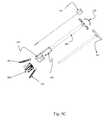
- FIGS. 2A-Cillustrate the Lumbar intervertebral non-expandable screw box with two BDFT screws (Embodiment II) in lateral ( FIG. 2A ), oblique ( FIG. 2B ), and superior perspective ( FIG. 2C ) views.
- FIG. 3illustrates a superior oblique perspective view of left and right lumbar intervertebral non-expandable screw boxes with one BDFT screw (Embodiment III).
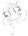
- FIGS. 4A-Billustrate the horizontal intervertebral zero-profile mini-plate prior to insertion ( FIG. 4A ), and after insertion ( FIG. 4B ) into two non-expandable lumbar intervertebral screw boxes with two BDFT screws.
- FIG. 4Cillustrates two non-expandable lumbar intervertebral screw boxes with two screws within a large circumferential cage for anterior placement into the lumbar spine
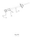
- FIGS. 5A-Cillustrate t positioning tool/screw guide/box expander in oblique perspective ( FIG. 5A ), lateral ( FIG. 5B ), and exploded ( FIG. 5C ) views.
- FIG. 5Dillustrates a superior oblique perspective view of the positioning tool/drill guide/box expander component.
- FIGS. E-Gillustrate the sequential steps (I-III) of the positioning tool/screw guide/box expander assembly. Step I ( FIG. 5E ), step II ( FIG. 5F ), and step III ( FIG. 5G ).
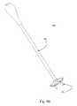
- FIGS. 5H-Iillustrate the positioning tool for impaction and placement of the non-expandable screw box with two transvertebral screws.
- Embodiment Ihas a rectangular positioning handle ( FIG. 5H )
- embodiment IIhas a circular positioning handle ( FIG. 5I )
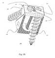
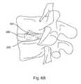
- FIGS. 6A-Billustrate the insertion of expandable Lumbar bi-directional screw box with two BDFT screws into the Lumbar spine in oblique ( FIG. 6A ) and lateral ( FIG. 6B ) views.
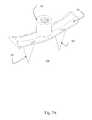
- FIGS. 7A-Billustrate the cervical facet staple (Embodiment I) in lateral ( FIG. 7A ) and oblique ( FIG. 7B ) views.
- FIG. 8A-Cillustrate the cervical facet staple (Embodiment II) in oblique ( FIG. 8A ), superior perspective ( FIG. 8B ) and inferior-oblique ( FIG. 8C ) views.
- FIG. 9Aillustrates the two-pronged cervical facet staple inserter/impactor (Embodiment I).
- FIG. 9Billustrates the two-pronged cervical facet staple inserter/impactor inserted into the staple (Embodiment I).
- FIG. 10Aillustrates the four pronged cervical facet staple impactor (Embodiment II).
- FIG. 10Billustrates the four pronged cervical facet staple impactor inserted into the cervical facet staple (Embodiment II).
- FIG. 10Cillustrates an inferior-oblique perspective view of the four-pronged cervical facet staple impactor (Embodiment II).
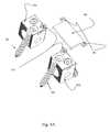
- FIG. 11Aillustrates placement of two-pronged cervical facet staples in a three-dimensional cervical spine.
- FIG. 11Billustrates placement of four-pronged cervical facet staples in a three-dimensional cervical spine.
- FIG. 11Cillustrates modular placement of two and four pronged cervical facet staples in a three-dimensional cervical spine to achieve differing calibrated degrees of flexibility.
- FIGS. 12 A-Billustrate the Lumbar facet joint staple with a calibrated ratcheting mechanism in opened (FIG. A) and closed (FIG. B) positions.
- the above described problemcan be solved in the thoracic and lumbar spine by insertion into the denuded intervertebral disc space multiple embodiments of screw box constructs with BDFT screws.
- FIGS. 1A-Dillustrate three-dimensional views of the Lumbar intervertebral expandable screw box 100 with two BDFT screws 101 , 102 ; one lateral and one medially oriented (Embodiment IA).
- FIG. 1Eillustrates a sagittal-oblique view of the lumbar intervertebral expandable screw box 120 with two lateral oriented BDFT screws 121 , 122 (Embodiment IB).
- the expandable box 100consists of top and bottom triangular sliding bases 103 , 104 ( FIG. 1 -D).
- the superior and inferior segments of the height/depth adjusting screw 105are integrated and connected to the two separate top and bottom triangular bases 103 , 104 , respectively.
- the sliding rails 106 of the top triangular base 103slide up and down the rail inserts 107 on the bottom triangular base 104 ( FIG. 1D ). This action will simultaneously alter the intervertebral height and depth of the screw box 100 allowing individualized custom fitting of the screw box 100 conforming to the dimensions of the disc space.
- Transvertebral screw 101penetrates the top base 103 , and transvertebral screw 102 traverses the bottom base 104 of the screw box 100 .
- the two screws 101 , 102traverse the screw box 100 in opposing directions, bi-directionally (whether they are lateral or medially oriented).
- the external edges of the triangular bases 103 , 104 in contact with vertebral body surfacesinclude ridges 107 . This facilitates the screw box's 100 incorporation into and fusion with the superior and inferior vertebral bodies ( FIGS. 1A-E ).
- Both top and bottom screw box bases 103 , 104are perforated with holes 108 to allow bone placement for fusion.
- the entire construct, furthermore,is hollow to allow bone filling. Hence this device functions as both an intervertebral bone fusion spacer and bi-directional transvertebral screw fusion device.
- FIGS. 2A-Cillustrate three-dimensional views of the Lumbar intervertebral non-expandable screw box 200 with two BDFT screws 201 , 202 (Embodiment II). Screws 201 and 202 perforate and orient in opposing, superior and inferior directions. There are holes 208 and hollow spaces allowing packaging with bone. There are also holes which allow the traversal of screws. The superior and inferior edges include ridges 207 to facilitate integration and fusion with superior and inferior vertebral bodies.
- the expandable screw box 200may include a screw insert 209 to attach a horizontal mini-plate (not shown).
- the self-contained internalized drill guidesare at a 25 degree angle. The screw boxes can be designed with the internalized drill guides with different angles and/or different positions within the box.
- FIG. 3illustrates a three-dimensional view of left and right lumbar intervertebral non-expandable screw boxes 300 a , 300 b with one BDFT screw 301 or 302 (Embodiment III). It is roughly half the width of Embodiments I and II. Screw 301 is inserted into screw box 300 a (left) and screw 302 is inserted into screw box 300 b (right). There are holes 308 and hollow spaces allowing packing of bone to achieve biological fusion. The combined effect of one superior oriented and one inferior oriented screw fuses the superior and inferior vertebral bodies with small constructs. This also enables placement of larger dimension screws compared to embodiments I and II.
- FIGS. 4A and Billustrate three-dimensional views of the horizontal intervertebral zero profile mini-plate 400 with two non-expandable lumbar intervertebral screw boxes 300 a , 300 b housing two BDFT screws 301 , 302 .
- FIG. 4Aillustrates the perforations 401 within the plate 400 through which small plate securing screws 310 will be inserted to connect it to the built-in screw holes of the screw box 300 a , 300 b ( FIG. 4B ).
- the horizontal mini-plate 400 together with the top surfaces of left and right screw boxes 300 a , 300 bprovide a physical barrier between the underlying bone placed beneath it (not illustrated), and the thecal sac and nerve roots above it (not illustrated).
- FIG. 4Cillustrates two screw boxes 300 c , 300 d within a circumferential cage 420 (2 in 1) construct which is designed for anterior placement into the lumbar spine.
- a circumferential cage 420(2 in 1) construct which is designed for anterior placement into the lumbar spine.
- the circumferential cage 420has perforations 401 a for the placement of transvertebral screws (not shown).
- FIGS. 5A-Cillustrate three-dimensional views of the external drill/screw guide-box expander 500 which assists in screw trajectory and box expansion (embodiments IA-B).
- the same instrumentis utilized; however, an expanding Allen key component is not used.
- the key components of this deviceinclude an Allen key 501 , a spring 502 , a handle 503 , a griper 504 and a screw guide 505 .
- the Allen key 501when inserted in the insertion 514 and turned, turns the screw adjuster ( FIG. 5C ) which in turn regulates top and bottom triangular screw box base sliding, and hence box 200 width and depth.
- the griper 504has griper prongs 506 which insert into grooves of the screw guide 505 and the screw box 200 ( FIGS. 5A-D ) thus perfectly aligning them.
- FIG. 5Dillustrates a superior oblique view of the screw guide 505 demonstrating insertions 509 for griper prong 506 , built-in trajectory guides 511 , 512 for insertions of screws 101 and 102 , and the Allen key 501 .
- FIGS. 5E-Gillustrate three-dimensional views of the sequential steps necessary for the external guide assembly.
- FIG. 5Eillustrates the insertion of the Allen key 501 into the handle 503 .
- FIG. 5Fillustrates the insertion of the handle 503 through the spring 502 and griper 504 .
- FIG. 5Gillustrates insertion of the griper 504 into the screw guide 505 .
- FIGS. 5H-Iillustrate three-dimensional views of a positioning tool 500 a for impaction and placement of two transvertebral screws 201 , 202 in the non-expandable screw box 200 .
- the driver assembly 550consists of a screw driver 551 , a flexible shaft 552 and a square recess bit 553 . This facilitates turning the screws 201 , 202 into the bone.
- the flexible shaft 552facilitates the avoidance of spinous processes which might hinder the screw driving if the shaft 552 were straight.
- the positioning tool 500 acan have a rectangular handle, Embodiment I ( FIG. 5H ), or a circular handle, Embodiment II ( FIG. 5I ).
- the positioning tool's 500 a griper handleinserts into the screw guide and the box, which maintains alignment.
- FIG. 6Aillustrates a three-dimensional view of insertion of the construct (Embodiment I) into the lumbar intervertebral disc space.
- FIG. 6Billustrates a three dimensional lateral view of insertion of the construct (Embodiment I) into the disc space with short screws. Placement with longer screws would capture more bone.
- FIGS. 7A and Billustrate three-dimensional views of the two-pronged cervical facet staple 700 (Embodiment I).
- a staple base 701which is contoured to align with the curved surface of the cervical facet joints.
- a superior impactor threaded insert 702There is a superior impactor threaded insert 702 .
- An impactorcan be screwed into this insert 702 and then impacted with a mallet.
- the two spikes 703 , 704perforate the inferior and superior facets of the superior and inferior vertebral bodies hence leading to cervical facet joint fusion.
- the spikescan be designed with ridges and/or fishhooks to facilitate irreversible extraction.
- FIGS. 8A-Cillustrate three-dimensional views of the four-pronged cervical facet staple 800 (Embodiment II). Likewise it has a staple base 805 contoured specifically for the surface of the facet joint. It also has an impactor insert 806 . The insertion of a device with four prongs 801 - 804 instead of two prongs further limits the degrees of motion of the joint hence making the fusion more rigid.
- FIGS. 9 A-Billustrate a three-dimensional view of the two-pronged cervical staple impactor 900 . It has a handle 901 , a stem 902 , and a screw insert 903 which can be screwed into the threaded staple insert.
- the impactorhas two wings 904 which keep the staple base edges in place facilitating staple impaction.
- the handle 901 of the impactor 900is broad in order to allow impaction by a mallet.
- FIGS. 10A-Cillustrate three-dimensional views of the four-pronged cervical staple impactor 1000 (Embodiment II). It has the same features as the two-pronged impactor 900 , except its wings 1004 are broader accommodating the broader staple base.
- the impactor 1000also includes a handle 1001 , a stem 1002 , and an impact screw 1003 .
- FIG. 11Aillustrates a three-dimensional view of placement of the two pronged cervical facet staple 700 into a cervical spine model having vertebral body 1103 and lamina 1104 .
- One staple 700is perched on the joint 1101 prior to impaction.
- the other staple 700is impacted.
- FIG. 11Billustrates a three-dimensional view of placement of the four pronged cervical facet staple 800 into a cervical spine pre and post impaction.
- FIG. 11Cillustrates the concept of modularity and incremental diminution of movement of the joint by the modular placement of different combinations and permutations of varying numbers of two and four pronged cervical facet staples 700 , 800 .
- each facet jointis fused using a total number of six prongs. One side this is accomplished by using three two pronged staples 700 , and on the other side using one four pronged staple 800 and one two pronged staple 700 .
- FIGS. 12 A-Billustrate a lumbar facet joint staple 1200 in open and closed positions and having staple prongs 1203 .
- This lumbar facet staplehas been thoroughly described in our previous co-pending patent application Ser. No. 11/536,815, filed on Sep. 29, 2006, and Ser. No. 11/208,644, filed on Aug. 23, 2005, the relevant portion of each of which is hereby incorporated by reference hereinafter.
- the new improvement of this deviceincludes a ratchet 1201 .
- the staple 1200can be incrementally closed with increased ratcheting over increasing number of spurs 1202 . This achieves increasing calibrated levels of lumbar facet joint fusion, and conversely diminishing joint flexibility. This new designs further enhances the capacity to achieve flexible fusions in the lumbar spine.
- the posterior lumbar spine implantation of all the screw box 100 , 200 , 300 embodiments, with BDFT screws, and horizontal mini-plate 400can be implanted via previously described posterior lumbar interbody fusion (PLIF) or posterior transforaminal lumbar interbody fusion (TLIF) procedures.
- PLIFposterior lumbar interbody fusion
- TLIFposterior transforaminal lumbar interbody fusion
- the procedurescan be performed open, microscopic, closed tubular or endoscopic. Fluoroscopic guidance can be used with any of these procedures.
- a midline incisionis made for a PLIF procedure, and one or two parallel paramedian incisions or a midline incision is made for the TLIF procedure.
- a unilateral or bilateral facet sparing hemi-laminotomyis created to introduce screw box 100 , 200 , 300 embodiments I-III into the disc space, after it is adequately prepared.
- the far lateral disc spaceis entered and a circumferential discectomy is performed.
- the disc spaceis prepared and the endplates exposed.
- one screw box 100 , 200 , 300 of either embodiments I-IIIis placed on either right, left or both sides.
- another screw box of embodiments 100 , 200 , 300 I-IIIis placed on the contralateral side.
- the external screw guide 505 /box expanderis attached to the screw box ( FIGS. 5A-H ).
- Allen key 501is screwed until the box conforms perfectly to the height and depth of the space.
- a pilot holecan be drilled or an awl can start a pilot hole in the vertebral bodies.
- a transvertebral screwis screwed into the vertebral body via the built-in box screw guides 505 .
- an angled screw drivercan be employed.
- FIGS. 6A and Billustrate the process of insertion and final placement of the construct into the lumbar spine.
- the mini-plates 400can come in different horizontal lengths and widths to accommodate different intra and inter-patient disc space diameters.
- the BDFT screwscan come in different widths, lengths and thread designs.
- the anterior thoracic and lumbar spine implantation of one, two or three screw box constructs 100 , 200 , 300 and BDFT screwscan be performed in a similar manner to the posterior application.
- a horizontal mini-plate 400can be used to cap two or three screw box constructs 100 , 200 , 300 (one placed midline deeply, one placed left and one placed right, forming a triangulation).
- two screw box constructsmay be placed into a circumferential ring for anterior placement.
- Anterior placement of these devicescan be performed into the L4/5 and L5/S1 spaces on the supine anesthetized patient via previously described open microscopic or endoscopic techniques.
- screw box embodiments 100 , 200 , 300 (I-III) or a 2 in I constructcan be placed.
- the screw placementis facilitated by the internal screw guides, and different positioning tools (( FIG. 5 ).
- a right angled screw driver and/or ratchetcould alternatively be employed
- a capping mini-plate 400may be applied if desirable.
- the mechanism of screw placement and mini-plate 400 attachmentare identical to what was described above.
- the posterior placement of screw box constructs 100 , 200 , 300 alone or combined with horizontal mini-plates 400 into the thoracic spinecan be performed via previously described transpedicular approaches; open or endoscopic.
- the anterior placement into the thoracic spinecan be accomplished via a trans-thoracic approach. Once the disc space is exposed via either approach, any combination of the above mention Embodiments (I-III) can be inserted. Engagement of the devices is identical to what was mentioned above.
- cervical facet staple 700 , 800For posterior placement of cervical facet staple 700 , 800 embodiments, after adequate induction of anesthesia the patient is flipped prone and his head and neck secured. A single midline or two para-median incisions are made for unilateral or bilateral or multilevel placement of staples. Ultimately the facet joint is exposed. Alternatively and preferably this can be performed percutaneously under fluoroscopic guidance with intravenous sedation.
- the staple 700 , 800(Embodiments I or II) is loaded into the impactor 900 , 1000 .
- the staple 700 , 800is placed on the two articulating cervical facets, and then impacted into the joint.
- FIGS. 11A-Cillustrates placement of the staples 700 , 800 in the cervical spine.
- the present inventionsmay provide effective and safe techniques that overcome the problems associated with current transpedicular based cervical, thoracic and lumbar fusion technology, and for many degenerative stable and unstable spine disease. These inventions could replace much pedicle screw-based instrumentation in many but not all degenerative spine conditions.
Landscapes
- Health & Medical Sciences (AREA)
- Orthopedic Medicine & Surgery (AREA)
- Life Sciences & Earth Sciences (AREA)
- Biomedical Technology (AREA)
- Engineering & Computer Science (AREA)
- Surgery (AREA)
- Animal Behavior & Ethology (AREA)
- General Health & Medical Sciences (AREA)
- Public Health (AREA)
- Veterinary Medicine (AREA)
- Heart & Thoracic Surgery (AREA)
- Neurology (AREA)
- Medical Informatics (AREA)
- Molecular Biology (AREA)
- Nuclear Medicine, Radiotherapy & Molecular Imaging (AREA)
- Transplantation (AREA)
- Vascular Medicine (AREA)
- Cardiology (AREA)
- Oral & Maxillofacial Surgery (AREA)
- Physical Education & Sports Medicine (AREA)
- Rheumatology (AREA)
- Prostheses (AREA)
- Surgical Instruments (AREA)
Abstract
Description
Claims (55)
Priority Applications (6)
| Application Number | Priority Date | Filing Date | Title |
|---|---|---|---|
| US13/210,168US9907674B2 (en) | 2005-04-12 | 2011-08-15 | Bi-directional fixating transvertebral body screws and posterior cervical and lumbar interarticulating joint calibrated stapling devices for spinal fusion |
| US14/063,197US9848993B2 (en) | 2005-04-12 | 2013-10-25 | Zero-profile expandable intervertebral spacer devices for distraction and spinal fusion and a universal tool for their placement and expansion |
| US15/820,232US10016284B2 (en) | 2005-04-12 | 2017-11-21 | Zero-profile expandable intervertebral spacer devices for distraction and spinal fusion and a universal tool for their placement and expansion |
| US16/025,667US10426633B2 (en) | 2005-04-12 | 2018-07-02 | Zero-profile expandable intervertebral spacer devices for distraction and spinal fusion and a universal tool for their placement and expansion |
| US16/587,993US11096797B2 (en) | 2005-04-12 | 2019-09-30 | Zero-profile expandable intervertebral spacer devices for distraction and spinal fusion and a universal tool for their placement and expansion |
| US17/408,068US12011367B2 (en) | 2005-04-12 | 2021-08-20 | Expandable intervertebral device |
Applications Claiming Priority (7)
| Application Number | Priority Date | Filing Date | Title |
|---|---|---|---|
| US67023105P | 2005-04-12 | 2005-04-12 | |
| US11/208,644US7704279B2 (en) | 2005-04-12 | 2005-08-23 | Bi-directional fixating transvertebral body screws, zero-profile horizontal intervertebral miniplates, expansile intervertebral body fusion devices, and posterior motion-calibrating interarticulating joint stapling device for spinal fusion |
| US11/536,815US7846188B2 (en) | 2005-04-12 | 2006-09-29 | Bi-directional fixating transvertebral body screws, zero-profile horizontal intervertebral miniplates, total intervertebral body fusion devices, and posterior motion-calibrating interarticulating joint stapling device for spinal fusion |
| US11/842,855US7942903B2 (en) | 2005-04-12 | 2007-08-21 | Bi-directional fixating transvertebral body screws and posterior cervical and lumbar interarticulating joint calibrated stapling devices for spinal fusion |
| US13/084,543US8353913B2 (en) | 2005-04-12 | 2011-04-11 | Bi-directional fixating transvertebral body screws and posterior cervical and lumbar interarticulating joint calibrated stapling devices for spinal fusion |
| US13/108,982US9005293B2 (en) | 2005-04-12 | 2011-05-16 | Bi-directional fixating transvertebral body screws and posterior cervical and lumbar interarticulating joint calibrated stapling devices for spinal fusion |
| US13/210,168US9907674B2 (en) | 2005-04-12 | 2011-08-15 | Bi-directional fixating transvertebral body screws and posterior cervical and lumbar interarticulating joint calibrated stapling devices for spinal fusion |
Related Parent Applications (3)
| Application Number | Title | Priority Date | Filing Date |
|---|---|---|---|
| US13/084,543ContinuationUS8353913B2 (en) | 2005-04-12 | 2011-04-11 | Bi-directional fixating transvertebral body screws and posterior cervical and lumbar interarticulating joint calibrated stapling devices for spinal fusion |
| US13/108,982ContinuationUS9005293B2 (en) | 2005-04-12 | 2011-05-16 | Bi-directional fixating transvertebral body screws and posterior cervical and lumbar interarticulating joint calibrated stapling devices for spinal fusion |
| US13/741,361Continuation-In-PartUS9301854B2 (en) | 2005-04-12 | 2013-01-14 | Bi-directional fixating transvertebral body screws and posterior cervical and lumbar interarticulating joint calibrated stapling devices for spinal fusion |
Related Child Applications (3)
| Application Number | Title | Priority Date | Filing Date |
|---|---|---|---|
| US11/208,644Continuation-In-PartUS7704279B2 (en) | 2005-04-12 | 2005-08-23 | Bi-directional fixating transvertebral body screws, zero-profile horizontal intervertebral miniplates, expansile intervertebral body fusion devices, and posterior motion-calibrating interarticulating joint stapling device for spinal fusion |
| US13/210,162Continuation-In-PartUS9895238B2 (en) | 2005-04-12 | 2011-08-15 | Bi-directional fixating transvertebral body screws and posterior cervical and lumbar interarticulating joint calibrated stapling devices for spinal fusion |
| US14/063,197Continuation-In-PartUS9848993B2 (en) | 2005-04-12 | 2013-10-25 | Zero-profile expandable intervertebral spacer devices for distraction and spinal fusion and a universal tool for their placement and expansion |
Publications (2)
| Publication Number | Publication Date |
|---|---|
| US20130018469A1 US20130018469A1 (en) | 2013-01-17 |
| US9907674B2true US9907674B2 (en) | 2018-03-06 |
Family
ID=39269006
Family Applications (15)
| Application Number | Title | Priority Date | Filing Date |
|---|---|---|---|
| US11/842,855Active2028-01-23US7942903B2 (en) | 2005-04-12 | 2007-08-21 | Bi-directional fixating transvertebral body screws and posterior cervical and lumbar interarticulating joint calibrated stapling devices for spinal fusion |
| US13/084,543Expired - LifetimeUS8353913B2 (en) | 2005-04-12 | 2011-04-11 | Bi-directional fixating transvertebral body screws and posterior cervical and lumbar interarticulating joint calibrated stapling devices for spinal fusion |
| US13/108,982Active2028-04-11US9005293B2 (en) | 2005-04-12 | 2011-05-16 | Bi-directional fixating transvertebral body screws and posterior cervical and lumbar interarticulating joint calibrated stapling devices for spinal fusion |
| US13/210,157Active2026-05-28US9889022B2 (en) | 2005-04-12 | 2011-08-15 | Bi-directional fixating transvertebral body screws and posterior cervical and lumbar interarticulating joint calibrated stapling devices for spinal fusion |
| US13/210,168Active2026-07-18US9907674B2 (en) | 2005-04-12 | 2011-08-15 | Bi-directional fixating transvertebral body screws and posterior cervical and lumbar interarticulating joint calibrated stapling devices for spinal fusion |
| US13/210,162Active2026-06-02US9895238B2 (en) | 2005-04-12 | 2011-08-15 | Bi-directional fixating transvertebral body screws and posterior cervical and lumbar interarticulating joint calibrated stapling devices for spinal fusion |
| US13/210,150Active2026-02-12US9867719B2 (en) | 2005-04-12 | 2011-08-15 | Bi-directional fixating transvertebral body screws and posterior cervical and lumbar interarticulating joint calibrated stapling devices for spinal fusion |
| US13/741,361Active2025-11-22US9301854B2 (en) | 2005-04-12 | 2013-01-14 | Bi-directional fixating transvertebral body screws and posterior cervical and lumbar interarticulating joint calibrated stapling devices for spinal fusion |
| US15/054,926Expired - LifetimeUS9848998B2 (en) | 2005-04-12 | 2016-02-26 | Bi-directional fixating transvertebral body screws and posterior cervical and lumbar interarticulating joint calibrated stapling devices for spinal fusion |
| US15/894,471Expired - LifetimeUS10390969B2 (en) | 2005-04-12 | 2018-02-12 | Bi-directional fixating transvertebral body screws and posterior cervical and lumbar interarticulating joint calibrated stapling devices for spinal fusion |
| US15/944,117Expired - LifetimeUS10537442B2 (en) | 2005-04-12 | 2018-04-03 | Bidirectional fixating intervertebral implant system |
| US15/976,340Expired - LifetimeUS10307268B2 (en) | 2005-04-12 | 2018-05-10 | Intervertebral expandable implant |
| US16/018,354Expired - LifetimeUS10376386B2 (en) | 2005-04-12 | 2018-06-26 | Spinal staple |
| US16/280,684Expired - LifetimeUS10478319B2 (en) | 2005-04-12 | 2019-02-20 | System with tool assembly and expandable spinal implant |
| US16/744,755Active2026-03-17US11376136B2 (en) | 2005-04-12 | 2020-01-16 | Expandable spinal implant and tool system |
Family Applications Before (4)
| Application Number | Title | Priority Date | Filing Date |
|---|---|---|---|
| US11/842,855Active2028-01-23US7942903B2 (en) | 2005-04-12 | 2007-08-21 | Bi-directional fixating transvertebral body screws and posterior cervical and lumbar interarticulating joint calibrated stapling devices for spinal fusion |
| US13/084,543Expired - LifetimeUS8353913B2 (en) | 2005-04-12 | 2011-04-11 | Bi-directional fixating transvertebral body screws and posterior cervical and lumbar interarticulating joint calibrated stapling devices for spinal fusion |
| US13/108,982Active2028-04-11US9005293B2 (en) | 2005-04-12 | 2011-05-16 | Bi-directional fixating transvertebral body screws and posterior cervical and lumbar interarticulating joint calibrated stapling devices for spinal fusion |
| US13/210,157Active2026-05-28US9889022B2 (en) | 2005-04-12 | 2011-08-15 | Bi-directional fixating transvertebral body screws and posterior cervical and lumbar interarticulating joint calibrated stapling devices for spinal fusion |
Family Applications After (10)
| Application Number | Title | Priority Date | Filing Date |
|---|---|---|---|
| US13/210,162Active2026-06-02US9895238B2 (en) | 2005-04-12 | 2011-08-15 | Bi-directional fixating transvertebral body screws and posterior cervical and lumbar interarticulating joint calibrated stapling devices for spinal fusion |
| US13/210,150Active2026-02-12US9867719B2 (en) | 2005-04-12 | 2011-08-15 | Bi-directional fixating transvertebral body screws and posterior cervical and lumbar interarticulating joint calibrated stapling devices for spinal fusion |
| US13/741,361Active2025-11-22US9301854B2 (en) | 2005-04-12 | 2013-01-14 | Bi-directional fixating transvertebral body screws and posterior cervical and lumbar interarticulating joint calibrated stapling devices for spinal fusion |
| US15/054,926Expired - LifetimeUS9848998B2 (en) | 2005-04-12 | 2016-02-26 | Bi-directional fixating transvertebral body screws and posterior cervical and lumbar interarticulating joint calibrated stapling devices for spinal fusion |
| US15/894,471Expired - LifetimeUS10390969B2 (en) | 2005-04-12 | 2018-02-12 | Bi-directional fixating transvertebral body screws and posterior cervical and lumbar interarticulating joint calibrated stapling devices for spinal fusion |
| US15/944,117Expired - LifetimeUS10537442B2 (en) | 2005-04-12 | 2018-04-03 | Bidirectional fixating intervertebral implant system |
| US15/976,340Expired - LifetimeUS10307268B2 (en) | 2005-04-12 | 2018-05-10 | Intervertebral expandable implant |
| US16/018,354Expired - LifetimeUS10376386B2 (en) | 2005-04-12 | 2018-06-26 | Spinal staple |
| US16/280,684Expired - LifetimeUS10478319B2 (en) | 2005-04-12 | 2019-02-20 | System with tool assembly and expandable spinal implant |
| US16/744,755Active2026-03-17US11376136B2 (en) | 2005-04-12 | 2020-01-16 | Expandable spinal implant and tool system |
Country Status (2)
| Country | Link |
|---|---|
| US (15) | US7942903B2 (en) |
| WO (1) | WO2008042303A2 (en) |
Cited By (12)
| Publication number | Priority date | Publication date | Assignee | Title |
|---|---|---|---|---|
| US20180168824A1 (en)* | 2005-04-12 | 2018-06-21 | Nathan C. Moskowitz | Bi-directional fixating transvertebral body screws and posterior cervical and lumbar interarticulating joint calibrated stapling devices for spinal fusion |
| US11554020B2 (en) | 2020-09-08 | 2023-01-17 | Life Spine, Inc. | Expandable implant with pivoting control assembly |
| US11602440B2 (en) | 2020-06-25 | 2023-03-14 | Life Spine, Inc. | Expandable implant assembly |
| US11602439B2 (en) | 2020-04-16 | 2023-03-14 | Life Spine, Inc. | Expandable implant assembly |
| US11857432B2 (en) | 2020-04-13 | 2024-01-02 | Life Spine, Inc. | Expandable implant assembly |
| US11896494B2 (en) | 2017-07-10 | 2024-02-13 | Life Spine, Inc. | Expandable implant assembly |
| US11903849B2 (en) | 2005-04-12 | 2024-02-20 | Moskowitz Family Llc | Intervertebral implant and tool assembly |
| US11986398B2 (en) | 2013-03-13 | 2024-05-21 | Life Spine, Inc. | Expandable implant assembly |
| US12042395B2 (en) | 2019-06-11 | 2024-07-23 | Life Spine, Inc. | Expandable implant assembly |
| US12138179B2 (en) | 2019-06-10 | 2024-11-12 | Life Spine, Inc. | Expandable implant assembly with compression features |
| US12193948B2 (en) | 2013-03-13 | 2025-01-14 | Life Spine, Inc. | Expandable implant assembly |
| US12336917B2 (en) | 2020-05-15 | 2025-06-24 | Life Spine, Inc. | Steerable implant assembly |
Families Citing this family (292)
| Publication number | Priority date | Publication date | Assignee | Title |
|---|---|---|---|---|
| US6206922B1 (en)* | 1995-03-27 | 2001-03-27 | Sdgi Holdings, Inc. | Methods and instruments for interbody fusion |
| FR2897259B1 (en) | 2006-02-15 | 2008-05-09 | Ldr Medical Soc Par Actions Si | INTERSOMATIC TRANSFORAMINAL CAGE WITH INTERBREBAL FUSION GRAFT AND CAGE IMPLANTATION INSTRUMENT |
| FR2824261B1 (en) | 2001-05-04 | 2004-05-28 | Ldr Medical | INTERVERTEBRAL DISC PROSTHESIS AND IMPLEMENTATION METHOD AND TOOLS |
| FR2827156B1 (en) | 2001-07-13 | 2003-11-14 | Ldr Medical | VERTEBRAL CAGE DEVICE WITH MODULAR FASTENING |
| AR038680A1 (en) | 2002-02-19 | 2005-01-26 | Synthes Ag | INTERVERTEBRAL IMPLANT |
| US6793678B2 (en) | 2002-06-27 | 2004-09-21 | Depuy Acromed, Inc. | Prosthetic intervertebral motion disc having dampening |
| FR2846550B1 (en) | 2002-11-05 | 2006-01-13 | Ldr Medical | INTERVERTEBRAL DISC PROSTHESIS |
| CA2515247C (en) | 2003-02-06 | 2010-10-05 | Synthes (U.S.A.) | Intervertebral implant |
| AU2004212942A1 (en) | 2003-02-14 | 2004-09-02 | Depuy Spine, Inc. | In-situ formed intervertebral fusion device |
| US20040267367A1 (en) | 2003-06-30 | 2004-12-30 | Depuy Acromed, Inc | Intervertebral implant with conformable endplate |
| FR2865629B1 (en) | 2004-02-04 | 2007-01-26 | Ldr Medical | INTERVERTEBRAL DISC PROSTHESIS |
| EP2113227B1 (en) | 2004-02-04 | 2015-07-29 | LDR Medical | Intervertebral disc prosthesis |
| EP1713408B1 (en) | 2004-02-09 | 2010-09-15 | DePuy Spine, Inc. | Systems for spinal surgery |
| US8636802B2 (en) | 2004-03-06 | 2014-01-28 | DePuy Synthes Products, LLC | Dynamized interspinal implant |
| FR2869528B1 (en) | 2004-04-28 | 2007-02-02 | Ldr Medical | INTERVERTEBRAL DISC PROSTHESIS |
| US7955357B2 (en) | 2004-07-02 | 2011-06-07 | Ellipse Technologies, Inc. | Expandable rod system to treat scoliosis and method of using the same |
| US8597360B2 (en) | 2004-11-03 | 2013-12-03 | Neuropro Technologies, Inc. | Bone fusion device |
| WO2006058221A2 (en) | 2004-11-24 | 2006-06-01 | Abdou Samy M | Devices and methods for inter-vertebral orthopedic device placement |
| FR2879436B1 (en) | 2004-12-22 | 2007-03-09 | Ldr Medical | INTERVERTEBRAL DISC PROSTHESIS |
| US8696707B2 (en) | 2005-03-08 | 2014-04-15 | Zyga Technology, Inc. | Facet joint stabilization |
| US7704279B2 (en) | 2005-04-12 | 2010-04-27 | Moskowitz Mosheh T | Bi-directional fixating transvertebral body screws, zero-profile horizontal intervertebral miniplates, expansile intervertebral body fusion devices, and posterior motion-calibrating interarticulating joint stapling device for spinal fusion |
| US9532821B2 (en) | 2005-04-12 | 2017-01-03 | Nathan C. Moskowitz | Bi-directional fixating/locking transvertebral body screw/intervertebral cage stand-alone constructs with vertical hemi-bracket screw locking mechanism |
| US7972363B2 (en) | 2005-04-12 | 2011-07-05 | Moskowitz Ahmnon D | Bi-directional fixating/locking transvertebral body screw/intervertebral cage stand-alone constructs and posterior cervical and lumbar interarticulating joint stapling guns and devices for spinal fusion |
| US9848993B2 (en) | 2005-04-12 | 2017-12-26 | Nathan C. Moskowitz | Zero-profile expandable intervertebral spacer devices for distraction and spinal fusion and a universal tool for their placement and expansion |
| US9744052B2 (en) | 2005-04-12 | 2017-08-29 | Nathan C. Moskowitz | Bi-directional fixating/locking transvertebral body screw/intervertebral cage stand-alone constructs |
| US7846188B2 (en) | 2005-04-12 | 2010-12-07 | Moskowitz Nathan C | Bi-directional fixating transvertebral body screws, zero-profile horizontal intervertebral miniplates, total intervertebral body fusion devices, and posterior motion-calibrating interarticulating joint stapling device for spinal fusion |
| US9814601B2 (en) | 2005-04-12 | 2017-11-14 | Nathan C. Moskowitz | Bi-directional fixating/locking transvertebral body screw/intervertebral cage stand-alone constructs |
| EP1879527A4 (en)* | 2005-05-02 | 2009-08-26 | Kinetic Spine Technologies Inc | Artificial vertebral body |
| US8092528B2 (en) | 2005-05-27 | 2012-01-10 | Depuy Spine, Inc. | Intervertebral ligament having a helical bone fastener |
| FR2891135B1 (en) | 2005-09-23 | 2008-09-12 | Ldr Medical Sarl | INTERVERTEBRAL DISC PROSTHESIS |
| FR2893838B1 (en) | 2005-11-30 | 2008-08-08 | Ldr Medical Soc Par Actions Si | PROSTHESIS OF INTERVERTEBRAL DISC AND INSTRUMENTATION OF INSERTION OF THE PROSTHESIS BETWEEN VERTEBRATES |
| US20070162132A1 (en) | 2005-12-23 | 2007-07-12 | Dominique Messerli | Flexible elongated chain implant and method of supporting body tissue with same |
| EP1988855A2 (en) | 2006-02-27 | 2008-11-12 | Synthes GmbH | Intervertebral implant with fixation geometry |
| US7854765B2 (en) | 2006-04-20 | 2010-12-21 | Moskowitz Mosheh T | Electronically controlled artificial intervertebral disc with motor assisted actuation systems |
| US8034110B2 (en) | 2006-07-31 | 2011-10-11 | Depuy Spine, Inc. | Spinal fusion implant |
| US9526525B2 (en) | 2006-08-22 | 2016-12-27 | Neuropro Technologies, Inc. | Percutaneous system for dynamic spinal stabilization |
| US7862502B2 (en) | 2006-10-20 | 2011-01-04 | Ellipse Technologies, Inc. | Method and apparatus for adjusting a gastrointestinal restriction device |
| WO2008070863A2 (en) | 2006-12-07 | 2008-06-12 | Interventional Spine, Inc. | Intervertebral implant |
| US9039768B2 (en) | 2006-12-22 | 2015-05-26 | Medos International Sarl | Composite vertebral spacers and instrument |
| US20080161929A1 (en) | 2006-12-29 | 2008-07-03 | Mccormack Bruce | Cervical distraction device |
| US8465546B2 (en) | 2007-02-16 | 2013-06-18 | Ldr Medical | Intervertebral disc prosthesis insertion assemblies |
| US8273124B2 (en) | 2007-05-17 | 2012-09-25 | Depuy Spine, Inc. | Self-distracting cage |
| FR2916956B1 (en) | 2007-06-08 | 2012-12-14 | Ldr Medical | INTERSOMATIC CAGE, INTERVERTEBRAL PROSTHESIS, ANCHORING DEVICE AND IMPLANTATION INSTRUMENTATION |
| US8900307B2 (en) | 2007-06-26 | 2014-12-02 | DePuy Synthes Products, LLC | Highly lordosed fusion cage |
| US20240189114A1 (en)* | 2007-08-21 | 2024-06-13 | Moskowitz Family Llc | Intervertebral implant and tool assembly |
| US8343189B2 (en)* | 2007-09-25 | 2013-01-01 | Zyga Technology, Inc. | Method and apparatus for facet joint stabilization |
| US20090088789A1 (en) | 2007-09-28 | 2009-04-02 | O'neil Michael J | Balloon With Shape Control For Spinal Procedures |
| JP2011502708A (en) | 2007-11-16 | 2011-01-27 | ジンテス ゲゼルシャフト ミット ベシュレンクテル ハフツング | Low profile intervertebral implant |
| WO2009089367A2 (en) | 2008-01-09 | 2009-07-16 | Providence Medical Technology, Inc. | Methods and apparatus for accessing and treating the facet joint |
| EP2237748B1 (en) | 2008-01-17 | 2012-09-05 | Synthes GmbH | An expandable intervertebral implant |
| US8088163B1 (en) | 2008-02-06 | 2012-01-03 | Kleiner Jeffrey B | Tools and methods for spinal fusion |
| US11202707B2 (en) | 2008-03-25 | 2021-12-21 | Nuvasive Specialized Orthopedics, Inc. | Adjustable implant system |
| US20090248092A1 (en) | 2008-03-26 | 2009-10-01 | Jonathan Bellas | Posterior Intervertebral Disc Inserter and Expansion Techniques |
| US8936641B2 (en) | 2008-04-05 | 2015-01-20 | DePuy Synthes Products, LLC | Expandable intervertebral implant |
| US20210378834A1 (en) | 2008-05-22 | 2021-12-09 | Spinal Surgical Strategies, Inc., A Nevada Corporation D/B/A Kleiner Device Labs | Spinal fusion cage system with inserter |
| US9333086B2 (en) | 2008-06-06 | 2016-05-10 | Providence Medical Technology, Inc. | Spinal facet cage implant |
| CA2725811A1 (en) | 2008-06-06 | 2009-12-10 | Providence Medical Technology, Inc. | Facet joint implants and delivery tools |
| EP2361046B1 (en) | 2008-06-06 | 2019-04-24 | Providence Medical Technology, Inc. | Cervical distraction/implant delivery device |
| US8361152B2 (en) | 2008-06-06 | 2013-01-29 | Providence Medical Technology, Inc. | Facet joint implants and delivery tools |
| US11224521B2 (en) | 2008-06-06 | 2022-01-18 | Providence Medical Technology, Inc. | Cervical distraction/implant delivery device |
| US8267966B2 (en) | 2008-06-06 | 2012-09-18 | Providence Medical Technology, Inc. | Facet joint implants and delivery tools |
| US9381049B2 (en)* | 2008-06-06 | 2016-07-05 | Providence Medical Technology, Inc. | Composite spinal facet implant with textured surfaces |
| USD853560S1 (en) | 2008-10-09 | 2019-07-09 | Nuvasive, Inc. | Spinal implant insertion device |
| CN102256570B (en)* | 2008-11-07 | 2015-09-02 | 斯恩蒂斯有限公司 | Spacer and connecting plate assembly between vertebral bodies |
| US8382756B2 (en) | 2008-11-10 | 2013-02-26 | Ellipse Technologies, Inc. | External adjustment device for distraction device |
| US9717403B2 (en) | 2008-12-05 | 2017-08-01 | Jeffrey B. Kleiner | Method and apparatus for performing retro peritoneal dissection |
| US8864654B2 (en) | 2010-04-20 | 2014-10-21 | Jeffrey B. Kleiner | Method and apparatus for performing retro peritoneal dissection |
| US8366748B2 (en) | 2008-12-05 | 2013-02-05 | Kleiner Jeffrey | Apparatus and method of spinal implant and fusion |
| FR2941365B1 (en)* | 2009-01-27 | 2011-03-18 | Acmel Ind | TOOL FOR IMPLANTING AND FIXING AN INTERVERTEBRAL CAGE |
| USD656610S1 (en) | 2009-02-06 | 2012-03-27 | Kleiner Jeffrey B | Spinal distraction instrument |
| US9247943B1 (en) | 2009-02-06 | 2016-02-02 | Kleiner Intellectual Property, Llc | Devices and methods for preparing an intervertebral workspace |
| US20100241231A1 (en)* | 2009-02-20 | 2010-09-23 | Marino James F | Intervertebral fixation device |
| US9526620B2 (en)* | 2009-03-30 | 2016-12-27 | DePuy Synthes Products, Inc. | Zero profile spinal fusion cage |
| FR2944692B1 (en)* | 2009-04-27 | 2011-04-15 | Medicrea International | MATERIAL OF VERTEBRAL OSTEOSYNTHESIS |
| US9622792B2 (en) | 2009-04-29 | 2017-04-18 | Nuvasive Specialized Orthopedics, Inc. | Interspinous process device and method |
| KR101687435B1 (en) | 2009-07-06 | 2016-12-19 | 신세스 게엠바하 | Expandable fixation assemblies |
| US9095444B2 (en) | 2009-07-24 | 2015-08-04 | Warsaw Orthopedic, Inc. | Implant with an interference fit fastener |
| CN105326585B (en) | 2009-09-17 | 2018-12-11 | Ldr控股公司 | Intervertebral implant with extensible bone anchoring element |
| USD750249S1 (en) | 2014-10-20 | 2016-02-23 | Spinal Surgical Strategies, Llc | Expandable fusion cage |
| US20170238984A1 (en) | 2009-09-18 | 2017-08-24 | Spinal Surgical Strategies, Llc | Bone graft delivery device with positioning handle |
| US8685031B2 (en) | 2009-09-18 | 2014-04-01 | Spinal Surgical Strategies, Llc | Bone graft delivery system |
| US9186193B2 (en) | 2009-09-18 | 2015-11-17 | Spinal Surgical Strategies, Llc | Fusion cage with combined biological delivery system |
| US8906028B2 (en) | 2009-09-18 | 2014-12-09 | Spinal Surgical Strategies, Llc | Bone graft delivery device and method of using the same |
| US9173694B2 (en) | 2009-09-18 | 2015-11-03 | Spinal Surgical Strategies, Llc | Fusion cage with combined biological delivery system |
| US10973656B2 (en) | 2009-09-18 | 2021-04-13 | Spinal Surgical Strategies, Inc. | Bone graft delivery system and method for using same |
| US9629729B2 (en) | 2009-09-18 | 2017-04-25 | Spinal Surgical Strategies, Llc | Biological delivery system with adaptable fusion cage interface |
| USD723682S1 (en) | 2013-05-03 | 2015-03-03 | Spinal Surgical Strategies, Llc | Bone graft delivery tool |
| US10245159B1 (en) | 2009-09-18 | 2019-04-02 | Spinal Surgical Strategies, Llc | Bone graft delivery system and method for using same |
| US9060877B2 (en) | 2009-09-18 | 2015-06-23 | Spinal Surgical Strategies, Llc | Fusion cage with combined biological delivery system |
| PL215752B1 (en)* | 2009-09-28 | 2014-01-31 | Lfc Spolka Z Ograniczona Odpowiedzialnoscia | Equipment for surgical vertebra movement |
| US20140163682A1 (en)* | 2012-12-11 | 2014-06-12 | Expandable Vertebral Implant | Expandable Vertebral Implant |
| US20110106157A1 (en)* | 2009-10-30 | 2011-05-05 | Warsaw Orthropedic, Inc. | Self-Locking Interference Bone Screw for use with Spinal Implant |
| US9028553B2 (en) | 2009-11-05 | 2015-05-12 | DePuy Synthes Products, Inc. | Self-pivoting spinal implant and associated instrumentation |
| EP2496160B1 (en) | 2009-11-06 | 2017-08-23 | Mark Crawford | Spinal surgery apparatus and method |
| US8979927B2 (en)* | 2009-11-18 | 2015-03-17 | Innovasis, Inc. | Spinal implant with staples |
| BR112012012498B1 (en)* | 2009-11-24 | 2020-09-24 | Spine21 Ltd. | SPINAL IMPLANT |
| US9901455B2 (en) | 2009-11-25 | 2018-02-27 | Nathan C. Moskowitz | Total artificial spino-laminar prosthetic replacement |
| US9168138B2 (en) | 2009-12-09 | 2015-10-27 | DePuy Synthes Products, Inc. | Aspirating implants and method of bony regeneration |
| US9393129B2 (en) | 2009-12-10 | 2016-07-19 | DePuy Synthes Products, Inc. | Bellows-like expandable interbody fusion cage |
| WO2011080535A1 (en) | 2009-12-31 | 2011-07-07 | Lrd Medical | Anchoring device, intervertebral implant and implantation instrument |
| US8795366B2 (en)* | 2010-01-11 | 2014-08-05 | Innova Spinal Technologies, Llc | Expandable intervertebral implant and associated surgical method |
| US9381045B2 (en) | 2010-01-13 | 2016-07-05 | Jcbd, Llc | Sacroiliac joint implant and sacroiliac joint instrument for fusing a sacroiliac joint |
| CA3002234C (en) | 2010-01-13 | 2020-07-28 | Jcbd, Llc | Sacroiliac joint fixation fusion system |
| US9333090B2 (en) | 2010-01-13 | 2016-05-10 | Jcbd, Llc | Systems for and methods of fusing a sacroiliac joint |
| WO2014015309A1 (en) | 2012-07-20 | 2014-01-23 | Jcbd, Llc | Orthopedic anchoring system and methods |
| US9421109B2 (en)* | 2010-01-13 | 2016-08-23 | Jcbd, Llc | Systems and methods of fusing a sacroiliac joint |
| EP2547292B1 (en) | 2010-03-16 | 2019-04-24 | Pinnacle Spine Group, LLC | Ntervertebral implants and graft delivery systems |
| US9233006B2 (en) | 2010-06-15 | 2016-01-12 | Zyga Technology, Inc. | Systems and methods for facet joint treatment |
| US8663293B2 (en) | 2010-06-15 | 2014-03-04 | Zyga Technology, Inc. | Systems and methods for facet joint treatment |
| US8979860B2 (en) | 2010-06-24 | 2015-03-17 | DePuy Synthes Products. LLC | Enhanced cage insertion device |
| US9907560B2 (en) | 2010-06-24 | 2018-03-06 | DePuy Synthes Products, Inc. | Flexible vertebral body shavers |
| US8623091B2 (en) | 2010-06-29 | 2014-01-07 | DePuy Synthes Products, LLC | Distractible intervertebral implant |
| US9248043B2 (en) | 2010-06-30 | 2016-02-02 | Ellipse Technologies, Inc. | External adjustment device for distraction device |
| US8753396B1 (en) | 2010-09-13 | 2014-06-17 | Theken Spine, Llc | Intervertebral implant having back-out prevention feature |
| US20120078373A1 (en) | 2010-09-23 | 2012-03-29 | Thomas Gamache | Stand alone intervertebral fusion device |
| US11529241B2 (en) | 2010-09-23 | 2022-12-20 | DePuy Synthes Products, Inc. | Fusion cage with in-line single piece fixation |
| US20120078372A1 (en) | 2010-09-23 | 2012-03-29 | Thomas Gamache | Novel implant inserter having a laterally-extending dovetail engagement feature |
| US9402732B2 (en) | 2010-10-11 | 2016-08-02 | DePuy Synthes Products, Inc. | Expandable interspinous process spacer implant |
| US9241809B2 (en) | 2010-12-21 | 2016-01-26 | DePuy Synthes Products, Inc. | Intervertebral implants, systems, and methods of use |
| WO2012088238A2 (en) | 2010-12-21 | 2012-06-28 | Synthes Usa, Llc | Intervertebral implants, systems, and methods of use |
| US9308099B2 (en) | 2011-02-14 | 2016-04-12 | Imds Llc | Expandable intervertebral implants and instruments |
| WO2012112396A2 (en) | 2011-02-14 | 2012-08-23 | Ellipse Technologies, Inc. | Device and method for treating fractured bones |
| EP3485851B1 (en) | 2011-03-22 | 2021-08-25 | DePuy Synthes Products, LLC | Universal trial for lateral cages |
| US9999456B2 (en)* | 2011-05-10 | 2018-06-19 | DePuy Synthes Products, Inc. | Bone fracture fixation clamp |
| US10420654B2 (en) | 2011-08-09 | 2019-09-24 | Neuropro Technologies, Inc. | Bone fusion device, system and method |
| WO2013023096A1 (en) | 2011-08-09 | 2013-02-14 | Neuropro Technologies, Inc. | Bone fusion device, system and method |
| US9358123B2 (en) | 2011-08-09 | 2016-06-07 | Neuropro Spinal Jaxx, Inc. | Bone fusion device, apparatus and method |
| US9248028B2 (en) | 2011-09-16 | 2016-02-02 | DePuy Synthes Products, Inc. | Removable, bone-securing cover plate for intervertebral fusion cage |
| US8845728B1 (en)* | 2011-09-23 | 2014-09-30 | Samy Abdou | Spinal fixation devices and methods of use |
| US10743794B2 (en) | 2011-10-04 | 2020-08-18 | Nuvasive Specialized Orthopedics, Inc. | Devices and methods for non-invasive implant length sensing |
| US10016220B2 (en) | 2011-11-01 | 2018-07-10 | Nuvasive Specialized Orthopedics, Inc. | Adjustable magnetic devices and methods of using same |
| US9380932B1 (en) | 2011-11-02 | 2016-07-05 | Pinnacle Spine Group, Llc | Retractor devices for minimally invasive access to the spine |
| US9198764B2 (en)* | 2012-01-31 | 2015-12-01 | Blackstone Medical, Inc. | Intervertebral disc prosthesis and method |
| FR2987256B1 (en) | 2012-02-24 | 2014-08-08 | Ldr Medical | ANCHORING DEVICE FOR INTERVERTEBRAL IMPLANT, INTERVERTEBRAL IMPLANT AND IMPLANTATION INSTRUMENTATION |
| US9271836B2 (en) | 2012-03-06 | 2016-03-01 | DePuy Synthes Products, Inc. | Nubbed plate |
| US9283089B2 (en)* | 2012-04-05 | 2016-03-15 | Warsaw Orthopedic, Inc. | Interbody bone implant device |
| US9532883B2 (en) | 2012-04-13 | 2017-01-03 | Neuropro Technologies, Inc. | Bone fusion device |
| US10159583B2 (en) | 2012-04-13 | 2018-12-25 | Neuropro Technologies, Inc. | Bone fusion device |
| US10709482B2 (en)* | 2012-05-30 | 2020-07-14 | Globus Medical, Inc. | Laminoplasty system |
| US20130325071A1 (en)* | 2012-05-30 | 2013-12-05 | Marcin Niemiec | Aligning Vertebral Bodies |
| EP2877127B1 (en) | 2012-07-26 | 2019-08-21 | Synthes GmbH | Expandable implant |
| US8814912B2 (en) | 2012-07-27 | 2014-08-26 | Zimmer Spine, Inc. | Bone stabilization member with bone screw retention mechanism |
| USD732667S1 (en) | 2012-10-23 | 2015-06-23 | Providence Medical Technology, Inc. | Cage spinal implant |
| USD745156S1 (en) | 2012-10-23 | 2015-12-08 | Providence Medical Technology, Inc. | Spinal implant |
| EP2911616B1 (en) | 2012-10-29 | 2020-10-07 | NuVasive Specialized Orthopedics, Inc. | Adjustable devices for treating arthritis of the knee |
| US10182921B2 (en) | 2012-11-09 | 2019-01-22 | DePuy Synthes Products, Inc. | Interbody device with opening to allow packing graft and other biologics |
| CA2887215A1 (en) | 2012-11-15 | 2014-05-22 | Zyga Technology, Inc. | Systems and methods for facet joint treatment |
| EP2928418A4 (en)* | 2012-12-07 | 2016-12-21 | Providence Medical Tech Inc | Apparatus and method for bone screw deployment |
| US10022245B2 (en) | 2012-12-17 | 2018-07-17 | DePuy Synthes Products, Inc. | Polyaxial articulating instrument |
| US9585765B2 (en)* | 2013-02-14 | 2017-03-07 | Globus Medical, Inc | Devices and methods for correcting vertebral misalignment |
| US9717601B2 (en) | 2013-02-28 | 2017-08-01 | DePuy Synthes Products, Inc. | Expandable intervertebral implant, system, kit and method |
| US9522070B2 (en) | 2013-03-07 | 2016-12-20 | Interventional Spine, Inc. | Intervertebral implant |
| US9456908B2 (en) | 2013-03-12 | 2016-10-04 | Coorstek Medical Llc | Fusion cage |
| WO2014159739A1 (en) | 2013-03-14 | 2014-10-02 | Pinnacle Spine Group, Llc | Interbody implants and graft delivery systems |
| US10433880B2 (en) | 2013-03-15 | 2019-10-08 | Jcbd, Llc | Systems and methods for fusing a sacroiliac joint and anchoring an orthopedic appliance |
| US11311312B2 (en) | 2013-03-15 | 2022-04-26 | Medtronic, Inc. | Subcutaneous delivery tool |
| US9149367B2 (en)* | 2013-03-15 | 2015-10-06 | Globus Medical Inc | Expandable intervertebral implant |
| US9034045B2 (en)* | 2013-03-15 | 2015-05-19 | Globus Medical, Inc | Expandable intervertebral implant |
| US9826986B2 (en) | 2013-07-30 | 2017-11-28 | Jcbd, Llc | Systems for and methods of preparing a sacroiliac joint for fusion |
| US10245087B2 (en) | 2013-03-15 | 2019-04-02 | Jcbd, Llc | Systems and methods for fusing a sacroiliac joint and anchoring an orthopedic appliance |
| CA2906531C (en) | 2013-03-15 | 2020-10-06 | Neuropro Technologies, Inc. | Bodiless bone fusion device, apparatus and method |
| WO2014146018A1 (en) | 2013-03-15 | 2014-09-18 | Jcbd, Llc | Systems and methods for fusing a sacroiliac joint and anchoring an orthopedic appliance |
| US9717539B2 (en) | 2013-07-30 | 2017-08-01 | Jcbd, Llc | Implants, systems, and methods for fusing a sacroiliac joint |
| US9149368B1 (en)* | 2013-03-15 | 2015-10-06 | Wade K. Jensen | Spondylolithesis reduction spinal insert fusion cage and method of reducing spondylolithesis |
| WO2015038196A1 (en)* | 2013-04-24 | 2015-03-19 | Doyle Michael J | Vertebral interbody fusion tool and related methods |
| FR3005569B1 (en) | 2013-05-16 | 2021-09-03 | Ldr Medical | VERTEBRAL IMPLANT, VERTEBRAL IMPLANT FIXATION DEVICE AND IMPLANTATION INSTRUMENTATION |
| US9788971B1 (en) | 2013-05-22 | 2017-10-17 | Nuvasive, Inc. | Expandable fusion implant and related methods |
| US10603187B2 (en) | 2013-07-17 | 2020-03-31 | Aesculap Implant Systems, Llc | Spinal interbody device, system and method |
| US9801734B1 (en) | 2013-08-09 | 2017-10-31 | Nuvasive, Inc. | Lordotic expandable interbody implant |
| US9918848B2 (en)* | 2013-10-07 | 2018-03-20 | Warsaw Orthopedic, Inc. | Spinal implant system and method |
| US10751094B2 (en) | 2013-10-10 | 2020-08-25 | Nuvasive Specialized Orthopedics, Inc. | Adjustable spinal implant |
| US10507119B2 (en) | 2013-12-19 | 2019-12-17 | Aesculap Implant Systems, Llc | Spinal interbody device, system and method |
| AU2014365821B2 (en) | 2013-12-20 | 2019-10-03 | Crossroads Extremity Systems, Llc | Polyaxial locking hole |
| FR3016793B1 (en) | 2014-01-30 | 2021-05-07 | Ldr Medical | ANCHORING DEVICE FOR SPINAL IMPLANT, SPINAL IMPLANT AND IMPLANTATION INSTRUMENTATION |
| CN106456215B (en) | 2014-04-28 | 2020-04-10 | 诺威适骨科专科公司 | External adjustment device for adjusting a medical implant |
| FR3020756B1 (en) | 2014-05-06 | 2022-03-11 | Ldr Medical | VERTEBRAL IMPLANT, VERTEBRAL IMPLANT FIXATION DEVICE AND IMPLANT INSTRUMENTATION |
| US9801546B2 (en) | 2014-05-27 | 2017-10-31 | Jcbd, Llc | Systems for and methods of diagnosing and treating a sacroiliac joint disorder |
| AU2015267055B2 (en) | 2014-05-27 | 2020-04-02 | Christopher U. Phan | Lateral mass fixation implant |
| JP2017520357A (en) | 2014-05-28 | 2017-07-27 | プロビデンス メディカル テクノロジー インコーポレイテッド | Outer mass fixing system |
| US11202626B2 (en) | 2014-07-10 | 2021-12-21 | Crossroads Extremity Systems, Llc | Bone implant with means for multi directional force and means of insertion |
| JP2017529886A (en) | 2014-07-10 | 2017-10-12 | クロスローズ エクストリミティ システムズ リミテッド ライアビリティ カンパニー | Bone implant and means of insertion |
| US10206720B2 (en) | 2014-09-03 | 2019-02-19 | Aesculap Implant Systems, Llc | Fastener, spinal interbody system including same and method |
| US9867718B2 (en) | 2014-10-22 | 2018-01-16 | DePuy Synthes Products, Inc. | Intervertebral implants, systems, and methods of use |
| WO2016065489A1 (en)* | 2014-10-31 | 2016-05-06 | RIOS Medical AG | Implant assembly for the sacroiliac joint |
| ES2908064T3 (en) | 2014-12-26 | 2022-04-27 | Nuvasive Specialized Orthopedics Inc | distraction systems |
| US10238427B2 (en) | 2015-02-19 | 2019-03-26 | Nuvasive Specialized Orthopedics, Inc. | Systems and methods for vertebral adjustment |
| US11426290B2 (en) | 2015-03-06 | 2022-08-30 | DePuy Synthes Products, Inc. | Expandable intervertebral implant, system, kit and method |
| US9615931B2 (en)* | 2015-03-20 | 2017-04-11 | Globus Medical, Inc. | Surgical plate systems |
| US10149710B2 (en)* | 2015-05-11 | 2018-12-11 | Providence Medical Technology, Inc. | Bone screw and implant delivery device |
| CN107847249A (en)* | 2015-05-11 | 2018-03-27 | 普罗维登斯医疗技术公司 | Bone screws and implant delivery apparatus |
| US9820867B2 (en)* | 2015-05-13 | 2017-11-21 | Gil Tepper | Three column spinal fixation implants and associated surgical methods |
| JP6643364B2 (en) | 2015-06-25 | 2020-02-12 | インスティテュート フォー マスキュロスケレタル サイエンス アンド エジュケイション,リミテッド | Interbody fusion device and system for implantation |
| US9913727B2 (en) | 2015-07-02 | 2018-03-13 | Medos International Sarl | Expandable implant |
| WO2017011589A1 (en) | 2015-07-13 | 2017-01-19 | Crossroads Extremity Systems, Llc | Bone plates with dynamic elements |
| JP6949006B2 (en) | 2015-08-25 | 2021-10-13 | アイエムディーエス リミテッド ライアビリティ カンパニー | Expandable facet implant |
| US10034768B2 (en) | 2015-09-02 | 2018-07-31 | Globus Medical, Inc. | Implantable systems, devices and related methods |
| CN108289689A (en) | 2015-10-13 | 2018-07-17 | 普罗维登斯医疗技术公司 | Joint of vertebral column implantation material conveying device and system |
| USD841165S1 (en) | 2015-10-13 | 2019-02-19 | Providence Medical Technology, Inc. | Cervical cage |
| BR112018007347A2 (en) | 2015-10-16 | 2018-10-23 | Nuvasive Specialized Orthopedics, Inc. | adjustable devices for the treatment of knee arthritis |
| USD797290S1 (en) | 2015-10-19 | 2017-09-12 | Spinal Surgical Strategies, Llc | Bone graft delivery tool |
| CN108601611B (en) | 2015-12-10 | 2021-11-02 | 诺威适骨科专科公司 | External adjustment device for stretcher |
| US9895235B2 (en)* | 2015-12-18 | 2018-02-20 | Warsaw Orthopedic, Inc. | Spinal implant system and method |
| US10064741B2 (en) | 2015-12-28 | 2018-09-04 | Titan Spine, Inc. | Clamping device for affixing a stop plate to an interbody implant |
| BR112018015504A2 (en) | 2016-01-28 | 2018-12-18 | Nuvasive Specialized Orthopedics, Inc. | bone transport systems |
| CN105708536B (en)* | 2016-04-26 | 2018-02-23 | 山东省文登整骨医院 | Adjustment height anchor goes out formula Invasive lumbar fusion device |
| TW201806562A (en) | 2016-06-28 | 2018-03-01 | 普羅維登斯醫療科技公司 | Spinal implant and methods of using the same |
| EP3474784A2 (en) | 2016-06-28 | 2019-05-01 | Eit Emerging Implant Technologies GmbH | Expandable and angularly adjustable intervertebral cages with articulating joint |
| US11510788B2 (en) | 2016-06-28 | 2022-11-29 | Eit Emerging Implant Technologies Gmbh | Expandable, angularly adjustable intervertebral cages |
| USD887552S1 (en) | 2016-07-01 | 2020-06-16 | Providence Medical Technology, Inc. | Cervical cage |
| AU2017100001A4 (en)* | 2016-07-26 | 2017-02-23 | Prism Surgical Designs Pty Ltd | A Spinal Fixation and Guidance System |
| US10307265B2 (en) | 2016-10-18 | 2019-06-04 | Institute for Musculoskeletal Science and Education, Ltd. | Implant with deployable blades |
| WO2018081322A1 (en) | 2016-10-25 | 2018-05-03 | Imds Llc | Methods and instrumentation for intervertebral cage expansion |
| US10405992B2 (en) | 2016-10-25 | 2019-09-10 | Institute for Musculoskeletal Science and Education, Ltd. | Spinal fusion implant |
| US10537436B2 (en) | 2016-11-01 | 2020-01-21 | DePuy Synthes Products, Inc. | Curved expandable cage |
| US10888433B2 (en) | 2016-12-14 | 2021-01-12 | DePuy Synthes Products, Inc. | Intervertebral implant inserter and related methods |
| US10111760B2 (en) | 2017-01-18 | 2018-10-30 | Neuropro Technologies, Inc. | Bone fusion system, device and method including a measuring mechanism |
| US10729560B2 (en) | 2017-01-18 | 2020-08-04 | Neuropro Technologies, Inc. | Bone fusion system, device and method including an insertion instrument |
| US10213321B2 (en) | 2017-01-18 | 2019-02-26 | Neuropro Technologies, Inc. | Bone fusion system, device and method including delivery apparatus |
| US10973657B2 (en) | 2017-01-18 | 2021-04-13 | Neuropro Technologies, Inc. | Bone fusion surgical system and method |
| US11864753B2 (en) | 2017-02-06 | 2024-01-09 | Crossroads Extremity Systems, Llc | Implant inserter |
| EP3579762B1 (en) | 2017-02-07 | 2024-06-26 | Crossroads Extremity Systems, LLC | Counter-torque implant |
| CN106943197B (en)* | 2017-04-05 | 2023-06-13 | 闻泰医疗科技(上海)有限公司 | Digital orthopaedics-based minimally invasive spine nail feeding positioning method and device |
| US10398563B2 (en) | 2017-05-08 | 2019-09-03 | Medos International Sarl | Expandable cage |
| US11871968B2 (en) | 2017-05-19 | 2024-01-16 | Providence Medical Technology, Inc. | Spinal fixation access and delivery system |
| RU176259U1 (en)* | 2017-05-31 | 2018-01-12 | Федеральное государственное бюджетное учреждение "Российский ордена Трудового Красного Знамени научно-исследовательский институт травматологии и ортопедии им. Р.Р. Вредена" Министерства здравоохранения Российской Федерации (ФГБУ "РНИИТО им. Р.Р. Вредена" Минздрава России) | Implant for anterior spinal fusion in the lumbar spine |
| US11344424B2 (en) | 2017-06-14 | 2022-05-31 | Medos International Sarl | Expandable intervertebral implant and related methods |
| US10940016B2 (en) | 2017-07-05 | 2021-03-09 | Medos International Sarl | Expandable intervertebral fusion cage |
| US10966843B2 (en) | 2017-07-18 | 2021-04-06 | DePuy Synthes Products, Inc. | Implant inserters and related methods |
| US11045331B2 (en) | 2017-08-14 | 2021-06-29 | DePuy Synthes Products, Inc. | Intervertebral implant inserters and related methods |
| US10492912B2 (en) | 2017-08-18 | 2019-12-03 | Innovasis, Inc. | Interbody spinal fusion implant having locking elements with lateral displacement |
| US10555764B2 (en) | 2017-08-22 | 2020-02-11 | Innovasis, Inc. | Interbody spinal fusion implant having locking elements that outwardly displace for locking |
| US10603055B2 (en) | 2017-09-15 | 2020-03-31 | Jcbd, Llc | Systems for and methods of preparing and fusing a sacroiliac joint |
| US10888643B2 (en)* | 2017-10-07 | 2021-01-12 | Thomas Zink | Negative pressure interbody device, system, and method |
| US10973658B2 (en) | 2017-11-27 | 2021-04-13 | Titan Spine, Inc. | Rotating implant and associated instrumentation |
| US11648128B2 (en) | 2018-01-04 | 2023-05-16 | Providence Medical Technology, Inc. | Facet screw and delivery device |
| US10945859B2 (en) | 2018-01-29 | 2021-03-16 | Amplify Surgical, Inc. | Expanding fusion cages |
| US11135070B2 (en) | 2018-02-14 | 2021-10-05 | Titan Spine, Inc. | Modular adjustable corpectomy cage |
| US11806250B2 (en) | 2018-02-22 | 2023-11-07 | Warsaw Orthopedic, Inc. | Expandable spinal implant system and method of using same |
| CN111655203A (en) | 2018-02-22 | 2020-09-11 | 华沙整形外科股份有限公司 | Expandable spinal implant system and method of use |
| EP3755273B1 (en) | 2018-02-22 | 2025-04-30 | Warsaw Orthopedic, Inc. | Expandable spinal implant system |
| US10932922B2 (en) | 2018-04-20 | 2021-03-02 | JWD Products, LLC | Spinal implant insertion tool |
| US11324609B2 (en) | 2018-04-20 | 2022-05-10 | JWD Products, LLC | Spinal implant insertion tool |
| US11273043B1 (en)* | 2018-06-15 | 2022-03-15 | Advance Research System, Llc | System and method for fusion of sacroiliac joint |
| WO2020061464A1 (en) | 2018-09-21 | 2020-03-26 | Providence Medical Technology, Inc. | Vertebral joint access and decortication devices and methods of using |
| US11446156B2 (en) | 2018-10-25 | 2022-09-20 | Medos International Sarl | Expandable intervertebral implant, inserter instrument, and related methods |
| US11298244B2 (en) | 2019-01-31 | 2022-04-12 | K2M, Inc. | Interbody implants and instrumentation |
| US10426634B1 (en) | 2019-02-05 | 2019-10-01 | King Saud University | Expandable intervertebral cage |
| USD933230S1 (en) | 2019-04-15 | 2021-10-12 | Providence Medical Technology, Inc. | Cervical cage |
| USD955579S1 (en) | 2019-04-26 | 2022-06-21 | Warsaw Orthopedic, Inc. | Surgical implant |
| USD948048S1 (en) | 2019-04-26 | 2022-04-05 | Warsaw Orthopedic, Inc. | Surgical implant |
| USD911525S1 (en) | 2019-06-21 | 2021-02-23 | Providence Medical Technology, Inc. | Spinal cage |
| US11793558B2 (en) | 2019-08-30 | 2023-10-24 | K2M, Inc. | All in one plate holder and spring loaded awl |
| US11534307B2 (en) | 2019-09-16 | 2022-12-27 | K2M, Inc. | 3D printed cervical standalone implant |
| US11278426B2 (en) | 2019-11-26 | 2022-03-22 | GetSet Surgical SA | Spinal surgery assemblies, systems, and methods |
| US11173042B2 (en) | 2019-11-26 | 2021-11-16 | GetSet Surgical SA | Spinal surgery devices, systems, and methods |
| USD925740S1 (en) | 2019-11-26 | 2021-07-20 | GetSet Surgical SA | Spinal fusion cage |
| US11273057B2 (en) | 2019-11-26 | 2022-03-15 | GetSet Surgical SA | Spinal surgery instruments, systems, and methods |
| USD945621S1 (en) | 2020-02-27 | 2022-03-08 | Providence Medical Technology, Inc. | Spinal cage |
| US11426286B2 (en) | 2020-03-06 | 2022-08-30 | Eit Emerging Implant Technologies Gmbh | Expandable intervertebral implant |
| US11259936B2 (en) | 2020-06-15 | 2022-03-01 | Nofusco Corporation | Intravertebral implant system and methods of use |
| US12144742B2 (en) | 2020-06-15 | 2024-11-19 | Foundation Surgical Group, Inc. | Implant system and methods of use |
| US11723778B1 (en) | 2021-09-23 | 2023-08-15 | Nofusco Corporation | Vertebral implant system and methods of use |
| US11883300B2 (en) | 2020-06-15 | 2024-01-30 | Nofusco Corporation | Orthopedic implant system and methods of use |
| US12059183B2 (en) | 2020-07-31 | 2024-08-13 | Crossroads Extremity Systems, Llc | Bone plates with dynamic elements and screws |
| CN114176748B (en)* | 2020-09-15 | 2023-12-08 | 北京纳通医学科技研究院有限公司 | Atlantoaxial joint fusion device |
| CN112244972B (en)* | 2020-11-02 | 2021-08-27 | 西安市第九医院 | Magnesium alloy screw for joint injury of tibia and fibula under ankle joint |
| US11376134B1 (en) | 2020-11-05 | 2022-07-05 | Warsaw Orthopedic, Inc. | Dual expanding spinal implant, system, and method of use |
| US12318308B2 (en) | 2020-11-05 | 2025-06-03 | Warsaw Orthopedic, Inc. | Dual expandable inter-body device |
| US12171439B2 (en) | 2020-11-05 | 2024-12-24 | Warsaw Orthopedic, Inc. | Protected drill |
| US11517443B2 (en) | 2020-11-05 | 2022-12-06 | Warsaw Orthopedic, Inc. | Dual wedge expandable implant, system and method of use |
| US12239544B2 (en) | 2020-11-05 | 2025-03-04 | Warsaw Orthopedic, Inc. | Rhomboid shaped implants |
| US11963881B2 (en) | 2020-11-05 | 2024-04-23 | Warsaw Orthopedic, Inc. | Expandable inter-body device, system, and method |
| US11638653B2 (en) | 2020-11-05 | 2023-05-02 | Warsaw Orthopedic, Inc. | Surgery instruments with a movable handle |
| US11395743B1 (en) | 2021-05-04 | 2022-07-26 | Warsaw Orthopedic, Inc. | Externally driven expandable interbody and related methods |
| US11285014B1 (en) | 2020-11-05 | 2022-03-29 | Warsaw Orthopedic, Inc. | Expandable inter-body device, system, and method |
| US12121453B2 (en) | 2020-11-05 | 2024-10-22 | Warsaw Orthopedic, Inc. | Dual wedge expandable implant with eyelets, system, and method of use |
| US11291554B1 (en) | 2021-05-03 | 2022-04-05 | Medtronic, Inc. | Unibody dual expanding interbody implant |
| US11517363B2 (en) | 2020-11-05 | 2022-12-06 | Warsaw Orthopedic, Inc. | Screw driver and complimentary screws |
| US11833059B2 (en) | 2020-11-05 | 2023-12-05 | Warsaw Orthopedic, Inc. | Expandable inter-body device, expandable plate system, and associated methods |
| USD961081S1 (en) | 2020-11-18 | 2022-08-16 | Crossroads Extremity Systems, Llc | Orthopedic implant |
| EP4251096A1 (en)* | 2020-11-24 | 2023-10-04 | K2M, Inc. | Stationary wedge expandable interbody device |
| US11850160B2 (en) | 2021-03-26 | 2023-12-26 | Medos International Sarl | Expandable lordotic intervertebral fusion cage |
| US11752009B2 (en) | 2021-04-06 | 2023-09-12 | Medos International Sarl | Expandable intervertebral fusion cage |
| US12268614B2 (en) | 2021-06-24 | 2025-04-08 | Warsaw Orthopedic, Inc. | Interbody implant with adjusting shims |
| WO2022271280A1 (en) | 2021-06-24 | 2022-12-29 | Warsaw Orthopedic, Inc. | Expandable interbody implant and corresponding surgical tool |
| US12295865B2 (en) | 2021-06-24 | 2025-05-13 | Warsaw Orthopedic, Inc. | Expandable interbody implant and corresponding inserter |
| US11612499B2 (en) | 2021-06-24 | 2023-03-28 | Warsaw Orthopedic, Inc. | Expandable interbody implant |
| US11730608B2 (en) | 2021-07-13 | 2023-08-22 | Warsaw Orthopedic, Inc. | Monoblock expandable interbody implant |
| US12310855B2 (en) | 2021-09-09 | 2025-05-27 | Warsaw Orthopedic, Inc. | End cap and bone screw for use therewith |
| US11850163B2 (en) | 2022-02-01 | 2023-12-26 | Warsaw Orthopedic, Inc. | Interbody implant with adjusting shims |
| US12090064B2 (en) | 2022-03-01 | 2024-09-17 | Medos International Sarl | Stabilization members for expandable intervertebral implants, and related systems and methods |
| US12324753B2 (en) | 2022-10-05 | 2025-06-10 | Warsaw Orthopedic, Inc. | Interbody trial instrument with screw trajectory indicators |
Citations (146)
| Publication number | Priority date | Publication date | Assignee | Title |
|---|---|---|---|---|
| US2360942A (en) | 1943-01-23 | 1944-10-24 | Jack I Ellerstein | Drill guide |
| US4064881A (en) | 1975-06-06 | 1977-12-27 | Rocket Of London Limited | Surgical clip applicator |
| US4554914A (en) | 1983-10-04 | 1985-11-26 | Kapp John P | Prosthetic vertebral body |
| US4599086A (en) | 1985-06-07 | 1986-07-08 | Doty James R | Spine stabilization device and method |
| US4636217A (en) | 1985-04-23 | 1987-01-13 | Regents Of The University Of Minnesota | Anterior spinal implant |
| US4904261A (en) | 1987-08-06 | 1990-02-27 | A. W. Showell (Surgicraft) Limited | Spinal implants |
| US4960420A (en) | 1988-08-23 | 1990-10-02 | Marlowe Goble E | Channel ligament clamp and system |
| US4997432A (en) | 1988-03-23 | 1991-03-05 | Waldemar Link Gmbh & Co. | Surgical instrument set |
| US5005749A (en) | 1988-07-01 | 1991-04-09 | United States Surgical Corp. | Anastomosis surgical stapling instrument |
| US5062850A (en) | 1990-01-16 | 1991-11-05 | University Of Florida | Axially-fixed vertebral body prosthesis and method of fixation |
| US5123926A (en) | 1991-02-22 | 1992-06-23 | Madhavan Pisharodi | Artificial spinal prosthesis |
| US5290312A (en) | 1991-09-03 | 1994-03-01 | Alphatec | Artificial vertebral body |
| US5405391A (en) | 1993-02-16 | 1995-04-11 | Hednerson; Fraser C. | Fusion stabilization chamber |
| US5413583A (en) | 1992-05-21 | 1995-05-09 | Ethicon, Inc. | Force limiting arrangement for needle holder for endoscopic surgery |
| US5454819A (en) | 1994-03-17 | 1995-10-03 | Nusurg Medical, Inc. | Spring biased laparoscopic surgical needle holder |
| US5514180A (en) | 1994-01-14 | 1996-05-07 | Heggeness; Michael H. | Prosthetic intervertebral devices |
| FR2727003A1 (en) | 1994-11-18 | 1996-05-24 | Euros Sa | Lumbar-sacral vertebrae anterior stabiliser |
| US5660188A (en) | 1991-05-09 | 1997-08-26 | Groiso; Jorge A. | Procedure for applying an elastic clip |
| US5667472A (en) | 1994-03-18 | 1997-09-16 | Clarus Medical Systems, Inc. | Surgical instrument and method for use with a viewing system |
| US5713912A (en) | 1995-08-30 | 1998-02-03 | Stress Management, Inc. | Ligating clip having ramp-shaped vessel clamping members and tool for applying same |
| US5782832A (en) | 1996-10-01 | 1998-07-21 | Surgical Dynamics, Inc. | Spinal fusion implant and method of insertion thereof |
| US5865848A (en) | 1997-09-12 | 1999-02-02 | Artifex, Ltd. | Dynamic intervertebral spacer and method of use |
| US5916224A (en) | 1997-07-09 | 1999-06-29 | The United States Of America As Represented By The Secretary Of The Army | Tendon repair clip implant |
| US5951574A (en) | 1998-10-23 | 1999-09-14 | Ethicon Endo-Surgery, Inc. | Multiple clip applier having a split feeding mechanism |
| US5960522A (en) | 1997-05-21 | 1999-10-05 | Micron Electronics, Inc. | Ribbon cable alligator clamp |
| US5968054A (en) | 1998-02-11 | 1999-10-19 | Yeatts, Ii; Stanley D. | Compressible structure clamping and cutting |
| US5976136A (en) | 1998-05-11 | 1999-11-02 | Electro Biology, Inc. | Method and apparatus for external bone fixator |
| US6126689A (en) | 1998-06-15 | 2000-10-03 | Expanding Concepts, L.L.C. | Collapsible and expandable interbody fusion device |
| US6224602B1 (en) | 1999-10-11 | 2001-05-01 | Interpore Cross International | Bone stabilization plate with a secured-locking mechanism for cervical fixation |
| US6235034B1 (en) | 1997-10-24 | 2001-05-22 | Robert S. Bray | Bone plate and bone screw guide mechanism |
| US6322562B1 (en) | 1998-12-19 | 2001-11-27 | Dietmar Wolter | Fixation system for bones |
| US6342074B1 (en)* | 1999-04-30 | 2002-01-29 | Nathan S. Simpson | Anterior lumbar interbody fusion implant and method for fusing adjacent vertebrae |
| US6368350B1 (en) | 1999-03-11 | 2002-04-09 | Sulzer Spine-Tech Inc. | Intervertebral disc prosthesis and method |
| US6375682B1 (en) | 2001-08-06 | 2002-04-23 | Lewis W. Fleischmann | Collapsible, rotatable and expandable spinal hydraulic prosthetic device |
| US20020068977A1 (en) | 2000-12-05 | 2002-06-06 | Jackson Roger P. | Anterior variable expandable fusion cage |
| US6419704B1 (en) | 1999-10-08 | 2002-07-16 | Bret Ferree | Artificial intervertebral disc replacement methods and apparatus |
| US6432106B1 (en)* | 1999-11-24 | 2002-08-13 | Depuy Acromed, Inc. | Anterior lumbar interbody fusion cage with locking plate |
| US6454807B1 (en) | 2000-11-30 | 2002-09-24 | Roger P. Jackson | Articulated expandable spinal fusion cage system |
| US6458159B1 (en) | 2000-08-15 | 2002-10-01 | John S. Thalgott | Disc prosthesis |
| US20020143338A1 (en) | 2000-02-01 | 2002-10-03 | Hand Innovations, Inc. | Fixation system with multidirectional stabilization pegs |
| US6527804B1 (en) | 1998-12-11 | 2003-03-04 | Dimso (Distribution Medicale Du Sud-Quest) | Intervertebral disk prosthesis |
| US6533818B1 (en) | 2000-04-26 | 2003-03-18 | Pearl Technology Holdings, Llc | Artificial spinal disc |
| US6558423B1 (en)* | 1999-05-05 | 2003-05-06 | Gary K. Michelson | Interbody spinal fusion implants with multi-lock for locking opposed screws |
| US6572653B1 (en) | 2001-12-07 | 2003-06-03 | Rush E. Simonson | Vertebral implant adapted for posterior insertion |
| US6579318B2 (en) | 2000-06-12 | 2003-06-17 | Ortho Development Corporation | Intervertebral spacer |
| US6582468B1 (en) | 1998-12-11 | 2003-06-24 | Spryker Spine | Intervertebral disc prosthesis with compressible body |
| US20030130737A1 (en) | 2000-02-22 | 2003-07-10 | Mcgahan Thomas V. | Anterior impacted bone graft and driver instruments |
| US6613055B2 (en) | 2001-09-21 | 2003-09-02 | Piergiacomi Sud - S.R.L. | Instrument for the implant of a surgical plate for osteosynthesis |
| US6629998B1 (en)* | 2000-08-23 | 2003-10-07 | Chih-I Lin | Intervertebral retrieval device |
| US6641614B1 (en) | 1997-05-01 | 2003-11-04 | Spinal Concepts, Inc. | Multi-variable-height fusion device |
| US6655243B2 (en) | 1996-07-31 | 2003-12-02 | Wayne Anderson | Multiple-in-1 precision hand tool |
| US6716247B2 (en) | 2000-02-04 | 2004-04-06 | Gary K. Michelson | Expandable push-in interbody spinal fusion implant |
| US6719794B2 (en) | 2001-05-03 | 2004-04-13 | Synthes (U.S.A.) | Intervertebral implant for transforaminal posterior lumbar interbody fusion procedure |
| US6723126B1 (en) | 2002-11-01 | 2004-04-20 | Sdgi Holdings, Inc. | Laterally expandable cage |
| US6733532B1 (en) | 1998-12-11 | 2004-05-11 | Stryker Spine | Intervertebral disc prosthesis with improved mechanical behavior |
| US6764491B2 (en) | 1999-10-21 | 2004-07-20 | Sdgi Holdings, Inc. | Devices and techniques for a posterior lateral disc space approach |
| US6770094B2 (en) | 2001-07-05 | 2004-08-03 | Gerald Fehling | Intervertebral disc prosthesis |
| US20040177531A1 (en) | 2003-03-10 | 2004-09-16 | Adidas International Marketing B.V. | Intelligent footwear systems |
| US20040186482A1 (en) | 2003-03-21 | 2004-09-23 | Kolb Eric D. | Modular drill guide |
| US20040186569A1 (en) | 2003-03-20 | 2004-09-23 | Berry Bret M. | Height adjustable vertebral body and disc space replacement devices |
| US20040193272A1 (en) | 2003-03-06 | 2004-09-30 | Rafail Zubok | Instrumentation and methods for use in implanting a cervical disc replacement device |
| WO2004093749A1 (en) | 2003-04-23 | 2004-11-04 | Sepitec Foundation | Spondylodesis device |
| US20040220571A1 (en) | 1998-04-30 | 2004-11-04 | Richard Assaker | Bone plate assembly |
| US6824564B2 (en)* | 1997-04-25 | 2004-11-30 | Stryker France, Sas | Two-part intersomatic implant |
| US20040254644A1 (en) | 2002-10-21 | 2004-12-16 | Taylor Brett Allison | Intervertebral disk prosthesis |
| US20050027362A1 (en) | 1999-02-26 | 2005-02-03 | Williams Lytton A. | Method and apparatus for intervertebral implant anchorage |
| US6852117B2 (en) | 2000-07-12 | 2005-02-08 | Medical Device Group, Inc. | Medical knife assembly and method of using same |
| US20050049590A1 (en) | 2003-03-07 | 2005-03-03 | Neville Alleyne | Spinal implant with securement spikes |
| US6890355B2 (en) | 2001-04-02 | 2005-05-10 | Gary K. Michelson | Artificial contoured spinal fusion implants made of a material other than bone |
| US6904308B2 (en) | 2001-05-20 | 2005-06-07 | Given Imaging Ltd. | Array system and method for locating an in vivo signal source |
| US20050177235A1 (en) | 2004-02-10 | 2005-08-11 | Baynham Bret O. | Spinal fusion device |
| US20050216084A1 (en) | 2003-04-22 | 2005-09-29 | Fleischmann Lewis W | Collapsible, rotatable, and tiltable hydraulic spinal disc prosthesis system with selectable modular components |
| US6955671B2 (en) | 1999-02-18 | 2005-10-18 | Olympus Corporation | Remote surgery support system |
| US6962606B2 (en) | 2000-02-04 | 2005-11-08 | Gary Karlin Michelson | Expandable push-in interbody spinal fusion implant |
| US20050256576A1 (en) | 2004-05-13 | 2005-11-17 | Moskowitz Nathan C | Artificial expansile total lumbar and thoracic discs for posterior placement without supplemental instrumentation and its adaptation for anterior placement of artificial cervical, thoracic and lumbar discs |
| US6972019B2 (en)* | 2001-01-23 | 2005-12-06 | Michelson Gary K | Interbody spinal implant with trailing end adapted to receive bone screws |
| US20050273170A1 (en) | 2004-06-08 | 2005-12-08 | Navarro Richard R | Prosthetic intervertebral spinal disc with integral microprocessor |
| US6974480B2 (en)* | 2001-05-03 | 2005-12-13 | Synthes (Usa) | Intervertebral implant for transforaminal posterior lumbar interbody fusion procedure |
| US20050278026A1 (en) | 2003-08-05 | 2005-12-15 | Gordon Charles R | Expandable intervertebral implant with wedged expansion member |
| US7030904B2 (en) | 1997-10-06 | 2006-04-18 | Micro-Medical Devices, Inc. | Reduced area imaging device incorporated within wireless endoscopic devices |
| US7037258B2 (en) | 1999-09-24 | 2006-05-02 | Karl Storz Imaging, Inc. | Image orientation for endoscopic video displays |
| US20060155285A1 (en) | 2005-01-12 | 2006-07-13 | Kent Anderson | Anchor retaining mechanisms for bone plates |
| US7077864B2 (en) | 2002-02-12 | 2006-07-18 | Cross Medical Products, Inc. | Vertebral interbody cage with translatable locking screw |
| US7097615B2 (en) | 2001-10-05 | 2006-08-29 | Boston Scientific Scimed, Inc. | Robotic endoscope with wireless interface |
| WO2006091503A1 (en) | 2005-02-22 | 2006-08-31 | Timken Us Corporation | Thrust bearing assembly |
| US20060241621A1 (en) | 2005-04-12 | 2006-10-26 | Moskowitz Mosheh T | Bi-directional fixating transvertebral body screws, zero-profile horizontal intervertebral miniplates, expansile intervertebral body fusion devices, and posterior motion-calibrating interarticulating joint stapling device for spinal fusion |
| US7135043B2 (en) | 2002-08-20 | 2006-11-14 | Showa Ika Kohgyo Co., Ltd. | Intervertebral cage |
| US20070049943A1 (en) | 2005-04-12 | 2007-03-01 | Nathan Moskowitz | Bi-directional fixating transvertebral body screws, zero-profile horizontal intervertebral miniplates, total intervertebral body fusion devices, and posterior motion-calibrating interarticulating joint stapling device for spinal fusion |
| US7232464B2 (en) | 2002-02-19 | 2007-06-19 | Synthes (Usa) | Intervertebral implant |
| US7238203B2 (en)* | 2001-12-12 | 2007-07-03 | Vita Special Purpose Corporation | Bioactive spinal implants and method of manufacture thereof |
| US20070167678A1 (en) | 2004-05-14 | 2007-07-19 | Nathan Moskowitz | Tools for implantation and extraction of posteriorly placed lumbar articial discs including: a totally wireless electronically embedded action-ended endoscope utilizing differential directional illumination with digitally controlled mirrors and/or prisms, and a disc ball inserter , a plate extractor, and rescue disc plates |
| US20070198089A1 (en) | 2004-05-13 | 2007-08-23 | Nathan Moskowitz | Artificial total lumbar disc for unilateral safe and simple posterior placement in the lumbar spine, and removable bifunctional screw which drives vertical sliding expansile plate expansion, and interplate widening,and angled traction spikes |
| US20070250167A1 (en) | 2003-04-21 | 2007-10-25 | Rsb Spine Llc | Spine implants |
| US20070250172A1 (en) | 2006-04-20 | 2007-10-25 | Moskowitz Mosheh T | Electronically controlled artificial intervertebral disc with motor assisted actuation systems and an active closed-loop microchip responding by sensors to variable human locomotor activity and spinal motion |
| US20070276498A1 (en) | 2002-12-17 | 2007-11-29 | Mayhys Medizinaltechnik Ag | Interbertebral Implant with Tiltable Joint Parts |
| US7326248B2 (en)* | 2001-03-09 | 2008-02-05 | Warsaw Orthopedic, Inc. | Expandable interbody spinal fusion implant with expansion constraining member and method for use thereof |
| US20080033440A1 (en) | 2005-04-12 | 2008-02-07 | Moskowitz Ahmnon D | Bi-directional fixating transvertebral body screws and posterior cervical and lumbar interarticulating joint calibrated stapling devices for spinal fusion |
| US20080177307A1 (en) | 2005-04-12 | 2008-07-24 | Moskowitz Ahmnon D | Bi-directional fixating/locking transvertebral body screw/intervertebral cage stand-alone constructs and posterior cervical and lumbar interarticulating joint stapling guns and devices for spinal fusion |
| US20080183293A1 (en) | 2007-11-12 | 2008-07-31 | John Parry | Orthopaedic Implants and Protheses |
| US20080249569A1 (en) | 2007-04-03 | 2008-10-09 | Warsaw Orthopedic, Inc. | Implant Face Plates |
| US20080249625A1 (en) | 2007-04-03 | 2008-10-09 | Warsaw Orthopedic, Inc. | Composite Interbody Spacer |
| US20080249575A1 (en)* | 2007-04-03 | 2008-10-09 | Warsaw Orthopedic, Inc. | Anchor Member Locking Features |
| US7442299B2 (en) | 1998-06-12 | 2008-10-28 | Waters Investments Limited | Ion exchange porous resins for solid phase extraction and chromatography |
| US20080281425A1 (en) | 2007-02-21 | 2008-11-13 | John Thalgott | Orthopaedic Implants and Prostheses |
| US20080281424A1 (en) | 2006-11-29 | 2008-11-13 | John Parry | Orthopaedic Implants and Prostheses |
| US20090030520A1 (en) | 2007-07-26 | 2009-01-29 | Lutz Biedermann | Fixation device for bones |
| US20090080997A1 (en)* | 2007-09-24 | 2009-03-26 | Jeffrey Johnson | Retaining Device and Apparatus |
| US20090105830A1 (en) | 2007-06-06 | 2009-04-23 | Jones Robert J | Interbody fusion device, integral retention device, and associated methods |
| US20090105831A1 (en) | 2007-10-19 | 2009-04-23 | Jones Robert J | Locking mechanisms and associated methods |
| US20090182430A1 (en) | 2008-01-16 | 2009-07-16 | Aesculap Implant Systems, Inc. | Dynamic interbody |
| US20090187218A1 (en) | 2008-01-17 | 2009-07-23 | Amedica Corporation | Bone fixation plate with wire members for resisting back out of bone anchors |
| US20090210062A1 (en) | 2008-02-20 | 2009-08-20 | John Thalgott | Orthopaedic Implants and Prostheses |
| US20090224023A1 (en) | 2005-04-12 | 2009-09-10 | Moskowitz Ahmnon D | Posterior cervical and lumbar interarticulating joint staples, stapling guns, and devices for spinal fusion |
| US7615059B2 (en) | 2001-05-30 | 2009-11-10 | Ams Research Corporation | Surgical suture passers and methods |
| US7727246B2 (en) | 2000-12-06 | 2010-06-01 | Ethicon Endo-Surgery, Inc. | Methods for endoluminal treatment |
| US20100145460A1 (en) | 2008-11-07 | 2010-06-10 | Mcdonough William P | Zero-profile interbody spacer and coupled plate assembly |
| US7758617B2 (en) | 2005-04-27 | 2010-07-20 | Globus Medical, Inc. | Percutaneous vertebral stabilization system |
| US7776093B2 (en) | 2003-10-20 | 2010-08-17 | Blackstone Medical, Inc. | Vertebral body replacement apparatus and method |
| US7776047B2 (en) | 2003-04-09 | 2010-08-17 | Depuy Spine, Inc. | Guide for spinal tools, implants, and devices |
| US7803162B2 (en) | 2003-07-21 | 2010-09-28 | Spine Solutions, Inc. | Instruments and method for inserting an intervertebral implant |
| US20100305704A1 (en)* | 2006-02-27 | 2010-12-02 | Synthes Gmbh | Intervertebral implant with fixation geometry |
| US7846207B2 (en) | 2003-02-06 | 2010-12-07 | Synthes Usa, Llc | Intervertebral implant |
| US7887591B2 (en) | 2002-12-17 | 2011-02-15 | Synthes Usa, Llc | Intervertebral implant comprising joint parts that are mounted to form a universal joint |
| US20110125269A1 (en) | 2009-11-25 | 2011-05-26 | Moskowitz Nathan C | Total artificial spino-laminar prosthetic replacement |
| US20110137349A1 (en) | 2005-04-12 | 2011-06-09 | Moskowitz Nathan C | Horizontal-transvertebral curvilinear nail-screws with inter-locking rigid or jointed flexible rods for spinal fusion |
| US7959675B2 (en) | 2005-04-08 | 2011-06-14 | G&L Consulting, Llc | Spine implant insertion device and method |
| US7985255B2 (en) | 2003-04-21 | 2011-07-26 | Rsb Spine Llc | Implant subsidence control |
| US8029512B2 (en) | 2004-10-26 | 2011-10-04 | Pioneer Surgical Technology | Spinal stabilization device and methods |
| US8034060B2 (en) | 2004-05-21 | 2011-10-11 | Neatstitch Ltd. | Suture device with first and second needle giudes attached to a shaft and respectively holding first and second needles |
| US20110307011A1 (en) | 2005-04-12 | 2011-12-15 | Moskowitz Mosheh T | Spinous process staple with interdigitating-interlocking hemi-spacers for adjacent spinous process separation and distraction |
| US20110319935A1 (en) | 2005-04-12 | 2011-12-29 | Moskowitz Mosheh T | Interarticulating spinous and transverse process staples for spinal fusion |
| US8105367B2 (en) | 2003-09-29 | 2012-01-31 | Smith & Nephew, Inc. | Bone plate and bone plate assemblies including polyaxial fasteners |
| US8114162B1 (en) | 2006-08-09 | 2012-02-14 | Nuvasive, Inc. | Spinal fusion implant and related methods |
| US8137405B2 (en) | 2008-10-08 | 2012-03-20 | K2M, Inc. | Spinal interbody spacer |
| US8167949B2 (en) | 2008-01-25 | 2012-05-01 | Aesculap Implant Systems, Llc | Hydrostatic interbody |
| US20120271423A1 (en) | 2011-04-22 | 2012-10-25 | K2M, Inc. | Spinal interbody spacer with semi-constrained screws |
| US20120277870A1 (en) | 2011-04-29 | 2012-11-01 | Wolters Madeline C | Spinal Interbody Implant With Bone Screw Retention |
| US8328872B2 (en) | 2008-09-02 | 2012-12-11 | Globus Medical, Inc. | Intervertebral fusion implant |
| US8328851B2 (en) | 2005-07-28 | 2012-12-11 | Nuvasive, Inc. | Total disc replacement system and related methods |
| US20120323330A1 (en) | 2007-11-16 | 2012-12-20 | Synthes Usa, Llc | Low profile intervertebral implant |
| US20120330419A1 (en) | 2005-04-12 | 2012-12-27 | Moskowitz Nathan C | Bi-directional fixating/locking transvertebral body screw/intervertebral cage stand-alone constructs |
| US20130018470A1 (en) | 2005-04-12 | 2013-01-17 | Moskowitz Nathan C | Bi-directional fixating/locking transvertebral body screw/intervertebral cage stand-alone constructs with vertical hemi-bracket screw locking mechanism |
| US20130023992A1 (en) | 2005-04-12 | 2013-01-24 | Moskowitz Nathan C | Bi-directional fixating/locking transvertebral body screw/intervertebral cage stand-alone constructs |
| US8419797B2 (en) | 2010-02-26 | 2013-04-16 | Biedermann Technologies Gmbh & Co. Kg | Implant for stabilizing bones or vertebrae |
| US8613761B2 (en) | 2007-09-28 | 2013-12-24 | Warsaw Orthopedic, Inc. | Surgical implant with an anti-backout feature |
| US20140249629A1 (en) | 2005-04-12 | 2014-09-04 | Ahmnon D. Moskowitz | Zero-profile expandable intervertebral spacer devices for distraction and spinal fusion and a universal tool for their placement and expansion |
Family Cites Families (58)
| Publication number | Priority date | Publication date | Assignee | Title |
|---|---|---|---|---|
| DE3204532C2 (en)* | 1982-02-10 | 1983-12-08 | B. Braun Melsungen Ag, 3508 Melsungen | Surgical skin staple |
| US5609635A (en) | 1988-06-28 | 1997-03-11 | Michelson; Gary K. | Lordotic interbody spinal fusion implants |
| CA1333209C (en) | 1988-06-28 | 1994-11-29 | Gary Karlin Michelson | Artificial spinal fusion implants |
| US5236460A (en) | 1990-02-12 | 1993-08-17 | Midas Rex Pneumatic Tools, Inc. | Vertebral body prosthesis |
| US5390683A (en) | 1991-02-22 | 1995-02-21 | Pisharodi; Madhavan | Spinal implantation methods utilizing a middle expandable implant |
| US5192327A (en) | 1991-03-22 | 1993-03-09 | Brantigan John W | Surgical prosthetic implant for vertebrae |
| FR2693899B1 (en)* | 1992-07-24 | 1994-09-23 | Laboureau Jacques | Osteosynthesis plate clip. |
| US6066175A (en) | 1993-02-16 | 2000-05-23 | Henderson; Fraser C. | Fusion stabilization chamber |
| US5352229A (en)* | 1993-05-12 | 1994-10-04 | Marlowe Goble E | Arbor press staple and washer and method for its use |
| US5425490A (en) | 1994-01-18 | 1995-06-20 | Goble; E. Marlowe | Instrument with dual holding feature |
| CA2551185C (en) | 1994-03-28 | 2007-10-30 | Sdgi Holdings, Inc. | Apparatus and method for anterior spinal stabilization |
| US5665122A (en) | 1995-01-31 | 1997-09-09 | Kambin; Parviz | Expandable intervertebral cage and surgical method |
| US5658335A (en)* | 1995-03-09 | 1997-08-19 | Cohort Medical Products Group, Inc. | Spinal fixator |
| US6206922B1 (en) | 1995-03-27 | 2001-03-27 | Sdgi Holdings, Inc. | Methods and instruments for interbody fusion |
| DE19529605C2 (en) | 1995-08-11 | 1997-10-09 | Bernhard Zientek | Intervertebral implant |
| CA2242645A1 (en) | 1995-12-08 | 1997-06-12 | Robert S. Bray, Jr. | Anterior stabilization device |
| US5800550A (en) | 1996-03-13 | 1998-09-01 | Sertich; Mario M. | Interbody fusion cage |
| FR2754702B1 (en) | 1996-10-18 | 1999-01-08 | Medinov Amp | DEVICE FOR SOLIDARIZING AT LEAST TWO VERTEBRAL BODIES |
| DE19807236C2 (en) | 1998-02-20 | 2000-06-21 | Biedermann Motech Gmbh | Intervertebral implant |
| US6099531A (en) | 1998-08-20 | 2000-08-08 | Bonutti; Peter M. | Changing relationship between bones |
| BR9805340B1 (en) | 1998-12-14 | 2009-01-13 | variable expansion insert for spinal stabilization. | |
| US6102950A (en) | 1999-01-19 | 2000-08-15 | Vaccaro; Alex | Intervertebral body fusion device |
| US6325805B1 (en)* | 1999-04-23 | 2001-12-04 | Sdgi Holdings, Inc. | Shape memory alloy staple |
| EP1370183B1 (en)* | 1999-07-07 | 2014-02-19 | Children's Hospital Medical Center | Spinal correction system |
| US6454806B1 (en) | 1999-07-26 | 2002-09-24 | Advanced Prosthetic Technologies, Inc. | Spinal surgical prosthesis |
| US6730127B2 (en) | 2000-07-10 | 2004-05-04 | Gary K. Michelson | Flanged interbody spinal fusion implants |
| US6443989B1 (en) | 2000-12-04 | 2002-09-03 | Roger P. Jackson | Posterior expandable fusion cage |
| DE10065232C2 (en) | 2000-12-27 | 2002-11-14 | Ulrich Gmbh & Co Kg | Implant for insertion between the vertebral body and surgical instrument for handling the implant |
| DE10116412C1 (en) | 2001-04-02 | 2003-01-16 | Ulrich Gmbh & Co Kg | Implant to be inserted between the vertebral body of the spine |
| FR2822674B1 (en) | 2001-04-03 | 2003-06-27 | Scient X | STABILIZED INTERSOMATIC MELTING SYSTEM FOR VERTEBERS |
| US20030149438A1 (en) | 2001-04-30 | 2003-08-07 | Howmedica Osteonics Corp. | Insertion instrument |
| FR2824261B1 (en) | 2001-05-04 | 2004-05-28 | Ldr Medical | INTERVERTEBRAL DISC PROSTHESIS AND IMPLEMENTATION METHOD AND TOOLS |
| US6652533B2 (en) | 2001-09-20 | 2003-11-25 | Depuy Acromed, Inc. | Medical inserter tool with slaphammer |
| US6648917B2 (en) | 2001-10-17 | 2003-11-18 | Medicinelodge, Inc. | Adjustable bone fusion implant and method |
| KR200290058Y1 (en) | 2002-05-11 | 2002-09-26 | 정연문 | Lumbar vertebra fixture |
| US6839649B2 (en) | 2002-07-19 | 2005-01-04 | Honeywell International Inc. | Hardware device testing with fast abstract scripting tool |
| US7588573B2 (en) | 2002-09-23 | 2009-09-15 | Warsaw Orthopedic, Inc. | Expansion tool for adjustable spinal implant |
| US7811312B2 (en)* | 2002-12-04 | 2010-10-12 | Morphographics, Lc | Bone alignment implant and method of use |
| US7828849B2 (en) | 2003-02-03 | 2010-11-09 | Warsaw Orthopedic, Inc. | Expanding interbody implant and articulating inserter and method |
| US20040162558A1 (en)* | 2003-02-18 | 2004-08-19 | Hegde Sajan K. | Spinal plate having an integral rod connector portion |
| US7850733B2 (en)* | 2004-02-10 | 2010-12-14 | Atlas Spine, Inc. | PLIF opposing wedge ramp |
| US7703727B2 (en) | 2004-07-21 | 2010-04-27 | Selness Jerry N | Universal adjustable spacer assembly |
| US7883510B2 (en)* | 2004-08-27 | 2011-02-08 | Depuy Spine, Inc. | Vertebral staples and insertion tools |
| US7799081B2 (en) | 2004-09-14 | 2010-09-21 | Aeolin, Llc | System and method for spinal fusion |
| JP2008517723A (en) | 2004-10-25 | 2008-05-29 | アルファスパイン インコーポレイテッド | Expandable intervertebral spacer method and device |
| US20060095136A1 (en) | 2004-11-03 | 2006-05-04 | Mcluen Design, Inc. | Bone fusion device |
| US7909826B2 (en)* | 2005-03-24 | 2011-03-22 | Depuy Spine, Inc. | Low profile spinal tethering methods |
| US7763078B2 (en) | 2005-03-28 | 2010-07-27 | Warsaw Orthopedic, Inc. | Spinal device including lateral approach |
| US20100100138A1 (en)* | 2005-09-21 | 2010-04-22 | Reynolds Joseph E | Endoscopic Insturments and Mehod for Delivery of Spinal Implant |
| US8696681B2 (en) | 2005-09-29 | 2014-04-15 | K2M, Inc. | Adjustable interbody introducer device and method |
| US20080045968A1 (en) | 2006-08-18 | 2008-02-21 | Warsaw Orthopedic, Inc. | Instruments and Methods for Spinal Surgery |
| US8172854B2 (en) | 2007-07-19 | 2012-05-08 | Spinal Elements, Inc. | Attachable instrument guide with detachable handle |
| US20100211176A1 (en)* | 2008-11-12 | 2010-08-19 | Stout Medical Group, L.P. | Fixation device and method |
| US8795366B2 (en) | 2010-01-11 | 2014-08-05 | Innova Spinal Technologies, Llc | Expandable intervertebral implant and associated surgical method |
| US8845731B2 (en) | 2010-09-03 | 2014-09-30 | Globus Medical, Inc. | Expandable fusion device and method of installation thereof |
| EP2729092B1 (en) | 2011-08-16 | 2016-09-21 | Stryker European Holdings I, LLC | Expandable implant |
| US9248028B2 (en) | 2011-09-16 | 2016-02-02 | DePuy Synthes Products, Inc. | Removable, bone-securing cover plate for intervertebral fusion cage |
| AU2014268740B2 (en) | 2013-05-20 | 2018-04-26 | K2M, Inc. | Adjustable implant and insertion tool |
- 2007
- 2007-08-21USUS11/842,855patent/US7942903B2/enactiveActive
- 2007-10-01WOPCT/US2007/021013patent/WO2008042303A2/enactiveApplication Filing
- 2011
- 2011-04-11USUS13/084,543patent/US8353913B2/ennot_activeExpired - Lifetime
- 2011-05-16USUS13/108,982patent/US9005293B2/enactiveActive
- 2011-08-15USUS13/210,157patent/US9889022B2/enactiveActive
- 2011-08-15USUS13/210,168patent/US9907674B2/enactiveActive
- 2011-08-15USUS13/210,162patent/US9895238B2/enactiveActive
- 2011-08-15USUS13/210,150patent/US9867719B2/enactiveActive
- 2013
- 2013-01-14USUS13/741,361patent/US9301854B2/enactiveActive
- 2016
- 2016-02-26USUS15/054,926patent/US9848998B2/ennot_activeExpired - Lifetime
- 2018
- 2018-02-12USUS15/894,471patent/US10390969B2/ennot_activeExpired - Lifetime
- 2018-04-03USUS15/944,117patent/US10537442B2/ennot_activeExpired - Lifetime
- 2018-05-10USUS15/976,340patent/US10307268B2/ennot_activeExpired - Lifetime
- 2018-06-26USUS16/018,354patent/US10376386B2/ennot_activeExpired - Lifetime
- 2019
- 2019-02-20USUS16/280,684patent/US10478319B2/ennot_activeExpired - Lifetime
- 2020
- 2020-01-16USUS16/744,755patent/US11376136B2/enactiveActive
Patent Citations (191)
| Publication number | Priority date | Publication date | Assignee | Title |
|---|---|---|---|---|
| US2360942A (en) | 1943-01-23 | 1944-10-24 | Jack I Ellerstein | Drill guide |
| US4064881A (en) | 1975-06-06 | 1977-12-27 | Rocket Of London Limited | Surgical clip applicator |
| US4554914A (en) | 1983-10-04 | 1985-11-26 | Kapp John P | Prosthetic vertebral body |
| US4636217A (en) | 1985-04-23 | 1987-01-13 | Regents Of The University Of Minnesota | Anterior spinal implant |
| US4599086A (en) | 1985-06-07 | 1986-07-08 | Doty James R | Spine stabilization device and method |
| US4904261A (en) | 1987-08-06 | 1990-02-27 | A. W. Showell (Surgicraft) Limited | Spinal implants |
| US4997432A (en) | 1988-03-23 | 1991-03-05 | Waldemar Link Gmbh & Co. | Surgical instrument set |
| US5005749A (en) | 1988-07-01 | 1991-04-09 | United States Surgical Corp. | Anastomosis surgical stapling instrument |
| US4960420A (en) | 1988-08-23 | 1990-10-02 | Marlowe Goble E | Channel ligament clamp and system |
| US5062850A (en) | 1990-01-16 | 1991-11-05 | University Of Florida | Axially-fixed vertebral body prosthesis and method of fixation |
| US5123926A (en) | 1991-02-22 | 1992-06-23 | Madhavan Pisharodi | Artificial spinal prosthesis |
| US5660188A (en) | 1991-05-09 | 1997-08-26 | Groiso; Jorge A. | Procedure for applying an elastic clip |
| US5290312A (en) | 1991-09-03 | 1994-03-01 | Alphatec | Artificial vertebral body |
| US5413583A (en) | 1992-05-21 | 1995-05-09 | Ethicon, Inc. | Force limiting arrangement for needle holder for endoscopic surgery |
| US5405391A (en) | 1993-02-16 | 1995-04-11 | Hednerson; Fraser C. | Fusion stabilization chamber |
| US5514180A (en) | 1994-01-14 | 1996-05-07 | Heggeness; Michael H. | Prosthetic intervertebral devices |
| US5454819A (en) | 1994-03-17 | 1995-10-03 | Nusurg Medical, Inc. | Spring biased laparoscopic surgical needle holder |
| US5667472A (en) | 1994-03-18 | 1997-09-16 | Clarus Medical Systems, Inc. | Surgical instrument and method for use with a viewing system |
| FR2727003A1 (en) | 1994-11-18 | 1996-05-24 | Euros Sa | Lumbar-sacral vertebrae anterior stabiliser |
| US5713912A (en) | 1995-08-30 | 1998-02-03 | Stress Management, Inc. | Ligating clip having ramp-shaped vessel clamping members and tool for applying same |
| US6655243B2 (en) | 1996-07-31 | 2003-12-02 | Wayne Anderson | Multiple-in-1 precision hand tool |
| US5782832A (en) | 1996-10-01 | 1998-07-21 | Surgical Dynamics, Inc. | Spinal fusion implant and method of insertion thereof |
| US6824564B2 (en)* | 1997-04-25 | 2004-11-30 | Stryker France, Sas | Two-part intersomatic implant |
| US6641614B1 (en) | 1997-05-01 | 2003-11-04 | Spinal Concepts, Inc. | Multi-variable-height fusion device |
| US5960522A (en) | 1997-05-21 | 1999-10-05 | Micron Electronics, Inc. | Ribbon cable alligator clamp |
| US5916224A (en) | 1997-07-09 | 1999-06-29 | The United States Of America As Represented By The Secretary Of The Army | Tendon repair clip implant |
| US5865848A (en) | 1997-09-12 | 1999-02-02 | Artifex, Ltd. | Dynamic intervertebral spacer and method of use |
| US7030904B2 (en) | 1997-10-06 | 2006-04-18 | Micro-Medical Devices, Inc. | Reduced area imaging device incorporated within wireless endoscopic devices |
| US6235034B1 (en) | 1997-10-24 | 2001-05-22 | Robert S. Bray | Bone plate and bone screw guide mechanism |
| US5968054A (en) | 1998-02-11 | 1999-10-19 | Yeatts, Ii; Stanley D. | Compressible structure clamping and cutting |
| US20040220571A1 (en) | 1998-04-30 | 2004-11-04 | Richard Assaker | Bone plate assembly |
| US5976136A (en) | 1998-05-11 | 1999-11-02 | Electro Biology, Inc. | Method and apparatus for external bone fixator |
| US7442299B2 (en) | 1998-06-12 | 2008-10-28 | Waters Investments Limited | Ion exchange porous resins for solid phase extraction and chromatography |
| US6126689A (en) | 1998-06-15 | 2000-10-03 | Expanding Concepts, L.L.C. | Collapsible and expandable interbody fusion device |
| US5951574A (en) | 1998-10-23 | 1999-09-14 | Ethicon Endo-Surgery, Inc. | Multiple clip applier having a split feeding mechanism |
| US6527804B1 (en) | 1998-12-11 | 2003-03-04 | Dimso (Distribution Medicale Du Sud-Quest) | Intervertebral disk prosthesis |
| US6733532B1 (en) | 1998-12-11 | 2004-05-11 | Stryker Spine | Intervertebral disc prosthesis with improved mechanical behavior |
| US6582468B1 (en) | 1998-12-11 | 2003-06-24 | Spryker Spine | Intervertebral disc prosthesis with compressible body |
| US6322562B1 (en) | 1998-12-19 | 2001-11-27 | Dietmar Wolter | Fixation system for bones |
| US6955671B2 (en) | 1999-02-18 | 2005-10-18 | Olympus Corporation | Remote surgery support system |
| US20050027362A1 (en) | 1999-02-26 | 2005-02-03 | Williams Lytton A. | Method and apparatus for intervertebral implant anchorage |
| US6368350B1 (en) | 1999-03-11 | 2002-04-09 | Sulzer Spine-Tech Inc. | Intervertebral disc prosthesis and method |
| US6342074B1 (en)* | 1999-04-30 | 2002-01-29 | Nathan S. Simpson | Anterior lumbar interbody fusion implant and method for fusing adjacent vertebrae |
| US6558423B1 (en)* | 1999-05-05 | 2003-05-06 | Gary K. Michelson | Interbody spinal fusion implants with multi-lock for locking opposed screws |
| US7033394B2 (en)* | 1999-05-05 | 2006-04-25 | Sdgi Holdings, Inc. | Interbody spinal fusion implants with end cap for locking vertebral body penetrating members |
| US8403986B2 (en) | 1999-05-05 | 2013-03-26 | Warsaw Orthopedic, Inc. | Push-in interbody spinal fusion implant with multi-lock for locking opposed screws and method for use thereof |
| US7037258B2 (en) | 1999-09-24 | 2006-05-02 | Karl Storz Imaging, Inc. | Image orientation for endoscopic video displays |
| US6419704B1 (en) | 1999-10-08 | 2002-07-16 | Bret Ferree | Artificial intervertebral disc replacement methods and apparatus |
| US6224602B1 (en) | 1999-10-11 | 2001-05-01 | Interpore Cross International | Bone stabilization plate with a secured-locking mechanism for cervical fixation |
| US6764491B2 (en) | 1999-10-21 | 2004-07-20 | Sdgi Holdings, Inc. | Devices and techniques for a posterior lateral disc space approach |
| US6432106B1 (en)* | 1999-11-24 | 2002-08-13 | Depuy Acromed, Inc. | Anterior lumbar interbody fusion cage with locking plate |
| US20020143338A1 (en) | 2000-02-01 | 2002-10-03 | Hand Innovations, Inc. | Fixation system with multidirectional stabilization pegs |
| US6716247B2 (en) | 2000-02-04 | 2004-04-06 | Gary K. Michelson | Expandable push-in interbody spinal fusion implant |
| US6962606B2 (en) | 2000-02-04 | 2005-11-08 | Gary Karlin Michelson | Expandable push-in interbody spinal fusion implant |
| US20030130737A1 (en) | 2000-02-22 | 2003-07-10 | Mcgahan Thomas V. | Anterior impacted bone graft and driver instruments |
| US6533818B1 (en) | 2000-04-26 | 2003-03-18 | Pearl Technology Holdings, Llc | Artificial spinal disc |
| US6579318B2 (en) | 2000-06-12 | 2003-06-17 | Ortho Development Corporation | Intervertebral spacer |
| US6852117B2 (en) | 2000-07-12 | 2005-02-08 | Medical Device Group, Inc. | Medical knife assembly and method of using same |
| US6458159B1 (en) | 2000-08-15 | 2002-10-01 | John S. Thalgott | Disc prosthesis |
| US6629998B1 (en)* | 2000-08-23 | 2003-10-07 | Chih-I Lin | Intervertebral retrieval device |
| US6454807B1 (en) | 2000-11-30 | 2002-09-24 | Roger P. Jackson | Articulated expandable spinal fusion cage system |
| US20020068977A1 (en) | 2000-12-05 | 2002-06-06 | Jackson Roger P. | Anterior variable expandable fusion cage |
| US7727246B2 (en) | 2000-12-06 | 2010-06-01 | Ethicon Endo-Surgery, Inc. | Methods for endoluminal treatment |
| US7442209B2 (en)* | 2001-01-23 | 2008-10-28 | Warsaw Orthopedic, Inc. | Implant with trailing end adapted to receive bone screws |
| US6972019B2 (en)* | 2001-01-23 | 2005-12-06 | Michelson Gary K | Interbody spinal implant with trailing end adapted to receive bone screws |
| US7326248B2 (en)* | 2001-03-09 | 2008-02-05 | Warsaw Orthopedic, Inc. | Expandable interbody spinal fusion implant with expansion constraining member and method for use thereof |
| US6890355B2 (en) | 2001-04-02 | 2005-05-10 | Gary K. Michelson | Artificial contoured spinal fusion implants made of a material other than bone |
| US6719794B2 (en) | 2001-05-03 | 2004-04-13 | Synthes (U.S.A.) | Intervertebral implant for transforaminal posterior lumbar interbody fusion procedure |
| US6974480B2 (en)* | 2001-05-03 | 2005-12-13 | Synthes (Usa) | Intervertebral implant for transforaminal posterior lumbar interbody fusion procedure |
| US6904308B2 (en) | 2001-05-20 | 2005-06-07 | Given Imaging Ltd. | Array system and method for locating an in vivo signal source |
| US7615059B2 (en) | 2001-05-30 | 2009-11-10 | Ams Research Corporation | Surgical suture passers and methods |
| US6770094B2 (en) | 2001-07-05 | 2004-08-03 | Gerald Fehling | Intervertebral disc prosthesis |
| US6375682B1 (en) | 2001-08-06 | 2002-04-23 | Lewis W. Fleischmann | Collapsible, rotatable and expandable spinal hydraulic prosthetic device |
| US6613055B2 (en) | 2001-09-21 | 2003-09-02 | Piergiacomi Sud - S.R.L. | Instrument for the implant of a surgical plate for osteosynthesis |
| US7097615B2 (en) | 2001-10-05 | 2006-08-29 | Boston Scientific Scimed, Inc. | Robotic endoscope with wireless interface |
| US6572653B1 (en) | 2001-12-07 | 2003-06-03 | Rush E. Simonson | Vertebral implant adapted for posterior insertion |
| US7238203B2 (en)* | 2001-12-12 | 2007-07-03 | Vita Special Purpose Corporation | Bioactive spinal implants and method of manufacture thereof |
| US7077864B2 (en) | 2002-02-12 | 2006-07-18 | Cross Medical Products, Inc. | Vertebral interbody cage with translatable locking screw |
| US7232464B2 (en) | 2002-02-19 | 2007-06-19 | Synthes (Usa) | Intervertebral implant |
| US7618456B2 (en) | 2002-02-19 | 2009-11-17 | Synthes Usa, Llc | Intervertebral implant |
| US7875076B2 (en) | 2002-02-19 | 2011-01-25 | Synthes Usa, Llc | Intervertebral implant |
| US7135043B2 (en) | 2002-08-20 | 2006-11-14 | Showa Ika Kohgyo Co., Ltd. | Intervertebral cage |
| US20040254644A1 (en) | 2002-10-21 | 2004-12-16 | Taylor Brett Allison | Intervertebral disk prosthesis |
| US6953477B2 (en) | 2002-11-01 | 2005-10-11 | Sdgi Holdings, Inc. | Laterally expandable cage |
| US20040088054A1 (en) | 2002-11-01 | 2004-05-06 | Bret Berry | Laterally expandable cage |
| US6723126B1 (en) | 2002-11-01 | 2004-04-20 | Sdgi Holdings, Inc. | Laterally expandable cage |
| US7887591B2 (en) | 2002-12-17 | 2011-02-15 | Synthes Usa, Llc | Intervertebral implant comprising joint parts that are mounted to form a universal joint |
| US20070276498A1 (en) | 2002-12-17 | 2007-11-29 | Mayhys Medizinaltechnik Ag | Interbertebral Implant with Tiltable Joint Parts |
| US7846207B2 (en) | 2003-02-06 | 2010-12-07 | Synthes Usa, Llc | Intervertebral implant |
| US7862616B2 (en) | 2003-02-06 | 2011-01-04 | Synthes Usa, Llc | Intervertebral implant |
| US20040193272A1 (en) | 2003-03-06 | 2004-09-30 | Rafail Zubok | Instrumentation and methods for use in implanting a cervical disc replacement device |
| US20050049590A1 (en) | 2003-03-07 | 2005-03-03 | Neville Alleyne | Spinal implant with securement spikes |
| US20040177531A1 (en) | 2003-03-10 | 2004-09-16 | Adidas International Marketing B.V. | Intelligent footwear systems |
| US20040186569A1 (en) | 2003-03-20 | 2004-09-23 | Berry Bret M. | Height adjustable vertebral body and disc space replacement devices |
| US20040186482A1 (en) | 2003-03-21 | 2004-09-23 | Kolb Eric D. | Modular drill guide |
| US7776047B2 (en) | 2003-04-09 | 2010-08-17 | Depuy Spine, Inc. | Guide for spinal tools, implants, and devices |
| US7985255B2 (en) | 2003-04-21 | 2011-07-26 | Rsb Spine Llc | Implant subsidence control |
| US20070250167A1 (en) | 2003-04-21 | 2007-10-25 | Rsb Spine Llc | Spine implants |
| US20050216084A1 (en) | 2003-04-22 | 2005-09-29 | Fleischmann Lewis W | Collapsible, rotatable, and tiltable hydraulic spinal disc prosthesis system with selectable modular components |
| US20070213820A1 (en) | 2003-04-23 | 2007-09-13 | Sepitec Foundation | Spondylodesis Device |
| WO2004093749A1 (en) | 2003-04-23 | 2004-11-04 | Sepitec Foundation | Spondylodesis device |
| US7628816B2 (en) | 2003-04-23 | 2009-12-08 | Friedrich Magerl | Spondylodesis device |
| US7803162B2 (en) | 2003-07-21 | 2010-09-28 | Spine Solutions, Inc. | Instruments and method for inserting an intervertebral implant |
| US20050278026A1 (en) | 2003-08-05 | 2005-12-15 | Gordon Charles R | Expandable intervertebral implant with wedged expansion member |
| US8105367B2 (en) | 2003-09-29 | 2012-01-31 | Smith & Nephew, Inc. | Bone plate and bone plate assemblies including polyaxial fasteners |
| US7776093B2 (en) | 2003-10-20 | 2010-08-17 | Blackstone Medical, Inc. | Vertebral body replacement apparatus and method |
| US7211112B2 (en) | 2004-02-10 | 2007-05-01 | Atlas Spine | Spinal fusion device |
| US20050177235A1 (en) | 2004-02-10 | 2005-08-11 | Baynham Bret O. | Spinal fusion device |
| US20070198089A1 (en) | 2004-05-13 | 2007-08-23 | Nathan Moskowitz | Artificial total lumbar disc for unilateral safe and simple posterior placement in the lumbar spine, and removable bifunctional screw which drives vertical sliding expansile plate expansion, and interplate widening,and angled traction spikes |
| US20050256576A1 (en) | 2004-05-13 | 2005-11-17 | Moskowitz Nathan C | Artificial expansile total lumbar and thoracic discs for posterior placement without supplemental instrumentation and its adaptation for anterior placement of artificial cervical, thoracic and lumbar discs |
| US20050261769A1 (en) | 2004-05-13 | 2005-11-24 | Moskowitz Nathan C | Artificial expansile total lumbar and thoracic discs for posterior placement without supplemental instrumentation and its adaptation for anterior placement of artificial cervical, thoracic and lumbar discs |
| US20070167678A1 (en) | 2004-05-14 | 2007-07-19 | Nathan Moskowitz | Tools for implantation and extraction of posteriorly placed lumbar articial discs including: a totally wireless electronically embedded action-ended endoscope utilizing differential directional illumination with digitally controlled mirrors and/or prisms, and a disc ball inserter , a plate extractor, and rescue disc plates |
| US20130173002A1 (en) | 2004-05-14 | 2013-07-04 | Nathan Moskowitz | Tools for implantation and extraction of posteriorly placed lumbar articial discs including: a totally wireless electronically embedded action-ended endoscope utilizing differential directional illumination with digitally controlled mirrors and/or prisms, and a disc ball inserter , a plate extractor, and rescue disc plates |
| US8034060B2 (en) | 2004-05-21 | 2011-10-11 | Neatstitch Ltd. | Suture device with first and second needle giudes attached to a shaft and respectively holding first and second needles |
| US20050273170A1 (en) | 2004-06-08 | 2005-12-08 | Navarro Richard R | Prosthetic intervertebral spinal disc with integral microprocessor |
| US8029512B2 (en) | 2004-10-26 | 2011-10-04 | Pioneer Surgical Technology | Spinal stabilization device and methods |
| US20060155285A1 (en) | 2005-01-12 | 2006-07-13 | Kent Anderson | Anchor retaining mechanisms for bone plates |
| WO2006091503A1 (en) | 2005-02-22 | 2006-08-31 | Timken Us Corporation | Thrust bearing assembly |
| US7959675B2 (en) | 2005-04-08 | 2011-06-14 | G&L Consulting, Llc | Spine implant insertion device and method |
| US20130053962A1 (en) | 2005-04-12 | 2013-02-28 | Ahmnon D. Moskowitz | Bi-directional fixating transvertebral body screws and posterior cervical and lumbar interarticulating joint calibrated stapling devices for spinal fusion |
| US20110137349A1 (en) | 2005-04-12 | 2011-06-09 | Moskowitz Nathan C | Horizontal-transvertebral curvilinear nail-screws with inter-locking rigid or jointed flexible rods for spinal fusion |
| US20090234455A1 (en) | 2005-04-12 | 2009-09-17 | Moskowitz Ahmnon D | Bi-directional fixating/locking transvertebral body screw/intervertebral cage stand-alone constructs having a central screw locking lever, and pliers and devices for spinal fusion |
| US20120330419A1 (en) | 2005-04-12 | 2012-12-27 | Moskowitz Nathan C | Bi-directional fixating/locking transvertebral body screw/intervertebral cage stand-alone constructs |
| US20090112271A1 (en) | 2005-04-12 | 2009-04-30 | Moskowitz Mosheh T | Bi-directional fixating transvertebral body screws, zero-profile horizontal intervertebral miniplates, expansile intervertebral body fusion devices, and posterior motion-calibrating interarticulating joint stapling device for spinal fusion |
| US20130282017A1 (en) | 2005-04-12 | 2013-10-24 | Ahmnon D. Moskowitz | Bi-directional fixating transvertebral body screws and posterior cervical and lumbar interarticulating joint calibrated stapling devices for spinal fusion |
| US7704279B2 (en) | 2005-04-12 | 2010-04-27 | Moskowitz Mosheh T | Bi-directional fixating transvertebral body screws, zero-profile horizontal intervertebral miniplates, expansile intervertebral body fusion devices, and posterior motion-calibrating interarticulating joint stapling device for spinal fusion |
| US20140249629A1 (en) | 2005-04-12 | 2014-09-04 | Ahmnon D. Moskowitz | Zero-profile expandable intervertebral spacer devices for distraction and spinal fusion and a universal tool for their placement and expansion |
| US20130023991A1 (en) | 2005-04-12 | 2013-01-24 | Moskowitz Ahmnon D | Bi-directional fixating transvertebral body screws and posterior cervical and lumbar interarticulating joint calibrated stapling devices for spinal fusion |
| US8353913B2 (en) | 2005-04-12 | 2013-01-15 | Moskowitz Ahmnon D | Bi-directional fixating transvertebral body screws and posterior cervical and lumbar interarticulating joint calibrated stapling devices for spinal fusion |
| US20150025637A1 (en) | 2005-04-12 | 2015-01-22 | Ahmnon D. Moskowitz | Bi-directional fixating/locking transvertebral body screw/intervertebral cage stand-alone constructs having a central screw locking lever, and pliers and devices for spinal fusion |
| US20150105824A1 (en) | 2005-04-12 | 2015-04-16 | Nathan C. Moskowitz | Bi-directional fixating transvertebral body screws, zero-profile horizontal intervertebral miniplates, total intervertebral body fusion devices, and posterior motion-calibrating interarticulating joint stapling device for spinal fusion |
| US20130018469A1 (en) | 2005-04-12 | 2013-01-17 | Moskowitz Ahmnon D | Bi-directional fixating transvertebral body screws and posterior cervical and lumbar interarticulating joint calibrated stapling devices for spinal fusion |
| US20130018468A1 (en) | 2005-04-12 | 2013-01-17 | Moskowitz Ahmnon D | Bi-directional fixating transvertebral body screws and posterior cervical and lumbar interarticulating joint calibrated stapling devices for spinal fusion |
| US20130018470A1 (en) | 2005-04-12 | 2013-01-17 | Moskowitz Nathan C | Bi-directional fixating/locking transvertebral body screw/intervertebral cage stand-alone constructs with vertical hemi-bracket screw locking mechanism |
| US20060241621A1 (en) | 2005-04-12 | 2006-10-26 | Moskowitz Mosheh T | Bi-directional fixating transvertebral body screws, zero-profile horizontal intervertebral miniplates, expansile intervertebral body fusion devices, and posterior motion-calibrating interarticulating joint stapling device for spinal fusion |
| US20150148847A1 (en) | 2005-04-12 | 2015-05-28 | Mosheh T. MOSKOWITZ | Cervical spinous process staple |
| US20160374830A1 (en) | 2005-04-12 | 2016-12-29 | Nathan C. Moskowitz | Bi-directional fixating transvertebral body screws and posterior cervical and lumbar interarticulating joint calibrated stapling devices for spinal fusion |
| US20120010714A1 (en) | 2005-04-12 | 2012-01-12 | Ahmnon D Moskowitz | Bi-directional fixating/locking transvertebral body screw/intervertebral cage stand-alone constructs and posterior cervical and lumbar interarticulating joint stapling guns and devices for spinal fusion |
| US7942903B2 (en) | 2005-04-12 | 2011-05-17 | Moskowitz Ahmnon D | Bi-directional fixating transvertebral body screws and posterior cervical and lumbar interarticulating joint calibrated stapling devices for spinal fusion |
| US20130023992A1 (en) | 2005-04-12 | 2013-01-24 | Moskowitz Nathan C | Bi-directional fixating/locking transvertebral body screw/intervertebral cage stand-alone constructs |
| US20090224023A1 (en) | 2005-04-12 | 2009-09-10 | Moskowitz Ahmnon D | Posterior cervical and lumbar interarticulating joint staples, stapling guns, and devices for spinal fusion |
| US20080177307A1 (en) | 2005-04-12 | 2008-07-24 | Moskowitz Ahmnon D | Bi-directional fixating/locking transvertebral body screw/intervertebral cage stand-alone constructs and posterior cervical and lumbar interarticulating joint stapling guns and devices for spinal fusion |
| US7972363B2 (en)* | 2005-04-12 | 2011-07-05 | Moskowitz Ahmnon D | Bi-directional fixating/locking transvertebral body screw/intervertebral cage stand-alone constructs and posterior cervical and lumbar interarticulating joint stapling guns and devices for spinal fusion |
| US20110319935A1 (en) | 2005-04-12 | 2011-12-29 | Moskowitz Mosheh T | Interarticulating spinous and transverse process staples for spinal fusion |
| US20080033440A1 (en) | 2005-04-12 | 2008-02-07 | Moskowitz Ahmnon D | Bi-directional fixating transvertebral body screws and posterior cervical and lumbar interarticulating joint calibrated stapling devices for spinal fusion |
| US20110208312A1 (en) | 2005-04-12 | 2011-08-25 | Moskowitz Mosheh T | Bi-directional fixating transvertebral body screws, zero-profile horizontal intervertebral miniplates, expansile intervertebral body fusion devices, and posterior motion-calibrating interarticulating joint stapling device for spinal fusion |
| US20110307011A1 (en) | 2005-04-12 | 2011-12-15 | Moskowitz Mosheh T | Spinous process staple with interdigitating-interlocking hemi-spacers for adjacent spinous process separation and distraction |
| US20070049943A1 (en) | 2005-04-12 | 2007-03-01 | Nathan Moskowitz | Bi-directional fixating transvertebral body screws, zero-profile horizontal intervertebral miniplates, total intervertebral body fusion devices, and posterior motion-calibrating interarticulating joint stapling device for spinal fusion |
| US20110295327A1 (en) | 2005-04-12 | 2011-12-01 | Moskowitz Ahmnon D | Bi-directional fixating transvertebral body screws and posterior cervical and lumbar interarticulating joint calibrated stapling devices for spinal fusion |
| US20110295371A1 (en) | 2005-04-12 | 2011-12-01 | Moskowitz Ahmnon D | Bi-directional fixating transvertebral body screws and posterior cervical and lumbar interarticulating joint calibrated stapling devices for spinal fusion |
| US7758617B2 (en) | 2005-04-27 | 2010-07-20 | Globus Medical, Inc. | Percutaneous vertebral stabilization system |
| US8328851B2 (en) | 2005-07-28 | 2012-12-11 | Nuvasive, Inc. | Total disc replacement system and related methods |
| US20100324606A1 (en) | 2005-08-23 | 2010-12-23 | Nathan Moskowitz | Bi-directional fixating transvertebral body screws, zero-profile horizontal intervertebral miniplates, total intervertebral body fusion devices, and posterior motion-calibrating interarticulating joint stapling device for spinal fusion |
| US20100305704A1 (en)* | 2006-02-27 | 2010-12-02 | Synthes Gmbh | Intervertebral implant with fixation geometry |
| US20110288646A1 (en) | 2006-04-04 | 2011-11-24 | Nathan Moskowitz | Artificial total lumbar disc for unilateral safe and simple posterior placement in the lumbar spine, and removeable bifunctional screw which drives vertical sliding expansile plate expansion, and interplate widening, and angled traction spikes |
| US20070250172A1 (en) | 2006-04-20 | 2007-10-25 | Moskowitz Mosheh T | Electronically controlled artificial intervertebral disc with motor assisted actuation systems and an active closed-loop microchip responding by sensors to variable human locomotor activity and spinal motion |
| US20110178600A1 (en) | 2006-04-20 | 2011-07-21 | Moskowitz Mosheh T | Electronically controlled artificial intervertebral disc with motor assisted actuation systems and an active closed-loop microchip responding by sensors to variable human locomotor activity and spinal motion |
| US20170252178A1 (en) | 2006-04-20 | 2017-09-07 | Nathan C. Moskowitz | Electronically controlled artificial intervertebral disc with motor assisted actuation systems |
| US8114162B1 (en) | 2006-08-09 | 2012-02-14 | Nuvasive, Inc. | Spinal fusion implant and related methods |
| US20080281424A1 (en) | 2006-11-29 | 2008-11-13 | John Parry | Orthopaedic Implants and Prostheses |
| US20080281425A1 (en) | 2007-02-21 | 2008-11-13 | John Thalgott | Orthopaedic Implants and Prostheses |
| US20080249625A1 (en) | 2007-04-03 | 2008-10-09 | Warsaw Orthopedic, Inc. | Composite Interbody Spacer |
| US8425607B2 (en) | 2007-04-03 | 2013-04-23 | Warsaw Orthopedic, Inc. | Anchor member locking features |
| US20080249575A1 (en)* | 2007-04-03 | 2008-10-09 | Warsaw Orthopedic, Inc. | Anchor Member Locking Features |
| US8268000B2 (en) | 2007-04-03 | 2012-09-18 | Warsaw Orthopedic, Inc. | Composite interbody spacer |
| US20080249569A1 (en) | 2007-04-03 | 2008-10-09 | Warsaw Orthopedic, Inc. | Implant Face Plates |
| US8273127B2 (en) | 2007-06-06 | 2012-09-25 | Spinesmith Partners, L.P. | Interbody fusion device and associated methods |
| US20090105830A1 (en) | 2007-06-06 | 2009-04-23 | Jones Robert J | Interbody fusion device, integral retention device, and associated methods |
| US8790405B2 (en) | 2007-07-26 | 2014-07-29 | Biedermann Technologies Gmbh & Co. Kg | Fixation device for bones |
| US20090030520A1 (en) | 2007-07-26 | 2009-01-29 | Lutz Biedermann | Fixation device for bones |
| US20090080997A1 (en)* | 2007-09-24 | 2009-03-26 | Jeffrey Johnson | Retaining Device and Apparatus |
| US8613761B2 (en) | 2007-09-28 | 2013-12-24 | Warsaw Orthopedic, Inc. | Surgical implant with an anti-backout feature |
| US20090105831A1 (en) | 2007-10-19 | 2009-04-23 | Jones Robert J | Locking mechanisms and associated methods |
| US8882813B2 (en) | 2007-10-19 | 2014-11-11 | Spinesmith Partners, L.P. | Locking mechanisms and associated methods |
| US20080183293A1 (en) | 2007-11-12 | 2008-07-31 | John Parry | Orthopaedic Implants and Protheses |
| US8728165B2 (en) | 2007-11-12 | 2014-05-20 | Centinel Spine, Inc. | Orthopaedic implants and protheses |
| US20120323330A1 (en) | 2007-11-16 | 2012-12-20 | Synthes Usa, Llc | Low profile intervertebral implant |
| US8540774B2 (en) | 2007-11-16 | 2013-09-24 | DePuy Synthes Products, LLC | Low profile intervertebral implant |
| US20090182430A1 (en) | 2008-01-16 | 2009-07-16 | Aesculap Implant Systems, Inc. | Dynamic interbody |
| US8414651B2 (en) | 2008-01-16 | 2013-04-09 | Aesculap Implant Systems, Llc | Dynamic interbody |
| US20090187218A1 (en) | 2008-01-17 | 2009-07-23 | Amedica Corporation | Bone fixation plate with wire members for resisting back out of bone anchors |
| US8167949B2 (en) | 2008-01-25 | 2012-05-01 | Aesculap Implant Systems, Llc | Hydrostatic interbody |
| US20090210062A1 (en) | 2008-02-20 | 2009-08-20 | John Thalgott | Orthopaedic Implants and Prostheses |
| US20130060339A1 (en) | 2008-09-02 | 2013-03-07 | Globus Medical, Inc | Intervertebral Fusion Implant |
| US8328872B2 (en) | 2008-09-02 | 2012-12-11 | Globus Medical, Inc. | Intervertebral fusion implant |
| US8137405B2 (en) | 2008-10-08 | 2012-03-20 | K2M, Inc. | Spinal interbody spacer |
| US20100145460A1 (en) | 2008-11-07 | 2010-06-10 | Mcdonough William P | Zero-profile interbody spacer and coupled plate assembly |
| US20110125269A1 (en) | 2009-11-25 | 2011-05-26 | Moskowitz Nathan C | Total artificial spino-laminar prosthetic replacement |
| US8419797B2 (en) | 2010-02-26 | 2013-04-16 | Biedermann Technologies Gmbh & Co. Kg | Implant for stabilizing bones or vertebrae |
| US20120271423A1 (en) | 2011-04-22 | 2012-10-25 | K2M, Inc. | Spinal interbody spacer with semi-constrained screws |
| US20120277870A1 (en) | 2011-04-29 | 2012-11-01 | Wolters Madeline C | Spinal Interbody Implant With Bone Screw Retention |
Non-Patent Citations (7)
| Title |
|---|
| Dieter Grob et al., "Clinical Experience With the Dynesys Semirigid Fixation System for the Lumbar Spine," Spine, vol. 30, No. 3, 2005, pp. 324-331. |
| E.K. Wai et al., "Disk Replacement Arthroplasties: Can the Success of Hip and Knee Replacements be Repeated in the Spine?," Seminars in Spine Surgery, vol. 15, No. 4 Dec. 2003, pp. 473-482. |
| International Search Report (ISR) and Written Opinion of the International Searching Authority, dated Dec. 3, 2007, International Application No. PCT/US 07/05005. |
| International Search Report (ISR) and Written Opinion of the International Searching Authority, dated Jul. 9, 2008, International Application No. PCT/US2007021013. |
| International Search Report (ISR) and Written Opinion of the International Searching Authority, dated May 21, 2008, International Application No. PCT/US2007/021015. |
| Richard D. Guyer et al., "Intervertebral Disc Prostheses," Spine Journal, vol. 28, No. 15S, Supp. to Aug. 1, 2003, pp. S15-S23. |
| Vincent C. Traynelis, "Prosthetics and Biologics: The Wave of the Future," Clinical Neurosurgery, vol. 50, Proceedings of the Congress of Neurological Surgeons, Philadelphia, PA 2002, Chapter 9, pp. 207-219. |
Cited By (20)
| Publication number | Priority date | Publication date | Assignee | Title |
|---|---|---|---|---|
| US20180168824A1 (en)* | 2005-04-12 | 2018-06-21 | Nathan C. Moskowitz | Bi-directional fixating transvertebral body screws and posterior cervical and lumbar interarticulating joint calibrated stapling devices for spinal fusion |
| US20180221173A1 (en)* | 2005-04-12 | 2018-08-09 | Moskowitz Family Llc | Bi-directional fixating transvertebral body screws and posterior cervical and lumbar interarticulating joint calibrated stapling devices for spinal fusion |
| US10390969B2 (en)* | 2005-04-12 | 2019-08-27 | Moskowitz Family Llc | Bi-directional fixating transvertebral body screws and posterior cervical and lumbar interarticulating joint calibrated stapling devices for spinal fusion |
| US10478319B2 (en) | 2005-04-12 | 2019-11-19 | Moskowitz Family Llc | System with tool assembly and expandable spinal implant |
| US10537442B2 (en)* | 2005-04-12 | 2020-01-21 | Moskowitz Family Llc | Bidirectional fixating intervertebral implant system |
| US11376136B2 (en) | 2005-04-12 | 2022-07-05 | Moskowitz Family Llc | Expandable spinal implant and tool system |
| US11903849B2 (en) | 2005-04-12 | 2024-02-20 | Moskowitz Family Llc | Intervertebral implant and tool assembly |
| US12193948B2 (en) | 2013-03-13 | 2025-01-14 | Life Spine, Inc. | Expandable implant assembly |
| US11986398B2 (en) | 2013-03-13 | 2024-05-21 | Life Spine, Inc. | Expandable implant assembly |
| US11896494B2 (en) | 2017-07-10 | 2024-02-13 | Life Spine, Inc. | Expandable implant assembly |
| US12138179B2 (en) | 2019-06-10 | 2024-11-12 | Life Spine, Inc. | Expandable implant assembly with compression features |
| US12042395B2 (en) | 2019-06-11 | 2024-07-23 | Life Spine, Inc. | Expandable implant assembly |
| US11857432B2 (en) | 2020-04-13 | 2024-01-02 | Life Spine, Inc. | Expandable implant assembly |
| US11602439B2 (en) | 2020-04-16 | 2023-03-14 | Life Spine, Inc. | Expandable implant assembly |
| US12138178B2 (en) | 2020-04-16 | 2024-11-12 | Life Spine, Inc. | Expandable implant assembly |
| US12336917B2 (en) | 2020-05-15 | 2025-06-24 | Life Spine, Inc. | Steerable implant assembly |
| US11602440B2 (en) | 2020-06-25 | 2023-03-14 | Life Spine, Inc. | Expandable implant assembly |
| US12427033B2 (en) | 2020-06-25 | 2025-09-30 | Life Spine, Inc. | Expandable implant assembly |
| US11554020B2 (en) | 2020-09-08 | 2023-01-17 | Life Spine, Inc. | Expandable implant with pivoting control assembly |
| US12364610B2 (en) | 2020-09-08 | 2025-07-22 | Life Spine, Inc. | Expandable implant with pivoting control assembly |
Also Published As
| Publication number | Publication date |
|---|---|
| US9889022B2 (en) | 2018-02-13 |
| US20180325697A1 (en) | 2018-11-15 |
| US9005293B2 (en) | 2015-04-14 |
| US7942903B2 (en) | 2011-05-17 |
| US9895238B2 (en) | 2018-02-20 |
| US9301854B2 (en) | 2016-04-05 |
| US9848998B2 (en) | 2017-12-26 |
| US20130023991A1 (en) | 2013-01-24 |
| US20080033440A1 (en) | 2008-02-07 |
| WO2008042303A3 (en) | 2008-09-18 |
| US20110295371A1 (en) | 2011-12-01 |
| US10390969B2 (en) | 2019-08-27 |
| US20180311052A1 (en) | 2018-11-01 |
| US20130018468A1 (en) | 2013-01-17 |
| US20190175361A1 (en) | 2019-06-13 |
| US10307268B2 (en) | 2019-06-04 |
| US20180168824A1 (en) | 2018-06-21 |
| US20130282017A1 (en) | 2013-10-24 |
| US8353913B2 (en) | 2013-01-15 |
| WO2008042303A2 (en) | 2008-04-10 |
| US10376386B2 (en) | 2019-08-13 |
| US10537442B2 (en) | 2020-01-21 |
| US20130053962A1 (en) | 2013-02-28 |
| US20130018469A1 (en) | 2013-01-17 |
| US20110295327A1 (en) | 2011-12-01 |
| US20200253747A1 (en) | 2020-08-13 |
| US9867719B2 (en) | 2018-01-16 |
| US11376136B2 (en) | 2022-07-05 |
| US20160374830A1 (en) | 2016-12-29 |
| US10478319B2 (en) | 2019-11-19 |
| US20180221173A1 (en) | 2018-08-09 |
Similar Documents
| Publication | Publication Date | Title |
|---|---|---|
| US11376136B2 (en) | Expandable spinal implant and tool system | |
| US11357551B2 (en) | Bi-directional fixating transvertebral body screws, zero-profile horizontal intervertebral miniplates, total intervertebral body fusion devices, and posterior motion-calibrating interarticulating joint stapling device for spinal fusion | |
| US11141288B2 (en) | Bi-directional fixating/locking transvertebral body screw/intervertebral cage stand-alone constructs | |
| US20220023060A1 (en) | Bi-directional fixating/locking transvertebral body screw/intervertebral cage stand-alone constructs | |
| US20220133489A1 (en) | Bi-directional fixating/locking transvertebral body screw/intervertebral cage stand-alone constructs having a central screw locking lever, and pliers and devices for spinal fusion | |
| US8257370B2 (en) | Posterior cervical and lumbar interarticulating joint staples, stapling guns, and devices for spinal fusion | |
| US20220280205A1 (en) | Intervertebral spinal implant systems | |
| US20240189114A1 (en) | Intervertebral implant and tool assembly | |
| US11903849B2 (en) | Intervertebral implant and tool assembly |
Legal Events
| Date | Code | Title | Description |
|---|---|---|---|
| AS | Assignment | Owner name:MOSKOWITZ, NATHAN C., MARYLAND Free format text:ASSIGNMENT OF ASSIGNORS INTEREST;ASSIGNOR:ALVARADO, PABLO A. VALDIVIA Y;REEL/FRAME:035557/0312 Effective date:20150429 | |
| AS | Assignment | Owner name:MOSKOWTIZ, NATHAN C., MARYLAND Free format text:ASSIGNMENT OF ASSIGNORS INTEREST;ASSIGNOR:MOSKOWITZ, AHMNON D.;REEL/FRAME:039331/0648 Effective date:20160803 Owner name:MOSKOWITZ, NATHAN C., MARYLAND Free format text:ASSIGNMENT OF ASSIGNORS INTEREST;ASSIGNOR:MOSKOWITZ, MOSHEH T.;REEL/FRAME:039331/0867 Effective date:20160803 | |
| STCF | Information on status: patent grant | Free format text:PATENTED CASE | |
| AS | Assignment | Owner name:MOSKOWITZ FAMILY LLC, MARYLAND Free format text:ASSIGNMENT OF ASSIGNORS INTEREST;ASSIGNOR:MOSKOWITZ, NATHAN C.;REEL/FRAME:045586/0373 Effective date:20180313 | |
| CC | Certificate of correction | ||
| MAFP | Maintenance fee payment | Free format text:PAYMENT OF MAINTENANCE FEE, 4TH YR, SMALL ENTITY (ORIGINAL EVENT CODE: M2551); ENTITY STATUS OF PATENT OWNER: SMALL ENTITY Year of fee payment:4 | |
| MAFP | Maintenance fee payment | Free format text:PAYMENT OF MAINTENANCE FEE, 8TH YR, SMALL ENTITY (ORIGINAL EVENT CODE: M2552); ENTITY STATUS OF PATENT OWNER: SMALL ENTITY Year of fee payment:8 |