US9907658B2 - Unicondylar tibial knee implant - Google Patents
Unicondylar tibial knee implantDownload PDFInfo
- Publication number
- US9907658B2 US9907658B2US15/250,236US201615250236AUS9907658B2US 9907658 B2US9907658 B2US 9907658B2US 201615250236 AUS201615250236 AUS 201615250236AUS 9907658 B2US9907658 B2US 9907658B2
- Authority
- US
- United States
- Prior art keywords
- bone
- implant
- tibial
- keel
- projection
- Prior art date
- Legal status (The legal status is an assumption and is not a legal conclusion. Google has not performed a legal analysis and makes no representation as to the accuracy of the status listed.)
- Active
Links
Images


Classifications
- A—HUMAN NECESSITIES
- A61—MEDICAL OR VETERINARY SCIENCE; HYGIENE
- A61F—FILTERS IMPLANTABLE INTO BLOOD VESSELS; PROSTHESES; DEVICES PROVIDING PATENCY TO, OR PREVENTING COLLAPSING OF, TUBULAR STRUCTURES OF THE BODY, e.g. STENTS; ORTHOPAEDIC, NURSING OR CONTRACEPTIVE DEVICES; FOMENTATION; TREATMENT OR PROTECTION OF EYES OR EARS; BANDAGES, DRESSINGS OR ABSORBENT PADS; FIRST-AID KITS
- A61F2/00—Filters implantable into blood vessels; Prostheses, i.e. artificial substitutes or replacements for parts of the body; Appliances for connecting them with the body; Devices providing patency to, or preventing collapsing of, tubular structures of the body, e.g. stents
- A61F2/02—Prostheses implantable into the body
- A61F2/30—Joints
- A61F2/30767—Special external or bone-contacting surface, e.g. coating for improving bone ingrowth
- A61F2/30771—Special external or bone-contacting surface, e.g. coating for improving bone ingrowth applied in original prostheses, e.g. holes or grooves
- A—HUMAN NECESSITIES
- A61—MEDICAL OR VETERINARY SCIENCE; HYGIENE
- A61B—DIAGNOSIS; SURGERY; IDENTIFICATION
- A61B17/00—Surgical instruments, devices or methods
- A61B17/16—Instruments for performing osteoclasis; Drills or chisels for bones; Trepans
- A61B17/1662—Instruments for performing osteoclasis; Drills or chisels for bones; Trepans for particular parts of the body
- A61B17/1675—Instruments for performing osteoclasis; Drills or chisels for bones; Trepans for particular parts of the body for the knee
- A—HUMAN NECESSITIES
- A61—MEDICAL OR VETERINARY SCIENCE; HYGIENE
- A61F—FILTERS IMPLANTABLE INTO BLOOD VESSELS; PROSTHESES; DEVICES PROVIDING PATENCY TO, OR PREVENTING COLLAPSING OF, TUBULAR STRUCTURES OF THE BODY, e.g. STENTS; ORTHOPAEDIC, NURSING OR CONTRACEPTIVE DEVICES; FOMENTATION; TREATMENT OR PROTECTION OF EYES OR EARS; BANDAGES, DRESSINGS OR ABSORBENT PADS; FIRST-AID KITS
- A61F2/00—Filters implantable into blood vessels; Prostheses, i.e. artificial substitutes or replacements for parts of the body; Appliances for connecting them with the body; Devices providing patency to, or preventing collapsing of, tubular structures of the body, e.g. stents
- A61F2/02—Prostheses implantable into the body
- A61F2/30—Joints
- A61F2/38—Joints for elbows or knees
- A61F2/3859—Femoral components
- A—HUMAN NECESSITIES
- A61—MEDICAL OR VETERINARY SCIENCE; HYGIENE
- A61F—FILTERS IMPLANTABLE INTO BLOOD VESSELS; PROSTHESES; DEVICES PROVIDING PATENCY TO, OR PREVENTING COLLAPSING OF, TUBULAR STRUCTURES OF THE BODY, e.g. STENTS; ORTHOPAEDIC, NURSING OR CONTRACEPTIVE DEVICES; FOMENTATION; TREATMENT OR PROTECTION OF EYES OR EARS; BANDAGES, DRESSINGS OR ABSORBENT PADS; FIRST-AID KITS
- A61F2/00—Filters implantable into blood vessels; Prostheses, i.e. artificial substitutes or replacements for parts of the body; Appliances for connecting them with the body; Devices providing patency to, or preventing collapsing of, tubular structures of the body, e.g. stents
- A61F2/02—Prostheses implantable into the body
- A61F2/30—Joints
- A61F2/38—Joints for elbows or knees
- A61F2/389—Tibial components
- A—HUMAN NECESSITIES
- A61—MEDICAL OR VETERINARY SCIENCE; HYGIENE
- A61F—FILTERS IMPLANTABLE INTO BLOOD VESSELS; PROSTHESES; DEVICES PROVIDING PATENCY TO, OR PREVENTING COLLAPSING OF, TUBULAR STRUCTURES OF THE BODY, e.g. STENTS; ORTHOPAEDIC, NURSING OR CONTRACEPTIVE DEVICES; FOMENTATION; TREATMENT OR PROTECTION OF EYES OR EARS; BANDAGES, DRESSINGS OR ABSORBENT PADS; FIRST-AID KITS
- A61F2/00—Filters implantable into blood vessels; Prostheses, i.e. artificial substitutes or replacements for parts of the body; Appliances for connecting them with the body; Devices providing patency to, or preventing collapsing of, tubular structures of the body, e.g. stents
- A61F2/02—Prostheses implantable into the body
- A61F2/30—Joints
- A61F2/30721—Accessories
- A61F2/30744—End caps, e.g. for closing an endoprosthetic cavity
- A—HUMAN NECESSITIES
- A61—MEDICAL OR VETERINARY SCIENCE; HYGIENE
- A61F—FILTERS IMPLANTABLE INTO BLOOD VESSELS; PROSTHESES; DEVICES PROVIDING PATENCY TO, OR PREVENTING COLLAPSING OF, TUBULAR STRUCTURES OF THE BODY, e.g. STENTS; ORTHOPAEDIC, NURSING OR CONTRACEPTIVE DEVICES; FOMENTATION; TREATMENT OR PROTECTION OF EYES OR EARS; BANDAGES, DRESSINGS OR ABSORBENT PADS; FIRST-AID KITS
- A61F2/00—Filters implantable into blood vessels; Prostheses, i.e. artificial substitutes or replacements for parts of the body; Appliances for connecting them with the body; Devices providing patency to, or preventing collapsing of, tubular structures of the body, e.g. stents
- A61F2/02—Prostheses implantable into the body
- A61F2/30—Joints
- A61F2002/30001—Additional features of subject-matter classified in A61F2/28, A61F2/30 and subgroups thereof
- A61F2002/30003—Material related properties of the prosthesis or of a coating on the prosthesis
- A61F2002/3006—Properties of materials and coating materials
- A61F2002/30062—(bio)absorbable, biodegradable, bioerodable, (bio)resorbable, resorptive
- A—HUMAN NECESSITIES
- A61—MEDICAL OR VETERINARY SCIENCE; HYGIENE
- A61F—FILTERS IMPLANTABLE INTO BLOOD VESSELS; PROSTHESES; DEVICES PROVIDING PATENCY TO, OR PREVENTING COLLAPSING OF, TUBULAR STRUCTURES OF THE BODY, e.g. STENTS; ORTHOPAEDIC, NURSING OR CONTRACEPTIVE DEVICES; FOMENTATION; TREATMENT OR PROTECTION OF EYES OR EARS; BANDAGES, DRESSINGS OR ABSORBENT PADS; FIRST-AID KITS
- A61F2/00—Filters implantable into blood vessels; Prostheses, i.e. artificial substitutes or replacements for parts of the body; Appliances for connecting them with the body; Devices providing patency to, or preventing collapsing of, tubular structures of the body, e.g. stents
- A61F2/02—Prostheses implantable into the body
- A61F2/30—Joints
- A61F2/30767—Special external or bone-contacting surface, e.g. coating for improving bone ingrowth
- A61F2/30771—Special external or bone-contacting surface, e.g. coating for improving bone ingrowth applied in original prostheses, e.g. holes or grooves
- A61F2002/30878—Special external or bone-contacting surface, e.g. coating for improving bone ingrowth applied in original prostheses, e.g. holes or grooves with non-sharp protrusions, for instance contacting the bone for anchoring, e.g. keels, pegs, pins, posts, shanks, stems, struts
- A61F2002/30884—Fins or wings, e.g. longitudinal wings for preventing rotation within the bone cavity
- A—HUMAN NECESSITIES
- A61—MEDICAL OR VETERINARY SCIENCE; HYGIENE
- A61F—FILTERS IMPLANTABLE INTO BLOOD VESSELS; PROSTHESES; DEVICES PROVIDING PATENCY TO, OR PREVENTING COLLAPSING OF, TUBULAR STRUCTURES OF THE BODY, e.g. STENTS; ORTHOPAEDIC, NURSING OR CONTRACEPTIVE DEVICES; FOMENTATION; TREATMENT OR PROTECTION OF EYES OR EARS; BANDAGES, DRESSINGS OR ABSORBENT PADS; FIRST-AID KITS
- A61F2/00—Filters implantable into blood vessels; Prostheses, i.e. artificial substitutes or replacements for parts of the body; Appliances for connecting them with the body; Devices providing patency to, or preventing collapsing of, tubular structures of the body, e.g. stents
- A61F2/02—Prostheses implantable into the body
- A61F2/30—Joints
- A61F2/3094—Designing or manufacturing processes
- A61F2002/30967—Diffusion bonding
- A—HUMAN NECESSITIES
- A61—MEDICAL OR VETERINARY SCIENCE; HYGIENE
- A61F—FILTERS IMPLANTABLE INTO BLOOD VESSELS; PROSTHESES; DEVICES PROVIDING PATENCY TO, OR PREVENTING COLLAPSING OF, TUBULAR STRUCTURES OF THE BODY, e.g. STENTS; ORTHOPAEDIC, NURSING OR CONTRACEPTIVE DEVICES; FOMENTATION; TREATMENT OR PROTECTION OF EYES OR EARS; BANDAGES, DRESSINGS OR ABSORBENT PADS; FIRST-AID KITS
- A61F2/00—Filters implantable into blood vessels; Prostheses, i.e. artificial substitutes or replacements for parts of the body; Appliances for connecting them with the body; Devices providing patency to, or preventing collapsing of, tubular structures of the body, e.g. stents
- A61F2/02—Prostheses implantable into the body
- A61F2/30—Joints
- A61F2/38—Joints for elbows or knees
- A61F2002/3895—Joints for elbows or knees unicompartimental
Definitions
- the present inventionrelates generally to an orthopedic medical device implant.
- the present inventionis related to a unicondylar knee implant system's tibial component.
- Orthopedic knee implant systemshave been used for many years to treat patients with knee joints that have been damaged by trauma or disease, such as osteoarthritis, rheumatoid arthritis, and avascular neurosis.
- a knee arthroplastyresects, cuts, or resurfaces the damaged sections of the knee and replaces them with an endoprosthetic or implant.
- tricompartmental implantsMost knee implant systems are tricompartmental implants and the surgical procedure used with tricompartmental implants is commonly known as total knee arthroplasty. These implants are known as tricompartmental implants because they are used when the knee joint is prepared to receive an implant by resurfacing or resecting the three articulating compartments, i.e., the medial and lateral femorotibial and the patellofemoral surfaces. Regardless of the type of implant used, all arthroplasties require the bone to be specifically prepared to receive a corresponding implant by resecting, resurfacing, or deforming the bone to accept the implant.
- Unicondylar or unicompartmental knee implantshave become of great interest in the orthopedic industry due to their less invasive nature and the maintaining of the other healthy knee compartments.
- Unicondylar kneesresurface or resect typically the medial or lateral femorotibial articulating surfaces thus allowing preservation of the other compartments which may not be suffering from damage due to trauma or disease.
- unicondylar knee implantshave varied. Studies have reported long term survival rates for unicondylar implants to be less than that of comparable total knee implants. One particular cause for such discrepancies is due to the bone cement fixation technique associated with the tibial implant. Another cause is the limitations on longer term cement fixation integrity. And, another cause is the non-physiological tibial bone loading patterns of a required metal backed tibial component that is relatively stiff compared to the surrounding bone.
- Orthopedic devicesare mated with host bone by either cementing them in place using methyl methacrylate, generally termed bone cement, or by providing a rough or porous surface on the device for bone tissue to grow into, generally termed press-fit or cementless.
- bone cementin attaching a prosthesis within or onto a prepared bone provides an excellent immediate fixation but has various disadvantages that appear over time. Physical loads are repeatedly applied to the implant over its life. If bone cement is used to secure a unicompartmental knee prosthesis, the bone cement may fatigue and fracture under the repeated loading. In some instances, degradation of the bone cement integrity may cause the device to become loose, thereby necessitating replacement. Old bone cement must be removed from the host bone as part of the implant replacement procedure. This procedure can be complex, time consuming and potentially destructive to healthy bone structures surrounding the implant. Furthermore, conventional bone cement is cured after it has been dispensed into the patient's joint. Loose undetected cement fragments can remain in the joint space and, with patient mobility over time, increase the degradation rate of articulating implant surfaces.
- Primary fixation of an implantshould come from a high friction interface with the prepared bone and in the long term with bone tissue ingrowth into a porous portion of the device.
- Specific instruments and surgical proceduresare developed to match the implant and bone preparation. Often the bone cuts are undersized so that the implant or a portion of the implant such as a peg or keel is “press fit” into the bone. This assures an intimate contact between bone and implant.
- a high friction coating or porous portion of the implantassists with immediate bone fixation by mechanically locking the device in place. High friction will also resist any loading which may displace the device prior to bone ingrowth and more permanent biological fixation.
- the present inventionprovides for a unicondylar tibial implant.
- the tibial implantincludes a tibial keel positioned on a surface of the tibial implant to be submerged into prepared bone with a first projection extending along its lengthwise direction and a second projection extending along a direction perpendicular to the first projection.
- the first projectionmay be interrupted by a void to allow clearance for another implant or instrument.
- the second projectionintersects the first projection.
- the tibial implantcan be fabricated from a metal, a polymer, a biodegradable material, a porous metal material, or combinations thereof.
- the device as describedcould be produced through additive manufacturing techniques such as direct metal laser sintering.
- the tibial implantwhen used on the medial condyle.
- the preferred embodimentcan also be used on the lateral condyle, and when utilized in such a manner would have some features reversed in orientation.
- a description of the medial component features of the tibial implantis provided only for simplification.
- the tibial keelis configured as an anterior-posterior projection with an intersecting keel segment that extends about a medial-lateral direction.
- the tibial keelis comprised of a solid material on a bone interfacing leading edge of the tibial keel i.e., a solid end portion, with the tibial keel having a porous material between the tibial tray and the solid end portion of the tibial keel.
- the tibial implantcan optionally include a bone screw to secure the tibial implant to bone.
- the present inventionprovides for a unicondylar tibial implant having a tibial keel configured as an anterior-posterior projection with at its most anterior aspect being an intersecting keel in the medial-lateral direction.
- the tibial keelis comprised of a solid material on a leading edge of the keel and porous material between the tibial tray and the solid end portion of the keel, and smaller protrusions on the medial facing portion of the tibial keel at the intersection of the tibial keel and tibial tray.
- the tibial implantis fabricated from a metal, a polymer and/or a biodegradable material.
- the tibial implantcan optionally include a bone screw to secure the tibial implant to bone.
- the present inventionprovides for a unicondylar tibial implant having a tibial keel configured as an anterior-posterior projection with at its most anterior aspect being an intersecting keel in the medial-lateral direction.
- the tibial keelis comprised of a solid material on the leading edge of the keel and porous material between the tibial tray and a solid end portion of the keel being implanted into an interference-fit created by an undersized preparation in the bone.
- the tibial implantis fabricated from a metal, a polymer and/or a biodegradable material.
- the tibial implantcan optionally include a bone screw to secure the tibial implant to bone.
- the present inventionprovides for a unicondylar tibial implant having a tibial keel configured as an anterior-posterior projection with at its most anterior aspect being an intersecting keel in the medial-lateral direction.
- the tibial keelis comprised of a solid material on a leading edge of the keel and porous material between the tibial tray and a solid end portion of the keel, and smaller protrusions on the medial facing portion of the keel at the intersection of the tibial keel and tibial tray where the protrusions preferentially force the tibial implant into the bone prepared about a resected mid-tibial eminence.
- the tibial implantis implanted into an interference fit created by an undersized preparation in the bone.
- the tibial implantis fabricated from a metal, a polymer and/or a biodegradable material.
- the tibial implantcan optionally include a bone screw to secure the tibial implant to bone.
- the present inventionprovides for a keel for a unicondylar tibial implant.
- the keelis connected to the tibial tray of the tibial implant and includes smaller protrusions on a medial facing portion of the keel at an intersection of the keel and the tibial tray where the protrusions push the tibial implant into the bone prepared about a resected tibial eminence.
- the keelis fabricated from a metal, a polymer and/or a biodegradable material.
- the tibial implantcan optionally include a bone screw to secure the tibial implant to bone.
- the present inventionprovides for a unicondylar tibial implant having a tibial tray with a porous keel and protrusions extending from the keel.
- the tibial trayaccepts a polyethylene tibial bearing having an articulating surface for articulating with a femoral component.
- the tibial bearingcan be a modular polyethylene tibial bearing.
- the tibial implant and tibial bearingcan also be formed as a monoblock component.
- the tibial tray with a porous keelcan be formed out of a singular biomaterial which is also used to form the tibial bearing.
- the tibial implantcan optionally include a bone screw to secure the tibial implant to bone.
- the present inventionprovides for a unicondylar tibial implant having at least one section of material that in its normal state forms at least one uninterrupted surface of the implant that is separable from the greater bulk of the tibial implant in a predictable shape defined by the presence of a shear section.
- the shear section of materialwhen removed exposes a passageway for at least one additional implant, such as a bone screw.
- the removal of the shear sectionalso exposes a passageway for surgical instrumentation, for the application of osteobiologic materials or for the application of bone cement.
- the present inventionprovides for the ornamental design of a unicondylar tibial implant as shown and described in the figures below.
- FIGS. 1-8illustrate a unicondylar tibial implant assembly in accordance with a preferred embodiment of the present invention
- FIGS. 9-18illustrate a unicondylar tibial implant of the tibial implant assembly of FIGS. 1-8 ;
- FIGS. 19 and 20illustrate the unicondylar tibial implant of FIGS. 9-18 with a bone screw positioned within a through hole of the tibial implant;
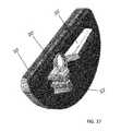
- FIGS. 21-29are highly magnified photographic images of a porous portion of the unicondylar tibial implant of FIGS. 9-18 ;
- FIGS. 30-37illustrate a unicondylar tibial implant in accordance with another aspect of the preferred embodiment of the present invention
- FIGS. 38-40illustrate a unicondylar tibial implant in accordance with yet another aspect of the preferred embodiment of the present invention.
- FIGS. 41-43illustrate a unicondylar tibial implant in accordance with another a further aspect of the preferred embodiment of the present invention.
- Partial knee implantsalso known as unicondylar or unicompartmental knee implants, replace either a medial or lateral compartment of a knee joint by resurfacing, either by itself or in conjunction with a resurfacing of the femoral condyle and an articulating surface of a proximal tibia with an engineered implant.
- the preparation of the bone to accept such implantsmay be facilitated by instrumentation such as bone files, burrs, saws, punches, and/or computer assisted instrumentation/navigation systems.
- the implantOnce the bone is prepared, the implant may be secured to the bone by bone cement which bonds to the implant and impregnates the bone resulting in fixation of the implant to the bone interface.
- cementless fixation or press-fit fixationIn order to remove bone cement from the surgical procedure of implanting partial knee implants, implants have been designed for fixation directly to the bone. Such fixation without bone cement is known as cementless fixation or press-fit fixation.
- the challenge of cementless fixation of tibial implant componentsis to have acceptable initial stability upon implantation to allow patient mobility immediately or a short time after surgery and promote adequate biologic fixation of the implant to the bone long term.
- the initial stability and long term fixationare requirements of the implant to reduce the incidence of implant loosening and reduce patient post-operative pain over time.
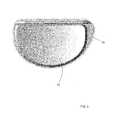
- the present invention illustrated in FIGS. 1-43discloses preferred embodiments of a unicondylar tibial implant assembly 5 having a unicondylar tibial implant 10 and a unicondylar tibial implant bearing 12 .
- the unicondylar tibial implant 10has been developed primarily for cementless application and includes a unique bone interfacing tibial keel 14 and a porous structured biomaterial interface i.e., a porous portion 16 ( FIGS. 21-29 ).
- the tibial implant 10can be constructed from any combination of solid metal, porous metal, polymers or resorbable materials.
- unicondylar tibial implant assembly 5For purposes of convenience only, and not by way of limitation, the foregoing description of the preferred embodiments of the unicondylar tibial implant assembly 5 will be described and illustrated with respect to a unicondylar tibial implant assembly 5 for a medial tibial condyle. However, the foregoing description and features of the unicondylar tibial implant assembly 5 are equally applicable to a unicondylar tibial implant assembly for a lateral condyle, such similar features of the lateral unicondylar tibial implant assembly being substantially mirror images of such features of the medial unicondylar tibial implant assembly.
- the tibial keel 14is located on an undersurface of a tibial tray 18 of the tibial implant 10 which contacts a resected tibia bone (not shown).
- the tibial keel 14is generally submerged into the bone to which the tibial implant 10 is to be implanted thereon.
- the tibial keel 14can prepare its own cavity in the bone as it is inserted into the resected tibia or it can occupy cavities within the bone previously prepared by instrumentation or other implants.
- Any pre-cavities for receiving the tibial keel 14 when pre-preparedare generally smaller in size than the tibial keel 14 so as to generate compressive forces between the bone interface and the tibial keel 14 and increase frictional forces between the bone and the tibial keel 14 . That is, the tibial keel 14 is press-fitted into the bone.
- the tibial keel 14is located on an underside of the tibial tray 18 of the tibial implant 10 and constructed out of a combination of a solid metal substrate and a porous portion 16 on the surfaces of the tibial keel 14 .
- the tibial keel 14is best shown in FIGS. 2, 4-10 and 14-20 and includes a first projection 20 which is generally planar and has a height which corresponds to a depth within a prepared bone to which the tibial keel 14 will protrude into.
- the tibial keel 14also includes a second projection 22 which is generally planar, has a height which corresponds to a depth within a prepared bone to which the tibial keel 14 will protrude into and is substantially perpendicular to the first projection 20 .
- the heights of first and second projections 20 , 22 of the tibial keel 14may be variable to accommodate access limitations while maximizing the fixation of the tibial implant 10 into bone.
- the tibial keel 14is positioned on an underside or inferior surface 24 of the tibial tray 18 with the first projection 20 running along the anterior-posterior direction.
- the second projection 22intersects the first projection 20 towards the anterior edge of the first projection 20 .
- Both of the first and second projections 20 , 22 of the tibial keelare substantially normal to the underside of the tibial tray 18 .
- the first protrusion 20can be configured to have a height that varies along its length.
- Each of the first and second protrusions 20 , 22 of the tibial implant 10can be configured to have one or more extensions i.e., a plurality of extensions 26 .
- FIGS. 2 and 5illustrate the extensions 26 extending from the second protrusion 22 .
- the extensions 26 that emanate from the protrusionsare oriented out of plane with the protrusion. That is, the extensions 26 extend outwardly from the lateral surfaces of the protrusions.
- the extensions 26are designed to create and fill cavities within the bone so as to create and maximize compressive frictional forces between the tibial keel 14 and the surrounding bone.
- the extensions 26are preferably located so that resultant forces during insertion of the tibial implant 10 into a resected tibia bias the position of the tibial implant 10 in a predetermined or desired direction.
- the extensions 26are configured as substantially wedge shaped extensions that extend along substantially the entire height of the keel. Further, the extensions 26 preferably tapered in the distal direction.
- the plurality of extensions 26 on the second protrusion 22are spaced apart from each other and substantially circumscribes the second protrusion 22 .
- the second protrusionincludes five extensions 26 , but can include more or less than five.
- the extensions 26are preferably located around the periphery of both the first and second protrusions 20 , 22 with a higher number of extensions 26 or higher density of extensions 26 emanating from the second protrusion 22 located about the anterior region of the tibial implant 10 where higher frictional forces are able to make a greater contribution to address anterior lift-off stability issues of the tibial implant 10 when implanted within the bone.
- the number of extensions 26is greater on the sides of the protrusion 22 that face away from a central region of the tibial implant 10 so that bone reaction forces will push/direct the tibial implant 10 into the central region of the tibia.
- the tibial implant 10can optionally be configured with a through hole 28 ( FIGS. 2, 5 and 21 ) through which another device, instrument or material e.g., a bone screw 30 ( FIGS. 19 and 20 ) can be inserted therethrough.
- the through hole 28may pass through one or more of the protrusions 20 , 22 thereby interrupting their general shape. However, material is removed from protrusions 20 , 22 around or adjacent the through hole 28 to provide for clearance of the device, instrument or material to be inserted therethrough.
- the majority of the surface area of the tibial implant 10 for fixing i.e., via bone ingrowth, the tibial implant 10 to the boneoccurs at the perimeter of the tibial keel 14 , i.e., the lateral side surfaces of the tibial keel 14 .
- the bone which engages and contacts the bottom of the tibial keel 14represents a small fraction of the overall surface area of the tibial implant 10 .
- the tibial implant 10is configured to prevent any bone ingrowth or fixation about a distal surface of the tibial keel 14 via the solid edge 32 . Preventing bone ingrowth about the distal surface of the tibial keel 14 allows for easier removal of the implant, if necessary, since bone ingrowth on such distal surfaces of the tibial keel 14 represents areas that are most problematic to achieving separation of the implant from bone during revision procedures. In other words, as an implant is pulled out of bone, bony ingrowth into the bottom portion of the tibial keel might not separate from the greater volume of the bone exactly at the implant interface but rather somewhere deeper within the volume of bone beneath the implant. If this occurs during implant removal, the additional bone that would otherwise be inadvertently removed would complicate the revision procedure and drive the use of more significant revision components.
- the general shape of the tibial keel 14is designed to maximize surface area to volume ratio for the tibial keel 14 to enhance bone ingrowth thereto while minimizing the amount of bone removal during bone preparation.
- the amount of surface area available for bone ingrowthis important for both short and long term fixation of the implant to the bone. Short term fixation is achieved by “press-fitting” a larger body into a smaller preparation. Once in place, the residual stresses from the compressed bone around the tibial keel 14 increase the frictional forces against the tibial keel 14 and increase the stability of the tibial implant 10 into the prepared bone. Increasing the surface area over which the press-fit interference is effective helps to increase the total frictional forces available to contribute to stability of the implant and to distribute frictional forces over a greater effective area of the tibial implant 10 .
- tibial implant 10Long term fixation of the tibial implant 10 is enhanced by the areas of the tibial implant 10 having the porous structure and surface, hereafter referred to as ‘porous metal’ 26 .
- porous metalAs the bone remodels and grows into the porous metal 26 , the frictional retention forces will be replaced and/or supplemented with bone ingrowth.
- the degree of this fixation via bone ingrowthis, in part, a function of the amount and distribution of the porous metal surface area available for ingrowth.
- the large distributed tibial keel surface areathereby provides a structure for increased stability via a larger area of bone ingrowth.
- the tibial keel 14also includes a plurality of fins 34 which extend beyond the nominal volume of the tibial keel 14 .
- the fins 34enter bone that has not been prepared to receive the fins 34 . Instead, the fins 34 prepare their own receiving volume within the bone as they are inserted into the bone, i.e., the fins 34 create their own preparation into the bone. In other words, the fins 34 are inserted into bone without the need to prepare the bone to receive such fins 34 .
- the fins 34are sized to maximize their surface area, minimize their volume and are shaped to ease entry into the bone. As shown in FIGS. 2 and 7 , the fins 34 are preferably configured as shown and are substantially wedge shaped or shaped as a dual inclined plane structure.
- the fins 34are tapered as they extend from a proximal end of the tibial keel 14 distally.
- the fins 34are also preferably configured to extend an overall length about half way the overall height of the tibial keel 14 .
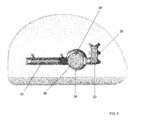
- the through hole 28is shaped and sized for the passage of the bone screw 30 ( FIGS. 19 and 20 ) through a superior aspect of the tibial implant 10 into the bone beneath the underside or inferior surface of the tibial tray 18 .
- the bone screw 30can be angulated to achieve a desired direction by the user. Further, with material from adjacent protrusion 20 removed, the protrusion 20 does not interfere with the passage of the bone screw 30 through the through hole 28 .
- Such bone screws 30are readily known in the art and a detailed description of their structure and operation is not necessary for a complete understanding of the present invention.
- the tibial implant 10may employ the use of a knockout plug 36 formed within the through hole 28 and out of a material that is metallurgically continuous with the greater bulk of the tibial implant 10 .
- the knockout plug 36is configured to be removed from the remainder of the tibial implant 10 via a boundary shear section 38 around the plug 36 .
- the plug 36may be machined into the tibial tray 18 or built in final form through an additive manufacturing process such as by direct metal laser sintering.
- the through hole 28is obstructed by the knockout plug 36 so that the superior surface 40 of the tibial tray 18 facing the bearing component 12 , which can be assembled thereto, is fully continuous without any path through which debris or material could pass through the tibial tray 18 to the bone engaging underside of the tibial implant 10 .
- the tibial tray 18has a through hole 28 into which a screw 30 can be placed to further stabilize the tibial implant 10 to the prepared bone upon implantation. This is especially advantageous for initial implant stability and when placing the tibial implant into bone of questionable density where the user/surgeon is not confident the bone itself is stable enough to support adequate short term stability.
- the through hole 28can be covered during the manufacturing process of the tibial implant 10 with the knockout plug or shear plug 36 .
- the knockout plug 36has a weak cross section which will yield to an appropriate level of force.
- the knockout plug 36can optionally include a threaded stud 42 ( FIG. 12 ), which mates to instrumentation to facilitate removal of the knockout plug 36 .
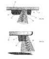
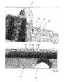
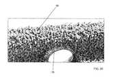
- the porous metal 16is formed from a porous structured biomaterial, and includes a plurality of struts 44 ( FIGS. 21-29 ) having varying lengths and cross sections. At least one strut of the porous metal 16 has an end connected to one or more other struts at node points 46 ( FIG. 29 ) thereby forming the porous geometry of the porous metal 16 .
- the porous metal 16also includes boundary struts 48 ( FIGS. 26, 27 and 28 ) that are configured to extend beyond a nominal boundary of the porous metal 16 . That is, the porous metal 16 has boundary struts 48 that extend away from the surface of the porous metal 16 in a finger-like or hair follicle-like fashion.
- the extending boundary struts 48impart a roughness to the surface, the degree of which is dependent upon the number and length of boundary struts 48 present.
- the average or main direction of the boundary struts 48also impart a surface roughness that varies dependent upon which direction the device is driven for implantation.
- the tibial keel 14is formed from a metal substrate and a layer of porous metal 16 adjacent the substrate.
- the porous metal 16 on the tibial keel 14includes extending boundary struts 48 with unconnected ends pointing or extending towards the bottom or inferior surface of the tibial tray 18 .
- the boundary struts 48are angled about +/ ⁇ 10 degrees from normal to a surface of the substrate to which the porous metal 16 is applied to.
- boundary struts 48are oriented in a predetermined direction such that they push or are directed towards the bone interface surface. While the surface of the porous metal 16 may exhibit characteristics of a rougher surface, the boundary struts 48 of the porous metal 16 implanted into a bone interface embed themselves into the bone and provide a mechanical interlock to the surrounding bone. This is especially advantageous during initial implantation for initial fixation purposes. In the aggregate, the plurality of boundary struts 48 significantly improves the overall stability of the tibial implant 10 upon initial implantation.
- the bottom surface of the tibial tray 18has extending boundary struts 48 ′ ( FIGS. 26 and 27 ) in a direction substantially normal to the bottom surface of the tibial tray 18 .
- the boundary struts 48 ′pierce the surface of the prepared bone to increase stability of the tibial implant 10 to the bone.
- the tibial implant 10has the porous metal 16 on all surfaces that make contact with bone.
- the surface of the porous metal 16is tailored for each specific region of the tibial implant 10 to have specific surface roughness and thereby specific amounts of friction when engaged with bone. That is, the tibial implant 10 is configured to have a porous metal 16 with boundary struts 48 at predetermined angles dependent upon the location of the porous metal 16 on the tibial implant 10 .
- the surfaces of the porous metal 16have extending boundary struts 48 which serve to modify the surface roughness of the tibial implant 10 .
- the size and average direction of the extending boundary struts 48impart different frictional coefficients depending upon the direction the boundary struts 48 extend.
- the boundary struts 48can also be directed in a direction largely normal to the surface from which they extend from. This can have an additive anchoring effect which enhances stability of the tibial implant 10 to the bone.
- the present inventionprovides for a tibial implant 10 ′.
- the tibial implant 10 ′is similarly configured as tibial implant 10 , excepted are follows.
- the tibial implant 10includes a first protrusion 20 ′ segmented by a void and a second protrusion 22 ′.
- the second protrusion 22 ′is similarly configured as the second protrusion 22 discussed above, but is spaced from the first protrusion 20 ′.
- the second protrusion 22 ′has a height equivalent to the height of the first protrusion 20 ′ adjacent the second protrusion 22 ′.
- the height of the first protrusion 20 ′slopes towards the posterior end of the tibial implant 10 ′ such that the height of the first protrusion decreases as it extends from the anterior end towards the posterior end.
- the tibial implant 10 ′can alternatively include a third protrusion 23 ′.
- the third protrusion 23 ′like the second protrusion 22 ′, is slightly spaced apart from the first protrusion 20 ′.
- the third protrusion 23 ′is positioned more towards the rear or posterior to the first protrusion and has a height similar to the height of the posterior end of the first protrusion 20 ′ to which it is adjacent to.
- the height of the third protrusion 23 ′is not equal to the height of the second protrusion 22 ′ or the height of the first protrusion adjacent the anterior end of the first protrusion 20 ′.
- the third protrusion 23 ′is also configured not to intersect the first protrusion 20 ′.
- the third protrusion 23 ′can also alternatively be positioned toward or about a middle section of the first protrusion 20 ′ and spaced apart from the first protrusion 20 ′.
- the third protrusion 23 ′has a height substantially the same as the area of the first protrusion 20 ′ that it is adjacent to.
Landscapes
- Health & Medical Sciences (AREA)
- Orthopedic Medicine & Surgery (AREA)
- Life Sciences & Earth Sciences (AREA)
- Animal Behavior & Ethology (AREA)
- Veterinary Medicine (AREA)
- Public Health (AREA)
- Oral & Maxillofacial Surgery (AREA)
- Engineering & Computer Science (AREA)
- Biomedical Technology (AREA)
- Heart & Thoracic Surgery (AREA)
- General Health & Medical Sciences (AREA)
- Transplantation (AREA)
- Vascular Medicine (AREA)
- Cardiology (AREA)
- Physical Education & Sports Medicine (AREA)
- Surgery (AREA)
- Dentistry (AREA)
- Nuclear Medicine, Radiotherapy & Molecular Imaging (AREA)
- Medical Informatics (AREA)
- Molecular Biology (AREA)
- Prostheses (AREA)
Abstract
Description
This application is a continuation of U.S. application Ser. No. 14/210,921, filed on Mar. 14, 2014, which claims benefit of U.S. Provisional Patent Application No. 61/794,339 filed Mar. 15, 2013, the disclosures of which are hereby incorporated herein by reference.
The present invention relates generally to an orthopedic medical device implant. In particular, the present invention is related to a unicondylar knee implant system's tibial component.
Orthopedic knee implant systems have been used for many years to treat patients with knee joints that have been damaged by trauma or disease, such as osteoarthritis, rheumatoid arthritis, and avascular neurosis. A knee arthroplasty resects, cuts, or resurfaces the damaged sections of the knee and replaces them with an endoprosthetic or implant.
Most knee implant systems are tricompartmental implants and the surgical procedure used with tricompartmental implants is commonly known as total knee arthroplasty. These implants are known as tricompartmental implants because they are used when the knee joint is prepared to receive an implant by resurfacing or resecting the three articulating compartments, i.e., the medial and lateral femorotibial and the patellofemoral surfaces. Regardless of the type of implant used, all arthroplasties require the bone to be specifically prepared to receive a corresponding implant by resecting, resurfacing, or deforming the bone to accept the implant.
Unicondylar or unicompartmental knee implants have become of great interest in the orthopedic industry due to their less invasive nature and the maintaining of the other healthy knee compartments. Unicondylar knees resurface or resect typically the medial or lateral femorotibial articulating surfaces thus allowing preservation of the other compartments which may not be suffering from damage due to trauma or disease.
Generally, the clinical outcomes for unicondylar knee implants have varied. Studies have reported long term survival rates for unicondylar implants to be less than that of comparable total knee implants. One particular cause for such discrepancies is due to the bone cement fixation technique associated with the tibial implant. Another cause is the limitations on longer term cement fixation integrity. And, another cause is the non-physiological tibial bone loading patterns of a required metal backed tibial component that is relatively stiff compared to the surrounding bone.
The development of orthopedic implant designs has been moving towards meeting the requirements of high demand patients. Patients today are requiring more from their implants and since patients are living longer, they are requiring implants to last longer. Accordingly, developments have been made in materials used to make orthopedic implants to improve implant survival rates, such as highly porous metals for biological bone fixation.
Orthopedic devices are mated with host bone by either cementing them in place using methyl methacrylate, generally termed bone cement, or by providing a rough or porous surface on the device for bone tissue to grow into, generally termed press-fit or cementless.
The use of bone cement in attaching a prosthesis within or onto a prepared bone provides an excellent immediate fixation but has various disadvantages that appear over time. Physical loads are repeatedly applied to the implant over its life. If bone cement is used to secure a unicompartmental knee prosthesis, the bone cement may fatigue and fracture under the repeated loading. In some instances, degradation of the bone cement integrity may cause the device to become loose, thereby necessitating replacement. Old bone cement must be removed from the host bone as part of the implant replacement procedure. This procedure can be complex, time consuming and potentially destructive to healthy bone structures surrounding the implant. Furthermore, conventional bone cement is cured after it has been dispensed into the patient's joint. Loose undetected cement fragments can remain in the joint space and, with patient mobility over time, increase the degradation rate of articulating implant surfaces.
Recognizing the disadvantages of cement fixation techniques, prior art devices have been developed that utilize mechanical attachment means to join an implant to bone for immediate stabilization. Various implant surface treatments intended to bond with bone biologically for long term stable attachment have proven successful. A simple technique of mechanically securing an implant, is to affix it within the bone with screws or other mechanical fasteners. However, due to the nature of the bone surrounding the surgical site, and other limiting factors such as artery location and the like, screws can only be applied in certain limited regions. The use of a screw for implant fixation should be considered only as an option by the surgeon depending upon implant placement and bone quality.
Primary fixation of an implant should come from a high friction interface with the prepared bone and in the long term with bone tissue ingrowth into a porous portion of the device. Specific instruments and surgical procedures are developed to match the implant and bone preparation. Often the bone cuts are undersized so that the implant or a portion of the implant such as a peg or keel is “press fit” into the bone. This assures an intimate contact between bone and implant. A high friction coating or porous portion of the implant assists with immediate bone fixation by mechanically locking the device in place. High friction will also resist any loading which may displace the device prior to bone ingrowth and more permanent biological fixation.
Prior art has established many methods for producing a high friction porous layer for implant designs. The use of metal beads, particles or wires which are metalurgically bonded to the implant surface is common. Plasma coating of metal surfaces with rough layers of metal particles is also utilized. More recently, porous metals of various chemical make up and structure have been developed which mimic the design of bone trabecular structure. These materials have been shown to have superior bone ingrowth results and should lead to improved implant fixation.
In accordance with a preferred embodiment, the present invention provides for a unicondylar tibial implant. The tibial implant includes a tibial keel positioned on a surface of the tibial implant to be submerged into prepared bone with a first projection extending along its lengthwise direction and a second projection extending along a direction perpendicular to the first projection. The first projection may be interrupted by a void to allow clearance for another implant or instrument. The second projection intersects the first projection. The tibial implant can be fabricated from a metal, a polymer, a biodegradable material, a porous metal material, or combinations thereof. The device as described could be produced through additive manufacturing techniques such as direct metal laser sintering. The foregoing description of the present invention is provided for the tibial implant when used on the medial condyle. However, the preferred embodiment can also be used on the lateral condyle, and when utilized in such a manner would have some features reversed in orientation. A description of the medial component features of the tibial implant is provided only for simplification.
The tibial keel is configured as an anterior-posterior projection with an intersecting keel segment that extends about a medial-lateral direction. The tibial keel is comprised of a solid material on a bone interfacing leading edge of the tibial keel i.e., a solid end portion, with the tibial keel having a porous material between the tibial tray and the solid end portion of the tibial keel. The tibial implant can optionally include a bone screw to secure the tibial implant to bone.
In accordance with another preferred embodiment, the present invention provides for a unicondylar tibial implant having a tibial keel configured as an anterior-posterior projection with at its most anterior aspect being an intersecting keel in the medial-lateral direction. The tibial keel is comprised of a solid material on a leading edge of the keel and porous material between the tibial tray and the solid end portion of the keel, and smaller protrusions on the medial facing portion of the tibial keel at the intersection of the tibial keel and tibial tray. The tibial implant is fabricated from a metal, a polymer and/or a biodegradable material. The tibial implant can optionally include a bone screw to secure the tibial implant to bone.
In accordance with yet another preferred embodiment, the present invention provides for a unicondylar tibial implant having a tibial keel configured as an anterior-posterior projection with at its most anterior aspect being an intersecting keel in the medial-lateral direction. The tibial keel is comprised of a solid material on the leading edge of the keel and porous material between the tibial tray and a solid end portion of the keel being implanted into an interference-fit created by an undersized preparation in the bone. The tibial implant is fabricated from a metal, a polymer and/or a biodegradable material. The tibial implant can optionally include a bone screw to secure the tibial implant to bone.
In accordance with another preferred embodiment, the present invention provides for a unicondylar tibial implant having a tibial keel configured as an anterior-posterior projection with at its most anterior aspect being an intersecting keel in the medial-lateral direction. The tibial keel is comprised of a solid material on a leading edge of the keel and porous material between the tibial tray and a solid end portion of the keel, and smaller protrusions on the medial facing portion of the keel at the intersection of the tibial keel and tibial tray where the protrusions preferentially force the tibial implant into the bone prepared about a resected mid-tibial eminence. The tibial implant is implanted into an interference fit created by an undersized preparation in the bone. The tibial implant is fabricated from a metal, a polymer and/or a biodegradable material. The tibial implant can optionally include a bone screw to secure the tibial implant to bone.
In accordance with yet another preferred embodiment, the present invention provides for a keel for a unicondylar tibial implant. The keel is connected to the tibial tray of the tibial implant and includes smaller protrusions on a medial facing portion of the keel at an intersection of the keel and the tibial tray where the protrusions push the tibial implant into the bone prepared about a resected tibial eminence. The keel is fabricated from a metal, a polymer and/or a biodegradable material. The tibial implant can optionally include a bone screw to secure the tibial implant to bone.
In accordance with another preferred embodiment, the present invention provides for a unicondylar tibial implant having a tibial tray with a porous keel and protrusions extending from the keel. The tibial tray accepts a polyethylene tibial bearing having an articulating surface for articulating with a femoral component. The tibial bearing can be a modular polyethylene tibial bearing. The tibial implant and tibial bearing can also be formed as a monoblock component. Alternatively, the tibial tray with a porous keel can be formed out of a singular biomaterial which is also used to form the tibial bearing. The tibial implant can optionally include a bone screw to secure the tibial implant to bone.
In accordance with yet another preferred embodiment, the present invention provides for a unicondylar tibial implant having at least one section of material that in its normal state forms at least one uninterrupted surface of the implant that is separable from the greater bulk of the tibial implant in a predictable shape defined by the presence of a shear section. The shear section of material when removed exposes a passageway for at least one additional implant, such as a bone screw. The removal of the shear section also exposes a passageway for surgical instrumentation, for the application of osteobiologic materials or for the application of bone cement.
In accordance with another preferred embodiment, the present invention provides for the ornamental design of a unicondylar tibial implant as shown and described in the figures below.
The foregoing summary, as well as the following detailed description of the preferred embodiments of the invention, will be better understood when read in conjunction with the appended drawings. For the purpose of illustrating the invention, there are shown in the drawings embodiments which are presently preferred. It should be understood, however, that the invention is not limited to the precise arrangements and instrumentalities shown.
Reference will now be made in detail to the preferred embodiments of the present invention illustrated in the accompanying drawings. Wherever possible, the same or like reference numbers will be used throughout the drawings to refer to the same or like features. It should be noted that the drawings are in simplified form and are not drawn to precise scale. In reference to the disclosure herein, for purposes of convenience and clarity only, directional terms such as top, bottom, above, below and diagonal, are used with respect to the accompanying drawings. Such directional terms used in conjunction with the following description of the drawings should not be construed to limit the scope of the invention in any manner not explicitly set forth. Additionally, the term “a,” as used in the specification, means “at least one.” The terminology includes the words above specifically mentioned, derivatives thereof, and words of similar import.
Partial knee implants, also known as unicondylar or unicompartmental knee implants, replace either a medial or lateral compartment of a knee joint by resurfacing, either by itself or in conjunction with a resurfacing of the femoral condyle and an articulating surface of a proximal tibia with an engineered implant. The preparation of the bone to accept such implants may be facilitated by instrumentation such as bone files, burrs, saws, punches, and/or computer assisted instrumentation/navigation systems. Once the bone is prepared, the implant may be secured to the bone by bone cement which bonds to the implant and impregnates the bone resulting in fixation of the implant to the bone interface.
In order to remove bone cement from the surgical procedure of implanting partial knee implants, implants have been designed for fixation directly to the bone. Such fixation without bone cement is known as cementless fixation or press-fit fixation. The challenge of cementless fixation of tibial implant components is to have acceptable initial stability upon implantation to allow patient mobility immediately or a short time after surgery and promote adequate biologic fixation of the implant to the bone long term. The initial stability and long term fixation are requirements of the implant to reduce the incidence of implant loosening and reduce patient post-operative pain over time.
The present invention illustrated inFIGS. 1-43 discloses preferred embodiments of a unicondylartibial implant assembly 5 having aunicondylar tibial implant 10 and a unicondylartibial implant bearing 12. Theunicondylar tibial implant 10 has been developed primarily for cementless application and includes a unique bone interfacingtibial keel 14 and a porous structured biomaterial interface i.e., a porous portion16 (FIGS. 21-29 ). Thetibial implant 10 can be constructed from any combination of solid metal, porous metal, polymers or resorbable materials.
For purposes of convenience only, and not by way of limitation, the foregoing description of the preferred embodiments of the unicondylartibial implant assembly 5 will be described and illustrated with respect to a unicondylartibial implant assembly 5 for a medial tibial condyle. However, the foregoing description and features of the unicondylartibial implant assembly 5 are equally applicable to a unicondylar tibial implant assembly for a lateral condyle, such similar features of the lateral unicondylar tibial implant assembly being substantially mirror images of such features of the medial unicondylar tibial implant assembly.
Thetibial keel 14 is located on an undersurface of atibial tray 18 of thetibial implant 10 which contacts a resected tibia bone (not shown). Thetibial keel 14 is generally submerged into the bone to which thetibial implant 10 is to be implanted thereon. Thetibial keel 14 can prepare its own cavity in the bone as it is inserted into the resected tibia or it can occupy cavities within the bone previously prepared by instrumentation or other implants. Any pre-cavities for receiving thetibial keel 14 when pre-prepared are generally smaller in size than thetibial keel 14 so as to generate compressive forces between the bone interface and thetibial keel 14 and increase frictional forces between the bone and thetibial keel 14. That is, thetibial keel 14 is press-fitted into the bone.
Preferably, thetibial keel 14 is located on an underside of thetibial tray 18 of thetibial implant 10 and constructed out of a combination of a solid metal substrate and aporous portion 16 on the surfaces of thetibial keel 14.
Thetibial keel 14 is best shown inFIGS. 2, 4-10 and 14-20 and includes afirst projection 20 which is generally planar and has a height which corresponds to a depth within a prepared bone to which thetibial keel 14 will protrude into. Thetibial keel 14 also includes asecond projection 22 which is generally planar, has a height which corresponds to a depth within a prepared bone to which thetibial keel 14 will protrude into and is substantially perpendicular to thefirst projection 20. The heights of first andsecond projections tibial keel 14 may be variable to accommodate access limitations while maximizing the fixation of thetibial implant 10 into bone. Preferably, thetibial keel 14 is positioned on an underside orinferior surface 24 of thetibial tray 18 with thefirst projection 20 running along the anterior-posterior direction. Thesecond projection 22 intersects thefirst projection 20 towards the anterior edge of thefirst projection 20. Both of the first andsecond projections tibial tray 18. Further, thefirst protrusion 20 can be configured to have a height that varies along its length.
Each of the first andsecond protrusions tibial implant 10 can be configured to have one or more extensions i.e., a plurality ofextensions 26.FIGS. 2 and 5 illustrate theextensions 26 extending from thesecond protrusion 22. Theextensions 26 that emanate from the protrusions are oriented out of plane with the protrusion. That is, theextensions 26 extend outwardly from the lateral surfaces of the protrusions. Theextensions 26 are designed to create and fill cavities within the bone so as to create and maximize compressive frictional forces between thetibial keel 14 and the surrounding bone. Theextensions 26 are preferably located so that resultant forces during insertion of thetibial implant 10 into a resected tibia bias the position of thetibial implant 10 in a predetermined or desired direction. Theextensions 26 are configured as substantially wedge shaped extensions that extend along substantially the entire height of the keel. Further, theextensions 26 preferably tapered in the distal direction. The plurality ofextensions 26 on thesecond protrusion 22 are spaced apart from each other and substantially circumscribes thesecond protrusion 22. Preferably, the second protrusion includes fiveextensions 26, but can include more or less than five.
Theextensions 26 are preferably located around the periphery of both the first andsecond protrusions extensions 26 or higher density ofextensions 26 emanating from thesecond protrusion 22 located about the anterior region of thetibial implant 10 where higher frictional forces are able to make a greater contribution to address anterior lift-off stability issues of thetibial implant 10 when implanted within the bone. The number ofextensions 26 is greater on the sides of theprotrusion 22 that face away from a central region of thetibial implant 10 so that bone reaction forces will push/direct thetibial implant 10 into the central region of the tibia.
Thetibial implant 10 can optionally be configured with a through hole28 (FIGS. 2, 5 and 21 ) through which another device, instrument or material e.g., a bone screw30 (FIGS. 19 and 20 ) can be inserted therethrough. The throughhole 28 may pass through one or more of theprotrusions protrusions hole 28 to provide for clearance of the device, instrument or material to be inserted therethrough.
A solid edge32 (FIGS. 2, 7 and 21 ) at the distal end of thetibial keel 14 prevents bone from growing into thetibial keel 14 from the bottom up. The majority of the surface area of thetibial implant 10 for fixing i.e., via bone ingrowth, thetibial implant 10 to the bone occurs at the perimeter of thetibial keel 14, i.e., the lateral side surfaces of thetibial keel 14. The bone which engages and contacts the bottom of thetibial keel 14 represents a small fraction of the overall surface area of thetibial implant 10.
That is, thetibial implant 10 is configured to prevent any bone ingrowth or fixation about a distal surface of thetibial keel 14 via thesolid edge 32. Preventing bone ingrowth about the distal surface of thetibial keel 14 allows for easier removal of the implant, if necessary, since bone ingrowth on such distal surfaces of thetibial keel 14 represents areas that are most problematic to achieving separation of the implant from bone during revision procedures. In other words, as an implant is pulled out of bone, bony ingrowth into the bottom portion of the tibial keel might not separate from the greater volume of the bone exactly at the implant interface but rather somewhere deeper within the volume of bone beneath the implant. If this occurs during implant removal, the additional bone that would otherwise be inadvertently removed would complicate the revision procedure and drive the use of more significant revision components.
The general shape of thetibial keel 14 is designed to maximize surface area to volume ratio for thetibial keel 14 to enhance bone ingrowth thereto while minimizing the amount of bone removal during bone preparation. The amount of surface area available for bone ingrowth is important for both short and long term fixation of the implant to the bone. Short term fixation is achieved by “press-fitting” a larger body into a smaller preparation. Once in place, the residual stresses from the compressed bone around thetibial keel 14 increase the frictional forces against thetibial keel 14 and increase the stability of thetibial implant 10 into the prepared bone. Increasing the surface area over which the press-fit interference is effective helps to increase the total frictional forces available to contribute to stability of the implant and to distribute frictional forces over a greater effective area of thetibial implant 10.
Long term fixation of thetibial implant 10 is enhanced by the areas of thetibial implant 10 having the porous structure and surface, hereafter referred to as ‘porous metal’26. As the bone remodels and grows into theporous metal 26, the frictional retention forces will be replaced and/or supplemented with bone ingrowth. The degree of this fixation via bone ingrowth is, in part, a function of the amount and distribution of the porous metal surface area available for ingrowth. The large distributed tibial keel surface area thereby provides a structure for increased stability via a larger area of bone ingrowth.
Thetibial keel 14 also includes a plurality offins 34 which extend beyond the nominal volume of thetibial keel 14. Thefins 34 enter bone that has not been prepared to receive thefins 34. Instead, thefins 34 prepare their own receiving volume within the bone as they are inserted into the bone, i.e., thefins 34 create their own preparation into the bone. In other words, thefins 34 are inserted into bone without the need to prepare the bone to receivesuch fins 34. Thefins 34 are sized to maximize their surface area, minimize their volume and are shaped to ease entry into the bone. As shown inFIGS. 2 and 7 , thefins 34 are preferably configured as shown and are substantially wedge shaped or shaped as a dual inclined plane structure. Further, thefins 34 are tapered as they extend from a proximal end of thetibial keel 14 distally. Thefins 34 are also preferably configured to extend an overall length about half way the overall height of thetibial keel 14.
Preferably, the throughhole 28 is shaped and sized for the passage of the bone screw30 (FIGS. 19 and 20 ) through a superior aspect of thetibial implant 10 into the bone beneath the underside or inferior surface of thetibial tray 18. Thebone screw 30 can be angulated to achieve a desired direction by the user. Further, with material fromadjacent protrusion 20 removed, theprotrusion 20 does not interfere with the passage of thebone screw 30 through the throughhole 28. Such bone screws30 are readily known in the art and a detailed description of their structure and operation is not necessary for a complete understanding of the present invention.
Thetibial implant 10 may employ the use of aknockout plug 36 formed within the throughhole 28 and out of a material that is metallurgically continuous with the greater bulk of thetibial implant 10. The knockout plug36 is configured to be removed from the remainder of thetibial implant 10 via aboundary shear section 38 around theplug 36. Theplug 36 may be machined into thetibial tray 18 or built in final form through an additive manufacturing process such as by direct metal laser sintering.
Preferably, the throughhole 28, designed for the passage of thebone screw 30 therethrough, is obstructed by theknockout plug 36 so that thesuperior surface 40 of thetibial tray 18 facing the bearingcomponent 12, which can be assembled thereto, is fully continuous without any path through which debris or material could pass through thetibial tray 18 to the bone engaging underside of thetibial implant 10.
In sum, thetibial tray 18 has a throughhole 28 into which ascrew 30 can be placed to further stabilize thetibial implant 10 to the prepared bone upon implantation. This is especially advantageous for initial implant stability and when placing the tibial implant into bone of questionable density where the user/surgeon is not confident the bone itself is stable enough to support adequate short term stability.
The throughhole 28 can be covered during the manufacturing process of thetibial implant 10 with the knockout plug orshear plug 36. The knockout plug36 has a weak cross section which will yield to an appropriate level of force. When theknockout plug 36 is in place, there exists an uninterrupted tibial tray surface between the poly (i.e., bearing component12) and the bone interface. In the event of backside wear of the bearingcomponent 12, wear particles are less likely to migrate out of thetibial tray 18 than if an already present through hole were in place. The knockout plug36 can optionally include a threaded stud42 (FIG. 12 ), which mates to instrumentation to facilitate removal of theknockout plug 36.
Theporous metal 16 is formed from a porous structured biomaterial, and includes a plurality of struts44 (FIGS. 21-29 ) having varying lengths and cross sections. At least one strut of theporous metal 16 has an end connected to one or more other struts at node points46 (FIG. 29 ) thereby forming the porous geometry of theporous metal 16. Theporous metal 16 also includes boundary struts48 (FIGS. 26, 27 and 28 ) that are configured to extend beyond a nominal boundary of theporous metal 16. That is, theporous metal 16 has boundary struts48 that extend away from the surface of theporous metal 16 in a finger-like or hair follicle-like fashion. The extending boundary struts48 impart a roughness to the surface, the degree of which is dependent upon the number and length of boundary struts48 present. The average or main direction of the boundary struts48 also impart a surface roughness that varies dependent upon which direction the device is driven for implantation.
Preferably, thetibial keel 14 is formed from a metal substrate and a layer ofporous metal 16 adjacent the substrate. Theporous metal 16 on thetibial keel 14 includes extending boundary struts48 with unconnected ends pointing or extending towards the bottom or inferior surface of thetibial tray 18. Under similar loading conditions, sliding over the angled struts toward the bottom surface of thetibial tray 18 will experience less frictional forces than bone sliding away from the bottom face of thetibial tray 18. Preferably, the boundary struts48 are angled about +/−10 degrees from normal to a surface of the substrate to which theporous metal 16 is applied to.
Another element of the present invention is that the boundary struts48 are oriented in a predetermined direction such that they push or are directed towards the bone interface surface. While the surface of theporous metal 16 may exhibit characteristics of a rougher surface, the boundary struts48 of theporous metal 16 implanted into a bone interface embed themselves into the bone and provide a mechanical interlock to the surrounding bone. This is especially advantageous during initial implantation for initial fixation purposes. In the aggregate, the plurality of boundary struts48 significantly improves the overall stability of thetibial implant 10 upon initial implantation.
Preferably, the bottom surface of thetibial tray 18 has extending boundary struts48′ (FIGS. 26 and 27 ) in a direction substantially normal to the bottom surface of thetibial tray 18. As thetibial implant 10 is definitively seated against the bone interface surface, the boundary struts48′ pierce the surface of the prepared bone to increase stability of thetibial implant 10 to the bone.
Thetibial implant 10 has theporous metal 16 on all surfaces that make contact with bone. The surface of theporous metal 16 is tailored for each specific region of thetibial implant 10 to have specific surface roughness and thereby specific amounts of friction when engaged with bone. That is, thetibial implant 10 is configured to have aporous metal 16 with boundary struts48 at predetermined angles dependent upon the location of theporous metal 16 on thetibial implant 10.
In sum, the surfaces of theporous metal 16 have extending boundary struts48 which serve to modify the surface roughness of thetibial implant 10. The size and average direction of the extending boundary struts48 impart different frictional coefficients depending upon the direction the boundary struts48 extend. The boundary struts48 can also be directed in a direction largely normal to the surface from which they extend from. This can have an additive anchoring effect which enhances stability of thetibial implant 10 to the bone.
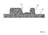
Referring toFIGS. 30-37 , in accordance with another preferred embodiment, the present invention provides for atibial implant 10′. Thetibial implant 10′ is similarly configured astibial implant 10, excepted are follows. Thetibial implant 10 includes afirst protrusion 20′ segmented by a void and asecond protrusion 22′. Thesecond protrusion 22′ is similarly configured as thesecond protrusion 22 discussed above, but is spaced from thefirst protrusion 20′. Thesecond protrusion 22′ has a height equivalent to the height of thefirst protrusion 20′ adjacent thesecond protrusion 22′. As best shown inFIGS. 34-36 , the height of thefirst protrusion 20′ slopes towards the posterior end of thetibial implant 10′ such that the height of the first protrusion decreases as it extends from the anterior end towards the posterior end.
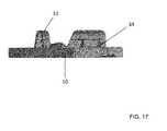
Referring toFIGS. 38-40 , thetibial implant 10′ can alternatively include athird protrusion 23′. Thethird protrusion 23′, like thesecond protrusion 22′, is slightly spaced apart from thefirst protrusion 20′. Preferably, thethird protrusion 23′ is positioned more towards the rear or posterior to the first protrusion and has a height similar to the height of the posterior end of thefirst protrusion 20′ to which it is adjacent to. The height of thethird protrusion 23′ is not equal to the height of thesecond protrusion 22′ or the height of the first protrusion adjacent the anterior end of thefirst protrusion 20′. Thethird protrusion 23′ is also configured not to intersect thefirst protrusion 20′.
Referring toFIGS. 41-43 , thethird protrusion 23′ can also alternatively be positioned toward or about a middle section of thefirst protrusion 20′ and spaced apart from thefirst protrusion 20′. When positioned about the middle section of thefirst protrusion 20′, thethird protrusion 23′ has a height substantially the same as the area of thefirst protrusion 20′ that it is adjacent to.
It will be appreciated by those skilled in the art that changes could be made to the embodiments described above without departing from the broad inventive concept thereof. For example, additional components can be added to the tibial implant assembly. It is to be understood, therefore, that this invention is not limited to the particular embodiments disclosed, but it is intended to cover modifications within the spirit and scope of the present invention as described above.
Claims (20)
1. A method of replacing a portion of a bone comprising the steps of:
resecting a portion of the bone to create a resected surface;
contacting a first projection having a first longitudinal axis and a second projection having a second longitudinal axis of an implant with the resected surface, the first and second longitudinal axes oriented transversally with respect to each other; and
placing a screw through a hole separating the first and second projections and into the bone for threaded fixation thereof to the bone.
2. The method ofclaim 1 , wherein the resecting step includes creating first and second cavities in the bone.
3. The method ofclaim 2 , wherein the bone is a tibia and the first projection is placed within the first cavity and the second projections is placed within the second cavity.
4. The method ofclaim 1 , wherein the contacting step including forming a first cavity with the first projection and a second cavity with the second projection.
5. The method ofclaim 1 , wherein the first and second projections are orthogonal with respect to each other.
6. The method ofclaim 1 , further comprising the step of determining a trajectory for placement of the screw through the hole.
7. The method ofclaim 1 , further comprising the step of removing a plug from the hole.
8. The method ofclaim 1 , further comprising the step of contacting a fin associated with the first projection with the resected surface.
9. The method ofclaim 8 , wherein the fin forms a third cavity in the bone.
10. The method ofclaim 1 , further comprising the step of contacting an extension associated with the second projection with the resected surface.
11. The method ofclaim 10 , wherein the extension frictionally engages the bone.
12. The method ofclaim 1 , further comprising the step of placing a porous portion in contact with the bone.
13. The method ofclaim 12 , wherein the porous portion covers at least a portion of the first and/or second projections.
14. The method ofclaim 12 , wherein the placing step includes engaging a boundary strut extending from the porous portion with the bone.
15. The method ofclaim 1 , further comprising contacting a third projection having a third longitudinal axis with the resected surface.
16. The method ofclaim 1 , further comprising attaching a bearing component to the implant.
17. The method ofclaim 1 , wherein the bone is a tibia and the implant is a unicondylar tibial baseplate.
18. The method ofclaim 17 , further comprising the step of contacting the implant with another implant.
19. The method ofclaim 18 , wherein the implants are tibial and femoral implants.
20. The method ofclaim 19 , wherein the implants are unicondylar implants.
Priority Applications (1)
| Application Number | Priority Date | Filing Date | Title |
|---|---|---|---|
| US15/250,236US9907658B2 (en) | 2013-03-15 | 2016-08-29 | Unicondylar tibial knee implant |
Applications Claiming Priority (3)
| Application Number | Priority Date | Filing Date | Title |
|---|---|---|---|
| US201361794339P | 2013-03-15 | 2013-03-15 | |
| US14/210,921US9445909B2 (en) | 2013-03-15 | 2014-03-14 | Unicondylar tibial knee implant |
| US15/250,236US9907658B2 (en) | 2013-03-15 | 2016-08-29 | Unicondylar tibial knee implant |
Related Parent Applications (1)
| Application Number | Title | Priority Date | Filing Date |
|---|---|---|---|
| US14/210,921ContinuationUS9445909B2 (en) | 2013-03-15 | 2014-03-14 | Unicondylar tibial knee implant |
Publications (2)
| Publication Number | Publication Date |
|---|---|
| US20170027700A1 US20170027700A1 (en) | 2017-02-02 |
| US9907658B2true US9907658B2 (en) | 2018-03-06 |
Family
ID=50792536
Family Applications (3)
| Application Number | Title | Priority Date | Filing Date |
|---|---|---|---|
| US14/210,921ActiveUS9445909B2 (en) | 2013-03-15 | 2014-03-14 | Unicondylar tibial knee implant |
| US14/212,051ActiveUS9744044B2 (en) | 2013-03-15 | 2014-03-14 | Unicondylar tibial knee implant |
| US15/250,236ActiveUS9907658B2 (en) | 2013-03-15 | 2016-08-29 | Unicondylar tibial knee implant |
Family Applications Before (2)
| Application Number | Title | Priority Date | Filing Date |
|---|---|---|---|
| US14/210,921ActiveUS9445909B2 (en) | 2013-03-15 | 2014-03-14 | Unicondylar tibial knee implant |
| US14/212,051ActiveUS9744044B2 (en) | 2013-03-15 | 2014-03-14 | Unicondylar tibial knee implant |
Country Status (7)
| Country | Link |
|---|---|
| US (3) | US9445909B2 (en) |
| EP (1) | EP2967885B1 (en) |
| JP (1) | JP2016513551A (en) |
| CN (1) | CN105392450B (en) |
| AU (1) | AU2014228237B2 (en) |
| CA (1) | CA2906631C (en) |
| WO (1) | WO2014143740A1 (en) |
Cited By (2)
| Publication number | Priority date | Publication date | Assignee | Title |
|---|---|---|---|---|
| US11957593B2 (en) | 2020-12-30 | 2024-04-16 | Howmedica Osteonics Corp. | Cementless screw-in-peg fixation |
| US12427029B2 (en) | 2020-11-25 | 2025-09-30 | Howmedica Osteonics Corp. | Fixation device for unicondylar prosthesis |
Families Citing this family (44)
| Publication number | Priority date | Publication date | Assignee | Title |
|---|---|---|---|---|
| US20060147332A1 (en) | 2004-12-30 | 2006-07-06 | Howmedica Osteonics Corp. | Laser-produced porous structure |
| AU2003261497B2 (en) | 2002-11-08 | 2009-02-26 | Howmedica Osteonics Corp. | Laser-produced porous surface |
| US8728387B2 (en) | 2005-12-06 | 2014-05-20 | Howmedica Osteonics Corp. | Laser-produced porous surface |
| US9408705B2 (en)* | 2011-09-29 | 2016-08-09 | Christiaan Rudolf Oosthuizen | Tibial component |
| US9180010B2 (en) | 2012-04-06 | 2015-11-10 | Howmedica Osteonics Corp. | Surface modified unit cell lattice structures for optimized secure freeform fabrication |
| CN105392450B (en) | 2013-03-15 | 2017-09-29 | 马科外科公司 | Tibial knee list condyle implant |
| WO2015024122A1 (en)* | 2013-08-21 | 2015-02-26 | Laboratoires Bodycad Inc. | Anatomically adapted orthopedic implant and method of manufacturing same |
| US10098746B1 (en) | 2015-02-13 | 2018-10-16 | Nextstep Arthropedix, LLC | Medical implants having desired surface features and methods of manufacturing |
| CN104887355B (en)* | 2015-05-08 | 2017-05-03 | 江苏奥康尼医疗科技发展有限公司 | Artificial knee joint tibial tray |
| US10117713B2 (en) | 2015-07-01 | 2018-11-06 | Mako Surgical Corp. | Robotic systems and methods for controlling a tool removing material from a workpiece |
| US10070928B2 (en) | 2015-07-01 | 2018-09-11 | Mako Surgical Corp. | Implant placement planning |
| WO2017011576A2 (en)* | 2015-07-13 | 2017-01-19 | Mako Surgical Corp. | Lower extremities leg length calculation method |
| US10856992B2 (en)* | 2016-04-27 | 2020-12-08 | AOD Holdings, LLC | Implant device(s) including tapered protrusions and method(s) for inserting the same into bone |
| US10136998B2 (en)* | 2016-08-30 | 2018-11-27 | Wright Medical Technology, Inc. | Revision total ankle implants |
| HK1224885A (en)* | 2016-09-08 | 2017-08-25 | 科能三维技术(医疗)有限公司 | Device and method for producing artificial solid bone |
| CA2988052A1 (en)* | 2016-12-06 | 2018-06-06 | Smed-Ta/Td, Llc | Orthopaedic implant with fixation feature and a method of implanting thereof |
| US11039938B2 (en) | 2017-07-26 | 2021-06-22 | Optimotion Implants LLC | Modular knee prothesis |
| US12083027B2 (en) | 2017-03-02 | 2024-09-10 | Optimotion Implants LLC | Universal femoral trial system and methods |
| US10905436B2 (en) | 2017-03-02 | 2021-02-02 | Optimotion Implants, Llc | Knee arthroplasty systems and methods |
| US11406502B2 (en) | 2017-03-02 | 2022-08-09 | Optimotion Implants LLC | Orthopedic implants and methods |
| US20210290410A1 (en)* | 2017-03-03 | 2021-09-23 | Engage Uni Llc | Unicompartmental knee arthroplasty |
| US11298747B2 (en) | 2017-05-18 | 2022-04-12 | Howmedica Osteonics Corp. | High fatigue strength porous structure |
| EP3412252B1 (en) | 2017-06-09 | 2020-02-12 | Howmedica Osteonics Corp. | Polymer interlock support structure |
| DE102017119728A1 (en)* | 2017-08-29 | 2019-02-28 | Renk Aktiengesellschaft | Plain bearing and method for producing the same |
| USD850616S1 (en) | 2017-10-31 | 2019-06-04 | Sicage Llc | Parallel surgical guide spacer |
| USD847336S1 (en) | 2017-10-31 | 2019-04-30 | Sicage Llc | Parallel surgical guide spacer |
| US10603054B2 (en) | 2017-10-31 | 2020-03-31 | Sicage Llc | Parallel guide for surgical implants |
| ZAF201801915S (en)* | 2018-12-13 | 2019-11-27 | Oosthuizen Christian Rudolf | Fixed bearing insert |
| ZAF201801914S (en)* | 2018-12-13 | 2019-11-27 | Oosthuizen Christian Rudolf | Tibial component |
| JP7519369B2 (en)* | 2019-02-28 | 2024-07-19 | リマコルポラーテ エッセ.ピ.ア. | Tibial base plate for a tibial component of an artificial knee joint, a tibial component including a tibial base plate, and a method for manufacturing the tibial base plate |
| CN109771104A (en)* | 2019-03-11 | 2019-05-21 | 北京力达康科技有限公司 | A kind of MTS medial tibial plateau sticking patch, assembly type MTS medial tibial plateau sticking patch and its minimally invasive method of replacing |
| WO2020223564A1 (en) | 2019-05-02 | 2020-11-05 | World Class Technology Corporation | Orthodontic bracket with a biased ligating member |
| US11160568B1 (en) | 2019-09-10 | 2021-11-02 | Lento Medical, Inc | Optimal selection of contact curves |
| GB201918534D0 (en)* | 2019-12-16 | 2020-01-29 | Depuy Ireland Ultd Co | Tibial preparation |
| US11357634B1 (en) | 2020-01-15 | 2022-06-14 | Lento Medical, Inc. | Posterior-stabilized symmetric knee prosthesis |
| US11382757B1 (en) | 2020-01-15 | 2022-07-12 | Lento Medical, Inc. | Condylar asymmetry knee prosthesis |
| CN113633436A (en)* | 2020-04-27 | 2021-11-12 | 萨摩(重庆)医疗器材有限公司 | A 3D printed metal trabecular tibial revision pad |
| US11478260B2 (en) | 2020-07-17 | 2022-10-25 | Asfora Ip, Llc | Parallel guide for access needle |
| US11844697B2 (en) | 2020-09-03 | 2023-12-19 | Globus Medical, Inc. | Systems and methods for knee arthroplasty |
| US11730603B2 (en) | 2020-09-03 | 2023-08-22 | Globus Medical, Inc. | Systems and methods for knee arthroplasty |
| JP2024506178A (en)* | 2021-02-05 | 2024-02-09 | オーバーチュア・リサーフェシング・インコーポレイテッド | Articular surface replacement implant system and method for osteochondral defects |
| CN113367854B (en)* | 2021-05-24 | 2023-08-01 | 北京纳通医疗科技控股有限公司 | Tibial tray prosthesis and knee joint prosthesis |
| US20230210670A1 (en)* | 2021-12-31 | 2023-07-06 | Depuy Ireland Unlimited Company | Knee prosthesis having non-uniform stiffness |
| WO2025171292A1 (en)* | 2024-02-09 | 2025-08-14 | Ignite Orthomotion, Llc | Implants, systems and methods of using the same |
Citations (255)
| Publication number | Priority date | Publication date | Assignee | Title |
|---|---|---|---|---|
| US3715763A (en) | 1971-04-21 | 1973-02-13 | W Link | Artificial limb for the knee joint |
| US3774244A (en) | 1972-02-08 | 1973-11-27 | Relief Ruptured And Crippled S | Knee-joint prosthesis |
| US3824630A (en) | 1972-06-23 | 1974-07-23 | Zimmer Mfg Co | Prosthetic joint for total knee replacement |
| US3852830A (en) | 1973-02-15 | 1974-12-10 | Richards Mfg Co | Knee prosthesis |
| US3958278A (en) | 1974-04-22 | 1976-05-25 | National Research Development Corporation | Endoprosthetic knee joint |
| US4001896A (en) | 1975-06-09 | 1977-01-11 | Zimmer, U.S.A. Inc. | Prosthetic joint for total knee replacement |
| US4034418A (en) | 1975-05-26 | 1977-07-12 | The Governing Council Of The University Of Toronto | Artificial knee joint |
| US4085466A (en) | 1974-11-18 | 1978-04-25 | National Research Development Corporation | Prosthetic joint device |
| US4224696A (en) | 1978-09-08 | 1980-09-30 | Hexcel Corporation | Prosthetic knee |
| US4309778A (en) | 1979-07-02 | 1982-01-12 | Biomedical Engineering Corp. | New Jersey meniscal bearing knee replacement |
| US4711639A (en) | 1984-09-11 | 1987-12-08 | S+G Implants Gmbh | Anchorage for tibia plates |
| US4719908A (en) | 1986-08-15 | 1988-01-19 | Osteonics Corp. | Method and apparatus for implanting a prosthetic device |
| US4743261A (en) | 1986-01-27 | 1988-05-10 | Epinette Jean Alain | Tibial component for unicompartmental knee prosthesis for a cementness implantation |
| US4795468A (en) | 1987-12-23 | 1989-01-03 | Zimmer, Inc. | Mechanism and method for locking a bearing insert to the base of a prosthetic implant |
| US4935023A (en) | 1989-01-09 | 1990-06-19 | Dow Corning Wright | Femoral surface shaping guide for knee implants |
| US4944757A (en) | 1988-11-07 | 1990-07-31 | Martinez David M | Modulator knee prosthesis system |
| US4978357A (en) | 1987-06-12 | 1990-12-18 | Mecron Medizinische Produkte Gmbh | Endoprosthesis |
| US5037439A (en) | 1988-04-11 | 1991-08-06 | Albrektsson Bjoern | Knee-joint prosthesis |
| US5080673A (en) | 1988-02-03 | 1992-01-14 | Intermedics Orthopedics, Inc. | Glenoid prosthesis and method of use |
| US5080675A (en) | 1990-03-12 | 1992-01-14 | Howmedica | Tibial component for a replacement knee prosthesis |
| US5152797A (en) | 1991-10-25 | 1992-10-06 | Johnson & Johnson Orthopaedics, Inc. | Modular prosthesis |
| US5171276A (en) | 1990-01-08 | 1992-12-15 | Caspari Richard B | Knee joint prosthesis |
| US5171244A (en) | 1990-01-08 | 1992-12-15 | Caspari Richard B | Methods and apparatus for arthroscopic prosthetic knee replacement |
| US5201881A (en) | 1991-08-13 | 1993-04-13 | Smith & Nephew Richards Inc. | Joint prosthesis with improved shock absorption |
| US5203807A (en) | 1991-07-10 | 1993-04-20 | Smith & Nephew Richards Inc. | Knee joint prosthesis articular surface |
| US5226915A (en) | 1992-04-03 | 1993-07-13 | Bertin Kim C | Femoral prosthesis component system for knee replacement surgery |
| US5246459A (en) | 1992-02-24 | 1993-09-21 | Elias Sarmed G | Modular tibial support pegs for the tibial component of a prosthetic knee replacement system |
| US5258032A (en) | 1992-04-03 | 1993-11-02 | Bertin Kim C | Knee prosthesis provisional apparatus and resection guide and method of use in knee replacement surgery |
| US5271737A (en) | 1992-09-04 | 1993-12-21 | U.S. Medical Products, Inc. | Tibial prosthetic implant with offset stem |
| US5282866A (en) | 1992-02-12 | 1994-02-01 | Osteonics Corp. | Prosthetic knee tibial component with axially ribbed keel and apparatus for effecting implant |
| US5312411A (en) | 1992-10-27 | 1994-05-17 | Smith & Nephew Richards, Inc. | Uni-compartmental femoral knee instruments and prosthesis |
| US5314487A (en) | 1991-02-14 | 1994-05-24 | Smith & Nephew Richards Inc. | Acetabular prosthesis with anchoring pegs |
| US5330533A (en) | 1991-02-04 | 1994-07-19 | Walker Peter S | Prosthesis for knee replacement |
| EP0611559A1 (en) | 1993-02-18 | 1994-08-24 | Societe Civile Essor | Unicondylar knee prostheses |
| US5413604A (en) | 1992-12-24 | 1995-05-09 | Osteonics Corp. | Prosthetic knee implant for an anterior cruciate ligament deficient total knee replacement |
| US5480444A (en) | 1994-06-02 | 1996-01-02 | Incavo; Stephen J. | Hybrid tibial tray knee prosthesis |
| US5507820A (en) | 1992-12-14 | 1996-04-16 | Biomedical Engineering Trust I | Fixed bearing joint endoprosthesis |
| US5514183A (en) | 1994-12-20 | 1996-05-07 | Epstein; Norman | Reduced friction prosthetic knee joint utilizing replaceable roller bearings |
| US5520695A (en) | 1992-02-14 | 1996-05-28 | Johnson & Johnson Professional, Inc. | Instruments for use in knee replacement surgery |
| US5534027A (en) | 1993-06-21 | 1996-07-09 | Zimmer, Inc. | Method for providing a barrier to the advancement of wear debris in an orthopaedic implant assembly |
| US5609645A (en) | 1994-10-28 | 1997-03-11 | Intermedics, Inc. | Knee revision prosthesis with shims |
| US5658341A (en) | 1993-03-10 | 1997-08-19 | Medinov S.A. | Tibial implant for a knee prosthesis |
| US5716361A (en) | 1995-11-02 | 1998-02-10 | Masini; Michael A. | Bone cutting guides for use in the implantation of prosthetic joint components |
| US5755801A (en) | 1993-07-16 | 1998-05-26 | Walker; Peter Stanley | Prostheses for knee replacement |
| US5782925A (en) | 1997-11-06 | 1998-07-21 | Howmedica Inc. | Knee implant rotational alignment apparatus |
| US5824103A (en) | 1997-05-12 | 1998-10-20 | Howmedica Inc. | Tibial prosthesis |
| US5871542A (en) | 1994-07-06 | 1999-02-16 | British Technology Group Limited | Endoprosthetic knee joint device |
| US5879389A (en) | 1995-04-07 | 1999-03-09 | Koshino; Tomihisa | Medical substituting element for hard tissues and artificial joint |
| US5906643A (en) | 1994-07-28 | 1999-05-25 | Walker; Peter Stanley | Stabilised mobile bearing knee |
| US5911758A (en) | 1995-06-21 | 1999-06-15 | Sulzer Orthopaedie Ag | Tibia platform for a knee joint prosthesis and knee joint prosthesis with such a tibia platform |
| US5989261A (en) | 1997-03-13 | 1999-11-23 | Zimmer, Ltd. | Evaluating the fit of an orthopaedic implant |
| US6059831A (en) | 1999-03-31 | 2000-05-09 | Biomet, Inc. | Method of implanting a uni-condylar knee prosthesis |
| US6068658A (en) | 1997-03-13 | 2000-05-30 | Zimmer Ltd. | Prosthesis for knee replacement |
| US6102954A (en) | 1992-05-18 | 2000-08-15 | Astra Aktiebolag | Joint prosthesis and apparatus for preparing the bone prior to fitting of the prosthesis |
| US6102951A (en) | 1997-06-12 | 2000-08-15 | Sulzer Orthopaedie Ag | Mounting system for metallic support shells |
| US6132468A (en) | 1998-09-10 | 2000-10-17 | Mansmann; Kevin A. | Arthroscopic replacement of cartilage using flexible inflatable envelopes |
| US6152962A (en) | 1998-12-30 | 2000-11-28 | Depuy Orthopaedics, Inc. | Acetabular cup with plug for screw holes |
| US6179876B1 (en) | 1998-11-04 | 2001-01-30 | Blake A. Stamper | Orthopedic prosthesis with cement compression ring and method |
| US6224632B1 (en) | 1994-10-27 | 2001-05-01 | Biomedical Engineering Trust I | Prosthesis fixturing device |
| US6264697B1 (en) | 1997-04-16 | 2001-07-24 | Peter Stanley Walker | Knee prosthesis having guide surfaces for control of anterior-posterior displacement |
| US6342075B1 (en) | 2000-02-18 | 2002-01-29 | Macarthur A. Creig | Prosthesis and methods for total knee arthroplasty |
| US6344059B1 (en) | 1996-02-26 | 2002-02-05 | Gabor Krakovits | Knee surface replacement prosthesis |
| US6379388B1 (en) | 1999-12-08 | 2002-04-30 | Ortho Development Corporation | Tibial prosthesis locking system and method of repairing knee joint |
| US20020095214A1 (en) | 2001-01-16 | 2002-07-18 | Hyde Edward R. | Transosseous core approach and instrumentation for joint replacement and repair |
| US6475241B2 (en) | 2000-03-13 | 2002-11-05 | Biomedical Engineering Trust I | Posterior stabilized knee replacement with bearing translation for knees with retained collateral ligaments |
| US20020173855A1 (en) | 2001-02-05 | 2002-11-21 | Mansmann Kevin A. | Cartilage repair implant with soft bearing surface and flexible anchoring device |
| US6491726B2 (en) | 2000-03-08 | 2002-12-10 | Biomedical Engineering Trust I | Posterior stabilized prosthetic knee replacement with bearing translation and dislocation prevention features |
| US6494914B2 (en) | 2000-12-05 | 2002-12-17 | Biomet, Inc. | Unicondylar femoral prosthesis and instruments |
| US6506216B1 (en)* | 1998-05-13 | 2003-01-14 | Depuy Products, Inc. | Tibial tray with adjustable keel |
| US20030014122A1 (en) | 2001-04-02 | 2003-01-16 | Whiteside Biomechanics, Inc. | Tray and liner for joint replacement system |
| US20030060884A1 (en) | 1999-05-10 | 2003-03-27 | Fell Barry M. | Surgically implantable knee prosthesis having keels |
| US6554838B2 (en) | 2001-05-31 | 2003-04-29 | Howmedica Osteonics Corp. | Method and apparatus for implanting a prosthetic device |
| US6554866B1 (en) | 1999-10-29 | 2003-04-29 | Sulzer Orthopedics Ltd. | Mono-condylar knee joint prosthesis |
| US6558426B1 (en) | 2000-11-28 | 2003-05-06 | Medidea, Llc | Multiple-cam, posterior-stabilized knee prosthesis |
| US20030100953A1 (en) | 2001-11-28 | 2003-05-29 | Rosa Richard A. | Knee joint prostheses |
| US20030114933A1 (en) | 1999-12-23 | 2003-06-19 | Denis Bouttens | Shoulder prosthesis assembly |
| US6616696B1 (en) | 1998-09-04 | 2003-09-09 | Alan C. Merchant | Modular knee replacement system |
| US6620198B2 (en) | 1999-10-07 | 2003-09-16 | Exactech, Inc. | Composite bearing inserts for total knee joints |
| US20040006393A1 (en) | 2002-07-03 | 2004-01-08 | Brian Burkinshaw | Implantable prosthetic knee for lateral compartment |
| US6749638B1 (en) | 2002-11-22 | 2004-06-15 | Zimmer Technology, Inc. | Modular knee prosthesis |
| US6770097B2 (en) | 1999-12-13 | 2004-08-03 | Centerpulse Orthopedics Ltd. | Kit for a knee joint prosthesis |
| US20040153087A1 (en) | 2003-02-04 | 2004-08-05 | Sanford Adam H. | Provisional orthopedic implant with removable guide |
| US20040167630A1 (en) | 2003-02-20 | 2004-08-26 | Rolston Lindsey R. | Device and method for bicompartmental arthroplasty |
| US6797006B2 (en) | 2002-06-18 | 2004-09-28 | Zimmer Technology, Inc. | Porous unicondylar knee |
| US20040193280A1 (en) | 2003-02-03 | 2004-09-30 | Webster Vincent A. | Mobile bearing unicondylar tibial knee prosthesis |
| US6840960B2 (en) | 2002-09-27 | 2005-01-11 | Stephen K. Bubb | Porous implant system and treatment method |
| US20050021145A1 (en) | 2003-05-27 | 2005-01-27 | Spinalmotion, Inc. | Prosthetic disc for intervertebral insertion |
| US20050033424A1 (en) | 1999-05-10 | 2005-02-10 | Fell Barry M. | Surgically implantable knee prosthesis |
| US20050065611A1 (en) | 2001-11-06 | 2005-03-24 | Jean Huppert | Osseous achoring device for a prosthesis |
| US6890358B2 (en) | 2002-03-29 | 2005-05-10 | Depuy Products, Inc. | Distal component for wrist prosthesis |
| US20050112397A1 (en) | 2003-07-24 | 2005-05-26 | Rolfe Jonathan L. | Assembled non-random foams |
| US6916324B2 (en) | 2003-02-04 | 2005-07-12 | Zimmer Technology, Inc. | Provisional orthopedic prosthesis for partially resected bone |
| US20050165491A1 (en) | 2004-01-23 | 2005-07-28 | Diaz Robert L. | Method and apparatus for bi-compartmental partial knee replacement |
| US20050171604A1 (en) | 2004-01-20 | 2005-08-04 | Alexander Michalow | Unicondylar knee implant |
| US20050169893A1 (en) | 2004-02-03 | 2005-08-04 | Antony Koblish | Bone restorative carrier mediums |
| US20050192674A1 (en) | 1999-10-08 | 2005-09-01 | Ferree Bret A. | Prosthetic joints with contained compressible resilient members |
| US20050203631A1 (en) | 2004-03-09 | 2005-09-15 | Daniels Michael E. | Tibial implant with a broad keel and a through post |
| US6946001B2 (en) | 2003-02-03 | 2005-09-20 | Zimmer Technology, Inc. | Mobile bearing unicompartmental knee |
| US20050261775A1 (en) | 2004-05-19 | 2005-11-24 | Zimmer Gmbh | Glenoid anchor |
| US6969393B2 (en) | 2000-03-10 | 2005-11-29 | Smith & Nephew, Inc. | Apparatus for use in arthroplasty of the knees |
| US20060015113A1 (en) | 1999-03-12 | 2006-01-19 | Masini Michael A | Optimizing patellar femoral mechanics through alternative depth referencing |
| US20060064169A1 (en) | 2002-09-10 | 2006-03-23 | Ferree Bret A | Shock-absorbing joint and spine replacements |
| US7048741B2 (en) | 2002-05-10 | 2006-05-23 | Swanson Todd V | Method and apparatus for minimally invasive knee arthroplasty |
| US20060129246A1 (en) | 2004-10-20 | 2006-06-15 | Zimmer Technology, Inc. | Mobile bearing unicondylar knee prosthesis |
| US20060149387A1 (en) | 2004-12-30 | 2006-07-06 | Smith Todd S | Orthopaedic bearing and method for making the same |
| US20060147332A1 (en) | 2004-12-30 | 2006-07-06 | Howmedica Osteonics Corp. | Laser-produced porous structure |
| US20060155383A1 (en) | 2004-12-30 | 2006-07-13 | Smith Todd S | Orthopaedic bearing and method for making the same |
| US20060157543A1 (en) | 2004-11-10 | 2006-07-20 | Stanley Abkowitz | Fine grain titanium-alloy article and articles with clad porous titanium surfaces |
| US20060178749A1 (en) | 2005-02-10 | 2006-08-10 | Zimmer Technology, Inc. | Modular porous implant |
| US7094241B2 (en) | 2002-11-27 | 2006-08-22 | Zimmer Technology, Inc. | Method and apparatus for achieving correct limb alignment in unicondylar knee arthroplasty |
| US20060190086A1 (en) | 2005-02-22 | 2006-08-24 | Mako Surgical Corporation | Knee implant |
| US20060195196A1 (en) | 2005-02-26 | 2006-08-31 | Zimmer Technology, Inc. | Modular tibial implant with a mortise coupling |
| US20060200248A1 (en) | 2005-03-03 | 2006-09-07 | Laurent Beguin | Prosthesis for the glenoid cavity of the scapula |
| US7105027B2 (en) | 2002-05-08 | 2006-09-12 | Mathys Medical Ltd. | Self-aligning knee prosthesis |
| US20060217734A1 (en) | 2005-03-09 | 2006-09-28 | Zimmer Technology, Inc. | Femoral resection guide apparatus and method |
| US20060235537A1 (en) | 2005-04-18 | 2006-10-19 | Accin Corporation | Unicondylar knee implant |
| US20060235541A1 (en) | 2005-04-15 | 2006-10-19 | Zimmer Technology, Inc. | Bearing implant |
| US7150761B2 (en) | 2002-05-24 | 2006-12-19 | Medicinelodge, Inc. | Modular femoral components for knee arthroplasty |
| US20060287733A1 (en) | 2005-06-15 | 2006-12-21 | Bonutti Peter M | Gender specific implant and packaging |
| US20070055269A1 (en) | 2005-08-16 | 2007-03-08 | Iannarone Ronald C | Implants, instruments and procedure for a unicompartmental knee replacement |
| US20070067032A1 (en) | 2003-06-27 | 2007-03-22 | Felt Jeffrey C | Meniscus preserving implant method and apparatus |
| US20070083266A1 (en) | 2001-05-25 | 2007-04-12 | Vertegen, Inc. | Devices and methods for treating facet joints, uncovertebral joints, costovertebral joints and other joints |
| US20070100461A1 (en) | 2005-04-12 | 2007-05-03 | The University Of Vermont And State Agriculture College | Knee prosthesis |
| US20070100460A1 (en) | 2005-10-27 | 2007-05-03 | Rhodes James M | Orthopaedic implant systems with anti-abrasion studs |
| US20070142914A1 (en) | 2005-12-06 | 2007-06-21 | Eric Jones | Laser-produced porous surface |
| US20070173946A1 (en) | 2000-01-14 | 2007-07-26 | Bonutti Peter M | Inlaid articular implant |
| US7258701B2 (en) | 2004-01-12 | 2007-08-21 | Depuy Products, Inc. | Systems and methods for compartmental replacement in a knee |
| US20070233269A1 (en) | 2001-05-25 | 2007-10-04 | Conformis, Inc. | Interpositional Joint Implant |
| US20070244564A1 (en) | 2006-04-13 | 2007-10-18 | Tornier | Glenoid component with an anatomically optimized keel |
| US20070255412A1 (en)* | 2006-04-18 | 2007-11-01 | Binyamin Hajaj | Prosthetic device |
| US7294149B2 (en) | 2003-12-05 | 2007-11-13 | Howmedica Osteonics Corp. | Orthopedic implant with angled pegs |
| US20070299532A1 (en) | 2006-06-22 | 2007-12-27 | Depuy Products, Inc. | Tibial insert having a keel including a bore formed therein |
| US20070299529A1 (en) | 2006-06-22 | 2007-12-27 | Depuy Products, Inc. | Tibial insert having multiple keels |
| US20080027556A1 (en) | 2006-07-10 | 2008-01-31 | Biomet Manufacturing Corp. | Compliant tibial component |
| US20080027557A1 (en) | 2006-05-09 | 2008-01-31 | Finsbury (Development) Limited | Knee Prosthesis |
| US20080058945A1 (en) | 2006-03-13 | 2008-03-06 | Mako Surgical Corp. | Prosthetic device and system and method for implanting prosthetic device |
| US7357817B2 (en) | 2005-05-19 | 2008-04-15 | Howmedica Osteonics Corp. | Modular keel tibial component |
| US20080091273A1 (en) | 2006-10-13 | 2008-04-17 | Hazebrouck Stephen A | Mobile/fixed prosthetic knee systems |
| US20080119938A1 (en) | 2006-11-17 | 2008-05-22 | Sang Soo Oh | Knee joint prosthesis for bi-compartmental knee replacement and surgical devices thereof |
| US20080133020A1 (en) | 2006-11-30 | 2008-06-05 | Biomet Manufacturing Corp. | Arthroscopic unicompartmental knee implantation system and related method |
| US20080139965A1 (en) | 2006-10-05 | 2008-06-12 | Meneghini R Michael | Device and method for locating the anteroposterior femoral axis to determine proper femoral component rotation in knee replacement |
| US20080183177A1 (en) | 2005-06-09 | 2008-07-31 | Biomet Manufacturing Corp. | Instrumentation And Method For Implanting A Curved Stem Tibial Tray |
| US20080183291A1 (en) | 2007-01-29 | 2008-07-31 | Howmedica Osteonics Corp. | Resurfacing the tibial plateau |
| US20080243259A1 (en) | 2007-03-30 | 2008-10-02 | Lee Jordan S | Mobile bearing insert having offset dwell point |
| US7465320B1 (en) | 2004-05-06 | 2008-12-16 | Biomet Manufacturing Corp. | Knee joint prosthesis |
| US20090036984A1 (en) | 2007-07-04 | 2009-02-05 | Aesculap Ag | Artificial meniscus part and knee-joint prosthesis |
| US7524334B2 (en) | 2004-11-29 | 2009-04-28 | Haidukewych George J | Tibial tray for total knee arthroplasty |
| US20090118830A1 (en) | 2004-04-26 | 2009-05-07 | Fell Barry M | Surgically Implantable Knee Prosthesis |
| US20090132047A1 (en) | 2004-11-30 | 2009-05-21 | Mansmann Kevin A | Anchoring systems and interfaces for flexible surgical implants for replacing cartilage |
| US7537664B2 (en) | 2002-11-08 | 2009-05-26 | Howmedica Osteonics Corp. | Laser-produced porous surface |
| US20090138021A1 (en) | 2005-09-30 | 2009-05-28 | Callum Colquhoun | Instrument assembly for use in knee joint replacement surgery |
| US7544210B2 (en) | 2004-02-27 | 2009-06-09 | Roberto Schaefer | Medial and lateral femoral implants for single-compartment knee prosthesis |
| CN100502808C (en) | 2001-05-25 | 2009-06-24 | 肯弗默斯股份有限公司 | Composition for articular resurfacing |
| US7572293B2 (en) | 2005-06-30 | 2009-08-11 | Depuy Products, Inc. | Tibial insert and associated surgical method |
| US20090210066A1 (en) | 2004-01-23 | 2009-08-20 | The General Hospital Corporation Dba Massachusetts General Hospital | Anterior cruciate ligament substituting knee replacement prosthesis |
| US20090216325A1 (en) | 2008-02-27 | 2009-08-27 | Biomet Manufacturing Corp. | Method And Apparatus For Providing Resorbable Fixation Of Press-Fit Implants |
| US20090226068A1 (en) | 2008-03-05 | 2009-09-10 | Conformis, Inc. | Implants for Altering Wear Patterns of Articular Surfaces |
| US20090228114A1 (en) | 2008-02-29 | 2009-09-10 | Ron Clark | Femoral Prosthesis |
| US7608079B1 (en) | 2004-03-05 | 2009-10-27 | Biomet Manufacturing Corp. | Unicondylar knee apparatus and system |
| US20090299481A9 (en) | 2006-02-03 | 2009-12-03 | Zimmer Gmbh | Tibia platform implant |
| US20090326667A1 (en) | 2008-06-30 | 2009-12-31 | Williams John L | Orthopaedic femoral component having controlled condylar curvature |
| US20100016981A1 (en) | 2006-07-24 | 2010-01-21 | Advanced Surgical Design & Manufacture Limited | Bone reinforcement device |
| US7678115B2 (en) | 2006-06-21 | 2010-03-16 | Howmedia Osteonics Corp. | Unicondylar knee implants and insertion methods therefor |
| US20100094429A1 (en) | 2008-10-02 | 2010-04-15 | Mako Surgical Corp. | Prosthetic device for knee joint and methods of implanting and removing same |
| US20100100190A1 (en) | 2008-10-17 | 2010-04-22 | Biomet Manufacturing Corp. | Tibial tray having a reinforcing member |
| US20100100191A1 (en) | 2008-10-17 | 2010-04-22 | Biomet Manufacturing Corp. | Tibial Tray Having a Reinforcing Member |
| US7708741B1 (en) | 2001-08-28 | 2010-05-04 | Marctec, Llc | Method of preparing bones for knee replacement surgery |
| US7753960B2 (en) | 2004-02-26 | 2010-07-13 | Omni Life Science, Inc. | Modular knee prosthesis |
| US20100191341A1 (en) | 2009-01-28 | 2010-07-29 | Zimmer, Inc. | Lateral condyle posterior inflection for total knee implant |
| US20100217395A1 (en) | 2006-07-24 | 2010-08-26 | Rudolf Bertagnoli | Intervertebral implant with keel |
| US20100249941A1 (en) | 2007-05-15 | 2010-09-30 | Fell Barry M | Surgically implantable knee prosthesis with captured keel |
| US20100298947A1 (en) | 2009-04-22 | 2010-11-25 | Unger Anthony S | Precision Total Knee Arthroplasty |
| US7842092B2 (en) | 2006-03-14 | 2010-11-30 | Mako Surgical Corp. | Prosthetic device and system and method for implanting prosthetic device |
| US20100305575A1 (en) | 2009-05-29 | 2010-12-02 | Zachary Christopher Wilkinson | Methods and Apparatus for Performing Knee Arthroplasty |
| US7850698B2 (en) | 2005-02-17 | 2010-12-14 | Zimmer Technology, Inc. | Tibial trialing assembly and method of trialing a tibial implant |
| US7862619B2 (en) | 2005-08-05 | 2011-01-04 | Vot, Llc | Knee joint prosthesis |
| US20110004316A1 (en) | 2009-07-01 | 2011-01-06 | David Murray | Method of Implanting a Unicondylar Knee Prosthesis |
| US20110015751A1 (en) | 2008-01-18 | 2011-01-20 | Lindsay Laird | Augment For Use In A Knee Prelacement System And Method Of Performing A Knee Replacement Operation |
| US20110022179A1 (en) | 2009-07-27 | 2011-01-27 | Andriacchi Thomas P | Knee replacement system and method for enabling natural knee movement |
| US20110029092A1 (en) | 2009-05-21 | 2011-02-03 | Depuy Products, Inc. | Prosthesis with surfaces having different textures and method of making the prosthesis |
| US20110029089A1 (en) | 2006-08-03 | 2011-02-03 | Plustek S.R.L. | Shoulder Prosthesis |
| US20110035018A1 (en) | 2007-09-25 | 2011-02-10 | Depuy Products, Inc. | Prosthesis with composite component |
| US7896924B1 (en) | 2008-01-09 | 2011-03-01 | Howmedica Osteonics Corp. | Unicondylar femoral prosthetic implant component |
| US20110066246A1 (en) | 2009-08-11 | 2011-03-17 | Michael D. Ries | Articulating Trials for Prosthetic Implants |
| US20110112650A1 (en) | 2009-11-09 | 2011-05-12 | Masini Michael A | Modified modular joint prosthesis component |
| US7981159B2 (en) | 2008-07-16 | 2011-07-19 | Depuy Products, Inc. | Antero-posterior placement of axis of rotation for a rotating platform |
| US20110178607A1 (en) | 2008-07-24 | 2011-07-21 | Christiaan Rudolf Oosthuizen | Orthopedic Prosthesis |
| US20110178606A1 (en) | 2010-01-21 | 2011-07-21 | Depuy Products, Inc. | Tibial components for a knee prosthesis system |
| US20110178605A1 (en) | 2010-01-21 | 2011-07-21 | Depuy Products, Inc. | Knee prosthesis system |
| US20110184528A1 (en) | 2010-01-22 | 2011-07-28 | Osteomed L.P. | Resurfacing Implant |
| US20110190898A1 (en) | 2010-01-29 | 2011-08-04 | Lenz Nathaniel M | Cruciate-retaining knee prosthesis |
| US20110218635A1 (en) | 2008-07-10 | 2011-09-08 | Andrew Arthur Amis | Modular knee implants |
| WO2011110865A2 (en) | 2010-03-11 | 2011-09-15 | Biomet Ltd | Tibial prosthetic component for a partial or unicondylar bearing knee replacement, method of selecting such a tibial prosthetic component, method of implanting such a tibial prosthetic component and a kit for a surgeon |
| US8083803B2 (en) | 2007-05-03 | 2011-12-27 | Arthrex, Inc. | Arthroscopic unicompartmental knee technique and instrumentation |
| US20120016482A1 (en) | 2010-07-14 | 2012-01-19 | Howmedica Osteonics Corp. | Prosthetic knee void filers with splined fixation |
| US20120022658A1 (en) | 2010-07-24 | 2012-01-26 | Zimmer, Inc. | Asymmetric tibial components for a knee prosthesis |
| US8114165B2 (en) | 2006-06-22 | 2012-02-14 | Depuy Products, Inc. | Tibial insert and method for implanting the same |
| US20120041564A1 (en) | 2010-08-13 | 2012-02-16 | Smith & Nephew, Inc. | Orthopaedic implants and methods |
| US20120046752A1 (en) | 2010-08-20 | 2012-02-23 | Zimmer, Inc. | Unitary Orthopedic Implant |
| US8137407B2 (en) | 2004-03-09 | 2012-03-20 | Zimmer, Inc. | Tibial knee component with a mobile bearing |
| US8142510B2 (en) | 2007-03-30 | 2012-03-27 | Depuy Products, Inc. | Mobile bearing assembly having a non-planar interface |
| US8147558B2 (en) | 2007-03-30 | 2012-04-03 | Depuy Products, Inc. | Mobile bearing assembly having multiple articulation interfaces |
| US8157868B2 (en) | 2008-10-10 | 2012-04-17 | New York University | Implants for the treatment of osteoarthritis of the knee |
| US8163027B2 (en) | 2006-06-22 | 2012-04-24 | Depuy Products, Inc. | Tibial insert having a reinforced keel |
| US20120109324A1 (en) | 2010-03-10 | 2012-05-03 | John Keggi | Low stress all poly tibial component |
| US20120116524A1 (en) | 2010-05-03 | 2012-05-10 | New York University | Early intervention knee implant device and methods |
| US8187336B2 (en) | 2003-06-16 | 2012-05-29 | Jamali Amir A | Device and method for reconstruction of osseous skeletal defects |
| US20120136452A1 (en) | 2009-07-10 | 2012-05-31 | Medizinische Hochschule Hannover | Knee joint prosthesis and related method |
| US8192498B2 (en) | 2008-06-30 | 2012-06-05 | Depuy Products, Inc. | Posterior cructiate-retaining orthopaedic knee prosthesis having controlled condylar curvature |
| US8202323B2 (en) | 2008-07-16 | 2012-06-19 | Depuy Products, Inc. | Knee prostheses with enhanced kinematics |
| US8211041B2 (en) | 2008-08-20 | 2012-07-03 | Synvasive Technology, Inc. | Sensing force during partial and total knee replacement surgery |
| US20120191204A1 (en) | 2010-12-16 | 2012-07-26 | Hyun Bae | Arthroplasty systems and methods |
| US8234097B2 (en) | 2001-05-25 | 2012-07-31 | Conformis, Inc. | Automated systems for manufacturing patient-specific orthopedic implants and instrumentation |
| US8236061B2 (en) | 2008-06-30 | 2012-08-07 | Depuy Products, Inc. | Orthopaedic knee prosthesis having controlled condylar curvature |
| US20120209390A1 (en) | 2009-02-10 | 2012-08-16 | Tornier Sas | Implant for bone and cartilage reconstruction |
| US8273131B2 (en) | 2006-05-31 | 2012-09-25 | Biomet Manufacturing Corp. | Method and apparatus for positioning a multiple piece prosthesis |
| US20120245699A1 (en) | 2001-05-25 | 2012-09-27 | Conformis, Inc. | Joint arthroplasty devices |
| US20120265315A1 (en) | 2011-03-25 | 2012-10-18 | Zimmer, Gmbh | Shoulder prosthesis |
| US20120296436A1 (en) | 2009-12-14 | 2012-11-22 | Ascension Orthopedics, Inc. | Humeral head resurfacing implant |
| US20120310361A1 (en) | 2011-05-20 | 2012-12-06 | Zimmer, Inc. | Stabilizing prosthesis support structure |
| US8328874B2 (en) | 2007-03-30 | 2012-12-11 | Depuy Products, Inc. | Mobile bearing assembly |
| US8337564B2 (en) | 2008-02-18 | 2012-12-25 | Maxx Orthopedics, Inc. | Total knee replacement prosthesis |
| US20120330429A1 (en) | 2011-06-23 | 2012-12-27 | Stryker Corporation | Prosthetic implant and method of implantation |
| US20120330431A1 (en) | 2010-03-09 | 2012-12-27 | Rolston Lindsey R | Device for unicompartmental knee arthroplasty |
| US20130018477A1 (en) | 2011-07-13 | 2013-01-17 | The General Hospital Corporation D/B/A Massachusetts General Hospital | Methods and Devices for Knee Joint Replacement with Anterior Cruciate Ligament Substitution |
| US20130020733A1 (en) | 2010-11-23 | 2013-01-24 | Richard Berger | Apparatus and Method for Creating Spacer Lattice |
| US8361147B2 (en) | 2008-04-09 | 2013-01-29 | Active Implants Corporation | Meniscus prosthetic devices with anti-migration features |
| US20130030540A1 (en) | 2011-07-26 | 2013-01-31 | Rita Leibinger GmbH & Co., KG | Tibia implant for tightening the patella tendons |
| US8366783B2 (en) | 2007-08-27 | 2013-02-05 | Samuelson Kent M | Systems and methods for providing deeper knee flexion capabilities for knee prosthesis patients |
| US8382848B2 (en) | 2009-08-11 | 2013-02-26 | Imds Corporation | Position adjustable trial systems for prosthetic implants |
| US8403993B2 (en) | 2005-10-31 | 2013-03-26 | Depuy Products, Inc. | Modular fixed and mobile bearing prosthesis system |
| US8409293B1 (en) | 2011-10-26 | 2013-04-02 | Sevika Holding AG | Knee prosthesis |
| US20130102929A1 (en) | 2011-10-24 | 2013-04-25 | Synvasive Technology, Inc. | Knee balancing devices, systems and methods |
| US20130144393A1 (en) | 2009-12-14 | 2013-06-06 | Austin W. Mutchler | Shoulder prosthesis glenoid component |
| US8470048B2 (en) | 2007-11-02 | 2013-06-25 | Biomet Uk Limited | Prosthesis for simulating natural kinematics |
| US8470047B2 (en) | 2007-09-25 | 2013-06-25 | Depuy (Ireland) | Fixed-bearing knee prosthesis |
| US8500816B2 (en) | 2006-09-06 | 2013-08-06 | Smith & Nephew, Inc. | Instrumentation for implants with transition surfaces and related processes |
| US20130204258A1 (en) | 2010-04-20 | 2013-08-08 | Biomet Uk Limited | Unicondylar knee replacement |
| US20130204384A1 (en) | 2012-02-02 | 2013-08-08 | Biomet Manufacturing Corporation | Implant With Patient-Specific Porous Structure |
| US8506571B2 (en) | 2008-10-23 | 2013-08-13 | Synvasive Technology, Inc. | Knee balancing for revision procedures |
| US20130218284A1 (en) | 2012-02-16 | 2013-08-22 | Mobius Medical LLC | Tibial baseplate assembly for knee joint prosthesis |
| US8632600B2 (en) | 2007-09-25 | 2014-01-21 | Depuy (Ireland) | Prosthesis with modular extensions |
| US20140128983A1 (en) | 2011-03-14 | 2014-05-08 | Topsfield Medical Gmbh | Implantable glenoid prostheses |
| US8758445B2 (en) | 2003-07-22 | 2014-06-24 | Avanta Orthopaedics, Llc | Prosthetic wrist implant |
| US20140236308A1 (en) | 2011-09-29 | 2014-08-21 | Christiaan Rudolph Oosthuizen | Tibial Component |
| US20140243990A1 (en) | 2013-02-22 | 2014-08-28 | Stryker Corporation | Bicruciate retaining tibial implant system |
| US20140277548A1 (en) | 2013-03-15 | 2014-09-18 | Mako Surgical Corp. | Unicondylar tibial knee implant |
| US20140277520A1 (en) | 2013-03-12 | 2014-09-18 | DePuy Synthes Products, LLC | System and Method for Implanting a Secondary Glenoid Prosthesis |
| US20140277539A1 (en) | 2013-03-14 | 2014-09-18 | Michael A. Cook | Orthopaedic tibial prosthesis having tibial augments |
| US20140277528A1 (en) | 2013-03-15 | 2014-09-18 | Angela Black Mines | Knee augment |
| US20140296985A1 (en) | 2003-07-31 | 2014-10-02 | Globus Medical, Inc | Prosthetic Spinal Disc Replacement and Methods Thereof |
| US20140324179A1 (en) | 2011-12-19 | 2014-10-30 | Smith & Nephew, Inc. | Orthopedic insert systems and methods |
| US20150018956A1 (en) | 2012-06-21 | 2015-01-15 | Renovis Surgical, Inc. | Surgical implant devices incorporating porous surfaces |
| US8945229B2 (en) | 2012-03-27 | 2015-02-03 | DePuy Synthes Products, LLC | Reverse shoulder orthopaedic implant having a metaglene component with a screw locking cap |
| US20150134063A1 (en) | 2012-06-21 | 2015-05-14 | Renovis Surgical Technologies, Inc. | Surgical implant devices incorporating porous surfaces and a locking plate |
- 2014
- 2014-03-14CNCN201480027567.6Apatent/CN105392450B/enactiveActive
- 2014-03-14WOPCT/US2014/027827patent/WO2014143740A1/enactiveApplication Filing
- 2014-03-14CACA2906631Apatent/CA2906631C/ennot_activeExpired - Fee Related
- 2014-03-14USUS14/210,921patent/US9445909B2/enactiveActive
- 2014-03-14USUS14/212,051patent/US9744044B2/enactiveActive
- 2014-03-14JPJP2016502635Apatent/JP2016513551A/enactivePending
- 2014-03-14AUAU2014228237Apatent/AU2014228237B2/enactiveActive
- 2014-03-14EPEP14726238.0Apatent/EP2967885B1/enactiveActive
- 2016
- 2016-08-29USUS15/250,236patent/US9907658B2/enactiveActive
Patent Citations (269)
| Publication number | Priority date | Publication date | Assignee | Title |
|---|---|---|---|---|
| US3715763A (en) | 1971-04-21 | 1973-02-13 | W Link | Artificial limb for the knee joint |
| US3774244A (en) | 1972-02-08 | 1973-11-27 | Relief Ruptured And Crippled S | Knee-joint prosthesis |
| US3824630A (en) | 1972-06-23 | 1974-07-23 | Zimmer Mfg Co | Prosthetic joint for total knee replacement |
| US3852830A (en) | 1973-02-15 | 1974-12-10 | Richards Mfg Co | Knee prosthesis |
| US3958278A (en) | 1974-04-22 | 1976-05-25 | National Research Development Corporation | Endoprosthetic knee joint |
| US4085466A (en) | 1974-11-18 | 1978-04-25 | National Research Development Corporation | Prosthetic joint device |
| US4034418A (en) | 1975-05-26 | 1977-07-12 | The Governing Council Of The University Of Toronto | Artificial knee joint |
| US4001896A (en) | 1975-06-09 | 1977-01-11 | Zimmer, U.S.A. Inc. | Prosthetic joint for total knee replacement |
| US4224696A (en) | 1978-09-08 | 1980-09-30 | Hexcel Corporation | Prosthetic knee |
| US4309778A (en) | 1979-07-02 | 1982-01-12 | Biomedical Engineering Corp. | New Jersey meniscal bearing knee replacement |
| US4711639A (en) | 1984-09-11 | 1987-12-08 | S+G Implants Gmbh | Anchorage for tibia plates |
| US4743261A (en) | 1986-01-27 | 1988-05-10 | Epinette Jean Alain | Tibial component for unicompartmental knee prosthesis for a cementness implantation |
| US4719908A (en) | 1986-08-15 | 1988-01-19 | Osteonics Corp. | Method and apparatus for implanting a prosthetic device |
| US4978357A (en) | 1987-06-12 | 1990-12-18 | Mecron Medizinische Produkte Gmbh | Endoprosthesis |
| US4795468A (en) | 1987-12-23 | 1989-01-03 | Zimmer, Inc. | Mechanism and method for locking a bearing insert to the base of a prosthetic implant |
| US5080673A (en) | 1988-02-03 | 1992-01-14 | Intermedics Orthopedics, Inc. | Glenoid prosthesis and method of use |
| US5037439A (en) | 1988-04-11 | 1991-08-06 | Albrektsson Bjoern | Knee-joint prosthesis |
| US4944757A (en) | 1988-11-07 | 1990-07-31 | Martinez David M | Modulator knee prosthesis system |
| US4935023A (en) | 1989-01-09 | 1990-06-19 | Dow Corning Wright | Femoral surface shaping guide for knee implants |
| US5171276A (en) | 1990-01-08 | 1992-12-15 | Caspari Richard B | Knee joint prosthesis |
| US5171244A (en) | 1990-01-08 | 1992-12-15 | Caspari Richard B | Methods and apparatus for arthroscopic prosthetic knee replacement |
| US5336266A (en) | 1990-01-08 | 1994-08-09 | Caspari Richard B | Knee joint prosthesis |
| US5080675A (en) | 1990-03-12 | 1992-01-14 | Howmedica | Tibial component for a replacement knee prosthesis |
| US5330533A (en) | 1991-02-04 | 1994-07-19 | Walker Peter S | Prosthesis for knee replacement |
| US5314487A (en) | 1991-02-14 | 1994-05-24 | Smith & Nephew Richards Inc. | Acetabular prosthesis with anchoring pegs |
| US5203807A (en) | 1991-07-10 | 1993-04-20 | Smith & Nephew Richards Inc. | Knee joint prosthesis articular surface |
| US5201881A (en) | 1991-08-13 | 1993-04-13 | Smith & Nephew Richards Inc. | Joint prosthesis with improved shock absorption |
| US5152797A (en) | 1991-10-25 | 1992-10-06 | Johnson & Johnson Orthopaedics, Inc. | Modular prosthesis |
| US5282866A (en) | 1992-02-12 | 1994-02-01 | Osteonics Corp. | Prosthetic knee tibial component with axially ribbed keel and apparatus for effecting implant |
| US5520695A (en) | 1992-02-14 | 1996-05-28 | Johnson & Johnson Professional, Inc. | Instruments for use in knee replacement surgery |
| US5246459A (en) | 1992-02-24 | 1993-09-21 | Elias Sarmed G | Modular tibial support pegs for the tibial component of a prosthetic knee replacement system |
| US5226915A (en) | 1992-04-03 | 1993-07-13 | Bertin Kim C | Femoral prosthesis component system for knee replacement surgery |
| US5258032A (en) | 1992-04-03 | 1993-11-02 | Bertin Kim C | Knee prosthesis provisional apparatus and resection guide and method of use in knee replacement surgery |
| US6102954A (en) | 1992-05-18 | 2000-08-15 | Astra Aktiebolag | Joint prosthesis and apparatus for preparing the bone prior to fitting of the prosthesis |
| US5271737A (en) | 1992-09-04 | 1993-12-21 | U.S. Medical Products, Inc. | Tibial prosthetic implant with offset stem |
| US5312411A (en) | 1992-10-27 | 1994-05-17 | Smith & Nephew Richards, Inc. | Uni-compartmental femoral knee instruments and prosthesis |
| US5507820A (en) | 1992-12-14 | 1996-04-16 | Biomedical Engineering Trust I | Fixed bearing joint endoprosthesis |
| US5413604A (en) | 1992-12-24 | 1995-05-09 | Osteonics Corp. | Prosthetic knee implant for an anterior cruciate ligament deficient total knee replacement |
| EP0611559A1 (en) | 1993-02-18 | 1994-08-24 | Societe Civile Essor | Unicondylar knee prostheses |
| US5658341A (en) | 1993-03-10 | 1997-08-19 | Medinov S.A. | Tibial implant for a knee prosthesis |
| US5534027A (en) | 1993-06-21 | 1996-07-09 | Zimmer, Inc. | Method for providing a barrier to the advancement of wear debris in an orthopaedic implant assembly |
| US5755801A (en) | 1993-07-16 | 1998-05-26 | Walker; Peter Stanley | Prostheses for knee replacement |
| US5480444A (en) | 1994-06-02 | 1996-01-02 | Incavo; Stephen J. | Hybrid tibial tray knee prosthesis |
| US5871542A (en) | 1994-07-06 | 1999-02-16 | British Technology Group Limited | Endoprosthetic knee joint device |
| US5906643A (en) | 1994-07-28 | 1999-05-25 | Walker; Peter Stanley | Stabilised mobile bearing knee |
| US6224632B1 (en) | 1994-10-27 | 2001-05-01 | Biomedical Engineering Trust I | Prosthesis fixturing device |
| US5609645A (en) | 1994-10-28 | 1997-03-11 | Intermedics, Inc. | Knee revision prosthesis with shims |
| US5514183A (en) | 1994-12-20 | 1996-05-07 | Epstein; Norman | Reduced friction prosthetic knee joint utilizing replaceable roller bearings |
| US5879389A (en) | 1995-04-07 | 1999-03-09 | Koshino; Tomihisa | Medical substituting element for hard tissues and artificial joint |
| US5911758A (en) | 1995-06-21 | 1999-06-15 | Sulzer Orthopaedie Ag | Tibia platform for a knee joint prosthesis and knee joint prosthesis with such a tibia platform |
| US5716361A (en) | 1995-11-02 | 1998-02-10 | Masini; Michael A. | Bone cutting guides for use in the implantation of prosthetic joint components |
| US6344059B1 (en) | 1996-02-26 | 2002-02-05 | Gabor Krakovits | Knee surface replacement prosthesis |
| US6068658A (en) | 1997-03-13 | 2000-05-30 | Zimmer Ltd. | Prosthesis for knee replacement |
| US5989261A (en) | 1997-03-13 | 1999-11-23 | Zimmer, Ltd. | Evaluating the fit of an orthopaedic implant |
| US6264697B1 (en) | 1997-04-16 | 2001-07-24 | Peter Stanley Walker | Knee prosthesis having guide surfaces for control of anterior-posterior displacement |
| US5824103A (en) | 1997-05-12 | 1998-10-20 | Howmedica Inc. | Tibial prosthesis |
| US6102951A (en) | 1997-06-12 | 2000-08-15 | Sulzer Orthopaedie Ag | Mounting system for metallic support shells |
| US5782925A (en) | 1997-11-06 | 1998-07-21 | Howmedica Inc. | Knee implant rotational alignment apparatus |
| US7083652B2 (en) | 1998-05-13 | 2006-08-01 | Depuy Products, Inc. | Tibial tray with adjustable keel |
| US6506216B1 (en)* | 1998-05-13 | 2003-01-14 | Depuy Products, Inc. | Tibial tray with adjustable keel |
| US6616696B1 (en) | 1998-09-04 | 2003-09-09 | Alan C. Merchant | Modular knee replacement system |
| US6132468A (en) | 1998-09-10 | 2000-10-17 | Mansmann; Kevin A. | Arthroscopic replacement of cartilage using flexible inflatable envelopes |
| US6179876B1 (en) | 1998-11-04 | 2001-01-30 | Blake A. Stamper | Orthopedic prosthesis with cement compression ring and method |
| US6152962A (en) | 1998-12-30 | 2000-11-28 | Depuy Orthopaedics, Inc. | Acetabular cup with plug for screw holes |
| US20060015113A1 (en) | 1999-03-12 | 2006-01-19 | Masini Michael A | Optimizing patellar femoral mechanics through alternative depth referencing |
| US6059831A (en) | 1999-03-31 | 2000-05-09 | Biomet, Inc. | Method of implanting a uni-condylar knee prosthesis |
| US20030060884A1 (en) | 1999-05-10 | 2003-03-27 | Fell Barry M. | Surgically implantable knee prosthesis having keels |
| US6966928B2 (en) | 1999-05-10 | 2005-11-22 | Fell Barry M | Surgically implantable knee prosthesis having keels |
| US20050033424A1 (en) | 1999-05-10 | 2005-02-10 | Fell Barry M. | Surgically implantable knee prosthesis |
| US6620198B2 (en) | 1999-10-07 | 2003-09-16 | Exactech, Inc. | Composite bearing inserts for total knee joints |
| US20050192674A1 (en) | 1999-10-08 | 2005-09-01 | Ferree Bret A. | Prosthetic joints with contained compressible resilient members |
| US6554866B1 (en) | 1999-10-29 | 2003-04-29 | Sulzer Orthopedics Ltd. | Mono-condylar knee joint prosthesis |
| US6379388B1 (en) | 1999-12-08 | 2002-04-30 | Ortho Development Corporation | Tibial prosthesis locking system and method of repairing knee joint |
| US6770097B2 (en) | 1999-12-13 | 2004-08-03 | Centerpulse Orthopedics Ltd. | Kit for a knee joint prosthesis |
| US20030114933A1 (en) | 1999-12-23 | 2003-06-19 | Denis Bouttens | Shoulder prosthesis assembly |
| US20070173946A1 (en) | 2000-01-14 | 2007-07-26 | Bonutti Peter M | Inlaid articular implant |
| US20100312350A1 (en) | 2000-01-14 | 2010-12-09 | Bonutti Peter M | Segmental knee arthroplasty |
| US6342075B1 (en) | 2000-02-18 | 2002-01-29 | Macarthur A. Creig | Prosthesis and methods for total knee arthroplasty |
| US6491726B2 (en) | 2000-03-08 | 2002-12-10 | Biomedical Engineering Trust I | Posterior stabilized prosthetic knee replacement with bearing translation and dislocation prevention features |
| US6969393B2 (en) | 2000-03-10 | 2005-11-29 | Smith & Nephew, Inc. | Apparatus for use in arthroplasty of the knees |
| US6475241B2 (en) | 2000-03-13 | 2002-11-05 | Biomedical Engineering Trust I | Posterior stabilized knee replacement with bearing translation for knees with retained collateral ligaments |
| US6558426B1 (en) | 2000-11-28 | 2003-05-06 | Medidea, Llc | Multiple-cam, posterior-stabilized knee prosthesis |
| US6494914B2 (en) | 2000-12-05 | 2002-12-17 | Biomet, Inc. | Unicondylar femoral prosthesis and instruments |
| US20020095214A1 (en) | 2001-01-16 | 2002-07-18 | Hyde Edward R. | Transosseous core approach and instrumentation for joint replacement and repair |
| US20020173855A1 (en) | 2001-02-05 | 2002-11-21 | Mansmann Kevin A. | Cartilage repair implant with soft bearing surface and flexible anchoring device |
| US20030014122A1 (en) | 2001-04-02 | 2003-01-16 | Whiteside Biomechanics, Inc. | Tray and liner for joint replacement system |
| US20120245699A1 (en) | 2001-05-25 | 2012-09-27 | Conformis, Inc. | Joint arthroplasty devices |
| US8234097B2 (en) | 2001-05-25 | 2012-07-31 | Conformis, Inc. | Automated systems for manufacturing patient-specific orthopedic implants and instrumentation |
| CN100502808C (en) | 2001-05-25 | 2009-06-24 | 肯弗默斯股份有限公司 | Composition for articular resurfacing |
| US20070083266A1 (en) | 2001-05-25 | 2007-04-12 | Vertegen, Inc. | Devices and methods for treating facet joints, uncovertebral joints, costovertebral joints and other joints |
| US20070233269A1 (en) | 2001-05-25 | 2007-10-04 | Conformis, Inc. | Interpositional Joint Implant |
| US6554838B2 (en) | 2001-05-31 | 2003-04-29 | Howmedica Osteonics Corp. | Method and apparatus for implanting a prosthetic device |
| US7708741B1 (en) | 2001-08-28 | 2010-05-04 | Marctec, Llc | Method of preparing bones for knee replacement surgery |
| US20050065611A1 (en) | 2001-11-06 | 2005-03-24 | Jean Huppert | Osseous achoring device for a prosthesis |
| US20030100953A1 (en) | 2001-11-28 | 2003-05-29 | Rosa Richard A. | Knee joint prostheses |
| US6890358B2 (en) | 2002-03-29 | 2005-05-10 | Depuy Products, Inc. | Distal component for wrist prosthesis |
| US7105027B2 (en) | 2002-05-08 | 2006-09-12 | Mathys Medical Ltd. | Self-aligning knee prosthesis |
| US7048741B2 (en) | 2002-05-10 | 2006-05-23 | Swanson Todd V | Method and apparatus for minimally invasive knee arthroplasty |
| US7150761B2 (en) | 2002-05-24 | 2006-12-19 | Medicinelodge, Inc. | Modular femoral components for knee arthroplasty |
| US6797006B2 (en) | 2002-06-18 | 2004-09-28 | Zimmer Technology, Inc. | Porous unicondylar knee |
| US20040006393A1 (en) | 2002-07-03 | 2004-01-08 | Brian Burkinshaw | Implantable prosthetic knee for lateral compartment |
| US20060064169A1 (en) | 2002-09-10 | 2006-03-23 | Ferree Bret A | Shock-absorbing joint and spine replacements |
| US6840960B2 (en) | 2002-09-27 | 2005-01-11 | Stephen K. Bubb | Porous implant system and treatment method |
| US7537664B2 (en) | 2002-11-08 | 2009-05-26 | Howmedica Osteonics Corp. | Laser-produced porous surface |
| US6749638B1 (en) | 2002-11-22 | 2004-06-15 | Zimmer Technology, Inc. | Modular knee prosthesis |
| US7094241B2 (en) | 2002-11-27 | 2006-08-22 | Zimmer Technology, Inc. | Method and apparatus for achieving correct limb alignment in unicondylar knee arthroplasty |
| US6946001B2 (en) | 2003-02-03 | 2005-09-20 | Zimmer Technology, Inc. | Mobile bearing unicompartmental knee |
| US20040193280A1 (en) | 2003-02-03 | 2004-09-30 | Webster Vincent A. | Mobile bearing unicondylar tibial knee prosthesis |
| US20040153087A1 (en) | 2003-02-04 | 2004-08-05 | Sanford Adam H. | Provisional orthopedic implant with removable guide |
| US6916324B2 (en) | 2003-02-04 | 2005-07-12 | Zimmer Technology, Inc. | Provisional orthopedic prosthesis for partially resected bone |
| US20040167630A1 (en) | 2003-02-20 | 2004-08-26 | Rolston Lindsey R. | Device and method for bicompartmental arthroplasty |
| US20050021145A1 (en) | 2003-05-27 | 2005-01-27 | Spinalmotion, Inc. | Prosthetic disc for intervertebral insertion |
| US8187336B2 (en) | 2003-06-16 | 2012-05-29 | Jamali Amir A | Device and method for reconstruction of osseous skeletal defects |
| US20070067032A1 (en) | 2003-06-27 | 2007-03-22 | Felt Jeffrey C | Meniscus preserving implant method and apparatus |
| US8758445B2 (en) | 2003-07-22 | 2014-06-24 | Avanta Orthopaedics, Llc | Prosthetic wrist implant |
| US20050112397A1 (en) | 2003-07-24 | 2005-05-26 | Rolfe Jonathan L. | Assembled non-random foams |
| US20140296985A1 (en) | 2003-07-31 | 2014-10-02 | Globus Medical, Inc | Prosthetic Spinal Disc Replacement and Methods Thereof |
| US7294149B2 (en) | 2003-12-05 | 2007-11-13 | Howmedica Osteonics Corp. | Orthopedic implant with angled pegs |
| US7258701B2 (en) | 2004-01-12 | 2007-08-21 | Depuy Products, Inc. | Systems and methods for compartmental replacement in a knee |
| US20050171604A1 (en) | 2004-01-20 | 2005-08-04 | Alexander Michalow | Unicondylar knee implant |
| US20090210066A1 (en) | 2004-01-23 | 2009-08-20 | The General Hospital Corporation Dba Massachusetts General Hospital | Anterior cruciate ligament substituting knee replacement prosthesis |
| US20050165491A1 (en) | 2004-01-23 | 2005-07-28 | Diaz Robert L. | Method and apparatus for bi-compartmental partial knee replacement |
| US20050169893A1 (en) | 2004-02-03 | 2005-08-04 | Antony Koblish | Bone restorative carrier mediums |
| US7753960B2 (en) | 2004-02-26 | 2010-07-13 | Omni Life Science, Inc. | Modular knee prosthesis |
| US7544210B2 (en) | 2004-02-27 | 2009-06-09 | Roberto Schaefer | Medial and lateral femoral implants for single-compartment knee prosthesis |
| US7608079B1 (en) | 2004-03-05 | 2009-10-27 | Biomet Manufacturing Corp. | Unicondylar knee apparatus and system |
| US8137407B2 (en) | 2004-03-09 | 2012-03-20 | Zimmer, Inc. | Tibial knee component with a mobile bearing |
| US20050203631A1 (en) | 2004-03-09 | 2005-09-15 | Daniels Michael E. | Tibial implant with a broad keel and a through post |
| US20090118830A1 (en) | 2004-04-26 | 2009-05-07 | Fell Barry M | Surgically Implantable Knee Prosthesis |
| US7465320B1 (en) | 2004-05-06 | 2008-12-16 | Biomet Manufacturing Corp. | Knee joint prosthesis |
| US20050261775A1 (en) | 2004-05-19 | 2005-11-24 | Zimmer Gmbh | Glenoid anchor |
| US20060129246A1 (en) | 2004-10-20 | 2006-06-15 | Zimmer Technology, Inc. | Mobile bearing unicondylar knee prosthesis |
| US20060157543A1 (en) | 2004-11-10 | 2006-07-20 | Stanley Abkowitz | Fine grain titanium-alloy article and articles with clad porous titanium surfaces |
| US7524334B2 (en) | 2004-11-29 | 2009-04-28 | Haidukewych George J | Tibial tray for total knee arthroplasty |
| US20090132047A1 (en) | 2004-11-30 | 2009-05-21 | Mansmann Kevin A | Anchoring systems and interfaces for flexible surgical implants for replacing cartilage |
| US20060149387A1 (en) | 2004-12-30 | 2006-07-06 | Smith Todd S | Orthopaedic bearing and method for making the same |
| US20060155383A1 (en) | 2004-12-30 | 2006-07-13 | Smith Todd S | Orthopaedic bearing and method for making the same |
| US20060147332A1 (en) | 2004-12-30 | 2006-07-06 | Howmedica Osteonics Corp. | Laser-produced porous structure |
| US20060178749A1 (en) | 2005-02-10 | 2006-08-10 | Zimmer Technology, Inc. | Modular porous implant |
| US7850698B2 (en) | 2005-02-17 | 2010-12-14 | Zimmer Technology, Inc. | Tibial trialing assembly and method of trialing a tibial implant |
| US20060190086A1 (en) | 2005-02-22 | 2006-08-24 | Mako Surgical Corporation | Knee implant |
| US20060195196A1 (en) | 2005-02-26 | 2006-08-31 | Zimmer Technology, Inc. | Modular tibial implant with a mortise coupling |
| US20060200248A1 (en) | 2005-03-03 | 2006-09-07 | Laurent Beguin | Prosthesis for the glenoid cavity of the scapula |
| US20060217734A1 (en) | 2005-03-09 | 2006-09-28 | Zimmer Technology, Inc. | Femoral resection guide apparatus and method |
| US20070100461A1 (en) | 2005-04-12 | 2007-05-03 | The University Of Vermont And State Agriculture College | Knee prosthesis |
| US20060235541A1 (en) | 2005-04-15 | 2006-10-19 | Zimmer Technology, Inc. | Bearing implant |
| US7578850B2 (en) | 2005-04-18 | 2009-08-25 | Uni-Knee, Llc | Unicondylar knee implant |
| US20060235537A1 (en) | 2005-04-18 | 2006-10-19 | Accin Corporation | Unicondylar knee implant |
| US7357817B2 (en) | 2005-05-19 | 2008-04-15 | Howmedica Osteonics Corp. | Modular keel tibial component |
| US20080183177A1 (en) | 2005-06-09 | 2008-07-31 | Biomet Manufacturing Corp. | Instrumentation And Method For Implanting A Curved Stem Tibial Tray |
| US20060287733A1 (en) | 2005-06-15 | 2006-12-21 | Bonutti Peter M | Gender specific implant and packaging |
| US7572293B2 (en) | 2005-06-30 | 2009-08-11 | Depuy Products, Inc. | Tibial insert and associated surgical method |
| US7862619B2 (en) | 2005-08-05 | 2011-01-04 | Vot, Llc | Knee joint prosthesis |
| US20070055269A1 (en) | 2005-08-16 | 2007-03-08 | Iannarone Ronald C | Implants, instruments and procedure for a unicompartmental knee replacement |
| US20090138021A1 (en) | 2005-09-30 | 2009-05-28 | Callum Colquhoun | Instrument assembly for use in knee joint replacement surgery |
| US20070100460A1 (en) | 2005-10-27 | 2007-05-03 | Rhodes James M | Orthopaedic implant systems with anti-abrasion studs |
| US8403993B2 (en) | 2005-10-31 | 2013-03-26 | Depuy Products, Inc. | Modular fixed and mobile bearing prosthesis system |
| US20070142914A1 (en) | 2005-12-06 | 2007-06-21 | Eric Jones | Laser-produced porous surface |
| US20090299481A9 (en) | 2006-02-03 | 2009-12-03 | Zimmer Gmbh | Tibia platform implant |
| US20080058945A1 (en) | 2006-03-13 | 2008-03-06 | Mako Surgical Corp. | Prosthetic device and system and method for implanting prosthetic device |
| US7842092B2 (en) | 2006-03-14 | 2010-11-30 | Mako Surgical Corp. | Prosthetic device and system and method for implanting prosthetic device |
| US20070244564A1 (en) | 2006-04-13 | 2007-10-18 | Tornier | Glenoid component with an anatomically optimized keel |
| US8080063B2 (en) | 2006-04-13 | 2011-12-20 | Tornier Sas | Glenoid component with an anatomically optimized keel |
| US20070255412A1 (en)* | 2006-04-18 | 2007-11-01 | Binyamin Hajaj | Prosthetic device |
| US20080027557A1 (en) | 2006-05-09 | 2008-01-31 | Finsbury (Development) Limited | Knee Prosthesis |
| US8273131B2 (en) | 2006-05-31 | 2012-09-25 | Biomet Manufacturing Corp. | Method and apparatus for positioning a multiple piece prosthesis |
| US7678115B2 (en) | 2006-06-21 | 2010-03-16 | Howmedia Osteonics Corp. | Unicondylar knee implants and insertion methods therefor |
| US20070299532A1 (en) | 2006-06-22 | 2007-12-27 | Depuy Products, Inc. | Tibial insert having a keel including a bore formed therein |
| US20070299529A1 (en) | 2006-06-22 | 2007-12-27 | Depuy Products, Inc. | Tibial insert having multiple keels |
| US8163027B2 (en) | 2006-06-22 | 2012-04-24 | Depuy Products, Inc. | Tibial insert having a reinforced keel |
| US8540778B2 (en) | 2006-06-22 | 2013-09-24 | DePuy Synthes Products, LLC | Tibial insert having multiple keels |
| US8114165B2 (en) | 2006-06-22 | 2012-02-14 | Depuy Products, Inc. | Tibial insert and method for implanting the same |
| US20080027556A1 (en) | 2006-07-10 | 2008-01-31 | Biomet Manufacturing Corp. | Compliant tibial component |
| US20100016981A1 (en) | 2006-07-24 | 2010-01-21 | Advanced Surgical Design & Manufacture Limited | Bone reinforcement device |
| US20100217395A1 (en) | 2006-07-24 | 2010-08-26 | Rudolf Bertagnoli | Intervertebral implant with keel |
| US20110029089A1 (en) | 2006-08-03 | 2011-02-03 | Plustek S.R.L. | Shoulder Prosthesis |
| US8500816B2 (en) | 2006-09-06 | 2013-08-06 | Smith & Nephew, Inc. | Instrumentation for implants with transition surfaces and related processes |
| US20080139965A1 (en) | 2006-10-05 | 2008-06-12 | Meneghini R Michael | Device and method for locating the anteroposterior femoral axis to determine proper femoral component rotation in knee replacement |
| US20080091273A1 (en) | 2006-10-13 | 2008-04-17 | Hazebrouck Stephen A | Mobile/fixed prosthetic knee systems |
| US20080119938A1 (en) | 2006-11-17 | 2008-05-22 | Sang Soo Oh | Knee joint prosthesis for bi-compartmental knee replacement and surgical devices thereof |
| US7896923B2 (en) | 2006-11-30 | 2011-03-01 | Biomet Manufacturing Corp. | Arthroscopic unicompartmental knee implantation system and related method |
| US20080133020A1 (en) | 2006-11-30 | 2008-06-05 | Biomet Manufacturing Corp. | Arthroscopic unicompartmental knee implantation system and related method |
| US20080183291A1 (en) | 2007-01-29 | 2008-07-31 | Howmedica Osteonics Corp. | Resurfacing the tibial plateau |
| US8147558B2 (en) | 2007-03-30 | 2012-04-03 | Depuy Products, Inc. | Mobile bearing assembly having multiple articulation interfaces |
| US8328874B2 (en) | 2007-03-30 | 2012-12-11 | Depuy Products, Inc. | Mobile bearing assembly |
| US20080243259A1 (en) | 2007-03-30 | 2008-10-02 | Lee Jordan S | Mobile bearing insert having offset dwell point |
| US8142510B2 (en) | 2007-03-30 | 2012-03-27 | Depuy Products, Inc. | Mobile bearing assembly having a non-planar interface |
| US8083803B2 (en) | 2007-05-03 | 2011-12-27 | Arthrex, Inc. | Arthroscopic unicompartmental knee technique and instrumentation |
| US20100249941A1 (en) | 2007-05-15 | 2010-09-30 | Fell Barry M | Surgically implantable knee prosthesis with captured keel |
| US20090036984A1 (en) | 2007-07-04 | 2009-02-05 | Aesculap Ag | Artificial meniscus part and knee-joint prosthesis |
| US7998205B2 (en) | 2007-07-04 | 2011-08-16 | Aesculap Ag | Artificial meniscus part and knee-joint prosthesis |
| US8366783B2 (en) | 2007-08-27 | 2013-02-05 | Samuelson Kent M | Systems and methods for providing deeper knee flexion capabilities for knee prosthesis patients |
| US20110035018A1 (en) | 2007-09-25 | 2011-02-10 | Depuy Products, Inc. | Prosthesis with composite component |
| US8470047B2 (en) | 2007-09-25 | 2013-06-25 | Depuy (Ireland) | Fixed-bearing knee prosthesis |
| US8632600B2 (en) | 2007-09-25 | 2014-01-21 | Depuy (Ireland) | Prosthesis with modular extensions |
| US8470048B2 (en) | 2007-11-02 | 2013-06-25 | Biomet Uk Limited | Prosthesis for simulating natural kinematics |
| US7896924B1 (en) | 2008-01-09 | 2011-03-01 | Howmedica Osteonics Corp. | Unicondylar femoral prosthetic implant component |
| US20110015751A1 (en) | 2008-01-18 | 2011-01-20 | Lindsay Laird | Augment For Use In A Knee Prelacement System And Method Of Performing A Knee Replacement Operation |
| US8337564B2 (en) | 2008-02-18 | 2012-12-25 | Maxx Orthopedics, Inc. | Total knee replacement prosthesis |
| US20090216325A1 (en) | 2008-02-27 | 2009-08-27 | Biomet Manufacturing Corp. | Method And Apparatus For Providing Resorbable Fixation Of Press-Fit Implants |
| US8226727B2 (en) | 2008-02-29 | 2012-07-24 | Vot, Llc | Femoral prosthesis |
| US8100981B2 (en) | 2008-02-29 | 2012-01-24 | Vot, Llc | Tibial prosthesis |
| US20090228114A1 (en) | 2008-02-29 | 2009-09-10 | Ron Clark | Femoral Prosthesis |
| US20090226068A1 (en) | 2008-03-05 | 2009-09-10 | Conformis, Inc. | Implants for Altering Wear Patterns of Articular Surfaces |
| US8361147B2 (en) | 2008-04-09 | 2013-01-29 | Active Implants Corporation | Meniscus prosthetic devices with anti-migration features |
| US8192498B2 (en) | 2008-06-30 | 2012-06-05 | Depuy Products, Inc. | Posterior cructiate-retaining orthopaedic knee prosthesis having controlled condylar curvature |
| US8236061B2 (en) | 2008-06-30 | 2012-08-07 | Depuy Products, Inc. | Orthopaedic knee prosthesis having controlled condylar curvature |
| US20090326667A1 (en) | 2008-06-30 | 2009-12-31 | Williams John L | Orthopaedic femoral component having controlled condylar curvature |
| US20110218635A1 (en) | 2008-07-10 | 2011-09-08 | Andrew Arthur Amis | Modular knee implants |
| US8202323B2 (en) | 2008-07-16 | 2012-06-19 | Depuy Products, Inc. | Knee prostheses with enhanced kinematics |
| US7981159B2 (en) | 2008-07-16 | 2011-07-19 | Depuy Products, Inc. | Antero-posterior placement of axis of rotation for a rotating platform |
| US20110178607A1 (en) | 2008-07-24 | 2011-07-21 | Christiaan Rudolf Oosthuizen | Orthopedic Prosthesis |
| US8211041B2 (en) | 2008-08-20 | 2012-07-03 | Synvasive Technology, Inc. | Sensing force during partial and total knee replacement surgery |
| US20100094429A1 (en) | 2008-10-02 | 2010-04-15 | Mako Surgical Corp. | Prosthetic device for knee joint and methods of implanting and removing same |
| US8157868B2 (en) | 2008-10-10 | 2012-04-17 | New York University | Implants for the treatment of osteoarthritis of the knee |
| US20100100191A1 (en) | 2008-10-17 | 2010-04-22 | Biomet Manufacturing Corp. | Tibial Tray Having a Reinforcing Member |
| US20100100190A1 (en) | 2008-10-17 | 2010-04-22 | Biomet Manufacturing Corp. | Tibial tray having a reinforcing member |
| US8506571B2 (en) | 2008-10-23 | 2013-08-13 | Synvasive Technology, Inc. | Knee balancing for revision procedures |
| US20100191341A1 (en) | 2009-01-28 | 2010-07-29 | Zimmer, Inc. | Lateral condyle posterior inflection for total knee implant |
| US20120209390A1 (en) | 2009-02-10 | 2012-08-16 | Tornier Sas | Implant for bone and cartilage reconstruction |
| US20100298947A1 (en) | 2009-04-22 | 2010-11-25 | Unger Anthony S | Precision Total Knee Arthroplasty |
| US20110029092A1 (en) | 2009-05-21 | 2011-02-03 | Depuy Products, Inc. | Prosthesis with surfaces having different textures and method of making the prosthesis |
| US20100305575A1 (en) | 2009-05-29 | 2010-12-02 | Zachary Christopher Wilkinson | Methods and Apparatus for Performing Knee Arthroplasty |
| US20110004316A1 (en) | 2009-07-01 | 2011-01-06 | David Murray | Method of Implanting a Unicondylar Knee Prosthesis |
| US20120136452A1 (en) | 2009-07-10 | 2012-05-31 | Medizinische Hochschule Hannover | Knee joint prosthesis and related method |
| US20110022179A1 (en) | 2009-07-27 | 2011-01-27 | Andriacchi Thomas P | Knee replacement system and method for enabling natural knee movement |
| US20130103159A1 (en) | 2009-07-27 | 2013-04-25 | Biomet Manufacturing Corp. | Knee replacement system and method for enabling natural knee movement |
| US20110066246A1 (en) | 2009-08-11 | 2011-03-17 | Michael D. Ries | Articulating Trials for Prosthetic Implants |
| US8382848B2 (en) | 2009-08-11 | 2013-02-26 | Imds Corporation | Position adjustable trial systems for prosthetic implants |
| US20110112650A1 (en) | 2009-11-09 | 2011-05-12 | Masini Michael A | Modified modular joint prosthesis component |
| US20130144393A1 (en) | 2009-12-14 | 2013-06-06 | Austin W. Mutchler | Shoulder prosthesis glenoid component |
| US20120296436A1 (en) | 2009-12-14 | 2012-11-22 | Ascension Orthopedics, Inc. | Humeral head resurfacing implant |
| US20110178606A1 (en) | 2010-01-21 | 2011-07-21 | Depuy Products, Inc. | Tibial components for a knee prosthesis system |
| US20110178605A1 (en) | 2010-01-21 | 2011-07-21 | Depuy Products, Inc. | Knee prosthesis system |
| US20110184528A1 (en) | 2010-01-22 | 2011-07-28 | Osteomed L.P. | Resurfacing Implant |
| US20110190898A1 (en) | 2010-01-29 | 2011-08-04 | Lenz Nathaniel M | Cruciate-retaining knee prosthesis |
| US20120330431A1 (en) | 2010-03-09 | 2012-12-27 | Rolston Lindsey R | Device for unicompartmental knee arthroplasty |
| US20120109324A1 (en) | 2010-03-10 | 2012-05-03 | John Keggi | Low stress all poly tibial component |
| WO2011110865A2 (en) | 2010-03-11 | 2011-09-15 | Biomet Ltd | Tibial prosthetic component for a partial or unicondylar bearing knee replacement, method of selecting such a tibial prosthetic component, method of implanting such a tibial prosthetic component and a kit for a surgeon |
| US20130166037A1 (en) | 2010-03-11 | 2013-06-27 | John O'Connor | Tibial prosthetic component for a partial or unicondylar bearing knee replacement, method of selecting such a tibial prosthetic component, method of implanting such a tibial prosthetic component and a kit for a surgeon |
| US20130204258A1 (en) | 2010-04-20 | 2013-08-08 | Biomet Uk Limited | Unicondylar knee replacement |
| US20120116524A1 (en) | 2010-05-03 | 2012-05-10 | New York University | Early intervention knee implant device and methods |
| US20120016482A1 (en) | 2010-07-14 | 2012-01-19 | Howmedica Osteonics Corp. | Prosthetic knee void filers with splined fixation |
| US20120022658A1 (en) | 2010-07-24 | 2012-01-26 | Zimmer, Inc. | Asymmetric tibial components for a knee prosthesis |
| US20120041564A1 (en) | 2010-08-13 | 2012-02-16 | Smith & Nephew, Inc. | Orthopaedic implants and methods |
| US20120046752A1 (en) | 2010-08-20 | 2012-02-23 | Zimmer, Inc. | Unitary Orthopedic Implant |
| US20130020733A1 (en) | 2010-11-23 | 2013-01-24 | Richard Berger | Apparatus and Method for Creating Spacer Lattice |
| US20120191204A1 (en) | 2010-12-16 | 2012-07-26 | Hyun Bae | Arthroplasty systems and methods |
| US20140128983A1 (en) | 2011-03-14 | 2014-05-08 | Topsfield Medical Gmbh | Implantable glenoid prostheses |
| US20120265315A1 (en) | 2011-03-25 | 2012-10-18 | Zimmer, Gmbh | Shoulder prosthesis |
| US20120310361A1 (en) | 2011-05-20 | 2012-12-06 | Zimmer, Inc. | Stabilizing prosthesis support structure |
| US20120330429A1 (en) | 2011-06-23 | 2012-12-27 | Stryker Corporation | Prosthetic implant and method of implantation |
| US20130018477A1 (en) | 2011-07-13 | 2013-01-17 | The General Hospital Corporation D/B/A Massachusetts General Hospital | Methods and Devices for Knee Joint Replacement with Anterior Cruciate Ligament Substitution |
| US20130030540A1 (en) | 2011-07-26 | 2013-01-31 | Rita Leibinger GmbH & Co., KG | Tibia implant for tightening the patella tendons |
| US20140236308A1 (en) | 2011-09-29 | 2014-08-21 | Christiaan Rudolph Oosthuizen | Tibial Component |
| US20130102929A1 (en) | 2011-10-24 | 2013-04-25 | Synvasive Technology, Inc. | Knee balancing devices, systems and methods |
| US8409293B1 (en) | 2011-10-26 | 2013-04-02 | Sevika Holding AG | Knee prosthesis |
| US20140324179A1 (en) | 2011-12-19 | 2014-10-30 | Smith & Nephew, Inc. | Orthopedic insert systems and methods |
| US20130204384A1 (en) | 2012-02-02 | 2013-08-08 | Biomet Manufacturing Corporation | Implant With Patient-Specific Porous Structure |
| US20130218284A1 (en) | 2012-02-16 | 2013-08-22 | Mobius Medical LLC | Tibial baseplate assembly for knee joint prosthesis |
| US8945229B2 (en) | 2012-03-27 | 2015-02-03 | DePuy Synthes Products, LLC | Reverse shoulder orthopaedic implant having a metaglene component with a screw locking cap |
| US20150018956A1 (en) | 2012-06-21 | 2015-01-15 | Renovis Surgical, Inc. | Surgical implant devices incorporating porous surfaces |
| US20150134063A1 (en) | 2012-06-21 | 2015-05-14 | Renovis Surgical Technologies, Inc. | Surgical implant devices incorporating porous surfaces and a locking plate |
| US20140243990A1 (en) | 2013-02-22 | 2014-08-28 | Stryker Corporation | Bicruciate retaining tibial implant system |
| US20140277520A1 (en) | 2013-03-12 | 2014-09-18 | DePuy Synthes Products, LLC | System and Method for Implanting a Secondary Glenoid Prosthesis |
| US20140277539A1 (en) | 2013-03-14 | 2014-09-18 | Michael A. Cook | Orthopaedic tibial prosthesis having tibial augments |
| US20140277528A1 (en) | 2013-03-15 | 2014-09-18 | Angela Black Mines | Knee augment |
| US20140277548A1 (en) | 2013-03-15 | 2014-09-18 | Mako Surgical Corp. | Unicondylar tibial knee implant |
| US20140343681A1 (en) | 2013-03-15 | 2014-11-20 | Mako Surgical Corp. | Unicondylar tibial knee implant |
Non-Patent Citations (28)
| Title |
|---|
| Berger et. al. Results of Unicompartmental Knee Arthroplasty at a Minimum of Ten Years of Follow. Journal of Bone and Joint Surgery; May 2005; 87, 5; Proquest Central, p. 999. |
| Bert et. al. A Comparison of the Mechanical Stability of Various Unicompartmental Tibial. Orthopedics; Jun. 1994; 17, 6; Proquest Central, p. 559. |
| Bloebaum et. al. Postmortem Analysis of Bone Growth Into Porous-Coated Acetabular Components. Journal of Bone and Joint Surgery; Jul. 1997; 79, 7; Proquest Central p. 1013. |
| Burton et. al. Computer-Assisted Fluoroguide Navigation of Unicompartmental Knee Arthroplasty. Can J Surg, vol. 52, No. 5, Oct. 2009. |
| Callaghan et. al. Mobile-Bearing Knee Replacement: Concepts and Results. Journal of Bone and Joint Surgery; Jul. 2000; 82, 7; Proquest Central p. 1020. |
| Collier et.al. Shelf Age of the Polyethylene Tibial Component and Outcome of Unicondylar Knee. Journal of Bone and Joint Surgery; Apr 2004; 86, 4; Proquest Central p. 763. |
| Diezi et al. Effect of Femoral to Tibial Varus Mismatch on the Contact Area of Unicondylar Knee Prostheses. The Knee 17 (2010) 350-355. |
| Epinette et. al.,"Is Hydroxyapatite a Reliable Fixation Option in Unicompartmental Knee Arthroplasty? A 5- to 13-Year Experience With the Hydroxyapatite-Coated Unix Prosthesis", The Journal of Knee Surgery, Oct. 2008, vol. 21, No. 4, pp. 299-306. |
| Forsythe et. al. Unicondylar Knee Arthroplasty: A Cementless Perspective. Canadian Journal of Surgery; Dec. 2000; 13, 6; Proquest Central p. 417. |
| Geller et. al. Unicompartmental Knee Arthroplasty: A Controversial History and a Rationale for Contemporary Resurgence. J Knee Surg. 2008; 21:7-14. |
| Hall et. al. Unicompartmental Knee Arthroplasty (Alias Uni-Knee): An Overview With Nursing Implications. Orthopaedic Nursing; May/Jun. 2004; 23, 3; Proquest Central,p. 163. |
| Harman et. al. Polyethylene Insert Damage in Unicondylar Knee Replacement: A comparison of in vivo function and in vitro simulation. A Proceedings of the Institution of Mechanical Engineers; 2010; 224, H7; Proquest Central, p. 823. |
| Hofmann et. al. Modular Uncemented Tricompartmental Total Knee Arthroplasty. A Comparison Between Posttraumatic and Nonposttraumatic Osteoarthrosis. European Journal of Trauma 2005 No. 2 © Urban & Vogel. |
| International Search Report and Written Opinion for Application No. PCT/US2014/027827 dated Jun. 25, 2014. |
| Kasisa et. al. The Precision and Accuracy of Templating the Size of Unicondylar Knee Arthroplasty. The Knee 11 (2004) 395-398. |
| Lavernia et al. Knee Arthroplasty: Growing Trends and Future Problems. Int. J. Clin. Rheumatol. (2010) 5(5), 565-579. |
| Lecuire et. al. Mid-Term Results of a New Cementless Hydroxyapatite Coated Anatomic Unicompartmental Knee Arthroplasty. Eur J Orthop Surg Traumatol (2008) 18:279-285. DOI 10.1007/S00590-008-0299-4. |
| Rosa et. al. An Evaluation of All-Ultra-High Molecular Weight Polyethylene Unicompartmental Tibial Component Cement-Fixation Mechanisms.Journal of Bone and Joint Surgery; 2002; 84, Proquest Central. |
| Saccomanni et. al. Unicompartmental Knee Arthroplasty: A Review of Literature. Clin Rheumatol (2010) 29:339-346; DOI 10.1007/S10067-009-1354-1. |
| Sanchis-Alfonso et al. Extensive Osteolytic Cystlike Area Associated With Polyethylene Wear Debris Adjacent to an Aseptic, Stable, Uncemented Unicompartmental Knee Prosthesis: Case Report.Knee Surg, Sports Traumatol, Arthrosc, (2001) 9 :173-177. |
| Soininvaara et. al. Periprosthetic Bone Mineral Density Changes After Unicondylar Knee Arthroplasty. The Knee 20 (2013) 120-127. |
| Sorrells et. al. The Clinical History and Development of the Low Contact Stress Total Knee Arthroplasty. Orthopedics; Feb. 2002; 25, 2; Proquest Central p. S207. |
| Sorrells et. al. The Rotating Platform Mobile Bearing TKA. Orthopedics; Sep. 1996; 19, 9; Proquest Central, p. 793. |
| Suero et. al. Effects of Tibial Slope Changes in the Stability of Fixed Bearing Medial Unicompartmental Arthroplasty in Anterior Cruciate Ligament Deficient Knees. The Knee 19 (2012) 365-369. |
| Tanavalee et. al. Unicondylar Knee Arthroplasty: Past and Present. Orthopedics; Dec. 2005; 28, 12; Proquest Central, p. 1423. |
| Web Page: "Partial Knee Replacement (Unicondylar Knee Replacement) Program", Downloaded on Jun. 16, 2014, <http://www.hss.edu/condition-list-partial-knee-replacement-conditions.asp>. |
| Web Page: "Partial Knee Replacement (Unicondylar Knee Replacement) Program", Downloaded on Jun. 16, 2014, <http://www.hss.edu/condition-list—partial-knee-replacement-conditions.asp>. |
| Whiteside et al. Effect of Porous-Coating Configuration on Tibial Osteolysis After Total Knee Arthroplasty. Clinical Orthopaedics & Related Research: Dec. 1995. |
Cited By (2)
| Publication number | Priority date | Publication date | Assignee | Title |
|---|---|---|---|---|
| US12427029B2 (en) | 2020-11-25 | 2025-09-30 | Howmedica Osteonics Corp. | Fixation device for unicondylar prosthesis |
| US11957593B2 (en) | 2020-12-30 | 2024-04-16 | Howmedica Osteonics Corp. | Cementless screw-in-peg fixation |
Also Published As
| Publication number | Publication date |
|---|---|
| US9744044B2 (en) | 2017-08-29 |
| US20140277548A1 (en) | 2014-09-18 |
| EP2967885A1 (en) | 2016-01-20 |
| CA2906631C (en) | 2018-05-01 |
| WO2014143740A1 (en) | 2014-09-18 |
| US20140343681A1 (en) | 2014-11-20 |
| EP2967885B1 (en) | 2016-12-14 |
| US9445909B2 (en) | 2016-09-20 |
| AU2014228237B2 (en) | 2016-09-08 |
| CA2906631A1 (en) | 2014-09-18 |
| AU2014228237A1 (en) | 2015-11-05 |
| CN105392450A (en) | 2016-03-09 |
| JP2016513551A (en) | 2016-05-16 |
| US20170027700A1 (en) | 2017-02-02 |
| CN105392450B (en) | 2017-09-29 |
Similar Documents
| Publication | Publication Date | Title |
|---|---|---|
| US9907658B2 (en) | Unicondylar tibial knee implant | |
| US12150860B2 (en) | Cruciate-retaining knee prosthesis | |
| US10052208B2 (en) | Surgically implantable knee prosthesis with captured keel | |
| US20210338448A1 (en) | Talar Ankle Implant | |
| AU2011210760B2 (en) | Cruciate-retaining knee prosthesis |
Legal Events
| Date | Code | Title | Description |
|---|---|---|---|
| AS | Assignment | Owner name:MAKO SURGICAL CORP., FLORIDA Free format text:ASSIGNMENT OF ASSIGNORS INTEREST;ASSIGNORS:COHEN, ROBERT CRAIG;FRANK, PHILIP HARRIS;REEL/FRAME:039739/0394 Effective date:20140310 | |
| STCF | Information on status: patent grant | Free format text:PATENTED CASE | |
| MAFP | Maintenance fee payment | Free format text:PAYMENT OF MAINTENANCE FEE, 4TH YEAR, LARGE ENTITY (ORIGINAL EVENT CODE: M1551); ENTITY STATUS OF PATENT OWNER: LARGE ENTITY Year of fee payment:4 | |
| MAFP | Maintenance fee payment | Free format text:PAYMENT OF MAINTENANCE FEE, 8TH YEAR, LARGE ENTITY (ORIGINAL EVENT CODE: M1552); ENTITY STATUS OF PATENT OWNER: LARGE ENTITY Year of fee payment:8 |