US9907648B2 - Intraocular lens and cartridge packaging with lens-loading function - Google Patents
Intraocular lens and cartridge packaging with lens-loading functionDownload PDFInfo
- Publication number
- US9907648B2 US9907648B2US11/563,621US56362106AUS9907648B2US 9907648 B2US9907648 B2US 9907648B2US 56362106 AUS56362106 AUS 56362106AUS 9907648 B2US9907648 B2US 9907648B2
- Authority
- US
- United States
- Prior art keywords
- push
- lid
- rod
- tray
- lens
- Prior art date
- Legal status (The legal status is an assumption and is not a legal conclusion. Google has not performed a legal analysis and makes no representation as to the accuracy of the status listed.)
- Active, expires
Links
Images


Classifications
- A—HUMAN NECESSITIES
- A61—MEDICAL OR VETERINARY SCIENCE; HYGIENE
- A61F—FILTERS IMPLANTABLE INTO BLOOD VESSELS; PROSTHESES; DEVICES PROVIDING PATENCY TO, OR PREVENTING COLLAPSING OF, TUBULAR STRUCTURES OF THE BODY, e.g. STENTS; ORTHOPAEDIC, NURSING OR CONTRACEPTIVE DEVICES; FOMENTATION; TREATMENT OR PROTECTION OF EYES OR EARS; BANDAGES, DRESSINGS OR ABSORBENT PADS; FIRST-AID KITS
- A61F2/00—Filters implantable into blood vessels; Prostheses, i.e. artificial substitutes or replacements for parts of the body; Appliances for connecting them with the body; Devices providing patency to, or preventing collapsing of, tubular structures of the body, e.g. stents
- A61F2/02—Prostheses implantable into the body
- A61F2/14—Eye parts, e.g. lenses or corneal implants; Artificial eyes
- A61F2/16—Intraocular lenses
- A61F2/1691—Packages or dispensers for intraocular lenses
- A—HUMAN NECESSITIES
- A61—MEDICAL OR VETERINARY SCIENCE; HYGIENE
- A61F—FILTERS IMPLANTABLE INTO BLOOD VESSELS; PROSTHESES; DEVICES PROVIDING PATENCY TO, OR PREVENTING COLLAPSING OF, TUBULAR STRUCTURES OF THE BODY, e.g. STENTS; ORTHOPAEDIC, NURSING OR CONTRACEPTIVE DEVICES; FOMENTATION; TREATMENT OR PROTECTION OF EYES OR EARS; BANDAGES, DRESSINGS OR ABSORBENT PADS; FIRST-AID KITS
- A61F2/00—Filters implantable into blood vessels; Prostheses, i.e. artificial substitutes or replacements for parts of the body; Appliances for connecting them with the body; Devices providing patency to, or preventing collapsing of, tubular structures of the body, e.g. stents
- A61F2/02—Prostheses implantable into the body
- A61F2/14—Eye parts, e.g. lenses or corneal implants; Artificial eyes
- A61F2/16—Intraocular lenses
- A61F2/1662—Instruments for inserting intraocular lenses into the eye
- A61F2/1678—Instruments for inserting intraocular lenses into the eye with a separate cartridge or other lens setting part for storage of a lens, e.g. preloadable for shipping
Definitions
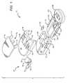
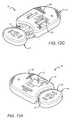
- FIG. 6is a perspective view of an embodiment of a lens packaging system in accordance with the present invention.
- the lid 14 of the packaging system 10also includes one or more longitudinal side-slots 68 .
- Each side-slot 68is positioned on either side of the indentations/tabs 66 and are designed to accommodate the guideposts of the lock 16 .
- FIGS. 2A, 2B, 5A, 5B, 6 and 7it is instructive to first describe the lock 16 of the present invention. For this purpose, reference is made to FIGS. 2A, 2B, 5A, 5B, 6 and 7 .
Landscapes
- Health & Medical Sciences (AREA)
- Ophthalmology & Optometry (AREA)
- Cardiology (AREA)
- Oral & Maxillofacial Surgery (AREA)
- Transplantation (AREA)
- Engineering & Computer Science (AREA)
- Biomedical Technology (AREA)
- Heart & Thoracic Surgery (AREA)
- Vascular Medicine (AREA)
- Life Sciences & Earth Sciences (AREA)
- Animal Behavior & Ethology (AREA)
- General Health & Medical Sciences (AREA)
- Public Health (AREA)
- Veterinary Medicine (AREA)
- Prostheses (AREA)
- Packaging Frangible Articles (AREA)
Abstract
Description
Claims (19)
Priority Applications (1)
| Application Number | Priority Date | Filing Date | Title |
|---|---|---|---|
| US11/563,621US9907648B2 (en) | 2003-06-02 | 2006-11-27 | Intraocular lens and cartridge packaging with lens-loading function |
Applications Claiming Priority (2)
| Application Number | Priority Date | Filing Date | Title |
|---|---|---|---|
| US10/453,830US8403941B2 (en) | 2003-06-02 | 2003-06-02 | Intraocular lens and cartridge packaging with lens-loading function |
| US11/563,621US9907648B2 (en) | 2003-06-02 | 2006-11-27 | Intraocular lens and cartridge packaging with lens-loading function |
Related Parent Applications (1)
| Application Number | Title | Priority Date | Filing Date |
|---|---|---|---|
| US10/453,830DivisionUS8403941B2 (en) | 2003-06-02 | 2003-06-02 | Intraocular lens and cartridge packaging with lens-loading function |
Publications (2)
| Publication Number | Publication Date |
|---|---|
| US20070095700A1 US20070095700A1 (en) | 2007-05-03 |
| US9907648B2true US9907648B2 (en) | 2018-03-06 |
Family
ID=33452135
Family Applications (3)
| Application Number | Title | Priority Date | Filing Date |
|---|---|---|---|
| US10/453,830Expired - LifetimeUS8403941B2 (en) | 2003-06-02 | 2003-06-02 | Intraocular lens and cartridge packaging with lens-loading function |
| US11/563,603Expired - LifetimeUS8475527B2 (en) | 2003-06-02 | 2006-11-27 | Intraocular lens and cartridge packaging with lens-loading function |
| US11/563,621Active2026-06-08US9907648B2 (en) | 2003-06-02 | 2006-11-27 | Intraocular lens and cartridge packaging with lens-loading function |
Family Applications Before (2)
| Application Number | Title | Priority Date | Filing Date |
|---|---|---|---|
| US10/453,830Expired - LifetimeUS8403941B2 (en) | 2003-06-02 | 2003-06-02 | Intraocular lens and cartridge packaging with lens-loading function |
| US11/563,603Expired - LifetimeUS8475527B2 (en) | 2003-06-02 | 2006-11-27 | Intraocular lens and cartridge packaging with lens-loading function |
Country Status (7)
| Country | Link |
|---|---|
| US (3) | US8403941B2 (en) |
| EP (2) | EP1628598B1 (en) |
| JP (1) | JP4345986B2 (en) |
| AU (1) | AU2004245116B2 (en) |
| BR (1) | BRPI0410917A (en) |
| CA (2) | CA2791285C (en) |
| WO (1) | WO2004108018A1 (en) |
Cited By (4)
| Publication number | Priority date | Publication date | Assignee | Title |
|---|---|---|---|---|
| US11058607B1 (en)* | 2015-07-14 | 2021-07-13 | Cornerstone Automation Systems, Llc | Secure portable pill canister for order fulfillment |
| US11911263B2 (en) | 2019-08-23 | 2024-02-27 | Alcon Inc. | Packaging-assisted actuation for an intraocular lens cartridge |
| US11931247B2 (en) | 2019-08-23 | 2024-03-19 | Alcon Inc. | Packaging-integrated manually actuated intraocular lens cartridge |
| RU2820458C2 (en)* | 2019-08-23 | 2024-06-04 | Алькон Инк. | Manually actuated intraocular lens cartridge integrated into package, and lens delivery device |
Families Citing this family (122)
| Publication number | Priority date | Publication date | Assignee | Title |
|---|---|---|---|---|
| USD526409S1 (en) | 1998-07-14 | 2006-08-08 | Unomedical A/S | Medical puncturing device |
| US6830562B2 (en) | 2001-09-27 | 2004-12-14 | Unomedical A/S | Injector device for placing a subcutaneous infusion set |
| FR2833154B1 (en) | 2001-12-12 | 2004-11-19 | Ioltechnologie Production | CASSETTE AND FLEXIBLE INTRAOCULAR LENS INJECTOR AND METHOD FOR INJECTING SUCH LENSES |
| ITTO20011228A1 (en) | 2001-12-28 | 2003-06-28 | Cane Srl | DISPOSABLE NEEDLE CONTAINER. |
| DE60304681T2 (en) | 2002-02-12 | 2007-01-25 | Unomedical A/S | INFUSION DEVICE WITH NADELSCHUTZHÜLSE |
| AU2003257754A1 (en) | 2002-09-02 | 2004-03-19 | Unomedical A/S | An apparatus and a method for adjustment of the length of an infusion tubing |
| US20040051019A1 (en) | 2002-09-02 | 2004-03-18 | Mogensen Lasse Wesseltoft | Apparatus for and a method of adjusting the length of an infusion tube |
| AU2003258487A1 (en) | 2002-09-02 | 2004-03-19 | Unomedical A/S | A device for subcutaneous administration of a medicament to a patient |
| EP1534378B1 (en) | 2002-09-02 | 2008-12-31 | Unomedical A/S | A device for subcutaneous administration of a medicament to a patient and tubing for same |
| DK200201823A (en) | 2002-11-26 | 2004-05-27 | Maersk Medical As | Connection piece for a hose connection |
| US20040158202A1 (en) | 2003-02-12 | 2004-08-12 | Soren Jensen | Cover |
| US7070580B2 (en) | 2003-04-01 | 2006-07-04 | Unomedical A/S | Infusion device and an adhesive sheet material and a release liner |
| US8403941B2 (en)* | 2003-06-02 | 2013-03-26 | Abbott Medical Optics Inc. | Intraocular lens and cartridge packaging with lens-loading function |
| US20070060925A1 (en)* | 2003-09-26 | 2007-03-15 | Joel Pynson | Preloaded iol injector and method |
| USD554253S1 (en) | 2003-10-15 | 2007-10-30 | Unomedical A/S | Medical infusion device |
| USD576267S1 (en) | 2003-10-15 | 2008-09-02 | Unomedical A/S | Medical infusion device |
| USD579541S1 (en) | 2003-10-15 | 2008-10-28 | Unomedical A/S | Medical insertion device |
| MXPA06010784A (en) | 2004-03-26 | 2006-12-15 | Unomedical As | Injector device for infusion set. |
| FR2873914A1 (en)* | 2004-08-06 | 2006-02-10 | Hitech Perspectives Soc Par Ac | Intraocular lens inserting process for cataract operation, involves transferring lens in injection cartridge by translation in case passage and inner surface of cartridge`s blade, and maintaining lens in cartridge when cartridge is closed |
| US8062250B2 (en) | 2004-08-10 | 2011-11-22 | Unomedical A/S | Cannula device |
| US7867199B2 (en) | 2004-12-10 | 2011-01-11 | Unomedical A/S | Inserter |
| EP1832247B1 (en) | 2004-12-27 | 2015-06-24 | Hoya Corporation | Intraocular lens implanting device |
| JP4766442B2 (en)* | 2004-12-28 | 2011-09-07 | Hoya株式会社 | Intraocular lens insertion device |
| US20060142780A1 (en)* | 2004-12-29 | 2006-06-29 | Joel Pynson | Preloaded IOL injector and method |
| US20060142781A1 (en)* | 2004-12-29 | 2006-06-29 | Joel Pynson | Preloaded IOL injector and method |
| EP1849436B1 (en) | 2005-01-26 | 2017-11-01 | Hoya Corporation | Intraocular lens insertion device |
| JP4836046B2 (en)* | 2005-02-24 | 2011-12-14 | Hoya株式会社 | Intraocular lens insertion device |
| US7985199B2 (en) | 2005-03-17 | 2011-07-26 | Unomedical A/S | Gateway system |
| DE202005009089U1 (en)* | 2005-06-10 | 2005-08-25 | Acrimed Gmbh | Device for loading intraocular lenses into injection system has locking element that interacts with vane elements to hold cartridge in position with vane elements open, locking element with handle and holding sections |
| CA2612664A1 (en) | 2005-06-28 | 2007-01-04 | Unomedical A/S | Packing for infusion set and method of applying an infusion set |
| EP1762259B2 (en) | 2005-09-12 | 2025-01-01 | Unomedical A/S | Inserter for an infusion set with a first and second spring units |
| US8574239B2 (en) | 2005-09-28 | 2013-11-05 | Hoya Corporation | Intraocular lens insertion device |
| JP4767671B2 (en)* | 2005-12-02 | 2011-09-07 | 株式会社ニデック | Intraocular lens insertion system |
| JP4877643B2 (en) | 2005-12-08 | 2012-02-15 | Hoya株式会社 | Intraocular lens insertion device |
| USD655807S1 (en) | 2005-12-09 | 2012-03-13 | Unomedical A/S | Medical device |
| US20070150054A1 (en)* | 2005-12-22 | 2007-06-28 | Joel Pynson | Apparatus and methods for loading of an IOL injector |
| US8475526B2 (en)* | 2005-12-22 | 2013-07-02 | Bausch & Lomb Incorporated | Apparatus and methods for loading of an IOL injector |
| DK1962926T3 (en) | 2005-12-23 | 2009-09-28 | Unomedical As | injection device |
| JP5312951B2 (en) | 2006-01-26 | 2013-10-09 | ウェイク・フォレスト・ユニヴァーシティ・ヘルス・サイエンシズ | Medical tools and related methods to facilitate deep endothelial corneal transplantation |
| US20070202186A1 (en) | 2006-02-22 | 2007-08-30 | Iscience Interventional Corporation | Apparatus and formulations for suprachoroidal drug delivery |
| WO2007098771A2 (en) | 2006-02-28 | 2007-09-07 | Unomedical A/S | Inserter for infusion part and infusion part provided with needle protector |
| JP4648859B2 (en)* | 2006-03-15 | 2011-03-09 | スター・ジャパン株式会社 | Intraocular lens insertion device and intraocular lens insertion system |
| CA2653631A1 (en) | 2006-06-07 | 2007-12-13 | Unomedical A/S | Inserter |
| CA2653764A1 (en) | 2006-06-09 | 2007-12-13 | Unomedical A/S | Mounting pad |
| JP2009545341A (en) | 2006-08-02 | 2009-12-24 | ウノメディカル アクティーゼルスカブ | Cannula and delivery device |
| US8460375B2 (en)* | 2006-08-14 | 2013-06-11 | Novartis Ag | Lens delivery system |
| EP1917990A1 (en) | 2006-10-31 | 2008-05-07 | Unomedical A/S | Infusion set |
| US7879090B2 (en)* | 2006-12-13 | 2011-02-01 | Bausch & Lomb Incorporated | Intraocular lens injector apparatus and methods of use |
| US20080147082A1 (en)* | 2006-12-13 | 2008-06-19 | Joel Pynson | Injector apparatus for use with intraocular lenses and methods of use |
| EP2111820A1 (en) | 2007-01-17 | 2009-10-28 | Ajl, S.a. | Container for an intraocular lens and method for applying an intraocular lens |
| US9522061B2 (en)* | 2007-02-15 | 2016-12-20 | Novartis Ag | Lens delivery system |
| US8475528B2 (en) | 2007-05-30 | 2013-07-02 | Hoya Corporation | Intraocular lens insertion device |
| JP5236638B2 (en) | 2007-05-30 | 2013-07-17 | Hoya株式会社 | Intraocular lens insertion device |
| EP2155311B1 (en) | 2007-06-20 | 2013-01-02 | Unomedical A/S | A method and an apparatus for making a catheter |
| AU2008270327A1 (en) | 2007-07-03 | 2009-01-08 | Unomedical A/S | Inserter having bistable equilibrium states |
| DE602008005153D1 (en) | 2007-07-10 | 2011-04-07 | Unomedical As | INSERT WITH TWO SPRINGS |
| JP5086713B2 (en) | 2007-07-11 | 2012-11-28 | Hoya株式会社 | Intraocular lens insertion device |
| AU2008277763B2 (en) | 2007-07-18 | 2011-11-10 | Unomedical A/S | Insertion device with pivoting action |
| US8668734B2 (en) | 2010-07-09 | 2014-03-11 | Powervision, Inc. | Intraocular lens delivery devices and methods of use |
| US8968396B2 (en) | 2007-07-23 | 2015-03-03 | Powervision, Inc. | Intraocular lens delivery systems and methods of use |
| US8956408B2 (en) | 2007-07-23 | 2015-02-17 | Powervision, Inc. | Lens delivery system |
| KR101264267B1 (en) | 2008-02-07 | 2013-05-22 | 알콘, 인코퍼레이티드 | lens delivery system cartridge |
| ATE522240T1 (en) | 2008-02-13 | 2011-09-15 | Unomedical As | SEAL BETWEEN A CANNULAR PART AND A FLUID PATH |
| US9566384B2 (en) | 2008-02-20 | 2017-02-14 | Unomedical A/S | Insertion device with horizontally moving part |
| USD615651S1 (en)* | 2008-04-28 | 2010-05-11 | Abbott Medical Optics Inc. | Back loaded intraocular lens (IOL) cartridge |
| JP5254669B2 (en) | 2008-06-05 | 2013-08-07 | Hoya株式会社 | Intraocular lens insertion device and cartridge |
| JP5470753B2 (en) | 2008-06-17 | 2014-04-16 | Hoya株式会社 | Intraocular lens insertion device |
| JP5323420B2 (en) | 2008-08-21 | 2013-10-23 | Hoya株式会社 | Intraocular lens insertion device |
| JP5416379B2 (en) | 2008-09-04 | 2014-02-12 | Hoya株式会社 | Intraocular lens insertion device |
| US8308736B2 (en) | 2008-10-13 | 2012-11-13 | Alcon Research, Ltd. | Automated intraocular lens injector device |
| US8808308B2 (en) | 2008-10-13 | 2014-08-19 | Alcon Research, Ltd. | Automated intraocular lens injector device |
| US8801780B2 (en) | 2008-10-13 | 2014-08-12 | Alcon Research, Ltd. | Plunger tip coupling device for intraocular lens injector |
| AU2009331635A1 (en) | 2008-12-22 | 2011-06-23 | Unomedical A/S | Medical device comprising adhesive pad |
| SG172876A1 (en) | 2009-01-07 | 2011-08-29 | Hoya Corp | Intraocular lens insertion device |
| US9421092B2 (en)* | 2009-02-11 | 2016-08-23 | Alcon Research, Ltd. | Automated intraocular lens injector device |
| AU2010277755A1 (en) | 2009-07-30 | 2012-02-02 | Unomedical A/S | Inserter device with horizontal moving part |
| KR20120047896A (en) | 2009-08-07 | 2012-05-14 | 우노메디컬 에이/에스 | Delivery device with sensor and one or more cannulas |
| KR20130018783A (en) | 2010-03-30 | 2013-02-25 | 우노메디컬 에이/에스 | Medical device |
| JP5735531B2 (en) | 2010-04-08 | 2015-06-17 | Hoya株式会社 | Ocular graft insertion device |
| US8308799B2 (en) | 2010-04-20 | 2012-11-13 | Alcon Research, Ltd. | Modular intraocular lens injector device |
| JP5511530B2 (en) | 2010-06-10 | 2014-06-04 | Hoya株式会社 | Intraocular lens insertion device |
| US9220590B2 (en) | 2010-06-10 | 2015-12-29 | Z Lens, Llc | Accommodative intraocular lens and method of improving accommodation |
| KR101179976B1 (en)* | 2010-06-16 | 2012-09-07 | 주식회사 알이티 | Injector for disposable intraocular lens |
| US8579969B2 (en) | 2010-07-25 | 2013-11-12 | Alcon Research, Ltd. | Dual mode automated intraocular lens injector device |
| WO2012027516A2 (en)* | 2010-08-24 | 2012-03-01 | Abbott Medical Optics Inc. | Advanced pushrod and pushrod assembly features |
| EP2433663A1 (en) | 2010-09-27 | 2012-03-28 | Unomedical A/S | Insertion system |
| EP2436412A1 (en) | 2010-10-04 | 2012-04-04 | Unomedical A/S | A sprinkler cannula |
| JP5996544B2 (en) | 2010-10-15 | 2016-09-21 | クリアサイド・バイオメディカル・インコーポレーテッドClearside Biomedical Incorporated | Eye access device |
| EP2688515B1 (en) | 2011-03-24 | 2021-05-19 | Alcon Inc. | Intraocular lens loading systems and methods of use |
| US8690941B2 (en) | 2011-10-04 | 2014-04-08 | Novartis Ag | Intraocular lens surgical system and method |
| WO2013050277A1 (en) | 2011-10-05 | 2013-04-11 | Unomedical A/S | Inserter for simultaneous insertion of multiple transcutaneous parts |
| EP2583715A1 (en) | 2011-10-19 | 2013-04-24 | Unomedical A/S | Infusion tube system and method for manufacture |
| US9440051B2 (en) | 2011-10-27 | 2016-09-13 | Unomedical A/S | Inserter for a multiplicity of subcutaneous parts |
| US8657835B2 (en) | 2012-01-27 | 2014-02-25 | Alcon Research, Ltd. | Automated intraocular lens injector device |
| WO2013116061A1 (en) | 2012-02-03 | 2013-08-08 | Forsight Vision4, Inc. | Insertion and removal methods and apparatus for therapeutic devices |
| US9364318B2 (en) | 2012-05-10 | 2016-06-14 | Z Lens, Llc | Accommodative-disaccommodative intraocular lens |
| US9962256B2 (en) | 2012-08-15 | 2018-05-08 | The Arizona Board Of Regents On Behalf Of The University Of Arizona | Buttressed haptic |
| USD704072S1 (en) | 2012-09-12 | 2014-05-06 | Apple Inc. | Packaging with accessories |
| KR20210133321A (en) | 2012-11-08 | 2021-11-05 | 클리어사이드 바이오메디컬, 인코포레이드 | Methods and devices for the treatment of ocular disease in human subjects |
| DE102012223885B4 (en)* | 2012-12-20 | 2022-01-05 | Humanoptics Ag | Intraocular lens storage system, transfer arrangement and method for transferring an intraocular lens to an injection device |
| EP3785668A1 (en) | 2013-03-15 | 2021-03-03 | Alcon Inc. | Intraocular lens storage and loading devices and methods of use |
| CA2911290C (en) | 2013-05-03 | 2021-07-27 | Clearside Biomedical, Inc. | Apparatus and methods for ocular injection |
| US20150114855A1 (en)* | 2013-10-24 | 2015-04-30 | Aaren Scientific Inc. | Hydrophilic iol packaging system |
| US10231826B2 (en)* | 2013-11-20 | 2019-03-19 | Medicontur Orvostechnikal Kft | Preloaded injector with rotatable member for storing and injecting hydrophobic intra ocular lenses |
| ES2803102T3 (en)* | 2014-07-15 | 2021-01-22 | Forsight Vision4 Inc | Eye implant delivery device |
| JP6646987B2 (en) | 2015-09-16 | 2020-02-14 | Hoya株式会社 | Intraocular lens insertion device |
| EP3351212B2 (en) | 2015-09-16 | 2023-08-23 | HOYA Corporation | Intraocular lens insertion tool |
| EP3181060B1 (en) | 2015-12-14 | 2018-12-05 | Stryker European Holdings I, LLC | Universal sterile packaging assembly |
| EP3413851B1 (en) | 2016-02-10 | 2023-09-27 | Clearside Biomedical, Inc. | Packaging |
| WO2017192565A1 (en) | 2016-05-02 | 2017-11-09 | Clearside Biomedical, Inc. | Systems and methods for ocular drug delivery |
| JP6929843B2 (en) | 2016-06-28 | 2021-09-01 | Hoya株式会社 | Intraocular lens inserter |
| EP3476374B1 (en) | 2016-06-28 | 2025-01-08 | Hoya Corporation | Intraocular lens insertion tool |
| US10973681B2 (en) | 2016-08-12 | 2021-04-13 | Clearside Biomedical, Inc. | Devices and methods for adjusting the insertion depth of a needle for medicament delivery |
| US10512535B2 (en) | 2016-08-24 | 2019-12-24 | Z Lens, Llc | Dual mode accommodative-disaccomodative intraocular lens |
| US10299877B2 (en)* | 2017-03-15 | 2019-05-28 | K2M, Inc. | Package for medical device |
| US10792143B2 (en) | 2017-04-28 | 2020-10-06 | Howmedica Osteonics Corp. | Snap lock packaging |
| US12090294B2 (en) | 2017-05-02 | 2024-09-17 | Georgia Tech Research Corporation | Targeted drug delivery methods using a microneedle |
| JP7162443B2 (en) | 2018-05-16 | 2022-10-28 | Hoya株式会社 | intraocular ring inserter with container |
| JP7162445B2 (en) | 2018-05-25 | 2022-10-28 | Hoya株式会社 | intraocular lens inserter |
| CN113164282B (en)* | 2018-12-11 | 2024-03-29 | 爱尔康公司 | Loop optics management system utilizing squid clips |
| US11678973B2 (en)* | 2020-05-27 | 2023-06-20 | EyeYon Medical Ltd. | Corneal implant injector system |
| DE102023105064B3 (en) | 2023-03-01 | 2024-05-08 | Carl Zeiss Meditec Ag | Packaging arrangement with an injector for introducing an intraocular lens into the capsular bag of an eye |
Citations (55)
| Publication number | Priority date | Publication date | Assignee | Title |
|---|---|---|---|---|
| US4199826A (en) | 1977-08-04 | 1980-04-29 | Eileen Devereux | Portable toilet combination |
| US4402396A (en) | 1982-02-16 | 1983-09-06 | Cooper Laboratories, Inc. | Intraocular lens case |
| US4763650A (en) | 1987-01-20 | 1988-08-16 | Hauser Stephen G | Instrument for inserting a deformable lens into the eye |
| US4765329A (en) | 1987-10-19 | 1988-08-23 | Cumming, Redwitz & Wilson, Inc. | Intraocular lens insertion instrument |
| US4817789A (en) | 1987-09-23 | 1989-04-04 | Allergan, Inc. | Lens container assembly |
| US4834094A (en) | 1987-10-07 | 1989-05-30 | Patton Medical Technologies, Inc. | "Canoe" apparatus for inserting intra-ocular lens into the eye |
| US4836201A (en) | 1988-03-24 | 1989-06-06 | Patton Medical Technologies, Inc. | "Envelope" apparatus for inserting intra-ocular lens into the eye |
| US4862885A (en) | 1988-05-25 | 1989-09-05 | Cumming J Stuart | Instrument for inserting a deformable intraocular lens into the eye |
| US4919130A (en) | 1986-11-07 | 1990-04-24 | Nestle S.A. | Tool for inserting compressible intraocular lenses into the eye and method |
| US4976716A (en) | 1989-01-23 | 1990-12-11 | Cumming J Stuart | Intraocular lens insertion device |
| EP0402138A1 (en) | 1989-06-09 | 1990-12-12 | Ioptex Research Inc. | Method and apparatus for holding and folding deformable elastic intraocular lenses |
| US5066297A (en)* | 1989-01-23 | 1991-11-19 | Cumming J Stuart | Intraocular lens insertion device |
| US5123905A (en) | 1991-06-07 | 1992-06-23 | Kelman Charles D | Intraocular lens injector |
| US5139501A (en) | 1990-12-07 | 1992-08-18 | Dieter Klaas | Device for folding an elastic rubber intraocular lens |
| US5176686A (en) | 1987-03-26 | 1993-01-05 | Poley Brooks J | Apparatus for packaging, folding, rigidifying and inserting an intraocular lens |
| US5199559A (en) | 1992-03-16 | 1993-04-06 | Ioptex Research, Inc. | Intraocular lens case |
| US5281227A (en) | 1992-11-09 | 1994-01-25 | Allergan, Inc. | Lens case with IOL folding device |
| WO1994020027A1 (en) | 1993-03-09 | 1994-09-15 | Chiron Vision Corporation | Apparatus and method for preparing an intraocular lens for insertion |
| US5356006A (en) | 1992-12-16 | 1994-10-18 | Ethicon, Inc. | Sterile package for surgical devices |
| US5578042A (en)* | 1994-03-14 | 1996-11-26 | Cumming; J. Stuart | Ophthalmic kit and method for lens insertion |
| US5582614A (en)* | 1992-09-30 | 1996-12-10 | Staar Surgical Company, Inc. | Intraocular lens insertion system |
| WO1997020661A1 (en) | 1995-12-04 | 1997-06-12 | Unova Industrial Automation Systems Inc. | Motorized spindle with indexing fixture |
| US5647372A (en) | 1992-06-30 | 1997-07-15 | United States Surgical Corporation | Specimen retrieval pouch and method for use |
| US5752923A (en) | 1996-06-24 | 1998-05-19 | Medical Device Technologies, Inc. | Biopsy instrument with handle and needle set |
| WO1998020819A1 (en) | 1996-11-15 | 1998-05-22 | Cumming J Stuart | Ophthalmic lens insertion instrument and package |
| WO1998026189A1 (en) | 1996-12-09 | 1998-06-18 | Skf France | Rolling bearing of steering column for motor vehicles |
| US5800441A (en) | 1994-07-15 | 1998-09-01 | Micro Medical Devices | Foldable lens delivery system |
| WO1999029267A1 (en) | 1997-12-09 | 1999-06-17 | Allergan Sales, Inc. | Folding device and method for an intraocular lens |
| US6048347A (en) | 1995-11-01 | 2000-04-11 | Micro Medical Devices, Inc. | Lens storage and folding apparatus |
| US6129733A (en) | 1999-04-15 | 2000-10-10 | Allergan Sales, Inc. | Apparatus for holding intraocular lenses and injectors, and methods for using same |
| US6143000A (en) | 1992-09-30 | 2000-11-07 | Staar Surgical Company, Inc. | Hingeless intraocular lens microcartridges |
| US6183513B1 (en) | 1998-06-05 | 2001-02-06 | Bausch & Lomb Surgical, Inc. | Intraocular lens packaging system, method of producing, and method of using |
| JP2001104363A (en) | 1999-10-05 | 2001-04-17 | Canon Star Kk | System for inserting intraocular insertion lens |
| US6228094B1 (en)* | 1995-11-01 | 2001-05-08 | Micro Medical Devices, Inc. | Lens storage and folding apparatus |
| US20010004052A1 (en) | 1999-12-09 | 2001-06-21 | Menicon Co., Ltd. | Soft intraocular lens container having folding function |
| US20010041897A1 (en) | 1992-09-30 | 2001-11-15 | William L. Klima | Method preloading a deformable intraocular lens into injecting apparatus for storage and/or shipment |
| US6336932B1 (en) | 1994-08-05 | 2002-01-08 | Bausch & Lomb Surgical, Inc. | Device for inserting a flexible intraocular lens |
| US6355046B2 (en) | 1997-03-07 | 2002-03-12 | Canon Staar Co., Inc. | Inserting device for deformable intraocular lens |
| US6386357B1 (en)* | 1999-07-12 | 2002-05-14 | Hoya Healthcare Corporation | Soft intraocular lens-folding device and storage case |
| US20020082609A1 (en)* | 2000-12-21 | 2002-06-27 | Green George F. | Intraocular lens and additive packaging system |
| US20020103490A1 (en) | 2001-01-26 | 2002-08-01 | Allergan Sales, Inc. | Apparatus and method for multiply folding and inserting an intraocular lens in an eye |
| US20020108875A1 (en) | 2000-12-11 | 2002-08-15 | Ethicon, Inc. | Packaging assembly for surgical use |
| US6497708B1 (en) | 1998-05-11 | 2002-12-24 | Medevec Licensing, B.V. | Intraocular lens insertion instrument |
| US6497709B1 (en) | 1992-03-31 | 2002-12-24 | Boston Scientific Corporation | Metal medical device |
| US6500181B1 (en) | 2000-10-17 | 2002-12-31 | Valdemar Portney | Instrument for folding and inserting anterior chamber intraocular lenses |
| FR2833154A1 (en) | 2001-12-12 | 2003-06-13 | Ioltechnologie Production | CASSETTE AND FLEXIBLE INTRAOCULAR LENS INJECTOR AND METHOD FOR INJECTING SUCH LENSES |
| US20030209452A1 (en)* | 2001-05-25 | 2003-11-13 | Kikuo Mitomo | Storage case having soft intraocular lens folding funtion |
| WO2004018175A1 (en) | 2002-07-09 | 2004-03-04 | Ichimaru Giken Co., Ltd. | Piping structure in tire-vulcanizing machine |
| US20040059343A1 (en) | 2002-09-25 | 2004-03-25 | Kevin Shearer | Novel enhanced system for intraocular lens insertion |
| US20040238392A1 (en) | 2003-06-02 | 2004-12-02 | Peterson Rod T. | Intraocular lens and cartridge packaging with lens-loading function |
| US20050163686A1 (en) | 2004-01-15 | 2005-07-28 | William I. Summers | Sterilization case with matrix base |
| US6960200B2 (en) | 1996-09-06 | 2005-11-01 | Medtronic Xomed, Inc. | Package for removable device tips |
| US20060200167A1 (en) | 2005-03-02 | 2006-09-07 | Peterson Rod T | Devices and methods for storing, loading, and delivering an intraocular lens |
| US7172104B2 (en) | 2004-02-17 | 2007-02-06 | Tyco Healthcare Group Lp | Surgical stapling apparatus |
| US20070060925A1 (en) | 2003-09-26 | 2007-03-15 | Joel Pynson | Preloaded iol injector and method |
- 2003
- 2003-06-02USUS10/453,830patent/US8403941B2/ennot_activeExpired - Lifetime
- 2004
- 2004-06-01CACA2791285Apatent/CA2791285C/ennot_activeExpired - Lifetime
- 2004-06-01EPEP04754706.2Apatent/EP1628598B1/ennot_activeExpired - Lifetime
- 2004-06-01JPJP2006509085Apatent/JP4345986B2/ennot_activeExpired - Fee Related
- 2004-06-01BRBRPI0410917-1Apatent/BRPI0410917A/ennot_activeApplication Discontinuation
- 2004-06-01EPEP11184829.7Apatent/EP2407126B1/ennot_activeExpired - Lifetime
- 2004-06-01CACA2527891Apatent/CA2527891C/ennot_activeExpired - Lifetime
- 2004-06-01AUAU2004245116Apatent/AU2004245116B2/ennot_activeCeased
- 2004-06-01WOPCT/US2004/018175patent/WO2004108018A1/enactiveApplication Filing
- 2006
- 2006-11-27USUS11/563,603patent/US8475527B2/ennot_activeExpired - Lifetime
- 2006-11-27USUS11/563,621patent/US9907648B2/enactiveActive
Patent Citations (67)
| Publication number | Priority date | Publication date | Assignee | Title |
|---|---|---|---|---|
| US4199826A (en) | 1977-08-04 | 1980-04-29 | Eileen Devereux | Portable toilet combination |
| US4402396A (en) | 1982-02-16 | 1983-09-06 | Cooper Laboratories, Inc. | Intraocular lens case |
| US4919130A (en) | 1986-11-07 | 1990-04-24 | Nestle S.A. | Tool for inserting compressible intraocular lenses into the eye and method |
| US4763650A (en) | 1987-01-20 | 1988-08-16 | Hauser Stephen G | Instrument for inserting a deformable lens into the eye |
| US5176686A (en) | 1987-03-26 | 1993-01-05 | Poley Brooks J | Apparatus for packaging, folding, rigidifying and inserting an intraocular lens |
| US4817789A (en) | 1987-09-23 | 1989-04-04 | Allergan, Inc. | Lens container assembly |
| US4834094A (en) | 1987-10-07 | 1989-05-30 | Patton Medical Technologies, Inc. | "Canoe" apparatus for inserting intra-ocular lens into the eye |
| US4765329A (en) | 1987-10-19 | 1988-08-23 | Cumming, Redwitz & Wilson, Inc. | Intraocular lens insertion instrument |
| US4836201A (en) | 1988-03-24 | 1989-06-06 | Patton Medical Technologies, Inc. | "Envelope" apparatus for inserting intra-ocular lens into the eye |
| US4862885A (en) | 1988-05-25 | 1989-09-05 | Cumming J Stuart | Instrument for inserting a deformable intraocular lens into the eye |
| US4976716A (en) | 1989-01-23 | 1990-12-11 | Cumming J Stuart | Intraocular lens insertion device |
| US5066297A (en)* | 1989-01-23 | 1991-11-19 | Cumming J Stuart | Intraocular lens insertion device |
| US5171241A (en) | 1989-06-09 | 1992-12-15 | Ioptex Research Inc. | Device for folding an intraocular lens and holding it in the folded state |
| EP0402138A1 (en) | 1989-06-09 | 1990-12-12 | Ioptex Research Inc. | Method and apparatus for holding and folding deformable elastic intraocular lenses |
| US5139501A (en) | 1990-12-07 | 1992-08-18 | Dieter Klaas | Device for folding an elastic rubber intraocular lens |
| US5123905A (en) | 1991-06-07 | 1992-06-23 | Kelman Charles D | Intraocular lens injector |
| US5199559A (en) | 1992-03-16 | 1993-04-06 | Ioptex Research, Inc. | Intraocular lens case |
| US6497709B1 (en) | 1992-03-31 | 2002-12-24 | Boston Scientific Corporation | Metal medical device |
| US5647372A (en) | 1992-06-30 | 1997-07-15 | United States Surgical Corporation | Specimen retrieval pouch and method for use |
| US6143000A (en) | 1992-09-30 | 2000-11-07 | Staar Surgical Company, Inc. | Hingeless intraocular lens microcartridges |
| US20010041897A1 (en) | 1992-09-30 | 2001-11-15 | William L. Klima | Method preloading a deformable intraocular lens into injecting apparatus for storage and/or shipment |
| US6406481B2 (en) | 1992-09-30 | 2002-06-18 | Starr Surgical Company, Inc. | Method preloading a deformable intraocular lens into injecting apparatus for storage and/or shipment |
| US5582614A (en)* | 1992-09-30 | 1996-12-10 | Staar Surgical Company, Inc. | Intraocular lens insertion system |
| US5281227A (en) | 1992-11-09 | 1994-01-25 | Allergan, Inc. | Lens case with IOL folding device |
| US5356006A (en) | 1992-12-16 | 1994-10-18 | Ethicon, Inc. | Sterile package for surgical devices |
| JPH08507457A (en) | 1993-03-09 | 1996-08-13 | チロン ビジョン コーポレイション | Preparation device and method for inserting an intraocular lens |
| WO1994020027A1 (en) | 1993-03-09 | 1994-09-15 | Chiron Vision Corporation | Apparatus and method for preparing an intraocular lens for insertion |
| US5578042A (en)* | 1994-03-14 | 1996-11-26 | Cumming; J. Stuart | Ophthalmic kit and method for lens insertion |
| US5800441A (en) | 1994-07-15 | 1998-09-01 | Micro Medical Devices | Foldable lens delivery system |
| US6336932B1 (en) | 1994-08-05 | 2002-01-08 | Bausch & Lomb Surgical, Inc. | Device for inserting a flexible intraocular lens |
| US6048347A (en) | 1995-11-01 | 2000-04-11 | Micro Medical Devices, Inc. | Lens storage and folding apparatus |
| US6228094B1 (en)* | 1995-11-01 | 2001-05-08 | Micro Medical Devices, Inc. | Lens storage and folding apparatus |
| WO1997020661A1 (en) | 1995-12-04 | 1997-06-12 | Unova Industrial Automation Systems Inc. | Motorized spindle with indexing fixture |
| US5752923A (en) | 1996-06-24 | 1998-05-19 | Medical Device Technologies, Inc. | Biopsy instrument with handle and needle set |
| US6960200B2 (en) | 1996-09-06 | 2005-11-01 | Medtronic Xomed, Inc. | Package for removable device tips |
| US6503275B1 (en) | 1996-11-15 | 2003-01-07 | Medevec Licensing, B.V. | Ophthalmic lens insertion instrument and package |
| WO1998020819A1 (en) | 1996-11-15 | 1998-05-22 | Cumming J Stuart | Ophthalmic lens insertion instrument and package |
| WO1998026189A1 (en) | 1996-12-09 | 1998-06-18 | Skf France | Rolling bearing of steering column for motor vehicles |
| US6355046B2 (en) | 1997-03-07 | 2002-03-12 | Canon Staar Co., Inc. | Inserting device for deformable intraocular lens |
| US5947974A (en) | 1997-12-09 | 1999-09-07 | Allergan | Folding device and method for an intraocular lens |
| WO1999029267A1 (en) | 1997-12-09 | 1999-06-17 | Allergan Sales, Inc. | Folding device and method for an intraocular lens |
| US6497708B1 (en) | 1998-05-11 | 2002-12-24 | Medevec Licensing, B.V. | Intraocular lens insertion instrument |
| US6183513B1 (en) | 1998-06-05 | 2001-02-06 | Bausch & Lomb Surgical, Inc. | Intraocular lens packaging system, method of producing, and method of using |
| US6447519B1 (en)* | 1999-04-15 | 2002-09-10 | Allergan Sales, Inc. | Apparatus for holding intraocular lenses and injectors, and methods for using same |
| US6129733A (en) | 1999-04-15 | 2000-10-10 | Allergan Sales, Inc. | Apparatus for holding intraocular lenses and injectors, and methods for using same |
| US6386357B1 (en)* | 1999-07-12 | 2002-05-14 | Hoya Healthcare Corporation | Soft intraocular lens-folding device and storage case |
| US20020077633A1 (en) | 1999-10-05 | 2002-06-20 | Cannon Staar Co., Inc. | Insertion system for intraocular lens |
| US6468282B2 (en) | 1999-10-05 | 2002-10-22 | Canon Staar Co., Inc. | Insertion system for intraocular lens |
| JP2001104363A (en) | 1999-10-05 | 2001-04-17 | Canon Star Kk | System for inserting intraocular insertion lens |
| US20010004052A1 (en) | 1999-12-09 | 2001-06-21 | Menicon Co., Ltd. | Soft intraocular lens container having folding function |
| US6500181B1 (en) | 2000-10-17 | 2002-12-31 | Valdemar Portney | Instrument for folding and inserting anterior chamber intraocular lenses |
| US20020108875A1 (en) | 2000-12-11 | 2002-08-15 | Ethicon, Inc. | Packaging assembly for surgical use |
| US6471708B2 (en)* | 2000-12-21 | 2002-10-29 | Bausch & Lomb Incorporated | Intraocular lens and additive packaging system |
| US20020082609A1 (en)* | 2000-12-21 | 2002-06-27 | Green George F. | Intraocular lens and additive packaging system |
| US20020103490A1 (en) | 2001-01-26 | 2002-08-01 | Allergan Sales, Inc. | Apparatus and method for multiply folding and inserting an intraocular lens in an eye |
| US20030209452A1 (en)* | 2001-05-25 | 2003-11-13 | Kikuo Mitomo | Storage case having soft intraocular lens folding funtion |
| US6786911B2 (en) | 2001-05-25 | 2004-09-07 | Hoya Healthcare Corporation | Storage case having soft intraocular lens folding function |
| WO2003049645A2 (en) | 2001-12-12 | 2003-06-19 | Ioltechnologie-Production | Cassette and injector for flexible intraocular lens and method for injecting such lenses |
| FR2833154A1 (en) | 2001-12-12 | 2003-06-13 | Ioltechnologie Production | CASSETTE AND FLEXIBLE INTRAOCULAR LENS INJECTOR AND METHOD FOR INJECTING SUCH LENSES |
| WO2004018175A1 (en) | 2002-07-09 | 2004-03-04 | Ichimaru Giken Co., Ltd. | Piping structure in tire-vulcanizing machine |
| US20040059343A1 (en) | 2002-09-25 | 2004-03-25 | Kevin Shearer | Novel enhanced system for intraocular lens insertion |
| US20040238392A1 (en) | 2003-06-02 | 2004-12-02 | Peterson Rod T. | Intraocular lens and cartridge packaging with lens-loading function |
| US20070123980A1 (en) | 2003-06-02 | 2007-05-31 | Advanced Medical Optics, Inc. | Intraocular lens and cartridge packaging with lens-loading function |
| US20070060925A1 (en) | 2003-09-26 | 2007-03-15 | Joel Pynson | Preloaded iol injector and method |
| US20050163686A1 (en) | 2004-01-15 | 2005-07-28 | William I. Summers | Sterilization case with matrix base |
| US7172104B2 (en) | 2004-02-17 | 2007-02-06 | Tyco Healthcare Group Lp | Surgical stapling apparatus |
| US20060200167A1 (en) | 2005-03-02 | 2006-09-07 | Peterson Rod T | Devices and methods for storing, loading, and delivering an intraocular lens |
Non-Patent Citations (2)
| Title |
|---|
| U.S. Appl. No. 10/453,830, filed Jun. 2, 2003. |
| U.S. Appl. No. 11/563,603, filed Nov. 27, 2006. |
Cited By (5)
| Publication number | Priority date | Publication date | Assignee | Title |
|---|---|---|---|---|
| US11058607B1 (en)* | 2015-07-14 | 2021-07-13 | Cornerstone Automation Systems, Llc | Secure portable pill canister for order fulfillment |
| US11911263B2 (en) | 2019-08-23 | 2024-02-27 | Alcon Inc. | Packaging-assisted actuation for an intraocular lens cartridge |
| US11931247B2 (en) | 2019-08-23 | 2024-03-19 | Alcon Inc. | Packaging-integrated manually actuated intraocular lens cartridge |
| RU2820458C2 (en)* | 2019-08-23 | 2024-06-04 | Алькон Инк. | Manually actuated intraocular lens cartridge integrated into package, and lens delivery device |
| RU2822649C2 (en)* | 2019-08-23 | 2024-07-11 | Алькон Инк. | Actuation by means of intraocular lens cartridge |
Also Published As
| Publication number | Publication date |
|---|---|
| US20040238392A1 (en) | 2004-12-02 |
| JP4345986B2 (en) | 2009-10-14 |
| US20070123980A1 (en) | 2007-05-31 |
| AU2004245116A1 (en) | 2004-12-16 |
| US8403941B2 (en) | 2013-03-26 |
| US20070095700A1 (en) | 2007-05-03 |
| JP2006526462A (en) | 2006-11-24 |
| EP1628598B1 (en) | 2014-05-28 |
| CA2527891A1 (en) | 2004-12-16 |
| AU2004245116B2 (en) | 2011-03-31 |
| EP2407126A1 (en) | 2012-01-18 |
| CA2527891C (en) | 2012-11-06 |
| CA2791285C (en) | 2013-09-24 |
| WO2004108018A1 (en) | 2004-12-16 |
| BRPI0410917A (en) | 2006-06-27 |
| CA2791285A1 (en) | 2004-12-16 |
| EP2407126B1 (en) | 2013-06-12 |
| US8475527B2 (en) | 2013-07-02 |
| EP1628598A1 (en) | 2006-03-01 |
Similar Documents
| Publication | Publication Date | Title |
|---|---|---|
| US9907648B2 (en) | Intraocular lens and cartridge packaging with lens-loading function | |
| US7867240B2 (en) | Devices and methods for storing, loading, and delivering an intraocular lens | |
| EP1720490B1 (en) | Devices for storing, loading, and delivering an intraocular lens | |
| EP1173115B1 (en) | Apparatus for holding intraocular lenses and injectors, and methods for using same | |
| US20090125034A1 (en) | Preloaded IOL Injector | |
| US20080147082A1 (en) | Injector apparatus for use with intraocular lenses and methods of use | |
| US20080147080A1 (en) | Injector apparatus for use with intraocular lenses and methods of use | |
| AU2011203121B2 (en) | Intraocular lens and cartridge packaging with lens-loading function | |
| AU2012202321B2 (en) | Devices and methods for storing, loading, and delivering an intraocular lens |
Legal Events
| Date | Code | Title | Description |
|---|---|---|---|
| AS | Assignment | Owner name:BANK OF AMERICA, N.A., AS ADMINISTRATIVE AGENT,NOR Free format text:INTELLECTUAL PROPERTY SECURITY AGREEMENT;ASSIGNOR:ADVANCED MEDICAL OPTICS, INC.;REEL/FRAME:019501/0069 Effective date:20070402 Owner name:BANK OF AMERICA, N.A., AS ADMINISTRATIVE AGENT, NORTH CAROLINA Free format text:INTELLECTUAL PROPERTY SECURITY AGREEMENT;ASSIGNOR:ADVANCED MEDICAL OPTICS, INC.;REEL/FRAME:019501/0069 Effective date:20070402 Owner name:BANK OF AMERICA, N.A., AS ADMINISTRATIVE AGENT, NO Free format text:INTELLECTUAL PROPERTY SECURITY AGREEMENT;ASSIGNOR:ADVANCED MEDICAL OPTICS, INC.;REEL/FRAME:019501/0069 Effective date:20070402 | |
| AS | Assignment | Owner name:ADVANCED MEDICAL OPTICS, INC., CALIFORNIA Free format text:RELEASE BY SECURED PARTY;ASSIGNOR:BANK OF AMERICA, N.A. AS ADMINISTRATIVE AGENT;REEL/FRAME:022320/0427 Effective date:20090225 Owner name:ADVANCED MEDICAL OPTICS, INC.,CALIFORNIA Free format text:RELEASE BY SECURED PARTY;ASSIGNOR:BANK OF AMERICA, N.A. AS ADMINISTRATIVE AGENT;REEL/FRAME:022320/0427 Effective date:20090225 | |
| AS | Assignment | Owner name:ABBOTT MEDICAL OPTICS INC., CALIFORNIA Free format text:MERGER;ASSIGNOR:ADVANCED MEDICAL OPTICS, INC.;REEL/FRAME:023234/0277 Effective date:20090226 Owner name:ABBOTT MEDICAL OPTICS INC.,CALIFORNIA Free format text:MERGER;ASSIGNOR:ADVANCED MEDICAL OPTICS, INC.;REEL/FRAME:023234/0277 Effective date:20090226 | |
| AS | Assignment | Owner name:ADVANCED MEDICAL OPTICS, INC., CALIFORNIA Free format text:ASSIGNMENT OF ASSIGNORS INTEREST;ASSIGNORS:PETERSON, ROD T.;COLE, MARK S.;OTT, ROBERT D.;SIGNING DATES FROM 20051108 TO 20051114;REEL/FRAME:044693/0499 | |
| STCF | Information on status: patent grant | Free format text:PATENTED CASE | |
| AS | Assignment | Owner name:JOHNSON & JOHNSON SURGICAL VISION, INC., CALIFORNIA Free format text:CHANGE OF NAME;ASSIGNOR:ABBOTT MEDICAL OPTICS INC.;REEL/FRAME:047101/0021 Effective date:20180209 Owner name:JOHNSON & JOHNSON SURGICAL VISION, INC., CALIFORNI Free format text:CHANGE OF NAME;ASSIGNOR:ABBOTT MEDICAL OPTICS INC.;REEL/FRAME:047101/0021 Effective date:20180209 | |
| MAFP | Maintenance fee payment | Free format text:PAYMENT OF MAINTENANCE FEE, 4TH YEAR, LARGE ENTITY (ORIGINAL EVENT CODE: M1551); ENTITY STATUS OF PATENT OWNER: LARGE ENTITY Year of fee payment:4 | |
| MAFP | Maintenance fee payment | Free format text:PAYMENT OF MAINTENANCE FEE, 8TH YEAR, LARGE ENTITY (ORIGINAL EVENT CODE: M1552); ENTITY STATUS OF PATENT OWNER: LARGE ENTITY Year of fee payment:8 |