US9907613B2 - Radiation applicator and method of radiating tissue - Google Patents
Radiation applicator and method of radiating tissueDownload PDFInfo
- Publication number
- US9907613B2 US9907613B2US14/940,354US201514940354AUS9907613B2US 9907613 B2US9907613 B2US 9907613B2US 201514940354 AUS201514940354 AUS 201514940354AUS 9907613 B2US9907613 B2US 9907613B2
- Authority
- US
- United States
- Prior art keywords
- ferrule
- conductor
- distal
- applicator
- tissue
- Prior art date
- Legal status (The legal status is an assumption and is not a legal conclusion. Google has not performed a legal analysis and makes no representation as to the accuracy of the status listed.)
- Active
Links
Images


Classifications
- A—HUMAN NECESSITIES
- A61—MEDICAL OR VETERINARY SCIENCE; HYGIENE
- A61B—DIAGNOSIS; SURGERY; IDENTIFICATION
- A61B18/00—Surgical instruments, devices or methods for transferring non-mechanical forms of energy to or from the body
- A61B18/18—Surgical instruments, devices or methods for transferring non-mechanical forms of energy to or from the body by applying electromagnetic radiation, e.g. microwaves
- A61B18/1815—Surgical instruments, devices or methods for transferring non-mechanical forms of energy to or from the body by applying electromagnetic radiation, e.g. microwaves using microwaves
- A—HUMAN NECESSITIES
- A61—MEDICAL OR VETERINARY SCIENCE; HYGIENE
- A61B—DIAGNOSIS; SURGERY; IDENTIFICATION
- A61B18/00—Surgical instruments, devices or methods for transferring non-mechanical forms of energy to or from the body
- A61B18/04—Surgical instruments, devices or methods for transferring non-mechanical forms of energy to or from the body by heating
- A—HUMAN NECESSITIES
- A61—MEDICAL OR VETERINARY SCIENCE; HYGIENE
- A61B—DIAGNOSIS; SURGERY; IDENTIFICATION
- A61B18/00—Surgical instruments, devices or methods for transferring non-mechanical forms of energy to or from the body
- A61B18/18—Surgical instruments, devices or methods for transferring non-mechanical forms of energy to or from the body by applying electromagnetic radiation, e.g. microwaves
- A—HUMAN NECESSITIES
- A61—MEDICAL OR VETERINARY SCIENCE; HYGIENE
- A61N—ELECTROTHERAPY; MAGNETOTHERAPY; RADIATION THERAPY; ULTRASOUND THERAPY
- A61N5/00—Radiation therapy
- G—PHYSICS
- G06—COMPUTING OR CALCULATING; COUNTING
- G06T—IMAGE DATA PROCESSING OR GENERATION, IN GENERAL
- G06T7/00—Image analysis
- G06T7/30—Determination of transform parameters for the alignment of images, i.e. image registration
- A—HUMAN NECESSITIES
- A61—MEDICAL OR VETERINARY SCIENCE; HYGIENE
- A61B—DIAGNOSIS; SURGERY; IDENTIFICATION
- A61B18/00—Surgical instruments, devices or methods for transferring non-mechanical forms of energy to or from the body
- A61B2018/00005—Cooling or heating of the probe or tissue immediately surrounding the probe
- A61B2018/00011—Cooling or heating of the probe or tissue immediately surrounding the probe with fluids
- A61B2018/00023—Cooling or heating of the probe or tissue immediately surrounding the probe with fluids closed, i.e. without wound contact by the fluid
- A—HUMAN NECESSITIES
- A61—MEDICAL OR VETERINARY SCIENCE; HYGIENE
- A61B—DIAGNOSIS; SURGERY; IDENTIFICATION
- A61B18/00—Surgical instruments, devices or methods for transferring non-mechanical forms of energy to or from the body
- A61B2018/00005—Cooling or heating of the probe or tissue immediately surrounding the probe
- A61B2018/00011—Cooling or heating of the probe or tissue immediately surrounding the probe with fluids
- A61B2018/00029—Cooling or heating of the probe or tissue immediately surrounding the probe with fluids open
- A—HUMAN NECESSITIES
- A61—MEDICAL OR VETERINARY SCIENCE; HYGIENE
- A61B—DIAGNOSIS; SURGERY; IDENTIFICATION
- A61B18/00—Surgical instruments, devices or methods for transferring non-mechanical forms of energy to or from the body
- A61B2018/00053—Mechanical features of the instrument of device
- A61B2018/00059—Material properties
- A61B2018/00071—Electrical conductivity
- A61B2018/00077—Electrical conductivity high, i.e. electrically conducting
- A—HUMAN NECESSITIES
- A61—MEDICAL OR VETERINARY SCIENCE; HYGIENE
- A61B—DIAGNOSIS; SURGERY; IDENTIFICATION
- A61B18/00—Surgical instruments, devices or methods for transferring non-mechanical forms of energy to or from the body
- A61B2018/00053—Mechanical features of the instrument of device
- A61B2018/00059—Material properties
- A61B2018/00071—Electrical conductivity
- A61B2018/00083—Electrical conductivity low, i.e. electrically insulating
- A—HUMAN NECESSITIES
- A61—MEDICAL OR VETERINARY SCIENCE; HYGIENE
- A61B—DIAGNOSIS; SURGERY; IDENTIFICATION
- A61B18/00—Surgical instruments, devices or methods for transferring non-mechanical forms of energy to or from the body
- A61B2018/00053—Mechanical features of the instrument of device
- A61B2018/00172—Connectors and adapters therefor
- A61B2018/00178—Electrical connectors
- A—HUMAN NECESSITIES
- A61—MEDICAL OR VETERINARY SCIENCE; HYGIENE
- A61B—DIAGNOSIS; SURGERY; IDENTIFICATION
- A61B18/00—Surgical instruments, devices or methods for transferring non-mechanical forms of energy to or from the body
- A61B2018/00571—Surgical instruments, devices or methods for transferring non-mechanical forms of energy to or from the body for achieving a particular surgical effect
- A61B2018/00577—Ablation
- A—HUMAN NECESSITIES
- A61—MEDICAL OR VETERINARY SCIENCE; HYGIENE
- A61B—DIAGNOSIS; SURGERY; IDENTIFICATION
- A61B18/00—Surgical instruments, devices or methods for transferring non-mechanical forms of energy to or from the body
- A61B18/18—Surgical instruments, devices or methods for transferring non-mechanical forms of energy to or from the body by applying electromagnetic radiation, e.g. microwaves
- A61B18/1815—Surgical instruments, devices or methods for transferring non-mechanical forms of energy to or from the body by applying electromagnetic radiation, e.g. microwaves using microwaves
- A61B2018/183—Surgical instruments, devices or methods for transferring non-mechanical forms of energy to or from the body by applying electromagnetic radiation, e.g. microwaves using microwaves characterised by the type of antenna
- A61B2018/1838—Dipole antennas
- A—HUMAN NECESSITIES
- A61—MEDICAL OR VETERINARY SCIENCE; HYGIENE
- A61B—DIAGNOSIS; SURGERY; IDENTIFICATION
- A61B18/00—Surgical instruments, devices or methods for transferring non-mechanical forms of energy to or from the body
- A61B18/18—Surgical instruments, devices or methods for transferring non-mechanical forms of energy to or from the body by applying electromagnetic radiation, e.g. microwaves
- A61B18/1815—Surgical instruments, devices or methods for transferring non-mechanical forms of energy to or from the body by applying electromagnetic radiation, e.g. microwaves using microwaves
- A61B2018/1869—Surgical instruments, devices or methods for transferring non-mechanical forms of energy to or from the body by applying electromagnetic radiation, e.g. microwaves using microwaves with an instrument interstitially inserted into the body, e.g. needles
- A—HUMAN NECESSITIES
- A61—MEDICAL OR VETERINARY SCIENCE; HYGIENE
- A61B—DIAGNOSIS; SURGERY; IDENTIFICATION
- A61B18/00—Surgical instruments, devices or methods for transferring non-mechanical forms of energy to or from the body
- A61B18/18—Surgical instruments, devices or methods for transferring non-mechanical forms of energy to or from the body by applying electromagnetic radiation, e.g. microwaves
- A61B18/1815—Surgical instruments, devices or methods for transferring non-mechanical forms of energy to or from the body by applying electromagnetic radiation, e.g. microwaves using microwaves
- A61B2018/1892—Details of electrical isolations of the antenna
- A—HUMAN NECESSITIES
- A61—MEDICAL OR VETERINARY SCIENCE; HYGIENE
- A61N—ELECTROTHERAPY; MAGNETOTHERAPY; RADIATION THERAPY; ULTRASOUND THERAPY
- A61N5/00—Radiation therapy
- A61N5/02—Radiation therapy using microwaves
- A61N5/04—Radiators for near-field treatment
- A61N5/045—Radiators for near-field treatment specially adapted for treatment inside the body
Definitions
- FIG. 3shows a partial transverse cross-section of the tube of the radiation applicator of FIG. 1 ;
- FIG. 8is a plot of S 11 against frequency for the radiation applicator of FIG. 1 ;
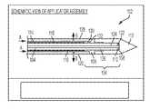
- FIG. 1is a schematic, partial cross-sectional view of a radiation applicator in accordance with one embodiment of the invention.
- the radiation applicatorgenerally designated 102 , includes a distal end portion of a coaxial cable 104 that is used to couple to a source (not shown) of microwaves, a copper ferrule 106 , a tuning washer 108 attached on the end 110 of the insulator part of the coaxial cable 104 , and a tip 112 .
- the applicator 102further includes a metal tube 114 . Tube 114 is rigidly attached to the ferrule 106 .
- the tip 112is preferably coated with a non-stick layer such as silicone or paralene, to facilitate movement of the tip 112 relative to tissue.
- a non-stick layersuch as silicone or paralene
- the tube 114is then slid over the cable 104 .
- the ferrule rule 106is slid over the cable 104 ( FIG. 10C ), and fixedly attached to the tube 114 and to the cable 104 , as described earlier.
- the washer 108is attached to the inner conductor 124 by soldering, as shown in FIG. 10D .
- the tip 112is slid over the cable 104 and part of the ferrule 106 , and affixed thereto, as described earlier.
- the completed applicatoris shown in FIG. 10E . This results in a construction of great rigidity and mechanical stability.
- the cooling systemis an open, perusing totaling system that cools the coaxial cable connected to the radiation applicator 102 . That is, after absorbing heat from the coaxial cable, the cooling fluid perfuses the tissue near the radiation applicator 102 .
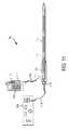
- the sleeve 1234is formed from stainless steel, and the ferrule 1212 is formed from gold-plated copper.
- the tip 1226 and the spacer 1220are formed from dielectric materials.
- the tip 1226 and the spacer 1220are formed from an itrium stabilized zirconia, such as the Technox brand of ceramic material commercially available from Dynamic Ceramic Ltd. of Stoke-on-Trent, Staffordshire, England, which has a dielectric constant of 25.
- the tip 1226may be further provided with a composite coating, such as a polyimide undercoat layer, for adhesion, and a paralyne overcoat layer, for its non-stick properties. Alternatively, silicone or some other suitable material could be used in place of paralyne.
- the composite coatingmay also be applied to the ferrule and at least part of the stainless steel sleeve, in addition to being applied to the tip.
- the radiation applicator 1202is attached to a source of microwave radiation in a similar manner, as described above in connection with the applicator 102 of FIG. 1 .
- the coaxial cableis also attached to a source of cooling fluid in a similar manner as described above.
- the present inventionit is the dielectric tip, ferrule and stainless steel sleeve that cooperate to provide the necessary stiffness and mechanical strength for the applicator to be used in treatment procedures.
- the applicatordoes not rely on the coaxial cable for any of its strength. Indeed, a flexible coaxial cable, having little or no rigidity, could be used with the radiation applicator of the present invention.
Landscapes
- Health & Medical Sciences (AREA)
- Life Sciences & Earth Sciences (AREA)
- Engineering & Computer Science (AREA)
- Surgery (AREA)
- Biomedical Technology (AREA)
- Public Health (AREA)
- Animal Behavior & Ethology (AREA)
- General Health & Medical Sciences (AREA)
- Veterinary Medicine (AREA)
- Nuclear Medicine, Radiotherapy & Molecular Imaging (AREA)
- Physics & Mathematics (AREA)
- Medical Informatics (AREA)
- Heart & Thoracic Surgery (AREA)
- Otolaryngology (AREA)
- Molecular Biology (AREA)
- Electromagnetism (AREA)
- Radiology & Medical Imaging (AREA)
- Pathology (AREA)
- Plasma & Fusion (AREA)
- Computer Vision & Pattern Recognition (AREA)
- General Physics & Mathematics (AREA)
- Theoretical Computer Science (AREA)
- Surgical Instruments (AREA)
- Radiation-Therapy Devices (AREA)
Abstract
Description
Claims (20)
Priority Applications (1)
| Application Number | Priority Date | Filing Date | Title |
|---|---|---|---|
| US14/940,354US9907613B2 (en) | 2005-07-01 | 2015-11-13 | Radiation applicator and method of radiating tissue |
Applications Claiming Priority (7)
| Application Number | Priority Date | Filing Date | Title |
|---|---|---|---|
| PCT/EP2005/007103WO2006002943A1 (en) | 2004-07-02 | 2005-07-01 | Radiation applicator and method of radiating tissue |
| US10/577,414US9788896B2 (en) | 2004-07-02 | 2005-07-01 | Radiation applicator and method of radiating tissue |
| EPPCT/EP2005/007103 | 2005-07-01 | ||
| GB600018.6 | 2006-01-03 | ||
| GBGB600018.6 | 2006-01-03 | ||
| GB0600018AGB2434314B (en) | 2006-01-03 | 2006-01-03 | Microwave applicator with dipole antenna |
| US14/940,354US9907613B2 (en) | 2005-07-01 | 2015-11-13 | Radiation applicator and method of radiating tissue |
Related Parent Applications (1)
| Application Number | Title | Priority Date | Filing Date |
|---|---|---|---|
| US10/577,414DivisionUS9788896B2 (en) | 2004-07-02 | 2005-07-01 | Radiation applicator and method of radiating tissue |
Publications (2)
| Publication Number | Publication Date |
|---|---|
| US20160262832A1 US20160262832A1 (en) | 2016-09-15 |
| US9907613B2true US9907613B2 (en) | 2018-03-06 |
Family
ID=35841437
Family Applications (3)
| Application Number | Title | Priority Date | Filing Date |
|---|---|---|---|
| US12/158,831AbandonedUS20080294155A1 (en) | 2006-01-03 | 2006-12-15 | Radiation Applicator and Method of Radiating Tissue |
| US11/646,141AbandonedUS20070203551A1 (en) | 2005-07-01 | 2006-12-27 | Radiation applicator and method of radiating tissue |
| US14/940,354ActiveUS9907613B2 (en) | 2005-07-01 | 2015-11-13 | Radiation applicator and method of radiating tissue |
Family Applications Before (2)
| Application Number | Title | Priority Date | Filing Date |
|---|---|---|---|
| US12/158,831AbandonedUS20080294155A1 (en) | 2006-01-03 | 2006-12-15 | Radiation Applicator and Method of Radiating Tissue |
| US11/646,141AbandonedUS20070203551A1 (en) | 2005-07-01 | 2006-12-27 | Radiation applicator and method of radiating tissue |
Country Status (12)
| Country | Link |
|---|---|
| US (3) | US20080294155A1 (en) |
| EP (1) | EP1968469B8 (en) |
| JP (1) | JP5318581B2 (en) |
| KR (1) | KR20080092402A (en) |
| CN (1) | CN101631506B (en) |
| AU (1) | AU2006332213B2 (en) |
| BR (1) | BRPI0620875A2 (en) |
| CA (1) | CA2635316A1 (en) |
| GB (1) | GB2434314B (en) |
| IL (1) | IL192469A0 (en) |
| TW (1) | TW200740407A (en) |
| WO (1) | WO2007076924A2 (en) |
Cited By (1)
| Publication number | Priority date | Publication date | Assignee | Title |
|---|---|---|---|---|
| USD1084316S1 (en) | 2023-11-20 | 2025-07-15 | Angiodynamics, Inc. | Ferrule |
Families Citing this family (95)
| Publication number | Priority date | Publication date | Assignee | Title |
|---|---|---|---|---|
| US6878147B2 (en) | 2001-11-02 | 2005-04-12 | Vivant Medical, Inc. | High-strength microwave antenna assemblies |
| US7128739B2 (en) | 2001-11-02 | 2006-10-31 | Vivant Medical, Inc. | High-strength microwave antenna assemblies and methods of use |
| GB2403148C2 (en) | 2003-06-23 | 2013-02-13 | Microsulis Ltd | Radiation applicator |
| US7311703B2 (en) | 2003-07-18 | 2007-12-25 | Vivant Medical, Inc. | Devices and methods for cooling microwave antennas |
| GB2415630C2 (en) | 2004-07-02 | 2007-03-22 | Microsulis Ltd | Radiation applicator and method of radiating tissue |
| US7799019B2 (en) | 2005-05-10 | 2010-09-21 | Vivant Medical, Inc. | Reinforced high strength microwave antenna |
| US7826904B2 (en) | 2006-02-07 | 2010-11-02 | Angiodynamics, Inc. | Interstitial microwave system and method for thermal treatment of diseases |
| US10363092B2 (en) | 2006-03-24 | 2019-07-30 | Neuwave Medical, Inc. | Transmission line with heat transfer ability |
| US11389235B2 (en) | 2006-07-14 | 2022-07-19 | Neuwave Medical, Inc. | Energy delivery systems and uses thereof |
| US10376314B2 (en) | 2006-07-14 | 2019-08-13 | Neuwave Medical, Inc. | Energy delivery systems and uses thereof |
| GB0624658D0 (en) | 2006-12-11 | 2007-01-17 | Medical Device Innovations Ltd | Electrosurgical ablation apparatus and a method of ablating biological tissue |
| US7998139B2 (en)* | 2007-04-25 | 2011-08-16 | Vivant Medical, Inc. | Cooled helical antenna for microwave ablation |
| US8353901B2 (en) | 2007-05-22 | 2013-01-15 | Vivant Medical, Inc. | Energy delivery conduits for use with electrosurgical devices |
| US9023024B2 (en) | 2007-06-20 | 2015-05-05 | Covidien Lp | Reflective power monitoring for microwave applications |
| US20090005766A1 (en)* | 2007-06-28 | 2009-01-01 | Joseph Brannan | Broadband microwave applicator |
| US20090082762A1 (en)* | 2007-09-20 | 2009-03-26 | Ormsby Theodore C | Radio frequency energy transmission device for the ablation of biological tissues |
| US8221409B2 (en)* | 2007-12-21 | 2012-07-17 | St. Jude Medical, Atrial Fibrillation Division, Inc. | Thermally insulated irrigation catheter assembly |
| US8945111B2 (en)* | 2008-01-23 | 2015-02-03 | Covidien Lp | Choked dielectric loaded tip dipole microwave antenna |
| US8965536B2 (en) | 2008-03-03 | 2015-02-24 | Covidien Lp | Intracooled percutaneous microwave ablation probe |
| US9198723B2 (en) | 2008-03-31 | 2015-12-01 | Covidien Lp | Re-hydration antenna for ablation |
| US8059059B2 (en)* | 2008-05-29 | 2011-11-15 | Vivant Medical, Inc. | Slidable choke microwave antenna |
| US8251987B2 (en) | 2008-08-28 | 2012-08-28 | Vivant Medical, Inc. | Microwave antenna |
| US8403924B2 (en) | 2008-09-03 | 2013-03-26 | Vivant Medical, Inc. | Shielding for an isolation apparatus used in a microwave generator |
| US8394086B2 (en)* | 2008-09-03 | 2013-03-12 | Vivant Medical, Inc. | Microwave shielding apparatus |
| US9113924B2 (en) | 2008-10-17 | 2015-08-25 | Covidien Lp | Choked dielectric loaded tip dipole microwave antenna |
| US8118808B2 (en)* | 2009-03-10 | 2012-02-21 | Vivant Medical, Inc. | Cooled dielectrically buffered microwave dipole antenna |
| US8632534B2 (en) | 2009-04-03 | 2014-01-21 | Angiodynamics, Inc. | Irreversible electroporation (IRE) for congestive obstructive pulmonary disease (COPD) |
| US10022202B2 (en) | 2013-03-15 | 2018-07-17 | Triagenics, Llc | Therapeutic tooth bud ablation |
| WO2014143014A1 (en) | 2013-03-15 | 2014-09-18 | Triagenics, Llc | Therapeutic tooth bud ablation |
| CA2761652C (en) | 2009-05-11 | 2019-10-01 | Leigh E. Colby | Therapeutic tooth bud ablation |
| WO2010138919A2 (en) | 2009-05-28 | 2010-12-02 | Angiodynamics, Inc. | System and method for synchronizing energy delivery to the cardiac rhythm |
| US9895189B2 (en) | 2009-06-19 | 2018-02-20 | Angiodynamics, Inc. | Methods of sterilization and treating infection using irreversible electroporation |
| EP3549544B1 (en) | 2009-07-28 | 2021-01-06 | Neuwave Medical, Inc. | DEVICE FOR ABLATION |
| US8328801B2 (en)* | 2009-08-17 | 2012-12-11 | Vivant Medical, Inc. | Surface ablation antenna with dielectric loading |
| TWI397399B (en)* | 2009-08-26 | 2013-06-01 | Univ Nat Cheng Kung | Two-portion device for electromagnetic hyperthermia therapy |
| US8069553B2 (en) | 2009-09-09 | 2011-12-06 | Vivant Medical, Inc. | Method for constructing a dipole antenna |
| US9113925B2 (en)* | 2009-09-09 | 2015-08-25 | Covidien Lp | System and method for performing an ablation procedure |
| US9113926B2 (en) | 2009-09-29 | 2015-08-25 | Covidien Lp | Management of voltage standing wave ratio at skin surface during microwave ablation |
| US8568398B2 (en) | 2009-09-29 | 2013-10-29 | Covidien Lp | Flow rate monitor for fluid cooled microwave ablation probe |
| GB2474233A (en) | 2009-10-06 | 2011-04-13 | Uk Investments Associates Llc | Cooling pump comprising a detachable head portion |
| US8551083B2 (en) | 2009-11-17 | 2013-10-08 | Bsd Medical Corporation | Microwave coagulation applicator and system |
| US9993294B2 (en)* | 2009-11-17 | 2018-06-12 | Perseon Corporation | Microwave coagulation applicator and system with fluid injection |
| US8882759B2 (en) | 2009-12-18 | 2014-11-11 | Covidien Lp | Microwave ablation system with dielectric temperature probe |
| KR101173455B1 (en) | 2010-01-26 | 2012-08-14 | 서울대학교산학협력단 | Applicator with plural slots having each different size |
| US8568404B2 (en) | 2010-02-19 | 2013-10-29 | Covidien Lp | Bipolar electrode probe for ablation monitoring |
| US12076074B2 (en) | 2010-04-26 | 2024-09-03 | Medtronic Holding Company Sàrl | Electrosurgical device and methods |
| EP2563256B1 (en) | 2010-04-26 | 2019-08-28 | Medtronic Holding Company Sàrl | Electrosurgical device |
| ES2856026T3 (en) | 2010-05-03 | 2021-09-27 | Neuwave Medical Inc | Power supply systems |
| US8740893B2 (en) | 2010-06-30 | 2014-06-03 | Covidien Lp | Adjustable tuning of a dielectrically loaded loop antenna |
| EP2627274B1 (en) | 2010-10-13 | 2022-12-14 | AngioDynamics, Inc. | System for electrically ablating tissue of a patient |
| US9770294B2 (en) | 2011-01-05 | 2017-09-26 | Covidien Lp | Energy-delivery devices with flexible fluid-cooled shaft, inflow/outflow junctions suitable for use with same, and systems including same |
| US8932281B2 (en)* | 2011-01-05 | 2015-01-13 | Covidien Lp | Energy-delivery devices with flexible fluid-cooled shaft, inflow/outflow junctions suitable for use with same, and systems including same |
| US9017319B2 (en) | 2011-01-05 | 2015-04-28 | Covidien Lp | Energy-delivery devices with flexible fluid-cooled shaft, inflow/outflow junctions suitable for use with same, and systems including same |
| US9011421B2 (en) | 2011-01-05 | 2015-04-21 | Covidien Lp | Energy-delivery devices with flexible fluid-cooled shaft, inflow/outflow junctions suitable for use with same, and systems including same |
| US9198724B2 (en) | 2011-04-08 | 2015-12-01 | Covidien Lp | Microwave tissue dissection and coagulation |
| US20120310230A1 (en)* | 2011-06-01 | 2012-12-06 | Angiodynamics, Inc. | Coaxial dual function probe and method of use |
| US9078665B2 (en) | 2011-09-28 | 2015-07-14 | Angiodynamics, Inc. | Multiple treatment zone ablation probe |
| US9192438B2 (en) | 2011-12-21 | 2015-11-24 | Neuwave Medical, Inc. | Energy delivery systems and uses thereof |
| US9414881B2 (en) | 2012-02-08 | 2016-08-16 | Angiodynamics, Inc. | System and method for increasing a target zone for electrical ablation |
| US9095360B2 (en) | 2012-04-06 | 2015-08-04 | Wisconsin Alumni Research Foundation | Feeding structure for dual slot microwave ablation probe |
| US9529025B2 (en) | 2012-06-29 | 2016-12-27 | Covidien Lp | Systems and methods for measuring the frequency of signals generated by high frequency medical devices |
| US9192439B2 (en) | 2012-06-29 | 2015-11-24 | Covidien Lp | Method of manufacturing a surgical instrument |
| US9901398B2 (en) | 2012-06-29 | 2018-02-27 | Covidien Lp | Microwave antenna probes |
| US9333035B2 (en) | 2012-09-19 | 2016-05-10 | Denervx LLC | Cooled microwave denervation |
| US9901399B2 (en)* | 2012-12-17 | 2018-02-27 | Covidien Lp | Ablation probe with tissue sensing configuration |
| US9888956B2 (en) | 2013-01-22 | 2018-02-13 | Angiodynamics, Inc. | Integrated pump and generator device and method of use |
| US9877707B2 (en) | 2013-03-07 | 2018-01-30 | Kyphon SÀRL | Systems and methods for track coagulation |
| CN105377128B (en) | 2013-03-15 | 2019-02-22 | 9234438加拿大股份有限公司 | Electrosurgical mapping tools and methods |
| US9987087B2 (en)* | 2013-03-29 | 2018-06-05 | Covidien Lp | Step-down coaxial microwave ablation applicators and methods for manufacturing same |
| US9872719B2 (en) | 2013-07-24 | 2018-01-23 | Covidien Lp | Systems and methods for generating electrosurgical energy using a multistage power converter |
| US9655670B2 (en) | 2013-07-29 | 2017-05-23 | Covidien Lp | Systems and methods for measuring tissue impedance through an electrosurgical cable |
| ITMO20130234A1 (en)* | 2013-08-08 | 2015-02-09 | Hs Hospital Service Spa | ANTENNA FOR A MICROWAVE DEVICE FOR FABRIC EXTRACTION |
| US10390881B2 (en) | 2013-10-25 | 2019-08-27 | Denervx LLC | Cooled microwave denervation catheter with insertion feature |
| US20150209107A1 (en) | 2014-01-24 | 2015-07-30 | Denervx LLC | Cooled microwave denervation catheter configuration |
| US12114911B2 (en) | 2014-08-28 | 2024-10-15 | Angiodynamics, Inc. | System and method for ablating a tissue site by electroporation with real-time pulse monitoring |
| CN104323856B (en)* | 2014-11-11 | 2017-07-18 | 南京维京九洲医疗器械研发中心 | Without magnetic water-cooled microwave ablation needle manufacture method |
| CN104905874A (en)* | 2015-06-16 | 2015-09-16 | 翟博 | Microwave ablation needle having biopsy function and method for manufacturing stab head thereof |
| US10660691B2 (en) | 2015-10-07 | 2020-05-26 | Angiodynamics, Inc. | Multiple use subassembly with integrated fluid delivery system for use with single or dual-lumen peristaltic tubing |
| JP6953404B2 (en)* | 2015-10-16 | 2021-10-27 | ユー.エス. パテント イノベーションズ エルエルシーU.S. Patent Innovations Llc | Low electromagnetic field electrosurgery cable |
| CN113367788B (en) | 2015-10-26 | 2024-09-06 | 纽韦弗医疗设备公司 | Energy delivery systems and uses thereof |
| US10441339B2 (en) | 2015-11-17 | 2019-10-15 | Medtronic Holding Company Sárl | Spinal tissue ablation apparatus, system, and method |
| US10531917B2 (en) | 2016-04-15 | 2020-01-14 | Neuwave Medical, Inc. | Systems and methods for energy delivery |
| US10905492B2 (en) | 2016-11-17 | 2021-02-02 | Angiodynamics, Inc. | Techniques for irreversible electroporation using a single-pole tine-style internal device communicating with an external surface electrode |
| WO2018140816A1 (en) | 2017-01-26 | 2018-08-02 | Broncus Medical Inc. | Bronchoscopic-based microwave ablation system and method |
| US11672596B2 (en) | 2018-02-26 | 2023-06-13 | Neuwave Medical, Inc. | Energy delivery devices with flexible and adjustable tips |
| GB2576481B (en)* | 2018-05-30 | 2022-07-20 | Creo Medical Ltd | Electrosurgical instrument |
| US11524538B2 (en) | 2018-07-01 | 2022-12-13 | Ree Automotive Ltd | Wheel suspension and transmission gear assembly |
| GB2575485A (en)* | 2018-07-12 | 2020-01-15 | Creo Medical Ltd | Electrosurgical instrument |
| JP7374135B2 (en)* | 2018-07-19 | 2023-11-06 | ザ・ユニバーシティ・オブ・シドニー | Ablation cauterization nest formation device |
| EP3695798A1 (en)* | 2019-02-13 | 2020-08-19 | National University of Ireland Galway | An ablation probe |
| US11832879B2 (en) | 2019-03-08 | 2023-12-05 | Neuwave Medical, Inc. | Systems and methods for energy delivery |
| EP4413935A3 (en)* | 2019-06-06 | 2024-09-18 | TriAgenics, Inc. | Ablation probe systems |
| WO2021026471A2 (en)* | 2019-08-07 | 2021-02-11 | Biocompatibles Uk Limited | Microwave ablation probe |
| US12226143B2 (en) | 2020-06-22 | 2025-02-18 | Covidien Lp | Universal surgical footswitch toggling |
| WO2023180355A1 (en) | 2022-03-24 | 2023-09-28 | Huber+Suhner Ag | Cable assembly |
Citations (66)
| Publication number | Priority date | Publication date | Assignee | Title |
|---|---|---|---|---|
| US3065752A (en) | 1959-11-14 | 1962-11-27 | Philips Corp | High frequency therapeutic radiator |
| US3461261A (en) | 1966-10-31 | 1969-08-12 | Du Pont | Heating apparatus |
| US3871359A (en) | 1973-06-25 | 1975-03-18 | Interscience Technology Corp | Impedance measuring system |
| GB2074826A (en) | 1980-01-22 | 1981-11-04 | Por Microtrans Ab | Microwave heating applicator |
| US4446874A (en) | 1981-12-30 | 1984-05-08 | Clini-Therm Corporation | Microwave applicator with discoupled input coupling and frequency tuning functions |
| US4476363A (en) | 1980-01-03 | 1984-10-09 | Stiftelsen Institutet For Mikrovagsteknik Vid Tekniska Hogskolan I Stockholm | Method and device for heating by microwave energy |
| US4612940A (en)* | 1984-05-09 | 1986-09-23 | Scd Incorporated | Microwave dipole probe for in vivo localized hyperthermia |
| US4676258A (en) | 1983-01-24 | 1987-06-30 | Kureha Kagaku Kogyo Kabushiki Kaisha | Device for hyperthermia |
| EP0294854A2 (en) | 1983-01-12 | 1988-12-14 | The University of Glasgow, University Court | Microwave thermographic apparatus |
| US4891483A (en) | 1985-06-29 | 1990-01-02 | Tokyo Keiki Co. Ltd. | Heating apparatus for hyperthermia |
| US5227730A (en) | 1992-09-14 | 1993-07-13 | Kdc Technology Corp. | Microwave needle dielectric sensors |
| US5364392A (en) | 1993-05-14 | 1994-11-15 | Fidus Medical Technology Corporation | Microwave ablation catheter system with impedance matching tuner and method |
| US5370644A (en) | 1988-11-25 | 1994-12-06 | Sensor Electronics, Inc. | Radiofrequency ablation catheter |
| US5458597A (en) | 1993-11-08 | 1995-10-17 | Zomed International | Device for treating cancer and non-malignant tumors and methods |
| US5536267A (en) | 1993-11-08 | 1996-07-16 | Zomed International | Multiple electrode ablation apparatus |
| US5540737A (en) | 1991-06-26 | 1996-07-30 | Massachusetts Institute Of Technology | Minimally invasive monopole phased array hyperthermia applicators and method for treating breast carcinomas |
| US5620479A (en) | 1992-11-13 | 1997-04-15 | The Regents Of The University Of California | Method and apparatus for thermal therapy of tumors |
| US5630426A (en) | 1995-03-03 | 1997-05-20 | Neovision Corporation | Apparatus and method for characterization and treatment of tumors |
| US5683384A (en) | 1993-11-08 | 1997-11-04 | Zomed | Multiple antenna ablation apparatus |
| US5728143A (en) | 1995-08-15 | 1998-03-17 | Rita Medical Systems, Inc. | Multiple antenna ablation apparatus and method |
| US5735847A (en) | 1995-08-15 | 1998-04-07 | Zomed International, Inc. | Multiple antenna ablation apparatus and method with cooling element |
| US5800484A (en) | 1995-08-15 | 1998-09-01 | Rita Medical Systems, Inc. | Multiple antenna ablation apparatus with expanded electrodes |
| US5807272A (en) | 1995-10-31 | 1998-09-15 | Worcester Polytechnic Institute | Impedance spectroscopy system for ischemia monitoring and detection |
| US5810742A (en) | 1994-10-24 | 1998-09-22 | Transcan Research & Development Co., Ltd. | Tissue characterization based on impedance images and on impedance measurements |
| US5810804A (en)* | 1995-08-15 | 1998-09-22 | Rita Medical Systems | Multiple antenna ablation apparatus and method with cooling element |
| US5873849A (en) | 1997-04-24 | 1999-02-23 | Ichor Medical Systems, Inc. | Electrodes and electrode arrays for generating electroporation inducing electrical fields |
| US6009347A (en) | 1998-01-27 | 1999-12-28 | Genetronics, Inc. | Electroporation apparatus with connective electrode template |
| US6016452A (en) | 1996-03-19 | 2000-01-18 | Kasevich; Raymond S. | Dynamic heating method and radio frequency thermal treatment |
| US6027502A (en) | 1998-01-29 | 2000-02-22 | Desai; Ashvin H. | Surgical apparatus providing tool access and replaceable irrigation pump cartridge |
| US6050994A (en) | 1998-05-05 | 2000-04-18 | Cardiac Pacemakers, Inc. | RF ablation apparatus and method using controllable duty cycle with alternate phasing |
| US6066134A (en) | 1992-01-07 | 2000-05-23 | Arthrocare Corporation | Method for electrosurgical cutting and ablation |
| US6106524A (en) | 1995-03-03 | 2000-08-22 | Neothermia Corporation | Methods and apparatus for therapeutic cauterization of predetermined volumes of biological tissue |
| US6134476A (en) | 1996-04-17 | 2000-10-17 | The United States Of America As Represented By The Administrator Of The National Aeronautics And Space Administration | Transcatheter antenna for microwave treatment |
| US6134460A (en) | 1988-11-02 | 2000-10-17 | Non-Invasive Technology, Inc. | Spectrophotometers with catheters for measuring internal tissue |
| US6200314B1 (en) | 1998-05-05 | 2001-03-13 | Cardiac Pacemakers, Inc. | RF ablation apparatus and method using unipolar and bipolar techniques |
| US6223086B1 (en) | 1996-04-17 | 2001-04-24 | The United States Of America As Represented By The Administrator Of The National Aeronautics And Space Administration | Endothelium preserving microwave treatment for atherosclerosis |
| US6223085B1 (en)* | 1997-05-06 | 2001-04-24 | Urologix, Inc. | Device and method for preventing restenosis |
| US6287302B1 (en) | 1999-06-14 | 2001-09-11 | Fidus Medical Technology Corporation | End-firing microwave ablation instrument with horn reflection device |
| US6296636B1 (en) | 1994-05-10 | 2001-10-02 | Arthrocare Corporation | Power supply and methods for limiting power in electrosurgery |
| US6298726B1 (en) | 1998-06-25 | 2001-10-09 | Olympus Optical Co., Ltd. | Acoustic impedance measuring apparatus using ultrasonic waves |
| JP2002109971A (en) | 2000-09-27 | 2002-04-12 | Mitsubishi Cable Ind Ltd | Highly foamed plastic insulation coaxial cable |
| US20020077627A1 (en) | 2000-07-25 | 2002-06-20 | Johnson Theodore C. | Method for detecting and treating tumors using localized impedance measurement |
| US6436072B1 (en) | 1996-08-15 | 2002-08-20 | Deka Products Limited Partnership | Medical irrigation pump and system |
| US20020161361A1 (en) | 1998-05-05 | 2002-10-31 | Sherman Marshall L. | RF ablation system and method having automatic temperature control |
| US6478793B1 (en) | 1999-06-11 | 2002-11-12 | Sherwood Services Ag | Ablation treatment of bone metastases |
| US6485487B1 (en) | 1998-05-05 | 2002-11-26 | Cardiac Pacemakers, Inc. | RF ablation apparatus having high output impedance drivers |
| US6497704B2 (en) | 2001-04-04 | 2002-12-24 | Moshe Ein-Gal | Electrosurgical apparatus |
| US20030100894A1 (en) | 2001-11-23 | 2003-05-29 | John Mahon | Invasive therapeutic probe |
| US20030109862A1 (en) | 2001-11-02 | 2003-06-12 | Mani Prakash | High-strength microwave antenna assemblies and methods of use |
| US6616657B2 (en) | 1998-05-05 | 2003-09-09 | Cardiac Pacemakers, Inc. | RF ablation catheter tip electrode with multiple thermal sensors |
| US6635055B1 (en) | 1998-05-06 | 2003-10-21 | Microsulis Plc | Microwave applicator for endometrial ablation |
| GB2387544A (en) | 2002-10-10 | 2003-10-22 | Microsulis Plc | Microwave Applicator |
| US6673070B2 (en) | 1994-06-24 | 2004-01-06 | Curon Medical, Inc. | Sphincter treatment apparatus |
| US6712811B2 (en) | 1998-02-20 | 2004-03-30 | Arthrocare Corporation | Methods for electrosurgical spine surgery |
| US6723094B1 (en) | 1998-12-18 | 2004-04-20 | Kai Desinger | Electrode assembly for a surgical instrument provided for carrying out an electrothermal coagulation of tissue |
| US6770070B1 (en) | 2000-03-17 | 2004-08-03 | Rita Medical Systems, Inc. | Lung treatment apparatus and method |
| US20040204679A1 (en) | 1998-01-29 | 2004-10-14 | Allegiance Healthcare Corporation | Disposable surgical suction/irrigation trumpet valve tube cassette |
| US20040215185A1 (en) | 2001-10-18 | 2004-10-28 | Csaba Truckai | Electrosurgical working end for cotrolled energy delivery |
| US20040267340A1 (en) | 2002-12-12 | 2004-12-30 | Wit Ip Corporation | Modular thermal treatment systems with single-use disposable catheter assemblies and related methods |
| US6840935B2 (en) | 2000-08-09 | 2005-01-11 | Bekl Corporation | Gynecological ablation procedure and system using an ablation needle |
| US20050015081A1 (en) | 2003-07-18 | 2005-01-20 | Roman Turovskiy | Devices and methods for cooling microwave antennas |
| US20050033276A1 (en) | 2003-07-07 | 2005-02-10 | Olympus Corporation | Blood vessel detection device |
| US6869430B2 (en) | 2000-03-31 | 2005-03-22 | Rita Medical Systems, Inc. | Tissue biopsy and treatment apparatus and method |
| US20050107781A1 (en) | 2003-11-18 | 2005-05-19 | Isaac Ostrovsky | System and method for tissue ablation |
| WO2006002943A1 (en) | 2004-07-02 | 2006-01-12 | Microsulis Limited | Radiation applicator and method of radiating tissue |
| US7008421B2 (en) | 2002-08-21 | 2006-03-07 | Resect Medical, Inc. | Apparatus and method for tissue resection |
Family Cites Families (8)
| Publication number | Priority date | Publication date | Assignee | Title |
|---|---|---|---|---|
| US4557272A (en)* | 1980-03-31 | 1985-12-10 | Microwave Associates, Inc. | Microwave endoscope detection and treatment system |
| US6289249B1 (en)* | 1996-04-17 | 2001-09-11 | The United States Of America As Represented By The Administrator Of The National Aeronautics And Space Administration | Transcatheter microwave antenna |
| ITPI20010006A1 (en)* | 2001-01-31 | 2002-07-31 | Cnr Consiglio Naz Delle Ricer | INTERSTITIAL ANTENNA WITH MINIATURIZED CHOKE FOR MICROWAVE HYPERTEMIA APPLICATIONS IN MEDICINE AND SURGERY |
| US6878147B2 (en)* | 2001-11-02 | 2005-04-12 | Vivant Medical, Inc. | High-strength microwave antenna assemblies |
| JP4138468B2 (en)* | 2002-12-06 | 2008-08-27 | アルフレッサファーマ株式会社 | Microwave surgical device |
| JP4138469B2 (en)* | 2002-12-06 | 2008-08-27 | アルフレッサファーマ株式会社 | Microwave surgical device |
| GB2406521B (en)* | 2003-10-03 | 2007-05-09 | Microsulis Ltd | Treatment of hollow anatomical structures |
| US20050245920A1 (en)* | 2004-04-30 | 2005-11-03 | Vitullo Jeffrey M | Cell necrosis apparatus with cooled microwave antenna |
- 2006
- 2006-01-03GBGB0600018Apatent/GB2434314B/ennot_activeExpired - Fee Related
- 2006-12-15EPEP06829673.0Apatent/EP1968469B8/enactiveActive
- 2006-12-15CACA002635316Apatent/CA2635316A1/ennot_activeAbandoned
- 2006-12-15WOPCT/EP2006/012144patent/WO2007076924A2/enactiveApplication Filing
- 2006-12-15JPJP2008547872Apatent/JP5318581B2/enactiveActive
- 2006-12-15USUS12/158,831patent/US20080294155A1/ennot_activeAbandoned
- 2006-12-15KRKR1020087019019Apatent/KR20080092402A/ennot_activeCeased
- 2006-12-15AUAU2006332213Apatent/AU2006332213B2/ennot_activeCeased
- 2006-12-15BRBRPI0620875-4Apatent/BRPI0620875A2/ennot_activeIP Right Cessation
- 2006-12-15CNCN2006800502779Apatent/CN101631506B/ennot_activeExpired - Fee Related
- 2006-12-18TWTW095147386Apatent/TW200740407A/enunknown
- 2006-12-27USUS11/646,141patent/US20070203551A1/ennot_activeAbandoned
- 2008
- 2008-06-26ILIL192469Apatent/IL192469A0/enunknown
- 2015
- 2015-11-13USUS14/940,354patent/US9907613B2/enactiveActive
Patent Citations (71)
| Publication number | Priority date | Publication date | Assignee | Title |
|---|---|---|---|---|
| US3065752A (en) | 1959-11-14 | 1962-11-27 | Philips Corp | High frequency therapeutic radiator |
| US3461261A (en) | 1966-10-31 | 1969-08-12 | Du Pont | Heating apparatus |
| US3871359A (en) | 1973-06-25 | 1975-03-18 | Interscience Technology Corp | Impedance measuring system |
| US4476363A (en) | 1980-01-03 | 1984-10-09 | Stiftelsen Institutet For Mikrovagsteknik Vid Tekniska Hogskolan I Stockholm | Method and device for heating by microwave energy |
| GB2074826A (en) | 1980-01-22 | 1981-11-04 | Por Microtrans Ab | Microwave heating applicator |
| US4446874A (en) | 1981-12-30 | 1984-05-08 | Clini-Therm Corporation | Microwave applicator with discoupled input coupling and frequency tuning functions |
| EP0294854A2 (en) | 1983-01-12 | 1988-12-14 | The University of Glasgow, University Court | Microwave thermographic apparatus |
| US4676258A (en) | 1983-01-24 | 1987-06-30 | Kureha Kagaku Kogyo Kabushiki Kaisha | Device for hyperthermia |
| US4612940A (en)* | 1984-05-09 | 1986-09-23 | Scd Incorporated | Microwave dipole probe for in vivo localized hyperthermia |
| US4891483A (en) | 1985-06-29 | 1990-01-02 | Tokyo Keiki Co. Ltd. | Heating apparatus for hyperthermia |
| US6134460A (en) | 1988-11-02 | 2000-10-17 | Non-Invasive Technology, Inc. | Spectrophotometers with catheters for measuring internal tissue |
| US5370644A (en) | 1988-11-25 | 1994-12-06 | Sensor Electronics, Inc. | Radiofrequency ablation catheter |
| US5540737A (en) | 1991-06-26 | 1996-07-30 | Massachusetts Institute Of Technology | Minimally invasive monopole phased array hyperthermia applicators and method for treating breast carcinomas |
| US6066134A (en) | 1992-01-07 | 2000-05-23 | Arthrocare Corporation | Method for electrosurgical cutting and ablation |
| US5227730A (en) | 1992-09-14 | 1993-07-13 | Kdc Technology Corp. | Microwave needle dielectric sensors |
| US5620479A (en) | 1992-11-13 | 1997-04-15 | The Regents Of The University Of California | Method and apparatus for thermal therapy of tumors |
| US5364392A (en) | 1993-05-14 | 1994-11-15 | Fidus Medical Technology Corporation | Microwave ablation catheter system with impedance matching tuner and method |
| US5536267A (en) | 1993-11-08 | 1996-07-16 | Zomed International | Multiple electrode ablation apparatus |
| US5458597A (en) | 1993-11-08 | 1995-10-17 | Zomed International | Device for treating cancer and non-malignant tumors and methods |
| US5683384A (en) | 1993-11-08 | 1997-11-04 | Zomed | Multiple antenna ablation apparatus |
| US6296636B1 (en) | 1994-05-10 | 2001-10-02 | Arthrocare Corporation | Power supply and methods for limiting power in electrosurgery |
| US6673070B2 (en) | 1994-06-24 | 2004-01-06 | Curon Medical, Inc. | Sphincter treatment apparatus |
| US5810742A (en) | 1994-10-24 | 1998-09-22 | Transcan Research & Development Co., Ltd. | Tissue characterization based on impedance images and on impedance measurements |
| US6106524A (en) | 1995-03-03 | 2000-08-22 | Neothermia Corporation | Methods and apparatus for therapeutic cauterization of predetermined volumes of biological tissue |
| US5630426A (en) | 1995-03-03 | 1997-05-20 | Neovision Corporation | Apparatus and method for characterization and treatment of tumors |
| US5810804A (en)* | 1995-08-15 | 1998-09-22 | Rita Medical Systems | Multiple antenna ablation apparatus and method with cooling element |
| US5800484A (en) | 1995-08-15 | 1998-09-01 | Rita Medical Systems, Inc. | Multiple antenna ablation apparatus with expanded electrodes |
| US5735847A (en) | 1995-08-15 | 1998-04-07 | Zomed International, Inc. | Multiple antenna ablation apparatus and method with cooling element |
| US5728143A (en) | 1995-08-15 | 1998-03-17 | Rita Medical Systems, Inc. | Multiple antenna ablation apparatus and method |
| US5807272A (en) | 1995-10-31 | 1998-09-15 | Worcester Polytechnic Institute | Impedance spectroscopy system for ischemia monitoring and detection |
| US6016452A (en) | 1996-03-19 | 2000-01-18 | Kasevich; Raymond S. | Dynamic heating method and radio frequency thermal treatment |
| US6223086B1 (en) | 1996-04-17 | 2001-04-24 | The United States Of America As Represented By The Administrator Of The National Aeronautics And Space Administration | Endothelium preserving microwave treatment for atherosclerosis |
| US6134476A (en) | 1996-04-17 | 2000-10-17 | The United States Of America As Represented By The Administrator Of The National Aeronautics And Space Administration | Transcatheter antenna for microwave treatment |
| US6436072B1 (en) | 1996-08-15 | 2002-08-20 | Deka Products Limited Partnership | Medical irrigation pump and system |
| US5873849A (en) | 1997-04-24 | 1999-02-23 | Ichor Medical Systems, Inc. | Electrodes and electrode arrays for generating electroporation inducing electrical fields |
| US6223085B1 (en)* | 1997-05-06 | 2001-04-24 | Urologix, Inc. | Device and method for preventing restenosis |
| US6009347A (en) | 1998-01-27 | 1999-12-28 | Genetronics, Inc. | Electroporation apparatus with connective electrode template |
| US20040204679A1 (en) | 1998-01-29 | 2004-10-14 | Allegiance Healthcare Corporation | Disposable surgical suction/irrigation trumpet valve tube cassette |
| US6027502A (en) | 1998-01-29 | 2000-02-22 | Desai; Ashvin H. | Surgical apparatus providing tool access and replaceable irrigation pump cartridge |
| US6712811B2 (en) | 1998-02-20 | 2004-03-30 | Arthrocare Corporation | Methods for electrosurgical spine surgery |
| US6488678B2 (en) | 1998-05-05 | 2002-12-03 | Cardiac Pacemakers, Inc. | RF ablation apparatus and method using unipolar and bipolar techniques |
| US6616657B2 (en) | 1998-05-05 | 2003-09-09 | Cardiac Pacemakers, Inc. | RF ablation catheter tip electrode with multiple thermal sensors |
| US6200314B1 (en) | 1998-05-05 | 2001-03-13 | Cardiac Pacemakers, Inc. | RF ablation apparatus and method using unipolar and bipolar techniques |
| US20020161361A1 (en) | 1998-05-05 | 2002-10-31 | Sherman Marshall L. | RF ablation system and method having automatic temperature control |
| US6485487B1 (en) | 1998-05-05 | 2002-11-26 | Cardiac Pacemakers, Inc. | RF ablation apparatus having high output impedance drivers |
| US6050994A (en) | 1998-05-05 | 2000-04-18 | Cardiac Pacemakers, Inc. | RF ablation apparatus and method using controllable duty cycle with alternate phasing |
| US6558378B2 (en) | 1998-05-05 | 2003-05-06 | Cardiac Pacemakers, Inc. | RF ablation system and method having automatic temperature control |
| US6635055B1 (en) | 1998-05-06 | 2003-10-21 | Microsulis Plc | Microwave applicator for endometrial ablation |
| US6298726B1 (en) | 1998-06-25 | 2001-10-09 | Olympus Optical Co., Ltd. | Acoustic impedance measuring apparatus using ultrasonic waves |
| US6723094B1 (en) | 1998-12-18 | 2004-04-20 | Kai Desinger | Electrode assembly for a surgical instrument provided for carrying out an electrothermal coagulation of tissue |
| US6478793B1 (en) | 1999-06-11 | 2002-11-12 | Sherwood Services Ag | Ablation treatment of bone metastases |
| US6287302B1 (en) | 1999-06-14 | 2001-09-11 | Fidus Medical Technology Corporation | End-firing microwave ablation instrument with horn reflection device |
| US6770070B1 (en) | 2000-03-17 | 2004-08-03 | Rita Medical Systems, Inc. | Lung treatment apparatus and method |
| US6869430B2 (en) | 2000-03-31 | 2005-03-22 | Rita Medical Systems, Inc. | Tissue biopsy and treatment apparatus and method |
| US20020077627A1 (en) | 2000-07-25 | 2002-06-20 | Johnson Theodore C. | Method for detecting and treating tumors using localized impedance measurement |
| US6962587B2 (en) | 2000-07-25 | 2005-11-08 | Rita Medical Systems, Inc. | Method for detecting and treating tumors using localized impedance measurement |
| US6840935B2 (en) | 2000-08-09 | 2005-01-11 | Bekl Corporation | Gynecological ablation procedure and system using an ablation needle |
| JP2002109971A (en) | 2000-09-27 | 2002-04-12 | Mitsubishi Cable Ind Ltd | Highly foamed plastic insulation coaxial cable |
| US6497704B2 (en) | 2001-04-04 | 2002-12-24 | Moshe Ein-Gal | Electrosurgical apparatus |
| US20040215185A1 (en) | 2001-10-18 | 2004-10-28 | Csaba Truckai | Electrosurgical working end for cotrolled energy delivery |
| US20030109862A1 (en) | 2001-11-02 | 2003-06-12 | Mani Prakash | High-strength microwave antenna assemblies and methods of use |
| US6706040B2 (en)* | 2001-11-23 | 2004-03-16 | Medlennium Technologies, Inc. | Invasive therapeutic probe |
| US20030100894A1 (en) | 2001-11-23 | 2003-05-29 | John Mahon | Invasive therapeutic probe |
| US7008421B2 (en) | 2002-08-21 | 2006-03-07 | Resect Medical, Inc. | Apparatus and method for tissue resection |
| GB2387544A (en) | 2002-10-10 | 2003-10-22 | Microsulis Plc | Microwave Applicator |
| US20040267340A1 (en) | 2002-12-12 | 2004-12-30 | Wit Ip Corporation | Modular thermal treatment systems with single-use disposable catheter assemblies and related methods |
| US20050033276A1 (en) | 2003-07-07 | 2005-02-10 | Olympus Corporation | Blood vessel detection device |
| US20050015081A1 (en) | 2003-07-18 | 2005-01-20 | Roman Turovskiy | Devices and methods for cooling microwave antennas |
| US7311703B2 (en)* | 2003-07-18 | 2007-12-25 | Vivant Medical, Inc. | Devices and methods for cooling microwave antennas |
| US20050107781A1 (en) | 2003-11-18 | 2005-05-19 | Isaac Ostrovsky | System and method for tissue ablation |
| WO2006002943A1 (en) | 2004-07-02 | 2006-01-12 | Microsulis Limited | Radiation applicator and method of radiating tissue |
Non-Patent Citations (39)
| Title |
|---|
| Carmi, et al, Combination Percutaneous and Intraarterial Therapy for the Treatment of Hepatocellular Carcinoma: A Review, Semin Intervent Radiol 2010, 27:296-301. |
| International Search Report PCT-EP-05-007103-ISR dated Nov. 10, 2005. |
| International Search Report PCT-EP-05-007103—ISR dated Nov. 10, 2005. |
| International Search Report PCT-EP-05-007553-ISR dated Apr. 10, 2005. |
| International Search Report PCT-EP-05-007553—ISR dated Apr. 10, 2005. |
| International Search Report PCT-GB-00-00682-IPRP dated May 21, 2001. |
| International Search Report PCT-GB-00-00682—IPRP dated May 21, 2001. |
| International Search Report PCT-GB-00-00682-ISR dated May 24, 2000. |
| International Search Report PCT-GB-00-00682—ISR dated May 24, 2000. |
| International Search Report PCT-GB-03-004082-ISR dated Apr. 22, 2004. |
| International Search Report PCT-GB-03-004082—ISR dated Apr. 22, 2004. |
| International Search Report PCT-GB-03-04082-IPER dated Nov. 12, 2004. |
| International Search Report PCT-GB-03-04082—IPER dated Nov. 12, 2004. |
| International Search Report PCT-GB-03-04082-IPER dated Nov. 2, 2004. |
| International Search Report PCT-GB-03-04082—IPER dated Nov. 2, 2004. |
| International Search Report PCT-GB-04-002620-IPRP dated Jul. 21, 2005. |
| International Search Report PCT-GB-04-002620—IPRP dated Jul. 21, 2005. |
| International Search Report PCT-GB-04-002620-ISR dated Oct. 1, 2004. |
| International Search Report PCT-GB-04-002620—ISR dated Oct. 1, 2004. |
| International Search Report PCT-GB-94-01565-IPER dated Nov. 2, 1995. |
| International Search Report PCT-GB-94-01565—IPER dated Nov. 2, 1995. |
| International Search Report PCT-GB-94-01565-ISR dated Nov. 28, 1994. |
| International Search Report PCT-GB-94-01565—ISR dated Nov. 28, 1994. |
| International Search Report PCT-GB-99-001398-ISR dated Nov. 11, 1999. |
| International Search Report PCT-GB-99-001398—ISR dated Nov. 11, 1999. |
| International Search Report PCT-GB-99-001400-ISR dated Mar. 9, 1999. |
| International Search Report PCT-GB-99-001400—ISR dated Mar. 9, 1999. |
| International Search Report PCT-GB-99-01398-IPER dated Aug. 7, 2000. |
| International Search Report PCT-GB-99-01398—IPER dated Aug. 7, 2000. |
| International Search Report PCT-GB-99-01398-ISR dated Sep. 3, 1999. |
| International Search Report PCT-GB-99-01398—ISR dated Sep. 3, 1999. |
| International Search Report PCT-GB-99-01400-ISR dated Sep. 3, 1999. |
| International Search Report PCT-GB-99-01400—ISR dated Sep. 3, 1999. |
| International Search Report PCT-US-04-043477-ISR dated Aug. 26, 2005. |
| International Search Report PCT-US-04-043477—ISR dated Aug. 26, 2005. |
| Kurup, et al, Image-Guided Percutaneous Ablation of Bone and soft Tissue Tumors, Semin Intervent Radiol 2010, 27:276-284. |
| Maybody, An Overview of Image-Guided Percutaneous Ablation of Renal Tumors, Seminars in Interventional Radiology/vol. 27, No. 3, 2010, pp. 261-267. |
| McCarley, et al, Percutaneous Ablation of Hepatic Tumors, Semin Intervent Radiol 2010, 27: 255-260. |
| Saldanha, et al, Current Tumor Ablation Technologies: Basic Science and Device Review, Semin Intervent Radiol 2010, 27:247-254. |
Cited By (1)
| Publication number | Priority date | Publication date | Assignee | Title |
|---|---|---|---|---|
| USD1084316S1 (en) | 2023-11-20 | 2025-07-15 | Angiodynamics, Inc. | Ferrule |
Also Published As
| Publication number | Publication date |
|---|---|
| WO2007076924A2 (en) | 2007-07-12 |
| WO2007076924A3 (en) | 2007-08-30 |
| AU2006332213B2 (en) | 2013-01-10 |
| AU2006332213A1 (en) | 2007-07-12 |
| EP1968469A2 (en) | 2008-09-17 |
| JP5318581B2 (en) | 2013-10-16 |
| US20080294155A1 (en) | 2008-11-27 |
| TW200740407A (en) | 2007-11-01 |
| GB0600018D0 (en) | 2006-02-08 |
| EP1968469B1 (en) | 2016-11-02 |
| CN101631506B (en) | 2011-12-28 |
| GB2434314B (en) | 2011-06-15 |
| IL192469A0 (en) | 2009-02-11 |
| US20160262832A1 (en) | 2016-09-15 |
| BRPI0620875A2 (en) | 2011-11-29 |
| GB2434314A (en) | 2007-07-25 |
| EP1968469B8 (en) | 2017-01-11 |
| KR20080092402A (en) | 2008-10-15 |
| JP2009521967A (en) | 2009-06-11 |
| CN101631506A (en) | 2010-01-20 |
| US20070203551A1 (en) | 2007-08-30 |
| CA2635316A1 (en) | 2007-07-12 |
Similar Documents
| Publication | Publication Date | Title |
|---|---|---|
| US9907613B2 (en) | Radiation applicator and method of radiating tissue | |
| US9788896B2 (en) | Radiation applicator and method of radiating tissue | |
| JP2009521967A5 (en) | ||
| JP5027439B2 (en) | Reinforced high-intensity microwave antenna | |
| US5556377A (en) | Medical probe apparatus with laser and/or microwave monolithic integrated circuit probe | |
| US5599295A (en) | Medical probe apparatus with enhanced RF, resistance heating, and microwave ablation capabilities | |
| US7108696B2 (en) | Bone-treatment instrument and method | |
| US20110238061A1 (en) | Microwave device for vascular ablation | |
| US20050245920A1 (en) | Cell necrosis apparatus with cooled microwave antenna | |
| JP2022509813A (en) | Electrical surgical instruments | |
| US9095360B2 (en) | Feeding structure for dual slot microwave ablation probe | |
| MX2008008716A (en) | Radiation applicator and method of radiating tissue | |
| AU2007202890A1 (en) | Bone-treatment instrument and method |
Legal Events
| Date | Code | Title | Description |
|---|---|---|---|
| AS | Assignment | Owner name:JPMORGAN CHASE BANK, N.A., AS ADMINISTRATIVE AGENT, ILLINOIS Free format text:SECURITY INTEREST;ASSIGNOR:ANGIODYNAMICS, INC.;REEL/FRAME:040613/0049 Effective date:20161107 Owner name:JPMORGAN CHASE BANK, N.A., AS ADMINISTRATIVE AGENT Free format text:SECURITY INTEREST;ASSIGNOR:ANGIODYNAMICS, INC.;REEL/FRAME:040613/0049 Effective date:20161107 | |
| STCF | Information on status: patent grant | Free format text:PATENTED CASE | |
| AS | Assignment | Owner name:JPMORGAN CHASE BANK, N.A., AS ADMINISTRATIVE AGENT Free format text:CONFIRMATORY GRANT OF SECURITY INTEREST IN UNITED STATES PATENTS;ASSIGNOR:ANGIODYNAMICS, INC.;REEL/FRAME:049371/0657 Effective date:20190603 Owner name:JPMORGAN CHASE BANK, N.A., AS ADMINISTRATIVE AGENT, ILLINOIS Free format text:CONFIRMATORY GRANT OF SECURITY INTEREST IN UNITED STATES PATENTS;ASSIGNOR:ANGIODYNAMICS, INC.;REEL/FRAME:049371/0657 Effective date:20190603 | |
| MAFP | Maintenance fee payment | Free format text:PAYMENT OF MAINTENANCE FEE, 4TH YEAR, LARGE ENTITY (ORIGINAL EVENT CODE: M1551); ENTITY STATUS OF PATENT OWNER: LARGE ENTITY Year of fee payment:4 | |
| AS | Assignment | Owner name:JPMORGAN CHASE BANK, N.A., AS ADMINISTRATIVE AGENT, ILLINOIS Free format text:SECURITY INTEREST;ASSIGNOR:ANGIODYNAMICS, INC.;REEL/FRAME:061360/0668 Effective date:20220830 Owner name:ANGIODYNAMICS, INC., NEW YORK Free format text:RELEASE BY SECURED PARTY;ASSIGNOR:JPMORGAN CHASE BANK, N.A., AS ADMINISTRATIVE AGENT;REEL/FRAME:061363/0446 Effective date:20220830 | |
| AS | Assignment | Owner name:ANGIODYNAMICS, INC., NEW YORK Free format text:RELEASE BY SECURED PARTY;ASSIGNOR:JPMORGAN CHASE BANK, N.A., AS ADMINISTRATIVE AGENT;REEL/FRAME:063940/0362 Effective date:20230608 |