US9907574B2 - Polyaxial bone anchors with pop-on shank, friction fit fully restrained retainer, insert and tool receiving features - Google Patents
Polyaxial bone anchors with pop-on shank, friction fit fully restrained retainer, insert and tool receiving featuresDownload PDFInfo
- Publication number
- US9907574B2 US9907574B2US13/373,289US201113373289AUS9907574B2US 9907574 B2US9907574 B2US 9907574B2US 201113373289 AUS201113373289 AUS 201113373289AUS 9907574 B2US9907574 B2US 9907574B2
- Authority
- US
- United States
- Prior art keywords
- receiver
- shank
- retainer
- insert
- anchor assembly
- Prior art date
- Legal status (The legal status is an assumption and is not a legal conclusion. Google has not performed a legal analysis and makes no representation as to the accuracy of the status listed.)
- Active
Links
- 0CCCC(CC1)CCNCC23C1C2C*3Chemical compoundCCCC(CC1)CCNCC23C1C2C*30.000description1
Images


Classifications
- A—HUMAN NECESSITIES
- A61—MEDICAL OR VETERINARY SCIENCE; HYGIENE
- A61B—DIAGNOSIS; SURGERY; IDENTIFICATION
- A61B17/00—Surgical instruments, devices or methods
- A61B17/56—Surgical instruments or methods for treatment of bones or joints; Devices specially adapted therefor
- A61B17/58—Surgical instruments or methods for treatment of bones or joints; Devices specially adapted therefor for osteosynthesis, e.g. bone plates, screws or setting implements
- A61B17/68—Internal fixation devices, including fasteners and spinal fixators, even if a part thereof projects from the skin
- A61B17/70—Spinal positioners or stabilisers, e.g. stabilisers comprising fluid filler in an implant
- A61B17/7001—Screws or hooks combined with longitudinal elements which do not contact vertebrae
- A61B17/7002—Longitudinal elements, e.g. rods
- A61B17/7019—Longitudinal elements having flexible parts, or parts connected together, such that after implantation the elements can move relative to each other
- A61B17/702—Longitudinal elements having flexible parts, or parts connected together, such that after implantation the elements can move relative to each other having a core or insert, and a sleeve, whereby a screw or hook can move along the core or in the sleeve
- A—HUMAN NECESSITIES
- A61—MEDICAL OR VETERINARY SCIENCE; HYGIENE
- A61B—DIAGNOSIS; SURGERY; IDENTIFICATION
- A61B17/00—Surgical instruments, devices or methods
- A61B17/56—Surgical instruments or methods for treatment of bones or joints; Devices specially adapted therefor
- A61B17/58—Surgical instruments or methods for treatment of bones or joints; Devices specially adapted therefor for osteosynthesis, e.g. bone plates, screws or setting implements
- A61B17/68—Internal fixation devices, including fasteners and spinal fixators, even if a part thereof projects from the skin
- A61B17/70—Spinal positioners or stabilisers, e.g. stabilisers comprising fluid filler in an implant
- A61B17/7001—Screws or hooks combined with longitudinal elements which do not contact vertebrae
- A61B17/7002—Longitudinal elements, e.g. rods
- A61B17/7004—Longitudinal elements, e.g. rods with a cross-section which varies along its length
- A61B17/7008—Longitudinal elements, e.g. rods with a cross-section which varies along its length with parts of, or attached to, the longitudinal elements, bearing against an outside of the screw or hook heads, e.g. nuts on threaded rods
- A—HUMAN NECESSITIES
- A61—MEDICAL OR VETERINARY SCIENCE; HYGIENE
- A61B—DIAGNOSIS; SURGERY; IDENTIFICATION
- A61B17/00—Surgical instruments, devices or methods
- A61B17/56—Surgical instruments or methods for treatment of bones or joints; Devices specially adapted therefor
- A61B17/58—Surgical instruments or methods for treatment of bones or joints; Devices specially adapted therefor for osteosynthesis, e.g. bone plates, screws or setting implements
- A61B17/68—Internal fixation devices, including fasteners and spinal fixators, even if a part thereof projects from the skin
- A61B17/70—Spinal positioners or stabilisers, e.g. stabilisers comprising fluid filler in an implant
- A61B17/7001—Screws or hooks combined with longitudinal elements which do not contact vertebrae
- A61B17/7032—Screws or hooks with U-shaped head or back through which longitudinal rods pass
- A—HUMAN NECESSITIES
- A61—MEDICAL OR VETERINARY SCIENCE; HYGIENE
- A61B—DIAGNOSIS; SURGERY; IDENTIFICATION
- A61B17/00—Surgical instruments, devices or methods
- A61B17/56—Surgical instruments or methods for treatment of bones or joints; Devices specially adapted therefor
- A61B17/58—Surgical instruments or methods for treatment of bones or joints; Devices specially adapted therefor for osteosynthesis, e.g. bone plates, screws or setting implements
- A61B17/68—Internal fixation devices, including fasteners and spinal fixators, even if a part thereof projects from the skin
- A61B17/70—Spinal positioners or stabilisers, e.g. stabilisers comprising fluid filler in an implant
- A61B17/7001—Screws or hooks combined with longitudinal elements which do not contact vertebrae
- A61B17/7035—Screws or hooks, wherein a rod-clamping part and a bone-anchoring part can pivot relative to each other
- A61B17/7037—Screws or hooks, wherein a rod-clamping part and a bone-anchoring part can pivot relative to each other wherein pivoting is blocked when the rod is clamped
- A—HUMAN NECESSITIES
- A61—MEDICAL OR VETERINARY SCIENCE; HYGIENE
- A61B—DIAGNOSIS; SURGERY; IDENTIFICATION
- A61B17/00—Surgical instruments, devices or methods
- A61B17/56—Surgical instruments or methods for treatment of bones or joints; Devices specially adapted therefor
- A61B17/58—Surgical instruments or methods for treatment of bones or joints; Devices specially adapted therefor for osteosynthesis, e.g. bone plates, screws or setting implements
- A61B17/68—Internal fixation devices, including fasteners and spinal fixators, even if a part thereof projects from the skin
- A61B17/70—Spinal positioners or stabilisers, e.g. stabilisers comprising fluid filler in an implant
- A61B17/7074—Tools specially adapted for spinal fixation operations other than for bone removal or filler handling
- A61B17/7076—Tools specially adapted for spinal fixation operations other than for bone removal or filler handling for driving, positioning or assembling spinal clamps or bone anchors specially adapted for spinal fixation
Definitions
- the present inventionis directed to polyaxial bone screw shanks with heads for use in bone surgery, more specifically to spinal surgery and particularly to such screws with receiver member assemblies including compression or pressure inserts and expansion-only split retainers to snap over, capture and retain the bone screw shank head in the receiver member assembly and later fix the bone screw shank with respect to the receiver assembly.
- Bone screwsare utilized in many types of spinal surgery in order to secure various implants to vertebrae along the spinal column for the purpose of stabilizing and/or adjusting spinal alignment.
- closed-ended and open-ended bone screwsare known
- open-ended screwsare particularly well suited for connections to rods and connector arms, because such rods or arms do not need to be passed through a closed bore, but rather can be laid or urged into an open channel within a receiver or head of such a screw.
- the screwsmust be inserted into the bone as an integral unit along with the head, or as a preassembled unit in the form of a shank and pivotal receiver, such as a polyaxial bone screw assembly.
- Typical open-ended bone screwsinclude a threaded shank with a pair of parallel projecting branches or arms which form a yoke with a U-shaped slot or channel to receive a rod.
- Hooks and other types of connectorsas are used in spinal fixation techniques, may also include similar open ends for receiving rods or portions of other fixation and stabilization structure.
- Bone screws of this typemay have a fixed head or receiver relative to a shank thereof, or may be of a polyaxial screw nature.
- the rod receiver headcannot be moved relative to the shank and the rod must be favorably positioned in order for it to be placed within the receiver head. This is sometimes very difficult or impossible to do. Therefore, polyaxial bone screws are commonly preferred.
- Open-ended polyaxial bone screwstypically allow for a loose or floppy rotation of the head or receiver about the shank until a desired rotational position of the receiver is achieved by fixing such position relative to the shank during a final stage of a medical procedure when a rod or other longitudinal connecting member is inserted into the receiver, followed by a locking screw or other closure.
- This floppy featurecan be, in some cases, undesirable and make the procedure more difficult.
- Such screws that allow for this capabilityare sometimes referred to as modular polyaxial screws.
- the prior arthas shown and taught the concept of the receiver and certain retainer parts forming an assembly wherein a contractile locking engagement between the parts is created to fix the shank head with respect to the receiver and retainer.
- the receiver and shank head retainer assemblies in the prior arthave included a contractile retainer ring and/or a lower pressure insert with an expansion and contraction collet-type of structure having contractile locking engagement for the shank head due to direct contact between the retainer and/or the collet structure with the receiver resulting in contraction of the retainer ring and/or the collet-type structure of the insert against the shank head.
- the prior art for modular polyaxial screw assemblieshas also shown and taught that the contact surfaces on the outside of the collect and/or retainer and the inside of the receiver can be tapered, conical, radiused, spherical, curvate, multi-curvate, rounded, as well as other configurations to create a contractile type of locking engagement for the shank head with respect to the receiver.
- the prior art for modular polyaxial screw assemblieshas shown and taught that the shank head can both enter and escape from a collet-like structure on the insert or from the retainer when the insert or retainer is in the up position and within the expansion recess or chamber of the receiver. This is the case unless the insert and/or the retainer are blocked from being able to be pushed back up into receiver bore or cavity.
- the present inventiondifferentiates from the prior art by not allowing the receiver to be removed from the shank head once the parts are snapped-on and connected. This is true even if the retainer can go back up into the expansion chamber.
- This approach or designhas been found to be more secure and to provide more resistance to pull-out forces compared to the prior art for modular polyaxial screw designs.
- Collect-like structures extending downwardly from lower pressure inserts, when used in modular polyaxial screw designs, as shown in the prior arthave been found to be somewhat weak with respect to pull-out forces encountered during some spinal reduction procedures.
- the present inventionis designed to solve these problems.
- the present inventionalso differentiates from all of the prior art by providing a split retainer ring with a collet-like upper structure portion, wherein the collet-like structure does not participate at all in the locking engagement for the shank head with respect to the receiver.
- the retainer ring itself for the present inventionis uniquely characterized by a base portion providing expansion to receive and capture the shank head and then having only expansion (not contraction) locking engagement between the shank head and the retainer ring base and between the retainer ring base and horizontal and vertical loading surfaces near a bottom opening of the receiver.
- the expansion-only retainer ring base in the present inventionis positioned entirely below the shank head hemisphere in the receiver and can be a stronger, more substantial structure to resist larger pull out forces on the assembly.
- the retainer ring basecan also be better supported on a generally horizontal loading surface near the lower opening in the bottom of the receiver. This design has been found to be stronger and more secure when compared to that of the prior art which uses some type of contractile locking engagement between the parts, as described above; and, again, once assembled it cannot be disassembled.
- a polyaxial bone screw assemblyincludes a shank having an integral upper portion or integral spherical head and a body for fixation to a bone; a separate receiver defining an upper open channel, a central bore, a lower cavity and a lower opening; an insert that may be top drop and turn in place or may have extended portions that are received in the receiver channel; and a friction fit resilient expansion-only split retainer for capturing the shank head in the receiver lower cavity, the shank head being frictionally engaged with, but still movable in a non-floppy manner with respect to the friction fit retainer and the receiver prior to locking of the shank into a desired configuration.
- the compression insertoperatively engages the shank head and is spaced from the retainer by the head that is snapped into the resilient retainer.
- the shankis finally locked into a fixed position relative to the receiver by frictional engagement between the insert and a lower split ring-like portion of the retainer, as described previously, due to a downward force placed on the compression insert by a closure top pressing on a rod, or other longitudinal connecting member, captured within the receiver bore and channel.
- retainers and compression insertsare downloaded into the receiver, but uploaded embodiments are also foreseen.
- the shank headcan be positioned into the receiver lower cavity at the lower opening thereof prior to or after insertion of the shank into bone.
- Some compression insertsinclude a lock and release feature for independent locking of the polyaxial mechanism so the screw can be used like a fixed monoaxial screw.
- the shankcan be cannulated for minimally invasive surgery applications.
- the receivercan have crimp tabs, but is devoid of any type of spring tabs or collet-like structures.
- the lower pressure insert and/or the retainerare both devoid of any type of receiver-retainer contractile locking engagements with respect to the shank head.
- the retainercan also have upwardly extending spring tabs which are deployed into openings in the receiver cavity so that the retainer and captured shank head are stabilized and fully constrained in the region of the receiver locking chamber once they enter into this lower portion of the receiver cavity. In this way, the shank head and retainer cannot go back up into the receiver cavity.
- a pre-assembled receiver, compression insert and friction fit split retainermay be “pushed-on”, “snapped-on” or “popped-on” to the shank head prior to or after implantation of the shank into a vertebra.
- Such a “snapping on” procedureincludes the steps of uploading the shank head into the receiver lower opening, the shank head pressing against the base portion of the split retainer ring and expanding the resilient lower open retainer portion out into an expansion portion or chamber of the receiver cavity followed by an elastic return of the retainer back to an original or nominal shape thereof after the hemisphere of the shank head or upper portion passes through the lower ring-like portion of the retainer.
- the shank headalso enters into the friction fit upper portion of the retainer, the panels of the friction fit portion of the retainer snapping onto the shank head as the retainer returns to a neutral or close to neutral orientation, providing a non-floppy connection between the retainer and the shank head.
- the friction fit between the shank head and the retaineris temporary and not part of the final locking mechanism. In the illustrated embodiments, when the shank is ultimately locked between the compression insert and the lower portion of the retainer, the friction fit collet-like panels of the retainer are no longer in a friction fit engagement with the shank head and they are not in contact with the receiver.
- the final fixationoccurs as a result of a locking expansion-type of contact between the shank head and the lower portion of the split retainer and an expansion-type of non-tapered locking engagement between the lower portion of the retainer ring and the locking chamber in the lower portion of the receiver cavity.
- the retainercan expand more in the upper portion or expansion chamber of the receiver cavity to allow the shank head to pass through, but has restricted expansion to retain the shank head when the retainer lower ring portion is against the locking chamber surfaces in the lower portion of the receiver cavity and the shank head is forced down against the retainer ring during final locking.
- the insertwhen the polyaxial mechanism is locked, the insert is forced or wedged against a surface of the receiver resulting in an interference locking engagement, allowing for adjustment or removal of the rod or other connecting member without loss of a desired angular relationship between the shank and the receiver.
- This independent locking featureallows the polyaxial screw to function like a fixed monoaxial screw.
- the lower pressure insertmay also be configured to be independently locked by a tool or instrument, thereby allowing the pop-on polyaxial screw to be distracted, compressed and/or rotated along and around the rod to provide for improved spinal correction techniques.
- a toolengages the pop-on receiver from the sides and then engages the insert to force the insert down into a locked position within the receiver.
- both the receiver and the insertinclude apertures having tool receiving surfaces that are disposed at an oblique angle with respect to a central axis of the receiver.
- Such sloping surfaces of the receiver and the insertalign and provide a path for such a locking tool to be inserted through the receiver at arm surfaces thereof and against the insert in a downwardly directed angle towards the head of the shank.
- retainer spring tabsare deployed outwardly stabilizing the retainer so that the retainer cannot go back up into the receiver cavity.
- This spring tab deploymentalso creates good rotational stability between the retainer and receiver and provides for an additional rotational friction fit between the shank head and the receiver itself since the retainer cannot axially rotate in the receiver.
- Objects of the inventionfurther include providing apparatus and methods that are easy to use and especially adapted for the intended use thereof and wherein the tools are comparatively inexpensive to produce.
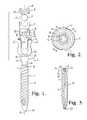
- FIG. 1is an exploded front elevational view of a polyaxial bone screw assembly according to the present invention including a shank, a receiver, an open friction fit expansion-only retainer and a top drop and turn in place lower compression insert, further shown with a portion of a longitudinal connecting member in the form of a rod and a closure top.
- FIG. 2is an enlarged top plan view of the shank of FIG. 1 .
- FIG. 3is reduced cross-sectional view taken along the line 3 - 3 of FIG. 2 .
- FIG. 4is an enlarged side elevational view of the receiver of FIG. 1 .
- FIG. 5is an enlarged perspective view of the receiver of FIG. 4 .
- FIG. 6is an enlarged top plan view of the receiver of FIG. 4 .
- FIG. 7is an enlarged bottom plan view of the receiver of FIG. 4 .
- FIG. 8is an enlarged cross-sectional view taken along the line 8 - 8 of FIG. 6 .
- FIG. 9is an enlarged cross-sectional view taken along the line 9 - 9 of FIG. 6 .
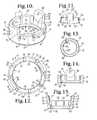
- FIG. 10is an enlarged perspective view of the retainer of FIG. 1 .
- FIG. 11is a reduced side elevational view of the retainer of FIG. 10 .
- FIG. 12is a top plan view of the retainer of FIG. 10 .
- FIG. 13is a reduced bottom plan view of the retainer of FIG. 10 .
- FIG. 14is a reduced cross-sectional view taken along the line 14 - 14 of FIG. 12 .
- FIG. 15is a reduced cross-sectional view taken along the line 15 - 15 of FIG. 12 .
- FIG. 16is an enlarged perspective view of the insert of FIG. 1 .
- FIG. 17is a side elevational view of the insert of FIG. 16 .
- FIG. 18is a top plan view of the insert of FIG. 16 .
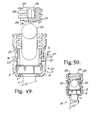
- FIG. 19is a bottom plan view of the insert of FIG. 16 .
- FIG. 20is an enlarged cross-sectional view taken along the line 20 - 20 of FIG. 18 .
- FIG. 21is an enlarged cross-sectional view taken along the line 21 - 21 of FIG. 18 .
- FIG. 22is an enlarged front elevational view of the retainer and receiver of FIG. 1 with portions of the receiver broken away to show the detail thereof, the retainer being shown downloaded into the receiver (in phantom) to a partially inserted stage of assembly.
- FIG. 23is a front elevational view of the retainer and receiver with portions broken away, similar to what is shown in FIG. 22 , showing the retainer in a subsequent stage of assembly.
- FIG. 24is a front elevational view of the retainer and receiver with portions broken away, similar to what is shown in FIG. 23 , showing the retainer in a subsequent stage of assembly.
- FIG. 25is a front elevational view of the retainer and receiver with portions broken away, similar to what is shown in FIG. 24 , showing the retainer in a subsequent stage of assembly.
- FIG. 26is a front elevational view of the retainer and receiver with portions broken away, similar to what is shown in FIG. 25 , showing the retainer in a subsequent stage of assembly.
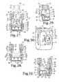
- FIG. 27is a front elevational view of the retainer and receiver with portions broken away, similar to what is shown in FIG. 26 , further showing an enlarged side elevational view of the insert of FIG. 1 (in phantom) above the receiver and then in solid lines being downloaded into the receiver to a partially inserted stage of assembly.
- FIG. 28is a front elevational view with portions broken away, similar to FIG. 27 , showing the insert rotated into a position in alignment with the receiver.
- FIG. 29is a perspective view, with portions broken away, of the receiver, retainer and insert of FIG. 28 .
- FIG. 30is an enlarged perspective view of the receiver, retainer and insert of FIG. 29 , further showing the receiver crimped to the insert.
- FIG. 31is a reduced front elevational view of the receiver, retainer and insert of FIG. 30 with portions broken away to show the detail thereof, showing the retainer spring tab arms placed in a desired upward position within the receiver so that the retainer spring tabs push resiliently outwardly against the receiver, holding the retainer against the receiver and keeping the insert in an upward position during shipping.
- FIG. 32is a front elevational view with portions broken away, similar to FIG. 31 , and further showing an enlarged and partial shank of FIG. 1 in a first stage of assembly with the retainer, a hemisphere of the shank head and a vertebra portion are both shown in phantom.
- FIG. 33is a partial front elevational view with portions broken away, similar to FIG. 32 , showing the retainer lower portion in an expanded state about a mid-portion of the shank head, the head hemisphere shown in phantom.
- FIG. 34is a reduced partial front elevational view with portions broken away, similar to FIG. 33 , the shank upper portion or head in frictional engagement with an upper portion of the retainer.
- FIG. 35is a partial front elevational view with portions broken away, similar to FIG. 34 , the shank upper portion with attached retainer being shown pulled down into a seated position within the lower receiver cavity, the retainer spring tabs in a substantially neutral state, extending outwardly partially into receiver apertures.
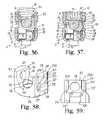
- FIG. 36is an enlarged and partial front elevational view with portions broken away of all of the components shown in FIG. 1 , the assembly of FIG. 35 shown in a stage of assembly with the rod and closure top.
- FIG. 37is a partial front elevational view with portions broken away, similar to FIG. 36 , shown in a final locking position.
- FIG. 38is an enlarged perspective view of an alternative locking insert for use with the assembly of FIG. 1 in lieu of the insert shown in FIG. 1 .
- FIG. 39is a side elevational view of the insert of FIG. 38 .
- FIG. 40is a front elevational view of the insert of FIG. 38 .
- FIG. 41is a top plan view of the insert of FIG. 38 .
- FIG. 42is a bottom plan view of the insert of FIG. 38 .
- FIG. 43is a cross-sectional view taken along the line 43 - 43 of FIG. 41 .
- FIG. 44is a cross-sectional view taken along the line 44 - 44 of FIG. 41 .
- FIG. 45is an enlarged and partial front elevational view with portions broken away of the receiver and retainer of FIG. 1 and the insert of FIG. 38 , shown in an un-locked shipping position.
- FIG. 46is a reduced side elevational view of the assembly of FIG. 45 further showing the receiver crimped to the insert.
- FIG. 47is a reduced and partial front elevational view of the shank, receiver, retainer, rod and closure of FIG. 1 and the insert of FIG. 38 , shown with portions broken away and in a final stage of assembly.
- FIG. 48is an enlarged and partial front elevational view with portions broken away, similar to FIG. 47 , shown fully assembled and in a final locked position.
- FIG. 49is an enlarged and partial front elevational view with portions broken away, similar to FIG. 48 , showing the shank, retainer, insert and receiver remaining in a locked position after removal of the rod and closure top of FIG. 1 and further showing, in exploded view, an alternative deformable rod and cooperating alternative closure top.
- FIG. 50is a reduced and partial front elevational view with portions broken away, similar to FIG. 49 , showing the alternative rod and closure top fixed to the remainder of the assembly.
- FIG. 51is a reduced and partial front elevational view with portions broken away of the assembly of FIG. 49 without the alternative rod and closure top, and further showing unlocking of the insert from the receiver with a two-piece tool having an inner insert engaging portion and an outer tubular holding portion.
- FIG. 52is a reduced and partial front elevational view of the two-piece tool of FIG. 51 , holding prongs of the inner insert engaging portion being shown in phantom.
- FIG. 53is an enlarged and partial front elevational view of the inner insert engaging portion of the tool shown in FIG. 52 with portions broken away to show the detail thereof.
- FIG. 54is an enlarged and partial perspective view of the assembly of FIG. 1 , shown in a position similar to what is shown in FIG. 47 , but with the shank being at an angle with respect to the receiver and further showing an alternative locking tool for independently locking the insert into an interference fit with the receiver and thus locking the shank with respect to the receiver even when the closure top and rod are in a loose, unlocked relationship with the receiver as shown.
- FIG. 55is a partial perspective view of a portion of the locking tool of FIG. 54 .
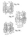
- FIG. 56is an enlarged and partial front elevational view of the assembly and locking tool of FIG. 54 with portions broken away to shown the detail thereof.
- FIG. 57is an enlarged perspective view of another alternative and non-locking insert for use with the assembly of FIG. 1 in lieu of the insert shown in FIG. 1 .
- FIG. 58is a partial front elevational view, similar to FIG. 56 , with portions broken away to show the detail thereof, showing the assembly of FIG. 1 with the alternative insert of FIG. 57 and showing the locking tool pressing the insert into a locked position with respect to a remainder of the assembly.
- FIG. 59is an exploded front elevational view of another polyaxial bone screw assembly according to the present invention including a shank, a receiver, an open friction fit expansion-only retainer and a lower compression insert, further shown with a portion of a longitudinal connecting member in the form of a rod and a closure top.
- FIG. 60is an enlarged top plan view of the shank of FIG. 59 .
- FIG. 61is reduced cross-sectional view taken along the line 61 - 61 of FIG. 60 .
- FIG. 62is an enlarged side elevational view of the receiver of FIG. 59 .
- FIG. 63is an enlarged perspective view of the receiver of FIG. 62 .
- FIG. 64is an enlarged top plan view of the receiver of FIG. 62 .
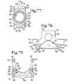
- FIG. 65is an enlarged bottom plan view of the receiver of FIG. 62 .
- FIG. 66is an enlarged cross-sectional view taken along the line 66 - 66 of FIG. 64 .
- FIG. 67is an enlarged cross-sectional view taken along the line 67 - 67 of FIG. 64 .
- FIG. 68is an enlarged perspective view of the retainer of FIG. 59 .
- FIG. 69is a reduced side elevational view of the retainer of FIG. 68 .
- FIG. 70is a top plan view of the retainer of FIG. 68 .
- FIG. 71is a reduced bottom plan view of the retainer of FIG. 68 .
- FIG. 72is a cross-sectional view taken along the line 72 - 72 of FIG. 70 .
- FIG. 73is a cross-sectional view taken along the line 73 - 73 of FIG. 70 .
- FIG. 74is an enlarged perspective view of the insert of FIG. 59 .
- FIG. 75is a front elevational view of the insert of FIG. 74 .
- FIG. 76is a top plan view of the insert of FIG. 74 .
- FIG. 77is a bottom plan view of the insert of FIG. 74 .
- FIG. 78is an enlarged cross-sectional view taken along the line 78 - 78 of FIG. 76 .
- FIG. 79is an enlarged cross-sectional view taken along the line 79 - 79 of FIG. 76 .
- FIG. 80is an enlarged front elevational view of the retainer and receiver of FIG. 59 with portions of the receiver broken away to show the detail thereof, the retainer being shown downloaded into the receiver (in phantom) to a partially inserted stage of assembly.
- FIG. 81is a front elevational view of the retainer and receiver with portions broken away, similar to what is shown in FIG. 80 , showing the retainer in a subsequent stage of assembly.
- FIG. 82is a front elevational view of the retainer and receiver with portions broken away, similar to what is shown in FIG. 81 , also showing the insert being downloaded into the receiver (in phantom) to a partially inserted stage of assembly.
- FIG. 83is a front elevational view of the retainer, receiver and insert with portions broken away, similar to what is shown in FIG. 82 , showing the retainer and insert in a subsequent stage of assembly, the retainer spring tabs being pressed inwardly and the insert being captured by the receiver.
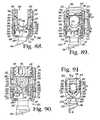
- FIG. 84is an enlarged front elevational view of the assembly as shown in FIG. 83 showing the capture of the insert by opposed projections of the receiver.
- FIG. 85is an enlarged front elevational view with portions broken away, similar to FIG. 83 , and further showing an enlarged and partial shank of FIG. 59 in a first stage of assembly with the retainer, a hemisphere of the shank head and a vertebra portion both being shown in phantom.
- FIG. 86is a partial front elevational view with portions broken away, similar to FIG. 85 , showing the retainer lower portion in an expanded state about a mid-portion of the shank head, the head hemisphere shown in phantom.
- FIG. 87is a reduced partial front elevational view with portions broken away, similar to FIG. 86 , the shank upper portion or head in frictional engagement with an upper portion of the retainer.
- FIG. 87Ais an enlarged cross-sectional view taken along the line 87 A- 87 A of FIG. 87 .
- FIG. 88is a partial front elevational view with portions broken away, similar to FIG. 87 , the shank upper portion with attached retainer being shown pulled down into a seated position within the lower receiver cavity, the retainer spring tabs in a substantially neutral state, extending outwardly partially into receiver apertures.
- FIG. 89is an enlarged and partial front elevational view with portions broken away of all of the components shown in FIG. 59 , the assembly as in FIG. 88 being shown in a stage of assembly with the rod and closure top.
- FIG. 90is an enlarged and partial front elevational view with portions broken away, similar to FIG. 89 , shown in a final locking position.
- FIG. 91is a reduced and partial front elevational view of the assembly of FIG. 90 .
- FIG. 92is an enlarged cross-sectional view taken along the line 92 - 92 of FIG. 91 .
- FIG. 93is an enlarged perspective view of an alternative locking insert for use with the assembly of FIG. 59 in lieu of the insert shown in FIG. 59 .
- FIG. 94is a top plan view of the insert of FIG. 93 .
- FIG. 95is a front elevational view of the insert of FIG. 93 .
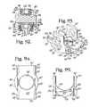
- FIG. 96is an enlarged front elevational view with portions broken away of the receiver and retainer of FIG. 59 and the insert of FIG. 93 in reduced front elevation, the assembly shown in an un-locked shipping position.
- FIG. 97is a reduced and partial front elevational view of the shank, receiver, retainer, rod and closure of FIG. 59 , with portions broken away and assembled with the locking insert as shown in FIG. 96 in an interim unlocked stage of assembly.
- FIG. 98is an enlarged and partial front elevational view of the shank, receiver, retainer, locking insert, rod and closure of FIG. 97 , with portions broken away and shown in a final locked position.
- FIG. 99is an enlarged and partial front elevational view with portions broken away, similar to FIG. 98 , showing the shank, retainer, insert and receiver remaining in a locked position after removal of the rod and closure top of FIG. 59 and further showing, in exploded view, an alternative deformable rod and cooperating alternative closure top.
- FIG. 100is a partial front elevational view with portions broken away, similar to FIG. 99 , showing the alternative rod and closure top fixed to the remainder of the assembly.
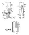
- FIG. 101is a reduced and partial front elevational view with portions broken away of the assembly of FIG. 100 without the alternative rod and closure top, and further showing unlocking of the insert from the receiver with a two-piece tool having an inner insert engaging portion and an outer tubular holding portion.
- FIG. 102is a reduced and partial front elevational view of the two-piece tool of FIG. 101 , holding prongs of the inner insert engaging portion being shown in phantom.
- FIG. 103is an enlarged and partial front elevational view of the inner insert engaging portion of the tool shown in FIG. 102 with portions broken away to show the detail thereof.
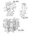
- FIG. 104is an enlarged and partial perspective view of the assembly of FIG. 97 , but shown with the shank being at an angle with respect to the receiver and further showing an alternative locking tool for independently locking the insert into an interference fit with the receiver and thus locking the shank with respect to the receiver even when the closure top and rod are in a loose, unlocked relationship with the receiver as shown.
- FIG. 105is an enlarged and partial perspective view of a portion of the locking tool of FIG. 104 .
- FIG. 106is an enlarged and partial front elevational view of the assembly and locking tool of FIG. 104 with portions broken away to show the detail thereof.
- the reference number 1generally represents a polyaxial bone screw apparatus or assembly according to the present invention.
- the assembly 1includes a shank 4 , that further includes a body 6 integral with an upwardly extending upper portion or head structure 8 ; a receiver 10 ; a friction fit retainer 12 , and a crown-like compression or pressure insert 14 .
- the receiver 10 , retainer 12 and compression insert 14are initially assembled and may be further assembled with the shank 4 either prior or subsequent to implantation of the shank body 6 into a vertebra 17 , as will be described in greater detail below.
- a closure structure 18 for capturing a longitudinal connecting memberfor example, a rod 21 which in turn engages the compression insert 14 that presses against the shank upper portion 8 into fixed frictional contact with the retainer 12 , so as to capture, and fix the longitudinal connecting member 21 within the receiver 10 and thus fix the member 21 relative to the vertebra 17 .
- the illustrated rod 21is hard, stiff, non-elastic and cylindrical, having an outer cylindrical surface 22 . It is foreseen that in other embodiments, the rod 21 may be elastic, deformable and/or of different materials and cross-sectional geometries.
- the receiver 10 and the shank 4cooperate in such a manner that the receiver 10 and the shank 4 can be secured at any of a plurality of angles, articulations or rotational alignments relative to one another and within a selected range of angles both from side to side and from front to rear, to enable flexible or articulated engagement of the receiver 10 with the shank 4 until both are locked or fixed relative to each other near the end of an implantation procedure.
- the shank 4is elongate, with the shank body 6 having a helically wound bone implantable thread 24 (single or dual lead thread form and different thread types) extending from near a neck 26 located adjacent to the upper portion or head 8 , to a tip 28 of the body 6 and extending radially outwardly therefrom.
- the body 6utilizing the thread 24 for gripping and advancement is implanted into the vertebra 17 leading with the tip 28 and driven down into the vertebra with an installation or driving tool (not shown), so as to be implanted in the vertebra to a location at or near the neck 26 , as more fully described in the paragraphs below.
- the shank 4has an elongate axis of rotation generally identified by the reference letter A.
- the neck 26extends axially upward from the shank body 6 .
- the neck 26may be of the same or is typically of a slightly reduced radius as compared to an adjacent upper end or top 32 of the body 6 where the thread 24 terminates.
- the shank upper portion or head 8Further extending axially and outwardly from the neck 26 is the shank upper portion or head 8 that provides a connective or capture apparatus disposed at a distance from the upper end 32 and thus at a distance from the vertebra 17 when the body 6 is implanted in such vertebra.
- the shank upper portion 8is configured for a pivotable connection between the shank 4 and the retainer 12 and receiver 10 prior to fixing of the shank 4 in a desired position with respect to the receiver 10 .
- the shank upper portion 8has an outer, convex and substantially spherical surface 34 that extends outwardly and upwardly from the neck 26 that in some embodiments terminates at a substantially planar top or rim surface 38 .
- a frusto-conical surface 39extends from the spherical surface 34 to the top surface 38 , providing additional clearance during pivoting of the shank with respect to the receiver 10 and the insert 14 .
- the spherical surface 34has an outer radius configured for temporary frictional, non-floppy, sliding cooperation with panels of the retainer 12 having concave or flat surfaces, as well as ultimate frictional engagement with the insert 14 at an inner partially spherical surface thereof, as will be discussed more fully in the paragraphs below.
- the top surface 38is substantially perpendicular to the axis A.
- the spherical surface 34 shown in the present embodimentis substantially smooth, but in some embodiments may include a roughening or other surface treatment and is sized and shaped for cooperation and ultimate frictional engagement with the compression insert 14 as well as ultimate frictional engagement with a lower ring-like portion of the retainer 12 .
- the shank spherical surface 34is locked into place exclusively by the insert 14 and the retainer 12 lower portion and not by inner surfaces defining the receiver cavity.
- a counter sunk substantially planar base or stepped seating surface 45partially defines an internal drive feature or imprint 46 .
- the illustrated internal drive feature 46is an aperture formed in the top surface 38 and has a star shape designed to receive a tool (not shown) of an Allen wrench type, into the aperture for rotating and driving the bone screw shank 4 . It is foreseen that such an internal tool engagement structure may take a variety of tool-engaging forms and may include one or more apertures of various shapes, such as a pair of spaced apart apertures or a multi-lobular or hex-shaped aperture.
- the seat or base surfaces 45 of the drive feature 46are disposed substantially perpendicular to the axis A with the drive feature 46 otherwise being coaxial with the axis A. As illustrated in FIGS.
- the drive seat 45may include beveled or stepped surfaces that may further enhance gripping with the driving tool.
- a driving tool(not shown) is received in the internal drive feature 46 , being seated at the base 45 and engaging the faces of the drive feature 46 for both driving and rotating the shank body 6 into the vertebra 17 , either before the shank 4 is attached to the receiver 10 or after the shank 4 is attached to the receiver 10 , with the shank body 6 being driven into the vertebra 17 with the driving tool extending into the receiver 10 .
- the shank 4 shown in the drawingsis cannulated, having a small central bore 50 extending an entire length of the shank 4 along the axis A.
- the bore 50is defined by an inner cylindrical wall of the shank 4 and has a circular opening at the shank tip 28 and an upper opening communicating with the external drive 46 at the driving seat 45 .
- the bore 50is coaxial with the threaded body 6 and the upper portion 8 .
- the bore 50provides a passage through the shank 4 interior for a length of wire (not shown) inserted into the vertebra 17 prior to the insertion of the shank body 6 , the wire providing a guide for insertion of the shank body 6 into the vertebra 17 .
- the shankcould be solid and made of different materials, including metal and non-metals.
- the threaded shank body 6may be coated, perforated, made porous or otherwise treated.
- the treatmentmay include, but is not limited to a plasma spray coating or other type of coating of a metal or, for example, a calcium phosphate; or a roughening, perforation or indentation in the shank surface, such as by sputtering, sand blasting or acid etching, that allows for bony ingrowth or ongrowth.
- Certain metal coatingsact as a scaffold for bone ingrowth.
- Bio-ceramic calcium phosphate coatingsinclude, but are not limited to: alpha-tri-calcium phosphate and beta-tri-calcium phosphate (Ca 3 (PO 4 ) 2 , tetra-calcium phosphate (Ca 4 P 2 O 9 ), amorphous calcium phosphate and hydroxyapatite (Ca 10 (PO 4 ) 6 (OH) 2 ).
- Coating with hydroxyapatitefor example, is desirable as hydroxyapatite is chemically similar to bone with respect to mineral content and has been identified as being bioactive and thus not only supportive of bone ingrowth, but actively taking part in bone bonding.
- the receiver 10has a generally U-shaped appearance with partially discontinuous and partially cylindrical inner and outer profiles.
- the receiver 10has an axis of rotation B that is shown in FIG. 1 as being aligned with and the same as the axis of rotation A of the shank 4 , such orientation being desirable, but not required during assembly of the receiver 10 with the shank 4 .
- the axis Bis typically disposed at an angle with respect to the axis A, as shown, for example, in FIG. 54 .
- the receiver 10includes a substantially cylindrical base 60 defining a bore or inner cavity, generally 61 , the base 60 being integral with a pair of opposed upstanding arms 62 forming a cradle and defining a channel 64 between the arms 62 with an upper opening, generally 66 , and a U-shaped lower channel portion or seat 68 , the channel 64 having a width for operably snugly receiving the rod 21 or portion of another longitudinal connector between the arms 62 , the channel 64 communicating with the base cavity 61 .
- Inner opposed substantially planar arm surfaces 69partially define the channel 64 directly above the seat 68 and are located on either side of each arm interior surface generally 70 , that includes various inner cylindrical profiles, an upper one of which is a partial helically wound guide and advancement structure 72 located adjacent top surfaces 73 of each of the arms 62 .
- the guide and advancement structure 72is a partial helically wound interlocking flangeform configured to mate under rotation with a similar structure on the closure structure 18 , as described more fully below.
- the guide and advancement structure 72could alternatively be a square-shaped thread, a buttress thread, a reverse angle thread or other thread-like or non-thread-like helically wound discontinuous advancement structures, for operably guiding under rotation and advancing the closure structure 18 downward between the arms 62 , as well as eventual torquing when the closure structure 18 abuts against the rod 21 or other longitudinal connecting member. It is foreseen that the arms 62 could have break-off extensions.
- An opposed pair of upper rounded off triangular or delta-shaped tool receiving and engaging apertures 74are formed on outer surfaces 76 of the arms 62 .
- Each through bore surface 75 and 75 ′extends through the arm inner surface 70 .
- the apertures 74 with through bore portions 75 and 75 ′are sized and shaped for receiving portions of the retainer 12 during top loading of the retainer from the receiver opening 66 and into the base cavity 61 as shown, for example, in FIGS. 22-24 and as will be described in greater detail below.
- Each apertures 74further includes a sloping tool alignment surface 77 that surrounds the arched bore portion 75 and does not extend completely through the respective arm 62 .
- Thin edge portions 77 A and 77 B of the sloping surface 77also function as a crimp wall that is pressed or crimped into the insert 14 to prohibit rotation and misalignment of the insert 14 with respect to the receiver 10 as will be described in greater detail below.
- other surfaces forming the aperture 74may be inwardly crimped.
- the receiver 10is an integral structure and devoid of any spring tabs or collet-like structures.
- the insert and/or receiverare configured with structure for blocking rotation of the insert with respect to the receiver, such as the sloping crimp wall 77 , but allowing some up and down movement of the insert with respect to the receiver during the assembly and implant procedure.
- Two additional rectangular shaped through bores 78are also formed in the arms 62 and are located directly below the apertures 74 . It is foreseen that the opening 78 could assume almost any shape.
- the through bores 78are sized and shaped for receiving spring tab portions of the retainer 12 during assembly and final operation and which capture and retain the retainer 12 within the receiver as shown, for example, in FIG. 26 .
- each bore 78functions as an upper stop for a portion of the retainer 12 , during shipping and during assembly as will be described in greater detail below. Also formed in each outer arm surface 76 near the top surface 73 is an undercut tool receiving and engaging groove 81 .
- apertures 74 and 78 and the groove 81may be used for holding the receiver 10 during assembly with the insert 14 , the retainer 12 and the shank 4 ; during the implantation of the shank body 6 into a vertebra when the shank is pre-assembled with the receiver 10 ; during assembly of the bone anchor assembly 1 with the rod 21 and the closure structure 18 ; and during lock and release adjustment of some inserts according to the invention with respect to the receiver 10 , either into or out of frictional engagement with the inner surfaces of the receiver 10 as will be described in greater detail below. It is foreseen that tool receiving grooves or apertures may be configured in a variety of shapes and sizes and be disposed at other locations on the receiver arms 62 .
- a discontinuous cylindrical surface 82located below the guide and advancement structure 72 .
- the cylindrical surface 82has a diameter equal to or slightly greater than a greater diameter of the guide and advancement structure 72 .
- a cylindrical surface (or, in some embodiments, a tapered surface) 88located below an annular run-out seat or surface 85 that extends inwardly toward the axis B and runs perpendicular or somewhat obliquely towards the axis B.
- the surface 88has a diameter smaller than the diameter of the surface 82 .
- the surface 88is sized and shaped to initially closely receive a portion of the insert 14 .
- a discontinuous annular surface or narrow ledge 89is located below the surface 88 and is substantially perpendicular to the axis B.
- a partially discontinuous cylindrical surface 90is located on each arm below and adjacent to the surface 89 .
- the surface 90also defines an upper cylindrical surface of the base cavity 61 .
- the surface 90has a diameter slightly smaller than the diameter of the surface 88 . It is noted that in some embodiments of the invention, the surfaces 88 and 90 are combined and form a single cylindrical surface.
- the through bores 75 of the apertures 74each extend through the arms at the surfaces 82 and 88 with the sloping tool engagement and crimp walls 77 extending substantially on either side of each bore surface 75 and formed in the arm outer surfaces 76 at a location opposite the inner surfaces 82 and 88 .
- portions of the surfaces 88are pressed into engagement with the insert 14 when the thin, deformable edge portions of the walls 77 are pressed toward the insert 14 as will be described in greater detail below.
- the crimp wall portions that are pressed into engagement with the insert 14are identified as 77 A and 77 B. It is foreseen that the crimp wall portions could be in the form of deformable crimp tabs.
- annular surface 98partially defining the base cavity 61 and is located below and adjacent to the cylindrical surface 90 .
- the surface 98is disposed substantially perpendicular to the axis B, but could be oblique.
- Another cylindrical surface 99is located below and adjacent to the surface 98 .
- the cylindrical surface 99is oriented substantially parallel to the axis B and is sized and shaped to receive an expanded portion of retainer 12 .
- the surfaces 98 and 99define a circumferential recess that is sized and shaped to receive the retainer 12 as it expands around the shank upper portion 8 as the shank 8 moves upwardly toward the channel 64 during assembly. It is foreseen that the recess could be tapered or conical in configuration.
- a cylindrical surface 101 located below the cylindrical surface 99is sized and shaped to closely receive and surround a lower portion of the retainer 12 when the retainer is in a substantially neutral position as shown in FIG. 28 , for example.
- the cylindrical surface 101has a diameter smaller than the diameter of the cylindrical surface 99 that defines the expansion area or expansion chamber for the retainer 12 .
- the surface 101is joined or connected to the surface 99 by one or more beveled, curved or conical surfaces 102 .
- the surfaces 102allow for sliding and neutral or nominal positioning of the retainer 12 into the space defined by the surface 101 and ultimate seating of the retainer 12 on a lower substantially horizontal annular surface 104 located below and adjacent to the cylindrical surface 101 .
- Located below and adjacent to the annular seating surface 104is another substantially cylindrical surface 106 that communicates with a beveled or flared bottom opening surface 107 , the surface 107 communicating with an exterior base surface 108 of the base 60 , defining a lower opening, generally 110 , into the base cavity 61 of the receiver 10 .
- the lower open or split friction fit retainer 12that operates to capture the shank upper portion 8 within the receiver 10 , has a central axis that is operationally the same as the axis B associated with the receiver 10 when the shank upper portion 8 and the retainer 12 are installed within the receiver 10 .
- the retainer 12includes a substantially cylindrical discontinuous lower body 116 , a plurality of flex fingers or panels, 117 extending upwardly from the body 116 and a pair of opposed spring arms or tabs 118 , also extending upwardly from the body 116 .
- the retainer ring 12is made from a resilient material, such as a stainless steel or titanium alloy, so that the retainer 12 body 116 may be expanded and the fingers and tabs ( 117 and 118 ) of the retainer may be manipulated during various steps of assembly as will be described in greater detail below.
- the retainer 12has a central channel or hollow through bore, generally 121 , that passes entirely through the retainer 12 from tab 118 top surfaces 122 to a bottom surface 124 of the retainer body 116 .
- Surfaces that define the channel or bore 121 at the body 116include an inner lower frusto-conical surface 128 adjacent to the retainer body bottom surface 124 , a substantially cylindrical surface 130 adjacent the frusto-conical surface 128 and a partially continuous partially discontinuous substantially spherical surface 132 located adjacent the cylindrical surface 130 , the surface 132 being substantially continuous near the surface 130 and at each of the spring tabs 118 and otherwise broken by a through slot or slit, generally 134 and a plurality of evenly spaced partial slots or grooves 136 .
- the grooves 136separate the surface 132 into a plurality of segments or pieces that have already been described herein as the flex fingers 117 .
- the grooves or slots 136run outwardly and upwardly from the retainer body 116 through an upper surface 137 of the retainer 12 located between the spring tabs 118 .
- the slots 136 and the through slit 134form the six substantially uniform flex fingers or tabs 117 as well as partially define the two spring tabs 118 , each finger 117 having the inner spherical surface 132 while each of the spring tabs 118 extend outwardly and away from the surface 132 at the retainer body 116 . It is foreseen that more or fewer flex fingers may be made by the forming of more or fewer slots 136 and that the surface 132 could be planar, tapered, faceted or otherwise curved.
- the illustrated discontinuous spherical surface 132is sized and shaped to closely fit about and snap onto the shank surface 34 during assembly as will be described in greater detail below.
- the surface 132has a radius the same, slightly smaller or slightly larger than the radius of the spherical shank surface 34 .
- the surface 132could be bent or deformed inwardly or outwardly to better cooperate with the shank head.
- the discontinuous surface 132advantageously frictionally engages the bone screw shank upper portion or head 8 , allowing for an un-locked friction fit, non-floppy placement of the angle of the shank 4 with respect to the receiver 10 during surgery prior to locking of the shank 4 with respect to the receiver 10 near the end of the procedure.
- the flex fingers 117may have sloping outer surfaces or other geometry to gain the level of resiliency desired for expansion and gripping of the fingers 117 about the shank upper portion 8 .
- the illustrated fingers 117each include an outer bevel 138 .
- the spherical surfaces 132may include a surface treatment or roughening to provide a desired friction fit.
- the surfaces 132need not be spherical and may be planar or include other surface geometries that resiliently grip the shank upper portion or head 8 .
- the flexible tabs 117may be bent or deformed to further enhance frictional engagement. It is noted that the fingers 117 that are directed generally upwardly toward the receiver channel 64 advantageously sufficiently snap about and then grip the shank surface 34 to an extent to provide the friction fit desired for non-floppy placement of the shank body 6 at a desired angle with respect to the receiver 10 during manipulation of the bone screws 1 and the rod 21 or other longitudinal connecting member during surgery.
- the thin upwardly directed fingers 117that extend away from the shank locking surface that are not as strong as the retainer body 116 or the insert 114 , do not participate or cooperate with the final locking of the insert 114 to the shank upper portion 8 , the shank upper portion 8 to the retainer 12 , and the retainer 12 to the receiver inner and substantially planar surfaces 101 and 104 .
- the more substantial retainer body 116 located below the slots 136 having only the very narrow slit 134is the component or portion that locks the shank upper portion 8 between the receiver 10 , the insert 114 and the rod 21 or other longitudinal connecting member.
- the retainer body 116 and the flex fingers 117have an outer substantially cylindrical profile, sized and shaped to closely and slidingly fit within the receiver cavity 61 .
- the opposed pair of spring tabs 118extend outwardly away from one another and thus outwardly from the body 116 .
- Each spring tab 118is sized and shaped to closely cooperate and frictionally engage upper surfaces 79 defining the through bores 78 .
- An outer surface 143 of each spring tab 118 located adjacent each upper surface 122is sized and shaped to cooperate with and frictionally engage the cylindrical surface 90 during assembly and shipping as shown, for example, in FIG. 31 .
- the tab 118 surface 143may include one or more projections, grooves or notches as needed for tooling to resiliently hold the retainer in an upper portion of the cavity 61 when desired, but readily release the retainer 12 into a lower portion of the receiver cavity 61 once the retainer flex tabs 117 engage the shank head 8 .
- the illustrated spring tabs 118each include one or more planar or curved concave inner surfaces 144 running from the top surface 122 to a tab base seat, surface or surfaces 145 located adjacent to and running laterally outwardly from the surface 132 .
- the surfaces 144extend both outwardly and upwardly from the base seat surfaces 145 . It is foreseen that in other embodiments of the invention, fewer or greater number of planar or other surfaces with other geometries may extend between the top surface 122 and the inner surfaces defining the body 116 of the retainer 12 .
- the through slit 134 of the resilient retainer 12is defined by first and second end surfaces, 146 and 147 disposed in spaced relation to one another (they may also be touching) when the retainer is in a neutral state. Both end surfaces 146 and 147 are disposed substantially perpendicular to the bottom surface 124 .
- a width X between the surfaces 146 and 147is very narrow (slit may be made by EDM process) to provide stability to the retainer 12 during operation. Because the retainer 12 is top loadable in a neutral state and the retainer 12 does not need to be compressed to fit within the receiver cavity 61 , the width X may be much smaller than might be required for a bottom loaded compressible retainer ring.
- the gap Xfunctions only in expansion to allow the retainer 12 to expand about the shank upper portion 8 . This results in a stronger retainer that provides more surface contact with the shank upper portion 8 upon locking, resulting in a sturdier connection with less likelihood of failure than a retainer ring having a greater gap. Furthermore, because the retainer 12 body 116 is only expanded and never compressed inwardly, the retainer 12 does not undergo the mechanical stress that typically is placed on spring ring type retainers known in the prior art that are both compressed inwardly and expanded outwardly during assembly.
- the retainer 12 inner surfacesmay include a roughening or additional material to increase the friction fit against the shank upper portion 8 prior to lock down by the rod 21 or other longitudinal connecting member.
- the embodiment shown in FIGS. 10-15illustrates the surfaces 146 and 147 as substantially parallel, however, it is foreseen that it may be desirable to orient the surfaces obliquely or at a slight angle.
- the compression insert 14is illustrated that is sized and shaped to be received by and down-loaded into the receiver 10 at the upper opening 66 .
- the compression insert 14has an operational central axis that is the same as the central axis B of the receiver 10 . In operation, the insert advantageously frictionally engages the bone screw shank upper portion 8 .
- the insert that has locked the shank 4 in a desired angular position with respect to the receiver 10by, for example, compression from the rod 21 and closure top 18 , is also forced into an interference fit engagement with the receiver 10 at an outer cylindrical surface thereof and thus is capable of retaining the shank 6 in a locked position even if the rod 21 and closure top 18 are removed.
- Such locked positionmay also be released by the surgeon if desired.
- the non-locking insert 14 as well as the locking insert 214are preferably made from a solid resilient material, such as a stainless steel or titanium alloy, so that portions of the insert may be pinched and un-wedged from the receiver 10 with a release tool.
- the non-locking compression insert 14includes a substantially cylindrical body 156 integral with a pair of upstanding arms 157 .
- a bore, generally 160is disposed primarily within and through the body 156 and communicates with a generally U-shaped through channel 161 that is defined by the upstanding arms 157 .
- the channel 161has a lower seat 162 sized and shaped to closely, snugly engage the rod 21 .
- an alternative embodimentmay be configured to include planar holding surfaces that closely hold a square or rectangular bar as well as hold a cylindrical rod-shaped, cord, or sleeved cord longitudinal connecting member.
- the arms 157 disposed on either side of the channel 141extend upwardly and outwardly from the body 156 .
- the arms 157are sized and configured for ultimate placement beneath the cylindrical run-out surface 82 located below the receiver guide and advancement structure 72 . It is foreseen that in some embodiments of the invention, the arms may be extended and the closure top configured such that the arms and, more specifically, the surfaces 164 ultimately directly engage the closure top 18 for locking of the polyaxial mechanism, for example, when the rod 21 is made from a deformable material.
- the insert 14would include a rotation blocking structure or feature that abuts against cooperating structure located on an inner wall of the receiver 10 , preventing rotation of the insert with respect to the receiver when the closure top is rotated into engagement with the insert.
- the arms 157include upper outer cylindrical surfaces 163 and top surfaces 164 that are ultimately positioned in spaced relation with the closure top 18 , so that the closure top 18 frictionally engages the rod 21 only, pressing the rod 21 downwardly against the seating surface 162 , the insert 14 in turn pressing against the shank 4 upper portion 8 that presses against the retainer 12 to lock the polyaxial mechanism of the bone screw assembly 1 at a desired angle.
- the bore, generally 160is substantially defined at the body 156 by an inner cylindrical surface 166 that communicates with the seat 162 and a lower concave substantially spherical surface 168 having a radius the same or substantially similar to a radius of the surface 34 of the shank upper portion 8 .
- the surface 168terminates at an annular and substantially planar base surface 169 of the body 156 .
- the gripping surface portion 170includes one or more stepped surfaces or ridges sized and shaped to grip and penetrate into the shank head 8 when the insert 14 is locked against the head surface 34 .
- the stepped surface portion 170may include greater or fewer number of stepped surfaces. It is foreseen that the shank gripping surface portion 170 and also the spherical surface 168 may additionally or alternatively include a roughened or textured surface or surface finish, or may be scored, knurled, or the like, for enhancing frictional engagement with the shank upper portion 8 .
- the compression insert 14 through bore 160is sized and shaped to receive the driving tool (not shown) therethrough that engages the shank drive feature 46 when the shank body 6 is driven into bone with the receiver 10 attached.
- the borereceives a manipulation tool (not shown) used for releasing the insert from a locked position with the receiver, the tool pressing down on the shank and also gripping the insert at through bores located in the arms or with other tool engaging features.
- a manipulation tool for releasing the insert from the receiver 10may also access such bores from the receiver through the apertures 74 in the receiver.
- toolscan be configured to release a locking insert from the inside and outside of the receiver 10 .
- the illustrated insert 14further includes an outer lower arm surface 174 adjacent to the upper arm outer surface 164 and having a radius slightly smaller than a radius of the upper arm surfaces 163 .
- the arm surfaces 163further include notches or grooves formed thereon.
- each surface 163includes a pair of spaced v-notches or grooves 175 A and 175 B that run from the respective top surface 164 to the respective lower arm surface 174 .
- the grooves 175cooperate with the receiver crimp walls 77 to aid in alignment of the insert channel 161 with the receiver channel 64 .
- Each lower arm surface 174runs from the mid-point or location of the arm to the insert bottom surface 169 .
- Each surfaceincludes a recessed area or portion 178 sized and shaped to receive and allow clearance for the upper surface 122 of the retainer spring tabs 118 , as shown, for example, in FIG. 31 , during assembly and shipping of the pre-assembled receiver 10 , retainer 12 and insert 14 .
- Adjacent each recessed area or portion 178is a bevel or flat surface 179 cut into the lower outer surface 174 near the base or bottom surface 169 .
- the surfaces 170allow for clockwise rotation of the insert 14 into place within the receiver, the bevel or flat 179 allowing clearance between the insert 14 and the retainer spring tab 118 during rotation into place.
- the insert surface located adjacent the recess 178 that is not beveled, identified by the reference number 180prohibits further rotation of the insert as best shown, for example, in FIG. 29 .
- the insert body 156has an outer diameter slightly smaller than a diameter between crests of the guide and advancement structure 72 of the receiver 10 , allowing for top loading of the compression insert 14 into the receiver opening 66 , with the arms 157 of the insert 14 being located between the receiver arms 62 during insertion of the insert 14 into the receiver 10 .
- the insert 14is rotated in a clockwise direction K into place about the receiver axis B until the top surfaces 164 are located directly below the guide and advancement structure 72 as will be described in greater detail below.
- the insert outer arm surfaces 174are sized and shaped to be slidingly received by the receiver surface 90 during final locking of the assembly 1 .
- the illustrated elongate rod or longitudinal connecting member 21can be any of a variety of implants utilized in reconstructive spinal surgery, but is typically a cylindrical, elongate structure having the outer substantially smooth, cylindrical surface 22 of uniform diameter.
- the rod 21may be made from a variety of metals, metal alloys, non-metals and deformable and less compressible plastics, including, but not limited to rods made of elastomeric, polyetheretherketone (PEEK) and other types of materials, such as polycarbonate urethanes (PCU) and polyethelenes.
- PEEKpolyetheretherketone
- Longitudinal connecting members for use with the assembly 1may take a variety of shapes, including but not limited to rods or bars of oval, rectangular or other curved or polygonal cross-section.
- the shape of the insert 14may be modified so as to closely hold the particular longitudinal connecting member used in the assembly 1 .
- Some embodiments of the assembly 1may also be used with a tensioned cord.
- a tensioned cordmay be made from a variety of materials, including polyester or other plastic fibers, strands or threads, such as polyethylene-terephthalate.
- the longitudinal connectormay be a component of a longer overall dynamic stabilization connecting member, with cylindrical or bar-shaped portions sized and shaped for being received by the compression insert 14 of the receiver having a U-shaped, rectangular- or other-shaped channel, for closely receiving the longitudinal connecting member.
- the longitudinal connecting membermay be integral or otherwise fixed to a bendable or damping component that is sized and shaped to be located between adjacent pairs of bone screw assemblies 1 , for example.
- a damping component or bumpermay be attached to the longitudinal connecting member at one or both sides of the bone screw assembly 1 .
- a rod or bar (or rod or bar component) of a longitudinal connecting membermay be made of a variety of materials ranging from deformable plastics to hard metals, depending upon the desired application.
- bars and rods of the inventionmay be made of materials including, but not limited to metal and metal alloys including but not limited to stainless steel, titanium, titanium alloys and cobalt chrome; or other suitable materials, including plastic polymers such as polyetheretherketone (PEEK), ultra-high-molecular weight-polyethylene (UHMWP), polyurethanes and composites, including composites containing carbon fiber, natural or synthetic elastomers such as polyisoprene (natural rubber), and synthetic polymers, copolymers, and thermoplastic elastomers, for example, polyurethane elastomers such as polycarbonate-urethane elastomers.
- plastic polymerssuch as polyetheretherketone (PEEK), ultra-high-molecular weight-polyethylene (UHMWP), polyurethanes and composites, including composites containing carbon fiber, natural or synthetic elastomers such as polyisoprene (natural rubber), and synthetic polymers, copolymers, and thermoplastic elastomers
- closure structure or closure top 18 shown with the assembly 1is rotatably received between the spaced arms 62 of the receiver 10 .
- closure 18 topcould be a twist-in or slide-in closure structure.
- the illustrated closure structure 18is substantially cylindrical and includes a an outer helically wound guide and advancement structure 182 in the form of a flange that operably joins with the guide and advancement structure 72 disposed on the arms 62 of the receiver 10 .
- the flange form utilized in accordance with the present inventionmay take a variety of forms, including those described in Applicant's U.S. Pat. No. 6,726,689, which is incorporated herein by reference.
- closure structure guide and advancement structurecould alternatively be a buttress thread, a square thread, a reverse angle thread or other thread like or non-thread like helically wound advancement structure, for operably guiding under rotation and advancing the closure structure 18 downward between the arms 62 and having such a nature as to resist splaying of the arms 62 when the closure structure 18 is advanced into the channel 64
- the flange form illustrated herein as described more fully in Applicant's U.S. Pat. No. 6,726,689is preferred as the added strength provided by such flange form beneficially cooperates with and counters any reduction in strength caused by the any reduced profile of the receiver 10 that may more advantageously engage longitudinal connecting member components.
- the illustrated closure structure 18also includes a top surface 184 with an internal drive 186 in the form of an aperture that is illustrated as a star-shaped internal drive such as that sold under the trademark TORX, or may be, for example, a hex drive, or other internal drives such as slotted, tri-wing, spanner, two or more apertures of various shapes, and the like.
- a driving tool(not shown) sized and shaped for engagement with the internal drive 186 is used for both rotatable engagement and, if needed, disengagement of the closure 18 from the receiver arms 62 .
- the closure structure 18may alternatively include a break-off head designed to allow such a head to break from a base of the closure at a preselected torque, for example, 70 to 140 inch pounds.
- a closure structurewould also include a base having an internal drive to be used for closure removal.
- a base or bottom surface 188 of the closureis planar and further includes a point 189 and a rim 190 for engagement and penetration into the surface 22 of the rod 21 in certain embodiments of the invention. It is noted that in some embodiments, the closure top bottom surface 188 does not include the point and/or the rim.
- the closure top 18may further include a cannulation through bore (not shown) extending along a central axis thereof and through the top and bottom surfaces thereof. Such a through bore provides a passage through the closure 18 interior for a length of wire (not shown) inserted therein to provide a guide for insertion of the closure top into the receiver arms 62 .
- FIGS. 49 and 50An alternative closure top 218 for use with a deformable rod, such as a PEEK rod 221 , is shown in FIGS. 49 and 50 .
- the top 218is identical to the top 18 with the exception that a point or nub 289 is located on a domed surface 290 in lieu of the point and rim of the closure top 18 .
- the closure top 218otherwise includes a guide and advancement structure 282 , a top 284 , an internal drive 286 and a bottom outer rim surface 288 that same or substantially similar to the guide and advancement structure 182 , top 184 , internal drive 186 and a bottom surface 188 described herein with respect to the closure top 18 .
- the internal drive 286is not as large as the drive 186 of the closure top 18 , such smaller drive providing for less force being placed on a deformable rod, for example, and not being required when a locking insert, for example, the insert 218 discussed below is utilized in a bone screw assembly of the invention.
- the receiver 10 , the retainer 12 and the compression insert 14are assembled at a factory setting that includes tooling for holding and alignment of the component pieces and pinching or compressing of the retainer 12 spring tabs 118 and rotating and otherwise manipulating the insert 14 arms, as well as crimping a portion of the receiver 10 toward the insert 14 .
- the shank 4is also assembled with the receiver 10 , the retainer 12 and the compression insert 14 at the factory. In other instances, it is desirable to first implant the shank 4 , followed by addition of the pre-assembled receiver, retainer and compression insert at the insertion point.
- the surgeonmay advantageously and more easily implant and manipulate the shanks 4 , distract or compress the vertebrae with the shanks and work around the shank upper portions or heads without the cooperating receivers being in the way.
- FIGS. 22-31Pre-assembly of the receiver 10 , retainer 12 and compression insert 14 is shown in FIGS. 22-31 .
- the retainer 12is inserted into the upper receiver opening 66 , leading with one of the spring tabs 118 with both of the spring tab top surfaces 122 facing one arm 62 and the retainer bottom surface 124 facing the opposing arm 62 (shown in phantom).
- the retainer 12is then lowered in such sideways manner into the channel 64 and partially into the receiver cavity 61 , followed by tilting the retainer 12 such that the top surface 122 and thereafter the top surface 122 of the leading spring tab 118 is moved into a nearby receiver arm aperture 74 below the arched through bore surface 75 .
- the retainer 12is then further tilted or turned and manipulated within the receiver to a position within the cavity until the retainer 12 bottom surface 124 is directed toward the receiver cavity 61 and the spring tab upper surfaces 122 are facing upwardly toward the receiver channel opening 66 as shown in FIG. 24 .
- the spring tab arm 118 located within the receiver bore surface 75is manipulated downwardly and then upwardly within such bore and finally shifted out of such bore when the opposed spring tab arm 118 moves past and clears the guide and advancement structure 72 of the receiver 10 .
- the retainer 12is moved downwardly toward the receiver base 60 and the spring tabs 118 are pressed resiliently toward one another as the retainer spring tab outside surfaces 143 abut against the receiver cylindrical surfaces 90 .
- the spring tab surfaces 143clear the surface 90 and the tabs spring back out to a substantially neutral position with portions of the top surfaces 122 of each of the spring tabs 118 being located beneath the surfaces 79 of the through bores 78 .
- the retainer 12is captured within the receiver base cavity 61 unless the spring tabs 118 are squeezed toward one another so as to clear the through bores 78 .
- the compression insert 14is then downloaded into the receiver 10 through the upper opening 66 with the bottom surface 169 facing the receiver arm top surfaces 73 and the insert arms 157 located between the opposed receiver arms 62 .
- the insert 14is then lowered toward the receiver base 60 until the insert 14 arm upper surfaces 164 are adjacent the run-out area below the guide and advancement structure 72 defined in part by the cylindrical surface 82 .
- the insert 14is rotated in a clockwise manner (see the arrow K) about the receiver axis B until the upper arm surfaces 164 are directly below the guide and advancement structure 72 as illustrated in FIG. 28 with the U-shaped channel 161 of the insert 14 aligned with the U-shaped channel 64 of the receiver 10 .
- the insert arms 157may need to be compressed slightly during rotation to clear inner surfaces of the receiver arms 62 .
- the bevel or flat 179 at the base of the arm portion 157is initially received within one of the receiver arms 62 when the clock-wise rotation is begun, the flat 179 clearing the retainer spring tab 118 during rotation.
- the surface 180 partially defining the recess 178abuts against the spring tab 118 at a desirable location wherein the insert U-shaped channel 161 is aligned with the receiver channel 64 . This is best seen in FIG. 29 . With reference to FIG.
- crimps 77 A and 77 Bare made in the receiver surface 77 , the crimps 77 A and 77 B are pressed toward the insert 14 at respective grooves 175 A and 175 B.
- The, crimped portions 77 A and 77 Bhelp retain the desired alignment between the insert 14 and the receiver 10 and prohibit relative rotation between the two parts.
- relative vertical movement between the insert 14 and the receiver 10is possible as the crimps do not vertically fix the insert with respect to the receiver.
- a tool(not shown) is then used to grip the retainer spring tab arms 118 at outer surfaces 143 thereof and squeeze or press the tabs 118 toward one another while moving the retainer 12 in an upward direction away from the surface 104 .
- the tool(not shown) is released and a portion of the surface 143 of each spring tab 118 spring out to engage the surface portion 90 .
- the retainer 12 and the insert 14are now in a desired position for shipping as an assembly along with the separate shank 4 .
- the insert 14 recessed areas 178are now located adjacent to the retainer spring tab top surfaces 122 .
- the insert 14is fully captured within the receiver 10 by the guide and advancement structure 72 prohibiting movement of the insert 14 up and out through the receiver opening 66 as well as by retainer 12 located below the insert.
- the receiver and retainer combinationare shipped or otherwise provided to the end user with the spring tabs 118 wedged against the receiver as shown in FIG. 31 .
- the receiver 10 , retainer 12 and insert 14 combinationis now pre-assembled and ready for assembly with the shank 4 either at the factory, by surgery staff prior to implantation, or directly upon an implanted shank 4 as will be described herein.
- the bone screw shank 4 or an entire assembly 1 made up of the assembled shank 4 , receiver 10 , retainer 12 and compression insert 14is screwed into a bone, such as the vertebra 17 (shown in phantom), by rotation of the shank 4 using a suitable driving tool (not shown) that operably drives and rotates the shank body 6 by engagement thereof at the internal drive 46 .
- the vertebra 17may be pre-drilled to minimize stressing the bone and have a guide wire (not shown) inserted therein to provide a guide for the placement and angle of the shank 4 with respect to the vertebra.
- a further tap holemay be made using a tap with the guide wire as a guide.
- the bone screw shank 4 or the entire assembly 1is threaded onto the guide wire utilizing the cannulation bore 50 by first threading the wire into the opening at the bottom 28 and then out of the top opening at the drive feature 46 .
- the shank 4is then driven into the vertebra using the wire as a placement guide.
- the shank and other bone screw assembly parts, the rod 21 (also having a central lumen in some embodiments) and the closure top 18 (also with a central bore)can be inserted in a percutaneous or minimally invasive surgical manner, utilizing guide wires and attachable tower tools mating with the receiver.
- the shank 4When the shank 4 is driven into the vertebra 17 without the remainder of the assembly 1 , the shank 4 may either be driven to a desired final location or may be driven to a location slightly above or proud to provide for ease in assembly with the pre-assembled receiver, compression insert and retainer.
- the pre-assembled receiver, insert and retainerare placed above the shank upper portion 8 until the shank upper portion is received within the opening 110 .
- the shank upper portion 8presses upwardly against the retainer 12 in the recess partially defined by the cylindrical surface 99 .
- the surface 34forces outward movement of the retainer 12 towards the cylindrical surface 99 defining the receiver expansion recess or chamber as shown in FIG. 33 .
- the retainer 12begins to return to its neutral state as the center of the sphere (shown in dotted lines) passes beyond the center of the retainer expansion recess. At this time also, the spherical surface 34 moves into engagement with the surfaces 132 of the retainer flex tabs 117 , the tabs 117 expanding slightly outwardly to receive the surface 34 . With further reference to FIG. 34 , the spherical surface 34 then enters into full frictional engagement with the panel inner surfaces 132 . At this time, the retainer 12 panels and the surface 34 are in a fairly tight friction fit, the surface 34 being pivotable with respect to the retainer 12 with some force. Thus, a tight, non-floppy ball and socket joint is now created between the retainer 12 and the shank upper portion 8 .
- the receiveris then pulled upwardly or the shank 4 and attached retainer 12 are then moved downwardly into a desired position with the retainer seated on the surface 104 . Again, this may be accomplished by either an upward pull on the receiver 10 or, in some cases, by driving the shank 4 further into the vertebra 17 .
- the retainer spring tabs 118once against spring outwardly into the receiver bores 78 , making it impossible to move the retainer out of the locking portion of the chamber defined in part by the receiver seat 104 unless pressed inwardly by a tool or tools via the through bores 78 .
- the insert 14may be pressed downwardly by a tool or by the rod 21 and the closure top 18 .
- the entire assembly 1may be implanted at this time by inserting the driving tool (not shown) into the receiver and the shank drive 46 and rotating and driving the shank 4 into a desired location of the vertebra 17 .
- the receiver 10may be articulated to a desired angular position with respect to the shank 4 , such as that shown in FIG. 54 , that will be held, but not locked, by the frictional engagement between the retainer 12 and the shank upper portion 8 .
- the rod 21is eventually positioned in an open or percutaneous manner in cooperation with the at least two bone screw assemblies 1 .
- the closure structure 18is then advanced between the arms 62 of each of the receivers 10 .
- the closure structure 18is rotated, using a tool engaged with the inner drive 186 until a selected pressure is reached at which point the rod 21 engages the U-shaped seating surface 162 of the compression insert 14 , further pressing the insert spherical surface 168 and stepped shank gripping surfaces 170 against the shank spherical surface 34 , the edges of the stepped surfaces 170 penetrating into the spherical surface 34 , pressing the shank upper portion 8 into locked frictional engagement with the retainer 12 .
- the closure structure 18rotates and moves downwardly into the respective receiver 10 , the point 189 and rim 190 engage and penetrate the rod surface 22 , the closure structure 18 pressing downwardly against and biasing the rod 21 into compressive engagement with the insert 14 that urges the shank upper portion 8 toward the retainer 12 and into locking engagement therewith, the retainer 12 frictionally abutting the surface 104 and expanding outwardly against the cylindrical surface 101 .
- about 80 to about 120 inch pounds of torque on the closure topmay be applied for fixing the bone screw shank 6 with respect to the receiver 10 . If disassembly if the assembly 1 is desired, such is accomplished in reverse order to the procedure described previously herein for assembly.
- an alternative lock-and-release compression insert 214is illustrated for use with the shank 4 , receiver 10 , retainer 12 , closure top 18 and rod 21 previously described herein, the resulting assembly identified as an assembly 201 in FIGS. 47 and 48 , for example.
- the insert 214is substantially similar to the insert 14 previously described herein, with addition features that include positioning and locking apertures and bores and an outer cylindrical surface 374 that is sized for a locking interference fit with the cylindrical surface 90 of the receiver 10 as will be described in greater detail below.
- the locking insert 214includes a cylindrical body 356 , opposed arms 357 , a through bore 360 , a U-shaped channel 361 , a channel seat 362 , outer upper arm surfaces 363 , top arm surfaces 364 , an inner cylindrical surface 366 , an inner spherical surface 368 , a base surface 369 , an inner gripping portion 370 , outer v-shaped grooves 375 A and 375 B, recessed areas 378 , opposed bevels or flats 379 and a surface 380 partially defining the recessed area 378 that are the same or substantially similar in form and function to the respective cylindrical body 156 , opposed arms 157 , through bore 160 , U-shaped channel 161 , channel seat 162 , outer upper arm surfaces 163 , top arm surfaces 164 , inner cylindrical surface 166 , inner spherical surface 168 , base surface 169 , inner gripping portion 170 , grooves 175 A and 175 B, recessed areas 178 , opposed
- the insert 214includes a lower arm surface 374 that is similar to the arm surface 174 of the insert 14 with the exception that the cylindrical surface 374 is sized for a locking interference fit with the receiver cylindrical surface 90 .
- a diameter of the surface 374is sized large enough to require that the cylindrical surface 374 must be forced into the cylindrical surface 90 by a tool or tools or by the closure top 18 forcing the rod 21 downwardly against the insert 214 with sufficient force to interferingly lock the insert into the receiver surface 90 .
- the insert 214 upper arm surfaces 363include a through hole or bore 376 for receiving tooling, such as that shown in FIGS. 51 and 58 , for example.
- a through hole or bore 376for receiving tooling, such as that shown in FIGS. 51 and 58 , for example.
- the through holes 376 and surfaces 377 and 377 ′cooperate and align with the receiver aperture surfaces 75 , 77 and 75 ′ when receiving tooling as will be described in greater detail below.
- the insert 214is assembled with the receiver 10 , retainer 12 , shank 4 , rod 21 and closure top 18 in a manner the same as previously described above with respect to the assembly 1 , with the exception that the insert 214 must be forced downwardly into a locking interference fit with the receiver 10 when the shank 4 is locked in place, as compared to the easily sliding relationship between the insert 14 and the receiver 10 .
- the compression insert 214 outer arm surfaces 374are slidingly received by receiver surfaces 88 , but are not received by the surfaces 90 .
- the insert 214is thus prohibited from moving any further downwardly at the beginning of the surface 90 unless forced downwardly by a locking tool or by the closure top pressing downwardly on the rod that in turn presses downwardly on the insert 214 as shown in FIGS. 47 and 48 .
- the receiver 10may be articulated to a desired angular position with respect to the shank 4 , such as that shown in FIG. 54 , for example, that will be held, but not locked, by the frictional engagement between the retainer 12 and the shank upper portion 8 .
- the rod 21is eventually positioned in an open or percutaneous manner in cooperation with the at least two bone screw assemblies 1 .
- the closure structure 18is then inserted into and advanced between the arms 62 of each of the receivers 10 .
- the closure structure 18is rotated, using a tool engaged with the inner drive 186 until a selected pressure is reached at which point the rod 21 engages the U-shaped seating surface 362 of the compression insert 214 , further pressing the insert spherical surface 368 and stepped shank gripping surfaces 370 against the shank spherical surface 34 , the edges of the stepped surfaces 370 penetrating into the spherical surface 34 , pressing the shank upper portion 8 into locked frictional engagement with the retainer 12 .
- the closure structure 18rotates and moves downwardly into the respective receiver 10 , the point 189 and rim 190 engage and penetrate the rod surface 22 , the closure structure 18 pressing downwardly against and biasing the rod 21 into compressive engagement with the insert 214 that urges the shank upper portion 8 toward the retainer 12 and into locking engagement therewith, the retainer 12 frictionally abutting the surface 104 and expanding outwardly against the cylindrical surface 101 .
- about 80 to about 120 inch pounds of torque on the closure topmay be applied for fixing the bone screw shank 6 with respect to the receiver 10 .
- Tightening the helical flange form to 100 inch poundscan create 1000 pounds of force and it has been found that an interference fit is created between the cylindrical portions 374 of the insert 214 and the cylindrical portions 90 of the receiver at between about 700-900 inch pounds. So, as the closure structure 18 and the rod 21 press the insert 14 downwardly toward the base of the receiver 10 , the insert cylindrical surface 374 is forced into the receiver cylindrical surface 90 , thus forcing and fixing the insert 14 into frictional interference engagement with the receiver surface 90 .
- the closure top 18may be loosened or removed and/or the rod 21 may be adjusted and/or removed and the frictional engagement between the insert 214 and the receiver 10 at the receiver surface 90 will remain locked in place, advantageously maintaining a locked angular position of the shank 4 with respect to the receiver 10 .
- another rodsuch as the deformable rod 221 and cooperating alternative closure top 218 may be loaded onto the already locked-up assembly to result in an alternative assembly 201 ′.
- the closure drive 286may advantageously be made smaller than the drive of the closure 18 , such that the deformable rod 221 is not unduly pressed or deformed during assembly since the polyaxial mechanism is already locked.
- a two-piece tool 600is illustrated for releasing the insert 214 from the receiver 10 .
- the tool 600includes an inner flexible tube-like structure with opposed inwardly facing prongs 612 located on either side of a through-channel 616 .
- the channel 616may terminate at a location spaced from the prongs 612 or may extend further upwardly through the tool, resulting in a two-piece tool 610 .
- the tool 600includes an outer, more rigid tubular member 620 having a smaller through channel 622 .
- the member 620slidingly fits over the tube 610 after the flexible member 610 prongs 612 are flexed outwardly and then fitted over the receiver 10 and then within through bores of the opposed apertures 74 of the receiver 10 and aligned opposed bores 376 located on arms of the insert 214 .
- the tool 600is shown during the process of unlocking the insert 214 from the receiver 10 with the outer member 620 surrounding the inner member 610 and holding the prongs 612 within the receiver and insert apertures while the tool 600 is pulled upwardly away from the shank 4 .
- the tool 600may further include structure for pressing down upon the receiver 10 while the prongs and tubular member are pulled upwardly, such structure may be located within the tool 600 and press down upon the top surfaces 73 of the receiver arms, for example.
- another manipulation tool(not shown) may be used that is inserted into the receiver at the opening 66 and into the insert channel 361 , with prongs or extensions thereof extending outwardly into the insert through bores 376 ; a piston-like portion of the tool thereafter pushing directly on the shank upper portion 8 , thereby pulling the insert 214 surface 374 away from the receiver surface 90 and thus releasing the polyaxial mechanism.
- the shank 4may be articulated with respect to the receiver 10 , and the desired friction fit returns between the retainer 12 and the shank surface 34 , so that an adjustable, but non-floppy relationship still exists between the shank 4 and the receiver 10 . If further disassembly if the assembly is desired, such is accomplished in reverse order to the procedure described previously herein for the assembly 1 .
- the tool 700includes a pair of opposed arms 712 , each having an engagement extension 716 positioned at an angle with respect to the respective arm 712 such that when the tool is moved downwardly toward the receiver, one or more inner surfaces 718 of the engagement extension 716 slide along the surfaces 77 of the receiver and 377 of the insert 214 to engage the insert 214 , with a surface 720 pressing downwardly on the insert surfaces 377 ′, pushing the cylindrical surfaces 374 into an interference locking fit within the receiver surfaces 90 . As shown in FIG.
- each arm extension 716further includes a planar lower surface 722 that creates an edge with the bottom surface 720 for insertion and gripping of the insert 214 at the juncture of the surface 377 and the surface 377 ′.
- the tool 700may include a variety of holding and pushing/pulling mechanisms, such as a pistol grip tool, that may include a ratchet feature, a hinged tool, or, a rotatably threaded device, for example.
- FIGS. 57 and 58another alternative non-locking insert 414 according to the invention is shown.
- the insert 414may be used in lieu of either the insert 14 or the insert 214 with the shank 4 , receiver 10 , retainer 12 , rod 21 and closure top 18 previously described herein.
- the insert 414is assembled with the shank 4 , receiver 10 , retainer 12 , rod 21 and closure top 18 as previously discussed with respect to the assembly 1 .
- the resulting assembly that includes the insert 414is identified as an assembly 401 .
- the insert 414is identical to the insert 214 with two exceptions: the insert 414 does not include the tool receiving holes or through bores 376 of the insert 214 and the insert 414 has a lower outer arm surface 574 that is similar in form to the surface 374 of the insert 214 , but is sized smaller for a sliding, non-locking fit within the receiver cylindrical surface 90 .
- the insert 414does however include a v-notch or sloping aperture with a sloping surface 577 and a planar base surface 577 ′ that is the same or substantially similar to the aperture with the respective sloping surface 377 and base surface 377 ′ of the insert 214 . All other features of the insert 414 are identical or substantially similar to the insert 214 .
- the assembly 401 that includes the insert 414is shown with the locking tool 700 previously described herein.
- the locking tool 700presses against the surfaces 577 and 577 ′ of the v-notches of the insert 414 to place a temporary, locking force on the shank head 8 that temporarily locks the shank 4 into position with respect to the receiver 10 , allowing a surgeon to manipulate the assembly 401 as if it were a mono-axial or fixed screw as long as the tool 700 presses inwardly and downwardly on the receiver 10 and the insert 414 .
- the tool 700may be removed and a non-floppy, but movable friction fit relationship returns between the shank 4 and the receiver 10 due to the frictional engagement of the retainer 12 flex tabs or fingers and the shank head 8 surface 34 .
- the reference number 1001generally represents another alternative polyaxial bone screw apparatus or assembly according to the present invention.
- the assembly 1001includes a shank 1004 , that further includes a body 1006 integral with an upwardly extending upper portion or head structure 1008 ; a receiver 1010 ; a friction fit retainer 1012 , and a compression or pressure insert 1014 .
- the receiver 1010 , retainer 1012 and compression insert 1014are initially assembled and may be further assembled with the shank 1004 either prior or subsequent to implantation of the shank body 1006 into a vertebra 1017 (see FIG. 85 ), as will be described in greater detail below.
- 59 and 89-92further show a closure structure 1018 for capturing a longitudinal connecting member, for example, a rod 1021 which in turn engages the compression insert 1014 that presses against the shank upper portion 1008 into fixed frictional contact with the retainer 1012 , so as to capture, and fix the longitudinal connecting member 1021 within the receiver 1010 and thus fix the member 1021 relative to the vertebra 1017 .
- the illustrated rod 1021is identical or substantially similar to the rod 21 previously described herein.
- the receiver 1010 and the shank 1004cooperate in such a manner that the receiver 1010 and the shank 1004 can be secured at any of a plurality of angles, articulations or rotational alignments relative to one another and within a selected range of angles both from side to side and from front to rear, to enable flexible or articulated engagement of the receiver 1010 with the shank 1004 until both are locked or fixed relative to each other near the end of an implantation procedure.
- the shank 1004is identical or substantially the same in form and function as the shank 4 previously described herein with respect to the assembly 1 .
- the shank 1004includes the shank body 1006 , the head or upper portion 1008 , a thread 1024 on the body 1006 , a neck 1026 , a bottom tip 1028 , a shank top 1032 where the thread 1024 begins, a shank head spherical surface 1034 , a top rim surface 1038 , a frusto-conical surface 1039 , a counter sunk base 1045 partially defining an internal drive feature or imprint 1046 and a small central cannulation bore 1050 that are the same or substantially similar to the respective the shank body 6 , head or upper portion 8 , thread 24 , neck 26 , tip 28 , shank top 32 , shank head spherical surface 34 , top rim surface 38 , frusto-conical surface 39 ,
- the receiver 1010is substantially similar to the receiver 10 previously described herein, particularly with respect to inner surfaces that cooperate with the retainer 1012 that is substantially similar to the retainer 12 , but there are some differences due to the fact that the receiver 1010 cooperates with the insert 1014 that is not a drop and rotate insert like the insert 14 of the assembly 1 . Rather, the receiver 1010 includes surface features for receiving the retainer 1012 surfaces that extend through an upper channel of the receiver 1010 as will be described in greater detail below.
- the receiver 1010has a generally U-shaped appearance with a partially discontinuous, partially faceted and partially curved outer profile and partially cylindrical inner and outer profiles.
- the receiver 1010has an axis of rotation B that is shown in FIG.
- the axis Bis typically disposed at an angle with respect to the axis A, as shown, for example, in FIG. 104 with respect to the assembly 1001 ′ that also includes the shank 1004 and the receiver 1010 .
- the receiver 1010includes a curvate lower base portion 1060 defining a bore or inner cavity, generally 1061 , the base 1060 being integral with a pair of opposed upstanding arms 1062 forming a cradle and defining a channel 1064 between the arms 1062 with an upper opening, generally 1066 , and a substantially planar lower channel portion or seat 1068 , the channel 1064 having a width for operably receiving the rod 1021 or portion of another longitudinal connector between the arms 1062 , as well as closely receiving laterally extending portions of the insert 1014 , the channel 1064 communicating with the base cavity 1061 .
- Inner opposed substantially planar perimeter arm surfaces 1069partially define the channel 1064 and are located on either side of each arm interior surface generally 1070 .
- Lower opposed substantially planar and parallel surface portions 1071 of the arm surfaces 1069terminate at the lower substantially planar seat 1068 .
- the arm interior surfaces 1070each include various inner cylindrical profiles, an upper one of which is a partial helically wound guide and advancement structure 1072 located adjacent top surfaces 1073 of each of the arms 1062 .
- the guide and advancement structure 1072is a partial helically wound interlocking flangeform configured to mate under rotation with a similar structure on the closure structure 1018 .
- the guide and advancement structure 1072could alternatively be a square-shaped thread, a buttress thread, a reverse angle thread or other thread-like or non-thread-like helically wound discontinuous advancement structures, for operably guiding under rotation and advancing the closure structure 1018 downward between the arms 1062 , as well as eventual torquing when the closure structure 1018 abuts against the rod 1021 or other longitudinal connecting member.
- the arms 1062could have break-off extensions.
- An opposed pair of upper rounded off triangular or delta-shaped tool receiving and engaging apertures 1074are formed on outer surfaces 1076 of the arms 1062 .
- Each through bore surface 1075 and 1075 ′extends through the arm inner surface 1070 .
- the apertures 1074 with through bore portions 1075 and 1075 ′are sized and shaped for receiving portions of the retainer 1012 during top loading of the retainer from the receiver opening 1066 and into the base cavity 1061 as shown, for example, in FIG. 80 .
- Each aperture 1074further includes a sloping tool alignment surface 1077 that surrounds the arched bore portion 1075 and does not extend completely through the respective arm 1062 .
- the sloping surface 1077allows for an angled or sloping tool receiving interface running obliquely with respect to the receiver axis B. It is noted that the receiver 1010 is an integral structure and devoid of any spring tabs or collet-like structures. As will be discussed in greater detail below, the geometry of the insert 1014 that extends outwardly into the receiver channel 1065 at the perimeter arms surfaces 1069 prohibit the insert 1014 from rotating during assembly and thus misalignments with the receiver 1010 and the rod 1021 or other longitudinal connecting member that sometimes occurs with compression inserts does not occur in the assembly shown in FIG. 59 . Two additional rectangular shaped through bores 1078 are also formed in the arms 1062 and are located directly below the apertures 1074 .
- the opening 1078could assume almost any shape.
- the through bores 1078are sized and shaped for receiving spring tab portions of the retainer 1012 during final assembly and operation, the bores 1078 capturing and retaining the retainer 1012 within the receiver as shown, for example, in FIG. 88 .
- An upper surface 1079 defining each bore 1078functions as an upper stop for a portion of the retainer 1012 .
- apertures 1074 and 1078 and additional tool receiving apertures or groovesmay be used for holding the receiver 1010 during assembly with the insert 1014 , the retainer 1012 and the shank 1004 ; during the implantation of the shank body 1006 into a vertebra when the shank is pre-assembled with the receiver 10 ; during assembly of the bone anchor assembly 1001 with the rod 1021 and the closure structure 1018 ; and during lock and release adjustment of some inserts according to the invention with respect to the receiver 1010 , either into or out of frictional engagement with the inner surfaces of the receiver 1010 as will be described in greater detail below. It is foreseen that tool receiving grooves or apertures may be configured in a variety of shapes and sizes and be disposed at other locations on the receiver arms 1062 .
- a discontinuous cylindrical surface 1082located below the guide and advancement structure 1072 .
- the cylindrical surface 1082has a diameter equal to or slightly greater than a greater diameter of the guide and advancement structure 1072 .
- a cylindrical surface (or, in some embodiments, a tapered surface) 1088located below an annular run-out seat or surface 1085 that extends inwardly toward the axis B and runs perpendicular or somewhat obliquely towards the axis B.
- the surface 1088has a diameter smaller than the diameter of the surface 1082 .
- the surface 1088is sized and shaped to initially closely receive a portion of the insert 1014 .
- a discontinuous annular surface or narrow ledge 1089is located below the surface 1088 and is substantially perpendicular to the axis B.
- a partially discontinuous cylindrical surface 1090is located on each arm below and adjacent to the surface 1089 .
- the surface 1090has a diameter slightly smaller than the diameter of the surface 1088 . It is noted that in some embodiments of the invention, the surfaces 1088 and 1090 are combined and form a single cylindrical surface.
- the through bores 1075 of the apertures 1074each extend through the arms at the surfaces 1082 , 1088 and 1090 with the sloping tool engagement walls 1077 extending substantially on either side of each bore surface 1075 and formed in the arm outer surfaces 1076 at a location primarily opposite the inner surface 1088 .
- each arm 1062includes a pair of projecting ridges or stops 1092 , located on each surface 1069 , for a total of four stops 1092 that are located near the annular surface 1085 and extend from front and back arm surfaces or faces 1094 to the cylindrical surface 1088 .
- the stops 1092 of one arm 1062directly face the opposing pair of stops 1092 on the other arm 1062 , each stop 1092 projecting outwardly from the respective planar surface 1069 .
- the illustrated stops 1092are elongate and run in a direction perpendicular to the axis B.
- each stop 1092cooperates with surfaces of the insert 1014 to retain the insert 1014 within the channel 1064 of the receiver 1010 .
- each stop 1092includes a bottom surface or ledge 1095 adjacent to a partially planar and partially curved surface 1096 .
- a planar portion of the surface 1096 located directly beneath the stop 1092is in line with or may be slightly inset from the surface 1069 .
- Each set of opposed surfaces 1096curve toward one another and terminate at the respective adjacent lower surface portions 1071 .
- An edge 1097defines a juncture of each curved surface 1096 and the respective adjacent lower surface portion 1071 .
- a first width measured between opposing surface portions 1071is smaller than a second width measured between opposed surfaces 1069 located between the stops 1092 and arm top surfaces 1073 , providing opposed planar locking interference fit surfaces for the insert 1014 ′ as will be described in greater detail below.
- the insert 1014is sized and shaped to be closely received but slidable between the surfaces 1071 .
- annular surface 1098partially defines the base cavity 1061 and is located below and adjacent to the cylindrical surface 1090 .
- the surface 1098is disposed substantially perpendicular to the axis B, but could be oblique.
- Another cylindrical surface 1099is located below and adjacent to the surface 1098 .
- the surface 1099also defines an upper cylindrical surface of the base cavity 1061 .
- the cylindrical surface 1099is oriented substantially parallel to the axis B and is sized and shaped to receive an expanded portion of the retainer 1012 .
- the surfaces 1098 and 1099define a circumferential recess that is sized and shaped to receive the retainer 1012 as it expands around the shank upper portion 1008 as the shank 1008 moves upwardly through the receiver base and toward the channel 1064 during assembly. It is foreseen that the recess could be tapered or conical in configuration.
- a cylindrical surface 1101 located below the cylindrical surface 1099is sized and shaped to closely receive and surround a lower portion of the retainer 1012 when the retainer is in a substantially neutral position as shown in FIG. 88 , for example.
- the cylindrical surface 1101has a diameter smaller than the diameter of the cylindrical surface 1099 that defines the expansion area or expansion chamber for the retainer 1012 .
- the surface 1101is joined or connected to the surface 1099 by one or more beveled, curved or conical surfaces 1102 .
- the surfaces 1102allow for sliding and neutral or nominal positioning of the retainer 1012 into the space defined by the surface 1101 and ultimate seating of the retainer 1012 on a lower substantially horizontal annular surface 1104 located below and adjacent to the cylindrical surface 1101 .
- annular seating surface 1104Located below and adjacent to the annular seating surface 1104 is another substantially cylindrical surface 1106 that communicates with a beveled or flared bottom opening surface 1107 , the surface 1107 communicating with an exterior base surface 1108 of the base 1060 , defining a lower opening, generally 1110 , into the base cavity 1061 of the receiver 1010 .
- the lower open or split friction fit retainer 1012that operates to capture the shank upper portion 1008 within the receiver 1010 , has a central axis that is operationally the same as the axis B associated with the receiver 1010 when the shank upper portion 1008 and the retainer 1012 are installed within the receiver 1010 .
- the retainer 1012includes a substantially cylindrical discontinuous lower body 1116 , a plurality of flex fingers or panels, 1117 extending upwardly from the body 1116 and a pair of opposed spring arms or tabs 1118 , also extending upwardly from the body 1116 .
- the retainer ring 12is made from a resilient material, such as a stainless steel or titanium alloy, so that the retainer 1012 body 1116 may be expanded and the fingers and tabs ( 1117 and 1118 ) of the retainer may be manipulated during various steps of assembly as will be described in greater detail below.
- the retainer 1012has a central channel or hollow through bore, generally 1121 , that passes entirely through the retainer 1012 from tab 1118 top surfaces 1122 to a bottom surface 1124 of the retainer body 1116 .
- Surfaces that define the channel or bore 1121 at the body 1116include an inner lower frusto-conical surface 1128 adjacent to the retainer body bottom surface 1124 , a substantially cylindrical surface 1130 adjacent the frusto-conical surface 128 and a partially continuous partially discontinuous substantially radiused or spherical surface 1132 located adjacent the cylindrical surface 1130 , the surface 1132 being substantially continuous near the surface 1130 and at each of the spring tabs 1118 and otherwise broken by a through slot or slit, generally 1134 and a plurality of evenly spaced partial slots or grooves 1136 .
- the grooves 1136separate the surface 1132 into a plurality of segments or pieces that have already been described herein as the flex fingers 1117 .
- the grooves or slots 1136run outwardly and upwardly from the retainer body 1116 through an upper surface 1137 of the retainer 1012 located between the spring tabs 1118 .
- the slots 1136 and the through slit 1134form the six substantially uniform flex fingers or tabs 1117 as well as partially define the two spring tabs 1118 , each finger 1117 having the inner spherical surface 1132 while each of the spring tabs 1118 extend outwardly and away from the surface 1132 at the retainer body 1116 .
- more or fewer flex fingersmay be made by the forming of more or fewer slots 1136 and that the surface 1132 could be planar, tapered, faceted or otherwise curved.
- the illustrated discontinuous spherical surface 1132is sized and shaped to closely fit about and snap onto the shank surface 1034 during assembly as will be described in greater detail below.
- the surface 1132has a radius the same, slightly smaller or slightly larger than the radius of the spherical shank surface 1034 .
- the surface 1132could be bent or deformed inwardly or outwardly to better cooperate with the shank head.
- the discontinuous surface 1132advantageously frictionally engages the bone screw shank upper portion or head 1008 , allowing for an un-locked friction fit, non-floppy placement of the angle of the shank 1004 with respect to the receiver 1010 during surgery prior to locking of the shank 1004 with respect to the receiver 1010 near the end of the procedure.
- the flex fingers 1117may have sloping outer surfaces or other geometry to gain the level of resiliency desired for expansion and gripping of the fingers 1117 about the shank upper portion 1008 .
- the illustrated fingers 1117each include an outer bevel 1138 .
- the spherical surfaces 1132may include a surface treatment or roughening to provide a desired friction fit.
- the surfaces 1132need not be spherical and may be planar or include other surface geometries that resiliently grip the shank upper portion or head 1008 .
- the flexible tabs 1117may be bent or deformed to further enhance frictional engagement.
- the fingers 1117 that are directed generally upwardly toward the receiver channel 1064advantageously sufficiently snap about and then grip the shank surface 1034 to an extent to provide the friction fit desired for non-floppy placement of the shank body 1006 at a desired angle with respect to the receiver 1010 during manipulation of the bone screws 1001 and the rod 1021 or other longitudinal connecting member during surgery.
- the thin upwardly directed fingers 1117that extend away from the shank locking surface that are not as strong as the retainer body 1116 or the insert 1114 , do not participate or cooperate with the final locking of the insert 1114 to the shank upper portion 1008 , the shank upper portion 8 to the retainer 1012 , and the retainer 1012 to the receiver inner and substantially planar surfaces 1101 and 1104 .
- the more substantial retainer body 1116 located below the slots 1136 having only the very narrow slit 1134is the component or portion that locks the shank upper portion 1008 between the receiver 1010 , the insert 1114 and the rod 1021 or other longitudinal connecting member.
- the retainer body 1116 and the flex fingers 1117have an outer substantially cylindrical profile, sized and shaped to closely and slidingly fit within the receiver cavity 1061 .
- Opposed flex fingers 1117 located centrally between the spring tabs 1118each include a small groove 1140 sized and shaped to receive a portion of the insert 1014 as will be described in greater detail below.
- each spring tab 1118extends outwardly away from one another and thus outwardly from the body 1116 .
- Each spring tab 1118is sized and shaped to closely cooperate and frictionally engage upper surfaces 1079 defining the receiver through bores 1078 .
- An outer surface 1143 of each spring tab 1118 located adjacent each upper surface 1122is sized and shaped to cooperate with and frictionally engage the cylindrical surface 1090 during assembly and shipping as shown, for example, in FIG. 83 .
- the tab 1118 surface 1143may include one or more projections, grooves or notches as needed for tooling to resiliently hold the retainer in an upper portion of the cavity 1061 when desired, but readily release the retainer 1012 into a lower portion of the receiver cavity 1061 once the retainer flex tabs 1117 engage the shank head 1008 .
- the illustrated spring tabs 1118each include one or more planar or curved concave inner surfaces 1144 running from the top surface 1122 to a tab base seat, surface or surfaces 1145 located adjacent to and running laterally outwardly from the surface 1132 .
- the surfaces 1144extend both outwardly and upwardly from the base seat surfaces 1145 . It is foreseen that in other embodiments of the invention, fewer or greater number of planar or other surfaces with other geometries may extend between the top surface 1122 and the inner surfaces defining the body 1116 of the retainer 1012 .
- the through slit 1134 of the resilient retainer 1012is defined by first and second end surfaces, 1146 and 1147 disposed in spaced relation to one another (they may also be touching) when the retainer is in a neutral state. Both end surfaces 1146 and 1147 are disposed substantially perpendicular to the bottom surface 1124 .
- a width X between the surfaces 1146 and 1147is very narrow (slit may be made by EDM process) to provide stability to the retainer 1012 during operation. Because the retainer 1012 is top loadable in a neutral state and the retainer 1012 does not need to be compressed to fit within the receiver cavity 1061 , the width X may be much smaller than might be required for a bottom loaded compressible retainer ring.
- the gap Xfunctions only in expansion to allow the retainer 1012 to expand about the shank upper portion 1008 . This results in a stronger retainer that provides more surface contact with the shank upper portion 1008 upon locking, resulting in a sturdier connection with less likelihood of failure than a retainer ring having a greater gap. Furthermore, because the retainer 1012 body 1116 is only expanded and never compressed inwardly, the retainer 1012 does not undergo the mechanical stress that typically is placed on spring ring type retainers known in the prior art that are both compressed inwardly and expanded outwardly during assembly.
- the retainer 1012 inner surfacesmay include a roughening or additional material to increase the friction fit against the shank upper portion 1008 prior to lock down by the rod 1021 or other longitudinal connecting member.
- the embodiment shown in FIGS. 68-73illustrates the surfaces 1146 and 1147 as substantially parallel to the central axis of the retainer, however, it is foreseen that it may be desirable to orient the surfaces obliquely or at a slight angle.
- the compression insert 1014is illustrated that is sized and shaped to be received by and down-loaded into the receiver 1010 at the upper opening 1066 .
- the compression insert 1014has an operational central axis that is the same as the central axis B of the receiver 1010 .
- the insertadvantageously frictionally engages the bone screw shank upper portion 1008 .
- the insert that has locked the shank 1004 in a desired angular position with respect to the receiver 1010by, for example, compression from the rod 1021 and closure top 1018 , is also forced into an interference fit engagement with the receiver 1010 at the pair of opposed planar arm surfaces 1071 thereof and thus is capable of retaining the shank 1006 in a locked position even if the rod 1021 and closure top 1018 are removed.
- Such locked positionmay also be released by the surgeon if desired.
- the non-locking insert 1014 as well as the locking insert 1014 ′are preferably made from a solid resilient material, such as a stainless steel or titanium alloy, so that portions of the insert may be pinched or pressed against and un-wedged from the receiver 1010 with a release tool.
- a solid resilient materialsuch as a stainless steel or titanium alloy
- the non-locking compression insert 1014includes a substantially U-shaped body 1150 having opposed ends, generally 1151 , the body 1150 being sized and shaped to extend completely through the U-shaped channel 1064 between the opposed front and back surfaces or faces 1094 of the arms 1062 so as to cooperate with the receiver arm side surfaces 1069 , the stops 1092 , the surfaces 1096 and 1071 below the stops 1092 and the channel seat 1068 .
- a U-shaped channel surface or saddle 1153 formed in the body 1150also extends between the insert ends 1151 and when the insert 1014 is assembled with the receiver 1010 , the saddle 1153 substantially aligns with the receiver channel 1064 .
- the saddle 1153is formed by the insert body 1150 and by two upstanding arms 1157 and is sized and shaped to closely receive the rod 1021 or other longitudinal connecting member. It is foreseen that an alternative insert embodiment may be configured to include planar holding surfaces that closely hold a square or rectangular bar as well as hold a cylindrical rod-shaped, cord, or sleeved cord longitudinal connecting member.
- a bore, generally 1160is disposed primarily within and through the insert body 1150 that runs along the axis B and communicates with the U-shaped channel formed by the saddle 1153 and upstanding arms 1157 .
- the bore 1160is sized and shaped to provide space and clearance for shank driving and other manipulation tools.
- the arms 1157 that are disposed on either side of the saddle 1153extend upwardly therefrom and are sized and configured for ultimate placement above the retainer spring tabs 1118 and beneath and spaced from the closure top 1118 within the cylindrical run-out surface 1082 located below the receiver guide and advancement structure 1072 .
- the arms 1157include outer curved, convex surfaces 1163 that are illustrated as partially cylindrical, and planar top surfaces 1164 that are ultimately positioned in spaced relation with the closure top 1018 , so that the closure top 1018 frictionally engages the rod 1021 only, pressing the rod 1021 downwardly against the insert saddle 1153 , the shank 1004 upper portion 1008 then pressing against the retainer 1012 to lock the polyaxial mechanism of the bone screw assembly 1001 at a desired angle.
- the partially cylindrical surface 1163extends from each top surface 1164 to a substantially annular bottom surface 1165 of the insert 1014 .
- the surface 1163is sized and shaped to generally fit within the receiver arms 1062 and also within the opposed retainer spring tab inner surfaces 1144 . It is foreseen that in some embodiments of the invention, the arms 1157 may be extended and the closure top configured such that the arms and, more specifically, the surfaces 1164 ultimately directly engage the closure top 1018 for locking of the polyaxial mechanism, for example, when the rod 1021 is made from a deformable material.
- the arm outer surfaces 1163further include notches or grooves formed thereon for receiving manipulation, unlocking and locking tools.
- each surface 1163includes a through bore or hole 1166 for receiving tooling, such as that shown in FIG. 101 , for example.
- a v-notch or recessfor receiving tooling, such as that shown in FIGS. 104 and 106 , the notch defined by an upper sloping surface 1167 adjacent to the through bore 1166 and intersecting a lower planar surface 1168 disposed substantially perpendicular to a central axis of the insert 1014 .
- Each through hole 1166 , surfaces 1167 and surface 1168cooperate and align with the respective receiver aperture through bore 1075 , surface, and surface 1075 ′ when the insert 1014 is captured and operationally positioned within the receiver 1010 as will be described in greater detail below.
- the insert outer arm surfaces 1163are sized and shaped to be slidingly received by the surfaces 1144 of the retainer spring tabs 1118 during assembly and are spaced from the spring tabs 1118 after final locking of the assembly 1001 .
- the insert 1014extends from the substantially cylindrical outer arms surfaces 1163 equally outwardly to each end 1151 .
- Substantially planar outer side surfaces 1170extend from each arm surface 1163 to a substantially planar surface 1171 disposed perpendicular thereto, the surfaces 1171 substantially defining each of the ends 1151 .
- Each end surface 1171is adjacent to a lower or base extension surface 1172 that runs parallel to the base surface 1165 and extends inwardly toward the insert body 1150 .
- Adjacent to each side surface 1170is a substantially planar upper or top surface 1173 running from one of the arms 1157 to each of the end surfaces 1171 .
- Each of the surfaces 1170form a narrow outer strip and are adjacent and perpendicular to a lower narrow ledge 1174 .
- the ledges 1174run parallel to the upper surfaces 1173 .
- An inset planar surface 1175is adjacent to each lower ledge surface 1174 and runs parallel to the respective outer planar side surface 1170 .
- a width between opposing surfaces 1175is sized such that the surfaces 1175 are slidingly received between the opposed receiver lower arm surfaces 1071 .
- a width between the surfaces 1175may be enlarged such that the surfaces 1175 must be forced downwardly between the planar surfaces 1071 to provide a locking interference fit of the insert against the receiver and thus lock the polyaxial mechanism of the bone screw assembly as will be described below with respect to the insert 1014 ′.
- the surfaces 1175terminate at the lower base extension surface 1172 .
- each lower base body portion 1176Adjacent to the surface 1172 and located on either side of the insert body 1150 is a partial lower base body portion 1176 that extends outwardly from the generally cylindrical body 1150 of the insert 1014 , but does not extend all the way to the insert end surfaces 1171 .
- Each lower base body portion 1176includes cut-outs, protrusions and tapers sized and shaped for close cooperation with the retainer 1012 .
- each base body portion 1176is partially defined by a planar surface 1177 that runs parallel to the nearby surface 1171 , the surface 1177 partially defining a protrusion 1178 that is sized and shaped to be slidingly received by and closely fit within one of the retainer grooves 1140 .
- the protrusion 1178extends below the insert substantially annular bottom surface 1165 .
- the illustrated protrusionis substantially rectangular in profile to match the profile of the cooperating retainer groove 1150 , but in other embodiments it may be of a different geometry to substantially match and fill the groove 1140 . Further cut-outs, tapers or bevels may be made to the insert surfaces to provide adequate clearance and ease of manipulation of the insert 1014 within the receiver 1010 and retainer 1102 , such as lower surfaces 1179 located on either side of the protrusion 1178 that are integral and flush with the bottom surface 1165 and are sized and located to seat on the retainer 1012 upper planar surface 1137 .
- the insert boreis substantially defined at the body 1150 by an inner substantially cylindrical surface 1180 that communicates with the saddle 1153 and also communicates with a lower concave substantially spherical surface 1181 having a radius the same or substantially similar to a radius of the surface 1034 of the shank upper portion or head 1008 .
- the surface 1181primarily terminates at the base 1165 , but also extends into and partially defines each of the lower protrusions 1178 .
- Located along the spherical surface 1181 between the cylindrical surface 1180 and the annular base surface 1165is a shank gripping surface portion 1182 .
- the gripping surface portion 1182includes one or more stepped surfaces or ridges sized and shaped to grip and penetrate into the shank head 1008 when the insert 1014 is locked against the head surface 1034 . It is foreseen that the stepped surface portion 1182 may include grater or fewer number of stepped surfaces and cover greater or less surface area of the spherical surface 1181 . It is foreseen that the shank gripping surface portion 1182 and also the spherical surface 1181 may additionally or alternatively include a roughened or textured surface or surface finish, or may be scored, knurled, or the like, for enhancing frictional engagement with the shank upper portion 1008 .
- the bore 1160is sized and shaped to receive the driving tool (not shown) therethrough that engages the shank drive feature 1046 when the shank body 1006 is driven into bone with the receiver 1010 attached. Also, the bore 1160 may receive a manipulation tool used for releasing the alternative locking insert 1014 ′ from a locked position with the receiver, the tool pressing down on the shank and also gripping the insert 1014 ′ at the opposed through bores 1166 or with other tool engaging features. A manipulation tool for un-wedging the insert 1014 ′ from the receiver 1010 may also access the bores 1166 from the receiver through bores 1074 .
- the illustrated insert 1014may further include other features, including grooves and recesses for manipulating and holding the insert 1014 within the receiver 1010 and providing adequate clearance between the retainer 1012 and the insert 1014 . It is foreseen that insert 1014 does not require bores 1166 in some embodiments.
- the illustrated elongate rod or longitudinal connecting member 1021(of which only a portion has been shown) is identical or substantially similar to the rod 21 previously described herein with respect to the assembly 1 .
- Longitudinal connecting members for use with the assembly 1001may take a variety of shapes, including but not limited to rods or bars of oval, rectangular or other curved or polygonal cross-section.
- the shape of the insert 1014may be modified so as to closely hold the particular longitudinal connecting member used in the assembly 1001 .
- Some embodiments of the assembly 1001may also be used with a tensioned cord.
- a tensioned cordmay be made from a variety of materials, including polyester or other plastic fibers, strands or threads, such as polyethylene-terephthalate.
- the longitudinal connectormay be a component of a longer overall dynamic stabilization connecting member, with cylindrical or bar-shaped portions sized and shaped for being received by the compression insert 1014 of the receiver having a U-shaped, rectangular- or other-shaped channel, for closely receiving the longitudinal connecting member.
- the longitudinal connecting membermay be integral or otherwise fixed to a bendable or damping component that is sized and shaped to be located between adjacent pairs of bone screw assemblies 1001 , for example.
- a damping component or bumpermay be attached to the longitudinal connecting member at one or both sides of the bone screw assembly 1001 .
- a rod or bar (or rod or bar component) of a longitudinal connecting membermay be made of a variety of materials ranging from deformable plastics to hard metals, depending upon the desired application.
- bars and rods of the inventionmay be made of materials including, but not limited to metal and metal alloys including but not limited to stainless steel, titanium, titanium alloys and cobalt chrome; or other suitable materials, including plastic polymers such as polyetheretherketone (PEEK), ultra-high-molecular weight-polyethylene (UHMWP), polyurethanes and composites, including composites containing carbon fiber, natural or synthetic elastomers such as polyisoprene (natural rubber), and synthetic polymers, copolymers, and thermoplastic elastomers, for example, polyurethane elastomers such as polycarbonate-urethane elastomers.
- plastic polymerssuch as polyetheretherketone (PEEK), ultra-high-molecular weight-polyethylene (UHMWP), polyurethanes and composites, including composites containing carbon fiber, natural or synthetic elastomers such as polyisoprene (natural rubber), and synthetic polymers, copolymers, and thermoplastic elastomers
- the closure structure or closure top 1018 shown with the assembly 1001is substantially similar to the closure top 18 previously described herein with respect to the assembly 1 .
- the closure top 1018includes an outer helically wound guide and advancement structure 1183 , a top surface 1184 , an internal drive 1186 , a base or bottom surface 1188 , and a rim 1190 that are substantially similar in form and function to the respective guide and advancement structure 182 , top surface 184 , internal drive 186 , base or bottom surface 188 and rim 190 of the closure top 18 previously described herein.
- the closure top bottom surface 1188may include a central point and in other embodiments need not include a point and/or the rim.
- the closure top 1018may further include a cannulation through bore (not shown) extending along a central axis thereof and through the top and bottom surfaces thereof. Such a through bore provides a passage through the closure 1018 interior for a length of wire (not shown) inserted therein to provide a guide for insertion of the closure top into the receiver arms 1062 .
- FIGS. 99 and 100An alternative closure top 1218 for use with a deformable rod, such as a PEEK rod 1221 , is shown in FIGS. 99 and 100 .
- the top 1218is identical to the top 1018 with the exception that a point or nub 1289 is located on a domed surface 1290 in lieu of the rim of the closure top 1018 .
- the closure top 1218otherwise includes a guide and advancement structure 1283 , a top 1284 , an internal drive 1286 and a bottom outer annular surface 1288 that same or substantially similar to the guide and advancement structure 1183 , top 1184 , internal drive 1186 and a bottom surface 1188 described herein with respect to the closure top 1018 .
- the internal drive 1286is not as large as the drive 1186 of the closure top 1018 , such smaller drive providing for less force being placed on a deformable rod, for example, and not being required when a locking insert, for example, the insert 1014 ′ discussed below is utilized in a bone screw assembly of the invention.
- the receiver 1010 , the retainer 1012 and the compression insert 1014are assembled at a factory setting that includes tooling for holding and alignment of the component pieces and pinching or compressing of the retainer 1012 spring tabs 1118 , if necessary and otherwise manipulating the retainer 1012 and insert 1014 with respect to the receiver 1010 .
- the shank 1004is also assembled with the receiver 1010 , the retainer 1012 and the compression insert 1014 at the factory. In other instances, it is desirable to first implant the shank 1004 , followed by addition of the pre-assembled receiver, retainer and compression insert at the insertion point.
- the surgeonmay advantageously and more easily implant and manipulate the shanks 1004 , distract or compress the vertebrae with the shanks and work around the shank upper portions or heads without the cooperating receivers being in the way.
- FIGS. 80-84Pre-assembly of the receiver 1010 , retainer 1012 and compression insert 1014 is shown in FIGS. 80-84 .
- the retainer 1012is inserted into the upper receiver opening 1066 , leading with one of the spring tabs 1118 with both of the spring tab top surfaces 1122 facing one arm 1062 and the retainer bottom surface 1124 facing the opposing arm 1062 (shown in phantom).
- the retainer 1012is then lowered in such sideways manner into the channel 1064 and partially into the receiver cavity 1061 , followed by tilting the retainer 1012 such that the top surface 1122 of the leading spring tab 1118 is moved into a nearby receiver arm aperture 1074 below the arched through bore surface 1075 .
- the retainer 1012is then further tilted or turned and manipulated within the receiver to a position within the cavity until the retainer 1012 bottom surface 1124 is directed toward the receiver cavity 1061 and the spring tab upper surfaces 1122 are facing upwardly toward the receiver channel opening 1066 as shown in FIGS. 81 and 82 .
- the spring tab arm 1118 located within the receiver bore surface 1075is manipulated downwardly and then upwardly within such bore and finally shifted out of such bore when the opposed spring tab arm 1118 moves past and clears the guide and advancement structure 1072 of the receiver 1010 .
- the retainer 1012is moved downwardly toward the receiver base 1060 and the spring tabs 1118 are pressed resiliently toward one another as the retainer spring tab outside surfaces 1143 abut against the receiver cylindrical surfaces 1090 .
- the insert 1014is loaded into the receiver 1010 and may be used to push the retainer downwardly into the desired compressed shipping position shown in FIG. 83 .
- the insert 1014is loaded into the receiver through the opening 1066 as shown in phantom in FIG. 82 with the protrusions 1178 facing the receiver channel 1064 .
- the side surfaces 1170are slidingly received by the opposed receiver inner arm surfaces 1069 defining the channel 1064 .
- the insert 1014may be pressed further downwardly until the insert 1014 is captured within the receiver 1010 as best shown in FIG. 84 , with the saddle 1153 being slightly pinched or pressed to allow the opposed surfaces 1170 to engage and then move past the receiver stops 1092 , the stops 1092 thereafter prohibiting upward movement of the insert 1014 out of the receiver channel 1064 .
- the insert surfaces 1173abut against bottom surfaces 1095 of the stops 1092 , prohibiting further upward movement of the insert 1014 unless a tool is used to pinch the surfaces 1170 toward one another while moving the insert 1014 upwardly toward the receiver opening 1066 .
- the insert 1014 and the retainer 1012 that is slightly spaced from the seating surface 1104 of the receiver 1010 and held in such position by the spring tabs 1118 resiliently pressing against the receiver inner cylindrical surfaces 1090are now in a desired position for shipping as an assembly along with the separate shank 1004 .
- the insert 1014 protrusions 1178are seated within the retainer grooves 1140 prohibiting further downward movement of the insert 1014 and the insert 1014 is fully captured within the receiver 10 by the stops 1092 , prohibiting further upward movement thereof.
- the receiver and retainer combinationare shipped or otherwise provided to the end user with the spring tabs 1118 wedged against the receiver as shown in FIG. 83 .
- the receiver 1010 , retainer 1012 and insert 1014 combinationis now pre-assembled and ready for assembly with the shank 1004 either at the factory, by surgery staff prior to implantation, or directly upon an implanted shank 1004 as will be described herein.
- the bone screw shank 1004 or an entire assembly 1001 made up of the assembled shank 1004 , receiver 1010 , retainer 1012 and compression insert 1014is screwed into a bone, such as the vertebra 1017 (shown in phantom), by rotation of the shank 1004 using a suitable driving tool (not shown) that operably drives and rotates the shank body 1006 by engagement thereof at the internal drive 1046 .
- the vertebra 1017may be pre-drilled to minimize stressing the bone and have a guide wire (not shown) inserted therein to provide a guide for the placement and angle of the shank 1004 with respect to the vertebra.
- a further tap holemay be made using a tap with the guide wire as a guide.
- the bone screw shank 1004 or the entire assembly 1001is threaded onto the guide wire utilizing the cannulation bore 1050 by first threading the wire into the opening at the bottom 1028 and then out of the top opening at the drive feature 1046 .
- the shank 1004is then driven into the vertebra using the wire as a placement guide.
- the shank and other bone screw assembly parts, the rod 1021 (also having a central lumen in some embodiments) and the closure top 1018 (also with a central bore)can be inserted in a percutaneous or minimally invasive surgical manner, utilizing guide wires and attachable tower tools mating with the receiver.
- the shank 1004When the shank 1004 is driven into the vertebra 1017 without the remainder of the assembly 1001 , the shank 1004 may either be driven to a desired final location or may be driven to a location slightly above or proud to provide for ease in assembly with the pre-assembled receiver, compression insert and retainer.
- the pre-assembled receiver, insert and retainerare placed above the shank upper portion 1008 until the shank upper portion is received within the opening 1110 .
- the shank upper portion 1008presses upwardly against the retainer 1012 in the recess partially defined by the cylindrical surface 1099 .
- the surface 1034forces outward movement of the retainer 1012 towards the cylindrical surface 1099 defining the receiver expansion recess or chamber as shown in FIG. 86 .
- the retainer 1012begins to return to its neutral state as the center of the sphere (shown in dotted lines) passes beyond the center of the retainer expansion recess. At this time also, the spherical surface 1034 moves into engagement with the surfaces 1132 of the retainer flex tabs 1117 , the tabs 1117 expanding slightly outwardly to receive the surface 1034 as best shown in FIG. 87A . With further reference to both FIGS. 87 and 87A , the spherical surface 1034 then enters into full frictional engagement with the panel inner surfaces 1132 . At this time, the retainer 1012 panels and the surface 1034 are in a fairly tight friction fit, the surface 1034 being pivotable with respect to the retainer 1012 with some force. Thus, a tight, non-floppy ball and socket joint is now created between the retainer 1012 and the shank upper portion 1008 .
- the receiveris then pulled upwardly or the shank 1004 and attached retainer 1012 are then moved downwardly into a desired position with the retainer seated on the surface 1104 . Again, this may be accomplished by either an upward pull on the receiver 1010 or, in some cases, by driving the shank 1004 further into the vertebra 1017 .
- the retainer spring tabs 1118once against spring outwardly into the receiver bores 1078 , making it impossible to move the retainer out of the locking portion of the chamber defined in part by the receiver seat 1104 unless pressed inwardly by a tool or tools via the through bores 1078 .
- the insert 1014may be pressed downwardly by a tool or by the rod 1021 and the closure top 1018 .
- the entire assembly 1001may be implanted at this time by inserting the driving tool (not shown) into the receiver and the shank drive 1046 and rotating and driving the shank 1004 into a desired location of the vertebra 1017 .
- the receiver 1010may be articulated to a desired angular position with respect to the shank 1004 , such as that shown in FIG. 106 , that will be held, but not locked, by the frictional engagement between the retainer 1012 and the shank upper portion 1008 .
- the rod 1021is eventually positioned in an open or percutaneous manner in cooperation with the at least two bone screw assemblies 1001 .
- the closure structure 1018is then advanced between the arms 1062 of each of the receivers 1010 .
- the closure structure 1018is rotated, using a tool engaged with the inner drive 1186 until a selected pressure is reached at which point the rod 1021 engages the U-shaped seating surface 1153 of the compression insert 1014 , pressing the insert spherical surface 1181 and stepped shank gripping surfaces 1182 against the shank spherical surface 1034 , the edges of the stepped surfaces 1182 penetrating into the spherical surface 1034 , pressing the shank upper portion 1008 into locked frictional engagement with the retainer 1012 .
- the closure structure 1018rotates and moves downwardly into the respective receiver 1010 , the rim 1190 engages and penetrates the rod surface 1022 , the closure structure 1018 pressing downwardly against and biasing the rod 1021 into compressive engagement with the insert 1014 that urges the shank upper portion 1008 toward the retainer 1012 inner body portion at least partially defined by the inner surface 1130 located below the friction fit panels 1132 and into locking engagement therewith, the retainer 1012 frictionally abutting the surface 1104 and expanding outwardly and abutting against the cylindrical surface 1101 .
- about 80 to about 120 inch pounds of torque on the closure topmay be applied for fixing the bone screw shank 1006 with respect to the receiver 1010 . If disassembly if the assembly 1001 is desired, such is accomplished in reverse order to the procedure described previously herein for assembly.
- an alternative lock-and-release compression insert 1014 ′is illustrated for use with the shank 1004 , receiver 1010 , retainer 1012 , closure top 1018 and rod 1021 previously described herein, the resulting assembly identified as an assembly 1001 ′ in FIGS. 97 and 98 , for example.
- the insert 1014 ′is identical or substantially similar to the insert 1014 previously described herein, with the exception that the insert 1014 ′ is sized for a locking interference fit with the edges 1097 and adjacent planar surfaces 1071 of the receiver 1010 as will be described in greater detail below.
- the locking insert 1014includes a body 1150 ′, a pair of opposed ends 1151 ′, a saddle surface 1153 ′, a pair of arms 1157 ′, a bore 1160 ′, outer curved arm surfaces 1163 ′, arm planar top surfaces 1164 ′, an annular bottom surface 1165 ′, a pair of v-shaped apertures that include arm through holes 1166 ′, outer sloping surfaces 1167 ′, and a lower planar surface 1168 ′, extended portions with outer planar side surfaces 1170 ′, planar end surfaces 1171 ′, a pair of base extensions 1172 ′, upper surfaces 1173 ′, narrow lower ledges 1174 ′, inset planar side surfaces 1175 ′, lower body portions 1176 ′ with planar surfaces 1177 ′, protrusions 1178 ′, surfaces 1179 ′ on either side of the protrusions, an inner cylindrical surface 1180 ′, an inner spherical surface 1181 ′ and an inner gripping surface
- the insert 1014 ′ planar side surfaces 1175 ′are sized and shaped for a locking interference fit with the receiver at a lower portion of the receiver channel 1064 .
- a width measured between surfaces 1175 ′is sized large enough to require that the insert 1014 ′ must be forced into the space between the receiver surfaces 1071 starting at the edge surfaces 1097 by a tool or tools or by the closure top 1018 forcing the rod 1021 downwardly against the insert 1014 ′ with sufficient force to interferingly lock the insert into the receiver between the planar surfaces 1071 .
- the insert 1014 ′is assembled with the receiver 1010 , retainer 1012 , shank 1004 , rod 1021 and closure top 1018 , in a manner the same as previously described above with respect to the assembly 1001 , resulting in an assembly 1001 ′, with the exception that the insert 1014 ′ must be forced downwardly into a locking interference fit with the receiver 1010 when the shank 1004 is locked in place, as compared to the easily sliding relationship between the insert 1014 and the receiver 1010 .
- the compression insert 1014 ′ outer surfaces 1170 ′are slidingly received by receiver surfaces 1071 , but the surfaces 1175 ′ are not.
- the insert 1014 ′is thus prohibited from moving any further downwardly at the edges 1097 unless forced downwardly by a locking tool or by the closure top pressing downwardly on the rod that in turn presses downwardly on the insert 1014 ′ as shown in FIGS. 97 and 98 .
- the receiver 1010may be articulated to a desired angular position with respect to the shank 1004 , such as that shown in FIGS. 104 and 106 , for example, that will be held, but not locked, by the frictional engagement between the retainer 1012 and the shank upper portion 1008 .
- the rod 1021is eventually positioned in an open or percutaneous manner in cooperation with the at least two bone screw assemblies 1001 ′.
- the closure structure 1018is then inserted into and advanced between the arms 1062 of each of the receivers 1010 .
- the closure structure 1018is rotated, using a tool engaged with the inner drive 1186 until a selected pressure is reached at which point the rod 1021 engages the U-shaped seating surface 1153 ′ of the compression insert 1014 ′, further pressing the insert spherical surface 1181 ′ and stepped shank gripping surfaces 1182 ′ against the shank spherical surface 1034 , the edges of the stepped surfaces 1182 ′ penetrating into the spherical surface 1034 , pressing the shank upper portion 1008 into locked frictional engagement with the retainer 1012 .
- the closure structure 1018rotates and moves downwardly into the respective receiver 1010 , the rim 1190 engages and penetrates the rod surface 1022 , the closure structure 1018 pressing downwardly against and biasing the rod 1021 into compressive engagement with the insert 1014 ′ that urges the shank upper portion 1008 toward the retainer 1012 and into locking engagement therewith, the retainer 1012 frictionally abutting the surface 1104 and expanding outwardly against the cylindrical surface 1101 .
- about 80 to about 120 inch pounds of torque on the closure topmay be applied for fixing the bone screw shank 1006 with respect to the receiver 1010 .
- Tightening the helical flange form to 100 inch poundscan create 1000 pounds of force and it has been found that an interference fit is created between the planar surfaces 1175 ′ of the insert 1014 ′ and the edges 1097 and planar surfaces 1071 of the receiver at between about 700-900 inch pounds. So, as the closure structure 1018 and the rod 1021 press the insert 1014 downwardly toward the base of the receiver 1010 , the insert surfaces 1175 ′ are forced into the receiver at the edges 1097 , thus forcing and fixing the insert 1014 into frictional interference engagement with the receiver surfaces 1071 .
- the closure top 1018may be loosened or removed and/or the rod 1021 may be adjusted and/or removed and the frictional engagement between the insert 1014 ′ and the receiver 1010 at the insert surfaces 1175 ′ will remain locked in place, advantageously maintaining a locked angular position of the shank 1004 with respect to the receiver 1010 .
- another rodsuch as the deformable rod 1221 and cooperating alternative closure top 1218 may be loaded onto the already locked-up assembly to result in an alternative assembly 1201 ′.
- the closure drive 1286may advantageously be made smaller than the drive of the closure 1018 , such that the deformable rod 1221 is not unduly pressed or deformed during assembly since the polyaxial mechanism is already locked.
- a two-piece tool 1600is illustrated for releasing the insert 1014 ′ from the receiver 1010 .
- the tool 1600includes an inner flexible tube-like structure with opposed inwardly facing prongs 1612 located on either side of a through-channel 1616 .
- the channel 1616may terminate at a location spaced from the prongs 1612 or may extend further upwardly through the tool, resulting in a two-piece tool 1610 .
- the tool 1600includes an outer, more rigid tubular member 1620 having a smaller through channel 1622 .
- the member 1620slidingly fits over the tube 1610 after the flexible member 1610 prongs 1612 are flexed outwardly and then fitted over the receiver 1010 and then within through bores of the opposed apertures 1074 of the receiver 1010 and aligned opposed bores 1166 ′ located on arms of the insert 1014 ′.
- the tool 1600is shown during the process of unlocking the insert 1014 ′ from the receiver 1010 with the outer member 6120 surrounding the inner member 1610 and holding the prongs 1612 within the receiver 1010 and insert 1014 ′ apertures while the tool 1600 is pulled upwardly away from the shank 1004 .
- the tool 1600may further include structure for pressing down upon the receiver 1010 while the prongs and tubular member are pulled upwardly, such structure may be located within the tool 1600 and press down upon the top surfaces 1073 of the receiver arms, for example.
- another manipulation tool(not shown) may be used that is inserted into the receiver at the opening 1066 and into the insert channel formed by the saddle 1153 ′, with prongs or extensions thereof extending outwardly into the insert through bores 1166 ′; a piston-like portion of the tool thereafter pushing directly on the shank upper portion 1008 , thereby pulling the insert 1014 ′ away from the receiver surface 1090 and thus releasing the polyaxial mechanism.
- the shank 1004may be articulated with respect to the receiver 1010 , and the desired friction fit returns between the retainer 1012 and the shank surface 1034 , so that an adjustable, but non-floppy relationship still exists between the shank 1004 and the receiver 1010 . If further disassembly if the assembly is desired, such is accomplished in reverse order to the procedure described previously herein for the assembly 1001 .
- FIGS. 104-106another manipulation tool, generally 1700 is illustrated for independently locking the insert 1014 ′ to the receiver 1010 .
- the tool 1700includes a pair of opposed arms 1712 , each having an engagement extension 1716 positioned at an oblique angle with respect to the respective arm 1712 such that when the tool is moved downwardly toward the receiver, one or more inner surfaces 1718 of the engagement extension 1716 slide along the surfaces 1077 of the receiver and 1167 ′ of the insert 1014 ′ to engage the insert 1014 ′, with a surface 1720 pressing downwardly on the insert surfaces 1168 ′, pushing the planar surfaces 1175 ′ into an interference locking fit within the receiver edge 1097 and surfaces 1072 .
- each arm extension 1716further includes a planar lower surface 1722 that creates an edge with the bottom surface 1720 for insertion and gripping of the insert 1014 ′ at the juncture of the surface 1167 ′ and the surface 1168 ′.
- the tool 1700may include a variety of holding and pushing/pulling mechanisms, such as a pistol grip tool, that may include a ratchet feature, a hinged tool, or, a rotatably threaded device, for example.
Landscapes
- Health & Medical Sciences (AREA)
- Orthopedic Medicine & Surgery (AREA)
- Neurology (AREA)
- Life Sciences & Earth Sciences (AREA)
- Surgery (AREA)
- Heart & Thoracic Surgery (AREA)
- Engineering & Computer Science (AREA)
- Biomedical Technology (AREA)
- Nuclear Medicine, Radiotherapy & Molecular Imaging (AREA)
- Medical Informatics (AREA)
- Molecular Biology (AREA)
- Animal Behavior & Ethology (AREA)
- General Health & Medical Sciences (AREA)
- Public Health (AREA)
- Veterinary Medicine (AREA)
- Surgical Instruments (AREA)
Abstract
Description
This application claims the benefit of U.S. Provisional Patent Application Ser. No. 61/456,649 filed Nov. 10, 2010 and Provisional Patent Application Ser. No. 61/460,234 filed Dec. 29, 2010, both of which are incorporated by reference herein. This application is also a continuation-in-part of U.S. patent application Ser. No. 12/924,802 filed Oct. 5, 2010 that claims the benefit of the following U.S. Provisional Patent Application Ser. Nos. 61/278,240, filed Oct. 5, 2009; 61/336,911, filed Jan. 28, 2010; 61/343,737 filed May 3, 2010; 61/395,564 filed May 14, 2010; 61/395,752 filed May 17, 2010; 61/396,390 filed May 26, 2010; 61/398,807 filed Jul. 1, 2010; 61/400,504 filed Jul. 29, 2010; 61/402,959 filed Sep. 8, 2010; 61/403,696 filed Sep. 20, 2010; and 61/403,915 filed Sep. 23, 2010, all of which are incorporated by reference herein. This application is also a continuation-in-part of U.S. patent application Ser. No. 12/802,849 filed Jun. 15, 2010 that claims the benefit of U.S. Provisional Patent Application Ser. No. 61/268,708 filed Jun. 15, 2009, both of which are incorporated by reference herein. U.S. patent application Ser. No. 12/802,849 also claims the benefit of U.S. Provisional Patent Application Ser. Nos. 61/270,754, filed Jul. 13, 2009; 61/336,911, filed Jan. 28, 2010; 61/395,564, filed May 14, 2010; 61/395,752, filed May 17, 2010; 61/396,390 filed May 26, 2010.
The present invention is directed to polyaxial bone screw shanks with heads for use in bone surgery, more specifically to spinal surgery and particularly to such screws with receiver member assemblies including compression or pressure inserts and expansion-only split retainers to snap over, capture and retain the bone screw shank head in the receiver member assembly and later fix the bone screw shank with respect to the receiver assembly.
Bone screws are utilized in many types of spinal surgery in order to secure various implants to vertebrae along the spinal column for the purpose of stabilizing and/or adjusting spinal alignment. Although both closed-ended and open-ended bone screws are known, open-ended screws are particularly well suited for connections to rods and connector arms, because such rods or arms do not need to be passed through a closed bore, but rather can be laid or urged into an open channel within a receiver or head of such a screw. Generally, the screws must be inserted into the bone as an integral unit along with the head, or as a preassembled unit in the form of a shank and pivotal receiver, such as a polyaxial bone screw assembly.
Typical open-ended bone screws include a threaded shank with a pair of parallel projecting branches or arms which form a yoke with a U-shaped slot or channel to receive a rod. Hooks and other types of connectors, as are used in spinal fixation techniques, may also include similar open ends for receiving rods or portions of other fixation and stabilization structure.
A common approach for providing vertebral column support is to implant bone screws into certain bones which then in turn support a longitudinal structure such as a rod, or are supported by such a rod. Bone screws of this type may have a fixed head or receiver relative to a shank thereof, or may be of a polyaxial screw nature. In the fixed bone screws, the rod receiver head cannot be moved relative to the shank and the rod must be favorably positioned in order for it to be placed within the receiver head. This is sometimes very difficult or impossible to do. Therefore, polyaxial bone screws are commonly preferred. Open-ended polyaxial bone screws typically allow for a loose or floppy rotation of the head or receiver about the shank until a desired rotational position of the receiver is achieved by fixing such position relative to the shank during a final stage of a medical procedure when a rod or other longitudinal connecting member is inserted into the receiver, followed by a locking screw or other closure. This floppy feature can be, in some cases, undesirable and make the procedure more difficult. Also, it is often desirable to insert the bone screw shank separate from the receiver or head due to its bulk which can get in the way of what the surgeon needs to do. Such screws that allow for this capability are sometimes referred to as modular polyaxial screws.
With specific reference to modular snap-on or pop-on polyaxial pedicle screw systems having shank receiver assemblies, the prior art has shown and taught the concept of the receiver and certain retainer parts forming an assembly wherein a contractile locking engagement between the parts is created to fix the shank head with respect to the receiver and retainer. The receiver and shank head retainer assemblies in the prior art have included a contractile retainer ring and/or a lower pressure insert with an expansion and contraction collet-type of structure having contractile locking engagement for the shank head due to direct contact between the retainer and/or the collet structure with the receiver resulting in contraction of the retainer ring and/or the collet-type structure of the insert against the shank head.
The prior art for modular polyaxial screw assemblies has also shown and taught that the contact surfaces on the outside of the collect and/or retainer and the inside of the receiver can be tapered, conical, radiused, spherical, curvate, multi-curvate, rounded, as well as other configurations to create a contractile type of locking engagement for the shank head with respect to the receiver.
In addition, the prior art for modular polyaxial screw assemblies has shown and taught that the shank head can both enter and escape from a collet-like structure on the insert or from the retainer when the insert or retainer is in the up position and within the expansion recess or chamber of the receiver. This is the case unless the insert and/or the retainer are blocked from being able to be pushed back up into receiver bore or cavity.
The present invention differentiates from the prior art by not allowing the receiver to be removed from the shank head once the parts are snapped-on and connected. This is true even if the retainer can go back up into the expansion chamber. This approach or design has been found to be more secure and to provide more resistance to pull-out forces compared to the prior art for modular polyaxial screw designs. Collect-like structures extending downwardly from lower pressure inserts, when used in modular polyaxial screw designs, as shown in the prior art, have been found to be somewhat weak with respect to pull-out forces encountered during some spinal reduction procedures. The present invention is designed to solve these problems.
The present invention also differentiates from all of the prior art by providing a split retainer ring with a collet-like upper structure portion, wherein the collet-like structure does not participate at all in the locking engagement for the shank head with respect to the receiver. In addition, the retainer ring itself for the present invention is uniquely characterized by a base portion providing expansion to receive and capture the shank head and then having only expansion (not contraction) locking engagement between the shank head and the retainer ring base and between the retainer ring base and horizontal and vertical loading surfaces near a bottom opening of the receiver.
The expansion-only retainer ring base in the present invention is positioned entirely below the shank head hemisphere in the receiver and can be a stronger, more substantial structure to resist larger pull out forces on the assembly. The retainer ring base can also be better supported on a generally horizontal loading surface near the lower opening in the bottom of the receiver. This design has been found to be stronger and more secure when compared to that of the prior art which uses some type of contractile locking engagement between the parts, as described above; and, again, once assembled it cannot be disassembled.
Thus, a polyaxial bone screw assembly according to the invention includes a shank having an integral upper portion or integral spherical head and a body for fixation to a bone; a separate receiver defining an upper open channel, a central bore, a lower cavity and a lower opening; an insert that may be top drop and turn in place or may have extended portions that are received in the receiver channel; and a friction fit resilient expansion-only split retainer for capturing the shank head in the receiver lower cavity, the shank head being frictionally engaged with, but still movable in a non-floppy manner with respect to the friction fit retainer and the receiver prior to locking of the shank into a desired configuration. The compression insert operatively engages the shank head and is spaced from the retainer by the head that is snapped into the resilient retainer. The shank is finally locked into a fixed position relative to the receiver by frictional engagement between the insert and a lower split ring-like portion of the retainer, as described previously, due to a downward force placed on the compression insert by a closure top pressing on a rod, or other longitudinal connecting member, captured within the receiver bore and channel. In the illustrated embodiments, retainers and compression inserts are downloaded into the receiver, but uploaded embodiments are also foreseen. The shank head can be positioned into the receiver lower cavity at the lower opening thereof prior to or after insertion of the shank into bone. Some compression inserts include a lock and release feature for independent locking of the polyaxial mechanism so the screw can be used like a fixed monoaxial screw. The shank can be cannulated for minimally invasive surgery applications. The receiver can have crimp tabs, but is devoid of any type of spring tabs or collet-like structures. The lower pressure insert and/or the retainer are both devoid of any type of receiver-retainer contractile locking engagements with respect to the shank head. The retainer can also have upwardly extending spring tabs which are deployed into openings in the receiver cavity so that the retainer and captured shank head are stabilized and fully constrained in the region of the receiver locking chamber once they enter into this lower portion of the receiver cavity. In this way, the shank head and retainer cannot go back up into the receiver cavity.
Again, a pre-assembled receiver, compression insert and friction fit split retainer may be “pushed-on”, “snapped-on” or “popped-on” to the shank head prior to or after implantation of the shank into a vertebra. Such a “snapping on” procedure includes the steps of uploading the shank head into the receiver lower opening, the shank head pressing against the base portion of the split retainer ring and expanding the resilient lower open retainer portion out into an expansion portion or chamber of the receiver cavity followed by an elastic return of the retainer back to an original or nominal shape thereof after the hemisphere of the shank head or upper portion passes through the lower ring-like portion of the retainer. The shank head also enters into the friction fit upper portion of the retainer, the panels of the friction fit portion of the retainer snapping onto the shank head as the retainer returns to a neutral or close to neutral orientation, providing a non-floppy connection between the retainer and the shank head. The friction fit between the shank head and the retainer is temporary and not part of the final locking mechanism. In the illustrated embodiments, when the shank is ultimately locked between the compression insert and the lower portion of the retainer, the friction fit collet-like panels of the retainer are no longer in a friction fit engagement with the shank head and they are not in contact with the receiver. The final fixation occurs as a result of a locking expansion-type of contact between the shank head and the lower portion of the split retainer and an expansion-type of non-tapered locking engagement between the lower portion of the retainer ring and the locking chamber in the lower portion of the receiver cavity. The retainer can expand more in the upper portion or expansion chamber of the receiver cavity to allow the shank head to pass through, but has restricted expansion to retain the shank head when the retainer lower ring portion is against the locking chamber surfaces in the lower portion of the receiver cavity and the shank head is forced down against the retainer ring during final locking. In some embodiments, when the polyaxial mechanism is locked, the insert is forced or wedged against a surface of the receiver resulting in an interference locking engagement, allowing for adjustment or removal of the rod or other connecting member without loss of a desired angular relationship between the shank and the receiver. This independent locking feature allows the polyaxial screw to function like a fixed monoaxial screw.
The lower pressure insert may also be configured to be independently locked by a tool or instrument, thereby allowing the pop-on polyaxial screw to be distracted, compressed and/or rotated along and around the rod to provide for improved spinal correction techniques. Such a tool engages the pop-on receiver from the sides and then engages the insert to force the insert down into a locked position within the receiver. In the illustrated embodiments, both the receiver and the insert include apertures having tool receiving surfaces that are disposed at an oblique angle with respect to a central axis of the receiver. Such sloping surfaces of the receiver and the insert align and provide a path for such a locking tool to be inserted through the receiver at arm surfaces thereof and against the insert in a downwardly directed angle towards the head of the shank. With the locking tool still in place and a desired correction maintained, the rod is then locked within the receiver channel by a closure top followed by removal of the tool. This process may involve multiple screws all being manipulated simultaneously with multiple tools to achieve the desired correction.
It is noted that once the shank head is captured by the retainer ring and the retainer and head are moved down into the locking chamber region of the receiver cavity, retainer spring tabs are deployed outwardly stabilizing the retainer so that the retainer cannot go back up into the receiver cavity. This spring tab deployment also creates good rotational stability between the retainer and receiver and provides for an additional rotational friction fit between the shank head and the receiver itself since the retainer cannot axially rotate in the receiver.
Objects of the invention further include providing apparatus and methods that are easy to use and especially adapted for the intended use thereof and wherein the tools are comparatively inexpensive to produce. Other objects and advantages of this invention will become apparent from the following description taken in conjunction with the accompanying drawings wherein are set forth, by way of illustration and example, certain embodiments of this invention.
The drawings constitute a part of this specification and include exemplary embodiments of the present invention and illustrate various objects and features thereof.
As required, detailed embodiments of the present invention are disclosed herein; however, it is to be understood that the disclosed embodiments are merely exemplary of the invention, which may be embodied in various forms. Therefore, specific structural and functional details disclosed herein are not to be interpreted as limiting, but merely as a basis for the claims and as a representative basis for teaching one skilled in the art to variously employ the present invention in virtually any appropriately detailed structure. It is also noted that any reference to the words top, bottom, up and down, and the like, in this application refers to the alignment shown in the various drawings, as well as the normal connotations applied to such devices, and is not intended to restrict positioning of the bone attachment structures in actual use.
With reference toFIGS. 1-37 thereference number 1 generally represents a polyaxial bone screw apparatus or assembly according to the present invention. Theassembly 1 includes ashank 4, that further includes abody 6 integral with an upwardly extending upper portion orhead structure 8; areceiver 10; a frictionfit retainer 12, and a crown-like compression orpressure insert 14. Thereceiver 10,retainer 12 andcompression insert 14 are initially assembled and may be further assembled with theshank 4 either prior or subsequent to implantation of theshank body 6 into avertebra 17, as will be described in greater detail below.FIGS. 1 and 36-37 further show aclosure structure 18 for capturing a longitudinal connecting member, for example, arod 21 which in turn engages thecompression insert 14 that presses against the shankupper portion 8 into fixed frictional contact with theretainer 12, so as to capture, and fix the longitudinal connectingmember 21 within thereceiver 10 and thus fix themember 21 relative to thevertebra 17. The illustratedrod 21 is hard, stiff, non-elastic and cylindrical, having an outercylindrical surface 22. It is foreseen that in other embodiments, therod 21 may be elastic, deformable and/or of different materials and cross-sectional geometries. Thereceiver 10 and theshank 4 cooperate in such a manner that thereceiver 10 and theshank 4 can be secured at any of a plurality of angles, articulations or rotational alignments relative to one another and within a selected range of angles both from side to side and from front to rear, to enable flexible or articulated engagement of thereceiver 10 with theshank 4 until both are locked or fixed relative to each other near the end of an implantation procedure.
Theshank 4, best illustrated inFIGS. 1-3 , is elongate, with theshank body 6 having a helically wound bone implantable thread24 (single or dual lead thread form and different thread types) extending from near aneck 26 located adjacent to the upper portion orhead 8, to atip 28 of thebody 6 and extending radially outwardly therefrom. During use, thebody 6 utilizing thethread 24 for gripping and advancement is implanted into thevertebra 17 leading with thetip 28 and driven down into the vertebra with an installation or driving tool (not shown), so as to be implanted in the vertebra to a location at or near theneck 26, as more fully described in the paragraphs below. Theshank 4 has an elongate axis of rotation generally identified by the reference letter A.
Theneck 26 extends axially upward from theshank body 6. Theneck 26 may be of the same or is typically of a slightly reduced radius as compared to an adjacent upper end or top32 of thebody 6 where thethread 24 terminates. Further extending axially and outwardly from theneck 26 is the shank upper portion orhead 8 that provides a connective or capture apparatus disposed at a distance from theupper end 32 and thus at a distance from thevertebra 17 when thebody 6 is implanted in such vertebra.
The shankupper portion 8 is configured for a pivotable connection between theshank 4 and theretainer 12 andreceiver 10 prior to fixing of theshank 4 in a desired position with respect to thereceiver 10. The shankupper portion 8 has an outer, convex and substantiallyspherical surface 34 that extends outwardly and upwardly from theneck 26 that in some embodiments terminates at a substantially planar top orrim surface 38. In the illustrated embodiment, a frusto-conical surface 39 extends from thespherical surface 34 to thetop surface 38, providing additional clearance during pivoting of the shank with respect to thereceiver 10 and theinsert 14. Thespherical surface 34 has an outer radius configured for temporary frictional, non-floppy, sliding cooperation with panels of theretainer 12 having concave or flat surfaces, as well as ultimate frictional engagement with theinsert 14 at an inner partially spherical surface thereof, as will be discussed more fully in the paragraphs below. Thetop surface 38 is substantially perpendicular to the axis A. Thespherical surface 34 shown in the present embodiment is substantially smooth, but in some embodiments may include a roughening or other surface treatment and is sized and shaped for cooperation and ultimate frictional engagement with thecompression insert 14 as well as ultimate frictional engagement with a lower ring-like portion of theretainer 12. The shankspherical surface 34 is locked into place exclusively by theinsert 14 and theretainer 12 lower portion and not by inner surfaces defining the receiver cavity.
A counter sunk substantially planar base or steppedseating surface 45 partially defines an internal drive feature orimprint 46. The illustratedinternal drive feature 46 is an aperture formed in thetop surface 38 and has a star shape designed to receive a tool (not shown) of an Allen wrench type, into the aperture for rotating and driving thebone screw shank 4. It is foreseen that such an internal tool engagement structure may take a variety of tool-engaging forms and may include one or more apertures of various shapes, such as a pair of spaced apart apertures or a multi-lobular or hex-shaped aperture. The seat or base surfaces45 of thedrive feature 46 are disposed substantially perpendicular to the axis A with thedrive feature 46 otherwise being coaxial with the axis A. As illustrated inFIGS. 2 and 3 , thedrive seat 45 may include beveled or stepped surfaces that may further enhance gripping with the driving tool. In operation, a driving tool (not shown) is received in theinternal drive feature 46, being seated at thebase 45 and engaging the faces of thedrive feature 46 for both driving and rotating theshank body 6 into thevertebra 17, either before theshank 4 is attached to thereceiver 10 or after theshank 4 is attached to thereceiver 10, with theshank body 6 being driven into thevertebra 17 with the driving tool extending into thereceiver 10.
Theshank 4 shown in the drawings is cannulated, having a smallcentral bore 50 extending an entire length of theshank 4 along the axis A. Thebore 50 is defined by an inner cylindrical wall of theshank 4 and has a circular opening at theshank tip 28 and an upper opening communicating with theexternal drive 46 at the drivingseat 45. Thebore 50 is coaxial with the threadedbody 6 and theupper portion 8. Thebore 50 provides a passage through theshank 4 interior for a length of wire (not shown) inserted into thevertebra 17 prior to the insertion of theshank body 6, the wire providing a guide for insertion of theshank body 6 into thevertebra 17. It is foreseen that the shank could be solid and made of different materials, including metal and non-metals.
To provide a biologically active interface with the bone, the threadedshank body 6 may be coated, perforated, made porous or otherwise treated. The treatment may include, but is not limited to a plasma spray coating or other type of coating of a metal or, for example, a calcium phosphate; or a roughening, perforation or indentation in the shank surface, such as by sputtering, sand blasting or acid etching, that allows for bony ingrowth or ongrowth. Certain metal coatings act as a scaffold for bone ingrowth. Bio-ceramic calcium phosphate coatings include, but are not limited to: alpha-tri-calcium phosphate and beta-tri-calcium phosphate (Ca3(PO4)2, tetra-calcium phosphate (Ca4P2O9), amorphous calcium phosphate and hydroxyapatite (Ca10(PO4)6(OH)2). Coating with hydroxyapatite, for example, is desirable as hydroxyapatite is chemically similar to bone with respect to mineral content and has been identified as being bioactive and thus not only supportive of bone ingrowth, but actively taking part in bone bonding.
With particular reference toFIGS. 1 and 4-9 , thereceiver 10 has a generally U-shaped appearance with partially discontinuous and partially cylindrical inner and outer profiles. Thereceiver 10 has an axis of rotation B that is shown inFIG. 1 as being aligned with and the same as the axis of rotation A of theshank 4, such orientation being desirable, but not required during assembly of thereceiver 10 with theshank 4. After thereceiver 10 is pivotally attached to theshank 4, either before or after theshank 4 is implanted in avertebra 17, the axis B is typically disposed at an angle with respect to the axis A, as shown, for example, inFIG. 54 .
Thereceiver 10 includes a substantiallycylindrical base 60 defining a bore or inner cavity, generally61, thebase 60 being integral with a pair of opposedupstanding arms 62 forming a cradle and defining achannel 64 between thearms 62 with an upper opening, generally66, and a U-shaped lower channel portion orseat 68, thechannel 64 having a width for operably snugly receiving therod 21 or portion of another longitudinal connector between thearms 62, thechannel 64 communicating with thebase cavity 61. Inner opposed substantially planar arm surfaces69 partially define thechannel 64 directly above theseat 68 and are located on either side of each arm interior surface generally70, that includes various inner cylindrical profiles, an upper one of which is a partial helically wound guide andadvancement structure 72 located adjacenttop surfaces 73 of each of thearms 62. In the illustrated embodiment, the guide andadvancement structure 72 is a partial helically wound interlocking flangeform configured to mate under rotation with a similar structure on theclosure structure 18, as described more fully below. However, it is foreseen that for certain embodiments of the invention, the guide andadvancement structure 72 could alternatively be a square-shaped thread, a buttress thread, a reverse angle thread or other thread-like or non-thread-like helically wound discontinuous advancement structures, for operably guiding under rotation and advancing theclosure structure 18 downward between thearms 62, as well as eventual torquing when theclosure structure 18 abuts against therod 21 or other longitudinal connecting member. It is foreseen that thearms 62 could have break-off extensions.
An opposed pair of upper rounded off triangular or delta-shaped tool receiving and engagingapertures 74, each having a through bore formed by an upperarched surface 75 and a substantially planarbottom surface 75′, are formed onouter surfaces 76 of thearms 62. Each throughbore surface inner surface 70. Theapertures 74 with throughbore portions retainer 12 during top loading of the retainer from thereceiver opening 66 and into thebase cavity 61 as shown, for example, inFIGS. 22-24 and as will be described in greater detail below. Eachapertures 74 further includes a slopingtool alignment surface 77 that surrounds thearched bore portion 75 and does not extend completely through therespective arm 62.Thin edge portions surface 77 also function as a crimp wall that is pressed or crimped into theinsert 14 to prohibit rotation and misalignment of theinsert 14 with respect to thereceiver 10 as will be described in greater detail below. In other embodiments of the invention, other surfaces forming theaperture 74 may be inwardly crimped. Thereceiver 10 is an integral structure and devoid of any spring tabs or collet-like structures. Preferably the insert and/or receiver are configured with structure for blocking rotation of the insert with respect to the receiver, such as thesloping crimp wall 77, but allowing some up and down movement of the insert with respect to the receiver during the assembly and implant procedure. Two additional rectangular shaped throughbores 78 are also formed in thearms 62 and are located directly below theapertures 74. It is foreseen that theopening 78 could assume almost any shape. The through bores78 are sized and shaped for receiving spring tab portions of theretainer 12 during assembly and final operation and which capture and retain theretainer 12 within the receiver as shown, for example, inFIG. 26 . Anupper surface 79 defining each bore78 functions as an upper stop for a portion of theretainer 12, during shipping and during assembly as will be described in greater detail below. Also formed in eachouter arm surface 76 near thetop surface 73 is an undercut tool receiving and engaginggroove 81. Some or all of theapertures groove 81 may be used for holding thereceiver 10 during assembly with theinsert 14, theretainer 12 and theshank 4; during the implantation of theshank body 6 into a vertebra when the shank is pre-assembled with thereceiver 10; during assembly of thebone anchor assembly 1 with therod 21 and theclosure structure 18; and during lock and release adjustment of some inserts according to the invention with respect to thereceiver 10, either into or out of frictional engagement with the inner surfaces of thereceiver 10 as will be described in greater detail below. It is foreseen that tool receiving grooves or apertures may be configured in a variety of shapes and sizes and be disposed at other locations on thereceiver arms 62.
Returning to theinterior surface 70 of thereceiver arms 62, located below the guide andadvancement structure 72 is a discontinuouscylindrical surface 82 partially defining a run-out feature for the guide andadvancement structure 72. Thecylindrical surface 82 has a diameter equal to or slightly greater than a greater diameter of the guide andadvancement structure 72. Moving downwardly, in a direction toward thebase 60, following thecylindrical surface 82 of each arm is a cylindrical surface (or, in some embodiments, a tapered surface)88 located below an annular run-out seat orsurface 85 that extends inwardly toward the axis B and runs perpendicular or somewhat obliquely towards the axis B. Thesurface 88 has a diameter smaller than the diameter of thesurface 82. Thesurface 88 is sized and shaped to initially closely receive a portion of theinsert 14. A discontinuous annular surface ornarrow ledge 89 is located below thesurface 88 and is substantially perpendicular to the axis B. A partially discontinuouscylindrical surface 90 is located on each arm below and adjacent to thesurface 89. Thesurface 90 also defines an upper cylindrical surface of thebase cavity 61. Thesurface 90 has a diameter slightly smaller than the diameter of thesurface 88. It is noted that in some embodiments of the invention, thesurfaces
The through bores75 of theapertures 74 each extend through the arms at thesurfaces walls 77 extending substantially on either side of eachbore surface 75 and formed in the armouter surfaces 76 at a location opposite theinner surfaces surfaces 88 are pressed into engagement with theinsert 14 when the thin, deformable edge portions of thewalls 77 are pressed toward theinsert 14 as will be described in greater detail below. With reference toFIG. 30 , the crimp wall portions that are pressed into engagement with theinsert 14 are identified as77A and77B. It is foreseen that the crimp wall portions could be in the form of deformable crimp tabs.
Returning toFIGS. 8 and 9 , anannular surface 98 partially defining thebase cavity 61 and is located below and adjacent to thecylindrical surface 90. Thesurface 98 is disposed substantially perpendicular to the axis B, but could be oblique. Anothercylindrical surface 99 is located below and adjacent to thesurface 98. Thecylindrical surface 99 is oriented substantially parallel to the axis B and is sized and shaped to receive an expanded portion ofretainer 12. Thesurfaces retainer 12 as it expands around the shankupper portion 8 as theshank 8 moves upwardly toward thechannel 64 during assembly. It is foreseen that the recess could be tapered or conical in configuration. Acylindrical surface 101 located below thecylindrical surface 99 is sized and shaped to closely receive and surround a lower portion of theretainer 12 when the retainer is in a substantially neutral position as shown inFIG. 28 , for example. Thus, thecylindrical surface 101 has a diameter smaller than the diameter of thecylindrical surface 99 that defines the expansion area or expansion chamber for theretainer 12. Thesurface 101 is joined or connected to thesurface 99 by one or more beveled, curved orconical surfaces 102. Thesurfaces 102 allow for sliding and neutral or nominal positioning of theretainer 12 into the space defined by thesurface 101 and ultimate seating of theretainer 12 on a lower substantially horizontalannular surface 104 located below and adjacent to thecylindrical surface 101.
Located below and adjacent to theannular seating surface 104 is another substantiallycylindrical surface 106 that communicates with a beveled or flaredbottom opening surface 107, thesurface 107 communicating with anexterior base surface 108 of thebase 60, defining a lower opening, generally110, into thebase cavity 61 of thereceiver 10.
With particular reference toFIGS. 1 and 10-15 , the lower open or split frictionfit retainer 12, that operates to capture the shankupper portion 8 within thereceiver 10, has a central axis that is operationally the same as the axis B associated with thereceiver 10 when the shankupper portion 8 and theretainer 12 are installed within thereceiver 10. Theretainer 12 includes a substantially cylindrical discontinuouslower body 116, a plurality of flex fingers or panels,117 extending upwardly from thebody 116 and a pair of opposed spring arms ortabs 118, also extending upwardly from thebody 116. Theretainer ring 12 is made from a resilient material, such as a stainless steel or titanium alloy, so that theretainer 12body 116 may be expanded and the fingers and tabs (117 and118) of the retainer may be manipulated during various steps of assembly as will be described in greater detail below. Theretainer 12 has a central channel or hollow through bore, generally121, that passes entirely through theretainer 12 fromtab 118top surfaces 122 to abottom surface 124 of theretainer body 116. Surfaces that define the channel or bore121 at thebody 116 include an inner lower frusto-conical surface 128 adjacent to the retainerbody bottom surface 124, a substantiallycylindrical surface 130 adjacent the frusto-conical surface 128 and a partially continuous partially discontinuous substantiallyspherical surface 132 located adjacent thecylindrical surface 130, thesurface 132 being substantially continuous near thesurface 130 and at each of thespring tabs 118 and otherwise broken by a through slot or slit, generally134 and a plurality of evenly spaced partial slots orgrooves 136. Thegrooves 136 separate thesurface 132 into a plurality of segments or pieces that have already been described herein as theflex fingers 117. The grooves orslots 136 run outwardly and upwardly from theretainer body 116 through anupper surface 137 of theretainer 12 located between thespring tabs 118. In the illustrated embodiment, theslots 136 and the throughslit 134 form the six substantially uniform flex fingers ortabs 117 as well as partially define the twospring tabs 118, eachfinger 117 having the innerspherical surface 132 while each of thespring tabs 118 extend outwardly and away from thesurface 132 at theretainer body 116. It is foreseen that more or fewer flex fingers may be made by the forming of more orfewer slots 136 and that thesurface 132 could be planar, tapered, faceted or otherwise curved. The illustrated discontinuousspherical surface 132 is sized and shaped to closely fit about and snap onto theshank surface 34 during assembly as will be described in greater detail below. Preferably thesurface 132 has a radius the same, slightly smaller or slightly larger than the radius of thespherical shank surface 34. Thesurface 132 could be bent or deformed inwardly or outwardly to better cooperate with the shank head. In operation, thediscontinuous surface 132 advantageously frictionally engages the bone screw shank upper portion orhead 8, allowing for an un-locked friction fit, non-floppy placement of the angle of theshank 4 with respect to thereceiver 10 during surgery prior to locking of theshank 4 with respect to thereceiver 10 near the end of the procedure. At the time of locking engagement, as shown inFIG. 37 , for example, downward and outward force placed on theretainer 12 by the shankupper portion 8 expands theretainer body 116 at theslit 134 and theindividual flex fingers 117 no longer frictionally grip thespherical head surface 34 of theupper portion 8. To aid in bending flexibility and resiliency, some or all of theflex fingers 117 may have sloping outer surfaces or other geometry to gain the level of resiliency desired for expansion and gripping of thefingers 117 about the shankupper portion 8. For example, the illustratedfingers 117 each include anouter bevel 138. Thespherical surfaces 132 may include a surface treatment or roughening to provide a desired friction fit. Again, it is noted that thesurfaces 132 need not be spherical and may be planar or include other surface geometries that resiliently grip the shank upper portion orhead 8. Again, in some embodiments, theflexible tabs 117 may be bent or deformed to further enhance frictional engagement. It is noted that thefingers 117 that are directed generally upwardly toward thereceiver channel 64 advantageously sufficiently snap about and then grip theshank surface 34 to an extent to provide the friction fit desired for non-floppy placement of theshank body 6 at a desired angle with respect to thereceiver 10 during manipulation of the bone screws1 and therod 21 or other longitudinal connecting member during surgery. However, as compared to bone screw inserts such as collects known in the art that include downwardly directed portions or panels that are ultimately wedged between a receiver surface and a shank surface upon final locking of the shank to the receiver, the thin upwardly directedfingers 117 that extend away from the shank locking surface that are not as strong as theretainer body 116 or the insert114, do not participate or cooperate with the final locking of the insert114 to the shankupper portion 8, the shankupper portion 8 to theretainer 12, and theretainer 12 to the receiver inner and substantiallyplanar surfaces substantial retainer body 116 located below theslots 136 having only the verynarrow slit 134, used for expansion purposes only, is the component or portion that locks the shankupper portion 8 between thereceiver 10, the insert114 and therod 21 or other longitudinal connecting member.
Theretainer body 116 and theflex fingers 117 have an outer substantially cylindrical profile, sized and shaped to closely and slidingly fit within thereceiver cavity 61. The opposed pair ofspring tabs 118, however, extend outwardly away from one another and thus outwardly from thebody 116. Eachspring tab 118 is sized and shaped to closely cooperate and frictionally engageupper surfaces 79 defining the through bores78. Anouter surface 143 of eachspring tab 118 located adjacent eachupper surface 122 is sized and shaped to cooperate with and frictionally engage thecylindrical surface 90 during assembly and shipping as shown, for example, inFIG. 31 . In some embodiments of the invention, thetab 118surface 143 may include one or more projections, grooves or notches as needed for tooling to resiliently hold the retainer in an upper portion of thecavity 61 when desired, but readily release theretainer 12 into a lower portion of thereceiver cavity 61 once theretainer flex tabs 117 engage theshank head 8. The illustratedspring tabs 118 each include one or more planar or curved concaveinner surfaces 144 running from thetop surface 122 to a tab base seat, surface or surfaces145 located adjacent to and running laterally outwardly from thesurface 132. Thesurfaces 144 extend both outwardly and upwardly from the base seat surfaces145. It is foreseen that in other embodiments of the invention, fewer or greater number of planar or other surfaces with other geometries may extend between thetop surface 122 and the inner surfaces defining thebody 116 of theretainer 12.
The throughslit 134 of theresilient retainer 12 is defined by first and second end surfaces,146 and147 disposed in spaced relation to one another (they may also be touching) when the retainer is in a neutral state. Both end surfaces146 and147 are disposed substantially perpendicular to thebottom surface 124. A width X between thesurfaces 146 and147 is very narrow (slit may be made by EDM process) to provide stability to theretainer 12 during operation. Because theretainer 12 is top loadable in a neutral state and theretainer 12 does not need to be compressed to fit within thereceiver cavity 61, the width X may be much smaller than might be required for a bottom loaded compressible retainer ring. The gap X functions only in expansion to allow theretainer 12 to expand about the shankupper portion 8. This results in a stronger retainer that provides more surface contact with the shankupper portion 8 upon locking, resulting in a sturdier connection with less likelihood of failure than a retainer ring having a greater gap. Furthermore, because theretainer 12body 116 is only expanded and never compressed inwardly, theretainer 12 does not undergo the mechanical stress that typically is placed on spring ring type retainers known in the prior art that are both compressed inwardly and expanded outwardly during assembly.
It is foreseen that in some embodiments of the invention, theretainer 12 inner surfaces may include a roughening or additional material to increase the friction fit against the shankupper portion 8 prior to lock down by therod 21 or other longitudinal connecting member. Also, the embodiment shown inFIGS. 10-15 illustrates thesurfaces 146 and147 as substantially parallel, however, it is foreseen that it may be desirable to orient the surfaces obliquely or at a slight angle.
With particular reference toFIGS. 1 and 16-21 , thecompression insert 14 is illustrated that is sized and shaped to be received by and down-loaded into thereceiver 10 at theupper opening 66. Thecompression insert 14 has an operational central axis that is the same as the central axis B of thereceiver 10. In operation, the insert advantageously frictionally engages the bone screw shankupper portion 8. As will be described in greater detail below with respect to theinsert 214, in some embodiments of the invention, the insert that has locked theshank 4 in a desired angular position with respect to thereceiver 10, by, for example, compression from therod 21 andclosure top 18, is also forced into an interference fit engagement with thereceiver 10 at an outer cylindrical surface thereof and thus is capable of retaining theshank 6 in a locked position even if therod 21 and closure top18 are removed. Such locked position may also be released by the surgeon if desired. Thenon-locking insert 14 as well as the lockinginsert 214 are preferably made from a solid resilient material, such as a stainless steel or titanium alloy, so that portions of the insert may be pinched and un-wedged from thereceiver 10 with a release tool.
Thenon-locking compression insert 14 includes a substantiallycylindrical body 156 integral with a pair ofupstanding arms 157. A bore, generally160, is disposed primarily within and through thebody 156 and communicates with a generally U-shaped throughchannel 161 that is defined by theupstanding arms 157. Thechannel 161 has alower seat 162 sized and shaped to closely, snugly engage therod 21. It is foreseen that an alternative embodiment may be configured to include planar holding surfaces that closely hold a square or rectangular bar as well as hold a cylindrical rod-shaped, cord, or sleeved cord longitudinal connecting member. Thearms 157 disposed on either side of the channel141 extend upwardly and outwardly from thebody 156. Thearms 157 are sized and configured for ultimate placement beneath the cylindrical run-out surface 82 located below the receiver guide andadvancement structure 72. It is foreseen that in some embodiments of the invention, the arms may be extended and the closure top configured such that the arms and, more specifically, thesurfaces 164 ultimately directly engage theclosure top 18 for locking of the polyaxial mechanism, for example, when therod 21 is made from a deformable material. In such embodiments, theinsert 14 would include a rotation blocking structure or feature that abuts against cooperating structure located on an inner wall of thereceiver 10, preventing rotation of the insert with respect to the receiver when the closure top is rotated into engagement with the insert. In the present embodiment, thearms 157 include upper outercylindrical surfaces 163 andtop surfaces 164 that are ultimately positioned in spaced relation with theclosure top 18, so that the closure top18 frictionally engages therod 21 only, pressing therod 21 downwardly against theseating surface 162, theinsert 14 in turn pressing against theshank 4upper portion 8 that presses against theretainer 12 to lock the polyaxial mechanism of thebone screw assembly 1 at a desired angle.
The bore, generally160, is substantially defined at thebody 156 by an innercylindrical surface 166 that communicates with theseat 162 and a lower concave substantiallyspherical surface 168 having a radius the same or substantially similar to a radius of thesurface 34 of the shankupper portion 8. Thesurface 168 terminates at an annular and substantiallyplanar base surface 169 of thebody 156. Located between thecylindrical surface 166 and thespherical surface 168 or located along thespherical surface 168 is a shank gripping surface portion, generally170. Thegripping surface portion 170 includes one or more stepped surfaces or ridges sized and shaped to grip and penetrate into theshank head 8 when theinsert 14 is locked against thehead surface 34. It is foreseen that the steppedsurface portion 170 may include greater or fewer number of stepped surfaces. It is foreseen that the shank grippingsurface portion 170 and also thespherical surface 168 may additionally or alternatively include a roughened or textured surface or surface finish, or may be scored, knurled, or the like, for enhancing frictional engagement with the shankupper portion 8.
Thecompression insert 14 throughbore 160 is sized and shaped to receive the driving tool (not shown) therethrough that engages theshank drive feature 46 when theshank body 6 is driven into bone with thereceiver 10 attached. Also, in some locking embodiments of the invention, the bore receives a manipulation tool (not shown) used for releasing the insert from a locked position with the receiver, the tool pressing down on the shank and also gripping the insert at through bores located in the arms or with other tool engaging features. For example, a manipulation tool for releasing the insert from thereceiver 10 may also access such bores from the receiver through theapertures 74 in the receiver. Thereby, tools can be configured to release a locking insert from the inside and outside of thereceiver 10.
The illustratedinsert 14 further includes an outerlower arm surface 174 adjacent to the upper armouter surface 164 and having a radius slightly smaller than a radius of the upper arm surfaces163. The arm surfaces163 further include notches or grooves formed thereon. In the illustrated embodiments, eachsurface 163 includes a pair of spaced v-notches orgrooves top surface 164 to the respectivelower arm surface 174. Thegrooves 175 cooperate with thereceiver crimp walls 77 to aid in alignment of theinsert channel 161 with thereceiver channel 64. Eachlower arm surface 174 runs from the mid-point or location of the arm to theinsert bottom surface 169. Each surface includes a recessed area orportion 178 sized and shaped to receive and allow clearance for theupper surface 122 of theretainer spring tabs 118, as shown, for example, inFIG. 31 , during assembly and shipping of thepre-assembled receiver 10,retainer 12 andinsert 14. Adjacent each recessed area orportion 178 is a bevel orflat surface 179 cut into the lowerouter surface 174 near the base orbottom surface 169. Thus, there are twosurfaces 179 located on either side of theinsert 14 at opposite sides thereof. As best shown inFIGS. 27-29 , and described in greater detail below, thesurfaces 170 allow for clockwise rotation of theinsert 14 into place within the receiver, the bevel or flat179 allowing clearance between theinsert 14 and theretainer spring tab 118 during rotation into place. Once theinsert 14 is in the desired position within the receiver, the insert surface located adjacent therecess 178 that is not beveled, identified by thereference number 180, prohibits further rotation of the insert as best shown, for example, inFIG. 29 .
Theinsert body 156 has an outer diameter slightly smaller than a diameter between crests of the guide andadvancement structure 72 of thereceiver 10, allowing for top loading of thecompression insert 14 into thereceiver opening 66, with thearms 157 of theinsert 14 being located between thereceiver arms 62 during insertion of theinsert 14 into thereceiver 10. Once thearms 157 of theinsert 14 are generally located beneath the guide andadvancement structure 72, theinsert 14 is rotated in a clockwise direction K into place about the receiver axis B until thetop surfaces 164 are located directly below the guide andadvancement structure 72 as will be described in greater detail below. The insert outer arm surfaces174 are sized and shaped to be slidingly received by thereceiver surface 90 during final locking of theassembly 1.
With reference toFIGS. 1 and 36-37 , the illustrated elongate rod or longitudinal connecting member21 (of which only a portion has been shown) can be any of a variety of implants utilized in reconstructive spinal surgery, but is typically a cylindrical, elongate structure having the outer substantially smooth,cylindrical surface 22 of uniform diameter. Therod 21 may be made from a variety of metals, metal alloys, non-metals and deformable and less compressible plastics, including, but not limited to rods made of elastomeric, polyetheretherketone (PEEK) and other types of materials, such as polycarbonate urethanes (PCU) and polyethelenes.
Longitudinal connecting members for use with theassembly 1 may take a variety of shapes, including but not limited to rods or bars of oval, rectangular or other curved or polygonal cross-section. The shape of theinsert 14 may be modified so as to closely hold the particular longitudinal connecting member used in theassembly 1. Some embodiments of theassembly 1 may also be used with a tensioned cord. Such a cord may be made from a variety of materials, including polyester or other plastic fibers, strands or threads, such as polyethylene-terephthalate. Furthermore, the longitudinal connector may be a component of a longer overall dynamic stabilization connecting member, with cylindrical or bar-shaped portions sized and shaped for being received by thecompression insert 14 of the receiver having a U-shaped, rectangular- or other-shaped channel, for closely receiving the longitudinal connecting member. The longitudinal connecting member may be integral or otherwise fixed to a bendable or damping component that is sized and shaped to be located between adjacent pairs ofbone screw assemblies 1, for example. A damping component or bumper may be attached to the longitudinal connecting member at one or both sides of thebone screw assembly 1. A rod or bar (or rod or bar component) of a longitudinal connecting member may be made of a variety of materials ranging from deformable plastics to hard metals, depending upon the desired application. Thus, bars and rods of the invention may be made of materials including, but not limited to metal and metal alloys including but not limited to stainless steel, titanium, titanium alloys and cobalt chrome; or other suitable materials, including plastic polymers such as polyetheretherketone (PEEK), ultra-high-molecular weight-polyethylene (UHMWP), polyurethanes and composites, including composites containing carbon fiber, natural or synthetic elastomers such as polyisoprene (natural rubber), and synthetic polymers, copolymers, and thermoplastic elastomers, for example, polyurethane elastomers such as polycarbonate-urethane elastomers.
With reference toFIGS. 1 and 36-37 , the closure structure or closure top18 shown with theassembly 1 is rotatably received between the spacedarms 62 of thereceiver 10. It is noted that theclosure 18 top could be a twist-in or slide-in closure structure. The illustratedclosure structure 18 is substantially cylindrical and includes a an outer helically wound guide andadvancement structure 182 in the form of a flange that operably joins with the guide andadvancement structure 72 disposed on thearms 62 of thereceiver 10. The flange form utilized in accordance with the present invention may take a variety of forms, including those described in Applicant's U.S. Pat. No. 6,726,689, which is incorporated herein by reference. Although it is foreseen that the closure structure guide and advancement structure could alternatively be a buttress thread, a square thread, a reverse angle thread or other thread like or non-thread like helically wound advancement structure, for operably guiding under rotation and advancing theclosure structure 18 downward between thearms 62 and having such a nature as to resist splaying of thearms 62 when theclosure structure 18 is advanced into thechannel 64, the flange form illustrated herein as described more fully in Applicant's U.S. Pat. No. 6,726,689 is preferred as the added strength provided by such flange form beneficially cooperates with and counters any reduction in strength caused by the any reduced profile of thereceiver 10 that may more advantageously engage longitudinal connecting member components. The illustratedclosure structure 18 also includes atop surface 184 with aninternal drive 186 in the form of an aperture that is illustrated as a star-shaped internal drive such as that sold under the trademark TORX, or may be, for example, a hex drive, or other internal drives such as slotted, tri-wing, spanner, two or more apertures of various shapes, and the like. A driving tool (not shown) sized and shaped for engagement with theinternal drive 186 is used for both rotatable engagement and, if needed, disengagement of theclosure 18 from thereceiver arms 62. It is also foreseen that theclosure structure 18 may alternatively include a break-off head designed to allow such a head to break from a base of the closure at a preselected torque, for example, 70 to 140 inch pounds. Such a closure structure would also include a base having an internal drive to be used for closure removal. A base orbottom surface 188 of the closure is planar and further includes apoint 189 and arim 190 for engagement and penetration into thesurface 22 of therod 21 in certain embodiments of the invention. It is noted that in some embodiments, the closure topbottom surface 188 does not include the point and/or the rim. Theclosure top 18 may further include a cannulation through bore (not shown) extending along a central axis thereof and through the top and bottom surfaces thereof. Such a through bore provides a passage through theclosure 18 interior for a length of wire (not shown) inserted therein to provide a guide for insertion of the closure top into thereceiver arms 62.
Analternative closure top 218 for use with a deformable rod, such as aPEEK rod 221, is shown inFIGS. 49 and 50 . The top218 is identical to the top18 with the exception that a point ornub 289 is located on adomed surface 290 in lieu of the point and rim of theclosure top 18. Theclosure top 218 otherwise includes a guide andadvancement structure 282, a top284, aninternal drive 286 and a bottomouter rim surface 288 that same or substantially similar to the guide andadvancement structure 182, top184,internal drive 186 and abottom surface 188 described herein with respect to theclosure top 18. In some embodiments, theinternal drive 286 is not as large as thedrive 186 of theclosure top 18, such smaller drive providing for less force being placed on a deformable rod, for example, and not being required when a locking insert, for example, theinsert 218 discussed below is utilized in a bone screw assembly of the invention.
Returning to theassembly 1, preferably, thereceiver 10, theretainer 12 and thecompression insert 14 are assembled at a factory setting that includes tooling for holding and alignment of the component pieces and pinching or compressing of theretainer 12spring tabs 118 and rotating and otherwise manipulating theinsert 14 arms, as well as crimping a portion of thereceiver 10 toward theinsert 14. In some circumstances, theshank 4 is also assembled with thereceiver 10, theretainer 12 and thecompression insert 14 at the factory. In other instances, it is desirable to first implant theshank 4, followed by addition of the pre-assembled receiver, retainer and compression insert at the insertion point. In this way, the surgeon may advantageously and more easily implant and manipulate theshanks 4, distract or compress the vertebrae with the shanks and work around the shank upper portions or heads without the cooperating receivers being in the way. In other instances, it is desirable for the surgical staff to pre-assemble a shank of a desired size and/or variety (e.g., surface treatment of roughening theupper portion 8 and/or hydroxyapatite on the shank6), with the receiver, retainer and compression insert. Allowing the surgeon to choose the appropriately sized or treatedshank 4 advantageously reduces inventory requirements, thus reducing overall cost and improving logistics and distribution.
Pre-assembly of thereceiver 10,retainer 12 andcompression insert 14 is shown inFIGS. 22-31 . With particular reference toFIG. 22 , first theretainer 12 is inserted into theupper receiver opening 66, leading with one of thespring tabs 118 with both of the spring tab top surfaces122 facing onearm 62 and theretainer bottom surface 124 facing the opposing arm62 (shown in phantom). Theretainer 12 is then lowered in such sideways manner into thechannel 64 and partially into thereceiver cavity 61, followed by tilting theretainer 12 such that thetop surface 122 and thereafter thetop surface 122 of the leadingspring tab 118 is moved into a nearbyreceiver arm aperture 74 below the arched throughbore surface 75. With reference toFIG. 23 , theretainer 12 is then further tilted or turned and manipulated within the receiver to a position within the cavity until theretainer 12bottom surface 124 is directed toward thereceiver cavity 61 and the spring tabupper surfaces 122 are facing upwardly toward thereceiver channel opening 66 as shown inFIG. 24 . To accomplish such tilting and turning of theretainer 12, thespring tab arm 118 located within the receiver boresurface 75 is manipulated downwardly and then upwardly within such bore and finally shifted out of such bore when the opposedspring tab arm 118 moves past and clears the guide andadvancement structure 72 of thereceiver 10. With further reference toFIG. 24 and alsoFIG. 25 , theretainer 12 is moved downwardly toward thereceiver base 60 and thespring tabs 118 are pressed resiliently toward one another as the retainer spring tab outside surfaces143 abut against the receiver cylindrical surfaces90. With reference toFIG. 26 , once theretainer bottom surface 124 seats on thereceiver surface 104, the spring tab surfaces143 clear thesurface 90 and the tabs spring back out to a substantially neutral position with portions of thetop surfaces 122 of each of thespring tabs 118 being located beneath thesurfaces 79 of the through bores78. At this time, theretainer 12 is captured within thereceiver base cavity 61 unless thespring tabs 118 are squeezed toward one another so as to clear the through bores78.
With reference toFIG. 27 , thecompression insert 14 is then downloaded into thereceiver 10 through theupper opening 66 with thebottom surface 169 facing the receiver arm top surfaces73 and theinsert arms 157 located between theopposed receiver arms 62. Theinsert 14 is then lowered toward thereceiver base 60 until theinsert 14 armupper surfaces 164 are adjacent the run-out area below the guide andadvancement structure 72 defined in part by thecylindrical surface 82. Thereafter, theinsert 14 is rotated in a clockwise manner (see the arrow K) about the receiver axis B until the upper arm surfaces164 are directly below the guide andadvancement structure 72 as illustrated inFIG. 28 with theU-shaped channel 161 of theinsert 14 aligned with theU-shaped channel 64 of thereceiver 10. In some embodiments, theinsert arms 157 may need to be compressed slightly during rotation to clear inner surfaces of thereceiver arms 62. As shown inFIGS. 27-29 , the bevel or flat179 at the base of thearm portion 157 is initially received within one of thereceiver arms 62 when the clock-wise rotation is begun, the flat179 clearing theretainer spring tab 118 during rotation. However, as there is no such flat surface on the other side of the recess oraperture 178, thesurface 180 partially defining therecess 178 abuts against thespring tab 118 at a desirable location wherein the insertU-shaped channel 161 is aligned with thereceiver channel 64. This is best seen inFIG. 29 . With reference toFIG. 30 , thereafter, a pair ofcrimps receiver surface 77, thecrimps insert 14 atrespective grooves portions insert 14 and thereceiver 10 and prohibit relative rotation between the two parts. However, relative vertical movement between theinsert 14 and thereceiver 10 is possible as the crimps do not vertically fix the insert with respect to the receiver.
With further reference toFIG. 31 , a tool (not shown) is then used to grip the retainerspring tab arms 118 atouter surfaces 143 thereof and squeeze or press thetabs 118 toward one another while moving theretainer 12 in an upward direction away from thesurface 104. When the spring tab surfaces143 are located within thecylindrical surface 90 and are partially received in the insert recesses178, the tool (not shown) is released and a portion of thesurface 143 of eachspring tab 118 spring out to engage thesurface portion 90. Theretainer 12 and theinsert 14 are now in a desired position for shipping as an assembly along with theseparate shank 4. Theinsert 14 recessedareas 178 are now located adjacent to the retainer spring tab top surfaces122. Theinsert 14 is fully captured within thereceiver 10 by the guide andadvancement structure 72 prohibiting movement of theinsert 14 up and out through thereceiver opening 66 as well as byretainer 12 located below the insert.
Typically, the receiver and retainer combination are shipped or otherwise provided to the end user with thespring tabs 118 wedged against the receiver as shown inFIG. 31 . Thereceiver 10,retainer 12 and insert14 combination is now pre-assembled and ready for assembly with theshank 4 either at the factory, by surgery staff prior to implantation, or directly upon an implantedshank 4 as will be described herein.
As illustrated inFIG. 32 , thebone screw shank 4 or anentire assembly 1 made up of the assembledshank 4,receiver 10,retainer 12 andcompression insert 14, is screwed into a bone, such as the vertebra17 (shown in phantom), by rotation of theshank 4 using a suitable driving tool (not shown) that operably drives and rotates theshank body 6 by engagement thereof at theinternal drive 46. Specifically, thevertebra 17 may be pre-drilled to minimize stressing the bone and have a guide wire (not shown) inserted therein to provide a guide for the placement and angle of theshank 4 with respect to the vertebra. A further tap hole may be made using a tap with the guide wire as a guide. Then, thebone screw shank 4 or theentire assembly 1 is threaded onto the guide wire utilizing the cannulation bore50 by first threading the wire into the opening at the bottom28 and then out of the top opening at thedrive feature 46. Theshank 4 is then driven into the vertebra using the wire as a placement guide. It is foreseen that the shank and other bone screw assembly parts, the rod21 (also having a central lumen in some embodiments) and the closure top18 (also with a central bore) can be inserted in a percutaneous or minimally invasive surgical manner, utilizing guide wires and attachable tower tools mating with the receiver. When theshank 4 is driven into thevertebra 17 without the remainder of theassembly 1, theshank 4 may either be driven to a desired final location or may be driven to a location slightly above or proud to provide for ease in assembly with the pre-assembled receiver, compression insert and retainer.
With further reference toFIG. 32 , the pre-assembled receiver, insert and retainer are placed above the shankupper portion 8 until the shank upper portion is received within theopening 110. With particular reference toFIGS. 32, 33 and 34 , as the shankupper portion 8 is moved into the interior61 of the receiver base, the shankupper portion 8 presses upwardly against theretainer 12 in the recess partially defined by thecylindrical surface 99. As theportion 8 continues to move upwardly toward thechannel 64, thesurface 34 forces outward movement of theretainer 12 towards thecylindrical surface 99 defining the receiver expansion recess or chamber as shown inFIG. 33 . With reference toFIG. 34 , theretainer 12 begins to return to its neutral state as the center of the sphere (shown in dotted lines) passes beyond the center of the retainer expansion recess. At this time also, thespherical surface 34 moves into engagement with thesurfaces 132 of theretainer flex tabs 117, thetabs 117 expanding slightly outwardly to receive thesurface 34. With further reference toFIG. 34 , thespherical surface 34 then enters into full frictional engagement with the panelinner surfaces 132. At this time, theretainer 12 panels and thesurface 34 are in a fairly tight friction fit, thesurface 34 being pivotable with respect to theretainer 12 with some force. Thus, a tight, non-floppy ball and socket joint is now created between theretainer 12 and the shankupper portion 8.
With reference toFIG. 35 , the receiver is then pulled upwardly or theshank 4 and attachedretainer 12 are then moved downwardly into a desired position with the retainer seated on thesurface 104. Again, this may be accomplished by either an upward pull on thereceiver 10 or, in some cases, by driving theshank 4 further into thevertebra 17. At this time, theretainer spring tabs 118 once against spring outwardly into the receiver bores78, making it impossible to move the retainer out of the locking portion of the chamber defined in part by thereceiver seat 104 unless pressed inwardly by a tool or tools via the through bores78. With reference toFIG. 36 , theinsert 14 may be pressed downwardly by a tool or by therod 21 and theclosure top 18. Also, in some embodiments, when thereceiver 10 is pre-assembled with theshank 4, theentire assembly 1 may be implanted at this time by inserting the driving tool (not shown) into the receiver and theshank drive 46 and rotating and driving theshank 4 into a desired location of thevertebra 17.
With reference toFIG. 36 and also, for example, toFIG. 54 (that shows the use of theassembly 1 with an alternative insert), at this time, thereceiver 10 may be articulated to a desired angular position with respect to theshank 4, such as that shown inFIG. 54 , that will be held, but not locked, by the frictional engagement between theretainer 12 and the shankupper portion 8.
With further reference toFIGS. 36 and 37 , therod 21 is eventually positioned in an open or percutaneous manner in cooperation with the at least twobone screw assemblies 1. Theclosure structure 18 is then advanced between thearms 62 of each of thereceivers 10. Theclosure structure 18 is rotated, using a tool engaged with theinner drive 186 until a selected pressure is reached at which point therod 21 engages theU-shaped seating surface 162 of thecompression insert 14, further pressing the insertspherical surface 168 and steppedshank gripping surfaces 170 against the shankspherical surface 34, the edges of the steppedsurfaces 170 penetrating into thespherical surface 34, pressing the shankupper portion 8 into locked frictional engagement with theretainer 12. Specifically, as theclosure structure 18 rotates and moves downwardly into therespective receiver 10, thepoint 189 andrim 190 engage and penetrate therod surface 22, theclosure structure 18 pressing downwardly against and biasing therod 21 into compressive engagement with theinsert 14 that urges the shankupper portion 8 toward theretainer 12 and into locking engagement therewith, theretainer 12 frictionally abutting thesurface 104 and expanding outwardly against thecylindrical surface 101. For example, about 80 to about 120 inch pounds of torque on the closure top may be applied for fixing thebone screw shank 6 with respect to thereceiver 10. If disassembly if theassembly 1 is desired, such is accomplished in reverse order to the procedure described previously herein for assembly.
With reference toFIGS. 38-48 , an alternative lock-and-release compression insert 214 is illustrated for use with theshank 4,receiver 10,retainer 12,closure top 18 androd 21 previously described herein, the resulting assembly identified as anassembly 201 inFIGS. 47 and 48 , for example. Theinsert 214 is substantially similar to theinsert 14 previously described herein, with addition features that include positioning and locking apertures and bores and an outercylindrical surface 374 that is sized for a locking interference fit with thecylindrical surface 90 of thereceiver 10 as will be described in greater detail below.
Thus, the lockinginsert 214 includes acylindrical body 356, opposedarms 357, a throughbore 360, aU-shaped channel 361, achannel seat 362, outer upper arm surfaces363, top arm surfaces364, an innercylindrical surface 366, an innerspherical surface 368, abase surface 369, an innergripping portion 370, outer v-shapedgrooves areas 378, opposed bevels orflats 379 and a surface380 partially defining the recessedarea 378 that are the same or substantially similar in form and function to the respectivecylindrical body 156, opposedarms 157, throughbore 160,U-shaped channel 161,channel seat 162, outer upper arm surfaces163, top arm surfaces164, innercylindrical surface 166, innerspherical surface 168,base surface 169, inner grippingportion 170,grooves areas 178, opposed bevels orflats 179 andsurfaces 180 partially defining each of the recessedareas 178 previously described herein with respect to theinsert 14.
Furthermore, theinsert 214 includes alower arm surface 374 that is similar to thearm surface 174 of theinsert 14 with the exception that thecylindrical surface 374 is sized for a locking interference fit with the receivercylindrical surface 90. In other words, a diameter of thesurface 374 is sized large enough to require that thecylindrical surface 374 must be forced into thecylindrical surface 90 by a tool or tools or by theclosure top 18 forcing therod 21 downwardly against theinsert 214 with sufficient force to interferingly lock the insert into thereceiver surface 90.
In addition to thegrooves insert 214 upper arm surfaces363 include a through hole or bore376 for receiving tooling, such as that shown inFIGS. 51 and 58 , for example. Formed in eachsurface 363 as well as in a portion of eachouter surface 374 is a v-notch or recess formed from an uppersloping surface 377 and a lowerplanar surface 377′. The throughholes 376 andsurfaces
With reference toFIGS. 45-48 , theinsert 214 is assembled with thereceiver 10,retainer 12,shank 4,rod 21 and closure top18 in a manner the same as previously described above with respect to theassembly 1, with the exception that theinsert 214 must be forced downwardly into a locking interference fit with thereceiver 10 when theshank 4 is locked in place, as compared to the easily sliding relationship between theinsert 14 and thereceiver 10. In particular, with reference toFIG. 45 , prior to assembly with therod 21 and theclosure top 18, thecompression insert 214 outer arm surfaces374 are slidingly received byreceiver surfaces 88, but are not received by thesurfaces 90. Theinsert 214 is thus prohibited from moving any further downwardly at the beginning of thesurface 90 unless forced downwardly by a locking tool or by the closure top pressing downwardly on the rod that in turn presses downwardly on theinsert 214 as shown inFIGS. 47 and 48 . With further reference toFIG. 47 , at this time, thereceiver 10 may be articulated to a desired angular position with respect to theshank 4, such as that shown inFIG. 54 , for example, that will be held, but not locked, by the frictional engagement between theretainer 12 and the shankupper portion 8.
Therod 21 is eventually positioned in an open or percutaneous manner in cooperation with the at least twobone screw assemblies 1. Theclosure structure 18 is then inserted into and advanced between thearms 62 of each of thereceivers 10. Theclosure structure 18 is rotated, using a tool engaged with theinner drive 186 until a selected pressure is reached at which point therod 21 engages theU-shaped seating surface 362 of thecompression insert 214, further pressing the insertspherical surface 368 and steppedshank gripping surfaces 370 against the shankspherical surface 34, the edges of the steppedsurfaces 370 penetrating into thespherical surface 34, pressing the shankupper portion 8 into locked frictional engagement with theretainer 12. Specifically, as theclosure structure 18 rotates and moves downwardly into therespective receiver 10, thepoint 189 andrim 190 engage and penetrate therod surface 22, theclosure structure 18 pressing downwardly against and biasing therod 21 into compressive engagement with theinsert 214 that urges the shankupper portion 8 toward theretainer 12 and into locking engagement therewith, theretainer 12 frictionally abutting thesurface 104 and expanding outwardly against thecylindrical surface 101. For example, about 80 to about 120 inch pounds of torque on the closure top may be applied for fixing thebone screw shank 6 with respect to thereceiver 10. Tightening the helical flange form to 100 inch pounds can create 1000 pounds of force and it has been found that an interference fit is created between thecylindrical portions 374 of theinsert 214 and thecylindrical portions 90 of the receiver at between about 700-900 inch pounds. So, as theclosure structure 18 and therod 21 press theinsert 14 downwardly toward the base of thereceiver 10, the insertcylindrical surface 374 is forced into the receivercylindrical surface 90, thus forcing and fixing theinsert 14 into frictional interference engagement with thereceiver surface 90.
With reference toFIG. 49 , at this time, theclosure top 18 may be loosened or removed and/or therod 21 may be adjusted and/or removed and the frictional engagement between theinsert 214 and thereceiver 10 at thereceiver surface 90 will remain locked in place, advantageously maintaining a locked angular position of theshank 4 with respect to thereceiver 10.
With further reference toFIGS. 49 and 50 , at this time, another rod, such as thedeformable rod 221 and cooperating alternative closure top218 may be loaded onto the already locked-up assembly to result in analternative assembly 201′. As mentioned above, theclosure drive 286 may advantageously be made smaller than the drive of theclosure 18, such that thedeformable rod 221 is not unduly pressed or deformed during assembly since the polyaxial mechanism is already locked.
With reference toFIGS. 51-53 , a two-piece tool 600 is illustrated for releasing theinsert 214 from thereceiver 10. Thetool 600 includes an inner flexible tube-like structure with opposed inwardly facingprongs 612 located on either side of a through-channel 616. Thechannel 616 may terminate at a location spaced from theprongs 612 or may extend further upwardly through the tool, resulting in a two-piece tool 610. Thetool 600 includes an outer, more rigidtubular member 620 having a smaller throughchannel 622. Themember 620 slidingly fits over thetube 610 after theflexible member 610prongs 612 are flexed outwardly and then fitted over thereceiver 10 and then within through bores of theopposed apertures 74 of thereceiver 10 and alignedopposed bores 376 located on arms of theinsert 214. InFIG. 51 , thetool 600 is shown during the process of unlocking theinsert 214 from thereceiver 10 with theouter member 620 surrounding theinner member 610 and holding theprongs 612 within the receiver and insert apertures while thetool 600 is pulled upwardly away from theshank 4. It is foreseen that thetool 600 may further include structure for pressing down upon thereceiver 10 while the prongs and tubular member are pulled upwardly, such structure may be located within thetool 600 and press down upon thetop surfaces 73 of the receiver arms, for example.
Alternatively, another manipulation tool (not shown) may be used that is inserted into the receiver at theopening 66 and into theinsert channel 361, with prongs or extensions thereof extending outwardly into the insert throughbores 376; a piston-like portion of the tool thereafter pushing directly on the shankupper portion 8, thereby pulling theinsert 214surface 374 away from thereceiver surface 90 and thus releasing the polyaxial mechanism. At such time, theshank 4 may be articulated with respect to thereceiver 10, and the desired friction fit returns between theretainer 12 and theshank surface 34, so that an adjustable, but non-floppy relationship still exists between theshank 4 and thereceiver 10. If further disassembly if the assembly is desired, such is accomplished in reverse order to the procedure described previously herein for theassembly 1.
With reference toFIGS. 54-56 , another manipulation tool, generally700 is illustrated for independently locking theinsert 214 to thereceiver 10. Thetool 700 includes a pair ofopposed arms 712, each having anengagement extension 716 positioned at an angle with respect to therespective arm 712 such that when the tool is moved downwardly toward the receiver, one or moreinner surfaces 718 of theengagement extension 716 slide along thesurfaces 77 of the receiver and377 of theinsert 214 to engage theinsert 214, with asurface 720 pressing downwardly on the insert surfaces377′, pushing thecylindrical surfaces 374 into an interference locking fit within the receiver surfaces90. As shown inFIG. 56 , when theinsert 214 is locked against thereceiver 10, the tool bottom surfaces720 do not bottom out on the receiver surfaces75′, but remained spaced therefrom. In the illustrated embodiment, thesurface 718 is slightly rounded and eacharm extension 716 further includes a planarlower surface 722 that creates an edge with thebottom surface 720 for insertion and gripping of theinsert 214 at the juncture of thesurface 377 and thesurface 377′. Thetool 700 may include a variety of holding and pushing/pulling mechanisms, such as a pistol grip tool, that may include a ratchet feature, a hinged tool, or, a rotatably threaded device, for example.
With reference toFIGS. 57 and 58 , another alternativenon-locking insert 414 according to the invention is shown. Theinsert 414 may be used in lieu of either theinsert 14 or theinsert 214 with theshank 4,receiver 10,retainer 12,rod 21 and closure top18 previously described herein. Theinsert 414 is assembled with theshank 4,receiver 10,retainer 12,rod 21 and closure top18 as previously discussed with respect to theassembly 1. InFIG. 58 , the resulting assembly that includes theinsert 414 is identified as anassembly 401.
Theinsert 414 is identical to theinsert 214 with two exceptions: theinsert 414 does not include the tool receiving holes or throughbores 376 of theinsert 214 and theinsert 414 has a lowerouter arm surface 574 that is similar in form to thesurface 374 of theinsert 214, but is sized smaller for a sliding, non-locking fit within the receivercylindrical surface 90. Theinsert 414 does however include a v-notch or sloping aperture with asloping surface 577 and aplanar base surface 577′ that is the same or substantially similar to the aperture with the respectivesloping surface 377 andbase surface 377′ of theinsert 214. All other features of theinsert 414 are identical or substantially similar to theinsert 214.
With reference toFIG. 58 , theassembly 401 that includes theinsert 414 is shown with thelocking tool 700 previously described herein. Thelocking tool 700 presses against thesurfaces insert 414 to place a temporary, locking force on theshank head 8 that temporarily locks theshank 4 into position with respect to thereceiver 10, allowing a surgeon to manipulate theassembly 401 as if it were a mono-axial or fixed screw as long as thetool 700 presses inwardly and downwardly on thereceiver 10 and theinsert 414. However, also advantageously, when the surgeon no longer requires such rigid and fixed connection between theshank 4 and thereceiver 10, thetool 700 may be removed and a non-floppy, but movable friction fit relationship returns between theshank 4 and thereceiver 10 due to the frictional engagement of theretainer 12 flex tabs or fingers and theshank head 8surface 34.
With reference toFIGS. 59-92 thereference number 1001 generally represents another alternative polyaxial bone screw apparatus or assembly according to the present invention. Theassembly 1001 includes ashank 1004, that further includes abody 1006 integral with an upwardly extending upper portion orhead structure 1008; areceiver 1010; a frictionfit retainer 1012, and a compression orpressure insert 1014. Thereceiver 1010,retainer 1012 andcompression insert 1014 are initially assembled and may be further assembled with theshank 1004 either prior or subsequent to implantation of theshank body 1006 into a vertebra1017 (seeFIG. 85 ), as will be described in greater detail below.FIGS. 59 and 89-92 further show aclosure structure 1018 for capturing a longitudinal connecting member, for example, arod 1021 which in turn engages thecompression insert 1014 that presses against the shankupper portion 1008 into fixed frictional contact with theretainer 1012, so as to capture, and fix the longitudinal connectingmember 1021 within thereceiver 1010 and thus fix themember 1021 relative to thevertebra 1017. The illustratedrod 1021 is identical or substantially similar to therod 21 previously described herein. Like theassembly 1 previously described herein, thereceiver 1010 and theshank 1004 cooperate in such a manner that thereceiver 1010 and theshank 1004 can be secured at any of a plurality of angles, articulations or rotational alignments relative to one another and within a selected range of angles both from side to side and from front to rear, to enable flexible or articulated engagement of thereceiver 1010 with theshank 1004 until both are locked or fixed relative to each other near the end of an implantation procedure.
Theshank 1004, best illustrated inFIGS. 59-61 , is identical or substantially the same in form and function as theshank 4 previously described herein with respect to theassembly 1. Thus, theshank 1004 includes theshank body 1006, the head orupper portion 1008, athread 1024 on thebody 1006, aneck 1026, abottom tip 1028, ashank top 1032 where thethread 1024 begins, a shank headspherical surface 1034, atop rim surface 1038, a frusto-conical surface 1039, a counter sunkbase 1045 partially defining an internal drive feature orimprint 1046 and a small central cannulation bore1050 that are the same or substantially similar to the respective theshank body 6, head orupper portion 8,thread 24,neck 26,tip 28,shank top 32, shank headspherical surface 34,top rim surface 38, frusto-conical surface 39, counter sunkbase 45,internal drive feature 46 and cannulation bore50 of theshank 4 of theassembly 1 previously described herein.
With particular reference toFIGS. 59 and 62-67 , thereceiver 1010 is substantially similar to thereceiver 10 previously described herein, particularly with respect to inner surfaces that cooperate with theretainer 1012 that is substantially similar to theretainer 12, but there are some differences due to the fact that thereceiver 1010 cooperates with theinsert 1014 that is not a drop and rotate insert like theinsert 14 of theassembly 1. Rather, thereceiver 1010 includes surface features for receiving theretainer 1012 surfaces that extend through an upper channel of thereceiver 1010 as will be described in greater detail below. Thereceiver 1010 has a generally U-shaped appearance with a partially discontinuous, partially faceted and partially curved outer profile and partially cylindrical inner and outer profiles. Thereceiver 1010 has an axis of rotation B that is shown inFIG. 59 as being aligned with and the same as an axis of rotation A of theshank 1004, such orientation being desirable, but not required during assembly of thereceiver 1010 with theshank 1004. After thereceiver 1010 is pivotally attached to theshank 1004, either before or after theshank 1004 is implanted in avertebra 1017, the axis B is typically disposed at an angle with respect to the axis A, as shown, for example, inFIG. 104 with respect to theassembly 1001′ that also includes theshank 1004 and thereceiver 1010.
Thereceiver 1010 includes a curvatelower base portion 1060 defining a bore or inner cavity, generally1061, thebase 1060 being integral with a pair of opposedupstanding arms 1062 forming a cradle and defining achannel 1064 between thearms 1062 with an upper opening, generally1066, and a substantially planar lower channel portion orseat 1068, thechannel 1064 having a width for operably receiving therod 1021 or portion of another longitudinal connector between thearms 1062, as well as closely receiving laterally extending portions of theinsert 1014, thechannel 1064 communicating with thebase cavity 1061. Inner opposed substantially planarperimeter arm surfaces 1069 partially define thechannel 1064 and are located on either side of each arm interior surface generally1070. Lower opposed substantially planar andparallel surface portions 1071 of the arm surfaces1069 terminate at the lower substantiallyplanar seat 1068. The arminterior surfaces 1070, each include various inner cylindrical profiles, an upper one of which is a partial helically wound guide andadvancement structure 1072 located adjacenttop surfaces 1073 of each of thearms 1062. In the illustrated embodiment, the guide andadvancement structure 1072 is a partial helically wound interlocking flangeform configured to mate under rotation with a similar structure on theclosure structure 1018. However, it is foreseen that for certain embodiments of the invention, the guide andadvancement structure 1072 could alternatively be a square-shaped thread, a buttress thread, a reverse angle thread or other thread-like or non-thread-like helically wound discontinuous advancement structures, for operably guiding under rotation and advancing theclosure structure 1018 downward between thearms 1062, as well as eventual torquing when theclosure structure 1018 abuts against therod 1021 or other longitudinal connecting member. It is foreseen that thearms 1062 could have break-off extensions.
An opposed pair of upper rounded off triangular or delta-shaped tool receiving and engagingapertures 1074, each having a through bore formed by an upperarched surface 1075 and a substantiallyplanar bottom surface 1075′, are formed onouter surfaces 1076 of thearms 1062. Each throughbore surface inner surface 1070. Theapertures 1074 with throughbore portions retainer 1012 during top loading of the retainer from thereceiver opening 1066 and into thebase cavity 1061 as shown, for example, inFIG. 80 . Eachaperture 1074 further includes a slopingtool alignment surface 1077 that surrounds thearched bore portion 1075 and does not extend completely through therespective arm 1062. Thesloping surface 1077 allows for an angled or sloping tool receiving interface running obliquely with respect to the receiver axis B. It is noted that thereceiver 1010 is an integral structure and devoid of any spring tabs or collet-like structures. As will be discussed in greater detail below, the geometry of theinsert 1014 that extends outwardly into the receiver channel1065 at the perimeter arms surfaces1069 prohibit theinsert 1014 from rotating during assembly and thus misalignments with thereceiver 1010 and therod 1021 or other longitudinal connecting member that sometimes occurs with compression inserts does not occur in the assembly shown inFIG. 59 . Two additional rectangular shaped throughbores 1078 are also formed in thearms 1062 and are located directly below theapertures 1074. It is foreseen that theopening 1078 could assume almost any shape. The through bores1078 are sized and shaped for receiving spring tab portions of theretainer 1012 during final assembly and operation, thebores 1078 capturing and retaining theretainer 1012 within the receiver as shown, for example, inFIG. 88 . Anupper surface 1079 defining each bore1078 functions as an upper stop for a portion of theretainer 1012. Some or all of theapertures receiver 1010 during assembly with theinsert 1014, theretainer 1012 and theshank 1004; during the implantation of theshank body 1006 into a vertebra when the shank is pre-assembled with thereceiver 10; during assembly of thebone anchor assembly 1001 with therod 1021 and theclosure structure 1018; and during lock and release adjustment of some inserts according to the invention with respect to thereceiver 1010, either into or out of frictional engagement with the inner surfaces of thereceiver 1010 as will be described in greater detail below. It is foreseen that tool receiving grooves or apertures may be configured in a variety of shapes and sizes and be disposed at other locations on thereceiver arms 1062.
Returning to theinterior surface 1070 of thereceiver arms 1062, located below the guide andadvancement structure 1072 is a discontinuouscylindrical surface 1082 partially defining a run-out feature for the guide andadvancement structure 1072. Thecylindrical surface 1082 has a diameter equal to or slightly greater than a greater diameter of the guide andadvancement structure 1072. Moving downwardly, in a direction toward thebase 1060, following thecylindrical surface 1082 of each arm is a cylindrical surface (or, in some embodiments, a tapered surface)1088 located below an annular run-out seat orsurface 1085 that extends inwardly toward the axis B and runs perpendicular or somewhat obliquely towards the axis B. Thesurface 1088 has a diameter smaller than the diameter of thesurface 1082. Thesurface 1088 is sized and shaped to initially closely receive a portion of theinsert 1014. A discontinuous annular surface ornarrow ledge 1089 is located below thesurface 1088 and is substantially perpendicular to the axis B. A partially discontinuouscylindrical surface 1090 is located on each arm below and adjacent to thesurface 1089. Thesurface 1090 has a diameter slightly smaller than the diameter of thesurface 1088. It is noted that in some embodiments of the invention, thesurfaces
The through bores1075 of theapertures 1074 each extend through the arms at thesurfaces tool engagement walls 1077 extending substantially on either side of eachbore surface 1075 and formed in the armouter surfaces 1076 at a location primarily opposite theinner surface 1088.
With particular reference toFIGS. 59, 63 and 64 , returning to the substantially planarperipheral surfaces 1069, eacharm 1062 includes a pair of projecting ridges or stops1092, located on eachsurface 1069, for a total of fourstops 1092 that are located near theannular surface 1085 and extend from front and back arm surfaces or faces1094 to thecylindrical surface 1088. Thestops 1092 of onearm 1062 directly face the opposing pair ofstops 1092 on theother arm 1062, eachstop 1092 projecting outwardly from the respectiveplanar surface 1069. The illustrated stops1092 are elongate and run in a direction perpendicular to the axis B. As will be described in greater detail below, thestops 1092 cooperate with surfaces of theinsert 1014 to retain theinsert 1014 within thechannel 1064 of thereceiver 1010. In the illustrated embodiment, eachstop 1092 includes a bottom surface orledge 1095 adjacent to a partially planar and partiallycurved surface 1096. A planar portion of thesurface 1096 located directly beneath thestop 1092 is in line with or may be slightly inset from thesurface 1069. Each set ofopposed surfaces 1096 curve toward one another and terminate at the respective adjacentlower surface portions 1071. Anedge 1097 defines a juncture of eachcurved surface 1096 and the respective adjacentlower surface portion 1071. A first width measured between opposingsurface portions 1071 is smaller than a second width measured betweenopposed surfaces 1069 located between thestops 1092 and armtop surfaces 1073, providing opposed planar locking interference fit surfaces for theinsert 1014′ as will be described in greater detail below. Theinsert 1014 is sized and shaped to be closely received but slidable between thesurfaces 1071.
Returning toFIGS. 66 and 67 , an annular surface1098 partially defines thebase cavity 1061 and is located below and adjacent to thecylindrical surface 1090. The surface1098 is disposed substantially perpendicular to the axis B, but could be oblique. Anothercylindrical surface 1099 is located below and adjacent to the surface1098. Thesurface 1099 also defines an upper cylindrical surface of thebase cavity 1061. Thecylindrical surface 1099 is oriented substantially parallel to the axis B and is sized and shaped to receive an expanded portion of theretainer 1012. Thesurfaces 1098 and1099 define a circumferential recess that is sized and shaped to receive theretainer 1012 as it expands around the shankupper portion 1008 as theshank 1008 moves upwardly through the receiver base and toward thechannel 1064 during assembly. It is foreseen that the recess could be tapered or conical in configuration. Acylindrical surface 1101 located below thecylindrical surface 1099 is sized and shaped to closely receive and surround a lower portion of theretainer 1012 when the retainer is in a substantially neutral position as shown inFIG. 88 , for example. Thus, thecylindrical surface 1101 has a diameter smaller than the diameter of thecylindrical surface 1099 that defines the expansion area or expansion chamber for theretainer 1012. Thesurface 1101 is joined or connected to thesurface 1099 by one or more beveled, curved orconical surfaces 1102. Thesurfaces 1102 allow for sliding and neutral or nominal positioning of theretainer 1012 into the space defined by thesurface 1101 and ultimate seating of theretainer 1012 on a lower substantially horizontalannular surface 1104 located below and adjacent to thecylindrical surface 1101.
Located below and adjacent to theannular seating surface 1104 is another substantiallycylindrical surface 1106 that communicates with a beveled or flaredbottom opening surface 1107, thesurface 1107 communicating with anexterior base surface 1108 of thebase 1060, defining a lower opening, generally1110, into thebase cavity 1061 of thereceiver 1010.
With particular reference toFIGS. 59 and 68-73 , the lower open or split frictionfit retainer 1012, that operates to capture the shankupper portion 1008 within thereceiver 1010, has a central axis that is operationally the same as the axis B associated with thereceiver 1010 when the shankupper portion 1008 and theretainer 1012 are installed within thereceiver 1010. Theretainer 1012 includes a substantially cylindrical discontinuouslower body 1116, a plurality of flex fingers or panels,1117 extending upwardly from thebody 1116 and a pair of opposed spring arms ortabs 1118, also extending upwardly from thebody 1116. Theretainer ring 12 is made from a resilient material, such as a stainless steel or titanium alloy, so that theretainer 1012body 1116 may be expanded and the fingers and tabs (1117 and1118) of the retainer may be manipulated during various steps of assembly as will be described in greater detail below. Theretainer 1012 has a central channel or hollow through bore, generally1121, that passes entirely through theretainer 1012 fromtab 1118top surfaces 1122 to abottom surface 1124 of theretainer body 1116. Surfaces that define the channel or bore1121 at thebody 1116 include an inner lower frusto-conical surface 1128 adjacent to the retainerbody bottom surface 1124, a substantiallycylindrical surface 1130 adjacent the frusto-conical surface 128 and a partially continuous partially discontinuous substantially radiused orspherical surface 1132 located adjacent thecylindrical surface 1130, thesurface 1132 being substantially continuous near thesurface 1130 and at each of thespring tabs 1118 and otherwise broken by a through slot or slit, generally1134 and a plurality of evenly spaced partial slots orgrooves 1136. Thegrooves 1136 separate thesurface 1132 into a plurality of segments or pieces that have already been described herein as theflex fingers 1117. The grooves orslots 1136 run outwardly and upwardly from theretainer body 1116 through anupper surface 1137 of theretainer 1012 located between thespring tabs 1118. In the illustrated embodiment, theslots 1136 and the throughslit 1134 form the six substantially uniform flex fingers ortabs 1117 as well as partially define the twospring tabs 1118, eachfinger 1117 having the innerspherical surface 1132 while each of thespring tabs 1118 extend outwardly and away from thesurface 1132 at theretainer body 1116. It is foreseen that more or fewer flex fingers may be made by the forming of more orfewer slots 1136 and that thesurface 1132 could be planar, tapered, faceted or otherwise curved. The illustrated discontinuousspherical surface 1132 is sized and shaped to closely fit about and snap onto theshank surface 1034 during assembly as will be described in greater detail below. Preferably thesurface 1132 has a radius the same, slightly smaller or slightly larger than the radius of thespherical shank surface 1034. Thesurface 1132 could be bent or deformed inwardly or outwardly to better cooperate with the shank head. In operation, thediscontinuous surface 1132 advantageously frictionally engages the bone screw shank upper portion orhead 1008, allowing for an un-locked friction fit, non-floppy placement of the angle of theshank 1004 with respect to thereceiver 1010 during surgery prior to locking of theshank 1004 with respect to thereceiver 1010 near the end of the procedure. At the time of locking engagement, as shown inFIG. 95 , for example, downward and outward force placed on theretainer 1012 by the shankupper portion 1008 expands theretainer body 1116 at theslit 1134 and theindividual flex fingers 1117 no longer frictionally grip thespherical head surface 1034 of theupper portion 1008. To aid in bending flexibility and resiliency, some or all of theflex fingers 1117 may have sloping outer surfaces or other geometry to gain the level of resiliency desired for expansion and gripping of thefingers 1117 about the shankupper portion 1008. For example, the illustratedfingers 1117 each include anouter bevel 1138. Thespherical surfaces 1132 may include a surface treatment or roughening to provide a desired friction fit. Again, it is noted that thesurfaces 1132 need not be spherical and may be planar or include other surface geometries that resiliently grip the shank upper portion orhead 1008. Again, in some embodiments, theflexible tabs 1117 may be bent or deformed to further enhance frictional engagement. It is noted that thefingers 1117 that are directed generally upwardly toward thereceiver channel 1064 advantageously sufficiently snap about and then grip theshank surface 1034 to an extent to provide the friction fit desired for non-floppy placement of theshank body 1006 at a desired angle with respect to thereceiver 1010 during manipulation of the bone screws1001 and therod 1021 or other longitudinal connecting member during surgery. However, as compared to bone screw inserts such as collets known in the art that include downwardly directed portions or panels that are ultimately wedged between a receiver surface and a shank surface upon final locking of the shank to the receiver, the thin upwardly directedfingers 1117 that extend away from the shank locking surface that are not as strong as theretainer body 1116 or the insert1114, do not participate or cooperate with the final locking of the insert1114 to the shankupper portion 1008, the shankupper portion 8 to theretainer 1012, and theretainer 1012 to the receiver inner and substantiallyplanar surfaces substantial retainer body 1116 located below theslots 1136 having only the verynarrow slit 1134, used for expansion purposes only, is the component or portion that locks the shankupper portion 1008 between thereceiver 1010, the insert1114 and therod 1021 or other longitudinal connecting member.
Theretainer body 1116 and theflex fingers 1117 have an outer substantially cylindrical profile, sized and shaped to closely and slidingly fit within thereceiver cavity 1061.Opposed flex fingers 1117 located centrally between thespring tabs 1118, each include asmall groove 1140 sized and shaped to receive a portion of theinsert 1014 as will be described in greater detail below.
The opposed pair ofspring tabs 1118, extend outwardly away from one another and thus outwardly from thebody 1116. Eachspring tab 1118 is sized and shaped to closely cooperate and frictionally engageupper surfaces 1079 defining the receiver throughbores 1078. Anouter surface 1143 of eachspring tab 1118 located adjacent eachupper surface 1122 is sized and shaped to cooperate with and frictionally engage thecylindrical surface 1090 during assembly and shipping as shown, for example, inFIG. 83 . In some embodiments of the invention, thetab 1118surface 1143 may include one or more projections, grooves or notches as needed for tooling to resiliently hold the retainer in an upper portion of thecavity 1061 when desired, but readily release theretainer 1012 into a lower portion of thereceiver cavity 1061 once theretainer flex tabs 1117 engage theshank head 1008. The illustratedspring tabs 1118 each include one or more planar or curved concaveinner surfaces 1144 running from thetop surface 1122 to a tab base seat, surface orsurfaces 1145 located adjacent to and running laterally outwardly from thesurface 1132. Thesurfaces 1144 extend both outwardly and upwardly from the base seat surfaces1145. It is foreseen that in other embodiments of the invention, fewer or greater number of planar or other surfaces with other geometries may extend between thetop surface 1122 and the inner surfaces defining thebody 1116 of theretainer 1012.
The throughslit 1134 of theresilient retainer 1012 is defined by first and second end surfaces,1146 and1147 disposed in spaced relation to one another (they may also be touching) when the retainer is in a neutral state. Bothend surfaces bottom surface 1124. A width X between thesurfaces retainer 1012 during operation. Because theretainer 1012 is top loadable in a neutral state and theretainer 1012 does not need to be compressed to fit within thereceiver cavity 1061, the width X may be much smaller than might be required for a bottom loaded compressible retainer ring. The gap X functions only in expansion to allow theretainer 1012 to expand about the shankupper portion 1008. This results in a stronger retainer that provides more surface contact with the shankupper portion 1008 upon locking, resulting in a sturdier connection with less likelihood of failure than a retainer ring having a greater gap. Furthermore, because theretainer 1012body 1116 is only expanded and never compressed inwardly, theretainer 1012 does not undergo the mechanical stress that typically is placed on spring ring type retainers known in the prior art that are both compressed inwardly and expanded outwardly during assembly.
It is foreseen that in some embodiments of the invention, theretainer 1012 inner surfaces may include a roughening or additional material to increase the friction fit against the shankupper portion 1008 prior to lock down by therod 1021 or other longitudinal connecting member. Also, the embodiment shown inFIGS. 68-73 illustrates thesurfaces
With particular reference toFIGS. 59 and 74-79 , thecompression insert 1014 is illustrated that is sized and shaped to be received by and down-loaded into thereceiver 1010 at theupper opening 1066. Thecompression insert 1014 has an operational central axis that is the same as the central axis B of thereceiver 1010. In operation, the insert advantageously frictionally engages the bone screw shankupper portion 1008. As will be described in greater detail below with respect to theinsert 1014′ illustrated inFIGS. 93-95 , in some embodiments of the invention, the insert that has locked theshank 1004 in a desired angular position with respect to thereceiver 1010, by, for example, compression from therod 1021 andclosure top 1018, is also forced into an interference fit engagement with thereceiver 1010 at the pair of opposedplanar arm surfaces 1071 thereof and thus is capable of retaining theshank 1006 in a locked position even if therod 1021 and closure top1018 are removed. Such locked position may also be released by the surgeon if desired. Thenon-locking insert 1014 as well as thelocking insert 1014′ are preferably made from a solid resilient material, such as a stainless steel or titanium alloy, so that portions of the insert may be pinched or pressed against and un-wedged from thereceiver 1010 with a release tool.
Thenon-locking compression insert 1014 includes a substantiallyU-shaped body 1150 having opposed ends, generally1151, thebody 1150 being sized and shaped to extend completely through theU-shaped channel 1064 between the opposed front and back surfaces or faces1094 of thearms 1062 so as to cooperate with the receiver arm side surfaces1069, thestops 1092, thesurfaces stops 1092 and thechannel seat 1068. A U-shaped channel surface orsaddle 1153 formed in thebody 1150 also extends between the insert ends1151 and when theinsert 1014 is assembled with thereceiver 1010, thesaddle 1153 substantially aligns with thereceiver channel 1064. Thesaddle 1153 is formed by theinsert body 1150 and by twoupstanding arms 1157 and is sized and shaped to closely receive therod 1021 or other longitudinal connecting member. It is foreseen that an alternative insert embodiment may be configured to include planar holding surfaces that closely hold a square or rectangular bar as well as hold a cylindrical rod-shaped, cord, or sleeved cord longitudinal connecting member. A bore, generally1160, is disposed primarily within and through theinsert body 1150 that runs along the axis B and communicates with the U-shaped channel formed by thesaddle 1153 andupstanding arms 1157. Thebore 1160 is sized and shaped to provide space and clearance for shank driving and other manipulation tools.
Thearms 1157 that are disposed on either side of thesaddle 1153 extend upwardly therefrom and are sized and configured for ultimate placement above theretainer spring tabs 1118 and beneath and spaced from theclosure top 1118 within the cylindrical run-out surface 1082 located below the receiver guide andadvancement structure 1072. Thearms 1157 include outer curved,convex surfaces 1163 that are illustrated as partially cylindrical, and planartop surfaces 1164 that are ultimately positioned in spaced relation with theclosure top 1018, so that the closure top1018 frictionally engages therod 1021 only, pressing therod 1021 downwardly against theinsert saddle 1153, theshank 1004upper portion 1008 then pressing against theretainer 1012 to lock the polyaxial mechanism of thebone screw assembly 1001 at a desired angle. The partiallycylindrical surface 1163 extends from eachtop surface 1164 to a substantiallyannular bottom surface 1165 of theinsert 1014. Thesurface 1163 is sized and shaped to generally fit within thereceiver arms 1062 and also within the opposed retainer spring tabinner surfaces 1144. It is foreseen that in some embodiments of the invention, thearms 1157 may be extended and the closure top configured such that the arms and, more specifically, thesurfaces 1164 ultimately directly engage theclosure top 1018 for locking of the polyaxial mechanism, for example, when therod 1021 is made from a deformable material. The armouter surfaces 1163 further include notches or grooves formed thereon for receiving manipulation, unlocking and locking tools. In the illustrated embodiments, eachsurface 1163 includes a through bore orhole 1166 for receiving tooling, such as that shown inFIG. 101 , for example. Located below the throughbore 1166 and formed in eachsurface 1163 is a v-notch or recess for receiving tooling, such as that shown inFIGS. 104 and 106 , the notch defined by an uppersloping surface 1167 adjacent to the throughbore 1166 and intersecting a lowerplanar surface 1168 disposed substantially perpendicular to a central axis of theinsert 1014. Each throughhole 1166,surfaces 1167 andsurface 1168 cooperate and align with the respective receiver aperture throughbore 1075, surface, andsurface 1075′ when theinsert 1014 is captured and operationally positioned within thereceiver 1010 as will be described in greater detail below. The insertouter arm surfaces 1163 are sized and shaped to be slidingly received by thesurfaces 1144 of theretainer spring tabs 1118 during assembly and are spaced from thespring tabs 1118 after final locking of theassembly 1001.
Theinsert 1014 extends from the substantially cylindricalouter arms surfaces 1163 equally outwardly to eachend 1151. Substantially planarouter side surfaces 1170 extend from eacharm surface 1163 to a substantiallyplanar surface 1171 disposed perpendicular thereto, thesurfaces 1171 substantially defining each of the ends1151. Eachend surface 1171 is adjacent to a lower orbase extension surface 1172 that runs parallel to thebase surface 1165 and extends inwardly toward theinsert body 1150. Adjacent to eachside surface 1170 is a substantially planar upper ortop surface 1173 running from one of thearms 1157 to each of the end surfaces1171. Each of thesurfaces 1170 form a narrow outer strip and are adjacent and perpendicular to a lowernarrow ledge 1174. Theledges 1174 run parallel to theupper surfaces 1173. An insetplanar surface 1175 is adjacent to eachlower ledge surface 1174 and runs parallel to the respective outerplanar side surface 1170. A width between opposingsurfaces 1175 is sized such that thesurfaces 1175 are slidingly received between the opposed receiver lower arm surfaces1071. In other embodiments of the invention, a width between thesurfaces 1175 may be enlarged such that thesurfaces 1175 must be forced downwardly between theplanar surfaces 1071 to provide a locking interference fit of the insert against the receiver and thus lock the polyaxial mechanism of the bone screw assembly as will be described below with respect to theinsert 1014′. Thesurfaces 1175 terminate at the lowerbase extension surface 1172. Adjacent to thesurface 1172 and located on either side of theinsert body 1150 is a partial lowerbase body portion 1176 that extends outwardly from the generallycylindrical body 1150 of theinsert 1014, but does not extend all the way to the insert end surfaces1171. Each lowerbase body portion 1176 includes cut-outs, protrusions and tapers sized and shaped for close cooperation with theretainer 1012. For example, eachbase body portion 1176 is partially defined by aplanar surface 1177 that runs parallel to thenearby surface 1171, thesurface 1177 partially defining aprotrusion 1178 that is sized and shaped to be slidingly received by and closely fit within one of theretainer grooves 1140. Theprotrusion 1178 extends below the insert substantiallyannular bottom surface 1165. The illustrated protrusion is substantially rectangular in profile to match the profile of the cooperatingretainer groove 1150, but in other embodiments it may be of a different geometry to substantially match and fill thegroove 1140. Further cut-outs, tapers or bevels may be made to the insert surfaces to provide adequate clearance and ease of manipulation of theinsert 1014 within thereceiver 1010 andretainer 1102, such aslower surfaces 1179 located on either side of theprotrusion 1178 that are integral and flush with thebottom surface 1165 and are sized and located to seat on theretainer 1012 upperplanar surface 1137.
The insert bore, generally1160, is substantially defined at thebody 1150 by an inner substantiallycylindrical surface 1180 that communicates with thesaddle 1153 and also communicates with a lower concave substantiallyspherical surface 1181 having a radius the same or substantially similar to a radius of thesurface 1034 of the shank upper portion orhead 1008. Thesurface 1181 primarily terminates at thebase 1165, but also extends into and partially defines each of thelower protrusions 1178. Located along thespherical surface 1181 between thecylindrical surface 1180 and theannular base surface 1165 is a shank grippingsurface portion 1182. Thegripping surface portion 1182 includes one or more stepped surfaces or ridges sized and shaped to grip and penetrate into theshank head 1008 when theinsert 1014 is locked against thehead surface 1034. It is foreseen that the steppedsurface portion 1182 may include grater or fewer number of stepped surfaces and cover greater or less surface area of thespherical surface 1181. It is foreseen that the shank grippingsurface portion 1182 and also thespherical surface 1181 may additionally or alternatively include a roughened or textured surface or surface finish, or may be scored, knurled, or the like, for enhancing frictional engagement with the shankupper portion 1008.
Thebore 1160 is sized and shaped to receive the driving tool (not shown) therethrough that engages theshank drive feature 1046 when theshank body 1006 is driven into bone with thereceiver 1010 attached. Also, thebore 1160 may receive a manipulation tool used for releasing thealternative locking insert 1014′ from a locked position with the receiver, the tool pressing down on the shank and also gripping theinsert 1014′ at the opposed throughbores 1166 or with other tool engaging features. A manipulation tool for un-wedging theinsert 1014′ from thereceiver 1010 may also access thebores 1166 from the receiver throughbores 1074. The illustratedinsert 1014 may further include other features, including grooves and recesses for manipulating and holding theinsert 1014 within thereceiver 1010 and providing adequate clearance between theretainer 1012 and theinsert 1014. It is foreseen thatinsert 1014 does not requirebores 1166 in some embodiments.
With reference toFIGS. 59 and 89-92 , the illustrated elongate rod or longitudinal connecting member1021 (of which only a portion has been shown) is identical or substantially similar to therod 21 previously described herein with respect to theassembly 1.
Longitudinal connecting members for use with theassembly 1001 may take a variety of shapes, including but not limited to rods or bars of oval, rectangular or other curved or polygonal cross-section. The shape of theinsert 1014 may be modified so as to closely hold the particular longitudinal connecting member used in theassembly 1001. Some embodiments of theassembly 1001 may also be used with a tensioned cord. Such a cord may be made from a variety of materials, including polyester or other plastic fibers, strands or threads, such as polyethylene-terephthalate. Furthermore, the longitudinal connector may be a component of a longer overall dynamic stabilization connecting member, with cylindrical or bar-shaped portions sized and shaped for being received by thecompression insert 1014 of the receiver having a U-shaped, rectangular- or other-shaped channel, for closely receiving the longitudinal connecting member. The longitudinal connecting member may be integral or otherwise fixed to a bendable or damping component that is sized and shaped to be located between adjacent pairs ofbone screw assemblies 1001, for example. A damping component or bumper may be attached to the longitudinal connecting member at one or both sides of thebone screw assembly 1001. A rod or bar (or rod or bar component) of a longitudinal connecting member may be made of a variety of materials ranging from deformable plastics to hard metals, depending upon the desired application. Thus, bars and rods of the invention may be made of materials including, but not limited to metal and metal alloys including but not limited to stainless steel, titanium, titanium alloys and cobalt chrome; or other suitable materials, including plastic polymers such as polyetheretherketone (PEEK), ultra-high-molecular weight-polyethylene (UHMWP), polyurethanes and composites, including composites containing carbon fiber, natural or synthetic elastomers such as polyisoprene (natural rubber), and synthetic polymers, copolymers, and thermoplastic elastomers, for example, polyurethane elastomers such as polycarbonate-urethane elastomers.
With reference toFIGS. 59 and 89-92 , the closure structure or closure top1018 shown with theassembly 1001 is substantially similar to the closure top18 previously described herein with respect to theassembly 1. Thus, theclosure top 1018 includes an outer helically wound guide andadvancement structure 1183, atop surface 1184, aninternal drive 1186, a base orbottom surface 1188, and arim 1190 that are substantially similar in form and function to the respective guide andadvancement structure 182,top surface 184,internal drive 186, base orbottom surface 188 andrim 190 of the closure top18 previously described herein. It is noted that in some embodiments, the closuretop bottom surface 1188 may include a central point and in other embodiments need not include a point and/or the rim. Theclosure top 1018 may further include a cannulation through bore (not shown) extending along a central axis thereof and through the top and bottom surfaces thereof. Such a through bore provides a passage through theclosure 1018 interior for a length of wire (not shown) inserted therein to provide a guide for insertion of the closure top into thereceiver arms 1062.
An alternative closure top1218 for use with a deformable rod, such as aPEEK rod 1221, is shown inFIGS. 99 and 100 . The top1218 is identical to the top1018 with the exception that a point ornub 1289 is located on adomed surface 1290 in lieu of the rim of theclosure top 1018. The closure top1218 otherwise includes a guide andadvancement structure 1283, a top1284, aninternal drive 1286 and a bottom outerannular surface 1288 that same or substantially similar to the guide andadvancement structure 1183, top1184,internal drive 1186 and abottom surface 1188 described herein with respect to theclosure top 1018. In some embodiments, theinternal drive 1286 is not as large as thedrive 1186 of theclosure top 1018, such smaller drive providing for less force being placed on a deformable rod, for example, and not being required when a locking insert, for example, theinsert 1014′ discussed below is utilized in a bone screw assembly of the invention.
Returning to theassembly 1001, preferably, thereceiver 1010, theretainer 1012 and thecompression insert 1014 are assembled at a factory setting that includes tooling for holding and alignment of the component pieces and pinching or compressing of theretainer 1012spring tabs 1118, if necessary and otherwise manipulating theretainer 1012 and insert1014 with respect to thereceiver 1010. In some circumstances, theshank 1004 is also assembled with thereceiver 1010, theretainer 1012 and thecompression insert 1014 at the factory. In other instances, it is desirable to first implant theshank 1004, followed by addition of the pre-assembled receiver, retainer and compression insert at the insertion point. In this way, the surgeon may advantageously and more easily implant and manipulate theshanks 1004, distract or compress the vertebrae with the shanks and work around the shank upper portions or heads without the cooperating receivers being in the way. In other instances, it is desirable for the surgical staff to pre-assemble a shank of a desired size and/or variety (e.g., surface treatment of roughening theupper portion 1008 and/or hydroxyapatite on the shank1006), with the receiver, retainer and compression insert. Allowing the surgeon to choose the appropriately sized or treatedshank 1004 advantageously reduces inventory requirements, thus reducing overall cost and improving logistics and distribution.
Pre-assembly of thereceiver 1010,retainer 1012 andcompression insert 1014 is shown inFIGS. 80-84 . With particular reference toFIG. 80 , first theretainer 1012 is inserted into theupper receiver opening 1066, leading with one of thespring tabs 1118 with both of the springtab top surfaces 1122 facing onearm 1062 and theretainer bottom surface 1124 facing the opposing arm1062 (shown in phantom). Theretainer 1012 is then lowered in such sideways manner into thechannel 1064 and partially into thereceiver cavity 1061, followed by tilting theretainer 1012 such that thetop surface 1122 of the leadingspring tab 1118 is moved into a nearbyreceiver arm aperture 1074 below the arched throughbore surface 1075. With reference toFIGS. 80 and 81 , theretainer 1012 is then further tilted or turned and manipulated within the receiver to a position within the cavity until theretainer 1012bottom surface 1124 is directed toward thereceiver cavity 1061 and the spring tabupper surfaces 1122 are facing upwardly toward thereceiver channel opening 1066 as shown inFIGS. 81 and 82 . To accomplish such tilting and turning of theretainer 1012, thespring tab arm 1118 located within thereceiver bore surface 1075 is manipulated downwardly and then upwardly within such bore and finally shifted out of such bore when the opposedspring tab arm 1118 moves past and clears the guide andadvancement structure 1072 of thereceiver 1010. With further reference toFIG. 82 and alsoFIG. 83 , theretainer 1012 is moved downwardly toward thereceiver base 1060 and thespring tabs 1118 are pressed resiliently toward one another as the retainer spring tab outside surfaces1143 abut against the receiver cylindrical surfaces1090.
Also with reference toFIGS. 82 and 83 , theinsert 1014 is loaded into thereceiver 1010 and may be used to push the retainer downwardly into the desired compressed shipping position shown inFIG. 83 . Theinsert 1014 is loaded into the receiver through theopening 1066 as shown in phantom inFIG. 82 with theprotrusions 1178 facing thereceiver channel 1064. As theinsert 1014 is lowered into the receiver, the side surfaces1170 are slidingly received by the opposed receiverinner arm surfaces 1069 defining thechannel 1064. Once theinsert 1014protrusion 1178 andsurfaces 1179 make contact with therespective retainer groove 1140 andupper surfaces 1137 as shown inFIG. 82 with the insertlower body 1150 located between thespring tabs 1118, theinsert 1014 may be pressed further downwardly until theinsert 1014 is captured within thereceiver 1010 as best shown inFIG. 84 , with thesaddle 1153 being slightly pinched or pressed to allow theopposed surfaces 1170 to engage and then move past the receiver stops1092, thestops 1092 thereafter prohibiting upward movement of theinsert 1014 out of thereceiver channel 1064. Specifically, if theinsert 1014 is moved upwardly toward theopening 1066 of the receiver, the insert surfaces1173 abut againstbottom surfaces 1095 of thestops 1092, prohibiting further upward movement of theinsert 1014 unless a tool is used to pinch thesurfaces 1170 toward one another while moving theinsert 1014 upwardly toward thereceiver opening 1066.
Theinsert 1014 and theretainer 1012 that is slightly spaced from theseating surface 1104 of thereceiver 1010 and held in such position by thespring tabs 1118 resiliently pressing against the receiver innercylindrical surfaces 1090 are now in a desired position for shipping as an assembly along with theseparate shank 1004. Theinsert 1014protrusions 1178 are seated within theretainer grooves 1140 prohibiting further downward movement of theinsert 1014 and theinsert 1014 is fully captured within thereceiver 10 by thestops 1092, prohibiting further upward movement thereof.
Typically, the receiver and retainer combination are shipped or otherwise provided to the end user with thespring tabs 1118 wedged against the receiver as shown inFIG. 83 . Thereceiver 1010,retainer 1012 and insert1014 combination is now pre-assembled and ready for assembly with theshank 1004 either at the factory, by surgery staff prior to implantation, or directly upon an implantedshank 1004 as will be described herein.
As illustrated inFIG. 85 , thebone screw shank 1004 or anentire assembly 1001 made up of the assembledshank 1004,receiver 1010,retainer 1012 andcompression insert 1014, is screwed into a bone, such as the vertebra1017 (shown in phantom), by rotation of theshank 1004 using a suitable driving tool (not shown) that operably drives and rotates theshank body 1006 by engagement thereof at theinternal drive 1046. Specifically, thevertebra 1017 may be pre-drilled to minimize stressing the bone and have a guide wire (not shown) inserted therein to provide a guide for the placement and angle of theshank 1004 with respect to the vertebra. A further tap hole may be made using a tap with the guide wire as a guide. Then, thebone screw shank 1004 or theentire assembly 1001 is threaded onto the guide wire utilizing thecannulation bore 1050 by first threading the wire into the opening at the bottom1028 and then out of the top opening at thedrive feature 1046. Theshank 1004 is then driven into the vertebra using the wire as a placement guide. It is foreseen that the shank and other bone screw assembly parts, the rod1021 (also having a central lumen in some embodiments) and the closure top1018 (also with a central bore) can be inserted in a percutaneous or minimally invasive surgical manner, utilizing guide wires and attachable tower tools mating with the receiver. When theshank 1004 is driven into thevertebra 1017 without the remainder of theassembly 1001, theshank 1004 may either be driven to a desired final location or may be driven to a location slightly above or proud to provide for ease in assembly with the pre-assembled receiver, compression insert and retainer.
With further reference toFIG. 85 , the pre-assembled receiver, insert and retainer are placed above the shankupper portion 1008 until the shank upper portion is received within theopening 1110. With particular reference toFIGS. 85-87A , as the shankupper portion 1008 is moved into theinterior 1061 of the receiver base, the shankupper portion 1008 presses upwardly against theretainer 1012 in the recess partially defined by thecylindrical surface 1099. As theportion 1008 continues to move upwardly toward the channel6104, thesurface 1034 forces outward movement of theretainer 1012 towards thecylindrical surface 1099 defining the receiver expansion recess or chamber as shown inFIG. 86 . With reference toFIG. 87 , theretainer 1012 begins to return to its neutral state as the center of the sphere (shown in dotted lines) passes beyond the center of the retainer expansion recess. At this time also, thespherical surface 1034 moves into engagement with thesurfaces 1132 of theretainer flex tabs 1117, thetabs 1117 expanding slightly outwardly to receive thesurface 1034 as best shown inFIG. 87A . With further reference to bothFIGS. 87 and 87A , thespherical surface 1034 then enters into full frictional engagement with the panelinner surfaces 1132. At this time, theretainer 1012 panels and thesurface 1034 are in a fairly tight friction fit, thesurface 1034 being pivotable with respect to theretainer 1012 with some force. Thus, a tight, non-floppy ball and socket joint is now created between theretainer 1012 and the shankupper portion 1008.
With reference toFIG. 88 , the receiver is then pulled upwardly or theshank 1004 and attachedretainer 1012 are then moved downwardly into a desired position with the retainer seated on thesurface 1104. Again, this may be accomplished by either an upward pull on thereceiver 1010 or, in some cases, by driving theshank 1004 further into thevertebra 1017. At this time, theretainer spring tabs 1118 once against spring outwardly into the receiver bores1078, making it impossible to move the retainer out of the locking portion of the chamber defined in part by thereceiver seat 1104 unless pressed inwardly by a tool or tools via the through bores1078. With reference toFIG. 89 , theinsert 1014 may be pressed downwardly by a tool or by therod 1021 and theclosure top 1018. Also, in some embodiments, when thereceiver 1010 is pre-assembled with theshank 1004, theentire assembly 1001 may be implanted at this time by inserting the driving tool (not shown) into the receiver and theshank drive 1046 and rotating and driving theshank 1004 into a desired location of thevertebra 1017.
With reference toFIGS. 88 and 89 and also, for example, toFIG. 106 (that shows the use of theassembly 1001′ which is anassembly 1001 with an alternative locking insert), at this time, thereceiver 1010 and may be articulated to a desired angular position with respect to theshank 1004, such as that shown inFIG. 106 , that will be held, but not locked, by the frictional engagement between theretainer 1012 and the shankupper portion 1008.
With reference toFIGS. 89-92 , therod 1021 is eventually positioned in an open or percutaneous manner in cooperation with the at least twobone screw assemblies 1001. Theclosure structure 1018 is then advanced between thearms 1062 of each of thereceivers 1010. Theclosure structure 1018 is rotated, using a tool engaged with theinner drive 1186 until a selected pressure is reached at which point therod 1021 engages theU-shaped seating surface 1153 of thecompression insert 1014, pressing the insertspherical surface 1181 and steppedshank gripping surfaces 1182 against the shankspherical surface 1034, the edges of the steppedsurfaces 1182 penetrating into thespherical surface 1034, pressing the shankupper portion 1008 into locked frictional engagement with theretainer 1012. Specifically, as theclosure structure 1018 rotates and moves downwardly into therespective receiver 1010, therim 1190 engages and penetrates therod surface 1022, theclosure structure 1018 pressing downwardly against and biasing therod 1021 into compressive engagement with theinsert 1014 that urges the shankupper portion 1008 toward theretainer 1012 inner body portion at least partially defined by theinner surface 1130 located below the frictionfit panels 1132 and into locking engagement therewith, theretainer 1012 frictionally abutting thesurface 1104 and expanding outwardly and abutting against thecylindrical surface 1101. For example, about 80 to about 120 inch pounds of torque on the closure top may be applied for fixing thebone screw shank 1006 with respect to thereceiver 1010. If disassembly if theassembly 1001 is desired, such is accomplished in reverse order to the procedure described previously herein for assembly.
With reference toFIGS. 93-98 , an alternative lock-and-release compression insert 1014′ is illustrated for use with theshank 1004,receiver 1010,retainer 1012,closure top 1018 androd 1021 previously described herein, the resulting assembly identified as anassembly 1001′ inFIGS. 97 and 98 , for example. Theinsert 1014′ is identical or substantially similar to theinsert 1014 previously described herein, with the exception that theinsert 1014′ is sized for a locking interference fit with theedges 1097 and adjacentplanar surfaces 1071 of thereceiver 1010 as will be described in greater detail below.
Thus, the locking insert1014 includes a body1150′, a pair of opposed ends1151′, a saddle surface1153′, a pair of arms1157′, a bore1160′, outer curved arm surfaces1163′, arm planar top surfaces1164′, an annular bottom surface1165′, a pair of v-shaped apertures that include arm through holes1166′, outer sloping surfaces1167′, and a lower planar surface1168′, extended portions with outer planar side surfaces1170′, planar end surfaces1171′, a pair of base extensions1172′, upper surfaces1173′, narrow lower ledges1174′, inset planar side surfaces1175′, lower body portions1176′ with planar surfaces1177′, protrusions1178′, surfaces1179′ on either side of the protrusions, an inner cylindrical surface1180′, an inner spherical surface1181′ and an inner gripping surface portion1182′ that are the same or substantially similar in form and function to the respective body1150, pair of opposed ends1151, the saddle surface1153, arms1157, bore1160, outer curved arm surfaces1163, arm planar top surfaces1164, annular bottom surface1165, v-shaped apertures that include arm through holes1166, outer sloping surfaces1167, and a lower planar surface1168, the extended portions with outer planar side surfaces1170, planar end surfaces1171, the base extensions1172, upper surfaces1173, narrow lower ledges1174, inset planar side surfaces1175, lower body portions1176 with planar surfaces1177, protrusions1178, surfaces1179 on either side of the protrusions, and the inner cylindrical surface1180, inner spherical surface1181 and inner gripping surface portion1182 previously described herein with respect to the insert1014.
Theinsert 1014′planar side surfaces 1175′ are sized and shaped for a locking interference fit with the receiver at a lower portion of thereceiver channel 1064. In other words, a width measured betweensurfaces 1175′ is sized large enough to require that theinsert 1014′ must be forced into the space between thereceiver surfaces 1071 starting at the edge surfaces1097 by a tool or tools or by theclosure top 1018 forcing therod 1021 downwardly against theinsert 1014′ with sufficient force to interferingly lock the insert into the receiver between theplanar surfaces 1071.
With reference toFIGS. 96-98 , theinsert 1014′ is assembled with thereceiver 1010,retainer 1012,shank 1004,rod 1021 andclosure top 1018, in a manner the same as previously described above with respect to theassembly 1001, resulting in anassembly 1001′, with the exception that theinsert 1014′ must be forced downwardly into a locking interference fit with thereceiver 1010 when theshank 1004 is locked in place, as compared to the easily sliding relationship between theinsert 1014 and thereceiver 1010. In particular, prior to assembly with therod 1021 and theclosure top 1018, thecompression insert 1014′outer surfaces 1170′ are slidingly received byreceiver surfaces 1071, but thesurfaces 1175′ are not. Theinsert 1014′ is thus prohibited from moving any further downwardly at theedges 1097 unless forced downwardly by a locking tool or by the closure top pressing downwardly on the rod that in turn presses downwardly on theinsert 1014′ as shown inFIGS. 97 and 98 . With further reference toFIG. 97 , at this time, thereceiver 1010 may be articulated to a desired angular position with respect to theshank 1004, such as that shown inFIGS. 104 and 106 , for example, that will be held, but not locked, by the frictional engagement between theretainer 1012 and the shankupper portion 1008.
Therod 1021 is eventually positioned in an open or percutaneous manner in cooperation with the at least twobone screw assemblies 1001′. Theclosure structure 1018 is then inserted into and advanced between thearms 1062 of each of thereceivers 1010. Theclosure structure 1018 is rotated, using a tool engaged with theinner drive 1186 until a selected pressure is reached at which point therod 1021 engages theU-shaped seating surface 1153′ of thecompression insert 1014′, further pressing the insertspherical surface 1181′ and steppedshank gripping surfaces 1182′ against the shankspherical surface 1034, the edges of the steppedsurfaces 1182′ penetrating into thespherical surface 1034, pressing the shankupper portion 1008 into locked frictional engagement with theretainer 1012. Specifically, as theclosure structure 1018 rotates and moves downwardly into therespective receiver 1010, therim 1190 engages and penetrates therod surface 1022, theclosure structure 1018 pressing downwardly against and biasing therod 1021 into compressive engagement with theinsert 1014′ that urges the shankupper portion 1008 toward theretainer 1012 and into locking engagement therewith, theretainer 1012 frictionally abutting thesurface 1104 and expanding outwardly against thecylindrical surface 1101. For example, about 80 to about 120 inch pounds of torque on the closure top may be applied for fixing thebone screw shank 1006 with respect to thereceiver 1010. Tightening the helical flange form to 100 inch pounds can create 1000 pounds of force and it has been found that an interference fit is created between theplanar surfaces 1175′ of theinsert 1014′ and theedges 1097 andplanar surfaces 1071 of the receiver at between about 700-900 inch pounds. So, as theclosure structure 1018 and therod 1021 press theinsert 1014 downwardly toward the base of thereceiver 1010, the insert surfaces1175′ are forced into the receiver at theedges 1097, thus forcing and fixing theinsert 1014 into frictional interference engagement with the receiver surfaces1071.
With reference toFIG. 99 , at this time, theclosure top 1018 may be loosened or removed and/or therod 1021 may be adjusted and/or removed and the frictional engagement between theinsert 1014′ and thereceiver 1010 at the insert surfaces1175′ will remain locked in place, advantageously maintaining a locked angular position of theshank 1004 with respect to thereceiver 1010.
With further reference toFIGS. 99 and 100 , at this time, another rod, such as thedeformable rod 1221 and cooperating alternative closure top1218 may be loaded onto the already locked-up assembly to result in analternative assembly 1201′. As mentioned above, theclosure drive 1286 may advantageously be made smaller than the drive of theclosure 1018, such that thedeformable rod 1221 is not unduly pressed or deformed during assembly since the polyaxial mechanism is already locked.
With reference toFIGS. 101-103 , a two-piece tool 1600 is illustrated for releasing theinsert 1014′ from thereceiver 1010. Thetool 1600 includes an inner flexible tube-like structure with opposed inwardly facingprongs 1612 located on either side of a through-channel 1616. Thechannel 1616 may terminate at a location spaced from theprongs 1612 or may extend further upwardly through the tool, resulting in a two-piece tool 1610. Thetool 1600 includes an outer, morerigid tubular member 1620 having a smaller throughchannel 1622. Themember 1620 slidingly fits over thetube 1610 after theflexible member 1610prongs 1612 are flexed outwardly and then fitted over thereceiver 1010 and then within through bores of theopposed apertures 1074 of thereceiver 1010 and alignedopposed bores 1166′ located on arms of theinsert 1014′. InFIG. 101 , thetool 1600 is shown during the process of unlocking theinsert 1014′ from thereceiver 1010 with the outer member6120 surrounding theinner member 1610 and holding theprongs 1612 within thereceiver 1010 and insert1014′ apertures while thetool 1600 is pulled upwardly away from theshank 1004. It is foreseen that thetool 1600 may further include structure for pressing down upon thereceiver 1010 while the prongs and tubular member are pulled upwardly, such structure may be located within thetool 1600 and press down upon thetop surfaces 1073 of the receiver arms, for example.
Alternatively, another manipulation tool (not shown) may be used that is inserted into the receiver at theopening 1066 and into the insert channel formed by thesaddle 1153′, with prongs or extensions thereof extending outwardly into the insert throughbores 1166′; a piston-like portion of the tool thereafter pushing directly on the shankupper portion 1008, thereby pulling theinsert 1014′ away from thereceiver surface 1090 and thus releasing the polyaxial mechanism. At such time, theshank 1004 may be articulated with respect to thereceiver 1010, and the desired friction fit returns between theretainer 1012 and theshank surface 1034, so that an adjustable, but non-floppy relationship still exists between theshank 1004 and thereceiver 1010. If further disassembly if the assembly is desired, such is accomplished in reverse order to the procedure described previously herein for theassembly 1001.
With reference toFIGS. 104-106 , another manipulation tool, generally1700 is illustrated for independently locking theinsert 1014′ to thereceiver 1010. Thetool 1700 includes a pair ofopposed arms 1712, each having anengagement extension 1716 positioned at an oblique angle with respect to therespective arm 1712 such that when the tool is moved downwardly toward the receiver, one or moreinner surfaces 1718 of theengagement extension 1716 slide along thesurfaces 1077 of the receiver and1167′ of theinsert 1014′ to engage theinsert 1014′, with asurface 1720 pressing downwardly on the insert surfaces1168′, pushing theplanar surfaces 1175′ into an interference locking fit within thereceiver edge 1097 and surfaces1072. As shown inFIG. 106 , when theinsert 1014′ is locked against thereceiver 1010, thetool bottom surfaces 1720 do not bottom out on thereceiver surfaces 1075′, but remain spaced therefrom. In the illustrated embodiment, thesurface 1718 is slightly rounded and eacharm extension 1716 further includes a planarlower surface 1722 that creates an edge with thebottom surface 1720 for insertion and gripping of theinsert 1014′ at the juncture of thesurface 1167′ and thesurface 1168′. Thetool 1700 may include a variety of holding and pushing/pulling mechanisms, such as a pistol grip tool, that may include a ratchet feature, a hinged tool, or, a rotatably threaded device, for example.
It is to be understood that while certain forms of the present invention have been illustrated and described herein, it is not to be limited to the specific forms or arrangement of parts described and shown.
Claims (20)
1. A pivotal bone anchor assembly for securing an elongate rod to a bone, the pivotal bone anchor assembly comprising:
a receiver having a longitudinal axis, a lower body defining a cavity with a bottom opening, an upper shank capture region, and a lower shank locking region, and a pair of upwardly extending arms with opposed interior surfaces that define an open channel for receiving the elongate rod, the open channel communicating with the cavity to define a central bore, the open channel interior surfaces having a closure-mating structure formed therein, the central bore including an interference wedging structure that extends inwardly toward the longitudinal axis below the closure-mating structure;
a shank having an upper end portion and an anchor portion extending distally from the upper end portion for attachment to the bone, the upper end portion being up-loadable into the receiver cavity through the bottom opening;
a retaining structure positionable within the receiver cavity upper shank capture region prior to the shank and operable to capture the shank upper end portion, upon uploading through the bottom opening, in spaced relationship from an internal surface of the receiver cavity, the retaining structure being held in the cavity upper shank capture region until the shank upper end portion is capture therein; and
a compression insert having an upwardly facing surface sized and shaped for engaging the elongate rod, a laterally facing exterior surface for engaging the receiver interference wedging structure, and a recess formed into a lower portion of the insert for receiving and overlappingly engaging an upper portion of the retaining structure,
wherein the compression insert is positionable within the receiver central bore prior to the shank and in a side-to-side overlapping relationship with the retaining structure, with the compression insert being prevented from moving downwardly within the central bore by at least partial engagement with the receiver interference wedging structure extending inwardly toward the longitudinal axis; and
wherein after the shank upper end portion is captured within the retaining structure, the compression insert is downwardly deployable within the receiver by direct engagement with a tool until the exterior surface of the compression insert comes into a forced interference engagement with the receiver interference wedging structure so as to prevent the compression insert from moving back up within the receiver central bore.
2. The pivotal bone anchor assembly ofclaim 1 , wherein the retaining structure is non-pivotal with respect to the receiver.
3. The pivotal bone anchor assembly ofclaim 1 , wherein upward movement of the retaining structure during the uploading of the shank upper end portion is restricted by engagement between a top surface of the retaining structure upper portion and an overlapping surface of the compression insert recess.
4. The pivotal bone anchor assembly ofclaim 1 , wherein the retaining structure includes at least one vertical gap defined by spaced apart end surfaces.
5. The pivotal bone anchor assembly ofclaim 1 , wherein the compression insert is downwardly deployable by a first tool that is removably inserted into the open channel along the longitudinal axis.
6. The pivotal bone anchor assembly ofclaim 5 , wherein the compression insert is upwardly retrievable from the forced interference engagement using a second tool so as to release the shank from a fixed angular orientation relative to the receiver.
7. The pivotal bone anchor assembly ofclaim 1 , wherein the retaining structure frictionally engages the shank upper end portion upon capture within the receiver cavity to allow for an unlocked but non-floppy angular positioning of the shank with respect to the receiver prior to a final locking of the pivotal bone anchor assembly.
8. The pivotal bone anchor assembly ofclaim 1 , wherein the retaining structure is downwardly deployable with the compression insert within the receiver until a lower portion of the retaining structure becomes wedged between the internal surface of the receiver cavity and the shank upper end portion so as lock the shank in a fixed angular orientation with respect to the receiver.
9. The pivotal bone anchor assembly ofclaim 1 , wherein the shank upper end portion is spherical in shape.
10. The pivotal bone anchor assembly ofclaim 1 , wherein the shank is cannulated.
11. The pivotal bone anchor assembly ofclaim 1 , further comprising a closure having a helically wound guide and advancement structure formed into an outer sidewall surface and engageable with the closure-mating structure formed into the interior surfaces of the receiver upwardly extending arms to capture the elongate rod within the open channel.
12. A pivotal bone anchor assembly for securing an elongate rod to a bone, the pivotal bone anchor assembly comprising:
a receiver having a longitudinal axis, a lower body defining a cavity with a bottom opening and a pair of upwardly extending arms with opposed interior surfaces that define an open channel for receiving the elongate rod, the open channel communicating with the cavity to define a central bore, the open channel interior surfaces having a discontinuous helically wound guide and advancement structure formed thereon, the central bore including an interference structure formed therein that extends inwardly towards the longitudinal axis and is located below the guide and advancement structure;
a shank having an upper end portion and an anchor portion extending distally from the upper end portion for attachment to the bone, the upper end portion being up-loadable into the receiver cavity through the bottom opening;
a compression insert positionable within the central bore prior to the shank and having an upper surface configured to engage the elongate rod and a curved exterior surface configured to engage the receiver interference structure; and
a retainer positionable within the receiver cavity prior to the shank and operable to capture the shank upper end portion, upon uploading through the bottom opening, in spaced relationship from an internal surface of the receiver cavity, the retainer having an upper portion that is at least partially receivable, in a side-to-side overlapping engageable relationship, within a recess formed into a lower portion of the compression insert, prior to the retainer capturing the shank upper end portion,
wherein the retainer and compression insert are downwardly deployable within the receiver lower body after capture of the shank upper end portion until the exterior surface of the compression insert comes into a forced interference engagement with the receiver interference structure so as to prevent the compression insert from moving back up within the receiver central bore.
13. The pivotal bone anchor assembly ofclaim 12 , wherein the retainer gets wider to receive the upper end portion of the shank before the retainer is downwardly-deployed within the receiver central bore.
14. The pivotal bone anchor assembly ofclaim 12 , wherein upward movement of the retainer during the uploading of the shank upper end portion is restricted by engagement between a top surface of the retainer upper portion and an overlapping surface of the compression insert recess.
15. The pivotal bone anchor assembly ofclaim 12 , wherein the retainer frictionally engages the shank upper end portion upon capture within the receiver cavity to allow for an unlocked but non-floppy angular positioning of the shank with respect to the receiver prior to a final locking of the pivotal bone anchor assembly.
16. The pivotal bone anchor assembly ofclaim 12 , wherein the retainer is downwardly deployable within the receiver until a lower portion of the retainer becomes wedged between the internal surface of the receiver cavity and the shank upper end portion so as lock the shank in a fixed angular orientation with respect to the receiver.
17. The pivotal bone anchor assembly ofclaim 12 , wherein the compression insert is downwardly deployable by direct engagement with a first tool.
18. The pivotal bone anchor assembly ofclaim 17 , wherein the compression insert is upwardly retrievable from the forced interference engagement using a second tool so as to release the shank from a fixed angular orientation relative to the receiver.
19. The pivotal bone anchor assembly ofclaim 12 , wherein the shank upper end portion is spherical in shape.
20. The pivotal bone anchor assembly ofclaim 12 , wherein the shank is cannulated.
Priority Applications (55)
| Application Number | Priority Date | Filing Date | Title |
|---|---|---|---|
| US13/373,289US9907574B2 (en) | 2008-08-01 | 2011-11-09 | Polyaxial bone anchors with pop-on shank, friction fit fully restrained retainer, insert and tool receiving features |
| US13/374,439US9980753B2 (en) | 2009-06-15 | 2011-12-29 | pivotal anchor with snap-in-place insert having rotation blocking extensions |
| US13/385,997US10194951B2 (en) | 2005-05-10 | 2012-03-20 | Polyaxial bone anchor with compound articulation and pop-on shank |
| US13/506,365US8444681B2 (en) | 2009-06-15 | 2012-04-13 | Polyaxial bone anchor with pop-on shank, friction fit retainer and winged insert |
| US13/573,303US9393047B2 (en) | 2009-06-15 | 2012-09-07 | Polyaxial bone anchor with pop-on shank and friction fit retainer with low profile edge lock |
| US13/573,304US8979904B2 (en) | 2007-05-01 | 2012-09-07 | Connecting member with tensioned cord, low profile rigid sleeve and spacer with torsion control |
| US13/573,516US9918745B2 (en) | 2009-06-15 | 2012-09-19 | Polyaxial bone anchor with pop-on shank and winged insert with friction fit compressive collet |
| US13/573,874US9480517B2 (en) | 2009-06-15 | 2012-10-10 | Polyaxial bone anchor with pop-on shank, shank, friction fit retainer, winged insert and low profile edge lock |
| US13/694,110US9168069B2 (en) | 2009-06-15 | 2012-10-26 | Polyaxial bone anchor with pop-on shank and winged insert with lower skirt for engaging a friction fit retainer |
| US13/694,332US20130103098A1 (en) | 2009-06-15 | 2012-11-20 | Polyaxial bone anchor with pop-on shank, friction fit retainer and lateral alignment feature |
| US13/896,842US9504496B2 (en) | 2009-06-15 | 2013-05-17 | Polyaxial bone anchor with pop-on shank, friction fit retainer and winged insert |
| US13/966,748US20140018863A1 (en) | 2009-06-15 | 2013-08-14 | Polyaxial bone anchor with pop-on shank, friction fit retainer, winged insert and low profile edge lock |
| US14/674,517US9522021B2 (en) | 2004-11-23 | 2015-03-31 | Polyaxial bone anchor with retainer with notch for mono-axial motion |
| US14/872,621US9717534B2 (en) | 2009-06-15 | 2015-10-01 | Polyaxial bone anchor with pop-on shank and friction fit retainer with low profile edge lock |
| US15/338,817US9883892B2 (en) | 2009-06-15 | 2016-10-31 | Polyaxial bone anchor with pop-on shank, friction fit retainer, winged insert and low profile edge lock |
| US15/638,039US10238431B2 (en) | 2009-06-15 | 2017-06-29 | Pivotal bone anchor assembly with post-positioning compression insert tool deployment |
| US15/836,383US10219837B2 (en) | 2005-05-10 | 2017-12-08 | Bone anchor receiver with longitudinally extending tool attachment structures |
| US15/878,542US10172649B2 (en) | 2009-06-15 | 2018-01-24 | Bottom-loaded pivotal bone anchor assembly with non-pivoting retainer and deployable insert |
| US15/893,333US10179010B2 (en) | 2008-08-01 | 2018-02-09 | Pivotal bone anchor with bottom-loaded shank and tool-deployable interference fit rod-engaging insert |
| US15/969,502US10278738B2 (en) | 2009-06-15 | 2018-05-02 | Pivotal bone anchor with snap-in-place insert having rotation blocking extensions |
| US16/040,258US10398475B2 (en) | 2009-06-15 | 2018-07-19 | Uniplanar bone anchor assembly with pop-on shank and insert with tool deployment |
| US16/223,598US20190142474A1 (en) | 2005-05-10 | 2018-12-18 | Polyaxial bone anchor with compound articulation and pop-on shank |
| US16/227,382US10869694B2 (en) | 2009-06-15 | 2018-12-20 | Pivotal bone anchor assembly with independent locking by a tool engaging an insert |
| US16/247,378US10478225B2 (en) | 2008-08-01 | 2019-01-14 | Tool compressed insert for closure independent locking of a pivotal bone anchor assembly |
| US16/290,141US10987137B2 (en) | 2005-05-10 | 2019-03-01 | Pivotal bone anchor assembly with independent lock via insert compressing tool |
| US16/363,195US10918420B2 (en) | 2009-06-15 | 2019-03-25 | Pivotal bone anchor assembly with forced downward displacement of a compression insert by a tool |
| US16/393,544US10945768B2 (en) | 2009-06-15 | 2019-04-24 | Pivotal bone anchor assembly insert with upright arms and rotation blocking extensions |
| US16/514,798US10813671B2 (en) | 2009-06-15 | 2019-07-17 | Method of assembling a bone anchor receiver assembly having an insert with rotation blocking extensions and a downward facing collet |
| US16/522,426US11109896B2 (en) | 2009-06-15 | 2019-07-25 | Uniplanar bone anchor assembly |
| US16/591,457US10856911B2 (en) | 2009-06-15 | 2019-10-02 | Pivotal bone anchor assembly having insert with rotation blocking extensions and downward facing collet |
| US16/593,086US10813672B2 (en) | 2009-06-15 | 2019-10-04 | Pivotal bone anchor assembly having insert with rotation blocking extensions and downward facing collet |
| US16/675,431US10856909B2 (en) | 2008-08-01 | 2019-11-06 | Bone anchor insert with rotation blocking extensions and tool forced displacement |
| US17/075,955US11147592B2 (en) | 2009-06-15 | 2020-10-21 | Pivotal bone anchor assembly configured for independent provisional locking with insert having rotation blocking extensions |
| US17/114,214US11185349B2 (en) | 2008-08-01 | 2020-12-07 | Pivotal bone anchor assembly with insert tool deployment |
| US17/129,281US11116548B2 (en) | 2009-06-15 | 2020-12-21 | Pivotal bone anchor assembly with receiver having tool engagement grooves and increased shank angulation |
| US17/176,244US11471195B2 (en) | 2009-06-15 | 2021-02-16 | Pivotal bone anchor assembly with circumferential multi-directional increased angulation |
| US17/239,192US12016594B2 (en) | 2009-10-05 | 2021-04-23 | Pivotal bone anchor assembly with temporary positional locking by tooling |
| US17/328,713US20210275230A1 (en) | 2005-05-10 | 2021-05-24 | Polyaxial bone anchor with compound articulation and pop-on shank |
| US17/467,721US11497532B2 (en) | 2009-06-15 | 2021-09-07 | Pivotal bone anchor system with universal shank head |
| US17/473,060US11464548B2 (en) | 2009-06-15 | 2021-09-13 | Pivotal bone anchor assembly with receiver having vertical tool engagement groove |
| US17/504,135US11419636B2 (en) | 2009-06-15 | 2021-10-18 | Pivotal bone anchor assembly with friction fit insert having rotation blocking extensions |
| US17/522,725US11484346B2 (en) | 2008-08-01 | 2021-11-09 | Pivotal bone anchor assembly with tool compressed insert for closure independent locking |
| US17/891,067US12402917B2 (en) | 2009-06-15 | 2022-08-18 | Pivotal bone anchor assembly with independent provisional locking |
| US17/933,430US11751916B2 (en) | 2009-06-15 | 2022-09-19 | Pivotal bone anchor assembly with polyaxial screw having frusto-conical upper surface |
| US17/938,081US11751917B2 (en) | 2009-06-15 | 2022-10-05 | Pivotal bone anchor assembly with slidably movable retaining structure |
| US18/048,760US12376886B2 (en) | 2008-08-01 | 2022-10-21 | Pivotal bone anchor assembly with retainer pre-positioned in expansion chamber and tool-deployable insert |
| US18/055,314US11779374B2 (en) | 2009-06-15 | 2022-11-14 | Pivotal bone anchor assembly with non-pivoting, non-rotatable retainer |
| US18/460,924US12082854B2 (en) | 2009-06-15 | 2023-09-05 | Method of assembling a pivotable bone anchor assembly with a slidable retaining structure |
| US18/462,275US12440245B2 (en) | 2023-09-06 | Pivotable bone anchor assembly with independent provisional locking by insert compressing member | |
| US18/483,252US12185983B2 (en) | 2009-06-15 | 2023-10-09 | Receiver assembly having a vertical tool-engaging slot for independent lock via tooling |
| US18/751,745US20240341816A1 (en) | 2009-10-05 | 2024-06-24 | Pivotal bone anchor assembly with temporary positional locking by tooling |
| US18/825,541US20240423682A1 (en) | 2009-06-15 | 2024-09-05 | Pivotal bone anchor assembly with non-pivoting retainer and downwardly-movable insert |
| US19/011,090US20250134559A1 (en) | 2009-06-15 | 2025-01-06 | Pivotal bone anchor assembly with lock and release member vertically translatable with tooling |
| US19/030,977US20250160902A1 (en) | 2009-06-15 | 2025-01-17 | Pivotal bone anchor assembly with non-pivoting retainer having dual outer cylindrical surfaces |
| US19/031,019US20250160900A1 (en) | 2009-06-15 | 2025-01-17 | Pivotal bone anchor assembly with top loaded press-in-place insert |
Applications Claiming Priority (20)
| Application Number | Priority Date | Filing Date | Title |
|---|---|---|---|
| US12/221,442US20080294198A1 (en) | 2006-01-09 | 2008-08-01 | Dynamic spinal stabilization assembly with torsion and shear control |
| US26870809P | 2009-06-15 | 2009-06-15 | |
| US27075409P | 2009-07-13 | 2009-07-13 | |
| US27824009P | 2009-10-05 | 2009-10-05 | |
| US33691110P | 2010-01-28 | 2010-01-28 | |
| US12/661,042US20160242816A9 (en) | 2001-05-09 | 2010-03-10 | Dynamic spinal stabilization assembly with elastic bumpers and locking limited travel closure mechanisms |
| US34373710P | 2010-05-03 | 2010-05-03 | |
| US39556410P | 2010-05-14 | 2010-05-14 | |
| US39575210P | 2010-05-17 | 2010-05-17 | |
| US39639010P | 2010-05-26 | 2010-05-26 | |
| US12/802,849US20100331887A1 (en) | 2006-01-09 | 2010-06-15 | Longitudinal connecting member with sleeved tensioned cords |
| US39880710P | 2010-07-01 | 2010-07-01 | |
| US40050410P | 2010-07-29 | 2010-07-29 | |
| US40295910P | 2010-09-08 | 2010-09-08 | |
| US40369610P | 2010-09-20 | 2010-09-20 | |
| US40391510P | 2010-09-23 | 2010-09-23 | |
| US12/924,802US8556938B2 (en) | 2009-06-15 | 2010-10-05 | Polyaxial bone anchor with non-pivotable retainer and pop-on shank, some with friction fit |
| US45664910P | 2010-11-10 | 2010-11-10 | |
| US201061460234P | 2010-12-29 | 2010-12-29 | |
| US13/373,289US9907574B2 (en) | 2008-08-01 | 2011-11-09 | Polyaxial bone anchors with pop-on shank, friction fit fully restrained retainer, insert and tool receiving features |
Related Parent Applications (4)
| Application Number | Title | Priority Date | Filing Date |
|---|---|---|---|
| US12/802,849Continuation-In-PartUS20100331887A1 (en) | 2004-11-23 | 2010-06-15 | Longitudinal connecting member with sleeved tensioned cords |
| US12/924,802Continuation-In-PartUS8556938B2 (en) | 2004-11-23 | 2010-10-05 | Polyaxial bone anchor with non-pivotable retainer and pop-on shank, some with friction fit |
| US13/136,331Continuation-In-PartUS20120029568A1 (en) | 2004-11-23 | 2011-07-28 | Spinal connecting members with radiused rigid sleeves and tensioned cords |
| US13/385,997Continuation-In-PartUS10194951B2 (en) | 2005-05-10 | 2012-03-20 | Polyaxial bone anchor with compound articulation and pop-on shank |
Related Child Applications (10)
| Application Number | Title | Priority Date | Filing Date |
|---|---|---|---|
| US13/374,439Continuation-In-PartUS9980753B2 (en) | 2004-11-23 | 2011-12-29 | pivotal anchor with snap-in-place insert having rotation blocking extensions |
| US13/374,439ContinuationUS9980753B2 (en) | 2004-11-23 | 2011-12-29 | pivotal anchor with snap-in-place insert having rotation blocking extensions |
| US13/385,997Continuation-In-PartUS10194951B2 (en) | 2005-05-10 | 2012-03-20 | Polyaxial bone anchor with compound articulation and pop-on shank |
| US13/506,365Continuation-In-PartUS8444681B2 (en) | 2004-11-23 | 2012-04-13 | Polyaxial bone anchor with pop-on shank, friction fit retainer and winged insert |
| US13/573,516Continuation-In-PartUS9918745B2 (en) | 2004-11-23 | 2012-09-19 | Polyaxial bone anchor with pop-on shank and winged insert with friction fit compressive collet |
| US13/573,874Continuation-In-PartUS9480517B2 (en) | 2004-11-23 | 2012-10-10 | Polyaxial bone anchor with pop-on shank, shank, friction fit retainer, winged insert and low profile edge lock |
| US14/872,621ContinuationUS9717534B2 (en) | 2009-06-15 | 2015-10-01 | Polyaxial bone anchor with pop-on shank and friction fit retainer with low profile edge lock |
| US14/872,621Continuation-In-PartUS9717534B2 (en) | 2009-06-15 | 2015-10-01 | Polyaxial bone anchor with pop-on shank and friction fit retainer with low profile edge lock |
| US15/338,817ContinuationUS9883892B2 (en) | 2009-06-15 | 2016-10-31 | Polyaxial bone anchor with pop-on shank, friction fit retainer, winged insert and low profile edge lock |
| US15/893,333ContinuationUS10179010B2 (en) | 2008-08-01 | 2018-02-09 | Pivotal bone anchor with bottom-loaded shank and tool-deployable interference fit rod-engaging insert |
Publications (3)
| Publication Number | Publication Date |
|---|---|
| US20120059426A1 US20120059426A1 (en) | 2012-03-08 |
| US20160296253A9 US20160296253A9 (en) | 2016-10-13 |
| US9907574B2true US9907574B2 (en) | 2018-03-06 |
Family
ID=89307976
Family Applications (13)
| Application Number | Title | Priority Date | Filing Date |
|---|---|---|---|
| US12/802,849AbandonedUS20100331887A1 (en) | 2004-11-23 | 2010-06-15 | Longitudinal connecting member with sleeved tensioned cords |
| US13/373,289ActiveUS9907574B2 (en) | 2004-11-23 | 2011-11-09 | Polyaxial bone anchors with pop-on shank, friction fit fully restrained retainer, insert and tool receiving features |
| US13/957,791AbandonedUS20150025577A9 (en) | 2008-04-18 | 2013-08-02 | Longitudinal connecting member with sleeved tensioned cords |
| US15/835,216ActiveUS11751913B2 (en) | 2006-01-09 | 2017-12-07 | Longitudinal connecting member with sleeved tensioned cords and releasable end blocker-bumper |
| US15/893,333ActiveUS10179010B2 (en) | 2008-08-01 | 2018-02-09 | Pivotal bone anchor with bottom-loaded shank and tool-deployable interference fit rod-engaging insert |
| US16/247,378ActiveUS10478225B2 (en) | 2008-08-01 | 2019-01-14 | Tool compressed insert for closure independent locking of a pivotal bone anchor assembly |
| US16/675,431ActiveUS10856909B2 (en) | 2008-08-01 | 2019-11-06 | Bone anchor insert with rotation blocking extensions and tool forced displacement |
| US17/114,214ActiveUS11185349B2 (en) | 2008-08-01 | 2020-12-07 | Pivotal bone anchor assembly with insert tool deployment |
| US17/242,478AbandonedUS20220079628A9 (en) | 2008-04-18 | 2021-04-28 | Longitudinal connecting member with sleeved tensioned cords |
| US17/522,725ActiveUS11484346B2 (en) | 2008-08-01 | 2021-11-09 | Pivotal bone anchor assembly with tool compressed insert for closure independent locking |
| US18/048,760ActiveUS12376886B2 (en) | 2008-08-01 | 2022-10-21 | Pivotal bone anchor assembly with retainer pre-positioned in expansion chamber and tool-deployable insert |
| US18/191,176ActiveUS11871966B2 (en) | 2008-04-18 | 2023-03-28 | Longitudinal connecting member with sleeved tensioned cords |
| US18/449,509AbandonedUS20230380869A1 (en) | 2006-01-09 | 2023-08-14 | Longitudinal connecting member with sleeved tensioned cords and releasable end blocker-bumper |
Family Applications Before (1)
| Application Number | Title | Priority Date | Filing Date |
|---|---|---|---|
| US12/802,849AbandonedUS20100331887A1 (en) | 2004-11-23 | 2010-06-15 | Longitudinal connecting member with sleeved tensioned cords |
Family Applications After (11)
| Application Number | Title | Priority Date | Filing Date |
|---|---|---|---|
| US13/957,791AbandonedUS20150025577A9 (en) | 2008-04-18 | 2013-08-02 | Longitudinal connecting member with sleeved tensioned cords |
| US15/835,216ActiveUS11751913B2 (en) | 2006-01-09 | 2017-12-07 | Longitudinal connecting member with sleeved tensioned cords and releasable end blocker-bumper |
| US15/893,333ActiveUS10179010B2 (en) | 2008-08-01 | 2018-02-09 | Pivotal bone anchor with bottom-loaded shank and tool-deployable interference fit rod-engaging insert |
| US16/247,378ActiveUS10478225B2 (en) | 2008-08-01 | 2019-01-14 | Tool compressed insert for closure independent locking of a pivotal bone anchor assembly |
| US16/675,431ActiveUS10856909B2 (en) | 2008-08-01 | 2019-11-06 | Bone anchor insert with rotation blocking extensions and tool forced displacement |
| US17/114,214ActiveUS11185349B2 (en) | 2008-08-01 | 2020-12-07 | Pivotal bone anchor assembly with insert tool deployment |
| US17/242,478AbandonedUS20220079628A9 (en) | 2008-04-18 | 2021-04-28 | Longitudinal connecting member with sleeved tensioned cords |
| US17/522,725ActiveUS11484346B2 (en) | 2008-08-01 | 2021-11-09 | Pivotal bone anchor assembly with tool compressed insert for closure independent locking |
| US18/048,760ActiveUS12376886B2 (en) | 2008-08-01 | 2022-10-21 | Pivotal bone anchor assembly with retainer pre-positioned in expansion chamber and tool-deployable insert |
| US18/191,176ActiveUS11871966B2 (en) | 2008-04-18 | 2023-03-28 | Longitudinal connecting member with sleeved tensioned cords |
| US18/449,509AbandonedUS20230380869A1 (en) | 2006-01-09 | 2023-08-14 | Longitudinal connecting member with sleeved tensioned cords and releasable end blocker-bumper |
Country Status (8)
| Country | Link |
|---|---|
| US (13) | US20100331887A1 (en) |
| EP (2) | EP2442739A1 (en) |
| JP (2) | JP2012529969A (en) |
| AU (1) | AU2010260521C1 (en) |
| CA (2) | CA2739997C (en) |
| DE (1) | DE112011103716T5 (en) |
| GB (1) | GB2499757A (en) |
| WO (2) | WO2010147639A1 (en) |
Cited By (27)
| Publication number | Priority date | Publication date | Assignee | Title |
|---|---|---|---|---|
| US20160045227A1 (en)* | 2013-03-14 | 2016-02-18 | Medos International Sarl | Devices and methods for monoaxial screw conversion |
| US10238431B2 (en) | 2009-06-15 | 2019-03-26 | Roger P. Jackson | Pivotal bone anchor assembly with post-positioning compression insert tool deployment |
| US10278738B2 (en) | 2009-06-15 | 2019-05-07 | Roger P. Jackson | Pivotal bone anchor with snap-in-place insert having rotation blocking extensions |
| US10398475B2 (en) | 2009-06-15 | 2019-09-03 | Roger P. Jackson | Uniplanar bone anchor assembly with pop-on shank and insert with tool deployment |
| US10478225B2 (en) | 2008-08-01 | 2019-11-19 | Roger P. Jackson | Tool compressed insert for closure independent locking of a pivotal bone anchor assembly |
| US10765455B2 (en) | 2009-06-15 | 2020-09-08 | Roger P. Jackson | Pivotal bone anchor twist-in-place friction fit insert with side notches |
| US10869694B2 (en) | 2009-06-15 | 2020-12-22 | Roger P. Jackson | Pivotal bone anchor assembly with independent locking by a tool engaging an insert |
| US10939940B2 (en) | 2010-11-02 | 2021-03-09 | Roger P. Jackson | Pivotal bone anchor assembly with pressure insert and snap on articulating retainer |
| US10987137B2 (en) | 2005-05-10 | 2021-04-27 | Roger P. Jackson | Pivotal bone anchor assembly with independent lock via insert compressing tool |
| US11219471B2 (en) | 2014-10-21 | 2022-01-11 | Roger P. Jackson | Pivotal bone anchor receiver having an insert with post-placement tool deployment |
| US11259845B2 (en) | 2017-03-30 | 2022-03-01 | K2M, Inc. | Bone anchor apparatus and method of use thereof |
| US11298156B2 (en) | 2017-03-30 | 2022-04-12 | K2M, Inc. | Modular screw |
| US11337734B2 (en) | 2019-05-22 | 2022-05-24 | Nuvasive, Inc. | Posterior spinal fixation screws |
| US11369417B1 (en) | 2021-06-08 | 2022-06-28 | Curiteva, Inc. | Modular polyaxial pedicle screw assembly with split ring |
| US11419639B2 (en) | 2017-03-30 | 2022-08-23 | K2M, Inc. | Modular offset screw |
| US11464549B2 (en) | 2009-06-15 | 2022-10-11 | Roger P. Jackson | Pivotal bone anchor assembly with horizontal tool engagement grooves and insert with upright arms having flared outer portions |
| US11857223B2 (en) | 2021-01-27 | 2024-01-02 | Spine Wave, Inc. | Modular apparatus for extending an existing spinal construct |
| US11998247B2 (en) | 2009-06-15 | 2024-06-04 | Roger P. Jackson | Method of assembling a pivotal bone anchor assembly using insert tool deployment |
| US12096964B2 (en) | 2021-07-09 | 2024-09-24 | Roger P. Jackson | Modular bone anchor system with bottom loaded shank heads having a single shank head shape |
| US12114898B2 (en) | 2020-11-19 | 2024-10-15 | K2M, Inc. | Modular head assembly for spinal fixation |
| US12137945B2 (en) | 2018-09-13 | 2024-11-12 | Roger P. Jackson | Pivotal bone anchor system with modular receiver sub-assemblies and universal bone anchors |
| US12137944B2 (en) | 2018-11-16 | 2024-11-12 | Jackson Roger P | Bone anchor assembly having a tool deployable insert in compressive overlapping engagement with a retainer |
| US12167872B2 (en) | 2014-10-21 | 2024-12-17 | Roger P. Jackson | Bottom loaded pivotal bone anchor assembly with locking and blocking rings and insert tool deployment |
| US12262921B2 (en) | 2020-06-26 | 2025-04-01 | K2M, Inc. | Modular head assembly |
| US12329422B2 (en) | 2010-05-14 | 2025-06-17 | Roger P. Jackson | Pivotal bone anchor assembly with resiliently axially compressible shank head and rod engaging insert |
| US12376894B2 (en) | 2005-07-14 | 2025-08-05 | Roger P. Jackson | Pivotal bone anchor assembly with ring retainer and twist-in-place pressure insert |
| US12440245B2 (en) | 2023-09-06 | 2025-10-14 | Pivotable bone anchor assembly with independent provisional locking by insert compressing member |
Families Citing this family (116)
| Publication number | Priority date | Publication date | Assignee | Title |
|---|---|---|---|---|
| US7833250B2 (en) | 2004-11-10 | 2010-11-16 | Jackson Roger P | Polyaxial bone screw with helically wound capture connection |
| US10258382B2 (en) | 2007-01-18 | 2019-04-16 | Roger P. Jackson | Rod-cord dynamic connection assemblies with slidable bone anchor attachment members along the cord |
| US10729469B2 (en) | 2006-01-09 | 2020-08-04 | Roger P. Jackson | Flexible spinal stabilization assembly with spacer having off-axis core member |
| US7862587B2 (en) | 2004-02-27 | 2011-01-04 | Jackson Roger P | Dynamic stabilization assemblies, tool set and method |
| US20160242816A9 (en) | 2001-05-09 | 2016-08-25 | Roger P. Jackson | Dynamic spinal stabilization assembly with elastic bumpers and locking limited travel closure mechanisms |
| US8876868B2 (en) | 2002-09-06 | 2014-11-04 | Roger P. Jackson | Helical guide and advancement flange with radially loaded lip |
| US7377923B2 (en) | 2003-05-22 | 2008-05-27 | Alphatec Spine, Inc. | Variable angle spinal screw assembly |
| US7967850B2 (en) | 2003-06-18 | 2011-06-28 | Jackson Roger P | Polyaxial bone anchor with helical capture connection, insert and dual locking assembly |
| US7776067B2 (en) | 2005-05-27 | 2010-08-17 | Jackson Roger P | Polyaxial bone screw with shank articulation pressure insert and method |
| US7766915B2 (en) | 2004-02-27 | 2010-08-03 | Jackson Roger P | Dynamic fixation assemblies with inner core and outer coil-like member |
| US8926670B2 (en) | 2003-06-18 | 2015-01-06 | Roger P. Jackson | Polyaxial bone screw assembly |
| US11241261B2 (en) | 2005-09-30 | 2022-02-08 | Roger P Jackson | Apparatus and method for soft spinal stabilization using a tensionable cord and releasable end structure |
| US8475495B2 (en) | 2004-04-08 | 2013-07-02 | Globus Medical | Polyaxial screw |
| US7503924B2 (en) | 2004-04-08 | 2009-03-17 | Globus Medical, Inc. | Polyaxial screw |
| US8926672B2 (en) | 2004-11-10 | 2015-01-06 | Roger P. Jackson | Splay control closure for open bone anchor |
| US20120029568A1 (en)* | 2006-01-09 | 2012-02-02 | Jackson Roger P | Spinal connecting members with radiused rigid sleeves and tensioned cords |
| US9168069B2 (en) | 2009-06-15 | 2015-10-27 | Roger P. Jackson | Polyaxial bone anchor with pop-on shank and winged insert with lower skirt for engaging a friction fit retainer |
| US9216041B2 (en) | 2009-06-15 | 2015-12-22 | Roger P. Jackson | Spinal connecting members with tensioned cords and rigid sleeves for engaging compression inserts |
| WO2006058221A2 (en) | 2004-11-24 | 2006-06-01 | Abdou Samy M | Devices and methods for inter-vertebral orthopedic device placement |
| US7901437B2 (en) | 2007-01-26 | 2011-03-08 | Jackson Roger P | Dynamic stabilization member with molded connection |
| US8475498B2 (en) | 2007-01-18 | 2013-07-02 | Roger P. Jackson | Dynamic stabilization connecting member with cord connection |
| US8366745B2 (en) | 2007-05-01 | 2013-02-05 | Jackson Roger P | Dynamic stabilization assembly having pre-compressed spacers with differential displacements |
| US11224463B2 (en) | 2007-01-18 | 2022-01-18 | Roger P. Jackson | Dynamic stabilization connecting member with pre-tensioned flexible core member |
| US10383660B2 (en) | 2007-05-01 | 2019-08-20 | Roger P. Jackson | Soft stabilization assemblies with pretensioned cords |
| US20110172708A1 (en)* | 2007-06-22 | 2011-07-14 | Simpirica Spine, Inc. | Methods and systems for increasing the bending stiffness of a spinal segment with elongation limit |
| US8007522B2 (en) | 2008-02-04 | 2011-08-30 | Depuy Spine, Inc. | Methods for correction of spinal deformities |
| US8118837B2 (en) | 2008-07-03 | 2012-02-21 | Zimmer Spine, Inc. | Tapered-lock spinal rod connectors and methods for use |
| US8167914B1 (en) | 2008-07-16 | 2012-05-01 | Zimmer Spine, Inc. | Locking insert for spine stabilization and method of use |
| US8197512B1 (en)* | 2008-07-16 | 2012-06-12 | Zimmer Spine, Inc. | System and method for spine stabilization using resilient inserts |
| US20100087858A1 (en)* | 2008-09-18 | 2010-04-08 | Abdou M Samy | Dynamic connector for spinal stabilization and method of use |
| EP2174608B1 (en)* | 2008-10-08 | 2012-08-01 | Biedermann Technologies GmbH & Co. KG | Bone anchoring device and stabilization device for bone parts or vertebrae |
| US9668771B2 (en)* | 2009-06-15 | 2017-06-06 | Roger P Jackson | Soft stabilization assemblies with off-set connector |
| US8998959B2 (en) | 2009-06-15 | 2015-04-07 | Roger P Jackson | Polyaxial bone anchors with pop-on shank, fully constrained friction fit retainer and lock and release insert |
| US20110066187A1 (en)* | 2009-09-11 | 2011-03-17 | Zimmer Spine, Inc. | Spinal stabilization system |
| US8764806B2 (en) | 2009-12-07 | 2014-07-01 | Samy Abdou | Devices and methods for minimally invasive spinal stabilization and instrumentation |
| EP2606842B1 (en)* | 2010-03-29 | 2018-08-29 | Biedermann Technologies GmbH & Co. KG | Bone anchoring device |
| US8740945B2 (en) | 2010-04-07 | 2014-06-03 | Zimmer Spine, Inc. | Dynamic stabilization system using polyaxial screws |
| US9113960B2 (en)* | 2010-06-08 | 2015-08-25 | Globus Medical, Inc. | Conforming bone stabilization receiver |
| US9345519B1 (en)* | 2010-07-02 | 2016-05-24 | Presidio Surgical, Inc. | Pedicle screw |
| US8382803B2 (en) | 2010-08-30 | 2013-02-26 | Zimmer Gmbh | Vertebral stabilization transition connector |
| AU2011299558A1 (en) | 2010-09-08 | 2013-05-02 | Roger P. Jackson | Dynamic stabilization members with elastic and inelastic sections |
| EP2436325B1 (en)* | 2010-10-01 | 2013-11-27 | Spinelab AG | Spinal implant for stabilising and reinforcing spinal bodies |
| EP2460484A1 (en)* | 2010-12-01 | 2012-06-06 | FACET-LINK Inc. | Variable angle bone screw fixation assembly |
| EP2502594B1 (en)* | 2011-03-22 | 2014-12-03 | Medacta International S.A. | Polyaxial pedicle screw and fixation system kit comprising said screw |
| US9358047B2 (en) | 2011-07-15 | 2016-06-07 | Globus Medical, Inc. | Orthopedic fixation devices and methods of installation thereof |
| US9186187B2 (en) | 2011-07-15 | 2015-11-17 | Globus Medical, Inc. | Orthopedic fixation devices and methods of installation thereof |
| US8888827B2 (en) | 2011-07-15 | 2014-11-18 | Globus Medical, Inc. | Orthopedic fixation devices and methods of installation thereof |
| US9993269B2 (en) | 2011-07-15 | 2018-06-12 | Globus Medical, Inc. | Orthopedic fixation devices and methods of installation thereof |
| US9198694B2 (en) | 2011-07-15 | 2015-12-01 | Globus Medical, Inc. | Orthopedic fixation devices and methods of installation thereof |
| US8845728B1 (en) | 2011-09-23 | 2014-09-30 | Samy Abdou | Spinal fixation devices and methods of use |
| EP2574297B1 (en)* | 2011-09-30 | 2015-11-11 | Biedermann Technologies GmbH & Co. KG | Bone anchoring device and tool cooperating with such a bone anchoring device |
| US8956361B2 (en) | 2011-12-19 | 2015-02-17 | Amendia, Inc. | Extended tab bone screw system |
| US8911479B2 (en) | 2012-01-10 | 2014-12-16 | Roger P. Jackson | Multi-start closures for open implants |
| EP2837347B1 (en) | 2012-01-30 | 2018-10-03 | Biedermann Technologies GmbH & Co. KG | Bone anchoring device |
| US20130226240A1 (en) | 2012-02-22 | 2013-08-29 | Samy Abdou | Spinous process fixation devices and methods of use |
| ES2386042B1 (en)* | 2012-05-09 | 2013-06-14 | Dentisel, S.L. | DENTAL PROSTHESIS SYSTEM |
| EP2846718B1 (en) | 2012-05-11 | 2019-11-20 | OrthoPediatrics Corp. | Surgical connectors and instrumentation |
| EP2674123B1 (en) | 2012-06-11 | 2018-03-21 | Biedermann Technologies GmbH & Co. KG | Polyaxial bone anchoring device |
| EP2687171B1 (en) | 2012-07-18 | 2015-04-22 | Biedermann Technologies GmbH & Co. KG | Polyaxial bone anchoring device |
| US9198767B2 (en) | 2012-08-28 | 2015-12-01 | Samy Abdou | Devices and methods for spinal stabilization and instrumentation |
| US9782204B2 (en) | 2012-09-28 | 2017-10-10 | Medos International Sarl | Bone anchor assemblies |
| US9320617B2 (en) | 2012-10-22 | 2016-04-26 | Cogent Spine, LLC | Devices and methods for spinal stabilization and instrumentation |
| US9339300B2 (en)* | 2012-11-05 | 2016-05-17 | University of Medical Center of Johannes Guten University Mainz | Dynamic stabilizing device for bones |
| US10485587B2 (en)* | 2012-11-06 | 2019-11-26 | Globus Medical, Inc | Low profile connectors |
| US8911478B2 (en) | 2012-11-21 | 2014-12-16 | Roger P. Jackson | Splay control closure for open bone anchor |
| US10058354B2 (en) | 2013-01-28 | 2018-08-28 | Roger P. Jackson | Pivotal bone anchor assembly with frictional shank head seating surfaces |
| US8852239B2 (en) | 2013-02-15 | 2014-10-07 | Roger P Jackson | Sagittal angle screw with integral shank and receiver |
| US9724145B2 (en) | 2013-03-14 | 2017-08-08 | Medos International Sarl | Bone anchor assemblies with multiple component bottom loading bone anchors |
| US9259247B2 (en) | 2013-03-14 | 2016-02-16 | Medos International Sarl | Locking compression members for use with bone anchor assemblies and methods |
| US9775660B2 (en) | 2013-03-14 | 2017-10-03 | DePuy Synthes Products, Inc. | Bottom-loading bone anchor assemblies and methods |
| US10342582B2 (en)* | 2013-03-14 | 2019-07-09 | DePuy Synthes Products, Inc. | Bone anchor assemblies and methods with improved locking |
| US20140277153A1 (en) | 2013-03-14 | 2014-09-18 | DePuy Synthes Products, LLC | Bone Anchor Assemblies and Methods With Improved Locking |
| EP2851021B1 (en) | 2013-09-19 | 2016-12-14 | Biedermann Technologies GmbH & Co. KG | Coupling assembly for coupling a rod to a bone anchoring element, polyaxial bone anchoring device and modular stabilization device |
| US9566092B2 (en) | 2013-10-29 | 2017-02-14 | Roger P. Jackson | Cervical bone anchor with collet retainer and outer locking sleeve |
| US9717533B2 (en) | 2013-12-12 | 2017-08-01 | Roger P. Jackson | Bone anchor closure pivot-splay control flange form guide and advancement structure |
| US9451993B2 (en) | 2014-01-09 | 2016-09-27 | Roger P. Jackson | Bi-radial pop-on cervical bone anchor |
| ES2611014T3 (en)* | 2014-01-13 | 2017-05-04 | Biedermann Technologies Gmbh & Co. Kg | Coupling assembly for coupling a rod to a bone anchoring element, and polyaxial bone anchoring device |
| US9597119B2 (en) | 2014-06-04 | 2017-03-21 | Roger P. Jackson | Polyaxial bone anchor with polymer sleeve |
| US10064658B2 (en) | 2014-06-04 | 2018-09-04 | Roger P. Jackson | Polyaxial bone anchor with insert guides |
| EP4183356B1 (en) | 2014-06-13 | 2025-04-30 | OrthoPediatrics Corp. | Bottom loaded pedicle screw |
| US9763706B2 (en)* | 2014-08-14 | 2017-09-19 | FloSpine, LLC | Interspinous fusion device |
| US9655656B2 (en) | 2015-01-20 | 2017-05-23 | Amendia, Inc. | Modular pedicle screw assembly with a snap tulip |
| US10052136B2 (en)* | 2015-03-12 | 2018-08-21 | Amedica Corporation | Spring cage spinal fixation systems |
| EP3100692A1 (en)* | 2015-06-04 | 2016-12-07 | Zimmer Spine | Spinal dynamic stabilization system |
| DE102015008036A1 (en) | 2015-06-09 | 2016-12-15 | Signus Medizintechnik Gmbh | Pedicle screw with tulip |
| EP3120791B1 (en) | 2015-07-24 | 2017-11-22 | Biedermann Technologies GmbH & Co. KG | Polyaxial bone anchoring device and instrument for use with the same |
| US10857003B1 (en) | 2015-10-14 | 2020-12-08 | Samy Abdou | Devices and methods for vertebral stabilization |
| EP3278750B1 (en) | 2016-08-04 | 2018-12-12 | Biedermann Technologies GmbH & Co. KG | Polyaxial bone anchoring device and system of an instrument and a polyaxial bone anchoring device |
| US10265103B2 (en)* | 2016-08-18 | 2019-04-23 | Premia Spine Ltd. | Spinal prosthesis with adjustable support element |
| EP3287089B1 (en) | 2016-08-24 | 2019-07-24 | Biedermann Technologies GmbH & Co. KG | Polyaxial bone anchoring device and system of an instrument and a polyaxial bone anchoring device |
| US10744000B1 (en) | 2016-10-25 | 2020-08-18 | Samy Abdou | Devices and methods for vertebral bone realignment |
| US10973648B1 (en) | 2016-10-25 | 2021-04-13 | Samy Abdou | Devices and methods for vertebral bone realignment |
| US11026730B2 (en)* | 2017-05-10 | 2021-06-08 | Medos International Sarl | Bone anchors with drag features and related methods |
| US10610265B1 (en) | 2017-07-31 | 2020-04-07 | K2M, Inc. | Polyaxial bone screw with increased angulation |
| EP3441028B1 (en) | 2017-08-08 | 2021-10-06 | Biedermann Technologies GmbH & Co. KG | Receiving part and instrument for holding the receiving part |
| EP3476340B1 (en) | 2017-10-25 | 2021-06-02 | Biedermann Technologies GmbH & Co. KG | Polyaxial bone anchoring device |
| EP3510954B1 (en)* | 2018-01-10 | 2021-07-28 | Biedermann Technologies GmbH & Co. KG | Polyaxial bone anchoring device and system of an instrument and a polyaxial bone anchoring device |
| EP3536271B1 (en) | 2018-03-06 | 2022-05-04 | Biedermann Technologies GmbH & Co. KG | Polyaxial bone anchoring device and system of an instrument and a polyaxial bone anchoring device |
| CN108670394B (en)* | 2018-06-14 | 2024-04-19 | 谢少鹏 | A bone expansion structure |
| US11241259B2 (en)* | 2018-08-30 | 2022-02-08 | Zimmer Biomet Spine, Inc. | Bone anchor |
| US11179248B2 (en) | 2018-10-02 | 2021-11-23 | Samy Abdou | Devices and methods for spinal implantation |
| US11331123B2 (en)* | 2018-11-28 | 2022-05-17 | Warsaw Orthopedic, Inc. | Spinal implant |
| US11559333B2 (en) | 2019-01-21 | 2023-01-24 | Zimmer Biomet Spine, Inc. | Bone anchor |
| EP3785649B1 (en) | 2019-08-30 | 2022-08-03 | Biedermann Technologies GmbH & Co. KG | Bone anchoring device |
| WO2021127251A1 (en) | 2019-12-17 | 2021-06-24 | Jackson Roger P | Bone anchor assembly with closed ring retainer and internal snap ring |
| CA3178868A1 (en)* | 2020-04-09 | 2021-10-14 | Orthopediatrics Corp. | Methods and apparatus for guided spinal growth |
| EP3991673B1 (en)* | 2020-10-29 | 2023-12-20 | Biedermann Technologies GmbH & Co. KG | Coupling device for coupling a rod to a bone anchor |
| WO2022184797A1 (en) | 2021-03-05 | 2022-09-09 | Medos International Sarl | Selectively locking polyaxial screw |
| US12364515B2 (en) | 2021-03-05 | 2025-07-22 | Medos International Sàrl | Multi-feature polyaxial screw |
| CN113558828B (en)* | 2021-09-24 | 2022-01-21 | 上海汇禾医疗器械有限公司 | Detachable implantation instrument and operation method thereof |
| CN114281117B (en)* | 2022-03-04 | 2022-05-27 | 交通运输部天津水运工程科学研究所 | Anchoring device and method that can finely control the initial tension of cables for mooring test |
| EP4260823B1 (en)* | 2022-04-11 | 2024-10-09 | Biedermann Technologies GmbH & Co. KG | Coupling device for coupling a rod to a bone anchoring element and method of manufacturing the same |
| DE102022002763A1 (en) | 2022-07-29 | 2024-02-01 | Taurus Gmbh & Co. Kg | Instrument set and tulip same |
| US12414801B2 (en) | 2022-11-03 | 2025-09-16 | Roger P. Jackson | Spinal fixation system with modular receiver sub-assemblies for connecting with bi-spherical universal shank heads |
| CN116035681B (en)* | 2023-04-03 | 2023-05-26 | 中国人民解放军总医院第一医学中心 | Spinal stabilization device |
| CN118000878B (en)* | 2024-03-07 | 2024-08-13 | 中国人民解放军总医院第四医学中心 | Locking bone screw with expansion structure |
Citations (1326)
| Publication number | Priority date | Publication date | Assignee | Title |
|---|---|---|---|---|
| US154864A (en) | 1874-09-08 | Improvement in bolts and nuts | ||
| US1472464A (en) | 1922-06-13 | 1923-10-30 | David F Murphy | Inside pipe wrench |
| US2243717A (en) | 1938-09-20 | 1941-05-27 | Moreira Franciseo Elias Godoy | Surgical device |
| US2346346A (en) | 1941-01-21 | 1944-04-11 | Anderson Roger | Fracture immobilization splint |
| US2362999A (en) | 1943-06-28 | 1944-11-21 | Hewitt Elmer Spencer | Screwhead |
| US2531892A (en) | 1947-01-27 | 1950-11-28 | Richard T Reese | Bolt and nut fixture |
| US2813450A (en) | 1954-05-03 | 1957-11-19 | Dzus William | Rotatable fastener having circular toothed tool receiving groove |
| US3013244A (en) | 1957-05-01 | 1961-12-12 | Verdugo Products Company | Clamp connection and spacer for electrical transmission lines |
| US3236275A (en) | 1962-10-24 | 1966-02-22 | Robert D Smith | Screw driver with an h-shaped drawing bit |
| US3444775A (en) | 1968-02-16 | 1969-05-20 | Lockheed Aircraft Corp | Nut formed with multiple torque-off collars |
| US3604487A (en) | 1969-03-10 | 1971-09-14 | Richard S Gilbert | Orthopedic screw driving means |
| US3640416A (en) | 1970-10-16 | 1972-02-08 | John J Temple | Reverse angle thread system for containers |
| SU371359A1 (en) | 1971-06-15 | 1973-02-22 | В. И. Соколовский, В. П. Банков , В. С. Паршин Уральский политехнический институт С. М. Кирова | SCREW PAIR |
| JPS4867159A (en) | 1971-12-20 | 1973-09-13 | ||
| JPS50106061A (en) | 1974-01-29 | 1975-08-21 | ||
| US3989284A (en) | 1975-04-23 | 1976-11-02 | Hydril Company | Tubular connection |
| US3997138A (en) | 1974-06-18 | 1976-12-14 | Henry Vernon Crock | Securing devices and structures |
| US4013071A (en) | 1974-11-11 | 1977-03-22 | Lior Rosenberg | Fasteners particularly useful as orthopedic screws |
| US4033139A (en) | 1974-02-08 | 1977-07-05 | Frederick Leonard L | Pile driving hammer, apparatus and method |
| US4041939A (en) | 1975-04-28 | 1977-08-16 | Downs Surgical Limited | Surgical implant spinal screw |
| US4190091A (en) | 1978-09-26 | 1980-02-26 | Sebastian Zuppichin | Screw, screwdriver and screw-holding attachment therefor |
| US4347845A (en) | 1981-03-23 | 1982-09-07 | Mayfield Jack K | Hook inserter device |
| US4369769A (en) | 1980-06-13 | 1983-01-25 | Edwards Charles C | Spinal fixation device and method |
| US4373754A (en) | 1978-08-09 | 1983-02-15 | Hydril Company | Threaded connector |
| US4409968A (en) | 1980-02-04 | 1983-10-18 | Drummond Denis S | Method and apparatus for engaging a hook assembly to a spinal column |
| US4448191A (en) | 1981-07-07 | 1984-05-15 | Rodnyansky Lazar I | Implantable correctant of a spinal curvature and a method for treatment of a spinal curvature |
| US4484570A (en) | 1980-05-28 | 1984-11-27 | Synthes Ltd. | Device comprising an implant and screws for fastening said implant to a bone, and a device for connecting two separated pieces of bone |
| US4600224A (en) | 1983-12-23 | 1986-07-15 | Interlock Technologies Corporation | Tubular connection having a chevron wedge thread |
| US4600225A (en) | 1983-12-23 | 1986-07-15 | Interlock Technologies Corporation | Tubular connection having a parallel chevron thread |
| US4653481A (en) | 1985-07-24 | 1987-03-31 | Howland Robert S | Advanced spine fixation system and method |
| US4653486A (en) | 1984-04-12 | 1987-03-31 | Coker Tom P | Fastener, particularly suited for orthopedic use |
| US4703954A (en) | 1985-11-08 | 1987-11-03 | Hydril Company | Threaded pipe connection having wedge threads |
| US4707001A (en) | 1986-06-20 | 1987-11-17 | Seal-Tech, Inc. | Liner connection |
| US4743260A (en) | 1985-06-10 | 1988-05-10 | Burton Charles V | Method for a flexible stabilization system for a vertebral column |
| US4748260A (en) | 1986-12-22 | 1988-05-31 | Ethyl Corporation | Preparation of amine alanes |
| US4759672A (en) | 1987-05-08 | 1988-07-26 | Illinois Tool Works Inc. | Fastener head with stabilizing ring |
| US4790297A (en) | 1987-07-24 | 1988-12-13 | Biotechnology, Inc. | Spinal fixation method and system |
| US4836196A (en) | 1988-01-11 | 1989-06-06 | Acromed Corporation | Surgically implantable spinal correction system |
| WO1989009030A1 (en) | 1988-04-02 | 1989-10-05 | Aesculap Ag | Bone screw |
| US4877020A (en) | 1984-11-30 | 1989-10-31 | Vich Jose M O | Apparatus for bone graft |
| US4887596A (en) | 1988-03-02 | 1989-12-19 | Synthes (U.S.A.) | Open backed pedicle screw |
| WO1989012431A1 (en) | 1988-06-13 | 1989-12-28 | Michelson Gary K | Threaded spinal implant |
| US4917606A (en) | 1988-05-09 | 1990-04-17 | Ipco Corporation | Threaded dental anchor |
| US4946458A (en) | 1986-04-25 | 1990-08-07 | Harms Juergen | Pedicle screw |
| US4950269A (en) | 1988-06-13 | 1990-08-21 | Acromed Corporation | Spinal column fixation device |
| US4961740A (en) | 1988-10-17 | 1990-10-09 | Surgical Dynamics, Inc. | V-thread fusion cage and method of fusing a bone joint |
| US5005562A (en) | 1988-06-24 | 1991-04-09 | Societe De Fabrication De Material Orthopedique | Implant for spinal osteosynthesis device, in particular in traumatology |
| US5019080A (en) | 1990-02-13 | 1991-05-28 | Trextron Inc. | Drive system for prosthetic fasteners |
| US5022791A (en) | 1989-02-06 | 1991-06-11 | H. Weidmann Ag | Process, anchoring member, and clamping device for clamping a rod |
| US5034011A (en) | 1990-08-09 | 1991-07-23 | Advanced Spine Fixation Systems Incorporated | Segmental instrumentation of the posterior spine |
| WO1991016018A1 (en) | 1989-02-03 | 1991-10-31 | Francis Henri Breard | Flexible intervertebral stabilizer, and method and apparatus for determining or controlling its tension before it is placed on the back bone |
| WO1991016020A1 (en) | 1990-04-26 | 1991-10-31 | Danninger Medical Technology, Inc. | Transpedicular screw system and method of use |
| US5067428A (en) | 1990-09-21 | 1991-11-26 | Dickerson Mack F | Portable boat dock |
| US5067955A (en) | 1989-04-13 | 1991-11-26 | Societe De Fabrication De Material Orthopedique | Vertebral implant for osteosynthesis device |
| US5084048A (en) | 1989-07-12 | 1992-01-28 | Sulzer Brothers Limited | Implant for vertebrae with spinal stabilizer |
| US5092635A (en) | 1990-04-27 | 1992-03-03 | Baker Hughes Incorporated | Buttress thread form |
| WO1992003100A1 (en) | 1990-08-21 | 1992-03-05 | Synthes Ag, Chur | Implant for osteosynthesis device, in particular for correcting the vertebral column |
| US5102412A (en) | 1990-06-19 | 1992-04-07 | Chaim Rogozinski | System for instrumentation of the spine in the treatment of spinal deformities |
| DE9202745U1 (en) | 1992-03-02 | 1992-04-30 | Howmedica Gmbh, 2314 Schoenkirchen | Device for bracing vertebrae of the human spine |
| US5129388A (en) | 1989-02-09 | 1992-07-14 | Vignaud Jean Louis | Device for supporting the spinal column |
| US5129899A (en) | 1991-03-27 | 1992-07-14 | Smith & Nephew Richards Inc. | Bone fixation apparatus |
| US5147363A (en) | 1989-12-21 | 1992-09-15 | Haerle Anton | Screw for use in osteosynthesis |
| US5154719A (en) | 1990-02-19 | 1992-10-13 | Societe De Fabrication De Materiel Orthopedique - Sofamor | Implant for a device for osteosynthesis, in particular of the spine |
| US5176483A (en) | 1991-01-21 | 1993-01-05 | Inq. Walter Hengst Gmbh & Co. | Detachment lock for a bolt connection |
| US5176678A (en) | 1991-03-14 | 1993-01-05 | Tsou Paul M | Orthopaedic device with angularly adjustable anchor attachments to the vertebrae |
| US5176680A (en) | 1990-02-08 | 1993-01-05 | Vignaud Jean Louis | Device for the adjustable fixing of spinal osteosynthesis rods |
| US5180393A (en) | 1990-09-21 | 1993-01-19 | Polyclinique De Bourgogne & Les Hortensiad | Artificial ligament for the spine |
| US5201734A (en) | 1988-12-21 | 1993-04-13 | Zimmer, Inc. | Spinal locking sleeve assembly |
| US5207678A (en) | 1989-07-20 | 1993-05-04 | Prufer | Pedicle screw and receiver member therefore |
| US5217497A (en) | 1990-07-04 | 1993-06-08 | Mehdian Seyed M H | Apparatus for use in the treatment of spinal disorders |
| US5257993A (en) | 1991-10-04 | 1993-11-02 | Acromed Corporation | Top-entry rod retainer |
| WO1993021848A1 (en) | 1992-04-28 | 1993-11-11 | Huene Donald R | Absorbable bone screw and tool for its insertion |
| US5261907A (en) | 1991-05-17 | 1993-11-16 | Vignaud Jean L | Interconnecting device able to lock spinal osteosynthesis fasteners |
| US5263953A (en) | 1991-12-31 | 1993-11-23 | Spine-Tech, Inc. | Apparatus and system for fusing bone joints |
| WO1993025161A2 (en) | 1992-06-08 | 1993-12-23 | Campbell Robert M Jr | Segmental rib carriage instrumentation and associated methods |
| US5275601A (en) | 1991-09-03 | 1994-01-04 | Synthes (U.S.A) | Self-locking resorbable screws and plates for internal fixation of bone fractures and tendon-to-bone attachment |
| US5282862A (en) | 1991-12-03 | 1994-02-01 | Artifex Ltd. | Spinal implant system and a method for installing the implant onto a vertebral column |
| US5306275A (en) | 1992-12-31 | 1994-04-26 | Bryan Donald W | Lumbar spine fixation apparatus and method |
| US5312404A (en) | 1990-07-24 | 1994-05-17 | Acromed Corporation | Spinal column retaining apparatus |
| WO1994010927A1 (en) | 1992-11-10 | 1994-05-26 | Sofamor S.N.C. | Spine osteosynthesis instrumentation for an anterior approach |
| US5321901A (en) | 1990-04-03 | 1994-06-21 | Trisport Limited | Studs and sockets for studded footwear |
| US5330472A (en) | 1990-06-13 | 1994-07-19 | Howmedica Gmbh | Device for applying a tensional force between vertebrae of the human vertebral column |
| DE4239716C1 (en) | 1992-11-26 | 1994-08-04 | Kernforschungsz Karlsruhe | Elastic implant for stabilising degenerated spinal column segments |
| US5354292A (en) | 1993-03-02 | 1994-10-11 | Braeuer Harry L | Surgical mesh introduce with bone screw applicator for the repair of an inguinal hernia |
| US5358289A (en) | 1992-03-13 | 1994-10-25 | Nkk Corporation | Buttress-threaded tubular connection |
| WO1994026191A1 (en) | 1993-05-18 | 1994-11-24 | Schäfer Micomed GmbH | Osteosynthesis device |
| WO1994028824A2 (en) | 1988-06-13 | 1994-12-22 | Karlin Technology, Inc. | Apparatus and method of inserting spinal implants |
| US5375823A (en) | 1992-06-25 | 1994-12-27 | Societe Psi | Application of an improved damper to an intervertebral stabilization device |
| WO1995001132A1 (en) | 1993-07-02 | 1995-01-12 | Synthes Ag, Chur | Posterior vertebral column implant |
| US5385583A (en) | 1991-08-19 | 1995-01-31 | Sofamor | Implant for an osteosynthesis device, particular for the spine |
| US5387211A (en) | 1993-03-10 | 1995-02-07 | Trimedyne, Inc. | Multi-head laser assembly |
| US5395371A (en) | 1991-07-15 | 1995-03-07 | Danek Group, Inc. | Spinal fixation system |
| US5409489A (en) | 1993-01-12 | 1995-04-25 | Sioufi; Georges | Surgical instrument for cone-shaped sub-trochanteric rotational osteotomy |
| US5415661A (en) | 1993-03-24 | 1995-05-16 | University Of Miami | Implantable spinal assist device |
| WO1995013755A1 (en) | 1993-11-19 | 1995-05-26 | Cross Medical Products, Inc. | Rod anchor seat having sliding closure member |
| US5423816A (en) | 1993-07-29 | 1995-06-13 | Lin; Chih I. | Intervertebral locking device |
| US5427418A (en) | 1986-07-18 | 1995-06-27 | Watts; John D. | High strength, low torque threaded tubular connection |
| US5429639A (en) | 1993-05-17 | 1995-07-04 | Tornier S.A. | Spine fixator for holding a vertebral column |
| US5434001A (en) | 1990-06-23 | 1995-07-18 | Sumitomo Electric Industries, Ltd. | Fluororesin-coated article |
| FR2715825A1 (en) | 1994-02-09 | 1995-08-11 | Soprane Sa | Self-aligning rod for spinal osteosynthesis apparatus |
| EP0667127A1 (en) | 1994-02-10 | 1995-08-16 | Acromed B.V. | Device for implantation for the purpose of limiting the movements between two vertebrae |
| US5443467A (en) | 1993-03-10 | 1995-08-22 | Biedermann Motech Gmbh | Bone screw |
| EP0669109A1 (en) | 1994-02-28 | 1995-08-30 | SULZER Medizinaltechnik AG | Stabilizer for adjacent vertebrae |
| FR2717370A1 (en) | 1994-03-18 | 1995-09-22 | Moreau Patrice | Intervertebral stabilising prosthesis for spinal reinforcement inserted during spinal surgery |
| EP0677277A2 (en) | 1994-03-18 | 1995-10-18 | Patrice Moreau | Spinal prosthetic assembly |
| FR2718946A1 (en) | 1994-04-25 | 1995-10-27 | Soprane Sa | Lumbar-sacral osteosynthesis fixing |
| WO1995028889A1 (en) | 1994-04-20 | 1995-11-02 | Pierre Roussouly | Device for stabilizing orthopedic anchors |
| DE4425392A1 (en) | 1994-04-28 | 1995-11-02 | Schaefer Micomed Gmbh | Holder for fixing bar in bone surgery |
| US5466237A (en) | 1993-11-19 | 1995-11-14 | Cross Medical Products, Inc. | Variable locking stabilizer anchor seat and screw |
| US5468241A (en) | 1988-02-18 | 1995-11-21 | Howmedica Gmbh | Support device for the human vertebral column |
| WO1995031947A1 (en) | 1994-05-23 | 1995-11-30 | Spine-Tech, Inc. | Intervertebral fusion implant |
| US5474551A (en) | 1994-11-18 | 1995-12-12 | Smith & Nephew Richards, Inc. | Universal coupler for spinal fixation |
| US5476464A (en) | 1993-02-25 | 1995-12-19 | Howmedica Gmbh | Device for setting a spine |
| US5476462A (en) | 1992-06-30 | 1995-12-19 | Zimmer, Inc. | Spinal implant system |
| US5480401A (en) | 1993-02-17 | 1996-01-02 | Psi | Extra-discal inter-vertebral prosthesis for controlling the variations of the inter-vertebral distance by means of a double damper |
| US5484440A (en) | 1992-11-03 | 1996-01-16 | Zimmer, Inc. | Bone screw and screwdriver |
| US5487742A (en) | 1990-03-08 | 1996-01-30 | Sofamore Danek Group | Transverse fixation device for a spinal osteosynthesis system |
| US5489307A (en) | 1993-02-10 | 1996-02-06 | Spine-Tech, Inc. | Spinal stabilization surgical method |
| US5490750A (en) | 1994-06-09 | 1996-02-13 | Gundy; William P. | Anchoring device for a threaded member |
| US5499892A (en) | 1993-06-16 | 1996-03-19 | Lock-N-Stitch International | Apparatus for repairing cracks |
| US5501684A (en) | 1992-06-25 | 1996-03-26 | Synthes (U.S.A.) | Osteosynthetic fixation device |
| US5505731A (en) | 1993-09-01 | 1996-04-09 | Tornier Sa | Screw for lumbar-sacral fixator |
| US5507745A (en) | 1994-02-18 | 1996-04-16 | Sofamor, S.N.C. | Occipito-cervical osteosynthesis instrumentation |
| US5534001A (en) | 1993-05-11 | 1996-07-09 | Synthes (U.S.A.) | Osteosynthetic fixation element and manipulation device |
| WO1996021396A1 (en) | 1995-01-12 | 1996-07-18 | Euros | Spinal fixator |
| US5540688A (en) | 1991-05-30 | 1996-07-30 | Societe "Psi" | Intervertebral stabilization device incorporating dampers |
| US5545165A (en) | 1992-10-09 | 1996-08-13 | Biedermann Motech Gmbh | Anchoring member |
| WO1996025104A1 (en) | 1995-02-15 | 1996-08-22 | Stone Kevin R | Improved suture anchor assembly |
| US5549607A (en) | 1993-02-19 | 1996-08-27 | Alphatec Manufacturing, Inc, | Apparatus for spinal fixation system |
| US5549608A (en) | 1995-07-13 | 1996-08-27 | Fastenetix, L.L.C. | Advanced polyaxial locking screw and coupling element device for use with rod fixation apparatus |
| US5554157A (en) | 1995-07-13 | 1996-09-10 | Fastenetix, L.L.C. | Rod securing polyaxial locking screw and coupling element assembly |
| DE19507141A1 (en) | 1995-03-01 | 1996-09-12 | Juergen Prof Dr Med Harms | Tool for stopping movement between adaptor and head of bone screw |
| WO1996028105A1 (en) | 1995-03-15 | 1996-09-19 | Harms Juergen | Cervical vertebra stabilisation |
| US5562663A (en) | 1995-06-07 | 1996-10-08 | Danek Medical, Inc. | Implant interconnection mechanism |
| US5562660A (en) | 1993-02-09 | 1996-10-08 | Plus Endoprothetik Ag | Apparatus for stiffening and/or correcting the vertebral column |
| US5569251A (en) | 1993-07-16 | 1996-10-29 | Bhc Engineering, L.P. | Implant device and method of installing |
| US5569247A (en) | 1995-03-27 | 1996-10-29 | Smith & Nephew Richards, Inc. | Enhanced variable angle bone bolt |
| US5578033A (en) | 1995-07-13 | 1996-11-26 | Fastenetix, L.L.C. | Advanced polyaxial locking hook and coupling element device for use with side loading rod fixation devices |
| US5584834A (en) | 1995-07-13 | 1996-12-17 | Fastenetix, L.L.C. | Polyaxial locking screw and coupling element assembly for use with side loading rod fixation apparatus |
| US5586984A (en) | 1995-07-13 | 1996-12-24 | Fastenetix, L.L.C. | Polyaxial locking screw and coupling element assembly for use with rod fixation apparatus |
| WO1996041582A1 (en) | 1995-06-13 | 1996-12-27 | Societe De Fabrication De Materiel Orthopedique En Abrege - Sofamor | Implant for surgically treating a vertebral isthmic fracture |
| US5591166A (en) | 1995-03-27 | 1997-01-07 | Smith & Nephew Richards, Inc. | Multi angle bone bolt |
| US5601553A (en) | 1994-10-03 | 1997-02-11 | Synthes (U.S.A.) | Locking plate and bone screw |
| US5605458A (en) | 1995-03-06 | 1997-02-25 | Crystal Medical Technology, A Division Of Folsom Metal Products, Inc. | Negative load flank implant connector |
| US5607425A (en) | 1993-10-08 | 1997-03-04 | Rogozinski; Chaim | Apparatus, method and system for the treatment of spinal conditions |
| US5607304A (en) | 1995-04-17 | 1997-03-04 | Crystal Medical Technology, A Division Of Folsom Metal Products, Inc. | Implant connector |
| US5607426A (en) | 1995-04-13 | 1997-03-04 | Fastenletix, L.L.C. | Threaded polyaxial locking screw plate assembly |
| US5607428A (en) | 1995-05-01 | 1997-03-04 | Lin; Kwan C. | Orthopedic fixation device having a double-threaded screw |
| US5609594A (en) | 1995-07-13 | 1997-03-11 | Fastenetix Llc | Extending hook and polyaxial coupling element device for use with side loading road fixation devices |
| US5609593A (en) | 1995-07-13 | 1997-03-11 | Fastenetix, Llc | Advanced polyaxial locking hook and coupling element device for use with top loading rod fixation devices |
| US5611800A (en) | 1994-02-15 | 1997-03-18 | Alphatec Manufacturing, Inc. | Spinal fixation system |
| WO1997014368A1 (en) | 1995-10-17 | 1997-04-24 | Wright Medical Technology, Inc. | Multi-planar locking mechanism for bone fixation |
| US5628740A (en) | 1993-12-23 | 1997-05-13 | Mullane; Thomas S. | Articulating toggle bolt bone screw |
| US5630817A (en) | 1992-11-18 | 1997-05-20 | Eurosurgical | Rod attachment device for rachidian orthopaedy |
| US5641256A (en) | 1994-06-09 | 1997-06-24 | Npc, Inc. | Anchoring device for a threaded member |
| US5643260A (en) | 1995-02-14 | 1997-07-01 | Smith & Nephew, Inc. | Orthopedic fixation system |
| US5643261A (en) | 1994-03-10 | 1997-07-01 | Schafer Micomed Gmbh | Osteosynthesis device |
| WO1997027812A1 (en) | 1996-01-31 | 1997-08-07 | Axel Kirsch | Screw for insertion into a bone and tool for removing this screw |
| WO1997030649A1 (en) | 1996-02-20 | 1997-08-28 | Medicinelodge, Inc. | Ligament bone anchor and method for its use |
| US5662653A (en) | 1996-02-22 | 1997-09-02 | Pioneer Laboratories, Inc. | Surgical rod-to-bone attachment |
| US5662652A (en) | 1994-04-28 | 1997-09-02 | Schafer Micomed Gmbh | Bone surgery holding apparatus |
| US5667508A (en) | 1996-05-01 | 1997-09-16 | Fastenetix, Llc | Unitary locking cap for use with a pedicle screw |
| US5669909A (en) | 1995-03-27 | 1997-09-23 | Danek Medical, Inc. | Interbody fusion device and method for restoration of normal spinal anatomy |
| US5669911A (en) | 1995-04-13 | 1997-09-23 | Fastenetix, L.L.C. | Polyaxial pedicle screw |
| US5672176A (en) | 1995-03-15 | 1997-09-30 | Biedermann; Lutz | Anchoring member |
| US5672175A (en) | 1993-08-27 | 1997-09-30 | Martin; Jean Raymond | Dynamic implanted spinal orthosis and operative procedure for fitting |
| US5676703A (en) | 1994-05-11 | 1997-10-14 | Gelbard; Steven D. | Spinal stabilization implant system |
| US5676665A (en) | 1995-06-23 | 1997-10-14 | Bryan; Donald W. | Spinal fixation apparatus and method |
| WO1997037604A1 (en) | 1996-04-09 | 1997-10-16 | Waldemar Link (Gmbh & Co.) | Spinal fixing device |
| WO1997037605A1 (en) | 1996-04-03 | 1997-10-16 | Aesculap - Jbs | Cap for locking a member into a groove |
| US5683390A (en) | 1994-02-22 | 1997-11-04 | Howmedica Gmbh | Correcting a spinal column |
| US5683391A (en) | 1995-06-07 | 1997-11-04 | Danek Medical, Inc. | Anterior spinal instrumentation and method for implantation and revision |
| US5697929A (en) | 1995-10-18 | 1997-12-16 | Cross Medical Products, Inc. | Self-limiting set screw for use with spinal implant systems |
| US5702393A (en) | 1995-12-07 | 1997-12-30 | Groupe Lepine | Assembly device for elongate components of osteosynthesis, especially spinal, equipment |
| US5711709A (en) | 1996-03-07 | 1998-01-27 | Douville-Johnston Corporation | Self-aligning rod end coupler |
| US5713898A (en) | 1993-05-18 | 1998-02-03 | Schafer Micomed Gmbh | Orthopedic surgical holding device |
| US5716356A (en) | 1994-07-18 | 1998-02-10 | Biedermann; Lutz | Anchoring member and adjustment tool therefor |
| US5720751A (en) | 1996-11-27 | 1998-02-24 | Jackson; Roger P. | Tools for use in seating spinal rods in open ended implants |
| US5723013A (en) | 1995-02-06 | 1998-03-03 | Jbs S.A. | Spacer implant for substituting missing vertebrae |
| US5725528A (en) | 1997-02-12 | 1998-03-10 | Third Millennium Engineering, Llc | Modular polyaxial locking pedicle screw |
| US5728098A (en) | 1996-11-07 | 1998-03-17 | Sdgi Holdings, Inc. | Multi-angle bone screw assembly using shape-memory technology |
| US5733286A (en) | 1997-02-12 | 1998-03-31 | Third Millennium Engineering, Llc | Rod securing polyaxial locking screw and coupling element assembly |
| WO1998012977A1 (en) | 1996-09-24 | 1998-04-02 | Sdgi Holdings, Inc. | Multi-axial bone screw assembly |
| US5735853A (en) | 1994-06-17 | 1998-04-07 | Olerud; Sven | Bone screw for osteosynthesis |
| WO1998015233A1 (en) | 1996-10-09 | 1998-04-16 | Third Millennium Engineering, L.L.C. | A modular polyaxial locking pedicle screw |
| US5741254A (en) | 1993-04-19 | 1998-04-21 | Stryker Corporation | Implant for an ostheosynthesis device, in particular for the spine |
| US5752957A (en) | 1997-02-12 | 1998-05-19 | Third Millennium Engineering, Llc | Polyaxial mechanism for use with orthopaedic implant devices |
| WO1998025534A1 (en) | 1996-12-12 | 1998-06-18 | Synthes Ag Chur | Device for connecting a longitudinal support to a pedicle screw |
| DE29806563U1 (en) | 1998-04-09 | 1998-06-18 | Howmedica GmbH, 24232 Schönkirchen | Pedicle screw and assembly aid for it |
| US5782833A (en) | 1996-12-20 | 1998-07-21 | Haider; Thomas T. | Pedicle screw system for osteosynthesis |
| WO1998034554A1 (en) | 1997-02-11 | 1998-08-13 | Sdgi Holdings, Inc. | Multi-axial bone screw assembly |
| WO1998034556A1 (en) | 1997-02-11 | 1998-08-13 | Michelson Gary K | Skeletal plating system |
| US5797911A (en) | 1996-09-24 | 1998-08-25 | Sdgi Holdings, Inc. | Multi-axial bone screw assembly |
| US5800435A (en) | 1996-10-09 | 1998-09-01 | Techsys, Llc | Modular spinal plate for use with modular polyaxial locking pedicle screws |
| US5800547A (en) | 1994-08-20 | 1998-09-01 | Schafer Micomed Gmbh | Ventral intervertebral implant |
| WO1998038924A2 (en) | 1997-03-06 | 1998-09-11 | Sulzer Spine-Tech, Inc. | Lordotic spinal implant |
| JPH10277070A (en) | 1997-04-09 | 1998-10-20 | Shigeo Sano | Artificial intervertebral joint |
| EP0885598A2 (en) | 1997-06-16 | 1998-12-23 | Howmedica GmbH | A receiving part for a retaining component of a vertebral column implant |
| US5863293A (en) | 1996-10-18 | 1999-01-26 | Spinal Innovations | Spinal implant fixation assembly |
| WO1999003415A1 (en) | 1997-07-14 | 1999-01-28 | Sdgi Holdings, Inc. | Multi-axial bone screw |
| WO1999005980A1 (en) | 1997-07-31 | 1999-02-11 | Plus Endoprothetik Ag | Device for stiffening and/or correcting a vertebral column or such like |
| US5873878A (en) | 1996-04-30 | 1999-02-23 | Harms; Juergen | Anchoring member |
| US5879351A (en) | 1998-04-03 | 1999-03-09 | Eurosurgical | Spinal osteosynthesis device adaptable to differences of alignment, angulation and depth of penetration of pedicle screws |
| US5882350A (en) | 1995-04-13 | 1999-03-16 | Fastenetix, Llc | Polyaxial pedicle screw having a threaded and tapered compression locking mechanism |
| USRE36221E (en) | 1989-02-03 | 1999-06-01 | Breard; Francis Henri | Flexible inter-vertebral stabilizer as well as process and apparatus for determining or verifying its tension before installation on the spinal column |
| US5910142A (en) | 1998-10-19 | 1999-06-08 | Bones Consulting, Llc | Polyaxial pedicle screw having a rod clamping split ferrule coupling element |
| US5910141A (en) | 1997-02-12 | 1999-06-08 | Sdgi Holdings, Inc. | Rod introduction apparatus |
| WO1999032084A1 (en) | 1997-12-22 | 1999-07-01 | Edko Trading And Representation Company Limited | Compositions for the treatment of skin and anorectal conditions |
| US5928236A (en) | 1994-07-04 | 1999-07-27 | Depuy France | Locking pin or screw device for an osteosynthesis plate or for the coaptation of bone fragments |
| WO1999038463A2 (en) | 1998-01-28 | 1999-08-05 | Sdgi Holdings, Inc. | Methods and instruments for interbody fusion |
| US5938663A (en) | 1995-03-06 | 1999-08-17 | Stryker France, S.A. | Spinal instruments, particularly for a rod |
| US5941880A (en) | 1998-01-02 | 1999-08-24 | The J7 Summit Medical Group, Lll | Coupling member for cross-linking intervertebral cage devices |
| US5944465A (en) | 1997-08-04 | 1999-08-31 | Janitzki; Bernhard M. | Low tolerance threaded fastener |
| US5951553A (en) | 1997-07-14 | 1999-09-14 | Sdgi Holdings, Inc. | Methods and apparatus for fusionless treatment of spinal deformities |
| WO1999047083A1 (en) | 1998-03-20 | 1999-09-23 | Sulzer Spine-Tech Inc. | Intervertebral implant with reduced contact area and method |
| US5961517A (en) | 1994-07-18 | 1999-10-05 | Biedermann; Lutz | Anchoring member and adjustment tool therefor |
| WO1999049802A1 (en) | 1998-03-31 | 1999-10-07 | Bianchi | Connecting device for osteosynthesis |
| US5964760A (en) | 1996-10-18 | 1999-10-12 | Spinal Innovations | Spinal implant fixation assembly |
| US5964767A (en) | 1997-09-12 | 1999-10-12 | Tapia; Eduardo Armando | Hollow sealable device for temporary or permanent surgical placement through a bone to provide a passageway into a cavity or internal anatomic site in a mammal |
| DE29810798U1 (en) | 1998-06-17 | 1999-10-28 | SCHÄFER micomed GmbH, 73035 Göppingen | Osteosynthesis device |
| US5997539A (en) | 1997-05-15 | 1999-12-07 | Spinal Concepts, Inc. | Polyaxial pedicle screw having a compression locking rod gripping mechanism |
| US6001098A (en) | 1997-01-17 | 1999-12-14 | Howmedica Gmbh | Connecting element for spinal stabilizing system |
| US6004349A (en) | 1997-01-06 | 1999-12-21 | Jackson; Roger P. | Set screw for use with osteosynthesis apparatus |
| US6010503A (en) | 1998-04-03 | 2000-01-04 | Spinal Innovations, Llc | Locking mechanism |
| WO2000000001A2 (en) | 1999-10-15 | 2000-01-06 | Phonak Ag | Binaural synchronisation |
| US6019759A (en) | 1996-07-29 | 2000-02-01 | Rogozinski; Chaim | Multi-Directional fasteners or attachment devices for spinal implant elements |
| US6022350A (en) | 1996-05-13 | 2000-02-08 | Stryker France S.A. | Bone fixing device, in particular for fixing to the sacrum during osteosynthesis of the backbone |
| WO2000015125A1 (en) | 1998-09-11 | 2000-03-23 | Synthes Ag Chur | Variable angle spinal fixation system |
| WO2000022997A1 (en) | 1998-10-22 | 2000-04-27 | Jackson Roger P | Set screw for medical implants |
| US6063088A (en) | 1997-03-24 | 2000-05-16 | United States Surgical Corporation | Method and instrumentation for implant insertion |
| WO2000027297A1 (en) | 1998-11-09 | 2000-05-18 | Sdgi Holdings, Inc. | Reverse angle thread for preventing splaying in medical devices |
| US6077262A (en) | 1993-06-04 | 2000-06-20 | Synthes (U.S.A.) | Posterior spinal implant |
| US6086588A (en) | 1997-05-07 | 2000-07-11 | Aesculap Ag & Co. Kg | Osteosynthesis system for vertebra arthrodesis |
| US6090111A (en) | 1998-06-17 | 2000-07-18 | Surgical Dynamics, Inc. | Device for securing spinal rods |
| US6099528A (en) | 1997-05-29 | 2000-08-08 | Sofamor S.N.C. | Vertebral rod for spinal osteosynthesis instrumentation and osteosynthesis instrumentation, including said rod |
| US6110172A (en) | 1998-07-31 | 2000-08-29 | Jackson; Roger P. | Closure system for open ended osteosynthesis apparatus |
| US6113601A (en) | 1998-06-12 | 2000-09-05 | Bones Consulting, Llc | Polyaxial pedicle screw having a loosely coupled locking cap |
| US6117137A (en) | 1998-04-07 | 2000-09-12 | Schafer Micomed Gmbh | Osteosynthesis device |
| US6129763A (en) | 1996-09-13 | 2000-10-10 | Chauvin; Jean-Luc | Expandable osteosynthesis cage |
| US6132431A (en) | 1996-04-18 | 2000-10-17 | Tresona Instrument Ab | Device and method for correcting and stabilizing a deviating curvature of a spinal column |
| US6136003A (en) | 1995-06-06 | 2000-10-24 | Sdgi Holdings, Inc. | Device for linking adjacent rods in spinal instrumentation |
| US6136002A (en) | 1999-02-05 | 2000-10-24 | Industrial Technology Research Institute | Anterior spinal fixation system |
| WO2000065268A1 (en) | 1999-04-23 | 2000-11-02 | John Gandy Corporation | Thread form with multifaceted flanks |
| US6143032A (en) | 1997-11-12 | 2000-11-07 | Schafer Micomed Gmbh | Intervertebral implant |
| WO2000066045A1 (en) | 1999-05-05 | 2000-11-09 | Michelson Gary K | Spinal fusion implants with opposed locking screws |
| US6146383A (en) | 1998-02-02 | 2000-11-14 | Sulzer Orthopadie Ag | Pivotal securing system at a bone screw |
| JP2000325358A (en) | 1999-05-17 | 2000-11-28 | Robert Riido Shokai:Kk | Wire rod fixing device |
| WO2000072769A1 (en) | 1999-05-28 | 2000-12-07 | Sdgi Holdings, Inc. | Device selectively preventing locking of shape-memory couplings |
| US6162223A (en) | 1999-04-09 | 2000-12-19 | Smith & Nephew, Inc. | Dynamic wrist fixation apparatus for early joint motion in distal radius fractures |
| US6168597B1 (en) | 1996-02-28 | 2001-01-02 | Lutz Biedermann | Bone screw |
| FR2796545A1 (en) | 1999-07-22 | 2001-01-26 | Dimso Sa | Polyaxial connector for spinal support frame has head, coupling and connector with deformable seating |
| WO2001008574A1 (en) | 1999-08-02 | 2001-02-08 | Lutz Biedermann | Bone screw |
| US6186718B1 (en) | 1998-06-18 | 2001-02-13 | Northrop Grumman Corporation | Threaded fastener having a head with a triangle centerpost within a triangle recess |
| WO2001010317A1 (en) | 1999-08-05 | 2001-02-15 | Traiber, S.A. | Intervertebral fixing system used in treatments of the spinal column |
| US6193720B1 (en) | 1998-11-30 | 2001-02-27 | Depuy Orthopaedics, Inc. | Cervical spine stabilization method and system |
| WO2001015612A1 (en) | 1999-09-01 | 2001-03-08 | Sdgi Holdings, Inc. | Multi-axial bone screw assembly |
| WO2001022893A1 (en) | 1999-09-27 | 2001-04-05 | Blackstone Medical, Inc. | A surgical screw system and related methods |
| US6214012B1 (en) | 1998-11-13 | 2001-04-10 | Harrington Arthritis Research Center | Method and apparatus for delivering material to a desired location |
| WO2001028436A1 (en) | 1999-10-20 | 2001-04-26 | Sdgi Holdings, Inc. | Instruments and methods for stabilization of bony structures |
| WO2001028435A1 (en) | 1999-10-15 | 2001-04-26 | Sdgi Holdings, Inc. | Distraction instrument with fins for maintaining insertion location |
| FR2799949A1 (en) | 1999-10-22 | 2001-04-27 | Abder Benazza | Spinal osteosynthesis apparatus has lengthwise supports in form of single or double spiral springs to allow for movement |
| US6224598B1 (en) | 2000-02-16 | 2001-05-01 | Roger P. Jackson | Bone screw threaded plug closure with central set screw |
| US6224596B1 (en) | 1997-01-06 | 2001-05-01 | Roger P. Jackson | Set screw for use with osteosynthesis apparatus |
| US6235028B1 (en) | 2000-02-14 | 2001-05-22 | Sdgi Holdings, Inc. | Surgical guide rod |
| US6235034B1 (en) | 1997-10-24 | 2001-05-22 | Robert S. Bray | Bone plate and bone screw guide mechanism |
| DE19951145A1 (en) | 1999-10-23 | 2001-05-31 | Schaefer Micomed Gmbh | Osteosynthetic device has bone-screw, with fork head with groove for holding correction bar, notches , snap-on cap, lugs and holders |
| US6241731B1 (en) | 1998-08-11 | 2001-06-05 | Daniel Fiz | Plate and screw assembly for fixing bones |
| US6241730B1 (en) | 1997-11-26 | 2001-06-05 | Scient'x (Societe A Responsabilite Limitee) | Intervertebral link device capable of axial and angular displacement |
| US6248107B1 (en) | 2000-03-15 | 2001-06-19 | Sdgi Holdings, Inc. | System for reducing the displacement of a vertebra |
| US6248105B1 (en) | 1997-05-17 | 2001-06-19 | Synthes (U.S.A.) | Device for connecting a longitudinal support with a pedicle screw |
| US6251112B1 (en) | 2000-04-18 | 2001-06-26 | Roger P. Jackson | Thin profile closure cap for open ended medical implant |
| WO2001045576A1 (en) | 1999-12-20 | 2001-06-28 | Synthes Ag Chur | Device for the stabilisation of two adjacent verterbral bodies of the spine |
| US6254602B1 (en) | 1999-05-28 | 2001-07-03 | Sdgi Holdings, Inc. | Advanced coupling device using shape-memory technology |
| US20010007941A1 (en) | 1998-08-21 | 2001-07-12 | Beatrice Steiner | Bone anchoring assembly with a snap-in ballhead |
| US20010010000A1 (en) | 1995-01-25 | 2001-07-26 | Stanley Gertzbein | Spinal rod transverse connectors |
| US6267764B1 (en) | 1996-11-15 | 2001-07-31 | Stryker France S.A. | Osteosynthesis system with elastic deformation for spinal column |
| US6267765B1 (en) | 1997-06-03 | 2001-07-31 | Jean Taylor | Multidirectional adaptable vertebral osteosyntsis device with reduced space requirement |
| US20010011172A1 (en) | 2000-02-01 | 2001-08-02 | Hand Innovations, Inc. | Volar fixation system with articulating stabilization pegs |
| EP1121902A2 (en) | 2000-02-07 | 2001-08-08 | Ulrich GmbH & Co. KG | Pedicle screw |
| WO2001058370A1 (en) | 2000-02-08 | 2001-08-16 | Cross Medical Products, Inc. | Self-aligning cap nut for use with a spinal rod anchor |
| US6280445B1 (en) | 1999-04-16 | 2001-08-28 | Sdgi Holdings, Inc. | Multi-axial bone anchor system |
| US6287308B1 (en) | 1997-07-14 | 2001-09-11 | Sdgi Holdings, Inc. | Methods and apparatus for fusionless treatment of spinal deformities |
| WO2001067974A1 (en) | 2000-03-15 | 2001-09-20 | Sdgi Holdings, Inc. | Multi-axial bone anchor system |
| WO2001067972A2 (en) | 2000-03-15 | 2001-09-20 | Sdgi Holdings, Inc. | Spinal implant connection assembly |
| US20010023350A1 (en) | 2000-03-15 | 2001-09-20 | Gil-Woon Choi | Spine supporting system |
| US6296643B1 (en) | 1999-04-23 | 2001-10-02 | Sdgi Holdings, Inc. | Device for the correction of spinal deformities through vertebral body tethering without fusion |
| US6299613B1 (en) | 1999-04-23 | 2001-10-09 | Sdgi Holdings, Inc. | Method for the correction of spinal deformities through vertebral body tethering without fusion |
| US6299616B1 (en) | 1998-11-07 | 2001-10-09 | Aesculap Ag & Co. Kg | Endoscopic insertion apparatus |
| US6302888B1 (en) | 1999-03-19 | 2001-10-16 | Interpore Cross International | Locking dovetail and self-limiting set screw assembly for a spinal stabilization member |
| US6309391B1 (en) | 2000-03-15 | 2001-10-30 | Sdgi Holding, Inc. | Multidirectional pivoting bone screw and fixation system |
| US20010037111A1 (en) | 2000-05-08 | 2001-11-01 | Dixon Robert A. | Method and apparatus for dynamized spinal stabilization |
| US6315564B1 (en) | 2000-03-21 | 2001-11-13 | Ricardo Levisman | Bone implant |
| US20010041894A1 (en) | 1998-05-19 | 2001-11-15 | Campbell Christopher M. | Anterior cervical plate and fixation system |
| US20010047175A1 (en) | 2000-03-14 | 2001-11-29 | Doubler Robert L. | Method of making a bonescrew |
| US20010047173A1 (en) | 1998-09-29 | 2001-11-29 | Fridolin Schlapfer | Device for connecting a longitudinal support to a bone anchor |
| US20010047174A1 (en) | 2000-05-12 | 2001-11-29 | Cosimo Donno | Connection of a bone screw to a bone plate |
| US6331179B1 (en) | 2000-01-06 | 2001-12-18 | Spinal Concepts, Inc. | System and method for stabilizing the human spine with a bone plate |
| US20010052438A1 (en) | 1999-04-30 | 2001-12-20 | Robert Tucker | Protection plug |
| US20020004683A1 (en) | 2000-07-10 | 2002-01-10 | Michelson Gary K. | Flanged interbody spinal fusion implants |
| US20020010467A1 (en) | 2000-07-22 | 2002-01-24 | Corin Spinal Systems Limited | Pedicle attachment assembly |
| US20020013586A1 (en) | 2000-03-01 | 2002-01-31 | Justis Jeff R. | Superelastic spinal stabilization system and method |
| US20020016594A1 (en) | 1998-11-26 | 2002-02-07 | Schlapfer Fridolin J. | Bone screw |
| JP2002052030A (en) | 2000-08-07 | 2002-02-19 | Peter Muller | Stem screw |
| GB2365345A (en) | 2000-07-22 | 2002-02-20 | Corin Spinal Systems Ltd | A pedicle attachment assembly |
| US20020022842A1 (en) | 2000-04-18 | 2002-02-21 | Horvath Andres A. | Medical fastener cap system |
| US20020022764A1 (en) | 1996-03-22 | 2002-02-21 | Smith Maurice M. | Devices and methods for percutaneous surgery |
| US20020035367A1 (en) | 2000-06-30 | 2002-03-21 | Stephen Ritland | Polyaxial connection device and method |
| US20020035366A1 (en) | 2000-09-18 | 2002-03-21 | Reto Walder | Pedicle screw for intervertebral support elements |
| WO2002022030A2 (en) | 2000-09-15 | 2002-03-21 | Sdgi Holdings, Inc. | Posterior fixation system |
| US20020035365A1 (en) | 2000-07-28 | 2002-03-21 | Kumar Kris G. | Spinal fixation system |
| EP1190678A2 (en) | 2000-09-22 | 2002-03-27 | DePuy Acromed, Inc. | Lock cap anchor assembly for orthopaedic fixation |
| US6368321B1 (en) | 2000-12-04 | 2002-04-09 | Roger P. Jackson | Lockable swivel head bone screw |
| FR2814936A1 (en) | 2000-10-11 | 2002-04-12 | Frederic Fortin | Supple one-piece vertebral connector has central core with elastic fibres, fixings and polymerised resin covering |
| US6371957B1 (en) | 1997-01-22 | 2002-04-16 | Synthes (Usa) | Device for connecting a longitudinal bar to a pedicle screw |
| US20020045899A1 (en) | 1995-04-13 | 2002-04-18 | Errico Joseph P. | Anterior cervical plate having polyaxial locking screws and sliding coupling elements |
| US20020049446A1 (en) | 2000-08-08 | 2002-04-25 | Harkey Haynes Louis | Orthopaedic rod/plate locking mechanisms and surgical methods |
| FR2815535A1 (en) | 2000-10-23 | 2002-04-26 | Patrice Moreau | Pedicular implant has screw with threaded rod on head, two hemispherical washers and nut |
| US6379356B1 (en) | 2000-04-26 | 2002-04-30 | Roger P. Jackson | Closure for open ended medical implant |
| WO2002034150A2 (en) | 2000-10-23 | 2002-05-02 | Sdgi Holdings, Inc. | Spinal implant connection assembly |
| US20020055741A1 (en) | 1999-05-14 | 2002-05-09 | Schlapfer Fridolin J. | Bone fixation device with a rotation joint |
| US20020055740A1 (en) | 2000-11-08 | 2002-05-09 | The Cleveland Clinic Foundation | Method and apparatus for correcting spinal deformity |
| US20020058942A1 (en) | 2000-11-10 | 2002-05-16 | Biedermann Motech Gmbh | Bone screw |
| US20020068975A1 (en) | 2000-06-23 | 2002-06-06 | Teitelbaum George P. | Formable orthopedic fixation system with cross linking |
| US6402757B1 (en) | 1999-03-12 | 2002-06-11 | Biomet, Inc. | Cannulated fastener system for repair of bone fracture |
| US20020072751A1 (en) | 2000-12-08 | 2002-06-13 | Jackson Roger P. | Closure plug for open-headed medical implant |
| US20020072750A1 (en) | 2000-12-08 | 2002-06-13 | Jackson Roger P. | Set screw for medical implant with gripping side slots |
| US20020082603A1 (en) | 2000-11-22 | 2002-06-27 | Dixon Robert A. | Method and device utilizing tapered screw shanks for spinal stabilization |
| US20020082602A1 (en) | 2000-12-22 | 2002-06-27 | Lutz Biedermann | Fixing element |
| US20020087159A1 (en) | 2000-12-29 | 2002-07-04 | James Thomas | Vertebral alignment system |
| US20020087161A1 (en) | 2001-01-03 | 2002-07-04 | Randall Bernard L. | Cannulated locking screw system especially for transiliac implant |
| US20020091386A1 (en) | 2001-01-05 | 2002-07-11 | Greg Martin | Pedicle screw assembly |
| US20020095153A1 (en) | 2001-09-12 | 2002-07-18 | Jones Robert J. | Spinal rod translation instrument |
| WO2002054966A2 (en) | 2001-01-12 | 2002-07-18 | Depuy Acromed, Inc. | Polyaxial screw with improved locking |
| US20020095154A1 (en) | 2000-04-04 | 2002-07-18 | Atkinson Robert E. | Devices and methods for the treatment of spinal disorders |
| US20020095881A1 (en) | 2001-01-22 | 2002-07-25 | Shreiner Thomas A. | Handrail and end member assembly |
| US20020103487A1 (en) | 2001-01-30 | 2002-08-01 | Errico Thomas J. | Porous interbody fusion device having integrated polyaxial locking interference screws |
| JP2002221218A (en) | 2002-02-21 | 2002-08-09 | Maruzen Seisakusho:Kk | Resin-made ball joint |
| US20020111627A1 (en) | 2001-01-23 | 2002-08-15 | Philippe Vincent-Prestigiacomo | Position-adjustment system for an instrument for surgery of the spine |
| US20020111626A1 (en) | 2001-02-15 | 2002-08-15 | Ralph James D. | Polyaxial pedicle screw having a rotating locking element |
| US20020116001A1 (en) | 2001-02-17 | 2002-08-22 | Bernd Schafer | Bone screw |
| US6440133B1 (en) | 2001-07-03 | 2002-08-27 | Sdgi Holdings, Inc. | Rod reducer instruments and methods |
| US20020120270A1 (en) | 2001-02-28 | 2002-08-29 | Hai Trieu | Flexible systems for spinal stabilization and fixation |
| US6443956B1 (en) | 2000-09-22 | 2002-09-03 | Mekanika, Inc. | Vertebral drill bit and inserter |
| US20020123752A1 (en) | 1999-08-14 | 2002-09-05 | Aesculap Ag & Co. Kg | Bone screw |
| US20020133159A1 (en) | 2000-12-08 | 2002-09-19 | Jackson Roger P. | Closure for open-headed medical implant |
| US20020133158A1 (en) | 2001-03-15 | 2002-09-19 | Saint Martin Pierre Henri | Anchoring member with packer |
| US20020138076A1 (en) | 2000-12-27 | 2002-09-26 | Biederman Motech Gmbh | Screw |
| US20020138077A1 (en) | 2001-03-26 | 2002-09-26 | Ferree Bret A. | Spinal alignment apparatus and methods |
| US20020143341A1 (en) | 2001-03-27 | 2002-10-03 | Lutz Biedermann | Anchoring element |
| US20020143338A1 (en) | 2000-02-01 | 2002-10-03 | Hand Innovations, Inc. | Fixation system with multidirectional stabilization pegs |
| US20020143330A1 (en) | 2001-04-02 | 2002-10-03 | Endius Incorporated | Polyaxial transverse connector |
| US20020143332A1 (en) | 1997-05-15 | 2002-10-03 | Chih-I Lin | Clamping connector for spinal fixation systems |
| US20020143328A1 (en) | 2001-03-29 | 2002-10-03 | Endius Incorporated | Apparatus for retaining bone portions in a desired spatial relationship |
| US6467958B1 (en) | 1999-11-22 | 2002-10-22 | Minebea Co., Ltd. | Free spherical ball bearing |
| US6471703B1 (en) | 1999-04-21 | 2002-10-29 | Sdgi Holdings, Inc. | Variable angle connection assembly for a spinal implant system |
| US20020161370A1 (en) | 1999-07-07 | 2002-10-31 | Robert Frigg | Bone screw with two-part screw head |
| US6478798B1 (en) | 2001-05-17 | 2002-11-12 | Robert S. Howland | Spinal fixation apparatus and methods for use |
| US6478797B1 (en) | 2001-05-16 | 2002-11-12 | Kamaljit S. Paul | Spinal fixation device |
| US20020173791A1 (en) | 2001-05-17 | 2002-11-21 | Howland Robert S. | Spinal fixation apparatus with enhanced axial support and methods for use |
| US6485492B1 (en) | 1998-08-08 | 2002-11-26 | Bernd Schafer | Osteosynthesis device |
| US20020183747A1 (en) | 2001-05-30 | 2002-12-05 | Merries International Inc. | Spinal fixation apparatus |
| US20020198526A1 (en) | 2000-06-23 | 2002-12-26 | Shaolian Samuel M. | Formed in place fixation system with thermal acceleration |
| WO2002102259A2 (en) | 2001-06-16 | 2002-12-27 | Dilip Kumar Sengupta | An assembly for the stabilisation of vertebral bodies of the spine |
| US20030004519A1 (en) | 2001-06-29 | 2003-01-02 | Ian Torode | Tool and system for aligning and applying fastener to implanted anchor |
| WO2003007828A1 (en) | 2001-07-18 | 2003-01-30 | Frederic Fortin | Flexible vertebral linking device |
| US20030023243A1 (en) | 2001-07-27 | 2003-01-30 | Biedermann Motech Gmbh | Bone screw and fastening tool for same |
| US20030032957A1 (en) | 2001-08-13 | 2003-02-13 | Mckinley Laurence M. | Vertebral alignment and fixation assembly |
| US6520962B1 (en) | 2000-10-23 | 2003-02-18 | Sdgi Holdings, Inc. | Taper-locked adjustable connector |
| US6527804B1 (en) | 1998-12-11 | 2003-03-04 | Dimso (Distribution Medicale Du Sud-Quest) | Intervertebral disk prosthesis |
| US6533786B1 (en) | 1999-10-13 | 2003-03-18 | Sdgi Holdings, Inc. | Anterior cervical plating system |
| US20030055426A1 (en) | 2001-09-14 | 2003-03-20 | John Carbone | Biased angulation bone fixation assembly |
| US20030055427A1 (en) | 1999-12-01 | 2003-03-20 | Henry Graf | Intervertebral stabilising device |
| WO2003026523A1 (en) | 2001-09-28 | 2003-04-03 | Stephen Ritland | Connection rod for screw or hook polyaxial system and method of use |
| US20030073996A1 (en) | 2001-10-17 | 2003-04-17 | Doubler Robert L. | Split ring bone screw for a spinal fixation system |
| US20030073998A1 (en) | 2000-08-01 | 2003-04-17 | Endius Incorporated | Method of securing vertebrae |
| US20030073995A1 (en) | 2001-10-15 | 2003-04-17 | Reed Gary Jack | Orthopedic stabilization device and method |
| US20030078580A1 (en) | 2000-04-28 | 2003-04-24 | Hideo Shitoto | Spinal-rod connecting apparatus and a connector thereof |
| US6554834B1 (en) | 1999-10-07 | 2003-04-29 | Stryker Spine | Slotted head pedicle screw assembly |
| US6554831B1 (en) | 2000-09-01 | 2003-04-29 | Hopital Sainte-Justine | Mobile dynamic system for treating spinal disorder |
| US20030083657A1 (en) | 2001-10-30 | 2003-05-01 | Drewry Troy D. | Flexible spinal stabilization system and method |
| US20030083667A1 (en) | 2001-10-31 | 2003-05-01 | Ralph James D. | Polyaxial drill guide |
| WO2003037199A1 (en) | 2001-10-31 | 2003-05-08 | U & I Co., Ltd. | Bone fixation apparatus |
| US6562040B1 (en) | 1996-10-24 | 2003-05-13 | Spinal Concepts, Inc. | Spinal fixation system |
| US20030093077A1 (en) | 2000-04-19 | 2003-05-15 | Schlapfer Fridolin J. | Device for the articulated connection of two bodies |
| US6565565B1 (en) | 1998-06-17 | 2003-05-20 | Howmedica Osteonics Corp. | Device for securing spinal rods |
| GB2382304A (en) | 2001-10-10 | 2003-05-28 | Dilip Kumar Sengupta | An assembly for soft stabilisation of vertebral bodies of the spine |
| US20030100896A1 (en) | 2001-11-27 | 2003-05-29 | Lutz Biedermann | Element with a shank and a holding element connected to it for connecting to a rod |
| US20030100904A1 (en) | 2001-11-27 | 2003-05-29 | Lutz Biedermann | Locking device for securing a rod-shaped element in a holding element connected to a shank |
| US20030105460A1 (en) | 2000-03-15 | 2003-06-05 | Dennis Crandall | Multidirectional pivoting bone screw and fixation system |
| WO2003047442A1 (en) | 2001-12-07 | 2003-06-12 | Mathys Medizinaltechnik Ag | Damping element and device for stabilisation of adjacent vertebral bodies |
| US20030109880A1 (en) | 2001-08-01 | 2003-06-12 | Showa Ika Kohgyo Co., Ltd. | Bone connector |
| US20030114852A1 (en) | 2001-01-12 | 2003-06-19 | Lutz Biedermann | Connector element for bone rods or spinal rods |
| US6582466B1 (en) | 1998-12-11 | 2003-06-24 | Stryker Spine | Intervertebral disc prosthesis with reduced friction |
| US20030120275A1 (en) | 2000-07-31 | 2003-06-26 | Lenke Lawrence G. | Contourable spinal staple with centralized and unilateral prongs |
| US20030125749A1 (en) | 2001-12-27 | 2003-07-03 | Ethicon, Inc. | Cannulated screw and associated driver system |
| US20030125741A1 (en) | 2001-12-28 | 2003-07-03 | Biedermann Motech Gmbh | Locking device for securing a rod-shaped element in a holding element connected to a shank |
| US20030130659A1 (en) | 2002-01-10 | 2003-07-10 | Haider Thomas T. | Orthopedic hook system |
| US20030130661A1 (en) | 2002-01-08 | 2003-07-10 | Osman Said G. | Uni-directional dynamic spinal fixation device |
| US20030135210A1 (en) | 2002-01-14 | 2003-07-17 | Dixon Robert A. | Dynamized vertebral stabilized using an outrigger implant |
| US20030135217A1 (en) | 2002-01-14 | 2003-07-17 | Buttermann Glenn Robin | Apparatus and method for performing spinal surgery |
| US20030139745A1 (en) | 2002-01-23 | 2003-07-24 | Ashman Richard B. | Variable angle spinal implant connection assembly |
| US20030149435A1 (en) | 2002-02-01 | 2003-08-07 | Baynham Bret O?Apos;Neil | Polyaxial modular skeletal hook |
| US20030149432A1 (en) | 2000-08-24 | 2003-08-07 | Robert Frigg | Apparatus for connecting a bone fastener to a longitudinal rod |
| US20030149431A1 (en) | 2002-02-01 | 2003-08-07 | Varieur Michael S. | Closure system for spinal fixation instrumentation |
| US20030153912A1 (en) | 2000-06-30 | 2003-08-14 | Henry Graf | Intervertebral connecting device |
| US20030153911A1 (en) | 2002-02-13 | 2003-08-14 | Endius Incorporated | Apparatus for connecting a longitudinal member to a bone portion |
| US20030153920A1 (en) | 2002-02-13 | 2003-08-14 | Ralph James D. | Longitudinal plate assembly having an adjustable length |
| WO2003068088A1 (en) | 2002-02-13 | 2003-08-21 | Cross Medical Products, Inc. | Posterior polyaxial system for the spine |
| US20030163133A1 (en) | 2002-02-13 | 2003-08-28 | Moti Altarac | Posterior rod system |
| US6613050B1 (en) | 1996-10-24 | 2003-09-02 | Spinal Concepts, Inc. | Method and apparatus for spinal fixation |
| US20030167058A1 (en) | 2002-03-01 | 2003-09-04 | Endius Incorporated | Apparatus for connecting a longitudinal member to a bone portion |
| US6616667B1 (en) | 1999-11-25 | 2003-09-09 | Sulzer Orthopedics, Ltd. | Surgical instrument for tensioning a cable-like tensioning element |
| US20030171749A1 (en) | 2000-07-25 | 2003-09-11 | Regis Le Couedic | Semirigid linking piece for stabilizing the spine |
| US20030176863A1 (en) | 2000-09-22 | 2003-09-18 | Showa Ika Kohgyo Co., Ltd. | Rod for cervical vertebra and connecting system thereof |
| US20030181913A1 (en) | 2000-10-05 | 2003-09-25 | The Cleveland Clinic Foundation | Apparatus for implantation into bone |
| US20030187433A1 (en) | 2002-01-17 | 2003-10-02 | A-Spine Inc. | Rotary device for fixing vertebrae under treatment |
| US20030187434A1 (en) | 2002-01-24 | 2003-10-02 | A-Spine Inc. | Rotary device for fixing spinal column under treatment |
| US20030191470A1 (en) | 2002-04-05 | 2003-10-09 | Stephen Ritland | Dynamic fixation device and method of use |
| WO2003084415A1 (en) | 2002-04-04 | 2003-10-16 | Kiscomedica | Spinal osteosynthesis system |
| US20030199873A1 (en) | 2002-04-18 | 2003-10-23 | Marc Richelsoph | Screw and rod fixation assembly and device |
| US20030199872A1 (en) | 2002-04-17 | 2003-10-23 | Stryker Spine | Rod persuader |
| US20030208204A1 (en) | 2001-04-17 | 2003-11-06 | Bailey Kirk J. | Anterior cervical plating system |
| US20030212398A1 (en) | 2002-05-09 | 2003-11-13 | Jackson Roger P. | Multiple diameter tangential set screw |
| US6648888B1 (en) | 2002-09-06 | 2003-11-18 | Endius Incorporated | Surgical instrument for moving a vertebra |
| US6648885B1 (en) | 1998-11-12 | 2003-11-18 | Sdgi Holdings, Inc. | Device for the osteosynthesis of a spinal segment |
| US20030216735A1 (en) | 2002-05-15 | 2003-11-20 | Moti Altarac | Variable locking spinal screw having a knurled collar |
| WO2003094699A2 (en) | 2002-05-08 | 2003-11-20 | Stephen Ritland | Dynamic fixation device and method of use |
| US6652765B1 (en) | 1994-11-30 | 2003-11-25 | Implant Innovations, Inc. | Implant surface preparation |
| US6652526B1 (en) | 2001-10-05 | 2003-11-25 | Ruben P. Arafiles | Spinal stabilization rod fastener |
| US20030220643A1 (en) | 2002-05-24 | 2003-11-27 | Ferree Bret A. | Devices to prevent spinal extension |
| US20030220642A1 (en) | 2002-05-21 | 2003-11-27 | Stefan Freudiger | Elastic stabilization system for vertebral columns |
| US6656179B1 (en) | 1999-10-18 | 2003-12-02 | Bernd Schaefer | Bone plate |
| US20030225408A1 (en) | 2002-06-04 | 2003-12-04 | Howmedica Osteonics Corp. | Apparatus for securing a spinal rod system |
| US20030229345A1 (en) | 2002-06-11 | 2003-12-11 | Stahurski Terrence M. | Connector assembly with multidimensional accommodation and associated method |
| US6663632B1 (en) | 1998-05-19 | 2003-12-16 | Synthes (U.S.A.) | Osteosynthetic implant with an embedded hinge joint |
| US20030236529A1 (en) | 2002-06-24 | 2003-12-25 | Endius Incorporated | Surgical instrument for moving vertebrae |
| US6673073B1 (en) | 1999-11-29 | 2004-01-06 | Schaefer Bernd | Transverse connector |
| US20040006342A1 (en) | 2002-02-13 | 2004-01-08 | Moti Altarac | Posterior polyaxial plate system for the spine |
| US6676661B1 (en) | 1999-07-23 | 2004-01-13 | Antonio Martin Benlloch | Multiaxial connector for spinal implant |
| DE10236691A1 (en) | 2002-08-09 | 2004-02-26 | Biedermann Motech Gmbh | Dynamic stabilization device for bones, especially for vertebrae |
| US20040039385A1 (en) | 2000-12-07 | 2004-02-26 | Keyvan Mazda | Device for fixing a rod and a spherical symmetry screw head |
| US20040039384A1 (en) | 2002-08-21 | 2004-02-26 | Boehm Frank H. | Device and method for pertcutaneous placement of lumbar pedicle screws and connecting rods |
| US20040049189A1 (en) | 2000-07-25 | 2004-03-11 | Regis Le Couedic | Flexible linking piece for stabilising the spine |
| US6712818B1 (en) | 1997-02-11 | 2004-03-30 | Gary K. Michelson | Method for connecting adjacent vertebral bodies of a human spine with a plating system |
| US6716247B2 (en) | 2000-02-04 | 2004-04-06 | Gary K. Michelson | Expandable push-in interbody spinal fusion implant |
| US6716214B1 (en) | 2003-06-18 | 2004-04-06 | Roger P. Jackson | Polyaxial bone screw with spline capture connection |
| US20040073215A1 (en) | 2002-10-14 | 2004-04-15 | Scient ' X | Dynamic intervertebral connection device with controlled multidirectional deflection |
| US20040073218A1 (en) | 2002-10-15 | 2004-04-15 | The University Of North Carolina At Chapel Hill | Multi-angular fastening apparatus and method for surgical bone screw/plate systems |
| US20040078051A1 (en) | 1998-08-20 | 2004-04-22 | Davison Thomas W. | Cannula for receiving surgical instruments |
| US20040078082A1 (en) | 2001-02-28 | 2004-04-22 | Lange Eric C. | Flexible spine stabilization systems |
| FR2846223A1 (en) | 2002-10-24 | 2004-04-30 | Frederic Fortin | Flexible intervertebral connection device has two screws and connection acting as damper with three degrees of freedom and heads with radii at ends enabling rotation in connection opening |
| US20040087952A1 (en) | 2002-10-31 | 2004-05-06 | Amie Borgstrom | Universal polyaxial washer assemblies |
| US20040087950A1 (en) | 2000-06-23 | 2004-05-06 | Teitelbaum George P. | Percutaneous vertebral fusion system |
| US20040087949A1 (en) | 2002-10-31 | 2004-05-06 | Bono Frank S. | Snap-in washers and assemblies thereof |
| US20040092934A1 (en) | 2002-04-24 | 2004-05-13 | Howland Robert S. | Multi selective axis spinal fixation system |
| US20040092938A1 (en) | 2002-11-08 | 2004-05-13 | Scient ' X | Clamping nut for an osteosynthesis device |
| US20040097933A1 (en) | 2002-11-19 | 2004-05-20 | Rodolphe Lourdel | Vertebral anchoring device and its blocking device on a polyaxial screw |
| WO2004041100A1 (en) | 2002-10-30 | 2004-05-21 | Spinal Concepts, Inc. | Spinal stabilization system insertion and methods |
| US6743231B1 (en) | 2000-10-02 | 2004-06-01 | Sulzer Spine-Tech Inc. | Temporary spinal fixation apparatuses and methods |
| US20040106925A1 (en) | 2002-11-25 | 2004-06-03 | Culbert Brad S. | Soft tissue anchor and method of using same |
| US20040111091A1 (en) | 2002-05-21 | 2004-06-10 | James Ogilvie | Reduction cable and bone anchor |
| US20040122442A1 (en) | 2002-12-20 | 2004-06-24 | High Plains Technology Group, Llc | Bone screw fastener and apparatus for inserting and removing same |
| US20040127904A1 (en) | 2002-12-31 | 2004-07-01 | Konieczynski David D. | Bone plate and resilient screw system allowing bi-directional assembly |
| US20040133207A1 (en) | 2002-10-11 | 2004-07-08 | Abdou M. Samy | Distraction screw for skeletal surgery and method of use |
| US20040138660A1 (en) | 2003-01-10 | 2004-07-15 | Serhan Hassan A. | Locking cap assembly for spinal fixation instrumentation |
| US20040147929A1 (en) | 2002-12-20 | 2004-07-29 | Biedermann Motech Gmbh | Tubular element for an implant for use in spine or bone surgery and implant having such an element |
| US20040147937A1 (en) | 2003-01-24 | 2004-07-29 | Depuy Spine, Inc. | Spinal rod approximators |
| US20040147928A1 (en) | 2002-10-30 | 2004-07-29 | Landry Michael E. | Spinal stabilization system using flexible members |
| US20040158245A1 (en) | 2003-02-11 | 2004-08-12 | Chin Kingsley Richard | Apparatus and method for connecting spinal vertebrae |
| US20040158247A1 (en) | 2003-02-07 | 2004-08-12 | Arthit Sitiso | Polyaxial pedicle screw system |
| US20040158258A1 (en) | 2003-02-12 | 2004-08-12 | Bonati Alfred O. | Method for removing orthopaedic hardware |
| US6778861B1 (en) | 1999-06-23 | 2004-08-17 | Geot Gesellschaft Fur Elektro-Osteo-Therapie G.M.B.H. | Bone screw comprising a device for electrostimulation |
| US20040167523A1 (en) | 2000-12-08 | 2004-08-26 | Jackson Roger P. | Closure for rod receiving orthopedic implant having a pair of spaced apertures for removal |
| US20040167525A1 (en) | 2002-09-06 | 2004-08-26 | Jackson Roger P. | Anti-splay medical implant closure with multi-stepped removal counterbore |
| US20040172031A1 (en) | 2003-02-27 | 2004-09-02 | Reinhard Rubecamp | Compression bone screw and screwdriver blade therefor |
| US20040176776A1 (en) | 2003-03-06 | 2004-09-09 | Rafail Zubok | Instrumentation and methods for use in implanting a cervical disc replacement device |
| WO2004075778A2 (en) | 2003-02-25 | 2004-09-10 | Stephen Ritland | Adjustable rod and connector device and method of use |
| US20040186473A1 (en) | 2003-03-21 | 2004-09-23 | Cournoyer John R. | Spinal fixation devices of improved strength and rigidity |
| US20040186475A1 (en) | 2003-03-20 | 2004-09-23 | Falahee Mark H. | Posterior spinal reconstruction system |
| US20040186474A1 (en) | 2002-12-02 | 2004-09-23 | Biedermann Motech Gmbh | Implant having a shaft and a holding element connected therewith for connecting with a rod |
| WO2004089245A2 (en) | 2003-04-04 | 2004-10-21 | Theken Surgical, Llc | Bone anchor |
| US20040210227A1 (en) | 2003-02-03 | 2004-10-21 | Kinetikos Medical, Inc. | Compression screw apparatuses, systems and methods |
| US20040210216A1 (en) | 2003-04-17 | 2004-10-21 | Farris Robert A | Spinal fixation system and method |
| US20040215190A1 (en) | 2003-04-25 | 2004-10-28 | Nguyen Thanh V. | System and method for minimally invasive posterior fixation |
| US20040215191A1 (en) | 2003-04-25 | 2004-10-28 | Kitchen Michael S. | Spinal curvature correction device |
| US20040220671A1 (en) | 2001-10-01 | 2004-11-04 | Ralph James D | Intervertebral spacer device utilizing a spirally slotted belleville washer and a rotational mounting |
| US20040220567A1 (en) | 2003-02-12 | 2004-11-04 | Sdgi Holdings, Inc. | Instruments and methods for aligning implants for insertion |
| US20040225289A1 (en) | 2003-05-07 | 2004-11-11 | Biedermann Motech Gmbh | Dynamic anchoring device and dynamic stabilization device for bones, in particular for vertebrae, with such an anchoring device |
| WO2004098452A2 (en) | 2003-05-02 | 2004-11-18 | Yale University | Dynamic spine stabilizer |
| US20040230100A1 (en) | 2003-05-16 | 2004-11-18 | Shluzas Alan E. | Access device for minimally invasive surgery |
| US20040236327A1 (en) | 2003-05-23 | 2004-11-25 | Paul David C. | Spine stabilization system |
| US20040236330A1 (en) | 2003-05-22 | 2004-11-25 | Thomas Purcell | Variable angle spinal screw assembly |
| US20040249378A1 (en) | 2001-10-04 | 2004-12-09 | Saint Martin Pierre Henri | Spinal osteosynthesis assembly comprising the head of an anchoring member and a tool for fixing said head |
| WO2004105577A2 (en) | 2003-05-23 | 2004-12-09 | Globus Medical, Inc. | Spine stabilization system |
| US20040254574A1 (en) | 2003-06-11 | 2004-12-16 | Morrison Matthew M. | Variable offset spinal fixation system |
| WO2004107997A2 (en) | 2003-05-28 | 2004-12-16 | Spinevision | Connecting device for spinal osteosynthesis |
| US20040260283A1 (en) | 2003-06-19 | 2004-12-23 | Shing-Cheng Wu | Multi-axis spinal fixation device |
| US20040267264A1 (en)* | 2003-06-27 | 2004-12-30 | Konieczynski David D. | Polyaxial bone screw |
| FR2856578A1 (en) | 2003-06-27 | 2004-12-31 | Medicrea | Vertebral osteosynthesis material, has screw with deformable elastic circular wall interposed between connection piece and threaded distal screw body, where wall permits mobility of piece with respect to body |
| WO2005000137A1 (en) | 2003-06-27 | 2005-01-06 | Medicrea Technologies | Vertebral osteosynthesis equipment |
| WO2005000136A1 (en) | 2003-06-27 | 2005-01-06 | Medicrea Technologies | Vertebral osteosynthesis equipment |
| US20050010219A1 (en) | 2003-07-07 | 2005-01-13 | Dalton Brain E. | Bone fixation assembly and method of securement |
| FR2857850A1 (en) | 2003-06-27 | 2005-01-28 | Medicrea International | Vertebral osteosynthesis material for immobilizing vertebras, has flange located such that coupling unit coupling connection rod and pedicle screw, allows articulated movement of proximal slug with respect to base part |
| US20050027296A1 (en) | 2002-06-24 | 2005-02-03 | Jeffrey Thramann | Cervical plate with backout protection |
| US20050033436A1 (en) | 2001-12-31 | 2005-02-10 | Synthes U.S.A. | Device for a ball-and-socket joint type connection of two members |
| US20050033439A1 (en) | 2003-08-05 | 2005-02-10 | Charles Gordon | Artificial functional spinal unit assemblies |
| US20050033298A1 (en) | 2001-10-31 | 2005-02-10 | Ortho Development Corporation | Cervical plate for stabilizing the human spine |
| US20050038430A1 (en) | 2003-08-11 | 2005-02-17 | Mckinley Laurence M. | Low profile vertebral alignment and fixation assembly |
| WO2005013839A2 (en) | 2003-08-08 | 2005-02-17 | Sdgi Holdings, Inc. | Implants formed of shape memory polymeric material for spinal fixation |
| US20050038433A1 (en) | 2000-10-23 | 2005-02-17 | Stewart Young | Multi-planar adjustable connector |
| US20050049588A1 (en) | 2003-08-28 | 2005-03-03 | Jackson Roger P. | Polyaxial bone screw with split retainer ring |
| WO2005018466A2 (en) | 2003-08-26 | 2005-03-03 | Endius, Inc. | Access systems and methods for minimally invasive surgery |
| WO2005018471A1 (en) | 2003-08-20 | 2005-03-03 | Sdgi Holdings, Inc. | Multi-axial orthopedic device and system, e.g. for spinal surgery |
| WO2005020829A1 (en) | 2003-09-01 | 2005-03-10 | Ldr Medical | Osseous anchoring implant with a polyaxial head and method for installing the implant |
| US20050055026A1 (en) | 2002-10-02 | 2005-03-10 | Biedermann Motech Gmbh | Bone anchoring element |
| US20050065515A1 (en) | 2003-09-24 | 2005-03-24 | Tae-Ahn Jahng | Marking and guidance method and system for flexible fixation of a spine |
| US20050065517A1 (en) | 2003-09-24 | 2005-03-24 | Chin Kingsley Richard | Methods and devices for improving percutaneous access in minimally invasive surgeries |
| US6872208B1 (en) | 2000-10-06 | 2005-03-29 | Spinal Concepts, Inc. | Adjustable transverse connector |
| US20050070899A1 (en) | 2003-09-26 | 2005-03-31 | Doubler Robert L. | Polyaxial bone screw with torqueless fastening |
| US20050070901A1 (en) | 2003-09-26 | 2005-03-31 | Stryker Spine | Bone fixation assembly and method |
| WO2005030068A1 (en) | 2003-09-29 | 2005-04-07 | Synthes Gmbh | Dynamic damping element for two bones |
| US20050080415A1 (en) | 2003-10-14 | 2005-04-14 | Keyer Thomas R. | Polyaxial bone anchor and method of spinal fixation |
| US20050085816A1 (en) | 2001-06-04 | 2005-04-21 | Michelson Gary K. | Method for installation of dynamic anterior cervical plate system having moveable segments |
| US20050085815A1 (en) | 2003-10-17 | 2005-04-21 | Biedermann Motech Gmbh | Rod-shaped implant element for application in spine surgery or trauma surgery, stabilization apparatus comprising said rod-shaped implant element, and production method for the rod-shaped implant element |
| US20050085813A1 (en) | 2003-10-21 | 2005-04-21 | Innovative Spinal Technologies | System and method for stabilizing of internal structures |
| US20050085812A1 (en) | 2003-10-21 | 2005-04-21 | Sherman Michael C. | Apparatus and method for providing dynamizable translations to orthopedic implants |
| US20050090821A1 (en) | 2003-10-22 | 2005-04-28 | Gregory Berrevoets | Crosslink for securing spinal rods |
| US20050096652A1 (en) | 2003-10-31 | 2005-05-05 | Burton Charles V. | Integral flexible spine stabilization device and method |
| US20050096654A1 (en) | 2003-11-03 | 2005-05-05 | A-Spine Holding Group Corp. | Plug-type device for retrieving spinal column under treatment |
| US20050107788A1 (en) | 2001-12-12 | 2005-05-19 | Jacques Beaurain | Implant for osseous anchoring with polyaxial head |
| US6896677B1 (en) | 2003-12-11 | 2005-05-24 | A-Spine Holding Group Corp. | Rotary device for retrieving spinal column under treatment |
| US20050113927A1 (en) | 2003-11-25 | 2005-05-26 | Malek Michel H. | Spinal stabilization systems |
| US20050124991A1 (en) | 2003-12-05 | 2005-06-09 | Tae-Ahn Jahng | Method and apparatus for flexible fixation of a spine |
| US20050131404A1 (en) | 2002-02-25 | 2005-06-16 | Keyvan Mazda | Device for the connection between a shaft and a screw head with spherical symmetry |
| US20050131413A1 (en) | 2003-06-20 | 2005-06-16 | O'driscoll Shawn W. | Bone plate with interference fit screw |
| US20050131408A1 (en) | 2003-12-16 | 2005-06-16 | Sicvol Christopher W. | Percutaneous access devices and bone anchor assemblies |
| US20050131407A1 (en) | 2003-12-16 | 2005-06-16 | Sicvol Christopher W. | Flexible spinal fixation elements |
| US20050131422A1 (en) | 2003-12-16 | 2005-06-16 | Anderson David G. | Methods and devices for spinal fixation element placement |
| US20050131405A1 (en) | 2003-12-10 | 2005-06-16 | Sdgi Holdings, Inc. | Method and apparatus for replacing the function of facet joints |
| US20050131419A1 (en) | 2003-12-16 | 2005-06-16 | Mccord David | Pivoting implant holder |
| US20050131406A1 (en) | 2003-12-15 | 2005-06-16 | Archus Orthopedics, Inc. | Polyaxial adjustment of facet joint prostheses |
| US20050137594A1 (en) | 2002-02-04 | 2005-06-23 | Doubler Robert L. | Spinal fixation assembly |
| US20050137597A1 (en) | 2003-12-22 | 2005-06-23 | Life Spine | Dynamic cervical plates and cervical plate constructs |
| US20050143737A1 (en) | 2003-12-31 | 2005-06-30 | John Pafford | Dynamic spinal stabilization system |
| US20050141986A1 (en) | 2003-10-24 | 2005-06-30 | Flesher Robert W. | Tamper-resistant fastener and method and tool for use with same |
| US20050143823A1 (en) | 2003-12-31 | 2005-06-30 | Boyd Lawrence M. | Dynamic spinal stabilization system |
| US20050149053A1 (en) | 2003-12-17 | 2005-07-07 | Varieur Michael S. | Instruments and methods for bone anchor engagement and spinal rod reduction |
| US20050154390A1 (en) | 2003-11-07 | 2005-07-14 | Lutz Biedermann | Stabilization device for bones comprising a spring element and manufacturing method for said spring element |
| US20050154391A1 (en) | 2003-12-30 | 2005-07-14 | Thomas Doherty | Bone anchor assemblies |
| US20050154389A1 (en) | 2003-12-16 | 2005-07-14 | Depuy Spine, Inc. | Methods and devices for minimally invasive spinal fixation element placement |
| US20050159750A1 (en) | 2003-12-30 | 2005-07-21 | Thomas Doherty | Bone anchor assemblies and methods of manufacturing bone anchor assemblies |
| US20050165400A1 (en) | 2004-01-26 | 2005-07-28 | Fernandez Alberto A. | Variable angle locked bone fixation system |
| FR2865378A1 (en) | 2004-01-27 | 2005-07-29 | Medicrea International | Vertebral osteosynthesis equipment for immobilizing vertebras, has pin, bolt, nut, unit with structure and ring, forming assembly to connect rod to base part, where articulation of assembly is formed by flexible structure of elongated unit |
| FR2865377A1 (en) | 2004-01-27 | 2005-07-29 | Medicrea | Vertebral osteosynthesis equipment for use in correcting position of vertebrae has polyaxial anchor with nut that is elastically deformable and is interposed between the connecting portion and a bearing surface of the base |
| FR2865373A1 (en) | 2004-01-27 | 2005-07-29 | Medicrea International | Vertebral osteosynthesis material for use in treatment of scoliosis, has polyaxial pedicle screw with proximal threaded pin having distal ring engaged in fixed ring of distal threaded screw body that is fixed to vertebrae |
| US20050171543A1 (en) | 2003-05-02 | 2005-08-04 | Timm Jens P. | Spine stabilization systems and associated devices, assemblies and methods |
| US20050171540A1 (en) | 2004-01-30 | 2005-08-04 | Roy Lim | Instruments and methods for minimally invasive spinal stabilization |
| US20050177166A1 (en) | 2003-05-02 | 2005-08-11 | Timm Jens P. | Mounting mechanisms for pedicle screws and related assemblies |
| US20050182401A1 (en) | 2003-05-02 | 2005-08-18 | Timm Jens P. | Systems and methods for spine stabilization including a dynamic junction |
| US20050182410A1 (en) | 2002-09-06 | 2005-08-18 | Jackson Roger P. | Helical guide and advancement flange with radially loaded lip |
| US20050187548A1 (en) | 2004-01-13 | 2005-08-25 | Butler Michael S. | Pedicle screw constructs for spine fixation systems |
| US20050187555A1 (en) | 2004-02-24 | 2005-08-25 | Biedermann Motech Gmbh | Bone anchoring element |
| US20050192580A1 (en) | 2004-02-26 | 2005-09-01 | Dalton Brian E. | Polyaxial locking screw plate assembly |
| US20050192589A1 (en) | 2004-02-06 | 2005-09-01 | Douglas Raymond | Devices and methods for inserting a spinal fixation element |
| US20050192572A1 (en) | 2004-02-27 | 2005-09-01 | Custom Spine, Inc. | Medialised rod pedicle screw assembly |
| US20050192573A1 (en) | 2004-02-27 | 2005-09-01 | Custom Spine, Inc. | Biased angle polyaxial pedicle screw assembly |
| US20050192571A1 (en) | 2004-02-27 | 2005-09-01 | Custom Spine, Inc. | Polyaxial pedicle screw assembly |
| US20050192579A1 (en) | 2004-02-27 | 2005-09-01 | Jackson Roger P. | Orthopedic implant rod reduction tool set and method |
| EP1570795A1 (en) | 2004-03-05 | 2005-09-07 | BIEDERMANN MOTECH GmbH | Apparatus for dynamic stabilisation of the spine or bones and rod-like element for same |
| US20050203514A1 (en) | 2003-09-24 | 2005-09-15 | Tae-Ahn Jahng | Adjustable spinal stabilization system |
| US20050203517A1 (en) | 2003-09-24 | 2005-09-15 | N Spine, Inc. | Spinal stabilization device |
| US20050203516A1 (en) | 2004-03-03 | 2005-09-15 | Biedermann Motech Gmbh | Anchoring element and stabilization device for the dynamic stabilization of vertebrae or bones using such anchoring elements |
| US20050203519A1 (en) | 2004-03-09 | 2005-09-15 | Jurgen Harms | Rod-like element for application in spinal or trauma surgery, and stabilization device with such a rod-like element |
| US20050203511A1 (en) | 2004-03-02 | 2005-09-15 | Wilson-Macdonald James | Orthopaedics device and system |
| WO2005087121A1 (en) | 2004-03-02 | 2005-09-22 | Spinevision | Dynamic linking element for a spinal attachment system, and spinal attachment system including said linking element |
| US20050216003A1 (en) | 2004-03-03 | 2005-09-29 | Biedermann Motech Gmbh | Bone anchoring element for anchoring in a bone or vertebra, and stabilization device with such a bone anchoring element |
| US20050216001A1 (en) | 2004-03-23 | 2005-09-29 | Stryker Spine | Sphere and bone plate |
| US20050215999A1 (en) | 2004-03-19 | 2005-09-29 | Depuy Spine, Inc. | Spinal fixation element and methods |
| US20050216000A1 (en) | 2004-03-22 | 2005-09-29 | Innovative Spinal Technologies | Closure member for a medical implant device |
| US20050228385A1 (en) | 2004-04-08 | 2005-10-13 | Globus Medical Inc. | Polyaxial screw |
| US20050228326A1 (en) | 2004-03-31 | 2005-10-13 | Depuy Spine, Inc. | Head-to-head connector spinal fixation system |
| US20050228501A1 (en) | 2003-09-15 | 2005-10-13 | Sdgi Holdings, Inc. | Spinal implant system |
| US20050228400A1 (en) | 2004-03-31 | 2005-10-13 | Chao Nam T | Instrument for inserting, adjusting and removing pedicle screws and other orthopedic implants |
| US20050234454A1 (en) | 2003-09-24 | 2005-10-20 | Chin Kingsley R | Multi-axial screw with a spherical landing |
| US20050234452A1 (en) | 2004-04-16 | 2005-10-20 | Malandain Hugues F | Subcutaneous support |
| US20050234450A1 (en) | 2004-04-15 | 2005-10-20 | Barker B T | Transfer ring for offset tapered 3D connector |
| US20050234459A1 (en) | 2002-10-10 | 2005-10-20 | U.S. Spinal Technologies, Llc | Bone fixation implant system and method |
| US20050234456A1 (en) | 2004-04-16 | 2005-10-20 | Malandain Hugues F | Plate system for minimally invasive support of the spine |
| US20050234451A1 (en) | 2004-04-16 | 2005-10-20 | Markworth Aaron D | Pedicle screw assembly |
| US20050240183A1 (en) | 2001-10-03 | 2005-10-27 | Vaughan Medical Technologies, Inc. | Vertebral stabilization assembly and method |
| US20050240181A1 (en) | 2004-04-23 | 2005-10-27 | Boomer Mark C | Spinal implant connectors |
| WO2005102195A1 (en) | 2004-04-20 | 2005-11-03 | Allez Spine, Llc | Pedicle screw assembly |
| US20050245930A1 (en) | 2003-05-02 | 2005-11-03 | Timm Jens P | Dynamic spine stabilizer |
| US20050251137A1 (en) | 2003-12-12 | 2005-11-10 | Kinetikos Medical Inc. | Apparatuses, systems and methods for bone fixation |
| WO2005104969A1 (en) | 2004-04-28 | 2005-11-10 | Synthes Gmbh | Device for dynamic bone stabilization |
| US20050251139A1 (en) | 2004-05-07 | 2005-11-10 | Roh Jeffrey S | Systems and methods that facilitate minimally invasive spine surgery |
| US20050260058A1 (en) | 2004-05-18 | 2005-11-24 | Cassagne Alphonse G Iii | Hex fastener |
| US20050267477A1 (en) | 2000-06-06 | 2005-12-01 | Jackson Roger P | Removable medical implant closure |
| US20050267471A1 (en) | 2004-05-04 | 2005-12-01 | Lutz Biedermann | Flexible space holder |
| US20050267470A1 (en) | 2004-05-13 | 2005-12-01 | Mcbride Duncan Q | Spinal stabilization system to flexibly connect vertebrae |
| US20050267472A1 (en) | 2002-03-27 | 2005-12-01 | Biedermann Motech Gmbh | Bone anchoring device for stabilising bone segments and seat part of a bone anchoring device |
| US20050273101A1 (en) | 2004-05-28 | 2005-12-08 | Aesculap Ag & Co. Kg | Bone screw and osteosynthesis device |
| US20050273099A1 (en) | 2002-10-07 | 2005-12-08 | Christian Baccelli | Plate fixing system |
| US20050277934A1 (en) | 2004-06-10 | 2005-12-15 | Vardiman Arnold B | Rod delivery device and method |
| US20050277919A1 (en) | 2004-05-28 | 2005-12-15 | Depuy Spine, Inc. | Anchoring systems and methods for correcting spinal deformities |
| US20050277927A1 (en) | 2004-06-14 | 2005-12-15 | Guenther Kevin V | Fastening system for spinal stabilization system |
| US20050277928A1 (en) | 2004-06-14 | 2005-12-15 | Boschert Paul F | Spinal implant fixation assembly |
| US20050277922A1 (en) | 2004-06-09 | 2005-12-15 | Trieu Hai H | Systems and methods for flexible spinal stabilization |
| US20050278023A1 (en) | 2004-06-10 | 2005-12-15 | Zwirkoski Paul A | Method and apparatus for filling a cavity |
| US20050277925A1 (en) | 2004-06-09 | 2005-12-15 | Mujwid James R | Spinal fixation device with internal drive structure |
| US20050277931A1 (en) | 2004-06-09 | 2005-12-15 | Spinal Generations, Llc | Spinal fixation system |
| US20050277923A1 (en) | 2004-06-09 | 2005-12-15 | Sweeney Patrick J | Spinal fixation system |
| US20050283157A1 (en) | 2004-06-17 | 2005-12-22 | Coates Bradley J | Multi-axial bone attachment assembly |
| US20050283244A1 (en) | 2003-08-05 | 2005-12-22 | Gordon Charles R | Method of insertion of an expandable intervertebral implant |
| US20050283152A1 (en) | 2004-06-17 | 2005-12-22 | Lindemann Gary S | Method and apparatus for retaining screws in a plate |
| US20050283238A1 (en) | 1999-10-22 | 2005-12-22 | Reiley Mark A | Facet arthroplasty devices and methods |
| US20050288669A1 (en) | 2004-06-14 | 2005-12-29 | Abdou M S | Occipito fixation system and method of use |
| US20050288670A1 (en) | 2004-06-23 | 2005-12-29 | Panjabi Manohar M | Dynamic stabilization device including overhanging stabilizing member |
| US20050288673A1 (en) | 2003-12-19 | 2005-12-29 | Adrian Catbagan | Low profile anterior thoracic and thoracolumbar plate |
| US20060004360A1 (en) | 2002-09-04 | 2006-01-05 | Aesculap Ag & Co. Kg | Orthopedic fixation device |
| US20060004363A1 (en) | 2004-05-25 | 2006-01-05 | University Of Utah Research Foundation | Occipitocervical plate |
| US20060004359A1 (en) | 2002-09-04 | 2006-01-05 | Aesculap Ag & Co. Kg | Orthopedic fixation device |
| US20060009770A1 (en) | 2003-11-18 | 2006-01-12 | Andrew Speirs | Bone plate and bone screw system |
| US20060009780A1 (en) | 1997-09-24 | 2006-01-12 | Foley Kevin T | Percutaneous registration apparatus and method for use in computer-assisted surgical navigation |
| US20060009767A1 (en) | 2004-07-02 | 2006-01-12 | Kiester P D | Expandable rod system to treat scoliosis and method of using the same |
| US20060015099A1 (en) | 2004-07-14 | 2006-01-19 | Cannon Bradley J | Force diffusion spinal hook |
| WO2006005198A1 (en) | 2004-07-12 | 2006-01-19 | Synthes Gmbh | Device for the dynamic fixation of bones |
| US20060025770A1 (en) | 2002-12-06 | 2006-02-02 | Fridolin Schlapfer | Device for stabilizing bones |
| US20060025771A1 (en) | 2000-08-23 | 2006-02-02 | Jackson Roger P | Helical reverse angle guide and advancement structure with break-off extensions |
| US20060025767A1 (en) | 2002-11-04 | 2006-02-02 | Khalili Farid B | Orthopedic rod system |
| US20060025768A1 (en) | 2003-07-03 | 2006-02-02 | Andy Iott | Top loading spinal fixation device and instruments for loading and handling the same |
| US20060030850A1 (en) | 2004-07-23 | 2006-02-09 | Keegan Thomas E | Methods and apparatuses for percutaneous implant delivery |
| US20060036324A1 (en) | 2004-08-03 | 2006-02-16 | Dan Sachs | Adjustable spinal implant device and method |
| US20060036243A1 (en) | 2004-08-13 | 2006-02-16 | Ricardo Sasso | Replacement facet joint and method |
| US20060036259A1 (en) | 2004-08-03 | 2006-02-16 | Carl Allen L | Spine treatment devices and methods |
| US20060036242A1 (en) | 2004-08-10 | 2006-02-16 | Nilsson C M | Screw and rod fixation system |
| US20060036252A1 (en) | 2004-08-12 | 2006-02-16 | Baynham Bret O | Polyaxial screw |
| US20060036244A1 (en) | 2003-10-21 | 2006-02-16 | Innovative Spinal Technologies | Implant assembly and method for use in an internal structure stabilization system |
| US20060036323A1 (en) | 2004-08-03 | 2006-02-16 | Carl Alan L | Facet device and method |
| US20060036240A1 (en) | 2004-08-09 | 2006-02-16 | Innovative Spinal Technologies | System and method for dynamic skeletal stabilization |
| US20060036254A1 (en) | 2004-08-10 | 2006-02-16 | Roy Lim | Reducing instrument for spinal surgery |
| US7001389B1 (en) | 2002-07-05 | 2006-02-21 | Navarro Richard R | Fixed and variable locking fixation assembly |
| WO2006020530A2 (en) | 2004-08-09 | 2006-02-23 | Innovative Spinal Technologies | System and method for dynamic skeletal stabilization |
| US20060052783A1 (en) | 2004-08-17 | 2006-03-09 | Dant Jack A | Polyaxial device for spine stabilization during osteosynthesis |
| US20060052786A1 (en) | 2004-08-17 | 2006-03-09 | Zimmer Spine, Inc. | Polyaxial device for spine stabilization during osteosynthesis |
| US20060052784A1 (en) | 2004-08-17 | 2006-03-09 | Zimmer Spine, Inc. | Polyaxial device for spine stabilization during osteosynthesis |
| US20060052780A1 (en) | 2001-02-15 | 2006-03-09 | Spinecore, Inc. | Wedge plate inserter/impactor and related methods for use in implanting an artificial intervertebral disc |
| US20060058790A1 (en) | 2004-08-03 | 2006-03-16 | Carl Allen L | Spinous process reinforcement device and method |
| US20060058788A1 (en) | 2004-08-27 | 2006-03-16 | Hammer Michael A | Multi-axial connection system |
| US20060064090A1 (en) | 2004-09-22 | 2006-03-23 | Kyung-Woo Park | Bio-flexible spinal fixation apparatus with shape memory alloy |
| US20060064092A1 (en) | 2001-05-17 | 2006-03-23 | Howland Robert S | Selective axis serrated rod low profile spinal fixation system |
| US20060064091A1 (en) | 2004-03-31 | 2006-03-23 | Depuy Spine, Inc. | Rod attachment for head to head cross connector |
| US20060069390A1 (en) | 2003-04-15 | 2006-03-30 | Robert Frigg | Bone fixation device |
| US20060074418A1 (en) | 2004-09-24 | 2006-04-06 | Jackson Roger P | Spinal fixation tool set and method for rod reduction and fastener insertion |
| US20060074419A1 (en) | 2004-10-05 | 2006-04-06 | Taylor Harold S | Spinal implants with multi-axial anchor assembly and methods |
| US20060079894A1 (en) | 2003-10-21 | 2006-04-13 | Innovative Spinal Technologies | Connector transfer tool for internal structure stabilization systems |
| US20060079896A1 (en) | 2004-09-30 | 2006-04-13 | Depuy Spine, Inc. | Methods and devices for posterior stabilization |
| US20060079895A1 (en) | 2004-09-30 | 2006-04-13 | Mcleer Thomas J | Methods and devices for improved bonding of devices to bone |
| US20060079898A1 (en) | 2003-10-23 | 2006-04-13 | Trans1 Inc. | Spinal motion preservation assemblies |
| US20060084984A1 (en) | 2004-10-20 | 2006-04-20 | The Board Of Trustees For The Leland Stanford Junior University | Systems and methods for posterior dynamic stabilization of the spine |
| US20060084988A1 (en) | 2004-10-20 | 2006-04-20 | The Board Of Trustees Of The Leland Stanford Junior University | Systems and methods for posterior dynamic stabilization of the spine |
| US20060084977A1 (en) | 2004-09-29 | 2006-04-20 | The Cleveland Clinic Foundation | Minimally invasive method and apparatus for fusing adjacent vertebrae |
| US20060084985A1 (en) | 2004-10-20 | 2006-04-20 | The Board Of Trustees Of The Leland Stanford Junior University | Systems and methods for posterior dynamic stabilization of the spine |
| US20060084991A1 (en) | 2004-09-30 | 2006-04-20 | Depuy Spine, Inc. | Posterior dynamic stabilizer devices |
| US20060084980A1 (en) | 2004-10-05 | 2006-04-20 | Melkent Anthony J | Spinal implants and methods with extended multi-axial anchor assemblies |
| US20060084989A1 (en) | 2004-10-05 | 2006-04-20 | Sdgi Holdings, Inc. | Multi-axial anchor assemblies for spinal implants and methods |
| US20060084983A1 (en) | 2004-10-20 | 2006-04-20 | The Board Of Trustees Of The Leland Stanford Junior University | Systems and methods for posterior dynamic stabilization of the spine |
| US20060085069A1 (en) | 2004-10-20 | 2006-04-20 | The Board Of Trustees Of The Leland Stanford Junior University | Systems and methods for posterior dynamic stabilization of the spine |
| US20060084981A1 (en) | 2004-10-20 | 2006-04-20 | Endius Incorporated | Apparatus for connecting a longitudinal member to a bone portion |
| US20060085070A1 (en) | 2004-10-20 | 2006-04-20 | Vertiflex, Inc. | Systems and methods for posterior dynamic stabilization of the spine |
| US20060089645A1 (en) | 2004-10-26 | 2006-04-27 | Concept Matrix, Llc | Internal fixation system for spine surgery |
| US20060089643A1 (en) | 2004-06-09 | 2006-04-27 | Mujwid James R | Spinal fixation device |
| US20060089644A1 (en) | 2004-10-27 | 2006-04-27 | Felix Brent A | Spinal stabilizing system |
| US20060095037A1 (en) | 2004-10-29 | 2006-05-04 | Jones Bryan S | Connector assemblies for connecting a bone anchor to a fixation element |
| US20060095038A1 (en) | 2004-11-03 | 2006-05-04 | Jackson Roger P | Polyaxial bone screw |
| WO2006047711A2 (en) | 2004-10-25 | 2006-05-04 | Alphaspine, Inc. | Pedicle screw systems and methods |
| US20060095035A1 (en) | 2004-11-03 | 2006-05-04 | Jones Robert J | Instruments and methods for reduction of vertebral bodies |
| US20060100622A1 (en) | 2004-11-10 | 2006-05-11 | Jackson Roger P | Polyaxial bone screw with helically wound capture connection |
| US20060106381A1 (en) | 2004-11-18 | 2006-05-18 | Ferree Bret A | Methods and apparatus for treating spinal stenosis |
| US20060106394A1 (en) | 2004-11-16 | 2006-05-18 | Innovative Spinal Technologies, Inc. | Off-axis anchor guidance system |
| US20060111713A1 (en) | 2004-11-23 | 2006-05-25 | Jackson Roger P | Spinal fixation tool set and method |
| US20060111715A1 (en) | 2004-02-27 | 2006-05-25 | Jackson Roger P | Dynamic stabilization assemblies, tool set and method |
| WO2006054111A1 (en) | 2004-11-20 | 2006-05-26 | Dajue Wang | Spinal prostheses |
| US20060116677A1 (en) | 2004-12-01 | 2006-06-01 | Burd Brian A | Side-loading bone anchor |
| US20060122597A1 (en) | 2004-12-02 | 2006-06-08 | Jones Robert J | Instruments and methods for adjusting separation distance of vertebral bodies with a minimally invasive spinal stabilization procedure |
| US20060129149A1 (en) | 2004-04-08 | 2006-06-15 | Andrew Iott | Polyaxial screw |
| US20060129147A1 (en) | 2004-04-16 | 2006-06-15 | Biedermann Motech Gmbh | Elastic element for the use in a stabilization device for bones and vertebrae and method for the manufacture of such elastic element |
| US20060129239A1 (en) | 2004-12-13 | 2006-06-15 | Kwak Seungkyu D | Artificial facet joint device having a compression spring |
| WO2006065607A1 (en) | 2004-12-15 | 2006-06-22 | Orthopaedic Innovations, Inc. | Multi-axial bone screw mechanism |
| US20060131421A1 (en) | 2004-12-20 | 2006-06-22 | Ncr Corporation | Document stacker apparatus and method of stacking documents |
| US20060142758A1 (en) | 2002-09-11 | 2006-06-29 | Dominique Petit | Linking element for dynamically stabilizing a spinal fixing system and spinal fixing system comprising same |
| WO2006068711A2 (en) | 2004-12-20 | 2006-06-29 | Jackson Roger P | Medical implant fastener with nested set screw and method |
| US20060142760A1 (en) | 2004-12-15 | 2006-06-29 | Stryker Spine | Methods and apparatus for modular and variable spinal fixation |
| WO2006066685A1 (en) | 2004-12-17 | 2006-06-29 | Zimmer Gmbh | Intervertebral stabilisation system |
| WO2006071742A2 (en) | 2004-12-27 | 2006-07-06 | N Spine, Inc. | Adjustable spinal stabilization system |
| US20060149241A1 (en) | 2002-04-18 | 2006-07-06 | Marc Richelsoph | Screw and rod fixation assembly and device |
| US20060149240A1 (en) | 2004-11-23 | 2006-07-06 | Jackson Roger P | Polyaxial bone screw with multi-part shank retainer |
| US20060149238A1 (en) | 2005-01-04 | 2006-07-06 | Sherman Michael C | Systems and methods for spinal stabilization with flexible elements |
| US20060149251A1 (en) | 2004-12-22 | 2006-07-06 | Tara Ziolo | Bone fixation system |
| US20060149228A1 (en) | 2003-06-12 | 2006-07-06 | Stratec Medical | Device for dynamically stabilizing bones or bone fragments, especially thoracic vertebral bodies |
| US20060149229A1 (en) | 2004-12-30 | 2006-07-06 | Kwak Seungkyu Daniel | Artificial facet joint |
| US20060155277A1 (en) | 2002-03-21 | 2006-07-13 | Peter Metz-Stavenhagen | Anchoring element for securing a rod of a device for adjusting a human or animal vertrebal column on a vertreba |
| US20060161152A1 (en) | 2004-10-25 | 2006-07-20 | Alphaspine, Inc. | Bone fixation systems and methods of assembling and/or installing the same |
| US7081116B1 (en) | 1999-06-14 | 2006-07-25 | Scient'x | Implant for osteosynthesis device in particular of the backbone |
| US20060167454A1 (en) | 2004-11-09 | 2006-07-27 | Depuy Spine, Inc. | Minimally invasive spinal fixation guide systems and methods |
| US20060167455A1 (en) | 2003-06-27 | 2006-07-27 | Mecidrea Technologies | Vertebral osteosynthesis equipment |
| US20060166535A1 (en) | 2005-01-26 | 2006-07-27 | Brumfield David L | Reducing instrument for spinal surgery |
| US20060173456A1 (en) | 2005-01-31 | 2006-08-03 | Hawkes David T | Polyaxial pedicle screw assembly |
| WO2006079531A1 (en) | 2005-01-26 | 2006-08-03 | Aesculap Ag & Co. Kg | Self-contouring spinal rod |
| US7090674B2 (en) | 2003-11-03 | 2006-08-15 | Spinal, Llc | Bone fixation system with low profile fastener |
| US20060184171A1 (en) | 2004-11-17 | 2006-08-17 | Lutz Biedermann | Flexible element for use in a stabilization device for bones or vertebrae |
| US20060184180A1 (en) | 2004-04-22 | 2006-08-17 | Augostino Teena M | Facet Joint Prosthesis Measurement and Implant Tools |
| US20060189983A1 (en) | 2005-02-22 | 2006-08-24 | Medicinelodge, Inc. | Apparatus and method for dynamic vertebral stabilization |
| US20060189985A1 (en) | 2005-02-09 | 2006-08-24 | Lewis David W | Device for providing a combination of flexibility and variable force to the spinal column for the treatment of scoliosis |
| US20060195090A1 (en) | 2005-02-10 | 2006-08-31 | Loubert Suddaby | Apparatus for and method of aligning a spine |
| US20060195198A1 (en) | 2005-02-22 | 2006-08-31 | Anthony James | Interactive orthopaedic biomechanics system |
| US20060200123A1 (en) | 2005-03-04 | 2006-09-07 | Gyrus Ent, L.L.C. | Surgical instrument and method |
| US20060200149A1 (en) | 2005-02-22 | 2006-09-07 | Hoy Robert W | Polyaxial orhtopedic fastening apparatus |
| US20060200130A1 (en) | 2005-02-18 | 2006-09-07 | Hawkins Nathaniel E | Spinal fixation device and associated method |
| US20060200131A1 (en) | 2005-03-04 | 2006-09-07 | Depuy Spine Sarl | Constrained motion bone screw assembly |
| US20060200023A1 (en) | 2005-03-04 | 2006-09-07 | Sdgi Holdings, Inc. | Instruments and methods for nerve monitoring in spinal surgical procedures |
| US20060200132A1 (en) | 2005-03-04 | 2006-09-07 | Chao Nam T | Instruments and methods for manipulating a vertebra |
| US20060200133A1 (en) | 2005-02-22 | 2006-09-07 | Jackson Roger P | Polyaxial bone screw assembly |
| WO2006096351A1 (en) | 2005-03-03 | 2006-09-14 | Accelerated Innovation, Llc | Spinal stabilization using bone anchor and anchor seat with tangential locking feature |
| WO2006096240A2 (en) | 2005-03-03 | 2006-09-14 | Accelerated Innovation, Llc | Methods and apparatus for vertebral stabilization using sleeved springs |
| US20060212033A1 (en) | 2005-03-03 | 2006-09-21 | Accin Corporation | Vertebral stabilization using flexible rods |
| US20060217713A1 (en) | 2005-03-24 | 2006-09-28 | Serhan Hassan A | Low profile spinal tethering devices |
| US20060217716A1 (en) | 2005-03-22 | 2006-09-28 | Baker Daniel R | Spinal fixation locking mechanism |
| US20060217719A1 (en) | 2005-03-24 | 2006-09-28 | Accin Corporation | Method and apparatus for bone stabilization |
| WO2006104874A2 (en) | 2005-03-25 | 2006-10-05 | Blackstone Medical, Inc. | Multi-axial connection system |
| US20060229615A1 (en) | 2005-02-18 | 2006-10-12 | Abdou M S | Devices and methods for dynamic fixation of skeletal structure |
| US20060229608A1 (en) | 2005-03-17 | 2006-10-12 | Foster Thomas A | Apparatus and methods for spinal implant with dynamic stabilization system |
| US20060229613A1 (en) | 2004-12-31 | 2006-10-12 | Timm Jens P | Sheath assembly for spinal stabilization device |
| US20060229609A1 (en) | 2005-03-18 | 2006-10-12 | Chao-Jan Wang | Microadjustment spinal joint fixture |
| WO2006110463A1 (en) | 2005-04-08 | 2006-10-19 | Warsaw Orthopedic, Inc. | Systems, devices and methods for stabilization of the spinal column |
| US20060241593A1 (en) | 2005-04-08 | 2006-10-26 | Sdgi Holdings, Inc. | Multi-piece vertebral attachment device |
| US20060241601A1 (en) | 2005-04-08 | 2006-10-26 | Trautwein Frank T | Interspinous vertebral and lumbosacral stabilization devices and methods of use |
| US20060241771A1 (en) | 2003-08-05 | 2006-10-26 | Southwest Research Institute | Artificial functional spinal unit system and method for use |
| US20060241595A1 (en) | 2005-04-22 | 2006-10-26 | Sdgi Holdings, Inc. | Force limiting coupling assemblies for spinal implants |
| US20060241600A1 (en) | 2005-03-23 | 2006-10-26 | Ensign Michael D | Percutaneous pedicle screw assembly |
| US20060247631A1 (en) | 2005-04-27 | 2006-11-02 | Ahn Sae Y | Spinal pedicle screw assembly |
| WO2006116437A2 (en) | 2005-04-25 | 2006-11-02 | Synthes (U.S.A.) | Bone anchor with locking cap and method of spinal fixation |
| US20060247633A1 (en) | 2004-12-13 | 2006-11-02 | St. Francis Medical Technologies, Inc. | Inter-cervical facet implant with surface enhancements |
| US20060247658A1 (en) | 2005-04-28 | 2006-11-02 | Pond John D Jr | Instrument and method for guiding surgical implants and instruments during surgery |
| US20060247630A1 (en) | 2005-04-27 | 2006-11-02 | Andrew Iott | Percutaneous vertebral stabilization system |
| US20060247624A1 (en) | 2005-04-29 | 2006-11-02 | Ezzine Banouskou | Orthopedic implant apparatus |
| WO2006119447A1 (en) | 2005-05-04 | 2006-11-09 | K2M, Inc. | Mobile spine stabilization device |
| US20060264935A1 (en) | 2005-05-04 | 2006-11-23 | White Patrick M | Orthopedic stabilization device |
| US20060260483A1 (en) | 2003-09-29 | 2006-11-23 | Stephan Hartmann | Device for elastically stabilizing vertebral bodies |
| US20060264936A1 (en) | 2004-11-30 | 2006-11-23 | Partin Jason I | Systems and methods for bone fixation |
| US20060264933A1 (en) | 2005-05-04 | 2006-11-23 | Baker Daniel R | Multistage spinal fixation locking mechanism |
| US20060264962A1 (en) | 2003-09-24 | 2006-11-23 | Chin Kingsley R | System and method for spinal implant placement |
| US20060264934A1 (en) | 2005-05-18 | 2006-11-23 | Medicinelodge, Inc. | System and method for orthopedic implant configuration |
| US7141051B2 (en) | 2003-02-05 | 2006-11-28 | Pioneer Laboratories, Inc. | Low profile spinal fixation system |
| US20060276787A1 (en) | 2005-05-26 | 2006-12-07 | Accin Corporation | Pedicle screw, cervical screw and rod |
| US20060276789A1 (en) | 2005-05-27 | 2006-12-07 | Jackson Roger P | Polyaxial bone screw with shank articulation pressure insert and method |
| US20060276791A1 (en) | 2002-02-13 | 2006-12-07 | Shluzas Alan E | Methods for connecting a longitudinal member to a bone portion |
| US20060276792A1 (en) | 2005-05-25 | 2006-12-07 | Ensign Michael D | Low profile pedicle screw and rod assembly |
| US20060282077A1 (en) | 2005-06-10 | 2006-12-14 | Depuy Spine, Inc. | Multi-level posterior dynamic stabilization systems and methods |
| US20060282080A1 (en) | 2005-06-08 | 2006-12-14 | Accin Corporation | Vertebral facet stabilizer |
| US20060293663A1 (en) | 2005-04-21 | 2006-12-28 | Spine Wave, Inc. | Dynamic stabilization system for the spine |
| US20060293657A1 (en) | 2003-09-29 | 2006-12-28 | Stephan Hartmann | Damping element |
| US20060293659A1 (en) | 2003-07-25 | 2006-12-28 | Alvarez Luis M | Vertebral fixation device for the treatment of spondylolisthesis |
| US20060293693A1 (en) | 2005-06-08 | 2006-12-28 | Innovative Spine, Llc | Sleeve assembly for spinal stabilization system and methods of use |
| US20060293666A1 (en) | 2005-05-27 | 2006-12-28 | Wilfried Matthis | Receiving part for connecting a shank of a bone anchoring element to a rod and bone anchoring device with such a receiving part |
| US20070005137A1 (en) | 2005-06-30 | 2007-01-04 | Depuy Spine, Inc. | Non-linear artificial ligament system |
| WO2007002409A2 (en) | 2005-06-22 | 2007-01-04 | Stephen Ritland | Dynamic fixation device and method of use |
| US20070005063A1 (en) | 2005-06-20 | 2007-01-04 | Sdgi Holdings, Inc. | Multi-level multi-functional spinal stabilization systems and methods |
| US20070005062A1 (en) | 2005-06-20 | 2007-01-04 | Sdgi Holdings, Inc. | Multi-directional spinal stabilization systems and methods |
| US20070016200A1 (en) | 2003-04-09 | 2007-01-18 | Jackson Roger P | Dynamic stabilization medical implant assemblies and methods |
| US20070016190A1 (en) | 2005-07-14 | 2007-01-18 | Medical Device Concepts Llc | Dynamic spinal stabilization system |
| US20070032123A1 (en) | 2005-08-03 | 2007-02-08 | Timm Jens P | Spring junction and assembly methods for spinal device |
| US20070038219A1 (en) | 2005-07-08 | 2007-02-15 | Wilfried Matthis | Bone anchoring element |
| US20070043357A1 (en) | 2005-07-29 | 2007-02-22 | X-Spine Systems, Inc. | Capless multiaxial screw and spinal fixation assembly and method |
| US20070043364A1 (en) | 2005-06-17 | 2007-02-22 | Cawley Trace R | Spinal correction system with multi-stage locking mechanism |
| US20070043358A1 (en) | 2005-08-05 | 2007-02-22 | Sdgi Holdings, Inc. | Coupling assemblies for spinal implants |
| US20070043359A1 (en) | 2005-07-22 | 2007-02-22 | Moti Altarac | Systems and methods for stabilization of bone structures |
| US20070043356A1 (en) | 2005-07-26 | 2007-02-22 | Timm Jens P | Dynamic spine stabilization device with travel-limiting functionality |
| US20070049931A1 (en) | 2005-08-26 | 2007-03-01 | Sdgi Holdings, Inc. | Instruments for minimally invasive stabilization of bony structures |
| US20070049933A1 (en) | 2005-08-30 | 2007-03-01 | Ahn Sae Y | Multi-axial spinal pedicle screw |
| US20070049936A1 (en) | 2005-08-26 | 2007-03-01 | Dennis Colleran | Alignment instrument for dynamic spinal stabilization systems |
| US20070055240A1 (en) | 2005-07-08 | 2007-03-08 | Wilfried Matthis | Bone anchoring device |
| US20070055244A1 (en) | 2004-02-27 | 2007-03-08 | Jackson Roger P | Dynamic fixation assemblies with inner core and outer coil-like member |
| US20070055239A1 (en) | 2004-06-09 | 2007-03-08 | Spinal Generations, Llc | Spinal fixation system |
| US20070055242A1 (en) | 2005-07-27 | 2007-03-08 | Bailly Frank E | Device for securing spinal rods |
| US20070055241A1 (en) | 2005-07-12 | 2007-03-08 | Wilfried Matthis | Bone anchoring device |
| US20070055236A1 (en) | 2005-09-02 | 2007-03-08 | Zimmer Spine, Inc. | Translaminar facet augmentation and flexible spinal stabilization |
| US20070073293A1 (en) | 2003-10-16 | 2007-03-29 | Martz Erik O | System and method for flexible correction of bony motion segment |
| US20070073291A1 (en) | 2005-09-12 | 2007-03-29 | Seaspine, Inc. | Implant system for Osteosynthesis |
| US20070073290A1 (en) | 2005-09-13 | 2007-03-29 | Boehm Frank H Jr | Insertion of artificial/prosthetic facet joints with ballotable/compressible joint space component |
| US20070073294A1 (en) | 2003-09-24 | 2007-03-29 | Spinefrontier Lls | System and method for implanting spinal stabilization devices |
| US20070073289A1 (en) | 2005-09-27 | 2007-03-29 | Depuy Spine, Inc. | Posterior dynamic stabilization systems and methods |
| WO2007038350A2 (en) | 2005-09-23 | 2007-04-05 | Synthes (Usa) | Bone support apparatus |
| US20070078461A1 (en) | 2005-09-27 | 2007-04-05 | Shluzas Alan E | Methods and apparatuses for stabilizing the spine through an access device |
| US20070078460A1 (en) | 2005-08-25 | 2007-04-05 | Robert Frigg | Methods of spinal fixation and instrumentation |
| US20070083199A1 (en) | 2003-09-04 | 2007-04-12 | Abbott Spine | Spinal implant |
| WO2007040750A2 (en) | 2005-09-29 | 2007-04-12 | K2M, Inc. | Spinal fixation system having locking and unlocking devices for use with a multi-planar taper lock screw |
| WO2007041702A2 (en) | 2005-10-04 | 2007-04-12 | Alphaspine, Inc. | Pedicle screw system with provisional locking aspects |
| WO2007040888A2 (en) | 2005-09-29 | 2007-04-12 | K2M, Inc. | Single action anti-torque rod reducer |
| US20070088359A1 (en) | 2005-02-07 | 2007-04-19 | Woods Richard W | Universal dynamic spine stabilization device and method of use |
| US20070088357A1 (en) | 2005-10-18 | 2007-04-19 | Sdgi Holdings, Inc. | Adjustable bone anchor assembly |
| US20070093824A1 (en) | 2005-09-22 | 2007-04-26 | Hestad Hugh D | Pedicle fixation rod alignment system |
| US20070093815A1 (en) | 2005-10-11 | 2007-04-26 | Callahan Ronald Ii | Dynamic spinal stabilizer |
| US20070093833A1 (en) | 2004-05-03 | 2007-04-26 | Kuiper Mark K | Crossbar spinal prosthesis having a modular design and related implantation methods |
| US20070093814A1 (en) | 2005-10-11 | 2007-04-26 | Callahan Ronald Ii | Dynamic spinal stabilization systems |
| US20070090238A1 (en) | 2005-10-20 | 2007-04-26 | Sdgi Holdings, Inc. | Bottom loading multi-axial screw assembly |
| US20070093818A1 (en) | 2005-08-03 | 2007-04-26 | Lutz Biedermann | Bone anchoring device |
| US20070093826A1 (en) | 2005-10-04 | 2007-04-26 | Hawkes David T | Modular pedicle screw systems and methods of intra-operatively assembling the same |
| US20070093819A1 (en) | 2005-09-19 | 2007-04-26 | Albert Todd J | Bone screw apparatus, system and method |
| US20070093813A1 (en) | 2005-10-11 | 2007-04-26 | Callahan Ronald Ii | Dynamic spinal stabilizer |
| US20070100341A1 (en) | 2004-10-20 | 2007-05-03 | Reglos Joey C | Systems and methods for stabilization of bone structures |
| WO2007053566A2 (en) | 2005-10-31 | 2007-05-10 | Stryker Spine | System and method for dynamic vertebral stabilization |
| US20070118117A1 (en) | 2005-10-20 | 2007-05-24 | Ebi, L.P. | Bone fixation assembly |
| US20070118119A1 (en) | 2005-11-18 | 2007-05-24 | Zimmer Spine, Inc. | Methods and device for dynamic stabilization |
| US20070118122A1 (en) | 2005-11-18 | 2007-05-24 | Life Spine, Llc | Dynamic spinal stabilization device and systems |
| US20070118124A1 (en) | 2001-10-23 | 2007-05-24 | Lutz Biedermann | Bone fixation device and screw therefor |
| US20070118118A1 (en) | 2005-10-21 | 2007-05-24 | Depuy Spine, Inc. | Adjustable bone screw assembly |
| US20070118123A1 (en) | 2005-11-21 | 2007-05-24 | Strausbaugh William L | Polyaxial bone anchors with increased angulation |
| WO2007060534A2 (en) | 2005-11-24 | 2007-05-31 | Giuseppe Calvosa | Modular vertebral stabilizer |
| US20070124249A1 (en) | 2005-11-30 | 2007-05-31 | Naveen Aerrabotu | Methods and devices for image and digital rights management |
| US20070123870A1 (en) | 2005-07-18 | 2007-05-31 | Jeon Dong M | Bi-polar screw assembly |
| US20070123862A1 (en) | 2004-10-25 | 2007-05-31 | Warnick David R | Bone fixation system and method for using the same |
| WO2007075454A1 (en) | 2005-12-19 | 2007-07-05 | Synthes (U.S.A) | Polyaxial bone anchor with headless pedicle screw |
| US20070156142A1 (en) | 2005-12-30 | 2007-07-05 | Sdgi Holdings, Inc. | Top-tightening side-locking spinal connector assembly |
| US20070161994A1 (en) | 2005-09-30 | 2007-07-12 | Lowery Gary L | Hinged Polyaxial Screw and methods of use |
| US20070161986A1 (en) | 2005-12-13 | 2007-07-12 | Levy Mark M | Polyaxial fastener assembly |
| US20070161991A1 (en) | 2004-10-20 | 2007-07-12 | Moti Altarac | Systems and methods for posterior dynamic stabilization of the spine |
| US20070161995A1 (en) | 2005-10-06 | 2007-07-12 | Trautwein Frank T | Polyaxial Screw |
| US20070161999A1 (en) | 2005-11-17 | 2007-07-12 | Lutz Biedermann | Bone anchoring device |
| US20070161996A1 (en) | 2005-10-12 | 2007-07-12 | Lutz Biedermann | Bone anchoring device |
| US20070161997A1 (en) | 2005-05-12 | 2007-07-12 | Lanx, Llc | Dynamic spinal stabilization |
| US20070167949A1 (en) | 2004-10-20 | 2007-07-19 | Moti Altarac | Screw systems and methods for use in stabilization of bone structures |
| US20070167948A1 (en) | 2005-12-19 | 2007-07-19 | Abdou M S | Devices and methods for inter-vertebral orthopedic device placement |
| US20070173822A1 (en) | 2006-01-13 | 2007-07-26 | Sdgi Holdings, Inc. | Use of a posterior dynamic stabilization system with an intradiscal device |
| US20070173820A1 (en) | 2006-01-13 | 2007-07-26 | Sdgi Holdings, Inc. | Materials, devices, and methods for treating multiple spinal regions including the anterior region |
| US20070173832A1 (en) | 2004-10-20 | 2007-07-26 | Vertiflex, Inc. | Systems and methods for posterior dynamic stabilization of the spine |
| US20070173828A1 (en) | 2006-01-20 | 2007-07-26 | Depuy Spine, Inc. | Spondylolistheses correction system and method of correcting spondylolistheses |
| US20070173819A1 (en) | 2006-01-11 | 2007-07-26 | Robin Sandlin | Spinal implant fixation assembly |
| US20070173818A1 (en) | 2006-01-09 | 2007-07-26 | Zimmer Spine, Inc. | Posterior dynamic stabilization of spine |
| WO2007087469A1 (en) | 2006-01-26 | 2007-08-02 | Warsaw Orthopedic, Inc. | Spinal anchor assemblies having extended receivers |
| WO2007087628A1 (en) | 2006-01-27 | 2007-08-02 | Warsaw Orthopedic, Inc. | Pivoting joints for spinal implants including designed resistance to motion and methods of use |
| WO2007090021A1 (en) | 2006-01-31 | 2007-08-09 | Warsaw Orthopedic, Inc | Expandable spinal rods and methods of use |
| US20070191846A1 (en) | 2006-01-31 | 2007-08-16 | Aurelien Bruneau | Expandable spinal rods and methods of use |
| WO2007092870A2 (en) | 2006-02-07 | 2007-08-16 | Warsaw Orthopedic, Inc. | Surgical instruments and techniques for percutaneous placement of spinal stabilization elements |
| US20070191841A1 (en) | 2006-01-27 | 2007-08-16 | Sdgi Holdings, Inc. | Spinal rods having different flexural rigidities about different axes and methods of use |
| US20070191839A1 (en) | 2006-01-27 | 2007-08-16 | Sdgi Holdings, Inc. | Non-locking multi-axial joints in a vertebral implant and methods of use |
| WO2007092056A1 (en) | 2006-02-06 | 2007-08-16 | Stryker Spine | Rod contouring apparatus and method for percutaneous pedicle screw extension |
| US20070198014A1 (en) | 2006-02-07 | 2007-08-23 | Sdgi Holdings, Inc. | Articulating connecting member and anchor systems for spinal stabilization |
| WO2007097905A2 (en) | 2006-02-17 | 2007-08-30 | Holt Development L.L.C. | Apparatus and method for flexible spinal fixation |
| US20070208344A1 (en) | 2006-03-01 | 2007-09-06 | Sdgi Holdings, Inc. | Devices for securing elongated spinal connecting elements in bone anchors |
| US20070213720A1 (en) | 2006-03-08 | 2007-09-13 | Southwest Research Institute | Dynamic interbody device |
| US20070225708A1 (en) | 2005-12-23 | 2007-09-27 | Lutz Biedermann | Dynamic stabilization device for bones or vertebrae |
| US20070225711A1 (en) | 2006-03-22 | 2007-09-27 | Ensign Michael D | Low top bone fixation system and method for using the same |
| US20070225707A1 (en) | 2006-03-22 | 2007-09-27 | Sdgi Holdings, Inc. | Orthopedic spinal devices fabricated from two or more materials |
| WO2007109470A2 (en) | 2006-03-16 | 2007-09-27 | Zimmer Spine, Inc. | Spinal fixation device with variable stiffness |
| US20070233078A1 (en) | 2006-01-27 | 2007-10-04 | Justis Jeff R | Pivoting joints for spinal implants including designed resistance to motion and methods of use |
| US20070233095A1 (en) | 2004-10-07 | 2007-10-04 | Schlaepfer Fridolin J | Device for dynamic stabilization of bones or bone fragments |
| US20070233094A1 (en) | 2006-03-29 | 2007-10-04 | Dennis Colleran | Dynamic motion spinal stabilization system |
| US20070233080A1 (en) | 2006-03-20 | 2007-10-04 | Sean Joo Na | Poly-axial bone screw mating seat |
| US20070233155A1 (en) | 2005-12-07 | 2007-10-04 | Lovell John R | Device and method for holding and inserting one or more components of a pedicle screw assembly |
| US20070233085A1 (en) | 2005-12-23 | 2007-10-04 | Lutz Biedermann | Flexible stabilization device for dynamic stabilization of bones or vertebrae |
| US20070233073A1 (en) | 2006-03-02 | 2007-10-04 | Sdgi Holdings, Inc. | Spinal rod characterized by a time-varying stiffness |
| US20070233092A1 (en) | 2006-02-24 | 2007-10-04 | Falahee Mark H | Dynamic/static facet fixation device and method |
| US20070233089A1 (en) | 2006-02-17 | 2007-10-04 | Endius, Inc. | Systems and methods for reducing adjacent level disc disease |
| US20070233086A1 (en) | 2006-01-11 | 2007-10-04 | Jurgen Harms | Bone anchoring assembly |
| WO2007114834A1 (en) | 2006-04-05 | 2007-10-11 | Dong Myung Jeon | Multi-axial, double locking bone screw assembly |
| US20070244481A1 (en) | 2006-04-17 | 2007-10-18 | Timm Jens P | Spinal stabilization device with weld cap |
| US20070244482A1 (en) | 2006-04-18 | 2007-10-18 | Joseph Aferzon | Pedicle screw with vertical adjustment |
| WO2007118045A1 (en) | 2006-04-07 | 2007-10-18 | Warsaw Orthopedic, Inc. | Devices and methods for receiving spinal connecting elements |
| WO2007121030A1 (en) | 2006-04-11 | 2007-10-25 | Warsaw Orthopedic, Inc. | Pedicle screw spinal rod connector arrangement |
| WO2007121271A2 (en) | 2006-04-11 | 2007-10-25 | Synthes (U.S.A) | Minimally invasive fixation system |
| US20070250061A1 (en) | 2006-04-24 | 2007-10-25 | Spinefrontier Lls | Spine fixation method and apparatus |
| WO2007121057A1 (en) | 2006-04-10 | 2007-10-25 | Warsaw Orthopedic, Inc. | Multi-piece circumferential retaining ring |
| WO2007123920A2 (en) | 2006-04-18 | 2007-11-01 | Joseph Nicholas Logan | Spinal rod system |
| WO2007124249A1 (en) | 2006-04-20 | 2007-11-01 | Warsaw Orthopedic, Inc | Vertebral stabilizer |
| WO2007124222A1 (en) | 2006-04-20 | 2007-11-01 | Warsaw Orthopedic, Inc. | Polyaxial bone anchor and method of spinal fixation |
| WO2007127595A2 (en) | 2006-04-28 | 2007-11-08 | Warsaw Orthopedic, Inc. | Open axle surgical implant |
| WO2007127604A2 (en) | 2006-04-25 | 2007-11-08 | Warsaw Orthopedic, Inc. | Surgical instruments and techniques for controlling spinal motion segments with positioning of spinal stabilization elements |
| US20070260243A1 (en) | 2004-11-02 | 2007-11-08 | Kazuo Kagami | Bone Correction Device |
| US7294127B2 (en) | 2002-03-05 | 2007-11-13 | Baylis Medical Company Inc. | Electrosurgical tissue treatment method |
| US7294128B2 (en) | 2002-04-09 | 2007-11-13 | Nas Medical Technologies, Inc. | Bone fixation apparatus |
| WO2007130835A2 (en) | 2006-05-01 | 2007-11-15 | Warsaw Orthopedic, Inc | Bone anchor system utilizing a molded coupling member for coupling a bone anchor to a stabilization member and method therefor |
| WO2007130840A1 (en) | 2006-05-01 | 2007-11-15 | Warsaw Orthopedic, Inc | Locking device and method, for use in a bone stabilization system, employing a set screw member and deformable saddle member |
| WO2007130941A2 (en) | 2006-05-05 | 2007-11-15 | Warsaw Orthopedic, Inc. | Bone attachment devices with a threaded interconnection including a solid lubricious material |
| US20070270837A1 (en) | 2006-05-08 | 2007-11-22 | Sdgi Holdings, Inc. | Load bearing flexible spinal connecting element |
| US20070270813A1 (en)* | 2006-04-12 | 2007-11-22 | Laszlo Garamszegi | Pedicle screw assembly |
| US20070270836A1 (en) | 2006-05-08 | 2007-11-22 | Sdgi Holdings, Inc. | Dynamic spinal stabilization members and methods |
| US20070270838A1 (en) | 2006-05-08 | 2007-11-22 | Sdgi Holdings, Inc. | Dynamic spinal stabilization device with dampener |
| US20070270843A1 (en) | 2006-05-16 | 2007-11-22 | Wilfried Matthis | Longitudinal member for use in spinal or trauma surgery and stabilization device with such a longitudinal member |
| US20070270869A1 (en) | 2006-04-25 | 2007-11-22 | Young John S | Surgical instrumentation for rod reduction |
| US20070270821A1 (en) | 2006-04-28 | 2007-11-22 | Sdgi Holdings, Inc. | Vertebral stabilizer |
| US20070276380A1 (en) | 2003-09-24 | 2007-11-29 | Tae-Ahn Jahng | Spinal stabilization device |
| US20070276379A1 (en) | 2005-02-09 | 2007-11-29 | Miller Keith E | Reducing instrument for spinal surgery |
| US20070276371A1 (en) | 2004-02-10 | 2007-11-29 | Baynham Bret O | Dynamic cervical plate |
| WO2007138270A2 (en) | 2006-05-26 | 2007-12-06 | Mark Richard Cunliffe | A bone fixation device |
| US20070288012A1 (en) | 2006-04-21 | 2007-12-13 | Dennis Colleran | Dynamic motion spinal stabilization system and device |
| US20070288004A1 (en) | 2006-06-05 | 2007-12-13 | Luis Marquez Alvarez | Vertebral fixation device and tool for assembling the device |
| US20070288009A1 (en) | 2006-06-08 | 2007-12-13 | Steven Brown | Dynamic spinal stabilization device |
| US20070293862A1 (en) | 2005-09-30 | 2007-12-20 | Jackson Roger P | Dynamic stabilization connecting member with elastic core and outer sleeve |
| WO2007146032A2 (en) | 2006-06-07 | 2007-12-21 | Disc Motion Technologies, Inc. | Pedicle screw system |
| US20080009862A1 (en) | 2006-06-16 | 2008-01-10 | Zimmer Spine, Inc. | Removable polyaxial housing for a pedicle screw |
| WO2008006098A2 (en) | 2006-07-07 | 2008-01-10 | Warsaw Orthopedic, Inc. | Dynamic constructs for spinal stablization |
| WO2008005740A1 (en) | 2006-07-07 | 2008-01-10 | Warsaw Orthopedic, Inc | Minimal spacing spinal stabilization device and method |
| US20080015578A1 (en) | 2006-07-12 | 2008-01-17 | Dave Erickson | Orthopedic implants comprising bioabsorbable metal |
| US20080015579A1 (en) | 2006-04-28 | 2008-01-17 | Whipple Dale E | Large diameter bone anchor assembly |
| US20080015580A1 (en) | 2006-04-28 | 2008-01-17 | Nam Chao | Large diameter bone anchor assembly |
| WO2008008511A2 (en) | 2006-07-14 | 2008-01-17 | Laszlo Garamszegi | Pedicle screw assembly with inclined surface seat |
| US20080015597A1 (en) | 2006-04-28 | 2008-01-17 | Whipple Dale E | Large diameter bone anchor assembly |
| US20080021464A1 (en) | 2006-07-19 | 2008-01-24 | Joshua Morin | System and method for a spinal implant locking assembly |
| US20080021455A1 (en) | 2006-07-21 | 2008-01-24 | Depuy Spine, Inc. | Articulating Sacral or Iliac Connector |
| US20080021466A1 (en) | 2006-07-20 | 2008-01-24 | Shadduck John H | Spine treatment devices and methods |
| US20080021462A1 (en) | 2006-07-24 | 2008-01-24 | Warsaw Orthopedic Inc. | Spinal stabilization implants |
| US20080021454A1 (en) | 2006-07-21 | 2008-01-24 | Depuy Spine, Inc. | Sacral or iliac connector |
| US20080021465A1 (en) | 2006-07-20 | 2008-01-24 | Shadduck John H | Spine treatment devices and methods |
| WO2008013892A2 (en) | 2006-07-24 | 2008-01-31 | Nuvasive, Inc. | Systems and methods for dynamic spinal stabilization |
| US20080027432A1 (en) | 2006-07-27 | 2008-01-31 | Strauss Kevin R | Multi-planar, taper lock screw |
| US20080039843A1 (en) | 2006-08-11 | 2008-02-14 | Abdou M S | Spinal motion preservation devices and methods of use |
| US20080045951A1 (en) | 2006-08-16 | 2008-02-21 | Depuy Spine, Inc. | Modular multi-level spine stabilization system and method |
| US20080045955A1 (en) | 2006-08-16 | 2008-02-21 | Berrevoets Gregory A | Spinal Rod Anchor Device and Method |
| US20080051787A1 (en) | 2006-08-22 | 2008-02-28 | Neuropro Technologies, Inc. | Percutaneous system for dynamic spinal stabilization |
| US20080051780A1 (en) | 2006-08-04 | 2008-02-28 | Zimmer Spine, Inc. | Spinal rod connector |
| WO2008027860A2 (en) | 2006-08-31 | 2008-03-06 | Warsaw Orthopedic, Inc. | Polymer rods for spinal applications |
| US20080058812A1 (en) | 2006-02-03 | 2008-03-06 | Thomas Zehnder | Vertebral column implant |
| US20080065071A1 (en) | 2006-09-07 | 2008-03-13 | Kyung-Woo Park | Flexible rod manufacturing apparatus and method for a spinal fixation and the flexible rod manufactured through the same |
| US20080065079A1 (en) | 2006-09-11 | 2008-03-13 | Aurelien Bruneau | Spinal Stabilization Devices and Methods of Use |
| US20080065073A1 (en) | 2006-09-08 | 2008-03-13 | Michael Perriello | Offset dynamic motion spinal stabilization system |
| WO2008033742A1 (en) | 2006-09-14 | 2008-03-20 | Warsaw Orthopedic, Inc. | Hybrid bone fixation apparatus |
| US20080071274A1 (en) | 2006-09-15 | 2008-03-20 | Ensign Michael D | Percutaneous Screw Assembly and Placement Method |
| US20080071273A1 (en) | 2006-09-15 | 2008-03-20 | Hawkes David T | Dynamic Pedicle Screw System |
| US20080077136A1 (en) | 2006-09-25 | 2008-03-27 | Stryker Spine | Rod inserter and rod with reduced diameter end |
| US20080077138A1 (en) | 2006-09-26 | 2008-03-27 | Cohen Dan S | Percutaneous instrument assembly |
| WO2008036975A2 (en) | 2006-09-22 | 2008-03-27 | Vessa Paul P | Flexible spinal stabilization |
| US20080077143A1 (en) | 2006-09-25 | 2008-03-27 | Zimmer Spine, Inc. | Apparatus for connecting a longitudinal member to a bone portion |
| US20080077139A1 (en) | 2002-10-30 | 2008-03-27 | Landry Michael E | Spinal stabilization systems with quick-connect sleeve assemblies for use in surgical procedures |
| WO2008037256A2 (en) | 2006-09-28 | 2008-04-03 | 3L-Ludvigsen A/S | Rotary ultrasonic sealer |
| WO2008039777A2 (en) | 2006-09-26 | 2008-04-03 | Synthes Usa, Llc | Transconnector |
| WO2008042948A2 (en) | 2006-10-05 | 2008-04-10 | Javin Pierce | Anchor assembly for spinal implant system |
| US20080086132A1 (en) | 2006-08-24 | 2008-04-10 | Lutz Biedermann | Bone anchoring device |
| US20080086131A1 (en) | 2006-10-06 | 2008-04-10 | Depuy Spine, Inc. | Bone screw fixation |
| US20080091213A1 (en) | 2004-02-27 | 2008-04-17 | Jackson Roger P | Tool system for dynamic spinal implants |
| US20080097441A1 (en) | 2004-10-20 | 2008-04-24 | Stanley Kyle Hayes | Systems and methods for posterior dynamic stabilization of the spine |
| WO2008048923A2 (en) | 2006-10-17 | 2008-04-24 | Warsaw Orthopedic, Inc. | Central rod connector and t-rod |
| WO2008048953A2 (en) | 2006-10-16 | 2008-04-24 | Innovative Delta Technology Llc | Bone screw and associated assembly and methods of use thereof |
| US20080103502A1 (en) | 2006-04-26 | 2008-05-01 | Warsaw Orthopedic, Inc. | Revision Fixation Plate and Method of Use |
| WO2008051737A1 (en) | 2006-10-26 | 2008-05-02 | Warsaw Orthopedic, Inc. | Bone screw |
| US20080108992A1 (en) | 2006-11-08 | 2008-05-08 | Ebi, L.P. | Multi-axial bone fixation apparatus |
| US20080114404A1 (en) | 2006-09-15 | 2008-05-15 | Wilfried Matthis | Bone anchoring device |
| US20080114362A1 (en)* | 2006-11-10 | 2008-05-15 | Warsaw Orthopedic, Inc. | Keyed Crown Orientation For Multi-Axial Screws |
| US20080114403A1 (en) | 2006-11-09 | 2008-05-15 | Zimmer Spine, Inc. | Minimally invasive pedicle screw access system and associated method |
| US20080119849A1 (en) | 2006-11-20 | 2008-05-22 | Depuy Spine Inc. | Break-off screw extensions |
| US20080119857A1 (en) | 2006-11-16 | 2008-05-22 | Spine Wave, Inc. | Multi-Axial Spinal Fixation System |
| EP1925263A1 (en) | 2006-11-22 | 2008-05-28 | BIEDERMANN MOTECH GmbH | Bone anchoring device |
| US20080125777A1 (en) | 2006-11-27 | 2008-05-29 | Warsaw Orthopedic, Inc. | Vertebral Stabilizer Having Adjustable Rigidity |
| US20080125787A1 (en) | 2006-11-27 | 2008-05-29 | Doubler Robert L | Dynamic rod |
| US20080125813A1 (en) | 2006-09-21 | 2008-05-29 | Warsaw Orthopedic, Inc. | Low profile vertebral stabilization systems and methods |
| WO2008070716A2 (en) | 2006-12-05 | 2008-06-12 | Spine Wave, Inc. | Dynamic stabilization devices and methods |
| US20080140075A1 (en) | 2006-12-07 | 2008-06-12 | Ensign Michael D | Press-On Pedicle Screw Assembly |
| US20080140136A1 (en) | 2003-06-18 | 2008-06-12 | Jackson Roger P | Polyaxial bone screw with cam capture |
| WO2008069420A1 (en) | 2006-12-07 | 2008-06-12 | Soo-Kyung Kim | Spinal stabilization apparatus |
| US20080140133A1 (en) | 2006-12-08 | 2008-06-12 | Randall Noel Allard | Methods and Devices for Treating a Multi-Level Spinal Deformity |
| US20080140076A1 (en) | 2005-09-30 | 2008-06-12 | Jackson Roger P | Dynamic stabilization connecting member with slitted segment and surrounding external elastomer |
| US20080147122A1 (en) | 2006-10-12 | 2008-06-19 | Jackson Roger P | Dynamic stabilization connecting member with molded inner segment and surrounding external elastomer |
| US20080147121A1 (en) | 2006-01-27 | 2008-06-19 | Warsaw Orthopedic, Inc. | Multi-Axial Screw Assembly |
| US20080147129A1 (en)* | 2006-11-17 | 2008-06-19 | Lutz Biedermann | Bone anchoring device |
| US20080147195A1 (en) | 2006-12-15 | 2008-06-19 | Depuy Spine, Inc. | Facet joint prosthesis |
| US20080154279A1 (en) | 2006-12-22 | 2008-06-26 | Joerg Schumacher | Surgical instrument and osteosynthesis device |
| US20080154315A1 (en) | 2005-02-22 | 2008-06-26 | Jackson Roger P | Polyaxial bone screw with spherical capture, compression and alignment and retention structures |
| US20080161863A1 (en) | 2006-12-28 | 2008-07-03 | Depuy Spine, Inc. | Spinal anchoring screw |
| US20080161857A1 (en) | 2006-10-06 | 2008-07-03 | Zimmer Spine, Inc. | Spinal stabilization system with flexible guides |
| WO2008078163A2 (en) | 2006-12-21 | 2008-07-03 | Ldr Medical | Vertebral support device |
| US20080167687A1 (en) | 2007-01-03 | 2008-07-10 | Dennis Colleran | Dynamic linking member for spine stabilization system |
| WO2008082737A2 (en) | 2007-01-02 | 2008-07-10 | Zimmer Spine, Inc. | Spine stiffening device and associated method |
| US20080172090A1 (en) | 2007-01-12 | 2008-07-17 | Warsaw Orthopedic, Inc. | Spinal Prosthesis Systems |
| US20080172091A1 (en) | 2007-01-12 | 2008-07-17 | Warsaw Orthopedic, Inc. | Spinal Stabilization System |
| US20080172096A1 (en) | 2007-01-15 | 2008-07-17 | Ebi, L.P. | Spinal fixation device |
| US20080177316A1 (en) | 2006-11-30 | 2008-07-24 | Bergeron Brian J | Apparatus and methods for spinal implant |
| US20080177323A1 (en) | 2006-10-18 | 2008-07-24 | Null William B | Orthopedic revision connector |
| US20080177321A1 (en) | 2006-10-17 | 2008-07-24 | Warsaw Orthopedic, Inc. | Multi-axial bone attachment member |
| US20080177317A1 (en) | 2007-01-18 | 2008-07-24 | Jackson Roger P | Dynamic stabilization connecting member with cord connection |
| US20080177322A1 (en) | 2006-12-29 | 2008-07-24 | Melissa Davis | Spinal stabilization systems and methods |
| US20080177388A1 (en) | 2007-01-18 | 2008-07-24 | Warsaw Orthopedic, Inc. | Variable Stiffness Support Members |
| US20080183219A1 (en) | 2003-12-17 | 2008-07-31 | Morton Bertram | Anti-backout arthroscopic uni-compartmental prosthesis |
| US20080183223A1 (en) | 2005-09-26 | 2008-07-31 | Jeon Dong M | Hybrid jointed bone screw system |
| US20080183213A1 (en) | 2007-01-30 | 2008-07-31 | Warsaw Orthopedic, Inc. | Collar Bore Configuration for Dynamic Spinal Stabilization Assembly |
| US20080183215A1 (en) | 2004-10-20 | 2008-07-31 | Moti Altarac | Multi-level minimally invasive spinal stabilization system |
| US20080183216A1 (en) | 2007-01-26 | 2008-07-31 | Jackson Roger P | Dynamic stabilization member with molded connection |
| US20080183212A1 (en) | 2007-01-30 | 2008-07-31 | Warsaw Orthopedic, Inc. | Dynamic Spinal Stabilization Assembly with Sliding Collars |
| DE102007055745A1 (en) | 2006-12-10 | 2008-07-31 | Paradigm Spine, Llc | Spinal stabilization unit for treating spinal pathologies in patient, has anchoring system with anchors to cooperate with arms of coupler to attach coupler to bone, where one arm is connected to body of coupler at connection |
| US20080188898A1 (en) | 2004-11-23 | 2008-08-07 | Jackson Roger P | Polyaxial bone screw with multi-part shank retainer and pressure insert |
| US20080195155A1 (en) | 2007-02-12 | 2008-08-14 | Jeffrey Hoffman | Locking instrument for implantable fixation device |
| US20080195153A1 (en) | 2007-02-08 | 2008-08-14 | Matthew Thompson | Dynamic spinal deformity correction |
| US20080195159A1 (en) | 2005-02-08 | 2008-08-14 | Henning Kloss | Spine Fixator |
| US20080200918A1 (en) | 2007-02-12 | 2008-08-21 | James Spitler | Pedicle screw driver |
| US20080200956A1 (en) | 2007-02-19 | 2008-08-21 | Tutela Medicus, Llc | Low Profile Orthopedic Fastener Assembly Having Enhanced Flexibility |
| WO2008100590A1 (en) | 2007-02-14 | 2008-08-21 | Flex Technology Inc | Flexible spine components |
| US20080215095A1 (en) | 2007-02-23 | 2008-09-04 | Lutz Biedermann | Stabilization device for stabilizing bones of a vertebra and rod connector used therefor |
| US20080215100A1 (en) | 2006-12-22 | 2008-09-04 | Wilfried Matthis | Bone anchoring device |
| US20080228184A1 (en) | 2007-03-15 | 2008-09-18 | Zimmer Spine, Inc. | System and method for minimally invasive spinal surgery |
| US20080234744A1 (en) | 2007-03-21 | 2008-09-25 | Emmanuel Zylber | Spinal stabilization system with rigid and flexible elements |
| US20080234739A1 (en) | 2007-03-13 | 2008-09-25 | Zimmer Spine, Inc. | Dynamic spinal stabilization system and method of using the same |
| US20080234736A1 (en) | 2007-02-28 | 2008-09-25 | Warsaw Orthopedic, Inc. | Vertebral Stabilizer |
| US20080234756A1 (en) | 2002-11-19 | 2008-09-25 | John Sutcliffe | Pedicle Screw |
| US20080234738A1 (en) | 2007-03-23 | 2008-09-25 | Zimmer Gmbh | System and method for insertion of flexible spinal stabilization element |
| US20080234759A1 (en) | 2005-04-27 | 2008-09-25 | Trinity Orthopedics, Llc | Mono-Planar Pedicle Screw Method, System and Kit |
| US20080234737A1 (en) | 2007-03-16 | 2008-09-25 | Zimmer Spine, Inc. | Dynamic spinal stabilization system and method of using the same |
| US20080243185A1 (en) | 2006-09-27 | 2008-10-02 | Felix Brent A | Spinal stabilizing system |
| US20080243052A1 (en) | 2007-03-26 | 2008-10-02 | Warsaw Orthopedic, Inc. | Guide and Method for Inserting an Elongated Member Into a Patient |
| WO2008119006A1 (en) | 2007-03-27 | 2008-10-02 | Alpinespine Llc | Pedicle screw system configured to receive a straight or a curved rod |
| US20080243193A1 (en) | 2005-05-25 | 2008-10-02 | Ensign Michael D | Low Profile Pedicle Screw Assembly |
| WO2008118295A2 (en) | 2007-03-26 | 2008-10-02 | Laszlo Garamszegi | Bottom-loading pedicle screw assembly |
| US20080249570A1 (en) | 2007-04-06 | 2008-10-09 | Warsaw Orthopedic, Inc. | Adjustable multi-axial spinal coupling assemblies |
| WO2008124772A1 (en) | 2007-04-09 | 2008-10-16 | Synthes Usa, Llc | Bone fixation element |
| US20080262556A1 (en) | 2007-02-27 | 2008-10-23 | Jacofsky Marc C | Modular polyaxial pedicle screw system |
| US20080262551A1 (en) | 2007-04-19 | 2008-10-23 | Zimmer Spine, Inc. | Method and associated instrumentation for installation of spinal dynamic stabilization system |
| US20080262554A1 (en) | 2004-10-20 | 2008-10-23 | Stanley Kyle Hayes | Dyanamic rod |
| US20080262548A1 (en) | 2007-03-23 | 2008-10-23 | Coligne Ag | Elongated stabilization member and bone anchor useful in bone and especially spinal repair processes |
| US20080269742A1 (en) | 2007-04-25 | 2008-10-30 | Levy Mark M | Connector assembly for bone anchoring element |
| US20080269804A1 (en) | 2006-02-17 | 2008-10-30 | Holt Development L.L.C. | Apparatus and method for flexible spinal fixation |
| US20080269805A1 (en) | 2007-04-25 | 2008-10-30 | Warsaw Orthopedic, Inc. | Methods for correcting spinal deformities |
| WO2008134703A2 (en) | 2007-04-30 | 2008-11-06 | Globus Medical, Inc. | Flexible spine stabilization system |
| US20080275504A1 (en) | 2007-05-02 | 2008-11-06 | Bonin Henry K | Constructs for dynamic spinal stabilization |
| US20080275456A1 (en) | 2007-05-02 | 2008-11-06 | Zimmer Spine, Inc. | Installation systems for spinal stabilization system and related methods |
| US20080287994A1 (en) | 2007-04-19 | 2008-11-20 | Mi4Spine, Llc | Pedicle Screw and Rod System |
| US20080288002A1 (en) | 2006-12-29 | 2008-11-20 | Abbott Spine Inc. | Spinal Stabilization Systems and Methods |
| WO2008140756A2 (en) | 2007-05-09 | 2008-11-20 | Vertiflex, Inc. | Systems and methods for posterior dynamic stabilization of the spine |
| US20080294203A1 (en) | 2007-05-24 | 2008-11-27 | Aesculap Implant Systems, Inc. | Pedicle screw fixation system |
| US20080300631A1 (en) | 2007-05-31 | 2008-12-04 | Phusis | Device and unit for the posterior dynamic guidance of the spine and treatment system comprising such a device |
| US20080300633A1 (en) | 2007-05-31 | 2008-12-04 | Jackson Roger P | Dynamic stabilization connecting member with pre-tensioned solid core |
| US20080300630A1 (en) | 2007-05-31 | 2008-12-04 | Baat Holding B.V. | Medical device for positioning bone elements, in particular vertebrae, relative to each other, as well as a tool for the placement, part by part, of such a medical device |
| US20080306536A1 (en) | 2007-06-08 | 2008-12-11 | Robert Frigg | Dynamic stabilization system |
| US20080306533A1 (en) | 2007-06-05 | 2008-12-11 | Spartek Medical, Inc. | Deflection rod system for use with a vertebral fusion implant for dynamic stabilization and motion preservation spinal implantation system and method |
| US20080306526A1 (en) | 2007-06-05 | 2008-12-11 | Spartek Medical, Inc. | Deflection rod system with a deflection contouring shield for a spine implant and method |
| US20080306513A1 (en) | 2007-06-05 | 2008-12-11 | Spartek Medical, Inc. | Shaped horizontal rod for dynamic stabilization and motion preservation spinal implantation system and method |
| US20080306540A1 (en) | 2007-06-05 | 2008-12-11 | Spartek Medical, Inc. | Spine implant with a defelction rod system anchored to a bone anchor and method |
| US20080312704A1 (en) | 2007-06-12 | 2008-12-18 | Zimmer Spine, Inc. | Instrumentation and associated techniques for minimally invasive spinal construct installation |
| US20080312692A1 (en) | 2007-06-15 | 2008-12-18 | Terrence Brennan | Multi-level spinal stabilization system |
| US20080312701A1 (en) | 2007-06-15 | 2008-12-18 | Robert Reid, Inc. | System and Method for Polyaxially Adjustable Bone Anchorage |
| US20080312703A1 (en) | 2007-06-12 | 2008-12-18 | Zimmer Spine, Inc. | Instrumentation and associated techniques for minimally invasive vertebral rod installation |
| US20080312655A1 (en) | 2007-06-14 | 2008-12-18 | X-Spine Systems, Inc. | Polyaxial screw system and method having a hinged receiver |
| WO2008157589A1 (en) | 2007-06-19 | 2008-12-24 | Zimmer Spine, Inc. | Flexible member with variable flexibility for providing dynamic stability to a spine |
| US20080319490A1 (en) | 2005-09-30 | 2008-12-25 | Jackson Roger P | Polyaxial bone anchor assembly with one-piece closure, pressure insert and plastic elongate member |
| US20080319482A1 (en) | 2007-01-18 | 2008-12-25 | Jackson Roger P | Dynamic fixation assemblies with pre-tensioned cord segments |
| WO2009003153A2 (en) | 2007-06-27 | 2008-12-31 | Spinefrontier, Inc. | Dynamic facet replacement system |
| US20090005787A1 (en) | 2007-06-28 | 2009-01-01 | Angela Crall | Device and system for implanting polyaxial bone fasteners |
| US20090005814A1 (en) | 2007-06-28 | 2009-01-01 | Peter Thomas Miller | Stabilization system and method |
| US20090005813A1 (en) | 2007-06-28 | 2009-01-01 | Angela Crall | Apparatus and methods for spinal implants |
| US20090012567A1 (en) | 2006-03-31 | 2009-01-08 | Lutz Biedermann | Locking assembly for securing a rod member in a receiver part for use in spinal or trauma surgery, bone anchoring device with such a locking assembly and tool therefor |
| WO2009006225A2 (en) | 2007-06-28 | 2009-01-08 | Spinal Elements, Inc. | Spinal stabilization device |
| US20090018557A1 (en) | 2007-07-11 | 2009-01-15 | Perumala Corporation | Multi-axis connection and methods for internal spinal stabilizers |
| US20090018583A1 (en) | 2007-07-12 | 2009-01-15 | Vermillion Technologies, Llc | Dynamic spinal stabilization system incorporating a wire rope |
| US20090024165A1 (en) | 2007-07-17 | 2009-01-22 | Ferree Bret A | Methods of annulus and ligament reconstruction using flexible devices |
| WO2009011845A1 (en) | 2007-07-13 | 2009-01-22 | George Frey | Systems and methods for spinal stabilization |
| US20090024169A1 (en) | 2004-06-02 | 2009-01-22 | Facet Solutions, Inc. | System and method for multiple level facet joint arthroplasty and fusion |
| WO2009014540A1 (en) | 2007-07-26 | 2009-01-29 | Biotechni America Spine Group Inc. | Spinal fixation assembly |
| WO2009015100A2 (en) | 2007-07-20 | 2009-01-29 | Synthes (U.S.A.) | Polyaxial bone fixation element |
| US20090030457A1 (en) | 2003-02-05 | 2009-01-29 | Janowski Brian P | Spinal Fixation Systems |
| US20090036934A1 (en) | 2007-07-31 | 2009-02-05 | Lutz Biedermann | Bone anchoring device |
| WO2009018086A2 (en) | 2007-07-27 | 2009-02-05 | The Cleveland Clinic Foundation | Oblique lumbar interbody fusion |
| US20090036932A1 (en) | 2007-06-21 | 2009-02-05 | Guillaume Francois Rouyer | Fixation kit for medical or surgical use |
| US20090036929A1 (en) | 2005-07-22 | 2009-02-05 | Joey Camia Reglos | Offset connector for a spinal stabilization rod |
| US20090048601A1 (en) | 2007-08-15 | 2009-02-19 | Forton Charles R | Mis crosslink apparatus and methods for spinal implant |
| US20090048631A1 (en) | 2007-08-17 | 2009-02-19 | Bhatnagar Mohit K | Dynamic Stabilization Device for Spine |
| US20090062865A1 (en) | 2007-08-30 | 2009-03-05 | Aesculap Ag | Orthopedic retaining system |
| US20090062860A1 (en) | 2007-08-31 | 2009-03-05 | Frasier William J | Spinal fixation implants |
| WO2009029928A1 (en) | 2007-08-31 | 2009-03-05 | University Of South Florida | Translational manipulation polyaxial screw head |
| US20090062866A1 (en) | 2003-06-18 | 2009-03-05 | Jackson Roger P | Polyaxial bone anchor with helical capture connection, insert and dual locking assembly |
| US20090062867A1 (en)* | 2007-08-30 | 2009-03-05 | Aesculap Ag | Surgical retaining system |
| US20090062914A1 (en) | 2007-08-29 | 2009-03-05 | Marino James F | Devices and methods for intervertebral therapy |
| US20090069852A1 (en) | 2007-09-06 | 2009-03-12 | Warsaw Orthopedic, Inc. | Multi-Axial Bone Anchor Assembly |
| US20090069849A1 (en) | 2007-09-10 | 2009-03-12 | Oh Younghoon | Dynamic screw system |
| US20090069853A1 (en) | 2007-08-30 | 2009-03-12 | Aesculap Ag | Surgical retaining screw |
| US20090076552A1 (en) | 2007-09-17 | 2009-03-19 | Clariance | Vertebral anchoring device |
| US20090076550A1 (en) | 2007-09-18 | 2009-03-19 | Ortho Development Corporation | Spinal fixation system connectors |
| US20090082666A1 (en) | 2006-08-04 | 2009-03-26 | Wyatt Drake Geist | Magnetic targeting system for facilitating navigation |
| US20090082812A1 (en) | 2007-09-21 | 2009-03-26 | Lewis Trevor K | Provisional locking pedicle screw system and method |
| US20090082815A1 (en) | 2007-09-20 | 2009-03-26 | Zimmer Gmbh | Spinal stabilization system with transition member |
| US20090088803A1 (en) | 2007-10-01 | 2009-04-02 | Warsaw Orthopedic, Inc. | Flexible members for correcting spinal deformities |
| US20090088799A1 (en) | 2007-10-01 | 2009-04-02 | Chung-Chun Yeh | Spinal fixation device having a flexible cable and jointed components received thereon |
| US20090088807A1 (en) | 2007-09-27 | 2009-04-02 | Castaneda Javier E | Locking Screw System With Relatively Hard Spiked Polyaxial Bushing |
| US20090088769A1 (en) | 2007-09-28 | 2009-04-02 | Poletti Steven C | Spinal Fixation Alignment Apparatus |
| US20090093820A1 (en) | 2007-10-09 | 2009-04-09 | Warsaw Orthopedic, Inc. | Adjustable spinal stabilization systems |
| US20090093846A1 (en) | 2007-10-04 | 2009-04-09 | Zimmer Spine Inc. | Pre-Curved Flexible Member For Providing Dynamic Stability To A Spine |
| US20090093843A1 (en) | 2007-10-05 | 2009-04-09 | Lemoine Jeremy J | Dynamic spine stabilization system |
| US20090099608A1 (en) | 2007-10-12 | 2009-04-16 | Aesculap Implant Systems, Inc. | Rod assembly for dynamic posterior stabilization |
| US20090099606A1 (en) | 2007-10-16 | 2009-04-16 | Zimmer Spine Inc. | Flexible member with variable flexibility for providing dynamic stability to a spine |
| US20090105770A1 (en) | 2007-10-23 | 2009-04-23 | Gregory Berrevoets | Rod Coupling Assembly and Methods for Bone Fixation |
| US20090105820A1 (en) | 2007-10-23 | 2009-04-23 | Jackson Roger P | Dynamic stabilization member with fin support and cable core extension |
| US20090105771A1 (en) | 2006-05-18 | 2009-04-23 | Wei Lei | Multi-Axial Expandable Pedicle Screw and an Expansion Method Thereof |
| US20090105769A1 (en)* | 2007-10-22 | 2009-04-23 | Andy Rock | Uni-planar, taper lock bone screw |
| WO2009055407A1 (en) | 2007-10-23 | 2009-04-30 | K2M, Inc. | Posterior pedicle screw having a taper lock |
| WO2009055400A1 (en) | 2007-10-23 | 2009-04-30 | K2M, Inc. | Polyaxial screw assembly |
| US20090112266A1 (en) | 2007-10-25 | 2009-04-30 | Industrial Technology Research Institute | Spinal dynamic stabilization device |
| WO2009055028A2 (en) | 2007-10-23 | 2009-04-30 | Arch Day Design, Llc | Shape-changing anatomical anchor |
| US20090112265A1 (en) | 2007-10-24 | 2009-04-30 | Zimmer Spine, Inc. | Flexible member for use in a spinal column and method for making |
| US20090112269A1 (en) | 2007-10-24 | 2009-04-30 | The Cleveland Clinic Foundation | Apparatus and method for affixing body structures |
| US20090118772A1 (en) | 2007-06-01 | 2009-05-07 | Jennifer Diederich | Polyaxial bone anchor with increased angulation |
| US20090131983A1 (en) | 2007-10-11 | 2009-05-21 | Lutz Biedermann | Bone anchoring device and bone stabilization device including the same |
| US20090138052A1 (en) | 2007-07-20 | 2009-05-28 | Lutz Biedermann | Bone anchoring device |
| US20090138044A1 (en) | 2007-11-28 | 2009-05-28 | Bergeron Brian J | Stabilization system and method |
| US20090143827A1 (en) | 2007-12-04 | 2009-06-04 | Levy Mark M | Double collet connector assembly for bone anchoring element |
| US20090143828A1 (en) | 2007-10-04 | 2009-06-04 | Shawn Stad | Methods and Devices For Minimally Invasive Spinal Connection Element Delivery |
| US20090149892A1 (en) | 2007-12-05 | 2009-06-11 | Depuy Spine, Inc. | System and method of manipulating spinal constructs |
| US20090149885A1 (en) | 2007-12-10 | 2009-06-11 | Custom Spine, Inc. | Spinal flexion and extension motion damper |
| US20090157120A1 (en) | 2007-12-13 | 2009-06-18 | Marino James F | Spinal transverse connector |
| US20090163956A1 (en) | 2007-12-13 | 2009-06-25 | Lutz Biedermann | Anchoring device for anchoring a rod in bones or vertebrae |
| US20090163954A1 (en) | 2007-12-19 | 2009-06-25 | Kwak Seungkyu Daniel | Posterior Dynamic Stabilization Device |
| US20090163955A1 (en) | 2007-12-19 | 2009-06-25 | Missoum Moumene | Polymeric Pedicle Rods and Methods of Manufacturing |
| US20090163961A1 (en) | 2007-12-19 | 2009-06-25 | X-Spine Systems, Inc. | Offset multiaxial or polyaxial screw, system and assembly |
| US20090163953A1 (en) | 2007-10-11 | 2009-06-25 | Lutz Biedermann | Rod assembly and modular rod system for spinal stabilization |
| US20090163963A1 (en) | 2005-09-26 | 2009-06-25 | Gregory Berrevoets | Apparatus and Method for Implantation of Surgical Devices |
| US20090163901A1 (en) | 2007-12-19 | 2009-06-25 | Depuy Spine, Inc. | Smart pedicle tool |
| FR2925288A1 (en) | 2007-12-21 | 2009-06-26 | Michel Timoteo | Pivotal connecting device for connecting backbone osteosynthesis screw to bone body of vertebra of spinal section to instrument vertebral column, has nut cooperating with element to allow locking of rod in position at interior of screw |
| US20090171395A1 (en) | 2007-12-28 | 2009-07-02 | Jeon Dong M | Dynamic spinal rod system |
| US20090171392A1 (en) | 2007-12-04 | 2009-07-02 | Javier Garcia-Bengochea | Guide wire mounting collar for spinal fixation using minimally invasive surgical techniques |
| US20090177237A1 (en) | 2008-01-04 | 2009-07-09 | Spartek Medical, Inc. | Cervical spine implant system and method |
| US20090177232A1 (en) | 2008-01-03 | 2009-07-09 | Kiester P Douglas | Spine reconstruction rod extender |
| US20090182380A1 (en) | 2008-01-16 | 2009-07-16 | Custom Spine, Inc. | Spring-loaded dynamic pedicle screw assembly |
| US20090182430A1 (en) | 2008-01-16 | 2009-07-16 | Aesculap Implant Systems, Inc. | Dynamic interbody |
| EP2082709A1 (en) | 2008-01-24 | 2009-07-29 | Bort GmbH | Orthopaedic ankle joint support |
| US20090192548A1 (en) | 2008-01-25 | 2009-07-30 | Jeon Dong M | Pedicle-laminar dynamic spinal stabilization device |
| US20090192551A1 (en) | 2008-01-24 | 2009-07-30 | Jason Cianfrani | Facet Fixation Prosthesis |
| US20090198281A1 (en) | 2008-02-05 | 2009-08-06 | Zimmer Spine, Inc. | System and method for insertion of flexible spinal stabilization element |
| US20090198291A1 (en) | 2006-10-26 | 2009-08-06 | Warsaw Orthopedic, Inc. | Bone screw |
| US20090198289A1 (en) | 2008-02-02 | 2009-08-06 | Manderson Easton L | Fortified cannulated screw |
| US20090198280A1 (en) | 2007-10-24 | 2009-08-06 | Frank Spratt | Assembly for Orthopaedic Surgery |
| US7572279B2 (en) | 2004-11-10 | 2009-08-11 | Jackson Roger P | Polyaxial bone screw with discontinuous helically wound capture connection |
| US20090216280A1 (en) | 2008-02-04 | 2009-08-27 | John Hutchinson | Methods for Correction of Spinal Deformities |
| US20090216278A1 (en) | 2008-02-25 | 2009-08-27 | Dr. John K. Song | Method and device for stabilization |
| US20090221877A1 (en) | 2008-02-28 | 2009-09-03 | K2M, Inc. | Minimally Invasive Retraction Device Having Detachable Blades |
| US20090228045A1 (en) | 2004-10-20 | 2009-09-10 | Stanley Kyle Hayes | Dynamic rod |
| US20090240292A1 (en) | 2008-03-21 | 2009-09-24 | Butler Michael S | Spinal Rod Guide For A Vertebral Screw Spinal Rod Connector Assembly |
| US20090248088A1 (en) | 2008-03-28 | 2009-10-01 | Lutz Biedermann | Bone anchoring device |
| US20090248075A1 (en) | 2008-03-26 | 2009-10-01 | Warsaw Orthopedic, Inc. | Devices and methods for correcting spinal deformities |
| US20090248083A1 (en) | 2008-03-26 | 2009-10-01 | Warsaw Orthopedic, Inc. | Elongated connecting element with varying modulus of elasticity |
| US20090248030A1 (en) | 2008-03-27 | 2009-10-01 | Butler Michael S | Self-Contained Assembly For Installation of Orthopedic Implant Components Onto an Orthopedic Implant |
| US20090248077A1 (en) | 2008-03-31 | 2009-10-01 | Derrick William Johns | Hybrid dynamic stabilization |
| US20090254125A1 (en) | 2008-04-03 | 2009-10-08 | Daniel Predick | Top Loading Polyaxial Spine Screw Assembly With One Step Lockup |
| US20090259254A1 (en) | 2008-04-15 | 2009-10-15 | Madhavan Pisharodi | Apparatus ans method for aligning and/or stabilizing the spine |
| US20090259257A1 (en) | 2008-04-15 | 2009-10-15 | Warsaw Orthopedic, Inc. | Pedicule-Based Motion- Preserving Device |
| US20090259258A1 (en) | 2006-12-28 | 2009-10-15 | M14Spine, Llc | Vertebral disc tensioning device |
| US20090264896A1 (en) | 2008-04-22 | 2009-10-22 | Lutz Biedermann | Instrument for assembling a bone anchoring device |
| US20090264930A1 (en) | 2008-04-16 | 2009-10-22 | Warsaw Orthopedic, Inc. | Minimally invasive Systems and Methods for Insertion of a Connecting Member Adjacent the Spinal Column |
| US20090264933A1 (en) | 2008-04-22 | 2009-10-22 | Warsaw Orthopedic, Inc. | Anchors for securing a rod to a vertebral member |
| US20090264895A1 (en) | 2008-04-22 | 2009-10-22 | Warsaw Orthopedic, Inc. | Systems and methods for implanting a bone fastener and delivering a bone filling material |
| US20090270921A1 (en) | 2008-02-14 | 2009-10-29 | Krause William R | Flexible spine components having a concentric slot |
| US20090270920A1 (en) | 2008-04-24 | 2009-10-29 | Zimmer Spine S.A.S. | System for Stabilizing at Least a Portion of the Spine |
| US20090270916A1 (en) | 2008-04-28 | 2009-10-29 | Ramsay Christopher L | Implants for securing spinal fixation elements |
| US20090270922A1 (en) | 2008-04-28 | 2009-10-29 | Lutz Biedermann | Rod-shaped implant, in particular for spinal stabilization, method and tool for producing the same |
| US20090270917A1 (en) | 2005-09-13 | 2009-10-29 | Boehm Frank H | Device and method for implantation that restores physiologic range of motion by establishing an adjustable constrained motion of the spine without intrusion of associated facet joints |
| US20090275983A1 (en) | 2008-05-05 | 2009-11-05 | Warsaw Orthopedic, Inc. | Dynamic stabilization rod |
| US20090275981A1 (en) | 2008-05-01 | 2009-11-05 | Custom Spine, Inc. | Artificial Ligament Assembly |
| US20090275986A1 (en) | 2008-05-05 | 2009-11-05 | Warsaw Orthopedic, Inc. | Flexible spinal stabilization element and system |
| US20090281571A1 (en) | 2008-05-08 | 2009-11-12 | Aesculap Implant Systems, Inc. | Minimally invasive spinal stabilization system |
| US20090281542A1 (en) | 2008-05-12 | 2009-11-12 | Warsaw Orthopedics, Inc. | Elongated members with expansion chambers for treating bony memebers |
| US20090281572A1 (en) | 2006-04-21 | 2009-11-12 | Patrick White | Dynamic intervertebral stabilization system |
| US20090281573A1 (en) | 2008-05-06 | 2009-11-12 | Lutz Biedermann | Rod-shaped implant, in particular for the dynamic stabilization of the spine |
| US20090281574A1 (en) | 2007-02-12 | 2009-11-12 | Jackson Roger P | Dynamic stabilization assembly with frusto-conical connection |
| US20090287253A1 (en) | 2008-05-15 | 2009-11-19 | Innovasis, Inc. | Polyaxial screw system |
| US20090287252A1 (en) | 2008-05-14 | 2009-11-19 | Warsaw Orthopedic, Inc. | Connecting Element and System for Flexible Spinal Stabilization |
| US20090299415A1 (en) | 2008-05-29 | 2009-12-03 | Luis Henrique Mattos Pimenta | Pedicular percutaneous minimally invasive screw |
| US20090299411A1 (en) | 2008-05-30 | 2009-12-03 | Daniel Laskowitz | System and Method for Replacement of Spinal Motion Segment |
| US20090306720A1 (en) | 2007-05-16 | 2009-12-10 | Doubler Robert L | Polyaxial bone screw |
| US20090306719A1 (en) | 2008-06-06 | 2009-12-10 | Syberspine Limited | Structure and method for driving a pedicle screw with an attached support rod for spinal osteosynthesis |
| US20090312804A1 (en) | 2008-06-17 | 2009-12-17 | Thomas Gamache | Adjustable implant assembly |
| WO2009152302A1 (en) | 2008-06-11 | 2009-12-17 | K2M, Inc. | Rod reduction device |
| WO2009155360A2 (en) | 2008-06-20 | 2009-12-23 | Neil Duggal | Systems and methods for posterior dynamic stabilization |
| US20090326583A1 (en) | 2008-06-25 | 2009-12-31 | Missoum Moumene | Posterior Dynamic Stabilization System With Flexible Ligament |
| US20090326582A1 (en) | 2008-04-10 | 2009-12-31 | Marcus Songer | Dynamic Rod |
| US20090326586A1 (en) | 2008-06-30 | 2009-12-31 | Duarte Luis E | Percutaneous spinal rod insertion system and related methods |
| US20100004692A1 (en) | 2008-07-01 | 2010-01-07 | Lutz Biedermann | Bone anchor with plug member and tool for inserting the plug member into the bone anchor |
| US20100004695A1 (en) | 2008-07-07 | 2010-01-07 | Depuy Spine, Inc. | System and method for manipulating a spinal construct |
| US20100004694A1 (en) | 2008-07-01 | 2010-01-07 | Alphatec Spine, Inc. | Screw assembly |
| US20100010542A1 (en) | 2006-01-09 | 2010-01-14 | Jackson Roger P | Flexible spinal stbilization assembly with spacer having off-axis core member |
| US20100010540A1 (en) | 2008-07-09 | 2010-01-14 | Gi-Hoon Park | Device for vertebral stabilization |
| US20100023061A1 (en) | 2008-07-24 | 2010-01-28 | Randol David S | Locking mechanism with two-piece washer |
| US20100030224A1 (en) | 2008-02-26 | 2010-02-04 | Spartek Medical, Inc. | Surgical tool and method for connecting a dynamic bone anchor and dynamic vertical rod |
| US20100030283A1 (en) | 2008-07-31 | 2010-02-04 | Zimmer Spine Austin, Inc. | Surgical instrument with integrated compression and distraction mechanisms |
| US20100030272A1 (en) | 2007-06-05 | 2010-02-04 | Spartek Medical Inc. | Spinal prosthesis having a three bar linkage for motion preservation and dynamic stabilization of the spine |
| US20100036422A1 (en) | 2008-02-26 | 2010-02-11 | Spartek Medical, Inc. | Load-sharing component having a deflectable post and centering spring and method for dynamic stabilization of the spine |
| US20100036425A1 (en) | 2008-08-06 | 2010-02-11 | K2M, Inc. | Anti-torsion spine fixation device |
| US20100036432A1 (en) | 2008-08-05 | 2010-02-11 | Abbott Spine Inc. | Twist off reduction screw |
| US20100036417A1 (en) | 2008-08-06 | 2010-02-11 | Spine Wave, Inc. | Multi-axial spinal fixation system |
| US20100036443A1 (en) | 2007-10-23 | 2010-02-11 | Alphatec Spine, Inc. | Systems and methods for spinal fixation |
| US20100036423A1 (en) | 2004-10-20 | 2010-02-11 | Stanley Kyle Hayes | Dynamic rod |
| WO2010018317A1 (en) | 2008-08-14 | 2010-02-18 | Henry Graf | Dynamic prosthesis for the extra-discal stabilisation of the intervertebral articulation |
| US20100042152A1 (en) | 2008-08-12 | 2010-02-18 | Blackstone Medical Inc. | Apparatus for Stabilizing Vertebral Bodies |
| US20100042155A1 (en) | 2008-08-12 | 2010-02-18 | Lutz Biedermann | Modular system for the stabilization of the spinal column |
| WO2010019857A2 (en) | 2008-08-14 | 2010-02-18 | Synthes Usa, Llc | Posterior dynamic stabilization system |
| WO2010017631A1 (en) | 2008-08-15 | 2010-02-18 | Kinetic Spine Technologies Inc. | Dynamic pedicle screw |
| WO2010018316A1 (en) | 2008-08-14 | 2010-02-18 | Henry Graf | Extra-discal assembly for intervertebral stabilisation for arthrodesis |
| US20100042149A1 (en) | 2008-08-18 | 2010-02-18 | Chao Nam T | Pelvic obliquity correction instrument |
| US20100057126A1 (en) | 2008-09-04 | 2010-03-04 | Zimmer Spine, Inc. | Dynamic vertebral fastener |
| US20100057131A1 (en) | 2008-08-29 | 2010-03-04 | Abbott Spine Inc. | Polyaxial transverse connector |
| US20100057125A1 (en) | 2008-09-03 | 2010-03-04 | Zimmer Spine Inc. | Vertebral fixation system |
| US20100063546A1 (en) | 2008-09-09 | 2010-03-11 | Warsaw Orthopedic, Inc. | Offset vertebral rod connector |
| US20100063550A1 (en) | 2008-09-11 | 2010-03-11 | Innovasis, Inc, | Radiolucent screw with radiopaque marker |
| US20100063544A1 (en) | 2008-09-10 | 2010-03-11 | Butler Michael S | Spinal Rod |
| US20100063552A1 (en) | 2005-05-04 | 2010-03-11 | Spinefrontier, Inc | Spinal screw assembly and screw insertion tool |
| US20100063551A1 (en) | 2008-09-09 | 2010-03-11 | Richelsoph Marc E | Polyaxial screw assembly |
| US20100063547A1 (en) | 2008-05-02 | 2010-03-11 | Joshua Morin | Dynamic motion spinal stabilization system and device |
| US20100069919A1 (en) | 2008-09-16 | 2010-03-18 | Warsaw Orthopedic, Inc. | Electronic Guidance of Spinal Instrumentation |
| WO2010030916A2 (en) | 2008-09-12 | 2010-03-18 | Synthes Usa, Llc | Reduction tool |
| US20100069969A1 (en) | 2008-09-15 | 2010-03-18 | Ampuero Eduardo A | Low Profile Screw and Washer System for Bone Plating |
| US7686833B1 (en) | 2004-04-02 | 2010-03-30 | Muhanna Nabil L | Ball jointed pedicle screw and rod system |
| US7686834B2 (en) | 2001-03-15 | 2010-03-30 | Stryker Spine | Anchoring member with safety ring |
| US20100082066A1 (en) | 2008-09-30 | 2010-04-01 | Ashok Biyani | Posterior fixation device for percutaneous stabilization of thoracic and lumbar burst fractures |
| US20100087864A1 (en) | 2008-10-03 | 2010-04-08 | Assaf Klein | Fastener assembly that fastens to polyaxial pedicle screw |
| US20100087862A1 (en) | 2008-10-08 | 2010-04-08 | Lutz Biedermann | Elongated implant device and bone stabilization device including the same |
| US20100087858A1 (en) | 2008-09-18 | 2010-04-08 | Abdou M Samy | Dynamic connector for spinal stabilization and method of use |
| US20100087865A1 (en) | 2008-10-08 | 2010-04-08 | Lutz Biedermann | Bone anchoring device and stabilization device for bone parts or vertebrae comprising such a bone anchoring device |
| US20100087863A1 (en) | 2008-09-04 | 2010-04-08 | Lutz Biedermann | Rod-shaped implant in particular for stabilizing the spinal column and stabilization device including such a rod-shaped implant |
| US20100094348A1 (en) | 2008-09-05 | 2010-04-15 | Lutz Biedermann | Bone anchoring element and stabilization device for bones, in particular for the spinal column |
| US20100094349A1 (en)* | 2004-08-27 | 2010-04-15 | Michael Hammer | Multi-Axial Connection System |
| US20100094353A1 (en) | 2008-10-09 | 2010-04-15 | Korea Bone Bank, Inc. | Pedicle screw |
| US20100094352A1 (en) | 2008-10-10 | 2010-04-15 | Andrew Iott | Bone screw |
| US20100094343A1 (en) | 2008-10-10 | 2010-04-15 | Khiem Pham | Uniplanar screw |
| US20100100136A1 (en) | 2008-10-17 | 2010-04-22 | Omni Surgical, D/B/A Spine 360 | Poly-axial pedicle scre implements and lock screw therefor |
| WO2010045383A2 (en) | 2008-10-14 | 2010-04-22 | Trinity Orthopedics, Llc | Insertion and reduction tool for pedicle screw assembly |
| US20100100137A1 (en) | 2008-10-17 | 2010-04-22 | Warsaw Orthopedics, Inc. | Dynamic Anchor Assembly for Connecting Elements in Spinal Surgical Procedures |
| US20100106192A1 (en) | 2008-10-27 | 2010-04-29 | Barry Mark A | System and method for aligning vertebrae in the amelioration of aberrant spinal column deviation condition in patients requiring the accomodation of spinal column growth or elongation |
| US20100106189A1 (en) | 2008-10-29 | 2010-04-29 | Warsaw Orthopedic, Inc. | Anchor with two member securing mechanism for attaching an elongated member to a bone |
| US20100114165A1 (en) | 2008-11-04 | 2010-05-06 | Abbott Spine, Inc. | Posterior dynamic stabilization system with pivoting collars |
| US20100114180A1 (en) | 2008-11-05 | 2010-05-06 | K2M, Inc. | Multi-planar, taper lock screw with additional lock |
| US20100114179A1 (en) | 2008-11-03 | 2010-05-06 | Shawn Moore | System And Method For Micro-Invasive Transfacet Lumbar Interbody Fusion |
| US20100114171A1 (en) | 2008-11-05 | 2010-05-06 | K2M, Inc. | Multi-planar spinal fixation assembly with locking element |
| US20100114108A1 (en) | 2008-11-05 | 2010-05-06 | K2M, Inc. | Multiplanar taper lock screw and lock indicator gauge |
| US20100114182A1 (en) | 2008-11-05 | 2010-05-06 | Warsaw Orthopedic, Inc. | Surgical instruments for delivering forces to bony strucures |
| US20100114170A1 (en) | 2008-11-05 | 2010-05-06 | K2M, Inc. | Multi-planar taper lock screw with increased rod friction |
| US20100121386A1 (en) | 2008-11-05 | 2010-05-13 | Warsaw Orthopedic, Inc. | Progressive Reduction Instrument for Reduction of a Vertebral Rod and Method of Use |
| US20100125302A1 (en) | 2008-11-14 | 2010-05-20 | Hammill Sr John E | Locking Polyaxial Ball And Socket Fastener |
| US20100137918A1 (en) | 2008-12-03 | 2010-06-03 | Warsaw Orthopedic, Inc. | Rod and anchor system and method for using |
| US20100137908A1 (en) | 2008-12-01 | 2010-06-03 | Zimmer Spine, Inc. | Dynamic Stabilization System Components Including Readily Visualized Polymeric Compositions |
| US20100137912A1 (en) | 2008-12-03 | 2010-06-03 | Zimmer Gmbh | Cord for Vertebral Fixation Having Multiple Stiffness Phases |
| US20100137920A1 (en) | 2007-05-16 | 2010-06-03 | Hammill Sr John E | Pedicle screw implant system |
| WO2010065648A1 (en) | 2008-12-02 | 2010-06-10 | Eminent Spine Llc | Pedicle screw fixation system and method for use of same |
| US20100152785A1 (en) | 2008-12-16 | 2010-06-17 | Abbott Spine Inc. | Coaxially lockable poly-axial bone fastener assemblies |
| US20100152776A1 (en) | 2008-12-17 | 2010-06-17 | Synthes Usa, Llc | Posterior spine dynamic stabilizer |
| US20100160965A1 (en) | 2008-12-22 | 2010-06-24 | Zimmer Spine, Inc. | Bone Anchor Assembly and Methods of Use |
| US20100160974A1 (en) | 2008-12-22 | 2010-06-24 | Zimmer Spine, Inc. | Method of Bone Anchor Assembly |
| US20100160968A1 (en) | 2008-12-19 | 2010-06-24 | Abbott Spine Inc. | Systems and methods for pedicle screw-based spine stabilization using flexible bands |
| US20100160967A1 (en) | 2008-12-22 | 2010-06-24 | Joseph Capozzoli | Variable tension spine fixation rod |
| US20100160976A1 (en) | 2008-12-23 | 2010-06-24 | Lutz Biedermann | Receiving part for receiving a rod for coupling the rod to a bone anchoring element and a bone anchoring device with such a receiving part |
| US20100168803A1 (en) | 2008-12-29 | 2010-07-01 | Zimmer Spine, Inc. | Flexible Guide for Insertion of a Vertebral Stabilization System |
| US20100168801A1 (en) | 2008-12-29 | 2010-07-01 | Lutz Biedermann | Receiving part for receiving a rod for coupling the rod to a bone anchoring element and bone anchoring device with such a receiving part |
| US20100168800A1 (en) | 2008-12-30 | 2010-07-01 | Lutz Biedermann | Receiving part for receiving a rod for coupling the rod to a bone anchoring element and a bone anchoring device with such a receiving part |
| US20100168796A1 (en) | 2008-07-29 | 2010-07-01 | Kenneth Arden Eliasen | Bone anchoring member with clamp mechanism |
| US20100174322A1 (en) | 2009-01-03 | 2010-07-08 | Custom Spine, Inc. | Biased Bumper Mechanism and Method |
| WO2010078901A1 (en) | 2008-12-19 | 2010-07-15 | Sepitec Foundation | Implant system for stabilizing bones |
| US20100179602A1 (en) | 2009-01-15 | 2010-07-15 | Aesculap Implant Systems, Inc. | Receiver body for spinal fixation system |
| US20100191293A1 (en) | 2003-06-18 | 2010-07-29 | Jackson Roger P | Polyaxial bone anchor with spline capture connection and lower pressure insert |
| US7766943B1 (en) | 2005-08-11 | 2010-08-03 | Medicine Lodge Inc. | Modular percutaneous spinal fusion system and method |
| US20100204735A1 (en) | 2009-02-11 | 2010-08-12 | Gephart Matthew P | Wide Angulation Coupling Members For Bone Fixation System |
| US20100211105A1 (en) | 2009-02-13 | 2010-08-19 | Missoum Moumene | Telescopic Rod For Posterior Dynamic Stabilization |
| US20100211114A1 (en) | 2003-06-18 | 2010-08-19 | Jackson Roger P | Polyaxial bone anchor with shelf capture connection |
| US20100211104A1 (en) | 2009-02-13 | 2010-08-19 | Missoum Moumene | Dual Spring Posterior Dynamic Stabilization Device With Elongation Limiting Elastomers |
| US20100222828A1 (en) | 2009-02-27 | 2010-09-02 | Depuy Spine, Inc. | Spinal fixation element rotation instrument |
| US20100222822A1 (en) | 2002-08-28 | 2010-09-02 | Warsaw Orthopedic, Inc. | Posterior Fixation System |
| US20100234902A1 (en) | 2009-02-20 | 2010-09-16 | Lutz Biedermann | Receiving part for receiving a rod for coupling the rod to a bone anchoring element and a bone anchoring device with such a receiving part |
| US20100249846A1 (en) | 2009-03-25 | 2010-09-30 | Simonson Peter M | Variable height, multi-axial bone screw assembly |
| WO2010111500A2 (en) | 2009-03-26 | 2010-09-30 | Kspine, Inc. | Semi-constrained anchoring system |
| US20100249843A1 (en) | 2009-03-24 | 2010-09-30 | Wegrzyn Iii Thomas J | Supplementary Spinal Fixation/Stabilization Apparatus With Dynamic Inter-Vertebral Connection |
| US20100249856A1 (en) | 2009-03-27 | 2010-09-30 | Andrew Iott | Devices and Methods for Inserting a Vertebral Fixation Member |
| US20100256686A1 (en) | 2009-04-06 | 2010-10-07 | Lanx, Inc. | Bone plate assemblies with backout protection and visual indicator |
| US20100262185A1 (en) | 2009-04-10 | 2010-10-14 | Suspension Orthopaedic Solutions, Llc | Method and apparatus for aperture fixation by securing flexible material with a knotless fixation device |
| US20100262187A1 (en) | 2009-04-13 | 2010-10-14 | Warsaw Orthopedic, Inc. | Systems and devices for dynamic stabilization of the spine |
| US20100262191A1 (en) | 2009-04-13 | 2010-10-14 | Warsaw Orthopedic, Inc. | Systems and devices for dynamic stabilization of the spine |
| US20100262192A1 (en) | 2009-04-13 | 2010-10-14 | Warsaw Orthopedic, Inc. | Systems and Devices for Dynamic Stabilization of the Spine |
| US20100262190A1 (en) | 2009-04-09 | 2010-10-14 | Warsaw Orthopedic, Inc. | Spinal rod translation device |
| WO2010120989A1 (en) | 2009-04-15 | 2010-10-21 | Synthes Usa, Llc | Revision connector for spinal constructs |
| US20100274287A1 (en) | 2009-04-24 | 2010-10-28 | Warsaw Orthopedic, Inc. | Flexible Articulating Spinal Rod |
| US20100274285A1 (en) | 2009-04-24 | 2010-10-28 | Medtronic, Inc. | Elastomeric spinal implant with limit element |
| US20100274288A1 (en) | 2009-04-24 | 2010-10-28 | Warsaw Orthopedic, Inc. | Dynamic spinal rod and implantation method |
| US7833251B1 (en)* | 2004-01-06 | 2010-11-16 | Nuvasive, Inc. | System and method for performing spinal fixation |
| US20100298891A1 (en) | 2004-11-23 | 2010-11-25 | Jackson Roger P | Bone anchors with longitudinal connecting member engaging inserts and closures for fixation and optional angulation |
| US20100305621A1 (en) | 2009-06-02 | 2010-12-02 | Alphatec Spine, Inc. | Bone screw assembly for limited angulation |
| US20100312288A1 (en) | 2007-05-16 | 2010-12-09 | Hammill Sr John E | Thread-thru polyaxial pedicle screw system |
| WO2010147639A1 (en) | 2008-08-01 | 2010-12-23 | Jackson Roger P | Longitudinal connecting member with sleeved tensioned cords |
| US20100331885A1 (en) | 2009-06-24 | 2010-12-30 | Neuropro Technologies, Inc. | Percutaneous system for dynamic spinal stabilization |
| US20110004256A1 (en) | 2009-07-01 | 2011-01-06 | Lutz Biedermann | Instruments for use with a bone anchor with plug member |
| US20110009911A1 (en) | 2008-11-14 | 2011-01-13 | Hammill Sr John E | Locking polyaxial ball and socket fastener |
| US20110009906A1 (en) | 2009-07-13 | 2011-01-13 | Zimmer Spine, Inc. | Vertebral stabilization transition connector |
| US20110040338A1 (en) | 2003-08-28 | 2011-02-17 | Jackson Roger P | Polyaxial bone anchor having an open retainer with conical, cylindrical or curvate capture |
| US20110046683A1 (en) | 2009-08-20 | 2011-02-24 | Lutz Biedermann | Bone anchoring device, tool and method for assembling the same and tool for use with the same |
| WO2011043805A1 (en) | 2009-10-05 | 2011-04-14 | Roger Jackson P | Polyaxial bone anchor with non-pivotable retainer and pop-on shank, some with friction fit |
| US20110093021A1 (en) | 2009-10-16 | 2011-04-21 | Jonathan Fanger | Bone Anchor Assemblies and Methods of Manufacturing and Use Thereof |
| US20110093015A1 (en) | 2009-10-20 | 2011-04-21 | Ramsay Christopher L | Spinal implant with a flexible extension element |
| US20110106175A1 (en) | 2009-10-30 | 2011-05-05 | Warsaw Orthopedic, Inc. | Bone Engaging Implant With Adjustment Saddle |
| US20110106174A1 (en) | 2009-10-30 | 2011-05-05 | Warsaw Orthopedic, Inc. | Direct Control Spinal Implant |
| US20110130792A1 (en) | 2009-12-01 | 2011-06-02 | Zimmer Gmbh | Cord for vertebral stabilization system |
| WO2011068818A1 (en) | 2009-12-01 | 2011-06-09 | Osteomed, L.P. | Polyaxial facet fixation screw system |
| US20110152939A1 (en) | 2009-12-19 | 2011-06-23 | Aldridge James H | Apparatus and system for vertebrae stabilization and curvature correction, and methods of making and using same |
| US20110152949A1 (en) | 2009-12-21 | 2011-06-23 | Lutz Biedermann | Bone anchoring device |
| US20110160778A1 (en) | 2009-11-16 | 2011-06-30 | Nexxt Spine, LLC | Poly-Axial Implant Fixation System |
| US20110166610A1 (en) | 2009-08-07 | 2011-07-07 | Moti Altarac | Systems and methods for stabilization of bone structures, including thorocolumbar stabilization systems and methods |
| US20110178560A1 (en) | 2008-03-21 | 2011-07-21 | Life Spine, Inc. | Systems and methods for spinal rod insertion and reduction |
| US20110178558A1 (en) | 2010-01-15 | 2011-07-21 | Ebi, Llc | Uniplanar bone anchor system |
| US20110184471A1 (en) | 2010-01-28 | 2011-07-28 | Warsaw Orthopedic, Inc. | Bone anchor with predetermined break point and removal features |
| US20110184469A1 (en) | 2010-01-28 | 2011-07-28 | Warsaw Orthopedic, Inc. | Set screw alignment tool |
| US20110190822A1 (en) | 2004-11-16 | 2011-08-04 | James Spitler | Internal Structure Stabilization System for Spanning Three or More Structures |
| US20110196430A1 (en) | 2010-02-10 | 2011-08-11 | Walsh David A | Spinal fixation assembly with intermediate element |
| US20110202095A1 (en) | 2010-02-17 | 2011-08-18 | Blackstone Medical, Inc. | Anti-splay apparatus |
| US20110202094A1 (en) | 2009-11-11 | 2011-08-18 | Pereira Mario L | Trans-polyaxial screw |
| US8021097B2 (en) | 2007-10-15 | 2011-09-20 | Dejana Truck & Utility Equipment Co. | Loading and unloading reel carrier truck |
| US20110230915A1 (en) | 2002-03-19 | 2011-09-22 | Anderson D Greg | Device and Method for Expanding the Spinal Canal With Spinal Column Stabilization and Spinal Deformity Correction |
| US20110238119A1 (en) | 2010-03-24 | 2011-09-29 | Missoum Moumene | Composite Material Posterior Dynamic Stabilization Spring Rod |
| US20110251644A1 (en) | 2010-04-07 | 2011-10-13 | Zimmer Spine, Inc. | Dynamic stabilization system using polyaxial screws |
| US20110257690A1 (en) | 2010-04-20 | 2011-10-20 | Warsaw Orthopedic, Inc. | Transverse and Sagittal Adjusting Screw |
| US20110257689A1 (en) | 2008-12-19 | 2011-10-20 | Meinrad Fiechter | Bone screw |
| US20110257685A1 (en) | 2010-04-15 | 2011-10-20 | Hay J Scott | Pre-stressed spinal stabilization system |
| US20110257687A1 (en) | 2010-04-19 | 2011-10-20 | Warsaw Orthopedic, Inc. | Load sharing bone fastener and methods of use |
| US8043340B1 (en) | 2008-06-09 | 2011-10-25 | Melvin Law | Dynamic spinal stabilization system |
| US20110263945A1 (en) | 2010-04-23 | 2011-10-27 | Synthes Usa, Llc | Minimally invasive instrument set, devices and related methods |
| US8048112B2 (en) | 2002-09-12 | 2011-11-01 | Showa Ika Kohgyo Co., Ltd. | Rod fixing apparatus for vertebra connecting member |
| US8092499B1 (en) | 2008-01-11 | 2012-01-10 | Roth Herbert J | Skeletal flexible/rigid rod for treating skeletal curvature |
| US20120046700A1 (en) | 2009-06-15 | 2012-02-23 | Jackson Roger P | Polyaxial bone anchor with pop-on shank and pivotable retainer |
| US8137386B2 (en) | 2003-08-28 | 2012-03-20 | Jackson Roger P | Polyaxial bone screw apparatus |
| US8167914B1 (en) | 2008-07-16 | 2012-05-01 | Zimmer Spine, Inc. | Locking insert for spine stabilization and method of use |
| US20120143266A1 (en) | 2009-06-15 | 2012-06-07 | Jackson Roger P | Polyaxial bone anchor with open planar retainer, pop-on shank and friction fit insert |
| US8197517B1 (en) | 2007-05-08 | 2012-06-12 | Theken Spine, Llc | Frictional polyaxial screw assembly |
| US8211110B1 (en) | 2006-11-10 | 2012-07-03 | Lanx, Inc. | Minimally invasive tool to facilitate implanting a pedicle screw and housing |
| US8236035B1 (en) | 2009-06-16 | 2012-08-07 | Bedor Bernard M | Spinal fixation system and method |
| US20130023941A1 (en) | 2009-06-15 | 2013-01-24 | Jackson Roger P | Polyaxial bone anchor with pop-on shank and winged insert with friction fit compressive collet |
| US8388659B1 (en) | 2008-10-17 | 2013-03-05 | Theken Spine, Llc | Spondylolisthesis screw and instrument for implantation |
| US20130296951A1 (en) | 2009-06-15 | 2013-11-07 | Roger P. Jackson | Polyaxial bone anchor with pop-on shank, friction fit retainer and winged insert |
| US9168069B2 (en) | 2009-06-15 | 2015-10-27 | Roger P. Jackson | Polyaxial bone anchor with pop-on shank and winged insert with lower skirt for engaging a friction fit retainer |
| US20160051290A1 (en) | 2009-06-15 | 2016-02-25 | Roger P. Jackson | Polyaxial bone anchor with pop-on shank and friction fit retainer with low profile edge lock |
Family Cites Families (175)
| Publication number | Priority date | Publication date | Assignee | Title |
|---|---|---|---|---|
| US5171279A (en) | 1992-03-17 | 1992-12-15 | Danek Medical | Method for subcutaneous suprafascial pedicular internal fixation |
| USD346217S (en) | 1992-07-13 | 1994-04-19 | Acromed Corporation | Combined hook holder and rod mover for spinal surgery |
| US5569253A (en) | 1994-03-29 | 1996-10-29 | Danek Medical, Inc. | Variable-angle surgical cable crimp assembly and method |
| EP1123054A4 (en)* | 1998-10-21 | 2006-06-21 | Roger P Jackson | Spinal fusion apparatus and method |
| US6248106B1 (en) | 2000-02-25 | 2001-06-19 | Bret Ferree | Cross-coupled vertebral stabilizers |
| US20060241602A1 (en)* | 2000-06-06 | 2006-10-26 | Jackson Roger P | Hooked transverse connector for spinal implant system |
| US6752831B2 (en) | 2000-12-08 | 2004-06-22 | Osteotech, Inc. | Biocompatible osteogenic band for repair of spinal disorders |
| US6726689B2 (en) | 2002-09-06 | 2004-04-27 | Roger P. Jackson | Helical interlocking mating guide and advancement structure |
| US20160242816A9 (en) | 2001-05-09 | 2016-08-25 | Roger P. Jackson | Dynamic spinal stabilization assembly with elastic bumpers and locking limited travel closure mechanisms |
| US6579292B2 (en) | 2001-06-18 | 2003-06-17 | Sdgi Holdings, Inc. | Connection assembly for spinal implant systems |
| FR2829014B1 (en) | 2001-09-03 | 2005-04-08 | Stryker Spine | SPINAL OSTEOSYNTHESIS SYSTEM COMPRISING A SUPPORT SKATE |
| US6730089B2 (en) | 2002-08-26 | 2004-05-04 | Roger P. Jackson | Nested closure plug and set screw with break-off heads |
| US8257402B2 (en) | 2002-09-06 | 2012-09-04 | Jackson Roger P | Closure for rod receiving orthopedic implant having left handed thread removal |
| US8282673B2 (en) | 2002-09-06 | 2012-10-09 | Jackson Roger P | Anti-splay medical implant closure with multi-surface removal aperture |
| WO2006052796A2 (en) | 2004-11-10 | 2006-05-18 | Jackson Roger P | Helical guide and advancement flange with break-off extensions |
| KR100495876B1 (en) | 2002-11-25 | 2005-06-16 | 유앤아이 주식회사 | bone fixation appratus and assembling method and tool |
| US6835093B1 (en) | 2002-12-13 | 2004-12-28 | Pic Wire & Cable/The Angelus Corporation | Multiple jack bulkhead feedthrough adapter |
| EP1470790B1 (en) | 2003-04-24 | 2006-04-05 | Zimmer GmbH | Instrumentsystem for pedicle screw |
| DE10327358A1 (en)* | 2003-06-16 | 2005-01-05 | Ulrich Gmbh & Co. Kg | Implant for correction and stabilization of the spine |
| JP4357486B2 (en) | 2003-06-18 | 2009-11-04 | ロジャー・ピー・ジャクソン | Polyaxial bone screw with spline capture connection |
| US8092500B2 (en) | 2007-05-01 | 2012-01-10 | Jackson Roger P | Dynamic stabilization connecting member with floating core, compression spacer and over-mold |
| US8366753B2 (en) | 2003-06-18 | 2013-02-05 | Jackson Roger P | Polyaxial bone screw assembly with fixed retaining structure |
| US7846183B2 (en) | 2004-02-06 | 2010-12-07 | Spinal Elements, Inc. | Vertebral facet joint prosthesis and method of fixation |
| US11241261B2 (en) | 2005-09-30 | 2022-02-08 | Roger P Jackson | Apparatus and method for soft spinal stabilization using a tensionable cord and releasable end structure |
| US7160300B2 (en) | 2004-02-27 | 2007-01-09 | Jackson Roger P | Orthopedic implant rod reduction tool set and method |
| US8034085B2 (en)* | 2004-05-28 | 2011-10-11 | Depuy Spine, Inc. | Non-fusion spinal correction systems and methods |
| US7744634B2 (en) | 2004-06-15 | 2010-06-29 | Warsaw Orthopedic, Inc. | Spinal rod system |
| BRPI0418941A (en)* | 2004-07-06 | 2007-12-04 | Synthes Gmbh | surgical instrument for forcing a longitudinal spinal rod into a bone fixator |
| US20090030465A1 (en)* | 2004-10-20 | 2009-01-29 | Moti Altarac | Dynamic rod |
| US20060161153A1 (en) | 2004-10-25 | 2006-07-20 | Alphaspine, Inc. | Pedicle screw systems and methods of assembling/installing the same |
| US8926672B2 (en)* | 2004-11-10 | 2015-01-06 | Roger P. Jackson | Splay control closure for open bone anchor |
| US20140121703A1 (en) | 2012-10-31 | 2014-05-01 | Roger P. Jackson | Polyaxial bone anchor with pop-on multi-thread shank, some with diametric interference fit inserts |
| US20130144346A1 (en) | 2004-11-23 | 2013-06-06 | Roger P. Jackson | Modular polyaxial bone anchor with retainer having interconnected pieces |
| US9216041B2 (en) | 2009-06-15 | 2015-12-22 | Roger P. Jackson | Spinal connecting members with tensioned cords and rigid sleeves for engaging compression inserts |
| US7914536B2 (en) | 2005-03-11 | 2011-03-29 | Aesculap Ag | Bone repair device and method |
| DE102005021879B4 (en)* | 2005-05-04 | 2007-04-12 | Aesculap Ag & Co. Kg | Orthopedic anchoring element and osteosynthesis device |
| US20080294198A1 (en) | 2006-01-09 | 2008-11-27 | Jackson Roger P | Dynamic spinal stabilization assembly with torsion and shear control |
| US7871426B2 (en) | 2006-03-21 | 2011-01-18 | Spinefrontier, LLS | Spinous process fixation device |
| EP2308402A3 (en) | 2006-05-15 | 2011-04-27 | Biomet Spain Orthopaedics S.L. | Surgical screw system |
| US8663292B2 (en)* | 2006-08-22 | 2014-03-04 | DePuy Synthes Products, LLC | Reduction sleeve |
| US8317830B2 (en) | 2006-08-29 | 2012-11-27 | Warsaw Orthopedic, Inc. | Orthopaedic screw system with linear motion |
| US20080086130A1 (en) | 2006-10-06 | 2008-04-10 | Depuy Spine, Inc. | Torsionally stable fixation |
| CN102525623B (en) | 2006-12-10 | 2015-04-29 | 帕拉迪格脊骨有限责任公司 | Posterior functionally dynamic stabilization system |
| US8366745B2 (en) | 2007-05-01 | 2013-02-05 | Jackson Roger P | Dynamic stabilization assembly having pre-compressed spacers with differential displacements |
| US11224463B2 (en) | 2007-01-18 | 2022-01-18 | Roger P. Jackson | Dynamic stabilization connecting member with pre-tensioned flexible core member |
| US10792074B2 (en)* | 2007-01-22 | 2020-10-06 | Roger P. Jackson | Pivotal bone anchor assemly with twist-in-place friction fit insert |
| US20080234691A1 (en) | 2007-02-21 | 2008-09-25 | Helmut Schwab | Flex-Rod, Curvature-Adaptable |
| US20080221681A1 (en) | 2007-03-09 | 2008-09-11 | Warsaw Orthopedic, Inc. | Methods for Improving Fatigue Performance of Implants With Osteointegrating Coatings |
| US8337527B2 (en) | 2007-04-18 | 2012-12-25 | Ebi, Llc | Spinal connector |
| US10383660B2 (en) | 2007-05-01 | 2019-08-20 | Roger P. Jackson | Soft stabilization assemblies with pretensioned cords |
| US7942909B2 (en) | 2009-08-13 | 2011-05-17 | Ortho Innovations, Llc | Thread-thru polyaxial pedicle screw system |
| US9439681B2 (en)* | 2007-07-20 | 2016-09-13 | DePuy Synthes Products, Inc. | Polyaxial bone fixation element |
| WO2009026519A1 (en) | 2007-08-23 | 2009-02-26 | Life Spine Inc. | Resilient spinal rod system with controllable angulation |
| US8187330B2 (en) | 2007-10-22 | 2012-05-29 | Flexuspine, Inc. | Dampener system for a posterior stabilization system with a variable length elongated member |
| US8523912B2 (en) | 2007-10-22 | 2013-09-03 | Flexuspine, Inc. | Posterior stabilization systems with shared, dual dampener systems |
| EP2211742A4 (en) | 2007-10-24 | 2012-12-19 | Nuvasive Inc | Surgical fixation system and related methods |
| US8366746B2 (en)* | 2008-01-03 | 2013-02-05 | Kiester P Douglas | Spine reconstruction rod extender |
| US8439922B1 (en) | 2008-02-06 | 2013-05-14 | NiVasive, Inc. | Systems and methods for holding and implanting bone anchors |
| KR100895243B1 (en)* | 2008-02-27 | 2009-04-30 | 최길운 | Buffered pedicle screws |
| USD601702S1 (en) | 2008-08-14 | 2009-10-06 | Yechiel Gotfried | Surgical instrument |
| EP2355725B1 (en) | 2008-09-05 | 2017-03-08 | Synthes GmbH | Bone fixation assembly |
| KR20110081208A (en) | 2008-09-29 | 2011-07-13 | 신세스 게엠바하 | Multi-Axis Bottom-Loading Screw and Rod Assemblies |
| US8506601B2 (en)* | 2008-10-14 | 2013-08-13 | Pioneer Surgical Technology, Inc. | Low profile dual locking fixation system and offset anchor member |
| CA2742399A1 (en) | 2008-11-03 | 2010-06-03 | Dustin M. Harvey | Uni-planar bone fixation assembly |
| EP2335629B1 (en)* | 2009-04-07 | 2014-03-26 | Biedermann Technologies GmbH & Co. KG | Tool for use with a bone anchor, in particular for spinal surgery |
| US8998959B2 (en)* | 2009-06-15 | 2015-04-07 | Roger P Jackson | Polyaxial bone anchors with pop-on shank, fully constrained friction fit retainer and lock and release insert |
| US9668771B2 (en) | 2009-06-15 | 2017-06-06 | Roger P Jackson | Soft stabilization assemblies with off-set connector |
| US20130103098A1 (en)* | 2009-06-15 | 2013-04-25 | Roger P. Jackson | Polyaxial bone anchor with pop-on shank, friction fit retainer and lateral alignment feature |
| US20130131730A1 (en)* | 2009-06-15 | 2013-05-23 | Roger P. Jackson | Polyaxial bone anchor with articulating retainer and multi-start closure |
| US11229457B2 (en)* | 2009-06-15 | 2022-01-25 | Roger P. Jackson | Pivotal bone anchor assembly with insert tool deployment |
| US8876869B1 (en) | 2009-06-19 | 2014-11-04 | Nuvasive, Inc. | Polyaxial bone screw assembly |
| EP2283786B1 (en)* | 2009-08-12 | 2015-06-17 | Biedermann Technologies GmbH & Co. KG | A receiving part for receiving a rod for coupling the rod to a bone anchoring element |
| EP2548525B1 (en) | 2009-09-25 | 2014-04-02 | Biedermann Technologies GmbH & Co. KG | Bone anchoring device |
| US8449578B2 (en) | 2009-11-09 | 2013-05-28 | Ebi, Llc | Multiplanar bone anchor system |
| US9044272B2 (en) | 2009-11-09 | 2015-06-02 | Ebi, Llc | Multiplanar bone anchor system |
| US8986349B1 (en) | 2009-11-11 | 2015-03-24 | Nuvasive, Inc. | Systems and methods for correcting spinal deformities |
| US20120041490A1 (en)* | 2009-11-18 | 2012-02-16 | Synthes Usa, Llc | Variable offset spine fixation system and method |
| US20110270321A1 (en) | 2010-04-30 | 2011-11-03 | Warsaw Orthopedic, Inc. | Engaging Member With a Cavity-Base for Engaging a Connecting Element to a Bone Anchor |
| US20110301644A1 (en) | 2010-06-08 | 2011-12-08 | Zimmer Spine | Spinal stabilization system |
| US8882817B2 (en)* | 2010-08-20 | 2014-11-11 | K2M, Inc. | Spinal fixation system |
| US9393049B2 (en) | 2010-08-20 | 2016-07-19 | K2M, Inc. | Spinal fixation system |
| WO2012030712A1 (en) | 2010-08-30 | 2012-03-08 | Zimmer Spine, Inc. | Polyaxial pedicle screw |
| US8382803B2 (en) | 2010-08-30 | 2013-02-26 | Zimmer Gmbh | Vertebral stabilization transition connector |
| AU2011299558A1 (en) | 2010-09-08 | 2013-05-02 | Roger P. Jackson | Dynamic stabilization members with elastic and inelastic sections |
| US8491641B2 (en)* | 2010-09-28 | 2013-07-23 | Spinofix, Inc. | Pedicle screws and dynamic adaptors |
| US10111694B2 (en) | 2010-10-05 | 2018-10-30 | Skeletal Design Partnership, Llc | Pedicle screw assembly and method of assembly |
| EP2637584A4 (en)* | 2010-10-15 | 2015-01-28 | Alphatec Holdings Inc | FIXING SCREW ASSEMBLY |
| EP3047812B1 (en)* | 2010-11-22 | 2020-01-01 | Biedermann Technologies GmbH & Co. KG | Polyaxial bone anchoring device |
| EP2457527B1 (en)* | 2010-11-24 | 2014-04-16 | Biedermann Technologies GmbH & Co. KG | Polyaxial bone anchoring device with enlarged pivot angle |
| EP2502594B1 (en) | 2011-03-22 | 2014-12-03 | Medacta International S.A. | Polyaxial pedicle screw and fixation system kit comprising said screw |
| JP5865479B2 (en) | 2011-03-24 | 2016-02-17 | ロジャー・ピー・ジャクソン | Multiaxial bone anchor with compound joint and pop-mounted shank |
| US20120310284A1 (en) | 2011-06-03 | 2012-12-06 | Royal Oak Industries | Polyaxial pedicle screw |
| US9186187B2 (en)* | 2011-07-15 | 2015-11-17 | Globus Medical, Inc. | Orthopedic fixation devices and methods of installation thereof |
| US8888827B2 (en)* | 2011-07-15 | 2014-11-18 | Globus Medical, Inc. | Orthopedic fixation devices and methods of installation thereof |
| US11076887B2 (en)* | 2011-07-15 | 2021-08-03 | Globus Medical, Inc. | Orthopedic fixation devices and methods of installation thereof |
| US9198694B2 (en) | 2011-07-15 | 2015-12-01 | Globus Medical, Inc. | Orthopedic fixation devices and methods of installation thereof |
| US9999447B2 (en)* | 2011-07-15 | 2018-06-19 | Globus Medical, Inc. | Orthopedic fixation devices and methods of installation thereof |
| US9993269B2 (en)* | 2011-07-15 | 2018-06-12 | Globus Medical, Inc. | Orthopedic fixation devices and methods of installation thereof |
| US9603635B2 (en)* | 2011-07-15 | 2017-03-28 | Globus Medical, Inc | Orthopedic fixation devices and methods of installation thereof |
| US11172961B2 (en)* | 2011-07-15 | 2021-11-16 | Globus Medical Inc. | Orthopedic fixation devices and methods of installation thereof |
| US20190247094A1 (en)* | 2011-07-15 | 2019-08-15 | Globus Medical, Inc. | Orthopedic fixation devices and methods of installation thereof |
| US9681894B2 (en)* | 2011-07-15 | 2017-06-20 | Globus Medical, Inc. | Orthopedic fixation devices and methods of installation thereof |
| US9358047B2 (en)* | 2011-07-15 | 2016-06-07 | Globus Medical, Inc. | Orthopedic fixation devices and methods of installation thereof |
| EP2559389B1 (en)* | 2011-08-18 | 2013-04-03 | Biedermann Technologies GmbH & Co. KG | Polyaxial bone anchoring device |
| ES2504067T3 (en)* | 2011-08-18 | 2014-10-08 | Biedermann Technologies Gmbh & Co. Kg | Polyaxial bone anchoring device with extended turning angle |
| EP2559391B1 (en)* | 2011-08-18 | 2014-06-18 | Biedermann Technologies GmbH & Co. KG | Polyaxial bone anchoring system |
| DE102011053295A1 (en) | 2011-09-06 | 2013-03-07 | Aesculap Ag | Polyaxial pedicle screw with provisional fixation |
| DE102011054203A1 (en)* | 2011-10-05 | 2013-04-11 | Aesculap Ag | Readjustable polyaxial pedicle screw |
| US8663291B2 (en) | 2011-10-28 | 2014-03-04 | Ortho Innovations, Llc | Top loading polyaxial ball and socket fastener |
| US8663290B2 (en) | 2011-10-28 | 2014-03-04 | Ortho Innovations, Llc | Top loading polyaxial ball and socket fastener with saddle |
| EP2591738A1 (en)* | 2011-11-14 | 2013-05-15 | Biedermann Technologies GmbH & Co. KG | Polyaxial bone anchoring device |
| US20130123853A1 (en) | 2011-11-16 | 2013-05-16 | Kspine, Inc. | Spinal correction and secondary stabilization |
| EP2606841B1 (en) | 2011-12-23 | 2016-03-09 | Biedermann Technologies GmbH & Co. KG | Polyaxial bone anchoring device |
| US8961566B2 (en) | 2012-01-26 | 2015-02-24 | Warsaw Othopedic, Inc. | Vertebral construct and methods of use |
| EP2837347B1 (en)* | 2012-01-30 | 2018-10-03 | Biedermann Technologies GmbH & Co. KG | Bone anchoring device |
| US9271759B2 (en)* | 2012-03-09 | 2016-03-01 | Institute Of Musculoskeletal Science And Education, Ltd. | Pedicle screw assembly with locking cap |
| ES2527766T3 (en)* | 2012-05-29 | 2015-01-29 | Biedermann Technologies Gmbh & Co. Kg | Receiver piece for receiving and housing a bar in order to couple it with a bone anchoring element, and bone anchoring device with such a receiving piece |
| EP2687171B1 (en)* | 2012-07-18 | 2015-04-22 | Biedermann Technologies GmbH & Co. KG | Polyaxial bone anchoring device |
| US20140025115A1 (en)* | 2012-07-23 | 2014-01-23 | Chih-Hsuan Wei | Clamping Device of a Flexible Rod for a Minimally Invasive Surgery |
| US9763702B2 (en)* | 2012-11-16 | 2017-09-19 | DePuy Synthes Products, Inc. | Bone fixation assembly |
| US10058354B2 (en)* | 2013-01-28 | 2018-08-28 | Roger P. Jackson | Pivotal bone anchor assembly with frictional shank head seating surfaces |
| EP2764840B1 (en)* | 2013-02-11 | 2017-05-03 | Biedermann Technologies GmbH & Co. KG | Coupling assembly for coupling a rod to a bone anchoring element and bone anchoring device with such a coupling assembly |
| EP2772212B1 (en) | 2013-03-01 | 2019-05-08 | Biedermann Technologies GmbH & Co. KG | Instrument for inserting a bone anchoring element and system of such an instrument and a polyaxial bone anchoring element |
| US9259247B2 (en)* | 2013-03-14 | 2016-02-16 | Medos International Sarl | Locking compression members for use with bone anchor assemblies and methods |
| US9980743B2 (en) | 2013-03-15 | 2018-05-29 | The Spectranetics Corporation | Medical device for removing an implanted object using laser cut hypotubes |
| WO2014169189A1 (en)* | 2013-04-12 | 2014-10-16 | Alphatec Spine, Inc. | Uniplanar screw assembly and methods of use |
| EP2826429B1 (en)* | 2013-07-19 | 2016-09-14 | Biedermann Technologies GmbH & Co. KG | Polyaxial bone anchoring device |
| ES2611158T3 (en)* | 2013-07-24 | 2017-05-05 | Biedermann Technologies Gmbh & Co. Kg | Coupling assembly for coupling a rod to a bone anchoring element, kit for such coupling assembly and different rod receiving elements, and bone anchoring device |
| US9526529B2 (en)* | 2013-09-25 | 2016-12-27 | Blackstone Medical, Inc. | Bone screw systems with pressure caps having biasing members |
| US20150134006A1 (en)* | 2013-11-08 | 2015-05-14 | Blackstone Medical, Inc. | Lockable Pedicle Fastener |
| EP2873383B1 (en)* | 2013-11-14 | 2016-10-19 | Biedermann Technologies GmbH & Co. KG | Polyaxial bone anchoring device with enlarged pivot angle |
| US9717533B2 (en) | 2013-12-12 | 2017-08-01 | Roger P. Jackson | Bone anchor closure pivot-splay control flange form guide and advancement structure |
| EP2886073B1 (en)* | 2013-12-19 | 2017-05-31 | Biedermann Technologies GmbH & Co. KG | Polyaxial bone anchoring device with enlarged pivot angle |
| US9498255B2 (en)* | 2013-12-31 | 2016-11-22 | Blackstone Medical, Inc. | Translational pedicle screw systems |
| ES2611014T3 (en)* | 2014-01-13 | 2017-05-04 | Biedermann Technologies Gmbh & Co. Kg | Coupling assembly for coupling a rod to a bone anchoring element, and polyaxial bone anchoring device |
| US10039572B2 (en)* | 2014-02-17 | 2018-08-07 | FloSpine LLC | Polyaxial bone anchor incorporating a two position saddle assembly |
| FR3018442B1 (en)* | 2014-03-12 | 2016-03-25 | Safe Orthopaedics | IMPROVED ANCHOR SCREW FOR VERTEBRATES STABILIZATION AND OSTEOSYNTHESIS SYSTEM COMPRISING SUCH SCREWS |
| EP3128933B1 (en)* | 2014-04-08 | 2019-11-13 | Medacta International SA | Fixing device for a surgical anchor member |
| US10188432B2 (en)* | 2014-06-04 | 2019-01-29 | Roger P. Jackson | Snap-on multi-planar and mono-planar receiver assemblies having integral and multi-part multipurpose positioners for pivoting and non-pivoting retainers |
| DE102014215529A1 (en)* | 2014-08-06 | 2016-02-11 | Silony Medical International AG | osteosynthesis |
| EP2985001B1 (en)* | 2014-08-11 | 2017-04-19 | Biedermann Technologies GmbH & Co. KG | Polyaxial bone anchoring device |
| US20160051289A1 (en)* | 2014-08-21 | 2016-02-25 | Spineology Inc. | Screw retention cap for use in spine surgery |
| US9924975B2 (en)* | 2014-10-21 | 2018-03-27 | Roger P. Jackson | Bone anchor having a snap-fit assembly |
| US20160113684A1 (en)* | 2014-10-23 | 2016-04-28 | Warsaw Orthopedic, Inc. | Spinal implant system and methods of use |
| EP3031415B1 (en)* | 2014-12-10 | 2018-10-31 | Biedermann Technologies GmbH & Co. KG | Coupling assembly and polyaxial bone anchoring device comprising the same |
| US20160262801A1 (en)* | 2015-03-12 | 2016-09-15 | Warsaw Orthopedic, Inc. | Spinal implant system and methods of use |
| CN104783886B (en)* | 2015-05-06 | 2017-09-19 | 山东威高骨科材料股份有限公司 | Undercut mark screw base and the assembly method for positioning pressure ring |
| EP3092963B1 (en)* | 2015-05-12 | 2017-07-12 | Biedermann Technologies GmbH & Co. KG | Coupling device for coupling a rod to a bone anchoring element and bone anchoring device with such a coupling device |
| EP3100692A1 (en) | 2015-06-04 | 2016-12-07 | Zimmer Spine | Spinal dynamic stabilization system |
| DE102015008036A1 (en)* | 2015-06-09 | 2016-12-15 | Signus Medizintechnik Gmbh | Pedicle screw with tulip |
| US20170020573A1 (en)* | 2015-07-20 | 2017-01-26 | Amendia, Inc. | Pedicle screw tulip assembly with multi-segmented member |
| US9968378B1 (en)* | 2015-07-22 | 2018-05-15 | University Of South Florida | Adaptation sphere saddle |
| US9974569B2 (en)* | 2015-08-10 | 2018-05-22 | Warsaw Orthopedic, Inc. | Spinal implant system and methods of use |
| US10130395B2 (en)* | 2015-08-17 | 2018-11-20 | Globus Medical, Inc. | Modular uniplanar pedicle screw assembly for use with a polyaxial bone fastener |
| US20170049482A1 (en)* | 2015-08-17 | 2017-02-23 | Spinal Usa, Inc. | Spinal screws and methods of using the same |
| US10918418B2 (en)* | 2015-08-21 | 2021-02-16 | Kyocera Corporation | Spinal implant |
| US20170086886A1 (en)* | 2015-09-30 | 2017-03-30 | Amendia, Inc. | Modular bone screw assembly |
| WO2017059941A1 (en)* | 2015-10-06 | 2017-04-13 | Joimax Gmbh | Device for securing a rod to a bone |
| CN108697441A (en)* | 2015-10-09 | 2018-10-23 | 脊椎固定公司 | Spinal multilevel intersegmental stabilization system and method for implantation |
| US10098669B2 (en)* | 2015-10-14 | 2018-10-16 | Alphatec Spine, Inc. | Polyaxial bone screw and bushing |
| EP3158957B1 (en)* | 2015-10-21 | 2020-02-12 | Biedermann Technologies GmbH & Co. KG | Coupling device for coupling a bone anchor to a rod and bone anchoring device with such a coupling device |
| US10022157B2 (en)* | 2015-11-20 | 2018-07-17 | Blackstone Medical, Inc. | Convertible screw for spinal fixation |
| EP3184063B1 (en)* | 2015-12-21 | 2019-07-10 | Biedermann Technologies GmbH & Co. KG | Polyaxial bone anchoring device |
| US9603632B1 (en)* | 2016-05-20 | 2017-03-28 | Amendia, Inc. | Tulip bone screw assembly |
| US10463402B2 (en)* | 2016-07-13 | 2019-11-05 | Medos International Sàrl | Bone anchor assemblies and related instrumentation |
| US10874438B2 (en)* | 2016-07-13 | 2020-12-29 | Medos International Sarl | Bone anchor assemblies and related instrumentation |
| US10568667B2 (en)* | 2016-07-13 | 2020-02-25 | Medos International Sàrl | Bone anchor assemblies and related instrumentation |
| US10363073B2 (en)* | 2016-07-13 | 2019-07-30 | Medos International Sàrl | Bone anchor assemblies and related instrumentation |
| US10575878B2 (en)* | 2016-07-21 | 2020-03-03 | Warsaw Orthopedic, Inc. | Spinal implant system and methods of use |
| US11154331B2 (en)* | 2016-10-04 | 2021-10-26 | Spinal Elements, Inc. | Modular tulip assembly |
| KR101868694B1 (en)* | 2016-10-21 | 2018-06-18 | 주식회사 지비에스커먼웰스 | Apparatus of bone fixation screw and fastening method thereof |
| WO2018191131A1 (en)* | 2017-04-10 | 2018-10-18 | Life Spine, Inc. (A Delaware Corporation) | Modular bone screw |
| US11026730B2 (en)* | 2017-05-10 | 2021-06-08 | Medos International Sarl | Bone anchors with drag features and related methods |
| EP3441028B1 (en)* | 2017-08-08 | 2021-10-06 | Biedermann Technologies GmbH & Co. KG | Receiving part and instrument for holding the receiving part |
| EP3510954B1 (en)* | 2018-01-10 | 2021-07-28 | Biedermann Technologies GmbH & Co. KG | Polyaxial bone anchoring device and system of an instrument and a polyaxial bone anchoring device |
- 2010
- 2010-06-15AUAU2010260521Apatent/AU2010260521C1/enactiveActive
- 2010-06-15USUS12/802,849patent/US20100331887A1/ennot_activeAbandoned
- 2010-06-15CACA2739997Apatent/CA2739997C/ennot_activeExpired - Fee Related
- 2010-06-15WOPCT/US2010/001707patent/WO2010147639A1/enactiveApplication Filing
- 2010-06-15JPJP2012516055Apatent/JP2012529969A/enactivePending
- 2010-06-15EPEP10789855Apatent/EP2442739A1/ennot_activeWithdrawn
- 2011
- 2011-11-09GBGB1310175.3Apatent/GB2499757A/ennot_activeWithdrawn
- 2011-11-09EPEP11839511.0Apatent/EP2637585A4/ennot_activeWithdrawn
- 2011-11-09CACA2825285Apatent/CA2825285A1/ennot_activeAbandoned
- 2011-11-09USUS13/373,289patent/US9907574B2/enactiveActive
- 2011-11-09JPJP2013538706Apatent/JP2014500068A/enactivePending
- 2011-11-09DEDE112011103716Tpatent/DE112011103716T5/ennot_activeCeased
- 2011-11-09WOPCT/US2011/001873patent/WO2012064360A1/enactiveApplication Filing
- 2013
- 2013-08-02USUS13/957,791patent/US20150025577A9/ennot_activeAbandoned
- 2017
- 2017-12-07USUS15/835,216patent/US11751913B2/enactiveActive
- 2018
- 2018-02-09USUS15/893,333patent/US10179010B2/enactiveActive
- 2019
- 2019-01-14USUS16/247,378patent/US10478225B2/enactiveActive
- 2019-11-06USUS16/675,431patent/US10856909B2/enactiveActive
- 2020
- 2020-12-07USUS17/114,214patent/US11185349B2/enactiveActive
- 2021
- 2021-04-28USUS17/242,478patent/US20220079628A9/ennot_activeAbandoned
- 2021-11-09USUS17/522,725patent/US11484346B2/enactiveActive
- 2022
- 2022-10-21USUS18/048,760patent/US12376886B2/enactiveActive
- 2023
- 2023-03-28USUS18/191,176patent/US11871966B2/enactiveActive
- 2023-08-14USUS18/449,509patent/US20230380869A1/ennot_activeAbandoned
Patent Citations (1803)
| Publication number | Priority date | Publication date | Assignee | Title |
|---|---|---|---|---|
| US154864A (en) | 1874-09-08 | Improvement in bolts and nuts | ||
| US1472464A (en) | 1922-06-13 | 1923-10-30 | David F Murphy | Inside pipe wrench |
| US2243717A (en) | 1938-09-20 | 1941-05-27 | Moreira Franciseo Elias Godoy | Surgical device |
| US2346346A (en) | 1941-01-21 | 1944-04-11 | Anderson Roger | Fracture immobilization splint |
| US2362999A (en) | 1943-06-28 | 1944-11-21 | Hewitt Elmer Spencer | Screwhead |
| US2531892A (en) | 1947-01-27 | 1950-11-28 | Richard T Reese | Bolt and nut fixture |
| US2813450A (en) | 1954-05-03 | 1957-11-19 | Dzus William | Rotatable fastener having circular toothed tool receiving groove |
| US3013244A (en) | 1957-05-01 | 1961-12-12 | Verdugo Products Company | Clamp connection and spacer for electrical transmission lines |
| US3236275A (en) | 1962-10-24 | 1966-02-22 | Robert D Smith | Screw driver with an h-shaped drawing bit |
| US3444775A (en) | 1968-02-16 | 1969-05-20 | Lockheed Aircraft Corp | Nut formed with multiple torque-off collars |
| US3604487A (en) | 1969-03-10 | 1971-09-14 | Richard S Gilbert | Orthopedic screw driving means |
| US3640416A (en) | 1970-10-16 | 1972-02-08 | John J Temple | Reverse angle thread system for containers |
| SU371359A1 (en) | 1971-06-15 | 1973-02-22 | В. И. Соколовский, В. П. Банков , В. С. Паршин Уральский политехнический институт С. М. Кирова | SCREW PAIR |
| JPS4867159A (en) | 1971-12-20 | 1973-09-13 | ||
| JPS50106061A (en) | 1974-01-29 | 1975-08-21 | ||
| US4033139A (en) | 1974-02-08 | 1977-07-05 | Frederick Leonard L | Pile driving hammer, apparatus and method |
| US3997138A (en) | 1974-06-18 | 1976-12-14 | Henry Vernon Crock | Securing devices and structures |
| US4013071A (en) | 1974-11-11 | 1977-03-22 | Lior Rosenberg | Fasteners particularly useful as orthopedic screws |
| US3989284A (en) | 1975-04-23 | 1976-11-02 | Hydril Company | Tubular connection |
| US4041939A (en) | 1975-04-28 | 1977-08-16 | Downs Surgical Limited | Surgical implant spinal screw |
| US4373754A (en) | 1978-08-09 | 1983-02-15 | Hydril Company | Threaded connector |
| US4190091A (en) | 1978-09-26 | 1980-02-26 | Sebastian Zuppichin | Screw, screwdriver and screw-holding attachment therefor |
| US4409968A (en) | 1980-02-04 | 1983-10-18 | Drummond Denis S | Method and apparatus for engaging a hook assembly to a spinal column |
| US4484570A (en) | 1980-05-28 | 1984-11-27 | Synthes Ltd. | Device comprising an implant and screws for fastening said implant to a bone, and a device for connecting two separated pieces of bone |
| US4369769A (en) | 1980-06-13 | 1983-01-25 | Edwards Charles C | Spinal fixation device and method |
| US4347845A (en) | 1981-03-23 | 1982-09-07 | Mayfield Jack K | Hook inserter device |
| US4448191A (en) | 1981-07-07 | 1984-05-15 | Rodnyansky Lazar I | Implantable correctant of a spinal curvature and a method for treatment of a spinal curvature |
| US4600224A (en) | 1983-12-23 | 1986-07-15 | Interlock Technologies Corporation | Tubular connection having a chevron wedge thread |
| US4600225A (en) | 1983-12-23 | 1986-07-15 | Interlock Technologies Corporation | Tubular connection having a parallel chevron thread |
| US4653486A (en) | 1984-04-12 | 1987-03-31 | Coker Tom P | Fastener, particularly suited for orthopedic use |
| US4877020A (en) | 1984-11-30 | 1989-10-31 | Vich Jose M O | Apparatus for bone graft |
| US5282863A (en) | 1985-06-10 | 1994-02-01 | Charles V. Burton | Flexible stabilization system for a vertebral column |
| US4743260A (en) | 1985-06-10 | 1988-05-10 | Burton Charles V | Method for a flexible stabilization system for a vertebral column |
| US4653481A (en) | 1985-07-24 | 1987-03-31 | Howland Robert S | Advanced spine fixation system and method |
| US4703954A (en) | 1985-11-08 | 1987-11-03 | Hydril Company | Threaded pipe connection having wedge threads |
| US4946458A (en) | 1986-04-25 | 1990-08-07 | Harms Juergen | Pedicle screw |
| US4707001A (en) | 1986-06-20 | 1987-11-17 | Seal-Tech, Inc. | Liner connection |
| US5427418A (en) | 1986-07-18 | 1995-06-27 | Watts; John D. | High strength, low torque threaded tubular connection |
| US4748260A (en) | 1986-12-22 | 1988-05-31 | Ethyl Corporation | Preparation of amine alanes |
| US4759672A (en) | 1987-05-08 | 1988-07-26 | Illinois Tool Works Inc. | Fastener head with stabilizing ring |
| US4790297A (en) | 1987-07-24 | 1988-12-13 | Biotechnology, Inc. | Spinal fixation method and system |
| US4836196A (en) | 1988-01-11 | 1989-06-06 | Acromed Corporation | Surgically implantable spinal correction system |
| US5468241A (en) | 1988-02-18 | 1995-11-21 | Howmedica Gmbh | Support device for the human vertebral column |
| US4887596A (en) | 1988-03-02 | 1989-12-19 | Synthes (U.S.A.) | Open backed pedicle screw |
| WO1989009030A1 (en) | 1988-04-02 | 1989-10-05 | Aesculap Ag | Bone screw |
| US4917606A (en) | 1988-05-09 | 1990-04-17 | Ipco Corporation | Threaded dental anchor |
| US4950269A (en) | 1988-06-13 | 1990-08-21 | Acromed Corporation | Spinal column fixation device |
| WO1994028824A2 (en) | 1988-06-13 | 1994-12-22 | Karlin Technology, Inc. | Apparatus and method of inserting spinal implants |
| WO1989012431A1 (en) | 1988-06-13 | 1989-12-28 | Michelson Gary K | Threaded spinal implant |
| US5005562A (en) | 1988-06-24 | 1991-04-09 | Societe De Fabrication De Material Orthopedique | Implant for spinal osteosynthesis device, in particular in traumatology |
| US4961740A (en) | 1988-10-17 | 1990-10-09 | Surgical Dynamics, Inc. | V-thread fusion cage and method of fusing a bone joint |
| US4961740B1 (en) | 1988-10-17 | 1997-01-14 | Surgical Dynamics Inc | V-thread fusion cage and method of fusing a bone joint |
| US5201734A (en) | 1988-12-21 | 1993-04-13 | Zimmer, Inc. | Spinal locking sleeve assembly |
| USRE36221E (en) | 1989-02-03 | 1999-06-01 | Breard; Francis Henri | Flexible inter-vertebral stabilizer as well as process and apparatus for determining or verifying its tension before installation on the spinal column |
| WO1991016018A1 (en) | 1989-02-03 | 1991-10-31 | Francis Henri Breard | Flexible intervertebral stabilizer, and method and apparatus for determining or controlling its tension before it is placed on the back bone |
| US5022791A (en) | 1989-02-06 | 1991-06-11 | H. Weidmann Ag | Process, anchoring member, and clamping device for clamping a rod |
| US5129388A (en) | 1989-02-09 | 1992-07-14 | Vignaud Jean Louis | Device for supporting the spinal column |
| US5067955A (en) | 1989-04-13 | 1991-11-26 | Societe De Fabrication De Material Orthopedique | Vertebral implant for osteosynthesis device |
| US5084048A (en) | 1989-07-12 | 1992-01-28 | Sulzer Brothers Limited | Implant for vertebrae with spinal stabilizer |
| US5207678A (en) | 1989-07-20 | 1993-05-04 | Prufer | Pedicle screw and receiver member therefore |
| US5147363A (en) | 1989-12-21 | 1992-09-15 | Haerle Anton | Screw for use in osteosynthesis |
| US5176680A (en) | 1990-02-08 | 1993-01-05 | Vignaud Jean Louis | Device for the adjustable fixing of spinal osteosynthesis rods |
| US5019080A (en) | 1990-02-13 | 1991-05-28 | Trextron Inc. | Drive system for prosthetic fasteners |
| US5154719A (en) | 1990-02-19 | 1992-10-13 | Societe De Fabrication De Materiel Orthopedique - Sofamor | Implant for a device for osteosynthesis, in particular of the spine |
| US5487742A (en) | 1990-03-08 | 1996-01-30 | Sofamore Danek Group | Transverse fixation device for a spinal osteosynthesis system |
| US5321901A (en) | 1990-04-03 | 1994-06-21 | Trisport Limited | Studs and sockets for studded footwear |
| US5474555A (en) | 1990-04-26 | 1995-12-12 | Cross Medical Products | Spinal implant system |
| WO1991016020A1 (en) | 1990-04-26 | 1991-10-31 | Danninger Medical Technology, Inc. | Transpedicular screw system and method of use |
| US5360431A (en) | 1990-04-26 | 1994-11-01 | Cross Medical Products | Transpedicular screw system and method of use |
| US5092635A (en) | 1990-04-27 | 1992-03-03 | Baker Hughes Incorporated | Buttress thread form |
| US5330472A (en) | 1990-06-13 | 1994-07-19 | Howmedica Gmbh | Device for applying a tensional force between vertebrae of the human vertebral column |
| US5102412A (en) | 1990-06-19 | 1992-04-07 | Chaim Rogozinski | System for instrumentation of the spine in the treatment of spinal deformities |
| US5434001A (en) | 1990-06-23 | 1995-07-18 | Sumitomo Electric Industries, Ltd. | Fluororesin-coated article |
| US5217497A (en) | 1990-07-04 | 1993-06-08 | Mehdian Seyed M H | Apparatus for use in the treatment of spinal disorders |
| US5312404A (en) | 1990-07-24 | 1994-05-17 | Acromed Corporation | Spinal column retaining apparatus |
| US5034011A (en) | 1990-08-09 | 1991-07-23 | Advanced Spine Fixation Systems Incorporated | Segmental instrumentation of the posterior spine |
| US5261912A (en) | 1990-08-21 | 1993-11-16 | Synthes (U.S.A.) | Implant for an osteosynthesis device, in particular for spinal column correction |
| WO1992003100A1 (en) | 1990-08-21 | 1992-03-05 | Synthes Ag, Chur | Implant for osteosynthesis device, in particular for correcting the vertebral column |
| US5067428A (en) | 1990-09-21 | 1991-11-26 | Dickerson Mack F | Portable boat dock |
| US5180393A (en) | 1990-09-21 | 1993-01-19 | Polyclinique De Bourgogne & Les Hortensiad | Artificial ligament for the spine |
| US5176483A (en) | 1991-01-21 | 1993-01-05 | Inq. Walter Hengst Gmbh & Co. | Detachment lock for a bolt connection |
| US5176678A (en) | 1991-03-14 | 1993-01-05 | Tsou Paul M | Orthopaedic device with angularly adjustable anchor attachments to the vertebrae |
| US5129899A (en) | 1991-03-27 | 1992-07-14 | Smith & Nephew Richards Inc. | Bone fixation apparatus |
| US5261907A (en) | 1991-05-17 | 1993-11-16 | Vignaud Jean L | Interconnecting device able to lock spinal osteosynthesis fasteners |
| US5540688A (en) | 1991-05-30 | 1996-07-30 | Societe "Psi" | Intervertebral stabilization device incorporating dampers |
| US5395371A (en) | 1991-07-15 | 1995-03-07 | Danek Group, Inc. | Spinal fixation system |
| US5385583A (en) | 1991-08-19 | 1995-01-31 | Sofamor | Implant for an osteosynthesis device, particular for the spine |
| US5275601A (en) | 1991-09-03 | 1994-01-04 | Synthes (U.S.A) | Self-locking resorbable screws and plates for internal fixation of bone fractures and tendon-to-bone attachment |
| US5346493A (en) | 1991-10-04 | 1994-09-13 | Acromed Corporation | Top-entry rod retainer |
| US5257993A (en) | 1991-10-04 | 1993-11-02 | Acromed Corporation | Top-entry rod retainer |
| US5282862A (en) | 1991-12-03 | 1994-02-01 | Artifex Ltd. | Spinal implant system and a method for installing the implant onto a vertebral column |
| US5263953A (en) | 1991-12-31 | 1993-11-23 | Spine-Tech, Inc. | Apparatus and system for fusing bone joints |
| US7128743B2 (en) | 1992-03-02 | 2006-10-31 | Stryker Trauma Gmbh | Apparatus for bracing vertebrae |
| US6090110A (en) | 1992-03-02 | 2000-07-18 | Howmedica Gmbh | Apparatus for bracing vertebrae |
| US20030100897A1 (en) | 1992-03-02 | 2003-05-29 | Stryker Trauma Gmbh | Apparatus for bracing vertebrae |
| DE9202745U1 (en) | 1992-03-02 | 1992-04-30 | Howmedica Gmbh, 2314 Schoenkirchen | Device for bracing vertebrae of the human spine |
| US5358289A (en) | 1992-03-13 | 1994-10-25 | Nkk Corporation | Buttress-threaded tubular connection |
| WO1993021848A1 (en) | 1992-04-28 | 1993-11-11 | Huene Donald R | Absorbable bone screw and tool for its insertion |
| WO1993025161A2 (en) | 1992-06-08 | 1993-12-23 | Campbell Robert M Jr | Segmental rib carriage instrumentation and associated methods |
| US5501684A (en) | 1992-06-25 | 1996-03-26 | Synthes (U.S.A.) | Osteosynthetic fixation device |
| US5375823A (en) | 1992-06-25 | 1994-12-27 | Societe Psi | Application of an improved damper to an intervertebral stabilization device |
| US5476462A (en) | 1992-06-30 | 1995-12-19 | Zimmer, Inc. | Spinal implant system |
| US5725527A (en) | 1992-09-10 | 1998-03-10 | Biedermann Motech Gmbh | Anchoring member |
| US5545165A (en) | 1992-10-09 | 1996-08-13 | Biedermann Motech Gmbh | Anchoring member |
| US5484440A (en) | 1992-11-03 | 1996-01-16 | Zimmer, Inc. | Bone screw and screwdriver |
| WO1994010927A1 (en) | 1992-11-10 | 1994-05-26 | Sofamor S.N.C. | Spine osteosynthesis instrumentation for an anterior approach |
| US5630817A (en) | 1992-11-18 | 1997-05-20 | Eurosurgical | Rod attachment device for rachidian orthopaedy |
| DE4239716C1 (en) | 1992-11-26 | 1994-08-04 | Kernforschungsz Karlsruhe | Elastic implant for stabilising degenerated spinal column segments |
| US5306275A (en) | 1992-12-31 | 1994-04-26 | Bryan Donald W | Lumbar spine fixation apparatus and method |
| US5409489A (en) | 1993-01-12 | 1995-04-25 | Sioufi; Georges | Surgical instrument for cone-shaped sub-trochanteric rotational osteotomy |
| US5562660A (en) | 1993-02-09 | 1996-10-08 | Plus Endoprothetik Ag | Apparatus for stiffening and/or correcting the vertebral column |
| US5489307A (en) | 1993-02-10 | 1996-02-06 | Spine-Tech, Inc. | Spinal stabilization surgical method |
| US5480401A (en) | 1993-02-17 | 1996-01-02 | Psi | Extra-discal inter-vertebral prosthesis for controlling the variations of the inter-vertebral distance by means of a double damper |
| US5549607A (en) | 1993-02-19 | 1996-08-27 | Alphatec Manufacturing, Inc, | Apparatus for spinal fixation system |
| US5476464A (en) | 1993-02-25 | 1995-12-19 | Howmedica Gmbh | Device for setting a spine |
| US5354292A (en) | 1993-03-02 | 1994-10-11 | Braeuer Harry L | Surgical mesh introduce with bone screw applicator for the repair of an inguinal hernia |
| US5387211B1 (en) | 1993-03-10 | 1996-12-31 | Trimedyne Inc | Multi-head laser assembly |
| US5443467A (en) | 1993-03-10 | 1995-08-22 | Biedermann Motech Gmbh | Bone screw |
| US5387211A (en) | 1993-03-10 | 1995-02-07 | Trimedyne, Inc. | Multi-head laser assembly |
| US5415661A (en) | 1993-03-24 | 1995-05-16 | University Of Miami | Implantable spinal assist device |
| US5741254A (en) | 1993-04-19 | 1998-04-21 | Stryker Corporation | Implant for an ostheosynthesis device, in particular for the spine |
| US5534001A (en) | 1993-05-11 | 1996-07-09 | Synthes (U.S.A.) | Osteosynthetic fixation element and manipulation device |
| US5429639A (en) | 1993-05-17 | 1995-07-04 | Tornier S.A. | Spine fixator for holding a vertebral column |
| WO1994026191A1 (en) | 1993-05-18 | 1994-11-24 | Schäfer Micomed GmbH | Osteosynthesis device |
| US5713898A (en) | 1993-05-18 | 1998-02-03 | Schafer Micomed Gmbh | Orthopedic surgical holding device |
| US5738685A (en) | 1993-05-18 | 1998-04-14 | Schafer Micomed Gmbh | Osteosynthesis device |
| US6077262A (en) | 1993-06-04 | 2000-06-20 | Synthes (U.S.A.) | Posterior spinal implant |
| US5499892A (en) | 1993-06-16 | 1996-03-19 | Lock-N-Stitch International | Apparatus for repairing cracks |
| WO1995001132A1 (en) | 1993-07-02 | 1995-01-12 | Synthes Ag, Chur | Posterior vertebral column implant |
| US5569251A (en) | 1993-07-16 | 1996-10-29 | Bhc Engineering, L.P. | Implant device and method of installing |
| US5423816A (en) | 1993-07-29 | 1995-06-13 | Lin; Chih I. | Intervertebral locking device |
| US5672175A (en) | 1993-08-27 | 1997-09-30 | Martin; Jean Raymond | Dynamic implanted spinal orthosis and operative procedure for fitting |
| US5505731A (en) | 1993-09-01 | 1996-04-09 | Tornier Sa | Screw for lumbar-sacral fixator |
| US5607425A (en) | 1993-10-08 | 1997-03-04 | Rogozinski; Chaim | Apparatus, method and system for the treatment of spinal conditions |
| US5496321A (en) | 1993-11-19 | 1996-03-05 | Cross Medical Products, Inc. | Rod anchor seat having a sliding interlocking rod connector |
| US5466237A (en) | 1993-11-19 | 1995-11-14 | Cross Medical Products, Inc. | Variable locking stabilizer anchor seat and screw |
| WO1995013755A1 (en) | 1993-11-19 | 1995-05-26 | Cross Medical Products, Inc. | Rod anchor seat having sliding closure member |
| US5628740A (en) | 1993-12-23 | 1997-05-13 | Mullane; Thomas S. | Articulating toggle bolt bone screw |
| FR2715825A1 (en) | 1994-02-09 | 1995-08-11 | Soprane Sa | Self-aligning rod for spinal osteosynthesis apparatus |
| EP0667127A1 (en) | 1994-02-10 | 1995-08-16 | Acromed B.V. | Device for implantation for the purpose of limiting the movements between two vertebrae |
| US5611800A (en) | 1994-02-15 | 1997-03-18 | Alphatec Manufacturing, Inc. | Spinal fixation system |
| US5507745A (en) | 1994-02-18 | 1996-04-16 | Sofamor, S.N.C. | Occipito-cervical osteosynthesis instrumentation |
| US5683390A (en) | 1994-02-22 | 1997-11-04 | Howmedica Gmbh | Correcting a spinal column |
| EP0669109A1 (en) | 1994-02-28 | 1995-08-30 | SULZER Medizinaltechnik AG | Stabilizer for adjacent vertebrae |
| US5643261A (en) | 1994-03-10 | 1997-07-01 | Schafer Micomed Gmbh | Osteosynthesis device |
| FR2717370A1 (en) | 1994-03-18 | 1995-09-22 | Moreau Patrice | Intervertebral stabilising prosthesis for spinal reinforcement inserted during spinal surgery |
| EP0677277A2 (en) | 1994-03-18 | 1995-10-18 | Patrice Moreau | Spinal prosthetic assembly |
| WO1995028889A1 (en) | 1994-04-20 | 1995-11-02 | Pierre Roussouly | Device for stabilizing orthopedic anchors |
| FR2718946A1 (en) | 1994-04-25 | 1995-10-27 | Soprane Sa | Lumbar-sacral osteosynthesis fixing |
| US5662652A (en) | 1994-04-28 | 1997-09-02 | Schafer Micomed Gmbh | Bone surgery holding apparatus |
| DE4425392A1 (en) | 1994-04-28 | 1995-11-02 | Schaefer Micomed Gmbh | Holder for fixing bar in bone surgery |
| US5676703A (en) | 1994-05-11 | 1997-10-14 | Gelbard; Steven D. | Spinal stabilization implant system |
| WO1995031947A1 (en) | 1994-05-23 | 1995-11-30 | Spine-Tech, Inc. | Intervertebral fusion implant |
| US5641256A (en) | 1994-06-09 | 1997-06-24 | Npc, Inc. | Anchoring device for a threaded member |
| US5490750A (en) | 1994-06-09 | 1996-02-13 | Gundy; William P. | Anchoring device for a threaded member |
| US5735853A (en) | 1994-06-17 | 1998-04-07 | Olerud; Sven | Bone screw for osteosynthesis |
| US5928236A (en) | 1994-07-04 | 1999-07-27 | Depuy France | Locking pin or screw device for an osteosynthesis plate or for the coaptation of bone fragments |
| US5961517A (en) | 1994-07-18 | 1999-10-05 | Biedermann; Lutz | Anchoring member and adjustment tool therefor |
| US5716356A (en) | 1994-07-18 | 1998-02-10 | Biedermann; Lutz | Anchoring member and adjustment tool therefor |
| US5800547A (en) | 1994-08-20 | 1998-09-01 | Schafer Micomed Gmbh | Ventral intervertebral implant |
| US5601553A (en) | 1994-10-03 | 1997-02-11 | Synthes (U.S.A.) | Locking plate and bone screw |
| USRE39035E1 (en) | 1994-11-18 | 2006-03-21 | Howmedica Osteonics Corp. | Universal coupler for spinal fixation |
| US5474551A (en) | 1994-11-18 | 1995-12-12 | Smith & Nephew Richards, Inc. | Universal coupler for spinal fixation |
| US6652765B1 (en) | 1994-11-30 | 2003-11-25 | Implant Innovations, Inc. | Implant surface preparation |
| FR2729291A1 (en) | 1995-01-12 | 1996-07-19 | Euros Sa | RACHIDIAN IMPLANT |
| WO1996021396A1 (en) | 1995-01-12 | 1996-07-18 | Euros | Spinal fixator |
| US20020193795A1 (en) | 1995-01-25 | 2002-12-19 | Stanley Gertzbein | Spinal rod transverse connectors |
| US20010010000A1 (en) | 1995-01-25 | 2001-07-26 | Stanley Gertzbein | Spinal rod transverse connectors |
| US5723013A (en) | 1995-02-06 | 1998-03-03 | Jbs S.A. | Spacer implant for substituting missing vertebrae |
| US5643260A (en) | 1995-02-14 | 1997-07-01 | Smith & Nephew, Inc. | Orthopedic fixation system |
| WO1996025104A1 (en) | 1995-02-15 | 1996-08-22 | Stone Kevin R | Improved suture anchor assembly |
| DE19507141A1 (en) | 1995-03-01 | 1996-09-12 | Juergen Prof Dr Med Harms | Tool for stopping movement between adaptor and head of bone screw |
| US5681319A (en) | 1995-03-01 | 1997-10-28 | Biedermann; Lutz | Locking tool |
| US5605458A (en) | 1995-03-06 | 1997-02-25 | Crystal Medical Technology, A Division Of Folsom Metal Products, Inc. | Negative load flank implant connector |
| US5938663A (en) | 1995-03-06 | 1999-08-17 | Stryker France, S.A. | Spinal instruments, particularly for a rod |
| WO1996028105A1 (en) | 1995-03-15 | 1996-09-19 | Harms Juergen | Cervical vertebra stabilisation |
| US5672176A (en) | 1995-03-15 | 1997-09-30 | Biedermann; Lutz | Anchoring member |
| DE19509331A1 (en) | 1995-03-15 | 1996-09-26 | Juergen Harms | Element for stabilizing the cervical vertebrae |
| US5591166A (en) | 1995-03-27 | 1997-01-07 | Smith & Nephew Richards, Inc. | Multi angle bone bolt |
| US5569247A (en) | 1995-03-27 | 1996-10-29 | Smith & Nephew Richards, Inc. | Enhanced variable angle bone bolt |
| US6695851B2 (en) | 1995-03-27 | 2004-02-24 | Sdgi Holdings, Inc. | Methods and instruments for interbody fusion |
| US5669909A (en) | 1995-03-27 | 1997-09-23 | Danek Medical, Inc. | Interbody fusion device and method for restoration of normal spinal anatomy |
| US5607426A (en) | 1995-04-13 | 1997-03-04 | Fastenletix, L.L.C. | Threaded polyaxial locking screw plate assembly |
| US6780186B2 (en) | 1995-04-13 | 2004-08-24 | Third Millennium Engineering Llc | Anterior cervical plate having polyaxial locking screws and sliding coupling elements |
| US5690630A (en) | 1995-04-13 | 1997-11-25 | Fastenetix, Llc | Polyaxial pedicle screw |
| US5882350A (en) | 1995-04-13 | 1999-03-16 | Fastenetix, Llc | Polyaxial pedicle screw having a threaded and tapered compression locking mechanism |
| USRE39089E1 (en) | 1995-04-13 | 2006-05-02 | Fastenetix, Llc | Polyaxial pedicle screw having a threaded and tapered compression locking mechanism |
| US5876402A (en) | 1995-04-13 | 1999-03-02 | Errico; Joseph P. | Anterior spinal polyaxial locking screw plate assembly having recessed retaining rings |
| US20020045899A1 (en) | 1995-04-13 | 2002-04-18 | Errico Joseph P. | Anterior cervical plate having polyaxial locking screws and sliding coupling elements |
| US5669911A (en) | 1995-04-13 | 1997-09-23 | Fastenetix, L.L.C. | Polyaxial pedicle screw |
| USRE37665E1 (en) | 1995-04-13 | 2002-04-16 | Fastenetix, Llc | Polyaxial pedicle screw having a threaded and tapered compression locking mechanism |
| US5817094A (en) | 1995-04-13 | 1998-10-06 | Fastenetix, Llc | Polyaxial locking screw and coupling element |
| US5647873A (en) | 1995-04-13 | 1997-07-15 | Fastenetix, L.L.C. | Bicentric polyaxial locking screw and coupling element |
| US5607304A (en) | 1995-04-17 | 1997-03-04 | Crystal Medical Technology, A Division Of Folsom Metal Products, Inc. | Implant connector |
| US5607428A (en) | 1995-05-01 | 1997-03-04 | Lin; Kwan C. | Orthopedic fixation device having a double-threaded screw |
| US6136003A (en) | 1995-06-06 | 2000-10-24 | Sdgi Holdings, Inc. | Device for linking adjacent rods in spinal instrumentation |
| US5683391A (en) | 1995-06-07 | 1997-11-04 | Danek Medical, Inc. | Anterior spinal instrumentation and method for implantation and revision |
| US5562663A (en) | 1995-06-07 | 1996-10-08 | Danek Medical, Inc. | Implant interconnection mechanism |
| USRE37161E1 (en) | 1995-06-07 | 2001-05-01 | Gary Karlin Michelson | Anterior spinal instrumentation and method for implantation and revision |
| WO1996041582A1 (en) | 1995-06-13 | 1996-12-27 | Societe De Fabrication De Materiel Orthopedique En Abrege - Sofamor | Implant for surgically treating a vertebral isthmic fracture |
| US5676665A (en) | 1995-06-23 | 1997-10-14 | Bryan; Donald W. | Spinal fixation apparatus and method |
| US5554157A (en) | 1995-07-13 | 1996-09-10 | Fastenetix, L.L.C. | Rod securing polyaxial locking screw and coupling element assembly |
| US5549608A (en) | 1995-07-13 | 1996-08-27 | Fastenetix, L.L.C. | Advanced polyaxial locking screw and coupling element device for use with rod fixation apparatus |
| US5584834A (en) | 1995-07-13 | 1996-12-17 | Fastenetix, L.L.C. | Polyaxial locking screw and coupling element assembly for use with side loading rod fixation apparatus |
| US5609594A (en) | 1995-07-13 | 1997-03-11 | Fastenetix Llc | Extending hook and polyaxial coupling element device for use with side loading road fixation devices |
| US5586984A (en) | 1995-07-13 | 1996-12-24 | Fastenetix, L.L.C. | Polyaxial locking screw and coupling element assembly for use with rod fixation apparatus |
| US5578033A (en) | 1995-07-13 | 1996-11-26 | Fastenetix, L.L.C. | Advanced polyaxial locking hook and coupling element device for use with side loading rod fixation devices |
| US5609593A (en) | 1995-07-13 | 1997-03-11 | Fastenetix, Llc | Advanced polyaxial locking hook and coupling element device for use with top loading rod fixation devices |
| US5683392A (en) | 1995-10-17 | 1997-11-04 | Wright Medical Technology, Inc. | Multi-planar locking mechanism for bone fixation |
| WO1997014368A1 (en) | 1995-10-17 | 1997-04-24 | Wright Medical Technology, Inc. | Multi-planar locking mechanism for bone fixation |
| US5697929A (en) | 1995-10-18 | 1997-12-16 | Cross Medical Products, Inc. | Self-limiting set screw for use with spinal implant systems |
| US5702393A (en) | 1995-12-07 | 1997-12-30 | Groupe Lepine | Assembly device for elongate components of osteosynthesis, especially spinal, equipment |
| WO1997027812A1 (en) | 1996-01-31 | 1997-08-07 | Axel Kirsch | Screw for insertion into a bone and tool for removing this screw |
| WO1997030649A1 (en) | 1996-02-20 | 1997-08-28 | Medicinelodge, Inc. | Ligament bone anchor and method for its use |
| US5662653A (en) | 1996-02-22 | 1997-09-02 | Pioneer Laboratories, Inc. | Surgical rod-to-bone attachment |
| US6168597B1 (en) | 1996-02-28 | 2001-01-02 | Lutz Biedermann | Bone screw |
| US5711709A (en) | 1996-03-07 | 1998-01-27 | Douville-Johnston Corporation | Self-aligning rod end coupler |
| US20020022764A1 (en) | 1996-03-22 | 2002-02-21 | Smith Maurice M. | Devices and methods for percutaneous surgery |
| US6679833B2 (en) | 1996-03-22 | 2004-01-20 | Sdgi Holdings, Inc. | Devices and methods for percutaneous surgery |
| WO1997037605A1 (en) | 1996-04-03 | 1997-10-16 | Aesculap - Jbs | Cap for locking a member into a groove |
| WO1997037604A1 (en) | 1996-04-09 | 1997-10-16 | Waldemar Link (Gmbh & Co.) | Spinal fixing device |
| US6132431A (en) | 1996-04-18 | 2000-10-17 | Tresona Instrument Ab | Device and method for correcting and stabilizing a deviating curvature of a spinal column |
| US5873878A (en) | 1996-04-30 | 1999-02-23 | Harms; Juergen | Anchoring member |
| US5667508A (en) | 1996-05-01 | 1997-09-16 | Fastenetix, Llc | Unitary locking cap for use with a pedicle screw |
| US6022350A (en) | 1996-05-13 | 2000-02-08 | Stryker France S.A. | Bone fixing device, in particular for fixing to the sacrum during osteosynthesis of the backbone |
| US6019759A (en) | 1996-07-29 | 2000-02-01 | Rogozinski; Chaim | Multi-Directional fasteners or attachment devices for spinal implant elements |
| US6129763A (en) | 1996-09-13 | 2000-10-10 | Chauvin; Jean-Luc | Expandable osteosynthesis cage |
| US5879350A (en) | 1996-09-24 | 1999-03-09 | Sdgi Holdings, Inc. | Multi-axial bone screw assembly |
| US5797911A (en) | 1996-09-24 | 1998-08-25 | Sdgi Holdings, Inc. | Multi-axial bone screw assembly |
| WO1998012977A1 (en) | 1996-09-24 | 1998-04-02 | Sdgi Holdings, Inc. | Multi-axial bone screw assembly |
| US5885286A (en) | 1996-09-24 | 1999-03-23 | Sdgi Holdings, Inc. | Multi-axial bone screw assembly |
| US6053917A (en) | 1996-09-24 | 2000-04-25 | Sdgi Holdings, Inc. | Multi-axial bone screw assembly |
| WO1998015233A1 (en) | 1996-10-09 | 1998-04-16 | Third Millennium Engineering, L.L.C. | A modular polyaxial locking pedicle screw |
| US5800435A (en) | 1996-10-09 | 1998-09-01 | Techsys, Llc | Modular spinal plate for use with modular polyaxial locking pedicle screws |
| EP1634537A1 (en) | 1996-10-09 | 2006-03-15 | K2 Medical, L.L.C. | A modular polyaxial locking pedicle screw |
| US5863293A (en) | 1996-10-18 | 1999-01-26 | Spinal Innovations | Spinal implant fixation assembly |
| US5964760A (en) | 1996-10-18 | 1999-10-12 | Spinal Innovations | Spinal implant fixation assembly |
| US6132432A (en) | 1996-10-18 | 2000-10-17 | Spinal Innovations Llc | Spinal implant fixation assembly |
| US6595992B1 (en) | 1996-10-24 | 2003-07-22 | Spinal Concepts, Inc. | Method and apparatus for spinal fixation |
| US6562040B1 (en) | 1996-10-24 | 2003-05-13 | Spinal Concepts, Inc. | Spinal fixation system |
| US6613050B1 (en) | 1996-10-24 | 2003-09-02 | Spinal Concepts, Inc. | Method and apparatus for spinal fixation |
| US5728098A (en) | 1996-11-07 | 1998-03-17 | Sdgi Holdings, Inc. | Multi-angle bone screw assembly using shape-memory technology |
| US6287311B1 (en) | 1996-11-07 | 2001-09-11 | Sdgi Holdings, Inc. | Multi-angle bone screw assembly using shape-memory technology |
| US5954725A (en) | 1996-11-07 | 1999-09-21 | Sdgi Holdings, Inc. | Multi-angle bone screw assembly using shape memory technology |
| US6132434A (en) | 1996-11-07 | 2000-10-17 | Sdgi Holdings, Inc. | Multi-angle bone screw assembly using shape-memory technology |
| US6267764B1 (en) | 1996-11-15 | 2001-07-31 | Stryker France S.A. | Osteosynthesis system with elastic deformation for spinal column |
| US5720751A (en) | 1996-11-27 | 1998-02-24 | Jackson; Roger P. | Tools for use in seating spinal rods in open ended implants |
| US6063090A (en)* | 1996-12-12 | 2000-05-16 | Synthes (U.S.A.) | Device for connecting a longitudinal support to a pedicle screw |
| WO1998025534A1 (en) | 1996-12-12 | 1998-06-18 | Synthes Ag Chur | Device for connecting a longitudinal support to a pedicle screw |
| US6485494B1 (en) | 1996-12-20 | 2002-11-26 | Thomas T. Haider | Pedicle screw system for osteosynthesis |
| US6565567B1 (en) | 1996-12-20 | 2003-05-20 | Thomas T. Haider | Pedicle screw for osteosynthesis |
| US5782833A (en) | 1996-12-20 | 1998-07-21 | Haider; Thomas T. | Pedicle screw system for osteosynthesis |
| US6224596B1 (en) | 1997-01-06 | 2001-05-01 | Roger P. Jackson | Set screw for use with osteosynthesis apparatus |
| US6004349A (en) | 1997-01-06 | 1999-12-21 | Jackson; Roger P. | Set screw for use with osteosynthesis apparatus |
| US6001098A (en) | 1997-01-17 | 1999-12-14 | Howmedica Gmbh | Connecting element for spinal stabilizing system |
| US7022122B2 (en) | 1997-01-22 | 2006-04-04 | Synthes (U.S.A.) | Device for connecting a longitudinal bar to a pedicle screw |
| US6371957B1 (en) | 1997-01-22 | 2002-04-16 | Synthes (Usa) | Device for connecting a longitudinal bar to a pedicle screw |
| US20060149244A1 (en) | 1997-01-22 | 2006-07-06 | Synthes (Usa) | Device for connecting a longitudinal bar to a pedicle screw |
| US20030023240A1 (en) | 1997-01-22 | 2003-01-30 | Synthes (Usa) | Device for connecting a longitudinal bar to a pedicle screw |
| WO1998034556A1 (en) | 1997-02-11 | 1998-08-13 | Michelson Gary K | Skeletal plating system |
| WO1998034554A1 (en) | 1997-02-11 | 1998-08-13 | Sdgi Holdings, Inc. | Multi-axial bone screw assembly |
| US6712818B1 (en) | 1997-02-11 | 2004-03-30 | Gary K. Michelson | Method for connecting adjacent vertebral bodies of a human spine with a plating system |
| US5752957A (en) | 1997-02-12 | 1998-05-19 | Third Millennium Engineering, Llc | Polyaxial mechanism for use with orthopaedic implant devices |
| US5910141A (en) | 1997-02-12 | 1999-06-08 | Sdgi Holdings, Inc. | Rod introduction apparatus |
| US5733286A (en) | 1997-02-12 | 1998-03-31 | Third Millennium Engineering, Llc | Rod securing polyaxial locking screw and coupling element assembly |
| US5725528A (en) | 1997-02-12 | 1998-03-10 | Third Millennium Engineering, Llc | Modular polyaxial locking pedicle screw |
| WO1998038924A2 (en) | 1997-03-06 | 1998-09-11 | Sulzer Spine-Tech, Inc. | Lordotic spinal implant |
| US6063088A (en) | 1997-03-24 | 2000-05-16 | United States Surgical Corporation | Method and instrumentation for implant insertion |
| JPH10277070A (en) | 1997-04-09 | 1998-10-20 | Shigeo Sano | Artificial intervertebral joint |
| US6086588A (en) | 1997-05-07 | 2000-07-11 | Aesculap Ag & Co. Kg | Osteosynthesis system for vertebra arthrodesis |
| US5997539A (en) | 1997-05-15 | 1999-12-07 | Spinal Concepts, Inc. | Polyaxial pedicle screw having a compression locking rod gripping mechanism |
| US6706045B2 (en) | 1997-05-15 | 2004-03-16 | Howmedica Osteonics Corp. | Clamping connector for spinal fixation systems |
| US20020143332A1 (en) | 1997-05-15 | 2002-10-03 | Chih-I Lin | Clamping connector for spinal fixation systems |
| US6248105B1 (en) | 1997-05-17 | 2001-06-19 | Synthes (U.S.A.) | Device for connecting a longitudinal support with a pedicle screw |
| US6099528A (en) | 1997-05-29 | 2000-08-08 | Sofamor S.N.C. | Vertebral rod for spinal osteosynthesis instrumentation and osteosynthesis instrumentation, including said rod |
| US6267765B1 (en) | 1997-06-03 | 2001-07-31 | Jean Taylor | Multidirectional adaptable vertebral osteosyntsis device with reduced space requirement |
| US6074391A (en) | 1997-06-16 | 2000-06-13 | Howmedica Gmbh | Receiving part for a retaining component of a vertebral column implant |
| EP0885598A2 (en) | 1997-06-16 | 1998-12-23 | Howmedica GmbH | A receiving part for a retaining component of a vertebral column implant |
| WO1999003415A1 (en) | 1997-07-14 | 1999-01-28 | Sdgi Holdings, Inc. | Multi-axial bone screw |
| US20010029375A1 (en) | 1997-07-14 | 2001-10-11 | Randall Betz | Methods and apparatus for fusionless treatment of spinal deformities |
| US5891145A (en) | 1997-07-14 | 1999-04-06 | Sdgi Holdings, Inc. | Multi-axial screw |
| US6287308B1 (en) | 1997-07-14 | 2001-09-11 | Sdgi Holdings, Inc. | Methods and apparatus for fusionless treatment of spinal deformities |
| US5951553A (en) | 1997-07-14 | 1999-09-14 | Sdgi Holdings, Inc. | Methods and apparatus for fusionless treatment of spinal deformities |
| WO1999005980A1 (en) | 1997-07-31 | 1999-02-11 | Plus Endoprothetik Ag | Device for stiffening and/or correcting a vertebral column or such like |
| US5944465A (en) | 1997-08-04 | 1999-08-31 | Janitzki; Bernhard M. | Low tolerance threaded fastener |
| US5964767A (en) | 1997-09-12 | 1999-10-12 | Tapia; Eduardo Armando | Hollow sealable device for temporary or permanent surgical placement through a bone to provide a passageway into a cavity or internal anatomic site in a mammal |
| US20060009780A1 (en) | 1997-09-24 | 2006-01-12 | Foley Kevin T | Percutaneous registration apparatus and method for use in computer-assisted surgical navigation |
| US6235034B1 (en) | 1997-10-24 | 2001-05-22 | Robert S. Bray | Bone plate and bone screw guide mechanism |
| US6143032A (en) | 1997-11-12 | 2000-11-07 | Schafer Micomed Gmbh | Intervertebral implant |
| US6241730B1 (en) | 1997-11-26 | 2001-06-05 | Scient'x (Societe A Responsabilite Limitee) | Intervertebral link device capable of axial and angular displacement |
| WO1999032084A1 (en) | 1997-12-22 | 1999-07-01 | Edko Trading And Representation Company Limited | Compositions for the treatment of skin and anorectal conditions |
| US5941880A (en) | 1998-01-02 | 1999-08-24 | The J7 Summit Medical Group, Lll | Coupling member for cross-linking intervertebral cage devices |
| WO1999038463A2 (en) | 1998-01-28 | 1999-08-05 | Sdgi Holdings, Inc. | Methods and instruments for interbody fusion |
| US6146383A (en) | 1998-02-02 | 2000-11-14 | Sulzer Orthopadie Ag | Pivotal securing system at a bone screw |
| WO1999047083A1 (en) | 1998-03-20 | 1999-09-23 | Sulzer Spine-Tech Inc. | Intervertebral implant with reduced contact area and method |
| WO1999049802A1 (en) | 1998-03-31 | 1999-10-07 | Bianchi | Connecting device for osteosynthesis |
| US5879351A (en) | 1998-04-03 | 1999-03-09 | Eurosurgical | Spinal osteosynthesis device adaptable to differences of alignment, angulation and depth of penetration of pedicle screws |
| US6010503A (en) | 1998-04-03 | 2000-01-04 | Spinal Innovations, Llc | Locking mechanism |
| US6355040B1 (en) | 1998-04-03 | 2002-03-12 | Spinal Innovations, L.L.C. | Locking mechanism |
| US6117137A (en) | 1998-04-07 | 2000-09-12 | Schafer Micomed Gmbh | Osteosynthesis device |
| US6183472B1 (en) | 1998-04-09 | 2001-02-06 | Howmedica Gmbh | Pedicle screw and an assembly aid therefor |
| DE29806563U1 (en) | 1998-04-09 | 1998-06-18 | Howmedica GmbH, 24232 Schönkirchen | Pedicle screw and assembly aid for it |
| US6663632B1 (en) | 1998-05-19 | 2003-12-16 | Synthes (U.S.A.) | Osteosynthetic implant with an embedded hinge joint |
| US6626907B2 (en) | 1998-05-19 | 2003-09-30 | Alphatec Manufacturing, Inc. | Anterior cervical plate and fixation system |
| US20010041894A1 (en) | 1998-05-19 | 2001-11-15 | Campbell Christopher M. | Anterior cervical plate and fixation system |
| US6113601A (en) | 1998-06-12 | 2000-09-05 | Bones Consulting, Llc | Polyaxial pedicle screw having a loosely coupled locking cap |
| US20060247636A1 (en) | 1998-06-17 | 2006-11-02 | Hansen Yuan | Methods for securing spinal rods |
| US20050288671A1 (en) | 1998-06-17 | 2005-12-29 | Hansen Yuan | Methods for securing spinal rods |
| US6090111A (en) | 1998-06-17 | 2000-07-18 | Surgical Dynamics, Inc. | Device for securing spinal rods |
| US6565565B1 (en) | 1998-06-17 | 2003-05-20 | Howmedica Osteonics Corp. | Device for securing spinal rods |
| DE29810798U1 (en) | 1998-06-17 | 1999-10-28 | SCHÄFER micomed GmbH, 73035 Göppingen | Osteosynthesis device |
| US6186718B1 (en) | 1998-06-18 | 2001-02-13 | Northrop Grumman Corporation | Threaded fastener having a head with a triangle centerpost within a triangle recess |
| US6110172A (en) | 1998-07-31 | 2000-08-29 | Jackson; Roger P. | Closure system for open ended osteosynthesis apparatus |
| US6485492B1 (en) | 1998-08-08 | 2002-11-26 | Bernd Schafer | Osteosynthesis device |
| US6241731B1 (en) | 1998-08-11 | 2001-06-05 | Daniel Fiz | Plate and screw assembly for fixing bones |
| US20040078051A1 (en) | 1998-08-20 | 2004-04-22 | Davison Thomas W. | Cannula for receiving surgical instruments |
| US6508818B2 (en) | 1998-08-21 | 2003-01-21 | Synthes (U.S.A.) | Bone anchoring assembly with a snap-in ballhead |
| US20010007941A1 (en) | 1998-08-21 | 2001-07-12 | Beatrice Steiner | Bone anchoring assembly with a snap-in ballhead |
| WO2000015125A1 (en) | 1998-09-11 | 2000-03-23 | Synthes Ag Chur | Variable angle spinal fixation system |
| US6187005B1 (en) | 1998-09-11 | 2001-02-13 | Synthes (Usa) | Variable angle spinal fixation system |
| US6582436B2 (en) | 1998-09-29 | 2003-06-24 | Synthes (U.S.A.) | Device for connecting a longitudinal support to a bone anchor |
| US20010047173A1 (en) | 1998-09-29 | 2001-11-29 | Fridolin Schlapfer | Device for connecting a longitudinal support to a bone anchor |
| US5910142A (en) | 1998-10-19 | 1999-06-08 | Bones Consulting, Llc | Polyaxial pedicle screw having a rod clamping split ferrule coupling element |
| US6102913A (en) | 1998-10-22 | 2000-08-15 | Jackson; Roger P. | Removeable set screw for medical implant |
| US6059786A (en) | 1998-10-22 | 2000-05-09 | Jackson; Roger P. | Set screw for medical implants |
| WO2000022997A1 (en) | 1998-10-22 | 2000-04-27 | Jackson Roger P | Set screw for medical implants |
| US6299616B1 (en) | 1998-11-07 | 2001-10-09 | Aesculap Ag & Co. Kg | Endoscopic insertion apparatus |
| WO2000027297A1 (en) | 1998-11-09 | 2000-05-18 | Sdgi Holdings, Inc. | Reverse angle thread for preventing splaying in medical devices |
| US6296642B1 (en) | 1998-11-09 | 2001-10-02 | Sdgi Holdings, Inc. | Reverse angle thread for preventing splaying in medical devices |
| US6648885B1 (en) | 1998-11-12 | 2003-11-18 | Sdgi Holdings, Inc. | Device for the osteosynthesis of a spinal segment |
| US6214012B1 (en) | 1998-11-13 | 2001-04-10 | Harrington Arthritis Research Center | Method and apparatus for delivering material to a desired location |
| US6585740B2 (en) | 1998-11-26 | 2003-07-01 | Synthes (U.S.A.) | Bone screw |
| US20020016594A1 (en) | 1998-11-26 | 2002-02-07 | Schlapfer Fridolin J. | Bone screw |
| US6193720B1 (en) | 1998-11-30 | 2001-02-27 | Depuy Orthopaedics, Inc. | Cervical spine stabilization method and system |
| US6527804B1 (en) | 1998-12-11 | 2003-03-04 | Dimso (Distribution Medicale Du Sud-Quest) | Intervertebral disk prosthesis |
| US6582466B1 (en) | 1998-12-11 | 2003-06-24 | Stryker Spine | Intervertebral disc prosthesis with reduced friction |
| US6136002A (en) | 1999-02-05 | 2000-10-24 | Industrial Technology Research Institute | Anterior spinal fixation system |
| US6402757B1 (en) | 1999-03-12 | 2002-06-11 | Biomet, Inc. | Cannulated fastener system for repair of bone fracture |
| US6302888B1 (en) | 1999-03-19 | 2001-10-16 | Interpore Cross International | Locking dovetail and self-limiting set screw assembly for a spinal stabilization member |
| US6162223A (en) | 1999-04-09 | 2000-12-19 | Smith & Nephew, Inc. | Dynamic wrist fixation apparatus for early joint motion in distal radius fractures |
| US6280445B1 (en) | 1999-04-16 | 2001-08-28 | Sdgi Holdings, Inc. | Multi-axial bone anchor system |
| US20020029040A1 (en) | 1999-04-16 | 2002-03-07 | Morrison Matthew M. | Multi-axial bone anchor system |
| US6858031B2 (en) | 1999-04-16 | 2005-02-22 | Sdgi Holdings, Inc. | Multi-axial bone anchor system |
| US6689133B2 (en) | 1999-04-16 | 2004-02-10 | Sdgi Holdings, Inc. | Multi-axial bone anchor system |
| US6471703B1 (en) | 1999-04-21 | 2002-10-29 | Sdgi Holdings, Inc. | Variable angle connection assembly for a spinal implant system |
| US6299613B1 (en) | 1999-04-23 | 2001-10-09 | Sdgi Holdings, Inc. | Method for the correction of spinal deformities through vertebral body tethering without fusion |
| US20020007184A1 (en) | 1999-04-23 | 2002-01-17 | James Ogilvie | Method for the correction of spinal deformities through vertebral body tethering without fusion |
| US6254146B1 (en) | 1999-04-23 | 2001-07-03 | John Gandy Corporation | Thread form with multifacited flanks |
| US6296643B1 (en) | 1999-04-23 | 2001-10-02 | Sdgi Holdings, Inc. | Device for the correction of spinal deformities through vertebral body tethering without fusion |
| WO2000065268A1 (en) | 1999-04-23 | 2000-11-02 | John Gandy Corporation | Thread form with multifaceted flanks |
| US20010052438A1 (en) | 1999-04-30 | 2001-12-20 | Robert Tucker | Protection plug |
| WO2000066045A1 (en) | 1999-05-05 | 2000-11-09 | Michelson Gary K | Spinal fusion implants with opposed locking screws |
| US6699249B2 (en) | 1999-05-14 | 2004-03-02 | Synthes (U.S.A.) | Bone fixation device with a rotation joint |
| US20020055741A1 (en) | 1999-05-14 | 2002-05-09 | Schlapfer Fridolin J. | Bone fixation device with a rotation joint |
| JP2000325358A (en) | 1999-05-17 | 2000-11-28 | Robert Riido Shokai:Kk | Wire rod fixing device |
| US6254602B1 (en) | 1999-05-28 | 2001-07-03 | Sdgi Holdings, Inc. | Advanced coupling device using shape-memory technology |
| WO2000072769A1 (en) | 1999-05-28 | 2000-12-07 | Sdgi Holdings, Inc. | Device selectively preventing locking of shape-memory couplings |
| US6273888B1 (en) | 1999-05-28 | 2001-08-14 | Sdgi Holdings, Inc. | Device and method for selectively preventing the locking of a shape-memory alloy coupling system |
| US7081116B1 (en) | 1999-06-14 | 2006-07-25 | Scient'x | Implant for osteosynthesis device in particular of the backbone |
| US6778861B1 (en) | 1999-06-23 | 2004-08-17 | Geot Gesellschaft Fur Elektro-Osteo-Therapie G.M.B.H. | Bone screw comprising a device for electrostimulation |
| US6663635B2 (en) | 1999-07-07 | 2003-12-16 | Synthes (U.S.A.) | Bone screw with two-part screw head |
| US20020161370A1 (en) | 1999-07-07 | 2002-10-31 | Robert Frigg | Bone screw with two-part screw head |
| FR2796545A1 (en) | 1999-07-22 | 2001-01-26 | Dimso Sa | Polyaxial connector for spinal support frame has head, coupling and connector with deformable seating |
| WO2001006940A1 (en) | 1999-07-22 | 2001-02-01 | Stryker Spine | Multiaxial connection for osteosynthesis |
| US7316684B1 (en) | 1999-07-22 | 2008-01-08 | Stryker Spine | Multiaxial connection for osteosynthesis |
| US6676661B1 (en) | 1999-07-23 | 2004-01-13 | Antonio Martin Benlloch | Multiaxial connector for spinal implant |
| US6471705B1 (en) | 1999-08-02 | 2002-10-29 | Lutz Biedermann | Bone screw |
| WO2001008574A1 (en) | 1999-08-02 | 2001-02-08 | Lutz Biedermann | Bone screw |
| WO2001010317A1 (en) | 1999-08-05 | 2001-02-15 | Traiber, S.A. | Intervertebral fixing system used in treatments of the spinal column |
| EP1210914A1 (en) | 1999-08-05 | 2002-06-05 | Traiber, S.A. | Intervertebral fixing system used in treatments of the spinal column |
| US20020123752A1 (en) | 1999-08-14 | 2002-09-05 | Aesculap Ag & Co. Kg | Bone screw |
| US6755835B2 (en) | 1999-08-14 | 2004-06-29 | Aesculap Ag & Co. Kg | Bone screw |
| US6660004B2 (en) | 1999-09-01 | 2003-12-09 | Sdgi Holdings, Inc. | Multi-axial bone screw assembly |
| US20100198270A1 (en) | 1999-09-01 | 2010-08-05 | Warsaw Orthopedic, Inc. | Multi-Axial Bone Screw Assembly |
| US20020026193A1 (en) | 1999-09-01 | 2002-02-28 | B. Thomas Barker | Multi-axial bone screw assembly |
| US7727261B2 (en) | 1999-09-01 | 2010-06-01 | Warsaw Orthopedic, Inc. | Multi-axial bone screw assembly |
| US6280442B1 (en) | 1999-09-01 | 2001-08-28 | Sdgi Holdings, Inc. | Multi-axial bone screw assembly |
| US20040116929A1 (en) | 1999-09-01 | 2004-06-17 | Barker B. Thomas | Multi-axial bone screw assembly |
| WO2001015612A1 (en) | 1999-09-01 | 2001-03-08 | Sdgi Holdings, Inc. | Multi-axial bone screw assembly |
| WO2001022893A1 (en) | 1999-09-27 | 2001-04-05 | Blackstone Medical, Inc. | A surgical screw system and related methods |
| US20010001119A1 (en) | 1999-09-27 | 2001-05-10 | Alan Lombardo | Surgical screw system and related methods |
| US6554834B1 (en) | 1999-10-07 | 2003-04-29 | Stryker Spine | Slotted head pedicle screw assembly |
| US6533786B1 (en) | 1999-10-13 | 2003-03-18 | Sdgi Holdings, Inc. | Anterior cervical plating system |
| WO2001028435A1 (en) | 1999-10-15 | 2001-04-26 | Sdgi Holdings, Inc. | Distraction instrument with fins for maintaining insertion location |
| WO2000000001A2 (en) | 1999-10-15 | 2000-01-06 | Phonak Ag | Binaural synchronisation |
| US6656179B1 (en) | 1999-10-18 | 2003-12-02 | Bernd Schaefer | Bone plate |
| US20030060826A1 (en) | 1999-10-20 | 2003-03-27 | Foley Kevin T. | Instruments and methods for stabilization of bony structures |
| US20060229614A1 (en) | 1999-10-20 | 2006-10-12 | Foley Kevin T | Instruments and methods for stabilization of bony structures |
| WO2001028436A1 (en) | 1999-10-20 | 2001-04-26 | Sdgi Holdings, Inc. | Instruments and methods for stabilization of bony structures |
| US6530929B1 (en) | 1999-10-20 | 2003-03-11 | Sdgi Holdings, Inc. | Instruments for stabilization of bony structures |
| US20030229347A1 (en) | 1999-10-20 | 2003-12-11 | Sherman Michael C. | Instruments and methods for stabilization of bony structures |
| US20020161368A1 (en) | 1999-10-20 | 2002-10-31 | Foley Kevin T. | Instruments and methods for stabilization of bony structures |
| US20050283238A1 (en) | 1999-10-22 | 2005-12-22 | Reiley Mark A | Facet arthroplasty devices and methods |
| FR2799949A1 (en) | 1999-10-22 | 2001-04-27 | Abder Benazza | Spinal osteosynthesis apparatus has lengthwise supports in form of single or double spiral springs to allow for movement |
| DE19951145A1 (en) | 1999-10-23 | 2001-05-31 | Schaefer Micomed Gmbh | Osteosynthetic device has bone-screw, with fork head with groove for holding correction bar, notches , snap-on cap, lugs and holders |
| US6467958B1 (en) | 1999-11-22 | 2002-10-22 | Minebea Co., Ltd. | Free spherical ball bearing |
| US6616667B1 (en) | 1999-11-25 | 2003-09-09 | Sulzer Orthopedics, Ltd. | Surgical instrument for tensioning a cable-like tensioning element |
| US6673073B1 (en) | 1999-11-29 | 2004-01-06 | Schaefer Bernd | Transverse connector |
| US20030055427A1 (en) | 1999-12-01 | 2003-03-20 | Henry Graf | Intervertebral stabilising device |
| WO2001045576A1 (en) | 1999-12-20 | 2001-06-28 | Synthes Ag Chur | Device for the stabilisation of two adjacent verterbral bodies of the spine |
| US6331179B1 (en) | 2000-01-06 | 2001-12-18 | Spinal Concepts, Inc. | System and method for stabilizing the human spine with a bone plate |
| US20020045898A1 (en) | 2000-01-06 | 2002-04-18 | Spinal Concepts, Inc. | System and method for stabilizing the human spine with a bone plate |
| US6964664B2 (en) | 2000-01-06 | 2005-11-15 | Spinal Concepts Inc. | System and method for stabilizing the human spine with a bone plate |
| US20010011172A1 (en) | 2000-02-01 | 2001-08-02 | Hand Innovations, Inc. | Volar fixation system with articulating stabilization pegs |
| US20020143338A1 (en) | 2000-02-01 | 2002-10-03 | Hand Innovations, Inc. | Fixation system with multidirectional stabilization pegs |
| US6767351B2 (en) | 2000-02-01 | 2004-07-27 | Hand Innovations, Inc. | Fixation system with multidirectional stabilization pegs |
| US6716247B2 (en) | 2000-02-04 | 2004-04-06 | Gary K. Michelson | Expandable push-in interbody spinal fusion implant |
| US6402752B2 (en) | 2000-02-07 | 2002-06-11 | Ulrich Gmbh & Co. Kg | Polyaxial pedicle-screw |
| US20010012937A1 (en) | 2000-02-07 | 2001-08-09 | Ulrich Gmbh & Co. Kg | Polyaxial pedicle screw |
| EP1121902A2 (en) | 2000-02-07 | 2001-08-08 | Ulrich GmbH & Co. KG | Pedicle screw |
| WO2001058370A1 (en) | 2000-02-08 | 2001-08-16 | Cross Medical Products, Inc. | Self-aligning cap nut for use with a spinal rod anchor |
| US6235028B1 (en) | 2000-02-14 | 2001-05-22 | Sdgi Holdings, Inc. | Surgical guide rod |
| US6224598B1 (en) | 2000-02-16 | 2001-05-01 | Roger P. Jackson | Bone screw threaded plug closure with central set screw |
| US20020013586A1 (en) | 2000-03-01 | 2002-01-31 | Justis Jeff R. | Superelastic spinal stabilization system and method |
| US6551323B2 (en) | 2000-03-14 | 2003-04-22 | Hammill Manufacturing | Method of making a bonescrew |
| US20010047175A1 (en) | 2000-03-14 | 2001-11-29 | Doubler Robert L. | Method of making a bonescrew |
| US20030105460A1 (en) | 2000-03-15 | 2003-06-05 | Dennis Crandall | Multidirectional pivoting bone screw and fixation system |
| WO2001067972A2 (en) | 2000-03-15 | 2001-09-20 | Sdgi Holdings, Inc. | Spinal implant connection assembly |
| US20010023350A1 (en) | 2000-03-15 | 2001-09-20 | Gil-Woon Choi | Spine supporting system |
| US7322979B2 (en) | 2000-03-15 | 2008-01-29 | Warsaw Orthopedic, Inc. | Multidirectional pivoting bone screw and fixation system |
| US6309391B1 (en) | 2000-03-15 | 2001-10-30 | Sdgi Holding, Inc. | Multidirectional pivoting bone screw and fixation system |
| US6248107B1 (en) | 2000-03-15 | 2001-06-19 | Sdgi Holdings, Inc. | System for reducing the displacement of a vertebra |
| WO2001067974A1 (en) | 2000-03-15 | 2001-09-20 | Sdgi Holdings, Inc. | Multi-axial bone anchor system |
| US6315564B1 (en) | 2000-03-21 | 2001-11-13 | Ricardo Levisman | Bone implant |
| US20020095154A1 (en) | 2000-04-04 | 2002-07-18 | Atkinson Robert E. | Devices and methods for the treatment of spinal disorders |
| US20050049708A1 (en) | 2000-04-04 | 2005-03-03 | Atkinson Robert E. | Devices and methods for the treatment of spinal disorders |
| US6440137B1 (en) | 2000-04-18 | 2002-08-27 | Andres A. Horvath | Medical fastener cap system |
| US20020022842A1 (en) | 2000-04-18 | 2002-02-21 | Horvath Andres A. | Medical fastener cap system |
| US6251112B1 (en) | 2000-04-18 | 2001-06-26 | Roger P. Jackson | Thin profile closure cap for open ended medical implant |
| US20030093077A1 (en) | 2000-04-19 | 2003-05-15 | Schlapfer Fridolin J. | Device for the articulated connection of two bodies |
| US6869432B2 (en) | 2000-04-19 | 2005-03-22 | Synthes (U.S.A.) | Device for the articulated connection of two bodies |
| US6379356B1 (en) | 2000-04-26 | 2002-04-30 | Roger P. Jackson | Closure for open ended medical implant |
| US20030078580A1 (en) | 2000-04-28 | 2003-04-24 | Hideo Shitoto | Spinal-rod connecting apparatus and a connector thereof |
| US6716213B2 (en) | 2000-04-28 | 2004-04-06 | Hideo Shitoto | Spinal-rod connecting apparatus and a connector thereof |
| US20010037111A1 (en) | 2000-05-08 | 2001-11-01 | Dixon Robert A. | Method and apparatus for dynamized spinal stabilization |
| US6595993B2 (en) | 2000-05-12 | 2003-07-22 | Suler Orthopedics Ltd. | Connection of a bone screw to a bone plate |
| US20010047174A1 (en) | 2000-05-12 | 2001-11-29 | Cosimo Donno | Connection of a bone screw to a bone plate |
| US20050267477A1 (en) | 2000-06-06 | 2005-12-01 | Jackson Roger P | Removable medical implant closure |
| US20020068975A1 (en) | 2000-06-23 | 2002-06-06 | Teitelbaum George P. | Formable orthopedic fixation system with cross linking |
| US7008424B2 (en) | 2000-06-23 | 2006-03-07 | University Of Southern California | Percutaneous vertebral fusion system |
| US20050251140A1 (en) | 2000-06-23 | 2005-11-10 | Shaolian Samuel M | Formed in place fixation system with thermal acceleration |
| US20040087950A1 (en) | 2000-06-23 | 2004-05-06 | Teitelbaum George P. | Percutaneous vertebral fusion system |
| US20020198526A1 (en) | 2000-06-23 | 2002-12-26 | Shaolian Samuel M. | Formed in place fixation system with thermal acceleration |
| US6964667B2 (en) | 2000-06-23 | 2005-11-15 | Sdgi Holdings, Inc. | Formed in place fixation system with thermal acceleration |
| US20050234453A1 (en) | 2000-06-23 | 2005-10-20 | Shaolian Samuel M | Formed in place fixation system with thermal acceleration |
| US20030153912A1 (en) | 2000-06-30 | 2003-08-14 | Henry Graf | Intervertebral connecting device |
| US20020035367A1 (en) | 2000-06-30 | 2002-03-21 | Stephen Ritland | Polyaxial connection device and method |
| US7691131B2 (en) | 2000-06-30 | 2010-04-06 | Sofamor S.N.C. | Intervertebral connecting device |
| US6736816B2 (en) | 2000-06-30 | 2004-05-18 | Stephen Ritland | Polyaxial connection device and method |
| US6730127B2 (en) | 2000-07-10 | 2004-05-04 | Gary K. Michelson | Flanged interbody spinal fusion implants |
| US20020004683A1 (en) | 2000-07-10 | 2002-01-10 | Michelson Gary K. | Flanged interbody spinal fusion implants |
| GB2365345A (en) | 2000-07-22 | 2002-02-20 | Corin Spinal Systems Ltd | A pedicle attachment assembly |
| US6626908B2 (en) | 2000-07-22 | 2003-09-30 | Corin Spinal Systems Limited | Pedicle attachment assembly |
| US20020010467A1 (en) | 2000-07-22 | 2002-01-24 | Corin Spinal Systems Limited | Pedicle attachment assembly |
| US20030171749A1 (en) | 2000-07-25 | 2003-09-11 | Regis Le Couedic | Semirigid linking piece for stabilizing the spine |
| US20040049189A1 (en) | 2000-07-25 | 2004-03-11 | Regis Le Couedic | Flexible linking piece for stabilising the spine |
| US6610063B2 (en) | 2000-07-28 | 2003-08-26 | Synthes (Usa) | Spinal fixation system |
| US20020035365A1 (en) | 2000-07-28 | 2002-03-21 | Kumar Kris G. | Spinal fixation system |
| US6830571B2 (en) | 2000-07-31 | 2004-12-14 | Sdgi Holdings, Inc. | Contourable spinal staple with centralized and unilateral prongs |
| US20030120275A1 (en) | 2000-07-31 | 2003-06-26 | Lenke Lawrence G. | Contourable spinal staple with centralized and unilateral prongs |
| US20030073998A1 (en) | 2000-08-01 | 2003-04-17 | Endius Incorporated | Method of securing vertebrae |
| JP2002052030A (en) | 2000-08-07 | 2002-02-19 | Peter Muller | Stem screw |
| US20020049446A1 (en) | 2000-08-08 | 2002-04-25 | Harkey Haynes Louis | Orthopaedic rod/plate locking mechanisms and surgical methods |
| US6547790B2 (en) | 2000-08-08 | 2003-04-15 | Depuy Acromed, Inc. | Orthopaedic rod/plate locking mechanisms and surgical methods |
| US20060025771A1 (en) | 2000-08-23 | 2006-02-02 | Jackson Roger P | Helical reverse angle guide and advancement structure with break-off extensions |
| US6945972B2 (en) | 2000-08-24 | 2005-09-20 | Synthes | Apparatus for connecting a bone fastener to a longitudinal rod |
| US20030149432A1 (en) | 2000-08-24 | 2003-08-07 | Robert Frigg | Apparatus for connecting a bone fastener to a longitudinal rod |
| US20050251141A1 (en) | 2000-08-24 | 2005-11-10 | Synthes Usa | Apparatus for connecting a bone fastener to a longitudinal rod |
| US6554831B1 (en) | 2000-09-01 | 2003-04-29 | Hopital Sainte-Justine | Mobile dynamic system for treating spinal disorder |
| US6485491B1 (en) | 2000-09-15 | 2002-11-26 | Sdgi Holdings, Inc. | Posterior fixation system |
| WO2002022030A2 (en) | 2000-09-15 | 2002-03-21 | Sdgi Holdings, Inc. | Posterior fixation system |
| US7699872B2 (en) | 2000-09-15 | 2010-04-20 | Warsaw Orthopedic, Inc. | Posterior fixation system |
| US20080234734A1 (en) | 2000-09-18 | 2008-09-25 | Reto Walder | Pedicle screw for intervertebral support elements |
| US20020035366A1 (en) | 2000-09-18 | 2002-03-21 | Reto Walder | Pedicle screw for intervertebral support elements |
| US7758618B2 (en) | 2000-09-18 | 2010-07-20 | Zimmer Gmbh | Pedicle screw for intervertebral support elements |
| US20080228229A1 (en) | 2000-09-18 | 2008-09-18 | Reto Walder | Pedicle screw for intervertebral support elements |
| US7611518B2 (en) | 2000-09-18 | 2009-11-03 | Zimmer Gmbh | Pedicle screw for intervertebral support elements |
| US20070123864A1 (en) | 2000-09-18 | 2007-05-31 | Reto Walder | Pedicle screw for intervertebral support elements |
| US6958065B2 (en) | 2000-09-22 | 2005-10-25 | Showa Ika Kohgyo Co., Ltd. | Rod for cervical vertebra and connecting system thereof |
| US20060235393A1 (en) | 2000-09-22 | 2006-10-19 | Depuy Spine, Inc. | Locking cap assembly for spinal fixation instrumentation |
| US20050177154A1 (en) | 2000-09-22 | 2005-08-11 | Missoum Moumene | Locking cap assembly for spinal fixation instrumentation |
| US6755829B1 (en) | 2000-09-22 | 2004-06-29 | Depuy Acromed, Inc. | Lock cap anchor assembly for orthopaedic fixation |
| US20030176863A1 (en) | 2000-09-22 | 2003-09-18 | Showa Ika Kohgyo Co., Ltd. | Rod for cervical vertebra and connecting system thereof |
| US7125426B2 (en) | 2000-09-22 | 2006-10-24 | Depuy Spine Sarl | Locking cap assembly for spinal fixation instrumentation |
| EP1190678A2 (en) | 2000-09-22 | 2002-03-27 | DePuy Acromed, Inc. | Lock cap anchor assembly for orthopaedic fixation |
| US6443956B1 (en) | 2000-09-22 | 2002-09-03 | Mekanika, Inc. | Vertebral drill bit and inserter |
| US6743231B1 (en) | 2000-10-02 | 2004-06-01 | Sulzer Spine-Tech Inc. | Temporary spinal fixation apparatuses and methods |
| US6953462B2 (en) | 2000-10-05 | 2005-10-11 | The Cleveland Clinic Foundation | Apparatus for implantation into bone |
| US20030181913A1 (en) | 2000-10-05 | 2003-09-25 | The Cleveland Clinic Foundation | Apparatus for implantation into bone |
| US20060009769A1 (en) | 2000-10-05 | 2006-01-12 | The Cleveland Clinic Foundation | Apparatus for implantation into bone |
| US6872208B1 (en) | 2000-10-06 | 2005-03-29 | Spinal Concepts, Inc. | Adjustable transverse connector |
| FR2814936A1 (en) | 2000-10-11 | 2002-04-12 | Frederic Fortin | Supple one-piece vertebral connector has central core with elastic fibres, fixings and polymerised resin covering |
| US6520962B1 (en) | 2000-10-23 | 2003-02-18 | Sdgi Holdings, Inc. | Taper-locked adjustable connector |
| US20030176862A1 (en) | 2000-10-23 | 2003-09-18 | Taylor Harold Sparr | Taper-locked adjustable connector |
| WO2002034150A2 (en) | 2000-10-23 | 2002-05-02 | Sdgi Holdings, Inc. | Spinal implant connection assembly |
| US7211087B2 (en) | 2000-10-23 | 2007-05-01 | Warsaw Orthopedic, Inc. | Multi-planar adjustable connector |
| US20050038433A1 (en) | 2000-10-23 | 2005-02-17 | Stewart Young | Multi-planar adjustable connector |
| FR2815535A1 (en) | 2000-10-23 | 2002-04-26 | Patrice Moreau | Pedicular implant has screw with threaded rod on head, two hemispherical washers and nut |
| US6551320B2 (en) | 2000-11-08 | 2003-04-22 | The Cleveland Clinic Foundation | Method and apparatus for correcting spinal deformity |
| US20020055740A1 (en) | 2000-11-08 | 2002-05-09 | The Cleveland Clinic Foundation | Method and apparatus for correcting spinal deformity |
| US20060106383A1 (en) | 2000-11-10 | 2006-05-18 | Biedermann Motech Gmbh | Bone screw |
| US20020058942A1 (en) | 2000-11-10 | 2002-05-16 | Biedermann Motech Gmbh | Bone screw |
| US7785354B2 (en) | 2000-11-10 | 2010-08-31 | Biedermann Motech Gmbh | Bone screw |
| US20060084995A1 (en) | 2000-11-10 | 2006-04-20 | Biedermann Motech Gmbh | Bone screw |
| US6736820B2 (en) | 2000-11-10 | 2004-05-18 | Biedermann Motech Gmbh | Bone screw |
| US6656181B2 (en) | 2000-11-22 | 2003-12-02 | Robert A Dixon | Method and device utilizing tapered screw shanks for spinal stabilization |
| US20020082603A1 (en) | 2000-11-22 | 2002-06-27 | Dixon Robert A. | Method and device utilizing tapered screw shanks for spinal stabilization |
| US6368321B1 (en) | 2000-12-04 | 2002-04-09 | Roger P. Jackson | Lockable swivel head bone screw |
| US7166108B2 (en) | 2000-12-07 | 2007-01-23 | Abbott Spine | Device for fixing a rod and a spherical symmetry screw head |
| US20040039385A1 (en) | 2000-12-07 | 2004-02-26 | Keyvan Mazda | Device for fixing a rod and a spherical symmetry screw head |
| US20020072751A1 (en) | 2000-12-08 | 2002-06-13 | Jackson Roger P. | Closure plug for open-headed medical implant |
| US20020133159A1 (en) | 2000-12-08 | 2002-09-19 | Jackson Roger P. | Closure for open-headed medical implant |
| US20020072750A1 (en) | 2000-12-08 | 2002-06-13 | Jackson Roger P. | Set screw for medical implant with gripping side slots |
| US20040167523A1 (en) | 2000-12-08 | 2004-08-26 | Jackson Roger P. | Closure for rod receiving orthopedic implant having a pair of spaced apertures for removal |
| US6695843B2 (en) | 2000-12-22 | 2004-02-24 | Biedermann Motech Gmbh | Fixing element |
| US20020082602A1 (en) | 2000-12-22 | 2002-06-27 | Lutz Biedermann | Fixing element |
| US7018378B2 (en) | 2000-12-27 | 2006-03-28 | Biedermann Motech Gmbh | Screw |
| US20020138076A1 (en) | 2000-12-27 | 2002-09-26 | Biederman Motech Gmbh | Screw |
| US20070055238A1 (en) | 2000-12-27 | 2007-03-08 | Biedermann Motech Gmbh | Screw |
| US20020087159A1 (en) | 2000-12-29 | 2002-07-04 | James Thomas | Vertebral alignment system |
| US6964665B2 (en) | 2000-12-29 | 2005-11-15 | Thomas James C | Vertebral alignment system |
| US20020087161A1 (en) | 2001-01-03 | 2002-07-04 | Randall Bernard L. | Cannulated locking screw system especially for transiliac implant |
| US6635059B2 (en) | 2001-01-03 | 2003-10-21 | Bernard L. Randall | Cannulated locking screw system especially for transiliac implant |
| US6488681B2 (en) | 2001-01-05 | 2002-12-03 | Stryker Spine S.A. | Pedicle screw assembly |
| US20020091386A1 (en) | 2001-01-05 | 2002-07-11 | Greg Martin | Pedicle screw assembly |
| US20040249380A1 (en) | 2001-01-12 | 2004-12-09 | Craig Glascott | Polyaxial screw with improved locking |
| US6869433B2 (en) | 2001-01-12 | 2005-03-22 | Depuy Acromed, Inc. | Polyaxial screw with improved locking |
| WO2002054966A2 (en) | 2001-01-12 | 2002-07-18 | Depuy Acromed, Inc. | Polyaxial screw with improved locking |
| US20030114852A1 (en) | 2001-01-12 | 2003-06-19 | Lutz Biedermann | Connector element for bone rods or spinal rods |
| US7291153B2 (en) | 2001-01-12 | 2007-11-06 | Debuy Acromed, Inc. | Polyaxial screw with improved locking |
| US20020095881A1 (en) | 2001-01-22 | 2002-07-25 | Shreiner Thomas A. | Handrail and end member assembly |
| US20020111627A1 (en) | 2001-01-23 | 2002-08-15 | Philippe Vincent-Prestigiacomo | Position-adjustment system for an instrument for surgery of the spine |
| US6558387B2 (en) | 2001-01-30 | 2003-05-06 | Fastemetix, Llc | Porous interbody fusion device having integrated polyaxial locking interference screws |
| US20020103487A1 (en) | 2001-01-30 | 2002-08-01 | Errico Thomas J. | Porous interbody fusion device having integrated polyaxial locking interference screws |
| US20060052780A1 (en) | 2001-02-15 | 2006-03-09 | Spinecore, Inc. | Wedge plate inserter/impactor and related methods for use in implanting an artificial intervertebral disc |
| US7722646B2 (en) | 2001-02-15 | 2010-05-25 | K2M, Inc. | Polyaxial pedicle screw having a rotating locking element |
| US6827719B2 (en) | 2001-02-15 | 2004-12-07 | K2 Medical, Llc | Polyaxial pedicle screw having a rotating locking element |
| US6451021B1 (en) | 2001-02-15 | 2002-09-17 | Third Millennium Engineering, Llc | Polyaxial pedicle screw having a rotating locking element |
| US6840940B2 (en) | 2001-02-15 | 2005-01-11 | K2 Medical, Llc | Polyaxial pedicle screw having a rotating locking element |
| US20020111626A1 (en) | 2001-02-15 | 2002-08-15 | Ralph James D. | Polyaxial pedicle screw having a rotating locking element |
| US20050119658A1 (en) | 2001-02-15 | 2005-06-02 | K2 Medical Llc | Polyaxial pedicle screw having a rotating locking element |
| US6540749B2 (en) | 2001-02-17 | 2003-04-01 | Bernd Schäfer | Bone screw |
| US20020116001A1 (en) | 2001-02-17 | 2002-08-22 | Bernd Schafer | Bone screw |
| US20020120270A1 (en) | 2001-02-28 | 2002-08-29 | Hai Trieu | Flexible systems for spinal stabilization and fixation |
| US20040078082A1 (en) | 2001-02-28 | 2004-04-22 | Lange Eric C. | Flexible spine stabilization systems |
| US20060009846A1 (en) | 2001-02-28 | 2006-01-12 | Hai Trieu | Flexible systems for spinal stabilization and fixation |
| US7229441B2 (en) | 2001-02-28 | 2007-06-12 | Warsaw Orthopedic, Inc. | Flexible systems for spinal stabilization and fixation |
| US6730093B2 (en) | 2001-03-15 | 2004-05-04 | Stryker Spine | Anchoring member with packer |
| US20020133158A1 (en) | 2001-03-15 | 2002-09-19 | Saint Martin Pierre Henri | Anchoring member with packer |
| US7686834B2 (en) | 2001-03-15 | 2010-03-30 | Stryker Spine | Anchoring member with safety ring |
| US20020138077A1 (en) | 2001-03-26 | 2002-09-26 | Ferree Bret A. | Spinal alignment apparatus and methods |
| US6802844B2 (en) | 2001-03-26 | 2004-10-12 | Nuvasive, Inc | Spinal alignment apparatus and methods |
| US20080065077A1 (en) | 2001-03-26 | 2008-03-13 | Nuvasive, Inc. | Spinal alignment system and related methods |
| US20020143341A1 (en) | 2001-03-27 | 2002-10-03 | Lutz Biedermann | Anchoring element |
| US6835196B2 (en) | 2001-03-27 | 2004-12-28 | Biedermann Motech Gmbh | Anchoring element |
| US20020143328A1 (en) | 2001-03-29 | 2002-10-03 | Endius Incorporated | Apparatus for retaining bone portions in a desired spatial relationship |
| US20020143330A1 (en) | 2001-04-02 | 2002-10-03 | Endius Incorporated | Polyaxial transverse connector |
| US6554832B2 (en) | 2001-04-02 | 2003-04-29 | Endius Incorporated | Polyaxial transverse connector |
| US20030208204A1 (en) | 2001-04-17 | 2003-11-06 | Bailey Kirk J. | Anterior cervical plating system |
| US6478797B1 (en) | 2001-05-16 | 2002-11-12 | Kamaljit S. Paul | Spinal fixation device |
| US20060064092A1 (en) | 2001-05-17 | 2006-03-23 | Howland Robert S | Selective axis serrated rod low profile spinal fixation system |
| US6770075B2 (en) | 2001-05-17 | 2004-08-03 | Robert S. Howland | Spinal fixation apparatus with enhanced axial support and methods for use |
| US20020173789A1 (en) | 2001-05-17 | 2002-11-21 | Howland Robert S. | Spinal fixation apparatus and methods for use |
| US20020173791A1 (en) | 2001-05-17 | 2002-11-21 | Howland Robert S. | Spinal fixation apparatus with enhanced axial support and methods for use |
| US6478798B1 (en) | 2001-05-17 | 2002-11-12 | Robert S. Howland | Spinal fixation apparatus and methods for use |
| US20020183747A1 (en) | 2001-05-30 | 2002-12-05 | Merries International Inc. | Spinal fixation apparatus |
| US20050085816A1 (en) | 2001-06-04 | 2005-04-21 | Michelson Gary K. | Method for installation of dynamic anterior cervical plate system having moveable segments |
| WO2002102259A2 (en) | 2001-06-16 | 2002-12-27 | Dilip Kumar Sengupta | An assembly for the stabilisation of vertebral bodies of the spine |
| US20030004519A1 (en) | 2001-06-29 | 2003-01-02 | Ian Torode | Tool and system for aligning and applying fastener to implanted anchor |
| US6440133B1 (en) | 2001-07-03 | 2002-08-27 | Sdgi Holdings, Inc. | Rod reducer instruments and methods |
| US6790209B2 (en) | 2001-07-03 | 2004-09-14 | Sdgi Holdings, Inc. | Rod reducer instruments and methods |
| US20050165396A1 (en) | 2001-07-18 | 2005-07-28 | Frederic Fortin | Flexible vertebral linking device |
| WO2003007828A1 (en) | 2001-07-18 | 2003-01-30 | Frederic Fortin | Flexible vertebral linking device |
| US20050261685A1 (en) | 2001-07-18 | 2005-11-24 | Frederic Fortin | Flexible vertebral linking device |
| US20030023243A1 (en) | 2001-07-27 | 2003-01-30 | Biedermann Motech Gmbh | Bone screw and fastening tool for same |
| US6723100B2 (en) | 2001-07-27 | 2004-04-20 | Biedermann Motech Gmbh | Bone screw and fastening tool for same |
| US20030109880A1 (en) | 2001-08-01 | 2003-06-12 | Showa Ika Kohgyo Co., Ltd. | Bone connector |
| US20030032957A1 (en) | 2001-08-13 | 2003-02-13 | Mckinley Laurence M. | Vertebral alignment and fixation assembly |
| US6746449B2 (en) | 2001-09-12 | 2004-06-08 | Spinal Concepts, Inc. | Spinal rod translation instrument |
| US20020095153A1 (en) | 2001-09-12 | 2002-07-18 | Jones Robert J. | Spinal rod translation instrument |
| US20030055426A1 (en) | 2001-09-14 | 2003-03-20 | John Carbone | Biased angulation bone fixation assembly |
| US6974460B2 (en) | 2001-09-14 | 2005-12-13 | Stryker Spine | Biased angulation bone fixation assembly |
| US6991632B2 (en) | 2001-09-28 | 2006-01-31 | Stephen Ritland | Adjustable rod and connector device and method of use |
| US20050149023A1 (en) | 2001-09-28 | 2005-07-07 | Stephen Ritland | Adjustable rod and connector device and method of use |
| US7207992B2 (en) | 2001-09-28 | 2007-04-24 | Stephen Ritland | Connection rod for screw or hook polyaxial system and method of use |
| US7695498B2 (en) | 2001-09-28 | 2010-04-13 | Stephen Ritland | Connection rod for screw or hook polyaxial system and method of use |
| US20030093078A1 (en) | 2001-09-28 | 2003-05-15 | Stephen Ritland | Connection rod for screw or hook polyaxial system and method of use |
| US20060079899A1 (en) | 2001-09-28 | 2006-04-13 | Stephen Ritland | Connection rod for screw or hook polyaxial system and method of use |
| WO2003026523A1 (en) | 2001-09-28 | 2003-04-03 | Stephen Ritland | Connection rod for screw or hook polyaxial system and method of use |
| US20040220671A1 (en) | 2001-10-01 | 2004-11-04 | Ralph James D | Intervertebral spacer device utilizing a spirally slotted belleville washer and a rotational mounting |
| US20050240183A1 (en) | 2001-10-03 | 2005-10-27 | Vaughan Medical Technologies, Inc. | Vertebral stabilization assembly and method |
| US20040249378A1 (en) | 2001-10-04 | 2004-12-09 | Saint Martin Pierre Henri | Spinal osteosynthesis assembly comprising the head of an anchoring member and a tool for fixing said head |
| US6652526B1 (en) | 2001-10-05 | 2003-11-25 | Ruben P. Arafiles | Spinal stabilization rod fastener |
| GB2382304A (en) | 2001-10-10 | 2003-05-28 | Dilip Kumar Sengupta | An assembly for soft stabilisation of vertebral bodies of the spine |
| US20030073995A1 (en) | 2001-10-15 | 2003-04-17 | Reed Gary Jack | Orthopedic stabilization device and method |
| US20030073996A1 (en) | 2001-10-17 | 2003-04-17 | Doubler Robert L. | Split ring bone screw for a spinal fixation system |
| US6623485B2 (en) | 2001-10-17 | 2003-09-23 | Hammill Manufacturing Company | Split ring bone screw for a spinal fixation system |
| US20070118124A1 (en) | 2001-10-23 | 2007-05-24 | Lutz Biedermann | Bone fixation device and screw therefor |
| US6783527B2 (en) | 2001-10-30 | 2004-08-31 | Sdgi Holdings, Inc. | Flexible spinal stabilization system and method |
| US7018379B2 (en) | 2001-10-30 | 2006-03-28 | Sdgi Holdings, Inc. | Flexible spinal stabilization system and method |
| US20060122599A1 (en) | 2001-10-30 | 2006-06-08 | Sdgi Holdings, Inc. | Flexible spinal stabilization system and method |
| US20030083657A1 (en) | 2001-10-30 | 2003-05-01 | Drewry Troy D. | Flexible spinal stabilization system and method |
| US20040172025A1 (en) | 2001-10-30 | 2004-09-02 | Drewry Troy D. | Flexible spinal stabilization system and method |
| WO2003037199A1 (en) | 2001-10-31 | 2003-05-08 | U & I Co., Ltd. | Bone fixation apparatus |
| US20050033298A1 (en) | 2001-10-31 | 2005-02-10 | Ortho Development Corporation | Cervical plate for stabilizing the human spine |
| US20030083667A1 (en) | 2001-10-31 | 2003-05-01 | Ralph James D. | Polyaxial drill guide |
| US7223268B2 (en) | 2001-11-27 | 2007-05-29 | Biedermann Mötech GmbH | Locking device for securing a rod-shaped element in a holding element connected to a shank |
| US20030100896A1 (en) | 2001-11-27 | 2003-05-29 | Lutz Biedermann | Element with a shank and a holding element connected to it for connecting to a rod |
| US20030100904A1 (en) | 2001-11-27 | 2003-05-29 | Lutz Biedermann | Locking device for securing a rod-shaped element in a holding element connected to a shank |
| WO2003047442A1 (en) | 2001-12-07 | 2003-06-12 | Mathys Medizinaltechnik Ag | Damping element and device for stabilisation of adjacent vertebral bodies |
| US20080033435A1 (en) | 2001-12-07 | 2008-02-07 | Armin Studer | Damping element and device for stabilization of adjacent vertebral bodies |
| US7329258B2 (en) | 2001-12-07 | 2008-02-12 | Synthes (U.S.A.) | Damping element |
| US20050065514A1 (en) | 2001-12-07 | 2005-03-24 | Armin Studer | Damping element |
| US20050107788A1 (en) | 2001-12-12 | 2005-05-19 | Jacques Beaurain | Implant for osseous anchoring with polyaxial head |
| US20030125749A1 (en) | 2001-12-27 | 2003-07-03 | Ethicon, Inc. | Cannulated screw and associated driver system |
| US7211086B2 (en) | 2001-12-28 | 2007-05-01 | Biedermann Motech Gmbh | Locking device for securing a rod-shaped element in a holding element connected to a shank |
| US20030125741A1 (en) | 2001-12-28 | 2003-07-03 | Biedermann Motech Gmbh | Locking device for securing a rod-shaped element in a holding element connected to a shank |
| US20050033436A1 (en) | 2001-12-31 | 2005-02-10 | Synthes U.S.A. | Device for a ball-and-socket joint type connection of two members |
| US7121755B2 (en) | 2001-12-31 | 2006-10-17 | Synthes (U.S.A.) | Device for a ball-and-socket joint type connection of two members |
| US20030130661A1 (en) | 2002-01-08 | 2003-07-10 | Osman Said G. | Uni-directional dynamic spinal fixation device |
| US6932820B2 (en) | 2002-01-08 | 2005-08-23 | Said G. Osman | Uni-directional dynamic spinal fixation device |
| US20030130659A1 (en) | 2002-01-10 | 2003-07-10 | Haider Thomas T. | Orthopedic hook system |
| US6682530B2 (en) | 2002-01-14 | 2004-01-27 | Robert A Dixon | Dynamized vertebral stabilizer using an outrigger implant |
| US20030135217A1 (en) | 2002-01-14 | 2003-07-17 | Buttermann Glenn Robin | Apparatus and method for performing spinal surgery |
| US20030135210A1 (en) | 2002-01-14 | 2003-07-17 | Dixon Robert A. | Dynamized vertebral stabilized using an outrigger implant |
| US6761723B2 (en) | 2002-01-14 | 2004-07-13 | Dynamic Spine, Inc. | Apparatus and method for performing spinal surgery |
| US20030187433A1 (en) | 2002-01-17 | 2003-10-02 | A-Spine Inc. | Rotary device for fixing vertebrae under treatment |
| US6648887B2 (en) | 2002-01-23 | 2003-11-18 | Richard B. Ashman | Variable angle spinal implant connection assembly |
| US20030139745A1 (en) | 2002-01-23 | 2003-07-24 | Ashman Richard B. | Variable angle spinal implant connection assembly |
| US20030187434A1 (en) | 2002-01-24 | 2003-10-02 | A-Spine Inc. | Rotary device for fixing spinal column under treatment |
| US6932817B2 (en) | 2002-02-01 | 2005-08-23 | Innovative Spinal Design | Polyaxial modular skeletal hook |
| US20030149431A1 (en) | 2002-02-01 | 2003-08-07 | Varieur Michael S. | Closure system for spinal fixation instrumentation |
| US20030149435A1 (en) | 2002-02-01 | 2003-08-07 | Baynham Bret O?Apos;Neil | Polyaxial modular skeletal hook |
| US7678136B2 (en) | 2002-02-04 | 2010-03-16 | Spinal, Llc | Spinal fixation assembly |
| US20050137594A1 (en) | 2002-02-04 | 2005-06-23 | Doubler Robert L. | Spinal fixation assembly |
| US20060276791A1 (en) | 2002-02-13 | 2006-12-07 | Shluzas Alan E | Methods for connecting a longitudinal member to a bone portion |
| US20030153920A1 (en) | 2002-02-13 | 2003-08-14 | Ralph James D. | Longitudinal plate assembly having an adjustable length |
| US20040176766A1 (en) | 2002-02-13 | 2004-09-09 | Shluzas Alan E. | Apparatus for connecting a longitudinal member to a bone portion |
| WO2003068088A1 (en) | 2002-02-13 | 2003-08-21 | Cross Medical Products, Inc. | Posterior polyaxial system for the spine |
| US6689134B2 (en) | 2002-02-13 | 2004-02-10 | Third Millennium Engineering, Llc | Longitudinal plate assembly having an adjustable length |
| WO2003068083A1 (en) | 2002-02-13 | 2003-08-21 | Endius Incorporated | An apparatus for connecting a longitudinal member to a bone portion |
| US20040006342A1 (en) | 2002-02-13 | 2004-01-08 | Moti Altarac | Posterior polyaxial plate system for the spine |
| US20030153911A1 (en) | 2002-02-13 | 2003-08-14 | Endius Incorporated | Apparatus for connecting a longitudinal member to a bone portion |
| US7604656B2 (en) | 2002-02-13 | 2009-10-20 | Zimmer Spine, Inc. | Apparatus for connecting a longitudinal member to a bone portion |
| US20060293665A1 (en) | 2002-02-13 | 2006-12-28 | Shluzas Alan E | Apparatus for connecting a longitudinal member to a bone portion |
| US7163538B2 (en) | 2002-02-13 | 2007-01-16 | Cross Medical Products, Inc. | Posterior rod system |
| US7066937B2 (en) | 2002-02-13 | 2006-06-27 | Endius Incorporated | Apparatus for connecting a longitudinal member to a bone portion |
| US7144396B2 (en) | 2002-02-13 | 2006-12-05 | Endius Incorporated | Apparatus for connecting a longitudinal member to a bone portion |
| US20030163133A1 (en) | 2002-02-13 | 2003-08-28 | Moti Altarac | Posterior rod system |
| JP2002221218A (en) | 2002-02-21 | 2002-08-09 | Maruzen Seisakusho:Kk | Resin-made ball joint |
| US20050131404A1 (en) | 2002-02-25 | 2005-06-16 | Keyvan Mazda | Device for the connection between a shaft and a screw head with spherical symmetry |
| US6837889B2 (en) | 2002-03-01 | 2005-01-04 | Endius Incorporated | Apparatus for connecting a longitudinal member to a bone portion |
| US20030167058A1 (en) | 2002-03-01 | 2003-09-04 | Endius Incorporated | Apparatus for connecting a longitudinal member to a bone portion |
| US7294127B2 (en) | 2002-03-05 | 2007-11-13 | Baylis Medical Company Inc. | Electrosurgical tissue treatment method |
| US20110230915A1 (en) | 2002-03-19 | 2011-09-22 | Anderson D Greg | Device and Method for Expanding the Spinal Canal With Spinal Column Stabilization and Spinal Deformity Correction |
| US20060155277A1 (en) | 2002-03-21 | 2006-07-13 | Peter Metz-Stavenhagen | Anchoring element for securing a rod of a device for adjusting a human or animal vertrebal column on a vertreba |
| US20050267472A1 (en) | 2002-03-27 | 2005-12-01 | Biedermann Motech Gmbh | Bone anchoring device for stabilising bone segments and seat part of a bone anchoring device |
| US7530992B2 (en)* | 2002-03-27 | 2009-05-12 | Biedermann Motech Gmbh | Bone anchoring device for stabilising bone segments and seat part of a bone anchoring device |
| WO2003084415A1 (en) | 2002-04-04 | 2003-10-16 | Kiscomedica | Spinal osteosynthesis system |
| US20060009768A1 (en) | 2002-04-05 | 2006-01-12 | Stephen Ritland | Dynamic fixation device and method of use |
| US20030191470A1 (en) | 2002-04-05 | 2003-10-09 | Stephen Ritland | Dynamic fixation device and method of use |
| US6966910B2 (en) | 2002-04-05 | 2005-11-22 | Stephen Ritland | Dynamic fixation device and method of use |
| US7294128B2 (en) | 2002-04-09 | 2007-11-13 | Nas Medical Technologies, Inc. | Bone fixation apparatus |
| US20080058811A1 (en) | 2002-04-09 | 2008-03-06 | Nas Medical Technologies, Inc. | Bone fixation apparatus |
| US20030199872A1 (en) | 2002-04-17 | 2003-10-23 | Stryker Spine | Rod persuader |
| US20030199873A1 (en) | 2002-04-18 | 2003-10-23 | Marc Richelsoph | Screw and rod fixation assembly and device |
| US20060149241A1 (en) | 2002-04-18 | 2006-07-06 | Marc Richelsoph | Screw and rod fixation assembly and device |
| US20080015584A1 (en) | 2002-04-18 | 2008-01-17 | Aesculap Implant Systems | Screw and rod fixation assembly and device |
| US6740086B2 (en) | 2002-04-18 | 2004-05-25 | Spinal Innovations, Llc | Screw and rod fixation assembly and device |
| US20040092934A1 (en) | 2002-04-24 | 2004-05-13 | Howland Robert S. | Multi selective axis spinal fixation system |
| US7314467B2 (en) | 2002-04-24 | 2008-01-01 | Medical Device Advisory Development Group, Llc. | Multi selective axis spinal fixation system |
| WO2003094699A2 (en) | 2002-05-08 | 2003-11-20 | Stephen Ritland | Dynamic fixation device and method of use |
| US20070016193A1 (en) | 2002-05-08 | 2007-01-18 | Stephen Ritland | Dynamic fixation device and method of use |
| US20040002708A1 (en) | 2002-05-08 | 2004-01-01 | Stephen Ritland | Dynamic fixation device and method of use |
| US20030212398A1 (en) | 2002-05-09 | 2003-11-13 | Jackson Roger P. | Multiple diameter tangential set screw |
| US6733502B2 (en) | 2002-05-15 | 2004-05-11 | Cross Medical Products, Inc. | Variable locking spinal screw having a knurled collar |
| US20030216735A1 (en) | 2002-05-15 | 2003-11-20 | Moti Altarac | Variable locking spinal screw having a knurled collar |
| US7125410B2 (en) | 2002-05-21 | 2006-10-24 | Spinelab Gmbh | Elastic stabilization system for vertebral columns |
| US20030220642A1 (en) | 2002-05-21 | 2003-11-27 | Stefan Freudiger | Elastic stabilization system for vertebral columns |
| US20040111091A1 (en) | 2002-05-21 | 2004-06-10 | James Ogilvie | Reduction cable and bone anchor |
| US7338490B2 (en) | 2002-05-21 | 2008-03-04 | Warsaw Orthopedic, Inc. | Reduction cable and bone anchor |
| US7766944B2 (en) | 2002-05-21 | 2010-08-03 | Peter Metz-Stavenhagen | Anchoring element for fastening a rod of a device for adjusting a human or animal vertebral column on a vertebra |
| US20030220643A1 (en) | 2002-05-24 | 2003-11-27 | Ferree Bret A. | Devices to prevent spinal extension |
| US20030225408A1 (en) | 2002-06-04 | 2003-12-04 | Howmedica Osteonics Corp. | Apparatus for securing a spinal rod system |
| US20030229345A1 (en) | 2002-06-11 | 2003-12-11 | Stahurski Terrence M. | Connector assembly with multidimensional accommodation and associated method |
| US6682529B2 (en) | 2002-06-11 | 2004-01-27 | Stahurski Consulting, Inc. | Connector assembly with multidimensional accommodation and associated method |
| US20050027296A1 (en) | 2002-06-24 | 2005-02-03 | Jeffrey Thramann | Cervical plate with backout protection |
| US20030236529A1 (en) | 2002-06-24 | 2003-12-25 | Endius Incorporated | Surgical instrument for moving vertebrae |
| US7001389B1 (en) | 2002-07-05 | 2006-02-21 | Navarro Richard R | Fixed and variable locking fixation assembly |
| US20040049190A1 (en) | 2002-08-09 | 2004-03-11 | Biedermann Motech Gmbh | Dynamic stabilization device for bones, in particular for vertebrae |
| DE10236691A1 (en) | 2002-08-09 | 2004-02-26 | Biedermann Motech Gmbh | Dynamic stabilization device for bones, especially for vertebrae |
| US7722649B2 (en) | 2002-08-09 | 2010-05-25 | Biedermann Motech Gmbh | Dynamic stabilization device for bones, in particular for vertebrae |
| US7306603B2 (en) | 2002-08-21 | 2007-12-11 | Innovative Spinal Technologies | Device and method for percutaneous placement of lumbar pedicle screws and connecting rods |
| US20040039384A1 (en) | 2002-08-21 | 2004-02-26 | Boehm Frank H. | Device and method for pertcutaneous placement of lumbar pedicle screws and connecting rods |
| US20070016188A1 (en) | 2002-08-21 | 2007-01-18 | Boehm Frank H Jr | Methods and systems for performing spinal surgery |
| US20070016198A1 (en) | 2002-08-21 | 2007-01-18 | Boehm Frank H Jr | Systems, methods and devices for placement of bone anchors and connectors |
| US20100222822A1 (en) | 2002-08-28 | 2010-09-02 | Warsaw Orthopedic, Inc. | Posterior Fixation System |
| US20060004359A1 (en) | 2002-09-04 | 2006-01-05 | Aesculap Ag & Co. Kg | Orthopedic fixation device |
| US20060004360A1 (en) | 2002-09-04 | 2006-01-05 | Aesculap Ag & Co. Kg | Orthopedic fixation device |
| WO2004022108A2 (en) | 2002-09-06 | 2004-03-18 | Endius Incorporated | Surgical instrument for moving a vertebra |
| US20040167525A1 (en) | 2002-09-06 | 2004-08-26 | Jackson Roger P. | Anti-splay medical implant closure with multi-stepped removal counterbore |
| US6648888B1 (en) | 2002-09-06 | 2003-11-18 | Endius Incorporated | Surgical instrument for moving a vertebra |
| US20050182410A1 (en) | 2002-09-06 | 2005-08-18 | Jackson Roger P. | Helical guide and advancement flange with radially loaded lip |
| US7717941B2 (en) | 2002-09-11 | 2010-05-18 | Spinevision | Linking element for dynamically stabilizing a spinal fixing system and spinal fixing system comprising same |
| US20060142758A1 (en) | 2002-09-11 | 2006-06-29 | Dominique Petit | Linking element for dynamically stabilizing a spinal fixing system and spinal fixing system comprising same |
| US8048112B2 (en) | 2002-09-12 | 2011-11-01 | Showa Ika Kohgyo Co., Ltd. | Rod fixing apparatus for vertebra connecting member |
| US20050055026A1 (en) | 2002-10-02 | 2005-03-10 | Biedermann Motech Gmbh | Bone anchoring element |
| US7503918B2 (en) | 2002-10-07 | 2009-03-17 | Abbott Spine | Plate fixing system |
| US20050273099A1 (en) | 2002-10-07 | 2005-12-08 | Christian Baccelli | Plate fixing system |
| US7563275B2 (en) | 2002-10-10 | 2009-07-21 | U.S. Spinal Technologies, Llc | Bone fixation implant system and method |
| US20050234459A1 (en) | 2002-10-10 | 2005-10-20 | U.S. Spinal Technologies, Llc | Bone fixation implant system and method |
| US7476228B2 (en) | 2002-10-11 | 2009-01-13 | Abdou M Samy | Distraction screw for skeletal surgery and method of use |
| US20040133207A1 (en) | 2002-10-11 | 2004-07-08 | Abdou M. Samy | Distraction screw for skeletal surgery and method of use |
| US20040073215A1 (en) | 2002-10-14 | 2004-04-15 | Scient ' X | Dynamic intervertebral connection device with controlled multidirectional deflection |
| US20040073218A1 (en) | 2002-10-15 | 2004-04-15 | The University Of North Carolina At Chapel Hill | Multi-angular fastening apparatus and method for surgical bone screw/plate systems |
| US6955677B2 (en) | 2002-10-15 | 2005-10-18 | The University Of North Carolina At Chapel Hill | Multi-angular fastening apparatus and method for surgical bone screw/plate systems |
| FR2846223A1 (en) | 2002-10-24 | 2004-04-30 | Frederic Fortin | Flexible intervertebral connection device has two screws and connection acting as damper with three degrees of freedom and heads with radii at ends enabling rotation in connection opening |
| US20080045957A1 (en) | 2002-10-30 | 2008-02-21 | Landry Michael E | Spinal stabilization systems and methods using minimally invasive surgical procedures |
| US20060142761A1 (en) | 2002-10-30 | 2006-06-29 | Landry Michael E | Spinal stabilization systems and methods |
| US7563264B2 (en) | 2002-10-30 | 2009-07-21 | Zimmer Spine Austin, Inc. | Spinal stabilization systems and methods |
| US20080077139A1 (en) | 2002-10-30 | 2008-03-27 | Landry Michael E | Spinal stabilization systems with quick-connect sleeve assemblies for use in surgical procedures |
| US20040143265A1 (en) | 2002-10-30 | 2004-07-22 | Landry Michael E. | Spinal stabilization systems and methods using minimally invasive surgical procedures |
| US20080039838A1 (en) | 2002-10-30 | 2008-02-14 | Landry Michael E | Spinal stabilization systems and methods |
| US20080009864A1 (en) | 2002-10-30 | 2008-01-10 | Charlie Forton | Instruments and methods for reduction of vertebral bodies |
| US20040172022A1 (en) | 2002-10-30 | 2004-09-02 | Landry Michael E. | Bone fastener assembly for a spinal stabilization system |
| US7691132B2 (en) | 2002-10-30 | 2010-04-06 | Zimmer Spine, Inc. | Spinal stabilization systems and methods |
| US20060084993A1 (en) | 2002-10-30 | 2006-04-20 | Landry Michael E | Spinal stabilization systems and methods |
| US20040138662A1 (en) | 2002-10-30 | 2004-07-15 | Landry Michael E. | Spinal stabilization systems and methods |
| WO2004041100A1 (en) | 2002-10-30 | 2004-05-21 | Spinal Concepts, Inc. | Spinal stabilization system insertion and methods |
| US7491218B2 (en) | 2002-10-30 | 2009-02-17 | Abbott Spine, Inc. | Spinal stabilization systems and methods using minimally invasive surgical procedures |
| US20040147928A1 (en) | 2002-10-30 | 2004-07-29 | Landry Michael E. | Spinal stabilization system using flexible members |
| US20040087952A1 (en) | 2002-10-31 | 2004-05-06 | Amie Borgstrom | Universal polyaxial washer assemblies |
| US20040087949A1 (en) | 2002-10-31 | 2004-05-06 | Bono Frank S. | Snap-in washers and assemblies thereof |
| US20060025767A1 (en) | 2002-11-04 | 2006-02-02 | Khalili Farid B | Orthopedic rod system |
| US20040092938A1 (en) | 2002-11-08 | 2004-05-13 | Scient ' X | Clamping nut for an osteosynthesis device |
| US7306604B2 (en) | 2002-11-08 | 2007-12-11 | Scient'x | Clamping nut for an osteosynthesis device |
| US20080234756A1 (en) | 2002-11-19 | 2008-09-25 | John Sutcliffe | Pedicle Screw |
| US7479156B2 (en) | 2002-11-19 | 2009-01-20 | Choice Spine, Lp | Vertebral anchoring device and its blocking device on a polyaxial screw |
| US20040097933A1 (en) | 2002-11-19 | 2004-05-20 | Rodolphe Lourdel | Vertebral anchoring device and its blocking device on a polyaxial screw |
| US20040106925A1 (en) | 2002-11-25 | 2004-06-03 | Culbert Brad S. | Soft tissue anchor and method of using same |
| US7335202B2 (en) | 2002-12-02 | 2008-02-26 | Biedermann Motech Gmbh | Implant having a shaft and a hold element connected therewith for connecting with a rod |
| US20040186474A1 (en) | 2002-12-02 | 2004-09-23 | Biedermann Motech Gmbh | Implant having a shaft and a holding element connected therewith for connecting with a rod |
| US7621941B2 (en) | 2002-12-06 | 2009-11-24 | Synthes Usa, Llc | Device for stabilizing bones |
| US20060025770A1 (en) | 2002-12-06 | 2006-02-02 | Fridolin Schlapfer | Device for stabilizing bones |
| US20040122442A1 (en) | 2002-12-20 | 2004-06-24 | High Plains Technology Group, Llc | Bone screw fastener and apparatus for inserting and removing same |
| US6755836B1 (en) | 2002-12-20 | 2004-06-29 | High Plains Technology Group, Llc | Bone screw fastener and apparatus for inserting and removing same |
| US20040147929A1 (en) | 2002-12-20 | 2004-07-29 | Biedermann Motech Gmbh | Tubular element for an implant for use in spine or bone surgery and implant having such an element |
| US20040127904A1 (en) | 2002-12-31 | 2004-07-01 | Konieczynski David D. | Bone plate and resilient screw system allowing bi-directional assembly |
| US6843791B2 (en) | 2003-01-10 | 2005-01-18 | Depuy Acromed, Inc. | Locking cap assembly for spinal fixation instrumentation |
| US20040138660A1 (en) | 2003-01-10 | 2004-07-15 | Serhan Hassan A. | Locking cap assembly for spinal fixation instrumentation |
| US20040147937A1 (en) | 2003-01-24 | 2004-07-29 | Depuy Spine, Inc. | Spinal rod approximators |
| US20040210227A1 (en) | 2003-02-03 | 2004-10-21 | Kinetikos Medical, Inc. | Compression screw apparatuses, systems and methods |
| US20090030457A1 (en) | 2003-02-05 | 2009-01-29 | Janowski Brian P | Spinal Fixation Systems |
| US20070055235A1 (en) | 2003-02-05 | 2007-03-08 | Pioneer Laboratories, Inc. | Low profile spinal fixation system |
| US7141051B2 (en) | 2003-02-05 | 2006-11-28 | Pioneer Laboratories, Inc. | Low profile spinal fixation system |
| US20040158247A1 (en) | 2003-02-07 | 2004-08-12 | Arthit Sitiso | Polyaxial pedicle screw system |
| US20040158245A1 (en) | 2003-02-11 | 2004-08-12 | Chin Kingsley Richard | Apparatus and method for connecting spinal vertebrae |
| US20040220567A1 (en) | 2003-02-12 | 2004-11-04 | Sdgi Holdings, Inc. | Instruments and methods for aligning implants for insertion |
| US20040158258A1 (en) | 2003-02-12 | 2004-08-12 | Bonati Alfred O. | Method for removing orthopaedic hardware |
| WO2004075778A2 (en) | 2003-02-25 | 2004-09-10 | Stephen Ritland | Adjustable rod and connector device and method of use |
| US20040172031A1 (en) | 2003-02-27 | 2004-09-02 | Reinhard Rubecamp | Compression bone screw and screwdriver blade therefor |
| US6896676B2 (en) | 2003-03-06 | 2005-05-24 | Spinecore, Inc. | Instrumentation and methods for use in implanting a cervical disc replacement device |
| US20040176776A1 (en) | 2003-03-06 | 2004-09-09 | Rafail Zubok | Instrumentation and methods for use in implanting a cervical disc replacement device |
| US20040186475A1 (en) | 2003-03-20 | 2004-09-23 | Falahee Mark H. | Posterior spinal reconstruction system |
| US20040186473A1 (en) | 2003-03-21 | 2004-09-23 | Cournoyer John R. | Spinal fixation devices of improved strength and rigidity |
| WO2004089245A2 (en) | 2003-04-04 | 2004-10-21 | Theken Surgical, Llc | Bone anchor |
| US20070016200A1 (en) | 2003-04-09 | 2007-01-18 | Jackson Roger P | Dynamic stabilization medical implant assemblies and methods |
| US20060069390A1 (en) | 2003-04-15 | 2006-03-30 | Robert Frigg | Bone fixation device |
| US20040210216A1 (en) | 2003-04-17 | 2004-10-21 | Farris Robert A | Spinal fixation system and method |
| US20050038432A1 (en) | 2003-04-25 | 2005-02-17 | Shaolian Samuel M. | Articulating spinal fixation rod and system |
| US20040215191A1 (en) | 2003-04-25 | 2004-10-28 | Kitchen Michael S. | Spinal curvature correction device |
| US7083621B2 (en) | 2003-04-25 | 2006-08-01 | Sdgi Holdings, Inc. | Articulating spinal fixation rod and system |
| US20090082809A1 (en) | 2003-04-25 | 2009-03-26 | Warsaw Orthopedic, Inc. | System and Method for Minimally Invasive Posterior Fixation |
| US20070016194A1 (en) | 2003-04-25 | 2007-01-18 | Shaolian Samuel M | Articulating spinal fixation rod and system |
| US20040215190A1 (en) | 2003-04-25 | 2004-10-28 | Nguyen Thanh V. | System and method for minimally invasive posterior fixation |
| US20050177166A1 (en) | 2003-05-02 | 2005-08-11 | Timm Jens P. | Mounting mechanisms for pedicle screws and related assemblies |
| US7615068B2 (en) | 2003-05-02 | 2009-11-10 | Applied Spine Technologies, Inc. | Mounting mechanisms for pedicle screws and related assemblies |
| US7029475B2 (en) | 2003-05-02 | 2006-04-18 | Yale University | Spinal stabilization method |
| US20050171543A1 (en) | 2003-05-02 | 2005-08-04 | Timm Jens P. | Spine stabilization systems and associated devices, assemblies and methods |
| US20050245930A1 (en) | 2003-05-02 | 2005-11-03 | Timm Jens P | Dynamic spine stabilizer |
| WO2004098452A2 (en) | 2003-05-02 | 2004-11-18 | Yale University | Dynamic spine stabilizer |
| US20050182401A1 (en) | 2003-05-02 | 2005-08-18 | Timm Jens P. | Systems and methods for spine stabilization including a dynamic junction |
| US20040236329A1 (en) | 2003-05-02 | 2004-11-25 | Panjabi Manohar M. | Dynamic spine stabilizer |
| US20040225289A1 (en) | 2003-05-07 | 2004-11-11 | Biedermann Motech Gmbh | Dynamic anchoring device and dynamic stabilization device for bones, in particular for vertebrae, with such an anchoring device |
| US20090143829A1 (en) | 2003-05-16 | 2009-06-04 | Zimmer Spine, Inc. | Access device for minimally invasive surgery |
| US20040230100A1 (en) | 2003-05-16 | 2004-11-18 | Shluzas Alan E. | Access device for minimally invasive surgery |
| US20040236330A1 (en) | 2003-05-22 | 2004-11-25 | Thomas Purcell | Variable angle spinal screw assembly |
| US6986771B2 (en) | 2003-05-23 | 2006-01-17 | Globus Medical, Inc. | Spine stabilization system |
| US6989011B2 (en) | 2003-05-23 | 2006-01-24 | Globus Medical, Inc. | Spine stabilization system |
| US20040236327A1 (en) | 2003-05-23 | 2004-11-25 | Paul David C. | Spine stabilization system |
| US20060041259A1 (en) | 2003-05-23 | 2006-02-23 | Paul David C | Spine stabilization system |
| US20040236328A1 (en) | 2003-05-23 | 2004-11-25 | Paul David C. | Spine stabilization system |
| WO2004105577A2 (en) | 2003-05-23 | 2004-12-09 | Globus Medical, Inc. | Spine stabilization system |
| US20050288672A1 (en) | 2003-05-23 | 2005-12-29 | Nuvasive, Inc. | Devices to prevent spinal extension |
| US20070043355A1 (en) | 2003-05-28 | 2007-02-22 | Stephane Bette | Connecting device for spinal osteosynthesis |
| WO2004107997A2 (en) | 2003-05-28 | 2004-12-16 | Spinevision | Connecting device for spinal osteosynthesis |
| US20040254574A1 (en) | 2003-06-11 | 2004-12-16 | Morrison Matthew M. | Variable offset spinal fixation system |
| US7270665B2 (en) | 2003-06-11 | 2007-09-18 | Sdgi Holdings, Inc. | Variable offset spinal fixation system |
| US20060149228A1 (en) | 2003-06-12 | 2006-07-06 | Stratec Medical | Device for dynamically stabilizing bones or bone fragments, especially thoracic vertebral bodies |
| US6716214B1 (en) | 2003-06-18 | 2004-04-06 | Roger P. Jackson | Polyaxial bone screw with spline capture connection |
| US20080234761A1 (en) | 2003-06-18 | 2008-09-25 | Jackson Roger P | Polyaxial bone screw with shank-retainer insert capture |
| US20080140136A1 (en) | 2003-06-18 | 2008-06-12 | Jackson Roger P | Polyaxial bone screw with cam capture |
| US20100191293A1 (en) | 2003-06-18 | 2010-07-29 | Jackson Roger P | Polyaxial bone anchor with spline capture connection and lower pressure insert |
| US20100211114A1 (en) | 2003-06-18 | 2010-08-19 | Jackson Roger P | Polyaxial bone anchor with shelf capture connection |
| US20090062866A1 (en) | 2003-06-18 | 2009-03-05 | Jackson Roger P | Polyaxial bone anchor with helical capture connection, insert and dual locking assembly |
| US20040260283A1 (en) | 2003-06-19 | 2004-12-23 | Shing-Cheng Wu | Multi-axis spinal fixation device |
| US20050131413A1 (en) | 2003-06-20 | 2005-06-16 | O'driscoll Shawn W. | Bone plate with interference fit screw |
| US20060241599A1 (en) | 2003-06-27 | 2006-10-26 | Konieczynski David D | Polyaxial Bone Screw |
| US7682377B2 (en) | 2003-06-27 | 2010-03-23 | Depuy Spine, Inc. | Polyaxial bone screw |
| FR2857850A1 (en) | 2003-06-27 | 2005-01-28 | Medicrea International | Vertebral osteosynthesis material for immobilizing vertebras, has flange located such that coupling unit coupling connection rod and pedicle screw, allows articulated movement of proximal slug with respect to base part |
| US20040267264A1 (en)* | 2003-06-27 | 2004-12-30 | Konieczynski David D. | Polyaxial bone screw |
| US7087057B2 (en) | 2003-06-27 | 2006-08-08 | Depuy Acromed, Inc. | Polyaxial bone screw |
| US20100131018A1 (en) | 2003-06-27 | 2010-05-27 | Depuy Spine, Inc. | Polyaxial bone screw |
| WO2005000136A1 (en) | 2003-06-27 | 2005-01-06 | Medicrea Technologies | Vertebral osteosynthesis equipment |
| US20060167455A1 (en) | 2003-06-27 | 2006-07-27 | Mecidrea Technologies | Vertebral osteosynthesis equipment |
| WO2005000137A1 (en) | 2003-06-27 | 2005-01-06 | Medicrea Technologies | Vertebral osteosynthesis equipment |
| US20080140135A1 (en)* | 2003-06-27 | 2008-06-12 | Depuy Spine, Inc. | Polyaxial bone screw |
| FR2856578A1 (en) | 2003-06-27 | 2004-12-31 | Medicrea | Vertebral osteosynthesis material, has screw with deformable elastic circular wall interposed between connection piece and threaded distal screw body, where wall permits mobility of piece with respect to body |
| US20060025768A1 (en) | 2003-07-03 | 2006-02-02 | Andy Iott | Top loading spinal fixation device and instruments for loading and handling the same |
| US20060015104A1 (en) | 2003-07-07 | 2006-01-19 | Dalton Brian E | Bone fixation assembly and method of securement |
| US20050010219A1 (en) | 2003-07-07 | 2005-01-13 | Dalton Brain E. | Bone fixation assembly and method of securement |
| US20050267474A1 (en) | 2003-07-07 | 2005-12-01 | Dalton Brian E | Bone fixation assembly and method of securement |
| US6979334B2 (en) | 2003-07-07 | 2005-12-27 | Aesculap, Inc. | Bone fixation assembly and method of securement |
| US20060293659A1 (en) | 2003-07-25 | 2006-12-28 | Alvarez Luis M | Vertebral fixation device for the treatment of spondylolisthesis |
| US7291151B2 (en) | 2003-07-25 | 2007-11-06 | Traiber, S.A. | Vertebral fixation device for the treatment of spondylolisthesis |
| US20060241771A1 (en) | 2003-08-05 | 2006-10-26 | Southwest Research Institute | Artificial functional spinal unit system and method for use |
| US20050283244A1 (en) | 2003-08-05 | 2005-12-22 | Gordon Charles R | Method of insertion of an expandable intervertebral implant |
| US20060247779A1 (en) | 2003-08-05 | 2006-11-02 | Gordon Charles R | Artificial functional spinal unit system and method for use |
| US20060247635A1 (en) | 2003-08-05 | 2006-11-02 | Gordon Charles R | Dynamic posterior stabilization systems and methods of use |
| US7794480B2 (en) | 2003-08-05 | 2010-09-14 | Flexuspine, Inc. | Artificial functional spinal unit system and method for use |
| US7785351B2 (en) | 2003-08-05 | 2010-08-31 | Flexuspine, Inc. | Artificial functional spinal implant unit system and method for use |
| US20060241769A1 (en) | 2003-08-05 | 2006-10-26 | Southwest Research Institute | Artificial functional spinal implant unit system and method for use |
| US20050033439A1 (en) | 2003-08-05 | 2005-02-10 | Charles Gordon | Artificial functional spinal unit assemblies |
| WO2005013839A2 (en) | 2003-08-08 | 2005-02-17 | Sdgi Holdings, Inc. | Implants formed of shape memory polymeric material for spinal fixation |
| US20050038430A1 (en) | 2003-08-11 | 2005-02-17 | Mckinley Laurence M. | Low profile vertebral alignment and fixation assembly |
| US6981973B2 (en) | 2003-08-11 | 2006-01-03 | Mckinley Laurence M | Low profile vertebral alignment and fixation assembly |
| US8021397B2 (en) | 2003-08-20 | 2011-09-20 | Warsaw Orthopedic, Inc. | Multi-axial orthopedic device and system |
| US20120010661A1 (en) | 2003-08-20 | 2012-01-12 | Warsaw Orthopedic, Inc. | Multi-axial orthopedic device and system |
| WO2005018471A1 (en) | 2003-08-20 | 2005-03-03 | Sdgi Holdings, Inc. | Multi-axial orthopedic device and system, e.g. for spinal surgery |
| WO2005018466A2 (en) | 2003-08-26 | 2005-03-03 | Endius, Inc. | Access systems and methods for minimally invasive surgery |
| US20110040338A1 (en) | 2003-08-28 | 2011-02-17 | Jackson Roger P | Polyaxial bone anchor having an open retainer with conical, cylindrical or curvate capture |
| US20050049588A1 (en) | 2003-08-28 | 2005-03-03 | Jackson Roger P. | Polyaxial bone screw with split retainer ring |
| US8137386B2 (en) | 2003-08-28 | 2012-03-20 | Jackson Roger P | Polyaxial bone screw apparatus |
| US7322981B2 (en) | 2003-08-28 | 2008-01-29 | Jackson Roger P | Polyaxial bone screw with split retainer ring |
| US20060282074A1 (en) | 2003-09-01 | 2006-12-14 | Christian Renaud | Osseous anchorig implant with a polyazial head and method for installing the implant |
| WO2005020829A1 (en) | 2003-09-01 | 2005-03-10 | Ldr Medical | Osseous anchoring implant with a polyaxial head and method for installing the implant |
| US20070083199A1 (en) | 2003-09-04 | 2007-04-12 | Abbott Spine | Spinal implant |
| US20050228501A1 (en) | 2003-09-15 | 2005-10-13 | Sdgi Holdings, Inc. | Spinal implant system |
| US20070055247A1 (en) | 2003-09-24 | 2007-03-08 | N Spine, Inc. | Marking and guidance method and system for flexible fixation of a spine |
| US20050065516A1 (en) | 2003-09-24 | 2005-03-24 | Tae-Ahn Jahng | Method and apparatus for flexible fixation of a spine |
| US20070123871A1 (en) | 2003-09-24 | 2007-05-31 | Tae-Ahn Jahng | Method and apparatus for flexible fixation of a spine |
| US20050177157A1 (en) | 2003-09-24 | 2005-08-11 | N Spine, Inc. | Method and apparatus for flexible fixation of a spine |
| US20050203514A1 (en) | 2003-09-24 | 2005-09-15 | Tae-Ahn Jahng | Adjustable spinal stabilization system |
| US20050203517A1 (en) | 2003-09-24 | 2005-09-15 | N Spine, Inc. | Spinal stabilization device |
| US20060264962A1 (en) | 2003-09-24 | 2006-11-23 | Chin Kingsley R | System and method for spinal implant placement |
| US20050203513A1 (en) | 2003-09-24 | 2005-09-15 | Tae-Ahn Jahng | Spinal stabilization device |
| US20070073294A1 (en) | 2003-09-24 | 2007-03-29 | Spinefrontier Lls | System and method for implanting spinal stabilization devices |
| US7137985B2 (en) | 2003-09-24 | 2006-11-21 | N Spine, Inc. | Marking and guidance method and system for flexible fixation of a spine |
| US20070225710A1 (en) | 2003-09-24 | 2007-09-27 | Tae-Ahn Jahng | Spinal stabilization device |
| US20070276380A1 (en) | 2003-09-24 | 2007-11-29 | Tae-Ahn Jahng | Spinal stabilization device |
| US20050065515A1 (en) | 2003-09-24 | 2005-03-24 | Tae-Ahn Jahng | Marking and guidance method and system for flexible fixation of a spine |
| US20060195093A1 (en) | 2003-09-24 | 2006-08-31 | Tae-Ahn Jahng | Method and apparatus for flexible fixation of a spine |
| US20050065517A1 (en) | 2003-09-24 | 2005-03-24 | Chin Kingsley Richard | Methods and devices for improving percutaneous access in minimally invasive surgeries |
| US20050234454A1 (en) | 2003-09-24 | 2005-10-20 | Chin Kingsley R | Multi-axial screw with a spherical landing |
| US7648522B2 (en) | 2003-09-26 | 2010-01-19 | Stryker Spine | Bone fixation assembly and method |
| US20050070901A1 (en) | 2003-09-26 | 2005-03-31 | Stryker Spine | Bone fixation assembly and method |
| US7335201B2 (en) | 2003-09-26 | 2008-02-26 | Zimmer Spine, Inc. | Polyaxial bone screw with torqueless fastening |
| US20050070899A1 (en) | 2003-09-26 | 2005-03-31 | Doubler Robert L. | Polyaxial bone screw with torqueless fastening |
| US20060260483A1 (en) | 2003-09-29 | 2006-11-23 | Stephan Hartmann | Device for elastically stabilizing vertebral bodies |
| US20060293657A1 (en) | 2003-09-29 | 2006-12-28 | Stephan Hartmann | Damping element |
| WO2005030068A1 (en) | 2003-09-29 | 2005-04-07 | Synthes Gmbh | Dynamic damping element for two bones |
| US20060264940A1 (en) | 2003-09-29 | 2006-11-23 | Stephan Hartmann | Dynamic damping element for two bones |
| US20050080415A1 (en) | 2003-10-14 | 2005-04-14 | Keyer Thomas R. | Polyaxial bone anchor and method of spinal fixation |
| US20070073293A1 (en) | 2003-10-16 | 2007-03-29 | Martz Erik O | System and method for flexible correction of bony motion segment |
| US20050085815A1 (en) | 2003-10-17 | 2005-04-21 | Biedermann Motech Gmbh | Rod-shaped implant element for application in spine surgery or trauma surgery, stabilization apparatus comprising said rod-shaped implant element, and production method for the rod-shaped implant element |
| US20100042156A1 (en) | 2003-10-17 | 2010-02-18 | Biedermann Motech Gmbh | Rod-shaped implant element with flexible section |
| US7588575B2 (en) | 2003-10-21 | 2009-09-15 | Innovative Spinal Technologies | Extension for use with stabilization systems for internal structures |
| US20050085812A1 (en) | 2003-10-21 | 2005-04-21 | Sherman Michael C. | Apparatus and method for providing dynamizable translations to orthopedic implants |
| US20060079894A1 (en) | 2003-10-21 | 2006-04-13 | Innovative Spinal Technologies | Connector transfer tool for internal structure stabilization systems |
| US20060173454A1 (en) | 2003-10-21 | 2006-08-03 | Innovative Spinal Technologies | Internal structure stabilization system for spanning three or more structures |
| US20050085813A1 (en) | 2003-10-21 | 2005-04-21 | Innovative Spinal Technologies | System and method for stabilizing of internal structures |
| US7588588B2 (en) | 2003-10-21 | 2009-09-15 | Innovative Spinal Technologies | System and method for stabilizing of internal structures |
| US20060036244A1 (en) | 2003-10-21 | 2006-02-16 | Innovative Spinal Technologies | Implant assembly and method for use in an internal structure stabilization system |
| US20060106380A1 (en) | 2003-10-21 | 2006-05-18 | Innovative Spinal Technologies | Extension for use with stabilization systems for internal structures |
| US20050090821A1 (en) | 2003-10-22 | 2005-04-28 | Gregory Berrevoets | Crosslink for securing spinal rods |
| US20060079898A1 (en) | 2003-10-23 | 2006-04-13 | Trans1 Inc. | Spinal motion preservation assemblies |
| US7066062B2 (en) | 2003-10-24 | 2006-06-27 | Flesher Robert W | Torque-setting, tamper-resistant fastener and method and tool for use with same |
| US20050141986A1 (en) | 2003-10-24 | 2005-06-30 | Flesher Robert W. | Tamper-resistant fastener and method and tool for use with same |
| US20050096652A1 (en) | 2003-10-31 | 2005-05-05 | Burton Charles V. | Integral flexible spine stabilization device and method |
| US20050096654A1 (en) | 2003-11-03 | 2005-05-05 | A-Spine Holding Group Corp. | Plug-type device for retrieving spinal column under treatment |
| US7090674B2 (en) | 2003-11-03 | 2006-08-15 | Spinal, Llc | Bone fixation system with low profile fastener |
| US20050154390A1 (en) | 2003-11-07 | 2005-07-14 | Lutz Biedermann | Stabilization device for bones comprising a spring element and manufacturing method for said spring element |
| US20060009770A1 (en) | 2003-11-18 | 2006-01-12 | Andrew Speirs | Bone plate and bone screw system |
| US20050113927A1 (en) | 2003-11-25 | 2005-05-26 | Malek Michel H. | Spinal stabilization systems |
| US20050149020A1 (en) | 2003-12-05 | 2005-07-07 | Tae-Ahn Jahng | Method and apparatus for flexible fixation of a spine |
| US20050124991A1 (en) | 2003-12-05 | 2005-06-09 | Tae-Ahn Jahng | Method and apparatus for flexible fixation of a spine |
| US20050131405A1 (en) | 2003-12-10 | 2005-06-16 | Sdgi Holdings, Inc. | Method and apparatus for replacing the function of facet joints |
| US6896677B1 (en) | 2003-12-11 | 2005-05-24 | A-Spine Holding Group Corp. | Rotary device for retrieving spinal column under treatment |
| US20050251137A1 (en) | 2003-12-12 | 2005-11-10 | Kinetikos Medical Inc. | Apparatuses, systems and methods for bone fixation |
| US20050131406A1 (en) | 2003-12-15 | 2005-06-16 | Archus Orthopedics, Inc. | Polyaxial adjustment of facet joint prostheses |
| US20080177332A1 (en) | 2003-12-15 | 2008-07-24 | Archus Orthopedics, Inc. | Polyaxial adjustment of facet joint prostheses |
| US20050131407A1 (en) | 2003-12-16 | 2005-06-16 | Sicvol Christopher W. | Flexible spinal fixation elements |
| US20050131408A1 (en) | 2003-12-16 | 2005-06-16 | Sicvol Christopher W. | Percutaneous access devices and bone anchor assemblies |
| US20050131422A1 (en) | 2003-12-16 | 2005-06-16 | Anderson David G. | Methods and devices for spinal fixation element placement |
| US20050131419A1 (en) | 2003-12-16 | 2005-06-16 | Mccord David | Pivoting implant holder |
| US20050154389A1 (en) | 2003-12-16 | 2005-07-14 | Depuy Spine, Inc. | Methods and devices for minimally invasive spinal fixation element placement |
| US20080183219A1 (en) | 2003-12-17 | 2008-07-31 | Morton Bertram | Anti-backout arthroscopic uni-compartmental prosthesis |
| US20050149053A1 (en) | 2003-12-17 | 2005-07-07 | Varieur Michael S. | Instruments and methods for bone anchor engagement and spinal rod reduction |
| US20050288673A1 (en) | 2003-12-19 | 2005-12-29 | Adrian Catbagan | Low profile anterior thoracic and thoracolumbar plate |
| US20050137597A1 (en) | 2003-12-22 | 2005-06-23 | Life Spine | Dynamic cervical plates and cervical plate constructs |
| US20050154391A1 (en) | 2003-12-30 | 2005-07-14 | Thomas Doherty | Bone anchor assemblies |
| US20050159750A1 (en) | 2003-12-30 | 2005-07-21 | Thomas Doherty | Bone anchor assemblies and methods of manufacturing bone anchor assemblies |
| WO2005065375A2 (en) | 2003-12-31 | 2005-07-21 | Spine Wave, Inc. | Dynamic spinal stabilization system |
| WO2005065374A2 (en) | 2003-12-31 | 2005-07-21 | Spine Wave, Inc. | Dynamic spinal stabilization system |
| US20050143823A1 (en) | 2003-12-31 | 2005-06-30 | Boyd Lawrence M. | Dynamic spinal stabilization system |
| US20050143737A1 (en) | 2003-12-31 | 2005-06-30 | John Pafford | Dynamic spinal stabilization system |
| US7833251B1 (en)* | 2004-01-06 | 2010-11-16 | Nuvasive, Inc. | System and method for performing spinal fixation |
| US20080021473A1 (en) | 2004-01-13 | 2008-01-24 | Life Spine Llc | Pedicle screw constructs for spine fixation systetms |
| US20050187548A1 (en) | 2004-01-13 | 2005-08-25 | Butler Michael S. | Pedicle screw constructs for spine fixation systems |
| US20050165400A1 (en) | 2004-01-26 | 2005-07-28 | Fernandez Alberto A. | Variable angle locked bone fixation system |
| FR2865375A1 (en) | 2004-01-27 | 2005-07-29 | Medicrea International | Vertebral osteosynthesis material for scoliosis treatment, has connection rods connected to pedicle screws, where one screw is of polyaxial type and has flexible extended unit connecting threaded pin and base piece fixed to vertebrate |
| WO2005082262A2 (en) | 2004-01-27 | 2005-09-09 | Medicrea International | Vertebral osteosynthesys device |
| FR2865377A1 (en) | 2004-01-27 | 2005-07-29 | Medicrea | Vertebral osteosynthesis equipment for use in correcting position of vertebrae has polyaxial anchor with nut that is elastically deformable and is interposed between the connecting portion and a bearing surface of the base |
| FR2865373A1 (en) | 2004-01-27 | 2005-07-29 | Medicrea International | Vertebral osteosynthesis material for use in treatment of scoliosis, has polyaxial pedicle screw with proximal threaded pin having distal ring engaged in fixed ring of distal threaded screw body that is fixed to vertebrae |
| FR2865378A1 (en) | 2004-01-27 | 2005-07-29 | Medicrea International | Vertebral osteosynthesis equipment for immobilizing vertebras, has pin, bolt, nut, unit with structure and ring, forming assembly to connect rod to base part, where articulation of assembly is formed by flexible structure of elongated unit |
| WO2005072632A1 (en) | 2004-01-27 | 2005-08-11 | Medicrea International | Vertebral osteosynthesis equipment |
| US20050171540A1 (en) | 2004-01-30 | 2005-08-04 | Roy Lim | Instruments and methods for minimally invasive spinal stabilization |
| US20050192589A1 (en) | 2004-02-06 | 2005-09-01 | Douglas Raymond | Devices and methods for inserting a spinal fixation element |
| US20070276371A1 (en) | 2004-02-10 | 2007-11-29 | Baynham Bret O | Dynamic cervical plate |
| US20050187555A1 (en) | 2004-02-24 | 2005-08-25 | Biedermann Motech Gmbh | Bone anchoring element |
| US20050192580A1 (en) | 2004-02-26 | 2005-09-01 | Dalton Brian E. | Polyaxial locking screw plate assembly |
| US7763057B2 (en) | 2004-02-27 | 2010-07-27 | Custom Spine, Inc. | Biased angle polyaxial pedicle screw assembly |
| US7819902B2 (en) | 2004-02-27 | 2010-10-26 | Custom Spine, Inc. | Medialised rod pedicle screw assembly |
| US7163539B2 (en) | 2004-02-27 | 2007-01-16 | Custom Spine, Inc. | Biased angle polyaxial pedicle screw assembly |
| US20050192571A1 (en) | 2004-02-27 | 2005-09-01 | Custom Spine, Inc. | Polyaxial pedicle screw assembly |
| US20050192572A1 (en) | 2004-02-27 | 2005-09-01 | Custom Spine, Inc. | Medialised rod pedicle screw assembly |
| US20060111715A1 (en) | 2004-02-27 | 2006-05-25 | Jackson Roger P | Dynamic stabilization assemblies, tool set and method |
| US20070093831A1 (en) | 2004-02-27 | 2007-04-26 | Abdelgany Mahmoud F | Biased angle polyaxial pedicle screw assembly |
| US20050192573A1 (en) | 2004-02-27 | 2005-09-01 | Custom Spine, Inc. | Biased angle polyaxial pedicle screw assembly |
| US20080091213A1 (en) | 2004-02-27 | 2008-04-17 | Jackson Roger P | Tool system for dynamic spinal implants |
| US20070055244A1 (en) | 2004-02-27 | 2007-03-08 | Jackson Roger P | Dynamic fixation assemblies with inner core and outer coil-like member |
| US20050192579A1 (en) | 2004-02-27 | 2005-09-01 | Jackson Roger P. | Orthopedic implant rod reduction tool set and method |
| WO2005087121A1 (en) | 2004-03-02 | 2005-09-22 | Spinevision | Dynamic linking element for a spinal attachment system, and spinal attachment system including said linking element |
| US20070129729A1 (en) | 2004-03-02 | 2007-06-07 | Spinevision, A Corporation Of France | Dynamic linking element for a spinal attachment system, and spinal attachment system including said linking element |
| US20050203511A1 (en) | 2004-03-02 | 2005-09-15 | Wilson-Macdonald James | Orthopaedics device and system |
| EP1579816A1 (en) | 2004-03-03 | 2005-09-28 | BIEDERMANN MOTECH GmbH | Enchoring element and dynamic stabilisation device for vertebral bodies or bones |
| US20050203516A1 (en) | 2004-03-03 | 2005-09-15 | Biedermann Motech Gmbh | Anchoring element and stabilization device for the dynamic stabilization of vertebrae or bones using such anchoring elements |
| US20050216003A1 (en) | 2004-03-03 | 2005-09-29 | Biedermann Motech Gmbh | Bone anchoring element for anchoring in a bone or vertebra, and stabilization device with such a bone anchoring element |
| US7591839B2 (en) | 2004-03-03 | 2009-09-22 | Biedermann Motech Gmbh | Bone anchoring element for anchoring in a bone or vertebra, and stabilization device with such a bone anchoring element |
| US7601166B2 (en) | 2004-03-05 | 2009-10-13 | Biedermann Motech Gmbh | Stabilization device for the dynamic stabilization of vertebrae or bones and rod like element for such a stabilization device |
| EP1570795A1 (en) | 2004-03-05 | 2005-09-07 | BIEDERMANN MOTECH GmbH | Apparatus for dynamic stabilisation of the spine or bones and rod-like element for same |
| US20100049254A1 (en) | 2004-03-05 | 2010-02-25 | Lutz Biedermann | Stabilization device for the dynamic stabilization of vertebrae or bones and rod like element for such a stabilization device |
| US20050203518A1 (en) | 2004-03-05 | 2005-09-15 | Biedermann Motech Gmbh | Stabilization device for the dynamic stabilization of vertebrae or bones and rod like element for such a stabilization device |
| US20050203519A1 (en) | 2004-03-09 | 2005-09-15 | Jurgen Harms | Rod-like element for application in spinal or trauma surgery, and stabilization device with such a rod-like element |
| US20050215999A1 (en) | 2004-03-19 | 2005-09-29 | Depuy Spine, Inc. | Spinal fixation element and methods |
| US7214227B2 (en) | 2004-03-22 | 2007-05-08 | Innovative Spinal Technologies | Closure member for a medical implant device |
| US20050216000A1 (en) | 2004-03-22 | 2005-09-29 | Innovative Spinal Technologies | Closure member for a medical implant device |
| US20050216001A1 (en) | 2004-03-23 | 2005-09-29 | Stryker Spine | Sphere and bone plate |
| US7491221B2 (en) | 2004-03-23 | 2009-02-17 | Stryker Spine | Modular polyaxial bone screw and plate |
| US20050228400A1 (en) | 2004-03-31 | 2005-10-13 | Chao Nam T | Instrument for inserting, adjusting and removing pedicle screws and other orthopedic implants |
| US7645294B2 (en) | 2004-03-31 | 2010-01-12 | Depuy Spine, Inc. | Head-to-head connector spinal fixation system |
| US20060064091A1 (en) | 2004-03-31 | 2006-03-23 | Depuy Spine, Inc. | Rod attachment for head to head cross connector |
| US20100036420A1 (en) | 2004-03-31 | 2010-02-11 | Depuy Spine, Inc. | Head-to-head connector spinal fixation system |
| US20050228326A1 (en) | 2004-03-31 | 2005-10-13 | Depuy Spine, Inc. | Head-to-head connector spinal fixation system |
| US7686833B1 (en) | 2004-04-02 | 2010-03-30 | Muhanna Nabil L | Ball jointed pedicle screw and rod system |
| US7503924B2 (en) | 2004-04-08 | 2009-03-17 | Globus Medical, Inc. | Polyaxial screw |
| US20060129149A1 (en) | 2004-04-08 | 2006-06-15 | Andrew Iott | Polyaxial screw |
| US20050228385A1 (en) | 2004-04-08 | 2005-10-13 | Globus Medical Inc. | Polyaxial screw |
| WO2005099400A2 (en) | 2004-04-08 | 2005-10-27 | Globus Medical | Polyaxial screw |
| US20060004357A1 (en) | 2004-04-08 | 2006-01-05 | Andrew Lee | Polyaxial screw |
| US20050234450A1 (en) | 2004-04-15 | 2005-10-20 | Barker B T | Transfer ring for offset tapered 3D connector |
| US20050234451A1 (en) | 2004-04-16 | 2005-10-20 | Markworth Aaron D | Pedicle screw assembly |
| US7524323B2 (en) | 2004-04-16 | 2009-04-28 | Kyphon Sarl | Subcutaneous support |
| US20060129147A1 (en) | 2004-04-16 | 2006-06-15 | Biedermann Motech Gmbh | Elastic element for the use in a stabilization device for bones and vertebrae and method for the manufacture of such elastic element |
| US20050234456A1 (en) | 2004-04-16 | 2005-10-20 | Malandain Hugues F | Plate system for minimally invasive support of the spine |
| US20050234452A1 (en) | 2004-04-16 | 2005-10-20 | Malandain Hugues F | Subcutaneous support |
| WO2005102195A1 (en) | 2004-04-20 | 2005-11-03 | Allez Spine, Llc | Pedicle screw assembly |
| US20050261687A1 (en) | 2004-04-20 | 2005-11-24 | Laszlo Garamszegi | Pedicle screw assembly |
| US7678139B2 (en) | 2004-04-20 | 2010-03-16 | Allez Spine, Llc | Pedicle screw assembly |
| US20060184180A1 (en) | 2004-04-22 | 2006-08-17 | Augostino Teena M | Facet Joint Prosthesis Measurement and Implant Tools |
| US20050240181A1 (en) | 2004-04-23 | 2005-10-27 | Boomer Mark C | Spinal implant connectors |
| US20070123865A1 (en) | 2004-04-28 | 2007-05-31 | Fridolin Schlapfer | Device for the dynamic stabilization of bones |
| WO2005104969A1 (en) | 2004-04-28 | 2005-11-10 | Synthes Gmbh | Device for dynamic bone stabilization |
| US20070093833A1 (en) | 2004-05-03 | 2007-04-26 | Kuiper Mark K | Crossbar spinal prosthesis having a modular design and related implantation methods |
| US20050267471A1 (en) | 2004-05-04 | 2005-12-01 | Lutz Biedermann | Flexible space holder |
| US20050251139A1 (en) | 2004-05-07 | 2005-11-10 | Roh Jeffrey S | Systems and methods that facilitate minimally invasive spine surgery |
| US20050267470A1 (en) | 2004-05-13 | 2005-12-01 | Mcbride Duncan Q | Spinal stabilization system to flexibly connect vertebrae |
| US20050260058A1 (en) | 2004-05-18 | 2005-11-24 | Cassagne Alphonse G Iii | Hex fastener |
| US20060004363A1 (en) | 2004-05-25 | 2006-01-05 | University Of Utah Research Foundation | Occipitocervical plate |
| US20050273101A1 (en) | 2004-05-28 | 2005-12-08 | Aesculap Ag & Co. Kg | Bone screw and osteosynthesis device |
| US20050277919A1 (en) | 2004-05-28 | 2005-12-15 | Depuy Spine, Inc. | Anchoring systems and methods for correcting spinal deformities |
| US7717942B2 (en) | 2004-05-28 | 2010-05-18 | Aesculap Ag | Bone screw and osteosynthesis device |
| US20090024169A1 (en) | 2004-06-02 | 2009-01-22 | Facet Solutions, Inc. | System and method for multiple level facet joint arthroplasty and fusion |
| US20050277931A1 (en) | 2004-06-09 | 2005-12-15 | Spinal Generations, Llc | Spinal fixation system |
| US20060089643A1 (en) | 2004-06-09 | 2006-04-27 | Mujwid James R | Spinal fixation device |
| US20050277923A1 (en) | 2004-06-09 | 2005-12-15 | Sweeney Patrick J | Spinal fixation system |
| US7559943B2 (en) | 2004-06-09 | 2009-07-14 | Zimmer Spine, Inc. | Spinal fixation device with internal drive structure |
| US20070055239A1 (en) | 2004-06-09 | 2007-03-08 | Spinal Generations, Llc | Spinal fixation system |
| US20050277925A1 (en) | 2004-06-09 | 2005-12-15 | Mujwid James R | Spinal fixation device with internal drive structure |
| US20050277922A1 (en) | 2004-06-09 | 2005-12-15 | Trieu Hai H | Systems and methods for flexible spinal stabilization |
| US20050277934A1 (en) | 2004-06-10 | 2005-12-15 | Vardiman Arnold B | Rod delivery device and method |
| US20050278023A1 (en) | 2004-06-10 | 2005-12-15 | Zwirkoski Paul A | Method and apparatus for filling a cavity |
| US7731736B2 (en) | 2004-06-14 | 2010-06-08 | Zimmer Spine, Inc. | Fastening system for spinal stabilization system |
| US7857834B2 (en)* | 2004-06-14 | 2010-12-28 | Zimmer Spine, Inc. | Spinal implant fixation assembly |
| US20050277928A1 (en) | 2004-06-14 | 2005-12-15 | Boschert Paul F | Spinal implant fixation assembly |
| US20050288669A1 (en) | 2004-06-14 | 2005-12-29 | Abdou M S | Occipito fixation system and method of use |
| US20050277927A1 (en) | 2004-06-14 | 2005-12-15 | Guenther Kevin V | Fastening system for spinal stabilization system |
| US7264621B2 (en) | 2004-06-17 | 2007-09-04 | Sdgi Holdings, Inc. | Multi-axial bone attachment assembly |
| US20050283152A1 (en) | 2004-06-17 | 2005-12-22 | Lindemann Gary S | Method and apparatus for retaining screws in a plate |
| US20050283157A1 (en) | 2004-06-17 | 2005-12-22 | Coates Bradley J | Multi-axial bone attachment assembly |
| US20050288670A1 (en) | 2004-06-23 | 2005-12-29 | Panjabi Manohar M | Dynamic stabilization device including overhanging stabilizing member |
| WO2006012088A1 (en) | 2004-06-25 | 2006-02-02 | Kingsley Richard Chin | Multi-axial screw with a spherical landing |
| US20060009767A1 (en) | 2004-07-02 | 2006-01-12 | Kiester P D | Expandable rod system to treat scoliosis and method of using the same |
| WO2006005198A1 (en) | 2004-07-12 | 2006-01-19 | Synthes Gmbh | Device for the dynamic fixation of bones |
| US20070233087A1 (en) | 2004-07-12 | 2007-10-04 | Fridolin Schlapfer | Device for the dynamic fixation of bones |
| US20060015099A1 (en) | 2004-07-14 | 2006-01-19 | Cannon Bradley J | Force diffusion spinal hook |
| US20060030850A1 (en) | 2004-07-23 | 2006-02-09 | Keegan Thomas E | Methods and apparatuses for percutaneous implant delivery |
| US20060058790A1 (en) | 2004-08-03 | 2006-03-16 | Carl Allen L | Spinous process reinforcement device and method |
| US20060036256A1 (en) | 2004-08-03 | 2006-02-16 | Carl Allen L | Spine stabilization device and method |
| US20060036259A1 (en) | 2004-08-03 | 2006-02-16 | Carl Allen L | Spine treatment devices and methods |
| US20060036323A1 (en) | 2004-08-03 | 2006-02-16 | Carl Alan L | Facet device and method |
| US20060036324A1 (en) | 2004-08-03 | 2006-02-16 | Dan Sachs | Adjustable spinal implant device and method |
| US20060036246A1 (en) | 2004-08-03 | 2006-02-16 | Carl Allen L | Device and method for correcting a spinal deformity |
| WO2006017616A1 (en) | 2004-08-05 | 2006-02-16 | Zimmer Spine, Inc. | Spinal fixation assembly |
| US20060036240A1 (en) | 2004-08-09 | 2006-02-16 | Innovative Spinal Technologies | System and method for dynamic skeletal stabilization |
| WO2006020530A2 (en) | 2004-08-09 | 2006-02-23 | Innovative Spinal Technologies | System and method for dynamic skeletal stabilization |
| US20060247637A1 (en) | 2004-08-09 | 2006-11-02 | Dennis Colleran | System and method for dynamic skeletal stabilization |
| US20060036242A1 (en) | 2004-08-10 | 2006-02-16 | Nilsson C M | Screw and rod fixation system |
| US20060036254A1 (en) | 2004-08-10 | 2006-02-16 | Roy Lim | Reducing instrument for spinal surgery |
| US7766945B2 (en) | 2004-08-10 | 2010-08-03 | Lanx, Inc. | Screw and rod fixation system |
| US20060036252A1 (en) | 2004-08-12 | 2006-02-16 | Baynham Bret O | Polyaxial screw |
| US7186255B2 (en) | 2004-08-12 | 2007-03-06 | Atlas Spine, Inc. | Polyaxial screw |
| US20060036243A1 (en) | 2004-08-13 | 2006-02-16 | Ricardo Sasso | Replacement facet joint and method |
| US20060052783A1 (en) | 2004-08-17 | 2006-03-09 | Dant Jack A | Polyaxial device for spine stabilization during osteosynthesis |
| US20080065075A1 (en) | 2004-08-17 | 2008-03-13 | Zimmer Spine, Inc. | METHOD FOR SPINE STABILIZATION DURING OSTEOSYNTHESIS (As Amended) |
| US20060052784A1 (en) | 2004-08-17 | 2006-03-09 | Zimmer Spine, Inc. | Polyaxial device for spine stabilization during osteosynthesis |
| US20060052786A1 (en) | 2004-08-17 | 2006-03-09 | Zimmer Spine, Inc. | Polyaxial device for spine stabilization during osteosynthesis |
| US20060058788A1 (en) | 2004-08-27 | 2006-03-16 | Hammer Michael A | Multi-axial connection system |
| US20060235392A1 (en) | 2004-08-27 | 2006-10-19 | Hammer Michael A | Multi-axial connection system |
| US20100094349A1 (en)* | 2004-08-27 | 2010-04-15 | Michael Hammer | Multi-Axial Connection System |
| US20100256681A1 (en) | 2004-08-27 | 2010-10-07 | Hammer Michael A | Multi-axial connection system |
| WO2006028537A2 (en) | 2004-09-01 | 2006-03-16 | Lanx, Llc | Cervical plate with backout protection |
| US20060064090A1 (en) | 2004-09-22 | 2006-03-23 | Kyung-Woo Park | Bio-flexible spinal fixation apparatus with shape memory alloy |
| US20070288008A1 (en) | 2004-09-22 | 2007-12-13 | Kyung-Woo Park | Semi-rigid spinal fixation apparatus |
| US20060074418A1 (en) | 2004-09-24 | 2006-04-06 | Jackson Roger P | Spinal fixation tool set and method for rod reduction and fastener insertion |
| US20060084977A1 (en) | 2004-09-29 | 2006-04-20 | The Cleveland Clinic Foundation | Minimally invasive method and apparatus for fusing adjacent vertebrae |
| US20060084991A1 (en) | 2004-09-30 | 2006-04-20 | Depuy Spine, Inc. | Posterior dynamic stabilizer devices |
| US20060079895A1 (en) | 2004-09-30 | 2006-04-13 | Mcleer Thomas J | Methods and devices for improved bonding of devices to bone |
| US20060079896A1 (en) | 2004-09-30 | 2006-04-13 | Depuy Spine, Inc. | Methods and devices for posterior stabilization |
| US7722654B2 (en) | 2004-10-05 | 2010-05-25 | Warsaw Orthopedic, Inc. | Spinal implants with multi-axial anchor assembly and methods |
| US20060084980A1 (en) | 2004-10-05 | 2006-04-20 | Melkent Anthony J | Spinal implants and methods with extended multi-axial anchor assemblies |
| US20060074419A1 (en) | 2004-10-05 | 2006-04-06 | Taylor Harold S | Spinal implants with multi-axial anchor assembly and methods |
| US7794477B2 (en) | 2004-10-05 | 2010-09-14 | Warsaw Orthopedic, Inc. | Spinal implants and methods with extended multi-axial anchor assemblies |
| US20060084989A1 (en) | 2004-10-05 | 2006-04-20 | Sdgi Holdings, Inc. | Multi-axial anchor assemblies for spinal implants and methods |
| US20100198269A1 (en) | 2004-10-05 | 2010-08-05 | Warsaw Orthopedic, Inc. | Spinal Implants with Multi-Axial Anchor Assembly and Methods |
| WO2006119241A2 (en) | 2004-10-05 | 2006-11-09 | Warsaw Orthopedic, Inc. | Multi-axial anchor assemblies for spinal implants and methods |
| US7572280B2 (en) | 2004-10-05 | 2009-08-11 | Warsaw Orthopedic, Inc. | Multi-axial anchor assemblies for spinal implants and methods |
| US20070233095A1 (en) | 2004-10-07 | 2007-10-04 | Schlaepfer Fridolin J | Device for dynamic stabilization of bones or bone fragments |
| WO2006042188A2 (en) | 2004-10-08 | 2006-04-20 | Innovative Spinal Technologies | A spinal implant stabilization system |
| US20060084982A1 (en) | 2004-10-20 | 2006-04-20 | The Board Of Trustees Of The Leland Stanford Junior University | Systems and methods for posterior dynamic stabilization of the spine |
| US20070173832A1 (en) | 2004-10-20 | 2007-07-26 | Vertiflex, Inc. | Systems and methods for posterior dynamic stabilization of the spine |
| US20070161991A1 (en) | 2004-10-20 | 2007-07-12 | Moti Altarac | Systems and methods for posterior dynamic stabilization of the spine |
| US20070100341A1 (en) | 2004-10-20 | 2007-05-03 | Reglos Joey C | Systems and methods for stabilization of bone structures |
| US20080097441A1 (en) | 2004-10-20 | 2008-04-24 | Stanley Kyle Hayes | Systems and methods for posterior dynamic stabilization of the spine |
| US20100036423A1 (en) | 2004-10-20 | 2010-02-11 | Stanley Kyle Hayes | Dynamic rod |
| US20090228045A1 (en) | 2004-10-20 | 2009-09-10 | Stanley Kyle Hayes | Dynamic rod |
| US20080262554A1 (en) | 2004-10-20 | 2008-10-23 | Stanley Kyle Hayes | Dyanamic rod |
| US20070167949A1 (en) | 2004-10-20 | 2007-07-19 | Moti Altarac | Screw systems and methods for use in stabilization of bone structures |
| US20060084984A1 (en) | 2004-10-20 | 2006-04-20 | The Board Of Trustees For The Leland Stanford Junior University | Systems and methods for posterior dynamic stabilization of the spine |
| US20080183215A1 (en) | 2004-10-20 | 2008-07-31 | Moti Altarac | Multi-level minimally invasive spinal stabilization system |
| US20060084983A1 (en) | 2004-10-20 | 2006-04-20 | The Board Of Trustees Of The Leland Stanford Junior University | Systems and methods for posterior dynamic stabilization of the spine |
| US20060084985A1 (en) | 2004-10-20 | 2006-04-20 | The Board Of Trustees Of The Leland Stanford Junior University | Systems and methods for posterior dynamic stabilization of the spine |
| US20060085069A1 (en) | 2004-10-20 | 2006-04-20 | The Board Of Trustees Of The Leland Stanford Junior University | Systems and methods for posterior dynamic stabilization of the spine |
| US20060084981A1 (en) | 2004-10-20 | 2006-04-20 | Endius Incorporated | Apparatus for connecting a longitudinal member to a bone portion |
| US20060084988A1 (en) | 2004-10-20 | 2006-04-20 | The Board Of Trustees Of The Leland Stanford Junior University | Systems and methods for posterior dynamic stabilization of the spine |
| US20060085070A1 (en) | 2004-10-20 | 2006-04-20 | Vertiflex, Inc. | Systems and methods for posterior dynamic stabilization of the spine |
| WO2006045094A2 (en) | 2004-10-20 | 2006-04-27 | The Board Of Trustees Of The Leland Stanford Junior University | Systems and methods for posterior dynamic stabilization of the spine |
| US20060084987A1 (en) | 2004-10-20 | 2006-04-20 | Kim Daniel H | Systems and methods for posterior dynamic stabilization of the spine |
| US7662172B2 (en) | 2004-10-25 | 2010-02-16 | X-Spine Systems, Inc. | Pedicle screw systems and methods of assembling/installing the same |
| WO2006047711A2 (en) | 2004-10-25 | 2006-05-04 | Alphaspine, Inc. | Pedicle screw systems and methods |
| US20060161152A1 (en) | 2004-10-25 | 2006-07-20 | Alphaspine, Inc. | Bone fixation systems and methods of assembling and/or installing the same |
| US20100179603A1 (en) | 2004-10-25 | 2010-07-15 | X-Spine Systems, Inc. | Pedicle screw systems and methods of assembling/installing the same |
| US7604655B2 (en) | 2004-10-25 | 2009-10-20 | X-Spine Systems, Inc. | Bone fixation system and method for using the same |
| US20060155278A1 (en) | 2004-10-25 | 2006-07-13 | Alphaspine, Inc. | Pedicle screw systems and methods of assembling/installing the same |
| US20100063553A1 (en) | 2004-10-25 | 2010-03-11 | X-Spine Systems, Inc. | Bone fixation method |
| US20080071277A1 (en) | 2004-10-25 | 2008-03-20 | Warnick David R | Pedicle Screw Systems and Methods of Assembling/Installing the Same |
| US20070123862A1 (en) | 2004-10-25 | 2007-05-31 | Warnick David R | Bone fixation system and method for using the same |
| US20080097457A1 (en) | 2004-10-25 | 2008-04-24 | Warnick David R | Pedicle screw systems and methods of assembling/installing the same |
| US20060089645A1 (en) | 2004-10-26 | 2006-04-27 | Concept Matrix, Llc | Internal fixation system for spine surgery |
| US20100069963A1 (en) | 2004-10-26 | 2010-03-18 | Concept Matrix, Llc | Internal fixation system for spine surgery |
| US7691129B2 (en) | 2004-10-27 | 2010-04-06 | Felix Brent A | Spinal stabilizing system |
| US20100191290A1 (en) | 2004-10-27 | 2010-07-29 | Felix Brent A | Spinal stabilizing system |
| US20060089644A1 (en) | 2004-10-27 | 2006-04-27 | Felix Brent A | Spinal stabilizing system |
| US20060095037A1 (en) | 2004-10-29 | 2006-05-04 | Jones Bryan S | Connector assemblies for connecting a bone anchor to a fixation element |
| US20070260243A1 (en) | 2004-11-02 | 2007-11-08 | Kazuo Kagami | Bone Correction Device |
| US20060095038A1 (en) | 2004-11-03 | 2006-05-04 | Jackson Roger P | Polyaxial bone screw |
| US20060095035A1 (en) | 2004-11-03 | 2006-05-04 | Jones Robert J | Instruments and methods for reduction of vertebral bodies |
| US20060167454A1 (en) | 2004-11-09 | 2006-07-27 | Depuy Spine, Inc. | Minimally invasive spinal fixation guide systems and methods |
| US20060100622A1 (en) | 2004-11-10 | 2006-05-11 | Jackson Roger P | Polyaxial bone screw with helically wound capture connection |
| US7572279B2 (en) | 2004-11-10 | 2009-08-11 | Jackson Roger P | Polyaxial bone screw with discontinuous helically wound capture connection |
| US20110190822A1 (en) | 2004-11-16 | 2011-08-04 | James Spitler | Internal Structure Stabilization System for Spanning Three or More Structures |
| US7569061B2 (en) | 2004-11-16 | 2009-08-04 | Innovative Spinal Technologies, Inc. | Off-axis anchor guidance system |
| US20060106394A1 (en) | 2004-11-16 | 2006-05-18 | Innovative Spinal Technologies, Inc. | Off-axis anchor guidance system |
| US20060184171A1 (en) | 2004-11-17 | 2006-08-17 | Lutz Biedermann | Flexible element for use in a stabilization device for bones or vertebrae |
| US20060106381A1 (en) | 2004-11-18 | 2006-05-18 | Ferree Bret A | Methods and apparatus for treating spinal stenosis |
| WO2006054111A1 (en) | 2004-11-20 | 2006-05-26 | Dajue Wang | Spinal prostheses |
| US7875065B2 (en) | 2004-11-23 | 2011-01-25 | Jackson Roger P | Polyaxial bone screw with multi-part shank retainer and pressure insert |
| US20100298891A1 (en) | 2004-11-23 | 2010-11-25 | Jackson Roger P | Bone anchors with longitudinal connecting member engaging inserts and closures for fixation and optional angulation |
| US20080188898A1 (en) | 2004-11-23 | 2008-08-07 | Jackson Roger P | Polyaxial bone screw with multi-part shank retainer and pressure insert |
| US7625396B2 (en) | 2004-11-23 | 2009-12-01 | Jackson Roger P | Polyaxial bone screw with multi-part shank retainer |
| US20060111713A1 (en) | 2004-11-23 | 2006-05-25 | Jackson Roger P | Spinal fixation tool set and method |
| US20060149240A1 (en) | 2004-11-23 | 2006-07-06 | Jackson Roger P | Polyaxial bone screw with multi-part shank retainer |
| US20060264936A1 (en) | 2004-11-30 | 2006-11-23 | Partin Jason I | Systems and methods for bone fixation |
| US20060116677A1 (en) | 2004-12-01 | 2006-06-01 | Burd Brian A | Side-loading bone anchor |
| US7674277B2 (en) | 2004-12-01 | 2010-03-09 | Warsaw Orthopedic, Inc. | Side-loading bone anchor |
| US7811288B2 (en) | 2004-12-02 | 2010-10-12 | Zimmer Spine, Inc. | Instruments and methods for adjusting separation distance of vertebral bodies with a minimally invasive spinal stabilization procedure |
| US20060122597A1 (en) | 2004-12-02 | 2006-06-08 | Jones Robert J | Instruments and methods for adjusting separation distance of vertebral bodies with a minimally invasive spinal stabilization procedure |
| US20060247632A1 (en) | 2004-12-13 | 2006-11-02 | St. Francis Medical Technologies, Inc. | Inter-cervical facet implant with surface enhancements |
| US20060129239A1 (en) | 2004-12-13 | 2006-06-15 | Kwak Seungkyu D | Artificial facet joint device having a compression spring |
| US20060247633A1 (en) | 2004-12-13 | 2006-11-02 | St. Francis Medical Technologies, Inc. | Inter-cervical facet implant with surface enhancements |
| US20060142760A1 (en) | 2004-12-15 | 2006-06-29 | Stryker Spine | Methods and apparatus for modular and variable spinal fixation |
| US20060149232A1 (en) | 2004-12-15 | 2006-07-06 | Sasing Jude L | Multi-axial bone screw mechanism |
| WO2006065607A1 (en) | 2004-12-15 | 2006-06-22 | Orthopaedic Innovations, Inc. | Multi-axial bone screw mechanism |
| US7306606B2 (en) | 2004-12-15 | 2007-12-11 | Orthopaedic Innovations, Inc. | Multi-axial bone screw mechanism |
| WO2006066685A1 (en) | 2004-12-17 | 2006-06-29 | Zimmer Gmbh | Intervertebral stabilisation system |
| US20060131421A1 (en) | 2004-12-20 | 2006-06-22 | Ncr Corporation | Document stacker apparatus and method of stacking documents |
| WO2006068711A2 (en) | 2004-12-20 | 2006-06-29 | Jackson Roger P | Medical implant fastener with nested set screw and method |
| US7527640B2 (en) | 2004-12-22 | 2009-05-05 | Ebi, Llc | Bone fixation system |
| US20060149251A1 (en) | 2004-12-22 | 2006-07-06 | Tara Ziolo | Bone fixation system |
| WO2006071742A2 (en) | 2004-12-27 | 2006-07-06 | N Spine, Inc. | Adjustable spinal stabilization system |
| US20060149229A1 (en) | 2004-12-30 | 2006-07-06 | Kwak Seungkyu Daniel | Artificial facet joint |
| US20060229613A1 (en) | 2004-12-31 | 2006-10-12 | Timm Jens P | Sheath assembly for spinal stabilization device |
| US20060149238A1 (en) | 2005-01-04 | 2006-07-06 | Sherman Michael C | Systems and methods for spinal stabilization with flexible elements |
| US20060166535A1 (en) | 2005-01-26 | 2006-07-27 | Brumfield David L | Reducing instrument for spinal surgery |
| WO2006079531A1 (en) | 2005-01-26 | 2006-08-03 | Aesculap Ag & Co. Kg | Self-contouring spinal rod |
| US20060173456A1 (en) | 2005-01-31 | 2006-08-03 | Hawkes David T | Polyaxial pedicle screw assembly |
| US7445627B2 (en) | 2005-01-31 | 2008-11-04 | Alpinespine, Llc | Polyaxial pedicle screw assembly |
| US20090018591A1 (en) | 2005-01-31 | 2009-01-15 | Hawkes David T | Polyaxial Pedicle Screw Assembly |
| US20070088359A1 (en) | 2005-02-07 | 2007-04-19 | Woods Richard W | Universal dynamic spine stabilization device and method of use |
| US20080195159A1 (en) | 2005-02-08 | 2008-08-14 | Henning Kloss | Spine Fixator |
| US20060189985A1 (en) | 2005-02-09 | 2006-08-24 | Lewis David W | Device for providing a combination of flexibility and variable force to the spinal column for the treatment of scoliosis |
| US20070276379A1 (en) | 2005-02-09 | 2007-11-29 | Miller Keith E | Reducing instrument for spinal surgery |
| US20060195090A1 (en) | 2005-02-10 | 2006-08-31 | Loubert Suddaby | Apparatus for and method of aligning a spine |
| US20060229615A1 (en) | 2005-02-18 | 2006-10-12 | Abdou M S | Devices and methods for dynamic fixation of skeletal structure |
| US7294129B2 (en) | 2005-02-18 | 2007-11-13 | Ebi, L.P. | Spinal fixation device and associated method |
| US20060200130A1 (en) | 2005-02-18 | 2006-09-07 | Hawkins Nathaniel E | Spinal fixation device and associated method |
| US20060189983A1 (en) | 2005-02-22 | 2006-08-24 | Medicinelodge, Inc. | Apparatus and method for dynamic vertebral stabilization |
| US20080154315A1 (en) | 2005-02-22 | 2008-06-26 | Jackson Roger P | Polyaxial bone screw with spherical capture, compression and alignment and retention structures |
| US20060195198A1 (en) | 2005-02-22 | 2006-08-31 | Anthony James | Interactive orthopaedic biomechanics system |
| US20060212034A1 (en) | 2005-02-22 | 2006-09-21 | Triplett Daniel J | Polyaxial orhtopedic fastening apparatus with independent locking modes |
| US20060189984A1 (en) | 2005-02-22 | 2006-08-24 | Medicinelodge, Inc. | Apparatus and method for dynamic vertebral stabilization |
| US20060200149A1 (en) | 2005-02-22 | 2006-09-07 | Hoy Robert W | Polyaxial orhtopedic fastening apparatus |
| US20060200133A1 (en) | 2005-02-22 | 2006-09-07 | Jackson Roger P | Polyaxial bone screw assembly |
| US20060235389A1 (en) | 2005-03-03 | 2006-10-19 | Accin Corporation | Spinal stabilization using bone anchor and anchor seat with tangential locking feature |
| WO2006096240A2 (en) | 2005-03-03 | 2006-09-14 | Accelerated Innovation, Llc | Methods and apparatus for vertebral stabilization using sleeved springs |
| WO2006096351A1 (en) | 2005-03-03 | 2006-09-14 | Accelerated Innovation, Llc | Spinal stabilization using bone anchor and anchor seat with tangential locking feature |
| US20060229612A1 (en) | 2005-03-03 | 2006-10-12 | Accin Corporation | Methods and apparatus for vertebral stabilization using sleeved springs |
| US20060212033A1 (en) | 2005-03-03 | 2006-09-21 | Accin Corporation | Vertebral stabilization using flexible rods |
| US20060200023A1 (en) | 2005-03-04 | 2006-09-07 | Sdgi Holdings, Inc. | Instruments and methods for nerve monitoring in spinal surgical procedures |
| US20060200123A1 (en) | 2005-03-04 | 2006-09-07 | Gyrus Ent, L.L.C. | Surgical instrument and method |
| US20060200131A1 (en) | 2005-03-04 | 2006-09-07 | Depuy Spine Sarl | Constrained motion bone screw assembly |
| US20060200132A1 (en) | 2005-03-04 | 2006-09-07 | Chao Nam T | Instruments and methods for manipulating a vertebra |
| US20060229608A1 (en) | 2005-03-17 | 2006-10-12 | Foster Thomas A | Apparatus and methods for spinal implant with dynamic stabilization system |
| US20060229609A1 (en) | 2005-03-18 | 2006-10-12 | Chao-Jan Wang | Microadjustment spinal joint fixture |
| US20060217716A1 (en) | 2005-03-22 | 2006-09-28 | Baker Daniel R | Spinal fixation locking mechanism |
| US7338491B2 (en) | 2005-03-22 | 2008-03-04 | Spinefrontier Inc | Spinal fixation locking mechanism |
| US20060241600A1 (en) | 2005-03-23 | 2006-10-26 | Ensign Michael D | Percutaneous pedicle screw assembly |
| US20060217719A1 (en) | 2005-03-24 | 2006-09-28 | Accin Corporation | Method and apparatus for bone stabilization |
| US20060217713A1 (en) | 2005-03-24 | 2006-09-28 | Serhan Hassan A | Low profile spinal tethering devices |
| WO2006104874A2 (en) | 2005-03-25 | 2006-10-05 | Blackstone Medical, Inc. | Multi-axial connection system |
| US20100145390A1 (en) | 2005-04-08 | 2010-06-10 | Warsaw Orthopedic, Inc. | Systems, Devices and Methods for Stabilization of the Spinal Column |
| WO2006110463A1 (en) | 2005-04-08 | 2006-10-19 | Warsaw Orthopedic, Inc. | Systems, devices and methods for stabilization of the spinal column |
| US20060241593A1 (en) | 2005-04-08 | 2006-10-26 | Sdgi Holdings, Inc. | Multi-piece vertebral attachment device |
| US20060241601A1 (en) | 2005-04-08 | 2006-10-26 | Trautwein Frank T | Interspinous vertebral and lumbosacral stabilization devices and methods of use |
| US20060293663A1 (en) | 2005-04-21 | 2006-12-28 | Spine Wave, Inc. | Dynamic stabilization system for the spine |
| US20060241595A1 (en) | 2005-04-22 | 2006-10-26 | Sdgi Holdings, Inc. | Force limiting coupling assemblies for spinal implants |
| WO2006116437A2 (en) | 2005-04-25 | 2006-11-02 | Synthes (U.S.A.) | Bone anchor with locking cap and method of spinal fixation |
| US20080234759A1 (en) | 2005-04-27 | 2008-09-25 | Trinity Orthopedics, Llc | Mono-Planar Pedicle Screw Method, System and Kit |
| US7780706B2 (en) | 2005-04-27 | 2010-08-24 | Trinity Orthopedics, Llc | Mono-planar pedicle screw method, system and kit |
| US20060247630A1 (en) | 2005-04-27 | 2006-11-02 | Andrew Iott | Percutaneous vertebral stabilization system |
| US20060247631A1 (en) | 2005-04-27 | 2006-11-02 | Ahn Sae Y | Spinal pedicle screw assembly |
| US20060247658A1 (en) | 2005-04-28 | 2006-11-02 | Pond John D Jr | Instrument and method for guiding surgical implants and instruments during surgery |
| US20060247624A1 (en) | 2005-04-29 | 2006-11-02 | Ezzine Banouskou | Orthopedic implant apparatus |
| US20060264937A1 (en) | 2005-05-04 | 2006-11-23 | White Patrick M | Mobile spine stabilization device |
| US20100063552A1 (en) | 2005-05-04 | 2010-03-11 | Spinefrontier, Inc | Spinal screw assembly and screw insertion tool |
| US7811310B2 (en) | 2005-05-04 | 2010-10-12 | Spinefrontier, Inc | Multistage spinal fixation locking mechanism |
| US20060264933A1 (en) | 2005-05-04 | 2006-11-23 | Baker Daniel R | Multistage spinal fixation locking mechanism |
| US20060264935A1 (en) | 2005-05-04 | 2006-11-23 | White Patrick M | Orthopedic stabilization device |
| WO2006119447A1 (en) | 2005-05-04 | 2006-11-09 | K2M, Inc. | Mobile spine stabilization device |
| US20070161997A1 (en) | 2005-05-12 | 2007-07-12 | Lanx, Llc | Dynamic spinal stabilization |
| US20060264934A1 (en) | 2005-05-18 | 2006-11-23 | Medicinelodge, Inc. | System and method for orthopedic implant configuration |
| US20080243193A1 (en) | 2005-05-25 | 2008-10-02 | Ensign Michael D | Low Profile Pedicle Screw Assembly |
| US20060276792A1 (en) | 2005-05-25 | 2006-12-07 | Ensign Michael D | Low profile pedicle screw and rod assembly |
| US20060276787A1 (en) | 2005-05-26 | 2006-12-07 | Accin Corporation | Pedicle screw, cervical screw and rod |
| US20060276789A1 (en) | 2005-05-27 | 2006-12-07 | Jackson Roger P | Polyaxial bone screw with shank articulation pressure insert and method |
| US20100262195A1 (en) | 2005-05-27 | 2010-10-14 | Jackson Roger P | Polyaxial bone screw with shank articulation pressure insert and method |
| US20060293666A1 (en) | 2005-05-27 | 2006-12-28 | Wilfried Matthis | Receiving part for connecting a shank of a bone anchoring element to a rod and bone anchoring device with such a receiving part |
| US7776067B2 (en) | 2005-05-27 | 2010-08-17 | Jackson Roger P | Polyaxial bone screw with shank articulation pressure insert and method |
| US20060282080A1 (en) | 2005-06-08 | 2006-12-14 | Accin Corporation | Vertebral facet stabilizer |
| US20060293693A1 (en) | 2005-06-08 | 2006-12-28 | Innovative Spine, Llc | Sleeve assembly for spinal stabilization system and methods of use |
| US20060282076A1 (en) | 2005-06-10 | 2006-12-14 | Depuy Spine, Inc. | Posterior dynamic stabilization y-device |
| US20060282079A1 (en) | 2005-06-10 | 2006-12-14 | Depuy Spine, Inc. | Posterior dynamic stabilization systems and methods |
| US20060282078A1 (en) | 2005-06-10 | 2006-12-14 | Depuy Spine, Inc. | Posterior dynamic stabilization cross connectors |
| US20060282077A1 (en) | 2005-06-10 | 2006-12-14 | Depuy Spine, Inc. | Multi-level posterior dynamic stabilization systems and methods |
| US20060282075A1 (en) | 2005-06-10 | 2006-12-14 | Depuy Spine, Inc. | Posterior dynamic stabilization x-device |
| US20070043364A1 (en) | 2005-06-17 | 2007-02-22 | Cawley Trace R | Spinal correction system with multi-stage locking mechanism |
| US20070005063A1 (en) | 2005-06-20 | 2007-01-04 | Sdgi Holdings, Inc. | Multi-level multi-functional spinal stabilization systems and methods |
| US20070005062A1 (en) | 2005-06-20 | 2007-01-04 | Sdgi Holdings, Inc. | Multi-directional spinal stabilization systems and methods |
| WO2007002409A2 (en) | 2005-06-22 | 2007-01-04 | Stephen Ritland | Dynamic fixation device and method of use |
| US20070005137A1 (en) | 2005-06-30 | 2007-01-04 | Depuy Spine, Inc. | Non-linear artificial ligament system |
| US8591558B2 (en) | 2005-07-08 | 2013-11-26 | Biedermann Technologies Gmbh & Co. Kg | Bone anchoring device |
| US20090326587A1 (en) | 2005-07-08 | 2009-12-31 | Biedermann Motech Gmbh | Bone anchoring device |
| US20070038219A1 (en) | 2005-07-08 | 2007-02-15 | Wilfried Matthis | Bone anchoring element |
| US8034089B2 (en) | 2005-07-08 | 2011-10-11 | Biedermann Motech Gmbh | Bone anchoring device |
| US20070055240A1 (en) | 2005-07-08 | 2007-03-08 | Wilfried Matthis | Bone anchoring device |
| US20070055241A1 (en) | 2005-07-12 | 2007-03-08 | Wilfried Matthis | Bone anchoring device |
| US20070016190A1 (en) | 2005-07-14 | 2007-01-18 | Medical Device Concepts Llc | Dynamic spinal stabilization system |
| US20070123870A1 (en) | 2005-07-18 | 2007-05-31 | Jeon Dong M | Bi-polar screw assembly |
| US20070021750A1 (en) | 2005-07-20 | 2007-01-25 | Shluzas Alan E | Apparatus for connecting a longitudinal member to a bone portion |
| US20090036929A1 (en) | 2005-07-22 | 2009-02-05 | Joey Camia Reglos | Offset connector for a spinal stabilization rod |
| US20070043359A1 (en) | 2005-07-22 | 2007-02-22 | Moti Altarac | Systems and methods for stabilization of bone structures |
| US20070043356A1 (en) | 2005-07-26 | 2007-02-22 | Timm Jens P | Dynamic spine stabilization device with travel-limiting functionality |
| US20070055242A1 (en) | 2005-07-27 | 2007-03-08 | Bailly Frank E | Device for securing spinal rods |
| US7766946B2 (en) | 2005-07-27 | 2010-08-03 | Frank Emile Bailly | Device for securing spinal rods |
| US20070123867A1 (en) | 2005-07-29 | 2007-05-31 | X-Spine Systems, Inc. | Capless multiaxial screw and spinal fixation assembly and method |
| US7717943B2 (en) | 2005-07-29 | 2010-05-18 | X-Spine Systems, Inc. | Capless multiaxial screw and spinal fixation assembly and method |
| US20070043357A1 (en) | 2005-07-29 | 2007-02-22 | X-Spine Systems, Inc. | Capless multiaxial screw and spinal fixation assembly and method |
| US20070093818A1 (en) | 2005-08-03 | 2007-04-26 | Lutz Biedermann | Bone anchoring device |
| US20070032123A1 (en) | 2005-08-03 | 2007-02-08 | Timm Jens P | Spring junction and assembly methods for spinal device |
| US7713288B2 (en) | 2005-08-03 | 2010-05-11 | Applied Spine Technologies, Inc. | Spring junction and assembly methods for spinal device |
| US7625394B2 (en) | 2005-08-05 | 2009-12-01 | Warsaw Orthopedic, Inc. | Coupling assemblies for spinal implants |
| US20070043358A1 (en) | 2005-08-05 | 2007-02-22 | Sdgi Holdings, Inc. | Coupling assemblies for spinal implants |
| US7766943B1 (en) | 2005-08-11 | 2010-08-03 | Medicine Lodge Inc. | Modular percutaneous spinal fusion system and method |
| US20100256682A1 (en) | 2005-08-11 | 2010-10-07 | Medicinelodge, Inc. Dba Imds Co-Innovation | Modular percutaneous spinal fusion |
| US20070078460A1 (en) | 2005-08-25 | 2007-04-05 | Robert Frigg | Methods of spinal fixation and instrumentation |
| US20070049931A1 (en) | 2005-08-26 | 2007-03-01 | Sdgi Holdings, Inc. | Instruments for minimally invasive stabilization of bony structures |
| US20070049936A1 (en) | 2005-08-26 | 2007-03-01 | Dennis Colleran | Alignment instrument for dynamic spinal stabilization systems |
| US20070049933A1 (en) | 2005-08-30 | 2007-03-01 | Ahn Sae Y | Multi-axial spinal pedicle screw |
| US20070055236A1 (en) | 2005-09-02 | 2007-03-08 | Zimmer Spine, Inc. | Translaminar facet augmentation and flexible spinal stabilization |
| US7695497B2 (en) | 2005-09-12 | 2010-04-13 | Seaspine, Inc. | Implant system for osteosynthesis |
| US20070073291A1 (en) | 2005-09-12 | 2007-03-29 | Seaspine, Inc. | Implant system for Osteosynthesis |
| US20090270917A1 (en) | 2005-09-13 | 2009-10-29 | Boehm Frank H | Device and method for implantation that restores physiologic range of motion by establishing an adjustable constrained motion of the spine without intrusion of associated facet joints |
| US20070073290A1 (en) | 2005-09-13 | 2007-03-29 | Boehm Frank H Jr | Insertion of artificial/prosthetic facet joints with ballotable/compressible joint space component |
| US20070093819A1 (en) | 2005-09-19 | 2007-04-26 | Albert Todd J | Bone screw apparatus, system and method |
| US20070093824A1 (en) | 2005-09-22 | 2007-04-26 | Hestad Hugh D | Pedicle fixation rod alignment system |
| WO2007038350A2 (en) | 2005-09-23 | 2007-04-05 | Synthes (Usa) | Bone support apparatus |
| US20090149887A1 (en) | 2005-09-23 | 2009-06-11 | Fridolin Schlaepfer | Bone support apparatus |
| US20080183223A1 (en) | 2005-09-26 | 2008-07-31 | Jeon Dong M | Hybrid jointed bone screw system |
| US20090163963A1 (en) | 2005-09-26 | 2009-06-25 | Gregory Berrevoets | Apparatus and Method for Implantation of Surgical Devices |
| US7658739B2 (en) | 2005-09-27 | 2010-02-09 | Zimmer Spine, Inc. | Methods and apparatuses for stabilizing the spine through an access device |
| US20070078461A1 (en) | 2005-09-27 | 2007-04-05 | Shluzas Alan E | Methods and apparatuses for stabilizing the spine through an access device |
| US20070073289A1 (en) | 2005-09-27 | 2007-03-29 | Depuy Spine, Inc. | Posterior dynamic stabilization systems and methods |
| WO2007040888A2 (en) | 2005-09-29 | 2007-04-12 | K2M, Inc. | Single action anti-torque rod reducer |
| US20070093817A1 (en) | 2005-09-29 | 2007-04-26 | Michael Barrus | Spinal fixation system having locking and unlocking devices for use with a multi-planar, taper lock screw |
| WO2007040750A2 (en) | 2005-09-29 | 2007-04-12 | K2M, Inc. | Spinal fixation system having locking and unlocking devices for use with a multi-planar taper lock screw |
| US20080319490A1 (en) | 2005-09-30 | 2008-12-25 | Jackson Roger P | Polyaxial bone anchor assembly with one-piece closure, pressure insert and plastic elongate member |
| US20080140076A1 (en) | 2005-09-30 | 2008-06-12 | Jackson Roger P | Dynamic stabilization connecting member with slitted segment and surrounding external elastomer |
| US20070293862A1 (en) | 2005-09-30 | 2007-12-20 | Jackson Roger P | Dynamic stabilization connecting member with elastic core and outer sleeve |
| US20070161994A1 (en) | 2005-09-30 | 2007-07-12 | Lowery Gary L | Hinged Polyaxial Screw and methods of use |
| US20070093826A1 (en) | 2005-10-04 | 2007-04-26 | Hawkes David T | Modular pedicle screw systems and methods of intra-operatively assembling the same |
| US20070093827A1 (en)* | 2005-10-04 | 2007-04-26 | Warnick David R | Pedicle screw system with provisional locking aspects |
| US7686835B2 (en) | 2005-10-04 | 2010-03-30 | X-Spine Systems, Inc. | Pedicle screw system with provisional locking aspects |
| US20100152788A1 (en) | 2005-10-04 | 2010-06-17 | X-Spine Systems, Inc. | Pedicle screw system with provisional locking aspects |
| WO2007041702A2 (en) | 2005-10-04 | 2007-04-12 | Alphaspine, Inc. | Pedicle screw system with provisional locking aspects |
| US20070161995A1 (en) | 2005-10-06 | 2007-07-12 | Trautwein Frank T | Polyaxial Screw |
| US20070093815A1 (en) | 2005-10-11 | 2007-04-26 | Callahan Ronald Ii | Dynamic spinal stabilizer |
| US20070093814A1 (en) | 2005-10-11 | 2007-04-26 | Callahan Ronald Ii | Dynamic spinal stabilization systems |
| US20070093813A1 (en) | 2005-10-11 | 2007-04-26 | Callahan Ronald Ii | Dynamic spinal stabilizer |
| US20070161996A1 (en) | 2005-10-12 | 2007-07-12 | Lutz Biedermann | Bone anchoring device |
| US7749258B2 (en) | 2005-10-12 | 2010-07-06 | Biedermann Motech Gmbh | Bone anchoring device |
| US20070088357A1 (en) | 2005-10-18 | 2007-04-19 | Sdgi Holdings, Inc. | Adjustable bone anchor assembly |
| US20070118117A1 (en) | 2005-10-20 | 2007-05-24 | Ebi, L.P. | Bone fixation assembly |
| US8048126B2 (en) | 2005-10-20 | 2011-11-01 | Ebi, Llc | Bone fixation assembly |
| US20070090238A1 (en) | 2005-10-20 | 2007-04-26 | Sdgi Holdings, Inc. | Bottom loading multi-axial screw assembly |
| US7722651B2 (en) | 2005-10-21 | 2010-05-25 | Depuy Spine, Inc. | Adjustable bone screw assembly |
| US20070118118A1 (en) | 2005-10-21 | 2007-05-24 | Depuy Spine, Inc. | Adjustable bone screw assembly |
| US20080249576A1 (en) | 2005-10-25 | 2008-10-09 | Hawkes David T | Pedicle Screw System Configured to Receive a Straight or Curved Rod |
| US20070135815A1 (en) | 2005-10-31 | 2007-06-14 | Stryker Spine | System and method for dynamic vertebral stabilization |
| WO2007053566A2 (en) | 2005-10-31 | 2007-05-10 | Stryker Spine | System and method for dynamic vertebral stabilization |
| US20070123866A1 (en) | 2005-10-31 | 2007-05-31 | Stryker Spine | System and method for dynamic vertebral stabilization |
| US20070161999A1 (en) | 2005-11-17 | 2007-07-12 | Lutz Biedermann | Bone anchoring device |
| US7731749B2 (en) | 2005-11-17 | 2010-06-08 | Biedermann Motech Gmbh | Bone anchoring device |
| US20070118119A1 (en) | 2005-11-18 | 2007-05-24 | Zimmer Spine, Inc. | Methods and device for dynamic stabilization |
| US20070118122A1 (en) | 2005-11-18 | 2007-05-24 | Life Spine, Llc | Dynamic spinal stabilization device and systems |
| US20070118123A1 (en) | 2005-11-21 | 2007-05-24 | Strausbaugh William L | Polyaxial bone anchors with increased angulation |
| WO2007060534A2 (en) | 2005-11-24 | 2007-05-31 | Giuseppe Calvosa | Modular vertebral stabilizer |
| US20070124249A1 (en) | 2005-11-30 | 2007-05-31 | Naveen Aerrabotu | Methods and devices for image and digital rights management |
| US20070233155A1 (en) | 2005-12-07 | 2007-10-04 | Lovell John R | Device and method for holding and inserting one or more components of a pedicle screw assembly |
| US20070161986A1 (en) | 2005-12-13 | 2007-07-12 | Levy Mark M | Polyaxial fastener assembly |
| US20090204155A1 (en) | 2005-12-19 | 2009-08-13 | Felix Aschmann | Polyaxial bone anchor with headless pedicle screw |
| WO2007075454A1 (en) | 2005-12-19 | 2007-07-05 | Synthes (U.S.A) | Polyaxial bone anchor with headless pedicle screw |
| US7704271B2 (en) | 2005-12-19 | 2010-04-27 | Abdou M Samy | Devices and methods for inter-vertebral orthopedic device placement |
| US20070167948A1 (en) | 2005-12-19 | 2007-07-19 | Abdou M S | Devices and methods for inter-vertebral orthopedic device placement |
| US20070225708A1 (en) | 2005-12-23 | 2007-09-27 | Lutz Biedermann | Dynamic stabilization device for bones or vertebrae |
| US20070233085A1 (en) | 2005-12-23 | 2007-10-04 | Lutz Biedermann | Flexible stabilization device for dynamic stabilization of bones or vertebrae |
| US20070156142A1 (en) | 2005-12-30 | 2007-07-05 | Sdgi Holdings, Inc. | Top-tightening side-locking spinal connector assembly |
| US7575587B2 (en) | 2005-12-30 | 2009-08-18 | Warsaw Orthopedic, Inc. | Top-tightening side-locking spinal connector assembly |
| WO2007081849A2 (en) | 2006-01-06 | 2007-07-19 | Alpinespine, Llc. | Bone fixation system and method for using the same |
| US20100010542A1 (en) | 2006-01-09 | 2010-01-14 | Jackson Roger P | Flexible spinal stbilization assembly with spacer having off-axis core member |
| US20070173818A1 (en) | 2006-01-09 | 2007-07-26 | Zimmer Spine, Inc. | Posterior dynamic stabilization of spine |
| US20070173819A1 (en) | 2006-01-11 | 2007-07-26 | Robin Sandlin | Spinal implant fixation assembly |
| US20070233086A1 (en) | 2006-01-11 | 2007-10-04 | Jurgen Harms | Bone anchoring assembly |
| US20070173822A1 (en) | 2006-01-13 | 2007-07-26 | Sdgi Holdings, Inc. | Use of a posterior dynamic stabilization system with an intradiscal device |
| US20070173820A1 (en) | 2006-01-13 | 2007-07-26 | Sdgi Holdings, Inc. | Materials, devices, and methods for treating multiple spinal regions including the anterior region |
| US20070173828A1 (en) | 2006-01-20 | 2007-07-26 | Depuy Spine, Inc. | Spondylolistheses correction system and method of correcting spondylolistheses |
| WO2007087469A1 (en) | 2006-01-26 | 2007-08-02 | Warsaw Orthopedic, Inc. | Spinal anchor assemblies having extended receivers |
| US7722652B2 (en) | 2006-01-27 | 2010-05-25 | Warsaw Orthopedic, Inc. | Pivoting joints for spinal implants including designed resistance to motion and methods of use |
| US20070233078A1 (en) | 2006-01-27 | 2007-10-04 | Justis Jeff R | Pivoting joints for spinal implants including designed resistance to motion and methods of use |
| WO2007087628A1 (en) | 2006-01-27 | 2007-08-02 | Warsaw Orthopedic, Inc. | Pivoting joints for spinal implants including designed resistance to motion and methods of use |
| US20080147121A1 (en) | 2006-01-27 | 2008-06-19 | Warsaw Orthopedic, Inc. | Multi-Axial Screw Assembly |
| US20070191841A1 (en) | 2006-01-27 | 2007-08-16 | Sdgi Holdings, Inc. | Spinal rods having different flexural rigidities about different axes and methods of use |
| US20070191839A1 (en) | 2006-01-27 | 2007-08-16 | Sdgi Holdings, Inc. | Non-locking multi-axial joints in a vertebral implant and methods of use |
| WO2007090021A1 (en) | 2006-01-31 | 2007-08-09 | Warsaw Orthopedic, Inc | Expandable spinal rods and methods of use |
| US20070191846A1 (en) | 2006-01-31 | 2007-08-16 | Aurelien Bruneau | Expandable spinal rods and methods of use |
| US20080058812A1 (en) | 2006-02-03 | 2008-03-06 | Thomas Zehnder | Vertebral column implant |
| WO2007092056A1 (en) | 2006-02-06 | 2007-08-16 | Stryker Spine | Rod contouring apparatus and method for percutaneous pedicle screw extension |
| US20070198014A1 (en) | 2006-02-07 | 2007-08-23 | Sdgi Holdings, Inc. | Articulating connecting member and anchor systems for spinal stabilization |
| WO2007092870A2 (en) | 2006-02-07 | 2007-08-16 | Warsaw Orthopedic, Inc. | Surgical instruments and techniques for percutaneous placement of spinal stabilization elements |
| US20070233064A1 (en) | 2006-02-17 | 2007-10-04 | Holt Development L.L.C. | Apparatus and method for flexible spinal fixation |
| WO2007097905A2 (en) | 2006-02-17 | 2007-08-30 | Holt Development L.L.C. | Apparatus and method for flexible spinal fixation |
| US20080269804A1 (en) | 2006-02-17 | 2008-10-30 | Holt Development L.L.C. | Apparatus and method for flexible spinal fixation |
| US20070233089A1 (en) | 2006-02-17 | 2007-10-04 | Endius, Inc. | Systems and methods for reducing adjacent level disc disease |
| US20070233092A1 (en) | 2006-02-24 | 2007-10-04 | Falahee Mark H | Dynamic/static facet fixation device and method |
| US20070208344A1 (en) | 2006-03-01 | 2007-09-06 | Sdgi Holdings, Inc. | Devices for securing elongated spinal connecting elements in bone anchors |
| US7641674B2 (en) | 2006-03-01 | 2010-01-05 | Warsaw Orthopedic, Inc. | Devices for securing elongated spinal connecting elements in bone anchors |
| US20070233073A1 (en) | 2006-03-02 | 2007-10-04 | Sdgi Holdings, Inc. | Spinal rod characterized by a time-varying stiffness |
| US20070213720A1 (en) | 2006-03-08 | 2007-09-13 | Southwest Research Institute | Dynamic interbody device |
| US20070233075A1 (en) | 2006-03-16 | 2007-10-04 | Zimmer Spine, Inc. | Spinal fixation device with variable stiffness |
| WO2007109470A2 (en) | 2006-03-16 | 2007-09-27 | Zimmer Spine, Inc. | Spinal fixation device with variable stiffness |
| US20070233080A1 (en) | 2006-03-20 | 2007-10-04 | Sean Joo Na | Poly-axial bone screw mating seat |
| US20070225711A1 (en) | 2006-03-22 | 2007-09-27 | Ensign Michael D | Low top bone fixation system and method for using the same |
| US20070225707A1 (en) | 2006-03-22 | 2007-09-27 | Sdgi Holdings, Inc. | Orthopedic spinal devices fabricated from two or more materials |
| US20070233094A1 (en) | 2006-03-29 | 2007-10-04 | Dennis Colleran | Dynamic motion spinal stabilization system |
| US20090012567A1 (en) | 2006-03-31 | 2009-01-08 | Lutz Biedermann | Locking assembly for securing a rod member in a receiver part for use in spinal or trauma surgery, bone anchoring device with such a locking assembly and tool therefor |
| WO2007114834A1 (en) | 2006-04-05 | 2007-10-11 | Dong Myung Jeon | Multi-axial, double locking bone screw assembly |
| US20070270839A1 (en) | 2006-04-05 | 2007-11-22 | Dong Myung Jeon | Multi-axial double locking bone screw assembly |
| WO2007118045A1 (en) | 2006-04-07 | 2007-10-18 | Warsaw Orthopedic, Inc. | Devices and methods for receiving spinal connecting elements |
| US20070270806A1 (en) | 2006-04-07 | 2007-11-22 | Foley Kevin T | Devices and methods for receiving elongated connecting elements in spinal surgical procedures |
| WO2007121057A1 (en) | 2006-04-10 | 2007-10-25 | Warsaw Orthopedic, Inc. | Multi-piece circumferential retaining ring |
| US20070270807A1 (en) | 2006-04-10 | 2007-11-22 | Sdgi Holdings, Inc. | Multi-piece circumferential retaining ring |
| US20070270810A1 (en) | 2006-04-11 | 2007-11-22 | Sdgi Holdings, Inc. | Pedicle screw spinal rod connector arrangement |
| WO2007121030A1 (en) | 2006-04-11 | 2007-10-25 | Warsaw Orthopedic, Inc. | Pedicle screw spinal rod connector arrangement |
| WO2007121271A2 (en) | 2006-04-11 | 2007-10-25 | Synthes (U.S.A) | Minimally invasive fixation system |
| US20070270813A1 (en)* | 2006-04-12 | 2007-11-22 | Laszlo Garamszegi | Pedicle screw assembly |
| US7699875B2 (en) | 2006-04-17 | 2010-04-20 | Applied Spine Technologies, Inc. | Spinal stabilization device with weld cap |
| US20070244481A1 (en) | 2006-04-17 | 2007-10-18 | Timm Jens P | Spinal stabilization device with weld cap |
| US7588593B2 (en) | 2006-04-18 | 2009-09-15 | International Spinal Innovations, Llc | Pedicle screw with vertical adjustment |
| US20070244482A1 (en) | 2006-04-18 | 2007-10-18 | Joseph Aferzon | Pedicle screw with vertical adjustment |
| WO2007123920A2 (en) | 2006-04-18 | 2007-11-01 | Joseph Nicholas Logan | Spinal rod system |
| US20070288011A1 (en) | 2006-04-18 | 2007-12-13 | Joseph Nicholas Logan | Spinal Rod System |
| US20070270815A1 (en) | 2006-04-20 | 2007-11-22 | Chris Johnson | Bone anchors with end-loading receivers for elongated connecting elements in spinal surgical procedures |
| US20070270814A1 (en) | 2006-04-20 | 2007-11-22 | Sdgi Holdings, Inc. | Vertebral stabilizer |
| WO2007124222A1 (en) | 2006-04-20 | 2007-11-01 | Warsaw Orthopedic, Inc. | Polyaxial bone anchor and method of spinal fixation |
| WO2007124249A1 (en) | 2006-04-20 | 2007-11-01 | Warsaw Orthopedic, Inc | Vertebral stabilizer |
| US20090281572A1 (en) | 2006-04-21 | 2009-11-12 | Patrick White | Dynamic intervertebral stabilization system |
| US20070288012A1 (en) | 2006-04-21 | 2007-12-13 | Dennis Colleran | Dynamic motion spinal stabilization system and device |
| US20070250061A1 (en) | 2006-04-24 | 2007-10-25 | Spinefrontier Lls | Spine fixation method and apparatus |
| US20070270869A1 (en) | 2006-04-25 | 2007-11-22 | Young John S | Surgical instrumentation for rod reduction |
| WO2007127604A2 (en) | 2006-04-25 | 2007-11-08 | Warsaw Orthopedic, Inc. | Surgical instruments and techniques for controlling spinal motion segments with positioning of spinal stabilization elements |
| US20080103502A1 (en) | 2006-04-26 | 2008-05-01 | Warsaw Orthopedic, Inc. | Revision Fixation Plate and Method of Use |
| US8133262B2 (en) | 2006-04-28 | 2012-03-13 | Depuy Spine, Inc. | Large diameter bone anchor assembly |
| US20080015579A1 (en) | 2006-04-28 | 2008-01-17 | Whipple Dale E | Large diameter bone anchor assembly |
| US20080015580A1 (en) | 2006-04-28 | 2008-01-17 | Nam Chao | Large diameter bone anchor assembly |
| US8361129B2 (en) | 2006-04-28 | 2013-01-29 | Depuy Spine, Inc. | Large diameter bone anchor assembly |
| US20070270830A1 (en) | 2006-04-28 | 2007-11-22 | Sdgi Holdings, Inc. | Open axle surgical implant |
| US20080015597A1 (en) | 2006-04-28 | 2008-01-17 | Whipple Dale E | Large diameter bone anchor assembly |
| US20070270821A1 (en) | 2006-04-28 | 2007-11-22 | Sdgi Holdings, Inc. | Vertebral stabilizer |
| WO2007127595A2 (en) | 2006-04-28 | 2007-11-08 | Warsaw Orthopedic, Inc. | Open axle surgical implant |
| WO2007130840A1 (en) | 2006-05-01 | 2007-11-15 | Warsaw Orthopedic, Inc | Locking device and method, for use in a bone stabilization system, employing a set screw member and deformable saddle member |
| WO2007130835A2 (en) | 2006-05-01 | 2007-11-15 | Warsaw Orthopedic, Inc | Bone anchor system utilizing a molded coupling member for coupling a bone anchor to a stabilization member and method therefor |
| US20070270831A1 (en)* | 2006-05-01 | 2007-11-22 | Sdgi Holdings, Inc. | Bone anchor system utilizing a molded coupling member for coupling a bone anchor to a stabilization member and method therefor |
| US20070270832A1 (en) | 2006-05-01 | 2007-11-22 | Sdgi Holdings, Inc. | Locking device and method, for use in a bone stabilization system, employing a set screw member and deformable saddle member |
| WO2007130941A2 (en) | 2006-05-05 | 2007-11-15 | Warsaw Orthopedic, Inc. | Bone attachment devices with a threaded interconnection including a solid lubricious material |
| US20070270835A1 (en) | 2006-05-05 | 2007-11-22 | Sdgi Holdings, Inc. | Bone attachment devices with a threaded interconnection including a solid lubricious material |
| US20070270837A1 (en) | 2006-05-08 | 2007-11-22 | Sdgi Holdings, Inc. | Load bearing flexible spinal connecting element |
| US20070270838A1 (en) | 2006-05-08 | 2007-11-22 | Sdgi Holdings, Inc. | Dynamic spinal stabilization device with dampener |
| US20070270836A1 (en) | 2006-05-08 | 2007-11-22 | Sdgi Holdings, Inc. | Dynamic spinal stabilization members and methods |
| US20070270843A1 (en) | 2006-05-16 | 2007-11-22 | Wilfried Matthis | Longitudinal member for use in spinal or trauma surgery and stabilization device with such a longitudinal member |
| US20090105771A1 (en) | 2006-05-18 | 2009-04-23 | Wei Lei | Multi-Axial Expandable Pedicle Screw and an Expansion Method Thereof |
| WO2007138270A2 (en) | 2006-05-26 | 2007-12-06 | Mark Richard Cunliffe | A bone fixation device |
| US20070288004A1 (en) | 2006-06-05 | 2007-12-13 | Luis Marquez Alvarez | Vertebral fixation device and tool for assembling the device |
| US8277485B2 (en) | 2006-06-07 | 2012-10-02 | Spinadyne, Inc. | Pedicle screw system |
| US20080015586A1 (en) | 2006-06-07 | 2008-01-17 | Disc Motion Technologies, Inc. | Pedicle screw system |
| WO2007146032A2 (en) | 2006-06-07 | 2007-12-21 | Disc Motion Technologies, Inc. | Pedicle screw system |
| US20070288009A1 (en) | 2006-06-08 | 2007-12-13 | Steven Brown | Dynamic spinal stabilization device |
| US20080009862A1 (en) | 2006-06-16 | 2008-01-10 | Zimmer Spine, Inc. | Removable polyaxial housing for a pedicle screw |
| US7922748B2 (en) | 2006-06-16 | 2011-04-12 | Zimmer Spine, Inc. | Removable polyaxial housing for a pedicle screw |
| US20080021459A1 (en) | 2006-07-07 | 2008-01-24 | Warsaw Orthopedic Inc. | Dynamic constructs for spinal stabilization |
| US20080021458A1 (en) | 2006-07-07 | 2008-01-24 | Warsaw Orthopedic Inc. | Minimal spacing spinal stabilization device and method |
| WO2008005740A1 (en) | 2006-07-07 | 2008-01-10 | Warsaw Orthopedic, Inc | Minimal spacing spinal stabilization device and method |
| WO2008006098A2 (en) | 2006-07-07 | 2008-01-10 | Warsaw Orthopedic, Inc. | Dynamic constructs for spinal stablization |
| US20080015578A1 (en) | 2006-07-12 | 2008-01-17 | Dave Erickson | Orthopedic implants comprising bioabsorbable metal |
| WO2008008511A2 (en) | 2006-07-14 | 2008-01-17 | Laszlo Garamszegi | Pedicle screw assembly with inclined surface seat |
| US20080021464A1 (en) | 2006-07-19 | 2008-01-24 | Joshua Morin | System and method for a spinal implant locking assembly |
| US20080021466A1 (en) | 2006-07-20 | 2008-01-24 | Shadduck John H | Spine treatment devices and methods |
| US20080021465A1 (en) | 2006-07-20 | 2008-01-24 | Shadduck John H | Spine treatment devices and methods |
| US20080021455A1 (en) | 2006-07-21 | 2008-01-24 | Depuy Spine, Inc. | Articulating Sacral or Iliac Connector |
| US20080021454A1 (en) | 2006-07-21 | 2008-01-24 | Depuy Spine, Inc. | Sacral or iliac connector |
| US20080021462A1 (en) | 2006-07-24 | 2008-01-24 | Warsaw Orthopedic Inc. | Spinal stabilization implants |
| WO2008013892A2 (en) | 2006-07-24 | 2008-01-31 | Nuvasive, Inc. | Systems and methods for dynamic spinal stabilization |
| US20080027432A1 (en) | 2006-07-27 | 2008-01-31 | Strauss Kevin R | Multi-planar, taper lock screw |
| US20080051780A1 (en) | 2006-08-04 | 2008-02-28 | Zimmer Spine, Inc. | Spinal rod connector |
| US20090082666A1 (en) | 2006-08-04 | 2009-03-26 | Wyatt Drake Geist | Magnetic targeting system for facilitating navigation |
| US20080039843A1 (en) | 2006-08-11 | 2008-02-14 | Abdou M S | Spinal motion preservation devices and methods of use |
| US20080045955A1 (en) | 2006-08-16 | 2008-02-21 | Berrevoets Gregory A | Spinal Rod Anchor Device and Method |
| US7806913B2 (en) | 2006-08-16 | 2010-10-05 | Depuy Spine, Inc. | Modular multi-level spine stabilization system and method |
| US20080045951A1 (en) | 2006-08-16 | 2008-02-21 | Depuy Spine, Inc. | Modular multi-level spine stabilization system and method |
| US20080051787A1 (en) | 2006-08-22 | 2008-02-28 | Neuropro Technologies, Inc. | Percutaneous system for dynamic spinal stabilization |
| US20080086132A1 (en) | 2006-08-24 | 2008-04-10 | Lutz Biedermann | Bone anchoring device |
| WO2008027860A2 (en) | 2006-08-31 | 2008-03-06 | Warsaw Orthopedic, Inc. | Polymer rods for spinal applications |
| US20080065071A1 (en) | 2006-09-07 | 2008-03-13 | Kyung-Woo Park | Flexible rod manufacturing apparatus and method for a spinal fixation and the flexible rod manufactured through the same |
| US20080065073A1 (en) | 2006-09-08 | 2008-03-13 | Michael Perriello | Offset dynamic motion spinal stabilization system |
| US20080065079A1 (en) | 2006-09-11 | 2008-03-13 | Aurelien Bruneau | Spinal Stabilization Devices and Methods of Use |
| WO2008033742A1 (en) | 2006-09-14 | 2008-03-20 | Warsaw Orthopedic, Inc. | Hybrid bone fixation apparatus |
| US20080071274A1 (en) | 2006-09-15 | 2008-03-20 | Ensign Michael D | Percutaneous Screw Assembly and Placement Method |
| US20080114404A1 (en) | 2006-09-15 | 2008-05-15 | Wilfried Matthis | Bone anchoring device |
| US20080071273A1 (en) | 2006-09-15 | 2008-03-20 | Hawkes David T | Dynamic Pedicle Screw System |
| US20080125813A1 (en) | 2006-09-21 | 2008-05-29 | Warsaw Orthopedic, Inc. | Low profile vertebral stabilization systems and methods |
| WO2008036975A2 (en) | 2006-09-22 | 2008-03-27 | Vessa Paul P | Flexible spinal stabilization |
| US20080077136A1 (en) | 2006-09-25 | 2008-03-27 | Stryker Spine | Rod inserter and rod with reduced diameter end |
| US20100016898A1 (en) | 2006-09-25 | 2010-01-21 | Zimmer Spine, Inc. | Apparatus for connecting a longitudinal member to a bone portion |
| US20080077143A1 (en) | 2006-09-25 | 2008-03-27 | Zimmer Spine, Inc. | Apparatus for connecting a longitudinal member to a bone portion |
| US20100094345A1 (en) | 2006-09-26 | 2010-04-15 | Sean Saidha | Transconnector |
| WO2008039777A2 (en) | 2006-09-26 | 2008-04-03 | Synthes Usa, Llc | Transconnector |
| US20080077138A1 (en) | 2006-09-26 | 2008-03-27 | Cohen Dan S | Percutaneous instrument assembly |
| US20080243185A1 (en) | 2006-09-27 | 2008-10-02 | Felix Brent A | Spinal stabilizing system |
| WO2008037256A2 (en) | 2006-09-28 | 2008-04-03 | 3L-Ludvigsen A/S | Rotary ultrasonic sealer |
| WO2008042948A2 (en) | 2006-10-05 | 2008-04-10 | Javin Pierce | Anchor assembly for spinal implant system |
| US20100241170A1 (en) | 2006-10-05 | 2010-09-23 | Frank Cammisa | Anchor assembly for spinal implant system |
| US20080086131A1 (en) | 2006-10-06 | 2008-04-10 | Depuy Spine, Inc. | Bone screw fixation |
| US20080228228A1 (en) | 2006-10-06 | 2008-09-18 | Zimmer Spine, Inc. | Spinal stabilization system with flexible guides |
| US20080161857A1 (en) | 2006-10-06 | 2008-07-03 | Zimmer Spine, Inc. | Spinal stabilization system with flexible guides |
| US20080147122A1 (en) | 2006-10-12 | 2008-06-19 | Jackson Roger P | Dynamic stabilization connecting member with molded inner segment and surrounding external elastomer |
| US20080161859A1 (en) | 2006-10-16 | 2008-07-03 | Innovative Delta Technology Llc | Bone Screw and Associated Assembly and Methods of Use Thereof |
| WO2008048953A2 (en) | 2006-10-16 | 2008-04-24 | Innovative Delta Technology Llc | Bone screw and associated assembly and methods of use thereof |
| US20080177321A1 (en) | 2006-10-17 | 2008-07-24 | Warsaw Orthopedic, Inc. | Multi-axial bone attachment member |
| WO2008048923A2 (en) | 2006-10-17 | 2008-04-24 | Warsaw Orthopedic, Inc. | Central rod connector and t-rod |
| US20080177323A1 (en) | 2006-10-18 | 2008-07-24 | Null William B | Orthopedic revision connector |
| US20090198291A1 (en) | 2006-10-26 | 2009-08-06 | Warsaw Orthopedic, Inc. | Bone screw |
| WO2008051737A1 (en) | 2006-10-26 | 2008-05-02 | Warsaw Orthopedic, Inc. | Bone screw |
| US7699876B2 (en) | 2006-11-08 | 2010-04-20 | Ebi, Llc | Multi-axial bone fixation apparatus |
| US20080108992A1 (en) | 2006-11-08 | 2008-05-08 | Ebi, L.P. | Multi-axial bone fixation apparatus |
| US20080114403A1 (en) | 2006-11-09 | 2008-05-15 | Zimmer Spine, Inc. | Minimally invasive pedicle screw access system and associated method |
| US8066744B2 (en) | 2006-11-10 | 2011-11-29 | Warsaw Orthopedic, Inc. | Keyed crown orientation for multi-axial screws |
| US8211110B1 (en) | 2006-11-10 | 2012-07-03 | Lanx, Inc. | Minimally invasive tool to facilitate implanting a pedicle screw and housing |
| US20080114362A1 (en)* | 2006-11-10 | 2008-05-15 | Warsaw Orthopedic, Inc. | Keyed Crown Orientation For Multi-Axial Screws |
| US20080119857A1 (en) | 2006-11-16 | 2008-05-22 | Spine Wave, Inc. | Multi-Axial Spinal Fixation System |
| US20080119858A1 (en) | 2006-11-16 | 2008-05-22 | Spine Wave, Inc. | Multi-Axial Spinal Fixation System |
| US20080147129A1 (en)* | 2006-11-17 | 2008-06-19 | Lutz Biedermann | Bone anchoring device |
| US20080119849A1 (en) | 2006-11-20 | 2008-05-22 | Depuy Spine Inc. | Break-off screw extensions |
| EP1925263A1 (en) | 2006-11-22 | 2008-05-28 | BIEDERMANN MOTECH GmbH | Bone anchoring device |
| US20080132957A1 (en) | 2006-11-22 | 2008-06-05 | Wilfried Matthis | Bone anchoring device |
| US20080125787A1 (en) | 2006-11-27 | 2008-05-29 | Doubler Robert L | Dynamic rod |
| US20080125777A1 (en) | 2006-11-27 | 2008-05-29 | Warsaw Orthopedic, Inc. | Vertebral Stabilizer Having Adjustable Rigidity |
| US20080177316A1 (en) | 2006-11-30 | 2008-07-24 | Bergeron Brian J | Apparatus and methods for spinal implant |
| WO2008070716A2 (en) | 2006-12-05 | 2008-06-12 | Spine Wave, Inc. | Dynamic stabilization devices and methods |
| WO2008069420A1 (en) | 2006-12-07 | 2008-06-12 | Soo-Kyung Kim | Spinal stabilization apparatus |
| US20080140075A1 (en) | 2006-12-07 | 2008-06-12 | Ensign Michael D | Press-On Pedicle Screw Assembly |
| US20080140133A1 (en) | 2006-12-08 | 2008-06-12 | Randall Noel Allard | Methods and Devices for Treating a Multi-Level Spinal Deformity |
| DE102007055745A1 (en) | 2006-12-10 | 2008-07-31 | Paradigm Spine, Llc | Spinal stabilization unit for treating spinal pathologies in patient, has anchoring system with anchors to cooperate with arms of coupler to attach coupler to bone, where one arm is connected to body of coupler at connection |
| US20080147195A1 (en) | 2006-12-15 | 2008-06-19 | Depuy Spine, Inc. | Facet joint prosthesis |
| WO2008078163A2 (en) | 2006-12-21 | 2008-07-03 | Ldr Medical | Vertebral support device |
| US20080215100A1 (en) | 2006-12-22 | 2008-09-04 | Wilfried Matthis | Bone anchoring device |
| US20080154279A1 (en) | 2006-12-22 | 2008-06-26 | Joerg Schumacher | Surgical instrument and osteosynthesis device |
| US20090259258A1 (en) | 2006-12-28 | 2009-10-15 | M14Spine, Llc | Vertebral disc tensioning device |
| US20080161863A1 (en) | 2006-12-28 | 2008-07-03 | Depuy Spine, Inc. | Spinal anchoring screw |
| US20080177322A1 (en) | 2006-12-29 | 2008-07-24 | Melissa Davis | Spinal stabilization systems and methods |
| US20080288002A1 (en) | 2006-12-29 | 2008-11-20 | Abbott Spine Inc. | Spinal Stabilization Systems and Methods |
| US8206422B2 (en) | 2007-01-02 | 2012-06-26 | Zimmer Spine, Inc. | Spine stiffening device and associated method |
| WO2008082737A2 (en) | 2007-01-02 | 2008-07-10 | Zimmer Spine, Inc. | Spine stiffening device and associated method |
| US20080167687A1 (en) | 2007-01-03 | 2008-07-10 | Dennis Colleran | Dynamic linking member for spine stabilization system |
| US20080172090A1 (en) | 2007-01-12 | 2008-07-17 | Warsaw Orthopedic, Inc. | Spinal Prosthesis Systems |
| US20080172091A1 (en) | 2007-01-12 | 2008-07-17 | Warsaw Orthopedic, Inc. | Spinal Stabilization System |
| US20080172096A1 (en) | 2007-01-15 | 2008-07-17 | Ebi, L.P. | Spinal fixation device |
| WO2008088731A1 (en) | 2007-01-15 | 2008-07-24 | Ebi, Llc | Spinal fixation device |
| US20080177388A1 (en) | 2007-01-18 | 2008-07-24 | Warsaw Orthopedic, Inc. | Variable Stiffness Support Members |
| US20080177317A1 (en) | 2007-01-18 | 2008-07-24 | Jackson Roger P | Dynamic stabilization connecting member with cord connection |
| US20080319482A1 (en) | 2007-01-18 | 2008-12-25 | Jackson Roger P | Dynamic fixation assemblies with pre-tensioned cord segments |
| US20080183216A1 (en) | 2007-01-26 | 2008-07-31 | Jackson Roger P | Dynamic stabilization member with molded connection |
| US20080183213A1 (en) | 2007-01-30 | 2008-07-31 | Warsaw Orthopedic, Inc. | Collar Bore Configuration for Dynamic Spinal Stabilization Assembly |
| US20080183212A1 (en) | 2007-01-30 | 2008-07-31 | Warsaw Orthopedic, Inc. | Dynamic Spinal Stabilization Assembly with Sliding Collars |
| US20080195153A1 (en) | 2007-02-08 | 2008-08-14 | Matthew Thompson | Dynamic spinal deformity correction |
| US20090281574A1 (en) | 2007-02-12 | 2009-11-12 | Jackson Roger P | Dynamic stabilization assembly with frusto-conical connection |
| US20080200918A1 (en) | 2007-02-12 | 2008-08-21 | James Spitler | Pedicle screw driver |
| US20080195155A1 (en) | 2007-02-12 | 2008-08-14 | Jeffrey Hoffman | Locking instrument for implantable fixation device |
| WO2008100590A1 (en) | 2007-02-14 | 2008-08-21 | Flex Technology Inc | Flexible spine components |
| US20080200956A1 (en) | 2007-02-19 | 2008-08-21 | Tutela Medicus, Llc | Low Profile Orthopedic Fastener Assembly Having Enhanced Flexibility |
| US20080215095A1 (en) | 2007-02-23 | 2008-09-04 | Lutz Biedermann | Stabilization device for stabilizing bones of a vertebra and rod connector used therefor |
| US20080262556A1 (en) | 2007-02-27 | 2008-10-23 | Jacofsky Marc C | Modular polyaxial pedicle screw system |
| US20080234736A1 (en) | 2007-02-28 | 2008-09-25 | Warsaw Orthopedic, Inc. | Vertebral Stabilizer |
| US20080234739A1 (en) | 2007-03-13 | 2008-09-25 | Zimmer Spine, Inc. | Dynamic spinal stabilization system and method of using the same |
| US20080228184A1 (en) | 2007-03-15 | 2008-09-18 | Zimmer Spine, Inc. | System and method for minimally invasive spinal surgery |
| US20080234737A1 (en) | 2007-03-16 | 2008-09-25 | Zimmer Spine, Inc. | Dynamic spinal stabilization system and method of using the same |
| US20080234744A1 (en) | 2007-03-21 | 2008-09-25 | Emmanuel Zylber | Spinal stabilization system with rigid and flexible elements |
| US20080262548A1 (en) | 2007-03-23 | 2008-10-23 | Coligne Ag | Elongated stabilization member and bone anchor useful in bone and especially spinal repair processes |
| US20080234738A1 (en) | 2007-03-23 | 2008-09-25 | Zimmer Gmbh | System and method for insertion of flexible spinal stabilization element |
| US8657858B2 (en) | 2007-03-26 | 2014-02-25 | Alphatec Spine, Inc. | Bottom-loading pedicle screw assembly |
| US20080269809A1 (en) | 2007-03-26 | 2008-10-30 | Laszlo Garamszegi | Bottom-loading pedicle screw assembly |
| WO2008118295A2 (en) | 2007-03-26 | 2008-10-02 | Laszlo Garamszegi | Bottom-loading pedicle screw assembly |
| US20080243052A1 (en) | 2007-03-26 | 2008-10-02 | Warsaw Orthopedic, Inc. | Guide and Method for Inserting an Elongated Member Into a Patient |
| WO2008119006A1 (en) | 2007-03-27 | 2008-10-02 | Alpinespine Llc | Pedicle screw system configured to receive a straight or a curved rod |
| US20080249570A1 (en) | 2007-04-06 | 2008-10-09 | Warsaw Orthopedic, Inc. | Adjustable multi-axial spinal coupling assemblies |
| US20100087861A1 (en) | 2007-04-09 | 2010-04-08 | Synthes (U.S.A.) | Bone fixation element |
| WO2008124772A1 (en) | 2007-04-09 | 2008-10-16 | Synthes Usa, Llc | Bone fixation element |
| US20080287994A1 (en) | 2007-04-19 | 2008-11-20 | Mi4Spine, Llc | Pedicle Screw and Rod System |
| US20080262551A1 (en) | 2007-04-19 | 2008-10-23 | Zimmer Spine, Inc. | Method and associated instrumentation for installation of spinal dynamic stabilization system |
| US20080269742A1 (en) | 2007-04-25 | 2008-10-30 | Levy Mark M | Connector assembly for bone anchoring element |
| US20080269805A1 (en) | 2007-04-25 | 2008-10-30 | Warsaw Orthopedic, Inc. | Methods for correcting spinal deformities |
| WO2008134703A2 (en) | 2007-04-30 | 2008-11-06 | Globus Medical, Inc. | Flexible spine stabilization system |
| US20080275504A1 (en) | 2007-05-02 | 2008-11-06 | Bonin Henry K | Constructs for dynamic spinal stabilization |
| US20080275456A1 (en) | 2007-05-02 | 2008-11-06 | Zimmer Spine, Inc. | Installation systems for spinal stabilization system and related methods |
| US8197517B1 (en) | 2007-05-08 | 2012-06-12 | Theken Spine, Llc | Frictional polyaxial screw assembly |
| WO2008140756A2 (en) | 2007-05-09 | 2008-11-20 | Vertiflex, Inc. | Systems and methods for posterior dynamic stabilization of the spine |
| US20100312288A1 (en) | 2007-05-16 | 2010-12-09 | Hammill Sr John E | Thread-thru polyaxial pedicle screw system |
| US20100137920A1 (en) | 2007-05-16 | 2010-06-03 | Hammill Sr John E | Pedicle screw implant system |
| US20090306720A1 (en) | 2007-05-16 | 2009-12-10 | Doubler Robert L | Polyaxial bone screw |
| US20080294203A1 (en) | 2007-05-24 | 2008-11-27 | Aesculap Implant Systems, Inc. | Pedicle screw fixation system |
| US20080300633A1 (en) | 2007-05-31 | 2008-12-04 | Jackson Roger P | Dynamic stabilization connecting member with pre-tensioned solid core |
| US20080300630A1 (en) | 2007-05-31 | 2008-12-04 | Baat Holding B.V. | Medical device for positioning bone elements, in particular vertebrae, relative to each other, as well as a tool for the placement, part by part, of such a medical device |
| US20080300631A1 (en) | 2007-05-31 | 2008-12-04 | Phusis | Device and unit for the posterior dynamic guidance of the spine and treatment system comprising such a device |
| US20090118772A1 (en) | 2007-06-01 | 2009-05-07 | Jennifer Diederich | Polyaxial bone anchor with increased angulation |
| US20080306513A1 (en) | 2007-06-05 | 2008-12-11 | Spartek Medical, Inc. | Shaped horizontal rod for dynamic stabilization and motion preservation spinal implantation system and method |
| US20080306533A1 (en) | 2007-06-05 | 2008-12-11 | Spartek Medical, Inc. | Deflection rod system for use with a vertebral fusion implant for dynamic stabilization and motion preservation spinal implantation system and method |
| US20100030272A1 (en) | 2007-06-05 | 2010-02-04 | Spartek Medical Inc. | Spinal prosthesis having a three bar linkage for motion preservation and dynamic stabilization of the spine |
| US20080306525A1 (en) | 2007-06-05 | 2008-12-11 | Spartek Medical, Inc. | Spine implant with a deflection rod system including a deflection limiting shield associated with a bone screw and method |
| US20080306540A1 (en) | 2007-06-05 | 2008-12-11 | Spartek Medical, Inc. | Spine implant with a defelction rod system anchored to a bone anchor and method |
| US20080306543A1 (en) | 2007-06-05 | 2008-12-11 | Spartek Medical, Inc. | Super-elastic deflection rod for a dynamic stabilization and motion preservation spinal implantation system and method |
| US20080306528A1 (en) | 2007-06-05 | 2008-12-11 | Spartek Medical, Inc. | Deflection rod system for spine implant with end connectors and method |
| US20080306539A1 (en) | 2007-06-05 | 2008-12-11 | Spartek Medical, Inc. | Dynamic stabilization and motion preservation spinal implantation system and method with a deflection rod |
| US20080306526A1 (en) | 2007-06-05 | 2008-12-11 | Spartek Medical, Inc. | Deflection rod system with a deflection contouring shield for a spine implant and method |
| US20080306536A1 (en) | 2007-06-08 | 2008-12-11 | Robert Frigg | Dynamic stabilization system |
| US20080312703A1 (en) | 2007-06-12 | 2008-12-18 | Zimmer Spine, Inc. | Instrumentation and associated techniques for minimally invasive vertebral rod installation |
| US20080312704A1 (en) | 2007-06-12 | 2008-12-18 | Zimmer Spine, Inc. | Instrumentation and associated techniques for minimally invasive spinal construct installation |
| US20080312655A1 (en) | 2007-06-14 | 2008-12-18 | X-Spine Systems, Inc. | Polyaxial screw system and method having a hinged receiver |
| US20080312701A1 (en) | 2007-06-15 | 2008-12-18 | Robert Reid, Inc. | System and Method for Polyaxially Adjustable Bone Anchorage |
| US20080312692A1 (en) | 2007-06-15 | 2008-12-18 | Terrence Brennan | Multi-level spinal stabilization system |
| US20080312696A1 (en) | 2007-06-15 | 2008-12-18 | Robert Reid, Inc. | System and Method for Polyaxially Adjustable Bone Anchorage |
| WO2008157589A1 (en) | 2007-06-19 | 2008-12-24 | Zimmer Spine, Inc. | Flexible member with variable flexibility for providing dynamic stability to a spine |
| US20090036932A1 (en) | 2007-06-21 | 2009-02-05 | Guillaume Francois Rouyer | Fixation kit for medical or surgical use |
| WO2009003153A2 (en) | 2007-06-27 | 2008-12-31 | Spinefrontier, Inc. | Dynamic facet replacement system |
| WO2009006225A2 (en) | 2007-06-28 | 2009-01-08 | Spinal Elements, Inc. | Spinal stabilization device |
| US20090005814A1 (en) | 2007-06-28 | 2009-01-01 | Peter Thomas Miller | Stabilization system and method |
| US20090082819A1 (en) | 2007-06-28 | 2009-03-26 | Spinal Elements, Inc. | Spinal stabilization device |
| US20090005813A1 (en) | 2007-06-28 | 2009-01-01 | Angela Crall | Apparatus and methods for spinal implants |
| US20090005787A1 (en) | 2007-06-28 | 2009-01-01 | Angela Crall | Device and system for implanting polyaxial bone fasteners |
| US20090018557A1 (en) | 2007-07-11 | 2009-01-15 | Perumala Corporation | Multi-axis connection and methods for internal spinal stabilizers |
| US20090018583A1 (en) | 2007-07-12 | 2009-01-15 | Vermillion Technologies, Llc | Dynamic spinal stabilization system incorporating a wire rope |
| WO2009011845A1 (en) | 2007-07-13 | 2009-01-22 | George Frey | Systems and methods for spinal stabilization |
| US20090024165A1 (en) | 2007-07-17 | 2009-01-22 | Ferree Bret A | Methods of annulus and ligament reconstruction using flexible devices |
| US20090138052A1 (en) | 2007-07-20 | 2009-05-28 | Lutz Biedermann | Bone anchoring device |
| US20100198272A1 (en) | 2007-07-20 | 2010-08-05 | Thomas Keyer | Polyaxial bone fixation element |
| WO2009015100A2 (en) | 2007-07-20 | 2009-01-29 | Synthes (U.S.A.) | Polyaxial bone fixation element |
| WO2009014540A1 (en) | 2007-07-26 | 2009-01-29 | Biotechni America Spine Group Inc. | Spinal fixation assembly |
| US20100152787A1 (en) | 2007-07-26 | 2010-06-17 | Biotechni America Spine Group, Inc. | Spinal fixation assembly |
| US20100160980A1 (en) | 2007-07-26 | 2010-06-24 | Biotechni America Spine Group, Inc. | Spinal fixation assembly |
| WO2009018086A2 (en) | 2007-07-27 | 2009-02-05 | The Cleveland Clinic Foundation | Oblique lumbar interbody fusion |
| US20090036934A1 (en) | 2007-07-31 | 2009-02-05 | Lutz Biedermann | Bone anchoring device |
| US20090048601A1 (en) | 2007-08-15 | 2009-02-19 | Forton Charles R | Mis crosslink apparatus and methods for spinal implant |
| US20090048631A1 (en) | 2007-08-17 | 2009-02-19 | Bhatnagar Mohit K | Dynamic Stabilization Device for Spine |
| US20090062914A1 (en) | 2007-08-29 | 2009-03-05 | Marino James F | Devices and methods for intervertebral therapy |
| US20090062867A1 (en)* | 2007-08-30 | 2009-03-05 | Aesculap Ag | Surgical retaining system |
| US20090062865A1 (en) | 2007-08-30 | 2009-03-05 | Aesculap Ag | Orthopedic retaining system |
| US20090069853A1 (en) | 2007-08-30 | 2009-03-12 | Aesculap Ag | Surgical retaining screw |
| US20100234891A1 (en) | 2007-08-31 | 2010-09-16 | University Of South Florida | Translational manipulation polyaxial screw head |
| US20090062860A1 (en) | 2007-08-31 | 2009-03-05 | Frasier William J | Spinal fixation implants |
| WO2009029928A1 (en) | 2007-08-31 | 2009-03-05 | University Of South Florida | Translational manipulation polyaxial screw head |
| US20090069852A1 (en) | 2007-09-06 | 2009-03-12 | Warsaw Orthopedic, Inc. | Multi-Axial Bone Anchor Assembly |
| US20100131017A1 (en) | 2007-09-06 | 2010-05-27 | Warsaw Orthopedic, Inc. | Multi-Axial Bone Anchor Assembly |
| US20090069849A1 (en) | 2007-09-10 | 2009-03-12 | Oh Younghoon | Dynamic screw system |
| US20090076552A1 (en) | 2007-09-17 | 2009-03-19 | Clariance | Vertebral anchoring device |
| US20090076550A1 (en) | 2007-09-18 | 2009-03-19 | Ortho Development Corporation | Spinal fixation system connectors |
| US20090082815A1 (en) | 2007-09-20 | 2009-03-26 | Zimmer Gmbh | Spinal stabilization system with transition member |
| US20090082812A1 (en) | 2007-09-21 | 2009-03-26 | Lewis Trevor K | Provisional locking pedicle screw system and method |
| US20090088807A1 (en) | 2007-09-27 | 2009-04-02 | Castaneda Javier E | Locking Screw System With Relatively Hard Spiked Polyaxial Bushing |
| US20090088769A1 (en) | 2007-09-28 | 2009-04-02 | Poletti Steven C | Spinal Fixation Alignment Apparatus |
| US20090088803A1 (en) | 2007-10-01 | 2009-04-02 | Warsaw Orthopedic, Inc. | Flexible members for correcting spinal deformities |
| US20090088799A1 (en) | 2007-10-01 | 2009-04-02 | Chung-Chun Yeh | Spinal fixation device having a flexible cable and jointed components received thereon |
| US20090093846A1 (en) | 2007-10-04 | 2009-04-09 | Zimmer Spine Inc. | Pre-Curved Flexible Member For Providing Dynamic Stability To A Spine |
| US20090143828A1 (en) | 2007-10-04 | 2009-06-04 | Shawn Stad | Methods and Devices For Minimally Invasive Spinal Connection Element Delivery |
| US20090093843A1 (en) | 2007-10-05 | 2009-04-09 | Lemoine Jeremy J | Dynamic spine stabilization system |
| US20090093820A1 (en) | 2007-10-09 | 2009-04-09 | Warsaw Orthopedic, Inc. | Adjustable spinal stabilization systems |
| US20090131983A1 (en) | 2007-10-11 | 2009-05-21 | Lutz Biedermann | Bone anchoring device and bone stabilization device including the same |
| US20090163953A1 (en) | 2007-10-11 | 2009-06-25 | Lutz Biedermann | Rod assembly and modular rod system for spinal stabilization |
| US20090099608A1 (en) | 2007-10-12 | 2009-04-16 | Aesculap Implant Systems, Inc. | Rod assembly for dynamic posterior stabilization |
| US8021097B2 (en) | 2007-10-15 | 2011-09-20 | Dejana Truck & Utility Equipment Co. | Loading and unloading reel carrier truck |
| US20090099606A1 (en) | 2007-10-16 | 2009-04-16 | Zimmer Spine Inc. | Flexible member with variable flexibility for providing dynamic stability to a spine |
| US20090105769A1 (en)* | 2007-10-22 | 2009-04-23 | Andy Rock | Uni-planar, taper lock bone screw |
| WO2009055407A1 (en) | 2007-10-23 | 2009-04-30 | K2M, Inc. | Posterior pedicle screw having a taper lock |
| US20090105820A1 (en) | 2007-10-23 | 2009-04-23 | Jackson Roger P | Dynamic stabilization member with fin support and cable core extension |
| WO2009055400A1 (en) | 2007-10-23 | 2009-04-30 | K2M, Inc. | Polyaxial screw assembly |
| US20100262196A1 (en) | 2007-10-23 | 2010-10-14 | K2M, Inc. | Posterior pedicle screw having a taper lock |
| US20100036443A1 (en) | 2007-10-23 | 2010-02-11 | Alphatec Spine, Inc. | Systems and methods for spinal fixation |
| US20090105770A1 (en) | 2007-10-23 | 2009-04-23 | Gregory Berrevoets | Rod Coupling Assembly and Methods for Bone Fixation |
| WO2009055028A2 (en) | 2007-10-23 | 2009-04-30 | Arch Day Design, Llc | Shape-changing anatomical anchor |
| US20090112269A1 (en) | 2007-10-24 | 2009-04-30 | The Cleveland Clinic Foundation | Apparatus and method for affixing body structures |
| US20090112265A1 (en) | 2007-10-24 | 2009-04-30 | Zimmer Spine, Inc. | Flexible member for use in a spinal column and method for making |
| US8430914B2 (en) | 2007-10-24 | 2013-04-30 | Depuy Spine, Inc. | Assembly for orthopaedic surgery |
| US20090198280A1 (en) | 2007-10-24 | 2009-08-06 | Frank Spratt | Assembly for Orthopaedic Surgery |
| US20090112266A1 (en) | 2007-10-25 | 2009-04-30 | Industrial Technology Research Institute | Spinal dynamic stabilization device |
| US20090138044A1 (en) | 2007-11-28 | 2009-05-28 | Bergeron Brian J | Stabilization system and method |
| US20090143827A1 (en) | 2007-12-04 | 2009-06-04 | Levy Mark M | Double collet connector assembly for bone anchoring element |
| US7789900B2 (en) | 2007-12-04 | 2010-09-07 | Expanding Orthopedics, Inc. | Double collet connector assembly for bone anchoring element |
| US20090171392A1 (en) | 2007-12-04 | 2009-07-02 | Javier Garcia-Bengochea | Guide wire mounting collar for spinal fixation using minimally invasive surgical techniques |
| US20090149892A1 (en) | 2007-12-05 | 2009-06-11 | Depuy Spine, Inc. | System and method of manipulating spinal constructs |
| US20090149885A1 (en) | 2007-12-10 | 2009-06-11 | Custom Spine, Inc. | Spinal flexion and extension motion damper |
| US20090163956A1 (en) | 2007-12-13 | 2009-06-25 | Lutz Biedermann | Anchoring device for anchoring a rod in bones or vertebrae |
| US20090157120A1 (en) | 2007-12-13 | 2009-06-18 | Marino James F | Spinal transverse connector |
| US20090163955A1 (en) | 2007-12-19 | 2009-06-25 | Missoum Moumene | Polymeric Pedicle Rods and Methods of Manufacturing |
| US20090163901A1 (en) | 2007-12-19 | 2009-06-25 | Depuy Spine, Inc. | Smart pedicle tool |
| US20090163961A1 (en) | 2007-12-19 | 2009-06-25 | X-Spine Systems, Inc. | Offset multiaxial or polyaxial screw, system and assembly |
| US20090163954A1 (en) | 2007-12-19 | 2009-06-25 | Kwak Seungkyu Daniel | Posterior Dynamic Stabilization Device |
| FR2925288A1 (en) | 2007-12-21 | 2009-06-26 | Michel Timoteo | Pivotal connecting device for connecting backbone osteosynthesis screw to bone body of vertebra of spinal section to instrument vertebral column, has nut cooperating with element to allow locking of rod in position at interior of screw |
| US20090171395A1 (en) | 2007-12-28 | 2009-07-02 | Jeon Dong M | Dynamic spinal rod system |
| US20090177232A1 (en) | 2008-01-03 | 2009-07-09 | Kiester P Douglas | Spine reconstruction rod extender |
| US20090177237A1 (en) | 2008-01-04 | 2009-07-09 | Spartek Medical, Inc. | Cervical spine implant system and method |
| US8092499B1 (en) | 2008-01-11 | 2012-01-10 | Roth Herbert J | Skeletal flexible/rigid rod for treating skeletal curvature |
| US20090182380A1 (en) | 2008-01-16 | 2009-07-16 | Custom Spine, Inc. | Spring-loaded dynamic pedicle screw assembly |
| US20090182430A1 (en) | 2008-01-16 | 2009-07-16 | Aesculap Implant Systems, Inc. | Dynamic interbody |
| US20090192551A1 (en) | 2008-01-24 | 2009-07-30 | Jason Cianfrani | Facet Fixation Prosthesis |
| EP2082709A1 (en) | 2008-01-24 | 2009-07-29 | Bort GmbH | Orthopaedic ankle joint support |
| US20090192548A1 (en) | 2008-01-25 | 2009-07-30 | Jeon Dong M | Pedicle-laminar dynamic spinal stabilization device |
| US20090198289A1 (en) | 2008-02-02 | 2009-08-06 | Manderson Easton L | Fortified cannulated screw |
| US20090216280A1 (en) | 2008-02-04 | 2009-08-27 | John Hutchinson | Methods for Correction of Spinal Deformities |
| US20090198281A1 (en) | 2008-02-05 | 2009-08-06 | Zimmer Spine, Inc. | System and method for insertion of flexible spinal stabilization element |
| US20090270921A1 (en) | 2008-02-14 | 2009-10-29 | Krause William R | Flexible spine components having a concentric slot |
| US20090216278A1 (en) | 2008-02-25 | 2009-08-27 | Dr. John K. Song | Method and device for stabilization |
| US20100030271A1 (en) | 2008-02-26 | 2010-02-04 | Spartek Medical, Inc. | Modular in-line deflection rod and bone anchor system and method for dynamic stabilization of the spine |
| US20100036422A1 (en) | 2008-02-26 | 2010-02-11 | Spartek Medical, Inc. | Load-sharing component having a deflectable post and centering spring and method for dynamic stabilization of the spine |
| US20100030224A1 (en) | 2008-02-26 | 2010-02-04 | Spartek Medical, Inc. | Surgical tool and method for connecting a dynamic bone anchor and dynamic vertical rod |
| US20090221877A1 (en) | 2008-02-28 | 2009-09-03 | K2M, Inc. | Minimally Invasive Retraction Device Having Detachable Blades |
| US20090240292A1 (en) | 2008-03-21 | 2009-09-24 | Butler Michael S | Spinal Rod Guide For A Vertebral Screw Spinal Rod Connector Assembly |
| US20110178560A1 (en) | 2008-03-21 | 2011-07-21 | Life Spine, Inc. | Systems and methods for spinal rod insertion and reduction |
| US20090248075A1 (en) | 2008-03-26 | 2009-10-01 | Warsaw Orthopedic, Inc. | Devices and methods for correcting spinal deformities |
| US20090248083A1 (en) | 2008-03-26 | 2009-10-01 | Warsaw Orthopedic, Inc. | Elongated connecting element with varying modulus of elasticity |
| US20090248030A1 (en) | 2008-03-27 | 2009-10-01 | Butler Michael S | Self-Contained Assembly For Installation of Orthopedic Implant Components Onto an Orthopedic Implant |
| US20090248088A1 (en) | 2008-03-28 | 2009-10-01 | Lutz Biedermann | Bone anchoring device |
| US20090248077A1 (en) | 2008-03-31 | 2009-10-01 | Derrick William Johns | Hybrid dynamic stabilization |
| US20090254125A1 (en) | 2008-04-03 | 2009-10-08 | Daniel Predick | Top Loading Polyaxial Spine Screw Assembly With One Step Lockup |
| US20090326582A1 (en) | 2008-04-10 | 2009-12-31 | Marcus Songer | Dynamic Rod |
| US20090259254A1 (en) | 2008-04-15 | 2009-10-15 | Madhavan Pisharodi | Apparatus ans method for aligning and/or stabilizing the spine |
| US20090259257A1 (en) | 2008-04-15 | 2009-10-15 | Warsaw Orthopedic, Inc. | Pedicule-Based Motion- Preserving Device |
| US20090264930A1 (en) | 2008-04-16 | 2009-10-22 | Warsaw Orthopedic, Inc. | Minimally invasive Systems and Methods for Insertion of a Connecting Member Adjacent the Spinal Column |
| US20090264895A1 (en) | 2008-04-22 | 2009-10-22 | Warsaw Orthopedic, Inc. | Systems and methods for implanting a bone fastener and delivering a bone filling material |
| US20090264933A1 (en) | 2008-04-22 | 2009-10-22 | Warsaw Orthopedic, Inc. | Anchors for securing a rod to a vertebral member |
| US20090264896A1 (en) | 2008-04-22 | 2009-10-22 | Lutz Biedermann | Instrument for assembling a bone anchoring device |
| US20090270920A1 (en) | 2008-04-24 | 2009-10-29 | Zimmer Spine S.A.S. | System for Stabilizing at Least a Portion of the Spine |
| US20090270922A1 (en) | 2008-04-28 | 2009-10-29 | Lutz Biedermann | Rod-shaped implant, in particular for spinal stabilization, method and tool for producing the same |
| US20090270916A1 (en) | 2008-04-28 | 2009-10-29 | Ramsay Christopher L | Implants for securing spinal fixation elements |
| US20090275981A1 (en) | 2008-05-01 | 2009-11-05 | Custom Spine, Inc. | Artificial Ligament Assembly |
| US20100063547A1 (en) | 2008-05-02 | 2010-03-11 | Joshua Morin | Dynamic motion spinal stabilization system and device |
| US20090275986A1 (en) | 2008-05-05 | 2009-11-05 | Warsaw Orthopedic, Inc. | Flexible spinal stabilization element and system |
| US20090275983A1 (en) | 2008-05-05 | 2009-11-05 | Warsaw Orthopedic, Inc. | Dynamic stabilization rod |
| US20090281573A1 (en) | 2008-05-06 | 2009-11-12 | Lutz Biedermann | Rod-shaped implant, in particular for the dynamic stabilization of the spine |
| US20090281571A1 (en) | 2008-05-08 | 2009-11-12 | Aesculap Implant Systems, Inc. | Minimally invasive spinal stabilization system |
| US20090281542A1 (en) | 2008-05-12 | 2009-11-12 | Warsaw Orthopedics, Inc. | Elongated members with expansion chambers for treating bony memebers |
| US20090287252A1 (en) | 2008-05-14 | 2009-11-19 | Warsaw Orthopedic, Inc. | Connecting Element and System for Flexible Spinal Stabilization |
| US20090287253A1 (en) | 2008-05-15 | 2009-11-19 | Innovasis, Inc. | Polyaxial screw system |
| US20090299415A1 (en) | 2008-05-29 | 2009-12-03 | Luis Henrique Mattos Pimenta | Pedicular percutaneous minimally invasive screw |
| US20090299411A1 (en) | 2008-05-30 | 2009-12-03 | Daniel Laskowitz | System and Method for Replacement of Spinal Motion Segment |
| US20090306719A1 (en) | 2008-06-06 | 2009-12-10 | Syberspine Limited | Structure and method for driving a pedicle screw with an attached support rod for spinal osteosynthesis |
| US8043340B1 (en) | 2008-06-09 | 2011-10-25 | Melvin Law | Dynamic spinal stabilization system |
| WO2009152302A1 (en) | 2008-06-11 | 2009-12-17 | K2M, Inc. | Rod reduction device |
| US20090312804A1 (en) | 2008-06-17 | 2009-12-17 | Thomas Gamache | Adjustable implant assembly |
| WO2009155360A2 (en) | 2008-06-20 | 2009-12-23 | Neil Duggal | Systems and methods for posterior dynamic stabilization |
| US20090326583A1 (en) | 2008-06-25 | 2009-12-31 | Missoum Moumene | Posterior Dynamic Stabilization System With Flexible Ligament |
| US20090326586A1 (en) | 2008-06-30 | 2009-12-31 | Duarte Luis E | Percutaneous spinal rod insertion system and related methods |
| US20100004694A1 (en) | 2008-07-01 | 2010-01-07 | Alphatec Spine, Inc. | Screw assembly |
| US20100004692A1 (en) | 2008-07-01 | 2010-01-07 | Lutz Biedermann | Bone anchor with plug member and tool for inserting the plug member into the bone anchor |
| US20100004695A1 (en) | 2008-07-07 | 2010-01-07 | Depuy Spine, Inc. | System and method for manipulating a spinal construct |
| US20100010540A1 (en) | 2008-07-09 | 2010-01-14 | Gi-Hoon Park | Device for vertebral stabilization |
| US8167914B1 (en) | 2008-07-16 | 2012-05-01 | Zimmer Spine, Inc. | Locking insert for spine stabilization and method of use |
| US20100023061A1 (en) | 2008-07-24 | 2010-01-28 | Randol David S | Locking mechanism with two-piece washer |
| US20100168796A1 (en) | 2008-07-29 | 2010-07-01 | Kenneth Arden Eliasen | Bone anchoring member with clamp mechanism |
| US20100030283A1 (en) | 2008-07-31 | 2010-02-04 | Zimmer Spine Austin, Inc. | Surgical instrument with integrated compression and distraction mechanisms |
| WO2010147639A1 (en) | 2008-08-01 | 2010-12-23 | Jackson Roger P | Longitudinal connecting member with sleeved tensioned cords |
| US20100036432A1 (en) | 2008-08-05 | 2010-02-11 | Abbott Spine Inc. | Twist off reduction screw |
| US20100036417A1 (en) | 2008-08-06 | 2010-02-11 | Spine Wave, Inc. | Multi-axial spinal fixation system |
| US20100036425A1 (en) | 2008-08-06 | 2010-02-11 | K2M, Inc. | Anti-torsion spine fixation device |
| US20100042155A1 (en) | 2008-08-12 | 2010-02-18 | Lutz Biedermann | Modular system for the stabilization of the spinal column |
| US20100042152A1 (en) | 2008-08-12 | 2010-02-18 | Blackstone Medical Inc. | Apparatus for Stabilizing Vertebral Bodies |
| WO2010018317A1 (en) | 2008-08-14 | 2010-02-18 | Henry Graf | Dynamic prosthesis for the extra-discal stabilisation of the intervertebral articulation |
| WO2010018316A1 (en) | 2008-08-14 | 2010-02-18 | Henry Graf | Extra-discal assembly for intervertebral stabilisation for arthrodesis |
| WO2010019857A2 (en) | 2008-08-14 | 2010-02-18 | Synthes Usa, Llc | Posterior dynamic stabilization system |
| WO2010017631A1 (en) | 2008-08-15 | 2010-02-18 | Kinetic Spine Technologies Inc. | Dynamic pedicle screw |
| US20100042149A1 (en) | 2008-08-18 | 2010-02-18 | Chao Nam T | Pelvic obliquity correction instrument |
| US20100057131A1 (en) | 2008-08-29 | 2010-03-04 | Abbott Spine Inc. | Polyaxial transverse connector |
| US20100057125A1 (en) | 2008-09-03 | 2010-03-04 | Zimmer Spine Inc. | Vertebral fixation system |
| US20100087863A1 (en) | 2008-09-04 | 2010-04-08 | Lutz Biedermann | Rod-shaped implant in particular for stabilizing the spinal column and stabilization device including such a rod-shaped implant |
| US20100057126A1 (en) | 2008-09-04 | 2010-03-04 | Zimmer Spine, Inc. | Dynamic vertebral fastener |
| US20100094348A1 (en) | 2008-09-05 | 2010-04-15 | Lutz Biedermann | Bone anchoring element and stabilization device for bones, in particular for the spinal column |
| US20100063545A1 (en) | 2008-09-09 | 2010-03-11 | Richelsoph Marc E | Polyaxial screw assembly |
| US20100185247A1 (en) | 2008-09-09 | 2010-07-22 | Richelsoph Marc E | Polyaxial screw assembly |
| US20100063546A1 (en) | 2008-09-09 | 2010-03-11 | Warsaw Orthopedic, Inc. | Offset vertebral rod connector |
| US20100063551A1 (en) | 2008-09-09 | 2010-03-11 | Richelsoph Marc E | Polyaxial screw assembly |
| US20100063544A1 (en) | 2008-09-10 | 2010-03-11 | Butler Michael S | Spinal Rod |
| US20100063550A1 (en) | 2008-09-11 | 2010-03-11 | Innovasis, Inc, | Radiolucent screw with radiopaque marker |
| WO2010030916A2 (en) | 2008-09-12 | 2010-03-18 | Synthes Usa, Llc | Reduction tool |
| US20100069969A1 (en) | 2008-09-15 | 2010-03-18 | Ampuero Eduardo A | Low Profile Screw and Washer System for Bone Plating |
| US20100069919A1 (en) | 2008-09-16 | 2010-03-18 | Warsaw Orthopedic, Inc. | Electronic Guidance of Spinal Instrumentation |
| US20100087858A1 (en) | 2008-09-18 | 2010-04-08 | Abdou M Samy | Dynamic connector for spinal stabilization and method of use |
| US20100082066A1 (en) | 2008-09-30 | 2010-04-01 | Ashok Biyani | Posterior fixation device for percutaneous stabilization of thoracic and lumbar burst fractures |
| US20100087864A1 (en) | 2008-10-03 | 2010-04-08 | Assaf Klein | Fastener assembly that fastens to polyaxial pedicle screw |
| US20100087862A1 (en) | 2008-10-08 | 2010-04-08 | Lutz Biedermann | Elongated implant device and bone stabilization device including the same |
| US20100087865A1 (en) | 2008-10-08 | 2010-04-08 | Lutz Biedermann | Bone anchoring device and stabilization device for bone parts or vertebrae comprising such a bone anchoring device |
| US20100094353A1 (en) | 2008-10-09 | 2010-04-15 | Korea Bone Bank, Inc. | Pedicle screw |
| US20100094343A1 (en) | 2008-10-10 | 2010-04-15 | Khiem Pham | Uniplanar screw |
| US20100094352A1 (en) | 2008-10-10 | 2010-04-15 | Andrew Iott | Bone screw |
| WO2010045383A2 (en) | 2008-10-14 | 2010-04-22 | Trinity Orthopedics, Llc | Insertion and reduction tool for pedicle screw assembly |
| US20100100136A1 (en) | 2008-10-17 | 2010-04-22 | Omni Surgical, D/B/A Spine 360 | Poly-axial pedicle scre implements and lock screw therefor |
| US20100100137A1 (en) | 2008-10-17 | 2010-04-22 | Warsaw Orthopedics, Inc. | Dynamic Anchor Assembly for Connecting Elements in Spinal Surgical Procedures |
| US8388659B1 (en) | 2008-10-17 | 2013-03-05 | Theken Spine, Llc | Spondylolisthesis screw and instrument for implantation |
| US20100106192A1 (en) | 2008-10-27 | 2010-04-29 | Barry Mark A | System and method for aligning vertebrae in the amelioration of aberrant spinal column deviation condition in patients requiring the accomodation of spinal column growth or elongation |
| US20100106189A1 (en) | 2008-10-29 | 2010-04-29 | Warsaw Orthopedic, Inc. | Anchor with two member securing mechanism for attaching an elongated member to a bone |
| US20100114179A1 (en) | 2008-11-03 | 2010-05-06 | Shawn Moore | System And Method For Micro-Invasive Transfacet Lumbar Interbody Fusion |
| US20100114165A1 (en) | 2008-11-04 | 2010-05-06 | Abbott Spine, Inc. | Posterior dynamic stabilization system with pivoting collars |
| US20100114180A1 (en) | 2008-11-05 | 2010-05-06 | K2M, Inc. | Multi-planar, taper lock screw with additional lock |
| US20100114171A1 (en) | 2008-11-05 | 2010-05-06 | K2M, Inc. | Multi-planar spinal fixation assembly with locking element |
| US20100114108A1 (en) | 2008-11-05 | 2010-05-06 | K2M, Inc. | Multiplanar taper lock screw and lock indicator gauge |
| US20100114182A1 (en) | 2008-11-05 | 2010-05-06 | Warsaw Orthopedic, Inc. | Surgical instruments for delivering forces to bony strucures |
| US20100114170A1 (en) | 2008-11-05 | 2010-05-06 | K2M, Inc. | Multi-planar taper lock screw with increased rod friction |
| US20100121386A1 (en) | 2008-11-05 | 2010-05-13 | Warsaw Orthopedic, Inc. | Progressive Reduction Instrument for Reduction of a Vertebral Rod and Method of Use |
| US7947065B2 (en) | 2008-11-14 | 2011-05-24 | Ortho Innovations, Llc | Locking polyaxial ball and socket fastener |
| US20110009911A1 (en) | 2008-11-14 | 2011-01-13 | Hammill Sr John E | Locking polyaxial ball and socket fastener |
| US20100125302A1 (en) | 2008-11-14 | 2010-05-20 | Hammill Sr John E | Locking Polyaxial Ball And Socket Fastener |
| US20100137908A1 (en) | 2008-12-01 | 2010-06-03 | Zimmer Spine, Inc. | Dynamic Stabilization System Components Including Readily Visualized Polymeric Compositions |
| WO2010065648A1 (en) | 2008-12-02 | 2010-06-10 | Eminent Spine Llc | Pedicle screw fixation system and method for use of same |
| US20100228293A1 (en) | 2008-12-02 | 2010-09-09 | Steve Courtney | Pedicle Screw Fixation System and Method for Use of Same |
| US20100137918A1 (en) | 2008-12-03 | 2010-06-03 | Warsaw Orthopedic, Inc. | Rod and anchor system and method for using |
| US20100137912A1 (en) | 2008-12-03 | 2010-06-03 | Zimmer Gmbh | Cord for Vertebral Fixation Having Multiple Stiffness Phases |
| US20100152785A1 (en) | 2008-12-16 | 2010-06-17 | Abbott Spine Inc. | Coaxially lockable poly-axial bone fastener assemblies |
| US20100152776A1 (en) | 2008-12-17 | 2010-06-17 | Synthes Usa, Llc | Posterior spine dynamic stabilizer |
| US20110257689A1 (en) | 2008-12-19 | 2011-10-20 | Meinrad Fiechter | Bone screw |
| WO2010078901A1 (en) | 2008-12-19 | 2010-07-15 | Sepitec Foundation | Implant system for stabilizing bones |
| US20100160968A1 (en) | 2008-12-19 | 2010-06-24 | Abbott Spine Inc. | Systems and methods for pedicle screw-based spine stabilization using flexible bands |
| US20100160974A1 (en) | 2008-12-22 | 2010-06-24 | Zimmer Spine, Inc. | Method of Bone Anchor Assembly |
| US20100160965A1 (en) | 2008-12-22 | 2010-06-24 | Zimmer Spine, Inc. | Bone Anchor Assembly and Methods of Use |
| US20100160967A1 (en) | 2008-12-22 | 2010-06-24 | Joseph Capozzoli | Variable tension spine fixation rod |
| US20100160976A1 (en) | 2008-12-23 | 2010-06-24 | Lutz Biedermann | Receiving part for receiving a rod for coupling the rod to a bone anchoring element and a bone anchoring device with such a receiving part |
| US20100168801A1 (en) | 2008-12-29 | 2010-07-01 | Lutz Biedermann | Receiving part for receiving a rod for coupling the rod to a bone anchoring element and bone anchoring device with such a receiving part |
| US20100168803A1 (en) | 2008-12-29 | 2010-07-01 | Zimmer Spine, Inc. | Flexible Guide for Insertion of a Vertebral Stabilization System |
| US8506609B2 (en) | 2008-12-30 | 2013-08-13 | Biedermann Technologies Gmbh & Co. Kg | Receiving part for receiving a rod for coupling the rod to a bone anchoring element and a bone anchoring device with such a receiving part |
| US20100168800A1 (en) | 2008-12-30 | 2010-07-01 | Lutz Biedermann | Receiving part for receiving a rod for coupling the rod to a bone anchoring element and a bone anchoring device with such a receiving part |
| US20100174322A1 (en) | 2009-01-03 | 2010-07-08 | Custom Spine, Inc. | Biased Bumper Mechanism and Method |
| US20100179602A1 (en) | 2009-01-15 | 2010-07-15 | Aesculap Implant Systems, Inc. | Receiver body for spinal fixation system |
| US20100204735A1 (en) | 2009-02-11 | 2010-08-12 | Gephart Matthew P | Wide Angulation Coupling Members For Bone Fixation System |
| US20100211105A1 (en) | 2009-02-13 | 2010-08-19 | Missoum Moumene | Telescopic Rod For Posterior Dynamic Stabilization |
| US20100211104A1 (en) | 2009-02-13 | 2010-08-19 | Missoum Moumene | Dual Spring Posterior Dynamic Stabilization Device With Elongation Limiting Elastomers |
| US20100234902A1 (en) | 2009-02-20 | 2010-09-16 | Lutz Biedermann | Receiving part for receiving a rod for coupling the rod to a bone anchoring element and a bone anchoring device with such a receiving part |
| US20100222828A1 (en) | 2009-02-27 | 2010-09-02 | Depuy Spine, Inc. | Spinal fixation element rotation instrument |
| US20100249843A1 (en) | 2009-03-24 | 2010-09-30 | Wegrzyn Iii Thomas J | Supplementary Spinal Fixation/Stabilization Apparatus With Dynamic Inter-Vertebral Connection |
| US20100249846A1 (en) | 2009-03-25 | 2010-09-30 | Simonson Peter M | Variable height, multi-axial bone screw assembly |
| WO2010111500A2 (en) | 2009-03-26 | 2010-09-30 | Kspine, Inc. | Semi-constrained anchoring system |
| US20100249856A1 (en) | 2009-03-27 | 2010-09-30 | Andrew Iott | Devices and Methods for Inserting a Vertebral Fixation Member |
| US20100256686A1 (en) | 2009-04-06 | 2010-10-07 | Lanx, Inc. | Bone plate assemblies with backout protection and visual indicator |
| US20100262190A1 (en) | 2009-04-09 | 2010-10-14 | Warsaw Orthopedic, Inc. | Spinal rod translation device |
| US20100262185A1 (en) | 2009-04-10 | 2010-10-14 | Suspension Orthopaedic Solutions, Llc | Method and apparatus for aperture fixation by securing flexible material with a knotless fixation device |
| US20100262187A1 (en) | 2009-04-13 | 2010-10-14 | Warsaw Orthopedic, Inc. | Systems and devices for dynamic stabilization of the spine |
| US20100262192A1 (en) | 2009-04-13 | 2010-10-14 | Warsaw Orthopedic, Inc. | Systems and Devices for Dynamic Stabilization of the Spine |
| US20100262191A1 (en) | 2009-04-13 | 2010-10-14 | Warsaw Orthopedic, Inc. | Systems and devices for dynamic stabilization of the spine |
| WO2010120989A1 (en) | 2009-04-15 | 2010-10-21 | Synthes Usa, Llc | Revision connector for spinal constructs |
| US20100274287A1 (en) | 2009-04-24 | 2010-10-28 | Warsaw Orthopedic, Inc. | Flexible Articulating Spinal Rod |
| US20100274285A1 (en) | 2009-04-24 | 2010-10-28 | Medtronic, Inc. | Elastomeric spinal implant with limit element |
| US20100274288A1 (en) | 2009-04-24 | 2010-10-28 | Warsaw Orthopedic, Inc. | Dynamic spinal rod and implantation method |
| US20100305621A1 (en) | 2009-06-02 | 2010-12-02 | Alphatec Spine, Inc. | Bone screw assembly for limited angulation |
| US20130296951A1 (en) | 2009-06-15 | 2013-11-07 | Roger P. Jackson | Polyaxial bone anchor with pop-on shank, friction fit retainer and winged insert |
| US20120143266A1 (en) | 2009-06-15 | 2012-06-07 | Jackson Roger P | Polyaxial bone anchor with open planar retainer, pop-on shank and friction fit insert |
| US20140128927A1 (en) | 2009-06-15 | 2014-05-08 | Roger P. Jackson | Polyaxial bone anchor with non-pivotable retainer and pop-on shank, some with friction fit |
| US20160051290A1 (en) | 2009-06-15 | 2016-02-25 | Roger P. Jackson | Polyaxial bone anchor with pop-on shank and friction fit retainer with low profile edge lock |
| US20130046350A1 (en) | 2009-06-15 | 2013-02-21 | Roger P. Jackson | Polyaxial bone anchor with pop-on shank, shank, friction fit retainer, winged insert and low profile edge lock |
| US20130023941A1 (en) | 2009-06-15 | 2013-01-24 | Jackson Roger P | Polyaxial bone anchor with pop-on shank and winged insert with friction fit compressive collet |
| US20120046700A1 (en) | 2009-06-15 | 2012-02-23 | Jackson Roger P | Polyaxial bone anchor with pop-on shank and pivotable retainer |
| US20170042586A1 (en) | 2009-06-15 | 2017-02-16 | Roger P. Jackson | Polyaxial bone anchor with pop-on shank, friction fit retainer, winged insert and low profile edge lock |
| US20160354121A1 (en) | 2009-06-15 | 2016-12-08 | Roger P. Jackson | Polyaxial bone anchor with non-pivotable retainer and pop-on shank, some with friction fit |
| US9393047B2 (en) | 2009-06-15 | 2016-07-19 | Roger P. Jackson | Polyaxial bone anchor with pop-on shank and friction fit retainer with low profile edge lock |
| US9168069B2 (en) | 2009-06-15 | 2015-10-27 | Roger P. Jackson | Polyaxial bone anchor with pop-on shank and winged insert with lower skirt for engaging a friction fit retainer |
| US8236035B1 (en) | 2009-06-16 | 2012-08-07 | Bedor Bernard M | Spinal fixation system and method |
| US20100331885A1 (en) | 2009-06-24 | 2010-12-30 | Neuropro Technologies, Inc. | Percutaneous system for dynamic spinal stabilization |
| US20110004256A1 (en) | 2009-07-01 | 2011-01-06 | Lutz Biedermann | Instruments for use with a bone anchor with plug member |
| US20110009906A1 (en) | 2009-07-13 | 2011-01-13 | Zimmer Spine, Inc. | Vertebral stabilization transition connector |
| US20110166610A1 (en) | 2009-08-07 | 2011-07-07 | Moti Altarac | Systems and methods for stabilization of bone structures, including thorocolumbar stabilization systems and methods |
| US20110046683A1 (en) | 2009-08-20 | 2011-02-24 | Lutz Biedermann | Bone anchoring device, tool and method for assembling the same and tool for use with the same |
| WO2011043805A1 (en) | 2009-10-05 | 2011-04-14 | Roger Jackson P | Polyaxial bone anchor with non-pivotable retainer and pop-on shank, some with friction fit |
| US20110093021A1 (en) | 2009-10-16 | 2011-04-21 | Jonathan Fanger | Bone Anchor Assemblies and Methods of Manufacturing and Use Thereof |
| US20110093015A1 (en) | 2009-10-20 | 2011-04-21 | Ramsay Christopher L | Spinal implant with a flexible extension element |
| US20110106175A1 (en) | 2009-10-30 | 2011-05-05 | Warsaw Orthopedic, Inc. | Bone Engaging Implant With Adjustment Saddle |
| US20110106174A1 (en) | 2009-10-30 | 2011-05-05 | Warsaw Orthopedic, Inc. | Direct Control Spinal Implant |
| US20110202094A1 (en) | 2009-11-11 | 2011-08-18 | Pereira Mario L | Trans-polyaxial screw |
| US20110160778A1 (en) | 2009-11-16 | 2011-06-30 | Nexxt Spine, LLC | Poly-Axial Implant Fixation System |
| US20110130792A1 (en) | 2009-12-01 | 2011-06-02 | Zimmer Gmbh | Cord for vertebral stabilization system |
| WO2011068818A1 (en) | 2009-12-01 | 2011-06-09 | Osteomed, L.P. | Polyaxial facet fixation screw system |
| US20110152939A1 (en) | 2009-12-19 | 2011-06-23 | Aldridge James H | Apparatus and system for vertebrae stabilization and curvature correction, and methods of making and using same |
| US20110152949A1 (en) | 2009-12-21 | 2011-06-23 | Lutz Biedermann | Bone anchoring device |
| US20110178558A1 (en) | 2010-01-15 | 2011-07-21 | Ebi, Llc | Uniplanar bone anchor system |
| US20110184471A1 (en) | 2010-01-28 | 2011-07-28 | Warsaw Orthopedic, Inc. | Bone anchor with predetermined break point and removal features |
| US20110184469A1 (en) | 2010-01-28 | 2011-07-28 | Warsaw Orthopedic, Inc. | Set screw alignment tool |
| US20110196430A1 (en) | 2010-02-10 | 2011-08-11 | Walsh David A | Spinal fixation assembly with intermediate element |
| US20110202095A1 (en) | 2010-02-17 | 2011-08-18 | Blackstone Medical, Inc. | Anti-splay apparatus |
| US20110238119A1 (en) | 2010-03-24 | 2011-09-29 | Missoum Moumene | Composite Material Posterior Dynamic Stabilization Spring Rod |
| US20110251644A1 (en) | 2010-04-07 | 2011-10-13 | Zimmer Spine, Inc. | Dynamic stabilization system using polyaxial screws |
| US20110257685A1 (en) | 2010-04-15 | 2011-10-20 | Hay J Scott | Pre-stressed spinal stabilization system |
| US20110257687A1 (en) | 2010-04-19 | 2011-10-20 | Warsaw Orthopedic, Inc. | Load sharing bone fastener and methods of use |
| US20110257690A1 (en) | 2010-04-20 | 2011-10-20 | Warsaw Orthopedic, Inc. | Transverse and Sagittal Adjusting Screw |
| US20110263945A1 (en) | 2010-04-23 | 2011-10-27 | Synthes Usa, Llc | Minimally invasive instrument set, devices and related methods |
Non-Patent Citations (11)
| Title |
|---|
| Brochure of DePuy Spine on Surgical Technique, Published 2004, pp. 1-36. |
| Brochure of Tyco/Healthcare/Surgical Dynamics on Spiral Radius 90D, Publication Date: Sep. 2001, pp. 1-8. |
| Claris Instrumentation Brochure, G Med, pub. 1997. |
| EBI Omega 21 Brochure, EBI Spine Systems, pub. 1999. |
| SDRS Surgical Dynamics Rod System Brochure, Surgical Dynamics, pub. 1998-99. |
| Spine, Lipcott, Williams & Wilkins, Inc. vol. 24, No. 15, p. 1495 Brochure of Tyco/Healthcare/Surgical Dynamics on Spiral Radius 90D, Publication Date: Sep. 2001, pp. 1-8. |
| Spine, Lipcott, Williams & Wilkins, Inc. vol. 24, No. 15, p. 1495. |
| The Rod Plate System Brochure, Stryker Howmedica Osteonics, pub. Oct. 1999. |
| Versalok Low Back Fixation System Brochure, Wright Medical Technology, Inc., pub. 1997. |
| VLS System Variable Locking Screw Bruchure, Interpore Cross International,1999. |
| VLS System Variable Lockings Screw Brochure, Interpore Cross International, 1999. |
Cited By (60)
| Publication number | Priority date | Publication date | Assignee | Title |
|---|---|---|---|---|
| US10987137B2 (en) | 2005-05-10 | 2021-04-27 | Roger P. Jackson | Pivotal bone anchor assembly with independent lock via insert compressing tool |
| US12376894B2 (en) | 2005-07-14 | 2025-08-05 | Roger P. Jackson | Pivotal bone anchor assembly with ring retainer and twist-in-place pressure insert |
| US10856909B2 (en) | 2008-08-01 | 2020-12-08 | Roger P. Jackson | Bone anchor insert with rotation blocking extensions and tool forced displacement |
| US12376886B2 (en)* | 2008-08-01 | 2025-08-05 | Roger P. Jackson | Pivotal bone anchor assembly with retainer pre-positioned in expansion chamber and tool-deployable insert |
| US20230057541A1 (en)* | 2008-08-01 | 2023-02-23 | Roger P. Jackson | Pivotal bone anchor assembly with bottom loaded shank head and resiliently expandable retainer |
| US11484346B2 (en) | 2008-08-01 | 2022-11-01 | Roger P. Jackson | Pivotal bone anchor assembly with tool compressed insert for closure independent locking |
| US10478225B2 (en) | 2008-08-01 | 2019-11-19 | Roger P. Jackson | Tool compressed insert for closure independent locking of a pivotal bone anchor assembly |
| US11185349B2 (en)* | 2008-08-01 | 2021-11-30 | Roger P. Jackson | Pivotal bone anchor assembly with insert tool deployment |
| US11464549B2 (en) | 2009-06-15 | 2022-10-11 | Roger P. Jackson | Pivotal bone anchor assembly with horizontal tool engagement grooves and insert with upright arms having flared outer portions |
| US11497532B2 (en) | 2009-06-15 | 2022-11-15 | Roger P. Jackson | Pivotal bone anchor system with universal shank head |
| US10856911B2 (en) | 2009-06-15 | 2020-12-08 | Roger P. Jackson | Pivotal bone anchor assembly having insert with rotation blocking extensions and downward facing collet |
| US10813672B2 (en) | 2009-06-15 | 2020-10-27 | Roger P. Jackson | Pivotal bone anchor assembly having insert with rotation blocking extensions and downward facing collet |
| US10869694B2 (en) | 2009-06-15 | 2020-12-22 | Roger P. Jackson | Pivotal bone anchor assembly with independent locking by a tool engaging an insert |
| US10918420B2 (en) | 2009-06-15 | 2021-02-16 | Roger P. Jackson | Pivotal bone anchor assembly with forced downward displacement of a compression insert by a tool |
| US12402917B2 (en) | 2009-06-15 | 2025-09-02 | Roger P. Jackson | Pivotal bone anchor assembly with independent provisional locking |
| US10945768B2 (en) | 2009-06-15 | 2021-03-16 | Roger P. Jackson | Pivotal bone anchor assembly insert with upright arms and rotation blocking extensions |
| US10973555B2 (en) | 2009-06-15 | 2021-04-13 | Roger P. Jackson | Medical implant receiver assembly with internal insert positioning and arm break-off extensions above horizontal tool engagement grooves |
| US10765456B2 (en) | 2009-06-15 | 2020-09-08 | Roger P. Jackson | Pivotal bone anchor assembly with friction fit pop-on shank |
| US11109896B2 (en) | 2009-06-15 | 2021-09-07 | Roger P. Jackson | Uniplanar bone anchor assembly |
| US11116548B2 (en) | 2009-06-15 | 2021-09-14 | Roger P. Jackson | Pivotal bone anchor assembly with receiver having tool engagement grooves and increased shank angulation |
| US11147592B2 (en) | 2009-06-15 | 2021-10-19 | Roger P. Jackson | Pivotal bone anchor assembly configured for independent provisional locking with insert having rotation blocking extensions |
| US10765455B2 (en) | 2009-06-15 | 2020-09-08 | Roger P. Jackson | Pivotal bone anchor twist-in-place friction fit insert with side notches |
| US11185352B2 (en) | 2009-06-15 | 2021-11-30 | Roger P. Jackson | Pivotal bone anchor assembly with internal insert positioning and arm break-off extensions above horizontal tool engagement grooves |
| US10238431B2 (en) | 2009-06-15 | 2019-03-26 | Roger P. Jackson | Pivotal bone anchor assembly with post-positioning compression insert tool deployment |
| US10278738B2 (en) | 2009-06-15 | 2019-05-07 | Roger P. Jackson | Pivotal bone anchor with snap-in-place insert having rotation blocking extensions |
| US12207847B2 (en) | 2009-06-15 | 2025-01-28 | Roger P. Jackson | Modular pivotal bone anchor assembly having pre-loaded insert engageable with restrained pre-loaded expandable retainer |
| US12185983B2 (en) | 2009-06-15 | 2025-01-07 | Roger P. Jackson | Receiver assembly having a vertical tool-engaging slot for independent lock via tooling |
| US11998247B2 (en) | 2009-06-15 | 2024-06-04 | Roger P. Jackson | Method of assembling a pivotal bone anchor assembly using insert tool deployment |
| US11819249B2 (en) | 2009-06-15 | 2023-11-21 | Roger P. Jackson | Pivotal bone anchor assembly having twist-in-place insert with forced interference downward displacement |
| US11419636B2 (en) | 2009-06-15 | 2022-08-23 | Roger P. Jackson | Pivotal bone anchor assembly with friction fit insert having rotation blocking extensions |
| US11779374B2 (en) | 2009-06-15 | 2023-10-10 | Roger P. Jackson | Pivotal bone anchor assembly with non-pivoting, non-rotatable retainer |
| US11464548B2 (en) | 2009-06-15 | 2022-10-11 | Jackson Roger P | Pivotal bone anchor assembly with receiver having vertical tool engagement groove |
| US11471195B2 (en) | 2009-06-15 | 2022-10-18 | Roger P. Jackson | Pivotal bone anchor assembly with circumferential multi-directional increased angulation |
| US11751917B2 (en) | 2009-06-15 | 2023-09-12 | Roger P. Jackson | Pivotal bone anchor assembly with slidably movable retaining structure |
| US10813671B2 (en) | 2009-06-15 | 2020-10-27 | Roger P. Jackson | Method of assembling a bone anchor receiver assembly having an insert with rotation blocking extensions and a downward facing collet |
| US10398475B2 (en) | 2009-06-15 | 2019-09-03 | Roger P. Jackson | Uniplanar bone anchor assembly with pop-on shank and insert with tool deployment |
| US12016594B2 (en) | 2009-10-05 | 2024-06-25 | Roger P. Jackson | Pivotal bone anchor assembly with temporary positional locking by tooling |
| US12329422B2 (en) | 2010-05-14 | 2025-06-17 | Roger P. Jackson | Pivotal bone anchor assembly with resiliently axially compressible shank head and rod engaging insert |
| US10939940B2 (en) | 2010-11-02 | 2021-03-09 | Roger P. Jackson | Pivotal bone anchor assembly with pressure insert and snap on articulating retainer |
| US11918256B2 (en) | 2010-11-02 | 2024-03-05 | Roger P. Jackson | Pivotal bone anchor assembly with snap on articulating retainer |
| US10426525B2 (en)* | 2013-03-14 | 2019-10-01 | Medos International Sàrl | Devices and methods for monoaxial screw conversion |
| US20160045227A1 (en)* | 2013-03-14 | 2016-02-18 | Medos International Sarl | Devices and methods for monoaxial screw conversion |
| US11219471B2 (en) | 2014-10-21 | 2022-01-11 | Roger P. Jackson | Pivotal bone anchor receiver having an insert with post-placement tool deployment |
| US11793553B2 (en) | 2014-10-21 | 2023-10-24 | Roger P. Jackson | Pivotal bone anchor assembly having first and second split rings and an insert with post-placement tool deployment |
| US12167872B2 (en) | 2014-10-21 | 2024-12-17 | Roger P. Jackson | Bottom loaded pivotal bone anchor assembly with locking and blocking rings and insert tool deployment |
| US12251138B2 (en) | 2014-10-21 | 2025-03-18 | Roger P. Jackson | Pivotal bone anchor assembly with biasing members for pre-lock friction fit |
| US11419639B2 (en) | 2017-03-30 | 2022-08-23 | K2M, Inc. | Modular offset screw |
| US11259845B2 (en) | 2017-03-30 | 2022-03-01 | K2M, Inc. | Bone anchor apparatus and method of use thereof |
| US11298156B2 (en) | 2017-03-30 | 2022-04-12 | K2M, Inc. | Modular screw |
| US12137945B2 (en) | 2018-09-13 | 2024-11-12 | Roger P. Jackson | Pivotal bone anchor system with modular receiver sub-assemblies and universal bone anchors |
| US12137944B2 (en) | 2018-11-16 | 2024-11-12 | Jackson Roger P | Bone anchor assembly having a tool deployable insert in compressive overlapping engagement with a retainer |
| US11571244B2 (en) | 2019-05-22 | 2023-02-07 | Nuvasive, Inc. | Posterior spinal fixation screws |
| US11684395B2 (en) | 2019-05-22 | 2023-06-27 | Nuvasive, Inc. | Posterior spinal fixation screws |
| US11337734B2 (en) | 2019-05-22 | 2022-05-24 | Nuvasive, Inc. | Posterior spinal fixation screws |
| US12262921B2 (en) | 2020-06-26 | 2025-04-01 | K2M, Inc. | Modular head assembly |
| US12114898B2 (en) | 2020-11-19 | 2024-10-15 | K2M, Inc. | Modular head assembly for spinal fixation |
| US11857223B2 (en) | 2021-01-27 | 2024-01-02 | Spine Wave, Inc. | Modular apparatus for extending an existing spinal construct |
| US11369417B1 (en) | 2021-06-08 | 2022-06-28 | Curiteva, Inc. | Modular polyaxial pedicle screw assembly with split ring |
| US12096964B2 (en) | 2021-07-09 | 2024-09-24 | Roger P. Jackson | Modular bone anchor system with bottom loaded shank heads having a single shank head shape |
| US12440245B2 (en) | 2023-09-06 | 2025-10-14 | Pivotable bone anchor assembly with independent provisional locking by insert compressing member |
Also Published As
Similar Documents
| Publication | Publication Date | Title |
|---|---|---|
| US11185349B2 (en) | Pivotal bone anchor assembly with insert tool deployment | |
| US12402917B2 (en) | Pivotal bone anchor assembly with independent provisional locking | |
| US11559335B2 (en) | Pivotal bone anchor assembly with insert tool deployment | |
| US8998959B2 (en) | Polyaxial bone anchors with pop-on shank, fully constrained friction fit retainer and lock and release insert | |
| AU2011326817B8 (en) | Polyaxial bone anchors with pop-on shank, friction fit fully restrained retainer, insert and tool receiving features |
Legal Events
| Date | Code | Title | Description |
|---|---|---|---|
| AS | Assignment | Owner name:JACKSON, ROGER P., KANSAS Free format text:ASSIGNMENT OF ASSIGNORS INTEREST;ASSIGNOR:SURBER, JAMES L.;REEL/FRAME:029864/0593 Effective date:20130204 | |
| FEPP | Fee payment procedure | Free format text:ENTITY STATUS SET TO UNDISCOUNTED (ORIGINAL EVENT CODE: BIG.) | |
| STCF | Information on status: patent grant | Free format text:PATENTED CASE | |
| MAFP | Maintenance fee payment | Free format text:PAYMENT OF MAINTENANCE FEE, 4TH YEAR, LARGE ENTITY (ORIGINAL EVENT CODE: M1551); ENTITY STATUS OF PATENT OWNER: LARGE ENTITY Year of fee payment:4 | |
| FEPP | Fee payment procedure | Free format text:ENTITY STATUS SET TO SMALL (ORIGINAL EVENT CODE: SMAL); ENTITY STATUS OF PATENT OWNER: SMALL ENTITY | |
| MAFP | Maintenance fee payment | Free format text:PAYMENT OF MAINTENANCE FEE, 8TH YR, SMALL ENTITY (ORIGINAL EVENT CODE: M2552); ENTITY STATUS OF PATENT OWNER: SMALL ENTITY Year of fee payment:8 |