US9906235B2 - Microcontroller with digital delay line analog-to-digital converters and digital comparators - Google Patents
Microcontroller with digital delay line analog-to-digital converters and digital comparatorsDownload PDFInfo
- Publication number
- US9906235B2 US9906235B2US15/484,987US201715484987AUS9906235B2US 9906235 B2US9906235 B2US 9906235B2US 201715484987 AUS201715484987 AUS 201715484987AUS 9906235 B2US9906235 B2US 9906235B2
- Authority
- US
- United States
- Prior art keywords
- adc
- differential
- digital
- circuit
- digital delay
- Prior art date
- Legal status (The legal status is an assumption and is not a legal conclusion. Google has not performed a legal analysis and makes no representation as to the accuracy of the status listed.)
- Active
Links
Images


Classifications
- H—ELECTRICITY
- H03—ELECTRONIC CIRCUITRY
- H03M—CODING; DECODING; CODE CONVERSION IN GENERAL
- H03M1/00—Analogue/digital conversion; Digital/analogue conversion
- H03M1/004—Reconfigurable analogue/digital or digital/analogue converters
- H03M1/007—Reconfigurable analogue/digital or digital/analogue converters among different resolutions
- H—ELECTRICITY
- H03—ELECTRONIC CIRCUITRY
- H03M—CODING; DECODING; CODE CONVERSION IN GENERAL
- H03M1/00—Analogue/digital conversion; Digital/analogue conversion
- H03M1/10—Calibration or testing
- H03M1/1009—Calibration
- H—ELECTRICITY
- H03—ELECTRONIC CIRCUITRY
- H03M—CODING; DECODING; CODE CONVERSION IN GENERAL
- H03M1/00—Analogue/digital conversion; Digital/analogue conversion
- H03M1/12—Analogue/digital converters
- H03M1/34—Analogue value compared with reference values
- H—ELECTRICITY
- H02—GENERATION; CONVERSION OR DISTRIBUTION OF ELECTRIC POWER
- H02M—APPARATUS FOR CONVERSION BETWEEN AC AND AC, BETWEEN AC AND DC, OR BETWEEN DC AND DC, AND FOR USE WITH MAINS OR SIMILAR POWER SUPPLY SYSTEMS; CONVERSION OF DC OR AC INPUT POWER INTO SURGE OUTPUT POWER; CONTROL OR REGULATION THEREOF
- H02M3/00—Conversion of DC power input into DC power output
- H02M3/02—Conversion of DC power input into DC power output without intermediate conversion into AC
- H02M3/04—Conversion of DC power input into DC power output without intermediate conversion into AC by static converters
- H02M3/10—Conversion of DC power input into DC power output without intermediate conversion into AC by static converters using discharge tubes with control electrode or semiconductor devices with control electrode
- H02M3/145—Conversion of DC power input into DC power output without intermediate conversion into AC by static converters using discharge tubes with control electrode or semiconductor devices with control electrode using devices of a triode or transistor type requiring continuous application of a control signal
- H02M3/155—Conversion of DC power input into DC power output without intermediate conversion into AC by static converters using discharge tubes with control electrode or semiconductor devices with control electrode using devices of a triode or transistor type requiring continuous application of a control signal using semiconductor devices only
- H02M3/156—Conversion of DC power input into DC power output without intermediate conversion into AC by static converters using discharge tubes with control electrode or semiconductor devices with control electrode using devices of a triode or transistor type requiring continuous application of a control signal using semiconductor devices only with automatic control of output voltage or current, e.g. switching regulators
- H—ELECTRICITY
- H03—ELECTRONIC CIRCUITRY
- H03K—PULSE TECHNIQUE
- H03K5/00—Manipulating of pulses not covered by one of the other main groups of this subclass
- H03K5/13—Arrangements having a single output and transforming input signals into pulses delivered at desired time intervals
- H03K5/131—Digitally controlled
- H—ELECTRICITY
- H03—ELECTRONIC CIRCUITRY
- H03K—PULSE TECHNIQUE
- H03K5/00—Manipulating of pulses not covered by one of the other main groups of this subclass
- H03K5/13—Arrangements having a single output and transforming input signals into pulses delivered at desired time intervals
- H03K5/14—Arrangements having a single output and transforming input signals into pulses delivered at desired time intervals by the use of delay lines
- H—ELECTRICITY
- H03—ELECTRONIC CIRCUITRY
- H03M—CODING; DECODING; CODE CONVERSION IN GENERAL
- H03M1/00—Analogue/digital conversion; Digital/analogue conversion
- H03M1/10—Calibration or testing
- H03M1/1009—Calibration
- H03M1/1028—Calibration at two points of the transfer characteristic, i.e. by adjusting two reference values, e.g. offset and gain error
- H—ELECTRICITY
- H03—ELECTRONIC CIRCUITRY
- H03M—CODING; DECODING; CODE CONVERSION IN GENERAL
- H03M1/00—Analogue/digital conversion; Digital/analogue conversion
- H03M1/10—Calibration or testing
- H03M1/1009—Calibration
- H03M1/1033—Calibration over the full range of the converter, e.g. for correcting differential non-linearity
- H03M1/1057—Calibration over the full range of the converter, e.g. for correcting differential non-linearity by trimming, i.e. by individually adjusting at least part of the quantisation value generators or stages to their nominal values
- H—ELECTRICITY
- H03—ELECTRONIC CIRCUITRY
- H03M—CODING; DECODING; CODE CONVERSION IN GENERAL
- H03M1/00—Analogue/digital conversion; Digital/analogue conversion
- H03M1/10—Calibration or testing
- H03M1/1071—Measuring or testing
- H—ELECTRICITY
- H03—ELECTRONIC CIRCUITRY
- H03M—CODING; DECODING; CODE CONVERSION IN GENERAL
- H03M1/00—Analogue/digital conversion; Digital/analogue conversion
- H03M1/12—Analogue/digital converters
- H03M1/18—Automatic control for modifying the range of signals the converter can handle, e.g. gain ranging
- H—ELECTRICITY
- H03—ELECTRONIC CIRCUITRY
- H03M—CODING; DECODING; CODE CONVERSION IN GENERAL
- H03M1/00—Analogue/digital conversion; Digital/analogue conversion
- H03M1/12—Analogue/digital converters
- H03M1/34—Analogue value compared with reference values
- H03M1/38—Analogue value compared with reference values sequentially only, e.g. successive approximation type
- H—ELECTRICITY
- H03—ELECTRONIC CIRCUITRY
- H03K—PULSE TECHNIQUE
- H03K5/00—Manipulating of pulses not covered by one of the other main groups of this subclass
- H03K2005/00013—Delay, i.e. output pulse is delayed after input pulse and pulse length of output pulse is dependent on pulse length of input pulse
- H03K2005/00019—Variable delay
- H03K2005/00058—Variable delay controlled by a digital setting
- H—ELECTRICITY
- H03—ELECTRONIC CIRCUITRY
- H03M—CODING; DECODING; CODE CONVERSION IN GENERAL
- H03M1/00—Analogue/digital conversion; Digital/analogue conversion
- H03M1/12—Analogue/digital converters
- H03M1/50—Analogue/digital converters with intermediate conversion to time interval
- H03M1/502—Analogue/digital converters with intermediate conversion to time interval using tapped delay lines
Definitions
- the present disclosurerelates to time-based delay line analog to digital converters (ADC), in particular microcontrollers with such converters with background calibration, range adjustment and out of range estimation and forming digital comparators.
- ADCanalog to digital converters
- ADCsmay vary according to a bit size, wherein the analog signal will be digitized into 2 n different digital values, wherein the ADC is an n-bit converter, using n-bits to represent the range of analog values.
- ADCsmay include an input range for the analog signal.
- the lowest digitized output of the ADCe.g., 00000000 for an 8-bit ADC
- the highest digitized output of the ADC(e.g., 11111111 for an 8-bit ADC) may correspond to the upper limit of analog signal input.
- Such example valuesmay specify positive or unsigned values, though two's complement binary enumeration may be used instead.
- An ADCmay have a defined bandwidth that may correspond to a sampling rate, or how often the analog signal is sampled. The ADC may output values according to varying degrees of linearity.
- FIG. 1illustrates an example over range protection variable resolution differential delay line ADC, according to embodiments of the present disclosure
- FIG. 2illustrates a representation of an input circuit, according to embodiments of the present disclosure
- FIG. 3illustrates a typical usage model of an ADC, according to embodiments of the present disclosure
- FIG. 5illustrates an example front end, according to embodiments of the present disclosure
- FIG. 6illustrates example delay cells, according to embodiments of the present disclosure
- FIG. 7is a more detailed view of ADC, according to embodiments of the present disclosure.
- FIG. 8is an illustration of an example system, microcontroller, or other device configured to incorporate an ADC, according to embodiments of the present disclosure
- FIG. 9is an illustration of a microcontroller with an ADC featuring digital comparators for controlling PWM, according to embodiments of the present disclosure.
- FIG. 10is another, more detailed view of an ADC, according to embodiments of the present disclosure.
- Embodiments of the present disclosureinclude a differential digital delay line ADC, including differential digital delay lines, a first circuit comprising a set of delay elements included in the differential digital delay lines, and a second circuit comprising another set of delay elements included in the differential digital delay lines.
- the first circuitis configured to generate data representing an analog to digital conversion of an input.
- the second circuitis configured to calibrate a source to the differential digital delay lines.
- the first circuitis configured to measure a difference between an input voltage and a reference voltage.
- the ADCincludes a current source circuit configured to mirror reference currents to each of the differential digital delay lines.
- the current source circuitis configured to mirror reference currents to each of the differential digital delay lines, wherein the second circuit is configured to adjust the reference currents to minimize error.
- the ADCincludes a transconductor configured to convert an input differential voltage to a differential current, wherein the first circuit is configured to measure the differential current and generate data representing the differential voltage.
- the ADCincludes a transconductor configured to convert an input differential voltage to a differential current, and accept an input based on the plurality of differential digital delay lines to adjust a voltage-to-current range.
- each differential digital delay lineincludes a chain of current limited buffers.
- a given differential digital delay lineis configured to operate at a speed according to a differential current applied to the given differential digital delay line.
- the ADCfurther includes a latch configured to save data from a slower differential digital delay line upon a completion of faster differential digital delay line.
- the ADCincludes a third circuit comprising yet another set of delay elements included in the differential digital delay line, wherein the third circuit is configured to produce data to indicate a degree to which an input to the ADC is out of an input range.
- Embodiments of the present disclosureinclude a differential digital delay line ADC, including differential digital delay lines, a first circuit comprising a set of delay elements included in the differential digital delay lines, and a second circuit comprising another set of delay elements included in the differential digital delay lines.
- the first circuitis configured to generate data representing an analog to digital conversion of an input.
- the second circuitis configured to produce data to indicate a degree to which an input to the ADC is out of an input range.
- the first circuitis configured to measure a difference between an input voltage and a reference voltage.
- the ADCincludes a current source circuit configured to mirror reference currents to each of the differential digital delay lines. In combination with any of the above embodiments, the ADC includes a current source circuit configured to mirror reference currents to each of the differential digital delay lines, wherein the second circuit is configured to adjust the reference currents to minimize error. In combination with any of the above embodiments, the ADC includes a transconductor configured to convert an input differential voltage to a differential current, wherein the first circuit is configured to measure the differential current and generate data representing the differential voltage. In combination with any of the above embodiments, the transconductor is configured to accept an input based on the plurality of differential digital delay lines to adjust a voltage-to-current range.
- Embodiments of the present disclosureinclude processors, microcontrollers, electronic devices, die packages, semiconductor packages, and semiconductor devices including any of the ADCs of the above embodiments.
- Embodiments of the present disclosureinclude a microcontroller with a processor core, memory, and peripheral devices including any of the ADCs of the above embodiments, and a digital comparator.
- the digital comparatoris coupled with an output of the ADC and an associated register.
- at least one output of the digital comparatoris configured to directly control another peripheral of the plurality of peripherals.
- the digital comparatorhas a plurality of outputs selected from the group consisting of greater, less, equal, greater or equal, less or equal.
- the output of the digital comparatoris configured to directly drive voltage adjustments of the pulse width modulation circuit, bypassing software control.
- the ADCfurther comprises a second circuit, the second circuit comprising a set of delay elements included in the differential digital delay lines configured to produce data to indicate a degree to which an input to the ADC is out of an input range.
- the ADCfurther comprises a second circuit, the second circuit comprising a set of delay elements included in the differential digital delay lines configured to calibrate a source to the differential digital delay lines.
- the first circuitis configured to measure a difference between an input voltage and a reference voltage.
- the microcontrollerincludes a current source circuit configured to mirror reference currents to each of the differential digital delay lines.
- the ADCfurther comprises a second circuit, the second circuit comprising a set of delay elements included in the differential digital delay lines configured to calibrate a source to the differential digital delay lines, and the microcontroller further comprises a current source circuit configured to mirror reference currents to each of the differential digital delay lines, wherein the second circuit is configured to adjust the reference currents to minimize error.
- the microcontrollerfurther includes a transconductor configured to convert an input differential voltage to a differential current, wherein the first circuit is configured to measure the differential current and generate data representing the differential voltage.
- the transconductoris configured to accept an input based on the plurality of differential digital delay lines to adjust a voltage-to-current range.
- each differential digital delay lineincludes a chain of current limited buffers.
- a given differential digital delay lineis configured to operate at a speed according to a differential current applied to the given differential digital delay line
- the ADCfurther comprises a latch, and the latch is configured to save data from a slower differential digital delay line upon a completion of faster differential digital delay line.
- the ADCincludes a third circuit comprising a yet another set of delay elements included in the differential digital delay line, wherein the third circuit is configured to calibrate a source to the differential digital delay lines.
- Embodiments of the present disclosureinclude methods performed by any of the ADCs, processors, microcontrollers, electronic devices, die packages, semiconductor packages, and semiconductor devices of the above embodiments.
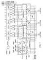
- FIG. 1illustrates an example over range protection variable resolution differential delay line ADC 100 , according to embodiments of the present disclosure.
- ADC 100may be used in, for example, switched-mode power systems (SMPS).
- SMPSswitched-mode power systems
- An SMPS control loopmay utilize measurements of analog values.
- the control loopmay require fast, one-execution-cycle measurements. Reading and acting on values measured by ADC 100 in a single cycle may improve stability and efficiency of the SMPS. Accordingly, a very fast implementation of ADC 100 may be needed.
- Speed of ADC 100may affect resolution of ADC 100 in order to update, during run-time, pulse-width-modulation (PWM) commands during a PWM cycle.
- PWMpulse-width-modulation
- ADC 100may be implemented as a digital delay line (DDL) ADC. Through implementation as a digital delay line ADC, ADC 100 may perform its measurements at a lower cost and less power than conventional flash ADCs.
- ADC 100may include background calibration.
- ADC 100may include range adjustment.
- ADC 100may estimate how far out of a desired range that its analog input would be measured. Incorporating background calibration or range adjustment improves performance and functionality.
- the out of range estimate created by ADC 100provides the direction, and a qualitative estimate of the error, so that an algorithm can make necessary adjustment. Even if the estimate is outside the accurate range of the ADC, a qualitative estimate of just how far outside the accurate range the estimate is may allow better action and performance.
- ADC 100may be implemented largely with digital, low voltage logic. Accordingly, ADC 100 may be small with respect to footprint or die size. Furthermore, ADC 100 may thus require low power. Also, ADC 100 may thus operate very fast. Accordingly, ADC 100 may be used as an error-calculating ADC in an SMPS control loop.
- Background calibrationmay improve ADC 100 performance with regards to key metrics such as resolution and accuracy.
- Range adjustmentmay make SMPS control loops more flexible and adaptable to system needs for whatever system ADC 100 is implemented.
- Out of range estimationmay provide useful information when ADC 100 is out of its linear range (with respect to its input).
- ADC 100may specify as part of the estimation a qualitative or quantitative magnitude and sign or direction of the out-of-range input.
- the outputs of pbias current and nbias currentmay be applied as inputs 102 , 104 .
- ADC 100may function with a data delay line through current starved buffers 116 , 118 .
- Each element of buffers 116 , 118may activate to propagate its input when current from respective nbias 102 , pbias 104 current reaches the element.
- the buffer statemight initially be all zeroes, and the convert signal 106 that is to be propagated may be a one. In other cases, the buffer state might initially be all ones, and the convert signal 106 that is to be propagated may be a zero.
- ADC 100may examine, upon completion of one of buffers 116 , 118 , the status of the incomplete buffer of buffers 116 , 118 .
- the relative difference between nbias 104 and pbias 102may be ascertained. Based upon this relative difference, the difference between the input voltage and the reference voltage may be ascertained. Buffers 116 , 118 may be referred to as current starved buffer in that the buffer is waiting to activate until current is received from pbias 102 or nbias 104 . Buffers 116 , 118 will activate successively with a speed related to the size of the respective differential currents.
- ADC 100may be configured to represent the difference in speeds between pbias 102 and nbias 104 through the relative speeds of each buffer 116 , 118 through a thermometer code.
- the codemay be stored in latches 112 .
- Latches 112may store the thermometer code as a snapshot of buffers 116 , 118 upon completion of the first of pbias 102 and nbias 104 .
- the respective buffer of buffers 116 , 118may output its signal that, instead of propagating to the next delay element, may become done+ or done ⁇ , respectively.
- Done+may represent that buffer 116 has finished propagating (due to pbias 102 ), and done ⁇ may represent that buffer 118 has finished propagating (due to nbias 104 ).
- An OR gatemay combine done+ and done ⁇ to generate a done signal.
- the done signalmay be fed as a control to set the values of latches 112 .
- latches 112may accept its values when the done signal is generated, which would be upon the completion of the first of buffers 116 , 118 .
- the one of done+ and done ⁇ that is set or completedmay be saved as a sign, indicating the sign of the differential. The sign may be represented by whichever of psign and nsign is set.
- Latches 112may also be set or reset according to whether the convert signal has been issued.
- the present values of buffers 116 , 118may be loaded into latches 112 .
- a modified version of the valuesmay be loaded into latches 112 .
- the values from corresponding elements of buffers 116 , 118may be passed together through a NAND gate before the result is stored in a corresponding element of latches 112 .
- latches 112may store a string of ones followed by a string of zeroes, and the location at which the ones switch to zeroes may represent the location at which the slower of pbias 102 or nbias 104 reached in its respective buffer when the faster of pbias 102 or nbias 104 reached the end of its respective buffer and generated a done signal.
- the thermometer code showing this location of the slower of pbias 102 or nbias 104may be converted by a shift register, multiplier, or other algorithmic circuit in thermometer to binary converter 114 .
- the resulting data 106may be used to show the relative difference between pbias 102 and nbias 104 .
- the difference in the voltage that generated pbias 102 and nbias 104may then be inferred from the resulting data 106 .
- this differencemay be the difference between actual output voltage of the regulator and the desired level of output voltage of the regulator.
- ADC 100includes buffers 116 , 118 implemented with digital cells. Accordingly, ADC 100 may have a small footprint or die requirement as well as low power. ADC 100 may thus be faster than other ADCs, which may include latency of ⁇ 200 ns for ADC core operation, ⁇ 100 ns for ADC control, and ⁇ 80 ns for interrupt latency, for a total of ⁇ 380 ns. In contrast, using DDL buffers, ADC 100 may be fast and small. For example, ADC 100 may be as small as 55 nm. The operation of ADC 100 , implemented as a 4-bit plus sign DDL ADC, may be 4.1 ns. A 5-bit plus sign DDL ADC implementation may operate at 8.2 ns and occupy 36 sq.
- a 6-bit plus sign DDL ADCmay operate at 16.4 ns and occupy 44 sq. mils (group of 4).
- a 7-bit plus sign DDL ADCmay operate at 32.8 ns, and may occupy 60 sq. mils (group of 4).
- an ADC implemented as a conventional flash ADCmight be fast, but in current submicron technology nodes may be large and consume significant current.
- a delay line ADCsuch as ADC 100 may be comparatively much smaller and lower power.
- FIG. 3illustrates a typical usage model of ADC 100 , according to embodiments of the present disclosure.
- 302illustrates use of an ADC in a voltage regulator feedback determination, wherein the ADC fails to implement the teachings of the present disclosure.
- 304illustrates use of ADC 100 in a voltage regulator feedback, according to the teachings of the present disclosure.
- a voltage sensemay sense voltage as-outputted by a voltage regulator. This voltage is to be compared against a reference voltage.
- the reference voltagemay be specified by a control loop command code applied to a digital-to-analog-converter, which may produce an analog signal of the desired voltage reference level.
- the Vsense and the reference voltagemay be input into a comparator.
- the comparatormay also be connected to another voltage reference (Vbg) to support or accommodate signed error results.
- Vbgmay also be referenced by the ADC itself.
- An errormay be output from the ADC, representing the control loop error between the reference voltage and Vsense.
- the voltage sense and the reference voltagemay be applied to ADC 100 . Additional elements, such as Vbg, may be unnecessary. Furthermore, the comparator used in 302 may be unnecessary.
- ADC 100may include delay elements to perform out-of-range estimation.
- Each of buffers 116 , 118may include p delay elements.
- the p delay elementsmay be sufficient for ADC 100 to implement a ADC conversion with a resolution of q bits.
- the conversion of voltage differential to a binary data 106may be performed with n delay elements.
- the thermometer codemay be n bits wide.
- the output of these additional delay elementsmay be output as overflow 120 .
- ADC 100may capture the output of them delay cells as overflow 120 .
- Overflow 120may be used to generate an estimate of the voltage value of the vsense when it is out of range with respect to the current settings.
- the estimatemay be used by part of the system in which ADC 100 is implemented to take corrective action.
- the corrective actionmay include changing an input range for ADC 100 , changing the reference voltage, or other suitable action.
- the input range of ADC 100may be 200 millivolts. If the reference voltage is 1.0 V, and the sensed voltage is 1.4 V, ADC 100 may produce a thermometer code corresponding to a voltage difference of 0.2 V. However, the maximum differential that can be represented given the resolution of ADC 100 is 0.2 V. Accordingly, ADC 100 may report that the differential between the sensed voltage and the reference voltage is 0.2 V. However, a consumer of such information may recognize that the differential value is the maximum value reportable by ADC 100 , and thus it is likely that the actual differential is greater than the reported value.
- ADC 100may provide overflow 120 .
- a consumer of the output of ADC 100may utilize overflow 120 when the output of ADC 100 indicates a maximum voltage differential of inputs of ADC 100 .
- overflow 120may be reused from existing delays of an ADC 100 from portions of buffers 116 , 118 that are not used to represent voltage differential from the range of input values of ADC 100 .
- overflow 120may be reused from delays that are used to linearize thermometer code with the current differential.
- overflow 120may be evaluated qualitatively. Such an evaluation may be because of the non-linear range of the transconductor or delay cell.
- ADC 100may be configured to perform range adjustment.
- Input ranges for ADC 100may be designed, for example, to have a +/ ⁇ 200 mV or +/ ⁇ 400 mV range. The range may be selectable.
- ADC 100may select one of the available ranges (such as +/ ⁇ 200 mV or +/ ⁇ 400 mV) based upon prior outputs of data 106 . For example, if data 106 indicates a maximum differential and the input range is selected as +/ ⁇ 200 mV, then the input range may be changed to +/ ⁇ 400 mV.
- the input rangemay be changed to +/ ⁇ 200 mV.
- the narrower rangemight be used to increase effective resolution while a same number of bits are used.
- the wider rangemight be used initially to find an initial error voltage and then as SMPS control loops bring measured and reference voltages to a closer level, the range may be decreased.
- ADC 100may be configured to perform calibration. For example, calibration might be performed by adjusting the current to individual ones of pbias 102 or nbias 104 . In another example, calibration might be performed by adjusting the current to both of pbias 102 and nbias 104 . Adjusting the current may adjust the speed or offset of pbias 102 or nbias 104 . The current may be adjusted according to a calibration line in the overflow. For example, if the overflow indicates that the differential is great, the current in a current source circuit may be adjusted up or down according to a sign of the differential.
- ADC 100may be configured to perform calibration by adjusting the length of delay lines 116 , 118 .
- the length of delay lines 116 , 118may be effectively adjusted by adding enable elements such as multiplexers to selectively eliminate usage of some of the delays in delay lines 116 , 118 .
- FIG. 4illustrates a timing diagram of operation of ADC 100 , according to embodiments of the present disclosure.
- a convert signalmay start an analog to digital conversion. Clearing the convert signal may act as a reset. Upon finishing of one of the first of the nbias or pbias signal, the associated delay line will finish. Accordingly, the latch signal will be triggered and the associated thermometer code will be latched. The thermometer code may be decoded to a digital value during a time of suitable length. When the convert signal goes low again, the delay lines may be reset. If necessary, calibration and out-of-range estimations may be applied.
- FIG. 5illustrates an example front end, according to embodiments of the present disclosure.
- the front endmay include an implementation of the voltage to current converter shown in FIG. 2 .
- the front endmay be implemented in part with a transconductor.
- the transconductormay convert differential voltage into differential current and the range selection is done by adjusting its impedance value R s .
- the transconductormay be defined according to its transconductance g m , which may be given according to the differential current output divided by the differential voltage input.
- the overall output current of the front endmay be given by:
- the impedance of the front endmay thus be adjusted in order to adjust the output current.
- FIG. 6illustrates example delay cells, according to embodiments of the present disclosure. Two corresponding delay cells and an associated portion of a latch are illustrated. The three may be implemented as a stack in order to create, in essence, a triple-height row or stack for a combined element.
- output from the previous cellmay be routed to a clock signal input and the pbias or nbias signal may be routed to a bias input. Once both inputs are high, the output may be routed to the next element.
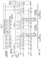
- FIG. 7is a more detailed view of ADC 100 , according to embodiments of the present disclosure.
- delay lines 116 , 118may be divided into optionally trimmed delay cells 702 , over-range delay cells 704 , and data delay cells 706 .
- one of trimmed delay cells 702 and over-range delay cells 704may be omitted.
- one or more of these groups of cellsmay be divided into cell ranges according to desired precision of ADC 100 .
- data delay cells 706may be divided into cell ranges according to desired precision.
- data delay cells 706 and over-range delay cells 704may be divided into cell ranges according to desired precision.
- some of the delay cellsmay be grouped into the number of data cells needed to support 5-bit precision for ADC 100 with a multiplexer 712 .
- some of the delay cellsmay be grouped into the number of data cells needed to support 6-bit precision for ADC 100 with a multiplexer 710 , or into 7-bit precision for ADC 100 with a multiplexer 708 .
- Each such multiplexermay enable delay operation for the delay cells within the delay lines that follow the multiplexer.
- portions of the delay linesmay be selectively activated according to a precision mode.
- the precision modemay be set according to a desired mode of ADC 100 , user or software operation, or dynamically by ADC 100 in response to over-voltage or under-voltage situations.
- Enablement of 5-bit precisionmay enable all subsequent delay cells until the done signal generation.
- enablement of 6-bit previsionmay enable all subsequent delay cells until the done signal generation.
- the enablement of 5-bit precision delay cellsmay be performed.
- enablement of 7-bit previsionmay enable all subsequent delay cells until the done signal generation.
- the enablement of 5-bit and 6-bit precision delay cellsmay be performed.
- groups 704 and 706there may be overlap between some of groups 704 and 706 in different cases and at different times.
- Cells not used for over-rangemight be used for regular data.
- cells not used for datamight be used for over-range.
- the configuration of optionally trimmed delay cells 702may be applied to elements of groups 704 or 706 . While bit groupings 708 , 710 , 712 may be accomplished with a multiplexer applied to an entire group, within a given such bit grouping, individual multiplexers may be applied to trim portions thereof.
- individual multiplexers for delay cellsmay trim or omit use in propagation lines.
- the multiplexer operation for delay cells in the nbias delay linemight differ from corresponding delay cells in the pbias delay line. Accordingly, the length of the delay lines might be adjusted so as to compensate for offsets, such that one of the pbias or nbias lines does not go through as many delay elements as the other delay line.
- the multiplexers for trimming the pbias linesmay be controlled through the indexed commands of bp, and multiplexers for trimming the nbias lines may be controlled through the indexed commands of bn. Trimming the delay line may calibrate the respective current values.
- FIG. 8is an illustration of an example system, microcontroller 800 , or other device configured to incorporate ADC 100 , according to embodiments of the present disclosure.
- ADC 100may be included in microcontroller 800 as a DDL ADC 812 .
- a processor 802 , memory 806 , conventional ADC 810 , and PWM circuit 812may also be included. These may be communicatively coupled through a suitable data bus 802 .
- DDL ADC 812Operation of DDL ADC 812 may be initiated on behalf of microcontroller 800 upon execution of instructions in memory 806 by processor 802 .
- the instructionsmay be for various parts of PWM 812 to perform voltage regulation.
- voltage comparisonsmay be made by DDL ADC 812 or conventional ADC 810 .
- processor 804may take corrective actions. For example, PWM settings might be adjusted based upon immediate conductor information.
- DDL ADC 812Operation of DDL ADC 812 with respect to the rest of microcontroller 800 may be made without having to use interrupt service routines (ISRs), as would be used by conventional ADC 810 . Moreover, there might be no need for direct memory access (DMA) to utilize DDL ADC 812 , as would be the case when conventional ADC 810 is used. Seven instances of DDL ADC 812 might be smaller than a 15 ns comparator, and as fast as an analog comparator.
- ISRsinterrupt service routines
- DMAdirect memory access
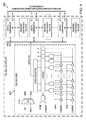
- FIG. 9is an illustration of a microcontroller with a DDL ADC featuring digital comparators for controlling PWM, according to embodiments of the present disclosure.
- pure analog comparatorsmight monitor the application to detect over or under current or over or under voltage conditions and directly turn off or on PWM signals.
- analog comparatorsare limited to a single output, yet might be fast.
- ADCsincorporate digital comparators to detect out of range operation and generate interrupts to a processor so software can make adjustments to the PWM.
- ADCscan provide multiple bits of output to software but are slow relative to a power supply control loop.
- the microcontrollermight take advantage of the very high speed of the ADC 100 .
- a 5-bit implementation of ADC 100might have a conversion time of 8.2 ns.
- Digital comparators and associated registersmay monitor the ADC 100 data output and assert digital output signals when the data meets the comparison criteria. These output signals might be connected to a PWM circuit to provide immediate control (modification) of the PWM output signals.
- ADC 100may output their values to one or more PWM controllers or circuits. These may be routed through an ADC bus directly to one or more digital comparators.
- the digital comparatorsmay be implemented in respective PWM controllers or circuits, or may be communicatively coupled thereto.
- the digital comparatorsmay be programmed with register values or other indicators of which of ADC 100 signals are to be used for a given digital comparator. Thus, a digital comparator may be designated to subscribe or accept data from a given ADC 100 .
- a value by which the digital comparator is to compare the ADC 100 signalmay be specified in the register.
- a PWM controllermay issue PWM signals based upon whether the differential voltage is greater than a threshold specified in the comparison value register. Moreover, different levels may be specified in the different comparison value registers.
- a PWM controllermay issue PWM signals based upon which thresholds that the differential voltage reaches.
- the digital comparatorsmay each have two outputs, a first output indicating that the value is greater than a value stored in an associated register and a second output indicating that the value is less or equal than the value stored in the associated register.
- the comparators according to other embodimentsmay have different outputs indicating using different operators such as equal, greater, less, greater or equal, less or equal, etc.
- the output signals provided by the comparatorscan be used to control the PWM module directly. This design does not need to wait for interrupt service routines and there is no need for DMA transfers.
- FIG. 10is another, more detailed view of ADC 100 , according to embodiments of the present disclosure. Illustrated are multiplexers 1006 , 1008 . Multiplexers 1006 , 1008 may serve a similar purpose to multiplexers 710 , 712 . Multiplexer 710 may be placed at the 50% point from the DDL end. Multiplexer 712 may be placed at the 25% point from the DDL end. Other multiplexers, not shown, may be placed, for example, at the 12.5% point from the DDL end.
- ADC 100may include digital logic blocks, such as block 1002 and block 1004 , to load data from the latches.
- the enable signals for the digital logic blocksmay be tied to the multiplexer enablement. For example, when multiplexers 1006 , 1008 are to enable full resolution, blocks 1002 and 1004 may allow loading of all data from the latches. When multiplexers 1006 , 1008 are to enable half resolution, block 1002 may be turned off while block 1004 is turned on. Other logic blocks for quarter resolution and so forth are not shown. Such blocks also be used in coordination with the multiplexers of FIG. 7 .
- Each multiplexer closer to the endreduces the resolution by 1-bit but doubles the speed of conversion when shutting down part of delay lines of ADC 100 .
- the AND gates of the logic blocks between the data latches and the thermometer to binary code converterselect the applicable inputs for differing resolution selections. Such logic blocks might be implemented instead between the delay lines and the latches.
- the “ones” in unused delay line tapsare prevented from corrupting data results.
- Multiplexers placed in the delay linesmight also provide a mechanism to insert a reset value into multiple points in the delay to yield a faster reset following a conversion cycle. This may reduce the time delay to when the next conversion can begin.
Landscapes
- Engineering & Computer Science (AREA)
- Theoretical Computer Science (AREA)
- Physics & Mathematics (AREA)
- Nonlinear Science (AREA)
- Power Engineering (AREA)
- Analogue/Digital Conversion (AREA)
- Power Conversion In General (AREA)
- Manipulation Of Pulses (AREA)
- Pulse Circuits (AREA)
Abstract
Description
Claims (15)
Priority Applications (8)
| Application Number | Priority Date | Filing Date | Title |
|---|---|---|---|
| US15/484,987US9906235B2 (en) | 2016-04-12 | 2017-04-11 | Microcontroller with digital delay line analog-to-digital converters and digital comparators |
| TW106112233ATW201810956A (en) | 2016-04-12 | 2017-04-12 | Microcontroller with digital delay line analog-to-digital converters and digital comparators |
| PCT/US2017/027250WO2017180771A1 (en) | 2016-04-12 | 2017-04-12 | Microcontroller with digital delay line analog-to-digital converters and digital comparators |
| KR1020187015385AKR20180127957A (en) | 2016-04-12 | 2017-04-12 | A microcontroller with digital delay line analog-to-digital converters and digital comparators |
| EP17732613.9AEP3443672A1 (en) | 2016-04-12 | 2017-04-12 | Microcontroller with digital delay line analog-to-digital converters and digital comparators |
| CN201780005061.9ACN108432141B (en) | 2016-04-12 | 2017-04-12 | Microcontroller with digital delay line analog-to-digital converter and digital comparator |
| JP2018523787AJP7036717B2 (en) | 2016-04-12 | 2017-04-12 | Digital Delay Line Microcontroller with analog-to-digital converter and digital comparator |
| US15/901,294US10355707B2 (en) | 2016-04-12 | 2018-02-21 | Microcontroller with digital delay line analog-to-digital converters and digital comparators |
Applications Claiming Priority (5)
| Application Number | Priority Date | Filing Date | Title |
|---|---|---|---|
| US201662321687P | 2016-04-12 | 2016-04-12 | |
| US201662321694P | 2016-04-12 | 2016-04-12 | |
| US201662321668P | 2016-04-12 | 2016-04-12 | |
| US201662321685P | 2016-04-12 | 2016-04-12 | |
| US15/484,987US9906235B2 (en) | 2016-04-12 | 2017-04-11 | Microcontroller with digital delay line analog-to-digital converters and digital comparators |
Related Child Applications (1)
| Application Number | Title | Priority Date | Filing Date |
|---|---|---|---|
| US15/901,294ContinuationUS10355707B2 (en) | 2016-04-12 | 2018-02-21 | Microcontroller with digital delay line analog-to-digital converters and digital comparators |
Publications (2)
| Publication Number | Publication Date |
|---|---|
| US20170294917A1 US20170294917A1 (en) | 2017-10-12 |
| US9906235B2true US9906235B2 (en) | 2018-02-27 |
Family
ID=59998462
Family Applications (7)
| Application Number | Title | Priority Date | Filing Date |
|---|---|---|---|
| US15/484,987ActiveUS9906235B2 (en) | 2016-04-12 | 2017-04-11 | Microcontroller with digital delay line analog-to-digital converters and digital comparators |
| US15/485,020ActiveUS9923570B2 (en) | 2016-04-12 | 2017-04-11 | Time-based delay line analog-to-digital converter with variable resolution |
| US15/484,965ActiveUS10090850B2 (en) | 2016-04-12 | 2017-04-11 | Microcontroller with digital delay line analog-to-digital converter |
| US15/484,949ActiveUS9948317B2 (en) | 2016-04-12 | 2017-04-11 | Time-based delay line analog to digital converter |
| US15/901,294ActiveUS10355707B2 (en) | 2016-04-12 | 2018-02-21 | Microcontroller with digital delay line analog-to-digital converters and digital comparators |
| US15/915,796ActiveUS10122375B2 (en) | 2016-04-12 | 2018-03-08 | Time-based delay line analog-to-digital converter with variable resolution |
| US15/949,479ActiveUS10171099B2 (en) | 2016-04-12 | 2018-04-10 | Time-based delay line analog to digital converter |
Family Applications After (6)
| Application Number | Title | Priority Date | Filing Date |
|---|---|---|---|
| US15/485,020ActiveUS9923570B2 (en) | 2016-04-12 | 2017-04-11 | Time-based delay line analog-to-digital converter with variable resolution |
| US15/484,965ActiveUS10090850B2 (en) | 2016-04-12 | 2017-04-11 | Microcontroller with digital delay line analog-to-digital converter |
| US15/484,949ActiveUS9948317B2 (en) | 2016-04-12 | 2017-04-11 | Time-based delay line analog to digital converter |
| US15/901,294ActiveUS10355707B2 (en) | 2016-04-12 | 2018-02-21 | Microcontroller with digital delay line analog-to-digital converters and digital comparators |
| US15/915,796ActiveUS10122375B2 (en) | 2016-04-12 | 2018-03-08 | Time-based delay line analog-to-digital converter with variable resolution |
| US15/949,479ActiveUS10171099B2 (en) | 2016-04-12 | 2018-04-10 | Time-based delay line analog to digital converter |
Country Status (7)
| Country | Link |
|---|---|
| US (7) | US9906235B2 (en) |
| EP (4) | EP3443673A1 (en) |
| JP (4) | JP6929282B2 (en) |
| KR (4) | KR20180127960A (en) |
| CN (4) | CN108432144B (en) |
| TW (4) | TW201810957A (en) |
| WO (4) | WO2017180771A1 (en) |
Cited By (2)
| Publication number | Priority date | Publication date | Assignee | Title |
|---|---|---|---|---|
| US10355707B2 (en)* | 2016-04-12 | 2019-07-16 | Microchip Technology Incorporated | Microcontroller with digital delay line analog-to-digital converters and digital comparators |
| US11402244B2 (en)* | 2017-03-20 | 2022-08-02 | Beamex Oy Ab | Automatic calibration of a measuring circuit |
Families Citing this family (10)
| Publication number | Priority date | Publication date | Assignee | Title |
|---|---|---|---|---|
| GB2567420B (en)* | 2017-10-02 | 2020-07-08 | Advanced Risc Mach Ltd | Adaptive voltage scaling methods and systems therefor |
| DE102017223466A1 (en)* | 2017-12-20 | 2019-06-27 | Dialog Semiconductor (Uk) Limited | ANALOG DIGITAL CONVERTER WITH SELF-TRACKING AND SELF-RANGING WINDOW |
| TWI696344B (en) | 2018-11-16 | 2020-06-11 | 財團法人工業技術研究院 | Linearity improving system and linearity improving method |
| TWI670939B (en)* | 2018-12-03 | 2019-09-01 | 新唐科技股份有限公司 | Delay line circuit with calibration function and calibration method thereof |
| CN109660302B (en)* | 2018-12-05 | 2021-08-03 | 中国人民解放军国防科技大学 | A kind of radio frequency pulse width modulator and modulation method based on digital delay line unit |
| CN109639281A (en)* | 2018-12-18 | 2019-04-16 | 四川长虹电器股份有限公司 | A kind of voltage code circuit of the controllable gain for amplifier front-end |
| US10892746B2 (en)* | 2019-01-14 | 2021-01-12 | Texas Instruments Incorporated | Switch on-time controller with delay line modulator |
| CN115280690B (en)* | 2020-03-10 | 2024-03-19 | 哲库科技(上海)有限公司 | Methods, apparatus, systems and media for delay line based transceiver calibration |
| IT202000013627A1 (en) | 2020-06-08 | 2021-12-08 | St Microelectronics Srl | A CONTROL CIRCUIT FOR AN ELECTRONIC CONVERTER, RELATED INTEGRATED CIRCUIT, ELECTRONIC CONVERTER AND PROCEDURE |
| CN114070316B (en)* | 2021-11-17 | 2023-04-14 | 苏州迅芯微电子有限公司 | Multi-phase clock generation circuit and analog-to-digital converter |
Citations (6)
| Publication number | Priority date | Publication date | Assignee | Title |
|---|---|---|---|---|
| US4998109A (en)* | 1989-12-13 | 1991-03-05 | Lechevalier Robert E | Analog to digital conversion device by charge integration using delay-line time measurement |
| US6032221A (en)* | 1997-10-24 | 2000-02-29 | Mitsubishi Denki Kabushiki Kaisha | Flash memory embedded microcomputer |
| US6977605B2 (en)* | 2003-11-26 | 2005-12-20 | Texas Instruments Incorporated | Dummy delay line based DLL and method for clocking in pipeline ADC |
| US7525471B2 (en)* | 2007-02-28 | 2009-04-28 | Exar Corporation | Wide-input windowed nonlinear analog-to-digital converter for high-frequency digitally controlled SMPS |
| US7733250B1 (en) | 2006-11-17 | 2010-06-08 | Zilog, Inc. | Microcontroller having in-situ autocalibrated integrating analog-to-digital converter (IADC) |
| US9312840B2 (en)* | 2014-02-28 | 2016-04-12 | Analog Devices Global | LC lattice delay line for high-speed ADC applications |
Family Cites Families (38)
| Publication number | Priority date | Publication date | Assignee | Title |
|---|---|---|---|---|
| US4471340A (en)* | 1981-06-02 | 1984-09-11 | The United States Of America As Represented By The Secretary Of The Navy | Analog to digital converter |
| DE3663860D1 (en)* | 1986-12-24 | 1989-07-13 | Hewlett Packard Gmbh | Method of and apparatus for adjusting the intensity profile of an ultrasound beam |
| US5140531A (en)* | 1990-08-01 | 1992-08-18 | General Electric Company | Analog neural nets supplied digital synapse signals on a bit-slice basis |
| US5412349A (en)* | 1992-03-31 | 1995-05-02 | Intel Corporation | PLL clock generator integrated with microprocessor |
| WO2000044098A1 (en)* | 1999-01-19 | 2000-07-27 | Steensgaard Madsen Jesper | Residue-compensating a / d converter |
| US6316987B1 (en)* | 1999-10-22 | 2001-11-13 | Velio Communications, Inc. | Low-power low-jitter variable delay timing circuit |
| US7595686B2 (en)* | 2001-11-09 | 2009-09-29 | The Regents Of The University Of Colorado | Digital controller for high-frequency switching power supplies |
| US7346638B2 (en)* | 2003-11-21 | 2008-03-18 | Board Of Regents, The University Of Texas System | Filtering, equalization, and power estimation for enabling higher speed signal transmission |
| US20060038596A1 (en)* | 2004-08-18 | 2006-02-23 | Binan Wang | Delay locked loop circuitry and method for optimizing delay timing in mixed signal systems |
| CA2483378A1 (en)* | 2004-10-01 | 2006-04-01 | Aleksandar Prodic | A digital controller for dc-dc switching converters that allows operation at ultra-high constant switching frequencies |
| US7456620B2 (en)* | 2004-12-03 | 2008-11-25 | The Regents Of The University Of Colorado | Determining dead times in switched-mode DC-DC converters |
| US7902803B2 (en)* | 2005-03-04 | 2011-03-08 | The Regents Of The University Of Colorado | Digital current mode controller |
| US7315270B2 (en)* | 2005-03-04 | 2008-01-01 | The Regents Of The University Of Colorado | Differential delay-line analog-to-digital converter |
| JP2009516414A (en)* | 2005-11-11 | 2009-04-16 | エヌエックスピー ビー ヴィ | Integrating analog-to-digital converter |
| JP4702179B2 (en)* | 2006-05-22 | 2011-06-15 | 株式会社デンソー | A / D conversion circuit |
| US7652604B2 (en)* | 2007-02-28 | 2010-01-26 | Exar Corporation | Programmable analog-to-digital converter for low-power DC-DC SMPS |
| DE102007026684B4 (en)* | 2007-06-08 | 2009-03-19 | Gesellschaft für Schwerionenforschung mbH | Time-amplitude converter component |
| KR100921815B1 (en)* | 2007-06-18 | 2009-10-16 | 주식회사 애트랩 | Delay time measurement circuit and delay time measurement method |
| US8022849B2 (en)* | 2008-04-14 | 2011-09-20 | Qualcomm, Incorporated | Phase to digital converter in all digital phase locked loop |
| TWI392241B (en)* | 2009-02-18 | 2013-04-01 | Realtek Semiconductor Corp | Apparatus for processing echo signal and method thereof |
| KR101069671B1 (en)* | 2009-04-15 | 2011-10-04 | 주식회사 하이닉스반도체 | Circuit for changing frequency of a signal and frequency change method thereof |
| US7893861B2 (en)* | 2009-06-30 | 2011-02-22 | International Business Machines Corporation | Time-to-digital based analog-to-digital converter architecture |
| EP2330744A1 (en)* | 2009-11-30 | 2011-06-08 | Nxp B.V. | Analog to digital conversion circuit and method |
| JP2011160369A (en)* | 2010-02-04 | 2011-08-18 | Sony Corp | Electronic circuit, electronic apparatus, and digital signal processing method |
| US8283950B2 (en)* | 2010-08-11 | 2012-10-09 | Micron Technology, Inc. | Delay lines, amplifier systems, transconductance compensating systems and methods of compensating |
| US8289062B2 (en)* | 2010-09-16 | 2012-10-16 | Micron Technology, Inc. | Analog delay lines and adaptive biasing |
| US8487806B2 (en)* | 2010-11-26 | 2013-07-16 | Electronics And Telecommunications Research Institute | Voltage-time converters and time-domain voltage comparators including the same |
| US8542138B2 (en)* | 2011-01-28 | 2013-09-24 | The Regents Of The University Of California | Ring oscillator delta sigma ADC modulator with replica path nonlinearity calibration |
| KR101202742B1 (en)* | 2011-04-05 | 2012-11-19 | 연세대학교 산학협력단 | Time-to-digital converters and conversion methods |
| US8786338B2 (en)* | 2011-11-14 | 2014-07-22 | Texas Instruments Incorporated | Delay locked loop |
| CN102522994B (en)* | 2011-12-07 | 2015-01-14 | 清华大学 | Clock generation circuit used in analog-to-digital converter (ADC) with high speed and high precision |
| US9098072B1 (en)* | 2012-09-05 | 2015-08-04 | IQ-Analog Corporation | Traveling pulse wave quantizer |
| US8797079B2 (en)* | 2012-09-28 | 2014-08-05 | Intel Mobile Communications GmbH | Differential delay line, ring oscillator and mobile communication device |
| JP6085523B2 (en)* | 2013-05-30 | 2017-02-22 | ルネサスエレクトロニクス株式会社 | Semiconductor device and method of operating semiconductor device |
| KR101503732B1 (en)* | 2013-06-14 | 2015-03-20 | 연세대학교 산학협력단 | Time to digital converter |
| JP6071840B2 (en)* | 2013-10-25 | 2017-02-01 | 株式会社東芝 | A / D converter and semiconductor integrated circuit |
| JP2015167278A (en)* | 2014-03-03 | 2015-09-24 | 株式会社デンソー | Output switching method of a/d converter and a/d converter |
| US9906235B2 (en)* | 2016-04-12 | 2018-02-27 | Microchip Technology Incorporated | Microcontroller with digital delay line analog-to-digital converters and digital comparators |
- 2017
- 2017-04-11USUS15/484,987patent/US9906235B2/enactiveActive
- 2017-04-11USUS15/485,020patent/US9923570B2/enactiveActive
- 2017-04-11USUS15/484,965patent/US10090850B2/enactiveActive
- 2017-04-11USUS15/484,949patent/US9948317B2/enactiveActive
- 2017-04-12CNCN201780005275.6Apatent/CN108432144B/enactiveActive
- 2017-04-12WOPCT/US2017/027250patent/WO2017180771A1/ennot_activeCeased
- 2017-04-12TWTW106112262Apatent/TW201810957A/enunknown
- 2017-04-12TWTW106112232Apatent/TW201810955A/enunknown
- 2017-04-12EPEP17733079.2Apatent/EP3443673A1/ennot_activeCeased
- 2017-04-12EPEP17732613.9Apatent/EP3443672A1/ennot_activeCeased
- 2017-04-12EPEP17719135.0Apatent/EP3443671A1/ennot_activeCeased
- 2017-04-12KRKR1020187015388Apatent/KR20180127960A/ennot_activeWithdrawn
- 2017-04-12CNCN201780005061.9Apatent/CN108432141B/enactiveActive
- 2017-04-12TWTW106112234Apatent/TW201803277A/enunknown
- 2017-04-12KRKR1020187015385Apatent/KR20180127957A/ennot_activeWithdrawn
- 2017-04-12EPEP17718779.6Apatent/EP3443670A1/ennot_activeCeased
- 2017-04-12JPJP2018523813Apatent/JP6929282B2/enactiveActive
- 2017-04-12KRKR1020187015386Apatent/KR20180127958A/ennot_activeWithdrawn
- 2017-04-12JPJP2018523787Apatent/JP7036717B2/enactiveActive
- 2017-04-12JPJP2018523754Apatent/JP2019514230A/enactivePending
- 2017-04-12TWTW106112233Apatent/TW201810956A/enunknown
- 2017-04-12WOPCT/US2017/027262patent/WO2017180778A1/ennot_activeCeased
- 2017-04-12CNCN201780005126.XApatent/CN108432142B/enactiveActive
- 2017-04-12KRKR1020187015387Apatent/KR20180127959A/ennot_activeWithdrawn
- 2017-04-12WOPCT/US2017/027191patent/WO2017180732A1/ennot_activeCeased
- 2017-04-12CNCN201780005127.4Apatent/CN108432143B/enactiveActive
- 2017-04-12JPJP2018523815Apatent/JP6934866B2/enactiveActive
- 2017-04-12WOPCT/US2017/027243patent/WO2017180765A1/ennot_activeCeased
- 2018
- 2018-02-21USUS15/901,294patent/US10355707B2/enactiveActive
- 2018-03-08USUS15/915,796patent/US10122375B2/enactiveActive
- 2018-04-10USUS15/949,479patent/US10171099B2/enactiveActive
Patent Citations (6)
| Publication number | Priority date | Publication date | Assignee | Title |
|---|---|---|---|---|
| US4998109A (en)* | 1989-12-13 | 1991-03-05 | Lechevalier Robert E | Analog to digital conversion device by charge integration using delay-line time measurement |
| US6032221A (en)* | 1997-10-24 | 2000-02-29 | Mitsubishi Denki Kabushiki Kaisha | Flash memory embedded microcomputer |
| US6977605B2 (en)* | 2003-11-26 | 2005-12-20 | Texas Instruments Incorporated | Dummy delay line based DLL and method for clocking in pipeline ADC |
| US7733250B1 (en) | 2006-11-17 | 2010-06-08 | Zilog, Inc. | Microcontroller having in-situ autocalibrated integrating analog-to-digital converter (IADC) |
| US7525471B2 (en)* | 2007-02-28 | 2009-04-28 | Exar Corporation | Wide-input windowed nonlinear analog-to-digital converter for high-frequency digitally controlled SMPS |
| US9312840B2 (en)* | 2014-02-28 | 2016-04-12 | Analog Devices Global | LC lattice delay line for high-speed ADC applications |
Non-Patent Citations (6)
| Title |
|---|
| Hensler, Stephan et al., "A Local Passive Time Interpolation Concept for Variation-Tolerant High-Resolution Time-to-Digital Conversion," IEEE Journal of Solid-State Circuits, vol. 43, No. 7, pp. 1666-1676, Jul. 1, 2008. |
| International Search Report and Written Opinion, Application No. PCT/US2017/027250, 17 pages, dated Jul. 31, 2017. |
| Li, Guansheng et al., "Delay-Line-Based Analog-to-Digital Converters," IEEE Transactions on Circuits and Systems-II: Express Briefs, vol. 56, No. 6, pp. 464-468, Jun. 1, 2009. |
| Li, Guansheng et al., "Delay-Line-Based Analog-to-Digital Converters," IEEE Transactions on Circuits and Systems—II: Express Briefs, vol. 56, No. 6, pp. 464-468, Jun. 1, 2009. |
| Lukić, Zdravko et al., "Multibit Σ-Δ PWM Digital Controller IC for DC-DC Converters Operating at Switching Frequencies Beyond 10 MHz," IEEE Transactions on Power Electronics, vol. 22, No. 5, pp. 1693-1707, Sep. 1, 2007. |
| Naraghi, Shahrzad, "Time-Based Analog to Digital Converters," Dissertation, University of Michigan, URL: http://deepblue.lib.umich.edu/bitstream/handle/2027.42/64787/nara?sequence=1, 118 pages, Jan. 1, 2009. |
Cited By (2)
| Publication number | Priority date | Publication date | Assignee | Title |
|---|---|---|---|---|
| US10355707B2 (en)* | 2016-04-12 | 2019-07-16 | Microchip Technology Incorporated | Microcontroller with digital delay line analog-to-digital converters and digital comparators |
| US11402244B2 (en)* | 2017-03-20 | 2022-08-02 | Beamex Oy Ab | Automatic calibration of a measuring circuit |
Also Published As
Similar Documents
| Publication | Publication Date | Title |
|---|---|---|
| US10355707B2 (en) | Microcontroller with digital delay line analog-to-digital converters and digital comparators | |
| US10003353B2 (en) | Time-based delay line analog comparator |
Legal Events
| Date | Code | Title | Description |
|---|---|---|---|
| AS | Assignment | Owner name:MICROCHIP TECHNOLOGY INCORPORATED, ARIZONA Free format text:ASSIGNMENT OF ASSIGNORS INTEREST;ASSIGNOR:KRIS, BRYAN;REEL/FRAME:041981/0154 Effective date:20170411 | |
| STCF | Information on status: patent grant | Free format text:PATENTED CASE | |
| CC | Certificate of correction | ||
| AS | Assignment | Owner name:JPMORGAN CHASE BANK, N.A., AS ADMINISTRATIVE AGENT, ILLINOIS Free format text:SECURITY INTEREST;ASSIGNORS:MICROCHIP TECHNOLOGY INCORPORATED;SILICON STORAGE TECHNOLOGY, INC.;ATMEL CORPORATION;AND OTHERS;REEL/FRAME:046426/0001 Effective date:20180529 Owner name:JPMORGAN CHASE BANK, N.A., AS ADMINISTRATIVE AGENT Free format text:SECURITY INTEREST;ASSIGNORS:MICROCHIP TECHNOLOGY INCORPORATED;SILICON STORAGE TECHNOLOGY, INC.;ATMEL CORPORATION;AND OTHERS;REEL/FRAME:046426/0001 Effective date:20180529 | |
| AS | Assignment | Owner name:WELLS FARGO BANK, NATIONAL ASSOCIATION, AS NOTES COLLATERAL AGENT, CALIFORNIA Free format text:SECURITY INTEREST;ASSIGNORS:MICROCHIP TECHNOLOGY INCORPORATED;SILICON STORAGE TECHNOLOGY, INC.;ATMEL CORPORATION;AND OTHERS;REEL/FRAME:047103/0206 Effective date:20180914 Owner name:WELLS FARGO BANK, NATIONAL ASSOCIATION, AS NOTES C Free format text:SECURITY INTEREST;ASSIGNORS:MICROCHIP TECHNOLOGY INCORPORATED;SILICON STORAGE TECHNOLOGY, INC.;ATMEL CORPORATION;AND OTHERS;REEL/FRAME:047103/0206 Effective date:20180914 | |
| AS | Assignment | Owner name:JPMORGAN CHASE BANK, N.A., AS ADMINISTRATIVE AGENT, DELAWARE Free format text:SECURITY INTEREST;ASSIGNORS:MICROCHIP TECHNOLOGY INC.;SILICON STORAGE TECHNOLOGY, INC.;ATMEL CORPORATION;AND OTHERS;REEL/FRAME:053311/0305 Effective date:20200327 | |
| AS | Assignment | Owner name:SILICON STORAGE TECHNOLOGY, INC., ARIZONA Free format text:RELEASE BY SECURED PARTY;ASSIGNOR:JPMORGAN CHASE BANK, N.A, AS ADMINISTRATIVE AGENT;REEL/FRAME:053466/0011 Effective date:20200529 Owner name:MICROSEMI STORAGE SOLUTIONS, INC., ARIZONA Free format text:RELEASE BY SECURED PARTY;ASSIGNOR:JPMORGAN CHASE BANK, N.A, AS ADMINISTRATIVE AGENT;REEL/FRAME:053466/0011 Effective date:20200529 Owner name:ATMEL CORPORATION, ARIZONA Free format text:RELEASE BY SECURED PARTY;ASSIGNOR:JPMORGAN CHASE BANK, N.A, AS ADMINISTRATIVE AGENT;REEL/FRAME:053466/0011 Effective date:20200529 Owner name:MICROSEMI CORPORATION, CALIFORNIA Free format text:RELEASE BY SECURED PARTY;ASSIGNOR:JPMORGAN CHASE BANK, N.A, AS ADMINISTRATIVE AGENT;REEL/FRAME:053466/0011 Effective date:20200529 Owner name:MICROCHIP TECHNOLOGY INC., ARIZONA Free format text:RELEASE BY SECURED PARTY;ASSIGNOR:JPMORGAN CHASE BANK, N.A, AS ADMINISTRATIVE AGENT;REEL/FRAME:053466/0011 Effective date:20200529 | |
| AS | Assignment | Owner name:WELLS FARGO BANK, NATIONAL ASSOCIATION, MINNESOTA Free format text:SECURITY INTEREST;ASSIGNORS:MICROCHIP TECHNOLOGY INC.;SILICON STORAGE TECHNOLOGY, INC.;ATMEL CORPORATION;AND OTHERS;REEL/FRAME:053468/0705 Effective date:20200529 | |
| AS | Assignment | Owner name:WELLS FARGO BANK, NATIONAL ASSOCIATION, AS COLLATERAL AGENT, MINNESOTA Free format text:SECURITY INTEREST;ASSIGNORS:MICROCHIP TECHNOLOGY INCORPORATED;SILICON STORAGE TECHNOLOGY, INC.;ATMEL CORPORATION;AND OTHERS;REEL/FRAME:055671/0612 Effective date:20201217 | |
| AS | Assignment | Owner name:WELLS FARGO BANK, NATIONAL ASSOCIATION, AS NOTES COLLATERAL AGENT, MINNESOTA Free format text:SECURITY INTEREST;ASSIGNORS:MICROCHIP TECHNOLOGY INCORPORATED;SILICON STORAGE TECHNOLOGY, INC.;ATMEL CORPORATION;AND OTHERS;REEL/FRAME:057935/0474 Effective date:20210528 | |
| MAFP | Maintenance fee payment | Free format text:PAYMENT OF MAINTENANCE FEE, 4TH YEAR, LARGE ENTITY (ORIGINAL EVENT CODE: M1551); ENTITY STATUS OF PATENT OWNER: LARGE ENTITY Year of fee payment:4 | |
| AS | Assignment | Owner name:MICROSEMI STORAGE SOLUTIONS, INC., ARIZONA Free format text:RELEASE BY SECURED PARTY;ASSIGNOR:JPMORGAN CHASE BANK, N.A., AS ADMINISTRATIVE AGENT;REEL/FRAME:059333/0222 Effective date:20220218 Owner name:MICROSEMI CORPORATION, ARIZONA Free format text:RELEASE BY SECURED PARTY;ASSIGNOR:JPMORGAN CHASE BANK, N.A., AS ADMINISTRATIVE AGENT;REEL/FRAME:059333/0222 Effective date:20220218 Owner name:ATMEL CORPORATION, ARIZONA Free format text:RELEASE BY SECURED PARTY;ASSIGNOR:JPMORGAN CHASE BANK, N.A., AS ADMINISTRATIVE AGENT;REEL/FRAME:059333/0222 Effective date:20220218 Owner name:SILICON STORAGE TECHNOLOGY, INC., ARIZONA Free format text:RELEASE BY SECURED PARTY;ASSIGNOR:JPMORGAN CHASE BANK, N.A., AS ADMINISTRATIVE AGENT;REEL/FRAME:059333/0222 Effective date:20220218 Owner name:MICROCHIP TECHNOLOGY INCORPORATED, ARIZONA Free format text:RELEASE BY SECURED PARTY;ASSIGNOR:JPMORGAN CHASE BANK, N.A., AS ADMINISTRATIVE AGENT;REEL/FRAME:059333/0222 Effective date:20220218 | |
| AS | Assignment | Owner name:MICROSEMI STORAGE SOLUTIONS, INC., ARIZONA Free format text:RELEASE BY SECURED PARTY;ASSIGNOR:WELLS FARGO BANK, NATIONAL ASSOCIATION, AS NOTES COLLATERAL AGENT;REEL/FRAME:059358/0001 Effective date:20220228 Owner name:MICROSEMI CORPORATION, ARIZONA Free format text:RELEASE BY SECURED PARTY;ASSIGNOR:WELLS FARGO BANK, NATIONAL ASSOCIATION, AS NOTES COLLATERAL AGENT;REEL/FRAME:059358/0001 Effective date:20220228 Owner name:ATMEL CORPORATION, ARIZONA Free format text:RELEASE BY SECURED PARTY;ASSIGNOR:WELLS FARGO BANK, NATIONAL ASSOCIATION, AS NOTES COLLATERAL AGENT;REEL/FRAME:059358/0001 Effective date:20220228 Owner name:SILICON STORAGE TECHNOLOGY, INC., ARIZONA Free format text:RELEASE BY SECURED PARTY;ASSIGNOR:WELLS FARGO BANK, NATIONAL ASSOCIATION, AS NOTES COLLATERAL AGENT;REEL/FRAME:059358/0001 Effective date:20220228 Owner name:MICROCHIP TECHNOLOGY INCORPORATED, ARIZONA Free format text:RELEASE BY SECURED PARTY;ASSIGNOR:WELLS FARGO BANK, NATIONAL ASSOCIATION, AS NOTES COLLATERAL AGENT;REEL/FRAME:059358/0001 Effective date:20220228 | |
| AS | Assignment | Owner name:MICROSEMI STORAGE SOLUTIONS, INC., ARIZONA Free format text:RELEASE BY SECURED PARTY;ASSIGNOR:WELLS FARGO BANK, NATIONAL ASSOCIATION, AS NOTES COLLATERAL AGENT;REEL/FRAME:059863/0400 Effective date:20220228 Owner name:MICROSEMI CORPORATION, ARIZONA Free format text:RELEASE BY SECURED PARTY;ASSIGNOR:WELLS FARGO BANK, NATIONAL ASSOCIATION, AS NOTES COLLATERAL AGENT;REEL/FRAME:059863/0400 Effective date:20220228 Owner name:ATMEL CORPORATION, ARIZONA Free format text:RELEASE BY SECURED PARTY;ASSIGNOR:WELLS FARGO BANK, NATIONAL ASSOCIATION, AS NOTES COLLATERAL AGENT;REEL/FRAME:059863/0400 Effective date:20220228 Owner name:SILICON STORAGE TECHNOLOGY, INC., ARIZONA Free format text:RELEASE BY SECURED PARTY;ASSIGNOR:WELLS FARGO BANK, NATIONAL ASSOCIATION, AS NOTES COLLATERAL AGENT;REEL/FRAME:059863/0400 Effective date:20220228 Owner name:MICROCHIP TECHNOLOGY INCORPORATED, ARIZONA Free format text:RELEASE BY SECURED PARTY;ASSIGNOR:WELLS FARGO BANK, NATIONAL ASSOCIATION, AS NOTES COLLATERAL AGENT;REEL/FRAME:059863/0400 Effective date:20220228 | |
| AS | Assignment | Owner name:MICROSEMI STORAGE SOLUTIONS, INC., ARIZONA Free format text:RELEASE BY SECURED PARTY;ASSIGNOR:WELLS FARGO BANK, NATIONAL ASSOCIATION, AS NOTES COLLATERAL AGENT;REEL/FRAME:059363/0001 Effective date:20220228 Owner name:MICROSEMI CORPORATION, ARIZONA Free format text:RELEASE BY SECURED PARTY;ASSIGNOR:WELLS FARGO BANK, NATIONAL ASSOCIATION, AS NOTES COLLATERAL AGENT;REEL/FRAME:059363/0001 Effective date:20220228 Owner name:ATMEL CORPORATION, ARIZONA Free format text:RELEASE BY SECURED PARTY;ASSIGNOR:WELLS FARGO BANK, NATIONAL ASSOCIATION, AS NOTES COLLATERAL AGENT;REEL/FRAME:059363/0001 Effective date:20220228 Owner name:SILICON STORAGE TECHNOLOGY, INC., ARIZONA Free format text:RELEASE BY SECURED PARTY;ASSIGNOR:WELLS FARGO BANK, NATIONAL ASSOCIATION, AS NOTES COLLATERAL AGENT;REEL/FRAME:059363/0001 Effective date:20220228 Owner name:MICROCHIP TECHNOLOGY INCORPORATED, ARIZONA Free format text:RELEASE BY SECURED PARTY;ASSIGNOR:WELLS FARGO BANK, NATIONAL ASSOCIATION, AS NOTES COLLATERAL AGENT;REEL/FRAME:059363/0001 Effective date:20220228 | |
| AS | Assignment | Owner name:MICROSEMI STORAGE SOLUTIONS, INC., ARIZONA Free format text:RELEASE BY SECURED PARTY;ASSIGNOR:WELLS FARGO BANK, NATIONAL ASSOCIATION, AS NOTES COLLATERAL AGENT;REEL/FRAME:060894/0437 Effective date:20220228 Owner name:MICROSEMI CORPORATION, ARIZONA Free format text:RELEASE BY SECURED PARTY;ASSIGNOR:WELLS FARGO BANK, NATIONAL ASSOCIATION, AS NOTES COLLATERAL AGENT;REEL/FRAME:060894/0437 Effective date:20220228 Owner name:ATMEL CORPORATION, ARIZONA Free format text:RELEASE BY SECURED PARTY;ASSIGNOR:WELLS FARGO BANK, NATIONAL ASSOCIATION, AS NOTES COLLATERAL AGENT;REEL/FRAME:060894/0437 Effective date:20220228 Owner name:SILICON STORAGE TECHNOLOGY, INC., ARIZONA Free format text:RELEASE BY SECURED PARTY;ASSIGNOR:WELLS FARGO BANK, NATIONAL ASSOCIATION, AS NOTES COLLATERAL AGENT;REEL/FRAME:060894/0437 Effective date:20220228 Owner name:MICROCHIP TECHNOLOGY INCORPORATED, ARIZONA Free format text:RELEASE BY SECURED PARTY;ASSIGNOR:WELLS FARGO BANK, NATIONAL ASSOCIATION, AS NOTES COLLATERAL AGENT;REEL/FRAME:060894/0437 Effective date:20220228 | |
| MAFP | Maintenance fee payment | Free format text:PAYMENT OF MAINTENANCE FEE, 8TH YEAR, LARGE ENTITY (ORIGINAL EVENT CODE: M1552); ENTITY STATUS OF PATENT OWNER: LARGE ENTITY Year of fee payment:8 |