US9901443B2 - Prosthetic heart valve devices, prosthetic mitral valves and associated systems and methods - Google Patents
Prosthetic heart valve devices, prosthetic mitral valves and associated systems and methodsDownload PDFInfo
- Publication number
- US9901443B2 US9901443B2US14/820,830US201514820830AUS9901443B2US 9901443 B2US9901443 B2US 9901443B2US 201514820830 AUS201514820830 AUS 201514820830AUS 9901443 B2US9901443 B2US 9901443B2
- Authority
- US
- United States
- Prior art keywords
- anchoring member
- valve
- valve support
- tissue
- native
- Prior art date
- Legal status (The legal status is an assumption and is not a legal conclusion. Google has not performed a legal analysis and makes no representation as to the accuracy of the status listed.)
- Active, expires
Links
Images


Classifications
- A—HUMAN NECESSITIES
- A61—MEDICAL OR VETERINARY SCIENCE; HYGIENE
- A61F—FILTERS IMPLANTABLE INTO BLOOD VESSELS; PROSTHESES; DEVICES PROVIDING PATENCY TO, OR PREVENTING COLLAPSING OF, TUBULAR STRUCTURES OF THE BODY, e.g. STENTS; ORTHOPAEDIC, NURSING OR CONTRACEPTIVE DEVICES; FOMENTATION; TREATMENT OR PROTECTION OF EYES OR EARS; BANDAGES, DRESSINGS OR ABSORBENT PADS; FIRST-AID KITS
- A61F2/00—Filters implantable into blood vessels; Prostheses, i.e. artificial substitutes or replacements for parts of the body; Appliances for connecting them with the body; Devices providing patency to, or preventing collapsing of, tubular structures of the body, e.g. stents
- A61F2/02—Prostheses implantable into the body
- A61F2/24—Heart valves ; Vascular valves, e.g. venous valves; Heart implants, e.g. passive devices for improving the function of the native valve or the heart muscle; Transmyocardial revascularisation [TMR] devices; Valves implantable in the body
- A61F2/2409—Support rings therefor, e.g. for connecting valves to tissue
- A—HUMAN NECESSITIES
- A61—MEDICAL OR VETERINARY SCIENCE; HYGIENE
- A61F—FILTERS IMPLANTABLE INTO BLOOD VESSELS; PROSTHESES; DEVICES PROVIDING PATENCY TO, OR PREVENTING COLLAPSING OF, TUBULAR STRUCTURES OF THE BODY, e.g. STENTS; ORTHOPAEDIC, NURSING OR CONTRACEPTIVE DEVICES; FOMENTATION; TREATMENT OR PROTECTION OF EYES OR EARS; BANDAGES, DRESSINGS OR ABSORBENT PADS; FIRST-AID KITS
- A61F2/00—Filters implantable into blood vessels; Prostheses, i.e. artificial substitutes or replacements for parts of the body; Appliances for connecting them with the body; Devices providing patency to, or preventing collapsing of, tubular structures of the body, e.g. stents
- A61F2/02—Prostheses implantable into the body
- A61F2/24—Heart valves ; Vascular valves, e.g. venous valves; Heart implants, e.g. passive devices for improving the function of the native valve or the heart muscle; Transmyocardial revascularisation [TMR] devices; Valves implantable in the body
- A61F2/2412—Heart valves ; Vascular valves, e.g. venous valves; Heart implants, e.g. passive devices for improving the function of the native valve or the heart muscle; Transmyocardial revascularisation [TMR] devices; Valves implantable in the body with soft flexible valve members, e.g. tissue valves shaped like natural valves
- A61F2/2418—Scaffolds therefor, e.g. support stents
- A—HUMAN NECESSITIES
- A61—MEDICAL OR VETERINARY SCIENCE; HYGIENE
- A61F—FILTERS IMPLANTABLE INTO BLOOD VESSELS; PROSTHESES; DEVICES PROVIDING PATENCY TO, OR PREVENTING COLLAPSING OF, TUBULAR STRUCTURES OF THE BODY, e.g. STENTS; ORTHOPAEDIC, NURSING OR CONTRACEPTIVE DEVICES; FOMENTATION; TREATMENT OR PROTECTION OF EYES OR EARS; BANDAGES, DRESSINGS OR ABSORBENT PADS; FIRST-AID KITS
- A61F2/00—Filters implantable into blood vessels; Prostheses, i.e. artificial substitutes or replacements for parts of the body; Appliances for connecting them with the body; Devices providing patency to, or preventing collapsing of, tubular structures of the body, e.g. stents
- A61F2/02—Prostheses implantable into the body
- A61F2/24—Heart valves ; Vascular valves, e.g. venous valves; Heart implants, e.g. passive devices for improving the function of the native valve or the heart muscle; Transmyocardial revascularisation [TMR] devices; Valves implantable in the body
- A61F2/2427—Devices for manipulating or deploying heart valves during implantation
- A61F2/2436—Deployment by retracting a sheath
- A—HUMAN NECESSITIES
- A61—MEDICAL OR VETERINARY SCIENCE; HYGIENE
- A61F—FILTERS IMPLANTABLE INTO BLOOD VESSELS; PROSTHESES; DEVICES PROVIDING PATENCY TO, OR PREVENTING COLLAPSING OF, TUBULAR STRUCTURES OF THE BODY, e.g. STENTS; ORTHOPAEDIC, NURSING OR CONTRACEPTIVE DEVICES; FOMENTATION; TREATMENT OR PROTECTION OF EYES OR EARS; BANDAGES, DRESSINGS OR ABSORBENT PADS; FIRST-AID KITS
- A61F2/00—Filters implantable into blood vessels; Prostheses, i.e. artificial substitutes or replacements for parts of the body; Appliances for connecting them with the body; Devices providing patency to, or preventing collapsing of, tubular structures of the body, e.g. stents
- A61F2/02—Prostheses implantable into the body
- A61F2/24—Heart valves ; Vascular valves, e.g. venous valves; Heart implants, e.g. passive devices for improving the function of the native valve or the heart muscle; Transmyocardial revascularisation [TMR] devices; Valves implantable in the body
- A61F2/2442—Annuloplasty rings or inserts for correcting the valve shape; Implants for improving the function of a native heart valve
- A61F2/2445—Annuloplasty rings in direct contact with the valve annulus
- A—HUMAN NECESSITIES
- A61—MEDICAL OR VETERINARY SCIENCE; HYGIENE
- A61F—FILTERS IMPLANTABLE INTO BLOOD VESSELS; PROSTHESES; DEVICES PROVIDING PATENCY TO, OR PREVENTING COLLAPSING OF, TUBULAR STRUCTURES OF THE BODY, e.g. STENTS; ORTHOPAEDIC, NURSING OR CONTRACEPTIVE DEVICES; FOMENTATION; TREATMENT OR PROTECTION OF EYES OR EARS; BANDAGES, DRESSINGS OR ABSORBENT PADS; FIRST-AID KITS
- A61F2/00—Filters implantable into blood vessels; Prostheses, i.e. artificial substitutes or replacements for parts of the body; Appliances for connecting them with the body; Devices providing patency to, or preventing collapsing of, tubular structures of the body, e.g. stents
- A61F2/02—Prostheses implantable into the body
- A61F2/24—Heart valves ; Vascular valves, e.g. venous valves; Heart implants, e.g. passive devices for improving the function of the native valve or the heart muscle; Transmyocardial revascularisation [TMR] devices; Valves implantable in the body
- A61F2/2442—Annuloplasty rings or inserts for correcting the valve shape; Implants for improving the function of a native heart valve
- A61F2/246—Devices for obstructing a leak through a native valve in a closed condition
- A—HUMAN NECESSITIES
- A61—MEDICAL OR VETERINARY SCIENCE; HYGIENE
- A61F—FILTERS IMPLANTABLE INTO BLOOD VESSELS; PROSTHESES; DEVICES PROVIDING PATENCY TO, OR PREVENTING COLLAPSING OF, TUBULAR STRUCTURES OF THE BODY, e.g. STENTS; ORTHOPAEDIC, NURSING OR CONTRACEPTIVE DEVICES; FOMENTATION; TREATMENT OR PROTECTION OF EYES OR EARS; BANDAGES, DRESSINGS OR ABSORBENT PADS; FIRST-AID KITS
- A61F2220/00—Fixations or connections for prostheses classified in groups A61F2/00 - A61F2/26 or A61F2/82 or A61F9/00 or A61F11/00 or subgroups thereof
- A61F2220/0008—Fixation appliances for connecting prostheses to the body
- A61F2220/0016—Fixation appliances for connecting prostheses to the body with sharp anchoring protrusions, e.g. barbs, pins, spikes
- A—HUMAN NECESSITIES
- A61—MEDICAL OR VETERINARY SCIENCE; HYGIENE
- A61F—FILTERS IMPLANTABLE INTO BLOOD VESSELS; PROSTHESES; DEVICES PROVIDING PATENCY TO, OR PREVENTING COLLAPSING OF, TUBULAR STRUCTURES OF THE BODY, e.g. STENTS; ORTHOPAEDIC, NURSING OR CONTRACEPTIVE DEVICES; FOMENTATION; TREATMENT OR PROTECTION OF EYES OR EARS; BANDAGES, DRESSINGS OR ABSORBENT PADS; FIRST-AID KITS
- A61F2220/00—Fixations or connections for prostheses classified in groups A61F2/00 - A61F2/26 or A61F2/82 or A61F9/00 or A61F11/00 or subgroups thereof
- A61F2220/0025—Connections or couplings between prosthetic parts, e.g. between modular parts; Connecting elements
- A61F2220/0041—Connections or couplings between prosthetic parts, e.g. between modular parts; Connecting elements using additional screws, bolts, dowels or rivets, e.g. connecting screws
- A—HUMAN NECESSITIES
- A61—MEDICAL OR VETERINARY SCIENCE; HYGIENE
- A61F—FILTERS IMPLANTABLE INTO BLOOD VESSELS; PROSTHESES; DEVICES PROVIDING PATENCY TO, OR PREVENTING COLLAPSING OF, TUBULAR STRUCTURES OF THE BODY, e.g. STENTS; ORTHOPAEDIC, NURSING OR CONTRACEPTIVE DEVICES; FOMENTATION; TREATMENT OR PROTECTION OF EYES OR EARS; BANDAGES, DRESSINGS OR ABSORBENT PADS; FIRST-AID KITS
- A61F2220/00—Fixations or connections for prostheses classified in groups A61F2/00 - A61F2/26 or A61F2/82 or A61F9/00 or A61F11/00 or subgroups thereof
- A61F2220/0025—Connections or couplings between prosthetic parts, e.g. between modular parts; Connecting elements
- A61F2220/005—Connections or couplings between prosthetic parts, e.g. between modular parts; Connecting elements using adhesives
- A—HUMAN NECESSITIES
- A61—MEDICAL OR VETERINARY SCIENCE; HYGIENE
- A61F—FILTERS IMPLANTABLE INTO BLOOD VESSELS; PROSTHESES; DEVICES PROVIDING PATENCY TO, OR PREVENTING COLLAPSING OF, TUBULAR STRUCTURES OF THE BODY, e.g. STENTS; ORTHOPAEDIC, NURSING OR CONTRACEPTIVE DEVICES; FOMENTATION; TREATMENT OR PROTECTION OF EYES OR EARS; BANDAGES, DRESSINGS OR ABSORBENT PADS; FIRST-AID KITS
- A61F2220/00—Fixations or connections for prostheses classified in groups A61F2/00 - A61F2/26 or A61F2/82 or A61F9/00 or A61F11/00 or subgroups thereof
- A61F2220/0025—Connections or couplings between prosthetic parts, e.g. between modular parts; Connecting elements
- A61F2220/0066—Connections or couplings between prosthetic parts, e.g. between modular parts; Connecting elements stapled
- A—HUMAN NECESSITIES
- A61—MEDICAL OR VETERINARY SCIENCE; HYGIENE
- A61F—FILTERS IMPLANTABLE INTO BLOOD VESSELS; PROSTHESES; DEVICES PROVIDING PATENCY TO, OR PREVENTING COLLAPSING OF, TUBULAR STRUCTURES OF THE BODY, e.g. STENTS; ORTHOPAEDIC, NURSING OR CONTRACEPTIVE DEVICES; FOMENTATION; TREATMENT OR PROTECTION OF EYES OR EARS; BANDAGES, DRESSINGS OR ABSORBENT PADS; FIRST-AID KITS
- A61F2220/00—Fixations or connections for prostheses classified in groups A61F2/00 - A61F2/26 or A61F2/82 or A61F9/00 or A61F11/00 or subgroups thereof
- A61F2220/0025—Connections or couplings between prosthetic parts, e.g. between modular parts; Connecting elements
- A61F2220/0075—Connections or couplings between prosthetic parts, e.g. between modular parts; Connecting elements sutured, ligatured or stitched, retained or tied with a rope, string, thread, wire or cable
- A—HUMAN NECESSITIES
- A61—MEDICAL OR VETERINARY SCIENCE; HYGIENE
- A61F—FILTERS IMPLANTABLE INTO BLOOD VESSELS; PROSTHESES; DEVICES PROVIDING PATENCY TO, OR PREVENTING COLLAPSING OF, TUBULAR STRUCTURES OF THE BODY, e.g. STENTS; ORTHOPAEDIC, NURSING OR CONTRACEPTIVE DEVICES; FOMENTATION; TREATMENT OR PROTECTION OF EYES OR EARS; BANDAGES, DRESSINGS OR ABSORBENT PADS; FIRST-AID KITS
- A61F2230/00—Geometry of prostheses classified in groups A61F2/00 - A61F2/26 or A61F2/82 or A61F9/00 or A61F11/00 or subgroups thereof
- A61F2230/0002—Two-dimensional shapes, e.g. cross-sections
- A61F2230/0028—Shapes in the form of latin or greek characters
- A61F2230/0054—V-shaped
- A—HUMAN NECESSITIES
- A61—MEDICAL OR VETERINARY SCIENCE; HYGIENE
- A61F—FILTERS IMPLANTABLE INTO BLOOD VESSELS; PROSTHESES; DEVICES PROVIDING PATENCY TO, OR PREVENTING COLLAPSING OF, TUBULAR STRUCTURES OF THE BODY, e.g. STENTS; ORTHOPAEDIC, NURSING OR CONTRACEPTIVE DEVICES; FOMENTATION; TREATMENT OR PROTECTION OF EYES OR EARS; BANDAGES, DRESSINGS OR ABSORBENT PADS; FIRST-AID KITS
- A61F2230/00—Geometry of prostheses classified in groups A61F2/00 - A61F2/26 or A61F2/82 or A61F9/00 or A61F11/00 or subgroups thereof
- A61F2230/0063—Three-dimensional shapes
- A61F2230/0067—Three-dimensional shapes conical
- A—HUMAN NECESSITIES
- A61—MEDICAL OR VETERINARY SCIENCE; HYGIENE
- A61F—FILTERS IMPLANTABLE INTO BLOOD VESSELS; PROSTHESES; DEVICES PROVIDING PATENCY TO, OR PREVENTING COLLAPSING OF, TUBULAR STRUCTURES OF THE BODY, e.g. STENTS; ORTHOPAEDIC, NURSING OR CONTRACEPTIVE DEVICES; FOMENTATION; TREATMENT OR PROTECTION OF EYES OR EARS; BANDAGES, DRESSINGS OR ABSORBENT PADS; FIRST-AID KITS
- A61F2230/00—Geometry of prostheses classified in groups A61F2/00 - A61F2/26 or A61F2/82 or A61F9/00 or A61F11/00 or subgroups thereof
- A61F2230/0063—Three-dimensional shapes
- A61F2230/0069—Three-dimensional shapes cylindrical
- A—HUMAN NECESSITIES
- A61—MEDICAL OR VETERINARY SCIENCE; HYGIENE
- A61F—FILTERS IMPLANTABLE INTO BLOOD VESSELS; PROSTHESES; DEVICES PROVIDING PATENCY TO, OR PREVENTING COLLAPSING OF, TUBULAR STRUCTURES OF THE BODY, e.g. STENTS; ORTHOPAEDIC, NURSING OR CONTRACEPTIVE DEVICES; FOMENTATION; TREATMENT OR PROTECTION OF EYES OR EARS; BANDAGES, DRESSINGS OR ABSORBENT PADS; FIRST-AID KITS
- A61F2230/00—Geometry of prostheses classified in groups A61F2/00 - A61F2/26 or A61F2/82 or A61F9/00 or A61F11/00 or subgroups thereof
- A61F2230/0063—Three-dimensional shapes
- A61F2230/0073—Quadric-shaped
- A61F2230/0078—Quadric-shaped hyperboloidal
- A—HUMAN NECESSITIES
- A61—MEDICAL OR VETERINARY SCIENCE; HYGIENE
- A61F—FILTERS IMPLANTABLE INTO BLOOD VESSELS; PROSTHESES; DEVICES PROVIDING PATENCY TO, OR PREVENTING COLLAPSING OF, TUBULAR STRUCTURES OF THE BODY, e.g. STENTS; ORTHOPAEDIC, NURSING OR CONTRACEPTIVE DEVICES; FOMENTATION; TREATMENT OR PROTECTION OF EYES OR EARS; BANDAGES, DRESSINGS OR ABSORBENT PADS; FIRST-AID KITS
- A61F2250/00—Special features of prostheses classified in groups A61F2/00 - A61F2/26 or A61F2/82 or A61F9/00 or A61F11/00 or subgroups thereof
- A61F2250/0058—Additional features; Implant or prostheses properties not otherwise provided for
- A61F2250/006—Additional features; Implant or prostheses properties not otherwise provided for modular
- A—HUMAN NECESSITIES
- A61—MEDICAL OR VETERINARY SCIENCE; HYGIENE
- A61F—FILTERS IMPLANTABLE INTO BLOOD VESSELS; PROSTHESES; DEVICES PROVIDING PATENCY TO, OR PREVENTING COLLAPSING OF, TUBULAR STRUCTURES OF THE BODY, e.g. STENTS; ORTHOPAEDIC, NURSING OR CONTRACEPTIVE DEVICES; FOMENTATION; TREATMENT OR PROTECTION OF EYES OR EARS; BANDAGES, DRESSINGS OR ABSORBENT PADS; FIRST-AID KITS
- A61F2250/00—Special features of prostheses classified in groups A61F2/00 - A61F2/26 or A61F2/82 or A61F9/00 or A61F11/00 or subgroups thereof
- A61F2250/0058—Additional features; Implant or prostheses properties not otherwise provided for
- A61F2250/0069—Sealing means
Definitions
- the present technologyrelates generally to prosthetic heart valve devices.
- several embodimentsare directed to prosthetic mitral valves and devices for percutaneous repair and/or replacement of native mitral valves and associated systems and methods.
- Mitral valve regurgitationis a disorder of the heart in which the leaflets of the mitral valve fail to coapt into apposition at peak contraction pressures, resulting in abnormal leaking of blood from the left ventricle into the left atrium.
- mitral valve leafletsThere are a number of structural factors that may affect the proper closure of the mitral valve leaflets. For example, many patients suffering from heart disease experience dilation of the heart muscle, resulting in an enlarged mitral annulus. Enlargement of the mitral annulus makes it difficult for the leaflets to coapt during systole.
- a stretch or tear in the chordae tendineae, the tendons connecting the papillary muscles to the inferior side of the mitral valve leaflets,may also affect proper closure of the mitral annulus.
- a ruptured chordae tendineaemay cause a valve leaflet to prolapse into the left atrium due to inadequate tension on the leaflet.
- Abnormal backflowcan also occur when the functioning of the papillary muscles is compromised, for example, due to ischemia. As the left ventricle contracts during systole, the affected papillary muscles do not contract sufficiently to effect proper closure.
- Mitral valve prolapseor when the mitral leaflets bulge abnormally up in to the left atrium, causes irregular behavior of the mitral valve and may also lead to mitral valve regurgitation. Normal functioning of the mitral valve may also be affected by mitral valve stenosis, or a narrowing of the mitral valve orifice, which causes impedance of filling of the left ventricle in diastole.
- treatment for mitral valve regurgitationhas involved the application of diuretics and/or vasodilators to reduce the amount of blood flowing back into the left atrium.
- Other procedureshave involved surgical approaches (open and intravascular) for either the repair or replacement of the valve.
- typical repair approacheshave involved cinching or resecting portions of the dilated annulus.
- Cinching of the annulushas been accomplished by the implantation of annular or peri-annular rings which are generally secured to the annulus or surrounding tissue. Other repair procedures have also involved suturing or clipping of the valve leaflets into partial apposition with one another.
- valvesinclude, e.g., the CoreValve Revalving® System from Medtronic/Corevalve Inc. (Irvine, Calif., USA) and the Edwards-Sapien® Valve from Edwards Lifesciences (Irvine, Calif., USA). Both valve systems include an expandable frame housing a tri-leaflet bioprosthetic valve. The frame is expanded to fit the substantially symmetric, circular and rigid aortic annulus.
- aortic valve anatomylends itself to an expandable frame housing a replacement valve since the aortic valve anatomy is substantially uniform, symmetric, and fairly rigid.
- Mitral valve replacementcompared with aortic valve replacement, poses unique anatomical obstacles, rendering percutaneous mitral valve replacement significantly more challenging than aortic valve replacement.
- the mitral valve annulushas a non-circular D-shape or kidney-like shape, with a non-planar, saddle-like geometry often lacking symmetry.
- Such unpredictabilitymakes it difficult to design a mitral valve prosthesis having the ability to conform to the mitral annulus.
- Lack of a snug fit between the prosthesis and the native leaflets and/or annulusmay leave gaps therein, creating backflow of blood through these gaps.
- Placement of a cylindrical valve prosthesisfor example, may leave gaps in commissural regions of the native valve, potentially resulting in perivalvular leaks in those regions.
- the mitral valve annuluslacks a significant amount of radial support from surrounding tissue.
- the aortic valvefor example, is completely surrounded by fibro-elastic tissue, helping to anchor a prosthetic valve by providing native structural support.
- the mitral valveon the other hand, is bound by muscular tissue on the outer wall only.
- the inner wall of the mitral valveis bound by a thin vessel wall separating the mitral valve annulus from the inferior portion of the aortic outflow tract.
- chordae tendineae of the left ventriclemay also present an obstacle in deploying a mitral valve prosthesis. This is unique to the mitral valve since aortic valve anatomy does not include chordae. The maze of chordae in the left ventricle makes navigating and positioning a deployment catheter that much more difficult in mitral valve replacement and repair. Deployment and positioning of a prosthetic valve or anchoring device on the ventricular side of the native mitral valve is further complicated by the presence of the chordae.
- FIGS. 1 and 2are schematic illustrations of a mammalian heart having native valve structures suitable for replacement with various prosthetic heart valve devices in accordance with embodiments of the present technology.
- FIG. 3is a schematic cross-sectional side view of a native mitral valve showing the annulus and leaflets.
- FIG. 4Ais a schematic illustration of the left ventricle of a heart having either i) prolapsed leaflets in the mitral valve, or ii) mitral valve regurgitation in the left ventricle of a heart having impaired papillary muscles, and which are suitable for combination with various prosthetic heart valve devices in accordance with embodiments of the present technology.
- FIG. 4Bis a schematic illustration of a heart in a patient suffering from cardiomyopathy, and which is suitable for combination with various prosthetic heart valve devices in accordance with embodiments of the present technology.
- FIG. 5Ais a schematic illustration of a native mitral valve of a heart showing normal closure of native mitral valve leaflets.
- FIG. 5Bis a schematic illustration of a native mitral valve of a heart showing abnormal closure of native mitral valve leaflets in a dilated heart, and which is suitable for combination with various prosthetic heart valve devices in accordance with embodiments of the present technology.
- FIG. 5Cis a schematic illustration of a mitral valve of a heart showing dimensions of the annulus, and which is suitable for combination with various prosthetic heart valve devices in accordance with embodiments of the present technology.
- FIG. 6Ais a schematic, cross-sectional illustration of the heart showing an antegrade approach to the native mitral valve from the venous vasculature, in accordance with various embodiments of the present technology.
- FIG. 6Bis a schematic, cross-sectional illustration of the heart showing access through the inter-atrial septum (IAS) maintained by the placement of a guide catheter over a guidewire, in accordance with various embodiments of the present technology.
- IASinter-atrial septum
- FIGS. 7 and 8are schematic, cross-sectional illustrations of the heart showing retrograde approaches to the native mitral valve through the aortic valve and arterial vasculature, in accordance with various embodiments of the present technology.
- FIG. 9is a schematic, cross-sectional illustration of the heart showing an approach to the native mitral valve using a trans-apical puncture in accordance with various embodiments of the present technology.
- FIG. 10Ashows an isometric view of a prosthetic heart valve device in accordance with an embodiment of the present technology.
- FIG. 10Billustrates a cut-away view of a heart showing the prosthetic treatment device of FIG. 10A implanted at a native mitral valve in accordance with an embodiment of the present technology.
- FIGS. 10C-10Fare side, perspective cut-away, top, and bottom views, respectively, of a prosthetic heart valve device in accordance with an embodiment of the present technology.
- FIG. 11Ais a side view of a valve support in an expanded configuration in accordance with an embodiment of the present technology.
- FIGS. 11B-11Dare isometric views of additional embodiments of valve supports with prosthetic valves mounted therein in accordance with the present technology.
- FIG. 11Eshows an isometric view of a prosthetic heart valve device in accordance with another embodiment of the present technology.
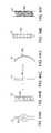
- FIGS. 12A-12Care side views of various longitudinal ribs flexing in response to a distorting force in accordance with further embodiments of the present technology.
- FIG. 13Ais a schematic, cross-sectional view of a prosthetic heart valve device in accordance with another embodiment of the present technology.
- FIGS. 13B-13Fare partial side views of prosthetic heart valve devices illustrating a variety of longitudinal rib configurations in accordance with additional embodiments of the present technology.
- FIG. 14Ais a schematic top view of a native mitral valve illustrating the major and minor axes.
- FIGS. 14B-14Care schematic top views of an anchoring member in an expanded configuration and in a deployed configuration, respectively, in accordance with an embodiment of the present technology.
- FIG. 15is an isometric view of a prosthetic heart valve device illustrated in a deployed configuration in accordance with an additional embodiment of the present technology.
- FIG. 16Ais a top view of a prosthetic heart valve device illustrated in an expanded configuration in accordance with a further embodiment of the present technology.
- FIGS. 16B-16Care a first side view and a second side view, respectively, of the prosthetic heart valve device of FIG. 16A .
- FIG. 16Dis a side view of a prosthetic heart valve device showing the longitudinal axis of the anchoring member off-set from the longitudinal axis of the valve support by a tilt angle in accordance with another embodiment of the present technology.
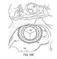
- FIG. 16Eis a schematic top view of a native mitral valve in the heart viewed from the left atrium and showing the prosthetic treatment device of FIG. 16A-16C implanted at the native mitral valve in accordance with an embodiment of the present technology.
- FIGS. 17A-17Care schematic top and first and second side views of the prosthetic heart valve device of FIG. 16A showing dimensions and taper angles of various aspects of the device in accordance with embodiments of the present technology.
- FIG. 18is an isometric view of an anchoring member illustrated in an expanded configuration in accordance with yet another embodiment of the present technology.
- FIGS. 19A-19Care isometric, side and top views, respectively, of a prosthetic heart valve device having a sealing member in accordance with a further embodiment of the present technology.
- FIG. 20Ais an isometric view of a prosthetic heart valve device without a sealing member in accordance with an embodiment of the present technology.
- FIGS. 20B-20Eare isometric views of prosthetic heart valve devices having sealing members in accordance with additional embodiments of the present technology.
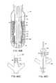
- FIGS. 21A-21Bare cross-sectional side and isometric views of a prosthetic heart valve device having a tubular valve support member in accordance with a further embodiment of the present technology.
- FIGS. 21C-21Fare partial cross-sectional side views and an isometric view of prosthetic heart valve devices having a tubular valve support member in accordance with other embodiments of the present technology.
- FIGS. 22A-22G and 22I-22Kare enlarged side views of various mechanisms of coupling a valve support to an anchoring member in accordance with additional embodiments of the present technology.
- FIG. 22His a side view of a post in the prosthetic heart valve device of FIG. 40G .
- FIGS. 23A-23Bare enlarged side views of a additional mechanisms for coupling an anchoring member to a valve support member in accordance with further embodiments of the present technology.
- FIG. 24Ais a perspective view of an integral connection between a valve support and an anchoring member in accordance with an additional embodiment of the present technology.
- FIGS. 24B-24Dare enlarged views of additional embodiments of an integral connection between a valve support and an anchoring member in accordance with the present technology.
- FIG. 25Ais a partial cross-sectional view of a prosthetic heart valve device having an anchoring member and a valve support in accordance with an embodiment of the present technology.
- FIG. 25Bis an enlarged view of the designated box shown in FIG. 25A
- FIGS. 26A-26Dare schematic cross-sectional views of prosthetic heart valve devices having atrial retainers and implanted at a native mitral valve in accordance with various embodiments of the present technology.
- FIG. 27is a side view of an anchoring member having a vertical portion at the upstream end for engaging the annulus in accordance with another embodiment of the present technology.
- FIG. 28is a side view of a prosthetic heart valve device in an expanded configuration and having a plurality of stabilizing elements in accordance with an embodiment of the present technology.
- FIG. 29is an enlarged schematic, side view of a prosthetic heart valve device having an extended arm in accordance with an embodiment of the present technology.
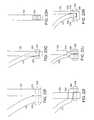
- FIGS. 30A-30Care enlarged partial side views of a prosthetic heart valve device having arms coupled to the device at various angles with respect to a longitudinal axis of the device in accordance with further embodiments of the present technology.
- FIGS. 31A-31Care enlarged, partial side views of a prosthetic heart valve device having arms of various lengths coupled to the device in accordance with additional embodiments of the present technology.
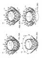
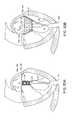
- FIGS. 32A, 32B, 32C, and 32Dare cross-sectional views of a heart with an implanted prosthetic heart valve device having arms disposed on an inward-facing surface of the leaflets in accordance with various embodiments of the present technology.
- FIGS. 32A-1, 32B-1, 32C-1 and 32D-1are enlarged views of the arms engaging the inward-facing surface of the leaflets as shown in FIGS. 32A, 32B, 32C and 32D , respectively in accordance with various embodiments of the present technology.
- FIGS. 33A-33Care schematic views illustrating various embodiments of tissue engaging elements for use with prosthetic heart valve devices in accordance with the present technology.
- FIGS. 34A, 34B and 34Care cross-sectional views of a heart with an implanted prosthetic heart valve device having arms with tissue engaging elements disposed on an inward-facing surface of the leaflets in accordance with various embodiments of the present technology.
- FIGS. 34A-1, 34B-1 and 34C-1are enlarged views of the arms engaging the inward-facing surface of the leaflets as shown in FIGS. 34A, 34B and 34C , respectively in accordance with various embodiments of the present technology.
- FIGS. 35A-35Care side views of prosthetic heart valve devices and shown implanted at a mitral valve (illustrated in cross-section), the devices having arms for engaging an outward-facing surface of the native leaflets in accordance with further embodiments of the present technology.
- FIG. 35C-1is an enlarged view of the arm engaging the inward-facing surface of the leaflets as shown in FIG. 35C in accordance with various embodiments of the present technology.
- FIG. 36Ais a side view of a prosthetic heart valve device and shown implanted at a mitral valve (illustrated in cross-section), the device having arms for engaging an outward-facing surface of the native leaflets and arms for engaging an inward-facing surface of the native leaflets in accordance with an additional embodiment of the present technology.
- FIG. 36Bis an enlarged view of the arms engaging the inward-facing and outward-facing surfaces of the leaflets as shown in FIG. 36A .
- FIGS. 37A-37Dare enlarged side views of additional embodiments of arms suitable for use with a prosthetic heart valve device in accordance with the present technology.
- FIG. 38Ais a side view of a prosthetic heart valve device having a plurality of non-interconnected arms in accordance with a further embodiment of the present technology.
- FIG. 38Bis a side view of a prosthetic heart valve device having a plurality of circumferentially connected arms in accordance with a further embodiment of the present technology.
- FIGS. 39A-39Dare schematic top views of arm location patterns in accordance with additional embodiments of the present technology.
- FIGS. 40A-40Dare side views of prosthetic heart valve devices having tissue engaging elements on varying structures of the device in accordance with additional embodiments of the present technology.
- FIGS. 40E-40Gare enlarged side views of tissue engaging elements suitable for use with prosthetic heart valve devices in accordance with other embodiments of the present technology.
- FIGS. 40I-40Tare enlarged side views of embodiments of tissue engaging elements suitable for use with prosthetic heart valve devices in accordance with additional embodiments of the present technology.
- FIG. 41is an isometric view of a prosthetic heart valve device having a plurality of annulus engaging elements in accordance with a further embodiment of the present technology.
- FIGS. 42A-42Bare cross-sectional side and enlarged views of a prosthetic heart valve device having tissue engaging elements deployable from a plurality of tubular ribs in accordance with another embodiment of the present technology.
- FIGS. 43A-43Bare an isometric view and an enlarged detail view of a prosthetic heart valve device having a sealing member configured with tissue engaging elements in accordance with another embodiment of the present technology
- FIGS. 44A-44Fare enlarged side views of embodiments of tissue engaging elements suitable for use with prosthetic heart valve devices in accordance with additional embodiments of the present technology.
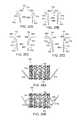
- FIG. 45Ais an isometric view of a prosthetic heart valve device having a plurality of tethers between the anchoring member 110 and the valve support 120 in accordance with an embodiment of the present technology.
- FIG. 45Bis an isometric view of a prosthetic heart valve device having a plurality of septa between the anchoring member 110 and the valve support 120 in accordance with another embodiment of the present technology.
- FIG. 46Ais side partial cut-away view of a delivery system in accordance with an embodiment of the present technology.
- FIG. 46Bis an enlarged cross-sectional view of a distal end of a delivery system in accordance with an embodiment of the present technology.
- FIGS. 46C-46Dare enlarged partial side views of a valve support configured for use with the delivery system of FIG. 46B in accordance with an embodiment of the present technology.
- FIGS. 47A-47Dare cross-sectional views of a heart showing an antegrade or trans-septal approach to the mitral valve in accordance with an embodiment of the present technology.
- FIGS. 48A-48Care cross-sectional views of the heart illustrating a method of implanting a prosthetic heart valve device using a trans-septal approach in accordance with another embodiment of the present technology.
- FIGS. 49A-49Bare cross-sectional views of the heart showing a retrograde approach to the mitral valve via the aorta and left ventricle in accordance with a further embodiment of the present technology.
- FIGS. 50A-50Bare cross-sectional views of the heart illustrating a further embodiment of a method of implanting the prosthetic heart valve device using a trans-apical approach in accordance with aspects of the present technology.
- FIGS. 51A-51Bare partial side views of a delivery system wherein a prosthetic heart valve device is mounted on an expandable balloon of a delivery catheter in accordance with another embodiment of the present technology.
- FIGS. 52A-52Dare cross-sectional views of a heart showing a method of delivering a prosthetic heart valve device having a valve support movably coupled to an anchoring member in accordance with a further embodiment of the present technology.
- FIGS. 53A-53Dare partial side views showing various mechanisms for movably coupling the valve support to the anchoring member in accordance with additional embodiments of the present technology.
- FIG. 53Eis a partial top view of the device of FIG. 53D .
- FIG. 53Fis a side view of an alternative mechanism for slideably coupling a valve support and anchoring member in accordance with another embodiment of the present technology.
- FIGS. 53G-53Hare schematic side views of a prosthetic heart valve device showing yet another mechanism for coupling the valve support to the anchoring member in accordance with a further embodiment of the present technology.
- FIG. 54Ais a cross-sectional side view of another embodiment of a delivery system for the prosthetic heart valve device in accordance with other aspects of the present technology.
- FIG. 54Bis a partial cross-sectional side view of a distal portion of the delivery system of FIG. 54A .
- FIGS. 55A-55Care perspective views of the delivery system of FIG. 46 illustrating the steps of delivering the prosthetic treatment device of the invention.
- FIG. 56is a side cross-sectional view of a further embodiment of a delivery system for the prosthetic treatment device of the invention.
- FIGS. 57A-57Dare isometric views of prosthetic treatment devices in accordance with additional embodiments of the present technology.
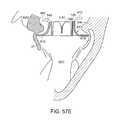
- FIG. 57Eis a schematic cross-sectional view of the prosthetic heart valve device of FIG. 57A implanted at a native mitral valve in accordance with an embodiment of the present technology.
- FIGS. 58A-58Dare cross-sectional views of a heart showing a method of delivering a prosthetic heart valve device to a native mitral valve in the heart using a trans-apical approach in accordance with another embodiment of the present technology.
- FIGS. 59A-59Care isometric views of prosthetic treatment devices in accordance with additional embodiments of the present technology.
- FIG. 59Dis a schematic cross-sectional view of a prosthetic heart valve device implanted at a native mitral valve in accordance with another embodiment of the present technology.
- FIGS. 60A-60Bare cross-sectional side views of a distal end of a delivery catheter for delivering the prosthetic heart valve device of FIG. 59C to a native mitral valve in the heart in accordance with another embodiment of the present technology.
- FIG. 61is a side view of a prosthetic heart valve device having first and second anchoring members for engaging supra-annular and subannular tissue of the mitral valve, respectively, in accordance with yet another embodiment of the present technology.
- FIGS. 62A-62Care partial cross-sectional side views of a distal end of a delivery system showing delivery of the prosthetic heart valve device of FIG. 61 at a mitral valve in accordance with another embodiment of the present technology.
- FIG. 63is an isometric side view of a prosthetic heart valve device having an anchoring member with a supra-annular engaging rim and a subannular engaging ring in accordance with a further embodiment of the present technology.
- FIGS. 64A-64Dare side views of the prosthetic heart valve device of FIG. 63 showing embodiments of methods for deploying the device at the mitral valve annulus in accordance with aspects of the present technology.
- FIG. 65Ais a cross-sectional view of a prosthetic heart valve device having an inflatable anchoring member and shown implanted in a native mitral valve of a heart in accordance with another embodiment of the present disclosure.
- FIG. 65Bis a partial cross-sectional side view of a distal end of a delivery system suitable for delivery of the prosthetic heart valve device of FIG. 65A in accordance with another embodiment of the present technology.
- FIGS. 66A-66Dare cross-sectional views of prosthetic heart valve devices having fillable chambers in accordance with additional embodiments of the present technology.
- FIGS. 67A-67Bare isometric views of additional embodiments of prosthetic heart valve devices in accordance with aspects of the present technology.
- FIGS. 68A-68Bare side views of prosthetic heart valve devices having a positioning element in accordance with an additional embodiments of the present technology.
- FIGS. 69A-69Eare cross-sectional and side views of prosthetic heart valve devices shown in an expanded configuration and configured in accordance with an additional embodiment of the present technology.
- FIG. 70is a cross-sectional side view of another prosthetic heart valve device configured in accordance with an embodiment of the present technology.
- FIG. 71is a cross-sectional side view of yet another prosthetic heart valve device configured in accordance with an embodiment of the present technology.
- FIGS. 1-71Specific details of several embodiments of the technology are described below with reference to FIGS. 1-71 . Although many of the embodiments are described below with respect to devices, systems, and methods for percutaneous replacement of a native mitral valve using prosthetic valve devices, other applications and other embodiments in addition to those described herein are within the scope of the technology. Additionally, several other embodiments of the technology can have different configurations, components, or procedures than those described herein. A person of ordinary skill in the art, therefore, will accordingly understand that the technology can have other embodiments with additional elements, or the technology can have other embodiments without several of the features shown and described below with reference to FIGS. 1-71 .
- distal and proximalwithin this description, unless otherwise specified, the terms can reference a relative position of the portions of a prosthetic valve device and/or an associated delivery device with reference to an operator and/or a location in the vasculature or heart.
- proximalcan refer to a position closer to the operator of the device or an incision into the vasculature
- distalcan refer to a position that is more distant from the operator of the device or further from the incision along the vasculature (e.g., the end of the catheter).
- proximal and distalcan refer to the location of portions of the device with respect to the direction of blood flow.
- proximalcan refer to an upstream position or a position of blood inflow
- distalcan refer to a downstream position or a position of blood outflow.
- identical reference numbers and/or lettersare used to identify similar or analogous components or features, but the use of the same reference number does not imply that the parts should be construed to be identical. Indeed, in many examples described herein, the identically numbered parts are distinct in structure and/or function. The headings provided herein are for convenience only.
- Embodiments of the present technologyprovide systems, methods and apparatus to treat valves of the body, such as heart valves including the mitral valve.
- the apparatus and methodsenable a percutaneous approach using a catheter delivered intravascularly through a vein or artery into the heart. Additionally, the apparatus and methods enable other less-invasive approaches including trans-apical, trans-atrial, and direct aortic delivery of a prosthetic replacement valve to a target location in the heart.
- the apparatus and methodsenable a prosthetic device to be anchored at a native valve location by engagement with a subannular surface of the valve annulus and/or valve leaflets.
- the embodiments of the devices and methods as described hereincan be combined with many known surgeries and procedures, such as known methods of accessing the valves of the heart (e.g., the mitral valve or triscuspid valve) with antegrade or retrograde approaches, and combinations thereof.
- known methods of accessing the valves of the hearte.g., the mitral valve or triscuspid valve
- antegrade or retrograde approachese.g., the mitral valve or triscuspid valve
- the devices and methods described hereinprovide a valve replacement device that has the flexibility to adapt and conform to the variably-shaped native mitral valve anatomy while mechanically isolating the prosthetic valve from the anchoring portion of the device.
- Several embodiments of the deviceeffectively absorb the distorting forces applied by the native anatomy.
- the devicehas the structural strength and integrity necessary to withstand the dynamic conditions of the heart over time, thus permanently anchoring a replacement valve and making it possible for the patient to resume a substantially normal life.
- the devices and methodsfurther deliver such a device in a less-invasive manner, providing a patient with a new, permanent replacement valve but also with a lower-risk procedure and a faster recovery.
- a device for repair or replacement of a native valve of a heartis disclosed.
- the native valvehas an annulus and leaflets, and the device includes an anchoring member having a first portion configured to engage tissue on or under the annulus and to deform in a non-circular shape to conform to the tissue.
- the anchoring memberalso can include a second portion.
- the devicealso includes a valve support coupled to the second portion of the anchoring member and configured to support a prosthetic valve and having a cross-sectional shape.
- the first portion of the anchoring memberis mechanically isolated from the valve support such that the cross-sectional shape of the valve support remains sufficiently stable so that the prosthetic valve remains competent when the anchoring member is deformed in the non-circular shape.
- Some embodiments of the disclosureare directed to prosthetic heart valve devices for implantation at a native mitral valve wherein the mitral valve has an annulus and leaflets.
- the devicecan have an anchoring member positionable in a location between the leaflets, wherein a first portion of the anchoring member is expandable to a dimension larger than a corresponding dimension of the annulus.
- upstream movement of the anchoring memberis blocked by engagement of the upstream portion with tissue on or near the annulus.
- the anchoring membercan also include a second portion.
- the devicecan also include a valve support coupled to the second portion of the anchoring member, wherein an upstream region of the valve support is spaced radially inward from at least the first portion of the anchoring member.
- the valve supportcan be configured to support a prosthetic valve.
- a device for implantation at a native valve having an annulus and leafletscan include a hyperboloidic anchoring member having an upstream end configured to engage an inward facing surface of the leaflets downstream of the annulus and a downstream end, wherein the upstream end has a larger cross-sectional area than the downstream end.
- the devicecan also include a valve support positioned in the anchoring member and configured to support a prosthetic valve. The valve support is coupled to the anchoring member at a location spaced substantially downstream from the upstream end and is uncoupled to the anchoring member at the upstream end.
- the deviceincludes an anchoring member having a first portion having a first cross-sectional dimension and second portion having a second cross-sectional dimension less than the first cross-sectional dimension.
- the first portionis configured to engage cardiac tissue to retain the anchoring member in a fixed longitudinal position relative to the annulus.
- the devicecan also include a valve support coupled to the second portion of the anchoring member and configured to support a prosthetic valve. The valve support can be radially separated from the first portion of the anchoring member such that the first portion can deform inwardly without substantially deforming the valve support.
- the present disclosurealso is directed to a device for implantation at a native heart valve.
- the devicecan include an anchoring member having an upstream end configured to engage tissue on or downstream of a native annulus of the heart valve, and a valve support configured to support a prosthetic valve.
- the valve supportcan be coupled to the anchoring member.
- the anchoring membercan resist upstream migration of the device without an element of the device extending behind native valve leaflets.
- the devicecan include an anchoring member positionable between the leaflets of the native valve.
- the anchoring membercan have a plurality of tissue engaging elements on an upstream end and/or on an exterior surface which are configured to engage cardiac tissue on or near the annulus so as to prevent migration of the device in the upstream direction.
- the devicecan also include a valve support positioned within an interior of the anchoring member and coupled to a downstream portion of the anchoring member, wherein the valve support is radially separated from at least an upstream portion of the anchoring member.
- FIG. 1For embodiments of the disclosure are directed to a device for repair or replacement of a native mitral valve having an annulus and a pair of leaflets that include a support structure having an upper region, a lower region, and an interior to retain a prosthetic valve.
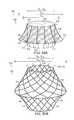
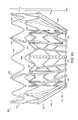
- the devicecan also include an anchoring member surrounding at least a portion of the support structure, wherein the anchoring member is positionable between the leaflets and has a plurality of flexible elements (e.g., wires, laser cut metal elements, etc.) arranged in a diamond pattern, an upper portion, and a lower portion.
- a plurality of flexible elementse.g., wires, laser cut metal elements, etc.
- the upper portion of the anchoring membercan be flared outwardly in a proximal direction such that proximal ends of the flexible elements point radially outward so as to engage cardiac tissue on or near the annulus and inhibit migration of the device in the upstream direction.
- the lower region of the support structurecan be coupled to the lower portion of the anchoring member, and the lower region of the support structure can be mechanically isolated from at least deformation of the flared upper portion of the anchoring member.
- prosthetic heart valve deviceshaving a cylindrical support and an anchor defined by a structure separate from the cylindrical support.
- the cylindrical supportcan have a longitudinal axis and an interior along the longitudinal axis through which blood may flow.
- the anchorcan have a non-circular cross-section with an outwardly flared upstream end configured to engage subannular tissue of a mitral valve.
- the anchorcan also surround the cylindrical support and be coupled to the support at a downstream end opposite the upstream end.
- the devicecan include an expandable valve support configured for placement between the two leaflets.
- the supportcan have a first region, a second region and an interior in which a valve may be coupled.
- the devicecan also include an anchoring member having a first portion and a second portion, the second portion coupled to the second region of the valve support.
- the first portion of the anchoring membercan extend outwardly away from the second portion.
- the anchoring membercan have a first perimeter at the first portion configured to engage tissue on or near the annulus.
- the anchoring membercan be mechanically isolated from the valve support such that a force exerted radially at or near the first perimeter will not substantially alter a shape of the valve support.
- Additional embodimentsare directed to devices to treat a heart valve of a patient that include an inner frame and an outer frame coupled to the inner frame.
- the inner framecan have an outer surface and an inner surface that is configured to support a prosthetic valve.
- the outer framecan have an upper portion with a cross-sectional dimension greater than a corresponding cross-sectional dimension of an annulus of the mitral valve, wherein the upper portion is configured to engage tissue at or below the annulus of the mitral valve.
- the upper portioncan also prevent migration of the device in an upward or upstream direction during ventricular systole.
- the upper portion of the outer framecan be mechanically isolated from the inner frame.
- the devicecan include a cylindrical inner skeleton and an outer skeleton coupled to the inner skeleton and positionable between the leaflets downstream of the annulus.
- the outer skeletoncan be deformable to a non-circular cross-section while the inner skeleton remains substantially circular in cross-section.
- the inner skeletoncan have an interior to which a prosthetic valve may be coupled.
- the outer skeletoncan have a plurality of flexible elements (e.g., wires, laser cut metal elements, etc.), wherein at least a portion of the flexible elements can be configured to engage native subannular tissue so as to prevent migration of the device in an upstream direction.
- the plurality of flexible wiresare arranged in a diamond configuration.
- a prosthetic mitral valve devicecan include a valve support having upstream and downstream ends, an interior in which a valve may be coupled, and a perimeter.
- the devicecan also include an anchoring member having a flared upstream portion and a downstream portion coupled to the perimeter of the valve support.
- the upstream portioncan be mechanically isolated from the valve support and can be configured to engage subannular tissue of a native mitral valve.
- the devicecan be moveable into a plurality of configurations including a first configuration in which the valve support and the anchoring member are radially contracted, and wherein the valve support has a first cross-sectional shape.
- the devicecan also move into a second configuration in which the valve support and the anchoring member are radially expanded and in which the valve support has a second cross-sectional shape. Additionally, the device can move into a third configuration in which the anchoring member is engaged with and deformed by the subannular tissue while the valve support remains in the second cross-sectional shape.
- the devicemay comprise an atrial retainer extending from the anchoring member or the valve support to a position at least partially upstream of the native mitral annulus.
- the atrial extension membermay comprise an atrial engagement structure adapted to engage an upstream surface (e.g., supra-annular surface) of the annulus and/or an interior wall of the atrium for further stabilizing or anchoring the device.
- the atrial retainercan block downstream movement of the device.
- the devicemay further comprise one or more stabilizing members to inhibit the device from tilting or being displaced laterally.
- the stabilizing membersmay comprise a plurality of arms extending radially outwardly from the valve support and/or the anchoring member. The arms may be configured to extend behind the native leaflets and/or into engagement with the ventricular wall or papillary muscles.
- a further embodiment, in accordance with another aspect of the present disclosure,is directed to a device for implantation at a native mitral valve, wherein the native mitral valve has an annulus and leaflets.
- the devicecan include a valve support having upstream and downstream ends, an interior in which a valve may be coupled, and an outer surface, and include a first anchoring member having a first flared upstream portion and a first downstream portion coupled to the outer surface of the valve support.
- the first downstream portioncan be coupled to inner surface of the valve support, or in some embodiments, to an end of the valve support.
- the devicecan also include a second anchoring member at least partially surrounding the first anchoring member.
- the first upstream portion of the first anchoring membercan be mechanically isolated from the valve support and configured to engage supra-annular tissue of the native mitral valve.
- the second anchoring membercan have a second flared upstream portion and a second downstream portion coupled to the outer surface of the valve support, wherein the second upstream portion can be mechanically isolated from the valve support and is configured to engage subannular tissue of the native mitral valve.
- the device for implantationcan include a radially expandable anchoring member configured to engage native tissue on or downstream of the annulus.
- the anchoring membercan have a first longitudinal length on a posterior leaflet-facing side and a second length on an anterior leaflet-facing side. In certain embodiments, the first length can be greater than the second length such that occlusion of a left ventricle outflow tract (LVOT) is limited.
- the devicecan also include a valve support, or alternatively a prosthetic valve, coupled to an interior or to an end of the anchoring member.
- inventions of the present technologyprovide a device for implantation at a native mitral valve having an annulus and leaflets, wherein the device includes a valve support having upstream and downstream ends, an interior in which a valve may be coupled, and an outer surface.
- the devicecan also include an anchoring member having a flared upstream portion and a downstream portion coupled to the outer surface of the valve support, wherein the upstream portion can have an upper ring and a lower ring coupled to the upper ring.
- the devicecan further include a plurality of flexible annulus engaging elements distributed around a circumference of the anchoring member and coupling the upper ring to the lower ring.
- the lower ringis configured to move in an upstream direction toward the upper ring such that the annulus is received between the upper and lower rings and within the annulus engaging elements.
- inventionsfurther provides systems for delivery of prosthetic valves and other devices using endovascular or other minimally invasive forms of access.
- embodiments of the present technologyprovide a system to treat a mitral valve of a patient, in which the mitral valve has an annulus.
- the systemcomprises a device to treat the mitral valve as described herein and a catheter having a lumen configured to retain the device within the catheter.
- a system for replacing a native valve in a patientcan include an elongated catheter body having a distal end and a proximal end, and a housing coupled to the distal end of the catheter body and having a closed end and an open end.
- the systemcan also include a plunger within the housing which is axially movable relative to the housing, and an actuator at the proximal end of the catheter body and coupled to the plunger such that moving the actuator moves the housing axially relative to the plunger.
- the systemcan further include a prosthetic valve device having a collapsed configuration and an expanded configuration. The prosthetic valve device can be positionable in the housing in the collapsed configuration and can be releasable proximally from the housing by moving the actuator.
- embodiments of the present technologyprovide a method of treating a heart valve of a patient.
- the mitral valvehas an annulus and leaflets coupled to the annulus.
- the methodcan include implanting a device as described herein within or adjacent to the annulus.
- the devicein some embodiments, can include a valve support coupled to and at least partially surrounded by an anchoring member.
- the anchoring membercan be disposed between the leaflets and an upstream portion of the anchoring member can be configured to engage tissue on or downstream of the annulus to prevent migration of the device in an upstream direction.
- the valve supportcan be mechanically isolated from the anchoring member at least at the upstream portion.
- embodiments of the present technologyprovide a method for replacement of a native mitral valve having an annulus and leaflets.
- the methodcan include positioning a device as described herein between the leaflets, while the device is in a collapsed configuration.
- the methodcan also include allowing the prosthetic device to expand such that an anchoring member of the prosthetic device is in a subannular position in which it engages tissue on or downstream of the annulus.
- the anchoring membercan have a diameter larger than a corresponding diameter of the annulus in the subannular position.
- the methodcan further include allowing a valve support to expand within the anchoring member, wherein the valve support is coupled to the anchoring member.
- the valve supportcan be mechanically isolated from the anchoring member such that deformation of the anchoring member when the anchoring member engages the tissue does not substantially deform the valve support. In some arrangements, certain regions of the valve support may deform, but a support region suitable for retaining a prosthetic valve does not substantially deform such that leaflet coaptation of the prosthetic valve would not be compromised.
- the devices and methods disclosed hereincan be configured for treating non-circular, asymmetrically shaped valves and bileaflet or bicuspid valves, such as the mitral valve. Many of the devices and methods disclosed herein can further provide for long-term (e.g., permanent) and reliable anchoring of the prosthetic device even in conditions where the heart or native valve may experience gradual enlargement or distortion.
- FIGS. 1 and 2show a normal heart H.
- the heartcomprises a left atrium that receives oxygenated blood from the lungs via the pulmonary veins PV and pumps this oxygenated blood through the mitral valve MV into the left ventricle LV.
- the left ventricle LV of a normal heart H in systoleis illustrated in FIG. 2 .
- the left ventricle LVis contracting and blood flows outwardly through the aortic valve AV in the direction of the arrows.
- Back flow of blood or “regurgitation” through the mitral valve MVis prevented since the mitral valve is configured as a “check valve” which prevents back flow when pressure in the left ventricle is higher than that in the left atrium LA.
- the mitral valve MVcomprises a pair of leaflets having free edges FE which meet evenly, or “coapt” to close, as illustrated in FIG. 2 .
- the opposite ends of the leaflets LFare attached to the surrounding heart structure via an annular region of tissue referred to as the annulus AN.
- FIG. 3is a schematic cross-sectional side view of an annulus and leaflets of a mitral valve. As illustrated, the opposite ends of the leaflets LF are attached to the surrounding heart structure via a fibrous ring of dense connective tissue referred to as the annulus AN, which is distinct from both the leaflet tissue LF as well as the adjoining muscular tissue of the heart wall.
- the leaflets LF and annulus ANare comprised of different types of cardiac tissue having varying strength, toughness, fibrosity, and flexibility. Furthermore, the mitral valve MV may also comprise a unique region of tissue interconnecting each leaflet LF to the annulus AN, referred to herein as leaflet/annulus connecting tissue LAC (indicated by overlapping cross-hatching). In general, annular tissue AN is tougher, more fibrous, and stronger than leaflet tissue LF.
- chordae tendineae CTwhich include a plurality of branching tendons secured over the lower surfaces of each of the valve leaflets LF.
- the chordae CTin turn, are attached to the papillary muscles PM, which extend upwardly from the lower wall of the left ventricle LV and interventricular septum IVS.
- FIGS. 4A to 4Ba number of structural defects in the heart can cause mitral valve regurgitation.
- Ruptured chordae RCTas shown in FIG. 4A , can cause a valve leaflet LF 2 to prolapse since inadequate tension is transmitted to the leaflet via the chordae. While the other leaflet LF 1 maintains a normal profile, the two valve leaflets do not properly meet and leakage from the left ventricle LV into the left atrium LA will occur, as shown by the arrow.
- Regurgitationalso occurs in the patients suffering from cardiomyopathy where the heart is dilated and the increased size prevents the valve leaflets LF from meeting properly, as shown in FIG. 4B .
- the enlargement of the heartcauses the mitral annulus to become enlarged, making it impossible for the free edges FE to meet during systole.
- the free edges of the anterior and posterior leafletsnormally meet along a line of coaptation C as shown in FIG. 5A , but a significant gap G can be left in patients suffering from cardiomyopathy, as shown in FIG. 5B .
- Mitral valve regurgitationcan also occur in patients who have suffered ischemic heart disease where the functioning of the papillary muscles PM is impaired, as illustrated in FIG. 4A .
- the papillary muscles PMdo not contract sufficiently to effect proper closure.
- One or both of the leaflets LF 1 and LF 2then prolapse. Leakage again occurs from the left ventricle LV to the left atrium LA.
- FIGS. 5A-5Cfurther illustrate the shape and relative sizes of the leaflets L of the mitral valve.
- the overall valvehas a generally “D”-shape or kidney-like shape, with a long axis MVA 1 and a short axis MVA 2 .
- the long axis MVA 1is typically within a range from about 33.3 mm to about 42.5 mm in length (37.9+/ ⁇ 4.6 mm)
- the short axis MVA 2is within a range from about 26.9 to about 38.1 mm in length (32.5+/ ⁇ 5.6 mm).
- MVA 1can be within a range from about 45 mm to 55 mm and MVA 2 can be within a range from about 35 mm to about 40 mm.
- the line of coaptation Cis curved or C-shaped, thereby defining a relatively large anterior leaflet AL and substantially smaller posterior leaflet PL ( FIG. 5A ). Both leaflets appear generally crescent-shaped from the superior or atrial side, with the anterior leaflet AL being substantially wider in the middle of the valve than the posterior leaflet. As illustrated in FIG. 5A , at the opposing ends of the line of coaptation C the leaflets join together at corners called the anterolateral commissure AC and posteromedial commissure PC, respectively.
- FIG. 5Cshows the shape and dimensions of the annulus of the mitral valve.
- the annulusis an annular area around the circumference of the valve comprised of fibrous tissue which is thicker and tougher than that of the leaflets LF and distinct from the muscular tissue of the ventricular and atrial walls.
- the annulusmay comprise a saddle-like shape with a first peak portion PP 1 and a second peak portion PP 2 located along an interpeak axis IPD, and a first valley portion VP 1 and a second valley portion VP 2 located along an intervalley axis IVD.
- the first and second peak portion PP 1 and PP 2are higher in elevation relative to a plane containing the nadirs of the two valley portions VP 1 , VP 2 , typically being about 8-19 mm higher in humans, thus giving the valve an overall saddle-like shape.
- the distance between the first and second peak portions PP 1 , PP 2referred to as interpeak span IPD, is substantially shorter than the intervalley span IVD, the distance between first and second valley portions VP 1 , VP 2 .
- the dimensions and physiology of the patientmay vary among patients, and although some patients may comprise differing physiology, the teachings as described herein can be adapted for use by many patients having various conditions, dimensions and shapes of the mitral valve.
- work in relation to embodimentssuggests that some patients may have a long dimension across the annulus and a short dimension across the annulus without well-defined peak and valley portions, and the methods and device as described herein can be configured accordingly.
- Access to the mitral valve or other atrioventricular valvecan be accomplished through the patient's vasculature in a percutaneous manner.
- percutaneousit is meant that a location of the vasculature remote from the heart is accessed through the skin, typically using a surgical cut down procedure or a minimally invasive procedure, such as using needle access through, for example, the Seldinger technique.
- the ability to percutaneously access the remote vasculatureis well-known and described in the patent and medical literature.
- the approach to the mitral valvemay be antegrade and may rely on entry into the left atrium by crossing the inter-atrial septum.
- approach to the mitral valvecan be retrograde where the left ventricle is entered through the aortic valve.
- the interventional tools and supporting catheter(s)may be advanced to the heart intravascularly and positioned adjacent the target cardiac valve in a variety of manners, as described herein.
- a catheter 1 having a needle 2may be advanced from the inferior vena cava IVC into the right atrium RA. Once the catheter 1 reaches the anterior side of the inter-atrial septum IAS, the needle 2 may be advanced so that it penetrates through the septum, for example at the fossa ovalis FO or the foramen ovate into the left atrium LA. At this point, a guidewire may be exchanged for the needle 2 and the catheter 1 withdrawn.
- access through the inter-atrial septum IASmay usually be maintained by the placement of a guide catheter 4 , typically over a guidewire 6 which has been placed as described above.
- the guide catheter 4affords subsequent access to permit introduction of the device to replace the mitral valve, as described in more detail herein.
- surgical accessmay be obtained through an intercostal incision, preferably without removing ribs, and a small puncture or incision may be made in the left atrial wall.
- a guide cathetermay then be placed through this puncture or incision directly into the left atrium, sealed by a purse string-suture.
- the antegrade or trans-septal approach to the mitral valvecan be advantageous in many respects.
- the use of the antegrade approachwill usually allow for more precise and effective centering and stabilization of the guide catheter and/or prosthetic valve device. Precise positioning facilitates accuracy in the placement of the prosthetic valve device.
- the antegrade approachmay also reduce the risk of damaging the subvalvular device during catheter and interventional tool introduction and manipulation. Additionally, the antegrade approach may decrease risks associated with crossing the aortic valve as in retrograde approaches. This can be particularly relevant to patients with prosthetic aortic valves, which cannot be crossed at all or without substantial risk of damage.
- FIGS. 7 and 8An example of a retrograde approach to the mitral valve is illustrated in FIGS. 7 and 8 .
- the mitral valve MVmay be accessed by an approach from the aortic arch AA, across the aortic valve AV, and into the left ventricle LV below the mitral valve MV.
- the aortic arch AAmay be accessed through a conventional femoral artery access route, as well as through more direct approaches via the brachial artery, axillary artery, radial artery, or carotid artery. Such access may be achieved with the use of a guidewire 6 . Once in place, a guide catheter 4 may be tracked over the guidewire 6 .
- a surgical approachmay be taken through an incision in the chest, preferably intercostally without removing ribs, and placing a guide catheter through a puncture in the aorta itself.
- the guide catheter 4affords subsequent access to permit placement of the prosthetic valve device, as described in more detail herein.
- a retrograde arterial approach to the mitral valvemay be choosen due to certain advantages.
- use of the retrograde approachcan eliminate the need for a trans-septal puncture.
- the retrograde approachis also more commonly used by cardiologists and thus has the advantage of familiarity.
- FIG. 9An additional approach to the mitral valve is via trans-apical puncture, as shown in FIG. 9 .
- access to the heartis gained via thoracic incision, which can be a conventional open thoracotomy or sternotomy, or a smaller intercostal or sub-xyphoid incision or puncture.
- An access cannulais then placed through a puncture, sealed by a purse-string suture, in the wall of the left ventricle at or near the apex of the heart.
- the catheters and prosthetic devices of the inventionmay then be introduced into the left ventricle through this access cannula.
- the trans-apical approachhas the feature of providing a shorter, straighter, and more direct path to the mitral or aortic valve. Further, because it does not involve intravascular access, the trans-apical procedure can be performed by surgeons who may not have the necessary training in interventional cardiology to perform the catheterizations required in other percutaneous approaches.
- the prosthetic treatment devicemay be specifically designed for the approach or interchangeable among approaches.
- a person of ordinary skill in the artcan identify an appropriate approach for an individual patient and design the treatment apparatus for the identified approach in accordance with embodiments described herein.
- Orientation and steering of the prosthetic valve devicecan be combined with many known catheters, tools and devices. Such orientation may be accomplished by gross steering of the device to the desired location and then refined steering of the device components to achieve a desired result.
- Gross steeringmay be accomplished by a number of methods.
- a steerable guidewiremay be used to introduce a guide catheter and the prosthetic treatment device into the proper position.
- the guide cathetermay be introduced, for example, using a surgical cut down or Seldinger access to the femoral artery in the patient's groin. After placing a guidewire, the guide catheter may be introduced over the guidewire to the desired position. Alternatively, a shorter and differently shaped guide catheter could be introduced through the other routes described above.
- a guide cathetermay be pre-shaped to provide a desired orientation relative to the mitral valve.
- the guide cathetermay have a curved, angled or other suitable shape at its tip to orient the distal end toward the mitral valve from the location of the septal puncture through which the guide catheter extends.
- guide catheter 4may have a pre-shaped J-tip which is configured so that it turns toward the mitral valve MV after it is placed over the aortic arch AA and through the aortic valve AV. As shown in FIG.
- the guide catheter 4may be configured to extend down into the left ventricle LV and to assume a J-shaped configuration so that the orientation of an interventional tool or catheter is more closely aligned with the axis of the mitral valve MV.
- a pre-shaped guide cathetermay be configured to be straightened for endovascular delivery by means of a stylet or stiff guidewire which is passed through a lumen of the guide catheter.
- the guide cathetermight also have pull-wires or other means to adjust its shape for more fine steering adjustment.
- Embodiments of the present technology as described hereincan be used to treat one or more of the valves of the heart as described herein, and in particular embodiments, can be used for treatment of the mitral valve.
- Introductory examples of prosthetic heart valve devices, system components and associated methods in accordance with embodiments of the present technologyare described in this section with reference to FIGS. 10A-56 .
- specific elements, substructures, advantages, uses, and/or other features of the embodiments described with reference to FIGS. 10A-56can be suitably interchanged, substituted or otherwise configured with one another and/or with the embodiments described with reference to FIGS. 57A-71 in accordance with additional embodiments of the present technology.
- suitable elements of the embodiments described with reference to FIGS. 10A-71can be used as stand-alone and/or self-contained devices.
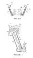
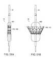
- FIG. 10Ashows an isometric view of a prosthetic heart valve device 100 in an expanded configuration 102 in accordance with an embodiment of the present technology
- FIG. 10Bis a schematic illustration of a cross-sectional view of a heart depicting the left atrium, left ventricle, and native mitral valve of the heart.
- FIG. 10Balso shows an embodiment of the expandable prosthetic valve device 100 implanted in the native mitral valve region of the heart.
- the device 100can include a flexible anchoring member 110 at least partially surrounding and coupled to an inner valve support 120 .
- the device 100can further include a prosthetic valve 130 coupled to, mounted within, or otherwise carried by the valve support 120 .
- FIGS. 10C-10Fare side, perspective cut-away, top, and bottom views, respectively, of the prosthetic heart valve device 100 in accordance with the present technology.
- the device 100can also include one or more sealing members 140 and tissue engaging elements 170 .
- the sealing member 140can, in one embodiment, extend around an inner wall 141 of the anchoring member 110 and/or around an exterior surface 127 of the valve support 120 to prevent paravalvular (e.g., paraprosthetic) leaks between the device 100 and the native tissue and/or between the anchoring member 110 and the valve support 120 .
- the tissue engaging elements 170can be spikes disposed on an upstream perimeter 113 of the anchoring member 110 and extend in an upward and/or radially outward direction to engage, and in some embodiments, penetrate the native tissue to facilitate retention or maintain position of the device in a desired implanted location.
- the tissue engaging elements 170may also be included around an outer wall 142 of the anchoring member 110 and can extend outwardly to engage and, in some embodiments, penetrate the native valve leaflets or other adjacent tissue. Additionally, the valve support 120 can have a plurality of coupling features 180 , such as eyelets, around an upstream end 121 to facilitate loading, retention and deployment of the device 100 within and from a delivery catheter (not shown), as further described herein.
- the prosthetic heart valve device 100can be movable between a delivery configuration (not shown), an expanded configuration 102 ( FIG. 10A ), and a deployed configuration 104 ( FIG. 10B ).
- the prosthetic heart valve device 100has a low profile suitable for delivery through small-diameter guide catheters positioned in the heart via the trans-septal, retrograde, or trans-apical approaches described herein.
- the delivery configuration of the prosthetic heart valve device 100will preferably have an outer diameter no larger than about 8-10 mm for trans-septal approaches, about 8-10 mm for retrograde approaches, or about 8-12 mm for trans-apical approaches to the mitral valve MV.
- expansion configurationrefers to the configuration of the device when allowed to freely expand to an unrestrained size without the presence of constraining or distorting forces.
- Delivery configurationrefers to the device once expanded at the native valve site and subject to the constraining and distorting forces exerted by the native anatomy.
- a subannular surface of the mitral valve MVis a tissue surface lying on the ventricular side of the plane PO, and preferably one that faces generally downstream, toward the left ventricle LV.
- the subannular surfacemay be disposed on the annulus AN itself or the ventricular wall behind the native leaflets LF, or it may comprise a surface of the native leaflets LF, either inward-facing IF or outward-facing OF, which lies below the plane PO.
- the subannular surface or subannular tissuemay thus comprise the annulus AN itself, the native leaflets LF, leaflet/annulus connective tissue, the ventricular wall or combinations thereof.
- the prosthetic heart valve device 100can be intravascularly delivered to a desired location in the heart, such as an intracardiac location near the mitral valve MV, while in the delivery (e.g., collapsed) configuration within a delivery catheter (not shown).
- a desired location in the heartsuch as an intracardiac location near the mitral valve MV
- the device 100can be advanced to a position within or downstream of the native annulus AN where the device 100 can be released from the delivery catheter to enlarge toward the expanded configuration 102 ( FIG. 1 OA).
- the device 100will engage the native tissue at the desired location, which will deform or otherwise alter the shape of the device 100 into the deployed configuration 104 ( FIG. 10B ).
- the device 100can be positioned such that at least a portion of the flexible anchoring member 110 engages a subannular surface of the native valve so as to resist systolic forces and prevent upstream migration of the device 100 ( FIG. 10B ).
- the upstream perimeter 113 of the anchoring member 110engages the inward-facing surfaces IF ( FIG. 3 ) of the native leaflets LF, which are pushed outwardly and folded under the native annulus AN.
- the leaflets LFengage a ventricular side of the annulus AN and are prevented from being pushed further in the upstream direction, thus maintaining the anchoring member 110 below the plane of the native valve annulus.
- the tissue engaging elements 170can penetrate the tissue of the leaflets LF and/or the annulus AN to stabilize and firmly anchor the device 100 . In some embodiments, however, some portions of the anchoring member 110 may extend above the annulus AN, with at least some portions of the anchoring member 110 engaging tissue in a subannular location to prevent migration of the device 100 toward the left atrium LA. As shown in FIG. 10B , the leaflets LF can lie in apposition against the outer wall 142 of the anchoring member 110 forming a blood-tight seal with the sealing member 140 .
- the tissue engaging elements 170can apply pressure against or, in another embodiment, penetrate the annulus AN or leaflets LF along the outer wall 142 of the anchoring member 110 to further stabilize the device 100 and prevent migration.
- the proximal or upper end of the anchoring member 110while in a deployed configuration 104 , conforms to the irregularly-shaped mitral annulus AN, effectively sealing the device 100 against the native annulus AN to anchor the device and to prevent paravalvular leaks.
- the anchoring member 110mechanically isolates the valve support 120 from distorting forces present in the heart such that the anchoring member 110 may adapt and/or conform to native forces while the valve support 120 maintains its structural integrity.
- the anchoring member 110can be sufficiently flexible and resilient and/or coupled to the valve support 120 in such a manner as to mechanically isolate the valve support 120 from the forces exerted upon the anchoring member 110 by the native anatomy.
- the valve support 120may be more rigid and/or have greater radial strength than the radial strength of the anchoring member 110 so as to maintain its cylindrical or other desired shape and to ensure proper opening and closing of the prosthetic valve 130 housed within the valve support structure 120 .
- the valve support 120has a radial strength of at least 100%, or in other embodiments at least 200%, and in further embodiments at least 300%, greater than a radial strength of the anchoring member 110 .
- the valve support 120can have a radial strength of approximately 10 N to about 12 N.
- valve support 120can exhibit a hoop force which is about 2 to about 20 times greater for a given degree of deformation than will be exhibited by the anchoring member 110 .
- the anchoring member 110has a downstream portion 111 and an upstream portion 112 opposite the downstream portion 111 relative to a longitudinal axis 101 of the device 100 .
- the upstream portion 112 of the anchoring member 110can be a generally outward oriented portion of the device 100 , as shown in FIG. 10D .
- the anchoring member 110has a generally hyperboloidic shape, such as the shape of a two-sheet hyperboloid.
- the downstream portion 111can be substantially circular in cross-section while the upstream portion 112 can be generally non-circular.
- the anchoring member 110can include a series of circumferentially positioned, resiliently deformable and flexible longitudinal ribs 114 which, in some embodiments, are connected circumferentially by deformable and/or flexible connectors 116 .
- a subannular surface of the native valvee.g., mitral valve.
- certain embodiments of longitudinal ribs 114are configured to penetrate subannular tissue to anchor and further stabilize the device 100 .
- FIGS. 10A-10Falso illustrate that the longitudinal ribs 114 and/or circumferential connectors 116 may be arranged in a variety of geometrical patterns.
- the connectors 116are formed in a chevron configuration.
- diamond-shaped patterns, sinusoidal configurations, closed cells, open cells, or other circumferentially expandable configurationsare also possible.
- the longitudinal ribs 114may be divided along their length into multiple, separated segments (not shown), e.g. where the connectors 116 interconnect with the longitudinal ribs 114 .
- the plurality of connectors 116 and ribs 114can be formed from a deformable material or from a resilient or shape memory material (e.g., nitinol).
- the anchoring member 110can comprise a mesh or woven construction in addition to or in place of the longitudinal ribs 114 and/or circumferential connectors 116 .
- the anchoring member 110could include a tube or braided mesh formed from a plurality of flexible wires or filaments arranged in a diamond pattern or other configuration.
- a metal tubecan be laser cut to provide a desired rib or strut geometry.
- the diamond configurationcan, in some embodiments, provide column strength sufficient to inhibit movement of the device 100 relative the annulus under the force of systolic blood pressure against the valve 130 mounted in the valve support 120 .
- the anchoring member 120can be formed of a preshaped nitinol tube having, for example, a wall thickness of approximately 0.010 inches to about 0.030 inches.
- FIGS. 11A-11Eshow several embodiments of valve supports 120 that can be used in embodiments of the prosthetic heart valve device 100 shown in FIGS. 10A-10F .
- FIGS. 11A-11Dare side and isometric views of the valve support 120 shown in an expanded configuration 102
- FIG. 11Eis an isometric view of another embodiment of a prosthetic heart valve device 100 disposed in an expanded configuration 102 in accordance with the present technology. Referring to FIGS.
- valve support 120can be generally cylindrical having an upstream end 121 and a downstream end 123 formed around a longitudinal axis 101 with a circular, oval, elliptical, kidney-shaped, D-shaped, or other suitable cross-sectional shape configured to support a tricuspid or other prosthetic valve 130 .
- the valve support 120includes a plurality of posts 122 connected circumferentially by a plurality of struts 124 .
- the posts 122 and struts 124can be arranged in a variety of geometrical patterns that can expand and provide sufficient resilience and column strength for maintaining the integrity of the prosthetic valve 130 .
- the plurality of posts 122can extend longitudinally across multiple rows of struts 124 to provide column strength to the valve support 120 .
- the valve support 120can include a metallic, polymeric, or fabric mesh or a woven construction.
- the plurality of posts 122can extend along an axial direction generally parallel to the longitudinal axis 101 and the struts 124 can extend circumferentially around and transverse to the longitudinal axis 101 .
- the posts 122can extend an entire longitudinal height H 1 of the valve support 120 ( FIG. 11A ), or in another embodiment, the posts 122 can include a plurality of independent and separate post segments (not shown) along the valve support height H 1 . In one embodiment the height H 1 can be approximately 14 mm to about 17 mm.
- the struts 124can form a series of rings around the longitudinal axis 101 , wherein each ring has a circumferentially expandable geometry. In the example shown in FIGS.
- the struts 124are formed in a series of zig-zags and arranged in pairs 180 degrees out of phase with each other so as to form a series of diamonds.
- Alternative expandable geometriescan include sinusoidal patterns, chevron configurations ( FIG. 11B ), closed cells ( FIG. 11C ), open cells, or other expandable configurations.
- the plurality of struts 124can attach to the plurality of posts 122 so as to define a plurality of nodes 125 where the struts and posts intersect.
- the plurality of struts 124 and the plurality of posts 122can be formed from a deformable material or a resilient or shape memory material (e.g., nitinol).
- the anchoring member 110 and the valve support 120may be made of the same or, in some embodiments, different materials.
- both the anchoring member 110 and the valve support 120include a resilient biocompatible metal, such as stainless steel, nickel cobalt or cobalt chromium alloys such as MP35N, or nickel titanium alloys such as nitinol.
- Superelastic shape memory materialssuch as nitinol can allow the device to be collapsed into a very low profile delivery configuration suitable for delivery through the vasculature via catheter, and allow self-expansion to a deployed configuration suitably sized to replace the target valve.
- the anchoring member 110 and/or the valve support 120can be laser cut from a single metal tube into the desired geometry, creating a tubular scaffold of interconnected struts.
- Anchoring member 110may then be shaped into a desired configuration, e.g. a flared, funnel-like or hyperboloid shape, using known shape-setting techniques for such materials.
- the valve support 120has an interior surface 126 and an exterior surface 127 , and the valve support 120 is configured to receive or support the prosthetic valve 130 within an interior lumen of the valve support 120 to inhibit retrograde blood flow (e.g., blood flow from the left ventricle into the left atrium). Accordingly, the valve support 120 can provide a scaffold to which prosthetic valve tissue can be secured and provide a scaffold that has sufficient axial rigidity to maintain a longitudinal position of the prosthetic valve 130 relative to the anchoring member 110 .
- the valve support 120can further provide such a scaffold having radial rigidity to maintain circularity (or other desired cross-sectional shape) to ensure that leaflets 132 of the prosthetic valve 130 coapt or otherwise seal when the device 100 is subject to external radial pressure.
- the valve support 120can have a support region 145 along the longitudinal axis 101 that is configured to attach to the prosthetic valve, or in other embodiments, be aligned with the coaptation portion of the leaflets 132 (shown in FIG. 11B ).
- the valve 130may comprise a temporary or permanent valve adapted to block blood flow in the upstream direction and allow blood flow in the downstream direction through the valve support 120 .
- the valve 130may also be a replacement valve configured to be disposed in the valve support 120 after the device 100 is implanted at the native mitral valve.
- the valve 130can have a plurality of leaflets 132 , and may be formed of various flexible and impermeable materials including PTFE, Dacron®, pyrolytic carbon, or other biocompatible materials or biologic tissue such as pericardial tissue or xenograft valve tissue such as porcine heart tissue or bovine pericardium. Other aspects of valve 130 are described further below.
- the interior surface 126 within the lumen of the valve support 120can be covered at least partially by an impermeable sealing member 140 to prevent blood flow from inside the valve support 120 to the outside of the valve support 120 , where it could leak around the exterior of the valve support 120 .
- the sealing member 140may be affixed to the exterior surface 127 of the valve support 120 and, in either embodiment, may be integrally formed with or attached directly to valve 130 .
- the sealing member 140can be applied on at least portions of both the interior surface 126 and the exterior surface 127 of the valve support 120 .
- the prosthetic valve 130can be sutured, riveted, glued, bonded, mechanically interlocked, or otherwise fastened to posts 122 or commissural attachment structures 128 , which are configured to align with valve commissures C.
- the posts 122 or commissural attachment structures 128can include eyelets 129 , loops, or other features formed thereon to facilitate attachment of sutures or other fastening means to facilitate attachment of the prosthetic valve 130 .
- the attachment structures 128can be integrated into the structural frame of the valve support 120 such that the attachment structures 128 are distributed around the circumference of the valve support 120 and function as posts 122 . In another embodiment, shown in FIG.
- the attachment structures 128can be attachment pads formed on parts of the posts 122 (e.g., along an upper end of the posts 122 ).
- the attachment structures 128can be separate structures that can be coupled to posts 122 , struts 124 or other components along the interior surface 126 of the valve support 120 .
- the prosthetic valve 130may also be attached to the sealing member 140 or sleeve which is attached to the interior surface 126 of the valve support 120 , as described above. Once attached, the prosthetic valve 130 can be suitable to collapse or compress with the device 100 for loading into a delivery catheter (not shown).
- the prosthetic valve 130has a tri-leaflet configuration, although various alternative valve configurations may be used, such as a bi-leaflet configuration.
- the design of the prosthetic valve 130such as the selection of tri-leaflet vs. bi-leaflet configurations, can be used to determine the suitable shape of the valve support 120 .
- the valve support 120can have a circular cross-section, while for a bi-leaflet valve, alternative cross-sectional shapes are possible such as oval or D-shaped cross-sections.
- the valve supportcan have a circular cross-sectional diameter of approximately 25 mm to about 32 mm, such as 27 mm.
- the valve support 120can have a permanent prosthetic valve pre-mounted therein, or the valve support 120 may be configured to receive a separate catheter-delivered valve following implantation of the device 100 at the native mitral valve.
- the valve support 120can further include a temporary valve pre-mounted within the interior lumen. If a period of time between placement of the device 100 and further implantation of the permanent prosthetic valve is desirable, a temporary valve sewn into or otherwise secured within the valve support 120 can assure regulation of blood flow in the interim. For example, temporary valves may be used for a period of about 15 minutes to several hours or up to a several days.
- Permanent or replacement prosthetic valvesmay be implanted within a temporary valve or may be implanted after the temporary valve has been removed.
- pre-assembled, percutaneous prosthetic valvesinclude, e.g., the CoreValve ReValving® System from Medtronic/Corevalve Inc. (Irvine, Calif., USA), or the Edwards-Sapien® valve from Edwards Lifesciences (Irvine, Calif., USA).
- the valve support 120may have features within its interior lumen or on its upper or lower ends to engage and retain the catheter-delivered valve therein, such as inwardly extending ridges, bumps, prongs, or flaps.
- the anchoring member 110is defined by a structure separate from the valve support 120 .
- the anchoring member 110can be a first or outer frame or skeleton and the valve support 120 can be a second or inner frame or skeleton.
- the anchoring member 110can at least partially surround the valve support 120 .
- the downstream portion 111 of the anchoring member 110can be coupled to the valve support 120 while the upstream portion 112 is not connected or coupled to the valve support 120 in a manner that unduly influences the shape of the valve support 120 .
- the upstream portion 112 of the anchoring member 110can be configured to engage and deform to the shape of the native tissue on or under the annulus while the cross-sectional shape of the valve support 120 remains sufficiently stable.
- the valve support 120e.g., at least at the upstream end 121
- the valve support 120can be spaced radially inward from the upstream portion 112 of the anchoring member 110 such that if the anchoring member 110 is deformed inwardly, at least the upstream end 121 of the valve support 120 remains substantially undeformed.
- substantially undeformedcan refer to situations in which the valve support 120 is not engaged or deformed, or can refer to scenarios in which the valve support 120 can deform slightly but the prosthetic valve 130 remains intact and competent (e.g., the leaflets 132 coapt sufficiently to prevent retrograde blood flow). In such arrangements, leaflets 132 of the prosthetic valve 130 can close sufficiently even when the device 100 is under systolic pressures or forces from the pumping action of the heart.
- the longitudinal ribs 114 and/or circumferential connectors 116can be less rigid than the posts 122 and/or struts 124 of the valve support 120 , allowing greater flexibility in the anchoring member 110 and/or more stability to the shape and position of the valve support 120 .
- the flexibility of the anchoring member 110can allow the anchoring member 110 to absorb distorting forces as well as allow the device 100 to conform to the irregular, non-circular shape of the native annulus (while leaving the valve support 120 substantially unaffected), encouraging tissue ingrowth and creating a seal to prevent leaks between the device 100 and the native tissue.
- the longitudinal ribs 114 and/or connectors 116can be configured to press radially outward against the native valve, ventricular and/or aortic structures so as to anchor the device 100 in a desired position, as well as maintain an upstream deployed circumference 150 ′ larger than that of the native annulus such that subannular positioning effectively prevents upstream migration of the device 100 (described further below in FIG. 14C ).
- the longitudinal ribs 114can have sufficient resilience and column strength (e.g., axial stiffness) to prevent longitudinal collapse or eversion of the anchoring member 110 and/or the device 100 and to resist movement of the device in an upstream direction.
- the valve 130 and valve support 120are effectively mechanically isolated from the distorting forces exerted on the anchoring member 110 by the native tissue, e.g., radially compressive forces exerted by the native annulus and/or leaflets, longitudinal diastolic and systolic forces, hoop stress, etc.
- deformation of the anchoring member 110 by the native tissuecan change a cross-section of the anchoring member 110 (e.g., to a non-circular or non-symmetrical cross-section), while the valve support 120 may be substantially undeformed.
- At least a portion of the valve support 120can be deformed by the radially compressive forces, for example, where the anchoring member 110 is coupled to the valve support 120 (e.g., the downstream end 123 ).
- the upstream end 121 of the valve support 120 and/or the valve support region 145( FIG. 11B ) is mechanically isolated from the anchoring member 110 and the compressive forces such that at least the valve support region 145 can be substantially undeformed.
- the valve support 120 , and at least the valve support region 145can maintain a circular or other desirable cross-section so that the valve remains stable and/or competent.
- the flexibility of the longitudinal ribs 114can contribute to the absorption of the distorting forces, and also aid in mechanically isolating the valve support 120 and valve 130 from the anchoring member 110 .
- the valve support 120can be configured to sit below, even with, or above the uppermost terminal of the upstream portion 112 of the anchoring member 110 .
- the anchoring member 110can be coupled to the valve support 120 .
- the anchoring member 110can be coupled to the valve support 120 anywhere along a length of the valve support 120 .
- the valve support 120 and anchoring member 110may be coupled by a variety of methods known in the art, e.g., suturing, soldering, welding, staples, rivets or other fasteners, mechanical interlocking, friction, interference fit, or any combination thereof.
- valve support 120 and the anchoring member 110can be integrally formed with one another.
- a sleeve or other overlaying structure(not shown) may be attached to both the anchoring member 110 and the valve support 120 to interconnect the two structures.
- FIGS. 12A-12Care side views of various longitudinal ribs 114 flexing in response to a distorting force F in accordance with further embodiments of the present technology.
- the degree of flexibility of individual longitudinal ribs 114(and thus the anchoring member 110 ) may be consistent among all ribs of an anchoring member 110 , or, alternatively, some ribs 114 may be more flexible than other ribs 114 within the same anchoring member 110 .
- a degree of flexibility of individual ribs 114may be consistent throughout an entire length of the rib 114 or the degree of flexibility can vary along the length of each rib 114 .
- the longitudinal ribs 114may flex along their respective lengths in response to distorting forces F that can be applied by the surrounding tissue during or after implantation of the device 100 .
- the rib 114 Amay flex downward to a position 75 ′ or upward to a position 75 ′′ in response to an upward or downward force F 1 , respectively.
- a rib 114 B with multiple distinct segments 85 A, 85 B, 85 Cmay flex and/or rotate inwardly/outwardly or side-to-side in response to a laterally-directed force F 2 .
- the distinct segment 85 A at the end of the rib 114 Bmay flex and/or rotate inwardly/outwardly or side-to-side (e.g., to position 85 A′) in response to the laterally directed force F 2 separate from lower distinct segments 85 B and 85 C.
- the segment 85 Amay flex and/or rotate (e.g., to position 85 AB′) with the distinct segment 85 B or with both segments 85 B and 85 C together (not shown). As shown in FIG.
- the rib 114 Chaving a generally linear shape when in a relaxed state, may also flex and/or rotate inwardly/outwardly or side-to-side (e.g., to positions 95 ′ or 95 ′′) in response to a laterally-directed force F 3 , by bending to create a curved shape, or in another embodiment not shown, by bending so as to create two substantially linear segments.
- Individual ribs 114can also have a variety of shapes and be placed in a variety of positions around a circumference of the anchoring member 110 .
- the device 100can include a first and second plurality of ribs wherein the first plurality of ribs have a characteristic different than the second plurality of ribs.
- Various characteristicscould include size of the rib, rib shape, rib stiffness, extension angle and the number of ribs within a given area of the anchoring member.
- the longitudinal ribscan be unevenly or evenly spaced around an outer perimeter of the anchoring member,
- FIG. 13Ais a schematic, cross-sectional view of a prosthetic heart valve device in accordance with another embodiment of the present technology
- FIGS. 13B-13Fare partial side views of prosthetic heart valve devices illustrating a variety of longitudinal rib configurations in accordance with additional embodiments of the present technology.
- an individual rib 114can comprise a plurality of linear segments, such as segments 85 A and 85 B.
- the rib segment 85 Bis angled radially outwardly (e.g., angled away from the longitudinal axis 101 ) by a first angle A 1 .
- the rib segment 85 Bextends in an upstream direction from its point of attachment to the valve support 120 at the downstream end of the segment 85 B, thereby giving the anchoring member 110 a conical or flared shape, with a larger diameter D 2 at the upstream portion 112 and a smaller diameter D 3 at the downstream portion 112 of the anchoring member 110 .
- the upper rib segment 85 Acan be angled at a steeper second angle A 2 relative to the longitudinal axis 101 than lower rib segment 85 B, resulting in a wider flared upstream portion 112 A at the upstream portion 112 of the anchoring member 110 .
- the wider flared upstream portion 112 Amay enhance sealing between the anchoring member 110 and the native tissue, while the downstream portion 111 can provide a more rigid geometry for resisting upstream movement of the device 100 when systolic forces are exerted on the device 100 .
- the rib 114can be arcuate over all or a portion of its length, as shown in the partial side view of FIG. 13B .
- the rib 114can have a more complex shape defined by multiple distinct segments 85 A, 85 B, 85 C, etc.
- the rib 114includes a linear rib segment 85 C generally parallel to the longitudinal axis 101 connected at its upstream end to a linear and radially outwardly extending rib segment 85 B, where rib segment 85 B is connected at its upstream end to a more vertical rib segment 85 A which is about parallel with the longitudinal axis 101 .
- the rib 114can include a linear rib segment 85 B generally parallel to longitudinal axis 101 and connected at its upstream end to a linear and radially outwardly extending rib segment 85 A, which is generally perpendicular to longitudinal axis 101 .
- the rib 114can include a linear rib segment 85 C generally parallel to the longitudinal axis 101 and connected at its upstream end to a linear and radially outwardly extending rib segment 85 B which is generally perpendicular to the longitudinal axis 101 .
- the rib segment 85 Bcan further be connected at its most radially outward end to a vertical rib segment 85 C generally parallel with the longitudinal axis 101 .
- the rib 114includes a linear segment 85 D generally parallel with the longitudinal axis 101 and connected at its upstream end to a radially outwardly extending segment 85 C which is generally perpendicular to the longitudinal axis 101 .
- the rib segment 85 Ccan further be connected at its most radially outward end to a linear, vertical segment 85 B generally parallel with the longitudinal axis 101 , and where 85 B is connected at its most radially outward end to a linear and radially inward extending segment 85 A.
- the ribs 114can be coupled to the valve support 120 (e.g., coupled to posts 122 ) in a manner to enhance mechanical isolation of the valve support 120 .
- the ribs 114may be attached to the valve support 120 near the downstream end of the ribs 114 such that a substantial portion of each rib 114 upstream of the attachment point is movable and deformable relative to the valve support 120 , thereby allowing the rib 120 to flex radially outward or circumferentially back and forth relative to the valve support 120 .
- FIGS. 13C-13Fthe ribs 114 can be coupled to the valve support 120 in a manner to enhance mechanical isolation of the valve support 120 .
- the ribs 114may be attached to the valve support 120 near the downstream end of the ribs 114 such that a substantial portion of each rib 114 upstream of the attachment point is movable and deformable relative to the valve support 120 , thereby allowing the rib 120 to flex radially outward or circumferential
- any or all of the rib segmentsmay have a curvature, and any interconnections of segments shown as angled may instead be curved. Accordingly, any of these various geometries may be configured to allow the anchoring member 110 to conform to the native anatomy, resist migration of the device 100 , and mechanically isolate the valve support 120 and/or the prosthetic valve 130 contained therein from forces exerted on the anchoring member 110 by the native tissue.
- FIG. 14Ais a schematic top view of a native mitral valve MV illustrating the minor axis 50 and major axis 55
- FIGS. 14B-14Care schematic top views of an anchoring member 110 in an expanded configuration 102 and in a deployed configuration 104 , respectively, overlaying the schematic of the native mitral valve MV in accordance with an embodiment of the present technology.
- the upstream portion 112 ( FIG. 10A ) of the anchoring member 110can have an outer circumference 150 with a diameter D 1 that is greater than the minor axis 50 ( FIG. 14A ) of the native annulus, and usually less than the major axis 55 of the annulus, when the anchoring member 110 is in an expanded configuration 102 (shown as dashed lines).
- the anchoring member 110may have a diameter D 1 at least as large as the distance between the native commissures C, and may be as large as or even larger than the major axis 55 of the native annulus.
- the outer circumference 150 of the anchoring member 110has the diameter D 1 which is approximately 1.2 to 1.5 times the diameter (not shown) of the valve support 120 (or the prosthetic valve 130 ), and can be as large as 2.5 times the diameter of the valve support 120 (or the prosthetic valve 130 ). While conventional valves must be manufactured in multiple sizes to treat diseased valves of various sizes, the valve support 120 and the prosthetic valve 130 , in accordance with aspects of the present technology, may be manufactured in just a single diameter to fit a multitude of native valve sizes. For example, the valve support 120 and the prosthetic valve 130 do not need to engage and fit the native anatomy precisely.
- the valve support 120may have a diameter (not shown) in the range of about 25 mm to about 32 mm for adult human patients.
- the anchoring member 110may be provided in multiple diameters to fit various native valve sizes, and may range in diameter at an upstream end from about 28 mm to about 80 mm, or in other embodiments, greater than 80 mm.
- the top view of the anchoring member 110 shown in FIG. 14Cillustrates how flexibility and/or deformation of one or more longitudinal ribs 114 and/or rib segments allows the anchoring member 110 to distort relative to the expanded configuration 102 , as shown by the dashed lines, into a deployed configuration 104 , as shown by the bolded lines. As shown in FIG. 14C
- the anchoring member 110when deployed or implanted at or under the mitral valve annulus, can conform to the highly variable native mitral valve tissue shape MV, as shown in the dotted lines, while the ribs 114 bend, twist, and stretch such that the overall shape of the anchoring member 110 has a deployed (e.g., a generally more oval or D-shaped, or other irregular shape) configuration 104 instead of a fully expanded configuration 102 .
- the anchoring member 110covers the mitral valve commissures C in the deployed configuration 104 , whereas the commissures C would be left unsealed or exposed in the more circular expanded configuration 102 , potentially allowing paravalvular leaks.
- the anchoring member 110could also be pre-shaped to be in a generally oval or D-shape, or other shape, when in an unbiased condition.
- FIG. 15is an isometric view of an embodiment of the prosthetic heart valve device 100 illustrated in a deployed configuration 104 in accordance with an embodiment of the present technology.
- FIG. 15illustrates the device 100 having a plurality of ribs 114 , wherein a first set of ribs 160 can be configured to bend inwards or compress toward the center longitudinal axis 101 of the device 100 and a second set of ribs 162 can be configured to bend outwards or flex in response to an distorting forces present in a subannular space of the native valve.
- the outer circumference 150 of the anchoring member 110may distort from a more circular shape in the expanded configuration 102 , as shown by the dashed line, to a generally more oval or D-shape in the expanded configuration 104 , as shown by the solid line, thus conforming to the shape of the native anatomy.
- the upstream portion 112 of the anchoring member 110may be sized slightly larger than the subannular space into which it is deployed, such that the anchoring member 110 is compressed to a slightly smaller diameter in its deployed configuration 104 .
- the unbiased, expanded configuration of the valve support 120which in the illustrated embodiment is circular in cross-section, remains substantially unaffected while the anchoring member 110 conforms to the non-circular shape of the native mitral valve annulus MV. Accordingly, the valve support 120 is mechanically isolated from these forces and maintains its structural shape and integrity.
- the mechanical isolation of the valve support 120 from the anchoring member 110may be attributed to several aspects of the prosthetic heart valve device 100 .
- the relative high flexibility of the anchoring member 110 compared with the lower flexibility of the valve support 120allows the anchoring member 110 to deform significantly when deployed and when in operation (e.g., conform to the shape and motion of the anatomy under ventricular systole forces) while the valve support 120 remains substantially undeformed (e.g., generally circular) in these same conditions.
- radial spacing between the anchoring member 110 and the valve support 120particularly at the upstream portion/upstream end where the anchoring member 110 engages the native annulus and/or subannular tissue, allows the anchoring member 110 to be deformed inwardly a substantial amount without engaging the valve support 110 .
- the anchoring member 110can be coupled to the valve support 120 at a location (e.g.
- the downstream portion 111 of the anchoring member 110which is spaced apart longitudinally a substantial distance from the location (e.g., the upstream portion 112 of the anchoring member 110 ) at which the anchoring member 110 engages the native annulus, allowing the ribs 114 of the anchoring member 110 to absorb much of the distorting forces exerted upon it rather than transmitting those forces directly to the valve support 120 .
- the coupling mechanisms employed to attach the anchoring member 110 to the valve support 120can be configured (e.g., to be flexible or moveable) so as to reduce the transmission of forces from the anchoring member 110 to the valve support 120 (discussed in more detail herein).
- the anchoring member 110can have sufficient flexibility such that the anchoring member 110 conforms to the native mitral annulus when in the deployed configuration 104 ( FIGS. 14C and 15 ); however, the anchoring member 110 can be configured to remain biased towards its expanded configuration 102 (e.g., FIGS. 10A and 14B ) such that, when in the deployed configuration 104 , the anchoring member 110 pushes radially outwards against the native annulus, leaflets, and/or ventricular walls just below the annulus.
- the radial force generated by the biased anchoring member shapemay be sufficient to deform the native anatomy such that the minor axis 50 ( FIG. 14A ) of the native valve is increased slightly, and/or the shape of the annulus is otherwise altered.
- Such radial forcecan enhance anchoring of the device 100 to resist movement toward the atrium when the valve 130 is closed during ventricular systole as well as movement toward the ventricle when the valve 130 is open. Furthermore, the resulting compression fit between the anchoring member 110 and leaflets and/or ventricular walls or other structures helps create a long-term bond between the tissue and the device 100 by encouraging tissue ingrowth and encapsulation.
- FIGS. 16A-17Cillustrate a prosthetic heart valve device 100 configured in accordance with additional embodiments of the present disclosure.
- FIGS. 16A-16Cinclude a top view and first and second side views of a prosthetic heart valve device 100 illustrated in an expanded configuration 102 that includes features generally similar to the features of the prosthetic heart valve device 100 described above with reference FIGS. 10A-15 .
- the device 100includes the valve support 120 and the prosthetic valve 130 housed within an interior lumen of the valve support 120 .
- the device 100includes an anchoring member 210 having an oval or D-shaped upstream perimeter 213 and a plurality of elevations around a circumference 250 of the anchoring member 210 such that the anchoring member 210 is suitable for engaging and conforming with tissue in the subannular region of the mitral valve.
- the device 100can include the flexible anchoring member 210 at least partially surrounding and coupled to the valve support 120 at a downstream portion 211 of the anchoring member 210 .
- the device 100can also include one or more sealing members 140 extending around an inner wall 241 of the anchoring member 210 and/or around the exterior surface 127 or the interior surface 126 of the valve support 120 to prevent paravalvular leaks between the device 100 and the native tissue and/or between the anchoring member 210 and the valve support 120 .
- the sealing member 140can wrap around and/or cover the upstream perimeter 213 of the anchoring member 210 .
- the sealing member 140can be sewn, sutured, or adhered to a wall 241 , 242 and have an extended portion (not shown) that folds over the upstream perimeter 213 .
- the sealing member 140can be adhered to an opposite wall (e.g., extend from the inner wall 241 to cover the upstream perimeter 213 and attached to an upper portion of the outer wall 242 ).
- the sealing member 140can have a longer free edge (not shown) left unattached. The free edge of the sealing member 140 can be suitable in some arrangements to inhibit blood flow between the upper perimeter 213 and the native tissue.
- the anchoring member 210has the downstream portion 211 and an upstream portion 212 opposite the downstream portion 111 along a longitudinal axis 201 of the device 100 . Similar to the anchoring member 110 of device 100 ( FIG. 10A ), the upstream portion 212 of the anchoring member 210 can be a generally outward oriented portion of the device 100 .
- the anchoring member 110can include of a series of circumferentially positioned, resiliently deformable and flexible ribs 214 which can be in a crisscross pattern around the circumference 250 of the anchoring member 210 to form a diamond pattern.
- the ribs 214can be flexible wires or filaments arranged in a diamond pattern or configuration.
- the diamond configurationcan, in some embodiments, provide column strength sufficient to inhibit movement of the device 100 relative the annulus under the force of systolic blood pressure against the valve 130 mounted in the valve support 120 .
- the anchoring member 120can be formed of a preshaped nitinol tube having, for example, a wall thickness of approximately 0.010 inches to about 0.030 inches.
- the diamond pattern or configurationcan, for example, include one ore more rows of diamonds, and in some embodiments, between approximately 12 and approximately 36 columns of diamonds around the circumference 250 of the anchoring member 210 .
- the upstream perimeter 213 of the anchoring member 210does not lie in a single plane.
- the ribs 214can have variable lengths and/or be off-set from each other at variable angles such that a distance (e.g., elevation) between a downstream perimeter 215 and the upstream perimeter 213 can vary around the circumference 250 .
- the upstream perimeter 213can form a rim having a plurality of peaks 251 and valleys 252 ( FIG. 16B ) for adapting to the shape of the native mitral valve (see FIG. 5C ).
- peaks and “valleys”do not refer to diamond peaks and diamond valleys of a diamond pattern formed by the plurality of ribs 214 , but refers to portions of the upstream perimeter 213 having an undulating shape formed by changes in elevation with respect to the downstream perimeter 215 .
- the distance between the downstream perimeter 215 and the upstream perimetercan vary from about 6 mm to about 20 mm, and in another embodiment, between about 9 mm and about 12 mm.
- the upstream perimeter 213 of the anchoring member 210can have two peaks 251 that are separated by two valleys 252 .
- a first peakcan have a different shape or elevation than that of a second peak.
- the shape of a valley 252can be different than a shape of an inverted peak 251 .
- the peaks 251 and valleys 252can be asymmetrically positioned and shaped around the circumference 250 of the anchoring member 210 .
- the valleys 252can be configured for positioning along commissural regions of the native annulus
- the peaks 251can be configured for positioning along leaflet regions of the native annulus.
- the peaks 251can have apices configured to be positioned near midpoint regions of the leaflets.
- one specific example of the anchoring member 210can have a first elevation E 1 between the downstream perimeter 215 and the upstream perimeter 213 of approximately 7 mm to about 8 mm at first and second regions 253 , 254 of the anchoring member.
- the first and second regions 253 , 254are configured to align with the first and second commissures (e.g., anterolateral commissure AC and posteromedial commissure PC, FIG. 5A ) of the native mitral valve.
- the anchoring member 210can also have a second elevation E 2 between the downstream perimeter 215 and the upstream perimeter 213 of approximately 9 mm to about 11 mm at a third region 255 of the anchoring member 210 , wherein the third region 255 is configured to align with an anterior leaflet AL ( FIG. 5A ) of the native mitral valve.
- the anchoring member 210can further have a third elevation E 3 between the downstream perimeter 215 and the upstream perimeter 213 of approximately 12 mm to about 13 mm at a fourth region 256 of the anchoring member 210 opposite the third region 255 , wherein the fourth region 256 is configured to align with a posterior leaflet PL ( FIG. 5A ) of the native mitral valve.
- the elevations E 1 , E 2 and E 3can have other measurements, and in some embodiments, the elevations E 1 , E 2 and E 3 can be different from one another or the same.
- the upstream perimeter 213can form a rim having a generally oval or D-shape, or other irregular shape for adapting to the shape of the native mitral valve.
- the upstream perimeter 213 of the anchoring member 210can have a major perimeter diameter D m1 and a minor perimeter diameter D m2 perpendicular to the major perimeter diameter D m1 .
- the major perimeter diameter D m1is greater than the long axis MVA 1 of the native mitral valve (shown in FIG. 5C ) when the device 100 is in the expanded configuration 102 ( FIG. 17A ).
- the major perimeter diameter D m1is less than the long axis MVA 1 when the device 100 is in the expanded configuration 102 .
- the device 100can be configured to have a major perimeter diameter D m1 that is greater than the long axis MVA 1 when the device is in the deployed configuration (e.g., when engaging the tissue on or under the native annulus, see FIG. 16E ).
- the minor perimeter diameter D m2can be greater than the short axis MVA 2 of the native mitral valve (shown in FIG. 5C ) when the device 100 is in the expanded configuration 102 ( FIG. 17A ), or alternatively in the deployed configuration ( FIG. 16E ).
- the major perimeter diameter D m1 and/or minor perimeter diameter D m2can be approximately 2 mm to approximately 22 mm, or in another embodiment, approximately 8 mm to approximately 15 mm greater than the long axis MVA 1 and/or the short axis MVA 2 , respectively, of the native mitral valve. In some embodiments, the major perimeter diameter can be approximately 45 mm to about 60 mm and the minor perimeter diameter can be approximately 40 mm to about 55 mm.
- the upstream portion 212 of the anchoring member 210can be radially separated from the valve support 120 by a gap 257 .
- the gap 257is greater on an anterior leaflet facing side of the device 100 (e.g., along the third region 255 ) than on a posterior leaflet-facing side of the device 100 (e.g., along the fourth region 256 ).
- the valve support 120can be oriented along the first longitudinal axis 101 and the anchoring member 210 can be oriented along the second longitudinal axis 201 .
- the second longitudinal axis 201can be off-set from the first longitudinal axis 101 . “Off-set” can refer to an arrangement where the axes 101 , 201 are parallel but separated such that the gap 257 can vary around the circumference 250 ( FIG. 16C ). FIG.
- 16Dshows another embodiment in which “off-set” can refer to an arrangement wherein the second axis 201 can be angled from the first axis 101 (e.g., the first and second 101 , 201 axes are non-collinear or non-parallel) such that the anchoring member 210 is generally tilted with respect to the valve support 120 .
- the second longitudinal axis 201is disposed at a tilt angle A TL between 15° and 45° relative to the first longitudinal axis 101 .
- the first and second regions 253 and 254 of the upstream perimeter 213can extend further from the longitudinal axis 201 than the third 255 and fourth regions 256 .
- the anchoring member 210can have a generally conical body (shown in dotted lines) and have upstream rim extensions 258 in the first and second regions 253 and 254 .
- the third region 255 of the upstream perimeter 213can extend further from the longitudinal axis 201 than the fourth region 256 .
- the third region 255can have a size and shape that allows the anchoring member 210 to engage the inward facing surface of the anterior leaflet without substantially obstructing the left ventricular outflow tract (LVOT).
- LVOTleft ventricular outflow tract
- the valve support 120can be oriented along the longitudinal axis 101 , and the upstream portion 212 of the anchoring member 210 can flare outward from the longitudinal axis 101 by a taper angle A T .
- the taper angle A Tcan continuously change between the downstream portion and the upstream portion.
- the taper angle A Tcan be the same around the circumference 250 of the upstream portion 212 of the anchoring member 210 ; however, in other embodiments, the taper angle A T can vary around the circumference 250 .
- the anchoring member 210can have a first taper angle A T1 at the first and second regions 253 and 254 ( FIG. 17B ) which can be configured to align with the anterolateral commissure AC and posteromedial commissure PC (see FIG. 5C ), respectively.
- the anchoring member 210can further have a second taper angle A T2 at the third region 255 which can be configured to align with the anterior leaflet, and a third taper angle A T3 at the fourth region 256 which can be configured to align with the posterior leaflet ( FIG. 17C ).
- the taper anglecan be approximately 30° to about 75°, and in another embodiment, between approximately 40° and about 60°.
- FIG. 16Eis a schematic top view of a native mitral valve in the heart viewed from the left atrium and showing the prosthetic treatment device 100 of FIG. 16A-16C implanted at the native mitral valve MV in accordance with an embodiment of the present technology.
- the prosthetic treatment device 100 of FIG. 16A-16Cimplanted at the native mitral valve MV in accordance with an embodiment of the present technology.
- at least a portion of the upstream ends of the ribs 214engage a subannular surface of the native valve (e.g., mitral valve).
- certain embodiments of ribs 114 or 214are configured to penetrate subannular tissue to anchor and further stabilize the devices 100 .
- the valve support 120can have sufficient rigidity to maintain a circular or other original cross-sectional shape, thus ensuring proper functioning of the prosthetic valve leaflets 132 when opening and closing.
- Such mechanical isolation from the anchoring member 210may be achieved by the valve support 120 having sufficient rigidity to resist deformation while anchoring member 210 is deformed, and by selecting a location and means for coupling the valve support 120 to the anchoring member 210 so as to mitigate the transmission of forces through the anchoring member 210 to the valve support 120 or the prosthetic valve 130 contained therein.
- valve support 120may be coupled to the anchoring member 210 only at the downstream end 123 of the valve support 120 , which is separated from the upstream end 121 where the anchoring member 210 engages the annulus.
- the valve support 120On the upstream end 121 of the anchoring member 210 , the valve support 120 may be completely unconnected to and spaced radially apart from the anchoring member 210 by the gap 257 to allow deformation of the anchoring member 210 without impacting the shape of valve support 120 (see FIGS. 16A-16C where the prosthetic valve 130 is located).
- forces exerted on the anchoring member 210 by the annuluscan be absorbed by the flexible ribs 214 of the anchoring member 210 to mitigate transmission of such forces to the downstream end 123 of valve support 120 .
- some embodiments of the device 100can include anchoring members 210 having a relatively low overall elevation (e.g., elevations E 1 , E 2 and E 3 , FIGS. 17B-17C ), such that the anchoring member 210 does not extend into or obstruct the LVOT. As shown in the side view of FIG.
- the anchoring member 110can have a low overall elevation E L (e.g., the distance between the upstream perimeter 213 and the downstream perimeter 215 of the anchoring member 210 ) with respect to a height H V of the valve support 120 .
- E Le.g., the distance between the upstream perimeter 213 and the downstream perimeter 215 of the anchoring member 210
- the upstream perimeter 213 of the anchoring member 110may be just below, adjacent to, or positioned within the annulus of the native mitral valve while the downstream perimeter 215 of the anchoring member 210 is configured to extend minimally into the left ventricle below the native mitral valve annulus when the device 100 is implanted.
- the valve support 120can be coupled to anchoring member 210 so as to also minimize protrusion into the left ventricle, and in some embodiments, may extend upwardly through the plane of the native annulus into the left atrium.
- some embodiments of the prosthetic heart valve device 100can include a sealing member 140 that extends around portions of the anchoring member 110 and/or the valve support 120 .
- the embodiment illustrated in FIG. 10Ahas a sealing member 140 around the inner wall 141 of the anchoring member 110 and around an exterior surface 127 of the valve support 120 to prevent paravalvular leaks both between the device 100 and the anatomy but also through components of the device 100 .
- FIGS. 19A-19Care isometric, side and top views, respectively, of a prosthetic heart valve device 100 having a sealing member 140 in accordance with a further embodiment of the present technology.
- the device 100includes a sealing member 140 , such as a skirt 144 .
- the skirt 144can be disposed on the outer wall 142 or disposed on the inner wall 141 and at least partially over the upstream perimeter 113 of the anchoring member 110 . Accordingly, the skirt 144 can be fixed and/or coupled to any surface of the anchoring member 110 .
- the skirt 144can also overlay an interior surface 126 (shown in FIG. 19A ) and/or exterior surface 127 of the valve support 120 .
- Variations of the skirt 144 and/or other sealing members 140can be configured to (1) create a blood flow-inhibiting seal between the anchoring member 110 and the native tissue, (2) block blood flow through the walls 141 , 142 of the anchoring member 110 and/or through the surfaces 126 , 127 of the valve support 120 , and (3) block blood flow through the space between the valve support 120 and the anchoring member 110 .
- the sealing member 140can be configured to promote in-growth of adjacent tissue. The sealing member 140 can help to seal between the anchoring member 110 and the valve support 120 , as well as between the device 100 and the surrounding anatomy such that blood flow is restricted to flowing through the prosthetic valve 130 from the left atrium to the left ventricle.
- the sealing member 140can provide circumferential support for the anchoring member 110 when in the expanded configuration 102 ( FIGS. 10A, 16A and 19A ) or deployed configuration 104 ( FIGS. 10B and 16B ).
- the sealing member 140may further serve to attach the anchoring member 110 to the valve support 120 .
- the skirt 144can be coupled to the inner wall 141 of the anchoring member 110 and integrally formed with or otherwise attached to the sealing member 140 that is coupled to the valve support 120 .
- the sealing member 140can be used to couple the valve support 120 to the prosthetic valve 130 housed in the interior of the valve support 120 .
- Sealing members 140can be coupled to the anchoring member 110 and/or valve support 120 with sutures, rivets or other known mechanical fasteners. In other embodiments, adhesives, glues and other bonding materials can be used to couple the sealing members to components of the device 100 .
- FIG. 20Ais an isometric view of a prosthetic heart valve device 100 without a sealing member 140
- FIGS. 20B-20Eare isometric views of prosthetic heart valve devices 100 having sealing members 140 in accordance with additional embodiments of the present technology.
- FIGS. 20B-20Cshow embodiments of the device 100 in which the sealing member 140 is a sleeve 146 .
- the sleeve 146can include an impermeable sealing material that is cylindrical and configured to fit within or over various frame or skeleton structures of the device 100 as further described below.
- the sleeve 146is on the exterior surface 127 of the valve support 120
- FIG. 20Bthe sleeve 146 is on the exterior surface 127 of the valve support 120
- the sleeve 146is also disposed on the inner wall 141 of the anchoring member 110 and on the exterior surface 127 of the valve support 120 .
- FIG. 20Dillustrates an embodiment of the device 100 in which the sleeve 146 is disposed on the outer wall 142 of the anchoring member 110 and on the exterior surface 127 of the valve support 120 .
- the device 100can also incorporate the sleeve 146 on both the outer wall 142 and inner wall 141 of the anchoring member 110 as well as on the exterior surface 127 of the valve support 120 .
- sealing members 140can fully cover the walls 141 , 142 or surfaces 126 , 127 , or in other embodiments, at least partially cover the walls 141 , 142 , and/or the surfaces 126 , 127 of the anchoring member 110 and the valve support 120 , respectively. Any combination of sealing members 140 is contemplated. Additionally, the sealing member 140 can comprise a single continuous sheet of fluid impervious material (e.g., for covering the inner surface 141 of the anchoring member 110 and the exterior surface 127 of the valve support 120 ), which could create a seal between the anchoring member 110 and the valve support 120 .
- the sealing member 140can comprise a fabric or other flexible and biocompatible material such as Dacron®, ePTFE, bovine pericardium, or other suitable flexible material to integrate with tissue and minimize paravalvular leaks.
- the sealing member 140can include a polymer, thermoplastic polymer, polyester, Gore-Tex®, a synthetic fiber, a natural fiber or polyethylene terephthalate (PET).
- PETpolyethylene terephthalate
- the valve 130may also be attached to the sealing member 140 or integrally formed with the sealing member 140 .
- the valve support 120may comprise a tubular member 148 of fabric, polymer, or pericardium with little or no metallic or other structural support.
- the tubular member 148may be a thicker and more rigid portion of a sleeve 146 which is capable of retaining its shape and has sufficient strength to resist radial and axially tensile forces during systole, and axial compressive forces during diastole.
- the leaflets 132 of the prosthetic valve 130may be integrally formed with, sewn or otherwise attached to the tubular member 148 .
- the tubular member 148can be integrally formed with an outer portion 146 A of the sleeve 146 that extends around the anchoring member 110 (shown in FIG. 21A ), or in another embodiment, the tubular member 148 can be a separate and/or thicker member which is sewn, bonded, or otherwise fastened to the sleeve 146 in a blood-tight manner.
- the tubular member 148can optionally include reinforcing members to give it greater strength and to help it retain a desirable shape suitable for operating the valve 130 .
- a series of relatively stiff longitudinal struts 190 of metal or polymercan be coupled to or embedded within the walls of tubular member 148 ( FIG.
- a wire coil 192may extend around or be embedded within walls of the tubular member 148 ( FIG. 21D ).
- a series of tethers 194can be coupled between the outer portion 146 A of the sleeve 146 and tubular member 148 ( FIG. 21E ).
- the tethers 194can extend at a downstream angle from the upstream portion 112 of the anchoring member 110 so as to inhibit collapse or structural compromise of the tubular member 148 during atrial systole.
- a plurality of vertical septa 196may be interconnected between the anchoring member 110 (and/or a sealing member 140 coupled to the inner wall 141 of the anchoring member 110 ) and the tubular member 148 ( FIG. 21F ).
- the plurality of vertical septa 196 coupled between the anchoring member 110 and the valve support 120can be a flexible fabric or polymer, and in some embodiments, can be the same material used for the sleeve 146 .
- the septa 196which can be collapsed with the anchoring member 110 to a low profile delivery configuration (not shown) can also constrain the outward deflection of the ribs 114 when the device 100 is in the expanded configuration 102 .
- the anchoring member 110can be a structure or component separate from the valve support 120 .
- the anchoring member 110can be coupled to the valve support 120 at, for example, a downstream end 123 of the valve support 120 , while the upstream portion of the anchoring member 110 can remain uncoupled to the valve support 120 and/or other otherwise be mechanically isolated from the valve support 120 .
- the anchoring member 110can be coupled to the valve support 120 using a variety of mechanisms, including flexible, or non-rigid, coupling mechanisms. FIGS.
- 22A-22G and 22I-22Kare enlarged side views of various mechanisms of coupling the valve support 120 to the anchoring member 110 that allow relative movement between the downstream portions or the anchoring member 110 and the valve support 120 or otherwise provide mechanical isolation of the valve support 120 from the anchoring member 110 in accordance with additional embodiments of the present technology.
- FIGS. 22A-22Billustrate a downstream end 326 of a rib 114 of the anchoring member 110 coupled to a post 122 of the valve support 120 .
- the rib 114can be coupled to the post 122 by a suture, wire or other suitable filament 310 which is wrapped around the adjacent elements and tied ( FIG. 22B ).
- either or both the rib 114 and the post 122may have a feature to which the filament 310 may be secured, such as a through-hole 312 ( FIG. 22C ), a loop or eyelet 314 ( FIG. 22D ), or a groove 316 configured to retain the filament 310 therein and inhibit sliding along the rib 114 or post 122 .
- the rib 114can be coupled to the post 122 by a rivet, screw, pin, or other fastener 318 which passes through aligned holes 319 in the rib 114 and the post 122 .
- the post 122may have a cavity 320 in its outer wall configured to receive a downstream end 326 of rib 144 , and the two elements 114 , 122 can be fastened together by a filament or fastener 322 .
- a substantial portion of the systolic force exerted on the valve support 110can be translated directly to the rib 114 because the downstream end of the rib 114 engages the floor of the cavity 320 , thereby relieving the suture or fastener 322 from having to resist such force.
- a downstream end 326 of the rib 114passes through a passage 324 formed through the post 122 .
- the downstream end 326is then secured to post 122 by a fastener 328 or a filament like those described above.
- the systolic loads exerted on the valve support 120can be translated directly to the ribs 114 rather than to the fastener 328 .
- a downstream end 330 of the post 122is formed radially outward in a hook or J-shape, forming a channel 332 in which a downstream end 326 of the rib 114 can be received.
- the ends 330 , 326 of the two elementsmay be secured by a fastener 334 passing through holes 319 in the rib 114 and the post 122 .
- Systolic loads applied to the post 122can be translated directly to the rib 114 via channel 332 , relieving fastener 334 from bearing a substantial portion of the load.
- FIGS. 23A-23Billustrate further embodiments of mechanisms suitable for coupling the anchoring member 110 to the valve support 120 .
- circumferential connectors 116 of the anchoring member 110are coupled to the struts 124 of the valve support 120 .
- the connectors 116are formed so as to have an hourglass-shaped portion 336 forming a waist 338 and an enlarged connector head 340 forming a connector cell 341 .
- Struts 124similarly have an enlarged strut head 346 forming a strut cell 347 .
- the hourglass portion 336 of the connector 116can be configured to pass through the strut cell 347 such that the strut head 346 extends around the waist 338 of the connector 116 .
- the connector head 340can be sufficiently large that it is prevented from being released from the strut cell 347 . Further, due to the diverging angles of connector segments 116 A, 116 B, the strut head 346 can be prevented from sliding upward relative to the connector head 340 . In such arrangements, systolic loads exerted in the upward direction on the valve support 120 can be translated through the struts 124 to the connectors 116 , which in turn translate these forces to the ribs 114 which are driven into the native anatomy to anchor the device 100 in place.
- the connectors 116can be formed so as to have a loop portion 348 extending downwardly which is nested in a concave portion 350 formed in the strut 124 .
- the loop portion 348can be fastened to the concave portion 350 in various ways, e.g. by a suture 352 wrapped around each member 348 , 350 . In this arrangement, systolic loads applied to valve support 120 in the upstream direction can be transferred through the concave portion 350 to loop portions 348 of the anchoring member 110 .
- the anchoring member 110can be integrally formed with the valve support 120 .
- the ribs 114 of the anchoring member 110can be integrally formed with posts 122 of the valve support 120 with a U-shaped bridge member 356 interconnecting each rib 114 to respectively aligned posts 122 .
- the ribs 114may be circumferentially interconnected by expandable connectors 116 formed integrally therewith.
- a plurality of separate bands or wires 358extend around the circumference 150 of the anchoring member 110 and are each slideably coupled to the ribs 114 , e.g.
- each individual rib 114by extending through a hole 360 formed in each individual rib 114 .
- the flexible bands or wires 358permit ribs 114 to be collapsed inwardly to a low-profile delivery configuration (not shown), while limiting the outward deflection of the ribs 114 when in the expanded configuration 102 .
- a tether 361 of wire or suturemay be coupled between the individual ribs 114 and the posts 122 (shown in FIG. 24B ) to limit the outward deflection of the ribs 114 when in the expanded configuration 102 .
- a sleeve 146may be secured to the ribs 114 in a manner which limits the outward deflection of the ribs 114 when the device 100 is in the expanded configuration (shown in FIG. 24C ).
- the sleeve 146may, for example, extend around the outer side of each rib 114 as shown in FIG. 24C to constrain it from expanding outwardly beyond a predetermined limit.
- the sleeve 146may further include a horizontal septum 359 extending between an inner portion 146 B of the sleeve 146 that extends around the valve support 120 and an outer portion 146 A of the sleeve 146 that extends around the anchoring member 110 .
- the horizontal septum 359can more rigidly constrain the outward flexion of the ribs 114 .
- the septum 359can also seal the annular cavity 163 formed by the septum 359 between the inner portion 146 B and the outer portion 146 A to limit blood flow into this cavity 163 and minimizing clot formation therein.
- openingsmay be formed in the sleeve 146 downstream of the septum 359 which can permit blood to flow into the enclosed cavity 163 to form a region of clot, thereby limiting the deflection of the ribs 114 and making the device more rigid and securely anchored.
- the septum 359which can be a flexible fabric, polymeric, or pericardial material, can be located at the upstream end of the device 100 as shown, or at a location spaced further downstream from the upstream end 121 of the valve support 120 .
- each individual rib 114can be constrained within a passage 364 formed in the sleeve 146 by suturing or bonding two layers of sleeve fabric together. In the expanded configuration 102 , the movement of the ribs 114 can be limited relative to the sleeve 146 .
- FIG. 25Ais a partial cross-sectional view of a prosthetic heart valve device 100 having an anchoring member 110 and a valve support 120
- FIG. 25Bis an enlarged view of the designated box shown in FIG. 25A in accordance with an embodiment of the present technology.
- FIGS. 26A-26Dare schematic cross-sectional views of prosthetic heart valve devices 100 having atrial retainers 410 and implanted at a native mitral valve MV in accordance with various embodiments of the present technology.
- FIGS. 26A-26Cshow several embodiments of the device 100 in which the device 100 includes an atrial retainer 410 configured to engage a supra-annular surface of the annulus AN or other tissue within the left atrium to assist the native leaflets in preventing downstream migration of the device 100 into the left ventricle.
- the annulus ANcan be sandwiched between a top circumference 150 of the anchoring member 110 and a bottom surface of the atrial retainer 410 .
- one embodiment of the device 100can include the atrial retainer 410 coupled to or integrally formed with the inner valve support 120 .
- the atrial retainer 410can extend upstream through the annulus AN and into a supra-annular space within the atrium and engage the supra-annular surface or other atrial tissue with an outwardly extending flange 420 .
- the atrial retainer 410can comprise a plurality of fingers 412 which may be formed integrally with or otherwise coupled to the valve support 120 (e.g. comprising upward extensions of posts 122 or upward extensions of the anchoring member 110 ).
- the fingers 212can be generally uncovered or exposed within the left atrium as illustrated in FIG.
- the fingers 412can be covered with a sealing member (not shown) or other covering of fabric, polyMeric sheet, or pericardial tissue extending around the outside or inside surfaces of the fingers 412 to form a conical shape to help seal the device 100 with the native tissue on the atrial side of the annulus AN and to help funnel blood into the prosthetic valve 130 ( FIG. 10A ).
- the fingers 412may also include circumferential struts (not shown) interconnecting the fingers 412 to limit lateral deflection and enhance the stiffness of the fingers.
- the fingers 412can include a resilient shape memory material (e.g., nitinol) such that the fingers can be straightened and deflected inwardly for delivery and be released to an unbiased, radially projecting outward position in the expanded configuration 102 as shown.
- the fingers 412can have finger tips 414 biased outwardly and, in some arrangements, in the downstream direction in the expanded configuration 102 .
- the device 100can be unsheathed in the distal or downstream direction (discussed in more detail below), such that the fingers 412 are first released to engage the atrial side of the valve annulus AN. This indexes the position of the device 100 relative to the native valve to ensure that the anchoring member 110 is positioned on the ventricular side of the native annulus AN but not overextended into the ventricle when it is unsheathed and expanded.
- the atrial retainer 410may alternatively be an extension of the anchoring member 110 .
- the atrial retainer 410can include a plurality of atrial loops 416 , which, although depicted in a more vertical plane, may alternatively lie in a plane more parallel to the plane of the native annulus AN, and which extend upstream through the annulus AN, then extend radially outwardly to engage a supra-annular surface.
- the loops 416which may comprise extensions of one or more ribs 114 of the anchoring member 110 , can include a resilient shape-memory metal (e.g., nitinol) or other material that may be compressed into a low profile shape for delivery then released to expand to the radially-extended configuration shown in FIG. 26C .
- FIG. 26Dis also a cross-sectional view of a prosthetic heart valve device 100 that includes an atrial retainer 410 formed by an extension of the anchoring member 110 . As shown in FIG.
- the atrial retainer 410can include a cylindrical portion 418 which extends upwardly from the anchoring member 110 through the native annulus AN, with a flange 420 at the proximal region which extends over the atrial side of the native annulus AN to engage the supra-annular surface.
- the flange 420can include a resilient shape memory material (e.g., nitinol) that can be collapsed for delivery and expand when deployed at the native mitral valve MV.
- the cylindrical portion 418 and flange 420may be integrally formed with the anchoring member 110 , e.g. comprised of extensions of the ribs 114 , or in another embodiment, can be coupled to one or more portions of the anchoring member 110 and/or the valve support 120 .
- the prosthetic heart valve device 100can include atrial extending features that assist in retaining the device 100 in a desired location within the native mitral valve, but do not substantially engage atrial or supra-annular tissue.
- FIG. 27is a side view of an anchoring member 110 having a vertical portion 422 at the upstream end 424 for engaging the annulus AN in accordance with another embodiment of the present technology.
- the anchoring member 110can include the lower portion 111 and the upper flared portion 112 which is positionable in a subannular location between the leaflets LF and downstream of the annulus AN.
- the upstream portion 112can be expandable to a dimension that is larger than a corresponding dimension of the subannular tissue and/or inward facing leaflets LF.
- the vertical portion 422can be fitted within the annulus orifice so as to engage the annulus AN around an entire upstream circumference 150 of the anchoring member 110 .
- the vertical portion 422can be expandable to a dimension that is larger than a corresponding dimension of the annulus AN such that radial expansion of the vertical portion 422 presses outwardly against the native tissue to assist retaining the device in the desired location with the native mitral valve.
- the anchoring member 110can also include a plurality of tissue engaging elements 170 , such as spikes.
- the spikes(shown here as tissue engaging elements 170 ) can be distributed around the circumference 150 of the upper portion 112 of the anchoring member 110 and oriented such that the spikes can penetrate tissue in a subannular location and can be configured to help the anchoring member 110 resist movement in either an upstream or downstream direction.
- FIG. 28illustrates one embodiment of the prosthetic heart valve device 100 in an expanded configuration 102 that further comprises one or more stabilizing members 501 to help stabilize the device 100 at the native valve site and, in some embodiments, prevent tilting or lateral migration, or to inhibit upstream or downstream migration of the device 100 .
- the stabilizing members 501may comprise one or more arms 510 extending from a lower or downstream portion 111 of the anchoring member 110 .
- the arms 510are configured to engage the native tissue, e.g. the valve leaflets, subannular tissue, or ventricular wall, either inside or outside the native leaflets, depending on the configuration.
- FIG. 29is an enlarged schematic, side view of a prosthetic heart valve device having an extended arm in accordance with an embodiment of the present technology.
- an individual arm 510may comprise an arm body 512 , an arm extension 514 , and an arm tip 516 .
- the arm body 512has an arm body length L 1 and may connect to a post 511 at a first joint 508 .
- the post 511can be a valve support post 122 , an anchoring member rib 114 , and/or another feature of the device 100 (e.g., strut 124 or connector 116 ).
- a first arm angle A A1is formed by the intersection of the axes of post 511 and the arm body 512 ; the first arm angle A A1 selected such that the arm 512 is positionable so that the tip 516 can engage the native tissue at a desired location, e.g. the subannular tissue or ventricular wall behind the native leaflets.
- FIGS. 30A-30Care enlarged partial side views of a prosthetic heart valve device 100 having arms 510 coupled to the device at various angles with respect to a longitudinal axis 101 of the device in accordance with further embodiments of the present technology.
- the first arm angle A A1can be about 10° to about 45°.
- the first arm angle A A1can be an obtuse angle ( FIG. 30A ), generally perpendicular or approximately a 90° angle ( FIG. 30B ), or an acute angle ( FIG. 30C ).
- the arm body 512can connect to the arm extension 514 at a distal end of the arm body 512 .
- the arm extension 514can have an arm extension length L 2 which can be selected or optimized for penetrating a desired distance into the native tissue, such as about 0.5-2 mm.
- the arm extension 514can extend from the arm body 212 at second arm angle A A2 .
- the second arm angle A A2can be formed by the intersection between the arm extension 514 and arm body 512 and be selected to provide the desired angle of engagement with the native tissue, such as about 100° to about 135°.
- the arm extension 514may be parallel or collinear with the arm body 512 (not shown), or may be eliminated entirely.
- the arm extension 514terminates at the arm tip 516 . In embodiments without an arm extension 514 , the arm tip 516 can be the most distal portion of the arm body 512 (not shown).
- the arm 510may have an arm height H A1 extending from the first joint 508 to the most distal reaching point of the arm, which could be the arm tip 516 (shown in FIG. 29 ) along an axis parallel to the longitudinal axis 101 of the device 100 .
- the arm height H A1can be selected or optimized such that the arm tip 516 engages a desired location in the subannular anatomy when the device 100 is in a desired longitudinal position relative to the native mitral valve (e.g., when the anchoring member 110 is in engagement with the subannular tissue).
- the arm height H A1will depend upon of the overall height of the anchoring member 110 and/or valve support 120 as well as the location of the joint 508 .
- 31A-31Care enlarged, partial side views of prosthetic heart valve devices having arms 510 of various lengths (L 1 +L 2 ), and accordingly having variable heights H A1 .
- the arm height H A1may be greater than the overall height H D1 of the anchoring member 110 (represented by rib 114 ) or valve support ( FIG. 31A ), be intermediate between the respective heights H D1 , H V1 of the anchoring member 110 (represented by rib 114 ) and the valve support 120 (represented by post 122 ) ( FIG. 31B ), or be less than the overall height H D1 of both the anchoring member 110 (represented by rib 114 ) and the valve support 120 ( FIG. 31C ).
- FIGS. 32A, 32B, 32C, and 32Dare cross-sectional views of a heart with an implanted prosthetic heart valve device 100 having arms 510 a disposed on an inward-facing surface of the leaflets LF, and FIGS. 32A-1, 32B-1, 32C-1 and 32D-1 are enlarged views of the arms 510 a engaging the inward-facing surface of the leaflets as shown in FIGS. 32A , 32 B, 32 C and 32 D, respectively.
- the embodiments of prosthetic heart valve devices 100 illustrated in FIGS. 32A-32D-1have arms 510 a configured to expand to a position radially inside the leaflets LF, radially outside the leaflets LF, or a combination of inside and outside the leaflets LF.
- FIGS. 32A and 32A-1show arms 510 a expanding and engaging an inward surface of the leaflets LF and show the arms 510 a partially piercing the leaflets LF.
- the arms 510 amay fully penetrate the leaflets LF.
- the device 100can incorporate arms 510 a that 1) completely penetrate the leaflets LF and 2) partially pierce subannular tissue ( FIGS. 32C and 32C-1 ).
- the device 100can be configured to incorporate arms 510 a that fully penetrate both the leaflets LF and the annular tissue of the mitral valve MV.
- FIGS. 33A-33Care schematic views illustrating various embodiments of tissue engaging elements 170 for use with prosthetic heart valve devices 100 in accordance with the present technology.
- Tissue engaging elements 170can include any feature that engaged tissue in an atraumatic manner, such as a blunt element, or which partially pierces or fully penetrates cardiac tissue, such as a barb or spike.
- tissue engagingrefers to an element 170 which exerts a force on the tissue T but does not necessarily pierce the tissue T, such as being atraumatic to the tissue T, as shown in FIG. 33A .
- tissue engaging feature 170which at least partially penetrates the tissue T but does not break through an opposite surface S, as shown in FIG. 33B .
- tissue engaging feature 170which can both enter and exit the tissue T, as shown in FIG. 33C .
- Piercingalone may refer to either partial or full piercing.
- Tissue engaging elements 170may take the form of spikes, barbs, or any structure known in art capable of piercing cardiac tissue, or alternatively, any blunt or atraumatic feature configured to apply pressure on the cardiac tissue without piercing the tissue. Further details on positioning of such elements is described herein.
- FIGS. 34A, 34B and 34Care cross-sectional views of a heart with an implanted prosthetic heart valve device 100 having arms 510 a with tissue engaging elements 170 disposed on an inward-facing surface of the leaflets LF
- FIGS. 34A-1, 34B-1 and 34C-1are enlarged views of the arms 510 a engaging the inward-facing surface of the leaflets LF as shown in FIGS. 34A, 34B and 34C , respectively.
- tissue engaging elements 170can be incorporated on and extend from the arms 510 a in either a downstream direction ( FIGS. 34A and 34A-1 ), upstream direction ( FIGS.
- tissue engaging elements 170can be incorporated on and extend from the components of the anchoring member 110 and/or the valve support 120 in either or both the upstream and downstream directions.
- FIGS. 35A-35Care side views showing prosthetic heart valve devices 100 implanted at a mitral valve MV (illustrated in cross-section) in a deployed configuration 104 , wherein the devices have arms 510 b for engaging an outward-facing surface of the native leaflets LF in accordance with various embodiments of the present technology.
- FIG. 35Ashows an embodiment of the device 100 that includes arms 510 b configured to extend from the downstream end of the device 100 (e.g., the ventricular end of a device implanted at a native mitral valve downstream of the leaflets) to reach behind the leaflets LF such that the leaflets LF are effectively sandwiched between the arms 510 b and the outer wall 142 of the anchoring member 110 .
- the arms 510 bmay cause leaflets LF to fold upon themselves in the space between the arms 510 b and the outer wall 142 of the anchoring member 110 .
- the arms 510 bcan also include the tissue engaging elements 170 .
- FIG. 35C-1is an enlarged view of the arm 510 b having tissue engaging elements 170 for engaging the outward-facing surface of the leaflets LF as shown in FIG. 35C .
- the arms 510 b configured to engage an outside-facing surface of the native leaflets LFmay include tissue engaging elements 170 on an inside surface of the arms 510 b such that they are oriented toward the leaflet tissue.
- FIG. 36Ais a side view showing a prosthetic heart valve device 100 implanted at a mitral valve MV (illustrated in cross-section).
- the device shown in FIG. 36Ahas arms 510 b for engaging an outward-facing surface of the native leaflets LF and arms 510 a for engaging an inward-facing surface of the native leaflets LF.
- Inside/outside arms 510 a , 510 bmay further comprise tissue engaging elements 170 on a radially inside surface or radially outside surface of the arms 510 a , 510 b , respectively, for engaging or piercing the leaflet tissue.
- inside/outside arms 510 a , 510 b around a circumference of the device 100can alternate in a pre-designed pattern.
- inside arms 510 acan alternate with outside arms 510 b as shown in FIG. 36B , or alternatively, arms 510 a , 510 b may extend radially outward and/or radially inward randomly or at irregular intervals, depending on placement of the device 100 and with respect to alignment with the native posterior and anterior leaflets.
- FIGS. 37A-37Dare enlarged side views of additional embodiments of arms 510 suitable for use with a prosthetic heart valve device 100 in accordance with the present technology.
- the arms 510can have a similar overall profile as a profile of the anchoring member 110 .
- the anchoring member 110can include ribs having varying shapes, sizes and/or outwardly or inwardly oriented rib segments 85 for forming the overall anchoring member profile.
- the arms 510can also have varying shapes, sizes and/or outwardly or inwardly oriented arm segments that mimic the anchoring member 110 profile.
- FIGS. 37A-37Dare configured to clamp leaflets LF and/or the annulus AN tissue between the arms 510 and the ribs 114 so as to conform the leaflet tissue to the shape of the anchoring device 110 for enhanced sealing and anchoring of the device.
- FIG. 37Aillustrates one embodiment in which arm extensions 514 and/or arm bodies 512 may partially mimic the shape of the ribs 114 and/or rib segments 85
- FIG. 37Billustrates another embodiment in which arm extensions 514 and/or arm bodies 512 more closely follow the shape of the ribs 114 .
- Embodiments encompassed by FIGS. 37A-37Bcan apply to outward surface engaging arms 510 b and/or inward surface engaging arms 510 a . Additionally, as shown in FIGS.
- the arm extensions 514can extend radially outwardly so as to be generally parallel with an upstream segment 85 A of the rib 114 .
- the arm extension 514can be configured to extend partially along the length of the rib 114 and/or rib segments 85 ( FIGS. 37A and 37C ) or fully along the length of the rib 114 and/or rib segments 85 .
- the arms 510have second arm extensions 518 connected to an upstream portion of the first arm extension 514 and extending outwardly so as to be generally parallel to a second rib segment 85 B and third rib segment 85 A.
- the prosthetic heart valve device 100may incorporate a plurality of arms 510 around a circumference of the device 100 ; however, in other embodiments, the device may include the plurality of arms in groupings (e.g., first and second groupings so as to engage the posterior and anterior leaflets, respectively). Additionally, the arms 510 may extend from the anchoring member 110 and/or valve support 120 independently of other components including other arms 510 , such as shown in FIG. 38A . In other embodiments and as shown in FIG. 38B , the device 100 may further include at least one first arm 510 x interconnected with at least one second arm 510 y by interconnecting arm struts 520 .
- the arm struts 520can be configured to be circumferentially expandable and may connect all arms 510 (e.g., arm 510 x and 510 y ) or one or more groups of arms 510 . In some embodiments, the arm struts 520 can limit the outward extension of the arms 510 x , 510 y away from the device 100 .
- the arms 510can be coupled to and/or extend from components of the device 100 symmetrically and/or asymmetrically around the circumference 150 of the device 100 .
- FIGS. 39A-39Dare schematic top views of arm location patterns with respect to the ribs 114 of the anchoring member 110 (e.g., as shown in FIG. 38A ).
- the arms 510can be interspersed with ribs 114 ( FIGS. 39A and 39C ), in the same radial plane as the ribs 114 of the anchoring member 110 ( FIG. 39B ), or both interspersed and in plane with the ribs 114 ( FIG. 39D ).
- the arms 510may be configured to extend outside the expanded outer circumference 150 of the anchoring member 110 ( FIG. 39B ), inside the expanded outer circumference 150 of the anchoring member 110 ( FIG. 39A ), extend to the same outer circumference 150 of the anchoring member 110 ( FIG. 39C ), or a combination of these configurations ( FIG. 39D ).
- the arms 510may be configured to engage tissue independently of the deployment of anchoring member 110 .
- delivery catheters suitable for the delivery of the prosthetic heart valve devices 100may be equipped with separate mechanisms operable to deploy the arms 510 and the anchoring members 110 individually or otherwise independently of each other.
- the anchoring member 110may be first released into engagement with the native tissue so that the position of device 100 may be assessed and adjusted by the operator until the desired final position has been attained.
- the arms 510can be released to engage the tissue.
- tissue engaging elements 170which, once deployed, may prohibit any repositioning of the device 100 .
- the anchoring member 110will be equipped with atraumatic tissue engagement elements 170 which do not penetrate tissue or inhibit device relocation once the anchoring member 110 has been deployed. Accordingly, some embodiments of the device 100 may be repositionable even with the anchoring member 110 expanded so long as the arms 510 are constrained in an undeployed configuration, with the device 100 becoming permanently anchored only when the arms 510 are released.
- tissue engaging elements 170may be present on other components of the device 100 .
- FIGS. 40A-40Eare side views of prosthetic heart valve devices 100 having tissue engaging elements 170 on varying structures of the device 100 in accordance with additional embodiments of the present technology.
- tissue engaging elements 170can be incorporated on the ribs 114 of the anchoring member 110 .
- FIG. 40Ashows tissue engaging elements 170 incorporated on the upper rib segment 85 A
- FIG. 40Bshows the tissue engaging elements 170 incorporated on lower rib segment 85 B.
- FIG. 40Cillustrates an embodiment of the device having the tissue engaging elements 170 along the entire rib 114 .
- the tissue engaging elements 170are shown in FIGS.
- the elementscan be any of a variety of tissue engaging elements 170 described herein (e.g., atraumatic, partially piercing, fully penetrating, etc.), or in other embodiments, a combination of different types of tissue engaging elements 170 .
- the tissue engaging elements 170are shown oriented in an upstream direction (e.g., to inhibit upstream migration of the device 100 ); however, in other embodiments, the tissue engaging elements 170 can be oriented in a downstream direction (e.g., to inhibit downstream migration of the device 100 ), or in a combination of downstream and upstream oriented directions.
- the tissue engaging elements 170can be incorporated symmetrically around a circumference of the device 100 , or in other embodiments, the tissue engaging elements 170 can be incorporated asymmetrically.
- the tissue engaging elements 170can be present on a side of the device 100 aligned with the posterior leaflet, but be absent or have a different arrangement on a side of the device 100 aligned with the anterior leaflet such that the wall separating the aortic valve from the left ventricle will not be affected by the tissue engaging elements 170 .
- FIG. 40Dillustrates an embodiment of the device 100 having tissue engaging elements 170 , such as spikes on an upstream tip 175 of the rib 114 , wherein the spikes can be configured to fully or partially penetrate subannular tissue when the device 100 is deployed on or under the annulus of the mitral valve.
- the tissue engaging elements 170e.g., spikes
- the tissue engaging elements 170can include barbs 176 or other features for retaining the tissue engaging elements 170 (e.g., spikes) in the tissue.
- the tissue engaging elements 170e.g., spikes
- tissue engaging elements 170e.g., spikes
- Devices 100 having tissue engaging elements 170 on the upstream tips 175can also incorporate features for limiting the distance of penetration into the tissue.
- the upstream tip 175can have a hilt 177 formed a short distance, e.g. 1-5 mm, proximal to the tip of each tissue engaging element 170 to limit the distance to which the tissue engaging element 170 can penetrate the subannular tissue ( FIG. 40E ).
- FIG. 40Eare enlarged side views of tissue engaging elements 170 (e.g., spikes) suitable for use on upstream tips 175 of the ribs 114 .
- Devices 100 having tissue engaging elements 170 on the upstream tips 175can also incorporate features for limiting the distance of penetration into the tissue.
- the upstream tip 175can have a hilt 177 formed a short distance, e.g. 1-5 mm, proximal to the tip of each tissue engaging element 170 to limit the distance to which the tissue
- the depth penetration of the tissue engaging element 170 into the tissuecan be limited by positioning connectors 116 a desired distance from the tips of the tissue engaging element 170 .
- a sealing member 140may be attached to the ribs 114 such that the upstream edge 178 of the sealing member 140 can limit the depth of penetration of the tissue engaging element 170 .
- an attachment featuresuch as a hole 173 configured to receive a suture may be formed in the rib 114 at the desired distance from its upstream tip 175 to which the sealing member 140 can be firmly secured.
- tissue engaging elements 170such as bumps, ridges, or other protrusions configured to exert frictional forces on cardiac tissue, may be also present on one or more valve support struts 124 , valve support posts 122 , and/or other components (e.g., sealing members 140 ). These tissue engaging elements 170 can be disposed on an outer portion of these features and can be configured to extend outwardly to engage the native leaflets and to stabilize and firmly anchor the device 100 in the desired location.
- ridges, scales, bristles, or other features having directionalitymay be formed on the surface of the ribs 114 , connectors 116 , or sealing member 140 to allow movement relative to native tissue in one direction, while limiting movement in the opposite direction.
- the tissue engaging elements 170 on the anchoring member 110can be barbs, spikes, or other retention features configured to have a delayed deployment so as to allow the device to be repositioned or removed for a period of time until these elements become fully deployed.
- the tissue engaging element 170may be constructed of a shape memory material (e.g., nitinol) which is preshaped in a deployed configuration and adapted to retain the tissue engaging element 170 in the native tissue.
- the tissue engaging element 170may be deformed into a contracted configuration which permits removal from tissue, and retained in this shape by a bioerodable material or adhesive. Once immersed in tissue, this material can erode over a period of time (e.g., 10 minutes-2 hours) allowing the tissue engaging element 170 to return to its unbiased deployed shape which will assist in retaining the tissue engaging element 170 in the tissue.
- the tissue engaging element 170comprises a shape memory alloy shaft 450 laser cut so as to have a diamond-shaped window 451 near its distal tip 452 , which can be sharp enough to penetrate tissue.
- window 451Prior to delivery of the device, window 451 may be pinched closed and a bioerodable glue 455 may be injected into window 451 to hold it in a closed configuration as shown in FIG. 40J .
- the distal tip 452can penetrate the native tissue, e.g.
- FIG. 40KThe glue 455 within window 451 maintains it in a closed configuration for a period of time to allow the operator to reposition or remove the device if necessary. If left in position, the glue 455 erodes, allowing the window 451 to reopen into the expanded configuration which will retain the tissue engaging element 170 in the tissue as shown in FIG. 40L .
- the tissue engaging element 170comprises an arrowhead-shaped tip 453 having two or more wings 454 biased to be angled radially outward and pointing in a proximal direction as shown in FIG. 40M .
- a bioerodable glue or coating 455is applied over the arrowhead tip 453 to hold the wings 454 in a radially contracted configuration as shown in FIG. 40N .
- the device 100In the contracted configuration, the device 100 is deployed such that the tissue engaging element 170 pierces the native tissue as shown in FIG. 40O .
- the bioerodable coating 455then erodes gradually until it allows the wings 454 to return to the laterally expanded configuration shown in FIG. 40P , thus retaining the tissue engaging element 170 in the tissue.
- FIGS. 40Q-40TA further embodiment is shown in FIGS. 40Q-40T .
- the tissue engaging element 170comprises a helical tip 456 in an unbiased state.
- a bioerodable coating 455may be used to retain the helical tip 456 in a straightened configuration as shown in FIG. 40R .
- the tissue engaging element 170can penetrate the tissue in the contracted configuration, and when the bioerodable coating 455 erodes sufficiently to allow the helical tip 456 to return to its deployed configuration, the tissue engaging element 170 can be retained in the tissue.
- FIG. 41is an isometric view of a prosthetic heart valve device 100 having a plurality of annulus engaging elements 179 in accordance with a further embodiment of the present technology.
- the annulus engaging elements 179can be a C-shaped hook feature or other shape that allows the element 179 to engage tissue on the annulus, as well as a portion of supra-annular tissue and subannular tissue. As shown, the annulus engaging elements 179 can be symmetrically (shown in FIG.
- the annulus engaging elements 179may also be coupled to the anchoring member 110 at other locations downstream of the upstream perimeter 113 , or in other embodiments to a portion of the valve support 120 that extends through at least the annulus plane PO ( FIG. 3 ). Additionally, the annulus engaging elements 179 may be blunt (e.g., for pressing but not penetrating into the annular tissue), or they may be sharp for penetrating the annulus tissue on either or both of the supra-annular or subannular surfaces. The annulus engaging element 179 can be suitable for both positioning the device 100 in the desired location (e.g., with anchoring member 110 below the annulus), as well as to inhibit movement of the device in either an upstream or downstream direction.
- a prosthetic heart valve device 100can have tissue engaging elements 372 deployable from a plurality of tubular ribs 314 .
- the prosthetic heart valve device 100can have an anchoring member 110 having a plurality of tubular ribs 314 configured to retain a plurality of deployable tissue engaging elements 372 .
- FIG. 42Bis an enlarged view of the tubular rib 314 and a deployable tissue engaging element 372 retained within a lumen 316 of the rib 314 and shown before deployment of the element 372 .
- the tissue engaging element 372can comprise a shape memory material (e.g., nitinol) configured to deploy to a preformed shape upon release of the tissue engaging element 372 from the inner lumen 316 of the rib 314 . Release of the tissue engaging element 372 can be achieved by engaging a proximal end 374 of the tissue engaging element 372 .
- the proximal end 374can be engaged during the deployment of the device 100 to release the tissue engaging element 372 after the anchoring member 110 is positioned at the desired location below the annulus AN.
- the tubular rib 314can include a U-shaped deflector 318 and a pivot point 320 configured to guide the tissue engaging element 372 distally through a distal opening 315 of the rib 314 .
- engagement of the proximal end 374 of element 372will encourage a distal end 376 of the tissue engaging element 372 from the distal opening 315 of the tubular rib 314 to penetrate adjacent subannular tissue.
- the tissue engaging element 372can transition into its preformed shape, such as a curled shape 378 that can resist retraction of the distal end 376 from the tissue.
- tissue engaging elements 170can be incorporated into sealing members 140 (e.g., sleeve 146 ).
- FIGS. 43A-43Bare an isometric view and an enlarged detail view of a prosthetic heart valve device 100 having a sealing member 140 configured with tissue engaging elements 170 .
- the tissue engaging elements 170can comprise metallic or polymeric wires 274 or fibers, rigid and sharp enough to penetrate tissue, which are woven into or otherwise coupled to sealing member 140 materials.
- the sealing member 140can then be attached to outer and/or inner walls 141 , 142 of the anchoring member 110 and/or interior and/or exterior surfaces 126 , 127 of the valve support 120 such that tissue engaging elements 170 extend radially outward from the sealing member 140 to engage the adjacent leaflets or other tissue.
- FIGS. 44A-44Fare enlarged side views of embodiments of additional tissue engaging elements that can be incorporated on various device structures (referred collectively as “ST”), such struts, connectors, posts, arms, and/or ribs which may be incorporated into device features, such as the anchoring member 110 or valve support 120 .
- the additional tissue engaging elementsmay comprise one or more cut-out protrusions 350 ( FIGS. 44A and 44B ) in place of or in addition to tissue engaging elements 170 .
- cut-out protrusion 350maintains low relief relative to the surface of structure ST to maintain a low profile during delivery.
- the protrusionseparates from the ST to a higher relief.
- the protrusion 350may also be configured to grab subannular tissue, pulling the cut-out protrusions even farther away from structure ST.
- the device structures STmay also be shaped to include sharp protrusions 352 along one or more of its edges or faces, as illustrated in FIG. 44E , or may also include pointed scale-like protrusions 354 , as shown in FIG. 44F .
- the prosthetic heart valve devices described hereinmay also include support features such as tethers 360 and sealing member septa 370 for stabilizing the anchoring member 110 and/or the valve support 120 , and/or for spreading pressure gradient loads evenly over a greater area of the device 100 (e.g., during ventricular systole).
- support featuressuch as tethers 360 and sealing member septa 370 for stabilizing the anchoring member 110 and/or the valve support 120 , and/or for spreading pressure gradient loads evenly over a greater area of the device 100 (e.g., during ventricular systole).
- the device 100can incorporate a plurality of tethers 360 at least loosely coupling the upper portion 112 of the anchoring member 110 to the upstream end 121 of the valve support 120 .
- the tethers 360can include a single suture that is run continuously around the circumference 150 of the anchoring member 110 .
- the device 100can include several sutures of discreet lengths tied between the anchoring member 110 and the valve support 120 .
- the tetherscan be a suture comprising polytetrafluoroethylene (PTFE).
- PTFEpolytetrafluoroethylene
- the tethers 360assist in distributing forces evenly along the anchoring member 110 without deforming the valve support 120 or compromising the closure of the prosthetic valve 130 .
- the tethers 360can assist in limiting radial expansion of the upstream portion. Accordingly, even with the incorporation of the tethers 360 , the valve support 120 remains mechanically isolated from at least the upstream portion of the anchoring member 110 .
- FIG. 45Bshows another example of a stabilizing member 501 suitable to stabilize the anchoring member 110 and/or the valve support 120 , and/or for spreading pressure gradient loads evenly over a greater area of the device 100 (e.g., during ventricular systole).
- the device 100can include a plurality of sealing member septa 370 extending between the anchoring member 110 and the valve support 120 .
- the septa 370can be extensions of the sealing member material configured to span between a sealing member 140 , such as a skirt 144 , coupled to the inner wall 141 of the anchoring member 110 and a sealing member 140 , such as a sleeve 146 , coupled to an interior or exterior surface 126 , 127 of the valve support 120 .
- the septa 370can be formed of fabric or other flexible and biocompatible materials such as Dacron®, ePTFE, bovine pericardium, or other suitable materials. Similar to the embodiment illustrated in FIG. 45A , the septa 370 can assist in distributing forces evenly along the anchoring member 110 without deforming the valve support 120 or otherwise compromising the closure of the prosthetic valve 130 .
- the septa 370can assist in preventing the device 100 from everting during ventricular systole. Accordingly, even with the incorporation of the septa 370 , the valve support 120 is mechanically isolated from at least the upstream portion of the anchoring member 110 .
- Each of the elements and members of the device 100may be made from any number of suitable biocompatible materials, e.g., stainless steel, nickel titanium alloys such as NitinolTM, cobalt chromium alloys such as MP35N, other alloys such as ELGILOY® (Elgin, Ill.), various polymers, pyrolytic carbon, silicone, polytetrafluoroethylene (PTFE), or any number of other materials or combination of materials depending upon the desired results.
- the arm members 510 , sealing member 140 , sleeves 146 , anchoring member 110 and/or valve support 120 or other elements of device 100may also be coated or covered with a material that promotes tissue in-growth (e.g., Dacron®, PTFE, etc.)
- FIGS. 46A-46Dillustrate one embodiment of a delivery system 10 suitable for delivery of the prosthetic heart valve devices disclosed herein.
- distalrefers to a position having a distance farther from a handle of the delivery system 10 along the longitudinal axis of the system 10
- proximalrefers to a position having a distance closer to the handle of the delivery system 10 along the longitudinal axis of the system 10 .
- FIG. 46Aillustrates one embodiment of the delivery system 10 which may be used to deliver and deploy the embodiments of the prosthetic heart valve device 100 disclosed herein through the vasculature and to the heart of a patient.
- the delivery system 10may optionally include a guiding catheter GC having a handle 12 coupled to a delivery shaft 16 , which in one embodiment is 34 F or less, and in another embodiment, 28 F or less in diameter.
- the guiding catheter GCmay be steerable or preshaped in a configuration suitable for the particular approach to the target valve.
- the delivery catheter 18is placed through a hemostasis valve HV on the proximal end of guiding catheter GC and includes a flexible tubular outer shaft 19 extending to a delivery sheath 20 in which the device 100 is positioned in a collapsed or delivery configuration 106 .
- a flexible inner shaft 28is positioned slideably within outer shaft 19 and extends through the device 100 to a nosecone 21 at the distal end.
- the inner shaft 28has a guidewire lumen through which a guidewire 24 may be slideably positioned.
- the device 100is coupled to the inner shaft 28 and is releasable from the inner shaft 28 by release wires 30 , as more fully described below.
- the delivery sheath 20can protect and secure the device 100 in its collapsed configuration 106 during delivery.
- the outer shaft 20is coupled to a retraction mechanism 23 on the handle 14 of the delivery catheter 18 .
- Various retraction mechanisms 23may be used, such as an axially-slidable lever, a rotatable rack and pinion gear, or other known mechanisms. In this way, the outer shaft 20 may be retracted relative to the inner shaft 28 to release (e.g., deploy) the device 100 from the sheath 20 .
- FIG. 46Bshows the distal end of the delivery catheter 18 with the sheath 20 cut away to illustrate the coupling of the device 100 to the inner shaft 28 .
- a plurality of locking fingers 32are coupled to the nose cone 21 and extend proximally through the interior of the valve support 120 of the device 100 .
- a selected number of posts 122 of the valve support 120have a coupling element 61 comprising a tab 34 cut out from each post 122 at a proximal end thereof.
- the tab 34may be deflected inwardly from the post 122 as shown in FIG. 46B and is configured to extend through a window 42 in the locking finger 32 as shown in FIG. 46D .
- the release wires 30pass through the holes 40 in the tabs 34 , which prevents the tabs 34 from being withdrawn from the windows 42 to secure the device 100 to the inner shaft 28 .
- the pull-wires 30can be sandwiched tightly between the tabs 34 and the locking fingers 32 , such that friction temporarily prevents the pull-wire 30 from slipping in a proximal or distal direction. In this way, the sheath 20 may be retracted relative to the device 100 to permit expansion of the device 100 while the inner shaft 28 maintains the longitudinal position of the device 100 relative to the anatomy.
- the pull-wires 30may extend proximally to the handle 14 , for example, in between the inner shaft 28 and the outer shaft 19 or within one or more designated lumens.
- a suitable mechanism (not shown) on the handle 14can allow the operator to retract the release wires 30 in a proximal direction until they are disengaged from the tabs 34 . Accordingly, the device 100 can be released from the locking fingers 32 and expand for deployment at the target site.
- FIGS. 47A-47Dare schematic, cross-sectional side views of a heart H showing a trans-septal or antegrade approach for delivering and deploying a prosthetic heart valve device 100 .
- a guidewire 24may be advanced intravascularly using any number of techniques, e.g., through the inferior vena cava IVC or superior vena cava SVC, through the inter-atrial septum IAS and into the right atrium RA.
- the guiding catheter GCmay be advanced along the guidewire 24 and into the right atrium RA until reaching the anterior side of the atrial septum AS, as shown in FIG. 47B .
- the guidewire 24may be exchanged for the needle 25 , which is used to penetrate through the inter-atrial septum IAS ( FIG. 47C ).
- the guiding catheter GCmay then be advanced over the needle 25 into the left atrium LA, as shown in FIG. 47D .
- the guiding catheter GCmay have a pre-shaped or steerable distal end to shape or steer the guiding catheter GC such that it will direct the delivery catheter 18 ( FIG. 46A ) toward the mitral valve.
- the mitral valvemay also be accessed directly through an incision in the left atrium.
- Access to the heartmay be obtained through an intercostal incision in the chest without removing ribs, and a guiding catheter may be placed into the left atrium through an atrial incision sealed with a purse-string suture.
- a delivery cathetermay then be advanced through the guiding catheter to the mitral valve.
- the delivery cathetermay be placed directly through an atrial incision without the use of a guiding catheter.
- FIGS. 48A-48Care cross-sectional views of the heart illustrating a method of implanting a prosthetic heart valve device 100 using a trans-septal approach.
- the distal end 21 of the delivery catheter 18may be advanced into proximity to the mitral valve MV.
- a guidewire GWmay be used over which catheter 18 may be slideably advanced over a guidewire GW.
- the sheath 20 of the delivery catheter 18which contains the device 100 in a collapsed configuration 106 , is advanced through the mitral valve annulus AN between native leaflets LF, as shown in FIG. 48A . Referring to FIG.
- the sheath 20is then pulled back proximally relative to the distal nose cone 27 allowing the device 100 to expand such that anchoring member 110 pushes the leaflets LF outwardly to fold beneath the mitral valve annulus AN.
- the tips of the ribs 114engage and may penetrate into or through the leaflet tissue to further engage the tissue of the annulus AN.
- the delivery systemcan still be connected to the device 100 (e.g., system eyelets, not shown, are connected to the device eyelets 180 , shown in FIG. 10A ) so that the operator can further control the placement of the device 100 in the expanded configuration 102 .
- the device 100may be expanded upstream or downstream of the target location then pushed downstream or upstream, respectively, into the desired target location before releasing the device 100 from delivery system 10 .
- the pull-wires 30FIGS. 46A-46B
- the delivery catheter 18can then be removed as shown in FIG. 48C .
- the device 100may not be connected to the delivery system 10 such that the device 100 deploys and is fully released from the delivery system 10 .
- FIGS. 49A and 49Billustrate another variation for delivering and deploying one or more prosthetic heart valve devices 100 using a retrograde approach to the mitral valve via the aorta and left ventricle.
- the guidewire GWmay be advanced intravascularly from a femoral or radial artery or through direct aortic puncture through the aorta AO and aortic valve AV, and into the left ventricle LV of the heart H ( FIG. 49A ).
- a guiding catheter GC, or alternatively, the delivery catheter 18may be advanced along the guidewire GW until the distal end is positioned within the left ventricle in proximity to the mitral valve MV, as shown in FIGS. 49A and 49B .
- the guiding catheter GC and/or the delivery catheter 18will have a steering mechanism or a pre-shaped distal tip allowing it to be steered around the 180° turn from the aortic valve AV to the mitral valve MV.
- the distal end of the delivery catheter 18may optionally be advanced at least partially through the mitral valve MV into the left atrium LA.
- FIGS. 50A-50Billustrate delivery of the device 100 in the collapsed configuration 106 to the mitral valve MV in a trans-apical approach.
- the delivery catheter 18is advanced through a guiding catheter GC that has been inserted into the left ventricle of the heart through a puncture in the left ventricle wall at or near the apex of the heart.
- the cathetercan be sealed by a purse-string suture.
- the delivery catheter 18may be placed directly through a purse-string-sealed trans-apical incision without a guiding catheter.
- the sheath 20 and the device 100 (e.g., in the collapsed configuration 106 ) within the sheath 20are advanced through the mitral annulus AN between native leaflets LF as shown in FIG. 50A .
- the sheath 20is pulled proximally such that the device 100 expands to the expanded and/or deployed configurations 102 , 104 .
- the delivery system 10can remain connected to the device 100 (e.g., system eyelets, not shown, are connected to the device eyelets 180 , FIG. 10A ) after removing the sheath 20 so that the operator can control the placement of the device 100 while in the expanded configuration 102 .
- the pull-wires 30may be retracted in a proximal direction to release the device 100 from the delivery system 10 , allowing the delivery system 10 to be removed and the device to be fully implanted at the mitral valve MV in the deployed configuration 104 .
- the device 100may be expanded upstream or downstream of the desired target location then pulled or pushed downstream or upstream, respectively, into the target location before releasing the device 100 from delivery system 10 .
- the device 100may not be connected to the delivery system 10 such that the device 100 deploys and is fully released from the delivery system 10 .
- FIGS. 51A-51Bare partial side views of a delivery system 10 wherein a prosthetic heart valve device 100 is mounted on an expandable balloon 300 of a delivery catheter 18 in accordance with another embodiment of the present technology.
- the device 100can be mounted on an expandable balloon 300 of a delivery catheter while in a collapsed configuration 106 and delivered to the desired location at or near a native mitral valve ( FIG. 51A ).
- the device 100can be expanded to its expanded configuration 102 by inflation of the balloon 300 ( FIG. 51B ).
- the device 100can be advanced from the delivery shaft 16 to initially position the device 100 in a target location.
- the balloon 300can be inflated to fully expand the device 100 .
- the position of the device 100 relative to the mitral valvemay then be adjusted using the device locking hub to position the device into desired implantation site (e.g., just below the annulus of the native mitral valve).
- the balloon 300can initially be partially inflated to partially expand the device 100 in the left atrium.
- the delivery system 10can then be adjusted to push or pull (depending on the approach) the partially expanded heart valve device 100 into the implantation site, after which the device 100 can be fully expanded to its functional size.
- the anchoring member 110is a self-expanding construct which is first released from a sheath 20 ( FIGS. 46A-46B ) at the target site to engage the native anatomy, while the valve support 120 is a balloon-expandable element mounted on a balloon 300 which is then expanded to fully deploy the valve support 120 after the anchoring member 110 has been released.
- valve support 120 of device 100may be configured to be axially movable or detachable from the anchoring member 110 .
- the two components 110 , 120may be loaded in an axially separated configuration within the delivery system 10 , thereby reducing the overall profile of the system 10 .
- the components 110 , 120can be assembled together.
- FIGS. 52A-52Dshow an embodiment of assembling the valve support 120 and anchoring member 110 in the heart. As shown in FIG. 52A , the delivery catheter 380 is advanced into the left atrium via a guiding catheter GC placed through the inter-atrial septum or the atrial wall.
- the delivery catheter 380has a split sheath 382 , 384 comprising a distal nose cone 382 and a proximal capsule 384 .
- the delivery catheter 380is advanced through the native valve MV until the nose cone 382 is positioned distally of the native annulus AN ( FIG. 52A ).
- the nose cone 382is then advanced further distally while maintaining the position of the remainder of the delivery catheter 380 thereby releasing the anchoring member 110 from the nose cone 382 ( FIG. 52B ).
- the anchoring member 110self-expands outward, engaging the native leaflets LF and folding them outward beneath the native annulus AN, as shown in FIG. 52B .
- the upstream tips of ribs 114FIG.
- the sealing member 140is fixed around the perimeter 113 of the anchoring member 110 and has a connecting portion 386 extending into the proximal capsule 384 where it is fixed to the valve support 120 , which is still constrained within the proximal capsule 384 .
- the delivery catheter 380is then advanced so as to position the proximal capsule 384 within the anchoring member 110 as shown in FIG. 52C . By advancing the catheter 380 until the sealing member 140 becomes taught, the proper positioning may be attained.
- the proximal capsule 384is then retracted relative to the nose cone 382 to release the valve support 120 from the proximal capsule 384 .
- the valve support 120can self-expand into engagement with the downstream end of anchoring member 110 to couple the two components together.
- the delivery catheter 380may then be withdrawn from the patient.
- FIGS. 53A-53Hshow various mechanisms that may be used for coupling the valve support 120 to the anchoring member 110 in the process shown in FIGS. 52A-52D .
- the valve support 120may include a circumferential ridge or detent 388 near its downstream end that engages in a groove 390 in the anchoring member 110 to inhibit detachment of the two components.
- valve support 120may have a hook 392 formed at the downstream end of each post 122 which is configured to extend around a downstream end of anchoring member 110 , e.g. around either the downstream tip of rib 114 or connectors 116 , as shown in FIGS. 53B-53C .
- the hook 392may be configured to flex inwardly when it engages the inner surface of the rib 114 as the valve support 120 is advanced, and be configured to resiliently recoil to its outward configuration when extended beyond the downstream end of the rib 114 , as shown in FIG. 53C .
- a depth-limiting featuresuch as a stub 394 may extend outwardly from the valve support 120 which is configured to engage a complementary feature such as a bump or ridge 396 on the anchoring member 110 to prevent insertion of the valve support 120 beyond a predetermined depth.
- the valve support 120may have a coupling element 398 on its outer surface configured to slideably couple to the anchoring member 110 .
- the coupling element 398comprises a loop 400 , shown in FIG. 53E , through which a vertical guide member 402 on the anchoring member 110 may slide.
- the anchoring member 110may have a plurality of such guide members 402 extending upwardly from its downstream end at locations spaced around its circumference.
- a bump 404may be formed near the downstream end of each guide member 402 over which the loop 400 may slide to inhibit the valve support 120 from sliding back in the upstream direction ( FIG. 53D ).
- FIG. 53Dan alternative configuration, shown in FIG.
- the guide member 402has a vertical slot 406 into which a radially extending pin 408 on the valve support 120 can extend.
- the pin 408may slide to the downstream end of the slot 406 where it may be urged through a waist 411 , which prevents the pin 408 from sliding back in the upstream direction.
- coupling elements 398 on the valve support 120are configured to slideably receive the ribs 114 , which themselves perform a similar function as the guide members 402 (described with respect to FIGS. 53D-53F ).
- FIG. 53Gcoupling of the ribs 114 to the valve support 120 helps restrain the ribs 114 in a radially compact configuration when the valve support 120 slides axially upward relative to the anchoring member 110 .
- the delivery of the device 100may not require the need for a separate sheath to constrain the ribs 114 during the delivery. As shown in FIG.
- valve support 120may slide in the downstream direction relative to the anchoring member 110 until the ribs 114 assume their radially outward configuration.
- each rib 114may have a bump 412 formed near its downstream end past which coupling element 398 may be urged, but which then inhibits valve support 120 from sliding in the upstream direction ( FIG. 53H ).
- FIGS. 54A-55Cillustrate a delivery catheter 400 of a delivery system 40 in accordance with additional embodiments of the present technology.
- FIG. 54Ais a cross-sectional side view of the delivery system 40 for the prosthetic heart valve device 100 and
- FIG. 54Bis a partial cross-sectional side view of a distal portion of the delivery system 40 shown in FIG. 54A .
- the delivery catheter 400comprises a sheath 402 having an outer wall 403 and a closed distal nose 406 defining a blind annular cavity 408 .
- An inner wall 405extends proximally to the proximal end of the catheter (not shown), thus forming a tubular catheter shaft 407 defining an inner lumen extending axially therethrough in which a guidewire GW may be slideably positioned.
- a piston 412is slideably disposed in the cavity 408 and has an O-ring 413 around its circumference to create a fluid seal with the wall of the cavity 408 .
- a tubular piston shaft 414extends proximally from piston 412 and is slideably mounted over the catheter shaft 407 .
- the piston shaft 414is oversized relative to the catheter shaft 407 so as to define a fluid lumen 416 which is in communication with the cavity 408 .
- the device 26is retained in its radially collapsed delivery configuration within cavity 408 , with piston shaft 414 and catheter shaft 407 extending through the interior of the valve support 120 (shown in FIGS. 55A-55C ).
- the device 100is releasably coupled to piston 412 by, for example, pins (not shown) extending radially outwardly from piston shaft 414 .
- the sheath 402may have features that limit its travel.
- a wire(not shown) may tether the protective sheath to a handle on the proximal end of catheter 400 .
- the wiremay be attached to an adjustable stop on the handle, allowing the length of piston travel to be adjusted.
- piston 412When fluid is injected into cavity 408 , piston 412 will travel until this stop is reached. In this manner, the deployment progression can be controlled.
- a tapered featuremay advance to abut the proximal end of the sheath 402 (see FIG. 56 ).
- piston 412may have a taper or soft bumper material affixed directly to the back of piston 412 facing in the proximal direction. In this way the proximal side of the piston would itself provide an atraumatic leading surface to ease retraction of the sheath 402 through the valve support 120 .
- a common problem during deployment of self-expanding stentsis a tendency of the deployed device to “pop” or jump forward or backward as the final elements exit the deployment device.
- Features to prevent the sheath 402 from being thrust forward by the expanding skeletons of the device 100may be important in order to prevent accidental damage to the ventricle or other tissue.
- Such featuresmay incorporate stops or tethers within the deployment system designed to retain the position of the sheath 402 relative to the deployed device 100 .
- the proximal edge of the sheath 402could be swaged slightly inward to prevent the piston from exiting the sheath and to precisely locate the taper or bumper features described above to ease withdrawal of the system through the deployed valve.
- a spring mechanism(not shown) could be built into the delivery system 40 so that when the last features of the device 100 leave the sheath 402 , the sheath actively retracts slightly into the downstream end of the newly deployed device 100 .
- FIGS. 55A-55CThe operation of the delivery catheter 400 is illustrated in FIGS. 55A-55C .
- the delivery catheter 400is positioned at the target valve site using one of the approaches described elsewhere herein.
- the delivery catheter 400is particularly well suited to placement through the native valve from the upstream direction.
- the catheter 400is advanced until the sheath 402 is positioned downstream of the native annulus ( FIG. 55A ). Fluid can then be injected through fluid lumen 416 into the cavity 408 , distal to the piston 412 ( FIG. 55B ). This drives the sheath 402 distally, releasing the device 100 from the cavity 408 ( FIG. 55C ).
- the delivery catheter 400 and the device 100may remain in a stationary longitudinal position relative to the native valve while the device 100 is deployed, thereby increasing the precision of deployment.
- the device 100may be deployed in a slow and controlled manner, avoiding sudden and uncontrolled jumps of the device 100 . Further, such hydraulic actuation allows the sheath 402 to be moved in incremental steps to only partially deploy the device 100 , allowing the operator to assess its position relative to the native valve and reposition as needed before complete deployment.
- the piston 412can be hydraulically actuated, however, in another embodiment, the piston 412 could be operated by manual retraction of the piston shaft 414 or advancement of the sheath 402 .
- the delivery catheter 400may be equipped with a handle on its proximal end having a retraction mechanism coupled to the piston shaft 414 and/or catheter shaft 407 .
- Such a mechanismmay use gears or pulleys to provide a mechanical advantage to reduce the force required to retract the piston or advance the sheath.
- the delivery catheters in accordance with aspects of the present technologymay further be configured to be reversible, to allow the device 100 to be retracted back in to the catheter 400 after a full or partial deployment.
- One embodiment of such a catheteris illustrated in FIG. 56 , wherein the delivery catheter 400 of FIGS. 54A-55C is adapted to retract the device 100 back into the sheath 402 after being fully or partially deployed therefrom.
- the piston 412has at least a first pulley 420 coupled thereto, while distal nose 406 has at least a second pulley 422 coupled thereto.
- a plurality of additional pulleys 423may also be provided at locations around the circumference of the piston 412 for additional mechanical assistance.
- a cable 424which may comprise a length of wire or suture, extends through the fluid lumen 416 and cavity 408 , passes around first and second pulleys 420 , 422 and any additional pulleys 423 , and is secured to piston 412 .
- the device 100can be releasably coupled to the piston shaft 414 by a plurality of pins 426 extending radially from the piston shaft 414 into engagement with the device 100 , preferably near a downstream end 428 thereof.
- the delivery catheter 400 of FIG. 56operates similarly as described above in connection with FIGS. 55A-55C ; however, in an additional embodiment and before the downstream end 428 has been fully released from the sheath 402 , the operator can checks the location of the device 100 . Upon deployment, the upstream end 430 of the device 100 will expand toward its expanded configuration. An operator can view, using ultrasound, fluoroscopy, MRI, or other means, the position and shape of the deployed device 100 in the native tissue. Following positioning, the sheath 402 may be further advanced relative to the piston 412 to fully deploy the device 100 from the sheath 402 , whereupon the downstream end 428 fully expands and pins 426 are disengaged from device 100 .
- the cable 424is pulled so as to move the piston 412 in the distal direction relative to the sheath 402 .
- the pins 426pull the device 100 with the piston 412 back into the sheath 402 and the device 100 is collapsed as it is pulled in the sheath 402 .
- the delivery catheter 400may then be repositioned and the device redeployed.
- the prosthetic heart valve device 100may be specifically designed for a specific approach or delivery method to reach the mitral valve, or in another embodiment, the device 100 may be designed to be interchangeable among the approaches or delivery methods.
- FIGS. 57A-57Eare isometric views of prosthetic heart valve devices 600 shown in an expanded configuration 602 and configured in accordance with additional embodiments of the present technology.
- the prosthetic heart valve devices 600include features generally similar to the features of the prosthetic heart valve device 100 described above with reference to FIGS. 10A-56 .
- the prosthetic heart valve device 600includes the valve support 120 configured to support a prosthetic valve 130 and an anchoring member 610 coupled to the valve support 120 in a manner that mechanically isolates the valve support 120 from forces exerted upon the anchoring member 610 when implanted at the native mitral valve.
- an upstream region 612 of the anchoring member 610is coupled to the valve support 120 such that a downstream region 611 of the anchoring member 610 is configured to engage native tissue on or downstream of the annulus so as to prevent migration of the device 600 in the upstream direction.
- FIGS. 57A and 57Billustrate embodiments of the device 600 wherein the anchoring member 610 includes a plurality of longitudinal ribs 614 coupled to the upstream end 121 of the valve support 120 and extending in a downstream to distal direction. As shown in FIG. 57A , the ribs 614 can project radially outward away from the longitudinal axis 101 at the downstream region 611 of the anchoring member 610 such that the downstream region 611 is flared outward for engaging subannular tissue below the mitral annulus.
- FIG. 57Billustrates an embodiment of the device 600 having an anchoring member 610 with an upward-facing lip 617 at the downstream region.
- the ribs 614can be formed such that the downstream region is generally flared outwardly from the longitudinal axis 101 but the tips 615 of the ribs 614 reorient to point in an upstream direction at the lip 617 .
- the lip 617may assist the anchoring member 610 in engaging subannular tissue and can be configured to include tissue engaging elements (not shown) as described above with respect to device 100 .
- the anchoring member 610can also be coupled to the valve support 120 at a position desirable for positioning the valve support 120 and prosthetic valve 130 within the native valve.
- FIG. 57Cillustrates an embodiment of the device 600 in which the anchoring member 610 can be coupled to the valve support 120 at a location downstream from the upstream end 121 .
- the anchoring member 610can have a first cross-sectional dimension D C1 at the upstream region 612 that is less than a second cross-sectional dimension D C2 at the downstream region 611 .
- the valve support 120is radially separated from the downstream region 611 of the anchoring member 610 such that when the device 600 is deployed, the downstream region 611 can deform inwardly without deforming the upstream portion of the valve support 120 .
- the anchoring member 610can have a generally oval or D-shape, or other irregular shape such as those described above with respect to FIGS. 16A-17C , while the valve support 120 can be generally cylindrical in shape.
- the second cross-sectional dimension D C2can be greater than a corresponding cross-sectional dimension (e.g., MVA 1 or MVA 2 ) of the annulus of the native mitral valve ( FIG. 5C ).
- FIG. 57Dillustrates yet another embodiment of the device 600 in an expanded configuration 602 .
- the valve support 120can include a flange 620 at the downstream end 123 of the valve support 120 .
- the flange 620can extend radially outward from the longitudinal axis 101 at the downstream end 123 to radially engage subannular tissue.
- the anchoring member 610can include a plurality of ribs 614 coupled to the upstream end 121 of the valve support 120 and extending radially outward in the downstream direction to attach to an outer rim 622 of the flange 620 .
- the anchoring member 610can be configured to engage subannular tissue, such as inward-facing surfaces of the leaflets.
- the ribs 614can be flexible such that deformation of the anchoring member 610 between the coupling at the upstream region 612 and the coupling to the flange 620 at the lower region 611 will not substantially deform the valve support 120 wherein a prosthetic valve is connected.
- FIG. 57Eis a schematic cross-sectional view of the prosthetic heart valve device 600 of FIG. 57A implanted at a native mitral valve MV in accordance with an embodiment of the present technology.
- the flared downstream region 611 of the anchoring member 610can engage the subannular tissue, e.g., inward-facing surfaces of the leaflets LF, a subannular surface, etc.
- the ribs 614can incorporate tissue engaging elements 170 on the rib tips 615 for penetrating and/or partially penetrating the tissue.
- the anchoring member 610can expand radially outward to seal (not shown) against the tissue to prevent migration of the device 600 in the upstream or downstream direction and/or to prevent paravalvular leaks between the tissue and the device 600 .
- the device 600can incorporate one or more sealing members 140 as described above with respect to device 100 .
- the device 600can also include an atrial extension member or atrial retainer 410 (shown in dotted lines) as described above with respect to the device 100 .
- the atrial retainerif present, can be configured to engage tissue above the annulus AN such as a supra-annular surface or some other tissue in the left atrium LA to inhibit downstream migration of the device (e.g., during atrial systole).
- FIGS. 58A-58Dare cross-sectional views of a heart showing a method of delivering a prosthetic heart valve device 600 to a native mitral valve MV in the heart using a trans-apical approach in accordance with another embodiment of the present technology.
- the delivery catheter 18is advanced through guiding catheter (not shown) which enters the left ventricle LV of the heart through a puncture in the left ventricle wall at or near the apex of the heart and is sealed by a purse-string suture.
- the delivery catheter 18may be placed directly through a purse-string-sealed trans-apical incision without a guiding catheter.
- the sheath 20containing a collapsed device 600 , 606 (shown in FIG. 58B ), is advanced through the mitral annulus AN between native leaflets LF as shown in FIG. 58A .
- the sheath 20is pulled proximally to allow the device 600 to expand to the expanded and/or deployed configurations 602 , 604 ( FIGS. 58C and 58D ).
- the delivery systemcan remain connected to the device 600 (e.g., system eyelets, not shown, are connected to the device eyelets, not shown) such that the operator can control the placement of the device 600 while in the expanded configuration 602 ( FIGS. 58C and 58D ).
- the upstream region 612 of the anchoring member 610can remain collapsed within the sheath preventing the anchoring member 610 from fully expanding ( FIG. 58C ).
- the position of the device 600 within the mitral valve areacan be adjusted or altered.
- the sheath 20can be fully removed from the device 600 and the anchoring member 610 of the device 600 can expand outwardly at the downstream region 611 to engage subannular tissue, such as the leaflets LF, and to retain the device 600 in the desired target location.
- the pull-wires(not shown) may be retracted in a proximal direction to release the device 600 from the delivery system, allowing the delivery system to be removed and the device to be fully implanted at the mitral valve MV in the deployed configuration 104 .
- the device 600may be expanded upstream or downstream of the desired target location then pulled or pushed downstream or upstream, respectively, into the target location before releasing the device 600 from delivery system.
- FIGS. 59A-59Care isometric views of prosthetic heart valve devices 700 shown in an expanded configuration 702
- FIG. 59Dis a schematic cross-sectional view of the prosthetic heart valve device 700 implanted at a native mitral valve configured in accordance with further embodiments of the present technology.
- the prosthetic heart valve devices 700include features generally similar to the features of the prosthetic heart valve devices 100 and 600 described above with reference to FIGS. 10A-58D .
- the prosthetic heart valve device 700includes the valve support 120 configured to support a prosthetic valve 130 and a first anchoring member 610 coupled to the valve support 120 in a manner that mechanically isolates the valve support 120 from forces exerted upon the first anchoring member 610 when implanted at the native mitral valve.
- the upstream region 612 of the first anchoring member 610is coupled to the valve support 120 and the downstream region 611 of the first anchoring member 610 is configured to flare outwardly to engage native tissue on or downstream of the annulus so as to prevent migration of the device 600 in the upstream direction.
- the device 700also includes a second anchoring member 710 having a downstream region 711 coupled to the valve support 120 , and an upstream region 712 extending radially outward in the upstream direction. Accordingly, the device 700 includes both the first and second anchoring members 610 and 710 for engaging tissue on or under the annulus of the mitral valve.
- the first anchoring member 610can have the first cross-sectional dimension D C1 at the upstream region 612 that is less than the second cross-sectional dimension D C2 at the downstream region 611 .
- the second anchoring member 710can have a third cross-sectional dimension D C3 at the upstream region 712 that is greater than a fourth cross-sectional dimension D C4 at the downstream region 711 .
- the third cross-sectional dimension D C3is less than the second cross-sectional dimension D C2 such that the second anchoring member 710 can be partially surrounded by the first anchoring member 610 ( FIG. 59A ).
- the upstream region 712can apply radial outward pressure against an inner wall (not shown) of the first anchoring member 610 and further support the fixation of the first anchoring member 610 to the tissue on or under the annulus.
- the third cross-sectional dimension D C3can be approximately the same as the second cross-sectional dimension D C2 such that the first and second anchoring members 610 , 710 meet at a flared junction 740 .
- the first and second anchoring members 610 and 710can be coupled at the flared junction 740 ; however, in other embodiments, the first and second anchoring members 610 and 710 are not coupled.
- FIG. 59Cshows another embodiment of the device 700 wherein the downstream region 615 of the first anchoring member 610 is separated from the upstream region 713 of the second anchoring member 710 by a gap 750 .
- the device 700 shown in FIG. 59Ccan be implanted at the native heart valve such that the first anchoring member 610 can engage supra-annular tissue or other cardiac tissue upstream of the annulus and the second anchoring member 710 can engage subannular tissue or other cardiac tissue downstream of the annulus such that the annulus is retained or captured within the gap 750 .
- the third cross-sectional dimension D C3is greater than the second cross-sectional dimension D C2 such that the second anchoring member 710 can partially surround the first anchoring member 610 .
- the downstream region 611 of the first anchoring member 610can apply radial outward pressure against an inner wall 741 of the second anchoring member 710 and further support the fixation of the second anchoring member 710 to the tissue on or under the annulus AN.
- valve support 120can be radially separated from the downstream region 611 of the first anchoring member 610 as well as the upstream region 712 of the second anchoring member 710 such that when the device 700 is deployed, the downstream region 611 and/or the upstream region 712 can deform inwardly without substantially deforming the valve support 120 or without deforming a support region 734 of the valve support 120 supporting the prosthetic valve 130 .
- first and second anchoring members 610 , 710can have a generally oval or D-shape, or other irregular shape such as those described above with respect to FIGS. 16A-17C , while the valve support 120 can be generally cylindrical in shape.
- additional featuresmay be incorporated on the device 700 , such as sealing membranes 140 and tissue engaging elements 170 as described above with respect to the device 100 .
- FIGS. 60A-60Bare cross-sectional side views of a distal end of a delivery catheter 18 for delivering the prosthetic heart valve device 700 of FIG. 59C to a native mitral valve in the heart in accordance with another embodiment of the present technology.
- the prosthetic heart valve device 700is collapsed into a delivery configuration 706 and retained within a two portion delivery sheath 70 at the distal end of the catheter 18 ( FIG. 60A ).
- the device 700can be released from the two portion sheath 70 by retracting an upper portion 72 in a distal direction and/or retracting a lower portion 74 in a proximal direction (shown with arrows in FIG. 60A ) thereby separating the sheath and exposing the collapsed device 700 from within the sheath 70 .
- the device 700can self-expand to its expanded configuration 702 following retraction of the sheath 70 ( FIG. 60B ). As illustrated in FIG.
- the first and second anchoring members 610 , 710can self-expand outwardly to engage the native tissue.
- the balloon 300can be inflated to fully expand the device 700 .
- FIG. 61illustrates a prosthetic heart valve device 800 configured in accordance with another embodiment of the present technology.
- FIG. 61is a side view of the device 800 that includes features generally similar to the features of the prosthetic heart valve devices 100 , 600 , 700 described above with reference to FIGS. 10A-60B .
- the device 800includes a support valve 120 having upstream and downstream ends 121 , 123 and an interior in which a valve (not shown) may be coupled.
- the devicealso includes first and second anchoring members 810 and 850 .
- the first anchoring member 810has a first flared upstream portion 812 and a first downstream portion 811 that is coupled to an outer or exterior surface 127 of the valve support 120 .
- the first flared upstream portion 812can be mechanically isolated from the valve support 120 . Additionally, the first flared upstream portion 812 can be configured to engage supra-annular tissue of the native mitral valve.
- the second anchoring member 850can be configured to at least partially surround the first anchoring member 810 and to have a second flared upstream portion 852 for engaging the subannular tissue of the native mitral valve.
- the second anchoring member 850can also have a second downstream portion 851 coupled to the outer surface 127 of the valve support 120 in a manner that mechanically isolates the valve support 120 from at least the second upstream portion 852 .
- the first anchoring member 810can have a plurality of first longitudinal ribs 814 and the second anchoring member 850 can have a plurality of second longitudinal ribs 854 .
- each of the individual first ribs 814are longer than each of the individual second ribs 854 such that the first anchoring member 810 has a height H AM1 greater than a height H AM2 of the second anchoring member 850 .
- the height H AM2can be selected to orient the second anchoring member 850 to engage subannular tissue
- the height H AM1can be selected to orient the first anchoring member 810 to extend through the mitral valve from the left ventricle to engage supra-annular tissue in the left atrium.
- FIG. 61illustrates one embodiment of the device 800 that can include a lower ring 808 on which the ribs 814 , 854 can be interconnected.
- the lower ring 808can allow the ribs 814 , 854 to expand radially outward away from the valve support 120 at the upstream portions 812 , 852 .
- the device 800can also include a first upper ring member 816 coupled to the plurality of first longitudinal ribs 814 .
- the first upper ring member 816can be shaped and or patterned to have a downward oriented rim 818 for engaging supra-annular tissue.
- the devicecan further include a second upper ring member 856 coupled to the plurality of second longitudinal ribs 854 .
- the second upper ring member 856can be shaped and or patterned to have an upward oriented rim 858 for engaging subannular tissue.
- FIGS. 62A-62Care partial cross-sectional side views of a distal end of a delivery system 10 showing delivery of the prosthetic heart valve device 800 of FIG. 61 at a mitral valve MV in accordance with another embodiment of the present technology.
- the device 800can be retained in a collapsed configuration 806 within a sheath 20 of the delivery system ( FIG. 62A ).
- the sheath 20can be retracted proximally from the device 800 , thereby releasing the features of the device 800 to expand into the expanded configuration 102 ( FIGS. 62B-62C ). As shown in FIG.
- the second anchoring member 850can be released first from the retracting sheath 20 and the upward oriented rim 858 of the second upper ring member 856 can be positioned to engage the subannular tissue.
- the sheath 20can prevent the first anchoring member 810 from disengaging from the delivery system 10 and/or moving outside the sheath 20 until the rim 858 of the second anchoring member 850 is moved into position to engage the subannular tissue.
- a plunger 11can engage the first anchoring member 810 (as shown by downward arrow in FIG. 62B ) and/or the sheath 20 can be disengaged/retracted (shown by upward arrow in FIG.
- the downward oriented rim 818 of the first upper ring member 816can be positioned to engage the supra-annular tissue ( FIG. 62C ). Once deployed, the rings 816 , 856 can sandwich the annulus AN of the mitral valve and inhibit movement of the device 800 in both upstream and downstream directions.
- FIG. 63is an isometric side view of a prosthetic heart valve device 900 in accordance with a further embodiment of the present technology.
- the device 900includes features generally similar to the features of the prosthetic heart valve devices 100 , 600 , 700 and 800 described above with reference to FIGS. 10A-62C .
- the device 900includes a support valve 120 having upstream and downstream ends 121 , 123 and an interior in which a valve (not shown) may be coupled.
- the device 900includes an anchoring member 910 that has a flared upstream portion 912 and a downstream portion 911 coupled to the valve support 120 .
- the device 900also includes upper and lower rings 950 , 952 and a plurality of flexible annulus engaging elements 970 distributed around a circumference 980 of the anchoring member 910 and configured to couple the upper ring 950 to the lower ring 952 .
- the flexible annulus engaging elements 970can have a shape such as a C-shape or U-shape that is oriented to have an open portion outward from the device 900 such that the native annulus AN can be engaged in recesses 971 of the annulus engaging elements 970 .
- the annulus engaging elements 970can also include points 972 , 973 for engaging and potentially piercing supra-annular and subannular tissue, respectively.
- the annulus engaging elements 970can be suitably flexible to bend in a manner that brings the points 972 , 973 close together for securing the device 900 to the annulus AN when the device 900 is deployed.
- FIGS. 64A-64Billustrate a method for deploying the device 900 at the native mitral valve.
- the annulus engaging elements 970can be generally relaxed or have a wide recess 971 in an open state 903 .
- the upper ring 950can rest above the lower ring 952 a first distance D R1 when the elements 970 are in the open state 903 .
- the device 900can also include a plurality of pull-wires 974 that are slideably engaged with the upper ring 950 (e.g., through holes 975 ) and secured to the lower ring 952 .
- the lower ring 952moves in an upward/upstream direction toward the upper ring 950 .
- the annulus engaging elements 970can bend such that the points 972 , 973 are brought closer together and/or engage or pierce the annulus tissue ( FIG. 64B ).
- the upper ring 950can be held by the pull-wires 974 at a second distance D R2 above the lower ring 952 , wherein the second distance D R2 is less than the first distance D R1 .
- FIGS. 64C-64Dshow an alternative arrangement of the pull-wires 974 in which the wires 974 are secured to the upper ring 950 and are slideably engaged with the lower ring 952 (e.g., through holes 976 ).
- the pull-wires 974can also be slideably engaged with the upper ring 950 (e.g., such as through holes 975 ) such that the pull-wires can be pulled in an upward direction to bring the rings 950 , 952 closer together in the deployed state 904 .
- FIG. 65Ais an isometric side view of a prosthetic heart valve device 1000 in accordance with a further embodiment of the present technology.
- the device 1000includes features generally similar to the features of the prosthetic heart valve devices 100 , 600 , 700 , 800 and 900 described above with reference to FIGS. 10A-64D .
- the device 1000includes a support valve 120 having upstream and downstream ends 121 , 123 and an interior 134 in which a valve 130 may be coupled.
- the device 1000includes an inflatable anchoring member 1010 coupled to and at least partially surrounding the valve support 120 .
- the inflatable anchoring member 1010can be configured to inflate/expand upon deployment and engage native tissue at the desired target location. As shown in FIG.
- the inflatable anchoring member 1010can have one or more fillable chambers 1014 for receiving a fill substance such as a solution (e.g., saline or other liquid) or gas (e.g., helium, CO 2 or other gas) following implantation of the device 1000 .
- a fill substancesuch as a solution (e.g., saline or other liquid) or gas (e.g., helium, CO 2 or other gas) following implantation of the device 1000 .
- the fillable chambers 1014can be filled with a hardening material (e.g., epoxy, cement, or other resin).
- the fillable chambers 1014 and/or the anchoring member 1010can be formed of polytetrafluoroethylene (PTFE), urethane, or other expandable polymer or biocompatible material.
- the fillable chambers 1014can have a predetermined shape such that the fillable chambers 1014 , when inflated, form fixation elements 1015 for engaging the native anatomy.
- the fixation elements 1015can include a supra-annular flange 1016 for engaging a surface of the annulus AN within the left atrium LA.
- the elements 1015may also include subannular flanges 1018 for engaging subannular tissue and/or arms 1020 for engaging leaflets LF (e.g., behind leaflets).
- the chambers 1014can be incorporated or shaped such that the anchoring member 1010 engages supra-annular tissue, subannular tissue, leaflets or other tissue at or near the mitral valve MV while mechanically isolating the valve support 120 from distorting diastolic and systolic forces generated in the heart and particularly radial forces exerted on the device 1000 at or near the native mitral valve.
- the inflatable anchoring member 1010can absorb pulsatile loading and other forces generated against the device 1000 such that deformation of the anchoring member 1010 does not substantially deform the valve support 120 .
- FIG. 65Bis a partial cross-sectional side view of a distal end of a delivery system 10 suitable for delivery of the prosthetic heart valve device 1000 of FIG. 65A in accordance with another embodiment of the present technology.
- the delivery system 10can include a delivery catheter 18 configured to retain the device 1000 in a collapsed configuration 1006 .
- the inflatable anchoring member 1010is deflated.
- the delivery system 10can also include a fill tube 90 suitable to deliver the fill substance when the device 1000 is in position and ready for deployment. Referring to FIGS.
- the inflatable anchoring member 1010can be partially filled with the fill substance such that the position of the device 1000 at the implant site can be adjusted to align the fixation elements 1015 with the native tissue features before fully expanding and/or inflating the anchoring member 1010 to hold the device 1000 in place at the target location.
- FIGS. 66A-66Dare cross-sectional views of prosthetic heart valve devices 1100 having fillable chambers 1114 in accordance with additional embodiments of the present technology. Similar to the device 1000 discussed with respect to FIGS. 65A-65B , the devices 1100 include features such as the valve support 120 having an interior 134 in which a valve 130 is coupled and include an expandable anchoring member 1110 coupled to the valve support 120 in a manner that mechanically isolates the valve support 120 from forces exerted upon the anchoring member 1110 when implanted at the native mitral valve.
- the anchoring member 1110can be coupled to the valve support 120 such that an upstream region 1112 of the anchoring member 1110 is configured to engage native tissue on or downstream of the annulus so as to prevent migration of the device 1100 in the upstream direction.
- the devices 1100can also include one or more fillable chambers 1114 configured to expand and/or inflate in an outward direction to support an outward expansion of the anchoring member 1100 ( FIGS. 66A, 66C-66D ), or to engage native tissue ( FIG. 66B ).
- the fillable chambers 1114 and/or the anchoring member 1010can be formed of polytetrafluoroethylene (PTFE), urethane, or other expandable polymer or biocompatible material.
- the fillable chambers 1114can have a predetermined shape such that the fillable chambers 1114 , when inflated, form fixation elements for engaging the native anatomy (as shown in FIG. 66B ) or for engaging the anchoring member 1110 (as shown in FIGS. 66A, 66C and 66D ).
- the fillable chamber 1114can be chambers 1114 created with a space between the valve support 120 and the anchoring member 1110 .
- the fillable chambers 1114can be filled with a fill substance such as a solution (e.g., saline or other liquid) or gas (e.g., helium, CO 2 or other gas).
- the fillable chambers 1114can be filled with a hardening material (e.g., epoxy, cement, or other resin).
- the fillable chambers 1114can be a separate component of the device 1100 , such a ring-shaped chamber 1150 coupled to an outer surface 1142 of the anchoring member 1110 ( FIG.
- the ring-shaped chamber 1150can provide additional support to the anchoring member 1110 such that inward deformation is counteracted by the presence of the ring-shaped chamber 1150 .
- the fillable chamber 114can be a ring-shaped chamber 1150 that deforms the anchoring member 1110 in an outward direction against the native tissue.
- FIGS. 67A-67Billustrates other embodiments of a prosthetic heart valve device 1200 .
- the device 1200can include a radially expandable anchoring member 1210 configured to engage native tissue on or downstream of the annulus, and a support valve 120 and/or a prosthetic valve 130 coupled to an interior portion 1234 of the anchoring member 1210 .
- the anchoring member 1210can have a first longitudinal length L L1 on a posterior leaflet-facing side 1222 of the anchoring member 1210 and have a second longitudinal length L L2 on an anterior leaflet-facing side 1224 of the anchoring member 1210 . As shown in FIG.
- the first length L L1is greater than the second length L L2 such that occlusion of a left ventricle outflow tract (LVOT) is limited.
- the posterior leaflet-facing side 1222can provide suitable fixation and support for the anchoring member 1210 by engaging the thicker ventricular wall and tissue on the posterior leaflet side of the mitral valve.
- the shorter anterior leaflet-facing side 1224 of the anchoring member 1210can have sufficient sealing and conformability to engage the anterior leaflet and/or subannular tissue aligned with the anterior leaflet of the native valve.
- the device 1200can also include one or more stabilizing elements such as an arm 1250 coupled to the anchoring member 1210 for engaging a leaflet and/or a subannular surface.
- the arm 1250can be coupled to a downstream end 1223 of the anchoring member 1210 on the posterior leaflet-facing side 1222 of the anchoring member 1210 and be configured to extend behind the posterior leaflet.
- the arm 1250can be configured to sandwich the posterior leaflet between the arm 1250 and the anchoring member 1210 .
- the device 1200can include first and second arms (individually identified as 1250 a and 1250 b ) coupled to the anchoring member 1210 for engaging leaflets and/or subannular surfaces.
- first arm 1250 acan be coupled to the downstream end 1223 at the anterior leaflet-facing side 1224 of the anchoring member 1210 with extension 1251 a and can be configured to further extend behind the anterior leaflet.
- the second arm 1250 bcan be coupled to the downstream end 1223 of the posterior leaflet-facing side 1222 of the anchoring member 1210 with extension 1251 b and be configured to extend behind the posterior leaflet.
- the extensions 1251 a and 1251 bcan vary with respect to each other and be selected based on the anatomy of the target tissue.
- the arm 1250 and or the anchoring member 1210can include tissue engaging elements as described above with respect to device 100 for further positioning and stabilizing of the device 1200 at the desired target location.
- the valve support 120can also be uneven or have sides having different lengths such that the valve support will not substantially occlude the left ventricle outflow tract (LVOT).
- LVOTleft ventricle outflow tract
- FIGS. 68A-68Bare side views of prosthetic heart valve devices 1300 shown in an expanded configuration 1302 and configured in accordance with an additional embodiment of the present technology.
- the prosthetic heart valve devices 1300include features generally similar to the features of the prosthetic heart valve device 100 described above with reference to FIGS. 10A-56 .
- the prosthetic heart valve device 1300includes the valve support 120 configured to support a prosthetic valve 130 and an anchoring member 110 coupled to the valve support 120 in a manner that mechanically isolates the valve support 120 from forces exerted upon the anchoring member 110 when implanted at the native mitral valve.
- the device 1300also includes a positioning element 1350 configured to adjust or maintain a desired position of the device 1300 within or near the native mitral valve (e.g., away from the LVOT).
- the positioning element 1350can be coupled to the downstream portion 111 of the anchoring member 110 (as shown in FIGS. 68A-68B ), the upstream portion 112 of the anchoring member 110 , or to the valve support 120 , at an element connection point 1352 and extend outward from the element connection point 1352 to engage ventricular tissue at a desired location.
- the positioning element 1350can extend outward from the device 1300 in a direction approximately transverse to the longitudinal axis 101 . In other embodiments, not shown, the positioning element 1350 can extend outwardly from the device 1300 at an obtuse or an acute angle relative to the longitudinal axis 101 for engaging the ventricular tissue at the desired location.
- the positioning element 1350can include a positioning arm 1354 and a tissue engaging portion 1356 coupled to the distal arm end 1358 of the positioning arm 1354 .
- the positioning arm 1354 and tissue engaging portion 1356 togethercan extend a desired positioning distance D P1 away from the element connection point 1352 on the device 1300 (e.g., from the anchoring member 110 ) such that the distal end 1360 of the positioning element 1350 can engage ventricular tissue, such as a ventricular wall.
- the positioning distance D P1can be selected to be greater than a distance between the implanted device 1300 and the ventricular tissue such that the positioning element 1350 , after engaging the ventricular tissue, extends the distance between the implant device 1300 and the ventricular tissue. In this way, the device 1300 can be positioned, aligned and maintained in an alternate position within or near the mitral valve.
- the tissue engaging portion 1356can be configured to contact the ventricular tissue, or other tissue (e.g., annular tissue, leaflet tissue, etc.), in an atraumatic manner such that the tissue engaging portion 1356 does not penetrate or pierce the tissue.
- the tissue engaging portion 1356can be resilient and/or be formed of a shape memory material (e.g., nitinol) that can be partially deformed when engaging tissue.
- the tissue engaging portion 1356can be configured to absorb forces generated by the ventricular tissue (e.g., ventricular wall) during e.g., systole, without translating movement or altering a desired position of the device 1300 with respect to the native mitral valve.
- the distal end 1360 of the positioning element 1350can have other shapes or configurations that penetrate the ventricular tissue.
- the device 1300can include one or more positioning elements 1350 disposed around the device 1300 for positioning and/or maintaining a desired position of the device 1300 with respect to native anatomy. For example, it may be desirable to increase the distance between the device 1300 and the left ventricular outflow tract (LVOT), and a positioning element 1350 can be configured to engage ventricular tissue to push or encourage the device 1300 a selected distance away from the LVOT.
- LVOTleft ventricular outflow tract
- the positioning element 1350can include a looped tissue engaging portion 1358 coupled to the device 1300 at the connection point 1352 .
- the looped tissue engaging portion 1358can extend the desired positioning distance D P1 away from the element connection point 1352 on the device 1300 (e.g., from the anchoring member 110 ) such that the distal end 1360 of the looped tissue engaging portion 1358 can engage ventricular tissue, such as a ventricular wall.
- the looped tissue engaging portion 1358can be configured to absorb radially contracting forces or other forces generated and transmitted by the ventricular tissue (e.g., within the left ventricle) such that they are not transmitted to or can change the position of the device 1300 with respect to the native heart valve. Accordingly, the device 1300 can be positioned, aligned and maintained in an alternate position within or near the mitral valve.
- a positioning structureseparate from the prosthetic heart valve device 100 , can be implanted or otherwise positioned in the left ventricle (e.g., at or near the LVOT) and which can be configured to engage portions of the device 100 , such as the anchoring member 110 . Accordingly, such a positioning structure can be provided to prevent the device 100 from obstructing or partially obstructing the LVOT.
- the positioning structurecould be a stent-like cylinder or cage that expands into engagement with the ventricular wall and keeps the LVOT clear to allow blood to flow freely from the left ventricle through the aortic valve.
- the positioning structurecould be delivered by catheter that is inserted through the aorta and the aortic valve into the left ventricle, or through the apex or the left atrium via the same delivery catheter used for delivering and implanting the device 100 .
- FIGS. 69A-69Eare cross-sectional and side views of prosthetic heart valve devices 1400 shown in an expanded configuration 1402 and configured in accordance with an additional embodiment of the present technology.
- the prosthetic heart valve devices 1400include features generally similar to the features of the prosthetic heart valve devices 100 , 600 described above with reference to FIGS. 10A-57E .
- the prosthetic heart valve devices 1400include the valve support 120 configured to support a prosthetic valve 130 and an anchoring member 110 or 610 coupled to the valve support 120 in a manner that mechanically isolates the valve support 120 from forces exerted upon the anchoring member 110 when implanted at the native mitral valve.
- the devices 1400also includes a an expandable tissue-engaging ring 1450 coupled to a tissue engaging portion of the anchoring member 110 and configured to provide additional contact surface for engaging native tissue at or near the annulus of the heart valve.
- the expandable tissue-engaging ring 1450can be coupled to an upstream perimeter 113 of the anchoring member 110 and have a tissue-engaging surface 1452 facing in an outward direction relative to the device 1400 .
- the tissue-engaging surface 1452can have tissue-engaging elements 170 for engaging and/or piercing the tissue.
- the expandable tissue-engaging ring 1450can be coupled to a downstream perimeter 115 of the anchoring member 1410 and have a tissue-engaging surface 1452 facing in an outward direction relative to the device 1400 .
- FIG. 69Cthe expandable tissue-engaging ring 1450 can be coupled to a downstream perimeter 115 of the anchoring member 1410 and have a tissue-engaging surface 1452 facing in an outward direction relative to the device 1400 .
- the expandable tissue-engaging ring 1450may include a plurality of fibrous elements 1454 (e.g., fiber elements) that can be configured to encourage tissue ingrowth, thrombus and/or be configured to provide a seal between the anchoring member 110 and the tissue.
- the expandable tissue-engaging ring 1450can expand and contract between various deployment and delivery configurations.
- FIG. 69Eshows another embodiment of the prosthetic heart valve device 1400 having the expandable tissue-engaging ring 1450 .
- the device 1400can have a valve support 120 coupled to a first anchoring member 110 and a second anchoring member.
- the first anchoring member 110can be coupled to the valve support 120 at the downstream end 123 and extends outward and in an upstream direction.
- the second anchoring member 1410can be coupled to the valve support 120 at the upstream end 121 and extend outward and in a downstream direction.
- the expandable tissue-engaging ring 1450can be coupled to the distal portions of the first and second anchoring members 110 , 1410 and have the tissue-engaging surface 1452 facing in an outward direction relative to the device 1500 for engaging tissue at or near the annulus AN or leaflets LF.
- the expandable tissue-engaging ring 1450can have a first end 1460 coupled to an upstream end 1461 of the first anchoring member 110 .
- the expandable tissue-engaging ring 1450can also have a second end 1470 coupled to a downstream end 1471 of the second anchoring member 1410 .
- the tissue-engaging surface 1452may also include tissue engaging elements 170 for engaging and/or piercing the tissue at the target location.
- the outward radial force of the expandable tissue-engaging ring 1450 against the tissue and supported by the anchoring members 110 and/or 1410can prevent the device 1400 from migrating in an upstream direction. Additionally, the expandable tissue-engaging ring 1450 along with at least the portions of the anchoring members 110 and/or 1410 that are uncoupled from the valve support 120 can effectively mechanically isolate the valve support 120 and the valve 130 from compromising radially compressive forces exerted on the device 1400 from the heart valve tissue.
- FIG. 70is a cross-sectional side view of another prosthetic heart valve device 1500 configured in accordance with an embodiment of the present technology.
- the device 1500can also include features as described above including a valve support 120 and a prosthetic valve 130 retained within the valve support 120 .
- the device 1500can also include a plurality of anchoring members (individually identified as 110 a - c ).
- the anchoring members 110 a - ccan be coupled at respective downstream perimeters 115 a - c to the valve support 120 and be separated by gaps 1515 such that respective upstream perimeter 113 a - c can engage cardiac tissue at variable target locations at the native valve.
- the device 1500can also include the expandable tissue-engaging ring 1450 ( FIGS.
- the expandable tissue-engaging ring 1450can be coupled to the upstream perimeter of more than one anchoring member (e.g., the upstream perimeters 113 b and 113 c of anchoring members 110 b and 110 c ). However, in other arrangements, the device 1500 will not have the expandable tissue-engaging ring 1450 .
- FIG. 71is a cross-sectional side view of yet another prosthetic heart valve device 1600 configured in accordance with an embodiment of the present technology.
- the device 1600can also include features as described above including a valve support 120 and a prosthetic valve 130 retained within the valve support 120 .
- the device 1500can also include the anchoring member 110 .
- the device 1600can also include an expandable retainer 1610 for further engaging tissue at or near the native valve annulus.
- the retainer 1610can be an extension of upstream end 121 of the valve support 120 , however, in another embodiment, the retainer 1610 can include a separate expandable feature coupled to the upstream end 121 of the valve support.
- the retainer 1610can be mechanically isolated from the valve support 120 such that forces generated at the native valve are absorbed or otherwise translated by the retainer 1610 . In this manner, the retainer 1610 may be deformed by radial forces exerted on the retainer 1610 while the valve support remains substantially undeformed.
- the anchoring member 110can be configured to engage the retainer 1610 ; however, in other embodiments, the anchoring member 110 can be positioned differently such that the anchoring member 110 contacts tissue different than that of the retainer 1610 .
- the anchoring member 110may extend outside a radius (not shown) of the retainer to contact subannular tissue. Additional details and embodiments regarding the structure, delivery and attachment of retainers 1610 suitable for use with the prosthetic heart valve devices disclosed herein can be found in International PCT Patent Application No. PCT/US2012/61215 entitled “DEVICES, SYSTEMS AND METHODS FOR HEART VALVE REPLACEMENT,” filed Oct. 19, 2012, the entire contents of which are incorporated herein by reference.
- prosthetic heart valve device 1100 illustrated in FIGS. 65A-65B without flared anchoring memberscan include anchoring members that are coupled to the valve support or other feature and are configured to extend radially outward to engage subannular tissue.
- the prosthetic heart valve devices described above and illustrated in FIGS. 57A-71can include features such as sealing members as well as stabilizing features such as arms and tissue engaging elements.
- prosthetic heart valve device components described abovealso can be interchanged to form additional embodiments of the present technology.
- the anchoring member 1210 of the prosthetic heart valve device 1200 illustrated in FIG. 67Acan be incorporated into the prosthetic heart valve device 600 shown in FIGS. 57A-57C .
- a device for repair or replacement of a native valve of a hearthaving an annulus and leaflets coupled to the annulus, comprising:
- valve supporthas an upstream region spaced radially inward from the upstream portion of the anchoring member such that if the anchoring member is deformed inwardly the upstream region remains substantially undeformed.
- anchoring memberis configured to apply outward force against the valve tissue so as to resist movement of the device when blood flows through the valve support in a downstream direction when the valve is open and when blood pushes in an upstream direction against the valve when the valve is closed.
- valve supportis self-expanding.
- both the anchoring member and the valve supportcomprise a metal.
- the anchoring memberis formed of a nitinol tube having a wall thickness of approximately 0.010 inches to about 0.130 inches.
- the anchoring memberincludes a plurality of longitudinal ribs having axial stiffness to resist movement of the device in an upstream direction.
- the anchoring memberincludes a plurality of flexible filaments arranged in a diamond configuration around a circumference of the anchoring member, and wherein the diamond configuration includes one or more rows of diamonds and between approximately 12 and approximately 36 columns of diamonds around the circumference.
- valve supportincludes an upstream end and a downstream end, and wherein the upstream end extends a distance in an upstream direction beyond the upstream portion of the anchoring member.
- valve supportincludes an upstream end and a downstream end, and wherein the upstream portion of the anchoring member extends a distance in an upstream direction beyond the upstream end of the valve support.
- the anchoring memberincludes a rim at a proximal end of the upstream portion, the rim having an undeformed configuration, the undeformed configuration having a generally oval shape or a D-shape
- valve supportis a generally circular cylinder.
- valve supporthas a diameter of approximately 25 mm to about 30 mm.
- valve supportis a cylindrical valve support having a diameter of approximately 27 mm.
- valve supportis a cylindrical valve support having a longitudinal height of approximately 14 mm to about 17 mm.
- valve supportis extends around a longitudinal axis, and wherein the upstream portion of the anchoring member flares outward from the longitudinal axis by a taper angle.
- valve supportis oriented along a first longitudinal axis and the anchoring member is oriented along a second longitudinal axis, and wherein the first and second longitudinal axes are non-collinear.
- LVOTleft ventricular outflow tract
- the device of example 1further comprising a skirt overlying a surface of the anchoring member, the skirt configured to inhibit blood flow between the anchoring member and the valve support.
- skirtcomprises at least one of Dacron®, ePTFE, bovine pericardium, a polymer, thermoplastic polymer, polyester, Gore-Tex®, a synthetic fiber, a natural fiber or polyethylene terephthalate (PET).
- Dacron®ePTFE
- bovine pericardiuma polymer, thermoplastic polymer, polyester, Gore-Tex®, a synthetic fiber, a natural fiber or polyethylene terephthalate (PET).
- valve supportis coupled to the anchoring member with one or more of a plurality of rivets and a plurality of sutures.
- valve supporthas a radial strength of approximately 42 mm Hg to about 47 mm Hg.
- valve supporthas a radial strength at least 100% greater than a radial strength of the anchoring member.
- the device of example 1further comprising a valve coupled to the valve support to inhibit retrograde blood flow.
- valveis a tri-leaflet valve.
- valvecomprises bovine pericardium.
- valvehas a plurality of commissural attachment structures, the valve being coupled to the valve support at the commissural attachment structures.
- commissural attachment structuresare integral with an interior wall of the valve support.
- valve supporthas a first height and the commissural attachment structures have a second height less than the first height.
- valve supportis further configured to receive a replacement valve after the device is implanted at a native valve location.
- the device of example 62further comprising a temporary valve coupled to the valve support.
- valve supportis mechanically isolated from at least the upstream portion of the anchoring member.
- the device of example 66further comprising a plurality of flexible coupling mechanisms configured to flexibly couple the valve support to the downstream portion of the anchoring member.
- the device of example 71 wherein the flexible coupling mechanismcan include at least one of a suture, a wire, or a flexible filament.
- the device of example 71 wherein the flexible coupling mechanismcan include at least one of a rivet, a screw, or a pin.
- valve supporthas an expanded shape in the second configuration, and wherein the valve support remains substantially in the expanded shape in the third configuration.
- the device of example 74 wherein the device in the first configurationhas a low profile configured for delivery through a guide catheter positioned at or near the native mitral valve.
- valve supporthas an expanded diameter of approximately 25 mm to about 32 mm.
- downstream portionis longitudinally spaced apart from the upstream portion, and wherein the upstream portion has a first cross-sectional dimension and the downstream portion has a second cross-sectional dimension less than the first cross-sectional dimension.
- the device of example 66further comprising a sealing member extending around the upstream portion of the anchoring member and configured to seal against the tissue on or downstream of the annulus to inhibit blood flow between the anchoring member and the tissue.
- sealing membercomprises one or more of a polymer, thermoplastic polymer, a polyester, a synthetic fiber, a fiber, polyethylene terephthalate (PET), PTFE, Gore-Tex® or Dacron®.
- sealing memberincludes a plurality of tissue engaging elements on an outer surface of the sealing member.
- the anchoring memberhas a plurality of points on an upstream end, and wherein the points are configured to penetrate tissue on or downstream of the annulus so as to prevent upstream movement of the device.
- the anchoring memberincludes a delivery mechanism for transitioning the plurality of points from a retracted position to an engagement position, and wherein the engagement position includes penetration of the annulus tissue with the points.
- the device of example 66further comprising a plurality of anchoring clips on an upstream end of the anchoring member, wherein the anchoring clips are configured to engage the annulus.
- each individual ribhas a plurality of segments having varying extension angles relative to the longitudinal axis.
- the plurality of longitudinal ribsincludes a first and second plurality of ribs, and wherein the first plurality of ribs have a characteristic different than the second plurality of ribs, the characteristic selected from the group of size, shape, stiffness, extension angle and the number of ribs within a given area of the anchoring member.
- valve supportincludes a plurality of posts connected circumferentially by a plurality of struts, and wherein each individual longitudinal rib is integrally formed with a corresponding post on the valve support.
- each of the plurality of longitudinal ribscomprises a curved elbow portion integrally formed with the corresponding posts, the elbow portion configured to urge individual ribs radially outward from an inward configuration to an outward configuration.
- example 98further comprising a tether coupling each individual rib with the corresponding post, wherein the tether is configured to limit an outward deflection of the rib when the rib is in an expanded configuration.
- the plurality of circumferential connectorsinclude a plurality of bands extending around a circumference of the anchoring member, and wherein the bands are slideably coupled to each individual rib.
- the anchoring memberincludes a plurality of longitudinal ribs arranged in a crisscross pattern to form a diamond configuration, and wherein the anchoring member is flared in a proximal direction such that proximal ends of the ribs orient radially outward for engaging tissue on or near the annulus so as to prevent migration of the device in an upstream direction.
- valve supportis generally cylindrical and at least the upstream portion of the anchoring member is generally non-circular.
- downstream portionis substantially tubular, and wherein the upstream portion of the anchoring member is deformable to a non-circular cross-section while the valve support remains substantially circular in cross-section.
- tissue engaging elementson at least one of the ribs or the circumferential connectors, wherein the tissue engaging elements are configured to engage tissue of the annulus or leaflets.
- tissue engaging elementson at least the second struts, wherein the tissue engaging elements are configured to engage tissue of the annulus or leaflets.
- tissue engaging elementsare one of barbs, hooks or spikes.
- tissue engaging elementsare oriented in an upstream direction, the one or more tissue engaging elements configured to limit movement of the device in the upstream direction during ventricular systole.
- tissue engaging elementsare oriented in a downstream direction, the one or more tissue engaging elements configured to limit movement of the device in the downstream direction.
- tissue engaging elementshave:
- tissue engaging elementsare held in the piercing configuration with one or more of a biodegradable glue or a biodegradable coating.
- tissue engaging elementsexpand to one of a diamond shape, an arrowhead shape or a helical shape when in the retaining configuration.
- sleeveincludes an outer portion configured to cover the anchoring member and an inner portion configured to at least partially surround the valve support.
- each individual ribhas a flexibility independent of the flexibility of other ribs.
- each individual ribhas variable flexibility along a length of the rib.
- a device for treating a native mitral valve having an annulus and leafletscomprising:
- the device of example 141further comprising a sleeve at least partially surrounding the valve support, wherein the sleeve provides a fluid barrier.
- the device of example 141further comprising a sealing member extending around the upstream portion of the anchor and configured to seal against at least the upstream-facing surface of the leaflets to inhibit blood flow between the anchor and the leaflets.
- sealing memberfurther extends around the valve support, and wherein the sealing member is configured to inhibit blood flow in a space between the valve support and the anchor.
- valve supporthas an upstream end and a downstream end oriented along a longitudinal axis, and wherein the anchor is coupled to the valve support at an intermediate position between the upstream and downstream ends.
- the device of example 141further comprising a plurality of tethers coupling the upstream portion of the anchor to the valve support, the tethers configured to limit radial expansion of the upstream portion.
- a device for implantation at a native valve having an annulus and leafletscomprising:
- anchoring memberis formed of a flexible and shape memory material formed in a diamond pattern and configured to self-expand radially outward.
- the device of example 150 wherein the flared anchoring memberhas the shape of a two-sheet hyperboloid.
- example 150The device of example 150, further comprising an atrial retainer configured to engage supra-annular tissue such that downstream movement of the device is blocked by engagement of the atrial retainer with the supra-annular tissue.
- Atrial retainerincludes extensions of the anchoring member configured to pass through the native valve to engage the supra-annular tissue.
- the device of example 150further comprising a sealing member disposed on the anchoring member and the valve support, the sealing member configured to block blood flow between the valve support and the anchoring member.
- sealing membersurrounds an outer surface of the valve support and an inner surface of the anchoring member.
- sealing memberincludes a sleeve configured to cover at least a portion of the upstream end of the anchoring member and configured to seal against at least the inward facing surface of the leaflets to inhibit blood flow between the anchoring member and the leaflets.
- sealing membercomprises a flexible and biocompatible material.
- the device of example 159 wherein the materialcomprises one or more of Dacron®, ePTFE, or bovine pericardium.
- the anchoring memberincludes a posterior facing side and an anterior facing side, and wherein a first atraumatic node configuration on the posterior facing side is different than a second atraumatic node configuration on the anterior facing side.
- valve supportcomprises an interior sized to receive a balloon, and wherein the balloon expands the valve support from a delivery configuration to an expanded configuration.
- At least one of the anchoring member or the valve supportcomprises one or more of a resilient material, shape memory material, super elastic material, or a nickel titanium alloy, and wherein the at least one of the valve support or the anchoring member is configured to self-expand from a delivery configuration to an expanded configuration when released from a constraint.
- the device of example 172further comprising one or more positioning elements coupled to the anchoring member, the positioning elements configured to engage ventricular tissue to position the device away from the left ventricle outflow tract (LVOT).
- LVOTleft ventricle outflow tract
- the device of example 181 wherein the flexible coupling mechanismcan include at least one of a suture, a wire, a flexible filament, a rivet, a screw, or a pin.
- anchoring membercomprises a material sufficiently resilient to self-expand from an inward configuration to an outward configuration when released from a constrained condition.
- the device of example 179further comprising a covering extending over the plurality of interconnected struts, the covering comprising a material to encourage tissue in-growth.
- the coveringcomprises a skirt extending over at least a portion of the anchoring member.
- a prosthetic heart valve devicecomprising:
- the device of example 186further comprising a valve coupled within the interior of the support and configured to block blood flow through the support in an upstream direction and allow blood flow through the support in a downstream direction.
- the device of example 186further comprising a stabilizing member extending outward from the downstream end of the anchor, the stabilizing member configured to engage native tissue downstream of an annulus of the mitral valve.
- the stabilizing memberincludes a plurality of arms extending from the downstream end, the arm configured to engage one or more of the subannular tissue, native leaflets, or a ventricular wall.
- each individual armincludes an arm body and a tip at a distal end of the arm body, the tip configured to engage native tissue.
- tissue engaging elementincludes at least one of a spike and a barb.
- each individual armincludes an arm body extending away from the longitudinal axis at a first angle, and wherein each arm also includes an arm extension extending away from the longitudinal axis at a second angle greater than the first angle.
- the upstream perimeterincludes a tissue engaging element configured to at least partially penetrate the tissue on or near the annulus.
- the device of example 197further comprising a second anchoring structure coupled to the upstream region of the cylindrical support and extending outwardly, so as to engage at least one of the anchoring structure or the tissue on or near the annulus.
- the device of example 197further comprising a second anchoring structure coupled to the upstream perimeter, the second anchoring structure extending outwardly in a downstream direction.
- a device to treat a heart mitral valve of a patientcomprising:
- the device of example 205wherein the inner frame has a first longitudinal length on a posterior leaflet-facing side and a second length on an anterior leaflet facing side, and wherein the first length is greater than the second length.
- the device of example 208 wherein the posterior leaflet facing sidefurther includes an arm configured to receive a posterior leaflet between the arm and the outer frame.
- outer skeletonhas a downstream portion and an upstream portion, wherein the downstream portion is coupled to the inner skeleton, and wherein the struts extend outwardly at the upstream portion to engage native subannular tissue.
- outer skeletonhas a downstream portion and an upstream portion, wherein the upstream portion is coupled to the inner skeleton, and wherein the struts extend outwardly at the downstream portion to engage native subannular tissue.
- each of the interconnected strutsprovides a column strength sufficient to inhibit movement of the device relative to the annulus under the force of systolic blood pressure against a valve mounted in the inner skeleton.
- interconnected strutscomprise ribs interconnected by a plurality of circumferential connectors.
- a prosthetic mitral valve devicecomprising
- valve supportis substantially circular in cross-section in the third configuration.
- example 228The device of example 228 wherein the anchoring member has an upstream end having a first cross-sectional dimension and the downstream end having a second cross-sectional dimension greater than the first cross-sectional dimension, and wherein the downstream end is configured to engage an inward facing surface of the leaflets downstream of the annulus.
- valve supportis radially separated from the downstream end of the anchoring member such that the downstream end can deform inwardly without deforming the valve support.
- valve supporthas a proximal end and a distal end, and wherein the anchoring member is coupled to the valve support at a position intermediate the proximal and distal ends.
- valve supportincludes a downstream portion, and wherein the downstream portion includes an outward extending flange configured to radially engage subannular tissue.
- first upstream portionincludes a first ring member for engaging the supra-annular tissue
- second upstream portionincludes a second ring member for engaging the subannular tissue
- the device of example 244 wherein the inflatable chambersare formed of Polytetrafluoroethylene (PTFE) or urethane.
- PTFEPolytetrafluoroethylene
- the device of example 249 wherein the posterior leaflet facing sidefurther includes an arm configured to receive a posterior leaflet between the arm and the valve support.
- a method for replacement of a native heart valve having an annulus and leaflets coupled to the annuluscomprising:
- prosthetic devicecomprises the device of any one of examples 1-140, 150-178, 219-227 and 251-253.
- example 254further comprising delivering the prosthetic device by catheter prior to positioning the prosthetic device between the leaflets.
- example 256further comprising retracting a sheath on the catheter to expose the prosethetic device in an expanded configuration, and moving the prosthetic device in an upstream direction such that the upstream portion of the anchoring member engages tissue.
- example 256further comprising navigating the catheter configured to retain the prosthetic device in a delivery configuration by one or more of a trans-septal approach from a right atrium, a trans-apical approach via a left ventricular incision or puncture, or a trans-aortic approach through the aorta.
- example 262The method of example 259 wherein the prosthetic valve is coupled to the valve support, and wherein the prosthetic valve configured to allow blood to flow from a left atrium to a left ventricle and to inhibit blood flow from the left ventricle to the left atrium.
- example 259further comprising delivering the device by catheter prior to implantation at the mitral valve.
- example 259further comprising retracting a sheath on the catheter to expose the device in an expanded configuration, and moving the device in an upstream direction such that the upstream portion of the anchoring member engages subannular tissue.
- example 266further comprising navigating a catheter configured to retain the device in a delivery configuration by one or more of a trans-septal approach from a right atrium, a trans-apical approach via a left ventricular incision or puncture, or a trans-aortic approach through the aorta.
- example 268The method of example 267, further comprising positioning a replacement valve in an interior of the valve support and expanding the replacement valve into engagement with the valve support after the device has been implanted.
- example 259further comprising coupling the prosthetic valve to the valve support after the device has been implanted at the mitral valve.
- example 259wherein the device further comprises the prosthetic valve mounted to the support region of the valve support before the device is implanted.
- prosthetic valvecomprises a tissue valve.
- prosthetic valvecomprises a plurality of leaflets which coapt to block blood flow through the valve support in the upstream direction.
- sealing blood flow pathscomprises positioning a flexible sealing member between the anchor member and the tissue.
- example 280 wherein inhibiting downstream movement of the device relative to the annulus of the mitral valvecomprises penetrating tissue on or near the annulus with a plurality of tissue engaging elements coupled to the anchor member.
- tissue engaging elementscomprise retention elements configured to resist pull-out from the tissue after penetration.
- the method of example 260 wherein expanding the device from the delivery configurationcomprises allowing the valve support to resiliently self-expand from a collapsed configuration to a deployed configuration.
- the method of example 260 wherein expanding the device from the delivery configurationcomprises allowing the anchor member to resiliently self-expand from a delivery configuration to an expanded configuration.
- implanting a device within or adjacent to the annulusincludes moving the device through a plurality of configurations including:
- example 259further comprising engaging one or more stabilizing members coupled to the anchoring member with native tissue.
- a system for replacing a native valve in a patientcomprising:
- prosthetic valve devicecomprises the device of any one of examples 1-253.
- example 294The system of example 293, further comprising a replacement valve configured to couple to the device after placement of the device at a native mitral valve location.
- example 295.The system of example 294, further comprising a delivery catheter coupled to the replacement valve.
Landscapes
- Health & Medical Sciences (AREA)
- Cardiology (AREA)
- Engineering & Computer Science (AREA)
- Biomedical Technology (AREA)
- Heart & Thoracic Surgery (AREA)
- Transplantation (AREA)
- Oral & Maxillofacial Surgery (AREA)
- Vascular Medicine (AREA)
- Life Sciences & Earth Sciences (AREA)
- Animal Behavior & Ethology (AREA)
- General Health & Medical Sciences (AREA)
- Public Health (AREA)
- Veterinary Medicine (AREA)
- Prostheses (AREA)
Abstract
Description
- an anchoring member having an upstream portion or a first portion configured to engage with tissue on or under the annulus and to deform in a non-circular shape to conform to the tissue and a downstream portion or second portion; and
- a valve support coupled to the downstream portion of the anchoring member and configured to support a prosthetic valve, wherein the valve support has a cross-sectional shape;
- wherein the upstream portion of the anchoring member is mechanically isolated from the valve support such that the cross-sectional shape of the valve support remains sufficiently stable that the prosthetic valve remains competent when the anchoring member is deformed in the non-circular shape.
- the anchoring member includes a rim at a proximal end of the upstream portion, the rim having a generally oval shape or D-shape; and
- the anchoring member includes a downstream end, and wherein a distance between the downstream end and the rim varies around a circumference of the anchoring member.
- a first distance between the downstream end and the rim being approximately 7 mm to about 8 mm at first and second regions of the anchoring member, first and second regions configured to align with first and second commissures of the native mitral valve;
- a second distance between the downstream end and the rim being approximately 9 mm to about 11 mm at a third region of the anchoring member, the third region configured to align with an anterior leaflet of the native mitral valve; and
- a third distance between the downstream end and the rim being approximately 12 mm to about 13 mm at a fourth region of the anchoring member opposite the third region, the fourth region configured to align with a posterior leaflet of the native mitral valve.
- the anchoring member includes a rim at a proximal end of the upstream portion, the rim having a generally oval shape or D-shape;
- the tissue on or under the annulus has a non-circular shape having a minor diameter and a major diameter generally perpendicular to the minor diameter;
- the upstream portion of the anchoring member has an outer perimeter having a major perimeter diameter and a minor perimeter diameter generally perpendicular to
- the major perimeter diameter;
- the major perimeter diameter is greater than the major diameter; and the minor perimeter diameter is greater than the minor diameter.
- the upstream portion of the anchoring member has a proximal end perimeter having peak portions and valley portions corresponding to native peak and valley portions of the annulus, respectively; and
- the corresponding peak portions are configured to align with the native valley portion and the corresponding valley portions are configured to align with the native peak portions.
- the anchoring member includes a rim at a proximal end of the upstream portion, the rim having an oval shape;
- the valve support is a cylindrical valve support at least partially surrounded by the anchoring member; and
- the gap varies around a circumference of the cylindrical valve support.
- an anchoring member positionable in a location between the leaflets, wherein an upstream portion or first portion of the anchoring member is expandable to a dimension larger than a corresponding dimension of the annulus such that upstream movement of the anchoring member is blocked by engagement of the upstream portion with tissue on or near the annulus, and the anchoring member has a downstream portion or a second portion; and
- a valve support coupled to the downstream portion of the anchoring member, wherein the valve support is spaced radially inward from at least the upstream portion of the anchoring member, and wherein the valve support is configured to support a prosthetic valve.
- the anchoring member is defined by a structure separate from the valve support;
- the valve support is coupled to the anchoring member at the downstream portion of the anchoring member; and
- the downstream portion is longitudinally spaced apart from the upstream portion.
- a first configuration in which the valve support and the anchoring member are radially contracted;
- a second configuration in which the valve support and the anchoring member are radially expanded; and
- a third configuration in which the anchoring member is engaged with and at least partially deformed by tissue on or near the annulus.
- a plurality of longitudinal ribs; and
- a plurality of circumferential connectors interconnecting the plurality of ribs;
- wherein the anchoring member is flared in a proximal direction such that proximal ends of the ribs orient radially outward for engaging tissue on or downstream of the annulus so as to prevent migration of the device in an upstream direction.
- the annulus comprises native peak portions and native valley portions;
- the upstream portion of the anchoring member has a proximal end perimeter having corresponding peak portions and corresponding valley portion; and
- the corresponding peak portions are configured to align with the native valley portion and the corresponding valley portions are configured to align with the native peak portions.
- the upstream portion of the anchoring member has a cross-sectional dimension greater than a corresponding cross-sectional dimension of the annulus of the native mitral valve; and
- the valve support has a support cross-sectional dimension less than the corresponding cross-sectional dimension of the annulus.
- the valve support includes a plurality of first struts interconnected around a circumference of the valve support;
- the anchoring member includes a plurality of second struts interconnected around a circumference of the anchoring member; and
- the first struts are more rigid than the second struts.
- a piercing configuration in which the tissue engaging elements have a low profile for penetrating the tissue; and
- a retaining configuration in which the tissue engaging elements have an expanded profile for maintaining the tissue engaging element within the tissue.
- an anchor having an upstream portion configured to engage an upstream-facing surface of the leaflets downstream of the annulus; and
- a valve support at least partially within the anchor, wherein the valve support is configured to support a prosthetic valve;
- wherein the anchor is deformable to a non-circular cross-section while the valve support remains substantially circular in cross-section.
- a hyperboloidic anchoring member having an upstream end configured to engage an inward facing surface of the leaflets downstream of the annulus and a downstream end, wherein the upstream end has a different cross-sectional area than the downstream end;
- a valve support positioned in the anchoring member and configured to support a prosthetic valve, wherein the valve support is coupled to the anchoring member at a location spaced substantially downstream from the upstream end and is uncoupled to the anchoring member at the upstream end.
- an anchoring member having an upstream portion or a first portion having a first cross-sectional dimension and a downstream portion or a second portion having a second cross-sectional dimension less than the first cross-sectional dimension, wherein the upstream portion is configured to engage cardiac tissue to retain the anchoring member in a fixed longitudinal position relative to the annulus; and
- a valve support coupled to the downstream portion of the anchoring member and configured to support a prosthetic valve, wherein the valve support is radially separated from the upstream portion of the anchoring member such that the upstream portion can deform inwardly without substantially deforming the valve support.
- a positioning arm configured to extend from the anchoring member to the ventricular tissue; and
- a tissue engaging portion at a distal end of the positioning arm, wherein the tissue engaging portion is configured to engage the ventricular tissue atraumatically.
- an anchoring member positionable between the leaflets and having a plurality of tissue engaging elements on an upstream end configured to engage cardiac tissue on or near the annulus so as to prevent migration of the device in the upstream direction; and
- a valve support positioned within an interior of the anchoring member and coupled to a downstream portion of the anchoring member, wherein the valve support is radially separated from at least an upstream portion of the anchoring member.
- a support structure having an upper region, a lower region, and an interior to retain a prosthetic valve; and
- an anchoring member surrounding at least a portion of the support structure, wherein the anchoring member is positionable between the leaflets and has a plurality of interconnected struts, an upper portion, and a lower portion;
- wherein the upper portion of the anchoring member is flared outwardly in a proximal direction and includes a plurality of tissue engaging elements extending radially outward so as to engage cardiac tissue on or near the annulus and inhibit migration of the device in the upstream direction; and
- wherein the lower region of the support structure is coupled to the lower portion of the anchoring member, and wherein the lower region of the support structure is mechanically isolated from at least deformation of the flared upper portion of the anchoring member.
- a cylindrical support having a longitudinal axis and an interior along the longitudinal axis through which blood may flow; and
- an anchor defined by a structure separate from the cylindrical support, the anchor having a non-circular cross-section, wherein the anchor has an outwardly flared upstream end configured to engage subannular tissue of a mitral valve, and wherein the anchor surrounds the cylindrical support and is coupled to the cylindrical support at a downstream end opposite the upstream end.
- an expandable cylindrical support configured for placement between the leaflets, the support having an upstream region or a first region, a downstream region or a second region and an interior in which a valve may be coupled; and
- an anchoring structure having a first portion and a second portion, wherein the second portion of the anchoring structure is coupled to the downstream region of the cylindrical support, and wherein the first portion of the anchoring structure extends outwardly away from the second portion, the anchoring structure having an upstream or first perimeter configured to engage tissue on or near the annulus;
- wherein the anchoring structure is mechanically isolated from the cylindrical support such that a force exerted radially at or near the upstream perimeter will not substantially alter a shape of the cylindrical support.
- an inner frame having an outer surface and an inner surface, the inner surface configured to support a prosthetic valve; and
- an outer frame coupled to the inner frame, the outer frame having an upper portion with a cross-sectional dimension greater than a corresponding cross-sectional dimension of an annulus of the mitral valve, wherein the upper portion is configured to engage tissue at or below the annulus of the mitral valve and prevent migration of the device in an upward direction during ventricular systole, and wherein at least the upper portion is mechanically isolated from the inner frame.
- the inner frame comprises a longitudinal axis; and
- the inner frame comprises a delivery configuration and an expanded configuration, wherein the outer surface is further from the longitudinal axis in the expanded configuration than in the delivery configuration.
- inner frame comprises a longitudinal axis;
- the outer surface is separated from the longitudinal axis by a first distance; and
- the upper portion of the outer frame is separated from the longitudinal axis by a second distance greater than the first distance.
- a cylindrical inner skeleton having an interior to which a prosthetic valve may be coupled;
- an outer skeleton coupled to the inner skeleton and positionable between the leaflets downstream of the annulus, the outer skeleton having a plurality of interconnected struts, wherein at least a portion of the struts are configured to engage native subannular tissue so as to prevent migration of the device in an upstream direction; and
- wherein the outer skeleton is deformable to a non-circular cross-section while the inner skeleton remains substantially circular in cross-section.
- a valve support having upstream and downstream ends, an interior in which a valve may be coupled, and a perimeter; and
- an anchoring member having a flared upstream portion and a downstream portion coupled to the perimeter of the valve support, wherein the upstream portion is mechanically isolated from the valve support and is configured to engage subannular tissue of a native mitral valve;
- wherein the device is moveable into a plurality of configurations including:
- a first configuration in which the valve support and the anchoring member are radially contracted, and wherein the valve support has a first cross-sectional shape;
- a second configuration in which the valve support and the anchoring member are radially expanded, and wherein the valve support has a second cross-sectional shape; and
- a third configuration in which the anchoring member is engaged with and deformed by the subannular tissue while the valve support remains in the second cross-sectional shape.
- an anchoring member positionable between the leaflets and having a downstream end configured to engage native tissue on or downstream of the annulus so as to prevent migration of the device in the upstream direction; and
- a valve support configured to support a prosthetic valve, wherein the valve support is coupled to the anchoring member, and wherein the valve support is mechanically isolated from the anchoring member.
- the anchoring member surrounds at least a portion of the support structure;
- the anchoring member has a plurality of flexible wires arranged in a diamond pattern, wherein the anchoring member is flared in a distal direction such that distal ends of the wires point radially outward so as to engage native tissue on or near the annulus and to inhibit migration of the device in the upstream direction; and
- the valve support is mechanically isolated from at least a flared portion of the anchoring member.
- the downstream end of the anchoring member is non-cylindrical;
- the valve support is cylindrical and at least partially surrounded by the anchoring member; and
- the anchoring member is coupled to the valve support at an upstream end opposite the downstream end.
- a valve support having upstream and downstream ends, an interior in which a valve may be coupled, and an outer surface;
- a first anchoring member having a first flared upstream portion and a first downstream portion coupled to the outer surface of the valve support, the first upstream portion mechanically isolated from the valve support and configured to engage supra-annular tissue of the native mitral valve; and
- a second anchoring member at least partially surrounding the first anchoring member, the second anchoring member having a second flared upstream portion and a second downstream portion coupled to the outer surface of the valve support, wherein the second upstream portion is mechanically isolated from the valve support and is configured to engage subannular tissue of the native mitral valve.
- the first anchoring member has a plurality of first flexible filaments arranged in a diamond configuration, wherein at least a portion of the first filaments are configured to engage native supra-annular tissue so as to prevent migration of the device in the downstream direction; and
- the second anchoring member has a plurality of second flexible filaments arranged in the diamond configuration, wherein at least a portion of the second filaments are configured to engage native subannular tissue so as to prevent migration of the device in the upstream direction.
- a valve support having upstream and downstream ends, an interior in which a valve may be coupled, and an outer surface; and
- an expandable fixation element coupled to the outer surface, wherein the fixation element is configured to engage tissue above, on and below the annulus;
- wherein the fixation element includes one or more inflatable chambers coupled to and mechanically isolated from the outer surface of the valve support between the upstream and downstream ends.
- a radially expandable valve support configured to engage native tissue on or downstream of the annulus, wherein the valve support has a first longitudinal length on a posterior leaflet-facing side and a second length on an anterior leaflet facing side; and
- a valve coupled to an interior of the valve support;
- wherein the first length is greater than the second length such that occlusion of a left ventricle outflow tract (LVOT) is limited.
- a valve support having upstream and downstream ends, an interior in which a valve may be coupled, and an outer surface; and
- an anchoring member having a flared upstream portion and a downstream portion coupled to the outer surface of the valve support, wherein the upstream portion has an upper ring and a lower ring coupled to the upper ring; and
- a plurality of flexible coupling elements coupling the upper ring to the lower ring and configured to draw the lower and upper rings together;
- wherein the lower ring is configured to move in an upstream direction toward the upper ring such that the annulus is received between the upper and lower rings.
- positioning a prosthetic device between the leaflets in a collapsed configuration;
- allowing the prosthetic device to expand such that an anchoring member of the prosthetic device is in a subannular position in which it engages tissue on or downstream of the annulus, the anchoring member having a diameter larger than a corresponding diameter of the annulus in the subannular position; and
- allowing a valve support to expand within the anchoring member, wherein the valve support is coupled to the anchoring member, the valve support having a support region configured to support a prosthetic valve;
- wherein the support region of valve support is mechanically isolated from the anchoring member such that deformation of the anchoring member when engaging the tissue does not substantially deform the support region.
- implanting a device within or adjacent to the annulus, the device comprising a valve support and an anchoring member coupled to and at least partially surrounding the valve support, wherein the anchoring member is disposed between the leaflets, and wherein an upstream portion of the anchoring member engages tissue on or downstream of the annulus to prevent migration of the device in an upstream direction; and
- wherein the valve support has a support region for supporting a prosthetic valve, and the support region is mechanically isolated from the anchoring member at least at the upstream portion such that deformation of the upstream portion does not substantially deform the support region.
- positioning the device between the leaflets and downstream of the annulus when the device is in a delivery configuration;
- expanding the device from the delivery configuration to an expanded configuration with the anchoring member extending between the leaflets; and
- moving the device in an upstream direction to engage the tissue on or downstream of the annulus with the upstream portion.
- viewing the anchoring member and the mitral valve with echocardiography or fluoroscopy; and
- aligning the upstream portion of the anchoring member to engage with the tissue on or downstream of the annulus based on the echocardiography or fluoroscopy.
- inserting the retention elements into the tissue in a compact configuration; and
- allowing the retention elements to expand into an expanded configuration after penetration of the tissue.
- a first configuration in which the valve support and the anchoring member are radially contracted, and wherein the valve support has a first cross-sectional shape;
- a second configuration in which the valve support and the anchoring member are radially expanded and the valve support has a second cross-sectional shape greater than the first cross-sectional shape; and
- a third configuration in which the anchoring member is engaged with and at least partially deformed by tissue on or downstream of the annulus while the valve support remains in the second cross-sectional shape.
- an elongated catheter body having a distal end and a proximal end;
- a housing coupled to the distal end of the catheter body and having a closed end and an open end;
- a plunger within the housing axially movable relative thereto;
- an actuator at the proximal end of the catheter body and coupled to the plunger such that moving the actuator moves the housing axially relative to the plunger; and
- a prosthetic valve device having a collapsed configuration and an expanded configuration, wherein the prosthetic valve device is positionable in the housing in the collapsed configuration and is releasable proximally from the housing by moving the actuator.
- a device comprising the device of any one of examples 1-253; and
- a catheter having a lumen configured to retain the device therein.
Claims (18)
Priority Applications (1)
| Application Number | Priority Date | Filing Date | Title |
|---|---|---|---|
| US14/820,830US9901443B2 (en) | 2011-10-19 | 2015-08-07 | Prosthetic heart valve devices, prosthetic mitral valves and associated systems and methods |
Applications Claiming Priority (5)
| Application Number | Priority Date | Filing Date | Title |
|---|---|---|---|
| US201161549044P | 2011-10-19 | 2011-10-19 | |
| US201261605699P | 2012-03-01 | 2012-03-01 | |
| PCT/US2012/061219WO2013059747A1 (en) | 2011-10-19 | 2012-10-19 | Prosthetic heart valve devices, prosthetic mitral valves and associated systems and methods |
| US201414352969A | 2014-06-24 | 2014-06-24 | |
| US14/820,830US9901443B2 (en) | 2011-10-19 | 2015-08-07 | Prosthetic heart valve devices, prosthetic mitral valves and associated systems and methods |
Related Parent Applications (2)
| Application Number | Title | Priority Date | Filing Date |
|---|---|---|---|
| US14/352,969ContinuationUS10016271B2 (en) | 2011-10-19 | 2012-10-19 | Prosthetic heart valve devices, prosthetic mitral valves and associated systems and methods |
| PCT/US2012/061219ContinuationWO2013059747A1 (en) | 2011-10-19 | 2012-10-19 | Prosthetic heart valve devices, prosthetic mitral valves and associated systems and methods |
Publications (2)
| Publication Number | Publication Date |
|---|---|
| US20150335429A1 US20150335429A1 (en) | 2015-11-26 |
| US9901443B2true US9901443B2 (en) | 2018-02-27 |
Family
ID=47178317
Family Applications (4)
| Application Number | Title | Priority Date | Filing Date |
|---|---|---|---|
| US14/352,969Active2035-07-20US10016271B2 (en) | 2011-10-19 | 2012-10-19 | Prosthetic heart valve devices, prosthetic mitral valves and associated systems and methods |
| US14/820,830Active2032-12-20US9901443B2 (en) | 2011-10-19 | 2015-08-07 | Prosthetic heart valve devices, prosthetic mitral valves and associated systems and methods |
| US15/973,417ActiveUS10945835B2 (en) | 2011-10-19 | 2018-05-07 | Prosthetic heart valve devices, prosthetic mitral valves and associated systems and methods |
| US17/202,217PendingUS20210196455A1 (en) | 2011-10-19 | 2021-03-15 | Prosthetic heart valve devices, prosthetic mitral valves and associated systems and methods |
Family Applications Before (1)
| Application Number | Title | Priority Date | Filing Date |
|---|---|---|---|
| US14/352,969Active2035-07-20US10016271B2 (en) | 2011-10-19 | 2012-10-19 | Prosthetic heart valve devices, prosthetic mitral valves and associated systems and methods |
Family Applications After (2)
| Application Number | Title | Priority Date | Filing Date |
|---|---|---|---|
| US15/973,417ActiveUS10945835B2 (en) | 2011-10-19 | 2018-05-07 | Prosthetic heart valve devices, prosthetic mitral valves and associated systems and methods |
| US17/202,217PendingUS20210196455A1 (en) | 2011-10-19 | 2021-03-15 | Prosthetic heart valve devices, prosthetic mitral valves and associated systems and methods |
Country Status (8)
| Country | Link |
|---|---|
| US (4) | US10016271B2 (en) |
| EP (3) | EP3984500B1 (en) |
| JP (6) | JP6133309B2 (en) |
| CN (4) | CN103974674B (en) |
| AU (4) | AU2012325813A1 (en) |
| CA (2) | CA3090422C (en) |
| EA (1) | EA201400481A1 (en) |
| WO (1) | WO2013059747A1 (en) |
Cited By (15)
| Publication number | Priority date | Publication date | Assignee | Title |
|---|---|---|---|---|
| US10702380B2 (en) | 2011-10-19 | 2020-07-07 | Twelve, Inc. | Devices, systems and methods for heart valve replacement |
| US10751173B2 (en) | 2011-06-21 | 2020-08-25 | Twelve, Inc. | Prosthetic heart valve devices and associated systems and methods |
| US10945835B2 (en) | 2011-10-19 | 2021-03-16 | Twelve, Inc. | Prosthetic heart valve devices, prosthetic mitral valves and associated systems and methods |
| US11197758B2 (en) | 2011-10-19 | 2021-12-14 | Twelve, Inc. | Prosthetic heart valve devices, prosthetic mitral valves and associated systems and methods |
| US11202704B2 (en) | 2011-10-19 | 2021-12-21 | Twelve, Inc. | Prosthetic heart valve devices, prosthetic mitral valves and associated systems and methods |
| US11259780B2 (en) | 2017-02-16 | 2022-03-01 | Shenzhen Mindray Bio-Medical Electronics Co., Ltd. | Ultrasound medical detection devices and imaging method, imaging system and display terminal |
| US11318013B2 (en) | 2020-04-21 | 2022-05-03 | Medtronic, Inc. | Compact prosthetic heart valve device |
| US20220304804A1 (en)* | 2014-07-30 | 2022-09-29 | Cardiovalve Ltd. | Anchoring of a prosthetic valve |
| US11517319B2 (en) | 2017-09-23 | 2022-12-06 | Universität Zürich | Medical occluder device |
| US11666444B2 (en) | 2017-08-03 | 2023-06-06 | The Regents Of The University Of California | Atrial cage for placement, securing and anchoring of atrioventricular valves |
| US11684474B2 (en) | 2018-01-25 | 2023-06-27 | Edwards Lifesciences Corporation | Delivery system for aided replacement valve recapture and repositioning post-deployment |
| US11944315B2 (en) | 2019-09-26 | 2024-04-02 | Universität Zürich | Left atrial appendage occlusion devices |
| US12310575B2 (en) | 2010-07-21 | 2025-05-27 | Cardiovalve Ltd. | Helical anchor implantation |
| US12396851B2 (en) | 2015-02-05 | 2025-08-26 | Cardiovalve Ltd. | Prosthetic valve with arms and flanges |
| US12402885B2 (en) | 2017-09-23 | 2025-09-02 | Universität Zürich | Medical occlusion device |
Families Citing this family (345)
| Publication number | Priority date | Publication date | Assignee | Title |
|---|---|---|---|---|
| AU2004324043A1 (en) | 2004-10-02 | 2006-04-20 | Christoph Hans Huber | Methods and devices for repair or replacement of heart valves or adjacent tissue without the need for full cardiopulmonary support |
| CA2881760C (en) | 2005-11-10 | 2017-06-13 | Arshad Quadri | Balloon-expandable, self-expanding, vascular prosthesis connecting stent |
| DE102007043830A1 (en) | 2007-09-13 | 2009-04-02 | Lozonschi, Lucian, Madison | Heart valve stent |
| US20090276040A1 (en) | 2008-05-01 | 2009-11-05 | Edwards Lifesciences Corporation | Device and method for replacing mitral valve |
| CN102292053A (en) | 2008-09-29 | 2011-12-21 | 卡迪尔克阀门技术公司 | Heart valve |
| CA2961053C (en) | 2009-04-15 | 2019-04-30 | Edwards Lifesciences Cardiaq Llc | Vascular implant and delivery system |
| NZ596179A (en) | 2009-04-29 | 2014-05-30 | Cleveland Clinic Foundation | Apparatus and method for replacing a diseased cardiac valve |
| US8652203B2 (en) | 2010-09-23 | 2014-02-18 | Cardiaq Valve Technologies, Inc. | Replacement heart valves, delivery devices and methods |
| US9730790B2 (en) | 2009-09-29 | 2017-08-15 | Edwards Lifesciences Cardiaq Llc | Replacement valve and method |
| US8449599B2 (en) | 2009-12-04 | 2013-05-28 | Edwards Lifesciences Corporation | Prosthetic valve for replacing mitral valve |
| US8870950B2 (en) | 2009-12-08 | 2014-10-28 | Mitral Tech Ltd. | Rotation-based anchoring of an implant |
| EP3300695B1 (en) | 2009-12-08 | 2023-05-24 | Avalon Medical Ltd. | Device and system for transcatheter mitral valve replacement |
| US20110224785A1 (en) | 2010-03-10 | 2011-09-15 | Hacohen Gil | Prosthetic mitral valve with tissue anchors |
| US8579964B2 (en) | 2010-05-05 | 2013-11-12 | Neovasc Inc. | Transcatheter mitral valve prosthesis |
| WO2011163275A2 (en) | 2010-06-21 | 2011-12-29 | Cardiaq Valve Technologies, Inc. | Replacement heart valve |
| US9763657B2 (en) | 2010-07-21 | 2017-09-19 | Mitraltech Ltd. | Techniques for percutaneous mitral valve replacement and sealing |
| CA2822381C (en) | 2010-12-23 | 2019-04-02 | Foundry Newco Xii, Inc. | System for mitral valve repair and replacement |
| US8845717B2 (en) | 2011-01-28 | 2014-09-30 | Middle Park Medical, Inc. | Coaptation enhancement implant, system, and method |
| US8888843B2 (en) | 2011-01-28 | 2014-11-18 | Middle Peak Medical, Inc. | Device, system, and method for transcatheter treatment of valve regurgitation |
| EP2688516B1 (en) | 2011-03-21 | 2022-08-17 | Cephea Valve Technologies, Inc. | Disk-based valve apparatus |
| US9308087B2 (en) | 2011-04-28 | 2016-04-12 | Neovasc Tiara Inc. | Sequentially deployed transcatheter mitral valve prosthesis |
| US9554897B2 (en) | 2011-04-28 | 2017-01-31 | Neovasc Tiara Inc. | Methods and apparatus for engaging a valve prosthesis with tissue |
| EP2720641B1 (en)* | 2011-06-15 | 2019-02-20 | St. Jude Medical, LLC | Prosthetic heart valve with multi-layer stent |
| WO2013021374A2 (en) | 2011-08-05 | 2013-02-14 | Mitraltech Ltd. | Techniques for percutaneous mitral valve replacement and sealing |
| US8852272B2 (en) | 2011-08-05 | 2014-10-07 | Mitraltech Ltd. | Techniques for percutaneous mitral valve replacement and sealing |
| US20140324164A1 (en) | 2011-08-05 | 2014-10-30 | Mitraltech Ltd. | Techniques for percutaneous mitral valve replacement and sealing |
| EP2739214B1 (en) | 2011-08-05 | 2018-10-10 | Cardiovalve Ltd | Percutaneous mitral valve replacement and sealing |
| EP4289398A3 (en) | 2011-08-11 | 2024-03-13 | Tendyne Holdings, Inc. | Improvements for prosthetic valves and related inventions |
| US9655722B2 (en) | 2011-10-19 | 2017-05-23 | Twelve, Inc. | Prosthetic heart valve devices, prosthetic mitral valves and associated systems and methods |
| US9763780B2 (en) | 2011-10-19 | 2017-09-19 | Twelve, Inc. | Devices, systems and methods for heart valve replacement |
| CN103945793B (en) | 2011-12-06 | 2016-05-04 | 俄奥梯科创新有限公司 | For device and the using method thereof of repairing in aorta lumen |
| US9827092B2 (en) | 2011-12-16 | 2017-11-28 | Tendyne Holdings, Inc. | Tethers for prosthetic mitral valve |
| US9579198B2 (en) | 2012-03-01 | 2017-02-28 | Twelve, Inc. | Hydraulic delivery systems for prosthetic heart valve devices and associated methods |
| US9066800B2 (en) | 2012-03-28 | 2015-06-30 | Medtronic, Inc. | Dual valve prosthesis for transcatheter valve implantation |
| US8926694B2 (en) | 2012-03-28 | 2015-01-06 | Medtronic Vascular Galway Limited | Dual valve prosthesis for transcatheter valve implantation |
| US9295547B2 (en) | 2012-03-28 | 2016-03-29 | Medtronic Vascular Galway | Prosthesis for transcatheter valve implantation |
| US9345573B2 (en) | 2012-05-30 | 2016-05-24 | Neovasc Tiara Inc. | Methods and apparatus for loading a prosthesis onto a delivery system |
| US9883941B2 (en) | 2012-06-19 | 2018-02-06 | Boston Scientific Scimed, Inc. | Replacement heart valve |
| US9283072B2 (en) | 2012-07-25 | 2016-03-15 | W. L. Gore & Associates, Inc. | Everting transcatheter valve and methods |
| US10376360B2 (en) | 2012-07-27 | 2019-08-13 | W. L. Gore & Associates, Inc. | Multi-frame prosthetic valve apparatus and methods |
| WO2014022124A1 (en) | 2012-07-28 | 2014-02-06 | Tendyne Holdings, Inc. | Improved multi-component designs for heart valve retrieval device, sealing structures and stent assembly |
| WO2014021905A1 (en) | 2012-07-30 | 2014-02-06 | Tendyne Holdings, Inc. | Improved delivery systems and methods for transcatheter prosthetic valves |
| US9232995B2 (en)* | 2013-01-08 | 2016-01-12 | Medtronic, Inc. | Valve prosthesis and method for delivery |
| US10206775B2 (en) | 2012-08-13 | 2019-02-19 | Medtronic, Inc. | Heart valve prosthesis |
| US9510946B2 (en) | 2012-09-06 | 2016-12-06 | Edwards Lifesciences Corporation | Heart valve sealing devices |
| US8628571B1 (en) | 2012-11-13 | 2014-01-14 | Mitraltech Ltd. | Percutaneously-deliverable mechanical valve |
| US9144492B2 (en) | 2012-12-19 | 2015-09-29 | W. L. Gore & Associates, Inc. | Truncated leaflet for prosthetic heart valves, preformed valve |
| US10039638B2 (en) | 2012-12-19 | 2018-08-07 | W. L. Gore & Associates, Inc. | Geometric prosthetic heart valves |
| US9101469B2 (en) | 2012-12-19 | 2015-08-11 | W. L. Gore & Associates, Inc. | Prosthetic heart valve with leaflet shelving |
| US9968443B2 (en) | 2012-12-19 | 2018-05-15 | W. L. Gore & Associates, Inc. | Vertical coaptation zone in a planar portion of prosthetic heart valve leaflet |
| US10321986B2 (en) | 2012-12-19 | 2019-06-18 | W. L. Gore & Associates, Inc. | Multi-frame prosthetic heart valve |
| US10966820B2 (en) | 2012-12-19 | 2021-04-06 | W. L. Gore & Associates, Inc. | Geometric control of bending character in prosthetic heart valve leaflets |
| US9737398B2 (en) | 2012-12-19 | 2017-08-22 | W. L. Gore & Associates, Inc. | Prosthetic valves, frames and leaflets and methods thereof |
| US9132007B2 (en) | 2013-01-10 | 2015-09-15 | Medtronic CV Luxembourg S.a.r.l. | Anti-paravalvular leakage components for a transcatheter valve prosthesis |
| US20150351906A1 (en) | 2013-01-24 | 2015-12-10 | Mitraltech Ltd. | Ventricularly-anchored prosthetic valves |
| US9675451B2 (en) | 2013-02-01 | 2017-06-13 | Medtronic CV Luxembourg S.a.r.l. | Anti-paravalvular leakage component for a transcatheter valve prosthesis |
| US10413401B2 (en) | 2013-02-01 | 2019-09-17 | Medtronic CV Luxembourg S.a.r.l. | Anti-paravalvular leakage component for a transcatheter valve prosthesis |
| US9439763B2 (en) | 2013-02-04 | 2016-09-13 | Edwards Lifesciences Corporation | Prosthetic valve for replacing mitral valve |
| WO2014138194A1 (en)* | 2013-03-07 | 2014-09-12 | Medtronic Vascular Galway | Prosthesis for transcatheter valve implantation |
| CN107184292B (en)* | 2013-03-13 | 2020-07-10 | 爱德华兹生命科学卡迪尔克有限责任公司 | Articulating commissure valve stents and methods |
| US9730791B2 (en) | 2013-03-14 | 2017-08-15 | Edwards Lifesciences Cardiaq Llc | Prosthesis for atraumatically grasping intralumenal tissue and methods of delivery |
| US11259923B2 (en) | 2013-03-14 | 2022-03-01 | Jc Medical, Inc. | Methods and devices for delivery of a prosthetic valve |
| US11406497B2 (en) | 2013-03-14 | 2022-08-09 | Jc Medical, Inc. | Heart valve prosthesis |
| US20140277427A1 (en) | 2013-03-14 | 2014-09-18 | Cardiaq Valve Technologies, Inc. | Prosthesis for atraumatically grasping intralumenal tissue and methods of delivery |
| US9681951B2 (en) | 2013-03-14 | 2017-06-20 | Edwards Lifesciences Cardiaq Llc | Prosthesis with outer skirt and anchors |
| AU2014233505B2 (en)* | 2013-03-15 | 2019-09-12 | Twelve, Inc. | Prosthetic heart valve devices, prosthetic mitral valves and associated systems and methods |
| US9486306B2 (en) | 2013-04-02 | 2016-11-08 | Tendyne Holdings, Inc. | Inflatable annular sealing device for prosthetic mitral valve |
| US11224510B2 (en) | 2013-04-02 | 2022-01-18 | Tendyne Holdings, Inc. | Prosthetic heart valve and systems and methods for delivering the same |
| US10463489B2 (en) | 2013-04-02 | 2019-11-05 | Tendyne Holdings, Inc. | Prosthetic heart valve and systems and methods for delivering the same |
| US10478293B2 (en) | 2013-04-04 | 2019-11-19 | Tendyne Holdings, Inc. | Retrieval and repositioning system for prosthetic heart valve |
| US9572665B2 (en) | 2013-04-04 | 2017-02-21 | Neovasc Tiara Inc. | Methods and apparatus for delivering a prosthetic valve to a beating heart |
| AU2014268631B2 (en) | 2013-05-20 | 2019-08-01 | Twelve, Inc. | Implantable heart valve devices, mitral valve repair devices and associated systems and methods |
| US9610159B2 (en) | 2013-05-30 | 2017-04-04 | Tendyne Holdings, Inc. | Structural members for prosthetic mitral valves |
| US20140358224A1 (en)* | 2013-05-30 | 2014-12-04 | Tendyne Holdlings, Inc. | Six cell inner stent device for prosthetic mitral valves |
| US20140371844A1 (en)* | 2013-06-18 | 2014-12-18 | St. Jude Medical, Cardiology Division, Inc. | Transcatheter mitral valve and delivery system |
| CN105658178B (en) | 2013-06-25 | 2018-05-08 | 坦迪尼控股股份有限公司 | Thrombus management and structural compliance features for prosthetic heart valves |
| US8870948B1 (en) | 2013-07-17 | 2014-10-28 | Cephea Valve Technologies, Inc. | System and method for cardiac valve repair and replacement |
| AU2014296087B2 (en) | 2013-08-01 | 2019-08-01 | Tendyne Holdings, Inc. | Epicardial anchor devices and methods |
| US9839511B2 (en) | 2013-10-05 | 2017-12-12 | Sino Medical Sciences Technology Inc. | Device and method for mitral valve regurgitation treatment |
| CA2922123C (en)* | 2013-10-05 | 2021-11-02 | Sino Medical Sciences Technology, Inc. | Device and use for mitral valve regurgitation treatment |
| US9393111B2 (en)* | 2014-01-15 | 2016-07-19 | Sino Medical Sciences Technology Inc. | Device and method for mitral valve regurgitation treatment |
| WO2015058039A1 (en) | 2013-10-17 | 2015-04-23 | Robert Vidlund | Apparatus and methods for alignment and deployment of intracardiac devices |
| US9662202B2 (en) | 2013-10-24 | 2017-05-30 | Medtronic, Inc. | Heart valve prosthesis |
| EP3060169B1 (en)* | 2013-10-25 | 2020-01-15 | Kephalios S.A.S. | Adjustable annuloplasty ring and system |
| US10166098B2 (en)* | 2013-10-25 | 2019-01-01 | Middle Peak Medical, Inc. | Systems and methods for transcatheter treatment of valve regurgitation |
| EP3062744B1 (en) | 2013-10-28 | 2020-01-22 | Tendyne Holdings, Inc. | Prosthetic heart valve and systems for delivering the same |
| US9526611B2 (en) | 2013-10-29 | 2016-12-27 | Tendyne Holdings, Inc. | Apparatus and methods for delivery of transcatheter prosthetic valves |
| EP2896387A1 (en) | 2014-01-20 | 2015-07-22 | Mitricares | Heart valve anchoring device |
| WO2015120122A2 (en) | 2014-02-05 | 2015-08-13 | Robert Vidlund | Apparatus and methods for transfemoral delivery of prosthetic mitral valve |
| US9986993B2 (en) | 2014-02-11 | 2018-06-05 | Tendyne Holdings, Inc. | Adjustable tether and epicardial pad system for prosthetic heart valve |
| WO2015126711A1 (en)* | 2014-02-18 | 2015-08-27 | St. Jude Medical, Cardiology Division, Inc. | Bowed runners and corresponding valve assemblies for paravalvular leak protection |
| EP3107497B1 (en) | 2014-02-21 | 2020-07-22 | Edwards Lifesciences CardiAQ LLC | Delivery device for controlled deployment of a replacement valve |
| US10064719B2 (en)* | 2014-03-11 | 2018-09-04 | Highlife Sas | Transcatheter valve prosthesis |
| JP6865037B2 (en) | 2014-03-10 | 2021-04-28 | テンダイン ホールディングス,インコーポレイテッド | Devices and methods for positioning the artificial mitral valve and monitoring the tether load of the artificial mitral valve |
| US10390943B2 (en) | 2014-03-17 | 2019-08-27 | Evalve, Inc. | Double orifice device for transcatheter mitral valve replacement |
| US10293090B2 (en)* | 2014-04-25 | 2019-05-21 | Yale University | Percutaneous device and method for promoting movement of a bodily fluid |
| EP3142608B1 (en)* | 2014-05-16 | 2024-05-15 | TruLeaf Medical Ltd. | Replacement heart valve |
| EP4470506A3 (en)* | 2014-05-19 | 2025-01-08 | Edwards Lifesciences CardiAQ LLC | Replacement mitral valve with annular flap |
| US9532870B2 (en) | 2014-06-06 | 2017-01-03 | Edwards Lifesciences Corporation | Prosthetic valve for replacing a mitral valve |
| EP3157469B2 (en) | 2014-06-18 | 2024-10-02 | Polares Medical Inc. | Mitral valve implants for the treatment of valvular regurgitation |
| US9180005B1 (en)* | 2014-07-17 | 2015-11-10 | Millipede, Inc. | Adjustable endolumenal mitral valve ring |
| ES2725883T3 (en)* | 2014-08-01 | 2019-09-30 | Alvimedica Tibbi Ueruenler Sanayi Ve Dis Ticaret A S | Aortic valve prostheses, particularly suitable for transcatheter implantation |
| BR112017003339A2 (en) | 2014-08-18 | 2017-11-28 | Gore & Ass | integral seamed structure for protective valves |
| US9827094B2 (en) | 2014-09-15 | 2017-11-28 | W. L. Gore & Associates, Inc. | Prosthetic heart valve with retention elements |
| GB2536538B (en) | 2014-09-17 | 2018-07-18 | Cardiomech As | Anchor for implantation in body tissue |
| KR20170066470A (en) | 2014-09-28 | 2017-06-14 | 카디오키네틱스 인크. | Apparatuses for treating cardiac dysfunction |
| US10383729B2 (en) | 2014-09-29 | 2019-08-20 | The Provost, Fellows Foundation Scholars, and The Other Members of the Board, of the College of The Holy and Undivided Trinity of Queen Elizabeth Near Dublin (TCD) | Heart valve treatment device and method |
| US10213307B2 (en) | 2014-11-05 | 2019-02-26 | Medtronic Vascular, Inc. | Transcatheter valve prosthesis having an external skirt for sealing and preventing paravalvular leakage |
| US10531951B2 (en) | 2014-11-26 | 2020-01-14 | Edwards Lifesciences Corporation | Transcatheter prosthetic heart valve and delivery system |
| WO2016090308A1 (en) | 2014-12-04 | 2016-06-09 | Edwards Lifesciences Corporation | Percutaneous clip for repairing a heart valve |
| WO2016093877A1 (en) | 2014-12-09 | 2016-06-16 | Cephea Valve Technologies, Inc. | Replacement cardiac valves and methods of use and manufacture |
| CA2971281C (en)* | 2014-12-19 | 2023-02-21 | Venus Medtech (Hangzhou), Inc. | Minimally invasive mitral valve replacement with brim |
| AU2016205371B2 (en) | 2015-01-07 | 2019-10-10 | Tendyne Holdings, Inc. | Prosthetic mitral valves and apparatus and methods for delivery of same |
| US9579195B2 (en)* | 2015-01-13 | 2017-02-28 | Horizon Scientific Corp. | Mitral bileaflet valve |
| CA2975361A1 (en)* | 2015-02-02 | 2016-08-11 | Symetis Sa | Stent seals and method of production |
| US9974651B2 (en) | 2015-02-05 | 2018-05-22 | Mitral Tech Ltd. | Prosthetic valve with axially-sliding frames |
| AU2016215197B2 (en) | 2015-02-05 | 2020-01-02 | Tendyne Holdings Inc. | Expandable epicardial pads and devices and methods for their delivery |
| US9848983B2 (en)* | 2015-02-13 | 2017-12-26 | Millipede, Inc. | Valve replacement using rotational anchors |
| US10314699B2 (en)* | 2015-03-13 | 2019-06-11 | St. Jude Medical, Cardiology Division, Inc. | Recapturable valve-graft combination and related methods |
| WO2016153918A1 (en) | 2015-03-20 | 2016-09-29 | Cardiokinetix, Inc. | Systems and methods for delivering an implantable device |
| EP3270826B1 (en) | 2015-03-20 | 2020-01-01 | St. Jude Medical, Cardiology Division, Inc. | Mitral valve loading tool |
| CA2983002C (en) | 2015-04-16 | 2023-07-04 | Tendyne Holdings, Inc. | Apparatus and methods for delivery, repositioning, and retrieval of transcatheter prosthetic valves |
| US10064718B2 (en) | 2015-04-16 | 2018-09-04 | Edwards Lifesciences Corporation | Low-profile prosthetic heart valve for replacing a mitral valve |
| US10441416B2 (en)* | 2015-04-21 | 2019-10-15 | Edwards Lifesciences Corporation | Percutaneous mitral valve replacement device |
| US10376363B2 (en) | 2015-04-30 | 2019-08-13 | Edwards Lifesciences Cardiaq Llc | Replacement mitral valve, delivery system for replacement mitral valve and methods of use |
| EP3294219B1 (en) | 2015-05-14 | 2020-05-13 | Edwards Lifesciences Corporation | Heart valve sealing devices and delivery devices therefor |
| AU2016262564B2 (en) | 2015-05-14 | 2020-11-05 | Cephea Valve Technologies, Inc. | Replacement mitral valves |
| EP3294220B1 (en) | 2015-05-14 | 2023-12-06 | Cephea Valve Technologies, Inc. | Cardiac valve delivery devices and systems |
| WO2018136959A1 (en) | 2017-01-23 | 2018-07-26 | Cephea Valve Technologies, Inc. | Replacement mitral valves |
| EP3302364B2 (en)* | 2015-06-04 | 2023-05-10 | Epygon | Atrio-ventricular valve stent with native leaflet grasping and holding mechanism |
| CA2990872C (en) | 2015-06-22 | 2022-03-22 | Edwards Lifescience Cardiaq Llc | Actively controllable heart valve implant and methods of controlling same |
| US10092400B2 (en) | 2015-06-23 | 2018-10-09 | Edwards Lifesciences Cardiaq Llc | Systems and methods for anchoring and sealing a prosthetic heart valve |
| EP3334382B1 (en) | 2015-08-14 | 2020-12-16 | Caisson Interventional, LLC | Systems and methods for heart valve therapy |
| US10238490B2 (en) | 2015-08-21 | 2019-03-26 | Twelve, Inc. | Implant heart valve devices, mitral valve repair devices and associated systems and methods |
| US10117744B2 (en) | 2015-08-26 | 2018-11-06 | Edwards Lifesciences Cardiaq Llc | Replacement heart valves and methods of delivery |
| US10575951B2 (en) | 2015-08-26 | 2020-03-03 | Edwards Lifesciences Cardiaq Llc | Delivery device and methods of use for transapical delivery of replacement mitral valve |
| US10350066B2 (en) | 2015-08-28 | 2019-07-16 | Edwards Lifesciences Cardiaq Llc | Steerable delivery system for replacement mitral valve and methods of use |
| US10327894B2 (en) | 2015-09-18 | 2019-06-25 | Tendyne Holdings, Inc. | Methods for delivery of prosthetic mitral valves |
| US10456243B2 (en) | 2015-10-09 | 2019-10-29 | Medtronic Vascular, Inc. | Heart valves prostheses and methods for percutaneous heart valve replacement |
| CN109091272B (en) | 2015-11-06 | 2021-10-22 | 麦克尔有限公司 | mitral valve prosthesis |
| ITUB20155767A1 (en)* | 2015-11-20 | 2017-05-20 | Antonio Colombo | ASSEMBLY OF CARDIAC VALVE PROSTHESIS, A CUSTOMIZED SET TOGETHER AND AN ANCHORING METHOD OF THE ASSEMBLY |
| FR3043907A1 (en)* | 2015-11-23 | 2017-05-26 | Alain Dibie | ASSEMBLY FOR REPLACING THE TRICUSPID ATRIO-VENTRICULAR VALVE |
| AU2016362474B2 (en) | 2015-12-03 | 2021-04-22 | Tendyne Holdings, Inc. | Frame features for prosthetic mitral valves |
| CA3007660A1 (en) | 2015-12-15 | 2017-06-22 | Neovasc Tiara Inc. | Transseptal delivery system |
| CN105581858B (en)* | 2015-12-15 | 2018-04-10 | 先健科技(深圳)有限公司 | Prosthetic heart valve holder and heart valve prosthesis |
| WO2017117109A1 (en)* | 2015-12-28 | 2017-07-06 | Tendyne Holdings, Inc. | Atrial pocket closures for prosthetic heart valves |
| US11833034B2 (en) | 2016-01-13 | 2023-12-05 | Shifamed Holdings, Llc | Prosthetic cardiac valve devices, systems, and methods |
| US10433952B2 (en) | 2016-01-29 | 2019-10-08 | Neovasc Tiara Inc. | Prosthetic valve for avoiding obstruction of outflow |
| US10531866B2 (en) | 2016-02-16 | 2020-01-14 | Cardiovalve Ltd. | Techniques for providing a replacement valve and transseptal communication |
| EP3423005A4 (en) | 2016-03-01 | 2019-11-13 | Paul A. Spence | System, devices and methods for anchoring and/or sealing a heart valve prosthesis |
| CN108834399B (en) | 2016-03-14 | 2024-06-11 | 美敦力瓦斯科尔勒公司 | Stented prosthetic heart valve with wrap and delivery device |
| RU2632516C2 (en)* | 2016-03-30 | 2017-10-05 | Закрытое Акционерное Общество Научно-Производственное Предприятие "Мединж" | Cuff with seamless fixation for heart valves prostheses and device for its installation |
| USD815744S1 (en) | 2016-04-28 | 2018-04-17 | Edwards Lifesciences Cardiaq Llc | Valve frame for a delivery system |
| WO2017189276A1 (en) | 2016-04-29 | 2017-11-02 | Medtronic Vascular Inc. | Prosthetic heart valve devices with tethered anchors and associated systems and methods |
| US10470877B2 (en) | 2016-05-03 | 2019-11-12 | Tendyne Holdings, Inc. | Apparatus and methods for anterior valve leaflet management |
| EP3454788B1 (en) | 2016-05-13 | 2020-02-05 | St. Jude Medical, Cardiology Division, Inc. | Mitral valve delivery device |
| US11039921B2 (en) | 2016-06-13 | 2021-06-22 | Tendyne Holdings, Inc. | Sequential delivery of two-part prosthetic mitral valve |
| WO2017218877A1 (en) | 2016-06-17 | 2017-12-21 | Cephea Valve Technologies, Inc. | Cardiac valve delivery devices and systems |
| JP6968113B2 (en)* | 2016-06-30 | 2021-11-17 | テンダイン ホールディングス,インコーポレイテッド | Transapical delivery device for artificial heart valves |
| WO2018013515A1 (en) | 2016-07-12 | 2018-01-18 | Tendyne Holdings, Inc. | Apparatus and methods for trans-septal retrieval of prosthetic heart valves |
| US10350062B2 (en)* | 2016-07-21 | 2019-07-16 | Edwards Lifesciences Corporation | Replacement heart valve prosthesis |
| US20190231525A1 (en) | 2016-08-01 | 2019-08-01 | Mitraltech Ltd. | Minimally-invasive delivery systems |
| USD800908S1 (en) | 2016-08-10 | 2017-10-24 | Mitraltech Ltd. | Prosthetic valve element |
| CA3031187A1 (en)* | 2016-08-10 | 2018-02-15 | Cardiovalve Ltd. | Prosthetic valve with concentric frames |
| US10646340B2 (en) | 2016-08-19 | 2020-05-12 | Edwards Lifesciences Corporation | Steerable delivery system for replacement mitral valve |
| WO2018039631A1 (en) | 2016-08-26 | 2018-03-01 | Edwards Lifesciences Corporation | Multi-portion replacement heat valve prosthesis |
| US10548722B2 (en) | 2016-08-26 | 2020-02-04 | St. Jude Medical, Cardiology Division, Inc. | Prosthetic heart valve with paravalvular leak mitigation features |
| US11241307B2 (en) | 2016-10-13 | 2022-02-08 | Boston Scientific Scimed, Inc. | Replacement heart valve with diaphragm |
| EP3531977B1 (en)* | 2016-10-28 | 2024-06-26 | St. Jude Medical, Cardiology Division, Inc. | Prosthetic mitral valve |
| US10758348B2 (en) | 2016-11-02 | 2020-09-01 | Edwards Lifesciences Corporation | Supra and sub-annular mitral valve delivery system |
| US10456247B2 (en) | 2016-11-04 | 2019-10-29 | Highlife Sas | Transcatheter valve prosthesis |
| US9999502B2 (en)* | 2016-11-04 | 2018-06-19 | Highlife Sas | Transcather valve prosthesis |
| US11376121B2 (en)* | 2016-11-04 | 2022-07-05 | Highlife Sas | Transcatheter valve prosthesis |
| US10188514B2 (en) | 2016-11-04 | 2019-01-29 | Highlife Sas | Transcatheter valve prosthesis |
| US10492907B2 (en)* | 2016-11-07 | 2019-12-03 | Medtronic Vascular, Inc. | Valve delivery system |
| US10368988B2 (en)* | 2016-11-09 | 2019-08-06 | Medtronic Vascular, Inc. | Valve delivery system having an integral displacement component for managing chordae tendineae in situ and methods of use thereof |
| US10363138B2 (en) | 2016-11-09 | 2019-07-30 | Evalve, Inc. | Devices for adjusting the curvature of cardiac valve structures |
| FR3058631B1 (en)* | 2016-11-14 | 2019-01-25 | Laboratoires Invalv | IMPLANT FOR TREATING A BIOLOGICAL VALVE |
| US10426616B2 (en)* | 2016-11-17 | 2019-10-01 | Evalve, Inc. | Cardiac implant delivery system |
| CA3042588A1 (en) | 2016-11-21 | 2018-05-24 | Neovasc Tiara Inc. | Methods and systems for rapid retraction of a transcatheter heart valve delivery system |
| AU2017369122B2 (en)* | 2016-12-02 | 2023-01-12 | Sino Medical Sciences Technology Inc. | Low profile heart valve and delivery system |
| WO2018119192A1 (en) | 2016-12-21 | 2018-06-28 | TriFlo Cardiovascular Inc. | Heart valve support device and methods for making and using the same |
| US11253357B2 (en)* | 2017-01-11 | 2022-02-22 | Mitrassist Medical Ltd. | Multi-level cardiac implant |
| US10653523B2 (en) | 2017-01-19 | 2020-05-19 | 4C Medical Technologies, Inc. | Systems, methods and devices for delivery systems, methods and devices for implanting prosthetic heart valves |
| US10433993B2 (en) | 2017-01-20 | 2019-10-08 | Medtronic Vascular, Inc. | Valve prosthesis having a radially-expandable sleeve integrated thereon for delivery and prevention of paravalvular leakage |
| AU2018203053B2 (en) | 2017-01-23 | 2020-03-05 | Cephea Valve Technologies, Inc. | Replacement mitral valves |
| US10561495B2 (en) | 2017-01-24 | 2020-02-18 | 4C Medical Technologies, Inc. | Systems, methods and devices for two-step delivery and implantation of prosthetic heart valve |
| US10561497B2 (en) | 2017-03-07 | 2020-02-18 | Medtronic Vascular, Inc. | Delivery system having a short capsule segment and a cinch mechanism and methods of use thereof |
| US12029647B2 (en) | 2017-03-07 | 2024-07-09 | 4C Medical Technologies, Inc. | Systems, methods and devices for prosthetic heart valve with single valve leaflet |
| JP7159230B2 (en) | 2017-03-13 | 2022-10-24 | ポラレス・メディカル・インコーポレイテッド | Devices, systems and methods for transcatheter treatment of valvular regurgitation |
| US10478303B2 (en) | 2017-03-13 | 2019-11-19 | Polares Medical Inc. | Device, system, and method for transcatheter treatment of valvular regurgitation |
| US11224511B2 (en) | 2017-04-18 | 2022-01-18 | Edwards Lifesciences Corporation | Heart valve sealing devices and delivery devices therefor |
| US10702378B2 (en) | 2017-04-18 | 2020-07-07 | Twelve, Inc. | Prosthetic heart valve device and associated systems and methods |
| US10433961B2 (en) | 2017-04-18 | 2019-10-08 | Twelve, Inc. | Delivery systems with tethers for prosthetic heart valve devices and associated methods |
| US10575950B2 (en) | 2017-04-18 | 2020-03-03 | Twelve, Inc. | Hydraulic systems for delivering prosthetic heart valve devices and associated methods |
| EP4613214A2 (en) | 2017-04-18 | 2025-09-10 | Edwards Lifesciences Corporation | Heart valve sealing devices and delivery devices therefor |
| US10959846B2 (en) | 2017-05-10 | 2021-03-30 | Edwards Lifesciences Corporation | Mitral valve spacer device |
| US10792151B2 (en) | 2017-05-11 | 2020-10-06 | Twelve, Inc. | Delivery systems for delivering prosthetic heart valve devices and associated methods |
| USD875250S1 (en) | 2017-05-15 | 2020-02-11 | St. Jude Medical, Cardiology Division, Inc. | Stent having tapered aortic struts |
| USD889653S1 (en) | 2017-05-15 | 2020-07-07 | St. Jude Medical, Cardiology Division, Inc. | Stent having tapered struts |
| USD875935S1 (en) | 2017-05-15 | 2020-02-18 | St. Jude Medical, Cardiology Division, Inc. | Stent having tapered struts |
| CN114631913A (en)* | 2017-05-22 | 2022-06-17 | 爱德华兹生命科学公司 | Valve anchor and installation method |
| US10646338B2 (en) | 2017-06-02 | 2020-05-12 | Twelve, Inc. | Delivery systems with telescoping capsules for deploying prosthetic heart valve devices and associated methods |
| US10709591B2 (en) | 2017-06-06 | 2020-07-14 | Twelve, Inc. | Crimping device and method for loading stents and prosthetic heart valves |
| US12036113B2 (en) | 2017-06-14 | 2024-07-16 | 4C Medical Technologies, Inc. | Delivery of heart chamber prosthetic valve implant |
| EP4397285A3 (en) | 2017-06-30 | 2024-09-25 | Edwards Lifesciences Corporation | Lock and release mechanisms for trans-catheter implantable devices |
| CN116196149A (en)* | 2017-06-30 | 2023-06-02 | 爱德华兹生命科学公司 | Transcatheter valve docking station |
| EP4112009A1 (en) | 2017-07-06 | 2023-01-04 | Edwards Lifesciences Corporation | Steerable rail delivery system |
| US10786352B2 (en) | 2017-07-06 | 2020-09-29 | Twelve, Inc. | Prosthetic heart valve devices and associated systems and methods |
| US10729541B2 (en) | 2017-07-06 | 2020-08-04 | Twelve, Inc. | Prosthetic heart valve devices and associated systems and methods |
| CN111050702B (en) | 2017-07-13 | 2022-07-05 | 坦迪尼控股股份有限公司 | Prosthetic heart valve and devices and methods for delivering the prosthetic heart valve |
| US10888421B2 (en) | 2017-09-19 | 2021-01-12 | Cardiovalve Ltd. | Prosthetic heart valve with pouch |
| US12064347B2 (en) | 2017-08-03 | 2024-08-20 | Cardiovalve Ltd. | Prosthetic heart valve |
| US11793633B2 (en) | 2017-08-03 | 2023-10-24 | Cardiovalve Ltd. | Prosthetic heart valve |
| US11246704B2 (en) | 2017-08-03 | 2022-02-15 | Cardiovalve Ltd. | Prosthetic heart valve |
| US10575948B2 (en) | 2017-08-03 | 2020-03-03 | Cardiovalve Ltd. | Prosthetic heart valve |
| US10537426B2 (en) | 2017-08-03 | 2020-01-21 | Cardiovalve Ltd. | Prosthetic heart valve |
| CA3073834A1 (en) | 2017-08-25 | 2019-02-28 | Neovasc Tiara Inc. | Sequentially deployed transcatheter mitral valve prosthesis |
| AU2018323900A1 (en) | 2017-08-28 | 2020-02-27 | Tendyne Holdings, Inc. | Prosthetic heart valves with tether coupling features |
| US10973629B2 (en)* | 2017-09-06 | 2021-04-13 | Edwards Lifesciences Corporation | Sealing member for prosthetic heart valve |
| US11051940B2 (en) | 2017-09-07 | 2021-07-06 | Edwards Lifesciences Corporation | Prosthetic spacer device for heart valve |
| WO2019055577A1 (en) | 2017-09-12 | 2019-03-21 | W. L. Gore & Associates, Inc. | Leaflet frame attachment for prosthetic valves |
| US20190083242A1 (en) | 2017-09-19 | 2019-03-21 | Cardiovalve Ltd. | Systems and methods for implanting a prosthetic valve within a native heart valve |
| US10856982B2 (en) | 2017-09-19 | 2020-12-08 | St. Jude Medical, Cardiology Division, Inc. | Transapical mitral valve delivery system |
| CN111163728B (en) | 2017-09-27 | 2022-04-29 | W.L.戈尔及同仁股份有限公司 | Prosthetic valve with mechanically coupled leaflets |
| CN111132636B (en)* | 2017-09-27 | 2022-04-08 | W.L.戈尔及同仁股份有限公司 | Prosthetic valve with expandable frame and related systems and methods |
| US11090153B2 (en) | 2017-10-13 | 2021-08-17 | W. L. Gore & Associates, Inc. | Telescoping prosthetic valve and delivery system |
| US9895226B1 (en) | 2017-10-19 | 2018-02-20 | Mitral Tech Ltd. | Techniques for use with prosthetic valve leaflets |
| US11154397B2 (en) | 2017-10-31 | 2021-10-26 | W. L. Gore & Associates, Inc. | Jacket for surgical heart valve |
| CN111295158A (en) | 2017-10-31 | 2020-06-16 | W.L.戈尔及同仁股份有限公司 | Medical valve and valve leaflet for promoting tissue ingrowth |
| EP3703618A1 (en) | 2017-10-31 | 2020-09-09 | W. L. Gore & Associates, Inc. | Prosthetic heart valve |
| JP7072062B2 (en) | 2017-10-31 | 2022-05-19 | ダブリュ.エル.ゴア アンド アソシエイツ,インコーポレイティド | Transcatheter placement system and related methods |
| WO2020223669A1 (en)* | 2019-05-02 | 2020-11-05 | University Of Maryland, Baltimore | Valve translocation device and method for the treatment of functional valve regurgitation |
| US20200306043A1 (en)* | 2017-11-03 | 2020-10-01 | University Of Maryland, Baltimore | Valve translocation device and method for the treatment of functional valve regurgitation |
| US10722349B2 (en)* | 2017-12-07 | 2020-07-28 | Medtronic Vascular, Inc. | Adjustable prosthetic heart valve |
| GB201720803D0 (en)* | 2017-12-13 | 2018-01-24 | Mitraltech Ltd | Prosthetic Valve and delivery tool therefor |
| CN109966033B (en)* | 2017-12-28 | 2022-05-20 | 先健科技(深圳)有限公司 | Lumen Stent |
| AU2019205321A1 (en)* | 2018-01-07 | 2020-07-23 | Jc Medical, Inc. | Prosthetic heart valve delivery system |
| US10973639B2 (en) | 2018-01-09 | 2021-04-13 | Edwards Lifesciences Corporation | Native valve repair devices and procedures |
| US10507109B2 (en) | 2018-01-09 | 2019-12-17 | Edwards Lifesciences Corporation | Native valve repair devices and procedures |
| GB201800399D0 (en) | 2018-01-10 | 2018-02-21 | Mitraltech Ltd | Temperature-control during crimping of an implant |
| EP3743017A4 (en)* | 2018-01-25 | 2021-12-01 | Cephea Valve Technologies, Inc. | Cardiac valve delivery devices and systems |
| CN110101486B (en)* | 2018-02-01 | 2024-02-27 | 上海微创心通医疗科技有限公司 | Heart valve prosthesis and conveyor thereof |
| JP7300455B2 (en) | 2018-02-09 | 2023-06-29 | ザ プロボースト,フェローズ,ファンデーション スカラーズ,アンド ジ アザー メンバーズ オブ ボード,オブ ザ カレッジ オブ ザ ホーリー アンド アンディバイデッド トリニティ オブ クイーン エリザベス ニア ダブリン | heart valve therapy device |
| US10874513B2 (en)* | 2018-02-12 | 2020-12-29 | 4C Medical Technologies, Inc. | Expandable frames and paravalvular leak mitigation systems for implantable prosthetic heart valve devices |
| US11051934B2 (en) | 2018-02-28 | 2021-07-06 | Edwards Lifesciences Corporation | Prosthetic mitral valve with improved anchors and seal |
| WO2019195860A2 (en) | 2018-04-04 | 2019-10-10 | Vdyne, Llc | Devices and methods for anchoring transcatheter heart valve |
| US11389297B2 (en) | 2018-04-12 | 2022-07-19 | Edwards Lifesciences Corporation | Mitral valve spacer device |
| US11207181B2 (en) | 2018-04-18 | 2021-12-28 | Edwards Lifesciences Corporation | Heart valve sealing devices and delivery devices therefor |
| CN108578016B (en) | 2018-04-26 | 2020-09-08 | 赛诺医疗科学技术股份有限公司 | Trans-apex implantable mitral valve device |
| US20190365538A1 (en)* | 2018-06-04 | 2019-12-05 | 4C Medical Technologies, Inc. | Devices, systems and methods for preventing prolapse of native cardiac valve leaflets |
| US11083571B2 (en)* | 2018-06-27 | 2021-08-10 | Edwards Lifesciences Corporation | Frame for prosthetic heart valve |
| AU2019325548B2 (en) | 2018-08-21 | 2025-06-26 | Shifamed Holdings, Llc | Prosthetic cardiac valve devices, systems, and methods |
| US11857441B2 (en) | 2018-09-04 | 2024-01-02 | 4C Medical Technologies, Inc. | Stent loading device |
| WO2020055811A1 (en)* | 2018-09-12 | 2020-03-19 | Polares Medical Inc. | Device, system, and method for transcatheter treatment of valvular regurgitation |
| US10779946B2 (en) | 2018-09-17 | 2020-09-22 | Cardiovalve Ltd. | Leaflet-testing apparatus |
| US12310850B2 (en) | 2018-09-20 | 2025-05-27 | Vdyne, Inc. | Transcatheter deliverable prosthetic heart valves and methods of delivery |
| US10321995B1 (en) | 2018-09-20 | 2019-06-18 | Vdyne, Llc | Orthogonally delivered transcatheter heart valve replacement |
| US12186187B2 (en) | 2018-09-20 | 2025-01-07 | Vdyne, Inc. | Transcatheter deliverable prosthetic heart valves and methods of delivery |
| US11071627B2 (en) | 2018-10-18 | 2021-07-27 | Vdyne, Inc. | Orthogonally delivered transcatheter heart valve frame for valve in valve prosthesis |
| US11278437B2 (en) | 2018-12-08 | 2022-03-22 | Vdyne, Inc. | Compression capable annular frames for side delivery of transcatheter heart valve replacement |
| US11344413B2 (en) | 2018-09-20 | 2022-05-31 | Vdyne, Inc. | Transcatheter deliverable prosthetic heart valves and methods of delivery |
| CN113693784B (en)* | 2018-09-21 | 2024-01-16 | 上海纽脉医疗科技股份有限公司 | heart valve stent |
| US11931525B2 (en) | 2018-10-04 | 2024-03-19 | Edwards Lifesciences Corporation | Stabilizer for a delivery system |
| CN113260337A (en) | 2018-10-05 | 2021-08-13 | 施菲姆德控股有限责任公司 | Prosthetic heart valve devices, systems, and methods |
| WO2020073056A1 (en)* | 2018-10-06 | 2020-04-09 | Gifford Iii Hanson S | Modular valve replacement systems and associated devices and methods of use |
| CN113056302B (en) | 2018-10-19 | 2023-03-28 | 施菲姆德控股有限责任公司 | Adjustable medical device |
| US11109969B2 (en) | 2018-10-22 | 2021-09-07 | Vdyne, Inc. | Guidewire delivery of transcatheter heart valve |
| CN109199640B (en)* | 2018-10-24 | 2020-06-12 | 宁波健世生物科技有限公司 | Artificial valve prosthesis |
| USD926322S1 (en) | 2018-11-07 | 2021-07-27 | W. L. Gore & Associates, Inc. | Heart valve cover |
| CN113271890B (en) | 2018-11-08 | 2024-08-30 | 内奥瓦斯克迪亚拉公司 | Ventricular deployment of transcatheter mitral valve prosthesis |
| US20220015906A1 (en) | 2018-11-29 | 2022-01-20 | Cardiomech As | Device for Heart Repair |
| US11253359B2 (en) | 2018-12-20 | 2022-02-22 | Vdyne, Inc. | Proximal tab for side-delivered transcatheter heart valves and methods of delivery |
| WO2020146842A1 (en) | 2019-01-10 | 2020-07-16 | Vdyne, Llc | Anchor hook for side-delivery transcatheter heart valve prosthesis |
| US11185409B2 (en) | 2019-01-26 | 2021-11-30 | Vdyne, Inc. | Collapsible inner flow control component for side-delivered transcatheter heart valve prosthesis |
| US11273032B2 (en) | 2019-01-26 | 2022-03-15 | Vdyne, Inc. | Collapsible inner flow control component for side-deliverable transcatheter heart valve prosthesis |
| JP7322155B2 (en)* | 2019-01-28 | 2023-08-07 | トライケアス | 2nd generation 3 part stent |
| CN119857008A (en)* | 2019-01-28 | 2025-04-22 | 爱德华兹生命科学公司 | Prosthetic valve |
| JP7530906B2 (en) | 2019-02-06 | 2024-08-08 | インキュベート メディカル テクノロジーズ、 エルエルシー | Intracardiac left atrium and dual assist system |
| GB201901887D0 (en) | 2019-02-11 | 2019-04-03 | Cardiovalve Ltd | Device for conditioning ex vivo pericardial tissue |
| US11278402B2 (en) | 2019-02-21 | 2022-03-22 | Medtronic, Inc. | Prosthesis for transcatheter delivery having an infolding longitudinal segment for a smaller radially compressed profile |
| US11497601B2 (en) | 2019-03-01 | 2022-11-15 | W. L. Gore & Associates, Inc. | Telescoping prosthetic valve with retention element |
| WO2020181154A2 (en) | 2019-03-05 | 2020-09-10 | Vdyne, Inc. | Tricuspid regurgitation control devices for orthogonal transcatheter heart valve prosthesis |
| CA3132873A1 (en) | 2019-03-08 | 2020-09-17 | Neovasc Tiara Inc. | Retrievable prosthesis delivery system |
| US11173027B2 (en) | 2019-03-14 | 2021-11-16 | Vdyne, Inc. | Side-deliverable transcatheter prosthetic valves and methods for delivering and anchoring the same |
| US11076956B2 (en) | 2019-03-14 | 2021-08-03 | Vdyne, Inc. | Proximal, distal, and anterior anchoring tabs for side-delivered transcatheter mitral valve prosthesis |
| JP7568635B2 (en)* | 2019-03-14 | 2024-10-16 | ブイダイン,インコーポレイテッド | Laterally deliverable transcatheter prosthetic valves and methods for delivering and anchoring them - Patents.com |
| EP3941391B1 (en) | 2019-03-19 | 2024-12-04 | Shifamed Holdings, LLC | Prosthetic cardiac valve devices, systems |
| CN109938879A (en)* | 2019-03-19 | 2019-06-28 | 上海欣吉特生物科技有限公司 | A kind of surgical valve and its implanted device |
| US20220000613A1 (en)* | 2019-03-21 | 2022-01-06 | The Trustees Of Columbia University In The City Of New York | Transcatheter dilatable biostable polymeric stented valved tube prosthesis |
| CA3135753C (en) | 2019-04-01 | 2023-10-24 | Neovasc Tiara Inc. | Controllably deployable prosthetic valve |
| US11491006B2 (en) | 2019-04-10 | 2022-11-08 | Neovasc Tiara Inc. | Prosthetic valve with natural blood flow |
| US11452628B2 (en) | 2019-04-15 | 2022-09-27 | 4C Medical Technologies, Inc. | Loading systems for collapsible prosthetic heart valve devices and methods thereof |
| ES2982566T3 (en) | 2019-04-23 | 2024-10-16 | Edwards Lifesciences Corp | Motorized implant delivery system |
| EP3962417A4 (en) | 2019-05-02 | 2023-01-18 | University of Maryland, Baltimore | VALVE TRANSLOCATION DEVICE AND METHODS FOR TREATMENT OF FUNCTIONAL VALVE REGURGITATION |
| CA3138875A1 (en) | 2019-05-04 | 2020-11-12 | Vdyne, Inc. | Cinch device and method for deployment of a side-delivered prosthetic heart valve in a native annulus |
| WO2020227686A1 (en)* | 2019-05-09 | 2020-11-12 | Caisson Interventional Llc | Anchor configurations for prosthetic heart valves |
| US11779742B2 (en) | 2019-05-20 | 2023-10-10 | Neovasc Tiara Inc. | Introducer with hemostasis mechanism |
| US10842628B1 (en) | 2019-05-22 | 2020-11-24 | TriFlo Cardiovascular Inc. | Heart valve support device |
| JP7520897B2 (en) | 2019-06-20 | 2024-07-23 | ニオバスク ティアラ インコーポレイテッド | Thin prosthetic mitral valve |
| CA3148739A1 (en) | 2019-08-05 | 2021-02-11 | Croivalve Ltd. | Apparatus and methods for treating a defective cardiac valve |
| EP4480458A3 (en) | 2019-08-20 | 2025-04-09 | Vdyne, Inc. | Delivery devices for side-deliverable transcatheter prosthetic valves |
| CN120531525A (en) | 2019-08-26 | 2025-08-26 | 维迪内股份有限公司 | Laterally deliverable transcatheter prosthetic valve and method for its delivery and anchoring |
| US11583397B2 (en) | 2019-09-24 | 2023-02-21 | Medtronic, Inc. | Prosthesis with anti-paravalvular leakage component including a one-way valve |
| EP3831343B1 (en) | 2019-12-05 | 2024-01-31 | Tendyne Holdings, Inc. | Braided anchor for mitral valve |
| US11648114B2 (en) | 2019-12-20 | 2023-05-16 | Tendyne Holdings, Inc. | Distally loaded sheath and loading funnel |
| US11234813B2 (en) | 2020-01-17 | 2022-02-01 | Vdyne, Inc. | Ventricular stability elements for side-deliverable prosthetic heart valves and methods of delivery |
| US12133797B2 (en) | 2020-01-31 | 2024-11-05 | 4C Medical Technologies, Inc. | Prosthetic heart valve delivery system: paddle attachment feature |
| US11931253B2 (en)* | 2020-01-31 | 2024-03-19 | 4C Medical Technologies, Inc. | Prosthetic heart valve delivery system: ball-slide attachment |
| US12053375B2 (en) | 2020-03-05 | 2024-08-06 | 4C Medical Technologies, Inc. | Prosthetic mitral valve with improved atrial and/or annular apposition and paravalvular leakage mitigation |
| US11992403B2 (en) | 2020-03-06 | 2024-05-28 | 4C Medical Technologies, Inc. | Devices, systems and methods for improving recapture of prosthetic heart valve device with stent frame having valve support with inwardly stent cells |
| US11951002B2 (en) | 2020-03-30 | 2024-04-09 | Tendyne Holdings, Inc. | Apparatus and methods for valve and tether fixation |
| JP7300728B2 (en)* | 2020-04-21 | 2023-06-30 | 株式会社ユニバーサルエンターテインメント | game machine |
| CN111643223B (en)* | 2020-05-13 | 2023-04-14 | 中国人民解放军海军军医大学第一附属医院 | Grafts to repair or replace the heart's own valves |
| IT202000012562A1 (en) | 2020-05-27 | 2021-11-27 | Milano Politecnico | DEVICE AND ASSEMBLY FOR REPAIRING A HEART VALVE |
| US11707355B2 (en) | 2020-05-28 | 2023-07-25 | Medtronic, Inc. | Modular heart valve prosthesis |
| US11938022B2 (en) | 2020-06-26 | 2024-03-26 | Highlife Sas | Transcatheter valve prosthesis and method for implanting the same |
| CN111772879B (en)* | 2020-07-15 | 2024-11-26 | 上海臻亿医疗科技有限公司 | An artificial heart valve |
| WO2022012010A1 (en)* | 2020-07-15 | 2022-01-20 | 上海臻亿医疗科技有限公司 | Heart valve prosthesis |
| CN111772880A (en)* | 2020-07-21 | 2020-10-16 | 江苏臻亿医疗科技有限公司 | A kind of valve support and artificial heart valve comprising the valve support |
| EP3970667A4 (en)* | 2020-07-21 | 2022-10-12 | Jiangsu Trulive Medtech Co., Ltd | VALVE STENT AND PROSTHETIC HEART VALVE CONTAINING IT |
| EP4199860A1 (en) | 2020-08-19 | 2023-06-28 | Tendyne Holdings, Inc. | Fully-transseptal apical pad with pulley for tensioning |
| CN116456937A (en) | 2020-08-31 | 2023-07-18 | 施菲姆德控股有限责任公司 | Prosthetic Valve Delivery System |
| US12279949B2 (en) | 2020-09-24 | 2025-04-22 | Cephea Valve Technologies, Inc. | Controlled expression of expandable heart valve |
| US11197755B1 (en)* | 2020-10-28 | 2021-12-14 | Occam Labs LLC | Systems, devices and methods for folded unibody heart valve stents |
| US12357459B2 (en) | 2020-12-03 | 2025-07-15 | Cardiovalve Ltd. | Transluminal delivery system |
| US12329635B2 (en) | 2020-12-04 | 2025-06-17 | Shifamed Holdings, Llc | Flared prosthetic cardiac valve delivery devices and systems |
| EP4247297A1 (en) | 2020-12-18 | 2023-09-27 | Edwards Lifesciences Corporation | Storage jar assembly for aprosthetic heart valve |
| CN114831775B (en)* | 2020-12-21 | 2025-07-11 | 杭州德晋医疗科技有限公司 | Artificial heart valve and stent thereof, and artificial heart valve replacement system |
| EP4265225A1 (en)* | 2020-12-21 | 2023-10-25 | Hangzhou Valgen Medtech Co., Ltd. | Heart valve prosthesis and stent thereof, and heart valve prosthesis replacement system |
| CN117062585A (en)* | 2021-02-10 | 2023-11-14 | 爱德华兹生命科学公司 | Prosthetic valve systems, assemblies, and methods |
| CN112773423B (en)* | 2021-02-10 | 2025-09-12 | 依奈德医疗技术(上海)有限公司 | Atrial septostomy device |
| US20220273434A1 (en)* | 2021-02-26 | 2022-09-01 | The Regents Of The University Of California | Device for transcatheter grabbing and securing a native mitral valve leaflet to a prosthesis |
| US12201521B2 (en) | 2021-03-22 | 2025-01-21 | Shifamed Holdings, Llc | Anchor position verification for prosthetic cardiac valve devices |
| CN113116606B (en)* | 2021-05-27 | 2025-01-17 | 上海市同济医院 | An electric stent delivery system based on remote control |
| US20230025890A1 (en)* | 2021-07-20 | 2023-01-26 | Tendyne Holdings, Inc. | Transcatheter Valve To Treat Small Native Mitral Anatomy |
| WO2023062551A1 (en)* | 2021-10-12 | 2023-04-20 | Laguna Tech Usa, Inc. | Prosthesis heart valve device, delivery system, interventional system and relate method |
| JP2024541394A (en)* | 2021-11-17 | 2024-11-08 | 北京佰仁医療科技股▲ふん▼有限公司 | Transcatheter bicuspid valve system with separate and precise anchoring |
| CN115068172B (en)* | 2022-07-12 | 2024-03-12 | 上海以心医疗器械有限公司 | Artificial heart valve support and heart valve prosthesis |
| US20240091000A1 (en)* | 2022-09-21 | 2024-03-21 | St. Jude Medical, Cardiology Division, Inc. | Prosthetic Tricuspid Heart Valve |
| WO2024157129A1 (en)* | 2023-01-27 | 2024-08-02 | Medtronic, Inc. | Valve prosthesis with reduced packing density |
| CN119523688A (en)* | 2023-08-31 | 2025-02-28 | 宁波健世科技股份有限公司 | Positioning device of valve repair system |
| US12171662B1 (en) | 2023-10-26 | 2024-12-24 | Approxima Srl | Heart chamber reshaping and valve repair system |
| WO2025158372A1 (en)* | 2024-01-26 | 2025-07-31 | Medtronic, Inc. | Transcatheter heart valve prosthesis with deflecting segments for lvoto prevention |
| CN118542758A (en)* | 2024-05-29 | 2024-08-27 | 上海以心医疗器械有限公司 | Artificial heart valve frame, double-layer artificial heart valve frame and artificial heart valve prosthesis |
Citations (643)
| Publication number | Priority date | Publication date | Assignee | Title |
|---|---|---|---|---|
| US3526219A (en) | 1967-07-21 | 1970-09-01 | Ultrasonic Systems | Method and apparatus for ultrasonically removing tissue from a biological organism |
| US3565062A (en) | 1968-06-13 | 1971-02-23 | Ultrasonic Systems | Ultrasonic method and apparatus for removing cholesterol and other deposits from blood vessels and the like |
| US3589363A (en) | 1967-07-25 | 1971-06-29 | Cavitron Corp | Material removal apparatus and method employing high frequency vibrations |
| US3667474A (en) | 1970-01-05 | 1972-06-06 | Konstantin Vasilievich Lapkin | Dilator for performing mitral and tricuspidal commissurotomy per atrium cordis |
| US3823717A (en) | 1972-04-22 | 1974-07-16 | R Pohlman | Apparatus for disintegrating concretions in body cavities of living organisms by means of an ultrasonic probe |
| US3861391A (en) | 1972-07-02 | 1975-01-21 | Blackstone Corp | Apparatus for disintegration of urinary calculi |
| US3896811A (en) | 1972-08-31 | 1975-07-29 | Karl Storz | Ultrasonic surgical instrument |
| US4042979A (en) | 1976-07-12 | 1977-08-23 | Angell William W | Valvuloplasty ring and prosthetic method |
| US4188952A (en) | 1973-12-28 | 1980-02-19 | Loschilov Vladimir I | Surgical instrument for ultrasonic separation of biological tissue |
| US4431006A (en) | 1982-01-07 | 1984-02-14 | Technicare Corporation | Passive ultrasound needle probe locator |
| US4445509A (en) | 1982-02-04 | 1984-05-01 | Auth David C | Method and apparatus for removal of enclosed abnormal deposits |
| US4484579A (en) | 1982-07-19 | 1984-11-27 | University Of Pittsburgh | Commissurotomy catheter apparatus and method |
| US4490859A (en) | 1982-01-20 | 1985-01-01 | University Of Sheffield | Artificial heart valves |
| US4587958A (en) | 1983-04-04 | 1986-05-13 | Sumitomo Bakelite Company Limited | Ultrasonic surgical device |
| US4589419A (en) | 1984-11-01 | 1986-05-20 | University Of Iowa Research Foundation | Catheter for treating arterial occlusion |
| EP0186104A2 (en) | 1984-12-20 | 1986-07-02 | Matsushita Electric Industrial Co., Ltd. | Microwave heating oven |
| US4602911A (en) | 1982-08-19 | 1986-07-29 | General Resorts S.A. | Adjustable ringprosthesis |
| US4646736A (en) | 1984-09-10 | 1987-03-03 | E. R. Squibb & Sons, Inc. | Transluminal thrombectomy apparatus |
| US4692139A (en) | 1984-03-09 | 1987-09-08 | Stiles Frank B | Catheter for effecting removal of obstructions from a biological duct |
| US4747821A (en) | 1986-10-22 | 1988-05-31 | Intravascular Surgical Instruments, Inc. | Catheter with high speed moving working head |
| US4750902A (en) | 1985-08-28 | 1988-06-14 | Sonomed Technology, Inc. | Endoscopic ultrasonic aspirators |
| US4777951A (en) | 1986-09-19 | 1988-10-18 | Mansfield Scientific, Inc. | Procedure and catheter instrument for treating patients for aortic stenosis |
| US4787388A (en) | 1985-11-29 | 1988-11-29 | Schneider - Shiley Ag | Method for opening constricted regions in the cardiovascular system |
| US4796629A (en) | 1987-06-03 | 1989-01-10 | Joseph Grayzel | Stiffened dilation balloon catheter device |
| US4808153A (en) | 1986-11-17 | 1989-02-28 | Ultramed Corporation | Device for removing plaque from arteries |
| US4819751A (en) | 1987-10-16 | 1989-04-11 | Baxter Travenol Laboratories, Inc. | Valvuloplasty catheter and method |
| US4841977A (en) | 1987-05-26 | 1989-06-27 | Inter Therapy, Inc. | Ultra-thin acoustic transducer and balloon catheter using same in imaging array subassembly |
| US4870953A (en) | 1987-11-13 | 1989-10-03 | Donmicheal T Anthony | Intravascular ultrasonic catheter/probe and method for treating intravascular blockage |
| US4878495A (en) | 1987-05-15 | 1989-11-07 | Joseph Grayzel | Valvuloplasty device with satellite expansion means |
| US4898575A (en) | 1987-08-31 | 1990-02-06 | Medinnovations, Inc. | Guide wire following tunneling catheter system and method for transluminal arterial atherectomy |
| US4909252A (en) | 1988-05-26 | 1990-03-20 | The Regents Of The Univ. Of California | Perfusion balloon catheter |
| US4919133A (en) | 1988-08-18 | 1990-04-24 | Chiang Tien Hon | Catheter apparatus employing shape memory alloy structures |
| US4920954A (en) | 1988-08-05 | 1990-05-01 | Sonic Needle Corporation | Ultrasonic device for applying cavitation forces |
| US4936281A (en) | 1989-04-13 | 1990-06-26 | Everest Medical Corporation | Ultrasonically enhanced RF ablation catheter |
| US4960411A (en) | 1984-09-18 | 1990-10-02 | Medtronic Versaflex, Inc. | Low profile sterrable soft-tip catheter |
| US4986830A (en) | 1989-09-22 | 1991-01-22 | Schneider (U.S.A.) Inc. | Valvuloplasty catheter with balloon which remains stable during inflation |
| US4990134A (en) | 1986-01-06 | 1991-02-05 | Heart Technology, Inc. | Transluminal microdissection device |
| US5058570A (en) | 1986-11-27 | 1991-10-22 | Sumitomo Bakelite Company Limited | Ultrasonic surgical apparatus |
| US5069664A (en) | 1990-01-25 | 1991-12-03 | Inter Therapy, Inc. | Intravascular ultrasonic angioplasty probe |
| US5076276A (en) | 1989-11-01 | 1991-12-31 | Olympus Optical Co., Ltd. | Ultrasound type treatment apparatus |
| US5106302A (en) | 1990-09-26 | 1992-04-21 | Ormco Corporation | Method of fracturing interfaces with an ultrasonic tool |
| WO1992017118A1 (en) | 1991-04-04 | 1992-10-15 | Shturman Cardiology Systems, Inc. | Method and apparatus for in vivo heart valve decalcification |
| US5248296A (en) | 1990-12-24 | 1993-09-28 | Sonic Needle Corporation | Ultrasonic device having wire sheath |
| US5267954A (en) | 1991-01-11 | 1993-12-07 | Baxter International Inc. | Ultra-sound catheter for removing obstructions from tubular anatomical structures such as blood vessels |
| US5269291A (en) | 1990-12-10 | 1993-12-14 | Coraje, Inc. | Miniature ultrasonic transducer for plaque ablation |
| US5304115A (en) | 1991-01-11 | 1994-04-19 | Baxter International Inc. | Ultrasonic angioplasty device incorporating improved transmission member and ablation probe |
| US5314407A (en) | 1986-11-14 | 1994-05-24 | Heart Technology, Inc. | Clinically practical rotational angioplasty system |
| JPH06504516A (en) | 1991-01-23 | 1994-05-26 | エクソン ケミカル パテンツ インコーポレイテッド | Method for producing substantially binder-free zeolite |
| US5318014A (en) | 1992-09-14 | 1994-06-07 | Coraje, Inc. | Ultrasonic ablation/dissolution transducer |
| US5332402A (en) | 1992-05-12 | 1994-07-26 | Teitelbaum George P | Percutaneously-inserted cardiac valve |
| US5344426A (en) | 1990-04-25 | 1994-09-06 | Advanced Cardiovascular Systems, Inc. | Method and system for stent delivery |
| US5352199A (en) | 1993-05-28 | 1994-10-04 | Numed, Inc. | Balloon catheter |
| US5356418A (en) | 1992-10-28 | 1994-10-18 | Shturman Cardiology Systems, Inc. | Apparatus and method for rotational atherectomy |
| US5397293A (en) | 1992-11-25 | 1995-03-14 | Misonix, Inc. | Ultrasonic device with sheath and transverse motion damping |
| US5411552A (en) | 1990-05-18 | 1995-05-02 | Andersen; Henning R. | Valve prothesis for implantation in the body and a catheter for implanting such valve prothesis |
| WO1995016407A1 (en) | 1993-12-13 | 1995-06-22 | Brigham And Women's Hospital | Aortic valve supporting device |
| US5449373A (en) | 1994-03-17 | 1995-09-12 | Medinol Ltd. | Articulated stent |
| US5489297A (en) | 1992-01-27 | 1996-02-06 | Duran; Carlos M. G. | Bioprosthetic heart valve with absorbable stent |
| US5609151A (en) | 1994-09-08 | 1997-03-11 | Medtronic, Inc. | Method for R-F ablation |
| US5626603A (en) | 1994-10-05 | 1997-05-06 | Fogazzi Di Ventureli Andrea & C. S.N.C. | Hydraulic stent inserter |
| US5656036A (en) | 1992-09-01 | 1997-08-12 | Expandable Grafts Partnership | Apparatus for occluding vessels |
| US5662671A (en) | 1996-07-17 | 1997-09-02 | Embol-X, Inc. | Atherectomy device having trapping and excising means for removal of plaque from the aorta and other arteries |
| US5681336A (en) | 1995-09-07 | 1997-10-28 | Boston Scientific Corporation | Therapeutic device for treating vien graft lesions |
| US5695507A (en) | 1994-10-03 | 1997-12-09 | Boston Scientific Corporation Northwest Technology Center, Inc. | Transluminal thrombectomy apparatus |
| DE19605042A1 (en) | 1996-02-12 | 1998-01-15 | Figulla Hans Reiner Prof Dr Me | Vessel implant for bridging vascular weaknesses |
| US5725494A (en) | 1995-11-30 | 1998-03-10 | Pharmasonics, Inc. | Apparatus and methods for ultrasonically enhanced intraluminal therapy |
| US5782931A (en) | 1996-07-30 | 1998-07-21 | Baxter International Inc. | Methods for mitigating calcification and improving durability in glutaraldehyde-fixed bioprostheses and articles manufactured by such methods |
| JPH10258124A (en) | 1997-03-13 | 1998-09-29 | Schneider Usa Inc | Fluid driving type stent supplying system |
| US5827321A (en) | 1997-02-07 | 1998-10-27 | Cornerstone Devices, Inc. | Non-Foreshortening intraluminal prosthesis |
| US5827229A (en) | 1995-05-24 | 1998-10-27 | Boston Scientific Corporation Northwest Technology Center, Inc. | Percutaneous aspiration thrombectomy catheter system |
| US5840081A (en) | 1990-05-18 | 1998-11-24 | Andersen; Henning Rud | System and method for implanting cardiac valves |
| US5853422A (en) | 1996-03-22 | 1998-12-29 | Scimed Life Systems, Inc. | Apparatus and method for closing a septal defect |
| US5855601A (en) | 1996-06-21 | 1999-01-05 | The Trustees Of Columbia University In The City Of New York | Artificial heart valve and method and device for implanting the same |
| WO1999004730A1 (en) | 1997-07-22 | 1999-02-04 | Baxter International Inc. | Expandable annuloplasty ring |
| US5868781A (en) | 1996-10-22 | 1999-02-09 | Scimed Life Systems, Inc. | Locking stent |
| US5873811A (en) | 1997-01-10 | 1999-02-23 | Sci-Med Life Systems | Composition containing a radioactive component for treatment of vessel wall |
| US5904679A (en) | 1989-01-18 | 1999-05-18 | Applied Medical Resources Corporation | Catheter with electrosurgical cutter |
| WO1999039648A1 (en) | 1998-02-10 | 1999-08-12 | Dubrul William R | Entrapping apparatus and method for use |
| US5957882A (en) | 1991-01-11 | 1999-09-28 | Advanced Cardiovascular Systems, Inc. | Ultrasound devices for ablating and removing obstructive matter from anatomical passageways and blood vessels |
| WO1999049799A1 (en) | 1998-03-30 | 1999-10-07 | Arthrocare Corporation | Systems and methods for electrosurgical removal of calcified deposits |
| US5972004A (en) | 1996-02-23 | 1999-10-26 | Cardiovascular Technologies, Llc. | Wire fasteners for use in minimally invasive surgery and apparatus and methods for handling those fasteners |
| US5989208A (en) | 1997-05-16 | 1999-11-23 | Nita; Henry | Therapeutic ultrasound system |
| US5989280A (en) | 1993-10-22 | 1999-11-23 | Scimed Lifesystems, Inc | Stent delivery apparatus and method |
| US6085754A (en) | 1998-07-13 | 2000-07-11 | Acorn Cardiovascular, Inc. | Cardiac disease treatment method |
| US6113608A (en) | 1998-11-20 | 2000-09-05 | Scimed Life Systems, Inc. | Stent delivery device |
| US6129734A (en) | 1997-01-21 | 2000-10-10 | Shturman Cardiology Systems, Inc. | Rotational atherectomy device with radially expandable prime mover coupling |
| US6132444A (en) | 1997-08-14 | 2000-10-17 | Shturman Cardiology Systems, Inc. | Eccentric drive shaft for atherectomy device and method for manufacture |
| USRE36939E (en) | 1991-03-22 | 2000-10-31 | Ekos Corporation | Composition for therapy of diseases with ultrasonic and pharmaceutical liquid composition containing the same |
| US6168579B1 (en) | 1999-08-04 | 2001-01-02 | Scimed Life Systems, Inc. | Filter flush system and methods of use |
| US6217595B1 (en) | 1996-11-18 | 2001-04-17 | Shturman Cardiology Systems, Inc. | Rotational atherectomy device |
| US6254635B1 (en) | 1998-02-02 | 2001-07-03 | St. Jude Medical, Inc. | Calcification-resistant medical articles |
| US20010021872A1 (en) | 1999-12-31 | 2001-09-13 | Bailey Steven R. | Endoluminal cardiac and venous valve prostheses and methods of manufacture and delivery thereof |
| US6295712B1 (en) | 1996-07-15 | 2001-10-02 | Shturman Cardiology Systems, Inc. | Rotational atherectomy device |
| US6306414B1 (en) | 1997-02-10 | 2001-10-23 | Takeda Chemical Industries, Ltd. | Aqueous suspension of agrochemical |
| US6321109B2 (en) | 1996-02-15 | 2001-11-20 | Biosense, Inc. | Catheter based surgery |
| US20010049492A1 (en) | 1999-09-20 | 2001-12-06 | Frazier Andrew G.C. | Anastomosis catheter |
| US20020007219A1 (en) | 1996-02-13 | 2002-01-17 | Merrill Edward W. | Radiation and melt treated ultra high molecular weight polyethylene prosthetic devices |
| WO2002003892A1 (en) | 2000-07-06 | 2002-01-17 | Medtentia Ab | Annuloplasty devices |
| US20020013571A1 (en) | 1999-04-09 | 2002-01-31 | Evalve, Inc. | Methods and devices for capturing and fixing leaflets in valve repair |
| WO2002028421A1 (en) | 2000-10-06 | 2002-04-11 | University Of Washington | Methods of inhibition of stenosis and/or sclerosis of the aortic valve |
| WO2002039908A2 (en) | 2000-11-16 | 2002-05-23 | Hill J Donald | Automatic suture fixation apparatus and method |
| US6402679B1 (en) | 1998-09-21 | 2002-06-11 | Myocor, Inc. | External stress reduction device and method |
| US20020072792A1 (en) | 2000-09-22 | 2002-06-13 | Robert Burgermeister | Stent with optimal strength and radiopacity characteristics |
| US20020082637A1 (en) | 2000-12-22 | 2002-06-27 | Cardiovascular Systems, Inc. | Catheter and method for making the same |
| US6423032B2 (en) | 1998-03-13 | 2002-07-23 | Arteria Medical Science, Inc. | Apparatus and methods for reducing embolization during treatment of carotid artery disease |
| US20020099439A1 (en) | 2000-09-29 | 2002-07-25 | Schwartz Robert S. | Venous valvuloplasty device and method |
| US6425916B1 (en) | 1999-02-10 | 2002-07-30 | Michi E. Garrison | Methods and devices for implanting cardiac valves |
| US6440164B1 (en) | 1999-10-21 | 2002-08-27 | Scimed Life Systems, Inc. | Implantable prosthetic valve |
| US6454799B1 (en) | 2000-04-06 | 2002-09-24 | Edwards Lifesciences Corporation | Minimally-invasive heart valves and methods of use |
| US6454737B1 (en) | 1991-01-11 | 2002-09-24 | Advanced Cardiovascular Systems, Inc. | Ultrasonic angioplasty-atherectomy catheter and method of use |
| US20020138138A1 (en) | 2001-03-23 | 2002-09-26 | Jibin Yang | Rolled minimally-invasive heart valves and methods of use |
| US6461382B1 (en) | 2000-09-22 | 2002-10-08 | Edwards Lifesciences Corporation | Flexible heart valve having moveable commissures |
| US6494891B1 (en) | 1999-12-30 | 2002-12-17 | Advanced Cardiovascular Systems, Inc. | Ultrasonic angioplasty transmission member |
| US6494890B1 (en) | 1997-08-14 | 2002-12-17 | Shturman Cardiology Systems, Inc. | Eccentric rotational atherectomy device |
| US6505080B1 (en) | 1999-05-04 | 2003-01-07 | Medtronic, Inc. | Method and apparatus for inhibiting or minimizing calcification of aortic valves |
| US6530952B2 (en) | 1997-12-29 | 2003-03-11 | The Cleveland Clinic Foundation | Bioprosthetic cardiovascular valve system |
| US6540782B1 (en) | 2000-02-02 | 2003-04-01 | Robert V. Snyders | Artificial heart valve |
| US6562067B2 (en) | 2001-06-08 | 2003-05-13 | Cordis Corporation | Stent with interlocking elements |
| US6565588B1 (en) | 2000-04-05 | 2003-05-20 | Pathway Medical Technologies, Inc. | Intralumenal material removal using an expandable cutting device |
| US6569196B1 (en) | 1997-12-29 | 2003-05-27 | The Cleveland Clinic Foundation | System for minimally invasive insertion of a bioprosthetic heart valve |
| WO2003043685A2 (en) | 2001-11-19 | 2003-05-30 | Cardiovascular Systems, Inc | High torque, low profile intravascular guidewire system |
| US6579308B1 (en) | 2000-11-28 | 2003-06-17 | Scimed Life Systems, Inc. | Stent devices with detachable distal or proximal wires |
| US20030120340A1 (en) | 2001-12-26 | 2003-06-26 | Jan Liska | Mitral and tricuspid valve repair |
| US6595912B2 (en) | 2000-03-10 | 2003-07-22 | Paracor Surgical, Inc. | Expandable cardiac harness for treating congestive heart failure |
| US6616689B1 (en) | 2000-05-03 | 2003-09-09 | Advanced Cardiovascular Systems, Inc. | Intravascular stent |
| US6623452B2 (en) | 2000-12-19 | 2003-09-23 | Scimed Life Systems, Inc. | Drug delivery catheter having a highly compliant balloon with infusion holes |
| US6648854B1 (en) | 1999-05-14 | 2003-11-18 | Scimed Life Systems, Inc. | Single lumen balloon-tipped micro catheter with reinforced shaft |
| US20040006358A1 (en) | 2000-04-05 | 2004-01-08 | Pathway Medical Technologies, Inc. | Intralumenal material removal using a cutting device for differential cutting |
| US6689086B1 (en) | 1994-10-27 | 2004-02-10 | Advanced Cardiovascular Systems, Inc. | Method of using a catheter for delivery of ultrasonic energy and medicament |
| US20040039412A1 (en) | 2002-08-20 | 2004-02-26 | Takaaki Isshiki | Thrombus capture catheter |
| US20040044350A1 (en) | 1999-04-09 | 2004-03-04 | Evalve, Inc. | Steerable access sheath and methods of use |
| US6702748B1 (en) | 2002-09-20 | 2004-03-09 | Flowcardia, Inc. | Connector for securing ultrasound catheter to transducer |
| US20040057955A1 (en) | 2001-10-05 | 2004-03-25 | O'brien Kevin D. | Methods of inhibition of stenosis and/or sclerosis of the aortic valve |
| US20040082910A1 (en) | 2002-10-29 | 2004-04-29 | Constantz Brent R. | Devices and methods for treating aortic valve stenosis |
| US20040092858A1 (en) | 2002-08-28 | 2004-05-13 | Heart Leaflet Technologies, Inc. | Leaflet valve |
| US20040092962A1 (en) | 1999-04-09 | 2004-05-13 | Evalve, Inc., A Delaware Corporation | Multi-catheter steerable guiding system and methods of use |
| US20040106989A1 (en) | 2002-07-03 | 2004-06-03 | Wilson Robert F. | Leaflet reinforcement for regurgitant valves |
| US6746463B1 (en) | 2003-01-27 | 2004-06-08 | Scimed Life Systems, Inc | Device for percutaneous cutting and dilating a stenosis of the aortic valve |
| US20040117009A1 (en) | 2002-09-23 | 2004-06-17 | Cali Douglas S. | Prosthetic mitral valve |
| US20040122510A1 (en) | 2002-07-22 | 2004-06-24 | Sarac Timur P. | Percutaneous endovascular apparatus for repair of aneurysms and arterial blockages |
| US20040127982A1 (en) | 2002-10-01 | 2004-07-01 | Ample Medical, Inc. | Devices, systems, and methods for reshaping a heart valve annulus |
| US20040186558A1 (en) | 2001-02-05 | 2004-09-23 | Cook Incorporated | Implantable vascular device |
| WO2004084746A2 (en) | 2003-03-26 | 2004-10-07 | Reitan Oeyvind M D | Device for treatment of an insufficiency of a heart valve |
| US6811801B2 (en) | 2001-12-12 | 2004-11-02 | Abbott Laboratories | Methods and compositions for brightening the color of thermally processed nutritionals |
| WO2004093728A2 (en) | 2003-04-18 | 2004-11-04 | Alexander Khairkhahan | Percutaneous transcatheter heart valve replacement |
| WO2004096097A2 (en) | 2003-04-25 | 2004-11-11 | Boston Scientific Limited | Cutting stent and balloon |
| US20040230117A1 (en) | 2003-04-17 | 2004-11-18 | Tosaya Carol A. | Non-contact damage-free ultrasonic cleaning of implanted or natural structures having moving parts and located in a living body |
| US20040230213A1 (en) | 2000-04-05 | 2004-11-18 | Pathway Medical Technologies, Inc. | Liquid seal assembly for a rotating torque tube |
| US20040230212A1 (en) | 2000-04-05 | 2004-11-18 | Pathway Medical Technologies, Inc. | Medical sealed tubular structures |
| US20040243162A1 (en) | 2000-04-05 | 2004-12-02 | Pathway Medical Technologies, Inc. | Interventional catheter assemblies and control systems |
| WO2004112657A1 (en) | 2003-06-20 | 2004-12-29 | Medtronic Vascular Inc. | Cardiac valve annulus compressor system |
| WO2005002466A2 (en) | 2003-07-08 | 2005-01-13 | Ventor Technologies Ltd. | Implantable prosthetic devices particularly for transarterial delivery in the treatment of aortic stenosis, and methods of implanting such devices |
| US20050007219A1 (en) | 2002-07-11 | 2005-01-13 | Qing Ma | Microelectromechanical (MEMS) switching apparatus |
| US6843797B2 (en) | 1996-07-26 | 2005-01-18 | Kensey Nash Corporation | System and method of use for revascularizing stenotic bypass grafts and other occluded blood vessels |
| WO2005007219A2 (en) | 2003-07-18 | 2005-01-27 | Intervalve, Inc. | Valvuloplasty devices and methods |
| WO2005009285A2 (en) | 2003-07-21 | 2005-02-03 | The Trustees Of The University Of Pennsylvania | Percutaneous heart valve |
| WO2005009506A2 (en) | 2003-07-22 | 2005-02-03 | Corazon Technologies, Inc. | Devices and methods for treating aortic valve stenosis |
| US6852118B2 (en) | 2001-10-19 | 2005-02-08 | Shturman Cardiology Systems, Inc. | Self-indexing coupling for rotational angioplasty device |
| US6855123B2 (en) | 2002-08-02 | 2005-02-15 | Flow Cardia, Inc. | Therapeutic ultrasound system |
| EP1512383A2 (en) | 2000-06-26 | 2005-03-09 | Rex Medical, L.P. | Vascular device for valve leaflet apposition |
| US6869439B2 (en) | 1996-09-19 | 2005-03-22 | United States Surgical Corporation | Ultrasonic dissector |
| US20050075720A1 (en) | 2003-10-06 | 2005-04-07 | Nguyen Tuoc Tan | Minimally invasive valve replacement system |
| US20050137690A1 (en) | 2003-12-23 | 2005-06-23 | Sadra Medical | Low profile heart valve and delivery system |
| US20050137691A1 (en) | 2003-12-23 | 2005-06-23 | Sadra Medical | Two piece heart valve and anchor |
| US20050137682A1 (en) | 2003-12-22 | 2005-06-23 | Henri Justino | Stent mounted valve |
| US20050137702A1 (en) | 2003-12-23 | 2005-06-23 | Haug Ulrich R. | Methods and apparatus for endovascularly replacing a patient's heart valve |
| US20050137700A1 (en) | 2003-12-23 | 2005-06-23 | Spence Paul A. | Tissue fastening systems and methods utilizing magnetic guidance |
| US20050137697A1 (en) | 2003-12-23 | 2005-06-23 | Amr Salahieh | Leaflet engagement elements and methods for use thereof |
| US20050137698A1 (en) | 2003-12-23 | 2005-06-23 | Amr Salahieh | Leaflet engagement elements and methods for use thereof |
| US20050137701A1 (en) | 2003-12-23 | 2005-06-23 | Sadra Medical | Locking heart valve anchor |
| EP1545371A2 (en) | 2002-08-01 | 2005-06-29 | The General Hospital Association | Cardiac devices and methods for minimally invasive repair of ischemic mitral regurgitation |
| WO2005087140A1 (en) | 2004-03-11 | 2005-09-22 | Percutaneous Cardiovascular Solutions Pty Limited | Percutaneous heart valve prosthesis |
| US6951571B1 (en) | 2004-09-30 | 2005-10-04 | Rohit Srivastava | Valve implanting device |
| JP2005280917A (en) | 2004-03-30 | 2005-10-13 | Nishimatsu Constr Co Ltd | Granular filling device and filling method |
| US20050267523A1 (en) | 2004-03-03 | 2005-12-01 | Nmt Medical Inc. | Delivery/recovery system for septal occluder |
| US6986775B2 (en) | 2002-06-13 | 2006-01-17 | Guided Delivery Systems, Inc. | Devices and methods for heart valve repair |
| EP1629794A2 (en) | 2000-01-31 | 2006-03-01 | Edwards Lifesciences AG | Percutaneous mitral annuloplasty and cardiac reinforcement |
| US20060058372A1 (en) | 2002-10-25 | 2006-03-16 | Herve Dumas | N-Benzodioxolyl, n-benzodioxanyl and n-benzodioxepinyl arylcarboxamide derivatives and pharmaceutical compositions comprising them |
| US7018404B2 (en) | 2002-01-24 | 2006-03-28 | St. Jude Medical, Inc. | Conduit for aorta or pulmonary artery replacement |
| EP1646332A2 (en) | 2003-07-18 | 2006-04-19 | Edwards Lifesciences AG | Remotely activated mitral annuloplasty system and methods |
| WO2006041877A2 (en) | 2004-10-05 | 2006-04-20 | Ample Medical, Inc. | Atrioventricular valve annulus repair systems and methods including retro-chordal anchors |
| US7052487B2 (en) | 2001-10-26 | 2006-05-30 | Cohn William E | Method and apparatus for reducing mitral regurgitation |
| WO2006063199A2 (en) | 2004-12-09 | 2006-06-15 | The Foundry, Inc. | Aortic valve repair |
| US20060149360A1 (en) | 2003-07-08 | 2006-07-06 | Ventor Technologies Ltd. | Fluid flow prosthetic device |
| US7077861B2 (en) | 2000-07-06 | 2006-07-18 | Medtentia Ab | Annuloplasty instrument |
| US20060195183A1 (en) | 2005-02-18 | 2006-08-31 | The Cleveland Clinic Foundation | Apparatus and methods for replacing a cardiac valve |
| EP1702247A2 (en) | 2003-12-23 | 2006-09-20 | Sadra Medical, Inc. | Repositionable heart valve |
| US7125420B2 (en) | 2002-02-05 | 2006-10-24 | Viacor, Inc. | Method and apparatus for improving mitral valve function |
| US20060253191A1 (en) | 2003-12-23 | 2006-11-09 | Amr Salahieh | Methods and apparatus for endovascular heart valve replacement comprising tissue grasping elements |
| US20060287719A1 (en) | 2005-05-24 | 2006-12-21 | Rowe Stanton J | Rapid deployment prosthetic heart valve |
| WO2007008371A2 (en) | 2005-07-13 | 2007-01-18 | Edwards Lifesciences Corporation | Prosthetic mitral heart valve having a contoured sewing ring |
| US7186264B2 (en) | 2001-03-29 | 2007-03-06 | Viacor, Inc. | Method and apparatus for improving mitral valve function |
| US20070061010A1 (en) | 2005-09-09 | 2007-03-15 | Hauser David L | Device and method for reshaping mitral valve annulus |
| US20070073391A1 (en) | 2005-09-28 | 2007-03-29 | Henry Bourang | System and method for delivering a mitral valve repair device |
| US20070088431A1 (en) | 2005-10-18 | 2007-04-19 | Henry Bourang | Heart valve delivery system with valve catheter |
| WO2007067820A2 (en) | 2005-12-09 | 2007-06-14 | Edwards Lifesciences Corporation | Improved anchoring system for medical implant |
| US20070142906A1 (en) | 2005-11-04 | 2007-06-21 | Jen. Cardiotec Gmbh | Self-expandable medical instrument for treating defects in a patient's heart |
| US7296577B2 (en) | 2000-01-31 | 2007-11-20 | Edwards Lifescience Ag | Transluminal mitral annuloplasty with active anchoring |
| DE102006052564B3 (en) | 2006-11-06 | 2007-12-13 | Georg Lutter | Mitral valve stent for surgical implantation and fixation of heart valve prosthesis to heart, has stent clips arranged distally, where one of stent clips forms section that is externally rolled in unfolded condition of stent |
| WO2008022077A2 (en) | 2006-08-14 | 2008-02-21 | Buch Wally S | Methods and apparatus for mitral valve repair |
| WO2008028569A1 (en) | 2006-09-07 | 2008-03-13 | Symetis Sa | Stent-valves for valve replacement and associated methods and systems for surgery |
| US20080071369A1 (en) | 2006-09-19 | 2008-03-20 | Yosi Tuval | Valve fixation member having engagement arms |
| US20080082166A1 (en) | 2006-09-28 | 2008-04-03 | Mikolaj Styrc | Implant which is intended to be placed in a blood vessel |
| US20080103586A1 (en) | 2006-10-16 | 2008-05-01 | Mikolaj Styrc | Implant for placing in a blood circulation conduit |
| US20080140189A1 (en) | 2006-12-06 | 2008-06-12 | Corevalve, Inc. | System and method for transapical delivery of an annulus anchored self-expanding valve |
| US7404824B1 (en) | 2002-11-15 | 2008-07-29 | Advanced Cardiovascular Systems, Inc. | Valve aptation assist device |
| JP2008528117A (en) | 2005-01-21 | 2008-07-31 | イノビア,リミティド ライアビリティー カンパニー | Stent valve and placement catheter for use therewith |
| US20080208332A1 (en) | 2007-02-23 | 2008-08-28 | Endovalve, Inc. | Valve Prosthesis Systems and Methods |
| US20080221672A1 (en) | 2007-02-23 | 2008-09-11 | Endovalve, Inc. | Mitral Valve System |
| US20080234728A1 (en) | 2002-06-13 | 2008-09-25 | Guided Delivery Systems, Inc. | Devices and methods for heart valve repair |
| US20080243246A1 (en) | 2007-02-16 | 2008-10-02 | Ryan Timothy R | Replacement prosthetic heart valves and methods of implantation |
| WO2008129405A2 (en) | 2007-04-20 | 2008-10-30 | Medtronic Corevalve Llc. | Implant for treatment of a heart valve, in particular a mitral valve, material including such an implant, and material for insertion thereof |
| US7473275B2 (en) | 2005-04-06 | 2009-01-06 | Edwards Lifesciences Corporation | Stress absorbing flexible heart valve frame |
| EP2026280A1 (en) | 2007-07-23 | 2009-02-18 | Esaote S.p.A. | Method and corresponding apparatus for quantitative measurements on sequences of images, particularly ultrasonic images |
| US20090076598A1 (en) | 2004-06-16 | 2009-03-19 | Amr Salahieh | Everting Heart Valve |
| EP2037829A2 (en) | 2006-06-28 | 2009-03-25 | Kardium, Inc. | Apparatus and method for intra-cardiac mapping and ablation |
| US7510575B2 (en) | 2001-10-11 | 2009-03-31 | Edwards Lifesciences Corporation | Implantable prosthetic valve |
| WO2009045338A1 (en) | 2007-09-28 | 2009-04-09 | St. Jude Medical, Inc. | Collapsible-expandable prosthetic heart valves with structures for clamping native tissue |
| US20090093670A1 (en) | 2007-10-03 | 2009-04-09 | Bioventrix (A Chf Technologies, Inc.) | Treating Dysfunctional Cardiac Tissue |
| US20090157174A1 (en) | 2005-12-15 | 2009-06-18 | Georgia Tech Reasearch Corporation | Systems and methods for enabling heart valve replacement |
| US20090164006A1 (en) | 1999-11-17 | 2009-06-25 | Jacques Seguin | Prosthetic valve for transluminal delivery |
| EP2081519A2 (en) | 2006-10-04 | 2009-07-29 | Edwards Lifesciences Corporation | Method and apparatus for reshaping a ventricle |
| US20090198315A1 (en) | 2006-04-28 | 2009-08-06 | Younes Boudjemline | Vascular Stents, Methods of Use and Methods of Manufacture |
| US20090216312A1 (en) | 2008-02-26 | 2009-08-27 | Helmut Straubinger | Stent for the Positioning and Anchoring of a Valvular Prosthesis in an Implantation Site in the Heart of a Patient |
| US7585321B2 (en) | 1996-12-31 | 2009-09-08 | Edwards Lifesciences Pvt, Inc. | Methods of implanting a prosthetic heart valve within a native heart valve |
| US7588582B2 (en) | 2002-06-13 | 2009-09-15 | Guided Delivery Systems Inc. | Methods for remodeling cardiac tissue |
| US20090240320A1 (en) | 2008-03-18 | 2009-09-24 | Yosi Tuval | Valve suturing and implantation procedures |
| US20090259292A1 (en) | 2008-04-08 | 2009-10-15 | Medtronic, Inc. | Multiple Orifice Implantable Heart Valve and Methods of Implantation |
| US20090259306A1 (en) | 2007-10-15 | 2009-10-15 | Edwards Lifesciences Corporation | Transcatheter heart valve with micro-anchors |
| EP2111190A2 (en) | 2007-01-19 | 2009-10-28 | Medtronic, Inc. | Stented heart valve devices and methods for atrioventricular valve replacement |
| US20090276040A1 (en) | 2008-05-01 | 2009-11-05 | Edwards Lifesciences Corporation | Device and method for replacing mitral valve |
| US20090281609A1 (en) | 2008-02-29 | 2009-11-12 | Edwards Lifesciences | Two-step heart valve implantation |
| US20090281618A1 (en) | 2008-04-23 | 2009-11-12 | Medtronic, Inc. | Prosthetic Heart Valve Devices and Methods of Valve Replacement |
| US20090292350A1 (en) | 2008-01-24 | 2009-11-26 | Medtronic, Inc. | Stents for Prosthetic Heart Valves |
| US20090306768A1 (en) | 2006-07-28 | 2009-12-10 | Cardiaq Valve Technologies, Inc. | Percutaneous valve prosthesis and system and method for implanting same |
| US20090319038A1 (en) | 2008-06-05 | 2009-12-24 | Arbor Surgical Technologies, Inc. | Connection systems for two piece prosthetic heart valve assemblies and methods for making and using them |
| US20090319037A1 (en) | 2008-06-20 | 2009-12-24 | Edwards Lifesciences Corporation | Retaining mechanisms for prosthetic valves |
| EP2142143A2 (en) | 2007-05-02 | 2010-01-13 | Lapeyre Industries Llc | Mechanical prosthetic heart valve |
| WO2010008549A1 (en) | 2008-07-15 | 2010-01-21 | St. Jude Medical, Inc. | Axially anchoring collapsible and re-expandable prosthetic heart valves for various disease states |
| WO2010006627A1 (en) | 2008-07-17 | 2010-01-21 | Nvt Ag | Cardiac valve prosthesis system |
| US20100016958A1 (en) | 1999-04-09 | 2010-01-21 | Evalve, Inc. | Methods and apparatus for cardiac valve repair |
| US20100023117A1 (en) | 2005-12-15 | 2010-01-28 | Georgia Tech Research Corporation | Papillary muscle position control devices, systems, & methods |
| US20100030330A1 (en) | 2008-08-01 | 2010-02-04 | Edwards Lifesciences Corporation | Device and method for mitral valve repair |
| US20100049313A1 (en) | 2008-08-22 | 2010-02-25 | Edwards Lifesciences Corporation | Prosthetic heart valve and delivery apparatus |
| US20100076548A1 (en) | 2008-09-19 | 2010-03-25 | Edwards Lifesciences Corporation | Prosthetic Heart Valve Configured to Receive a Percutaneous Prosthetic Heart Valve Implantation |
| EP2167742A1 (en) | 2007-06-05 | 2010-03-31 | Vivi Aakjaer Jensen | Container unit for storage and disinfection |
| US20100082094A1 (en)* | 2008-09-29 | 2010-04-01 | Arshad Quadri | Heart valve |
| US20100094411A1 (en) | 2008-10-13 | 2010-04-15 | Vector Technologies, Ltd. | Prosthetic valve having tapered tip when compressed for delivery |
| US20100121436A1 (en) | 2008-09-15 | 2010-05-13 | Yossi Tuval | Prosthetic Heart Valve Having Identifiers for Aiding in Radiographic Positioning |
| WO2010057262A1 (en) | 2008-11-21 | 2010-05-27 | Percutaneous Cardiovascular Solutions Pty Limited | Heart valve prosthesis and method |
| US7753922B2 (en) | 2003-09-04 | 2010-07-13 | Guided Delivery Systems, Inc. | Devices and methods for cardiac annulus stabilization and treatment |
| WO2010080594A2 (en) | 2008-12-19 | 2010-07-15 | Edwards Lifesciences Corporation | Quick-connect prosthetic heart valve and methods |
| US20100185275A1 (en) | 2009-01-12 | 2010-07-22 | Valve Medical Ltd. | Modular percutaneous valve structure and delivery method |
| US20100217382A1 (en) | 2009-02-25 | 2010-08-26 | Edwards Lifesciences | Mitral valve replacement with atrial anchoring |
| WO2010098857A1 (en) | 2009-02-27 | 2010-09-02 | St. Jude Medical, Inc. | Stent features for collapsible prosthetic heart valves |
| US20100249915A1 (en) | 2009-03-30 | 2010-09-30 | Ji Zhang | Valve prosthesis with movably attached claspers with apex |
| US20100249923A1 (en) | 2007-09-28 | 2010-09-30 | St Jude Medical Inc. | Collapsible/expandable prosthetic heart valves with native calcified leaflet retention features |
| US20100298929A1 (en) | 2005-02-07 | 2010-11-25 | Thornton Troy L | Methods, systems and devices for cardiac valve repair |
| US20100298931A1 (en) | 2009-04-15 | 2010-11-25 | Arshad Quadri | Vascular implant and delivery system |
| US20100312333A1 (en) | 2009-04-29 | 2010-12-09 | The Cleveland Clinic Foundation | Apparatus and method for replacing a diseased cardiac valve |
| US7857845B2 (en) | 2005-02-10 | 2010-12-28 | Sorin Biomedica Cardio S.R.L. | Cardiac-valve prosthesis |
| US20110004296A1 (en) | 2007-09-13 | 2011-01-06 | Georg Lutter | Heart Valve Stent |
| US20110022166A1 (en) | 2008-05-13 | 2011-01-27 | Kardium Inc. | Medical device for constricting tissue or a bodily orifice, for example a mitral valve |
| US20110029072A1 (en) | 2009-08-03 | 2011-02-03 | Shlomo Gabbay | Heart valve prosthesis and method of implantation thereof |
| US20110040374A1 (en) | 2006-02-16 | 2011-02-17 | Transcatheter Technologies Gmbh | Minimally invasive heart valve replacement |
| US7896915B2 (en) | 2007-04-13 | 2011-03-01 | Jenavalve Technology, Inc. | Medical device for treating a heart valve insufficiency |
| US20110066231A1 (en) | 2007-01-03 | 2011-03-17 | Cartledge Richard G | Implantable devices for controlling the size and shape of an anatomical structure or lumen |
| US20110066233A1 (en) | 2005-02-07 | 2011-03-17 | Thornton Troy L | Methods, systems and devices for cardiac valve repair |
| EP2306821A1 (en) | 2008-05-30 | 2011-04-13 | University Of Cincinnati | Use of zinc chelators to inhibit biofilm formation |
| WO2011047168A1 (en) | 2009-10-14 | 2011-04-21 | Cardiovascular Technologies, Llc | Percutaneous transvalvular intraannular band for mitral valve repair |
| WO2011051043A1 (en) | 2009-11-02 | 2011-05-05 | Symetis Sa | Aortic bioprosthesis and systems for delivery thereof |
| WO2011057087A1 (en) | 2009-11-05 | 2011-05-12 | The Trustees University Of Pennsylvania | Valve prosthesis |
| EP2327429A1 (en) | 2005-03-23 | 2011-06-01 | Abbott Laboratories | Delivery of highly lipophilic agents via medical devices |
| US20110137397A1 (en) | 2009-12-04 | 2011-06-09 | Edwards Lifesciences Corporation | Prosthetic valve for replacing mitral valve |
| US20110137410A1 (en) | 2009-12-08 | 2011-06-09 | Hacohen Gil | Foldable hinged prosthetic heart valve |
| WO2011072084A2 (en) | 2009-12-08 | 2011-06-16 | Avalon Medical Ltd. | Device and system for transcatheter mitral valve replacement |
| US20110153008A1 (en) | 2007-08-09 | 2011-06-23 | Coralie Marchand | Artificial valve |
| US20110172784A1 (en) | 2010-01-12 | 2011-07-14 | Valve Medical Ltd. | Self-assembling modular percutaneous valve and methods of folding, assembly and delivery |
| US8002826B2 (en) | 2001-07-04 | 2011-08-23 | Medtronic Corevalve Llc | Assembly for placing a prosthetic valve in a duct in the body |
| US20110208293A1 (en) | 2010-02-23 | 2011-08-25 | Medtronic, Inc. | Catheter-Based Heart Valve Therapy System with Sizing Balloon |
| WO2011106544A1 (en) | 2010-02-24 | 2011-09-01 | Medtronic Ventor Technologies Ltd | Mitral prosthesis |
| WO2011106137A1 (en) | 2010-02-24 | 2011-09-01 | Medtronic Inc. | Mitral prosthesis |
| WO2011111047A2 (en) | 2010-03-10 | 2011-09-15 | Mitraltech Ltd. | Prosthetic mitral valve with tissue anchors |
| WO2011139747A1 (en) | 2010-04-27 | 2011-11-10 | Medtronic Inc. | Transcatheter prosthetic heart valve delivery device with biased release features |
| WO2011137531A1 (en) | 2010-05-05 | 2011-11-10 | Neovasc Inc. | Transcatheter mitral valve prosthesis |
| WO2012011108A2 (en) | 2010-07-21 | 2012-01-26 | Mitraltech Ltd. | Techniques for percutaneous mitral valve replacement and sealing |
| US20120022639A1 (en) | 2010-07-21 | 2012-01-26 | Hacohen Gil | Guide wires with commissural anchors to advance a prosthetic valve |
| WO2012011018A1 (en) | 2010-07-20 | 2012-01-26 | Global Engineering Constructions Srl | Waves collection system for electricity production by means of hydraulic turbines and current generators |
| EP2410947A1 (en) | 2009-03-26 | 2012-02-01 | Sorin Group USA, Inc. | Annuloplasty sizers for minimally invasive procedures |
| US8109996B2 (en) | 2004-03-03 | 2012-02-07 | Sorin Biomedica Cardio, S.R.L. | Minimally-invasive cardiac-valve prosthesis |
| US8114154B2 (en) | 2007-09-07 | 2012-02-14 | Sorin Biomedica Cardio S.R.L. | Fluid-filled delivery system for in situ deployment of cardiac valve prostheses |
| EP2416739A2 (en) | 2009-04-10 | 2012-02-15 | Lon Sutherland Annest | An implantable scaffolding containing an orifice for use with a prosthetic or bio-prosthetic valve |
| US20120053680A1 (en) | 2010-08-24 | 2012-03-01 | Bolling Steven F | Reconfiguring Heart Features |
| US20120053682A1 (en) | 2010-09-01 | 2012-03-01 | Medtronic Vascular Galway Limited | Prosthetic Valve Support Structure |
| WO2012027487A2 (en) | 2010-08-24 | 2012-03-01 | St. Jude Medical, Cardiology Division, Inc. D/B/A St. Jude Medical, Cardiovascular Division | Repositoning of prosthetic heart valve and deployment |
| WO2012035279A1 (en) | 2010-09-17 | 2012-03-22 | Centre Hospitalier Régional Universitaire D'amiens | Implant designed to be placed in an auriculo-ventricular blood passage |
| US20120078360A1 (en) | 2010-09-23 | 2012-03-29 | Nasser Rafiee | Prosthetic devices, systems and methods for replacing heart valves |
| WO2012040655A2 (en) | 2010-09-23 | 2012-03-29 | Cardiaq Valve Technologies, Inc. | Replacement heart valves, delivery devices and methods |
| WO2012047644A2 (en) | 2010-09-27 | 2012-04-12 | Edwards Lifesciences Corporation | Prosthetic heart valve frame with flexible commissures |
| WO2012055498A1 (en) | 2010-10-26 | 2012-05-03 | Osio Universitetssykehus Hf | Method for myocardial segment work analysis |
| WO2012087842A1 (en) | 2010-12-23 | 2012-06-28 | The Foundry, Llc | System for mitral valve repair and replacement |
| EP2470119A1 (en) | 2009-08-27 | 2012-07-04 | Medtronic Inc. | Transcatheter valve delivery systems and methods |
| US20120179239A1 (en) | 2005-11-10 | 2012-07-12 | Cardiaq Valve Technologies, Inc. | Vascular prosthesis connecting stent |
| WO2012095455A2 (en) | 2011-01-11 | 2012-07-19 | Symetis Sa | Systems, methods and devices for retrograde pericardial release of a prosthetic heart valve |
| WO2012102928A1 (en) | 2011-01-28 | 2012-08-02 | Middle Peak Medical, Inc. | Coaptation enhancement implant, system, and method |
| WO2012106602A2 (en) | 2011-02-04 | 2012-08-09 | Annest Lon Sutherland | A device and method for temporaty or permanent suspension of an implantable scaffolding containing an orifice for placement of a prosthetic or bio-prosthetic valve |
| US20120203336A1 (en) | 2009-04-10 | 2012-08-09 | Annest Lon Sutherland | Device and method for temporary or permanent suspension of an implantable scaffolding containing an orifice for placement of a prosthetic or bio-prosthetic valve |
| WO2012118894A2 (en) | 2011-03-01 | 2012-09-07 | Medtronic Ventor Technologies Ltd | Self-suturing anchors |
| WO2012118816A1 (en) | 2011-03-01 | 2012-09-07 | Medtronic Ventor Technologies Ltd | Mitral valve repair |
| WO2012118508A1 (en) | 2011-03-03 | 2012-09-07 | Empire Technology Development Llc | Temporary perfusion channel percutaneous delivery of balloon-expandable stents |
| WO2012177942A2 (en) | 2011-06-21 | 2012-12-27 | Hanson Gifford, Iii | Prosthetic heart valve devices and associated systems and methods |
| EP2549956A1 (en) | 2010-03-25 | 2013-01-30 | Synergio AG | A device and a method to controllably assist movement of a mitral valve |
| EP2549955A1 (en) | 2010-03-25 | 2013-01-30 | Synergio AG | A device and a method to controllably assist movement of a mitral valve |
| WO2013021375A2 (en) | 2011-08-05 | 2013-02-14 | Mitraltech Ltd. | Percutaneous mitral valve replacement and sealing |
| WO2013021374A2 (en) | 2011-08-05 | 2013-02-14 | Mitraltech Ltd. | Techniques for percutaneous mitral valve replacement and sealing |
| WO2013028387A2 (en) | 2011-08-11 | 2013-02-28 | Tendyne Holdings, Inc. | Improvements for prosthetic valves and related inventions |
| US8398704B2 (en) | 2008-02-26 | 2013-03-19 | Jenavalve Technology, Inc. | Stent for the positioning and anchoring of a valvular prosthesis in an implantation site in the heart of a patient |
| US8403981B2 (en) | 2006-02-27 | 2013-03-26 | CardiacMC, Inc. | Methods and devices for delivery of prosthetic heart valves and other prosthetics |
| WO2013059743A1 (en) | 2011-10-19 | 2013-04-25 | Foundry Newco Xii, Inc. | Devices, systems and methods for heart valve replacement |
| WO2013059747A1 (en) | 2011-10-19 | 2013-04-25 | Foundry Newco Xii, Inc. | Prosthetic heart valve devices, prosthetic mitral valves and associated systems and methods |
| EP2586492A1 (en) | 2011-10-24 | 2013-05-01 | St. Jude Medical AB | Pacing sequence optimization |
| US20130172978A1 (en) | 2011-12-16 | 2013-07-04 | Tendyne Holdings Inc. | Tethers for Prosthetic Mitral Valve |
| US8496671B1 (en) | 2010-06-16 | 2013-07-30 | Cardica, Inc. | Mitral valve treatment |
| US20130197354A1 (en) | 2012-01-30 | 2013-08-01 | Siemens Aktiengesellschaft | Minimally invasive treatment of mitral regurgitation |
| US20130197630A1 (en) | 2012-01-26 | 2013-08-01 | Centre Hospitalier Universitaire De Clermont-Fd | Device for Replacing at Least One Chord in The Mitral Valve, Kit Comprising at Least Two Devices, and Surgical Method |
| EP2623068A1 (en) | 2010-09-29 | 2013-08-07 | June-Hong Kim | Tissue protective device for coronary sinus and tricuspid valve, knot delivery device, and device for mitral valve cerclage, containing same |
| WO2013114214A2 (en) | 2012-01-31 | 2013-08-08 | Orford Holdings Sa | Mitral valve docking devices, systems and methods |
| US20130204358A1 (en) | 2010-09-03 | 2013-08-08 | Robert Matheny | Prosthetic Tissue Valve |
| EP2626013A2 (en) | 2008-12-22 | 2013-08-14 | Cordis Corporation | Deflecting guide catheter for mitral valve treatment |
| US8512252B2 (en) | 2002-10-07 | 2013-08-20 | Integrated Sensing Systems Inc. | Delivery method and system for monitoring cardiovascular pressures |
| WO2013123059A1 (en) | 2012-02-13 | 2013-08-22 | Mitraspan, Inc | Method and apparatus for repairing a mitral valve |
| WO2013120181A1 (en) | 2012-02-14 | 2013-08-22 | Neovasc Inc. | Methods and apparatus for engaging a valve prosthesis with tissue |
| US8518107B2 (en) | 2010-08-04 | 2013-08-27 | Valcare, Inc. | Percutaneous transcatheter repair of heart valves |
| EP2629699A1 (en) | 2010-10-21 | 2013-08-28 | Medtronic, Inc. | Mitral bioprosthesis with low ventricular profile |
| US20130226289A1 (en) | 2012-02-29 | 2013-08-29 | Valcare, Inc. | Percutaneous annuloplasty system with anterior-posterior adjustment |
| US20130226290A1 (en) | 2012-02-29 | 2013-08-29 | ValCare,Inc. | Methods, devices, and systems for percutaneously anchoring annuloplasty rings |
| US8523883B2 (en) | 1999-06-25 | 2013-09-03 | Hansen Medical, Inc. | Apparatus and methods for treating tissue |
| US20130231735A1 (en) | 2012-03-01 | 2013-09-05 | Foundry Newco Xii, Inc. | Hydraulic delivery systems for prosthetic heart valve devices and associated methods |
| WO2013128432A1 (en) | 2012-02-28 | 2013-09-06 | Mvalve Technologies Ltd. | Cardiac valve support structure |
| US8532352B2 (en) | 2010-10-06 | 2013-09-10 | Siemens Aktiengesellschaft | Method and system for intraoperative guidance using physiological image fusion |
| WO2013131925A1 (en) | 2012-03-06 | 2013-09-12 | Highlife Sas | Treatment catheter member with encircling function |
| US20130238089A1 (en) | 2006-06-28 | 2013-09-12 | Kardium Inc. | Method for anchoring a mitral valve |
| EP2637659A1 (en) | 2010-11-09 | 2013-09-18 | Ironwood Pharmaceuticals, Inc. | Sgc stimulators |
| US20130244927A1 (en) | 1998-06-26 | 2013-09-19 | Incyte Corporation | Polynucleotides encoding signal peptide-containing molecules |
| EP2641569A1 (en) | 2012-03-23 | 2013-09-25 | Sorin Group Italia S.r.l. | A collapsible valve prosthesis |
| US20130253641A1 (en) | 2001-12-08 | 2013-09-26 | Trans Cardiac Therapeutics, Inc. | Methods for accessing a left ventricle |
| US20130253642A1 (en) | 2012-03-22 | 2013-09-26 | Stephen Brecker | Replacement heart valve |
| US8545551B2 (en) | 2005-11-23 | 2013-10-01 | Hansen Medical, Inc. | Methods, devices, and kits for treating mitral valve prolapse |
| US20130261739A1 (en) | 2012-03-28 | 2013-10-03 | Medtronic, Inc. | Dual Valve Prosthesis for Transcatheter Valve Implantation |
| WO2013148018A1 (en) | 2012-03-28 | 2013-10-03 | Medtronic Inc. | Dual valve prosthesis for transcatheter valve implantation |
| US20130261741A1 (en) | 2010-07-21 | 2013-10-03 | Kevin D. Accola | Prosthetic Heart Valves and Devices, Systems and Methods for Prosthetic Heart Valves |
| US20130259337A1 (en) | 2010-09-29 | 2013-10-03 | Siemens Corporation | Cardiac Chamber Volume Computation from Contours and Base Plane in Cardiac MR Cine Images |
| US20130261737A1 (en) | 2012-03-28 | 2013-10-03 | Medtronic Vascular Galway Limited | Dual Valve Prosthesis for Transcatheter Valve Implantation |
| US8551161B2 (en) | 2006-04-25 | 2013-10-08 | Medtronic Vascular, Inc. | Cardiac valve annulus restraining device |
| WO2013152161A1 (en) | 2012-04-04 | 2013-10-10 | The Trustees Of The University Of Pennsylvania | Treatment of mitral regurgitation |
| WO2013150512A1 (en) | 2012-04-05 | 2013-10-10 | Mvalve Technologies Ltd. | Cardiac valve support structure |
| WO2013158613A1 (en) | 2012-04-19 | 2013-10-24 | Caisson Interventional, LLC | Valve replacement systems and methods |
| US20130282059A1 (en) | 2005-02-07 | 2013-10-24 | Evalve, Inc. | Methods, systems and devices for cardiac valve repair |
| US20130296851A1 (en) | 2012-04-12 | 2013-11-07 | Vanderbilt University | Ablation catheter having temperature-controlled anchor and related methods |
| US20130296999A1 (en) | 2010-10-22 | 2013-11-07 | Gaetano Burriesci | Prosthesis delivery system |
| US8579788B2 (en) | 2010-03-08 | 2013-11-12 | Wilmo Orejola | Auto-regulated R-wave synchronized intraventricular balloon pump heart assist device |
| US20130304200A1 (en) | 2011-10-19 | 2013-11-14 | Foundry Newco Xii, Inc. | Prosthetic heart valve devices, prosthetic mitral valves and associated systems and methods |
| WO2013169448A1 (en) | 2012-05-09 | 2013-11-14 | Abbott Cardiovascular Systems Inc. | Catheter having hydraulic actuator with tandem chambers |
| US20130304197A1 (en) | 2012-02-28 | 2013-11-14 | Mvalve Technologies Ltd. | Cardiac valve modification device |
| US20130310436A1 (en) | 2012-05-18 | 2013-11-21 | The Regents Of The University Of Colorado, A Body Corporate | Methods for predicting response to beta-blocker therapy in non-ischemic heart failure patients |
| US20130310925A1 (en) | 2005-10-26 | 2013-11-21 | Cardiosolutions, Inc. | Balloon Mitral Spacer |
| US20130309292A1 (en) | 2004-06-29 | 2013-11-21 | Carsten Andersen | Tobacco Alkaloid Releasing Chewing Gum |
| WO2013175468A2 (en) | 2012-05-20 | 2013-11-28 | Tel Hashomer Medical Research Infrastructure And Services Ltd. | Prosthetic mitral valve |
| WO2013176583A2 (en) | 2012-05-24 | 2013-11-28 | Закрытое Акционерное Общество Научно-Производственное Предприятие "Мединж" | Flexible atrioventricular heart valve prosthesis |
| US8597347B2 (en) | 2007-11-15 | 2013-12-03 | Cardiosolutions, Inc. | Heart regurgitation method and apparatus |
| US20130325110A1 (en) | 2012-05-16 | 2013-12-05 | Edwards Lifesciences Corporation | Systems and methods for placing a coapting member between valvular leaflets |
| US20130331864A1 (en) | 2012-06-12 | 2013-12-12 | Medtronic, Inc. | Method and Device for Percutaneous Valve Annuloplasty |
| US8608797B2 (en) | 2005-03-17 | 2013-12-17 | Valtech Cardio Ltd. | Mitral valve treatment techniques |
| US20130338763A1 (en) | 2012-05-16 | 2013-12-19 | Edwards Lifesciences Corporation | Devices and methods for reducing cardiac valve regurgitation |
| US20130345803A1 (en) | 2004-04-23 | 2013-12-26 | Medtronic 3F Therapeutics, Inc. | Methods for Delivering a Heart Valve Prosthesis |
| US20130345797A1 (en) | 2009-10-01 | 2013-12-26 | Kardium Inc. | Medical device, kit and method for constricting tissue or a bodily orifice, for example, a mitral valve |
| WO2013192107A1 (en) | 2012-06-22 | 2013-12-27 | Middle Peak Medical, Inc. | Device, system, and method for transcatheter treatment of valve regurgitation |
| US20140005778A1 (en) | 2010-09-01 | 2014-01-02 | Mvalve Technologies Ltd. | Cardiac valve support structure |
| US8623077B2 (en) | 2001-06-29 | 2014-01-07 | Medtronic, Inc. | Apparatus for replacing a cardiac valve |
| US20140018913A1 (en) | 2002-08-29 | 2014-01-16 | StJude Medical, Cardiology Division, Inc. | Methods for controlling the internal circumference of an anatomic orifice or lumen |
| US20140018906A1 (en) | 2010-09-23 | 2014-01-16 | Nasser Rafiee | Methods and systems for delivering prostheses using rail techniques |
| US8632585B2 (en) | 2008-04-18 | 2014-01-21 | Medtronic Corevalve, Inc. | Apparatus for treating a heart valve, in particular a mitral valve |
| US8634935B2 (en) | 2006-10-03 | 2014-01-21 | Vincent A. Gaudiani | Transcoronary sinus pacing system, LV summit pacing, early mitral closure pacing, and methods therefor |
| EP2688041A2 (en) | 2012-07-17 | 2014-01-22 | Fujitsu Limited | Display processing method and apparatus |
| US20140025164A1 (en) | 2011-03-21 | 2014-01-23 | Matteo Montorfano | Disk-Based Valve Apparatus and Method for the Treatment of Valve Dysfunction |
| US20140031928A1 (en) | 2011-01-25 | 2014-01-30 | National University Of Ireland, Galway | Implant Device |
| US8647254B2 (en) | 2008-07-01 | 2014-02-11 | Maquet Cardiovascular Llc | Epicardial clip |
| US20140046436A1 (en) | 2012-07-27 | 2014-02-13 | The Regents Of The University Of California | Implantable prosthetic valves and methods |
| US8652204B2 (en) | 2010-04-01 | 2014-02-18 | Medtronic, Inc. | Transcatheter valve with torsion spring fixation and related systems and methods |
| EP2697721A2 (en) | 2011-04-15 | 2014-02-19 | Heartstitch, Inc. | Suturing devices and methods for suturing an anatomic valve |
| US8657872B2 (en) | 2010-07-19 | 2014-02-25 | Jacques Seguin | Cardiac valve repair system and methods of use |
| US20140056906A1 (en) | 2000-11-08 | 2014-02-27 | Incyte Corporation | Secreted proteins |
| US20140067054A1 (en) | 2012-09-06 | 2014-03-06 | Edwards Lifesciences Corporation | Heart Valve Sealing Devices |
| WO2014036113A1 (en) | 2012-08-29 | 2014-03-06 | Robert Kipperman | Anatomic device delivery and positioning system and method of use |
| WO2014043527A2 (en) | 2012-09-14 | 2014-03-20 | Millepede, Llc. | Mitral valve inversion prostheses |
| US8679176B2 (en) | 2007-12-18 | 2014-03-25 | Cormatrix Cardiovascular, Inc | Prosthetic tissue valve |
| WO2014047325A1 (en) | 2012-09-19 | 2014-03-27 | Ironwood Pharmaceuticals, Inc. | Sgc stimulators |
| US20140088695A1 (en) | 2011-01-11 | 2014-03-27 | Hans Reiner Figulla | Valve prosthesis for replacing an atrioventricular valve of the heart |
| US20140088680A1 (en) | 2012-03-28 | 2014-03-27 | Medtronic Vascular Galway Limited | Prosthesis for Transcatheter Valve Implantation |
| WO2014047111A1 (en) | 2012-09-18 | 2014-03-27 | Ironwood Pharmaceuticals, Inc. | Sgc stimulators |
| US8688234B2 (en) | 2008-12-19 | 2014-04-01 | Cardiac Pacemakers, Inc. | Devices, methods, and systems including cardiac pacing |
| US8685086B2 (en) | 2006-02-18 | 2014-04-01 | The Cleveland Clinic Foundation | Apparatus and method for replacing a diseased cardiac valve |
| US20140094906A1 (en) | 2007-03-13 | 2014-04-03 | Mitralign, Inc. | Tissue anchors, systems and methods, and devices |
| US8690858B2 (en) | 2000-09-20 | 2014-04-08 | Mvrx, Inc. | Devices, systems, and methods for reshaping a heart valve annulus, including the use of magnetic tools |
| EP2714068A2 (en) | 2011-05-27 | 2014-04-09 | Cormatrix Cardiovascular, Inc. | Extracellular matrix material conduits and methods of making and using same |
| EP2713953A1 (en) | 2011-05-08 | 2014-04-09 | Aeeg Ab | Device for delivery of medical devices to a cardiac valve |
| WO2014055981A1 (en) | 2012-10-05 | 2014-04-10 | Board Of Regents, The University Of Texas System | System and method for scoring the left ventricular endocardium to increase left ventricular compliance |
| WO2014059432A2 (en) | 2012-10-12 | 2014-04-17 | Mardil, Inc. | Cardiac treatment system and method |
| US20140114407A1 (en) | 2012-10-22 | 2014-04-24 | ConcieValve LLC | Methods for inhibiting stenosis, obstruction, or calcification of a stented heart valve |
| US20140114404A1 (en) | 2011-06-27 | 2014-04-24 | University Of Maryland, Baltimore | Transapical mitral valve repair device |
| US8709074B2 (en) | 1999-06-30 | 2014-04-29 | Edwards Lifesciences Ag | Method and device for treatment of mitral insufficiency |
| EP2723272A2 (en) | 2011-06-24 | 2014-04-30 | Inceptus Medical LLC | Percutaneously implantable artificial heart valve system and associated methods and devices |
| WO2014064694A2 (en) | 2012-10-23 | 2014-05-01 | Valtech Cardio, Ltd. | Controlled steering functionality for implant-delivery tool |
| US20140121763A1 (en) | 2012-10-31 | 2014-05-01 | Medtronic Vascular Galway Limited | Prosthetic Mitral Valve and Delivery Method |
| US8715160B2 (en) | 2001-09-07 | 2014-05-06 | Mardil, Inc. | Method and apparatus for external stabilization of the heart |
| US20140128965A1 (en) | 2011-09-22 | 2014-05-08 | Nasser Rafiee | Devices, systems and methods for repairing lumenal systems |
| US8721665B2 (en) | 1997-06-27 | 2014-05-13 | The Trustees Of Columbia University In The City Of New York | Method and apparatus for circulatory valve repair |
| US8721718B2 (en) | 2007-01-23 | 2014-05-13 | Cvdevices, Llc | Systems and methods for valve annulus remodeling |
| US8740918B2 (en) | 1997-09-12 | 2014-06-03 | Evalve, Inc. | Surgical device for connecting soft tissue |
| US20140163652A1 (en) | 2012-12-10 | 2014-06-12 | Thomas Witzel | Method for treating and repairing mitral valve annulus |
| US20140163668A1 (en) | 2010-09-23 | 2014-06-12 | Nasser Rafiee | Methods and systems for delivering prostheses using rail techniques |
| WO2014089424A1 (en) | 2012-12-07 | 2014-06-12 | Valcare, Inc. | Methods, devices, and systems for percutaneously anchoring annuloplasty rings |
| US8753431B2 (en) | 2009-08-12 | 2014-06-17 | National University Corporation Nagoya Institute Of Technology | Bubble removal method and bubble removal device |
| WO2014093861A1 (en) | 2012-12-14 | 2014-06-19 | Mayo Foundation For Medical Education And Research | Mitral valve repair devices |
| US20140172076A1 (en) | 2011-08-03 | 2014-06-19 | Aeeg Ab | Delivery Device For Medical Implant And Medical Procedure |
| US8758432B2 (en) | 2005-04-21 | 2014-06-24 | Edwards Lifesciences Ag | Blood flow controlling apparatus |
| US20140179993A1 (en) | 1999-08-09 | 2014-06-26 | Miles D. Alexander | Systems and methods for improving cardiac function |
| US20140188108A1 (en) | 2012-12-28 | 2014-07-03 | Mitralign, Inc. | Energy Assisted Tissue Piercing Device and Method of Use Thereof |
| US20140188215A1 (en) | 2001-04-24 | 2014-07-03 | Mitralign, Inc. | Method and apparatus for catheter-based annuloplasty using local plications |
| US8771292B2 (en) | 1999-10-21 | 2014-07-08 | Edwards Lifesciences Corporation | Minimally invasive mitral valve repair method and apparatus |
| US8778016B2 (en) | 2008-08-14 | 2014-07-15 | Edwards Lifesciences Corporation | Method and apparatus for repairing or replacing chordae tendinae |
| US8777991B2 (en) | 2003-03-14 | 2014-07-15 | David Zarbatany | Mitral valve repair system and method for use |
| US20140200657A1 (en) | 2005-10-26 | 2014-07-17 | Cardiosolutions, Inc. | Mitral Spacer |
| US20140200662A1 (en) | 2013-01-16 | 2014-07-17 | Mvalve Technologies Ltd. | Anchoring elements for intracardiac devices |
| WO2014108868A1 (en) | 2013-01-14 | 2014-07-17 | Greenrail S.R.L. | Composite railway sleeper |
| US8784482B2 (en) | 2000-09-20 | 2014-07-22 | Mvrx, Inc. | Method of reshaping a heart valve annulus using an intravascular device |
| EP2755602A1 (en) | 2011-09-12 | 2014-07-23 | Highlife SAS | Transcatheter valve prosthesis |
| EP2755562A1 (en) | 2011-09-12 | 2014-07-23 | Highlife SAS | Treatment catheter system |
| US8792699B2 (en) | 2010-09-29 | 2014-07-29 | Siemens Aktiengesellschaft | Motion tracking for clinical parameter derivation and adaptive flow acquisition in magnetic resonance imaging |
| EP2757962A1 (en) | 2011-11-23 | 2014-07-30 | Occlutech Holding AG | Medical occlusion device |
| WO2014116502A1 (en) | 2013-01-23 | 2014-07-31 | Rox Medical, Inc. | Methods, systems and devices for treating cardiac arrhythmias |
| WO2014114794A2 (en) | 2013-01-25 | 2014-07-31 | Medtentia International Ltd Oy | A medical device and method for facilitating selection of an annuloplasty implant |
| WO2014114795A1 (en) | 2013-01-25 | 2014-07-31 | Medtentia International Ltd Oy | A valve for short time replacement, for taking over the function of and/or for temporary or partial support of a native valve in a heart and a method for delivery therefor |
| WO2014114798A1 (en) | 2013-01-25 | 2014-07-31 | Medtentia International Ltd Oy | A system for cardiac valve repair |
| WO2014114796A1 (en) | 2013-01-25 | 2014-07-31 | Medtentia International Ltd Oy | A medical system, a device for collecting chordae and/or leaflets and a method therefor |
| US20140222040A1 (en) | 2013-02-01 | 2014-08-07 | Jin S. Park | Method and Device for Connecting a Conduit to a Hollow Organ |
| US20140219524A1 (en) | 2011-05-11 | 2014-08-07 | Toshiba Medical Systems Corporation | Medical image processing apparatus and method thereof |
| WO2014121280A2 (en) | 2013-02-04 | 2014-08-07 | Twelve, Inc. | Hydraulic delivery systems for prosthetic heart valve devices and associated methods |
| US8808356B2 (en) | 2008-07-15 | 2014-08-19 | St. Jude Medical, Inc. | Collapsible and re-expandable prosthetic heart valve cuff designs and complementary technological applications |
| US8812431B2 (en) | 2010-02-03 | 2014-08-19 | Siemens Aktiengesellschaft | Method and system for medical decision support using organ models and learning based discriminative distance functions |
| WO2014128705A1 (en) | 2013-02-20 | 2014-08-28 | Mvalve Technologies Ltd. | Delivery systems for cardiac valve support devices |
| US20140243860A1 (en) | 2013-02-28 | 2014-08-28 | St. Jude Medical, Cardiology Division, Inc. | Apparatus and method for heart valve repair |
| US20140243964A1 (en) | 2013-02-25 | 2014-08-28 | St. Jude Medical, Cardiology Division, Inc. | Sutureless prosthetic device |
| US20140243954A1 (en) | 2013-02-27 | 2014-08-28 | Donald Shannon | Transcatheter mitral valve prosthesis |
| US20140249621A1 (en) | 2013-03-01 | 2014-09-04 | St. Jude Medical, Cardiology Division, Inc. | Transapical Mitral Valve Replacement |
| WO2014134277A1 (en) | 2013-02-28 | 2014-09-04 | Guided Interventions, Inc. | Ultrasound imaging sheath and associated method for guided percutaneous trans-catheter therapy |
| US8828043B2 (en) | 2010-06-10 | 2014-09-09 | Jeffrey W. Chambers | Systems and methods for preventing formation of blood clots in the left atrium |
| US20140257473A1 (en) | 2012-10-22 | 2014-09-11 | Nalini Marie Rajamannan | Methods for inhibiting stenosis, obstruction, or calcification of a stented heart valve or bioprosthesis |
| US20140257475A1 (en) | 2011-08-05 | 2014-09-11 | Mitraltech Ltd. | Percutaneous mitral valve replacement and sealing |
| US20140257467A1 (en) | 2013-03-11 | 2014-09-11 | Neovasc Tiara Inc. | Prosthetic valve with anti-pivoting mechanism |
| US20140257466A1 (en) | 2013-03-11 | 2014-09-11 | St. Jude Medical, Cardiology Division, Inc. | Transcatheter valve replacement |
| WO2014138284A1 (en) | 2013-03-07 | 2014-09-12 | Cedars-Sinai Medical Center | Catheter based apical approach heart prostheses delivery system |
| WO2014138482A1 (en) | 2013-03-07 | 2014-09-12 | Cedars-Sinai Medical Center | Method and apparatus for percutaneous delivery and deployment of a cardiovascular prosthesis |
| WO2014138194A1 (en) | 2013-03-07 | 2014-09-12 | Medtronic Vascular Galway | Prosthesis for transcatheter valve implantation |
| EP2777616A1 (en) | 2013-03-14 | 2014-09-17 | CardiAQ Valve Technologies, Inc. | Prosthesis for atraumatically grasping intralumenal tissue |
| EP2777617A1 (en) | 2013-03-15 | 2014-09-17 | CardiAQ Valve Technologies, Inc. | Prosthesis with outer skirt |
| US20140277407A1 (en) | 2013-03-13 | 2014-09-18 | St. Jude Medical, Cardiology Division, Inc. | Simulated environment for transcatheter heart valve repair |
| US20140277420A1 (en) | 2013-03-14 | 2014-09-18 | Edwards Lifesciences Corporation | Multi-stranded heat set annuloplasty rings |
| US20140277405A1 (en) | 2013-03-15 | 2014-09-18 | Cardiosolutions, Inc. | Mitral valve spacer and system and method for implanting the same |
| US20140277408A1 (en) | 2013-03-12 | 2014-09-18 | Boston Scientific Scimed, Inc. | Prosthetic Heart Valve System |
| US20140277422A1 (en) | 2013-03-14 | 2014-09-18 | Cardiaq Valve Technologies, Inc. | Prosthesis with outer skirt |
| US20140277411A1 (en) | 2011-09-12 | 2014-09-18 | Highlife Sas | Transcatheter valve prosthesis |
| US20140277404A1 (en) | 2013-03-15 | 2014-09-18 | Cardiosolutions, Inc. | Trans-apical implant systems, implants and methods |
| US20140276395A1 (en) | 2008-06-13 | 2014-09-18 | Cardiosolutions Inc. | Steerable Catheter and Dilator and System and Method for Implanting a Heart Implant |
| US20140275757A1 (en) | 2013-03-15 | 2014-09-18 | Mitralign, Inc. | Translation Catheters, Systems, and Methods of Use Thereof |
| WO2014145338A1 (en) | 2013-03-15 | 2014-09-18 | Navigate Cardiac Structures, Inc. | Catheter-guided replacement valves apparatus and methods |
| US20140277390A1 (en) | 2013-03-14 | 2014-09-18 | CardiAQ Value Technologies, Inc. | Prosthesis for atraumatically grasping intralumenal tissue and methods of delivery |
| US20140276971A1 (en) | 2013-03-13 | 2014-09-18 | St. Jude Medical, Cardiology Division, Inc. | Mitral valve leaflet clip |
| WO2014144100A2 (en) | 2013-03-15 | 2014-09-18 | Takashi Nakai | Sgc stimulators |
| WO2014144937A2 (en) | 2013-03-15 | 2014-09-18 | Twelve, Inc. | Prosthetic heart valve devices, prosthetic mitral valves and associated systems and methods |
| US20140277412A1 (en) | 2011-09-12 | 2014-09-18 | Highlife Sas | Transcatheter valve prosthesis |
| US20140277406A1 (en) | 2012-08-22 | 2014-09-18 | Joseph M. Arcidi | Method and Apparatus for Mitral Valve Annuloplasty |
| US20140276609A1 (en) | 2013-03-12 | 2014-09-18 | Fetal Care Consultants, LLC | Fetal Intervention Using Magnetically-Guided Navigation |
| US20140276782A1 (en) | 2013-03-15 | 2014-09-18 | Larry D. Paskar | Catheter system |
| WO2014147336A1 (en) | 2013-03-20 | 2014-09-25 | Vola Marco | Device for carrying out a transapical mitral valve annuloplasty |
| WO2014153544A1 (en) | 2013-03-22 | 2014-09-25 | Edwards Lifesciences Corporation | Device and method for increasing flow through the left atrial appendage |
| EP2782523A1 (en) | 2011-11-23 | 2014-10-01 | Neovasc Tiara Inc. | Sequentially deployed transcatheter mitral valve prosthesis |
| US20140296971A1 (en) | 2013-04-02 | 2014-10-02 | Tendyne Holdings | Alignment Device for Asymmetric Transcatheter Valve |
| US20140296970A1 (en) | 2013-04-02 | 2014-10-02 | Tendyne Holdings, Inc. | Positioning Tool for Transcatheter Valve Delivery |
| US20140296969A1 (en) | 2013-04-02 | 2014-10-02 | Tendyne Holdlings, Inc. | Anterior Leaflet Clip Device for Prosthetic Mitral Valve |
| US20140296975A1 (en) | 2013-04-02 | 2014-10-02 | Tendyne Holdlings, Inc. | Inflatable Annular Sealing Device for Prosthetic Mitral Valve |
| EP2785282A1 (en) | 2011-12-01 | 2014-10-08 | The Trustees Of The University Of Pennsylvania | Percutaneous valve replacement devices |
| WO2014162306A2 (en) | 2013-04-02 | 2014-10-09 | Tendyne Holdings, Inc. | Improved devices and methods for transcatheter prosthetic heart valves |
| US20140303721A1 (en) | 2010-04-13 | 2014-10-09 | Sentreheart, Inc. | Methods and devices for accessing and delivering devices to a heart |
| WO2014162181A2 (en) | 2013-03-14 | 2014-10-09 | Cardioart Technologies Ltd. | System and method for personalized hemodynamics modeling and monitoring |
| US8859724B2 (en) | 2006-04-26 | 2014-10-14 | B. Braun Melsungen Ag | Manufacture and use of modified polysaccharide chitosan bonds and a process to improve the preparation of HES-medicinal substance compounds |
| US8858622B2 (en) | 2000-09-20 | 2014-10-14 | Mvrx, Inc. | Devices, systems, and methods for reshaping a heart valve annulus, including the use of magnetic tools |
| US20140309727A1 (en) | 2013-04-12 | 2014-10-16 | St. George Medical, Inc. (Bvi) | Mitral heart valve prosthesis and associated delivery catheter |
| US20140309730A1 (en) | 2011-12-12 | 2014-10-16 | David Alon | Heart Valve Repair Device |
| US8864822B2 (en) | 2003-12-23 | 2014-10-21 | Mitralign, Inc. | Devices and methods for introducing elements into tissue |
| US20140316516A1 (en) | 2012-01-04 | 2014-10-23 | Tendyne Holdings, Inc. | Multi-component cuff designs for transcatheter mitral valve replacement subvalvular sealing apparatus for transcatheter mitral valves and wire framed leaflet assembly |
| US8870948B1 (en) | 2013-07-17 | 2014-10-28 | Cephea Valve Technologies, Inc. | System and method for cardiac valve repair and replacement |
| EP2793751A1 (en) | 2011-12-21 | 2014-10-29 | The Trustees Of The University Of Pennsylvania | Platforms for mitral valve replacement |
| US20140324164A1 (en) | 2011-08-05 | 2014-10-30 | Mitraltech Ltd. | Techniques for percutaneous mitral valve replacement and sealing |
| WO2014179391A2 (en) | 2013-05-02 | 2014-11-06 | Siegenthaler Michael | Catheter-based heart support system and method of implanting thereof |
| WO2014181336A1 (en) | 2013-05-09 | 2014-11-13 | Mitrassist Medical Ltd. | Heart valve assistive prosthesis |
| WO2014189974A1 (en) | 2013-05-20 | 2014-11-27 | Twelve, Inc. | Implantable heart valve devices, mitral valve repair devices and associated systems and methods |
| US8900295B2 (en) | 2011-09-26 | 2014-12-02 | Edwards Lifesciences Corporation | Prosthetic valve with ventricular tethers |
| US20140358224A1 (en) | 2013-05-30 | 2014-12-04 | Tendyne Holdlings, Inc. | Six cell inner stent device for prosthetic mitral valves |
| WO2014191994A1 (en) | 2013-05-29 | 2014-12-04 | Mvalve Technologies Ltd. | Cardiac valve support device fitted with valve leaflets |
| US20140371843A1 (en) | 2013-06-14 | 2014-12-18 | Cardiosolutions, Inc. | Mitral valve spacer and system and method for implanting the same |
| US20140371844A1 (en) | 2013-06-18 | 2014-12-18 | St. Jude Medical, Cardiology Division, Inc. | Transcatheter mitral valve and delivery system |
| WO2014201384A1 (en) | 2013-06-14 | 2014-12-18 | The Regents Of The University Of California | Transcatheter mitral valve |
| US20140379076A1 (en) | 2013-06-25 | 2014-12-25 | Tendyne Holdings, Inc. | Halo Wire Fluid Seal Device for Prosthetic Mitral Valves |
| WO2014210299A1 (en) | 2013-06-27 | 2014-12-31 | Bridges Charles R | Device, system, and method for implanting a prosthetic heart valve |
| WO2014210124A1 (en) | 2013-06-25 | 2014-12-31 | Mark Christianson | Thrombus management and structural compliance features for prosthetic heart valves |
| WO2014207699A1 (en) | 2013-06-26 | 2014-12-31 | Strait Access Technologies Holdings (Pty) Ltd | Orientation device for use in mitral valve repair |
| US20150005874A1 (en) | 2013-06-27 | 2015-01-01 | Tendyne Holdings, Inc. | Atrial Thrombogenic Sealing Pockets for Prosthetic Mitral Valves |
| EP2819618A1 (en) | 2012-02-28 | 2015-01-07 | Mvalve Technologies Ltd. | Single-ring cardiac valve support |
| US8932348B2 (en) | 2006-05-18 | 2015-01-13 | Edwards Lifesciences Corporation | Device and method for improving heart valve function |
| US8951285B2 (en) | 2005-07-05 | 2015-02-10 | Mitralign, Inc. | Tissue anchor, anchoring system and methods of using the same |
| WO2015020971A1 (en) | 2013-08-04 | 2015-02-12 | Mehr Medical Llc | Devices, systems and methods for repairing lumenal systems |
| US8961597B2 (en) | 2008-04-16 | 2015-02-24 | Heart Repair Technologies, Inc. | Percutaneous transvalvular intraannular band for mitral valve repair |
| US8968395B2 (en) | 2006-06-01 | 2015-03-03 | Edwards Lifesciences Corporation | Prosthetic insert for treating a mitral valve |
| US8968393B2 (en) | 2008-02-28 | 2015-03-03 | Medtronic, Inc. | System and method for percutaneous mitral valve repair |
| WO2015028986A1 (en) | 2013-08-29 | 2015-03-05 | June-Hong Kim | Rvot wire capturing (rwc) system in mitral valve cerclage annuloplasty |
| US8974445B2 (en) | 2009-01-09 | 2015-03-10 | Recor Medical, Inc. | Methods and apparatus for treatment of cardiac valve insufficiency |
| EP2844190A1 (en) | 2012-04-30 | 2015-03-11 | St. Jude Medical, Cardiology Division, Inc. | Aortic valve holder with stent protection and/or ability to decrease valve profile |
| US8979923B2 (en) | 2002-10-21 | 2015-03-17 | Mitralign, Inc. | Tissue fastening systems and methods utilizing magnetic guidance |
| EP2849681A1 (en) | 2012-05-16 | 2015-03-25 | Edwards Lifesciences Corporation | Devices and methods for reducing cardiac valve regurgitation |
| US20150094802A1 (en) | 2012-02-28 | 2015-04-02 | Mvalve Technologies Ltd. | Single-ring cardiac valve support |
| US20150100116A1 (en) | 2013-10-07 | 2015-04-09 | Medizinische Universitat Wien | Implant and method for improving coaptation of an atrioventricular valve |
| WO2015052663A1 (en) | 2013-10-08 | 2015-04-16 | Medical Research, Infrastructure And Health Services Fund Of The Tel Aviv Medical Center | Cardiac prostheses and their deployment |
| WO2015051430A1 (en) | 2013-10-10 | 2015-04-16 | Neves Filho Antonio Francisco | Arrangement applied to supporting element for heart-valve replacement or plasty |
| US9011523B2 (en) | 2011-06-20 | 2015-04-21 | Jacques Seguin | Prosthetic leaflet assembly for repairing a defective cardiac valve and methods of using the same |
| US20150112427A1 (en) | 2013-10-23 | 2015-04-23 | Caisson Interventional Llc | Methods and systems for heart valve therapy |
| WO2015057995A2 (en) | 2013-10-16 | 2015-04-23 | Cedars-Sinai Medical Center | Modular dis-assembly of transcatheter valve replacement devices and uses thereof |
| WO2015057407A1 (en) | 2013-10-05 | 2015-04-23 | Sino Medical Sciences Technology, Inc. | Device and method for mitral valve regurgitation method |
| WO2015057735A1 (en) | 2013-10-15 | 2015-04-23 | Cedars-Sinai Medical Center | Anatomically-orientated and self-positioning transcatheter mitral valve |
| US20150119981A1 (en) | 2013-10-25 | 2015-04-30 | Middle Peak Medical, Inc. | Systems and methods for transcatheter treatment of valve regurgitation |
| WO2015061431A1 (en) | 2013-10-22 | 2015-04-30 | ConcieValve LLC | Methods for inhibiting stenosis, obstruction, or calcification of a stented heart valve or bioprosthesis |
| US20150119978A1 (en) | 2013-10-29 | 2015-04-30 | Tendyne Holdings, Inc. | Apparatus and methods for delivery of transcatheter prosthetic valves |
| US20150119982A1 (en) | 2013-10-24 | 2015-04-30 | Medtronic, Inc | Heart valve prosthesis |
| US20150127091A1 (en) | 2012-05-02 | 2015-05-07 | The Royal Institution For The Advancement Of Learning/Mcgill University | Device for soft tissue support and method for anchoring |
| EP2870933A1 (en) | 2013-11-12 | 2015-05-13 | St. Jude Medical, Cardiology Division, Inc. | Transfemoral mitral valve repair delivery device |
| EP2873011A1 (en) | 2012-05-16 | 2015-05-20 | Feops BVBA | Pre -operative simulation of trans - catheter valve implantation |
| US20150142101A1 (en) | 2013-11-20 | 2015-05-21 | James E. Coleman | Adjustable Heart Valve Implant |
| US20150142103A1 (en) | 2012-07-28 | 2015-05-21 | Tendyne Holdings, Inc. | Multi-component designs for heart valve retrieval device, sealing structures and stent assembly |
| WO2015081775A1 (en) | 2013-12-05 | 2015-06-11 | 中国科学院过程工程研究所 | Method for comprehensively using high-chromium-content vanadium-titanium magnetite concentrate |
| US20150157459A1 (en) | 2000-09-20 | 2015-06-11 | Mvrx, Inc. | Devices and Systems for Reshaping a Heart Valve Annulus, Using a Tensioning Implant |
| EP2882374A1 (en) | 2012-08-13 | 2015-06-17 | Medtronic Inc. | Heart valve prosthesis |
| WO2015089334A1 (en) | 2013-12-11 | 2015-06-18 | Cedars-Sinai Medical Center | Methods, devices and systems for transcatheter mitral valve replacement in a double-orifice mitral valve |
| US20150164637A1 (en) | 2011-01-28 | 2015-06-18 | Middle Peak Medical, Inc. | Device, system, and method for transcatheter treatment of valve regurgitation |
| US20150173898A1 (en) | 2013-12-03 | 2015-06-25 | William Joseph Drasler | Transcatheter Mitral Valve Replacement Apparatus |
| WO2015092554A2 (en) | 2013-12-03 | 2015-06-25 | Mark Lynn Jenson | Transcatheter mitral valve replacement apparatus |
| US20150196393A1 (en) | 2012-07-30 | 2015-07-16 | Tendyme Holdings, Inc. | Delivery systems and methods for transcatheter prosthetic valves |
| US20150196390A1 (en) | 2014-01-15 | 2015-07-16 | Jianlu Ma | Device and Method for Mitral Valve Regurgitation Treatment |
| US20150202043A1 (en) | 2004-09-14 | 2015-07-23 | Edwards Lifesciences Ag | Device and method for treatment of heart valve regurgitation |
| US20150223302A1 (en) | 2014-02-05 | 2015-08-06 | Dror Manor | Lighting color control method and system |
| US20150216661A1 (en) | 2010-07-21 | 2015-08-06 | Mitraltech Ltd. | Techniques for percutaneous mitral valve replacement and sealing |
| US20150223934A1 (en) | 2014-02-11 | 2015-08-13 | Tendyne Holdings, Inc. | Adjustable tether and epicardial pad system for prosthetic heart valve |
| WO2015120122A2 (en) | 2014-02-05 | 2015-08-13 | Robert Vidlund | Apparatus and methods for transfemoral delivery of prosthetic mitral valve |
| EP2907479A1 (en) | 2014-02-18 | 2015-08-19 | Medtentia International Ltd Oy | A system and a method for delivery of an annuloplasty implant |
| US20150230920A1 (en) | 2001-05-17 | 2015-08-20 | Edwards Lifesciences Corporation | Methods for repair of abnormal mitral valves |
| US20150230921A1 (en) | 2013-08-14 | 2015-08-20 | Mitral Valve Technologies, Sarl | Coiled anchor for supporting prosthetic heart valve, prosthetic heart valve, and deployment device |
| WO2015127283A1 (en) | 2014-02-21 | 2015-08-27 | Cardiaq Valve Technologies, Inc. | Delivery device for controlled deployement of a replacement valve |
| WO2015125024A2 (en) | 2014-02-21 | 2015-08-27 | Mitral Valve Technologies Sarl | Devices, systems and methods for delivering a prosthetic mitral valve and anchoring device |
| WO2015128741A2 (en) | 2014-02-28 | 2015-09-03 | Highlife Sas | Transcatheter valve prosthesis |
| WO2015128739A2 (en) | 2014-02-28 | 2015-09-03 | Highlife Sas | Transcatheter valve prosthesis |
| WO2015128747A2 (en) | 2014-02-28 | 2015-09-03 | Highlife Sas | Transcatheter valve prosthesis |
| WO2015132667A1 (en) | 2014-02-28 | 2015-09-11 | Highlife Sas | Transcatheter valve prosthesis |
| WO2015132668A1 (en) | 2014-02-28 | 2015-09-11 | Highlife Sas | Transcatheter valve prosthesis |
| US20150257877A1 (en) | 2014-03-17 | 2015-09-17 | Evalve, Inc. | Double orifice device for transcatheter mitral valve replacement |
| US20150257882A1 (en) | 2014-03-11 | 2015-09-17 | Highlife Sas | Transcatheter valve prosthesis |
| WO2015135050A1 (en) | 2014-03-14 | 2015-09-17 | Neves Filho Antonio Francisco | Stent with mechanical or biological heart valve for minimally invasive valve replacement procedure, and applicator |
| US20150257879A1 (en) | 2014-03-11 | 2015-09-17 | Highlife Sas | Transcatheter valve prosthesis |
| US20150257381A1 (en) | 2014-03-13 | 2015-09-17 | Shenkar College Of Engineering And Design | Antimicrobial polymeric film and composition |
| US9138313B2 (en) | 2000-11-21 | 2015-09-22 | Rex Medical, L.P. | Percutaneous aortic valve |
| WO2015142648A1 (en) | 2014-03-18 | 2015-09-24 | St. Jude Medical, Cardiology Division, Inc. | Mitral valve replacement toggle cell securement |
| WO2015148241A1 (en) | 2014-03-26 | 2015-10-01 | St. Jude Medical, Cardiology Division, Inc. | Transcatheter mitral valve stent frames |
| US20150305364A1 (en) | 2012-12-13 | 2015-10-29 | Mars, Incorporated | Process for making confections |
| US9180005B1 (en) | 2014-07-17 | 2015-11-10 | Millipede, Inc. | Adjustable endolumenal mitral valve ring |
| WO2015171190A1 (en) | 2014-05-09 | 2015-11-12 | Foldax, Inc. | Replacement heart valves and their methods of use and manufacture |
| WO2015171743A2 (en) | 2014-05-07 | 2015-11-12 | Baylor College Of Medicine | Artificial, flexible valves and methods of fabricating and serially expanding the same |
| US20150323000A1 (en) | 2014-05-12 | 2015-11-12 | Lufkin Industries, Inc. | Five-axial groove cylindrical journal bearing with pressure dams for bi-directional rotation |
| US9192471B2 (en) | 2007-01-08 | 2015-11-24 | Millipede, Inc. | Device for translumenal reshaping of a mitral valve annulus |
| EP2948094A1 (en) | 2013-01-22 | 2015-12-02 | Frederick Guy | Tooth and bone restoration via plasma deposition |
| WO2015191839A1 (en) | 2014-06-12 | 2015-12-17 | Caisson Interventional, LLC | Two stage anchor and mitral valve assembly |
| WO2015191604A1 (en) | 2014-06-10 | 2015-12-17 | Hlozek Edward | Direct view optical cardiac catheter |
| US20150359631A1 (en) | 2014-06-11 | 2015-12-17 | Medtronic Vascular, Inc. | Prosthetic Valve With Vortice-Inducing Baffle |
| WO2015195823A1 (en) | 2014-06-18 | 2015-12-23 | Middle Peak Medical, Inc. | Mitral valve implants for the treatment of valvular regurgitation |
| US20150374495A1 (en) | 2013-08-14 | 2015-12-31 | Sorin Group Italia S.R.L. | Apparatus and method for chordal replacement |
| US20160000983A1 (en) | 2014-07-07 | 2016-01-07 | Werner Mohl | Ventricular assist device |
| US9232942B2 (en) | 2006-12-22 | 2016-01-12 | Medtronic Corevalve Llc | Material for treatment of a heart valve, in particular a mitral valve |
| EP2982336A1 (en) | 2014-08-04 | 2016-02-10 | Alvimedica Tibb Ürünler San. Ve Dis Tic. A.S. | Mitral valve prosthesis, particularly suitable for transcatheter implantation |
| EP2981208A1 (en) | 2013-06-14 | 2016-02-10 | Perfusion Solutions Pty Ltd | Cardiac function evaluation system |
| WO2016020918A1 (en) | 2014-08-03 | 2016-02-11 | Mvalve Technologies Ltd. | Sealing elements for intracardiac devices |
| US20160038280A1 (en) | 2011-10-19 | 2016-02-11 | Twelve, Inc. | Prosthetic heart valve devices, prosthetic mitral valves and associated systems and methods |
| US20160038283A1 (en) | 2014-08-06 | 2016-02-11 | The University Of Iowa Research Foundation | Systems and methods utilizing expandable transcatheter valve |
| US20160038246A1 (en) | 2014-08-07 | 2016-02-11 | Henry Ford Health System | Method of analyzing hollow anatomical structures for percutaneous implantation |
| WO2016027272A1 (en) | 2014-08-21 | 2016-02-25 | Mvalve Technologies Ltd. | Cardiac valve support devices having improved compatibility with transcatheter prosthetic valves |
| US9271833B2 (en) | 2006-11-14 | 2016-03-01 | The United States Of America, As Represented By The Secretary, Department Of Health And Human Services | Transcatheter coronary sinus mitral valve annuloplasty procedure and coronary artery and myocardial protection device |
| US20160074160A1 (en) | 2013-05-30 | 2016-03-17 | Tendyne Holdings, Inc. | Structural members for prosthetic mitral valves |
| EP2999436A1 (en) | 2013-05-20 | 2016-03-30 | Edwards Lifesciences Corporation | Prosthetic heart valve delivery apparatus |
| EP2999433A1 (en) | 2013-05-22 | 2016-03-30 | ValCare, Inc. | Transcatheter prosthetic valve for mitral or tricuspid valve replacement |
| US9301836B2 (en) | 2010-09-01 | 2016-04-05 | Mvalve Technologies Ltd. | Cardiac valve support structure |
| EP3003187A1 (en) | 2013-05-24 | 2016-04-13 | Valcare, Inc. | Heart and peripheral vascular valve replacement in conjunction with a support ring |
| WO2016059533A1 (en) | 2014-10-16 | 2016-04-21 | Jacques Seguin | Intervalvular implant for a mitral valve |
| WO2016065158A1 (en) | 2014-10-23 | 2016-04-28 | Caisson Interventional, LLC | Systems and methods for heart valve therapy |
| US20160113766A1 (en) | 2014-10-23 | 2016-04-28 | Caisson Interventional, LLC | Systems and methods for heart valve therapy |
| US20160120643A1 (en) | 2014-11-05 | 2016-05-05 | Tara Kupumbati | Transcatheter cardiac valve prosthetic |
| US9339382B2 (en) | 2008-01-24 | 2016-05-17 | Medtronic, Inc. | Stents for prosthetic heart valves |
| US20160143730A1 (en) | 2013-06-14 | 2016-05-26 | Arash Kheradvar | Transcatheter mitral valve |
| WO2016083551A1 (en) | 2014-11-26 | 2016-06-02 | Konstantinos Spargias | Transcatheter prosthetic heart valve and delivery system |
| EP3027143A1 (en) | 2013-07-31 | 2016-06-08 | Medtronic Vascular Galway Limited | Mitral valve prosthesis for transcatheter valve implantation |
| US20160158000A1 (en) | 2014-12-09 | 2016-06-09 | Juan F. Granada | Replacement cardiac valves and methods of use and manufacture |
| EP3033048A2 (en) | 2013-08-14 | 2016-06-22 | Mitral Valve Technologies Sàrl | Replacement heart valve apparatus and methods |
| WO2016097337A1 (en) | 2014-12-19 | 2016-06-23 | Transcatheter Technologies Gmbh | Minimally invasive mitral valve replacement with brim |
| EP3037064A1 (en) | 2014-12-23 | 2016-06-29 | Transcatheter Technologies GmbH | Minimally invasive mitral valve replacement with brim |
| WO2016108181A1 (en) | 2014-12-30 | 2016-07-07 | Tel Hashomer Medical Research, Infrastructure And Services Ltd. | Cardiac prostheses |
| US9387073B2 (en) | 2013-01-29 | 2016-07-12 | St. Jude Medical, Cardiology Division, Inc. | Delivery device distal sheath connector |
| US20170100250A1 (en) | 2015-10-09 | 2017-04-13 | Evalve, Inc. | Delivery catheter handle and methods of use |
| US9629719B2 (en) | 2010-04-23 | 2017-04-25 | Medtronic, Inc. | Delivery systems and methods of implantation for prosthetic heart valves |
| US20170119526A1 (en) | 2015-11-03 | 2017-05-04 | Edwards Lifesciences Corporation | Adapter for prosthesis delivery device and methods of use |
| US20170128198A1 (en) | 2011-10-21 | 2017-05-11 | Edwards Lifesciences Cardiaq Llc | Actively controllable stent, stent graft, heart valve and method of controlling same |
| US20170128205A1 (en) | 2015-11-10 | 2017-05-11 | Edwards Lifesciences Corporation | Implant delivery capsule |
| WO2017096157A1 (en) | 2015-12-03 | 2017-06-08 | Tendyne Holdings, Inc. | Frame features for prosthetic mitral valves |
| US20170165064A1 (en) | 2015-12-15 | 2017-06-15 | Neovasc Tiara Inc. | Transseptal delivery system |
| WO2017101232A1 (en) | 2015-12-15 | 2017-06-22 | 先健科技(深圳)有限公司 | Artificial heart valve stent, artificial heart valve and implantation method |
| US20170172737A1 (en) | 2015-12-22 | 2017-06-22 | Nvt Ag | Prosthetic mitral valve coaptation enhancement device |
| US9693859B2 (en) | 2007-09-26 | 2017-07-04 | St. Jude Medical, Llc | Collapsible prosthetic heart valves |
| US9693862B2 (en) | 2012-07-31 | 2017-07-04 | Edwards Lifesciences Corporation | Holders for prosthetic heart valves |
| US20170189179A1 (en) | 2014-05-19 | 2017-07-06 | Edwards Lifesciences Cardiaq Llc | Replacement mitral valve |
| US20170189177A1 (en) | 2015-12-30 | 2017-07-06 | Caisson Interventional, LLC | Systems and methods for heart valve therapy |
| US20170189180A1 (en) | 2007-09-28 | 2017-07-06 | St. Jude Medical, Llc | Two-stage collapsible/expandable prosthetic heart valves and anchoring systems |
| US9700409B2 (en) | 2013-11-06 | 2017-07-11 | St. Jude Medical, Cardiology Division, Inc. | Reduced profile prosthetic heart valve |
| US9700411B2 (en) | 2010-08-17 | 2017-07-11 | St. Jude Medical, Inc. | Delivery system for collapsible heart valve |
| EP3191027A1 (en) | 2014-09-12 | 2017-07-19 | Mitral Valve Technologies Sàrl | Mitral repair and replacement devices and methods |
| WO2017127939A1 (en) | 2016-01-29 | 2017-08-03 | Neovasc Tiara Inc. | Prosthetic valve for avoiding obstruction of outflow |
| WO2017136596A1 (en) | 2016-02-04 | 2017-08-10 | Millipede, Inc. | Mitral valve inversion prostheses |
| US9730794B2 (en) | 2004-01-23 | 2017-08-15 | Edwards Lifesciences Corporation | Prosthetic mitral valve |
| US20170231763A1 (en) | 2013-05-22 | 2017-08-17 | Valcare, Inc. | Transcatheter prosthetic valve for mitral or tricuspid valve replacement |
| US20170231762A1 (en) | 2009-09-29 | 2017-08-17 | Edwards Lifesciences Cardiaq Llc | Replacement heart valve |
Family Cites Families (195)
| Publication number | Priority date | Publication date | Assignee | Title |
|---|---|---|---|---|
| JPS5219518B2 (en) | 1972-12-11 | 1977-05-28 | ||
| US4388735A (en) | 1980-11-03 | 1983-06-21 | Shiley Inc. | Low profile prosthetic xenograft heart valve |
| IT1144379B (en) | 1981-07-14 | 1986-10-29 | Sorin Biomedica Spa | CARDIAC VALVE PROSTHESIS |
| IT1159433B (en) | 1983-07-25 | 1987-02-25 | Sorin Biomedica Spa | PROCEDURE AND EQUIPMENT FOR THE MANUFACTURE OF VALVE FLAPS FOR CARDIAC VALVE PROSTHESIS AND CARDIAC VALVE PROSTHESIS PROVIDED WITH SUCH FLAPS |
| US5387247A (en) | 1983-10-25 | 1995-02-07 | Sorin Biomedia S.P.A. | Prosthetic device having a biocompatible carbon film thereon and a method of and apparatus for forming such device |
| US4629459A (en) | 1983-12-28 | 1986-12-16 | Shiley Inc. | Alternate stent covering for tissue valves |
| IT1208326B (en) | 1984-03-16 | 1989-06-12 | Sorin Biomedica Spa | CARDIAC VALVE PROSTHESIS PROVIDED WITH VALVES OF ORGANIC FABRIC |
| US5084151A (en) | 1985-11-26 | 1992-01-28 | Sorin Biomedica S.P.A. | Method and apparatus for forming prosthetic device having a biocompatible carbon film thereon |
| ATE77848T1 (en) | 1985-11-26 | 1992-07-15 | Sorin Biomedica Spa | MANUFACTURE OF A PROSTHETIC DEVICE. |
| US4653577A (en) | 1986-01-23 | 1987-03-31 | Shiley, Inc. | Unitary heat exchanger and debubbler for a liquid |
| US4679556A (en) | 1986-04-16 | 1987-07-14 | Shiley Inc. | Releasable holder and method of use |
| JPS6356183A (en) | 1986-08-22 | 1988-03-10 | Nippon Oochisu Elevator Kk | Invertor for driving elevator |
| IT1196836B (en) | 1986-12-12 | 1988-11-25 | Sorin Biomedica Spa | Polymeric or metal alloy prosthesis with biocompatible carbon coating |
| IT1218947B (en) | 1988-01-12 | 1990-04-24 | Sorin Biomedica Spa | CARDIAC VALVE PROSTHESIS |
| US4892540A (en) | 1988-04-21 | 1990-01-09 | Sorin Biomedica S.P.A. | Two-leaflet prosthetic heart valve |
| IT1240110B (en) | 1990-02-21 | 1993-11-27 | Sorin Biomedica Spa | CARDIAC VALVE PROSTHESIS |
| IT1245750B (en) | 1991-05-24 | 1994-10-14 | Sorin Biomedica Emodialisi S R | CARDIAC VALVE PROSTHESIS, PARTICULARLY FOR REPLACING THE AORTIC VALVE |
| US5411025A (en) | 1992-06-30 | 1995-05-02 | Cordis Webster, Inc. | Cardiovascular catheter with laterally stable basket-shaped electrode array |
| IT1285308B1 (en) | 1996-03-12 | 1998-06-03 | Sorin Biomedica Cardio Spa | PROCEDURE FOR THE PREPARATION OF BIOLOGICAL MATERIAL FOR PLANT |
| US5910129A (en) | 1996-12-19 | 1999-06-08 | Ep Technologies, Inc. | Catheter distal assembly with pull wires |
| US6015431A (en)* | 1996-12-23 | 2000-01-18 | Prograft Medical, Inc. | Endolumenal stent-graft with leak-resistant seal |
| US6352561B1 (en)* | 1996-12-23 | 2002-03-05 | W. L. Gore & Associates | Implant deployment apparatus |
| US6312465B1 (en) | 1999-07-23 | 2001-11-06 | Sulzer Carbomedics Inc. | Heart valve prosthesis with a resiliently deformable retaining member |
| IT1307268B1 (en) | 1999-09-30 | 2001-10-30 | Sorin Biomedica Cardio Spa | DEVICE FOR HEART VALVE REPAIR OR REPLACEMENT. |
| AU5317301A (en) | 2000-04-05 | 2001-10-23 | Stx Medical Inc | Intralumenal material removal systems and methods |
| JP2004520865A (en) | 2000-07-25 | 2004-07-15 | リタ メディカル システムズ インコーポレイテッド | Apparatus for tumor detection and treatment using localized impedance measurements |
| US6893459B1 (en) | 2000-09-20 | 2005-05-17 | Ample Medical, Inc. | Heart valve annulus device and method of using same |
| US6591998B2 (en) | 2000-12-21 | 2003-07-15 | Sulzer Carbomedics Inc. | Leakproof container for implantable prosthetic device |
| US20020188170A1 (en) | 2001-04-27 | 2002-12-12 | Santamore William P. | Prevention of myocardial infarction induced ventricular expansion and remodeling |
| DE60106216T2 (en) | 2001-06-11 | 2005-11-17 | Sorin Biomedica Cardio S.P.A., Saluggia | Annuloplasty prosthesis and manufacturing method therefor |
| US7425545B2 (en) | 2001-07-25 | 2008-09-16 | Isis Pharmaceuticals, Inc. | Modulation of C-reactive protein expression |
| MXPA04002476A (en) | 2001-09-14 | 2004-05-31 | Anthony A Boiarski | Microfabricated nanopore device for sustained release of therapeutic agent. |
| GB0125925D0 (en) | 2001-10-29 | 2001-12-19 | Univ Glasgow | Mitral valve prosthesis |
| DE60234675D1 (en) | 2002-03-27 | 2010-01-21 | Sorin Biomedica Emodialisi S R | Anuloplasty prosthesis with a pierced component |
| US8172856B2 (en) | 2002-08-02 | 2012-05-08 | Cedars-Sinai Medical Center | Methods and apparatus for atrioventricular valve repair |
| DE202004021953U1 (en) | 2003-09-12 | 2013-06-19 | Vessix Vascular, Inc. | Selectable eccentric remodeling and / or ablation of atherosclerotic material |
| US20050228477A1 (en) | 2004-04-09 | 2005-10-13 | Xtent, Inc. | Topographic coatings and coating methods for medical devices |
| EP1748732A1 (en) | 2004-05-07 | 2007-02-07 | NMT Medical, Inc. | Catching mechanisms for tubular septal occluder |
| DE102006039823A1 (en) | 2005-02-25 | 2008-03-20 | Strecker, Ernst Peter, Prof. Dr. med. | Catheter-stent-device for treatment of e.g. body hollow organ, has catheter surrounding stent, where catheter and stent are movable by difference of pressure developed by pressuring medium consisting of liquid or gas for implanting stent |
| ES2376885T3 (en) | 2005-05-06 | 2012-03-20 | Sorin Biomedica Cardio S.R.L. | Annuloplasty prosthesis |
| US20070016069A1 (en) | 2005-05-06 | 2007-01-18 | Sorin Grunwald | Ultrasound sensor |
| US7914569B2 (en) | 2005-05-13 | 2011-03-29 | Medtronics Corevalve Llc | Heart valve prosthesis and methods of manufacture and use |
| US20070016288A1 (en) | 2005-07-13 | 2007-01-18 | Gurskis Donnell W | Two-piece percutaneous prosthetic heart valves and methods for making and using them |
| US8029522B2 (en) | 2005-08-05 | 2011-10-04 | Ethicon Endo-Surgery, Inc. | Method and apparatus for sealing a gastric opening |
| US7530253B2 (en) | 2005-09-09 | 2009-05-12 | Edwards Lifesciences Corporation | Prosthetic valve crimping device |
| CN100584292C (en)* | 2005-11-09 | 2010-01-27 | 温宁 | Artificial heart stent valve |
| KR20080103510A (en) | 2005-12-22 | 2008-11-27 | 시메티스 에스에이 | Stent-valve for valve replacement and associated methods and systems for surgery |
| EP2316381B2 (en)* | 2005-12-22 | 2018-05-23 | Symetis SA | Cardiac valve prosthesis |
| EP1803420B1 (en) | 2005-12-28 | 2009-07-01 | Sorin Biomedica Cardio S.R.L. | Annuloplasty prosthesis with an auxetic structure |
| US7806926B2 (en) | 2006-04-14 | 2010-10-05 | Edwards Lifesciences Corporation | Holders for prosthetic aortic heart valves |
| WO2007149933A2 (en) | 2006-06-21 | 2007-12-27 | Aortx, Inc. | Prosthetic valve implantation systems |
| CN101636128B (en)* | 2006-09-07 | 2012-08-15 | 西美蒂斯股份公司 | Stent-valve for valve replacement and related methods and systems for surgery |
| US7534261B2 (en) | 2006-10-02 | 2009-05-19 | Edwards Lifesciences Corporation | Sutureless heart valve attachment |
| SE530568C2 (en)* | 2006-11-13 | 2008-07-08 | Medtentia Ab | Device and method for improving the function of a heart valve |
| US20080147181A1 (en) | 2006-12-19 | 2008-06-19 | Sorin Biomedica Cardio S.R.L. | Device for in situ axial and radial positioning of cardiac valve prostheses |
| EP1967164A3 (en) | 2006-12-19 | 2009-01-28 | Sorin Biomedica Cardio S.R.L. | Instrument for in situ deployment of cardiac valve prostheses |
| US8070799B2 (en) | 2006-12-19 | 2011-12-06 | Sorin Biomedica Cardio S.R.L. | Instrument and method for in situ deployment of cardiac valve prostheses |
| AU2008216670B2 (en) | 2007-02-15 | 2013-10-17 | Medtronic, Inc. | Multi-layered stents and methods of implanting |
| WO2008121888A1 (en) | 2007-03-30 | 2008-10-09 | Onset Medical Corporation | Expandable trans-septal sheath |
| CA2682564C (en)* | 2007-04-13 | 2013-10-08 | Jenavalve Technology Inc. | Medical device for treating a heart valve insufficiency or stenosis |
| US20080255678A1 (en)* | 2007-04-13 | 2008-10-16 | Cully Edward H | Medical apparatus and method of making the same |
| US20080262603A1 (en) | 2007-04-23 | 2008-10-23 | Sorin Biomedica Cardio | Prosthetic heart valve holder |
| US9333076B1 (en) | 2007-05-24 | 2016-05-10 | St. Jude Medical, Inc. | Prosthetic heart valve holder apparatus |
| EP2157916A2 (en) | 2007-06-04 | 2010-03-03 | Mor Research Applications Ltd. | Cardiac valve leaflet augmentation |
| JP5660890B2 (en) | 2007-06-26 | 2015-01-28 | バソノバ・インコーポレイテッドVasonova, Inc. | Vascular access and guidance system |
| US8006535B2 (en) | 2007-07-12 | 2011-08-30 | Sorin Biomedica Cardio S.R.L. | Expandable prosthetic valve crimping device |
| EP2229921B1 (en) | 2007-07-12 | 2014-11-12 | Sorin Group Italia S.r.l. | Expandable prosthetic valve crimping device |
| US8808367B2 (en) | 2007-09-07 | 2014-08-19 | Sorin Group Italia S.R.L. | Prosthetic valve delivery system including retrograde/antegrade approach |
| US20090105794A1 (en) | 2007-09-07 | 2009-04-23 | Ziarno W Andrew | Microprocessor controlled delivery system for cardiac valve prosthesis |
| ATE501688T1 (en) | 2007-09-07 | 2011-04-15 | Sorin Biomedica Cardio Srl | FLUID-FILLED RELEASE SYSTEM FOR IN-SITU USE OF HEART VALVE PROSTHESIS |
| EP2033581A1 (en) | 2007-09-07 | 2009-03-11 | Sorin Biomedica Cardio S.R.L. | Prosthetic valve delivery system including retrograde/antegrade approch |
| US9848981B2 (en) | 2007-10-12 | 2017-12-26 | Mayo Foundation For Medical Education And Research | Expandable valve prosthesis with sealing mechanism |
| EP2679198B1 (en) | 2007-10-25 | 2021-03-24 | Symetis SA | Valved-stents and systems for delivery thereof |
| US9131928B2 (en) | 2007-12-20 | 2015-09-15 | Mor Research Applications Ltd. | Elongated body for deployment in a heart |
| US20090171456A1 (en) | 2007-12-28 | 2009-07-02 | Kveen Graig L | Percutaneous heart valve, system, and method |
| WO2009091509A1 (en) | 2008-01-16 | 2009-07-23 | St. Jude Medical, Inc. | Delivery and retrieval systems for collapsible/expandable prosthetic heart valves |
| AU2009218521B2 (en) | 2008-02-26 | 2012-09-27 | Jenavalve Technology Inc. | Stent for the positioning and anchoring of a valvular prosthesis in an implantation site in the heart of a patient |
| US8096985B2 (en) | 2008-05-07 | 2012-01-17 | Guided Delivery Systems Inc. | Deflectable guide |
| EP2119417B2 (en) | 2008-05-16 | 2020-04-29 | Sorin Group Italia S.r.l. | Atraumatic prosthetic heart valve prosthesis |
| US7951193B2 (en) | 2008-07-23 | 2011-05-31 | Boston Scientific Scimed, Inc. | Drug-eluting stent |
| US20100030061A1 (en) | 2008-07-31 | 2010-02-04 | Canfield Monte R | Navigation system for cardiac therapies using gating |
| US8180481B2 (en) | 2008-08-06 | 2012-05-15 | Consolidated Edison Company Of New York, Inc. | Autoloop system and method of operation |
| US20100076376A1 (en) | 2008-09-19 | 2010-03-25 | Sorin Biomedica Cardio S. r. l. | Surgical tool for vascular exposure and access |
| EP2165651B1 (en) | 2008-09-19 | 2011-08-17 | Sorin Biomedica Cardio S.R.L. | Surgical tool for vascular exposure and access |
| EP2682072A1 (en)* | 2008-12-23 | 2014-01-08 | Sorin Group Italia S.r.l. | Expandable prosthetic valve having anchoring appendages |
| US8715207B2 (en) | 2009-03-19 | 2014-05-06 | Sorin Group Italia S.R.L. | Universal valve annulus sizing device |
| US9980818B2 (en)* | 2009-03-31 | 2018-05-29 | Edwards Lifesciences Corporation | Prosthetic heart valve system with positioning markers |
| EP2246011B1 (en) | 2009-04-27 | 2014-09-03 | Sorin Group Italia S.r.l. | Prosthetic vascular conduit |
| US8353953B2 (en) | 2009-05-13 | 2013-01-15 | Sorin Biomedica Cardio, S.R.L. | Device for the in situ delivery of heart valves |
| ES2549429T3 (en) | 2009-05-13 | 2015-10-28 | Sorin Group Italia S.R.L. | On-site delivery device for heart valves |
| EP2250970B1 (en) | 2009-05-13 | 2012-12-26 | Sorin Biomedica Cardio S.r.l. | Device for surgical interventions |
| US8403982B2 (en) | 2009-05-13 | 2013-03-26 | Sorin Group Italia S.R.L. | Device for the in situ delivery of heart valves |
| EP2263747B1 (en) | 2009-06-15 | 2015-08-26 | Sorin CRM SAS | Implantable cardiac prosthesis comprising means for analysing patient's tolerance of stimulation mode aiming at spontaneous atrio-ventricular conduction |
| WO2011025981A1 (en) | 2009-08-28 | 2011-03-03 | 3F Therapeutics, Inc. | Transapical delivery device and method of use |
| US8821538B2 (en) | 2009-11-20 | 2014-09-02 | Peter Karl Johansson | Implantable tissue structure modifiers and methods for using the same |
| ATE548986T1 (en) | 2009-11-30 | 2012-03-15 | Sorin Crm Sas | CUTLERY FOR DRILLING THE CARDIAC SEPTUM AND IMPLANTING A TRANSSEPTAL PROBE, ESPECIALLY A PROBE FOR DETECTING/STIMULATING A DEPRESSION TO THE LEFT OF THE HEART |
| US20130190861A1 (en) | 2012-01-23 | 2013-07-25 | Tendyne Holdings, Inc. | Prosthetic Valve for Replacing Mitral Valve |
| US8998980B2 (en) | 2010-04-09 | 2015-04-07 | Medtronic, Inc. | Transcatheter prosthetic heart valve delivery system with recapturing feature and method |
| IT1400327B1 (en) | 2010-05-21 | 2013-05-24 | Sorin Biomedica Cardio Srl | SUPPORT DEVICE FOR VALVULAR PROSTHESIS AND CORRESPONDING CORRESPONDENT. |
| IT1400544B1 (en) | 2010-06-09 | 2013-06-11 | Sorin Biomedica Cardio Srl | PROCESS OF DETOXIFICATION OF BIOLOGICAL FABRIC. |
| US20130190860A1 (en) | 2010-06-15 | 2013-07-25 | Mayo Foundation For Medical Education And Research | Percutaneously deliverable valves |
| EP2588465B1 (en) | 2010-06-30 | 2017-01-25 | Ironwood Pharmaceuticals, Inc. | Sgc stimulators |
| EP2618779B1 (en) | 2010-09-24 | 2016-08-03 | Symetis SA | Stent valve and delivery apparatus |
| ES2641902T3 (en) | 2011-02-14 | 2017-11-14 | Sorin Group Italia S.R.L. | Sutureless anchoring device for cardiac valve prostheses |
| EP2486894B1 (en) | 2011-02-14 | 2021-06-09 | Sorin Group Italia S.r.l. | Sutureless anchoring device for cardiac valve prostheses |
| US9072511B2 (en) | 2011-03-25 | 2015-07-07 | Kardium Inc. | Medical kit for constricting tissue or a bodily orifice, for example, a mitral valve |
| US20120303048A1 (en) | 2011-05-24 | 2012-11-29 | Sorin Biomedica Cardio S.R.I. | Transapical valve replacement |
| US9101471B2 (en) | 2011-06-13 | 2015-08-11 | Edwards Lifesciences Corporation | Systems and delivery handles for delivering prosthetic heart valves disposed on valve holders |
| US10010412B2 (en) | 2011-07-27 | 2018-07-03 | Edwards Lifesciences Corporation | Conical crimper |
| US9763780B2 (en) | 2011-10-19 | 2017-09-19 | Twelve, Inc. | Devices, systems and methods for heart valve replacement |
| US11202704B2 (en) | 2011-10-19 | 2021-12-21 | Twelve, Inc. | Prosthetic heart valve devices, prosthetic mitral valves and associated systems and methods |
| CN104066731B (en) | 2011-12-27 | 2016-06-15 | 铁木医药有限公司 | 2-Benzyl, 3-(pyrimidin-2-yl)-substituted pyrazoles useful as SGC stimulators |
| EP2842517A1 (en) | 2011-12-29 | 2015-03-04 | Sorin Group Italia S.r.l. | A kit for implanting prosthetic vascular conduits |
| EP3281608B1 (en) | 2012-02-10 | 2020-09-16 | CVDevices, LLC | Medical product comprising a frame and visceral pleura |
| EP2644158A1 (en) | 2012-03-28 | 2013-10-02 | Sorin Group Italia S.r.l. | A kit for the manipulation of implantable medical devices |
| ES2552382T3 (en) | 2012-04-04 | 2015-11-27 | Sorin Group Italia S.R.L. | Support device for prosthetic heart valves |
| US9011515B2 (en) | 2012-04-19 | 2015-04-21 | Caisson Interventional, LLC | Heart valve assembly systems and methods |
| US9486610B2 (en) | 2012-05-03 | 2016-11-08 | The Board Of Trustees Of The University Of Illinois | Implanter device for nerve stimulation and method of using the same |
| US20130304180A1 (en) | 2012-05-09 | 2013-11-14 | Michael L. Green | Catheter having dual balloon hydraulic actuator |
| US9345573B2 (en) | 2012-05-30 | 2016-05-24 | Neovasc Tiara Inc. | Methods and apparatus for loading a prosthesis onto a delivery system |
| US9883941B2 (en) | 2012-06-19 | 2018-02-06 | Boston Scientific Scimed, Inc. | Replacement heart valve |
| ES2735536T3 (en) | 2012-08-10 | 2019-12-19 | Sorin Group Italia Srl | A valve prosthesis and a kit |
| CN102805676B (en) | 2012-08-14 | 2015-06-17 | 杭州启明医疗器械有限公司 | Compression device for artificial valve replacement device |
| CH707319A1 (en) | 2012-12-11 | 2014-06-13 | Carag Ag | Stent applicator. |
| EP2943123B1 (en) | 2013-01-08 | 2023-12-13 | Biocardia, Inc. | Target site selection, entry and update with automatic remote image annotation |
| US20150351906A1 (en) | 2013-01-24 | 2015-12-10 | Mitraltech Ltd. | Ventricularly-anchored prosthetic valves |
| US10463489B2 (en) | 2013-04-02 | 2019-11-05 | Tendyne Holdings, Inc. | Prosthetic heart valve and systems and methods for delivering the same |
| PT2786817T (en) | 2013-04-05 | 2019-06-27 | Lillbacka Powerco Oy | Crimping machine system |
| US9980653B2 (en) | 2013-05-03 | 2018-05-29 | Biosense Webster (Israel), Ltd. | Valve view map |
| US20160095867A1 (en) | 2013-05-28 | 2016-04-07 | Dana-Farber Cancer Institute, Inc. | Bet inhibition therapy for heart disease |
| WO2014200764A1 (en) | 2013-06-12 | 2014-12-18 | The United States Of America, As Represented By The Secretary, Department Of Health & Human Services | Encircling implant delivery systems and methods |
| WO2014205234A1 (en) | 2013-06-21 | 2014-12-24 | MyoKardia, Inc. | Cycloalkyl-substituted pyrimidinedione compounds |
| SMT202000071T1 (en) | 2013-06-21 | 2020-03-13 | Myokardia Inc | Pyrimidinedione compounds against cardiac conditions |
| WO2015003183A1 (en) | 2013-07-05 | 2015-01-08 | Emory University | Methods for intracardiac surgery and intracardiac delivery of therapies and devices |
| WO2015006575A1 (en) | 2013-07-10 | 2015-01-15 | Medtronic Inc. | Helical coil mitral valve annuloplasty systems and methods |
| WO2015013238A2 (en) | 2013-07-22 | 2015-01-29 | Mayo Foundation For Medical Education And Research | Device and methods for self-centering a guide catheter |
| AU2014296087B2 (en) | 2013-08-01 | 2019-08-01 | Tendyne Holdings, Inc. | Epicardial anchor devices and methods |
| EP2835112B1 (en) | 2013-08-08 | 2021-01-27 | Sorin Group Italia S.r.l. | Heart valve prosthesis |
| EP2839815A1 (en) | 2013-08-20 | 2015-02-25 | Biotronik AG | Catheter system with movable sleeve |
| CN105611903B (en) | 2013-08-30 | 2017-11-21 | 雪松-西奈医学中心 | For taking out the apparatus and method of mechanical heart valve leaflets through conduit |
| US10070857B2 (en) | 2013-08-31 | 2018-09-11 | Mitralign, Inc. | Devices and methods for locating and implanting tissue anchors at mitral valve commissure |
| EP3052052B1 (en) | 2013-09-30 | 2018-01-17 | The Cleveland Clinic Foundation | Apparatus for treating a regurgitant heart valve |
| US9839511B2 (en) | 2013-10-05 | 2017-12-12 | Sino Medical Sciences Technology Inc. | Device and method for mitral valve regurgitation treatment |
| WO2015058039A1 (en) | 2013-10-17 | 2015-04-23 | Robert Vidlund | Apparatus and methods for alignment and deployment of intracardiac devices |
| CR20160240A (en) | 2013-11-11 | 2016-08-04 | Edwards Lifesciences Cardiaq Llc | SYSTEMS AND METHODS FOR THE MANUFACTURE OF THE FRAME OF A CANNULA |
| US9901444B2 (en) | 2013-12-17 | 2018-02-27 | Edwards Lifesciences Corporation | Inverted valve structure |
| ES2755938T3 (en) | 2014-02-04 | 2020-04-24 | Innovheart S R L | Prosthetic device for a heart valve |
| US9763779B2 (en) | 2014-03-11 | 2017-09-19 | Highlife Sas | Transcatheter valve prosthesis |
| US20150250590A1 (en) | 2014-03-10 | 2015-09-10 | St. Jude Medical, Cardiology Division, Inc. | Transapical mitral chordae replacement |
| JP6206424B2 (en) | 2014-03-25 | 2017-10-04 | トヨタ自動車株式会社 | 4-wheel drive vehicle transfer |
| USRE49792E1 (en) | 2014-05-14 | 2024-01-09 | Corcym S.R.L. | Implant device and implantation kit |
| US9757232B2 (en) | 2014-05-22 | 2017-09-12 | Edwards Lifesciences Corporation | Crimping apparatus for crimping prosthetic valve with protruding anchors |
| WO2015184452A1 (en) | 2014-05-30 | 2015-12-03 | Rechord Medical Solutions Llc | Mitral and ventricular geometry restoration systems and methods |
| US10111749B2 (en) | 2014-06-11 | 2018-10-30 | Medtronic Vascular, Inc. | Prosthetic valve with flow director |
| FR3023703B1 (en) | 2014-07-17 | 2021-01-29 | Cormove | BLOOD CIRCULATION DUCT TREATMENT DEVICE |
| EP3054893B1 (en) | 2014-09-24 | 2017-04-12 | Sorin Group Italia S.r.l. | A holder for heart valve prostheses, corresponding storage arrangement, delivery instrument and kit |
| US10758265B2 (en) | 2014-11-14 | 2020-09-01 | Cedars-Sinai Medical Center | Cardiovascular access and device delivery system |
| US9861477B2 (en) | 2015-01-26 | 2018-01-09 | Boston Scientific Scimed Inc. | Prosthetic heart valve square leaflet-leaflet stitch |
| US10231834B2 (en) | 2015-02-09 | 2019-03-19 | Edwards Lifesciences Corporation | Low profile transseptal catheter and implant system for minimally invasive valve procedure |
| US9848983B2 (en) | 2015-02-13 | 2017-12-26 | Millipede, Inc. | Valve replacement using rotational anchors |
| WO2016133950A1 (en) | 2015-02-17 | 2016-08-25 | Medtronic Vascular Inc. | Methods for anchoring a heart valve prosthesis in a transcatheter valve implantation procedure |
| JP6763885B2 (en) | 2015-02-20 | 2020-09-30 | 4シー メディカル テクノロジーズ,インコーポレイテッド | Devices, systems and methods for cardiac treatment |
| EP3270827B1 (en) | 2015-03-19 | 2023-12-20 | Caisson Interventional, LLC | Systems for heart valve therapy |
| EP3270825B1 (en) | 2015-03-20 | 2020-04-22 | JenaValve Technology, Inc. | Heart valve prosthesis delivery system |
| US10070954B2 (en) | 2015-03-24 | 2018-09-11 | St. Jude Medical, Cardiology Division, Inc. | Mitral heart valve replacement |
| AU2016262564B2 (en) | 2015-05-14 | 2020-11-05 | Cephea Valve Technologies, Inc. | Replacement mitral valves |
| EP3307207A1 (en) | 2015-06-12 | 2018-04-18 | St. Jude Medical, Cardiology Division, Inc. | Heart valve repair and replacement |
| CA2990872C (en) | 2015-06-22 | 2022-03-22 | Edwards Lifescience Cardiaq Llc | Actively controllable heart valve implant and methods of controlling same |
| US9974650B2 (en) | 2015-07-14 | 2018-05-22 | Edwards Lifesciences Corporation | Prosthetic heart valve |
| ITUB20152409A1 (en) | 2015-07-22 | 2017-01-22 | Sorin Group Italia Srl | VALVE SLEEVE FOR VALVULAR PROSTHESIS AND CORRESPONDING DEVICE |
| EP3334382B1 (en) | 2015-08-14 | 2020-12-16 | Caisson Interventional, LLC | Systems and methods for heart valve therapy |
| US10327894B2 (en) | 2015-09-18 | 2019-06-25 | Tendyne Holdings, Inc. | Methods for delivery of prosthetic mitral valves |
| US10555814B2 (en) | 2015-11-17 | 2020-02-11 | Edwards Lifesciences Corporation | Ultrasound probe for cardiac treatment |
| US10265059B2 (en) | 2016-02-04 | 2019-04-23 | Edwards Lifesciences Corporation | Trans-septal closure and port device |
| US10667904B2 (en) | 2016-03-08 | 2020-06-02 | Edwards Lifesciences Corporation | Valve implant with integrated sensor and transmitter |
| EP3432834B1 (en) | 2016-03-25 | 2021-01-13 | Project Moray, Inc. | Fluid-actuated sheath displacement and articulation behavior improving systems for catheters |
| US11612749B2 (en) | 2016-04-01 | 2023-03-28 | Livanova Usa, Inc. | Vagus nerve stimulation patient selection |
| DE102016106575A1 (en) | 2016-04-11 | 2017-10-12 | Biotronik Ag | Heart valve prosthesis |
| US10470877B2 (en) | 2016-05-03 | 2019-11-12 | Tendyne Holdings, Inc. | Apparatus and methods for anterior valve leaflet management |
| WO2017192960A1 (en) | 2016-05-06 | 2017-11-09 | North Carolina State University | Transapical delivery mirtal valve procedure devices |
| US10172710B2 (en) | 2016-05-10 | 2019-01-08 | William Joseph Drasler | Two component mitral valve |
| WO2017196909A1 (en) | 2016-05-12 | 2017-11-16 | St. Jude Medical, Cardiology Division, Inc. | Mitral heart valve replacement |
| US10667907B2 (en) | 2016-05-13 | 2020-06-02 | St. Jude Medical, Cardiology Division, Inc. | Systems and methods for device implantation |
| EP3454788B1 (en) | 2016-05-13 | 2020-02-05 | St. Jude Medical, Cardiology Division, Inc. | Mitral valve delivery device |
| WO2017196977A1 (en) | 2016-05-13 | 2017-11-16 | Cardiosolutions, Inc. | Heart valve implant and methods for delivering and implanting same |
| WO2017216607A1 (en) | 2016-06-15 | 2017-12-21 | Sorin Group Italia S.R.L | Two-part mitral valve and implant method |
| US20170360558A1 (en) | 2016-06-16 | 2017-12-21 | Jianlu Ma | Method and design for a mitral regurgitation treatment device |
| US10350062B2 (en) | 2016-07-21 | 2019-07-16 | Edwards Lifesciences Corporation | Replacement heart valve prosthesis |
| US10688308B2 (en) | 2016-12-12 | 2020-06-23 | Sorin Crm Sas | System and method for extra cardiac defibrillation |
| WO2018145055A1 (en) | 2017-02-06 | 2018-08-09 | Caisson Interventional Llc | Systems and methods for heart valve therapy |
| WO2018167536A1 (en) | 2017-03-15 | 2018-09-20 | Sorin Group Italia S.R.L. | Implantable material and method for preserving |
| WO2018217338A1 (en) | 2017-05-26 | 2018-11-29 | Caisson Interventional, LLC | Systems and methods for heart valve therapy |
| WO2019069145A1 (en) | 2017-10-07 | 2019-04-11 | Sorin Group Italia S.R.L. | Bendable cardiac surgery instruments |
| EP3784174B8 (en) | 2018-04-24 | 2024-12-11 | Caisson Interventional, LLC | Systems for heart valve therapy |
| US11318013B2 (en)* | 2020-04-21 | 2022-05-03 | Medtronic, Inc. | Compact prosthetic heart valve device |
- 2012
- 2012-10-19JPJP2014537343Apatent/JP6133309B2/enactiveActive
- 2012-10-19EPEP21212528.0Apatent/EP3984500B1/enactiveActive
- 2012-10-19CNCN201280051787.3Apatent/CN103974674B/enactiveActive
- 2012-10-19CNCN201910994619.1Apatent/CN111000663B/enactiveActive
- 2012-10-19CNCN202210596539.2Apatent/CN114903657B/enactiveActive
- 2012-10-19AUAU2012325813Apatent/AU2012325813A1/ennot_activeAbandoned
- 2012-10-19EAEA201400481Apatent/EA201400481A1/enunknown
- 2012-10-19EPEP12784810.9Apatent/EP2750631B1/enactiveActive
- 2012-10-19WOPCT/US2012/061219patent/WO2013059747A1/enactiveApplication Filing
- 2012-10-19USUS14/352,969patent/US10016271B2/enactiveActive
- 2012-10-19CACA3090422Apatent/CA3090422C/enactiveActive
- 2012-10-19EPEP24186571.6Apatent/EP4438009A3/enactivePending
- 2012-10-19CACA2849030Apatent/CA2849030C/enactiveActive
- 2012-10-19CNCN201610916761.0Apatent/CN107028685B/enactiveActive
- 2015
- 2015-08-07USUS14/820,830patent/US9901443B2/enactiveActive
- 2016
- 2016-01-22AUAU2016200392Apatent/AU2016200392B2/ennot_activeExpired - Fee Related
- 2017
- 2017-04-19JPJP2017083033Apatent/JP6348201B2/enactiveActive
- 2018
- 2018-02-26AUAU2018201362Apatent/AU2018201362B2/enactiveActive
- 2018-02-26AUAU2018201360Apatent/AU2018201360B2/enactiveActive
- 2018-05-07USUS15/973,417patent/US10945835B2/enactiveActive
- 2018-05-10JPJP2018091250Apatent/JP2018130567A/ennot_activeWithdrawn
- 2020
- 2020-02-03JPJP2020016227Apatent/JP7097922B2/enactiveActive
- 2021
- 2021-03-15USUS17/202,217patent/US20210196455A1/enactivePending
- 2022
- 2022-06-28JPJP2022103291Apatent/JP7387819B2/enactiveActive
- 2023
- 2023-11-15JPJP2023194145Apatent/JP7661449B2/enactiveActive
Patent Citations (972)
| Publication number | Priority date | Publication date | Assignee | Title |
|---|---|---|---|---|
| US3526219A (en) | 1967-07-21 | 1970-09-01 | Ultrasonic Systems | Method and apparatus for ultrasonically removing tissue from a biological organism |
| US3589363A (en) | 1967-07-25 | 1971-06-29 | Cavitron Corp | Material removal apparatus and method employing high frequency vibrations |
| US3565062A (en) | 1968-06-13 | 1971-02-23 | Ultrasonic Systems | Ultrasonic method and apparatus for removing cholesterol and other deposits from blood vessels and the like |
| US3667474A (en) | 1970-01-05 | 1972-06-06 | Konstantin Vasilievich Lapkin | Dilator for performing mitral and tricuspidal commissurotomy per atrium cordis |
| US3823717A (en) | 1972-04-22 | 1974-07-16 | R Pohlman | Apparatus for disintegrating concretions in body cavities of living organisms by means of an ultrasonic probe |
| US3861391A (en) | 1972-07-02 | 1975-01-21 | Blackstone Corp | Apparatus for disintegration of urinary calculi |
| US3896811A (en) | 1972-08-31 | 1975-07-29 | Karl Storz | Ultrasonic surgical instrument |
| US4188952A (en) | 1973-12-28 | 1980-02-19 | Loschilov Vladimir I | Surgical instrument for ultrasonic separation of biological tissue |
| US4042979A (en) | 1976-07-12 | 1977-08-23 | Angell William W | Valvuloplasty ring and prosthetic method |
| US4431006A (en) | 1982-01-07 | 1984-02-14 | Technicare Corporation | Passive ultrasound needle probe locator |
| US4490859A (en) | 1982-01-20 | 1985-01-01 | University Of Sheffield | Artificial heart valves |
| US4445509A (en) | 1982-02-04 | 1984-05-01 | Auth David C | Method and apparatus for removal of enclosed abnormal deposits |
| US4484579A (en) | 1982-07-19 | 1984-11-27 | University Of Pittsburgh | Commissurotomy catheter apparatus and method |
| US4602911A (en) | 1982-08-19 | 1986-07-29 | General Resorts S.A. | Adjustable ringprosthesis |
| US4587958A (en) | 1983-04-04 | 1986-05-13 | Sumitomo Bakelite Company Limited | Ultrasonic surgical device |
| US4692139A (en) | 1984-03-09 | 1987-09-08 | Stiles Frank B | Catheter for effecting removal of obstructions from a biological duct |
| US4646736A (en) | 1984-09-10 | 1987-03-03 | E. R. Squibb & Sons, Inc. | Transluminal thrombectomy apparatus |
| US4960411A (en) | 1984-09-18 | 1990-10-02 | Medtronic Versaflex, Inc. | Low profile sterrable soft-tip catheter |
| US4589419A (en) | 1984-11-01 | 1986-05-20 | University Of Iowa Research Foundation | Catheter for treating arterial occlusion |
| EP0186104A2 (en) | 1984-12-20 | 1986-07-02 | Matsushita Electric Industrial Co., Ltd. | Microwave heating oven |
| US4750902A (en) | 1985-08-28 | 1988-06-14 | Sonomed Technology, Inc. | Endoscopic ultrasonic aspirators |
| US4787388A (en) | 1985-11-29 | 1988-11-29 | Schneider - Shiley Ag | Method for opening constricted regions in the cardiovascular system |
| US4990134B1 (en) | 1986-01-06 | 1996-11-05 | Heart Techn Inc | Transluminal microdissection device |
| US4990134A (en) | 1986-01-06 | 1991-02-05 | Heart Technology, Inc. | Transluminal microdissection device |
| US4777951A (en) | 1986-09-19 | 1988-10-18 | Mansfield Scientific, Inc. | Procedure and catheter instrument for treating patients for aortic stenosis |
| US4747821A (en) | 1986-10-22 | 1988-05-31 | Intravascular Surgical Instruments, Inc. | Catheter with high speed moving working head |
| US5314407A (en) | 1986-11-14 | 1994-05-24 | Heart Technology, Inc. | Clinically practical rotational angioplasty system |
| US4808153A (en) | 1986-11-17 | 1989-02-28 | Ultramed Corporation | Device for removing plaque from arteries |
| US5058570A (en) | 1986-11-27 | 1991-10-22 | Sumitomo Bakelite Company Limited | Ultrasonic surgical apparatus |
| US4878495A (en) | 1987-05-15 | 1989-11-07 | Joseph Grayzel | Valvuloplasty device with satellite expansion means |
| US4841977A (en) | 1987-05-26 | 1989-06-27 | Inter Therapy, Inc. | Ultra-thin acoustic transducer and balloon catheter using same in imaging array subassembly |
| US4796629A (en) | 1987-06-03 | 1989-01-10 | Joseph Grayzel | Stiffened dilation balloon catheter device |
| US4898575A (en) | 1987-08-31 | 1990-02-06 | Medinnovations, Inc. | Guide wire following tunneling catheter system and method for transluminal arterial atherectomy |
| US4819751A (en) | 1987-10-16 | 1989-04-11 | Baxter Travenol Laboratories, Inc. | Valvuloplasty catheter and method |
| US4870953A (en) | 1987-11-13 | 1989-10-03 | Donmicheal T Anthony | Intravascular ultrasonic catheter/probe and method for treating intravascular blockage |
| US4909252A (en) | 1988-05-26 | 1990-03-20 | The Regents Of The Univ. Of California | Perfusion balloon catheter |
| US4920954A (en) | 1988-08-05 | 1990-05-01 | Sonic Needle Corporation | Ultrasonic device for applying cavitation forces |
| US4919133A (en) | 1988-08-18 | 1990-04-24 | Chiang Tien Hon | Catheter apparatus employing shape memory alloy structures |
| US5904679A (en) | 1989-01-18 | 1999-05-18 | Applied Medical Resources Corporation | Catheter with electrosurgical cutter |
| US4936281A (en) | 1989-04-13 | 1990-06-26 | Everest Medical Corporation | Ultrasonically enhanced RF ablation catheter |
| US4986830A (en) | 1989-09-22 | 1991-01-22 | Schneider (U.S.A.) Inc. | Valvuloplasty catheter with balloon which remains stable during inflation |
| US5076276A (en) | 1989-11-01 | 1991-12-31 | Olympus Optical Co., Ltd. | Ultrasound type treatment apparatus |
| US5069664A (en) | 1990-01-25 | 1991-12-03 | Inter Therapy, Inc. | Intravascular ultrasonic angioplasty probe |
| US5344426A (en) | 1990-04-25 | 1994-09-06 | Advanced Cardiovascular Systems, Inc. | Method and system for stent delivery |
| US5840081A (en) | 1990-05-18 | 1998-11-24 | Andersen; Henning Rud | System and method for implanting cardiac valves |
| US6582462B1 (en) | 1990-05-18 | 2003-06-24 | Heartport, Inc. | Valve prosthesis for implantation in the body and a catheter for implanting such valve prosthesis |
| US5411552A (en) | 1990-05-18 | 1995-05-02 | Andersen; Henning R. | Valve prothesis for implantation in the body and a catheter for implanting such valve prothesis |
| US5106302A (en) | 1990-09-26 | 1992-04-21 | Ormco Corporation | Method of fracturing interfaces with an ultrasonic tool |
| US5269291A (en) | 1990-12-10 | 1993-12-14 | Coraje, Inc. | Miniature ultrasonic transducer for plaque ablation |
| US5248296A (en) | 1990-12-24 | 1993-09-28 | Sonic Needle Corporation | Ultrasonic device having wire sheath |
| US5267954A (en) | 1991-01-11 | 1993-12-07 | Baxter International Inc. | Ultra-sound catheter for removing obstructions from tubular anatomical structures such as blood vessels |
| US5304115A (en) | 1991-01-11 | 1994-04-19 | Baxter International Inc. | Ultrasonic angioplasty device incorporating improved transmission member and ablation probe |
| US5957882A (en) | 1991-01-11 | 1999-09-28 | Advanced Cardiovascular Systems, Inc. | Ultrasound devices for ablating and removing obstructive matter from anatomical passageways and blood vessels |
| US6454757B1 (en) | 1991-01-11 | 2002-09-24 | Advanced Cardiovascular Systems, Inc. | Ultrasonic method for ablating and removing obstructive matter from anatomical passageways and blood vessels |
| US6454737B1 (en) | 1991-01-11 | 2002-09-24 | Advanced Cardiovascular Systems, Inc. | Ultrasonic angioplasty-atherectomy catheter and method of use |
| JPH06504516A (en) | 1991-01-23 | 1994-05-26 | エクソン ケミカル パテンツ インコーポレイテッド | Method for producing substantially binder-free zeolite |
| USRE36939E (en) | 1991-03-22 | 2000-10-31 | Ekos Corporation | Composition for therapy of diseases with ultrasonic and pharmaceutical liquid composition containing the same |
| US5443446A (en) | 1991-04-04 | 1995-08-22 | Shturman Cardiology Systems, Inc. | Method and apparatus for in vivo heart valve decalcification |
| WO1992017118A1 (en) | 1991-04-04 | 1992-10-15 | Shturman Cardiology Systems, Inc. | Method and apparatus for in vivo heart valve decalcification |
| US5295958A (en) | 1991-04-04 | 1994-03-22 | Shturman Cardiology Systems, Inc. | Method and apparatus for in vivo heart valve decalcification |
| US5489297A (en) | 1992-01-27 | 1996-02-06 | Duran; Carlos M. G. | Bioprosthetic heart valve with absorbable stent |
| US5332402A (en) | 1992-05-12 | 1994-07-26 | Teitelbaum George P | Percutaneously-inserted cardiac valve |
| US5656036A (en) | 1992-09-01 | 1997-08-12 | Expandable Grafts Partnership | Apparatus for occluding vessels |
| US5318014A (en) | 1992-09-14 | 1994-06-07 | Coraje, Inc. | Ultrasonic ablation/dissolution transducer |
| US5356418A (en) | 1992-10-28 | 1994-10-18 | Shturman Cardiology Systems, Inc. | Apparatus and method for rotational atherectomy |
| US5397293A (en) | 1992-11-25 | 1995-03-14 | Misonix, Inc. | Ultrasonic device with sheath and transverse motion damping |
| US5352199A (en) | 1993-05-28 | 1994-10-04 | Numed, Inc. | Balloon catheter |
| US5989280A (en) | 1993-10-22 | 1999-11-23 | Scimed Lifesystems, Inc | Stent delivery apparatus and method |
| US5584879A (en) | 1993-12-13 | 1996-12-17 | Brigham & Women's Hospital | Aortic valve supporting device |
| WO1995016407A1 (en) | 1993-12-13 | 1995-06-22 | Brigham And Women's Hospital | Aortic valve supporting device |
| US5449373A (en) | 1994-03-17 | 1995-09-12 | Medinol Ltd. | Articulated stent |
| US5609151A (en) | 1994-09-08 | 1997-03-11 | Medtronic, Inc. | Method for R-F ablation |
| US5695507A (en) | 1994-10-03 | 1997-12-09 | Boston Scientific Corporation Northwest Technology Center, Inc. | Transluminal thrombectomy apparatus |
| US5626603A (en) | 1994-10-05 | 1997-05-06 | Fogazzi Di Ventureli Andrea & C. S.N.C. | Hydraulic stent inserter |
| US6689086B1 (en) | 1994-10-27 | 2004-02-10 | Advanced Cardiovascular Systems, Inc. | Method of using a catheter for delivery of ultrasonic energy and medicament |
| US5827229A (en) | 1995-05-24 | 1998-10-27 | Boston Scientific Corporation Northwest Technology Center, Inc. | Percutaneous aspiration thrombectomy catheter system |
| US5681336A (en) | 1995-09-07 | 1997-10-28 | Boston Scientific Corporation | Therapeutic device for treating vien graft lesions |
| US5725494A (en) | 1995-11-30 | 1998-03-10 | Pharmasonics, Inc. | Apparatus and methods for ultrasonically enhanced intraluminal therapy |
| DE19605042A1 (en) | 1996-02-12 | 1998-01-15 | Figulla Hans Reiner Prof Dr Me | Vessel implant for bridging vascular weaknesses |
| US20020007219A1 (en) | 1996-02-13 | 2002-01-17 | Merrill Edward W. | Radiation and melt treated ultra high molecular weight polyethylene prosthetic devices |
| US6321109B2 (en) | 1996-02-15 | 2001-11-20 | Biosense, Inc. | Catheter based surgery |
| US5972004A (en) | 1996-02-23 | 1999-10-26 | Cardiovascular Technologies, Llc. | Wire fasteners for use in minimally invasive surgery and apparatus and methods for handling those fasteners |
| US5853422A (en) | 1996-03-22 | 1998-12-29 | Scimed Life Systems, Inc. | Apparatus and method for closing a septal defect |
| US5855601A (en) | 1996-06-21 | 1999-01-05 | The Trustees Of Columbia University In The City Of New York | Artificial heart valve and method and device for implanting the same |
| US6295712B1 (en) | 1996-07-15 | 2001-10-02 | Shturman Cardiology Systems, Inc. | Rotational atherectomy device |
| US5662671A (en) | 1996-07-17 | 1997-09-02 | Embol-X, Inc. | Atherectomy device having trapping and excising means for removal of plaque from the aorta and other arteries |
| US6843797B2 (en) | 1996-07-26 | 2005-01-18 | Kensey Nash Corporation | System and method of use for revascularizing stenotic bypass grafts and other occluded blood vessels |
| US5782931A (en) | 1996-07-30 | 1998-07-21 | Baxter International Inc. | Methods for mitigating calcification and improving durability in glutaraldehyde-fixed bioprostheses and articles manufactured by such methods |
| US6869439B2 (en) | 1996-09-19 | 2005-03-22 | United States Surgical Corporation | Ultrasonic dissector |
| US5868781A (en) | 1996-10-22 | 1999-02-09 | Scimed Life Systems, Inc. | Locking stent |
| US6217595B1 (en) | 1996-11-18 | 2001-04-17 | Shturman Cardiology Systems, Inc. | Rotational atherectomy device |
| US20110040375A1 (en) | 1996-12-31 | 2011-02-17 | Edwards Lifesciences Pvt, Inc. | Implantable prosthetic valve for treating aortic stenosis |
| US7585321B2 (en) | 1996-12-31 | 2009-09-08 | Edwards Lifesciences Pvt, Inc. | Methods of implanting a prosthetic heart valve within a native heart valve |
| US5873811A (en) | 1997-01-10 | 1999-02-23 | Sci-Med Life Systems | Composition containing a radioactive component for treatment of vessel wall |
| US6129734A (en) | 1997-01-21 | 2000-10-10 | Shturman Cardiology Systems, Inc. | Rotational atherectomy device with radially expandable prime mover coupling |
| US5827321A (en) | 1997-02-07 | 1998-10-27 | Cornerstone Devices, Inc. | Non-Foreshortening intraluminal prosthesis |
| US6306414B1 (en) | 1997-02-10 | 2001-10-23 | Takeda Chemical Industries, Ltd. | Aqueous suspension of agrochemical |
| US5817101A (en) | 1997-03-13 | 1998-10-06 | Schneider (Usa) Inc | Fluid actuated stent delivery system |
| JPH10258124A (en) | 1997-03-13 | 1998-09-29 | Schneider Usa Inc | Fluid driving type stent supplying system |
| US6605109B2 (en) | 1997-03-13 | 2003-08-12 | Scimed Life Systems, Inc | Fluid actuated stent delivery system |
| US6056759A (en) | 1997-03-13 | 2000-05-02 | Schneider (Usa) Inc. | Fluid actuated stent delivery system |
| US5989208A (en) | 1997-05-16 | 1999-11-23 | Nita; Henry | Therapeutic ultrasound system |
| US20140296878A1 (en) | 1997-06-27 | 2014-10-02 | The Trustees Of Columbia University In The City Of New York | Method and apparatus for circulatory valve repair |
| US8721665B2 (en) | 1997-06-27 | 2014-05-13 | The Trustees Of Columbia University In The City Of New York | Method and apparatus for circulatory valve repair |
| WO1999004730A1 (en) | 1997-07-22 | 1999-02-04 | Baxter International Inc. | Expandable annuloplasty ring |
| US6494890B1 (en) | 1997-08-14 | 2002-12-17 | Shturman Cardiology Systems, Inc. | Eccentric rotational atherectomy device |
| US6132444A (en) | 1997-08-14 | 2000-10-17 | Shturman Cardiology Systems, Inc. | Eccentric drive shaft for atherectomy device and method for manufacture |
| US6638288B1 (en) | 1997-08-14 | 2003-10-28 | Shturman Cardiology Systems, Inc. | Eccentric drive shaft for atherectomy device and method for manufacture |
| US8740918B2 (en) | 1997-09-12 | 2014-06-03 | Evalve, Inc. | Surgical device for connecting soft tissue |
| US6530952B2 (en) | 1997-12-29 | 2003-03-11 | The Cleveland Clinic Foundation | Bioprosthetic cardiovascular valve system |
| US6569196B1 (en) | 1997-12-29 | 2003-05-27 | The Cleveland Clinic Foundation | System for minimally invasive insertion of a bioprosthetic heart valve |
| US6254635B1 (en) | 1998-02-02 | 2001-07-03 | St. Jude Medical, Inc. | Calcification-resistant medical articles |
| WO1999039648A1 (en) | 1998-02-10 | 1999-08-12 | Dubrul William R | Entrapping apparatus and method for use |
| US6423032B2 (en) | 1998-03-13 | 2002-07-23 | Arteria Medical Science, Inc. | Apparatus and methods for reducing embolization during treatment of carotid artery disease |
| US6047700A (en) | 1998-03-30 | 2000-04-11 | Arthrocare Corporation | Systems and methods for electrosurgical removal of calcified deposits |
| JP2002509756A (en) | 1998-03-30 | 2002-04-02 | アースロケア コーポレイション | Method and apparatus for removing substances or calcified deposits |
| WO1999049799A1 (en) | 1998-03-30 | 1999-10-07 | Arthrocare Corporation | Systems and methods for electrosurgical removal of calcified deposits |
| US20130244927A1 (en) | 1998-06-26 | 2013-09-19 | Incyte Corporation | Polynucleotides encoding signal peptide-containing molecules |
| US20140242086A1 (en) | 1998-06-26 | 2014-08-28 | Incyte Corporation | Polynucleotides encoding signal peptide-containing molecules |
| US6085754A (en) | 1998-07-13 | 2000-07-11 | Acorn Cardiovascular, Inc. | Cardiac disease treatment method |
| US6402679B1 (en) | 1998-09-21 | 2002-06-11 | Myocor, Inc. | External stress reduction device and method |
| US6113608A (en) | 1998-11-20 | 2000-09-05 | Scimed Life Systems, Inc. | Stent delivery device |
| US20020151970A1 (en) | 1999-02-10 | 2002-10-17 | Garrison Michi E. | Methods and devices for implanting cardiac valves |
| US6425916B1 (en) | 1999-02-10 | 2002-07-30 | Michi E. Garrison | Methods and devices for implanting cardiac valves |
| US20040092962A1 (en) | 1999-04-09 | 2004-05-13 | Evalve, Inc., A Delaware Corporation | Multi-catheter steerable guiding system and methods of use |
| US20100016958A1 (en) | 1999-04-09 | 2010-01-21 | Evalve, Inc. | Methods and apparatus for cardiac valve repair |
| US20040044350A1 (en) | 1999-04-09 | 2004-03-04 | Evalve, Inc. | Steerable access sheath and methods of use |
| US20020013571A1 (en) | 1999-04-09 | 2002-01-31 | Evalve, Inc. | Methods and devices for capturing and fixing leaflets in valve repair |
| US6505080B1 (en) | 1999-05-04 | 2003-01-07 | Medtronic, Inc. | Method and apparatus for inhibiting or minimizing calcification of aortic valves |
| US6648854B1 (en) | 1999-05-14 | 2003-11-18 | Scimed Life Systems, Inc. | Single lumen balloon-tipped micro catheter with reinforced shaft |
| US8523883B2 (en) | 1999-06-25 | 2013-09-03 | Hansen Medical, Inc. | Apparatus and methods for treating tissue |
| US8709074B2 (en) | 1999-06-30 | 2014-04-29 | Edwards Lifesciences Ag | Method and device for treatment of mitral insufficiency |
| WO2001010343A1 (en) | 1999-08-04 | 2001-02-15 | Scimed Life Systems, Inc. | Filter flush system and methods of use |
| US6168579B1 (en) | 1999-08-04 | 2001-01-02 | Scimed Life Systems, Inc. | Filter flush system and methods of use |
| US20140179993A1 (en) | 1999-08-09 | 2014-06-26 | Miles D. Alexander | Systems and methods for improving cardiac function |
| US9694121B2 (en) | 1999-08-09 | 2017-07-04 | Cardiokinetix, Inc. | Systems and methods for improving cardiac function |
| US20010049492A1 (en) | 1999-09-20 | 2001-12-06 | Frazier Andrew G.C. | Anastomosis catheter |
| US8771292B2 (en) | 1999-10-21 | 2014-07-08 | Edwards Lifesciences Corporation | Minimally invasive mitral valve repair method and apparatus |
| US6440164B1 (en) | 1999-10-21 | 2002-08-27 | Scimed Life Systems, Inc. | Implantable prosthetic valve |
| US8801779B2 (en) | 1999-11-17 | 2014-08-12 | Medtronic Corevalve, Llc | Prosthetic valve for transluminal delivery |
| US20090164006A1 (en) | 1999-11-17 | 2009-06-25 | Jacques Seguin | Prosthetic valve for transluminal delivery |
| US6494891B1 (en) | 1999-12-30 | 2002-12-17 | Advanced Cardiovascular Systems, Inc. | Ultrasonic angioplasty transmission member |
| US6458153B1 (en) | 1999-12-31 | 2002-10-01 | Abps Venture One, Ltd. | Endoluminal cardiac and venous valve prostheses and methods of manufacture and delivery thereof |
| US20010021872A1 (en) | 1999-12-31 | 2001-09-13 | Bailey Steven R. | Endoluminal cardiac and venous valve prostheses and methods of manufacture and delivery thereof |
| US20060167543A1 (en) | 1999-12-31 | 2006-07-27 | Bailey Steven R | Endoluminal cardiac and venous valve prostheses and methods of manufacture and delivery thereof |
| US7296577B2 (en) | 2000-01-31 | 2007-11-20 | Edwards Lifescience Ag | Transluminal mitral annuloplasty with active anchoring |
| EP1629794A2 (en) | 2000-01-31 | 2006-03-01 | Edwards Lifesciences AG | Percutaneous mitral annuloplasty and cardiac reinforcement |
| US6540782B1 (en) | 2000-02-02 | 2003-04-01 | Robert V. Snyders | Artificial heart valve |
| US6595912B2 (en) | 2000-03-10 | 2003-07-22 | Paracor Surgical, Inc. | Expandable cardiac harness for treating congestive heart failure |
| US6565588B1 (en) | 2000-04-05 | 2003-05-20 | Pathway Medical Technologies, Inc. | Intralumenal material removal using an expandable cutting device |
| US20040243162A1 (en) | 2000-04-05 | 2004-12-02 | Pathway Medical Technologies, Inc. | Interventional catheter assemblies and control systems |
| US20040230213A1 (en) | 2000-04-05 | 2004-11-18 | Pathway Medical Technologies, Inc. | Liquid seal assembly for a rotating torque tube |
| US20040230212A1 (en) | 2000-04-05 | 2004-11-18 | Pathway Medical Technologies, Inc. | Medical sealed tubular structures |
| US20040006358A1 (en) | 2000-04-05 | 2004-01-08 | Pathway Medical Technologies, Inc. | Intralumenal material removal using a cutting device for differential cutting |
| US6454799B1 (en) | 2000-04-06 | 2002-09-24 | Edwards Lifesciences Corporation | Minimally-invasive heart valves and methods of use |
| US7381218B2 (en) | 2000-04-06 | 2008-06-03 | Edwards Lifesciences Corporation | System and method for implanting a two-part prosthetic heart valve |
| US6616689B1 (en) | 2000-05-03 | 2003-09-09 | Advanced Cardiovascular Systems, Inc. | Intravascular stent |
| EP1512383A2 (en) | 2000-06-26 | 2005-03-09 | Rex Medical, L.P. | Vascular device for valve leaflet apposition |
| CN1440261A (en) | 2000-07-06 | 2003-09-03 | 梅德坦蒂亚公司 | Annuloplasty Device |
| US20020173841A1 (en) | 2000-07-06 | 2002-11-21 | Paul A. Spence | Annuloplasty devices and related heart valve repair methods |
| WO2002003892A1 (en) | 2000-07-06 | 2002-01-17 | Medtentia Ab | Annuloplasty devices |
| US6730121B2 (en) | 2000-07-06 | 2004-05-04 | Medtentia | Annuloplasty devices and related heart valve repair methods |
| US7077861B2 (en) | 2000-07-06 | 2006-07-18 | Medtentia Ab | Annuloplasty instrument |
| US8784482B2 (en) | 2000-09-20 | 2014-07-22 | Mvrx, Inc. | Method of reshaping a heart valve annulus using an intravascular device |
| US20150157459A1 (en) | 2000-09-20 | 2015-06-11 | Mvrx, Inc. | Devices and Systems for Reshaping a Heart Valve Annulus, Using a Tensioning Implant |
| US20140222138A1 (en) | 2000-09-20 | 2014-08-07 | Mvrx, Inc. | Devices, Systems, and Methods for Reshaping a Heart Valve Annulus, Including the Use of Magnetic Tools |
| US8858622B2 (en) | 2000-09-20 | 2014-10-14 | Mvrx, Inc. | Devices, systems, and methods for reshaping a heart valve annulus, including the use of magnetic tools |
| US8690858B2 (en) | 2000-09-20 | 2014-04-08 | Mvrx, Inc. | Devices, systems, and methods for reshaping a heart valve annulus, including the use of magnetic tools |
| US20020072792A1 (en) | 2000-09-22 | 2002-06-13 | Robert Burgermeister | Stent with optimal strength and radiopacity characteristics |
| US6461382B1 (en) | 2000-09-22 | 2002-10-08 | Edwards Lifesciences Corporation | Flexible heart valve having moveable commissures |
| US20020099439A1 (en) | 2000-09-29 | 2002-07-25 | Schwartz Robert S. | Venous valvuloplasty device and method |
| WO2002028421A1 (en) | 2000-10-06 | 2002-04-11 | University Of Washington | Methods of inhibition of stenosis and/or sclerosis of the aortic valve |
| US20140056906A1 (en) | 2000-11-08 | 2014-02-27 | Incyte Corporation | Secreted proteins |
| WO2002039908A2 (en) | 2000-11-16 | 2002-05-23 | Hill J Donald | Automatic suture fixation apparatus and method |
| US9138313B2 (en) | 2000-11-21 | 2015-09-22 | Rex Medical, L.P. | Percutaneous aortic valve |
| US6579308B1 (en) | 2000-11-28 | 2003-06-17 | Scimed Life Systems, Inc. | Stent devices with detachable distal or proximal wires |
| US6623452B2 (en) | 2000-12-19 | 2003-09-23 | Scimed Life Systems, Inc. | Drug delivery catheter having a highly compliant balloon with infusion holes |
| US20020082637A1 (en) | 2000-12-22 | 2002-06-27 | Cardiovascular Systems, Inc. | Catheter and method for making the same |
| US20040186558A1 (en) | 2001-02-05 | 2004-09-23 | Cook Incorporated | Implantable vascular device |
| US20110137409A1 (en) | 2001-03-23 | 2011-06-09 | Edwards Lifesciences Corporation | Prosthetic heart valve having flared outflow section |
| US20020138138A1 (en) | 2001-03-23 | 2002-09-26 | Jibin Yang | Rolled minimally-invasive heart valves and methods of use |
| US7186264B2 (en) | 2001-03-29 | 2007-03-06 | Viacor, Inc. | Method and apparatus for improving mitral valve function |
| US20140188215A1 (en) | 2001-04-24 | 2014-07-03 | Mitralign, Inc. | Method and apparatus for catheter-based annuloplasty using local plications |
| US20150230920A1 (en) | 2001-05-17 | 2015-08-20 | Edwards Lifesciences Corporation | Methods for repair of abnormal mitral valves |
| US6562067B2 (en) | 2001-06-08 | 2003-05-13 | Cordis Corporation | Stent with interlocking elements |
| US8623077B2 (en) | 2001-06-29 | 2014-01-07 | Medtronic, Inc. | Apparatus for replacing a cardiac valve |
| US8002826B2 (en) | 2001-07-04 | 2011-08-23 | Medtronic Corevalve Llc | Assembly for placing a prosthetic valve in a duct in the body |
| US20140200397A1 (en) | 2001-09-07 | 2014-07-17 | Mardil, Inc. | Method and apparatus for external stabilization of the heart |
| US8715160B2 (en) | 2001-09-07 | 2014-05-06 | Mardil, Inc. | Method and apparatus for external stabilization of the heart |
| US20040057955A1 (en) | 2001-10-05 | 2004-03-25 | O'brien Kevin D. | Methods of inhibition of stenosis and/or sclerosis of the aortic valve |
| US8632586B2 (en) | 2001-10-11 | 2014-01-21 | Edwards Lifesciences Pvt, Inc. | Implantable prosthetic valve |
| US7510575B2 (en) | 2001-10-11 | 2009-03-31 | Edwards Lifesciences Corporation | Implantable prosthetic valve |
| US6852118B2 (en) | 2001-10-19 | 2005-02-08 | Shturman Cardiology Systems, Inc. | Self-indexing coupling for rotational angioplasty device |
| US7052487B2 (en) | 2001-10-26 | 2006-05-30 | Cohn William E | Method and apparatus for reducing mitral regurgitation |
| WO2003043685A2 (en) | 2001-11-19 | 2003-05-30 | Cardiovascular Systems, Inc | High torque, low profile intravascular guidewire system |
| US20030139689A1 (en) | 2001-11-19 | 2003-07-24 | Leonid Shturman | High torque, low profile intravascular guidewire system |
| US20130253641A1 (en) | 2001-12-08 | 2013-09-26 | Trans Cardiac Therapeutics, Inc. | Methods for accessing a left ventricle |
| US6811801B2 (en) | 2001-12-12 | 2004-11-02 | Abbott Laboratories | Methods and compositions for brightening the color of thermally processed nutritionals |
| US20030120340A1 (en) | 2001-12-26 | 2003-06-26 | Jan Liska | Mitral and tricuspid valve repair |
| US7018404B2 (en) | 2002-01-24 | 2006-03-28 | St. Jude Medical, Inc. | Conduit for aorta or pulmonary artery replacement |
| US7125420B2 (en) | 2002-02-05 | 2006-10-24 | Viacor, Inc. | Method and apparatus for improving mitral valve function |
| US7588582B2 (en) | 2002-06-13 | 2009-09-15 | Guided Delivery Systems Inc. | Methods for remodeling cardiac tissue |
| US6986775B2 (en) | 2002-06-13 | 2006-01-17 | Guided Delivery Systems, Inc. | Devices and methods for heart valve repair |
| US20080234728A1 (en) | 2002-06-13 | 2008-09-25 | Guided Delivery Systems, Inc. | Devices and methods for heart valve repair |
| US20140194976A1 (en) | 2002-06-13 | 2014-07-10 | Guided Delivery Systems Inc. | Devices and methods for heart valve repair |
| US20040106989A1 (en) | 2002-07-03 | 2004-06-03 | Wilson Robert F. | Leaflet reinforcement for regurgitant valves |
| US20050007219A1 (en) | 2002-07-11 | 2005-01-13 | Qing Ma | Microelectromechanical (MEMS) switching apparatus |
| US20040122510A1 (en) | 2002-07-22 | 2004-06-24 | Sarac Timur P. | Percutaneous endovascular apparatus for repair of aneurysms and arterial blockages |
| EP1545371A2 (en) | 2002-08-01 | 2005-06-29 | The General Hospital Association | Cardiac devices and methods for minimally invasive repair of ischemic mitral regurgitation |
| US6855123B2 (en) | 2002-08-02 | 2005-02-15 | Flow Cardia, Inc. | Therapeutic ultrasound system |
| US20040039412A1 (en) | 2002-08-20 | 2004-02-26 | Takaaki Isshiki | Thrombus capture catheter |
| US20040127979A1 (en) | 2002-08-28 | 2004-07-01 | Heart Leaflet Technologies, Inc | Method of treating diseased valve |
| US20040092989A1 (en) | 2002-08-28 | 2004-05-13 | Heart Leaflet Technologies, Inc | Delivery device for leaflet valve |
| US20040092858A1 (en) | 2002-08-28 | 2004-05-13 | Heart Leaflet Technologies, Inc. | Leaflet valve |
| US20140018913A1 (en) | 2002-08-29 | 2014-01-16 | StJude Medical, Cardiology Division, Inc. | Methods for controlling the internal circumference of an anatomic orifice or lumen |
| US8673001B2 (en) | 2002-08-29 | 2014-03-18 | StJude Medical, Cardiology Division, Inc. | Methods for controlling the internal circumference of an anatomic orifice or lumen |
| US6702748B1 (en) | 2002-09-20 | 2004-03-09 | Flowcardia, Inc. | Connector for securing ultrasound catheter to transducer |
| US20040117009A1 (en) | 2002-09-23 | 2004-06-17 | Cali Douglas S. | Prosthetic mitral valve |
| EP1551274A2 (en) | 2002-09-23 | 2005-07-13 | 3F Therapeutics, Inc | Prosthetic mitral valve |
| US20070173932A1 (en) | 2002-09-23 | 2007-07-26 | 3F Therapeutics, Inc. | Prosthetic mitral valve |
| US20040127982A1 (en) | 2002-10-01 | 2004-07-01 | Ample Medical, Inc. | Devices, systems, and methods for reshaping a heart valve annulus |
| US20060106456A9 (en) | 2002-10-01 | 2006-05-18 | Ample Medical, Inc. | Devices, systems, and methods for reshaping a heart valve annulus |
| US8512252B2 (en) | 2002-10-07 | 2013-08-20 | Integrated Sensing Systems Inc. | Delivery method and system for monitoring cardiovascular pressures |
| US8979923B2 (en) | 2002-10-21 | 2015-03-17 | Mitralign, Inc. | Tissue fastening systems and methods utilizing magnetic guidance |
| US20060058372A1 (en) | 2002-10-25 | 2006-03-16 | Herve Dumas | N-Benzodioxolyl, n-benzodioxanyl and n-benzodioxepinyl arylcarboxamide derivatives and pharmaceutical compositions comprising them |
| US20040082910A1 (en) | 2002-10-29 | 2004-04-29 | Constantz Brent R. | Devices and methods for treating aortic valve stenosis |
| US7404824B1 (en) | 2002-11-15 | 2008-07-29 | Advanced Cardiovascular Systems, Inc. | Valve aptation assist device |
| US20110184512A1 (en) | 2002-11-15 | 2011-07-28 | Webler William E | Valve aptation assist device |
| US7942928B2 (en) | 2002-11-15 | 2011-05-17 | Advanced Cardiovascular Systems, Inc. | Valve aptation assist device |
| US6746463B1 (en) | 2003-01-27 | 2004-06-08 | Scimed Life Systems, Inc | Device for percutaneous cutting and dilating a stenosis of the aortic valve |
| US20040199191A1 (en) | 2003-01-27 | 2004-10-07 | Leonard Schwartz | Device for percutaneous cutting and dilating a stenosis of the aortic valve |
| US8777991B2 (en) | 2003-03-14 | 2014-07-15 | David Zarbatany | Mitral valve repair system and method for use |
| WO2004084746A2 (en) | 2003-03-26 | 2004-10-07 | Reitan Oeyvind M D | Device for treatment of an insufficiency of a heart valve |
| US20040230117A1 (en) | 2003-04-17 | 2004-11-18 | Tosaya Carol A. | Non-contact damage-free ultrasonic cleaning of implanted or natural structures having moving parts and located in a living body |
| WO2004093728A2 (en) | 2003-04-18 | 2004-11-04 | Alexander Khairkhahan | Percutaneous transcatheter heart valve replacement |
| WO2004096097A2 (en) | 2003-04-25 | 2004-11-11 | Boston Scientific Limited | Cutting stent and balloon |
| WO2004112657A1 (en) | 2003-06-20 | 2004-12-29 | Medtronic Vascular Inc. | Cardiac valve annulus compressor system |
| US20060149360A1 (en) | 2003-07-08 | 2006-07-06 | Ventor Technologies Ltd. | Fluid flow prosthetic device |
| WO2005002466A2 (en) | 2003-07-08 | 2005-01-13 | Ventor Technologies Ltd. | Implantable prosthetic devices particularly for transarterial delivery in the treatment of aortic stenosis, and methods of implanting such devices |
| US7442204B2 (en) | 2003-07-08 | 2008-10-28 | Ventor Technologies, Ltd. | Fluid flow prosthetic device |
| WO2005007219A2 (en) | 2003-07-18 | 2005-01-27 | Intervalve, Inc. | Valvuloplasty devices and methods |
| US20050075662A1 (en) | 2003-07-18 | 2005-04-07 | Wesley Pedersen | Valvuloplasty catheter |
| EP1646332A2 (en) | 2003-07-18 | 2006-04-19 | Edwards Lifesciences AG | Remotely activated mitral annuloplasty system and methods |
| US7621948B2 (en) | 2003-07-21 | 2009-11-24 | The Trustees Of The University Of Pennsylvania | Percutaneous heart valve |
| WO2005009285A2 (en) | 2003-07-21 | 2005-02-03 | The Trustees Of The University Of Pennsylvania | Percutaneous heart valve |
| WO2005009506A2 (en) | 2003-07-22 | 2005-02-03 | Corazon Technologies, Inc. | Devices and methods for treating aortic valve stenosis |
| US7753922B2 (en) | 2003-09-04 | 2010-07-13 | Guided Delivery Systems, Inc. | Devices and methods for cardiac annulus stabilization and treatment |
| US20050075720A1 (en) | 2003-10-06 | 2005-04-07 | Nguyen Tuoc Tan | Minimally invasive valve replacement system |
| US7261732B2 (en) | 2003-12-22 | 2007-08-28 | Henri Justino | Stent mounted valve |
| US20050137682A1 (en) | 2003-12-22 | 2005-06-23 | Henri Justino | Stent mounted valve |
| US20050137700A1 (en) | 2003-12-23 | 2005-06-23 | Spence Paul A. | Tissue fastening systems and methods utilizing magnetic guidance |
| US20050137702A1 (en) | 2003-12-23 | 2005-06-23 | Haug Ulrich R. | Methods and apparatus for endovascularly replacing a patient's heart valve |
| US20090054969A1 (en) | 2003-12-23 | 2009-02-26 | Amr Salahieh | Repositionable Heart Valve and Method |
| US20050137701A1 (en) | 2003-12-23 | 2005-06-23 | Sadra Medical | Locking heart valve anchor |
| US20050137698A1 (en) | 2003-12-23 | 2005-06-23 | Amr Salahieh | Leaflet engagement elements and methods for use thereof |
| US20050137697A1 (en) | 2003-12-23 | 2005-06-23 | Amr Salahieh | Leaflet engagement elements and methods for use thereof |
| US20050137695A1 (en) | 2003-12-23 | 2005-06-23 | Sadra Medical | Replacement valve and anchor |
| US20050137691A1 (en) | 2003-12-23 | 2005-06-23 | Sadra Medical | Two piece heart valve and anchor |
| US8864822B2 (en) | 2003-12-23 | 2014-10-21 | Mitralign, Inc. | Devices and methods for introducing elements into tissue |
| US20050137690A1 (en) | 2003-12-23 | 2005-06-23 | Sadra Medical | Low profile heart valve and delivery system |
| EP1702247A2 (en) | 2003-12-23 | 2006-09-20 | Sadra Medical, Inc. | Repositionable heart valve |
| US7748389B2 (en) | 2003-12-23 | 2010-07-06 | Sadra Medical, Inc. | Leaflet engagement elements and methods for use thereof |
| US20060253191A1 (en) | 2003-12-23 | 2006-11-09 | Amr Salahieh | Methods and apparatus for endovascular heart valve replacement comprising tissue grasping elements |
| US9730794B2 (en) | 2004-01-23 | 2017-08-15 | Edwards Lifesciences Corporation | Prosthetic mitral valve |
| US8109996B2 (en) | 2004-03-03 | 2012-02-07 | Sorin Biomedica Cardio, S.R.L. | Minimally-invasive cardiac-valve prosthesis |
| US20050267523A1 (en) | 2004-03-03 | 2005-12-01 | Nmt Medical Inc. | Delivery/recovery system for septal occluder |
| US20080243245A1 (en) | 2004-03-11 | 2008-10-02 | Percutaneous Cardiovascular Solutions Pty Limited | Percutaneous Heart Valve Prosthesis |
| US20150157458A1 (en) | 2004-03-11 | 2015-06-11 | Percutaneous Cardiovascular Solutions Pty Limited | Percutaneous heart valve prosthesis |
| US8979922B2 (en) | 2004-03-11 | 2015-03-17 | Percutaneous Cardiovascular Solutions Pty Limited | Percutaneous heart valve prosthesis |
| EP1734903A1 (en) | 2004-03-11 | 2006-12-27 | Percutaneous Cardiovascular Solutions Pty Limited | Percutaneous heart valve prosthesis |
| WO2005087140A1 (en) | 2004-03-11 | 2005-09-22 | Percutaneous Cardiovascular Solutions Pty Limited | Percutaneous heart valve prosthesis |
| JP2005280917A (en) | 2004-03-30 | 2005-10-13 | Nishimatsu Constr Co Ltd | Granular filling device and filling method |
| US20130345803A1 (en) | 2004-04-23 | 2013-12-26 | Medtronic 3F Therapeutics, Inc. | Methods for Delivering a Heart Valve Prosthesis |
| US20090264997A1 (en) | 2004-06-16 | 2009-10-22 | Amr Salahieh | Everting Heart Valve |
| US20090076598A1 (en) | 2004-06-16 | 2009-03-19 | Amr Salahieh | Everting Heart Valve |
| US20130309292A1 (en) | 2004-06-29 | 2013-11-21 | Carsten Andersen | Tobacco Alkaloid Releasing Chewing Gum |
| US20150202043A1 (en) | 2004-09-14 | 2015-07-23 | Edwards Lifesciences Ag | Device and method for treatment of heart valve regurgitation |
| US6951571B1 (en) | 2004-09-30 | 2005-10-04 | Rohit Srivastava | Valve implanting device |
| WO2006041877A2 (en) | 2004-10-05 | 2006-04-20 | Ample Medical, Inc. | Atrioventricular valve annulus repair systems and methods including retro-chordal anchors |
| US7803168B2 (en) | 2004-12-09 | 2010-09-28 | The Foundry, Llc | Aortic valve repair |
| US20100324554A1 (en) | 2004-12-09 | 2010-12-23 | The Foundry, Llc | Aortic Valve Repair |
| CN101076290A (en) | 2004-12-09 | 2007-11-21 | 铸造品公司 | Aortic valve repair |
| JP5219518B2 (en) | 2004-12-09 | 2013-06-26 | ザ ファウンドリー, エルエルシー | Aortic valve repair |
| WO2006063199A2 (en) | 2004-12-09 | 2006-06-15 | The Foundry, Inc. | Aortic valve repair |
| JP2008528117A (en) | 2005-01-21 | 2008-07-31 | イノビア,リミティド ライアビリティー カンパニー | Stent valve and placement catheter for use therewith |
| US20110066233A1 (en) | 2005-02-07 | 2011-03-17 | Thornton Troy L | Methods, systems and devices for cardiac valve repair |
| US20100298929A1 (en) | 2005-02-07 | 2010-11-25 | Thornton Troy L | Methods, systems and devices for cardiac valve repair |
| US20130282059A1 (en) | 2005-02-07 | 2013-10-24 | Evalve, Inc. | Methods, systems and devices for cardiac valve repair |
| US7857845B2 (en) | 2005-02-10 | 2010-12-28 | Sorin Biomedica Cardio S.R.L. | Cardiac-valve prosthesis |
| US20060195183A1 (en) | 2005-02-18 | 2006-08-31 | The Cleveland Clinic Foundation | Apparatus and methods for replacing a cardiac valve |
| US8608797B2 (en) | 2005-03-17 | 2013-12-17 | Valtech Cardio Ltd. | Mitral valve treatment techniques |
| EP2327429A1 (en) | 2005-03-23 | 2011-06-01 | Abbott Laboratories | Delivery of highly lipophilic agents via medical devices |
| US7473275B2 (en) | 2005-04-06 | 2009-01-06 | Edwards Lifesciences Corporation | Stress absorbing flexible heart valve frame |
| US20140309732A1 (en) | 2005-04-21 | 2014-10-16 | Edwards Lifesciences Corporation | Blood flow controlling apparatus |
| US8758432B2 (en) | 2005-04-21 | 2014-06-24 | Edwards Lifesciences Ag | Blood flow controlling apparatus |
| US7708775B2 (en) | 2005-05-24 | 2010-05-04 | Edwards Lifesciences Corporation | Methods for rapid deployment of prosthetic heart valves |
| JP2008541863A (en) | 2005-05-24 | 2008-11-27 | エドワーズ ライフサイエンシーズ コーポレイション | Rapid placement prosthetic heart valve |
| US20060287719A1 (en) | 2005-05-24 | 2006-12-21 | Rowe Stanton J | Rapid deployment prosthetic heart valve |
| US8951285B2 (en) | 2005-07-05 | 2015-02-10 | Mitralign, Inc. | Tissue anchor, anchoring system and methods of using the same |
| WO2007008371A2 (en) | 2005-07-13 | 2007-01-18 | Edwards Lifesciences Corporation | Prosthetic mitral heart valve having a contoured sewing ring |
| US20110015722A1 (en) | 2005-09-09 | 2011-01-20 | Edwards Lifesciences Corporation | Device and method for reshaping mitral valve annulus |
| US20070061010A1 (en) | 2005-09-09 | 2007-03-15 | Hauser David L | Device and method for reshaping mitral valve annulus |
| US20090076586A1 (en) | 2005-09-09 | 2009-03-19 | Edwards Lifesciences Corporation | Device and Method for ReShaping Mitral Valve Annulus |
| US20070073391A1 (en) | 2005-09-28 | 2007-03-29 | Henry Bourang | System and method for delivering a mitral valve repair device |
| CN101291637A (en) | 2005-10-18 | 2008-10-22 | 爱德华兹生命科学公司 | Heart valve delivery system with valve catheter |
| US20070088431A1 (en) | 2005-10-18 | 2007-04-19 | Henry Bourang | Heart valve delivery system with valve catheter |
| US20140200657A1 (en) | 2005-10-26 | 2014-07-17 | Cardiosolutions, Inc. | Mitral Spacer |
| US20130310925A1 (en) | 2005-10-26 | 2013-11-21 | Cardiosolutions, Inc. | Balloon Mitral Spacer |
| US9232999B2 (en) | 2005-10-26 | 2016-01-12 | Cardiosolutions Inc. | Mitral spacer |
| US8062355B2 (en) | 2005-11-04 | 2011-11-22 | Jenavalve Technology, Inc. | Self-expandable medical instrument for treating defects in a patient's heart |
| US20070142906A1 (en) | 2005-11-04 | 2007-06-21 | Jen. Cardiotec Gmbh | Self-expandable medical instrument for treating defects in a patient's heart |
| US20120179239A1 (en) | 2005-11-10 | 2012-07-12 | Cardiaq Valve Technologies, Inc. | Vascular prosthesis connecting stent |
| US8545551B2 (en) | 2005-11-23 | 2013-10-01 | Hansen Medical, Inc. | Methods, devices, and kits for treating mitral valve prolapse |
| WO2007067820A2 (en) | 2005-12-09 | 2007-06-14 | Edwards Lifesciences Corporation | Improved anchoring system for medical implant |
| US20100023117A1 (en) | 2005-12-15 | 2010-01-28 | Georgia Tech Research Corporation | Papillary muscle position control devices, systems, & methods |
| US20090157174A1 (en) | 2005-12-15 | 2009-06-18 | Georgia Tech Reasearch Corporation | Systems and methods for enabling heart valve replacement |
| US20110040374A1 (en) | 2006-02-16 | 2011-02-17 | Transcatheter Technologies Gmbh | Minimally invasive heart valve replacement |
| US8685086B2 (en) | 2006-02-18 | 2014-04-01 | The Cleveland Clinic Foundation | Apparatus and method for replacing a diseased cardiac valve |
| US8403981B2 (en) | 2006-02-27 | 2013-03-26 | CardiacMC, Inc. | Methods and devices for delivery of prosthetic heart valves and other prosthetics |
| US8551161B2 (en) | 2006-04-25 | 2013-10-08 | Medtronic Vascular, Inc. | Cardiac valve annulus restraining device |
| US8859724B2 (en) | 2006-04-26 | 2014-10-14 | B. Braun Melsungen Ag | Manufacture and use of modified polysaccharide chitosan bonds and a process to improve the preparation of HES-medicinal substance compounds |
| US20090198315A1 (en) | 2006-04-28 | 2009-08-06 | Younes Boudjemline | Vascular Stents, Methods of Use and Methods of Manufacture |
| US8932348B2 (en) | 2006-05-18 | 2015-01-13 | Edwards Lifesciences Corporation | Device and method for improving heart valve function |
| US20150173900A1 (en) | 2006-06-01 | 2015-06-25 | Edwards Lifesciences Corporation | Prosthetic insert for treating a mitral valve |
| US8968395B2 (en) | 2006-06-01 | 2015-03-03 | Edwards Lifesciences Corporation | Prosthetic insert for treating a mitral valve |
| US20170165055A1 (en) | 2006-06-01 | 2017-06-15 | Edwards Lifesciences Corporation | Mitral valve prosthesis |
| US20140135913A1 (en) | 2006-06-28 | 2014-05-15 | Kardium Inc. | Method for anchoring a mitral valve |
| EP2037829A2 (en) | 2006-06-28 | 2009-03-25 | Kardium, Inc. | Apparatus and method for intra-cardiac mapping and ablation |
| US8672998B2 (en) | 2006-06-28 | 2014-03-18 | Kardium Inc. | Method for anchoring a mitral valve |
| US20130238089A1 (en) | 2006-06-28 | 2013-09-12 | Kardium Inc. | Method for anchoring a mitral valve |
| US20090306768A1 (en) | 2006-07-28 | 2009-12-10 | Cardiaq Valve Technologies, Inc. | Percutaneous valve prosthesis and system and method for implanting same |
| WO2008022077A2 (en) | 2006-08-14 | 2008-02-21 | Buch Wally S | Methods and apparatus for mitral valve repair |
| JP2009195712A (en) | 2006-09-07 | 2009-09-03 | Symetis Sa | Stent-valve for valve replacement as well as associated method and system for surgery |
| WO2008028569A1 (en) | 2006-09-07 | 2008-03-13 | Symetis Sa | Stent-valves for valve replacement and associated methods and systems for surgery |
| US20150005875A1 (en) | 2006-09-19 | 2015-01-01 | Medtronic Ventor Technologies Ltd. | Valve Prostheses |
| US8771346B2 (en) | 2006-09-19 | 2014-07-08 | Medtronic Ventor Technologies Ltd. | Valve prosthetic fixation techniques using sandwiching |
| US9138312B2 (en) | 2006-09-19 | 2015-09-22 | Medtronic Ventor Technologies Ltd. | Valve prostheses |
| US8771345B2 (en) | 2006-09-19 | 2014-07-08 | Medtronic Ventor Technologies Ltd. | Valve prosthesis fixation techniques using sandwiching |
| US20080071369A1 (en) | 2006-09-19 | 2008-03-20 | Yosi Tuval | Valve fixation member having engagement arms |
| US8052750B2 (en) | 2006-09-19 | 2011-11-08 | Medtronic Ventor Technologies Ltd | Valve prosthesis fixation techniques using sandwiching |
| US8414643B2 (en) | 2006-09-19 | 2013-04-09 | Medtronic Ventor Technologies Ltd. | Sinus-engaging valve fixation member |
| WO2008035337A2 (en) | 2006-09-19 | 2008-03-27 | Ventor Technologies, Ltd. | Fixation member for valve |
| US8747460B2 (en) | 2006-09-19 | 2014-06-10 | Medtronic Ventor Technologies Ltd. | Methods for implanting a valve prothesis |
| US20080082166A1 (en) | 2006-09-28 | 2008-04-03 | Mikolaj Styrc | Implant which is intended to be placed in a blood vessel |
| US8634935B2 (en) | 2006-10-03 | 2014-01-21 | Vincent A. Gaudiani | Transcoronary sinus pacing system, LV summit pacing, early mitral closure pacing, and methods therefor |
| US20140257101A1 (en) | 2006-10-03 | 2014-09-11 | Vincent A. Gaudiani | Transcoronary sinus pacing system, lv summit pacing, early mitral closure pacing, and methods therefor |
| EP2081519A2 (en) | 2006-10-04 | 2009-07-29 | Edwards Lifesciences Corporation | Method and apparatus for reshaping a ventricle |
| US20150045878A1 (en) | 2006-10-04 | 2015-02-12 | Edwards Lifesciences Corporation | Method and apparatus for reshaping a ventricle |
| US8870936B2 (en) | 2006-10-04 | 2014-10-28 | Edwards Lifesciences Corporation | Method of reshaping a ventricle |
| US20080103586A1 (en) | 2006-10-16 | 2008-05-01 | Mikolaj Styrc | Implant for placing in a blood circulation conduit |
| DE102006052564B3 (en) | 2006-11-06 | 2007-12-13 | Georg Lutter | Mitral valve stent for surgical implantation and fixation of heart valve prosthesis to heart, has stent clips arranged distally, where one of stent clips forms section that is externally rolled in unfolded condition of stent |
| US9271833B2 (en) | 2006-11-14 | 2016-03-01 | The United States Of America, As Represented By The Secretary, Department Of Health And Human Services | Transcatheter coronary sinus mitral valve annuloplasty procedure and coronary artery and myocardial protection device |
| US20080140189A1 (en) | 2006-12-06 | 2008-06-12 | Corevalve, Inc. | System and method for transapical delivery of an annulus anchored self-expanding valve |
| US9232942B2 (en) | 2006-12-22 | 2016-01-12 | Medtronic Corevalve Llc | Material for treatment of a heart valve, in particular a mitral valve |
| US20160151156A1 (en) | 2006-12-22 | 2016-06-02 | Medtronic Corevalve Llc | Material for Treatment of a Heart Valve, in Particular a Mitral Valve |
| US20110066231A1 (en) | 2007-01-03 | 2011-03-17 | Cartledge Richard G | Implantable devices for controlling the size and shape of an anatomical structure or lumen |
| US9192471B2 (en) | 2007-01-08 | 2015-11-24 | Millipede, Inc. | Device for translumenal reshaping of a mitral valve annulus |
| EP2444031A2 (en) | 2007-01-19 | 2012-04-25 | Medtronic, Inc. | Stented heart valve devices and methods for atrioventricular valve replacement |
| EP2111190A2 (en) | 2007-01-19 | 2009-10-28 | Medtronic, Inc. | Stented heart valve devices and methods for atrioventricular valve replacement |
| US8721718B2 (en) | 2007-01-23 | 2014-05-13 | Cvdevices, Llc | Systems and methods for valve annulus remodeling |
| US20080243246A1 (en) | 2007-02-16 | 2008-10-02 | Ryan Timothy R | Replacement prosthetic heart valves and methods of implantation |
| US7753949B2 (en) | 2007-02-23 | 2010-07-13 | The Trustees Of The University Of Pennsylvania | Valve prosthesis systems and methods |
| US20080208332A1 (en) | 2007-02-23 | 2008-08-28 | Endovalve, Inc. | Valve Prosthesis Systems and Methods |
| WO2008103497A2 (en) | 2007-02-23 | 2008-08-28 | Endovalve, Inc. | Valve prosthesis systems and methods |
| JP2010518947A (en) | 2007-02-23 | 2010-06-03 | エンドバルブ、インク. | Mitral valve system |
| US20080221672A1 (en) | 2007-02-23 | 2008-09-11 | Endovalve, Inc. | Mitral Valve System |
| US8845723B2 (en) | 2007-03-13 | 2014-09-30 | Mitralign, Inc. | Systems and methods for introducing elements into tissue |
| US20140094906A1 (en) | 2007-03-13 | 2014-04-03 | Mitralign, Inc. | Tissue anchors, systems and methods, and devices |
| US7896915B2 (en) | 2007-04-13 | 2011-03-01 | Jenavalve Technology, Inc. | Medical device for treating a heart valve insufficiency |
| WO2008129405A2 (en) | 2007-04-20 | 2008-10-30 | Medtronic Corevalve Llc. | Implant for treatment of a heart valve, in particular a mitral valve, material including such an implant, and material for insertion thereof |
| EP2142143A2 (en) | 2007-05-02 | 2010-01-13 | Lapeyre Industries Llc | Mechanical prosthetic heart valve |
| EP2167742A1 (en) | 2007-06-05 | 2010-03-31 | Vivi Aakjaer Jensen | Container unit for storage and disinfection |
| EP2026280A1 (en) | 2007-07-23 | 2009-02-18 | Esaote S.p.A. | Method and corresponding apparatus for quantitative measurements on sequences of images, particularly ultrasonic images |
| US20110153008A1 (en) | 2007-08-09 | 2011-06-23 | Coralie Marchand | Artificial valve |
| US8114154B2 (en) | 2007-09-07 | 2012-02-14 | Sorin Biomedica Cardio S.R.L. | Fluid-filled delivery system for in situ deployment of cardiac valve prostheses |
| US20120283824A1 (en) | 2007-09-13 | 2012-11-08 | Georg Lutter | Heart Valve Stent |
| US9095433B2 (en) | 2007-09-13 | 2015-08-04 | Georg Lutter | Truncated cone heart valve stent |
| US20110004296A1 (en) | 2007-09-13 | 2011-01-06 | Georg Lutter | Heart Valve Stent |
| US20120035713A1 (en) | 2007-09-13 | 2012-02-09 | Tendyne Medical, Inc. | Truncated Cone Heart Valve Stent |
| US20140364944A1 (en) | 2007-09-13 | 2014-12-11 | Georg Lutter | Truncated cone heart valve stent |
| US20120035703A1 (en) | 2007-09-13 | 2012-02-09 | Tendyne Medical, Inc. | Truncated Conical Heart Valve Stent with Anchoring Threads and Methods of Use |
| US9254192B2 (en) | 2007-09-13 | 2016-02-09 | Georg Lutter | Truncated cone heart valve stent |
| US9693859B2 (en) | 2007-09-26 | 2017-07-04 | St. Jude Medical, Llc | Collapsible prosthetic heart valves |
| US20150342733A1 (en) | 2007-09-28 | 2015-12-03 | St. Jude Medical, Inc. | Collapsible/expandable prosthetic heart valves with native calcified leaflet retention features |
| US20170189180A1 (en) | 2007-09-28 | 2017-07-06 | St. Jude Medical, Llc | Two-stage collapsible/expandable prosthetic heart valves and anchoring systems |
| WO2009045338A1 (en) | 2007-09-28 | 2009-04-09 | St. Jude Medical, Inc. | Collapsible-expandable prosthetic heart valves with structures for clamping native tissue |
| US20100249923A1 (en) | 2007-09-28 | 2010-09-30 | St Jude Medical Inc. | Collapsible/expandable prosthetic heart valves with native calcified leaflet retention features |
| US20170189181A1 (en) | 2007-09-28 | 2017-07-06 | St. Jude Medical, Llc | Collapsible/expandable prosthetic heart valves with native calcified leaflet retention features |
| US20090093670A1 (en) | 2007-10-03 | 2009-04-09 | Bioventrix (A Chf Technologies, Inc.) | Treating Dysfunctional Cardiac Tissue |
| US20130268066A1 (en) | 2007-10-15 | 2013-10-10 | Edwards Lifesciences Corporation | Transcatheter heart valve with micro-anchors |
| US8870949B2 (en) | 2007-10-15 | 2014-10-28 | Edwards Lifesciences Corporation | Transcatheter heart valve with micro-anchors |
| US20090259306A1 (en) | 2007-10-15 | 2009-10-15 | Edwards Lifesciences Corporation | Transcatheter heart valve with micro-anchors |
| US8597347B2 (en) | 2007-11-15 | 2013-12-03 | Cardiosolutions, Inc. | Heart regurgitation method and apparatus |
| US8679176B2 (en) | 2007-12-18 | 2014-03-25 | Cormatrix Cardiovascular, Inc | Prosthetic tissue valve |
| US9339382B2 (en) | 2008-01-24 | 2016-05-17 | Medtronic, Inc. | Stents for prosthetic heart valves |
| US20090292350A1 (en) | 2008-01-24 | 2009-11-26 | Medtronic, Inc. | Stents for Prosthetic Heart Valves |
| US8628566B2 (en) | 2008-01-24 | 2014-01-14 | Medtronic, Inc. | Stents for prosthetic heart valves |
| US20090216312A1 (en) | 2008-02-26 | 2009-08-27 | Helmut Straubinger | Stent for the Positioning and Anchoring of a Valvular Prosthesis in an Implantation Site in the Heart of a Patient |
| US8398704B2 (en) | 2008-02-26 | 2013-03-19 | Jenavalve Technology, Inc. | Stent for the positioning and anchoring of a valvular prosthesis in an implantation site in the heart of a patient |
| US8968393B2 (en) | 2008-02-28 | 2015-03-03 | Medtronic, Inc. | System and method for percutaneous mitral valve repair |
| US20090281609A1 (en) | 2008-02-29 | 2009-11-12 | Edwards Lifesciences | Two-step heart valve implantation |
| US20090240320A1 (en) | 2008-03-18 | 2009-09-24 | Yosi Tuval | Valve suturing and implantation procedures |
| US20090259292A1 (en) | 2008-04-08 | 2009-10-15 | Medtronic, Inc. | Multiple Orifice Implantable Heart Valve and Methods of Implantation |
| US20150223935A1 (en) | 2008-04-16 | 2015-08-13 | Heart Repair Technologies, Inc. | Percutaneous transvalvular intraannular band for mitral valve repair |
| US8961597B2 (en) | 2008-04-16 | 2015-02-24 | Heart Repair Technologies, Inc. | Percutaneous transvalvular intraannular band for mitral valve repair |
| US8632585B2 (en) | 2008-04-18 | 2014-01-21 | Medtronic Corevalve, Inc. | Apparatus for treating a heart valve, in particular a mitral valve |
| US20140088693A1 (en) | 2008-04-18 | 2014-03-27 | Medtronic Corevalve Llc | Methods for Treating a Heart Valve, in Particular a Mitral Valve |
| US20090281618A1 (en) | 2008-04-23 | 2009-11-12 | Medtronic, Inc. | Prosthetic Heart Valve Devices and Methods of Valve Replacement |
| EP2676640A1 (en) | 2008-05-01 | 2013-12-25 | Edwards Lifesciences Corporation | Device for replacing mitral valve |
| EP2278944A2 (en) | 2008-05-01 | 2011-02-02 | Edwards Lifesciences Corporation | Device and method for replacing mitral valve |
| US20150127096A1 (en) | 2008-05-01 | 2015-05-07 | Edwards Lifesciences Corporation | Method for replacing mitral valve |
| US20090276040A1 (en) | 2008-05-01 | 2009-11-05 | Edwards Lifesciences Corporation | Device and method for replacing mitral valve |
| US20110022166A1 (en) | 2008-05-13 | 2011-01-27 | Kardium Inc. | Medical device for constricting tissue or a bodily orifice, for example a mitral valve |
| EP2306821A1 (en) | 2008-05-30 | 2011-04-13 | University Of Cincinnati | Use of zinc chelators to inhibit biofilm formation |
| US20090319038A1 (en) | 2008-06-05 | 2009-12-24 | Arbor Surgical Technologies, Inc. | Connection systems for two piece prosthetic heart valve assemblies and methods for making and using them |
| US20140276395A1 (en) | 2008-06-13 | 2014-09-18 | Cardiosolutions Inc. | Steerable Catheter and Dilator and System and Method for Implanting a Heart Implant |
| US20090319037A1 (en) | 2008-06-20 | 2009-12-24 | Edwards Lifesciences Corporation | Retaining mechanisms for prosthetic valves |
| US8597348B2 (en) | 2008-06-20 | 2013-12-03 | Edwards Lifesciences Corporation | Retaining mechanisms for prosthetic valves |
| US20140172084A1 (en) | 2008-07-01 | 2014-06-19 | Maquet Cardiovascular Llc | Epicardial Clip |
| US8647254B2 (en) | 2008-07-01 | 2014-02-11 | Maquet Cardiovascular Llc | Epicardial clip |
| US8808356B2 (en) | 2008-07-15 | 2014-08-19 | St. Jude Medical, Inc. | Collapsible and re-expandable prosthetic heart valve cuff designs and complementary technological applications |
| WO2010008549A1 (en) | 2008-07-15 | 2010-01-21 | St. Jude Medical, Inc. | Axially anchoring collapsible and re-expandable prosthetic heart valves for various disease states |
| WO2010006627A1 (en) | 2008-07-17 | 2010-01-21 | Nvt Ag | Cardiac valve prosthesis system |
| US20100030330A1 (en) | 2008-08-01 | 2010-02-04 | Edwards Lifesciences Corporation | Device and method for mitral valve repair |
| US8778016B2 (en) | 2008-08-14 | 2014-07-15 | Edwards Lifesciences Corporation | Method and apparatus for repairing or replacing chordae tendinae |
| JP2012500665A (en) | 2008-08-22 | 2012-01-12 | エドワーズ ライフサイエンシーズ コーポレイション | Prosthetic heart valve and delivery device |
| US20100049313A1 (en) | 2008-08-22 | 2010-02-25 | Edwards Lifesciences Corporation | Prosthetic heart valve and delivery apparatus |
| US20100121436A1 (en) | 2008-09-15 | 2010-05-13 | Yossi Tuval | Prosthetic Heart Valve Having Identifiers for Aiding in Radiographic Positioning |
| US20100076548A1 (en) | 2008-09-19 | 2010-03-25 | Edwards Lifesciences Corporation | Prosthetic Heart Valve Configured to Receive a Percutaneous Prosthetic Heart Valve Implantation |
| EP2901966A1 (en) | 2008-09-29 | 2015-08-05 | Cardiaq Valve Technologies, Inc. | Heart valve |
| US8894702B2 (en) | 2008-09-29 | 2014-11-25 | Cardiaq Valve Technologies, Inc. | Replacement heart valve and method |
| US20100082094A1 (en)* | 2008-09-29 | 2010-04-01 | Arshad Quadri | Heart valve |
| US20100094411A1 (en) | 2008-10-13 | 2010-04-15 | Vector Technologies, Ltd. | Prosthetic valve having tapered tip when compressed for delivery |
| WO2010057262A1 (en) | 2008-11-21 | 2010-05-27 | Percutaneous Cardiovascular Solutions Pty Limited | Heart valve prosthesis and method |
| US20120101571A1 (en) | 2008-11-21 | 2012-04-26 | Percutaneous Cardiovascular Solutions Pty Limited | Heart valve prosthesis and method |
| US8688234B2 (en) | 2008-12-19 | 2014-04-01 | Cardiac Pacemakers, Inc. | Devices, methods, and systems including cardiac pacing |
| WO2010080594A2 (en) | 2008-12-19 | 2010-07-15 | Edwards Lifesciences Corporation | Quick-connect prosthetic heart valve and methods |
| EP2656796A1 (en) | 2008-12-22 | 2013-10-30 | Cordis Corporation | Deflecting guide catheter for mitral valve treatment |
| EP2656794A1 (en) | 2008-12-22 | 2013-10-30 | Cordis Corporation | Deflecting guide catheter for mitral valve treatment |
| EP2656795A1 (en) | 2008-12-22 | 2013-10-30 | Cordis Corporation | Deflecting guide catheter for mitral valve treatment |
| EP2626013A2 (en) | 2008-12-22 | 2013-08-14 | Cordis Corporation | Deflecting guide catheter for mitral valve treatment |
| US8974445B2 (en) | 2009-01-09 | 2015-03-10 | Recor Medical, Inc. | Methods and apparatus for treatment of cardiac valve insufficiency |
| US20100185275A1 (en) | 2009-01-12 | 2010-07-22 | Valve Medical Ltd. | Modular percutaneous valve structure and delivery method |
| EP2400926A2 (en) | 2009-02-25 | 2012-01-04 | Edwards Lifesciences Corporation | Mitral valve replacement with atrial anchoring |
| US20110112632A1 (en) | 2009-02-25 | 2011-05-12 | Edwards Lifesciences Corporation | Method of implanting a prosthetic valve in a mitral valve with pulmonary vein anchoring |
| WO2010099032A2 (en) | 2009-02-25 | 2010-09-02 | Edwards Lifesciences Corporation | Mitral valve replacement with atrial anchoring |
| US20100217382A1 (en) | 2009-02-25 | 2010-08-26 | Edwards Lifesciences | Mitral valve replacement with atrial anchoring |
| US8252051B2 (en) | 2009-02-25 | 2012-08-28 | Edwards Lifesciences Corporation | Method of implanting a prosthetic valve in a mitral valve with pulmonary vein anchoring |
| WO2010098857A1 (en) | 2009-02-27 | 2010-09-02 | St. Jude Medical, Inc. | Stent features for collapsible prosthetic heart valves |
| EP2400924A1 (en) | 2009-02-27 | 2012-01-04 | St. Jude Medical, Inc. | Stent features for collapsible prosthetic heart valves |
| US20120078347A1 (en) | 2009-02-27 | 2012-03-29 | St. Jude Medical, Inc. | Stent features for collapsible prosthetic heart valves |
| US8808366B2 (en) | 2009-02-27 | 2014-08-19 | St. Jude Medical, Inc. | Stent features for collapsible prosthetic heart valves |
| US20140046219A1 (en) | 2009-03-26 | 2014-02-13 | Sorin Group Usa, Inc. | Annuloplasty sizers for minimally invasive procedures |
| EP2410947A1 (en) | 2009-03-26 | 2012-02-01 | Sorin Group USA, Inc. | Annuloplasty sizers for minimally invasive procedures |
| US8540767B2 (en) | 2009-03-30 | 2013-09-24 | Causper Medical Inc. | Devices and methods for delivery of aortic and mitral valve prostheses |
| US20100249915A1 (en) | 2009-03-30 | 2010-09-30 | Ji Zhang | Valve prosthesis with movably attached claspers with apex |
| WO2010117680A1 (en) | 2009-03-30 | 2010-10-14 | Cardiovantage Medical, Inc. | Sutureless valve prostheses and devices and methods for delivery |
| US20140052240A1 (en) | 2009-03-30 | 2014-02-20 | Causper Medical lnc. | Devices and methods for delivery of valve prostheses |
| US20170181851A1 (en) | 2009-04-10 | 2017-06-29 | Lon Sutherland ANNEST | Device and Method for Temporary or Permanent Suspension of an Implantable Scaffolding Containing an Orifice for Placement of a Prosthetic or Bio-Prosthetic Valve |
| US8986370B2 (en) | 2009-04-10 | 2015-03-24 | Lon Sutherland ANNEST | Implantable scaffolding containing an orifice for use with a prosthetic or bio-prosthetic valve |
| EP2416739A2 (en) | 2009-04-10 | 2012-02-15 | Lon Sutherland Annest | An implantable scaffolding containing an orifice for use with a prosthetic or bio-prosthetic valve |
| US20120203336A1 (en) | 2009-04-10 | 2012-08-09 | Annest Lon Sutherland | Device and method for temporary or permanent suspension of an implantable scaffolding containing an orifice for placement of a prosthetic or bio-prosthetic valve |
| US20150305861A1 (en) | 2009-04-10 | 2015-10-29 | Lon Sutherland ANNEST | Device and Method for Temporary or Permanent Suspension of an Implantable Scaffolding Containing an Orifice for Placement of a Prosthetic or Bio-Prosthetic Valve |
| US20150164641A1 (en) | 2009-04-10 | 2015-06-18 | Lon Sutherland ANNEST | Implantable scaffolding containing an orifice for use with a prosthetic or bio-prosthetic valve |
| US9011522B2 (en) | 2009-04-10 | 2015-04-21 | Lon Sutherland ANNEST | Device and method for temporary or permanent suspension of an implantable scaffolding containing an orifice for placement of a prosthetic or bio-prosthetic valve |
| US9339379B2 (en) | 2009-04-15 | 2016-05-17 | Edwards Lifesciences Cardiaq Llc | Vascular implant and delivery system |
| US9339380B2 (en) | 2009-04-15 | 2016-05-17 | Edwards Lifesciences Cardiaq Llc | Vascular implant |
| US9339378B2 (en) | 2009-04-15 | 2016-05-17 | Edwards Lifesciences Cardiaq Llc | Vascular implant and delivery system |
| US20100298931A1 (en) | 2009-04-15 | 2010-11-25 | Arshad Quadri | Vascular implant and delivery system |
| EP2419050A2 (en) | 2009-04-15 | 2012-02-22 | Cardiaq Valve Technologies, Inc. | Vascular implant and delivery system |
| US8795356B2 (en) | 2009-04-15 | 2014-08-05 | Cardiaq Valve Technologies, Inc. | Vascular implant |
| US20150066140A1 (en) | 2009-04-15 | 2015-03-05 | Cardiaq Valve Technologies, Inc. | Vascular implant and delivery method |
| US20140172085A1 (en) | 2009-04-15 | 2014-06-19 | Cardiaq Valve Technologies, Inc. | Vascular implant |
| US20150209137A1 (en) | 2009-04-15 | 2015-07-30 | Cardiaq Valve Technologies, Inc. | Vascular implant and delivery system |
| EP2810620A1 (en) | 2009-04-15 | 2014-12-10 | Cardiaq Valve Technologies, Inc. | Vascular implant and delivery system |
| US20140172086A1 (en) | 2009-04-15 | 2014-06-19 | Cardiaq Valve Technologies, Inc. | Vascular implant and delivery system |
| US20140309731A1 (en) | 2009-04-15 | 2014-10-16 | Cardiaq Valve Technologies, Inc. | Vascular implant |
| US20100312333A1 (en) | 2009-04-29 | 2010-12-09 | The Cleveland Clinic Foundation | Apparatus and method for replacing a diseased cardiac valve |
| US20110029072A1 (en) | 2009-08-03 | 2011-02-03 | Shlomo Gabbay | Heart valve prosthesis and method of implantation thereof |
| US8753431B2 (en) | 2009-08-12 | 2014-06-17 | National University Corporation Nagoya Institute Of Technology | Bubble removal method and bubble removal device |
| EP2470119A1 (en) | 2009-08-27 | 2012-07-04 | Medtronic Inc. | Transcatheter valve delivery systems and methods |
| US20130204356A1 (en) | 2009-08-27 | 2013-08-08 | Medtronic, Inc. | Transcatheter Valve Delivery Systems and Methods |
| US20170231762A1 (en) | 2009-09-29 | 2017-08-17 | Edwards Lifesciences Cardiaq Llc | Replacement heart valve |
| US9023100B2 (en) | 2009-09-29 | 2015-05-05 | Cardiaq Valve Technologies, Inc. | Replacement heart valves, delivery devices and methods |
| US20130345797A1 (en) | 2009-10-01 | 2013-12-26 | Kardium Inc. | Medical device, kit and method for constricting tissue or a bodily orifice, for example, a mitral valve |
| EP2488126A1 (en) | 2009-10-14 | 2012-08-22 | Cardiovascular Technologies, Llc | Percutaneous transvalvular intraannular band for mitral valve repair |
| WO2011047168A1 (en) | 2009-10-14 | 2011-04-21 | Cardiovascular Technologies, Llc | Percutaneous transvalvular intraannular band for mitral valve repair |
| WO2011051043A1 (en) | 2009-11-02 | 2011-05-05 | Symetis Sa | Aortic bioprosthesis and systems for delivery thereof |
| US20160151154A1 (en) | 2009-11-05 | 2016-06-02 | The Trustees Of The University Of Pennsylvania | Valve prosthesis |
| WO2011057087A1 (en) | 2009-11-05 | 2011-05-12 | The Trustees University Of Pennsylvania | Valve prosthesis |
| US9289291B2 (en) | 2009-11-05 | 2016-03-22 | The Trustees Of The University Of Pennsylvania | Valve prosthesis |
| US20150320553A1 (en) | 2009-12-04 | 2015-11-12 | Edwards Lifesciences Corporation | Prosthetic valve for replacing mitral valve |
| US20140228946A1 (en) | 2009-12-04 | 2014-08-14 | Edwards Lifesciences Corporation | Apparatus for treating a mitral valve |
| US8449599B2 (en) | 2009-12-04 | 2013-05-28 | Edwards Lifesciences Corporation | Prosthetic valve for replacing mitral valve |
| US9084676B2 (en) | 2009-12-04 | 2015-07-21 | Edwards Lifesciences Corporation | Apparatus for treating a mitral valve |
| US8585755B2 (en) | 2009-12-04 | 2013-11-19 | Edwards Lifesciences Corporation | Prosthetic apparatus for implantation at mitral valve |
| US20110137397A1 (en) | 2009-12-04 | 2011-06-09 | Edwards Lifesciences Corporation | Prosthetic valve for replacing mitral valve |
| EP3023117A1 (en) | 2009-12-04 | 2016-05-25 | Edwards Lifesciences Corporation | Prosthetic valve for replacing mitral valve |
| EP2509538A2 (en) | 2009-12-08 | 2012-10-17 | Avalon Medical Ltd. | Device and system for transcatheter mitral valve replacement |
| US20110319988A1 (en) | 2009-12-08 | 2011-12-29 | Avalon Medical, Ltd. | Device and System for Transcatheter Mitral Valve Replacement |
| WO2011072084A2 (en) | 2009-12-08 | 2011-06-16 | Avalon Medical Ltd. | Device and system for transcatheter mitral valve replacement |
| US20120179244A1 (en) | 2009-12-08 | 2012-07-12 | Avalon Medical, Ltd. | Device and System for Transcatheter Mitral Valve Replacement |
| US20110137410A1 (en) | 2009-12-08 | 2011-06-09 | Hacohen Gil | Foldable hinged prosthetic heart valve |
| US20110172784A1 (en) | 2010-01-12 | 2011-07-14 | Valve Medical Ltd. | Self-assembling modular percutaneous valve and methods of folding, assembly and delivery |
| US8812431B2 (en) | 2010-02-03 | 2014-08-19 | Siemens Aktiengesellschaft | Method and system for medical decision support using organ models and learning based discriminative distance functions |
| US20110208293A1 (en) | 2010-02-23 | 2011-08-25 | Medtronic, Inc. | Catheter-Based Heart Valve Therapy System with Sizing Balloon |
| WO2011106544A1 (en) | 2010-02-24 | 2011-09-01 | Medtronic Ventor Technologies Ltd | Mitral prosthesis |
| WO2011106137A1 (en) | 2010-02-24 | 2011-09-01 | Medtronic Inc. | Mitral prosthesis |
| US8579788B2 (en) | 2010-03-08 | 2013-11-12 | Wilmo Orejola | Auto-regulated R-wave synchronized intraventricular balloon pump heart assist device |
| US20110224785A1 (en) | 2010-03-10 | 2011-09-15 | Hacohen Gil | Prosthetic mitral valve with tissue anchors |
| WO2011111047A2 (en) | 2010-03-10 | 2011-09-15 | Mitraltech Ltd. | Prosthetic mitral valve with tissue anchors |
| EP2549956A1 (en) | 2010-03-25 | 2013-01-30 | Synergio AG | A device and a method to controllably assist movement of a mitral valve |
| US8986376B2 (en) | 2010-03-25 | 2015-03-24 | Synergio Ag | Device and a method for augmenting heart function |
| US20160151552A1 (en) | 2010-03-25 | 2016-06-02 | Synergio Ag | Device And A Method For Augmenting Heart Function |
| US20130289717A1 (en) | 2010-03-25 | 2013-10-31 | Synergio Ag | Device And A Method For Augmenting Heart Function |
| US20130304198A1 (en) | 2010-03-25 | 2013-11-14 | Synergio Ag | Left Heart Assist Device and Method |
| EP2875797A1 (en) | 2010-03-25 | 2015-05-27 | Synergio AG | A system for heart support |
| EP2549955A1 (en) | 2010-03-25 | 2013-01-30 | Synergio AG | A device and a method to controllably assist movement of a mitral valve |
| US8652204B2 (en) | 2010-04-01 | 2014-02-18 | Medtronic, Inc. | Transcatheter valve with torsion spring fixation and related systems and methods |
| US20140180401A1 (en) | 2010-04-01 | 2014-06-26 | Medtronic, Inc. | Transcatheter Valve With Torsion Spring Fixation And Related Systems And Methods |
| US20140303721A1 (en) | 2010-04-13 | 2014-10-09 | Sentreheart, Inc. | Methods and devices for accessing and delivering devices to a heart |
| US9629719B2 (en) | 2010-04-23 | 2017-04-25 | Medtronic, Inc. | Delivery systems and methods of implantation for prosthetic heart valves |
| WO2011139747A1 (en) | 2010-04-27 | 2011-11-10 | Medtronic Inc. | Transcatheter prosthetic heart valve delivery device with biased release features |
| US20150216655A1 (en) | 2010-05-05 | 2015-08-06 | Neovasc Tiara Inc. | Transcatheter mitral valve prosthesis |
| US9248014B2 (en) | 2010-05-05 | 2016-02-02 | Neovasc Tiara Inc. | Transcatheter mitral valve prosthesis |
| EP2566416A1 (en) | 2010-05-05 | 2013-03-13 | Neovasc Inc. | Transcatheter mitral valve prosthesis |
| WO2011137531A1 (en) | 2010-05-05 | 2011-11-10 | Neovasc Inc. | Transcatheter mitral valve prosthesis |
| US20150257878A1 (en) | 2010-05-05 | 2015-09-17 | Neovasc Tiara Inc. | Transcatheter mitral valve prosthesis |
| US9241790B2 (en) | 2010-05-05 | 2016-01-26 | Neovasc Tiara Inc. | Transcatheter mitral valve prosthesis |
| US8579964B2 (en) | 2010-05-05 | 2013-11-12 | Neovasc Inc. | Transcatheter mitral valve prosthesis |
| US8828043B2 (en) | 2010-06-10 | 2014-09-09 | Jeffrey W. Chambers | Systems and methods for preventing formation of blood clots in the left atrium |
| US8496671B1 (en) | 2010-06-16 | 2013-07-30 | Cardica, Inc. | Mitral valve treatment |
| US20130338684A1 (en) | 2010-06-16 | 2013-12-19 | Cardica, Inc. | Mitral valve treatment |
| US8657872B2 (en) | 2010-07-19 | 2014-02-25 | Jacques Seguin | Cardiac valve repair system and methods of use |
| WO2012011018A1 (en) | 2010-07-20 | 2012-01-26 | Global Engineering Constructions Srl | Waves collection system for electricity production by means of hydraulic turbines and current generators |
| WO2012011108A2 (en) | 2010-07-21 | 2012-01-26 | Mitraltech Ltd. | Techniques for percutaneous mitral valve replacement and sealing |
| US20150216661A1 (en) | 2010-07-21 | 2015-08-06 | Mitraltech Ltd. | Techniques for percutaneous mitral valve replacement and sealing |
| US8992604B2 (en) | 2010-07-21 | 2015-03-31 | Mitraltech Ltd. | Techniques for percutaneous mitral valve replacement and sealing |
| US9132009B2 (en) | 2010-07-21 | 2015-09-15 | Mitraltech Ltd. | Guide wires with commissural anchors to advance a prosthetic valve |
| US20120022639A1 (en) | 2010-07-21 | 2012-01-26 | Hacohen Gil | Guide wires with commissural anchors to advance a prosthetic valve |
| US20130261741A1 (en) | 2010-07-21 | 2013-10-03 | Kevin D. Accola | Prosthetic Heart Valves and Devices, Systems and Methods for Prosthetic Heart Valves |
| US9017399B2 (en) | 2010-07-21 | 2015-04-28 | Mitraltech Ltd. | Techniques for percutaneous mitral valve replacement and sealing |
| EP2611389A2 (en) | 2010-07-21 | 2013-07-10 | Mitraltech Ltd. | Techniques for percutaneous mitral valve replacement and sealing |
| US8518107B2 (en) | 2010-08-04 | 2013-08-27 | Valcare, Inc. | Percutaneous transcatheter repair of heart valves |
| US20130289718A1 (en) | 2010-08-04 | 2013-10-31 | Valcare, Inc. | Percutaneous transcatheter repair of heart valves |
| US9700411B2 (en) | 2010-08-17 | 2017-07-11 | St. Jude Medical, Inc. | Delivery system for collapsible heart valve |
| US20120053680A1 (en) | 2010-08-24 | 2012-03-01 | Bolling Steven F | Reconfiguring Heart Features |
| WO2012027487A2 (en) | 2010-08-24 | 2012-03-01 | St. Jude Medical, Cardiology Division, Inc. D/B/A St. Jude Medical, Cardiovascular Division | Repositoning of prosthetic heart valve and deployment |
| US20150142105A1 (en) | 2010-08-24 | 2015-05-21 | Millipede, Inc. | Reconfiguring tissue features of a heart annulus |
| US9301836B2 (en) | 2010-09-01 | 2016-04-05 | Mvalve Technologies Ltd. | Cardiac valve support structure |
| US20140005778A1 (en) | 2010-09-01 | 2014-01-02 | Mvalve Technologies Ltd. | Cardiac valve support structure |
| US20120053682A1 (en) | 2010-09-01 | 2012-03-01 | Medtronic Vascular Galway Limited | Prosthetic Valve Support Structure |
| US8608796B2 (en) | 2010-09-03 | 2013-12-17 | Cormatrix Cardiovascular, Inc. | Prosthetic tissue valve |
| US20130204358A1 (en) | 2010-09-03 | 2013-08-08 | Robert Matheny | Prosthetic Tissue Valve |
| WO2012035279A1 (en) | 2010-09-17 | 2012-03-22 | Centre Hospitalier Régional Universitaire D'amiens | Implant designed to be placed in an auriculo-ventricular blood passage |
| EP2618784A2 (en) | 2010-09-23 | 2013-07-31 | Cardiaq Valve Technologies, Inc. | Replacement heart valves, delivery devices and methods |
| US8652203B2 (en) | 2010-09-23 | 2014-02-18 | Cardiaq Valve Technologies, Inc. | Replacement heart valves, delivery devices and methods |
| US20140018906A1 (en) | 2010-09-23 | 2014-01-16 | Nasser Rafiee | Methods and systems for delivering prostheses using rail techniques |
| US20140163668A1 (en) | 2010-09-23 | 2014-06-12 | Nasser Rafiee | Methods and systems for delivering prostheses using rail techniques |
| WO2012040655A2 (en) | 2010-09-23 | 2012-03-29 | Cardiaq Valve Technologies, Inc. | Replacement heart valves, delivery devices and methods |
| US20120078360A1 (en) | 2010-09-23 | 2012-03-29 | Nasser Rafiee | Prosthetic devices, systems and methods for replacing heart valves |
| WO2012047644A2 (en) | 2010-09-27 | 2012-04-12 | Edwards Lifesciences Corporation | Prosthetic heart valve frame with flexible commissures |
| US8712133B2 (en) | 2010-09-29 | 2014-04-29 | Siemens Aktiengesellschaft | Cardiac chamber volume computation from contours and base plane in cardiac MR Cine images |
| US20130259337A1 (en) | 2010-09-29 | 2013-10-03 | Siemens Corporation | Cardiac Chamber Volume Computation from Contours and Base Plane in Cardiac MR Cine Images |
| US8792699B2 (en) | 2010-09-29 | 2014-07-29 | Siemens Aktiengesellschaft | Motion tracking for clinical parameter derivation and adaptive flow acquisition in magnetic resonance imaging |
| EP2623068A1 (en) | 2010-09-29 | 2013-08-07 | June-Hong Kim | Tissue protective device for coronary sinus and tricuspid valve, knot delivery device, and device for mitral valve cerclage, containing same |
| US8532352B2 (en) | 2010-10-06 | 2013-09-10 | Siemens Aktiengesellschaft | Method and system for intraoperative guidance using physiological image fusion |
| EP2629699A1 (en) | 2010-10-21 | 2013-08-28 | Medtronic, Inc. | Mitral bioprosthesis with low ventricular profile |
| US9192466B2 (en) | 2010-10-21 | 2015-11-24 | Medtronic, Inc. | Mitral bioprosthesis with low ventricular profile |
| US20130296999A1 (en) | 2010-10-22 | 2013-11-07 | Gaetano Burriesci | Prosthesis delivery system |
| EP2633457A1 (en) | 2010-10-26 | 2013-09-04 | Oslo Universitetssykehus HF | Method for myocardial segment work analysis |
| WO2012055498A1 (en) | 2010-10-26 | 2012-05-03 | Osio Universitetssykehus Hf | Method for myocardial segment work analysis |
| US20140088071A1 (en) | 2010-11-09 | 2014-03-27 | Ironwood Pharmaceuticals, Inc. | sGC STIMULATORS |
| EP2637659A1 (en) | 2010-11-09 | 2013-09-18 | Ironwood Pharmaceuticals, Inc. | Sgc stimulators |
| CN103491900A (en) | 2010-12-23 | 2014-01-01 | 第七铸造纽克公司 | System for mitral valve repair and replacement |
| EP2654624A1 (en) | 2010-12-23 | 2013-10-30 | Foundry Newco XII, Inc. | System for mitral valve repair and replacement |
| US20120165930A1 (en) | 2010-12-23 | 2012-06-28 | The Foundy, Llc | System for mitral valve repair and replacement |
| WO2012087842A1 (en) | 2010-12-23 | 2012-06-28 | The Foundry, Llc | System for mitral valve repair and replacement |
| US20140200649A1 (en) | 2011-01-11 | 2014-07-17 | Symetis Sa | Systems, Methods and Devices for Retrograde Pericardial Release of a Prosthetic Heart Valve |
| WO2012095455A2 (en) | 2011-01-11 | 2012-07-19 | Symetis Sa | Systems, methods and devices for retrograde pericardial release of a prosthetic heart valve |
| US9687342B2 (en) | 2011-01-11 | 2017-06-27 | Hans Reiner Figulla | Valve prosthesis for replacing an atrioventricular valve of the heart with anchoring element |
| US20140088695A1 (en) | 2011-01-11 | 2014-03-27 | Hans Reiner Figulla | Valve prosthesis for replacing an atrioventricular valve of the heart |
| US20140031928A1 (en) | 2011-01-25 | 2014-01-30 | National University Of Ireland, Galway | Implant Device |
| US20150164637A1 (en) | 2011-01-28 | 2015-06-18 | Middle Peak Medical, Inc. | Device, system, and method for transcatheter treatment of valve regurgitation |
| US20150112429A1 (en) | 2011-01-28 | 2015-04-23 | Middle Peak Medical, Inc. | Coaptation enhancement implant, system, and method |
| US8845717B2 (en) | 2011-01-28 | 2014-09-30 | Middle Park Medical, Inc. | Coaptation enhancement implant, system, and method |
| EP2667823A1 (en) | 2011-01-28 | 2013-12-04 | Middle Peak Medical, Inc. | Coaptation enhancement implant, system, and method |
| WO2012102928A1 (en) | 2011-01-28 | 2012-08-02 | Middle Peak Medical, Inc. | Coaptation enhancement implant, system, and method |
| EP2670358A2 (en) | 2011-02-04 | 2013-12-11 | Lon Sutherland Annest | A device and method for temporaty or permanent suspension of an implantable scaffolding containing an orifice for placement of a prosthetic or bio-prosthetic valve |
| WO2012106602A2 (en) | 2011-02-04 | 2012-08-09 | Annest Lon Sutherland | A device and method for temporaty or permanent suspension of an implantable scaffolding containing an orifice for placement of a prosthetic or bio-prosthetic valve |
| WO2012118816A1 (en) | 2011-03-01 | 2012-09-07 | Medtronic Ventor Technologies Ltd | Mitral valve repair |
| US20130282060A1 (en) | 2011-03-01 | 2013-10-24 | Medtronic Ventor Technologies Ltd. | Self-Suturing Anchors |
| WO2012118894A2 (en) | 2011-03-01 | 2012-09-07 | Medtronic Ventor Technologies Ltd | Self-suturing anchors |
| WO2012118508A1 (en) | 2011-03-03 | 2012-09-07 | Empire Technology Development Llc | Temporary perfusion channel percutaneous delivery of balloon-expandable stents |
| US20140025164A1 (en) | 2011-03-21 | 2014-01-23 | Matteo Montorfano | Disk-Based Valve Apparatus and Method for the Treatment of Valve Dysfunction |
| EP2697721A2 (en) | 2011-04-15 | 2014-02-19 | Heartstitch, Inc. | Suturing devices and methods for suturing an anatomic valve |
| US20140052237A1 (en) | 2011-04-28 | 2014-02-20 | Neovasc, Inc. | Methods and apparatus for engaging a valve prosthesis with tissue |
| US9308087B2 (en) | 2011-04-28 | 2016-04-12 | Neovasc Tiara Inc. | Sequentially deployed transcatheter mitral valve prosthesis |
| US20160157999A1 (en) | 2011-04-28 | 2016-06-09 | Neovasc Tiara Inc. | Sequentially deployed transcatheter mitral valve prosthesis |
| US20140228942A1 (en) | 2011-05-06 | 2014-08-14 | Contego Ab | Device For Delivery Of Medical Devices To A Cardiac Valve |
| US20140194920A1 (en) | 2011-05-08 | 2014-07-10 | Aeeg Ab | Device For Delivery Of Medical Devices To A Cardiac Valve |
| EP2713953A1 (en) | 2011-05-08 | 2014-04-09 | Aeeg Ab | Device for delivery of medical devices to a cardiac valve |
| US20140219524A1 (en) | 2011-05-11 | 2014-08-07 | Toshiba Medical Systems Corporation | Medical image processing apparatus and method thereof |
| EP2714068A2 (en) | 2011-05-27 | 2014-04-09 | Cormatrix Cardiovascular, Inc. | Extracellular matrix material conduits and methods of making and using same |
| US20150190229A1 (en) | 2011-06-20 | 2015-07-09 | Jacques Seguin | Prosthetic leaflet assembly for repairing a defective cardiac valve and methods of using the same |
| US9011523B2 (en) | 2011-06-20 | 2015-04-21 | Jacques Seguin | Prosthetic leaflet assembly for repairing a defective cardiac valve and methods of using the same |
| EP2723273A2 (en) | 2011-06-21 | 2014-04-30 | Foundry Newco XII, Inc. | Prosthetic heart valve devices and associated systems and methods |
| WO2012177942A2 (en) | 2011-06-21 | 2012-12-27 | Hanson Gifford, Iii | Prosthetic heart valve devices and associated systems and methods |
| US20130310928A1 (en) | 2011-06-21 | 2013-11-21 | Foundry Newco Xii, Inc. | Prosthetic heart valve devices and associated systems and methods |
| EP2723272A2 (en) | 2011-06-24 | 2014-04-30 | Inceptus Medical LLC | Percutaneously implantable artificial heart valve system and associated methods and devices |
| US20140303719A1 (en) | 2011-06-24 | 2014-10-09 | Inceptus Medical, Llc | Percutaneously implantable artificial heart valve system and associated methods and devices |
| US20140114404A1 (en) | 2011-06-27 | 2014-04-24 | University Of Maryland, Baltimore | Transapical mitral valve repair device |
| EP2723277A1 (en) | 2011-06-27 | 2014-04-30 | University of Maryland, Baltimore | Transapical mitral valve repair device |
| US8852213B2 (en) | 2011-06-27 | 2014-10-07 | University Of Maryland, Baltimore | Transapical mitral valve repair device |
| US20150032127A1 (en) | 2011-06-27 | 2015-01-29 | University Of Maryland, Baltimore | Transapical mitral valve repair method |
| US20140172076A1 (en) | 2011-08-03 | 2014-06-19 | Aeeg Ab | Delivery Device For Medical Implant And Medical Procedure |
| WO2013021374A2 (en) | 2011-08-05 | 2013-02-14 | Mitraltech Ltd. | Techniques for percutaneous mitral valve replacement and sealing |
| US20140324164A1 (en) | 2011-08-05 | 2014-10-30 | Mitraltech Ltd. | Techniques for percutaneous mitral valve replacement and sealing |
| US20140257475A1 (en) | 2011-08-05 | 2014-09-11 | Mitraltech Ltd. | Percutaneous mitral valve replacement and sealing |
| EP2739214A2 (en) | 2011-08-05 | 2014-06-11 | Mitraltech Ltd. | Percutaneous mitral valve replacement and sealing |
| US8852272B2 (en) | 2011-08-05 | 2014-10-07 | Mitraltech Ltd. | Techniques for percutaneous mitral valve replacement and sealing |
| WO2013021375A2 (en) | 2011-08-05 | 2013-02-14 | Mitraltech Ltd. | Percutaneous mitral valve replacement and sealing |
| EP2741711A2 (en) | 2011-08-11 | 2014-06-18 | Tendyne Holdings, Inc. | Improvements for prosthetic valves and related inventions |
| US20140214159A1 (en) | 2011-08-11 | 2014-07-31 | Tendyne Holdings, Inc. | Prosthetic valves and related inventions |
| WO2013028387A2 (en) | 2011-08-11 | 2013-02-28 | Tendyne Holdings, Inc. | Improvements for prosthetic valves and related inventions |
| US20140277410A1 (en) | 2011-09-12 | 2014-09-18 | Highlife Sas | Transcatheter valve prosthesis |
| US9387075B2 (en) | 2011-09-12 | 2016-07-12 | Highlife Sas | Transcatheter valve prosthesis |
| US20140277412A1 (en) | 2011-09-12 | 2014-09-18 | Highlife Sas | Transcatheter valve prosthesis |
| EP2755562A1 (en) | 2011-09-12 | 2014-07-23 | Highlife SAS | Treatment catheter system |
| EP2755602A1 (en) | 2011-09-12 | 2014-07-23 | Highlife SAS | Transcatheter valve prosthesis |
| US20140277409A1 (en) | 2011-09-12 | 2014-09-18 | Highlife Sas | Transcatheter valve prosthesis |
| US20140277411A1 (en) | 2011-09-12 | 2014-09-18 | Highlife Sas | Transcatheter valve prosthesis |
| US9358108B2 (en) | 2011-09-12 | 2016-06-07 | Highlife Sas | Transcatheter valve prosthesis |
| US20170128206A1 (en) | 2011-09-22 | 2017-05-11 | Transmural Systems Llc | Devices, systems and methods for repairing lumenal systems |
| US20140128965A1 (en) | 2011-09-22 | 2014-05-08 | Nasser Rafiee | Devices, systems and methods for repairing lumenal systems |
| US8900295B2 (en) | 2011-09-26 | 2014-12-02 | Edwards Lifesciences Corporation | Prosthetic valve with ventricular tethers |
| EP2750630A1 (en) | 2011-10-19 | 2014-07-09 | Twelve, Inc. | Devices, systems and methods for heart valve replacement |
| WO2013059747A1 (en) | 2011-10-19 | 2013-04-25 | Foundry Newco Xii, Inc. | Prosthetic heart valve devices, prosthetic mitral valves and associated systems and methods |
| US20130304200A1 (en) | 2011-10-19 | 2013-11-14 | Foundry Newco Xii, Inc. | Prosthetic heart valve devices, prosthetic mitral valves and associated systems and methods |
| WO2013059743A1 (en) | 2011-10-19 | 2013-04-25 | Foundry Newco Xii, Inc. | Devices, systems and methods for heart valve replacement |
| US20130317603A1 (en) | 2011-10-19 | 2013-11-28 | Foundry Newco Xii, Inc. | Prosthetic heart valve devices, prosthetic mitral valves and associated systems and methods |
| US20160038280A1 (en) | 2011-10-19 | 2016-02-11 | Twelve, Inc. | Prosthetic heart valve devices, prosthetic mitral valves and associated systems and methods |
| EP2750631A1 (en) | 2011-10-19 | 2014-07-09 | Twelve, Inc. | Prosthetic heart valve devices, prosthetic mitral valves and associated systems and methods |
| US20130325114A1 (en) | 2011-10-19 | 2013-12-05 | Foundry Newco Xii, Inc. | Prosthetic heart valve devices, prosthetic mitral valves and associated systems and methods |
| US20170128198A1 (en) | 2011-10-21 | 2017-05-11 | Edwards Lifesciences Cardiaq Llc | Actively controllable stent, stent graft, heart valve and method of controlling same |
| US20130289642A1 (en) | 2011-10-24 | 2013-10-31 | St. Jude Medical Ab | Pacing sequence optimization |
| EP2586492A1 (en) | 2011-10-24 | 2013-05-01 | St. Jude Medical AB | Pacing sequence optimization |
| US8781580B2 (en) | 2011-10-24 | 2014-07-15 | St. Jude Medical Ab | Pacing sequence optimization |
| EP2757962A1 (en) | 2011-11-23 | 2014-07-30 | Occlutech Holding AG | Medical occlusion device |
| US20140277119A1 (en) | 2011-11-23 | 2014-09-18 | Occlutech Holding Ag | Medical Occlusion Device |
| EP2782523A1 (en) | 2011-11-23 | 2014-10-01 | Neovasc Tiara Inc. | Sequentially deployed transcatheter mitral valve prosthesis |
| EP2785282A1 (en) | 2011-12-01 | 2014-10-08 | The Trustees Of The University Of Pennsylvania | Percutaneous valve replacement devices |
| US20140309730A1 (en) | 2011-12-12 | 2014-10-16 | David Alon | Heart Valve Repair Device |
| EP2886084A1 (en) | 2011-12-12 | 2015-06-24 | David Alon | Heart valve repair device |
| EP2790609A1 (en) | 2011-12-12 | 2014-10-22 | David Alon | Heart valve repair device |
| US20130172978A1 (en) | 2011-12-16 | 2013-07-04 | Tendyne Holdings Inc. | Tethers for Prosthetic Mitral Valve |
| EP2793751A1 (en) | 2011-12-21 | 2014-10-29 | The Trustees Of The University Of Pennsylvania | Platforms for mitral valve replacement |
| US20140358222A1 (en) | 2011-12-21 | 2014-12-04 | The Trustees Of The University Of Pennsylania | Platforms for mitral valve replacement |
| US20140316516A1 (en) | 2012-01-04 | 2014-10-23 | Tendyne Holdings, Inc. | Multi-component cuff designs for transcatheter mitral valve replacement subvalvular sealing apparatus for transcatheter mitral valves and wire framed leaflet assembly |
| US20130197630A1 (en) | 2012-01-26 | 2013-08-01 | Centre Hospitalier Universitaire De Clermont-Fd | Device for Replacing at Least One Chord in The Mitral Valve, Kit Comprising at Least Two Devices, and Surgical Method |
| US20130197354A1 (en) | 2012-01-30 | 2013-08-01 | Siemens Aktiengesellschaft | Minimally invasive treatment of mitral regurgitation |
| EP2809263A2 (en) | 2012-01-31 | 2014-12-10 | Mitral Valve Technologies SA | Mitral valve docking devices, systems and methods |
| WO2013114214A2 (en) | 2012-01-31 | 2013-08-08 | Orford Holdings Sa | Mitral valve docking devices, systems and methods |
| US20140379074A1 (en) | 2012-01-31 | 2014-12-25 | Mitral Valve Technologies Sa | Mitral valve docking devices, systems and methods |
| EP2814428A1 (en) | 2012-02-13 | 2014-12-24 | Mitraspan Inc | Method and apparatus for repairing a mitral valve |
| WO2013123059A1 (en) | 2012-02-13 | 2013-08-22 | Mitraspan, Inc | Method and apparatus for repairing a mitral valve |
| WO2013120181A1 (en) | 2012-02-14 | 2013-08-22 | Neovasc Inc. | Methods and apparatus for engaging a valve prosthesis with tissue |
| EP2814429A1 (en) | 2012-02-14 | 2014-12-24 | Neovasc Tiara Inc. | Methods and apparatus for engaging a valve prosthesis with tissue |
| EP2819618A1 (en) | 2012-02-28 | 2015-01-07 | Mvalve Technologies Ltd. | Single-ring cardiac valve support |
| WO2013128432A1 (en) | 2012-02-28 | 2013-09-06 | Mvalve Technologies Ltd. | Cardiac valve support structure |
| EP2819617A1 (en) | 2012-02-28 | 2015-01-07 | Mvalve Technologies Ltd. | Cardiac valve support structure |
| US20150094802A1 (en) | 2012-02-28 | 2015-04-02 | Mvalve Technologies Ltd. | Single-ring cardiac valve support |
| US20130304197A1 (en) | 2012-02-28 | 2013-11-14 | Mvalve Technologies Ltd. | Cardiac valve modification device |
| US20130226290A1 (en) | 2012-02-29 | 2013-08-29 | ValCare,Inc. | Methods, devices, and systems for percutaneously anchoring annuloplasty rings |
| US20130226289A1 (en) | 2012-02-29 | 2013-08-29 | Valcare, Inc. | Percutaneous annuloplasty system with anterior-posterior adjustment |
| WO2013130641A1 (en) | 2012-02-29 | 2013-09-06 | Valcare, Inc. | Percutaneous annuloplasty system with anterior-posterior adjustment |
| EP2819619A1 (en) | 2012-02-29 | 2015-01-07 | ValCare, Inc. | Percutaneous annuloplasty system with anterior-posterior adjustment |
| US20160038286A1 (en) | 2012-02-29 | 2016-02-11 | Valcare, Inc. | Methods, devices, and systems for percutaneously anchoring annuloplasty rings |
| US20130231735A1 (en) | 2012-03-01 | 2013-09-05 | Foundry Newco Xii, Inc. | Hydraulic delivery systems for prosthetic heart valve devices and associated methods |
| WO2013131925A1 (en) | 2012-03-06 | 2013-09-12 | Highlife Sas | Treatment catheter member with encircling function |
| US20130253642A1 (en) | 2012-03-22 | 2013-09-26 | Stephen Brecker | Replacement heart valve |
| US20150150678A1 (en) | 2012-03-22 | 2015-06-04 | Stephen Brecker | Replacement heart valve |
| WO2013140318A1 (en) | 2012-03-23 | 2013-09-26 | Sorin Group Italia S.R.L. | A collapsible valve prosthesis |
| US20130253643A1 (en) | 2012-03-23 | 2013-09-26 | Sorin Group Italia S.R.L. | Collapsible valve prosthesis |
| EP2886083A1 (en) | 2012-03-23 | 2015-06-24 | Sorin Group Italia S.r.l. | A collapsible valve prosthesis |
| EP2641569A1 (en) | 2012-03-23 | 2013-09-25 | Sorin Group Italia S.r.l. | A collapsible valve prosthesis |
| US9023098B2 (en) | 2012-03-28 | 2015-05-05 | Medtronic, Inc. | Dual valve prosthesis for transcatheter valve implantation |
| US20130261737A1 (en) | 2012-03-28 | 2013-10-03 | Medtronic Vascular Galway Limited | Dual Valve Prosthesis for Transcatheter Valve Implantation |
| US20130261739A1 (en) | 2012-03-28 | 2013-10-03 | Medtronic, Inc. | Dual Valve Prosthesis for Transcatheter Valve Implantation |
| WO2013148019A1 (en) | 2012-03-28 | 2013-10-03 | Medtronic Inc. | Dual valve prosthesis for transcatheter valve implantation |
| WO2013148017A1 (en) | 2012-03-28 | 2013-10-03 | Medtronic Vascular Galway Limited | Dual valve prosthesis for transcatheter valve implantation |
| US20130261738A1 (en) | 2012-03-28 | 2013-10-03 | Medtronic, Inc. | Dual Valve Prosthesis for Transcatheter Valve Implantation |
| US8926694B2 (en) | 2012-03-28 | 2015-01-06 | Medtronic Vascular Galway Limited | Dual valve prosthesis for transcatheter valve implantation |
| US9066800B2 (en) | 2012-03-28 | 2015-06-30 | Medtronic, Inc. | Dual valve prosthesis for transcatheter valve implantation |
| WO2013148018A1 (en) | 2012-03-28 | 2013-10-03 | Medtronic Inc. | Dual valve prosthesis for transcatheter valve implantation |
| US9295547B2 (en) | 2012-03-28 | 2016-03-29 | Medtronic Vascular Galway | Prosthesis for transcatheter valve implantation |
| US20140088680A1 (en) | 2012-03-28 | 2014-03-27 | Medtronic Vascular Galway Limited | Prosthesis for Transcatheter Valve Implantation |
| WO2013152161A1 (en) | 2012-04-04 | 2013-10-10 | The Trustees Of The University Of Pennsylvania | Treatment of mitral regurgitation |
| WO2013150512A1 (en) | 2012-04-05 | 2013-10-10 | Mvalve Technologies Ltd. | Cardiac valve support structure |
| EP2833836A1 (en) | 2012-04-05 | 2015-02-11 | Mvalve Technologies Ltd. | Cardiac valve support structure |
| US20130296851A1 (en) | 2012-04-12 | 2013-11-07 | Vanderbilt University | Ablation catheter having temperature-controlled anchor and related methods |
| US20130282110A1 (en) | 2012-04-19 | 2013-10-24 | Caisson Interventional, LLC | Valve replacement systems and methods |
| EP2838475A1 (en) | 2012-04-19 | 2015-02-25 | Caisson Interventional, LLC | Valve replacement systems and methods |
| WO2013158613A1 (en) | 2012-04-19 | 2013-10-24 | Caisson Interventional, LLC | Valve replacement systems and methods |
| EP2844190A1 (en) | 2012-04-30 | 2015-03-11 | St. Jude Medical, Cardiology Division, Inc. | Aortic valve holder with stent protection and/or ability to decrease valve profile |
| US20150127091A1 (en) | 2012-05-02 | 2015-05-07 | The Royal Institution For The Advancement Of Learning/Mcgill University | Device for soft tissue support and method for anchoring |
| WO2013169448A1 (en) | 2012-05-09 | 2013-11-14 | Abbott Cardiovascular Systems Inc. | Catheter having hydraulic actuator with tandem chambers |
| EP2849680A2 (en) | 2012-05-16 | 2015-03-25 | Edwards Lifesciences Corporation | Systems and methods for placing a coapting member between valvular leaflets |
| US20130338763A1 (en) | 2012-05-16 | 2013-12-19 | Edwards Lifesciences Corporation | Devices and methods for reducing cardiac valve regurgitation |
| US20130325110A1 (en) | 2012-05-16 | 2013-12-05 | Edwards Lifesciences Corporation | Systems and methods for placing a coapting member between valvular leaflets |
| EP2873011A1 (en) | 2012-05-16 | 2015-05-20 | Feops BVBA | Pre -operative simulation of trans - catheter valve implantation |
| EP2849681A1 (en) | 2012-05-16 | 2015-03-25 | Edwards Lifesciences Corporation | Devices and methods for reducing cardiac valve regurgitation |
| US20130310436A1 (en) | 2012-05-18 | 2013-11-21 | The Regents Of The University Of Colorado, A Body Corporate | Methods for predicting response to beta-blocker therapy in non-ischemic heart failure patients |
| US20150173897A1 (en) | 2012-05-20 | 2015-06-25 | Tel Hashomer Medical Research Infrastructure And Services Ltd. | Prosthetic mitral valve |
| WO2013175468A2 (en) | 2012-05-20 | 2013-11-28 | Tel Hashomer Medical Research Infrastructure And Services Ltd. | Prosthetic mitral valve |
| EP2852354A2 (en) | 2012-05-20 | 2015-04-01 | Tel Hashomer Medical Research Infrastructure And Services Ltd. | Prosthetic mitral valve |
| WO2013176583A2 (en) | 2012-05-24 | 2013-11-28 | Закрытое Акционерное Общество Научно-Производственное Предприятие "Мединж" | Flexible atrioventricular heart valve prosthesis |
| US20130331864A1 (en) | 2012-06-12 | 2013-12-12 | Medtronic, Inc. | Method and Device for Percutaneous Valve Annuloplasty |
| WO2013188077A1 (en) | 2012-06-12 | 2013-12-19 | Medtronic Inc. | Method and device for percutaneous valve annuloplasty |
| WO2013192107A1 (en) | 2012-06-22 | 2013-12-27 | Middle Peak Medical, Inc. | Device, system, and method for transcatheter treatment of valve regurgitation |
| US20140023261A1 (en) | 2012-07-17 | 2014-01-23 | The University Of Tokyo | Display processing method and apparatus |
| EP2688041A2 (en) | 2012-07-17 | 2014-01-22 | Fujitsu Limited | Display processing method and apparatus |
| US20140046436A1 (en) | 2012-07-27 | 2014-02-13 | The Regents Of The University Of California | Implantable prosthetic valves and methods |
| US20150142103A1 (en) | 2012-07-28 | 2015-05-21 | Tendyne Holdings, Inc. | Multi-component designs for heart valve retrieval device, sealing structures and stent assembly |
| US9675454B2 (en) | 2012-07-30 | 2017-06-13 | Tendyne Holdings, Inc. | Delivery systems and methods for transcatheter prosthetic valves |
| US20150196393A1 (en) | 2012-07-30 | 2015-07-16 | Tendyme Holdings, Inc. | Delivery systems and methods for transcatheter prosthetic valves |
| US9693862B2 (en) | 2012-07-31 | 2017-07-04 | Edwards Lifesciences Corporation | Holders for prosthetic heart valves |
| EP2882374A1 (en) | 2012-08-13 | 2015-06-17 | Medtronic Inc. | Heart valve prosthesis |
| US20140277406A1 (en) | 2012-08-22 | 2014-09-18 | Joseph M. Arcidi | Method and Apparatus for Mitral Valve Annuloplasty |
| US20140066895A1 (en) | 2012-08-29 | 2014-03-06 | Robert Kipperman | Anatomic device delivery and positioning system and method of use |
| WO2014036113A1 (en) | 2012-08-29 | 2014-03-06 | Robert Kipperman | Anatomic device delivery and positioning system and method of use |
| US20140067054A1 (en) | 2012-09-06 | 2014-03-06 | Edwards Lifesciences Corporation | Heart Valve Sealing Devices |
| US20140067052A1 (en) | 2012-09-06 | 2014-03-06 | Edwards Lifesciences Corporation | Heart Valve Sealing Devices |
| US20140067048A1 (en) | 2012-09-06 | 2014-03-06 | Edwards Lifesciences Corporation | Heart Valve Sealing Devices |
| US20170156860A1 (en) | 2012-09-14 | 2017-06-08 | Millipede, Inc. | Mitral valve inversion prostheses |
| WO2014043527A2 (en) | 2012-09-14 | 2014-03-20 | Millepede, Llc. | Mitral valve inversion prostheses |
| US20150238312A1 (en) | 2012-09-14 | 2015-08-27 | Millepede, Llc. | Mitral valve inversion prostheses |
| EP2895111A2 (en) | 2012-09-14 | 2015-07-22 | Millipede, Inc. | Mitral valve inversion prostheses |
| WO2014047111A1 (en) | 2012-09-18 | 2014-03-27 | Ironwood Pharmaceuticals, Inc. | Sgc stimulators |
| WO2014047325A1 (en) | 2012-09-19 | 2014-03-27 | Ironwood Pharmaceuticals, Inc. | Sgc stimulators |
| WO2014055981A1 (en) | 2012-10-05 | 2014-04-10 | Board Of Regents, The University Of Texas System | System and method for scoring the left ventricular endocardium to increase left ventricular compliance |
| US20140107775A1 (en) | 2012-10-12 | 2014-04-17 | Mardil, Inc. | Cardiac treatment system |
| WO2014059432A2 (en) | 2012-10-12 | 2014-04-17 | Mardil, Inc. | Cardiac treatment system and method |
| US20140114407A1 (en) | 2012-10-22 | 2014-04-24 | ConcieValve LLC | Methods for inhibiting stenosis, obstruction, or calcification of a stented heart valve |
| US20140257473A1 (en) | 2012-10-22 | 2014-09-11 | Nalini Marie Rajamannan | Methods for inhibiting stenosis, obstruction, or calcification of a stented heart valve or bioprosthesis |
| WO2014066365A1 (en) | 2012-10-22 | 2014-05-01 | ConcieValve LLC | Methods for inhibiting stenosis, obstruction, or calcification of a stented heart valve |
| WO2014064694A2 (en) | 2012-10-23 | 2014-05-01 | Valtech Cardio, Ltd. | Controlled steering functionality for implant-delivery tool |
| US20140121763A1 (en) | 2012-10-31 | 2014-05-01 | Medtronic Vascular Galway Limited | Prosthetic Mitral Valve and Delivery Method |
| WO2014089424A1 (en) | 2012-12-07 | 2014-06-12 | Valcare, Inc. | Methods, devices, and systems for percutaneously anchoring annuloplasty rings |
| US20140163652A1 (en) | 2012-12-10 | 2014-06-12 | Thomas Witzel | Method for treating and repairing mitral valve annulus |
| US20150305364A1 (en) | 2012-12-13 | 2015-10-29 | Mars, Incorporated | Process for making confections |
| WO2014093861A1 (en) | 2012-12-14 | 2014-06-19 | Mayo Foundation For Medical Education And Research | Mitral valve repair devices |
| US20140188108A1 (en) | 2012-12-28 | 2014-07-03 | Mitralign, Inc. | Energy Assisted Tissue Piercing Device and Method of Use Thereof |
| WO2014108868A1 (en) | 2013-01-14 | 2014-07-17 | Greenrail S.R.L. | Composite railway sleeper |
| US20140200662A1 (en) | 2013-01-16 | 2014-07-17 | Mvalve Technologies Ltd. | Anchoring elements for intracardiac devices |
| WO2014111918A1 (en) | 2013-01-16 | 2014-07-24 | Mvalve Technologies Ltd. | Anchoring elements for intracardiac devices |
| EP2945572A1 (en) | 2013-01-16 | 2015-11-25 | Mvalve Technologies Ltd. | Anchoring elements for intracardiac devices |
| EP2948094A1 (en) | 2013-01-22 | 2015-12-02 | Frederick Guy | Tooth and bone restoration via plasma deposition |
| WO2014116502A1 (en) | 2013-01-23 | 2014-07-31 | Rox Medical, Inc. | Methods, systems and devices for treating cardiac arrhythmias |
| WO2014114796A1 (en) | 2013-01-25 | 2014-07-31 | Medtentia International Ltd Oy | A medical system, a device for collecting chordae and/or leaflets and a method therefor |
| WO2014114794A2 (en) | 2013-01-25 | 2014-07-31 | Medtentia International Ltd Oy | A medical device and method for facilitating selection of an annuloplasty implant |
| WO2014114795A1 (en) | 2013-01-25 | 2014-07-31 | Medtentia International Ltd Oy | A valve for short time replacement, for taking over the function of and/or for temporary or partial support of a native valve in a heart and a method for delivery therefor |
| US20150359628A1 (en) | 2013-01-25 | 2015-12-17 | Medtentia International Ltd Oy | A Valve For Short Time Replacement, For Taking Over The Function Of And/Or For Temporary Or Partial Support Of A Native Valve In A Heart And A Method For Delivery Therefor |
| US20150351908A1 (en) | 2013-01-25 | 2015-12-10 | Medtentia International Ltd Oy | A System For Cardiac Valve Repair |
| EP2948102A1 (en) | 2013-01-25 | 2015-12-02 | Medtentia International Ltd Oy | A valve for short time replacement, for taking over the function of and/or for temporary or partial support of a native valve in a heart and a method for delivery therefor |
| WO2014114798A1 (en) | 2013-01-25 | 2014-07-31 | Medtentia International Ltd Oy | A system for cardiac valve repair |
| US9387073B2 (en) | 2013-01-29 | 2016-07-12 | St. Jude Medical, Cardiology Division, Inc. | Delivery device distal sheath connector |
| US20140222040A1 (en) | 2013-02-01 | 2014-08-07 | Jin S. Park | Method and Device for Connecting a Conduit to a Hollow Organ |
| WO2014121280A2 (en) | 2013-02-04 | 2014-08-07 | Twelve, Inc. | Hydraulic delivery systems for prosthetic heart valve devices and associated methods |
| WO2014128705A1 (en) | 2013-02-20 | 2014-08-28 | Mvalve Technologies Ltd. | Delivery systems for cardiac valve support devices |
| US20140243964A1 (en) | 2013-02-25 | 2014-08-28 | St. Jude Medical, Cardiology Division, Inc. | Sutureless prosthetic device |
| US9326850B2 (en) | 2013-02-25 | 2016-05-03 | St. Jude Medical, Cardiology Division, Inc. | Sutureless prosthetic device |
| US20140243954A1 (en) | 2013-02-27 | 2014-08-28 | Donald Shannon | Transcatheter mitral valve prosthesis |
| WO2014134277A1 (en) | 2013-02-28 | 2014-09-04 | Guided Interventions, Inc. | Ultrasound imaging sheath and associated method for guided percutaneous trans-catheter therapy |
| US20140243860A1 (en) | 2013-02-28 | 2014-08-28 | St. Jude Medical, Cardiology Division, Inc. | Apparatus and method for heart valve repair |
| US20140249621A1 (en) | 2013-03-01 | 2014-09-04 | St. Jude Medical, Cardiology Division, Inc. | Transapical Mitral Valve Replacement |
| EP2964152A1 (en) | 2013-03-07 | 2016-01-13 | Medtronic Vascular Galway | Prosthesis for transcatheter valve implantation |
| WO2014138194A1 (en) | 2013-03-07 | 2014-09-12 | Medtronic Vascular Galway | Prosthesis for transcatheter valve implantation |
| WO2014138482A1 (en) | 2013-03-07 | 2014-09-12 | Cedars-Sinai Medical Center | Method and apparatus for percutaneous delivery and deployment of a cardiovascular prosthesis |
| WO2014138284A1 (en) | 2013-03-07 | 2014-09-12 | Cedars-Sinai Medical Center | Catheter based apical approach heart prostheses delivery system |
| US9119713B2 (en) | 2013-03-11 | 2015-09-01 | St. Jude Medical, Cardiology Division, Inc. | Transcatheter valve replacement |
| US20140257466A1 (en) | 2013-03-11 | 2014-09-11 | St. Jude Medical, Cardiology Division, Inc. | Transcatheter valve replacement |
| EP2967860A1 (en) | 2013-03-11 | 2016-01-20 | Neovasc Tiara Inc. | Prosthetic valve with anti-pivoting mechanism |
| WO2014163705A1 (en) | 2013-03-11 | 2014-10-09 | St. Jude Medical, Cardiology Division, Inc. | Transcatheter valve replacement |
| US20150327999A1 (en) | 2013-03-11 | 2015-11-19 | St. Jude Medical, Cardiology Division, Inc. | Transcatheter valve replacement |
| US20140257467A1 (en) | 2013-03-11 | 2014-09-11 | Neovasc Tiara Inc. | Prosthetic valve with anti-pivoting mechanism |
| US20140276609A1 (en) | 2013-03-12 | 2014-09-18 | Fetal Care Consultants, LLC | Fetal Intervention Using Magnetically-Guided Navigation |
| US20140277408A1 (en) | 2013-03-12 | 2014-09-18 | Boston Scientific Scimed, Inc. | Prosthetic Heart Valve System |
| US20140276971A1 (en) | 2013-03-13 | 2014-09-18 | St. Jude Medical, Cardiology Division, Inc. | Mitral valve leaflet clip |
| US20140277407A1 (en) | 2013-03-13 | 2014-09-18 | St. Jude Medical, Cardiology Division, Inc. | Simulated environment for transcatheter heart valve repair |
| WO2014158617A1 (en) | 2013-03-14 | 2014-10-02 | Edwards Lifesciences Corporation | Multi-stranded heat set annuloplasty rings |
| US9681951B2 (en) | 2013-03-14 | 2017-06-20 | Edwards Lifesciences Cardiaq Llc | Prosthesis with outer skirt and anchors |
| US20140277390A1 (en) | 2013-03-14 | 2014-09-18 | CardiAQ Value Technologies, Inc. | Prosthesis for atraumatically grasping intralumenal tissue and methods of delivery |
| US20140277422A1 (en) | 2013-03-14 | 2014-09-18 | Cardiaq Valve Technologies, Inc. | Prosthesis with outer skirt |
| US20140277420A1 (en) | 2013-03-14 | 2014-09-18 | Edwards Lifesciences Corporation | Multi-stranded heat set annuloplasty rings |
| EP2777616A1 (en) | 2013-03-14 | 2014-09-17 | CardiAQ Valve Technologies, Inc. | Prosthesis for atraumatically grasping intralumenal tissue |
| WO2014162181A2 (en) | 2013-03-14 | 2014-10-09 | Cardioart Technologies Ltd. | System and method for personalized hemodynamics modeling and monitoring |
| US9730791B2 (en) | 2013-03-14 | 2017-08-15 | Edwards Lifesciences Cardiaq Llc | Prosthesis for atraumatically grasping intralumenal tissue and methods of delivery |
| EP2968847A1 (en) | 2013-03-15 | 2016-01-20 | Mitralign, Inc. | Translation catheters, systems, and methods of use thereof |
| US20140277405A1 (en) | 2013-03-15 | 2014-09-18 | Cardiosolutions, Inc. | Mitral valve spacer and system and method for implanting the same |
| WO2014144937A2 (en) | 2013-03-15 | 2014-09-18 | Twelve, Inc. | Prosthetic heart valve devices, prosthetic mitral valves and associated systems and methods |
| EP2777617A1 (en) | 2013-03-15 | 2014-09-17 | CardiAQ Valve Technologies, Inc. | Prosthesis with outer skirt |
| US20160030171A1 (en) | 2013-03-15 | 2016-02-04 | Navigate Caediac Structures, Inc. | Catheter-guided replacement valves apparatus and methods |
| WO2014152375A2 (en) | 2013-03-15 | 2014-09-25 | Cardiosolutions, Inc. | Mitral valve spacer and system and method for implanting the same |
| US20140275757A1 (en) | 2013-03-15 | 2014-09-18 | Mitralign, Inc. | Translation Catheters, Systems, and Methods of Use Thereof |
| US20140276782A1 (en) | 2013-03-15 | 2014-09-18 | Larry D. Paskar | Catheter system |
| WO2014144100A2 (en) | 2013-03-15 | 2014-09-18 | Takashi Nakai | Sgc stimulators |
| EP2967866A2 (en) | 2013-03-15 | 2016-01-20 | Cardiosolutions, Inc. | Mitral valve spacer and system and method for implanting the same |
| WO2014145338A1 (en) | 2013-03-15 | 2014-09-18 | Navigate Cardiac Structures, Inc. | Catheter-guided replacement valves apparatus and methods |
| EP2967859A1 (en) | 2013-03-15 | 2016-01-20 | Navigate Cardiac Structures, Inc. | Catheter-guided replacement valves apparatus and methods |
| WO2014152306A1 (en) | 2013-03-15 | 2014-09-25 | Cardiosolutions, Inc. | Trans-apical implant systems, implants and methods |
| US20140277404A1 (en) | 2013-03-15 | 2014-09-18 | Cardiosolutions, Inc. | Trans-apical implant systems, implants and methods |
| US9289297B2 (en) | 2013-03-15 | 2016-03-22 | Cardiosolutions, Inc. | Mitral valve spacer and system and method for implanting the same |
| WO2014152503A1 (en) | 2013-03-15 | 2014-09-25 | Mitralign, Inc. | Translation catheters, systems, and methods of use thereof |
| WO2014147336A1 (en) | 2013-03-20 | 2014-09-25 | Vola Marco | Device for carrying out a transapical mitral valve annuloplasty |
| US20140288480A1 (en) | 2013-03-22 | 2014-09-25 | Edwards Lifesciences Corporation | Device and method for increasing flow through the left atrial appendage |
| WO2014153544A1 (en) | 2013-03-22 | 2014-09-25 | Edwards Lifesciences Corporation | Device and method for increasing flow through the left atrial appendage |
| US20140296975A1 (en) | 2013-04-02 | 2014-10-02 | Tendyne Holdlings, Inc. | Inflatable Annular Sealing Device for Prosthetic Mitral Valve |
| US20140296970A1 (en) | 2013-04-02 | 2014-10-02 | Tendyne Holdings, Inc. | Positioning Tool for Transcatheter Valve Delivery |
| US20140296971A1 (en) | 2013-04-02 | 2014-10-02 | Tendyne Holdings | Alignment Device for Asymmetric Transcatheter Valve |
| US20140296969A1 (en) | 2013-04-02 | 2014-10-02 | Tendyne Holdlings, Inc. | Anterior Leaflet Clip Device for Prosthetic Mitral Valve |
| WO2014162306A2 (en) | 2013-04-02 | 2014-10-09 | Tendyne Holdings, Inc. | Improved devices and methods for transcatheter prosthetic heart valves |
| WO2014168655A1 (en) | 2013-04-12 | 2014-10-16 | St. George Medical, Inc. | Mitral heart valve prosthesis and associated delivery catheter |
| US20140309727A1 (en) | 2013-04-12 | 2014-10-16 | St. George Medical, Inc. (Bvi) | Mitral heart valve prosthesis and associated delivery catheter |
| WO2014179391A2 (en) | 2013-05-02 | 2014-11-06 | Siegenthaler Michael | Catheter-based heart support system and method of implanting thereof |
| WO2014181336A1 (en) | 2013-05-09 | 2014-11-13 | Mitrassist Medical Ltd. | Heart valve assistive prosthesis |
| WO2014189974A1 (en) | 2013-05-20 | 2014-11-27 | Twelve, Inc. | Implantable heart valve devices, mitral valve repair devices and associated systems and methods |
| EP2999436A1 (en) | 2013-05-20 | 2016-03-30 | Edwards Lifesciences Corporation | Prosthetic heart valve delivery apparatus |
| EP2999433A1 (en) | 2013-05-22 | 2016-03-30 | ValCare, Inc. | Transcatheter prosthetic valve for mitral or tricuspid valve replacement |
| US20170231763A1 (en) | 2013-05-22 | 2017-08-17 | Valcare, Inc. | Transcatheter prosthetic valve for mitral or tricuspid valve replacement |
| EP3003187A1 (en) | 2013-05-24 | 2016-04-13 | Valcare, Inc. | Heart and peripheral vascular valve replacement in conjunction with a support ring |
| US20160106539A1 (en) | 2013-05-29 | 2016-04-21 | Mvalve Technologies Ltd. | Cardiac valve support device fitted with valve leaflets |
| WO2014191994A1 (en) | 2013-05-29 | 2014-12-04 | Mvalve Technologies Ltd. | Cardiac valve support device fitted with valve leaflets |
| EP3003220A1 (en) | 2013-05-29 | 2016-04-13 | Mvalve Technologies Ltd. | Cardiac valve support device fitted with valve leaflets |
| EP3003219A1 (en) | 2013-05-30 | 2016-04-13 | Tendyne Holdings, Inc. | Structural members for prosthetic mitral valves |
| US20170196688A1 (en) | 2013-05-30 | 2017-07-13 | Tendyne Holdings, Inc. | Structural members for prosthetic mitral valves |
| WO2014194178A1 (en) | 2013-05-30 | 2014-12-04 | Mark Christianson | Structural members for prosthetic mitral valves |
| US20140358224A1 (en) | 2013-05-30 | 2014-12-04 | Tendyne Holdlings, Inc. | Six cell inner stent device for prosthetic mitral valves |
| US20160074160A1 (en) | 2013-05-30 | 2016-03-17 | Tendyne Holdings, Inc. | Structural members for prosthetic mitral valves |
| WO2014201452A1 (en) | 2013-06-14 | 2014-12-18 | Cardiosolutions, Inc. | Mitral valve spacer and system and method for implanting the same |
| WO2014201384A1 (en) | 2013-06-14 | 2014-12-18 | The Regents Of The University Of California | Transcatheter mitral valve |
| US20140371843A1 (en) | 2013-06-14 | 2014-12-18 | Cardiosolutions, Inc. | Mitral valve spacer and system and method for implanting the same |
| US20140371846A1 (en) | 2013-06-14 | 2014-12-18 | Cardiosolutions, Inc. | Mitral valve spacer and system and method for implanting the same |
| US20160143730A1 (en) | 2013-06-14 | 2016-05-26 | Arash Kheradvar | Transcatheter mitral valve |
| EP2981208A1 (en) | 2013-06-14 | 2016-02-10 | Perfusion Solutions Pty Ltd | Cardiac function evaluation system |
| US20140371844A1 (en) | 2013-06-18 | 2014-12-18 | St. Jude Medical, Cardiology Division, Inc. | Transcatheter mitral valve and delivery system |
| EP3010447A1 (en) | 2013-06-18 | 2016-04-27 | St. Jude Medical, Cardiology Division, Inc. | Transcatheter mitral valve and delivery system |
| WO2014205064A1 (en) | 2013-06-18 | 2014-12-24 | St. Jude Medical, Cardiology Division, Inc. | Transcatheter mitral valve and delivery system |
| EP3013281A1 (en) | 2013-06-25 | 2016-05-04 | Tendyne Holdings, Inc. | Thrombus management and structural compliance features for prosthetic heart valves |
| WO2014210124A1 (en) | 2013-06-25 | 2014-12-31 | Mark Christianson | Thrombus management and structural compliance features for prosthetic heart valves |
| US20140379076A1 (en) | 2013-06-25 | 2014-12-25 | Tendyne Holdings, Inc. | Halo Wire Fluid Seal Device for Prosthetic Mitral Valves |
| WO2014207699A1 (en) | 2013-06-26 | 2014-12-31 | Strait Access Technologies Holdings (Pty) Ltd | Orientation device for use in mitral valve repair |
| US20150005874A1 (en) | 2013-06-27 | 2015-01-01 | Tendyne Holdings, Inc. | Atrial Thrombogenic Sealing Pockets for Prosthetic Mitral Valves |
| WO2014210299A1 (en) | 2013-06-27 | 2014-12-31 | Bridges Charles R | Device, system, and method for implanting a prosthetic heart valve |
| US8870948B1 (en) | 2013-07-17 | 2014-10-28 | Cephea Valve Technologies, Inc. | System and method for cardiac valve repair and replacement |
| US20150209139A1 (en) | 2013-07-17 | 2015-07-30 | Juan F. Granada | System and method for cardiac valve repair and replacement |
| WO2015009503A2 (en) | 2013-07-17 | 2015-01-22 | Cephea Valve Technologies, Inc. | System and method for cardiac valve repair and replacement |
| EP3021792A2 (en) | 2013-07-17 | 2016-05-25 | Cephea Valve Technologies, Inc. | System and method for cardiac valve repair and replacement |
| US20150025623A1 (en) | 2013-07-17 | 2015-01-22 | Juan F. Granada | System and method for cardiac valve repair and replacement |
| EP3027143A1 (en) | 2013-07-31 | 2016-06-08 | Medtronic Vascular Galway Limited | Mitral valve prosthesis for transcatheter valve implantation |
| WO2015020971A1 (en) | 2013-08-04 | 2015-02-12 | Mehr Medical Llc | Devices, systems and methods for repairing lumenal systems |
| US20160184095A1 (en) | 2013-08-14 | 2016-06-30 | Mitral Valve Technologies Sarl | Replacement heart valve apparatus and methods |
| US20150230921A1 (en) | 2013-08-14 | 2015-08-20 | Mitral Valve Technologies, Sarl | Coiled anchor for supporting prosthetic heart valve, prosthetic heart valve, and deployment device |
| EP3033048A2 (en) | 2013-08-14 | 2016-06-22 | Mitral Valve Technologies Sàrl | Replacement heart valve apparatus and methods |
| US20150374495A1 (en) | 2013-08-14 | 2015-12-31 | Sorin Group Italia S.R.L. | Apparatus and method for chordal replacement |
| WO2015028986A1 (en) | 2013-08-29 | 2015-03-05 | June-Hong Kim | Rvot wire capturing (rwc) system in mitral valve cerclage annuloplasty |
| WO2015057407A1 (en) | 2013-10-05 | 2015-04-23 | Sino Medical Sciences Technology, Inc. | Device and method for mitral valve regurgitation method |
| US20150100116A1 (en) | 2013-10-07 | 2015-04-09 | Medizinische Universitat Wien | Implant and method for improving coaptation of an atrioventricular valve |
| WO2015052663A1 (en) | 2013-10-08 | 2015-04-16 | Medical Research, Infrastructure And Health Services Fund Of The Tel Aviv Medical Center | Cardiac prostheses and their deployment |
| WO2015051430A1 (en) | 2013-10-10 | 2015-04-16 | Neves Filho Antonio Francisco | Arrangement applied to supporting element for heart-valve replacement or plasty |
| WO2015057735A1 (en) | 2013-10-15 | 2015-04-23 | Cedars-Sinai Medical Center | Anatomically-orientated and self-positioning transcatheter mitral valve |
| US20160206424A1 (en) | 2013-10-15 | 2016-07-21 | Cedars-Sinai Medical Center | Anatomically-orientated and self-positioning transcatheter mitral valve |
| WO2015057995A2 (en) | 2013-10-16 | 2015-04-23 | Cedars-Sinai Medical Center | Modular dis-assembly of transcatheter valve replacement devices and uses thereof |
| WO2015061431A1 (en) | 2013-10-22 | 2015-04-30 | ConcieValve LLC | Methods for inhibiting stenosis, obstruction, or calcification of a stented heart valve or bioprosthesis |
| WO2015061463A1 (en) | 2013-10-23 | 2015-04-30 | Caisson Interventional, LLC | Methods and systems for heart valve therapy |
| US20150112427A1 (en) | 2013-10-23 | 2015-04-23 | Caisson Interventional Llc | Methods and systems for heart valve therapy |
| US20150112433A1 (en) | 2013-10-23 | 2015-04-23 | Caisson Interventional Llc | Methods and systems for heart valve therapy |
| US9050188B2 (en) | 2013-10-23 | 2015-06-09 | Caisson Interventional, LLC | Methods and systems for heart valve therapy |
| US20150119982A1 (en) | 2013-10-24 | 2015-04-30 | Medtronic, Inc | Heart valve prosthesis |
| WO2015061378A1 (en) | 2013-10-24 | 2015-04-30 | Medtronic, Inc. | Heart valve prosthesis |
| WO2015061533A1 (en) | 2013-10-25 | 2015-04-30 | Middle Peak Medical, Inc. | Systems and methods for transcatheter treatment of valve regurgitation |
| US20150119981A1 (en) | 2013-10-25 | 2015-04-30 | Middle Peak Medical, Inc. | Systems and methods for transcatheter treatment of valve regurgitation |
| US20150119978A1 (en) | 2013-10-29 | 2015-04-30 | Tendyne Holdings, Inc. | Apparatus and methods for delivery of transcatheter prosthetic valves |
| US20170100248A1 (en) | 2013-10-29 | 2017-04-13 | Tendyne Holdings, Inc. | Apparatus and methods for delivery of transcatheter prosthetic valves |
| US9700409B2 (en) | 2013-11-06 | 2017-07-11 | St. Jude Medical, Cardiology Division, Inc. | Reduced profile prosthetic heart valve |
| EP2870933A1 (en) | 2013-11-12 | 2015-05-13 | St. Jude Medical, Cardiology Division, Inc. | Transfemoral mitral valve repair delivery device |
| WO2015075128A1 (en) | 2013-11-20 | 2015-05-28 | Coleman James E | Adjustable heart valve implant |
| US20150142101A1 (en) | 2013-11-20 | 2015-05-21 | James E. Coleman | Adjustable Heart Valve Implant |
| US20150173898A1 (en) | 2013-12-03 | 2015-06-25 | William Joseph Drasler | Transcatheter Mitral Valve Replacement Apparatus |
| WO2015092554A2 (en) | 2013-12-03 | 2015-06-25 | Mark Lynn Jenson | Transcatheter mitral valve replacement apparatus |
| WO2015081775A1 (en) | 2013-12-05 | 2015-06-11 | 中国科学院过程工程研究所 | Method for comprehensively using high-chromium-content vanadium-titanium magnetite concentrate |
| WO2015089334A1 (en) | 2013-12-11 | 2015-06-18 | Cedars-Sinai Medical Center | Methods, devices and systems for transcatheter mitral valve replacement in a double-orifice mitral valve |
| EP3079633A1 (en) | 2013-12-11 | 2016-10-19 | Cedars-Sinai Medical Center | Methods, devices and systems for transcatheter mitral valve replacement in a double-orifice mitral valve |
| US9393111B2 (en) | 2014-01-15 | 2016-07-19 | Sino Medical Sciences Technology Inc. | Device and method for mitral valve regurgitation treatment |
| US20150196390A1 (en) | 2014-01-15 | 2015-07-16 | Jianlu Ma | Device and Method for Mitral Valve Regurgitation Treatment |
| US20150223302A1 (en) | 2014-02-05 | 2015-08-06 | Dror Manor | Lighting color control method and system |
| WO2015120122A2 (en) | 2014-02-05 | 2015-08-13 | Robert Vidlund | Apparatus and methods for transfemoral delivery of prosthetic mitral valve |
| US20150223934A1 (en) | 2014-02-11 | 2015-08-13 | Tendyne Holdings, Inc. | Adjustable tether and epicardial pad system for prosthetic heart valve |
| EP2907479A1 (en) | 2014-02-18 | 2015-08-19 | Medtentia International Ltd Oy | A system and a method for delivery of an annuloplasty implant |
| WO2015127264A1 (en) | 2014-02-20 | 2015-08-27 | Mitral Valve Technologies Sarl | Coiled anchor for supporting prosthetic heart valve, prosthetic heart valve, and deployment device |
| US20150238313A1 (en) | 2014-02-21 | 2015-08-27 | Mitral Valve Technologies, Sarl | Devices, systems and methods for delivering a prosthetic mitral valve and anchoring device |
| WO2015127283A1 (en) | 2014-02-21 | 2015-08-27 | Cardiaq Valve Technologies, Inc. | Delivery device for controlled deployement of a replacement valve |
| WO2015125024A2 (en) | 2014-02-21 | 2015-08-27 | Mitral Valve Technologies Sarl | Devices, systems and methods for delivering a prosthetic mitral valve and anchoring device |
| WO2015128741A2 (en) | 2014-02-28 | 2015-09-03 | Highlife Sas | Transcatheter valve prosthesis |
| WO2015128739A2 (en) | 2014-02-28 | 2015-09-03 | Highlife Sas | Transcatheter valve prosthesis |
| WO2015128747A2 (en) | 2014-02-28 | 2015-09-03 | Highlife Sas | Transcatheter valve prosthesis |
| WO2015132667A1 (en) | 2014-02-28 | 2015-09-11 | Highlife Sas | Transcatheter valve prosthesis |
| WO2015132668A1 (en) | 2014-02-28 | 2015-09-11 | Highlife Sas | Transcatheter valve prosthesis |
| US20150257882A1 (en) | 2014-03-11 | 2015-09-17 | Highlife Sas | Transcatheter valve prosthesis |
| US20150257879A1 (en) | 2014-03-11 | 2015-09-17 | Highlife Sas | Transcatheter valve prosthesis |
| US9687343B2 (en) | 2014-03-11 | 2017-06-27 | Highlife Sas | Transcatheter valve prosthesis |
| US20150257381A1 (en) | 2014-03-13 | 2015-09-17 | Shenkar College Of Engineering And Design | Antimicrobial polymeric film and composition |
| WO2015135050A1 (en) | 2014-03-14 | 2015-09-17 | Neves Filho Antonio Francisco | Stent with mechanical or biological heart valve for minimally invasive valve replacement procedure, and applicator |
| US20150257877A1 (en) | 2014-03-17 | 2015-09-17 | Evalve, Inc. | Double orifice device for transcatheter mitral valve replacement |
| WO2015142834A1 (en) | 2014-03-17 | 2015-09-24 | Evalve, Inc. | Double orifice device for transcatheter mitral valve replacement |
| US20170165054A1 (en) | 2014-03-18 | 2017-06-15 | StJude Medical, Cardiology Division, Inc. | Mitral valve replacement toggle cell securement |
| WO2015142648A1 (en) | 2014-03-18 | 2015-09-24 | St. Jude Medical, Cardiology Division, Inc. | Mitral valve replacement toggle cell securement |
| WO2015148241A1 (en) | 2014-03-26 | 2015-10-01 | St. Jude Medical, Cardiology Division, Inc. | Transcatheter mitral valve stent frames |
| US20150272737A1 (en) | 2014-03-26 | 2015-10-01 | St. Jude Medical, Cardiology Division, Inc. | Transcatheter mitral valve stent frames |
| WO2015171743A2 (en) | 2014-05-07 | 2015-11-12 | Baylor College Of Medicine | Artificial, flexible valves and methods of fabricating and serially expanding the same |
| WO2015171190A1 (en) | 2014-05-09 | 2015-11-12 | Foldax, Inc. | Replacement heart valves and their methods of use and manufacture |
| US20150323000A1 (en) | 2014-05-12 | 2015-11-12 | Lufkin Industries, Inc. | Five-axial groove cylindrical journal bearing with pressure dams for bi-directional rotation |
| US20170189179A1 (en) | 2014-05-19 | 2017-07-06 | Edwards Lifesciences Cardiaq Llc | Replacement mitral valve |
| WO2015191604A1 (en) | 2014-06-10 | 2015-12-17 | Hlozek Edward | Direct view optical cardiac catheter |
| US20150359631A1 (en) | 2014-06-11 | 2015-12-17 | Medtronic Vascular, Inc. | Prosthetic Valve With Vortice-Inducing Baffle |
| US20150359629A1 (en) | 2014-06-12 | 2015-12-17 | Caisson Interventional, LLC | Two stage anchor and mitral valve assembly |
| WO2015191839A1 (en) | 2014-06-12 | 2015-12-17 | Caisson Interventional, LLC | Two stage anchor and mitral valve assembly |
| US20150366666A1 (en) | 2014-06-18 | 2015-12-24 | Middle Peak Medical, Inc. | Mitral valve implants for the treatment of valvular regurgitation |
| WO2015195823A1 (en) | 2014-06-18 | 2015-12-23 | Middle Peak Medical, Inc. | Mitral valve implants for the treatment of valvular regurgitation |
| US20160000983A1 (en) | 2014-07-07 | 2016-01-07 | Werner Mohl | Ventricular assist device |
| US20160015513A1 (en) | 2014-07-17 | 2016-01-21 | Millipede, Inc. | Adjustable endolumenal implant for reshaping the mitral valve annulus |
| US9180005B1 (en) | 2014-07-17 | 2015-11-10 | Millipede, Inc. | Adjustable endolumenal mitral valve ring |
| WO2016011185A1 (en) | 2014-07-17 | 2016-01-21 | Millipede, Inc. | Adjustable endolumenal mitral valve ring |
| US20160015514A1 (en) | 2014-07-17 | 2016-01-21 | Millipede, Inc. | Prosthetic mitral valve with adjustable support |
| US20160015515A1 (en) | 2014-07-17 | 2016-01-21 | Millipede, Inc. | Method of reconfiguring a mitral valve annulus |
| WO2016020918A1 (en) | 2014-08-03 | 2016-02-11 | Mvalve Technologies Ltd. | Sealing elements for intracardiac devices |
| EP2982336A1 (en) | 2014-08-04 | 2016-02-10 | Alvimedica Tibb Ürünler San. Ve Dis Tic. A.S. | Mitral valve prosthesis, particularly suitable for transcatheter implantation |
| US20160038283A1 (en) | 2014-08-06 | 2016-02-11 | The University Of Iowa Research Foundation | Systems and methods utilizing expandable transcatheter valve |
| US20160038246A1 (en) | 2014-08-07 | 2016-02-11 | Henry Ford Health System | Method of analyzing hollow anatomical structures for percutaneous implantation |
| WO2016027272A1 (en) | 2014-08-21 | 2016-02-25 | Mvalve Technologies Ltd. | Cardiac valve support devices having improved compatibility with transcatheter prosthetic valves |
| EP3191027A1 (en) | 2014-09-12 | 2017-07-19 | Mitral Valve Technologies Sàrl | Mitral repair and replacement devices and methods |
| EP3206628A1 (en) | 2014-10-16 | 2017-08-23 | Jacques Seguin | Intervalvular implant for a mitral valve |
| WO2016059533A1 (en) | 2014-10-16 | 2016-04-21 | Jacques Seguin | Intervalvular implant for a mitral valve |
| EP3017792A1 (en) | 2014-10-23 | 2016-05-11 | Caisson Interventional, LLC | Systems for heart valve therapy |
| US20160113766A1 (en) | 2014-10-23 | 2016-04-28 | Caisson Interventional, LLC | Systems and methods for heart valve therapy |
| US20160113765A1 (en) | 2014-10-23 | 2016-04-28 | Caisson Interventional, LLC | Systems and methods for heart valve therapy |
| US20160113768A1 (en) | 2014-10-23 | 2016-04-28 | Caisson Interventional, LLC | Systems and methods for heart valve therapy |
| WO2016065158A1 (en) | 2014-10-23 | 2016-04-28 | Caisson Interventional, LLC | Systems and methods for heart valve therapy |
| US20160120643A1 (en) | 2014-11-05 | 2016-05-05 | Tara Kupumbati | Transcatheter cardiac valve prosthetic |
| WO2016073741A1 (en) | 2014-11-05 | 2016-05-12 | Kupumbati Tara | Transcatheter cardiac valve prosthetic |
| WO2016083551A1 (en) | 2014-11-26 | 2016-06-02 | Konstantinos Spargias | Transcatheter prosthetic heart valve and delivery system |
| US20160158000A1 (en) | 2014-12-09 | 2016-06-09 | Juan F. Granada | Replacement cardiac valves and methods of use and manufacture |
| US20160158001A1 (en) | 2014-12-09 | 2016-06-09 | Dan Wallace | Replacement cardiac valves and methods of use and manufacture |
| US20160158003A1 (en) | 2014-12-09 | 2016-06-09 | Dan Wallace | Replacement cardiac valves and methods of use and manufacture |
| US20160158002A1 (en) | 2014-12-09 | 2016-06-09 | Dan Wallace | Replacement cardiac valves and methods of use and manufacture |
| WO2016093877A1 (en) | 2014-12-09 | 2016-06-16 | Cephea Valve Technologies, Inc. | Replacement cardiac valves and methods of use and manufacture |
| WO2016097337A1 (en) | 2014-12-19 | 2016-06-23 | Transcatheter Technologies Gmbh | Minimally invasive mitral valve replacement with brim |
| EP3037064A1 (en) | 2014-12-23 | 2016-06-29 | Transcatheter Technologies GmbH | Minimally invasive mitral valve replacement with brim |
| WO2016108181A1 (en) | 2014-12-30 | 2016-07-07 | Tel Hashomer Medical Research, Infrastructure And Services Ltd. | Cardiac prostheses |
| US20170100250A1 (en) | 2015-10-09 | 2017-04-13 | Evalve, Inc. | Delivery catheter handle and methods of use |
| WO2017062640A1 (en) | 2015-10-09 | 2017-04-13 | Evalve, Inc. | A delivery catheter handle and methods of use |
| US20170119526A1 (en) | 2015-11-03 | 2017-05-04 | Edwards Lifesciences Corporation | Adapter for prosthesis delivery device and methods of use |
| US20170128205A1 (en) | 2015-11-10 | 2017-05-11 | Edwards Lifesciences Corporation | Implant delivery capsule |
| WO2017096157A1 (en) | 2015-12-03 | 2017-06-08 | Tendyne Holdings, Inc. | Frame features for prosthetic mitral valves |
| US20170165064A1 (en) | 2015-12-15 | 2017-06-15 | Neovasc Tiara Inc. | Transseptal delivery system |
| WO2017100927A1 (en) | 2015-12-15 | 2017-06-22 | Neovasc Tiara Inc. | Transseptal delivery system |
| WO2017101232A1 (en) | 2015-12-15 | 2017-06-22 | 先健科技(深圳)有限公司 | Artificial heart valve stent, artificial heart valve and implantation method |
| EP3184081A1 (en) | 2015-12-22 | 2017-06-28 | Nvt Ag | Prosthetic mitral valve coaptation enhancement device |
| US20170172737A1 (en) | 2015-12-22 | 2017-06-22 | Nvt Ag | Prosthetic mitral valve coaptation enhancement device |
| US20170189177A1 (en) | 2015-12-30 | 2017-07-06 | Caisson Interventional, LLC | Systems and methods for heart valve therapy |
| WO2017127939A1 (en) | 2016-01-29 | 2017-08-03 | Neovasc Tiara Inc. | Prosthetic valve for avoiding obstruction of outflow |
| WO2017136596A1 (en) | 2016-02-04 | 2017-08-10 | Millipede, Inc. | Mitral valve inversion prostheses |
Non-Patent Citations (45)
| Title |
|---|
| Bernard et al., "Aortic Valve Area Evolution After Percutaneous Aortic Valvuloplasty," European Heart Journal, Jul. 1990, vol. 11 (2), pp. 98-107. |
| BlueCross BlueShield of Northern Carolina Corporate Medical Policy "Balloon valvuloplasty, Percutaneous", (Jun. 1994). |
| Cimino et al., "Physics of Ultrasonic Surgery Using Tissue Fragmentation: Part I and Part II", Ultrasound in Medicine and Biologyl, Jun. 1996, vol. 22 (1), pp. 89-100, and pp. 101-117. |
| Cimino, "Ultrasonic Surgery: Power Quantification and Efficiency Optimization", Aesthetic Surgery Journal, Feb. 2001, pp. 233-241. |
| Cowell et al., "A Randomized Trial of Intensive Lipid-Lowering Therapy in Calcific Aortic Stenosis," NEJM, Jun. 2005, vol. 352 (23), pp. 2389-2397. |
| De Korte et al., "Characterization of Plaque Components and Vulnerability with Intravascular Ultrasound Elastography", Phys. Med. Biol., Feb. 2000, vol. 45, pp. 1465-1475. |
| European Search Report dated Mar. 13, 2015 for European Application. No. 05353460.3. |
| Feldman, "Restenosis Following Successful Balloon Valvuloplasty: Bone Formation in Aortic Valve Leaflets", Cathet Cardiovasc Diagn, May 1993, vol. 29 (1), pp. 1-7. |
| Fitzgerald et al., "Intravascular Sonotherapy Decreased Neointimal Hyperplasia After Stent Implantation in Swine", Circulation, Feb. 2001, vol. 103, pp. 1828-1831. |
| Freeman et al., "Ultrasonic Aortic Valve Decalcification: Serial Doppler Echocardiographic Follow Up", J Am Coll Cardiol., Sep. 1990, vol. 16 (3), pp. 623-630. |
| Greenleaf et al., "Selected Methods for Imaging Elastic Properties of Biological Tissues", Annu. Rev. Biomed. Eng., Apr. 2003, vol. 5, pp. 57-78. |
| Gunn et al., "New Developments in Therapeutic Ultrasound-Assisted Coronary Angioplasty", Curr Interv Cardiol Rep., Dec. 1990, vol. 1 (4), pp. 281-290. |
| Guzman et al., "Bioeffects Caused by Changes in Acoustic Cavitation Bubble Density and Cell Concentration: A Unified Explanation Based on Cell-to-Bubble Ratio and Blast Radius", Ultrasound in Med. & Biol., Mar. 2003, vol. 29 (8), pp. 1211-1222. |
| Hallgrimsson et al., "Chronic Non-Rheumatic Aortic Valvular Disease: a Population Study Based on Autopsies", J Chronic Dis., Jun. 1979, vol. 32 (5), pp. 355-363. |
| Isner et al., "Contrasting Histoarchitecture of Calcified Leaflets from Stenotic Bicuspid Versus Stenotic Tricuspid Aortic Valves", J Am Coll Cardiol., Apr. 1990, vol. 15 (5), p. 1104-1103. |
| Lung et al., "A Prospective Survey of Patients with Valvular Heart Disease in Europe: The Euro Heart Survey on Valvular Heart Disease", Euro Heart Journal, Mar. 2003, vol. 24, pp. 1231-1243. |
| Mcbride et al "Aortic Valve Decalcification", J Thorac Cardiovas-Surg, Jul. 1990, vol. 100, pp. 36-42. |
| Miller et al., "Lysis and Sonoporation of Epidermoid and Phagocytic Monolayer Cells by Diagnostic Ultrasound Activation of Contrast Agent Gas Bodies", Ultrasound in Med. & Biol., May 2007, vol. 27 (8), pp. 1107-1113. |
| Mohler, "Mechanisms of Aortic Valve Calcificaion", Am J Cardiol, Dec. 2004, vol. 94 (11), pp. 1396-1402. |
| Otto et al., "Three-Year Outcome After Balloon Aortic Valvuloplasty. Insights into Prognosis of Valvular Aortic Stenosis", Circulation, Feb. 1994, vol. 89, pp. 642-650. |
| Passik et al., "Temporal Changes in the Causes of Aortic Stenosis: A Surgical Pathologic Study of 646 Cases", Mayo Clin Proc, Feb. 1987, vol. 62, pp. 19-123. |
| Quaden et al., "Percutaneous Aortic Valve Replacement: Resection Before Implantation", Eur J Cardiothorac Surg, Jan. 2005, vol. 27, pp. 836-840. |
| Riebman et al., "New Concepts in the Management of Patients with Aortic Valve Disease", Abstract, Valvular Heart Disease, JACC, Mar. 2004, p. 34A. |
| Rosenschein et al., "Percutaneous Transluminal Therapy of Occluded Saphenous Vein Grafts" Circulation, Jan. 1999, vol. 99, pp. 26-29. |
| Sakata et al., "Percutaneous Balloon Aortic Valvuloplasty: Antegrade Transseptal vs. Conventional Retrograde Transarterial Approach", Catheter Cardiovasc Interv., Mar. 2005, vol. 64 (3), pp. 314-321. |
| Sasaki et al., "Scanning Electron Microscopy and Fourier Transformed Infrared Spectroscopy Analysis of Bone Removal Using Er:YAG and CO2 Lasers", J Periodontol., Jun. 2002, vol. 73 (6), pp. 643-652. |
| Search Report and Written Opinion dated Dec. 10, 2012 for PCT Application No. PCT/US2012/043636. |
| Search Report and Written Opinion dated Dec. 6, 2016 for PCT Application No. PCT/US2016/047631. |
| Search Report and Written Opinion dated Jan. 30, 2013 for PCT Application No. PCT/US2012/061215. |
| Search Report and Written Opinion dated Jan. 30, 2013 PCT Application No. PCT/US2012/061219. |
| Search Report and Written Opinion dated Mar. 2, 2015 for PCT Application No. PCT/US2014/029549. |
| Search Report and Written Opinion dated May 1, 2012 for PCT Application No. PCT/US2011/065627. |
| Search report and Written Opinion dated May 22, 2007 for PCT Application No. PCT/US2005/044543. |
| Search Report and Written Opinion dated Oct. 20, 2014 for PCT Application No. PCT/US2014/038849. |
| Search Report and Written Opinion dated Sep. 4, 2014 for PCT Application No. PCT/US2014/014704. |
| The CoreValve System Medtronic; Dated 2012; 4 Pages. |
| US 9,265,606, 02/2016, Buchbinder et al. (withdrawn) |
| Van Den Brand et al., "Histological Changes in the Aortic Valve after Balloon Dilation: Evidence for a Delayed Healing Process", Br Heart J, Jun. 1992,vol. 67, pp. 445-459. |
| Verdaadadonk et al., "The Mechanism of Action of the Ultrasonic Tissue Resectors Disclosed Using High-Speed and Thermal Imaging Techniques", SPIE, Jan. 1999, vol. 3594, pp. 221-231. |
| Voelker et al., "Inoperative Valvuloplasty in Calcific Aortic Stenosis: a Study Comparing the Mechanism of a Novel Expandable Device with Conventional Balloon Dilation", Am Heart J., Nov. 1991, vol. 122 (5), pp. 1327-1333. |
| Waller et al., "Catheter Balloon Valvuloplasty of Stenotic Aortic Valves. Part II: Balloon Valvuloplasty During Life Subsequent Tissue Examination", Clin Cardiol., Nov. 1991, vol. 14 (11), pp. 924-930. |
| Wang, "Balloon Aortic Valvuloplasty", Prog Cardiovasc Dis., Jul.-Aug. 1997, vol. 40 (1), pp. 27-36. |
| Wilson et al., "Elastography-The movement Begins", Phys. Med. Biol., Jun. 2000, vol. 45, pp. 1409-1421. |
| Wilson et al., "Elastography—The movement Begins", Phys. Med. Biol., Jun. 2000, vol. 45, pp. 1409-1421. |
| Yock et al, "Catheter-Based Ultrasound Thrombolysis", Circulation, Mar. 1997, vol. 95 (6), pp. 1411-1416. |
Cited By (25)
| Publication number | Priority date | Publication date | Assignee | Title |
|---|---|---|---|---|
| US12310575B2 (en) | 2010-07-21 | 2025-05-27 | Cardiovalve Ltd. | Helical anchor implantation |
| US10751173B2 (en) | 2011-06-21 | 2020-08-25 | Twelve, Inc. | Prosthetic heart valve devices and associated systems and methods |
| US11523900B2 (en) | 2011-06-21 | 2022-12-13 | Twelve, Inc. | Prosthetic heart valve devices and associated systems and methods |
| US11712334B2 (en) | 2011-06-21 | 2023-08-01 | Twelve, Inc. | Prosthetic heart valve devices and associated systems and methods |
| US11197758B2 (en) | 2011-10-19 | 2021-12-14 | Twelve, Inc. | Prosthetic heart valve devices, prosthetic mitral valves and associated systems and methods |
| US12370042B2 (en) | 2011-10-19 | 2025-07-29 | Twelve, Inc. | Devices, systems and methods for heart valve replacement |
| US11202704B2 (en) | 2011-10-19 | 2021-12-21 | Twelve, Inc. | Prosthetic heart valve devices, prosthetic mitral valves and associated systems and methods |
| US10702380B2 (en) | 2011-10-19 | 2020-07-07 | Twelve, Inc. | Devices, systems and methods for heart valve replacement |
| US11497603B2 (en) | 2011-10-19 | 2022-11-15 | Twelve, Inc. | Prosthetic heart valve devices, prosthetic mitral valves and associated systems and methods |
| US11826249B2 (en) | 2011-10-19 | 2023-11-28 | Twelve, Inc. | Devices, systems and methods for heart valve replacement |
| US10945835B2 (en) | 2011-10-19 | 2021-03-16 | Twelve, Inc. | Prosthetic heart valve devices, prosthetic mitral valves and associated systems and methods |
| US11617648B2 (en) | 2011-10-19 | 2023-04-04 | Twelve, Inc. | Prosthetic heart valve devices, prosthetic mitral valves and associated systems and methods |
| US11628063B2 (en) | 2011-10-19 | 2023-04-18 | Twelve, Inc. | Prosthetic heart valve devices, prosthetic mitral valves and associated systems and methods |
| US12053380B2 (en)* | 2014-07-30 | 2024-08-06 | Cardiovalve Ltd. | Anchoring of a prosthetic valve |
| US20220304804A1 (en)* | 2014-07-30 | 2022-09-29 | Cardiovalve Ltd. | Anchoring of a prosthetic valve |
| US12396851B2 (en) | 2015-02-05 | 2025-08-26 | Cardiovalve Ltd. | Prosthetic valve with arms and flanges |
| US11259780B2 (en) | 2017-02-16 | 2022-03-01 | Shenzhen Mindray Bio-Medical Electronics Co., Ltd. | Ultrasound medical detection devices and imaging method, imaging system and display terminal |
| US11666444B2 (en) | 2017-08-03 | 2023-06-06 | The Regents Of The University Of California | Atrial cage for placement, securing and anchoring of atrioventricular valves |
| US11517319B2 (en) | 2017-09-23 | 2022-12-06 | Universität Zürich | Medical occluder device |
| US12402885B2 (en) | 2017-09-23 | 2025-09-02 | Universität Zürich | Medical occlusion device |
| US11684474B2 (en) | 2018-01-25 | 2023-06-27 | Edwards Lifesciences Corporation | Delivery system for aided replacement valve recapture and repositioning post-deployment |
| US11944315B2 (en) | 2019-09-26 | 2024-04-02 | Universität Zürich | Left atrial appendage occlusion devices |
| US12426887B2 (en) | 2019-09-26 | 2025-09-30 | Universität Zürich | Left atrial appendage occlusion devices |
| US12263084B2 (en) | 2020-04-21 | 2025-04-01 | Medtronic, Inc. | Compact prosthetic heart valve device |
| US11318013B2 (en) | 2020-04-21 | 2022-05-03 | Medtronic, Inc. | Compact prosthetic heart valve device |
Also Published As
Similar Documents
| Publication | Publication Date | Title |
|---|---|---|
| US20210196455A1 (en) | Prosthetic heart valve devices, prosthetic mitral valves and associated systems and methods | |
| US11197758B2 (en) | Prosthetic heart valve devices, prosthetic mitral valves and associated systems and methods | |
| US20220331099A1 (en) | Prosthetic heart valve devices, prosthetic mitral valves and associated systems and methods | |
| EP2967858B1 (en) | Prosthetic heart valve devices, prosthetic mitral valves and associated systems | |
| US20170128209A1 (en) | Prosthetic heart valve devices, prosthetic mitral valves and associated systems and methods |
Legal Events
| Date | Code | Title | Description |
|---|---|---|---|
| AS | Assignment | Owner name:FOUNDRY NEWCO XII, INC., CALIFORNIA Free format text:CONFIRMATORY ASSIGNMENT;ASSIGNOR:THE FOUNDRY, LLC;REEL/FRAME:036398/0665 Effective date:20150819 | |
| FEPP | Fee payment procedure | Free format text:ENTITY STATUS SET TO UNDISCOUNTED (ORIGINAL EVENT CODE: BIG.) | |
| STCF | Information on status: patent grant | Free format text:PATENTED CASE | |
| AS | Assignment | Owner name:TWELVE, INC., CALIFORNIA Free format text:ASSIGNMENT OF ASSIGNORS INTEREST;ASSIGNOR:MCLEAN, MATT;REEL/FRAME:051480/0927 Effective date:20140313 Owner name:THE FOUNDRY, LLC, CALIFORNIA Free format text:ASSIGNMENT OF ASSIGNORS INTEREST;ASSIGNORS:MORRISS, JOHN;GIFFORD, HANSON S., III;FANN, JAMES I.;AND OTHERS;SIGNING DATES FROM 20120510 TO 20120524;REEL/FRAME:051480/0681 Owner name:FOUNDRY NEWCO XII, INC., CALIFORNIA Free format text:ASSIGNMENT OF ASSIGNORS INTEREST;ASSIGNOR:THE FOUNDRY, LLC;REEL/FRAME:051480/0737 Effective date:20120605 Owner name:TWELVE, INC., CALIFORNIA Free format text:CHANGE OF NAME;ASSIGNOR:FOUNDRY NEWCO XII, INC.;REEL/FRAME:051566/0687 Effective date:20131112 | |
| MAFP | Maintenance fee payment | Free format text:PAYMENT OF MAINTENANCE FEE, 4TH YEAR, LARGE ENTITY (ORIGINAL EVENT CODE: M1551); ENTITY STATUS OF PATENT OWNER: LARGE ENTITY Year of fee payment:4 | |
| MAFP | Maintenance fee payment | Free format text:PAYMENT OF MAINTENANCE FEE, 8TH YEAR, LARGE ENTITY (ORIGINAL EVENT CODE: M1552); ENTITY STATUS OF PATENT OWNER: LARGE ENTITY Year of fee payment:8 |