US9899744B1 - Antenna for wireless charging systems - Google Patents
Antenna for wireless charging systemsDownload PDFInfo
- Publication number
- US9899744B1 US9899744B1US14/925,469US201514925469AUS9899744B1US 9899744 B1US9899744 B1US 9899744B1US 201514925469 AUS201514925469 AUS 201514925469AUS 9899744 B1US9899744 B1US 9899744B1
- Authority
- US
- United States
- Prior art keywords
- metamaterial
- unit cells
- board
- layer
- aperture
- Prior art date
- Legal status (The legal status is an assumption and is not a legal conclusion. Google has not performed a legal analysis and makes no representation as to the accuracy of the status listed.)
- Active, expires
Links
Images


Classifications
- H—ELECTRICITY
- H04—ELECTRIC COMMUNICATION TECHNIQUE
- H04B—TRANSMISSION
- H04B5/00—Near-field transmission systems, e.g. inductive or capacitive transmission systems
- H04B5/20—Near-field transmission systems, e.g. inductive or capacitive transmission systems characterised by the transmission technique; characterised by the transmission medium
- H04B5/22—Capacitive coupling
- H—ELECTRICITY
- H01—ELECTRIC ELEMENTS
- H01Q—ANTENNAS, i.e. RADIO AERIALS
- H01Q19/00—Combinations of primary active antenna elements and units with secondary devices, e.g. with quasi-optical devices, for giving the antenna a desired directional characteristic
- H01Q19/06—Combinations of primary active antenna elements and units with secondary devices, e.g. with quasi-optical devices, for giving the antenna a desired directional characteristic using refracting or diffracting devices, e.g. lens
- H01Q19/062—Combinations of primary active antenna elements and units with secondary devices, e.g. with quasi-optical devices, for giving the antenna a desired directional characteristic using refracting or diffracting devices, e.g. lens for focusing
- H—ELECTRICITY
- H01—ELECTRIC ELEMENTS
- H01Q—ANTENNAS, i.e. RADIO AERIALS
- H01Q1/00—Details of, or arrangements associated with, antennas
- H01Q1/27—Adaptation for use in or on movable bodies
- H01Q1/273—Adaptation for carrying or wearing by persons or animals
- H—ELECTRICITY
- H01—ELECTRIC ELEMENTS
- H01Q—ANTENNAS, i.e. RADIO AERIALS
- H01Q1/00—Details of, or arrangements associated with, antennas
- H01Q1/36—Structural form of radiating elements, e.g. cone, spiral, umbrella; Particular materials used therewith
- H01Q1/38—Structural form of radiating elements, e.g. cone, spiral, umbrella; Particular materials used therewith formed by a conductive layer on an insulating support
- H—ELECTRICITY
- H01—ELECTRIC ELEMENTS
- H01Q—ANTENNAS, i.e. RADIO AERIALS
- H01Q15/00—Devices for reflection, refraction, diffraction or polarisation of waves radiated from an antenna, e.g. quasi-optical devices
- H01Q15/0006—Devices acting selectively as reflecting surface, as diffracting or as refracting device, e.g. frequency filtering or angular spatial filtering devices
- H01Q15/0086—Devices acting selectively as reflecting surface, as diffracting or as refracting device, e.g. frequency filtering or angular spatial filtering devices said selective devices having materials with a synthesized negative refractive index, e.g. metamaterials or left-handed materials
- H—ELECTRICITY
- H01—ELECTRIC ELEMENTS
- H01Q—ANTENNAS, i.e. RADIO AERIALS
- H01Q21/00—Antenna arrays or systems
- H01Q21/0087—Apparatus or processes specially adapted for manufacturing antenna arrays
- H—ELECTRICITY
- H01—ELECTRIC ELEMENTS
- H01Q—ANTENNAS, i.e. RADIO AERIALS
- H01Q9/00—Electrically-short antennas having dimensions not more than twice the operating wavelength and consisting of conductive active radiating elements
- H01Q9/04—Resonant antennas
- H01Q9/0407—Substantially flat resonant element parallel to ground plane, e.g. patch antenna
- H—ELECTRICITY
- H04—ELECTRIC COMMUNICATION TECHNIQUE
- H04B—TRANSMISSION
- H04B5/00—Near-field transmission systems, e.g. inductive or capacitive transmission systems
- H04B5/70—Near-field transmission systems, e.g. inductive or capacitive transmission systems specially adapted for specific purposes
- H04B5/79—Near-field transmission systems, e.g. inductive or capacitive transmission systems specially adapted for specific purposes for data transfer in combination with power transfer
Definitions
- This applicationgenerally relates to wireless charging systems, and in particular, to metamaterial unit cells configured to radiate wireless power signals to power electronic devices.
- Wireless charging systemshave been made to wirelessly transmit energy to electronic devices, where a receiver device can consume the transmission and convert it to electrical energy. Wireless charging systems are further capable of transmitting the energy at a meaningful distance.
- the wireless charging systemsmake use of an array of antennas to provide spatial diversity, focus the wireless transmission waves at a target location, direction-finding, and increased capacity.
- the antennaWhen the antenna is not at its ideal dimensions, the antenna loses efficiency.
- the antennais also often used to capture information encoded on an electromagnetic wave. However, if the antenna is smaller than an incoming electromagnetic wavelength, the information is captured inefficiently and considerable power is lost. In order to meet such demanding design criteria, antenna designers have been constantly driven to seek better materials on which to build antenna systems for the new generation wireless charging systems.
- Metamaterialsare a broad class of synthetic materials that have been engineered to yield permittivity and permeability values or other physical characteristics, not found in natural materials, aligned with the antenna system requirements. It has been theorized that by embedding specific structures in some host media usually a dielectric substrate, the resulting material can be tailored to exhibit desirable characteristics. These promise to miniaturize antennas by a significant factor while operating at acceptable efficiencies.
- metamaterialshave been used as substrates or superstrates on existing antennas to enhance their properties.
- the metamaterialis usually integrated behind the antenna, either monolithically on the same PCB as the printed antenna, or as a separate structure in close proximity to the antenna.
- the metamaterialcan be integrated on an already directive antenna to further enhance its directivity and gain.
- the benefit of integrating the metamaterial to the antennaenhances various properties of the antennas such as it creates one or more directive beams. It has been noted that certain metamaterials can transform an omnidirectional antenna into a very directive one while maintaining very thin profiles.
- metamaterial antenna systemsthat provide an optimal size and performance for modern wireless charging systems having stringent space constraints.
- Metamaterialsare artificial composites that achieve material performance beyond the limitation of uniform materials and exhibit properties not found in naturally-formed substances. Such artificially structured materials are typically constructed by patterning or arranging a material or materials to expand the range of electromagnetic properties of the material. When an electromagnetic wave enters a material, the electric and magnetic fields of the wave interact with electrons and other charges of the atoms and molecules of the material. These interactions alter the motion of the wave changing the electromagnetic wave propagation properties in the material, e.g., velocity, wavelength, direction, impedance, index of refraction, and the like. Similarly, in a metamaterial, the electromagnetic wave interacts with appropriately designed artificial unit cells that macroscopically affect these characteristics.
- the metamaterialmay comprise an array of unit cells formed on or in a dielectric substrate and are configured to radiate wireless power signals to power electronic devices.
- a wireless transmission apparatuscomprises a metamaterial unit cell.
- the metamaterial unit cellmay include a surface having a metal patch with an aperture.
- the apertureis defined such that a periphery of the aperture is within a periphery of the surface by a spacing distance.
- An antenna elementis disposed within the aperture.
- a method of forming a unit cellcomprises forming a metamaterial layer using metamaterial substrate.
- a surface on the metamaterial layermay be created, and a metal patch with an aperture in the surface of the metamaterial layer may be created.
- An antenna elementmay be disposed in the aperture to form the unit cell.
- a metamaterial system (or a metamaterial board) of a wireless transmission apparatuscomprises a metamaterial layer.
- the metamaterial layermay include an array of metamaterial unit cells, where each of the metamaterial unit cells may include a surface having an aperture.
- the apertureis defined such that a periphery of the aperture is within a periphery of the surface by a spacing distance.
- An antenna elementis disposed within the aperture.
- the metamaterial systemmay further include at least one input RF port disposed on a backing layer that is positioned below the metamaterial layer such that there is no short-circuit between the conductive backing layer and the metamaterial layer. At least one set of vias may connect the array of metamaterial unit cells with the input RF port(s).
- a method of forming a metamaterial systemcomprises forming a backing layer.
- a metamaterial layermay be formed from a metamaterial substrate.
- the metamaterial layermay be formed above the backing layer.
- Multiple partitionsmay be created in the metamaterial layer, where each of the partitions define a portion of a unit cell of a plurality of unit cells.
- the methodfurther includes creating an aperture in each of the partitions, where the aperture is defined such that a periphery of the aperture is within a periphery of a partition in which the aperture is created by a spacing distance.
- An elementmay be disposed in the aperture in each of the plurality of partitions.
- At least one input RF portmay be formed on the backing layer such that there is no short-circuit between the backing layer and the metamaterial layer.
- the unit cellsmay be connected with the input RF port(s) by at least one set of vias.
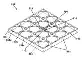
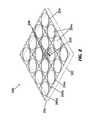
- FIG. 1Aillustrates an isometric view of a structure of a metamaterial board having a contactless capacitive coupling mechanism, according to an exemplary embodiment.
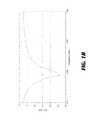
- FIG. 1Billustrates a graph depicting a return loss of a metamaterial board having a contactless capacitive coupling mechanism of FIG. 1A , according to an exemplary embodiment.
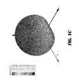
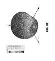
- FIG. 1Cillustrates an isometric view of a radiation gain pattern of a metamaterial board having a contactless capacitive coupling mechanism of FIG. 1A , according to an exemplary embodiment.
- FIG. 1Dillustrates a profile view of a radiation gain pattern in linear scale of a metamaterial board having a contactless capacitive coupling mechanism of FIG. 1A , according to an exemplary embodiment.
- FIG. 1Eillustrates a polar plot of a radiation gain pattern on a principal Y-Z plane of a metamaterial board having a contactless capacitive coupling mechanism of FIG. 1C , according to an exemplary embodiment.
- FIG. 1Fillustrates a magnitude of electric current surface density distribution on metamaterial cells layer of a metamaterial board having a contactless capacitive coupling mechanism of FIG. 1A at operational frequencies, according to an exemplary embodiment.
- FIG. 1Gillustrates a magnitude of electric current surface density distribution on backing conductor layer of a metamaterial board having a contactless capacitive coupling mechanism of FIG. 1A at operational frequencies, according to an exemplary embodiment.
- FIG. 2illustrates an isometric view of a structure of a metamaterial board having a co-planar coupling mechanism, according to an exemplary embodiment.
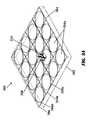
- FIG. 3Aillustrates an isometric view of a structure of a metamaterial board having a direct feeding excitation mechanism, according to an exemplary embodiment.
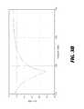
- FIG. 3Billustrates a graph depicting a return loss of a metamaterial board having a direct feeding excitation mechanism of FIG. 3A , according to an exemplary embodiment.
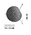
- FIG. 3Cillustrates an isometric view of a radiation gain pattern of a metamaterial board having a direct feeding excitation mechanism of FIG. 3A , according to an exemplary embodiment.
- FIG. 3Dillustrates a magnitude of electric current surface density distribution on metamaterial cells layer of a metamaterial board having a direct feeding excitation mechanism of FIG. 3A at operational frequencies, according to an exemplary embodiment.
- FIG. 3Eillustrates an isometric view of a structure of a metamaterial board having a direct feeding excitation mechanism, according to an exemplary embodiment.
- FIG. 3Fillustrates a graph depicting a return loss of a metamaterial board having a direct feeding excitation mechanism of FIG. 3E , according to an exemplary embodiment.
- FIG. 4illustrates an enlarged sectional view of a structure of a metamaterial board having a contactless capacitive coupling mechanism, a co-planar coupling mechanism, and a direct feeding excitation mechanism, according to an exemplary embodiment.
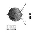
- FIG. 5Aillustrates an isometric view of a structure of a metamaterial board having a direct feeding excitation mechanism, according to an exemplary embodiment.
- FIG. 5Billustrates a graph depicting a return loss of a metamaterial board having a direct feeding excitation mechanism of FIG. 5A , according to an exemplary embodiment.
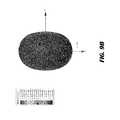
- FIG. 5Cillustrates an isometric view of a radiation gain pattern of a metamaterial board having a direct feeding excitation mechanism of FIG. 5A , according to an exemplary embodiment.
- FIG. 5Dillustrates an isometric view of a structure of a metamaterial board having a direct feeding excitation mechanism, according to an exemplary embodiment.
- FIG. 5Eillustrates a graph depicting a return loss of a metamaterial board having a direct feeding excitation mechanism of FIG. 5D , according to an exemplary embodiment.
- FIG. 5Fillustrates an isometric view of a radiation gain pattern of a metamaterial board having a direct feeding excitation mechanism of FIG. 5D , according to an exemplary embodiment.
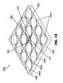
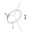
- FIG. 6Aillustrates a configuration of metamaterial unit cells for use as wearable antennas, according to an exemplary embodiment.
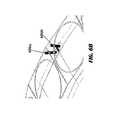
- FIG. 6Billustrates an enlarged sectional view of a metamaterial unit cells as wearable antennas, according to an exemplary embodiment.
- FIG. 6Cillustrates a graph depicting a return loss metamaterial unit cells as wearable antennas of FIG. 6A , according to an exemplary embodiment.
- FIG. 6Dillustrates an isometric view of a radiation gain pattern of metamaterial unit cells as wearable antennas of FIG. 6A , according to an exemplary embodiment.
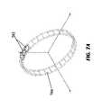
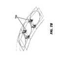
- FIG. 7Aillustrates a structure of metamaterial unit cells configured as wearable antennas, according to an exemplary embodiment.
- FIG. 7Billustrates an enlarged sectional view of a structure of metamaterial unit cells configured as wearable antennas, according to an exemplary embodiment.
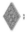
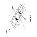
- FIG. 8Aillustrates an isometric view of a structure of a metamaterial board configured as an antenna array, according to an exemplary embodiment.
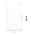
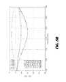
- FIG. 8Billustrates a graph depicting a return loss of a metamaterial board configured as an antenna array of FIG. 8A , according to an exemplary embodiment.
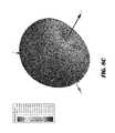
- FIG. 8Cillustrates an isometric view of a radiation gain pattern of a metamaterial board configured as an antenna array of FIG. 8A , according to an exemplary embodiment.
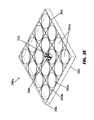
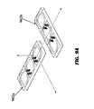
- FIG. 9Aillustrates an isometric view of a metamaterial board including two orthogonal sub-arrays, according to an exemplary embodiment.
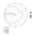
- FIG. 9Billustrates a planar view of a radiation gain pattern of a metamaterial board including two orthogonal sub-arrays of FIG. 9A , according to an exemplary embodiment.
- FIG. 9Cillustrates a planar view of a radiation gain pattern of a metamaterial board including two orthogonal sub-arrays of FIG. 9A , according to an exemplary embodiment.
- FIG. 9Dillustrates a planar view of a radiation gain pattern of a metamaterial board including two orthogonal sub-arrays of FIG. 9A , according to an exemplary embodiment.
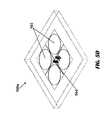
- FIG. 9Eillustrates an isometric view of a radiation gain pattern of a metamaterial board including two orthogonal sub-arrays of FIG. 9A , according to an exemplary embodiment.
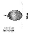
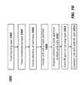
- FIG. 10illustrates a method of forming a metamaterial board, according to an exemplary embodiment.
- a response of a structure in any material to electromagnetic wavesmay be described by overall parameters, such as permittivity and permeability of the material, where the dimensions of the structure are far smaller than the wavelength of the electromagnetic wave.
- the permittivity and the permeability at each point of the materialmay be the same or different, so that the overall permittivity and the overall permeability of the material are distributed regularly to some extent.
- the regularly distributed permeability and permittivitycan cause the material to exhibit a macroscopic response to the electromagnetic wave, for example, converging the electromagnetic wave, diverging the electromagnetic wave, and the like.
- Such a material with regularly distributed permeability and permittivityis called metamaterial.
- metamaterialsare a broad class of synthetic materials that are engineered to yield permittivity and permeability characteristics compliant with the system requirements. By embedding specific structures, usually periodic structures, in some host media, usually a dielectric substrate, the resulting material is tailored to exhibit desirable characteristics. These metamaterials enable miniaturizing antennas by a significant factor while operating at acceptable efficiencies. The metamaterials may also convert omnidirectionally radiating antennas into directively radiating antennas.
- metamaterials of the present disclosuredo not need an additional layer of antennas for the metamaterials to radiate.
- the metamaterialsradiate on their own, and at the same time, the metamaterials maintain the properties of a traditional antenna-type metamaterials.
- the metamaterialsact as very thin reflectors, and at the same time, the metamaterials do not need antennas for radiating as the metamaterials radiate themselves.
- the metamaterials of the present disclosurework like artificial magnetic conductors.
- the metamaterialsare configured as very thin reflectors, and therefore the metamaterials are easy to integrate in very thin profiles of products, such as wearable bracelets.
- a metamaterial system(also referred as metamaterial board) that comprises at least two metal layers and a thin substrate.
- the structure of the metamaterial system of the present disclosureprovides for no antenna placement layers in relation to prior art implementations that require at least three metallization layers because of the additional antenna layer for the placement of antennas.
- the metamaterial system of the present disclosureis much thinner in size than the prior art implementations as absence of additional antenna layers, often at prescribed non-negligible distances from the ordinary metamaterials, reduce significantly the overall system thickness that incorporates the metamaterial system. Therefore, the metamaterial system of the present disclosure due to absence of any layer of antennas results in very thin profiles, and is appropriate for dense integration at reduced cost.
- a metamaterial systemcomposed of several sub-wavelength-sized “artificial atoms” or radiative metamaterial unit cells.
- the metamaterial systemoperates by electromagnetically exciting all of the radiative metamaterial unit cells simultaneously.
- the metamaterial systemalso have many degrees of freedom that may translate into beam-forming possibilities that are unavailable with a conventional single antenna.
- some regions of the metamaterial systemcontain the radiative metamaterial unit cells that have different design and radiative properties than other regions of the same metamaterial system.
- the radiative metamaterial unit cellsfacilitate creation of beam-forming and/or beam steering without introduction of any phase-shifting networks.
- a metamaterial systemcomposed of several radiative metamaterial unit cells.
- the metamaterial systemmay obtain linear, circular or elliptical polarization by appropriately designing the radiative metamaterial unit cells.
- the linear, circular or elliptical polarization propertiesmay be obtained by the metamaterial system that is composed of regions of the radiative metamaterial unit cells, where each of the radiative metamaterial unit cell has a different design with respect to other metamaterial unit cells.
- designing the radiative metamaterial unit cellsappropriately may obtain various different functionalities, such as linear, circular, circular, or elliptical polarization.
- a metamaterial systemcomposed of radiative metamaterial unit cells.
- the radiative metamaterial unit cellsmay be electrically interconnected by switches realized by integrated diodes, RF microelectromechanical (MEM) devices, or other means, to form larger radiative domains or different metamaterial “super-cells” that scan selected frequencies of operation over which the electromagnetic radiation is desired.
- MEMmicroelectromechanical
- a metamaterial systemcomposed of an array of unit cells.
- the array of unit cellsradiate on their own and have engineered metamaterials.
- an array of switchesmay be constructed by connecting adjacent unit cells of the array of unit cells.
- the metamaterial systemis composed of a lattice of unit cells, and a lattice of switches can be manufactured by connecting adjacent unit cells through diodes.
- the lattice of switchesmay be superimposed on the lattice of the unit cells, and because the switches connect adjacent unit cells electronically, there may be a configuration where the metamaterial has two types of unit cells, one type of unit cells that are not connected, and the other type of unit cells where a pair of unit cells are connected.
- the electrical sizemay be variable according to whether the switches are open or closed.
- the frequencymay be varied according to whether or not the switches to connect adjacent unit cells. This is also called smart radiative metamaterials, where the frequency tuning is arranged through the connectivity of the switches.
- a metamaterial systemcomposed of radiative metamaterial unit cells.
- the metamaterial unit cellsare extremely small in size due to which resulting metamaterial antennas occupy small form factors and are ideally suited to follow the curved shapes of wearable and other conformal applications. In other words, the form factors are proportional to the size of the metamaterial unit cells. Due to smaller size, the metamaterial unit cells may be placed on flexible/wearable substrates to realize wearable antennas or antennas in curved geometries.
- a metamaterial systemthat is composed of several radiative metamaterial unit cells.
- the metamaterial unit cellsare extremely small in size due to which there are smaller form factors, and because of the small form factors, the radiative metamaterial unit cells may be placed in closely spaced orthogonal orientations, and thus forming dual linearly-polarized antenna systems that are able to transmit or receive electromagnetic waves simultaneously in orthogonal linear polarizations.
- the simultaneous transmission and receiving of the electromagnetic waves in orthogonal linear polarizationscan be realized within very small areas, such as curved wearable platforms (e.g., wearable bracelets).
- a metamaterial systemthat is composed of radiative metamaterial unit cells.
- the radiative metamaterial unit cells in a receiving modeoperate as uniform materials that absorb electromagnetic radiation with high absorption efficiency.
- the radiative metamaterial unit cellsmay further operate over a wide range of frequencies, including a microwave spectrum.
- the radiative metamaterial unit cellshave a very high absorption efficiency (90% or higher).
- the radiative metamaterial unit cellsmay be tapped by inserting localized radio frequency (RF) ports to arbitrary metamaterial unit cells. This power is then directed specifically to these RF ports.
- RFradio frequency
- the radiative metamaterial unit cellswork as a dense antenna array with many RF ports that receive the absorbed energy.
- Such metamaterial systemis ideal for very small receivers, where the received power may be distributed to multiple channels simultaneously.
- a high density of the RF portsmay be achieved, with each such RF port tapping adjacent radiative metamaterial unit cells.
- An even higher density of the RF portsmay be achieved, with some RF ports tapping the same radiative metamaterial unit cell, provided additional decoupling techniques are employed.
- these multiple densely placed RF portscan accept phase control, resulting in electronically modulated RF patterns.
- FIG. 1Aillustrates an isometric view of a structure of a metamaterial board 100 having a contactless capacitive coupling mechanism, according to an exemplary embodiment.
- the metamaterial board 100 illustrated hereis realized in standard Printed Circuit Board (PCB) technology utilizing three metal layers. Three metal layers may include a conductive backing layer 102 , a metamaterial layer 104 , and a coupling layer 106 . Also, a dielectric layer 108 is disposed between the conductive backing layer 102 and the metamaterial layer 104 .
- PCBPrinted Circuit Board
- the conductive backing layer 102is placed at the bottom of the structure of the metamaterial board 100 .
- the metamaterial layer 104may be deposited above the conductive backing layer 102 , and then may be etched to create an array of metamaterial unit cells 104 a .
- the term “unit cell” and “metamaterial unit cell”may be interchangeably used.
- a distance between the conductive backing layer 102 , and the metamaterial layer 104is such that there is no short-circuit between the conductive backing layer 102 , and the metamaterial layer 104 in order to make the metamaterial unit cells 104 a radiate.
- Below the metamaterial layer 104 and above the conductive backing layer 102may be deposited a layer of dielectric 108 or insulating material, often a silicon dioxide.
- the metamaterial layer 104comprises the array of unit cells 104 a .
- the metamaterial layer 104 of the metamaterial board 100comprises sixteen radiative metamaterial unit cells 104 a in a four-by-four (4 ⁇ 4) arrangement.
- Each of the metamaterial unit cell 104 amay include a surface.
- the surfacemay be a substantially flat surface.
- the surfacemay not be a flat surface or a substantially flat surface.
- the substantially flat surface of each of the array of metamaterial unit cells 104 amay be a square surface containing a square metal patch 104 b with an aperture 104 c inscribed within it.
- the square metal patch 104 bdoes not completely fill the metamaterial unit cell surface, but is slightly smaller than the metamaterial unit cell.
- the aperture 104 cis defined such that a periphery of the aperture 104 c is within a periphery of the square metal patch 104 b by a spacing distance.
- the aperture 104 cmay be a circular aperture.
- An element 104 dmay be disposed within the aperture 104 c to form a circular slot.
- the aperturemay be a narrow shaped circular slot formed by the circular shape aperture 104 c and the element 104 d disposed within it.
- the element 104 dis a circular metal disk that is disposed within aperture 104 c to form the circular slot.
- the shape of the aperture 104 cis not limited to circular shape, and the aperture 104 c may be of any other suitable shape without moving out from the scope of the disclosed embodiments.
- the array composed of metamaterial unit cells 104 acontains square metal patches that do not touch each other, but are separated by narrow straight slots, since the metamaterial unit cell surface is slightly larger than that of the square metal patch 104 b inscribed therein. Further, there is a thin slot separating the circular element 104 d from the periphery of the square metal patch 104 b .
- one subset of the array of the metamaterial unit cells 104 amay be of one shape and size, and another subset of the array of the metamaterial unit cells 104 a may be of another shape and size.
- one metamaterial unit cell 104 a on its owndoes not radiate efficiently and also does not match the required impedance value.
- one metamaterial unit cell 104 adoes not have properties for a standard antenna.
- the array or the collection of the metamaterial unit cells 104 awork together as an antenna. Therefore, the metamaterial board 100 may include 16 unit cells 104 a .
- the metamaterial board 100may comprise any number of unit cells 104 a in other embodiments without moving out from the scope of the disclosed embodiments.
- the metamaterial layer 104may comprise the array of unit cells 104 a formed on or in a dielectric substrate.
- the metamaterial layer 104may comprise a stack of 2D arrays of unit cells 104 a , where each 2D array of unit cells 104 a is formed on or in a respective dielectric substrate.
- magnetic permeability enhanced metamaterialsare constructed by stacking up the unit cells 104 a that can store magnetic energy by virtue of their structure.
- the unit cell 104 a in embodiments of the present disclosureis composed of the circular element 104 d and the square metal patch 104 b , where the circular element 104 d may be embedded in a dielectric material. The magnetic energy storage is created in the unit cell 104 a when a magnetic field passes normally to the plane of the circular element 104 d and inducing a current in the loop.
- the dielectric layer 108may be masked and etched to open narrow profile openings known as vias 110 .
- Each of the vias 110respectively extend as an opening through the dielectric layer 108 to a portion of the uppermost coupling layer 106 .
- the vias 110may be present to provide electrical paths between different metal layers of the metamaterial board 100 .
- the vias 110may run from a surface of the metamaterial board 100 through each of the layers of the metamaterial board 100 .
- the vias 110may run from one layer of the metamaterial board 100 or a surface of the metamaterial board 100 and through other layers of the metamaterial board 100 but stop short of running through one of the layers.
- the vias 110may terminate on bond pads that couple to the integrated circuit.
- An opposite surface of the metamaterial board 100is to be coupled to a PCB.
- certain vias 110may go entirely through entire core of the metamaterial board 100 .
- Other vias 110may be isolated vias 110 , which are present through only a portion of the metamaterial board 100 .
- the particular layering and the vias 110 pattern configuration utilizedis a matter of design choice involving several factors related to the purposes to be served by the particular metamaterial board 100 .
- these particular vias 110may be machine drilled, punched, or etched through the layers. Alternative techniques for providing electrical paths between the layers may be utilized.
- the vias 110extend from the uppermost coupling layer 106 to input RF ports 112 .
- the input RF ports 112may be located on or behind the conductive backing layer 102 .
- the input RF ports 112may include a housing having any arbitrary shape, and manufactured from plastic, metal, or any other convenient material.
- the input RF ports 112may be configured such that two or more submodules may be removably located within or attached to housing. That is, the submodules are removably coupled electrically, and may be removably inserted within housing. In an alternate embodiment, the submodules are removably attached to the exterior of housing.
- the input RF ports 112are not limited to two submodules, and may be configured to accommodate 3, 4, or even more such submodules.
- the submodulesmay include a variety of electrical components that communicate via RF energy. In general, the submodules are capable of fulfilling many of the functions of the components.
- another layer of metalmay be deposited over the dielectric layer 108 .
- the deposited metalfills the vias 110 , forming metallic contact structures engaging the exposed underlying metal at the bottom of the vias and making points of contact through layer between the conductive backing layer 102 and the uppermost coupling layer 106 .
- the geometries of the vias 110 and the contact structures that now fill the vias 110are usually circular, although the vias 110 may also form other shapes such as a trench shape.
- the vias 110have been positioned so that the metallic structures which fill the vias 110 provide contacts between two separated metal layers of the metamaterial board 100 .
- the contactless capacitive coupling excitation mechanismis used to excite the structure of the metamaterial board 100 .
- Some of the components utilized for the contactless capacitive coupling excitation mechanismare provided above the metamaterial layer 104 at the center of the metamaterial board 100 to excite the structure of the metamaterial board 100 .
- the componentsat least include a plurality of pads 114 on the coupling layer 106 .
- the plurality of pads 114are used to excite the metamaterial unit cells of the metamaterial board 100 .
- the plurality of pads 114are connected through the vias 110 that traverse though the metamaterial layer 104 of the metamaterial board 100 up to the conductive backing layer 106 of the metamaterial board 100 .
- the excitation of the metamaterial unit cells of the metamaterial layer 104is achieved without direct contact by a capacitive structure (of small size) that couples RF power from the input RF port 112 to the metamaterial layer 104 .
- the plurality of pads 114placed above the metamaterial layer 104 , and going through the vias 110 behind the structure of the metamaterial board 100 excite the metamaterial unit cells as a capacitor, and therefore such a coupling is called the capacitive coupling.
- the contactless capacitive coupling excitation mechanismenables three metal layers of the metamaterial board 100 .
- the excitation of the metamaterial board 100may utilize fewer than or more than three metal layers.
- the two vias 110connect to the RF port 112 , and therefore have a positive polarity and a negative polarity.
- One of the vias 110 at a negative potentialis configured to excite half of the metamaterial unit cells 104 a
- the other of two vias 110 at a positive potentialis configured to excite remaining half of the metamaterial unit cells 104 a .
- a single via 110 with the corresponding pad 114excites the adjacent metamaterial unit cells 104 a of the metamaterial board 100 simultaneously because of a finite size of the corresponding pad 114 and since the corresponding pad 114 couples to both of the adjacent metamaterial unit cells 104 a equally.
- the metamaterial unit cell 104 ais a square surface surrounding the square metal 104 b comprising the aperture, and the metallic element 104 d disposed within the aperture 104 c .
- the metallic element 104 dis a circular metal disk that has a smaller diameter than the aperture 104 c .
- the size of the aperture 104 cis inversely proportional to a frequency of operation. If the size of the aperture 104 c is reduced, the size of the metallic element 104 d disposed within the aperture 104 c is also reduced, and then the frequency of the operation moves up.
- the aperture 104 cmay be of circular shape. In an alternate embodiment, the aperture 104 c may be of an elliptical shape. Alternate shapes may be utilized.
- the radiating structure of the metamaterial board 100is linearly polarized, and has a transmit mode and a receive mode. In the transmit mode/configuration, the radiating structure of the metamaterial board 100 emits radiation where the electric field has a specific direction along a single line. In the receive mode/configuration, the radiating structure of the metamaterial board 100 receives the radiation.
- FIG. 1Billustrates a graph depicting the return loss of a metamaterial board 100 having a contactless capacitive coupling mechanism of FIG. 1A , according to an exemplary embodiment.
- the return loss (reflected power) of the metamaterial board 100 having the contactless capacitive couplingis measured in dB.
- the metamaterial board 100 having the contactless capacitive coupling mechanismresonates at a center frequency of 6 GHz.
- the impedance matching here to a 50 Ohm RF portis at below ⁇ 25 dB.
- the impedance matchingrepresents matching of the metamaterial board 100 having the contactless capacitive coupling mechanism to a standard RF port, which is typically 50 ohm.
- the impedance matching bandwidth at the ⁇ 10 dB levelis 350 MHz, or 6% with respect to a center frequency of the metamaterial board 100 .
- the impedance matchingdefines the operation frequency band of the structure of the metamaterial board 100 having the contactless capacitive coupling mechanism.
- the dimensions of the metamaterial board 100 having the contactless capacitive coupling mechanismmay be chosen so that the metamaterial board 100 having the contactless capacitive coupling mechanism tune to a standard operation frequency around 500 GHz.
- impedance matching to other RF port valuesis possible with modifications of the presented shapes without moving out from the scope the disclosed embodiments.
- FIG. 1Cillustrates an isometric view of a radiation gain pattern, in dB, of a metamaterial board 100 having a contactless capacitive coupling mechanism of FIG. 1A , according to an exemplary embodiment.
- the metamaterial board 100 having the contactless capacitive coupling mechanismhas a single directive electromagnetic beam of energy that is radiating upward/forward along the z-axis.
- the single directive electromagnetic beamis generated by excitation of entire sixteen metamaterial unit cells 104 a of the metamaterial board 100 .
- FIG. 1Dillustrates a polar plot of a radiation gain pattern in linear scale of a metamaterial board 100 having a contactless capacitive coupling of FIG. 1A , according to an exemplary embodiment.
- the metamaterial board 100 having the contactless capacitive coupling mechanismhas a single directive electromagnetic beam of energy that is directed broadside, with negligible radiation behind the metamaterial board 100 .
- the single directive electromagnetic beamis generated by excitation of entire sixteen metamaterial unit cells 104 a of the metamaterial board 100 .
- FIG. 1Eillustrates a polar plot of a radiation gain pattern, in dB, on a principal Y-Z plane of a metamaterial board 100 having a contactless capacitive coupling of FIG. 1C , according to an exemplary embodiment.
- the electromagnetic radiation emitted from the metamaterial board 100 having the contactless capacitive coupling mechanismis linearly polarized, with a cross-polarization level at about 40 dB below a co-polarized radiation.
- the metamaterial board 100 back-side radiationis suppressed and a front-to-back gain ratio is about 17 dB.
- FIG. 1Fillustrates a magnitude of electric current surface density distribution on metamaterial unit cells layer 104 of a metamaterial board 100 having a contactless capacitive coupling mechanism of FIG. 1A at operational frequencies, according to an exemplary embodiment.
- the magnitude of the electric current surface density distributed on the radiative metamaterial unit cells 104 a of the metamaterial board 100 having the contactless capacitive coupling mechanism, at the operating frequency band, where the metamaterial unit cells 104 a of the metamaterial board 100 radiatesis shown.
- a plurality of metamaterial unit cells 104 a of the metamaterial board 100are excited from the contactless capacitive coupling mechanism and subsequently strong electric currents develop both on square patch edges and on circular slot edges of each of the metamaterial unit cells 104 a of the metamaterial board 100 .
- all the metamaterial unit cells 104 a of the metamaterial board 100are excited from the contactless capacitive coupling mechanism due to strong electric currents that develop both on the square patch edges and on the circular slot edges of each of the metamaterial unit cells 104 a of the metamaterial board 100 .
- all the metamaterial unit cells 104 a of the metamaterial board 100contributing to the electromagnetic radiation simultaneously, thereby leading to a high radiative gain of the metamaterial board 100 . It is contemplated that an alternate embodiment may actively or passively engage a plurality, but not all, metamaterial unit cells 104 a to contribute to the electromagnetic radiation. In an embodiment, although the excitation of the metamaterial unit cells 104 a of the metamaterial board 100 is localized at the center of the metamaterial board 100 using the contactless capacitive coupling mechanism, however as shown in the figure, the electric current spreads on all of the metamaterial unit cells 104 a of the metamaterial board 100 in order for radiation to occur.
- the excitation of the metamaterial unit cells 104 a of the metamaterial board 100may be localized at any location of the metamaterial board 100 using the contactless capacitive coupling mechanism such that the electric current spreads on the plurality of the metamaterial unit cells 104 a of the metamaterial board 100 in order for radiation to occur.
- the metamaterial board 100 using the contactless capacitive coupling mechanismresults in more than one metamaterial unit cell 104 a being excited for radiation to happen.
- the multiple metamaterial unit cells 104 a of the metamaterial board 100has properties to work as a standard antenna.
- the metamaterial board 100 using the contactless capacitive coupling mechanismmay have only a single metamaterial unit cell 104 a that may be excited for radiation to happen. In such a case, the single metamaterial unit cell 104 a has properties to work as a standard antenna.
- FIG. 1Gillustrates a magnitude of electric current surface density distribution on a backing conductor layer 102 of a metamaterial board 100 having a contactless capacitive coupling mechanism of FIG. 1A at operation frequencies, according to an exemplary embodiment.
- the electric currentconcentrates at the center of the conductive backing layer 102 of the metamaterial board 100 , and thereby creating a focusing effect that directs the electromagnetic power radiated by the metamaterial unit cells 104 a of the metamaterial board 100 in an upward direction, that is, along the z-axis.
- FIG. 2illustrates an isometric view of a structure of a metamaterial board 200 having a co-planar coupling mechanism, according to an exemplary embodiment.
- the co-planar coupling mechanismis used to excite an array of metamaterial unit cells of the metamaterial board 200 .
- the co-planar coupling mechanismis a contactless coupling mechanism, where a fewer number of metal layers may be utilized, and thereby resulting in reduction of manufacturing cost.
- the metamaterial board 200 illustratedmay be realized in standard Printed Circuit Board (PCB) technology utilizing two metal layers.
- the two metal layerscomprise a conductive backing layer 202 and a metamaterial layer 204 .
- a dielectric layer 206is disposed between the conductive backing layer 202 , and the metamaterial layer 204 .
- the conductive backing layer 202is placed at the bottom of the structure of the metamaterial board 200 .
- the metamaterial layer 204may be deposited above the conductive backing layer 202 , and then may be etched to create an array of unit cells 204 a .
- a distance between the conductive backing layer 202 and the metamaterial layer 204is such that there is no short-circuit between the conductive backing layer 202 and the metamaterial layer 204 in order to make the metamaterial unit cells 204 a radiate.
- a layer of dielectric 206 or insulating materialoften a silicon dioxide.
- the metamaterial layer 204comprises the array of unit cells 204 a .
- the metamaterial layer 204 of the metamaterial board 100comprises sixteen radiative metamaterial unit cells 204 a in a four-by-four (4 ⁇ 4) arrangement.
- Each of the metamaterial unit cell 204 amay include a surface.
- the surfacemay be a substantially flat surface.
- the surfacemay not be a flat surface or a substantially flat surface.
- the substantially flat surface of each of the array of unit cells 204 amay be a square surface containing a square metal patch 204 b with an aperture 204 c inscribed within it.
- the square metal patch 204 bdoes not completely fill the unit cell surface, but is slightly smaller than the unit cell.
- each of the array of unit cells 204 amay be a square metal patch 204 b with an aperture 204 c inscribed therein.
- the aperture 204 cis defined such that a periphery of the aperture 204 c is within a periphery of the square metal patch 204 b by a spacing distance.
- the aperture 204 cmay be a circular aperture.
- An element 204 dmay be disposed within the aperture 204 c to form a circular slot.
- the element 204 dis a circular metal disk that is disposed within aperture 204 c to form the circular slot.
- the shape of the aperture 204 cis not limited to circular shape, and the aperture 204 c may be of any other suitable shape without moving out from the scope of the disclosed embodiments.
- the array composed of metamaterial unit cells 204 acontains square metal patches 204 b that do not touch each other, but are separated by narrow straight slots, since the unit cell surface is slightly larger than that of the square metal patches 204 b inscribed therein.
- each of the unit cells 204 ais attached to the neighboring unit cell 204 a , but the inscribed square metal patches 204 b corresponding to these unit cells are separated by small-sized slots.
- one subset of the array of the metamaterial unit cells 204 amay be of one shape and size, and another subset of the array of the metamaterial unit cells 204 a may be of another shape and size.
- the dielectric layer 206is masked and etched to open narrow profile openings known as vias 208 .
- Each of the vias 208respectively extends as an opening through the dielectric layer 206 to a portion of the uppermost layer.
- the vias 208may be present to provide electrical paths between different metal layers of the metamaterial board 200 .
- the vias 208extend from the metamaterial layer 204 to input RF ports 210 .
- the input RF ports 210may be located on or behind the conductive backing layer 202 .
- the geometries of the vias 208 and the contact structures that now fill the vias 208are usually circular although the vias 208 may also form other shapes such as a trench shape.
- the vias 208have been positioned so that the metallic structures that fill the vias 208 provide contacts between two separated metal layers of the metamaterial board 200 .
- these particular vias 208may be machine drilled, punched, or etched through the layers. Alternative techniques for providing electrical paths between the layers may be utilized.
- excitation components of the co-planar coupling mechanismmay be placed on the plane of the metamaterial unit cells 204 a of the metamaterial board 200 to excite the structure of the metamaterial board 200 .
- the excitation of the metamaterial unit cells 204 a of the metamaterial layer 204is achieved without direct contact by a capacitive structure which couples RF power from the input RF port 210 to the metamaterial layer 204 .
- the RF port 210is placed on the conductive backing layer 202 , where the RF port 210 feeding pads are placed within a small aperture in the conductive backing layer 202 .
- the co-planar coupling excitation mechanismutilize two metal layers of the metamaterial board 200 .
- the two vias 208connect to the RF port 210 , and therefore have a positive polarity and a negative polarity.
- One of the vias 208 at a negative potentialis configured to excite half of the metamaterial unit cells 204 a and the other via of two vias 208 at a positive potential is configured to excite the remaining half of the metamaterial unit cells 204 a.
- the metamaterial unit cell 204 ais a square surface surrounding the square metal 204 b comprising the aperture 204 c , and the metallic element 204 d disposed within the aperture 204 c .
- the size of the aperture 204 cis inversely proportional to a frequency of operation. If the size of the aperture 204 c is reduced, the size of the metallic element 204 d disposed within the aperture 204 c is also reduced, and then the frequency of the operation moves up. If the size of the aperture 204 c is increased, the size of the metallic element 204 d disposed within the aperture 204 c also becomes larger, and the frequency at which the metamaterial unit cell 204 a operates goes down.
- the aperture 204 cmay be of circular shape. In an alternate embodiment, the aperture 204 c may be an elliptical shape. Alternate shapes may be utilized as well.
- the radiating structure of the metamaterial board 200is linearly polarized, and has a transmit mode and a receive mode. In the transmit mode/configuration, the radiating structure of the metamaterial board 200 emits radiation, where the electric field has a specific direction along a single line. In the receive mode/configuration, the radiating structure of the metamaterial board 200 receives the radiation.
- the radiation and impedance matching properties of the metamaterial board 200 having the co-planar coupling mechanismis identical to the structure of the metamaterial board 100 of FIG. 1A .
- FIG. 3Aillustrates an isometric view of a structure of a metamaterial board 300 having a direct feeding excitation mechanism, according to an exemplary embodiment.
- the excitation mechanism usedis the direct feeding mechanism through conductive vias.
- the direct feeding excitation mechanismmay utilize two metal layers, thereby resulting in reduction of manufacturing cost.
- the excitation of the metamaterial unit cells of the metamaterial board 300does not happen with coupling either capacitively or coplanar, but happens when the vias directly connect to metamaterial unit cells.
- the metamaterial board 300 illustrated heremay be realized in standard Printed Circuit Board (PCB) technology utilizing two metal layers.
- the two metal layersmay include a conductive backing layer 302 , and a metamaterial layer 304 .
- a dielectric layer 306may be disposed between the conductive backing layer 302 , and the metamaterial layer 304 .
- the conductive backing layer 302is placed at the bottom of the structure of the metamaterial board 300 .
- the metamaterial layer 304is deposited above the conductive backing layer 302 , and then may be etched to create an array of unit cells 304 a .
- a distance between the conductive backing layer 302 and the metamaterial layer 304is such that there is no short-circuit between the conductive backing layer 202 and the metamaterial layer 204 in order to make the metamaterial unit cells 304 a radiate.
- a layer of dielectric 306 or insulating materialoften a silicon dioxide.
- the metamaterial layer 304comprises the array of unit cells 304 a .
- the metamaterial layer 304 of the metamaterial board 300comprises sixteen radiative metamaterial unit cells 304 a in a four-by-four (4 ⁇ 4) arrangement.
- each of the unit cells 304 anot attached to the other, and there is a small sized slot separating these unit cells 304 a from each other.
- Each of the metamaterial unit cell 304 amay include a surface. In one embodiment, the surface may be a substantially flat surface. In another embodiment, the surface may not be a flat surface or a substantially flat surface.
- the substantially flat surface of each of the array of unit cells 304 amay be a square surface containing a square metal patch 304 b with an aperture 304 c inscribed within it.
- the square metal patch 304 bdoes not completely fill the unit cell surface, but is slightly smaller than the unit cell.
- the substantially flat surface of each of the array of unit cells 304 amay be a square metal patch 304 b with an aperture 304 c inscribed within it.
- the aperture 304 cis defined such that a periphery of the aperture 304 c is within a periphery of the square metal patch 304 b by a spacing distance.
- the aperture 304 cmay be a circular aperture.
- An element 304 dmay be disposed within the aperture 304 c to form a circular slot.
- the element 304 dis a circular metal disk that is disposed within aperture 304 c to form the circular slot.
- the shape of the aperture 304 cis not limited to circular shape, and the aperture 304 c may be of any other suitable shape without moving out from the scope of the disclosed embodiments.
- the array composed of metamaterial unit cells 304 acontains square metal patches 304 b that do not touch each other, but are separated by narrow straight slots, since the unit cell surface is slightly larger than that of the metal patch inscribed in it.
- each of the unit cells 304 ais attached to the neighboring unit cell 304 a , but the inscribed square metal patches 304 b corresponding to these unit cells 304 a are separated by small-sized slots. Further, there is a thin slot separating the circular element 304 d from the periphery of the square metal patch 304 b .
- one subset of the array of the metamaterial unit cells 304 amay be of one shape and size, and another subset of the array of the metamaterial unit cells 304 a may be of another shape and size.
- the dielectric layer 306may be masked and etched to open narrow profile openings known as vias 308 .
- Each of the vias 208respectively extend as an opening through the dielectric layer 306 to a portion of the uppermost layer.
- the vias 308may be present to provide electrical paths between different metal layers of the metamaterial board 300 .
- the vias 308extend from the metamaterial layer 304 to input RF ports 310 .
- the input RF ports 310may be located on or behind the conductive backing layer 302 .
- the geometries of the vias 308 and the contact structures which now fill the vias 308are usually circular although the vias 308 may also form other shapes such as a trench shape.
- the vias 308have been positioned so that the metallic structures which fill the vias 308 provide contacts between two separated metal layers of the metamaterial board 300 .
- excitation components of the direct feeding mechanismmay be placed on the plane of the metamaterial unit cells 304 a of the metamaterial board 300 to excite the metamaterial board 300 .
- the excitation of the metamaterial unit cells 304 a of the metamaterial layer 304is achieved by the vias 308 .
- the vias 308may connect to the RF port 310 and therefore have a positive polarity and a negative polarity.
- One of the vias 308 a at a negative potentialis configured to excite half of the metamaterial unit cells 304 a and the other via of two vias 308 b at a positive potential is configured to excite remaining half of the metamaterial unit cells 304 a.
- the metamaterial unit cell 304 amay be a square surface surrounding the square metal 304 b comprising the aperture 304 c , and the metallic element 304 d may be disposed within the aperture 304 c .
- the size of the aperture 304 cis inversely proportional to a frequency of operation. If the size of the aperture 304 c is reduced, the size of the metallic element 304 c disposed within the aperture 304 c is also reduced, and then the frequency of the operation moves up. If the size of the aperture 304 c is increased, the size of the metallic element 304 c disposed within the aperture 304 c is also becomes larger, and then the frequency at which the metamaterial unit cell 304 a operates goes down.
- the aperture 304 cmay be of circular shape. In an alternate embodiment, the aperture 304 c may be an eclipse shape. Alternate shapes may be utilized.
- the radiating structure of the metamaterial board 300is linearly polarized, and has a transmit mode and a receive mode. In the transmit mode/configuration, the radiating structure of the metamaterial board 300 emit radiation, where the electric field has a specific direction along a single line. In the receive mode/configuration, the radiating structure of the metamaterial board 200 receives the radiations.
- FIG. 3Billustrates a graph depicting a return loss of a metamaterial board 300 having a direct feeding excitation mechanism of FIG. 3A , according to an exemplary embodiment.
- the return loss (reflected power) of the metamaterial board 300 having the direct feeding excitation mechanismis measured in dB.
- the metamaterial board 300 having the direct feeding excitation mechanismresonates at a center frequency of 5.9 GHz.
- the impedance matching here to a 50 Ohm RF port 310is at ⁇ 25 dB.
- the impedance matchingrepresents matching of the metamaterial board 300 having the direct feeding excitation mechanism to a standard RF port 310 which is typically 50 ohm.
- the impedance matching bandwidth at the ⁇ 10 dB levelis 350 MHz, or 6% with respect to a center frequency of the metamaterial board 300 .
- the impedance matchingdefines the operation frequency band of the metamaterial board 300 having the direct feeding excitation mechanism.
- FIG. 3Cillustrates an isometric view of a radiation gain pattern of a metamaterial board 300 having a direct feeding excitation mechanism of FIG. 3A , according to an exemplary embodiment.
- the metamaterial board 300 having the direct feeding excitation mechanismhas a single directive electromagnetic beam of energy that is radiating upward/forward, that is, along the z-axis.
- the single directive electromagnetic beamis generated by excitation of entire sixteen metamaterial unit cells 304 a of the metamaterial board 300 .
- FIG. 3Dillustrates a magnitude of electric current surface density distribution on metamaterial cells layer 302 of a metamaterial board 300 having a direct feeding excitation mechanism of FIG. 3A at operation frequencies, according to an exemplary embodiment.
- the magnitude of the electric current surface density distributed on the radiative metamaterial unit cells 304 a of the metamaterial board 300 having the direct feeding excitation mechanism, at the operating frequency band, where the metamaterial board radiatesis shown.
- a plurality of metamaterial unit cells 304 a of the metamaterial board 300are excited from the direct feeding excitation mechanism and subsequently strong electric currents develop both on square patch edges and on circular slot edges of each of the metamaterial unit cells 304 a of the metamaterial board 300 .
- all the metamaterial unit cells 304 a of the metamaterial board 300are excited from the direct feeding excitation mechanism due to strong electric currents that develop both on the square patch edges and on the circular slot edges of each of the metamaterial unit cells 304 a of the metamaterial board 300 .
- all the metamaterial unit cells 304 a of the metamaterial board 300contributing to the electromagnetic radiation simultaneously, thereby leading to a high radiative gain of the metamaterial board 300 .
- the excitation of the metamaterial unit cells 304 a of the metamaterial board 300is localized at the center of the metamaterial board 300 using the direct feed coupling mechanism, however as shown in the figure, the electric current spreads on all of the metamaterial unit cells 304 a of the metamaterial board 300 in order for radiation to occur.
- the excitation of the metamaterial unit cells 304 a of the metamaterial board 300may be localized at any location of the metamaterial board 300 such that the electric current spreads on the plurality of the metamaterial unit cells 304 a of the metamaterial board 300 in order for radiation to occur.
- the metamaterial board 300 using the direct feed coupling mechanismmay utilize more than one metamaterial unit cell 304 a that causes excitation for radiation to happen. In such a case, the multiple metamaterial unit cells 304 a of the metamaterial board 300 has properties to work as a standard antenna.
- the metamaterial board 300 using the direct feed coupling mechanismmay have a single metamaterial unit cell 304 a that may be excited for radiation to happen. In such a case, the single metamaterial unit cell 304 a has properties to work as a standard antenna.
- FIG. 3Eillustrates an isometric view of a structure of a metamaterial board 300 a having a direct feeding excitation mechanism, according to an exemplary embodiment.
- the structure of the metamaterial board 300 a of FIG. 3Eis similar to the structure of the metamaterial board 300 of FIG. 3A other than the dimensions and sizes of the metamaterial unit cells 304 a of the metamaterial board 300 a .
- the difference in the dimensions and sizes of the components such as metamaterial unit cells 304 a of the metamaterial board 300 a in comparison to the dimensions and sizes of the components such as metamaterial unit cells of the metamaterial board 300aids to achieve the scaling of the operation frequency.
- circular slots on each of the metamaterial unit cells 304 a of the metamaterial board 300 aare narrower than the circular slots on each of the metamaterial unit cells of the metamaterial board 300 of FIG. 3A .
- spacing distance between the square patches of the metamaterial unit cells 304 a of the metamaterial board 300 ais narrower than the spacing distance between the square patches of metamaterial unit cells of the metamaterial board 300 of FIG. 3A .
- the circular slots on each of the metamaterial unit cells 304 a of the metamaterial board 300 aare 0.1 mm wide in comparison to the circular slots on each of the metamaterial unit cells of the metamaterial board 300 of FIG. 3A which were 0.15 mm wide.
- the total size of the metamaterial board in the embodiments described in FIG. 3A and FIG. 3Eis 20 mm ⁇ 20 mm, however it is to be appreciated by a person having ordinary skill in the art that in other embodiments the size may vary without moving out from the scope of the disclosed embodiments.
- FIG. 3Fillustrates a graph depicting a return loss of a metamaterial board 300 a having a direct feeding excitation mechanism of FIG. 3E , according to an exemplary embodiment.
- the return loss (reflected power) of the metamaterial board 300 a having the direct feeding excitation mechanismis measured in dB.
- the metamaterial board 300 a having the direct feeding excitation mechanismresonates at a center frequency of 5.8 GHz.
- the center frequencyis reduced by 150-100 MHz relative to the embodiments discussed in FIG. 3A without increase in the size of the overall structure of the metamaterial board 300 a .
- the impedance matching to a 50-Ohm RF portis at ⁇ 28 dB.
- the impedance matchingrepresents matching of the metamaterial board 300 a having the direct feeding excitation mechanism to a standard RF port which is typically 50 ohm.
- the impedance matching bandwidth at the ⁇ 10 dB levelis 350 MHz, or 6% with respect to a center frequency of the metamaterial board 300 a.
- FIG. 4illustrates an enlarged sectional view of a structure of a metamaterial board having a contactless capacitive coupling, a co-planar coupling mechanism, and a direct feeding excitation mechanism, according to an exemplary embodiment.
- the metamaterial board 100 having the contactless capacitive coupling mechanism, the metamaterial board 200 having the co-planar coupling mechanism, and the metamaterial board 300 having the direct feeding excitation mechanismhave the same or substantially the same physical characteristics, operation bandwidth and performance.
- other excitation mechanisms to excite the metamaterial board for radiation to happenmay be used.
- hybrid combinations of the metamaterial board 100 having the contactless capacitive coupling mechanism, the metamaterial board 200 having the co-planar coupling mechanism, and the metamaterial board 300 having the direct feeding excitation mechanismmay be employed.
- the metamaterial board 100 having the contactless capacitive coupling mechanismuses three metal layers.
- the metamaterial board 200 having the co-planar coupling mechanism, and the metamaterial board 300 having the direct feeding excitation mechanismuses two metal layers.
- the metamaterial board 100 having the contactless capacitive coupling mechanismuses an extra metallic layer in comparison to the metamaterial board 200 having the co-planar coupling mechanism, and the metamaterial board 300 having the direct feeding excitation mechanism.
- Each layer of metalincreases the cost of manufacturing and therefore the manufacturing cost of the metamaterial board 200 having the co-planar coupling mechanism, and the metamaterial board 300 having the direct feeding excitation mechanism is less than the metamaterial board 100 having the contactless capacitive coupling mechanism.
- the control of manufacturing processis more robust in the metamaterial board 300 having the direct feeding excitation mechanism by directly having the vias positioned on the actual metamaterial unit cells without having any circular patches with a specific slot exciting the central metamaterial unit cells of the metamaterial board 300 .
- the size of the metamaterial unit cell in the metamaterial board 100 having the contactless capacitive coupling mechanism, the metamaterial board 200 having the co-planar coupling mechanism, and the metamaterial board 300 having the direct feeding excitation mechanismis selected based on a desired operating frequency.
- the size of the metamaterial unit cell along with its adjacent metamaterial unit cellsdetermines the frequency of operation of the metamaterial board 100 having the contactless capacitive coupling mechanism, the metamaterial board 200 having the co-planar coupling mechanism, and the metamaterial board 300 having the direct feeding excitation mechanism.
- the frequency of the unit cellis configured to operate in a frequency band ranging from 900 MHz to 100 GHz.
- the shape of the metamaterial unit cell in the metamaterial board 100 having the contactless capacitive coupling mechanism, the metamaterial board 200 having the co-planar coupling mechanism, and the metamaterial board 300 having the direct feeding excitation mechanism such as thin slotsare important for frequency tuning.
- the diameter of each of the metamaterial unit cell of the metamaterial board 100 having the contactless capacitive coupling mechanism, the metamaterial board 200 having the co-planar coupling mechanism, and the metamaterial board 300 having the direct feeding excitation mechanismis about one-tenth of the wavelength of the frequency of operation.
- FIG. 5Aillustrates an isometric view of a structure of a metamaterial board 500 having a direct feeding excitation mechanism, according to an exemplary embodiment.
- number of metamaterial unit cellsaffects the performance of metamaterial board.
- the size of the metamaterial board 500is identical or substantially identical to the size of the metamaterial board 300 illustrated in FIG. 3A , but the metamaterial board 500 of the illustrative embodiment comprises four metamaterial unit cells 502 in comparison to the sixteen unit cells 304 a of the metamaterial board 300 illustrated in FIG. 3A .
- the excitation mechanism usedis direct feeding excitation mechanism through conductive vias.
- the direct feeding excitation mechanismutilizes two metal layers, and thereby resulting in reduction of manufacturing cost.
- the excitation of the metamaterial unit cells 502 of the metamaterial board 500does not happen with coupling either capacitively or coplanar, but happens when vias 504 directly connect to metamaterial unit cells 502 .
- the direct feeding excitation mechanismis explained in detail in FIG. 3A .
- FIG. 5Billustrates a graph depicting a return loss of a metamaterial board 500 having a direct feeding excitation mechanism FIG. 5A , according to an exemplary embodiment.
- the return loss (reflected power) of the metamaterial board 500 having the direct feeding excitation mechanismis measured in dB.
- the metamaterial board 500 having the direct feeding excitation mechanismresonates at a center frequency of 5.8 GHz. This illustrates that the resonant frequency of operation is determined by design of the metamaterial unit cells 502 and is not dependent on the number of the metamaterial unit cells 502 .
- the impedance matching to a 50-Ohm RF portis at or below ⁇ 30 dB, which is smaller than the embodiments discussed earlier having sixteen metamaterial unit cells.
- the impedance matchingrepresents matching of the metamaterial board 500 to a standard RF port, which is typically 50 ohm.
- the impedance matching bandwidth at the ⁇ 10 dB levelis 240 MHz, or 4% with respect to a center frequency of the metamaterial board 500 .
- the impedance matchingdefines the operation frequency band of the structure of the metamaterial board 500 .
- FIG. 5Cillustrates a 3-dimensional isometric view of a radiation gain pattern of a metamaterial board 500 having a direct feeding excitation mechanism of FIG. 5A , according to an exemplary embodiment.
- the metamaterial board 500 having the direct feeding excitation mechanismhas a single directive electromagnetic beam of energy that is radiating upward/forward.
- the single directive electromagnetic beamis generated by excitation of entire four metamaterial unit cells 502 of the metamaterial board 500 .
- the maximum gainis 5 dBi, which is 1 dB lower than the earlier embodiments discussed comprising sixteen metamaterial unit cells. Since the size of the conductive backing layer is same in earlier and the present embodiment, the directive radiation is caused by the collective excitation of a plurality of metamaterial unit cells 502 in the present embodiment as well as earlier embodiments.
- FIG. 5Dillustrates an isometric view of a structure of a metamaterial board 500 a having a direct feeding excitation mechanism, according to an exemplary embodiment.
- the illustrative embodimenthas the metamaterial board 500 a that may be identically configured to the metamaterial board 500 described in FIG. 5A , but not identical in all facets and thus this results in a compact form factor in this structure.
- FIG. 5Eillustrates a graph depicting a return loss of a metamaterial board 500 a having a direct feeding excitation mechanism FIG. 5D , according to an exemplary embodiment.
- the return loss (reflected power) of the metamaterial board 500 a having the direct feeding excitation mechanismis measured in dB.
- the metamaterial board 500 aresonates at a center frequency of 5.75 GHz.
- the impedance matching to a 50 Ohm RF portis at or below ⁇ 25 dB.
- the impedance matchingrepresents matching of the metamaterial board 500 a to a standard RF port, which is typically 50 ohm.
- the impedance matching bandwidth at the ⁇ 10 dB levelis 160 MHz, or 3% with respect to a center frequency of the metamaterial board 500 a .
- the impedance matchingdefines the operation frequency band of the structure of the metamaterial board 500 a.
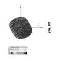
- FIG. 5Fillustrates an isometric view of a radiation gain pattern of a metamaterial board 500 a having a direct feeding excitation mechanism of FIG. 5D , according to an exemplary embodiment.
- the metamaterial board 500 ahas a single directive electromagnetic beam of energy that is radiating upward/forward.
- the single directive electromagnetic beamis generated by excitation of entire four metamaterial unit cells 502 .
- the maximum gainis 4.4 dBi, which 0.6 dB lower relative to earlier embodiment described with respect to FIG. 5A and 1.6 dB lower than the earlier embodiments comprising sixteen metamaterial unit cells. Since the size of a conductive backing layer is same in earlier and the present embodiments, the directive radiation is caused by the collective excitation of all metamaterial unit cells 502 in the present embodiment as well as earlier embodiments.
- FIG. 6Aillustrates a configuration of metamaterial unit cells for use as wearable antennas, according to an exemplary embodiment
- FIG. 6Billustrates an enlarged sectional view of the structure depicted in FIG. 6A
- the metamaterial unit cells 602are of small size and the size of the metamaterial unit cells 602 is smaller than a radius of curvature of a curved surface of any wrist wearable bracelet. This flexibility in size allows the metamaterial unit cells 602 to be etched on the curved surface of the bracelet.
- the wearable bracelet 604is made of a flexible plastic and is a flexible isolator.
- the thickness of the plasticis about 1.5 millimeters, and the inner diameter is about 60 millimeters.
- the number of the metamaterial unit cells 602is four, and the metamaterial unit cells 602 are arranged in a linear array configuration. In the illustrated example, the size of each of the four metamaterial unit cells 602 is about six millimeters, however, it is to be noted that in other embodiments the metamaterial unit cells 602 can be of different size without moving out from the scope of the disclosed embodiments.
- the excitation mechanism employed for exciting the metamaterial unit cells 602is a direct feeding exciting mechanism. It is to be noted that in other embodiments of the present disclosure, any other exciting mechanism may be employed for exciting the metamaterial unit cells 602 without moving out from the scope of the disclosed embodiments.
- a set of viasmay directly excite the metamaterial unit cells 602 .
- there is only a single row of the metamaterial unit cells 602and therefore a double set of vias may not be utilized, and a single set of vias may be utilized to excite the single row of the metamaterial unit cells 602 .
- one via 606 ais configured to have a positive polarity contact and another via 606 b is configured to have a negative polarity contact.
- the positive polarity via 606 afeeds and/or excite half proportion of the row of the metamaterial unit cells 602
- the negative polarity via 606 bfeeds and/or excite the other half proportion of the row of the metamaterial unit cells 602 .
- the direct feed exciting mechanismis explained in detail in FIG. 3A .
- the size of the each of the metamaterial unit cells 602is 6 mm ⁇ 6 mm ⁇ 1.5 mm (bracelet thickness) or 0.11 ⁇ 0.11 ⁇ 0.03 ⁇ 3 , where ⁇ is the wavelength at a frequency of operation.
- An inner diameter of the bracelet 604is 60 mm which is similar to that of a standard-size wrist-worn bracelet. Alternate dimensions of the bracelet 604 may be utilized for different purpose.
- FIG. 6Cillustrates a graph depicting a return loss of metamaterial unit cells as wearable antennas of FIG. 6A , according to an exemplary embodiment.
- the return loss (reflected power) of the metamaterial unit cells 602 as wearable antennasis measured in dB.
- the metamaterial unit cells 602 as wearable antennasresonates at a center frequency of 5.75 GHz where the reflection is at the minimum.
- the resonant frequency of operationis determined by design of the metamaterial unit cells 602 and is not dependent on the number of the metamaterial unit cells 602 .
- the impedance matchingis to a 50-Ohm RF port and is at or below ⁇ 10 dB.
- the impedance matchingrepresents matching of the structure to a standard RF port, which is typically 50 ohms.
- the impedance matching bandwidth at the ⁇ 10 dB levelis 500 MHz, which is quite large, and defines the operation frequency band of the structure of the metamaterial unit cells 602 configured as wearable antennas.
- the present embodimentis ideal for wearable antennas due to this large natural bandwidth because it is desirable to have spare bandwidth to accommodate impedance because the impedance provides a tuning effect from adjacent structures, such as from objects behind the bracelet 604 (e.g., human hand).
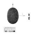
- FIG. 6Dillustrates a 3-dimensional isometric view of a radiation gain pattern of metamaterial unit cells as wearable antennas of FIG. 6A , according to an exemplary embodiment.
- the metamaterial unit cells 602 as wearable antennashas a single directive electromagnetic beam of energy that is radiating upward/forward, that is, along the z-axis.
- the single directive electromagnetic beamis generated by excitation of a plurality of the metamaterial unit cells 602 and there is minimum radiation towards the inside of the bracelet 604 and into a human wrist.
- a maximum gainis 3.7 dBi
- an antenna radiation efficiencyis 91%.
- FIG. 7Aillustrates a structure of metamaterial unit cells configured as wearable antennas, according to an exemplary embodiment
- FIG. 7Billustrates an enlarged sectional view of the structure depicted in FIG. 7A
- FIG. 7Ashows another embodiment of radiative metamaterials unit cells 702 as wearable/flexible/conformal antennas.
- a bracelet 704may have the same dimensions as of the bracelet 604 depicted in the embodiment of the FIG. 6A , however, there are three metamaterials unit cells 702 of smaller size attached on a curved surface of the bracelet 704 .
- the three metamaterials unit cells 702are probed with four RF ports 706 , making the structure equivalent to an extremely dense 4-antenna array.
- the three metamaterials unit cells 702absorbs RF energy which is directed to distinct prescribed locations.
- the three metamaterials unit cells 702operate as uniform materials that absorb electromagnetic radiation with high absorption efficiency.
- the three metamaterials unit cells 702can be tapped by inserting four localized RF ports 706 to the three metamaterials unit cells 702 . This power is then directed specifically to the localized RF ports 706 .
- this structure with the metamaterials unit cells 702works as a dense antenna array with many RF ports 706 that receive the absorbed energy. Such structure is ideal for very physically small receivers where there is a need to distribute the received power to multiple channels simultaneously.
- these multiple densely placed RF ports 706can accept phase control, resulting in electronically modulated RF patterns.
- this structure with the metamaterials unit cells 702has a very small form factor that matches a receiver ASIC (not shown).
- the ASICis positioned in middle behind a conductive backing layer positioned at the bottom of the structure, and would be configured to connect its inputs to the four RF ports 706 . Since the tapping can be performed at different places, the ASIC may require less power per RF port.
- both the space as well as thickness of a substrateis required.
- a 2 GHz bandwidthmay be obtained using a structure including three metamaterial unit cells 702 and four RF ports 706 .
- FIG. 8Aillustrates an isometric view of a structure of a metamaterial board 800 configured as a flat antenna array that can be fabricated on standard PCB boards, according to an exemplary embodiment.
- radiative metamaterials unit cells 802are configured as the antenna arrays to receive and/or transmit RF signals.
- the metamaterials unit cells 802are connected to 4 RF ports, making this structure equivalent of four antennas that are extremely closely spaced.
- the present embodimentis the equivalent of the wearable configuration of FIG. 7A , but on a flat platform appropriate for systems realized on standard flat boards.
- the absorbed poweris then directed specifically to localized RF ports 804 and 806 .
- the structureis ideal for physically small receivers where there is a need to distribute the received power to multiple channels simultaneously.
- the multiple densely placed RF ports 804 and 806can accept phase control, resulting in electronically modulated RF patterns.
- the metamaterial unit cell 802 sizeis 6 mm ⁇ 6 mm ⁇ 1.5 mm (bracelet thickness) or 0.11 ⁇ 0.11 ⁇ 0.03 ⁇ 3 , where ⁇ is the wavelength at the frequency of operation.
- the overall metamaterial structure dimensionis 6 mm ⁇ 18 mm ⁇ 1.5 mm or 0.11 ⁇ 0.33 ⁇ 0.03 ⁇ 3 . Alternate dimensions of the metamaterial unit cell 802 and bracelet thickness may be utilized.
- FIG. 8Billustrates a graph depicting a return loss of a metamaterial board 800 configured as an antenna array of FIG. 8A , according to an exemplary embodiment.
- the return loss (reflected power) of the metamaterial board 800 as the antenna arrayis measured in dB.
- the impedance matchingis at ⁇ 10 dB.
- the impedance matchingrepresents matching of the metamaterial board 800 as antenna array to a standard RF port, which is typically 50 ohm.
- the impedance matching bandwidth at the ⁇ 10 dB levelis 2 GHz, or 35% with respect to a center frequency of the metamaterial board 800 . This defines the operation frequency band of the metamaterial board 800 as flat antenna array.
- FIG. 8Cillustrates an isometric view of a radiation gain pattern of a metamaterial board configured as an antenna array of FIG. 8A , according to an exemplary embodiment.
- the metamaterial board 800 as the antenna arrayhas a single directive electromagnetic beam of energy that is radiating upward/forward, that is, along the z-axis.
- the single directive electromagnetic beamis generated by excitation of all of the metamaterials unit cells 802 .
- the maximum gainis 3.6-3.8 dBi.
- a directive radiationis caused by the collective excitation of a plurality of metamaterials unit cells 802 in the present embodiment as well as earlier embodiments. Also, there is minimal radiation on the backside of the metamaterial board 800 , and an antenna radiation efficiency is about 90%.
- FIG. 9Aillustrates an isometric view of a structure of a metamaterial board including two orthogonal sub-arrays, according to an exemplary embodiment.
- Each of the two sub-arrays 902 a and 902 bhas three metamaterials unit cells that are connected to 4 RF ports, thereby making the structure of each of the two sub-arrays 902 a and 902 b equivalent of four antennas that are extremely closely spaced.
- the impedance matching of the two sub-arrays 902 a and 902 bmay be identical to each metamaterial board 800 , shown in FIG. 8B .
- the 3D radiation gain as seen from the topis shown in FIG. 9B .
- the 3D radiation gain as seen from the topis shown in FIG. 9C .
- the polarization of the structure, at a far-field point on the z-axis,is also shown in FIG. 9C and the polarization along the z-axis is orthogonal to the polarization of FIG. 9C .
- the radiation gainis shown in FIGS. 9D and 9E .
- the radiation gainhas a rhombic, or rotated square shape.
- the structurereceives electromagnetic power polarized either in the x-axis or the y-axis direction, equally.
- this metamaterial board structure with the two sub-arrays 902 a and 902 bis a very compact and extremely efficient dual linear polarization receiver array.
- the structuremay be able to receive both polarizations, and therefore a signal may always be present to charge a battery or other chargeable device from received RF signals.
- FIG. 10illustrates a method of forming a metamaterial board, according to an exemplary embodiment.
- a backing layeris formed.
- the conductive backing layeris placed at the bottom of the structure of the metamaterial board.
- a metamaterial layeris formed.
- the metamaterial layermay be formed by a metamaterial substrate.
- the metamaterial layermay be deposited above the conductive backing layer, and then may be etched to create an array of metamaterial unit cells at step 1006 .
- the term “unit cell” and “metamaterial unit cell”may be interchangeably used.
- a distance between the conductive backing layer, and the metamaterial layeris such that there is no short-circuit between the conductive backing layer and the metamaterial layer in order to make the metamaterial unit cells radiate.
- Below the metamaterial layer and above the conductive backing layer 102may be deposited a layer of dielectric or insulating material, often a silicon dioxide.
- a plurality of partitionsmay be created.
- a surfaceis created in the metamaterial layer.
- the surface createdis a substantially flat surface.
- the surface createdis not a substantially flat surface or a flat surface.
- the surface of the metamaterial layermay be composed of a plurality of partitions The plurality of partitions are created on the surface of the metamaterial layer.
- Each of the plurality of partitionincludes identical unit cells.
- two different partitionsmay contain different unit cells.
- a unit cellis created in each partition.
- the unit cellis defined as a surface, which by periodic repetition fills the surface of each partition.
- a metal patch of a square or other arbitrary shapemay be inscribed.
- an apertureexists within the metal patch.
- the apertureis defined such that a periphery of the aperture is within a periphery of the metal patch by a spacing distance.
- a metallic elementis disposed in each aperture to form unit cells.
- the elementis a circular element (or disk) that may be disposed within each aperture to form unit cells.
- the unit cellis therefore defined as the composite shape composed of the unit cell surface, the inscribed metal patch, the aperture within the metal patch and the metallic element within that aperture.
- Each different partition in the plurality of partitions that collectively forms the metamaterial layermay be composed of different types of unit cells.
- RF portis formed on backing layer.
- the RF portsmay be located on or behind the conductive backing layer.
- the RF portsmay include a housing having any arbitrary shape, and manufactured from plastic, metal, or any other convenient material.
- unit cellsare connected to RF port.
- the dielectric layermay be masked and etched to open narrow profile openings known as vias.
- the viasrespectively extend as an opening through the dielectric layer to a portion of the metamaterial layer.
- the viasmay be present to provide electrical paths between different metal layers of the metamaterial board by connecting the unit cells with the RF port.
- process flow diagramsare provided merely as illustrative examples and are not intended to require or imply that the steps of the various embodiments must be performed in the order presented. As will be appreciated by one of skill in the art the steps in the foregoing embodiments may be performed in any order. Words such as “then,” “next,” etc. are not intended to limit the order of the steps; these words are simply used to guide the reader through the description of the methods.
- process flow diagramsmay describe the operations as a sequential process, many of the operations can be performed in parallel or concurrently. In addition, the order of the operations may be re-arranged.
- a processmay correspond to a method, a function, a procedure, a subroutine, a subprogram, etc. When a process corresponds to a function, its termination may correspond to a return of the function to the calling function or the main function.
- Embodiments implemented in computer softwaremay be implemented in software, firmware, middleware, microcode, hardware description languages, or any combination thereof.
- a code segment or machine-executable instructionsmay represent a procedure, a function, a subprogram, a program, a routine, a subroutine, a module, a software package, a class, or any combination of instructions, data structures, or program statements.
- a code segmentmay be coupled to another code segment or a hardware circuit by passing and/or receiving information, data, arguments, parameters, or memory contents.
- Information, arguments, parameters, data, etc.may be passed, forwarded, or transmitted via any suitable means including memory sharing, message passing, token passing, network transmission, etc.
- the functionsWhen implemented in software, the functions may be stored as one or more instructions or code on a non-transitory computer-readable or processor-readable storage medium.
- the steps of a method or algorithm disclosed hereinmay be embodied in a processor-executable software module which may reside on a computer-readable or processor-readable storage medium.
- a non-transitory computer-readable or processor-readable mediaincludes both computer storage media and tangible storage media that facilitate transfer of a computer program from one place to another.
- a non-transitory processor-readable storage mediamay be any available media that may be accessed by a computer.
- non-transitory processor-readable mediamay comprise RAM, ROM, EEPROM, CD-ROM or other optical disk storage, magnetic disk storage or other magnetic storage devices, or any other tangible storage medium that may be used to store desired program code in the form of instructions or data structures and that may be accessed by a computer or processor.
- Disk and discinclude compact disc (CD), laser disc, optical disc, digital versatile disc (DVD), floppy disk, and Blu-ray disc where disks usually reproduce data magnetically, while discs reproduce data optically with lasers. Combinations of the above should also be included within the scope of computer-readable media.
- the operations of a method or algorithmmay reside as one or any combination or set of codes and/or instructions on a non-transitory processor-readable medium and/or computer-readable medium, which may be incorporated into a computer program product.
Landscapes
- Engineering & Computer Science (AREA)
- Computer Networks & Wireless Communication (AREA)
- Signal Processing (AREA)
- Manufacturing & Machinery (AREA)
- Waveguide Aerials (AREA)
Abstract
Description
Claims (20)
Priority Applications (1)
| Application Number | Priority Date | Filing Date | Title |
|---|---|---|---|
| US14/925,469US9899744B1 (en) | 2015-10-28 | 2015-10-28 | Antenna for wireless charging systems |
Applications Claiming Priority (1)
| Application Number | Priority Date | Filing Date | Title |
|---|---|---|---|
| US14/925,469US9899744B1 (en) | 2015-10-28 | 2015-10-28 | Antenna for wireless charging systems |
Publications (1)
| Publication Number | Publication Date |
|---|---|
| US9899744B1true US9899744B1 (en) | 2018-02-20 |
Family
ID=61188393
Family Applications (1)
| Application Number | Title | Priority Date | Filing Date |
|---|---|---|---|
| US14/925,469Active2035-12-19US9899744B1 (en) | 2015-10-28 | 2015-10-28 | Antenna for wireless charging systems |
Country Status (1)
| Country | Link |
|---|---|
| US (1) | US9899744B1 (en) |
Cited By (44)
| Publication number | Priority date | Publication date | Assignee | Title |
|---|---|---|---|---|
| CN108832304A (en)* | 2018-06-13 | 2018-11-16 | 重庆邮电大学 | UHF biphasic modulating panel of dual polarized frequency selective surface and method of use thereof |
| WO2020005961A1 (en)* | 2018-06-25 | 2020-01-02 | Energous Corporation | Power wave transmission techniques to focus wirelessly delivered power at a receiving device |
| US10594165B2 (en) | 2015-11-02 | 2020-03-17 | Energous Corporation | Stamped three-dimensional antenna |
| CN110931948A (en)* | 2018-09-20 | 2020-03-27 | 中车株洲电力机车研究所有限公司 | A design method of train conformal multifunctional antenna |
| US10840743B2 (en) | 2016-12-12 | 2020-11-17 | Energous Corporation | Circuit for managing wireless power transmitting devices |
| US10848853B2 (en) | 2017-06-23 | 2020-11-24 | Energous Corporation | Systems, methods, and devices for utilizing a wire of a sound-producing device as an antenna for receipt of wirelessly delivered power |
| US10923954B2 (en) | 2016-11-03 | 2021-02-16 | Energous Corporation | Wireless power receiver with a synchronous rectifier |
| US10965164B2 (en) | 2012-07-06 | 2021-03-30 | Energous Corporation | Systems and methods of wirelessly delivering power to a receiver device |
| US10985617B1 (en) | 2019-12-31 | 2021-04-20 | Energous Corporation | System for wirelessly transmitting energy at a near-field distance without using beam-forming control |
| US10992187B2 (en) | 2012-07-06 | 2021-04-27 | Energous Corporation | System and methods of using electromagnetic waves to wirelessly deliver power to electronic devices |
| US10992185B2 (en) | 2012-07-06 | 2021-04-27 | Energous Corporation | Systems and methods of using electromagnetic waves to wirelessly deliver power to game controllers |
| US10998633B2 (en)* | 2017-03-31 | 2021-05-04 | Agency For Science, Technology And Research | Compact wideband high gain circularly polarized antenna |
| US11005187B2 (en)* | 2019-08-28 | 2021-05-11 | Government Of The United States, As Represented By The Secretary Of The Army | Antenna structure with metamaterial |
| US11011942B2 (en) | 2017-03-30 | 2021-05-18 | Energous Corporation | Flat antennas having two or more resonant frequencies for use in wireless power transmission systems |
| US11018779B2 (en) | 2019-02-06 | 2021-05-25 | Energous Corporation | Systems and methods of estimating optimal phases to use for individual antennas in an antenna array |
| US11056929B2 (en) | 2015-09-16 | 2021-07-06 | Energous Corporation | Systems and methods of object detection in wireless power charging systems |
| US11063476B2 (en) | 2017-01-24 | 2021-07-13 | Energous Corporation | Microstrip antennas for wireless power transmitters |
| US11139699B2 (en) | 2019-09-20 | 2021-10-05 | Energous Corporation | Classifying and detecting foreign objects using a power amplifier controller integrated circuit in wireless power transmission systems |
| US11245289B2 (en) | 2016-12-12 | 2022-02-08 | Energous Corporation | Circuit for managing wireless power transmitting devices |
| US11342798B2 (en) | 2017-10-30 | 2022-05-24 | Energous Corporation | Systems and methods for managing coexistence of wireless-power signals and data signals operating in a same frequency band |
| US11355966B2 (en) | 2019-12-13 | 2022-06-07 | Energous Corporation | Charging pad with guiding contours to align an electronic device on the charging pad and efficiently transfer near-field radio-frequency energy to the electronic device |
| US11381118B2 (en) | 2019-09-20 | 2022-07-05 | Energous Corporation | Systems and methods for machine learning based foreign object detection for wireless power transmission |
| US11411441B2 (en) | 2019-09-20 | 2022-08-09 | Energous Corporation | Systems and methods of protecting wireless power receivers using multiple rectifiers and establishing in-band communications using multiple rectifiers |
| US11437735B2 (en) | 2018-11-14 | 2022-09-06 | Energous Corporation | Systems for receiving electromagnetic energy using antennas that are minimally affected by the presence of the human body |
| US11444386B2 (en)* | 2018-05-14 | 2022-09-13 | Paris Sciences Et Lettres | Reconfigurable antenna assembly having a metasurface of metasurfaces |
| US11462949B2 (en) | 2017-05-16 | 2022-10-04 | Wireless electrical Grid LAN, WiGL Inc | Wireless charging method and system |
| US11502551B2 (en) | 2012-07-06 | 2022-11-15 | Energous Corporation | Wirelessly charging multiple wireless-power receivers using different subsets of an antenna array to focus energy at different locations |
| US11539243B2 (en) | 2019-01-28 | 2022-12-27 | Energous Corporation | Systems and methods for miniaturized antenna for wireless power transmissions |
| US11670970B2 (en) | 2015-09-15 | 2023-06-06 | Energous Corporation | Detection of object location and displacement to cause wireless-power transmission adjustments within a transmission field |
| US11689045B2 (en) | 2015-12-24 | 2023-06-27 | Energous Corporation | Near-held wireless power transmission techniques |
| US11710321B2 (en) | 2015-09-16 | 2023-07-25 | Energous Corporation | Systems and methods of object detection in wireless power charging systems |
| US11722177B2 (en) | 2013-06-03 | 2023-08-08 | Energous Corporation | Wireless power receivers that are externally attachable to electronic devices |
| US11799324B2 (en) | 2020-04-13 | 2023-10-24 | Energous Corporation | Wireless-power transmitting device for creating a uniform near-field charging area |
| US11831361B2 (en) | 2019-09-20 | 2023-11-28 | Energous Corporation | Systems and methods for machine learning based foreign object detection for wireless power transmission |
| US11863001B2 (en) | 2015-12-24 | 2024-01-02 | Energous Corporation | Near-field antenna for wireless power transmission with antenna elements that follow meandering patterns |
| US11916398B2 (en) | 2021-12-29 | 2024-02-27 | Energous Corporation | Small form-factor devices with integrated and modular harvesting receivers, and shelving-mounted wireless-power transmitters for use therewith |
| US12057715B2 (en) | 2012-07-06 | 2024-08-06 | Energous Corporation | Systems and methods of wirelessly delivering power to a wireless-power receiver device in response to a change of orientation of the wireless-power receiver device |
| US12074452B2 (en) | 2017-05-16 | 2024-08-27 | Wireless Electrical Grid Lan, Wigl Inc. | Networked wireless charging system |
| US12074460B2 (en) | 2017-05-16 | 2024-08-27 | Wireless Electrical Grid Lan, Wigl Inc. | Rechargeable wireless power bank and method of using |
| US12142939B2 (en) | 2022-05-13 | 2024-11-12 | Energous Corporation | Integrated wireless-power-transmission platform designed to operate in multiple bands, and multi-band antennas for use therewith |
| US12155231B2 (en) | 2019-04-09 | 2024-11-26 | Energous Corporation | Asymmetric spiral antennas for wireless power transmission and reception |
| US12224599B2 (en) | 2020-08-12 | 2025-02-11 | Energous Corporation | Systems and methods for secure wireless transmission of power using unidirectional communication signals from a wireless-power-receiving device |
| US12306285B2 (en) | 2020-12-01 | 2025-05-20 | Energous Corporation | Systems and methods for using one or more sensors to detect and classify objects in a keep-out zone of a wireless-power transmission field, and antennas with integrated sensor arrangements |
| US12431735B2 (en) | 2019-09-20 | 2025-09-30 | Energous Corporation | Asymmetric spiral antennas with parasitic elements for wireless power transmission |
Citations (801)
| Publication number | Priority date | Publication date | Assignee | Title |
|---|---|---|---|---|
| US787412A (en) | 1900-05-16 | 1905-04-18 | Nikola Tesla | Art of transmitting electrical energy through the natural mediums. |
| US3434678A (en) | 1965-05-05 | 1969-03-25 | Raytheon Co | Microwave to dc converter |
| US3696384A (en) | 1971-07-08 | 1972-10-03 | Recognition Devices | Ultrasonic tracking and locating system |
| US3754269A (en) | 1972-03-07 | 1973-08-21 | Vorta Systems Inc | Omni-directional antenna mounted in circular radome |
| US4101895A (en) | 1977-02-14 | 1978-07-18 | The United States Of America As Represented By The Secretary Of The Army | Multifrequency antenna system integrated into a radome |
| US4360741A (en) | 1980-10-06 | 1982-11-23 | The Boeing Company | Combined antenna-rectifier arrays for power distribution systems |
| US4944036A (en) | 1970-12-28 | 1990-07-24 | Hyatt Gilbert P | Signature filter system |
| US4995010A (en) | 1989-07-21 | 1991-02-19 | Johnson Fishing, Inc. | Depth finding-trolling system |
| US5200759A (en) | 1991-06-03 | 1993-04-06 | Mcginnis Henry J | Telecommunications tower equipment housing |
| US5211471A (en) | 1990-12-28 | 1993-05-18 | The Brinkmann Corporation | Flashlight with tailcap switch boot |
| US5548292A (en) | 1993-05-07 | 1996-08-20 | Space Systems/Loral | Mobile communication satellite payload |
| US5556749A (en) | 1992-11-12 | 1996-09-17 | Hitachi Chemical Research Center, Inc. | Oligoprobe designstation: a computerized method for designing optimal DNA probes |
| US5568088A (en) | 1994-01-11 | 1996-10-22 | Ericsson Ge Mobile Communications Inc. | Waste energy control and management in power amplifier |
| US5646633A (en) | 1995-04-05 | 1997-07-08 | Mcdonnell Douglas Corporation | Microstrip antenna having a plurality of broken loops |
| US5697063A (en) | 1995-05-30 | 1997-12-09 | Matsushita Electric Industrial Co., Ltd. | Indoor radio communication system |
| US5712642A (en) | 1994-09-27 | 1998-01-27 | Hughes Missile Systems Company | Spatial power combiner using subharmonic beam position control |
| US5936527A (en) | 1998-02-10 | 1999-08-10 | E-Tag Systems, Inc. | Method and apparatus for locating and tracking documents and other objects |
| WO1999052173A2 (en) | 1998-03-16 | 1999-10-14 | Raytheon Company | Phased array antenna calibration system and method |
| US5982139A (en) | 1997-05-09 | 1999-11-09 | Parise; Ronald J. | Remote charging system for a vehicle |
| US6046708A (en) | 1998-02-03 | 2000-04-04 | Telefonaktiebolaget Lm Ericsson | Termination contact for an antenna with a nickel-titanium radiating element |
| EP1028482A2 (en) | 1999-02-11 | 2000-08-16 | Patria Vehicles Oy | Telescopic mast system |
| US6127799A (en) | 1999-05-14 | 2000-10-03 | Gte Internetworking Incorporated | Method and apparatus for wireless powering and recharging |
| US6127942A (en) | 1998-10-27 | 2000-10-03 | The Aerospace Corporation | Ultrasonic power sensory system |
| US6163296A (en) | 1999-07-12 | 2000-12-19 | Lockheed Martin Corp. | Calibration and integrated beam control/conditioning system for phased-array antennas |
| WO2001011716A1 (en) | 1999-08-09 | 2001-02-15 | Franco Toninato | Antenna for mobile radiocommunications equipment |
| EP1081506A1 (en) | 1999-08-10 | 2001-03-07 | Armstrong World Industries, Inc. | Ceiling tile transmitter and receiver system |
| US6289237B1 (en) | 1998-12-22 | 2001-09-11 | University Of Pittsburgh Of The Commonwealth System Of Higher Education | Apparatus for energizing a remote station and related method |
| US6329908B1 (en) | 2000-06-23 | 2001-12-11 | Armstrong World Industries, Inc. | Addressable speaker system |
| US20020001307A1 (en) | 2000-05-20 | 2002-01-03 | Equipe Communications Corporation | VPI/VCI availability index |
| US20020028655A1 (en) | 2000-07-14 | 2002-03-07 | Rosener Douglas K. | Repeater system |
| US20020034958A1 (en) | 2000-06-05 | 2002-03-21 | Gerald Oberschmidt | Indoor wireless system using active reflector |
| US20020054330A1 (en) | 2000-07-11 | 2002-05-09 | Noriyuki Jinbo | Image forming system and image forming apparatus |
| US20020072784A1 (en) | 2000-10-10 | 2002-06-13 | Sheppard Norman F. | Microchip reservoir devices using wireless transmission of power and data |
| US6421235B2 (en) | 1997-04-04 | 2002-07-16 | Richarad J. Ditzik | Portable electronic units including notebook computers, PDAs and battery operated units |
| US20020095980A1 (en) | 2000-09-08 | 2002-07-25 | Breed David S. | Method and apparatus for monitoring tires |
| US20020103447A1 (en) | 2000-09-12 | 2002-08-01 | Koninklijke Philips Electronic N.V. | Data transmission system |
| US6437685B2 (en) | 2000-06-30 | 2002-08-20 | Mitsubishi Denki Kabushiki Kaisha | Cordless power transmission system, power transmission terminal and electrical appliance |
| US20020133592A1 (en) | 1998-01-23 | 2002-09-19 | Sony Corporation | Information processing apparatus and method, information processing system and program providing medium |
| US6456253B1 (en) | 1999-11-02 | 2002-09-24 | RR Elektronische Geräte GmbH & Co. KG | Reflector antenna and method of producing a sub-reflector |
| US6476795B1 (en) | 2000-01-20 | 2002-11-05 | Hewlett-Packard Company | Mouse recharging module |
| US20020172223A1 (en) | 1999-01-08 | 2002-11-21 | Stilp Louis A. | Calibration for wireless location system |
| US6501414B2 (en) | 2001-04-02 | 2002-12-31 | The United States Of America As Represented By The United States National Aeronautics And Space Administration | Method for locating a concealed object |
| US20030005759A1 (en) | 2001-07-09 | 2003-01-09 | Breed David S. | Wireless sensing and communication system of roadways |
| US20030058187A1 (en) | 2001-09-24 | 2003-03-27 | Billiet Romain Louis | Ceramic-embedded micro-electromagnetic device and method of fabrication thereof |
| US20030076274A1 (en) | 2001-07-23 | 2003-04-24 | Phelan Harry Richard | Antenna arrays formed of spiral sub-array lattices |
| US6583723B2 (en) | 2001-02-23 | 2003-06-24 | Fujitsu Limited | Human interface system using a plurality of sensors |
| US6597897B2 (en) | 1998-12-14 | 2003-07-22 | Lear Automotive Dearborn, Inc. | Low power radio frequency transmitter with controllable gain |
| US6615074B2 (en) | 1998-12-22 | 2003-09-02 | University Of Pittsburgh Of The Commonwealth System Of Higher Education | Apparatus for energizing a remote station and related method |
| US20030179573A1 (en) | 2002-03-22 | 2003-09-25 | Chun James K. | Watertight, low power L.E.D. flashlight |
| US20030179152A1 (en) | 2002-03-14 | 2003-09-25 | Kyocera Corporation | Herical antenna and communication apparatus |
| US20030192053A1 (en) | 1997-02-19 | 2003-10-09 | Next Level Communications, Inc. | Method and apparatus for transmitting wireless signals over media |
| WO2003091943A1 (en) | 2002-04-24 | 2003-11-06 | Marconi Intellectual Property (Us) Inc | Energy source recharging device and method |
| US6664920B1 (en) | 1993-11-18 | 2003-12-16 | Raytheon Company | Near-range microwave detection for frequency-modulation continuous-wave and stepped frequency radar systems |
| US20040019624A1 (en) | 2002-07-23 | 2004-01-29 | Hitachi, Ltd. | Computing system and control method |
| US20040020100A1 (en) | 2002-08-05 | 2004-02-05 | O'brien Denis Michael | Apparatus for a wireless animal trap detection system |
| US20040036657A1 (en) | 2002-04-24 | 2004-02-26 | Forster Ian J. | Energy source communication employing slot antenna |
| US20040066251A1 (en) | 2002-05-31 | 2004-04-08 | Eleftheriades George V. | Planar metamaterials for control of electromagnetic wave guidance and radiation |
| US20040107641A1 (en) | 2002-12-04 | 2004-06-10 | The Ohio State University Ppg Industries Inc. | Sidelobe controlled radio transmission region in metallic panel |
| US20040113543A1 (en) | 2002-11-19 | 2004-06-17 | Daniels John James | Organic light active devices and methods for fabricating the same |
| US20040119675A1 (en) | 2002-12-13 | 2004-06-24 | Sharp Kabushiki Kaisha | Display device |
| US20040130425A1 (en) | 2002-08-12 | 2004-07-08 | Tal Dayan | Enhanced RF wireless adaptive power provisioning system for small devices |
| US20040130442A1 (en) | 1995-06-07 | 2004-07-08 | Breed David S. | Wireless and powerless sensor and interrogator |
| US20040142733A1 (en) | 1997-05-09 | 2004-07-22 | Parise Ronald J. | Remote power recharge for electronic equipment |
| US20040145342A1 (en) | 2003-01-28 | 2004-07-29 | Lyon Geoff M. | Adaptive charger system and method |
| WO2004077550A1 (en) | 2003-02-28 | 2004-09-10 | Innotron Co., Ltd. | Wireless battery charging system using rectenna |
| US6798716B1 (en) | 2003-06-19 | 2004-09-28 | Bc Systems, Inc. | System and method for wireless electrical power transmission |
| US20040196190A1 (en) | 2003-04-02 | 2004-10-07 | Mendolia Gregory S. | Method for fabrication of miniature lightweight antennas |
| US6803744B1 (en) | 1999-11-01 | 2004-10-12 | Anthony Sabo | Alignment independent and self aligning inductive power transfer system |
| US20040207559A1 (en) | 2003-04-15 | 2004-10-21 | Filtronic Lk Oy | Adjustable multi-band antenna |
| US20040218759A1 (en) | 1999-10-20 | 2004-11-04 | Microsoft Corporation | Methods and apparatus for protecting information content |
| US20040259604A1 (en) | 2003-05-20 | 2004-12-23 | Mickle Marlin H. | Recharging method and associated apparatus |
| US20040263124A1 (en) | 2003-06-30 | 2004-12-30 | Sony Electronics Inc. | System and method for reducing external battery capacity requirement for a wireless card |
| US20050007276A1 (en) | 2003-07-10 | 2005-01-13 | Barrick Donald E. | Circular superdirective receive antenna arrays |
| US20050030118A1 (en) | 2001-11-30 | 2005-02-10 | Deging Wang | Broadband access transmission network integrating the functions of electric power network, telecommunication network, tv network and internet |
| US6856291B2 (en) | 2002-08-15 | 2005-02-15 | University Of Pittsburgh- Of The Commonwealth System Of Higher Education | Energy harvesting circuits and associated methods |
| US20050046584A1 (en) | 1992-05-05 | 2005-03-03 | Breed David S. | Asset system control arrangement and method |
| US20050055316A1 (en) | 2003-09-04 | 2005-03-10 | Sun Microsystems, Inc. | Method and apparatus having multiple identifiers for use in making transactions |
| US20050093766A1 (en) | 2003-10-30 | 2005-05-05 | Deere & Company, A Delaware Corporation | Controlling a telescopic antenna mast |
| US20050117660A1 (en) | 2002-04-30 | 2005-06-02 | Sandrine Vialle | Wireless transmission using an adaptive transmit antenna array |
| US20050116683A1 (en) | 2002-05-13 | 2005-06-02 | Splashpower Limited | Contact-less power transfer |
| US6911945B2 (en) | 2003-02-27 | 2005-06-28 | Filtronic Lk Oy | Multi-band planar antenna |
| US20050171411A1 (en) | 1999-06-03 | 2005-08-04 | Kenknight Bruce | System and method for transacting an automated patient communications session |
| US20050198673A1 (en) | 2003-11-03 | 2005-09-08 | John Kit | Satellite TV security system |
| US20050227619A1 (en) | 2002-02-21 | 2005-10-13 | Lee Jong H | Broadband wireless repeater for mobile communication system |
| US20050232469A1 (en) | 2004-04-15 | 2005-10-20 | Kenneth Schofield | Imaging system for vehicle |
| US6960968B2 (en) | 2002-06-26 | 2005-11-01 | Koninklijke Philips Electronics N.V. | Planar resonator for wireless power transfer |
| US6967462B1 (en) | 2003-06-05 | 2005-11-22 | Nasa Glenn Research Center | Charging of devices by microwave power beaming |
| US20050282591A1 (en) | 2004-06-22 | 2005-12-22 | Mari Shaff | Solar-Powered Mobile Telephone |
| US20060013335A1 (en) | 2004-07-19 | 2006-01-19 | Michael Leabman | Multi-connection, non-simultaneous frequency diversity in radio communication systems |
| US20060019712A1 (en) | 2001-11-14 | 2006-01-26 | Seung-Won Choi | Calibration apparatus for smart antenna and method thereof |
| US20060030279A1 (en) | 2004-07-19 | 2006-02-09 | Michael Leabman | Non-simultaneous frequency diversity in radio communication systems |
| US7003350B2 (en) | 2003-11-03 | 2006-02-21 | Kenergy, Inc. | Intravenous cardiac pacing system with wireless power supply |
| US7027311B2 (en) | 2003-10-17 | 2006-04-11 | Firefly Power Technologies, Inc. | Method and apparatus for a wireless power supply |
| US20060092079A1 (en) | 2004-10-01 | 2006-05-04 | De Rochemont L P | Ceramic antenna module and methods of manufacture thereof |
| US20060094425A1 (en) | 2004-10-28 | 2006-05-04 | Mickle Marlin H | Recharging apparatus |
| US20060113955A1 (en) | 2004-11-29 | 2006-06-01 | Patrick Nunally | Remote power charging of electronic devices |
| KR20060061776A (en) | 2006-05-12 | 2006-06-08 | 순천대학교 산학협력단 | Receiver integrated antenna power supply IC chip for power energy wireless transmission using radio waves |
| US20060119532A1 (en) | 2004-12-07 | 2006-06-08 | Jae-Seung Yun | Circular polarized helical radiation element and its array antenna operable in TX/RX band |
| JP2006157586A (en) | 2004-11-30 | 2006-06-15 | Keakomu:Kk | Portable radio equipment |
| US20060136004A1 (en) | 2004-12-21 | 2006-06-22 | Ebr Systems, Inc. | Leadless tissue stimulation systems and methods |
| US7068234B2 (en)* | 2003-05-12 | 2006-06-27 | Hrl Laboratories, Llc | Meta-element antenna and array |
| US20060160517A1 (en) | 2005-01-19 | 2006-07-20 | Samsung Electronics Co., Ltd. | Apparatus and method for using ambient RF power in a portable terminal |
| US20060183473A1 (en) | 2005-01-28 | 2006-08-17 | Brother Kogyo Kabushiki Kaisha | Cordless apparatus |
| US20060190063A1 (en) | 2004-05-07 | 2006-08-24 | John Kanzius | Enhanced systems and methods for RF-induced hyperthermia |
| US20060192913A1 (en) | 2003-02-03 | 2006-08-31 | Shunsuke Shutou | Phase difference film and production method therefor |
| US20060199620A1 (en) | 2005-02-24 | 2006-09-07 | Firefly Power Technologies, Inc. | Method, apparatus and system for power transmission |
| US20060238365A1 (en) | 2005-04-24 | 2006-10-26 | Elio Vecchione | Short-range wireless power transmission and reception |
| WO2006122783A2 (en) | 2005-05-18 | 2006-11-23 | Electrolux Home Products Corporation N.V. | Food temperature setting using rfid technology |
| US20060266564A1 (en) | 2005-05-24 | 2006-11-30 | Perlman Stephen G | System and method for powering a vehicle using radio frequency generators |
| US20060266917A1 (en) | 2005-05-23 | 2006-11-30 | Baldis Sisinio F | Wireless Power Transmission System |
| US20060278706A1 (en) | 2005-06-10 | 2006-12-14 | Nec Corporation | Radio communication system |
| US20060284593A1 (en) | 2005-06-21 | 2006-12-21 | Nagy Louis L | Wireless battery charging system and method |
| US20060287094A1 (en) | 2005-06-01 | 2006-12-21 | Clay Mahaffey | Methods and systems for betting with pari-mutuel payouts |
| US20070007821A1 (en) | 2005-07-06 | 2007-01-11 | Nazzareno Rossetti | Untethered power supply of electronic devices |
| US20070021140A1 (en) | 2005-07-22 | 2007-01-25 | Keyes Marion A Iv | Wireless power transmission systems and methods |
| US20070019693A1 (en) | 2005-03-07 | 2007-01-25 | Graham David S | Wireless power beaming to common electronic devices |
| JP2007043432A (en) | 2005-08-02 | 2007-02-15 | Mitsubishi Materials Corp | Surface-mounted antenna |
| US7183748B1 (en) | 2000-02-07 | 2007-02-27 | Fujitsu Limited | Electric charger and power supply device for portable terminal |
| US7191013B1 (en) | 2004-11-08 | 2007-03-13 | The United States Of America As Represented By The Administrator Of The National Aeronautics And Space Administration | Hand held device for wireless powering and interrogation of biomems sensors and actuators |
| US20070060185A1 (en) | 2003-09-25 | 2007-03-15 | Gwendal Simon | Method for adjusting a transmitting power in a wireless communications network |
| US7196663B2 (en) | 2002-09-09 | 2007-03-27 | Thomson Licensing | Dielectric resonator type antennas |
| US20070070490A1 (en) | 2005-09-28 | 2007-03-29 | Fujitsu Limited | Optical communication device provided with a reflector and method for forming a reflector in an optical communication device |
| US7205749B2 (en) | 2005-02-28 | 2007-04-17 | Texas Instruments Incorporated | Power line communication using power factor correction circuits |
| US20070093269A1 (en) | 2005-08-03 | 2007-04-26 | Michael Leabman | Beamforming using subset of antenna array |
| KR20070044302A (en) | 2005-10-24 | 2007-04-27 | 삼성전자주식회사 | Apparatus and method for sharing power wirelessly by induction |
| US20070097653A1 (en) | 2005-11-03 | 2007-05-03 | International Business Machines Corporation | Method and apparatus for grounding a heat sink in thermal contact with an electronic component using a grounding spring having multiple-jointed spring fingers |
| US20070106894A1 (en) | 2004-04-15 | 2007-05-10 | Yibo Zhang | Communication device, communication system and authentication method |
| US20070109121A1 (en) | 2005-08-04 | 2007-05-17 | Cohen Marc H | Harvesting ambient radio frequency electromagnetic energy for powering wireless electronic devices, sensors and sensor networks and applications thereof |
| US7222356B1 (en) | 1999-01-14 | 2007-05-22 | Canon Kabushiki Kaisha | Communication apparatus, storage medium, camera and processing method |
| US20070139000A1 (en) | 2005-03-03 | 2007-06-21 | Yosuke Kozuma | System, apparatus and method for supplying electric power, apparatus and method for receiving electric power, storage medium and program |
| US20070149162A1 (en) | 2005-02-24 | 2007-06-28 | Powercast, Llc | Pulse transmission method |
| US20070173196A1 (en) | 2006-01-24 | 2007-07-26 | Daniel Gallic | Built-In Low Power FM/VHF Transmitter for use of transmitting stored or streamed voice, music of video signals to entertainment systems wirelessly |
| US20070173214A1 (en) | 2006-01-05 | 2007-07-26 | University Of Pittsburgh-Of The Commonwealth System Of Higher Education | Wireless autonomous device system |
| US20070178945A1 (en) | 2006-01-18 | 2007-08-02 | Cook Nigel P | Method and system for powering an electronic device via a wireless link |
| US20070178857A1 (en) | 2005-10-24 | 2007-08-02 | Firefly Power Technologies, Inc. | Method and apparatus for high efficiency rectification for various loads |
| US20070182367A1 (en) | 2006-01-31 | 2007-08-09 | Afshin Partovi | Inductive power source and charging system |
| US20070191075A1 (en) | 2006-02-13 | 2007-08-16 | Powercast, Llc | Implementation of an RF power transmitter and network |
| US20070191074A1 (en) | 2005-05-24 | 2007-08-16 | Powercast, Llc | Power transmission network and method |
| US20070197281A1 (en) | 2005-09-13 | 2007-08-23 | Frank Stronach | Methods And Systems For Conducting Pari-Mutuel Wagers |
| KR100755144B1 (en) | 2006-06-02 | 2007-09-04 | 엘지전자 주식회사 | Refrigerator to communicate data wirelessly with sensors for detecting food storage conditions |
| US20070210960A1 (en) | 2006-03-10 | 2007-09-13 | Ahmadreza Rofougaran | Beamforming RF circuit and applications thereof |
| US7274336B2 (en) | 2002-01-25 | 2007-09-25 | The Boeing Company | Aircraft phased array antenna structure including adjacently supported equipment |
| US7274334B2 (en) | 2005-03-24 | 2007-09-25 | Tdk Corporation | Stacked multi-resonator antenna |
| US20070222681A1 (en) | 2006-03-22 | 2007-09-27 | Firefly Power Technologies, Inc. | Method and apparatus for implementation of a wireless power supply |
| US20070257634A1 (en) | 2006-05-05 | 2007-11-08 | Leschin Stephen J | Self-powered portable electronic device |
| US20070273486A1 (en) | 2005-01-13 | 2007-11-29 | Fujitsu Limited | Information access system for accessing information in contactless information storage device, and method therefor |
| US20070298846A1 (en) | 2006-06-14 | 2007-12-27 | Powercast, Llc | Wireless power transmission |
| US20080014897A1 (en) | 2006-01-18 | 2008-01-17 | Cook Nigel P | Method and apparatus for delivering energy to an electrical or electronic device via a wireless link |
| US20080048917A1 (en)* | 2006-08-25 | 2008-02-28 | Rayspan Corporation | Antennas Based on Metamaterial Structures |
| US20080062062A1 (en) | 2004-08-31 | 2008-03-13 | Borau Carmen M B | Slim Multi-Band Antenna Array For Cellular Base Stations |
| US20080062255A1 (en) | 2006-09-10 | 2008-03-13 | Wave Group Ltd. And O.D.F. Optronics Ltd. | Self contained compact & portable omni-directional monitoring and automatic alarm video device |
| US20080067874A1 (en) | 2006-09-14 | 2008-03-20 | Ryan Tseng | Method and apparatus for wireless power transmission |
| US20080074324A1 (en) | 2006-09-21 | 2008-03-27 | Puzella Angelo M | Tile sub-array and related circuits and techniques |
| US7351975B2 (en) | 2005-03-29 | 2008-04-01 | Duke University | Sensor system for identifying and tracking movements of multiple sources |
| US7359730B2 (en) | 2005-04-29 | 2008-04-15 | Telecordia Technologies, Inc. | Method and apparatus for reducing interference associated with wireless communication |
| US20080089277A1 (en) | 2006-10-16 | 2008-04-17 | Assa Abloy Hospitality, Inc. | Centralized wireless network for multi-room large properties |
| US20080113816A1 (en) | 2006-03-02 | 2008-05-15 | Mahaffey Clayton R | Methods and systems for betting with pari-mutuel payouts |
| US20080123383A1 (en) | 2006-11-29 | 2008-05-29 | Semiconductor Energy Laboratory Co., Ltd. | Rectifier circuit, power supply circuit, and semiconductor device |
| US20080122297A1 (en) | 2006-11-24 | 2008-05-29 | Semiconductor Energy Laboratory Co., Ltd. | Wireless Power Supply System and Wireless Power Supply Method |
| US20080129536A1 (en) | 2006-11-03 | 2008-06-05 | Smartsynch, Inc. | Forward throw antenna utility meter |
| US7392068B2 (en) | 2002-03-01 | 2008-06-24 | Mobilewise | Alternative wirefree mobile device power supply method and system with free positioning |
| JP2008167017A (en) | 2006-12-27 | 2008-07-17 | Renesas Technology Corp | Power amplification and detection circuit, and transmitter and transceiver each using the same, |
| US20080169910A1 (en) | 2007-01-05 | 2008-07-17 | Powercast Corporation | Implementation of a wireless power transmitter and method |
| US20080197802A1 (en) | 2007-02-16 | 2008-08-21 | Seiko Epson Corporation | Power transmission control device, power reception control device, non-contact power transmission system, power transmission device, power reception device, and electronic instrument |
| US20080204342A1 (en) | 2005-03-18 | 2008-08-28 | The University Of British Columbia | Reflector Antenna |
| US20080204350A1 (en) | 2007-02-23 | 2008-08-28 | Northrop Grumman Systems Corporation | Modular active phased array |
| US20080210762A1 (en) | 2006-08-31 | 2008-09-04 | Semiconductor Energy Laboratory Co., Ltd. | Semiconductor device and power receiving device |
| US20080211458A1 (en) | 2007-03-01 | 2008-09-04 | Lawther Joel S | Charging display system |
| US20080248846A1 (en) | 2007-04-06 | 2008-10-09 | Magna Entertainment Corporation | Method and system for conducting multi-race lottery or pari-mutuel wagers |
| US20080248758A1 (en) | 2007-04-04 | 2008-10-09 | Infineon Technologies Ag | Data Transmission And Retransmission |
| US20080278378A1 (en) | 2007-05-07 | 2008-11-13 | National Taiwan University | Wideband dielectric resonator antenna |
| US7463201B2 (en) | 2002-02-01 | 2008-12-09 | Interdigital Corporation | Aperiodic array antenna |
| US20080309452A1 (en) | 2007-06-14 | 2008-12-18 | Hatem Zeine | Wireless power transmission system |
| US7471247B2 (en)* | 2006-06-13 | 2008-12-30 | Nokia Siemens Networks, Oy | Antenna array and unit cell using an artificial magnetic layer |
| US20090002493A1 (en) | 2005-03-22 | 2009-01-01 | Lawrence Kates | System and method for pest detection |
| US20090019183A1 (en) | 2007-07-10 | 2009-01-15 | Qualcomm Incorporated | Methods and apparatus for data exchange in peer to peer communications |
| US20090036065A1 (en) | 2007-08-01 | 2009-02-05 | Crystalmedia Technology, Inc. | Transmit/receive switch |
| US20090047998A1 (en) | 2007-08-16 | 2009-02-19 | Motorola, Inc. | Method and apparatus for controlling power transmission levels for a mobile station having transmit diversity |
| US20090058361A1 (en) | 2007-06-01 | 2009-03-05 | Michael Sasha John | Systems and Methods for Wireless Power |
| US20090058354A1 (en) | 2007-09-04 | 2009-03-05 | Soren David Harrison | Solar-powered media system and apparatus |
| US20090067208A1 (en) | 2007-09-11 | 2009-03-12 | Donald Corey Martin | Method and apparatus for providing power |
| US20090096413A1 (en) | 2006-01-31 | 2009-04-16 | Mojo Mobility, Inc. | System and method for inductive charging of portable devices |
| US20090096412A1 (en) | 2007-10-10 | 2009-04-16 | Chuan-Pan Huang | Inductive charging device |
| US20090102296A1 (en) | 2007-01-05 | 2009-04-23 | Powercast Corporation | Powering cell phones and similar devices using RF energy harvesting |
| US20090102292A1 (en) | 2007-09-19 | 2009-04-23 | Nigel Power, Llc | Biological Effects of Magnetic Power Transfer |
| US20090108679A1 (en) | 2007-10-30 | 2009-04-30 | Ati Technologies Ulc | Wireless energy transfer |
| US20090128262A1 (en) | 2007-11-15 | 2009-05-21 | Samsung Electronics Co., Ltd. | Apparatus and system for transmitting power wirelessly |
| US20090157911A1 (en) | 2007-12-17 | 2009-06-18 | Takashi Aihara | Recording control apparatus, recording control method, and computer program product |
| US20090200985A1 (en) | 2005-10-21 | 2009-08-13 | Regan Zane | Systems and Methods for Receiving and Managing Power in Wireless Devices |
| US20090206791A1 (en) | 2008-02-20 | 2009-08-20 | Chun-Kil Jung | Non-Contact Power Charging System and Control Method Thereof |
| US20090207092A1 (en) | 2008-02-15 | 2009-08-20 | Paul Nysen | Compact diversity antenna system |
| US20090219903A1 (en) | 2006-05-23 | 2009-09-03 | Alamouti Siavash M | Millimeter-wave reflector antenna system and methods for communicating using millimeter-wave signals |
| US20090218891A1 (en) | 2008-02-29 | 2009-09-03 | Mccollough Jr Norman D | Method and apparatus for rfid based smart sensors |
| US20090218884A1 (en) | 2005-06-28 | 2009-09-03 | Soar Roger J | Contactless Battery Charging Apparel |
| US20090243397A1 (en) | 2008-03-05 | 2009-10-01 | Nigel Power, Llc | Packaging and Details of a Wireless Power device |
| US20090264069A1 (en) | 2008-04-17 | 2009-10-22 | Hiroyuki Yamasuge | Wireless communication apparatus, power supply method, program, and wireless communication system |
| US7614556B2 (en) | 2004-11-05 | 2009-11-10 | Goliath Solutions, Llc | Distributed RFID antenna array utilizing circular polarized helical antennas |
| US20090280866A1 (en) | 2005-11-14 | 2009-11-12 | Neocific, Inc. | Multiple-antenna system for cellular communication and broadcasting |
| US20090281678A1 (en) | 2008-05-12 | 2009-11-12 | Masataka Wakamatsu | Power Transmission Device, Power Transmission Method, Program, Power Receiving Device and Power Transfer System |
| US20090284083A1 (en) | 2008-05-14 | 2009-11-19 | Aristeidis Karalis | Wireless energy transfer, including interference enhancement |
| US20090284082A1 (en) | 2008-05-13 | 2009-11-19 | Qualcomm Incorporated | Method and apparatus with negative resistance in wireless power transfers |
| US20090284325A1 (en) | 2008-04-21 | 2009-11-19 | Spx Corporation | Phased-Array Antenna Filter and Diplexer for a Super Economical Broadcast System |
| US20090291634A1 (en) | 2006-04-24 | 2009-11-26 | Mikko Saarisalo | System and method for manage and control near field communication for a mobile multifunctional device when the device is uncharged or only partially charged |
| US20090299175A1 (en) | 2008-05-27 | 2009-12-03 | Kyma Medical Technologies | Location tracking of a metallic object in a living body |
| US20090312046A1 (en) | 2008-06-11 | 2009-12-17 | International Business Machines Corporation | Intelligent wireless power charging system |
| US20090315412A1 (en) | 2008-06-20 | 2009-12-24 | Mitsubishi Electric Corporation | Wireless power transfer system, power transmitter, and rectenna base station |
| US7639994B2 (en) | 2006-07-29 | 2009-12-29 | Powercast Corporation | RF power transmission network and method |
| US20090322281A1 (en) | 2008-06-25 | 2009-12-31 | Seiko Epson Corporation | Power transmission control device, power transmission device, power receiving control device, power receiving device, electronic apparatus, method for controlling power transmission, and method for controlling power receiving |
| US20100001683A1 (en) | 2008-07-03 | 2010-01-07 | Chi Mei Communication Systems, Inc. | Charging apparatus, portable electronic device using the apparatus, and charging method thereof |
| US20100007569A1 (en) | 2006-12-04 | 2010-01-14 | Dong-Uk Sim | Dipole tag antenna structure mountable on metallic objects using artificial magnetic conductor for wireless identification and wireless identification system using the dipole tag antenna structure |
| US20100007307A1 (en) | 2008-07-09 | 2010-01-14 | Access Business Group International Llc | Wireless charging system |
| US7652577B1 (en) | 2006-02-04 | 2010-01-26 | Checkpoint Systems, Inc. | Systems and methods of beamforming in radio frequency identification applications |
| US20100019686A1 (en) | 2008-02-13 | 2010-01-28 | Gutierrez Jr Enrique | Devices and methods for generating beam patterns with controllable intensity, color, or information content |
| US20100027379A1 (en) | 2006-10-02 | 2010-02-04 | Gary Saulnier | Ultrasonic Through-Wall Communication (UTWC) System |
| US20100026605A1 (en) | 2008-05-23 | 2010-02-04 | University Of Maryland | F-inverted compact antenna for wireless sensor networks and manufacturing method |
| US20100029383A1 (en) | 2008-07-31 | 2010-02-04 | Hon Hai Precision Industry Co., Ltd. | Remote control and television and method for playing a game |
| US20100033390A1 (en) | 2006-05-23 | 2010-02-11 | Alamouti Siavash M | Millimeter-wave communication system with directional antenna and one or more millimeter-wave reflectors |
| US20100033021A1 (en) | 2008-08-05 | 2010-02-11 | Broadcom Corporation | Phased array wireless resonant power delivery system |
| US20100041453A1 (en) | 2006-10-20 | 2010-02-18 | Grimm Jr Robert Dean | Method for playing casino-style games of chance with pari-mutuel race outcomes |
| US20100044123A1 (en) | 2005-05-24 | 2010-02-25 | Rearden, Llc | System and method for powering vehicle using radio frequency signals and feedback |
| WO2010022181A1 (en) | 2008-08-19 | 2010-02-25 | Qualcomm Incorporated | Wireless power transmission for portable wireless power charging |
| US20100054200A1 (en) | 2008-08-26 | 2010-03-04 | Samsung Electronics Co., Ltd. | Method and apparatus for beamforming in OFDM wireless system |
| US20100060534A1 (en) | 2008-09-09 | 2010-03-11 | Kabushiki Kaisha Toshiba | Antenna device |
| US20100075607A1 (en) | 2008-09-19 | 2010-03-25 | Kenichi Hosoya | Method of controlling wireless communication system and wireless communication system |
| US20100082193A1 (en) | 2004-07-07 | 2010-04-01 | Mark Joseph Chiappetta | Celestial navigation system for an autonomous vehicle |
| US20100079005A1 (en) | 2008-09-30 | 2010-04-01 | Searete Llc, A Limited Liability Corporation Of The State Of Delaware | Beam power with multiple power zones |
| WO2010039246A1 (en) | 2008-09-30 | 2010-04-08 | Searete, Llc | Beam power for local receivers |
| US20100087227A1 (en) | 2008-10-02 | 2010-04-08 | Alvarion Ltd. | Wireless base station design |
| US20100090656A1 (en) | 2005-06-08 | 2010-04-15 | Shearer John G | Powering devices using rf energy harvesting |
| US20100090524A1 (en) | 2007-05-17 | 2010-04-15 | Kazuyoshi Obayashi | Electric power supply system and vehicle |
| US7702771B2 (en) | 1996-07-23 | 2010-04-20 | Server Technology, Inc. | Electrical power distribution device having a current display |
| US20100109443A1 (en) | 2008-07-28 | 2010-05-06 | Qualcomm Incorporated | Wireless power transmission for electronic devices |
| US20100119234A1 (en) | 2008-11-12 | 2010-05-13 | Eiji Suematsu | Millimeter wave transceiving system and reflecting plate |
| US20100123618A1 (en) | 2008-11-19 | 2010-05-20 | Harris Corporation | Closed loop phase control between distant points |
| US20100123624A1 (en) | 2008-11-19 | 2010-05-20 | Harris Corporation | Systems and methods for determining element phase center locations for an array of antenna elements |
| US20100142509A1 (en) | 2008-12-08 | 2010-06-10 | Samsung Electronics Co., Ltd. | Method and system for integrated wireless power and data communication |
| US20100142418A1 (en) | 2008-06-02 | 2010-06-10 | Shinichiro Nishioka | Data communication system, data communication request device, and data communication response device |
| US20100151808A1 (en) | 2008-11-21 | 2010-06-17 | Qualcomm Incorporated | Reduced jamming between receivers and wireless power transmitters |
| US20100164433A1 (en) | 2008-12-30 | 2010-07-01 | Motorola, Inc. | Wireless Battery Charging Systems, Battery Systems and Charging Apparatus |
| US20100171461A1 (en) | 2009-01-06 | 2010-07-08 | Access Business Group International Llc | Wireless charging system with device power compliance |
| US20100174629A1 (en) | 2009-01-06 | 2010-07-08 | Taylor Joshua B | Metered Delivery of Wireless Power |
| US20100176934A1 (en) | 2009-01-14 | 2010-07-15 | Mstar Semiconductor, Inc. | Radio frequency charging system |
| US20100181961A1 (en) | 2009-01-22 | 2010-07-22 | Qualcomm Incorporated | Adaptive power control for wireless charging |
| US20100181964A1 (en) | 2009-01-22 | 2010-07-22 | Mark Huggins | Wireless power distribution system and method for power tools |
| US20100194206A1 (en) | 2009-02-05 | 2010-08-05 | Qualcomm Incorporated | Wireless power for charging devices |
| US20100201314A1 (en) | 2009-02-12 | 2010-08-12 | Qualcomm Incorporated | Wireless power transfer for low power devices |
| US20100201201A1 (en) | 2009-02-10 | 2010-08-12 | Qualcomm Incorporated | Wireless power transfer in public places |
| US20100201189A1 (en) | 2008-05-13 | 2010-08-12 | Qualcomm Incorporated | Wireless power transfer for vehicles |
| US20100207572A1 (en) | 2009-02-13 | 2010-08-19 | Qualcomm Incorporated | Wireless power from renewable energy |
| US20100210233A1 (en) | 2008-09-08 | 2010-08-19 | Qualcomm Incorporated | Receive antenna arrangement for wireless power |
| US20100214177A1 (en) | 2009-02-26 | 2010-08-26 | Harris Corporation, Corporation of the State of Delawre | Wireless communications including an antenna for wireless power transmission and data communication and associated methods |
| US7786419B2 (en) | 2008-09-30 | 2010-08-31 | The Invention Science Fund I, Llc | Beam power with beam redirection |
| US20100227570A1 (en) | 2009-03-09 | 2010-09-09 | Palm, Inc. | Isolation techniques for multiple co-located radio modules |
| US20100225270A1 (en) | 2009-03-08 | 2010-09-09 | Qualcomm Incorporated | Wireless power transfer for chargeable devices |
| US20100231470A1 (en)* | 2009-03-12 | 2010-09-16 | Rayspan Corporation | Multiband composite right and left handed (crlh) slot antenna |
| US20100237709A1 (en) | 2008-09-27 | 2010-09-23 | Hall Katherine L | Resonator arrays for wireless energy transfer |
| US20100244576A1 (en) | 2009-03-25 | 2010-09-30 | Qualcomm Incorporated | Optimization of wireless power devices |
| US20100256831A1 (en) | 2009-04-03 | 2010-10-07 | Keith Abramo | Wireless power infrastructure |
| US20100259447A1 (en) | 2009-04-10 | 2010-10-14 | Raytheon Company | Wireless power transmission system and method |
| US20100259110A1 (en) | 2008-09-27 | 2010-10-14 | Kurs Andre B | Resonator optimizations for wireless energy transfer |
| US20100264747A1 (en) | 2008-09-27 | 2010-10-21 | Hall Katherine L | Wireless energy transfer converters |
| US20100279606A1 (en) | 2009-02-13 | 2010-11-04 | Qualcomm Incorporated | Wireless power and wireless communication for electronic devices |
| US20100277121A1 (en) | 2008-09-27 | 2010-11-04 | Hall Katherine L | Wireless energy transfer between a source and a vehicle |
| US20100277003A1 (en) | 2009-03-20 | 2010-11-04 | Qualcomm Incorporated | Adaptive impedance tuning in wireless power transmission |
| US7830312B2 (en) | 2008-03-11 | 2010-11-09 | Intel Corporation | Wireless antenna array system architecture and methods to achieve 3D beam coverage |
| US20100289341A1 (en) | 2009-02-10 | 2010-11-18 | Qualcomm Incorporated | Systems and methods relating to multi-dimensional wireless charging |
| US20100295372A1 (en) | 2008-09-15 | 2010-11-25 | Searete Llc | Methods, devices and systems for transmission between an implanted device and an external device |
| US7844306B2 (en) | 2005-05-24 | 2010-11-30 | Powercast Corporation | Power transmission network |
| WO2010138994A1 (en) | 2009-06-02 | 2010-12-09 | Commonwealth Scientific Industrial Research Organisation | Power transmission to mobile devices on animals |
| US20100309088A1 (en) | 2009-06-05 | 2010-12-09 | Nokia Corporation | Near Field Communication |
| US20100308767A1 (en) | 2009-06-09 | 2010-12-09 | Ahmadreza Rofougaran | Method and system for distributed battery charging utilizing leaky wave antennas |
| US20100315045A1 (en) | 2007-06-14 | 2010-12-16 | Omnilectric, Inc. | Wireless power transmission system |
| US20100316163A1 (en) | 2004-04-02 | 2010-12-16 | Antonio Forenza | System and method for DIDO precoding interpolation in multicarrier systems |
| US20100327766A1 (en) | 2006-03-28 | 2010-12-30 | Recker Michael V | Wireless emergency lighting system |
| US20100332401A1 (en) | 2009-06-30 | 2010-12-30 | Anand Prahlad | Performing data storage operations with a cloud storage environment, including automatically selecting among multiple cloud storage sites |
| US20100328044A1 (en) | 2006-10-26 | 2010-12-30 | Koninklijke Philips Electronics N.V. | Inductive power system and method of operation |
| US20110018360A1 (en) | 2009-07-24 | 2011-01-27 | Access Business Group International Llc | Power supply |
| US20110028114A1 (en) | 2008-03-21 | 2011-02-03 | Nxp B.V. | Apparatus comprising a broadcast receiver circuit and provided with an antenna |
| US20110034190A1 (en) | 2009-08-06 | 2011-02-10 | Leabman Michael A | System and Methods for Simultaneous Wireless Broadband Communication Between Multiple Base Stations |
| US20110031928A1 (en) | 2007-12-21 | 2011-02-10 | Soar Roger J | Soldier system wireless power and data transmission |
| US20110043047A1 (en) | 2008-09-27 | 2011-02-24 | Aristeidis Karalis | Wireless energy transfer using field shaping to reduce loss |
| US20110043327A1 (en) | 2009-08-24 | 2011-02-24 | Baarman David W | Physical and virtual identification in a wireless power network |
| US7898105B2 (en) | 2006-09-01 | 2011-03-01 | Powercast Corporation | RF powered specialty lighting, motion, sound |
| US20110055037A1 (en) | 2009-08-11 | 2011-03-03 | Larry Hayashigawa | Stored energy and charging appliance |
| US7904117B2 (en) | 2005-08-12 | 2011-03-08 | Sibeam | Wireless communication device using adaptive beamforming |
| US20110056215A1 (en) | 2009-09-10 | 2011-03-10 | Qualcomm Incorporated | Wireless power for heating or cooling |
| US20110057607A1 (en) | 2009-09-10 | 2011-03-10 | Qualcomm Incorporated | Variable wireless power transmission |
| US20110062788A1 (en) | 2009-09-17 | 2011-03-17 | Yung-Hsiang Chen | Wirless power supply device |
| US7911386B1 (en)* | 2006-05-23 | 2011-03-22 | The Regents Of The University Of California | Multi-band radiating elements with composite right/left-handed meta-material transmission line |
| US20110078092A1 (en) | 2009-09-25 | 2011-03-31 | Lg Electronics Inc. | Apparatus and method for controlling a battery |
| US20110074349A1 (en) | 2008-05-28 | 2011-03-31 | Georgia Tech Research Corporation | Systems and methods for providing wireless power to a portable unit |
| US20110074620A1 (en) | 2008-07-02 | 2011-03-31 | Adc Automotive Distance Control Systems Gmbh | Radar System With Elevation Measuring Capability |
| US20110074342A1 (en) | 2009-09-30 | 2011-03-31 | Nellcor Puritan Bennett Llc | Wireless electricity for electronic devices |
| US7925308B2 (en) | 2005-11-21 | 2011-04-12 | Powercast Corporation | Radio-frequency (RF) power portal |
| US20110090126A1 (en) | 2009-10-21 | 2011-04-21 | Motorola, Inc. | Active reduction of electric field generated by a transmit antenna via an auxillary antenna structure |
| US20110115432A1 (en) | 2009-11-17 | 2011-05-19 | Qualcomm Incorporated | Power management for electronic devices |
| US20110115605A1 (en) | 2009-11-17 | 2011-05-19 | Strattec Security Corporation | Energy harvesting system |
| US20110115303A1 (en) | 2009-11-19 | 2011-05-19 | Access Business Group International Llc | Multiple use wireless power systems |
| US20110114401A1 (en) | 2009-11-13 | 2011-05-19 | Hiroshi Kanno | Electric power supply system for vehicle |
| US20110121660A1 (en) | 2008-06-02 | 2011-05-26 | Powermat Ltd. | Appliance mounted power outlets |
| US20110122026A1 (en) | 2009-11-24 | 2011-05-26 | Delaquil Matthew P | Scalable and/or reconfigurable beamformer systems |
| US20110127952A1 (en) | 2009-11-30 | 2011-06-02 | Broadcom Corporation | Ic controlled wireless power operation and applications thereof |
| US20110127845A1 (en) | 2009-11-30 | 2011-06-02 | Broadcom Corporation | Wireless power circuit board and assembly |
| US20110133691A1 (en) | 2007-11-20 | 2011-06-09 | Nokia Corporation | Wireless Galvanic Charging Device,Method of Operation Thereof and Mobile Electric Device to be Charged |
| US20110133655A1 (en) | 2006-03-28 | 2011-06-09 | Recker Michael V | Autonomous grid shifting lighting device |
| US20110154429A1 (en) | 2009-12-17 | 2011-06-23 | Winegard Company | Internal television antenna and method for a portable entertainment module |
| US20110148578A1 (en) | 2009-12-09 | 2011-06-23 | Oakland University | Automotive direction finding system based on received power levels |
| US20110151789A1 (en) | 2009-12-23 | 2011-06-23 | Louis Viglione | Wireless power transmission using phased array antennae |
| US20110156640A1 (en) | 2009-12-25 | 2011-06-30 | Mehran Moshfeghi | Method and apparatus for wirelessly transferring power and communicating with one or more slave devices |
| US20110156494A1 (en) | 2008-08-25 | 2011-06-30 | Governing Dynamics Llc | Wireless Energy Transfer System |
| US20110163128A1 (en) | 2007-08-09 | 2011-07-07 | Asahi Breweries, Ltd. | Beverage container and cooling system for the same |
| EP2346136A1 (en) | 2010-01-13 | 2011-07-20 | Universität Duisburg-Essen | Apparatus for generating an alternating magnetic field and apparatus for providing an effective power from an alternating magnetic field |
| US20110175461A1 (en) | 2010-01-07 | 2011-07-21 | Audiovox Corporation | Method and apparatus for harvesting energy |
| US20110175455A1 (en) | 2010-01-15 | 2011-07-21 | Sony Corporation | Wireless power supplying system |
| US20110181120A1 (en) | 2010-01-27 | 2011-07-28 | Honeywell International Inc. | Wireless energy transfer |
| US20110184842A1 (en) | 2010-01-28 | 2011-07-28 | Roger D Melen | Energy transfer systems and methods for mobile vehicles |
| US20110182245A1 (en) | 2008-03-20 | 2011-07-28 | Nokia Corporation | Data indicator for persistently allocated packets in a communications system |
| US20110188207A1 (en) | 2010-01-29 | 2011-08-04 | Lg Electronics Inc. | Mobile terminal |
| US20110194543A1 (en) | 2010-02-11 | 2011-08-11 | Yang Zhao | Routing device and signal transmitting method for wireless local area network |
| US20110195722A1 (en) | 2010-02-09 | 2011-08-11 | Jerold Michael Walter | Method and system for tracking, monitoring and/or charging tracking devices including wireless energy transfer features |
| US20110199046A1 (en) | 2010-02-12 | 2011-08-18 | Fu Da Tong Technology Co., Ltd. | Frequency modulation type wirelss power supply and charger system |
| US20110217923A1 (en) | 2010-03-05 | 2011-09-08 | Tyco Healthcare Group Lp | System and method for transferring power to intrabody instruments |
| US20110215086A1 (en) | 2010-03-02 | 2011-09-08 | Winharbor Technology Co., Ltd. | Wirelessly-chargeable stretch-resistant light-emitting or heat-emitting structure |
| US20110221389A1 (en) | 2010-03-12 | 2011-09-15 | Samsung Electronics Co., Ltd. | Wireless power charging method and apparatus for electronic device |
| US20110222272A1 (en) | 2010-03-09 | 2011-09-15 | Winharbor Technology Co., Ltd. | Removable wirelessly-chargeable light-emitting device |
| US20110220634A1 (en) | 2010-03-12 | 2011-09-15 | Winharbor Technology Co., Ltd. | Wirelessly-chargeable heating pad |
| US20110243050A1 (en) | 2004-10-14 | 2011-10-06 | Alvarion Ltd. | Method and apparatus for power saving in wireless systems |
| US20110243040A1 (en) | 2010-04-06 | 2011-10-06 | Samsung Electronics Co. Ltd. | Apparatus and method for spatial division duplex (sdd) for millimeter wave communication system |
| US20110244913A1 (en) | 2010-04-02 | 2011-10-06 | Samsung Electronics Co., Ltd. | Method and apparatus for controlling wireless power transmission |
| US20110248573A1 (en) | 2010-04-07 | 2011-10-13 | Panasonic Corporation | Wireless power transmission system |
| US20110249678A1 (en) | 2010-04-08 | 2011-10-13 | Hunt Technologies, Llc | Dynamic modulation selection |
| US20110248575A1 (en) | 2010-04-08 | 2011-10-13 | Samsung Electronics Co., Ltd. | Television system with wireless power transmission function, television set, and set-top box |
| US20110254377A1 (en) | 2010-04-08 | 2011-10-20 | Qualcomm Incorporated | Wireless power transmission in electric vehicles |
| US20110254503A1 (en) | 2010-04-08 | 2011-10-20 | Qualcomm Incorporated | Wireless power antenna alignment adjustment system for vehicles |
| US20110259953A1 (en) | 2010-04-08 | 2011-10-27 | Access Business Group International Llc | Point of sale inductive systems and methods |
| US8055003B2 (en) | 2008-04-01 | 2011-11-08 | Apple Inc. | Acoustic systems for electronic devices |
| US20110273977A1 (en) | 2010-05-04 | 2011-11-10 | Nir Shapira | System and method for channel state related feedback in multi-user multiple-input-multiple-output systems |
| US20110281535A1 (en) | 2010-05-14 | 2011-11-17 | Qualcomm Incorporated | Controlling field distribution of a wireless power transmitter |
| US20110282415A1 (en) | 2010-05-11 | 2011-11-17 | Searete Llc, A Limited Liability Corporation Of The State Of Delaware | Wearable wireless power transmitter |
| US20110278941A1 (en) | 2010-05-12 | 2011-11-17 | General Electric Company | Dielectric materials for power transfer system |
| US20110279226A1 (en) | 2010-05-14 | 2011-11-17 | Topco Scientific Co.,Ltd. | Charging system and charging method thereof |
| US20110286374A1 (en) | 2010-05-20 | 2011-11-24 | Samsung Electronics Co., Ltd. | Method and system for wireless charging using radio wave |
| US20110285213A1 (en) | 2009-02-04 | 2011-11-24 | Intel Mobile Communications Technology GmbH | Determining device, method for determining of transmitting parameter, energy transmitting device and method for wirelessly transmitting energy |
| US20110291489A1 (en) | 2010-05-31 | 2011-12-01 | Tsai Ming-Chiu | Power transmission method of high-power wireless induction power supply system |
| US8070595B2 (en) | 2009-02-10 | 2011-12-06 | Cfph, Llc | Amusement devices and games including means for processing electronic data where ultimate outcome of the game is dependent on relative odds of a card combination and/or where chance is a factor: the monty hall paradox |
| KR20110132059A (en) | 2010-06-01 | 2011-12-07 | 심현섭 | LED lighting using contactless power supply |
| US20110302078A1 (en) | 2010-06-02 | 2011-12-08 | Bryan Marc Failing | Managing an energy transfer between a vehicle and an energy transfer system |
| US20110304216A1 (en) | 2010-06-10 | 2011-12-15 | Access Business Group International Llc | Coil configurations for inductive power transer |
| US20110304437A1 (en) | 2010-06-09 | 2011-12-15 | Plus Location Systems USA LLC | Antenna and Sensor System for Sharply Defined Active Sensing Zones |
| KR20110135540A (en) | 2010-06-11 | 2011-12-19 | 삼성전자주식회사 | Receiver for wireless power reception and method of receiving wireless power thereof |
| EP2397973A1 (en) | 2010-06-18 | 2011-12-21 | Research In Motion Limited | Shared coil for inductive charging and hearing-aid-compliance requirements in mobile phones |
| US8092301B2 (en) | 2008-07-14 | 2012-01-10 | Cfph, Llc | Information aggregation games |
| US20120013196A1 (en) | 2010-07-16 | 2012-01-19 | Young-Jae Kim | Fuel cell system and power managing method of the same |
| US20120013296A1 (en) | 2010-07-15 | 2012-01-19 | Soudeh Heydari | Method and system for harvesting rf signals and wirelessly charging a device |
| US20120013198A1 (en) | 2010-07-15 | 2012-01-19 | Sony Corporation | Power relaying apparatus, power transmission system and method for manufacturing power relaying apparatus |
| US20120019419A1 (en) | 2009-01-07 | 2012-01-26 | Christophe Prat | Flat Screen With Integrated Antenna |
| KR20120009843A (en) | 2010-07-21 | 2012-02-02 | 엘지전자 주식회사 | Mobile terminal and its application sharing method |
| US20120043887A1 (en) | 2010-08-18 | 2012-02-23 | Steven Mesibov | Wireless power transmission system and associated devices |
| US20120051109A1 (en) | 2010-08-27 | 2012-03-01 | Dong Zo Kim | Active rectifier with delay locked loop, wireless power receiving apparatus including active rectifier |
| US20120051294A1 (en) | 2007-12-21 | 2012-03-01 | Thomson Licensing | Method of transmission of at least a data packet by several antennas and corresponding reception method |
| US20120056486A1 (en) | 2010-09-02 | 2012-03-08 | Advantest Corporation | Wireless power receiving apparatus |
| US20120056741A1 (en) | 2010-09-07 | 2012-03-08 | Liping Julia Zhu | System to track one or more indoor persons, outdoor persons and vehicles |
| US20120074891A1 (en) | 2010-09-27 | 2012-03-29 | Noel Wayne Anderson | Robot power source charging station |
| US20120080957A1 (en) | 2008-08-20 | 2012-04-05 | Cooper Emily B | Wireless power transfer apparatus and method thereof |
| US20120086284A1 (en) | 2008-09-27 | 2012-04-12 | Capanella Andrew J | Wireless transmission of solar generated power |
| US8159090B2 (en) | 2006-09-01 | 2012-04-17 | Powercast Corporation | Hybrid power harvesting and method |
| US20120095617A1 (en) | 2011-10-06 | 2012-04-19 | Ford Global Technologies, Llc | Vehicle guidance system |
| US20120098350A1 (en) | 2008-09-27 | 2012-04-26 | Campanella Andrew J | Wireless energy transfer for photovoltaic panels |
| US20120099675A1 (en) | 2009-07-02 | 2012-04-26 | Panasonic Corporation | Transmission circuit and communication device |
| US20120098485A1 (en) | 2010-10-21 | 2012-04-26 | Samsung Electronics Co., Ltd. | Wireless charging method and apparatus |
| US20120104849A1 (en) | 2010-02-17 | 2012-05-03 | Stewart John Robert Jackson | Electrical Supply Apparatus |
| US20120103562A1 (en) | 2010-11-02 | 2012-05-03 | Clayton Alexander | Heated or cooled dishwasher safe dishware and drinkware |
| US20120105252A1 (en) | 2010-10-28 | 2012-05-03 | Tongqing Wang | Wireless traffic sensor system |
| US20120112532A1 (en) | 2008-09-27 | 2012-05-10 | Kesler Morris P | Tunable wireless energy transfer for in-vehicle applications |
| US20120119914A1 (en) | 2009-07-23 | 2012-05-17 | Fujitsu Limited | Power transmission device, wireless power supply system, and wireless power supply device |
| US20120126743A1 (en) | 2011-10-21 | 2012-05-24 | Rivers Jr Cecil | System, charging device, and method of charging a power storage device |
| US20120133214A1 (en) | 2010-11-26 | 2012-05-31 | Electronics And Telecommunications Research Institute | Direct feeding apparatus for impedance matching of wireless power transmission device, and transmitter and receiver using the same |
| US20120132647A1 (en) | 2010-11-30 | 2012-05-31 | Bose Corporation | Induction Cooking |
| US20120147802A1 (en) | 2010-06-18 | 2012-06-14 | Yosuke Ukita | Communication apparatus and communication method |
| US20120146426A1 (en) | 1999-11-01 | 2012-06-14 | Anthony Sabo | Alignment independent and self-aligning inductive power transfer system |
| US20120146576A1 (en) | 2010-06-11 | 2012-06-14 | Mojo Mobility, Inc. | System for wireless power transfer that supports interoperability, and multi-pole magnets for use therewith |
| US20120146577A1 (en) | 2010-12-10 | 2012-06-14 | Canon Kabushiki Kaisha | Power supply apparatus, battery pack, method, and storage medium |
| US20120150670A1 (en) | 2009-01-06 | 2012-06-14 | Access Business Group International Llc | Wireless power delivery during payment |
| US20120149307A1 (en) | 2010-12-10 | 2012-06-14 | Hitachi, Ltd | Wireless Power Transmission System, Transmitter, and Receiver |
| US20120157019A1 (en) | 2010-12-16 | 2012-06-21 | Pai-Chi Li | Wireless power transmission system, wireless power transmitting apparatus and wireless power receiving apparatus |
| US20120153894A1 (en) | 2010-12-16 | 2012-06-21 | Qualcomm Incorporated | Wireless energy transfer and continuous radio station signal coexistence |
| US20120161531A1 (en) | 2010-12-23 | 2012-06-28 | Sang Joon Kim | Wireless power and data transmission and reception system |
| US20120161544A1 (en) | 2009-12-25 | 2012-06-28 | Kabushiki Kaisha Toshiba | Wireless power transmission device and power receiving device |
| US20120169278A1 (en) | 2011-01-03 | 2012-07-05 | Samsung Electronics Co., Ltd. | Wireless power transmission apparatus and system for wireless power transmission thereof |
| US20120169276A1 (en) | 2011-01-04 | 2012-07-05 | Primax Electronics Ltd. | Wireless charging transmitter for portable electronic device |
| US20120173418A1 (en) | 2010-12-30 | 2012-07-05 | International Business Machines Corporation | Managing power distribution |
| US20120182427A1 (en) | 2011-06-06 | 2012-07-19 | Aaron Marshall | System and method for providing thermal gender recognition |
| US20120181973A1 (en) | 2003-08-29 | 2012-07-19 | Robert Lyden | Solar array resembling natural foliage including means for wireless transmission of electric power |
| US20120187851A1 (en) | 2009-01-22 | 2012-07-26 | Mark Huggins | Wireless power distribution system and method |
| US20120200399A1 (en) | 2009-09-02 | 2012-08-09 | Kwang Muk Chae | Transmission apparatus for remotely indicating position and reception apparatus |
| US20120201153A1 (en) | 2011-02-03 | 2012-08-09 | Dinesh Bharadia | Adaptive techniques for full duplex communications |
| US20120206299A1 (en) | 2011-02-10 | 2012-08-16 | International Business Machines Corporation | Millimeter-wave communications using a reflector |
| US20120212072A1 (en) | 2011-02-21 | 2012-08-23 | Sony Corporation | Power transmission device, power transmission method, and power transmission system |
| US20120214536A1 (en) | 2009-08-27 | 2012-08-23 | Lg Electronics Inc. | Cooperative wireless power signal transmission method and device |
| US8264291B2 (en) | 2009-06-19 | 2012-09-11 | Sony Corporation | Resonator and a method of manufacturing the same, and oscillator and electronic apparatus including the same |
| US20120228956A1 (en) | 2011-03-10 | 2012-09-13 | Semiconductor Energy Laboratory Co., Ltd. | Power-receiving device, wireless power-feeding system including power-receiving device, and wireless communication system including power-receiving device |
| US20120231856A1 (en) | 2011-03-08 | 2012-09-13 | Jae-Cheol Lee | Mobile terminal, method of controlling wireless charging thereof, and wireless charging system thereof |
| US20120235636A1 (en) | 2011-01-18 | 2012-09-20 | Afshin Partovi | Systems and methods for providing positioning freedom, and support of different voltages, protocols, and power levels in a wireless power system |
| US20120242283A1 (en) | 2011-03-25 | 2012-09-27 | Nam Yun Kim | Portable device and wireless power charging system for portable device |
| US8276325B2 (en) | 2009-12-31 | 2012-10-02 | The United States Of America As Represented By The Secretary Of The Navy | Vehicle and mast mounting assembly therefor |
| US20120248891A1 (en) | 2011-03-31 | 2012-10-04 | Qualcomm Incorporated | Systems and methods for detecting and protecting a wireless power communication device in a wireless power system |
| US20120248886A1 (en) | 2008-09-27 | 2012-10-04 | Kesler Morris P | Multi-resonator wireless energy transfer to mobile devices |
| US20120249051A1 (en) | 2011-03-30 | 2012-10-04 | Samsung Electronics Co., Ltd. | Method and system for wireless charging in a portable terminal |
| US8284101B2 (en) | 2008-05-02 | 2012-10-09 | The Queen's University Of Belfast | Retrodirective antenna systems |
| US20120262002A1 (en) | 2011-04-13 | 2012-10-18 | Qualcomm Incorporated | Antenna alignment and vehicle guidance for wireless charging of electric vehicles |
| US20120268238A1 (en) | 2011-04-25 | 2012-10-25 | Park Jinmoo | Apparatus and system for providing wireless charging service |
| US20120267900A1 (en) | 2011-04-19 | 2012-10-25 | Huffman James D | Energy harvesting device including mems composite transducer |
| US20120274154A1 (en) | 2011-04-27 | 2012-11-01 | Research In Motion Limited | Methods and apparatuses for wireless power transfer |
| US20120280650A1 (en) | 2011-05-05 | 2012-11-08 | Samsung Electro-Mechanics Company, Ltd. | Wireless Power Transfer System and Methods |
| US8310201B1 (en) | 2003-05-06 | 2012-11-13 | Cypress Semiconductor Corporation | Battery with electronic compartment |
| US20120286582A1 (en) | 2011-05-11 | 2012-11-15 | Samsung Electronics Co., Ltd. | Wireless power transmission system, and method of controlling resonance impedance and resonance frequency of wireless power transmission system |
| US20120293021A1 (en) | 2011-03-22 | 2012-11-22 | Triune Ip Llc | Variable Power Energy Harvesting System |
| US20120293119A1 (en) | 2011-05-17 | 2012-11-22 | Samsung Electronics Co., Ltd. | Wireless charging apparatus and method |
| US20120292993A1 (en) | 2011-05-20 | 2012-11-22 | American Science And Technology Corporation | Energy Scavenging Power Supply |
| US20120299541A1 (en) | 2011-05-27 | 2012-11-29 | uBeam Inc. | Sender controller for wireless power transfer |
| US20120299389A1 (en) | 2011-05-27 | 2012-11-29 | Jaesung Lee | Establishing data communication connection using wireless power transmission |
| US20120309332A1 (en) | 2011-05-30 | 2012-12-06 | Shen-Yi Liao | RF Processing Circuit and Wireless Communication Device Using the Same |
| US20120309295A1 (en) | 2011-05-31 | 2012-12-06 | Yael Maguire | Passively powering a wireless communications device |
| US20120306705A1 (en) | 2010-03-31 | 2012-12-06 | Nec Corporation | Radio communication apparatus and current reducing method |
| US20120309308A1 (en) | 2011-06-01 | 2012-12-06 | Samsung Electronics Co., Ltd. | Wireless power transmission system, and method and apparatus for allocating communication channel and transmitting power in wireless power transmission system |
| US20120313449A1 (en) | 2008-09-27 | 2012-12-13 | Witricity Corporation | Resonator optimizations for wireless energy transfer |
| WO2012177283A1 (en) | 2011-06-21 | 2012-12-27 | Intel Corporation | Apparatus, systems and methods for wireless charging for pc platforms and peripherals |
| US20120326660A1 (en) | 2011-06-27 | 2012-12-27 | Board Of Regents, The University Of Texas System | Wireless Power Transmission |
| US20130002550A1 (en) | 2008-05-30 | 2013-01-03 | Sony Computer Entertainment America Llc. | Determination of controller three-dimensional location using image analysis and ultrasonic communication |
| US20130024059A1 (en) | 2011-07-21 | 2013-01-24 | Ut-Battelle, Llc | Wireless power transfer electric vehicle supply equipment installation and validation tool |
| US20130026982A1 (en) | 2011-07-29 | 2013-01-31 | Perry Rothenbaum | Wireless battery charging device, method and system |
| US20130026981A1 (en) | 2011-07-28 | 2013-01-31 | Broadcom Corporation | Dual mode wireless power |
| US20130032589A1 (en) | 2010-04-26 | 2013-02-07 | Korea Institute Of Industrial Technology | Contactlessly chargeable heater |
| US20130033571A1 (en) | 2011-08-03 | 2013-02-07 | General Electric Company | Method and system for cropping a 3-dimensional medical dataset |
| US20130038124A1 (en) | 2007-03-27 | 2013-02-14 | Ronald M. Newdoll | Pole-mounted power generation systems, structures and processes |
| US20130038402A1 (en) | 2011-07-21 | 2013-02-14 | Witricity Corporation | Wireless power component selection |
| US20130043738A1 (en) | 2011-08-18 | 2013-02-21 | Samsung Electronics Co., Ltd. | Apparatus and method for sharing energy in wireless device |
| US20130049475A1 (en) | 2011-08-31 | 2013-02-28 | Samsung Electronics Co., Ltd. | Wireless power transmission system using solar cell module |
| US20130049471A1 (en) | 2011-08-24 | 2013-02-28 | Vladislav Oleynik | Multipurpose, universal Converter with battery control and real-time Power Factor Correction. |
| US20130057078A1 (en) | 2011-06-29 | 2013-03-07 | Jaesung Lee | Wireless power transmitter and wireless power transfer method thereof in many-to-one communication |
| US20130057205A1 (en) | 2011-09-05 | 2013-03-07 | Ls Cable & System Ltd. | Apparatus for wireless power transmission using multi antenna and method for controlling the same |
| US20130057210A1 (en) | 2011-09-02 | 2013-03-07 | Tesla Motors, Inc. | Method of Operating a Multiport Vehicle Charging System |
| WO2013031988A1 (en) | 2011-09-02 | 2013-03-07 | 富士通株式会社 | Power relay |
| US20130057364A1 (en) | 2008-09-27 | 2013-03-07 | Witricity Corporation | Resonator enclosure |
| US20130063082A1 (en) | 2011-09-08 | 2013-03-14 | Samsung Electronics Co., Ltd. | Wireless power receiver and control method thereof |
| KR20130026977A (en) | 2011-09-06 | 2013-03-14 | 삼성전자주식회사 | Communication method and apparatus in wireless charge system |
| WO2013035190A1 (en) | 2011-09-09 | 2013-03-14 | 中国電力株式会社 | Non-contact power supply system and non-contact power supply method |
| US20130063143A1 (en) | 2011-09-01 | 2013-03-14 | Siemens Aktiengesellschaft | Local SAR Constrained Parallel Transmission RF Pulse in Magnetic Resonance Imaging |
| US20130069444A1 (en) | 2010-05-28 | 2013-03-21 | Koninklijke Philips Electronics N.V. | Transmitter module for use in a modular power transmitting system |
| WO2013038074A2 (en) | 2011-09-12 | 2013-03-21 | Valeo Systemes Thermiques | Inductive power transmission device |
| WO2013042399A1 (en) | 2011-09-21 | 2013-03-28 | パナソニック 株式会社 | Non-contact power supply system |
| US20130077650A1 (en) | 2010-04-08 | 2013-03-28 | Gerhard Traxler | Thermographic Test Method and Testing Device for Carrying Out the Test Method |
| US20130078918A1 (en) | 1996-02-20 | 2013-03-28 | Robert J. Crowley | Mobile wifi arrangement |
| US8411963B2 (en) | 2008-08-08 | 2013-04-02 | The Nielsen Company (U.S.), Llc | Methods and apparatus to count persons in a monitored environment |
| US20130082653A1 (en) | 2011-10-04 | 2013-04-04 | Samsung Electronics Co., Ltd. | Wireless power multi-charging method and power transmitter |
| US20130082651A1 (en) | 2011-09-30 | 2013-04-04 | Samsung Electronics Co., Ltd. | Apparatus and method for wireless charging |
| US20130083774A1 (en) | 2011-09-29 | 2013-04-04 | Samsung Electronics Co., Ltd | Method and apparatus for short handover latency in wireless communication system using beam forming |
| WO2013052950A1 (en) | 2011-10-06 | 2013-04-11 | Rolls-Royce Corporation | Wireless battery charging system |
| US20130088090A1 (en) | 2011-10-07 | 2013-04-11 | Utah State University Research Foundation | Wireless power transfer magnetic couplers |
| US20130088192A1 (en) | 2011-10-05 | 2013-04-11 | Research In Motion Limited | Wireless charging and communication with power source devices and power charge devices in a communication system |
| US20130088331A1 (en) | 2011-10-10 | 2013-04-11 | Electronics And Telecommunications Reasearch Institute | Apparatus and method for recognizing location of object in location recognition system |
| US20130088082A1 (en) | 2011-10-11 | 2013-04-11 | Electronics And Telecommunications Research Institute | Wireless power transferring device, wireless power receiving device and wireless power transferring and receiving device |
| US20130093388A1 (en) | 2008-05-07 | 2013-04-18 | Mojo Mobility, Inc. | Inductive charging including use of after-market accessories |
| US20130099389A1 (en) | 2011-10-19 | 2013-04-25 | Samsung Electronics Co., Ltd. | Multilayered circuit type antenna package |
| US20130099586A1 (en) | 2011-10-19 | 2013-04-25 | Toshiba Tec Kabushiki Kaisha | Power transmission apparatus, power transmission device, power reception device, and power transmission method |
| US8432071B2 (en) | 2010-08-05 | 2013-04-30 | Taiwan Semiconductor Manufacturing Company, Ltd. | Method and apparatus for energy harvest from ambient sources |
| US20130107023A1 (en) | 2011-10-28 | 2013-05-02 | Mayuko Tanaka | Contact-less Power Transmitter and Contact-less Power Transmission System |
| US20130106197A1 (en) | 2011-11-02 | 2013-05-02 | Lg Innotek Co., Ltd. | Wireless power transmitter and power transmission method thereof |
| US20130120217A1 (en) | 2010-07-28 | 2013-05-16 | Tetsuya Ueda | Microwave resonator configured by composite right/left-handed meta-material and antenna apparatus provided with the microwave resonator |
| US20130119777A1 (en) | 2011-11-03 | 2013-05-16 | Shaw Industries Group | Wireless energy transfer systems |
| US20130132010A1 (en) | 2011-11-21 | 2013-05-23 | Research In Motion Limited | Method and apparatus for battery charge level estimation |
| US8451189B1 (en)* | 2009-04-15 | 2013-05-28 | Herbert U. Fluhler | Ultra-wide band (UWB) artificial magnetic conductor (AMC) metamaterials for electrically thin antennas and arrays |
| US8452235B2 (en) | 2009-03-28 | 2013-05-28 | Qualcomm, Incorporated | Tracking receiver devices with wireless power systems, apparatuses, and methods |
| US20130134923A1 (en) | 2011-11-25 | 2013-05-30 | Research In Motion Limited | Apparatus, and associated method, for providing charging energy to recharge a portable power supply |
| US20130137455A1 (en) | 2011-11-28 | 2013-05-30 | Sony Corporation | Wireless energy transfer system |
| US8457656B2 (en) | 2010-09-27 | 2013-06-04 | Awarepoint Corporation | Wireless tracking system and method utilizing multiple location algorithms |
| US20130141037A1 (en) | 2011-12-05 | 2013-06-06 | Jatupum Jenwatanavet | Apparatus for wireless device charging using radio frequency (rf) energy and device to be wirelessly charged |
| US20130149975A1 (en) | 2011-12-08 | 2013-06-13 | Apple Inc. | System and methods for performing antenna transmit diversity |
| US20130148341A1 (en) | 2010-08-23 | 2013-06-13 | Litonics Limited | Heatsink for lighting device |
| US20130154387A1 (en) | 2011-12-15 | 2013-06-20 | Samsung Electronics Co., Ltd. | Apparatus and method for transmitting wireless power |
| US20130155748A1 (en) | 2010-06-15 | 2013-06-20 | Telefonaktiebolaget L M Ericsson (Publ) | Conversion Circuit |
| US20130157729A1 (en) | 2011-12-16 | 2013-06-20 | Joseph Akwo Tabe | Energy harvesting computer device in association with a communication device configured with apparatus for boosting signal reception |
| US20130169061A1 (en) | 2010-09-02 | 2013-07-04 | Vladimir Vitalievich Miroshnichenko | Appliance with a wireless electrical energy transmission device |
| US20130169348A1 (en) | 2012-01-04 | 2013-07-04 | Futurewei Technologies, Inc. | SAR Control Using Capacitive Sensor and Transmission Duty Cycle Control in a Wireless Device |
| US20130169219A1 (en) | 2011-12-29 | 2013-07-04 | Research In Motion Corporation | Power supply management for portable electronic devices |
| US20130171939A1 (en) | 2011-12-30 | 2013-07-04 | Robert Bosch Gmbh | Low cost proximity pairing mechanism in wireless personal area networks |
| US20130178253A1 (en) | 2002-09-12 | 2013-07-11 | Broadcom Corporation | Using location information to control transmission signal levels of wireless devices |
| WO2013105920A2 (en) | 2011-12-09 | 2013-07-18 | Intel Corporation | Implementing wireless power transfer with 60 ghz mmwave communication |
| US20130181881A1 (en) | 2012-01-13 | 2013-07-18 | Sarantel Limited | Antenna assembly |
| US20130190031A1 (en) | 2010-10-04 | 2013-07-25 | Håkan Persson | Minimizing drive test logged data reporting |
| US20130197320A1 (en) | 2012-01-26 | 2013-08-01 | David E. Albert | Ultrasonic digital communication of biological parameters |
| US20130193769A1 (en) | 2012-01-27 | 2013-08-01 | Vinay Mehta | Solar Roof Shingles and Underlayment with Wireless Power Transfer |
| US20130207477A1 (en) | 2012-02-15 | 2013-08-15 | Snu R&Db Foundation | Method, system and computer-readable recording medium for transferring wireless power by using antennas with high orders of spherical modes |
| US20130210357A1 (en) | 2012-02-10 | 2013-08-15 | Huawei Device Co., Ltd. | Method, device and system for radio frequency device pairing |
| US20130221757A1 (en) | 2012-02-29 | 2013-08-29 | Electronics And Telecommunications Research Institute | Wireless power transmission apparatus |
| US20130234658A1 (en) | 2012-03-12 | 2013-09-12 | Renesas Electronics Corporation | Wireless charging circuit, wireless charging system and semiconductor device |
| US20130234530A1 (en) | 2012-03-07 | 2013-09-12 | Hitachi Maxell, Ltd. | Wireless power transfer system and wireless power transfer method |
| US20130234536A1 (en) | 2012-03-08 | 2013-09-12 | Sergey Chemishkian | Method and system to control ambient rf energy for wireless devices |
| US20130241306A1 (en) | 2010-12-10 | 2013-09-19 | Everheart Systems Inc. | Mobile wireless power system |
| US20130241468A1 (en) | 2010-12-27 | 2013-09-19 | Mehran Moshfeghi | Method and system for wireless battery charging utilizing ultrasonic transducer array based beamforming |
| US20130241474A1 (en) | 2012-03-15 | 2013-09-19 | Mehran Moshfeghi | Method and system for a battery charging station utilizing multiple types of power transmitters for wireless battery charging |
| US20130249478A1 (en) | 2012-03-21 | 2013-09-26 | Kabushiki Kaisha Tokai Rika Denki Seisakusho | In-vehicle wireless charging system |
| US20130254578A1 (en) | 2012-03-23 | 2013-09-26 | Hon Hai Precision Industry Co., Ltd. | Computing device and method for managing servers in data center |
| US20130249479A1 (en) | 2011-01-18 | 2013-09-26 | Mojo Mobility, Inc. | Systems and methods for wireless power transfer |
| US8552597B2 (en) | 2006-03-31 | 2013-10-08 | Siemens Corporation | Passive RF energy harvesting scheme for wireless sensor |
| US20130264997A1 (en) | 2012-04-09 | 2013-10-10 | Samsung Electronics Co., Ltd. | Wireless charging apparatus and method |
| US20130268782A1 (en) | 2012-04-06 | 2013-10-10 | Broadcom Corporation | System and Method for Power Control in a Physical Layer Device |
| US8560026B2 (en) | 2010-11-23 | 2013-10-15 | Motorola Mobility Llc | Methods and devices for power-aware data synchronization in wireless devices |
| US20130270923A1 (en) | 2008-04-21 | 2013-10-17 | Qualcomm Incorporated | System and method for efficient wireless power transfer to devices located on and outside a charging base |
| US20130285477A1 (en) | 2010-11-09 | 2013-10-31 | The Regents Of The University Of California | Wireless power mechanisms for lab-on-a-chip devices |
| US20130288600A1 (en) | 2012-04-25 | 2013-10-31 | Nokia Corporation | Method, apparatus, and computer program product for wireless charging detection |
| US20130285606A1 (en) | 2011-01-10 | 2013-10-31 | Powermat Technologies Ltd. | System for transferring power inductively to items within a container |
| US20130293423A1 (en) | 2008-03-31 | 2013-11-07 | Golba Llc | Method and system for determining the location of an electronic device using multi-tone frequeny signals |
| US20130310020A1 (en) | 2010-10-25 | 2013-11-21 | Yamamoto Kazuhiro | Communication device |
| US20130311798A1 (en) | 2012-05-18 | 2013-11-21 | Dell Products, Lp | System and Method for Providing Wireless Power Feedback in a Wireless Power Delivery System |
| US8604746B2 (en) | 2010-05-31 | 2013-12-10 | Samsung Sdi Co., Ltd. | Contactless power charging system and energy storage system including the same |
| US20130328417A1 (en) | 2011-02-17 | 2013-12-12 | Panasonic Corporation | Power transmitting apparatus, power receiving apparatus, and power transmitting method |
| US20130339108A1 (en) | 2012-06-14 | 2013-12-19 | Sap Ag | Managing demand charge tariffs for electric power |
| US20130334883A1 (en) | 2012-06-19 | 2013-12-19 | Samsung Electronics Co., Ltd. | Battery charging method and electronic device |
| US20130343251A1 (en) | 2012-06-25 | 2013-12-26 | Huawei Device Co., Ltd. | Method and wi-fi device for setting communications mode |
| US20140001846A1 (en) | 2011-12-28 | 2014-01-02 | Lutron Electronics Co., Inc. | Load Control System Having A Broadcast Controller With A Diverse Wireless Communication System |
| US20140006017A1 (en) | 2012-06-29 | 2014-01-02 | Qualcomm Incorporated | Systems, methods, apparatus, and computer-readable media for generating obfuscated speech signal |
| US20140001875A1 (en) | 2012-06-29 | 2014-01-02 | Broadcom Corporation | Portable device capable of wireless power reception and transmission |
| US20140001876A1 (en) | 2012-06-29 | 2014-01-02 | Ihi Aerospace Co., Ltd. | Rectenna |
| US8626249B2 (en) | 2008-08-12 | 2014-01-07 | T-Mobile Usa, Inc. | Charging station that operates as an intermediary device between mobile devices and other devices |
| US20140008993A1 (en) | 2012-07-06 | 2014-01-09 | DvineWave Inc. | Methodology for pocket-forming |
| US20140009108A1 (en) | 2012-07-06 | 2014-01-09 | DvineWave Inc. | Transmitters for wireless power transmission |
| US20140009110A1 (en) | 2012-07-09 | 2014-01-09 | Samsung Electronics Co., Ltd. | Method and apparatus for providing wireless charging power to a wireless power receiver |
| US20140008992A1 (en) | 2012-07-06 | 2014-01-09 | DvineWave Inc. | Receivers for wireless power transmission |
| US20140011531A1 (en) | 2011-03-22 | 2014-01-09 | Telefonaktiebolaget L M Ericsson (Publ) | Performing Coordinated Multipoint Transmission and Reception (CoMP) in a Wireless Communication Network |
| US8629576B2 (en) | 2008-03-28 | 2014-01-14 | Qualcomm Incorporated | Tuning and gain control in electro-magnetic power systems |
| US20140015336A1 (en) | 2012-07-15 | 2014-01-16 | Access Business Group International Llc | Variable mode wireless power supply systems |
| US20140015344A1 (en) | 2012-07-10 | 2014-01-16 | Farrokh Mohamadi | Flat panel, stationary or mobile, spatially beam-formed wireless energy delivery system |
| US20140021908A1 (en) | 2012-03-23 | 2014-01-23 | Hevo Inc. | Systems and mobile application for electric wireless charging stations |
| US20140021907A1 (en) | 2011-10-03 | 2014-01-23 | The Board Of Trustees Of The Leland Stanford Junior University | Wireless energy transfer |
| US20140035526A1 (en) | 2012-07-31 | 2014-02-06 | Qualcomm Incorporated | Selective communication based on distance from a plurality of electric vehicle wireless charging stations in a facility |
| US8653966B2 (en) | 2007-05-23 | 2014-02-18 | Ip Holdings, Inc. | System for seamless and secure networking of implantable medical devices, electronic patch devices and wearable devices |
| US20140049422A1 (en) | 2012-08-17 | 2014-02-20 | Qualcomm Incorporated | Wireless power system with capacitive proximity sensing |
| US20140055098A1 (en) | 2012-08-23 | 2014-02-27 | Samsung Electronics Co., Ltd. | Method and apparatus for wireless charging an electronic device |
| US20140057618A1 (en) | 2011-02-24 | 2014-02-27 | Nokia Siemens Networks Oy | Configuring Power Distribution Within Cooperation Areas of Cellular Communication Networks |
| US20140062395A1 (en) | 2012-09-05 | 2014-03-06 | Samsung Electronics Co., Ltd. | Wireless power transmitter for excluding cross-connected wireless power receiver and method for controlling the same |
| US8674551B2 (en) | 2008-06-06 | 2014-03-18 | University Of Florida Research Foundation, Inc. | Method and apparatus for contactless power transfer |
| US20140082435A1 (en) | 2012-09-19 | 2014-03-20 | Anritsu Coporation | Test system, test method, and test device |
| US20140086125A1 (en) | 2012-09-24 | 2014-03-27 | Broadcom Corporation | Enhanced rate physical layer for bluetooth™ low energy |
| US20140086592A1 (en) | 2012-09-26 | 2014-03-27 | Rohm Co., Ltd. | Wireless power supply receiver-transmitter device, wireless power supply receiver and wireless power supply transmitter |
| US20140091968A1 (en) | 2009-09-08 | 2014-04-03 | Google Inc. | System and method for adaptive beamforming for specific absorption rate control |
| US20140091756A1 (en) | 2012-10-02 | 2014-04-03 | Witricity Corporation | Wireless power transfer |
| US20140111147A1 (en) | 2007-12-21 | 2014-04-24 | Cynetic Designs Ltd. | Modular pocket with inductive power and data |
| US20140113689A1 (en) | 2012-10-19 | 2014-04-24 | Samsung Electronics Co., Ltd. | Wireless power receiver and method for setting sleep mode in wireless power receiver |
| US8712355B2 (en) | 2011-08-30 | 2014-04-29 | Motorola Mobility Llc | Antenna tuning on an impedance trajectory |
| US8712485B2 (en) | 2010-11-19 | 2014-04-29 | Apple Inc. | Proximity sensor arrangement in a mobile device |
| US20140117946A1 (en) | 2012-10-31 | 2014-05-01 | GM Global Technology Operations LLC | Method and system for charging a plug-in electric vehicle |
| US20140118140A1 (en) | 2012-10-25 | 2014-05-01 | David Amis | Methods and systems for requesting the aid of security volunteers using a security network |
| US8718773B2 (en) | 2007-05-23 | 2014-05-06 | Ebr Systems, Inc. | Optimizing energy transmission in a leadless tissue stimulation system |
| US20140132210A1 (en) | 2012-03-21 | 2014-05-15 | Mojo Mobility, Inc. | System and method for charging or powering devices, such as robots, electric vehicles, or other mobile devices or equipment |
| US20140133279A1 (en) | 2012-11-13 | 2014-05-15 | The Board Of Trustees Of The Leland Stanford Junior University | Energy Harvesting |
| WO2014075103A1 (en) | 2012-11-09 | 2014-05-15 | California Institute Of Technology | Smart rf lensing: efficient, dynamic and mobile wireless power transfer |
| US8729737B2 (en) | 2008-09-27 | 2014-05-20 | Witricity Corporation | Wireless energy transfer using repeater resonators |
| US20140139180A1 (en) | 2012-11-20 | 2014-05-22 | Samsung Electronics Co., Ltd. | Wireless power receiver for increased charging efficiency |
| US20140142876A1 (en) | 2012-11-16 | 2014-05-22 | Witricity Corporation | Systems And Methods For Wireless Power System With Improved Performance and/or Ease of Use |
| US20140141838A1 (en) | 2012-11-16 | 2014-05-22 | UNU Electronics Inc. | Mobile device case with interchangeable display |
| US20140139034A1 (en) | 2012-09-07 | 2014-05-22 | Ganapathy Sankar | Multi-mode Multi-coupling Multi-protocol Ubiquitous Wireless Power Transmitter |
| US8736228B1 (en) | 2010-12-20 | 2014-05-27 | Amazon Technologies, Inc. | Charging an electronic device including traversing at least a portion of a path with an apparatus |
| US20140143933A1 (en) | 2012-11-27 | 2014-05-29 | Qualcomm Incorporated | Wireless charging systems and methods |
| US20140145879A1 (en) | 2011-03-15 | 2014-05-29 | Helen K. Pan | Mm-wave phased array antenna with beam tilting radiation pattern |
| US20140152117A1 (en) | 2012-12-03 | 2014-06-05 | WIPQTUS Inc. | Wireless Power System With A Self-regulating Wireless Power Receiver |
| US20140159662A1 (en) | 2011-07-24 | 2014-06-12 | Makita Corporation | Portable battery pack charging system, method for recharging a battery pack, and adapter therefor |
| US20140159667A1 (en) | 2012-12-10 | 2014-06-12 | Electronics & Telecommunications Research Institute | Energy conversion apparatus |
| US20140159651A1 (en) | 2012-12-12 | 2014-06-12 | Qualcomm Incorporated | Resolving communcations in a wireless power system with co-located transmitters |
| US8760113B2 (en) | 2009-02-24 | 2014-06-24 | Qualcomm Incorporated | Wireless power charging timing and charging control |
| US20140176054A1 (en) | 2012-12-20 | 2014-06-26 | Shahar Porat | Wireless charging optimization |
| US20140177399A1 (en) | 2012-12-24 | 2014-06-26 | Hon Hai Precision Industry Co., Ltd. | Electronic wrist watch having wireless charging function |
| US20140184163A1 (en) | 2012-12-28 | 2014-07-03 | Ripan Das | Battery charge management for electronic device |
| US20140184155A1 (en) | 2012-12-27 | 2014-07-03 | Korea Electronics Technology Institute | Transmitting antenna and transmitter for wireless power charging |
| US20140184148A1 (en) | 2012-12-28 | 2014-07-03 | Broadcom Corporation | Power Transfer Architecture With Charging History |
| US20140184170A1 (en) | 2013-01-02 | 2014-07-03 | Kt Corporation | Management of electric power demand in electric vehicle charging stations |
| US8772960B2 (en) | 2011-05-23 | 2014-07-08 | Denso Corporation | Power transmitting and receiving system for vehicle |
| US8770482B2 (en) | 2006-04-26 | 2014-07-08 | Roche Diagnostics Operations, Inc. | Apparatus and method to administer and manage an intelligent base unit for a handheld medical device |
| US20140191568A1 (en) | 2013-01-04 | 2014-07-10 | Mojo Mobility, Inc. | System and method for powering or charging multiple receivers wirelessly with a power transmitter |
| US20140194092A1 (en) | 2011-08-25 | 2014-07-10 | Telefonaktiebolaget L M Ericsson (Publ) | Charging of Battery-Operated Devices Over Wireless Connections |
| US20140194095A1 (en) | 2013-01-06 | 2014-07-10 | Wavemarket, Inc. | System and method for message identification and notification |
| US20140206384A1 (en) | 2013-01-24 | 2014-07-24 | Electronics And Telecommunications Research Institute | Wireless power charging apparatus and method of charging the apparatus |
| US20140210281A1 (en) | 2013-01-29 | 2014-07-31 | Canon Kabushiki Kaisha | Power supply system, power transmission device, power receiving device, method for controlling power transmission device, method for controlling power receiving device, and program |
| US20140217967A1 (en) | 2013-02-04 | 2014-08-07 | Ossia, Inc. | Systems and methods for optimally delivering pulsed wireless power |
| US20140232320A1 (en) | 2013-02-18 | 2014-08-21 | Maurice Ento July | Unit |
| US20140245036A1 (en) | 2011-11-18 | 2014-08-28 | Sony Corporation | Electronic apparatus, charging control method, charging system, and data transmission system |
| US20140239733A1 (en) | 2012-01-08 | 2014-08-28 | Powermat Technologies, Ltd. | System and method for providing and controlling inductive power charging |
| US20140241231A1 (en) | 2013-02-22 | 2014-08-28 | Ossia, Inc. | Method and apparatus for focused data communications |
| WO2014132258A1 (en) | 2013-02-28 | 2014-09-04 | Powermat Technologies Ltd. | Systems and methods for managing a distributed wireless power transfer network for electrical devices |
| US20140247152A1 (en) | 2013-03-04 | 2014-09-04 | Hello Inc. | Telemetry system with tracking receiver devices |
| US20140246416A1 (en) | 2013-03-04 | 2014-09-04 | Black & Decker Inc. | Electrically heated garment |
| CN203826555U (en) | 2014-05-15 | 2014-09-10 | 重庆大学 | Dual-band micro strip antenna based on split resonance ring |
| US20140252813A1 (en) | 2013-03-11 | 2014-09-11 | Robert Bosch Gmbh | Contactless Power Transfer System |
| US20140252866A1 (en) | 2011-11-03 | 2014-09-11 | Jim Walsh | Presence and range detection of wireless power receiving devices and method thereof |
| US20140266025A1 (en) | 2013-03-15 | 2014-09-18 | Daniel B. Jakubowski | Wireless interrogation and wireless charging of electronic devices |
| US20140265943A1 (en) | 2013-03-15 | 2014-09-18 | uBeam Inc. | Ultrasonic Transducer Control |
| US20140265725A1 (en) | 2013-03-15 | 2014-09-18 | uBeam Inc. | Ultrasonic Driver |
| US20140281655A1 (en) | 2013-03-15 | 2014-09-18 | uBeam Inc. | Transducer Clock Signal Distribution |
| US20140265727A1 (en) | 2013-03-15 | 2014-09-18 | uBeam Inc. | Ultrasonic Transducer |
| US20140273892A1 (en) | 2013-03-14 | 2014-09-18 | Farhad Nourbakhsh | Integrated networking equipment and diversity antenna in light bulb |
| CN104090265A (en) | 2014-07-04 | 2014-10-08 | 北京智谷睿拓技术服务有限公司 | Positioning method and device |
| US8860364B2 (en) | 2010-04-23 | 2014-10-14 | Qualcomm Incorporated | Wireless power distribution among a plurality of receivers |
| US20140312706A1 (en) | 2008-09-27 | 2014-10-23 | Witricity Corporation | Temperature compensation in a wireless transfer system |
| US20140325218A1 (en) | 2013-04-26 | 2014-10-30 | Toyota Jidosha Kabushiki Kaisha | Wireless Charging System Using Secure Wireless Charging Protocols |
| US20140327320A1 (en) | 2013-05-01 | 2014-11-06 | Witricity Corporation | Wireless energy transfer |
| US20140327390A1 (en) | 2013-05-02 | 2014-11-06 | Electronics And Telecommunications Research Institute | Apparatus and method for wireless charging |
| US8897770B1 (en) | 2014-08-18 | 2014-11-25 | Sunlight Photonics Inc. | Apparatus for distributed airborne wireless communications |
| US20140357309A1 (en) | 2013-05-10 | 2014-12-04 | DvineWave Inc. | Protocols for wireless power transmission |
| US20140354063A1 (en) | 2013-05-10 | 2014-12-04 | DvineWave Inc. | Tracking surface for determining optimal charging position |
| US20140355718A1 (en) | 2011-09-12 | 2014-12-04 | Rwth Aachen | Device for modifying trajectories |
| US20140354221A1 (en) | 2013-05-10 | 2014-12-04 | DvineWave Inc. | Antenna arrangement for pocket-forming |
| US20140368048A1 (en) | 2013-05-10 | 2014-12-18 | DvineWave Inc. | Wireless charging with reflectors |
| US20140368161A1 (en) | 2013-06-17 | 2014-12-18 | DvineWave Inc. | Battery life of portable electronic devices |
| US20140375258A1 (en) | 2013-06-19 | 2014-12-25 | Samsung Electronics Co., Ltd. | Wireless charger for electronic device |
| US20140375255A1 (en) | 2013-05-10 | 2014-12-25 | DvineWave Inc. | Wireless power transmission with selective range |
| US20140375261A1 (en) | 2012-02-05 | 2014-12-25 | Humavox Ltd. | Remote charging system |
| US20140375253A1 (en) | 2013-06-24 | 2014-12-25 | DvineWave Inc. | Methodology for multiple pocket-forming |
| US20150003207A1 (en) | 2013-06-27 | 2015-01-01 | Electronics And Telecommunications Research Institute | Wireless power transmission apparatus using ultrasound |
| US20150001949A1 (en) | 2013-07-01 | 2015-01-01 | DvineWave Inc. | Hybrid charging method for wireless power transmission based on pocket-forming |
| US8928544B2 (en) | 2011-02-21 | 2015-01-06 | Her Majesty The Queen In Right Of Canada As Represented By The Minister Of National Defence | Wideband circularly polarized hybrid dielectric resonator antenna |
| US20150008980A1 (en) | 2013-07-05 | 2015-01-08 | Samsung Electronics Co., Ltd. | Apparatus and method for matching harmonics |
| US20150011160A1 (en) | 2013-07-08 | 2015-01-08 | Research In Motion Limited | Docking station connectivity monitor/controller |
| US20150015180A1 (en) | 2013-03-20 | 2015-01-15 | Garold C. Miller | Portable Power Charger with Wireless and Direct Charging Connectivity |
| US20150015192A1 (en) | 2013-07-11 | 2015-01-15 | DvineWave Inc. | Wireless tracking pocket-forming |
| US20150015182A1 (en) | 2012-02-07 | 2015-01-15 | Puck Charger Systems Pty Ltd | System and method for charging mobile devices at a venue |
| US20150015194A1 (en) | 2013-05-10 | 2015-01-15 | DvineWave Inc. | Wireless charging and powering of electronic devices in a vehicle |
| US20150015195A1 (en) | 2012-07-06 | 2015-01-15 | DvineWave Inc. | Portable wireless charging pad |
| US8937408B2 (en) | 2008-09-27 | 2015-01-20 | Witricity Corporation | Wireless energy transfer for medical applications |
| US20150023204A1 (en) | 2013-07-19 | 2015-01-22 | General Electric Company | Systems and methods for combined wireless power charging and network pairing |
| US20150022009A1 (en) | 2013-07-19 | 2015-01-22 | DvineWave Inc. | Method for 3 dimensional pocket-forming |
| US20150022010A1 (en) | 2013-05-10 | 2015-01-22 | DvineWave Inc. | Wireless charging and powering of electronic sensors in a vehicle |
| US20150021990A1 (en) | 2007-02-02 | 2015-01-22 | Inovus Solar, Inc. | Energy-efficient solar-powered outdoor lighting |
| US20150022008A1 (en) | 2013-05-10 | 2015-01-22 | DvineWave Inc. | Home base station for multiple room coverage with multiple transmitters |
| US20150028694A1 (en) | 2013-07-25 | 2015-01-29 | DvineWave Inc. | Power couplings in transmitters for wireless power transmission |
| US20150028688A1 (en) | 2012-02-29 | 2015-01-29 | The Chugoku Electric Power Co., Inc. | Wireless power transfer system, power transmission device, power receiving device, and control method of wireless power transfer system |
| US20150029397A1 (en) | 2013-07-25 | 2015-01-29 | DvineWave Inc. | Tv with integrated wireless power transmitter |
| US20150028697A1 (en) | 2013-07-29 | 2015-01-29 | Kabushiki Kaisha Yaskawa Denki | Linear motor |
| US8946940B2 (en) | 2011-03-23 | 2015-02-03 | Samsung Electronics Co., Ltd. | Wireless power transmission system, and method for controlling wireless power transmission and wireless power reception |
| US20150035715A1 (en) | 2013-08-01 | 2015-02-05 | Samsung Electronics Co., Ltd. | Antenna device and electronic apparatus having the same |
| US20150046526A1 (en) | 2013-08-01 | 2015-02-12 | Google Inc. | Magnetic Induction Network Device |
| US20150042265A1 (en) | 2013-05-10 | 2015-02-12 | DvineWave Inc. | Wireless powering of electronic devices |
| US20150041459A1 (en) | 2013-08-06 | 2015-02-12 | DvineWave Inc. | Wireless electrical temperature regulator for food and beverages |
| US20150044977A1 (en) | 2013-08-06 | 2015-02-12 | Motorola Mobility Llc | Method and wireless communication device for using an antenna as a sensor device in guiding selection of optimized tuning networks |
| US20150042264A1 (en) | 2013-08-06 | 2015-02-12 | DvineWave Inc. | Social power sharing for mobile devices based on pocket-forming |
| US8970070B2 (en) | 2010-07-02 | 2015-03-03 | Panasonic Intellectual Property Management Co., Ltd. | Wireless power transmission system |
| US20150061404A1 (en) | 2010-08-31 | 2015-03-05 | Witricity Corporation | Communication in wireless energy transfer systems |
| US20150076917A1 (en) | 2013-05-10 | 2015-03-19 | DvineWave Inc. | Wireless power supply for logistic services |
| US20150076927A1 (en) | 2013-05-10 | 2015-03-19 | DvineWave Inc. | Wireless power supply for rescue devices |
| US20150077037A1 (en) | 2013-05-10 | 2015-03-19 | DvineWave Inc. | Wireless power transmission utilizing alternate energy sources |
| US20150077036A1 (en) | 2013-05-10 | 2015-03-19 | DvineWave Inc. | Wireless power distribution system for military applications |
| US8989053B1 (en) | 2013-11-29 | 2015-03-24 | Fedex Corporate Services, Inc. | Association management in a wireless node network |
| US20150091520A1 (en) | 2013-09-27 | 2015-04-02 | Siemens Aktiengesellschaft | Electrically powered vehicle and method of charging an electrical energy storage device of an electrically powered vehicle |
| US20150097663A1 (en) | 2013-10-07 | 2015-04-09 | Google Inc. | Smart-home multi-functional hazard detector providing location-specific feature configuration |
| US9006934B2 (en) | 2010-04-09 | 2015-04-14 | Sony Corporation | Power feeding apparatus, power receiving apparatus, wireless power feeding system and method for wireless transfer of power |
| US20150102764A1 (en) | 2013-05-10 | 2015-04-16 | DvineWave Inc. | Wireless charging methods and systems for game controllers, based on pocket-forming |
| US20150102769A1 (en) | 2013-05-10 | 2015-04-16 | DvineWave Inc. | Wireless charging of tools using a toolbox transmitter |
| US20150102681A1 (en) | 2013-05-10 | 2015-04-16 | DvineWave Inc. | Wireless charging and powering of healthcare gadgets and sensors |
| US20150108848A1 (en) | 2013-10-22 | 2015-04-23 | Nxp B.V. | Antenna resonance frequency control driver |
| US20150115878A1 (en) | 2013-10-31 | 2015-04-30 | Samsung Electro-Mechanics Co., Ltd. | Wireless charging device and control method thereof |
| US20150115877A1 (en) | 2013-10-31 | 2015-04-30 | Honda Motor Co., Ltd. | Method and system to mount a portable electronic device to wirelessly charge |
| US20150123496A1 (en) | 2013-05-10 | 2015-05-07 | DvineWave Inc. | Wireless powered house |
| US20150123483A1 (en) | 2013-05-10 | 2015-05-07 | DvineWave Inc. | Wireless powering of electronic devices with selective delivery range |
| US20150128733A1 (en) | 2013-11-12 | 2015-05-14 | Qualcomm Incorporated | Methods, devices and systems for self charging sensors |
| US20150130285A1 (en) | 2013-05-10 | 2015-05-14 | DvineWave Inc. | Portable transmitter for wireless power transmission |
| US20150148664A1 (en) | 2013-11-27 | 2015-05-28 | Clear Guide Medical | Ultrasound system with stereo image guidance or tracking |
| US20150155738A1 (en) | 2013-05-10 | 2015-06-04 | DvineWave Inc. | Wireless power distribution system for law enforcement equipment |
| US20150155737A1 (en) | 2013-12-02 | 2015-06-04 | Qualcomm Incorporated | Wireless power orthogonal polarization antenna array |
| US20150162779A1 (en) | 2011-12-15 | 2015-06-11 | Samsung Electronics Co., Ltd. | Method and apparatus for transmitting wireless power |
| US20150162751A1 (en) | 2013-05-10 | 2015-06-11 | DvineWave Inc. | Wireless charging of clothing and smart fabrics |
| US9059599B2 (en) | 2012-04-20 | 2015-06-16 | Korea Electronics Technology Institute | Method and system for multi wireless charging |
| US20150171656A1 (en) | 2013-05-10 | 2015-06-18 | DvineWave Inc. | Laptop computer as a transmitter for wireless charging |
| US20150171658A1 (en) | 2012-05-29 | 2015-06-18 | Humavox Ltd. | Wireless charging device |
| US20150171931A1 (en) | 2012-07-31 | 2015-06-18 | Intellectual Discovery Co., Ltd. | Wireless power transmission network and wireless power transmission method |
| US20150180133A1 (en)* | 2008-08-22 | 2015-06-25 | Duke University | Metamaterial waveguide lens |
| US20150177326A1 (en) | 2013-12-20 | 2015-06-25 | Texas Instruments Deutschland Gmbh | Waveform Calibration Using Built In Self Test Mechanism |
| US20150188352A1 (en) | 2013-12-28 | 2015-07-02 | Gregory A. Peek | Wireless charging device for wearable electronic device |
| WO2015097809A1 (en) | 2013-12-26 | 2015-07-02 | 三菱電機エンジニアリング株式会社 | Resonant transmitting power-supply device and resonant transmitting power-supply system |
| US20150199665A1 (en) | 2014-01-10 | 2015-07-16 | Htc Corporation | Method of Payment for Wireless Charging Service |
| US9088216B2 (en) | 2009-01-19 | 2015-07-21 | Power Systems Technologies, Ltd. | Controller for a synchronous rectifier switch |
| US20150207333A1 (en) | 2012-09-11 | 2015-07-23 | Access Business Group International Llc | Wireless power control |
| US20150207542A1 (en) | 2014-01-21 | 2015-07-23 | Ossia, Inc. | Systems and methods for wireless power and communication |
| US20150222126A1 (en) | 2013-05-10 | 2015-08-06 | Energous | External or internal receiver for smart mobile devices |
| US20150244187A1 (en) | 2014-02-26 | 2015-08-27 | Kabushiki Kaisha Toshiba | Electronic device |
| US20150244201A1 (en) | 2014-02-26 | 2015-08-27 | Htc Corporation | Method of Handling Wireless Charging Authentication |
| US20150244341A1 (en) | 2014-02-23 | 2015-08-27 | Apple Inc. | Impedance Matching for Inductive Power Transfer Systems |
| US20150249484A1 (en) | 2012-10-11 | 2015-09-03 | Powermat Technologies, Ltd. | Inductive power transmission system and method for concurrently transmitting digital messages |
| US20150255989A1 (en) | 2014-03-04 | 2015-09-10 | Broadcom Corporation | Resonant Tuning Through Rectifier Time Shifting |
| US20150263548A1 (en) | 2014-03-14 | 2015-09-17 | Emily Cooper | Systems and methods for wireless power distribution allocation |
| US20150263534A1 (en) | 2014-03-14 | 2015-09-17 | Research & Business Foundation Sungkyunkwan University | Active rectifier and wireless power receiving apparatus using the same that can reduce reverse current leakage |
| US9143010B2 (en) | 2010-12-28 | 2015-09-22 | Tdk Corporation | Wireless power transmission system for selectively powering one or more of a plurality of receivers |
| US20150280484A1 (en) | 2014-03-27 | 2015-10-01 | Piezo Energy Technologies, LLC | Electro-Acoustic Device Charging and Power Supply |
| US20150288438A1 (en) | 2012-12-10 | 2015-10-08 | Intel Corporation | Modular antenna array with rf and baseband beamforming |
| WO2015161323A1 (en) | 2014-04-18 | 2015-10-22 | Transsip, Inc. | Metamaterial substrate for circuit design |
| US9178389B2 (en) | 2011-08-29 | 2015-11-03 | Samsung Electro-Mechanics Co., Ltd. | Wireless power transmission system and method of controlling the same |
| US20150318729A1 (en) | 2013-05-10 | 2015-11-05 | Energous Corporation | Wireless sound tracking pocket-forming |
| US20150326068A1 (en) | 2014-05-07 | 2015-11-12 | Energous Corporation | Systems and methods for wireless transmission of power |
| US20150326072A1 (en) | 2014-05-07 | 2015-11-12 | Energous Corporation | Boost-Charger-Boost System for Enhanced Power Delivery |
| US20150326070A1 (en) | 2014-05-07 | 2015-11-12 | Energous Corporation | Methods and Systems for Maximum Power Point Transfer in Receivers |
| US20150326069A1 (en) | 2014-05-07 | 2015-11-12 | Energous Corporation | Enhanced Receiver for Wireless Power Transmission |
| US20150326025A1 (en) | 2014-05-07 | 2015-11-12 | Energous Corporation | System and Method for Controlling Communication Between Wireless Power Transmitter Managers |
| US20150326143A1 (en) | 2014-05-07 | 2015-11-12 | Energous Corporation | Synchronous Rectifier Design for Wireless Power Receiver |
| US20150326024A1 (en) | 2014-05-07 | 2015-11-12 | Energous Corporation | Systems and Methods for Device and Power Receiver Pairing |
| US20150326142A1 (en) | 2014-05-07 | 2015-11-12 | Energous Corporation | Integrated Rectifier and Boost Converter for Wireless Power Transmission |
| US20150333529A1 (en) | 2013-05-10 | 2015-11-19 | Energous Corporation | Transducer sound arrangement for pocket-forming |
| US20150333800A1 (en) | 2011-05-27 | 2015-11-19 | uBeam Inc. | Motion prediction for wireless power transfer |
| US20150333528A1 (en) | 2013-06-12 | 2015-11-19 | Energous Corporation | Wireless sound powered house |
| US20150333573A1 (en) | 2013-05-10 | 2015-11-19 | Energous Corporation | Wireless sound power distribution system for law enforcement equipment |
| US20150340911A1 (en) | 2014-05-23 | 2015-11-26 | Energous Corporation | System and Method for Generating a Power Receiver Identifier in a Wireless Power Network |
| US20150340910A1 (en) | 2014-05-23 | 2015-11-26 | Energous Corporation | Enhanced Transmitter for Wireless Power Transmission |
| US20150341087A1 (en) | 2011-01-20 | 2015-11-26 | Triune Ip, Llc | Multi-use wireless power and data system |
| US20150340909A1 (en) | 2014-05-23 | 2015-11-26 | Energous Corporation | System and Method for a Self-system Analysis in a Wireless Power Transmission Network |
| US20150340759A1 (en) | 2014-05-20 | 2015-11-26 | University Of North Dakota | Conformal antennas for unmanned and piloted vehicles and method of antenna operation |
| US20150340903A1 (en) | 2014-05-23 | 2015-11-26 | Energous Corporation | Systems and Methods for Power Payment Based on Proximity |
| US20150349574A1 (en) | 2014-06-03 | 2015-12-03 | Energous | Battery life of portable electronic devices charged by sound |
| US20150358222A1 (en) | 2012-05-01 | 2015-12-10 | Time Warner Cable Enterprises Llc | Power fluctuation detection and analysis |
| US20150365138A1 (en) | 2014-06-11 | 2015-12-17 | Enovate Medical, Llc | Interference Detection for a Wireless Transfer Station |
| US9225196B2 (en) | 2013-05-14 | 2015-12-29 | Richtek Technology Corp. | Rectifying-and-modulating circuit and wireless power receiver incorporating the same |
| US20160005068A1 (en) | 2014-07-02 | 2016-01-07 | Sk Planet Co., Ltd. | Service providing device, terminal, wireless charging system comprising the same, control method thereof and computer readable medium having computer program recorded therefor |
| US20160013855A1 (en) | 2013-02-16 | 2016-01-14 | Cable Television Laboratories, Inc. | Multiple-input multiple-output (mimo) communication system |
| US20160013677A1 (en) | 2014-07-14 | 2016-01-14 | Energous Corporation | System and Method for Enabling Automatic Charging Schedules in a Wireless Power Network to One or More Devices |
| US20160012695A1 (en) | 2014-07-14 | 2016-01-14 | Energous Corporation | Off-Premises Alert System and Method for Wireless Power Receivers in a Wireless Power Network |
| US20160013678A1 (en) | 2014-07-14 | 2016-01-14 | Energous Corporation | System and Method for Manually Selecting and Deselecting Devices to Charge in a Wireless Power Network |
| US20160013656A1 (en) | 2014-07-14 | 2016-01-14 | Energous Corporation | System and Method for Providing Health Safety in a Wireless Power Transmission System |
| US20160020649A1 (en) | 2013-05-10 | 2016-01-21 | Energous Corporation | System and Method for Smart Registration of Wireless Power Receivers in a Wireless Power Network |
| US20160020830A1 (en) | 2014-07-21 | 2016-01-21 | Energous Corporation | Systems and Methods for Communication with Remote Management Systems |
| US20160020636A1 (en) | 2014-07-15 | 2016-01-21 | Rf Micro Devices, Inc. | Radio frequency (rf) power harvesting circuit |
| US9244500B2 (en) | 2011-05-23 | 2016-01-26 | Intel Corporation | System integration supporting completely wireless peripheral applications |
| US9242411B2 (en) | 2009-01-06 | 2016-01-26 | Stratasys Ltd. | Method and apparatus for monitoring electro-magnetic radiation power in solid freeform fabrication systems |
| US20160042206A1 (en) | 2013-03-14 | 2016-02-11 | Alberto Pesavento | Powering rfid tags using multiple synthesized-beam rfid readers |
| US9270344B2 (en) | 2013-02-01 | 2016-02-23 | Creating Revolutions, LLC | Combination process interaction |
| US20160054440A1 (en) | 2014-08-25 | 2016-02-25 | Younis Technologies, Inc. | Indoor position location using delayed scanned directional reflectors |
| US20160054396A1 (en) | 2014-08-21 | 2016-02-25 | Energous Corporation | Method for Automatically Testing the Operational Status of a Wireless Power Receiver in a Wireless Power Transmission System |
| US20160056966A1 (en) | 2014-08-21 | 2016-02-25 | Energous Corporation | System and Method to Control a Wireless Power Transmission System by Configuration of Wireless Power Transmission Control Parameters |
| US20160056669A1 (en) | 2014-08-21 | 2016-02-25 | Energous Corporation | Systems and Methods for a Configuration Web Service to Provide Configuration of a Wireless Power Transmitter within a Wireless Power Transmission System |
| US20160056635A1 (en) | 2014-08-21 | 2016-02-25 | Energous Corporation | Systems and Methods for Tracking the Status and Usage Information of a Wireless Power Transmission System |
| US20160056640A1 (en) | 2014-08-25 | 2016-02-25 | NuVolta Technologies | Zero Voltage Switching Half-Bridge Converters |
| US20160054395A1 (en) | 2014-08-21 | 2016-02-25 | Energous Corporation | Systems and Methods for Automatically Testing the Communication Between Wireless Power Transmitter and Wireless Power Receiver |
| US20160065005A1 (en) | 2013-04-17 | 2016-03-03 | Intellectual Discovery Co., Ltd. | Wireless power transmission apparatus and method therefor |
| US9282582B1 (en) | 2014-10-31 | 2016-03-08 | Aruba Networks, Inc. | Sleep control for network of bluetooth low energy devices |
| US20160079799A1 (en) | 2014-09-16 | 2016-03-17 | Rf Micro Devices, Inc. | Method for wireless charging power control |
| US9294840B1 (en) | 2010-12-17 | 2016-03-22 | Logitech Europe S. A. | Ease-of-use wireless speakers |
| US9297896B1 (en) | 2011-05-24 | 2016-03-29 | Garmin International, Inc. | Electronically steered weather radar |
| US20160094092A1 (en) | 2014-09-25 | 2016-03-31 | Supply, Inc. | Wireless Power Transmission |
| WO2016048512A1 (en) | 2014-09-24 | 2016-03-31 | Intel IP Corporation | Methods and systems for optimizing location-based wireless charging |
| US20160100124A1 (en) | 2013-05-10 | 2016-04-07 | Energous Corporation | Tv system with wireless power transmitter |
| US20160099614A1 (en) | 2014-02-06 | 2016-04-07 | Energous Corporation | External or Internal Receiver for Smart Mobile Devices |
| US20160099602A1 (en) | 2013-06-03 | 2016-04-07 | Energous Corporation | Tracking Surface for Determining Optimal Charging Position |
| US20160099758A1 (en) | 2013-05-10 | 2016-04-07 | Energous Corporation | System and Method for Controlling Communication Between Wireless Power Transmitter Managers |
| US20160100312A1 (en) | 2013-05-10 | 2016-04-07 | Energous Corporation | System and method for smart registration of wireless power receivers in a wireless power network |
| US20160099612A1 (en) | 2012-07-06 | 2016-04-07 | Energous Corporation | Method for 3 dimensional pocket-forming |
| US20160099755A1 (en) | 2012-07-06 | 2016-04-07 | Energous Corporation | Methodology for multiple pocket-forming |
| US20160099757A1 (en) | 2012-07-06 | 2016-04-07 | Energous Corporation | Systems and methods for wireless power transmission |
| US20160099611A1 (en) | 2012-07-06 | 2016-04-07 | Energous Corporation | Wireless power transmission with selective range |
| US20160099756A1 (en) | 2012-07-06 | 2016-04-07 | Energous Corporation | Systems and methods for wireless power transmission |
| US20160099613A1 (en) | 2014-07-14 | 2016-04-07 | Energous Corporation | System and method for providing health safety in a wireless power transmission system |
| US20160099610A1 (en) | 2012-07-06 | 2016-04-07 | Energous Corporation | Transmitters for wireless power transmission |
| US20160099609A1 (en) | 2012-07-06 | 2016-04-07 | Energous Corporation | Methodology for pocket-forming |
| US20160099601A1 (en) | 2012-07-06 | 2016-04-07 | Energous Corporation | Receivers for Wireless Power Transmission |
| US20160126752A1 (en) | 2013-06-17 | 2016-05-05 | Nokia Technologies Oy | Method and apparatus for wireless power transfer |
| US20160126776A1 (en) | 2014-01-29 | 2016-05-05 | Sk Planet Co., Ltd. | Wireless charging equipment, terminal, wireless charging system comprising the same, control method thereof and non-transitory computer readable storage medium having computer program recorded thereon |
| US20160141908A1 (en) | 2014-11-14 | 2016-05-19 | Motorola Solutions, Inc | Method and apparatus for efficiency compliance in wireless charging systems |
| US20160164563A1 (en) | 2014-12-05 | 2016-06-09 | Microsoft Technology Licensing, Llc | Selective specific absorption rate adjustment |
| US9368020B1 (en) | 2013-05-10 | 2016-06-14 | Energous Corporation | Off-premises alert system and method for wireless power receivers in a wireless power network |
| US20160181873A1 (en) | 2013-08-09 | 2016-06-23 | Drayson Wireless Limited | RF Energy Harvester |
| US20160181867A1 (en) | 2014-12-23 | 2016-06-23 | Palo Alto Research Center Incorporated | Rectifying Circuit For Multiband Radio Frequency (RF) Energy Harvesting |
| US20160181854A1 (en) | 2013-07-11 | 2016-06-23 | Energous Corporation | Proximity transmitters for wireless power charging systems |
| US20160191121A1 (en) | 2014-12-27 | 2016-06-30 | Energous Corporation | Systems and methods for wireless power transmission |
| US20160204622A1 (en) | 2014-07-14 | 2016-07-14 | Energous Corporation | Systems and methods of providing wireless power using receiver device sensor inputs |
| US20160204642A1 (en) | 2013-08-13 | 2016-07-14 | Samsung Electronics Co., Ltd. | Wireless charging control method and apparatus in wireless power transmission system |
| US9401977B1 (en) | 2013-10-28 | 2016-07-26 | David Curtis Gaw | Remote sensing device, system, and method utilizing smartphone hardware components |
| US20160238365A1 (en) | 2015-01-14 | 2016-08-18 | Barry Douglas Wixey | Crown Molding Protractor |
| US9444283B2 (en) | 2012-02-28 | 2016-09-13 | Samsung Electronics Co., Ltd | Method and apparatus for wirelessly charging multiple wireless power receivers |
| US9450449B1 (en) | 2012-07-06 | 2016-09-20 | Energous Corporation | Antenna arrangement for pocket-forming |
| US9461502B2 (en) | 2013-05-03 | 2016-10-04 | Samsung Electronics Co., Ltd | Control method for wireless charging |
| US20160299210A1 (en) | 2015-04-10 | 2016-10-13 | Ossia Inc. | Techniques for imaging wireless power delivery environments and tracking objects therein |
| US20160323000A1 (en) | 2013-12-16 | 2016-11-03 | The Regents Of The University Of California | Wireless wearable big data brain machine interface |
| US20160336804A1 (en) | 2014-01-03 | 2016-11-17 | Wilus Institute Of Standards And Technology Inc. | Wireless power transmission apparatus and wireless power transmission method |
| US20160339258A1 (en) | 2014-05-12 | 2016-11-24 | Micron Devices Llc | Remote rf power system with low profile transmitting antenna |
| WO2016187357A1 (en) | 2015-05-18 | 2016-11-24 | Lasermotive, Inc. | Locating power receivers |
| US20160359367A1 (en) | 2011-09-03 | 2016-12-08 | Ariel Inventions, Llc | Transferring power to a mobile device |
| US9520748B2 (en) | 2013-04-17 | 2016-12-13 | El Wha Llc | Systems and methods for providing wireless power to a power-receiving device, and related power-receiving devices |
| US9520725B2 (en) | 2011-12-27 | 2016-12-13 | The Chugoku Electric Power Co., Inc. | Wireless power transfer system, transmission device, and controlling method of wireless power transfer system |
| US9522270B2 (en) | 2014-07-10 | 2016-12-20 | Micron Devices, LLC | Circuit for an implantable device |
| US20170005530A1 (en) | 2015-06-30 | 2017-01-05 | Ossia Inc. | Energy delivery modulation in wireless power delivery environments |
| US9544640B2 (en) | 2010-03-02 | 2017-01-10 | Harman International Industries, Incorporated | Wireless theater system |
| US20170026087A1 (en) | 2015-07-22 | 2017-01-26 | Canon Kabushiki Kaisha | Electronic device capable of performing wireless communication, method of controlling the electronic device, and program |
| US20170025903A1 (en) | 2014-02-20 | 2017-01-26 | Samsung Electronics Co., Ltd. | Wireless power transmitter and method for controlling wireless power transmitter |
| US9559553B2 (en) | 2015-02-16 | 2017-01-31 | Lg Innotek Co., Ltd. | Wireless power transmission apparatus and wireless power transmission method |
| US9571974B2 (en) | 2014-10-20 | 2017-02-14 | Samsung Electronics Co., Ltd. | Device searching method and electronic device supporting the same |
| US20170047784A1 (en) | 2015-08-12 | 2017-02-16 | Samsung Electronics Co., Ltd. | Electronic device and method for controlling fan of electronic device |
| US20170043675A1 (en) | 2015-08-14 | 2017-02-16 | Jaguar Land Rover Limited | System and method for charging portable electronic devices within a vehicle |
| US9590444B2 (en) | 2009-11-30 | 2017-03-07 | Broadcom Corporation | Device with integrated wireless power receiver configured to make a charging determination based on a level of battery life and charging efficiency |
| US20170077735A1 (en) | 2015-09-16 | 2017-03-16 | Energous Corporation | Systems and methods for transmitting power to receivers |
| US20170077765A1 (en) | 2015-09-16 | 2017-03-16 | Energous Corporation | Systems and methods of object detection in wireless power charging systems |
| US20170077995A1 (en) | 2015-09-15 | 2017-03-16 | Energous Corporation | Identifying receivers in a wireless charging transmission field |
| US20170077736A1 (en) | 2015-09-16 | 2017-03-16 | Energous Corporation | Systems and methods for wireless power charging |
| US20170085120A1 (en) | 2015-09-22 | 2017-03-23 | Energous Corporation | Systems and methods for identifying sensitive objects in a wireless charging transmission field |
| US20170085437A1 (en) | 2015-09-22 | 2017-03-23 | Veniam, Inc. | Systems and methods for monitoring a network of moving things |
| US9620996B2 (en) | 2015-04-10 | 2017-04-11 | Ossia Inc. | Wireless charging with multiple power receiving facilities on a wireless device |
| US20170110887A1 (en) | 2015-09-16 | 2017-04-20 | Energous Corporation | Systems and methods of object detection in wireless power charging systems |
| US20170163076A1 (en) | 2015-12-03 | 2017-06-08 | Samsung Electronics Co. Ltd. | Device for performing wireless charging and method thereof |
- 2015
- 2015-10-28USUS14/925,469patent/US9899744B1/enactiveActive
Patent Citations (900)
| Publication number | Priority date | Publication date | Assignee | Title |
|---|---|---|---|---|
| US787412A (en) | 1900-05-16 | 1905-04-18 | Nikola Tesla | Art of transmitting electrical energy through the natural mediums. |
| US3434678A (en) | 1965-05-05 | 1969-03-25 | Raytheon Co | Microwave to dc converter |
| US4944036A (en) | 1970-12-28 | 1990-07-24 | Hyatt Gilbert P | Signature filter system |
| US3696384A (en) | 1971-07-08 | 1972-10-03 | Recognition Devices | Ultrasonic tracking and locating system |
| US3754269A (en) | 1972-03-07 | 1973-08-21 | Vorta Systems Inc | Omni-directional antenna mounted in circular radome |
| US4101895A (en) | 1977-02-14 | 1978-07-18 | The United States Of America As Represented By The Secretary Of The Army | Multifrequency antenna system integrated into a radome |
| US4360741A (en) | 1980-10-06 | 1982-11-23 | The Boeing Company | Combined antenna-rectifier arrays for power distribution systems |
| US4995010A (en) | 1989-07-21 | 1991-02-19 | Johnson Fishing, Inc. | Depth finding-trolling system |
| US5211471A (en) | 1990-12-28 | 1993-05-18 | The Brinkmann Corporation | Flashlight with tailcap switch boot |
| US5200759A (en) | 1991-06-03 | 1993-04-06 | Mcginnis Henry J | Telecommunications tower equipment housing |
| US20050046584A1 (en) | 1992-05-05 | 2005-03-03 | Breed David S. | Asset system control arrangement and method |
| US5556749A (en) | 1992-11-12 | 1996-09-17 | Hitachi Chemical Research Center, Inc. | Oligoprobe designstation: a computerized method for designing optimal DNA probes |
| US5548292A (en) | 1993-05-07 | 1996-08-20 | Space Systems/Loral | Mobile communication satellite payload |
| US6664920B1 (en) | 1993-11-18 | 2003-12-16 | Raytheon Company | Near-range microwave detection for frequency-modulation continuous-wave and stepped frequency radar systems |
| US5568088A (en) | 1994-01-11 | 1996-10-22 | Ericsson Ge Mobile Communications Inc. | Waste energy control and management in power amplifier |
| US5712642A (en) | 1994-09-27 | 1998-01-27 | Hughes Missile Systems Company | Spatial power combiner using subharmonic beam position control |
| US5646633A (en) | 1995-04-05 | 1997-07-08 | Mcdonnell Douglas Corporation | Microstrip antenna having a plurality of broken loops |
| US5697063A (en) | 1995-05-30 | 1997-12-09 | Matsushita Electric Industrial Co., Ltd. | Indoor radio communication system |
| US6988026B2 (en) | 1995-06-07 | 2006-01-17 | Automotive Technologies International Inc. | Wireless and powerless sensor and interrogator |
| US20040130442A1 (en) | 1995-06-07 | 2004-07-08 | Breed David S. | Wireless and powerless sensor and interrogator |
| US20130078918A1 (en) | 1996-02-20 | 2013-03-28 | Robert J. Crowley | Mobile wifi arrangement |
| US7702771B2 (en) | 1996-07-23 | 2010-04-20 | Server Technology, Inc. | Electrical power distribution device having a current display |
| US20030192053A1 (en) | 1997-02-19 | 2003-10-09 | Next Level Communications, Inc. | Method and apparatus for transmitting wireless signals over media |
| US6421235B2 (en) | 1997-04-04 | 2002-07-16 | Richarad J. Ditzik | Portable electronic units including notebook computers, PDAs and battery operated units |
| US5982139A (en) | 1997-05-09 | 1999-11-09 | Parise; Ronald J. | Remote charging system for a vehicle |
| US20040142733A1 (en) | 1997-05-09 | 2004-07-22 | Parise Ronald J. | Remote power recharge for electronic equipment |
| US7068991B2 (en) | 1997-05-09 | 2006-06-27 | Parise Ronald J | Remote power recharge for electronic equipment |
| US20020133592A1 (en) | 1998-01-23 | 2002-09-19 | Sony Corporation | Information processing apparatus and method, information processing system and program providing medium |
| US6046708A (en) | 1998-02-03 | 2000-04-04 | Telefonaktiebolaget Lm Ericsson | Termination contact for an antenna with a nickel-titanium radiating element |
| US5936527A (en) | 1998-02-10 | 1999-08-10 | E-Tag Systems, Inc. | Method and apparatus for locating and tracking documents and other objects |
| WO1999052173A2 (en) | 1998-03-16 | 1999-10-14 | Raytheon Company | Phased array antenna calibration system and method |
| US6127942A (en) | 1998-10-27 | 2000-10-03 | The Aerospace Corporation | Ultrasonic power sensory system |
| US6597897B2 (en) | 1998-12-14 | 2003-07-22 | Lear Automotive Dearborn, Inc. | Low power radio frequency transmitter with controllable gain |
| US6289237B1 (en) | 1998-12-22 | 2001-09-11 | University Of Pittsburgh Of The Commonwealth System Of Higher Education | Apparatus for energizing a remote station and related method |
| US6615074B2 (en) | 1998-12-22 | 2003-09-02 | University Of Pittsburgh Of The Commonwealth System Of Higher Education | Apparatus for energizing a remote station and related method |
| US20020172223A1 (en) | 1999-01-08 | 2002-11-21 | Stilp Louis A. | Calibration for wireless location system |
| US7222356B1 (en) | 1999-01-14 | 2007-05-22 | Canon Kabushiki Kaisha | Communication apparatus, storage medium, camera and processing method |
| EP1028482A2 (en) | 1999-02-11 | 2000-08-16 | Patria Vehicles Oy | Telescopic mast system |
| US6127799A (en) | 1999-05-14 | 2000-10-03 | Gte Internetworking Incorporated | Method and apparatus for wireless powering and recharging |
| US20050171411A1 (en) | 1999-06-03 | 2005-08-04 | Kenknight Bruce | System and method for transacting an automated patient communications session |
| US6163296A (en) | 1999-07-12 | 2000-12-19 | Lockheed Martin Corp. | Calibration and integrated beam control/conditioning system for phased-array antennas |
| WO2001011716A1 (en) | 1999-08-09 | 2001-02-15 | Franco Toninato | Antenna for mobile radiocommunications equipment |
| EP1081506A1 (en) | 1999-08-10 | 2001-03-07 | Armstrong World Industries, Inc. | Ceiling tile transmitter and receiver system |
| US20040218759A1 (en) | 1999-10-20 | 2004-11-04 | Microsoft Corporation | Methods and apparatus for protecting information content |
| US20120146426A1 (en) | 1999-11-01 | 2012-06-14 | Anthony Sabo | Alignment independent and self-aligning inductive power transfer system |
| US6803744B1 (en) | 1999-11-01 | 2004-10-12 | Anthony Sabo | Alignment independent and self aligning inductive power transfer system |
| US6456253B1 (en) | 1999-11-02 | 2002-09-24 | RR Elektronische Geräte GmbH & Co. KG | Reflector antenna and method of producing a sub-reflector |
| US6476795B1 (en) | 2000-01-20 | 2002-11-05 | Hewlett-Packard Company | Mouse recharging module |
| US7183748B1 (en) | 2000-02-07 | 2007-02-27 | Fujitsu Limited | Electric charger and power supply device for portable terminal |
| US20020001307A1 (en) | 2000-05-20 | 2002-01-03 | Equipe Communications Corporation | VPI/VCI availability index |
| US20020034958A1 (en) | 2000-06-05 | 2002-03-21 | Gerald Oberschmidt | Indoor wireless system using active reflector |
| US6329908B1 (en) | 2000-06-23 | 2001-12-11 | Armstrong World Industries, Inc. | Addressable speaker system |
| US6437685B2 (en) | 2000-06-30 | 2002-08-20 | Mitsubishi Denki Kabushiki Kaisha | Cordless power transmission system, power transmission terminal and electrical appliance |
| US20020054330A1 (en) | 2000-07-11 | 2002-05-09 | Noriyuki Jinbo | Image forming system and image forming apparatus |
| US20020028655A1 (en) | 2000-07-14 | 2002-03-07 | Rosener Douglas K. | Repeater system |
| US20020095980A1 (en) | 2000-09-08 | 2002-07-25 | Breed David S. | Method and apparatus for monitoring tires |
| US20020103447A1 (en) | 2000-09-12 | 2002-08-01 | Koninklijke Philips Electronic N.V. | Data transmission system |
| US20020072784A1 (en) | 2000-10-10 | 2002-06-13 | Sheppard Norman F. | Microchip reservoir devices using wireless transmission of power and data |
| US6583723B2 (en) | 2001-02-23 | 2003-06-24 | Fujitsu Limited | Human interface system using a plurality of sensors |
| US6501414B2 (en) | 2001-04-02 | 2002-12-31 | The United States Of America As Represented By The United States National Aeronautics And Space Administration | Method for locating a concealed object |
| US20030005759A1 (en) | 2001-07-09 | 2003-01-09 | Breed David S. | Wireless sensing and communication system of roadways |
| US20030076274A1 (en) | 2001-07-23 | 2003-04-24 | Phelan Harry Richard | Antenna arrays formed of spiral sub-array lattices |
| US20030058187A1 (en) | 2001-09-24 | 2003-03-27 | Billiet Romain Louis | Ceramic-embedded micro-electromagnetic device and method of fabrication thereof |
| US20060019712A1 (en) | 2001-11-14 | 2006-01-26 | Seung-Won Choi | Calibration apparatus for smart antenna and method thereof |
| US20050030118A1 (en) | 2001-11-30 | 2005-02-10 | Deging Wang | Broadband access transmission network integrating the functions of electric power network, telecommunication network, tv network and internet |
| US7274336B2 (en) | 2002-01-25 | 2007-09-25 | The Boeing Company | Aircraft phased array antenna structure including adjacently supported equipment |
| US7463201B2 (en) | 2002-02-01 | 2008-12-09 | Interdigital Corporation | Aperiodic array antenna |
| US20050227619A1 (en) | 2002-02-21 | 2005-10-13 | Lee Jong H | Broadband wireless repeater for mobile communication system |
| US7392068B2 (en) | 2002-03-01 | 2008-06-24 | Mobilewise | Alternative wirefree mobile device power supply method and system with free positioning |
| US20030179152A1 (en) | 2002-03-14 | 2003-09-25 | Kyocera Corporation | Herical antenna and communication apparatus |
| US20030179573A1 (en) | 2002-03-22 | 2003-09-25 | Chun James K. | Watertight, low power L.E.D. flashlight |
| WO2003091943A1 (en) | 2002-04-24 | 2003-11-06 | Marconi Intellectual Property (Us) Inc | Energy source recharging device and method |
| US20040036657A1 (en) | 2002-04-24 | 2004-02-26 | Forster Ian J. | Energy source communication employing slot antenna |
| US20050117660A1 (en) | 2002-04-30 | 2005-06-02 | Sandrine Vialle | Wireless transmission using an adaptive transmit antenna array |
| US20050116683A1 (en) | 2002-05-13 | 2005-06-02 | Splashpower Limited | Contact-less power transfer |
| US20040066251A1 (en) | 2002-05-31 | 2004-04-08 | Eleftheriades George V. | Planar metamaterials for control of electromagnetic wave guidance and radiation |
| US6960968B2 (en) | 2002-06-26 | 2005-11-01 | Koninklijke Philips Electronics N.V. | Planar resonator for wireless power transfer |
| US20040019624A1 (en) | 2002-07-23 | 2004-01-29 | Hitachi, Ltd. | Computing system and control method |
| US20040020100A1 (en) | 2002-08-05 | 2004-02-05 | O'brien Denis Michael | Apparatus for a wireless animal trap detection system |
| US20040130425A1 (en) | 2002-08-12 | 2004-07-08 | Tal Dayan | Enhanced RF wireless adaptive power provisioning system for small devices |
| US6856291B2 (en) | 2002-08-15 | 2005-02-15 | University Of Pittsburgh- Of The Commonwealth System Of Higher Education | Energy harvesting circuits and associated methods |
| US7196663B2 (en) | 2002-09-09 | 2007-03-27 | Thomson Licensing | Dielectric resonator type antennas |
| US20130178253A1 (en) | 2002-09-12 | 2013-07-11 | Broadcom Corporation | Using location information to control transmission signal levels of wireless devices |
| US20040113543A1 (en) | 2002-11-19 | 2004-06-17 | Daniels John James | Organic light active devices and methods for fabricating the same |
| US20040107641A1 (en) | 2002-12-04 | 2004-06-10 | The Ohio State University Ppg Industries Inc. | Sidelobe controlled radio transmission region in metallic panel |
| US20040119675A1 (en) | 2002-12-13 | 2004-06-24 | Sharp Kabushiki Kaisha | Display device |
| US20040145342A1 (en) | 2003-01-28 | 2004-07-29 | Lyon Geoff M. | Adaptive charger system and method |
| US20060192913A1 (en) | 2003-02-03 | 2006-08-31 | Shunsuke Shutou | Phase difference film and production method therefor |
| US6911945B2 (en) | 2003-02-27 | 2005-06-28 | Filtronic Lk Oy | Multi-band planar antenna |
| WO2004077550A1 (en) | 2003-02-28 | 2004-09-10 | Innotron Co., Ltd. | Wireless battery charging system using rectenna |
| US20040196190A1 (en) | 2003-04-02 | 2004-10-07 | Mendolia Gregory S. | Method for fabrication of miniature lightweight antennas |
| US20040207559A1 (en) | 2003-04-15 | 2004-10-21 | Filtronic Lk Oy | Adjustable multi-band antenna |
| US8310201B1 (en) | 2003-05-06 | 2012-11-13 | Cypress Semiconductor Corporation | Battery with electronic compartment |
| US7068234B2 (en)* | 2003-05-12 | 2006-06-27 | Hrl Laboratories, Llc | Meta-element antenna and array |
| US7403803B2 (en) | 2003-05-20 | 2008-07-22 | University Of Pittsburgh - Of The Commonwealth System Of Higher Education | Recharging method and associated apparatus |
| US20040259604A1 (en) | 2003-05-20 | 2004-12-23 | Mickle Marlin H. | Recharging method and associated apparatus |
| US6967462B1 (en) | 2003-06-05 | 2005-11-22 | Nasa Glenn Research Center | Charging of devices by microwave power beaming |
| US6798716B1 (en) | 2003-06-19 | 2004-09-28 | Bc Systems, Inc. | System and method for wireless electrical power transmission |
| US20040263124A1 (en) | 2003-06-30 | 2004-12-30 | Sony Electronics Inc. | System and method for reducing external battery capacity requirement for a wireless card |
| US20050007276A1 (en) | 2003-07-10 | 2005-01-13 | Barrick Donald E. | Circular superdirective receive antenna arrays |
| US20120181973A1 (en) | 2003-08-29 | 2012-07-19 | Robert Lyden | Solar array resembling natural foliage including means for wireless transmission of electric power |
| US20050055316A1 (en) | 2003-09-04 | 2005-03-10 | Sun Microsystems, Inc. | Method and apparatus having multiple identifiers for use in making transactions |
| US20070060185A1 (en) | 2003-09-25 | 2007-03-15 | Gwendal Simon | Method for adjusting a transmitting power in a wireless communications network |
| US7643312B2 (en) | 2003-10-17 | 2010-01-05 | Powercast Corporation | Method and apparatus for a wireless power supply |
| US7027311B2 (en) | 2003-10-17 | 2006-04-11 | Firefly Power Technologies, Inc. | Method and apparatus for a wireless power supply |
| US20050093766A1 (en) | 2003-10-30 | 2005-05-05 | Deere & Company, A Delaware Corporation | Controlling a telescopic antenna mast |
| US7003350B2 (en) | 2003-11-03 | 2006-02-21 | Kenergy, Inc. | Intravenous cardiac pacing system with wireless power supply |
| US20050198673A1 (en) | 2003-11-03 | 2005-09-08 | John Kit | Satellite TV security system |
| US20100316163A1 (en) | 2004-04-02 | 2010-12-16 | Antonio Forenza | System and method for DIDO precoding interpolation in multicarrier systems |
| US20050232469A1 (en) | 2004-04-15 | 2005-10-20 | Kenneth Schofield | Imaging system for vehicle |
| US20070106894A1 (en) | 2004-04-15 | 2007-05-10 | Yibo Zhang | Communication device, communication system and authentication method |
| US20060190063A1 (en) | 2004-05-07 | 2006-08-24 | John Kanzius | Enhanced systems and methods for RF-induced hyperthermia |
| US20050282591A1 (en) | 2004-06-22 | 2005-12-22 | Mari Shaff | Solar-Powered Mobile Telephone |
| US20100082193A1 (en) | 2004-07-07 | 2010-04-01 | Mark Joseph Chiappetta | Celestial navigation system for an autonomous vehicle |
| US20060030279A1 (en) | 2004-07-19 | 2006-02-09 | Michael Leabman | Non-simultaneous frequency diversity in radio communication systems |
| US20060013335A1 (en) | 2004-07-19 | 2006-01-19 | Michael Leabman | Multi-connection, non-simultaneous frequency diversity in radio communication systems |
| US20080062062A1 (en) | 2004-08-31 | 2008-03-13 | Borau Carmen M B | Slim Multi-Band Antenna Array For Cellular Base Stations |
| US20060092079A1 (en) | 2004-10-01 | 2006-05-04 | De Rochemont L P | Ceramic antenna module and methods of manufacture thereof |
| US20110243050A1 (en) | 2004-10-14 | 2011-10-06 | Alvarion Ltd. | Method and apparatus for power saving in wireless systems |
| US20060094425A1 (en) | 2004-10-28 | 2006-05-04 | Mickle Marlin H | Recharging apparatus |
| US8228194B2 (en) | 2004-10-28 | 2012-07-24 | University Of Pittsburgh - Of The Commonwealth System Of Higher Education | Recharging apparatus |
| US7614556B2 (en) | 2004-11-05 | 2009-11-10 | Goliath Solutions, Llc | Distributed RFID antenna array utilizing circular polarized helical antennas |
| US7191013B1 (en) | 2004-11-08 | 2007-03-13 | The United States Of America As Represented By The Administrator Of The National Aeronautics And Space Administration | Hand held device for wireless powering and interrogation of biomems sensors and actuators |
| US20060113955A1 (en) | 2004-11-29 | 2006-06-01 | Patrick Nunally | Remote power charging of electronic devices |
| JP2006157586A (en) | 2004-11-30 | 2006-06-15 | Keakomu:Kk | Portable radio equipment |
| US20060119532A1 (en) | 2004-12-07 | 2006-06-08 | Jae-Seung Yun | Circular polarized helical radiation element and its array antenna operable in TX/RX band |
| US20060136004A1 (en) | 2004-12-21 | 2006-06-22 | Ebr Systems, Inc. | Leadless tissue stimulation systems and methods |
| US20070273486A1 (en) | 2005-01-13 | 2007-11-29 | Fujitsu Limited | Information access system for accessing information in contactless information storage device, and method therefor |
| US20060160517A1 (en) | 2005-01-19 | 2006-07-20 | Samsung Electronics Co., Ltd. | Apparatus and method for using ambient RF power in a portable terminal |
| US20060183473A1 (en) | 2005-01-28 | 2006-08-17 | Brother Kogyo Kabushiki Kaisha | Cordless apparatus |
| US20070149162A1 (en) | 2005-02-24 | 2007-06-28 | Powercast, Llc | Pulse transmission method |
| US20060199620A1 (en) | 2005-02-24 | 2006-09-07 | Firefly Power Technologies, Inc. | Method, apparatus and system for power transmission |
| US7205749B2 (en) | 2005-02-28 | 2007-04-17 | Texas Instruments Incorporated | Power line communication using power factor correction circuits |
| US20070139000A1 (en) | 2005-03-03 | 2007-06-21 | Yosuke Kozuma | System, apparatus and method for supplying electric power, apparatus and method for receiving electric power, storage medium and program |
| US20070019693A1 (en) | 2005-03-07 | 2007-01-25 | Graham David S | Wireless power beaming to common electronic devices |
| US20080204342A1 (en) | 2005-03-18 | 2008-08-28 | The University Of British Columbia | Reflector Antenna |
| US20090002493A1 (en) | 2005-03-22 | 2009-01-01 | Lawrence Kates | System and method for pest detection |
| US7274334B2 (en) | 2005-03-24 | 2007-09-25 | Tdk Corporation | Stacked multi-resonator antenna |
| US7351975B2 (en) | 2005-03-29 | 2008-04-01 | Duke University | Sensor system for identifying and tracking movements of multiple sources |
| US20060238365A1 (en) | 2005-04-24 | 2006-10-26 | Elio Vecchione | Short-range wireless power transmission and reception |
| US7359730B2 (en) | 2005-04-29 | 2008-04-15 | Telecordia Technologies, Inc. | Method and apparatus for reducing interference associated with wireless communication |
| WO2006122783A2 (en) | 2005-05-18 | 2006-11-23 | Electrolux Home Products Corporation N.V. | Food temperature setting using rfid technology |
| US20060266917A1 (en) | 2005-05-23 | 2006-11-30 | Baldis Sisinio F | Wireless Power Transmission System |
| US8380255B2 (en) | 2005-05-24 | 2013-02-19 | Powercast Corporation | Power transmission network |
| US20100044123A1 (en) | 2005-05-24 | 2010-02-25 | Rearden, Llc | System and method for powering vehicle using radio frequency signals and feedback |
| US7844306B2 (en) | 2005-05-24 | 2010-11-30 | Powercast Corporation | Power transmission network |
| US7451839B2 (en) | 2005-05-24 | 2008-11-18 | Rearden, Llc | System and method for powering a vehicle using radio frequency generators |
| US20070191074A1 (en) | 2005-05-24 | 2007-08-16 | Powercast, Llc | Power transmission network and method |
| US20060266564A1 (en) | 2005-05-24 | 2006-11-30 | Perlman Stephen G | System and method for powering a vehicle using radio frequency generators |
| US20060287094A1 (en) | 2005-06-01 | 2006-12-21 | Clay Mahaffey | Methods and systems for betting with pari-mutuel payouts |
| US8621245B2 (en) | 2005-06-08 | 2013-12-31 | Powercast Corporation | Powering devices using RF energy harvesting |
| US20100090656A1 (en) | 2005-06-08 | 2010-04-15 | Shearer John G | Powering devices using rf energy harvesting |
| US9021277B2 (en) | 2005-06-08 | 2015-04-28 | Powercast Corporation | Powering devices using RF energy harvesting |
| US20060278706A1 (en) | 2005-06-10 | 2006-12-14 | Nec Corporation | Radio communication system |
| US20060284593A1 (en) | 2005-06-21 | 2006-12-21 | Nagy Louis L | Wireless battery charging system and method |
| US20090218884A1 (en) | 2005-06-28 | 2009-09-03 | Soar Roger J | Contactless Battery Charging Apparel |
| US20070007821A1 (en) | 2005-07-06 | 2007-01-11 | Nazzareno Rossetti | Untethered power supply of electronic devices |
| US20070021140A1 (en) | 2005-07-22 | 2007-01-25 | Keyes Marion A Iv | Wireless power transmission systems and methods |
| JP2007043432A (en) | 2005-08-02 | 2007-02-15 | Mitsubishi Materials Corp | Surface-mounted antenna |
| US20070093269A1 (en) | 2005-08-03 | 2007-04-26 | Michael Leabman | Beamforming using subset of antenna array |
| US20070109121A1 (en) | 2005-08-04 | 2007-05-17 | Cohen Marc H | Harvesting ambient radio frequency electromagnetic energy for powering wireless electronic devices, sensors and sensor networks and applications thereof |
| US7904117B2 (en) | 2005-08-12 | 2011-03-08 | Sibeam | Wireless communication device using adaptive beamforming |
| US20070197281A1 (en) | 2005-09-13 | 2007-08-23 | Frank Stronach | Methods And Systems For Conducting Pari-Mutuel Wagers |
| US20070070490A1 (en) | 2005-09-28 | 2007-03-29 | Fujitsu Limited | Optical communication device provided with a reflector and method for forming a reflector in an optical communication device |
| US20090200985A1 (en) | 2005-10-21 | 2009-08-13 | Regan Zane | Systems and Methods for Receiving and Managing Power in Wireless Devices |
| KR20070044302A (en) | 2005-10-24 | 2007-04-27 | 삼성전자주식회사 | Apparatus and method for sharing power wirelessly by induction |
| US7868482B2 (en) | 2005-10-24 | 2011-01-11 | Powercast Corporation | Method and apparatus for high efficiency rectification for various loads |
| US9000616B2 (en) | 2005-10-24 | 2015-04-07 | Powercast Corporation | Method and apparatus for high efficiency rectification for various loads |
| US20070103110A1 (en) | 2005-10-24 | 2007-05-10 | Samsung Electronics Co., Ltd. | Apparatus and method of wirelessly sharing power by inductive method |
| US20070178857A1 (en) | 2005-10-24 | 2007-08-02 | Firefly Power Technologies, Inc. | Method and apparatus for high efficiency rectification for various loads |
| US20070097653A1 (en) | 2005-11-03 | 2007-05-03 | International Business Machines Corporation | Method and apparatus for grounding a heat sink in thermal contact with an electronic component using a grounding spring having multiple-jointed spring fingers |
| US20090280866A1 (en) | 2005-11-14 | 2009-11-12 | Neocific, Inc. | Multiple-antenna system for cellular communication and broadcasting |
| US7925308B2 (en) | 2005-11-21 | 2011-04-12 | Powercast Corporation | Radio-frequency (RF) power portal |
| US20070173214A1 (en) | 2006-01-05 | 2007-07-26 | University Of Pittsburgh-Of The Commonwealth System Of Higher Education | Wireless autonomous device system |
| US20070178945A1 (en) | 2006-01-18 | 2007-08-02 | Cook Nigel P | Method and system for powering an electronic device via a wireless link |
| US9130602B2 (en) | 2006-01-18 | 2015-09-08 | Qualcomm Incorporated | Method and apparatus for delivering energy to an electrical or electronic device via a wireless link |
| US20080014897A1 (en) | 2006-01-18 | 2008-01-17 | Cook Nigel P | Method and apparatus for delivering energy to an electrical or electronic device via a wireless link |
| US8447234B2 (en) | 2006-01-18 | 2013-05-21 | Qualcomm Incorporated | Method and system for powering an electronic device via a wireless link |
| US20110050166A1 (en) | 2006-01-18 | 2011-03-03 | Qualcomm Incorporated | Method and system for powering an electronic device via a wireless link |
| US20070173196A1 (en) | 2006-01-24 | 2007-07-26 | Daniel Gallic | Built-In Low Power FM/VHF Transmitter for use of transmitting stored or streamed voice, music of video signals to entertainment systems wirelessly |
| US20090096413A1 (en) | 2006-01-31 | 2009-04-16 | Mojo Mobility, Inc. | System and method for inductive charging of portable devices |
| US20070182367A1 (en) | 2006-01-31 | 2007-08-09 | Afshin Partovi | Inductive power source and charging system |
| US7652577B1 (en) | 2006-02-04 | 2010-01-26 | Checkpoint Systems, Inc. | Systems and methods of beamforming in radio frequency identification applications |
| US20070191075A1 (en) | 2006-02-13 | 2007-08-16 | Powercast, Llc | Implementation of an RF power transmitter and network |
| US20080113816A1 (en) | 2006-03-02 | 2008-05-15 | Mahaffey Clayton R | Methods and systems for betting with pari-mutuel payouts |
| US20070210960A1 (en) | 2006-03-10 | 2007-09-13 | Ahmadreza Rofougaran | Beamforming RF circuit and applications thereof |
| US20070222681A1 (en) | 2006-03-22 | 2007-09-27 | Firefly Power Technologies, Inc. | Method and apparatus for implementation of a wireless power supply |
| US7812771B2 (en) | 2006-03-22 | 2010-10-12 | Powercast, Llc | Method and apparatus for implementation of a wireless power supply |
| US20110133655A1 (en) | 2006-03-28 | 2011-06-09 | Recker Michael V | Autonomous grid shifting lighting device |
| US20100327766A1 (en) | 2006-03-28 | 2010-12-30 | Recker Michael V | Wireless emergency lighting system |
| US8552597B2 (en) | 2006-03-31 | 2013-10-08 | Siemens Corporation | Passive RF energy harvesting scheme for wireless sensor |
| US20090291634A1 (en) | 2006-04-24 | 2009-11-26 | Mikko Saarisalo | System and method for manage and control near field communication for a mobile multifunctional device when the device is uncharged or only partially charged |
| US8770482B2 (en) | 2006-04-26 | 2014-07-08 | Roche Diagnostics Operations, Inc. | Apparatus and method to administer and manage an intelligent base unit for a handheld medical device |
| US20070257634A1 (en) | 2006-05-05 | 2007-11-08 | Leschin Stephen J | Self-powered portable electronic device |
| KR20060061776A (en) | 2006-05-12 | 2006-06-08 | 순천대학교 산학협력단 | Receiver integrated antenna power supply IC chip for power energy wireless transmission using radio waves |
| US20090219903A1 (en) | 2006-05-23 | 2009-09-03 | Alamouti Siavash M | Millimeter-wave reflector antenna system and methods for communicating using millimeter-wave signals |
| US7911386B1 (en)* | 2006-05-23 | 2011-03-22 | The Regents Of The University Of California | Multi-band radiating elements with composite right/left-handed meta-material transmission line |
| US20100033390A1 (en) | 2006-05-23 | 2010-02-11 | Alamouti Siavash M | Millimeter-wave communication system with directional antenna and one or more millimeter-wave reflectors |
| US20100156721A1 (en) | 2006-05-23 | 2010-06-24 | Alamouti Siavash M | Millimeter-wave indoor wireless personal area network with ceiling reflector and methods for communicating using millimeter-waves |
| KR100755144B1 (en) | 2006-06-02 | 2007-09-04 | 엘지전자 주식회사 | Refrigerator to communicate data wirelessly with sensors for detecting food storage conditions |
| US7471247B2 (en)* | 2006-06-13 | 2008-12-30 | Nokia Siemens Networks, Oy | Antenna array and unit cell using an artificial magnetic layer |
| US20070298846A1 (en) | 2006-06-14 | 2007-12-27 | Powercast, Llc | Wireless power transmission |
| US7639994B2 (en) | 2006-07-29 | 2009-12-29 | Powercast Corporation | RF power transmission network and method |
| US20080048917A1 (en)* | 2006-08-25 | 2008-02-28 | Rayspan Corporation | Antennas Based on Metamaterial Structures |
| US20080210762A1 (en) | 2006-08-31 | 2008-09-04 | Semiconductor Energy Laboratory Co., Ltd. | Semiconductor device and power receiving device |
| US8159090B2 (en) | 2006-09-01 | 2012-04-17 | Powercast Corporation | Hybrid power harvesting and method |
| US8432062B2 (en) | 2006-09-01 | 2013-04-30 | Powercast Corporation | RF powered specialty lighting, motion, sound |
| US7898105B2 (en) | 2006-09-01 | 2011-03-01 | Powercast Corporation | RF powered specialty lighting, motion, sound |
| US20080062255A1 (en) | 2006-09-10 | 2008-03-13 | Wave Group Ltd. And O.D.F. Optronics Ltd. | Self contained compact & portable omni-directional monitoring and automatic alarm video device |
| US20080067874A1 (en) | 2006-09-14 | 2008-03-20 | Ryan Tseng | Method and apparatus for wireless power transmission |
| US20080074324A1 (en) | 2006-09-21 | 2008-03-27 | Puzella Angelo M | Tile sub-array and related circuits and techniques |
| US20100027379A1 (en) | 2006-10-02 | 2010-02-04 | Gary Saulnier | Ultrasonic Through-Wall Communication (UTWC) System |
| US20080089277A1 (en) | 2006-10-16 | 2008-04-17 | Assa Abloy Hospitality, Inc. | Centralized wireless network for multi-room large properties |
| US20100041453A1 (en) | 2006-10-20 | 2010-02-18 | Grimm Jr Robert Dean | Method for playing casino-style games of chance with pari-mutuel race outcomes |
| US20100328044A1 (en) | 2006-10-26 | 2010-12-30 | Koninklijke Philips Electronics N.V. | Inductive power system and method of operation |
| US20080129536A1 (en) | 2006-11-03 | 2008-06-05 | Smartsynch, Inc. | Forward throw antenna utility meter |
| US8099140B2 (en) | 2006-11-24 | 2012-01-17 | Semiconductor Energy Laboratory Co., Ltd. | Wireless power supply system and wireless power supply method |
| US20080122297A1 (en) | 2006-11-24 | 2008-05-29 | Semiconductor Energy Laboratory Co., Ltd. | Wireless Power Supply System and Wireless Power Supply Method |
| US20080123383A1 (en) | 2006-11-29 | 2008-05-29 | Semiconductor Energy Laboratory Co., Ltd. | Rectifier circuit, power supply circuit, and semiconductor device |
| US20100007569A1 (en) | 2006-12-04 | 2010-01-14 | Dong-Uk Sim | Dipole tag antenna structure mountable on metallic objects using artificial magnetic conductor for wireless identification and wireless identification system using the dipole tag antenna structure |
| JP2008167017A (en) | 2006-12-27 | 2008-07-17 | Renesas Technology Corp | Power amplification and detection circuit, and transmitter and transceiver each using the same, |
| US20090102296A1 (en) | 2007-01-05 | 2009-04-23 | Powercast Corporation | Powering cell phones and similar devices using RF energy harvesting |
| US20080169910A1 (en) | 2007-01-05 | 2008-07-17 | Powercast Corporation | Implementation of a wireless power transmitter and method |
| US20150021990A1 (en) | 2007-02-02 | 2015-01-22 | Inovus Solar, Inc. | Energy-efficient solar-powered outdoor lighting |
| US20080197802A1 (en) | 2007-02-16 | 2008-08-21 | Seiko Epson Corporation | Power transmission control device, power reception control device, non-contact power transmission system, power transmission device, power reception device, and electronic instrument |
| US20080204350A1 (en) | 2007-02-23 | 2008-08-28 | Northrop Grumman Systems Corporation | Modular active phased array |
| US20080211458A1 (en) | 2007-03-01 | 2008-09-04 | Lawther Joel S | Charging display system |
| US20130038124A1 (en) | 2007-03-27 | 2013-02-14 | Ronald M. Newdoll | Pole-mounted power generation systems, structures and processes |
| US20080248758A1 (en) | 2007-04-04 | 2008-10-09 | Infineon Technologies Ag | Data Transmission And Retransmission |
| US20080248846A1 (en) | 2007-04-06 | 2008-10-09 | Magna Entertainment Corporation | Method and system for conducting multi-race lottery or pari-mutuel wagers |
| US20080278378A1 (en) | 2007-05-07 | 2008-11-13 | National Taiwan University | Wideband dielectric resonator antenna |
| US20100090524A1 (en) | 2007-05-17 | 2010-04-15 | Kazuyoshi Obayashi | Electric power supply system and vehicle |
| US8653966B2 (en) | 2007-05-23 | 2014-02-18 | Ip Holdings, Inc. | System for seamless and secure networking of implantable medical devices, electronic patch devices and wearable devices |
| US8718773B2 (en) | 2007-05-23 | 2014-05-06 | Ebr Systems, Inc. | Optimizing energy transmission in a leadless tissue stimulation system |
| US8115448B2 (en) | 2007-06-01 | 2012-02-14 | Michael Sasha John | Systems and methods for wireless power |
| US9318898B2 (en) | 2007-06-01 | 2016-04-19 | Witricity Corporation | Wireless power harvesting and transmission with heterogeneous signals |
| US20090058361A1 (en) | 2007-06-01 | 2009-03-05 | Michael Sasha John | Systems and Methods for Wireless Power |
| US8446248B2 (en) | 2007-06-14 | 2013-05-21 | Omnilectric, Inc. | Wireless power transmission system |
| US8854176B2 (en) | 2007-06-14 | 2014-10-07 | Ossia, Inc. | Wireless power transmission system |
| US20130207604A1 (en) | 2007-06-14 | 2013-08-15 | Omnilectric, Inc. | Wireless power transmission system |
| US20120193999A1 (en) | 2007-06-14 | 2012-08-02 | Omnilectric, Inc. | Wireless power transmission system |
| WO2008156571A2 (en) | 2007-06-14 | 2008-12-24 | Hatem Zeine | Wireless power transmission system |
| US20100315045A1 (en) | 2007-06-14 | 2010-12-16 | Omnilectric, Inc. | Wireless power transmission system |
| US8558661B2 (en) | 2007-06-14 | 2013-10-15 | Omnilectric, Inc. | Wireless power transmission system |
| US20140035524A1 (en) | 2007-06-14 | 2014-02-06 | Omnilectric, Inc. | Wireless power transmission system |
| US8159364B2 (en) | 2007-06-14 | 2012-04-17 | Omnilectric, Inc. | Wireless power transmission system |
| US20080309452A1 (en) | 2007-06-14 | 2008-12-18 | Hatem Zeine | Wireless power transmission system |
| US8410953B2 (en) | 2007-06-14 | 2013-04-02 | Omnilectric, Inc. | Wireless power transmission system |
| US20090019183A1 (en) | 2007-07-10 | 2009-01-15 | Qualcomm Incorporated | Methods and apparatus for data exchange in peer to peer communications |
| US20090036065A1 (en) | 2007-08-01 | 2009-02-05 | Crystalmedia Technology, Inc. | Transmit/receive switch |
| US20110163128A1 (en) | 2007-08-09 | 2011-07-07 | Asahi Breweries, Ltd. | Beverage container and cooling system for the same |
| US20090047998A1 (en) | 2007-08-16 | 2009-02-19 | Motorola, Inc. | Method and apparatus for controlling power transmission levels for a mobile station having transmit diversity |
| US20090058354A1 (en) | 2007-09-04 | 2009-03-05 | Soren David Harrison | Solar-powered media system and apparatus |
| US20090067208A1 (en) | 2007-09-11 | 2009-03-12 | Donald Corey Martin | Method and apparatus for providing power |
| US8461817B2 (en) | 2007-09-11 | 2013-06-11 | Powercast Corporation | Method and apparatus for providing wireless power to a load device |
| US20090102292A1 (en) | 2007-09-19 | 2009-04-23 | Nigel Power, Llc | Biological Effects of Magnetic Power Transfer |
| US20090096412A1 (en) | 2007-10-10 | 2009-04-16 | Chuan-Pan Huang | Inductive charging device |
| US20090108679A1 (en) | 2007-10-30 | 2009-04-30 | Ati Technologies Ulc | Wireless energy transfer |
| US20090128262A1 (en) | 2007-11-15 | 2009-05-21 | Samsung Electronics Co., Ltd. | Apparatus and system for transmitting power wirelessly |
| US20110133691A1 (en) | 2007-11-20 | 2011-06-09 | Nokia Corporation | Wireless Galvanic Charging Device,Method of Operation Thereof and Mobile Electric Device to be Charged |
| US20090157911A1 (en) | 2007-12-17 | 2009-06-18 | Takashi Aihara | Recording control apparatus, recording control method, and computer program product |
| US20110031928A1 (en) | 2007-12-21 | 2011-02-10 | Soar Roger J | Soldier system wireless power and data transmission |
| US20140111147A1 (en) | 2007-12-21 | 2014-04-24 | Cynetic Designs Ltd. | Modular pocket with inductive power and data |
| US20120051294A1 (en) | 2007-12-21 | 2012-03-01 | Thomson Licensing | Method of transmission of at least a data packet by several antennas and corresponding reception method |
| US20100019686A1 (en) | 2008-02-13 | 2010-01-28 | Gutierrez Jr Enrique | Devices and methods for generating beam patterns with controllable intensity, color, or information content |
| US20090207092A1 (en) | 2008-02-15 | 2009-08-20 | Paul Nysen | Compact diversity antenna system |
| US20090206791A1 (en) | 2008-02-20 | 2009-08-20 | Chun-Kil Jung | Non-Contact Power Charging System and Control Method Thereof |
| US20090218891A1 (en) | 2008-02-29 | 2009-09-03 | Mccollough Jr Norman D | Method and apparatus for rfid based smart sensors |
| US20090243397A1 (en) | 2008-03-05 | 2009-10-01 | Nigel Power, Llc | Packaging and Details of a Wireless Power device |
| US7830312B2 (en) | 2008-03-11 | 2010-11-09 | Intel Corporation | Wireless antenna array system architecture and methods to achieve 3D beam coverage |
| US20110182245A1 (en) | 2008-03-20 | 2011-07-28 | Nokia Corporation | Data indicator for persistently allocated packets in a communications system |
| US20110028114A1 (en) | 2008-03-21 | 2011-02-03 | Nxp B.V. | Apparatus comprising a broadcast receiver circuit and provided with an antenna |
| US8629576B2 (en) | 2008-03-28 | 2014-01-14 | Qualcomm Incorporated | Tuning and gain control in electro-magnetic power systems |
| US20130293423A1 (en) | 2008-03-31 | 2013-11-07 | Golba Llc | Method and system for determining the location of an electronic device using multi-tone frequeny signals |
| US8055003B2 (en) | 2008-04-01 | 2011-11-08 | Apple Inc. | Acoustic systems for electronic devices |
| US20090264069A1 (en) | 2008-04-17 | 2009-10-22 | Hiroyuki Yamasuge | Wireless communication apparatus, power supply method, program, and wireless communication system |
| US8180286B2 (en) | 2008-04-17 | 2012-05-15 | Sony Corporation | Wireless power and communication system |
| US20140139039A1 (en) | 2008-04-21 | 2014-05-22 | Qualcomm Incorporated | Short range efficient wireless power transfer |
| US20090284325A1 (en) | 2008-04-21 | 2009-11-19 | Spx Corporation | Phased-Array Antenna Filter and Diplexer for a Super Economical Broadcast System |
| US20130270923A1 (en) | 2008-04-21 | 2013-10-17 | Qualcomm Incorporated | System and method for efficient wireless power transfer to devices located on and outside a charging base |
| US8284101B2 (en) | 2008-05-02 | 2012-10-09 | The Queen's University Of Belfast | Retrodirective antenna systems |
| US20130093388A1 (en) | 2008-05-07 | 2013-04-18 | Mojo Mobility, Inc. | Inductive charging including use of after-market accessories |
| US20090281678A1 (en) | 2008-05-12 | 2009-11-12 | Masataka Wakamatsu | Power Transmission Device, Power Transmission Method, Program, Power Receiving Device and Power Transfer System |
| US20100201189A1 (en) | 2008-05-13 | 2010-08-12 | Qualcomm Incorporated | Wireless power transfer for vehicles |
| US20090284220A1 (en) | 2008-05-13 | 2009-11-19 | Qualcomm Incorporated | Method and apparatus for adaptive tuning of wireless power transfer |
| US20090286475A1 (en) | 2008-05-13 | 2009-11-19 | Qualcomm Incorporated | Signaling charging in wireless power environment |
| US20090284227A1 (en) | 2008-05-13 | 2009-11-19 | Qualcomm Incorporated | Receive antenna for wireless power transfer |
| US20090284082A1 (en) | 2008-05-13 | 2009-11-19 | Qualcomm Incorporated | Method and apparatus with negative resistance in wireless power transfers |
| US20090284083A1 (en) | 2008-05-14 | 2009-11-19 | Aristeidis Karalis | Wireless energy transfer, including interference enhancement |
| US20100026605A1 (en) | 2008-05-23 | 2010-02-04 | University Of Maryland | F-inverted compact antenna for wireless sensor networks and manufacturing method |
| US20090299175A1 (en) | 2008-05-27 | 2009-12-03 | Kyma Medical Technologies | Location tracking of a metallic object in a living body |
| US20110074349A1 (en) | 2008-05-28 | 2011-03-31 | Georgia Tech Research Corporation | Systems and methods for providing wireless power to a portable unit |
| US20130002550A1 (en) | 2008-05-30 | 2013-01-03 | Sony Computer Entertainment America Llc. | Determination of controller three-dimensional location using image analysis and ultrasonic communication |
| US20110121660A1 (en) | 2008-06-02 | 2011-05-26 | Powermat Ltd. | Appliance mounted power outlets |
| US20100142418A1 (en) | 2008-06-02 | 2010-06-10 | Shinichiro Nishioka | Data communication system, data communication request device, and data communication response device |
| US8674551B2 (en) | 2008-06-06 | 2014-03-18 | University Of Florida Research Foundation, Inc. | Method and apparatus for contactless power transfer |
| US20090312046A1 (en) | 2008-06-11 | 2009-12-17 | International Business Machines Corporation | Intelligent wireless power charging system |
| US20090315412A1 (en) | 2008-06-20 | 2009-12-24 | Mitsubishi Electric Corporation | Wireless power transfer system, power transmitter, and rectenna base station |
| US20090322281A1 (en) | 2008-06-25 | 2009-12-31 | Seiko Epson Corporation | Power transmission control device, power transmission device, power receiving control device, power receiving device, electronic apparatus, method for controlling power transmission, and method for controlling power receiving |
| US20110074620A1 (en) | 2008-07-02 | 2011-03-31 | Adc Automotive Distance Control Systems Gmbh | Radar System With Elevation Measuring Capability |
| US20100001683A1 (en) | 2008-07-03 | 2010-01-07 | Chi Mei Communication Systems, Inc. | Charging apparatus, portable electronic device using the apparatus, and charging method thereof |
| US20100007307A1 (en) | 2008-07-09 | 2010-01-14 | Access Business Group International Llc | Wireless charging system |
| US8092301B2 (en) | 2008-07-14 | 2012-01-10 | Cfph, Llc | Information aggregation games |
| US8278784B2 (en) | 2008-07-28 | 2012-10-02 | Qualcomm Incorporated | Wireless power transmission for electronic devices |
| US20100109443A1 (en) | 2008-07-28 | 2010-05-06 | Qualcomm Incorporated | Wireless power transmission for electronic devices |
| US20100029383A1 (en) | 2008-07-31 | 2010-02-04 | Hon Hai Precision Industry Co., Ltd. | Remote control and television and method for playing a game |
| US20100033021A1 (en) | 2008-08-05 | 2010-02-11 | Broadcom Corporation | Phased array wireless resonant power delivery system |
| US8411963B2 (en) | 2008-08-08 | 2013-04-02 | The Nielsen Company (U.S.), Llc | Methods and apparatus to count persons in a monitored environment |
| US8626249B2 (en) | 2008-08-12 | 2014-01-07 | T-Mobile Usa, Inc. | Charging station that operates as an intermediary device between mobile devices and other devices |
| WO2010022181A1 (en) | 2008-08-19 | 2010-02-25 | Qualcomm Incorporated | Wireless power transmission for portable wireless power charging |
| US20100127660A1 (en) | 2008-08-19 | 2010-05-27 | Qualcomm Incorporated | Wireless power transmission for portable wireless power charging |
| US20120080957A1 (en) | 2008-08-20 | 2012-04-05 | Cooper Emily B | Wireless power transfer apparatus and method thereof |
| US20150180133A1 (en)* | 2008-08-22 | 2015-06-25 | Duke University | Metamaterial waveguide lens |
| US20110156494A1 (en) | 2008-08-25 | 2011-06-30 | Governing Dynamics Llc | Wireless Energy Transfer System |
| US20100054200A1 (en) | 2008-08-26 | 2010-03-04 | Samsung Electronics Co., Ltd. | Method and apparatus for beamforming in OFDM wireless system |
| US20100210233A1 (en) | 2008-09-08 | 2010-08-19 | Qualcomm Incorporated | Receive antenna arrangement for wireless power |
| US20100060534A1 (en) | 2008-09-09 | 2010-03-11 | Kabushiki Kaisha Toshiba | Antenna device |
| US20100295372A1 (en) | 2008-09-15 | 2010-11-25 | Searete Llc | Methods, devices and systems for transmission between an implanted device and an external device |
| US20100075607A1 (en) | 2008-09-19 | 2010-03-25 | Kenichi Hosoya | Method of controlling wireless communication system and wireless communication system |
| US20100264747A1 (en) | 2008-09-27 | 2010-10-21 | Hall Katherine L | Wireless energy transfer converters |
| US20120086284A1 (en) | 2008-09-27 | 2012-04-12 | Capanella Andrew J | Wireless transmission of solar generated power |
| US8937408B2 (en) | 2008-09-27 | 2015-01-20 | Witricity Corporation | Wireless energy transfer for medical applications |
| US20140159652A1 (en) | 2008-09-27 | 2014-06-12 | Witricity Corporation | Wireless energy transfer converters |
| US20100237709A1 (en) | 2008-09-27 | 2010-09-23 | Hall Katherine L | Resonator arrays for wireless energy transfer |
| US20130057364A1 (en) | 2008-09-27 | 2013-03-07 | Witricity Corporation | Resonator enclosure |
| US20100259110A1 (en) | 2008-09-27 | 2010-10-14 | Kurs Andre B | Resonator optimizations for wireless energy transfer |
| US20120112532A1 (en) | 2008-09-27 | 2012-05-10 | Kesler Morris P | Tunable wireless energy transfer for in-vehicle applications |
| US20110043047A1 (en) | 2008-09-27 | 2011-02-24 | Aristeidis Karalis | Wireless energy transfer using field shaping to reduce loss |
| US20140312706A1 (en) | 2008-09-27 | 2014-10-23 | Witricity Corporation | Temperature compensation in a wireless transfer system |
| US20100277121A1 (en) | 2008-09-27 | 2010-11-04 | Hall Katherine L | Wireless energy transfer between a source and a vehicle |
| US20120313449A1 (en) | 2008-09-27 | 2012-12-13 | Witricity Corporation | Resonator optimizations for wireless energy transfer |
| US20120098350A1 (en) | 2008-09-27 | 2012-04-26 | Campanella Andrew J | Wireless energy transfer for photovoltaic panels |
| US20120248886A1 (en) | 2008-09-27 | 2012-10-04 | Kesler Morris P | Multi-resonator wireless energy transfer to mobile devices |
| US8729737B2 (en) | 2008-09-27 | 2014-05-20 | Witricity Corporation | Wireless energy transfer using repeater resonators |
| US20100079005A1 (en) | 2008-09-30 | 2010-04-01 | Searete Llc, A Limited Liability Corporation Of The State Of Delaware | Beam power with multiple power zones |
| WO2010039246A1 (en) | 2008-09-30 | 2010-04-08 | Searete, Llc | Beam power for local receivers |
| US7786419B2 (en) | 2008-09-30 | 2010-08-31 | The Invention Science Fund I, Llc | Beam power with beam redirection |
| US8264101B2 (en) | 2008-09-30 | 2012-09-11 | The Invention Science Fund I, Llc | Beam power with multiple power zones |
| US20100087227A1 (en) | 2008-10-02 | 2010-04-08 | Alvarion Ltd. | Wireless base station design |
| US20100119234A1 (en) | 2008-11-12 | 2010-05-13 | Eiji Suematsu | Millimeter wave transceiving system and reflecting plate |
| US20100123618A1 (en) | 2008-11-19 | 2010-05-20 | Harris Corporation | Closed loop phase control between distant points |
| US20100123624A1 (en) | 2008-11-19 | 2010-05-20 | Harris Corporation | Systems and methods for determining element phase center locations for an array of antenna elements |
| US20100151808A1 (en) | 2008-11-21 | 2010-06-17 | Qualcomm Incorporated | Reduced jamming between receivers and wireless power transmitters |
| US20100142509A1 (en) | 2008-12-08 | 2010-06-10 | Samsung Electronics Co., Ltd. | Method and system for integrated wireless power and data communication |
| US20100164433A1 (en) | 2008-12-30 | 2010-07-01 | Motorola, Inc. | Wireless Battery Charging Systems, Battery Systems and Charging Apparatus |
| US9242411B2 (en) | 2009-01-06 | 2016-01-26 | Stratasys Ltd. | Method and apparatus for monitoring electro-magnetic radiation power in solid freeform fabrication systems |
| US20120150670A1 (en) | 2009-01-06 | 2012-06-14 | Access Business Group International Llc | Wireless power delivery during payment |
| US20100171461A1 (en) | 2009-01-06 | 2010-07-08 | Access Business Group International Llc | Wireless charging system with device power compliance |
| US20100174629A1 (en) | 2009-01-06 | 2010-07-08 | Taylor Joshua B | Metered Delivery of Wireless Power |
| US20120019419A1 (en) | 2009-01-07 | 2012-01-26 | Christophe Prat | Flat Screen With Integrated Antenna |
| US20100176934A1 (en) | 2009-01-14 | 2010-07-15 | Mstar Semiconductor, Inc. | Radio frequency charging system |
| US9088216B2 (en) | 2009-01-19 | 2015-07-21 | Power Systems Technologies, Ltd. | Controller for a synchronous rectifier switch |
| US20100181961A1 (en) | 2009-01-22 | 2010-07-22 | Qualcomm Incorporated | Adaptive power control for wireless charging |
| US8497658B2 (en) | 2009-01-22 | 2013-07-30 | Qualcomm Incorporated | Adaptive power control for wireless charging of devices |
| US20120187851A1 (en) | 2009-01-22 | 2012-07-26 | Mark Huggins | Wireless power distribution system and method |
| US20130278209A1 (en) | 2009-01-22 | 2013-10-24 | Qualcomm Incorporated | Adaptive power control for wireless charging of devices |
| US8823319B2 (en) | 2009-01-22 | 2014-09-02 | Qualcomm Incorporated | Adaptive power control for wireless charging of devices |
| US20100181964A1 (en) | 2009-01-22 | 2010-07-22 | Mark Huggins | Wireless power distribution system and method for power tools |
| US20110285213A1 (en) | 2009-02-04 | 2011-11-24 | Intel Mobile Communications Technology GmbH | Determining device, method for determining of transmitting parameter, energy transmitting device and method for wirelessly transmitting energy |
| US20100194206A1 (en) | 2009-02-05 | 2010-08-05 | Qualcomm Incorporated | Wireless power for charging devices |
| US20100289341A1 (en) | 2009-02-10 | 2010-11-18 | Qualcomm Incorporated | Systems and methods relating to multi-dimensional wireless charging |
| US8070595B2 (en) | 2009-02-10 | 2011-12-06 | Cfph, Llc | Amusement devices and games including means for processing electronic data where ultimate outcome of the game is dependent on relative odds of a card combination and/or where chance is a factor: the monty hall paradox |
| US20100201201A1 (en) | 2009-02-10 | 2010-08-12 | Qualcomm Incorporated | Wireless power transfer in public places |
| US20100201314A1 (en) | 2009-02-12 | 2010-08-12 | Qualcomm Incorporated | Wireless power transfer for low power devices |
| US20100279606A1 (en) | 2009-02-13 | 2010-11-04 | Qualcomm Incorporated | Wireless power and wireless communication for electronic devices |
| US8963486B2 (en) | 2009-02-13 | 2015-02-24 | Qualcomm Incorporated | Wireless power from renewable energy |
| US20100207572A1 (en) | 2009-02-13 | 2010-08-19 | Qualcomm Incorporated | Wireless power from renewable energy |
| US8760113B2 (en) | 2009-02-24 | 2014-06-24 | Qualcomm Incorporated | Wireless power charging timing and charging control |
| US20100214177A1 (en) | 2009-02-26 | 2010-08-26 | Harris Corporation, Corporation of the State of Delawre | Wireless communications including an antenna for wireless power transmission and data communication and associated methods |
| US20100225270A1 (en) | 2009-03-08 | 2010-09-09 | Qualcomm Incorporated | Wireless power transfer for chargeable devices |
| US20100227570A1 (en) | 2009-03-09 | 2010-09-09 | Palm, Inc. | Isolation techniques for multiple co-located radio modules |
| US20100231470A1 (en)* | 2009-03-12 | 2010-09-16 | Rayspan Corporation | Multiband composite right and left handed (crlh) slot antenna |
| US20100277003A1 (en) | 2009-03-20 | 2010-11-04 | Qualcomm Incorporated | Adaptive impedance tuning in wireless power transmission |
| US20100244576A1 (en) | 2009-03-25 | 2010-09-30 | Qualcomm Incorporated | Optimization of wireless power devices |
| US8452235B2 (en) | 2009-03-28 | 2013-05-28 | Qualcomm, Incorporated | Tracking receiver devices with wireless power systems, apparatuses, and methods |
| US20100256831A1 (en) | 2009-04-03 | 2010-10-07 | Keith Abramo | Wireless power infrastructure |
| US20100259447A1 (en) | 2009-04-10 | 2010-10-14 | Raytheon Company | Wireless power transmission system and method |
| US8072380B2 (en) | 2009-04-10 | 2011-12-06 | Raytheon Company | Wireless power transmission system and method |
| US8451189B1 (en)* | 2009-04-15 | 2013-05-28 | Herbert U. Fluhler | Ultra-wide band (UWB) artificial magnetic conductor (AMC) metamaterials for electrically thin antennas and arrays |
| WO2010138994A1 (en) | 2009-06-02 | 2010-12-09 | Commonwealth Scientific Industrial Research Organisation | Power transmission to mobile devices on animals |
| US20100309088A1 (en) | 2009-06-05 | 2010-12-09 | Nokia Corporation | Near Field Communication |
| US20100309079A1 (en) | 2009-06-09 | 2010-12-09 | Ahmadreza Rofougaran | Method and system for a smart antenna utilizing leaky wave antennas |
| US20100308767A1 (en) | 2009-06-09 | 2010-12-09 | Ahmadreza Rofougaran | Method and system for distributed battery charging utilizing leaky wave antennas |
| US8264291B2 (en) | 2009-06-19 | 2012-09-11 | Sony Corporation | Resonator and a method of manufacturing the same, and oscillator and electronic apparatus including the same |
| US20100332401A1 (en) | 2009-06-30 | 2010-12-30 | Anand Prahlad | Performing data storage operations with a cloud storage environment, including automatically selecting among multiple cloud storage sites |
| US20120099675A1 (en) | 2009-07-02 | 2012-04-26 | Panasonic Corporation | Transmission circuit and communication device |
| US20120119914A1 (en) | 2009-07-23 | 2012-05-17 | Fujitsu Limited | Power transmission device, wireless power supply system, and wireless power supply device |
| US20110018360A1 (en) | 2009-07-24 | 2011-01-27 | Access Business Group International Llc | Power supply |
| US8923189B2 (en) | 2009-08-06 | 2014-12-30 | Truepath Technologies, Llc | System and methods for scalable processing of received radio frequency beamform signal |
| US20110034190A1 (en) | 2009-08-06 | 2011-02-10 | Leabman Michael A | System and Methods for Simultaneous Wireless Broadband Communication Between Multiple Base Stations |
| US20110032149A1 (en) | 2009-08-06 | 2011-02-10 | Leabman Michael A | System and Methods for Antenna Optimization for Wireless Broadband Communication |
| US8467733B2 (en) | 2009-08-06 | 2013-06-18 | Truepath Holdings Llc | System and methods for wireless broadband delivery of data |
| US8614643B2 (en) | 2009-08-06 | 2013-12-24 | Truepath Holdings Llc | System and methods for antenna optimization for wireless broadband communication |
| US20110032866A1 (en) | 2009-08-06 | 2011-02-10 | Leabman Michael A | System and Methods for Scalable Processing of Received Radio Frequency Beamform Signal |
| US20110034191A1 (en) | 2009-08-06 | 2011-02-10 | Leabman Michael A | System and Methods for Wireless Broadband Delivery of Data |
| US20110055037A1 (en) | 2009-08-11 | 2011-03-03 | Larry Hayashigawa | Stored energy and charging appliance |
| US20110043327A1 (en) | 2009-08-24 | 2011-02-24 | Baarman David W | Physical and virtual identification in a wireless power network |
| US20110043163A1 (en) | 2009-08-24 | 2011-02-24 | Access Business Group International Llc | Wireless power distribution and control system |
| US20120214536A1 (en) | 2009-08-27 | 2012-08-23 | Lg Electronics Inc. | Cooperative wireless power signal transmission method and device |
| US20120200399A1 (en) | 2009-09-02 | 2012-08-09 | Kwang Muk Chae | Transmission apparatus for remotely indicating position and reception apparatus |
| US20140091968A1 (en) | 2009-09-08 | 2014-04-03 | Google Inc. | System and method for adaptive beamforming for specific absorption rate control |
| US20110056215A1 (en) | 2009-09-10 | 2011-03-10 | Qualcomm Incorporated | Wireless power for heating or cooling |
| US20110057607A1 (en) | 2009-09-10 | 2011-03-10 | Qualcomm Incorporated | Variable wireless power transmission |
| US20110062788A1 (en) | 2009-09-17 | 2011-03-17 | Yung-Hsiang Chen | Wirless power supply device |
| US20110078092A1 (en) | 2009-09-25 | 2011-03-31 | Lg Electronics Inc. | Apparatus and method for controlling a battery |
| US20110074342A1 (en) | 2009-09-30 | 2011-03-31 | Nellcor Puritan Bennett Llc | Wireless electricity for electronic devices |
| US20110090126A1 (en) | 2009-10-21 | 2011-04-21 | Motorola, Inc. | Active reduction of electric field generated by a transmit antenna via an auxillary antenna structure |
| US20110114401A1 (en) | 2009-11-13 | 2011-05-19 | Hiroshi Kanno | Electric power supply system for vehicle |
| US20110115432A1 (en) | 2009-11-17 | 2011-05-19 | Qualcomm Incorporated | Power management for electronic devices |
| US20110115605A1 (en) | 2009-11-17 | 2011-05-19 | Strattec Security Corporation | Energy harvesting system |
| US20110115303A1 (en) | 2009-11-19 | 2011-05-19 | Access Business Group International Llc | Multiple use wireless power systems |
| US20110122026A1 (en) | 2009-11-24 | 2011-05-26 | Delaquil Matthew P | Scalable and/or reconfigurable beamformer systems |
| US20110127952A1 (en) | 2009-11-30 | 2011-06-02 | Broadcom Corporation | Ic controlled wireless power operation and applications thereof |
| US20110127845A1 (en) | 2009-11-30 | 2011-06-02 | Broadcom Corporation | Wireless power circuit board and assembly |
| US9590444B2 (en) | 2009-11-30 | 2017-03-07 | Broadcom Corporation | Device with integrated wireless power receiver configured to make a charging determination based on a level of battery life and charging efficiency |
| US20110148578A1 (en) | 2009-12-09 | 2011-06-23 | Oakland University | Automotive direction finding system based on received power levels |
| US20110154429A1 (en) | 2009-12-17 | 2011-06-23 | Winegard Company | Internal television antenna and method for a portable entertainment module |
| US20110151789A1 (en) | 2009-12-23 | 2011-06-23 | Louis Viglione | Wireless power transmission using phased array antennae |
| US20120161544A1 (en) | 2009-12-25 | 2012-06-28 | Kabushiki Kaisha Toshiba | Wireless power transmission device and power receiving device |
| US8686685B2 (en) | 2009-12-25 | 2014-04-01 | Golba, Llc | Secure apparatus for wirelessly transferring power and communicating with one or more slave devices |
| US20110156640A1 (en) | 2009-12-25 | 2011-06-30 | Mehran Moshfeghi | Method and apparatus for wirelessly transferring power and communicating with one or more slave devices |
| US8276325B2 (en) | 2009-12-31 | 2012-10-02 | The United States Of America As Represented By The Secretary Of The Navy | Vehicle and mast mounting assembly therefor |
| US8362745B2 (en) | 2010-01-07 | 2013-01-29 | Audiovox Corporation | Method and apparatus for harvesting energy |
| US20110175461A1 (en) | 2010-01-07 | 2011-07-21 | Audiovox Corporation | Method and apparatus for harvesting energy |
| EP2346136A1 (en) | 2010-01-13 | 2011-07-20 | Universität Duisburg-Essen | Apparatus for generating an alternating magnetic field and apparatus for providing an effective power from an alternating magnetic field |
| US20110175455A1 (en) | 2010-01-15 | 2011-07-21 | Sony Corporation | Wireless power supplying system |
| US20110181120A1 (en) | 2010-01-27 | 2011-07-28 | Honeywell International Inc. | Wireless energy transfer |
| US20110184842A1 (en) | 2010-01-28 | 2011-07-28 | Roger D Melen | Energy transfer systems and methods for mobile vehicles |
| US20110188207A1 (en) | 2010-01-29 | 2011-08-04 | Lg Electronics Inc. | Mobile terminal |
| US20110195722A1 (en) | 2010-02-09 | 2011-08-11 | Jerold Michael Walter | Method and system for tracking, monitoring and/or charging tracking devices including wireless energy transfer features |
| US20110194543A1 (en) | 2010-02-11 | 2011-08-11 | Yang Zhao | Routing device and signal transmitting method for wireless local area network |
| US20110199046A1 (en) | 2010-02-12 | 2011-08-18 | Fu Da Tong Technology Co., Ltd. | Frequency modulation type wirelss power supply and charger system |
| US20120104849A1 (en) | 2010-02-17 | 2012-05-03 | Stewart John Robert Jackson | Electrical Supply Apparatus |
| US9544640B2 (en) | 2010-03-02 | 2017-01-10 | Harman International Industries, Incorporated | Wireless theater system |
| US20110215086A1 (en) | 2010-03-02 | 2011-09-08 | Winharbor Technology Co., Ltd. | Wirelessly-chargeable stretch-resistant light-emitting or heat-emitting structure |
| US20110217923A1 (en) | 2010-03-05 | 2011-09-08 | Tyco Healthcare Group Lp | System and method for transferring power to intrabody instruments |
| US20110222272A1 (en) | 2010-03-09 | 2011-09-15 | Winharbor Technology Co., Ltd. | Removable wirelessly-chargeable light-emitting device |
| US20110221389A1 (en) | 2010-03-12 | 2011-09-15 | Samsung Electronics Co., Ltd. | Wireless power charging method and apparatus for electronic device |
| US20110220634A1 (en) | 2010-03-12 | 2011-09-15 | Winharbor Technology Co., Ltd. | Wirelessly-chargeable heating pad |
| EP2545635A2 (en) | 2010-03-12 | 2013-01-16 | Samsung Electronics Co., Ltd. | Wireless power charging method and apparatus for electronic device |
| WO2011112022A2 (en) | 2010-03-12 | 2011-09-15 | Samsung Electronics Co., Ltd. | Wireless power charging method and apparatus for electronic device |
| US20120306705A1 (en) | 2010-03-31 | 2012-12-06 | Nec Corporation | Radio communication apparatus and current reducing method |
| US20110244913A1 (en) | 2010-04-02 | 2011-10-06 | Samsung Electronics Co., Ltd. | Method and apparatus for controlling wireless power transmission |
| US20110243040A1 (en) | 2010-04-06 | 2011-10-06 | Samsung Electronics Co. Ltd. | Apparatus and method for spatial division duplex (sdd) for millimeter wave communication system |
| US20110248573A1 (en) | 2010-04-07 | 2011-10-13 | Panasonic Corporation | Wireless power transmission system |
| US20110259953A1 (en) | 2010-04-08 | 2011-10-27 | Access Business Group International Llc | Point of sale inductive systems and methods |
| US20110249678A1 (en) | 2010-04-08 | 2011-10-13 | Hunt Technologies, Llc | Dynamic modulation selection |
| US20110248575A1 (en) | 2010-04-08 | 2011-10-13 | Samsung Electronics Co., Ltd. | Television system with wireless power transmission function, television set, and set-top box |
| US20110254377A1 (en) | 2010-04-08 | 2011-10-20 | Qualcomm Incorporated | Wireless power transmission in electric vehicles |
| US20130077650A1 (en) | 2010-04-08 | 2013-03-28 | Gerhard Traxler | Thermographic Test Method and Testing Device for Carrying Out the Test Method |
| US20110254503A1 (en) | 2010-04-08 | 2011-10-20 | Qualcomm Incorporated | Wireless power antenna alignment adjustment system for vehicles |
| US9006934B2 (en) | 2010-04-09 | 2015-04-14 | Sony Corporation | Power feeding apparatus, power receiving apparatus, wireless power feeding system and method for wireless transfer of power |
| US8860364B2 (en) | 2010-04-23 | 2014-10-14 | Qualcomm Incorporated | Wireless power distribution among a plurality of receivers |
| US20130032589A1 (en) | 2010-04-26 | 2013-02-07 | Korea Institute Of Industrial Technology | Contactlessly chargeable heater |
| US20110273977A1 (en) | 2010-05-04 | 2011-11-10 | Nir Shapira | System and method for channel state related feedback in multi-user multiple-input-multiple-output systems |
| US20110282415A1 (en) | 2010-05-11 | 2011-11-17 | Searete Llc, A Limited Liability Corporation Of The State Of Delaware | Wearable wireless power transmitter |
| US20110278941A1 (en) | 2010-05-12 | 2011-11-17 | General Electric Company | Dielectric materials for power transfer system |
| US20110281535A1 (en) | 2010-05-14 | 2011-11-17 | Qualcomm Incorporated | Controlling field distribution of a wireless power transmitter |
| US20110279226A1 (en) | 2010-05-14 | 2011-11-17 | Topco Scientific Co.,Ltd. | Charging system and charging method thereof |
| US20110286374A1 (en) | 2010-05-20 | 2011-11-24 | Samsung Electronics Co., Ltd. | Method and system for wireless charging using radio wave |
| US20130069444A1 (en) | 2010-05-28 | 2013-03-21 | Koninklijke Philips Electronics N.V. | Transmitter module for use in a modular power transmitting system |
| US20110291489A1 (en) | 2010-05-31 | 2011-12-01 | Tsai Ming-Chiu | Power transmission method of high-power wireless induction power supply system |
| US8604746B2 (en) | 2010-05-31 | 2013-12-10 | Samsung Sdi Co., Ltd. | Contactless power charging system and energy storage system including the same |
| KR20110132059A (en) | 2010-06-01 | 2011-12-07 | 심현섭 | LED lighting using contactless power supply |
| US20110302078A1 (en) | 2010-06-02 | 2011-12-08 | Bryan Marc Failing | Managing an energy transfer between a vehicle and an energy transfer system |
| US20110304437A1 (en) | 2010-06-09 | 2011-12-15 | Plus Location Systems USA LLC | Antenna and Sensor System for Sharply Defined Active Sensing Zones |
| US20150236520A1 (en) | 2010-06-10 | 2015-08-20 | Access Business Group International Llc | Coil configurations for inductive power transfer |
| US20110304216A1 (en) | 2010-06-10 | 2011-12-15 | Access Business Group International Llc | Coil configurations for inductive power transer |
| US20120146576A1 (en) | 2010-06-11 | 2012-06-14 | Mojo Mobility, Inc. | System for wireless power transfer that supports interoperability, and multi-pole magnets for use therewith |
| KR20110135540A (en) | 2010-06-11 | 2011-12-19 | 삼성전자주식회사 | Receiver for wireless power reception and method of receiving wireless power thereof |
| US20130155748A1 (en) | 2010-06-15 | 2013-06-20 | Telefonaktiebolaget L M Ericsson (Publ) | Conversion Circuit |
| EP2397973A1 (en) | 2010-06-18 | 2011-12-21 | Research In Motion Limited | Shared coil for inductive charging and hearing-aid-compliance requirements in mobile phones |
| US20120147802A1 (en) | 2010-06-18 | 2012-06-14 | Yosuke Ukita | Communication apparatus and communication method |
| US8970070B2 (en) | 2010-07-02 | 2015-03-03 | Panasonic Intellectual Property Management Co., Ltd. | Wireless power transmission system |
| US20120013198A1 (en) | 2010-07-15 | 2012-01-19 | Sony Corporation | Power relaying apparatus, power transmission system and method for manufacturing power relaying apparatus |
| US20120013296A1 (en) | 2010-07-15 | 2012-01-19 | Soudeh Heydari | Method and system for harvesting rf signals and wirelessly charging a device |
| US20120013196A1 (en) | 2010-07-16 | 2012-01-19 | Young-Jae Kim | Fuel cell system and power managing method of the same |
| KR20120009843A (en) | 2010-07-21 | 2012-02-02 | 엘지전자 주식회사 | Mobile terminal and its application sharing method |
| US20130120217A1 (en) | 2010-07-28 | 2013-05-16 | Tetsuya Ueda | Microwave resonator configured by composite right/left-handed meta-material and antenna apparatus provided with the microwave resonator |
| US8432071B2 (en) | 2010-08-05 | 2013-04-30 | Taiwan Semiconductor Manufacturing Company, Ltd. | Method and apparatus for energy harvest from ambient sources |
| US20120043887A1 (en) | 2010-08-18 | 2012-02-23 | Steven Mesibov | Wireless power transmission system and associated devices |
| US20130148341A1 (en) | 2010-08-23 | 2013-06-13 | Litonics Limited | Heatsink for lighting device |
| US20120051109A1 (en) | 2010-08-27 | 2012-03-01 | Dong Zo Kim | Active rectifier with delay locked loop, wireless power receiving apparatus including active rectifier |
| US20150061404A1 (en) | 2010-08-31 | 2015-03-05 | Witricity Corporation | Communication in wireless energy transfer systems |
| US20130169061A1 (en) | 2010-09-02 | 2013-07-04 | Vladimir Vitalievich Miroshnichenko | Appliance with a wireless electrical energy transmission device |
| US20120056486A1 (en) | 2010-09-02 | 2012-03-08 | Advantest Corporation | Wireless power receiving apparatus |
| US20120056741A1 (en) | 2010-09-07 | 2012-03-08 | Liping Julia Zhu | System to track one or more indoor persons, outdoor persons and vehicles |
| US8457656B2 (en) | 2010-09-27 | 2013-06-04 | Awarepoint Corporation | Wireless tracking system and method utilizing multiple location algorithms |
| US20120074891A1 (en) | 2010-09-27 | 2012-03-29 | Noel Wayne Anderson | Robot power source charging station |
| US20130190031A1 (en) | 2010-10-04 | 2013-07-25 | Håkan Persson | Minimizing drive test logged data reporting |
| US20120098485A1 (en) | 2010-10-21 | 2012-04-26 | Samsung Electronics Co., Ltd. | Wireless charging method and apparatus |
| US9059598B2 (en) | 2010-10-21 | 2015-06-16 | Samsung Electronics Co., Ltd | Wireless charging method and apparatus |
| US20130310020A1 (en) | 2010-10-25 | 2013-11-21 | Yamamoto Kazuhiro | Communication device |
| US20120105252A1 (en) | 2010-10-28 | 2012-05-03 | Tongqing Wang | Wireless traffic sensor system |
| US20130200064A1 (en) | 2010-11-02 | 2013-08-08 | Piatto Technologies, Inc. | Heated or cooled dishwasher safe dishware and drinkware |
| US20120103562A1 (en) | 2010-11-02 | 2012-05-03 | Clayton Alexander | Heated or cooled dishwasher safe dishware and drinkware |
| US20130285477A1 (en) | 2010-11-09 | 2013-10-31 | The Regents Of The University Of California | Wireless power mechanisms for lab-on-a-chip devices |
| US8712485B2 (en) | 2010-11-19 | 2014-04-29 | Apple Inc. | Proximity sensor arrangement in a mobile device |
| US8560026B2 (en) | 2010-11-23 | 2013-10-15 | Motorola Mobility Llc | Methods and devices for power-aware data synchronization in wireless devices |
| US20120133214A1 (en) | 2010-11-26 | 2012-05-31 | Electronics And Telecommunications Research Institute | Direct feeding apparatus for impedance matching of wireless power transmission device, and transmitter and receiver using the same |
| US20120132647A1 (en) | 2010-11-30 | 2012-05-31 | Bose Corporation | Induction Cooking |
| US20130241306A1 (en) | 2010-12-10 | 2013-09-19 | Everheart Systems Inc. | Mobile wireless power system |
| US20120149307A1 (en) | 2010-12-10 | 2012-06-14 | Hitachi, Ltd | Wireless Power Transmission System, Transmitter, and Receiver |
| US20120146577A1 (en) | 2010-12-10 | 2012-06-14 | Canon Kabushiki Kaisha | Power supply apparatus, battery pack, method, and storage medium |
| US20120157019A1 (en) | 2010-12-16 | 2012-06-21 | Pai-Chi Li | Wireless power transmission system, wireless power transmitting apparatus and wireless power receiving apparatus |
| US20120153894A1 (en) | 2010-12-16 | 2012-06-21 | Qualcomm Incorporated | Wireless energy transfer and continuous radio station signal coexistence |
| US9294840B1 (en) | 2010-12-17 | 2016-03-22 | Logitech Europe S. A. | Ease-of-use wireless speakers |
| US8736228B1 (en) | 2010-12-20 | 2014-05-27 | Amazon Technologies, Inc. | Charging an electronic device including traversing at least a portion of a path with an apparatus |
| US20120161531A1 (en) | 2010-12-23 | 2012-06-28 | Sang Joon Kim | Wireless power and data transmission and reception system |
| US20130241468A1 (en) | 2010-12-27 | 2013-09-19 | Mehran Moshfeghi | Method and system for wireless battery charging utilizing ultrasonic transducer array based beamforming |
| US9143010B2 (en) | 2010-12-28 | 2015-09-22 | Tdk Corporation | Wireless power transmission system for selectively powering one or more of a plurality of receivers |
| US20120173418A1 (en) | 2010-12-30 | 2012-07-05 | International Business Machines Corporation | Managing power distribution |
| US20120169278A1 (en) | 2011-01-03 | 2012-07-05 | Samsung Electronics Co., Ltd. | Wireless power transmission apparatus and system for wireless power transmission thereof |
| US20120169276A1 (en) | 2011-01-04 | 2012-07-05 | Primax Electronics Ltd. | Wireless charging transmitter for portable electronic device |
| US20130285606A1 (en) | 2011-01-10 | 2013-10-31 | Powermat Technologies Ltd. | System for transferring power inductively to items within a container |
| US20130119929A1 (en) | 2011-01-18 | 2013-05-16 | Mojo Mobility, Inc. | Multi-dimensional inductive charger and applications thereof |
| US20130249479A1 (en) | 2011-01-18 | 2013-09-26 | Mojo Mobility, Inc. | Systems and methods for wireless power transfer |
| US20120235636A1 (en) | 2011-01-18 | 2012-09-20 | Afshin Partovi | Systems and methods for providing positioning freedom, and support of different voltages, protocols, and power levels in a wireless power system |
| US20150341087A1 (en) | 2011-01-20 | 2015-11-26 | Triune Ip, Llc | Multi-use wireless power and data system |
| US20120201153A1 (en) | 2011-02-03 | 2012-08-09 | Dinesh Bharadia | Adaptive techniques for full duplex communications |
| US20120201173A1 (en) | 2011-02-03 | 2012-08-09 | Mayank Jain | Single channel full duplex wireless communications |
| US20120206299A1 (en) | 2011-02-10 | 2012-08-16 | International Business Machines Corporation | Millimeter-wave communications using a reflector |
| US20130328417A1 (en) | 2011-02-17 | 2013-12-12 | Panasonic Corporation | Power transmitting apparatus, power receiving apparatus, and power transmitting method |
| US8928544B2 (en) | 2011-02-21 | 2015-01-06 | Her Majesty The Queen In Right Of Canada As Represented By The Minister Of National Defence | Wideband circularly polarized hybrid dielectric resonator antenna |
| US20120212072A1 (en) | 2011-02-21 | 2012-08-23 | Sony Corporation | Power transmission device, power transmission method, and power transmission system |
| US20140057618A1 (en) | 2011-02-24 | 2014-02-27 | Nokia Siemens Networks Oy | Configuring Power Distribution Within Cooperation Areas of Cellular Communication Networks |
| US20120231856A1 (en) | 2011-03-08 | 2012-09-13 | Jae-Cheol Lee | Mobile terminal, method of controlling wireless charging thereof, and wireless charging system thereof |
| US20120228956A1 (en) | 2011-03-10 | 2012-09-13 | Semiconductor Energy Laboratory Co., Ltd. | Power-receiving device, wireless power-feeding system including power-receiving device, and wireless communication system including power-receiving device |
| US20140225805A1 (en) | 2011-03-15 | 2014-08-14 | Helen K. Pan | Conformal phased array antenna with integrated transceiver |
| US20140145879A1 (en) | 2011-03-15 | 2014-05-29 | Helen K. Pan | Mm-wave phased array antenna with beam tilting radiation pattern |
| US20140011531A1 (en) | 2011-03-22 | 2014-01-09 | Telefonaktiebolaget L M Ericsson (Publ) | Performing Coordinated Multipoint Transmission and Reception (CoMP) in a Wireless Communication Network |
| US20120293021A1 (en) | 2011-03-22 | 2012-11-22 | Triune Ip Llc | Variable Power Energy Harvesting System |
| US8946940B2 (en) | 2011-03-23 | 2015-02-03 | Samsung Electronics Co., Ltd. | Wireless power transmission system, and method for controlling wireless power transmission and wireless power reception |
| US20120242283A1 (en) | 2011-03-25 | 2012-09-27 | Nam Yun Kim | Portable device and wireless power charging system for portable device |
| KR20120108759A (en) | 2011-03-25 | 2012-10-05 | 삼성전자주식회사 | Portable device and wireless power charging system |
| US20120249051A1 (en) | 2011-03-30 | 2012-10-04 | Samsung Electronics Co., Ltd. | Method and system for wireless charging in a portable terminal |
| US20120248891A1 (en) | 2011-03-31 | 2012-10-04 | Qualcomm Incorporated | Systems and methods for detecting and protecting a wireless power communication device in a wireless power system |
| US20120262002A1 (en) | 2011-04-13 | 2012-10-18 | Qualcomm Incorporated | Antenna alignment and vehicle guidance for wireless charging of electric vehicles |
| US20120267900A1 (en) | 2011-04-19 | 2012-10-25 | Huffman James D | Energy harvesting device including mems composite transducer |
| US20120268238A1 (en) | 2011-04-25 | 2012-10-25 | Park Jinmoo | Apparatus and system for providing wireless charging service |
| US20120274154A1 (en) | 2011-04-27 | 2012-11-01 | Research In Motion Limited | Methods and apparatuses for wireless power transfer |
| US20120280650A1 (en) | 2011-05-05 | 2012-11-08 | Samsung Electro-Mechanics Company, Ltd. | Wireless Power Transfer System and Methods |
| US20120286582A1 (en) | 2011-05-11 | 2012-11-15 | Samsung Electronics Co., Ltd. | Wireless power transmission system, and method of controlling resonance impedance and resonance frequency of wireless power transmission system |
| US20120293119A1 (en) | 2011-05-17 | 2012-11-22 | Samsung Electronics Co., Ltd. | Wireless charging apparatus and method |
| US20120292993A1 (en) | 2011-05-20 | 2012-11-22 | American Science And Technology Corporation | Energy Scavenging Power Supply |
| US9244500B2 (en) | 2011-05-23 | 2016-01-26 | Intel Corporation | System integration supporting completely wireless peripheral applications |
| US8772960B2 (en) | 2011-05-23 | 2014-07-08 | Denso Corporation | Power transmitting and receiving system for vehicle |
| US9297896B1 (en) | 2011-05-24 | 2016-03-29 | Garmin International, Inc. | Electronically steered weather radar |
| US20120300593A1 (en) | 2011-05-27 | 2012-11-29 | uBeam Inc. | Receiver transducer for wireless power transfer |
| US20120299542A1 (en) | 2011-05-27 | 2012-11-29 | uBeam Inc. | Receiver controller for wireless power transfer |
| US20120299540A1 (en) | 2011-05-27 | 2012-11-29 | uBeam Inc. | Sender communications for wireless power transfer |
| US20150333800A1 (en) | 2011-05-27 | 2015-11-19 | uBeam Inc. | Motion prediction for wireless power transfer |
| US20120299389A1 (en) | 2011-05-27 | 2012-11-29 | Jaesung Lee | Establishing data communication connection using wireless power transmission |
| US20120299541A1 (en) | 2011-05-27 | 2012-11-29 | uBeam Inc. | Sender controller for wireless power transfer |
| US20120300588A1 (en) | 2011-05-27 | 2012-11-29 | uBeam Inc. | Receiver communications for wireless power transfer |
| US9001622B2 (en) | 2011-05-27 | 2015-04-07 | uBeam Inc. | Receiver communications for wireless power transfer |
| US20120300592A1 (en) | 2011-05-27 | 2012-11-29 | uBeam Inc. | Sender transducer for wireless power transfer |
| US20120309332A1 (en) | 2011-05-30 | 2012-12-06 | Shen-Yi Liao | RF Processing Circuit and Wireless Communication Device Using the Same |
| US20120309295A1 (en) | 2011-05-31 | 2012-12-06 | Yael Maguire | Passively powering a wireless communications device |
| US20120309308A1 (en) | 2011-06-01 | 2012-12-06 | Samsung Electronics Co., Ltd. | Wireless power transmission system, and method and apparatus for allocating communication channel and transmitting power in wireless power transmission system |
| US20120182427A1 (en) | 2011-06-06 | 2012-07-19 | Aaron Marshall | System and method for providing thermal gender recognition |
| US20150002086A1 (en) | 2011-06-21 | 2015-01-01 | Gary N. Matos | Apparatus, systems and methods for wireless charging for pc platforms and peripherals |
| WO2012177283A1 (en) | 2011-06-21 | 2012-12-27 | Intel Corporation | Apparatus, systems and methods for wireless charging for pc platforms and peripherals |
| US9030161B2 (en) | 2011-06-27 | 2015-05-12 | Board Of Regents, The University Of Texas System | Wireless power transmission |
| US20120326660A1 (en) | 2011-06-27 | 2012-12-27 | Board Of Regents, The University Of Texas System | Wireless Power Transmission |
| US20130057078A1 (en) | 2011-06-29 | 2013-03-07 | Jaesung Lee | Wireless power transmitter and wireless power transfer method thereof in many-to-one communication |
| US20130024059A1 (en) | 2011-07-21 | 2013-01-24 | Ut-Battelle, Llc | Wireless power transfer electric vehicle supply equipment installation and validation tool |
| US20130038402A1 (en) | 2011-07-21 | 2013-02-14 | Witricity Corporation | Wireless power component selection |
| US20140159662A1 (en) | 2011-07-24 | 2014-06-12 | Makita Corporation | Portable battery pack charging system, method for recharging a battery pack, and adapter therefor |
| US20130026981A1 (en) | 2011-07-28 | 2013-01-31 | Broadcom Corporation | Dual mode wireless power |
| US20130026982A1 (en) | 2011-07-29 | 2013-01-31 | Perry Rothenbaum | Wireless battery charging device, method and system |
| US20130033571A1 (en) | 2011-08-03 | 2013-02-07 | General Electric Company | Method and system for cropping a 3-dimensional medical dataset |
| US20130043738A1 (en) | 2011-08-18 | 2013-02-21 | Samsung Electronics Co., Ltd. | Apparatus and method for sharing energy in wireless device |
| US20130049471A1 (en) | 2011-08-24 | 2013-02-28 | Vladislav Oleynik | Multipurpose, universal Converter with battery control and real-time Power Factor Correction. |
| US20140194092A1 (en) | 2011-08-25 | 2014-07-10 | Telefonaktiebolaget L M Ericsson (Publ) | Charging of Battery-Operated Devices Over Wireless Connections |
| US9178389B2 (en) | 2011-08-29 | 2015-11-03 | Samsung Electro-Mechanics Co., Ltd. | Wireless power transmission system and method of controlling the same |
| US8712355B2 (en) | 2011-08-30 | 2014-04-29 | Motorola Mobility Llc | Antenna tuning on an impedance trajectory |
| US20130049475A1 (en) | 2011-08-31 | 2013-02-28 | Samsung Electronics Co., Ltd. | Wireless power transmission system using solar cell module |
| US20130063143A1 (en) | 2011-09-01 | 2013-03-14 | Siemens Aktiengesellschaft | Local SAR Constrained Parallel Transmission RF Pulse in Magnetic Resonance Imaging |
| US20130057210A1 (en) | 2011-09-02 | 2013-03-07 | Tesla Motors, Inc. | Method of Operating a Multiport Vehicle Charging System |
| WO2013031988A1 (en) | 2011-09-02 | 2013-03-07 | 富士通株式会社 | Power relay |
| US20160359367A1 (en) | 2011-09-03 | 2016-12-08 | Ariel Inventions, Llc | Transferring power to a mobile device |
| US20130057205A1 (en) | 2011-09-05 | 2013-03-07 | Ls Cable & System Ltd. | Apparatus for wireless power transmission using multi antenna and method for controlling the same |
| KR20130026977A (en) | 2011-09-06 | 2013-03-14 | 삼성전자주식회사 | Communication method and apparatus in wireless charge system |
| US20130063082A1 (en) | 2011-09-08 | 2013-03-14 | Samsung Electronics Co., Ltd. | Wireless power receiver and control method thereof |
| WO2013035190A1 (en) | 2011-09-09 | 2013-03-14 | 中国電力株式会社 | Non-contact power supply system and non-contact power supply method |
| US20140346860A1 (en) | 2011-09-12 | 2014-11-27 | Valeo Systemes Thermiques | Inductive power transmission device |
| US20140355718A1 (en) | 2011-09-12 | 2014-12-04 | Rwth Aachen | Device for modifying trajectories |
| WO2013038074A2 (en) | 2011-09-12 | 2013-03-21 | Valeo Systemes Thermiques | Inductive power transmission device |
| WO2013042399A1 (en) | 2011-09-21 | 2013-03-28 | パナソニック 株式会社 | Non-contact power supply system |
| US20130083774A1 (en) | 2011-09-29 | 2013-04-04 | Samsung Electronics Co., Ltd | Method and apparatus for short handover latency in wireless communication system using beam forming |
| US20130082651A1 (en) | 2011-09-30 | 2013-04-04 | Samsung Electronics Co., Ltd. | Apparatus and method for wireless charging |
| US20140021907A1 (en) | 2011-10-03 | 2014-01-23 | The Board Of Trustees Of The Leland Stanford Junior University | Wireless energy transfer |
| US9142998B2 (en) | 2011-10-03 | 2015-09-22 | The Board Of Trustees Of The Leland Stanford Junior University | Wireless energy transfer |
| US20130082653A1 (en) | 2011-10-04 | 2013-04-04 | Samsung Electronics Co., Ltd. | Wireless power multi-charging method and power transmitter |
| US20130088192A1 (en) | 2011-10-05 | 2013-04-11 | Research In Motion Limited | Wireless charging and communication with power source devices and power charge devices in a communication system |
| US20120095617A1 (en) | 2011-10-06 | 2012-04-19 | Ford Global Technologies, Llc | Vehicle guidance system |
| WO2013052950A1 (en) | 2011-10-06 | 2013-04-11 | Rolls-Royce Corporation | Wireless battery charging system |
| US20130088090A1 (en) | 2011-10-07 | 2013-04-11 | Utah State University Research Foundation | Wireless power transfer magnetic couplers |
| US20130088331A1 (en) | 2011-10-10 | 2013-04-11 | Electronics And Telecommunications Reasearch Institute | Apparatus and method for recognizing location of object in location recognition system |
| US20130088082A1 (en) | 2011-10-11 | 2013-04-11 | Electronics And Telecommunications Research Institute | Wireless power transferring device, wireless power receiving device and wireless power transferring and receiving device |
| US20130099389A1 (en) | 2011-10-19 | 2013-04-25 | Samsung Electronics Co., Ltd. | Multilayered circuit type antenna package |
| US20130099586A1 (en) | 2011-10-19 | 2013-04-25 | Toshiba Tec Kabushiki Kaisha | Power transmission apparatus, power transmission device, power reception device, and power transmission method |
| US20120126743A1 (en) | 2011-10-21 | 2012-05-24 | Rivers Jr Cecil | System, charging device, and method of charging a power storage device |
| US20130107023A1 (en) | 2011-10-28 | 2013-05-02 | Mayuko Tanaka | Contact-less Power Transmitter and Contact-less Power Transmission System |
| US20130106197A1 (en) | 2011-11-02 | 2013-05-02 | Lg Innotek Co., Ltd. | Wireless power transmitter and power transmission method thereof |
| US20130119777A1 (en) | 2011-11-03 | 2013-05-16 | Shaw Industries Group | Wireless energy transfer systems |
| US20140252866A1 (en) | 2011-11-03 | 2014-09-11 | Jim Walsh | Presence and range detection of wireless power receiving devices and method thereof |
| US20140245036A1 (en) | 2011-11-18 | 2014-08-28 | Sony Corporation | Electronic apparatus, charging control method, charging system, and data transmission system |
| US20130132010A1 (en) | 2011-11-21 | 2013-05-23 | Research In Motion Limited | Method and apparatus for battery charge level estimation |
| US20130134923A1 (en) | 2011-11-25 | 2013-05-30 | Research In Motion Limited | Apparatus, and associated method, for providing charging energy to recharge a portable power supply |
| US20130137455A1 (en) | 2011-11-28 | 2013-05-30 | Sony Corporation | Wireless energy transfer system |
| US20130141037A1 (en) | 2011-12-05 | 2013-06-06 | Jatupum Jenwatanavet | Apparatus for wireless device charging using radio frequency (rf) energy and device to be wirelessly charged |
| US20130149975A1 (en) | 2011-12-08 | 2013-06-13 | Apple Inc. | System and methods for performing antenna transmit diversity |
| US20140292090A1 (en) | 2011-12-09 | 2014-10-02 | Carlos Cordeiro | Implementing wireless power transfer with 60 ghz mmwave communication |
| WO2013105920A2 (en) | 2011-12-09 | 2013-07-18 | Intel Corporation | Implementing wireless power transfer with 60 ghz mmwave communication |
| US20130154387A1 (en) | 2011-12-15 | 2013-06-20 | Samsung Electronics Co., Ltd. | Apparatus and method for transmitting wireless power |
| US20150162779A1 (en) | 2011-12-15 | 2015-06-11 | Samsung Electronics Co., Ltd. | Method and apparatus for transmitting wireless power |
| US20130157729A1 (en) | 2011-12-16 | 2013-06-20 | Joseph Akwo Tabe | Energy harvesting computer device in association with a communication device configured with apparatus for boosting signal reception |
| US9520725B2 (en) | 2011-12-27 | 2016-12-13 | The Chugoku Electric Power Co., Inc. | Wireless power transfer system, transmission device, and controlling method of wireless power transfer system |
| US20140001846A1 (en) | 2011-12-28 | 2014-01-02 | Lutron Electronics Co., Inc. | Load Control System Having A Broadcast Controller With A Diverse Wireless Communication System |
| US20130169219A1 (en) | 2011-12-29 | 2013-07-04 | Research In Motion Corporation | Power supply management for portable electronic devices |
| US20130171939A1 (en) | 2011-12-30 | 2013-07-04 | Robert Bosch Gmbh | Low cost proximity pairing mechanism in wireless personal area networks |
| US20130169348A1 (en) | 2012-01-04 | 2013-07-04 | Futurewei Technologies, Inc. | SAR Control Using Capacitive Sensor and Transmission Duty Cycle Control in a Wireless Device |
| US20140239733A1 (en) | 2012-01-08 | 2014-08-28 | Powermat Technologies, Ltd. | System and method for providing and controlling inductive power charging |
| US20130181881A1 (en) | 2012-01-13 | 2013-07-18 | Sarantel Limited | Antenna assembly |
| US20130197320A1 (en) | 2012-01-26 | 2013-08-01 | David E. Albert | Ultrasonic digital communication of biological parameters |
| US20130193769A1 (en) | 2012-01-27 | 2013-08-01 | Vinay Mehta | Solar Roof Shingles and Underlayment with Wireless Power Transfer |
| US20140375261A1 (en) | 2012-02-05 | 2014-12-25 | Humavox Ltd. | Remote charging system |
| US20150015182A1 (en) | 2012-02-07 | 2015-01-15 | Puck Charger Systems Pty Ltd | System and method for charging mobile devices at a venue |
| US20130210357A1 (en) | 2012-02-10 | 2013-08-15 | Huawei Device Co., Ltd. | Method, device and system for radio frequency device pairing |
| US20130207477A1 (en) | 2012-02-15 | 2013-08-15 | Snu R&Db Foundation | Method, system and computer-readable recording medium for transferring wireless power by using antennas with high orders of spherical modes |
| US9444283B2 (en) | 2012-02-28 | 2016-09-13 | Samsung Electronics Co., Ltd | Method and apparatus for wirelessly charging multiple wireless power receivers |
| US20150028688A1 (en) | 2012-02-29 | 2015-01-29 | The Chugoku Electric Power Co., Inc. | Wireless power transfer system, power transmission device, power receiving device, and control method of wireless power transfer system |
| US20130221757A1 (en) | 2012-02-29 | 2013-08-29 | Electronics And Telecommunications Research Institute | Wireless power transmission apparatus |
| US20130234530A1 (en) | 2012-03-07 | 2013-09-12 | Hitachi Maxell, Ltd. | Wireless power transfer system and wireless power transfer method |
| US20130234536A1 (en) | 2012-03-08 | 2013-09-12 | Sergey Chemishkian | Method and system to control ambient rf energy for wireless devices |
| US20130234658A1 (en) | 2012-03-12 | 2013-09-12 | Renesas Electronics Corporation | Wireless charging circuit, wireless charging system and semiconductor device |
| US20130241474A1 (en) | 2012-03-15 | 2013-09-19 | Mehran Moshfeghi | Method and system for a battery charging station utilizing multiple types of power transmitters for wireless battery charging |
| US9077188B2 (en) | 2012-03-15 | 2015-07-07 | Golba Llc | Method and system for a battery charging station utilizing multiple types of power transmitters for wireless battery charging |
| US20140132210A1 (en) | 2012-03-21 | 2014-05-15 | Mojo Mobility, Inc. | System and method for charging or powering devices, such as robots, electric vehicles, or other mobile devices or equipment |
| US20130249478A1 (en) | 2012-03-21 | 2013-09-26 | Kabushiki Kaisha Tokai Rika Denki Seisakusho | In-vehicle wireless charging system |
| US20130254578A1 (en) | 2012-03-23 | 2013-09-26 | Hon Hai Precision Industry Co., Ltd. | Computing device and method for managing servers in data center |
| US20140021908A1 (en) | 2012-03-23 | 2014-01-23 | Hevo Inc. | Systems and mobile application for electric wireless charging stations |
| US20130268782A1 (en) | 2012-04-06 | 2013-10-10 | Broadcom Corporation | System and Method for Power Control in a Physical Layer Device |
| US20130264997A1 (en) | 2012-04-09 | 2013-10-10 | Samsung Electronics Co., Ltd. | Wireless charging apparatus and method |
| US9059599B2 (en) | 2012-04-20 | 2015-06-16 | Korea Electronics Technology Institute | Method and system for multi wireless charging |
| US20130288600A1 (en) | 2012-04-25 | 2013-10-31 | Nokia Corporation | Method, apparatus, and computer program product for wireless charging detection |
| US20150358222A1 (en) | 2012-05-01 | 2015-12-10 | Time Warner Cable Enterprises Llc | Power fluctuation detection and analysis |
| US20130311798A1 (en) | 2012-05-18 | 2013-11-21 | Dell Products, Lp | System and Method for Providing Wireless Power Feedback in a Wireless Power Delivery System |
| US20150171658A1 (en) | 2012-05-29 | 2015-06-18 | Humavox Ltd. | Wireless charging device |
| US20130339108A1 (en) | 2012-06-14 | 2013-12-19 | Sap Ag | Managing demand charge tariffs for electric power |
| US20130334883A1 (en) | 2012-06-19 | 2013-12-19 | Samsung Electronics Co., Ltd. | Battery charging method and electronic device |
| US20130343251A1 (en) | 2012-06-25 | 2013-12-26 | Huawei Device Co., Ltd. | Method and wi-fi device for setting communications mode |
| US20140001875A1 (en) | 2012-06-29 | 2014-01-02 | Broadcom Corporation | Portable device capable of wireless power reception and transmission |
| US20140006017A1 (en) | 2012-06-29 | 2014-01-02 | Qualcomm Incorporated | Systems, methods, apparatus, and computer-readable media for generating obfuscated speech signal |
| US20140001876A1 (en) | 2012-06-29 | 2014-01-02 | Ihi Aerospace Co., Ltd. | Rectenna |
| US20140009108A1 (en) | 2012-07-06 | 2014-01-09 | DvineWave Inc. | Transmitters for wireless power transmission |
| US20160099601A1 (en) | 2012-07-06 | 2016-04-07 | Energous Corporation | Receivers for Wireless Power Transmission |
| US20160099756A1 (en) | 2012-07-06 | 2016-04-07 | Energous Corporation | Systems and methods for wireless power transmission |
| US9143000B2 (en) | 2012-07-06 | 2015-09-22 | Energous Corporation | Portable wireless charging pad |
| US20160099611A1 (en) | 2012-07-06 | 2016-04-07 | Energous Corporation | Wireless power transmission with selective range |
| US20150015195A1 (en) | 2012-07-06 | 2015-01-15 | DvineWave Inc. | Portable wireless charging pad |
| US20160099757A1 (en) | 2012-07-06 | 2016-04-07 | Energous Corporation | Systems and methods for wireless power transmission |
| US20140008993A1 (en) | 2012-07-06 | 2014-01-09 | DvineWave Inc. | Methodology for pocket-forming |
| US20160099755A1 (en) | 2012-07-06 | 2016-04-07 | Energous Corporation | Methodology for multiple pocket-forming |
| US20160099610A1 (en) | 2012-07-06 | 2016-04-07 | Energous Corporation | Transmitters for wireless power transmission |
| US20160099609A1 (en) | 2012-07-06 | 2016-04-07 | Energous Corporation | Methodology for pocket-forming |
| US9450449B1 (en) | 2012-07-06 | 2016-09-20 | Energous Corporation | Antenna arrangement for pocket-forming |
| US20140008992A1 (en) | 2012-07-06 | 2014-01-09 | DvineWave Inc. | Receivers for wireless power transmission |
| US20170005516A9 (en) | 2012-07-06 | 2017-01-05 | Energous Corporation | Method for 3 dimensional pocket-forming |
| US20160099612A1 (en) | 2012-07-06 | 2016-04-07 | Energous Corporation | Method for 3 dimensional pocket-forming |
| US20170179763A9 (en) | 2012-07-06 | 2017-06-22 | Energous Corporation | Methodology for pocket-forming |
| US20140009110A1 (en) | 2012-07-09 | 2014-01-09 | Samsung Electronics Co., Ltd. | Method and apparatus for providing wireless charging power to a wireless power receiver |
| US20140015344A1 (en) | 2012-07-10 | 2014-01-16 | Farrokh Mohamadi | Flat panel, stationary or mobile, spatially beam-formed wireless energy delivery system |
| US20140015336A1 (en) | 2012-07-15 | 2014-01-16 | Access Business Group International Llc | Variable mode wireless power supply systems |
| US20140035526A1 (en) | 2012-07-31 | 2014-02-06 | Qualcomm Incorporated | Selective communication based on distance from a plurality of electric vehicle wireless charging stations in a facility |
| US20150171931A1 (en) | 2012-07-31 | 2015-06-18 | Intellectual Discovery Co., Ltd. | Wireless power transmission network and wireless power transmission method |
| US20140049422A1 (en) | 2012-08-17 | 2014-02-20 | Qualcomm Incorporated | Wireless power system with capacitive proximity sensing |
| US20140055098A1 (en) | 2012-08-23 | 2014-02-27 | Samsung Electronics Co., Ltd. | Method and apparatus for wireless charging an electronic device |
| US20140062395A1 (en) | 2012-09-05 | 2014-03-06 | Samsung Electronics Co., Ltd. | Wireless power transmitter for excluding cross-connected wireless power receiver and method for controlling the same |
| US20140139034A1 (en) | 2012-09-07 | 2014-05-22 | Ganapathy Sankar | Multi-mode Multi-coupling Multi-protocol Ubiquitous Wireless Power Transmitter |
| US20150207333A1 (en) | 2012-09-11 | 2015-07-23 | Access Business Group International Llc | Wireless power control |
| US20140082435A1 (en) | 2012-09-19 | 2014-03-20 | Anritsu Coporation | Test system, test method, and test device |
| US20140086125A1 (en) | 2012-09-24 | 2014-03-27 | Broadcom Corporation | Enhanced rate physical layer for bluetooth™ low energy |
| US20140086592A1 (en) | 2012-09-26 | 2014-03-27 | Rohm Co., Ltd. | Wireless power supply receiver-transmitter device, wireless power supply receiver and wireless power supply transmitter |
| US20140091756A1 (en) | 2012-10-02 | 2014-04-03 | Witricity Corporation | Wireless power transfer |
| US20150249484A1 (en) | 2012-10-11 | 2015-09-03 | Powermat Technologies, Ltd. | Inductive power transmission system and method for concurrently transmitting digital messages |
| US20140113689A1 (en) | 2012-10-19 | 2014-04-24 | Samsung Electronics Co., Ltd. | Wireless power receiver and method for setting sleep mode in wireless power receiver |
| US20140118140A1 (en) | 2012-10-25 | 2014-05-01 | David Amis | Methods and systems for requesting the aid of security volunteers using a security network |
| US20140117946A1 (en) | 2012-10-31 | 2014-05-01 | GM Global Technology Operations LLC | Method and system for charging a plug-in electric vehicle |
| WO2014075103A1 (en) | 2012-11-09 | 2014-05-15 | California Institute Of Technology | Smart rf lensing: efficient, dynamic and mobile wireless power transfer |
| US20140175893A1 (en) | 2012-11-09 | 2014-06-26 | California Institute Of Technology | Smart rf lensing: efficient, dynamic and mobile wireless power transfer |
| US20150130293A1 (en) | 2012-11-09 | 2015-05-14 | California Institute Of Technology | Generator unit for wireless power transfer |
| US20140133279A1 (en) | 2012-11-13 | 2014-05-15 | The Board Of Trustees Of The Leland Stanford Junior University | Energy Harvesting |
| US20140142876A1 (en) | 2012-11-16 | 2014-05-22 | Witricity Corporation | Systems And Methods For Wireless Power System With Improved Performance and/or Ease of Use |
| US20140141838A1 (en) | 2012-11-16 | 2014-05-22 | UNU Electronics Inc. | Mobile device case with interchangeable display |
| US20140139180A1 (en) | 2012-11-20 | 2014-05-22 | Samsung Electronics Co., Ltd. | Wireless power receiver for increased charging efficiency |
| US20140143933A1 (en) | 2012-11-27 | 2014-05-29 | Qualcomm Incorporated | Wireless charging systems and methods |
| US20140152117A1 (en) | 2012-12-03 | 2014-06-05 | WIPQTUS Inc. | Wireless Power System With A Self-regulating Wireless Power Receiver |
| US20140159667A1 (en) | 2012-12-10 | 2014-06-12 | Electronics & Telecommunications Research Institute | Energy conversion apparatus |
| US20150288438A1 (en) | 2012-12-10 | 2015-10-08 | Intel Corporation | Modular antenna array with rf and baseband beamforming |
| US20140159651A1 (en) | 2012-12-12 | 2014-06-12 | Qualcomm Incorporated | Resolving communcations in a wireless power system with co-located transmitters |
| US20140176054A1 (en) | 2012-12-20 | 2014-06-26 | Shahar Porat | Wireless charging optimization |
| US20140177399A1 (en) | 2012-12-24 | 2014-06-26 | Hon Hai Precision Industry Co., Ltd. | Electronic wrist watch having wireless charging function |
| US20140184155A1 (en) | 2012-12-27 | 2014-07-03 | Korea Electronics Technology Institute | Transmitting antenna and transmitter for wireless power charging |
| US20140184148A1 (en) | 2012-12-28 | 2014-07-03 | Broadcom Corporation | Power Transfer Architecture With Charging History |
| US20140184163A1 (en) | 2012-12-28 | 2014-07-03 | Ripan Das | Battery charge management for electronic device |
| US20140184170A1 (en) | 2013-01-02 | 2014-07-03 | Kt Corporation | Management of electric power demand in electric vehicle charging stations |
| US20140191568A1 (en) | 2013-01-04 | 2014-07-10 | Mojo Mobility, Inc. | System and method for powering or charging multiple receivers wirelessly with a power transmitter |
| US20140194095A1 (en) | 2013-01-06 | 2014-07-10 | Wavemarket, Inc. | System and method for message identification and notification |
| US20140206384A1 (en) | 2013-01-24 | 2014-07-24 | Electronics And Telecommunications Research Institute | Wireless power charging apparatus and method of charging the apparatus |
| US20140210281A1 (en) | 2013-01-29 | 2014-07-31 | Canon Kabushiki Kaisha | Power supply system, power transmission device, power receiving device, method for controlling power transmission device, method for controlling power receiving device, and program |
| US9270344B2 (en) | 2013-02-01 | 2016-02-23 | Creating Revolutions, LLC | Combination process interaction |
| US20140217967A1 (en) | 2013-02-04 | 2014-08-07 | Ossia, Inc. | Systems and methods for optimally delivering pulsed wireless power |
| US20160013855A1 (en) | 2013-02-16 | 2016-01-14 | Cable Television Laboratories, Inc. | Multiple-input multiple-output (mimo) communication system |
| US20140232320A1 (en) | 2013-02-18 | 2014-08-21 | Maurice Ento July | Unit |
| US20140241231A1 (en) | 2013-02-22 | 2014-08-28 | Ossia, Inc. | Method and apparatus for focused data communications |
| WO2014132258A1 (en) | 2013-02-28 | 2014-09-04 | Powermat Technologies Ltd. | Systems and methods for managing a distributed wireless power transfer network for electrical devices |
| US20140246416A1 (en) | 2013-03-04 | 2014-09-04 | Black & Decker Inc. | Electrically heated garment |
| US20140247152A1 (en) | 2013-03-04 | 2014-09-04 | Hello Inc. | Telemetry system with tracking receiver devices |
| US20140252813A1 (en) | 2013-03-11 | 2014-09-11 | Robert Bosch Gmbh | Contactless Power Transfer System |
| US20160042206A1 (en) | 2013-03-14 | 2016-02-11 | Alberto Pesavento | Powering rfid tags using multiple synthesized-beam rfid readers |
| US20140273892A1 (en) | 2013-03-14 | 2014-09-18 | Farhad Nourbakhsh | Integrated networking equipment and diversity antenna in light bulb |
| US20140265943A1 (en) | 2013-03-15 | 2014-09-18 | uBeam Inc. | Ultrasonic Transducer Control |
| US20140266025A1 (en) | 2013-03-15 | 2014-09-18 | Daniel B. Jakubowski | Wireless interrogation and wireless charging of electronic devices |
| US20140265725A1 (en) | 2013-03-15 | 2014-09-18 | uBeam Inc. | Ultrasonic Driver |
| US20140281655A1 (en) | 2013-03-15 | 2014-09-18 | uBeam Inc. | Transducer Clock Signal Distribution |
| US20140265727A1 (en) | 2013-03-15 | 2014-09-18 | uBeam Inc. | Ultrasonic Transducer |
| US20150015180A1 (en) | 2013-03-20 | 2015-01-15 | Garold C. Miller | Portable Power Charger with Wireless and Direct Charging Connectivity |
| US20160065005A1 (en) | 2013-04-17 | 2016-03-03 | Intellectual Discovery Co., Ltd. | Wireless power transmission apparatus and method therefor |
| US9520748B2 (en) | 2013-04-17 | 2016-12-13 | El Wha Llc | Systems and methods for providing wireless power to a power-receiving device, and related power-receiving devices |
| US20140325218A1 (en) | 2013-04-26 | 2014-10-30 | Toyota Jidosha Kabushiki Kaisha | Wireless Charging System Using Secure Wireless Charging Protocols |
| US20140327320A1 (en) | 2013-05-01 | 2014-11-06 | Witricity Corporation | Wireless energy transfer |
| US20140327390A1 (en) | 2013-05-02 | 2014-11-06 | Electronics And Telecommunications Research Institute | Apparatus and method for wireless charging |
| US9461502B2 (en) | 2013-05-03 | 2016-10-04 | Samsung Electronics Co., Ltd | Control method for wireless charging |
| US20150077036A1 (en) | 2013-05-10 | 2015-03-19 | DvineWave Inc. | Wireless power distribution system for military applications |
| US20150318729A1 (en) | 2013-05-10 | 2015-11-05 | Energous Corporation | Wireless sound tracking pocket-forming |
| US20170134686A9 (en) | 2013-05-10 | 2017-05-11 | Energous Corporation | Tv system with wireless power transmitter |
| US20150123496A1 (en) | 2013-05-10 | 2015-05-07 | DvineWave Inc. | Wireless powered house |
| US20150130285A1 (en) | 2013-05-10 | 2015-05-14 | DvineWave Inc. | Portable transmitter for wireless power transmission |
| US20160020649A1 (en) | 2013-05-10 | 2016-01-21 | Energous Corporation | System and Method for Smart Registration of Wireless Power Receivers in a Wireless Power Network |
| US20150155738A1 (en) | 2013-05-10 | 2015-06-04 | DvineWave Inc. | Wireless power distribution system for law enforcement equipment |
| WO2014182788A2 (en) | 2013-05-10 | 2014-11-13 | Energous Corporation | Methodology for pocket-forming |
| US9537354B2 (en) | 2013-05-10 | 2017-01-03 | Energous Corporation | System and method for smart registration of wireless power receivers in a wireless power network |
| US20150162751A1 (en) | 2013-05-10 | 2015-06-11 | DvineWave Inc. | Wireless charging of clothing and smart fabrics |
| US9537357B2 (en) | 2013-05-10 | 2017-01-03 | Energous Corporation | Wireless sound charging methods and systems for game controllers, based on pocket-forming |
| US20150022008A1 (en) | 2013-05-10 | 2015-01-22 | DvineWave Inc. | Home base station for multiple room coverage with multiple transmitters |
| US20150171656A1 (en) | 2013-05-10 | 2015-06-18 | DvineWave Inc. | Laptop computer as a transmitter for wireless charging |
| US20150102681A1 (en) | 2013-05-10 | 2015-04-16 | DvineWave Inc. | Wireless charging and powering of healthcare gadgets and sensors |
| US20150102769A1 (en) | 2013-05-10 | 2015-04-16 | DvineWave Inc. | Wireless charging of tools using a toolbox transmitter |
| US20150102764A1 (en) | 2013-05-10 | 2015-04-16 | DvineWave Inc. | Wireless charging methods and systems for game controllers, based on pocket-forming |
| US9538382B2 (en) | 2013-05-10 | 2017-01-03 | Energous Corporation | System and method for smart registration of wireless power receivers in a wireless power network |
| US9537358B2 (en) | 2013-05-10 | 2017-01-03 | Energous Corporation | Laptop computer as a transmitter for wireless sound charging |
| US20140357309A1 (en) | 2013-05-10 | 2014-12-04 | DvineWave Inc. | Protocols for wireless power transmission |
| US9252628B2 (en) | 2013-05-10 | 2016-02-02 | Energous Corporation | Laptop computer as a transmitter for wireless charging |
| US20140354221A1 (en) | 2013-05-10 | 2014-12-04 | DvineWave Inc. | Antenna arrangement for pocket-forming |
| US20140354063A1 (en) | 2013-05-10 | 2014-12-04 | DvineWave Inc. | Tracking surface for determining optimal charging position |
| US20150022010A1 (en) | 2013-05-10 | 2015-01-22 | DvineWave Inc. | Wireless charging and powering of electronic sensors in a vehicle |
| US20140375255A1 (en) | 2013-05-10 | 2014-12-25 | DvineWave Inc. | Wireless power transmission with selective range |
| US20150222126A1 (en) | 2013-05-10 | 2015-08-06 | Energous | External or internal receiver for smart mobile devices |
| US20150077037A1 (en) | 2013-05-10 | 2015-03-19 | DvineWave Inc. | Wireless power transmission utilizing alternate energy sources |
| US20140368048A1 (en) | 2013-05-10 | 2014-12-18 | DvineWave Inc. | Wireless charging with reflectors |
| US20150042265A1 (en) | 2013-05-10 | 2015-02-12 | DvineWave Inc. | Wireless powering of electronic devices |
| US20150123483A1 (en) | 2013-05-10 | 2015-05-07 | DvineWave Inc. | Wireless powering of electronic devices with selective delivery range |
| US9124125B2 (en) | 2013-05-10 | 2015-09-01 | Energous Corporation | Wireless power transmission with selective range |
| US20150076927A1 (en) | 2013-05-10 | 2015-03-19 | DvineWave Inc. | Wireless power supply for rescue devices |
| US20150015194A1 (en) | 2013-05-10 | 2015-01-15 | DvineWave Inc. | Wireless charging and powering of electronic devices in a vehicle |
| US9130397B2 (en) | 2013-05-10 | 2015-09-08 | Energous Corporation | Wireless charging and powering of electronic devices in a vehicle |
| US20160100124A1 (en) | 2013-05-10 | 2016-04-07 | Energous Corporation | Tv system with wireless power transmitter |
| US20150326063A1 (en) | 2013-05-10 | 2015-11-12 | Energous Corporation | Portable wireless charging pad |
| US20160099758A1 (en) | 2013-05-10 | 2016-04-07 | Energous Corporation | System and Method for Controlling Communication Between Wireless Power Transmitter Managers |
| US20150076917A1 (en) | 2013-05-10 | 2015-03-19 | DvineWave Inc. | Wireless power supply for logistic services |
| US20160100312A1 (en) | 2013-05-10 | 2016-04-07 | Energous Corporation | System and method for smart registration of wireless power receivers in a wireless power network |
| US20150333573A1 (en) | 2013-05-10 | 2015-11-19 | Energous Corporation | Wireless sound power distribution system for law enforcement equipment |
| US20150270741A1 (en) | 2013-05-10 | 2015-09-24 | Energous Corporation | Wireless charging and powering of electronic devices in a vehicle |
| US9368020B1 (en) | 2013-05-10 | 2016-06-14 | Energous Corporation | Off-premises alert system and method for wireless power receivers in a wireless power network |
| US20150333529A1 (en) | 2013-05-10 | 2015-11-19 | Energous Corporation | Transducer sound arrangement for pocket-forming |
| US20140376646A1 (en) | 2013-05-10 | 2014-12-25 | DvineWave Inc. | Hybrid wi-fi and power router transmitter |
| US9225196B2 (en) | 2013-05-14 | 2015-12-29 | Richtek Technology Corp. | Rectifying-and-modulating circuit and wireless power receiver incorporating the same |
| WO2014197472A1 (en) | 2013-06-03 | 2014-12-11 | Energous Corporation | Tracking surface for determining optimal charging position |
| US20160099602A1 (en) | 2013-06-03 | 2016-04-07 | Energous Corporation | Tracking Surface for Determining Optimal Charging Position |
| US20150333528A1 (en) | 2013-06-12 | 2015-11-19 | Energous Corporation | Wireless sound powered house |
| US20140368161A1 (en) | 2013-06-17 | 2014-12-18 | DvineWave Inc. | Battery life of portable electronic devices |
| US20160126752A1 (en) | 2013-06-17 | 2016-05-05 | Nokia Technologies Oy | Method and apparatus for wireless power transfer |
| US20140375258A1 (en) | 2013-06-19 | 2014-12-25 | Samsung Electronics Co., Ltd. | Wireless charger for electronic device |
| WO2014209587A1 (en) | 2013-06-24 | 2014-12-31 | Energous Corporation | Methodology for multiple pocket-forming |
| US20140375253A1 (en) | 2013-06-24 | 2014-12-25 | DvineWave Inc. | Methodology for multiple pocket-forming |
| US20150003207A1 (en) | 2013-06-27 | 2015-01-01 | Electronics And Telecommunications Research Institute | Wireless power transmission apparatus using ultrasound |
| US20150001949A1 (en) | 2013-07-01 | 2015-01-01 | DvineWave Inc. | Hybrid charging method for wireless power transmission based on pocket-forming |
| US20150008980A1 (en) | 2013-07-05 | 2015-01-08 | Samsung Electronics Co., Ltd. | Apparatus and method for matching harmonics |
| US20150011160A1 (en) | 2013-07-08 | 2015-01-08 | Research In Motion Limited | Docking station connectivity monitor/controller |
| US20150015192A1 (en) | 2013-07-11 | 2015-01-15 | DvineWave Inc. | Wireless tracking pocket-forming |
| US20160181854A1 (en) | 2013-07-11 | 2016-06-23 | Energous Corporation | Proximity transmitters for wireless power charging systems |
| US20150023204A1 (en) | 2013-07-19 | 2015-01-22 | General Electric Company | Systems and methods for combined wireless power charging and network pairing |
| US20150022009A1 (en) | 2013-07-19 | 2015-01-22 | DvineWave Inc. | Method for 3 dimensional pocket-forming |
| US20150029397A1 (en) | 2013-07-25 | 2015-01-29 | DvineWave Inc. | Tv with integrated wireless power transmitter |
| US20150028694A1 (en) | 2013-07-25 | 2015-01-29 | DvineWave Inc. | Power couplings in transmitters for wireless power transmission |
| US20150028697A1 (en) | 2013-07-29 | 2015-01-29 | Kabushiki Kaisha Yaskawa Denki | Linear motor |
| US20150035715A1 (en) | 2013-08-01 | 2015-02-05 | Samsung Electronics Co., Ltd. | Antenna device and electronic apparatus having the same |
| US20150046526A1 (en) | 2013-08-01 | 2015-02-12 | Google Inc. | Magnetic Induction Network Device |
| US20150041459A1 (en) | 2013-08-06 | 2015-02-12 | DvineWave Inc. | Wireless electrical temperature regulator for food and beverages |
| US20150042264A1 (en) | 2013-08-06 | 2015-02-12 | DvineWave Inc. | Social power sharing for mobile devices based on pocket-forming |
| US20150044977A1 (en) | 2013-08-06 | 2015-02-12 | Motorola Mobility Llc | Method and wireless communication device for using an antenna as a sensor device in guiding selection of optimized tuning networks |
| US20160181873A1 (en) | 2013-08-09 | 2016-06-23 | Drayson Wireless Limited | RF Energy Harvester |
| US20160204642A1 (en) | 2013-08-13 | 2016-07-14 | Samsung Electronics Co., Ltd. | Wireless charging control method and apparatus in wireless power transmission system |
| WO2015038773A1 (en) | 2013-09-16 | 2015-03-19 | Energous Corporation | Wireless power supply for logistic services |
| US20150091520A1 (en) | 2013-09-27 | 2015-04-02 | Siemens Aktiengesellschaft | Electrically powered vehicle and method of charging an electrical energy storage device of an electrically powered vehicle |
| US20150097663A1 (en) | 2013-10-07 | 2015-04-09 | Google Inc. | Smart-home multi-functional hazard detector providing location-specific feature configuration |
| US20170092115A1 (en) | 2013-10-07 | 2017-03-30 | Google Inc. | Smart-home multi-functional device with guided installation |
| US20150108848A1 (en) | 2013-10-22 | 2015-04-23 | Nxp B.V. | Antenna resonance frequency control driver |
| US9401977B1 (en) | 2013-10-28 | 2016-07-26 | David Curtis Gaw | Remote sensing device, system, and method utilizing smartphone hardware components |
| US20150115877A1 (en) | 2013-10-31 | 2015-04-30 | Honda Motor Co., Ltd. | Method and system to mount a portable electronic device to wirelessly charge |
| US20150115878A1 (en) | 2013-10-31 | 2015-04-30 | Samsung Electro-Mechanics Co., Ltd. | Wireless charging device and control method thereof |
| US20150128733A1 (en) | 2013-11-12 | 2015-05-14 | Qualcomm Incorporated | Methods, devices and systems for self charging sensors |
| US20150148664A1 (en) | 2013-11-27 | 2015-05-28 | Clear Guide Medical | Ultrasound system with stereo image guidance or tracking |
| US8989053B1 (en) | 2013-11-29 | 2015-03-24 | Fedex Corporate Services, Inc. | Association management in a wireless node network |
| US20150155737A1 (en) | 2013-12-02 | 2015-06-04 | Qualcomm Incorporated | Wireless power orthogonal polarization antenna array |
| US20160323000A1 (en) | 2013-12-16 | 2016-11-03 | The Regents Of The University Of California | Wireless wearable big data brain machine interface |
| US20150177326A1 (en) | 2013-12-20 | 2015-06-25 | Texas Instruments Deutschland Gmbh | Waveform Calibration Using Built In Self Test Mechanism |
| WO2015097809A1 (en) | 2013-12-26 | 2015-07-02 | 三菱電機エンジニアリング株式会社 | Resonant transmitting power-supply device and resonant transmitting power-supply system |
| US20150188352A1 (en) | 2013-12-28 | 2015-07-02 | Gregory A. Peek | Wireless charging device for wearable electronic device |
| US20160336804A1 (en) | 2014-01-03 | 2016-11-17 | Wilus Institute Of Standards And Technology Inc. | Wireless power transmission apparatus and wireless power transmission method |
| US20150199665A1 (en) | 2014-01-10 | 2015-07-16 | Htc Corporation | Method of Payment for Wireless Charging Service |
| US20150207542A1 (en) | 2014-01-21 | 2015-07-23 | Ossia, Inc. | Systems and methods for wireless power and communication |
| US20160126776A1 (en) | 2014-01-29 | 2016-05-05 | Sk Planet Co., Ltd. | Wireless charging equipment, terminal, wireless charging system comprising the same, control method thereof and non-transitory computer readable storage medium having computer program recorded thereon |
| US20160099614A1 (en) | 2014-02-06 | 2016-04-07 | Energous Corporation | External or Internal Receiver for Smart Mobile Devices |
| US20170025903A1 (en) | 2014-02-20 | 2017-01-26 | Samsung Electronics Co., Ltd. | Wireless power transmitter and method for controlling wireless power transmitter |
| US20150244341A1 (en) | 2014-02-23 | 2015-08-27 | Apple Inc. | Impedance Matching for Inductive Power Transfer Systems |
| US20150244201A1 (en) | 2014-02-26 | 2015-08-27 | Htc Corporation | Method of Handling Wireless Charging Authentication |
| US20150244187A1 (en) | 2014-02-26 | 2015-08-27 | Kabushiki Kaisha Toshiba | Electronic device |
| US20150255989A1 (en) | 2014-03-04 | 2015-09-10 | Broadcom Corporation | Resonant Tuning Through Rectifier Time Shifting |
| US20150263548A1 (en) | 2014-03-14 | 2015-09-17 | Emily Cooper | Systems and methods for wireless power distribution allocation |
| US20150263534A1 (en) | 2014-03-14 | 2015-09-17 | Research & Business Foundation Sungkyunkwan University | Active rectifier and wireless power receiving apparatus using the same that can reduce reverse current leakage |
| US20150280484A1 (en) | 2014-03-27 | 2015-10-01 | Piezo Energy Technologies, LLC | Electro-Acoustic Device Charging and Power Supply |
| WO2015161323A1 (en) | 2014-04-18 | 2015-10-22 | Transsip, Inc. | Metamaterial substrate for circuit design |
| US20150326068A1 (en) | 2014-05-07 | 2015-11-12 | Energous Corporation | Systems and methods for wireless transmission of power |
| US20150326142A1 (en) | 2014-05-07 | 2015-11-12 | Energous Corporation | Integrated Rectifier and Boost Converter for Wireless Power Transmission |
| US20150326024A1 (en) | 2014-05-07 | 2015-11-12 | Energous Corporation | Systems and Methods for Device and Power Receiver Pairing |
| US20150326143A1 (en) | 2014-05-07 | 2015-11-12 | Energous Corporation | Synchronous Rectifier Design for Wireless Power Receiver |
| US20150326025A1 (en) | 2014-05-07 | 2015-11-12 | Energous Corporation | System and Method for Controlling Communication Between Wireless Power Transmitter Managers |
| US20150326069A1 (en) | 2014-05-07 | 2015-11-12 | Energous Corporation | Enhanced Receiver for Wireless Power Transmission |
| US20150326070A1 (en) | 2014-05-07 | 2015-11-12 | Energous Corporation | Methods and Systems for Maximum Power Point Transfer in Receivers |
| US20150326072A1 (en) | 2014-05-07 | 2015-11-12 | Energous Corporation | Boost-Charger-Boost System for Enhanced Power Delivery |
| US20160339258A1 (en) | 2014-05-12 | 2016-11-24 | Micron Devices Llc | Remote rf power system with low profile transmitting antenna |
| CN203826555U (en) | 2014-05-15 | 2014-09-10 | 重庆大学 | Dual-band micro strip antenna based on split resonance ring |
| US20150340759A1 (en) | 2014-05-20 | 2015-11-26 | University Of North Dakota | Conformal antennas for unmanned and piloted vehicles and method of antenna operation |
| US20150340911A1 (en) | 2014-05-23 | 2015-11-26 | Energous Corporation | System and Method for Generating a Power Receiver Identifier in a Wireless Power Network |
| US20150340910A1 (en) | 2014-05-23 | 2015-11-26 | Energous Corporation | Enhanced Transmitter for Wireless Power Transmission |
| US20150340909A1 (en) | 2014-05-23 | 2015-11-26 | Energous Corporation | System and Method for a Self-system Analysis in a Wireless Power Transmission Network |
| US20150340903A1 (en) | 2014-05-23 | 2015-11-26 | Energous Corporation | Systems and Methods for Power Payment Based on Proximity |
| US20150349574A1 (en) | 2014-06-03 | 2015-12-03 | Energous | Battery life of portable electronic devices charged by sound |
| US20150365138A1 (en) | 2014-06-11 | 2015-12-17 | Enovate Medical, Llc | Interference Detection for a Wireless Transfer Station |
| US20160005068A1 (en) | 2014-07-02 | 2016-01-07 | Sk Planet Co., Ltd. | Service providing device, terminal, wireless charging system comprising the same, control method thereof and computer readable medium having computer program recorded therefor |
| CN104090265A (en) | 2014-07-04 | 2014-10-08 | 北京智谷睿拓技术服务有限公司 | Positioning method and device |
| US9522270B2 (en) | 2014-07-10 | 2016-12-20 | Micron Devices, LLC | Circuit for an implantable device |
| US20160204622A1 (en) | 2014-07-14 | 2016-07-14 | Energous Corporation | Systems and methods of providing wireless power using receiver device sensor inputs |
| US20160099613A1 (en) | 2014-07-14 | 2016-04-07 | Energous Corporation | System and method for providing health safety in a wireless power transmission system |
| US20160012695A1 (en) | 2014-07-14 | 2016-01-14 | Energous Corporation | Off-Premises Alert System and Method for Wireless Power Receivers in a Wireless Power Network |
| US20160013656A1 (en) | 2014-07-14 | 2016-01-14 | Energous Corporation | System and Method for Providing Health Safety in a Wireless Power Transmission System |
| US20160013677A1 (en) | 2014-07-14 | 2016-01-14 | Energous Corporation | System and Method for Enabling Automatic Charging Schedules in a Wireless Power Network to One or More Devices |
| US20160013678A1 (en) | 2014-07-14 | 2016-01-14 | Energous Corporation | System and Method for Manually Selecting and Deselecting Devices to Charge in a Wireless Power Network |
| US20160020636A1 (en) | 2014-07-15 | 2016-01-21 | Rf Micro Devices, Inc. | Radio frequency (rf) power harvesting circuit |
| US20160020830A1 (en) | 2014-07-21 | 2016-01-21 | Energous Corporation | Systems and Methods for Communication with Remote Management Systems |
| US8897770B1 (en) | 2014-08-18 | 2014-11-25 | Sunlight Photonics Inc. | Apparatus for distributed airborne wireless communications |
| US20160054396A1 (en) | 2014-08-21 | 2016-02-25 | Energous Corporation | Method for Automatically Testing the Operational Status of a Wireless Power Receiver in a Wireless Power Transmission System |
| US20160056966A1 (en) | 2014-08-21 | 2016-02-25 | Energous Corporation | System and Method to Control a Wireless Power Transmission System by Configuration of Wireless Power Transmission Control Parameters |
| US20160056669A1 (en) | 2014-08-21 | 2016-02-25 | Energous Corporation | Systems and Methods for a Configuration Web Service to Provide Configuration of a Wireless Power Transmitter within a Wireless Power Transmission System |
| US20160056635A1 (en) | 2014-08-21 | 2016-02-25 | Energous Corporation | Systems and Methods for Tracking the Status and Usage Information of a Wireless Power Transmission System |
| US20160054395A1 (en) | 2014-08-21 | 2016-02-25 | Energous Corporation | Systems and Methods for Automatically Testing the Communication Between Wireless Power Transmitter and Wireless Power Receiver |
| US20160056640A1 (en) | 2014-08-25 | 2016-02-25 | NuVolta Technologies | Zero Voltage Switching Half-Bridge Converters |
| US20160054440A1 (en) | 2014-08-25 | 2016-02-25 | Younis Technologies, Inc. | Indoor position location using delayed scanned directional reflectors |
| US20160079799A1 (en) | 2014-09-16 | 2016-03-17 | Rf Micro Devices, Inc. | Method for wireless charging power control |
| US9564773B2 (en) | 2014-09-24 | 2017-02-07 | Intel IP Corportation | Methods and systems for optimizing location-based wireless charging |
| WO2016048512A1 (en) | 2014-09-24 | 2016-03-31 | Intel IP Corporation | Methods and systems for optimizing location-based wireless charging |
| US20160094092A1 (en) | 2014-09-25 | 2016-03-31 | Supply, Inc. | Wireless Power Transmission |
| US9571974B2 (en) | 2014-10-20 | 2017-02-14 | Samsung Electronics Co., Ltd. | Device searching method and electronic device supporting the same |
| US9282582B1 (en) | 2014-10-31 | 2016-03-08 | Aruba Networks, Inc. | Sleep control for network of bluetooth low energy devices |
| US20160141908A1 (en) | 2014-11-14 | 2016-05-19 | Motorola Solutions, Inc | Method and apparatus for efficiency compliance in wireless charging systems |
| US20160164563A1 (en) | 2014-12-05 | 2016-06-09 | Microsoft Technology Licensing, Llc | Selective specific absorption rate adjustment |
| US20160181867A1 (en) | 2014-12-23 | 2016-06-23 | Palo Alto Research Center Incorporated | Rectifying Circuit For Multiband Radio Frequency (RF) Energy Harvesting |
| US20160191121A1 (en) | 2014-12-27 | 2016-06-30 | Energous Corporation | Systems and methods for wireless power transmission |
| US20160238365A1 (en) | 2015-01-14 | 2016-08-18 | Barry Douglas Wixey | Crown Molding Protractor |
| US9559553B2 (en) | 2015-02-16 | 2017-01-31 | Lg Innotek Co., Ltd. | Wireless power transmission apparatus and wireless power transmission method |
| US20160299210A1 (en) | 2015-04-10 | 2016-10-13 | Ossia Inc. | Techniques for imaging wireless power delivery environments and tracking objects therein |
| US9620996B2 (en) | 2015-04-10 | 2017-04-11 | Ossia Inc. | Wireless charging with multiple power receiving facilities on a wireless device |
| WO2016187357A1 (en) | 2015-05-18 | 2016-11-24 | Lasermotive, Inc. | Locating power receivers |
| US20170005530A1 (en) | 2015-06-30 | 2017-01-05 | Ossia Inc. | Energy delivery modulation in wireless power delivery environments |
| US20170026087A1 (en) | 2015-07-22 | 2017-01-26 | Canon Kabushiki Kaisha | Electronic device capable of performing wireless communication, method of controlling the electronic device, and program |
| US20170047784A1 (en) | 2015-08-12 | 2017-02-16 | Samsung Electronics Co., Ltd. | Electronic device and method for controlling fan of electronic device |
| US20170043675A1 (en) | 2015-08-14 | 2017-02-16 | Jaguar Land Rover Limited | System and method for charging portable electronic devices within a vehicle |
| US20170077995A1 (en) | 2015-09-15 | 2017-03-16 | Energous Corporation | Identifying receivers in a wireless charging transmission field |
| US20170077765A1 (en) | 2015-09-16 | 2017-03-16 | Energous Corporation | Systems and methods of object detection in wireless power charging systems |
| US20170077736A1 (en) | 2015-09-16 | 2017-03-16 | Energous Corporation | Systems and methods for wireless power charging |
| US20170077764A1 (en) | 2015-09-16 | 2017-03-16 | Energous Corporation | Systems and methods of object detection in wireless power charging systems |
| US20170077735A1 (en) | 2015-09-16 | 2017-03-16 | Energous Corporation | Systems and methods for transmitting power to receivers |
| US20170110887A1 (en) | 2015-09-16 | 2017-04-20 | Energous Corporation | Systems and methods of object detection in wireless power charging systems |
| US20170085120A1 (en) | 2015-09-22 | 2017-03-23 | Energous Corporation | Systems and methods for identifying sensitive objects in a wireless charging transmission field |
| US20170085437A1 (en) | 2015-09-22 | 2017-03-23 | Veniam, Inc. | Systems and methods for monitoring a network of moving things |
| US20170163076A1 (en) | 2015-12-03 | 2017-06-08 | Samsung Electronics Co. Ltd. | Device for performing wireless charging and method thereof |
Non-Patent Citations (141)
| Title |
|---|
| Adamiuk G et al; "Compact, Dual-Polarized UWB-Antanna, Embedded in a Dielectric" IEEE Transactions on Antenna and Propagation, IEEE Service Center, Piscataway, NJ, US vol. 56, No. 2, ISSN: 0018-926X, abstract; Figure 1, Feb. 1, 2010, 8 pgs. |
| B.D. Van Veen et al., Beamforming: A Versatile Approach to Spatial Filtering, IEEE, ASSP Magazine, Apr. 1988, pp. 4-24. |
| Encegous Corp., IPRP, PCT/US2015/067294, dated Jul. 4, 2017, 6 pgs. |
| Encrgous Corp., IPRP, PCT/US2014/040705, dated Dec. 8, 2015, 6 pgs. |
| Encrgous Corp., IPRP, PCT/US2014/046956, dated Jan. 19, 2016, 7 pgs. |
| Encrgous Corp., ISRWO, PCT/US2014/041558, dated Oct. 10, 2014, 8 pgs. |
| Encrgous Corp., ISRWO, PCT/US2014/045102, dated Oct. 28, 2014, 14 pgs. |
| Encrgous Corp., ISRWO, PCT/US2015/067271, dated Mar. 11, 2016, 6 pgs. |
| Encrgous Corp., ISRWO, PCT/US2015/067291, dated Mar. 4, 2016, 10 pgs. |
| Encrgous Corp., ISRWO, PCT/US2015/67250, dated Mar. 30, 2016, 11 pgs. |
| Encrgous Corp., ISRWO, PCT/US2016/068565, dated Mar. 8, 2017, 11 pgs. |
| Encrgous Corp., ISRWO, PCT/US2016/068993, dated Mar. 13, 2017, 12 pgs. |
| Energous Corp , ISRWO, PCT/US2014/059317, dated Feb. 24, 2015, 13 pgs. |
| Energous Corp., IPRP, PCT/US2014/037072, dated Nov. 10, 2015, 6 pgs. |
| Energous Corp., IPRP, PCT/US2014/037109, dated Apr. 12, 2016, 9 pgs. |
| Energous Corp., IPRP, PCT/US2014/037170, dated Nov. 10, 2015, 8 pgs. |
| Energous Corp., IPRP, PCT/US2014/040648, dated Dec. 8, 2015, 8 pgs. |
| Energous Corp., IPRP, PCT/US2014/040697, dated Dec. 8, 2015, 9 pgs. |
| Energous Corp., IPRP, PCT/US2014/041323, dated Dec. 22, 2015, 8 pgs. |
| Energous Corp., IPRP, PCT/US2014/041342, dated Dec. 15, 2015, 8 pgs. |
| Energous Corp., IPRP, PCT/US2014/041546, dated Dec. 29, 2015, 9 pgs. |
| Energous Corp., IPRP, PCT/US2014/041558, dated Dec. 29, 2015, 6 pgs. |
| Energous Corp., IPRP, PCT/US2014/044810, dated Jan. 5, 2016, 10 pgs. |
| Energous Corp., IPRP, PCT/US2014/045102, dated Jan. 12, 2016, 11 pgs. |
| Energous Corp., IPRP, PCT/US2014/045119, dated Jan. 12, 2016, 9 pgs. |
| Energous Corp., IPRP, PCT/US2014/045237, dated Jan. 12, 2016, 12 pgs. |
| Energous Corp., IPRP, PCT/US2014/046941, dated Jan. 19, 2016, 9 pgs. |
| Energous Corp., IPRP, PCT/US2014/046961, dated Jan. 19, 2016, 8 pgs. |
| Energous Corp., IPRP, PCT/US2014/047963, dated Jan. 26, 2016, 10 pgs. |
| Energous Corp., IPRP, PCT/US2014/048002, dated Feb. 12, 2015 8 pgs. |
| Energous Corp., IPRP, PCT/US2014/049666, dated Feb. 9, 2016, 5 pgs. |
| Energous Corp., IPRP, PCT/US2014/049669, dated Feb. 9, 2016, 8 pgs. |
| Energous Corp., IPRP, PCT/US2014/049673, dated Feb. 9, 2016, 6 pgs. |
| Energous Corp., IPRP, PCT/US2014/054891, dated Mar. 15, 2016, 10 pgs. |
| Energous Corp., IPRP, PCT/US2014/054897, dated Mar. 15, 2016, 8 pgs. |
| Energous Corp., IPRP, PCT/US2014/054953, dated Mar. 22, 2016, 5 pgs. |
| Energous Corp., IPRP, PCT/US2014/055195, dated Mar. 22, 2016, 9 pgs. |
| Energous Corp., IPRP, PCT/US2014/059317, dated Apr. 12, 2016, 10 pgs. |
| Energous Corp., IPRP, PCT/US2014/059340, dated Apr. 12, 2016, 11 pgs. |
| Energous Corp., IPRP, PCT/US2014/059871, dated Apr. 12, 2016, 9 pgs. |
| Energous Corp., IPRP, PCT/US2014/062661, dated May 3, 2016, 10 pgs. |
| Energous Corp., IPRP, PCT/US2014/062672 dated May 10, 2016, 8 pgs. |
| Energous Corp., IPRP, PCT/US2014/062682, dated May 3, 2016, 8 pgs. |
| Energous Corp., IPRP, PCT/US2014/068282, dated Jun. 7, 2016, 10 pgs. |
| Energous Corp., IPRP, PCT/US2014/068568, dated Jun. 14, 2016, 8 pgs. |
| Energous Corp., IPRP, PCT/US2014/068586, dated Jun. 14, 2016, 8 pgs. |
| Energous Corp., IPRP, PCT/US2015/067242, dated Jun. 27, 2017, 7 pgs. |
| Energous Corp., IPRP, PCT/US2015/067243, dated Jun. 27, 2017, 7 pgs. |
| Energous Corp., IPRP, PCT/US2015/067245, dated Jun. 27, 2017, 7 pgs. |
| Energous Corp., IPRP, PCT/US2015/067246, dated Jun. 27, 2017, 9 pgs. |
| Energous Corp., IPRP, PCT/US2015/067249, dated Jun. 27, 2017, 7 pgs. |
| Energous Corp., IPRP, PCT/US2015/067271, dated Jul. 4, 2017, 5 pgs. |
| Energous Corp., IPRP, PCT/US2015/067275, dated Jul. 4, 2017, 7 pgs. |
| Energous Corp., IPRP, PCT/US2015/067279, dated Jul. 4, 2017, 7 pgs. |
| Energous Corp., IPRP, PCT/US2015/067282, dated Jul. 4, 2017, 6 pgs. |
| Energous Corp., IPRP, PCT/US2015/067287, dated Jul. 4, 2017, 6 pgs. |
| Energous Corp., IPRP, PCT/US2015/067291, dated Jul. 4, 2017, 4 pgs. |
| Energous Corp., IPRP, PCT/US2015/067325, dated Jul. 4 2017, 8 pgs. |
| Energous Corp., IPRP, PCT/US2015/067334, dated Jul. 4, 2017, 5 pgs. |
| Energous Corp., IPRP, PCT/US2015/67250, dated Mar. 30, 2016, 10 pgs. |
| Energous Corp., IPRP, PCT/US2614/041534, dated Dec. 29, 2015, 7 pgs. |
| Energous Corp., ISRWO, PCT/US2014/037109, dated Apr. 8, 2016, 12 pgs. |
| Energous Corp., ISRWO, PCT/US2014/040648, dated Oct. 10, 2014, 11 pgs. |
| Energous Corp., ISRWO, PCT/US2014/040697, dated Oct. 1, 2014, 12 pgs. |
| Energous Corp., ISRWO, PCT/US2014/040705, dated Sep. 23, 2014, 8 pgs. |
| Energous Corp., ISRWO, PCT/US2014/041342, dated Jan. 27, 2015, 10 pgs. |
| Energous Corp., ISRWO, PCT/US2014/041546, dated Oct. 16, 2014, 12 pgs. |
| Energous Corp., ISRWO, PCT/US2014/044810 dated Oct. 21, 2014, 12 pgs. |
| Energous Corp., ISRWO, PCT/US2014/045119, dated Oct. 13, 2014, 11 pgs. |
| Energous Corp., ISRWO, PCT/US2014/045237, dated Oct. 13, 2014, 16 pgs. |
| Energous Corp., ISRWO, PCT/US2014/046941, dated Nov. 6, 2014, 11 pgs. |
| Energous Corp., ISRWO, PCT/US2014/046961, dated Nov. 24, 2014, 16 pgs. |
| Energous Corp., ISRWO, PCT/US2014/047963, dated Nov. 7, 2014, 13 pgs. |
| Energous Corp., ISRWO, PCT/US2014/048002, dated Nov. 13, 2014, 11 pgs. |
| Energous Corp., ISRWO, PCT/US2014/049666, dated Nov. 10, 2014, 7 pgs. |
| Energous Corp., ISRWO, PCT/US2014/049669, dated Nov. 13, 2014, 10 pgs. |
| Energous Corp., ISRWO, PCT/US2014/049673, dated Nov. 18, 2014, 10 pgs. |
| Energous Corp., ISRWO, PCT/US2014/054891, dated Dec. 18, 2014, 12 pgs. |
| Energous Corp., ISRWO, PCT/US2014/054897, dated Feb. 17, 2015, 10 pgs. |
| Energous Corp., ISRWO, PCT/US2014/054953, dated Dec. 4, 2014, 7 pgs. |
| Energous Corp., ISRWO, PCT/US2014/055195, dated Dec. 22, 2014, 11 pgs. |
| Energous Corp., ISRWO, PCT/US2014/059340, dated Jan. 15, 2015, 13 pgs. |
| Energous Corp., ISRWO, PCT/US2014/059871, dated Jan. 23, 2015, 12 pgs. |
| Energous Corp., ISRWO, PCT/US2014/062661, dated Jan. 27, 2015, 12 pgs. |
| Energous Corp., ISRWO, PCT/US2014/062672 dated Jan. 26, 2015, 11 pgs. |
| Energous Corp., ISRWO, PCT/US2014/062682, dated Feb. 12, 2015, 10 pgs. |
| Energous Corp., ISRWO, PCT/US2014/068282, dated Mar. 19, 2015, 13 pgs. |
| Energous Corp., ISRWO, PCT/US2014/068568, dated Mar. 20, 2015, 10 pgs. |
| Energous Corp., ISRWO, PCT/US2014/068586, dated Mar. 20, 2015, 11 pgs. |
| Energous Corp., ISRWO, PCT/US2015/067242, dated Mar. 16, 2016, 9 pgs. |
| Energous Corp., ISRWO, PCT/US2015/067243, dated Mar. 10, 2016, 11 pgs. |
| Energous Corp., ISRWO, PCT/US2015/067245, dated Mar. 17, 2016. 8 pgs. |
| Energous Corp., ISRWO, PCT/US2015/067246, dated May 11, 2016, 18 pgs. |
| Energous Corp., ISRWO, PCT/US2015/067249, dated Mar. 29, 2016, 8 pgs. |
| Energous Corp., ISRWO, PCT/US2015/067275, dated Mar. 3, 2016, 8 pgs. |
| Energous Corp., ISRWO, PCT/US2015/067279, dated Mar. 11, 2015. 13 pgs. |
| Energous Corp., ISRWO, PCT/US2015/067282, dated Jul. 5, 2016, 7 pgs. |
| Energous Corp., ISRWO, PCT/US2015/067287, dated Feb. 2, 2016, 8 pgs. |
| Energous Corp., ISRWO, PCT/US2015/067294, dated Mar. 29, 2016, 7 pgs. |
| Energous Corp., ISRWO, PCT/US2015/067325, dated Mar. 10, 2016, 9 pgs. |
| Energous Corp., ISRWO, PCT/US2015/067334, dated Mar. 3, 2016, 6 pgs. |
| Energous Corp., ISRWO, PCT/US2016/068495, dated Mar. 30, 2017, 9 pgs. |
| Energous Corp., ISRWO, PCT/US2016/068498, dated May 17, 2017, 8 pgs. |
| Energous Corp., ISRWO, PCT/US2016/068504, dated Mar. 30, 2017, 8 pgs. |
| Energous Corp., ISRWO, PCT/US2016/068551, dated Mar. 17, 2017, 8 pgs. |
| Energous Corp., ISRWO, PCT/US2016/068987, dated May 8, 2017, 10 pgs. |
| Energous Corp., ISRWO, PCT/US2016/069316, dated Mar. 16, 2017, 15 pgs. |
| Energous Corp., ISRWO. PCT/US2014/041323, dated Oct. 1, 2014, 10 pgs. |
| Energous Corp., Written Opinion, PCT/US2014/037072, dated Sep. 12, 2014, 5 pgs. |
| Energous Corp., Written Opinion, PCT/US2014/037170, dated Sep. 15, 2014, 7 pgs. |
| Energous Corp., Written Opinion, PCT/US2014/041534, dated Oct. 13, 2014, 6 pgs. |
| European Search Report, EP Patent Application No. 14868901.1, dated Jul. 7, 2017, 5 pgs. |
| European Search Report, EP Patent Application No. 16189300, dated Feb. 28, 2017, 4 pgs. |
| European Search Report, EP Patent Application No. 16189974, dated Mar. 2, 2017, 5 pgs. |
| European Search Report, EP Patent Application No. 16189982.5, dated Jan. 27, 2017, 9 pgs. |
| European Search Report, EP Patent Application No. 16189988.5, dated Mar. 1, 2017, 4 pgs. |
| European Search Report, EP Patent Application No. 16193743, dated Feb. 2, 2017. 5 pgs. |
| European Search Report, EP Patent Application No. 16196205.5, dated Mar. 28, 2017. |
| European Search Report, EP Patent Application No. EP14822971, dated Feb. 1, 2017, 9 pgs. |
| European Search Report, EP Patent Application No. EP16189052.0, dated Jan. 31, 2017, 11 pgs. |
| European Search Report, EP Patent Application No. EP16189319-3, dated Feb. 1, 2017, 9 pgs. |
| European Search Report, EP Patent Application No. EP16189987, dated Feb. 1, 2017, 8 pgs. |
| International Search Report dated Jan. 27, 2015 corresponding to International Patent Application No. PCT/US2014/037170, 4 pages. |
| International Search Report dated Nov. 12, 2014 corresponding to International Patent Application No. PCT/US2014/046956, 4 pages. |
| International Search Report dated Oct. 13, 2014 corresponding to International Patent Application No. PCT/US2014/041534, 4 pages. |
| International Search Report dated Oct. 16, 2014 corresponding to International Patent Application No. PCT/US2014/041546, 4 pages. |
| International Search Report dated Sep. 12, 2014 corresponding to International Patent Application No. PCT/US2014/037072, 3 pages. |
| J. Han et al. Enhanced Computer Vision with Microsoft Kinect Sensor: A Review, IEEE Transactions on Cybernetics vol. 43. No. 5. pp. 1318-1334. |
| L.H. Hsieh et al. Development of a Retrodirective Wireless Microwave Power Transmission System, IEEE, 2003 pp. 393-396. |
| Leabman, Adaptive Band-partitioning for Interference Cancellation in Communication System, Thesis Massachusetts Institute of Technology, Feb. 1997, pp. 1-70. |
| Mao: Beam Star: An Edge-Based Approach to Routing in Wireless Sensors Networks, IEEE Transactions on Mobile Computing, IEEE Service Center, Los Alamitos, CA US, vol. 6, No. 11, Nov. 1, 2007, 13 pgs. |
| Mascarenas et al.; "Experimental Studies of Using Wireless Energy Transmission for Powering Embedded Sensor Nodes." Nov. 28, 2009, Journal of Sound and Vibration, pp. 2421-2433. |
| Panda, SIW based Slot Array Antenna and Power Management Circuit for Wireless Energy Harvesting Applications, IEEE APSURSI, Jul. 2012, 2 pgs. |
| Paolo Nenzi et al; "U-Helix: On-chip short conical antenna", 2013 7th European Conference on Antennas and Propagation (EUCAP), ISBN:978-1-4673-2187-7, IEEE, Apr. 8, 2013, 5 pgs. |
| Singh, Wireless Power Transfer Using Metamaterial Bonded Microstrip Antenna for Smart Grid WSN: In Fourth International Conference on Advances in Computing and Communications (ICACC), Aug. 27-29, 2014, Abstract 299. |
| Smolders-Institute of Electrical 1-15 and Electronics Engineers: "Broadband microstrip array antennas" Digest of the Antennas and Propagation Society International Symposium. Seattle, WA Jun. 19-24, 1994. Abstract. |
| Smolders—Institute of Electrical 1-15 and Electronics Engineers: "Broadband microstrip array antennas" Digest of the Antennas and Propagation Society International Symposium. Seattle, WA Jun. 19-24, 1994. Abstract. |
| Supplementary European Search Report, EP Patent Application No. EP14818136-5, dated Jul. 21, 2016, 9 pgs. |
| T. Gill et al. "A System for Change Detection and Human Recognition in Voxel Space using the Microsoft Kinect Sensor," 2011 IEEE Applied Imagery Pattern Recognition Workshop. 8 pgs. |
| Written Opinion of the International Searching Authority dated Nov. 12, 2014 corresponding to International Patent Application No. PCT/US2014/046956, 6 pages. |
| Zhai, "A Practical wireless charging system based on ultra-wideband retro-reflective beamforniing" 2010 IEEE Antennas and Propagation Society International Symposium, Toronto, on 2010, pp. 1-4. |
Cited By (75)
| Publication number | Priority date | Publication date | Assignee | Title |
|---|---|---|---|---|
| US10965164B2 (en) | 2012-07-06 | 2021-03-30 | Energous Corporation | Systems and methods of wirelessly delivering power to a receiver device |
| US11652369B2 (en) | 2012-07-06 | 2023-05-16 | Energous Corporation | Systems and methods of determining a location of a receiver device and wirelessly delivering power to a focus region associated with the receiver device |
| US11502551B2 (en) | 2012-07-06 | 2022-11-15 | Energous Corporation | Wirelessly charging multiple wireless-power receivers using different subsets of an antenna array to focus energy at different locations |
| US12166363B2 (en) | 2012-07-06 | 2024-12-10 | Energous Corporation | System and methods of using electromagnetic waves to wirelessly deliver power to security cameras and adjusting wireless delivery of power to the security cameras as they move |
| US12057715B2 (en) | 2012-07-06 | 2024-08-06 | Energous Corporation | Systems and methods of wirelessly delivering power to a wireless-power receiver device in response to a change of orientation of the wireless-power receiver device |
| US10992185B2 (en) | 2012-07-06 | 2021-04-27 | Energous Corporation | Systems and methods of using electromagnetic waves to wirelessly deliver power to game controllers |
| US10992187B2 (en) | 2012-07-06 | 2021-04-27 | Energous Corporation | System and methods of using electromagnetic waves to wirelessly deliver power to electronic devices |
| US11722177B2 (en) | 2013-06-03 | 2023-08-08 | Energous Corporation | Wireless power receivers that are externally attachable to electronic devices |
| US11670970B2 (en) | 2015-09-15 | 2023-06-06 | Energous Corporation | Detection of object location and displacement to cause wireless-power transmission adjustments within a transmission field |
| US12131546B2 (en) | 2015-09-16 | 2024-10-29 | Energous Corporation | Systems and methods of object detection in wireless power charging systems |
| US11710321B2 (en) | 2015-09-16 | 2023-07-25 | Energous Corporation | Systems and methods of object detection in wireless power charging systems |
| US11056929B2 (en) | 2015-09-16 | 2021-07-06 | Energous Corporation | Systems and methods of object detection in wireless power charging systems |
| US10594165B2 (en) | 2015-11-02 | 2020-03-17 | Energous Corporation | Stamped three-dimensional antenna |
| US11689045B2 (en) | 2015-12-24 | 2023-06-27 | Energous Corporation | Near-held wireless power transmission techniques |
| US12272986B2 (en) | 2015-12-24 | 2025-04-08 | Energous Corporation | Near-field wireless power transmission techniques |
| US11451096B2 (en) | 2015-12-24 | 2022-09-20 | Energous Corporation | Near-field wireless-power-transmission system that includes first and second dipole antenna elements that are switchably coupled to a power amplifier and an impedance-adjusting component |
| US11863001B2 (en) | 2015-12-24 | 2024-01-02 | Energous Corporation | Near-field antenna for wireless power transmission with antenna elements that follow meandering patterns |
| US10879740B2 (en) | 2015-12-24 | 2020-12-29 | Energous Corporation | Electronic device with antenna elements that follow meandering patterns for receiving wireless power from a near-field antenna |
| US10923954B2 (en) | 2016-11-03 | 2021-02-16 | Energous Corporation | Wireless power receiver with a synchronous rectifier |
| US11777342B2 (en) | 2016-11-03 | 2023-10-03 | Energous Corporation | Wireless power receiver with a transistor rectifier |
| US11594902B2 (en) | 2016-12-12 | 2023-02-28 | Energous Corporation | Circuit for managing multi-band operations of a wireless power transmitting device |
| US11245289B2 (en) | 2016-12-12 | 2022-02-08 | Energous Corporation | Circuit for managing wireless power transmitting devices |
| US12027899B2 (en) | 2016-12-12 | 2024-07-02 | Energous Corporation | Circuit for managing wireless power transmitting devices |
| US10840743B2 (en) | 2016-12-12 | 2020-11-17 | Energous Corporation | Circuit for managing wireless power transmitting devices |
| US11063476B2 (en) | 2017-01-24 | 2021-07-13 | Energous Corporation | Microstrip antennas for wireless power transmitters |
| US11011942B2 (en) | 2017-03-30 | 2021-05-18 | Energous Corporation | Flat antennas having two or more resonant frequencies for use in wireless power transmission systems |
| US10998633B2 (en)* | 2017-03-31 | 2021-05-04 | Agency For Science, Technology And Research | Compact wideband high gain circularly polarized antenna |
| US12074452B2 (en) | 2017-05-16 | 2024-08-27 | Wireless Electrical Grid Lan, Wigl Inc. | Networked wireless charging system |
| US11462949B2 (en) | 2017-05-16 | 2022-10-04 | Wireless electrical Grid LAN, WiGL Inc | Wireless charging method and system |
| US12074460B2 (en) | 2017-05-16 | 2024-08-27 | Wireless Electrical Grid Lan, Wigl Inc. | Rechargeable wireless power bank and method of using |
| US11218795B2 (en) | 2017-06-23 | 2022-01-04 | Energous Corporation | Systems, methods, and devices for utilizing a wire of a sound-producing device as an antenna for receipt of wirelessly delivered power |
| US10848853B2 (en) | 2017-06-23 | 2020-11-24 | Energous Corporation | Systems, methods, and devices for utilizing a wire of a sound-producing device as an antenna for receipt of wirelessly delivered power |
| US11817721B2 (en) | 2017-10-30 | 2023-11-14 | Energous Corporation | Systems and methods for managing coexistence of wireless-power signals and data signals operating in a same frequency band |
| US11342798B2 (en) | 2017-10-30 | 2022-05-24 | Energous Corporation | Systems and methods for managing coexistence of wireless-power signals and data signals operating in a same frequency band |
| US11444386B2 (en)* | 2018-05-14 | 2022-09-13 | Paris Sciences Et Lettres | Reconfigurable antenna assembly having a metasurface of metasurfaces |
| CN108832304A (en)* | 2018-06-13 | 2018-11-16 | 重庆邮电大学 | UHF biphasic modulating panel of dual polarized frequency selective surface and method of use thereof |
| US11967760B2 (en)* | 2018-06-25 | 2024-04-23 | Energous Corporation | Power wave transmission techniques to focus wirelessly delivered power at a location to provide usable energy to a receiving device |
| US11515732B2 (en)* | 2018-06-25 | 2022-11-29 | Energous Corporation | Power wave transmission techniques to focus wirelessly delivered power at a receiving device |
| US11699847B2 (en)* | 2018-06-25 | 2023-07-11 | Energous Corporation | Power wave transmission techniques to focus wirelessly delivered power at a receiving device |
| WO2020005961A1 (en)* | 2018-06-25 | 2020-01-02 | Energous Corporation | Power wave transmission techniques to focus wirelessly delivered power at a receiving device |
| US20230291094A1 (en)* | 2018-06-25 | 2023-09-14 | Energous Corporation | Power wave transmission techniques to focus wirelessly delivered power at a location to provide usable energy to a receiving device |
| US20230034005A1 (en)* | 2018-06-25 | 2023-02-02 | Energous Corporation | Power wave transmission techniques to focus wirelessly delivered power at a receiving device |
| CN110931948B (en)* | 2018-09-20 | 2021-12-24 | 中车株洲电力机车研究所有限公司 | Train conformal multifunctional antenna design method |
| CN110931948A (en)* | 2018-09-20 | 2020-03-27 | 中车株洲电力机车研究所有限公司 | A design method of train conformal multifunctional antenna |
| US11437735B2 (en) | 2018-11-14 | 2022-09-06 | Energous Corporation | Systems for receiving electromagnetic energy using antennas that are minimally affected by the presence of the human body |
| US12132261B2 (en) | 2018-11-14 | 2024-10-29 | Energous Corporation | Systems for receiving electromagnetic energy using antennas that are minimally affected by the presence of the human body |
| US11539243B2 (en) | 2019-01-28 | 2022-12-27 | Energous Corporation | Systems and methods for miniaturized antenna for wireless power transmissions |
| US11784726B2 (en) | 2019-02-06 | 2023-10-10 | Energous Corporation | Systems and methods of estimating optimal phases to use for individual antennas in an antenna array |
| US11018779B2 (en) | 2019-02-06 | 2021-05-25 | Energous Corporation | Systems and methods of estimating optimal phases to use for individual antennas in an antenna array |
| US11463179B2 (en) | 2019-02-06 | 2022-10-04 | Energous Corporation | Systems and methods of estimating optimal phases to use for individual antennas in an antenna array |
| US12155231B2 (en) | 2019-04-09 | 2024-11-26 | Energous Corporation | Asymmetric spiral antennas for wireless power transmission and reception |
| US11005187B2 (en)* | 2019-08-28 | 2021-05-11 | Government Of The United States, As Represented By The Secretary Of The Army | Antenna structure with metamaterial |
| US12418327B2 (en) | 2019-09-20 | 2025-09-16 | Energous Corporation | Systems and methods for machine learning zone-based foreign object detection for wireless power transmission |
| US11831361B2 (en) | 2019-09-20 | 2023-11-28 | Energous Corporation | Systems and methods for machine learning based foreign object detection for wireless power transmission |
| US11381118B2 (en) | 2019-09-20 | 2022-07-05 | Energous Corporation | Systems and methods for machine learning based foreign object detection for wireless power transmission |
| US12301020B2 (en) | 2019-09-20 | 2025-05-13 | Energous Corporation | Systems and methods of establishing in-band communications using a communication criterion |
| US12431735B2 (en) | 2019-09-20 | 2025-09-30 | Energous Corporation | Asymmetric spiral antennas with parasitic elements for wireless power transmission |
| US11799328B2 (en) | 2019-09-20 | 2023-10-24 | Energous Corporation | Systems and methods of protecting wireless power receivers using surge protection provided by a rectifier, a depletion mode switch, and a coupling mechanism having multiple coupling locations |
| US11139699B2 (en) | 2019-09-20 | 2021-10-05 | Energous Corporation | Classifying and detecting foreign objects using a power amplifier controller integrated circuit in wireless power transmission systems |
| US11411441B2 (en) | 2019-09-20 | 2022-08-09 | Energous Corporation | Systems and methods of protecting wireless power receivers using multiple rectifiers and establishing in-band communications using multiple rectifiers |
| US12074459B2 (en) | 2019-09-20 | 2024-08-27 | Energous Corporation | Classifying and detecting foreign objects using a power amplifier controller integrated circuit in wireless power transmission systems |
| US11715980B2 (en) | 2019-09-20 | 2023-08-01 | Energous Corporation | Classifying and detecting foreign objects using a power amplifier controller integrated circuit in wireless power transmission systems |
| US12218519B2 (en) | 2019-12-13 | 2025-02-04 | Energous Corporation | Charging pad with guiding contours to align an electronic device on the charging pad |
| US11355966B2 (en) | 2019-12-13 | 2022-06-07 | Energous Corporation | Charging pad with guiding contours to align an electronic device on the charging pad and efficiently transfer near-field radio-frequency energy to the electronic device |
| US10985617B1 (en) | 2019-12-31 | 2021-04-20 | Energous Corporation | System for wirelessly transmitting energy at a near-field distance without using beam-forming control |
| US12100971B2 (en) | 2019-12-31 | 2024-09-24 | Energous Corporation | Systems and methods for determining a keep-out zone of a wireless power transmitter |
| US11411437B2 (en) | 2019-12-31 | 2022-08-09 | Energous Corporation | System for wirelessly transmitting energy without using beam-forming control |
| US11817719B2 (en) | 2019-12-31 | 2023-11-14 | Energous Corporation | Systems and methods for controlling and managing operation of one or more power amplifiers to optimize the performance of one or more antennas |
| US11799324B2 (en) | 2020-04-13 | 2023-10-24 | Energous Corporation | Wireless-power transmitting device for creating a uniform near-field charging area |
| US12348055B2 (en) | 2020-04-13 | 2025-07-01 | Energous Corporation | Wireless-power transmitting device for creating a uniform near-field charging area |
| US12224599B2 (en) | 2020-08-12 | 2025-02-11 | Energous Corporation | Systems and methods for secure wireless transmission of power using unidirectional communication signals from a wireless-power-receiving device |
| US12306285B2 (en) | 2020-12-01 | 2025-05-20 | Energous Corporation | Systems and methods for using one or more sensors to detect and classify objects in a keep-out zone of a wireless-power transmission field, and antennas with integrated sensor arrangements |
| US11916398B2 (en) | 2021-12-29 | 2024-02-27 | Energous Corporation | Small form-factor devices with integrated and modular harvesting receivers, and shelving-mounted wireless-power transmitters for use therewith |
| US12413097B2 (en) | 2021-12-29 | 2025-09-09 | Energous Corporation | Small form-factor devices with integrated and modular harvesting receivers, and shelving-mounted wireless-power transmitters for use therewith |
| US12142939B2 (en) | 2022-05-13 | 2024-11-12 | Energous Corporation | Integrated wireless-power-transmission platform designed to operate in multiple bands, and multi-band antennas for use therewith |
Similar Documents
| Publication | Publication Date | Title |
|---|---|---|
| US10177594B2 (en) | Radiating metamaterial antenna for wireless charging | |
| US9899744B1 (en) | Antenna for wireless charging systems | |
| US10381880B2 (en) | Integrated antenna structure arrays for wireless power transmission | |
| US10116143B1 (en) | Integrated antenna arrays for wireless power transmission | |
| CN107534215B (en) | Sparse Phase Mode Planar Feeding for Ring Arrays | |
| KR0184529B1 (en) | Slot antenna and circular polarization energy reception method | |
| US8471776B2 (en) | Slotted antenna including an artificial dielectric substrate with embedded periodic conducting rings, for achieving an ideally-uniform, hemispherical radiation/reception when used as a single antenna element, or for azimuth(φ)-independent impedance-matched electronic beam scanning when used as a large antenna array | |
| KR20210023844A (en) | Dielectric antenna array and system | |
| WO2005067549A2 (en) | Multi frequency magnetic dipole antenna structures and methods of reusing the volume of an antenna | |
| Ko et al. | A compact dual-band pattern diversity antenna by dual-band reconfigurable frequency-selective reflectors with a minimum number of switches | |
| CN112117532B (en) | Compact low-coupling triple-polarization backtracking array and triple-polarization MIMO antenna unit based on microstrip antenna | |
| KR20110129462A (en) | High Gain Metamaterial Antenna Element | |
| KR100683005B1 (en) | Microstrip Stack Patch Antenna Using Multi-layer Circular Conductor Array and Planar Array Antenna Using Them | |
| JP5836097B2 (en) | Multi-beam antenna system | |
| CN110299609A (en) | A kind of nested both arms flat helical antenna realizing more OAM modes and generating | |
| US20100194656A1 (en) | Leaky wave antenna using waves propagating between parallel surfaces | |
| Danuor et al. | A Pattern Reconfigurable Antenna using Tunable Band-Stop FSS with Reduced Switching Elements | |
| CN110546761A (en) | Super-directional array of volumetric antenna elements for wireless device applications | |
| Chen et al. | Overview on multipattern and multipolarization antennas for aerospace and terrestrial applications | |
| EP3545586B1 (en) | High-frequency signal transmission/reception device | |
| WO2016131496A1 (en) | Multiport antenna element | |
| Li et al. | A novel linear sparse array with reconfigurable pixel antenna elements | |
| EP4208915A1 (en) | Dual polarized semi-continuous dipole antenna device, antenna array and antenna architecture | |
| Movahedinia | Low-cost beam steerable antennas using parasitic elements | |
| CN211789553U (en) | Three-dimensional reinforced antenna device |
Legal Events
| Date | Code | Title | Description |
|---|---|---|---|
| AS | Assignment | Owner name:ENERGOUS CORPORATION, CALIFORNIA Free format text:ASSIGNMENT OF ASSIGNORS INTEREST;ASSIGNORS:CONTOPANAGOS, HARRY;LEABMAN, MICHAEL A.;SIGNING DATES FROM 20151009 TO 20151015;REEL/FRAME:036905/0053 | |
| STCF | Information on status: patent grant | Free format text:PATENTED CASE | |
| CC | Certificate of correction | ||
| FEPP | Fee payment procedure | Free format text:ENTITY STATUS SET TO UNDISCOUNTED (ORIGINAL EVENT CODE: BIG.); ENTITY STATUS OF PATENT OWNER: LARGE ENTITY | |
| MAFP | Maintenance fee payment | Free format text:PAYMENT OF MAINTENANCE FEE, 4TH YEAR, LARGE ENTITY (ORIGINAL EVENT CODE: M1551); ENTITY STATUS OF PATENT OWNER: LARGE ENTITY Year of fee payment:4 | |
| FEPP | Fee payment procedure | Free format text:ENTITY STATUS SET TO SMALL (ORIGINAL EVENT CODE: SMAL); ENTITY STATUS OF PATENT OWNER: SMALL ENTITY | |
| MAFP | Maintenance fee payment | Free format text:PAYMENT OF MAINTENANCE FEE, 8TH YR, SMALL ENTITY (ORIGINAL EVENT CODE: M2552); ENTITY STATUS OF PATENT OWNER: SMALL ENTITY Year of fee payment:8 |