US9898802B2 - Cut line steering methods for forming a mosaic image of a geographical area - Google Patents
Cut line steering methods for forming a mosaic image of a geographical areaDownload PDFInfo
- Publication number
- US9898802B2 US9898802B2US14/829,105US201514829105AUS9898802B2US 9898802 B2US9898802 B2US 9898802B2US 201514829105 AUS201514829105 AUS 201514829105AUS 9898802 B2US9898802 B2US 9898802B2
- Authority
- US
- United States
- Prior art keywords
- image
- pixels
- pixel
- ground
- source images
- Prior art date
- Legal status (The legal status is an assumption and is not a legal conclusion. Google has not performed a legal analysis and makes no representation as to the accuracy of the status listed.)
- Active
Links
Images


Classifications
- G—PHYSICS
- G06—COMPUTING OR CALCULATING; COUNTING
- G06T—IMAGE DATA PROCESSING OR GENERATION, IN GENERAL
- G06T3/00—Geometric image transformations in the plane of the image
- G06T3/40—Scaling of whole images or parts thereof, e.g. expanding or contracting
- G06T3/4038—Image mosaicing, e.g. composing plane images from plane sub-images
- G—PHYSICS
- G01—MEASURING; TESTING
- G01C—MEASURING DISTANCES, LEVELS OR BEARINGS; SURVEYING; NAVIGATION; GYROSCOPIC INSTRUMENTS; PHOTOGRAMMETRY OR VIDEOGRAMMETRY
- G01C11/00—Photogrammetry or videogrammetry, e.g. stereogrammetry; Photographic surveying
- G01C11/02—Picture taking arrangements specially adapted for photogrammetry or photographic surveying, e.g. controlling overlapping of pictures
- G—PHYSICS
- G06—COMPUTING OR CALCULATING; COUNTING
- G06T—IMAGE DATA PROCESSING OR GENERATION, IN GENERAL
- G06T11/00—2D [Two Dimensional] image generation
- G06T11/60—Editing figures and text; Combining figures or text
- G—PHYSICS
- G06—COMPUTING OR CALCULATING; COUNTING
- G06T—IMAGE DATA PROCESSING OR GENERATION, IN GENERAL
- G06T7/00—Image analysis
- G06T7/10—Segmentation; Edge detection
- G06T7/12—Edge-based segmentation
- G—PHYSICS
- G06—COMPUTING OR CALCULATING; COUNTING
- G06T—IMAGE DATA PROCESSING OR GENERATION, IN GENERAL
- G06T2207/00—Indexing scheme for image analysis or image enhancement
- G06T2207/10—Image acquisition modality
- G06T2207/10016—Video; Image sequence
- G—PHYSICS
- G06—COMPUTING OR CALCULATING; COUNTING
- G06T—IMAGE DATA PROCESSING OR GENERATION, IN GENERAL
- G06T2207/00—Indexing scheme for image analysis or image enhancement
- G06T2207/10—Image acquisition modality
- G06T2207/10032—Satellite or aerial image; Remote sensing
- G—PHYSICS
- G06—COMPUTING OR CALCULATING; COUNTING
- G06T—IMAGE DATA PROCESSING OR GENERATION, IN GENERAL
- G06T2207/00—Indexing scheme for image analysis or image enhancement
- G06T2207/30—Subject of image; Context of image processing
- G06T2207/30181—Earth observation
- G06T2207/30184—Infrastructure
Definitions
- the presently claimed and disclosed invention(s)relate to automated cut-line steering methods for forming an output mosaic image of a geographical area. More particularly, in a preferred embodiment the presently claimed and disclosed invention(s) is an automated cut-line steering method whereby separate, overlapping source images are cut along preferred routes and then combined into at least one single output mosaic image without requiring human intervention.
- a methodis described and claimed which forms a ground confidence map, useful in cut-line steering, formed by analyzing overlapping portions of geo-referenced source images. The ground confidence map provides an indication of where the overlapping portions of the source images show ground locations.
- the ground confidence maphas a variety of uses such as determining preferred routes where individual source images are to be cut or correcting light detection and ranging data (commonly known in the art as LIDAR). When used to determine preferred routes, the ground confidence map maintains a high level of visual accuracy when the source images are combined to form at least one single output mosaic image. The at least one single output mosaic image is visually pleasing and geographically accurate.
- imageryis used to capture views of a geographic area and to be able to measure objects and structures within the images as well as to be able to determine geographic locations of points within the image.
- Theseare generally referred to as “geo-referenced images” and come in two basic categories:
- the most common form of projected imageryis the ortho-rectified image. This process aligns the image to an orthogonal or rectilinear grid (composed of rectangles).
- the input image used to create an ortho-rectified imageis a nadir image—that is, an image captured with the camera pointing straight down.
- Each input nadir image, as well as the output ortho-mosaic imageis composed of discrete pixels (individual picture elements) of information or data.
- an attemptis made to reproject (move within a mathematical model) each pixel within the image such that the resulting image appears as if every pixel in the image were a nadir pixel—that is, that the camera is directly above each pixel in the image.
- the reason this ortho-rectification process is neededis it is not currently possible to capture an image where every pixel is nadir to (directly below) the camera unless: (1) the camera used is as large as the area of capture, or (2) the camera is placed at an infinite distance above the area of capture such that the angle from the camera to the pixel is so close to straight down that it can be considered nadir.
- the ortho-rectification processcreates an image that approximates the appearance of being captured with a camera where the area on the ground each pixel captures is considered nadir to that pixel, i.e. directly below that pixel.
- This processis done by creating a mathematical model of the ground, generally in a rectilinear grid (a grid formed of rectangles), and reprojecting from the individual captured camera image into this rectilinear grid. This process moves the pixels from their relative non-nadir location within the individual images to their nadir positions within the rectilinear grid, i.e. the image is warped to line up with the grid.
- ortho-mosaic processWhen creating an ortho-mosaic, this same ortho-rectification process is used, however, instead of using only a single input nadir image, a collection of overlapping or adjacent nadir images are used and they are combined to form a single composite ortho-rectified image known as an ortho-mosaic.
- ortho-mosaic processentails the following steps:
- the ortho-mosaic imagesbear a striking similarity to maps and as such, are generally very easy to use from a direction and orientation standpoint.
- theysince they have an appearance dictated by mathematical projections instead of the normal appearance that a single camera captures and because they are captured looking straight down, this creates a view of the world to which we are not accustomed.
- many peoplehave difficulty determining what it is they are looking at in the image. For instance, they might see a yellow rectangle in the image and not realize what they are looking at is the top of a school bus.
- an oblique imageby definition, is captured at an angle, it presents a more natural appearance because it shows the sides of objects and structures—what we are most accustomed to seeing.
- oblique imagesare not generally ortho-rectified, they are still in the natural appearance that the camera captures as opposed to the mathematical construction of the ortho-mosaic image. This combination makes it very easy for people to look at something in an oblique image and realize what that object is. Photo interpretation skills are not required when working with oblique images.
- an oblique imagecan be captured from any direction and the top of the image is generally “up and back,” meaning that vertical structures point towards the top of the image, but that the top of the image is also closer to the horizon.
- the horizoncan be in any direction, north, south, east, west, or any point in between. If the image is captured such that the camera is pointing north, then the right side of the image is east and the left side of the image is west. However, if the image is captured such that the camera is pointing south, then the right side of the image is west and the left side of the image is east. This can cause confusion for someone trying to navigate within the image.
- the ortho-mosaic gridis generally a rectilinear grid
- the four cardinal compass directionsmeet at right angles (90-degrees).
- the compass directionsmeet at right angles within the image. Because in the oblique perspective, you are moving towards the horizon as you move up in the image, the image covers a wider area on the ground near the top of the image as compared to the area on the ground covered near the bottom of the image.
- This inventionallows for the creation of an output mosaic image that has both a natural appearance and is preferably geo-referenced to maintain the ability to measure and determine geographic coordinates. While the preferred embodiment applies this invention to aerial oblique imagery, the invention will also work with non-aerial oblique imagery captured in a variety of ways, including but not limited to cameras mounted obliquely on a vertical pole, hand-held cameras aimed obliquely, and cameras mounted at oblique angles on an underwater probe. While the preferred embodiment is used for cut-line steering when creating oblique mosaics, this invention will also work for cut-line steering for ortho-mosaics as well using input nadir images.
- This methodcan also be applied to “street side” imagery (images captured horizontally—typically from a moving vehicle or by pedestrians), with the slight modification of using the building fronts in a similar fashion as the ground is used when this invention is used in conjunction with aerial imagery.
- the present inventionis a method for automatically steering mosaic cut lines along preferred routes to form an output mosaic image.
- An area to be represented by the output mosaic imageis selected, and then an assignment map having a plurality of pixel assignments corresponding to the output mosaic image is created.
- the pixel assignmentshave an initial designation of unassigned.
- each pixel assignment of the assignment map that intersects the preferred routesis designated as a Preferred Cut Line pixel, which has the effect of dividing the Assignment Map into one or more regions that are bounded by Preferred Cut Line pixels or the edge of the Assignment Map.
- each regionone or more source images that completely cover the region are selected, and for each selected source image, a Selection Heuristic is used to determine the quality of coverage, and then each pixel assignment in that region is designated as being assigned to the image with the best heuristic.
- two or more source imagesare selected whose combined area completely covers the region, and for each set of two or more combined images, a Pairing Heuristic is used to determine the quality of coverage. Then each pixel in the region is designated as being assigned to the two or more combined images with the best heuristic.
- the Preferred Cut Line pixelsare re-designated to match the image assignments of their bounded regions, and then pixel values from the source images corresponding to the pixel assignments are utilized to create the output mosaic image. In one embodiment, this can be accomplished by stepping through each pixel in the Assignment Map and using the stored image assignment to determine which image or images to use for the actual image content of the output mosaic image.
- the presently disclosed and claimed inventionis directed to a method of cut-line steering by creating a ground confidence map (shown in FIG. 5 ) of a geographic area.
- the ground confidence mapshows which areas of the overlapping sources images are representative of a ground location and which are not, which minimizes the likelihood that the preferred routes will be steered through a three-dimensional object when forming the output mosaic image.
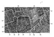
- FIG. 1is an exemplary color output mosaic image constructed in accordance with one embodiment of the present invention and formed from eleven separate source images.
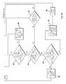
- FIG. 2Ais a flow chart illustrating an exemplary method for creating the output mosaic image in accordance with the present invention.
- FIG. 2Bis a continuation of the flow chart depicted in FIG. 2A .
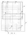
- FIG. 3is an illustration of an exemplary assignment map for the output mosaic image that has been marked with preferred routes for cutting the source images which has the effect of dividing the assignment map into one or more regions that are bounded by the preferred routes or the edge of the assignment map.
- FIG. 4is a diagrammatic view of the assignment map of FIG. 3 showing coverage of certain regions by three source images.
- FIG. 5is an exemplary color ground confidence map constructed in accordance with one embodiment of the present invention.
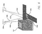
- FIG. 6is a schematic representation of capturing geo-referenced, color digital source images highlighting a plurality of kernels located on the ground of a geographic area.
- FIG. 7depicts exemplary color source images captured from different vantage points showing the plurality of kernels depicted in FIG. 6 .
- FIG. 8is an exemplary color pixel image of one of the kernels captured from the different vantage points in FIG. 6 .
- FIG. 9is an exemplary color pixel image of another kernel captured from the different vantage points in FIG. 6 .
- the presently claimed and disclosed invention(s)relate to mosaic images and methods for making and using the same. More particularly, the presently claimed and disclosed invention(s) use a methodology for automatically steering mosaic cut lines along preferred routes to form an output mosaic image whereby separately captured images (referred to hereinafter as “source images”) are automatically combined into at least one single mosaic image.
- the at least one single mosaic imageis visually pleasing and geographically accurate.
- the source imagesare preferably aerial images and can be either nadir images, orthogonal images, or oblique images.
- FIG. 10shown therein and designated by a reference numeral 10 is an exemplary output mosaic image constructed in accordance with one embodiment of the present invention and formed from contributing pixels of twelve separately captured geo-referenced source images, designated by reference numerals 16 a - 16 l .
- FIG. 1depicts the source images 16 as being primarily nadir (vertical) in their orientation, it should be understood that the source images 16 can be oriented in a variety of different ways, including, but not limited to, oblique and horizontal orientations.
- every pixel of the geo-referenced source images 16is associated with a geographic location of a point within the image.
- the source images 16can be geo-referenced utilizing any suitable technology.
- Shown on the output mosaic image 10are “preferred routes” 24 for “cutting” the source images 16 to form the output mosaic image 10 .
- the preferred routes 24are selected so as to minimize any adverse effects when transitioning between adjacent source images 16 .
- the preferred routes 24are selected in areas where there are no structures above or below the ground elevation model. This can be accomplished by placing the preferred route 24 down the middle of a street, or by using a ground confidence map as described below.
- the preferred routes 24are generated from street centerline information because streets are generally close to ground level, and do not normally run through vertical structures such as buildings or trees.
- the street centerlinescan be obtained, for example, from vector data files such as TIGER files or other Geographic Information System files. It should be understood that the preferred routes 24 can be generated from other sources besides street centerlines.
- the preferred routes 24 and transition lines 28are shown on the output mosaic image 10 of FIG. 1 for purposes of showing how the output mosaic image 10 was constructed. It should be understood that the preferred routes 24 and the transition lines 28 will not usually be shown in the output mosaic image 10 constructed in accordance with the present invention.
- FIGS. 2A and 2Bdepict a logic flow chart 30 of an automated cut line steering algorithm constructed in accordance with the present invention and stored on a computer readable medium.
- the automated cut line steering algorithmis adapted to execute on a computer system or systems and create the output mosaic image 10 preferably without any manual intervention.
- FIGS. 3 and 4cooperate to show certain steps in the formation of the output mosaic image 10 , and provide visual representations of the logic flow provided in FIGS. 2A and 2B .
- a desired areais selected to be represented by one or more output mosaic image(s) 10 .
- the desired areais preferably manually selected, although automated selection of the desired area is also contemplated.
- a number of output mosaic images 10 to represent the desired area or a size of each output mosaic image 10can be selected.
- the desired areacould be Los Angeles County, and the size of each output mosaic image 10 could be specified as one square mile.
- the automated cut line steering algorithmwould proceed to create an output mosaic image 10 for each square mile of Los Angeles County.
- the area to be represented by one or more output mosaic image(s) 10would be a specific geographical location. However, other areas can also be selected to be imaged into the output mosaic image 10 such as building sides, walls, landscapes, mountain sides and the like.
- the source images 16are obtained as indicated by block 36 .
- the source images 16can be obtained prior to selection of the desired area, stored on one or more computer readable medium and then accessed.
- the source images 16are preferably obtained utilizing one or more real cameras capturing the source images 16 of portions of the desired area and then geo-referenced as discussed above and optionally color-balanced.
- the output mosaic image 10is initially formed by creating an assignment map 41 corresponding to the output mosaic image 10 , as indicated by block 40 of FIG. 2A .
- An exemplary assignment map 41is shown in FIG. 3 .
- the assignment map 41is provided with output edges 42 surrounding an assignment area 43 with a plurality of pixels, denoted by the dashed lines and arranged in a rectilinear grid format covering the assignment area 43 .
- every pixel of the assignment map 41preferably has an initial designation of unassigned.
- pixels, such as each pixel, of the assignment map 41 that intersect a preferred route 24is marked as being a “preferred cut line pixel”, which has the effect of dividing the assignment map 41 into one or more regions 45 that are bounded by preferred cut line pixels 46 or the output edges 42 of the assignment map 41 .
- regions 45are depicted in FIG. 3 and labeled with the reference numerals 45 a - f .
- the remaining steps of the logic flow chart 30are to be performed on each region 45 .
- the preferred cut line pixels 46cover cut line areas represented by the preferred routes 24 and such cut line areas have a length and a width. It should be noted that the width of the preferred routes 24 can be varied depending upon design factors, such as the amount of feathering to be accomplished between the transitions from adjacent source images.
- a region 45is a contiguous set of pixels bounded by preferred cut line pixels 46 or the output edges 42 .
- the assignment map 41 depicted in FIG. 3the assignment map 41 is divided into six regions that are designated with the reference numerals 45 a - 45 f .
- the marking of the preferred routes 24can be accomplished in any suitable manner, such as by drawing a vector representation of the street centerlines onto the assignment map 41 thereby converting the vector representation of the street center lines into a raster representation.
- these preferred cut line pixels 46can be generated from raster form of data, such as by using those pixels in a ground confidence image whose ground confidence value meets or exceeds a particular threshold.
- FIG. 4shows the exemplary embodiment of the assignment map 41 of FIG. 3 with two overlapping source images (designated with reference numerals 16 l - 16 m ) assigned to a portion of the regions 45 .
- the overlapping source images 16 l - 16 mare depicted in FIG. 4 as being overlapping nadir source images 16 , it should be understood that the source images 16 can be in a variety of orientations, including, but not limited to, oblique and orthogonal and/or nadir orientations.
- the use of two source images 16 in FIG. 4is only to accentuate the overlapping assignment of source images 16 to the assignment map 41 .
- the number of sources images 16 used in the assignmentcan be of any number.
- one or more source images 16are preferably located in an orientation that allows the source images 16 to completely cover the region 45 , as indicated by branching decision block 56 .
- the ground location for the boundaries of the region 45is determined, which can then be used to ascertain and select which source images 16 contain image data for that particular identified ground location. This is generally done by checking to see if the ground location lies within the image boundaries of a previously captured source image 16 . In the example shown in FIG. 4 , source image 16 l completely covers the region 45 b , and the source image 16 m completely covers the regions 45 e and 45 f . If a source image 16 is not located that completely covers the one or more region 45 , then the automated cut line steering algorithm determines whether two or more of the source images 16 combine to completely cover the particular region 45 , as indicated by branching decision block 60 .
- a Selection Heuristic for quality of coveragecan optionally be utilized to determine which source image 16 to select for contributing pixels to the region 45 .
- a variety of Selection Heuristicscan be utilized and the following are discussed below by way of example.
- the Selection Heuristicscan be selected from the group comprising (1) which source image 16 is closest to nadir in the area covering the region 45 , (2) the first source image 16 located within a region 45 , (3) a source image 16 that covers the largest number of surrounding preferred cut line pixels 46 , and (4) a source image 16 that covers the largest number of other regions 45 .
- pixels in the region 45are designated as being assigned to particular pixels or groups of pixels of the selected source image 16 .
- the automated cut line steering algorithmdetermines whether two or more of the source images 16 combine to completely cover the particular region 45 which in the example shown are source images 16 l - m . If two or more source images 16 combine to cover the region 45 , then the automated cut line steering algorithm uses a Pairing Heuristic to attempt to enhance the quality of coverage of the region 45 as shown in block 76 .
- Pairing Heuristicscan be utilized and the following are discussed below by way of example. The following are examples of Pairing Heuristics that can be utilized.
- the relative orientation of the camera that captured the source images 16can be taken into account, e.g., in order to achieve a more desirable output mosaic image 10 , source images 16 that were captured in the same, or nearly the same, relative orientation of the virtual camera, in terms of oblique downward angle and compass direction of the optical axis will be more compatible.
- the type of cameracan also be taken into account when selecting source images 16 . That is, if the type of camera utilized the capture the source images 16 is radically different (for instance, a line scanner versus a full frame capture device), it may result in an undesirable resulting output mosaic image 10 .
- the automated cut-line steering algorithmthen designates particular parts of the source images 16 to the pixels in the assignment map 41 , as indicated in block 80 . This can be accomplished in a variety of manners and the following are examples of how this can be implemented.
- the preferred cut line pixels 46are then re-designated to match the source image 16 assignments of their bounded regions 45 . As will be discussed below, this can be accomplished in a variety of manners and the method utilized for such re-designation may be dependent on whether or not a single source image 16 covers adjacent regions 45 separated by the preferred cut line pixels 46 . The following are examples of how this can be accomplished.
- cut line areais only one pixel thick (as shown by way of example in FIGS. 3 and 4 ), assignment of cut line area could be combined with assignment of adjacent region 45 .
- the output mosaic image 10is created by contributing the designated or assigned pixel values to the output mosaic image 10 , as indicated by block 88 . This can be accomplished in a variety of manners and the following are merely examples of how this can be accomplished.
- the contribution of a source image 16 to a given mosaic pixelcould be determined using a nearest neighbor method, or based on averaging or interpolating source image 16 pixel values.
- a surface locationis preferably assigned to each pixel included in the assignment map 41 so that the output mosaic image 10 will be geo-referenced.
- the current inventionalso contemplates a method of cut-line steering by creating a ground confidence map 100 (shown in FIG. 5 ) of a geographic area.
- the ground confidence map 100shows which areas of the overlapping sources images 16 are representative of a ground location and which are not.
- the red areas 101are indicative of ground locations while the blacks pixels 102 are not.
- the cut line steering method utilizing the ground confidence map 100increases the statistical probability that preferred routes 24 used to transition between various source images 16 to form the output mosaic image 10 are located on the ground rather than on or through a three-dimensional object, such as, but not limited to, an automobile, building, or tree.
- kernel 104shown as 104 a and 104 b
- the kernels 104are shown as being circular in shape in FIGS. 5-9 , it should be understood that the kernels can be of any fanciful shape, including, but not limited to square, rectangular, ovular, or triangular.
- FIG. 6shown therein is a schematic diagram depicting the capturing of geo-referenced source images 16 from a plurality of different vantage points. While FIG. 6 shows the use of two cameras 105 a and 105 b for capturing the geo-referenced source images 16 from different vantage points, it should be understood that the capturing can be done from one or more camera(s) 108 as long as the camera(s) 108 capture(s) the source images 16 from a variety of different vantage points.
- the cameras 105 a and 105 butilize different vantage points 106 a , 106 b , 107 a , and 107 b to capture source images 16 that are associated with common kernels 104 a and 104 b . While the Figures indicate the identification of two kernels 104 a and 104 b , it should be understood that the invention contemplates the identification of at least one kernel 104 and is not limited to a specific number of kernels 104 identified within the source images 16 .
- FIG. 7shows two source images 16 which have been captured from two different vantage points.
- the kernel 104 aIn the source image 16 on the left, the kernel 104 a is represented on the roof of the building 112 , while in the source image 16 on the right, the kernel 104 a is represented on the ground and the pixels are very different in appearance. In contrast, the kernel 104 b in both source images is represented on the ground and the pixels within such kernel 104 b are similar in appearance. This has deleterious effects when establishing preferred routes 24 for combining source images 16 into an output mosaic image 10 as it is undesirable for the preferred routes 24 to run through the building 112 (or another three-dimensional structure).
- the present inventionis directed to solving this problem by creating the ground confidence map 100 in which the ground confidence is shown in FIG. 5 .
- each pixel of the ground confidence map 100can be assigned with a pixel value indicative of a ground confidence score by determining whether various points of overlapping portions of the source images 16 represent the same physical object. This can be accomplished by calculating a ground confidence score for pixel values of pixels located within the kernel 104 within the overlapping source images 16 corresponding to a particular geographic location of the pixel within the source images 16 .
- the kernel 104is a small matrix of pixels, usually no larger than 9 ⁇ 9, that is used as an operator during comparison of the overlapping source images 16 .
- the ground confidence scoreis indicated by analyzing the pixel score for each pixel located within kernel 104 to develop a composite pixel score. For example, the pixel scores can be summed or averaged to develop the composite pixel score for the kernel 104 .
- Pa[r′+i,c′+j]indicates the input image A pixel that is offset from the corresponding pixel Pa[r′,c′]
- Pb[r′′+i,c′′+j]indicates the input image A pixel that is offset from the corresponding pixel Pa[r′′,c′′].
- the size of the kernel 104(3 ⁇ 3, 3 ⁇ 4, 4 ⁇ 4, 5 ⁇ 5, 4 ⁇ 7, 12 ⁇ 14 or the like) determines how much of a pattern is looked at when determining how well the overlapping source images 16 for a particular pixel match.
- the larger the kernelthe more precise the pattern match will be.
- the larger the kernelthe longer the algorithm will take to run.
- the pixels of the geo-referenced overlapping source images 16may not be perfectly aligned, but are usually within one or two pixels of alignment.
- the above kernel algorithm(Equation 2) is run on the direct corresponding pixel and also on nearby surrounding pixels, for example, within 1-3 pixels of the direct corresponding pixel. Pixels that represent ground locations will usually only be offset by one or two pixels.
- pixels that represent structures that are above the groundwill be offset by a significant number of pixels, or will be occluded, and either way, will not get a good match, and therefore a bad ground confidence score, since they will either be two different features (when occluded) or will be two different parts of features (when they are too far away to test the same point in each).
- the kernel algorithm of Equation 2is run on the direct corresponding pixel and also on nearby surrounding pixels and the pixel score for each run of the kernel algorithm is initially stored, and then the initially stored pixel scores are compared to determine the best score.
- the best scorewill be the lowest score.
- Equation 2can be modified to make the best score the highest score.
- the direct corresponding pixelis found by calculating the geographic location of the pixel in the ground confidence map 100 that a ground confidence score (using the origin and pixel size formulas from early on) is being generated for and then determining which pixel(s) that location corresponds to in the overlapping source images 16 , using the projective equations of the source images 16 .
- the resulting row and column calculatedmay not correspond to the actual location, which is why the surrounding pixels are checked as well. This is typically done in a 1-pixel or 2-pixel radius from the corresponding pixel location. This radius needs to be large enough to account for the most common pixel location error. However, the larger the radius, the more computer time is necessary. In addition, if too large of a radius is used, then it will start to match for some things off the ground by a small amount, such as automobiles or one-story buildings.
- FIG. 8depicts a blown up portion 114 of the source images 16 within the kernel 104 a taken from vantage point 106 a of camera 105 a and vantage point 107 a of camera 105 b .
- Each pixel within the kernel 104 ahas a composite pixel score calculated in accordance with Equation 2 above.
- a comparison of the pixels and composite pixel scores located within the kernel 104 areveals that, depending on which vantage point ( 106 a or 107 a ) captured the source image 16 , the pixels are associated with substantially different colors and thus pixel values.
- this difference in coloris indicative that, while the geo-referenced location of the pixels are the same within the identified kernel 104 a , the same object is not being captured or represented within each source image 16 .
- the difference in coloris due to the camera 105 a capturing the roof of the building 112 with vantage point 106 a rather than the ground as initially projected.
- the ground confidence score for the kernel 104 aindicates that the pixels of both source images 16 within the kernel 104 a do not represent the ground. Consequently, the pixel in the ground confidence map 100 would not be a viable candidate for designating as preferred routes 24 , as the statistical probability of cutting through a three-dimensional object, such as building 112 , are elevated as indicated by the difference in colors of the pixels based on variance of the pixel scores.
- FIG. 9depicts a pixel image 116 of a plurality of pixels located within kernel 104 b taken from vantage point 106 b of camera 105 a and vantage point 107 b of camera 105 b .
- a comparison of the pixels associated with kernel 104 b utilizing Equation 2indicate that such pixels represent the ground. This can be discerned by similarity in pixel scores and colors of the pixels within kernel 104 b . Consequently, the pixel in the ground confidence map representing the center of the kernel 104 b is a viable candidate for being designated as a preferred route 24 as the statistical probability of cutting through a three-dimensional object, such as the building 112 , is minimal.
- An important aspect of the inventionis the setting of a threshold value which is an acceptable margin of error associated with the composite pixel scores of pixels within a particular kernel 104 . While the capturing of source images 16 is extremely precise, the capturing is not exact. It is preferable to create a threshold value for comparing the composite pixel scores, in which the composite pixel scores will be considered similar assuming the pixel does not deviate either above or below the pre-determined threshold value.
- each pixelis marked in the ground confidence map 100 by storing a pixel value indicative of the ground confidence score calculated for the particular pixel.
- the one or more assignment maps 41 , ground confidence maps 100 , and output mosaic image(s) 10 and its corresponding dataare then stored on one or more computer readable medium.
- the one or more assignment maps 41 , ground confidence maps 100 , and output mosaic image 10can be stored in any format, including one of many industry standard image formats such as TIFF, JFIF, TARGA, Windows Bitmap File, PNG or any other industry standard format.
- the georeferencing information about the output mosaic image 10might also be stored, either in a separate georeferencing file, such as an ESRI World File, or in the same file.
- the georeferencing informationcan be stored in the same file through use of metadata tags within the file format, such as the industry standard GeoTIFF tags used in the standard TIFF format.
- the logic embodied in the form of software instructions or firmware for steering the cut-lines or creating the ground confidence map 100may be executed on any appropriate hardware which may be a dedicated system or systems, or a general purpose computer system, or distributed processing computer system, all of which are well understood in the art, and a detailed description of how to make or use such computers is not deemed necessary herein.
- any appropriate hardwaremay be a dedicated system or systems, or a general purpose computer system, or distributed processing computer system, all of which are well understood in the art, and a detailed description of how to make or use such computers is not deemed necessary herein.
- the computer(s) and/or executioncan be conducted at a same geographic location or multiple different geographic locations.
- the execution of the logiccan be conducted continuously or at multiple discrete times. Further, such logic can be performed about simultaneously with the capture of the images, or thereafter or combinations thereof.
Landscapes
- Engineering & Computer Science (AREA)
- Physics & Mathematics (AREA)
- General Physics & Mathematics (AREA)
- Theoretical Computer Science (AREA)
- Computer Vision & Pattern Recognition (AREA)
- Multimedia (AREA)
- Radar, Positioning & Navigation (AREA)
- Remote Sensing (AREA)
- Image Processing (AREA)
Abstract
Description
- 1. Captured Imagery—these images have the appearance they were captured by the camera or sensor employed.
- 2. Projected Imagery—these images have been processed and converted such that they conform to a mathematical projection.
- A rectilinear grid is created, which results in an ortho-mosaic image where every grid pixel covers the same amount of area on the ground.
- The location of each grid pixel is determined from the mathematical definition of the grid. Generally, this means the grid is given an X and Y starting or origin location and an X and Y size for the grid pixels. Thus, the location of any pixel is simply the origin location plus the number of pixels times the size of each pixel. In mathematical terms: Xpixel=Xorigin+Xsize×Columnpixeland Ypixel=Yorigin+Ysize×ROWpixel.
- The available nadir images are checked to see if they cover the same point on the ground as the grid pixel being filled. If so, a mathematical formula is used to determine where that point on the ground projects up onto the camera's pixel image map and that resulting pixel value is then transferred to the grid pixel. During this selection process, two important steps are taken:
- When selecting the image to use to provide the pixel value, a mathematical formula is used to select an image that minimizes building lean—the effect where buildings appear to lean away from the camera. This is accomplished in a number of ways, but the most common is to pick the image where the grid pixel reprojects as close to the camera center, and hence as close to that camera's nadir point, as possible.
- When determining the source pixel value to use, the ground elevation is taken into account to ensure the correct pixel value is selected. Changes in elevation cause the apparent location of the pixel to shift when captured by the camera. A point on the ground that is higher up will appear farther from the center of the image than a point on the ground in the same location that is lower down. For instance, the top of a building will appear farther from the center of an image than the bottom of a building. By taking the ground elevation into account when determining the source pixel value, the net effect is to “flatten” the image out such that changes in pixel location due to ground elevation are removed.
- If the oblique perspective is to be maintained, the pixels cannot be aligned to a rectilinear grid, or even a trapezoidal grid. Instead, the pixels are preferably aligned to the natural perspective that a camera captures.
- As part of the oblique perspective, the pixels in the image cannot all measure the same size on the ground, as pixels in the foreground of the image cover a much smaller area on the ground than pixels in the background of the image—that is by definition part of the natural perspective of a camera.
- Because the pixels are so far from nadir, the effects of building lean become extreme and the standard solutions employed in the ortho-mosaic process do not do an adequate enough job compensating for this effect—new techniques must be developed to better compensate for this effect.
- If the effects of changes in elevation are backed out, the resulting image has a very unnatural appearance—the vertical sides of buildings can warp and twist, which is something we are not accustomed to seeing and therefore, when looking at such an image, we have a tendency to “reject” it. Thus, to keep the buildings, structures, and objects within an image looking natural, it is preferable to leave the effects of elevation in the perspective of the image and instead account for it in another manner.
Ps=|Pa−Pb|/(Pa+Pb) (1)
where Psis the pixel score associated with a pixel located within the kernel104, Pais the pixel value of a pixel located within the kernel104 captured by
Where Σ denotes summation,
r=row number, c=column number,
Ps[r,c] indicates the pixel score at that particular row and column
Pa[r′,c′] indicates the input image A pixel that corresponds to the location of Ps[r,c],
Pb[r″,c″] indicates the input image B pixel that corresponds to the location of Ps[r,c],
Note that r !=r′ !=r″ and c !=c′ !=c″ (!=means not equals) but that all three locations [r,c], [r′,c′] and [r″,c″] map to the same location in the assignment map.
Pa[r′+i,c′+j] indicates the input image A pixel that is offset from the corresponding pixel Pa[r′,c′]
Pb[r″+i,c″+j] indicates the input image A pixel that is offset from the corresponding pixel Pa[r″,c″].
Claims (6)
Priority Applications (4)
| Application Number | Priority Date | Filing Date | Title |
|---|---|---|---|
| US14/829,105US9898802B2 (en) | 2008-08-05 | 2015-08-18 | Cut line steering methods for forming a mosaic image of a geographical area |
| US15/897,997US10424047B2 (en) | 2008-08-05 | 2018-02-15 | Cut line steering methods for forming a mosaic image of a geographical area |
| US16/577,806US10839484B2 (en) | 2008-08-05 | 2019-09-20 | Cut-line steering methods for forming a mosaic image of a geographical area |
| US17/095,407US11551331B2 (en) | 2008-08-05 | 2020-11-11 | Cut-line steering methods for forming a mosaic image of a geographical area |
Applications Claiming Priority (3)
| Application Number | Priority Date | Filing Date | Title |
|---|---|---|---|
| US12/221,571US8588547B2 (en) | 2008-08-05 | 2008-08-05 | Cut-line steering methods for forming a mosaic image of a geographical area |
| US14/045,460US9147276B2 (en) | 2008-08-05 | 2013-10-03 | Cut line steering methods for forming a mosaic image of a geographical area |
| US14/829,105US9898802B2 (en) | 2008-08-05 | 2015-08-18 | Cut line steering methods for forming a mosaic image of a geographical area |
Related Parent Applications (1)
| Application Number | Title | Priority Date | Filing Date |
|---|---|---|---|
| US14/045,460ContinuationUS9147276B2 (en) | 2008-08-05 | 2013-10-03 | Cut line steering methods for forming a mosaic image of a geographical area |
Related Child Applications (1)
| Application Number | Title | Priority Date | Filing Date |
|---|---|---|---|
| US15/897,997ContinuationUS10424047B2 (en) | 2008-08-05 | 2018-02-15 | Cut line steering methods for forming a mosaic image of a geographical area |
Publications (2)
| Publication Number | Publication Date |
|---|---|
| US20160071239A1 US20160071239A1 (en) | 2016-03-10 |
| US9898802B2true US9898802B2 (en) | 2018-02-20 |
Family
ID=41653042
Family Applications (7)
| Application Number | Title | Priority Date | Filing Date |
|---|---|---|---|
| US12/221,571Active2032-03-13US8588547B2 (en) | 2008-08-05 | 2008-08-05 | Cut-line steering methods for forming a mosaic image of a geographical area |
| US13/787,417ActiveUS8630510B2 (en) | 2008-08-05 | 2013-03-06 | Cut-line steering methods for forming a mosaic image of a geographical area |
| US14/045,460Active2028-11-27US9147276B2 (en) | 2008-08-05 | 2013-10-03 | Cut line steering methods for forming a mosaic image of a geographical area |
| US14/829,105ActiveUS9898802B2 (en) | 2008-08-05 | 2015-08-18 | Cut line steering methods for forming a mosaic image of a geographical area |
| US15/897,997ActiveUS10424047B2 (en) | 2008-08-05 | 2018-02-15 | Cut line steering methods for forming a mosaic image of a geographical area |
| US16/577,806ActiveUS10839484B2 (en) | 2008-08-05 | 2019-09-20 | Cut-line steering methods for forming a mosaic image of a geographical area |
| US17/095,407Active2029-04-13US11551331B2 (en) | 2008-08-05 | 2020-11-11 | Cut-line steering methods for forming a mosaic image of a geographical area |
Family Applications Before (3)
| Application Number | Title | Priority Date | Filing Date |
|---|---|---|---|
| US12/221,571Active2032-03-13US8588547B2 (en) | 2008-08-05 | 2008-08-05 | Cut-line steering methods for forming a mosaic image of a geographical area |
| US13/787,417ActiveUS8630510B2 (en) | 2008-08-05 | 2013-03-06 | Cut-line steering methods for forming a mosaic image of a geographical area |
| US14/045,460Active2028-11-27US9147276B2 (en) | 2008-08-05 | 2013-10-03 | Cut line steering methods for forming a mosaic image of a geographical area |
Family Applications After (3)
| Application Number | Title | Priority Date | Filing Date |
|---|---|---|---|
| US15/897,997ActiveUS10424047B2 (en) | 2008-08-05 | 2018-02-15 | Cut line steering methods for forming a mosaic image of a geographical area |
| US16/577,806ActiveUS10839484B2 (en) | 2008-08-05 | 2019-09-20 | Cut-line steering methods for forming a mosaic image of a geographical area |
| US17/095,407Active2029-04-13US11551331B2 (en) | 2008-08-05 | 2020-11-11 | Cut-line steering methods for forming a mosaic image of a geographical area |
Country Status (4)
| Country | Link |
|---|---|
| US (7) | US8588547B2 (en) |
| EP (1) | EP2321792B1 (en) |
| ES (1) | ES2788687T3 (en) |
| WO (1) | WO2010017255A2 (en) |
Cited By (8)
| Publication number | Priority date | Publication date | Assignee | Title |
|---|---|---|---|---|
| US10733443B2 (en) | 2018-08-24 | 2020-08-04 | Loveland Innovations, LLC | Image analysis and estimation of rooftop solar exposure |
| US10810426B2 (en) | 2016-11-04 | 2020-10-20 | Loveland Innovations, LLC | Systems and methods for autonomous perpendicular imaging of test squares |
| US10825346B2 (en) | 2016-11-04 | 2020-11-03 | Loveland Innovations, LLC | Systems and methods for adaptive property analysis via autonomous vehicles |
| US10984182B2 (en) | 2017-05-12 | 2021-04-20 | Loveland Innovations, LLC | Systems and methods for context-rich annotation and report generation for UAV microscan data |
| US11097841B2 (en) | 2017-10-24 | 2021-08-24 | Loveland Innovations, LLC | Crisscross boustrophedonic flight patterns for UAV scanning and imaging |
| US11205072B2 (en) | 2018-08-24 | 2021-12-21 | Loveland Innovations, LLC | Solar ray mapping via divergent beam modeling |
| US11210514B2 (en) | 2018-08-24 | 2021-12-28 | Loveland Innovations, LLC | Image analysis and estimation of rooftop solar exposure via solar ray mapping |
| US11532116B2 (en) | 2020-10-30 | 2022-12-20 | Loveland Innovations, Inc. | Graphical user interface for controlling a solar ray mapping |
Families Citing this family (82)
| Publication number | Priority date | Publication date | Assignee | Title |
|---|---|---|---|---|
| US7640105B2 (en)* | 2007-03-13 | 2009-12-29 | Certus View Technologies, LLC | Marking system and method with location and/or time tracking |
| US8078436B2 (en) | 2007-04-17 | 2011-12-13 | Eagle View Technologies, Inc. | Aerial roof estimation systems and methods |
| US8145578B2 (en) | 2007-04-17 | 2012-03-27 | Eagel View Technologies, Inc. | Aerial roof estimation system and method |
| US9659268B2 (en)* | 2008-02-12 | 2017-05-23 | CertusVies Technologies, LLC | Ticket approval system for and method of performing quality control in field service applications |
| US9208464B2 (en)* | 2008-10-02 | 2015-12-08 | Certusview Technologies, Llc | Methods and apparatus for analyzing locate and marking operations with respect to historical information |
| US9473626B2 (en) | 2008-06-27 | 2016-10-18 | Certusview Technologies, Llc | Apparatus and methods for evaluating a quality of a locate operation for underground utility |
| US20090327024A1 (en)* | 2008-06-27 | 2009-12-31 | Certusview Technologies, Llc | Methods and apparatus for quality assessment of a field service operation |
| US8612271B2 (en) | 2008-10-02 | 2013-12-17 | Certusview Technologies, Llc | Methods and apparatus for analyzing locate and marking operations with respect to environmental landmarks |
| US9208458B2 (en)* | 2008-10-02 | 2015-12-08 | Certusview Technologies, Llc | Methods and apparatus for analyzing locate and marking operations with respect to facilities maps |
| US8620726B2 (en)* | 2008-10-02 | 2013-12-31 | Certusview Technologies, Llc | Methods and apparatus for analyzing locate and marking operations by comparing locate information and marking information |
| US8644965B2 (en) | 2008-10-02 | 2014-02-04 | Certusview Technologies, Llc | Marking device docking stations having security features and methods of using same |
| US8209152B2 (en) | 2008-10-31 | 2012-06-26 | Eagleview Technologies, Inc. | Concurrent display systems and methods for aerial roof estimation |
| US8170840B2 (en) | 2008-10-31 | 2012-05-01 | Eagle View Technologies, Inc. | Pitch determination systems and methods for aerial roof estimation |
| US8731234B1 (en) | 2008-10-31 | 2014-05-20 | Eagle View Technologies, Inc. | Automated roof identification systems and methods |
| CA2691780C (en)* | 2009-02-11 | 2015-09-22 | Certusview Technologies, Llc | Management system, and associated methods and apparatus, for providing automatic assesment of a locate operation |
| AU2011210538B2 (en) | 2010-02-01 | 2015-03-26 | Eagle View Technologies, Inc. | Geometric correction of rough wireframe models derived from photographs |
| EP2726937B1 (en)* | 2011-06-30 | 2019-01-23 | Nokia Technologies Oy | Method, apparatus and computer program product for generating panorama images |
| EP2786290B1 (en) | 2011-11-29 | 2018-04-18 | Pictometry International Corp. | System for automatic structure footprint detection from oblique imagery |
| US12140419B2 (en) | 2012-02-03 | 2024-11-12 | Eagle View Technologies, Inc. | Systems and methods for estimation of building wall area and producing a wall estimation report |
| US9599466B2 (en) | 2012-02-03 | 2017-03-21 | Eagle View Technologies, Inc. | Systems and methods for estimation of building wall area |
| US8774525B2 (en) | 2012-02-03 | 2014-07-08 | Eagle View Technologies, Inc. | Systems and methods for estimation of building floor area |
| US10515414B2 (en) | 2012-02-03 | 2019-12-24 | Eagle View Technologies, Inc. | Systems and methods for performing a risk management assessment of a property |
| US9933257B2 (en) | 2012-02-03 | 2018-04-03 | Eagle View Technologies, Inc. | Systems and methods for estimation of building wall area |
| US10663294B2 (en) | 2012-02-03 | 2020-05-26 | Eagle View Technologies, Inc. | Systems and methods for estimation of building wall area and producing a wall estimation report |
| US9501700B2 (en) | 2012-02-15 | 2016-11-22 | Xactware Solutions, Inc. | System and method for construction estimation using aerial images |
| US8774470B1 (en)* | 2012-04-03 | 2014-07-08 | Google Inc. | Processing a satellite image of a region to determine a terrain boundary included therein |
| US8938094B1 (en) | 2012-04-13 | 2015-01-20 | Google Inc. | Generating a road network based on satellite imagery |
| USD712421S1 (en)* | 2012-06-06 | 2014-09-02 | Apple Inc. | Display screen or portion thereof with graphical user interface |
| CN104428815B (en)* | 2012-07-13 | 2017-05-31 | 富士胶片株式会社 | Anamorphose device and its method of controlling operation |
| US8817339B2 (en)* | 2012-08-22 | 2014-08-26 | Top Image Systems Ltd. | Handheld device document imaging |
| US9141880B2 (en)* | 2012-10-05 | 2015-09-22 | Eagle View Technologies, Inc. | Systems and methods for relating images to each other by determining transforms without using image acquisition metadata |
| US9811880B2 (en)* | 2012-11-09 | 2017-11-07 | The Boeing Company | Backfilling points in a point cloud |
| US9147287B2 (en) | 2013-01-31 | 2015-09-29 | Eagle View Technologies, Inc. | Statistical point pattern matching technique |
| US9159164B2 (en) | 2013-01-31 | 2015-10-13 | Eagle View Technologies, Inc. | Statistical point pattern matching technique |
| US9959581B2 (en) | 2013-03-15 | 2018-05-01 | Eagle View Technologies, Inc. | Property management on a smartphone |
| US9058673B2 (en)* | 2013-03-15 | 2015-06-16 | Oracle International Corporation | Image mosaicking using a virtual grid |
| US10909482B2 (en) | 2013-03-15 | 2021-02-02 | Pictometry International Corp. | Building materials estimation |
| US9042674B2 (en)* | 2013-03-15 | 2015-05-26 | Digitalglobe, Inc. | Automated geospatial image mosaic generation |
| US11587176B2 (en) | 2013-03-15 | 2023-02-21 | Eagle View Technologies, Inc. | Price estimation model |
| CN103324948B (en)* | 2013-07-01 | 2016-04-27 | 武汉大学 | The sane matching process of a kind of low altitude remote sensing image based on line features |
| US9031325B2 (en)* | 2013-07-19 | 2015-05-12 | Digitalglobe, Inc. | Automatic extraction of built-up footprints from high resolution overhead imagery through manipulation of alpha-tree data structures |
| EP3028464B1 (en) | 2013-08-02 | 2019-05-01 | Xactware Solutions Inc. | System and method for detecting features in aerial images using disparity mapping and segmentation techniques |
| US9311720B2 (en) | 2013-11-26 | 2016-04-12 | Saudi Arabian Oil Company | Automated saw cut correction for 3D core digital modeling from computerized tomography scanner (CTS) images |
| AU2015204838B2 (en) | 2014-01-10 | 2020-01-02 | Pictometry International Corp. | Unmanned aircraft structure evaluation system and method |
| US9367895B2 (en) | 2014-03-19 | 2016-06-14 | Digitalglobe, Inc. | Automated sliver removal in orthomosaic generation |
| US9430839B2 (en)* | 2014-03-31 | 2016-08-30 | Regents Of The University Of Minnesota | Unsupervised framework to monitor lake dynamics |
| US9589334B2 (en)* | 2014-05-08 | 2017-03-07 | Digitalglobe, Inc. | Automated tonal balancing |
| US9619711B2 (en)* | 2014-09-29 | 2017-04-11 | Digitalglobe, Inc. | Multi-spectral image labeling with radiometric attribute vectors of image space representation components |
| US9460517B2 (en) | 2014-10-22 | 2016-10-04 | Pointivo, Inc | Photogrammetric methods and devices related thereto |
| US9805061B2 (en)* | 2014-11-18 | 2017-10-31 | International Business Machines Corporation | Image search for a location |
| WO2016198929A1 (en)* | 2015-06-12 | 2016-12-15 | Mathur Ashok Chand | Method and apparatus of very much faster 3d printer |
| US10482848B2 (en)* | 2015-08-07 | 2019-11-19 | International Business Machines Corporation | Facile and precise georeferencing and overlaying of map tiles |
| US10593074B1 (en)* | 2016-03-16 | 2020-03-17 | Liberty Mutual Insurance Company | Interactive user interface for displaying geographic boundaries |
| US10628802B2 (en) | 2016-05-19 | 2020-04-21 | Lockheed Martin Corporation | Systems and methods for assessing damage to infrastructure assets |
| US10032267B2 (en) | 2016-06-09 | 2018-07-24 | Lockheed Martin Corporation | Automating the assessment of damage to infrastructure assets |
| CN106339985B (en)* | 2016-08-29 | 2019-03-15 | 中国科学院地理科学与资源研究所 | A Method for Mosaic of Aerial Image Mosaic by Mosaic Lines from Vector Housing Data |
| US10521694B2 (en)* | 2016-09-09 | 2019-12-31 | The Chinese University Of Hong Kong | 3D building extraction apparatus, method and system |
| US11480438B2 (en)* | 2016-10-07 | 2022-10-25 | Google Llc | Identifying and displaying smooth and demarked paths |
| US10137945B2 (en) | 2016-11-30 | 2018-11-27 | Xstream Trucking Inc. | Deployable fairing for use with vehicles |
| US10217232B2 (en) | 2017-02-08 | 2019-02-26 | Toyota Motor Engineering & Manufacturing North America, Inc. | Systems and methods for locally aligning map data |
| CN106895825B (en)* | 2017-02-23 | 2019-06-11 | 周良辰 | The three-dimensional amount of geographic position of target object based on streetscape map calculates method and apparatus |
| CN107945196B (en)* | 2017-12-15 | 2021-07-06 | 大连理工大学 | A kind of image edge detection method used for aerial photo correction image stitching |
| US10503843B2 (en) | 2017-12-19 | 2019-12-10 | Eagle View Technologies, Inc. | Supervised automatic roof modeling |
| JP6935847B2 (en)* | 2018-05-08 | 2021-09-15 | 日本電気株式会社 | Synthetic Aperture Radar Image Analysis System, Synthetic Aperture Radar Image Analysis Method and Synthetic Aperture Radar Image Analysis Program |
| CN109271919B (en)* | 2018-09-12 | 2022-11-01 | 海南省海洋与渔业科学院 | Vegetation coverage measuring method based on grb and grid mode |
| CN109658446B (en)* | 2018-10-30 | 2023-04-07 | 武汉珈和科技有限公司 | Geometric registration method and device for high-resolution remote sensing image |
| WO2020106984A1 (en) | 2018-11-21 | 2020-05-28 | Eagle View Technologies, Inc. | Navigating unmanned aircraft using pitch |
| US11396334B2 (en) | 2019-03-06 | 2022-07-26 | Trucklabs, Inc. | Deployable fairing system for use with vehicles |
| US11427267B2 (en) | 2019-03-06 | 2022-08-30 | Trucklabs, Inc. | Deployable fairing system for use with vehicles |
| CN109934914B (en)* | 2019-03-28 | 2023-05-16 | 东南大学 | Embedded city design scene simulation method and system |
| USD949159S1 (en) | 2019-06-02 | 2022-04-19 | Apple Inc. | Display screen or portion thereof with graphical user interface |
| CN110503604B (en)* | 2019-07-31 | 2022-04-29 | 武汉大学 | A Real-time Ortho-Mosaic Method of Aerial Area Array Image Based on High-precision POS |
| US11094113B2 (en) | 2019-12-04 | 2021-08-17 | Geomni, Inc. | Systems and methods for modeling structures using point clouds derived from stereoscopic image pairs |
| WO2021226143A1 (en) | 2020-05-04 | 2021-11-11 | Xstream Trucking Inc. | Aerodynamic system for vehicles and methods for operating the same |
| WO2022125787A1 (en)* | 2020-12-09 | 2022-06-16 | Zesty.Ai, Inc. | Determining 3d structure features from dsm data |
| CN112561938B (en)* | 2020-12-22 | 2024-01-19 | 陕西理工大学 | Computer image processing method |
| CN114708354B (en)* | 2022-03-04 | 2023-06-23 | 广东省国土资源测绘院 | Method, equipment, medium and product for drawing embedded line |
| US12310274B1 (en)* | 2022-04-07 | 2025-05-27 | Sentera, Inc. | Precision agriculture using pose georeferenced analytics |
| CN114577191B (en)* | 2022-05-06 | 2022-07-12 | 成都纵横通达信息工程有限公司 | Surveying and mapping data acquisition method and system based on geospatial information data |
| US12360286B2 (en) | 2022-10-14 | 2025-07-15 | Zesty.Ai, Inc. | Hail predictions using artificial intelligence |
| US12360287B2 (en) | 2022-10-14 | 2025-07-15 | Zesty.Ai, Inc. | Hail frequency predictions using artificial intelligence |
| CN118279137B (en)* | 2024-04-30 | 2024-12-20 | 广州市鑫广飞信息科技有限公司 | Aerial image stitching method and device, terminal equipment and storage medium |
Citations (173)
| Publication number | Priority date | Publication date | Assignee | Title |
|---|---|---|---|---|
| US2273876A (en) | 1940-02-12 | 1942-02-24 | Frederick W Lutz | Apparatus for indicating tilt of cameras |
| US3153784A (en) | 1959-12-24 | 1964-10-20 | Us Industries Inc | Photo radar ground contour mapping system |
| US3594556A (en) | 1969-01-08 | 1971-07-20 | Us Navy | Optical sight with electronic image stabilization |
| US3614410A (en) | 1969-06-12 | 1971-10-19 | Knight V Bailey | Image rectifier |
| US3621326A (en) | 1968-09-30 | 1971-11-16 | Itek Corp | Transformation system |
| US3661061A (en) | 1969-05-05 | 1972-05-09 | Atomic Energy Commission | Picture position finder |
| US3716669A (en) | 1971-05-14 | 1973-02-13 | Japan Eng Dev Co | Mapping rectifier for generating polarstereographic maps from satellite scan signals |
| US3725563A (en) | 1971-12-23 | 1973-04-03 | Singer Co | Method of perspective transformation in scanned raster visual display |
| US3864513A (en) | 1972-09-11 | 1975-02-04 | Grumman Aerospace Corp | Computerized polarimetric terrain mapping system |
| US3866602A (en) | 1973-05-29 | 1975-02-18 | Olympus Optical Co | Endoscope camera with orientation indicator |
| US3877799A (en) | 1974-02-06 | 1975-04-15 | United Kingdom Government | Method of recording the first frame in a time index system |
| US4015080A (en) | 1973-04-30 | 1977-03-29 | Elliott Brothers (London) Limited | Display devices |
| US4044879A (en) | 1975-03-07 | 1977-08-30 | Siemens Aktiengesellschaft | Arrangement for recording characters using mosaic recording mechanisms |
| US4184711A (en) | 1977-10-14 | 1980-01-22 | Yasuo Wakimoto | Folding canvas chair |
| US4240108A (en) | 1977-10-03 | 1980-12-16 | Grumman Aerospace Corporation | Vehicle controlled raster display system |
| US4281354A (en) | 1978-05-19 | 1981-07-28 | Raffaele Conte | Apparatus for magnetic recording of casual events relating to movable means |
| US4344683A (en) | 1979-09-29 | 1982-08-17 | Agfa-Gevaert Aktiengesellschaft | Quality control method and apparatus for photographic pictures |
| US4360876A (en) | 1979-07-06 | 1982-11-23 | Thomson-Csf | Cartographic indicator system |
| US4382678A (en) | 1981-06-29 | 1983-05-10 | The United States Of America As Represented By The Secretary Of The Army | Measuring of feature for photo interpretation |
| US4387056A (en) | 1981-04-16 | 1983-06-07 | E. I. Du Pont De Nemours And Company | Process for separating zero-valent nickel species from divalent nickel species |
| US4396942A (en) | 1979-04-19 | 1983-08-02 | Jackson Gates | Video surveys |
| US4463380A (en) | 1981-09-25 | 1984-07-31 | Vought Corporation | Image processing system |
| US4489322A (en) | 1983-01-27 | 1984-12-18 | The United States Of America As Represented By The Secretary Of The Air Force | Radar calibration using direct measurement equipment and oblique photometry |
| US4490742A (en) | 1982-04-23 | 1984-12-25 | Vcs, Incorporated | Encoding apparatus for a closed circuit television system |
| US4491399A (en) | 1982-09-27 | 1985-01-01 | Coherent Communications, Inc. | Method and apparatus for recording a digital signal on motion picture film |
| US4495500A (en) | 1982-01-26 | 1985-01-22 | Sri International | Topographic data gathering method |
| US4527055A (en) | 1982-11-15 | 1985-07-02 | Honeywell Inc. | Apparatus for selectively viewing either of two scenes of interest |
| US4543603A (en) | 1982-11-30 | 1985-09-24 | Societe Nationale Industrielle Et Aerospatiale | Reconnaissance system comprising an air-borne vehicle rotating about its longitudinal axis |
| US4586138A (en) | 1982-07-29 | 1986-04-29 | The United States Of America As Represented By The United States Department Of Energy | Route profile analysis system and method |
| US4635136A (en) | 1984-02-06 | 1987-01-06 | Rochester Institute Of Technology | Method and apparatus for storing a massive inventory of labeled images |
| US4653316A (en) | 1986-03-14 | 1987-03-31 | Kabushiki Kaisha Komatsu Seisakusho | Apparatus mounted on vehicles for detecting road surface conditions |
| US4653136A (en) | 1985-06-21 | 1987-03-31 | Denison James W | Wiper for rear view mirror |
| US4673988A (en) | 1985-04-22 | 1987-06-16 | E.I. Du Pont De Nemours And Company | Electronic mosaic imaging process |
| US4686474A (en) | 1984-04-05 | 1987-08-11 | Deseret Research, Inc. | Survey system for collection and real time processing of geophysical data |
| US4688092A (en) | 1986-05-06 | 1987-08-18 | Ford Aerospace & Communications Corporation | Satellite camera image navigation |
| US4689748A (en) | 1979-10-09 | 1987-08-25 | Messerschmitt-Bolkow-Blohm Gesellschaft Mit Beschrankter Haftung | Device for aircraft and spacecraft for producing a digital terrain representation |
| US4707698A (en) | 1976-03-04 | 1987-11-17 | Constant James N | Coordinate measurement and radar device using image scanner |
| US4758850A (en) | 1985-08-01 | 1988-07-19 | British Aerospace Public Limited Company | Identification of ground targets in airborne surveillance radar returns |
| US4805033A (en) | 1987-02-18 | 1989-02-14 | Olympus Optical Co., Ltd. | Method of forming oblique dot pattern |
| US4807024A (en) | 1987-06-08 | 1989-02-21 | The University Of South Carolina | Three-dimensional display methods and apparatus |
| US4814711A (en) | 1984-04-05 | 1989-03-21 | Deseret Research, Inc. | Survey system and method for real time collection and processing of geophysicals data using signals from a global positioning satellite network |
| US4814896A (en) | 1987-03-06 | 1989-03-21 | Heitzman Edward F | Real time video data acquistion systems |
| US4843463A (en) | 1988-05-23 | 1989-06-27 | Michetti Joseph A | Land vehicle mounted audio-visual trip recorder |
| US4899296A (en) | 1987-11-13 | 1990-02-06 | Khattak Anwar S | Pavement distress survey system |
| US4906198A (en) | 1988-12-12 | 1990-03-06 | International Business Machines Corporation | Circuit board assembly and contact pin for use therein |
| US4953227A (en) | 1986-01-31 | 1990-08-28 | Canon Kabushiki Kaisha | Image mosaic-processing method and apparatus |
| US4956872A (en) | 1986-10-31 | 1990-09-11 | Canon Kabushiki Kaisha | Image processing apparatus capable of random mosaic and/or oil-painting-like processing |
| US5034812A (en) | 1988-11-14 | 1991-07-23 | Smiths Industries Public Limited Company | Image processing utilizing an object data store to determine information about a viewed object |
| US5086314A (en) | 1990-05-21 | 1992-02-04 | Nikon Corporation | Exposure control apparatus for camera |
| US5121222A (en) | 1989-06-14 | 1992-06-09 | Toshiaki Endoh | Method and apparatus for producing binary picture with detection and retention of plural binary picture blocks having a thin line pattern including an oblique line |
| US5138444A (en) | 1991-09-05 | 1992-08-11 | Nec Corporation | Image pickup system capable of producing correct image signals of an object zone |
| US5155597A (en) | 1990-11-28 | 1992-10-13 | Recon/Optical, Inc. | Electro-optical imaging array with motion compensation |
| US5164825A (en) | 1987-03-30 | 1992-11-17 | Canon Kabushiki Kaisha | Image processing method and apparatus for mosaic or similar processing therefor |
| US5166789A (en) | 1989-08-25 | 1992-11-24 | Space Island Products & Services, Inc. | Geographical surveying using cameras in combination with flight computers to obtain images with overlaid geographical coordinates |
| US5187754A (en) | 1991-04-30 | 1993-02-16 | General Electric Company | Forming, with the aid of an overview image, a composite image from a mosaic of images |
| US5191174A (en) | 1990-08-01 | 1993-03-02 | International Business Machines Corporation | High density circuit board and method of making same |
| US5200793A (en) | 1990-10-24 | 1993-04-06 | Kaman Aerospace Corporation | Range finding array camera |
| US5210586A (en) | 1990-06-27 | 1993-05-11 | Siemens Aktiengesellschaft | Arrangement for recognizing obstacles for pilots of low-flying aircraft |
| US5231435A (en) | 1991-07-12 | 1993-07-27 | Blakely Bruce W | Aerial camera mounting apparatus |
| US5247356A (en) | 1992-02-14 | 1993-09-21 | Ciampa John A | Method and apparatus for mapping and measuring land |
| US5251037A (en) | 1992-02-18 | 1993-10-05 | Hughes Training, Inc. | Method and apparatus for generating high resolution CCD camera images |
| US5265173A (en) | 1991-03-20 | 1993-11-23 | Hughes Aircraft Company | Rectilinear object image matcher |
| US5267042A (en) | 1991-01-11 | 1993-11-30 | Pioneer Electronic Corporation | Image pickup device for automatically recording the location where an image is recorded |
| US5270756A (en) | 1992-02-18 | 1993-12-14 | Hughes Training, Inc. | Method and apparatus for generating high resolution vidicon camera images |
| US5296884A (en) | 1990-02-23 | 1994-03-22 | Minolta Camera Kabushiki Kaisha | Camera having a data recording function |
| US5335072A (en) | 1990-05-30 | 1994-08-02 | Minolta Camera Kabushiki Kaisha | Photographic system capable of storing information on photographed image data |
| US5342999A (en) | 1992-12-21 | 1994-08-30 | Motorola, Inc. | Apparatus for adapting semiconductor die pads and method therefor |
| US5345086A (en) | 1962-11-28 | 1994-09-06 | Eaton Corporation | Automatic map compilation system |
| US5353055A (en) | 1991-04-16 | 1994-10-04 | Nec Corporation | Image pickup system with an image pickup device for control |
| US5369443A (en) | 1991-04-12 | 1994-11-29 | Abekas Video Systems, Inc. | Digital video effects generator |
| US5402170A (en) | 1991-12-11 | 1995-03-28 | Eastman Kodak Company | Hand-manipulated electronic camera tethered to a personal computer |
| US5414462A (en) | 1993-02-11 | 1995-05-09 | Veatch; John W. | Method and apparatus for generating a comprehensive survey map |
| US5467271A (en) | 1993-12-17 | 1995-11-14 | Trw, Inc. | Mapping and analysis system for precision farming applications |
| US5481479A (en) | 1992-12-10 | 1996-01-02 | Loral Fairchild Corp. | Nonlinear scanning to optimize sector scan electro-optic reconnaissance system performance |
| US5486948A (en) | 1989-03-24 | 1996-01-23 | Canon Hanbai Kabushiki Kaisha | Stereo image forming apparatus having a light deflection member in each optical path |
| US5506644A (en) | 1992-08-18 | 1996-04-09 | Olympus Optical Co., Ltd. | Camera |
| US5508736A (en) | 1993-05-14 | 1996-04-16 | Cooper; Roger D. | Video signal processing apparatus for producing a composite signal for simultaneous display of data and video information |
| US5555018A (en) | 1991-04-25 | 1996-09-10 | Von Braun; Heiko S. | Large-scale mapping of parameters of multi-dimensional structures in natural environments |
| US5604534A (en) | 1995-05-24 | 1997-02-18 | Omni Solutions International, Ltd. | Direct digital airborne panoramic camera system and method |
| US5617224A (en) | 1989-05-08 | 1997-04-01 | Canon Kabushiki Kaisha | Imae processing apparatus having mosaic processing feature that decreases image resolution without changing image size or the number of pixels |
| US5633946A (en) | 1994-05-19 | 1997-05-27 | Geospan Corporation | Method and apparatus for collecting and processing visual and spatial position information from a moving platform |
| US5668593A (en) | 1995-06-07 | 1997-09-16 | Recon/Optical, Inc. | Method and camera system for step frame reconnaissance with motion compensation |
| US5677515A (en) | 1991-10-18 | 1997-10-14 | Trw Inc. | Shielded multilayer printed wiring board, high frequency, high isolation |
| US5798786A (en) | 1996-05-07 | 1998-08-25 | Recon/Optical, Inc. | Electro-optical imaging detector array for a moving vehicle which includes two axis image motion compensation and transfers pixels in row directions and column directions |
| US5835133A (en) | 1996-01-23 | 1998-11-10 | Silicon Graphics, Inc. | Optical system for single camera stereo video |
| US5841574A (en) | 1996-06-28 | 1998-11-24 | Recon/Optical, Inc. | Multi-special decentered catadioptric optical system |
| US5844602A (en) | 1996-05-07 | 1998-12-01 | Recon/Optical, Inc. | Electro-optical imaging array and camera system with pitch rate image motion compensation which can be used in an airplane in a dive bomb maneuver |
| US5852753A (en) | 1997-11-10 | 1998-12-22 | Lo; Allen Kwok Wah | Dual-lens camera with shutters for taking dual or single images |
| WO1999006943A1 (en) | 1997-08-01 | 1999-02-11 | Sarnoff Corporation | Method and apparatus for performing local to global multiframe alignment to construct mosaic images |
| US5894323A (en) | 1996-03-22 | 1999-04-13 | Tasc, Inc, | Airborne imaging system using global positioning system (GPS) and inertial measurement unit (IMU) data |
| WO1999018732A1 (en) | 1997-10-06 | 1999-04-15 | Ciampa John A | Digital-image mapping |
| US5899945A (en) | 1995-04-17 | 1999-05-04 | Space Systems/Loral, Inc. | Attitude control and navigation system for high resolution imaging |
| US5963664A (en) | 1995-06-22 | 1999-10-05 | Sarnoff Corporation | Method and system for image combination using a parallax-based technique |
| EP0979487A1 (en) | 1996-07-17 | 2000-02-16 | Sarnoff Corporation | Method and apparatus for mosaic image construction |
| US6037945A (en) | 1997-12-16 | 2000-03-14 | Xactware, Inc. | Graphical method for modeling and estimating construction costs |
| EP1010966A1 (en) | 1998-12-15 | 2000-06-21 | Aerowest GmbH | Method for generating a three dimensional object description |
| US6094215A (en) | 1998-01-06 | 2000-07-25 | Intel Corporation | Method of determining relative camera orientation position to create 3-D visual images |
| US6097854A (en) | 1997-08-01 | 2000-08-01 | Microsoft Corporation | Image mosaic construction system and apparatus with patch-based alignment, global block adjustment and pair-wise motion-based local warping |
| US6108032A (en) | 1996-11-05 | 2000-08-22 | Lockheed Martin Fairchild Systems | System and method for image motion compensation of a CCD image sensor |
| CA2402234A1 (en) | 1999-03-08 | 2000-09-14 | Tci Incorporated | Electric mammograph |
| US6130705A (en) | 1998-07-10 | 2000-10-10 | Recon/Optical, Inc. | Autonomous electro-optical framing camera system with constant ground resolution, unmanned airborne vehicle therefor, and methods of use |
| US6157747A (en) | 1997-08-01 | 2000-12-05 | Microsoft Corporation | 3-dimensional image rotation method and apparatus for producing image mosaics |
| US6222583B1 (en) | 1997-03-27 | 2001-04-24 | Nippon Telegraph And Telephone Corporation | Device and system for labeling sight images |
| US6236886B1 (en) | 1996-12-11 | 2001-05-22 | Technology Commercialization International | Method for producing a tomographic image of the body and electric impedance tomograph |
| US6256057B1 (en) | 1996-11-05 | 2001-07-03 | Lockhead Martin Corporation | Electro-optical reconnaissance system with forward motion compensation |
| US20020041717A1 (en) | 2000-08-30 | 2002-04-11 | Ricoh Company, Ltd. | Image processing method and apparatus and computer-readable storage medium using improved distortion correction |
| US20020041328A1 (en) | 2000-03-29 | 2002-04-11 | Astrovision International, Inc. | Direct broadcast imaging satellite system apparatus and method for providing real-time, continuous monitoring of earth from geostationary earth orbit and related services |
| US6421610B1 (en) | 2000-09-15 | 2002-07-16 | Ernest A. Carroll | Method of preparing and disseminating digitized geospatial data |
| US6434280B1 (en) | 1997-11-10 | 2002-08-13 | Gentech Corporation | System and method for generating super-resolution-enhanced mosaic images |
| US20020114536A1 (en) | 1998-09-25 | 2002-08-22 | Yalin Xiong | Aligning rectilinear images in 3D through projective registration and calibration |
| US20030014224A1 (en) | 2001-07-06 | 2003-01-16 | Yanlin Guo | Method and apparatus for automatically generating a site model |
| US20030043824A1 (en) | 2001-08-31 | 2003-03-06 | Remboski Donald J. | Vehicle active network and device |
| US20030088362A1 (en) | 2000-08-16 | 2003-05-08 | Imagelinks, Inc. | 3-dimensional interactive image modeling system |
| US6597818B2 (en) | 1997-05-09 | 2003-07-22 | Sarnoff Corporation | Method and apparatus for performing geo-spatial registration of imagery |
| US20030164962A1 (en) | 2002-03-01 | 2003-09-04 | Nims Jerry C. | Multiple angle display produced from remote optical sensing devices |
| US6639596B1 (en) | 1999-09-20 | 2003-10-28 | Microsoft Corporation | Stereo reconstruction from multiperspective panoramas |
| JP2003317089A (en) | 2002-04-24 | 2003-11-07 | Dainippon Printing Co Ltd | Image correction method and system |
| US20030214585A1 (en) | 2002-01-09 | 2003-11-20 | Bakewell Charles Adams | Mobile enforcement platform with aimable violation identification and documentation system for multiple traffic violation types across all lanes in moving traffic, generating composite display images and data to support citation generation, homeland security, and monitoring |
| US6711475B2 (en) | 2000-03-16 | 2004-03-23 | The Johns Hopkins University | Light detection and ranging (LIDAR) mapping system |
| US20040057633A1 (en) | 2002-09-19 | 2004-03-25 | Mai Tuy Vu | System for mosaicing digital ortho-images |
| US6731329B1 (en) | 1999-05-14 | 2004-05-04 | Zsp Geodaetische Systeme Gmbh | Method and an arrangement for determining the spatial coordinates of at least one object point |
| WO2004044692A2 (en) | 2002-11-08 | 2004-05-27 | Pictometry International Corp. | Oblique geolocation and measurement system |
| US6747686B1 (en) | 2001-10-05 | 2004-06-08 | Recon/Optical, Inc. | High aspect stereoscopic mode camera and method |
| US20040167709A1 (en) | 2002-09-20 | 2004-08-26 | M7 Visual Intelligence, Lp | Vehicle based data collection and processing system |
| US6810383B1 (en) | 2000-01-21 | 2004-10-26 | Xactware, Inc. | Automated task management and evaluation |
| US6826539B2 (en) | 1999-12-31 | 2004-11-30 | Xactware, Inc. | Virtual structure data repository and directory |
| US6829584B2 (en) | 1999-12-31 | 2004-12-07 | Xactware, Inc. | Virtual home data repository and directory |
| US6834128B1 (en) | 2000-06-16 | 2004-12-21 | Hewlett-Packard Development Company, L.P. | Image mosaicing system and method adapted to mass-market hand-held digital cameras |
| US20050063608A1 (en) | 2003-09-24 | 2005-03-24 | Ian Clarke | System and method for creating a panorama image from a plurality of source images |
| US6876763B2 (en) | 2000-02-03 | 2005-04-05 | Alst Technical Excellence Center | Image resolution improvement using a color mosaic sensor |
| US20050073241A1 (en) | 1999-06-21 | 2005-04-07 | Semiconductor Energy Laboratory Co., Ltd. | EL display device, driving method thereof, and electronic equipment provided with the display device |
| US20050088251A1 (en) | 2003-10-23 | 2005-04-28 | Nihon Dempa Kogyo Co., Ltd. | Crystal oscillator |
| US20050147322A1 (en) | 2003-10-01 | 2005-07-07 | Aryan Saed | Digital composition of a mosaic image |
| US20050169521A1 (en) | 2004-01-31 | 2005-08-04 | Yacov Hel-Or | Processing of mosaic digital images |
| WO2005088251A1 (en) | 2004-02-27 | 2005-09-22 | Intergraph Software Technologies Company | Forming a single image from overlapping images |
| US20050209774A1 (en) | 2004-03-22 | 2005-09-22 | Speedinfo | Digital map system |
| US20060028550A1 (en) | 2004-08-06 | 2006-02-09 | Palmer Robert G Jr | Surveillance system and method |
| US7009638B2 (en) | 2001-05-04 | 2006-03-07 | Vexcel Imaging Gmbh | Self-calibrating, digital, large format camera with single or multiple detector arrays and single or multiple optical systems |
| US7018050B2 (en) | 2003-09-08 | 2006-03-28 | Hewlett-Packard Development Company, L.P. | System and method for correcting luminance non-uniformity of obliquely projected images |
| US20060092043A1 (en) | 2004-11-03 | 2006-05-04 | Lagassey Paul J | Advanced automobile accident detection, data recordation and reporting system |
| US7046401B2 (en) | 2001-06-01 | 2006-05-16 | Hewlett-Packard Development Company, L.P. | Camera-based document scanning system using multiple-pass mosaicking |
| US7061650B2 (en) | 1999-05-25 | 2006-06-13 | Silverbrook Research Pty Ltd | Method and apparatus for bayer mosaic image conversion |
| US7065260B2 (en) | 2000-10-27 | 2006-06-20 | Microsoft Corporation | Rebinning methods and arrangements for use in compressing image-based rendering (IBR) data |
| EP1696204A2 (en) | 2002-11-08 | 2006-08-30 | Pictometry International Corp. | Method and apparatus for capturing, geolocating and measuring oblique images |
| US20060238383A1 (en) | 2005-04-21 | 2006-10-26 | Microsoft Corporation | Virtual earth rooftop overlay and bounding |
| US7133551B2 (en) | 2002-02-07 | 2006-11-07 | National Central University | Semi-automatic reconstruction method of 3-D building models using building outline segments |
| US20060250515A1 (en) | 1998-09-16 | 2006-11-09 | Olympus Optical Co., Ltd. | Image pickup apparatus |
| US7142984B2 (en) | 2005-02-08 | 2006-11-28 | Harris Corporation | Method and apparatus for enhancing a digital elevation model (DEM) for topographical modeling |
| US20070024612A1 (en) | 2005-07-27 | 2007-02-01 | Balfour Technologies Llc | System for viewing a collection of oblique imagery in a three or four dimensional virtual scene |
| US7184072B1 (en) | 2000-06-15 | 2007-02-27 | Power View Company, L.L.C. | Airborne inventory and inspection system and apparatus |
| US20070046448A1 (en) | 2002-09-20 | 2007-03-01 | M7 Visual Intelligence | Vehicle based data collection and processing system and imaging sensor system and methods thereof |
| US7233691B2 (en) | 1999-12-29 | 2007-06-19 | Geospan Corporation | Any aspect passive volumetric image processing method |
| US20070237420A1 (en) | 2006-04-10 | 2007-10-11 | Microsoft Corporation | Oblique image stitching |
| WO2008028040A2 (en) | 2006-08-30 | 2008-03-06 | Pictometry International Corp. | Mosaic oblique images and methods of making and using same |
| US7359555B2 (en) | 2004-10-08 | 2008-04-15 | Mitsubishi Electric Research Laboratories, Inc. | Detecting roads in aerial images using feature-based classifiers |
| US20080120031A1 (en) | 2006-11-16 | 2008-05-22 | Daniel Rosenfeld | Tracking method |
| US20080158256A1 (en) | 2006-06-26 | 2008-07-03 | Lockheed Martin Corporation | Method and system for providing a perspective view image by intelligent fusion of a plurality of sensor data |
| US7499586B2 (en) | 2005-10-04 | 2009-03-03 | Microsoft Corporation | Photographing big things |
| US20090177458A1 (en) | 2007-06-19 | 2009-07-09 | Ch2M Hill, Inc. | Systems and methods for solar mapping, determining a usable area for solar energy production and/or providing solar information |
| US20090208095A1 (en) | 2008-02-15 | 2009-08-20 | Microsoft Corporation | Site modeling using image data fusion |
| US20090304227A1 (en) | 2008-02-01 | 2009-12-10 | Daniel Ian Kennedy | Methods and Systems for Provisioning Energy Systems |
| US7728833B2 (en) | 2004-08-18 | 2010-06-01 | Sarnoff Corporation | Method for generating a three-dimensional model of a roof structure |
| US7832267B2 (en) | 2007-04-25 | 2010-11-16 | Ecometriks, Llc | Method for determining temporal solar irradiance values |
| US7840032B2 (en) | 2005-10-04 | 2010-11-23 | Microsoft Corporation | Street-side maps and paths |
| US20100296693A1 (en) | 2009-05-22 | 2010-11-25 | Thornberry Dale R | System and process for roof measurement using aerial imagery |
| US7844499B2 (en) | 2005-12-23 | 2010-11-30 | Sharp Electronics Corporation | Integrated solar agent business model |
| US20110033110A1 (en) | 2008-04-23 | 2011-02-10 | Pasco Corporation | Building roof outline recognizing device, building roof outline recognizing method, and building roof outline recognizing program |
| US8078396B2 (en) | 2004-08-31 | 2011-12-13 | Meadow William D | Methods for and apparatus for generating a continuum of three dimensional image data |
| US8233741B1 (en) | 2009-11-17 | 2012-07-31 | Google Inc. | Reducing building lean in stitched images |
| US20130202197A1 (en)* | 2010-06-11 | 2013-08-08 | Edmund Cochrane Reeler | System and Method for Manipulating Data Having Spatial Co-ordinates |
| US20130246204A1 (en) | 2012-03-19 | 2013-09-19 | Chris T. Thornberry | Method and System for Quick Square Roof Reporting |
| US8593518B2 (en) | 2007-02-01 | 2013-11-26 | Pictometry International Corp. | Computer system for continuous oblique panning |
| US8705843B2 (en) | 2006-10-11 | 2014-04-22 | Gta Geoinformatik Gmbh | Method for texturizing virtual three-dimensional objects |
Family Cites Families (3)
| Publication number | Priority date | Publication date | Assignee | Title |
|---|---|---|---|---|
| DE2313037C3 (en) | 1973-03-16 | 1986-06-19 | Hoechst Ag, 6230 Frankfurt | Process for the production of vinyl chloride by the thermal cleavage of 1,2-dichloroethane |
| US5323317A (en)* | 1991-03-05 | 1994-06-21 | Hampton Terry L | Method and apparatus for determining runoff using remote geographic sensing |
| GB2326228B (en)* | 1997-06-10 | 2000-05-24 | British Aerospace | Non-contact deformation measurement |
- 2008
- 2008-08-05USUS12/221,571patent/US8588547B2/enactiveActive
- 2009
- 2009-08-05EPEP09805478.6Apatent/EP2321792B1/enactiveActive
- 2009-08-05ESES09805478Tpatent/ES2788687T3/enactiveActive
- 2009-08-05WOPCT/US2009/052776patent/WO2010017255A2/enactiveApplication Filing
- 2013
- 2013-03-06USUS13/787,417patent/US8630510B2/enactiveActive
- 2013-10-03USUS14/045,460patent/US9147276B2/enactiveActive
- 2015
- 2015-08-18USUS14/829,105patent/US9898802B2/enactiveActive
- 2018
- 2018-02-15USUS15/897,997patent/US10424047B2/enactiveActive
- 2019
- 2019-09-20USUS16/577,806patent/US10839484B2/enactiveActive
- 2020
- 2020-11-11USUS17/095,407patent/US11551331B2/enactiveActive
Patent Citations (205)
| Publication number | Priority date | Publication date | Assignee | Title |
|---|---|---|---|---|
| US2273876A (en) | 1940-02-12 | 1942-02-24 | Frederick W Lutz | Apparatus for indicating tilt of cameras |
| US3153784A (en) | 1959-12-24 | 1964-10-20 | Us Industries Inc | Photo radar ground contour mapping system |
| US5345086A (en) | 1962-11-28 | 1994-09-06 | Eaton Corporation | Automatic map compilation system |
| US3621326A (en) | 1968-09-30 | 1971-11-16 | Itek Corp | Transformation system |
| US3594556A (en) | 1969-01-08 | 1971-07-20 | Us Navy | Optical sight with electronic image stabilization |
| US3661061A (en) | 1969-05-05 | 1972-05-09 | Atomic Energy Commission | Picture position finder |
| US3614410A (en) | 1969-06-12 | 1971-10-19 | Knight V Bailey | Image rectifier |
| US3716669A (en) | 1971-05-14 | 1973-02-13 | Japan Eng Dev Co | Mapping rectifier for generating polarstereographic maps from satellite scan signals |
| US3725563A (en) | 1971-12-23 | 1973-04-03 | Singer Co | Method of perspective transformation in scanned raster visual display |
| US3864513A (en) | 1972-09-11 | 1975-02-04 | Grumman Aerospace Corp | Computerized polarimetric terrain mapping system |
| US4015080A (en) | 1973-04-30 | 1977-03-29 | Elliott Brothers (London) Limited | Display devices |
| US3866602A (en) | 1973-05-29 | 1975-02-18 | Olympus Optical Co | Endoscope camera with orientation indicator |
| US3877799A (en) | 1974-02-06 | 1975-04-15 | United Kingdom Government | Method of recording the first frame in a time index system |
| US4044879A (en) | 1975-03-07 | 1977-08-30 | Siemens Aktiengesellschaft | Arrangement for recording characters using mosaic recording mechanisms |
| US4707698A (en) | 1976-03-04 | 1987-11-17 | Constant James N | Coordinate measurement and radar device using image scanner |
| US4240108A (en) | 1977-10-03 | 1980-12-16 | Grumman Aerospace Corporation | Vehicle controlled raster display system |
| US4184711A (en) | 1977-10-14 | 1980-01-22 | Yasuo Wakimoto | Folding canvas chair |
| US4281354A (en) | 1978-05-19 | 1981-07-28 | Raffaele Conte | Apparatus for magnetic recording of casual events relating to movable means |
| US4396942A (en) | 1979-04-19 | 1983-08-02 | Jackson Gates | Video surveys |
| US4360876A (en) | 1979-07-06 | 1982-11-23 | Thomson-Csf | Cartographic indicator system |
| US4344683A (en) | 1979-09-29 | 1982-08-17 | Agfa-Gevaert Aktiengesellschaft | Quality control method and apparatus for photographic pictures |
| US4689748A (en) | 1979-10-09 | 1987-08-25 | Messerschmitt-Bolkow-Blohm Gesellschaft Mit Beschrankter Haftung | Device for aircraft and spacecraft for producing a digital terrain representation |
| US4387056A (en) | 1981-04-16 | 1983-06-07 | E. I. Du Pont De Nemours And Company | Process for separating zero-valent nickel species from divalent nickel species |
| US4382678A (en) | 1981-06-29 | 1983-05-10 | The United States Of America As Represented By The Secretary Of The Army | Measuring of feature for photo interpretation |
| US4463380A (en) | 1981-09-25 | 1984-07-31 | Vought Corporation | Image processing system |
| US4495500A (en) | 1982-01-26 | 1985-01-22 | Sri International | Topographic data gathering method |
| US4490742A (en) | 1982-04-23 | 1984-12-25 | Vcs, Incorporated | Encoding apparatus for a closed circuit television system |
| US4586138A (en) | 1982-07-29 | 1986-04-29 | The United States Of America As Represented By The United States Department Of Energy | Route profile analysis system and method |
| US4491399A (en) | 1982-09-27 | 1985-01-01 | Coherent Communications, Inc. | Method and apparatus for recording a digital signal on motion picture film |
| US4527055A (en) | 1982-11-15 | 1985-07-02 | Honeywell Inc. | Apparatus for selectively viewing either of two scenes of interest |
| US4543603A (en) | 1982-11-30 | 1985-09-24 | Societe Nationale Industrielle Et Aerospatiale | Reconnaissance system comprising an air-borne vehicle rotating about its longitudinal axis |
| US4489322A (en) | 1983-01-27 | 1984-12-18 | The United States Of America As Represented By The Secretary Of The Air Force | Radar calibration using direct measurement equipment and oblique photometry |
| US4635136A (en) | 1984-02-06 | 1987-01-06 | Rochester Institute Of Technology | Method and apparatus for storing a massive inventory of labeled images |
| US4814711A (en) | 1984-04-05 | 1989-03-21 | Deseret Research, Inc. | Survey system and method for real time collection and processing of geophysicals data using signals from a global positioning satellite network |
| US4686474A (en) | 1984-04-05 | 1987-08-11 | Deseret Research, Inc. | Survey system for collection and real time processing of geophysical data |
| US4673988A (en) | 1985-04-22 | 1987-06-16 | E.I. Du Pont De Nemours And Company | Electronic mosaic imaging process |
| US4653136A (en) | 1985-06-21 | 1987-03-31 | Denison James W | Wiper for rear view mirror |
| US4758850A (en) | 1985-08-01 | 1988-07-19 | British Aerospace Public Limited Company | Identification of ground targets in airborne surveillance radar returns |
| US4953227A (en) | 1986-01-31 | 1990-08-28 | Canon Kabushiki Kaisha | Image mosaic-processing method and apparatus |
| US4653316A (en) | 1986-03-14 | 1987-03-31 | Kabushiki Kaisha Komatsu Seisakusho | Apparatus mounted on vehicles for detecting road surface conditions |
| US4688092A (en) | 1986-05-06 | 1987-08-18 | Ford Aerospace & Communications Corporation | Satellite camera image navigation |
| US4956872A (en) | 1986-10-31 | 1990-09-11 | Canon Kabushiki Kaisha | Image processing apparatus capable of random mosaic and/or oil-painting-like processing |
| US4805033A (en) | 1987-02-18 | 1989-02-14 | Olympus Optical Co., Ltd. | Method of forming oblique dot pattern |
| US4814896A (en) | 1987-03-06 | 1989-03-21 | Heitzman Edward F | Real time video data acquistion systems |
| US5164825A (en) | 1987-03-30 | 1992-11-17 | Canon Kabushiki Kaisha | Image processing method and apparatus for mosaic or similar processing therefor |
| US4807024A (en) | 1987-06-08 | 1989-02-21 | The University Of South Carolina | Three-dimensional display methods and apparatus |
| US4899296A (en) | 1987-11-13 | 1990-02-06 | Khattak Anwar S | Pavement distress survey system |
| US4843463A (en) | 1988-05-23 | 1989-06-27 | Michetti Joseph A | Land vehicle mounted audio-visual trip recorder |
| US5034812A (en) | 1988-11-14 | 1991-07-23 | Smiths Industries Public Limited Company | Image processing utilizing an object data store to determine information about a viewed object |
| US4906198A (en) | 1988-12-12 | 1990-03-06 | International Business Machines Corporation | Circuit board assembly and contact pin for use therein |
| US5486948A (en) | 1989-03-24 | 1996-01-23 | Canon Hanbai Kabushiki Kaisha | Stereo image forming apparatus having a light deflection member in each optical path |
| US5617224A (en) | 1989-05-08 | 1997-04-01 | Canon Kabushiki Kaisha | Imae processing apparatus having mosaic processing feature that decreases image resolution without changing image size or the number of pixels |
| US5121222A (en) | 1989-06-14 | 1992-06-09 | Toshiaki Endoh | Method and apparatus for producing binary picture with detection and retention of plural binary picture blocks having a thin line pattern including an oblique line |
| US5166789A (en) | 1989-08-25 | 1992-11-24 | Space Island Products & Services, Inc. | Geographical surveying using cameras in combination with flight computers to obtain images with overlaid geographical coordinates |
| US5296884A (en) | 1990-02-23 | 1994-03-22 | Minolta Camera Kabushiki Kaisha | Camera having a data recording function |
| US5086314A (en) | 1990-05-21 | 1992-02-04 | Nikon Corporation | Exposure control apparatus for camera |
| US5335072A (en) | 1990-05-30 | 1994-08-02 | Minolta Camera Kabushiki Kaisha | Photographic system capable of storing information on photographed image data |
| US5210586A (en) | 1990-06-27 | 1993-05-11 | Siemens Aktiengesellschaft | Arrangement for recognizing obstacles for pilots of low-flying aircraft |
| US5191174A (en) | 1990-08-01 | 1993-03-02 | International Business Machines Corporation | High density circuit board and method of making same |
| US5200793A (en) | 1990-10-24 | 1993-04-06 | Kaman Aerospace Corporation | Range finding array camera |
| US5155597A (en) | 1990-11-28 | 1992-10-13 | Recon/Optical, Inc. | Electro-optical imaging array with motion compensation |
| US5267042A (en) | 1991-01-11 | 1993-11-30 | Pioneer Electronic Corporation | Image pickup device for automatically recording the location where an image is recorded |
| US5265173A (en) | 1991-03-20 | 1993-11-23 | Hughes Aircraft Company | Rectilinear object image matcher |
| US5369443A (en) | 1991-04-12 | 1994-11-29 | Abekas Video Systems, Inc. | Digital video effects generator |
| US5353055A (en) | 1991-04-16 | 1994-10-04 | Nec Corporation | Image pickup system with an image pickup device for control |
| US5555018A (en) | 1991-04-25 | 1996-09-10 | Von Braun; Heiko S. | Large-scale mapping of parameters of multi-dimensional structures in natural environments |
| US5187754A (en) | 1991-04-30 | 1993-02-16 | General Electric Company | Forming, with the aid of an overview image, a composite image from a mosaic of images |
| US5231435A (en) | 1991-07-12 | 1993-07-27 | Blakely Bruce W | Aerial camera mounting apparatus |
| US5138444A (en) | 1991-09-05 | 1992-08-11 | Nec Corporation | Image pickup system capable of producing correct image signals of an object zone |
| US5677515A (en) | 1991-10-18 | 1997-10-14 | Trw Inc. | Shielded multilayer printed wiring board, high frequency, high isolation |
| US5402170A (en) | 1991-12-11 | 1995-03-28 | Eastman Kodak Company | Hand-manipulated electronic camera tethered to a personal computer |
| US5247356A (en) | 1992-02-14 | 1993-09-21 | Ciampa John A | Method and apparatus for mapping and measuring land |
| US5270756A (en) | 1992-02-18 | 1993-12-14 | Hughes Training, Inc. | Method and apparatus for generating high resolution vidicon camera images |
| US5251037A (en) | 1992-02-18 | 1993-10-05 | Hughes Training, Inc. | Method and apparatus for generating high resolution CCD camera images |
| US5506644A (en) | 1992-08-18 | 1996-04-09 | Olympus Optical Co., Ltd. | Camera |
| US5481479A (en) | 1992-12-10 | 1996-01-02 | Loral Fairchild Corp. | Nonlinear scanning to optimize sector scan electro-optic reconnaissance system performance |
| US5342999A (en) | 1992-12-21 | 1994-08-30 | Motorola, Inc. | Apparatus for adapting semiconductor die pads and method therefor |
| US5414462A (en) | 1993-02-11 | 1995-05-09 | Veatch; John W. | Method and apparatus for generating a comprehensive survey map |
| US5508736A (en) | 1993-05-14 | 1996-04-16 | Cooper; Roger D. | Video signal processing apparatus for producing a composite signal for simultaneous display of data and video information |
| US5467271A (en) | 1993-12-17 | 1995-11-14 | Trw, Inc. | Mapping and analysis system for precision farming applications |
| US5633946A (en) | 1994-05-19 | 1997-05-27 | Geospan Corporation | Method and apparatus for collecting and processing visual and spatial position information from a moving platform |
| US5899945A (en) | 1995-04-17 | 1999-05-04 | Space Systems/Loral, Inc. | Attitude control and navigation system for high resolution imaging |
| US5604534A (en) | 1995-05-24 | 1997-02-18 | Omni Solutions International, Ltd. | Direct digital airborne panoramic camera system and method |
| US5668593A (en) | 1995-06-07 | 1997-09-16 | Recon/Optical, Inc. | Method and camera system for step frame reconnaissance with motion compensation |
| US5963664A (en) | 1995-06-22 | 1999-10-05 | Sarnoff Corporation | Method and system for image combination using a parallax-based technique |
| US5835133A (en) | 1996-01-23 | 1998-11-10 | Silicon Graphics, Inc. | Optical system for single camera stereo video |
| US5894323A (en) | 1996-03-22 | 1999-04-13 | Tasc, Inc, | Airborne imaging system using global positioning system (GPS) and inertial measurement unit (IMU) data |
| US5844602A (en) | 1996-05-07 | 1998-12-01 | Recon/Optical, Inc. | Electro-optical imaging array and camera system with pitch rate image motion compensation which can be used in an airplane in a dive bomb maneuver |
| US5798786A (en) | 1996-05-07 | 1998-08-25 | Recon/Optical, Inc. | Electro-optical imaging detector array for a moving vehicle which includes two axis image motion compensation and transfers pixels in row directions and column directions |
| US6088055A (en) | 1996-05-07 | 2000-07-11 | Recon /Optical, Inc. | Electro-optical imaging array and camera system with pitch rate image motion compensation |
| US5841574A (en) | 1996-06-28 | 1998-11-24 | Recon/Optical, Inc. | Multi-special decentered catadioptric optical system |
| EP0979487A1 (en) | 1996-07-17 | 2000-02-16 | Sarnoff Corporation | Method and apparatus for mosaic image construction |
| US6075905A (en) | 1996-07-17 | 2000-06-13 | Sarnoff Corporation | Method and apparatus for mosaic image construction |
| US6108032A (en) | 1996-11-05 | 2000-08-22 | Lockheed Martin Fairchild Systems | System and method for image motion compensation of a CCD image sensor |
| US6256057B1 (en) | 1996-11-05 | 2001-07-03 | Lockhead Martin Corporation | Electro-optical reconnaissance system with forward motion compensation |
| US6373522B2 (en) | 1996-11-05 | 2002-04-16 | Bae Systems Information And Electronic Systems Integration Inc. | Electro-optical reconnaissance system with forward motion compensation |
| US6236886B1 (en) | 1996-12-11 | 2001-05-22 | Technology Commercialization International | Method for producing a tomographic image of the body and electric impedance tomograph |
| US6222583B1 (en) | 1997-03-27 | 2001-04-24 | Nippon Telegraph And Telephone Corporation | Device and system for labeling sight images |
| US6597818B2 (en) | 1997-05-09 | 2003-07-22 | Sarnoff Corporation | Method and apparatus for performing geo-spatial registration of imagery |
| US6097854A (en) | 1997-08-01 | 2000-08-01 | Microsoft Corporation | Image mosaic construction system and apparatus with patch-based alignment, global block adjustment and pair-wise motion-based local warping |
| US6157747A (en) | 1997-08-01 | 2000-12-05 | Microsoft Corporation | 3-dimensional image rotation method and apparatus for producing image mosaics |
| WO1999006943A1 (en) | 1997-08-01 | 1999-02-11 | Sarnoff Corporation | Method and apparatus for performing local to global multiframe alignment to construct mosaic images |
| WO1999018732A1 (en) | 1997-10-06 | 1999-04-15 | Ciampa John A | Digital-image mapping |
| AU9783798A (en) | 1997-10-06 | 1999-04-27 | John A. Ciampa | Digital-image mapping |
| US5852753A (en) | 1997-11-10 | 1998-12-22 | Lo; Allen Kwok Wah | Dual-lens camera with shutters for taking dual or single images |
| US6434280B1 (en) | 1997-11-10 | 2002-08-13 | Gentech Corporation | System and method for generating super-resolution-enhanced mosaic images |
| US6816819B1 (en) | 1997-12-16 | 2004-11-09 | Xactware, Inc. | Graphical method and system for modeling and estimating construction parameters |
| US6037945A (en) | 1997-12-16 | 2000-03-14 | Xactware, Inc. | Graphical method for modeling and estimating construction costs |
| US6094215A (en) | 1998-01-06 | 2000-07-25 | Intel Corporation | Method of determining relative camera orientation position to create 3-D visual images |
| US6130705A (en) | 1998-07-10 | 2000-10-10 | Recon/Optical, Inc. | Autonomous electro-optical framing camera system with constant ground resolution, unmanned airborne vehicle therefor, and methods of use |
| US20060250515A1 (en) | 1998-09-16 | 2006-11-09 | Olympus Optical Co., Ltd. | Image pickup apparatus |
| US20020114536A1 (en) | 1998-09-25 | 2002-08-22 | Yalin Xiong | Aligning rectilinear images in 3D through projective registration and calibration |
| EP1010966A1 (en) | 1998-12-15 | 2000-06-21 | Aerowest GmbH | Method for generating a three dimensional object description |
| CA2402234A1 (en) | 1999-03-08 | 2000-09-14 | Tci Incorporated | Electric mammograph |
| US6167300A (en) | 1999-03-08 | 2000-12-26 | Tci Incorporated | Electric mammograph |
| DE60017384T2 (en) | 1999-03-08 | 2006-03-02 | Tci Inc., Albuquerque | ELECTRIC MAMMOGRAPH |
| EP1180967A1 (en) | 1999-03-08 | 2002-02-27 | TCI Incorporated | Electric mammograph |
| AU3874400A (en) | 1999-03-08 | 2000-09-28 | Tci Incorporated | Electric mammograph |
| WO2000053090A1 (en) | 1999-03-08 | 2000-09-14 | Tci Incorporated | Electric mammograph |
| US6731329B1 (en) | 1999-05-14 | 2004-05-04 | Zsp Geodaetische Systeme Gmbh | Method and an arrangement for determining the spatial coordinates of at least one object point |
| US7123382B2 (en) | 1999-05-25 | 2006-10-17 | Silverbrook Research Pty Ltd | Method for bayer mosaic image conversion |
| US7061650B2 (en) | 1999-05-25 | 2006-06-13 | Silverbrook Research Pty Ltd | Method and apparatus for bayer mosaic image conversion |
| US20050073241A1 (en) | 1999-06-21 | 2005-04-07 | Semiconductor Energy Laboratory Co., Ltd. | EL display device, driving method thereof, and electronic equipment provided with the display device |
| US6639596B1 (en) | 1999-09-20 | 2003-10-28 | Microsoft Corporation | Stereo reconstruction from multiperspective panoramas |
| US7233691B2 (en) | 1999-12-29 | 2007-06-19 | Geospan Corporation | Any aspect passive volumetric image processing method |
| US6826539B2 (en) | 1999-12-31 | 2004-11-30 | Xactware, Inc. | Virtual structure data repository and directory |
| US6829584B2 (en) | 1999-12-31 | 2004-12-07 | Xactware, Inc. | Virtual home data repository and directory |
| US6810383B1 (en) | 2000-01-21 | 2004-10-26 | Xactware, Inc. | Automated task management and evaluation |
| US6876763B2 (en) | 2000-02-03 | 2005-04-05 | Alst Technical Excellence Center | Image resolution improvement using a color mosaic sensor |
| US6711475B2 (en) | 2000-03-16 | 2004-03-23 | The Johns Hopkins University | Light detection and ranging (LIDAR) mapping system |
| US20020041328A1 (en) | 2000-03-29 | 2002-04-11 | Astrovision International, Inc. | Direct broadcast imaging satellite system apparatus and method for providing real-time, continuous monitoring of earth from geostationary earth orbit and related services |
| US7184072B1 (en) | 2000-06-15 | 2007-02-27 | Power View Company, L.L.C. | Airborne inventory and inspection system and apparatus |
| US6834128B1 (en) | 2000-06-16 | 2004-12-21 | Hewlett-Packard Development Company, L.P. | Image mosaicing system and method adapted to mass-market hand-held digital cameras |
| US20030088362A1 (en) | 2000-08-16 | 2003-05-08 | Imagelinks, Inc. | 3-dimensional interactive image modeling system |
| US20020041717A1 (en) | 2000-08-30 | 2002-04-11 | Ricoh Company, Ltd. | Image processing method and apparatus and computer-readable storage medium using improved distortion correction |
| US6421610B1 (en) | 2000-09-15 | 2002-07-16 | Ernest A. Carroll | Method of preparing and disseminating digitized geospatial data |
| US7065260B2 (en) | 2000-10-27 | 2006-06-20 | Microsoft Corporation | Rebinning methods and arrangements for use in compressing image-based rendering (IBR) data |
| US7009638B2 (en) | 2001-05-04 | 2006-03-07 | Vexcel Imaging Gmbh | Self-calibrating, digital, large format camera with single or multiple detector arrays and single or multiple optical systems |
| US7046401B2 (en) | 2001-06-01 | 2006-05-16 | Hewlett-Packard Development Company, L.P. | Camera-based document scanning system using multiple-pass mosaicking |
| US7509241B2 (en) | 2001-07-06 | 2009-03-24 | Sarnoff Corporation | Method and apparatus for automatically generating a site model |
| US20030014224A1 (en) | 2001-07-06 | 2003-01-16 | Yanlin Guo | Method and apparatus for automatically generating a site model |
| US20030043824A1 (en) | 2001-08-31 | 2003-03-06 | Remboski Donald J. | Vehicle active network and device |
| US6747686B1 (en) | 2001-10-05 | 2004-06-08 | Recon/Optical, Inc. | High aspect stereoscopic mode camera and method |
| US7262790B2 (en) | 2002-01-09 | 2007-08-28 | Charles Adams Bakewell | Mobile enforcement platform with aimable violation identification and documentation system for multiple traffic violation types across all lanes in moving traffic, generating composite display images and data to support citation generation, homeland security, and monitoring |
| US20030214585A1 (en) | 2002-01-09 | 2003-11-20 | Bakewell Charles Adams | Mobile enforcement platform with aimable violation identification and documentation system for multiple traffic violation types across all lanes in moving traffic, generating composite display images and data to support citation generation, homeland security, and monitoring |
| US7133551B2 (en) | 2002-02-07 | 2006-11-07 | National Central University | Semi-automatic reconstruction method of 3-D building models using building outline segments |
| US20030164962A1 (en) | 2002-03-01 | 2003-09-04 | Nims Jerry C. | Multiple angle display produced from remote optical sensing devices |
| JP2003317089A (en) | 2002-04-24 | 2003-11-07 | Dainippon Printing Co Ltd | Image correction method and system |
| US20040057633A1 (en) | 2002-09-19 | 2004-03-25 | Mai Tuy Vu | System for mosaicing digital ortho-images |
| US7630579B2 (en) | 2002-09-19 | 2009-12-08 | M7 Visual Intelligence, L.P. | System and method for mosaicing digital ortho-images |
| US7127348B2 (en) | 2002-09-20 | 2006-10-24 | M7 Visual Intelligence, Lp | Vehicle based data collection and processing system |
| US20040167709A1 (en) | 2002-09-20 | 2004-08-26 | M7 Visual Intelligence, Lp | Vehicle based data collection and processing system |
| US20070046448A1 (en) | 2002-09-20 | 2007-03-01 | M7 Visual Intelligence | Vehicle based data collection and processing system and imaging sensor system and methods thereof |
| BR0316110A (en) | 2002-11-08 | 2005-09-27 | Pictometry Int Corp | Systems for capturing images and geolocation data corresponding to them and for viewing, geolocating and measuring based on oblique captured images and methods for taking measurements within an obliquely viewed image and for capturing oblique images of an area of interest. |
| DK1418402T3 (en) | 2002-11-08 | 2006-10-23 | Pictometry Int Corp | Method and apparatus for recording, geolocating and measuring oblique images |
| ES2266704T3 (en) | 2002-11-08 | 2007-03-01 | Pictometry International Corp. | PROCEDURE AND APPARATUS TO CAPTURE, GEOLOCALIZE AND MEASURE OBLIQUE IMAGES. |
| US20040105090A1 (en) | 2002-11-08 | 2004-06-03 | Schultz Stephen L. | Method and apparatus for capturing, geolocating and measuring oblique images |
| MXPA05004987A (en) | 2002-11-08 | 2006-02-17 | Pictometry Int Corp | Oblique geolocation and measurement system. |
| JP2006505794A (en) | 2002-11-08 | 2006-02-16 | ピクトメトリー インターナショナル コーポレイション | Tilted geographic positioning and measurement system |
| CN1735897A (en) | 2002-11-08 | 2006-02-15 | 皮克托米特里国际公司 | Tilt Geolocation and Measurement System |
| EP1418402B1 (en) | 2002-11-08 | 2006-06-21 | Pictometry International Corp. | Method and apparatus for capturing, geolocating and measuring oblique images |
| ATE331204T1 (en) | 2002-11-08 | 2006-07-15 | Pictometry Int Corp | METHOD AND DEVICE FOR CAPTURE, GEOLOCALIZATION AND MEASURING OBLIQUELY TAKEN IMAGES |
| EP1696204A2 (en) | 2002-11-08 | 2006-08-30 | Pictometry International Corp. | Method and apparatus for capturing, geolocating and measuring oblique images |
| WO2004044692A2 (en) | 2002-11-08 | 2004-05-27 | Pictometry International Corp. | Oblique geolocation and measurement system |
| CA2505566A1 (en) | 2002-11-08 | 2004-05-27 | Stephen Schultz | Oblique geolocation and measurement system |
| DE60306301T2 (en) | 2002-11-08 | 2006-11-16 | Pictometry International Corp. | Method and device for detecting, geolocating and measuring obliquely recorded images |
| AU2003291364A1 (en) | 2002-11-08 | 2004-06-03 | Pictometry International Corp. | Oblique geolocation and measurement system |
| HK1088421A1 (en) | 2002-11-08 | 2006-11-03 | 皮克托米特里国际公司 | Oblique geolocation and measurement system |
| US7018050B2 (en) | 2003-09-08 | 2006-03-28 | Hewlett-Packard Development Company, L.P. | System and method for correcting luminance non-uniformity of obliquely projected images |
| US20050063608A1 (en) | 2003-09-24 | 2005-03-24 | Ian Clarke | System and method for creating a panorama image from a plurality of source images |
| US20050147322A1 (en) | 2003-10-01 | 2005-07-07 | Aryan Saed | Digital composition of a mosaic image |
| US20050088251A1 (en) | 2003-10-23 | 2005-04-28 | Nihon Dempa Kogyo Co., Ltd. | Crystal oscillator |
| US20050169521A1 (en) | 2004-01-31 | 2005-08-04 | Yacov Hel-Or | Processing of mosaic digital images |
| WO2005088251A1 (en) | 2004-02-27 | 2005-09-22 | Intergraph Software Technologies Company | Forming a single image from overlapping images |
| US20050209774A1 (en) | 2004-03-22 | 2005-09-22 | Speedinfo | Digital map system |
| US20060028550A1 (en) | 2004-08-06 | 2006-02-09 | Palmer Robert G Jr | Surveillance system and method |
| US7728833B2 (en) | 2004-08-18 | 2010-06-01 | Sarnoff Corporation | Method for generating a three-dimensional model of a roof structure |
| US8078396B2 (en) | 2004-08-31 | 2011-12-13 | Meadow William D | Methods for and apparatus for generating a continuum of three dimensional image data |
| US7359555B2 (en) | 2004-10-08 | 2008-04-15 | Mitsubishi Electric Research Laboratories, Inc. | Detecting roads in aerial images using feature-based classifiers |
| US20060092043A1 (en) | 2004-11-03 | 2006-05-04 | Lagassey Paul J | Advanced automobile accident detection, data recordation and reporting system |
| US7348895B2 (en) | 2004-11-03 | 2008-03-25 | Lagassey Paul J | Advanced automobile accident detection, data recordation and reporting system |
| US7142984B2 (en) | 2005-02-08 | 2006-11-28 | Harris Corporation | Method and apparatus for enhancing a digital elevation model (DEM) for topographical modeling |
| US20060238383A1 (en) | 2005-04-21 | 2006-10-26 | Microsoft Corporation | Virtual earth rooftop overlay and bounding |
| US20070024612A1 (en) | 2005-07-27 | 2007-02-01 | Balfour Technologies Llc | System for viewing a collection of oblique imagery in a three or four dimensional virtual scene |
| US7499586B2 (en) | 2005-10-04 | 2009-03-03 | Microsoft Corporation | Photographing big things |
| US7840032B2 (en) | 2005-10-04 | 2010-11-23 | Microsoft Corporation | Street-side maps and paths |
| US7844499B2 (en) | 2005-12-23 | 2010-11-30 | Sharp Electronics Corporation | Integrated solar agent business model |
| US7778491B2 (en) | 2006-04-10 | 2010-08-17 | Microsoft Corporation | Oblique image stitching |
| US20070237420A1 (en) | 2006-04-10 | 2007-10-11 | Microsoft Corporation | Oblique image stitching |
| US20080158256A1 (en) | 2006-06-26 | 2008-07-03 | Lockheed Martin Corporation | Method and system for providing a perspective view image by intelligent fusion of a plurality of sensor data |
| US7873238B2 (en) | 2006-08-30 | 2011-01-18 | Pictometry International Corporation | Mosaic oblique images and methods of making and using same |
| US20080123994A1 (en) | 2006-08-30 | 2008-05-29 | Stephen Schultz | Mosaic Oblique Images and Methods of Making and Using Same |
| WO2008028040A2 (en) | 2006-08-30 | 2008-03-06 | Pictometry International Corp. | Mosaic oblique images and methods of making and using same |
| US8705843B2 (en) | 2006-10-11 | 2014-04-22 | Gta Geoinformatik Gmbh | Method for texturizing virtual three-dimensional objects |
| US20080120031A1 (en) | 2006-11-16 | 2008-05-22 | Daniel Rosenfeld | Tracking method |
| US8593518B2 (en) | 2007-02-01 | 2013-11-26 | Pictometry International Corp. | Computer system for continuous oblique panning |
| US7832267B2 (en) | 2007-04-25 | 2010-11-16 | Ecometriks, Llc | Method for determining temporal solar irradiance values |
| US20090177458A1 (en) | 2007-06-19 | 2009-07-09 | Ch2M Hill, Inc. | Systems and methods for solar mapping, determining a usable area for solar energy production and/or providing solar information |
| US20090304227A1 (en) | 2008-02-01 | 2009-12-10 | Daniel Ian Kennedy | Methods and Systems for Provisioning Energy Systems |
| US20090208095A1 (en) | 2008-02-15 | 2009-08-20 | Microsoft Corporation | Site modeling using image data fusion |
| US20110033110A1 (en) | 2008-04-23 | 2011-02-10 | Pasco Corporation | Building roof outline recognizing device, building roof outline recognizing method, and building roof outline recognizing program |
| US20100296693A1 (en) | 2009-05-22 | 2010-11-25 | Thornberry Dale R | System and process for roof measurement using aerial imagery |
| US8233741B1 (en) | 2009-11-17 | 2012-07-31 | Google Inc. | Reducing building lean in stitched images |
| US20130202197A1 (en)* | 2010-06-11 | 2013-08-08 | Edmund Cochrane Reeler | System and Method for Manipulating Data Having Spatial Co-ordinates |
| US20130246204A1 (en) | 2012-03-19 | 2013-09-19 | Chris T. Thornberry | Method and System for Quick Square Roof Reporting |
Non-Patent Citations (105)
| Title |
|---|
| "Airvideo Analysis", MicroImages, Inc., Lincoln, NE, 1 page, Dec. 1992. |
| "Image Measurement and Aerial Photography", Magazine for all branches of Photogrammetry and its fringe areas, Organ of the German Photogrammetry Association, Berlin-Wilmersdorf, No. 1, 1958. |
| "Mobile Mapping Systems Lesson 4", Lesson 4 Sure 382 Geographic Information Systems II, pp. 1-29, Jul. 2, 2006. |
| "POS AV" Applanix, Product Outline, airborne@applanix.com, 3 pages, Mar. 28, 2007. |
| "POS AV" georeferenced by APPLANIX aided inertial technology, http://www.applanix.com/products/posav—index.php. |
| "POSTrack V5 Specifications" 2005. |
| "Protecting Natural Resources with Remote Sensing", Proceeding of the Third Forest Service Remote Sensing Applications Conference—Apr. 9-13, 1990. |
| "Remote Sensing for Resource Inventory Planning and Monitoring", Proceeding of the Second Forest Service Remote Sensing Applications Conference—Slidell, Louisiana and NSTL, Mississippi, Apr. 11-15, 1988. |
| "RGB Spectrum Videographics Report, vol. 4, No. 1, McDonnell Douglas Integrates RGB Spectrum Systems in Helicopter Simulators", pp. 1-6, 1995. |
| "Standards for Digital Orthophotos", National Mapping Program Technical Instructions, US Department of the Interior, Dec. 1996. |
| "The First Scan Converter with Digital Video Output", Introducing . . . The RGB/Videolink 1700D-1, RGB Spectrum, 2 pages, 1995. |
| Ackermann, Prospects of Kinematic GPS Aerial Triangulation, ITC Journal, 1992. |
| AeroDach® Online Roof Evaluation Standard Delivery Format and 3D Data File: Document Version 01.00.2002 with publication in 2002, 13 pages. |
| Aerowest Pricelist of Geodata as of Oct. 21, 2005 and translations to English 3 pages. |
| Anonymous, "Live automatic coordinates for aerial images," Advanced Imaging, 12(6):51, Jun. 1997. |
| Anonymous, "Pictometry and US Geological Survey announce—Cooperative Research and Development Agreement," Press Release published Oct. 20, 1999. |
| Applicad Online Product Bulletin archive from Jan. 7, 2003, 4 pages. |
| Applicad Reports dated Nov. 25, 1999-Mar. 9, 2005, 50 pages. |
| Applicad Sorcerer Guide, Version 3, Sep. 8, 1999, 142 pages. |
| Araujo Jr., "A Morphological Algorithm for Photomosaicking," Signal Processing VIII: Theories and Applications, pp. 1881-1884, Sep. 1996. |
| Artes F., & Hutton, J., "GPS and Inertial Navigation Delivering", Sep. 2005, GEOconnexion International Magazine, p. 52-53, Sep. 2005. |
| Bignone et al, Automatic Extraction of Generic House Roofs from High Resolution Aerial Imagery, Communication Technology Laboratory, Swiss Federal Institute of Technology ETH, CH-8092 Zurich, Switzerland, 12 pages, 1996. |
| Ciampa, J. A., Oversee, Presented at Reconstruction After Urban earthquakes, Buffalo, NY, 1989. |
| Ciampa, John A., "Pictometry Digital Video Mapping", SPIE, vol. 2598, pp. 140-148, 1995. |
| Dillow, "Grin, or bare it, for aerial shot," Orange County Register (California), Feb. 25, 200I. |
| Dunford et al., Remote Sensing for Rural Development Planning in Africa, The Journal for the International Institute for Aerial Survey and Earth Sciences, 2:99-108, 1983. |
| Erdas Field Guide, Version 7.4, A Manual for a commercial image processing system, 1990. |
| Gagnon, P.A., Agnard, J. P., Nolette, C., & Boulianne, M., "A Micro-Computer based General Photogrammetric System", Photogrammetric Engineering and Remote Sensing, vol. 56, No. 5., pp. 623-625, 1990. |
| Gaoxiang et al., "Second Generation Mosaic: A Novel Mechanism Based on Reference Database for Map Updating", ISPRS Workshop on Geospatial Data Infrastructure: from data acquisition and updating to smarter services, Oct. 2011, pp. 80-86. |
| Garrett, "Pictometry: Aerial photography on steroids," Law Enforcement Technology 29(7):114-116, Jul. 2002. |
| Geospan 2007 Job proposal. |
| Graham, Horita TRG-50 SMPTE Time-Code Reader, Generator, Window Inserter, 1990. |
| Graham, Lee A., "Airborne Video for Near-Real-Time Vegetation Mapping", Journal of Forestry, 8:28-32, 1993. |
| Greening et al., Commercial Applications of GPS-Assisted Photogrammetry, Presented at GIS/LIS Annual Conference and Exposition, Phoeniz, AZ, Oct. 1994. |
| Heipke, et al, "Test Goals and Test Set Up for the OEEPE Test—Integrated Sensor Orientation", 1999. |
| Hess, L.L, et al., "Geocoded Digital Videography for Validation of Land Cover Mapping in the Amazon Basin", International Journal of Remote Sensing, vol. 23, No. 7, pp. 1527-1555, 2002. |
| Hiatt, "Sensor Integration Aids Mapping at Ground Zero", Photogrammetric Engineering and Remote Sensing, Sep. 2002, p. 877-878. |
| Hinthorne, J., et al., "Image Processing in the Grass GIS", Geoscience and Remote Sensing Symposium, 4:2227-2229, 1991. |
| Imhof, Ralph K., "Mapping from Oblique Photographs", Manual of Photogrammetry, Chapter 18, 1966. |
| Jensen, John R., Introductory Digital Image Processing: A Remote Sensing Perspective, Prentice-Hall, 1986; 399 pages. |
| Konecny, G., "Analytical Aerial Triangulation with Convergent Photography", Department of Surveying Engineering, University of New Brunswick, pp. 37-57, 1966. |
| Konecny, G., "Interior Orientation and Convergent Photography", Photogrammetric Engineering, pp. 625-634, 1965. |
| Konecny, G., "Issues of Digital Mapping", Leibniz University Hannover, Germany, GIS Ostrava 2008, Ostrava 27.—Jan. 30, 2008, pp. 1-8. |
| Konecny, G., "Mechanische Radialtriangulation mit Konvergentaufnahmen", Bildmessung and Luftbildwesen, 1958, Nr. 1. |
| Kumar, et al., "Registration of Video to Georeferenced Imagery", Sarnoff Corporation, CN5300, Princeton, NJ, 1998. |
| Lapine, Lewis A., "Practical Photogrammetric Control by Kinematic GPS", GPS World, 1(3):44-49, 1990. |
| Lapine, Lewis A., Airborne Kinematic GPS Positioning for Photogrammetry—The Determination of the Camera Exposure Station, Silver Spring, MD, 11 pages, at least as early as 2000. |
| Linden et al., Airborne Video Automated Processing, US Forest Service Internal report, Fort Collins, CO, 1993. |
| McConnel, Proceedings Aerial Pest Detection and Monitoring Workshop—1994.pdf, USDA Forest Service Forest Pest Management, Northern Region, Intermountain region, Forest Insects and Diseases, Pacific Northwest Region. |
| Mikhail, Edward M., Multi-Source Feature Extraction and Visualization in Urban Environments, International Archives of Photogrammetry and Remote Sensing, vol. XXXIII, Part B3 Amsterdam 2000. |
| Miller, "Digital software gives small Arlington the Big Picture," Government Computer NewsState & Local, 7(12), Dec. 2001. |
| Mostafa, "Camera/IMU Boresight Calibration: New Advances and Performance Analysis", Proceedings of the ASPRS Annual Meeting, Washington, D.C., Apr. 21-26, 2002. |
| Mostafa, "ISAT Direct Exterior Orientation QA/QC Strategy Using POS Data", Proceedings of OEEPE Workshop: Integrated Sensor Orientation, Hanover, Germany, Sep. 17-18, 2001. |
| Mostafa, "Precision Aircraft GPS Positioning Using CORS", Photogrammetric Engineering and Remote Sensing, Nov. 2002, p. 1125-1126. |
| Mostafa, et al., "Airborne DGPS Without Dedicated Base Stations for Mapping Applications", Proceedings of ION-GPS 2001, Salt Lake City, Utah, USA, Sep. 11-14. |
| Mostafa, et al., "Airborne Direct Georeferencing of Frame Imagery: An Error Budget", The 3rd International Symposium on Mobile Mapping Technology, Cairo, Egypt, Jan. 3-5, 2001. |
| Mostafa, et al., "Digital image georeferencing from a multiple camera system by GPS/INS," ISP RS Journal of Photogrammetry & Remote Sensing, 56(1): I-12, Jun. 2001. |
| Mostafa, et al., "Direct Positioning and Orientation Systems How do they Work? What is the Attainable Accuracy?", Proceeding, American Society of Photogrammetry and Remote Sensing Annual Meeting, St. Louis, MO, Apr. 24-27, 2001. |
| Mostafa, et al., "Ground Accuracy from Directly Georeferenced Imagery", Published in GIM International vol. 14 N. Dec. 12, 2000. |
| Mostafa, et al., System Performance Analysis of INS/DGPS Integrated System for Mobile Mapping System (MMS), Department of Geomatics Engineering, University of Calgary, Commission VI, WG VI/4, Mar. 2004. |
| Mostafa, M.R. and Hutton, J., "Airborne Kinematic Positioning and Attitude Determination Without Base Stations", Proceedings, International Symposium on Kinematic Systems in Geodesy, Geomatics, and Navigation (KIS 2001) Banff, Alberta, Canada, Jun. 4-8, 2001. |
| Myhre et al., "Airborne Video Technology", Forest Pest Management/Methods Application Group, Fort Collins, CO, pp. 1-6, at least as early as Jul. 30, 2006. |
| Myhre et al., "Airborne Videography—A Potential Tool for Resource Managers"—Proceedings: Resource Technology 90, 2nd International Symposium on Advanced Technology in Natural Resource Management, 5 pages, 1990. |
| Myhre et al., "An Airborne Video System Developed Within Forest Pest Management—Status and Activities", 10 pages, 1992. |
| Myhre et al., Aerial Photography for Forest Pest Management, Proceedings of Second Forest Service Remote Sensing Applications Conference, Slidell, Louisiana, 153-162, 1988. |
| Myhre, "ASPRS/ACSM/RT 92" Technical papers, Washington, D.C., vol. 5 Resource Technology 92, Aug. 3-8, 1992. |
| Myhre, Dick, "Airborne Video System Users Guide", USDA Forest Service, Forest Pest Management Applications Group, published by Management Assistance Corporation of America, 6 pages, 1992. |
| Noronha et al., "Detection and Modeling of Building from Multiple Aerial Images," Institute for Robotics and Intelligent Systems, University of Southern California, Nov. 27, 2001, 32 pages. |
| Norton-Griffiths et al., "Aerial Point Sampling for Land Use Surveys", Journal of Biogeography, 15:149-156, 1988. |
| Norton-Griffiths et al., 1982. "Sample surveys from light aircraft combining visual observations and very large scale color photography". University of Arizona Remote Sensing Newsletter 82-2:1-4. |
| Novak, Rectification of Digital Imagery, Photogrammetric Engineering and Remote Sensing, 339-344, 1992. |
| Paparoditis, "Building Detection and Reconstruction from Mid- and High-Resolution Aerial Imagery," Computer Vision and Image Understanding, vol. 72, No. 2, pp. 122-142, Nov. 1998. |
| PCT/US2009/052776 International Search Report, dated Mar. 15, 2010. |
| PCT/US2009/052776 Preliminary Report on Patentability, Feb. 8, 2011. |
| POS AV "Digital Frame Camera Applications", 3001 Inc., Brochure, 2007. |
| POS AV "Digital Scanner Applications", Earthdata Brochure, Mar. 2007. |
| POS AV "Film Camera Applications" AeroMap Brochure, Mar. 2007. |
| POS AV "LIDAR Applications" MD Atlantic Brochure, Mar. 2007. |
| POS AV "OEM System Specifications", 2005. |
| POS AV "Synthetic Aperture Radar Applications", Overview, Orbisat Brochure, Mar. 2007. |
| POSTrack, "Factsheet", Applanix, Ontario, Canada, www.applanix.com, Mar. 2007. |
| Rattigan, "Towns get new view from above," The Boston Globe, Sep. 5, 2002. |
| Reed, "Firm gets latitude to map O.C. in 3D," Orange County Register (California), Sep. 27, 2000. |
| Reyes, "Orange County freezes ambitious aerial photography project," Los Angeles Times, Oct. 16, 2000. |
| RGB "Computer Wall", RGB Spectrum, 4 pages, 1995. |
| Slaymaker et al., Mapping Deciduous Forests in Southern New England using Aerial Videography and Hyperclustered Multi-Temporal Landsat TM Imagery, Department of Forestry and Wildlife Management, University of Massachusetts, 1996. |
| Slaymaker, Dana M., "Point Sampling Surveys with GPS-logged Aerial Videography", Gap Bulletin No. 5, University of Idaho, http://www.gap.uidaho.edu/Bulletins/5/PSSwGPS.html, 1996. |
| Slaymaker, et al., "A System for Real-time Generation of Geo-referenced Terrain Models", 4232A-08, SPIE Enabling Technologies for Law Enforcement Boston, MA, ftp://vis-ftp.cs.umass.edu/Papers/schultz/spie2000.pdf, 2000. |
| Slaymaker, et al., "Calculating Forest Biomass With Small Format Aerial Photography, Videography and a Profiling Laser", In Proceedings of the 17th Biennial Workshop on Color Photography and Videography in Resource Assessment, Reno, NV, 1999. |
| Slaymaker, et al., "Cost-effective Determination of Biomass from Aerial Images", Lecture Notes in Computer Science, 1737:67-76, http://portal.acm.org/citation.cfm?id=, 648004.743267&coll=GUIDE&dl=1999. |
| Slaymaker, et al., "Madagascar Protected Areas Mapped with GPS-logged Aerial Video and 35mm Air Photos", Earth Observation magazine, vol. 9, No. 1, http://www.eomonline.com/Common/Archives/2000jan/00jan—tableofcontents.html, pp. 1-4, 2000. |
| Slaymaker, et al.,"Integrating Small Format Aerial Photography, Videography, and a Laser Profiler for Environmental Monitoring", In ISPRS WG III/1 Workshop on Integrated Sensor Calibration and Orientation, Portland, Maine, 1999. |
| Soille, Pierre, "Morphological Image Compositing," IEE Transactions on Pattern Analysis and Machine Intelligence, vol. 28, No. 5, 12 pages, May 2006. |
| Star et al., "Geographic Information Systems an Introduction", Prentice-Hall, 1990. |
| Supplementary European Search Report and European Search opinion regarding EP App. No. 09805478.6 dated Jun. 14, 2017. |
| Supplementary European Search Report regarding EP App. No. 09805478.6 dated Apr. 12, 2017, 8 pages. |
| Tao, "Mobile Mapping Technology for Road Network Data Acquisition", Journal of Geospatial Engineering, vol. 2, No. 2, pp. 1-13, 2000. |
| Tomasi et al., "Shape and Motion from Image Streams: a Factorization Method"—Full Report on the Orthographic Case, pp. 9795-9802, 1992. |
| Warren, Fire Mapping with the Fire Mousetrap, Aviation and Fire Management, Advanced Electronics System Development Group, USDA Forest Service, 1986. |
| Weaver, "County gets an eyeful," The Post-Standard (Syracuse, NY), May 18, 2002. |
| Welch, R., "Desktop Mapping with Personal Computers", Photogrammetric Engineering and Remote Sensing, 1651-1662, 1989. |
| Westervelt, James, "Introduction to GRASS 4", pp. 1-25, 1991. |
| www.archive.org Web site showing archive of German AeroDach Web Site http://www.aerodach.de from Jun. 13, 2004 (retrieved Sep. 20, 2012) and translations to English 4 pages. |
| Xactimate Claims Estimating Software archive from Feb. 12, 2010, 8 pages. |
| Zhu, Zhigang, Hanson, Allen R., "Mosaic-Based 3D Scene Representation and Rendering", Image Processing, 2005, ICIP 2005, IEEE International Conference on 1(2005). |
Cited By (14)
| Publication number | Priority date | Publication date | Assignee | Title |
|---|---|---|---|---|
| US11720104B2 (en) | 2016-11-04 | 2023-08-08 | Loveland Innovations, Inc. | Systems and methods for adaptive property analysis via autonomous vehicles |
| US10810426B2 (en) | 2016-11-04 | 2020-10-20 | Loveland Innovations, LLC | Systems and methods for autonomous perpendicular imaging of test squares |
| US10825346B2 (en) | 2016-11-04 | 2020-11-03 | Loveland Innovations, LLC | Systems and methods for adaptive property analysis via autonomous vehicles |
| US10984182B2 (en) | 2017-05-12 | 2021-04-20 | Loveland Innovations, LLC | Systems and methods for context-rich annotation and report generation for UAV microscan data |
| US11097841B2 (en) | 2017-10-24 | 2021-08-24 | Loveland Innovations, LLC | Crisscross boustrophedonic flight patterns for UAV scanning and imaging |
| US11731762B2 (en) | 2017-10-24 | 2023-08-22 | Loveland Innovations, Inc. | Crisscross boustrophedonic flight patterns for UAV scanning and imaging |
| US11205072B2 (en) | 2018-08-24 | 2021-12-21 | Loveland Innovations, LLC | Solar ray mapping via divergent beam modeling |
| US11210514B2 (en) | 2018-08-24 | 2021-12-28 | Loveland Innovations, LLC | Image analysis and estimation of rooftop solar exposure via solar ray mapping |
| US10733443B2 (en) | 2018-08-24 | 2020-08-04 | Loveland Innovations, LLC | Image analysis and estimation of rooftop solar exposure |
| US11188751B2 (en) | 2018-08-24 | 2021-11-30 | Loveland Innovations, LLC | Image analysis and estimation of rooftop solar exposure |
| US11783544B2 (en) | 2018-08-24 | 2023-10-10 | Loveland Innovations, Inc. | Solar ray mapping via divergent beam modeling |
| US11878797B2 (en) | 2018-08-24 | 2024-01-23 | Loveland Innovations, Inc. | Image analysis and estimation of rooftop solar exposure |
| US11532116B2 (en) | 2020-10-30 | 2022-12-20 | Loveland Innovations, Inc. | Graphical user interface for controlling a solar ray mapping |
| US11699261B2 (en) | 2020-10-30 | 2023-07-11 | Loveland Innovations, Inc. | Graphical user interface for controlling a solar ray mapping |
Also Published As
| Publication number | Publication date |
|---|---|
| US20160071239A1 (en) | 2016-03-10 |
| WO2010017255A2 (en) | 2010-02-11 |
| US8588547B2 (en) | 2013-11-19 |
| US8630510B2 (en) | 2014-01-14 |
| EP2321792B1 (en) | 2020-03-25 |
| EP2321792A2 (en) | 2011-05-18 |
| WO2010017255A3 (en) | 2010-05-06 |
| US20200020078A1 (en) | 2020-01-16 |
| EP2321792A4 (en) | 2017-07-12 |
| US20100034483A1 (en) | 2010-02-11 |
| US10839484B2 (en) | 2020-11-17 |
| ES2788687T3 (en) | 2020-10-22 |
| US20140029867A1 (en) | 2014-01-30 |
| US20130315503A1 (en) | 2013-11-28 |
| US20180174272A1 (en) | 2018-06-21 |
| US10424047B2 (en) | 2019-09-24 |
| US20210133924A1 (en) | 2021-05-06 |
| US9147276B2 (en) | 2015-09-29 |
| US11551331B2 (en) | 2023-01-10 |
Similar Documents
| Publication | Publication Date | Title |
|---|---|---|
| US11551331B2 (en) | Cut-line steering methods for forming a mosaic image of a geographical area | |
| US11080911B2 (en) | Mosaic oblique images and systems and methods of making and using same | |
| KR102204040B1 (en) | Image processing system for unifying collecting images by altitude | |
| AU2012205205B2 (en) | Mosaic oblique images and methods of making and using same |
Legal Events
| Date | Code | Title | Description |
|---|---|---|---|
| AS | Assignment | Owner name:PICTOMETRY INTERNATIONAL CORPORATION, NEW YORK Free format text:ASSIGNMENT OF ASSIGNORS INTEREST;ASSIGNORS:SCHULTZ, STEPHEN;GIUFFRIDA, FRANK D.;GRAY, ROBERT L.;AND OTHERS;SIGNING DATES FROM 20110126 TO 20111226;REEL/FRAME:036350/0584 | |
| FEPP | Fee payment procedure | Free format text:ENTITY STATUS SET TO UNDISCOUNTED (ORIGINAL EVENT CODE: BIG.) | |
| STCF | Information on status: patent grant | Free format text:PATENTED CASE | |
| CC | Certificate of correction | ||
| AS | Assignment | Owner name:HPS INVESTMENT PARTNERS, LLC,, NEW YORK Free format text:SECOND LIEN PATENT SECURITY AGREEMENT;ASSIGNOR:PICTOMETRY INTERNATIONAL CORP.;REEL/FRAME:046823/0755 Effective date:20180814 | |
| AS | Assignment | Owner name:MORGAN STANLEY SENIOR FUNDING, INC., AS COLLATERAL AGENT, NEW YORK Free format text:FIRST LIEN PATENT SECURITY AGREEMENT;ASSIGNOR:PICTOMETRY INTERNATIONAL CORP.;REEL/FRAME:046919/0065 Effective date:20180814 Owner name:MORGAN STANLEY SENIOR FUNDING, INC., AS COLLATERAL Free format text:FIRST LIEN PATENT SECURITY AGREEMENT;ASSIGNOR:PICTOMETRY INTERNATIONAL CORP.;REEL/FRAME:046919/0065 Effective date:20180814 | |
| MAFP | Maintenance fee payment | Free format text:PAYMENT OF MAINTENANCE FEE, 4TH YEAR, LARGE ENTITY (ORIGINAL EVENT CODE: M1551); ENTITY STATUS OF PATENT OWNER: LARGE ENTITY Year of fee payment:4 | |
| AS | Assignment | Owner name:MORGAN STANLEY SENIOR FUNDING, INC., MARYLAND Free format text:FIRST LIEN SECURITY AGREEMENT;ASSIGNORS:EAGLE VIEW TECHNOLOGIES, INC.;PICTOMETRY INTERNATIONAL CORP.;REEL/FRAME:070671/0078 Effective date:20250327 | |
| AS | Assignment | Owner name:OMNIEARTH, INC., VIRGINIA Free format text:RELEASE OF FIRST LIEN SECURITY INTEREST IN PATENTS;ASSIGNOR:MORGAN STANLEY SENIOR FUNDING, INC.;REEL/FRAME:070786/0022 Effective date:20250407 Owner name:EAGLE VIEW TECHNOLOGIES, INC., WASHINGTON Free format text:RELEASE OF FIRST LIEN SECURITY INTEREST IN PATENTS;ASSIGNOR:MORGAN STANLEY SENIOR FUNDING, INC.;REEL/FRAME:070786/0022 Effective date:20250407 Owner name:PICTOMETRY INTERNATIONAL CORP., NEW YORK Free format text:RELEASE OF FIRST LIEN SECURITY INTEREST IN PATENTS;ASSIGNOR:MORGAN STANLEY SENIOR FUNDING, INC.;REEL/FRAME:070786/0022 Effective date:20250407 | |
| AS | Assignment | Owner name:PICTOMETRY INTERNATIONAL CORP., NEW YORK Free format text:RELEASE BY SECURED PARTY;ASSIGNOR:HPS INVESTMENT PARTNERS, LLC;REEL/FRAME:070828/0266 Effective date:20250411 | |
| MAFP | Maintenance fee payment | Free format text:PAYMENT OF MAINTENANCE FEE, 8TH YEAR, LARGE ENTITY (ORIGINAL EVENT CODE: M1552); ENTITY STATUS OF PATENT OWNER: LARGE ENTITY Year of fee payment:8 |