US9898168B2 - Security system access profiles - Google Patents
Security system access profilesDownload PDFInfo
- Publication number
- US9898168B2 US9898168B2US14/217,019US201414217019AUS9898168B2US 9898168 B2US9898168 B2US 9898168B2US 201414217019 AUS201414217019 AUS 201414217019AUS 9898168 B2US9898168 B2US 9898168B2
- Authority
- US
- United States
- Prior art keywords
- access
- user interface
- interface device
- functions
- premises
- Prior art date
- Legal status (The legal status is an assumption and is not a legal conclusion. Google has not performed a legal analysis and makes no representation as to the accuracy of the status listed.)
- Active, expires
Links
Images


Classifications
- G—PHYSICS
- G06—COMPUTING OR CALCULATING; COUNTING
- G06F—ELECTRIC DIGITAL DATA PROCESSING
- G06F3/00—Input arrangements for transferring data to be processed into a form capable of being handled by the computer; Output arrangements for transferring data from processing unit to output unit, e.g. interface arrangements
- G06F3/01—Input arrangements or combined input and output arrangements for interaction between user and computer
- G06F3/048—Interaction techniques based on graphical user interfaces [GUI]
- G06F3/0484—Interaction techniques based on graphical user interfaces [GUI] for the control of specific functions or operations, e.g. selecting or manipulating an object, an image or a displayed text element, setting a parameter value or selecting a range
- G—PHYSICS
- G08—SIGNALLING
- G08B—SIGNALLING OR CALLING SYSTEMS; ORDER TELEGRAPHS; ALARM SYSTEMS
- G08B25/00—Alarm systems in which the location of the alarm condition is signalled to a central station, e.g. fire or police telegraphic systems
- G08B25/008—Alarm setting and unsetting, i.e. arming or disarming of the security system
- G—PHYSICS
- G08—SIGNALLING
- G08B—SIGNALLING OR CALLING SYSTEMS; ORDER TELEGRAPHS; ALARM SYSTEMS
- G08B25/00—Alarm systems in which the location of the alarm condition is signalled to a central station, e.g. fire or police telegraphic systems
- G08B25/14—Central alarm receiver or annunciator arrangements
- H—ELECTRICITY
- H04—ELECTRIC COMMUNICATION TECHNIQUE
- H04L—TRANSMISSION OF DIGITAL INFORMATION, e.g. TELEGRAPHIC COMMUNICATION
- H04L12/00—Data switching networks
- H04L12/28—Data switching networks characterised by path configuration, e.g. LAN [Local Area Networks] or WAN [Wide Area Networks]
- H04L12/2803—Home automation networks
- H04L12/2816—Controlling appliance services of a home automation network by calling their functionalities
- H04L12/2818—Controlling appliance services of a home automation network by calling their functionalities from a device located outside both the home and the home network
- H—ELECTRICITY
- H04—ELECTRIC COMMUNICATION TECHNIQUE
- H04L—TRANSMISSION OF DIGITAL INFORMATION, e.g. TELEGRAPHIC COMMUNICATION
- H04L12/00—Data switching networks
- H04L12/28—Data switching networks characterised by path configuration, e.g. LAN [Local Area Networks] or WAN [Wide Area Networks]
- H04L12/2803—Home automation networks
- H04L12/2823—Reporting information sensed by appliance or service execution status of appliance services in a home automation network
- H04L12/2825—Reporting to a device located outside the home and the home network
- H—ELECTRICITY
- H04—ELECTRIC COMMUNICATION TECHNIQUE
- H04L—TRANSMISSION OF DIGITAL INFORMATION, e.g. TELEGRAPHIC COMMUNICATION
- H04L12/00—Data switching networks
- H04L12/28—Data switching networks characterised by path configuration, e.g. LAN [Local Area Networks] or WAN [Wide Area Networks]
- H04L12/2803—Home automation networks
- H04L12/2823—Reporting information sensed by appliance or service execution status of appliance services in a home automation network
- H04L12/2827—Reporting to a device within the home network; wherein the reception of the information reported automatically triggers the execution of a home appliance functionality
- H04L12/2829—Reporting to a device within the home network; wherein the reception of the information reported automatically triggers the execution of a home appliance functionality involving user profiles according to which the execution of a home appliance functionality is automatically triggered
- H—ELECTRICITY
- H04—ELECTRIC COMMUNICATION TECHNIQUE
- H04W—WIRELESS COMMUNICATION NETWORKS
- H04W12/00—Security arrangements; Authentication; Protecting privacy or anonymity
- H04W12/08—Access security
- H—ELECTRICITY
- H04—ELECTRIC COMMUNICATION TECHNIQUE
- H04W—WIRELESS COMMUNICATION NETWORKS
- H04W4/00—Services specially adapted for wireless communication networks; Facilities therefor
- H04W4/02—Services making use of location information
- H04W4/021—Services related to particular areas, e.g. point of interest [POI] services, venue services or geofences
- H—ELECTRICITY
- H04—ELECTRIC COMMUNICATION TECHNIQUE
- H04L—TRANSMISSION OF DIGITAL INFORMATION, e.g. TELEGRAPHIC COMMUNICATION
- H04L12/00—Data switching networks
- H04L12/28—Data switching networks characterised by path configuration, e.g. LAN [Local Area Networks] or WAN [Wide Area Networks]
- H04L12/2803—Home automation networks
- H04L2012/284—Home automation networks characterised by the type of medium used
- H04L2012/2841—Wireless
- H—ELECTRICITY
- H04—ELECTRIC COMMUNICATION TECHNIQUE
- H04L—TRANSMISSION OF DIGITAL INFORMATION, e.g. TELEGRAPHIC COMMUNICATION
- H04L12/00—Data switching networks
- H04L12/28—Data switching networks characterised by path configuration, e.g. LAN [Local Area Networks] or WAN [Wide Area Networks]
- H04L12/2803—Home automation networks
- H04L2012/2847—Home automation networks characterised by the type of home appliance used
- H04L2012/285—Generic home appliances, e.g. refrigerators
- H—ELECTRICITY
- H04—ELECTRIC COMMUNICATION TECHNIQUE
- H04L—TRANSMISSION OF DIGITAL INFORMATION, e.g. TELEGRAPHIC COMMUNICATION
- H04L67/00—Network arrangements or protocols for supporting network services or applications
- H04L67/01—Protocols
- H04L67/12—Protocols specially adapted for proprietary or special-purpose networking environments, e.g. medical networks, sensor networks, networks in vehicles or remote metering networks
- H04L67/125—Protocols specially adapted for proprietary or special-purpose networking environments, e.g. medical networks, sensor networks, networks in vehicles or remote metering networks involving control of end-device applications over a network
- H—ELECTRICITY
- H04—ELECTRIC COMMUNICATION TECHNIQUE
- H04L—TRANSMISSION OF DIGITAL INFORMATION, e.g. TELEGRAPHIC COMMUNICATION
- H04L67/00—Network arrangements or protocols for supporting network services or applications
- H04L67/2866—Architectures; Arrangements
- H04L67/30—Profiles
- H—ELECTRICITY
- H04—ELECTRIC COMMUNICATION TECHNIQUE
- H04W—WIRELESS COMMUNICATION NETWORKS
- H04W12/00—Security arrangements; Authentication; Protecting privacy or anonymity
- H04W12/60—Context-dependent security
- H04W12/63—Location-dependent; Proximity-dependent
- H—ELECTRICITY
- H04—ELECTRIC COMMUNICATION TECHNIQUE
- H04W—WIRELESS COMMUNICATION NETWORKS
- H04W12/00—Security arrangements; Authentication; Protecting privacy or anonymity
- H04W12/60—Context-dependent security
- H04W12/63—Location-dependent; Proximity-dependent
- H04W12/64—Location-dependent; Proximity-dependent using geofenced areas
- H—ELECTRICITY
- H04—ELECTRIC COMMUNICATION TECHNIQUE
- H04W—WIRELESS COMMUNICATION NETWORKS
- H04W12/00—Security arrangements; Authentication; Protecting privacy or anonymity
- H04W12/60—Context-dependent security
- H04W12/69—Identity-dependent
- H04W12/71—Hardware identity
Definitions
- the inventionrelates to premises based systems that centrally control a plurality of separate devices, and in particular to making different system functions available to a user interface device.
- a control panel and/or gatewaythat receive “event” (such as triggering alarms) and other information from various sensors and devices, and are used to operate those devices. This may be done locally by the user, or remotely over a network such as via a plain old telephone service (POTS) line, IP Broadband connections, or cellular radio through a user interface—such as a keypad, touch screen, or application operating on a smart phone or tablet.
- POTSplain old telephone service
- IP Broadband connectionsIP Broadband connections
- cellular radiothrough a user interface—such as a keypad, touch screen, or application operating on a smart phone or tablet.
- a remote monitoring centermay also take appropriate action, such as notifying emergency responders.
- Such systemsmay include conventional home security systems and Personal Emergency Response Systems (“PERS”), which are typically professionally installed and professionally monitored safety systems, more recent all-in-one (“AIO”) security panels, or do-it-yourself (“DIY”) security kits and self-contained units (where the various sensors, a control panel, and remote communications are integrated in a single device) have emerged that can be set-up/configured and taken down/relocated by the homeowner.
- PROSPersonal Emergency Response Systems
- AIOall-in-one
- DIYdo-it-yourself
- the aforementioned systemsare typically limited to controlling and monitoring life safety features, such as intrusion and fire detection.
- life style featuressuch as lighting control, temperature control and remote viewing of video
- an additional controlleris often needed and this life style functionality is often are typically operated and managed through a different provider and/or remote system than those used for monitoring life safety.
- Usersoften access this system through a separate user interface than the conventional security system—typically a mobile application—through certain security system functionality (particularly ARM/DISARM) may be available through a common interface.
- Such systemsprovide the same life safety and life style functionality to the user interface each time a user accesses the system, irrespective of circumstances. Moreover, such systems are typically passive in that they do not prompt the user for action based upon certain circumstances, but instead only provide such prompts to a user when the user accesses the use interface.
- the inventionadvantageously provides differing access to system functions of a premises based system through a user interface depending on circumstances.
- an apparatus for controlling access to a premises based systemis provided.
- a communication subsystemis configured to communicate with at least one user interface device through which a user may access functions relating to the premises based system.
- a memoryis configured to store access criteria for establishing a set of system functions that is accessible through the user interface device.
- a processoris configured to determine at least one access characteristic associated with the user interface device, compare the determined access characteristic to the criteria and determine the set of system functions to provide the user interface based at least in part on the comparison.
- the criteriais defined at least in part by an access profile containing a pre-determined set of system functions.
- the device typeis one of a personal computer, a wireless touch screen, a tablet device, and a mobile phone.
- the at least one access characteristicincludes at least one selected from the group consisting of a proximate physical location of the user interface device, a connection type for communicating with the user interface device, a device type for the user interface device, and an identifier for the user interface device.
- the proximate physical locationis determined using GPS.
- the identifieris at least one of a media access control (MAC) address, an international mobile station equipment (IMEI) number, and an identifier generated by software operating on the user interface device.
- the connection typeincludes one of Bluetooth, ZigBee, Z-Wave, Wi-Fi, and cellular.
- the set of functionsis automatically provided to the user interface device upon determination of the access characteristic, and includes a prompt for the user to perform at least one of arm the premises based system, disarm the premises based system, unlock a door of the premises, and turn on at least one light within the premises.
- the determination of the access characteristicincorporates geo-fencing based at least one of proximate physical location and network connection type.
- the communication subsystemis configured to enable communication between the premises based system and the user interface device using a particular connection type based on the determined access characteristic.
- a method for an apparatus for a premises based systemis provided. At least one user interface device is communicated with through which a user may access functions relating to the premises based system. Access criteria for establishing a set of system functions that is accessible through the user interface device is stored. At least one access characteristic associated with the user interface device is determined. The determined access characteristic are compared to the criteria. The set of system functions to provide the user interface are determined based at least in part on the comparison.
- the criteriais defined at least in part by an access profile containing a pre-determined set of system functions.
- the device typeis one of a personal computer, a wireless touch screen, a tablet device, and a mobile phone.
- the at least one access characteristicincludes at least one selected from the group consisting of a proximate physical location of the user interface device, a connection type for communicating with the user interface device, a device type for the user interface device, and an identifier for the user interface device.
- the proximate physical locationis determined using GPS.
- the identifieris at least one of a media access control (MAC) address, an international mobile station equipment (IMEI) number, and an identifier generated by software operating on the user interface device.
- MACmedia access control
- IMEIinternational mobile station equipment
- the connection typeincludes one of Bluetooth, ZigBee, Z-Wave, Wi-Fi, and cellular.
- the set of functionsis automatically provided to the user interface device upon determination of the access characteristic, and includes a prompt for the user to perform at least one of arm the premises based system, disarm the premises based system, unlock a door of the premises, and turn on at least one light within the premises.
- the determination of the access characteristicincorporates geo-fencing based at least one of proximate physical location and network connection type.
- the communication subsystemis configured to enable communication between the premises based system and the user interface device using a particular connection type based on the determined access characteristic.
- an apparatus for controlling access to a premises based systemis provided.
- a communication subsystemis configured to communicate with at least one user interface device through which a user may access functions relating to the premises based system.
- a memoryis configured to store access criteria for establishing a set of system functions that is accessible through the user interface device.
- a processoris configured to determine at least one access characteristic associated with the user interface device that includes a connection type for the user interface device, compare the determined access characteristic to the criteria and determine the set of system functions to provide the user interface device based at least in part on the comparison.
- the processoris configured to automatically authenticate the user interface device with the control apparatus based on comparison of the determined access characteristic and the access criteria. According to another embodiment of this aspect, the processor is further configured, based on the comparison of the determined access characteristic and the access criteria, to automatically one of prompt the user to perform, at least one of arm the premises based system, disarm the premises based system, unlock a door of the premises, and turn on at least one light within the premises.
- a user interface deviceis configured to communicate with a control unit at a premises.
- a processoris configured to cause a request message for access to a set of system functions to be transmitted to the control unit.
- the request messageincludes at least one of device type, location type and connection type of the user interface device.
- the processoris configured to determine a response to the request has been received and provide access to system functions based at least in part on the received response. The received response indicate the set of system functions accessible by the user interface device.
- communication with the control unitis local to the premises when the user interface device is located at the premises, local communication allowing the user interface device to control the operation of the control unit.
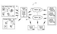
- FIG. 1is a block diagram of a premises based system that makes different system functions available to devices, constructed in accordance with the principles of the invention
- FIG. 2is a block diagram of a control unit constructed in accordance with the principles of the invention.
- FIG. 3is a block diagram of a user interface device constructed in accordance with the principles of the invention.
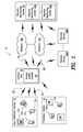
- FIG. 4is a block diagram of a software architecture of the control unit, constructed in accordance with the principles of the invention.
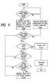
- FIG. 5is a flow chart of an example control unit power management process of the invention in accordance with the principles of the invention.
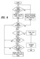
- FIG. 6is a flow chart of an example user interface device power management process of the invention in accordance with the principles of the invention.
- FIG. 7is a flow chart of an example access profiles process of the invention in accordance with the principles of the invention.
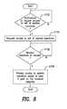
- FIG. 8is a flow chart of an example request process for requesting an access profile in accordance with the principles of the invention.
- FIGS. 9 and 10are example views of an interface and/or display on a user interface device providing different camera functions in accordance with the principles of the invention.
- FIGS. 11 and 12are example views of an interface and/or display on a user interface device providing different door lock functions in accordance with the principles of the invention
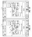
- FIGS. 13 and 14are example views of an interface and/or display on a user interface device providing different external camera functions in accordance with the principles of the invention
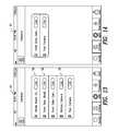
- FIGS. 15 and 16are example views of an interface and/or display on a user interface device providing different arming functions in accordance with the principles of the invention
- FIGS. 17 and 18are example views of an interface and/or display on a user interface device providing different monitored arming functions in accordance with the principles of the invention.
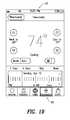
- FIG. 19are example views of an interface and/or display on a user interface device providing different thermostat functions in accordance with the principles of the invention.
- the inventionadvantageously provides differing access to system functions of a premises based system such as a security control system, and components have been represented where appropriate by convention symbols in the drawings, showing only those specific details that are pertinent to understanding the embodiments of the invention so as not to obscure the disclosure with details that will be readily apparent to those of ordinary skill in the art having the benefit of the description herein. While the invention is described herein with respect to a security system, the invention is not limited to such. It is contemplated that the processes and functions described herein may be applied to any premises based system that centrally controls a plurality of separate devices.
- relational termssuch as “first” and “second,” “top” and “bottom,” and the like, may be used solely to distinguish one entity or element from another entity or element without necessarily requiring or implying any physical or logical relationship or order between such entities or elements.
- System 10may include one or more user interface devices 12 a to 12 n (collectively referred to as “user interface device 12 ”), one or more premises devices 14 a to 14 n (collectively referred to as “premises device 14 ”), control unit 16 , one or more networks 18 a to 18 n (collectively referred to as “network 18 ”), one or more remote monitoring centers 20 a to 20 n (collectively referred to as “remote monitoring center 20 ”) and one or more remote servers 22 a to 22 n , communicating with each other directly and/or via network 18 .
- user interface device 12user interface device
- premises devices 14 a to 14 ncollectively referred to as “premises device 14 ”
- control unit 16one or more networks 18 a to 18 n (collectively referred to as “network 18 ”), one or more remote monitoring centers 20 a to 20 n (collectively referred to as “remote monitoring center 20 ”) and one or more remote servers 22 a to 22 n , communicating
- User interface device 12may be any device that allows a user to communicate with control unit 16 .
- User interface device 12may be a portable control keypad/interface (touch screen) 12 a , desktop/laptop computer 12 b , mobile phone 12 c and tablet 12 n , among other devices that allow a user to interface with control unit 16 .
- user interface device 12may communicate at least with control unit 16 using one or more wireless communication protocols well known to those of ordinary skill in the art.
- portable control keypad 12 amay communicate with control unit 16 via BLUETOOTH, a ZigBee based communication link 22 , e.g., network based on Institute of Electrical and Electronics Engineers (IEEE) 802.15.4 protocols, and/or Z-wave based communication link 24 , or over the premises' local area network, e.g., network based on Institute of Electrical and Electronics Engineers (IEEE) 802.11 protocols.
- Other communication protocolsmay be used and may be directional or bi-directional and proprietary and not per any published standard.
- User interface device 12is discussed in detail with respect to FIG. 3 .
- Premises devices 14may include one or more types of sensors, control and/or image capture devices.
- the types of sensorsmay include various life safety related sensors such as motion sensors, fire sensors, carbon monoxide sensors, flooding sensors and contact sensors, among other sensor types that are known in the art.
- the control devicesmay include, for example, one or more life style related devices configured to adjust at least one premises setting such as lighting, temperature, energy usage, door lock and power settings, among other settings associated with the premises or devices on the premises.
- Image capture devicesmay include a digital camera and/or video camera, among other image captures devices that are well known in the art.
- Premises device 14may communicate with control unit 16 via proprietary wireless communication protocols and may also use Wi-Fi, both of which are known in the art.
- sensors and control and/or image capture devicesmay relate to life safety or life style depending on both what the sensors, control and image capture devices do and how these sensors, control and image devices are used by system 10 .
- One of the advantages of the inventionis the ability to use any of these devices irrespective of whether they are life safety or life style.
- Control unit 16may provide management functions such as access management, power management, security system management, premises device management and alarm management, among other functions.
- control unit 16may include access profile module 24 that allows user interface device 12 to access various system functions.
- Access profiles module 24may include, for example, various access criteria used for determining a set of functions to be provided to user interface device 12 , as discussed in detail with respect to FIGS. 2, 3 and 8 .
- Control unit 16may manage one or more life safety and life style features.
- Life safety featuresmay correspond to security system functions and settings associated with premises conditions that may result in life threatening harm to a person such as carbon monoxide detection and intrusion detection.
- Life style featuresmay correspond to security system functions and settings associated with video capturing devices and non-life threatening conditions of the premises such as lighting and thermostat functions.
- Example control unit 16 components and functionsare described detail with respect to FIG. 2 .
- Control unit 16may communicate with network 18 via one or more communication links.
- the communications linksmay be broadband communication links such as a wired cable modem or Ethernet communication link 26 , and digital cellular communication link 28 , e.g., long term evolution (LTE) based link, among other broadband communication links known in the art.
- Broadbandas used herein may refer to a communication link other than a plain old telephone service (POTS) line such as wired and/or wireless communication links including Wi-Fi and/or other technologies.
- Ethernet communication link 26may be an IEEE 802.3 based communication link.
- Network 18may be a wide area network, local area network, wireless local network and metropolitan area network, among other networks known in the art.
- Network 18provides communications between control unit 16 and remote monitoring center 20 .
- System 10may include remote monitoring center 20 that is capable of performing monitoring, configuration and/or control functions associated with control unit 16 .
- remote monitoring center 20may include a remote life safety monitoring center that monitors life safety features associated with control unit 16 in which the remote monitoring center 20 receives life safety data from control unit 16 .
- life safety datamay include at least one carbon monoxide readings, smoke detection reading, sensor location and time of reading, among other related to these detectors that may be communicated with remote monitoring center 20 .
- life safety datamay include at least one of sensor location and time of detection, among other data related to the door contact detection that may be communicated with remote monitoring center 20 .
- Alarm event data from the premisesmay be used by the remote monitoring center in running through various life safety response processes in notifying the owner of the premises, determining whether an actual alarm event is occurring at the premises, and notifying any appropriate response agency (e.g., police, fire, emergency response, premises owner, other interested parties, etc.).
- any appropriate response agencye.g., police, fire, emergency response, premises owner, other interested parties, etc.
- the same or separate remote monitoring center 20may also include a life style system/service that allows for various life style features associated with control 16 .
- the remote life style systemmay receive life style data from control unit 16 .
- life safety datamay include thermostat readings.
- life style datamay include at least one of captured images, video, time of video capture and video location, among other data related to video capture devices that may be communicate with remote monitoring center 20 .
- Remote monitoring center 20may also provide updates to control unit 16 such as updates to features associated with life safety and/or life style operating system. Those of ordinary skill in the art will appreciate that video and other data may also be used by the life safety monitoring center.
- System 10may include remote server 22 that provides data to control unit 16 , among to other devices in system 10 .
- remote server 22may also store the aforementioned access criteria, such as one or more access profiles for one or more user devices and/or users that may include a predetermined set of functions to be provided based on determination of at least one access characteristic of user interface device 12 , and may provide the stored access criteria and data to control unit 16 and/or user interface device 12 .
- Access criteriamay include a defined predetermined set of system functions that is made available for each access profile as describe in detail below with respect to FIG. 2 .
- Remote server 22may provide system updates to control unit 16 and other information as discussed above with respect to remote monitoring center 20 .
- Control unit 16may include communication subsystem 30 that is configured to provide communications with user interface device 12 , premises device 14 and network 18 .
- Communication subsystem 30is configured to communicate with at least one user interface device through which a user may access functions relating to the premises based system, as described herein.
- Communication subsystem 30may include wireless communication element 32 and remote communication element 34 .
- Wireless communication element 32provides wireless communication with user interface device 12 and premises device 14 .
- Wireless communication element 32may support one or more wireless communication protocols such as BLUETOOTH, ZigBee, Z-wave and Wi-Fi, e.g., IEEE 802.11, among others wireless communications protocols that support wireless data transfer.
- Wireless communication element 32may be composed of one or more hardware components in which each hardware component is configured to provide wireless communication using a specific protocol.
- wireless communication element 32may include a ZigBee hardware component configured to provide ZigBee based communications and a Z-wave hardware component configured to provide Z-wave based communications.
- Other hardware componentsmay be included such as to provide one or more other communication protocols.
- the hardware components associated with wireless communication element 32may be internal components within control unit 16 such that these features are built-in or standard features. Alternatively, any one or more of the hardware components associated with wireless communication element 32 may be external components that may be replaced by a user, homeowner or installer.
- Wireless communication element 32may broadcast a wireless signal so that user interface device 12 may connect directly to control unit 16 .
- wireless communication element 32may provide a Wi-Fi encrypted service set identifier (SSID) and path for communication with multiple user interface devices 12 .
- SSIDWi-Fi encrypted service set identifier
- wireless communication element 32By supporting a plurality of wireless communication protocols, wireless communication element 32 enables control unit 16 to be used with a variety of user interface devices 12 and premises devices 12 that are designed to work using only a specific wireless communication protocol. Supporting a plurality of wireless communication protocols allows easy upgrading of existing user interface device 12 and premises device 14 , and for control unit 16 integration with various equipment venders that may incorporate different wireless protocols.
- Wireless communication element 32may provide two-way voice communication with user interface device 12 , which is then communicated with remote monitoring center 20 .
- wireless communication element 32may support voice over internet protocol (VoIP) based communications.
- VoIPvoice over internet protocol
- component parts of wireless communication element 32may also be past of remote communication element so that the wireless communication protocols, e.g., IEEE 802.11 protocols, can be used to communicate with remote monitoring center 20 .
- the wireless communication protocolse.g., IEEE 802.11 protocols
- one or more specific communication modules of wireless communication element 32can also be part of remote communication element 34 .
- Remote communication element 34is configured to provide broadband communications with remote monitoring center 20 via network 18 .
- remote communication element 34may be an Ethernet based hardware component that provides communication with network 18 .
- remote communication element 34may include a Wi-Fi (IEEE 802.11) hardware component that provides communication with a home or other premises network, e.g., a home wireless network, and may utilize some of the same components as wireless communication element 32 .
- the remote communication element 34may also include a cellular radio hardware component that provides communications with at least one cellular network such as an LTE based cellular network.
- Control unit 16may use Ethernet communication link 26 as a primary communication link such that the cellular communication link is used for broadband communications when the Ethernet or primary communication link is not functioning properly such as during a power outage where a home network is unavailable, i.e., home network router has no power.
- Control unit 16may include premises power supply 36 that is configured to provide power to control unit 16 .
- premises power supply 36may provide power to control unit 16 via a home alternating current (AC) power outlet or other power outlets that are known in the art.
- Premises power supply 36may be a primary power supply such that control unit 16 operates using power from the premises power supply 36 when available.
- Control unit 16may also include back-up power supply 38 that provides power during premises power supply failure.
- Back-up power supply 38may include one or more disposable or rechargeable batteries that are configured to provide enough power to operate control unit 16 for first predetermined amount of time and activate siren 40 for a second predetermined amount of time, e.g., a user can access the security system for at least twenty-four hours while control unit 16 is power by back-up power supply 38 while the siren can be activated and operate after the twenty-four hour period.
- Siren 40may be an eighty-five decibel (dB) siren, among other audible devices known in the art. Siren 40 may be an optional component in control unit 16 such that audible alerts are generated by user interface device 12 , e.g., portable control keypad/interface 12 a , and not control unit 16 . Moreover, control unit 16 may include at least one universal serial bus port (USB) to receive power from a laptop or other device with a USB interface. Other port types capable of providing power to control unit 16 may be used based on design need.
- USBuniversal serial bus port
- Input element 42may be configured to receive input data from a user.
- input element 42may be a ten number keypad that enables a user to arm and disarm system 10 .
- Input element 42allows for an alternative or back-up way of arming and disarming system, for example, when no user interface device 12 is available to a user.
- Other input elementsmay be used as are known in the art.
- Control unit 16may include one or more indicators such as light emitting diodes (LEDs) that may indicate the status of control unit 16 .
- LEDslight emitting diodes
- a first LEDis turned on when control panel is powered
- a second LEDis turned on when the system is armed or disarmed
- a third LEDis turned on when an internet protocol connection is connected
- a fourth LEDmay be turned on when the cellular connection has sufficient strength and the first LED may flash during low power conditions, among other LED and LED on/off may be used based on design need.
- Processor 44may be a central processing unit (CPU) that executes computer program instructions stored in memory 46 to perform the functions described herein.
- Memory 46may include non-volatile and volatile memory.
- non-volatile memorymay include a hard drive, memory stick, flash memory and the like.
- volatile memorymay include random access memory and others known in the art.
- Memory 46may store power management module 48 , life safety operating system 50 and life style operating system 52 , among other data and/or modules.
- Power management module 48includes instructions, which when executed by processor 44 , cause processor 44 to perform the process described herein, such as the power management process, discussed in detail with reference to FIG. 5 .
- Life safety operating systemis configured to provide life safety features associated with system 10 .
- Life style operating system 52is configured to provide life style features associated with system 10 .
- processor 44may be configured to run both life safety operating system 50 and life style operating system 52 such that separate processors are not needed to run both operating systems. This single processor configuration reduces cost while still providing both life safety and life style features.
- Memory 46may include access profiles module 24 configured to determine system functionality to make available to a particular user and/or user interface device 12 .
- Access profiles module 24may contain access criteria that are used to determine the set of function provided to user interface device 12 which may be implemented, i.e., is authorized to access specific system functions.
- the access criteriamay be one or more access profiles that may correspond to a predefined set of system functions to make available to user interface device 12 such that one access profile may allow a user to access different system functions than another access profile, even for the same user and for the same physical system.
- Access profiles module 70includes instructions, which when executed by processor 44 , cause processor 44 to perform the process described herein, such as the access profiles process, discussed in detail with reference to FIG. 7 .
- Criteria within access data 71may define the set of system functions for each access profile, thereby defining which system functions are made available for each access profile.
- Access data 71may be configured by the premises service provider, user and/or premises owner, among other users authorized to configure control unit 16 . Alternatively or in addition to access data 71 being stored in memory 46 , access data 71 may be stored in remote server 22 .
- the criteria in access data 71may include, for example, different functionality, or sets of functionality, to provide based on a plurality of access characteristics in which each access profile is associated with one or more access characteristics.
- Access characteristicsmay include proximate physical location, device type, device identifier, connection type (such as the aforementioned local and remote communication protocols; e.g., BLUETOOTH, ZigBee, Z-Wave, Wi-Fi, cellular, etc.), user type, time of day, and current state of the system (armed or disarmed for example), among other attributes.
- the location typemay indicate user interface device 12 is at the premises, proximate the premises (i.e., within a predefined distance from the premises) and/or remote from the premises (i.e., not within a predefined distance from the premises), among other location attributes.
- Location of user interface device 12may be determined by at least one of control unit 16 , network 18 and/or user interface device 12 based at least in part on at least one of triangulation, global position system (GPS), Wi-Fi communications and cellular base station communications, among other methods for determining position of an electronic device.
- GPSglobal position system
- Device typemay indicate the type of electronic device of user interface device 12 .
- device typemay indicate user interface device 12 that requested access to system functionality is one of laptop computer, desktop computer, mobile phone, smartphone tablet device and personal digital assistance (PDA), among electronic device type.
- PDApersonal digital assistance
- Each device typemay be associated with a predefined number of resources such as computational resources and/or display availability, among other resources.
- Connection typemay indicate a general category of commination link and/or actual data throughput.
- connection typemay indicate user interface device 12 is communicating with control unit 16 via a wired broadband connection, high speed wireless connection or low speed wireless connection, among other communication link.
- Device identifiersmay be any mechanism for identifying a particular physical device (which may or may not be associated with user information stored in access profile module 24 , or elsewhere in control unit 16 or remote server 22 .
- identifiersinclude an IP address for the device (such as on the local area network), a media access control (MAC) address, the International Mobile Station Equipment Identity (IMEI number) for a mobile phone or other device, or an identifier generated by software operating on the user interface device, for example such as is incorporated into APPLE's iOS and GOOGLE's Android OS, and may be incorporated into apps operating thereon.
- Memory 46may include a Wi-Fi hijacking module 72 that varies control unit 16 settings when processor determines an unauthorized device has connected to control unit 16 via Wi-Fi. For example, Wi-Fi hijacking module 72 may shutdown Wi-Fi and/or move to low power RF such that user interface device 12 and/or premises device 14 can still communicate with control panel 16 . Wi-Fi hijacking module 72 may include instructions, which when executed by processor 44 , cause processor 44 to perform the process described herein, such as the Wi-Fi hijacking process. Memory 46 may include an auto enrollment module (not shown) that is configured to cause processor 44 to search, wirelessly, for user interface device 12 and premises device 14 located within or near the premises.
- the auto enrollment modulemay cause processor 44 to forward information associated with the found devices 12 and 14 to remote monitoring center 20 such that remote monitoring center 20 may push enrollment data to control unit 16 to facilitate configuration.
- Control unit 16may use the enrollment data configured the security system such that the system operates using the found devices 12 and/ 14 .
- Auto enrollment modulereduces installation time as the devices 12 and/ 14 are automatically found and enrolled for use by control unit 16 .
- Processor 44may be further configured to cause a reminder notification to be sent to a Wi-Fi enabled device that is in the range of a connection type as the Wi-Fi network at the premises to prompt the user to turn off or disarm the system upon entering the premises being monitored by system 10 .
- a user's mobile devicemay come into range of a security Wi-Fi network of the security system when the user is entering the garage or walking through the door such that processor 44 causes a prompt to be sent to the user's mobile device to remind the user to disarm the system now that the user has arrived.
- the reminder notificationmay be a message and/or audible reminder.
- user interface device 12may also be a command for a user interface application on user interface device 12 to activate display 67 , providing a set of functionality for arming the system, such as a prompt for the user's PIN and a “disarm” button.
- processor 44can cause a reminder notification to be send to the user's mobile device as a prompt notifying the user that the system is not armed, e.g., “arm” button.
- a reminder notificationto be send to the user's mobile device as a prompt notifying the user that the system is not armed, e.g., “arm” button.
- Wi-Fi technologywith, in range, out of range, as the trigger for notification, ensures the user is in close proximity to security system before certain actions are taken and notifications made.
- Using secure encrypted Wi-Fi network and Wi-Fi device authenticationensures a reliable device to system identification, and provides a secure reliable connection from the user's device to the security system.
- User interface device 12may include a portable control keypad/interface 12 a , personal computer 12 b , mobile device 12 c and tablet computer 12 n, among other devices.
- User interface device 12includes communication element 54 that is configured to communicate with control unit 16 via at least one wireless communication protocol such as ZigBee, Z-wave and Wi-Fi, among other protocols known in the art.
- User interface device 12may include processor 56 and memory 58 that correspond to control unit 16 components, with size and performance being adjusted based on design need. Processor 56 performs the functions described herein with respect to user interface device 12 .
- Memory 58may include power management module 60 in which power management module 60 includes instructions, which when executed by processor 56 , cause processor 56 to perform the process described herein, such as the power management process, discussed with respect to FIG. 6 .
- Memory 58may include profile request module 61 that allows user interface device 12 to request an access profile.
- Profile request module 61includes instructions, which when executed by processor 56 , cause processor 56 to perform the process described herein, such as the profile request process, discussed with respect to FIG. 8 .
- Interface 62may be a user interface shown on the display of user interface device 12 that is configured to receive user inputs.
- interface 62may receive local control and configuration data input from user.
- User interface device 12may include siren 64 such as an eighty-five dB siren or other audible device(s) known in the art.
- User interface device 12may include power supply 66 for supplying power to user interface device 12 .
- Power supply 66may include one or more rechargeable and/or disposable batteries, among other types of batteries that are well known in the art.
- user interface device 12may be powered via a universal serial bus (USB), have an interface that allows the connection of an external power adapter/recharger, and/or other connection type.
- User interface devicemay include display 67 for displaying information to user of user interface device 12 .
- Example software architecture 68 of control unit 16is described with reference to FIG. 4 .
- software architecture 68may include life safety operating system 50 , life style operating system 52 and bootloader 53 , among other software components relates to security feature management and operation of control unit 16 .
- Life safety operating system 50 and life style operating system 52are configured to run in control unit 16 in which the life safety operating system 50 and life style operating system 52 run in a virtual machine configuration.
- the virtual machine configurationallows a single processor such as processor 44 to separately run the life safety operating system 50 while updating life style operating 52 without negatively affecting features associated with life safety operating system 50 , i.e., life safety features remain functioning while life style features are updated.
- Bootloader 53is used to load the run time environment for operating systems 50 and 52 .
- Processor 44determines whether premises power supply 36 has failed (Block S 100 ). For example, processor 44 may monitor the power being provided by premises power supply 36 using well known methods in the art to determine whether power failure has occurred. Power failure may occur when the voltage being supplied by premises power supply 36 falls below a predefined voltage threshold. If processor 44 determines a power failure has not occurred, the determination of Block S 100 may be repeated.
- processor 44disables a non-life safety feature such as a life style feature, while keeping the life safety feature(s) enabled (Block S 102 ).
- a non-life safety featuresuch as a life style feature
- the temperature control feature associated with the life style operating systemmay be disabled while keeping the intrusion detection, fire detection and carbon monoxide detection features associated with life safety operating system 50 enabled.
- Power management module 48advantageously allows non-life safety features such as life style features associated with life style operating system 50 to be disabled without interrupting life safety features associated with life safety operating system 52 . This configuration helps ensure life safety features will remain enabled during premises power supply 36 failure while at the same time reducing power consumed by disabling a non-life style feature.
- some life style featuresmay require or attempt to initiate communication with user interface device 12 and/or remote monitoring center 20 in which such communications consume power, i.e., may consume limited back-up power.
- Other non-life style features that may be disabledinclude turning off any security control device LEDs and/or terminating communications to user interface device 12 while maintaining communications with premises devices. Therefore, disabling at least one non-life safety feature reduces the amount of power consumed by control unit 16 in which the more non-life safety features that are disabled, the greater the power savings.
- Processor 44determines whether premises power supply 36 has been restored based at least in part on the monitoring of premises power supply 36 (Block S 104 ). For example, processor 44 may continually or periodically monitor the power level of premises power supply 36 to determine whether the power level is equal to or above the predetermined voltage threshold. If processor 44 determines premises power supply 36 has been restored, processor 44 may resume or enable the previously disabled non-life safety feature(s) (Block S 106 ). In other words, the power management process enables non-life safety features such as life style features that may consume more power once control device 16 is being power by premises power supply 36 such that the non-life safety features consume minimal power from the back-up power supply 38 .
- non-life safety featuressuch as life style features that may consume more power once control device 16 is being power by premises power supply 36 such that the non-life safety features consume minimal power from the back-up power supply 38 .
- an audible alarmmay be trigger after processor 44 determines control unit 16 has been operating on back-up power supply 38 for a predetermined amount of time, e.g., twenty-four hours. The predetermined amount of time may be based on design need and/or regulatory requirements. If the determination is made to trigger an alarm, siren 40 or siren 64 may be triggered for a predetermined amount of time (Block S 116 ). In one embodiment, processor 44 uses communication subsystem 30 to send a siren trigger message to user interface device 12 to trigger siren 64 in user interface device 12 .
- siren 64may be triggered for at least four minutes in order to alert a user of a control unit 16 status such as loss of all power.
- the predetermined amount of time the alarm is triggeredmay be based on design need and/or regulatory requirements. Other criteria may be used to trigger an audible alarm based on design need.
- control unit 16may shut down (Block S 118 ). For example, control unit 16 may perform a graceful shutdown according to a shutdown routine when the back-up power supply 38 reaches a predefined threshold such as ten percent power remaining.
- processor 44determines whether an available power threshold has been reached (Block S 110 ).
- the power thresholdmay correspond to a back-up power supply 38 level at which another non-life safety feature may be shutdown in order to reduce power consumption. For example, a different non-life safety feature may be terminated every time the power level falls by a predetermined amount such as five or ten percent or to a predetermined level. Moreover, one or more non-life safety features may be terminated at a time. If the determination is made that the feature threshold is not reached, the determination of Block S 104 may be repeated.
- processor 44determines whether at least one other non-life safety feature, e.g., life style feature, is enabled (Block S 112 ). For example, a lighting life style feature may have been previously been disabled in Block S 102 but a temperature life style feature remains enabled. If the determination is made that at least one other non-life safety feature is not enabled, the determination of Block S 104 may be repeated. If processor 44 determines at least one other non-life safety feature is enabled, processor 44 disables the at least one other non-life safety feature such that the non-life safety features consume less power from the back-up power supply 38 (Block S 114 ).
- at least one other non-life safety featuree.g., life style feature
- Non-life safety featuresmay vary based on design need and power consumption of individual features or other criteria. After disabling the at least one other non-life safety feature, the determination of Block S 104 may be repeated. The power management process helps ensure more important or safety-dependent features stay powered by terminating or disabling less important features such as life style features. Alternatively, processor 44 may disable more than one or all non-life safety features at one time.
- FIG. 6An example power management process for user interface device 12 is illustrated in FIG. 6 .
- the power management processrelates to managing user interface device 12 features based at least in part on the monitoring of power supply 66 .
- processor 56may monitor the power being provided by power supply 66 using well known methods in the art.
- Processor 56determines whether the power being supplied by power supply 66 drops below a predefined threshold based at least in part on the monitoring, i.e., whether a power supply 66 voltage or power level is less than a threshold (Block S 120 ).
- the thresholdmay be a power and/or voltage level determined based on design need and/or other factors. If processor 56 determines power supply 66 is not below, i.e., greater than or equal to, a predetermined threshold, the determination of Block S 120 may be repeated.
- processor 56disables at least one non-safety feature while keeping life safety feature(s) enabled at user interface device 12 (Block S 122 ).
- processor 56may disable a life style feature such that less power may be consumed by not having to perform processing, communication and/or other functions associated with the disabled feature.
- Other non-safety featuresmay include a backlight keypad and/or display feature. Therefore, disabling at least one non-life safety feature reduces the amount of power consumed by user interface device 12 such that the more non-safety features that are disabled, the greater the power savings.
- processor 56may determine whether power supply 66 is still below the threshold based at least in part on the monitoring (Block S 124 ). For example, processor 56 may continually or periodically monitor the voltage level of power supply 66 . If the determination is made that power supply 66 is not below the threshold (i.e., is greater than or equal to the threshold), processor 56 may resume the previously disabled or terminated non-safety feature(s) (Block S 126 ). In other words, the power management process of FIG. 6 enables or executes the previously disabled non-life safety feature(s) that may consume more power once power supply 66 is greater than or equal to the threshold such that the non-life safety features consume minimal power from power supply 66 .
- Power supply 66may rise back to the predetermined threshold level when power supply 66 is being recharged and/or when user interface device 12 is being power via USB, among other situations where power supply 66 is no longer below the predetermined threshold.
- Blocks S 124 and S 126may be skipped or excluded from the power management process of FIG. 6 based on design need, i.e., the process moves from Block S 122 directly to Block S 128 .
- processor 56determines whether to trigger an alarm such as an audible alarm (Block S 128 ).
- an audible alarmmay be trigger after processor 56 determines power supply 66 has reached a lower predetermined threshold.
- the lower predetermined thresholdmay correspond to a minimum power level needed to trigger siren 64 for a predetermined amount of time and/or shutdown user interface device 12 .
- the lower predetermined thresholdmay be based on design need. If the determination is made to trigger an alarm, siren 64 and/or siren 40 may be triggered for a predetermined amount of time (Block S 136 ).
- siren 64may be triggered for at least four minutes in order to alert a user of user interface device 12 status such as a loss of all power status.
- the predetermined amount of time the alarm is triggeredmay be based on design need and/or regulatory requirements. Other criteria may be used to trigger an audible alarm based on design need.
- user interface device 12may shut down (Block S 138 ).
- control unit 16may perform a graceful shutdown according to a shutdown routine.
- processor 56determines whether a feature threshold has been reached (Block S 130 ).
- the feature thresholdmay correspond to a back-up power supply 38 level at which another feature may be shutdown in order to reduce power consumption. For example, a difference feature may be terminated every time the power level fails another predetermined amount, e.g., five or ten percent. Moreover, more than one feature may be disabled or terminated at a time. If the determination is made that the feature threshold is not reached, the determination of Step S 124 may be repeated. Alternatively, if Block S 124 is skipped or excluded from the process and the determination is made that the feature threshold not been reached, the determination of Block S 128 may be performed.
- processor 56determines whether at least one other non-life safety feature is enabled (Block S 132 ). If the determination is made that at least one other non-life safety feature is not enabled, the determination of Block S 124 may be repeated. Alternatively, if Block S 124 is skipped or excluded from the process and the determination is made that at least one other non-life-style feature is not enabled, the determination of Block S 128 may be repeated, i.e., the process moves from Block S 132 to Block S 128 . If processor 56 determines at least one other non-life safety feature is enabled, processor 56 disables the at least one other life style feature such that the non-life safety features consume less power from power supply 66 (Block S 134 ). The order of which non-life safety features are disabled may vary based on design need and power consumption of individual features or other criteria.
- Block S 124After disabling the at least one other non-life style feature, the determination of Block S 124 may be repeated. Alternatively, if Block S 124 is skipped or excluded from the process and the other non-life safety feature has been disabled at Block S 134 , the determination of Block S 128 may be repeated, i.e., the process moves from Block S 134 to Block S 128 .
- the power management processhelps ensure more important or safety dependent features remain operating by terminating or disabling less important features such as life style features or other non-safety features at user interface device 12 .
- processor 56may disable more than one or all life style features at one time.
- the power managementis configured and power supply 66 sized such that processor 56 can still trigger and sound siren 64 for four minutes after a twenty-four hour period upon the occurrence of a triggering condition, e.g., low battery, sensor trigger detection, receipt of trigger message from control unit 16 , etc.
- a triggering conditione.g., low battery, sensor trigger detection, receipt of trigger message from control unit 16 , etc.
- system 10may be configured to authorize user interface device 12 to implement one or more sets of functionality as access profiles based on access criteria and determination of one or more access characteristics when user interface 12 is seeking access to control unit 16 , such as when a mobile app is launched and needs to be authenticated to provide the user with a set of functionality for such access.
- user interface device 12may execute, i.e., “pop up”, an application on user interface device 12 via interface 62 and/or display 67 for the user to manually actuate user interface 12 to request access.
- user interface device 12may automatically trigger a request for access.
- user interface device 12may periodically request an access profile or updated access profile or it may occur automatically when the user launches an application on user interface 12 .
- the functionality provided to user interface 12may be accomplished entirely within system 10 and transparent to the user, so the user simply experiences a different set of functions automatically depending on the status of the various access characteristics of device of user interface device and the analysis of those characteristics by the system.
- Processor 44 of control unit 16may determine if a request message for access has been received (Block S 140 ). If processor determines a request message for an access profile has not been received, processor 44 continues to perform the determination of Block S 140 .
- processor 44determines at least one access characteristic associated with requesting user interface device 12 (Block S 142 ). For example, processor 44 may determine at least one of a location type, device type, device identification, connection type and user type, etc. among other various attributes previously noted. In one embodiment, processor 44 may be preconfigured with at least one access characteristics such as device type. Alternatively or in addition to preconfiguring control unit 16 with knowledge of user interface device 12 , processor 44 may dynamically determine at least one access characteristic of user interface device 12 such as location type, connection type, etc.
- processor 44may determine location type of requesting user interface device 12 , i.e., determine user interface device 12 is proximate the premises, inside the premises or remote from the premises.
- the determination of the access characteristicincorporates geo-fencing based at least one of proximate physical location and network connection type.
- processor 44may determine at least one access characteristic based at least in part on data received the request message such as device identification, user identification, connection type and/or location, among other characteristics.
- a device identificationmay include a media access control (MAC) address, international mobile station equipment (IMEI) number and/or an identifier generate by software operating on the user interface, among other device identifiers.
- MACmedia access control
- IMEIinternational mobile station equipment
- processor 44may determine a connection type such as wired, wireless or broadband that user interface device 12 is using to communicate with control unit 16 .
- processor 44may determine the user type associated with user interface device 12 such as a master user or guest user. The user type may be based at least in part on an authorization code received from user interface device 12 .
- processor 44may determine at least one access characteristic of requesting user interface device 12 , the determination of at least one access characteristic may be made by remoter server 22 , user interface device 12 and/or remote monitoring center 20 . The determined at least one access characteristics may be transmitted to control unit 16 for access profile determination.
- Processor 44compares the determined access characteristic to access criteria (Block S 144 ).
- Processor 44determines the set of system functions to provide to user interface device 12 based at least in part on the comparison (Block S 146 ).
- processor 44determines which one of a stored plurality of access profiles user interface device 12 is to implement based at least in part on the determined at least one access characteristic. For example, processor 44 may restrict access to video camera functions if the determined access characteristics indicate the connection type is not broadband and/or the device type is a mobile phone with low computational resources.
- processor 44may restrict access to “STAY” security system arming option, which is used when a user is at the premises, if the determined access characteristic indicates the location type is remote from premises, i.e., request user interface device 12 is remote from premises.
- STAYsecurity system arming option
- Processor 44transmits a message indicating the determined set of system functions (Block S 148 ).
- the messagemay be transmitted toward user interface device 12 .
- the messagemay include access data 71 corresponding to a specific access profile.
- the access data 71may include system functions to make available and/or system functions not to make available.
- access data 71 in the messagelists system functions not to make available such the non-listed system functions are made available.
- access data 71 in the messagelists system functions to make available such non-listed system functions are not made available.
- Messagemay include other indications as to which system functions to make available and/or unavailable to user interface device 12 .
- the set of functionsis automatically provided to the user interface device upon determination of the access characteristic, and includes a prompt for the user to perform at least one of arm the premises based system, disarm the premises based system, unlock a door of the premises, and turn on at least one light within the premises.
- Processor 44monitors the determined at least one access characteristic (Block S 150 ).
- processor 44may periodically perform Blocks S 142 -S 146 and transmit an updated message to user interface device (Block S 148 ) if another access profile is to be implemented.
- the monitoring at Block S 150allows processor 44 to dynamically reduce, maintain or increase access to system functionality as the at least one access characteristic changes. Alternatively, Block S 150 may be skipped or omitted based on design implementation.
- the determination of the access characteristics, comparison with the access criteria, and determination of the set of functionality for user interface device 12may be accomplished using a processor in remote server 22 , and/or processor 56 of user interface device 12 itself.
- processor 56determines whether a notification to request such functionality (based on access criteria, such as an access profile) has been received (Block S 152 ). If processor 56 determines a notification to request access has not been received, processor 56 continues to or periodically performs the determination of Block S 152 . If processor 56 determines that a notification to request access has been received, processor 56 causes a request message for access to be transmitted (Block S 154 ).
- the request messagemay include data such as device identification, device location, user identification and/or connection types, among other data that may be determined by user interface device 12 , or otherwise obtained by control unit 16 or remote server 22 .
- the data in the request messagemay be used to determine one or more access characteristics of user interface device 12 , as discussed with respect to FIG. 7 .
- Processor 56determines whether a response to the request for access has been received (Block S 156 ). If an access profile has not been received, processor 56 may perform the determination of Block S 156 . If processor 56 determines an access profile has been received, processor 56 causes one or more system functions to be made available to user of user interface device 12 based at least in part on the received access profile (Block S 158 ).
- user interface device 12may receive an access profile from control unit 16 , remote monitoring center 20 and/or remote server 22 that contains a set of system functions to make available to the user.
- user interface device 12may store a plurality of access profiles in memory 58 each having sets of functionality, such that the received access profile indicates which one of the stored plurality of access profiles to implement.
- Processor 56may determine a connection type for user interface device 12 as being authenticated on the local WiFi network for the premise, and, based on the stored access criteria 71 , may enable user interface 12 to communicate locally with control unit 16 at the premises via wireless communication element 32 , e.g., through the local Wi-Fi network at the premises, without the need to communicate with a remote server 22 or remote monitoring center 20 .
- the communication between user interface device 12 and control unit 16is entirely local to the premises.
- user interface device 12can be used to locally control the operation of, i.e., operate and configure, control unit 16 .
- Access data 71 and any incorporated user access profilemay also distinguish based on device type as well, e.g., may only allow such local communication if user interface 12 is a mobile device, e.g., phone or tablet, as opposed to other devices such as a PC or a touch screen for control unit 16 —and based on the device identifier—e.g., may only allow certain “known” mobile devices to communicate locally.
- This arrangementreduces latency associated with communications between user interface device 12 and control unit 16 as compared with communications between user interface device 12 and control unit 16 that occur via a remote server 22 or remote monitoring center 20 .
- FIGS. 9 and 10illustrate example access profiles in which user interface device 12 is provided with or restricted from system functions.
- access to cameras at the premisesmay be granted or restricted based at least in part on at least on access characteristic.
- an implemented access profilemay restrict access to the cameras via a mobile phone application or for certain devices (device type) unless user interface device 12 is in the premises (location type).
- an implemented access profilemay allow access to the cameras via a mobile phone application or for certain devices (device type) unless user interface device 12 is in the premises (location type) since there may be no need for camera access while at home (premises).
- FIG. 9corresponds to an access profile that allows access to cameras, i.e., interactive camera icons 74 are present
- FIG. 10corresponds to an access profile that does not allow access to cameras, i.e., interactive camera icons 74 are not present.
- FIGS. 11 and 12illustrate example access profiles in which user interface device 12 is provided with or restricted from certain system functions. Access to an interactive icon for modifying electronic door locks (premises devices 14 ) at the premises may be granted or restricted based at least in part on at least on access characteristic.
- an implemented access profilemay provide access to an interactive icon for modifying door locks on a mobile phone application or certain devices (device type) if user device 12 is proximate the premises (location type). This access profile is illustrated in FIG. 11 where the interactive door lock icons are illustrated.
- the implemented access profilemay restrict access to interactive icons 76 for modifying door locks via certain devices (device type) if user interface device 12 is in the premises. The access profile that restricts access to door locks is illustrated in FIG. 12 in which the interactive door lock icons 76 are not present.
- FIGS. 13 and 14illustrate example access profiles in which user interface device 12 is provided with or restricted from system functions. Access to icons for viewing images/video from internal cameras (premises devices 14 ) at the premises may be granted or restricted based at least in part on at least on access characteristic.
- an implemented access profilemay provide access to icons for viewing images/video from internal cameras on a mobile phone application or certain devices (device type) and/or if user device 12 is remote the premises (location type). This access profile is illustrated in FIG. 13 where the interactive internal camera icons 78 are illustrated.
- the implemented access profilemay restrict access to icons for viewing images/video from internal cameras for certain devices (device type) and/or if user interface device 12 is in the premises, e.g., there may be no need for internal camera view if user is home.
- the access profile that restricts access to icons for viewing images/video from internal camerasis illustrated in FIG. 14 in which the interactive internal camera icons 78 are not illustrated, i.e., a user cannot selective the internal cameras.
- FIGS. 15 and 16illustrate example access profiles in which user interface device 12 is provided with or restricted from system functions. Access to icons for one or more alarm settings may be granted or restricted based at least in part on at least on access characteristic.
- an implemented access profilemay provide access to icons for both Arm Away and Arm Stay 80 settings if user device 12 is proximate or inside the premises (location type). This access profile is illustrated in FIG. 15 where the interactive arming icons are illustrated.
- the implemented access profilemay restrict access to the icon for Arm Stay 80 setting if user interface device 12 is remote from the premises (location type). The access profile that restricts access to the icon for the Arm Stay 80 setting is illustrated in FIG. 16 in which the interactive Arm Stay icon is not displayed.
- FIGS. 17 and 18illustrate example access profiles in which user interface device 12 is provided with or restricted from system functions. Access to icon for monitored arming functionality may be granted or restricted based at least in part on at least on access characteristic.
- an implemented access profilemay provide access to icon for arming functionality on a mobile phone application (device type) if user device 12 transitions from in the premises to proximate the premises (location types). For example, a user with user interface device 12 may be leaving the premises such that the mobile application prompts user to arm the premises.
- This access profileis illustrated in FIGS. 17 and 18 .
- the implemented access profilemay restrict access to icon for monitored arming functionality for certain devices (device type) such as a tablet even if user interface device 12 transitions from in premises to proximate premises (location types).
- FIG. 19illustrates an example access profile in which user interface device 12 is provided with or restricted from system functions. Access to icons for thermostats functionality at the premises may be granted or restricted based at least in part on at least on access characteristic.
- an implemented access profilemay provide access to icons such as 82 for thermostat functionality if user device 12 has authorization (user type). For example, thermostat functionality of a store premises may only be provide to higher level users. This access profile is illustrated in FIG. 19 where the interactive thermostat functionality is displayed on user interface device 12 .
- the implemented access profilemay restrict access to icons such as 82 for thermostat functionality for lower level users of user interface device 12 is in the premises.
- the menus and icons corresponding to system functionsare made available to the user via user interface device 12 depending on which access profile is implemented by user interface device 12 .
- the access profile chosen for user interface device 12is based on at least one access characteristic such as location, device type and/or connection type, among other processor determinable characteristics associated with user interface device 12 .
- the inventionmay control access to a premises based using the aforementioned combinations of various access criteria stored, for example, in memory 46 of control unit 16 , a memory or other storage on remote server 22 , or even in the memory of user interface 12 , to establish a set of system functions that may be provided as an access profile for accessing the system through user interface 12 ; using a processor such as processor 44 or processor 56 and/or another, to determine an access characteristic associated with the user interface device, comparing the access characteristic to the access criteria, and determining the set of system functions to provide the user interface based at least in part on the comparison.
- a processorsuch as processor 44 or processor 56 and/or another
- the access characteristicmay include proximate physical location, a connection type for communicating with the user interface device, a device type for the user interface device, an identifier for the user interface device, user type, time of day, and current state of the system.
- the proximate physical locationmay be determined, for example, by using triangulation, global position system (GPS), Wi-Fi communications and cellular base station communications.
- the identifiermay be any number of identifiers such as IP address, MAC address, an IMEI number, or an identifier generated by software operating on the user interface device.
- the connection typemay be a number of wireless communication protocols, including Bluetooth, ZigBee, Z-Wave, Wi-Fi, and cellular.
- the set of functionsmay be automatically provided to user interface 12 upon determination of the access characteristic, and may include a prompt for the user to perform at least one of arm the premises based system, disarm the premises based system, unlock a door of the premises, and turn on at least one light within the premises. This may be accomplished, for example, through geo-fencing based at least one of proximate physical location and network connection type.
- the communication subsystemmay be configured to enable communication between the premises based system and the user interface device using a particular connection type based on the determined access characteristic.
- One or more of the processorsmay be further configured to automatically authenticate user interface device 12 based on comparison of the determined access characteristic and the access criteria. It may also be configured, based on the comparison of the determined access characteristic and the access criteria, to automatically perform, or prompt the user to perform, at least one of arm the premises based system, disarm the premises based system, unlock a door of the premises, and turn on at least one light within the premises.
- the inventioncan be realized in hardware, software, or a combination of hardware and software. Any kind of computing system, or other apparatus adapted for carrying out the methods described herein, is suited to perform the functions described herein.
- a typical combination of hardware and softwarecould be a specialized or general purpose computer system having one or more processing elements and a computer program stored on a storage medium that, when loaded and executed, controls the computer system such that it carries out the methods described herein.
- the inventioncan also be embedded in a computer program product, which comprises all the features enabling the implementation of the methods described herein, and which, when loaded in a computing system is able to carry out these methods.
- Storage mediumrefers to any volatile or non-volatile storage device.
- Computer program or application in the present contextmeans any expression, in any language, code or notation, of a set of instructions intended to cause a system having an information processing capability to perform a particular function either directly or after either or both of the following a) conversion to another language, code or notation; b) reproduction in a different material form.
Landscapes
- Engineering & Computer Science (AREA)
- Automation & Control Theory (AREA)
- Computer Networks & Wireless Communication (AREA)
- Signal Processing (AREA)
- Computer Security & Cryptography (AREA)
- Physics & Mathematics (AREA)
- General Physics & Mathematics (AREA)
- Emergency Management (AREA)
- Business, Economics & Management (AREA)
- General Engineering & Computer Science (AREA)
- Theoretical Computer Science (AREA)
- Human Computer Interaction (AREA)
- Telephonic Communication Services (AREA)
- Selective Calling Equipment (AREA)
Abstract
Description
Claims (16)
Priority Applications (1)
| Application Number | Priority Date | Filing Date | Title |
|---|---|---|---|
| US14/217,019US9898168B2 (en) | 2013-03-15 | 2014-03-17 | Security system access profiles |
Applications Claiming Priority (2)
| Application Number | Priority Date | Filing Date | Title |
|---|---|---|---|
| US201361789183P | 2013-03-15 | 2013-03-15 | |
| US14/217,019US9898168B2 (en) | 2013-03-15 | 2014-03-17 | Security system access profiles |
Publications (2)
| Publication Number | Publication Date |
|---|---|
| US20140282048A1 US20140282048A1 (en) | 2014-09-18 |
| US9898168B2true US9898168B2 (en) | 2018-02-20 |
Family
ID=50687664
Family Applications (1)
| Application Number | Title | Priority Date | Filing Date |
|---|---|---|---|
| US14/217,019Active2036-04-08US9898168B2 (en) | 2013-03-15 | 2014-03-17 | Security system access profiles |
Country Status (8)
| Country | Link |
|---|---|
| US (1) | US9898168B2 (en) |
| EP (1) | EP2973477A1 (en) |
| KR (1) | KR20150132379A (en) |
| CN (1) | CN105190720A (en) |
| AU (2) | AU2014232422A1 (en) |
| CA (1) | CA2906195C (en) |
| HK (1) | HK1218339A1 (en) |
| WO (1) | WO2014145913A1 (en) |
Cited By (28)
| Publication number | Priority date | Publication date | Assignee | Title |
|---|---|---|---|---|
| US10354082B2 (en)* | 2014-09-06 | 2019-07-16 | Airwatch Llc | Document state interface |
| US10402084B2 (en) | 2014-09-06 | 2019-09-03 | Airwatch Llc | Collaboration for network-shared documents |
| US10528228B2 (en)* | 2017-06-21 | 2020-01-07 | Microsoft Technology Licensing, Llc | Interaction with notifications across devices with a digital assistant |
| US20210349588A1 (en)* | 2019-01-23 | 2021-11-11 | Opple Lighting Co., Ltd. | Mode setting method and device of monitoring system |
| US11270568B2 (en) | 2016-01-06 | 2022-03-08 | State Farm Mutual Automobile Insurance Company | Sensor data to identify catastrophe areas |
| US11270385B1 (en) | 2014-04-25 | 2022-03-08 | State Farm Mutual Automobile Insurance Company | Systems and methods for homeowner-directed risk of property damage mitigation |
| US11334040B2 (en) | 2014-10-07 | 2022-05-17 | State Farm Mutual Automobile Insurance Company | Systems and methods for automatically responding to a fire |
| US11367527B1 (en) | 2019-08-19 | 2022-06-21 | State Farm Mutual Automobile Insurance Company | Senior living engagement and care support platforms |
| US11423758B2 (en) | 2018-04-09 | 2022-08-23 | State Farm Mutual Automobile Insurance Company | Sensing peripheral heuristic evidence, reinforcement, and engagement system |
| US11451043B1 (en) | 2016-10-27 | 2022-09-20 | State Farm Mutual Automobile Insurance Company | Systems and methods for utilizing electricity monitoring devices to mitigate or prevent structural damage |
| US11488255B1 (en) | 2020-08-03 | 2022-11-01 | State Farm Mutual Automobile Insurance Company | Apparatuses, systems and methods for mitigating property loss based on an event driven probable roof loss confidence score |
| US11508138B1 (en) | 2020-04-27 | 2022-11-22 | State Farm Mutual Automobile Insurance Company | Systems and methods for a 3D home model for visualizing proposed changes to home |
| US20230087269A1 (en)* | 2021-09-20 | 2023-03-23 | Xerox Corporation | Transferring calls via near field communications |
| US11635080B1 (en) | 2021-02-12 | 2023-04-25 | State Farm Mutual Automobile Insurance Company | Determining and utilizing a desired frequency for a mechanical shaker for a sump pump system |
| US20230132334A1 (en)* | 2020-03-31 | 2023-04-27 | Daikin Industries, Ltd. | Control specification visualization program and control specification visualization method |
| US11688516B2 (en) | 2021-01-19 | 2023-06-27 | State Farm Mutual Automobile Insurance Company | Alert systems for senior living engagement and care support platforms |
| US11734767B1 (en) | 2020-02-28 | 2023-08-22 | State Farm Mutual Automobile Insurance Company | Systems and methods for light detection and ranging (lidar) based generation of a homeowners insurance quote |
| US11775940B1 (en) | 2015-09-10 | 2023-10-03 | State Farm Mutual Automobile Insurance Company | Systems and methods for ordering a replacement component or repair service |
| US11783422B1 (en) | 2017-09-27 | 2023-10-10 | State Farm Mutual Automobile Insurance Company | Implementing machine learning for life and health insurance claims handling |
| US11894129B1 (en) | 2019-07-03 | 2024-02-06 | State Farm Mutual Automobile Insurance Company | Senior living care coordination platforms |
| US12170143B1 (en) | 2019-07-03 | 2024-12-17 | State Farm Mutual Automobile Insurance Company | Multi-sided match making platforms |
| US12182873B2 (en) | 2021-06-24 | 2024-12-31 | State Farm Mutual Automobile Insurance Company | Systems and methods for automating property assessment using probable roof loss confidence scores |
| US12243641B2 (en) | 2021-01-29 | 2025-03-04 | State Farm Mutual Automobile Insurance Company | Senior living engagement and care support platforms with chatbot and list integration |
| US12277616B2 (en) | 2022-04-20 | 2025-04-15 | State Farm Mutual Automobile Insurance Company | Systems and methods for generating a home score for a user |
| US12315024B2 (en) | 2022-04-20 | 2025-05-27 | State Farm Mutual Automobile Insurance Company | Systems and methods for generating a home score for a user |
| US20250182548A1 (en)* | 2023-11-30 | 2025-06-05 | Honeywell International Inc. | Method and system for automatically changing a security level configuration of a security system of a facility based on a received event profile of an event to be held at the facility |
| US12437865B2 (en) | 2020-07-09 | 2025-10-07 | State Farm Mutual Automobile Insurance Company | Systems and methods for home health evaluation and remediation |
| US12444499B2 (en) | 2024-07-03 | 2025-10-14 | State Farm Mutual Automobile Insurance Company | Systems and methods for home health evaluation and remediation |
Families Citing this family (105)
| Publication number | Priority date | Publication date | Assignee | Title |
|---|---|---|---|---|
| US10237237B2 (en) | 2007-06-12 | 2019-03-19 | Icontrol Networks, Inc. | Communication protocols in integrated systems |
| US20090077623A1 (en) | 2005-03-16 | 2009-03-19 | Marc Baum | Security Network Integrating Security System and Network Devices |
| US11277465B2 (en) | 2004-03-16 | 2022-03-15 | Icontrol Networks, Inc. | Generating risk profile using data of home monitoring and security system |
| US7711796B2 (en) | 2006-06-12 | 2010-05-04 | Icontrol Networks, Inc. | Gateway registry methods and systems |
| US11316958B2 (en) | 2008-08-11 | 2022-04-26 | Icontrol Networks, Inc. | Virtual device systems and methods |
| US12063220B2 (en) | 2004-03-16 | 2024-08-13 | Icontrol Networks, Inc. | Communication protocols in integrated systems |
| US11201755B2 (en) | 2004-03-16 | 2021-12-14 | Icontrol Networks, Inc. | Premises system management using status signal |
| US8635350B2 (en) | 2006-06-12 | 2014-01-21 | Icontrol Networks, Inc. | IP device discovery systems and methods |
| US11582065B2 (en) | 2007-06-12 | 2023-02-14 | Icontrol Networks, Inc. | Systems and methods for device communication |
| US11916870B2 (en) | 2004-03-16 | 2024-02-27 | Icontrol Networks, Inc. | Gateway registry methods and systems |
| US11244545B2 (en) | 2004-03-16 | 2022-02-08 | Icontrol Networks, Inc. | Cross-client sensor user interface in an integrated security network |
| US11190578B2 (en) | 2008-08-11 | 2021-11-30 | Icontrol Networks, Inc. | Integrated cloud system with lightweight gateway for premises automation |
| US9531593B2 (en) | 2007-06-12 | 2016-12-27 | Icontrol Networks, Inc. | Takeover processes in security network integrated with premise security system |
| US11159484B2 (en) | 2004-03-16 | 2021-10-26 | Icontrol Networks, Inc. | Forming a security network including integrated security system components and network devices |
| US10339791B2 (en) | 2007-06-12 | 2019-07-02 | Icontrol Networks, Inc. | Security network integrated with premise security system |
| US10348575B2 (en) | 2013-06-27 | 2019-07-09 | Icontrol Networks, Inc. | Control system user interface |
| US11677577B2 (en) | 2004-03-16 | 2023-06-13 | Icontrol Networks, Inc. | Premises system management using status signal |
| US20170118037A1 (en) | 2008-08-11 | 2017-04-27 | Icontrol Networks, Inc. | Integrated cloud system for premises automation |
| US10522026B2 (en) | 2008-08-11 | 2019-12-31 | Icontrol Networks, Inc. | Automation system user interface with three-dimensional display |
| GB2428821B (en) | 2004-03-16 | 2008-06-04 | Icontrol Networks Inc | Premises management system |
| US11343380B2 (en) | 2004-03-16 | 2022-05-24 | Icontrol Networks, Inc. | Premises system automation |
| US9141276B2 (en) | 2005-03-16 | 2015-09-22 | Icontrol Networks, Inc. | Integrated interface for mobile device |
| US11811845B2 (en) | 2004-03-16 | 2023-11-07 | Icontrol Networks, Inc. | Communication protocols over internet protocol (IP) networks |
| US9729342B2 (en) | 2010-12-20 | 2017-08-08 | Icontrol Networks, Inc. | Defining and implementing sensor triggered response rules |
| US10721087B2 (en) | 2005-03-16 | 2020-07-21 | Icontrol Networks, Inc. | Method for networked touchscreen with integrated interfaces |
| US11113950B2 (en) | 2005-03-16 | 2021-09-07 | Icontrol Networks, Inc. | Gateway integrated with premises security system |
| US11489812B2 (en) | 2004-03-16 | 2022-11-01 | Icontrol Networks, Inc. | Forming a security network including integrated security system components and network devices |
| US10200504B2 (en) | 2007-06-12 | 2019-02-05 | Icontrol Networks, Inc. | Communication protocols over internet protocol (IP) networks |
| US10156959B2 (en) | 2005-03-16 | 2018-12-18 | Icontrol Networks, Inc. | Cross-client sensor user interface in an integrated security network |
| US11368429B2 (en) | 2004-03-16 | 2022-06-21 | Icontrol Networks, Inc. | Premises management configuration and control |
| US10142392B2 (en) | 2007-01-24 | 2018-11-27 | Icontrol Networks, Inc. | Methods and systems for improved system performance |
| US11615697B2 (en) | 2005-03-16 | 2023-03-28 | Icontrol Networks, Inc. | Premise management systems and methods |
| US11700142B2 (en) | 2005-03-16 | 2023-07-11 | Icontrol Networks, Inc. | Security network integrating security system and network devices |
| US11496568B2 (en) | 2005-03-16 | 2022-11-08 | Icontrol Networks, Inc. | Security system with networked touchscreen |
| US9306809B2 (en) | 2007-06-12 | 2016-04-05 | Icontrol Networks, Inc. | Security system with networked touchscreen |
| US20110128378A1 (en) | 2005-03-16 | 2011-06-02 | Reza Raji | Modular Electronic Display Platform |
| US20120324566A1 (en) | 2005-03-16 | 2012-12-20 | Marc Baum | Takeover Processes In Security Network Integrated With Premise Security System |
| US10999254B2 (en) | 2005-03-16 | 2021-05-04 | Icontrol Networks, Inc. | System for data routing in networks |
| US20170180198A1 (en) | 2008-08-11 | 2017-06-22 | Marc Baum | Forming a security network including integrated security system components |
| US12063221B2 (en) | 2006-06-12 | 2024-08-13 | Icontrol Networks, Inc. | Activation of gateway device |
| US10079839B1 (en) | 2007-06-12 | 2018-09-18 | Icontrol Networks, Inc. | Activation of gateway device |
| US11706279B2 (en) | 2007-01-24 | 2023-07-18 | Icontrol Networks, Inc. | Methods and systems for data communication |
| US7633385B2 (en) | 2007-02-28 | 2009-12-15 | Ucontrol, Inc. | Method and system for communicating with and controlling an alarm system from a remote server |
| US8451986B2 (en) | 2007-04-23 | 2013-05-28 | Icontrol Networks, Inc. | Method and system for automatically providing alternate network access for telecommunications |
| US11423756B2 (en) | 2007-06-12 | 2022-08-23 | Icontrol Networks, Inc. | Communication protocols in integrated systems |
| US11646907B2 (en) | 2007-06-12 | 2023-05-09 | Icontrol Networks, Inc. | Communication protocols in integrated systems |
| US11237714B2 (en) | 2007-06-12 | 2022-02-01 | Control Networks, Inc. | Control system user interface |
| US12184443B2 (en) | 2007-06-12 | 2024-12-31 | Icontrol Networks, Inc. | Controlling data routing among networks |
| US11601810B2 (en) | 2007-06-12 | 2023-03-07 | Icontrol Networks, Inc. | Communication protocols in integrated systems |
| US11316753B2 (en) | 2007-06-12 | 2022-04-26 | Icontrol Networks, Inc. | Communication protocols in integrated systems |
| US11089122B2 (en) | 2007-06-12 | 2021-08-10 | Icontrol Networks, Inc. | Controlling data routing among networks |
| US11218878B2 (en) | 2007-06-12 | 2022-01-04 | Icontrol Networks, Inc. | Communication protocols in integrated systems |
| US12003387B2 (en) | 2012-06-27 | 2024-06-04 | Comcast Cable Communications, Llc | Control system user interface |
| US12283172B2 (en) | 2007-06-12 | 2025-04-22 | Icontrol Networks, Inc. | Communication protocols in integrated systems |
| US10523689B2 (en) | 2007-06-12 | 2019-12-31 | Icontrol Networks, Inc. | Communication protocols over internet protocol (IP) networks |
| US11212192B2 (en) | 2007-06-12 | 2021-12-28 | Icontrol Networks, Inc. | Communication protocols in integrated systems |
| US10223903B2 (en) | 2010-09-28 | 2019-03-05 | Icontrol Networks, Inc. | Integrated security system with parallel processing architecture |
| US11831462B2 (en) | 2007-08-24 | 2023-11-28 | Icontrol Networks, Inc. | Controlling data routing in premises management systems |
| US11916928B2 (en) | 2008-01-24 | 2024-02-27 | Icontrol Networks, Inc. | Communication protocols over internet protocol (IP) networks |
| US20170185278A1 (en) | 2008-08-11 | 2017-06-29 | Icontrol Networks, Inc. | Automation system user interface |
| US11792036B2 (en) | 2008-08-11 | 2023-10-17 | Icontrol Networks, Inc. | Mobile premises automation platform |
| US11729255B2 (en) | 2008-08-11 | 2023-08-15 | Icontrol Networks, Inc. | Integrated cloud system with lightweight gateway for premises automation |
| US11258625B2 (en) | 2008-08-11 | 2022-02-22 | Icontrol Networks, Inc. | Mobile premises automation platform |
| US11758026B2 (en) | 2008-08-11 | 2023-09-12 | Icontrol Networks, Inc. | Virtual device systems and methods |
| US8638211B2 (en) | 2009-04-30 | 2014-01-28 | Icontrol Networks, Inc. | Configurable controller and interface for home SMA, phone and multimedia |
| WO2011143273A1 (en) | 2010-05-10 | 2011-11-17 | Icontrol Networks, Inc | Control system user interface |
| US8836467B1 (en) | 2010-09-28 | 2014-09-16 | Icontrol Networks, Inc. | Method, system and apparatus for automated reporting of account and sensor zone information to a central station |
| US11750414B2 (en) | 2010-12-16 | 2023-09-05 | Icontrol Networks, Inc. | Bidirectional security sensor communication for a premises security system |
| US9147337B2 (en) | 2010-12-17 | 2015-09-29 | Icontrol Networks, Inc. | Method and system for logging security event data |
| US20220132318A1 (en)* | 2013-03-15 | 2022-04-28 | Christopher V. Beckman | Access to Wireless Networks Based on Presence at a Physical Location |
| CA2940966C (en)* | 2014-02-28 | 2021-03-02 | Costar Realty Information, Inc. | Systems and methods for tracking, marketing, and/or attributing interest in one or more real estate properties |
| US11405463B2 (en) | 2014-03-03 | 2022-08-02 | Icontrol Networks, Inc. | Media content management |
| US11146637B2 (en) | 2014-03-03 | 2021-10-12 | Icontrol Networks, Inc. | Media content management |
| WO2015143099A2 (en)* | 2014-03-18 | 2015-09-24 | Castleos Software, Llc | Home automation systems, methods, and computer-readable media |
| US10534330B2 (en) | 2014-06-13 | 2020-01-14 | Vivint, Inc. | Selecting a level of autonomy |
| US20160378967A1 (en)* | 2014-06-25 | 2016-12-29 | Chian Chiu Li | System and Method for Accessing Application Program |
| US10593190B2 (en) | 2014-12-30 | 2020-03-17 | Google Llc | Systems and methods of providing status information in a smart home security detection system |
| CA2979411C (en)* | 2015-03-12 | 2024-02-13 | Alarm.Com Incorporated | Providing internet access through a property monitoring system |
| USD779543S1 (en)* | 2015-03-20 | 2017-02-21 | Ahtovation, Inc. | Display screen or portion thereof with graphical user interface |
| US10097368B2 (en)* | 2015-04-09 | 2018-10-09 | Honeywell International Inc. | WiFi access based actions/scenes execution in home automation security panels |
| US10054329B1 (en) | 2015-05-29 | 2018-08-21 | Alarm.Com Incorporated | Interpreting presence signals using historical data |
| US9838378B2 (en)* | 2015-07-27 | 2017-12-05 | Lenovo Enterprise Solutions (Singapore) Pte. Ltd. | Securing a server before connecting the server to a data communications network |
| US9619993B2 (en)* | 2015-07-27 | 2017-04-11 | Honeywell International Inc. | Logging into a system with a bluetooth device |
| US9818291B2 (en)* | 2015-09-11 | 2017-11-14 | Honeywell International Inc. | System arm notification based on BLE position |
| FR3044848B1 (en)* | 2015-12-03 | 2019-08-23 | Overkiz | METHOD FOR CONFIGURING, CONTROLLING OR SUPERVISING A DOMOTIC FACILITY |
| US10600305B2 (en) | 2016-04-08 | 2020-03-24 | Vivint, Inc. | Event based monitoring of a person |
| US9881492B2 (en)* | 2016-05-16 | 2018-01-30 | Google Llc | Security system with shielded devices |
| US9997054B2 (en) | 2016-06-07 | 2018-06-12 | Ecolink Intelligent Technology, Inc. | Method and apparatus for disarming a security system |
| CN106302653B (en)* | 2016-08-01 | 2020-01-14 | 厦门中控智慧信息技术有限公司 | Control authority sharing method of access control terminal and related equipment |
| US10306403B2 (en)* | 2016-08-03 | 2019-05-28 | Honeywell International Inc. | Location based dynamic geo-fencing system for security |
| DE202016106519U1 (en) | 2016-11-22 | 2017-02-02 | VERO Bulgaria EOOD | Release system and display device for access to a work equipment |
| CN110869928A (en)* | 2017-05-25 | 2020-03-06 | 巴克莱服务公司 | Authentication system and method |
| US10968669B2 (en) | 2017-08-30 | 2021-04-06 | Sensormatic Electronics, LLC | System and method for inductive power transfer to door |
| US10943415B2 (en) | 2017-08-30 | 2021-03-09 | Sensormatic Electronics, LLC | System and method for providing communication over inductive power transfer to door |
| US10937262B2 (en)* | 2017-08-30 | 2021-03-02 | Sensormatic Electronics, LLC | Door system with power management system and method of operation thereof |
| US11941114B1 (en) | 2018-01-31 | 2024-03-26 | Vivint, Inc. | Deterrence techniques for security and automation systems |
| CN109709818B (en)* | 2019-01-09 | 2021-08-13 | 腾讯科技(深圳)有限公司 | Equipment control method, device, system and medium |
| US11238724B2 (en) | 2019-02-15 | 2022-02-01 | Ademco Inc. | Systems and methods for automatically activating self-test devices of sensors of a security system |
| FR3095885A1 (en)* | 2019-05-10 | 2020-11-13 | Hu&Co | Removable electronic device, monitoring and detection system comprising such a device, and corresponding monitoring and detection method |
| US12248892B1 (en) | 2020-02-10 | 2025-03-11 | Vivint Llc | Techniques for lead information sharing |
| JP7276289B2 (en)* | 2020-09-01 | 2023-05-18 | 横河電機株式会社 | Apparatus, system, method and program |
| US12260737B1 (en) | 2020-09-30 | 2025-03-25 | Vivint, Inc. | Device configured to classify events and identify occupants |
| US12206813B1 (en) | 2021-06-18 | 2025-01-21 | Vivint, Inc | Techniques for camera programming |
| CN113596124B (en)* | 2021-07-20 | 2023-04-28 | 四川虹美智能科技有限公司 | Control system and method of intelligent equipment |
| US12302475B2 (en) | 2021-10-08 | 2025-05-13 | Vivint Llc | Apparatus for lighting control |
Citations (25)
| Publication number | Priority date | Publication date | Assignee | Title |
|---|---|---|---|---|
| US20050233744A1 (en)* | 2004-04-16 | 2005-10-20 | Jeyhan Karaoguz | Providing access dependent services via a broadband access gateway |
| US20060099971A1 (en)* | 2004-11-05 | 2006-05-11 | Houston Staton | Method and system to monitor and control devices utilizing wireless media |
| US20070256105A1 (en)* | 2005-12-08 | 2007-11-01 | Tabe Joseph A | Entertainment device configured for interactive detection and security vigilant monitoring in communication with a control server |
| US20080316730A1 (en)* | 2005-12-22 | 2008-12-25 | Koninklijke Philips Electronics, N.V. | User Interface and Method for Control of Light Systems |
| US20090070681A1 (en)* | 2005-03-16 | 2009-03-12 | Dawes Paul J | Security System With Networked Touchscreen and Gateway |
| US20090280863A1 (en)* | 2008-05-06 | 2009-11-12 | Lg Electronics Inc. | Mobile terminal and method for displaying menu on the same |
| US20100023865A1 (en)* | 2005-03-16 | 2010-01-28 | Jim Fulker | Cross-Client Sensor User Interface in an Integrated Security Network |
| US20100138764A1 (en)* | 2004-09-08 | 2010-06-03 | Universal Electronics, Inc. | System and method for flexible configuration of a controlling device |
| US20100159879A1 (en)* | 2008-12-19 | 2010-06-24 | Jay Salkini | Intelligent network access controller and method |
| US20100277300A1 (en) | 2009-04-30 | 2010-11-04 | Alan Wade Cohn | Configurable controller and interface for home sma, phone and multimedia |
| US7853241B1 (en)* | 2006-10-18 | 2010-12-14 | Harrison Tammy L | Remote access management systems |
| US20110071656A1 (en) | 2009-09-18 | 2011-03-24 | Verizon Patent And Licensing Inc. | Method and apparatus of template model view generation for home monitoring and control |
| US20120075588A1 (en) | 2010-09-29 | 2012-03-29 | Nikon Corporation | Speckle reducting device and projector |
| US20120154138A1 (en)* | 2010-12-17 | 2012-06-21 | Alan Wade Cohn | Method and System For Logging Security Event Data |
| US20120280790A1 (en)* | 2011-05-02 | 2012-11-08 | Apigy Inc. | Systems and methods for controlling a locking mechanism using a portable electronic device |
| US20130029630A1 (en)* | 2008-12-19 | 2013-01-31 | Jay Salkini | Intelligent network access control |
| WO2013019659A1 (en) | 2011-07-29 | 2013-02-07 | Adt Us Holding, Inc. | Security system and method |
| US20130057695A1 (en)* | 2011-09-07 | 2013-03-07 | Timothy J. Huisking | Method and apparatus for unlocking/locking a door and enabling two-way communications with a door security system via a smart phone |
| US20130057912A1 (en)* | 2011-09-02 | 2013-03-07 | Samsung Electronics Co., Ltd. | Image forming apparatus supporting peer-to-peer connection and method of controlling peer-to-peer connection thereof |
| US20130072226A1 (en)* | 2011-09-21 | 2013-03-21 | Jeff Thramann | Systems and Methods for Tracking Mobile Devices |
| US20130167196A1 (en)* | 2007-06-06 | 2013-06-27 | Boldstreet Inc. | System and method for remote device recognition at public hotspots |
| US8479154B1 (en)* | 2010-08-20 | 2013-07-02 | Google Inc. | Interaction with partially constructed mobile device applications |
| US8588765B1 (en)* | 2006-10-18 | 2013-11-19 | Tammy Lynn Harrison | Remote access management systems |
| US8973088B1 (en)* | 2011-05-24 | 2015-03-03 | Palo Alto Networks, Inc. | Policy enforcement using host information profile |
| US9055387B1 (en)* | 2012-05-24 | 2015-06-09 | Joingo, Llc | Method and system for self-regulating content download |
Family Cites Families (2)
| Publication number | Priority date | Publication date | Assignee | Title |
|---|---|---|---|---|
| CN201063815Y (en)* | 2007-06-08 | 2008-05-21 | 深圳键桥通讯技术股份有限公司 | Intelligent crossing multi-service network access system |
| US8705716B2 (en)* | 2011-04-27 | 2014-04-22 | Numerex Corp. | Interactive control of alarm systems by telephone interface using an intermediate gateway |
- 2014
- 2014-03-17USUS14/217,019patent/US9898168B2/enactiveActive
- 2014-03-17WOPCT/US2014/030764patent/WO2014145913A1/enactiveApplication Filing
- 2014-03-17KRKR1020157029112Apatent/KR20150132379A/ennot_activeWithdrawn
- 2014-03-17AUAU2014232422Apatent/AU2014232422A1/ennot_activeAbandoned
- 2014-03-17EPEP14723206.0Apatent/EP2973477A1/ennot_activeWithdrawn
- 2014-03-17CNCN201480022392.XApatent/CN105190720A/enactivePending
- 2014-03-17CACA2906195Apatent/CA2906195C/enactiveActive
- 2014-03-17HKHK16106339.9Apatent/HK1218339A1/enunknown
- 2018
- 2018-06-22AUAU2018204534Apatent/AU2018204534A1/ennot_activeAbandoned
Patent Citations (25)
| Publication number | Priority date | Publication date | Assignee | Title |
|---|---|---|---|---|
| US20050233744A1 (en)* | 2004-04-16 | 2005-10-20 | Jeyhan Karaoguz | Providing access dependent services via a broadband access gateway |
| US20100138764A1 (en)* | 2004-09-08 | 2010-06-03 | Universal Electronics, Inc. | System and method for flexible configuration of a controlling device |
| US20060099971A1 (en)* | 2004-11-05 | 2006-05-11 | Houston Staton | Method and system to monitor and control devices utilizing wireless media |
| US20090070681A1 (en)* | 2005-03-16 | 2009-03-12 | Dawes Paul J | Security System With Networked Touchscreen and Gateway |
| US20100023865A1 (en)* | 2005-03-16 | 2010-01-28 | Jim Fulker | Cross-Client Sensor User Interface in an Integrated Security Network |
| US20070256105A1 (en)* | 2005-12-08 | 2007-11-01 | Tabe Joseph A | Entertainment device configured for interactive detection and security vigilant monitoring in communication with a control server |
| US20080316730A1 (en)* | 2005-12-22 | 2008-12-25 | Koninklijke Philips Electronics, N.V. | User Interface and Method for Control of Light Systems |
| US7853241B1 (en)* | 2006-10-18 | 2010-12-14 | Harrison Tammy L | Remote access management systems |
| US8588765B1 (en)* | 2006-10-18 | 2013-11-19 | Tammy Lynn Harrison | Remote access management systems |
| US20130167196A1 (en)* | 2007-06-06 | 2013-06-27 | Boldstreet Inc. | System and method for remote device recognition at public hotspots |
| US20090280863A1 (en)* | 2008-05-06 | 2009-11-12 | Lg Electronics Inc. | Mobile terminal and method for displaying menu on the same |
| US20100159879A1 (en)* | 2008-12-19 | 2010-06-24 | Jay Salkini | Intelligent network access controller and method |
| US20130029630A1 (en)* | 2008-12-19 | 2013-01-31 | Jay Salkini | Intelligent network access control |
| US20100277300A1 (en) | 2009-04-30 | 2010-11-04 | Alan Wade Cohn | Configurable controller and interface for home sma, phone and multimedia |
| US20110071656A1 (en) | 2009-09-18 | 2011-03-24 | Verizon Patent And Licensing Inc. | Method and apparatus of template model view generation for home monitoring and control |
| US8479154B1 (en)* | 2010-08-20 | 2013-07-02 | Google Inc. | Interaction with partially constructed mobile device applications |
| US20120075588A1 (en) | 2010-09-29 | 2012-03-29 | Nikon Corporation | Speckle reducting device and projector |
| US20120154138A1 (en)* | 2010-12-17 | 2012-06-21 | Alan Wade Cohn | Method and System For Logging Security Event Data |
| US20120280790A1 (en)* | 2011-05-02 | 2012-11-08 | Apigy Inc. | Systems and methods for controlling a locking mechanism using a portable electronic device |
| US8973088B1 (en)* | 2011-05-24 | 2015-03-03 | Palo Alto Networks, Inc. | Policy enforcement using host information profile |
| WO2013019659A1 (en) | 2011-07-29 | 2013-02-07 | Adt Us Holding, Inc. | Security system and method |
| US20130057912A1 (en)* | 2011-09-02 | 2013-03-07 | Samsung Electronics Co., Ltd. | Image forming apparatus supporting peer-to-peer connection and method of controlling peer-to-peer connection thereof |
| US20130057695A1 (en)* | 2011-09-07 | 2013-03-07 | Timothy J. Huisking | Method and apparatus for unlocking/locking a door and enabling two-way communications with a door security system via a smart phone |
| US20130072226A1 (en)* | 2011-09-21 | 2013-03-21 | Jeff Thramann | Systems and Methods for Tracking Mobile Devices |
| US9055387B1 (en)* | 2012-05-24 | 2015-06-09 | Joingo, Llc | Method and system for self-regulating content download |
Non-Patent Citations (2)
| Title |
|---|
| International Search Report and Written Opinion dated Aug. 5, 2014 for International Application Serial No. PCT/US2014/030764, filed Mar. 17, 2014, consisting of 11 pages. |
| Xu et al.; Physical Proximity and Online User Behaviour in an Indoor Mobile Social Networking Application © 2011; IEEE; 10 pages.* |
Cited By (99)
| Publication number | Priority date | Publication date | Assignee | Title |
|---|---|---|---|---|
| US12315015B2 (en) | 2014-04-25 | 2025-05-27 | State Farm Mutual Automobile Insurance Company | Systems and methods for managing insurance associated with devices populated within a property |
| US11354748B1 (en) | 2014-04-25 | 2022-06-07 | State Farm Mutual Automobile Insurance Company | Systems and methods for automatically mitigating risk of water damage |
| US11966982B2 (en) | 2014-04-25 | 2024-04-23 | State Farm Mutual Automobile Insurance Company | Systems and methods for automatically mitigating risk of property damage |
| US12190392B2 (en) | 2014-04-25 | 2025-01-07 | State Farm Mutual Automobile Insurance Company | Systems and methods for assigning damage caused by an insurance-related event |
| US11823281B2 (en) | 2014-04-25 | 2023-11-21 | State Farm Mutual Automobile Insurance Company | Systems and methods for assigning damage caused by an insurance-related event |
| US11270385B1 (en) | 2014-04-25 | 2022-03-08 | State Farm Mutual Automobile Insurance Company | Systems and methods for homeowner-directed risk of property damage mitigation |
| US12354170B2 (en) | 2014-04-25 | 2025-07-08 | State Farm Mutual Automobile Insurance Company | Systems and methods for automatically mitigating risk of property damage |
| US12282966B2 (en) | 2014-04-25 | 2025-04-22 | State Farm Mutual Automobile Insurance Company | Systems and methods for predictively generating an insurance claim |
| US12423760B2 (en) | 2014-04-25 | 2025-09-23 | State Farm Mutual Automobile Insurance Company | Systems and methods for automatically mitigating risk of water damage |
| US11756134B2 (en) | 2014-04-25 | 2023-09-12 | State Farm Mutual Automobile Insurance Company | Systems and methods for homeowner-directed risk of property damage mitigation |
| US11361387B1 (en) | 2014-04-25 | 2022-06-14 | State Farm Mutual Automobile Insurance Company | Systems and methods for managing insurance associated with devices populated within a property |
| US11657459B1 (en) | 2014-04-25 | 2023-05-23 | State Farm Mutual Automobile Insurance Company | Systems and methods for predictively generating an insurance claim |
| US11379924B2 (en) | 2014-04-25 | 2022-07-05 | State Farm Mutual Automobile Insurance Company | Systems and methods for automatically mitigating risk of property damage |
| US11651441B2 (en) | 2014-04-25 | 2023-05-16 | State Farm Mutual Automobile Insurance Company | Systems and methods for homeowner-directed risk of property damage mitigation |
| US10354082B2 (en)* | 2014-09-06 | 2019-07-16 | Airwatch Llc | Document state interface |
| US10402084B2 (en) | 2014-09-06 | 2019-09-03 | Airwatch Llc | Collaboration for network-shared documents |
| US11815864B2 (en) | 2014-10-07 | 2023-11-14 | State Farm Mutual Automobile Insurance Company | Systems and methods for managing building code compliance for a property |
| US12321142B2 (en) | 2014-10-07 | 2025-06-03 | State Farm Mutual Automobile Insurance Company | Systems and methods for improved assisted or independent living environments |
| US11423754B1 (en) | 2014-10-07 | 2022-08-23 | State Farm Mutual Automobile Insurance Company | Systems and methods for improved assisted or independent living environments |
| US11551235B1 (en) | 2014-10-07 | 2023-01-10 | State Farm Mutual Automobile Insurance Company | Systems and methods for managing building code compliance for a property |
| US11334040B2 (en) | 2014-10-07 | 2022-05-17 | State Farm Mutual Automobile Insurance Company | Systems and methods for automatically responding to a fire |
| US12314020B2 (en) | 2014-10-07 | 2025-05-27 | State Farm Mutual Automobile Insurance Company | Systems and methods for managing smart devices based upon electrical usage data |
| US11656585B1 (en) | 2014-10-07 | 2023-05-23 | State Farm Mutual Automobile Insurance Company | Systems and methods for managing smart devices based upon electrical usage data |
| US12045783B2 (en) | 2015-09-10 | 2024-07-23 | State Farm Mutual Automobile Insurance Company | Systems and methods for ordering a replacement component or repair service |
| US11775940B1 (en) | 2015-09-10 | 2023-10-03 | State Farm Mutual Automobile Insurance Company | Systems and methods for ordering a replacement component or repair service |
| US11270568B2 (en) | 2016-01-06 | 2022-03-08 | State Farm Mutual Automobile Insurance Company | Sensor data to identify catastrophe areas |
| US11348436B2 (en) | 2016-01-06 | 2022-05-31 | State Farm Mutual Automobile Insurance Company | Sensor data to identify catastrophe areas |
| US11348437B1 (en) | 2016-01-06 | 2022-05-31 | State Farm Mutual Automobile Insurance Company | Sensor data to identify catastrophe areas |
| US11769996B2 (en) | 2016-10-27 | 2023-09-26 | State Farm Mutual Automobile Insurance Company | Systems and methods for utilizing electricity monitoring devices to mitigate or prevent structural damage |
| US12424836B2 (en) | 2016-10-27 | 2025-09-23 | State Farm Mutual Automobile Insurance Company | Systems and methods for utilizing electricity monitoring devices to reconstruct an electrical event |
| US11451043B1 (en) | 2016-10-27 | 2022-09-20 | State Farm Mutual Automobile Insurance Company | Systems and methods for utilizing electricity monitoring devices to mitigate or prevent structural damage |
| US11861716B1 (en) | 2016-10-27 | 2024-01-02 | State Farm Mutual Automobile Insurance Company | Systems and methods for utilizing electricity monitoring devices to reconstruct an electrical event |
| US10528228B2 (en)* | 2017-06-21 | 2020-01-07 | Microsoft Technology Licensing, Llc | Interaction with notifications across devices with a digital assistant |
| US11783422B1 (en) | 2017-09-27 | 2023-10-10 | State Farm Mutual Automobile Insurance Company | Implementing machine learning for life and health insurance claims handling |
| US11869328B2 (en) | 2018-04-09 | 2024-01-09 | State Farm Mutual Automobile Insurance Company | Sensing peripheral heuristic evidence, reinforcement, and engagement system |
| US11887461B2 (en) | 2018-04-09 | 2024-01-30 | State Farm Mutual Automobile Insurance Company | Sensing peripheral heuristic evidence, reinforcement, and engagement system |
| US11670153B2 (en) | 2018-04-09 | 2023-06-06 | State Farm Mutual Automobile Insurance Company | Sensing peripheral heuristic evidence, reinforcement, and engagement system |
| US11462094B2 (en) | 2018-04-09 | 2022-10-04 | State Farm Mutual Automobile Insurance Company | Sensing peripheral heuristic evidence, reinforcement, and engagement system |
| US11423758B2 (en) | 2018-04-09 | 2022-08-23 | State Farm Mutual Automobile Insurance Company | Sensing peripheral heuristic evidence, reinforcement, and engagement system |
| US12205450B2 (en) | 2018-04-09 | 2025-01-21 | State Farm Mutual Automobile Insurance Company | Sensing peripheral heuristic evidence, reinforcement, and engagement system |
| US20210349588A1 (en)* | 2019-01-23 | 2021-11-11 | Opple Lighting Co., Ltd. | Mode setting method and device of monitoring system |
| US11977719B2 (en)* | 2019-01-23 | 2024-05-07 | Opple Lighting Co., Ltd. | Mode setting method and device of monitoring system |
| US12170143B1 (en) | 2019-07-03 | 2024-12-17 | State Farm Mutual Automobile Insurance Company | Multi-sided match making platforms |
| US11894129B1 (en) | 2019-07-03 | 2024-02-06 | State Farm Mutual Automobile Insurance Company | Senior living care coordination platforms |
| US11923087B2 (en) | 2019-08-19 | 2024-03-05 | State Farm Mutual Automobile Insurance Company | Senior living engagement and care support platforms |
| US11923086B2 (en) | 2019-08-19 | 2024-03-05 | State Farm Mutual Automobile Insurance Company | Senior living engagement and care support platforms |
| US12354746B2 (en) | 2019-08-19 | 2025-07-08 | State Farm Mutual Automobile Insurance Company | Senior living engagement and care support platforms |
| US11367527B1 (en) | 2019-08-19 | 2022-06-21 | State Farm Mutual Automobile Insurance Company | Senior living engagement and care support platforms |
| US11393585B2 (en) | 2019-08-19 | 2022-07-19 | State Farm Mutual Automobile Insurance Company | Senior living engagement and care support platforms |
| US12243642B2 (en) | 2019-08-19 | 2025-03-04 | State Farm Mutual Automobile Insurance Company | Senior living engagement and care support platforms |
| US12254980B2 (en) | 2019-08-19 | 2025-03-18 | State Farm Mutual Automobile Insurance Company | Senior living engagement and care support platforms |
| US11380439B2 (en) | 2019-08-19 | 2022-07-05 | State Farm Mutual Automobile Insurance Company | Senior living engagement and care support platforms |
| US11682489B2 (en) | 2019-08-19 | 2023-06-20 | State Farm Mutual Automobile Insurance Company | Senior living engagement and care support platforms |
| US11908578B2 (en) | 2019-08-19 | 2024-02-20 | State Farm Mutual Automobile Insurance Company | Senior living engagement and care support platforms |
| US11901071B2 (en) | 2019-08-19 | 2024-02-13 | State Farm Mutual Automobile Insurance Company | Senior living engagement and care support platforms |
| US11996194B2 (en) | 2019-08-19 | 2024-05-28 | State Farm Mutual Automobile Insurance Company | Senior living engagement and care support platforms |
| US11989788B2 (en) | 2020-02-28 | 2024-05-21 | State Farm Mutual Automobile Insurance Company | Systems and methods for light detection and ranging (LIDAR) based generation of a homeowners insurance quote |
| US11734767B1 (en) | 2020-02-28 | 2023-08-22 | State Farm Mutual Automobile Insurance Company | Systems and methods for light detection and ranging (lidar) based generation of a homeowners insurance quote |
| US11756129B1 (en) | 2020-02-28 | 2023-09-12 | State Farm Mutual Automobile Insurance Company | Systems and methods for light detection and ranging (LIDAR) based generation of an inventory list of personal belongings |
| US20230132334A1 (en)* | 2020-03-31 | 2023-04-27 | Daikin Industries, Ltd. | Control specification visualization program and control specification visualization method |
| US11907507B2 (en)* | 2020-03-31 | 2024-02-20 | Daikin Industries, Ltd. | Control specification visualization program and control specification visualization method |
| US11676343B1 (en) | 2020-04-27 | 2023-06-13 | State Farm Mutual Automobile Insurance Company | Systems and methods for a 3D home model for representation of property |
| US12282893B2 (en) | 2020-04-27 | 2025-04-22 | State Farm Mutual Automobile Insurance Company | Systems and methods for a 3D model for visualization of landscape design |
| US12248907B1 (en) | 2020-04-27 | 2025-03-11 | State Farm Mutual Automobile Insurance Company | Systems and methods for commercial inventory mapping |
| US12086861B1 (en) | 2020-04-27 | 2024-09-10 | State Farm Mutual Automobile Insurance Company | Systems and methods for commercial inventory mapping including a lidar-based virtual map |
| US12148209B2 (en) | 2020-04-27 | 2024-11-19 | State Farm Mutual Automobile Insurance Company | Systems and methods for a 3D home model for visualizing proposed changes to home |
| US11900535B1 (en) | 2020-04-27 | 2024-02-13 | State Farm Mutual Automobile Insurance Company | Systems and methods for a 3D model for visualization of landscape design |
| US11508138B1 (en) | 2020-04-27 | 2022-11-22 | State Farm Mutual Automobile Insurance Company | Systems and methods for a 3D home model for visualizing proposed changes to home |
| US11830150B1 (en) | 2020-04-27 | 2023-11-28 | State Farm Mutual Automobile Insurance Company | Systems and methods for visualization of utility lines |
| US12198428B2 (en) | 2020-04-27 | 2025-01-14 | State Farm Mutual Automobile Insurance Company | Systems and methods for a 3D home model for representation of property |
| US12361376B2 (en) | 2020-04-27 | 2025-07-15 | State Farm Mutual Automobile Insurance Company | Systems and methods for commercial inventory mapping including determining if goods are still available |
| US11663550B1 (en) | 2020-04-27 | 2023-05-30 | State Farm Mutual Automobile Insurance Company | Systems and methods for commercial inventory mapping including determining if goods are still available |
| US12437865B2 (en) | 2020-07-09 | 2025-10-07 | State Farm Mutual Automobile Insurance Company | Systems and methods for home health evaluation and remediation |
| US11488255B1 (en) | 2020-08-03 | 2022-11-01 | State Farm Mutual Automobile Insurance Company | Apparatuses, systems and methods for mitigating property loss based on an event driven probable roof loss confidence score |
| US12198807B2 (en) | 2021-01-19 | 2025-01-14 | State Farm Mutual Automobile Insurance Company | Alert systems for senior living engagement and care support platforms |
| US12424320B2 (en) | 2021-01-19 | 2025-09-23 | State Farm Mutual Automobile Insurance Company | Alert systems for senior living engagement and care support platforms |
| US11688516B2 (en) | 2021-01-19 | 2023-06-27 | State Farm Mutual Automobile Insurance Company | Alert systems for senior living engagement and care support platforms |
| US11935651B2 (en) | 2021-01-19 | 2024-03-19 | State Farm Mutual Automobile Insurance Company | Alert systems for senior living engagement and care support platforms |
| US12243641B2 (en) | 2021-01-29 | 2025-03-04 | State Farm Mutual Automobile Insurance Company | Senior living engagement and care support platforms with chatbot and list integration |
| US11859620B1 (en) | 2021-02-12 | 2024-01-02 | State Farm Mutual Automobile Insurance Company | Detecting and utilizing water vibrations in sump pump system control |
| US12234827B2 (en) | 2021-02-12 | 2025-02-25 | State Farm Mutual Automobile Insurance Company | Detecting and utilizing water vibrations in sump pump system control |
| US12264680B2 (en) | 2021-02-12 | 2025-04-01 | State Farm Mutual Automobile Insurance Company | Determining and utilizing a desired frequency for a mechanical shaker for a sump pump system |
| US12055146B2 (en) | 2021-02-12 | 2024-08-06 | State Farm Mutual Automobile Insurance Company | Adaptive learning system for improving sump pump control |
| US12241471B2 (en) | 2021-02-12 | 2025-03-04 | State Farm Mutual Automobile Insurance Company | Detecting and utilizing a rise rate for sump pump system control |
| US11761447B1 (en) | 2021-02-12 | 2023-09-19 | State Farm Mutual Automobile Insurance Company | Adaptive learning system for improving sump pump control |
| US11788535B1 (en) | 2021-02-12 | 2023-10-17 | State Farm Mutual Automobile Insurance Company | Systems and methods for manipulating control of sump pumps to extend lifespans of sump pumps |
| US12234826B2 (en) | 2021-02-12 | 2025-02-25 | State Farm Mutual Automobile Insurance Company | Systems and methods for manipulating control of sump pumps to extend lifespans of sump pumps |
| US11988214B2 (en) | 2021-02-12 | 2024-05-21 | State Farm Mutual Automobile Insurance Company | Determining and utilizing a desired frequency for a mechanical shaker for a sump pump system |
| US11773856B1 (en) | 2021-02-12 | 2023-10-03 | State Farm Mutual Automobile Insurance Company | Detecting and utilizing a rise rate for sump pump system control |
| US12196211B1 (en) | 2021-02-12 | 2025-01-14 | State Farm Mutual Automobile Insurance Company | Sump pump smart home integration |
| US11635080B1 (en) | 2021-02-12 | 2023-04-25 | State Farm Mutual Automobile Insurance Company | Determining and utilizing a desired frequency for a mechanical shaker for a sump pump system |
| US12359669B2 (en) | 2021-02-12 | 2025-07-15 | State Farm Mutual Automobile Insurance Company | Adaptive learning system for improving sump pump control |
| US12182873B2 (en) | 2021-06-24 | 2024-12-31 | State Farm Mutual Automobile Insurance Company | Systems and methods for automating property assessment using probable roof loss confidence scores |
| US20230087269A1 (en)* | 2021-09-20 | 2023-03-23 | Xerox Corporation | Transferring calls via near field communications |
| US12069517B2 (en)* | 2021-09-20 | 2024-08-20 | Xerox Corporation | Transferring calls via near field communications |
| US12315024B2 (en) | 2022-04-20 | 2025-05-27 | State Farm Mutual Automobile Insurance Company | Systems and methods for generating a home score for a user |
| US12277616B2 (en) | 2022-04-20 | 2025-04-15 | State Farm Mutual Automobile Insurance Company | Systems and methods for generating a home score for a user |
| US20250182548A1 (en)* | 2023-11-30 | 2025-06-05 | Honeywell International Inc. | Method and system for automatically changing a security level configuration of a security system of a facility based on a received event profile of an event to be held at the facility |
| US12444499B2 (en) | 2024-07-03 | 2025-10-14 | State Farm Mutual Automobile Insurance Company | Systems and methods for home health evaluation and remediation |
Also Published As
| Publication number | Publication date |
|---|---|
| CN105190720A (en) | 2015-12-23 |
| AU2018204534A1 (en) | 2018-07-12 |
| AU2014232422A1 (en) | 2015-09-24 |
| WO2014145913A1 (en) | 2014-09-18 |
| CA2906195C (en) | 2021-11-02 |
| KR20150132379A (en) | 2015-11-25 |
| US20140282048A1 (en) | 2014-09-18 |
| EP2973477A1 (en) | 2016-01-20 |
| HK1218339A1 (en) | 2017-02-10 |
| CA2906195A1 (en) | 2014-09-18 |
Similar Documents
| Publication | Publication Date | Title |
|---|---|---|
| US9898168B2 (en) | Security system access profiles | |
| US10140846B2 (en) | Security system re-arming | |
| US9589441B2 (en) | Security system and method | |
| CA2906170C (en) | Security system using visual floor plan | |
| US9898921B2 (en) | Security system installation | |
| EP3241194B1 (en) | Alarm arming with open entry point | |
| EP2974151B1 (en) | Security system having segregated operating software |
Legal Events
| Date | Code | Title | Description |
|---|---|---|---|
| AS | Assignment | Owner name:ADT US HOLDINGS, INC., FLORIDA Free format text:ASSIGNMENT OF ASSIGNORS INTEREST;ASSIGNORS:SHAPIRO, STEVEN;NORTH, RAYMOND;RADER, TIMOTHY ALBERT;AND OTHERS;REEL/FRAME:032645/0378 Effective date:20140403 | |
| AS | Assignment | Owner name:CREDIT SUISSE AG, CAYMAN ISLANDS BRANCH, AS COLLAT Free format text:SECURITY INTEREST;ASSIGNOR:ADT US HOLDINGS, INC.;REEL/FRAME:038509/0887 Effective date:20160502 Owner name:BARCLAYS BANK PLC, AS COLLATERAL AGENT, NEW YORK Free format text:SECURITY INTEREST;ASSIGNOR:ADT US HOLDINGS, INC.;REEL/FRAME:038509/0862 Effective date:20160502 Owner name:WELLS FARGO BANK, NATIONAL ASSOCIATION, AS COLLATE Free format text:SECURITY INTEREST;ASSIGNOR:ADT US HOLDINGS, INC.;REEL/FRAME:038511/0840 Effective date:20160502 | |
| STCF | Information on status: patent grant | Free format text:PATENTED CASE | |
| AS | Assignment | Owner name:ADT HOLDINGS, INC., FLORIDA Free format text:MERGER;ASSIGNOR:ADT US HOLDINGS, INC.;REEL/FRAME:046848/0853 Effective date:20180228 Owner name:THE ADT SECURITY CORPORATION, FLORIDA Free format text:MERGER;ASSIGNOR:ADT HOLDINGS, INC.;REEL/FRAME:046848/0970 Effective date:20180228 | |
| AS | Assignment | Owner name:CREDIT SUISSE AG, CAYMAN ISLANDS BRANCH, AS COLLAT Free format text:CORRECTIVE ASSIGNMENT TO CORRECT THE INCORRECT APPLICATION NUMBER 29551947 PREVIOUSLY RECORDED ON REEL 038509 FRAME 0887. ASSIGNOR(S) HEREBY CONFIRMS THE SECURITY INTEREST;ASSIGNOR:ADT US HOLDINGS, INC.;REEL/FRAME:047286/0869 Effective date:20160502 | |
| AS | Assignment | Owner name:THE ADT SECURITY CORPORATION (F/K/A ADT US HOLDINGS, INC.), FLORIDA Free format text:RELEASE BY SECURED PARTY;ASSIGNOR:WELLS FARGO BANK, NATIONAL ASSOCIATION;REEL/FRAME:051646/0686 Effective date:20200128 Owner name:WELLS FARGO BANK, NATIONAL ASSOCIATION, NEW YORK Free format text:NOTICE OF GRANT OF SECURITY INTEREST (SECOND LIEN) IN INTELLECTUAL PROPERTY;ASSIGNOR:THE ADT SECURITY CORPORATION;REEL/FRAME:051724/0769 Effective date:20200128 | |
| MAFP | Maintenance fee payment | Free format text:PAYMENT OF MAINTENANCE FEE, 4TH YEAR, LARGE ENTITY (ORIGINAL EVENT CODE: M1551); ENTITY STATUS OF PATENT OWNER: LARGE ENTITY Year of fee payment:4 | |
| MAFP | Maintenance fee payment | Free format text:PAYMENT OF MAINTENANCE FEE, 8TH YEAR, LARGE ENTITY (ORIGINAL EVENT CODE: M1552); ENTITY STATUS OF PATENT OWNER: LARGE ENTITY Year of fee payment:8 |