US9898091B2 - Virtual reality system with head-mounted display, camera and hand-held controllers - Google Patents
Virtual reality system with head-mounted display, camera and hand-held controllersDownload PDFInfo
- Publication number
- US9898091B2 US9898091B2US14/729,954US201514729954AUS9898091B2US 9898091 B2US9898091 B2US 9898091B2US 201514729954 AUS201514729954 AUS 201514729954AUS 9898091 B2US9898091 B2US 9898091B2
- Authority
- US
- United States
- Prior art keywords
- user
- virtual
- reality system
- camera
- grip
- Prior art date
- Legal status (The legal status is an assumption and is not a legal conclusion. Google has not performed a legal analysis and makes no representation as to the accuracy of the status listed.)
- Active, expires
Links
Images


Classifications
- G—PHYSICS
- G06—COMPUTING OR CALCULATING; COUNTING
- G06F—ELECTRIC DIGITAL DATA PROCESSING
- G06F3/00—Input arrangements for transferring data to be processed into a form capable of being handled by the computer; Output arrangements for transferring data from processing unit to output unit, e.g. interface arrangements
- G06F3/01—Input arrangements or combined input and output arrangements for interaction between user and computer
- G06F3/017—Gesture based interaction, e.g. based on a set of recognized hand gestures
- A—HUMAN NECESSITIES
- A63—SPORTS; GAMES; AMUSEMENTS
- A63F—CARD, BOARD, OR ROULETTE GAMES; INDOOR GAMES USING SMALL MOVING PLAYING BODIES; VIDEO GAMES; GAMES NOT OTHERWISE PROVIDED FOR
- A63F13/00—Video games, i.e. games using an electronically generated display having two or more dimensions
- A—HUMAN NECESSITIES
- A63—SPORTS; GAMES; AMUSEMENTS
- A63F—CARD, BOARD, OR ROULETTE GAMES; INDOOR GAMES USING SMALL MOVING PLAYING BODIES; VIDEO GAMES; GAMES NOT OTHERWISE PROVIDED FOR
- A63F13/00—Video games, i.e. games using an electronically generated display having two or more dimensions
- A63F13/20—Input arrangements for video game devices
- A63F13/21—Input arrangements for video game devices characterised by their sensors, purposes or types
- A63F13/212—Input arrangements for video game devices characterised by their sensors, purposes or types using sensors worn by the player, e.g. for measuring heart beat or leg activity
- A—HUMAN NECESSITIES
- A63—SPORTS; GAMES; AMUSEMENTS
- A63F—CARD, BOARD, OR ROULETTE GAMES; INDOOR GAMES USING SMALL MOVING PLAYING BODIES; VIDEO GAMES; GAMES NOT OTHERWISE PROVIDED FOR
- A63F13/00—Video games, i.e. games using an electronically generated display having two or more dimensions
- A63F13/20—Input arrangements for video game devices
- A63F13/21—Input arrangements for video game devices characterised by their sensors, purposes or types
- A63F13/213—Input arrangements for video game devices characterised by their sensors, purposes or types comprising photodetecting means, e.g. cameras, photodiodes or infrared cells
- A—HUMAN NECESSITIES
- A63—SPORTS; GAMES; AMUSEMENTS
- A63F—CARD, BOARD, OR ROULETTE GAMES; INDOOR GAMES USING SMALL MOVING PLAYING BODIES; VIDEO GAMES; GAMES NOT OTHERWISE PROVIDED FOR
- A63F13/00—Video games, i.e. games using an electronically generated display having two or more dimensions
- A63F13/20—Input arrangements for video game devices
- A63F13/21—Input arrangements for video game devices characterised by their sensors, purposes or types
- A63F13/214—Input arrangements for video game devices characterised by their sensors, purposes or types for locating contacts on a surface, e.g. floor mats or touch pads
- A—HUMAN NECESSITIES
- A63—SPORTS; GAMES; AMUSEMENTS
- A63F—CARD, BOARD, OR ROULETTE GAMES; INDOOR GAMES USING SMALL MOVING PLAYING BODIES; VIDEO GAMES; GAMES NOT OTHERWISE PROVIDED FOR
- A63F13/00—Video games, i.e. games using an electronically generated display having two or more dimensions
- A63F13/20—Input arrangements for video game devices
- A63F13/24—Constructional details thereof, e.g. game controllers with detachable joystick handles
- G—PHYSICS
- G02—OPTICS
- G02B—OPTICAL ELEMENTS, SYSTEMS OR APPARATUS
- G02B27/00—Optical systems or apparatus not provided for by any of the groups G02B1/00 - G02B26/00, G02B30/00
- G02B27/01—Head-up displays
- G02B27/017—Head mounted
- G—PHYSICS
- G06—COMPUTING OR CALCULATING; COUNTING
- G06F—ELECTRIC DIGITAL DATA PROCESSING
- G06F1/00—Details not covered by groups G06F3/00 - G06F13/00 and G06F21/00
- G06F1/16—Constructional details or arrangements
- G06F1/1613—Constructional details or arrangements for portable computers
- G06F1/163—Wearable computers, e.g. on a belt
- G—PHYSICS
- G06—COMPUTING OR CALCULATING; COUNTING
- G06F—ELECTRIC DIGITAL DATA PROCESSING
- G06F1/00—Details not covered by groups G06F3/00 - G06F13/00 and G06F21/00
- G06F1/16—Constructional details or arrangements
- G06F1/1613—Constructional details or arrangements for portable computers
- G06F1/1633—Constructional details or arrangements of portable computers not specific to the type of enclosures covered by groups G06F1/1615 - G06F1/1626
- G06F1/1684—Constructional details or arrangements related to integrated I/O peripherals not covered by groups G06F1/1635 - G06F1/1675
- G06F1/1686—Constructional details or arrangements related to integrated I/O peripherals not covered by groups G06F1/1635 - G06F1/1675 the I/O peripheral being an integrated camera
- G—PHYSICS
- G06—COMPUTING OR CALCULATING; COUNTING
- G06F—ELECTRIC DIGITAL DATA PROCESSING
- G06F3/00—Input arrangements for transferring data to be processed into a form capable of being handled by the computer; Output arrangements for transferring data from processing unit to output unit, e.g. interface arrangements
- G06F3/01—Input arrangements or combined input and output arrangements for interaction between user and computer
- G06F3/011—Arrangements for interaction with the human body, e.g. for user immersion in virtual reality
- G06F3/014—Hand-worn input/output arrangements, e.g. data gloves
- G—PHYSICS
- G06—COMPUTING OR CALCULATING; COUNTING
- G06F—ELECTRIC DIGITAL DATA PROCESSING
- G06F3/00—Input arrangements for transferring data to be processed into a form capable of being handled by the computer; Output arrangements for transferring data from processing unit to output unit, e.g. interface arrangements
- G06F3/01—Input arrangements or combined input and output arrangements for interaction between user and computer
- G06F3/02—Input arrangements using manually operated switches, e.g. using keyboards or dials
- G06F3/0202—Constructional details or processes of manufacture of the input device
- G06F3/0219—Special purpose keyboards
- G—PHYSICS
- G06—COMPUTING OR CALCULATING; COUNTING
- G06F—ELECTRIC DIGITAL DATA PROCESSING
- G06F3/00—Input arrangements for transferring data to be processed into a form capable of being handled by the computer; Output arrangements for transferring data from processing unit to output unit, e.g. interface arrangements
- G06F3/01—Input arrangements or combined input and output arrangements for interaction between user and computer
- G06F3/03—Arrangements for converting the position or the displacement of a member into a coded form
- G06F3/0304—Detection arrangements using opto-electronic means
- G06F3/0325—Detection arrangements using opto-electronic means using a plurality of light emitters or reflectors or a plurality of detectors forming a reference frame from which to derive the orientation of the object, e.g. by triangulation or on the basis of reference deformation in the picked up image
- G—PHYSICS
- G06—COMPUTING OR CALCULATING; COUNTING
- G06F—ELECTRIC DIGITAL DATA PROCESSING
- G06F3/00—Input arrangements for transferring data to be processed into a form capable of being handled by the computer; Output arrangements for transferring data from processing unit to output unit, e.g. interface arrangements
- G06F3/01—Input arrangements or combined input and output arrangements for interaction between user and computer
- G06F3/03—Arrangements for converting the position or the displacement of a member into a coded form
- G06F3/033—Pointing devices displaced or positioned by the user, e.g. mice, trackballs, pens or joysticks; Accessories therefor
- G06F3/0346—Pointing devices displaced or positioned by the user, e.g. mice, trackballs, pens or joysticks; Accessories therefor with detection of the device orientation or free movement in a 3D space, e.g. 3D mice, 6-DOF [six degrees of freedom] pointers using gyroscopes, accelerometers or tilt-sensors
- G—PHYSICS
- G02—OPTICS
- G02B—OPTICAL ELEMENTS, SYSTEMS OR APPARATUS
- G02B27/00—Optical systems or apparatus not provided for by any of the groups G02B1/00 - G02B26/00, G02B30/00
- G02B27/01—Head-up displays
- G02B27/0101—Head-up displays characterised by optical features
- G02B2027/0138—Head-up displays characterised by optical features comprising image capture systems, e.g. camera
- G—PHYSICS
- G02—OPTICS
- G02B—OPTICAL ELEMENTS, SYSTEMS OR APPARATUS
- G02B27/00—Optical systems or apparatus not provided for by any of the groups G02B1/00 - G02B26/00, G02B30/00
- G02B27/01—Head-up displays
- G02B27/017—Head mounted
- G02B2027/0178—Eyeglass type
- G—PHYSICS
- G02—OPTICS
- G02B—OPTICAL ELEMENTS, SYSTEMS OR APPARATUS
- G02B27/00—Optical systems or apparatus not provided for by any of the groups G02B1/00 - G02B26/00, G02B30/00
- G02B27/01—Head-up displays
- G02B27/0179—Display position adjusting means not related to the information to be displayed
- G02B2027/0187—Display position adjusting means not related to the information to be displayed slaved to motion of at least a part of the body of the user, e.g. head, eye
Definitions
- This applicationrelates generally to gaming entertainment and virtual-reality systems, and more specifically to virtual-reality systems having an image-capturing device capable of sensing or tracking movement of hand-held controllers in order to detect a user's hand movements.
- Gaming entertainment systemstypically include a hand-held controller, game controller, or other controller.
- a usermanipulates the controller to send commands or other instructions to the gaming entertainment system to control a video game or other simulation.
- the controllermay be provided with several buttons or knobs operated by the user, such as a joystick. Each of the buttons or knobs corresponds to a desired action to be carried out on a display of the gaming entertainment or virtual-reality system.
- Other gaming and virtual-reality systemsfurther provide virtual-reality gear such as 3D glasses or mats having motion sensors which the user steps on to track the user's feet to give the user a perception of being in virtual reality.
- the action carried out on a display or screen of the virtual-reality or gaming systemis limited to a representation of a general position of the user while on the mat.
- the user's physical hand motionssuch as punching, swinging, or waving and the like are not detectable by the mat, therefore these virtual-reality or gaming systems provide only a limited feeling of “reality” to the user.
- HMDhead-mounted display
- a virtual-reality systemincludes a HMD, a forward-looking camera coupled to the HMD, and a hand-held controller communicatively (e.g., wirelessly) coupleable to the HMD.
- the hand-held controllerincludes a first user-input key, a grip, and an outward-facing surface coupled to the grip.
- the hand-held controllerfurther includes a plurality of illumination sources coupled to (e.g., mounted on or embedded in) the outward-facing surface. The illumination sources are configured to provide light that is detectable by the camera.
- the forward-looking cameraextends from a front surface of the HMD.
- the hand-held controllerfurther includes a cage coupled to the grip.
- the outward-facing surfaceincludes an outer surface of the cage.
- the plurality of illumination sourcesare coupled to the outer surface of the cage.
- At least a portion of the plurality of illumination sourcesare positioned to be detectable to the forward-looking camera when the HMD is worn by a user and the user holds the grip in a neutral position.
- the cageis configured to be positioned above a user's hand when the user holds the grip in the neutral position.
- the hand-held controllerfurther includes a user-input surface that includes the first user-input key.
- the virtual-reality systemfurther includes a structural web coupling the cage to the user-input surface.
- the virtual-reality systemfurther includes a second user-input key.
- the second user-input keyis a trigger mounted on at least one of the structural web and the grip at a position configured to be actuated by a middle finger of the user.
- the user-input surfaceforms an inner front surface of the cage.
- the gripis slanted at an angle with respect to the user-input surface.
- the user-input surfaceincludes a plurality of user-input keys including the first user-input key.
- the user-input surfacefurther includes a touch-sensitive surface partitioned into a plurality of sections where each section corresponds to a respective user-input key and includes at least one touch sensor to detect a touch on the corresponding section.
- the gripis integrally formed with the cage.
- the cageis detachably coupled to the grip.
- the plurality of illumination sourcesincludes a plurality of light-emitting diodes (LEDs) and the forward-looking camera is configured to track light emitted by the LEDs.
- LEDslight-emitting diodes
- the plurality of LEDsincludes a plurality of infrared LEDs and the forward-looking camera is configured to detect infrared light emitted by the infrared LEDs.
- the virtual-reality systemfurther includes a first power source to supply power to the HMD and the forward-looking camera, and a second power source to supply power to the hand-held controller, including to the plurality of LEDs.
- the plurality of illumination sourcesincludes a plurality of passive reflectors
- the cameraincludes an illumination source to provide light to the passive reflectors.
- the cameramay also include a sensor to detect light reflected back to the camera by the passive reflectors.
- the first user-input keyis selected from the group consisting of a thumbstick, a button, a trigger, and a directional pad.
- the buttonis selected from the group consisting of an A or X button, a B or Y button, a start button, a back button, a forward button, and a home button.
- the forward-looking camerais external to and electrically coupleable to the HMD.
- a virtual-reality systemincludes a head-mounted display (HMD), a forward-looking camera coupled to the HMD, and two hand-held controllers.
- Each of the hand-held controllersis communicatively (e.g., wirelessly) coupleable to the HMD and includes a respective user-input key, a respective grip, a respective outward-facing surface coupled to the respective grip, and a respective plurality of illumination sources coupled to the respective outward-facing surface and configured to provide light that is detectable by the camera.
- FIGS. 1A-1Cillustrate exemplary virtual-reality systems including a front-looking camera extending from a head-mounted display (HMD) in accordance with some embodiments.
- HMDhead-mounted display
- FIG. 2illustrates an exemplary virtual-reality system including a head-mounted display and an external camera in accordance with some embodiments.
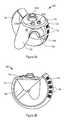
- FIG. 3A and FIG. 3Billustrate isometric views of a hand-held controller of the exemplary virtual-reality system in accordance with some embodiments.
- FIG. 4is a block diagram illustrating an electrical configuration of the exemplary virtual-reality system in accordance with some embodiments.
- FIG. 5Ais a block diagram of an exemplary head-mounted display in accordance with some embodiments.
- FIG. 5Bis a block diagram of an exemplary camera in accordance with some embodiments.
- Virtual-reality or gaming systemsmay include hand-held controllers held in one or both hands by a user while playing a video game or carrying out some other virtual reality activity in order to operate the user-input keys (e.g., buttons, thumbstick, directional pad, trigger, etc.) on the controller.
- the userWhile playing the game or carrying out the virtual-reality activity, the user may become so immersed in the game as to move their hands in a manner mimicking a desired action (e.g., performed by pressing one of the buttons while holding the controller). For example, during playing a boxing game a user may press an “L” button corresponding to a left hand punch while simultaneously jerking their left hand for a more “real” sensation. It is desirable to display the hand motion of the user as a corresponding motion by an image subject on the screen in the virtual reality system.
- the present inventiondescribes virtual reality systems capable of detecting physical positions of hand-held controllers at various points in time to simulate actual hand movements of users holding the controllers to allow easy tracking of the user hand movements and enhance the user virtual-reality experience.
- the detected positions and movements of the hand-held controllersmay be used as additional commands to control various aspects of the game or other simulation being played.
- a virtual-reality systemincludes a head-mounted display (HMD), a forward-looking camera coupled to the HMD, and a hand-held controller communicatively coupleable to the HMD (e.g., such that it can communicate wirelessly with the HMD).
- the hand-held controllerincludes one or more user-input keys, a grip, an outward-facing surface coupled to the grip, and illumination sources coupled to (e.g., mounted on or embedded in) the outward-facing surface of the controller.
- the forward-looking camerais adapted to detect light reflected or emitted by the illumination sources. In some embodiments, the forward-looking camera is directly coupled to and extends from a front surface of the HMD.
- the forward-looking camerais an external camera communicatively coupled to, but physically positioned separate from the HMD.
- the HMDuses the forward-looking camera to detect movement of the illumination sources by tracking positions of light reflected or emitted in order to model actions of the user's hand(s) in the virtual-reality system.
- the cameramay detect various movements of the hand-held controller, such as punching movements, throwing movements, hitting movements when playing a sport, and the like. Motions of the hand-held controller correspond to various commands such that the motions are transferred into actions in the virtual reality system.
- first, second, etc.are, in some instances, used herein to describe various elements, these elements should not be limited by these terms. These terms are used only to distinguish one element from another.
- a first user-input keycould be termed a second user-input key, and, similarly, a second user-input key could be termed a first user-input key, without departing from the scope of the various described embodiments.
- the first user-input key and the second user-input keyare both user-input keys, but they are not the same user-input key.
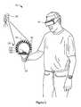
- FIGS. 1A and 1Billustrate exemplary virtual reality systems 100 A and 100 B including a front-looking camera 102 coupled to (e.g., extending from) a head-mounted display (HMD) 105 , and a hand-held controller 300 in accordance with some embodiments.
- the hand-held controller 300generally comprises a first user-input key 120 A, a grip 130 , an outward-facing surface 145 coupled to the grip 130 , and a plurality of illumination sources 150 coupled to (e.g., mounted on or embedded in) the outward-facing surface 145 .
- the illumination sources 150are configured to emit or reflect light that is detectable by camera 102 .
- the camera 102is positioned to detect movement in positions of the illumination sources 150 when the user makes a motion (e.g., waving, swinging, punching, shaking, or any other hand motion) while holding the grip 130 of the controller. By detecting a movement of the illumination sources 150 on the controller 300 , the camera is able to capture sequential positions of the controller 300 over time, and thus allow motion of an image subject to be modeled in virtual reality based on actual physical motions made by the user (e.g., punching, swinging, etc) as described above.
- the HMD 105is configured to display a view which shifts as a user shifts their head in a corresponding direction or tilts their head at an angle.
- the HMD 105is communicatively coupleable to the controller 300 and the camera 102 so as to be able to display the detected motions of the controller 300 along with motions of the head of the user as those of an image subject of the virtual reality system 100 .
- the HMD 105communicates wirelessly with the controller 300 and communicates with the camera 102 through a wired or wireless connection.
- the camera 102extends from (e.g., is mounted to) the top of the HMD 105 (e.g., at a downward facing angle) such that the controller 300 having the plurality of illumination sources 150 is within view of the camera 102 when the user holds the grip 130 in a neutral position.
- the camera 102extends from (e.g., is mounted to) a side of the HMD 105 or the bottom of the HMD 105 .
- the forward-looking camera 102is external to and communicatively coupled or coupleable to the HMD 105 (e.g., through a wired connection with the HMD 105 or wirelessly).
- a neutral positionrefers to when users hold the controller 300 in front of them with the grip 130 between palm and fingers and otherwise relax their arms and wrists.
- the distance at which the camera 102 is extendable from the HMD 105may be adjustable depending on how far away the user holds the controller 300 from the their body.
- the camera 102extends from a front surface of the HMD 105 .
- a first portion of the camera 102is in front of the HMD 105 while a second portion of the camera 102 is housed within the HMD 105 .
- Extending the camera 102 from the front surface of the HMD 105provides a wide (e.g., 180°) field of view for the camera 102 .
- the camerais embedded entirely within the HMD 105 (e.g., with the lens exposed through a transparent portion of the front surface of the HMD 105 ).
- the camera 102may be configured with sensors to sense light emitted or reflected by the illumination sources 150 .
- the camera 102is configured to sense a position of the controller 300 or illumination sources 150 based on the light emitted.
- the camera 102 or HMD 105thus may determine the position and orientation of the controller 300 .
- the camera 102based on a distance of the controller 300 from the user's body, the camera 102 is adapted to either extend away from or retract towards the HMD.
- an angle at which the camera faces the controller 102is also similarly adjustable depending on orientation of the controller 300 and the plurality of illumination sources.
- forward facing camera 102is positioned to detect the light emitted or reflected by the illumination sources 150 when the outward-facing surface 145 is positioned above the user's hand in the neutral position.
- FIG. 2illustrates an exemplary virtual-reality system 200 including a head-mounted display 105 and an external camera 202 in accordance with some embodiments.
- the camera 202is external to and communicatively (e.g., wirelessly) coupleable to the HMD 105 .
- the camera 202is positioned in front of the user and at least a portion of the illumination sources 150 are positioned to face away from the user so as to be visible or detectable to the external camera 202 when the user holds the grip 130 in the neutral position.
- the camera 202detects movement of the illumination sources 150 when the user makes a motion (e.g., waving, swinging, punching, shaking, or any other hand motion) while holding the grip 130 of the controller.
- a motione.g., waving, swinging, punching, shaking, or any other hand motion
- the outward-facing surface 145is positioned such that it is located above the user hand when the user holds the grip 130 in the neutral position. Given this orientation, the outward-facing surface 145 is within the view of the external forward-looking camera 202 which is separate from the HMD 105 .
- the camera 102 , 202may be customized for the purposes of the virtual reality system 100 .
- the camera 102 , 202may include but not be limited to a commercially available camera product of any type or brand, such as for example a web-cam, an IR capable camera, and/or a USB camera, etc.
- the camera 102 , 202is electrically connected to a power source which may or may not be the same power source providing power to the HMD 105 .
- the camera 102 , 202 and the HMD 105may be wireless; therefore, the power source may be one or more batteries.
- the illumination sources 150are positioned to allow the camera 102 , 202 to detect at least six degrees of freedom of the controller 102 .
- the six degrees of freedomare the controller's 300 position within x, y and z coordinates of space and the controller's 300 orientation —which includes the controller's 300 yaw, pitch and roll.
- the six degrees of freedom detected by the camera 102are used to determine the user's movements of the controller 300 and model these movements in virtual reality.
- the illumination sources 150are light-emitting diodes (LEDs). In some embodiments, the LEDs 150 are infrared (IR) LEDs.
- the camera 102is configured to detect the IR light emitted by the IR LEDs on the controller 300 and record the signals sensed from the emitted light to determine the position and orientation of the controller 300 .
- the LEDsmay be positioned on the outward-facing surface 145 of the controller 300 in any suitable pattern, order, or array.
- the outward-facing surface 145is an outer surface of a cage 140 coupled to the grip 130 .
- the LEDsmay be fixedly or detachably positioned on, and thus coupled to, the cage 140 by any appropriate method.
- the LED'smay be mounted on or embedded within the outer surface 145 of the cage 140 .
- the LEDsmay be on a sleeve that surrounds the cage 140 and effectively forms the outer surface 145 of the cage 140 .
- the LEDsare described as being positioned on the outer 145 surface of the cage 140 , they may additionally or alternatively be coupled to any other surface on the cage 140 and/or the rest of the controller 300 .
- the LEDsare electrically connected to a power source which may or may not be same power source providing power to the controller 300 .
- the controller 300may be wireless; therefore, the power source may be one or more batteries.
- the LEDsmay be housed in diffused cases including a current limiting resistor to keep the current from the power source to the LED below the LED's maximum current rating so as to ensure maximum life of the LEDs.
- the LEDsmay be activated when a suitable voltage is applied. By virtue of the LEDs being positioned in an area on the controller 300 detectable to the camera 102 , 202 , motion of the light produced by the LEDs that is detected by the camera 102 , 202 is used as an indication of the positions and motion of the controller 300 .
- motion of the controlleris tracked by the camera 102 , 202 , allowing for corresponding virtual-reality hand motions to be shown on the HMD 105 .
- movement of the LEDs in a manner corresponding to a punchmay be detected and used to model the user's motion for the image subject displayed on the HMD 105 in the virtual reality system 100 .
- the present inventionprovides the advantage of enhancing the virtual reality experience for the user by adding the additional element of hand motions to the image subject.
- the illumination sources 150are passive reflectors.
- the camera 102 , 202is adapted to include an illumination source (e.g., a flash) and to provide light to the passive reflectors.
- FIG. 1Cshows a virtual-reality system 100 C in which the camera 102 includes an illumination source (e.g., a flash) 160 .
- the illumination sourcemay be directly connected to the rest of the camera 102 or may be separate from the rest of the camera 102 .
- the illumination sourcemay be considered part of the camera 102 or may be considered a separate component of the virtual-reality system.
- the illumination source 160may be integrated into the HMD 160 (e.g., such that it provides illumination through a transparent portion of the front surface of the HMD 160 ), mounted on the HMD 160 (e.g., on the top, bottom or side of the HMD 160 ) or separate from the HMD 160 .
- an illumination sourcemay be integrated in the camera 202 , mounted on the camera 202 , or separate from the camera 202 .
- the passive reflectorsreceive light (e.g., from the illumination source 160 ) and reflect the light back in the direction of the camera 102 , 202 .
- the camera 102 . 202includes a sensor to detect the light reflected back by the passive reflectors and record the signals sensed from the reflected light to determine the position and orientation of the controller 300 .
- the controller 300includes the first user-input key 120 A and may include one or more additional user-input keys 120 B, 120 C.
- a user-input keyis a button, knob, switch, thumbstick, directional pad, or any other such part that a user presses or manipulates in some other way to carry out a specific action in a virtual reality system (e.g., during gaming).
- FIG. 3A and FIG. 3Billustrate isometric views of a hand-held controller 300 of the exemplary virtual reality system 100 in accordance with some embodiments.
- the first user-input key 120 Amay be selected from the group consisting of a thumbstick, a button, a trigger, and a directional pad.
- the first user-input key 120 Amay be the button selected from the group consisting of an A or X button, a B or Y button, a start button, a back button, a forward button, and a home button.
- the A or B buttonsmay correspond to a selection action between at least two choices presented to the user in the gaming system.
- the X or Y buttonmay correspond to a negative or affirmative decision to be made by the user dictating how the image subject will proceed in the game.
- Xmay correspond to an action of “NO” or “END” and Y may correspond to “YES” or “PROCEED/CONTINUE.”
- the start buttonmay be a button activated by the user to begin the virtual-reality (e.g., gaming) experience, and the back and forward buttons may indicate a direction in which the user desires the image subject to move.
- the home buttonmay be a button activated to return the gaming experience back to a main menu or to start the game or activity from the beginning.
- the hand-held controller 300further comprises a user-input surface 110 that includes the first user-input key 120 A.
- the user-input surface 110includes a plurality of user-input keys 120 A, 120 B and 120 C.
- the user-input surfaceincludes a single user-input key.
- the user input keysinclude a thumbstick 120 A and buttons 120 B and 120 C.
- the user-input surface 110is a surface on the controller 300 where the user delivers an input by activating one or more user-input keys (e.g., by pressing a button or pushing a knob) corresponding to an action that the user desires to carry out in the virtual-reality system 100 (e.g., the virtual reality system 100 A, 100 B, or 100 C).
- the virtual-reality system 100e.g., the virtual reality system 100 A, 100 B, or 100 C.
- Each of the user-input keys 120 A, 120 B and 120 Cis configured to communicate with the virtual-reality system 100 so as to translate an operation of the corresponding user-input key by the user into a corresponding action of the image subject displayed on the HMD 105 of the virtual reality system 100 .
- the user-input surface 110includes a plurality of user-input keys including the first user-input key 120 A, and respective user-input keys 120 B, 120 C of the plurality of user-input keys are selected from a group consisting of a thumbstick, a button, a trigger, and a directional pad.
- a home buttonis positioned further away from the other user-input keys.
- This configurationwould allow for user-input keys that are used most (e.g. a directional pad used to dictate a direction of movement of the image subject, e.g., up-down-left-right) to be placed closer to the vicinity of the fingers and thumb.
- This configurationprovides the advantage that the user would need to reach less to press the more frequently used user-input keys, thereby mitigating the possibility of ergonomic ailments associated with overreaching and overstretching fingers.
- At least a portion of the user-input surface 110is a touch-sensitive surface partitioned into a plurality of sections. Each section corresponds to a respective user-input key of the plurality of user-input keys.
- at least one touch sensoris positioned on a bottom surface of the user-input surface 110 , as illustrated in FIG. 4 , to detect a touch on the corresponding section.
- the grip 130is coupled to the user-input surface 110 .
- the grip 130is a protruding structure of the controller 300 which the user grips in one hand to hold the controller 300 .
- This configurationallows for the user to be able to grip the controller 300 between a palm and fingers (e.g., three or less fingers) while freeing up the thumb and, in some embodiments, another finger (e.g. the middle finger), for operating the user-input keys 120 A, 120 B and 120 C.
- the middle fingeris freed to operate a trigger 190 mounted at least in part on the grip 130 as shall be described below.
- the grip 130is a separate part of the controller 300 that is removably coupled to the user input surface 110 and/or cage 140 .
- the grip 130 and the user-input surfacemay be coupled by a method appropriate for their materials of construction.
- the grip and user-input surface 110may be formed of a hard plastic and may be coupled to each other by ultrasonic welding.
- the grip 130 and the user-input surface 110may be coupled to each other by a fastening mechanism such as a screw or a bolt, or may be threadedly engaged with each other.
- the grip 130is integrally formed with the user-input surface 110 and/or the cage 140 , as one part (e.g., which may be formed from molding).
- the grip 130is slanted at a predetermined angle with respect to the user-input surface 110 (e.g., with a plane through the user-input surface or a portion thereof) in order to provide a comfortable (e.g., optimum) ergonomic balance for a user between holding the grip in and using a thumb to operate the at least one user-input key.
- the cage 140is coupled to the user-input surface 110 .
- the cage 140which may also be referred to as a tracking cage, has the outer surface 145 on which the plurality of illumination sources 150 is positioned.
- the user-input surface 110is outward-facing with respect to the cage 140 .
- the user-input surface 110may be inward-facing with respect to the cage 140 , as illustrated in FIG. 2 .
- the user-input surface 110forms an inner front surface of the cage 140 or is contiguous with the inner surface of the cage 140 .
- the grip 130 and/or cage 140may be formed of an over-molded rubber material (e.g., so as to provide a surface providing sufficient friction with a user's palm thus improving the grip).
- the grip 130 and/or cage 140may be formed of a hard plastic, including, but not limited to high density polyethylene providing increased rigidity in structure. Additionally, any other suitable materials may be used.
- the cage 140may be detachably coupled to at least one of the user-input surface 110 and the grip 130 .
- the cage 140may be slidably coupled to the user-input surface 110 through a protrusion spanning a width of each end portion of the cage 140 being slidably engaged with a corresponding groove positioned on an outer circumference of the user-input surface 110 .
- the cage 140may be coupled to the grip 130 through a fastening mechanism such as a bolt, a screw or the like.
- the detachable configuration of the cage 140 to the grip 130 or the user-input surface 110yields the advantage of separating the aforementioned components for calibration as necessary. Detachable coupling of the components also allows for a separate and potentially cheaper manufacturing process of the parts.
- detachable coupling of the cage 140 to at least one of the user-input surface 110 and the grip 130allows for separation thereof upon dropping of the controller 300 , thereby reducing the need to replace the entire unit upon damage, but instead focus on fixing/replacing the separate damaged part.
- the controller 300may further comprise a structural web 195 coupling the cage 140 to the user-input surface 110 .
- the large structural web 195provides further rigidity in structure to the coupling between the cage 140 and the user-input surface 110 to mitigate damage and separation of these components upon dropping of the controller 300 by the user.
- a trigger 190is mounted at least in part on the structural web 195 . That is, the trigger 190 may be mounted between the structural web 190 and the grip 130 .
- This configurationyields the advantage that the trigger is positioned adjacent to a location of a user's finger (e.g., middle finger) when the grip 130 is held in the neutral position.
- the triggermay be both pushed and pulled by the middle finger, thus providing increased control in manipulating the trigger to achieve a desired action.
- the trigger 190is an example of a user-input key.
- FIG. 4is a block diagram illustrating an electrical configuration of an exemplary hand-held controller 300 in accordance with some embodiments.
- the hand-held controller 300includes an input board 402 and a main board 403 coupled to the input board 402 .
- the input board 402includes a trigger motion sensing device 425 , a thumbstick 430 , buttons 435 , and a capacitive touch controller 440 .
- the input board 402may include additional or alternative user-input keys.
- the trigger motion sensing device 425detects user activation of a trigger (e.g., trigger 190 ).
- the capacitive touch controller 440is coupled to multiple sensors such that the input board 402 receives sensed signals from capacitive sensors resulting from a user's touch.
- the capacitive sensorsinclude a trigger sensor 405 , a thumbstick sensor 410 , an “A” button sensor 415 , and/or a “B” button sensor 420 .
- the trigger sensor 405may sense when a user touches the trigger.
- the thumbstick sensor 410senses a signal resulting from the user touching the thumbstick 410 .
- the button sensors 415 and 420sense signals resulting from the user touching the buttons 415 and 420 .
- Other capacitive sensorsmay be included for other user-input keys (e.g., a directional pad).
- the mainboard 403includes a controller 460 , a haptics driver 465 , a middle finger position sensor 475 , power path 490 , motion tracking sensors/processors 495 and an illumination source driver 480 .
- the haptics driver 465drives a haptics output device 470 that provides haptic effects.
- An example of the haptics output device 470includes a short vibration feedback device that, when activated, causes the hand-held controller 300 to vibrate.
- the mainboard 403may be coupled to an antenna 445 to wirelessly receive and transmit signals.
- the hand-held controllere.g., controller 300
- the mainboard 403may also be coupled to a power source (e.g., a battery 450 ) to provide power supply to the hand-held controller.
- the powermay be supplied to the mainboard 403 , and also to the input board 402 , through a power path 490 .
- the illumination source driver 480(e.g., LED driver) drives illumination sources 485 (e.g., LEDs on the outer surface of the cage 140 ) under the control of the controller 460 , and thus turns the illumination sources 485 on or off.
- illumination sources 485e.g., LEDs on the outer surface of the cage 140
- the middle finger position sensor 475senses a position of the middle finger (e.g. when a user activates the trigger 190 ) and this information is processed by the controller 460 .
- the motion tracking sensors/processors 495include a plurality of motion sensors (e.g. accelerometers and/or gyroscopes) which tracks motion of the controller based on motions made by the user.
- the camera 102 , 202includes at least one sensor for sensing light emitted or reflected from the plurality of illumination sources (e.g., LEDs or passive reflectors) and a controller for processing the light images received for the illumination sources 485 to detect positions of the controller over time.
- illumination sourcese.g., LEDs or passive reflectors
- the HMDincludes at least one sensor to sense signals from the controller 460 and a controller to process these signals into images displayed on the HMD.
- the processor of the HMDmay further be configured to process information received from the camera 102 , 202 relating to positions of the hand-held controller 300 for display on the HMD.
- FIG. 5Ais a block diagram of an exemplary HMD 105 in accordance with some embodiments.
- the HMD 105includes an HMD 502 , one or more sensors 504 , a controller 506 , and a camera 102 .
- the controller 506is coupled to an antenna 510 for wireless communication (e.g., with hand-held controllers 300 ).
- the HMD 105(e.g., including the camera 102 ) is powered by a battery 512 .
- FIG. 5Bis a block diagram of an exemplary camera 530 in accordance with some embodiments.
- the camera 530is an example of a camera 102 or 202 .
- the camera 530includes sensor(s) 532 , a controller 534 , and an optional illumination source (e.g., flash) 536 .
- the controller 534is coupled to an antenna 538 for wireless communication (e.g., with an HMD 105 and/or hand-held controllers 300 ).
- the camera 530is powered by a battery 540 ; alternatively, the camera 530 is powered by a battery it shares with the HMD 105 (e.g., battery 512 , FIG. 5A ).
- Some embodimentsare directed to two hand-held controllers 300 —one to be held in each of a user's hands.
- the two controllers 300may be identical, but for a position of at least one of the user-input keys, so as to be adapted specifically for either a left or right hand in which the controller is to be held.
- the first controllerthus may be a right-handed controller and the second controller may be a left-handed controller.
- the two controllersmay be agnostic with respect to handedness (e.g., with both controllers having the same configuration of user-input keys, or with one controller having a configuration of user-input keys different than the other).
Landscapes
- Engineering & Computer Science (AREA)
- Theoretical Computer Science (AREA)
- Human Computer Interaction (AREA)
- Multimedia (AREA)
- General Engineering & Computer Science (AREA)
- Physics & Mathematics (AREA)
- General Physics & Mathematics (AREA)
- Computer Hardware Design (AREA)
- Optics & Photonics (AREA)
- Health & Medical Sciences (AREA)
- Biophysics (AREA)
- Cardiology (AREA)
- General Health & Medical Sciences (AREA)
- Heart & Thoracic Surgery (AREA)
- Life Sciences & Earth Sciences (AREA)
- User Interface Of Digital Computer (AREA)
- Computer Graphics (AREA)
- Software Systems (AREA)
Abstract
Description
Claims (20)
Priority Applications (2)
| Application Number | Priority Date | Filing Date | Title |
|---|---|---|---|
| US14/729,954US9898091B2 (en) | 2015-06-03 | 2015-06-03 | Virtual reality system with head-mounted display, camera and hand-held controllers |
| US15/893,515US20180173320A1 (en) | 2015-06-03 | 2018-02-09 | Virtual Reality System with Head-Mounted Display, Camera and Hand-Held Controllers |
Applications Claiming Priority (1)
| Application Number | Priority Date | Filing Date | Title |
|---|---|---|---|
| US14/729,954US9898091B2 (en) | 2015-06-03 | 2015-06-03 | Virtual reality system with head-mounted display, camera and hand-held controllers |
Related Child Applications (1)
| Application Number | Title | Priority Date | Filing Date |
|---|---|---|---|
| US15/893,515ContinuationUS20180173320A1 (en) | 2015-06-03 | 2018-02-09 | Virtual Reality System with Head-Mounted Display, Camera and Hand-Held Controllers |
Publications (2)
| Publication Number | Publication Date |
|---|---|
| US20160357261A1 US20160357261A1 (en) | 2016-12-08 |
| US9898091B2true US9898091B2 (en) | 2018-02-20 |
Family
ID=57452574
Family Applications (2)
| Application Number | Title | Priority Date | Filing Date |
|---|---|---|---|
| US14/729,954Active2036-05-09US9898091B2 (en) | 2015-06-03 | 2015-06-03 | Virtual reality system with head-mounted display, camera and hand-held controllers |
| US15/893,515AbandonedUS20180173320A1 (en) | 2015-06-03 | 2018-02-09 | Virtual Reality System with Head-Mounted Display, Camera and Hand-Held Controllers |
Family Applications After (1)
| Application Number | Title | Priority Date | Filing Date |
|---|---|---|---|
| US15/893,515AbandonedUS20180173320A1 (en) | 2015-06-03 | 2018-02-09 | Virtual Reality System with Head-Mounted Display, Camera and Hand-Held Controllers |
Country Status (1)
| Country | Link |
|---|---|
| US (2) | US9898091B2 (en) |
Cited By (10)
| Publication number | Priority date | Publication date | Assignee | Title |
|---|---|---|---|---|
| US20200089313A1 (en)* | 2018-09-14 | 2020-03-19 | Apple Inc. | Tracking and drift correction |
| US20200201045A1 (en)* | 2018-12-21 | 2020-06-25 | Microsoft Technology Licensing, Llc | Controlling light source intensities on optically trackable object |
| US10705597B1 (en) | 2019-12-17 | 2020-07-07 | Liteboxer Technologies, Inc. | Interactive exercise and training system and method |
| US10901506B2 (en) | 2018-07-30 | 2021-01-26 | Htc Corporation | Finger-gesture detection device for control handle use in virtual reality, control assembly having the same and correction method for virtual reality system |
| US10942252B2 (en)* | 2016-12-26 | 2021-03-09 | Htc Corporation | Tracking system and tracking method |
| US11003247B1 (en) | 2020-03-20 | 2021-05-11 | Microsoft Technology Licensing, Llc | Deployable controller |
| US11022784B1 (en) | 2018-08-17 | 2021-06-01 | Facebook Technologies, Llc | Use of folded optics to reduce volume in a virtual-reality system |
| US11054622B1 (en) | 2017-11-20 | 2021-07-06 | Facebook Technologies, Llc | Folded viewing optics with an optical retarder on a simple surface |
| US11372239B1 (en) | 2018-11-01 | 2022-06-28 | Facebook Technologies, Llc | Enabling eye tracking in pancake lens optics |
| US11395962B2 (en)* | 2018-11-12 | 2022-07-26 | Htc Corporation | Virtual reality controller |
Families Citing this family (75)
| Publication number | Priority date | Publication date | Assignee | Title |
|---|---|---|---|---|
| US10905943B2 (en)* | 2013-06-07 | 2021-02-02 | Sony Interactive Entertainment LLC | Systems and methods for reducing hops associated with a head mounted system |
| US9898091B2 (en) | 2015-06-03 | 2018-02-20 | Oculus Vr, Llc | Virtual reality system with head-mounted display, camera and hand-held controllers |
| US9833700B2 (en)* | 2015-06-11 | 2017-12-05 | Oculus Vr, Llc | Connectable hand-held controllers for virtual-reality systems |
| USD772986S1 (en) | 2015-06-11 | 2016-11-29 | Oculus Vr, Llc | Wireless game controller |
| US9839840B2 (en)* | 2015-11-05 | 2017-12-12 | Oculus Vr, Llc | Interconnectable handheld controllers |
| US10007339B2 (en) | 2015-11-05 | 2018-06-26 | Oculus Vr, Llc | Controllers with asymmetric tracking patterns |
| US10130875B2 (en) | 2015-11-12 | 2018-11-20 | Oculus Vr, Llc | Handheld controller with finger grip detection |
| US9990045B2 (en) | 2015-11-12 | 2018-06-05 | Oculus Vr, Llc | Method and apparatus for detecting hand gestures with a handheld controller |
| US20170168592A1 (en)* | 2015-12-14 | 2017-06-15 | Volodymyr Mishyn | System and method for optical tracking |
| US9804693B2 (en)* | 2015-12-18 | 2017-10-31 | Oculus Vr, Llc | Handheld controller with activation sensors |
| US9851561B2 (en)* | 2015-12-23 | 2017-12-26 | Intel Corporation | Head-mounted device with rear-facing camera |
| US10343059B2 (en) | 2015-12-30 | 2019-07-09 | Facebook Technologies, Llc | Handheld controller with thumbstick guard |
| US10441880B2 (en) | 2015-12-30 | 2019-10-15 | Facebook Technologies, Llc | Handheld controller with spring-biased third finger button assembly |
| US10386922B2 (en) | 2015-12-30 | 2019-08-20 | Facebook Technologies, Llc | Handheld controller with trigger button and sensor retainer assembly |
| US9977494B2 (en) | 2015-12-30 | 2018-05-22 | Oculus Vr, Llc | Tracking constellation assembly for use in a virtual reality system |
| USD819638S1 (en)* | 2015-12-31 | 2018-06-05 | Htc Corporation | Remote controller |
| US11857869B2 (en) | 2015-12-31 | 2024-01-02 | Meta Platforms Technologies, Llc | Handheld controller with hand detection sensors |
| USD835104S1 (en) | 2016-09-27 | 2018-12-04 | Oculus Vr, Llc | Wireless game controller |
| US11625898B2 (en) | 2016-10-11 | 2023-04-11 | Valve Corporation | Holding and releasing virtual objects |
| US10549183B2 (en)* | 2016-10-11 | 2020-02-04 | Valve Corporation | Electronic controller with a hand retainer, outer shell, and finger sensing |
| US10888773B2 (en) | 2016-10-11 | 2021-01-12 | Valve Corporation | Force sensing resistor (FSR) with polyimide substrate, systems, and methods thereof |
| US10307669B2 (en) | 2016-10-11 | 2019-06-04 | Valve Corporation | Electronic controller with finger sensing and an adjustable hand retainer |
| US10391400B1 (en)* | 2016-10-11 | 2019-08-27 | Valve Corporation | Electronic controller with hand retainer and finger motion sensing |
| US10649583B1 (en) | 2016-10-11 | 2020-05-12 | Valve Corporation | Sensor fusion algorithms for a handheld controller that includes a force sensing resistor (FSR) |
| US11185763B2 (en) | 2016-10-11 | 2021-11-30 | Valve Corporation | Holding and releasing virtual objects |
| US10987573B2 (en) | 2016-10-11 | 2021-04-27 | Valve Corporation | Virtual reality hand gesture generation |
| US10691233B2 (en) | 2016-10-11 | 2020-06-23 | Valve Corporation | Sensor fusion algorithms for a handheld controller that includes a force sensing resistor (FSR) |
| US11740690B2 (en)* | 2017-01-27 | 2023-08-29 | Qualcomm Incorporated | Systems and methods for tracking a controller |
| CN206863338U (en)* | 2017-02-24 | 2018-01-09 | 深圳市大疆创新科技有限公司 | Video eyeglasses headband and video eyeglasses |
| US10183217B2 (en) | 2017-04-13 | 2019-01-22 | Facebook Technologies, Llc | Hand-held controller using segmented capacitive touch trigger |
| US10061458B1 (en) | 2017-04-20 | 2018-08-28 | Oculus Vr, Llc | Hand-held controller using capacitive touch pad |
| US10537795B2 (en)* | 2017-04-26 | 2020-01-21 | Facebook Technologies, Llc | Hand-held controller using LED tracking ring |
| EP3395418B1 (en)* | 2017-04-26 | 2020-11-18 | Facebook Technologies, LLC | Hand-held controller using led tracking ring background |
| US10688396B2 (en)* | 2017-04-28 | 2020-06-23 | Sony Interactive Entertainment Inc. | Second screen virtual window into VR environment |
| JP7143336B2 (en) | 2017-06-16 | 2022-09-28 | バルブ コーポレーション | Electronic controller with finger motion sensing |
| US20190012835A1 (en)* | 2017-07-07 | 2019-01-10 | Microsoft Technology Licensing, Llc | Driving an Image Capture System to Serve Plural Image-Consuming Processes |
| CN107233729A (en)* | 2017-07-14 | 2017-10-10 | 歌尔科技有限公司 | Virtual reality device joystick and virtual reality device |
| CN109069920B (en)* | 2017-08-16 | 2022-04-01 | 广东虚拟现实科技有限公司 | Handheld controller, tracking and positioning method and system |
| US10386938B2 (en)* | 2017-09-18 | 2019-08-20 | Google Llc | Tracking of location and orientation of a virtual controller in a virtual reality system |
| US10509489B2 (en) | 2017-09-26 | 2019-12-17 | Yong Bum Kim | Systems and related methods for facilitating pen input in a virtual reality environment |
| US10540023B2 (en) | 2017-09-26 | 2020-01-21 | Yong Bum Kim | User interface devices for virtual reality system |
| EP3684484A4 (en)* | 2017-12-07 | 2021-03-31 | Valve Corporation | ELECTRONIC CONTROL UNIT WITH HAND HOLDER, OUTER SHELL AND FINGER SENSOR |
| EP3505219B1 (en)* | 2017-12-29 | 2021-01-27 | Facebook Technologies, LLC | Hand-held controller using sensors for hand disambiguation |
| US10912990B2 (en) | 2017-12-29 | 2021-02-09 | Facebook Technologies, Llc | Hand-held controller using sensors for hand disambiguation |
| KR102684302B1 (en)* | 2018-01-05 | 2024-07-12 | 삼성전자주식회사 | Method and apparatus for navigating virtual content displayed by a virtual reality (VR) device |
| US10678335B2 (en) | 2018-01-08 | 2020-06-09 | Facebook Technologies, Llc | Methods, devices, and systems for creating haptic stimulations and tracking motion of a user |
| CN111936959A (en) | 2018-03-23 | 2020-11-13 | 脸谱科技有限责任公司 | Method, device, and system for displaying a user interface on a user and detecting touch gestures |
| US10554883B2 (en)* | 2018-03-30 | 2020-02-04 | Ricoh Company, Ltd. | VR system, communication method, and non-transitory computer-readable medium |
| US11042226B2 (en)* | 2018-04-02 | 2021-06-22 | Microsoft Technology Licensing, Llc | Constellation-based augmentation of mouse form-factor for virtual reality applications |
| US10924566B2 (en) | 2018-05-18 | 2021-02-16 | High Fidelity, Inc. | Use of corroboration to generate reputation scores within virtual reality environments |
| JP7358408B2 (en)* | 2018-06-20 | 2023-10-10 | バルブ コーポレーション | Holding and releasing virtual objects |
| JP7337857B2 (en)* | 2018-06-20 | 2023-09-04 | バルブ コーポレーション | Virtual Reality Hand Gesture Generation |
| KR102737463B1 (en)* | 2018-06-20 | 2024-12-03 | 밸브 코포레이션 | Maintaining and releasing virtual objects |
| US20200023270A1 (en)* | 2018-07-18 | 2020-01-23 | Immersion Corporation | Trigger Button For Haptic Controller |
| GB2580915B (en)* | 2019-01-29 | 2021-06-09 | Sony Interactive Entertainment Inc | Peripheral tracking system and method |
| US11112886B2 (en)* | 2019-01-30 | 2021-09-07 | Disney Enterprises, Inc. | Model and detachable controller for augmented reality / virtual reality experience |
| US11175728B2 (en) | 2019-02-06 | 2021-11-16 | High Fidelity, Inc. | Enabling negative reputation submissions in manners that reduce chances of retaliation |
| JP7328322B2 (en)* | 2019-03-18 | 2023-08-16 | 株式会社ソニー・インタラクティブエンタテインメント | input device |
| JP7353773B2 (en)* | 2019-03-18 | 2023-10-02 | 株式会社ソニー・インタラクティブエンタテインメント | Devices with multiple markers |
| JP7066013B2 (en)* | 2019-04-25 | 2022-05-12 | 株式会社Nttドコモ | Video processing system showing the arrangement of jigs |
| CN112241200A (en)* | 2019-07-17 | 2021-01-19 | 苹果公司 | Object tracking for head mounted devices |
| GB2586601B (en) | 2019-08-27 | 2022-10-12 | Zeta Motion Ltd | Determining object pose from image data |
| CN110837295A (en)* | 2019-10-17 | 2020-02-25 | 重庆爱奇艺智能科技有限公司 | Handheld control equipment and tracking and positioning method, equipment and system thereof |
| US11635802B2 (en)* | 2020-01-13 | 2023-04-25 | Sony Interactive Entertainment Inc. | Combined light intensity based CMOS and event detection sensor for high speed predictive tracking and latency compensation in virtual and augmented reality HMD systems |
| CN111459279A (en)* | 2020-04-02 | 2020-07-28 | 重庆爱奇艺智能科技有限公司 | Active fill light equipment, 3DOF handle, VR equipment and tracking system |
| RU2745205C1 (en)* | 2020-07-20 | 2021-03-22 | Станислав Александрович Воронин | User wearable device (versions) |
| US11448884B2 (en)* | 2020-11-25 | 2022-09-20 | Sony Interactive Entertainment Inc. | Image based finger tracking plus controller tracking |
| CN113318435A (en)* | 2021-04-27 | 2021-08-31 | 青岛小鸟看看科技有限公司 | Control method and device of handle control tracker and head-mounted display equipment |
| EP4142285B1 (en)* | 2021-05-17 | 2025-07-23 | Qingdao Pico Technology Co., Ltd. | Head-mounted display device and head-mounted display system |
| EP4540648A1 (en)* | 2022-06-17 | 2025-04-23 | Magic Leap, Inc. | Method and system for performing eye tracking in augmented reality devices |
| US12282612B2 (en)* | 2022-08-04 | 2025-04-22 | Stmicroelectronics (Research & Development) Limited | Three-dimensional interactive display |
| WO2024112911A1 (en)* | 2022-11-23 | 2024-05-30 | Meta Platforms Technologies, Llc | Arrangements of illumination sources within and outside of a digit-occluded region of a top cover of a handheld controller to assist with positional tracking of the controller by an artificial-reality system, and systems and methods of use thereof |
| WO2024138433A1 (en)* | 2022-12-28 | 2024-07-04 | Celanese International Corporation | Thermoplastic vulcanizate based molded part for use in virtual reality system |
| WO2024167174A1 (en)* | 2023-02-10 | 2024-08-15 | 삼성전자 주식회사 | Controller device and method for tracking controller device by using wearable electronic device |
| WO2025023550A1 (en)* | 2023-07-24 | 2025-01-30 | 삼성전자 주식회사 | Wearable electronic device for changing mode related to user input and operation method thereof |
Citations (110)
| Publication number | Priority date | Publication date | Assignee | Title |
|---|---|---|---|---|
| US4518164A (en) | 1983-11-10 | 1985-05-21 | Hayford Jr Robert L | Video game control console |
| US4552360A (en) | 1982-09-29 | 1985-11-12 | Coleco Industries, Inc. | Video game with control of movement and rate of movement of a plurality of game objects |
| US5008497A (en) | 1990-03-22 | 1991-04-16 | Asher David J | Touch controller |
| US5159159A (en) | 1990-12-07 | 1992-10-27 | Asher David J | Touch sensor and controller |
| US5409239A (en) | 1992-10-26 | 1995-04-25 | Michael Tremmel | Touch sensitive video game controller |
| US5421590A (en) | 1993-07-23 | 1995-06-06 | Commodore Electronics Limited | Multiple linked game controllers |
| US5479163A (en) | 1994-08-04 | 1995-12-26 | Samulewicz; Thomas | Circular tactile keypad |
| US5551701A (en) | 1992-08-19 | 1996-09-03 | Thrustmaster, Inc. | Reconfigurable video game controller with graphical reconfiguration display |
| US5616078A (en) | 1993-12-28 | 1997-04-01 | Konami Co., Ltd. | Motion-controlled video entertainment system |
| US5632679A (en) | 1992-10-26 | 1997-05-27 | Tremmel; Michael | Touch sensitive computer interface controller |
| US5645277A (en) | 1994-11-15 | 1997-07-08 | Top Game & Company Ltd. | Controller for a video game console |
| US5855483A (en) | 1994-11-21 | 1999-01-05 | Compaq Computer Corp. | Interactive play with a computer |
| US20010000888A1 (en) | 1997-10-01 | 2001-05-10 | Armstrong Brad A. | Analog controls housed with electronic displays for kitchen appliances |
| US20010008848A1 (en) | 1997-10-01 | 2001-07-19 | Armstrong Brad A. | Controller with convexed surface analog pressure sensor |
| US6297811B1 (en) | 1999-06-02 | 2001-10-02 | Elo Touchsystems, Inc. | Projective capacitive touchscreen |
| US20010045938A1 (en) | 1998-07-20 | 2001-11-29 | Willner Michael A. | Hand grippable combined keyboard and game controller system |
| US20020024503A1 (en) | 1992-03-05 | 2002-02-28 | Armstrong Brad A. | Controller with variable sensor(s) |
| US20020058549A1 (en) | 1992-03-05 | 2002-05-16 | Armstrong Brad A. | Variable sensor having tactile feedback in a game control |
| US20030083131A1 (en) | 2001-06-29 | 2003-05-01 | Armstrong Brad A. | Controller with analog pressure sensor (s) |
| US20030100367A1 (en) | 1999-05-21 | 2003-05-29 | Cooke Michael Charles | Feedback assembly for computer games |
| US6572108B1 (en) | 2002-01-30 | 2003-06-03 | Radica China Ltd | Game pad controller |
| US6652383B1 (en) | 1997-01-22 | 2003-11-25 | Tomy Company Ltd. | Connection-fighting type game machine and connection-fighting type game method |
| US6659870B2 (en) | 2001-03-06 | 2003-12-09 | Arista Enterprises Inc. | Game controller |
| US6661239B1 (en) | 2001-01-02 | 2003-12-09 | Irobot Corporation | Capacitive sensor systems and methods with increased resolution and automatic calibration |
| US6811491B1 (en) | 1999-10-08 | 2004-11-02 | Gary Levenberg | Interactive video game controller adapter |
| US20040222970A1 (en) | 2003-05-09 | 2004-11-11 | Microsoft Corporation | Controller with removably attachable text input device |
| US20050121031A1 (en) | 2002-08-06 | 2005-06-09 | Ebersole John F.Jr. | Impact-protected advanced ruggedized augmented reality instrumented self contained breathing apparatus |
| US6909354B2 (en) | 2001-02-08 | 2005-06-21 | Interlink Electronics, Inc. | Electronic pressure sensitive transducer apparatus and method for manufacturing same |
| US20050255915A1 (en) | 2004-05-11 | 2005-11-17 | Riggs Andrew J | Game controller with interchangeable controls |
| US20060028434A1 (en) | 1995-02-23 | 2006-02-09 | Armstrong Brad A | Image controller |
| US20060111180A1 (en) | 2004-11-25 | 2006-05-25 | Zeroplus Technology Co., Ltd. | Touch-control game controller |
| US20060287089A1 (en) | 2005-05-13 | 2006-12-21 | Addington David R | System and method for interfacing a simulation device with a gaming device |
| US20070049374A1 (en) | 2005-08-30 | 2007-03-01 | Nintendo Co., Ltd. | Game system and storage medium having game program stored thereon |
| US20070066394A1 (en) | 2005-09-15 | 2007-03-22 | Nintendo Co., Ltd. | Video game system with wireless modular handheld controller |
| US20070065638A1 (en) | 2005-09-20 | 2007-03-22 | Eastman Kodak Company | Nano-structured thin film with reduced light reflection |
| US20070293318A1 (en) | 2006-03-27 | 2007-12-20 | Splitfish Gameware Inc. | Video game controller |
| US7331793B2 (en) | 2005-12-16 | 2008-02-19 | Motorola, Inc. | Magnetic connector |
| US20080180390A1 (en) | 2006-11-28 | 2008-07-31 | Smk Corporation | Non-contact input device |
| US20080261695A1 (en) | 2007-04-19 | 2008-10-23 | Adam Wesley Coe | Game controller |
| US20080261693A1 (en) | 2008-05-30 | 2008-10-23 | Sony Computer Entertainment America Inc. | Determination of controller three-dimensional location using image analysis and ultrasonic communication |
| US20090005164A1 (en) | 2007-06-29 | 2009-01-01 | Hon Hai Precision Industry Co., Ltd. | Separable recombinable game controller |
| US20090149256A1 (en) | 2007-12-07 | 2009-06-11 | Kam Lim Lui | Joystick for Video Game Machine |
| US20090298590A1 (en) | 2005-10-26 | 2009-12-03 | Sony Computer Entertainment Inc. | Expandable Control Device Via Hardware Attachment |
| US20100045607A1 (en) | 2008-08-19 | 2010-02-25 | Sony Computer Entertainment Inc. | Operation input device and character input device |
| US20100118195A1 (en) | 2008-11-13 | 2010-05-13 | Samsung Electronics Co., Ltd. | Remote control device and operating method thereof, and image display apparatus controlled by remote control device |
| US20100245239A1 (en) | 2009-03-25 | 2010-09-30 | Ippasa, Llc | Pressure sensing controller |
| US20100253651A1 (en) | 2009-04-06 | 2010-10-07 | Synaptics Incorporated | Input device with deflectable electrode |
| US20110118028A1 (en) | 2009-11-16 | 2011-05-19 | Broadcom Corporation | Hand-held gaming device with configurable touch sensitive panel(s) |
| US20110159959A1 (en) | 2009-12-24 | 2011-06-30 | Sony Computer Entertainment Inc. | Wireless Device Pairing Methods |
| US20110205161A1 (en) | 2010-02-22 | 2011-08-25 | Stephen Myers | Versatile keyboard input and output device |
| US20110294579A1 (en) | 2002-07-27 | 2011-12-01 | Sony Computer Entertainment Inc. | Peripheral Device Having Light Emitting Objects for Interfacing With a Computer Gaming System Claim of Priority |
| US20120013571A1 (en) | 2010-07-16 | 2012-01-19 | Elan Microelectronics Corporation | Three-dimensional touch sensor |
| US20120050229A1 (en) | 2010-08-27 | 2012-03-01 | Tenuta Matthew D | Touch sensor panel calibration |
| US20120088582A1 (en) | 2010-10-08 | 2012-04-12 | Primax Electronics Ltd. | Separable game controller |
| US20120193211A1 (en) | 2008-01-04 | 2012-08-02 | Craig Michael Ciesla | User Interface System and Method |
| US20120202597A1 (en) | 2011-02-03 | 2012-08-09 | Edmond Yee | Multi-player game controller system with combinable hand-held game controllers |
| US20120228111A1 (en) | 2011-03-07 | 2012-09-13 | Pacinian Corporation | Capacitive keyswitch technologies |
| US8267786B2 (en) | 2005-08-24 | 2012-09-18 | Nintendo Co., Ltd. | Game controller and game system |
| US20120306802A1 (en) | 2011-06-06 | 2012-12-06 | Mccracken David Harold | Differential capacitance touch sensor |
| US20120306725A1 (en) | 2010-12-03 | 2012-12-06 | Hilkes Robert G | Apparatus and Method for a Bioptic Real Time Video System |
| US8439753B2 (en) | 2003-09-12 | 2013-05-14 | Nintendo Co., Ltd | Operating apparatus for game machine |
| US20130141382A1 (en) | 2011-12-01 | 2013-06-06 | Martin John Simmons | Touch Sensor With Force Sensing |
| US8496528B2 (en) | 2010-09-03 | 2013-07-30 | Hiroaki Muramatsu | Directional pad keystroke adjustment mechanism |
| US20130324254A1 (en) | 2012-06-04 | 2013-12-05 | Sony Computer Entertainment Inc. | Flat Joystick Controller |
| US20130335546A1 (en) | 2012-06-18 | 2013-12-19 | Randall T. Crane | Selective imaging |
| US20140015813A1 (en) | 2012-07-13 | 2014-01-16 | Sony Computer Entertainment Inc. | Input apparatus using connectable blocks, information processing system, information processor, and information processing method |
| US20140118257A1 (en) | 2012-10-29 | 2014-05-01 | Amazon Technologies, Inc. | Gesture detection systems |
| US20140141891A1 (en) | 2012-11-21 | 2014-05-22 | Karim Georgy | Customizable moisture absorbing game controller cover |
| US20140152550A1 (en) | 2012-11-30 | 2014-06-05 | WorldViz LLC | Precision position tracking device |
| US20140228124A1 (en) | 2013-02-14 | 2014-08-14 | Microsoft Corporation | Control device with passive reflector |
| US8823399B1 (en) | 2013-10-07 | 2014-09-02 | Cypress Semiconductor Corporation | Detect and differentiate touches from different size conductive objects on a capacitive button |
| US20140274372A1 (en) | 2013-03-14 | 2014-09-18 | Igt | Touch button with tactile elements |
| US20140273546A1 (en) | 2013-03-15 | 2014-09-18 | Motorola Mobility Llc | Magnetic Electrical Connection System for an Electronic Device |
| US8870654B2 (en) | 2011-11-23 | 2014-10-28 | Sony Computer Entertainment America Llc | Gaming controller |
| US8882596B2 (en) | 2008-07-11 | 2014-11-11 | Nintendo Co., Ltd. | Game program and game apparatus |
| US20140342830A1 (en)* | 2006-07-14 | 2014-11-20 | Ailive Inc. | Method and system for providing backward compatibility |
| US20140354577A1 (en) | 2013-05-28 | 2014-12-04 | Ingar Hanssen | Multi-State Capacitive Button |
| US20140354305A1 (en) | 2013-05-29 | 2014-12-04 | Ingar Hanssen | Multi-State Capacitive Button |
| US20140364212A1 (en) | 2013-06-08 | 2014-12-11 | Sony Computer Entertainment Inc. | Systems and methods for transitioning between transparent mode and non-transparent mode in a head mounted dipslay |
| US20140361977A1 (en) | 2013-06-07 | 2014-12-11 | Sony Computer Entertainment Inc. | Image rendering responsive to user actions in head mounted display |
| US20140362110A1 (en) | 2013-06-08 | 2014-12-11 | Sony Computer Entertainment Inc. | Systems and methods for customizing optical representation of views provided by a head mounted display based on optical prescription of a user |
| US20150015482A1 (en) | 2012-01-09 | 2015-01-15 | Epson Norway Research And Development As | Low interference system and method for synchronization, identification and tracking of visual and interactive systems |
| US8957835B2 (en) | 2008-09-30 | 2015-02-17 | Apple Inc. | Head-mounted display apparatus for retaining a portable electronic device with display |
| US20150070604A1 (en) | 2013-09-09 | 2015-03-12 | Wintek Corporation | Touch device |
| US20150094142A1 (en) | 2013-09-30 | 2015-04-02 | Sony Computer Entertainment Inc. | Camera based safety mechanisms for users of head mounted displays |
| US20150116214A1 (en) | 2013-10-29 | 2015-04-30 | Anders Grunnet-Jepsen | Gesture based human computer interaction |
| US20150153869A1 (en) | 2013-11-29 | 2015-06-04 | Samsung Electro-Mechanics Co., Ltd. | Touchscreen device |
| US20150198864A1 (en) | 2014-01-15 | 2015-07-16 | Apple Inc. | Suspension for camera trim enabling thinner camera stack |
| US9110543B1 (en) | 2012-01-06 | 2015-08-18 | Steve Dabell | Method and apparatus for emulating touch and gesture events on a capacitive touch sensor |
| US9111005B1 (en) | 2014-03-13 | 2015-08-18 | Dell Products Lp | Systems and methods for configuring and controlling variable pressure and variable displacement sensor operations for information handling systems |
| US20150234189A1 (en) | 2014-02-18 | 2015-08-20 | Merge Labs, Inc. | Soft head mounted display goggles for use with mobile computing devices |
| US20150234477A1 (en) | 2013-07-12 | 2015-08-20 | Magic Leap, Inc. | Method and system for determining user input based on gesture |
| US20150258431A1 (en) | 2014-03-14 | 2015-09-17 | Sony Computer Entertainment Inc. | Gaming device with rotatably placed cameras |
| US20150258432A1 (en) | 2014-03-14 | 2015-09-17 | Sony Computer Entertainment Inc. | Gaming device with volumetric sensing |
| US20150286334A1 (en) | 2014-04-08 | 2015-10-08 | Martin J. SIMMONS | Touch Sensor Hand-Configuration Analysis |
| US20150287381A1 (en) | 2014-04-08 | 2015-10-08 | Samsung Display Co., Ltd. | Touch panel including touch sensor |
| US20150298363A1 (en) | 2012-09-28 | 2015-10-22 | Dai Nippon Printing Co., Ltd. | Anti-reflection article |
| US20150370040A1 (en) | 2014-06-20 | 2015-12-24 | Qualcomm Incorporated | Folded optic array camera using refractive prisms |
| US9246487B2 (en) | 2008-12-16 | 2016-01-26 | Dell Products Lp | Keyboard with user configurable granularity scales for pressure sensitive keys |
| US20160035136A1 (en) | 2014-07-31 | 2016-02-04 | Seiko Epson Corporation | Display apparatus, method for controlling display apparatus, and program |
| US20160187657A1 (en) | 2014-12-31 | 2016-06-30 | Oculus Vr, Llc | Overmolded leds and fabric in virtual reality headsets |
| US9411160B2 (en) | 2013-02-12 | 2016-08-09 | Seiko Epson Corporation | Head mounted display, control method for head mounted display, and image display system |
| US20160274662A1 (en) | 2015-03-20 | 2016-09-22 | Sony Computer Entertainment Inc. | Dynamic gloves to convey sense of touch and movement for virtual objects in hmd rendered environments |
| US20160307332A1 (en) | 2015-04-14 | 2016-10-20 | Nintendo Co., Ltd | Identifying And Tracking Objects Via Lighting Patterns |
| USD772986S1 (en) | 2015-06-11 | 2016-11-29 | Oculus Vr, Llc | Wireless game controller |
| US20160357261A1 (en) | 2015-06-03 | 2016-12-08 | Oculus Vr, Llc | Virtual Reality System with Head-Mounted Display, Camera and Hand-Held Controllers |
| US20160357249A1 (en) | 2015-06-03 | 2016-12-08 | Oculus Vr, Llc | Hand-Held Controllers For Virtual Reality System |
| US20160363996A1 (en) | 2015-06-11 | 2016-12-15 | Facebook, Inc. | Hand-Held Controller with Pressure-Sensing Switch for Virtual-Reality Systems |
| US20160361637A1 (en) | 2015-06-11 | 2016-12-15 | Oculus Vr, Llc | Connectable Hand-Held Controllers for Virtual-Reality Systems |
| US20160361638A1 (en) | 2015-06-11 | 2016-12-15 | Oculus Vr, Llc | Hand-Held Controllers with Capacitive Touch Sensors for Virtual-Reality Systems |
- 2015
- 2015-06-03USUS14/729,954patent/US9898091B2/enactiveActive
- 2018
- 2018-02-09USUS15/893,515patent/US20180173320A1/ennot_activeAbandoned
Patent Citations (113)
| Publication number | Priority date | Publication date | Assignee | Title |
|---|---|---|---|---|
| US4552360A (en) | 1982-09-29 | 1985-11-12 | Coleco Industries, Inc. | Video game with control of movement and rate of movement of a plurality of game objects |
| US4518164A (en) | 1983-11-10 | 1985-05-21 | Hayford Jr Robert L | Video game control console |
| US5008497A (en) | 1990-03-22 | 1991-04-16 | Asher David J | Touch controller |
| US5159159A (en) | 1990-12-07 | 1992-10-27 | Asher David J | Touch sensor and controller |
| US20020024503A1 (en) | 1992-03-05 | 2002-02-28 | Armstrong Brad A. | Controller with variable sensor(s) |
| US20020058549A1 (en) | 1992-03-05 | 2002-05-16 | Armstrong Brad A. | Variable sensor having tactile feedback in a game control |
| US5551701A (en) | 1992-08-19 | 1996-09-03 | Thrustmaster, Inc. | Reconfigurable video game controller with graphical reconfiguration display |
| US5409239A (en) | 1992-10-26 | 1995-04-25 | Michael Tremmel | Touch sensitive video game controller |
| US5632679A (en) | 1992-10-26 | 1997-05-27 | Tremmel; Michael | Touch sensitive computer interface controller |
| US5421590A (en) | 1993-07-23 | 1995-06-06 | Commodore Electronics Limited | Multiple linked game controllers |
| US5616078A (en) | 1993-12-28 | 1997-04-01 | Konami Co., Ltd. | Motion-controlled video entertainment system |
| US5479163A (en) | 1994-08-04 | 1995-12-26 | Samulewicz; Thomas | Circular tactile keypad |
| US5645277A (en) | 1994-11-15 | 1997-07-08 | Top Game & Company Ltd. | Controller for a video game console |
| US5855483A (en) | 1994-11-21 | 1999-01-05 | Compaq Computer Corp. | Interactive play with a computer |
| US20060028434A1 (en) | 1995-02-23 | 2006-02-09 | Armstrong Brad A | Image controller |
| US6652383B1 (en) | 1997-01-22 | 2003-11-25 | Tomy Company Ltd. | Connection-fighting type game machine and connection-fighting type game method |
| US20010008848A1 (en) | 1997-10-01 | 2001-07-19 | Armstrong Brad A. | Controller with convexed surface analog pressure sensor |
| US20010000888A1 (en) | 1997-10-01 | 2001-05-10 | Armstrong Brad A. | Analog controls housed with electronic displays for kitchen appliances |
| US20010045938A1 (en) | 1998-07-20 | 2001-11-29 | Willner Michael A. | Hand grippable combined keyboard and game controller system |
| US20030100367A1 (en) | 1999-05-21 | 2003-05-29 | Cooke Michael Charles | Feedback assembly for computer games |
| US6297811B1 (en) | 1999-06-02 | 2001-10-02 | Elo Touchsystems, Inc. | Projective capacitive touchscreen |
| US6811491B1 (en) | 1999-10-08 | 2004-11-02 | Gary Levenberg | Interactive video game controller adapter |
| US6661239B1 (en) | 2001-01-02 | 2003-12-09 | Irobot Corporation | Capacitive sensor systems and methods with increased resolution and automatic calibration |
| US6909354B2 (en) | 2001-02-08 | 2005-06-21 | Interlink Electronics, Inc. | Electronic pressure sensitive transducer apparatus and method for manufacturing same |
| US6659870B2 (en) | 2001-03-06 | 2003-12-09 | Arista Enterprises Inc. | Game controller |
| US20030083131A1 (en) | 2001-06-29 | 2003-05-01 | Armstrong Brad A. | Controller with analog pressure sensor (s) |
| US6572108B1 (en) | 2002-01-30 | 2003-06-03 | Radica China Ltd | Game pad controller |
| US20110294579A1 (en) | 2002-07-27 | 2011-12-01 | Sony Computer Entertainment Inc. | Peripheral Device Having Light Emitting Objects for Interfacing With a Computer Gaming System Claim of Priority |
| US20050121031A1 (en) | 2002-08-06 | 2005-06-09 | Ebersole John F.Jr. | Impact-protected advanced ruggedized augmented reality instrumented self contained breathing apparatus |
| US20040222970A1 (en) | 2003-05-09 | 2004-11-11 | Microsoft Corporation | Controller with removably attachable text input device |
| US8439753B2 (en) | 2003-09-12 | 2013-05-14 | Nintendo Co., Ltd | Operating apparatus for game machine |
| US20050255915A1 (en) | 2004-05-11 | 2005-11-17 | Riggs Andrew J | Game controller with interchangeable controls |
| US20060111180A1 (en) | 2004-11-25 | 2006-05-25 | Zeroplus Technology Co., Ltd. | Touch-control game controller |
| US20060287089A1 (en) | 2005-05-13 | 2006-12-21 | Addington David R | System and method for interfacing a simulation device with a gaming device |
| US20150119146A1 (en)* | 2005-08-24 | 2015-04-30 | Nintendo Co., Ltd. | Game controller and game system |
| US8267786B2 (en) | 2005-08-24 | 2012-09-18 | Nintendo Co., Ltd. | Game controller and game system |
| US20070049374A1 (en) | 2005-08-30 | 2007-03-01 | Nintendo Co., Ltd. | Game system and storage medium having game program stored thereon |
| US20070066394A1 (en) | 2005-09-15 | 2007-03-22 | Nintendo Co., Ltd. | Video game system with wireless modular handheld controller |
| US20070065638A1 (en) | 2005-09-20 | 2007-03-22 | Eastman Kodak Company | Nano-structured thin film with reduced light reflection |
| US20090298590A1 (en) | 2005-10-26 | 2009-12-03 | Sony Computer Entertainment Inc. | Expandable Control Device Via Hardware Attachment |
| US7331793B2 (en) | 2005-12-16 | 2008-02-19 | Motorola, Inc. | Magnetic connector |
| US20070293318A1 (en) | 2006-03-27 | 2007-12-20 | Splitfish Gameware Inc. | Video game controller |
| US20140342830A1 (en)* | 2006-07-14 | 2014-11-20 | Ailive Inc. | Method and system for providing backward compatibility |
| US20080180390A1 (en) | 2006-11-28 | 2008-07-31 | Smk Corporation | Non-contact input device |
| US20080261695A1 (en) | 2007-04-19 | 2008-10-23 | Adam Wesley Coe | Game controller |
| US20090005164A1 (en) | 2007-06-29 | 2009-01-01 | Hon Hai Precision Industry Co., Ltd. | Separable recombinable game controller |
| US20090149256A1 (en) | 2007-12-07 | 2009-06-11 | Kam Lim Lui | Joystick for Video Game Machine |
| US20120193211A1 (en) | 2008-01-04 | 2012-08-02 | Craig Michael Ciesla | User Interface System and Method |
| US20080261693A1 (en) | 2008-05-30 | 2008-10-23 | Sony Computer Entertainment America Inc. | Determination of controller three-dimensional location using image analysis and ultrasonic communication |
| US8882596B2 (en) | 2008-07-11 | 2014-11-11 | Nintendo Co., Ltd. | Game program and game apparatus |
| US20100045607A1 (en) | 2008-08-19 | 2010-02-25 | Sony Computer Entertainment Inc. | Operation input device and character input device |
| US8957835B2 (en) | 2008-09-30 | 2015-02-17 | Apple Inc. | Head-mounted display apparatus for retaining a portable electronic device with display |
| US20100118195A1 (en) | 2008-11-13 | 2010-05-13 | Samsung Electronics Co., Ltd. | Remote control device and operating method thereof, and image display apparatus controlled by remote control device |
| US9246487B2 (en) | 2008-12-16 | 2016-01-26 | Dell Products Lp | Keyboard with user configurable granularity scales for pressure sensitive keys |
| US20100245239A1 (en) | 2009-03-25 | 2010-09-30 | Ippasa, Llc | Pressure sensing controller |
| US20100253651A1 (en) | 2009-04-06 | 2010-10-07 | Synaptics Incorporated | Input device with deflectable electrode |
| US20110118028A1 (en) | 2009-11-16 | 2011-05-19 | Broadcom Corporation | Hand-held gaming device with configurable touch sensitive panel(s) |
| US20110159959A1 (en) | 2009-12-24 | 2011-06-30 | Sony Computer Entertainment Inc. | Wireless Device Pairing Methods |
| US20110205161A1 (en) | 2010-02-22 | 2011-08-25 | Stephen Myers | Versatile keyboard input and output device |
| US20120013571A1 (en) | 2010-07-16 | 2012-01-19 | Elan Microelectronics Corporation | Three-dimensional touch sensor |
| US20120050229A1 (en) | 2010-08-27 | 2012-03-01 | Tenuta Matthew D | Touch sensor panel calibration |
| US8496528B2 (en) | 2010-09-03 | 2013-07-30 | Hiroaki Muramatsu | Directional pad keystroke adjustment mechanism |
| US20120088582A1 (en) | 2010-10-08 | 2012-04-12 | Primax Electronics Ltd. | Separable game controller |
| US20120306725A1 (en) | 2010-12-03 | 2012-12-06 | Hilkes Robert G | Apparatus and Method for a Bioptic Real Time Video System |
| US20120202597A1 (en) | 2011-02-03 | 2012-08-09 | Edmond Yee | Multi-player game controller system with combinable hand-held game controllers |
| US20140224633A1 (en) | 2011-03-07 | 2014-08-14 | Synaptics Incorporated | Capacitive keyswitch technologies |
| US20120228111A1 (en) | 2011-03-07 | 2012-09-13 | Pacinian Corporation | Capacitive keyswitch technologies |
| US20120306802A1 (en) | 2011-06-06 | 2012-12-06 | Mccracken David Harold | Differential capacitance touch sensor |
| US8870654B2 (en) | 2011-11-23 | 2014-10-28 | Sony Computer Entertainment America Llc | Gaming controller |
| US20130141382A1 (en) | 2011-12-01 | 2013-06-06 | Martin John Simmons | Touch Sensor With Force Sensing |
| US9110543B1 (en) | 2012-01-06 | 2015-08-18 | Steve Dabell | Method and apparatus for emulating touch and gesture events on a capacitive touch sensor |
| US20150015482A1 (en) | 2012-01-09 | 2015-01-15 | Epson Norway Research And Development As | Low interference system and method for synchronization, identification and tracking of visual and interactive systems |
| US20130324254A1 (en) | 2012-06-04 | 2013-12-05 | Sony Computer Entertainment Inc. | Flat Joystick Controller |
| US20130335546A1 (en) | 2012-06-18 | 2013-12-19 | Randall T. Crane | Selective imaging |
| US20140015813A1 (en) | 2012-07-13 | 2014-01-16 | Sony Computer Entertainment Inc. | Input apparatus using connectable blocks, information processing system, information processor, and information processing method |
| US20150298363A1 (en) | 2012-09-28 | 2015-10-22 | Dai Nippon Printing Co., Ltd. | Anti-reflection article |
| US20140118257A1 (en) | 2012-10-29 | 2014-05-01 | Amazon Technologies, Inc. | Gesture detection systems |
| US20140141891A1 (en) | 2012-11-21 | 2014-05-22 | Karim Georgy | Customizable moisture absorbing game controller cover |
| US20140152550A1 (en) | 2012-11-30 | 2014-06-05 | WorldViz LLC | Precision position tracking device |
| US9411160B2 (en) | 2013-02-12 | 2016-08-09 | Seiko Epson Corporation | Head mounted display, control method for head mounted display, and image display system |
| US20140228124A1 (en) | 2013-02-14 | 2014-08-14 | Microsoft Corporation | Control device with passive reflector |
| US20140274372A1 (en) | 2013-03-14 | 2014-09-18 | Igt | Touch button with tactile elements |
| US20140273546A1 (en) | 2013-03-15 | 2014-09-18 | Motorola Mobility Llc | Magnetic Electrical Connection System for an Electronic Device |
| US20140354577A1 (en) | 2013-05-28 | 2014-12-04 | Ingar Hanssen | Multi-State Capacitive Button |
| US20140354305A1 (en) | 2013-05-29 | 2014-12-04 | Ingar Hanssen | Multi-State Capacitive Button |
| US20140361977A1 (en) | 2013-06-07 | 2014-12-11 | Sony Computer Entertainment Inc. | Image rendering responsive to user actions in head mounted display |
| US20140364212A1 (en) | 2013-06-08 | 2014-12-11 | Sony Computer Entertainment Inc. | Systems and methods for transitioning between transparent mode and non-transparent mode in a head mounted dipslay |
| US20140362110A1 (en) | 2013-06-08 | 2014-12-11 | Sony Computer Entertainment Inc. | Systems and methods for customizing optical representation of views provided by a head mounted display based on optical prescription of a user |
| US20150234477A1 (en) | 2013-07-12 | 2015-08-20 | Magic Leap, Inc. | Method and system for determining user input based on gesture |
| US20150070604A1 (en) | 2013-09-09 | 2015-03-12 | Wintek Corporation | Touch device |
| US20150094142A1 (en) | 2013-09-30 | 2015-04-02 | Sony Computer Entertainment Inc. | Camera based safety mechanisms for users of head mounted displays |
| US8823399B1 (en) | 2013-10-07 | 2014-09-02 | Cypress Semiconductor Corporation | Detect and differentiate touches from different size conductive objects on a capacitive button |
| US20150116214A1 (en) | 2013-10-29 | 2015-04-30 | Anders Grunnet-Jepsen | Gesture based human computer interaction |
| US20150153869A1 (en) | 2013-11-29 | 2015-06-04 | Samsung Electro-Mechanics Co., Ltd. | Touchscreen device |
| US20150198864A1 (en) | 2014-01-15 | 2015-07-16 | Apple Inc. | Suspension for camera trim enabling thinner camera stack |
| US20150234189A1 (en) | 2014-02-18 | 2015-08-20 | Merge Labs, Inc. | Soft head mounted display goggles for use with mobile computing devices |
| US9111005B1 (en) | 2014-03-13 | 2015-08-18 | Dell Products Lp | Systems and methods for configuring and controlling variable pressure and variable displacement sensor operations for information handling systems |
| US20150258431A1 (en) | 2014-03-14 | 2015-09-17 | Sony Computer Entertainment Inc. | Gaming device with rotatably placed cameras |
| US20150258432A1 (en) | 2014-03-14 | 2015-09-17 | Sony Computer Entertainment Inc. | Gaming device with volumetric sensing |
| US20150286334A1 (en) | 2014-04-08 | 2015-10-08 | Martin J. SIMMONS | Touch Sensor Hand-Configuration Analysis |
| US20150287381A1 (en) | 2014-04-08 | 2015-10-08 | Samsung Display Co., Ltd. | Touch panel including touch sensor |
| US20150370040A1 (en) | 2014-06-20 | 2015-12-24 | Qualcomm Incorporated | Folded optic array camera using refractive prisms |
| US20160035136A1 (en) | 2014-07-31 | 2016-02-04 | Seiko Epson Corporation | Display apparatus, method for controlling display apparatus, and program |
| US20160187657A1 (en) | 2014-12-31 | 2016-06-30 | Oculus Vr, Llc | Overmolded leds and fabric in virtual reality headsets |
| US20160274662A1 (en) | 2015-03-20 | 2016-09-22 | Sony Computer Entertainment Inc. | Dynamic gloves to convey sense of touch and movement for virtual objects in hmd rendered environments |
| US20160307332A1 (en) | 2015-04-14 | 2016-10-20 | Nintendo Co., Ltd | Identifying And Tracking Objects Via Lighting Patterns |
| US20160357261A1 (en) | 2015-06-03 | 2016-12-08 | Oculus Vr, Llc | Virtual Reality System with Head-Mounted Display, Camera and Hand-Held Controllers |
| US20160357249A1 (en) | 2015-06-03 | 2016-12-08 | Oculus Vr, Llc | Hand-Held Controllers For Virtual Reality System |
| US9678566B2 (en)* | 2015-06-03 | 2017-06-13 | Oculus Vr, Llc | Hand-held controllers for virtual reality system |
| USD772986S1 (en) | 2015-06-11 | 2016-11-29 | Oculus Vr, Llc | Wireless game controller |
| US20160363996A1 (en) | 2015-06-11 | 2016-12-15 | Facebook, Inc. | Hand-Held Controller with Pressure-Sensing Switch for Virtual-Reality Systems |
| US20160361637A1 (en) | 2015-06-11 | 2016-12-15 | Oculus Vr, Llc | Connectable Hand-Held Controllers for Virtual-Reality Systems |
| US20160361638A1 (en) | 2015-06-11 | 2016-12-15 | Oculus Vr, Llc | Hand-Held Controllers with Capacitive Touch Sensors for Virtual-Reality Systems |
Non-Patent Citations (19)
| Title |
|---|
| "Capacitive Touch (Touch Sensing Technologies—Part 2)," published Jun. 10, 2011, accessed and printed from URL<https://web.archive.org/web/20111028165628/http://www.touchadvance.com/2011/06/capacitive-touch-touch-sensing.html>, 3 pgs. |
| "Hands-On with Sixense STEM VR Motion-Tracking System," written by Tested, accessed and printed from URL <https://www.youtube.com/watch?v=C8z-On6FBTM>, 5 pgs. |
| "Projected Capacitive Technology," published by 3M Touch Systems, on or before Dec. 31, 2013, accessed and printed from URL<http://multimedia.3m.com/mws/media/7884630/tech-brief-projected-capacitive-technolgy.pdf, 8 pgs. |
| "STEM System," accessed and printed from URL <https://sixense.com/wireless>, 5 pgs. |
| Allin, Notice of Allowance, U.S. Appl. No. 14/850,821, dated Jul. 5, 2017, 8 pgs. |
| Allin, Office Action, U.S. Appl. No. 14/850,821, dated Oct. 13, 2016, 15 pgs. |
| Ben Lang, Sixense STEM Update, Nov. 27, 2013, from http://www.roadtovr.com/sixense-stem-update-pre-order-black-Friday-sale-prototype-colors/, 3 pgs. |
| Bristol, Office Action, U.S. Appl. No. 14/729,954, dated Jul. 10, 2017, 17 pgs. |
| Drinkwater, Final Office Action, U.S. Appl. No. 14/843,862, dated May 31, 2017, 12 pgs. |
| Drinkwater, Office Action, U.S. Appl. No. 14/843,862, dated Jan. 27, 2017, 7 pgs. |
| Higgins, Notice of Allowance, U.S. Appl. No. 14/737,151, Aug. 4, 2017, 11 pgs. |
| Higgins, Notice of Allowance, U.S. Appl. No. 14/737,185 dated Sep. 11, 2017, 12 pgs. |
| Higgins, Office Action, U.S. Appl. No. 14/737,151, dated Mar. 9, 2017, 19 pgs. |
| Higgins, Office Action, U.S. Appl. No. 14/737,162, dated Jun. 2, 2017, 22 pgs. |
| Higgins, Office Action, U.S. Appl. No. 14/737,169, dated May 15, 2017, 26 pgs. |
| Kickstarter, STEM System: The Best Way to Interact with Virtual Worlds, Feb. 9, 2015, from https://www.kickstarter.com/projects/89577853/stem-system-the-best-way-to-interact-with-virtual-worlds, 10 pgs. |
| Tactical Haptics, Sneak Peek at New Reactive Grip Motion Controller, Oct. 11, 2013, from http://tacticalhaptics.com/new-reactive-grip-motion-controller/, 1 pg. |
| Webb, Notice of Allowance, U.S. Appl. No. 14/729,951, dated Apr. 17, 2017, 8 pgs. |
| Webb, Office Action, U.S. Appl. No. 14/729,951, dated Jan. 4, 2017, 12 pgs. |
Cited By (15)
| Publication number | Priority date | Publication date | Assignee | Title |
|---|---|---|---|---|
| US10942252B2 (en)* | 2016-12-26 | 2021-03-09 | Htc Corporation | Tracking system and tracking method |
| US11054622B1 (en) | 2017-11-20 | 2021-07-06 | Facebook Technologies, Llc | Folded viewing optics with an optical retarder on a simple surface |
| US10901506B2 (en) | 2018-07-30 | 2021-01-26 | Htc Corporation | Finger-gesture detection device for control handle use in virtual reality, control assembly having the same and correction method for virtual reality system |
| US11226684B2 (en)* | 2018-07-30 | 2022-01-18 | Htc Corporation | Finger-gesture detection device for control handle use in virtual reality, control assembly having the same and correction method for virtual reality system |
| US11022784B1 (en) | 2018-08-17 | 2021-06-01 | Facebook Technologies, Llc | Use of folded optics to reduce volume in a virtual-reality system |
| US12008151B2 (en) | 2018-09-14 | 2024-06-11 | Apple Inc. | Tracking and drift correction |
| US20200089313A1 (en)* | 2018-09-14 | 2020-03-19 | Apple Inc. | Tracking and drift correction |
| US11036284B2 (en)* | 2018-09-14 | 2021-06-15 | Apple Inc. | Tracking and drift correction |
| US11372239B1 (en) | 2018-11-01 | 2022-06-28 | Facebook Technologies, Llc | Enabling eye tracking in pancake lens optics |
| US12399360B1 (en) | 2018-11-01 | 2025-08-26 | Meta Platforms Technologies, Llc | Enabling eye tracking in pancake lens optics |
| US11395962B2 (en)* | 2018-11-12 | 2022-07-26 | Htc Corporation | Virtual reality controller |
| US10802282B2 (en)* | 2018-12-21 | 2020-10-13 | Microsoft Technology Licensing, Llc | Controlling light source intensities on optically trackable object |
| US20200201045A1 (en)* | 2018-12-21 | 2020-06-25 | Microsoft Technology Licensing, Llc | Controlling light source intensities on optically trackable object |
| US10705597B1 (en) | 2019-12-17 | 2020-07-07 | Liteboxer Technologies, Inc. | Interactive exercise and training system and method |
| US11003247B1 (en) | 2020-03-20 | 2021-05-11 | Microsoft Technology Licensing, Llc | Deployable controller |
Also Published As
| Publication number | Publication date |
|---|---|
| US20160357261A1 (en) | 2016-12-08 |
| US20180173320A1 (en) | 2018-06-21 |
Similar Documents
| Publication | Publication Date | Title |
|---|---|---|
| US9898091B2 (en) | Virtual reality system with head-mounted display, camera and hand-held controllers | |
| US9921642B2 (en) | Hand-held controllers for virtual reality system | |
| US10532277B2 (en) | Hand-held controllers with light-emitting diodes synchronized to an external camera | |
| US9833700B2 (en) | Connectable hand-held controllers for virtual-reality systems | |
| US9999833B2 (en) | Hand-held controllers with capacitive touch sensors for virtual-reality systems | |
| US10124251B2 (en) | Virtual reality system with camera shock-mounted to head-mounted display | |
| US10874936B2 (en) | Hand-held controller with pressure-sensing switch for virtual-reality systems | |
| JP7199476B2 (en) | Control system, control device, control method, and program | |
| JP5969626B2 (en) | System and method for enhanced gesture-based dialogue | |
| US9804693B2 (en) | Handheld controller with activation sensors | |
| US10579151B2 (en) | Controller for finger gesture recognition and method for recognizing finger gesture | |
| US9746933B2 (en) | Systems and methods for natural motion interaction with a virtual environment | |
| US8917167B1 (en) | Haptic device | |
| WO2018200013A1 (en) | Hand-held controller using led tracking ring | |
| US11048341B2 (en) | Zonal input device | |
| US20120299829A1 (en) | Computer Input Device | |
| JP2005293512A (en) | Finger-worn type data input device | |
| EP3395418B1 (en) | Hand-held controller using led tracking ring background | |
| WO2011020219A1 (en) | Human-machine interface apparatus and operating method thereof | |
| JP6770103B2 (en) | Finger tracking on input devices with proximity sensing |
Legal Events
| Date | Code | Title | Description |
|---|---|---|---|
| AS | Assignment | Owner name:OCULUS VR, LLC, CALIFORNIA Free format text:ASSIGNMENT OF ASSIGNORS INTEREST;ASSIGNORS:BRISTOL, PETER WESLEY;CHEN, YI-YAUN;HIGGINS, JASON ANDREW;AND OTHERS;SIGNING DATES FROM 20150914 TO 20160317;REEL/FRAME:038287/0908 | |
| STCF | Information on status: patent grant | Free format text:PATENTED CASE | |
| CC | Certificate of correction | ||
| AS | Assignment | Owner name:FACEBOOK TECHNOLOGIES, LLC, CALIFORNIA Free format text:CHANGE OF NAME;ASSIGNOR:OCULUS VR, LLC;REEL/FRAME:048888/0706 Effective date:20180903 | |
| AS | Assignment | Owner name:FACEBOOK TECHNOLOGIES, LLC, CALIFORNIA Free format text:CHANGE OF NAME;ASSIGNOR:OCULUS VR, LLC;REEL/FRAME:047674/0369 Effective date:20180903 | |
| MAFP | Maintenance fee payment | Free format text:PAYMENT OF MAINTENANCE FEE, 4TH YEAR, LARGE ENTITY (ORIGINAL EVENT CODE: M1551); ENTITY STATUS OF PATENT OWNER: LARGE ENTITY Year of fee payment:4 | |
| AS | Assignment | Owner name:META PLATFORMS TECHNOLOGIES, LLC, CALIFORNIA Free format text:CHANGE OF NAME;ASSIGNOR:FACEBOOK TECHNOLOGIES, LLC;REEL/FRAME:061033/0801 Effective date:20220318 | |
| AS | Assignment | Owner name:META PLATFORMS TECHNOLOGIES, LLC, CALIFORNIA Free format text:CHANGE OF NAME;ASSIGNOR:FACEBOOK TECHNOLOGIES, LLC;REEL/FRAME:060390/0056 Effective date:20220318 | |
| MAFP | Maintenance fee payment | Free format text:PAYMENT OF MAINTENANCE FEE, 8TH YEAR, LARGE ENTITY (ORIGINAL EVENT CODE: M1552); ENTITY STATUS OF PATENT OWNER: LARGE ENTITY Year of fee payment:8 |