US9897411B2 - Apparatus and method for powering and networking a rail of a firearm - Google Patents
Apparatus and method for powering and networking a rail of a firearmDownload PDFInfo
- Publication number
- US9897411B2 US9897411B2US13/968,882US201313968882AUS9897411B2US 9897411 B2US9897411 B2US 9897411B2US 201313968882 AUS201313968882 AUS 201313968882AUS 9897411 B2US9897411 B2US 9897411B2
- Authority
- US
- United States
- Prior art keywords
- rail
- power
- accessory
- data
- pins
- Prior art date
- Legal status (The legal status is an assumption and is not a legal conclusion. Google has not performed a legal analysis and makes no representation as to the accuracy of the status listed.)
- Active
Links
Images


Classifications
- F—MECHANICAL ENGINEERING; LIGHTING; HEATING; WEAPONS; BLASTING
- F41—WEAPONS
- F41C—SMALLARMS, e.g. PISTOLS, RIFLES; ACCESSORIES THEREFOR
- F41C27/00—Accessories; Details or attachments not otherwise provided for
- F—MECHANICAL ENGINEERING; LIGHTING; HEATING; WEAPONS; BLASTING
- F41—WEAPONS
- F41G—WEAPON SIGHTS; AIMING
- F41G11/00—Details of sighting or aiming apparatus; Accessories
- F—MECHANICAL ENGINEERING; LIGHTING; HEATING; WEAPONS; BLASTING
- F41—WEAPONS
- F41G—WEAPON SIGHTS; AIMING
- F41G11/00—Details of sighting or aiming apparatus; Accessories
- F41G11/001—Means for mounting tubular or beam shaped sighting or aiming devices on firearms
- F41G11/003—Mountings with a dove tail element, e.g. "Picatinny rail systems"
Definitions
- Embodiments of the inventionrelate generally to a powered rail mounted on a device such as a firearm to provide power to accessories, such as: telescopic sights, tactical sights, laser sighting modules, and night vision scopes.
- Embodiments of the present inventionutilize multiple battery power sources to power multiple accessories through the use of a power and data system, mounted on a standard firearms rail.
- a rail for a weaponhaving: a plurality of slots and a plurality of ribs each being located in an alternating fashion on a surface of the rail; a first plurality of pins each having an end portion located on a surface of one of a first plurality of the plurality of ribs; a second plurality of pins each having a first end portion and a second end portion located on a surface of a second plurality of the plurality of ribs.
- a weapon or firearmhaving: an upper receiver; a lower receiver; a powered accessory mounted to a rail of the upper receiver; and an apparatus for providing power and data to the powered accessory, wherein the data is exclusively provided to the powered accessory from one of a plurality of coils or in another embodiment a plurality of contacts located within the rail; and wherein the powered accessory further comprises a plurality of coils or in another embodiment a plurality of contacts and the powered accessory is configured to determine when one of the plurality of coils or plurality of contacts of the powered accessory is adjacent to the one of the plurality of coils or plurality of contacts of the rail.
- a weapon or firearmhaving: an upper receiver; a lower receiver; a powered accessory mounted to a rail of the upper receiver; and an apparatus for networking a microcontroller of the powered accessory to a microcontroller of the upper receiver and a microcontroller of the lower receiver, wherein the data is exclusively provided to the powered accessory from one of a plurality of coils or in another embodiment a plurality of contacts located within the rail; and wherein the powered accessory further comprises a plurality of coils or contacts and the powered accessory is configured to determine when one of the plurality of coils or contacts of the powered accessory is adjacent to the one of the plurality of coils or contact of the rail.
- a method of networking a removable accessory of a weapon to a microcontroller of the weaponincluding the steps of: transferring data between the accessory and the microcontroller via a first pair of coils or in another embodiment a first pair of contacts exclusively dedicated to data transfer; inductively transferring power to the accessory via another pair of pair of coils or in another embodiment another pair of contacts exclusively dedicated to power transfer; and wherein the accessory is capable of determining the first pair of coils or first pair of contacts by magnetizing a pin located on the weapon.
- a rail for a weaponhaving: a plurality of slots and a plurality of ribs each being located in an alternating fashion on a surface of the rail; a first plurality of pins each having an end portion located on a surface of one of a first plurality of the plurality of ribs; a second plurality of pins each having a first end portion and a second end portion located on a surface of a second plurality of the plurality of ribs; and a plurality of pins located in the rail for power and data transfer, wherein the plurality of pins have an exposed contact surface comprising tungsten carbide and wherein the plurality of pins located in the rail for power and data transfer are configured to conductively transfer at least one of power or data to an accessory removably secured to the rail.
- a powered accessory and a railconfigured to removably receive and retain the powered accessory; an apparatus for conductively providing power and data to the powered accessory, wherein the data is exclusively provided to the powered accessory from a source in the rail; and wherein the rail has: a plurality of slots and a plurality of ribs each being located in an alternating fashion on a surface of the rail; a first plurality of pins each having an end portion located on a surface of one of a first plurality of the plurality of ribs; a second plurality of pins each having a first end portion and a second end portion located on a surface of a second plurality of the plurality of ribs; and a plurality of pins located in the rail for power and data transfer, wherein the plurality of pins have an exposed contact surface comprising tungsten carbide.
- a weaponhaving: an upper receiver; a lower receiver; a powered accessory removably mounted to a rail of the upper receiver; and an apparatus for conductively providing power and data to the powered accessory; and wherein the rail has: a plurality of slots and a plurality of ribs each being located in an alternating fashion on a surface of the rail; a first plurality of pins each having an end portion located on a surface of one of a first plurality of the plurality of ribs; a second plurality of pins each having a first end portion and a second end portion located on a surface of a second plurality of the plurality of ribs; and a plurality of pins located in the rail for power and data transfer, wherein the plurality of pins have an exposed contact surface comprising tungsten carbide, the exposed contact surface being configured to conductively transfer power and data to the powered accessory.
- a method of networking a removable accessory of a weapon to a microcontroller of the weaponcomprising the steps of: conductively transferring data between the accessory and the microcontroller via at least one pin having an exposed surface comprising tungsten carbide; conductively transferring power to the accessory via at least one pin having an exposed surface comprising tungsten carbide; and wherein the microcontroller is capable of determining whether to transfer data or power via magnetization of at least one pin located on the weapon.
- a method of networking a removable accessory of a weapon to a microcontroller of the weaponcomprising the steps of: conductively or inductively transferring data between the accessory and the microcontroller via at least one pin having an exposed surface comprising tungsten carbide; conductively or inductively transferring power to the accessory via at least one pin having an exposed surface comprising tungsten carbide; and wherein the microcontroller is capable of determining whether to transfer data or power via magnetization of at least one pin located on the weapon.
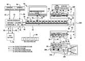
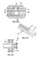
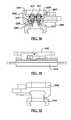
- FIG. 1is a perspective view of an inductively powering rail mounted on a MIL-STD-1913 rail;
- FIG. 2is cross section vertical view of a primary U-Core and a secondary U-Core
- FIG. 3is a longitudinal cross section side view of an accessory mounted to an inductively powering rail
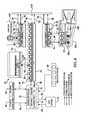
- FIG. 4is a block diagram of the components of one embodiment of an inductively powered rail system
- FIG. 5is a block diagram of a primary Printed Circuit Board (PCB) contained within an inductively powering rail;
- PCBPrinted Circuit Board
- FIG. 6is a block diagram of a PCB contained within an accessory
- FIG. 7is a block diagram of the components of a master controller
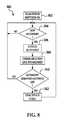
- FIG. 8is a flow chart of the steps of connecting an accessory to an inductively powering rail
- FIG. 9is a flow chart of the steps for managing power usage
- FIG. 10is a flow chart of the steps for determining voltage and temperature of the system
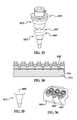
- FIG. 11is a perspective view of a portion of a rail of a networked powered data system (NPDS) in accordance with an embodiment of the present invention.
- NPDSnetworked powered data system
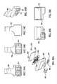
- FIGS. 12A-12Care cross-sectional views of an accessory mounted to a networked powered data system (NPDS);
- NPDSnetworked powered data system
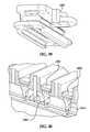
- FIGS. 13A and 13Bare perspective views of an upper receiver with rails of the networked powered data system (NPDS) mounted thereto;
- NPDSnetworked powered data system
- FIGS. 13C and 13Dillustrate alternative embodiments of the upper receiver illustrated in FIGS. 13A and 13B ;
- FIGS. 14A and 14Bare perspective views of rails of the networked powered data system (NPDS);
- FIGS. 14C and 14Dillustrate alternative embodiments of the rails illustrated in FIGS. 14A and 14B ;
- FIGS. 15A-15Cillustrate the mounting an the rails of the networked powered data system (NPDS);
- NPDSnetworked powered data system
- FIGS. 15D-15Fillustrate alternative embodiments of the rails illustrated in FIGS. 15A-15C ;
- FIG. 16is schematic illustration of power and data transfer between components of the networked powered data system (NPDS);
- FIG. 17is schematic illustration of a circuit for inductive power transfer in accordance with one exemplary embodiment of the present invention.
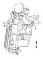
- FIG. 18is a perspective view of a portion of a weapon with the networked powered data system (NPDS) of one embodiment of the present invention.
- NPDSnetworked powered data system
- FIG. 18Ais a perspective view of a portion of a weapon with the networked powered data system (NPDS) according to an alternative embodiment of the present invention.
- NPDSnetworked powered data system
- FIGS. 19A-19Dare various views of a component for inductively coupling power and data between an upper receiver and a lower receiver of a weapon used with the networked powered data system (NPDS);
- NPDSnetworked powered data system
- FIGS. 20A-20Fare various views of an alternative component for inductively coupling power and data between an upper receiver and a lower receiver of a weapon used with the networked powered data system (NPDS);
- NPDSnetworked powered data system
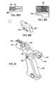
- FIG. 21is a perspective view of a pistol grip for use with the upper receiver illustrated in FIG. 18A ;
- FIG. 22is a perspective view of a portion of a weapon with the networked powered data system (NPDS) according to another alternative embodiment of the present invention.
- NPDSnetworked powered data system
- FIG. 23is a perspective view of a pistol grip for use with the upper receiver illustrated in FIG. 22 ;
- FIG. 24illustrates a battery pack or power supply secured to a pistol grip of an exemplary embodiment of the present invention
- FIG. 25illustrates an alternative method and apparatus for coupling a battery pack or power supply to an alternative embodiment of the pistol grip
- FIG. 26is a schematic illustration of a power system of the networked powered data system (NPDS) according to one exemplary embodiment of the present invention.
- NPDSnetworked powered data system
- FIGS. 27A-27Billustrate a rail for conductively transferring data and power according to various alternative embodiments of the present invention
- FIGS. 28A-28Care cross-sectional views of an accessory mounted to a rail of the conductive networked powered data system (CNPDS) in accordance with various embodiments of the present invention.
- CNPDSconductive networked powered data system
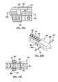
- FIG. 29Ais a bottom view of an accessory mount according to an embodiment of the present invention.
- FIGS. 29B-32illustrate the accessory mount secured to the rail of FIGS. 27A and 27B ;
- FIG. 33is a perspective view of an accessory pin or contact and a rail pin or contact according to various alternative embodiments of the present invention.
- FIG. 34is a side cross-sectional view of the rail illustrated in FIGS. 27A and 27B ;
- FIG. 35is a side view of a pin or contact for the conductive rail according to various alternative embodiments of the present invention.
- FIG. 36is a perspective view of the accessory base according to an embodiment of the present invention.
- FIGS. 37A-37Dare various views of a pin or contact contemplated for an accessory base according to an embodiment of the present invention.
- FIGS. 38A-38Care various views of a pin or contact contemplated for the conductive rail according to an embodiment of the present invention.
- FIG. 39is a perspective view of the accessory base secured to a rail section according to an embodiment of the present invention.
- FIG. 40is a perspective cross-sectional view of a rail section according to an embodiment of the present invention.
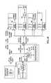
- FIG. 41is a schematic illustration of a communication system for a conductive networked powered data system
- FIG. 42is a schematic illustration of a comparison of 10Base2 to 10/100Base T Ethernet Physical Links
- FIG. 43is a schematic illustration of a Dual MII Switch Approach
- FIG. 44is a schematic illustration of a single MII Switch Approach.
- FIG. 45is a schematic illustration of a Data Contact Switch and Protection.
- an inductively powering rail on a rifle, weapon, firearm, (automatic or otherwise), etc.to power accessories such as: telescopic sights, tactical sights, laser sighting modules, Global Positioning Systems (GPS) and night vision scopes.
- GPSGlobal Positioning Systems
- This listis not meant to be exclusive, merely an example of accessories that may utilize an inductively powering rail.
- the connection between an accessory and the inductively powering railis achieved by having electromagnets, which we refer to as “primary U-Cores” on the inductively powering rail and “secondary U-Cores” on the accessory. Once in contact with the inductively powering rail, through the use of primary and secondary U-cores, the accessory is able to obtain power though induction.
- Embodimentsavoid the need for exposed electrical contacts, which may corrode or cause electrical shorting when submerged, or subjected to shock and vibration. This eliminates the need for features such as wires, pinned connections or watertight covers.
- Accessoriesmay be attached to various fixture points on the inductively powering rail and are detected by the firearm once attached.
- the firearmwill also be able to detect which accessory has been attached and the power required by the accessory.
- FIG. 1a perspective view of an inductively powering rail mounted on a MIL-STD-1913 rail is shown generally as 10 .
- Feature 12is a MIL-STD-1913 rail, such as a Weaver rail, NATO STANAG 4694 accessory rail or the like. Sliding over rail 12 is an inductively powering rail 14 .
- Rail 12has a plurality of rail slots 16 and rail ribs 18 , which are utilized in receiving an accessory.
- An inductively powering rail 14comprises a plurality of rail slots 20 , rail ribs 22 and pins 24 , in a configuration that allows for the mating of accessories with inductively powering rail 14 . It is not the intent of the inventors to restrict embodiments to a specific rail configuration, as it may be adapted to any rail configuration. The preceding serves only as an example of several embodiments to which inductively powering rail 14 may be mated. In other embodiments, the inductively powering rail 14 can be mounted to devices having apparatus adapted to receive the rail 14 .
- Pins 24 in one embodimentare stainless steel pins of grade 430.
- pins 24When an accessory is connected to inductively powering rail 14 , pins 24 connect to magnets 46 and trigger magnetic switch 48 (see FIG. 3 ) to indicate to the inductively powering rail 14 that an accessory has been connected. Should an accessory be removed the connection is broken and recognized by the system managing inductively powering rail 14 Pins 24 are offset from the center of inductively powering rail 14 to ensure an accessory is mounted in the correct orientation, for example a laser accessory or flashlight accessory could not be mounted backward, and point in the users face as it would be required to connect to pins 24 , to face away from the user of the firearm.
- Pin hole 28accepts a cross pin that locks and secures the rails 12 and 14 together.
- FIG. 2a cross section vertical view of a primacy U-Core and a secondary U-Core is shown.
- Primary U-Core 26provides inductive power to an accessory when connected to inductively powering rail 14 .
- Each of primary U-core 26 and secondary U-core 50are electromagnets.
- the wire wrappings 60 and 62provide an electromagnetic field to permit inductive power to be transmitted bi-directionally between inductively powering rail 14 and an accessory.
- Power sources for each primary U-core 26 or secondary U-core 50may be provided by a plurality of sources.
- a power sourcemay be within the firearm, it may be within an accessory or it may be provided by a source such as a battery pack contained in the uniform of the user that is connected to the firearm, or by a super capacitor connected to the system. These serve as examples of diverse power sources that may be utilize by embodiments of the invention.
- Accessory 42 in this exampleis a lighting accessory, having a forward facing lens 44 .
- Accessory 42connects to inductively powering rail 14 , through magnets 46 which engage pins 24 and trigger magnetic switch 48 to establish an electrical connection, via primary PCB 54 , to inductively powering rail 14 .
- each slotprovides on the order of two watts. Of course, power transfers greater or less than two watts are considered to be within the scope of embodiments disclosed herein.
- PCBsPrinted Circuit Boards
- the PCB for the accessory 42is shown as accessory PCB 52 .
- the PCB for the inductively powering rail 14is shown as primary PCB 54 .
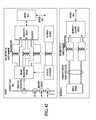
- FIG. 4a block diagram of the components of an inductively powered rail system is shown generally as 70 .
- Hot swap controller 74serves to monitor and distribute power within system 7 .
- the logic of power distributionis shown in FIG. 9 .
- Hot swap controller 74monitors power from multiple sources.
- the firstin one embodiment being one or more 18.5V batteries 78 contained within the system 70 , for example in the stock or pistol grip of a firearm. This voltage has been chosen as optimal to deliver two watts to each inductively powering rail slot 20 to which an accessory 42 is connected. This power is provided through conductive power path 82 .
- a second sourceis an external power source 80 , for example a power supply carried external to the system by the user.
- a third sourcemay come from accessories, which may have their own auxiliary power source 102 , i.e. they have a power source within them. When connected to the system, this feature is detected by master CPU 76 and the power source 102 may be utilized to provide power to other accessories through inductive power path 90 , should it be needed.
- conductive power path 82powers the inductively powering rail 14 while inductive power path 90 transfers power between the inductively powering rail 14 and accessories such as 42 .
- Master CPU 76in one embodiment is a Texas Instrument model MSP430F228, a mixed signal processor, which oversees the management of system 70 . Some of its functions include detecting when an accessory is connected or disconnected, determining the nature of an accessory, managing power usage in the system, and handling communications between the rail(s), accessories and the user.
- FIG. 4Shown in FIG. 4 are three rails. The first being the main inductively powering rail 14 and side rail units 94 and 96 . Any number of rails may be utilized. Side rail units 94 and 96 are identical in configuration and function identically to inductively powering rail unit 14 save that they are mounted on the side of the firearm and have fewer inductively powered sail slots 20 . Side rail units 94 and 96 communicate with master CPU 76 through communications bus 110 , which also provides a path for conductive power. Communications are conducted through a control path 86 . Thus Master CPU 76 is connected to inductively powering rail 14 and through rail 14 to the microcontrollers 98 of side rails 94 and 96 .
- This connectionpermits the master CPU 76 to determine when an accessory has been connected, when it is disconnected, its power level and other data that may be useful to the user, such as GPS feedback or power level of an accessory or the system. Data that may be useful to a user is sent to external data transfer module 84 and displayed to the user. In addition data such as current power level, the use of an accessory power source and accessory identification may be transferred between accessories. Another example would be data indicating the range to a target which could be communicated to an accessory 42 such as a scope.
- Communicationsmay be conducted through an inductive control path 92 .
- an accessory 42such as an optical scope are connected to the system, it may communicate with the master CPU 76 through the use of inductive control paths 92 .
- an accessoryOnce a connection has been made between an accessory and an inductively powering rail 14 , 94 or 96 communication is established from each rail via frequency modulation on an inductive control path 92 , through the use of primary U-cores 26 and secondary U-Cores 50 .
- Accessoriessuch as 42 in turn communicate with master CPU 76 through rails 14 , 94 or 96 by load modulation on the inductive control path 92 .
- a rail 14 , 94 , or 96sends power to an accessory 42 , by turning the power on and off to the primary U-core 26 and secondary U-core 50 . This is achieved by applying a frequency on the order of 40 kHz. To communicate with an accessory 42 different frequencies may be utilized. By way of example 40 kHz and 50 kHz may be used to represent 0 and 1 respectively. By changing the frequency that the primary U-cores are turned on or off information may be sent to an accessory 42 . Types of information that may be sent by inductive control path 92 may include asking the accessory information about itself, telling the accessory to enter low power mode, ask the accessory to transfer power. The purpose here is to have a two way communication with an accessory 42 .
- FSKFrequency Shift Key Modulation
- load modulationthe inventors mean monitoring the load on the system 70 . If an accessory 42 decreases or increases the amount of power it requires then master CPU 76 will adjust the power requirements as needed.
- Accessory 104serves as an example of an accessory, being a tactical light. It has an external power on/off switch 106 , which many accessories may have as well as a safe start component 108 . Safe start component 108 serves to ensure that the accessory is properly connected and has appropriate power before turning the accessory on.
- Multi button pad 88may reside on the firearm containing system 70 or it may reside externally. Multi button pad 88 permits the user to turn accessories on or off or to receive specific data, for example the distance to a target or the current GPS location. Multi-button pad 88 allows a user to access features the system can provide through external data transfer module 84 .
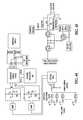
- FIG. 5a block diagram of a primary Printed Circuit Board (PCB) contained within an inductively powering rail is shown as feature 54 .
- PCBPrinted Circuit Board
- Hot swap controller 74serves to load the inductively powering rail 14 slowly. This reduces the amount of in rush current during power up. It also limits the amount of current that can be drawn from the inductively powering rail 14 .
- Conductive poweris distributed to two main components, the inductively powering rail slots 20 and the master CPU 76 residing on PCB 54 .
- Hot swap controller 74provides via feature 154 , voltage in the range of 14V to 22V which is sent to a MOSFET and transformer circuitry 156 for each inductively powering rail slot 20 on inductively powering rail 14 .
- Feature 158is a 5V switcher that converts battery power to 5V for the use of MOSFET drivers 160 .
- MOSFET drivers 160turn the power on and off to MOSFET and transformer circuitry 156 which provides the power to each primary U-Core 26 .
- Feature 162is a 3.3V Linear Drop Out Regulator (LDO), which receives its power from 5V switcher 158 .
- LDO 162provides power to mastel CPU 76 and supporting logic within each slot. Supporting logic is Mutiplexer 172 and D Flip Flops 176 .
- the Multiplexer 172 and the D Flip-Flops 176 , 177are utilized as a serial shift register. Any number of multiplexers 172 and D Flip-Flops 176 , 177 may be utilized, each for one inductively powered rail slot 20 . This allows master CPU 76 to determine which slots are enabled or disabled and to also enable or disable a slot.
- the multiplexer 172is used to select between shifting the bit from the previous slot or to provide a slot enable signal.
- the first D Flip Flop 176latches the content of the Multiplexer 172 and the second D Flip-Flop 177 latches the value of D Flip-Flop 177 if a decision is made to enable or disable a slot.
- Hall effect transistor 164detects when an accessory is connected to inductively powering rail 14 and enables MOSFET driver 160 .
- Feature 180refers to the primary U-Core 26 and the secondary U-Core 50 , establishing a power connection between inductively powering rail 14 and accessory 42 .
- High power ramp circuitry () 82slowly ramps the voltage up to high power load when power is turned on. This is necessary as some accessories such as those that utilize XEON bulbs when turned on have low resistance and they draw excessive current.
- High power load 184is an accessory that draws more than on the order of two watts of power.
- Full wave rectifier and DC/DC Converter 186rectifies the power from U-Cores 180 and converts it to a low power load 188 , for an accessory such as a night vision scope.
- Pulse shaper 190clamps the pulse from the U-Cores 180 so that it is within the acceptable ranges for microcontroller 98 and utilizes FSK via path 192 to provide a modified pulse to microcontroller 98
- Microcontroller 98utilizes a Zigbee component 198 via Universal Asynchronous Receiver Transmitter component (UART 196 ) to communicate between an accessory 42 and master controller 72 .
- the types of information that may be communicatedwould include asking the accessory for information about itself, instructing the accessory to enter low power mode or to transfer power.
- FIG. 7a block diagram of the components of a master controller 72 is shown (see FIG. 1 )
- Conductive poweris provided from battery 78 via conductive power path 82 .
- Hot swap controller 74slowly connects the load to the inductively powering rail 14 to reduce the amount of in rush current during power up. This also allows for the limiting of the amount of current that can be drawn.
- Feature 200is a 3.3 v DC/DC switcher, which converts the battery voltage to 3.3V to be used by the master CPU 76 .
- Master controller 72also utilizes a Zigbee component 204 via Universal Asynchronous Receiver Transmitter component (UART) 206 to communicate with accessories connected to the inductively powering rail 14 , 94 or 96 .
- UARTUniversal Asynchronous Receiver Transmitter component
- FIGS. 8, 9 and 10are flowcharts or processes that run in parallel, they each have their own independent tasks to perform. They may reside on any device but in one embodiment all would reside on master CPU 76 .
- a flow chart of the steps of connecting an accessory to an inductively powering railis shown generally as 300 .
- the main system power switchis turned on by the user through the use of multi-button pad 88 or another switch as selected by the designer.
- a testis made to determine if an accessory, such as feature 42 of FIG. 4 has been newly attached to inductively powering rail 14 and powered on or an existing accessory 42 connected to inductively powering rail 14 is powered on.
- the magnets 46 on the accessorymagnetize the pins 24 thereby closing the circuit on the primary PCB 54 via magnetic switch 48 and thus allowing the activation of the primary and secondary U-cores 26 and 50 , should they be needed.
- This connectionpermits the transmission of power and communications between the accessory 42 and the inductively powering rail 14 (see features 90 and 92 of FIG. 4 ).
- step 308a communication link is established between the master CPU 76 and the accessory via control inductive control path 92 . Processing then moves to step 310 where a test is made to determine if an accessory has been removed or powered off. If not, processing returns to step 304 . If so, processing moves to step 312 where power to the primary and secondary U-Cores 26 and 50 for the accessory that has been removed.
- FIG. 9is a flow chart of the steps for managing power usage shown generally as 320 .
- Process 320begins at step 322 where a test is made to determine if system 70 requires power. This is a test conducted by master CPU 76 to assess if any part of the system is underpowered. This is a continually running process. If power is at an acceptable level, processing returns to step 322 . If the system 70 does require power, processing moves to step 324 . At step 324 a test is made to determine if there is an external power source.
- processingmoves to step 326 where an external power source such as 80 (see FIG. 4 ) is utilized. Processing then returns to step 322 . If at step 324 it is found that there is no external power source, processing moves to step 328 . At step 328 a test is made to determine if there is an auxiliary power source such as feature 102 (see FIG. 4 ). If so processing moves to step 330 where the auxiliary power source is utilized. Processing then returns to step 322 . If at step 328 it is determined that there is no auxiliary power source, processing moves to step 332 . At step 332 a test is made to determine if on board power is available. On board power comprises a power device directly connected to the inductively powering rail 14 .
- step 334the system 70 is powered by on board power. Processing then returns to step 322 . If at step 332 no on board power device is located processing moves to step 336 . At step 336 a test is made to determine if there is available power in accessories. If so, processing moves to step 338 where power is transferred to the parts of the system requiring power from the accessories. Processing then returns to step 322 . If the test at step 336 finds there is no power available, then the inductively powering rail 14 is shut down at step 340 .
- FIG. 10is a flow chart of the steps for determining voltage and temperature of the system, shown generally as 350 . Beginning at step 352 a reading is made of the power remaining in battery 78 . The power level is then displayed to the user at step 354 . This permits the user to determine if they wish to replace the batteries or recharge the batteries from external power source 80 . Processing moves next to step 356 where a test is made on the voltage.
- the system 70utilizes Lithium-Ion batteries, which provide near constant voltage until the end of their life, which allows the system to determine the decline of the batteries be they battery 78 or batteries within accessories. If the voltage is below a determined threshold processing moves to step 358 and system 70 is shut down. If at step 356 the voltage is sufficient, processing moves to step 360 .
- a temperature recorded by a thermal fuseis read. Processing then moves to step 362 , where a test is conducted to determine if the temperature is below a specific temperature. Lithium-Ion batteries will typically not recharge below ⁇ 5 degrees Celsius. If it is too cold, processing moves to step 358 where inductively powering rail 14 is shut down. If the temperature is within range, processing returns to step 352 .
- control path 86provides communications between master CPU 76 and inductively powered rails 14 , 94 and 96 .
- Inductive control path 92provides communication between an accessory such as 42 with the inductively powered rails 14 , 94 and 96 .
- the Zigbee links ( 198 , 204 )provide for a third line of communication directly between an accessory such as 42 and master CPU 76 .
- a rail configuration designed to mount accessories such as sights, lasers and tactical lightsis provided.
- a Networked Powered Data System(NPDS) is provided wherein the rail or rails is/are configured to provide power and data through a weapon coupled to accessories.
- the power and datamay be exchanged between the weapon and/or a user coupled to the weapon by a tether and in some applications the user is linked a communications network that will allow data transfer to other users who may or may not also have weapons with rail configurations that are coupled to the communications network.
- railsmay refer to inductively powered rails or Networked Powered Data System rails. As previously described, the rails will have recoil slots that provide data and power as well as mechanically securing the accessory to the rail.
- every three rail slotsis dedicated for data communication and two of every three rail slots are dedicated to power transfer. Therefore, every three slots in this embodiment will be functionality defined as two power slots and one communications slot.
- the slotswill be defined from one end of the rail and the sequence will be as follows: first slot from an end of the rail is dedicated to data, second slot from the end is dedicated to power, third slot from the end is dedicated to power, fourth slot from the end is dedicated to data, fifth slot from the end is dedicated to power, six slot from the end is dedicated to power, etc.
- exemplary embodiments of the present inventioncontemplate any variations on the aforementioned sequence of data and power slots.
- Contemplated accessories for use with the NPDS railwould optimally have either a 3 slot or 6 slot or longer multiples of power-data sequence to benefit from interfacing with power and data slot sequence mentioned above. Accordingly, the accessory can be placed at random anywhere on the rail. In this embodiment, the accessory will have the capability to discern which recoil slot is dedicated to power and which recoil slot is dedicated to data.
- an inductively powered NPDS railis shown generally as 410 .
- an inductively powering rail 414is slid over a rail 412 that has a plurality of rail slots 416 and rail ribs 418 .
- the rail 414may be integral with the upper receiver and replace rail 412 .
- the inductively powering rail 414has a plurality of rail slots 420 , rail ribs 422 and pins 424 , 425 .
- the rail slots and ribsare arranged for mating of accessories with inductively powering rail 414 .
- pins 424are associated with powered slots “P” while pins 425 are associated with data slots “D”. It is not the intent of the inventors to restrict embodiments to a specific rail configuration, as it may be adapted to any rail configuration.
- the precedingserves only as an example of several embodiments to which inductively powering rail 414 may be mated.
- each slotprovides on the order of four watts.
- power transfers greater or less than four wattsare considered to be within the scope of embodiments disclosed herein.
- Pins 424 and 425are in one embodiment stainless steel pins of grade 430. Of course, other alternative materials are contemplated and the embodiments of the present invention are not limited to the specific materials mentioned above. Referring now to FIGS. 12A and 12B and when an accessory 442 is connected to inductively powering rail 414 , pins 424 and 425 are magnetized by magnets 446 located within each portion of the accessory configured to be positioned over the ribs 422 of the rail 414 such that pins 424 and 425 are magnetized by the magnets 446 . As illustrated in FIG.
- each pin 425is configured such that a first end 445 is located on top of rib 422 , an intermediate portion 447 of pin 425 is located above magnetic switch 448 and a second end 449 is also located on rib 422 . Accordingly and when pin 425 is magnetized by magnet 446 in accessory 442 when the accessory is placed upon the rail, the magnetized pin 425 causes magnetic switch 448 to close to indicate to the inductively powering rail 414 that an accessory has been connected to the data slot D.
- accessory 442is provided with a magnetic accessory switch 451 that is also closed by the magnetized pin 425 which now returns to the surface of rib 422 .
- the accessoryvia a signal from magnetic switch 451 to a microprocessor resident upon the accessory will be able to determine that the secondary coil 450 associated with the switch 451 in FIG. 12A is located above a data slot D and this coil will be dedicated to data transfer only via inductive coupling. Accordingly, the data recoil slot is different from the power slot in that the associated type 430 stainless steel pin is extended to become a fabricated clip to conduct the magnetic circuit from the accessory to the rail and back again to the accessory.
- the clipwill provide a magnetic field which, will activate the solid state switch or other equivalent item located within the rail on the one side and then will provide a path for the magnetic field on the other side of the rail reaching up to the accessory.
- the accessorywill have a solid state switch or equivalent item located at each slot position which, will be closed only if it is in proximity with the activated magnetic field of the data slot. This provides detection of the presence and location of the adjacent data slot.
- the accessory circuitry and softwareis configured to interface with the rail in terms of power and data communication.
- FIG. 12Bwhich is a cross sectional view of an another portion of the accessory secured to the rail
- the secondary coil 450 associated with switch 451 of the portion of the accessory illustrated in FIG. 12Bwill be able to determine that the secondary coil 450 associated with the switch 451 in FIG. 12B is located above a power slot P and this coil will be dedicated to power transfer only via inductive coupling.
- the complimentary accessoryis configured to have a secondary coil 450 , magnet 446 and switch 451 for each corresponding rib/slot combination of the rail they are placed on such that the accessory will be able to determine if it has been placed on a data only D of power only P slot/rib combination according to the output of switch 451 .
- the primary coils associated with a rib containing pin 424 or pin 425may in one non-limiting embodiment be on either side of the associated rib and accordingly the secondary coils of the accessory associated with switch 451 will be located in a corresponding location on the accessory.
- the secondary coils of the accessory associated with switch 451will be located in a corresponding location on the accessory.
- the configurationcould be exactly opposite. It being understood that the ribs at the end of the rail may only have one slot associated with it or the rail itself could possible end with a slot instead of a rib.
- the slots on either side of the rib having pin 425may both be data slots as opposed to a single data slot wherein a data/power slot configuration may be as follows: . . . D, D, P, P, D, D, . . . as opposed to . . . D, P, P, D, P, P, P, P, P, P, P, P, P, P, P, P, P, P, P, P, P, P, P, P, P, P, P, P, P, P, P, P, P, P, P, P, P, P, P . . . for the same six slot configurations however, and depending on the configuration of the accessory being coupled to the rail a device may now have two data slots (e.g., secondary coils on either side of switch 451 that are now activated for data transfer).
- any one of numerous combinationsare contemplated to be within the scope of exemplary embodiments of the present invention and the specific configurations disclosed herein are merely provided as non-limiting examples
- pins 424can be offset from the center of inductively powering rail 414 to ensure an accessory is mounted in the correct orientation.
- a pair of pins 425are provided in the data slot and a pair of separate magnets (accessory magnet and rail magnet are used).
- the pinsare separated from each other and one pin 425 , illustrated on the right side of the FIG., is associated with the accessory magnet 446 and rail switch 448 similar to the FIG. 12A embodiment however, the other pin 425 illustrated on the left side of the FIG., is associated with the accessory switch 451 and a separate rail magnet 453 , now located in the rail. Operation of accessory switch 451 and rail switch 448 are similar to the previous embodiments.
- Power for each primary 426 or secondary 450can be provided by a plurality of sources.
- a power sourcemay be within the firearm, it may be within an accessory or it may be provided by a source such as a battery pack contained in the uniform of the user that is connected to the firearm, or by a super capacitor connected to the system.
- the aforementionedserve merely as examples of diverse power sources that may be utilize by embodiments of the invention.
- the pin(s), magnet(s) and associated switches and arrangements thereofwill have applicability in any type of power and data transfer arrangement or configurations thereof (e.g., non-inductive, capacitive, conductive, or equivalents thereof, etc.).
- the NPDSalso has bidirectional data communication capabilities.
- data communicationis further defined as low speed communication, medium speed communication and high speed communication.
- data channelsthat are supported by the system and defined by their peak rates of 100 kb/s, 10 Mb/s and 500 Mb/s.
- the three data channelsare relatively independent and can transfer data at the same time.
- the three data channelstransfer data in a serial bit by bit manner and use dedicated hardware to implement this functionality.
- the 100 kb/s data channelalso called the low-speed data communication channel, is distributed within the system electrically and inductively. Similarly to the inductive power transfer, the low speed channel is transferred inductively by modulating a magnetic field across an air gap on the magnetic flux path, from the rail to the accessory and back. The data transfer is almost not affected by the gap size. This makes the communication channel very robust and tolerant to dirt or misalignment.
- This channelis the NPDS control plane. It is used to control the different accessories and transfer low speed data between the NPDS microprocessors and the accessories. One slot of every three rail slots is dedicated to the low speed communication channel.
- the 10 Mb/s data channelalso called the medium-speed data communication channel, is distributed within the system electrically and inductively. It is sharing communication rail slots with the low speed data channels and the data is transferred to the accessories inductively in the same manner.
- the NPDSis providing the medium speed data channel path from one accessory to another accessory or a soldier tether coupled to the rail, and as it does not terminate at the Master Control Unit (MCU) this allows simultaneous low speed and medium speed communications on the NPDS system.
- the MCUis capable of switching medium speed communications data from one accessory to another accessory. When the communication slot is in medium speed mode then all of the related circuit works at a higher frequency and uses different transmission path within the system.
- the low or medium speed communication channel functionalitycan be selected dynamically.
- the 500 Mb/s data channelalso called the high-speed data communication channel, is distributed within the system electrically and optically. It is using a dedicated optical data port at the beginning of the rail (e.g., closest to the pistol grip). The high-speed data channel is transferred optically between optical data port and the accessories.
- NPDSis providing the high-speed data channel path from an accessory to the soldier tether, and as it does not terminate at the Master Control Unit (MCU) this allows simultaneous low speed, medium speed and high speed communications on the NPDS system.
- MCUMaster Control Unit
- FIGS. 13A and 13Billustrate a front end of an upper receiver 471 showing an upper inductive/data rail 414 and side accessory inductive/data rails 494 and 496 wherein the side accessory inductive/data rails 494 and 496 are directly wired to upper inductive/data rail 414 via wires 486 and 482 that are located within bridges 487 fixedly secured to the upper receiver so that wires 486 and 482 are isolated and protected from the elements.
- the bridgesprovide a conduit of power 482 and data 486 from the top rail to the side rails (or even a bottom rail not shown).
- Bridges 487are configured to engage complimentary securement features 491 located on rails 414 , 494 and 496 or alternatively upper receiver 471 or a combination thereof.
- FIGS. 13C and Dillustrate alternative configurations of the rail bridges 487 illustrated in FIGS. 13A and 13B .
- FIG. 14Ais a top view of the upper receiver 471 with the upper inductive/data rail 414 and side accessory inductive/data rails 494 and 496 while FIG. 14B is a top view of the upper receiver 471 with the upper inductive/data rail 414 and side accessory inductive/data rails 494 and 496 without the upper receiver.
- FIGS. 14C and 14Dillustrate alternative configurations of the rail bridges 487 and the rail 494 illustrated in FIGS. 14A and 14B .
- FIGS. 15A-15Ban apparatus and method for securing and positively locking the inductive/data rail (e.g., upper, side or bottom) to the existing rail 412 of the upper receiver 471 .
- an expanding wedge feature 491comprising a pair of wedge members 493 is provided.
- each wedge memberis slid into a slot of the rail axially until they contact each other and the sliding contact causes the surface of the wedge members to engage a surface of the slot.
- a pair of complimentary securement screws 495are used to provide the axial insertion force as they are inserted into the rail by engaging a complimentary threaded opening of the rail 414 , wherein they contact and axially slide the wedge members 493 as the screw is inserted into the threaded opening.
- bridges 487are attached to the rails by a mechanical means such as screws or any other equivalent device.
- the accessories 42 and the master CPU 76can communicate with one another in several different manners.
- the master CPU 76can vary the frequency that power or another signal is provided to the accessories 42 to provide information (data) to them.
- the accessories 42can communicate data to the master CPU 76 by utilizing load modulation.
- load modulationcan occur on the same cores (referred to below as “core pairs”) as are used to provide power or can occur on separate coils. Indeed, as described above, in one embodiment, one in every three coils is dedicated to data transmission.
- FIG. 16illustrates three different communication channels shown as a low speed channel 502 , a medium speed channel 504 and a high speed channel 506 .
- the low speed channel 502extends from and allows communication between the master CPU 76 and any of the accessories 42 .
- the low speed channel 502can be driven by a low speed transmitter/receiver 510 in the master CPU 76 that includes selection logic 512 for selecting which of the accessories 42 to route the communication to.
- Each accessory 42includes low speed decoding/encoding logic 514 to receive and decode information received over the low speed channel 502 .
- the low speed decoding/encoding logic 514can also include the ability to transmit information from the accessories 42 as described above.
- the low speed channel 502carries data at or about 100 kB/s. Of course, other speeds could be used.
- the low speed channel 502passes through an inductive coil pair 520 (previously identified as primary coil 26 and secondary coil 50 hereinafter referred to as inductive coil pair 520 ) between each accessory 42 and the master CPU 76 .
- the inductive coil paircould be replaced include a two or more core portions about which the coil pair is wound.
- the corescan be omitted and the inductive coil pair can be implemented as an air core transformer.
- the inductive coil pairs 520are contained within the inductive powering rail 14 . Of course and as illustrated in the previous embodiments, one or more of the coils included in the inductive coil pairs 520 can be displaced from the inductive powering rail 14 .
- the medium speed channel 504is connected to the inductive coil pairs 520 and shares them with low speed channel 502 .
- branches of the medium speed channel 504as illustrated in dashed lines.
- datacan be transferred on both the low speed channel 502 and the medium speed channel at the same time.
- the medium speed channel 504is used to transmit data between the accessories 42 .
- Both the low and medium speed channels 502 , 504can also be used to transmit data to or receive data from an accessory (e.g. a tether) not physically attached to the inductively powering rail 14 as illustrated by element 540 .
- the connection between the master CPU 76can be either direct or through an optional inductive coil pair 520 ′.
- the optional inductive coil pair 520 ′couples power or data or both to a CPU located in or near a handle portion of a gun.
- the master CPU 76can include routing logic 522 that couples signals from one accessory to another based on information either received on the medium speed channel 504 .
- the signalcan be boosted or otherwise powered to ensure is can drive the inductive coil pairs 520 between the accessories.
- the accessory that is transmitting the datafirst utilizes the low speed channel 502 to cause the master CPU 76 to set the routing logic 522 to couple the medium speed channel 504 to the desired receiving accessory.
- the master CPU 76itself (or an element coupled to it) can be used to separate low and medium speed communications from one another and provide them to either the low speed transmitter/receiver 510 or the routing logic 522 , respectively.
- the medium speed channel 504carries data at 10 MB/s.
- FIG. 16also illustrates a high speed channel 506 .
- the high speed channel 506is formed by an optical data line and runs along at least a portion of the length of the inductively powering rail 14 . For clarity, however, the high speed channel 506 is illustrated separated from the inductively powering rail 14 .
- Accessories 42can include optical transmitter/receivers 542 for providing signals to and receiving signals from the high speed channel 506 .
- a high speed signal controller 532is provided to control data flow along the high speed channel 506 . It shall be understood that the high speed signal controller 532 can be located in any location and may be provided, for example, as part of the master CPU 76 . In one embodiment, the high speed signal controller 532 is an optical signal controller such as, for example, an optical router.
- FIG. 17illustrates an example of the MOSFET driver 154 coupled to MOSFET and transformer circuitry 156 .
- the MOSFET driver 154the MOSFET and transformer circuitry 156 to produce an alternating current (AC) output at an output coil 710 .
- the AC outputcouples power to a receiving coil 712 .
- the output coil 710 and the receiving coil 712form an inductive coil pair 520 .
- the receiving coil 712is located in an accessory as described above.
- the illustrated MOSFET and transformer circuitry 156includes an LLC circuit 711 that, in combination with the input and output coils, forms an LLC resonant converter.
- the LLC circuit 711includes, as illustrated, a leakage inductor 706 , a magnetizing inductor 708 and a capacitor 714 serially connected between input node 740 and ground.
- the magnetizing inductor 708is coupled in parallel with the output coil 710 .
- the operation and location of the first and second driving MOSFET's 702 , 704is well known in the art and not discussed further herein.
- utilizing an LLC resonant converter as illustrated in FIG. 17can lead to increased proximity effect losses due to the higher switching frequency, fringe effect losses due to the presence of a gap, an effective reverse power transfer topology, and additional protection circuits due to the unique nature of the topology.
- the MOSFET's 702 , 704are switched at the second resonant frequency of the resonant LLC resonant converter.
- the output voltage provided at the output coil 710is independent of load.
- the second resonant frequencyis dominated by the leakage inductance and not the magnetizing inductance, it also means that changes in the gap size (g) do little to change the second resonant point.
- the LLC resonant converteris above the second resonant point, reverse recovery losses in rectifying diodes in the receiving device (not illustrated) are eliminated as the current through the diode goes to zero when they are turned off.
- the RMS currentsare lower and conduction losses can be reduced which would be ideal for pure resistive loads (i.e.: flash light).
- a purely resistive loade.g., light bulb
- LEDrectified load
- the LLC resonant convertercan require a high resonant frequency (e.g., 300 kHz or higher). Increased frequency, of course, leads to increased gate drive loss at the MOSFET's 702 , 704 .
- litz wirecan be used to connect the elements forming the LLC circuit 711 and in the coils 710 , 712 . In addition, it has been found that utilizing litz wire in such a manner can increase gap tolerance.
- the increased gap tolerancecan increase fringe flux. Fringe flux from the gap between the cores around which coils 710 and 712 are wound can induce conduction losses in metal to the cores. Using litz wire can combat the loss induced in the windings. However, a means of reducing the loss induced in the rails is desirable. This can be achieved by keeping the gap away from the inductively coupling rail, creating a gap spacer with a distributed air gap that has enough permeability to prevent flux fringing, or by adding magnetic inserts into the rail to prevent the flux from reaching the aluminum.
- the pistol grip 897is configured to have a rear connector 899 configured for a sling tether 501 to transmit power and bi-directional data from an external soldier system 540 coupled to the tether.
- the pistol gripis configured to support the rear power/data connector for the sling tether.
- a portion 905 of the pistol gripis reconfigured to wrap up around the top of the upper receiver to provide a supporting surface for buttons 907 to control (on/off, etc.) the accessories mounted on the rails.
- the buttonswill also be provided with haptic features to indicate the status of the button or switch (e.g., the buttons will vibrate when depressed).
- Portion 905also includes a pair of coils 909 for inductively coupling with another pair of coils on the lower receiver (not shown).
- the inductive coreswill be an EQ20/R core commercially available from Ferroxcube. Further information is available at the following website http://www.ferroxcube.com/prod/assets/eq20r.pdf and in particular FIG. 1 found at the aforementioned website.
- a circuit boardwill have a coil pattern and the EQ20/Rcores will be cut into the middle of the circuit board.
- portion 905provides a means for coupling between the upper and lower receiver to transmit power and data to and from the rails.
- data from a microprocessor or other equivalent device resident upon the upper receivercan be transferred to a microprocessor or other equivalent device resident upon the lower receiver.
- powermay be transferred between the upper receiver and lower receiver via inductive coupling.
- FIGS. 19A-19Dillustrate views of portion 905 for coupling the upper receiver portion to the lower receiver wherein the coupling has features 911 for receipt of the cores therein.
- one of the optical transmitters/receivers 542is located at the rear portion of the rail for optical communication with a complimentary optical transmitter/receiver 542 located on the accessory (See at least FIG. 16 ).
- the optical transmitter/receiver 542is coupled to a fiber optic wire or other data communication channel 506 that is coupled to another optical transmitter/receiver 542 ′ that communicates with an optical transmitter/receiver 542 ′ located on the lower receiver and is coupled to the rear connector 899 via a fiber optic wire or other data communication channel 506 located within the lower receiver.
- portion 905allows data and power transfer between the upper receiver and the lower receiver via the coils of the upper receiver and the lower receiver while also allowing the upper receiver to be removed from the lower receiver without physically disconnecting a wire connection between the upper and lower receiver.
- the optical transmitter/receivers 542 ′allow the upper receiver to be removed from the lower receiver without physically disconnecting a wire connection between the upper and lower receiver.
- a rear sight 919is provided at the back of the NPDS rail.
- portion 905 ′provides a means for providing the inductive method of bi-directionally transferring power and data from the upper receiver to the lower receiver.
- 905 ′is an appendage of the upper receiver.
- Portion 905 ′has a housing configured to receive a circuit board 921 and associated electronics required for data and power communication. Once the circuit board 921 is inserted therein it is covered by a cover 923 .
- cover 923is secured to the housing of portion 905 ′ by a plurality of screws 925 .
- any suitable means of securementis contemplated to be within the scope of exemplary embodiments of the present invention.
- portion 905 ′is configured to have a power core 927 and a pair of data cores 929 .
- the power core 927is larger than the smaller two data cores 929 .
- Portion 905 ′is configured to interface with the pistol grip 897 such that as the two are aligned, portion 905 ′ locks or wedges into complementary features of the pistol grip 897 such that the pistol grip is secured thereto and the power and data cores ( 927 and 929 ) are aligned with complementary power and data cores located in the pistol grip 897 .
- the pistol grip 897will also have a pair of data cores and a power core matching the configuration of those in portion 905 ′.
- the smaller data cores 929 and those of the pistol gripcan be configured for low speed data (100 kbps) and medium speed data (10 Mbps) at the same time.
- the aforementioned data transfer ratesare merely provided as examples and exemplary embodiments of the present invention contemplate ranges greater or less than the aforementioned values.
- FIG. 21illustrates a portion of a pistol grip 897 contemplated for use with portion 905 ′.
- a pair of complementary data cores 931 and a complimentary power core 933are configured and positioned to be aligned with portion 905 ′ and its complementary cores (data and power) when portion 905 ′ is secured to pistol grip 897 such that inductive power and data transfer can be achieved.
- pistol grip 897has a feature 935 configured to engage a portion of portion 905 ′ wherein feature 935 is configured to assist with the alignment and securement of portion 905 ′ to the pistol grip 897 .
- FIGS. 22 and 23yet another alternative method of bi-directionally transferring power and data from the upper receiver to the lower receiver is illustrated.
- a connectorsuch as a cylindrical connector 936 .
- a generic connector 936(comprising in one embodiment a male and female coupling) couples a conduit or cable 937 (illustrated by the dashed lines in FIG. 22 ) of the upper receiver to a complementary conduit or cable 939 of the lower receiver (also illustrated by dashed lines in FIG. 22 ), when the upper receiver is secured to the lower receiver.
- a connectoris available from Tyco Electronics.
- the upper receiveris configured to have an appendage 941 that provides a passage for the cable 937 from the upper rail to the joining cylindrical connector 936 . Similar to portion 905 and 905 ′ the appendage 941 is configured to lock and secure the pistol grip 897 to the upper receiver to align both halves of the cylindrical connector 936 (e.g., insertion of male/female pins into each other).
- the sling attaching plate 938 of the lower receiver portionhas a common screw 940 to secure the pistol grip to the upper receiver to ensure alignment of both halves of the cylindrical connector.
- control button 942(for control on/off, etc. of various accessories mounted on the rails or any combination thereof) that is positioned on both sides the pistol grip 897 .
- the control buttonis configured to act as a switch for a laser accessory mounted to the weapon.
- the control buttonis found in both the conductive and inductive pistol grip configurations and is activated by the side of an operator's thumb. Requiring side activation by a user's thumb prevents inadvertent activation of the control button when handling the grip 897 .
- control button 942requires a deliberate side action of the thumb to press the control button 942 .
- an on/off button or switch 943is also located on the pistol grip 897 .
- a power pack or battery 945is shown attached to pistol grip 897 .
- the batteryis coupled to the pistol grip using a conductive attachment similar to the one used for power and data transfer between the upper receiver and the lower receiver via a generic connector (e.g., male/female configuration).
- a generic connectore.g., male/female configuration
- Tyco Electronicsone non-limiting example of such a connector is available from Tyco Electronics and could be a similar type connector used in the embodiment of FIGS. 22 and 23 .
- an actuating lever 947is provided in order to release the battery pack 945 actuating lever 947 is provided.
- FIG. 25shows an alternative method of fastening a battery pack to the bottom of the pistol grip 897 as well as an alternative method for transferring power/data inductively and bi-directionally.
- This methoduses a power/data rail section 949 that is mounted to the bottom of the pistol grip 897 , which in one exemplary embodiment is similar in configuration to the rails used for the upper and lower receivers and accordingly, it is now possible to use the same battery pack at the pistol grip location or at a rail section elsewhere and accordingly, power the system.
- the mounting to the bottom of the pistol gripit is also contemplated that the rail can be used to inductively couple the battery pack to the pistol grip as any other side as long as a desired location of the battery pack is achieved.
- NPDSNetwork Powered Data System
- a non-limiting example of a power system 951 for the Network Powered Data System (NPDS)is illustrated schematically.
- NPDSNetwork Powered Data System
- a primary battery pack 945is secured and coupled to the pistol grip 897 while a secondary power source or battery pack illustrated as 953 is secured to a forward rail of the upper receiver or, of course, any other rail of the weapon.
- the secondary battery pack 953can be a stand alone power supply similar to battery pack 945 or integrated with an accessory mounted to the rail.
- secondary battery pack 953is of the same size and configuration of primary battery pack 945 or alternatively may have a smaller profile depending on the desired location on the weapon. Secondary battery pack 953 can be utilized in a similar fashion as the primary battery pack 945 due to the reversible power capability of the rails as discussed above.
- yet another source of power 955 also controlled by the systemmay be resident upon a user of the weapon (e.g., power supply located in a back pack of a user of the weapon) wherein an external power/data coupling is provided via coupling 957 located at the rear of the pistol grip 897 (See at least FIGS. 21-23 ).
- a user of the weapone.g., power supply located in a back pack of a user of the weapon
- an external power/data couplingis provided via coupling 957 located at the rear of the pistol grip 897 (See at least FIGS. 21-23 ).
- both power and dataare transmitted as the master control unit (MCU) of the NPDS communicates with the power sources (e.g., primary 945 , secondary 953 and external 955 ) and thus the MCU controls all the power supplies of the power system.
- MCUmaster control unit
- One advantageis that the system will work without interruption if for example, the primary battery pack 945 is damaged or suddenly removed from pistol grip 897 or rail 414 as long as an alternative power connection (e.g., 953 , 955 ) is active. Connection of the primary battery pack 945 or other power source device will also ensure that the rails are powered if the pistol grip 897 is damaged or completely missing including the CPU. For example and in one implementation, the default configuration of the rails will be to turn power on as an emergency mode.
- a rail configuration designed to mount accessoriessuch as sights, lasers and tactical lights is provided.
- a Networked Powered Data System(NPDS) is provided wherein the rail or rails is/are configured to provide power and data through a weapon coupled to accessories.
- the power and datamay be exchanged between the weapon and/or a user coupled to the weapon by a tether and in some applications the user is linked a communications network that will allow data transfer to other users who may or may not also have weapons with rail configurations that are coupled to the communications network.
- the conductively powering rail 1014similar to the above embodiments comprises a plurality of rail slots 1020 , rail ribs 1022 and pins 1024 , in a configuration that allows for the mating of accessories with conductively powering rail 1014 .
- power and data transferis facilitated by a conductive connection or coupling via power and data pins 1015 embedded into the rail 1014 and power and data pins 1017 embedded into an accessory 1042 .
- Pins 1024 and 1025 in one embodimentare stainless steel pins of grade 430 and have configurations similar to those illustrated in the cross-sectional views illustrated in FIGS. 28A and 28B .
- pins 1024 , 1025connect to magnets 1046 , 1047 and trigger magnetic switch 1048 , 1051 (see FIGS. 28A-28C ) to indicate to the conductively powering rail 1014 that an accessory 1042 has been connected.
- Pins 1024are offset from the center of conductively powering rail 1014 to ensure an accessory is mounted in the correct orientation, for example a laser accessory or flashlight accessory could not be mounted backward, and point in the users face as it would be required to connect to pins 1024 , to face away from the user of the firearm.
- pins 1024 and 1025are magnetized by magnets 1046 located within each portion of the accessory configured to be positioned over the ribs 1022 of the rail 1014 such that pins 1024 and 1025 are magnetized by the magnets 1046 .
- FIG. 28Awhich is a cross sectional view of a portion of an accessory coupled to the rail, each pin 1025 is configured such that a first end 1045 is located on top of rib 1022 , an intermediate portion 1047 of pin 1025 is located above magnetic switch 1048 and a second end 1049 is also located on rib 1022 .
- the magnetized pin 1025causes magnetic switch 1048 to close to indicate to the conductively powering rail 1014 that an accessory has been connected to the data slot D.
- accessory 1042is provided with a magnetic accessory switch 1051 that is also closed by the magnetized pin 1025 which now returns to the surface of rib 1022 .
- the accessoryvia a signal from magnetic switch 1051 to a microprocessor resident upon the accessory will be able to determine that the accessory electronics 1053 associated with the switch 1051 in FIG. 28A is located above a data slot D and these electronics or equivalent items will be dedicated to data transfer only via conductive coupling. Accordingly, the data slot is different from the power slot in that the associated type 430 stainless steel pin is extended to become a fabricated clip to conduct the magnetic circuit from the accessory to the rail and back again to the accessory.
- the clipwill provide a magnetic field which, will activate the solid state switch or other equivalent item located within the rail on the one side and then will provide a path for the magnetic field on the other side of the rail reaching up to the accessory.
- the accessorywill have a solid state switch or equivalent item located at each slot position which, will be closed only if it is in proximity with the activated magnetic field of the data slot. This provides detection of the presence and location of the adjacent data slot.
- the accessory circuitry and softwareis configured to interface with the rail in terms of power and data communication.
- FIG. 28Bwhich is a cross sectional view of an another portion of the accessory secured to the rail
- the accessory electronics or other equivalent item 1053 associated with switch 1051 of the portion of the accessory illustrated in FIG. 28Bwill be able to determine that the accessory electronics 1053 associated with the switch 1051 in FIG. 28B is located above a power slot P and these electronics or equivalent items will be dedicated to power transfer only via conductive coupling.
- the complimentary accessorymay alternatively be configured to have a secondary electronics or equivalent item 1053 , magnet 1046 and switch 1051 for each corresponding rib/slot combination of the rail they are placed on such that the accessory will be able to determine if it has been placed on a data only D of power only P slot/rib combination according to the output of switch 1051 .
- the electronics associated with a rib containing pin 1024 or pin 1025may in one non-limiting embodiment be on either side of the associated rib and accordingly the electronics or equivalent item of the accessory associated with switch 1051 will be located in a corresponding location on the accessory.
- the data slotsare always forward (from a weapon view) from the rib having pin 1025 then the accessory will be configured to have the corresponding electronics forward from its corresponding switch 1051 .
- the configurationcould be exactly opposite. It being understood that the ribs at the end of the rail may only have one slot associated with it or the rail itself could possible end with a slot instead of a rib.
- the slots on either side of the rib having pin 1025may both be data slots as opposed to a single data slot wherein a data/power slot configuration may be as follows: . . . D, D, P, P, D, D, . . . as opposed to . . . D, P, P, D, P, P, P, P, P, P, P, P, P, P, P, P, P, P, P, P, P, P, P, P, P, P, P, P, P, P, P, P, P, P, P, P, P . . . for the same six slot configurations however, and depending on the configuration of the accessory being coupled to the rail a device may now have two data slots (e.g., secondary electronics on either side of switch 1051 that are now activated for data transfer).
- any one of numerous combinationsare contemplated to be within the scope of exemplary embodiments of the present invention and the specific configurations disclosed herein are merely provided as non-limiting examples.
- pins 1024can be offset from the center of conductively powering rail 1014 to ensure an accessory is mounted in the correct orientation.
- a pair of pins 1025are provided in the data slot and a pair of separate magnets (accessory magnet and rail magnet are used).
- the pinsare separated from each other and one pin 1025 , illustrated on the right side of the FIG., is associated with the accessory magnet 1046 and rail switch 1048 similar to the FIG. 28A embodiment however, the other pin 1025 illustrated on the left side of the FIG., is associated with the accessory switch 1051 and a separate rail magnet 1053 , now located in the rail. Operation of accessory switch 1051 and rail switch 1048 are similar to the previous embodiments.
- power and data to and from the accessoryis provided by a plurality of power and data pins or contacts 1015 embedded into the rail 1014 and power and data pins or contacts 1017 embedded into an accessory 1042 . Accordingly, a galvanically coupled conductive rail power and communication distribution method for the rail system is provided.
- the exposed conductive metal rail contacts or contact surfaces 1035 and 1037 of pins 1015 and 1017are made of Tungsten Carbide for excellent durability and corrosion resistance to most environmental elements.
- the contact surfacesare round pads, pressed against each other to make good galvanic contact.
- the pads, both in the rail and the accessoryare permanently bonded to short posts of copper or other metal, that in turn, are electrically bonded to PCB substrates, rigid in the rail and flex in the accessory so that there is some give when the two surfaces are brought together. Accordingly, at least one of the pads in each contact pair provides some mechanical compliance, and in one embodiment the accessory is the item that have the mechanical compliance. Of course, this could also be in the rail or both.
- the pin/pad assembliesuse an X-section ring 1019 as a seal and compressible bearing 1021 , with the internal connection end attached to a flex PCB.
- the pin/pad constructionis shown in at least FIG. 33 .
- the tungsten carbide padsprovide durability where the extreme G-forces of weapon firing vibrate the accessory attachment structure. The hardness of the touching contact surfaces ensures that little if any abrasion will take place as the surfaces slip minutely against each other.
- the pressure of the seal bearing (x-ring)will keep the pads firmly pressed together during the firing vibration, keeping electrical chatter of the contacts at minimal levels.
- the slot contactsare composed of small tungsten “pucks” that are press-fit or brazed to a metal pin.
- Tungsten carbideexhibits a conductivity of roughly 5-10% that of copper and is considered a practical conductor. Assuming a good electrical bond between the puck and the pin, resistance introduced into the power path, accounting two traversals per round trip (Positive and Negative contacts).
- the pinsare coated with tungsten carbide.
- the pinsare coated with a tungsten composite, which in one non-limiting embodiment may be a nano coat blend of primarily tungsten and other materials such as cobalt which will exhibit similar or superior properties to tungsten carbide.
- FIG. 34illustrates the rail side pins and caps installed in the rail at each slot position.
- FIG. 35also illustrates a rail side pin.
- Non-limiting examples of suitable copper alloys for the pinsare provided as follows: Copper Alloy 99.99% Cu Oxygen Free; 99.95% Cu 0.001% O; and 99.90% Cu 0.04% O of course, numerous other ranges are contemplated.
- the Tungsten Carbide padis secured to the copper pin via brazing process.
- the heads of the pinsare coated with Tungsten Carbide.
- Non-limiting examples of suitable Tungsten Carbide alloysare Tc—Co with Electrical Conductivity of 0.173 106/cm ⁇ and TC—Ni with Electrical Conductivity 0.143 106/cm ⁇ .
- Tungsten Carbideis desired for its hardness and corrosion/oxidation resistance.
- the ultra-hard contact surfacewill ensure excellent abrasion endurance under the extreme acceleration stresses of weapon firing.
- unpolished contact surfaceswere used.
- tungsten carbideonly a little less than that of diamond, has virtually no malleability or sponginess, unlike softer metals like copper and lead. This means that two surfaces forced together will touch at the tallest micro-level surface features with little or no deformation of the peaks. This consequently small contact area will yield a resistance level that is much higher, possibly by orders of magnitude, over the expected theoretical resistance.
- the conductive networked power and date systemis a four-rail (top, bottom, left, right) system that distributes power and provides communication service to accessories that are mounted on any of the rails as well as the base of the grip.
- the CNPDSprovides power and communications to accessories mounted on the rails, but differs from the aforementioned inductively systems through the use of direct galvanic contact of power and communications.
- semiconductor elements associated with the power transfer pathwill be moved to locations external to the CNPDS. Presumably, those external elements can be viewed and managed as field replaceable items of far less cost and effort to replace than the rail system itself.
- All elements of system communicationwill have the ability to be powered down into standby mode, and a main controller unit (MCU) software will be structured to make the best use of power saving opportunities.
- the CNPDSwill support bi-directional power.
- Slot power controlis in one embodiment a desired feature for meeting power conservation goals, and the operation will be largely based on the magnetic activation principle mentioned above.
- each power slotis unconditionally OFF when there is no activating magnet present on its respective Hall sensor.
- the Hall sensorpermits activation of the slot power but does not itself turn the power ON while the system is in normal operating state.
- the actual activation of the power switchesis left to the MCU, allowing it to activate slots that are understood to be occupied, while keeping all others OFF.
- the first stateis normal operating mode, either during maintenance/configuration, or in actual use.
- the MCU I/O extension logiccontrols the power switch and the switch is only activated when the MCU commands the slot logic to do so. This requires that the MCU be aware of and expect an accessory on the associated Hall activated slot, having been previously run through a configuration process.
- the second stateis defined as the Safe Power Only (SPO) mode, where the MCU is assumed to be incapacitated and is unable or not sane enough to control the slot power directly.
- SPOSafe Power Only
- the conditionis signaled to the rails from the MCU subsystem through a failsafe watchdog hardware mechanism, using either the absence of logic supply or a separate SPO flag signal.
- the Hall sensor signaloverrides the MCU logic control to activate the respective slot power unconditionally where an accessory is attached, assuming the system main power is also present.
- the primary consequence of this modeis loss of light load efficiency, since the MCU would normally shut down the Hall sensors to conserve power. Accessory ON-OFF control under the SPO condition is expected to be through a manual switch in the accessory.
- the rails, and any other CNPDS element that may be found to exceed +85C under operations heavy usemay have a temperature sensor embedded into it and readable by the MCU. Still further, the rails may actually have multiple sensors, one per 6-slot segment. With this provision, the system software can take protective actions when the rail temperature exceeds +85C.
- other weapon systemsmay feature an electromechanical trigger, the system can be allowed to automatically limit the generation of heat by pacing the rate of fire to some predetermined level.
- the sensor systemwould be necessarily engineered to the same reliability level of the Fire-by-Wire electronics.
- the battery packnow fully self-contained with charging system and charge state monitoring, will also contain a temperature sensor. Many battery chemistries have temperature limits for both charging and discharge, often with different temperature limits for each. The inclusion of a local temperature sensor in the battery pack will eliminate the need for the battery to depend on the CNPDS for temperature information, and thus allow the charge management to be fully autonomous.
- the CNPDSwill have slot position logic such that any accessory can be installed at any slot position on any of the rails, and can expect to receive power and communication access as long as the activation magnet is present.
- power and communicationwill not be shared among slot contacts, and will instead be arranged in a suitable power/comm. slot interleave on the rails.
- the CNPDSwill unify the low-speed and medium speed buses into a single, LAN-like 10 MBit/sec shared internal bus. Communication over this bus will be performed by transceiver technology that is commonly used for Ethernet networks. This simplifies the rail to accessory data connection, merging control messages from the MCU with data stream traffic from multimedia oriented accessories, over a single connection. Accessories and the MCU will act as autonomous devices on this LAN, using addressed packet based transactions between Ethernet Switch nodes. Although the internal LAN speed will be no faster than the original NPDS medium speed link, it will be able to support multiple streaming accessories simultaneously, using industry established bus arbitration methods. The availability of LAN bandwidth for accessory control and management messages will also enhance system responsiveness, making better use of the higher capability processor that is expected to be used in the MCU.
- the CNPDSwill be configured such that the slots are groups of six, which defines the basic kernel of slot count per rail.
- all four railswill be built up in multiples of the six slot kernel, where Side rails will be 6 or 12 slots each, the top rail will be 24 or 30 slots, and the bottom rail will be 12 or 18 slots. This aggregation is done to provide logical grouping of internal rail control logic resources and does not impact slot occupation rules.
- the CNPDS direct galvanic couplingcan be engineered to provide over 15 Watts per slot on a single pair of contacts of course ranges greater or less than 15 Watts are contemplated.
- the CNPDSprovides a low impedance galvanic connection path between the battery pack and the contacts in the slots of the rails. Power at each slot is individually switched, using local magnetic sense activation combined with MCU command.
- the management logicprovides the necessary control access circuitry to achieve this, as well as integrate SPO mode.
- the main power pathis bi-directional, allowing the attachment of the battery pack on any of the rails, in addition to the grip base.
- the CNPDS slot arrangement on each railwill be an interleave of power and data slots.
- a structure for the CNPDSwill aggregate groups of six slots into units that are concatenated to make up rail units of desired lengths.
- the management logic used to control the slot poweris based on the grouping, thus the longer top and bottom rails may have several management logic blocks.
- the CNPDSwill have an emergency power distribution mode in the event that the intelligent management and control systems (primarily the MCU) are incapacitated due to damage or malfunction. Under this mode, system control is assumed to be inoperative and the battery power is unconditionally available through individual slot Hall sensor activation.
- the intelligent management and control systemsprimarily the MCU
- the CNPDSwill have an alternative tether power connection which is a unidirectional input to the CNPDS, allowing the system to be powered and batteries to be charged from a weapon “Dock”.
- the Tether connectionprovides direct access to the lower receiver power connector, battery power port, and MCU power input.
- the OR-ing diode and any current limitingcan be implemented off-weapon at the tether power source.
- the tether sourceshould also contain inherent current limiting, same as the battery packs. These measures move protective components outside of the MCU to where they can be easily replaced in case of damage from power source malfunctions, rail slot overloads, or battle damage.
- the CNPDSwill have a reverse power, mode wherein the slots on the rails can accept DC power that could run the system.
- the CNPDSis can be used with high-density rechargeable chemistry batteries such as Lithium-Ion (Li-Ion) or any other equivalent power supply.
- the CNPDS communication infrastructuremay comprise two distributed networks between the rails and the MCU in the grip.
- the primary communication networkdefined as the data payload net, is based on 10Base2-like CSMA/CD line operation, supplying a 10 Mbit/sec Ethernet packet link from accessories on the rails to each other and/or to the Tether.
- the secondary networkis defined as the system management net on which the MCU is master and the rails are slave devices. Both networks operate in parallel without any dependencies between them. Accessories will only ever receive the primary packet bus and all accessory bound control and data transactions will funnel through that connection.
- the following diagramdetails the basic structure of the two networks within the CNPDS.
- the communication structurehas a very similar architecture to the power distribution structure of the CNPDS.
- the six slot groupingwill similarly affect only the control subsystem aggregation and not impose limits on accessory slot alignment.
- FIG. 41illustrates the integrated accessories, particularly the GPS, using the internal I2C bus for communication.
- using the I2C bus in this waycomplicates the software management structure for accessories.
- the accessory base illustrated in FIG. 36can take on many forms with respect to footprint size. Depending on the power draw of the accessory, it may straddle several rail cores or one. An example of a three slot device is shown in the illustration of FIG. 36 .
- Accessory clampingcan be semi-permanent or quick release. In the semi-permanent scenario, this is achieved with a fork lock system illustrated in at least FIGS. 29A-32 and 39 where the forks are pulled in to the rail with a thumb screw. Depending on the mass and geometry of the accessory, one or two fork assemblies may be required to securely mount it to the rail.
- a lever 1033is employed to effectively move the lock system (prong) into place and hold position.
- the weight and center of gravitywill define which type is used and how many are required for mechanical strength.
- electronic means of ensuring the accessory is installed correctlywill be employed.
- the systemwill identify the type and location of the accessory and provide power, communication or both.
- the accessory and the railboth have a 10 mm pitch such as to allow the lining up of accessory to rail slots and a shear area between accessory and rail to lock longitudinal relative movement between the two assemblies.
- the railcontains a ferromagnetic metal pin capable of transmitting the magnetic field from the accessory base, through the pin, to a Hall effect sensor located on the printed circuit board directly below the pin. See FIG. 40 .
- the assembly processis envisioned to involve pre-assembled unpotted rail shells and preassembled rail boards.
- the TCPsare pre-installed into the rail shells and are either glued or potted into place (not pressed) with exposed pegs facing into the cavity of the rail shell.
- the 6 slot rail boardsare dropped in place in the cavity over the pin rows, with holes lining up with the pegs to protrude through the board.
- the pegsare then soldered or riveted/welded to the rail assembly PCB. The entire assembly is then potted and tested.
Landscapes
- Engineering & Computer Science (AREA)
- General Engineering & Computer Science (AREA)
- Charge And Discharge Circuits For Batteries Or The Like (AREA)
Abstract
Description
Claims (5)
Priority Applications (6)
| Application Number | Priority Date | Filing Date | Title |
|---|---|---|---|
| US13/968,882US9897411B2 (en) | 2010-01-15 | 2013-08-16 | Apparatus and method for powering and networking a rail of a firearm |
| US14/476,210US10477618B2 (en) | 2010-01-15 | 2014-09-03 | Networked battle system or firearm |
| US14/481,542US10337834B2 (en) | 2010-01-15 | 2014-09-09 | Networked battle system or firearm |
| US14/517,334US10470010B2 (en) | 2010-01-15 | 2014-10-17 | Networked battle system or firearm |
| US14/808,535US10477619B2 (en) | 2010-01-15 | 2015-07-24 | Networked battle system or firearm |
| US15/165,125US20170010073A1 (en) | 2010-01-15 | 2016-05-26 | Networked battle system with heads up display |
Applications Claiming Priority (6)
| Application Number | Priority Date | Filing Date | Title |
|---|---|---|---|
| US12/688,256US9823043B2 (en) | 2010-01-15 | 2010-01-15 | Rail for inductively powering firearm accessories |
| US201161443085P | 2011-02-15 | 2011-02-15 | |
| US201161528728P | 2011-08-29 | 2011-08-29 | |
| US13/372,825US9891023B2 (en) | 2010-01-15 | 2012-02-14 | Apparatus and method for inductively powering and networking a rail of a firearm |
| US201261684062P | 2012-08-16 | 2012-08-16 | |
| US13/968,882US9897411B2 (en) | 2010-01-15 | 2013-08-16 | Apparatus and method for powering and networking a rail of a firearm |
Related Child Applications (1)
| Application Number | Title | Priority Date | Filing Date |
|---|---|---|---|
| US14/481,542Continuation-In-PartUS10337834B2 (en) | 2010-01-15 | 2014-09-09 | Networked battle system or firearm |
Publications (2)
| Publication Number | Publication Date |
|---|---|
| US20140047754A1 US20140047754A1 (en) | 2014-02-20 |
| US9897411B2true US9897411B2 (en) | 2018-02-20 |
Family
ID=50099048
Family Applications (1)
| Application Number | Title | Priority Date | Filing Date |
|---|---|---|---|
| US13/968,882ActiveUS9897411B2 (en) | 2010-01-15 | 2013-08-16 | Apparatus and method for powering and networking a rail of a firearm |
Country Status (7)
| Country | Link |
|---|---|
| US (1) | US9897411B2 (en) |
| EP (1) | EP2885595B1 (en) |
| AU (2) | AU2013302265A1 (en) |
| CA (1) | CA2881982C (en) |
| DK (1) | DK2885595T3 (en) |
| SG (1) | SG11201501094XA (en) |
| WO (1) | WO2014026278A1 (en) |
Cited By (15)
| Publication number | Priority date | Publication date | Assignee | Title |
|---|---|---|---|---|
| US10645348B2 (en) | 2018-07-07 | 2020-05-05 | Sensors Unlimited, Inc. | Data communication between image sensors and image displays |
| US10742913B2 (en) | 2018-08-08 | 2020-08-11 | N2 Imaging Systems, LLC | Shutterless calibration |
| US10753709B2 (en) | 2018-05-17 | 2020-08-25 | Sensors Unlimited, Inc. | Tactical rails, tactical rail systems, and firearm assemblies having tactical rails |
| US10796860B2 (en) | 2018-12-12 | 2020-10-06 | N2 Imaging Systems, LLC | Hermetically sealed over-molded button assembly |
| US10801813B2 (en) | 2018-11-07 | 2020-10-13 | N2 Imaging Systems, LLC | Adjustable-power data rail on a digital weapon sight |
| US10921578B2 (en) | 2018-09-07 | 2021-02-16 | Sensors Unlimited, Inc. | Eyecups for optics |
| US10976131B1 (en)* | 2020-01-17 | 2021-04-13 | T-Worx Holdings, LLC | Firearm with electrical power source |
| US11079202B2 (en) | 2018-07-07 | 2021-08-03 | Sensors Unlimited, Inc. | Boresighting peripherals to digital weapon sights |
| US11122698B2 (en) | 2018-11-06 | 2021-09-14 | N2 Imaging Systems, LLC | Low stress electronic board retainers and assemblies |
| US11143838B2 (en) | 2019-01-08 | 2021-10-12 | N2 Imaging Systems, LLC | Optical element retainers |
| US11162763B2 (en) | 2015-11-03 | 2021-11-02 | N2 Imaging Systems, LLC | Non-contact optical connections for firearm accessories |
| US20220408586A1 (en)* | 2021-06-21 | 2022-12-22 | Shanyao Lee | Cable management assembly for firearm |
| US20220404114A1 (en)* | 2021-06-19 | 2022-12-22 | Shanyao Lee | Cover kit for firearm handguard |
| US20220412696A1 (en)* | 2021-06-24 | 2022-12-29 | Wilcox Industries Corp. | Pressure pad accessory controller for weapon |
| US20220412695A1 (en)* | 2021-06-24 | 2022-12-29 | Wilcox Industries Corp. | Accessory control handgrip apparatus for weapon |
Families Citing this family (33)
| Publication number | Priority date | Publication date | Assignee | Title |
|---|---|---|---|---|
| US10215529B2 (en)* | 2009-01-16 | 2019-02-26 | Prototype Productions Incorporated Ventures Two, Llc | Accessory mount for rifle accessory rail, communication, and power transfer system—accessory attachment |
| US10477618B2 (en) | 2010-01-15 | 2019-11-12 | Colt Canada Ip Holding Partnership | Networked battle system or firearm |
| US10470010B2 (en) | 2010-01-15 | 2019-11-05 | Colt Canada Ip Holding Partnership | Networked battle system or firearm |
| US9823043B2 (en) | 2010-01-15 | 2017-11-21 | Colt Canada Ip Holding Partnership | Rail for inductively powering firearm accessories |
| US9921028B2 (en) | 2010-01-15 | 2018-03-20 | Colt Canada Ip Holding Partnership | Apparatus and method for powering and networking a rail of a firearm |
| US10477619B2 (en) | 2010-01-15 | 2019-11-12 | Colt Canada Ip Holding Partnership | Networked battle system or firearm |
| US10337834B2 (en) | 2010-01-15 | 2019-07-02 | Colt Canada Ip Holding Partnership | Networked battle system or firearm |
| DK3165868T3 (en) | 2011-02-15 | 2018-11-26 | Colt Canada Ip Holding Partnership | Apparatus and method for inductive power supply and network connection of a firearm's rail |
| US8776422B2 (en)* | 2012-01-24 | 2014-07-15 | Prototype Productions, Inc. | Communication and control of accessories mounted on the powered rail of a weapon |
| CA2881982C (en) | 2012-08-16 | 2020-10-13 | Colt Canada Corporation | Apparatus and method for powering and networking a rail of a firearm |
| DE102012110173A1 (en)* | 2012-10-24 | 2014-06-12 | Phoenix Contact Gmbh & Co. Kg | Modular electronic system and bus participants |
| WO2014160878A1 (en)* | 2013-03-27 | 2014-10-02 | Miller Craig M | Powered tactical rail (aka picatinny rail) system and method of using the same |
| USD713485S1 (en)* | 2013-04-16 | 2014-09-16 | GPI Custom Gunworks, LLC | Firearm lower receiver |
| US20150198396A1 (en)* | 2014-01-10 | 2015-07-16 | James Duncan MOTLEY | Rifle receiver |
| GB2528267A (en)* | 2014-07-15 | 2016-01-20 | Qioptiq Ltd | Weapon accessory bracket |
| EP3172524B1 (en)* | 2014-07-22 | 2020-10-07 | N2 Imaging Systems, LLC | Combination video and optical sight |
| DK3247969T3 (en)* | 2015-01-22 | 2020-11-09 | Colt Canada Ip Holding Partnership | SENSOR PACK FOR FIREARMS |
| USD768256S1 (en)* | 2015-02-27 | 2016-10-04 | Adaptive Tactical Llc | Firearm accessory rail |
| ITUB20160173A1 (en)* | 2016-01-27 | 2017-07-27 | Fabbrica Darmi Pietro Beretta S P A | GUIDE FOR FIRE WEAPONS |
| CN106052484B (en)* | 2016-07-28 | 2017-08-25 | 南阳市诚辉光电有限责任公司 | Orientation regulation rifle takes aim at support |
| CA3063839A1 (en)* | 2017-05-15 | 2018-11-22 | T-Worx Holdings, LLC | Power system for a firearm |
| CA3063897A1 (en) | 2017-05-15 | 2018-11-22 | T-Worx Holdings, LLC | System and method for networking firearm-mounted devices |
| AU2018289107B2 (en)* | 2017-06-20 | 2024-06-13 | Lightforce USA, Inc. D/B/A/ Nightforce Optics, Inc. | Scope mount with electrical connectivity hub |
| EP3372947B1 (en)* | 2018-01-22 | 2020-02-19 | Rade Tecnologías, S. L. | Weapon communication method and system |
| US20190353461A1 (en)* | 2018-05-17 | 2019-11-21 | Sensors Unlimited, Inc. | Hybrid tactical rails with slow speed and high speed data buses |
| USD923130S1 (en)* | 2019-07-25 | 2021-06-22 | T-Worx Holdings, LLC | Contact module for a firearm accessory |
| EP3835709A1 (en)* | 2019-12-11 | 2021-06-16 | FN Herstal S.A. | Mounting rail for a firearm |
| US20220341697A1 (en)* | 2021-04-21 | 2022-10-27 | T-Worx Holdings, LLC | Electrical power source for a firearm |
| US12007187B1 (en)* | 2021-07-19 | 2024-06-11 | Biofire Technologies Inc. | Monitoring energy discharge in a fire control system |
| US11716807B2 (en)* | 2021-12-09 | 2023-08-01 | Fieldpiece Instruments, Inc. | Power and communication handguard |
| AU2024200806A1 (en)* | 2023-02-15 | 2024-08-29 | Wilcox Industries Corp. | Battery Pack Adapter Assembly For Powered Weapon Accessory Rail Interface |
| US20250003712A1 (en)* | 2023-06-28 | 2025-01-02 | Wilcox Industries Corp. | Power and data interface for weapon accessory mounting rail |
| US12152853B1 (en)* | 2023-09-25 | 2024-11-26 | Polaris Capital Corporation | Scope mount |
Citations (231)
| Publication number | Priority date | Publication date | Assignee | Title |
|---|---|---|---|---|
| US1950835A (en) | 1933-03-29 | 1934-03-13 | Walter Piotrowski | Firearm light |
| DE2251670A1 (en) | 1972-10-21 | 1974-05-02 | Duerrwaechter E Dr Doduco | Bonded carbide electrical contacts - contg. molybdenum/tungsten carbides in silver or copper, for improved electrical and mechanical abrasion resistance |
| US4533980A (en) | 1982-06-21 | 1985-08-06 | Hayes Lawrence S | Luminous gun sighting system |
| US5033219A (en) | 1990-02-06 | 1991-07-23 | Emerging Technologies, Inc. | Modular laser aiming system |
| US5142806A (en) | 1991-09-23 | 1992-09-01 | Swan Richard E | Universal receiver sleeve |
| US5237773A (en) | 1991-09-20 | 1993-08-24 | Claridge Hi-Tec Inc. | Integral laser sight, switch for a gun |
| US5345707A (en) | 1993-03-31 | 1994-09-13 | The United States Of America As Represented By The Secretary Of The Army | Interchangeable laser cavity cartridge |
| US5360949A (en) | 1993-06-30 | 1994-11-01 | Northern Telecom Limited | Printed circuit board |
| US5555662A (en) | 1993-06-08 | 1996-09-17 | Teetzel; James W. | Laser range finding apparatus |
| US5557872A (en) | 1995-05-25 | 1996-09-24 | Langner; F. Richard | Power supply for firearm accessories |
| US5654594A (en) | 1996-02-27 | 1997-08-05 | Laser Products Ltd. | Ergonomic electrical current switching systems |
| US5669174A (en) | 1993-06-08 | 1997-09-23 | Teetzel; James W. | Laser range finding apparatus |
| US5822905A (en) | 1994-02-23 | 1998-10-20 | Teetzel; James W. | Firearm hand grips for controlling an electronic module |
| US5826363A (en) | 1997-07-10 | 1998-10-27 | Knights Armament Company | Rail adapter handguard systems for firearms |
| US5831841A (en) | 1996-08-02 | 1998-11-03 | Diafuku Co., Ltd. | Contactless power distribution system |
| US6163131A (en)* | 1998-04-02 | 2000-12-19 | The Procter & Gamble Company | Battery having a built-in controller |
| US6219952B1 (en) | 1999-01-25 | 2001-04-24 | Jonathan E. Mossberg | Magnetic tag firearm safety enhancement system |
| US6237271B1 (en) | 1996-07-23 | 2001-05-29 | Colt's Manufacturing Company, Inc. | Firearm with safety system having a communication package |
| US6412207B1 (en)* | 1998-06-24 | 2002-07-02 | Caleb Clark Crye | Firearm safety and control system |
| US6430861B1 (en) | 2000-06-12 | 2002-08-13 | Tyler Ayers | Electronically controlled firearm |
| US20020174588A1 (en) | 2001-05-24 | 2002-11-28 | R.A. Brands, Llc | Firearm orientation and drop sensor system |
| US6490822B1 (en) | 2001-03-09 | 2002-12-10 | Richard E. Swan | Modular sleeve |
| US6499245B1 (en) | 2001-03-09 | 2002-12-31 | Richard E. Swan | Modular sleeve yoke |
| US6508027B1 (en) | 2001-10-02 | 2003-01-21 | Surefire, Llc | Accessory mounts for firearms |
| US6513251B2 (en) | 2001-01-11 | 2003-02-04 | Quarton, Inc. | Illuminable laser sight |
| US20030029072A1 (en) | 2001-08-13 | 2003-02-13 | Lewis Danielson | Apparatus and method for actuating a weapon accessory by a laser sighting beam |
| US20030074822A1 (en) | 2001-10-16 | 2003-04-24 | First Samco Inc. | Forearm handguard for a rifle |
| US20030106251A1 (en) | 2001-12-12 | 2003-06-12 | Surefire, Llc | Accessory mounts for shotguns and other firearms |
| US6618976B1 (en) | 2001-12-10 | 2003-09-16 | Richard E. Swan | Drop-in laser |
| US6622416B2 (en) | 2001-01-04 | 2003-09-23 | Surefire, Llc | Target and navigation illuminators for firearms |
| US20040121292A1 (en) | 2002-08-08 | 2004-06-24 | Chung Bobby Hsiang-Hua | Wireless data communication link embedded in simulated weapon systems |
| US6779288B1 (en) | 2003-05-29 | 2004-08-24 | Surefire, Llc | Accessory mounts for firearms |
| US6792711B2 (en)* | 2002-06-17 | 2004-09-21 | Colt's Manufacturing Company, Inc. | Firearm adapter rail system |
| US20040198336A1 (en) | 2003-04-07 | 2004-10-07 | Jancic Dale Allen | Wireless controlled devices for a weapon and wireless control thereof |
| US20050000142A1 (en) | 2003-05-29 | 2005-01-06 | Surefire, Llc | Accessory mounts for firearms |
| US6847587B2 (en) | 2002-08-07 | 2005-01-25 | Frank K. Patterson | System and method for identifying and locating an acoustic event |
| US20050018041A1 (en) | 2003-07-21 | 2005-01-27 | Towery Clay E. | Electronic firearm sight, and method of operating same |
| US6849811B1 (en) | 2000-07-31 | 2005-02-01 | General Electric Company | Methods and apparatus for transfer switch |
| US20050033544A1 (en) | 2001-12-10 | 2005-02-10 | Brooks Colin Philip | Detectable components and detection apparatus for detecting such components |
| US6854206B2 (en) | 2003-06-24 | 2005-02-15 | T.D.I. Arms Systems, Ltd. | Rail connector and method |
| US6865599B2 (en) | 2001-09-04 | 2005-03-08 | Chenglin Zhang | Browser-to-browser, dom-based, peer-to-peer communication with delta synchronization |
| US20050109201A1 (en) | 2002-12-02 | 2005-05-26 | Giat Industries | Device to provide an electrical connection between a recoiling mass of a weapon and a fixed cradle |
| US6899539B1 (en) | 2000-02-17 | 2005-05-31 | Exponent, Inc. | Infantry wearable information and weapon system |
| CA2547081A1 (en) | 2003-11-24 | 2005-06-09 | Advanced Design Consulting Usa, Inc. | Device for collecting statistical data for maintenance of small-arms |
| US6918066B2 (en) | 2001-09-26 | 2005-07-12 | International Business Machines Corporation | Method and system for evaluating applications on different user agents |
| US6925744B2 (en) | 2003-05-13 | 2005-08-09 | Abrams Airborne Manufacturing, Inc. | Modular firearm buttstock |
| US6931775B2 (en) | 2002-06-05 | 2005-08-23 | Lockheed Martin Corporation | Remote control module for a vehicle |
| CA2537839A1 (en) | 2002-09-06 | 2005-09-01 | Prototype Productions, Inc. | Tool apparatus |
| WO2005080908A2 (en) | 2003-09-12 | 2005-09-01 | Vitronics Inc. | Processor aided firing of small arms |
| US20050204603A1 (en) | 2002-02-25 | 2005-09-22 | Sven-Erik Larsson | Gun accessory mounting device |
| US20050217161A1 (en) | 2004-03-31 | 2005-10-06 | Ra Brands, L.L.C. | Barrel accessory rail system |
| US20050241206A1 (en) | 2004-03-22 | 2005-11-03 | Wilcox Industries Corporation | Hand grip apparatus for firearm |
| US20050241211A1 (en) | 2004-03-26 | 2005-11-03 | Swan Richard E | Modular panel system for attaching accessories to a firearm rail system |
| WO2005109597A1 (en) | 2004-05-11 | 2005-11-17 | Splashpower Limited | Controlling inductive power transfer systems |
| US20050268521A1 (en) | 2004-06-07 | 2005-12-08 | Raytheon Company | Electronic sight for firearm, and method of operating same |
| US7007586B2 (en) | 2002-12-13 | 2006-03-07 | Giat Industries | Device providing an electrical connection between a weapon and a piece of ammunition |
| DE102004045753A1 (en) | 2004-09-21 | 2006-03-30 | Carl Walther Gmbh | Hand gun adapted to receive accessory, e.g. laser, has integrated power source and control device mounted in handgrip for powering and controlling accessory |
| US7059076B2 (en) | 2004-06-25 | 2006-06-13 | Abrahms Airborne Manufacturing | Firearm rail system |
| US7096619B2 (en) | 2004-02-17 | 2006-08-29 | Jackson Charles L | Equipment operator personalization device |
| US20060204935A1 (en) | 2004-05-03 | 2006-09-14 | Quantum 3D | Embedded marksmanship training system and method |
| US7121036B1 (en) | 2004-12-23 | 2006-10-17 | Raytheon Company | Method and apparatus for safe operation of an electronic firearm sight depending upon the detection of a selected color |
| US7124531B1 (en) | 2004-12-23 | 2006-10-24 | Raytheon Company | Method and apparatus for safe operation of an electronic firearm sight |
| US7131228B2 (en) | 2004-06-16 | 2006-11-07 | Colt Defense Llc | Modular firearm |
| US7144830B2 (en) | 2002-05-10 | 2006-12-05 | Sarnoff Corporation | Plural layer woven electronic textile, article and method |
| US20060288626A1 (en) | 2005-06-22 | 2006-12-28 | Surefire, Llc (A California Limited Liability Company) | Machine gun accessory mount adapter |
| US20070006509A1 (en) | 2004-07-06 | 2007-01-11 | Desomma Frank | Hand guard assembly for firearms |
| TW200715159A (en) | 2005-10-06 | 2007-04-16 | Chung Shan Inst Of Science | Method for integrating information and electronics of army command, control and management |
| US7216451B1 (en) | 2005-02-11 | 2007-05-15 | Troy Stephen P | Modular hand grip and rail assembly for firearms |
| US7231606B2 (en) | 2000-10-31 | 2007-06-12 | Software Research, Inc. | Method and system for testing websites |
| US20070150556A1 (en) | 2005-12-22 | 2007-06-28 | Kentarou Fukuda | Method for analyzing state transition in web page |
| US7243454B1 (en) | 2005-04-02 | 2007-07-17 | Tango Down, Llc | Integrated pressure switch pocket for a vertical fore grip |
| US20070216392A1 (en) | 2004-05-11 | 2007-09-20 | Stevens Michael C | Controlling Inductive Power Transfer Systems |
| USD556289S1 (en) | 2007-02-05 | 2007-11-27 | Herman Yu | Rail arrangement for firearm |
| US7316003B1 (en) | 2002-12-18 | 2008-01-01 | Oracle International Corp. | System and method for developing a dynamic web page |
| US20080010890A1 (en) | 2006-07-17 | 2008-01-17 | Vice Jack M | Mounted Isometric Controller |
| US20080039962A1 (en) | 2006-05-23 | 2008-02-14 | Mcrae Michael W | Firearm system for data acquisition and control |
| US20080040965A1 (en) | 1998-07-02 | 2008-02-21 | Solinsky Kenneth S | Auxiliary device for a weapon and attachment thereof |
| US20080063400A1 (en) | 2006-05-12 | 2008-03-13 | Irobot Corporation | Method and Device for Controlling a Remote Vehicle |
| WO2008048116A1 (en) | 2006-10-16 | 2008-04-24 | Urban Voyage Limited | Monitoring engagement of a weapon |
| US20080092422A1 (en) | 2006-05-24 | 2008-04-24 | Daniel Defense, Inc. | Systems and Methods for Providing a Hand Guard and Accessory Mounting Device for a Firearm |
| US20080108021A1 (en) | 2004-11-24 | 2008-05-08 | Dynamic Animation Systems, Inc. | Instructor-lead training environment and interfaces therewith |
| US20080134562A1 (en) | 2006-11-01 | 2008-06-12 | Wilcox Industries Corp. | Modular flashlight apparatus for firearm |
| US20080170838A1 (en) | 2007-01-11 | 2008-07-17 | Wilcox Industries Corp. | Head-mounted video recording system |
| US20080190002A1 (en) | 2007-02-12 | 2008-08-14 | Steve Hines | Modular rail cover |
| US7421818B2 (en) | 2006-02-04 | 2008-09-09 | Lasermax, Inc. | Firearm mount with embedded laser sight |
| US20080216380A1 (en) | 2006-11-01 | 2008-09-11 | Teetzel James W | Three-Point Clamp for Firearm Mounting Rail |
| US20080219100A1 (en) | 2003-01-24 | 2008-09-11 | Shotspotter, Inc. | Systems and Methods Related to Identifying and/or Locating Weapon Fire Incidents |
| WO2008108818A2 (en) | 2006-09-28 | 2008-09-12 | Wolf Pac Technologies Corp | Power rail system |
| US7438430B2 (en) | 2004-04-29 | 2008-10-21 | Surefire, Llc | Light beam generator apparatus |
| US7461346B2 (en) | 2002-07-30 | 2008-12-02 | Sap Ag | Editing browser documents |
| US20080301994A1 (en) | 2007-04-09 | 2008-12-11 | Kevin Langevin | Firearm having a removable hand guard |
| US20090044439A1 (en) | 2007-08-16 | 2009-02-19 | Breaching Technologies, Inc. | Tactical foregrip assembly |
| US20090058361A1 (en) | 2007-06-01 | 2009-03-05 | Michael Sasha John | Systems and Methods for Wireless Power |
| US7525203B1 (en) | 2005-08-11 | 2009-04-28 | Jeffrey Racho | Back-up electric power generator for electronic components attached to automatic firearms |
| US7523580B1 (en) | 2005-11-07 | 2009-04-28 | Jerome Benedict Tankersley | Handguard system integrated to a firearm |
| US7551121B1 (en) | 2004-03-12 | 2009-06-23 | Oceanit Laboratories, Inc. | Multi-target-tracking optical sensor-array technology |
| US7559169B2 (en) | 2006-03-20 | 2009-07-14 | Asia Optical Co., Inc. | Firearm aiming and photographing compound apparatus and laser sight |
| US20090218884A1 (en) | 2005-06-28 | 2009-09-03 | Soar Roger J | Contactless Battery Charging Apparel |
| US7584569B2 (en) | 2005-08-19 | 2009-09-08 | Lasermax, Inc. | Target illuminating assembly having integrated magazine tube and barrel clamp with laser sight |
| US20090249216A1 (en) | 2008-03-28 | 2009-10-01 | International Business Machines Corporation | Interacting with multiple browsers simultaneously using linked browsers controlled from a primary browser interface |
| US20090255160A1 (en) | 2008-04-11 | 2009-10-15 | James Summers | Weapon control device |
| WO2009127354A2 (en) | 2008-04-16 | 2009-10-22 | Heckler & Koch Gmbh | Line arrangement, weapon component and weapon with said line arrangement |
| US7627975B1 (en) | 2007-02-12 | 2009-12-08 | Steve Hines | Electrified handguard |
| US20090305197A1 (en) | 2006-06-29 | 2009-12-10 | Korea Elecom | Apparatus and System For Simulating of Shooting a Grenade Launcher |
| WO2009151713A2 (en) | 2008-03-25 | 2009-12-17 | Raytheon Company | Systems and methods for communicating a firearm discharge event |
| US7640690B2 (en) | 2006-07-27 | 2010-01-05 | Steve Hines | Stock interface |
| WO2010004470A1 (en) | 2008-06-26 | 2010-01-14 | Fischer Connectors Holding S.A. | System with inbuilt electrical contacts |
| US20100031552A1 (en) | 2008-07-16 | 2010-02-11 | Lasermax, Inc. | Firearm assembly |
| US20100083553A1 (en) | 2008-10-03 | 2010-04-08 | Nanomaterials Discovery Corporation | Firearm Having Central Power Source and Integrated Data Bus to both Power and Control Multiple Accessories |
| US7698983B1 (en) | 2005-11-04 | 2010-04-20 | The United States Of America As Represented By The Secretary Of The Army | Reconfigurable fire control apparatus and method |
| US20100095574A1 (en) | 2008-10-19 | 2010-04-22 | Terrill Abst | Trigger activated switch |
| US7707762B1 (en) | 2005-01-05 | 2010-05-04 | Swan Richard E | Modular integrated rail assembly for firearms |
| US20100122485A1 (en) | 2008-11-20 | 2010-05-20 | Abrams Airborne Inc. | Firearm mounting mechanism |
| USD616521S1 (en) | 2009-04-23 | 2010-05-25 | Starnes John M | Rifle rail handguard with oblong cross-section |
| US20100126054A1 (en) | 2008-09-22 | 2010-05-27 | Daniel Defense, Inc. | Hand Guard Assembly for Securely Attaching to a Firearm |
| US20100154280A1 (en) | 2008-12-24 | 2010-06-24 | Surefire, Llc. | Machine gun accessory mount |
| US20100175293A1 (en) | 2009-01-11 | 2010-07-15 | Steve Hines | Two piece rail system for firearm |
| US20100180485A1 (en) | 2009-01-16 | 2010-07-22 | Prototype Productions, Inc. | Rifle accessory rail, communication, and power transfer system - power distribution |
| US20100181933A1 (en) | 2009-01-21 | 2010-07-22 | Altair Engineering, Inc. | Direct ac-to-dc converter for passive component minimization and universal operation of led arrays |
| US20100186278A1 (en) | 2009-01-28 | 2010-07-29 | Daniel Defense, Inc. | Handguard assembly and stanag mount adapter assembly |
| US20100192448A1 (en) | 2009-02-05 | 2010-08-05 | Rubik Darian | Mounting rail |
| US20100192444A1 (en) | 2009-01-16 | 2010-08-05 | Prototype Productions, Inc. | Rifle accessory rail, communication, and power transfer system - rail contacts |
| US20100192446A1 (en) | 2009-02-05 | 2010-08-05 | Rubik Darian | Mounting rail |
| US20100192447A1 (en) | 2009-01-16 | 2010-08-05 | Prototype Productions, Inc. | Rifle accessory rail, communication, and power transfer system |
| US20100192443A1 (en) | 2009-01-16 | 2010-08-05 | Prototype Productions, Inc. | Rifle accessory rail, communication, and power transfer system - communication |
| US7775150B2 (en) | 2006-02-09 | 2010-08-17 | Colt Defense Llc | Law enforcement carbine with one piece receiver |
| US20100218410A1 (en) | 2009-01-16 | 2010-09-02 | Prototype Productions, Inc. | Accessory mount for rifle accessory rail, communication, and power transfer system - accessory attachment |
| US7793452B1 (en) | 2008-01-22 | 2010-09-14 | Samson Manufacturing Corporation | Modular fore-end rail assembly with locking mechanism |
| US20100229448A1 (en)* | 2007-12-14 | 2010-09-16 | Lasermax, Inc. | Removable foregrip with laser sight |
| WO2010107324A1 (en) | 2009-03-19 | 2010-09-23 | Techni As | Voltage-free connector integrated in a weapon rail |
| US20100242332A1 (en) | 2004-03-22 | 2010-09-30 | Teetzel James W | Hand grip apparatus for firearm |
| US7818910B2 (en) | 2004-09-29 | 2010-10-26 | The United States Of America As Represented By The Secretary Of The Army | Weapon integrated controller |
| US20100275489A1 (en) | 2009-01-16 | 2010-11-04 | Prototype Productions, Inc. | Rifle accessory rail, communication, and power transfer system-battery pack |
| US20100279544A1 (en) | 2009-01-16 | 2010-11-04 | Prototype Productions, Inc. | Rugged low light reflectivity electrical contact |
| US20100281725A1 (en) | 2009-05-05 | 2010-11-11 | Awis Llc | System and Method for the Remote Measurement of the Ammunition Level, Recording and Display of the current level |
| CA2754852A1 (en) | 2009-05-15 | 2010-11-18 | The Otis Patent Trust | Integrated rail system and method for making and using same |
| CA2754869A1 (en) | 2009-05-15 | 2010-11-18 | The Otis Patent Trust | Integrated rail system and method for making and using same |
| US20110010979A1 (en) | 2009-07-16 | 2011-01-20 | Lasermax, Inc. | Mounting rail assembly for firearms |
| US20110031928A1 (en) | 2007-12-21 | 2011-02-10 | Soar Roger J | Soldier system wireless power and data transmission |
| US20110030257A1 (en) | 2009-08-04 | 2011-02-10 | Gwillim Jr Reese C | Device for indicating low ammunition in a firearm magazine |
| US20110036337A1 (en) | 2009-08-17 | 2011-02-17 | Freitag William C | Archery lighted release aid apparatus |
| US20110061284A1 (en) | 2009-01-16 | 2011-03-17 | Prototype Productions, Inc. | System for providing electrical power to accessories mounted on the powered rail of a weapon |
| US7909490B2 (en) | 2004-10-08 | 2011-03-22 | B/E Aerospace, Inc. | Lighting apparatus |
| US20110089894A1 (en) | 2007-12-21 | 2011-04-21 | Soar Roger J | Contactless battery charging apparel |
| US20110099876A1 (en) | 2009-11-05 | 2011-05-05 | Bentley James K | Accessory for a firearm |
| US7953369B2 (en)* | 1999-06-21 | 2011-05-31 | Access Business Group International Llc | System and method for inductive power supply control using remote device power requirements |
| US20110126622A1 (en) | 2009-05-29 | 2011-06-02 | Turner Brian P | Apparatus and method for monitoring projectile emission and charging an energy storage device |
| US7954971B1 (en) | 2006-11-16 | 2011-06-07 | Blackhawk Industries Product Group Unlimited Llc | Offset mountable light accessory |
| US20110131858A1 (en) | 2009-02-05 | 2011-06-09 | Rubik Darian | Mounting rail |
| WO2011079233A2 (en) | 2009-12-23 | 2011-06-30 | Reset, Inc. | Communication and power distribution system and segmented rail adapter |
| US20110162245A1 (en) | 2010-01-05 | 2011-07-07 | Ibrahim Kamal | Firearm Sensing Device and Method |
| US20110162251A1 (en) | 2006-02-04 | 2011-07-07 | Houde-Walter William R | Firearm mount with embedded sight |
| US20110173865A1 (en) | 2010-01-15 | 2011-07-21 | Colt Canada Corporation | Rail for inductively powering firearm accessories |
| US7985527B2 (en) | 2006-12-21 | 2011-07-26 | Fujifilm Corporation | Conductive film and method of producing thereof |
| US7990147B2 (en)* | 2008-06-18 | 2011-08-02 | Siemens Aktiengesellschaft | System and method for electrically contacting local coils with a signal processor remote therefrom in a magnetic resonance scanner |
| US8001715B2 (en) | 2005-04-26 | 2011-08-23 | Tactical Devices, Inc. | Illumination apparatus implementing non-lethal weapon |
| US8005995B2 (en) | 2007-08-16 | 2011-08-23 | Micron Technology, Inc. | Command interface systems and methods |
| US20110239354A1 (en)* | 2010-02-02 | 2011-10-06 | Wilcox Industries Corp. | Helmet mounting system and mounting shoe interface |
| US20110252741A1 (en) | 2005-04-07 | 2011-10-20 | Prototype Productions, Inc. | Structural systems |
| US8042967B2 (en) | 2006-01-16 | 2011-10-25 | Koninklijke Philips Electronics N.V. | Lamp module and lighting device comprising such a lamp module |
| US20110264257A1 (en) | 2005-06-10 | 2011-10-27 | Prototype Productions, Inc. | Closed-loop cnc machine system and method |
| US20110271822A1 (en) | 2010-05-04 | 2011-11-10 | Makor Issues And Rights Ltd. | Automatic Real Time Command and Control System |
| US8063773B2 (en) | 2003-01-24 | 2011-11-22 | Shotspotter, Inc. | Systems and methods of directing a camera to image weapon fire |
| US20110283586A1 (en)* | 2010-05-21 | 2011-11-24 | Laurent Scallie | System and method for weapons instrumentation technique |
| US20110283585A1 (en) | 2009-01-16 | 2011-11-24 | Prototype Productions, Inc. | System for providing electrical power to accessories mounted on the powered rail of a weapon |
| US20110306251A1 (en)* | 2010-06-14 | 2011-12-15 | Tyco Electronics Corporation | Connector with a laterally moving contact |
| WO2011162245A1 (en) | 2010-06-23 | 2011-12-29 | 住友重機械工業株式会社 | Injection molding machine and power source regeneration converter |
| US8091265B1 (en) | 2007-01-10 | 2012-01-10 | Wilcox Industries Corp. | Floating rail system for firearm |
| US20120021385A1 (en) | 2006-11-24 | 2012-01-26 | Trex Enterprises Corp. | Celestial weapons orientation measuring system |
| US20120085331A1 (en) | 2008-08-22 | 2012-04-12 | Lang Russell W | Systems and methods of accessory mounting |
| US20120097741A1 (en) | 2010-10-25 | 2012-04-26 | Karcher Philip B | Weapon sight |
| US20120125092A1 (en) | 2010-11-22 | 2012-05-24 | DRS Technologies Canada, Ltd | Muzzle velocity sensor |
| US20120125189A1 (en)* | 2010-11-22 | 2012-05-24 | DM Innovations | Firearm accessory part with tracking capability |
| US20120131837A1 (en) | 2009-01-16 | 2012-05-31 | Prototype Productions, Inc. | Rail contacts for accessories mounted on the powered rail of a weapon |
| US20120144716A1 (en) | 2009-01-16 | 2012-06-14 | Prototype Productions, Inc. | Communication and control of accessories mounted on the powered rail of a weapon |
| US20120180363A1 (en) | 2011-01-18 | 2012-07-19 | Prototype Productions, Inc. | Apparatus for mounting accessories on the accessory rail of a weapon |
| US20120192476A1 (en)* | 2010-01-15 | 2012-08-02 | David Walter Compton | Apparatus and method for inductively powering and networking a rail of a firearm |
| US20120214137A1 (en) | 2004-10-12 | 2012-08-23 | John Goree | Network weapon system and method |
| US8251288B2 (en) | 2007-10-16 | 2012-08-28 | Raytheon Company | Network-centric targeting |
| US20120233901A1 (en) | 2009-04-24 | 2012-09-20 | In Woo Kim | Firearm having dual barrels |
| US8311757B2 (en) | 2007-08-14 | 2012-11-13 | American Gnc Corporation | Miniaturized smart self-calibration electronic pointing method and system |
| US8336776B2 (en) | 2010-06-30 | 2012-12-25 | Trijicon, Inc. | Aiming system for weapon |
| WO2013011242A1 (en) | 2011-07-21 | 2013-01-24 | Ecole Normale Superieure De Lyon | Novel water-soluble chromophore |
| US8371729B2 (en) | 2004-11-15 | 2013-02-12 | Streamlight, Inc. | Light with keying arrangement mountable on a mounting rail |
| US20130047482A1 (en) | 2011-08-23 | 2013-02-28 | Tyco Electronics Corporation | Communication connector system for a weapon |
| US20130047486A1 (en) | 2011-08-25 | 2013-02-28 | Leapers, Inc. | Adapter |
| US20130061509A1 (en) | 2011-09-09 | 2013-03-14 | Lasermax, Inc. | Target marking system |
| US20130104438A1 (en) | 2011-11-01 | 2013-05-02 | Steve Hines | Battery adaptive device |
| US20130105579A1 (en) | 2011-10-27 | 2013-05-02 | Harris Corporation | Single click fire control and visualization for small unit operations |
| US20130104439A1 (en) | 2011-11-01 | 2013-05-02 | Steve Hines | Powering firearm accessories with a false battery |
| US20130185978A1 (en) | 2012-01-24 | 2013-07-25 | Prototype Productions, Inc. | Communication and control of accessories mounted on the powered rail of a weapon |
| US8495945B1 (en) | 2010-01-06 | 2013-07-30 | The United States Of America As Represented By The Secretary Of The Navy | Weapon and weapon station system and method for loading, testing, targeting, and/or launching a weapon |
| WO2013120015A1 (en) | 2012-02-10 | 2013-08-15 | Reset Engineering, Llc. | Rail adapter accessory power protection circuit |
| US20130286239A1 (en) | 2012-04-30 | 2013-10-31 | Trackingpoint, Inc. | Rifle Scope with Video Output Stabilized Relative to a Target |
| US20130329211A1 (en) | 2012-06-07 | 2013-12-12 | Trackingpoint, Inc. | Target-Correlated Electronic Rangefinder |
| US20130337415A1 (en) | 2012-06-16 | 2013-12-19 | Tony Huet | Firearm training system |
| US20130344461A1 (en) | 2012-06-26 | 2013-12-26 | Selso Tello | Universal Firearm Marksmanship System |
| US20140007485A1 (en) | 2012-07-03 | 2014-01-09 | Enrique Castejon, SR. | Wireless Remote Aiming Systems |
| US20140028856A1 (en) | 2011-03-28 | 2014-01-30 | Smart Shooter Ltd. | Firearm, aiming system therefor, method of operating the firearm and method of reducing the probability of missing a target |
| WO2014026274A1 (en) | 2012-08-15 | 2014-02-20 | Redwood Vernon | Promoter system and method for processing product and service data |
| US20140047754A1 (en) | 2010-01-15 | 2014-02-20 | David Walter Compton | Apparatus and method for powering and networking a rail of a firearm |
| US20140059911A1 (en) | 2012-08-30 | 2014-03-06 | Tycon Electronics Corporation | Powered rail system for a weapon |
| US8668496B2 (en) | 2012-02-08 | 2014-03-11 | Troy Nolen | Training system |
| US20140130392A1 (en) | 2012-10-16 | 2014-05-15 | Tyco Electronics Corporation | Communication connector system for a weapon |
| US8739672B1 (en) | 2012-05-16 | 2014-06-03 | Rockwell Collins, Inc. | Field of view system and method |
| US20140184476A1 (en) | 2012-12-31 | 2014-07-03 | Trackingpoint, Inc. | Heads Up Display for a Gun Scope of a Small Arms Firearm |
| US8826575B2 (en) | 2008-02-27 | 2014-09-09 | Robert Ufer | Self calibrating weapon shot counter |
| US20140360081A1 (en) | 2013-06-07 | 2014-12-11 | John Hancock Lupher | Precision Guided Firearm With Hybrid Sensor Fire Control |
| US20140378088A1 (en) | 2013-06-25 | 2014-12-25 | Qualcomm Incorporated | Wiretapping Firearms Through a Wireless Network |
| US20150020427A1 (en) | 2010-01-15 | 2015-01-22 | David Walter Compton | Apparatus and method for powering and networking a rail of a firearm |
| US20150026588A1 (en) | 2012-06-08 | 2015-01-22 | Thales Canada Inc. | Integrated combat resource management system |
| US20150041538A1 (en) | 2012-02-09 | 2015-02-12 | Wilcox Industries Corp. | Weapon video display system employing smartphone or other portable computing device |
| CA2923506A1 (en) | 2013-09-09 | 2015-03-12 | Colt Canada Ip Holding Partnership | A networked battle system or firearm |
| US9010002B2 (en) | 2013-02-01 | 2015-04-21 | Liviu Popa-Simil | Method and accessory device to improve performances of ballistic throwers |
| US20150108215A1 (en) | 2013-02-17 | 2015-04-23 | Smart Shooter Ltd. | Firearm aiming system with range finder, and method of acquiring a target |
| US20150176949A1 (en) | 2013-12-24 | 2015-06-25 | Deepak Varshneya | Electro-optic system for crosswind measurement |
| US9151564B1 (en) | 2006-08-15 | 2015-10-06 | Triggermaster, Inc. | Firearm trigger pull training system and methods |
| US20150285593A1 (en) | 2010-01-26 | 2015-10-08 | Ehud DRIBBEN | Monitoring shots of firearms |
| US20150285599A1 (en) | 2010-01-15 | 2015-10-08 | Warren Downing | Networked battle system or firearm |
| US20150300786A1 (en) | 2010-01-15 | 2015-10-22 | Colt Canada Corporation | Networked battle system or firearm |
| US20150345887A1 (en) | 2014-05-27 | 2015-12-03 | Israel Weapon Industries (I.W.I) Ltd. | Apparatus and method for improving hit probability of a firearm |
| US20150345906A1 (en) | 2013-12-24 | 2015-12-03 | Deepak Varshneya | Electro-optic system for crosswind measurement |
| US20150369554A1 (en) | 2014-06-18 | 2015-12-24 | Centinel Solutions, Inc. | Firearm-mounted camera device with networked control and administration system and method |
| US20160025462A1 (en) | 2010-01-15 | 2016-01-28 | Warren Downing | Networked battle system or firearm |
| US20160025446A1 (en) | 2014-07-23 | 2016-01-28 | Maruzen Company Limited | Cartridge for air gun |
| US20160033221A1 (en) | 2013-03-15 | 2016-02-04 | Jacob Stewart Schmehl | Firearm accessory |
| US20160084617A1 (en) | 2014-09-19 | 2016-03-24 | Philip Lyren | Weapon Targeting System |
| US20160169627A1 (en) | 2013-05-09 | 2016-06-16 | Shooting Simulator, Llc | System and method for marksmanship training |
| US20160216082A1 (en) | 2015-01-22 | 2016-07-28 | Colt Canada Corporation | Sensor pack for firearm |
| US20160223278A1 (en) | 2013-10-24 | 2016-08-04 | Alfa Yuta, Prompting, Development And Advanced Technology Ltd | System, device and method for the prevention of friendly fire incidents |
| US20160316128A1 (en) | 2014-01-03 | 2016-10-27 | Flir Systems, Inc. | Camera system |
- 2013
- 2013-08-01CACA2881982Apatent/CA2881982C/enactiveActive
- 2013-08-01DKDK13829390.7Tpatent/DK2885595T3/enactive
- 2013-08-01AUAU2013302265Apatent/AU2013302265A1/ennot_activeAbandoned
- 2013-08-01EPEP13829390.7Apatent/EP2885595B1/enactiveActive
- 2013-08-01WOPCT/CA2013/050598patent/WO2014026278A1/enactiveApplication Filing
- 2013-08-01SGSG11201501094XApatent/SG11201501094XA/enunknown
- 2013-08-16USUS13/968,882patent/US9897411B2/enactiveActive
- 2017
- 2017-10-09AUAU2017245287Apatent/AU2017245287B2/ennot_activeCeased
Patent Citations (291)
| Publication number | Priority date | Publication date | Assignee | Title |
|---|---|---|---|---|
| US1950835A (en) | 1933-03-29 | 1934-03-13 | Walter Piotrowski | Firearm light |
| DE2251670A1 (en) | 1972-10-21 | 1974-05-02 | Duerrwaechter E Dr Doduco | Bonded carbide electrical contacts - contg. molybdenum/tungsten carbides in silver or copper, for improved electrical and mechanical abrasion resistance |
| US4533980A (en) | 1982-06-21 | 1985-08-06 | Hayes Lawrence S | Luminous gun sighting system |
| US5033219A (en) | 1990-02-06 | 1991-07-23 | Emerging Technologies, Inc. | Modular laser aiming system |
| US5237773A (en) | 1991-09-20 | 1993-08-24 | Claridge Hi-Tec Inc. | Integral laser sight, switch for a gun |
| US5142806A (en) | 1991-09-23 | 1992-09-01 | Swan Richard E | Universal receiver sleeve |
| US5345707A (en) | 1993-03-31 | 1994-09-13 | The United States Of America As Represented By The Secretary Of The Army | Interchangeable laser cavity cartridge |
| US5669174A (en) | 1993-06-08 | 1997-09-23 | Teetzel; James W. | Laser range finding apparatus |
| US5555662A (en) | 1993-06-08 | 1996-09-17 | Teetzel; James W. | Laser range finding apparatus |
| US5360949A (en) | 1993-06-30 | 1994-11-01 | Northern Telecom Limited | Printed circuit board |
| US5822905A (en) | 1994-02-23 | 1998-10-20 | Teetzel; James W. | Firearm hand grips for controlling an electronic module |
| US5557872A (en) | 1995-05-25 | 1996-09-24 | Langner; F. Richard | Power supply for firearm accessories |
| US5654594A (en) | 1996-02-27 | 1997-08-05 | Laser Products Ltd. | Ergonomic electrical current switching systems |
| US6237271B1 (en) | 1996-07-23 | 2001-05-29 | Colt's Manufacturing Company, Inc. | Firearm with safety system having a communication package |
| US5831841A (en) | 1996-08-02 | 1998-11-03 | Diafuku Co., Ltd. | Contactless power distribution system |
| US5826363A (en) | 1997-07-10 | 1998-10-27 | Knights Armament Company | Rail adapter handguard systems for firearms |
| US6163131A (en)* | 1998-04-02 | 2000-12-19 | The Procter & Gamble Company | Battery having a built-in controller |
| US6412207B1 (en)* | 1998-06-24 | 2002-07-02 | Caleb Clark Crye | Firearm safety and control system |
| US20080040965A1 (en) | 1998-07-02 | 2008-02-21 | Solinsky Kenneth S | Auxiliary device for a weapon and attachment thereof |
| US6219952B1 (en) | 1999-01-25 | 2001-04-24 | Jonathan E. Mossberg | Magnetic tag firearm safety enhancement system |
| US7953369B2 (en)* | 1999-06-21 | 2011-05-31 | Access Business Group International Llc | System and method for inductive power supply control using remote device power requirements |
| US6899539B1 (en) | 2000-02-17 | 2005-05-31 | Exponent, Inc. | Infantry wearable information and weapon system |
| US6430861B1 (en) | 2000-06-12 | 2002-08-13 | Tyler Ayers | Electronically controlled firearm |
| US6849811B1 (en) | 2000-07-31 | 2005-02-01 | General Electric Company | Methods and apparatus for transfer switch |
| US7231606B2 (en) | 2000-10-31 | 2007-06-12 | Software Research, Inc. | Method and system for testing websites |
| US6622416B2 (en) | 2001-01-04 | 2003-09-23 | Surefire, Llc | Target and navigation illuminators for firearms |
| US6513251B2 (en) | 2001-01-11 | 2003-02-04 | Quarton, Inc. | Illuminable laser sight |
| USRE39465E1 (en) | 2001-03-09 | 2007-01-16 | Swan Richard E | Modular sleeve yoke |
| US6490822B1 (en) | 2001-03-09 | 2002-12-10 | Richard E. Swan | Modular sleeve |
| USRE40216E1 (en) | 2001-03-09 | 2008-04-08 | Swan Richard E | Modular sleeve |
| US6499245B1 (en) | 2001-03-09 | 2002-12-31 | Richard E. Swan | Modular sleeve yoke |
| US20020174588A1 (en) | 2001-05-24 | 2002-11-28 | R.A. Brands, Llc | Firearm orientation and drop sensor system |
| US20030029072A1 (en) | 2001-08-13 | 2003-02-13 | Lewis Danielson | Apparatus and method for actuating a weapon accessory by a laser sighting beam |
| US6865599B2 (en) | 2001-09-04 | 2005-03-08 | Chenglin Zhang | Browser-to-browser, dom-based, peer-to-peer communication with delta synchronization |
| US6918066B2 (en) | 2001-09-26 | 2005-07-12 | International Business Machines Corporation | Method and system for evaluating applications on different user agents |
| US6508027B1 (en) | 2001-10-02 | 2003-01-21 | Surefire, Llc | Accessory mounts for firearms |
| US20030074822A1 (en) | 2001-10-16 | 2003-04-24 | First Samco Inc. | Forearm handguard for a rifle |
| US20050033544A1 (en) | 2001-12-10 | 2005-02-10 | Brooks Colin Philip | Detectable components and detection apparatus for detecting such components |
| US6618976B1 (en) | 2001-12-10 | 2003-09-16 | Richard E. Swan | Drop-in laser |
| US20030106251A1 (en) | 2001-12-12 | 2003-06-12 | Surefire, Llc | Accessory mounts for shotguns and other firearms |
| US7421817B2 (en) | 2002-02-25 | 2008-09-09 | Surefire, Llc | Gun accessory mounting device |
| US20050204603A1 (en) | 2002-02-25 | 2005-09-22 | Sven-Erik Larsson | Gun accessory mounting device |
| US7144830B2 (en) | 2002-05-10 | 2006-12-05 | Sarnoff Corporation | Plural layer woven electronic textile, article and method |
| US6931775B2 (en) | 2002-06-05 | 2005-08-23 | Lockheed Martin Corporation | Remote control module for a vehicle |
| US6792711B2 (en)* | 2002-06-17 | 2004-09-21 | Colt's Manufacturing Company, Inc. | Firearm adapter rail system |
| US7461346B2 (en) | 2002-07-30 | 2008-12-02 | Sap Ag | Editing browser documents |
| US6847587B2 (en) | 2002-08-07 | 2005-01-25 | Frank K. Patterson | System and method for identifying and locating an acoustic event |
| US20040121292A1 (en) | 2002-08-08 | 2004-06-24 | Chung Bobby Hsiang-Hua | Wireless data communication link embedded in simulated weapon systems |
| CA2537839A1 (en) | 2002-09-06 | 2005-09-01 | Prototype Productions, Inc. | Tool apparatus |
| US20050109201A1 (en) | 2002-12-02 | 2005-05-26 | Giat Industries | Device to provide an electrical connection between a recoiling mass of a weapon and a fixed cradle |
| US7007586B2 (en) | 2002-12-13 | 2006-03-07 | Giat Industries | Device providing an electrical connection between a weapon and a piece of ammunition |
| US7316003B1 (en) | 2002-12-18 | 2008-01-01 | Oracle International Corp. | System and method for developing a dynamic web page |
| US7750814B2 (en) | 2003-01-24 | 2010-07-06 | Shotspotter, Inc. | Highly portable system for acoustic event detection |
| US20080219100A1 (en) | 2003-01-24 | 2008-09-11 | Shotspotter, Inc. | Systems and Methods Related to Identifying and/or Locating Weapon Fire Incidents |
| US8063773B2 (en) | 2003-01-24 | 2011-11-22 | Shotspotter, Inc. | Systems and methods of directing a camera to image weapon fire |
| US20040198336A1 (en) | 2003-04-07 | 2004-10-07 | Jancic Dale Allen | Wireless controlled devices for a weapon and wireless control thereof |
| US6925744B2 (en) | 2003-05-13 | 2005-08-09 | Abrams Airborne Manufacturing, Inc. | Modular firearm buttstock |
| US6779288B1 (en) | 2003-05-29 | 2004-08-24 | Surefire, Llc | Accessory mounts for firearms |
| US20050000142A1 (en) | 2003-05-29 | 2005-01-06 | Surefire, Llc | Accessory mounts for firearms |
| US6895708B2 (en) | 2003-05-29 | 2005-05-24 | Surefire, Llc | Accessory mounts for firearms |
| US6854206B2 (en) | 2003-06-24 | 2005-02-15 | T.D.I. Arms Systems, Ltd. | Rail connector and method |
| US20050018041A1 (en) | 2003-07-21 | 2005-01-27 | Towery Clay E. | Electronic firearm sight, and method of operating same |
| US20060005447A1 (en) | 2003-09-12 | 2006-01-12 | Vitronics Inc. | Processor aided firing of small arms |
| WO2005080908A2 (en) | 2003-09-12 | 2005-09-01 | Vitronics Inc. | Processor aided firing of small arms |
| CA2547081A1 (en) | 2003-11-24 | 2005-06-09 | Advanced Design Consulting Usa, Inc. | Device for collecting statistical data for maintenance of small-arms |
| US7096619B2 (en) | 2004-02-17 | 2006-08-29 | Jackson Charles L | Equipment operator personalization device |
| US7551121B1 (en) | 2004-03-12 | 2009-06-23 | Oceanit Laboratories, Inc. | Multi-target-tracking optical sensor-array technology |
| US7841120B2 (en) | 2004-03-22 | 2010-11-30 | Wilcox Industries Corp. | Hand grip apparatus for firearm |
| US20100242332A1 (en) | 2004-03-22 | 2010-09-30 | Teetzel James W | Hand grip apparatus for firearm |
| US7712241B2 (en) | 2004-03-22 | 2010-05-11 | Wilcox Industries Corp. | Hand grip apparatus for firearm |
| US20050241206A1 (en) | 2004-03-22 | 2005-11-03 | Wilcox Industries Corporation | Hand grip apparatus for firearm |
| US7458179B2 (en) | 2004-03-26 | 2008-12-02 | Swan Richard E | Modular panel system for attaching accessories to a firearm rail system |
| US20050241211A1 (en) | 2004-03-26 | 2005-11-03 | Swan Richard E | Modular panel system for attaching accessories to a firearm rail system |
| US20050217161A1 (en) | 2004-03-31 | 2005-10-06 | Ra Brands, L.L.C. | Barrel accessory rail system |
| US7438430B2 (en) | 2004-04-29 | 2008-10-21 | Surefire, Llc | Light beam generator apparatus |
| US20060204935A1 (en) | 2004-05-03 | 2006-09-14 | Quantum 3D | Embedded marksmanship training system and method |
| US20110006613A1 (en) | 2004-05-11 | 2011-01-13 | Access Business Group International Llc | Controlling inductive power transfer systems |
| US20120068536A1 (en) | 2004-05-11 | 2012-03-22 | Access Business Group International Llc | Controlling inductive power transfer systems |
| US8039995B2 (en) | 2004-05-11 | 2011-10-18 | Access Business Group International Llc | Controlling inductive power transfer systems |
| US7868587B2 (en) | 2004-05-11 | 2011-01-11 | Access Business Group International Llc | Controlling inductive power transfer systems |
| US20070216392A1 (en) | 2004-05-11 | 2007-09-20 | Stevens Michael C | Controlling Inductive Power Transfer Systems |
| WO2005109597A1 (en) | 2004-05-11 | 2005-11-17 | Splashpower Limited | Controlling inductive power transfer systems |
| US20090322158A1 (en) | 2004-05-11 | 2009-12-31 | Access Business Group International Llc | Controlling inductive power transfer systems |
| US8035340B2 (en) | 2004-05-11 | 2011-10-11 | Access Business Group International Llc | Controlling inductive power transfer systems |
| US7554316B2 (en) | 2004-05-11 | 2009-06-30 | Access Business Group International Llc | Controlling inductive power transfer systems |
| US20070228833A1 (en) | 2004-05-11 | 2007-10-04 | Stevens Michael C | Controlling Inductive Power Transfer Systems |
| US7605496B2 (en) | 2004-05-11 | 2009-10-20 | Access Business Group International Llc | Controlling inductive power transfer systems |
| US20110285214A1 (en) | 2004-05-11 | 2011-11-24 | Access Business Group International Llc | Controlling inductive power transfer systems |
| US20090134713A1 (en) | 2004-05-11 | 2009-05-28 | Access Business Group International Llc | Controlling inductive power transfer systems |
| US20050268521A1 (en) | 2004-06-07 | 2005-12-08 | Raytheon Company | Electronic sight for firearm, and method of operating same |
| US7131228B2 (en) | 2004-06-16 | 2006-11-07 | Colt Defense Llc | Modular firearm |
| US7059076B2 (en) | 2004-06-25 | 2006-06-13 | Abrahms Airborne Manufacturing | Firearm rail system |
| US20070006509A1 (en) | 2004-07-06 | 2007-01-11 | Desomma Frank | Hand guard assembly for firearms |
| US7363741B2 (en) | 2004-07-06 | 2008-04-29 | Desomma Frank | Hand guard assembly for firearms |
| DE102004045753A1 (en) | 2004-09-21 | 2006-03-30 | Carl Walther Gmbh | Hand gun adapted to receive accessory, e.g. laser, has integrated power source and control device mounted in handgrip for powering and controlling accessory |
| US7818910B2 (en) | 2004-09-29 | 2010-10-26 | The United States Of America As Represented By The Secretary Of The Army | Weapon integrated controller |
| US7909490B2 (en) | 2004-10-08 | 2011-03-22 | B/E Aerospace, Inc. | Lighting apparatus |
| US20120214137A1 (en) | 2004-10-12 | 2012-08-23 | John Goree | Network weapon system and method |
| US8485085B2 (en) | 2004-10-12 | 2013-07-16 | Telerobotics Corporation | Network weapon system and method |
| US8371729B2 (en) | 2004-11-15 | 2013-02-12 | Streamlight, Inc. | Light with keying arrangement mountable on a mounting rail |
| US20080108021A1 (en) | 2004-11-24 | 2008-05-08 | Dynamic Animation Systems, Inc. | Instructor-lead training environment and interfaces therewith |
| US7124531B1 (en) | 2004-12-23 | 2006-10-24 | Raytheon Company | Method and apparatus for safe operation of an electronic firearm sight |
| US7121036B1 (en) | 2004-12-23 | 2006-10-17 | Raytheon Company | Method and apparatus for safe operation of an electronic firearm sight depending upon the detection of a selected color |
| US7707762B1 (en) | 2005-01-05 | 2010-05-04 | Swan Richard E | Modular integrated rail assembly for firearms |
| US7216451B1 (en) | 2005-02-11 | 2007-05-15 | Troy Stephen P | Modular hand grip and rail assembly for firearms |
| US7243454B1 (en) | 2005-04-02 | 2007-07-17 | Tango Down, Llc | Integrated pressure switch pocket for a vertical fore grip |
| US7464495B2 (en) | 2005-04-02 | 2008-12-16 | Tango Down, Inc. | Integrated pressure switch pocket for a vertical fore grip |
| US20110252741A1 (en) | 2005-04-07 | 2011-10-20 | Prototype Productions, Inc. | Structural systems |
| US8001715B2 (en) | 2005-04-26 | 2011-08-23 | Tactical Devices, Inc. | Illumination apparatus implementing non-lethal weapon |
| US20120143368A1 (en) | 2005-06-10 | 2012-06-07 | Prototype Productions, Inc. | Closed-loop cnc machine system and method |
| US20110264257A1 (en) | 2005-06-10 | 2011-10-27 | Prototype Productions, Inc. | Closed-loop cnc machine system and method |
| US7908784B2 (en) | 2005-06-22 | 2011-03-22 | Surefire, Llc | Accessory mount apparatus |
| US20100154276A1 (en) | 2005-06-22 | 2010-06-24 | Kim Paul Y | Accessory mount apparatus |
| US20060288626A1 (en) | 2005-06-22 | 2006-12-28 | Surefire, Llc (A California Limited Liability Company) | Machine gun accessory mount adapter |
| US20090218884A1 (en) | 2005-06-28 | 2009-09-03 | Soar Roger J | Contactless Battery Charging Apparel |
| US20090108589A1 (en) | 2005-08-11 | 2009-04-30 | Jeffrey Racho | Back-up electric power generator for electronic components attached to automatic firearms |
| US7525203B1 (en) | 2005-08-11 | 2009-04-28 | Jeffrey Racho | Back-up electric power generator for electronic components attached to automatic firearms |
| US7584569B2 (en) | 2005-08-19 | 2009-09-08 | Lasermax, Inc. | Target illuminating assembly having integrated magazine tube and barrel clamp with laser sight |
| TW200715159A (en) | 2005-10-06 | 2007-04-16 | Chung Shan Inst Of Science | Method for integrating information and electronics of army command, control and management |
| US7698983B1 (en) | 2005-11-04 | 2010-04-20 | The United States Of America As Represented By The Secretary Of The Army | Reconfigurable fire control apparatus and method |
| US7523580B1 (en) | 2005-11-07 | 2009-04-28 | Jerome Benedict Tankersley | Handguard system integrated to a firearm |
| US20070150556A1 (en) | 2005-12-22 | 2007-06-28 | Kentarou Fukuda | Method for analyzing state transition in web page |
| US8042967B2 (en) | 2006-01-16 | 2011-10-25 | Koninklijke Philips Electronics N.V. | Lamp module and lighting device comprising such a lamp module |
| US7421818B2 (en) | 2006-02-04 | 2008-09-09 | Lasermax, Inc. | Firearm mount with embedded laser sight |
| US20110162251A1 (en) | 2006-02-04 | 2011-07-07 | Houde-Walter William R | Firearm mount with embedded sight |
| US7775150B2 (en) | 2006-02-09 | 2010-08-17 | Colt Defense Llc | Law enforcement carbine with one piece receiver |
| US7559169B2 (en) | 2006-03-20 | 2009-07-14 | Asia Optical Co., Inc. | Firearm aiming and photographing compound apparatus and laser sight |
| US7548697B2 (en) | 2006-05-12 | 2009-06-16 | Edison Hudson | Method and device for controlling a remote vehicle |
| US20080063400A1 (en) | 2006-05-12 | 2008-03-13 | Irobot Corporation | Method and Device for Controlling a Remote Vehicle |
| US20080039962A1 (en) | 2006-05-23 | 2008-02-14 | Mcrae Michael W | Firearm system for data acquisition and control |
| US20080092422A1 (en) | 2006-05-24 | 2008-04-24 | Daniel Defense, Inc. | Systems and Methods for Providing a Hand Guard and Accessory Mounting Device for a Firearm |
| US20090305197A1 (en) | 2006-06-29 | 2009-12-10 | Korea Elecom | Apparatus and System For Simulating of Shooting a Grenade Launcher |
| US20080010890A1 (en) | 2006-07-17 | 2008-01-17 | Vice Jack M | Mounted Isometric Controller |
| US7640690B2 (en) | 2006-07-27 | 2010-01-05 | Steve Hines | Stock interface |
| US9151564B1 (en) | 2006-08-15 | 2015-10-06 | Triggermaster, Inc. | Firearm trigger pull training system and methods |
| WO2008108818A2 (en) | 2006-09-28 | 2008-09-12 | Wolf Pac Technologies Corp | Power rail system |
| US20110000120A1 (en) | 2006-09-28 | 2011-01-06 | John Thompson | Power rail system |
| US8347541B1 (en) | 2006-09-28 | 2013-01-08 | Wolf Pac Technologies Corp. | Power rail system |
| US8151505B2 (en) | 2006-09-28 | 2012-04-10 | Wolf Pac Technologies Corp. | Power rail system |
| WO2008048116A1 (en) | 2006-10-16 | 2008-04-24 | Urban Voyage Limited | Monitoring engagement of a weapon |
| US20080134562A1 (en) | 2006-11-01 | 2008-06-12 | Wilcox Industries Corp. | Modular flashlight apparatus for firearm |
| US7866083B2 (en) | 2006-11-01 | 2011-01-11 | Wilcox Industries Corp. | Modular flashlight apparatus for firearm |
| US20080216380A1 (en) | 2006-11-01 | 2008-09-11 | Teetzel James W | Three-Point Clamp for Firearm Mounting Rail |
| US7954971B1 (en) | 2006-11-16 | 2011-06-07 | Blackhawk Industries Product Group Unlimited Llc | Offset mountable light accessory |
| US8453369B1 (en) | 2006-11-16 | 2013-06-04 | Alliant Techsystems Inc. | Offset mountable accessory |
| US20120021385A1 (en) | 2006-11-24 | 2012-01-26 | Trex Enterprises Corp. | Celestial weapons orientation measuring system |
| US7985527B2 (en) | 2006-12-21 | 2011-07-26 | Fujifilm Corporation | Conductive film and method of producing thereof |
| US8091265B1 (en) | 2007-01-10 | 2012-01-10 | Wilcox Industries Corp. | Floating rail system for firearm |
| US20080170838A1 (en) | 2007-01-11 | 2008-07-17 | Wilcox Industries Corp. | Head-mounted video recording system |
| USD556289S1 (en) | 2007-02-05 | 2007-11-27 | Herman Yu | Rail arrangement for firearm |
| US20080190002A1 (en) | 2007-02-12 | 2008-08-14 | Steve Hines | Modular rail cover |
| US7627975B1 (en) | 2007-02-12 | 2009-12-08 | Steve Hines | Electrified handguard |
| US7562483B2 (en) | 2007-02-12 | 2009-07-21 | Steve Hines | Modular rail cover |
| US20080301994A1 (en) | 2007-04-09 | 2008-12-11 | Kevin Langevin | Firearm having a removable hand guard |
| US20090058361A1 (en) | 2007-06-01 | 2009-03-05 | Michael Sasha John | Systems and Methods for Wireless Power |
| US8311757B2 (en) | 2007-08-14 | 2012-11-13 | American Gnc Corporation | Miniaturized smart self-calibration electronic pointing method and system |
| US8005995B2 (en) | 2007-08-16 | 2011-08-23 | Micron Technology, Inc. | Command interface systems and methods |
| US7676975B2 (en) | 2007-08-16 | 2010-03-16 | Breaching Technologies, Inc. | Tactical foregrip assembly |
| US8572292B2 (en) | 2007-08-16 | 2013-10-29 | Micron Technology, Inc. | Command interface systems and methods |
| US20090044439A1 (en) | 2007-08-16 | 2009-02-19 | Breaching Technologies, Inc. | Tactical foregrip assembly |
| US20140052878A1 (en) | 2007-08-16 | 2014-02-20 | Micron Technology, Inc. | Command interface systems and methods |
| US8251288B2 (en) | 2007-10-16 | 2012-08-28 | Raytheon Company | Network-centric targeting |
| US20100229448A1 (en)* | 2007-12-14 | 2010-09-16 | Lasermax, Inc. | Removable foregrip with laser sight |
| US7994752B2 (en) | 2007-12-21 | 2011-08-09 | Cynetic Designs Ltd. | Contactless battery charging apparel |
| US20110031928A1 (en) | 2007-12-21 | 2011-02-10 | Soar Roger J | Soldier system wireless power and data transmission |
| US20110089894A1 (en) | 2007-12-21 | 2011-04-21 | Soar Roger J | Contactless battery charging apparel |
| US7793452B1 (en) | 2008-01-22 | 2010-09-14 | Samson Manufacturing Corporation | Modular fore-end rail assembly with locking mechanism |
| US8826575B2 (en) | 2008-02-27 | 2014-09-09 | Robert Ufer | Self calibrating weapon shot counter |
| WO2009151713A2 (en) | 2008-03-25 | 2009-12-17 | Raytheon Company | Systems and methods for communicating a firearm discharge event |
| US20090249216A1 (en) | 2008-03-28 | 2009-10-01 | International Business Machines Corporation | Interacting with multiple browsers simultaneously using linked browsers controlled from a primary browser interface |
| US20090255160A1 (en) | 2008-04-11 | 2009-10-15 | James Summers | Weapon control device |
| US8464459B1 (en) | 2008-04-11 | 2013-06-18 | James Summers | Weapon control device |
| WO2009127354A2 (en) | 2008-04-16 | 2009-10-22 | Heckler & Koch Gmbh | Line arrangement, weapon component and weapon with said line arrangement |
| US7990147B2 (en)* | 2008-06-18 | 2011-08-02 | Siemens Aktiengesellschaft | System and method for electrically contacting local coils with a signal processor remote therefrom in a magnetic resonance scanner |
| WO2010004470A1 (en) | 2008-06-26 | 2010-01-14 | Fischer Connectors Holding S.A. | System with inbuilt electrical contacts |
| US8458944B2 (en)* | 2008-07-16 | 2013-06-11 | Lasermax, Inc. | Firearm assembly |
| US8225542B2 (en)* | 2008-07-16 | 2012-07-24 | Lasermax, Inc. | Firearm assembly |
| US20120285064A1 (en)* | 2008-07-16 | 2012-11-15 | Lasermax, Inc. | Firearm assembly |
| US20100031552A1 (en) | 2008-07-16 | 2010-02-11 | Lasermax, Inc. | Firearm assembly |
| US20120085331A1 (en) | 2008-08-22 | 2012-04-12 | Lang Russell W | Systems and methods of accessory mounting |
| US20100126054A1 (en) | 2008-09-22 | 2010-05-27 | Daniel Defense, Inc. | Hand Guard Assembly for Securely Attaching to a Firearm |
| US20100083553A1 (en) | 2008-10-03 | 2010-04-08 | Nanomaterials Discovery Corporation | Firearm Having Central Power Source and Integrated Data Bus to both Power and Control Multiple Accessories |
| US20100095574A1 (en) | 2008-10-19 | 2010-04-22 | Terrill Abst | Trigger activated switch |
| US20100122485A1 (en) | 2008-11-20 | 2010-05-20 | Abrams Airborne Inc. | Firearm mounting mechanism |
| US20100154280A1 (en) | 2008-12-24 | 2010-06-24 | Surefire, Llc. | Machine gun accessory mount |
| US20100175293A1 (en) | 2009-01-11 | 2010-07-15 | Steve Hines | Two piece rail system for firearm |
| US20100192447A1 (en) | 2009-01-16 | 2010-08-05 | Prototype Productions, Inc. | Rifle accessory rail, communication, and power transfer system |
| US20100218410A1 (en) | 2009-01-16 | 2010-09-02 | Prototype Productions, Inc. | Accessory mount for rifle accessory rail, communication, and power transfer system - accessory attachment |
| US20120144714A1 (en) | 2009-01-16 | 2012-06-14 | Prototype Productions Incorporated Ventures | System for providing electrical power to accessories mounted on the powered rail of a weapon |
| US20100180485A1 (en) | 2009-01-16 | 2010-07-22 | Prototype Productions, Inc. | Rifle accessory rail, communication, and power transfer system - power distribution |
| US20140068990A1 (en) | 2009-01-16 | 2014-03-13 | Prototype Productions Incorporated Ventures Holdings, LLC | System for providing electrical power to accessories mounted on the powered rail of a weapon |
| US20120131837A1 (en) | 2009-01-16 | 2012-05-31 | Prototype Productions, Inc. | Rail contacts for accessories mounted on the powered rail of a weapon |
| US20100279544A1 (en) | 2009-01-16 | 2010-11-04 | Prototype Productions, Inc. | Rugged low light reflectivity electrical contact |
| US20100275489A1 (en) | 2009-01-16 | 2010-11-04 | Prototype Productions, Inc. | Rifle accessory rail, communication, and power transfer system-battery pack |
| US8516731B2 (en) | 2009-01-16 | 2013-08-27 | Prototype Productions Incorporated Ventures Two, Llc | Communication and control of accessories mounted on the powered rail of a weapon |
| US8146282B2 (en) | 2009-01-16 | 2012-04-03 | Prototype Productions, Inc. | System for providing electrical power to accessories mounted on the powered rail of a weapon |
| US8141288B2 (en) | 2009-01-16 | 2012-03-27 | Prototype Productions, Inc. | Rugged low light reflectivity electrical contact |
| US20100192444A1 (en) | 2009-01-16 | 2010-08-05 | Prototype Productions, Inc. | Rifle accessory rail, communication, and power transfer system - rail contacts |
| US20110283585A1 (en) | 2009-01-16 | 2011-11-24 | Prototype Productions, Inc. | System for providing electrical power to accessories mounted on the powered rail of a weapon |
| US20110061284A1 (en) | 2009-01-16 | 2011-03-17 | Prototype Productions, Inc. | System for providing electrical power to accessories mounted on the powered rail of a weapon |
| US20100192443A1 (en) | 2009-01-16 | 2010-08-05 | Prototype Productions, Inc. | Rifle accessory rail, communication, and power transfer system - communication |
| US20120144716A1 (en) | 2009-01-16 | 2012-06-14 | Prototype Productions, Inc. | Communication and control of accessories mounted on the powered rail of a weapon |
| US20100181933A1 (en) | 2009-01-21 | 2010-07-22 | Altair Engineering, Inc. | Direct ac-to-dc converter for passive component minimization and universal operation of led arrays |
| US20100186278A1 (en) | 2009-01-28 | 2010-07-29 | Daniel Defense, Inc. | Handguard assembly and stanag mount adapter assembly |
| US7975419B2 (en) | 2009-02-05 | 2011-07-12 | Rubik Darian | Mounting rail |
| US20100192446A1 (en) | 2009-02-05 | 2010-08-05 | Rubik Darian | Mounting rail |
| US8104211B2 (en) | 2009-02-05 | 2012-01-31 | Rubik Darian | Battery powered mounting rail |
| US20110131858A1 (en) | 2009-02-05 | 2011-06-09 | Rubik Darian | Mounting rail |
| US20100192448A1 (en) | 2009-02-05 | 2010-08-05 | Rubik Darian | Mounting rail |
| CA2756018A1 (en) | 2009-03-19 | 2010-09-23 | Techni As | Voltage-free connector integrated in a weapon rail |
| US20120180364A1 (en) | 2009-03-19 | 2012-07-19 | Techni As | Voltage-free connector integrated in a weapon rail |
| WO2010107324A1 (en) | 2009-03-19 | 2010-09-23 | Techni As | Voltage-free connector integrated in a weapon rail |
| USD616521S1 (en) | 2009-04-23 | 2010-05-25 | Starnes John M | Rifle rail handguard with oblong cross-section |
| US20120233901A1 (en) | 2009-04-24 | 2012-09-20 | In Woo Kim | Firearm having dual barrels |
| US20100281725A1 (en) | 2009-05-05 | 2010-11-11 | Awis Llc | System and Method for the Remote Measurement of the Ammunition Level, Recording and Display of the current level |
| CA2754869A1 (en) | 2009-05-15 | 2010-11-18 | The Otis Patent Trust | Integrated rail system and method for making and using same |
| US20110214328A1 (en)* | 2009-05-15 | 2011-09-08 | The Otis Patent Trust | Integrated rail system and method for making and using same |
| US8028460B2 (en) | 2009-05-15 | 2011-10-04 | The Otis Patent Trust | Integrated rail system and method for making and using same |
| CA2754852A1 (en) | 2009-05-15 | 2010-11-18 | The Otis Patent Trust | Integrated rail system and method for making and using same |
| US8028459B2 (en) | 2009-05-15 | 2011-10-04 | The Otis Patent Trust | Integrated rail system and method for making and using same |
| US20110126622A1 (en) | 2009-05-29 | 2011-06-02 | Turner Brian P | Apparatus and method for monitoring projectile emission and charging an energy storage device |
| US20110010979A1 (en) | 2009-07-16 | 2011-01-20 | Lasermax, Inc. | Mounting rail assembly for firearms |
| US20110030257A1 (en) | 2009-08-04 | 2011-02-10 | Gwillim Jr Reese C | Device for indicating low ammunition in a firearm magazine |
| US20110036337A1 (en) | 2009-08-17 | 2011-02-17 | Freitag William C | Archery lighted release aid apparatus |
| US20110099876A1 (en) | 2009-11-05 | 2011-05-05 | Bentley James K | Accessory for a firearm |
| WO2011079233A2 (en) | 2009-12-23 | 2011-06-30 | Reset, Inc. | Communication and power distribution system and segmented rail adapter |
| US20130061504A1 (en)* | 2009-12-23 | 2013-03-14 | Michael Jon Malherbe | Communication and power distribution system and segmented rail adapter |
| US20110162245A1 (en) | 2010-01-05 | 2011-07-07 | Ibrahim Kamal | Firearm Sensing Device and Method |
| US8495945B1 (en) | 2010-01-06 | 2013-07-30 | The United States Of America As Represented By The Secretary Of The Navy | Weapon and weapon station system and method for loading, testing, targeting, and/or launching a weapon |
| US20150300786A1 (en) | 2010-01-15 | 2015-10-22 | Colt Canada Corporation | Networked battle system or firearm |
| US20140047754A1 (en) | 2010-01-15 | 2014-02-20 | David Walter Compton | Apparatus and method for powering and networking a rail of a firearm |
| US20150020427A1 (en) | 2010-01-15 | 2015-01-22 | David Walter Compton | Apparatus and method for powering and networking a rail of a firearm |
| US20110173865A1 (en) | 2010-01-15 | 2011-07-21 | Colt Canada Corporation | Rail for inductively powering firearm accessories |
| US20120192476A1 (en)* | 2010-01-15 | 2012-08-02 | David Walter Compton | Apparatus and method for inductively powering and networking a rail of a firearm |
| US20160025462A1 (en) | 2010-01-15 | 2016-01-28 | Warren Downing | Networked battle system or firearm |
| US20150285599A1 (en) | 2010-01-15 | 2015-10-08 | Warren Downing | Networked battle system or firearm |
| US20150285593A1 (en) | 2010-01-26 | 2015-10-08 | Ehud DRIBBEN | Monitoring shots of firearms |
| US20110239354A1 (en)* | 2010-02-02 | 2011-10-06 | Wilcox Industries Corp. | Helmet mounting system and mounting shoe interface |
| US20110271822A1 (en) | 2010-05-04 | 2011-11-10 | Makor Issues And Rights Ltd. | Automatic Real Time Command and Control System |
| US20110283586A1 (en)* | 2010-05-21 | 2011-11-24 | Laurent Scallie | System and method for weapons instrumentation technique |
| US8528244B2 (en) | 2010-05-21 | 2013-09-10 | Laurent Scallie | System and method for weapons instrumentation technique |
| US20110306251A1 (en)* | 2010-06-14 | 2011-12-15 | Tyco Electronics Corporation | Connector with a laterally moving contact |
| EP2587659A1 (en) | 2010-06-23 | 2013-05-01 | Sumitomo Heavy Industries, Ltd. | Injection molding machine and power source regeneration converter |
| WO2011162245A1 (en) | 2010-06-23 | 2011-12-29 | 住友重機械工業株式会社 | Injection molding machine and power source regeneration converter |
| US8336776B2 (en) | 2010-06-30 | 2012-12-25 | Trijicon, Inc. | Aiming system for weapon |
| US20120097741A1 (en) | 2010-10-25 | 2012-04-26 | Karcher Philip B | Weapon sight |
| US20120125092A1 (en) | 2010-11-22 | 2012-05-24 | DRS Technologies Canada, Ltd | Muzzle velocity sensor |
| US20120125189A1 (en)* | 2010-11-22 | 2012-05-24 | DM Innovations | Firearm accessory part with tracking capability |
| US20120180363A1 (en) | 2011-01-18 | 2012-07-19 | Prototype Productions, Inc. | Apparatus for mounting accessories on the accessory rail of a weapon |
| US20140028856A1 (en) | 2011-03-28 | 2014-01-30 | Smart Shooter Ltd. | Firearm, aiming system therefor, method of operating the firearm and method of reducing the probability of missing a target |
| WO2013011242A1 (en) | 2011-07-21 | 2013-01-24 | Ecole Normale Superieure De Lyon | Novel water-soluble chromophore |
| US20130047482A1 (en) | 2011-08-23 | 2013-02-28 | Tyco Electronics Corporation | Communication connector system for a weapon |
| WO2013066472A2 (en) | 2011-08-23 | 2013-05-10 | Tyco Electronics Corporation | Communication connector system for a weapon |
| US8635798B2 (en)* | 2011-08-23 | 2014-01-28 | Tyco Electronics Corporation | Communication connector system for a weapon |
| US20130047486A1 (en) | 2011-08-25 | 2013-02-28 | Leapers, Inc. | Adapter |
| US20130061509A1 (en) | 2011-09-09 | 2013-03-14 | Lasermax, Inc. | Target marking system |
| US20130105579A1 (en) | 2011-10-27 | 2013-05-02 | Harris Corporation | Single click fire control and visualization for small unit operations |
| US20130104438A1 (en) | 2011-11-01 | 2013-05-02 | Steve Hines | Battery adaptive device |
| US20130104439A1 (en) | 2011-11-01 | 2013-05-02 | Steve Hines | Powering firearm accessories with a false battery |
| US20130185978A1 (en) | 2012-01-24 | 2013-07-25 | Prototype Productions, Inc. | Communication and control of accessories mounted on the powered rail of a weapon |
| US8668496B2 (en) | 2012-02-08 | 2014-03-11 | Troy Nolen | Training system |
| US20150041538A1 (en) | 2012-02-09 | 2015-02-12 | Wilcox Industries Corp. | Weapon video display system employing smartphone or other portable computing device |
| WO2013120015A1 (en) | 2012-02-10 | 2013-08-15 | Reset Engineering, Llc. | Rail adapter accessory power protection circuit |
| US20130286239A1 (en) | 2012-04-30 | 2013-10-31 | Trackingpoint, Inc. | Rifle Scope with Video Output Stabilized Relative to a Target |
| US8739672B1 (en) | 2012-05-16 | 2014-06-03 | Rockwell Collins, Inc. | Field of view system and method |
| US20130329211A1 (en) | 2012-06-07 | 2013-12-12 | Trackingpoint, Inc. | Target-Correlated Electronic Rangefinder |
| US20150026588A1 (en) | 2012-06-08 | 2015-01-22 | Thales Canada Inc. | Integrated combat resource management system |
| US20130337415A1 (en) | 2012-06-16 | 2013-12-19 | Tony Huet | Firearm training system |
| US20130344461A1 (en) | 2012-06-26 | 2013-12-26 | Selso Tello | Universal Firearm Marksmanship System |
| US20140007485A1 (en) | 2012-07-03 | 2014-01-09 | Enrique Castejon, SR. | Wireless Remote Aiming Systems |
| WO2014026274A1 (en) | 2012-08-15 | 2014-02-20 | Redwood Vernon | Promoter system and method for processing product and service data |
| US20140052578A1 (en) | 2012-08-15 | 2014-02-20 | Vernon REDWOOD | Promoter system and method for processing product and service data |
| US20140059911A1 (en) | 2012-08-30 | 2014-03-06 | Tycon Electronics Corporation | Powered rail system for a weapon |
| US20140130392A1 (en) | 2012-10-16 | 2014-05-15 | Tyco Electronics Corporation | Communication connector system for a weapon |
| US20140184476A1 (en) | 2012-12-31 | 2014-07-03 | Trackingpoint, Inc. | Heads Up Display for a Gun Scope of a Small Arms Firearm |
| US9010002B2 (en) | 2013-02-01 | 2015-04-21 | Liviu Popa-Simil | Method and accessory device to improve performances of ballistic throwers |
| US20150108215A1 (en) | 2013-02-17 | 2015-04-23 | Smart Shooter Ltd. | Firearm aiming system with range finder, and method of acquiring a target |
| US20160033221A1 (en) | 2013-03-15 | 2016-02-04 | Jacob Stewart Schmehl | Firearm accessory |
| US20160169627A1 (en) | 2013-05-09 | 2016-06-16 | Shooting Simulator, Llc | System and method for marksmanship training |
| US20140360081A1 (en) | 2013-06-07 | 2014-12-11 | John Hancock Lupher | Precision Guided Firearm With Hybrid Sensor Fire Control |
| US20140378088A1 (en) | 2013-06-25 | 2014-12-25 | Qualcomm Incorporated | Wiretapping Firearms Through a Wireless Network |
| CA2923506A1 (en) | 2013-09-09 | 2015-03-12 | Colt Canada Ip Holding Partnership | A networked battle system or firearm |
| US20160223278A1 (en) | 2013-10-24 | 2016-08-04 | Alfa Yuta, Prompting, Development And Advanced Technology Ltd | System, device and method for the prevention of friendly fire incidents |
| US20150176949A1 (en) | 2013-12-24 | 2015-06-25 | Deepak Varshneya | Electro-optic system for crosswind measurement |
| US20150345906A1 (en) | 2013-12-24 | 2015-12-03 | Deepak Varshneya | Electro-optic system for crosswind measurement |
| US20160316128A1 (en) | 2014-01-03 | 2016-10-27 | Flir Systems, Inc. | Camera system |
| US20150345887A1 (en) | 2014-05-27 | 2015-12-03 | Israel Weapon Industries (I.W.I) Ltd. | Apparatus and method for improving hit probability of a firearm |
| US20150369554A1 (en) | 2014-06-18 | 2015-12-24 | Centinel Solutions, Inc. | Firearm-mounted camera device with networked control and administration system and method |
| US20160025446A1 (en) | 2014-07-23 | 2016-01-28 | Maruzen Company Limited | Cartridge for air gun |
| US20160084617A1 (en) | 2014-09-19 | 2016-03-24 | Philip Lyren | Weapon Targeting System |
| US20160216082A1 (en) | 2015-01-22 | 2016-07-28 | Colt Canada Corporation | Sensor pack for firearm |
Non-Patent Citations (35)
| Title |
|---|
| "Interoperability and Integration of Dismounted Soldier System Weapon System"; Major Bruce Gilchrist on behalf of Mr. Mark Richter; SCI-178 RTG-043; May 20, 2009. |
| "Interoperability and Integration of Dismounted Soldier System Weapon Systems Update", Mr. Mark Richter; Chairman; SCI-178 RTG-043; May 21, 2008. |
| "Powered Rail"; Presentation to Intl Infantry & Joint Service Small Arms System Symposium; May 20, 2009; Torbjoem Eld, Chairman; Powered rail team; NATO SCI-178/RTG-043. |
| Australian Office Action for Application No. 2012218790; dated Feb. 9, 2016; 3 pgs. |
| CA Examination report for Application No. 2014331482, dated Mar. 22, 2017. |
| CA Offfice Action for Application No. 2,923,513, dated May 3, 2017. |
| English Abstract of DE102004045753. |
| English Translation to DE2251670 Abstract 1974. |
| European Office Action for Application No. 12747770.1-1655; dated Jun. 18, 2015; 4 pgs. |
| European Search Report for Application No. EP 16 19 5258, dated Mar. 29, 2017. |
| Extended European Search Report for EP Application No. 16162291.5. |
| International Preliminary Report dated Aug. 29, 2013 for International Application No. PCT/CA2012/050080. |
| International Search Report dated Nov. 8, 2013 for International Application No. PCT/CA2013/050598. |
| International Search Report for International Application No. PCT/CA2014/050837; dated Oct. 27, 2014. |
| International Search Report for International Application No. PCT/CA2014/050854; dated Nov. 6, 2014. |
| International Search Report for International Application No. PCT/CA2014/051006; dated Dec. 23, 2014. |
| International Search Report for International Application No. PCT/CA2014/051006; International Filing Date: Oct. 17, 2014; dated Dec. 23, 2014; 5 pgs. |
| International Search Report for PCT/CA2012/050080; Date of Mailing Jun. 4, 2012. |
| International Search Report for PCT/CA2012/050080; Date of Mailing May 16, 2012. |
| International Search Report for PCT/USCA2010/000039; Date of Mailing: Oct. 15, 2010. |
| International Written Opinion for International Application No. PCT/CA2014/051006; International Filing Date: Oct. 17, 2014; dated Dec. 23, 2014; 4 pgs. |
| ISR/WO, Issued Jul. 21, 2016, CFL0031PCT16—International Search Report for International Application No. PCT/CA2016/050591; dated Jul. 21, 2016. |
| Machine Translation of claims of DE102004045753. |
| Machine Translation of Specification of DE102004045753. |
| New Zealand Office Action for IP No. 709884; dated Jul. 29, 2015; 2 pgs. |
| Notification of Transmittal of the International Preliminary Report on Patentability and the Written Opinion of the International Searching Authority, or the Declaration; PCT/CA2015/0051369; dated Mar. 8, 2016, 8 pages. |
| Singapore Search Report dated Oct. 15, 2013 for Application No. 201205195-9. |
| Supplementary European Search Report for application No. EP13829390; dated Mar. 9, 2016, 2 pages. |
| Written Opinion dated Nov. 9, 2013 for International Application No. PCT/CA2013/050598. |
| Written Opinion for International Application No. PCT/CA2014/050837; dated Oct. 27, 2014. |
| Written Opinion for International Application No. PCT/CA2014/050854; dated Nov. 6, 2014. |
| Written Opinion for International Application No. PCT/CA2014/051006; dated Dec. 23, 2014. |
| Written Opinion for International Application No. PCT/CA2016/050591; International Filing Date: May 26, 2016; dated Jul. 21, 2016; 6 pgs. |
| Written Opinion for PCT/CA2012/050080; Date of Mailing Jun. 4, 2012. |
| Written Opinion for PCT/CA2012/050080; Date of Mailing May 16, 2012. |
Cited By (20)
| Publication number | Priority date | Publication date | Assignee | Title |
|---|---|---|---|---|
| US11162763B2 (en) | 2015-11-03 | 2021-11-02 | N2 Imaging Systems, LLC | Non-contact optical connections for firearm accessories |
| US10753709B2 (en) | 2018-05-17 | 2020-08-25 | Sensors Unlimited, Inc. | Tactical rails, tactical rail systems, and firearm assemblies having tactical rails |
| US10645348B2 (en) | 2018-07-07 | 2020-05-05 | Sensors Unlimited, Inc. | Data communication between image sensors and image displays |
| US11079202B2 (en) | 2018-07-07 | 2021-08-03 | Sensors Unlimited, Inc. | Boresighting peripherals to digital weapon sights |
| US10742913B2 (en) | 2018-08-08 | 2020-08-11 | N2 Imaging Systems, LLC | Shutterless calibration |
| US10921578B2 (en) | 2018-09-07 | 2021-02-16 | Sensors Unlimited, Inc. | Eyecups for optics |
| US11122698B2 (en) | 2018-11-06 | 2021-09-14 | N2 Imaging Systems, LLC | Low stress electronic board retainers and assemblies |
| US10801813B2 (en) | 2018-11-07 | 2020-10-13 | N2 Imaging Systems, LLC | Adjustable-power data rail on a digital weapon sight |
| US10796860B2 (en) | 2018-12-12 | 2020-10-06 | N2 Imaging Systems, LLC | Hermetically sealed over-molded button assembly |
| US11143838B2 (en) | 2019-01-08 | 2021-10-12 | N2 Imaging Systems, LLC | Optical element retainers |
| US11391538B2 (en) | 2020-01-17 | 2022-07-19 | T-Worx Holdings, LLC | Firearm with electrical power source |
| US10976131B1 (en)* | 2020-01-17 | 2021-04-13 | T-Worx Holdings, LLC | Firearm with electrical power source |
| US12320610B2 (en)* | 2021-06-19 | 2025-06-03 | Shanyao Lee | Cover kit for firearm handguard |
| US20220404114A1 (en)* | 2021-06-19 | 2022-12-22 | Shanyao Lee | Cover kit for firearm handguard |
| US20220408586A1 (en)* | 2021-06-21 | 2022-12-22 | Shanyao Lee | Cable management assembly for firearm |
| US12082366B2 (en)* | 2021-06-21 | 2024-09-03 | Shanyao Lee | Cable management assembly for firearm |
| US20220412695A1 (en)* | 2021-06-24 | 2022-12-29 | Wilcox Industries Corp. | Accessory control handgrip apparatus for weapon |
| US12031797B2 (en)* | 2021-06-24 | 2024-07-09 | Wilcox Industries Corp. | Pressure pad accessory controller for weapon |
| US12196529B2 (en)* | 2021-06-24 | 2025-01-14 | Wilcox Industries Corp. | Accessory control handgrip apparatus for weapon |
| US20220412696A1 (en)* | 2021-06-24 | 2022-12-29 | Wilcox Industries Corp. | Pressure pad accessory controller for weapon |
Also Published As
| Publication number | Publication date |
|---|---|
| US20140047754A1 (en) | 2014-02-20 |
| DK2885595T3 (en) | 2020-01-02 |
| EP2885595B1 (en) | 2019-09-25 |
| WO2014026278A1 (en) | 2014-02-20 |
| SG11201501094XA (en) | 2015-03-30 |
| CA2881982C (en) | 2020-10-13 |
| AU2017245287A1 (en) | 2017-11-02 |
| EP2885595A4 (en) | 2016-04-06 |
| CA2881982A1 (en) | 2014-02-20 |
| EP2885595A1 (en) | 2015-06-24 |
| AU2017245287B2 (en) | 2019-02-28 |
| AU2013302265A1 (en) | 2015-03-05 |
Similar Documents
| Publication | Publication Date | Title |
|---|---|---|
| AU2017245287B2 (en) | Apparatus and method for powering and networking a rail of a firearm | |
| US9921028B2 (en) | Apparatus and method for powering and networking a rail of a firearm | |
| US10060705B2 (en) | Apparatus and method for powering and networking a rail of a firearm | |
| US9879941B2 (en) | Method and system for providing power and data to firearm accessories | |
| US10337834B2 (en) | Networked battle system or firearm | |
| EP2524420B1 (en) | A rail for inductively powering firearm accessories | |
| NZ614209B2 (en) | Apparatus and method for inductively powering and networking a rail of a firearm | |
| NZ725237A (en) | Apparatus and method for powering and networking a rail of a firearm | |
| NZ725237B2 (en) | Apparatus and method for powering and networking a rail of a firearm | |
| NZ709884B2 (en) | Apparatus and method for powering and networking a rail of a firearm |
Legal Events
| Date | Code | Title | Description |
|---|---|---|---|
| AS | Assignment | Owner name:COLT CANADA CORPORATION, CANADA Free format text:ASSIGNMENT OF ASSIGNORS INTEREST;ASSIGNORS:COMPTON, DAVID WALTER;TEED, BRENTON STEWART;REEL/FRAME:031620/0135 Effective date:20131031 | |
| AS | Assignment | Owner name:WILMINGTON SAVINGS FUND SOCIETY, FSB, DELAWARE Free format text:SECURITY INTEREST;ASSIGNORS:COLT'S MANUFACTURING COMPANY LLC;NEW COLT HOLDING CORP.;COLT CANADA CORP.;REEL/FRAME:034298/0807 Effective date:20141117 | |
| AS | Assignment | Owner name:CORTLAND CAPITAL MARKET SERVICES LLC, ILLINOIS Free format text:SECURITY INTEREST;ASSIGNORS:COLT'S MANUFACTURING COMPANY LLC;COLT CANADA CORPORATION;COLT DEFENSE LLC;REEL/FRAME:034994/0480 Effective date:20150209 | |
| AS | Assignment | Owner name:WILMINGTON SAVINGS FUND SOCIETY, FSB, DELAWARE Free format text:PATENT SECURITY AGREEMENT;ASSIGNORS:COLT'S MANUFACTURING COMPANY LLC;NEW COLT HOLDING CORP.;COLT CANADA CORPORATION;AND OTHERS;REEL/FRAME:037508/0909 Effective date:20160113 Owner name:COLT'S MANUFACTURING COMPANY LLC, CONNECTICUT Free format text:RELEASE BY SECURED PARTY;ASSIGNOR:WILMINGTON SAVINGS FUND SOCIETY, FSB;REEL/FRAME:037512/0774 Effective date:20160112 Owner name:COLT 'S MANUFACTURING COMPANY LLC, CONNECTICUT Free format text:RELEASE BY SECURED PARTY;ASSIGNOR:CORTLAND CAPITAL MARKET SERVICES LLC;REEL/FRAME:037513/0572 Effective date:20160111 Owner name:CANTOR FITZGERALD SECURITIES, NEW YORK Free format text:SECURITY INTEREST;ASSIGNORS:COLT 'S MANUFACTURING COMPANY LLC;COLT CANADA CORPORATION;NEW COLT HOLDING CORP.;AND OTHERS;REEL/FRAME:037513/0625 Effective date:20160113 Owner name:COLT CANADA IP HOLDING PARTNERSHIP, CANADA Free format text:ASSIGNMENT OF ASSIGNORS INTEREST;ASSIGNOR:COLT CANADA CORPORATION;REEL/FRAME:037479/0460 Effective date:20160113 Owner name:NEW COLT HOLDING CORP., CONNECTICUT Free format text:RELEASE BY SECURED PARTY;ASSIGNOR:WILMINGTON SAVINGS FUND SOCIETY, FSB;REEL/FRAME:037512/0774 Effective date:20160112 Owner name:COLT CANADA CORPORATION, CANADA Free format text:RELEASE BY SECURED PARTY;ASSIGNOR:WILMINGTON SAVINGS FUND SOCIETY, FSB;REEL/FRAME:037512/0774 Effective date:20160112 Owner name:COLT CANADA CORPORATION, CANADA Free format text:RELEASE BY SECURED PARTY;ASSIGNOR:CORTLAND CAPITAL MARKET SERVICES LLC;REEL/FRAME:037513/0572 Effective date:20160111 Owner name:COLT DEFENSE LLC, CONNECTICUT Free format text:RELEASE BY SECURED PARTY;ASSIGNOR:CORTLAND CAPITAL MARKET SERVICES LLC;REEL/FRAME:037513/0572 Effective date:20160111 | |
| AS | Assignment | Owner name:CANTOR FITZGERALD SECURITIES, NEW YORK Free format text:SECURITY INTEREST;ASSIGNORS:COLT'S MANUFACTURING COMPANY LLC;NEW COLT HOLDING CORP.;COLT CANADA CORPORATION;AND OTHERS;REEL/FRAME:037528/0656 Effective date:20160113 Owner name:WILMINGTON TRUST, NATIONAL ASSOCIATION, MINNESOTA Free format text:SECURITY INTEREST;ASSIGNORS:COLT'S MANUFACTURING COMPANY LLC;NEW COLT HOLDING CORP.;COLT CANADA CORPORATION;AND OTHERS;REEL/FRAME:037529/0811 Effective date:20160113 | |
| STCF | Information on status: patent grant | Free format text:PATENTED CASE | |
| AS | Assignment | Owner name:COLT'S MANUFACTURING COMPANY LLC, CONNECTICUT Free format text:RELEASE BY SECURED PARTY;ASSIGNOR:WILMINGTON TRUST, NATIONAL ASSOCIATION;REEL/FRAME:056324/0810 Effective date:20210521 Owner name:NEW COLT HOLDING CORP., CONNECTICUT Free format text:RELEASE BY SECURED PARTY;ASSIGNOR:WILMINGTON TRUST, NATIONAL ASSOCIATION;REEL/FRAME:056324/0810 Effective date:20210521 Owner name:COLT CANADA CORPORATION, CANADA Free format text:RELEASE BY SECURED PARTY;ASSIGNOR:WILMINGTON TRUST, NATIONAL ASSOCIATION;REEL/FRAME:056324/0810 Effective date:20210521 Owner name:COLT'S MANUFACTURING IP HOLDING COMPANY LLC, CONNECTICUT Free format text:RELEASE BY SECURED PARTY;ASSIGNOR:WILMINGTON TRUST, NATIONAL ASSOCIATION;REEL/FRAME:056324/0810 Effective date:20210521 Owner name:COLT CANADA IP HOLDING PARTNERSHIP, CANADA Free format text:RELEASE BY SECURED PARTY;ASSIGNOR:WILMINGTON TRUST, NATIONAL ASSOCIATION;REEL/FRAME:056324/0810 Effective date:20210521 Owner name:COLT'S MANUFACTURING COMPANY LLC, CONNECTICUT Free format text:RELEASE BY SECURED PARTY;ASSIGNOR:CANTOR FITZGERALD SECURITIES;REEL/FRAME:056324/0923 Effective date:20210521 Owner name:NEW COLT HOLDING CORP., CONNECTICUT Free format text:RELEASE BY SECURED PARTY;ASSIGNOR:CANTOR FITZGERALD SECURITIES;REEL/FRAME:056324/0923 Effective date:20210521 Owner name:COLT CANADA CORPORATION, CANADA Free format text:RELEASE BY SECURED PARTY;ASSIGNOR:CANTOR FITZGERALD SECURITIES;REEL/FRAME:056324/0923 Effective date:20210521 Owner name:COLT'S MANUFACTURING IP HOLDING COMPANY LLC, CONNECTICUT Free format text:RELEASE BY SECURED PARTY;ASSIGNOR:CANTOR FITZGERALD SECURITIES;REEL/FRAME:056324/0923 Effective date:20210521 Owner name:COLT CANADA IP HOLDING PARTNERSHIP, CANADA Free format text:RELEASE BY SECURED PARTY;ASSIGNOR:CANTOR FITZGERALD SECURITIES;REEL/FRAME:056324/0923 Effective date:20210521 Owner name:COLT'S MANUFACTURING COMPANY LLC, CONNECTICUT Free format text:RELEASE BY SECURED PARTY;ASSIGNOR:WILMINGTON SAVINGS FUND SOCIETY, FSB;REEL/FRAME:056325/0001 Effective date:20210521 Owner name:NEW COLT HOLDING CORP., CONNECTICUT Free format text:RELEASE BY SECURED PARTY;ASSIGNOR:WILMINGTON SAVINGS FUND SOCIETY, FSB;REEL/FRAME:056325/0001 Effective date:20210521 Owner name:COLT CANADA CORPORATION, CANADA Free format text:RELEASE BY SECURED PARTY;ASSIGNOR:WILMINGTON SAVINGS FUND SOCIETY, FSB;REEL/FRAME:056325/0001 Effective date:20210521 Owner name:COLT'S MANUFACTURING IP HOLDING COMPANY LLC, CONNECTICUT Free format text:RELEASE BY SECURED PARTY;ASSIGNOR:WILMINGTON SAVINGS FUND SOCIETY, FSB;REEL/FRAME:056325/0001 Effective date:20210521 Owner name:COLT CANADA IP HOLDING PARTNERSHIP, CANADA Free format text:RELEASE BY SECURED PARTY;ASSIGNOR:WILMINGTON SAVINGS FUND SOCIETY, FSB;REEL/FRAME:056325/0001 Effective date:20210521 Owner name:COLT'S MANUFACTURING COMPANY LLC, CONNECTICUT Free format text:RELEASE BY SECURED PARTY;ASSIGNOR:CANTOR FITZGERALD SECURITIES;REEL/FRAME:056325/0040 Effective date:20210521 Owner name:NEW COLT HOLDING CORP., CONNECTICUT Free format text:RELEASE BY SECURED PARTY;ASSIGNOR:CANTOR FITZGERALD SECURITIES;REEL/FRAME:056325/0040 Effective date:20210521 Owner name:COLT CANADA CORPORATION, CANADA Free format text:RELEASE BY SECURED PARTY;ASSIGNOR:CANTOR FITZGERALD SECURITIES;REEL/FRAME:056325/0040 Effective date:20210521 Owner name:COLT'S MANUFACTURING IP HOLDING COMPANY LLC, CONNECTICUT Free format text:RELEASE BY SECURED PARTY;ASSIGNOR:CANTOR FITZGERALD SECURITIES;REEL/FRAME:056325/0040 Effective date:20210521 Owner name:COLT CANADA IP HOLDING PARTNERSHIP, CANADA Free format text:RELEASE BY SECURED PARTY;ASSIGNOR:CANTOR FITZGERALD SECURITIES;REEL/FRAME:056325/0040 Effective date:20210521 | |
| FEPP | Fee payment procedure | Free format text:MAINTENANCE FEE REMINDER MAILED (ORIGINAL EVENT CODE: REM.); ENTITY STATUS OF PATENT OWNER: LARGE ENTITY | |
| FEPP | Fee payment procedure | Free format text:SURCHARGE FOR LATE PAYMENT, LARGE ENTITY (ORIGINAL EVENT CODE: M1554); ENTITY STATUS OF PATENT OWNER: LARGE ENTITY | |
| MAFP | Maintenance fee payment | Free format text:PAYMENT OF MAINTENANCE FEE, 4TH YEAR, LARGE ENTITY (ORIGINAL EVENT CODE: M1551); ENTITY STATUS OF PATENT OWNER: LARGE ENTITY Year of fee payment:4 | |
| MAFP | Maintenance fee payment | Free format text:PAYMENT OF MAINTENANCE FEE, 8TH YEAR, LARGE ENTITY (ORIGINAL EVENT CODE: M1552); ENTITY STATUS OF PATENT OWNER: LARGE ENTITY Year of fee payment:8 |