US9895192B2 - Intrauterine treatment device with articulating array - Google Patents
Intrauterine treatment device with articulating arrayDownload PDFInfo
- Publication number
- US9895192B2 US9895192B2US13/800,352US201313800352AUS9895192B2US 9895192 B2US9895192 B2US 9895192B2US 201313800352 AUS201313800352 AUS 201313800352AUS 9895192 B2US9895192 B2US 9895192B2
- Authority
- US
- United States
- Prior art keywords
- array
- articulating
- geometry
- articulating array
- expansion chambers
- Prior art date
- Legal status (The legal status is an assumption and is not a legal conclusion. Google has not performed a legal analysis and makes no representation as to the accuracy of the status listed.)
- Active, expires
Links
Images


Classifications
- A—HUMAN NECESSITIES
- A61—MEDICAL OR VETERINARY SCIENCE; HYGIENE
- A61B—DIAGNOSIS; SURGERY; IDENTIFICATION
- A61B18/00—Surgical instruments, devices or methods for transferring non-mechanical forms of energy to or from the body
- A61B18/04—Surgical instruments, devices or methods for transferring non-mechanical forms of energy to or from the body by heating
- A61B18/12—Surgical instruments, devices or methods for transferring non-mechanical forms of energy to or from the body by heating by passing a current through the tissue to be heated, e.g. high-frequency current
- A61B18/14—Probes or electrodes therefor
- A61B18/1485—Probes or electrodes therefor having a short rigid shaft for accessing the inner body through natural openings
- A—HUMAN NECESSITIES
- A61—MEDICAL OR VETERINARY SCIENCE; HYGIENE
- A61B—DIAGNOSIS; SURGERY; IDENTIFICATION
- A61B17/00—Surgical instruments, devices or methods
- A61B17/42—Gynaecological or obstetrical instruments or methods
- A—HUMAN NECESSITIES
- A61—MEDICAL OR VETERINARY SCIENCE; HYGIENE
- A61B—DIAGNOSIS; SURGERY; IDENTIFICATION
- A61B17/00—Surgical instruments, devices or methods
- A61B2017/00535—Surgical instruments, devices or methods pneumatically or hydraulically operated
- A61B2017/00557—Surgical instruments, devices or methods pneumatically or hydraulically operated inflatable
- A—HUMAN NECESSITIES
- A61—MEDICAL OR VETERINARY SCIENCE; HYGIENE
- A61B—DIAGNOSIS; SURGERY; IDENTIFICATION
- A61B17/00—Surgical instruments, devices or methods
- A61B17/42—Gynaecological or obstetrical instruments or methods
- A61B2017/4216—Operations on uterus, e.g. endometrium
- A—HUMAN NECESSITIES
- A61—MEDICAL OR VETERINARY SCIENCE; HYGIENE
- A61B—DIAGNOSIS; SURGERY; IDENTIFICATION
- A61B18/00—Surgical instruments, devices or methods for transferring non-mechanical forms of energy to or from the body
- A61B2018/00315—Surgical instruments, devices or methods for transferring non-mechanical forms of energy to or from the body for treatment of particular body parts
- A61B2018/00559—Female reproductive organs
- A—HUMAN NECESSITIES
- A61—MEDICAL OR VETERINARY SCIENCE; HYGIENE
- A61B—DIAGNOSIS; SURGERY; IDENTIFICATION
- A61B18/00—Surgical instruments, devices or methods for transferring non-mechanical forms of energy to or from the body
- A61B2018/00571—Surgical instruments, devices or methods for transferring non-mechanical forms of energy to or from the body for achieving a particular surgical effect
- A61B2018/00577—Ablation
- A—HUMAN NECESSITIES
- A61—MEDICAL OR VETERINARY SCIENCE; HYGIENE
- A61B—DIAGNOSIS; SURGERY; IDENTIFICATION
- A61B18/00—Surgical instruments, devices or methods for transferring non-mechanical forms of energy to or from the body
- A61B2018/00636—Sensing and controlling the application of energy
- A61B2018/00773—Sensed parameters
- A61B2018/00791—Temperature
- A—HUMAN NECESSITIES
- A61—MEDICAL OR VETERINARY SCIENCE; HYGIENE
- A61B—DIAGNOSIS; SURGERY; IDENTIFICATION
- A61B34/00—Computer-aided surgery; Manipulators or robots specially adapted for use in surgery
- A61B34/30—Surgical robots
- A61B2034/302—Surgical robots specifically adapted for manipulations within body cavities, e.g. within abdominal or thoracic cavities
- A—HUMAN NECESSITIES
- A61—MEDICAL OR VETERINARY SCIENCE; HYGIENE
- A61B—DIAGNOSIS; SURGERY; IDENTIFICATION
- A61B90/00—Instruments, implements or accessories specially adapted for surgery or diagnosis and not covered by any of the groups A61B1/00 - A61B50/00, e.g. for luxation treatment or for protecting wound edges
- A61B90/06—Measuring instruments not otherwise provided for
- A61B2090/064—Measuring instruments not otherwise provided for for measuring force, pressure or mechanical tension
- A61B2090/065—Measuring instruments not otherwise provided for for measuring force, pressure or mechanical tension for measuring contact or contact pressure
Definitions
- Intrauterine medical devicesare often inserted through a patient's cervix and then expanded inside the patient's uterus.
- a uterine ablation proceduremay be performed by inserting a medical device having a sheath through the cervix and then extending an ablation device through the distal end of the sheath and expanding the ablation device in the uterus.
- the ablation devicecan be expanded inside the patient, out of view of the person performing the procedure. Deployment of such medical devices and/or ablation devices and their subsequent robustness can be important to avoid complications and potential injury to the patient during a procedure.
- the articulating arrayscan include a plurality of chambers that when expanded cause the articulating array to transition into an installed position, for example, within the uterus of the patient.
- the plurality of chamberscan be configured to transition between an insertion geometry and an installed geometry, where the insertion geometry is configured to have a small cross section relative to the installed geometry.
- the soft articulating arrayscan be advantageous because the soft articulating array has no rigid structures to increase perforation risk.
- the smaller insertion geometrycan permit intrauterine devices having smaller cross sections, which can reduce difficulty in insertion and reduce patient discomfort during such procedures.
- the soft articulating arrayscan be articulated from an insertion geometry into an installed position by, for example, inflating a plurality of chambers within the articulating array. Selective and/or controlled inflation of the plurality of chambers can cause the articulating array to take on a variety of geometries for the installed positions. In some embodiments, the articulating array can reach a roughly triangular geometry once in an installed position/geometry.
- the articulation of the articulating array into the installed positioncan enable greater intimate contact over a larger surface area within the patient over some conventional devices.
- the greater contacting surface areacan improve robustness of the positioning of the device during any procedure.
- Further aspects and embodimentare directed to reducing the diameter of the sheath used in conjunction with the articulating array of an intrauterine device while maintaining the strength and robustness of the device. Reducing the diameter of the sheath of an intrauterine device improves its ease of insertion and decreases patient discomfort.
- an intrauterine devicecomprises a sheath, an articulating array disposed within the sheath during insertion of the intrauterine device, wherein the articulating array includes a plurality of expansion chambers, an insertion geometry maintained when the plurality of expansion chambers are in a non-expanded position, and an installed geometry maintained when the plurality of expansion chambers are in an expanded position, and a conductive array on a surface of the articulating array, wherein the conductive array is configured to ablate a uterine surface upon receiving input power.
- the intrauterine devicefurther comprises an RF generator configured to supply power to the conductive array.
- the conductive arrayis disposed on an exterior surface of the articulating array.
- the conductive arrayis constructed and arranged to ablate the uterine surface when the articulating array is configured in the installed geometry.
- the articulating arrayfurther comprises a plurality of channels connected to the plurality of expansion chambers for controlling pressure within the plurality of expansion chambers.
- the intrauterine devicefurther comprises a pressure controller configured to increase or decrease pressure in the plurality of expansion chambers.
- the articulating arraytransitions between the insertion geometry and the installed geometry responsive to increased pressure delivered by the pressure controller.
- the articulating arraytransitions between the installation geometry and the insertion geometry responsive to decreased pressure in the plurality of expansion chambers.
- the pressure controlleris configured to alter pressure in the plurality of expansion chambers in response to physical manipulation.
- the pressure controlleris configured to operate a pump to increase pressure in the plurality of expansion chambers.
- the plurality of expansion chambersare constructed and arranged of high elongation silicone.
- the articulating arrayis constructed and arranged of a flexible material having a plurality of elasticities.
- the articulating arrayfurther comprises the at least one sensor for establishing position of the articulating array.
- the at least one sensorincludes a contact sensor on an exterior portion of the articulating application while the articulating array is in the installed geometry.
- the at least one sensorincludes a strain gauge.
- an intrauterine devicecomprises an articulating array, wherein the articulating array includes a plurality of expansion chambers, an insertion geometry maintained when the plurality of expansion chambers are in a non-expanded position, and an installed geometry maintained when the plurality of expansion chambers are in an expanded position, and a conductive array on a surface of the articulating array, configured to ablate a uterine surface upon receiving input power.
- the intrauterine devicefurther comprises a sheath configured to enclose the articulating array.
- the intrauterine devicefurther comprises a controller configured to transition the articulating array between the installed geometry and the insertion geometry.
- the intrauterine devicefurther comprises wherein a cross section of the installed geometry defines a substantially triangular shape.
- the conductive arrayis constructed and arranged of at least one electrode array on the surface of the articulating array.
- an intrauterine ablation devicecomprises an articulating array including a plurality of expansion chambers that provides an insertion geometry of the articulating array when the plurality of expansion chambers are in a non-expanded position, and that provides an installed geometry of the articulating array when the plurality of expansion chambers are in an expanded position, and a conductive array disposed on a surface of the articulating array that is configured, in response to receiving an input power, to provide a signal to ablate a uterine surface when the articulating array is in the installed geometry.
- the intrauterine devicefurther comprises an RF generator configured to supply the input power to the conductive array.
- the conductive arrayis disposed on an exterior surface of the articulating array.
- the conductive arraycomprises a plurality of electrodes arranged on the surface of the articulating array.
- the conductive arrayis a conductive array supported by the articulating array.
- the articulating arrayfurther comprises a plurality of channels coupled to the plurality of expansion chambers for controlling pressure within the plurality of expansion chambers.
- the intrauterine devicefurther comprises a pressure controller coupled to the plurality of channels and configured to increase or decrease pressure in the plurality of expansion chambers.
- the articulating arrayis configured to transition between the insertion geometry and the installed geometry responsive to increased pressure provided to the plurality of expansion chambers.
- the articulating arrayis configured to transition between the installation geometry and the insertion geometry responsive to decreased pressure provided to the plurality of expansion chambers.
- the pressure controllercomprises a pump to increase pressure in the plurality of expansion chambers.
- the plurality of expansion chambersare constructed and arranged of high elongation silicone.
- the articulating arrayis constructed and arranged of a flexible material having a plurality of elasticities.
- the articulating arrayfurther comprises at least one sensor for sensing a position of the articulating array.
- the at least one sensorincludes a contact sensor on an exterior portion of the articulating array that senses a position of the articulating array while the articulating array in the installed geometry.
- the at least one sensorincludes a strain gauge.
- the intrauterine devicefurther comprises a sheath configured to enclose the articulating array and the conductive array.
- the intrauterine devicefurther comprises a controller configured to control the pressure within the plurality of expansion chambers so as to transition the articulating array between the installed geometry and the insertion geometry.
- a cross section of the installed geometrydefines a substantially triangular shape.
- a method for facilitating ablation of a uterine tissuecomprises providing an articulating array and a conductive array on a surface of the articulating array, advancing the articulating array and conductive array in an insertion geometry through a cervix canal and into a uterus of a patient, and transitioning the articulating array and the conductive array between the insertion geometry and an installed geometry, providing an input power to the conductive array so as to provide a signal to ablate a uterine surface with the articulating array in the installed geometry.
- the act of transitioning the articulating array and the conductive arrayincludes an act of providing increased pressure to the plurality of expansion chambers. In one embodiment, the act of transitioning the articulating array and the conductive array includes an act of providing decreased pressure to the plurality of expansion chambers. In one embodiment, the articulating array and the conductive array are housed within a sheath, and the act of advancing the articulating array and the conductive array occurs while housed within the sheath. In one embodiment, the method further comprises an act of extending the articulating array and the conductive array from the sheath into the uterus of the patient.
- the methodfurther comprises an act of generating the input power with an RF generator coupled to the conductive array. In one embodiment, the method further comprises an act of controlling pressure provided to the plurality of expansion chambers through a plurality of channels coupled to the plurality of expansion chambers. In one embodiment, the method further comprises an act of receiving sensor data from at least one sensor for sensing a position of the articulating array. In one embodiment, the method further comprises an act of altering pressure delivered to at least one of the plurality of expansion chambers responsive to the act of receiving sensor data from the at least one sensor.
- an intrauterine ablation devicecomprising a sheath, an articulating array disposed within the sheath and including a plurality of expansion chambers to provide an insertion geometry of the articulating array when the plurality of expansion chambers are in a non-expanded position, and to provide an installed geometry of the articulating array when the plurality of expansion chambers are in an expanded position, a conductive array disposed on a surface of the articulating array and configured to receive an input signal, wherein the articulating array is configured to extend from the sheath and to retain the insertion geometry with the plurality of expansion chambers in the non-expanded position; and wherein the plurality of expansion chambers are configured to expand to transition to the installed geometry and the conductive array is configured, in response to receiving an input signal, to provide a signal to ablate a uterine surface with the articulating array in the installed geometry.
- the plurality of expansion chambersare arranged in a linear arrangement configured to provide the insertion geometry.
- the conductive arrayis a conductive array supported by the articulating array.
- the articulating arrayfurther comprises a plurality of channels coupled to the plurality of expansion chambers for controlling pressure within the plurality of expansion chambers.
- the devicefurther comprises a pressure controller coupled to the plurality of channels and configured to increase or decrease pressure in the plurality of expansion chambers.
- the articulating arrayis responsive to changes in pressure within the plurality of expansion chambers such that the plurality of expansion chambers transition between the insertion geometry and the installed geometry.
- the articulating arrayfurther comprises at least one sensor for sensing a position of the articulating array.
- the at least one sensorincludes a contact sensor on an exterior portion of the articulating array that is configured to sense a position of the articulating array while the articulating array is in the installed geometry.
- the at least one sensorincludes a strain gauge.
- the articulating arrayfurther comprising a controller configured to control the pressure within the plurality of expansion chambers so as to transition the articulating array between the installed geometry and the insertion geometry.
- an intrauterine ablation devicecomprising a sheath, an articulating array disposed within the sheath and including a plurality of expansion chambers to provide an insertion geometry of the articulating array when the plurality of expansion chambers are in a non-expanded position, and to provide an installed geometry of the articulating array when the plurality of expansion chambers are in an expanded position, wherein the articulating array is configured to extend from the sheath and to retain the insertion geometry with the plurality of expansion chambers in the non-expanded position, and wherein the plurality of expansion chambers are configured to expand to transition to the installed geometry placing an outer surface of the articulating array proximate to a uterine lining of a patient.
- the articulating arrayincludes a delivery component for passing fluid proximate to the uterine lining to ablate the uterine lining.
- the devicefurther comprises a controller configured to control the pressure within the plurality of expansion chambers so as to transition the articulating array between the installed geometry and the insertion geometry.
- a method for facilitating ablation of a uterine tissuecomprises providing an articulating array disposed within a sheath having a plurality of adjacent expansion chambers arranged in a linear arrangement, the articulating array having an insertion geometry with the plurality of expansion chambers in a non-expanded position and having an installed geometry with the plurality of expansion chambers in an expanded position, advancing the sheath and articulating array in the insertion geometry through a cervical canal and into a uterus of a patient, extending the articulating array from the sheath while maintaining the plurality of expansion chambers in the insertion geometry, expanding the plurality of expansion chambers to an expanded position so as to transition the articulating array and the conductive array between the insertion geometry and the installed geometry, and executing an ablation operation so as to ablate a uterine surface of the patient with the articulating array in the installed geometry.
- the articulating arrayincludes a conductive array disposed on a surface of the articulating array, and executing an ablation operation includes providing an input signal to the conductive array so as to ablate a uterine surface of the patient with the articulating array in the installed geometry.
- maintaining the plurality of expansion chambers in the insertion geometryincludes selectively controlling pressure in the plurality of adjacent expansion chambers.
- expanding the plurality of adjacent expansion chambersincludes expanding a first one of the plurality of expansion chambers such that a positioning of subsequent ones of the plurality of adjacent expansion chambers is modified.
- the methodfurther comprises an act of controlling pressure provided to the plurality of expansion chambers through a plurality of channels coupled to the plurality of expansion chambers.
- the methodfurther comprises an act of receiving sensor data from at least one sensor for sensing a position of the articulating array.
- the methodfurther comprises an act of altering pressure delivered to at least one of the plurality of expansion chambers responsive to the act of receiving sensor data from the at least one sensor.
- FIG. 1is a side elevation view of an intrauterine therapy application device with an articulating array according to aspects of the disclosure
- FIG. 2is a side elevation view of the intrauterine therapy application device of FIG. 1 , showing the articulating array according to aspects of the disclosure;
- FIG. 3Ais a perspective view of an embodiment of an intrauterine therapy application device with an articulating array in a deployed position, according to aspects of the disclosure
- FIG. 3Bis an elevation view of an embodiment of an intrauterine therapy application device with an articulating array in a deployed position, according to aspects of the disclosure
- FIG. 3Cis a perspective view of an embodiment of a portion of an intrauterine therapy application device with an articulating array showing a conductive array according to aspects of the disclosure
- FIG. 3Dis a perspective view of an embodiment of a portion of an intrauterine therapy application device with an articulating array showing a conductive array according to aspects of the disclosure
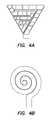
- FIGS. 4A-Cillustrate installed geometries of embodiments of an articulating array according to aspects of the disclosure
- FIGS. 5A-Billustrate examples of expansion chambers included in an articulating array according to aspects of the disclosure
- FIG. 6illustrates a process for positioning an intrauterine device for an ablation procedure according to aspects of the disclosure.
- FIG. 7is a block diagram of controller according to aspects of the disclosure.
- various structures and methodsare provided herein for decreasing a size or diameter of an intrauterine therapy application device in an insertion and/or retracted position, while maintaining its strength and robustness in expanded and/or deployed positions. Further, according to some aspects of the disclosure the structures and methods provide for more intimate contact between the device in an installed geometry and a patient's target cavity reducing, for example, risk of internal perforation during a medical procedure, including, for example, uterine ablation. In at least one embodiment, various structures and methods are provided for maintaining the robustness of a deployment mechanism of an intrauterine therapy application device by employing an articulating soft array.
- Articulating arrays as discussed hereininclude a plurality of expansion chambers that can be inflated or deflated to provide one or more positions of the articulating array.
- the articulating arrayis constructed of a soft extensible material having a plurality of expansion chambers. During insertion the articulating array maintains a small area, cross section, and/or diameter. Once inserted the articulating array can transition from an insertion geometry into an installed position that provides for intimate contact over the surface of the area within the patient being operated on by expanding the expansion chambers.
- structures and methodsare provided to decrease the stiffness of the installed device and provide for improved contact between, for example, the uterine lining and the installed geometry formed by the articulating array included in an intrauterine therapy application device.
- one advantage of employing an articulating arrayis the resulting decrease in the cross section of the intrauterine device, reducing patient discomfort and/or improving ease of insertion into an installed position within a patient.
- intrauterine devicesare provided having a reduced size or diameter in collapsed or retracted position which enable a smaller-diameter sheath while still maintaining the deployment mechanism's robustness in both collapsed and deployed positions.
- Another advantage in a smaller outer diameter sheathincludes reducing patient discomfort and decreasing the potential for cervical injury during insertion into the uterus. Further advantages can include the use of soft materials including, for example, silicone to fabricate the articulating arrays of the intrauterine therapy application device. Employing soft and/or flexible materials to construct the articulating arrays can reduce perforation risk in patients undergoing treatment.
- the articulating arraycan be housed within a sheath that is inserted into a patient.
- the articulating array or array componentcan be extended from the sheath in an insertion geometry.
- the insertion geometrycan be configured to minimize the area, cross section, and/or diameter or the articulating array (and the corresponding sheath) to provide, for example, for patient comfort.
- the articulating arraycan then be transitioned from the insertion geometry into an installed geometry.
- the installed geometryis configured to have as much intimate contact with the patient's internals as is possible.
- the articulating arraycan be constructed with a conductive array configured to ablate, for example, the patient's uterine lining during an ablation procedure once the articulating array is in an installed position.
- Reference to a conductive array hereinis intended to include an array of conductors disposed on the surface of an articulating, an array of conductors in the form of a mesh structure that can also be disposed on the surface of or within an articulating array. Additionally, reference to a conductive array is intended to include the examples of mesh arrays described in U.S. Pat. No. 6,813,520 to Truckai et al., which is hereby incorporated by reference herein in its entirety.
- the articulating arraycan position a conductive array disposed on its surface, and in others be configured to deploy conductive array including a mesh structure of conductors into a position for ablation.
- an intrauterine therapy application deviceincluding an articulating array 102 , a sheath 104 , and an RF generator 110 .
- the sheath of the deviceis inserted through the patient's cervix.
- the articulating arraymay be retracted in a collapsed or retracted position within the sheath for insertion into the patient's cervix.
- the sheathmay be inserted through the patient's cervix, and when the distal end 104 A of the sheath is inside the uterus, the articulating array may be extended into the uterus in an insertion geometry and articulated into a deployed state or installed geometry in the uterus.
- 3Billustrates an intrauterine therapy application device array 102 in a deployed or installed position. Decreasing the size, such as the cross section of an insertion geometry of the articulating array, allows for use of a smaller-diameter sheath 104 . A sheath having a smaller outer diameter may reduce patient discomfort, and also decrease the potential for cervical injury during insertion through the cervix and into the uterus.
- the device array 102includes an articulating array, having a plurality of chambers (see e.g., 150 of FIG. 3A ).
- device array 102In an insertion geometry or collapsed position, device array 102 is constructed and arranged to have a cylindrical structure shown, for example, in FIG. 3A .
- the plurality of chambers at 150can be, for example, air chambers constructed and arranged to configure array 102 into an insertion geometry when the air chambers are under atmospheric air pressure, or in other words, when the air chambers are not inflated.
- the air chamberscan be configured to articulate the device array 102 into an installed geometry.
- the installed geometrycan be defined by the respective elasticities of the plurality of chambers and surrounding material.
- materials having a first elasticity for one wall of the plurality of chambers and materials having a greater elasticity for another wall of the plurality of chambersresults in material having the greater elasticity distending to a greater extent than material having a lesser elasticity.
- This propertycan be configured to achieve a variety of geometries in any articulating array.
- various sections, portions, etc., of an articulating arraycan be constructed to have a plurality of elasticities, permitting articulation into any one or more of triangular, square, elliptical, ovular, and spherical shapes, among other examples.
- the articulating arrayis constructed and arranged of a soft expandable material.
- high expansion siliconcan be used to fabricate the articulating array using known approaches.
- the articulating arraycan be fabricated to include a plurality of chambers, and channels within the articulating array, where the channels are used to control the expansion of the plurality of chambers (e.g., each array can include a plurality of chambers and a plurality of channels to introduce air or fluid into one or more chambers thereby controlling the expansion of the plurality of chambers).
- the articulating arraycan be constructed to have any of a variety of insertion geometries and articulate into any of a variety of installation geometries.
- the insertion geometryincludes a cylinder, so that the cross section of, for example, array 102 is minimized.
- the installed geometry of the articulating arrayincludes a substantially triangular geometry to conform to patient physiology during an intrauterine procedure.
- the triangular geometry of the articulating array in its installed positionenables deployment of a conductive array within a patient.
- the conductive arraycan be integrated on the outside of the articulating array ( FIG. 3C , discussed in greater detail below).
- the conductive arraycan be constructed and arranged on the surface of the articulating array, so that the conductive array is proximate to an ablation surface when the articulating array is in an installed position.
- the articulating arrayBy releasing pressure on the plurality of chambers the articulating array can be configured to return to its insertion geometry, facilitating retraction of the articulating array from the patient and/or into the sheath.
- the intrauterine therapy application device 100can be deployed from the sheath in its insertion geometry by driving the device array 102 forward relative to the sheath 104 .
- the articulating arraymay or may not be driven forward to its maximum depth.
- a screw drivemay be employed to drive forward the device array 102 into the insertion position shown in FIG. 3A .
- the travel of the device array 102can be rigidly coupled to the travel of the screw drive.
- the device arraytravels to a first insertion position shown in FIG. 3A .
- the device array 102can then be articulated into an installed geometry, which in some examples results in the articulating array moving forward relative to the device and/or sheath 104 .
- the connection at the screw drivecan be configured to allow for forward travel by the articulating array 102 during subsequent articulation.
- the screw drivecan also be configured to travel forward responsive to the articulation of the articulating array 102 during transition from the insertion geometry to the installed geometry.
- connection between a screw drivecan include a compliant element, such as a spring, between the screw drive and an internal central support member.
- the springtransmits force from the screw drive to the device array, so that if the deployment of the device array is unrestricted, the articulating array will deploy normally.
- the springcan absorb the screw's travel, allowing the articulating array to rest at a sub-maximum deployment without heavy stress.
- the compliant elementcan permit the articulating array to move forward further into, for example, the patient's uterus responsive to articulation of the articulating array.
- the articulating arrayrolls into the installation geometry during expansion of the plurality of chambers.
- the process of rolling the articulating array into the installation geometrycan cause the articulating array to be positioned more securely inside the uterus by moving further into the uterine cavity.
- the compliant elementcan permit the additional movement of the articulating array.
- the devicecan be configured to permit the articulating array to move freely during articulation of the articulating array.
- the forward pressure exerted by the articulating arraycauses the articulating array and, for example, the screw drive to move forward.
- the introduction of a compliant element to the screw driveallows for a simple drive mechanism that controls the insertion force that the articulating array is able to generate.
- a purpose of the articulating array of the intrauterine therapy application deviceis to position a conductive array constructed on the surface of array 102 into a deployed state.
- An RF sourcee.g., RF generator 110
- RF generator 110can be configured to deliver power to the conductive array on the surface of the articulating array. Responsive to input of power from the RF generator, heat can be generated that ablates the uterine lining.
- the conductive arraycan be knit from elastic yarn, so a certain level of force is needed simply to spread the conductive array to the desired shape. In some examples, the force can be applied through expansion of the plurality of chambers.
- the conductive arraycan be printed and/or constructed on the surface of the articulating array.
- the conductive arraycan be printed and/or constructed on the surface of the articulating array based on the installed geometry, thus when the articulating array is transitioned into an installed geometry the mesh on the surface of the articulating array can be positioned proximate to, for example, the patients uterine lining.
- the device 100can be configured to overcome resistance encountered during transition from an insertion geometry to an installed geometry.
- a pressure controllercan be configured to increase pressure delivered to the plurality of chambers until the articulating array is configured in its installed geometry.
- the intrauterine deviceis configured to limit the pressure applied to the plurality of chambers, and thereby prevent injury during a procedure, as described in greater detail below.
- improving the durability and flexibility of the articulating arrayincludes constructing the articulating array of a high elongation material (e.g., silicone, rubber, etc.) to enable the articulating array to be softer, more compliant/resilient, and/or better form fitting so that the articulating array can endure significant stress and strain, and even displacement and/or deformation and still return to an original configuration.
- a high elongation materiale.g., silicone, rubber, etc.
- This approachenables reduction in the size of the articulating array and consequently the sheath and intrauterine device required.
- the strength of the high elongation materialscan be configured to supply the desired pressure for properly positioning of the conductive array.
- an intrauterine devicecan include a vacuum and/or pump for supplying increasing pressures to the plurality of chambers.
- pressured air or fluidcan be driven into the plurality of chambers by manual operation.
- FIG. 1is a side elevation view of an intrauterine therapy application device 100 with an articulating array 102 in a retracted position inside a hollow sheath 104 .
- the intrauterine therapy application device 100includes a handle 106 , and is coupled via a cable 120 to a radiofrequency signal generator 110 and via a tube 128 to a vacuum/pump source 112 .
- the radiofrequency generator 110generates an electrical signal, for example a radiofrequency signal, and transmits it to the a conductive array disposed on the articulating array 102 through the cable 120 , which is ultimately coupled to the conductive array through the handle 106 .
- the vacuum/pump source 112can be connected to the handle 106 at the port 122 .
- vacuum/pump source 112can create suction for removal of ablated tissue.
- vacuum pump sourcecan be connected to a plurality of tubes (e.g., 128 ) connected to one or more ports (e.g., 122 ) to control a pressure delivered to an articulating array 102 including a plurality of expansion chambers.
- the distal end 104 a of the sheath 104 of the intrauterine therapy application device 100is configured to be inserted into a patient's cervix.
- the handle 106includes a distal grip 124 and a proximal grip 126 .
- the proximal grip 126is squeezed toward the distal grip 124 , to cause the articulating array 102 to extend out from the sheath 104 , as shown in FIG. 2 , for example, by operation of drive shaft 108 .
- the articulating array 102is extended out from the sheath 104 in an insertion geometry or collapsed position as shaft 108 is driven forward.
- the articulating array 102extends out from the sheath 104 in the insertion geometry or collapsed position, it may be configured to begin transitioning into the installed geometry, as shown in the perspective view of the deployed array illustrated in FIG. 3B .
- operation of proximal and distal gripscan be configured to force air and/or liquid into the plurality of expansions chambers increasing the pressure in the plurality of expansion chambers causing the chambers to expand into the installed geometry as the articulating array 102 is fully extended from the sheath 104 .
- shaft 108can be configured to operate on a fluid or air bladder and shaft 108 can be configured to apply pressure on the bladder when the proximal grip 126 is squeezed toward the distal grip 124 . The increase in pressure can be communicated to the articulating array 102 causing it to extend out from the sheath 104 and subsequently to transition into an installed geometry.
- the articulating array 102may be configured to extend out from the sheath 104 until it reaches a preconfigured position. Once the articulating array 102 reaches the preconfigured position, a pressure controller can be operated to increase pressure in the plurality of expansion chambers (e.g., 150 , FIG. 3A ) thereby articulating the articulating array into an installed position.
- a pressure controllercan be operated to increase pressure in the plurality of expansion chambers (e.g., 150 , FIG. 3A ) thereby articulating the articulating array into an installed position.
- the preconfigured positioncan be set on the intrauterine device manually, for example via a dial 129 , such as to accommodate a specific patient's anatomy.
- the dial 129can control a length of shaft 108 .
- Lengthening and shortening the shaft 108can be configured to alter the insertion distance travelled by array 102 .
- lengthening and shortening of the shaft 108can be configured to alter a pressure delivered to the plurality of chambers, which can be configured to control insertion attributes (e.g., insertion depth, insertion geometry, etc.)
- a dialcan also be configured to control a valve that permits a fluid (gas and/or liquid) to flow into the plurality of expansion chambers, so that in response to reaching the preconfigured position, the valve may open and pressurized fluid may be delivered to the plurality of expansion chambers.
- the dialcan control the activation of a switch or sensor that indicates the preconfigured position has been reached.
- the switch or sensorcan control the opening of a valve that controls flow to the plurality of expansion chambers.
- a pump or motorcan be configured to deliver increased pressure to the plurality of expansion chambers once the preconfigured position has been reached.
- the switch and/or sensorcan also be configured to deliver a control signal to the pump or motor that indicates that increased pressure can be delivered to the plurality of expansion chambers.
- the articulating array 102 and the pressure controllercan be configured to extend the articulating array from the sheath 104 with selective pressure applied to one or more of the chambers of the articulating array, while maintaining the plurality of expansion chambers in the insertion geometry.
- the articulating array 102can be configured to extend outward from the sheath 104 with increased pressure applied to one of more of the plurality of expansion chambers.
- the plurality of expansion chamberscan be arranged in a linear arrangement.
- the pressure controller and the plurality of expansion chamberscan be configured to deliver an increased pressure to one of more of the plurality of expansion chambers to extend the articulating array, and once the articulating array is extended from the sheath in the insertion geometry, the pressure controller can be configured to further selectively provide increased pressure to the one or more of the plurality of expansion chambers to articulate the articulating array into an installed position.
- FIG. 3Ais a perspective view of a portion of an intrauterine therapy application device array in a deployed position, according to an embodiment of the disclosure.
- the articulating array 102includes a plurality of expansion chambers 150 and an external surface 151 .
- the articulating array 102can be constructed and arranged of a contiguous material and configured to retain an insertion geometry when the plurality of expansion chambers 150 are not under pressure.
- the plurality of expansion chambersare constructed to include respective seals, and/or valves that enable selective inflation of the plurality of expansion chambers and/or facilitate transition of the articulating array between the insertion and installed geometries.
- the plurality of expansion chamberscan be constructed and arranged to have a first geometry when not inflated or having a pressure less than a threshold and at least a second geometry when fully inflated or having a pressure greater than a threshold.
- the articulating arraycan be configured to achieve various positions in between the insertion geometry and installed geometry by varying the pressure within select of the plurality of expansion chambers.
- the plurality of expansion chambersare constructed and arranged of pneumatic networks (“pneunets”) of channels in elastomers.
- selective increases in pressurecan be supplied to the plurality of expansion chambers, for example, through the pneumatic networks.
- the delivery of selective increases in pressure to the plurality of expansion chamberscan be used to provide rigidity to the articulating array, for example, to restore the articulating array to its insertion geometry.
- the articulating arraycan be deformed from an insertion geometry upon advancement from the sheath due to, for example, gravity or the plurality of expansion chambers encountering some internal resistance to the advancement of the articulating array.
- a controllercan be configured to selectively deliver increases in pressure to one or more of the plurality of expansion chambers to overcome gravity or such deformation in the articulating array so as to restore the articulating array to its insertion geometry.
- the articulating arraycan be connected to a drive shaft or an air bladder as discussed above, at 152 .
- the spacing shown between 152 and the end of the sheath 104can be configured based on measurements taken of a patient's uterus. In some further embodiments, the spacing shown between 152 and the end of the sheath 104 can provide for some variation in a deployment distance.
- the connection at 152is configured to provide a telescoping arrangement whereby the articulating array 102 is extended outward from the sheath 104 when operated.
- the articulating array 102can include channels at 153 , some can be constructed and arranged to extend the length of the articulating array 102 .
- Channels 153are configured to deliver fluid to the plurality of expansion chambers at 150 .
- vacuum/pump 112can force fluid into the plurality of expansion chambers 150 , increasing fluid pressure within the expansion chambers.
- operation of the handlee.g., 124 - 126
- the articulating array 102extends outward from the sheath 104 in an insertion geometry defined by the outer surface 151 and shape of the plurality of expansion chambers 150 .
- additional expansion chamberscan be constructed and arranged within articulating array 102
- fewer expansion chamberscan be constructed and arranged within articulating array 102 .
- the articulating arraycan include one or more hollow elongate tubes (not shown).
- suctionis applied to the uterine cavity, for example from the suction source (e.g., 112 shown in FIG. 1 )
- fluid, vapor, liquid, and/or tissuemay be suctioned through the one or more hollow elongate tubes, away from the patient.
- FIG. 3Bis a perspective view of the portion of an intrauterine therapy application device in a installed position.
- the articulating array 102 and a plurality of expansion chambers at 160have been expanded to cause the articulating array to transition from an insertion geometry ( FIG. 3A ) to an installed geometry ( FIG. 3B ).
- the articulating arraycan also include a conductive array (e.g. FIG. 3C, 170 ) on an outer surface 161 of the articulating array 102 .
- the conductive arraycan be, for example, printed on the outer surface 161 of the articulating array 102 so that the conductive array is proximate to a patient's uterine lining when the articulating array 102 is in an installed geometry ( FIG. 3B ).
- the conductive arraymay be knitted from a nylon and spandex knit and plated with gold, silver, or another conductive material.
- the conductive arraycan be configured to be conformable, permeable, and to carry current.
- the conductive arraycan be attached to the articulating array at its outer surface 161 .
- strands of threadmay be connected to the outer surface 161 of the articulating array 102 .
- the strands of threadcan be constructed of nylon.
- the strands of thread forming the conductive arraycan be sewn into the articulating array 102 at the outer surface 161 .
- conformable metal filamentscan be printed directly on the outer surface of the articulating array 102 .
- metal filamentse.g., gold, silver, or another conductive material
- other filamentse.g., non-metal
- the articulating arraymay be connected to a drive or a first expansion chamber at 162 .
- the connection at 162can be configured to allow some variability in an insertion distance traveled by the articulating array 102 .
- the connection 162can travel further out from sheath 104 as the articulating array 102 transitions from an insertion geometry into an installed geometry.
- the conductive arraycan be configured to carry current. Shown in FIG. 3C is an example conductive array disposed on the surface of an articulating array 102 .
- Internal wires 172 A and 172 Bcan be configured to deliver current to the conductive array from, for example and RF source (e.g., RF 110 , FIG. 1 ).
- the amount of current delivered to the conductive arraycan be configurable according to a geometry of the installed articulating array 102 and/or the conductive array disposed on its surface.
- the installed geometry of the articulating array 102is approximately triangular.
- the power deliveredcan be calculated based on a desired power density, which can be determined from power divided by the surface area to which power is being delivered.
- Other geometriescan require differing amounts of current to be delivered to the conductive array, for example, based on the surface area of the other geometry. As discussed, the differing amount of current can be controlled by an RF source 110 connected to a conductive array.
- Conductive arrayscan be constructed and arranged on an outer surface of an articulating array 102 in a variety of structures.
- FIG. 3Dillustrates an example conductive array constructed and arranged of a plurality of mesh portions shown at 180 .
- Each mesh portioncan be printed on a portion of an outer surface of the articulating array 102 .
- Each mesh portioncan be connected to wires 182 A-B which can be connected to an RF source to supply current to each mesh portion.
- the conductive arraymay be knitted from a nylon and spandex knit and plated with gold, silver, or another conductive material.
- Each mesh portionmay also be knitted from a nylon and spandex knit and plated with gold, silver, or another conductive material.
- filamentse.g., metal, gold, silver, or another conductive material
- filamentscan be printed on the outer surface of an articulating array 102 to form each mesh portion at 180 . Once positioned, current can be supplied to each mesh portion to perform an ablation procedure on a patient's uterine lining.
- the articulating arraycan be fabricated without a conductive array.
- the uterine liningcould be ablated using hot or cold fluid introduced into the plurality of expansion chambers.
- refrigerantscan be introduced into the articulating array to ablate the uterine lining.
- the refrigerantscan include, for example, liquid nitrogen and nitrous oxide, among other options.
- the articulating arraycan be fabricated with the plurality of expansion chambers constructed to position the articulating array in optimal communication with the uterine lining of a patient.
- the articulating arraycan include additional channels for delivering hot or cold fluid proximate to the surface of the articulating array in contact with the uterine lining.
- the hot or cold fluidcan be introduced into the plurality of expansion chambers to ablate the uterine lining.
- the articulating array(e.g., 102 ) can be controlled to adjust stiffness and create a flexure with a plurality of expansion chambers, each having a variety of stiffnesses and expansion geometries.
- the plurality of expansion chambersOnce the plurality of expansion chambers are expanded the articulating array can take on a variety of installation geometries. Shown in FIGS. 4A-C are example installation geometries that can be obtained by expanding a plurality of expansion chambers within an articulating array (e.g., triangular FIG. 4A , circular FIG. 4B , and diamond FIG. 4C ).
- selected manufacturing processescan be used to alter the elasticity provided by different portions of the articulating array (e.g., combining different materials, using different thicknesses for dimensions of respective expansion chambers, etc.).
- the manufacturing processescan be used selectively on different areas of an articulating array to create an articulating array of a plurality of expansion chambers having different elasticities in different areas of the articulating array.
- the articulating arraymay be constructed of multiple materials, each material having a different modulus of elasticity.
- each expansion chambersuch as the thickness and/or width of the chamber, may be adjusted to create an expansion chamber having an expanded geometry that forces the articulating array to take on an installation geometry when the individual chambers comprising the articulating array are expanded.
- adjusting the cross-sectional profile of one or more of the expansion chamberscan alter the geometry obtained by a given embodiment of the articulating array, when the plurality of expansion chambers are being expanded.
- other methods and characteristicsmay be used to control the stiffness of certain portions of an articulating array so as to alter the geometry and/or overall volume obtained by the articulating array.
- varying pressurecan be selectively applied to one or more of the plurality of expansion chambers to trigger articulation of the articulating array in a desired manner during transition from the insertion geometry to the installed geometry.
- the pressure controller and the articulating arraycan be selectively controlled to transition to one or more intermediate positions of the articulating array from an insertion geometry (e.g., FIG.
- the shape and/or overall volume that the articulating array takes in the one or more intermediate positions during the transition from the insertion geometry to the installed geometrycan be controlled through the selective inflation of the plurality of expansion chambers. It is appreciated that with such an arrangement, the shape and/or the overall volume of the articulating array in the intermediate positions between the insertion geometry and the installed geometry can be controlled to minimize the overall volume occupied by the articulating array during the transition, such as to yield to neighboring tissue. This may be desirable, for example, so as to increase patient comfort during the transition from the insertion geometry of the articulating array to the installed geometry of the articulating array.
- Process 600begins at 602 with an operator inserting a sheath of the therapy device into the cervix of the patient. Once the sheath has been positioned, the articulating array of the device is extended outward from the sheath at 604 . Pressured can be delivered to the articulating array, for example, by increasing fluid pressure delivered to the articulating array through the therapy device. The increased pressure results in actuation of the articulating array. At 606 the articulating array transitions from an insertion geometry to an installed geometry within the uterus of the patient.
- a conductive array on the articulating arrayis also position proximate to the patient's uterine lining.
- powercan be supplied to the conductive array ablating the uterine lining of the patient.
- powercan be delivered by an RF source connected to the therapy device.
- the RF sourcecan be managed by a controller.
- the controllercan also be configured to mange and/or monitor pressure and temperature during the procedure.
- the controllercan be configured to alter pressure or power delivered in order to insure patient health and safety.
- FIG. 5Shown in FIG. 5 is a portion of an articulating array 500 including expansion chambers 510 , 512 , and 514 .
- Increased pressure delivered to chambers 510 - 514can result in the portion of the articulating array taking on an installed geometry defined by the elasticity of the chambers.
- the articulating arraycan be fabricated to include a plurality of sensors 502 , 504 , and 506 .
- the plurality of sensorscan be disposed on an exterior surface of the articulating array or can be embedded within the articulating array structure.
- pressure sensorscan be configured to detect pressure with the plurality of chambers.
- sensorscan be configured to determine a change in dimension of the plurality of chambers.
- the change in dimensionscan be communicated to a pressure controller.
- the pressure controllercan be configured to determine that, for example, the pressure supplied has resulted in a smaller change in configuration than expected. Smaller changes in configuration can be associated with resistance, prompting an increase in pressure delivered to the plurality of chambers and/or an articulating array.
- Proximity sensorscan also be employed to assist in deployment and positioning of an articulating array.
- strain gaugescan be included in the plurality of sensors. The strain gauges can provide information to a controller to establish that the articulating array has or has not reached an installed position.
- temperature sensorscan be constructed within and/or on the surface of the articulating array and temperatures applied to the patient, for example, by current through a conductive array can be monitored to insure the temperature remain below a safe operating temperature.
- Other sensorscan also be fabricated on or in the articulating array.
- sensor informationcan be communicated to a controller.
- the controllercan be configured in some embodiments to respond to the sensor information automatically, or in other embodiments to provide indications to an operator regarding the sensor information.
- the controllercan be configured to respond automatically and report to various operators. For example, sensors can signal the controller to turn off portions of a conductive array on non-expanded portions of the articulating array to prevent electrical shorts, among other options.
- Shown in FIG. 7is an example controller which can be configured to, for example, regulate pressure delivered to an articulating array.
- the controllercan receive sensor information from an intrauterine therapy application device.
- the controllercan be configured to process the information and act on the intrauterine therapy application device according to the received information. For example, if the sensor information indicates that the articulating array has not reached an installed geometry, increased pressure can be delivered to the device to achieve the installed geometry.
- the controllercan be connected to a vacuum/pump and control the pressure supplied to the device.
- the controller 700can be configured to manage power delivered to an intrauterine therapy application device.
- the controllercan be configured to receive sensor information on position and/or temperature.
- the controllercan be configured to limit power delivered from, for example, an RF source to the conductive array until the articulating array is in an installed position. Further, the controller can also be configured to maintain procedure appropriate temperature being applied to the patient. If a threshold temperature is exceeded, the controller can be configured to reduce or cease power supplied from the RF source to the conductive array.
- FIG. 7shows an example block diagram of the controller 700 , which can be implemented as a computer system, in which various aspects and functions in accordance with the present disclosure may be practiced.
- the controller 700may include one or more computer systems connected via a network.
- the computer systemsmay include mobile computing systems displaying user interfaces for interacting with the functions and/or sensor information provided by the controller (e.g., laptops, tablets, and other mobile devices).
- the user interfacescan be configured to allow an operator to make adjustments to the operation of the flexible array during a procedure.
- the controller 700includes a processor 710 , a memory 712 , a bus 714 , an interface 716 and a storage system 718 .
- the processor 710which may include one or more microprocessors or other types of controllers, can perform a series of instructions that manipulate data.
- the processor 710may be a well-known, commercially available processor such as an Intel Pentium, Intel Atom, ARM Processor, Motorola PowerPC, SGI MIPS, Sun UltraSPARC, or Hewlett-Packard PA-RISC processor, or may be any other type of processor or controller as many other processors and controllers are available. As shown, the processor 710 is connected to other system placements, including a memory 712 , by the bus 714 .
- the memory 712may be used for storing programs and data during operation of the controller 700 .
- the memory 712may be a relatively high performance, volatile, random access memory such as a dynamic random access memory (DRAM) or static memory (SRAM).
- the memory 712may include any device for storing data, such as a disk drive or other non-volatile storage device, such as flash memory or phase-change memory (PCM).
- PCMphase-change memory
- Various embodiments in accord with the present disclosurecan organize the memory 712 into particularized and, in some cases, unique structures to perform the aspects and functions disclosed herein.
- the bus 714may include one or more physical busses (for example, busses between components that are integrated within a same machine), and may include any communication coupling between system placements including specialized or standard computing bus technologies such as IDE, SCSI, PCI and InfiniBand.
- the bus 714enables communications (for example, data and instructions) to be exchanged between system components of the controller 700 .
- Controller 700can also include one or more interfaces 716 such as input devices, output devices and combination input/output devices.
- the interface devices 716may receive input, provide output, or both.
- output devicesmay render information for external presentation.
- Input devicesmay accept information from external sources. Examples of interface devices include, among others, keyboards, mouse devices, trackballs, microphones, touch screens, printing devices, display screens, speakers, network interface cards, etc.
- the interface devices 716allow the controller 700 to exchange information and communicate with external entities, such as users and other systems.
- Storage system 718may include a computer-readable and computer-writeable nonvolatile storage medium in which instructions are stored that define a program to be executed by the processor.
- the storage system 718also may include information that is recorded, on or in, the medium, and this information may be processed by the program. More specifically, the information may be stored in one or more data structures specifically configured to conserve storage space or increase data exchange performance.
- the instructionsmay be persistently stored as encoded signals, and the instructions may cause a processor to perform any of the functions described herein.
- a medium that can be used with various embodimentsmay include, for example, optical disk, magnetic disk or flash memory, among others.
- the processor 710 or some other controllermay cause data to be read from the nonvolatile recording medium into another memory, such as the memory 712 , that allows for faster access to the information by the processor 710 than does the storage medium included in the storage system 718 .
- the memorymay be located in the storage system 718 or in the memory 712 .
- the processor 710may manipulate the data within the memory 712 , and then copy the data to the medium associated with the storage system 718 after processing is completed.
- a variety of componentsmay manage data movement between the medium and the memory 712 , and the invention is not limited thereto.
- controller 700is shown by way of example as one type of computer system upon which various aspects and functions in accord with the present invention may be practiced, aspects of the invention are not limited to being implemented on the computer system, shown in FIG. 7 . Various aspects and functions in accord with the present invention may be practiced on one or more computers having different architectures or components than that shown in FIG. 7 .
Landscapes
- Health & Medical Sciences (AREA)
- Surgery (AREA)
- Life Sciences & Earth Sciences (AREA)
- Engineering & Computer Science (AREA)
- Veterinary Medicine (AREA)
- General Health & Medical Sciences (AREA)
- Nuclear Medicine, Radiotherapy & Molecular Imaging (AREA)
- Public Health (AREA)
- Biomedical Technology (AREA)
- Heart & Thoracic Surgery (AREA)
- Medical Informatics (AREA)
- Molecular Biology (AREA)
- Animal Behavior & Ethology (AREA)
- Otolaryngology (AREA)
- Physics & Mathematics (AREA)
- Plasma & Fusion (AREA)
- Gynecology & Obstetrics (AREA)
- Pregnancy & Childbirth (AREA)
- Reproductive Health (AREA)
- Surgical Instruments (AREA)
- Electromagnetism (AREA)
Abstract
Description
Claims (10)
Priority Applications (2)
| Application Number | Priority Date | Filing Date | Title |
|---|---|---|---|
| US13/800,352US9895192B2 (en) | 2013-03-13 | 2013-03-13 | Intrauterine treatment device with articulating array |
| US15/878,326US10499981B2 (en) | 2013-03-13 | 2018-01-23 | Intrauterine treatment device with articulating array |
Applications Claiming Priority (1)
| Application Number | Priority Date | Filing Date | Title |
|---|---|---|---|
| US13/800,352US9895192B2 (en) | 2013-03-13 | 2013-03-13 | Intrauterine treatment device with articulating array |
Related Child Applications (1)
| Application Number | Title | Priority Date | Filing Date |
|---|---|---|---|
| US15/878,326ContinuationUS10499981B2 (en) | 2013-03-13 | 2018-01-23 | Intrauterine treatment device with articulating array |
Publications (2)
| Publication Number | Publication Date |
|---|---|
| US20140276726A1 US20140276726A1 (en) | 2014-09-18 |
| US9895192B2true US9895192B2 (en) | 2018-02-20 |
Family
ID=51530899
Family Applications (2)
| Application Number | Title | Priority Date | Filing Date |
|---|---|---|---|
| US13/800,352Active2034-10-11US9895192B2 (en) | 2013-03-13 | 2013-03-13 | Intrauterine treatment device with articulating array |
| US15/878,326Active2033-03-20US10499981B2 (en) | 2013-03-13 | 2018-01-23 | Intrauterine treatment device with articulating array |
Family Applications After (1)
| Application Number | Title | Priority Date | Filing Date |
|---|---|---|---|
| US15/878,326Active2033-03-20US10499981B2 (en) | 2013-03-13 | 2018-01-23 | Intrauterine treatment device with articulating array |
Country Status (1)
| Country | Link |
|---|---|
| US (2) | US9895192B2 (en) |
Cited By (7)
| Publication number | Priority date | Publication date | Assignee | Title |
|---|---|---|---|---|
| US11160597B2 (en) | 2010-11-09 | 2021-11-02 | Aegea Medical Inc. | Positioning method and apparatus for delivering vapor to the uterus |
| US11207118B2 (en) | 2007-07-06 | 2021-12-28 | Tsunami Medtech, Llc | Medical system and method of use |
| US11213338B2 (en) | 2007-08-23 | 2022-01-04 | Aegea Medical Inc. | Uterine therapy device and method |
| US11219479B2 (en) | 2014-05-22 | 2022-01-11 | Aegea Medical Inc. | Integrity testing method and apparatus for delivering vapor to the uterus |
| US11331037B2 (en) | 2016-02-19 | 2022-05-17 | Aegea Medical Inc. | Methods and apparatus for determining the integrity of a bodily cavity |
| US11497089B2 (en) | 2017-06-20 | 2022-11-08 | Aegea Medical Inc. | Induction coil assembly for uterine ablation and method |
| US11849991B2 (en) | 2011-10-07 | 2023-12-26 | Aegea Medical Inc. | Integrity testing method and apparatus for delivering vapor to the uterus |
Families Citing this family (6)
| Publication number | Priority date | Publication date | Assignee | Title |
|---|---|---|---|---|
| JP6318088B2 (en) | 2011-07-26 | 2018-04-25 | アンフォラ メディカル, インコーポレイテッド | Apparatus and method for modulating pelvic nerve tissue |
| US9333111B2 (en) | 2013-02-04 | 2016-05-10 | Hologic, Inc. | Fundus bumper mechanical reference for easier mechanism deployment |
| WO2015120079A1 (en) | 2014-02-04 | 2015-08-13 | Amphora Medical, Inc. | Devices and methods for treating conditions caused by affarent nerve signals |
| JP2017516620A (en) | 2014-05-23 | 2017-06-22 | アンフォラ メディカル, インコーポレイテッド | Methods and devices for treatment of pelvic conditions |
| AU2019261320A1 (en)* | 2018-04-25 | 2020-12-03 | InnoMed Five, L.L.C. | Device and method for improving implantation of fertilized egg during pregnancy |
| ES2759515B2 (en)* | 2018-11-08 | 2021-02-16 | Haimovich Yaffa | INTRAUTERINE EXPANDER DEVICE |
Citations (113)
| Publication number | Priority date | Publication date | Assignee | Title |
|---|---|---|---|---|
| US2190383A (en) | 1936-08-29 | 1940-02-13 | Louis B Newman | Therapeutic apparatus |
| US4489732A (en) | 1982-09-20 | 1984-12-25 | Hasson Harrith M | Gynecological instrument |
| US4946440A (en) | 1988-10-05 | 1990-08-07 | Hall John E | Evertible membrane catheter and method of use |
| US5002558A (en) | 1989-08-23 | 1991-03-26 | The Beth Israel Hospital Association | Adjustable urethral catheter and method for treating obstructive prostatism |
| US5188596A (en) | 1990-09-27 | 1993-02-23 | Mentor Corporation | Transparent prostate dilation balloon and scope |
| US5217466A (en) | 1991-04-19 | 1993-06-08 | Hasson Harrith M | Guide for facilitating the performance of internal surgery |
| US5235966A (en) | 1991-10-17 | 1993-08-17 | Jay Jamner | Endoscopic retractor |
| US5314443A (en) | 1990-06-25 | 1994-05-24 | Meadox Medicals, Inc. | Prostate balloon dilatation catheter |
| US5501681A (en) | 1993-11-12 | 1996-03-26 | Neuwirth; Robert S. | Intrauterine cryoablation cauterizing apparatus and method |
| US5542928A (en) | 1991-05-17 | 1996-08-06 | Innerdyne, Inc. | Method and device for thermal ablation having improved heat transfer |
| US5656013A (en)* | 1988-07-22 | 1997-08-12 | Yoon; Inbae | Method of using an expandable multifunctional manipulating instrument for various medical procedures |
| US5702438A (en) | 1995-06-08 | 1997-12-30 | Avitall; Boaz | Expandable recording and ablation catheter system |
| US5769880A (en) | 1996-04-12 | 1998-06-23 | Novacept | Moisture transport system for contact electrocoagulation |
| US5830179A (en) | 1996-04-09 | 1998-11-03 | Endocare, Inc. | Urological stent therapy system and method |
| US5882290A (en) | 1996-02-29 | 1999-03-16 | Scimed Life Systems, Inc. | Intravascular radiation delivery system |
| US5891094A (en) | 1995-09-07 | 1999-04-06 | Innerdyne, Inc. | System for direct heating of fluid solution in a hollow body organ and methods |
| US5935098A (en) | 1996-12-23 | 1999-08-10 | Conceptus, Inc. | Apparatus and method for accessing and manipulating the uterus |
| US6096047A (en) | 1998-09-03 | 2000-08-01 | Smit; Julie Ann | Gynecological cylinders which treat diseases |
| US6159207A (en) | 1997-07-31 | 2000-12-12 | Yoon; Inbae | Protected ablation method and apparatus |
| US6261219B1 (en) | 1998-05-04 | 2001-07-17 | Novoste Corporation | Intraluminal radiation treatment system |
| US6266568B1 (en)* | 1998-06-02 | 2001-07-24 | Advanced Bionics Corporation | Inflatable cochlear electrode array and method of making same |
| US6277089B1 (en)* | 1990-07-24 | 2001-08-21 | Inbae Yoon | Method for ablating portions of the uterus |
| US20020022832A1 (en)* | 1998-06-19 | 2002-02-21 | Mikus Paul W. | Cryoprobe assembly with detachable sheath |
| US20020058951A1 (en) | 1997-03-13 | 2002-05-16 | Gary R. Fiedler | Fluid actuated stent delivery system |
| US20020068934A1 (en) | 1999-06-23 | 2002-06-06 | Edwards Stuart D. | Thin layer ablation apparatus |
| US20020082667A1 (en) | 2000-09-05 | 2002-06-27 | Shadduck John H. | Medical instruments and techniques for highly-localized thermally-mediated therapies |
| US6450983B1 (en) | 2001-10-03 | 2002-09-17 | Robert D. Rambo | O-ring for incrementally adjustable incision liner and retractor |
| US6450977B1 (en) | 2000-04-10 | 2002-09-17 | Cervilenz | Devices and methods for cervix measurement |
| US6468292B1 (en) | 1995-05-19 | 2002-10-22 | General Surgical Innovations, Inc. | Skin seal with inflatable membrane |
| US20020177846A1 (en) | 2001-03-06 | 2002-11-28 | Mulier Peter M.J. | Vaporous delivery of thermal energy to tissue sites |
| US20020183730A1 (en) | 2001-06-01 | 2002-12-05 | Reu Eugene Brian | Device and method for the creation of a circumferential Cryogenic lesion in a pulmonary vein |
| US6540655B1 (en) | 2000-11-10 | 2003-04-01 | Scimed Life Systems, Inc. | Miniature x-ray unit |
| US6547784B1 (en) | 2000-06-23 | 2003-04-15 | Ethicon, Inc. | System and method for placement of a surgical instrument in a body cavity |
| US6607477B1 (en) | 1998-02-16 | 2003-08-19 | Wallace A. Longton | Graduated intraluminal catheter and methods of use thereof |
| US6607545B2 (en) | 2000-12-27 | 2003-08-19 | Ethicon, Inc. | Conformal surgical balloon with varying wall expansibility |
| US6635054B2 (en) | 2000-07-13 | 2003-10-21 | Transurgical, Inc. | Thermal treatment methods and apparatus with focused energy application |
| US6663626B2 (en) | 1998-07-13 | 2003-12-16 | Novacept | Apparatuses and methods for interstitial tissue removal |
| US20040002698A1 (en) | 2002-06-26 | 2004-01-01 | Ethicon, Inc. | Thermal ablation with deployable cage |
| US6706026B1 (en) | 1996-08-09 | 2004-03-16 | Cook Urological Incorporated | Instillation uterine catheter |
| US20040098013A1 (en) | 1999-12-07 | 2004-05-20 | Pasquale Ciaglia | Percutaneous dilational device |
| US20040122463A1 (en) | 2002-11-21 | 2004-06-24 | Hibler Timothy B. | Cervical medical device, system and method |
| US6796976B1 (en) | 1998-03-06 | 2004-09-28 | Scimed Life Systems, Inc. | Establishing access to the body |
| US6813520B2 (en) | 1996-04-12 | 2004-11-02 | Novacept | Method for ablating and/or coagulating tissue using moisture transport |
| US6840937B2 (en) | 2001-10-18 | 2005-01-11 | Electrosurgery Associates, Llc | Electrosurgical ablator with aspiration |
| US20050061329A1 (en) | 2003-09-18 | 2005-03-24 | Conceptus, Inc. | Catheter for intrafallopian contraceptive delivery |
| US20050085827A1 (en) | 2003-10-15 | 2005-04-21 | G. Anselmo N. | Uterine manipulating device |
| US20050085880A1 (en)* | 1996-04-12 | 2005-04-21 | Csaba Truckai | Moisture transport system for contact electrocoagulation |
| US20050159644A1 (en) | 2003-12-24 | 2005-07-21 | Masayuki Takano | Endoscope apparatus |
| US6929642B2 (en) | 2002-06-28 | 2005-08-16 | Ethicon, Inc. | RF device for treating the uterus |
| US6942648B2 (en) | 1999-12-09 | 2005-09-13 | Advanced Cardiovascular Systems, Inc. | Catheter with a transparent shaft |
| US20050209627A1 (en) | 2004-03-18 | 2005-09-22 | Kick George F | Expandable medical access device |
| US20050234543A1 (en) | 2004-03-30 | 2005-10-20 | Nmt Medical, Inc. | Plug for use in left atrial appendage |
| US20050283178A1 (en) | 2004-05-06 | 2005-12-22 | Flagle Jacob A | Delivery system that facilitates visual inspection of an intraluminal medical device |
| US20060004398A1 (en) | 2004-07-02 | 2006-01-05 | Binder Lawrence J Jr | Sequential dilator system |
| US20060047269A1 (en) | 2004-08-30 | 2006-03-02 | Kenneth Reever | Urethral sealing method and device |
| US20060135887A1 (en) | 2004-12-20 | 2006-06-22 | Sampson Russel M | Uterine sound |
| US7101367B2 (en) | 2002-09-30 | 2006-09-05 | Ethicon, Inc. | Deployable cryosurgical catheter |
| US20060200185A1 (en) | 2005-03-04 | 2006-09-07 | Marchek Connie P | Adjustable access device for surgical procedures |
| US20060212062A1 (en) | 2005-03-16 | 2006-09-21 | David Farascioni | Radially expandable access system including trocar seal |
| US20060271034A1 (en) | 2005-05-28 | 2006-11-30 | Boston Scientific Scimed, Inc. | Fluid injecting devices and methods and apparatus for maintaining contact between fluid injecting devices and tissue |
| US20070005089A1 (en) | 2005-06-30 | 2007-01-04 | Smith Robert C | Beveled access apparatus with locking ribs elements |
| US20070066990A1 (en)* | 2005-09-19 | 2007-03-22 | Andrew Marsella | Device for forming a fluid tight seal during a procedure within a hollow organ |
| US20070142752A1 (en) | 2005-12-20 | 2007-06-21 | Robert Kotmel | Uterine cavity length measurement |
| US20080039865A1 (en) | 2006-08-08 | 2008-02-14 | Maasal Shaher | Maasal cervical dilator |
| US20080039864A1 (en) | 2006-08-10 | 2008-02-14 | Femsuite, Llc | Cervical tenaculum and methods of use |
| US20080109010A1 (en) | 2006-11-07 | 2008-05-08 | Femsuite, Llc | Apparatus for cervical manipulation and methods of use |
| US7381208B2 (en) | 2003-12-22 | 2008-06-03 | Ams Research Corporation | Cryosurgical devices for endometrial ablation |
| US20080135053A1 (en) | 2006-11-07 | 2008-06-12 | William Harwick Gruber | Methods, systems and devices for performing gynecological procedures |
| US20080208189A1 (en) | 2007-02-21 | 2008-08-28 | Van Wyk Robert A | Instruments and Methods for Thermal Tissue Treatment |
| US20080245374A1 (en) | 2007-04-06 | 2008-10-09 | Agnew Charles W | Fistula plugs having increased column strength and fistula plug delivery apparatuses and methods |
| US20080249534A1 (en) | 2007-04-06 | 2008-10-09 | Gruber William H | Method and device for distending a gynecological cavity |
| US20080259730A1 (en) | 2007-04-20 | 2008-10-23 | Ivan Di Federico | Method and apparatus for ultrasonic sensing |
| US20080312644A1 (en) | 2007-06-14 | 2008-12-18 | Boston Scientific Scimed, Inc. | Cryogenic balloon ablation instruments and systems |
| US20090054868A1 (en) | 2007-08-23 | 2009-02-26 | Sharkey Hugh R | Uterine Therapy Device and Method |
| US20090062602A1 (en) | 2007-07-30 | 2009-03-05 | Hansen Medical, Inc. | Apparatus for robotic instrument having variable flexibility and torque transmission |
| US20090125010A1 (en) | 2007-07-06 | 2009-05-14 | Sharkey Hugh R | Uterine Therapy Device and Method |
| US20090137970A1 (en) | 2006-04-21 | 2009-05-28 | Samuel George | Uterine manipulators |
| US20090149846A1 (en) | 2003-10-07 | 2009-06-11 | Tsunami Medtech, Llc | Medical system and method of use |
| US20090270989A1 (en) | 2007-11-19 | 2009-10-29 | Magellan Spine Technologies, Inc. | Spinal implants and methods |
| US20090292307A1 (en) | 2008-05-22 | 2009-11-26 | Nasser Razack | Mechanical embolectomy device and method |
| US7625368B2 (en) | 2005-10-17 | 2009-12-01 | Galil Medical Ltd. | Endometrial ablation device and method |
| US20090306588A1 (en)* | 2008-06-06 | 2009-12-10 | Ethicon, Inc. | Balloon catheter systems and methods for treating uterine disorders |
| US20100004651A1 (en) | 2008-06-13 | 2010-01-07 | The University Of Toledo | Transpedicular access to the intervertebral disc space for discectomy, end plate preparation, and interbody fusion |
| US7674259B2 (en) | 2000-12-09 | 2010-03-09 | Tsunami Medtech | Medical instruments and techniques for thermally-mediated therapies |
| US20100094074A1 (en) | 2008-10-10 | 2010-04-15 | Hologic Inc. | Brachytherapy apparatus and methods employing expandable medical devices comprising fixation elements |
| US20100094075A1 (en) | 2008-10-10 | 2010-04-15 | Hologic Inc. | Expandable medical devices with reinforced elastomeric members and methods employing the same |
| US20100100091A1 (en) | 2008-10-21 | 2010-04-22 | Hermes Innovations Llc | Tissue ablation systems |
| US20100114089A1 (en) | 2008-10-21 | 2010-05-06 | Hermes Innovations Llc | Endometrial ablation devices and systems |
| US20100114147A1 (en) | 2008-10-30 | 2010-05-06 | The University Of Toledo | Directional soft tissue dilator and docking pin with integrated light source for optimization of retractor placement in minimally invasive spine surgery |
| WO2010053700A1 (en) | 2008-11-10 | 2010-05-14 | Microcube, Llc | Methods and devices for applying energy to bodily tissues |
| US20100228239A1 (en) | 2009-03-09 | 2010-09-09 | Cytyc Corporation | Ablation device with suction capability |
| US20100256623A1 (en) | 2009-04-02 | 2010-10-07 | Patrick Nicolas | Cervical Seal |
| US20100268244A1 (en) | 2009-04-16 | 2010-10-21 | William Cook Europe Aps | Stent introducer apparatus |
| US20100274260A1 (en) | 2007-12-12 | 2010-10-28 | Vectec | Single Use, Disposable Uterine Manipulator and Method of Use |
| US7963962B2 (en) | 2005-07-21 | 2011-06-21 | Tyco Healthcare Group Lp | Methods for treating a hollow anatomical structure |
| US20110160715A1 (en) | 2009-12-31 | 2011-06-30 | Isaac Ostrovsky | Collapsible irrigation channel for procedures involving fluid circulation |
| WO2011084616A2 (en) | 2009-12-16 | 2011-07-14 | Macroplata, Inc. | Arrangements and methods for effecting an endoluminal anatomical structure |
| US20110190783A1 (en) | 2007-08-15 | 2011-08-04 | Ilan Calderon | Hysterectomy ring |
| US20110208178A1 (en) | 2010-02-24 | 2011-08-25 | Minerva Surgical, Inc. | Systems and methods for cervical seal |
| US8007449B2 (en) | 2005-12-20 | 2011-08-30 | Cytyc Corporation | Method and apparatus for uterine cavity length measurement |
| US20110213231A1 (en) | 2007-05-09 | 2011-09-01 | Hall Sacha C | Bendable catheter arms having varied flexibility |
| US20120065632A1 (en) | 1998-03-27 | 2012-03-15 | Tsunami Medtech, Llc | Medical instrument and method of use |
| US20120101332A1 (en) | 2010-04-27 | 2012-04-26 | Minerva Surgical, Inc. | Device for endometrial ablation having an expandable seal for a cervical canal |
| US20120116378A1 (en)* | 2010-04-26 | 2012-05-10 | Minerva Surgical, Inc. | Endometrial ablation with a device that conforms to symmetric or asymmetric uterine cavities |
| US20120209281A1 (en) | 2010-02-24 | 2012-08-16 | Minerva Surgical, Inc. | Systems and methods for endometrial ablation |
| US20120245581A1 (en) | 2011-03-23 | 2012-09-27 | Minerva Surgical, Inc. | System and method for endometrial ablation |
| US8298213B2 (en) | 2006-12-21 | 2012-10-30 | Steven Jiwan Singh | Medical instrument |
| US20130206147A1 (en) | 2011-12-13 | 2013-08-15 | Minerva Surgical, Inc. | Systems and methods for endometrial ablation |
| US20130269705A1 (en) | 2012-04-16 | 2013-10-17 | Thomas C. Kochem | Variable stiffness flexure |
| US8597289B2 (en) | 2009-01-30 | 2013-12-03 | Cytyc Corporation | Cervical opening sealing devices |
| US20140200591A1 (en) | 2013-01-11 | 2014-07-17 | Hologic, Inc. | Cervical sealing apparatus |
| US20140216467A1 (en) | 2013-02-04 | 2014-08-07 | Hologic, Inc. | Fundus bumper mechanical reference for easier mechanism deployment |
| US20140276234A1 (en) | 2013-03-13 | 2014-09-18 | Hologic, Inc. | Intrauterine measurement device |
Family Cites Families (1)
| Publication number | Priority date | Publication date | Assignee | Title |
|---|---|---|---|---|
| US5800493A (en)* | 1995-04-26 | 1998-09-01 | Gynecare, Inc. | Intrauterine ablation system |
- 2013
- 2013-03-13USUS13/800,352patent/US9895192B2/enactiveActive
- 2018
- 2018-01-23USUS15/878,326patent/US10499981B2/enactiveActive
Patent Citations (125)
| Publication number | Priority date | Publication date | Assignee | Title |
|---|---|---|---|---|
| US2190383A (en) | 1936-08-29 | 1940-02-13 | Louis B Newman | Therapeutic apparatus |
| US4489732A (en) | 1982-09-20 | 1984-12-25 | Hasson Harrith M | Gynecological instrument |
| US5656013A (en)* | 1988-07-22 | 1997-08-12 | Yoon; Inbae | Method of using an expandable multifunctional manipulating instrument for various medical procedures |
| US4946440A (en) | 1988-10-05 | 1990-08-07 | Hall John E | Evertible membrane catheter and method of use |
| US5002558A (en) | 1989-08-23 | 1991-03-26 | The Beth Israel Hospital Association | Adjustable urethral catheter and method for treating obstructive prostatism |
| US5314443A (en) | 1990-06-25 | 1994-05-24 | Meadox Medicals, Inc. | Prostate balloon dilatation catheter |
| US6277089B1 (en)* | 1990-07-24 | 2001-08-21 | Inbae Yoon | Method for ablating portions of the uterus |
| US5188596A (en) | 1990-09-27 | 1993-02-23 | Mentor Corporation | Transparent prostate dilation balloon and scope |
| US5217466A (en) | 1991-04-19 | 1993-06-08 | Hasson Harrith M | Guide for facilitating the performance of internal surgery |
| US5542928A (en) | 1991-05-17 | 1996-08-06 | Innerdyne, Inc. | Method and device for thermal ablation having improved heat transfer |
| US5235966A (en) | 1991-10-17 | 1993-08-17 | Jay Jamner | Endoscopic retractor |
| US5501681A (en) | 1993-11-12 | 1996-03-26 | Neuwirth; Robert S. | Intrauterine cryoablation cauterizing apparatus and method |
| US6468292B1 (en) | 1995-05-19 | 2002-10-22 | General Surgical Innovations, Inc. | Skin seal with inflatable membrane |
| US5702438A (en) | 1995-06-08 | 1997-12-30 | Avitall; Boaz | Expandable recording and ablation catheter system |
| US5891094A (en) | 1995-09-07 | 1999-04-06 | Innerdyne, Inc. | System for direct heating of fluid solution in a hollow body organ and methods |
| US5882290A (en) | 1996-02-29 | 1999-03-16 | Scimed Life Systems, Inc. | Intravascular radiation delivery system |
| US5830179A (en) | 1996-04-09 | 1998-11-03 | Endocare, Inc. | Urological stent therapy system and method |
| US5769880A (en) | 1996-04-12 | 1998-06-23 | Novacept | Moisture transport system for contact electrocoagulation |
| US20050085880A1 (en)* | 1996-04-12 | 2005-04-21 | Csaba Truckai | Moisture transport system for contact electrocoagulation |
| US6813520B2 (en) | 1996-04-12 | 2004-11-02 | Novacept | Method for ablating and/or coagulating tissue using moisture transport |
| US6706026B1 (en) | 1996-08-09 | 2004-03-16 | Cook Urological Incorporated | Instillation uterine catheter |
| US5935098A (en) | 1996-12-23 | 1999-08-10 | Conceptus, Inc. | Apparatus and method for accessing and manipulating the uterus |
| US20020058951A1 (en) | 1997-03-13 | 2002-05-16 | Gary R. Fiedler | Fluid actuated stent delivery system |
| US6159207A (en) | 1997-07-31 | 2000-12-12 | Yoon; Inbae | Protected ablation method and apparatus |
| US6607477B1 (en) | 1998-02-16 | 2003-08-19 | Wallace A. Longton | Graduated intraluminal catheter and methods of use thereof |
| US6796976B1 (en) | 1998-03-06 | 2004-09-28 | Scimed Life Systems, Inc. | Establishing access to the body |
| US20120065632A1 (en) | 1998-03-27 | 2012-03-15 | Tsunami Medtech, Llc | Medical instrument and method of use |
| US6261219B1 (en) | 1998-05-04 | 2001-07-17 | Novoste Corporation | Intraluminal radiation treatment system |
| US6266568B1 (en)* | 1998-06-02 | 2001-07-24 | Advanced Bionics Corporation | Inflatable cochlear electrode array and method of making same |
| US20020022832A1 (en)* | 1998-06-19 | 2002-02-21 | Mikus Paul W. | Cryoprobe assembly with detachable sheath |
| US6663626B2 (en) | 1998-07-13 | 2003-12-16 | Novacept | Apparatuses and methods for interstitial tissue removal |
| US6096047A (en) | 1998-09-03 | 2000-08-01 | Smit; Julie Ann | Gynecological cylinders which treat diseases |
| US20020068934A1 (en) | 1999-06-23 | 2002-06-06 | Edwards Stuart D. | Thin layer ablation apparatus |
| US20040098013A1 (en) | 1999-12-07 | 2004-05-20 | Pasquale Ciaglia | Percutaneous dilational device |
| US6942648B2 (en) | 1999-12-09 | 2005-09-13 | Advanced Cardiovascular Systems, Inc. | Catheter with a transparent shaft |
| US6450977B1 (en) | 2000-04-10 | 2002-09-17 | Cervilenz | Devices and methods for cervix measurement |
| US6547784B1 (en) | 2000-06-23 | 2003-04-15 | Ethicon, Inc. | System and method for placement of a surgical instrument in a body cavity |
| US6635054B2 (en) | 2000-07-13 | 2003-10-21 | Transurgical, Inc. | Thermal treatment methods and apparatus with focused energy application |
| US20020082667A1 (en) | 2000-09-05 | 2002-06-27 | Shadduck John H. | Medical instruments and techniques for highly-localized thermally-mediated therapies |
| US6540655B1 (en) | 2000-11-10 | 2003-04-01 | Scimed Life Systems, Inc. | Miniature x-ray unit |
| US7674259B2 (en) | 2000-12-09 | 2010-03-09 | Tsunami Medtech | Medical instruments and techniques for thermally-mediated therapies |
| US6607545B2 (en) | 2000-12-27 | 2003-08-19 | Ethicon, Inc. | Conformal surgical balloon with varying wall expansibility |
| US20020177846A1 (en) | 2001-03-06 | 2002-11-28 | Mulier Peter M.J. | Vaporous delivery of thermal energy to tissue sites |
| US20020183730A1 (en) | 2001-06-01 | 2002-12-05 | Reu Eugene Brian | Device and method for the creation of a circumferential Cryogenic lesion in a pulmonary vein |
| US6450983B1 (en) | 2001-10-03 | 2002-09-17 | Robert D. Rambo | O-ring for incrementally adjustable incision liner and retractor |
| US6840937B2 (en) | 2001-10-18 | 2005-01-11 | Electrosurgery Associates, Llc | Electrosurgical ablator with aspiration |
| US20040002698A1 (en) | 2002-06-26 | 2004-01-01 | Ethicon, Inc. | Thermal ablation with deployable cage |
| US6960203B2 (en) | 2002-06-26 | 2005-11-01 | Ethicon, Inc. | Thermal ablation with deployable cage |
| US6929642B2 (en) | 2002-06-28 | 2005-08-16 | Ethicon, Inc. | RF device for treating the uterus |
| US7101367B2 (en) | 2002-09-30 | 2006-09-05 | Ethicon, Inc. | Deployable cryosurgical catheter |
| US7105007B2 (en) | 2002-11-21 | 2006-09-12 | Hibler Timothy B | Cervical medical device, system and method |
| US20040122463A1 (en) | 2002-11-21 | 2004-06-24 | Hibler Timothy B. | Cervical medical device, system and method |
| US20070032814A1 (en) | 2002-11-21 | 2007-02-08 | Hibler Timothy B | Cervical Medical Device, System and Method |
| US20050061329A1 (en) | 2003-09-18 | 2005-03-24 | Conceptus, Inc. | Catheter for intrafallopian contraceptive delivery |
| US20090149846A1 (en) | 2003-10-07 | 2009-06-11 | Tsunami Medtech, Llc | Medical system and method of use |
| US20050085827A1 (en) | 2003-10-15 | 2005-04-21 | G. Anselmo N. | Uterine manipulating device |
| US7381208B2 (en) | 2003-12-22 | 2008-06-03 | Ams Research Corporation | Cryosurgical devices for endometrial ablation |
| US7500973B2 (en) | 2003-12-22 | 2009-03-10 | Ams Research Corporation | Cryosurgical devices and methods for endometrial ablation |
| US20050159644A1 (en) | 2003-12-24 | 2005-07-21 | Masayuki Takano | Endoscope apparatus |
| US20050209627A1 (en) | 2004-03-18 | 2005-09-22 | Kick George F | Expandable medical access device |
| US20050234543A1 (en) | 2004-03-30 | 2005-10-20 | Nmt Medical, Inc. | Plug for use in left atrial appendage |
| US20050283178A1 (en) | 2004-05-06 | 2005-12-22 | Flagle Jacob A | Delivery system that facilitates visual inspection of an intraluminal medical device |
| US20060004398A1 (en) | 2004-07-02 | 2006-01-05 | Binder Lawrence J Jr | Sequential dilator system |
| US20060047269A1 (en) | 2004-08-30 | 2006-03-02 | Kenneth Reever | Urethral sealing method and device |
| US20060135887A1 (en) | 2004-12-20 | 2006-06-22 | Sampson Russel M | Uterine sound |
| CA2591535A1 (en) | 2004-12-20 | 2006-06-29 | Cytyc Corporation | Uterine sound |
| EP1827231A1 (en) | 2004-12-20 | 2007-09-05 | Cytyc Corporation | Uterine sound |
| AU2005319523A1 (en) | 2004-12-20 | 2006-06-29 | Cytyc Corporation | Uterine sound |
| WO2006068807A1 (en) | 2004-12-20 | 2006-06-29 | Cytyc Corporation | Uterine sound |
| US20060200185A1 (en) | 2005-03-04 | 2006-09-07 | Marchek Connie P | Adjustable access device for surgical procedures |
| US20060212062A1 (en) | 2005-03-16 | 2006-09-21 | David Farascioni | Radially expandable access system including trocar seal |
| US20060271034A1 (en) | 2005-05-28 | 2006-11-30 | Boston Scientific Scimed, Inc. | Fluid injecting devices and methods and apparatus for maintaining contact between fluid injecting devices and tissue |
| US20070005089A1 (en) | 2005-06-30 | 2007-01-04 | Smith Robert C | Beveled access apparatus with locking ribs elements |
| US7963962B2 (en) | 2005-07-21 | 2011-06-21 | Tyco Healthcare Group Lp | Methods for treating a hollow anatomical structure |
| US20070066990A1 (en)* | 2005-09-19 | 2007-03-22 | Andrew Marsella | Device for forming a fluid tight seal during a procedure within a hollow organ |
| US7625368B2 (en) | 2005-10-17 | 2009-12-01 | Galil Medical Ltd. | Endometrial ablation device and method |
| US8348864B2 (en) | 2005-12-20 | 2013-01-08 | Cytyc Corporation | Uterine cavity length measurement |
| US8007449B2 (en) | 2005-12-20 | 2011-08-30 | Cytyc Corporation | Method and apparatus for uterine cavity length measurement |
| US20070142752A1 (en) | 2005-12-20 | 2007-06-21 | Robert Kotmel | Uterine cavity length measurement |
| US20090137970A1 (en) | 2006-04-21 | 2009-05-28 | Samuel George | Uterine manipulators |
| US20080039865A1 (en) | 2006-08-08 | 2008-02-14 | Maasal Shaher | Maasal cervical dilator |
| US20080039864A1 (en) | 2006-08-10 | 2008-02-14 | Femsuite, Llc | Cervical tenaculum and methods of use |
| US8025656B2 (en) | 2006-11-07 | 2011-09-27 | Hologic, Inc. | Methods, systems and devices for performing gynecological procedures |
| US20080135053A1 (en) | 2006-11-07 | 2008-06-12 | William Harwick Gruber | Methods, systems and devices for performing gynecological procedures |
| US20080109010A1 (en) | 2006-11-07 | 2008-05-08 | Femsuite, Llc | Apparatus for cervical manipulation and methods of use |
| US8298213B2 (en) | 2006-12-21 | 2012-10-30 | Steven Jiwan Singh | Medical instrument |
| US20080208189A1 (en) | 2007-02-21 | 2008-08-28 | Van Wyk Robert A | Instruments and Methods for Thermal Tissue Treatment |
| US20080249534A1 (en) | 2007-04-06 | 2008-10-09 | Gruber William H | Method and device for distending a gynecological cavity |
| US20080245374A1 (en) | 2007-04-06 | 2008-10-09 | Agnew Charles W | Fistula plugs having increased column strength and fistula plug delivery apparatuses and methods |
| US20080259730A1 (en) | 2007-04-20 | 2008-10-23 | Ivan Di Federico | Method and apparatus for ultrasonic sensing |
| US20110213231A1 (en) | 2007-05-09 | 2011-09-01 | Hall Sacha C | Bendable catheter arms having varied flexibility |
| US20080312644A1 (en) | 2007-06-14 | 2008-12-18 | Boston Scientific Scimed, Inc. | Cryogenic balloon ablation instruments and systems |
| US20090125010A1 (en) | 2007-07-06 | 2009-05-14 | Sharkey Hugh R | Uterine Therapy Device and Method |
| US20090062602A1 (en) | 2007-07-30 | 2009-03-05 | Hansen Medical, Inc. | Apparatus for robotic instrument having variable flexibility and torque transmission |
| US20110190783A1 (en) | 2007-08-15 | 2011-08-04 | Ilan Calderon | Hysterectomy ring |
| US20090054868A1 (en) | 2007-08-23 | 2009-02-26 | Sharkey Hugh R | Uterine Therapy Device and Method |
| US20090054870A1 (en) | 2007-08-23 | 2009-02-26 | Sharkey Hugh R | Uterine Therapy Device and Method |
| US20090270989A1 (en) | 2007-11-19 | 2009-10-29 | Magellan Spine Technologies, Inc. | Spinal implants and methods |
| US20100274260A1 (en) | 2007-12-12 | 2010-10-28 | Vectec | Single Use, Disposable Uterine Manipulator and Method of Use |
| US20090292307A1 (en) | 2008-05-22 | 2009-11-26 | Nasser Razack | Mechanical embolectomy device and method |
| US20090306588A1 (en)* | 2008-06-06 | 2009-12-10 | Ethicon, Inc. | Balloon catheter systems and methods for treating uterine disorders |
| US20100004651A1 (en) | 2008-06-13 | 2010-01-07 | The University Of Toledo | Transpedicular access to the intervertebral disc space for discectomy, end plate preparation, and interbody fusion |
| US20100094075A1 (en) | 2008-10-10 | 2010-04-15 | Hologic Inc. | Expandable medical devices with reinforced elastomeric members and methods employing the same |
| US20100094074A1 (en) | 2008-10-10 | 2010-04-15 | Hologic Inc. | Brachytherapy apparatus and methods employing expandable medical devices comprising fixation elements |
| US8372068B2 (en) | 2008-10-21 | 2013-02-12 | Hermes Innovations, LLC | Tissue ablation systems |
| US20100100091A1 (en) | 2008-10-21 | 2010-04-22 | Hermes Innovations Llc | Tissue ablation systems |
| US20100114089A1 (en) | 2008-10-21 | 2010-05-06 | Hermes Innovations Llc | Endometrial ablation devices and systems |
| US20100114147A1 (en) | 2008-10-30 | 2010-05-06 | The University Of Toledo | Directional soft tissue dilator and docking pin with integrated light source for optimization of retractor placement in minimally invasive spine surgery |
| WO2010053700A1 (en) | 2008-11-10 | 2010-05-14 | Microcube, Llc | Methods and devices for applying energy to bodily tissues |
| US8597289B2 (en) | 2009-01-30 | 2013-12-03 | Cytyc Corporation | Cervical opening sealing devices |
| US20100228239A1 (en) | 2009-03-09 | 2010-09-09 | Cytyc Corporation | Ablation device with suction capability |
| US20100256623A1 (en) | 2009-04-02 | 2010-10-07 | Patrick Nicolas | Cervical Seal |
| US20100268244A1 (en) | 2009-04-16 | 2010-10-21 | William Cook Europe Aps | Stent introducer apparatus |
| WO2011084616A2 (en) | 2009-12-16 | 2011-07-14 | Macroplata, Inc. | Arrangements and methods for effecting an endoluminal anatomical structure |
| US20110160715A1 (en) | 2009-12-31 | 2011-06-30 | Isaac Ostrovsky | Collapsible irrigation channel for procedures involving fluid circulation |
| US20110208178A1 (en) | 2010-02-24 | 2011-08-25 | Minerva Surgical, Inc. | Systems and methods for cervical seal |
| US20120209281A1 (en) | 2010-02-24 | 2012-08-16 | Minerva Surgical, Inc. | Systems and methods for endometrial ablation |
| US20120116378A1 (en)* | 2010-04-26 | 2012-05-10 | Minerva Surgical, Inc. | Endometrial ablation with a device that conforms to symmetric or asymmetric uterine cavities |
| US20120101332A1 (en) | 2010-04-27 | 2012-04-26 | Minerva Surgical, Inc. | Device for endometrial ablation having an expandable seal for a cervical canal |
| US20120245581A1 (en) | 2011-03-23 | 2012-09-27 | Minerva Surgical, Inc. | System and method for endometrial ablation |
| US20130206147A1 (en) | 2011-12-13 | 2013-08-15 | Minerva Surgical, Inc. | Systems and methods for endometrial ablation |
| US20130269705A1 (en) | 2012-04-16 | 2013-10-17 | Thomas C. Kochem | Variable stiffness flexure |
| US20140200591A1 (en) | 2013-01-11 | 2014-07-17 | Hologic, Inc. | Cervical sealing apparatus |
| US20140216467A1 (en) | 2013-02-04 | 2014-08-07 | Hologic, Inc. | Fundus bumper mechanical reference for easier mechanism deployment |
| US20140276234A1 (en) | 2013-03-13 | 2014-09-18 | Hologic, Inc. | Intrauterine measurement device |
Non-Patent Citations (19)
| Title |
|---|
| Gilbert Surgical Instruments, "Sounds", various products, <http://www.gilbertsurgical.com/html/fm/sounds.html>, 2000, 1 page. |
| International Search Report issued in corresponding International Application No. PCT/US2013/606113, dated Dec. 12, 2013. |
| International Search Report issued in corresponding International Application No. PCT/US2014/014544, dated Jun. 10, 2014, 3 pages. |
| International Search Report issued in corresponding International Application No. PCT/US2014/014895, dated Mar. 27, 2014. |
| Life Care Supplies, "OB/GYM Instruments-Sklar Surgical Insteruments-Uterine Sounds", various products, <http://lcsupplies.com/products/obgyn/sound.htm>, undated-downloaded on Mar. 31, 2005, 1 page. |
| Life Care Supplies, "OB/GYM Instruments—Sklar Surgical Insteruments—Uterine Sounds", various products, <http://lcsupplies.com/products/obgyn/sound.htm>, undated—downloaded on Mar. 31, 2005, 1 page. |
| Notification of Transmittal of the International Search Report and the Written Opinion of the International Searching Authority, or the Declaration for International Application No. PCT/US13/60613, dated Dec. 12, 2013, 19 pages. |
| Ole Daniel Emerson-Who Named It?, a description of Simpson's Uterine Sound (Sir James Young Simpson), <http://www.whonamedit.com/synd.cfm/2993.html>, 1994-2001, 1 page. |
| Ole Daniel Emerson—Who Named It?, a description of Simpson's Uterine Sound (Sir James Young Simpson), <http://www.whonamedit.com/synd.cfm/2993.html>, 1994-2001, 1 page. |
| Pelican Healthcare Ltd., "Pelican Disposable Sound-Technical Data Sheet", <http://www.pelicanhealthcare.co.uk/pdfs/sound.pft>, undated, accessed on Mar. 31, 2005, 1 page. |
| Pelican Healthcare Ltd., "Pelican Disposable Uterine Sound-Sterile", Product Description, <http://www.pelicanhealthcare.co.uk/sound.htm>, undated, accessed on Mar. 31, 2005, 1 page. |
| Pelican Healthcare Ltd., "Pelican Disposable Sound—Technical Data Sheet", <http://www.pelicanhealthcare.co.uk/pdfs/sound.pft>, undated, accessed on Mar. 31, 2005, 1 page. |
| Pelican Healthcare Ltd., "Pelican Disposable Uterine Sound—Sterile", Product Description, <http://www.pelicanhealthcare.co.uk/sound.htm>, undated, accessed on Mar. 31, 2005, 1 page. |
| Shepherd et al. 10.1073/pnas-1116564108-SI(2)-Supporting Information-pp. 1-7; Mar. 8, 2013. |
| Shepherd et al. 10.1073/pnas-1116564108—SI(2)—Supporting Information—pp. 1-7; Mar. 8, 2013. |
| Track of Surgical, "Assorted Uterine Sounds", various products, <http://www.track.com.pk/assorted2.htm>, undated-last printed Mar. 31, 2005, 2 pages. |
| Track of Surgical, "Assorted Uterine Sounds", various products, <http://www.track.com.pk/assorted2.htm>, undated—last printed Mar. 31, 2005, 2 pages. |
| Westons Internet Sales, "Uterine Sound", various products, <http://www.westons.com/acatalog/Online-Catalogue-Uterine-sound-326.html>, last modified Feb. 23, 2005, 2 pages. |
| Westons Internet Sales, "Uterine Sound", various products, <http://www.westons.com/acatalog/Online—Catalogue—Uterine—sound—326.html>, last modified Feb. 23, 2005, 2 pages. |
Cited By (11)
| Publication number | Priority date | Publication date | Assignee | Title |
|---|---|---|---|---|
| US11207118B2 (en) | 2007-07-06 | 2021-12-28 | Tsunami Medtech, Llc | Medical system and method of use |
| US11213338B2 (en) | 2007-08-23 | 2022-01-04 | Aegea Medical Inc. | Uterine therapy device and method |
| US11160597B2 (en) | 2010-11-09 | 2021-11-02 | Aegea Medical Inc. | Positioning method and apparatus for delivering vapor to the uterus |
| US12279802B2 (en) | 2010-11-09 | 2025-04-22 | Coopersurgical, Inc. | Positioning method and apparatus for delivering vapor to the uterus |
| US11849991B2 (en) | 2011-10-07 | 2023-12-26 | Aegea Medical Inc. | Integrity testing method and apparatus for delivering vapor to the uterus |
| US11219479B2 (en) | 2014-05-22 | 2022-01-11 | Aegea Medical Inc. | Integrity testing method and apparatus for delivering vapor to the uterus |
| US11331037B2 (en) | 2016-02-19 | 2022-05-17 | Aegea Medical Inc. | Methods and apparatus for determining the integrity of a bodily cavity |
| US12011283B2 (en) | 2016-02-19 | 2024-06-18 | Aegea Medical Inc. | Methods and apparatus for determining the integrity of a bodily cavity |
| US11497089B2 (en) | 2017-06-20 | 2022-11-08 | Aegea Medical Inc. | Induction coil assembly for uterine ablation and method |
| US11576236B2 (en) | 2017-06-20 | 2023-02-07 | Aegea Medical Inc. | Induction coil assembly for uterine ablation and method |
| US11950348B2 (en) | 2017-06-20 | 2024-04-02 | Aegea Medical Inc. | Induction coil assembly for uterine ablation and method |
Also Published As
| Publication number | Publication date |
|---|---|
| US20140276726A1 (en) | 2014-09-18 |
| US10499981B2 (en) | 2019-12-10 |
| US20180199989A1 (en) | 2018-07-19 |
Similar Documents
| Publication | Publication Date | Title |
|---|---|---|
| US10499981B2 (en) | Intrauterine treatment device with articulating array | |
| US10194813B2 (en) | Systems, devices and methods for assessment of body cavity pressures | |
| US11896265B2 (en) | Systems and methods for endometrial ablation | |
| US6632196B1 (en) | Dual balloon catheter and method of use | |
| US8298218B2 (en) | Compliant balloon | |
| US9055950B2 (en) | Method and system for delivering a tissue treatment using a balloon-catheter system | |
| US20100228239A1 (en) | Ablation device with suction capability | |
| US10722298B2 (en) | Systems and methods for endometrial ablation | |
| US20120283715A1 (en) | Electrical sensing systems and methods of use for treating tissue | |
| AU3824102A (en) | Selective ablation system | |
| CN103200889A (en) | Balloon catheter with deformable fluid delivery conduit | |
| CA2834749C (en) | Compliant sleeves coupled with wire structures for cryoablation | |
| US20120283713A1 (en) | Compliant sleeves coupled with wire structures for cryoablation | |
| CN111568532B (en) | Medical device for reducing tissue perforation | |
| US20120283714A1 (en) | Methods of treatment with compliant elements and wire structures | |
| KR102075491B1 (en) | Vagina treatment device, control method thereof, and treatment method using the same | |
| US11957396B2 (en) | Control method for a one balloon fits all in automated mode | |
| KR102233949B1 (en) | Energy transfer module for a vagina wall treatment device, control method of a vagina wall treatment device comprising that | |
| KR102075492B1 (en) | Vagina treatment device, control method thereof, and treatment method using the same | |
| KR20240031568A (en) | Multifunctional epidural catheter comprising sensor for detecting the pressure acted on the combined ballon | |
| CN118177909A (en) | Pulse generator, pulse generating method, pulse generating device and pulse generating system |
Legal Events
| Date | Code | Title | Description |
|---|---|---|---|
| AS | Assignment | Owner name:HOLOGIC, INC., MASSACHUSETTS Free format text:ASSIGNMENT OF ASSIGNORS INTEREST;ASSIGNOR:MODEL, JEFFREY;REEL/FRAME:030108/0322 Effective date:20130314 | |
| AS | Assignment | Owner name:GOLDMAN SACHS BANK USA, NEW JERSEY Free format text:SECURITY AGREEMENT;ASSIGNORS:HOLOGIC, INC.;BIOLUCENT, LLC;CYTYC CORPORATION;AND OTHERS;REEL/FRAME:030147/0812 Effective date:20130402 | |
| AS | Assignment | Owner name:DIRECT RADIOGRAPHY CORP., MASSACHUSETTS Free format text:SECURITY INTEREST RELEASE R/F 030147 0812;ASSIGNOR:GOLDMAN SACHS BANK USA, AS COLLATERAL AGENT;REEL/FRAME:036127/0315 Effective date:20150529 Owner name:HOLOGIC, INC., MASSACHUSETTS Free format text:SECURITY INTEREST RELEASE R/F 030147 0812;ASSIGNOR:GOLDMAN SACHS BANK USA, AS COLLATERAL AGENT;REEL/FRAME:036127/0315 Effective date:20150529 Owner name:BIOLUCENT, LLC, MASSACHUSETTS Free format text:SECURITY INTEREST RELEASE R/F 030147 0812;ASSIGNOR:GOLDMAN SACHS BANK USA, AS COLLATERAL AGENT;REEL/FRAME:036127/0315 Effective date:20150529 Owner name:CYTYC CORPORATION, MASSACHUSETTS Free format text:SECURITY INTEREST RELEASE R/F 030147 0812;ASSIGNOR:GOLDMAN SACHS BANK USA, AS COLLATERAL AGENT;REEL/FRAME:036127/0315 Effective date:20150529 Owner name:GEN-PROBE INCORPORATED, MASSACHUSETTS Free format text:SECURITY INTEREST RELEASE R/F 030147 0812;ASSIGNOR:GOLDMAN SACHS BANK USA, AS COLLATERAL AGENT;REEL/FRAME:036127/0315 Effective date:20150529 Owner name:CYTYC SURGICAL PRODUCTS, LIMITED PARTNERSHIP, MASS Free format text:SECURITY INTEREST RELEASE R/F 030147 0812;ASSIGNOR:GOLDMAN SACHS BANK USA, AS COLLATERAL AGENT;REEL/FRAME:036127/0315 Effective date:20150529 Owner name:THIRD WAVE TECHNOLOGIES, INC., MASSACHUSETTS Free format text:SECURITY INTEREST RELEASE R/F 030147 0812;ASSIGNOR:GOLDMAN SACHS BANK USA, AS COLLATERAL AGENT;REEL/FRAME:036127/0315 Effective date:20150529 Owner name:SUROS SURGICAL SYSTEMS, INC., MASSACHUSETTS Free format text:SECURITY INTEREST RELEASE R/F 030147 0812;ASSIGNOR:GOLDMAN SACHS BANK USA, AS COLLATERAL AGENT;REEL/FRAME:036127/0315 Effective date:20150529 | |
| AS | Assignment | Owner name:BANK OF AMERICA, N.A., AS COLLATERAL AGENT, NORTH CAROLINA Free format text:SECURITY AGREEMENT;ASSIGNORS:HOLOGIC, INC.;BIOLUCENT, LLC;CYTYC CORPORATION;AND OTHERS;REEL/FRAME:036307/0199 Effective date:20150529 Owner name:BANK OF AMERICA, N.A., AS COLLATERAL AGENT, NORTH Free format text:SECURITY AGREEMENT;ASSIGNORS:HOLOGIC, INC.;BIOLUCENT, LLC;CYTYC CORPORATION;AND OTHERS;REEL/FRAME:036307/0199 Effective date:20150529 | |
| STCF | Information on status: patent grant | Free format text:PATENTED CASE | |
| MAFP | Maintenance fee payment | Free format text:PAYMENT OF MAINTENANCE FEE, 4TH YEAR, LARGE ENTITY (ORIGINAL EVENT CODE: M1551); ENTITY STATUS OF PATENT OWNER: LARGE ENTITY Year of fee payment:4 | |
| MAFP | Maintenance fee payment | Free format text:PAYMENT OF MAINTENANCE FEE, 8TH YEAR, LARGE ENTITY (ORIGINAL EVENT CODE: M1552); ENTITY STATUS OF PATENT OWNER: LARGE ENTITY Year of fee payment:8 |