US9895185B2 - Systems and methods for prostate treatment - Google Patents
Systems and methods for prostate treatmentDownload PDFInfo
- Publication number
- US9895185B2 US9895185B2US14/241,977US201214241977AUS9895185B2US 9895185 B2US9895185 B2US 9895185B2US 201214241977 AUS201214241977 AUS 201214241977AUS 9895185 B2US9895185 B2US 9895185B2
- Authority
- US
- United States
- Prior art keywords
- vapor
- delivery needle
- vapor delivery
- magnet
- prostate
- Prior art date
- Legal status (The legal status is an assumption and is not a legal conclusion. Google has not performed a legal analysis and makes no representation as to the accuracy of the status listed.)
- Active, expires
Links
Images


Classifications
- A—HUMAN NECESSITIES
- A61—MEDICAL OR VETERINARY SCIENCE; HYGIENE
- A61B—DIAGNOSIS; SURGERY; IDENTIFICATION
- A61B18/00—Surgical instruments, devices or methods for transferring non-mechanical forms of energy to or from the body
- A61B18/04—Surgical instruments, devices or methods for transferring non-mechanical forms of energy to or from the body by heating
- A61B18/12—Surgical instruments, devices or methods for transferring non-mechanical forms of energy to or from the body by heating by passing a current through the tissue to be heated, e.g. high-frequency current
- A61B18/14—Probes or electrodes therefor
- A61B18/1492—Probes or electrodes therefor having a flexible, catheter-like structure, e.g. for heart ablation
- A—HUMAN NECESSITIES
- A61—MEDICAL OR VETERINARY SCIENCE; HYGIENE
- A61B—DIAGNOSIS; SURGERY; IDENTIFICATION
- A61B18/00—Surgical instruments, devices or methods for transferring non-mechanical forms of energy to or from the body
- A61B18/04—Surgical instruments, devices or methods for transferring non-mechanical forms of energy to or from the body by heating
- A—HUMAN NECESSITIES
- A61—MEDICAL OR VETERINARY SCIENCE; HYGIENE
- A61B—DIAGNOSIS; SURGERY; IDENTIFICATION
- A61B18/00—Surgical instruments, devices or methods for transferring non-mechanical forms of energy to or from the body
- A61B2018/00005—Cooling or heating of the probe or tissue immediately surrounding the probe
- A61B2018/00011—Cooling or heating of the probe or tissue immediately surrounding the probe with fluids
- A61B2018/00029—Cooling or heating of the probe or tissue immediately surrounding the probe with fluids open
- A—HUMAN NECESSITIES
- A61—MEDICAL OR VETERINARY SCIENCE; HYGIENE
- A61B—DIAGNOSIS; SURGERY; IDENTIFICATION
- A61B18/00—Surgical instruments, devices or methods for transferring non-mechanical forms of energy to or from the body
- A61B2018/00315—Surgical instruments, devices or methods for transferring non-mechanical forms of energy to or from the body for treatment of particular body parts
- A61B2018/00505—Urinary tract
- A61B2018/00517—Urinary bladder or urethra
- A—HUMAN NECESSITIES
- A61—MEDICAL OR VETERINARY SCIENCE; HYGIENE
- A61B—DIAGNOSIS; SURGERY; IDENTIFICATION
- A61B18/00—Surgical instruments, devices or methods for transferring non-mechanical forms of energy to or from the body
- A61B2018/00315—Surgical instruments, devices or methods for transferring non-mechanical forms of energy to or from the body for treatment of particular body parts
- A61B2018/00547—Prostate
- A—HUMAN NECESSITIES
- A61—MEDICAL OR VETERINARY SCIENCE; HYGIENE
- A61B—DIAGNOSIS; SURGERY; IDENTIFICATION
- A61B18/00—Surgical instruments, devices or methods for transferring non-mechanical forms of energy to or from the body
- A61B2018/00571—Surgical instruments, devices or methods for transferring non-mechanical forms of energy to or from the body for achieving a particular surgical effect
- A61B2018/00577—Ablation
- A—HUMAN NECESSITIES
- A61—MEDICAL OR VETERINARY SCIENCE; HYGIENE
- A61B—DIAGNOSIS; SURGERY; IDENTIFICATION
- A61B18/00—Surgical instruments, devices or methods for transferring non-mechanical forms of energy to or from the body
- A61B2018/00636—Sensing and controlling the application of energy
- A61B2018/00642—Sensing and controlling the application of energy with feedback, i.e. closed loop control
- A—HUMAN NECESSITIES
- A61—MEDICAL OR VETERINARY SCIENCE; HYGIENE
- A61B—DIAGNOSIS; SURGERY; IDENTIFICATION
- A61B18/00—Surgical instruments, devices or methods for transferring non-mechanical forms of energy to or from the body
- A61B2018/00636—Sensing and controlling the application of energy
- A61B2018/00666—Sensing and controlling the application of energy using a threshold value
- A61B2018/00678—Sensing and controlling the application of energy using a threshold value upper
- A—HUMAN NECESSITIES
- A61—MEDICAL OR VETERINARY SCIENCE; HYGIENE
- A61B—DIAGNOSIS; SURGERY; IDENTIFICATION
- A61B18/00—Surgical instruments, devices or methods for transferring non-mechanical forms of energy to or from the body
- A61B2018/00636—Sensing and controlling the application of energy
- A61B2018/00696—Controlled or regulated parameters
- A61B2018/00744—Fluid flow
- A—HUMAN NECESSITIES
- A61—MEDICAL OR VETERINARY SCIENCE; HYGIENE
- A61B—DIAGNOSIS; SURGERY; IDENTIFICATION
- A61B18/00—Surgical instruments, devices or methods for transferring non-mechanical forms of energy to or from the body
- A61B2018/00636—Sensing and controlling the application of energy
- A61B2018/00773—Sensed parameters
- A61B2018/00791—Temperature
- A61B2018/00821—Temperature measured by a thermocouple
- A—HUMAN NECESSITIES
- A61—MEDICAL OR VETERINARY SCIENCE; HYGIENE
- A61B—DIAGNOSIS; SURGERY; IDENTIFICATION
- A61B18/00—Surgical instruments, devices or methods for transferring non-mechanical forms of energy to or from the body
- A61B18/04—Surgical instruments, devices or methods for transferring non-mechanical forms of energy to or from the body by heating
- A61B2018/044—Surgical instruments, devices or methods for transferring non-mechanical forms of energy to or from the body by heating the surgical action being effected by a circulating hot fluid
- A61B2018/048—Surgical instruments, devices or methods for transferring non-mechanical forms of energy to or from the body by heating the surgical action being effected by a circulating hot fluid in gaseous form
- A—HUMAN NECESSITIES
- A61—MEDICAL OR VETERINARY SCIENCE; HYGIENE
- A61B—DIAGNOSIS; SURGERY; IDENTIFICATION
- A61B2218/00—Details of surgical instruments, devices or methods for transferring non-mechanical forms of energy to or from the body
- A61B2218/001—Details of surgical instruments, devices or methods for transferring non-mechanical forms of energy to or from the body having means for irrigation and/or aspiration of substances to and/or from the surgical site
- A61B2218/002—Irrigation
- A—HUMAN NECESSITIES
- A61—MEDICAL OR VETERINARY SCIENCE; HYGIENE
- A61B—DIAGNOSIS; SURGERY; IDENTIFICATION
- A61B2218/00—Details of surgical instruments, devices or methods for transferring non-mechanical forms of energy to or from the body
- A61B2218/001—Details of surgical instruments, devices or methods for transferring non-mechanical forms of energy to or from the body having means for irrigation and/or aspiration of substances to and/or from the surgical site
- A61B2218/007—Aspiration
Definitions
- the present inventionrelates to devices and related methods for treatment of benign prostatic hyperplasia using a minimally invasive approach.
- Benign prostatic hyperplasiais a common disorder in middle-aged and older men, with prevalence increasing with age. At age 50, more than one-half of men have symptomatic BPH, and by age 70, nearly 90% of men have microscopic evidence of an enlarged prostate. The severity of symptoms also increase with age with 27% of patients in the 60-70 age bracket having moderate-to-severe symptoms, and 37% of patients in their 70's suffering from moderate-to-severe symptoms.
- the prostate early in lifeis the size and shape of a walnut and prior to the enlargement resulting from BPH, weighs about 20 grams. Prostate enlargement appears to be a normal process. With age, the prostate gradually increases in size to twice or more its normal size. The fibromuscular tissue of the outer prostatic capsule restricts expansion after the gland reaches a certain size. Because of such restriction on expansion, the intracapsular tissue will compress against and constrict the prostatic urethra, thus causing resistance to urine flow.
- FIG. 1is a sectional schematic view the male urogenital anatomy, with the walnut-sized prostate gland 100 located below the bladder 105 and bladder neck indicated at 106 .
- the walls 108 of bladder 105can expand and contract to cause urine flow through the urethra 110 , which extends from the bladder 105 , through the prostate 100 and penis 112 .
- the portion of urethra 110 that is surrounded by the prostate gland 100is referred to as the prostatic urethra 120 .
- the prostate 100also surrounds the ejaculatory ducts 122 which have an open termination in the prostatic urethra 120 .
- each ejaculatory duct 122carries the seminal vesicle secretions and sperm into the prostatic urethra 120 .
- the prostate glandular structurecan be classified into three zones: the peripheral zone, transition zone, and central zone.
- the peripheral zone PZwhich is the region forming the postero-inferior aspect of the gland, contains 70% of the prostate glandular elements in a normal prostate ( FIGS. 2A-2C ). A majority of prostate cancers (up to 80%) arise in the peripheral zone PZ.
- the central zone CZsurrounds the ejaculatory ducts 122 and contains about 20-25% of the prostate volume. The central zone is often the site of inflammatory processes.
- the transition zone TZis the site in which benign prostatic hyperplasia develops, and contains about 5-10% of the volume of glandular elements in a normal prostate ( FIG.
- the transition zone TZconsists of two lateral prostate lobes and the periurethral gland region indicated at 130 .
- there are natural barriers around the transition zone TZi.e., the prostatic urethra 120 , the anterior fibromuscular stroma FS, and a fibrous plane FP between the transition zone TZ and peripheral zone PZ.
- the anterior fibromuscular stroma FS or fibromuscular zonecan be seen and is predominantly fibromuscular tissue.
- BPHis typically diagnosed when the patient seeks medical treatment complaining of bothersome urinary difficulties.
- the predominant symptoms of BPHare an increase in frequency and urgency of urination, and a significant decrease in the rate of flow during urination.
- BPHcan also cause urinary retention in the bladder which in turn can lead to lower urinary tract infection (LUTI).
- LUTIurinary tract infection
- the LUTIthen can ascend into the kidneys and cause chronic pyelonephritis, and can eventually lead to renal insufficiency.
- BPHalso may lead to sexual dysfunction related to sleep disturbance or psychological anxiety caused by severe urinary difficulties.
- BPHcan significantly alter the quality of life with aging of the male population.
- BPHis the result of an imbalance between the continuous production and natural death (apoptosis) of the glandular cells of the prostate.
- the overproduction of such cellsleads to increased prostate size, most significantly in the transition zone which traverses the prostatic urethra.
- alpha-blockerstreat BPH by relaxing smooth muscle tissue found in the prostate and the bladder neck, which may allow urine to flow out of the bladder more easily.
- Such drugscan prove effective until the glandular elements cause overwhelming cell growth in the prostate.
- FIG. 3Adepicts the elongated prior art RF needle being penetrated into a plurality of locations in a prostate lobe.
- the elongated RF needletypically is about 20 mm in length, together with an insulator that penetrates into the lobe. The resulting RF treatment thus ablates tissue away from the prostatic urethra 120 and does not target tissue close to, and parallel to, the prostatic urethra 120 .
- the application of RF energytypically extends for 1 to 3 minutes or longer which allows thermal diffusion of the RF energy to ablate tissue out to the capsule periphery.
- Such prior art RF energy delivery methodsmay not create a durable effect, since smooth muscle tissue and alpha adrenergic receptors are not uniformly ablated around the prostatic urethra or within the transition zone. As a result, tissue in the prostate lobes can continue to grow and impinge on the urethra thus limiting long-term effectiveness of the treatment.
- a prostate treatment devicecomprising an introducer shaft sized and configured for transurethral access into a patient, a vapor generator configured to generate a condensable vapor, a vapor delivery needle in communication with the vapor generator and slidably disposed within the introducer shaft, and a magnetic actuator configured to apply magnetic force to the vapor delivery needle to move the vapor delivery needle between a retracted position inside the introducer shaft and an extended position at least partially outside of the introducer shaft.
- the magnetic actuatoris configured to axially move the vapor delivery needle toward the extended position from the retracted position at a velocity ranging from 0.1 meter per second to 20.0 meters per second.
- the vapor delivery needlecan move between the retracted and extended positions (and vice versa) at a velocity ranging from 1 meter per second to 5 meters per second.
- the magnetic actuatoris configured to cause a tip portion of the vapor delivery needle to penetrate into prostate tissue when moving toward the extended position from the retracted position.
- the vapor delivery needleis sized and configured to extend into prostate tissue when the introducer shaft is positioned within a urethra of the patient.
- the magnetic actuatorfurther comprises a first magnet carried by the vapor delivery needle, wherein the magnetic actuator is configured to move the first magnet and the vapor delivery needle proximally and distally along a longitudinal axis of the introducer shaft.
- the magnetic actuatorfurther comprises a second magnet carried in a frame of a handle of the device, the second magnet being configured to interact with the first magnet to move the vapor delivery needle proximally and distally along the longitudinal axis of the introducer shaft.
- the frameis rotatable in the handle.
- the magnetic actuatorfurther comprises a third magnet carried in a second frame of the handle, the third magnet being configured to interact with the first and second magnets to move the vapor delivery needle proximally and distally along the longitudinal axis of the introducer shaft.
- the devicecan further include a grip adapted for manual control of the magnetic actuator to move the vapor delivery needle between the retracted position and the extended position.
- the devicecomprises a gear rack coupled to the grip, the gear rack being configured to rotate the frame and the second magnet so as to engage or disengage from the first magnet.
- the devicecan comprise a lock configured to lock the vapor delivery needle in the retracted position.
- the devicecan further comprise a trigger adapted to release the lock to thereby move the vapor delivery needle to the extended position from the retracted position.
- the magnetic actuatoris configured to apply a suitable magnetic force to cause the tip portion of the vapor delivery needle to withdraw from prostate tissue when moving to the retracted position.
- the suitable magnetic forcecan range from 1 to 3 pounds of force during advancement and retraction. In one embodiment, the force can be at least 2 pounds of force.
- the devicecan further include a vapor actuator for actuating a flow of condensable vapor through the vapor delivery needle.
- the devicecan further comprise an interlock mechanism which permits actuation of the vapor actuator only if a releasable lock has been released.
- the magnetic actuatorcomprises at least one rare earth magnet. In other embodiments, the magnetic actuator comprises at least one neodymium or neodymium-iron-boron magnet.
- the magnetic actuatororients first and second magnets relative to one another to utilize repelling forces to move the vapor delivery needle along a longitudinal axis of the introducer shaft. In another embodiment, the magnetic actuator orients first and second magnets relative to one another to utilize attracting forces to move the vapor delivery needle along a longitudinal axis of the introducer shaft. In some embodiments, the magnetic actuator orients first and second magnets relative to one another to utilize attracting and repelling forces to move the vapor delivery needle along a longitudinal axis of the introducer shaft.
- a method of treating prostate tissuecomprising inserting a shaft of a prostate therapy device transurethrally until a working end of the shaft is proximate to the prostate tissue, actuating a magnetic assembly to advance a vapor delivery needle from the introducer into the prostate tissue, and delivering condensable vapor from the vapor delivery needle into the prostate tissue.
- the condensable vaporprovides a thermal effect in the prostate tissue.
- the vapor delivery needleadvances into the prostate tissue under the influence of repelling forces between first and second magnets of the magnetic assembly. In another embodiment, the vapor delivery needle advances into the prostate tissue under the influence of attracting forces between first and second magnets of the magnetic assembly. In some embodiments, the vapor delivery needle advances into the prostate tissue under the influence of attracting and repelling forces between first and second magnets of the magnetic assembly.
- a prostate treatment devicecomprising an introducer shaft sized and configured for transurethral access into a patient, a vapor generator configured to generate a condensable vapor, a vapor delivery needle in communication with the vapor generator and slidably disposed within the introducer shaft, and an actuation mechanism configured to apply force to move a distal portion of the vapor delivery needle from a retracted position inside the introducer shaft to an extended position outside of the introducer shaft.
- the actuation mechanismmoves a distal tip of the vapor delivery needle outward from the introducer shaft a distance of less than 2 cm.
- the devicecomprises a controller configured to deliver a selected volume of condensable vapor through the needle that carries less than 240 calories of energy.
- the actuation mechanismcomprises a spring. In other embodiments, the actuation mechanism comprises at least one magnet. In one embodiment, the actuation mechanism is configured to move the vapor delivery needle toward the extended position from the retracted position at a velocity ranging from 0.1 meter per second to 20.0 meters per second.
- the vapor delivery needleis sized and configured to extend into prostate tissue when the introducer shaft is positioned within a urethra of the patient.
- the actuation mechanismcomprises a first magnet carried by the vapor delivery needle. In another embodiment, the actuation mechanism comprises a second magnet carried in a frame of a handle of the device, the second magnet being configured to interact with the first magnet to move the vapor delivery needle. In some embodiments, the frame is rotatable in the handle.
- the devicecan further include a grip adapted for manual control of the magnetic actuator to move the vapor delivery needle between the retracted position and the extended position.
- the devicecomprises a gear rack coupled to the grip, the gear rack being configured to rotate the frame and the second magnet so as to engage or disengage from the first magnet.
- the devicecan comprise a lock configured to lock the vapor delivery needle in the retracted position.
- the devicecan further comprise a trigger adapted to release the lock to thereby move the vapor delivery needle to the extended position from the retracted position.
- the devicecan further include a vapor actuator for actuating a flow of condensable vapor through the vapor delivery needle.
- the devicecan further comprise an interlock mechanism which permits actuation of the vapor actuator only if a releasable lock has been released.
- a method of treating prostate tissuecomprising inserting a shaft of a prostate therapy device transurethrally until a working end of the shaft is proximate to the prostate tissue, advancing a vapor delivery needle from the introducer into at least one site in prostate tissue to a depth of less than 2 cm, and delivering condensable vapor from the vapor delivery needle into the prostate tissue.
- the condensable vaporprovides a thermal effect in the prostate tissue. In other embodiments, the condensable vapor delivers less than 240 calories of energy at each site.
- the vapor delivery needleadvances into the prostate tissue under forces applied by a spring. In another embodiment, the vapor delivery needle advances into the prostate tissue under the influence of at least one magnet.
- FIG. 1is a sectional schematic view the male urogenital anatomy.
- FIGS. 2A-2Care views of a patient's prostate showing zones of prostate tissue.
- FIG. 3Ais a sectional view of a normal prostate gland.
- FIG. 3Bis a sectional view of a prostate gland with BPH.
- FIG. 4is a perspective view of a probe corresponding to the invention.
- FIG. 5is a view of components within a handle portion of the probe of FIG. 4 .
- FIG. 6is another view of components within a handle portion of the probe of FIG. 4 .
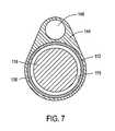
- FIG. 7is a cross sectional view of a probe.
- FIG. 8is a side view of a microcatheter or needle of a probe.
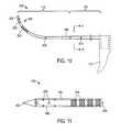
- FIG. 9is a side elevation view of the microcatheter or a vapor delivery needle of the probe of FIG. 4 showing its dimensions and vapor outlets.
- FIG. 10is another view of the microcatheter of FIG. 9 .
- FIG. 11is another view of a distal portion of the microcatheter of FIG. 10 .
- FIG. 12is a sectional view of the microcatheter of FIG. 10 taken along line 11 - 11 of FIG. 10 .
- FIGS. 13A-13Bare schematic views of the probe of FIG. 4 in a head-on view in a prostate indicating the radial angle of the probe as it is rotated in situ to treat lateral prostate lobes.
- FIGS. 14A-14Bare schematic views similar to that of FIGS. 13A-13B showing a method of rotating certain components of the probe again indicating the radial angles of the penetrating microcatheter of the probe of FIG. 4 , while leaving the probe handle in a non-rotated position.
- FIGS. 15A-15Bare schematic views similar to that of FIGS. 13A-13B showing a method of rotating other components of the probe, again indicating the radial angles of the penetrating microcatheter in the lateral lobes of the prostate while leaving the probe handle in a non-rotated position.
- FIG. 16Ais a longitudinal sectional schematic view showing a method of the invention in treating a prostate for BPH.
- FIG. 16Bis a transverse sectional view of the prostate of FIG. 16A .
- FIG. 17is another longitudinal sectional view showing ablation zones in the method of treating a prostate for BPH.
- FIG. 18is an MRI from a patient 1 week after a treatment as indicated schematically in FIGS. 16A-17 .
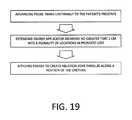
- FIG. 19is a block diagram of a method corresponding to the invention.
- FIG. 20is a block diagram of another method corresponding to the invention.
- FIG. 21is a block diagram of another method corresponding to the invention.
- FIG. 22is a perspective view of another embodiment of probe corresponding to invention that delivers vapor for treating BPH.
- FIG. 23is another perspective view of the probe of FIG. 22 .
- FIG. 24is a sectional view of the handle of the probe of FIG. 22 .
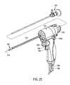
- FIG. 25is another sectional view of the handle of the probe of FIG. 22 showing components of a magnetic needle actuator system.
- FIG. 26is another sectional view of the handle of FIGS. 24-25 from a different angle.
- FIG. 27is another sectional view of the handle of FIGS. 24-26 from a different angle.
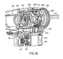
- FIG. 28is an exploded view of components of a magnetic needle actuator system as in the handle of FIGS. 24-26 .
- FIG. 29is a sectional view of the distal working end of the probe of FIGS. 22-23 .
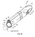
- FIG. 30is a cut-away view of the introducer portion of the probe of FIGS. 22-23 .
- one method of the invention for treating BPHcomprises introducing a heated vapor interstitially into the interior of a prostate, wherein the vapor controllably ablates prostate tissue.
- This methodcan utilize vapor for applied thermal energy of between 50 calories and 300 calories per each individual vapor treatment (and assumes multiple treatments for each prostate lobe) in an office-based procedure.
- the methodcan cause localized ablation of prostate tissue, and more particularly the applied thermal energy from vapor can be localized to ablate tissue adjacent the urethra without damaging prostate tissue that is not adjacent the urethra.
- the present inventionis directed to the treatment of BPH, and more particularly for ablating transitional zone prostate tissue without ablating central or peripheral zone prostate tissue.
- the present inventionis directed to treating a prostate using convective heating in a region adjacent the prostatic urethra.
- the method of ablative treatmentis configured to target smooth muscle tissue, alpha adrenergic receptors, sympathetic nerve structures and vasculature parallel to the prostatic urethra between the bladder neck region and the verumontanum region to a depth of less than 2 cm.
- the systemincludes a vapor delivery mechanism that delivers vapor media, including vapor media.
- the systemcan utilize a vapor source configured to provide vapor having a temperature of at least 60° C., 80° C., 100° C., 120° C., or 140° C.
- systemfurther comprises a computer controller configured to deliver vapor for an interval ranging from 1 second to 30 seconds.
- the systemfurther comprises a source of a pharmacologic agent or other chemical agent or compound for delivery with the vapor.
- agentsinclude, without limitation, an anesthetic, an antibiotic or a toxin such as Botox®, or a chemical agent that can treat cancerous tissue cells.
- the agentalso can be a sealant, an adhesive, a glue, a superglue or the like.
- Another method of the inventionprovides a treatment for BPH that can use a transrectal or transperineal approach using a transrectal ultrasound system (TRUS) as an imaging means to image the prostate, and navigate a vapor delivery tool to the targeted treatment sites.
- TRUStransrectal ultrasound system
- the tool or vapor delivery needle working endcan be advanced manually or at least in part by a spring mechanism.
- the systemmay contemporaneously deliver cooling fluids to the urethra during an ablation treatment to protect the interior lining of the urethra.
- FIGS. 4, 5 and 6depict one embodiment of probe 100 of the system of the invention that is adapted for trans-urethral access to the prostrate and which provides viewing means to view the urethra as the probe is navigated to a site in the interior of the patient's prostate.
- the probe 100further carries an extendable and retractable microcatheter member 105 ( FIGS. 5-6 ) having a distal tip portion 108 ( FIG. 4 ) that can be penetrated into precise targeted locations in prostate lobes to ablate targeted tissue volumes.
- probe 100has an elongate introducer portion 110 for insertion into the urethra and a handle portion 111 for gripping with a human hand.
- the key structural component of introducer portion 110comprises a rigid introducer sleeve or extension sleeve 112 extending along longitudinal axis 113 with proximal end 114 a and distal end 114 b .
- the bore 115 in the rigid extension sleeveextends along longitudinal axis 116 .
- the extension sleeve 112comprises a thin-wall stainless steel tube with bore 115 dimensioned to receive a commercially available viewing scope or endoscope 118 .
- the schematic cut-away view of FIG. 5shows structural bulkhead 120 coupled to a medial portion 122 of extension sleeve 112 .
- the structure or bulkhead 120comprises the structural member to which the molded handle having pistol grip 124 , and more particularly the right- and left-side mating handle parts, 125 a and 125 b , are coupled ( FIG. 4 ).
- the bulkheadcan be a plastic molded part that can be fixed to sleeve 112 or rotationally coupled to sleeve 112 .
- bore 115 in sleeve 112has a proximal open end 130 into which the endoscope 118 can be inserted.
- the proximal end portion 114 a of extension sleeve 112is coupled to an adapter mechanism 132 that releasably engages the endoscope 118 and rotationally aligns the scope 118 with the introducer portion 110 .
- the endoscope 118has a proximal viewing end 135 and light connector 136 extending outward from the viewing end 136 for coupling a light source 140 to the endoscope.
- bore 115 in sleeve 112has a diameter ranging from about 2 to 5 mm for accommodating various endoscopes 118 , while at the same time providing an annular space 138 for allowing an irrigation fluid to flow through bore 115 and outwardly from the introducer portion.
- the extendable-retractable microcatheter 105comprises a thin-wall flexible polymer tube with a sharp tip that is axially slidable in a passageway 148 in the introducer portion 110 .
- FIGS. 4, 7 and 9show that the introducer portion 110 comprises an elongate introducer body 144 of plastic or another suitable material that surrounds extension sleeve 112 .
- the introducer body 144extends to a distal working end portion 145 having a blunt nose or tip 146 for advancing through the urethra.
- the elongate introducer body 144is further configured with passageway 148 that accommodates the microcatheter member 105 as will be described below.
- the distal end portion 145 of the introducer body 144is configured with openings 160 that open to central open region 162 that is distal to the distal lens 164 of endoscope 118 that allows for viewing of the urethra through the lens 164 of the endoscope during navigation.
- the endoscope 118can have a lens with a 30°, 12.5° or other angle for viewing through openings 160 .
- the openings 160have bridge elements 165 therebetween that function to prevent tissue from falling into central open region 162 of the introducer body 144 .
- FIG. 8it can be seen that the working end portion 105 of the flexible microcatheter shaft 105 is disposed adjacent to open region 162 and thus can be viewed through the endoscope lens 164 .
- FIGS. 10-11show the flexible microcatheter member or needle 105 de-mated from the probe 100 to indicate its repose shape.
- the microcatheter 105has a first (proximal) larger cross-section portion 170 that necks down to second (distal) cross-section portion 175 wherein the smaller cross-section portion 175 has a curved repose shape with the curve configured to conform without significant resistance to the contour of the curved axis 177 of the path followed by the working end 108 of the microcatheter 105 as it is moved from its non-extended position to its extended position as shown in FIGS. 1, 8 and 9 .
- FIGS. 1shows the flexible microcatheter member or needle 105 de-mated from the probe 100 to indicate its repose shape.
- the microcatheter 105has a first (proximal) larger cross-section portion 170 that necks down to second (distal) cross-section portion 175 wherein the smaller cross-section portion 175 has a curved repose shape with the curve
- the microcatheter's first cross section portion 170comprises a thin wall outer sleeve 180 that is concentrically outward from inner microcatheter tube 185 that extends the length of the microcatheter member 105 .
- the outer sleeve 180provides a thermally insulative air gap 188 around inner tubular member 185 .
- the outer sleeve 180is configured with intermittent protrusions 190 that maintain the air gap 188 between the inner surface 192 of outer sleeve 180 and outer surface 193 of inner microcatheter tube.
- both the outer sleeve 180 and inner tubular membercan comprise a high-temperature resistant polymer such as Ultem® that is suited for delivering a high temperature vapor as will be described below.
- the microcatheter tube 185has an outside diameter of 0.050′′ with an interior lumen 195 of approximately 0.030′′.
- one embodiment of working end portion 108 for delivering vapor media to tissuehas a thin wall 198 with a plurality of outlet ports 200 therein that are configured for emitting a vapor media into tissue as will be described below.
- the outlet portscan range in number from about 2 to 100, and in one embodiment consist of 12 outlets each having a diameter of 0.008′′ in six rows of two outlets with the rows staggered around the working end 108 as shown in FIG. 10 .
- the distalmost tip 202 of the microcatheter tube 185has a sharpened conical configuration that can be formed of the plastic material of tube 185 .
- a polymeric needle and needle tip 202is useful for its thermal characteristics in that its heat capacity will not impinge on vapor quality during vapor delivery.
- FIGS. 10-11further illustrate that the distal tip portion 108 of microcatheter tube 185 has at least one marking 204 that contrasts with the color of the microcatheter tube 185 that is adapted for viewing through lens 164 of the endoscope 118 .
- the distal tip portionhas a series of annular marks 204 of a first color that contrasts with second color of tube 185 , wherein the marks are not visible through the endoscope lens 164 when the microcatheter tube 185 is in the non-extended position. After the microcatheter tube 185 is extended into tissue, the marks are visible through the lens 164 which indicates the tube 185 has been extended into tissue.
- FIG. 5shows flanges 208 a and 208 b of cocking actuator 210 are disposed on either side of actuator collar 212 that is coupled to proximal end 214 of the slidable microcatheter member 105 .
- the downward-extending cocking actuator 210is adapted to cock the flanges 208 a , 208 b and microcatheter 105 to a cocked position which corresponds to the non-extended position of the microcatheter 105 .
- FIG. 5shows flanges 208 a and 208 b of cocking actuator 210 are disposed on either side of actuator collar 212 that is coupled to proximal end 214 of the slidable microcatheter member 105 .
- the downward-extending cocking actuator 210is adapted to cock the flanges 208 a , 208 b and microcatheter 105 to a cocked position which corresponds to the non-extended position of the microcat
- the actuator 210is shown in a first position B (phantom view) and second positions B′ following actuation with an index finger to thus cock the microcatheter member 105 to the second releasable non-extended position (or cocked position) B′ from its extended position B.
- the flange 208 a and actuator 210is further shown in phantom view in the released position indicated at 208 a ′.
- the flanges 208 a , 208 b and associated assembliesare configured for an axial travel range indicated at A that can range from about 8 mm to 15 mm which corresponds to the travel of the microcatheter 105 and generally to the tissue-penetration depth.
- the flanges 208 a , 208 b and microcatheter member 105are spring-actuatable to move from the non-extended position to the extended position by means of helical spring 215 disposed around sleeve 112 .
- the spring 215is disposed between the slidable flange 208 b and trigger block 218 that comprises a superior portion of the release trigger 220 which is adapted to release the microcatheter 105 from its cocked position.
- FIG. 5further illustrates the release trigger 220 releasably maintaining the flange 205 a and microcatheter 105 in its cocked position wherein tooth portion 222 of the trigger 220 engages the lower edge of flange 205 a .
- the release trigger 220is configured to flex or pivot around living hinge portion 224 when trigger 220 is depressed in the proximal direction by the physician's finger actuation. After actuation of trigger 220 and release of the microcatheter 105 to move distally, the axial travel of the assembly is configured to terminate softly rather than abruptly as flange 208 a contacts at least one bumper element 230 as depicted in FIG. 6 .
- the bumper elements 230can comprise any spring or elastomeric element, and in FIG. 6 are shown as an elastomer element housed in a helical spring, which serve to cushion and dampen the end of the travel of the spring-driven microcatheter assembly.
- the bumper elements 230are coupled to flange 235 which in turn is configured to be fixed between right- and left-side handle parts 125 a and 125 b ( FIG. 4 ).
- a vapor source 250is provided for delivering a vapor media through the microcatheter member 105 to ablate tissue.
- the vapor sourcecan be a vapor generator that can deliver a vapor media, such as vapor media, that has a precisely controlled quality to provide a precise amount of thermal energy delivery, for example measured in calories per second. Descriptions of suitable vapor generators can be found in the following U.S. patent applications: application Ser. Nos.
- the vapor generation systemalso can comprise an inductive heating system similar to that described in U.S. Provisional Application Nos. 61/123,416, 61/123,417, and 61/126,647.
- the systemfurther includes a controller 255 that can be set to control the various parameters of vapor delivery, for example, the controller can be set to delivery vapor media for a selected treatment interval, a selected pressure, or selected vapor quality.
- the vapor source 250is remote from the handle 124 and vapor media is carried to the handle by a flexible conduit 262 that couples handle and check valve 264 therein.
- vaporcan be re-circulating in conduit 262 until a solenoid in the vapor source is actuated to cause the vapor flow to thus provide an increased fluid pressure which opens the check valve 265 and allows the vapor media to flow through flexible tube 268 to valve 270 that can be finger-actuated by trigger 275 .
- the trigger 275is urged toward a non-depressed position by spring 277 which corresponds to a closed position of valve 270 .
- the trigger 275also can be coupled by an electrical lead (not shown) to controller 255 .
- actuating the trigger 275can cause the controller to actuate a solenoid valve in the vapor generator to cause vapor flow through the relief valve.
- the valve 270 in the handleis opened only by its actuation to thus permit the flow of vapor media through flexible tube 278 which communicates with inflow port portion 280 of collar 212 which in turn communicates with the lumen 195 in the microcatheter 105 .
- FIG. 5illustrates the flow path and actuation mechanisms that provide vapor flow on demand from the vapor source 250 to the vapor outlets 200 in working end 108 of the microcatheter 105 .
- the handlecan also provide an interlock mechanism that prevents the actuation of vapor flow if the microcatheter release trigger is in the cocked position, wherein edge portion 292 coupled to release trigger 220 can engage notch 294 in trigger 275 to prevent depression of said trigger 275 .
- one embodiment of the systemincludes a fluid irrigation source 300 that is operatively coupled to the bore 115 in extension member 112 to deliver a fluid outward from the bore 115 to the open region 162 of the probe working end 145 (see FIG. 8 ).
- the bore 115is dimensioned to provide a space 138 for fluid irrigation flow around the endoscope 118 .
- fluid source 300which can be a drip bag or controlled pressure source of saline or another fluid, is detachably coupled to tubing 302 in the handle which extends to a valve 305 that can be thumb-operated from actuators 308 on either side of the handle.
- the thumb actuator 308also can control the rate of flow of the irrigation fluid by moving the actuator 308 progressively forward, for example, to open the valve more widely open.
- the fluidflows from valve 305 through tube 312 to a port or opening 315 in the extension sleeve 112 to thus enter the bore 115 of the sleeve.
- FIG. 5further depicts an aspiration source 320 operatively coupled to tubing 322 in the handle 124 which also can be actuated by valve 305 wherein the thumb actuator 308 can be rocked backwardly to allow suction forces to be applied through the valve 305 to tubing 312 that extends to port 315 in the extension member—which is the same pathway of irrigation flows.
- suction or aspiration forcescan withdraw fluid from the working end of the device during a treatment.
- FIGS. 4, 5, 6 and 8Another aspect of one embodiment of probe 100 corresponding to the invention, referring to FIGS. 4, 5, 6 and 8 , is the orientation of the microcatheter or needle 105 as it exits the working end 145 relative to the orientation of the pistol grip 124 of the handle portion 111 .
- the introducerwill typically be introduced through the urethra with the pistol grip in a “grip-downward” orientation GD ( FIG. 13A ) with the pistol grip 126 oriented downwardly which comfortable for the physician.
- the treatmenttypically will include rotationally re-orienting the probe as indicated in FIG. 13A so that the microcatheter or needle 105 can be penetrated into prostate lobes at 90° to about 135° relative to a grip-downward position.
- FIGS. 13A and 13Bare schematic head-on views of the probe 100 in a prostate with the microcatheter 105 deployed showing the orientation of the handle pistol grip 124 , the deployed microcatheter 105 and the connector endoscope 136 which indicate the rotational orientation of the endoscope 118 and thus the orientation of the camera image on the monitor.
- the assembly of the introducer 110 , microcatheter 105 and endoscope 118is rotatable within the handle within flanges 235 A and 235 B.
- the systemhas click-stops at various angles, such as every 15° between 75° and 135° relative to the grip-downward orientation GD of FIG. 13A .
- FIGS. 13A-13A and 14A-14Bdepict optional methods that the surgeon may use.
- FIGS. 13A and 13Bdepict the physician locking all components of the probe 100 in a single rotational orientation, and simply rotating his hand and pistol grip 124 to a selected orientation of greater that 90° from the grip-down position GD, then releasing the microcatheter 105 to penetrate into the prostate lobe. After actuating the vapor delivery trigger, the vapor ablates regions indicted at 400 . It can be appreciated that the endoscope 118 is rotated so that the image on the monitor also is rotated. Thereafter, the physician rotates the probe as depicted in FIG. 13B to treat the other prostate lobe. This method may be preferred by physicians that are familiar with anatomical landmarks, opt for simplicity and are accustomed to viewing an image on the monitor which is rotated relative a true vertical axis of the patient anatomy.
- FIGS. 14A and 14Bdepict the physician utilizing the rotational feature of the probe and maintaining the handle pistol grip 124 in the grip-down orientation GD and rotating the introducer 110 and microcatheter 105 to the appropriate angles to treat the first and second lobes of the prostate.
- This methodagain is suited for physicians who are familiar with anatomical landmarks and are accustomed to viewing a rotated image on the monitor in the OR.
- FIGS. 15A and 15Bdepict the physician utilizing another embodiment of a probe to treat the two prostate lobes.
- the endoscope 118is locked in rotational orientation with introducer 110 and the microcatheter 105 —but not with the handle pistol grip.
- a probecan be made which allows rotational adjustment between the introducer 110 and microcatheter 105 relative to the handle pistol grip 124 —but that provides a bracket that rotationally locks the endoscope 118 to the handle pistol grip 124 .
- 15A-15Bdepict the use of such an embodiment, wherein the physician can maintain the handle pistol grip 124 in the grip-down orientation GD and then rotates only the introducer 110 and microcatheter 105 .
- the image on the monitorwill remain vertical instead of rotated, which may be preferred by physicians accustomed to laparoscopy in which images are not rotated on the monitor when instruments are manipulated.
- the microcatheter 105carries a temperature sensor or thermocouple 405 at a distal location therein, for example as indicated in FIG. 10 .
- the thermocoupleis operatively connected to controller 255 to control vapor delivery.
- an algorithmreads an output signal from the thermocouple 405 after initiation of vapor delivery by actuation of trigger 275 , and in normal operation the thermocouple will indicate an instant rise in temperature due to the flow of vapor.
- the algorithm and thermocouple 405do not indicate a typical rise in temperature upon actuation of trigger 275 , then the algorithm can terminate energy delivery as it reflects a system fault that has prevented energy delivery.
- the microcatheter 105can carry another temperature sensor or thermocouple 410 in a portion of microcatheter 105 that resides in passageway 148 of the introducer body 144 .
- This thermocouple 410is also operatively connected to controller 255 and vapor source 250 .
- an algorithmreads an output signal from thermocouple 410 after initiation of vapor delivery and actuation of actuator 308 that delivers an irrigation fluid from source 300 to the working end 145 of the probe.
- the delivery of irrigation fluidwill maintain the temperature in the region of the thermocouple at a predetermined peak level which will not ablate tissue over a treatment interval, for example below 55° C., below 50° C. or below 45° C.
- thermocouple 410can be in carried in a portion of introducer body 144 exposed to passageway 148 in which the microcatheter resides.
- the device and method of this inventionprovide a precise, controlled thermal ablative treatment of tissue in the first and second lateral prostate lobes (or right- and left-side lobes), and additionally an affected median lobe in patients with an enlarged median lobe.
- the ablative treatmentis configured to ablate stromal or smooth muscle tissue, to ablate alpha adrenergic (muscle constriction) receptors, to ablate sympathetic nerve structures, and to ablate vasculature in the treatment zone.
- the method of ablative treatmentis configures to target smooth muscle tissue, alpha adrenergic receptors, sympathetic nerve structures, and vasculature parallel to the prostatic urethra between the bladder neck region 420 and the verumontanum region 422 as depicted in FIGS. 16A-16B .
- the targeted ablation regions 425have a depth indicated at D in FIGS. 16A-16B that is less than 2 cm from the prostatic urethra 120 , or less than 1.5 cm.
- the number of ablative energy deliveriescan range from 2 to 4 and typically is 2 or 3.
- the physicianwould first prepare the patient for trans-urethral insertion of the extension portion 110 of the probe 100 .
- the patientcan be administered a mild sedative orally or sublingually such as Valium, Lorazepam or the like from 15-60 minutes before the procedure.
- a mild sedative orally or sublinguallysuch as Valium, Lorazepam or the like from 15-60 minutes before the procedure.
- the physicianthen actuates the needle-retraction actuator 210 , for example with an index finger, to retract and cock the microcatheter 105 by axial movement of the actuator (see FIGS. 4-6 ).
- a safety lock mechanism(not shown) can be provided to lock the microcatheter 105 in the cocked position.
- the physicianadvances the extension portion 110 of the probe 100 trans-urethrally while viewing the probe insertion on a viewing monitor coupled to endoscope 118 .
- the physicianwill be oriented to the anatomical landmarks.
- the landmarks and length of the prostatic urethracan be considered relative to a pre-operative plan based on earlier diagnostic ultrasound images or other images, such as MRI images.
- the physiciancan rotate the microcatheter-carrying probe about its axis to orient the microcatheter at an angle depicted in FIG. 13A to treat a first lobe. Thereafter, the treatment included cocking and releasing the microcatheter followed by vapor delivery, the moving and repeating the vapor injection for a total of three (or more) vapor injections in each lobe.
- FIG. 13AThe physician can rotate the microcatheter-carrying probe about its axis to orient the microcatheter at an angle depicted in FIG. 13A to treat a first lobe.
- the treatmentincluded cocking and releasing the microcatheter followed by vapor delivery, the moving and repeating the vapor injection for a total of three (or more) vapor injections in each lobe.
- FIG. 17is a schematic view of a method the invention wherein three penetrations of the microcatheter 105 are made sequentially in a prostate lobe and wherein energy delivery is provided by vapor energy to produce slightly overlapping ablations or lesions to ablate the smooth muscle tissue, alpha adrenergic receptors, and sympathetic nerve structures in a region parallel to the prostatic urethra.
- the method of the inventionwhen compared to prior art, reduces the burden of ablated tissue and thus lessens the overall inflammatory response leading to more rapid tissue resorption and more rapid clinical improvement.
- FIG. 18is a saggital MRI image of an exemplary BPH treatment of a patient 1 week following the procedure, in which the treatment included the following steps and energy delivery parameters.
- the patient's prostateweighed 44.3 grams based on ultrasound diagnosis.
- Amparax(Lorazepam) was administered to the patient 30 minutes before the procedure.
- each treatment intervalconsisted of 10 seconds of vapor delivery at each of six locations (3 injections in each lobe).
- the energy deliveredwas 24 cal./sec, or 240 cal. per treatment location 425 ( FIG.
- the median lobewas also treated with a single 10 second injection of vapor, or 240 calories of energy.
- the vaporcan be configured to delivery energy in the range of 5 cal./sec. to 100 cal./sec.
- one methodincludes delivering less than 240 calories of energy to each site in the prostate.
- FIG. 3Aschematically depicts the prior art RF needle that is elongated, typically at about 20 mm in length, which ablates tissue away from the prostatic urethra and does not target tissue close to and parallel to the prostatic urethra.
- the prior art RF energy delivery methodsapply RF energy for 1 to 3 minutes or longer which allows thermal diffusion of effect to reach the capsule periphery, unlike the very short treatment intervals of the method of the present invention which greatly limit thermal diffusion.
- the prior art RF energy delivery methodsdo not create a uniform ablation of tissue adjacent and parallel to the prostatic urethra to ablate smooth muscle tissue, alpha adrenergic receptors, and sympathetic nerve structures in a region parallel to the prostatic urethra.
- FIG. 19One method corresponding to the invention is shown in the block diagram of FIG. 19 , which includes the steps of advancing a probe trans-urethrally to the patient's prostate, extending a energy applicator or microcatheter into prostate lobes in a plurality of locations to a depth of less than 2 cm, and then applying energy at each location to create an ablation zone in a continuous region parallel to at least a portion of the prostatic urethra.
- FIG. 20Another method of the invention is shown in the block diagram of FIG. 20 , which includes the steps of advancing a probe trans-urethrally to the patient's prostate, extending a energy applicator or microcatheter into prostate lobes in a plurality of locations, and applying energy at each location for less than 30 seconds to thereby prevent thermal diffusion to peripheral portions of the lobes.
- FIG. 21Another method of the invention is shown in FIG. 21 , which includes the steps of advancing a probe trans-urethrally to the patient's prostate, extending a energy applicator or microcatheter into prostate lobes in a plurality of locations, and applying energy at each location for a selected interval and irrigating the urethra with a cooling fluid throughout the selected interval of energy delivery.
- a flow of cooling fluidmay be useful, and most important the flow of cooling fluid can be continuous for the duration of the treatment interval since such times are short, for example 10 to 15 seconds.
- Such a continuous flow methodcan be used in prior art methods, such as RF ablation methods of FIGS. 3A-3B , since the cooling fluid volume accumulates in the patient's bladder and the long treatment intervals would result in the bladder being filled rapidly. This would lead to additional steps to withdraw the probe, remove the excess fluid and then re-start the treatment.
- FIGS. 22-30illustrate another probe 500 adapted to deliver condensable vapor to prostate tissue with vapor delivery through a microcatheter or vapor delivery needle as described above.
- the probe 500 of FIGS. 22-30can be configured with several different systems and mechanisms for vapor generation, vapor delivery, needle actuation, system function interlocks and for improved ergonomic function.
- FIGS. 22-24it can be seen that the probe 500 has a handle portion 504 coupled to elongate introducer portion 510 that is sized and adapted for insertion into the urethra.
- the introducer portion 510can comprise a rigid introducer sleeve 512 (shown in FIGS. 27, 30 ) extending along longitudinal axis 515 ( FIG.
- FIGS. 27, 29 and 30illustrate that sleeve 512 has a lumen 522 therein that is dimensioned to receive an endoscope 525 (see FIGS. 23 and 30 ).
- An irrigation source 530communicates with lumen 522 to provide a fluid flow around the endoscope to exit the working end 520 .
- probe 500includes an extendable-retractable microcatheter or vapor delivery needle 540 axially moveable in passageway 542 in sleeve 545 that is longitudinally coupled to sleeve 512 .
- the microcatheter or needle 540comprises a flexible polymer tube with a sharp tissue piercing tip.
- both sleeves 512 and 545can comprise thin-wall stainless steel tubes and can be welded together to provide a rigid structure.
- a polymer surface layer 550can be disposed around the assembly of sleeves 512 and 545 , which in one embodiment can comprise a lubricious heat shrink material having a wall thickness ranging from 0.005′′ to 0.020′′.
- FIGS. 29-30illustrate that the working end 520 of introducer portion 510 can comprise a distal body 555 of plastic or another suitable material with a blunt nose or tip 556 as described previously for advancing through the patient's urethra.
- the distal body 555can be configured with side window 560 on either side of bridge elements 562 and needle window 564 as described in the previous embodiments.
- the distal tip 565 of the microcatheter or needle 540is shown locked in the non-extended or retracted position for when the physician is navigating the working end 520 of the probe toward a targeted site in the urethra, but which can be released from said locked position.
- probe 500can be provided with a vapor generator 570 housed with the pistol-grip portion 572 of handle 504 .
- the vapor generatorcan be an RF-based induction vapor generator.
- the vapor generatorcan be housed within the handle of the probe, as shown, or in other embodiments the vapor generator can be placed elsewhere within the probe or even external to the probe.
- the vapor generatorcan be coupled to an energy source, such as RF source 575 and controller 580 .
- a RF coil 582can be positioned around a helically-wound stainless steel tubing component 584 which can be inductively heated by the RF coil 582 .
- the water flow in the lumen of the helical stainless steel componentcan be converted to vapor instantly.
- the controller 580can be configured to set and control all functional parameters of the probe, for example, parameters relating to vapor delivery intervals, pressure in the fluid flow into the vapor generator, vapor quality, irrigation flow rates, temperature monitoring, system cooling fans, over-ride mechanisms and the like.
- a fluid source 585can be coupled to inflow line 588 for delivering a treatment fluid or media such as sterile water to the vapor generator 570 .
- an outflow line 590 adapted to carry condensable vaporextends upwardly in the handle to flex-loop portion 592 that has a termination 594 that connects to a proximal end of the needle. From FIGS. 25-26 , it can be understood that the flex-loop portion 592 of outflow line 590 is configured to accommodate the axial movement of the vapor delivery needle 540 .
- the RF source 575is coupled to RF coil 582 of the vapor generator 570 by power cord 598 .
- FIGS. 24-28the sectional and exploded views of the handle portion 504 and components therein illustrate the microcatheter or vapor delivery needle 540 and the magnetic actuator system that is adapted to move the needle in a distal or extending stroke for penetrating into tissue.
- the magnetic systemfurther can be utilized to provide a proximal or retracting stroke for withdrawing the vapor delivery needle from tissue.
- FIGS. 26 and 28show first and second rotatable blocks 600 A and 600 B that each carry magnets 602 A, 602 B with magnetic poles oriented as shown in FIG. 24 .
- a central extending-retracting block 610also carries magnets 612 (see FIG. 25 ) and is positioned between the first and second rotatable blocks 600 A and 600 B.
- the central block 610is coupled to the vapor delivery needle and is configured to move distally and proximally between rotatable blocks 600 A and 600 B, and is keyed to not rotate, to thus extend the needle tip out of the working end 520 and to retract the needle tip back into the working end under the influence of magnetic fields.
- FIGS. 24-26the central block 610 is coupled to the vapor delivery needle and is configured to move distally and proximally between rotatable blocks 600 A and 600 B, and is keyed to not rotate, to thus extend the needle tip out of the working end 520 and to retract the needle tip back into the working end under the influence of magnetic fields.
- the rotation of the first and second rotatable blocks 600 A and 600 Bcan move the magnets 602 A, 602 B therein (i) into a position that applies forces upon the magnets 612 in central block 610 or (ii) into a position wherein the magnets 602 A, 602 B will be spaced apart from magnets 612 so as to not apply force.
- the magnetic actuator systemcan be configured to advance the vapor delivery needle a pre-determined distance. For example, when treating certain portions of prostate tissue transurethrally, the magnetic actuator system can be configured to advance the vapor delivery needle less than 2 cm from the shaft of the probe into the prostate. This pre-determined distance can be adjusted prior to therapy so as to ensure that the needle is placed directly into the proper position within the prostate.
- FIG. 28The exploded view of several handle components in FIG. 28 illustrates a magnetic actuator subassembly.
- a gear rack 620 in the handle 504is slidable proximally and/or distally when the grip body 622 is moved, for example, by the physician using his/her fingers or thumbs to engage and move axially the opposing grip elements 624 a and 624 b .
- the axial movement of the gear rack 620then turns gear 630 which engages and rotates the first and second rotatable blocks 600 A and 600 B that each carry magnets 602 A, 602 B.
- the movement of the grip 622further cocks the central block 610 into a proximal or retracted position ( FIGS.
- the mechanismfurther has a releasable latch that locks the central block 610 and needle 540 in the retracted or non-extended position. In this position, the magnets 612 of the central block 610 are oriented directly opposed to the magnets 602 A of block 600 A and a maximum stored energy is provided in this temporary locked position.
- blocks 600 A and 600 B and central block 610are shown spaced apart along longitudinal axis 615 .
- Needle actuation trigger 635( FIGS. 24-26 ) can be actuated to release the lock or latch which then allows the stored energy and forces of the magnets 602 A and 612 to extend the central block 610 and the vapor delivery needle in its distal stroke. It can be understood that the stored energy or repelling forces of magnets 602 A and 612 initially drive the central block distally. Further, it can be seen in FIGS. 24-26 that the attracting forces of magnets 612 and 602 B further drive the central block 610 distally. It has been found that the use of both expelling and attracting magnetic forces can provide a very high, consistent acceleration and a selected velocity over the extending stroke of the assembly. In some embodiments, the velocity of the vapor delivery needle in penetrating tissue can range from 0.1 meter per second to 20.0 meters per second.
- FIGS. 24-26show needle actuation trigger 635 and further show an integrated actuator 636 which opens and closes an inflow tubing 638 coupled to the fluid source 585 .
- a pinch valve 640can be actuated by depressing actuator 636 —wherein depressing the actuator 636 causes fluid to be provided under a selected pressure and flow rate through tubing to the endoscope lumen 522 .
- a spring 642urges the actuator toward the non-depressed position.
- FIGS. 24-26further illustrate that needle trigger 635 and the actuator 636 are integrated to be operated with a single finger pull.
- the trigger assemblyis configured to permit actuation of trigger 635 only if the irrigation actuator 636 is actuated.
- an interlockcan be provided so that irrigation fluid will be flowing into the urethra to provide for its distension when the needle is released and penetrates into tissue.
- FIG. 24further illustrates a vapor actuator or trigger 650 located below the needle actuation trigger 635 .
- a electrical switch 652is actuated which signals the controller 580 to simultaneously actuate the fluid inflow from fluid source 585 and the RF source 575 to generate vapor for a treatment interval, which can be from 1 to 20 seconds or more as described previously.
- a typical treatment intervalcan be from 5 to 12 seconds.
- a spring 654urges the vapor trigger 650 toward the non-depressed position.
- another interlockcan be provided between the irrigation fluid actuator 636 and the vapor trigger 650 to insure that fluid is flowing into the urethra during the entire vapor delivery interval.
- This interlockcan be useful to dissipate heat from sleeve 545 that houses the shaft of the vapor delivery needle 540 (see FIG. 30 ) and to cool and protect the surface of the urethra adjacent the targeted treatment region that is being ablated by the vapor delivery.
- FIG. 24shows that an outflow tubing 660 is provided through the handle 504 which is coupled to the endoscope lumen 522 .
- a reverse flow of fluid from the patient's bladdercan occur which is important for rapidly draining a full patient bladder.
- FIGS. 24-27shows that the handle can comprise right and left-side mating handle parts are coupled to rotatable nose piece 668 and endoscope adapter 670 to allow independent rotation of the introducer portion 510 and/or the endoscope adapter 670 and endoscope relative to the pistol-grip handle portion 572 to provide the freedom of use illustrated in FIGS. 13A-13B, 14A-14B, and 15A-15B above.
- a prostate treatment devicecomprising an introducer shaft sized and configured for transurethral access into a patient, a vapor generator configured to generate a condensable vapor, a vapor delivery needle in communication with the vapor generator and slidably disposed within the introducer shaft, and a magnetic actuator configured to apply magnetic force to the vapor delivery needle to move the vapor delivery needle between a retracted position inside the introducer shaft and an extended position at least partially outside of the introducer shaft.
- the magnetic actuatoris configured to axially move the vapor delivery needle toward the extended position from the retracted position at a velocity ranging from 0.1 meter per second to 20.0 meters per second.
- the vapor delivery needlecan move between the retracted and extended positions (and vice versa) at a velocity ranging from 1 meter per second to 5 meters per second.
- the magnetic actuatoris configured to cause a tip portion of the vapor delivery needle to penetrate into prostate tissue when moving toward the extended position from the retracted position.
- the vapor delivery needleis sized and configured to extend into prostate tissue when the introducer shaft is positioned within a urethra of the patient.
- the magnetic actuatorfurther comprises a first magnet carried by the vapor delivery needle, wherein the magnetic actuator is configured to move the first magnet and the vapor delivery needle proximally and distally along a longitudinal axis of the introducer shaft.
- the magnetic actuatorfurther comprises a second magnet carried in a frame of a handle of the device, the second magnet being configured to interact with the first magnet to move the vapor delivery needle proximally and distally along the longitudinal axis of the introducer shaft.
- the frameis rotatable in the handle.
- the magnetic actuatorfurther comprises a third magnet carried in a second frame of the handle, the third magnet being configured to interact with the first and second magnets to move the vapor delivery needle proximally and distally along the longitudinal axis of the introducer shaft.
- the devicecan further include a grip adapted for manual control of the magnetic actuator to move the vapor delivery needle between the retracted position and the extended position.
- the devicecomprises a gear rack coupled to the grip, the gear rack being configured to rotate the frame and the second magnet so as to engage or disengage from the first magnet.
- the devicecan comprise a lock configured to lock the vapor delivery needle in the retracted position.
- the devicecan further comprise a trigger adapted to release the lock to thereby move the vapor delivery needle to the extended position from the retracted position.
- the magnetic actuatoris configured to apply a suitable magnetic force to cause the tip portion of the vapor delivery needle to withdraw from prostate tissue when moving to the retracted position.
- the suitable magnetic forcecan range from 1 to 3 pounds of force during advancement and retraction. In one embodiment, the force can be at least 2 pounds of force.
- the devicecan further include a vapor actuator for actuating a flow of condensable vapor through the vapor delivery needle.
- the devicecan further comprise an interlock mechanism which permits actuation of the vapor actuator only if a releasable lock has been released.
- the magnetic actuatorcomprises at least one rare earth magnet. In other embodiments, the magnetic actuator comprises at least one neodymium or neodymium-iron-boron magnet.
- the magnetic actuatororients first and second magnets relative to one another to utilize repelling forces to move the vapor delivery needle along a longitudinal axis of the introducer shaft. In another embodiment, the magnetic actuator orients first and second magnets relative to one another to utilize attracting forces to move the vapor delivery needle along a longitudinal axis of the introducer shaft. In some embodiments, the magnetic actuator orients first and second magnets relative to one another to utilize attracting and repelling forces to move the vapor delivery needle along a longitudinal axis of the introducer shaft.
- a method of treating prostate tissuecomprising inserting a shaft of a prostate therapy device transurethrally until a working end of the shaft is proximate to the prostate tissue, actuating a magnetic assembly to advance a vapor delivery needle from the introducer into the prostate tissue, and delivering condensable vapor from the vapor delivery needle into the prostate tissue.
- the condensable vaporprovides a thermal effect in the prostate tissue.
- the vapor delivery needleadvances into the prostate tissue under the influence of repelling forces between first and second magnets of the magnetic assembly. In another embodiment, the vapor delivery needle advances into the prostate tissue under the influence of attracting forces between first and second magnets of the magnetic assembly. In some embodiments, the vapor delivery needle advances into the prostate tissue under the influence of attracting and repelling forces between first and second magnets of the magnetic assembly.
- a prostate treatment devicecomprising an introducer shaft sized and configured for transurethral access into a patient, a vapor generator configured to generate a condensable vapor, a vapor delivery needle in communication with the vapor generator and slidably disposed within the introducer shaft, and an actuation mechanism configured to apply force to move a distal portion of the vapor delivery needle from a retracted position inside the introducer shaft to an extended position outside of the introducer shaft.
- the actuation mechanismmoves a distal tip of the vapor delivery needle outward from the introducer shaft a distance of less than 2 cm.
- the devicecomprises a controller configured to deliver a selected volume of condensable vapor through the needle that carries less than 240 calories of energy.
- the actuation mechanismcomprises a spring. In other embodiments, the actuation mechanism comprises at least one magnet. In one embodiment, the actuation mechanism is configured to move the vapor delivery needle toward the extended position from the retracted position at a velocity ranging from 0.1 meter per second to 20.0 meters per second.
- the vapor delivery needleis sized and configured to extend into prostate tissue when the introducer shaft is positioned within a urethra of the patient.
- the actuation mechanismcomprises a first magnet carried by the vapor delivery needle. In another embodiment, the actuation mechanism comprises a second magnet carried in a frame of a handle of the device, the second magnet being configured to interact with the first magnet to move the vapor delivery needle. In some embodiments, the frame is rotatable in the handle.
- the devicecan further include a grip adapted for manual control of the magnetic actuator to move the vapor delivery needle between the retracted position and the extended position.
- the devicecomprises a gear rack coupled to the grip, the gear rack being configured to rotate the frame and the second magnet so as to engage or disengage from the first magnet.
- the devicecan comprise a lock configured to lock the vapor delivery needle in the retracted position.
- the devicecan further comprise a trigger adapted to release the lock to thereby move the vapor delivery needle to the extended position from the retracted position.
- the devicecan further include a vapor actuator for actuating a flow of condensable vapor through the vapor delivery needle.
- the devicecan further comprise an interlock mechanism which permits actuation of the vapor actuator only if a releasable lock has been released.
- a method of treating prostate tissuecomprising inserting a shaft of a prostate therapy device transurethrally until a working end of the shaft is proximate to the prostate tissue, advancing a vapor delivery needle from the introducer into at least one site in prostate tissue to a depth of less than 2 cm, and delivering condensable vapor from the vapor delivery needle into the prostate tissue.
- the condensable vaporprovides a thermal effect in the prostate tissue. In other embodiments, the condensable vapor delivers less than 240 calories of energy at each site.
- the vapor delivery needleadvances into the prostate tissue under forces applied by a spring. In another embodiment, the vapor delivery needle advances into the prostate tissue under the influence of at least one magnet.
Landscapes
- Health & Medical Sciences (AREA)
- Life Sciences & Earth Sciences (AREA)
- Surgery (AREA)
- Engineering & Computer Science (AREA)
- Plasma & Fusion (AREA)
- General Health & Medical Sciences (AREA)
- Otolaryngology (AREA)
- Physics & Mathematics (AREA)
- Veterinary Medicine (AREA)
- Biomedical Technology (AREA)
- Heart & Thoracic Surgery (AREA)
- Medical Informatics (AREA)
- Molecular Biology (AREA)
- Animal Behavior & Ethology (AREA)
- Nuclear Medicine, Radiotherapy & Molecular Imaging (AREA)
- Public Health (AREA)
- Cardiology (AREA)
- Surgical Instruments (AREA)
Abstract
Description
Claims (39)
Priority Applications (1)
| Application Number | Priority Date | Filing Date | Title |
|---|---|---|---|
| US14/241,977US9895185B2 (en) | 2011-09-13 | 2012-09-13 | Systems and methods for prostate treatment |
Applications Claiming Priority (3)
| Application Number | Priority Date | Filing Date | Title |
|---|---|---|---|
| US201161534053P | 2011-09-13 | 2011-09-13 | |
| PCT/US2012/055164WO2013040209A1 (en) | 2011-09-13 | 2012-09-13 | Systems and methods for prostate treatment |
| US14/241,977US9895185B2 (en) | 2011-09-13 | 2012-09-13 | Systems and methods for prostate treatment |
Related Parent Applications (1)
| Application Number | Title | Priority Date | Filing Date |
|---|---|---|---|
| PCT/US2012/055164A-371-Of-InternationalWO2013040209A1 (en) | 2011-09-13 | 2012-09-13 | Systems and methods for prostate treatment |
Related Child Applications (1)
| Application Number | Title | Priority Date | Filing Date |
|---|---|---|---|
| US15/900,295ContinuationUS10987150B2 (en) | 2011-09-13 | 2018-02-20 | Systems and methods for prostate treatment |
Publications (2)
| Publication Number | Publication Date |
|---|---|
| US20140288543A1 US20140288543A1 (en) | 2014-09-25 |
| US9895185B2true US9895185B2 (en) | 2018-02-20 |
Family
ID=47883733
Family Applications (4)
| Application Number | Title | Priority Date | Filing Date |
|---|---|---|---|
| US14/241,977Active2035-06-16US9895185B2 (en) | 2011-09-13 | 2012-09-13 | Systems and methods for prostate treatment |
| US15/900,295Active2033-12-19US10987150B2 (en) | 2011-09-13 | 2018-02-20 | Systems and methods for prostate treatment |
| US17/208,329PendingUS20210228257A1 (en) | 2011-09-13 | 2021-03-22 | Systems and methods for prostate treatment |
| US19/027,969PendingUS20250160923A1 (en) | 2011-09-13 | 2025-01-17 | Systems and methods for prostate treatment |
Family Applications After (3)
| Application Number | Title | Priority Date | Filing Date |
|---|---|---|---|
| US15/900,295Active2033-12-19US10987150B2 (en) | 2011-09-13 | 2018-02-20 | Systems and methods for prostate treatment |
| US17/208,329PendingUS20210228257A1 (en) | 2011-09-13 | 2021-03-22 | Systems and methods for prostate treatment |
| US19/027,969PendingUS20250160923A1 (en) | 2011-09-13 | 2025-01-17 | Systems and methods for prostate treatment |
Country Status (10)
| Country | Link |
|---|---|
| US (4) | US9895185B2 (en) |
| EP (4) | EP4613223A2 (en) |
| CN (2) | CN103917200B (en) |
| DK (1) | DK2755614T3 (en) |
| ES (1) | ES2656021T3 (en) |
| HK (1) | HK1243908A1 (en) |
| NO (1) | NO2817480T3 (en) |
| PL (1) | PL2755614T3 (en) |
| PT (1) | PT2755614T (en) |
| WO (1) | WO2013040209A1 (en) |
Cited By (9)
| Publication number | Priority date | Publication date | Assignee | Title |
|---|---|---|---|---|
| US10751107B2 (en) | 2017-01-06 | 2020-08-25 | Boston Scientific Scimed, Inc. | Transperineal vapor ablation systems and methods |
| US10987150B2 (en) | 2011-09-13 | 2021-04-27 | Boston Scientific Scimed, Inc. | Systems and methods for prostate treatment |
| US11246640B2 (en) | 2016-12-21 | 2022-02-15 | Boston Scientific Scimed, Inc. | Vapor ablation systems and methods |
| US11576563B2 (en) | 2016-11-28 | 2023-02-14 | Adaptivendo Llc | Endoscope with separable, disposable shaft |
| USD1018844S1 (en) | 2020-01-09 | 2024-03-19 | Adaptivendo Llc | Endoscope handle |
| USD1031035S1 (en) | 2021-04-29 | 2024-06-11 | Adaptivendo Llc | Endoscope handle |
| USD1051380S1 (en) | 2020-11-17 | 2024-11-12 | Adaptivendo Llc | Endoscope handle |
| USD1066659S1 (en) | 2021-09-24 | 2025-03-11 | Adaptivendo Llc | Endoscope handle |
| USD1070082S1 (en) | 2021-04-29 | 2025-04-08 | Adaptivendo Llc | Endoscope handle |
Families Citing this family (36)
| Publication number | Priority date | Publication date | Assignee | Title |
|---|---|---|---|---|
| US10064697B2 (en) | 2008-10-06 | 2018-09-04 | Santa Anna Tech Llc | Vapor based ablation system for treating various indications |
| US9700365B2 (en) | 2008-10-06 | 2017-07-11 | Santa Anna Tech Llc | Method and apparatus for the ablation of gastrointestinal tissue |
| US9561066B2 (en) | 2008-10-06 | 2017-02-07 | Virender K. Sharma | Method and apparatus for tissue ablation |
| US9561068B2 (en) | 2008-10-06 | 2017-02-07 | Virender K. Sharma | Method and apparatus for tissue ablation |
| US10695126B2 (en) | 2008-10-06 | 2020-06-30 | Santa Anna Tech Llc | Catheter with a double balloon structure to generate and apply a heated ablative zone to tissue |
| CN102271595A (en) | 2008-11-06 | 2011-12-07 | 恩克斯特拉公司 | Systems and methods for treatment of bph |
| CN105434039B (en) | 2008-11-06 | 2019-01-15 | 恩克斯特拉公司 | System and method for treating prostata tissue |
| US9833277B2 (en) | 2009-04-27 | 2017-12-05 | Nxthera, Inc. | Systems and methods for prostate treatment |
| EP2833815B1 (en) | 2012-04-03 | 2020-11-11 | Boston Scientific Scimed, Inc. | Induction coil vapor generator |
| EP3964151A3 (en) | 2013-01-17 | 2022-03-30 | Virender K. Sharma | Apparatus for tissue ablation |
| BR112015022358A2 (en) | 2013-03-14 | 2017-07-18 | Nxthera Inc | method for treating abnormal prostate tissue, and, method for treating prostate cancer, and, prostate cancer therapy system |
| US10194970B2 (en) | 2013-12-10 | 2019-02-05 | Nxthera, Inc. | Vapor ablation systems and methods |
| US9968395B2 (en) | 2013-12-10 | 2018-05-15 | Nxthera, Inc. | Systems and methods for treating the prostate |
| US10278759B2 (en)* | 2014-11-06 | 2019-05-07 | Covidien Lp | Cautery apparatus |
| US10342593B2 (en) | 2015-01-29 | 2019-07-09 | Nxthera, Inc. | Vapor ablation systems and methods |
| US10765332B2 (en) | 2015-04-29 | 2020-09-08 | Brainlab Ag | Detection of the heartbeat in cranial accelerometer data using independent component analysis |
| CA2982372A1 (en) | 2015-05-13 | 2016-11-17 | Nxthera, Inc. | Systems and methods for treating the bladder with condensable vapor |
| WO2017106843A1 (en)* | 2015-12-18 | 2017-06-22 | Nxthera, Inc. | Vapor ablation systems and methods |
| CN105726200B (en)* | 2016-02-05 | 2018-06-05 | 广州军区广州总医院 | A kind of abdominal cavity complexity kidney surgery heat sink |
| US12364537B2 (en) | 2016-05-02 | 2025-07-22 | Santa Anna Tech Llc | Catheter with a double balloon structure to generate and apply a heated ablative zone to tissue |
| US11331140B2 (en) | 2016-05-19 | 2022-05-17 | Aqua Heart, Inc. | Heated vapor ablation systems and methods for treating cardiac conditions |
| CN106726034B (en)* | 2016-12-30 | 2017-10-13 | 河南亚都实业有限公司 | Support for treating hyperplasia of prostate |
| US11311328B2 (en)* | 2018-05-16 | 2022-04-26 | Imam Abdulrahman Bin Faisal University | High-pressure steam-based surgical tool for cutting and hemostasis |
| EP3801324B1 (en)* | 2018-06-01 | 2025-05-28 | Aqua Medical, Inc. | Vapor generation and delivery systems |
| CN108478276B (en)* | 2018-06-07 | 2023-10-13 | 海杰亚(北京)医疗器械有限公司 | A minimally invasive steam probe and treatment equipment for tumor treatment |
| AU2020331903A1 (en)* | 2019-08-22 | 2022-02-10 | Boston Scientific Scimed, Inc. | Systems and methods for controlling needle penetration |
| CN114340533B (en)* | 2019-08-22 | 2025-09-16 | 波士顿科学医学有限公司 | Systems, devices, and methods for tissue ablation |
| AU2020419190A1 (en)* | 2019-12-30 | 2022-07-14 | Francis Medical, Inc. | Vapor therapy systems and methods |
| CN111631809A (en)* | 2020-06-24 | 2020-09-08 | 杭州堃博生物科技有限公司 | Steam Ablation Catheters and Steam Ablation Devices |
| CN116997304A (en)* | 2021-03-16 | 2023-11-03 | 弗朗西斯医疗公司 | Vapor therapy system and method |
| CN113749695A (en)* | 2021-10-22 | 2021-12-07 | 海南医学院第二附属医院 | A multi-visualization transurethral prostate biopsy system and using method thereof |
| CN118215443A (en)* | 2022-09-15 | 2024-06-18 | 苏州恒瑞宏远医疗科技有限公司 | Ablation needle driving system, pressure relief anti-scalding pipe, steam ablation system and control method |
| CN120529872A (en)* | 2022-12-19 | 2025-08-22 | 弗朗西斯医疗公司 | Prostate cancer lesion targeting and vapor needle tip tracking for prostate biopsy and vapor therapy |
| CN116849796B (en)* | 2023-07-17 | 2025-03-07 | 海汛医疗科技(苏州)有限公司 | Control method and device of steam ablation equipment and steam ablation equipment |
| CN117257373B (en)* | 2023-11-18 | 2024-03-12 | 英特姆(武汉)医疗科技股份有限公司 | Fascia suturing device |
| WO2025145179A1 (en)* | 2023-12-29 | 2025-07-03 | Francis Medical, Inc. | Vapor therapy systems and methods |
Citations (262)
| Publication number | Priority date | Publication date | Assignee | Title |
|---|---|---|---|---|
| US408899A (en) | 1889-08-13 | Island | ||
| US1719750A (en) | 1927-09-29 | 1929-07-02 | Charles E Parkhurst | Dental apparatus |
| US4672963A (en) | 1985-06-07 | 1987-06-16 | Israel Barken | Apparatus and method for computer controlled laser surgery |
| US4920982A (en) | 1988-06-27 | 1990-05-01 | Vastech Medical Products Inc. | Percutaneous vasectomy method |
| US4950267A (en) | 1987-11-27 | 1990-08-21 | Olympus Optical Co., Ltd. | Laser beam treatment device for an endoscope |
| CN2061443U (en) | 1990-02-24 | 1990-09-05 | 山东省泰安市中心医院 | Pummp-type surgical cutting instrument using physiological saline |
| US5117482A (en) | 1990-01-16 | 1992-05-26 | Automated Dynamics Corporation | Porous ceramic body electrical resistance fluid heater |
| WO1992010142A1 (en) | 1990-12-10 | 1992-06-25 | Howmedica Inc. | A device and method for interstitial laser energy delivery |
| US5222185A (en) | 1992-03-26 | 1993-06-22 | Mccord Jr Harry C | Portable water heater utilizing combined fluid-in-circuit and induction heating effects |
| US5300099A (en) | 1992-03-06 | 1994-04-05 | Urologix, Inc. | Gamma matched, helical dipole microwave antenna |
| US5312399A (en) | 1992-09-29 | 1994-05-17 | Hakky Said I | Laser resectoscope with mechanical cutting means and laser coagulating means |
| US5330518A (en) | 1992-03-06 | 1994-07-19 | Urologix, Inc. | Method for treating interstitial tissue associated with microwave thermal therapy |
| US5366490A (en) | 1992-08-12 | 1994-11-22 | Vidamed, Inc. | Medical probe device and method |
| US5370609A (en) | 1990-08-06 | 1994-12-06 | Possis Medical, Inc. | Thrombectomy device |
| US5370677A (en) | 1992-03-06 | 1994-12-06 | Urologix, Inc. | Gamma matched, helical dipole microwave antenna with tubular-shaped capacitor |
| US5385544A (en) | 1992-08-12 | 1995-01-31 | Vidamed, Inc. | BPH ablation method and apparatus |
| US5409453A (en) | 1992-08-12 | 1995-04-25 | Vidamed, Inc. | Steerable medical probe with stylets |
| US5413588A (en) | 1992-03-06 | 1995-05-09 | Urologix, Inc. | Device and method for asymmetrical thermal therapy with helical dipole microwave antenna |
| US5421819A (en) | 1992-08-12 | 1995-06-06 | Vidamed, Inc. | Medical probe device |
| US5435805A (en) | 1992-08-12 | 1995-07-25 | Vidamed, Inc. | Medical probe device with optical viewing capability |
| JPH07507696A (en) | 1992-02-06 | 1995-08-31 | アメリカン・メディカル・システムズ・インコーポレーテッド | Interstitial treatment device and method |
| US5464437A (en) | 1993-07-08 | 1995-11-07 | Urologix, Inc. | Benign prostatic hyperplasia treatment catheter with urethral cooling |
| US5470308A (en) | 1992-08-12 | 1995-11-28 | Vidamed, Inc. | Medical probe with biopsy stylet |
| US5484400A (en) | 1992-08-12 | 1996-01-16 | Vidamed, Inc. | Dual channel RF delivery system |
| JPH08501957A (en) | 1992-08-17 | 1996-03-05 | メール、トマス、エル | Handheld multipurpose portable steamer with modular components and attachments |
| US5499998A (en) | 1993-09-14 | 1996-03-19 | Microsurge, Inc. | Endoscoptic surgical instrument with guided jaws and ratchet control |
| JPH08504613A (en) | 1992-10-21 | 1996-05-21 | バヴァリア メディツィン テクノロジー ゲーエムベーハー | Drug injection catheter |
| US5531763A (en) | 1994-10-07 | 1996-07-02 | United States Surgical Corporation | Suture cinching apparatus |
| US5542916A (en) | 1992-08-12 | 1996-08-06 | Vidamed, Inc. | Dual-channel RF power delivery system |
| US5542915A (en) | 1992-08-12 | 1996-08-06 | Vidamed, Inc. | Thermal mapping catheter with ultrasound probe |
| US5545171A (en) | 1994-09-22 | 1996-08-13 | Vidamed, Inc. | Anastomosis catheter |
| US5549644A (en) | 1992-08-12 | 1996-08-27 | Vidamed, Inc. | Transurethral needle ablation device with cystoscope and method for treatment of the prostate |
| US5556377A (en) | 1992-08-12 | 1996-09-17 | Vidamed, Inc. | Medical probe apparatus with laser and/or microwave monolithic integrated circuit probe |
| US5558673A (en) | 1994-09-30 | 1996-09-24 | Vidamed, Inc. | Medical probe device and method having a flexible resilient tape stylet |
| US5588960A (en) | 1994-12-01 | 1996-12-31 | Vidamed, Inc. | Transurethral needle delivery device with cystoscope and method for treatment of urinary incontinence |
| US5601591A (en) | 1994-09-23 | 1997-02-11 | Vidamed, Inc. | Stent for use in prostatic urethra, apparatus and placement device for same and method |
| US5628770A (en) | 1995-06-06 | 1997-05-13 | Urologix, Inc. | Devices for transurethral thermal therapy |
| US5630794A (en) | 1992-08-12 | 1997-05-20 | Vidamed, Inc. | Catheter tip and method of manufacturing |
| US5645528A (en) | 1995-06-06 | 1997-07-08 | Urologix, Inc. | Unitary tip and balloon for transurethral catheter |
| US5667488A (en) | 1992-08-12 | 1997-09-16 | Vidamed, Inc. | Transurethral needle ablation device and method for the treatment of the prostate |
| US5672153A (en) | 1992-08-12 | 1997-09-30 | Vidamed, Inc. | Medical probe device and method |
| US5709680A (en) | 1993-07-22 | 1998-01-20 | Ethicon Endo-Surgery, Inc. | Electrosurgical hemostatic device |
| US5720718A (en) | 1992-08-12 | 1998-02-24 | Vidamed, Inc. | Medical probe apparatus with enhanced RF, resistance heating, and microwave ablation capabilities |
| US5720719A (en) | 1992-08-12 | 1998-02-24 | Vidamed, Inc. | Ablative catheter with conformable body |
| US5776176A (en) | 1996-06-17 | 1998-07-07 | Urologix Inc. | Microwave antenna for arterial for arterial microwave applicator |
| US5792070A (en) | 1996-08-30 | 1998-08-11 | Urologix, Inc. | Rectal thermosensing unit |
| US5797903A (en) | 1996-04-12 | 1998-08-25 | Ep Technologies, Inc. | Tissue heating and ablation systems and methods using porous electrode structures with electrically conductive surfaces |
| US5800486A (en) | 1996-06-17 | 1998-09-01 | Urologix, Inc. | Device for transurethral thermal therapy with cooling balloon |
| US5807395A (en) | 1993-08-27 | 1998-09-15 | Medtronic, Inc. | Method and apparatus for RF ablation and hyperthermia |
| US5830179A (en) | 1996-04-09 | 1998-11-03 | Endocare, Inc. | Urological stent therapy system and method |
| US5843144A (en) | 1995-06-26 | 1998-12-01 | Urologix, Inc. | Method for treating benign prostatic hyperplasia with thermal therapy |
| US5849011A (en) | 1995-06-19 | 1998-12-15 | Vidamed, Inc. | Medical device with trigger actuation assembly |
| US5861021A (en) | 1996-06-17 | 1999-01-19 | Urologix Inc | Microwave thermal therapy of cardiac tissue |
| US5871481A (en) | 1997-04-11 | 1999-02-16 | Vidamed, Inc. | Tissue ablation apparatus and method |
| US5873877A (en) | 1997-04-11 | 1999-02-23 | Vidamed, Inc. | Medical probe device with transparent distal extremity |
| US5897553A (en) | 1995-11-02 | 1999-04-27 | Medtronic, Inc. | Ball point fluid-assisted electrocautery device |
| US5899932A (en) | 1996-05-03 | 1999-05-04 | Urologix, Inc. | Method of axial preferential thermal therapy |
| US5938692A (en) | 1996-03-26 | 1999-08-17 | Urologix, Inc. | Voltage controlled variable tuning antenna |
| US5944715A (en) | 1996-06-20 | 1999-08-31 | Gyrus Medical Limited | Electrosurgical instrument |
| US5957922A (en) | 1993-06-10 | 1999-09-28 | Vidamed, Inc. | Transurethral radio frequency apparatus for ablation of the prostate gland and method |
| US5964752A (en) | 1998-02-02 | 1999-10-12 | Stone; Kevin R. | Articular cartilage surface shaping apparatus and method |
| US5964756A (en) | 1997-04-11 | 1999-10-12 | Vidamed, Inc. | Transurethral needle ablation device with replaceable stylet cartridge |
| US5976123A (en) | 1996-07-30 | 1999-11-02 | Laser Aesthetics, Inc. | Heart stabilization |
| US5990465A (en) | 1995-03-27 | 1999-11-23 | Omron Corporation | Electromagnetic induction-heated fluid energy conversion processing appliance |
| JPH11318925A (en) | 1998-05-21 | 1999-11-24 | Olympus Optical Co Ltd | Medical probe |
| US6009351A (en) | 1997-07-14 | 1999-12-28 | Urologix, Inc. | System and method for transurethral heating with rectal cooling |
| US6007571A (en) | 1996-04-25 | 1999-12-28 | Urologix, Inc. | Liquid coolant supply system |
| JP2000005191A (en) | 1998-06-25 | 2000-01-11 | Olympus Optical Co Ltd | High-frequency therapeutic device |
| JP2000014663A (en) | 1998-06-30 | 2000-01-18 | Olympus Optical Co Ltd | Therapy device for prostatic hypertrophy |
| US6017358A (en) | 1997-05-01 | 2000-01-25 | Inbae Yoon | Surgical instrument with multiple rotatably mounted offset end effectors |
| US6017361A (en) | 1997-03-13 | 2000-01-25 | Endo Care, Inc. | Urethral warming catheter |
| US6036631A (en) | 1998-03-09 | 2000-03-14 | Urologix, Inc. | Device and method for intracavitary cancer treatment |
| US6036713A (en) | 1996-01-24 | 2000-03-14 | Archimedes Surgical, Inc. | Instruments and methods for minimally invasive vascular procedures |
| US6053909A (en) | 1998-03-27 | 2000-04-25 | Shadduck; John H. | Ionothermal delivery system and technique for medical procedures |
| US6063081A (en) | 1995-02-22 | 2000-05-16 | Medtronic, Inc. | Fluid-assisted electrocautery device |
| US6067475A (en) | 1998-11-05 | 2000-05-23 | Urologix, Inc. | Microwave energy delivery system including high performance dual directional coupler for precisely measuring forward and reverse microwave power during thermal therapy |
| US6077257A (en) | 1996-05-06 | 2000-06-20 | Vidacare, Inc. | Ablation of rectal and other internal body structures |
| US6113593A (en) | 1999-02-01 | 2000-09-05 | Tu; Lily Chen | Ablation apparatus having temperature and force sensing capabilities |
| US6122551A (en) | 1998-12-11 | 2000-09-19 | Urologix, Inc. | Method of controlling thermal therapy |
| US6123083A (en) | 1997-08-29 | 2000-09-26 | Urologix, Inc. | Device and method for treatment of a prostate while preventing urethral constriction due to collagen rich tissue shrinkage |
| US6147336A (en) | 1998-02-26 | 2000-11-14 | Japanese Research And Development Association For Application Of Electronic Technology In Food Industry | Induction heaters for heating food, fluids or the like |
| US6148236A (en) | 1998-11-04 | 2000-11-14 | Urologix, Inc. | Cancer treatment system employing supplemented thermal therapy |
| US6156036A (en) | 1999-06-11 | 2000-12-05 | Alcon Laboratories, Inc. | Surgical handpiece tip |
| US6161049A (en) | 1999-03-26 | 2000-12-12 | Urologix, Inc. | Thermal therapy catheter |
| US6179805B1 (en) | 1998-06-04 | 2001-01-30 | Alcon Laboratories, Inc. | Liquefracture handpiece |
| US6179836B1 (en) | 1992-01-07 | 2001-01-30 | Arthrocare Corporation | Planar ablation probe for electrosurgical cutting and ablation |
| CN2418844Y (en) | 2000-05-11 | 2001-02-14 | 中国科学院低温技术实验中心 | Steam probe thermatological instrument for tumors |
| US6210404B1 (en) | 1998-10-28 | 2001-04-03 | John H. Shadduck | Microjoule electrical discharge catheter for thrombolysis in stroke patients |
| WO2001024715A1 (en) | 1999-10-05 | 2001-04-12 | Omnisonics Medical Technologies, Inc. | Method and apparatus for ultrasonic medical treatment, in particular, for debulking the prostate |
| US6223085B1 (en) | 1997-05-06 | 2001-04-24 | Urologix, Inc. | Device and method for preventing restenosis |
| US6231591B1 (en) | 1991-10-18 | 2001-05-15 | 2000 Injectx, Inc. | Method of localized fluid therapy |
| US6238393B1 (en) | 1998-07-07 | 2001-05-29 | Medtronic, Inc. | Method and apparatus for creating a bi-polar virtual electrode used for the ablation of tissue |
| US6238391B1 (en) | 1995-06-07 | 2001-05-29 | Arthrocare Corporation | Systems for tissue resection, ablation and aspiration |
| US6238389B1 (en) | 1997-09-30 | 2001-05-29 | Boston Scientific Corporation | Deflectable interstitial ablation device |
| US6258087B1 (en) | 1998-02-19 | 2001-07-10 | Curon Medical, Inc. | Expandable electrode assemblies for forming lesions to treat dysfunction in sphincters and adjoining tissue regions |
| US6272384B1 (en) | 1999-05-27 | 2001-08-07 | Urologix, Inc. | Microwave therapy apparatus |
| US6287297B1 (en) | 1999-03-05 | 2001-09-11 | Plc Medical Systems, Inc. | Energy delivery system and method for performing myocardial revascular |
| US6302903B1 (en) | 1998-07-07 | 2001-10-16 | Medtronic, Inc. | Straight needle apparatus for creating a virtual electrode used for the ablation of tissue |
| US6312391B1 (en) | 2000-02-16 | 2001-11-06 | Urologix, Inc. | Thermodynamic modeling of tissue treatment procedure |
| US6315777B1 (en) | 1998-07-07 | 2001-11-13 | Medtronic, Inc. | Method and apparatus for creating a virtual electrode used for the ablation of tissue |
| US6348039B1 (en) | 1999-04-09 | 2002-02-19 | Urologix, Inc. | Rectal temperature sensing probe |
| US6398759B1 (en) | 1998-06-04 | 2002-06-04 | Alcon Manufacturing, Ltd. | Liquefracture handpiece tip |
| US6409722B1 (en) | 1998-07-07 | 2002-06-25 | Medtronic, Inc. | Apparatus and method for creating, maintaining, and controlling a virtual electrode used for the ablation of tissue |
| US20020078956A1 (en) | 2000-12-22 | 2002-06-27 | Sharpe David E. | Aerosol generator having inductive heater and method of use thereof |
| US6423027B1 (en) | 1999-03-22 | 2002-07-23 | Saphir Medical Products Gmbh | Apparatus and method for dissection by pressurized liquid and injection by pressurized projection of a treating product |
| US20020111617A1 (en) | 2001-02-09 | 2002-08-15 | Cosman Eric R. | Adjustable trans-urethral radio-frequency ablation |
| US6440127B2 (en) | 1998-02-11 | 2002-08-27 | Cosman Company, Inc. | Method for performing intraurethral radio-frequency urethral enlargement |
| US20020177846A1 (en) | 2001-03-06 | 2002-11-28 | Mulier Peter M.J. | Vaporous delivery of thermal energy to tissue sites |
| US6494902B2 (en) | 1998-07-07 | 2002-12-17 | Medtronic, Inc. | Method for creating a virtual electrode for the ablation of tissue and for selected protection of tissue during an ablation |
| US6508816B2 (en) | 1998-03-27 | 2003-01-21 | John H. Shadduck | Medical instrument working end creating very high pressure gradients |
| US6517534B1 (en) | 1998-02-11 | 2003-02-11 | Cosman Company, Inc. | Peri-urethral ablation |
| US6524270B1 (en) | 1999-12-23 | 2003-02-25 | Prostalund Operations Ab | Method and device for the treatment of prostate tissue |
| US6537248B2 (en) | 1998-07-07 | 2003-03-25 | Medtronic, Inc. | Helical needle apparatus for creating a virtual electrode used for the ablation of tissue |
| US6537272B2 (en) | 1998-07-07 | 2003-03-25 | Medtronic, Inc. | Apparatus and method for creating, maintaining, and controlling a virtual electrode used for the ablation of tissue |
| US6544211B1 (en) | 1995-02-06 | 2003-04-08 | Mark S. Andrew | Tissue liquefaction and aspiration |
| US20030069575A1 (en) | 2000-12-29 | 2003-04-10 | Afx, Inc. | Tissue ablation system with a sliding ablating device and method |
| US6551300B1 (en) | 2000-10-04 | 2003-04-22 | Vidamed, Inc. | Device and method for delivery of topically applied local anesthetic to wall forming a passage in tissue |
| US20030092689A1 (en) | 2001-07-10 | 2003-05-15 | Escandon M. Alejandro Sousa | Regimen for treating prostate tissue and surgical kit for use in the regimen |
| US6565561B1 (en) | 1996-06-20 | 2003-05-20 | Cyrus Medical Limited | Electrosurgical instrument |
| US20030097126A1 (en) | 1993-05-10 | 2003-05-22 | Arthrocare Corporation | Bipolar electrosurgical clamp for removing and modifying tissue |
| US6575929B2 (en) | 2000-03-14 | 2003-06-10 | Alcon Manufacturing, Ltd. | Pumping chamber for a liquefaction handpiece |
| US6579270B2 (en) | 1998-06-04 | 2003-06-17 | Alcon Manufacturing, Ltd. | Liquefracture handpiece tip |
| US6589201B1 (en) | 1998-06-04 | 2003-07-08 | Alcon Manufacturing, Ltd. | Liquefracture handpiece tip |
| US20030130575A1 (en) | 1991-10-18 | 2003-07-10 | Ashvin Desai | Method and apparatus for tissue treatment with laser and electromagnetic radiation |
| US6607529B1 (en) | 1995-06-19 | 2003-08-19 | Medtronic Vidamed, Inc. | Electrosurgical device |
| US6640139B1 (en) | 1998-10-20 | 2003-10-28 | Dornier Medtech Holding International Gmbh | Thermal therapy with tissue protection |
| US6638275B1 (en) | 2000-10-05 | 2003-10-28 | Medironic, Inc. | Bipolar ablation apparatus and method |
| WO2003088851A1 (en) | 2001-06-12 | 2003-10-30 | Pelikan Technologies, Inc. | Tissue penetration device |
| US20030206730A1 (en) | 2000-08-22 | 2003-11-06 | Gady Golan | Liquid heating method and apparatus particularly useful for vaporizing a liquid condensate from cooling devices |
| WO2003096871A2 (en) | 2002-05-16 | 2003-11-27 | Patent Max Q (P.M.Q) Ltd. | Multipurpose fluid jet surgical device |
| US6669694B2 (en) | 2000-09-05 | 2003-12-30 | John H. Shadduck | Medical instruments and techniques for highly-localized thermally-mediated therapies |
| US20040006334A1 (en) | 2000-04-14 | 2004-01-08 | Mordechai Beyar | Method and apparatus for coagulation of superficial blood vessels in bladder and proximal urethra |
| US6676628B2 (en) | 1998-06-04 | 2004-01-13 | Alcon Manufacturing, Ltd. | Pumping chamber for a liquefracture handpiece |
| US6706039B2 (en) | 1998-07-07 | 2004-03-16 | Medtronic, Inc. | Method and apparatus for creating a bi-polar virtual electrode used for the ablation of tissue |
| US6716252B2 (en) | 2000-06-30 | 2004-04-06 | Wit Ip Corporation | Prostatic stent with localized tissue engaging anchoring means and methods for inhibiting obstruction of the prostatic urethra |
| US20040068306A1 (en) | 2000-12-09 | 2004-04-08 | Shadduck John H. | Medical instruments and techniques for thermally-medicated therapies |
| US6719738B2 (en) | 1998-11-17 | 2004-04-13 | Henri Mehier | Device for directly delivering an active substance within a cell tissue, means for implanting said device and appliances for injecting active substance into said device |
| US6726696B1 (en) | 2001-04-24 | 2004-04-27 | Advanced Catheter Engineering, Inc. | Patches and collars for medical applications and methods of use |
| US6730079B2 (en) | 2002-07-22 | 2004-05-04 | Medtronic Vidamed, Inc. | Method for calculating impedance and apparatus utilizing same |
| US6740108B1 (en) | 2001-04-05 | 2004-05-25 | Urologix, Inc. | Thermal treatment catheter having preferential asymmetrical heating pattern |
| US6760616B2 (en) | 2000-05-18 | 2004-07-06 | Nu Vasive, Inc. | Tissue discrimination and applications in medical procedures |
| US6780178B2 (en) | 2002-05-03 | 2004-08-24 | The Board Of Trustees Of The Leland Stanford Junior University | Method and apparatus for plasma-mediated thermo-electrical ablation |
| US20040186422A1 (en) | 2003-03-20 | 2004-09-23 | Robert Rioux | Devices and methods for delivering therapeutic or diagnostic agents |
| US20040230316A1 (en) | 2003-05-12 | 2004-11-18 | Iulian Cioanta | Method for treating the prostate and inhibiting obstruction of the prostatic urethra using biodegradable stents |
| US6827718B2 (en) | 2001-08-14 | 2004-12-07 | Scimed Life Systems, Inc. | Method of and apparatus for positioning and maintaining the position of endoscopic instruments |
| US20040267340A1 (en) | 2002-12-12 | 2004-12-30 | Wit Ip Corporation | Modular thermal treatment systems with single-use disposable catheter assemblies and related methods |
| US6855141B2 (en) | 2002-07-22 | 2005-02-15 | Medtronic, Inc. | Method for monitoring impedance to control power and apparatus utilizing same |
| US6887237B2 (en) | 2002-07-22 | 2005-05-03 | Medtronic, Inc. | Method for treating tissue with a wet electrode and apparatus for using same |
| US20050096629A1 (en) | 2003-10-31 | 2005-05-05 | Medtronic, Inc. | Techniques for transurethral delivery of a denervating agent to the prostate gland |
| US20050124915A1 (en) | 2003-07-30 | 2005-06-09 | Eggers Philip E. | Electrical apparatus and system with improved tissue capture component |
| US6905475B2 (en) | 2001-10-12 | 2005-06-14 | Ams Reseach Corporation | Method of injecting a drug and echogenic bubbles into prostate tissue |
| US6911028B2 (en) | 1998-10-28 | 2005-06-28 | John H. Shadduck | Medical instrument working end and method for endoluminal treatments |
| US20050149020A1 (en) | 2003-12-05 | 2005-07-07 | Tae-Ahn Jahng | Method and apparatus for flexible fixation of a spine |
| US20050159676A1 (en) | 2003-08-13 | 2005-07-21 | Taylor James D. | Targeted biopsy delivery system |
| US6969376B2 (en) | 2000-07-12 | 2005-11-29 | Mitsubishi Pencil Kabushiki Kaisha | Safety indwelling needle |
| US6974455B2 (en) | 2002-04-10 | 2005-12-13 | Boston Scientific Scimed, Inc. | Auto advancing radio frequency array |
| WO2006004482A1 (en) | 2004-06-30 | 2006-01-12 | Wallsten Medical S.A. | Balloon catheter |
| US7014652B2 (en) | 2001-07-27 | 2006-03-21 | Acmi Corporation | Methods for treating prostatitis |
| US7041121B1 (en) | 2002-01-31 | 2006-05-09 | Medtronicvidamed, Inc. | Apparatus for treating prostate cancer and method for same |
| US20060135955A1 (en) | 2003-01-18 | 2006-06-22 | Shadduck John H | Medical instrument and method of use |
| US7066935B2 (en) | 2004-04-30 | 2006-06-27 | Medtronic, Inc. | Ion eluting tuna device |
| US7089064B2 (en) | 1998-05-08 | 2006-08-08 | Ams Research Corporation | Therapeutic prostatic thermotherapy |
| US20060178670A1 (en) | 2003-07-16 | 2006-08-10 | Arthro Care Corporation | Rotary electrosurgical apparatus and methods thereof |
| US20060224154A1 (en) | 2001-12-07 | 2006-10-05 | Shadduck John H | Medical instrument and method of use |
| US20060224169A1 (en) | 2005-03-30 | 2006-10-05 | Weisenburgh William B Ii | Harness and balloon catheter assembly and method for use in anastomosis procedures |
| US7130697B2 (en) | 2002-08-13 | 2006-10-31 | Minnesota Medical Physics Llc | Apparatus and method for the treatment of benign prostatic hyperplasia |
| US20060253069A1 (en) | 2005-05-09 | 2006-11-09 | Jamie Li | Method and device for tissue removal and for delivery of a therapeutic agent or bulking agent |
| US20060276871A1 (en) | 2005-05-20 | 2006-12-07 | Exploramed Nc2, Inc. | Devices, systems and methods for treating benign prostatic hyperplasia and other conditions |
| US20070032785A1 (en) | 2005-08-03 | 2007-02-08 | Jennifer Diederich | Tissue evacuation device |
| US20070038089A1 (en) | 2005-06-29 | 2007-02-15 | Olympus Medical Systems Corp. | Transurethral diagnostic method and treatment method using ultrasonic endoscope |
| US20070142846A1 (en) | 2005-05-20 | 2007-06-21 | Neotract, Inc. | Integrated handle assembly for anchor delivery system |
| US7238182B2 (en) | 2003-04-25 | 2007-07-03 | Medtronic, Inc. | Device and method for transurethral prostate treatment |
| CN101006939A (en) | 2007-01-18 | 2007-08-01 | 上海交通大学 | Focal prostate cancer conformal radiofrequency ablation electrode |
| US20070179491A1 (en) | 2006-01-31 | 2007-08-02 | Medtronic, Inc. | Sensing needle for ablation therapy |
| US20070197864A1 (en) | 2006-02-23 | 2007-08-23 | Olympus Medical Systems Corp. | Overtube and natural opening medical procedures using the same |
| US7261709B2 (en) | 2004-10-13 | 2007-08-28 | Medtronic, Inc. | Transurethral needle ablation system with automatic needle retraction |
| US7261710B2 (en) | 2004-10-13 | 2007-08-28 | Medtronic, Inc. | Transurethral needle ablation system |
| US20070213703A1 (en) | 2006-03-13 | 2007-09-13 | Jang Hyun Naam | Electrode for radio frequency tissue ablation |
| CN101072544A (en) | 2004-05-14 | 2007-11-14 | 卡帝玛股份有限公司 | Ablation probe with stabilizing member |
| US20080021485A1 (en) | 2005-05-20 | 2008-01-24 | Neotract, Inc. | Apparatus and method for manipulating or retracting tissue and anatomical structure |
| US7322974B2 (en) | 2004-08-10 | 2008-01-29 | Medtronic, Inc. | TUNA device with integrated saline reservoir |
| US7328069B2 (en) | 2002-09-06 | 2008-02-05 | Medtronic, Inc. | Method, system and device for treating disorders of the pelvic floor by electrical stimulation of and the delivery of drugs to the left and right pudendal nerves |
| US7328068B2 (en) | 2003-03-31 | 2008-02-05 | Medtronic, Inc. | Method, system and device for treating disorders of the pelvic floor by means of electrical stimulation of the pudendal and associated nerves, and the optional delivery of drugs in association therewith |
| US20080033488A1 (en) | 2005-05-20 | 2008-02-07 | Neotract, Inc. | Devices, systems and methods for retracting, lifting, compressing, supporting or repositioning tissues or anatomical structures |
| US20080033458A1 (en) | 2005-05-20 | 2008-02-07 | Neotract, Inc. | Multi-actuating trigger anchor delivery system |
| US20080039893A1 (en) | 2005-05-20 | 2008-02-14 | Neotract, Inc. | Multi-actuating trigger anchor delivery system |
| US20080046045A1 (en) | 2002-04-04 | 2008-02-21 | Innercool Therapies, Inc. | Method of manufacturing a heat transfer element for in vivo cooling without undercuts |
| US7335197B2 (en) | 2004-10-13 | 2008-02-26 | Medtronic, Inc. | Transurethral needle ablation system with flexible catheter tip |
| US7340300B2 (en) | 2003-04-25 | 2008-03-04 | Medtronic, Inc. | Neurostimulation delivery during transurethral prostate treatment |
| US7369894B2 (en) | 2002-09-06 | 2008-05-06 | Medtronic, Inc. | Method, system and device for treating disorders of the pelvic floor by electrical stimulation of the sacral and/or pudendal nerves |
| US20080110457A1 (en) | 2006-11-13 | 2008-05-15 | Uptake Medical Corp. | Treatment with high temperature vapor |
| US20080132826A1 (en) | 2003-01-18 | 2008-06-05 | Shadduck John H | Medical instruments and techniques for treating pulmonary disorders |
| WO2008083407A1 (en) | 2007-01-02 | 2008-07-10 | Aquabeam Llc | Minimally invasive methods and devices for the treatment of prostate diseases |
| US20080188811A1 (en) | 2007-01-05 | 2008-08-07 | Kim Daniel H | Apparatus and method for prostatic tissue removal |
| US20080208187A1 (en) | 2007-02-22 | 2008-08-28 | Medtronic, Inc. | Impedance computation for ablation therapy |
| CN101257855A (en) | 2004-09-27 | 2008-09-03 | 低温动力有限公司 | Method and system for cryogenic cooling |
| US20080214956A1 (en) | 2002-04-19 | 2008-09-04 | Barry Dean Briggs | Methods and apparatus for lancet actuation |
| US20080217325A1 (en) | 2006-08-16 | 2008-09-11 | Itherm Technologies, Lp | Apparatus and method for inductive heating of a material in a channel |
| US7429262B2 (en) | 1992-01-07 | 2008-09-30 | Arthrocare Corporation | Apparatus and methods for electrosurgical ablation and resection of target tissue |
| US20080249399A1 (en) | 2003-10-31 | 2008-10-09 | Appling William M | Endovascular treatment apparatus and method |
| US7437194B2 (en) | 2003-10-31 | 2008-10-14 | Medtronic, Inc. | Stimulating the prostate gland |
| US20080262491A1 (en) | 2004-08-10 | 2008-10-23 | Medtronic, Inc. | Tuna Device with Integrated Saline Reservoir |
| US20080269737A1 (en) | 2007-04-26 | 2008-10-30 | Medtronic, Inc. | Fluid sensor for ablation therapy |
| US20080269862A1 (en) | 2007-04-30 | 2008-10-30 | Medtronic, Inc. | Extension and retraction mechanism for a hand-held device |
| US20080275440A1 (en) | 2007-05-03 | 2008-11-06 | Medtronic, Inc. | Post-ablation verification of lesion size |
| US20080297287A1 (en)* | 2007-05-30 | 2008-12-04 | Magnetecs, Inc. | Magnetic linear actuator for deployable catheter tools |
| US20080312497A1 (en) | 2007-06-14 | 2008-12-18 | Medtronic, Inc. | Distal viewing window of a medical catheter |
| US7470228B2 (en) | 2000-04-14 | 2008-12-30 | Attenuex Technologies, Inc. | Method of treating benign hypertrophy of the prostate |
| US20090018553A1 (en) | 2007-07-09 | 2009-01-15 | Neotract, Inc. | Multi-actuating trigger anchor delivery system |
| US20090054871A1 (en) | 2007-08-23 | 2009-02-26 | Sharkey Hugh R | Uterine Therapy Device and Method |
| US20090138001A1 (en) | 2007-10-22 | 2009-05-28 | Barry Robert L | Determining Patient-Specific Vapor Treatment and Delivery Parameters |
| US20090149846A1 (en) | 2003-10-07 | 2009-06-11 | Tsunami Medtech, Llc | Medical system and method of use |
| US7549987B2 (en) | 2000-12-09 | 2009-06-23 | Tsunami Medtech, Llc | Thermotherapy device |
| CN101491458A (en) | 2008-01-25 | 2009-07-29 | 普罗苏吉科斯有限公司 | Ablation device |
| US20090199855A1 (en) | 2004-11-01 | 2009-08-13 | Davenport James M | System and method for conserving oxygen delivery while maintaining saturation |
| US20090216220A1 (en) | 2008-02-20 | 2009-08-27 | Tsunami Medtech, Llc | Medical system and method of use |
| US20090227998A1 (en) | 2008-03-06 | 2009-09-10 | Aquabeam Llc | Tissue ablation and cautery with optical energy carried in fluid stream |
| US20090306640A1 (en) | 2008-06-06 | 2009-12-10 | Grant Michael Glaze | Vein Therapy Device and Method |
| US20100016757A1 (en) | 2008-07-10 | 2010-01-21 | Superdimension, Ltd. | Integrated Multi-Functional Endoscopic Tool |
| US20100049031A1 (en) | 2008-08-20 | 2010-02-25 | Ionix Medical, Inc. | Non-Thermal Ablation System for Treating BPH and Other Growths |
| US20100094270A1 (en) | 2008-10-06 | 2010-04-15 | Sharma Virender K | Method and Apparatus for Tissue Ablation |
| US20100179416A1 (en) | 2009-01-14 | 2010-07-15 | Michael Hoey | Medical Systems and Methods |
| WO2010080467A2 (en) | 2008-12-19 | 2010-07-15 | E. I. Du Pont De Nemours And Company | Absorption power cycle system |
| US20100193568A1 (en) | 2009-02-05 | 2010-08-05 | Ethicon Endo-Surgery, Inc. | Surgical stapling instrument comprising a magnetic element driver |
| US20100204688A1 (en) | 2008-09-09 | 2010-08-12 | Michael Hoey | Medical system and method of use |
| CN101803947A (en) | 2010-03-11 | 2010-08-18 | 中国科学院理化技术研究所 | Cold and hot probe device for tumor cold and hot combined treatment |
| US20100256636A1 (en) | 2006-04-29 | 2010-10-07 | Raul Fernandez | Devices for Use in Transluminal and Endoluminal Surgery |
| US20100262137A1 (en) | 2009-04-09 | 2010-10-14 | Neil Nye | Cooled antenna for device insertable into a body |
| US20100262133A1 (en) | 2009-02-03 | 2010-10-14 | Tsunami Medtech, Llc | Medical systems and methods for ablating and absorbing tissue |
| US20100286679A1 (en)* | 2009-04-27 | 2010-11-11 | Michael Hoey | Systems and Methods for Prostate Treatment |
| US20100298948A1 (en) | 2009-04-27 | 2010-11-25 | Michael Hoey | Systems and Methods for Prostate Treatment |
| US7865250B2 (en) | 2004-06-10 | 2011-01-04 | Medtronic Urinary Solutions, Inc. | Methods for electrical stimulation of nerves in adipose tissue regions |
| US7894913B2 (en) | 2004-06-10 | 2011-02-22 | Medtronic Urinary Solutions, Inc. | Systems and methods of neuromodulation stimulation for the restoration of sexual function |
| US20110060328A1 (en) | 2005-05-20 | 2011-03-10 | Medtronic, Inc. | Portable therapy delivery device with fluid delivery |
| US20110077628A1 (en) | 2006-01-10 | 2011-03-31 | Tsunami Medtech, Llc | Medical system and method of use |
| US7959577B2 (en) | 2007-09-06 | 2011-06-14 | Baxano, Inc. | Method, system, and apparatus for neural localization |
| US20110160648A1 (en) | 2009-12-30 | 2011-06-30 | Tsunami Medtech, Llc | Medical system and method of use |
| US20110264176A1 (en) | 2008-11-18 | 2011-10-27 | Jerome Jackson | Hot tip vein therapy device |
| US8048069B2 (en) | 2006-09-29 | 2011-11-01 | Medtronic, Inc. | User interface for ablation therapy |
| US20110319759A1 (en) | 2007-05-21 | 2011-12-29 | The Board Of Regents Of The University Of Texas System | Optically guided needle biopsy system using multi-modal spectroscopy |
| US8244327B2 (en) | 2002-04-22 | 2012-08-14 | The Johns Hopkins University | Apparatus for insertion of a medical device during a medical imaging process |
| US8251985B2 (en) | 2008-11-06 | 2012-08-28 | Nxthera, Inc. | Systems and methods for treatment of prostatic tissue |
| US8273079B2 (en) | 2010-03-25 | 2012-09-25 | Nxthera, Inc. | Systems and methods for prostate treatment |
| US8272383B2 (en) | 2008-05-06 | 2012-09-25 | Nxthera, Inc. | Systems and methods for male sterilization |
| US20120265276A1 (en) | 2011-04-12 | 2012-10-18 | Thermedical, Inc. | Devices and methods for shaping therapy in fluid enhanced ablation |
| US8301264B2 (en) | 2008-04-25 | 2012-10-30 | Urologix, Inc. | Thermal therapy temperature sensor calibration method |
| US20130006231A1 (en) | 2008-10-06 | 2013-01-03 | Sharma Virender K | Method and Apparatus for Tissue Ablation |
| US8372065B2 (en) | 2008-11-06 | 2013-02-12 | Nxthera, Inc. | Systems and methods for treatment of BPH |
| US8388611B2 (en) | 2009-01-14 | 2013-03-05 | Nxthera, Inc. | Systems and methods for treatment of prostatic tissue |
| US20130066308A1 (en) | 2011-08-31 | 2013-03-14 | Jaime Landman | Ablation-based therapy for bladder pathologies |
| US20130072855A1 (en) | 2011-09-16 | 2013-03-21 | Boston Scientific Scimed, Inc. | Apparatus for treating an organ and related methods of use |
| US8409109B2 (en) | 2004-04-01 | 2013-04-02 | Urologix, Inc. | Rectal probe with disposable balloon assembly |
| US8419723B2 (en) | 2008-11-06 | 2013-04-16 | Nxthera, Inc. | Methods for treatment of prostatic tissue |
| US20130261692A1 (en) | 2012-03-27 | 2013-10-03 | Urologix Inc. | Neuromodulation system and related methods |
| US8550743B2 (en) | 2005-09-30 | 2013-10-08 | Medtronic, Inc. | Sliding lock device |
| WO2013160772A2 (en) | 2012-04-22 | 2013-10-31 | Omry Ben-Ezra | Bladder tissue modification for overactive bladder disorders |
| US20140039356A1 (en) | 2011-07-26 | 2014-02-06 | Amphora Medical, Inc. | Apparatus and methods to modulate bladder function |
| US20140200568A1 (en) | 2008-10-06 | 2014-07-17 | Virender K. Sharma | Method and Apparatus for Tissue Ablation |
| US8900223B2 (en) | 2009-11-06 | 2014-12-02 | Tsunami Medtech, Llc | Tissue ablation systems and methods of use |
| US20150126990A1 (en) | 2008-10-06 | 2015-05-07 | Virender K. Sharma | Method and Apparatus for Tissue Ablation |
| US20150157384A1 (en) | 2013-12-10 | 2015-06-11 | Michael Hoey | Systems and methods for treating the prostate |
| WO2015089190A1 (en) | 2013-12-10 | 2015-06-18 | Nxthera, Inc. | Vapor ablation systems and methods |
Family Cites Families (31)
| Publication number | Priority date | Publication date | Assignee | Title |
|---|---|---|---|---|
| US5249585A (en) | 1988-07-28 | 1993-10-05 | Bsd Medical Corporation | Urethral inserted applicator for prostate hyperthermia |
| US6461296B1 (en) | 1998-06-26 | 2002-10-08 | 2000 Injectx, Inc. | Method and apparatus for delivery of genes, enzymes and biological agents to tissue cells |
| US5353807A (en)* | 1992-12-07 | 1994-10-11 | Demarco Thomas J | Magnetically guidable intubation device |
| US5417701A (en)* | 1993-03-30 | 1995-05-23 | Holmed Corporation | Surgical instrument with magnetic needle holder |
| KR100305902B1 (en) | 1996-01-23 | 2001-11-30 | 배종렬 | Information display system |
| GB9605206D0 (en) | 1996-03-12 | 1996-05-15 | Boc Group Plc | Medical devices |
| GB9817662D0 (en)* | 1998-08-13 | 1998-10-07 | Crocker Peter J | Substance delivery |
| US6385472B1 (en)* | 1999-09-10 | 2002-05-07 | Stereotaxis, Inc. | Magnetically navigable telescoping catheter and method of navigating telescoping catheter |
| US6702804B1 (en)* | 1999-10-04 | 2004-03-09 | Stereotaxis, Inc. | Method for safely and efficiently navigating magnetic devices in the body |
| US6813008B2 (en) | 2002-06-10 | 2004-11-02 | Palantyr Research, Llc | Microdissection optical system |
| US6804908B1 (en) | 2003-06-16 | 2004-10-19 | Thomas D. Hanson | Shotgun sight attachment |
| EP1541091A1 (en) | 2003-12-10 | 2005-06-15 | EL.EN. S.p.A. | Device for treating tumors by laser thermotherapy |
| US20060089636A1 (en) | 2004-10-27 | 2006-04-27 | Christopherson Mark A | Ultrasound visualization for transurethral needle ablation |
| JP4719225B2 (en)* | 2004-12-13 | 2011-07-06 | ジャイラス エーシーエムアイ インク | Endoscope gripping part, endoscope and manufacturing method thereof |
| US7470237B2 (en)* | 2005-01-10 | 2008-12-30 | Ethicon Endo-Surgery, Inc. | Biopsy instrument with improved needle penetration |
| US20070129219A1 (en)* | 2005-12-01 | 2007-06-07 | Robert Mahlberg | Exercise device |
| US20070179496A1 (en)* | 2006-01-31 | 2007-08-02 | Medtronic, Inc. | Flexible catheter for ablation therapy |
| US20080097319A1 (en)* | 2006-09-18 | 2008-04-24 | National Defense Medical Center | Active squeezing device for a drip bag |
| US20090275971A1 (en)* | 2007-10-30 | 2009-11-05 | Boston Scientific Scimed, Inc. | Energy activated preloaded detachment mechanisms for implantable devices |
| US8489172B2 (en)* | 2008-01-25 | 2013-07-16 | Kardium Inc. | Liposuction system |
| US8118824B2 (en)* | 2008-09-16 | 2012-02-21 | Roche Diagnostics Operations, Inc. | Magnetic powered lancing drive |
| EP2413809B1 (en)* | 2009-04-03 | 2014-10-08 | Cook Medical Technologies LLC | Medical devices for rapid deployment and fixation of tissue anchors |
| CN103917200B (en) | 2011-09-13 | 2016-03-30 | 恩克斯特拉公司 | Systems and methods for prostate treatment |
| EP2833815B1 (en) | 2012-04-03 | 2020-11-11 | Boston Scientific Scimed, Inc. | Induction coil vapor generator |
| BR112015022358A2 (en) | 2013-03-14 | 2017-07-18 | Nxthera Inc | method for treating abnormal prostate tissue, and, method for treating prostate cancer, and, prostate cancer therapy system |
| US10342593B2 (en) | 2015-01-29 | 2019-07-09 | Nxthera, Inc. | Vapor ablation systems and methods |
| CA2982372A1 (en) | 2015-05-13 | 2016-11-17 | Nxthera, Inc. | Systems and methods for treating the bladder with condensable vapor |
| WO2020095969A1 (en) | 2018-11-06 | 2020-05-14 | Jxtgエネルギー株式会社 | Lubricant composition |
| KR102752589B1 (en) | 2019-11-07 | 2025-01-08 | 주식회사 엘지에너지솔루션 | Battery Module |
| US12341708B2 (en) | 2022-09-01 | 2025-06-24 | At&T Intellectual Property I, L.P. | Management of routing information in a carrier-grade router |
| US12341608B2 (en) | 2023-11-03 | 2025-06-24 | Mediatek Inc. | Method for link transition in universal serial bus and system thereof |
- 2012
- 2012-09-13CNCN201280055441.0Apatent/CN103917200B/enactiveActive
- 2012-09-13PTPT128326675Tpatent/PT2755614T/enunknown
- 2012-09-13CNCN201610141378.2Apatent/CN105816237B/enactiveActive
- 2012-09-13PLPL12832667Tpatent/PL2755614T3/enunknown
- 2012-09-13DKDK12832667.5Tpatent/DK2755614T3/enactive
- 2012-09-13EPEP25191877.7Apatent/EP4613223A2/enactivePending
- 2012-09-13WOPCT/US2012/055164patent/WO2013040209A1/enactiveApplication Filing
- 2012-09-13ESES12832667.5Tpatent/ES2656021T3/enactiveActive
- 2012-09-13EPEP17196756.5Apatent/EP3290010B1/enactiveActive
- 2012-09-13USUS14/241,977patent/US9895185B2/enactiveActive
- 2012-09-13EPEP12832667.5Apatent/EP2755614B1/enactiveActive
- 2012-09-13EPEP21168121.8Apatent/EP3868344B1/enactiveActive
- 2013
- 2013-02-21NONO13751672Apatent/NO2817480T3/nounknown
- 2014
- 2014-09-11HKHK18103507.0Apatent/HK1243908A1/enunknown
- 2018
- 2018-02-20USUS15/900,295patent/US10987150B2/enactiveActive
- 2021
- 2021-03-22USUS17/208,329patent/US20210228257A1/enactivePending
- 2025
- 2025-01-17USUS19/027,969patent/US20250160923A1/enactivePending
Patent Citations (299)
| Publication number | Priority date | Publication date | Assignee | Title |
|---|---|---|---|---|
| US408899A (en) | 1889-08-13 | Island | ||
| US1719750A (en) | 1927-09-29 | 1929-07-02 | Charles E Parkhurst | Dental apparatus |
| US4672963A (en) | 1985-06-07 | 1987-06-16 | Israel Barken | Apparatus and method for computer controlled laser surgery |
| US4950267A (en) | 1987-11-27 | 1990-08-21 | Olympus Optical Co., Ltd. | Laser beam treatment device for an endoscope |
| US4920982A (en) | 1988-06-27 | 1990-05-01 | Vastech Medical Products Inc. | Percutaneous vasectomy method |
| US5117482A (en) | 1990-01-16 | 1992-05-26 | Automated Dynamics Corporation | Porous ceramic body electrical resistance fluid heater |
| CN2061443U (en) | 1990-02-24 | 1990-09-05 | 山东省泰安市中心医院 | Pummp-type surgical cutting instrument using physiological saline |
| US5370609A (en) | 1990-08-06 | 1994-12-06 | Possis Medical, Inc. | Thrombectomy device |
| WO1992010142A1 (en) | 1990-12-10 | 1992-06-25 | Howmedica Inc. | A device and method for interstitial laser energy delivery |
| US20030130575A1 (en) | 1991-10-18 | 2003-07-10 | Ashvin Desai | Method and apparatus for tissue treatment with laser and electromagnetic radiation |
| US6231591B1 (en) | 1991-10-18 | 2001-05-15 | 2000 Injectx, Inc. | Method of localized fluid therapy |
| US6179836B1 (en) | 1992-01-07 | 2001-01-30 | Arthrocare Corporation | Planar ablation probe for electrosurgical cutting and ablation |
| US6575968B1 (en) | 1992-01-07 | 2003-06-10 | Arthrocare Corp. | Electrosurgical system for treating the spine |
| US7429262B2 (en) | 1992-01-07 | 2008-09-30 | Arthrocare Corporation | Apparatus and methods for electrosurgical ablation and resection of target tissue |
| JPH07507696A (en) | 1992-02-06 | 1995-08-31 | アメリカン・メディカル・システムズ・インコーポレーテッド | Interstitial treatment device and method |
| US5330518A (en) | 1992-03-06 | 1994-07-19 | Urologix, Inc. | Method for treating interstitial tissue associated with microwave thermal therapy |
| US5370677A (en) | 1992-03-06 | 1994-12-06 | Urologix, Inc. | Gamma matched, helical dipole microwave antenna with tubular-shaped capacitor |
| US5300099A (en) | 1992-03-06 | 1994-04-05 | Urologix, Inc. | Gamma matched, helical dipole microwave antenna |
| US5413588A (en) | 1992-03-06 | 1995-05-09 | Urologix, Inc. | Device and method for asymmetrical thermal therapy with helical dipole microwave antenna |
| US5222185A (en) | 1992-03-26 | 1993-06-22 | Mccord Jr Harry C | Portable water heater utilizing combined fluid-in-circuit and induction heating effects |
| US5542915A (en) | 1992-08-12 | 1996-08-06 | Vidamed, Inc. | Thermal mapping catheter with ultrasound probe |
| US5591125A (en) | 1992-08-12 | 1997-01-07 | Vidamed, Inc. | Medical probe with stylets |
| US5720719A (en) | 1992-08-12 | 1998-02-24 | Vidamed, Inc. | Ablative catheter with conformable body |
| US5470309A (en) | 1992-08-12 | 1995-11-28 | Vidamed, Inc. | Medical ablation apparatus utilizing a heated stylet |
| US5470308A (en) | 1992-08-12 | 1995-11-28 | Vidamed, Inc. | Medical probe with biopsy stylet |
| US5484400A (en) | 1992-08-12 | 1996-01-16 | Vidamed, Inc. | Dual channel RF delivery system |
| US5672153A (en) | 1992-08-12 | 1997-09-30 | Vidamed, Inc. | Medical probe device and method |
| US5366490A (en) | 1992-08-12 | 1994-11-22 | Vidamed, Inc. | Medical probe device and method |
| US5667488A (en) | 1992-08-12 | 1997-09-16 | Vidamed, Inc. | Transurethral needle ablation device and method for the treatment of the prostate |
| US5531676A (en) | 1992-08-12 | 1996-07-02 | Vidamed, Inc. | Medical probe device and method |
| US5370675A (en) | 1992-08-12 | 1994-12-06 | Vidamed, Inc. | Medical probe device and method |
| US5542916A (en) | 1992-08-12 | 1996-08-06 | Vidamed, Inc. | Dual-channel RF power delivery system |
| US5435805A (en) | 1992-08-12 | 1995-07-25 | Vidamed, Inc. | Medical probe device with optical viewing capability |
| US5421819A (en) | 1992-08-12 | 1995-06-06 | Vidamed, Inc. | Medical probe device |
| US5549644A (en) | 1992-08-12 | 1996-08-27 | Vidamed, Inc. | Transurethral needle ablation device with cystoscope and method for treatment of the prostate |
| US5554110A (en) | 1992-08-12 | 1996-09-10 | Vidamed, Inc. | Medical ablation apparatus |
| US5556377A (en) | 1992-08-12 | 1996-09-17 | Vidamed, Inc. | Medical probe apparatus with laser and/or microwave monolithic integrated circuit probe |
| US5385544A (en) | 1992-08-12 | 1995-01-31 | Vidamed, Inc. | BPH ablation method and apparatus |
| US6206847B1 (en) | 1992-08-12 | 2001-03-27 | Vidamed, Inc. | Medical probe device |
| US5720718A (en) | 1992-08-12 | 1998-02-24 | Vidamed, Inc. | Medical probe apparatus with enhanced RF, resistance heating, and microwave ablation capabilities |
| US5599294A (en) | 1992-08-12 | 1997-02-04 | Vidamed, Inc. | Microwave probe device and method |
| US5409453A (en) | 1992-08-12 | 1995-04-25 | Vidamed, Inc. | Steerable medical probe with stylets |
| US6241702B1 (en) | 1992-08-12 | 2001-06-05 | Vidamed, Inc. | Radio frequency ablation device for treatment of the prostate |
| US5630794A (en) | 1992-08-12 | 1997-05-20 | Vidamed, Inc. | Catheter tip and method of manufacturing |
| JPH08501957A (en) | 1992-08-17 | 1996-03-05 | メール、トマス、エル | Handheld multipurpose portable steamer with modular components and attachments |
| US5312399A (en) | 1992-09-29 | 1994-05-17 | Hakky Said I | Laser resectoscope with mechanical cutting means and laser coagulating means |
| JPH08504613A (en) | 1992-10-21 | 1996-05-21 | バヴァリア メディツィン テクノロジー ゲーエムベーハー | Drug injection catheter |
| US20030097126A1 (en) | 1993-05-10 | 2003-05-22 | Arthrocare Corporation | Bipolar electrosurgical clamp for removing and modifying tissue |
| US5957922A (en) | 1993-06-10 | 1999-09-28 | Vidamed, Inc. | Transurethral radio frequency apparatus for ablation of the prostate gland and method |
| US5464437A (en) | 1993-07-08 | 1995-11-07 | Urologix, Inc. | Benign prostatic hyperplasia treatment catheter with urethral cooling |
| US5709680A (en) | 1993-07-22 | 1998-01-20 | Ethicon Endo-Surgery, Inc. | Electrosurgical hemostatic device |
| US5807395A (en) | 1993-08-27 | 1998-09-15 | Medtronic, Inc. | Method and apparatus for RF ablation and hyperthermia |
| US5499998A (en) | 1993-09-14 | 1996-03-19 | Microsurge, Inc. | Endoscoptic surgical instrument with guided jaws and ratchet control |
| US5545171A (en) | 1994-09-22 | 1996-08-13 | Vidamed, Inc. | Anastomosis catheter |
| US5601591A (en) | 1994-09-23 | 1997-02-11 | Vidamed, Inc. | Stent for use in prostatic urethra, apparatus and placement device for same and method |
| US5558673A (en) | 1994-09-30 | 1996-09-24 | Vidamed, Inc. | Medical probe device and method having a flexible resilient tape stylet |
| US5531763A (en) | 1994-10-07 | 1996-07-02 | United States Surgical Corporation | Suture cinching apparatus |
| US5588960A (en) | 1994-12-01 | 1996-12-31 | Vidamed, Inc. | Transurethral needle delivery device with cystoscope and method for treatment of urinary incontinence |
| US6544211B1 (en) | 1995-02-06 | 2003-04-08 | Mark S. Andrew | Tissue liquefaction and aspiration |
| US7247155B2 (en) | 1995-02-22 | 2007-07-24 | Medtronic, Inc. | Apparatus and method for creating, maintaining, and controlling a virtual electrode used for the ablation of tissue |
| US6063081A (en) | 1995-02-22 | 2000-05-16 | Medtronic, Inc. | Fluid-assisted electrocautery device |
| US5990465A (en) | 1995-03-27 | 1999-11-23 | Omron Corporation | Electromagnetic induction-heated fluid energy conversion processing appliance |
| US5628770A (en) | 1995-06-06 | 1997-05-13 | Urologix, Inc. | Devices for transurethral thermal therapy |
| US5645528A (en) | 1995-06-06 | 1997-07-08 | Urologix, Inc. | Unitary tip and balloon for transurethral catheter |
| US6238391B1 (en) | 1995-06-07 | 2001-05-29 | Arthrocare Corporation | Systems for tissue resection, ablation and aspiration |
| US6607529B1 (en) | 1995-06-19 | 2003-08-19 | Medtronic Vidamed, Inc. | Electrosurgical device |
| US5849011A (en) | 1995-06-19 | 1998-12-15 | Vidamed, Inc. | Medical device with trigger actuation assembly |
| US5843144A (en) | 1995-06-26 | 1998-12-01 | Urologix, Inc. | Method for treating benign prostatic hyperplasia with thermal therapy |
| US5897553A (en) | 1995-11-02 | 1999-04-27 | Medtronic, Inc. | Ball point fluid-assisted electrocautery device |
| US6036713A (en) | 1996-01-24 | 2000-03-14 | Archimedes Surgical, Inc. | Instruments and methods for minimally invasive vascular procedures |
| US5938692A (en) | 1996-03-26 | 1999-08-17 | Urologix, Inc. | Voltage controlled variable tuning antenna |
| US5830179A (en) | 1996-04-09 | 1998-11-03 | Endocare, Inc. | Urological stent therapy system and method |
| US5797903A (en) | 1996-04-12 | 1998-08-25 | Ep Technologies, Inc. | Tissue heating and ablation systems and methods using porous electrode structures with electrically conductive surfaces |
| US6007571A (en) | 1996-04-25 | 1999-12-28 | Urologix, Inc. | Liquid coolant supply system |
| US5899932A (en) | 1996-05-03 | 1999-05-04 | Urologix, Inc. | Method of axial preferential thermal therapy |
| US5987360A (en) | 1996-05-03 | 1999-11-16 | Urologix, Inc. | Axial preferential thermal therapy |
| US6077257A (en) | 1996-05-06 | 2000-06-20 | Vidacare, Inc. | Ablation of rectal and other internal body structures |
| US5776176A (en) | 1996-06-17 | 1998-07-07 | Urologix Inc. | Microwave antenna for arterial for arterial microwave applicator |
| US5800486A (en) | 1996-06-17 | 1998-09-01 | Urologix, Inc. | Device for transurethral thermal therapy with cooling balloon |
| US5861021A (en) | 1996-06-17 | 1999-01-19 | Urologix Inc | Microwave thermal therapy of cardiac tissue |
| US6565561B1 (en) | 1996-06-20 | 2003-05-20 | Cyrus Medical Limited | Electrosurgical instrument |
| US5944715A (en) | 1996-06-20 | 1999-08-31 | Gyrus Medical Limited | Electrosurgical instrument |
| US5976123A (en) | 1996-07-30 | 1999-11-02 | Laser Aesthetics, Inc. | Heart stabilization |
| US5792070A (en) | 1996-08-30 | 1998-08-11 | Urologix, Inc. | Rectal thermosensing unit |
| JP2001500763A (en) | 1996-09-20 | 2001-01-23 | ビダケア・インコーポレイテッド | Ablation of rectal tissue and other biological internal tissues |
| US6017361A (en) | 1997-03-13 | 2000-01-25 | Endo Care, Inc. | Urethral warming catheter |
| US5964756A (en) | 1997-04-11 | 1999-10-12 | Vidamed, Inc. | Transurethral needle ablation device with replaceable stylet cartridge |
| US5873877A (en) | 1997-04-11 | 1999-02-23 | Vidamed, Inc. | Medical probe device with transparent distal extremity |
| US5871481A (en) | 1997-04-11 | 1999-02-16 | Vidamed, Inc. | Tissue ablation apparatus and method |
| US6017358A (en) | 1997-05-01 | 2000-01-25 | Inbae Yoon | Surgical instrument with multiple rotatably mounted offset end effectors |
| US6223085B1 (en) | 1997-05-06 | 2001-04-24 | Urologix, Inc. | Device and method for preventing restenosis |
| US6009351A (en) | 1997-07-14 | 1999-12-28 | Urologix, Inc. | System and method for transurethral heating with rectal cooling |
| US6123083A (en) | 1997-08-29 | 2000-09-26 | Urologix, Inc. | Device and method for treatment of a prostate while preventing urethral constriction due to collagen rich tissue shrinkage |
| US6238389B1 (en) | 1997-09-30 | 2001-05-29 | Boston Scientific Corporation | Deflectable interstitial ablation device |
| US5964752A (en) | 1998-02-02 | 1999-10-12 | Stone; Kevin R. | Articular cartilage surface shaping apparatus and method |
| US6440127B2 (en) | 1998-02-11 | 2002-08-27 | Cosman Company, Inc. | Method for performing intraurethral radio-frequency urethral enlargement |
| US6517534B1 (en) | 1998-02-11 | 2003-02-11 | Cosman Company, Inc. | Peri-urethral ablation |
| US6258087B1 (en) | 1998-02-19 | 2001-07-10 | Curon Medical, Inc. | Expandable electrode assemblies for forming lesions to treat dysfunction in sphincters and adjoining tissue regions |
| US6147336A (en) | 1998-02-26 | 2000-11-14 | Japanese Research And Development Association For Application Of Electronic Technology In Food Industry | Induction heaters for heating food, fluids or the like |
| US6036631A (en) | 1998-03-09 | 2000-03-14 | Urologix, Inc. | Device and method for intracavitary cancer treatment |
| US6053909A (en) | 1998-03-27 | 2000-04-25 | Shadduck; John H. | Ionothermal delivery system and technique for medical procedures |
| US6508816B2 (en) | 1998-03-27 | 2003-01-21 | John H. Shadduck | Medical instrument working end creating very high pressure gradients |
| US20120259271A1 (en) | 1998-03-27 | 2012-10-11 | Tsunami Medtech, Llc | Medical instruments and techniques for treating pulmonary disorders |
| US7089064B2 (en) | 1998-05-08 | 2006-08-08 | Ams Research Corporation | Therapeutic prostatic thermotherapy |
| JPH11318925A (en) | 1998-05-21 | 1999-11-24 | Olympus Optical Co Ltd | Medical probe |
| US6676628B2 (en) | 1998-06-04 | 2004-01-13 | Alcon Manufacturing, Ltd. | Pumping chamber for a liquefracture handpiece |
| US6398759B1 (en) | 1998-06-04 | 2002-06-04 | Alcon Manufacturing, Ltd. | Liquefracture handpiece tip |
| US6179805B1 (en) | 1998-06-04 | 2001-01-30 | Alcon Laboratories, Inc. | Liquefracture handpiece |
| US6589201B1 (en) | 1998-06-04 | 2003-07-08 | Alcon Manufacturing, Ltd. | Liquefracture handpiece tip |
| US6579270B2 (en) | 1998-06-04 | 2003-06-17 | Alcon Manufacturing, Ltd. | Liquefracture handpiece tip |
| JP2000005191A (en) | 1998-06-25 | 2000-01-11 | Olympus Optical Co Ltd | High-frequency therapeutic device |
| JP2000014663A (en) | 1998-06-30 | 2000-01-18 | Olympus Optical Co Ltd | Therapy device for prostatic hypertrophy |
| US6238393B1 (en) | 1998-07-07 | 2001-05-29 | Medtronic, Inc. | Method and apparatus for creating a bi-polar virtual electrode used for the ablation of tissue |
| US6537248B2 (en) | 1998-07-07 | 2003-03-25 | Medtronic, Inc. | Helical needle apparatus for creating a virtual electrode used for the ablation of tissue |
| US6315777B1 (en) | 1998-07-07 | 2001-11-13 | Medtronic, Inc. | Method and apparatus for creating a virtual electrode used for the ablation of tissue |
| US6409722B1 (en) | 1998-07-07 | 2002-06-25 | Medtronic, Inc. | Apparatus and method for creating, maintaining, and controlling a virtual electrode used for the ablation of tissue |
| US6706039B2 (en) | 1998-07-07 | 2004-03-16 | Medtronic, Inc. | Method and apparatus for creating a bi-polar virtual electrode used for the ablation of tissue |
| US6302903B1 (en) | 1998-07-07 | 2001-10-16 | Medtronic, Inc. | Straight needle apparatus for creating a virtual electrode used for the ablation of tissue |
| US6494902B2 (en) | 1998-07-07 | 2002-12-17 | Medtronic, Inc. | Method for creating a virtual electrode for the ablation of tissue and for selected protection of tissue during an ablation |
| US6736810B2 (en) | 1998-07-07 | 2004-05-18 | Medtronic, Inc. | Apparatus and method for creating, maintaining, and controlling a virtual electrode used for the ablation of tissue |
| US6537272B2 (en) | 1998-07-07 | 2003-03-25 | Medtronic, Inc. | Apparatus and method for creating, maintaining, and controlling a virtual electrode used for the ablation of tissue |
| US6640139B1 (en) | 1998-10-20 | 2003-10-28 | Dornier Medtech Holding International Gmbh | Thermal therapy with tissue protection |
| US6210404B1 (en) | 1998-10-28 | 2001-04-03 | John H. Shadduck | Microjoule electrical discharge catheter for thrombolysis in stroke patients |
| US6911028B2 (en) | 1998-10-28 | 2005-06-28 | John H. Shadduck | Medical instrument working end and method for endoluminal treatments |
| US6148236A (en) | 1998-11-04 | 2000-11-14 | Urologix, Inc. | Cancer treatment system employing supplemented thermal therapy |
| US6067475A (en) | 1998-11-05 | 2000-05-23 | Urologix, Inc. | Microwave energy delivery system including high performance dual directional coupler for precisely measuring forward and reverse microwave power during thermal therapy |
| US6719738B2 (en) | 1998-11-17 | 2004-04-13 | Henri Mehier | Device for directly delivering an active substance within a cell tissue, means for implanting said device and appliances for injecting active substance into said device |
| US6122551A (en) | 1998-12-11 | 2000-09-19 | Urologix, Inc. | Method of controlling thermal therapy |
| US6113593A (en) | 1999-02-01 | 2000-09-05 | Tu; Lily Chen | Ablation apparatus having temperature and force sensing capabilities |
| US6287297B1 (en) | 1999-03-05 | 2001-09-11 | Plc Medical Systems, Inc. | Energy delivery system and method for performing myocardial revascular |
| US6423027B1 (en) | 1999-03-22 | 2002-07-23 | Saphir Medical Products Gmbh | Apparatus and method for dissection by pressurized liquid and injection by pressurized projection of a treating product |
| US6161049A (en) | 1999-03-26 | 2000-12-12 | Urologix, Inc. | Thermal therapy catheter |
| US6496737B2 (en) | 1999-03-26 | 2002-12-17 | Urologix, Inc. | Thermal therapy catheter |
| US6348039B1 (en) | 1999-04-09 | 2002-02-19 | Urologix, Inc. | Rectal temperature sensing probe |
| US6272384B1 (en) | 1999-05-27 | 2001-08-07 | Urologix, Inc. | Microwave therapy apparatus |
| US6156036A (en) | 1999-06-11 | 2000-12-05 | Alcon Laboratories, Inc. | Surgical handpiece tip |
| WO2001024715A1 (en) | 1999-10-05 | 2001-04-12 | Omnisonics Medical Technologies, Inc. | Method and apparatus for ultrasonic medical treatment, in particular, for debulking the prostate |
| US6524270B1 (en) | 1999-12-23 | 2003-02-25 | Prostalund Operations Ab | Method and device for the treatment of prostate tissue |
| US6312391B1 (en) | 2000-02-16 | 2001-11-06 | Urologix, Inc. | Thermodynamic modeling of tissue treatment procedure |
| US6575929B2 (en) | 2000-03-14 | 2003-06-10 | Alcon Manufacturing, Ltd. | Pumping chamber for a liquefaction handpiece |
| US20040006334A1 (en) | 2000-04-14 | 2004-01-08 | Mordechai Beyar | Method and apparatus for coagulation of superficial blood vessels in bladder and proximal urethra |
| US7470228B2 (en) | 2000-04-14 | 2008-12-30 | Attenuex Technologies, Inc. | Method of treating benign hypertrophy of the prostate |
| CN2418844Y (en) | 2000-05-11 | 2001-02-14 | 中国科学院低温技术实验中心 | Steam probe thermatological instrument for tumors |
| US6760616B2 (en) | 2000-05-18 | 2004-07-06 | Nu Vasive, Inc. | Tissue discrimination and applications in medical procedures |
| US6716252B2 (en) | 2000-06-30 | 2004-04-06 | Wit Ip Corporation | Prostatic stent with localized tissue engaging anchoring means and methods for inhibiting obstruction of the prostatic urethra |
| US6969376B2 (en) | 2000-07-12 | 2005-11-29 | Mitsubishi Pencil Kabushiki Kaisha | Safety indwelling needle |
| US20030206730A1 (en) | 2000-08-22 | 2003-11-06 | Gady Golan | Liquid heating method and apparatus particularly useful for vaporizing a liquid condensate from cooling devices |
| US6669694B2 (en) | 2000-09-05 | 2003-12-30 | John H. Shadduck | Medical instruments and techniques for highly-localized thermally-mediated therapies |
| US6551300B1 (en) | 2000-10-04 | 2003-04-22 | Vidamed, Inc. | Device and method for delivery of topically applied local anesthetic to wall forming a passage in tissue |
| US6638275B1 (en) | 2000-10-05 | 2003-10-28 | Medironic, Inc. | Bipolar ablation apparatus and method |
| US20040068306A1 (en) | 2000-12-09 | 2004-04-08 | Shadduck John H. | Medical instruments and techniques for thermally-medicated therapies |
| US7549987B2 (en) | 2000-12-09 | 2009-06-23 | Tsunami Medtech, Llc | Thermotherapy device |
| US20020078956A1 (en) | 2000-12-22 | 2002-06-27 | Sharpe David E. | Aerosol generator having inductive heater and method of use thereof |
| JP2005137916A (en) | 2000-12-29 | 2005-06-02 | Afx Inc | Tissue ablation device using slide ablation device |
| US20030069575A1 (en) | 2000-12-29 | 2003-04-10 | Afx, Inc. | Tissue ablation system with a sliding ablating device and method |
| US20020111617A1 (en) | 2001-02-09 | 2002-08-15 | Cosman Eric R. | Adjustable trans-urethral radio-frequency ablation |
| US20020177846A1 (en) | 2001-03-06 | 2002-11-28 | Mulier Peter M.J. | Vaporous delivery of thermal energy to tissue sites |
| US6740108B1 (en) | 2001-04-05 | 2004-05-25 | Urologix, Inc. | Thermal treatment catheter having preferential asymmetrical heating pattern |
| US6726696B1 (en) | 2001-04-24 | 2004-04-27 | Advanced Catheter Engineering, Inc. | Patches and collars for medical applications and methods of use |
| WO2003088851A1 (en) | 2001-06-12 | 2003-10-30 | Pelikan Technologies, Inc. | Tissue penetration device |
| US20030092689A1 (en) | 2001-07-10 | 2003-05-15 | Escandon M. Alejandro Sousa | Regimen for treating prostate tissue and surgical kit for use in the regimen |
| US7014652B2 (en) | 2001-07-27 | 2006-03-21 | Acmi Corporation | Methods for treating prostatitis |
| US6827718B2 (en) | 2001-08-14 | 2004-12-07 | Scimed Life Systems, Inc. | Method of and apparatus for positioning and maintaining the position of endoscopic instruments |
| US6905475B2 (en) | 2001-10-12 | 2005-06-14 | Ams Reseach Corporation | Method of injecting a drug and echogenic bubbles into prostate tissue |
| US20060224154A1 (en) | 2001-12-07 | 2006-10-05 | Shadduck John H | Medical instrument and method of use |
| US7041121B1 (en) | 2002-01-31 | 2006-05-09 | Medtronicvidamed, Inc. | Apparatus for treating prostate cancer and method for same |
| US20080046045A1 (en) | 2002-04-04 | 2008-02-21 | Innercool Therapies, Inc. | Method of manufacturing a heat transfer element for in vivo cooling without undercuts |
| US6974455B2 (en) | 2002-04-10 | 2005-12-13 | Boston Scientific Scimed, Inc. | Auto advancing radio frequency array |
| US20080214956A1 (en) | 2002-04-19 | 2008-09-04 | Barry Dean Briggs | Methods and apparatus for lancet actuation |
| US8244327B2 (en) | 2002-04-22 | 2012-08-14 | The Johns Hopkins University | Apparatus for insertion of a medical device during a medical imaging process |
| US6780178B2 (en) | 2002-05-03 | 2004-08-24 | The Board Of Trustees Of The Leland Stanford Junior University | Method and apparatus for plasma-mediated thermo-electrical ablation |
| WO2003096871A2 (en) | 2002-05-16 | 2003-11-27 | Patent Max Q (P.M.Q) Ltd. | Multipurpose fluid jet surgical device |
| US6730079B2 (en) | 2002-07-22 | 2004-05-04 | Medtronic Vidamed, Inc. | Method for calculating impedance and apparatus utilizing same |
| US6887237B2 (en) | 2002-07-22 | 2005-05-03 | Medtronic, Inc. | Method for treating tissue with a wet electrode and apparatus for using same |
| US6855141B2 (en) | 2002-07-22 | 2005-02-15 | Medtronic, Inc. | Method for monitoring impedance to control power and apparatus utilizing same |
| US7130697B2 (en) | 2002-08-13 | 2006-10-31 | Minnesota Medical Physics Llc | Apparatus and method for the treatment of benign prostatic hyperplasia |
| US7328069B2 (en) | 2002-09-06 | 2008-02-05 | Medtronic, Inc. | Method, system and device for treating disorders of the pelvic floor by electrical stimulation of and the delivery of drugs to the left and right pudendal nerves |
| US7369894B2 (en) | 2002-09-06 | 2008-05-06 | Medtronic, Inc. | Method, system and device for treating disorders of the pelvic floor by electrical stimulation of the sacral and/or pudendal nerves |
| US20040267340A1 (en) | 2002-12-12 | 2004-12-30 | Wit Ip Corporation | Modular thermal treatment systems with single-use disposable catheter assemblies and related methods |
| US8313485B2 (en) | 2003-01-18 | 2012-11-20 | Tsunami Medtech, Llc | Method for performing lung volume reduction |
| US20080132826A1 (en) | 2003-01-18 | 2008-06-05 | Shadduck John H | Medical instruments and techniques for treating pulmonary disorders |
| US20060135955A1 (en) | 2003-01-18 | 2006-06-22 | Shadduck John H | Medical instrument and method of use |
| US20040186422A1 (en) | 2003-03-20 | 2004-09-23 | Robert Rioux | Devices and methods for delivering therapeutic or diagnostic agents |
| US7328068B2 (en) | 2003-03-31 | 2008-02-05 | Medtronic, Inc. | Method, system and device for treating disorders of the pelvic floor by means of electrical stimulation of the pudendal and associated nerves, and the optional delivery of drugs in association therewith |
| US7340300B2 (en) | 2003-04-25 | 2008-03-04 | Medtronic, Inc. | Neurostimulation delivery during transurethral prostate treatment |
| US7238182B2 (en) | 2003-04-25 | 2007-07-03 | Medtronic, Inc. | Device and method for transurethral prostate treatment |
| US20040230316A1 (en) | 2003-05-12 | 2004-11-18 | Iulian Cioanta | Method for treating the prostate and inhibiting obstruction of the prostatic urethra using biodegradable stents |
| US20060178670A1 (en) | 2003-07-16 | 2006-08-10 | Arthro Care Corporation | Rotary electrosurgical apparatus and methods thereof |
| US20050124915A1 (en) | 2003-07-30 | 2005-06-09 | Eggers Philip E. | Electrical apparatus and system with improved tissue capture component |
| US20050159676A1 (en) | 2003-08-13 | 2005-07-21 | Taylor James D. | Targeted biopsy delivery system |
| US20090149846A1 (en) | 2003-10-07 | 2009-06-11 | Tsunami Medtech, Llc | Medical system and method of use |
| US7437194B2 (en) | 2003-10-31 | 2008-10-14 | Medtronic, Inc. | Stimulating the prostate gland |
| US20080249399A1 (en) | 2003-10-31 | 2008-10-09 | Appling William M | Endovascular treatment apparatus and method |
| US20050096629A1 (en) | 2003-10-31 | 2005-05-05 | Medtronic, Inc. | Techniques for transurethral delivery of a denervating agent to the prostate gland |
| US20050149020A1 (en) | 2003-12-05 | 2005-07-07 | Tae-Ahn Jahng | Method and apparatus for flexible fixation of a spine |
| US8409109B2 (en) | 2004-04-01 | 2013-04-02 | Urologix, Inc. | Rectal probe with disposable balloon assembly |
| US7066935B2 (en) | 2004-04-30 | 2006-06-27 | Medtronic, Inc. | Ion eluting tuna device |
| CN101072544A (en) | 2004-05-14 | 2007-11-14 | 卡帝玛股份有限公司 | Ablation probe with stabilizing member |
| US7865250B2 (en) | 2004-06-10 | 2011-01-04 | Medtronic Urinary Solutions, Inc. | Methods for electrical stimulation of nerves in adipose tissue regions |
| US7894913B2 (en) | 2004-06-10 | 2011-02-22 | Medtronic Urinary Solutions, Inc. | Systems and methods of neuromodulation stimulation for the restoration of sexual function |
| WO2006004482A1 (en) | 2004-06-30 | 2006-01-12 | Wallsten Medical S.A. | Balloon catheter |
| US7322974B2 (en) | 2004-08-10 | 2008-01-29 | Medtronic, Inc. | TUNA device with integrated saline reservoir |
| US20080262491A1 (en) | 2004-08-10 | 2008-10-23 | Medtronic, Inc. | Tuna Device with Integrated Saline Reservoir |
| CN101257855A (en) | 2004-09-27 | 2008-09-03 | 低温动力有限公司 | Method and system for cryogenic cooling |
| US7261709B2 (en) | 2004-10-13 | 2007-08-28 | Medtronic, Inc. | Transurethral needle ablation system with automatic needle retraction |
| US7261710B2 (en) | 2004-10-13 | 2007-08-28 | Medtronic, Inc. | Transurethral needle ablation system |
| US7335197B2 (en) | 2004-10-13 | 2008-02-26 | Medtronic, Inc. | Transurethral needle ablation system with flexible catheter tip |
| US20090199855A1 (en) | 2004-11-01 | 2009-08-13 | Davenport James M | System and method for conserving oxygen delivery while maintaining saturation |
| US20060224169A1 (en) | 2005-03-30 | 2006-10-05 | Weisenburgh William B Ii | Harness and balloon catheter assembly and method for use in anastomosis procedures |
| US20060253069A1 (en) | 2005-05-09 | 2006-11-09 | Jamie Li | Method and device for tissue removal and for delivery of a therapeutic agent or bulking agent |
| US20080021485A1 (en) | 2005-05-20 | 2008-01-24 | Neotract, Inc. | Apparatus and method for manipulating or retracting tissue and anatomical structure |
| US20080033488A1 (en) | 2005-05-20 | 2008-02-07 | Neotract, Inc. | Devices, systems and methods for retracting, lifting, compressing, supporting or repositioning tissues or anatomical structures |
| US20080039875A1 (en) | 2005-05-20 | 2008-02-14 | Neotract, Inc. | Apparatus and method for manipulating or retracting tissue and anatomical structure |
| US20060276871A1 (en) | 2005-05-20 | 2006-12-07 | Exploramed Nc2, Inc. | Devices, systems and methods for treating benign prostatic hyperplasia and other conditions |
| US20080039872A1 (en) | 2005-05-20 | 2008-02-14 | Neotract, Inc. | Apparatus and method for manipulating or retracting tissue and anatomical structure |
| US20110060328A1 (en) | 2005-05-20 | 2011-03-10 | Medtronic, Inc. | Portable therapy delivery device with fluid delivery |
| US20070142846A1 (en) | 2005-05-20 | 2007-06-21 | Neotract, Inc. | Integrated handle assembly for anchor delivery system |
| US20080021484A1 (en) | 2005-05-20 | 2008-01-24 | Neotract, Inc. | Apparatus and method for manipulating or retracting tissue and anatomical structure |
| US20080039893A1 (en) | 2005-05-20 | 2008-02-14 | Neotract, Inc. | Multi-actuating trigger anchor delivery system |
| US20080039874A1 (en) | 2005-05-20 | 2008-02-14 | Neotract, Inc. | Devices, systems and methods for retracting, lifting, compressing, supporting or repositioning tissues or anatomical structures |
| US20080039833A1 (en) | 2005-05-20 | 2008-02-14 | Neotract, Inc. | Apparatus and method for maniuplating or retracting tissue and anatomical structure |
| US20080039876A1 (en) | 2005-05-20 | 2008-02-14 | Neotract, Inc. | Apparatus and method for manipulating or retracting tissue and anatomical structure |
| US20080039894A1 (en) | 2005-05-20 | 2008-02-14 | Neotract, Inc. | Devices, systems and methods for retracting, lifting, compressing, supporting or repositioning tissues or anatomical structures |
| US20080033458A1 (en) | 2005-05-20 | 2008-02-07 | Neotract, Inc. | Multi-actuating trigger anchor delivery system |
| US20080033232A1 (en) | 2005-05-20 | 2008-02-07 | Neotract, Inc. | Devices, systems and methods for retracting, lifting, compressing, supporting or repositioning tissues or anatomical structures |
| US20070038089A1 (en) | 2005-06-29 | 2007-02-15 | Olympus Medical Systems Corp. | Transurethral diagnostic method and treatment method using ultrasonic endoscope |
| US20070032785A1 (en) | 2005-08-03 | 2007-02-08 | Jennifer Diederich | Tissue evacuation device |
| US8550743B2 (en) | 2005-09-30 | 2013-10-08 | Medtronic, Inc. | Sliding lock device |
| US20110077628A1 (en) | 2006-01-10 | 2011-03-31 | Tsunami Medtech, Llc | Medical system and method of use |
| US20070179491A1 (en) | 2006-01-31 | 2007-08-02 | Medtronic, Inc. | Sensing needle for ablation therapy |
| US20070197864A1 (en) | 2006-02-23 | 2007-08-23 | Olympus Medical Systems Corp. | Overtube and natural opening medical procedures using the same |
| US20070213703A1 (en) | 2006-03-13 | 2007-09-13 | Jang Hyun Naam | Electrode for radio frequency tissue ablation |
| US20100256636A1 (en) | 2006-04-29 | 2010-10-07 | Raul Fernandez | Devices for Use in Transluminal and Endoluminal Surgery |
| US20080217325A1 (en) | 2006-08-16 | 2008-09-11 | Itherm Technologies, Lp | Apparatus and method for inductive heating of a material in a channel |
| US8048069B2 (en) | 2006-09-29 | 2011-11-01 | Medtronic, Inc. | User interface for ablation therapy |
| US20080110457A1 (en) | 2006-11-13 | 2008-05-15 | Uptake Medical Corp. | Treatment with high temperature vapor |
| WO2008083407A1 (en) | 2007-01-02 | 2008-07-10 | Aquabeam Llc | Minimally invasive methods and devices for the treatment of prostate diseases |
| US20080188811A1 (en) | 2007-01-05 | 2008-08-07 | Kim Daniel H | Apparatus and method for prostatic tissue removal |
| CN101006939A (en) | 2007-01-18 | 2007-08-01 | 上海交通大学 | Focal prostate cancer conformal radiofrequency ablation electrode |
| US20080208187A1 (en) | 2007-02-22 | 2008-08-28 | Medtronic, Inc. | Impedance computation for ablation therapy |
| US20080269737A1 (en) | 2007-04-26 | 2008-10-30 | Medtronic, Inc. | Fluid sensor for ablation therapy |
| US20080269862A1 (en) | 2007-04-30 | 2008-10-30 | Medtronic, Inc. | Extension and retraction mechanism for a hand-held device |
| US20080275440A1 (en) | 2007-05-03 | 2008-11-06 | Medtronic, Inc. | Post-ablation verification of lesion size |
| US20110319759A1 (en) | 2007-05-21 | 2011-12-29 | The Board Of Regents Of The University Of Texas System | Optically guided needle biopsy system using multi-modal spectroscopy |
| US20080297287A1 (en)* | 2007-05-30 | 2008-12-04 | Magnetecs, Inc. | Magnetic linear actuator for deployable catheter tools |
| US20080312497A1 (en) | 2007-06-14 | 2008-12-18 | Medtronic, Inc. | Distal viewing window of a medical catheter |
| US20090018553A1 (en) | 2007-07-09 | 2009-01-15 | Neotract, Inc. | Multi-actuating trigger anchor delivery system |
| US8216217B2 (en) | 2007-08-23 | 2012-07-10 | Aegea Medical, Inc. | Uterine therapy device and method |
| US20090054871A1 (en) | 2007-08-23 | 2009-02-26 | Sharkey Hugh R | Uterine Therapy Device and Method |
| US7959577B2 (en) | 2007-09-06 | 2011-06-14 | Baxano, Inc. | Method, system, and apparatus for neural localization |
| US20090138001A1 (en) | 2007-10-22 | 2009-05-28 | Barry Robert L | Determining Patient-Specific Vapor Treatment and Delivery Parameters |
| CN101491458A (en) | 2008-01-25 | 2009-07-29 | 普罗苏吉科斯有限公司 | Ablation device |
| US20090216220A1 (en) | 2008-02-20 | 2009-08-27 | Tsunami Medtech, Llc | Medical system and method of use |
| US20090227998A1 (en) | 2008-03-06 | 2009-09-10 | Aquabeam Llc | Tissue ablation and cautery with optical energy carried in fluid stream |
| US8301264B2 (en) | 2008-04-25 | 2012-10-30 | Urologix, Inc. | Thermal therapy temperature sensor calibration method |
| US20130074847A1 (en) | 2008-05-06 | 2013-03-28 | Nxthera, Inc. | Systems and Methods for Male Sterilization |
| US8272383B2 (en) | 2008-05-06 | 2012-09-25 | Nxthera, Inc. | Systems and methods for male sterilization |
| US20090306640A1 (en) | 2008-06-06 | 2009-12-10 | Grant Michael Glaze | Vein Therapy Device and Method |
| US20100016757A1 (en) | 2008-07-10 | 2010-01-21 | Superdimension, Ltd. | Integrated Multi-Functional Endoscopic Tool |
| US20100049031A1 (en) | 2008-08-20 | 2010-02-25 | Ionix Medical, Inc. | Non-Thermal Ablation System for Treating BPH and Other Growths |
| US20100204688A1 (en) | 2008-09-09 | 2010-08-12 | Michael Hoey | Medical system and method of use |
| US20140200568A1 (en) | 2008-10-06 | 2014-07-17 | Virender K. Sharma | Method and Apparatus for Tissue Ablation |
| US20150126990A1 (en) | 2008-10-06 | 2015-05-07 | Virender K. Sharma | Method and Apparatus for Tissue Ablation |
| US20130006231A1 (en) | 2008-10-06 | 2013-01-03 | Sharma Virender K | Method and Apparatus for Tissue Ablation |
| US20100114083A1 (en) | 2008-10-06 | 2010-05-06 | Sharma Virender K | Method and Apparatus for the Ablation of Gastrointestinal Tissue |
| US20100094270A1 (en) | 2008-10-06 | 2010-04-15 | Sharma Virender K | Method and Apparatus for Tissue Ablation |
| US20130158534A1 (en) | 2008-11-06 | 2013-06-20 | Michael Hoey | Systems and Methods for Treatment of BPH |
| US8372065B2 (en) | 2008-11-06 | 2013-02-12 | Nxthera, Inc. | Systems and methods for treatment of BPH |
| US20170056089A1 (en) | 2008-11-06 | 2017-03-02 | Michael Hoey | Systems and methods for treatment of prostatic tissue |
| US8585692B2 (en) | 2008-11-06 | 2013-11-19 | Nxthera, Inc. | Systems and methods for treatment of prostatic tissue |
| US8251985B2 (en) | 2008-11-06 | 2012-08-28 | Nxthera, Inc. | Systems and methods for treatment of prostatic tissue |
| US8419723B2 (en) | 2008-11-06 | 2013-04-16 | Nxthera, Inc. | Methods for treatment of prostatic tissue |
| US20120323167A1 (en) | 2008-11-06 | 2012-12-20 | Michael Hoey | Systems and Methods for Treatment of Prostatic Tissue |
| US20110264176A1 (en) | 2008-11-18 | 2011-10-27 | Jerome Jackson | Hot tip vein therapy device |
| WO2010080467A2 (en) | 2008-12-19 | 2010-07-15 | E. I. Du Pont De Nemours And Company | Absorption power cycle system |
| US20100179416A1 (en) | 2009-01-14 | 2010-07-15 | Michael Hoey | Medical Systems and Methods |
| US8388611B2 (en) | 2009-01-14 | 2013-03-05 | Nxthera, Inc. | Systems and methods for treatment of prostatic tissue |
| US20130172867A1 (en) | 2009-01-14 | 2013-07-04 | John H. Shadduck | Systems and Methods for Treatment of Prostatic Tissue |
| US20100262133A1 (en) | 2009-02-03 | 2010-10-14 | Tsunami Medtech, Llc | Medical systems and methods for ablating and absorbing tissue |
| US20100193568A1 (en) | 2009-02-05 | 2010-08-05 | Ethicon Endo-Surgery, Inc. | Surgical stapling instrument comprising a magnetic element driver |
| US20100262137A1 (en) | 2009-04-09 | 2010-10-14 | Neil Nye | Cooled antenna for device insertable into a body |
| US20100286679A1 (en)* | 2009-04-27 | 2010-11-11 | Michael Hoey | Systems and Methods for Prostate Treatment |
| US20100292767A1 (en) | 2009-04-27 | 2010-11-18 | Michael Hoey | Systems and Methods for Prostate Treatment |
| US20100298948A1 (en) | 2009-04-27 | 2010-11-25 | Michael Hoey | Systems and Methods for Prostate Treatment |
| US8900223B2 (en) | 2009-11-06 | 2014-12-02 | Tsunami Medtech, Llc | Tissue ablation systems and methods of use |
| US20110160648A1 (en) | 2009-12-30 | 2011-06-30 | Tsunami Medtech, Llc | Medical system and method of use |
| CN101803947A (en) | 2010-03-11 | 2010-08-18 | 中国科学院理化技术研究所 | Cold and hot probe device for tumor cold and hot combined treatment |
| US8632530B2 (en) | 2010-03-25 | 2014-01-21 | Nxthera, Inc. | Systems and methods for prostate treatment |
| US20140107637A1 (en) | 2010-03-25 | 2014-04-17 | Michael Hoey | Systems and methods for prostate treatment |
| US20160081736A1 (en) | 2010-03-25 | 2016-03-24 | Michael Hoey | Systems and methods for prostate treatment |
| US8273079B2 (en) | 2010-03-25 | 2012-09-25 | Nxthera, Inc. | Systems and methods for prostate treatment |
| US20120265276A1 (en) | 2011-04-12 | 2012-10-18 | Thermedical, Inc. | Devices and methods for shaping therapy in fluid enhanced ablation |
| US20140039356A1 (en) | 2011-07-26 | 2014-02-06 | Amphora Medical, Inc. | Apparatus and methods to modulate bladder function |
| US20130066308A1 (en) | 2011-08-31 | 2013-03-14 | Jaime Landman | Ablation-based therapy for bladder pathologies |
| US20130072855A1 (en) | 2011-09-16 | 2013-03-21 | Boston Scientific Scimed, Inc. | Apparatus for treating an organ and related methods of use |
| US20130261692A1 (en) | 2012-03-27 | 2013-10-03 | Urologix Inc. | Neuromodulation system and related methods |
| WO2013160772A2 (en) | 2012-04-22 | 2013-10-31 | Omry Ben-Ezra | Bladder tissue modification for overactive bladder disorders |
| US20150157384A1 (en) | 2013-12-10 | 2015-06-11 | Michael Hoey | Systems and methods for treating the prostate |
| WO2015089190A1 (en) | 2013-12-10 | 2015-06-18 | Nxthera, Inc. | Vapor ablation systems and methods |
Non-Patent Citations (8)
| Title |
|---|
| Hai; Photoselective Vaporization Prostatectomy: A Palliative Treatment Option for Men with Urinary Obstruction Secondary to Prostate Cancer; PCRI Prost.Cancer Rsrch.Inst. Reprint.from PCRI Insights Nov. 2005, vol. 8(4); Dwnld from http://www.prostate-cancer.org/pcricms/node/233 on May 10, 2012; 4 pages. |
| Hastings et al.; U.S. Appl. No. 15/011,005 entitled "Vapor ablation systems and methods," filed Jan. 29, 2016. |
| Hastings et al.; U.S. Appl. No. 15/035,944 entitled "Vapor ablation systems and methods," filed May 11, 2016. |
| Hoey et al.; U.S. Appl. No. 14/384,774 entitled "Induction coil vapor generator," filed Sep. 12, 2014. |
| Hoey et al.; U.S. Appl. No. 14/453,254 entitled "Systems and Methods for Treatment of BPH," filed Aug. 6, 2014. |
| Hoey et al.; U.S. Appl. No. 14/773,853 entitled "Systems and methods for treating prostate cancer," filed Sep. 9, 2015. |
| Hoey et al.; U.S. Appl. No. 15/154,536 entitled "Systems and methods for treating the bladder with condensable vapor," filed May 13, 2016. |
| US 5,326,343, 07/1994, Rudie et al. (withdrawn) |
Cited By (12)
| Publication number | Priority date | Publication date | Assignee | Title |
|---|---|---|---|---|
| US10987150B2 (en) | 2011-09-13 | 2021-04-27 | Boston Scientific Scimed, Inc. | Systems and methods for prostate treatment |
| US20210228257A1 (en)* | 2011-09-13 | 2021-07-29 | Boston Scientific Scimed, Inc. | Systems and methods for prostate treatment |
| US11576563B2 (en) | 2016-11-28 | 2023-02-14 | Adaptivendo Llc | Endoscope with separable, disposable shaft |
| US11246640B2 (en) | 2016-12-21 | 2022-02-15 | Boston Scientific Scimed, Inc. | Vapor ablation systems and methods |
| US12096967B2 (en) | 2016-12-21 | 2024-09-24 | Boston Scientific Scimed, Inc. | Vapor ablation systems and methods |
| US10751107B2 (en) | 2017-01-06 | 2020-08-25 | Boston Scientific Scimed, Inc. | Transperineal vapor ablation systems and methods |
| US11992254B2 (en) | 2017-01-06 | 2024-05-28 | Boston Scientific Scimed, Inc. | Medical devices and methods |
| USD1018844S1 (en) | 2020-01-09 | 2024-03-19 | Adaptivendo Llc | Endoscope handle |
| USD1051380S1 (en) | 2020-11-17 | 2024-11-12 | Adaptivendo Llc | Endoscope handle |
| USD1031035S1 (en) | 2021-04-29 | 2024-06-11 | Adaptivendo Llc | Endoscope handle |
| USD1070082S1 (en) | 2021-04-29 | 2025-04-08 | Adaptivendo Llc | Endoscope handle |
| USD1066659S1 (en) | 2021-09-24 | 2025-03-11 | Adaptivendo Llc | Endoscope handle |
Also Published As
| Publication number | Publication date |
|---|---|
| US20250160923A1 (en) | 2025-05-22 |
| EP2755614A4 (en) | 2015-04-29 |
| EP2755614B1 (en) | 2017-11-01 |
| EP3290010B1 (en) | 2021-05-19 |
| US20140288543A1 (en) | 2014-09-25 |
| US20180168712A1 (en) | 2018-06-21 |
| NO2817480T3 (en) | 2018-09-29 |
| ES2656021T3 (en) | 2018-02-22 |
| CN105816237A (en) | 2016-08-03 |
| DK2755614T3 (en) | 2017-12-04 |
| EP3868344A1 (en) | 2021-08-25 |
| EP3868344B1 (en) | 2025-09-03 |
| CN103917200B (en) | 2016-03-30 |
| CN105816237B (en) | 2018-06-12 |
| EP2755614A1 (en) | 2014-07-23 |
| EP3290010A1 (en) | 2018-03-07 |
| HK1243908A1 (en) | 2018-07-27 |
| WO2013040209A1 (en) | 2013-03-21 |
| PL2755614T3 (en) | 2018-04-30 |
| US20210228257A1 (en) | 2021-07-29 |
| PT2755614T (en) | 2018-01-18 |
| CN103917200A (en) | 2014-07-09 |
| EP4613223A2 (en) | 2025-09-10 |
| US10987150B2 (en) | 2021-04-27 |
Similar Documents
| Publication | Publication Date | Title |
|---|---|---|
| US20250160923A1 (en) | Systems and methods for prostate treatment | |
| US12419678B2 (en) | Systems and methods for prostate treatment | |
| AU2017204568B2 (en) | Systems and methods for prostate treatment | |
| HK1196059A (en) | Systems for prostate treatment | |
| HK1196059B (en) | Systems for prostate treatment |
Legal Events
| Date | Code | Title | Description |
|---|---|---|---|
| AS | Assignment | Owner name:NXTHERA, INC., MINNESOTA Free format text:ASSIGNMENT OF ASSIGNORS INTEREST;ASSIGNORS:HOEY, MICHAEL;SCHROM, MARK;PAULOS, STEPHANOS;AND OTHERS;SIGNING DATES FROM 20140514 TO 20140602;REEL/FRAME:034044/0869 | |
| AS | Assignment | Owner name:BOSTON SCIENTIFIC CORPORATION, MASSACHUSETTS Free format text:SECURITY INTEREST;ASSIGNOR:NXTHERA, INC.;REEL/FRAME:037183/0011 Effective date:20151201 | |
| AS | Assignment | Owner name:EAST WEST BANK, CALIFORNIA Free format text:SECURITY INTEREST;ASSIGNOR:NXTHERA, INC.;REEL/FRAME:037265/0505 Effective date:20151201 | |
| STCF | Information on status: patent grant | Free format text:PATENTED CASE | |
| AS | Assignment | Owner name:NXTHERA, INC., MINNESOTA Free format text:RELEASE BY SECURED PARTY;ASSIGNOR:EAST WEST BANK;REEL/FRAME:045825/0641 Effective date:20180430 | |
| AS | Assignment | Owner name:BOSTON SCIENTIFIC SCIMED, INC., MINNESOTA Free format text:NUNC PRO TUNC ASSIGNMENT;ASSIGNOR:NXTHERA, INC.;REEL/FRAME:049240/0378 Effective date:20180427 | |
| FEPP | Fee payment procedure | Free format text:ENTITY STATUS SET TO UNDISCOUNTED (ORIGINAL EVENT CODE: BIG.); ENTITY STATUS OF PATENT OWNER: LARGE ENTITY | |
| MAFP | Maintenance fee payment | Free format text:PAYMENT OF MAINTENANCE FEE, 4TH YEAR, LARGE ENTITY (ORIGINAL EVENT CODE: M1551); ENTITY STATUS OF PATENT OWNER: LARGE ENTITY Year of fee payment:4 | |
| MAFP | Maintenance fee payment | Free format text:PAYMENT OF MAINTENANCE FEE, 8TH YEAR, LARGE ENTITY (ORIGINAL EVENT CODE: M1552); ENTITY STATUS OF PATENT OWNER: LARGE ENTITY Year of fee payment:8 |