US9895168B2 - Spinal correction system actuators - Google Patents
Spinal correction system actuatorsDownload PDFInfo
- Publication number
- US9895168B2 US9895168B2US15/010,036US201615010036AUS9895168B2US 9895168 B2US9895168 B2US 9895168B2US 201615010036 AUS201615010036 AUS 201615010036AUS 9895168 B2US9895168 B2US 9895168B2
- Authority
- US
- United States
- Prior art keywords
- drive
- housing
- connector
- correction
- stabilizing member
- Prior art date
- Legal status (The legal status is an assumption and is not a legal conclusion. Google has not performed a legal analysis and makes no representation as to the accuracy of the status listed.)
- Active, expires
Links
Images


Classifications
- A—HUMAN NECESSITIES
- A61—MEDICAL OR VETERINARY SCIENCE; HYGIENE
- A61B—DIAGNOSIS; SURGERY; IDENTIFICATION
- A61B17/00—Surgical instruments, devices or methods
- A61B17/56—Surgical instruments or methods for treatment of bones or joints; Devices specially adapted therefor
- A61B17/58—Surgical instruments or methods for treatment of bones or joints; Devices specially adapted therefor for osteosynthesis, e.g. bone plates, screws or setting implements
- A61B17/68—Internal fixation devices, including fasteners and spinal fixators, even if a part thereof projects from the skin
- A61B17/70—Spinal positioners or stabilisers, e.g. stabilisers comprising fluid filler in an implant
- A61B17/7001—Screws or hooks combined with longitudinal elements which do not contact vertebrae
- A61B17/7002—Longitudinal elements, e.g. rods
- A61B17/7014—Longitudinal elements, e.g. rods with means for adjusting the distance between two screws or hooks
- A—HUMAN NECESSITIES
- A61—MEDICAL OR VETERINARY SCIENCE; HYGIENE
- A61B—DIAGNOSIS; SURGERY; IDENTIFICATION
- A61B17/00—Surgical instruments, devices or methods
- A61B17/56—Surgical instruments or methods for treatment of bones or joints; Devices specially adapted therefor
- A61B17/58—Surgical instruments or methods for treatment of bones or joints; Devices specially adapted therefor for osteosynthesis, e.g. bone plates, screws or setting implements
- A61B17/68—Internal fixation devices, including fasteners and spinal fixators, even if a part thereof projects from the skin
- A61B17/70—Spinal positioners or stabilisers, e.g. stabilisers comprising fluid filler in an implant
- A61B17/7001—Screws or hooks combined with longitudinal elements which do not contact vertebrae
- A61B17/7002—Longitudinal elements, e.g. rods
- A61B17/7014—Longitudinal elements, e.g. rods with means for adjusting the distance between two screws or hooks
- A61B17/7016—Longitudinal elements, e.g. rods with means for adjusting the distance between two screws or hooks electric or electromagnetic means
- A—HUMAN NECESSITIES
- A61—MEDICAL OR VETERINARY SCIENCE; HYGIENE
- A61B—DIAGNOSIS; SURGERY; IDENTIFICATION
- A61B17/00—Surgical instruments, devices or methods
- A61B17/56—Surgical instruments or methods for treatment of bones or joints; Devices specially adapted therefor
- A61B17/58—Surgical instruments or methods for treatment of bones or joints; Devices specially adapted therefor for osteosynthesis, e.g. bone plates, screws or setting implements
- A61B17/68—Internal fixation devices, including fasteners and spinal fixators, even if a part thereof projects from the skin
- A61B17/70—Spinal positioners or stabilisers, e.g. stabilisers comprising fluid filler in an implant
- A61B17/7001—Screws or hooks combined with longitudinal elements which do not contact vertebrae
- A61B17/7041—Screws or hooks combined with longitudinal elements which do not contact vertebrae with single longitudinal rod offset laterally from single row of screws or hooks
- A—HUMAN NECESSITIES
- A61—MEDICAL OR VETERINARY SCIENCE; HYGIENE
- A61B—DIAGNOSIS; SURGERY; IDENTIFICATION
- A61B17/00—Surgical instruments, devices or methods
- A61B17/56—Surgical instruments or methods for treatment of bones or joints; Devices specially adapted therefor
- A61B17/58—Surgical instruments or methods for treatment of bones or joints; Devices specially adapted therefor for osteosynthesis, e.g. bone plates, screws or setting implements
- A61B17/68—Internal fixation devices, including fasteners and spinal fixators, even if a part thereof projects from the skin
- A61B17/70—Spinal positioners or stabilisers, e.g. stabilisers comprising fluid filler in an implant
- A61B17/7053—Spinal positioners or stabilisers, e.g. stabilisers comprising fluid filler in an implant with parts attached to bones or to each other by flexible wires, straps, sutures or cables
- A—HUMAN NECESSITIES
- A61—MEDICAL OR VETERINARY SCIENCE; HYGIENE
- A61B—DIAGNOSIS; SURGERY; IDENTIFICATION
- A61B17/00—Surgical instruments, devices or methods
- A61B17/56—Surgical instruments or methods for treatment of bones or joints; Devices specially adapted therefor
- A61B17/58—Surgical instruments or methods for treatment of bones or joints; Devices specially adapted therefor for osteosynthesis, e.g. bone plates, screws or setting implements
- A61B17/68—Internal fixation devices, including fasteners and spinal fixators, even if a part thereof projects from the skin
- A61B17/70—Spinal positioners or stabilisers, e.g. stabilisers comprising fluid filler in an implant
- A61B17/7074—Tools specially adapted for spinal fixation operations other than for bone removal or filler handling
- A61B17/7083—Tools for guidance or insertion of tethers, rod-to-anchor connectors, rod-to-rod connectors, or longitudinal elements
- A—HUMAN NECESSITIES
- A61—MEDICAL OR VETERINARY SCIENCE; HYGIENE
- A61B—DIAGNOSIS; SURGERY; IDENTIFICATION
- A61B17/00—Surgical instruments, devices or methods
- A61B17/56—Surgical instruments or methods for treatment of bones or joints; Devices specially adapted therefor
- A61B17/58—Surgical instruments or methods for treatment of bones or joints; Devices specially adapted therefor for osteosynthesis, e.g. bone plates, screws or setting implements
- A61B17/68—Internal fixation devices, including fasteners and spinal fixators, even if a part thereof projects from the skin
- A61B17/70—Spinal positioners or stabilisers, e.g. stabilisers comprising fluid filler in an implant
- A61B17/7062—Devices acting on, attached to, or simulating the effect of, vertebral processes, vertebral facets or ribs ; Tools for such devices
- A61B17/7067—Devices bearing against one or more spinous processes and also attached to another part of the spine; Tools therefor
- A—HUMAN NECESSITIES
- A61—MEDICAL OR VETERINARY SCIENCE; HYGIENE
- A61B—DIAGNOSIS; SURGERY; IDENTIFICATION
- A61B17/00—Surgical instruments, devices or methods
- A61B2017/00017—Electrical control of surgical instruments
- A61B2017/00221—Electrical control of surgical instruments with wireless transmission of data, e.g. by infrared radiation or radiowaves
Definitions
- a spinal correction systemfor implantation in a patient, the system including a reciprocating adjuster and/or a resistance adjuster coupled to a stabilizing member, for example.
- the resistance adjusterincludes a potential energy drive, a slide unit, a and a resistance unit.
- the reciprocating adjusterincludes a piston unit, a transfer unit coupled to the piston unit, and a return mechanism.
- FIG. 1shows a system for correcting a spine tending to exhibit a spinal deformity, according to some embodiments.
- FIG. 2shows a correction anchor and connector of the system of FIG. 1 , according to some embodiments.
- FIG. 3shows a top view of a tensioner and a stabilizing member of the system of FIG. 1 , according to some embodiments.
- FIG. 4shows the tensioner of FIG. 3 with a portion of a housing of the tensioner removed, according to some embodiments.
- FIGS. 5 and 6show a tensioning system for externally actuating one or more of the tensioners of the system of FIG. 1 , following implantation of the system, according to some embodiments.
- FIGS. 7 and 8show another tensioning system for externally actuating one or more of the tensioners of the system of FIG. 1 , following implantation of the system, according to some embodiments.
- FIGS. 9 and 10show another tensioning system that is optionally employed in addition to, or as a replacement for, one or more of the tensioners, according to some embodiments.
- FIGS. 11 and 12show another tensioning system that is optionally employed in addition to, or as a replacement for, one or more of the tensioners, according to some embodiments.
- FIGS. 13, 14, and 15show another tensioning system that is optionally employed in addition to, or as a replacement for, one or more of the tensioners, according to some embodiments.
- FIGS. 16 and 17show another tensioning system that is optionally employed in addition to, or as a replacement for, one or more of the tensioners, according to some embodiments.
- FIGS. 18 and 19show another tensioning system that is optionally employed in addition to, or as a replacement for, one or more of the tensioners, according to some embodiments.
- FIGS. 20 and 21show another tensioning system that is optionally employed in addition to, or as a replacement for, one or more of the tensioners, according to some embodiments.
- FIGS. 22, 23 and 24show another tensioning system that is optionally employed in addition to, or as a replacement for, one or more of the tensioners, according to some embodiments.
- FIGS. 25 and 26show another tensioning system that is optionally employed in addition to, or as a replacement for, one or more of the tensioners, according to some embodiments.
- FIGS. 27 and 28show an expanding stabilizing member system that is optionally employed in addition to, or as a replacement for, the stabilizing member of the system of FIG. 1 , according to some embodiments.
- FIG. 29shows another tensioning system that is optionally employed in addition to, or as a replacement for, one or more of the tensioners, according to some embodiments.
- FIGS. 30 and 31show a first actuator collar of the system of FIG. 29 , where FIG. 30 shows the first actuator collar in a free spinning, or unlocked state, and FIG. 31 shows the first actuator collar in a locked, or engaged state, according to some embodiments.
- FIG. 32shows another tensioning system that is optionally employed in addition to, or as a replacement for, one or more of the tensioners, according to some embodiments.
- FIGS. 33 and 34show another tensioning system that is optionally employed in addition to, or as a replacement for, one or more of the tensioners, according to some embodiments.
- FIGS. 35 and 36show another tensioning system that is optionally employed in addition to, or as a replacement for, one or more of the tensioners, according to some embodiments.
- FIGS. 37 and 38show another tensioning system that is optionally employed in addition to, or as a replacement for, one or more of the tensioners, according to some embodiments.
- FIGS. 39, 40, and 41show an expanding stabilizing member system that is optionally employed in addition to, or as a replacement for, the stabilizing member of the system of FIG. 1 , according to some embodiments.
- FIGS. 42, 43, and 44show an expanding stabilizing member system that is optionally employed in addition to, or as a replacement for, the stabilizing member of the system of FIG. 1 , according to some embodiments.
- FIGS. 45 and 46show another tensioning system that is optionally employed in addition to, or as a replacement for, one or more of the tensioners, according to some embodiments.
- Some embodimentsrelate to a system for correcting spinal deformities, as well as associated methods and devices.
- the systemprovides lateral translational corrective force(s) and/or derotational corrective force(s) on a spinal column tending to exhibit a defective curvature.
- the systemfacilitates incremental correction, gross correction, and/or correction maintenance as desired.
- sagittal planedefined by two axes, one drawn between a head (superior) and tail (inferior) of the body and one drawn between a back (posterior) and front (anterior) of the body
- coronal planedefined by two axes, one drawn between a center (medial) to side (lateral) of the body and one drawn between the head and tail of the body
- transverse planedefined by two axes, one drawn between a back and front of the body and one drawn between a center and side of the body.
- pitchgenerally refers to angulation, or rotation, in a first plane through which a longitudinal axis of a body orthogonally passes (e.g., rotation about a longitudinal axis corresponding to the spinal column)
- pitchrefers to angulation, or rotation, in a second plane orthogonal to the first plane
- yawrefers to angulation, or rotation, in a third plane orthogonal to the first and second planes.
- pitchis angulation in the sagittal plane
- yawis angulation in the coronal plane
- rollis angulation in the transverse plane.
- lateral translationis not limited to translation along the medial-lateral axis (in either the lateral-medial or medial-lateral direction(s)) unless specified as such.
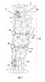
- FIG. 1is a perspective view of a system 10 for correcting a spine tending to exhibit a spinal deformity, according to some embodiments.
- the system 10includes a stabilizing member 12 ; a plurality of stabilizing anchors 14 , including a first stabilizing anchor 14 A and a second stabilizing anchor 14 B; a plurality of correction anchors 18 including a first correction anchor 18 A and a second correction anchor 18 B; a plurality of tensioners 20 including a first tensioner 20 A and a second tensioner 20 B; and a plurality of connectors 22 including a first connector 22 A and a second connector 22 B.
- the system 10is secured to a spinal column 24 formed of a plurality of vertebrae 26 , including a first vertebra 26 A, a second vertebra 26 B, a third vertebra 26 C, and a fourth vertebra 26 D.
- the stabilizing member 12is also referred to as a rod or alignment member; the stabilizing anchors 14 are also referred to as alignment supports or guides; the correction anchors 18 are also referred to as anchor arms or vertebral levers, the tensioners 20 are also referred to as adjustment mechanisms or tying devices, and the connectors 22 are also referred to as force directing members or cables, for example.
- the system 10is shown with two stabilizing anchors 14 , two correction anchors 18 , two tensioners 20 , and two connectors 22 , a greater or fewer number thereof are implemented as appropriate.
- the tensioners 20 and/or stabilizing member 12are optionally replaced and/or augmented by a variety of other tensioning and expanding stabilizing member systems.
- stabilizing members 12Some examples of suitable stabilizing members 12 , stabilizing anchors 14 , correction anchors 18 , tensioners 20 , and/or connectors 22 according to some embodiments are described in U.S. application Ser. No. 12/411,562, filed Mar. 26, 2009, and entitled “Semi-Constrained Anchoring System”; U.S. application Ser. No. 11/196,952, filed Aug. 3, 2005, and entitled “Device and Method for Correcting a Spinal Deformity”; and U.S. application Ser. No. 12/134,058, filed Jun. 5, 2008, and entitled “Medical Device and Method to Correct Deformity,” the entire contents of each which are incorporated herein by reference for all purposes.
- the spinal column 24has a transverse centerline of rotation Y, also described as a longitudinal axis of rotation.
- the transverse centerline rotation Y of the spinal column 24generally corresponds to a mid-distance position of the spinal canal (not shown) extending through the spinal column 24 , where each vertebra 26 has a transverse center of rotation generally located on the transverse centerline of rotation Y.
- the correction anchors 18are fixed to a target region 24 A of the spinal column 24 tending to exhibit an abnormal, or defective curvature (e.g., scoliosis) in need of correction.
- the system 10is optionally used to apply derotational and/or lateral translational forces on the target region 24 A of the spinal column 24 to translate and/or maintain the spinal column 24 at a desired curvature.
- the stabilizing member 12is substantially elongate and rigid, and, if desired, the stabilizing member 12 incorporates some flex, or springiness while substantially rigidly retaining its shape. As will be described in greater detail, the stabilizing member 12 is adapted, or otherwise structured, to extend along the spinal column 24 at a desired spacing from the vertebrae 26 of the spinal column 24 . In some embodiments, the stabilizing member 12 is partially or fully contoured to a typical, corrected curvature of the spinal column 24 .
- the stabilizing member 12has a longitudinal axis X and where the stabilizing member 12 is substantially straight, the longitudinal axis X is substantially straight. Where the stabilizing member 12 has curved or angled portions, the longitudinal axis X at those portions is similarly curved or angled. As described in greater detail, the stabilizing member 12 optionally includes features for adjusting a length of the stabilizing member 12 .
- FIG. 1shows the pair of stabilizing anchors 14 A, 14 B which are adapted, or otherwise structured, to be mounted or fixed to one or more stabilizing vertebrae, such as the first and second vertebrae 26 A, 26 B.
- the first and second stabilizing anchors 14 A, 14 Bare further adapted to receive, and include means for receiving, the stabilizing member 12 such that the stabilizing member 12 is secured laterally, against lateral translation relative to the first and second stabilizing anchors 14 A, 14 B.
- the stabilizing anchors 14are secured to a single one of the vertebra 26 (e.g., laterally across the vertebra at the pedicles, or at a single point, such as a single pedicle).
- the first and second stabilizing anchors 14 A, 14 Bare each secured to a single vertebra in some embodiments or multiple vertebrae in others, such as an additional, adjacent one of the vertebra 26 .
- the first and second stabilizing anchors 14 A, 14 Bare secured to the first and second vertebrae 26 A, 26 B, respectively, as well as one of the vertebrae 26 adjacent each of the first and second vertebrae 26 A, 26 B.
- the stabilizing member 12As received by the first and second stabilizing anchors 14 A, 14 B, the stabilizing member 12 is semi-constrained by the stabilizing anchors 14 , the stabilizing member 12 being free to move with natural movements of the spinal column 24 while being substantially prevented from translating in a direction that is substantially perpendicular to the longitudinal axis X of the stabilizing member 12 at each of the stabilizing anchors 14 A, 14 B.
- the stabilizing member 12is able to slide axially, or translate axially in one or two directions, along the longitudinal axis X, relative to the first and/or second stabilizing anchors 14 A, 14 B.
- the stabilizing member 12is able to slide and to change in at least pitch and yaw at the first and second stabilizing anchors 14 A, 14 B. If desired, the stabilizing member 12 is also able to change in roll at the first and/or the second stabilizing anchors 14 A, 14 B.
- the stabilizing anchors 14are adapted to receive the stabilizing member 12 and secure the stabilizing member 12 against substantial lateral translation relative to stabilizing vertebrae (e.g., the first and second vertebrae 26 A, 26 B).
- the vertebrae 26 A, 26 B(as well as secondary vertebra to which the stabilizing anchors 14 are secured) are used to stabilize the stabilizing member 12 which defines a line of reference from which to adjust defective curvature by providing a series of anchor points toward which the target region 24 A is able to be pulled.
- the first and second correction anchors 18 A, 18 Bare optionally substantially similar, and thus various features of the second correction anchor 18 B are described in association with the first correction anchor 18 A.
- Features of the first correction anchor 18 Aare designated with reference numbers followed by an “A” and similar features of the second correction anchor 18 B are designated with similar reference numbers followed by a “B.”
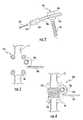
- FIG. 2shows the first correction anchor 18 A according to some embodiments.
- the first correction anchor 18 Ais generally L-shaped, where the first correction anchor 18 A includes an arm 50 A with optional threading 51 A (shown in broken lines) and a head 52 A assembled to one another in a generally L-shaped configuration.
- the first correction anchor 18 Ais optionally substantially rigid.
- the arm 50 Aextends from the head 52 A to a terminal coupler 54 A and is disposed generally perpendicular to the head 52 A.
- a length of the correction anchor 18 Ais adjustable, as described in greater detail below.
- the arm 50 Ais optionally secured about, and rotatable relative to the head 52 A and is adapted to extend across one of the vertebrae 26 , for example, from one side of the spinal column 24 to an opposite side of the spinal column 24 .
- the head 52 A of the correction anchor 18 Ais optionally adapted or otherwise structured to be fixed to a portion of the third vertebra 26 C, such as a pedicle of the third vertebra 26 C.
- the head 52 Aincludes a body portion 56 A and a cap portion 58 A.
- the head 52 Aincludes and/or is adapted to work in conjunction with any of a variety of means for securing to the third vertebra 26 C.
- the body portion 56 Ais optionally configured as a pedicle screw.
- Assembly of the first correction anchor 18 Aincludes receiving the arm 50 A on the body portion 56 A of the head 52 A and screwing or otherwise securing the cap portion 58 A onto the body portion 56 A.
- the arm 50 Ais rotatable relative to the head 52 A upon assembly of the correction anchor 18 A.
- the first correction anchor 18 Ais secured to the third vertebra 26 C such that the arm 50 A extends across the third vertebra 26 C either adjacent to the spinous processes or through a hole or hollowed portion in the spinous processes of the third vertebra 26 C.
- the second correction anchor 18 Bis secured to the fourth vertebra 26 D, where the fourth vertebra 26 D is an apical vertebra at the apex A of the target region 24 A ( FIG. 1 ).
- the first tensioner 20 Ais shown in FIGS. 3 and 4 , where FIG. 4 shows the first tensioner 20 A with a portion removed to illustrate inner features thereof.
- the tensioners 20are optionally substantially similar, and thus various features of the first, and second tensioners 20 A, 20 B are described in association with the first tensioner 20 A.
- Features of the first tensioner 20 Aare designated with reference numbers followed by an “A” and similar features of the second tensioner 20 B are designated with similar reference numbers followed by a “B.”
- the first tensioner 20 Aprovides means for securing the first connector 22 A to the stabilizing member 12 .
- the first tensioner 20 Aalso described as an adjustment mechanism or coupler, is further adapted to adjust, and provides means for adjusting the effective length of the first connector 22 A.
- the first tensioner 20 Aincludes a reel 70 A having a central lumen adapted to be coaxially received over the stabilizing member 12 , a circumferential gear 72 A surrounding the reel 70 A, a vertical gear 74 A in contact with the circumferential gear 72 A, an actuation head 78 A, and a housing 80 A.
- the reel 70 A, as well as the circumferential gear 72 A and vertical gear 74 Aare maintained at least partially within the housing 80 A.
- the housing 80 Ais adapted to be secured to the stabilizing member 12 .
- the housing 80 Aoptionally forms a clamshell configuration through which the stabilizing member 12 is receivable.
- the housing 80 AUpon inserting the stabilizing member 12 through the central lumen of the reel 70 A, the housing 80 A is adapted to be clamped onto the stabilizing member 12 with the reel 70 A free to rotate about the stabilizing member 12 .
- the first connector 22 Ais attached or secured to the reel 70 A and passes out of the housing 80 A through an appropriately sized opening in the housing 80 A.
- Actuation of the vertical gear 74 A via the actuation head 78 Aturns the circumferential gear 72 A, which turns the reel 70 A, thus winding (or unwinding, depending on the direction in which the reel 70 A is turned) the first connector 22 A about the reel 70 A.
- Rotation of the reel 70 A in the appropriate directiondraws the first connector 22 A in toward the first tensioner 20 A, pulling the first correction anchor 18 A ( FIG. 1 ) toward the first tensioner 20 A according to some methods of correcting a spinal defect.
- the actuation head 78 Ahas a receptacle for receiving a hex head driver for rotating the actuation head 78 A.
- the second connector 22 Bis similarly coupled to the second tensioner 20 B, where actuation of the second tensioner 20 B modifies the effective length of the second connector 22 B, drawing the connector 22 B in or letting them out.
- the connectors 22 A, 22 Bare optionally substantially similar, and thus various features of the connectors 22 are described in association with the first connector 22 A.
- Features of the first connector 22 Aare designated with reference numbers followed by an “A” and similar features of the second connector 22 B are designated with similar reference numbers followed by a “B.”
- the first connector 22 Ais substantially flexible such that the first connector 22 A is able to be pivoted in multiple directions (e.g., to facilitate a polyaxial connection to the correction anchor 18 A and/or the tensioner 20 A). Such flexibility additionally or alternatively facilitates spooling or winding of the first connector 22 A, for example.
- Suitable flexible materials for forming the first connector 22 Ainclude wire and stranded cables, monofilament polymer materials, multifilament polymer materials, multifilament carbon or ceramic fibers, and others.
- the first connector 22 Ais formed of stainless steel or titanium wire or cable, although a variety of materials are contemplated.
- the first connector 22 Aalso described as a force directing member or a cable, is adapted to be secured to the first correction anchor 18 A and the first tensioner 20 A, the first connector 22 A defining an effective length between the first tensioner 20 A and the first correction anchor 18 A, and thus the stabilizing member 12 (although, in some embodiments, the first connector 22 A is secured directly to the stabilizing member 12 ).
- the first tensioner 20 Ais adapted to modify, and provides means for modifying, the effective length of the first connector 22 A.
- the second connector 22 Binteracts similarly with the second correction anchors 18 B.
- assembly and use of the system 10generally includes attaching the stabilizing anchors 14 on superior and/or inferior locations of the target region 24 A, for example to transitional vertebrae characterizing a scoliotic curvature of the spinal column 24 .
- the target region 24 Aincludes those of the vertebrae 26 in need, or in greater need, of correction.
- the connectors 22couple the correction anchors 18 to the stabilizing member 12 and, by retracting the connectors 22 toward the stabilizing member 12 , the spinal column 24 is brought into more natural alignment.
- the system 10is optionally used for incremental correction, for gross correction, and/or for maintaining a correction as desired.
- the connectors 22are optionally retracted incrementally as part of one or more procedures using the tensioners 20 .
- a single, gross adjustmentis made using the tensioners 20 or other device(s) to accomplish a desired correction.
- a correctionis made using other hardware, prior to or in conjunction with securing the system 10 to the spinal column 24 , where the system 10 is utilized to maintain the desired correction.
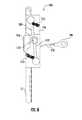
- FIGS. 5 and 6show a tensioning system 100 for externally actuating one or more of the tensioners 20 following implantation of the system 10 .
- the tensioning system 100includes an implantable driver 102 , also described as a reciprocating adjuster, and an external driver 104 .
- the implantable driver 102includes a housing 106 , one or more lever arms 108 , also described as piston units, maintaining one or more magnet(s) 110 and defining a center of rotation within the housing 106 , a drive shaft 112 coaxial with the center of rotation of the lever arms 108 , a one-way roller clutch 114 connected to the drive shaft 112 , and reset springs 114 ( FIG. 6 ), also described as a return mechanism.
- the drive shaft 112is adapted to couple with the actuation head 78 A, for example by including a suitable mating component, such as a hex head driver, or by being integrally formed or otherwise connected to the actuation head 78 A such that displacement of the lever arms 108 in a first direction causes the reel 70 A to rotate in a second, orthogonal direction such that the tensioner 20 A acts as a transfer unit.
- a suitable mating componentsuch as a hex head driver
- the housing 106 of the implantable driver 102is secured to the housing 80 A, for example being integrally formed therewith.
- the external driver 104is configured to activate the implantable driver 102 through the body of a patient (e.g., through skin, muscle, and/or bone as appropriate) and includes a housing 120 , a drive assembly 122 , a drive shaft 124 connected to the drive assembly 122 , and a magnet assembly 126 connected to the drive shaft 124 .
- activation of the drive assembly 122causes the magnet assembly 126 to rotate.
- the drive assembly 122is optionally an angle driver adapted to rotate the drive shaft 124 at a desired speed and torque.
- the housing 120is optionally substantially cylindrical in shape and includes a top 128 and a bottom 130 , the housing including a central aperture for receiving the drive shaft 124 and being sized and shaped to receive the magnet assembly 126 such that the magnet assembly 126 is free to rotate within the housing 120 .
- the magnet assembly 126includes a plurality of magnets, such as a first magnet 126 A of a first polarity and a second magnet 1268 of the same, or an opposite polarity. As shown in FIG. 5 , the first and second magnets 126 A, 126 B are connected to one another with a circular attachment 128 that is, in turn, connected to the drive shaft 124 , the drive shaft 124 being coaxial with an axis of rotation of the magnet assembly 126 . The first and second magnets 126 A, 126 B are optionally diametrically opposed to one another relative to the axis of rotation of the magnet assembly 126 .
- the implantable driver 102is operated, or magnetically powered, through the skin S of a patient using the external driver 104 .
- the magnet(s) 110 of the implantable driver 102are rotated until the magnet(s) 110 are unable to rotate further (e.g., with the housing 106 acting as a stop).
- the one-way roller clutch 114allows rotation in a single direction and, upon reaching the limit of rotation, the magnet(s) 110 reset back to their original position via spring-action before the next one of the first and second magnets 126 A, 1268 rotates into position with one or more of the magnet(s) 110 to initiate another ratchet sequence.
- the one-way roller clutch 114is adapted to ratchet, or hold, after a small amount of rotation. This helps allow a relative compact design, as the lever arms 108 are not required to travel through a large rotational angle. For example, the lever arms 108 optionally each travel through an angle of between 0 and 45 degrees or between 5 and 30 degrees, although a variety of angular limits are contemplated. In some embodiments, a gearing system (not shown) is also employed to help increase torque as desired.
- the housing 106 of the implantable driver 102 and the housing 120 of the external driver 104help avoid unwanted contact of moving parts with the skin of the patient.
- FIGS. 7 and 8show another tensioning system 150 for externally actuating one or more of the tensioners 20 following implantation of the system 10 .
- the tensioning system 150acts as a reciprocating adjuster and includes a cap 152 , also described as a piston unit, and a spring 154 , also described as a return mechanism, as well as a one-way drive roller clutch 156 and a drive shaft 158 , also described as a transfer unit.
- the tensioning system 150is adapted to translate a linear downward force to lateral, or transverse, rotation.
- the cap 152is engaged with the spring 154 and one-way drive clutch 156 such that when a downward force is applied to the spring-loaded cap 152 the ensuing downward movement of the cap 152 causes lateral rotation of the one-way drive roller clutch 154 .
- the clutch 156has grooves or ridges 156 A that are cut at an angle so that depression of the cap 152 causes the clutch 156 to rotate, where the steeper the angle the less the force required to depress the cap 152 and the less ensuing rotation of the drive shaft 158 .
- the drive shaft 158 and/or clutch 156are also optionally coupled to a gearbox (not shown) to enhance mechanical advantage of the system 150 .
- the system 150also optionally includes a plurality of low-friction ball bearings 160 between the cap 152 and the clutch 156 to reduce the force needed to depress the cap 152 and rotate the drive shaft 158 .
- the one-way drive roller clutch 156is coupled to the drive shaft 158 such that rotation of the clutch 156 translates to rotation of the drive shaft 158 .
- the drive shaft 158is adapted to be connected to the actuation head 78 A.
- the drive shaft 158is optionally a 4 mm hex drive adapted, for example, to engage with a female 4 mm hex pocket in the actuation head 78 A of the tensioner 20 A ( FIG. 1 ).
- the system 150is optionally activated by depressing the button through a patient's skin, where the cap 152 is located by a user via tactile feel and/or external markings (e.g., tattoos), for example.
- the cap 152does not rotate relative to the tensioner 20 A.
- the downward force on the cap 152rotates the one-way roller clutch 156 , which then actuates the tensioner 20 A to tighten the connector 22 A, for example.
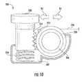
- FIGS. 9 and 10show another tensioning system 200 , also described as a reciprocating adjuster, that is optionally employed in addition to, or as a replacement for, one or more of the tensioners 20 .
- the tensioning system 200includes a housing 202 , an outer one-way roller clutch 204 , also referred to as an outer clutch, an inner one-way roller clutch 206 , also referred to as an inner clutch, a push button 208 , also described as a piston unit, and a spring 210 , also described as a return mechanism.
- the housing 202generally maintains the outer and inner clutches 204 , 206 , also described as a transfer unit, the push button 208 and the spring 210 , and is adapted to be secured (e.g., via a clamshell fit) to the stabilizing member 12 .
- the outer clutch 204includes gearing 212 and the push button 208 includes gearing 214 , the gearing 212 and the gearing 214 being adapted to complement one another to rotationally drive the outer clutch 204 upon depressing the push button 208 , where linear movement of the push button is translated into transverse movement of the outer clutch 204 .
- the outer clutch 204is adapted to spin freely in a first direction D 1 and to lock to the inner clutch 206 in a second direction D 2 .
- the inner clutch 206is adapted to spin freely relative to the stabilizing member 12 in the second direction D 2 while being locked to the stabilizing member 12 in the first direction D 1 .
- the outer and inner clutches 204 , 206are one-way drawn-cup roller clutches arranged with the outer clutch 204 around the inner clutch 206 such that when the push button 208 is depressed both the inner roller clutch 206 and the outer clutch 204 forward rotate relative to the stationary member and when the push button is released 208 the spring 210 returns the push button 208 to its original position and the inner clutch 206 remains stationary while the outer clutch 204 back rotates relative to the stabilizing member 12 .
- One of the connectors 22is secured to the inner clutch 206 such that a user accessing the push button 208 (e.g., through the skin of a patient as previously described) is able to repeatedly push the push button 208 in order to ratchet the connector 22 A toward (or alternatively, away) from the stabilizing rod 12 , shortening the effective length of the connector 22 A.
- Gear boxes or other means of enhancing mechanical advantage of the system 200are employed as desired.
- FIGS. 11 and 12show another tensioning system 250 , also described as a reciprocating adjuster, that is optionally employed in addition to, or as a replacement for, one or more of the tensioners 20 .
- the system 250similarly to the system 200 , the system 250 also employs a dual roller clutch mechanism, also described as a transfer unit.
- the system 250includes a housing 252 , an outer one-way roller clutch 254 , also referred to as an outer clutch, an inner one-way roller clutch 256 , also referred to as an inner clutch, a push button 258 , also referred to as a piston unit, a spring 260 , also described as a return mechanism, and a drive linkage 262 coupling the push button 258 to the outer clutch 254 .
- the housing 252generally maintains the outer and inner clutches 254 , 256 , the push button 258 , the spring 260 , and the drive linkage 262 , and is adapted to be secured (e.g., via a clamshell fit) to the stabilizing member 12 .
- the system 250also includes a magnetic latch assembly 270 adapted to allow selective activation of the system 250 for adjustment.
- the system 250generally operates similarly to the system 200 , where a user depresses the push button 258 through the skin of the patient to ratchet one of the connectors 22 , for example the first connector 22 A, around the inner clutch 254 .
- the magnetic latch assembly 270is present as an optional feature to help prevent inadvertent adjustment of the system 250 (e.g., by an unintentional depression of the push button 258 ).
- the magnetic latch assembly 270includes a housing 271 maintaining a spring 272 , a latch magnet 274 , and a stop member 276 adapted to engage with stop features 280 associated with the inner clutch 256 (e.g., slots formed into the outer surface of the inner clutch 256 ).
- the magnetic latch assembly 274is operated by bringing a magnet in close enough proximity to the latch magnet 274 to release the stop member 276 from the stop features 280 . Upon doing so, the push button 258 is able to be depressed to ratchet the system 250 .
- the system 250provides a relatively vertical, or in-line arrangement of a dual roller clutch mechanism, where the push button 258 is more in line with the stabilizing member 12 to help minimize the amount of lateral space taken up by the design.
- the magnetic latch assembly 274helps prevent rotation unless a magnet is placed above the latch magnet 274 , thereby helping to prevent unintentional activation of the tensioning system 250 .
- a userwould bring an external magnet into proximity with the latch magnet to put the system 250 into an active state and then operate the system 250 with the system 250 in the active state.
- FIGS. 13, 14, and 15show another tensioning system 300 that is optionally employed in addition to, or as a replacement for, one or more of the tensioners 20 .
- the system 300also described as a resistance adjuster and a reciprocating adjuster, includes a housing 302 , a drive member 304 , also described as a slide unit, a drive spring 306 , also described as a potential energy drive, a reset spring 310 ( FIG. 15 ), also described as a return mechanism, and a push button 308 and an engagement member 312 , also described as a resistance unit.
- the housing 302is optionally substantially cylindrical and hollow, defining a first compartment 302 A and a second compartment 302 B.
- the drive member 304extends from the first compartment 302 A out of the second compartment 302 B of the housing 302 , where the drive member 304 and the housing 302 are coaxially received over the stabilizing member 12 .
- the drive member 304is optionally substantially cylindrical and hollow and defines an enlarged base 316 , a main body 318 , and an enlarged head 320 .
- the main body 318includes a plurality of teeth 322 ( FIG. 15 ) adapted to selectively engage with the engagement member 312 .
- the drive member 304is adapted to slide over the stabilizing member 12 while the housing 302 is secured relative thereto, the drive member 304 being able to slide out from the housing 302 until the enlarged head limits further travel of the drive member 304 .
- the drive spring 306is coaxially received over the drive member 304 between the base 316 and the housing 302 .
- the drive spring 306is a compression spring for exerting a pushing force on the base 316 of the drive member 304 , to move the drive member 304 from a first position ( FIG. 13 ) to a second position ( FIG. 14 ) away from the housing 302 , although other types of potential energy drives are contemplated.
- the push button 308is slidably received through a sidewall of the second compartment 302 B and is connected to the engagement member 312 .
- the engagement member 312includes complementary sets of teeth 324 A, 324 B to the teeth 322 on the drive member 304 .
- the sets of teeth 324 A, 324 Bare located on opposite portions of the engagement member 312 and are offset slightly from one another.
- the first set of teeth 324 Ais released from the complementary teeth 322 on the drive member 304 and, in turn, the second set of teeth 324 B engage the complementary teeth 322 of the drive member 304 .
- the reset spring 310Upon releasing the push button 308 , the reset spring 310 causes the first set of teeth 324 A to reengage with the complementary teeth 322 and the second set of teeth 324 B to release from the complementary teeth 322 . In this manner, the drive member 304 is selectively released (e.g., a relatively small amount) following each cycle of depressing and releasing the push button 308 .
- One of the connectors 22such as the first connector 22 A is secured to the enlarged head 320 .
- An aperture, roller, or other transition(not shown) is provided on the housing 302 such that the connector 22 A is able to extend outwardly, in a transverse direction from the housing 302 .
- the drive member 304pistons downwardly out from the housing 302 , the enlarged head 320 moves downwardly, pulling the first connector 22 A into the housing 302 and reducing the effective length of the first connector 22 A between the stabilizing member 12 and the first correction anchor 18 A, for example.
- a magnetic latch assemblysuch as those previously described, is optionally employed with this embodiment, or any other appropriate embodiment, to help prevent inadvertent actuation of the tensioning system 300 .
- the pushing forceis supplied by the drive spring 306
- the pushing forceis supplied by other potential energy drives, including expansion of a hydrogel material, gas (e.g., pre-installed in the first compartment 302 A or generated via chemical reaction, for example), or other means for generating a pushing force on the drive member 304 .
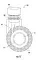
- FIGS. 16 and 17show another tensioning system 350 that is optionally employed in addition to, or as a replacement for, one or more of the tensioners 20 .
- the system 350also described as a reciprocating adjuster, includes a housing 352 , a drive member 354 , a one-way roller clutch 356 , also referred to as an outer clutch, a push button 358 , a reset spring 360 , also described as a return mechanism, and a drive linkage 362 coupling the push button 358 to the outer clutch 356 such that depression of the push button 358 (e.g., through the skin of a patient) results in rotational force on the outer clutch 356 in a first direction and releasing the push button 358 from the depressed position to an initial position resulting in a rotational force on the outer clutch 356 in an opposite direction.
- depression of the push button 358e.g., through the skin of a patient
- the housing 352generally maintains the outer clutch 356 , the push button 358 , the reset spring 360 , and the drive linkage 362 , and is adapted to be secured (e.g., via a clamshell fit) to the stabilizing member 12 .
- the housing 352is optionally substantially cylindrical and hollow, defining a first compartment 352 A and a second compartment 352 B.
- the drive member 354is also optionally cylindrical and hollow, the drive member 354 extending from the first compartment 352 A out of the second compartment 352 B of the housing 352 , where the drive member 354 and the housing 352 are coaxially received over the stabilizing member 12 .
- the drive member 354defines an enlarged base 366 , a main body 368 , and an enlarged head 370 .
- one or more of the connectors, such as the first connector 22 A,is secured to the enlarged head 370 .
- the main body 368includes a plurality of threads 372 ( FIG. 15 ) adapted to mate with the outer clutch 356 .
- the drive member 354is adapted to slide over the stabilizing member 12 while the housing 352 is secured relative thereto, the drive member 354 being able to slide out from the housing 352 until the enlarged head limits further travel of the drive member 354 .
- the outer clutch 356is coaxially received over the drive member 354 between the base 366 and the housing 352 .
- the outer clutch 356has a threaded internal lumen (not shown), where the threads of the outer clutch 356 mate with the threads 372 of the drive member 354 to move the drive member 304 from a first position to a second position away from the housing 352 .
- the push button 358is slidably received through a sidewall of the second compartment 352 B and is connected to the drive linkage 362 .
- the drive linkage 362causes the outer clutch 356 to rotate, or ratchet, until the push button 308 is fully depressed.
- the outer clutch 356rotates, the drive member 354 is driven out of the housing 352 and the first connector 22 A is pulled into the housing 352 , thereby shortening its effective length.
- the system 350is optionally used to tension the first connector 22 A to help correct a spinal deformity.
- a magnetic latch assemblysuch as those previously described, is optionally employed with this embodiment, or any other embodiment described herein, to help prevent inadvertent actuation of the tensioning system 350 .
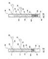
- FIGS. 18 and 19show another tensioning system 400 that is optionally employed in addition to, or as a replacement for, one or more of the tensioners 20 .
- the system 400also described as a resistance adjuster, includes a hollow portion 402 of the stabilizing member 12 , also described as a housing, a drive member 404 , also described as a slide unit, a drive spring 406 , also described as a potential energy drive, a biodegradable mass 408 , also described as a resistance unit, a first collar 410 , and a second collar 412 .
- the housing 402defines a first compartment 402 A and a second compartment 402 B separated by a wall 402 C having a lumen (not shown) sized to slidably receive the drive member 404 .
- the housing 402also includes a first connector aperture 420 and a second connector aperture 422 , the first and second connector apertures 420 , 422 being adapted to slidably receive one of the connectors 22 , such as the first connector 22 A and the second connector 22 B, for example.
- the drive member 404extends within the first compartment 402 A and the second compartment 402 B, where the drive member 404 includes an enlarged base 426 slidably received in the second compartment 402 B and abutted against the biodegradable mass 408 .
- the drive spring 406is optionally a compression spring received over the drive member 404 , the drive spring 406 being positioned between the enlarged base 426 of the drive member 404 and the wall 402 C.
- the biodegradable mass 408is a polymeric material configured to be absorbed into the body over a predetermined time period.
- the biodegradable mass 408is PGA (poly glycolic acid) with a degradation time between about 6 to about 12 months, PLA (poly lactic acid) with a degradation time greater than about 24 months, or a bacterial polyester (e.g., a polyhydroxyalkanoate) with a degradation time greater than about 12 months.
- the biodegradable mass 408can be tailored (e.g., with a pre-selected timing by combining different types of materials) to degrade over a predetermined time period.
- one or more portion(s) of the housing 402allows bodily fluids to interact with the biodegradable mass 408 .
- the second compartment 402 Boptionally a porous wall structure or otherwise allows the body to interact sufficiently with the biodegradable mass 408 to result in absorption of the material.
- the first and second collars 410 , 412are positioned along the drive member 404 and, in some embodiments, are secured to the drive member 404 such that the first and second collars 410 , 412 move with the drive member 404 as the drive member 404 slides in the housing 402 .
- the first and second connectors 22 A, 22 Bare secured to the first and second collars 410 , 412 .
- the biodegradable mass 408begins to be absorbed over time, allowing the drive spring 406 to push the enlarged base 426 downward, in turn causing the drive member 404 to slide downward along with the first and second collars 410 , 412 .
- potential energyis stored in the drive spring 406 or other means for storing energy (e.g., an expandable hydrogel) and is released at the rate of decay of the biodegradable mass 408 (e.g., a substantially continuous and predetermined rate of decay).
- the rate of decay or degradationcan be controlled by the type of biodegradable material used, material geometry, the surface area exposed, the porosity of the material, and the shape of the biodegradable mass 408 , for example.
- the axial movement of the drive member 404draws the connectors 22 A, 22 B into the housing 202 through the first and second connector apertures 420 , 422 .
- the effective length between the connectors 22 A, 22 B and the first and second correction anchors 18 A, 18 Bis shortened, the correction anchors being drawn toward the housing 402 , and consequently, the stabilizing member 12 .
- the correction anchors 18are able to be pulled toward the stabilizing member 12 , according to some embodiments.
- FIGS. 20 and 21show another tensioning system 450 that is optionally employed in addition to, or as a replacement for, one or more of the tensioners 20 .
- the system 450also described as a resistance adjuster, includes a housing 452 adapted to be received over the stabilizing member 12 , a drive member 454 , also described as a slide unit, a drive spring 456 , also described as a potential energy drive, and a biodegradable mass 458 , also described as a resistance unit.
- the system 450generally operates similarly to the system 400 , where the system 450 is adapted to be secured over the stabilizing member 12 .
- the housing 452is optionally substantially cylindrical and hollow, defining a first compartment 452 A.
- the drive member 454extends from the first compartment 452 A out of the housing 452 , where the drive member 454 and the housing 452 are coaxially received over the stabilizing member 12 .
- the drive member 454is optionally substantially cylindrical and hollow and defines an enlarged base 466 , a main body 468 , and an enlarged head 470 .
- the drive member 454is adapted to slide over the stabilizing member 12 while the housing 452 is secured relative thereto, the drive member 454 being able to slide out from the housing 452 until the enlarged head 470 limits further travel of the drive member 454 .
- the drive spring 456is coaxially received over the drive member 454 between the base 466 and the housing 452 .
- the drive spring 456is a compression spring for exerting a pushing force on the base 466 of the drive member 454 .
- the biodegradable mass 458is located in the first compartment 452 A between under the enlarged head 470 to substantially prevent the drive spring 456 from moving the drive member 454 .
- the drive spring 456is able to move the drive member 454 from a first position ( FIG. 20 ) to a second position ( FIG. 21 ) away from the housing 452 , although other types of springs are contemplated.
- the enlarged head 470moves within the first compartment 452 A.
- one or more of the connectors 22such as the first connector 22 A, is secured relative to the enlarged head 470 .
- the head 470is actuated within the first compartment 452 A, the first connector 22 A is drawn into the housing 452 , thereby shortening the effective length of the first connector 22 A between the stabilizing member 12 and the first correction anchor 18 A.
- the system 450is optionally employed to draw one or more of the correction anchors 18 toward the stabilizing member 12 .
- FIGS. 22, 23, and 24show another tensioning system 500 that is optionally employed in addition to, or as a replacement for, one or more of the tensioners 20 .
- the system 500also described as a resistance adjuster, includes a housing 502 adapted to be received over the stabilizing member 12 , a drive member 504 , also described as a slide unit, a drive spring 506 , also described as a potential energy drive, a biodegradable mass 508 , also described as a resistance unit, a drive unit 510 connected to the drive member 504 , and a guide piece 512 .
- the system 500generally operates similarly to the system 450 , the system 500 being adapted to be secured over the stabilizing member 12 .
- the housing 502is optionally substantially cylindrical and hollow, defining a first compartment 502 A.
- the drive member 504extends from the first compartment 502 A out of the housing 502 , where the drive member 504 and the housing 502 are coaxially received over the stabilizing member 12 .
- the drive member 504is optionally substantially cylindrical and hollow and defines an enlarged base 516 , a main body 518 , and an enlarged head 520 .
- the drive member 504is adapted to slide over the stabilizing member 12 while the housing 502 is secured relative thereto, the drive member 504 being able to slide out from the housing 502 until the enlarged head 520 limits further travel of the drive member 504 .
- the drive spring 506is coaxially received over the drive member 504 between the base 516 and the housing 502 .
- the drive spring 506is a compression spring for exerting a pushing force on the base 516 of the drive member 504 .
- the biodegradable mass 508is located in the first compartment 502 A under the enlarged base 516 to substantially prevent the drive spring 456 from moving the drive member 504 . As the biodegradable mass 508 degrades, the drive spring 506 is able to move the drive member 504 from a first position to a second position into the housing 502 , although other types of springs are contemplated.
- the drive unit 510is connected to the drive member 504 , the drive unit being slidably received over the stabilizing member 12 .
- the drive unit 510includes an inner cylinder 530 and with male threading and an outer cylinder 532 with female threading complementary to the male threading on the inner cylinder 530 .
- the outer cylinder 532includes an internal magnet 534 adapted to interact with one or more external magnets 536 adapted to be activated outside the patient, which, when rotated, rotationally drive the internal magnet 534 through the skin of the patient, causing the outer cylinder 532 to be driven up or down the inner cylinder 530 .
- the internal magnet 534has a first portion of a first polarity and a second portion of a second, opposite polarity.
- the external magnets 536similarly have two portions with opposite polarities. As the external magnets 536 rotate, the polarities of the external magnets push and pull, respectively, on the polarities of the internal magnet 534 as the external magnets are rotated.
- a suitable magnetic drive systemis described in U.S. Patent Application Publication 2009/0112207, filed May 15, 2008 and published Apr. 30, 2009, the entire contents of which are incorporated herein by reference.
- the guide piece 512is adapted to be a low friction interface for one or more of the connectors 22 adapted to direct the connectors 22 from an axial direction along the stabilizing member 12 to a more transverse direction.
- One of the connectors 22such as the first connector 22 A, is secured to the outer cylinder 532 and up through the guide piece 512 to one of the correction anchors 18 , such as the first correction anchor 18 A.
- the drive member 504is selectively released (e.g., a predetermined amount over time) following implantation of the system 500 such that the enlarged head 520 moves further into the first compartment 502 A.
- the drive member 504moves axially, so does the drive unit 510 , in turn pulling the connector 22 A and shortening the effective length of the connector 22 A between the stabilizing member 12 and the correction anchor 18 A.
- the connector 22 Ais loosened or tightened (e.g., for fine adjustment purposes), by using the external magnets 536 to rotate the internal magnet 534 .
- FIGS. 25 and 26show another tensioning system 550 that is optionally employed in addition to, or as a replacement for, one or more of the tensioners 20 .
- the system 550also described as a resistance adjuster, includes a housing 552 adapted to be received over the stabilizing member 12 , a coupler 554 , also described as a slide unit, a drive spring 556 , also described as a potential energy drive, and a biodegradable mass 558 , also described as a resistance unit.
- the housing 552is adapted to be secured to the stabilizing member 12 (e.g., via a clamshell fit) and includes a substantially helical internal compartment 552 A with a connector aperture 570 opening into the internal compartment 552 A.
- the drive spring 556is helically wound in the internal compartment 552 A and is adapted to act as a torsion spring, the drive spring 556 being in a compressed state with a first end 572 of the spring 556 secured to the housing 552 and a second end 574 of the spring 556 connected to the coupler 554 .
- the biodegradable mass 558is disposed at the second end 574 of the spring 556 and/or the coupler 554 , maintaining the spring 556 in a compressed state.
- One of the connectors 22such as the first connector 22 A, is secured to the coupler 554 , the first connector 22 A winding back out of the internal compartment 552 A through the connector aperture 570 .
- the second end 570 of the spring 556travels further into the internal compartment 552 A, drawing the coupler 554 and the first connector 22 A further into the internal compartment 552 A. In some embodiments, as the first connector 22 A is drawn into the internal compartment 552 A, the effective length between the stabilizer 12 and the correction anchor 18 A is reduced.
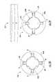
- FIGS. 27 and 28show an expanding stabilizing member system 600 that is optionally employed in addition to, or as a replacement for, the stabilizing member 12 .
- the system 600also described as a resistance adjuster, is optionally employed by attaching the system 600 to the spinal column 24 using the stabilizing anchors 18 , such that the spinal column 24 is able to be expanded longitudinally to help reduce the defective curvature of the spinal column 24 .
- the system 600includes a housing 602 , a drive member 604 , also described as a slide unit, a drive spring 606 , also described as a potential energy drive, a biodegradable mass 608 , also described as a resistance unit, and an adjustable collar 610 .
- the housing 602is optionally substantially cylindrical and hollow, defining a first compartment 602 A.
- the drive member 604extends from the first compartment 602 A out of the housing 602 .
- the drive member 604is optionally substantially cylindrical and defines a main body 612 having a plurality of male threads along the length thereof (not shown) and an enlarged head 614 .
- the adjustable collar 610has female threading and is coaxially received over the male threading of the main body 612 .
- the adjustable collar 610includes a magnetic element and/or is otherwise adapted to respond to magnetic force, the adjustable collar 610 having a first polarity portion 610 A and a second polarity portion 610 B.
- the drive member 604is adapted to slide within the housing 602 .
- the drive member 604is restricted from rotating relative to the drive housing, for example, being keyed or otherwise having complementary features to the portion of the housing 602 from which the drive member 604 extends that substantially prevent relative rotation between the housing and drive member 604 .
- the drive member 604is adapted to slide out from the housing 602 until the adjustable collar 610 limits further travel of the drive member 604 and into the housing 602 until the enlarged head 614 abuts the housing 602 .
- the drive spring 606is coaxially received over the drive member 604 between the adjustable collar 610 and the housing 602 .
- the drive spring 606is a compression spring for exerting a pushing force on the adjustable collar 610 of the drive member 604 .
- the biodegradable mass 608is located in the first compartment 602 A ahead of the adjustable collar 610 to substantially prevent the drive spring 606 from moving the drive member 604 . As the biodegradable mass 608 degrades, the drive spring 606 is able to move the drive member 604 from a first position to a second position outwardly from the housing 602 , to extend the overall length of the system 600 .
- the effective length of the system 600is adjusted (e.g., for fine adjustments or if the length of the system begins to grow too quickly), by rotating the adjustable collar 610 .
- an external magnetic drive 640such as those previously described, is utilized through the skin to rotate the adjustable collar 610 and adjust the overall length of the system 600 .
- an expanding materialis utilized to exert a pushing force on the drive member 604 .
- a hydrogel materiale.g., material having the tradename “HYPAN” available from Hymedix
- NDGAnonordihydroguaiaretic acid
- the spring 606is replaced and/or augmented by using a compressed gas cylinder or other means for storing potential energy for use in the system 600 to drive the drive member 604 .
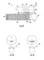
- FIG. 29shows another tensioning system 650 that is optionally employed in addition to, or as a replacement for, one or more of the tensioners 20 .
- the tensioning system 650optionally replaces the stabilizing member 12 or portions thereof, or is mounted to the stabilizing member 12 as desired.
- the system 650includes a housing 652 , a drive member 654 , a first actuator collar 656 , a second actuator collar 658 , a motor unit 660 connected to the drive member 654 , and a power coupler 662 .
- the housing 652includes a substantially hollow vertical rod (e.g., about 10-15 mm in diameter), the housing 652 being adapted to maintain the drive member 654 , the first and second actuator collars 656 , 658 , and the motor unit 660 .
- the housing 652optionally acts as the stabilizing member 12 in the system 10 , in some embodiments, the housing being secured to the spinal column 24 with the stabilizing anchors 18 , for example.
- the drive member 654is optionally adapted to act as a substantially flexible axle, for example being about 3 mm in diameter and formed of steel or other appropriate material (e.g., metallic and/or polymeric materials).
- the actuator collars 656 , 658are secured to the drive member 654 at longitudinal positions thereon and one or more of the connectors 22 , such as the first and second connectors 22 A, 22 B, respectively, are secured to the actuator collars 656 , 658 .
- the first and second actuator collars 656 , 658are optionally substantially similar, the first and second actuator collars 656 , 658 being described cumulatively with respect to the first actuator collar 656 .
- the first actuator collar 656is a magnetically activated tensioner means secured to one of the connectors 22 , such as the first connector 22 A.
- the first actuator collar 656is shown in FIGS. 30 and 31 , where FIG. 30 shows the first actuator collar 656 in a free spinning, or unlocked state, and FIG. 31 shows the first actuator collar 656 in a locked, or engaged state.
- the first actuator collar 656includes an outer portion 656 A and an inner portion 656 B having a plurality of pockets slidably receiving a plurality of magnetic engagement members 670 .
- an external magnet 672is brought into proximity of a patient (not shown) to cause the magnetic engagement members 670 to push inwardly to lock the inner and outer portions 656 A, 656 B.
- the magnetic polarity on the external magnet 672is switched (by physically flipping a magnet or switching the current to an electric magnet) in order to cause the magnetic engagement members 670 to slide outwardly into the pockets in the outer portion 656 A to release the first actuator collar 656 .
- magnetic activation of the actuator collars 656 , 658helps facilitate individual adjustment, allowing more torque from a single source to be available to draw the connectors 22 to the housing 652 .
- the motor unit 660is a Maxon Motor, 13 mm OD, with a 3371:1 gear ratio, although a variety of motors are optionally employed.
- the power coupler 662is optionally an inductive power coupler, also described as a receiver, a secondary coil, or an internal antenna, for receiving inductive power from an external inductive power source (not shown).
- the power coupler 662has about a 50 mm diameter body and includes a physical magnet such that the external inductive power source, or external primary coil, is better able to center on the power coupler 662 to increase the coupling efficiency.
- the external, primary coil(not shown) when the external, primary coil (not shown) is centered above the power coupler 662 , electrical energy on the order of 2-3 watts (up to 20 watts if needed) is delivered to the motor unit 660 causing rotation of the drive member 654 .
- the connectors 22are selectively tensioned by engaging a selected one of the actuator collars 656 , 658 magnetically. In at least this manner, power is selectively applied for tensioning so that the maximum amount of tension is directed to the desired connector 22 .
- the motor unit 660is reversible and/or gearing (not shown) is employed to pay out, or loosen the connectors 22 as desired.
- feedback and position informationis transmitted back from the system 650 to an external receiver via IR (infrared) or RF (radio frequency), for example.
- FIG. 32shows another tensioning system 700 that is optionally employed in addition to, or as a replacement for, one or more of the tensioners 20 .
- the tensioning system 700optionally replaces the stabilizing member 12 or portions thereof, or is mounted to the stabilizing member 12 as desired.
- the system 700includes a secondary spool 702 , a drive member 704 , a first actuator collar 706 , a second actuator collar 708 , a motor unit 710 connected to the drive member 704 , a power coupler 712 , and a gear system 714 .
- the power coupler 712is optionally an inductive power source, in other embodiments the power coupler is an implantable battery or other power source.
- the system 700operates generally similarly to the system 650 .
- the drive member 704 and the secondary spool 702are interconnected by the gear system 714 .
- the motor unit 710turns the drive member 704 , which, through the gear system 714 , turns the secondary spool 702 .
- the first and second actuator collars 706 , 708are secured to the secondary spool 702 and are thereby turned to draw one or more of the connectors 22 toward the secondary spool 702 .
- the secondary spool 702is optionally turned in an opposite direction to pay out the connectors 22 from the actuator collars 706 , 708 as desired.
- Magnetic means(not shown) are optionally employed to engage or disengage the actuator collars 706 , 708 as desired.
- FIGS. 33 and 34show another tensioning system 750 that is optionally employed in addition to, or as a replacement for, one or more of the tensioners 20 .
- the tensioning system 750optionally replaces the stabilizing member 12 or portions thereof, or is mounted to the stabilizing member 12 as desired.
- the system 750includes a housing 752 , a drive member 754 , a first actuator collar 756 , a second actuator collar 758 , a motor unit 760 connected to the drive member 754 , and a power coupler 762 .
- the housing 752includes a substantially hollow vertical cylindrical body (e.g., about 10-15 mm in diameter), the housing 752 being adapted to house the drive member 754 , the first and second adjustment collars 756 , 758 , and the motor unit 760 .
- the housing 752optionally acts as the stabilizing member 12 in the system 10 , in some embodiments, the housing being secured to the spinal column 24 with the stabilizing anchors 18 , for example.
- the drive member 754includes two portions, a base portion 754 A and a traveler portion 754 B.
- the base portion 754 Ais elongate and extends from a first end 770 connected to the motor unit 760 and a second end 772 bearing a male threaded head 774 .
- the traveler portion 754 Ais substantially elongate and includes a female threaded section 778 and a carrier section 780 .
- the traveler portion 754 Bis non-rotatable and axially slidable in the housing 752 .
- the female threaded section 778 of the traveler portion 754 Bis mated with the male threaded head 774 of the base portion 754 A such that rotation of the base portion 754 A by the motor unit 760 causes the traveler portion 754 B to move axially within the housing 752 .
- FIG. 33shows the traveler portion 754 B at a first position in the housing 752 and
- FIG. 34shows the traveler portion 756 B in a second, more retracted position in the housing 752 .
- the adjustment collars 756 , 758are secured at longitudinal positions along the carrier section 780 .
- One or more of the connectors 22are secured to each of the adjustment collars, such as the first and second connectors 22 A, 22 B, respectively, such that axial movement of the carrier section 780 draws in or lets out the connectors 22 from the housing 752 , thereby shortening or lengthening the effective length of the connectors 22 between the correction anchors 18 and the housing 752 as desired.
- the adjustment collars 756 , 758are also threaded onto the carrier section 780 , where rotation of the adjustment collars 756 , 758 using external magnets such as those previously referenced, allows additional tensioning and/or loosening of the connectors 22 .
- FIGS. 35 and 36show another tensioning system 800 that is optionally employed in addition to, or as a replacement for, one or more of the tensioners 20 .
- the tensioning system 800optionally replaces the stabilizing member 12 or portions thereof, or is mounted to the stabilizing member 12 as desired.
- the system 800includes a housing 802 , a drive member 804 , a first actuator anchor 806 , a second actuator anchor 808 , a motor unit 810 connected to the drive member 804 , and a power coupler 812 .
- the housing 802includes a substantially hollow vertical cylindrical body (e.g., about 10-15 mm in diameter) having a plurality of connector apertures 816 , the housing 802 being adapted to house the drive member 804 , the first and second adjustment anchors 806 , 808 , and the motor unit 810 .
- the housing 802optionally acts as the stabilizing member 12 in the system 10 .
- the housing 802is secured to the spinal column 24 with the stabilizing anchors 18 , for example.
- the drive member 804includes two portions, a base portion 804 A and a traveler portion 804 B.
- the base portion 804 Ais elongate and extends from a first end 820 connected to the motor unit 810 and a second end 822 bearing a male threaded head 824 .
- the traveler portion 804 Ais substantially elongate and includes a female threaded section 828 and a carrier section 830 .
- the traveler portion 804 Bis non-rotatable and axially slidable in the housing 802 .
- FIG. 35shows the traveler portion 804 B at a first position in the housing 802 and FIG. 36 shows the traveler portion 806 B in a second, more retracted position in the housing 802 .
- the first and second adjustment anchors 806 , 808are substantially similar to one another. As such, the second adjustment anchor 808 is described cumulative with respect to the first adjustment anchor 806 .
- the first and/or second adjustment anchors 806 , 808are optionally adapted to be substituted for one or more of the correction anchors 18 , according to some embodiments.
- the first adjustment anchor 806is generally L-shaped when viewed from the side, where the first adjustment anchor 806 includes an extension arm 806 A with male threading (not shown), a collar 806 B with female threading (not shown), a base arm 806 C, and a head 806 D all assembled together.
- the collar 806 Bis rotatably coupled to the base arm 806 C and the extension arm 806 A is non-rotatably and slidably coupled to the base arm 806 C.
- the extension arm 806 Ais received within the collar 806 B and the base arm 806 C.
- the threads of the extension arm 806 A and the collar 806 Bare mated such that the extension arm 806 A is able to be telescoped inward and outward from the collar 806 B and the base arm 806 C by rotating the collar 806 B in a first direction and a second direction, respectively.
- the collar 806 Bis optionally formed of a magnetic material and has a portion with a first polarity and another portion with a second polarity. External magnets (not shown), such as those previously described, are optionally used to rotate the collar 806 B to adjust the overall length of the adjustment anchor 806 .
- the head 806 D of the adjustment anchor 806optionally includes a pedicle screw that is adapted to be driven into a vertebra of the spinal column 24 such that the adjustment anchor 806 is able to be pulled upon similarly to one of the correction anchors 18 .
- One or more of the connectors 22are secured to the carrier section 830 , respectively, such that axial movement of the carrier section 830 draws in or lets out the connectors 22 from the connector apertures 816 of the housing 802 , thereby shortening or lengthening the effective length of the connectors 22 between the adjustment anchors 806 A, 806 B and the housing 802 , and thus the spinal column 24 , as desired.
- Each of the adjustment anchors 806 A, 806 Bare also optionally adjusted in length to modify the tension being exerted by the system 800 on the spinal column 24 as desired.
- FIGS. 37 and 38show another tensioning system 850 that is optionally employed as a means for externally operating the tensioners 20 .
- the system 850also described as a reciprocating adjuster, includes a housing 852 , a motor drive 854 , a power coupler 856 , a roller clutch 858 , and a drive shaft 860 .
- the housing 852is adapted to maintain the motor drive 854 , the roller clutch 858 , and the drive shaft 860 .
- the motor drive 854is optionally a nitinol drive, such as that sold under the trade name “DM01 nitinol actuator” from “MIGA MOTORS.”
- the motor drive 854includes an actuation arm 854 A and a return spring 854 B, also described as a return mechanism, connected on opposite sides of the roller clutch 858 .
- the power coupler 856is optionally similar to those previously described (e.g., an induction coil) and, when electrical energy is applied, the nitinol of the motor drive 854 is heated, causing contraction of the actuation arm 854 A which pulls the actuation arm 854 A (e.g., with about 7 lbs of force).
- the actuation arm 854 Ais connected to the roller clutch 858 , which is a one-way roller clutch, such that retraction of the actuation arm 854 A causes rotation of the one-way roller clutch 858 .
- the return spring 854 Bpresses on the opposite side of the roller clutch 858 such that the actuation arm 854 A returns to the original position where the actuation arm 854 A is able to be actuated again by activating the motor drive 854 , generating a ratcheting effect.
- the drive shaft 860is coupled to the roller clutch 858 such that ratcheting of the roller clutch ratchets the drive shaft 860 .
- the drive shaft 860is adapted to be connected to the actuation head of one of the tensioners 20 , such as the first tensioner 20 A, for example, by including a suitable mating component, such as a hex head driver, or by being integrally formed or otherwise connected to the actuation head, such as the actuation head 78 A ( FIG. 3 ).
- a suitable mating componentsuch as a hex head driver
- the housing 856 of the implantable driver 852is secured to the housing 80 A and/or the stabilizing member 12 , for example being integrally formed therewith.
- FIGS. 39, 40, and 41show an expanding stabilizing member system 900 that is optionally employed in addition to, or as a replacement for, the stabilizing member 12 .
- the system 900also described as a reciprocating adjuster and a resistance adjuster, is optionally employed by attaching the system 900 to the spinal column 24 ( FIG. 1 ) using the stabilizing anchors 18 , such that the spinal column 24 is able to be expanded longitudinally to help reduce the defective curvature of the spinal column 24 .
- the system 900includes a housing 902 , a drive member 904 , also described as a slide unit, a drive spring 906 , also described as a potential energy drive, and a magnetic walker assembly 908 , also described as a resistance unit.
- the drive member 904is optionally substantially cylindrical and includes a plurality of surface grooves 910 along the length of the drive member 904 , the surface grooves 910 being adapted to mate with the magnetic walker assembly 908 which acts as both a piston and a return mechanism.
- the drive spring 906is received within the housing 902 between the end of the drive member 904 and the housing 902 .
- the drive spring 906is a compression spring for exerting a pushing force on the drive member 904 .
- the drive member 904extends from the housing 902 , the drive member 904 being adapted to slide within the housing 902 when not restricted by the magnetic walker assembly 908 .
- the magnetic walker assembly 908is secured to the housing 902 and includes a first receptacle 916 holding a first toothed member 918 and a second receptacle 920 holding a second toothed member 922 .
- Each of the first and second toothed members 918 , 922are biased in the downward position (e.g., by a spring—not shown), the first and second toothed members 918 , 922 each including a plurality of teeth 918 A, 922 A for mating with the surface grooves 910 .
- each of the first and second toothed membersdisplays a different polarity from the other.
- each of the toothed members 918 , 922is substantially arcuately shaped to increase the surface engagement with the surface grooves 910 .
- An external magnet 930 having a first polarity portion 932 and a second, opposite polarity portion 934is optionally employed through the skin to alternately actuate the first and second toothed members 918 , 922 into and out of the surface grooves 910 .
- the effective length of the system 900is adjusted by alternatively actuating the first and second toothed members 918 , 922 to “walk” the drive member 904 outwardly from the housing 902 , where the potential energy represented in the system 900 by the spring 906 is released as the toothed members 918 , 922 engage and release the surface grooves 910 .
- FIGS. 40 and 41are illustrative of the alternate engagement of the first toothed member, those figures showing the external magnet 930 , the drive member 904 , and the first toothed member 918 with other portions removed for ease of illustration.
- FIG. 40shows the first toothed member 918 in an engaged position and
- FIG. 41shows the external magnet 930 rotated 180 degrees such that the first toothed member 918 is actuated to a disengaged position.
- FIGS. 42 and 43show another expanding stabilizing member system 950 that is optionally employed in addition to, or as a replacement for, the stabilizing member 12 .
- the system 950also described as a reciprocating adjuster and a resistance adjuster, is optionally employed by attaching the system 950 to the spinal column 24 ( FIG. 1 ) using the stabilizing anchors 18 , such that the spinal column 24 is able to be expanded longitudinally using the system 950 to help reduce the defective curvature of the spinal column 24 .
- the system 950includes a housing 952 , a drive member 954 , also described as a slide unit, a drive spring 956 , also described as a potential energy drive, and a magnetic walker assembly 958 , also described as a resistance unit, that acts as a drive piston and a return mechanism.
- the magnetic walker assembly 958is secured to the housing 952 and includes a receptacle 966 holding a first toothed member 968 and a second toothed member 972 , the first and second toothed members 968 , 972 being positioned on an arm that is hinged to the receptacle 966 .
- Each of the first and second toothed members 968 , 972is biased in the downward position (e.g., by a spring—not shown), the first and second toothed members 968 , 972 each including one or more teeth 968 A, 972 A for mating with the surface grooves 960 .
- each of the first and second toothed members 968 , 970is characterized by a different polarity from the other.
- each of the toothed members 968 , 972is substantially arcuately shaped to increase the surface engagement with the surface grooves 960 .
- FIG. 44A principle of operation of the system 950 is illustrated more generally in FIG. 44 .
- an external magnet 980 having a first polarity portion 982 and a second, opposite polarity portion 984is optionally employed through the skin (not shown) to alternately actuate the first and second toothed members 968 , 972 into and out of the surface grooves 960 .
- the effective length of the system 950is adjusted by alternatively actuating the first and second toothed members 968 , 972 to “walk” or “step” the drive member 954 outwardly from the housing 952 , where the potential energy represented in the system 950 by the spring 956 is released as the toothed members 968 , 972 alternately engage and release the surface grooves 960 , the two members 968 , 972 alternatively acting as piston unit and a return mechanism.
- a springis used in some embodiments, in other embodiments an expanding material, such as those previously described, is utilized to exert a pushing force on the drive member 954 .
- the external magnet 980is optionally an electric magnet that is able to switch polarities for stepping the system 950 at a desired electromagnetic force and speed.
- the system 1000also described as a reciprocating adjuster and a resistance adjuster, includes a housing 1002 , a drive member 1004 , also described as a slide unit, a drive spring 1006 , also described as a potential energy drive, and a magnetic walker assembly 1008 , also described as a resistance unit.
- the drive member 1004is optionally configured with surface grooves similar to those of the systems 900 and 950 and the magnetic walker assembly 1008 , acting as a piston unit and a return mechanism, is optionally adapted to interact with the drive member 1004 similarly to those of the systems 300 , 900 and/or 950 .
- the system 1000Upon application of a magnetic force of alternating polarity (schematically indicated by external magnet 1020 in FIG. 44 ), the system 1000 operates similarly to the system 300 described above.
- the drive member 1004is adapted to slide over the stabilizing member 12 while the housing 1002 is secured relative thereto, the drive member 1004 being able to slide out from the housing 1002 until an enlarged head 1020 of the drive member 1004 limits further travel of the drive member 1004 .
- the drive spring 1006is coaxially received over the drive member 1004 between the base 1016 and the housing 1002 .
- the drive spring 1006is a compression spring for exerting a pushing force on a base 1016 of the drive member 1004 , to move the drive member 1004 from a first position ( FIG. 45 ) to a second position ( FIG. 46 ) away from the housing 1002 , although other types of springs are contemplated.
- One of the connectors 22such as the first connector 22 A is secured to an enlarged head 1022 of the drive member 1004 .
- An aperture, roller, or other feature(not shown) is provided on the housing 1002 such that the connector 22 A is able to extend outwardly, in a transverse direction from the housing 1002 .
- the drive member 1004pistons downwardly out from the housing 1002
- the enlarged head 1022moves downwardly, pulling the first connector 22 A into the housing 1002 and reducing the effective length of the first connector 22 A between the stabilizing member 12 and the first correction anchor 18 A, for example.
- various embodimentsrelate to a spinal correction system for implantation in a patient, the system including a correction anchor, a stabilizing member, a reciprocating adjuster, and a connector.
- the correction anchoris configured to be secured to a vertebra in a defect area of a spine.
- the stabilizing memberis configured to be secured against translation at the defect area of the spine.
- the reciprocating adjusteris coupled to the stabilizing member, the reciprocating adjuster including: a piston unit displaceable in a first direction, and a transfer unit coupled to the piston unit such that displacement of the piston unit in the first direction causes the transfer unit to be displaced in a second direction.
- the connectorextends from the reciprocating adjuster to define an effective length between the reciprocating adjuster and the correction anchor, the connector having a first end configured to be coupled to the transfer unit and a second end configured to be coupled to the correction anchor such that displacement of the transfer unit causes shortening of the effective length of the connector.
- the piston unitincludes a depressible shaft and the transfer unit includes a roller.
- the rolleris a one-way drive clutch.
- the systemis configured such that displacement of the roller winds the connector about the roller.
- the piston unitincludes gearing and the transfer unit includes gearing for mating with the gearing of the piston unit.
- the piston unitincludes a tooth member and the transfer unit includes a plurality of surface grooves configured to mate with the tooth member such that, upon displacement of the piston unit, the tooth member mates with the groove to displace the transfer unit.
- the piston unitis displaceable between a first position and a second position and the piston unit includes a return mechanism for returning the piston unit from the second position to the first position.
- the return mechanismincludes a spring.
- the piston unitis coupled to a magnetic member.
- systemfurther comprises an external magnetic drive for actuating the piston unit by displacing the magnetic member.
- the systemfurther comprises an implantable motor and an implantable power source, the motor being coupled to the piston unit.
- the power sourceincludes an internal antennae for receiving inductive power.
- the power sourceincludes an implantable battery.
- various embodimentsrelate to a method of correcting a spine, the method including securing a correction anchor to a vertebra in a defect area of a spine and securing a stabilizing member against translation at the defect area of the spine.
- a piston unit of a reciprocating adjusteris displaced in a first direction to cause a transfer unit of the reciprocating adjuster to be displaced in a second direction, in turn, causing shortening of an effective length of a connector coupling the correction anchor and the reciprocating adjuster.
- various embodimentsrelate to a spinal correction system for implantation in a patient, the system including a correction anchor, a stabilizing member, a resistance adjuster, and a connector.
- the correction anchoris configured to be secured to a vertebra in a defect area of a spine.
- the stabilizing memberis configured to be secured against translation at the defect area of the spine.
- the resistance adjusteris coupled to the stabilizing member, the resistance adjuster including: a potential energy drive, a slide unit coupled to the potential energy drive such that the potential energy drive exerts a displacement force on the slide unit biasing the slide unit in a first direction, and a resistance unit coupled to the slide unit, the resistance unit being configured to selectively oppose the displacement force.
- the connectorextends from the resistance adjuster to define an effective length between the resistance adjuster and the correction anchor, the connector having a first end configured to be coupled to the slide unit and a second end configured to be coupled to the correction anchor such that displacement of the slide unit in the first direction causes shortening of the effective length of the connector.
- the potential energy driveis received coaxially about the slide unit.
- the resistance unitincludes a tooth member and the slide unit includes a plurality of surface grooves configured to mate with the tooth member such that upon displacing the tooth member longitudinally from a first position to a second position releases the resistance unit.
- the potential energy driveincludes an expanding material.
- the expanding materialis temperature activated.
- the expanding materialis fluid activated.
- the potential energy driveincludes a spring.
- the resistance unitincludes hydrogel material.
- the resistance unitincludes a biodegradable material.
- the resistance unitis coupled to a magnetic member.
- systemfurther comprises an external magnetic drive for actuating the slide unit by displacing the magnetic member.
- the external magnetic driveincludes a rotating magnet.
- the systemfurther comprises an implantable motor and an implantable power source, the motor being coupled to the piston unit.
- the power sourceincludes an internal antennae for receiving inductive power.
- the power sourceincludes an implantable battery.
- various embodimentsrelate to a method of correcting a spine, the method including securing a correction anchor to a vertebra in a defect area of a spine and securing a stabilizing member against translation at the defect area of the spine.
- the methodalso includes actuating a resistance unit of a resistance adjuster coupled to the stabilizing member such that the resistance adjuster selectively releases a displacement force provided by a potential energy drive coupled to a slide unit, the slide unit being displaced by the potential energy drive in a first direction to cause shortening in an effective length of a connector coupled between the resistance adjuster and the correction anchor.
- various embodimentsrelate to a spinal correction system for implantation in a patient, the system including a correction anchor, a stabilizing member, a resistance adjuster, and a connector.
- the correction anchoris configured to be secured to a vertebra in a defect area of a spine.
- the stabilizing memberis configured to be secured against translation at the defect area of the spine.
- the resistance adjusteris coupled to the stabilizing member, the resistance adjuster including: a potential energy drive including an expanding material configured to expand after being subjected to an internal body environment of the patient and a slide unit coupled to the potential energy drive such that the potential energy drive exerts a displacement force on the slide unit biasing the slide unit in a first direction.
- the connectorextends from the resistance adjuster to define an effective length between the resistance adjuster and the correction anchor, the connector having a first end configured to be coupled to the slide unit and a second end configured to be coupled to the correction anchor such that displacement of the slide unit in the first direction causes shortening of the effective length of the connector.
Landscapes
- Health & Medical Sciences (AREA)
- Orthopedic Medicine & Surgery (AREA)
- Neurology (AREA)
- Life Sciences & Earth Sciences (AREA)
- Surgery (AREA)
- Molecular Biology (AREA)
- General Health & Medical Sciences (AREA)
- Biomedical Technology (AREA)
- Heart & Thoracic Surgery (AREA)
- Medical Informatics (AREA)
- Nuclear Medicine, Radiotherapy & Molecular Imaging (AREA)
- Animal Behavior & Ethology (AREA)
- Engineering & Computer Science (AREA)
- Public Health (AREA)
- Veterinary Medicine (AREA)
- Physics & Mathematics (AREA)
- Electromagnetism (AREA)
- Orthopedics, Nursing, And Contraception (AREA)
- Surgical Instruments (AREA)
- Prostheses (AREA)
Abstract
Description
Claims (6)
Priority Applications (2)
| Application Number | Priority Date | Filing Date | Title |
|---|---|---|---|
| US15/010,036US9895168B2 (en) | 2011-06-03 | 2016-01-29 | Spinal correction system actuators |
| US15/729,964US10675062B2 (en) | 2011-06-03 | 2017-10-11 | Spinal correction system actuators |
Applications Claiming Priority (4)
| Application Number | Priority Date | Filing Date | Title |
|---|---|---|---|
| US201161493117P | 2011-06-03 | 2011-06-03 | |
| PCT/US2012/040493WO2012167105A1 (en) | 2011-06-03 | 2012-06-01 | Spinal correction system actuators |
| US201414123729A | 2014-05-01 | 2014-05-01 | |
| US15/010,036US9895168B2 (en) | 2011-06-03 | 2016-01-29 | Spinal correction system actuators |
Related Parent Applications (2)
| Application Number | Title | Priority Date | Filing Date |
|---|---|---|---|
| US14/123,729ContinuationUS9333009B2 (en) | 2011-06-03 | 2012-06-01 | Spinal correction system actuators |
| PCT/US2012/040493ContinuationWO2012167105A1 (en) | 2011-06-03 | 2012-06-01 | Spinal correction system actuators |
Related Child Applications (1)
| Application Number | Title | Priority Date | Filing Date |
|---|---|---|---|
| US15/729,964ContinuationUS10675062B2 (en) | 2011-06-03 | 2017-10-11 | Spinal correction system actuators |
Publications (2)
| Publication Number | Publication Date |
|---|---|
| US20160220276A1 US20160220276A1 (en) | 2016-08-04 |
| US9895168B2true US9895168B2 (en) | 2018-02-20 |
Family
ID=46246255
Family Applications (4)
| Application Number | Title | Priority Date | Filing Date |
|---|---|---|---|
| US14/123,729Expired - Fee RelatedUS9333009B2 (en) | 2011-06-03 | 2012-06-01 | Spinal correction system actuators |
| US15/010,036Active2032-08-30US9895168B2 (en) | 2011-06-03 | 2016-01-29 | Spinal correction system actuators |
| US15/010,049Expired - Fee RelatedUS9408638B2 (en) | 2011-06-03 | 2016-01-29 | Spinal correction system actuators |
| US15/729,964Expired - Fee RelatedUS10675062B2 (en) | 2011-06-03 | 2017-10-11 | Spinal correction system actuators |
Family Applications Before (1)
| Application Number | Title | Priority Date | Filing Date |
|---|---|---|---|
| US14/123,729Expired - Fee RelatedUS9333009B2 (en) | 2011-06-03 | 2012-06-01 | Spinal correction system actuators |
Family Applications After (2)
| Application Number | Title | Priority Date | Filing Date |
|---|---|---|---|
| US15/010,049Expired - Fee RelatedUS9408638B2 (en) | 2011-06-03 | 2016-01-29 | Spinal correction system actuators |
| US15/729,964Expired - Fee RelatedUS10675062B2 (en) | 2011-06-03 | 2017-10-11 | Spinal correction system actuators |
Country Status (7)
| Country | Link |
|---|---|
| US (4) | US9333009B2 (en) |
| EP (1) | EP2713916B1 (en) |
| JP (1) | JP6158176B2 (en) |
| CN (1) | CN103781429B (en) |
| AU (1) | AU2012261983B2 (en) |
| CA (1) | CA2838047A1 (en) |
| WO (1) | WO2012167105A1 (en) |
Cited By (1)
| Publication number | Priority date | Publication date | Assignee | Title |
|---|---|---|---|---|
| US10188428B2 (en)* | 2017-05-15 | 2019-01-29 | Loubert S. Suddaby | Subcutaneous implantable device for gradually aligning a spine |
Families Citing this family (79)
| Publication number | Priority date | Publication date | Assignee | Title |
|---|---|---|---|---|
| US7955357B2 (en) | 2004-07-02 | 2011-06-07 | Ellipse Technologies, Inc. | Expandable rod system to treat scoliosis and method of using the same |
| US7862502B2 (en) | 2006-10-20 | 2011-01-04 | Ellipse Technologies, Inc. | Method and apparatus for adjusting a gastrointestinal restriction device |
| US8790380B2 (en)* | 2007-07-26 | 2014-07-29 | Dynamic Spine, Llc | Segmental orthopaedic device for spinal elongation and for treatment of scoliosis |
| US9204908B2 (en) | 2007-07-26 | 2015-12-08 | Dynamic Spine, Llc | Segmental orthopedic device for spinal elongation and for treatment of scoliosis |
| US20090112262A1 (en) | 2007-10-30 | 2009-04-30 | Scott Pool | Skeletal manipulation system |
| US11202707B2 (en) | 2008-03-25 | 2021-12-21 | Nuvasive Specialized Orthopedics, Inc. | Adjustable implant system |
| US11241257B2 (en) | 2008-10-13 | 2022-02-08 | Nuvasive Specialized Orthopedics, Inc. | Spinal distraction system |
| US8382756B2 (en) | 2008-11-10 | 2013-02-26 | Ellipse Technologies, Inc. | External adjustment device for distraction device |
| US8828058B2 (en) | 2008-11-11 | 2014-09-09 | Kspine, Inc. | Growth directed vertebral fixation system with distractible connector(s) and apical control |
| US8197490B2 (en) | 2009-02-23 | 2012-06-12 | Ellipse Technologies, Inc. | Non-invasive adjustable distraction system |
| US9622792B2 (en) | 2009-04-29 | 2017-04-18 | Nuvasive Specialized Orthopedics, Inc. | Interspinous process device and method |
| JP5751642B2 (en) | 2009-09-04 | 2015-07-22 | エリプス テクノロジーズ, インク.Ellipse Technologies, Inc. | Bone growth apparatus and method |
| US9168071B2 (en)* | 2009-09-15 | 2015-10-27 | K2M, Inc. | Growth modulation system |
| AU2011264818B2 (en) | 2010-06-10 | 2015-06-18 | Globus Medical, Inc. | Low-profile, uniplanar bone screw |
| US9248043B2 (en) | 2010-06-30 | 2016-02-02 | Ellipse Technologies, Inc. | External adjustment device for distraction device |
| WO2012021378A2 (en) | 2010-08-09 | 2012-02-16 | Ellipse Technologies, Inc. | Maintenance feature in magnetic implant |
| WO2012112396A2 (en) | 2011-02-14 | 2012-08-23 | Ellipse Technologies, Inc. | Device and method for treating fractured bones |
| JP6158176B2 (en) | 2011-06-03 | 2017-07-05 | ケイツーエム インコーポレイテッドK2M,Inc. | Spine correction system |
| US10743794B2 (en) | 2011-10-04 | 2020-08-18 | Nuvasive Specialized Orthopedics, Inc. | Devices and methods for non-invasive implant length sensing |
| US10016220B2 (en) | 2011-11-01 | 2018-07-10 | Nuvasive Specialized Orthopedics, Inc. | Adjustable magnetic devices and methods of using same |
| US8920472B2 (en) | 2011-11-16 | 2014-12-30 | Kspine, Inc. | Spinal correction and secondary stabilization |
| US9468469B2 (en) | 2011-11-16 | 2016-10-18 | K2M, Inc. | Transverse coupler adjuster spinal correction systems and methods |
| US9451987B2 (en) | 2011-11-16 | 2016-09-27 | K2M, Inc. | System and method for spinal correction |
| WO2014172632A2 (en) | 2011-11-16 | 2014-10-23 | Kspine, Inc. | Spinal correction and secondary stabilization |
| FR2988992B1 (en)* | 2012-04-04 | 2015-03-20 | Medicrea International | MATERIAL OF VERTEBRAL OSTEOSYNTHESIS |
| US20130338714A1 (en) | 2012-06-15 | 2013-12-19 | Arvin Chang | Magnetic implants with improved anatomical compatibility |
| US9968379B2 (en)* | 2012-10-04 | 2018-05-15 | Loubert S. Suddaby | Subcutaneous implantable device for gradually aligning a spine and subcutaneous implantable device for gradually lengthening a bone |
| US9572601B2 (en)* | 2012-10-17 | 2017-02-21 | K2M, Inc. | Spinal correction adjustment systems and methods |
| US9044281B2 (en) | 2012-10-18 | 2015-06-02 | Ellipse Technologies, Inc. | Intramedullary implants for replacing lost bone |
| EP2911616B1 (en) | 2012-10-29 | 2020-10-07 | NuVasive Specialized Orthopedics, Inc. | Adjustable devices for treating arthritis of the knee |
| US20140148854A1 (en)* | 2012-11-28 | 2014-05-29 | Zimmer Spine, Inc. | Vertebral fixation system |
| US9179938B2 (en) | 2013-03-08 | 2015-11-10 | Ellipse Technologies, Inc. | Distraction devices and method of assembling the same |
| EP2986241A4 (en)* | 2013-04-18 | 2016-11-09 | K2M Inc | CORRECTION AND SECONDARY STABILIZATION OF THE VERTEBRAL COLUMN |
| US10226242B2 (en)* | 2013-07-31 | 2019-03-12 | Nuvasive Specialized Orthopedics, Inc. | Noninvasively adjustable suture anchors |
| US9801734B1 (en) | 2013-08-09 | 2017-10-31 | Nuvasive, Inc. | Lordotic expandable interbody implant |
| US9468471B2 (en) | 2013-09-17 | 2016-10-18 | K2M, Inc. | Transverse coupler adjuster spinal correction systems and methods |
| US10751094B2 (en) | 2013-10-10 | 2020-08-25 | Nuvasive Specialized Orthopedics, Inc. | Adjustable spinal implant |
| CN106456215B (en) | 2014-04-28 | 2020-04-10 | 诺威适骨科专科公司 | External adjustment device for adjusting a medical implant |
| KR102588501B1 (en) | 2014-10-23 | 2023-10-11 | 누베이시브 스페셜라이즈드 오소페딕스, 인크. | Remotely adjustable interactive bone reshaping implant |
| ES2908064T3 (en) | 2014-12-26 | 2022-04-27 | Nuvasive Specialized Orthopedics Inc | distraction systems |
| US10238427B2 (en) | 2015-02-19 | 2019-03-26 | Nuvasive Specialized Orthopedics, Inc. | Systems and methods for vertebral adjustment |
| DE102015109624A1 (en)* | 2015-06-16 | 2016-12-22 | Wittenstein Se | Mechatronic implant |
| US11071568B2 (en)* | 2015-10-05 | 2021-07-27 | Globus Medical, Inc. | Growing rod for treating spinal deformities and method for using same |
| US11259844B2 (en)* | 2015-10-05 | 2022-03-01 | Globus Medical Inc. | Growing rod for treating spinal deformities and method for using same |
| BR112018007347A2 (en) | 2015-10-16 | 2018-10-23 | Nuvasive Specialized Orthopedics, Inc. | adjustable devices for the treatment of knee arthritis |
| EP3376987B1 (en)* | 2015-11-19 | 2020-10-28 | EOS Imaging | Method of preoperative planning to correct spine misalignment of a patient |
| CN108601611B (en) | 2015-12-10 | 2021-11-02 | 诺威适骨科专科公司 | External adjustment device for stretcher |
| BR112018015504A2 (en) | 2016-01-28 | 2018-12-18 | Nuvasive Specialized Orthopedics, Inc. | bone transport systems |
| WO2017139548A1 (en) | 2016-02-10 | 2017-08-17 | Nuvasive Specialized Orthopedics, Inc. | Systems and methods for controlling multiple surgical variables |
| US10456172B2 (en) | 2016-02-12 | 2019-10-29 | Nuvasive, Inc. | Magnetically actuateable rod insertion for minimally invasive surgery |
| EP3413820B1 (en) | 2016-02-12 | 2024-04-10 | Nuvasive, Inc. | Post-operatively adjustable spinal fixation devices |
| WO2017142426A1 (en)* | 2016-02-19 | 2017-08-24 | Gallagher Group Limited | A fence post |
| US12262917B2 (en) | 2016-05-19 | 2025-04-01 | Auctus Surgical, Inc. | Spinal curvature modulation systems and methods |
| CN109152596B (en)* | 2016-05-19 | 2022-07-08 | 奥图斯外科手术股份有限公司 | Spinal curvature adjustment system |
| KR101791628B1 (en) | 2016-05-24 | 2017-10-30 | (주)시지바이오 | Length extendable rod for fixing the vertebra |
| US10653407B2 (en) | 2016-12-21 | 2020-05-19 | Nuvasive, Inc. | Surgical retractor |
| US11207135B2 (en) | 2017-07-12 | 2021-12-28 | K2M, Inc. | Systems and methods for modeling spines and treating spines based on spine models |
| US11000334B1 (en) | 2017-07-12 | 2021-05-11 | K2M, Inc. | Systems and methods for modeling spines and treating spines based on spine models |
| WO2019014452A1 (en) | 2017-07-12 | 2019-01-17 | K2M, Inc. | Systems and methods for modeling spines and treating spines based on spine models |
| US10874460B2 (en) | 2017-09-29 | 2020-12-29 | K2M, Inc. | Systems and methods for modeling spines and treating spines based on spine models |
| US10892058B2 (en) | 2017-09-29 | 2021-01-12 | K2M, Inc. | Systems and methods for simulating spine and skeletal system pathologies |
| US10624683B2 (en)* | 2018-04-25 | 2020-04-21 | Loubert S. Suddaby | Segmented alignment rod assembly |
| CN109009380B (en)* | 2018-06-26 | 2021-03-02 | 黄振强 | Spine posterior multi-point fixing device |
| IL260367A (en)* | 2018-07-02 | 2018-08-30 | Osteophile Ltd | Devices, systems and methods for distraction osteogenesis |
| WO2020033870A1 (en)* | 2018-08-09 | 2020-02-13 | Orthopediatrics Corp. | Apparatus and methods for modular and spooled vertebral anchors |
| CN112525705A (en)* | 2018-08-22 | 2021-03-19 | 黄志敏 | Spring dynamometer and operation method |
| US11636650B2 (en) | 2018-09-24 | 2023-04-25 | K2M, Inc. | System and method for isolating anatomical features in computerized tomography data |
| US12121265B2 (en)* | 2019-01-03 | 2024-10-22 | Globus Medical Inc. | Growing rod for treating spinal deformities and method for using same |
| JP2022519380A (en) | 2019-02-07 | 2022-03-23 | ニューベイシブ スペシャライズド オーソペディックス,インコーポレイテッド | Ultrasonic communication in medical devices |
| US11589901B2 (en) | 2019-02-08 | 2023-02-28 | Nuvasive Specialized Orthopedics, Inc. | External adjustment device |
| US11723691B2 (en)* | 2019-12-25 | 2023-08-15 | Apifix Ltd | Biasing device for spinal device |
| CN111759434B (en)* | 2020-05-26 | 2021-04-06 | 常州集硕医疗器械有限公司 | Clamping equipment for internal fixation of spine and working method of clamping equipment |
| US12213708B2 (en)* | 2020-09-08 | 2025-02-04 | Nuvasive Specialized Orthopedics, Inc. | Remote control module for adjustable implants |
| US20220265326A1 (en) | 2021-02-23 | 2022-08-25 | Nuvasive Specialized Orthopedics, Inc. | Adjustable implant, system and methods |
| US11737787B1 (en) | 2021-05-27 | 2023-08-29 | Nuvasive, Inc. | Bone elongating devices and methods of use |
| EP4380480A1 (en) | 2021-08-03 | 2024-06-12 | NuVasive Specialized Orthopedics, Inc. | Adjustable implant |
| US20240108381A1 (en)* | 2022-10-04 | 2024-04-04 | The Board Of Regents Of The University Of Texas System | Systems and methods for applying tension to the spine |
| CN116098689B (en)* | 2023-04-11 | 2023-07-28 | 中国医学科学院北京协和医院 | Spinal column orthopedic device |
| CN118021499B (en)* | 2024-04-12 | 2024-07-26 | 中国医学科学院北京协和医院 | Spinal orthosis system |
Citations (451)
| Publication number | Priority date | Publication date | Assignee | Title |
|---|---|---|---|---|
| US2774350A (en) | 1952-09-08 | 1956-12-18 | Jr Carl S Cleveland | Spinal clamp or splint |
| GB780652A (en) | 1954-04-30 | 1957-08-07 | Zimmer Orthopaedic Ltd | Improvements in or relating to apparatus for use in spinal fixation |
| US3242922A (en) | 1963-06-25 | 1966-03-29 | Charles B Thomas | Internal spinal fixation means |
| US3352226A (en) | 1965-03-15 | 1967-11-14 | Silas E Nelsen | Infusion package |
| US3648691A (en) | 1970-02-24 | 1972-03-14 | Univ Colorado State Res Found | Method of applying vertebral appliance |
| US3693616A (en) | 1970-06-26 | 1972-09-26 | Robert Roaf | Device for correcting scoliotic curves |
| US3865105A (en) | 1973-05-16 | 1975-02-11 | Lode S Instr N V | Device for exerting forces on and fixing the spinal column of a human body |
| DE2644735A1 (en) | 1975-05-30 | 1977-04-07 | Erkki Einari Dipl Ing Nissinen | STRETCH AND SUPPORT DEVICE FOR THE SPINAL COLUMN |
| US4024588A (en) | 1974-10-04 | 1977-05-24 | Allo Pro A.G. | Artificial joints with magnetic attraction or repulsion |
| DE2845647A1 (en) | 1978-10-20 | 1980-05-08 | Messerschmitt Boelkow Blohm | Implanted surgical device for correcting spinal curvature - has correction rod rotated by motor to gradually shorten wire attached to spine |
| US4257409A (en) | 1978-04-14 | 1981-03-24 | Kazimierz Bacal | Device for treatment of spinal curvature |
| US4269178A (en) | 1979-06-04 | 1981-05-26 | Keene James S | Hook assembly for engaging a spinal column |
| US4274401A (en) | 1978-12-08 | 1981-06-23 | Miskew Don B W | Apparatus for correcting spinal deformities and method for using |
| SU888968A1 (en) | 1979-01-11 | 1981-12-15 | Новосибирский научно-исследовательский институт травматологии и ортопедии | Apparatus for correcting vertebral column |
| US4355645A (en) | 1978-10-18 | 1982-10-26 | Kabushiki Kaisha Morita Seisakusho | Device for displaying masticatory muscle activities |
| US4361141A (en) | 1979-07-27 | 1982-11-30 | Zimmer Usa, Inc. | Scoliosis transverse traction assembly |
| US4369769A (en) | 1980-06-13 | 1983-01-25 | Edwards Charles C | Spinal fixation device and method |
| US4404967A (en) | 1982-01-18 | 1983-09-20 | Wyzsza Szkola Inzynierska Im. Jurija Gagarina | Surgical strut for treatment of the back-bone |
| US4411259A (en) | 1980-02-04 | 1983-10-25 | Drummond Denis S | Apparatus for engaging a hook assembly to a spinal column |
| US4411545A (en) | 1981-03-06 | 1983-10-25 | Skf Compagnie D'applications Mecaniques - Adr | Swivel joint |
| US4448191A (en) | 1981-07-07 | 1984-05-15 | Rodnyansky Lazar I | Implantable correctant of a spinal curvature and a method for treatment of a spinal curvature |
| US4505268A (en) | 1983-02-17 | 1985-03-19 | Vicente Sgandurra | Scoliosis frame |
| US4554914A (en) | 1983-10-04 | 1985-11-26 | Kapp John P | Prosthetic vertebral body |
| US4573454A (en) | 1984-05-17 | 1986-03-04 | Hoffman Gregory A | Spinal fixation apparatus |
| US4604995A (en) | 1984-03-30 | 1986-08-12 | Stephens David C | Spinal stabilizer |
| US4611581A (en) | 1983-12-16 | 1986-09-16 | Acromed Corporation | Apparatus for straightening spinal columns |
| US4611582A (en) | 1983-12-27 | 1986-09-16 | Wisconsin Alumni Research Foundation | Vertebral clamp |
| US4634445A (en) | 1981-01-30 | 1987-01-06 | Oec Europe Limited | Joint prosthesis |
| US4648388A (en) | 1985-11-01 | 1987-03-10 | Acromed Corporation | Apparatus and method for maintaining vertebrae in a desired relationship |
| US4653481A (en) | 1985-07-24 | 1987-03-31 | Howland Robert S | Advanced spine fixation system and method |
| US4658809A (en) | 1983-02-25 | 1987-04-21 | Firma Heinrich C. Ulrich | Implantable spinal distraction splint |
| US4697582A (en) | 1983-10-28 | 1987-10-06 | Peze William | Appliance for correcting rachidial deformities |
| EP0260044A1 (en) | 1986-08-29 | 1988-03-16 | John Anthony Norman Shepperd | Spinal implant |
| US4738251A (en) | 1987-02-20 | 1988-04-19 | Codespi, Corporation | Correcting device for spine pathology |
| US4773402A (en) | 1985-09-13 | 1988-09-27 | Isola Implants, Inc. | Dorsal transacral surgical implant |
| US4805602A (en) | 1986-11-03 | 1989-02-21 | Danninger Medical Technology | Transpedicular screw and rod system |
| US4815453A (en) | 1983-05-04 | 1989-03-28 | Societe De Fabrication De Materiel Orthopedique (Sofamor) | Device for supporting the rachis |
| US4827918A (en) | 1985-08-15 | 1989-05-09 | Sven Olerud | Fixing instrument for use in spinal surgery |
| EP0322334A1 (en) | 1987-12-23 | 1989-06-28 | Cremascoli France | Prosthesis implanted between vertebral spinous processes |
| US4854311A (en) | 1986-01-09 | 1989-08-08 | Acro Med Corporation | Bone screw |
| US4931055A (en) | 1986-05-30 | 1990-06-05 | John Bumpus | Distraction rods |
| US4936848A (en) | 1989-09-22 | 1990-06-26 | Bagby George W | Implant for vertebrae |
| US5000166A (en) | 1988-04-27 | 1991-03-19 | Sulzer Brothers Limited | Implant kit for stabilizing regions of a spine |
| EP0418387A1 (en) | 1989-02-21 | 1991-03-27 | Vsesojuzny Kurgansky Nauchny Tsentr "Vosstanovitelnaya Travmatologia I Ortopedia" | Device for treatment of curvature of and damage to the spine |
| US5005562A (en) | 1988-06-24 | 1991-04-09 | Societe De Fabrication De Material Orthopedique | Implant for spinal osteosynthesis device, in particular in traumatology |
| US5011484A (en) | 1987-11-16 | 1991-04-30 | Breard Francis H | Surgical implant for restricting the relative movement of vertebrae |
| US5030220A (en) | 1990-03-29 | 1991-07-09 | Advanced Spine Fixation Systems Incorporated | Spine fixation system |
| US5042982A (en) | 1987-07-08 | 1991-08-27 | Harms Juergen | Positioning device |
| US5084049A (en) | 1989-02-08 | 1992-01-28 | Acromed Corporation | Transverse connector for spinal column corrective devices |
| US5092867A (en) | 1988-07-13 | 1992-03-03 | Harms Juergen | Correction and supporting apparatus, in particular for the spinal column |
| US5092866A (en) | 1989-02-03 | 1992-03-03 | Breard Francis H | Flexible inter-vertebral stabilizer as well as process and apparatus for determining or verifying its tension before installation on the spinal column |
| US5127912A (en) | 1990-10-05 | 1992-07-07 | R. Charles Ray | Sacral implant system |
| US5129900A (en) | 1990-07-24 | 1992-07-14 | Acromed Corporation | Spinal column retaining method and apparatus |
| US5133716A (en) | 1990-11-07 | 1992-07-28 | Codespi Corporation | Device for correction of spinal deformities |
| WO1992013496A1 (en) | 1991-02-01 | 1992-08-20 | Biostab | Frame for rigidifying a bone or a bone assembly |
| US5147363A (en) | 1989-12-21 | 1992-09-15 | Haerle Anton | Screw for use in osteosynthesis |
| US5176679A (en) | 1991-09-23 | 1993-01-05 | Lin Chih I | Vertebral locking and retrieving system |
| US5176680A (en) | 1990-02-08 | 1993-01-05 | Vignaud Jean Louis | Device for the adjustable fixing of spinal osteosynthesis rods |
| US5181917A (en) | 1990-06-19 | 1993-01-26 | Chaim Rogozinski | System and method for instrumentation of the spine in the treatment of spinal deformities |
| US5190543A (en) | 1990-11-26 | 1993-03-02 | Synthes (U.S.A.) | Anchoring device |
| US5207678A (en) | 1989-07-20 | 1993-05-04 | Prufer | Pedicle screw and receiver member therefore |
| US5209752A (en) | 1991-12-04 | 1993-05-11 | Danek Medical, Inc. | Lateral offset connector for spinal implant system |
| US5219349A (en) | 1991-02-15 | 1993-06-15 | Howmedica, Inc. | Spinal fixator reduction frame |
| US5242443A (en) | 1991-08-15 | 1993-09-07 | Smith & Nephew Dyonics, Inc. | Percutaneous fixation of vertebrae |
| US5254118A (en) | 1991-12-04 | 1993-10-19 | Srdjian Mirkovic | Three dimensional spine fixation system |
| US5257994A (en) | 1991-09-23 | 1993-11-02 | Lin Chih I | Vertebral locking and retrieving system |
| US5259398A (en) | 1989-10-26 | 1993-11-09 | Giuseppe Vrespa | Method for fixing prosthesis to bones |
| US5282862A (en) | 1991-12-03 | 1994-02-01 | Artifex Ltd. | Spinal implant system and a method for installing the implant onto a vertebral column |
| US5306275A (en) | 1992-12-31 | 1994-04-26 | Bryan Donald W | Lumbar spine fixation apparatus and method |
| FR2697744A1 (en) | 1992-11-10 | 1994-05-13 | Fabrication Mat Orthopedique S | Spinal osteosynthesis instrumentation by the anterior route. |
| US5312420A (en) | 1992-10-09 | 1994-05-17 | United States Surgical Corporation | Surgical apparatus for removing fasteners |
| US5312410A (en) | 1992-12-07 | 1994-05-17 | Danek Medical, Inc. | Surgical cable tensioner |
| US5330473A (en) | 1993-03-04 | 1994-07-19 | Advanced Spine Fixation Systems, Inc. | Branch connector for spinal fixation systems |
| US5330474A (en) | 1991-09-23 | 1994-07-19 | Lin Chih I | Vertebral locking and retrieving system |
| US5352226A (en) | 1993-02-08 | 1994-10-04 | Lin Chih I | Side locking system rotatable in all directions for use in spinal surgery |
| US5360431A (en) | 1990-04-26 | 1994-11-01 | Cross Medical Products | Transpedicular screw system and method of use |
| US5366455A (en) | 1988-11-04 | 1994-11-22 | Surgicraft Limited | Pedicle engaging means |
| US5368594A (en) | 1991-09-30 | 1994-11-29 | Fixano S.A. | Vertebral osteosynthesis device |
| US5380325A (en) | 1992-11-06 | 1995-01-10 | Biomat | Osteosynthesis device for spinal consolidation |
| US5380323A (en) | 1993-06-16 | 1995-01-10 | Advanced Spine Fixation Systems, Inc. | Clamps for spinal fixation systems |
| US5382248A (en) | 1992-09-10 | 1995-01-17 | H. D. Medical, Inc. | System and method for stabilizing bone segments |
| US5387212A (en) | 1993-01-26 | 1995-02-07 | Yuan; Hansen A. | Vertebral locking and retrieving system with central locking rod |
| US5387213A (en) | 1991-02-05 | 1995-02-07 | Safir S.A.R.L. | Osseous surgical implant particularly for an intervertebral stabilizer |
| US5391168A (en) | 1992-04-01 | 1995-02-21 | Acromed B.V. | Device for correcting the shape of the human spinal column and/or for fixing the human spinal column |
| US5397363A (en) | 1992-08-11 | 1995-03-14 | Gelbard; Steven D. | Spinal stabilization implant system |
| US5413576A (en) | 1993-02-10 | 1995-05-09 | Rivard; Charles-Hilaire | Apparatus for treating spinal disorder |
| US5436542A (en) | 1994-01-28 | 1995-07-25 | Surgix, Inc. | Telescopic camera mount with remotely controlled positioning |
| US5437671A (en) | 1992-03-10 | 1995-08-01 | Zimmer, Inc. | Perpendicular rod connector for spinal fixation device |
| US5437669A (en) | 1993-08-12 | 1995-08-01 | Amei Technologies Inc. | Spinal fixation systems with bifurcated connectors |
| US5456722A (en) | 1993-01-06 | 1995-10-10 | Smith & Nephew Richards Inc. | Load bearing polymeric cable |
| US5466238A (en) | 1993-08-27 | 1995-11-14 | Lin; Chih-I | Vertebral locking and retrieving system having a fixation crossbar |
| US5470333A (en) | 1993-03-11 | 1995-11-28 | Danek Medical, Inc. | System for stabilizing the cervical and the lumbar region of the spine |
| US5480440A (en) | 1991-08-15 | 1996-01-02 | Smith & Nephew Richards, Inc. | Open surgical technique for vertebral fixation with subcutaneous fixators positioned between the skin and the lumbar fascia of a patient |
| US5486174A (en) | 1993-02-24 | 1996-01-23 | Soprane S.A. | Fastener for the osteosynthesis of the spinal column |
| US5487744A (en) | 1993-04-08 | 1996-01-30 | Advanced Spine Fixation Systems, Inc. | Closed connector for spinal fixation systems |
| US5490851A (en) | 1994-08-02 | 1996-02-13 | Nenov; Nikolay N. | Method and apparatus for treatment of idiopathic scoliosis |
| US5496318A (en) | 1993-01-08 | 1996-03-05 | Advanced Spine Fixation Systems, Inc. | Interspinous segmental spine fixation device |
| US5498262A (en) | 1992-12-31 | 1996-03-12 | Bryan; Donald W. | Spinal fixation apparatus and method |
| US5501684A (en) | 1992-06-25 | 1996-03-26 | Synthes (U.S.A.) | Osteosynthetic fixation device |
| US5520688A (en) | 1994-07-20 | 1996-05-28 | Lin; Chih-I | Vertebral auxiliary fixation device |
| US5527314A (en) | 1993-01-04 | 1996-06-18 | Danek Medical, Inc. | Spinal fixation system |
| US5540689A (en) | 1990-05-22 | 1996-07-30 | Sanders; Albert E. | Apparatus for securing a rod adjacent to a bone |
| US5544993A (en) | 1993-12-13 | 1996-08-13 | H+E,Uml A+Ee Rle; Anton | Threaded fastener |
| US5549679A (en) | 1994-05-20 | 1996-08-27 | Kuslich; Stephen D. | Expandable fabric implant for stabilizing the spinal motion segment |
| US5562660A (en) | 1993-02-09 | 1996-10-08 | Plus Endoprothetik Ag | Apparatus for stiffening and/or correcting the vertebral column |
| US5569246A (en) | 1993-12-28 | 1996-10-29 | Asahi Kogaku Kogyo Kabushiki Kaisha | Fixing instrument for spinal fusion members |
| US5571191A (en) | 1995-03-16 | 1996-11-05 | Fitz; William R. | Artificial facet joint |
| US5575791A (en) | 1994-07-27 | 1996-11-19 | Lin; Chih-I | Universal eccentric fixation mechanism for orthopedic surgery |
| US5584626A (en) | 1995-06-15 | 1996-12-17 | Excelsior Development Inc. | Torque-limiting fastening element |
| US5586983A (en) | 1990-05-22 | 1996-12-24 | Sanders; Albert E. | Bone clamp of shape memory material |
| US5591165A (en) | 1992-11-09 | 1997-01-07 | Sofamor, S.N.C. | Apparatus and method for spinal fixation and correction of spinal deformities |
| FR2736535A1 (en) | 1995-07-10 | 1997-01-17 | Martin Jean Jacques | Spinal osteosynthesis device to immobilise portion of spine e.g. in case of pathological degeneration between vertebrae |
| US5601554A (en) | 1993-03-04 | 1997-02-11 | Advanced Spine Fixation Systems, Inc. | Branch connector for spinal fixation systems |
| US5611800A (en) | 1994-02-15 | 1997-03-18 | Alphatec Manufacturing, Inc. | Spinal fixation system |
| US5620443A (en) | 1995-01-25 | 1997-04-15 | Danek Medical, Inc. | Anterior screw-rod connector |
| US5630816A (en) | 1995-05-01 | 1997-05-20 | Kambin; Parviz | Double barrel spinal fixation system and method |
| US5643259A (en) | 1994-03-31 | 1997-07-01 | Ricardo C. Sasso | Spine fixation instrumentation |
| US5645599A (en) | 1994-07-26 | 1997-07-08 | Fixano | Interspinal vertebral implant |
| US5649926A (en) | 1994-07-14 | 1997-07-22 | Advanced Spine Fixation Systems, Inc. | Spinal segmental reduction derotational fixation system |
| US5658284A (en) | 1994-06-30 | 1997-08-19 | Allo Pro Ag | Connection member for the connection of a resilient rod with a bone screw which can be anchored in a vertebra |
| US5672175A (en) | 1993-08-27 | 1997-09-30 | Martin; Jean Raymond | Dynamic implanted spinal orthosis and operative procedure for fitting |
| US5676703A (en) | 1994-05-11 | 1997-10-14 | Gelbard; Steven D. | Spinal stabilization implant system |
| US5702399A (en) | 1996-05-16 | 1997-12-30 | Pioneer Laboratories, Inc. | Surgical cable screw connector |
| US5702395A (en) | 1992-11-10 | 1997-12-30 | Sofamor S.N.C. | Spine osteosynthesis instrumentation for an anterior approach |
| US5702452A (en) | 1995-01-23 | 1997-12-30 | Sofamor S.N.C. | Spinal osteosynthesis device with median hook and vertebral anchoring support |
| US5704936A (en) | 1992-04-10 | 1998-01-06 | Eurosurgical | Spinal osteosynthesis device |
| US5713898A (en) | 1993-05-18 | 1998-02-03 | Schafer Micomed Gmbh | Orthopedic surgical holding device |
| US5716355A (en) | 1995-04-10 | 1998-02-10 | Sofamor Danek Group, Inc. | Transverse connection for spinal rods |
| US5720746A (en) | 1994-11-16 | 1998-02-24 | Soubeiran; Arnaud Andre | Device for displacing two bodies relative to each other |
| US5725582A (en) | 1992-08-19 | 1998-03-10 | Surgicraft Limited | Surgical implants |
| US5728097A (en) | 1992-03-17 | 1998-03-17 | Sdgi Holding, Inc. | Method for subcutaneous suprafascial internal fixation |
| US5733284A (en) | 1993-08-27 | 1998-03-31 | Paulette Fairant | Device for anchoring spinal instrumentation on a vertebra |
| US5735852A (en) | 1995-05-22 | 1998-04-07 | Synthes (U.S.A.) | Clamp jaw for a spinal affixation device |
| US5782831A (en) | 1996-11-06 | 1998-07-21 | Sdgi Holdings, Inc. | Method an device for spinal deformity reduction using a cable and a cable tensioning system |
| US5797910A (en) | 1993-08-27 | 1998-08-25 | Paulette Fairant | Operative equipment for correcting a spinal deformity |
| US5810819A (en) | 1997-05-15 | 1998-09-22 | Spinal Concepts, Inc. | Polyaxial pedicle screw having a compression locking rod gripping mechanism |
| US5810817A (en) | 1992-06-19 | 1998-09-22 | Roussouly; Pierre | Spinal therapy apparatus |
| US5814046A (en) | 1992-11-13 | 1998-09-29 | Sofamor S.N.C. | Pedicular screw and posterior spinal instrumentation |
| US5885285A (en) | 1995-08-14 | 1999-03-23 | Simonson; Peter Melott | Spinal implant connection assembly |
| US5891145A (en) | 1997-07-14 | 1999-04-06 | Sdgi Holdings, Inc. | Multi-axial screw |
| US5902305A (en) | 1996-07-11 | 1999-05-11 | Aesculap Ag & Co. Kg | Surgical tensioning device |
| US5910142A (en) | 1998-10-19 | 1999-06-08 | Bones Consulting, Llc | Polyaxial pedicle screw having a rod clamping split ferrule coupling element |
| US5928232A (en) | 1994-11-16 | 1999-07-27 | Advanced Spine Fixation Systems, Incorporated | Spinal fixation system |
| US5938663A (en) | 1995-03-06 | 1999-08-17 | Stryker France, S.A. | Spinal instruments, particularly for a rod |
| US5947967A (en) | 1997-10-22 | 1999-09-07 | Sdgt Holdings, Inc. | Variable angle connector |
| US5964769A (en) | 1997-08-26 | 1999-10-12 | Spinal Concepts, Inc. | Surgical cable system and method |
| US5976135A (en) | 1997-12-18 | 1999-11-02 | Sdgi Holdings, Inc. | Lateral connector assembly |
| US5980521A (en) | 1995-03-30 | 1999-11-09 | Sdgi Holdings,Inc. | Top-tightening transverse connector for a spinal fixation system |
| US5984924A (en) | 1998-10-07 | 1999-11-16 | Isola Implants, Inc. | Bone alignment system having variable orientation bone anchors |
| US5989256A (en) | 1999-01-19 | 1999-11-23 | Spineology, Inc. | Bone fixation cable ferrule |
| US6015409A (en) | 1994-05-25 | 2000-01-18 | Sdgi Holdings, Inc. | Apparatus and method for spinal fixation and correction of spinal deformities |
| FR2781359A1 (en) | 1998-07-21 | 2000-01-28 | Pierre Boccara | Osteosynthesis frame for spinal surgery has rod with clamps to hold cross bars with anchor screws |
| US6033412A (en) | 1997-04-03 | 2000-03-07 | Losken; H. Wolfgang | Automated implantable bone distractor for incremental bone adjustment |
| US6039738A (en) | 1997-07-03 | 2000-03-21 | Depuy Orthopaedics, Inc. | Fastener |
| US6053921A (en) | 1997-08-26 | 2000-04-25 | Spinal Concepts, Inc. | Surgical cable system and method |
| US6077268A (en) | 1994-03-29 | 2000-06-20 | Sdgi Holdings, Inc. | Variable angle surgical cable crimp assembly and method |
| US6086590A (en) | 1999-02-02 | 2000-07-11 | Pioneer Laboratories, Inc. | Cable connector for orthopaedic rod |
| US6101678A (en) | 1998-11-13 | 2000-08-15 | Invacare Corporation | Adjustable handle for a manually movable vehicle |
| US6110173A (en) | 1998-09-15 | 2000-08-29 | Advanced Spine Fixation Systems, Inc. | Transverse connector for spinal fixation systems |
| US6123706A (en) | 1997-12-17 | 2000-09-26 | Lange; Robert | Apparatus for stabilizing certain vertebrae of the spine |
| US6132464A (en) | 1994-06-24 | 2000-10-17 | Paulette Fairant | Vertebral joint facets prostheses |
| US6132431A (en) | 1996-04-18 | 2000-10-17 | Tresona Instrument Ab | Device and method for correcting and stabilizing a deviating curvature of a spinal column |
| US6136000A (en) | 1996-01-19 | 2000-10-24 | Louis; Rene | Anchoring device for posterior vertebral osteosynthesis |
| US6176861B1 (en) | 1994-10-25 | 2001-01-23 | Sdgi Holdings, Inc. | Modular spinal system |
| US6231575B1 (en) | 1998-08-27 | 2001-05-15 | Martin H. Krag | Spinal column retainer |
| FR2801492A1 (en) | 1999-11-30 | 2001-06-01 | Jean Jacques Martin | Gliding joint device for spinal support to ensure vertebrae are correctly aligned and treatment of spinal conditions in which the vertebrae require support, has improved positioning mechanism using tightening wires |
| US6248106B1 (en) | 2000-02-25 | 2001-06-19 | Bret Ferree | Cross-coupled vertebral stabilizers |
| US6251111B1 (en) | 1999-10-20 | 2001-06-26 | Sdgi Holdings, Inc. | Jack for pulling a vertebral anchor |
| US6261288B1 (en) | 2000-02-08 | 2001-07-17 | Roger P. Jackson | Implant stabilization and locking system |
| US6273914B1 (en) | 1995-09-28 | 2001-08-14 | Sparta, Inc. | Spinal implant |
| US6277120B1 (en) | 2000-09-20 | 2001-08-21 | Kevin Jon Lawson | Cable-anchor system for spinal fixation |
| US6283967B1 (en) | 1999-12-17 | 2001-09-04 | Synthes (U.S.A.) | Transconnector for coupling spinal rods |
| US6293949B1 (en) | 2000-03-01 | 2001-09-25 | Sdgi Holdings, Inc. | Superelastic spinal stabilization system and method |
| US6296643B1 (en) | 1999-04-23 | 2001-10-02 | Sdgi Holdings, Inc. | Device for the correction of spinal deformities through vertebral body tethering without fusion |
| US6299613B1 (en) | 1999-04-23 | 2001-10-09 | Sdgi Holdings, Inc. | Method for the correction of spinal deformities through vertebral body tethering without fusion |
| US20010037111A1 (en) | 2000-05-08 | 2001-11-01 | Dixon Robert A. | Method and apparatus for dynamized spinal stabilization |
| US6325805B1 (en) | 1999-04-23 | 2001-12-04 | Sdgi Holdings, Inc. | Shape memory alloy staple |
| US6328739B1 (en) | 1999-05-04 | 2001-12-11 | Industrial Technology Research Institute | Enhanced spine fixation apparatus |
| US20020032442A1 (en) | 2000-06-09 | 2002-03-14 | Moti Altarac | Adjustable transverse connector for use with a spinal implant system |
| US6358254B1 (en) | 2000-09-11 | 2002-03-19 | D. Greg Anderson | Method and implant for expanding a spinal canal |
| US6364885B1 (en) | 1994-02-24 | 2002-04-02 | Pioneer Laboratories, Inc. | Cable tensioning device |
| US6364883B1 (en) | 2001-02-23 | 2002-04-02 | Albert N. Santilli | Spinous process clamp for spinal fusion and method of operation |
| US6402752B2 (en) | 2000-02-07 | 2002-06-11 | Ulrich Gmbh & Co. Kg | Polyaxial pedicle-screw |
| US6402749B1 (en) | 1999-04-21 | 2002-06-11 | Sdgi Holdings, Inc. | Variable angle connection assembly for a spinal implant system |
| US6419703B1 (en) | 2001-03-01 | 2002-07-16 | T. Wade Fallin | Prosthesis for the replacement of a posterior element of a vertebra |
| US6423065B2 (en) | 2000-02-25 | 2002-07-23 | Bret A. Ferree | Cross-coupled vertebral stabilizers including cam-operated cable connectors |
| US6451019B1 (en) | 1998-10-20 | 2002-09-17 | St. Francis Medical Technologies, Inc. | Supplemental spine fixation device and method |
| US20020133155A1 (en) | 2000-02-25 | 2002-09-19 | Ferree Bret A. | Cross-coupled vertebral stabilizers incorporating spinal motion restriction |
| US6458131B1 (en) | 2000-08-07 | 2002-10-01 | Salut, Ltd. | Apparatus and method for reducing spinal deformity |
| US20020143329A1 (en) | 2001-03-30 | 2002-10-03 | Serhan Hassan A. | Intervertebral connection system |
| US20020151978A1 (en) | 1996-07-22 | 2002-10-17 | Fred Zacouto | Skeletal implant |
| US6488683B2 (en) | 2000-11-08 | 2002-12-03 | Cleveland Clinic Foundation | Method and apparatus for correcting spinal deformity |
| US6514255B1 (en) | 2000-02-25 | 2003-02-04 | Bret Ferree | Sublaminar spinal fixation apparatus |
| EP1281361A1 (en) | 2001-08-02 | 2003-02-05 | Lafitt, S.A. | Device to prevent intervertebral disk degeneration |
| US6520962B1 (en) | 2000-10-23 | 2003-02-18 | Sdgi Holdings, Inc. | Taper-locked adjustable connector |
| US20030040746A1 (en) | 2001-07-20 | 2003-02-27 | Mitchell Margaret E. | Spinal stabilization system and method |
| US20030045878A1 (en) | 1999-12-03 | 2003-03-06 | Dominique Petit | Connecting assembly for spinal osteosynthesis |
| US6537276B2 (en) | 1992-03-02 | 2003-03-25 | Stryker Trauma Gmbh | Apparatus for bracing vertebrae |
| US6547789B1 (en) | 1999-07-02 | 2003-04-15 | Sulzer Orthopedics Ltd. | Holding apparatus for the spinal column |
| US6551320B2 (en) | 2000-11-08 | 2003-04-22 | The Cleveland Clinic Foundation | Method and apparatus for correcting spinal deformity |
| US6554831B1 (en) | 2000-09-01 | 2003-04-29 | Hopital Sainte-Justine | Mobile dynamic system for treating spinal disorder |
| US6562038B1 (en) | 2000-03-15 | 2003-05-13 | Sdgi Holdings, Inc. | Spinal implant connection assembly |
| US20030093117A1 (en) | 1999-06-25 | 2003-05-15 | Vahid Saadat | Implantable artificial partition and methods of use |
| US6565605B2 (en) | 2000-12-13 | 2003-05-20 | Medicinelodge, Inc. | Multiple facet joint replacement |
| US6565569B1 (en) | 1998-04-29 | 2003-05-20 | Stryker Spine | Backbone osteosynthesis system with clamping means, in particlular for anterior fixing |
| US20030109881A1 (en) | 2001-08-01 | 2003-06-12 | Showa Ika Kohgyo Co., Ltd. | Implant for bone connector |
| US6579319B2 (en) | 2000-11-29 | 2003-06-17 | Medicinelodge, Inc. | Facet joint replacement |
| US6579292B2 (en) | 2001-06-18 | 2003-06-17 | Sdgi Holdings, Inc. | Connection assembly for spinal implant systems |
| US20030114853A1 (en) | 2001-10-12 | 2003-06-19 | Ian Burgess | Polyaxial cross connector |
| US6582433B2 (en) | 2001-04-09 | 2003-06-24 | St. Francis Medical Technologies, Inc. | Spine fixation device and method |
| US6585738B1 (en) | 1998-07-06 | 2003-07-01 | Stryker Spine | Spinal osteosynthesis device for anterior fixation with plate |
| US6589243B1 (en) | 1998-09-18 | 2003-07-08 | Guy Viart | Posterior backbone osteosynthesis device |
| US6602818B2 (en) | 2000-09-27 | 2003-08-05 | Sk Corporation | Method for preparing a catalyst for selective catalytic reduction of nitrogen oxides |
| US20030153915A1 (en) | 2002-02-08 | 2003-08-14 | Showa Ika Kohgyo Co., Ltd. | Vertebral body distance retainer |
| US6610091B1 (en) | 1999-10-22 | 2003-08-26 | Archus Orthopedics Inc. | Facet arthroplasty devices and methods |
| US6623484B2 (en) | 1997-07-14 | 2003-09-23 | Sdgi Holdings, Inc. | Methods and apparatus for fusionless treatment of spinal deformities |
| US6626909B2 (en) | 2002-02-27 | 2003-09-30 | Kingsley Richard Chin | Apparatus and method for spine fixation |
| US6626906B1 (en) | 2000-10-23 | 2003-09-30 | Sdgi Holdings, Inc. | Multi-planar adjustable connector |
| US6641585B2 (en) | 2000-09-22 | 2003-11-04 | Showa Ika Kohgyo Co., Ltd. | Bone connecting tool and connecting member thereof |
| US6651320B1 (en) | 1997-10-02 | 2003-11-25 | Matsushita Electric Industrial Co., Ltd. | Method for mounting semiconductor element to circuit board |
| US20030220643A1 (en) | 2002-05-24 | 2003-11-27 | Ferree Bret A. | Devices to prevent spinal extension |
| US6656185B2 (en) | 2000-10-24 | 2003-12-02 | Spineology Inc. | Tension band clip |
| US6669729B2 (en) | 2002-03-08 | 2003-12-30 | Kingsley Richard Chin | Apparatus and method for the replacement of posterior vertebral elements |
| US6682532B2 (en) | 2002-03-22 | 2004-01-27 | Depuy Acromed, Inc. | Coupling system and method for extending spinal instrumentation |
| US6685705B1 (en) | 2000-10-23 | 2004-02-03 | Sdgi Holdings, Inc. | Six-axis and seven-axis adjustable connector |
| US6689133B2 (en) | 1999-04-16 | 2004-02-10 | Sdgi Holdings, Inc. | Multi-axial bone anchor system |
| WO2004017705A2 (en) | 2002-08-25 | 2004-03-04 | The University Of Hong Kong | Device for correcting spinal deformities |
| US6709435B2 (en) | 2002-03-20 | 2004-03-23 | A-Spine Holding Group Corp. | Three-hooked device for fixing spinal column |
| US20040097931A1 (en) | 2002-10-29 | 2004-05-20 | Steve Mitchell | Interspinous process and sacrum implant and method |
| US6749612B1 (en) | 1998-10-09 | 2004-06-15 | Stryker Spine | Spinal osteosynthesis system with improved rigidity |
| US6755828B2 (en) | 2000-02-03 | 2004-06-29 | Russian Ilizarov Scientific Center | Device for external transpedicular spinal fixation, technique of its use |
| US20040149065A1 (en) | 2003-02-05 | 2004-08-05 | Moran Michael Julius | Tendon link mechanism with six degrees of freedom |
| US20040167520A1 (en) | 1997-01-02 | 2004-08-26 | St. Francis Medical Technologies, Inc. | Spinous process implant with tethers |
| US6802844B2 (en) | 2001-03-26 | 2004-10-12 | Nuvasive, Inc | Spinal alignment apparatus and methods |
| US20040215190A1 (en) | 2003-04-25 | 2004-10-28 | Nguyen Thanh V. | System and method for minimally invasive posterior fixation |
| US6811567B2 (en) | 1999-10-22 | 2004-11-02 | Archus Orthopedics Inc. | Facet arthroplasty devices and methods |
| US20040230304A1 (en) | 2003-05-14 | 2004-11-18 | Archus Orthopedics Inc. | Prostheses, tools and methods for replacement of natural facet joints with artifical facet joint surfaces |
| US20040230201A1 (en) | 2003-05-14 | 2004-11-18 | Archus Orthopedics Inc. | Prostheses, tools and methods for replacement of natural facet joints with artifical facet joint surfaces |
| US20050027361A1 (en) | 1999-10-22 | 2005-02-03 | Reiley Mark A. | Facet arthroplasty devices and methods |
| US20050033291A1 (en) | 2003-05-22 | 2005-02-10 | Sohei Ebara | Surgical device for correction of spinal deformity and method for using same |
| US20050033295A1 (en) | 2003-08-08 | 2005-02-10 | Paul Wisnewski | Implants formed of shape memory polymeric material for spinal fixation |
| US20050043797A1 (en) | 2003-07-17 | 2005-02-24 | Lee Casey K. | Facet joint prosthesis |
| US20050049705A1 (en) | 2003-08-29 | 2005-03-03 | Hale Horace Winston | Facet implant |
| US20050055096A1 (en) | 2002-12-31 | 2005-03-10 | Depuy Spine, Inc. | Functional spinal unit prosthetic |
| US20050080420A1 (en) | 2003-08-20 | 2005-04-14 | Farris Robert A. | Multi-axial orthopedic device and system |
| US20050080486A1 (en) | 2000-11-29 | 2005-04-14 | Fallin T. Wade | Facet joint replacement |
| US6887241B1 (en) | 2000-10-06 | 2005-05-03 | Spinal Concepts, Inc. | Adjustable transverse connector with cam activated engagers |
| US20050107789A1 (en) | 2003-10-21 | 2005-05-19 | Endius Incorporated | Method for interconnecting longitudinal members extending along a spinal column |
| US20050113927A1 (en) | 2003-11-25 | 2005-05-26 | Malek Michel H. | Spinal stabilization systems |
| US20050113928A1 (en) | 2000-02-16 | 2005-05-26 | Cragg Andrew H. | Dual anchor prosthetic nucleus apparatus |
| US20050131538A1 (en) | 2003-12-10 | 2005-06-16 | Alan Chervitz | Spinal facet implants with mating articulating bearing surface and methods of use |
| US20050149030A1 (en) | 2003-12-19 | 2005-07-07 | Depuy Spine, Inc. | Facet joint fixation system |
| US20050154390A1 (en) | 2003-11-07 | 2005-07-14 | Lutz Biedermann | Stabilization device for bones comprising a spring element and manufacturing method for said spring element |
| US20050165396A1 (en) | 2001-07-18 | 2005-07-28 | Frederic Fortin | Flexible vertebral linking device |
| US20050171538A1 (en) | 2002-02-11 | 2005-08-04 | Frederic Sgier | Vertebral arthrodesis device |
| US20050177240A1 (en) | 2004-02-06 | 2005-08-11 | Jason Blain | Vertebral facet joint prosthesis and method of fixation |
| US20050203514A1 (en) | 2003-09-24 | 2005-09-15 | Tae-Ahn Jahng | Adjustable spinal stabilization system |
| US20050203516A1 (en) | 2004-03-03 | 2005-09-15 | Biedermann Motech Gmbh | Anchoring element and stabilization device for the dynamic stabilization of vertebrae or bones using such anchoring elements |
| US20050203509A1 (en) | 2004-03-10 | 2005-09-15 | Anboo Chinnaian | Device and method for fixing bone segments |
| US20050203511A1 (en) | 2004-03-02 | 2005-09-15 | Wilson-Macdonald James | Orthopaedics device and system |
| US6946000B2 (en) | 2000-12-22 | 2005-09-20 | Spine Next | Intervertebral implant with deformable wedge |
| US20050209603A1 (en) | 2003-12-02 | 2005-09-22 | St. Francis Medical Technologies, Inc. | Method for remediation of intervertebral disks |
| US20050216004A1 (en) | 2004-03-23 | 2005-09-29 | Schwab Frank J | Device and method for dynamic spinal fixation for correction of spinal deformities |
| US20050228377A1 (en) | 2004-04-07 | 2005-10-13 | Depuy Spine, Inc. | Spinal cross-connectors |
| US20050228326A1 (en) | 2004-03-31 | 2005-10-13 | Depuy Spine, Inc. | Head-to-head connector spinal fixation system |
| US20050234453A1 (en) | 2000-06-23 | 2005-10-20 | Shaolian Samuel M | Formed in place fixation system with thermal acceleration |
| US20050240264A1 (en) | 2004-04-22 | 2005-10-27 | Archus Orthopedics, Inc. | Anti-rotation fixation element for spinal prostheses |
| US20050245929A1 (en) | 2004-04-28 | 2005-11-03 | St. Francis Medical Technologies, Inc. | System and method for an interspinous process implant as a supplement to a spine stabilization implant |
| US6966930B2 (en) | 2003-10-20 | 2005-11-22 | Impliant Ltd. | Facet prosthesis |
| US6966910B2 (en) | 2002-04-05 | 2005-11-22 | Stephen Ritland | Dynamic fixation device and method of use |
| US20050261770A1 (en) | 2004-04-22 | 2005-11-24 | Kuiper Mark K | Crossbar spinal prosthesis having a modular design and related implantation methods |
| US20050267579A1 (en) | 1999-10-22 | 2005-12-01 | Reiley Mark A | Implantable device for facet joint replacement |
| US20050267470A1 (en) | 2004-05-13 | 2005-12-01 | Mcbride Duncan Q | Spinal stabilization system to flexibly connect vertebrae |
| FR2872021A1 (en) | 2004-06-29 | 2005-12-30 | Frederic Fortin | IMPROVEMENT TO A SCOLIOTIC AUTOCORRECTION DEVICE REQUIRING MORE INTERVENTIONS AFTER IMPLANTATION |
| US20060009767A1 (en) | 2004-07-02 | 2006-01-12 | Kiester P D | Expandable rod system to treat scoliosis and method of using the same |
| US6986771B2 (en) | 2003-05-23 | 2006-01-17 | Globus Medical, Inc. | Spine stabilization system |
| WO2006017641A2 (en) | 2004-08-03 | 2006-02-16 | Vertech Innovations, L.L.C. | Spinous process reinforcement device and method |
| US20060036259A1 (en) | 2004-08-03 | 2006-02-16 | Carl Allen L | Spine treatment devices and methods |
| US20060036324A1 (en) | 2004-08-03 | 2006-02-16 | Dan Sachs | Adjustable spinal implant device and method |
| US20060036323A1 (en) | 2004-08-03 | 2006-02-16 | Carl Alan L | Facet device and method |
| US20060047282A1 (en) | 2004-08-30 | 2006-03-02 | Vermillion Technologies, Llc | Implant for correction of spinal deformity |
| US20060058791A1 (en) | 2004-08-18 | 2006-03-16 | Richard Broman | Implantable spinal device revision system |
| US20060058792A1 (en) | 2004-09-16 | 2006-03-16 | Hynes Richard A | Intervertebral support device with bias adjustment and related methods |
| US20060064091A1 (en) | 2004-03-31 | 2006-03-23 | Depuy Spine, Inc. | Rod attachment for head to head cross connector |
| US7018379B2 (en) | 2001-10-30 | 2006-03-28 | Sdgi Holdings, Inc. | Flexible spinal stabilization system and method |
| US7029475B2 (en) | 2003-05-02 | 2006-04-18 | Yale University | Spinal stabilization method |
| US20060085075A1 (en) | 2004-10-04 | 2006-04-20 | Archus Orthopedics, Inc. | Polymeric joint complex and methods of use |
| US20060084976A1 (en) | 2004-09-30 | 2006-04-20 | Depuy Spine, Inc. | Posterior stabilization systems and methods |
| US7048736B2 (en) | 2002-05-17 | 2006-05-23 | Sdgi Holdings, Inc. | Device for fixation of spinous processes |
| US7051451B2 (en) | 2004-04-22 | 2006-05-30 | Archus Orthopedics, Inc. | Facet joint prosthesis measurement and implant tools |
| US20060116686A1 (en) | 2004-11-30 | 2006-06-01 | Stryker Trauma Sa | Self-guiding threaded fastener |
| US20060142760A1 (en) | 2004-12-15 | 2006-06-29 | Stryker Spine | Methods and apparatus for modular and variable spinal fixation |
| US20060142758A1 (en) | 2002-09-11 | 2006-06-29 | Dominique Petit | Linking element for dynamically stabilizing a spinal fixing system and spinal fixing system comprising same |
| US20060149234A1 (en) | 2004-12-22 | 2006-07-06 | Stryker Spine | Variable offset connectors and bone fixation methods |
| US7087056B2 (en) | 2001-10-03 | 2006-08-08 | Vaughan Medical Technologies, Inc. | Vertebral stabilization assembly and method |
| US7090698B2 (en) | 2001-03-02 | 2006-08-15 | Facet Solutions | Method and apparatus for spine joint replacement |
| US20060189984A1 (en) | 2005-02-22 | 2006-08-24 | Medicinelodge, Inc. | Apparatus and method for dynamic vertebral stabilization |
| US20060200149A1 (en) | 2005-02-22 | 2006-09-07 | Hoy Robert W | Polyaxial orhtopedic fastening apparatus |
| US7104992B2 (en) | 2003-01-14 | 2006-09-12 | Ebi, L.P. | Spinal fixation system |
| US20060217712A1 (en) | 2003-03-24 | 2006-09-28 | Richard Mueller | Spinal implant adjustment device |
| US20060217715A1 (en) | 2005-03-24 | 2006-09-28 | Depuy Spine, Inc. | Low profile spinal tethering systems |
| US20060217718A1 (en) | 2005-03-28 | 2006-09-28 | Facet Solutions, Inc. | Facet joint implant crosslinking apparatus and method |
| USRE39325E1 (en) | 1992-12-31 | 2006-10-03 | Bryan Donald W | Spinal fixation apparatus and method |
| US20060229616A1 (en) | 2005-03-03 | 2006-10-12 | Accin Corporation | Spinal stabilization using bone anchor seat and cross coupling with improved locking feature |
| US20060241594A1 (en) | 2005-04-08 | 2006-10-26 | Mccarthy Richard | Systems, devices and methods for stabilization of the spinal column |
| US20060241598A1 (en) | 2005-03-07 | 2006-10-26 | Khalili Farid B | Center locking cross-connector with eccentric cam rod engagement |
| US20060247627A1 (en) | 2005-04-29 | 2006-11-02 | Sdgi Holdings, Inc. | Spinal construct system |
| US20060271050A1 (en) | 2005-03-30 | 2006-11-30 | Gabriel Piza Vallespir | Instrumentation and methods for reducing spinal deformities |
| US20060276787A1 (en) | 2005-05-26 | 2006-12-07 | Accin Corporation | Pedicle screw, cervical screw and rod |
| WO2006136937A2 (en) | 2005-06-24 | 2006-12-28 | Malan De Villiers | Dynamic spinal stabilisation device |
| US20060293663A1 (en) | 2005-04-21 | 2006-12-28 | Spine Wave, Inc. | Dynamic stabilization system for the spine |
| US20070005062A1 (en) | 2005-06-20 | 2007-01-04 | Sdgi Holdings, Inc. | Multi-directional spinal stabilization systems and methods |
| US20070016296A1 (en) | 2004-06-02 | 2007-01-18 | Triplett Daniel J | Surgical measurement systems and methods |
| US20070055373A1 (en) | 2005-09-08 | 2007-03-08 | Zimmer Spine, Inc. | Facet replacement/spacing and flexible spinal stabilization |
| US20070073293A1 (en) | 2003-10-16 | 2007-03-29 | Martz Erik O | System and method for flexible correction of bony motion segment |
| US20070083200A1 (en) | 2005-09-23 | 2007-04-12 | Gittings Darin C | Spinal stabilization systems and methods |
| US20070093814A1 (en) | 2005-10-11 | 2007-04-26 | Callahan Ronald Ii | Dynamic spinal stabilization systems |
| US20070093833A1 (en) | 2004-05-03 | 2007-04-26 | Kuiper Mark K | Crossbar spinal prosthesis having a modular design and related implantation methods |
| WO2007051924A1 (en) | 2005-11-02 | 2007-05-10 | Frederic Fortin | Scoliosis correction device that can be adjusted during growth |
| US7220262B1 (en) | 2001-03-16 | 2007-05-22 | Sdgi Holdings, Inc. | Spinal fixation system and related methods |
| US20070161993A1 (en) | 2005-09-27 | 2007-07-12 | Lowery Gary L | Interspinous vertebral stabilization devices |
| US20070161987A1 (en) | 2005-12-15 | 2007-07-12 | Sdgi Holdings, Inc. | Variable angle offset spinal connector assembly |
| US20070162002A1 (en) | 2005-12-07 | 2007-07-12 | Alain Tornier | Device for stabilizing the spine |
| US20070161994A1 (en) | 2005-09-30 | 2007-07-12 | Lowery Gary L | Hinged Polyaxial Screw and methods of use |
| US20070167946A1 (en) | 2004-02-17 | 2007-07-19 | Facet Solutions, Inc. | System and Method for Multiple Level Facet joint Arthroplasty and Fusion |
| US20070191846A1 (en) | 2006-01-31 | 2007-08-16 | Aurelien Bruneau | Expandable spinal rods and methods of use |
| US20070198014A1 (en) | 2006-02-07 | 2007-08-23 | Sdgi Holdings, Inc. | Articulating connecting member and anchor systems for spinal stabilization |
| US7261714B2 (en) | 2002-04-18 | 2007-08-28 | Aesculap Implant Systems, Inc. | Screw and rod fixation assembly and device |
| US20070213716A1 (en) | 2006-02-09 | 2007-09-13 | Sdgi Holdings, Inc. | Methods and instruments for spinal derotation |
| US7270665B2 (en) | 2003-06-11 | 2007-09-18 | Sdgi Holdings, Inc. | Variable offset spinal fixation system |
| US20070219556A1 (en) | 2004-10-20 | 2007-09-20 | Moti Altarac | System and methods for posterior dynamic stabilization of the spine |
| US20070233093A1 (en) | 2006-02-24 | 2007-10-04 | Falahee Mark H | Multilevel facet/laminar fixation system |
| US20070233090A1 (en) | 2006-02-23 | 2007-10-04 | Naifeh Bill R | Aligning cross-connector |
| US20070233075A1 (en) | 2006-03-16 | 2007-10-04 | Zimmer Spine, Inc. | Spinal fixation device with variable stiffness |
| US20070238335A1 (en) | 2006-04-05 | 2007-10-11 | Sdgi Holdings, Inc. | Lateral connector assembly |
| FR2900563A1 (en) | 2006-05-05 | 2007-11-09 | Frederic Fortin | Scoliosis rectification device for bone, has central module with toothed wheel whose rotation displaces rods in identical manner for extending scoliotic curvature in longitudinal direction and reducing curvature |
| US7294129B2 (en) | 2005-02-18 | 2007-11-13 | Ebi, L.P. | Spinal fixation device and associated method |
| US20070270838A1 (en) | 2006-05-08 | 2007-11-22 | Sdgi Holdings, Inc. | Dynamic spinal stabilization device with dampener |
| US20070270837A1 (en) | 2006-05-08 | 2007-11-22 | Sdgi Holdings, Inc. | Load bearing flexible spinal connecting element |
| US20070270803A1 (en) | 2006-04-06 | 2007-11-22 | Lukas Giger | Remotely Adjustable Tissue Displacement Device |
| US20070270836A1 (en) | 2006-05-08 | 2007-11-22 | Sdgi Holdings, Inc. | Dynamic spinal stabilization members and methods |
| US20070270817A1 (en) | 2006-04-24 | 2007-11-22 | Sdgi Holdings, Inc. | Connector apparatus |
| US20070270805A1 (en) | 2006-04-07 | 2007-11-22 | Sdgi Holdings, Inc. | Spinal rod connector system and method for a bone anchor |
| US20070276374A1 (en) | 2005-03-02 | 2007-11-29 | Richard Broman | Arthroplasty revision system and method |
| US20070288024A1 (en) | 2006-06-06 | 2007-12-13 | Sohrab Gollogly | Bone fixation |
| US20070288011A1 (en) | 2006-04-18 | 2007-12-13 | Joseph Nicholas Logan | Spinal Rod System |
| US7316684B1 (en) | 1999-07-22 | 2008-01-08 | Stryker Spine | Multiaxial connection for osteosynthesis |
| US20080015577A1 (en) | 2006-07-11 | 2008-01-17 | Alexander Loeb | Spinal Correction Device |
| US20080021466A1 (en) | 2006-07-20 | 2008-01-24 | Shadduck John H | Spine treatment devices and methods |
| US20080021469A1 (en) | 2006-02-17 | 2008-01-24 | Richard Holt | Apparatus and method for flexible spinal fixation |
| US20080027436A1 (en) | 2006-07-14 | 2008-01-31 | John Cournoyer | Rod to Rod Connectors and Methods of Adjusting The Length Of A Spinal Rod Construct |
| US20080033436A1 (en) | 2004-08-30 | 2008-02-07 | Vermillion Technologies, Llc | Device and method for treatment of spinal deformity |
| US7335203B2 (en) | 2003-02-12 | 2008-02-26 | Kyphon Inc. | System and method for immobilizing adjacent spinous processes |
| US7338490B2 (en) | 2002-05-21 | 2008-03-04 | Warsaw Orthopedic, Inc. | Reduction cable and bone anchor |
| US20080065069A1 (en) | 2006-09-07 | 2008-03-13 | Warsaw Orthopedic Inc. | Systems and methods for use in spinal support |
| US20080077143A1 (en) | 2006-09-25 | 2008-03-27 | Zimmer Spine, Inc. | Apparatus for connecting a longitudinal member to a bone portion |
| US20080097613A1 (en) | 1999-10-22 | 2008-04-24 | Reiley Mark A | Prostheses, Systems and Methods for Replacement of Natural Facet Joints With Artificial Facet Joint Surfaces |
| US20080097441A1 (en) | 2004-10-20 | 2008-04-24 | Stanley Kyle Hayes | Systems and methods for posterior dynamic stabilization of the spine |
| US7367978B2 (en) | 1999-04-23 | 2008-05-06 | Warsaw Orthopedic, Inc. | Adjustable spinal tether |
| US20080140202A1 (en) | 2006-12-08 | 2008-06-12 | Randall Noel Allard | Energy-Storing Spinal Implants and Methods of Use |
| US20080167688A1 (en) | 2005-02-22 | 2008-07-10 | Facet Solutions, Inc. | Taper-Locking Fixation System |
| US20080177326A1 (en) | 2007-01-19 | 2008-07-24 | Matthew Thompson | Orthosis to correct spinal deformities |
| US20080183212A1 (en) | 2007-01-30 | 2008-07-31 | Warsaw Orthopedic, Inc. | Dynamic Spinal Stabilization Assembly with Sliding Collars |
| US20080183209A1 (en) | 2005-09-23 | 2008-07-31 | Spinal Kinetics, Inc. | Spinal Stabilization Device |
| US7406775B2 (en) | 2004-04-22 | 2008-08-05 | Archus Orthopedics, Inc. | Implantable orthopedic device component selection instrument and methods |
| US20080195100A1 (en) | 2007-02-08 | 2008-08-14 | Warsaw Orthopedic, Inc. | Adjustable coupling systems for spinal stabilization members |
| US20080195153A1 (en) | 2007-02-08 | 2008-08-14 | Matthew Thompson | Dynamic spinal deformity correction |
| US20080195154A1 (en) | 2006-06-08 | 2008-08-14 | Disc Motion Technologies, Inc. | Dynamic spinal stabilization device |
| US20080221622A1 (en) | 2007-01-10 | 2008-09-11 | Facet Solutions, Inc. | Facet Joint Replacement |
| US20080228227A1 (en) | 2006-06-08 | 2008-09-18 | Disc Motion Technologies, Inc. | Dynamic connector for spinal device |
| US20080234737A1 (en) | 2007-03-16 | 2008-09-25 | Zimmer Spine, Inc. | Dynamic spinal stabilization system and method of using the same |
| US20080234739A1 (en) | 2007-03-13 | 2008-09-25 | Zimmer Spine, Inc. | Dynamic spinal stabilization system and method of using the same |
| US20080262546A1 (en) | 2005-11-24 | 2008-10-23 | Giuseppe Calvosa | Modular Vertebral Stabilizer |
| US20080269805A1 (en) | 2007-04-25 | 2008-10-30 | Warsaw Orthopedic, Inc. | Methods for correcting spinal deformities |
| US20080306536A1 (en) | 2007-06-08 | 2008-12-11 | Robert Frigg | Dynamic stabilization system |
| US20080306535A1 (en) | 2007-06-05 | 2008-12-11 | Spartek Medical, Inc. | Method for implanting a deflection rod system and customizing the deflection rod system for a particular patient need for dynamic stabilization and motion preservation spinal implantation system |
| WO2008154313A1 (en) | 2007-06-06 | 2008-12-18 | Vertech, Inc. | Medical device and method to correct deformity |
| US20090018583A1 (en) | 2007-07-12 | 2009-01-15 | Vermillion Technologies, Llc | Dynamic spinal stabilization system incorporating a wire rope |
| US20090024166A1 (en) | 2004-08-03 | 2009-01-22 | Vertech Innovations, Llc. | Facet device and method |
| US7481828B2 (en) | 2002-07-23 | 2009-01-27 | Abbott Spine, Inc. | Vertebral fixing system |
| US20090036929A1 (en) | 2005-07-22 | 2009-02-05 | Joey Camia Reglos | Offset connector for a spinal stabilization rod |
| US20090048632A1 (en) | 2005-10-22 | 2009-02-19 | Paul Firkins | Spinal Support Rod Kit |
| US20090062915A1 (en) | 2007-08-27 | 2009-03-05 | Andrew Kohm | Spinous-process implants and methods of using the same |
| US20090062864A1 (en) | 2007-08-31 | 2009-03-05 | Steven Ludwig | Offset connection bone anchor assembly |
| US20090069849A1 (en) | 2007-09-10 | 2009-03-12 | Oh Younghoon | Dynamic screw system |
| US20090093820A1 (en) | 2007-10-09 | 2009-04-09 | Warsaw Orthopedic, Inc. | Adjustable spinal stabilization systems |
| US20090112263A1 (en) | 2007-10-30 | 2009-04-30 | Scott Pool | Skeletal manipulation system |
| US20090125062A1 (en) | 2007-11-08 | 2009-05-14 | Uri Arnin | Spinal implant having a post-operative adjustable dimension |
| US20090194206A1 (en) | 2008-01-31 | 2009-08-06 | Jeon Dong M | Systems and methods for wrought nickel/titanium alloy flexible spinal rods |
| US20090204156A1 (en) | 2008-02-07 | 2009-08-13 | K2M, Inc. | Automatic lengthening bone fixation device |
| US7591836B2 (en) | 2004-07-30 | 2009-09-22 | Zimmer Spine, Inc. | Surgical devices and methods for vertebral shifting utilizing spinal fixation systems |
| US20090259256A1 (en) | 2008-04-11 | 2009-10-15 | Warsaw Orthopedic, Inc. | Connectors for Elongated Surgical Members and Methods of Use |
| US20090281575A1 (en) | 2008-05-06 | 2009-11-12 | Warsaw Orthopedic, Inc. An Indiana Corporation | Tethering Devices and Methods to Treat a Spinal Deformity |
| US7648521B2 (en) | 2007-03-15 | 2010-01-19 | Zimmer Spine, Inc. | System and method for minimally invasive spinal surgery |
| US7678136B2 (en) | 2002-02-04 | 2010-03-16 | Spinal, Llc | Spinal fixation assembly |
| US20100076493A1 (en) | 2004-02-17 | 2010-03-25 | Facet Solutions, Inc. | Facet Joint Replacement Instruments and Methods |
| US20100106192A1 (en) | 2008-10-27 | 2010-04-29 | Barry Mark A | System and method for aligning vertebrae in the amelioration of aberrant spinal column deviation condition in patients requiring the accomodation of spinal column growth or elongation |
| WO2010053662A1 (en) | 2008-11-04 | 2010-05-14 | Zimmer Spine, Inc. | Posterior dynamic stabilization system with pivoting collars |
| US7717940B2 (en) | 2005-05-23 | 2010-05-18 | K2M, Inc. | Cross-connector assembly |
| US7717942B2 (en) | 2004-05-28 | 2010-05-18 | Aesculap Ag | Bone screw and osteosynthesis device |
| WO2010056650A1 (en) | 2008-11-11 | 2010-05-20 | Kspine, Inc. | Growth directed vertebral fixation system with distractible connector(s) and apical control |
| US7722648B2 (en) | 2006-04-10 | 2010-05-25 | Warsaw Orthopedic, Inc. | Crosslink interconnection of bone attachment devices |
| US7722647B1 (en) | 2005-03-14 | 2010-05-25 | Facet Solutions, Inc. | Apparatus and method for posterior vertebral stabilization |
| US20100137913A1 (en) | 2008-11-03 | 2010-06-03 | Roberto Khatchadourian | Adjustable rod assembly |
| US7758581B2 (en) | 2005-03-28 | 2010-07-20 | Facet Solutions, Inc. | Polyaxial reaming apparatus and method |
| US7771474B2 (en) | 2003-07-01 | 2010-08-10 | Seaspine, Inc. | Transverse connector system |
| US7794478B2 (en) | 2007-01-15 | 2010-09-14 | Innovative Delta Technology, Llc | Polyaxial cross connector and methods of use thereof |
| US7799054B2 (en) | 2004-12-30 | 2010-09-21 | Depuy Spine, Inc. | Facet joint replacement |
| US20100249837A1 (en) | 2009-03-26 | 2010-09-30 | Kspine, Inc. | Semi-constrained anchoring system |
| US7819902B2 (en) | 2004-02-27 | 2010-10-26 | Custom Spine, Inc. | Medialised rod pedicle screw assembly |
| US20100274286A1 (en) | 2009-04-23 | 2010-10-28 | Spinal Elements, Inc. | Transverse connectors |
| US7833252B2 (en) | 2006-01-27 | 2010-11-16 | Warsaw Orthopedic, Inc. | Pivoting joints for spinal implants including designed resistance to motion and methods of use |
| US7837714B2 (en) | 2006-04-10 | 2010-11-23 | Warsaw Orthopedic, Inc. | Methods and devices for the interconnection of bone attachment devices |
| US7842071B2 (en) | 2006-07-11 | 2010-11-30 | Pioneer Surgical Technology, Inc. | Transverse connector |
| US20100318129A1 (en) | 2009-06-16 | 2010-12-16 | Kspine, Inc. | Deformity alignment system with reactive force balancing |
| US20110054536A1 (en) | 2008-11-11 | 2011-03-03 | Kspine, Inc. | Growth directed vertebral fixation system with distractible connector(s) and apical control |
| US20110060367A1 (en) | 2009-09-09 | 2011-03-10 | Marshall Ephraim Stauber | Spine Surgery Device And Method |
| US20110066188A1 (en) | 2009-09-15 | 2011-03-17 | Kspine, Inc. | Growth modulation system |
| US7927359B2 (en) | 2005-10-06 | 2011-04-19 | Paradigm Spine, Llc | Polyaxial screw |
| US7931676B2 (en) | 2007-01-18 | 2011-04-26 | Warsaw Orthopedic, Inc. | Vertebral stabilizer |
| US7935134B2 (en) | 2004-10-20 | 2011-05-03 | Exactech, Inc. | Systems and methods for stabilization of bone structures |
| US7942902B2 (en) | 2007-11-16 | 2011-05-17 | Warsaw Orthopedic, Inc. | Bone anchor and spinal alignment system |
| US7959653B2 (en) | 2004-09-03 | 2011-06-14 | Lanx, Inc. | Spinal rod cross connector |
| US8012184B2 (en) | 2002-12-06 | 2011-09-06 | Synthes Usa, Llc | Device for stabilizing bones |
| US8021400B2 (en) | 2007-12-13 | 2011-09-20 | Trinity Orthopedics Llc | Spinal transverse connector |
| US8029543B2 (en) | 2002-10-28 | 2011-10-04 | Warsaw Othopedic, Inc. | Multi-axial, cross-link connector system for spinal implants |
| US20110245876A1 (en) | 2010-04-05 | 2011-10-06 | Brumfield David L | Fully-Adjustable bone fixation device |
| US8034084B2 (en) | 2002-10-30 | 2011-10-11 | Zimmer Spine, Inc. | Spinal stabilization systems and methods |
| US8034078B2 (en) | 2008-05-30 | 2011-10-11 | Globus Medical, Inc. | System and method for replacement of spinal motion segment |
| US8066743B2 (en) | 2002-10-28 | 2011-11-29 | Warsaw Orthopedic, Inc. | Multi-axial, cross-link connector system for spinal implants |
| US20110301645A1 (en) | 2010-06-03 | 2011-12-08 | Connor Robert A | Skeletal adjustment device |
| US8075594B2 (en) | 2006-10-06 | 2011-12-13 | Alphatec Spine, Inc | Multi-axial transverse rod connector |
| US8097022B2 (en) | 2007-02-20 | 2012-01-17 | Warsaw Orthopedic, Inc. | Flexible coupling members for spinal stabilization members |
| US8114134B2 (en) | 2007-06-05 | 2012-02-14 | Spartek Medical, Inc. | Spinal prosthesis having a three bar linkage for motion preservation and dynamic stabilization of the spine |
| US8118837B2 (en) | 2008-07-03 | 2012-02-21 | Zimmer Spine, Inc. | Tapered-lock spinal rod connectors and methods for use |
| US8167908B2 (en) | 2008-08-29 | 2012-05-01 | Zimmer Spine, Inc. | Polyaxial transverse connector |
| US8221466B2 (en) | 2009-12-23 | 2012-07-17 | Spinecraft, LLC | Transconnector for coupling first and second spinal fixation elements |
| US20120221057A1 (en) | 2008-02-02 | 2012-08-30 | Texas Scottish Rite Hospital For Children | Spinal Rod Link Reducer |
| US20120255380A1 (en) | 2011-04-09 | 2012-10-11 | Timotion Technology Co., Ltd. | Stroke-restricting device of linear actuator and wire-reeling mechanism thereof |
| US8292934B2 (en) | 2008-10-17 | 2012-10-23 | Warsaw Orthopedic, Inc. | Dynamic anchor assembly for connecting elements in spinal surgical procedures |
| US8361117B2 (en) | 2006-11-08 | 2013-01-29 | Depuy Spine, Inc. | Spinal cross connectors |
| US20130066426A1 (en) | 2004-11-15 | 2013-03-14 | Izex Technologies, Inc. | Instrumented orthopedic and other medical implants |
| US8403958B2 (en) | 2006-08-21 | 2013-03-26 | Warsaw Orthopedic, Inc. | System and method for correcting spinal deformity |
| US8414614B2 (en) | 2005-10-22 | 2013-04-09 | Depuy International Ltd | Implant kit for supporting a spinal column |
| US20130123851A1 (en) | 2011-11-16 | 2013-05-16 | Kspine, Inc. | Transverse connector for spinal stabilization system |
| US20130123853A1 (en) | 2011-11-16 | 2013-05-16 | Kspine, Inc. | Spinal correction and secondary stabilization |
| US8480712B1 (en) | 2004-01-06 | 2013-07-09 | Nuvasive, Inc. | System and method for performing spinal fixation |
| US20130231703A1 (en) | 2011-11-16 | 2013-09-05 | Kspine, Inc. | Spinal correction and secondary stabilization |
| US20140236234A1 (en) | 2011-06-03 | 2014-08-21 | Kspine, Inc. | Spinal correction system actuators |
| WO2014172632A2 (en) | 2011-11-16 | 2014-10-23 | Kspine, Inc. | Spinal correction and secondary stabilization |
| US20140350602A1 (en) | 2011-11-16 | 2014-11-27 | Kspine, Inc. | System and method for spinal correction |
Family Cites Families (11)
| Publication number | Priority date | Publication date | Assignee | Title |
|---|---|---|---|---|
| US5626579A (en)* | 1993-02-12 | 1997-05-06 | The Cleveland Clinic Foundation | Bone transport and lengthening system |
| DE10240099A1 (en) | 2002-08-30 | 2004-03-11 | Infineon Technologies Ag | Production of a semiconductor structure comprises preparing a semiconductor substrate, providing a lower first, a middle second and an upper third mask layer on a surface of the substrate, and further processing |
| US7744634B2 (en) | 2004-06-15 | 2010-06-29 | Warsaw Orthopedic, Inc. | Spinal rod system |
| US7708737B2 (en)* | 2005-07-12 | 2010-05-04 | Intramed Systems Ltd | Intramedullar distraction device with user actuated distraction |
| EP1915099A2 (en)* | 2005-08-01 | 2008-04-30 | Orthogon Technologies 2003 Ltd. | An implantable magnetically activated actuator |
| WO2007118177A2 (en)* | 2006-04-06 | 2007-10-18 | Synthes (U.S.A.) | Remotely adjustable tissue displacement device |
| US7862502B2 (en)* | 2006-10-20 | 2011-01-04 | Ellipse Technologies, Inc. | Method and apparatus for adjusting a gastrointestinal restriction device |
| US20090076597A1 (en)* | 2007-09-19 | 2009-03-19 | Jonathan Micheal Dahlgren | System for mechanical adjustment of medical implants |
| US9408641B2 (en) | 2008-02-02 | 2016-08-09 | Globus Medical, Inc. | Spinal rod link reducer |
| US20110077673A1 (en)* | 2009-09-29 | 2011-03-31 | Cardiovascular Systems, Inc. | Rotational atherectomy device with frictional clutch having magnetic normal force |
| CN101785695B (en) | 2010-01-31 | 2011-12-21 | 赵胜 | Automatic-extending and anti-revolving scoliosis correcting system |
- 2012
- 2012-06-01JPJP2014513753Apatent/JP6158176B2/ennot_activeExpired - Fee Related
- 2012-06-01AUAU2012261983Apatent/AU2012261983B2/ennot_activeCeased
- 2012-06-01CNCN201280038348.9Apatent/CN103781429B/ennot_activeExpired - Fee Related
- 2012-06-01USUS14/123,729patent/US9333009B2/ennot_activeExpired - Fee Related
- 2012-06-01WOPCT/US2012/040493patent/WO2012167105A1/enactiveApplication Filing
- 2012-06-01EPEP12727018.9Apatent/EP2713916B1/enactiveActive
- 2012-06-01CACA2838047Apatent/CA2838047A1/ennot_activeAbandoned
- 2016
- 2016-01-29USUS15/010,036patent/US9895168B2/enactiveActive
- 2016-01-29USUS15/010,049patent/US9408638B2/ennot_activeExpired - Fee Related
- 2017
- 2017-10-11USUS15/729,964patent/US10675062B2/ennot_activeExpired - Fee Related
Patent Citations (609)
| Publication number | Priority date | Publication date | Assignee | Title |
|---|---|---|---|---|
| US2774350A (en) | 1952-09-08 | 1956-12-18 | Jr Carl S Cleveland | Spinal clamp or splint |
| GB780652A (en) | 1954-04-30 | 1957-08-07 | Zimmer Orthopaedic Ltd | Improvements in or relating to apparatus for use in spinal fixation |
| US3242922A (en) | 1963-06-25 | 1966-03-29 | Charles B Thomas | Internal spinal fixation means |
| US3352226A (en) | 1965-03-15 | 1967-11-14 | Silas E Nelsen | Infusion package |
| US3648691A (en) | 1970-02-24 | 1972-03-14 | Univ Colorado State Res Found | Method of applying vertebral appliance |
| US3693616A (en) | 1970-06-26 | 1972-09-26 | Robert Roaf | Device for correcting scoliotic curves |
| US3865105A (en) | 1973-05-16 | 1975-02-11 | Lode S Instr N V | Device for exerting forces on and fixing the spinal column of a human body |
| US4024588A (en) | 1974-10-04 | 1977-05-24 | Allo Pro A.G. | Artificial joints with magnetic attraction or repulsion |
| DE2644735A1 (en) | 1975-05-30 | 1977-04-07 | Erkki Einari Dipl Ing Nissinen | STRETCH AND SUPPORT DEVICE FOR THE SPINAL COLUMN |
| US4078559A (en) | 1975-05-30 | 1978-03-14 | Erkki Einari Nissinen | Straightening and supporting device for the spinal column in the surgical treatment of scoliotic diseases |
| US4257409A (en) | 1978-04-14 | 1981-03-24 | Kazimierz Bacal | Device for treatment of spinal curvature |
| US4355645A (en) | 1978-10-18 | 1982-10-26 | Kabushiki Kaisha Morita Seisakusho | Device for displaying masticatory muscle activities |
| DE2845647A1 (en) | 1978-10-20 | 1980-05-08 | Messerschmitt Boelkow Blohm | Implanted surgical device for correcting spinal curvature - has correction rod rotated by motor to gradually shorten wire attached to spine |
| US4274401A (en) | 1978-12-08 | 1981-06-23 | Miskew Don B W | Apparatus for correcting spinal deformities and method for using |
| SU888968A1 (en) | 1979-01-11 | 1981-12-15 | Новосибирский научно-исследовательский институт травматологии и ортопедии | Apparatus for correcting vertebral column |
| US4269178A (en) | 1979-06-04 | 1981-05-26 | Keene James S | Hook assembly for engaging a spinal column |
| US4361141A (en) | 1979-07-27 | 1982-11-30 | Zimmer Usa, Inc. | Scoliosis transverse traction assembly |
| US4411259A (en) | 1980-02-04 | 1983-10-25 | Drummond Denis S | Apparatus for engaging a hook assembly to a spinal column |
| US4369769A (en) | 1980-06-13 | 1983-01-25 | Edwards Charles C | Spinal fixation device and method |
| US4634445A (en) | 1981-01-30 | 1987-01-06 | Oec Europe Limited | Joint prosthesis |
| US4411545A (en) | 1981-03-06 | 1983-10-25 | Skf Compagnie D'applications Mecaniques - Adr | Swivel joint |
| US4448191A (en) | 1981-07-07 | 1984-05-15 | Rodnyansky Lazar I | Implantable correctant of a spinal curvature and a method for treatment of a spinal curvature |
| US4404967A (en) | 1982-01-18 | 1983-09-20 | Wyzsza Szkola Inzynierska Im. Jurija Gagarina | Surgical strut for treatment of the back-bone |
| US4505268A (en) | 1983-02-17 | 1985-03-19 | Vicente Sgandurra | Scoliosis frame |
| US4658809A (en) | 1983-02-25 | 1987-04-21 | Firma Heinrich C. Ulrich | Implantable spinal distraction splint |
| US4815453A (en) | 1983-05-04 | 1989-03-28 | Societe De Fabrication De Materiel Orthopedique (Sofamor) | Device for supporting the rachis |
| US4554914A (en) | 1983-10-04 | 1985-11-26 | Kapp John P | Prosthetic vertebral body |
| US4697582A (en) | 1983-10-28 | 1987-10-06 | Peze William | Appliance for correcting rachidial deformities |
| US4611581A (en) | 1983-12-16 | 1986-09-16 | Acromed Corporation | Apparatus for straightening spinal columns |
| US4611582A (en) | 1983-12-27 | 1986-09-16 | Wisconsin Alumni Research Foundation | Vertebral clamp |
| US4604995A (en) | 1984-03-30 | 1986-08-12 | Stephens David C | Spinal stabilizer |
| US4573454A (en) | 1984-05-17 | 1986-03-04 | Hoffman Gregory A | Spinal fixation apparatus |
| US4653481A (en) | 1985-07-24 | 1987-03-31 | Howland Robert S | Advanced spine fixation system and method |
| US4827918A (en) | 1985-08-15 | 1989-05-09 | Sven Olerud | Fixing instrument for use in spinal surgery |
| US4773402A (en) | 1985-09-13 | 1988-09-27 | Isola Implants, Inc. | Dorsal transacral surgical implant |
| US4648388B1 (en) | 1985-11-01 | 1995-10-31 | Acromed Corp | Apparatus and method for maintaining vertebrae in a desired relationship |
| US4648388A (en) | 1985-11-01 | 1987-03-10 | Acromed Corporation | Apparatus and method for maintaining vertebrae in a desired relationship |
| US4854311A (en) | 1986-01-09 | 1989-08-08 | Acro Med Corporation | Bone screw |
| US4931055A (en) | 1986-05-30 | 1990-06-05 | John Bumpus | Distraction rods |
| EP0260044A1 (en) | 1986-08-29 | 1988-03-16 | John Anthony Norman Shepperd | Spinal implant |
| US4805602A (en) | 1986-11-03 | 1989-02-21 | Danninger Medical Technology | Transpedicular screw and rod system |
| US4738251A (en) | 1987-02-20 | 1988-04-19 | Codespi, Corporation | Correcting device for spine pathology |
| US5042982A (en) | 1987-07-08 | 1991-08-27 | Harms Juergen | Positioning device |
| US5011484A (en) | 1987-11-16 | 1991-04-30 | Breard Francis H | Surgical implant for restricting the relative movement of vertebrae |
| EP0322334A1 (en) | 1987-12-23 | 1989-06-28 | Cremascoli France | Prosthesis implanted between vertebral spinous processes |
| US5000166A (en) | 1988-04-27 | 1991-03-19 | Sulzer Brothers Limited | Implant kit for stabilizing regions of a spine |
| US5005562A (en) | 1988-06-24 | 1991-04-09 | Societe De Fabrication De Material Orthopedique | Implant for spinal osteosynthesis device, in particular in traumatology |
| US5092867A (en) | 1988-07-13 | 1992-03-03 | Harms Juergen | Correction and supporting apparatus, in particular for the spinal column |
| US5366455A (en) | 1988-11-04 | 1994-11-22 | Surgicraft Limited | Pedicle engaging means |
| US5092866A (en) | 1989-02-03 | 1992-03-03 | Breard Francis H | Flexible inter-vertebral stabilizer as well as process and apparatus for determining or verifying its tension before installation on the spinal column |
| US5084049A (en) | 1989-02-08 | 1992-01-28 | Acromed Corporation | Transverse connector for spinal column corrective devices |
| EP0418387A1 (en) | 1989-02-21 | 1991-03-27 | Vsesojuzny Kurgansky Nauchny Tsentr "Vosstanovitelnaya Travmatologia I Ortopedia" | Device for treatment of curvature of and damage to the spine |
| US5207678A (en) | 1989-07-20 | 1993-05-04 | Prufer | Pedicle screw and receiver member therefore |
| US4936848A (en) | 1989-09-22 | 1990-06-26 | Bagby George W | Implant for vertebrae |
| US5259398A (en) | 1989-10-26 | 1993-11-09 | Giuseppe Vrespa | Method for fixing prosthesis to bones |
| US5147363A (en) | 1989-12-21 | 1992-09-15 | Haerle Anton | Screw for use in osteosynthesis |
| US5176680A (en) | 1990-02-08 | 1993-01-05 | Vignaud Jean Louis | Device for the adjustable fixing of spinal osteosynthesis rods |
| US5030220A (en) | 1990-03-29 | 1991-07-09 | Advanced Spine Fixation Systems Incorporated | Spine fixation system |
| US5360431A (en) | 1990-04-26 | 1994-11-01 | Cross Medical Products | Transpedicular screw system and method of use |
| US5586983A (en) | 1990-05-22 | 1996-12-24 | Sanders; Albert E. | Bone clamp of shape memory material |
| US5540689A (en) | 1990-05-22 | 1996-07-30 | Sanders; Albert E. | Apparatus for securing a rod adjacent to a bone |
| US5181917A (en) | 1990-06-19 | 1993-01-26 | Chaim Rogozinski | System and method for instrumentation of the spine in the treatment of spinal deformities |
| US5312404A (en) | 1990-07-24 | 1994-05-17 | Acromed Corporation | Spinal column retaining apparatus |
| US5129900A (en) | 1990-07-24 | 1992-07-14 | Acromed Corporation | Spinal column retaining method and apparatus |
| US5129900B1 (en) | 1990-07-24 | 1998-12-29 | Acromed Corp | Spinal column retaining method and apparatus |
| US6080156A (en) | 1990-07-24 | 2000-06-27 | Depuy Acromed, Inc. | Spinal column retaining method and apparatus |
| US5127912A (en) | 1990-10-05 | 1992-07-07 | R. Charles Ray | Sacral implant system |
| US5133716A (en) | 1990-11-07 | 1992-07-28 | Codespi Corporation | Device for correction of spinal deformities |
| US5190543A (en) | 1990-11-26 | 1993-03-02 | Synthes (U.S.A.) | Anchoring device |
| WO1992013496A1 (en) | 1991-02-01 | 1992-08-20 | Biostab | Frame for rigidifying a bone or a bone assembly |
| US5387213A (en) | 1991-02-05 | 1995-02-07 | Safir S.A.R.L. | Osseous surgical implant particularly for an intervertebral stabilizer |
| US5219349A (en) | 1991-02-15 | 1993-06-15 | Howmedica, Inc. | Spinal fixator reduction frame |
| US5242443A (en) | 1991-08-15 | 1993-09-07 | Smith & Nephew Dyonics, Inc. | Percutaneous fixation of vertebrae |
| US5480440A (en) | 1991-08-15 | 1996-01-02 | Smith & Nephew Richards, Inc. | Open surgical technique for vertebral fixation with subcutaneous fixators positioned between the skin and the lumbar fascia of a patient |
| US5330474A (en) | 1991-09-23 | 1994-07-19 | Lin Chih I | Vertebral locking and retrieving system |
| US5196014A (en) | 1991-09-23 | 1993-03-23 | Lin Chih I | Vertebral locking and retrieving system |
| US5176679A (en) | 1991-09-23 | 1993-01-05 | Lin Chih I | Vertebral locking and retrieving system |
| US5257994A (en) | 1991-09-23 | 1993-11-02 | Lin Chih I | Vertebral locking and retrieving system |
| US5368594A (en) | 1991-09-30 | 1994-11-29 | Fixano S.A. | Vertebral osteosynthesis device |
| US5282862A (en) | 1991-12-03 | 1994-02-01 | Artifex Ltd. | Spinal implant system and a method for installing the implant onto a vertebral column |
| US5209752A (en) | 1991-12-04 | 1993-05-11 | Danek Medical, Inc. | Lateral offset connector for spinal implant system |
| US5254118A (en) | 1991-12-04 | 1993-10-19 | Srdjian Mirkovic | Three dimensional spine fixation system |
| US6537276B2 (en) | 1992-03-02 | 2003-03-25 | Stryker Trauma Gmbh | Apparatus for bracing vertebrae |
| US20060084996A1 (en) | 1992-03-02 | 2006-04-20 | Stryker Trauma Gmbh | Apparatus for bracing vertebrae |
| US7128743B2 (en) | 1992-03-02 | 2006-10-31 | Stryker Trauma Gmbh | Apparatus for bracing vertebrae |
| US5437671A (en) | 1992-03-10 | 1995-08-01 | Zimmer, Inc. | Perpendicular rod connector for spinal fixation device |
| US5728097A (en) | 1992-03-17 | 1998-03-17 | Sdgi Holding, Inc. | Method for subcutaneous suprafascial internal fixation |
| US5391168A (en) | 1992-04-01 | 1995-02-21 | Acromed B.V. | Device for correcting the shape of the human spinal column and/or for fixing the human spinal column |
| US5704936A (en) | 1992-04-10 | 1998-01-06 | Eurosurgical | Spinal osteosynthesis device |
| US5810817A (en) | 1992-06-19 | 1998-09-22 | Roussouly; Pierre | Spinal therapy apparatus |
| US5501684A (en) | 1992-06-25 | 1996-03-26 | Synthes (U.S.A.) | Osteosynthetic fixation device |
| US5397363A (en) | 1992-08-11 | 1995-03-14 | Gelbard; Steven D. | Spinal stabilization implant system |
| US5725582A (en) | 1992-08-19 | 1998-03-10 | Surgicraft Limited | Surgical implants |
| US5382248A (en) | 1992-09-10 | 1995-01-17 | H. D. Medical, Inc. | System and method for stabilizing bone segments |
| US5312420A (en) | 1992-10-09 | 1994-05-17 | United States Surgical Corporation | Surgical apparatus for removing fasteners |
| US5380325A (en) | 1992-11-06 | 1995-01-10 | Biomat | Osteosynthesis device for spinal consolidation |
| US5591165A (en) | 1992-11-09 | 1997-01-07 | Sofamor, S.N.C. | Apparatus and method for spinal fixation and correction of spinal deformities |
| US5702395A (en) | 1992-11-10 | 1997-12-30 | Sofamor S.N.C. | Spine osteosynthesis instrumentation for an anterior approach |
| FR2697744A1 (en) | 1992-11-10 | 1994-05-13 | Fabrication Mat Orthopedique S | Spinal osteosynthesis instrumentation by the anterior route. |
| US5814046A (en) | 1992-11-13 | 1998-09-29 | Sofamor S.N.C. | Pedicular screw and posterior spinal instrumentation |
| US5312410A (en) | 1992-12-07 | 1994-05-17 | Danek Medical, Inc. | Surgical cable tensioner |
| US5306275A (en) | 1992-12-31 | 1994-04-26 | Bryan Donald W | Lumbar spine fixation apparatus and method |
| USRE39325E1 (en) | 1992-12-31 | 2006-10-03 | Bryan Donald W | Spinal fixation apparatus and method |
| US5498262A (en) | 1992-12-31 | 1996-03-12 | Bryan; Donald W. | Spinal fixation apparatus and method |
| US5534002A (en) | 1993-01-04 | 1996-07-09 | Danek Medical, Inc. | Spinal fixation system |
| US5527314A (en) | 1993-01-04 | 1996-06-18 | Danek Medical, Inc. | Spinal fixation system |
| US5562662A (en) | 1993-01-04 | 1996-10-08 | Danek Medical Inc. | Spinal fixation system and method |
| US5609592A (en) | 1993-01-04 | 1997-03-11 | Danek Medical, Inc. | Spinal Fixation System |
| US5456722A (en) | 1993-01-06 | 1995-10-10 | Smith & Nephew Richards Inc. | Load bearing polymeric cable |
| US5496318A (en) | 1993-01-08 | 1996-03-05 | Advanced Spine Fixation Systems, Inc. | Interspinous segmental spine fixation device |
| US5387212A (en) | 1993-01-26 | 1995-02-07 | Yuan; Hansen A. | Vertebral locking and retrieving system with central locking rod |
| US5352226A (en) | 1993-02-08 | 1994-10-04 | Lin Chih I | Side locking system rotatable in all directions for use in spinal surgery |
| US5562660A (en) | 1993-02-09 | 1996-10-08 | Plus Endoprothetik Ag | Apparatus for stiffening and/or correcting the vertebral column |
| US5413576A (en) | 1993-02-10 | 1995-05-09 | Rivard; Charles-Hilaire | Apparatus for treating spinal disorder |
| US5486174A (en) | 1993-02-24 | 1996-01-23 | Soprane S.A. | Fastener for the osteosynthesis of the spinal column |
| US5330473A (en) | 1993-03-04 | 1994-07-19 | Advanced Spine Fixation Systems, Inc. | Branch connector for spinal fixation systems |
| US5601554A (en) | 1993-03-04 | 1997-02-11 | Advanced Spine Fixation Systems, Inc. | Branch connector for spinal fixation systems |
| US5470333A (en) | 1993-03-11 | 1995-11-28 | Danek Medical, Inc. | System for stabilizing the cervical and the lumbar region of the spine |
| US5487744A (en) | 1993-04-08 | 1996-01-30 | Advanced Spine Fixation Systems, Inc. | Closed connector for spinal fixation systems |
| US5713898A (en) | 1993-05-18 | 1998-02-03 | Schafer Micomed Gmbh | Orthopedic surgical holding device |
| US5380323A (en) | 1993-06-16 | 1995-01-10 | Advanced Spine Fixation Systems, Inc. | Clamps for spinal fixation systems |
| US5437669A (en) | 1993-08-12 | 1995-08-01 | Amei Technologies Inc. | Spinal fixation systems with bifurcated connectors |
| US5797910A (en) | 1993-08-27 | 1998-08-25 | Paulette Fairant | Operative equipment for correcting a spinal deformity |
| US5733284A (en) | 1993-08-27 | 1998-03-31 | Paulette Fairant | Device for anchoring spinal instrumentation on a vertebra |
| US5466238A (en) | 1993-08-27 | 1995-11-14 | Lin; Chih-I | Vertebral locking and retrieving system having a fixation crossbar |
| US5672175A (en) | 1993-08-27 | 1997-09-30 | Martin; Jean Raymond | Dynamic implanted spinal orthosis and operative procedure for fitting |
| US5544993A (en) | 1993-12-13 | 1996-08-13 | H+E,Uml A+Ee Rle; Anton | Threaded fastener |
| US5569246A (en) | 1993-12-28 | 1996-10-29 | Asahi Kogaku Kogyo Kabushiki Kaisha | Fixing instrument for spinal fusion members |
| US5436542A (en) | 1994-01-28 | 1995-07-25 | Surgix, Inc. | Telescopic camera mount with remotely controlled positioning |
| US5611800A (en) | 1994-02-15 | 1997-03-18 | Alphatec Manufacturing, Inc. | Spinal fixation system |
| US6364885B1 (en) | 1994-02-24 | 2002-04-02 | Pioneer Laboratories, Inc. | Cable tensioning device |
| US6077268A (en) | 1994-03-29 | 2000-06-20 | Sdgi Holdings, Inc. | Variable angle surgical cable crimp assembly and method |
| US5643259A (en) | 1994-03-31 | 1997-07-01 | Ricardo C. Sasso | Spine fixation instrumentation |
| US5676703A (en) | 1994-05-11 | 1997-10-14 | Gelbard; Steven D. | Spinal stabilization implant system |
| US5549679A (en) | 1994-05-20 | 1996-08-27 | Kuslich; Stephen D. | Expandable fabric implant for stabilizing the spinal motion segment |
| US6015409A (en) | 1994-05-25 | 2000-01-18 | Sdgi Holdings, Inc. | Apparatus and method for spinal fixation and correction of spinal deformities |
| US6132464A (en) | 1994-06-24 | 2000-10-17 | Paulette Fairant | Vertebral joint facets prostheses |
| US5658284A (en) | 1994-06-30 | 1997-08-19 | Allo Pro Ag | Connection member for the connection of a resilient rod with a bone screw which can be anchored in a vertebra |
| US5649926A (en) | 1994-07-14 | 1997-07-22 | Advanced Spine Fixation Systems, Inc. | Spinal segmental reduction derotational fixation system |
| US5520688A (en) | 1994-07-20 | 1996-05-28 | Lin; Chih-I | Vertebral auxiliary fixation device |
| US5645599A (en) | 1994-07-26 | 1997-07-08 | Fixano | Interspinal vertebral implant |
| US5575791A (en) | 1994-07-27 | 1996-11-19 | Lin; Chih-I | Universal eccentric fixation mechanism for orthopedic surgery |
| US5490851A (en) | 1994-08-02 | 1996-02-13 | Nenov; Nikolay N. | Method and apparatus for treatment of idiopathic scoliosis |
| US6176861B1 (en) | 1994-10-25 | 2001-01-23 | Sdgi Holdings, Inc. | Modular spinal system |
| US5720746A (en) | 1994-11-16 | 1998-02-24 | Soubeiran; Arnaud Andre | Device for displacing two bodies relative to each other |
| US5928232A (en) | 1994-11-16 | 1999-07-27 | Advanced Spine Fixation Systems, Incorporated | Spinal fixation system |
| US5702452A (en) | 1995-01-23 | 1997-12-30 | Sofamor S.N.C. | Spinal osteosynthesis device with median hook and vertebral anchoring support |
| US5620443A (en) | 1995-01-25 | 1997-04-15 | Danek Medical, Inc. | Anterior screw-rod connector |
| US6471704B2 (en) | 1995-01-25 | 2002-10-29 | Sdgi Holdings, Inc. | Spinal rod transverse connectors |
| US6602254B2 (en) | 1995-01-25 | 2003-08-05 | Sdgi Holdings, Inc. | Spinal rod transverse connectors |
| US6254603B1 (en) | 1995-01-25 | 2001-07-03 | Sdgi Holdings, Inc. | Spinal rod transverse connectors |
| US6083224A (en) | 1995-01-25 | 2000-07-04 | Sdgi Holdings, Inc. | Dynamic spinal screw-rod connectors |
| US6066140A (en) | 1995-01-25 | 2000-05-23 | Sdgi Holdings, Inc. | Spinal rod transverse connectors |
| US5938663A (en) | 1995-03-06 | 1999-08-17 | Stryker France, S.A. | Spinal instruments, particularly for a rod |
| US5571191A (en) | 1995-03-16 | 1996-11-05 | Fitz; William R. | Artificial facet joint |
| US5980521A (en) | 1995-03-30 | 1999-11-09 | Sdgi Holdings,Inc. | Top-tightening transverse connector for a spinal fixation system |
| US5716355A (en) | 1995-04-10 | 1998-02-10 | Sofamor Danek Group, Inc. | Transverse connection for spinal rods |
| US5630816A (en) | 1995-05-01 | 1997-05-20 | Kambin; Parviz | Double barrel spinal fixation system and method |
| US5735852A (en) | 1995-05-22 | 1998-04-07 | Synthes (U.S.A.) | Clamp jaw for a spinal affixation device |
| US5584626A (en) | 1995-06-15 | 1996-12-17 | Excelsior Development Inc. | Torque-limiting fastening element |
| FR2736535A1 (en) | 1995-07-10 | 1997-01-17 | Martin Jean Jacques | Spinal osteosynthesis device to immobilise portion of spine e.g. in case of pathological degeneration between vertebrae |
| US5885285A (en) | 1995-08-14 | 1999-03-23 | Simonson; Peter Melott | Spinal implant connection assembly |
| US6273914B1 (en) | 1995-09-28 | 2001-08-14 | Sparta, Inc. | Spinal implant |
| US6136000A (en) | 1996-01-19 | 2000-10-24 | Louis; Rene | Anchoring device for posterior vertebral osteosynthesis |
| US6132431A (en) | 1996-04-18 | 2000-10-17 | Tresona Instrument Ab | Device and method for correcting and stabilizing a deviating curvature of a spinal column |
| US5702399A (en) | 1996-05-16 | 1997-12-30 | Pioneer Laboratories, Inc. | Surgical cable screw connector |
| US5902305A (en) | 1996-07-11 | 1999-05-11 | Aesculap Ag & Co. Kg | Surgical tensioning device |
| US6835207B2 (en) | 1996-07-22 | 2004-12-28 | Fred Zacouto | Skeletal implant |
| US20020151978A1 (en) | 1996-07-22 | 2002-10-17 | Fred Zacouto | Skeletal implant |
| US5782831A (en) | 1996-11-06 | 1998-07-21 | Sdgi Holdings, Inc. | Method an device for spinal deformity reduction using a cable and a cable tensioning system |
| US20040167520A1 (en) | 1997-01-02 | 2004-08-26 | St. Francis Medical Technologies, Inc. | Spinous process implant with tethers |
| US6033412A (en) | 1997-04-03 | 2000-03-07 | Losken; H. Wolfgang | Automated implantable bone distractor for incremental bone adjustment |
| US5810819A (en) | 1997-05-15 | 1998-09-22 | Spinal Concepts, Inc. | Polyaxial pedicle screw having a compression locking rod gripping mechanism |
| US6039738A (en) | 1997-07-03 | 2000-03-21 | Depuy Orthopaedics, Inc. | Fastener |
| US6623484B2 (en) | 1997-07-14 | 2003-09-23 | Sdgi Holdings, Inc. | Methods and apparatus for fusionless treatment of spinal deformities |
| US5891145A (en) | 1997-07-14 | 1999-04-06 | Sdgi Holdings, Inc. | Multi-axial screw |
| US6391030B1 (en) | 1997-08-26 | 2002-05-21 | Spinal Concepts, Inc. | Surgical cable system and method |
| US6682533B1 (en) | 1997-08-26 | 2004-01-27 | Spinal Concepts, Inc. | Surgical cable system and method |
| US5964769A (en) | 1997-08-26 | 1999-10-12 | Spinal Concepts, Inc. | Surgical cable system and method |
| US6053921A (en) | 1997-08-26 | 2000-04-25 | Spinal Concepts, Inc. | Surgical cable system and method |
| US6651320B1 (en) | 1997-10-02 | 2003-11-25 | Matsushita Electric Industrial Co., Ltd. | Method for mounting semiconductor element to circuit board |
| US5947967A (en) | 1997-10-22 | 1999-09-07 | Sdgt Holdings, Inc. | Variable angle connector |
| US6123706A (en) | 1997-12-17 | 2000-09-26 | Lange; Robert | Apparatus for stabilizing certain vertebrae of the spine |
| US5976135A (en) | 1997-12-18 | 1999-11-02 | Sdgi Holdings, Inc. | Lateral connector assembly |
| US6569164B1 (en) | 1998-04-29 | 2003-05-27 | Stryker Spine | Spinal osteosynthesis system for anterior fixation |
| US6565569B1 (en) | 1998-04-29 | 2003-05-20 | Stryker Spine | Backbone osteosynthesis system with clamping means, in particlular for anterior fixing |
| US7008423B2 (en) | 1998-04-29 | 2006-03-07 | Stryker Spine | Spinal osteosynthesis system for anterior fixation |
| US6585738B1 (en) | 1998-07-06 | 2003-07-01 | Stryker Spine | Spinal osteosynthesis device for anterior fixation with plate |
| FR2781359A1 (en) | 1998-07-21 | 2000-01-28 | Pierre Boccara | Osteosynthesis frame for spinal surgery has rod with clamps to hold cross bars with anchor screws |
| US6231575B1 (en) | 1998-08-27 | 2001-05-15 | Martin H. Krag | Spinal column retainer |
| US6110173A (en) | 1998-09-15 | 2000-08-29 | Advanced Spine Fixation Systems, Inc. | Transverse connector for spinal fixation systems |
| US6589243B1 (en) | 1998-09-18 | 2003-07-08 | Guy Viart | Posterior backbone osteosynthesis device |
| US5984924A (en) | 1998-10-07 | 1999-11-16 | Isola Implants, Inc. | Bone alignment system having variable orientation bone anchors |
| US6749612B1 (en) | 1998-10-09 | 2004-06-15 | Stryker Spine | Spinal osteosynthesis system with improved rigidity |
| US5910142A (en) | 1998-10-19 | 1999-06-08 | Bones Consulting, Llc | Polyaxial pedicle screw having a rod clamping split ferrule coupling element |
| US6451019B1 (en) | 1998-10-20 | 2002-09-17 | St. Francis Medical Technologies, Inc. | Supplemental spine fixation device and method |
| US6101678A (en) | 1998-11-13 | 2000-08-15 | Invacare Corporation | Adjustable handle for a manually movable vehicle |
| US5989256A (en) | 1999-01-19 | 1999-11-23 | Spineology, Inc. | Bone fixation cable ferrule |
| US6086590A (en) | 1999-02-02 | 2000-07-11 | Pioneer Laboratories, Inc. | Cable connector for orthopaedic rod |
| US6689133B2 (en) | 1999-04-16 | 2004-02-10 | Sdgi Holdings, Inc. | Multi-axial bone anchor system |
| US6402749B1 (en) | 1999-04-21 | 2002-06-11 | Sdgi Holdings, Inc. | Variable angle connection assembly for a spinal implant system |
| US6773437B2 (en) | 1999-04-23 | 2004-08-10 | Sdgi Holdings, Inc. | Shape memory alloy staple |
| US6296643B1 (en) | 1999-04-23 | 2001-10-02 | Sdgi Holdings, Inc. | Device for the correction of spinal deformities through vertebral body tethering without fusion |
| US6616669B2 (en) | 1999-04-23 | 2003-09-09 | Sdgi Holdings, Inc. | Method for the correction of spinal deformities through vertebral body tethering without fusion |
| US6299613B1 (en) | 1999-04-23 | 2001-10-09 | Sdgi Holdings, Inc. | Method for the correction of spinal deformities through vertebral body tethering without fusion |
| US7367978B2 (en) | 1999-04-23 | 2008-05-06 | Warsaw Orthopedic, Inc. | Adjustable spinal tether |
| US6325805B1 (en) | 1999-04-23 | 2001-12-04 | Sdgi Holdings, Inc. | Shape memory alloy staple |
| US6328739B1 (en) | 1999-05-04 | 2001-12-11 | Industrial Technology Research Institute | Enhanced spine fixation apparatus |
| US20030093117A1 (en) | 1999-06-25 | 2003-05-15 | Vahid Saadat | Implantable artificial partition and methods of use |
| US7160312B2 (en) | 1999-06-25 | 2007-01-09 | Usgi Medical, Inc. | Implantable artificial partition and methods of use |
| US6547789B1 (en) | 1999-07-02 | 2003-04-15 | Sulzer Orthopedics Ltd. | Holding apparatus for the spinal column |
| US7316684B1 (en) | 1999-07-22 | 2008-01-08 | Stryker Spine | Multiaxial connection for osteosynthesis |
| US6251111B1 (en) | 1999-10-20 | 2001-06-26 | Sdgi Holdings, Inc. | Jack for pulling a vertebral anchor |
| US6974478B2 (en) | 1999-10-22 | 2005-12-13 | Archus Orthopedics, Inc. | Prostheses, systems and methods for replacement of natural facet joints with artificial facet joint surfaces |
| US20080200953A1 (en) | 1999-10-22 | 2008-08-21 | Reiley Mark A | Facet Joint Prostheses |
| US7691145B2 (en) | 1999-10-22 | 2010-04-06 | Facet Solutions, Inc. | Prostheses, systems and methods for replacement of natural facet joints with artificial facet joint surfaces |
| US20060009847A1 (en) | 1999-10-22 | 2006-01-12 | Reiley Mark A | Facet arthroplasty devices and methods |
| US20060009849A1 (en) | 1999-10-22 | 2006-01-12 | Reiley Mark A | Facet arthroplasty devices and methods |
| US20050267579A1 (en) | 1999-10-22 | 2005-12-01 | Reiley Mark A | Implantable device for facet joint replacement |
| US20080132951A1 (en) | 1999-10-22 | 2008-06-05 | Reiley Mark A | Prostheses systems and methods for replacement of natural facet joints with artificial facet joint surfaces |
| US20080097437A1 (en) | 1999-10-22 | 2008-04-24 | Archus Orthopedics, Inc. | Facet arthroplasty devices and methods |
| US20080097612A1 (en) | 1999-10-22 | 2008-04-24 | Reiley Mark A | Facet Arthroplasty Devices and Methods |
| US20080097438A1 (en) | 1999-10-22 | 2008-04-24 | Reiley Mark A | Facet Arthroplasty Devices and Methods |
| US20080097439A1 (en) | 1999-10-22 | 2008-04-24 | Reiley Mark A | Facet Arthroplasty Devices and Methods |
| US20080097609A1 (en) | 1999-10-22 | 2008-04-24 | Archus Orthopedics, Inc. | Facet arthroplasty devices and methods |
| US20050043799A1 (en) | 1999-10-22 | 2005-02-24 | Archus Orthopedics Inc. | Facet arthroplasty devices and methods |
| US20080097613A1 (en) | 1999-10-22 | 2008-04-24 | Reiley Mark A | Prostheses, Systems and Methods for Replacement of Natural Facet Joints With Artificial Facet Joint Surfaces |
| US20080091268A1 (en) | 1999-10-22 | 2008-04-17 | Archus Orthopedics, Inc. | Facet arthroplasty devices and methods |
| US20050027361A1 (en) | 1999-10-22 | 2005-02-03 | Reiley Mark A. | Facet arthroplasty devices and methods |
| US20080091210A1 (en) | 1999-10-22 | 2008-04-17 | Archus Orthopedics, Inc. | Facet arthroplasty devices and methods |
| US6610091B1 (en) | 1999-10-22 | 2003-08-26 | Archus Orthopedics Inc. | Facet arthroplasty devices and methods |
| US20080091202A1 (en) | 1999-10-22 | 2008-04-17 | Reiley Mark A | Facet Arthroplasty Devices and Methods |
| US20080086213A1 (en) | 1999-10-22 | 2008-04-10 | Reiley Mark A | Facet arthroplasty devices and methods |
| US6811567B2 (en) | 1999-10-22 | 2004-11-02 | Archus Orthopedics Inc. | Facet arthroplasty devices and methods |
| US20080045954A1 (en) | 1999-10-22 | 2008-02-21 | Reiley Mark A | Prostheses, systems and methods for replacement of natural facet joints with artificial facet joint surfaces |
| US20040049277A1 (en) | 1999-10-22 | 2004-03-11 | Archus Orthopedics, Inc. | Facet arthroplasty devices and methods |
| US20040049274A1 (en) | 1999-10-22 | 2004-03-11 | Archus Orthopedics, Inc. | Facet arthroplasty devices and methods |
| US20040006391A1 (en) | 1999-10-22 | 2004-01-08 | Archus Orthopedics Inc. | Facet arthroplasty devices and methods |
| FR2801492A1 (en) | 1999-11-30 | 2001-06-01 | Jean Jacques Martin | Gliding joint device for spinal support to ensure vertebrae are correctly aligned and treatment of spinal conditions in which the vertebrae require support, has improved positioning mechanism using tightening wires |
| US20030045878A1 (en) | 1999-12-03 | 2003-03-06 | Dominique Petit | Connecting assembly for spinal osteosynthesis |
| US7137986B2 (en) | 1999-12-17 | 2006-11-21 | Synthes (U.S.A.) | Transconnector for coupling spinal rods |
| US6283967B1 (en) | 1999-12-17 | 2001-09-04 | Synthes (U.S.A.) | Transconnector for coupling spinal rods |
| US6736817B2 (en) | 1999-12-17 | 2004-05-18 | Thomas N. Troxell | Transconnector for coupling spinal rods |
| US6755828B2 (en) | 2000-02-03 | 2004-06-29 | Russian Ilizarov Scientific Center | Device for external transpedicular spinal fixation, technique of its use |
| US6402752B2 (en) | 2000-02-07 | 2002-06-11 | Ulrich Gmbh & Co. Kg | Polyaxial pedicle-screw |
| US6261288B1 (en) | 2000-02-08 | 2001-07-17 | Roger P. Jackson | Implant stabilization and locking system |
| US20050113928A1 (en) | 2000-02-16 | 2005-05-26 | Cragg Andrew H. | Dual anchor prosthetic nucleus apparatus |
| US6423065B2 (en) | 2000-02-25 | 2002-07-23 | Bret A. Ferree | Cross-coupled vertebral stabilizers including cam-operated cable connectors |
| US20020133155A1 (en) | 2000-02-25 | 2002-09-19 | Ferree Bret A. | Cross-coupled vertebral stabilizers incorporating spinal motion restriction |
| US6248106B1 (en) | 2000-02-25 | 2001-06-19 | Bret Ferree | Cross-coupled vertebral stabilizers |
| US6514255B1 (en) | 2000-02-25 | 2003-02-04 | Bret Ferree | Sublaminar spinal fixation apparatus |
| US6293949B1 (en) | 2000-03-01 | 2001-09-25 | Sdgi Holdings, Inc. | Superelastic spinal stabilization system and method |
| US6562038B1 (en) | 2000-03-15 | 2003-05-13 | Sdgi Holdings, Inc. | Spinal implant connection assembly |
| US20010037111A1 (en) | 2000-05-08 | 2001-11-01 | Dixon Robert A. | Method and apparatus for dynamized spinal stabilization |
| US6645207B2 (en) | 2000-05-08 | 2003-11-11 | Robert A. Dixon | Method and apparatus for dynamized spinal stabilization |
| US20020032442A1 (en) | 2000-06-09 | 2002-03-14 | Moti Altarac | Adjustable transverse connector for use with a spinal implant system |
| US20050234453A1 (en) | 2000-06-23 | 2005-10-20 | Shaolian Samuel M | Formed in place fixation system with thermal acceleration |
| US6458131B1 (en) | 2000-08-07 | 2002-10-01 | Salut, Ltd. | Apparatus and method for reducing spinal deformity |
| US6554831B1 (en) | 2000-09-01 | 2003-04-29 | Hopital Sainte-Justine | Mobile dynamic system for treating spinal disorder |
| US6358254B1 (en) | 2000-09-11 | 2002-03-19 | D. Greg Anderson | Method and implant for expanding a spinal canal |
| US6277120B1 (en) | 2000-09-20 | 2001-08-21 | Kevin Jon Lawson | Cable-anchor system for spinal fixation |
| US6641585B2 (en) | 2000-09-22 | 2003-11-04 | Showa Ika Kohgyo Co., Ltd. | Bone connecting tool and connecting member thereof |
| US6602818B2 (en) | 2000-09-27 | 2003-08-05 | Sk Corporation | Method for preparing a catalyst for selective catalytic reduction of nitrogen oxides |
| US6887241B1 (en) | 2000-10-06 | 2005-05-03 | Spinal Concepts, Inc. | Adjustable transverse connector with cam activated engagers |
| US6685705B1 (en) | 2000-10-23 | 2004-02-03 | Sdgi Holdings, Inc. | Six-axis and seven-axis adjustable connector |
| US6626906B1 (en) | 2000-10-23 | 2003-09-30 | Sdgi Holdings, Inc. | Multi-planar adjustable connector |
| US6520962B1 (en) | 2000-10-23 | 2003-02-18 | Sdgi Holdings, Inc. | Taper-locked adjustable connector |
| US6656185B2 (en) | 2000-10-24 | 2003-12-02 | Spineology Inc. | Tension band clip |
| US6488683B2 (en) | 2000-11-08 | 2002-12-03 | Cleveland Clinic Foundation | Method and apparatus for correcting spinal deformity |
| US6551320B2 (en) | 2000-11-08 | 2003-04-22 | The Cleveland Clinic Foundation | Method and apparatus for correcting spinal deformity |
| US7041136B2 (en) | 2000-11-29 | 2006-05-09 | Facet Solutions, Inc. | Facet joint replacement |
| US6579319B2 (en) | 2000-11-29 | 2003-06-17 | Medicinelodge, Inc. | Facet joint replacement |
| US7621955B2 (en) | 2000-11-29 | 2009-11-24 | Facet Solutions, Inc. | Facet joint replacement |
| US7618453B2 (en) | 2000-11-29 | 2009-11-17 | Facet Solutions, Inc | Facet joint replacement |
| US20050080486A1 (en) | 2000-11-29 | 2005-04-14 | Fallin T. Wade | Facet joint replacement |
| US20070270967A1 (en) | 2000-11-29 | 2007-11-22 | Facet Solutions, Inc. | Facet joint replacement |
| US20060004449A1 (en) | 2000-11-29 | 2006-01-05 | Goble E M | Facet joint replacement |
| US7618455B2 (en) | 2000-12-13 | 2009-11-17 | Facet Solutions, Inc | Multiple facet joint replacement |
| US7074237B2 (en) | 2000-12-13 | 2006-07-11 | Facet Solutions, Inc. | Multiple facet joint replacement |
| US20100057129A1 (en) | 2000-12-13 | 2010-03-04 | Facet Solutions Inc. | Multiple facet joint replacement |
| US6565605B2 (en) | 2000-12-13 | 2003-05-20 | Medicinelodge, Inc. | Multiple facet joint replacement |
| US20090088802A1 (en) | 2000-12-13 | 2009-04-02 | Facet Solutions, Inc. | Prosthesis for the replacement of a posterior element of a vertebra |
| US6946000B2 (en) | 2000-12-22 | 2005-09-20 | Spine Next | Intervertebral implant with deformable wedge |
| US6364883B1 (en) | 2001-02-23 | 2002-04-02 | Albert N. Santilli | Spinous process clamp for spinal fusion and method of operation |
| US6902580B2 (en) | 2001-03-01 | 2005-06-07 | Facet Solutions, Inc. | Prosthesis for the replacement of a posterior element of a vertebra |
| US7566345B1 (en) | 2001-03-01 | 2009-07-28 | Facet Solutions, Inc | Prosthesis for the replacement of a posterior element of a vertebra |
| US6419703B1 (en) | 2001-03-01 | 2002-07-16 | T. Wade Fallin | Prosthesis for the replacement of a posterior element of a vertebra |
| US20090082871A1 (en) | 2001-03-02 | 2009-03-26 | Facet Solutions, Inc. | Method and apparatus for spine joint replacement |
| US7090698B2 (en) | 2001-03-02 | 2006-08-15 | Facet Solutions | Method and apparatus for spine joint replacement |
| US7445635B2 (en) | 2001-03-02 | 2008-11-04 | Facet Solutions | Method and apparatus for spine joint replacement |
| USRE44392E1 (en) | 2001-03-16 | 2013-07-23 | Warsaw Orthopedic, Inc. | Spinal fixation system and related methods |
| US7220262B1 (en) | 2001-03-16 | 2007-05-22 | Sdgi Holdings, Inc. | Spinal fixation system and related methods |
| US7473269B1 (en) | 2001-03-16 | 2009-01-06 | Warsaw Orthopedic, Inc. | Spinal fixation system and related methods |
| US6802844B2 (en) | 2001-03-26 | 2004-10-12 | Nuvasive, Inc | Spinal alignment apparatus and methods |
| US20020143329A1 (en) | 2001-03-30 | 2002-10-03 | Serhan Hassan A. | Intervertebral connection system |
| US7344539B2 (en) | 2001-03-30 | 2008-03-18 | Depuy Acromed, Inc. | Intervertebral connection system |
| US6582433B2 (en) | 2001-04-09 | 2003-06-24 | St. Francis Medical Technologies, Inc. | Spine fixation device and method |
| US6579292B2 (en) | 2001-06-18 | 2003-06-17 | Sdgi Holdings, Inc. | Connection assembly for spinal implant systems |
| US20050261685A1 (en) | 2001-07-18 | 2005-11-24 | Frederic Fortin | Flexible vertebral linking device |
| US20050165396A1 (en) | 2001-07-18 | 2005-07-28 | Frederic Fortin | Flexible vertebral linking device |
| US20030040746A1 (en) | 2001-07-20 | 2003-02-27 | Mitchell Margaret E. | Spinal stabilization system and method |
| US20030109881A1 (en) | 2001-08-01 | 2003-06-12 | Showa Ika Kohgyo Co., Ltd. | Implant for bone connector |
| US6860884B2 (en) | 2001-08-01 | 2005-03-01 | Showa Ika Kohgyo Co., Ltd. | Implant for bone connector |
| EP1281361A1 (en) | 2001-08-02 | 2003-02-05 | Lafitt, S.A. | Device to prevent intervertebral disk degeneration |
| US20080097446A1 (en) | 2001-09-25 | 2008-04-24 | Reiley Mark A | Prostheses, Systems and Methods for Replacement of Natural Facet Joints With Artificial Facet Joint Surfaces |
| US20080097440A1 (en) | 2001-09-25 | 2008-04-24 | Reiley Mark A | Prostheses, Systems and Methods for Replacement of Natural Facet Joints With Artificial Facet Joint Surfaces |
| US7087056B2 (en) | 2001-10-03 | 2006-08-08 | Vaughan Medical Technologies, Inc. | Vertebral stabilization assembly and method |
| US20030114853A1 (en) | 2001-10-12 | 2003-06-19 | Ian Burgess | Polyaxial cross connector |
| US7018379B2 (en) | 2001-10-30 | 2006-03-28 | Sdgi Holdings, Inc. | Flexible spinal stabilization system and method |
| US7678136B2 (en) | 2002-02-04 | 2010-03-16 | Spinal, Llc | Spinal fixation assembly |
| US20030153915A1 (en) | 2002-02-08 | 2003-08-14 | Showa Ika Kohgyo Co., Ltd. | Vertebral body distance retainer |
| US20050171538A1 (en) | 2002-02-11 | 2005-08-04 | Frederic Sgier | Vertebral arthrodesis device |
| US6626909B2 (en) | 2002-02-27 | 2003-09-30 | Kingsley Richard Chin | Apparatus and method for spine fixation |
| US6669729B2 (en) | 2002-03-08 | 2003-12-30 | Kingsley Richard Chin | Apparatus and method for the replacement of posterior vertebral elements |
| US6709435B2 (en) | 2002-03-20 | 2004-03-23 | A-Spine Holding Group Corp. | Three-hooked device for fixing spinal column |
| US6682532B2 (en) | 2002-03-22 | 2004-01-27 | Depuy Acromed, Inc. | Coupling system and method for extending spinal instrumentation |
| US6966910B2 (en) | 2002-04-05 | 2005-11-22 | Stephen Ritland | Dynamic fixation device and method of use |
| US7261714B2 (en) | 2002-04-18 | 2007-08-28 | Aesculap Implant Systems, Inc. | Screw and rod fixation assembly and device |
| US7048736B2 (en) | 2002-05-17 | 2006-05-23 | Sdgi Holdings, Inc. | Device for fixation of spinous processes |
| US7338490B2 (en) | 2002-05-21 | 2008-03-04 | Warsaw Orthopedic, Inc. | Reduction cable and bone anchor |
| US20030220643A1 (en) | 2002-05-24 | 2003-11-27 | Ferree Bret A. | Devices to prevent spinal extension |
| US8323319B2 (en) | 2002-07-23 | 2012-12-04 | Zimmer Spine S.A.S. | Vertebral fixing system |
| US7481828B2 (en) | 2002-07-23 | 2009-01-27 | Abbott Spine, Inc. | Vertebral fixing system |
| WO2004017705A2 (en) | 2002-08-25 | 2004-03-04 | The University Of Hong Kong | Device for correcting spinal deformities |
| US20040106921A1 (en) | 2002-08-25 | 2004-06-03 | Cheung Kenneth Mc | Device for correcting spinal deformities |
| US20060142758A1 (en) | 2002-09-11 | 2006-06-29 | Dominique Petit | Linking element for dynamically stabilizing a spinal fixing system and spinal fixing system comprising same |
| US8029543B2 (en) | 2002-10-28 | 2011-10-04 | Warsaw Othopedic, Inc. | Multi-axial, cross-link connector system for spinal implants |
| US8414617B2 (en) | 2002-10-28 | 2013-04-09 | Warsaw Orthopedic, Inc. | Multi axial cross link connector system for spinal implants |
| US8066743B2 (en) | 2002-10-28 | 2011-11-29 | Warsaw Orthopedic, Inc. | Multi-axial, cross-link connector system for spinal implants |
| US20040097931A1 (en) | 2002-10-29 | 2004-05-20 | Steve Mitchell | Interspinous process and sacrum implant and method |
| US8034084B2 (en) | 2002-10-30 | 2011-10-11 | Zimmer Spine, Inc. | Spinal stabilization systems and methods |
| US8012184B2 (en) | 2002-12-06 | 2011-09-06 | Synthes Usa, Llc | Device for stabilizing bones |
| US20050055096A1 (en) | 2002-12-31 | 2005-03-10 | Depuy Spine, Inc. | Functional spinal unit prosthetic |
| US7104992B2 (en) | 2003-01-14 | 2006-09-12 | Ebi, L.P. | Spinal fixation system |
| US20060253118A1 (en) | 2003-01-14 | 2006-11-09 | Bailey Kirk J | Spinal fixation system |
| US20040149065A1 (en) | 2003-02-05 | 2004-08-05 | Moran Michael Julius | Tendon link mechanism with six degrees of freedom |
| US6840127B2 (en) | 2003-02-05 | 2005-01-11 | Michael Julius Moran | Tendon link mechanism with six degrees of freedom |
| US7335203B2 (en) | 2003-02-12 | 2008-02-26 | Kyphon Inc. | System and method for immobilizing adjacent spinous processes |
| US7918876B2 (en) | 2003-03-24 | 2011-04-05 | Theken Spine, Llc | Spinal implant adjustment device |
| US20060217712A1 (en) | 2003-03-24 | 2006-09-28 | Richard Mueller | Spinal implant adjustment device |
| US7473267B2 (en) | 2003-04-25 | 2009-01-06 | Warsaw Orthopedic, Inc. | System and method for minimally invasive posterior fixation |
| US7083621B2 (en) | 2003-04-25 | 2006-08-01 | Sdgi Holdings, Inc. | Articulating spinal fixation rod and system |
| US20040215190A1 (en) | 2003-04-25 | 2004-10-28 | Nguyen Thanh V. | System and method for minimally invasive posterior fixation |
| US7029475B2 (en) | 2003-05-02 | 2006-04-18 | Yale University | Spinal stabilization method |
| US20040230201A1 (en) | 2003-05-14 | 2004-11-18 | Archus Orthopedics Inc. | Prostheses, tools and methods for replacement of natural facet joints with artifical facet joint surfaces |
| US20040230304A1 (en) | 2003-05-14 | 2004-11-18 | Archus Orthopedics Inc. | Prostheses, tools and methods for replacement of natural facet joints with artifical facet joint surfaces |
| US20050033291A1 (en) | 2003-05-22 | 2005-02-10 | Sohei Ebara | Surgical device for correction of spinal deformity and method for using same |
| US6986771B2 (en) | 2003-05-23 | 2006-01-17 | Globus Medical, Inc. | Spine stabilization system |
| US7270665B2 (en) | 2003-06-11 | 2007-09-18 | Sdgi Holdings, Inc. | Variable offset spinal fixation system |
| US7771474B2 (en) | 2003-07-01 | 2010-08-10 | Seaspine, Inc. | Transverse connector system |
| US20050043797A1 (en) | 2003-07-17 | 2005-02-24 | Lee Casey K. | Facet joint prosthesis |
| US7794476B2 (en) | 2003-08-08 | 2010-09-14 | Warsaw Orthopedic, Inc. | Implants formed of shape memory polymeric material for spinal fixation |
| US20050033295A1 (en) | 2003-08-08 | 2005-02-10 | Paul Wisnewski | Implants formed of shape memory polymeric material for spinal fixation |
| US20050080420A1 (en) | 2003-08-20 | 2005-04-14 | Farris Robert A. | Multi-axial orthopedic device and system |
| US20050049705A1 (en) | 2003-08-29 | 2005-03-03 | Hale Horace Winston | Facet implant |
| US20050203514A1 (en) | 2003-09-24 | 2005-09-15 | Tae-Ahn Jahng | Adjustable spinal stabilization system |
| US20070073293A1 (en) | 2003-10-16 | 2007-03-29 | Martz Erik O | System and method for flexible correction of bony motion segment |
| US6966930B2 (en) | 2003-10-20 | 2005-11-22 | Impliant Ltd. | Facet prosthesis |
| US20050107789A1 (en) | 2003-10-21 | 2005-05-19 | Endius Incorporated | Method for interconnecting longitudinal members extending along a spinal column |
| US20050154390A1 (en) | 2003-11-07 | 2005-07-14 | Lutz Biedermann | Stabilization device for bones comprising a spring element and manufacturing method for said spring element |
| US7862586B2 (en) | 2003-11-25 | 2011-01-04 | Life Spine, Inc. | Spinal stabilization systems |
| US20050113927A1 (en) | 2003-11-25 | 2005-05-26 | Malek Michel H. | Spinal stabilization systems |
| US20050209603A1 (en) | 2003-12-02 | 2005-09-22 | St. Francis Medical Technologies, Inc. | Method for remediation of intervertebral disks |
| US20050131538A1 (en) | 2003-12-10 | 2005-06-16 | Alan Chervitz | Spinal facet implants with mating articulating bearing surface and methods of use |
| US7753937B2 (en) | 2003-12-10 | 2010-07-13 | Facet Solutions Inc. | Linked bilateral spinal facet implants and methods of use |
| US20050131537A1 (en) | 2003-12-10 | 2005-06-16 | Hoy Robert W. | Spinal facet joint implant |
| US7588590B2 (en) | 2003-12-10 | 2009-09-15 | Facet Solutions, Inc | Spinal facet implant with spherical implant apposition surface and bone bed and methods of use |
| US20050149030A1 (en) | 2003-12-19 | 2005-07-07 | Depuy Spine, Inc. | Facet joint fixation system |
| US8480712B1 (en) | 2004-01-06 | 2013-07-09 | Nuvasive, Inc. | System and method for performing spinal fixation |
| US20050177240A1 (en) | 2004-02-06 | 2005-08-11 | Jason Blain | Vertebral facet joint prosthesis and method of fixation |
| US20100076493A1 (en) | 2004-02-17 | 2010-03-25 | Facet Solutions, Inc. | Facet Joint Replacement Instruments and Methods |
| US20090030459A1 (en) | 2004-02-17 | 2009-01-29 | Facet Solutions, Inc. | Spinal facet implant with spherical implant apposition surface and bone bed and methods of use |
| US20090024168A1 (en) | 2004-02-17 | 2009-01-22 | Facet Solutions, Inc. | Linked bilateral spinal facet implants and methods of use |
| US20090024167A1 (en) | 2004-02-17 | 2009-01-22 | Facet Solutions, Inc. | Spinal facet implants with mating articulating bearing surface and methods of use |
| US20090030460A1 (en) | 2004-02-17 | 2009-01-29 | Facet Solutions, Inc. | Linked bilateral spinal facet implants and methods of use |
| US20090030461A1 (en) | 2004-02-17 | 2009-01-29 | Facet Solutions, Inc. | Spinal Facet Joint Implant |
| US20070167946A1 (en) | 2004-02-17 | 2007-07-19 | Facet Solutions, Inc. | System and Method for Multiple Level Facet joint Arthroplasty and Fusion |
| US20100082107A1 (en) | 2004-02-17 | 2010-04-01 | Facet Solutions, Inc. | Facet Joint Replacement Instruments and Methods |
| US20070185492A1 (en) | 2004-02-17 | 2007-08-09 | Alan Chervitz | Linked Bilateral Spinal Facet Implants and Methods of Use |
| US20100087880A1 (en) | 2004-02-17 | 2010-04-08 | Facet Solutions, Inc. | Facet Joint Replacement Instruments and Methods |
| US7819902B2 (en) | 2004-02-27 | 2010-10-26 | Custom Spine, Inc. | Medialised rod pedicle screw assembly |
| US20050203511A1 (en) | 2004-03-02 | 2005-09-15 | Wilson-Macdonald James | Orthopaedics device and system |
| US20050203516A1 (en) | 2004-03-03 | 2005-09-15 | Biedermann Motech Gmbh | Anchoring element and stabilization device for the dynamic stabilization of vertebrae or bones using such anchoring elements |
| US20050203509A1 (en) | 2004-03-10 | 2005-09-15 | Anboo Chinnaian | Device and method for fixing bone segments |
| US20050216004A1 (en) | 2004-03-23 | 2005-09-29 | Schwab Frank J | Device and method for dynamic spinal fixation for correction of spinal deformities |
| US8192471B2 (en) | 2004-03-31 | 2012-06-05 | Depuy Spine, Inc. | Rod attachment for head to head cross connector |
| US20050228326A1 (en) | 2004-03-31 | 2005-10-13 | Depuy Spine, Inc. | Head-to-head connector spinal fixation system |
| US20060064091A1 (en) | 2004-03-31 | 2006-03-23 | Depuy Spine, Inc. | Rod attachment for head to head cross connector |
| US20050228377A1 (en) | 2004-04-07 | 2005-10-13 | Depuy Spine, Inc. | Spinal cross-connectors |
| US20070079517A1 (en) | 2004-04-22 | 2007-04-12 | Augostino Teena M | Facet joint prosthesis measurement and implant tools |
| US7406775B2 (en) | 2004-04-22 | 2008-08-05 | Archus Orthopedics, Inc. | Implantable orthopedic device component selection instrument and methods |
| US7290347B2 (en) | 2004-04-22 | 2007-11-06 | Archus Orthopedics, Inc. | Facet joint prosthesis measurement and implant tools |
| US7051451B2 (en) | 2004-04-22 | 2006-05-30 | Archus Orthopedics, Inc. | Facet joint prosthesis measurement and implant tools |
| US7674293B2 (en) | 2004-04-22 | 2010-03-09 | Facet Solutions, Inc. | Crossbar spinal prosthesis having a modular design and related implantation methods |
| US20080292161A1 (en) | 2004-04-22 | 2008-11-27 | Funk Michael J | Implantable orthopedic device component selection instrument and methods |
| US20050261770A1 (en) | 2004-04-22 | 2005-11-24 | Kuiper Mark K | Crossbar spinal prosthesis having a modular design and related implantation methods |
| US20050240264A1 (en) | 2004-04-22 | 2005-10-27 | Archus Orthopedics, Inc. | Anti-rotation fixation element for spinal prostheses |
| US7524324B2 (en) | 2004-04-28 | 2009-04-28 | Kyphon Sarl | System and method for an interspinous process implant as a supplement to a spine stabilization implant |
| US20050245929A1 (en) | 2004-04-28 | 2005-11-03 | St. Francis Medical Technologies, Inc. | System and method for an interspinous process implant as a supplement to a spine stabilization implant |
| US20070093833A1 (en) | 2004-05-03 | 2007-04-26 | Kuiper Mark K | Crossbar spinal prosthesis having a modular design and related implantation methods |
| US20050267470A1 (en) | 2004-05-13 | 2005-12-01 | Mcbride Duncan Q | Spinal stabilization system to flexibly connect vertebrae |
| US7717942B2 (en) | 2004-05-28 | 2010-05-18 | Aesculap Ag | Bone screw and osteosynthesis device |
| US20090024134A1 (en) | 2004-06-02 | 2009-01-22 | Facet Solutions, Inc. | Surgical measurement and resection framework |
| US20090024135A1 (en) | 2004-06-02 | 2009-01-22 | Facet Solutions, Inc. | Surgical measurement systems and methods |
| US7588578B2 (en) | 2004-06-02 | 2009-09-15 | Facet Solutions, Inc | Surgical measurement systems and methods |
| US20090024169A1 (en) | 2004-06-02 | 2009-01-22 | Facet Solutions, Inc. | System and method for multiple level facet joint arthroplasty and fusion |
| US20070016296A1 (en) | 2004-06-02 | 2007-01-18 | Triplett Daniel J | Surgical measurement systems and methods |
| US7507242B2 (en) | 2004-06-02 | 2009-03-24 | Facet Solutions | Surgical measurement and resection framework |
| WO2006010844A1 (en) | 2004-06-29 | 2006-02-02 | Fortin Frederic | Device for self-correction of scoliosis not requiring interventions after implantation |
| FR2872021A1 (en) | 2004-06-29 | 2005-12-30 | Frederic Fortin | IMPROVEMENT TO A SCOLIOTIC AUTOCORRECTION DEVICE REQUIRING MORE INTERVENTIONS AFTER IMPLANTATION |
| US20060009767A1 (en) | 2004-07-02 | 2006-01-12 | Kiester P D | Expandable rod system to treat scoliosis and method of using the same |
| US7591836B2 (en) | 2004-07-30 | 2009-09-22 | Zimmer Spine, Inc. | Surgical devices and methods for vertebral shifting utilizing spinal fixation systems |
| US7658753B2 (en) | 2004-08-03 | 2010-02-09 | K Spine, Inc. | Device and method for correcting a spinal deformity |
| US20060036259A1 (en) | 2004-08-03 | 2006-02-16 | Carl Allen L | Spine treatment devices and methods |
| US8043345B2 (en) | 2004-08-03 | 2011-10-25 | K Spine, Inc. | Device and method for correcting a spinal deformity |
| US20100100130A1 (en) | 2004-08-03 | 2010-04-22 | K Spine, Inc. | Device and method for correcting a spinal deformity |
| US8016860B2 (en) | 2004-08-03 | 2011-09-13 | K Spine, Inc. | Device and method for correcting a spinal deformity |
| US20060058790A1 (en) | 2004-08-03 | 2006-03-16 | Carl Allen L | Spinous process reinforcement device and method |
| US20100100133A1 (en) | 2004-08-03 | 2010-04-22 | K Spine, Inc. | Device and method for correcting a spinal deformity |
| US8114158B2 (en) | 2004-08-03 | 2012-02-14 | Kspine, Inc. | Facet device and method |
| WO2006017641A2 (en) | 2004-08-03 | 2006-02-16 | Vertech Innovations, L.L.C. | Spinous process reinforcement device and method |
| US20060036324A1 (en) | 2004-08-03 | 2006-02-16 | Dan Sachs | Adjustable spinal implant device and method |
| US7611526B2 (en) | 2004-08-03 | 2009-11-03 | K Spine, Inc. | Spinous process reinforcement device and method |
| US20120109197A1 (en) | 2004-08-03 | 2012-05-03 | Albany Medical College | Facet device and method |
| US20060036256A1 (en) | 2004-08-03 | 2006-02-16 | Carl Allen L | Spine stabilization device and method |
| US20090024166A1 (en) | 2004-08-03 | 2009-01-22 | Vertech Innovations, Llc. | Facet device and method |
| US20060036246A1 (en) | 2004-08-03 | 2006-02-16 | Carl Allen L | Device and method for correcting a spinal deformity |
| US20060036323A1 (en) | 2004-08-03 | 2006-02-16 | Carl Alan L | Facet device and method |
| US20060058791A1 (en) | 2004-08-18 | 2006-03-16 | Richard Broman | Implantable spinal device revision system |
| US20060047282A1 (en) | 2004-08-30 | 2006-03-02 | Vermillion Technologies, Llc | Implant for correction of spinal deformity |
| US20100286730A1 (en) | 2004-08-30 | 2010-11-11 | Gordon Jeffrey D | Implant for correction of spinal deformity |
| US20080033436A1 (en) | 2004-08-30 | 2008-02-07 | Vermillion Technologies, Llc | Device and method for treatment of spinal deformity |
| US7959653B2 (en) | 2004-09-03 | 2011-06-14 | Lanx, Inc. | Spinal rod cross connector |
| US20060058792A1 (en) | 2004-09-16 | 2006-03-16 | Hynes Richard A | Intervertebral support device with bias adjustment and related methods |
| US20060084976A1 (en) | 2004-09-30 | 2006-04-20 | Depuy Spine, Inc. | Posterior stabilization systems and methods |
| US20060085075A1 (en) | 2004-10-04 | 2006-04-20 | Archus Orthopedics, Inc. | Polymeric joint complex and methods of use |
| US20070225712A1 (en) | 2004-10-20 | 2007-09-27 | Moti Altarac | Systems and methods for posterior dynamic stabilization of the spine |
| US20070225713A1 (en) | 2004-10-20 | 2007-09-27 | Moti Altarac | Systems and methods for posterior dynamic stabilization of the spine |
| US20070219556A1 (en) | 2004-10-20 | 2007-09-20 | Moti Altarac | System and methods for posterior dynamic stabilization of the spine |
| US7935134B2 (en) | 2004-10-20 | 2011-05-03 | Exactech, Inc. | Systems and methods for stabilization of bone structures |
| US20080097441A1 (en) | 2004-10-20 | 2008-04-24 | Stanley Kyle Hayes | Systems and methods for posterior dynamic stabilization of the spine |
| US20130066426A1 (en) | 2004-11-15 | 2013-03-14 | Izex Technologies, Inc. | Instrumented orthopedic and other medical implants |
| US20060116686A1 (en) | 2004-11-30 | 2006-06-01 | Stryker Trauma Sa | Self-guiding threaded fastener |
| US20060142760A1 (en) | 2004-12-15 | 2006-06-29 | Stryker Spine | Methods and apparatus for modular and variable spinal fixation |
| US20060149234A1 (en) | 2004-12-22 | 2006-07-06 | Stryker Spine | Variable offset connectors and bone fixation methods |
| US7799054B2 (en) | 2004-12-30 | 2010-09-21 | Depuy Spine, Inc. | Facet joint replacement |
| US7896906B2 (en) | 2004-12-30 | 2011-03-01 | Depuy Spine, Inc. | Artificial facet joint |
| US7294129B2 (en) | 2005-02-18 | 2007-11-13 | Ebi, L.P. | Spinal fixation device and associated method |
| US20060200149A1 (en) | 2005-02-22 | 2006-09-07 | Hoy Robert W | Polyaxial orhtopedic fastening apparatus |
| US20060212034A1 (en) | 2005-02-22 | 2006-09-21 | Triplett Daniel J | Polyaxial orhtopedic fastening apparatus with independent locking modes |
| US7361196B2 (en) | 2005-02-22 | 2008-04-22 | Stryker Spine | Apparatus and method for dynamic vertebral stabilization |
| US20060189984A1 (en) | 2005-02-22 | 2006-08-24 | Medicinelodge, Inc. | Apparatus and method for dynamic vertebral stabilization |
| US20080167688A1 (en) | 2005-02-22 | 2008-07-10 | Facet Solutions, Inc. | Taper-Locking Fixation System |
| US20090099607A1 (en) | 2005-02-22 | 2009-04-16 | Stryker Spine | Apparatus and method for dynamic vertebral stabilization |
| US20070276374A1 (en) | 2005-03-02 | 2007-11-29 | Richard Broman | Arthroplasty revision system and method |
| US20060229616A1 (en) | 2005-03-03 | 2006-10-12 | Accin Corporation | Spinal stabilization using bone anchor seat and cross coupling with improved locking feature |
| US7594924B2 (en) | 2005-03-03 | 2009-09-29 | Accelerated Innovation, Llc | Spinal stabilization using bone anchor seat and cross coupling with improved locking feature |
| US20060241598A1 (en) | 2005-03-07 | 2006-10-26 | Khalili Farid B | Center locking cross-connector with eccentric cam rod engagement |
| US7722647B1 (en) | 2005-03-14 | 2010-05-25 | Facet Solutions, Inc. | Apparatus and method for posterior vertebral stabilization |
| US20060217715A1 (en) | 2005-03-24 | 2006-09-28 | Depuy Spine, Inc. | Low profile spinal tethering systems |
| US7758581B2 (en) | 2005-03-28 | 2010-07-20 | Facet Solutions, Inc. | Polyaxial reaming apparatus and method |
| US20060217718A1 (en) | 2005-03-28 | 2006-09-28 | Facet Solutions, Inc. | Facet joint implant crosslinking apparatus and method |
| US8147524B2 (en) | 2005-03-30 | 2012-04-03 | Warsaw Orthopedic, Inc. | Instrumentation and methods for reducing spinal deformities |
| US20060271050A1 (en) | 2005-03-30 | 2006-11-30 | Gabriel Piza Vallespir | Instrumentation and methods for reducing spinal deformities |
| US7708762B2 (en) | 2005-04-08 | 2010-05-04 | Warsaw Orthopedic, Inc. | Systems, devices and methods for stabilization of the spinal column |
| US20060241594A1 (en) | 2005-04-08 | 2006-10-26 | Mccarthy Richard | Systems, devices and methods for stabilization of the spinal column |
| US20060293663A1 (en) | 2005-04-21 | 2006-12-28 | Spine Wave, Inc. | Dynamic stabilization system for the spine |
| US20060247627A1 (en) | 2005-04-29 | 2006-11-02 | Sdgi Holdings, Inc. | Spinal construct system |
| US7717940B2 (en) | 2005-05-23 | 2010-05-18 | K2M, Inc. | Cross-connector assembly |
| US20060276787A1 (en) | 2005-05-26 | 2006-12-07 | Accin Corporation | Pedicle screw, cervical screw and rod |
| US20070005062A1 (en) | 2005-06-20 | 2007-01-04 | Sdgi Holdings, Inc. | Multi-directional spinal stabilization systems and methods |
| WO2006136937A2 (en) | 2005-06-24 | 2006-12-28 | Malan De Villiers | Dynamic spinal stabilisation device |
| US20090036929A1 (en) | 2005-07-22 | 2009-02-05 | Joey Camia Reglos | Offset connector for a spinal stabilization rod |
| US20070055373A1 (en) | 2005-09-08 | 2007-03-08 | Zimmer Spine, Inc. | Facet replacement/spacing and flexible spinal stabilization |
| US20070083200A1 (en) | 2005-09-23 | 2007-04-12 | Gittings Darin C | Spinal stabilization systems and methods |
| US20080183209A1 (en) | 2005-09-23 | 2008-07-31 | Spinal Kinetics, Inc. | Spinal Stabilization Device |
| US20070167947A1 (en) | 2005-09-23 | 2007-07-19 | Gittings Darin C | Spinal stabilization device |
| US20070168035A1 (en) | 2005-09-23 | 2007-07-19 | Koske Nicholas C | Prosthetic facet and facet joint replacement device |
| US20070161993A1 (en) | 2005-09-27 | 2007-07-12 | Lowery Gary L | Interspinous vertebral stabilization devices |
| US20070161994A1 (en) | 2005-09-30 | 2007-07-12 | Lowery Gary L | Hinged Polyaxial Screw and methods of use |
| US7927359B2 (en) | 2005-10-06 | 2011-04-19 | Paradigm Spine, Llc | Polyaxial screw |
| US8470001B2 (en) | 2005-10-06 | 2013-06-25 | Paradigm Spine, Llc | Polyaxial screw |
| US20070093814A1 (en) | 2005-10-11 | 2007-04-26 | Callahan Ronald Ii | Dynamic spinal stabilization systems |
| US8414614B2 (en) | 2005-10-22 | 2013-04-09 | Depuy International Ltd | Implant kit for supporting a spinal column |
| US20090048632A1 (en) | 2005-10-22 | 2009-02-19 | Paul Firkins | Spinal Support Rod Kit |
| WO2007051924A1 (en) | 2005-11-02 | 2007-05-10 | Frederic Fortin | Scoliosis correction device that can be adjusted during growth |
| US20080262546A1 (en) | 2005-11-24 | 2008-10-23 | Giuseppe Calvosa | Modular Vertebral Stabilizer |
| US20070162002A1 (en) | 2005-12-07 | 2007-07-12 | Alain Tornier | Device for stabilizing the spine |
| US20070161987A1 (en) | 2005-12-15 | 2007-07-12 | Sdgi Holdings, Inc. | Variable angle offset spinal connector assembly |
| US8029546B2 (en) | 2005-12-15 | 2011-10-04 | Warsaw Orthopedic, Inc. | Variable angle offset spinal connector assembly |
| US7833252B2 (en) | 2006-01-27 | 2010-11-16 | Warsaw Orthopedic, Inc. | Pivoting joints for spinal implants including designed resistance to motion and methods of use |
| US20070191846A1 (en) | 2006-01-31 | 2007-08-16 | Aurelien Bruneau | Expandable spinal rods and methods of use |
| US20070198014A1 (en) | 2006-02-07 | 2007-08-23 | Sdgi Holdings, Inc. | Articulating connecting member and anchor systems for spinal stabilization |
| US20070213716A1 (en) | 2006-02-09 | 2007-09-13 | Sdgi Holdings, Inc. | Methods and instruments for spinal derotation |
| US20080021469A1 (en) | 2006-02-17 | 2008-01-24 | Richard Holt | Apparatus and method for flexible spinal fixation |
| US20070233090A1 (en) | 2006-02-23 | 2007-10-04 | Naifeh Bill R | Aligning cross-connector |
| US8262696B2 (en) | 2006-02-24 | 2012-09-11 | Medical Design, LLC | Multilevel facet/laminar fixation system |
| US20070233093A1 (en) | 2006-02-24 | 2007-10-04 | Falahee Mark H | Multilevel facet/laminar fixation system |
| US20070233075A1 (en) | 2006-03-16 | 2007-10-04 | Zimmer Spine, Inc. | Spinal fixation device with variable stiffness |
| US20070238335A1 (en) | 2006-04-05 | 2007-10-11 | Sdgi Holdings, Inc. | Lateral connector assembly |
| US20070270803A1 (en) | 2006-04-06 | 2007-11-22 | Lukas Giger | Remotely Adjustable Tissue Displacement Device |
| US20070270805A1 (en) | 2006-04-07 | 2007-11-22 | Sdgi Holdings, Inc. | Spinal rod connector system and method for a bone anchor |
| US8353934B2 (en) | 2006-04-10 | 2013-01-15 | Warsaw Orthopedic, Inc. | Crosslink interconnection of bone attachment devices |
| US7837714B2 (en) | 2006-04-10 | 2010-11-23 | Warsaw Orthopedic, Inc. | Methods and devices for the interconnection of bone attachment devices |
| US7722648B2 (en) | 2006-04-10 | 2010-05-25 | Warsaw Orthopedic, Inc. | Crosslink interconnection of bone attachment devices |
| US20070288011A1 (en) | 2006-04-18 | 2007-12-13 | Joseph Nicholas Logan | Spinal Rod System |
| US20070270817A1 (en) | 2006-04-24 | 2007-11-22 | Sdgi Holdings, Inc. | Connector apparatus |
| FR2900563A1 (en) | 2006-05-05 | 2007-11-09 | Frederic Fortin | Scoliosis rectification device for bone, has central module with toothed wheel whose rotation displaces rods in identical manner for extending scoliotic curvature in longitudinal direction and reducing curvature |
| US20070270838A1 (en) | 2006-05-08 | 2007-11-22 | Sdgi Holdings, Inc. | Dynamic spinal stabilization device with dampener |
| US20070270837A1 (en) | 2006-05-08 | 2007-11-22 | Sdgi Holdings, Inc. | Load bearing flexible spinal connecting element |
| US20070270836A1 (en) | 2006-05-08 | 2007-11-22 | Sdgi Holdings, Inc. | Dynamic spinal stabilization members and methods |
| US20070288024A1 (en) | 2006-06-06 | 2007-12-13 | Sohrab Gollogly | Bone fixation |
| US20080195154A1 (en) | 2006-06-08 | 2008-08-14 | Disc Motion Technologies, Inc. | Dynamic spinal stabilization device |
| US20080228227A1 (en) | 2006-06-08 | 2008-09-18 | Disc Motion Technologies, Inc. | Dynamic connector for spinal device |
| US7842071B2 (en) | 2006-07-11 | 2010-11-30 | Pioneer Surgical Technology, Inc. | Transverse connector |
| US20080015577A1 (en) | 2006-07-11 | 2008-01-17 | Alexander Loeb | Spinal Correction Device |
| US8475499B2 (en) | 2006-07-14 | 2013-07-02 | DePuy Synthes Products, LLC. | Rod to rod connectors and methods of adjusting the length of a spinal rod construct |
| US20080027436A1 (en) | 2006-07-14 | 2008-01-31 | John Cournoyer | Rod to Rod Connectors and Methods of Adjusting The Length Of A Spinal Rod Construct |
| US20080021466A1 (en) | 2006-07-20 | 2008-01-24 | Shadduck John H | Spine treatment devices and methods |
| US8403958B2 (en) | 2006-08-21 | 2013-03-26 | Warsaw Orthopedic, Inc. | System and method for correcting spinal deformity |
| US20080065069A1 (en) | 2006-09-07 | 2008-03-13 | Warsaw Orthopedic Inc. | Systems and methods for use in spinal support |
| US20080077143A1 (en) | 2006-09-25 | 2008-03-27 | Zimmer Spine, Inc. | Apparatus for connecting a longitudinal member to a bone portion |
| US8075594B2 (en) | 2006-10-06 | 2011-12-13 | Alphatec Spine, Inc | Multi-axial transverse rod connector |
| US8361117B2 (en) | 2006-11-08 | 2013-01-29 | Depuy Spine, Inc. | Spinal cross connectors |
| US20080140202A1 (en) | 2006-12-08 | 2008-06-12 | Randall Noel Allard | Energy-Storing Spinal Implants and Methods of Use |
| US20080319484A1 (en) | 2007-01-10 | 2008-12-25 | Facet Solutions, Inc. | System and method for facet joint replacement |
| US20080319488A1 (en) | 2007-01-10 | 2008-12-25 | Facet Solutions, Inc. | System and method for facet joint replacement |
| US20080221622A1 (en) | 2007-01-10 | 2008-09-11 | Facet Solutions, Inc. | Facet Joint Replacement |
| WO2008086467A2 (en) | 2007-01-10 | 2008-07-17 | Facet Solutions, Inc. | Taper-locking fixation system |
| US20090012566A1 (en) | 2007-01-10 | 2009-01-08 | Facet Solutions, Inc. | System and method for facet joint replacement |
| US20080319483A1 (en) | 2007-01-10 | 2008-12-25 | Facet Solutions, Inc. | System and method for facet joint replacement with detachable coupler |
| US7794478B2 (en) | 2007-01-15 | 2010-09-14 | Innovative Delta Technology, Llc | Polyaxial cross connector and methods of use thereof |
| US7931676B2 (en) | 2007-01-18 | 2011-04-26 | Warsaw Orthopedic, Inc. | Vertebral stabilizer |
| US20080177326A1 (en) | 2007-01-19 | 2008-07-24 | Matthew Thompson | Orthosis to correct spinal deformities |
| US20080183212A1 (en) | 2007-01-30 | 2008-07-31 | Warsaw Orthopedic, Inc. | Dynamic Spinal Stabilization Assembly with Sliding Collars |
| US20080195100A1 (en) | 2007-02-08 | 2008-08-14 | Warsaw Orthopedic, Inc. | Adjustable coupling systems for spinal stabilization members |
| US20080195153A1 (en) | 2007-02-08 | 2008-08-14 | Matthew Thompson | Dynamic spinal deformity correction |
| US8097022B2 (en) | 2007-02-20 | 2012-01-17 | Warsaw Orthopedic, Inc. | Flexible coupling members for spinal stabilization members |
| US20080234739A1 (en) | 2007-03-13 | 2008-09-25 | Zimmer Spine, Inc. | Dynamic spinal stabilization system and method of using the same |
| US7648521B2 (en) | 2007-03-15 | 2010-01-19 | Zimmer Spine, Inc. | System and method for minimally invasive spinal surgery |
| US20080234737A1 (en) | 2007-03-16 | 2008-09-25 | Zimmer Spine, Inc. | Dynamic spinal stabilization system and method of using the same |
| US20080275507A1 (en) | 2007-04-17 | 2008-11-06 | Faucet Solutions, Inc. | Facet Joint Replacement |
| US20080319489A1 (en) | 2007-04-17 | 2008-12-25 | Facet Solutions, Inc. | System and method for bone anchorage |
| US20080319485A1 (en) | 2007-04-17 | 2008-12-25 | Facet Solutions, Inc. | System and method for implant anchorage with anti-rotation features |
| US20080269805A1 (en) | 2007-04-25 | 2008-10-30 | Warsaw Orthopedic, Inc. | Methods for correcting spinal deformities |
| US7985243B2 (en) | 2007-06-05 | 2011-07-26 | Spartek Medical, Inc. | Deflection rod system with mount for a dynamic stabilization and motion preservation spinal implantation system and method |
| US8114134B2 (en) | 2007-06-05 | 2012-02-14 | Spartek Medical, Inc. | Spinal prosthesis having a three bar linkage for motion preservation and dynamic stabilization of the spine |
| US8052722B2 (en) | 2007-06-05 | 2011-11-08 | Spartek Medical, Inc. | Dual deflection rod system for a dynamic stabilization and motion preservation spinal implantation system and method |
| US20080306535A1 (en) | 2007-06-05 | 2008-12-11 | Spartek Medical, Inc. | Method for implanting a deflection rod system and customizing the deflection rod system for a particular patient need for dynamic stabilization and motion preservation spinal implantation system |
| US8048113B2 (en) | 2007-06-05 | 2011-11-01 | Spartek Medical, Inc. | Deflection rod system with a non-linear deflection to load characteristic for a dynamic stabilization and motion preservation spinal implantation system and method |
| US8070775B2 (en) | 2007-06-05 | 2011-12-06 | Spartek Medical, Inc. | Deflection rod system for a dynamic stabilization and motion preservation spinal implantation system and method |
| US7963978B2 (en) | 2007-06-05 | 2011-06-21 | Spartek Medical, Inc. | Method for implanting a deflection rod system and customizing the deflection rod system for a particular patient need for dynamic stabilization and motion preservation spinal implantation system |
| US8070776B2 (en) | 2007-06-05 | 2011-12-06 | Spartek Medical, Inc. | Deflection rod system for use with a vertebral fusion implant for dynamic stabilization and motion preservation spinal implantation system and method |
| WO2008154313A1 (en) | 2007-06-06 | 2008-12-18 | Vertech, Inc. | Medical device and method to correct deformity |
| US8162979B2 (en) | 2007-06-06 | 2012-04-24 | K Spine, Inc. | Medical device and method to correct deformity |
| US20090012565A1 (en) | 2007-06-06 | 2009-01-08 | Vertech, Inc. | Medical device and method to correct deformity |
| US20080306536A1 (en) | 2007-06-08 | 2008-12-11 | Robert Frigg | Dynamic stabilization system |
| US20090018583A1 (en) | 2007-07-12 | 2009-01-15 | Vermillion Technologies, Llc | Dynamic spinal stabilization system incorporating a wire rope |
| US20090062915A1 (en) | 2007-08-27 | 2009-03-05 | Andrew Kohm | Spinous-process implants and methods of using the same |
| US20090062864A1 (en) | 2007-08-31 | 2009-03-05 | Steven Ludwig | Offset connection bone anchor assembly |
| US20090069849A1 (en) | 2007-09-10 | 2009-03-12 | Oh Younghoon | Dynamic screw system |
| US20090093820A1 (en) | 2007-10-09 | 2009-04-09 | Warsaw Orthopedic, Inc. | Adjustable spinal stabilization systems |
| US20090112207A1 (en) | 2007-10-30 | 2009-04-30 | Blair Walker | Skeletal manipulation method |
| US8057472B2 (en) | 2007-10-30 | 2011-11-15 | Ellipse Technologies, Inc. | Skeletal manipulation method |
| US20090112263A1 (en) | 2007-10-30 | 2009-04-30 | Scott Pool | Skeletal manipulation system |
| US20090112262A1 (en) | 2007-10-30 | 2009-04-30 | Scott Pool | Skeletal manipulation system |
| US20090125062A1 (en) | 2007-11-08 | 2009-05-14 | Uri Arnin | Spinal implant having a post-operative adjustable dimension |
| US7942902B2 (en) | 2007-11-16 | 2011-05-17 | Warsaw Orthopedic, Inc. | Bone anchor and spinal alignment system |
| US8021400B2 (en) | 2007-12-13 | 2011-09-20 | Trinity Orthopedics Llc | Spinal transverse connector |
| US20090194206A1 (en) | 2008-01-31 | 2009-08-06 | Jeon Dong M | Systems and methods for wrought nickel/titanium alloy flexible spinal rods |
| US20120221057A1 (en) | 2008-02-02 | 2012-08-30 | Texas Scottish Rite Hospital For Children | Spinal Rod Link Reducer |
| US20090204156A1 (en) | 2008-02-07 | 2009-08-13 | K2M, Inc. | Automatic lengthening bone fixation device |
| US20090259256A1 (en) | 2008-04-11 | 2009-10-15 | Warsaw Orthopedic, Inc. | Connectors for Elongated Surgical Members and Methods of Use |
| US20090281575A1 (en) | 2008-05-06 | 2009-11-12 | Warsaw Orthopedic, Inc. An Indiana Corporation | Tethering Devices and Methods to Treat a Spinal Deformity |
| US8034078B2 (en) | 2008-05-30 | 2011-10-11 | Globus Medical, Inc. | System and method for replacement of spinal motion segment |
| US8118837B2 (en) | 2008-07-03 | 2012-02-21 | Zimmer Spine, Inc. | Tapered-lock spinal rod connectors and methods for use |
| US8167908B2 (en) | 2008-08-29 | 2012-05-01 | Zimmer Spine, Inc. | Polyaxial transverse connector |
| US8292934B2 (en) | 2008-10-17 | 2012-10-23 | Warsaw Orthopedic, Inc. | Dynamic anchor assembly for connecting elements in spinal surgical procedures |
| US20100106192A1 (en) | 2008-10-27 | 2010-04-29 | Barry Mark A | System and method for aligning vertebrae in the amelioration of aberrant spinal column deviation condition in patients requiring the accomodation of spinal column growth or elongation |
| US20100137913A1 (en) | 2008-11-03 | 2010-06-03 | Roberto Khatchadourian | Adjustable rod assembly |
| WO2010053662A1 (en) | 2008-11-04 | 2010-05-14 | Zimmer Spine, Inc. | Posterior dynamic stabilization system with pivoting collars |
| US8828058B2 (en) | 2008-11-11 | 2014-09-09 | Kspine, Inc. | Growth directed vertebral fixation system with distractible connector(s) and apical control |
| US20110054536A1 (en) | 2008-11-11 | 2011-03-03 | Kspine, Inc. | Growth directed vertebral fixation system with distractible connector(s) and apical control |
| WO2010056650A1 (en) | 2008-11-11 | 2010-05-20 | Kspine, Inc. | Growth directed vertebral fixation system with distractible connector(s) and apical control |
| US20130211455A1 (en) | 2009-03-26 | 2013-08-15 | Kspine Inc. | Alignment system with longitudinal support features |
| US20100249837A1 (en) | 2009-03-26 | 2010-09-30 | Kspine, Inc. | Semi-constrained anchoring system |
| US8357183B2 (en) | 2009-03-26 | 2013-01-22 | Kspine, Inc. | Semi-constrained anchoring system |
| US8357182B2 (en) | 2009-03-26 | 2013-01-22 | Kspine, Inc. | Alignment system with longitudinal support features |
| US20100256684A1 (en) | 2009-03-26 | 2010-10-07 | Kspine, Inc. | Semi-constrained anchoring system |
| US8518086B2 (en) | 2009-03-26 | 2013-08-27 | K Spine, Inc. | Semi-constrained anchoring system |
| US20130184757A1 (en) | 2009-03-26 | 2013-07-18 | Kspine, Inc. | Semi-constrained anchoring system |
| WO2010111500A2 (en) | 2009-03-26 | 2010-09-30 | Kspine, Inc. | Semi-constrained anchoring system |
| US20100249836A1 (en) | 2009-03-26 | 2010-09-30 | Kspine, Inc. | Alignment system with longitudinal support features |
| US20100274286A1 (en) | 2009-04-23 | 2010-10-28 | Spinal Elements, Inc. | Transverse connectors |
| US20100318129A1 (en) | 2009-06-16 | 2010-12-16 | Kspine, Inc. | Deformity alignment system with reactive force balancing |
| US20110060367A1 (en) | 2009-09-09 | 2011-03-10 | Marshall Ephraim Stauber | Spine Surgery Device And Method |
| US20110066188A1 (en) | 2009-09-15 | 2011-03-17 | Kspine, Inc. | Growth modulation system |
| US8221466B2 (en) | 2009-12-23 | 2012-07-17 | Spinecraft, LLC | Transconnector for coupling first and second spinal fixation elements |
| US20110245876A1 (en) | 2010-04-05 | 2011-10-06 | Brumfield David L | Fully-Adjustable bone fixation device |
| US20110301645A1 (en) | 2010-06-03 | 2011-12-08 | Connor Robert A | Skeletal adjustment device |
| US20120255380A1 (en) | 2011-04-09 | 2012-10-11 | Timotion Technology Co., Ltd. | Stroke-restricting device of linear actuator and wire-reeling mechanism thereof |
| US20140236234A1 (en) | 2011-06-03 | 2014-08-21 | Kspine, Inc. | Spinal correction system actuators |
| US9333009B2 (en) | 2011-06-03 | 2016-05-10 | K2M, Inc. | Spinal correction system actuators |
| US20130123851A1 (en) | 2011-11-16 | 2013-05-16 | Kspine, Inc. | Transverse connector for spinal stabilization system |
| US20130231703A1 (en) | 2011-11-16 | 2013-09-05 | Kspine, Inc. | Spinal correction and secondary stabilization |
| US20130123853A1 (en) | 2011-11-16 | 2013-05-16 | Kspine, Inc. | Spinal correction and secondary stabilization |
| WO2014172632A2 (en) | 2011-11-16 | 2014-10-23 | Kspine, Inc. | Spinal correction and secondary stabilization |
| US20140350602A1 (en) | 2011-11-16 | 2014-11-27 | Kspine, Inc. | System and method for spinal correction |
| US8920472B2 (en) | 2011-11-16 | 2014-12-30 | Kspine, Inc. | Spinal correction and secondary stabilization |
Non-Patent Citations (26)
| Title |
|---|
| Berry, James L. et al., A Morphometric Study of Human Lumbar and Selected Thoracic Vertebrae, 12 Spine 362 (1987). |
| Chinese Office Action dated Aug. 25, 2015, issued in Chinese Application No. 2012800383489. |
| Eglin, D. et al., "Degradable Polymeric Materials for Osteosynthesis: tutorial", European Cells and Materials, vol. 16, 2008, pp. 80-91. |
| European Search Report issued in EP Application No. 12154799, dated Mar. 2, 2012, 9 pages. |
| Fujita, Masaru et al., A Biomechanical Analysis of Sublaminar and Subtransverse Process Fixation Using Metal Wires and Polyethylene Cables, 31 Spine 2202 (2006). |
| Girardi, Federico P. et al., Safety of Sublaminar Wires With Isola Instrumentation for the Treatment of Idiopathic Scoliosis, 25 SPINE 691 (2000). |
| International Application No. PCT/US2008/065979, filed Jun. 5, 2008, entitled Medical Device and Method to Correct Deformity. |
| International Application No. PCT/US2009/063833, filed Nov. 10, 2009, entitled Growth Directed Vertebral Fixation System With Distractible Connector(s) and Apical Control. |
| International Application No. PCT/US2010/028684, filed Mar. 25, 2010, entitled Semi-Constrained Anchoring System. |
| International Search Report and Written Opinion issued in PCT/US2005/027692, dated May 19, 2008, 4 pages. |
| International Search Report and Written Opinion issued in PCT/US2008/065979, dated Oct. 2, 2008, 7 pages. |
| International Search Report and Written Opinion issued in PCT/US2009/063833, dated Mar. 15, 2010, 14 pages. |
| International Search Report and Written Opinion issued in PCT/US2010/028684, dated Sep. 28, 2010, 19 pages. |
| International Search Report and Written Opinion issued in PCT/US2010/036375, dated Sep. 10, 2010, 16 pages. |
| International Search Report and Written Opinion issued in PCT/US2010/047117, dated Dec. 2, 2010. |
| International Search Report and Written Opinion issued in PCT/US2011/049693, dated Nov. 15, 2011, 16 pages. |
| International Search Report and Written Opinion issued in PCT/US2012/040493, dated Aug. 21, 2012, 15 pages. |
| International Search Report and Written Opinion issued in PCT/US2012/065262, dated Feb. 5, 2013, 8 pages. |
| International Search Report and Written Opinion issued in PCT/US2013/065488, dated Feb. 18, 2014, 10 pages. |
| Invitation to Pay Additional Fees and Partial Search Report issued in PCT/US2010/028684, dated Jun. 30, 2010, 6 pages. |
| Japanese Office Action dated May 24, 2016, issued in Japanese Application No. 2014-513753. |
| Liljenqvist, Ulf R. et al., Analysis of Vertebral Morphology in Idiopathic Scoliosis with Use of Magnetic Resonance Imaging and Multiplanar Reconstruction, 84 J Bone Joint Surg Am. 359 (2002). |
| Molnar, Szabolcs et al., Ex Vivo and in Vitro Determination of the Axial Rotational Axis of the Human Thoracic Spine, 31 Spine E984 (2006). |
| Rajasekaran, S. et al., Eighteen-Level Analysis of Vertebral Rotation Following Harrington-Luque Instrumentation in Idiopathic Scoliosis, 76 J Bone Joint Surg Am. 104 (1994). |
| Wenger, Dennis R. et al., Biomechanics of Scoliosis Correction by Segmental Spinal Instrumentation, 7 Spine 260 (1982). |
| White III, Augustus A. et al., Biomechancis of the Spine 28-29, Tbl. 1-5 (2d ed. 1990). |
Cited By (1)
| Publication number | Priority date | Publication date | Assignee | Title |
|---|---|---|---|---|
| US10188428B2 (en)* | 2017-05-15 | 2019-01-29 | Loubert S. Suddaby | Subcutaneous implantable device for gradually aligning a spine |
Also Published As
| Publication number | Publication date |
|---|---|
| JP2014523281A (en) | 2014-09-11 |
| US20140236234A1 (en) | 2014-08-21 |
| CA2838047A1 (en) | 2012-12-06 |
| US20160143669A1 (en) | 2016-05-26 |
| US20180028233A1 (en) | 2018-02-01 |
| AU2012261983A8 (en) | 2013-05-02 |
| US9333009B2 (en) | 2016-05-10 |
| US10675062B2 (en) | 2020-06-09 |
| WO2012167105A1 (en) | 2012-12-06 |
| EP2713916B1 (en) | 2019-11-20 |
| US20160220276A1 (en) | 2016-08-04 |
| CN103781429B (en) | 2017-02-15 |
| AU2012261983A1 (en) | 2013-04-18 |
| CN103781429A (en) | 2014-05-07 |
| AU2012261983B2 (en) | 2015-10-08 |
| US9408638B2 (en) | 2016-08-09 |
| JP6158176B2 (en) | 2017-07-05 |
| EP2713916A1 (en) | 2014-04-09 |
Similar Documents
| Publication | Publication Date | Title |
|---|---|---|
| US10675062B2 (en) | Spinal correction system actuators | |
| US11712268B2 (en) | Expandable rod system to treat scoliosis and method of using the same | |
| US9833275B2 (en) | Tether tensioning instrument | |
| JP7218360B2 (en) | patient-worn surgical support | |
| US9113967B2 (en) | Intracorporeal device for moving tissue | |
| US12336746B2 (en) | Screw inserter instruments and methods | |
| US8298240B2 (en) | Remotely adjustable tissue displacement device | |
| EP2155086B1 (en) | Medical device to correct deformity | |
| US9370390B2 (en) | Instruments and methods for tensioning a spinal tether | |
| US20200390478A1 (en) | Screw inserter instruments and methods | |
| US20070043378A1 (en) | Instrument for inserting, adjusting and removing a surgical implant | |
| US11737787B1 (en) | Bone elongating devices and methods of use | |
| CN111526800A (en) | Patient Fixed Surgical Retractor |
Legal Events
| Date | Code | Title | Description |
|---|---|---|---|
| AS | Assignment | Owner name:K2M, INC., VIRGINIA Free format text:ASSIGNMENT OF ASSIGNORS INTEREST;ASSIGNOR:KSPINE, INC.;REEL/FRAME:038632/0557 Effective date:20150521 Owner name:KSPINE, INC., MINNESOTA Free format text:ASSIGNMENT OF ASSIGNORS INTEREST;ASSIGNORS:SEME, STEVEN J.;KROLL, RYAN M.;GISEL, THOMAS J.;AND OTHERS;REEL/FRAME:038632/0336 Effective date:20120702 | |
| STCF | Information on status: patent grant | Free format text:PATENTED CASE | |
| MAFP | Maintenance fee payment | Free format text:PAYMENT OF MAINTENANCE FEE, 4TH YEAR, LARGE ENTITY (ORIGINAL EVENT CODE: M1551); ENTITY STATUS OF PATENT OWNER: LARGE ENTITY Year of fee payment:4 | |
| AS | Assignment | Owner name:STRYKER CORPORATION, MICHIGAN Free format text:ASSIGNMENT OF ASSIGNORS INTEREST;ASSIGNOR:K2M, INC.;REEL/FRAME:071271/0170 Effective date:20250328 | |
| AS | Assignment | Owner name:VB SPINE US OPCO LLC, DELAWARE Free format text:ASSIGNMENT OF ASSIGNORS INTEREST;ASSIGNOR:STRYKER CORPORATION;REEL/FRAME:071312/0356 Effective date:20250505 | |
| AS | Assignment | Owner name:ANKURA TRUST COMPANY, LLC, AS COLLATERAL AGENT, CONNECTICUT Free format text:PATENT SECURITY AGREEMENT;ASSIGNORS:K2M, INC.;VB SPINE US OPCO LLC;VB SPINE LLC;REEL/FRAME:071682/0116 Effective date:20250616 | |
| MAFP | Maintenance fee payment | Free format text:PAYMENT OF MAINTENANCE FEE, 8TH YEAR, LARGE ENTITY (ORIGINAL EVENT CODE: M1552); ENTITY STATUS OF PATENT OWNER: LARGE ENTITY Year of fee payment:8 |