US9894742B2 - Dimmer with photo sensor and high/low clamping - Google Patents
Dimmer with photo sensor and high/low clampingDownload PDFInfo
- Publication number
- US9894742B2 US9894742B2US15/127,048US201515127048AUS9894742B2US 9894742 B2US9894742 B2US 9894742B2US 201515127048 AUS201515127048 AUS 201515127048AUS 9894742 B2US9894742 B2US 9894742B2
- Authority
- US
- United States
- Prior art keywords
- voltage
- level
- ambient light
- dimming
- dimming control
- Prior art date
- Legal status (The legal status is an assumption and is not a legal conclusion. Google has not performed a legal analysis and makes no representation as to the accuracy of the status listed.)
- Active
Links
Images


Classifications
- H—ELECTRICITY
- H05—ELECTRIC TECHNIQUES NOT OTHERWISE PROVIDED FOR
- H05B—ELECTRIC HEATING; ELECTRIC LIGHT SOURCES NOT OTHERWISE PROVIDED FOR; CIRCUIT ARRANGEMENTS FOR ELECTRIC LIGHT SOURCES, IN GENERAL
- H05B41/00—Circuit arrangements or apparatus for igniting or operating discharge lamps
- H05B41/14—Circuit arrangements
- H05B41/36—Controlling
- H05B41/38—Controlling the intensity of light
- H05B33/0851—
- H05B33/0854—
- H05B37/0218—
- H—ELECTRICITY
- H05—ELECTRIC TECHNIQUES NOT OTHERWISE PROVIDED FOR
- H05B—ELECTRIC HEATING; ELECTRIC LIGHT SOURCES NOT OTHERWISE PROVIDED FOR; CIRCUIT ARRANGEMENTS FOR ELECTRIC LIGHT SOURCES, IN GENERAL
- H05B45/00—Circuit arrangements for operating light-emitting diodes [LED]
- H05B45/10—Controlling the intensity of the light
- H05B45/12—Controlling the intensity of the light using optical feedback
- H—ELECTRICITY
- H05—ELECTRIC TECHNIQUES NOT OTHERWISE PROVIDED FOR
- H05B—ELECTRIC HEATING; ELECTRIC LIGHT SOURCES NOT OTHERWISE PROVIDED FOR; CIRCUIT ARRANGEMENTS FOR ELECTRIC LIGHT SOURCES, IN GENERAL
- H05B47/00—Circuit arrangements for operating light sources in general, i.e. where the type of light source is not relevant
- H05B47/10—Controlling the light source
- H05B47/105—Controlling the light source in response to determined parameters
- H05B47/11—Controlling the light source in response to determined parameters by determining the brightness or colour temperature of ambient light
- Y—GENERAL TAGGING OF NEW TECHNOLOGICAL DEVELOPMENTS; GENERAL TAGGING OF CROSS-SECTIONAL TECHNOLOGIES SPANNING OVER SEVERAL SECTIONS OF THE IPC; TECHNICAL SUBJECTS COVERED BY FORMER USPC CROSS-REFERENCE ART COLLECTIONS [XRACs] AND DIGESTS
- Y02—TECHNOLOGIES OR APPLICATIONS FOR MITIGATION OR ADAPTATION AGAINST CLIMATE CHANGE
- Y02B—CLIMATE CHANGE MITIGATION TECHNOLOGIES RELATED TO BUILDINGS, e.g. HOUSING, HOUSE APPLIANCES OR RELATED END-USER APPLICATIONS
- Y02B20/00—Energy efficient lighting technologies, e.g. halogen lamps or gas discharge lamps
- Y02B20/40—Control techniques providing energy savings, e.g. smart controller or presence detection
Definitions
- the present inventionrelates generally to the field of light dimming control. More particularly, the present invention relates to controlling the dimming range of a light fixture coupled to a dimmer.
- the Illuminating Engineering Society of North Americarecommends a 30-50 foot-candle (fc) range for ambient (general) office lighting, yet most workspaces are lit to 60 fc on average. Over-lighting can cause unnecessary eye strain for occupants and higher energy costs for companies. Under-lighting can also cause unnecessary eye strain and provide a less pleasing or less productive workspace.
- the amount of light provided within the spaceis impacted not only by the artificial lighting system installed in the space but also by the amount of natural light entering the space through windows, doors, and skylights.
- the amount of natural light entering a spacecan vary greatly based on the time of day, the time of year, and the weather conditions at any point in time. Further, the location and angle of the natural light entering the space can also vary greatly based on those same factors.
- Lighting controlmeans having the ability to illuminate a space where and when it is needed and the power to conserve energy when and where illumination is not needed. To accomplish this, controls can ideally provide the right amount of light where and when it is needed—either automatically or at a user's discretion.
- Lighting controlscan reduce lighting energy consumption and produce energy savings, especially if the dimming is responsive to the amount of natural light entering a space. Dimming a light fixture saves energy when operating a light source and also allows a user to adjust the intensity of the light source to a desired level.
- dimmingis also ideally suited to energy management applications, such as daylight harvesting.
- energy management applicationssuch as daylight harvesting.
- automated dimming systemscan provide a smooth and unnoticeable transition to lower electric light levels as daylight levels increase, all while maintaining the desired light level, to produce significant lighting energy savings.
- a time-based dimming controllercan turn on a lighting fixture at dusk, dim the lighting fixture at one or more predetermined times to preset amounts, return the lighting fixture to full brightness at 5 a.m., and turn off the lighting fixture at dawn, offering 20-30 percent energy savings above normal photocell operation.
- Photo sensorscan also be used to good effect to dim light fixtures in a workspace based on detecting ambient light levels.
- the amount of ambient lightcan vary significantly in different parts of the workspace, based on proximity or distance from natural light sources and based on amount of natural light coming into the workspace at different times of the day, at different times of the year, and based on variable weather conditions, which can change frequently throughout a single day.
- circuits, methods, devices, and systems for controlling the brightness level of a light electrically coupled with a dimmable driversuch as a dimming ballast or LED driver, as described in greater detail hereinafter.
- the dimming control voltageis adjusted to change the brightness level of the light to converge toward a desired ambient light level.
- Multiple driversmay be controlled by a single dimming controller having a photo sensor for detecting the actual ambient light level.
- One embodiment of the present inventionincludes a circuit for controlling a level of brightness of a light electrically coupled to a dimming circuit including control leads configured to provide a dimming control voltage to the dimmable driver, the dimming control voltage having a permissible voltage range.
- the circuitincludes a photo sensor for detecting an ambient light level in the vicinity of the light and a clamp controller for selectively reducing the dimming control voltage to a clamped voltage range less than the permissible voltage range. Also included is a feedback controller for adjusting the dimming control voltage in response to a detected ambient light level, the dimming control voltage being within the clamped voltage range
- the clamped voltage rangehas a high voltage limit set lower than the maximum output voltage and a low voltage limit set higher than the minimum output voltage.
- the actual ambient light level detected by the photo sensoris compared to a desired ambient light level and the feedback controller adjusts the dimming control voltage to adjust the level of brightness of the light to cause the actual ambient light level to converge toward the desired ambient light level.
- the desired ambient light levelis set using a reference voltage controller.
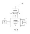
- FIG. 1shows a simplified block diagram of one example embodiment of a lighting system having a 0-10V dimmer control
- FIG. 2shows a block diagram of the main components of an example embodiment of a dimmer control circuit usable with the lighting system illustrated in FIG. 1 ;
- FIG. 3shows a schematic diagram of the main components of the dimmer control circuit of FIG. 2 ;
- FIG. 4shows a graph of the short circuit current generated in response to the level of ambient light detected by an exemplary photodiode, which is usable as a component of the dimmer control circuit of FIG. 3 .
- FIG. 1is an exemplary block diagram showing the primary components of a lighting system 100 having dimming control.
- the lighting system 100includes a dimmable driver 50 connected between an AC power supply 25 and an illumination load or light 90 .
- the dimmable driver 50is preferably either a dimming light emitting diode (LED) driver or a dimming ballast.
- LEDdimming light emitting diode
- the dimming LED driveris conventionally used to drive an illumination load 90 , such as one or more LEDs or an LED array, and the dimming ballast is conventionally used to drive a different type of illumination load 90 , such as a fluorescent light.
- the dimmable driver 50preferably includes low voltage control wires or leads 72 , 74 (conventionally colored violet and gray, respectively) that provide a low direct current (DC) voltage (e.g, 0-10V) to a dimmer control circuit 80 .
- DCdirect current
- the voltage (V OUT ) measured across the violet and gray low DC voltage leads or connectors 82 , 84 of the dimmer control circuit 80is used by the dimmable driver 50 to modify the power (typically the current, but sometimes the output voltage) provided by the dimmable driver 50 to the illumination load 90 ; thus, enabling the brightness level of light emitted from the illumination load 90 to be controllably dimmed between a non-dimmed, maximum (100%) output level and a predetermined, lower, minimum output level—preferably at a level that still emits some light and is not completely turned off.
- the AC voltage and current from the AC power supply 25typically runs first through a bridge or full-wave rectifier (not shown) and a high frequency input filter (not shown), which filters out high frequency noise and/or electromagnetic interference and prevents such noise or interference from being injected back into the bridge rectifier.
- the dimmable driver 50receives the rectified and filtered power from the AC power supply 25 and ensures that the power (either current or voltage) provided to the illumination load 90 does not exceed the current or voltage limits associated with the illumination load 90 .
- the dimmer control circuit 80provides a dimmer or dimming control voltage, conventionally ranging between 0 and 10V, sensed by the dimmable driver 50 , which enables the light emitted from the illumination load 90 to be dimmed in a controllable manner by the driver 50 between full (100%) illumination (i.e., no dimming) and a minimum, lower illumination level (usually some percentage of dimming above 0%; otherwise, the light is turned off completely).
- an on/off switchto eliminate the light output of illumination load 90 completely, rather than to allow the dimmer control circuit 80 to cause the light output from the illumination load 90 to drop below its minimum, lowest illumination level to a zero output.
- the present dimmer control circuit 80illustrates a type of photocell 0-10V dimmer that is powered from the conventional 0-10V output leads 72 , 74 of the dimmable driver 50 (which, as used herein, is either a dimming ballast or a dimming LED driver). Since the dimmer control circuit 80 is powered from the 0-10V leads from the dimmable driver 50 , a separate low voltage supply (and associated wiring) does not need to be provided.
- the dimmer control circuit 80uses a photo sensor component to measure ambient light, which includes a combination of both natural and artificial light sources detectable by the photo sensor component.
- the photo sensoris placed at or near the light or illumination load 90 being controlled by its dimmable driver 50 .
- This ambient light measurementis continuously or periodically compared to a desired or pre-determined light level or set point and, based on such comparison, the dimmer control circuit 80 varies the 0-10V voltage (V OUT ) of the dimmable driver 50 to maintain the output of the illumination load 90 at a desired light level brightness regardless of fluctuations in the natural or ambient light.
- the dimmable driver 50will cause the light output of the load 90 to dim, which in turn saves energy. Conversely, as the amount of natural light in a space decreases, the amount of dimming decreases, eventually to a point at which there is no dimming and the illumination load 90 is at its full-rated brightness level.
- the dimmer control circuit 80preferably includes a selectable “ideal” or “reference” lighting level that the tenant, building manager, technician, automated system controller, or other end user can set as the brightness of light (combined natural and artificial) that the end user would like to maintain regardless of fluctuations in the ambient or natural light detected by the photo sensor.
- the dimmer control circuit 80preferably includes two optional clamp or clamping circuits. These clamp circuits work independently of each other, but can be used advantageously to limit the 0-10V dimming range, at either or both of the low and high ends, provided to the dimmable driver 50 by the dimmer control circuit 80 .
- the clamp circuitsenable the end user, to limit the output voltage (V OUT ) range across the violet and gray leads and, hence, limit the high and/or low dimming levels of the dimmable driver 50 .
- This dimming control for individual lights or groups of lightsis important, typically for business and commercial lighting applications in which there is a need or desire to provide a more uniform “ceiling” appearance or illuminated space, particularly in a larger building or other interior space in which some lights are closer to windows (or other natural light sources, such as skylights, etc.) than others, which impacts the light distribution and setting within the space.
- An examplewould be a lighting installation with multiple photocells or photo sensors installed at different points within the space being illuminated by a plurality of light fixtures.
- fixtures near windowscould be configured to be noticeably dimmer than fixtures further away—particularly during daylight hours when the amount of natural light entering the space is likely to be greater.
- the clamp circuitscan be used to limit the low and high dimming levels to keep the light level between the fixtures closer in light level, while still taking into account the amount of ambient or natural light entering the space at any given point or time of day.
- SKUs for a dimmer controlhaving no clamps
- another SKUcan be offered that only provides low clamping capability
- another SKUcan be offered that only provides high clamping capability
- another SKUcan be offered that has both high and low clamping capability.
- FIG. 2shows a block diagram of the dimmer control circuit 80 of the example simplified system of FIG. 1 in more detail.
- the dimmer control circuit 80is comprised of the violet and gray low DC voltage connectors 82 , 84 , respectively, which defines the output voltage (V OUT ) of the dimmer control circuit 80 and which is designed to be connected to the low DC voltage leads 72 , 74 from the dimmable driver 50 (as shown in FIG. 1 ).
- the dimmer control circuit 80preferably includes a shunt regulator circuit 210 , an ambient light photo sensor and feedback circuit 220 , an error signal circuit 230 , an optional upper clamp circuit 250 , and an optional lower clamp circuit 270 .
- the dimmable driver 50provides a predetermined or known input current to the dimmer control circuit 80 at the violet low DC voltage connector 82 .
- the dimmer control circuit 80then adjusted its relative resistance value, based on the amount of light detected by the photo sensor and feedback circuit 220 , to provide the desired output voltage (V OUT ) across the violet and gray low DC voltage connectors 82 , 84 , which determines the amount of current provided to the illumination load 90 , which, in turn, impacts the amount of dimming, if any, of the light output from the illumination load 90 .
- the optional upper and lower clamp circuits 250 and 270determine whether the default minimum and maximum output voltages (V OUT ) (or, stated another way, the default “range” of output voltages) that can be output by the dimmer control circuit 80 are artificially capped, limited, or clamped to a minimum threshold output voltage greater than the default minimum output voltage and/or to a maximum threshold output voltage less than the default maximum output voltage.
- the input currents provided to the dimmer control circuit 80 at the violet low DC voltage connector 82 by all of the plurality of drivers 50are added together to provide a single predetermined or known input current.
- the number of drivers 50 simultaneously connected to a single dimmer control circuit 80will necessarily be limited by the maximum current input parameters permitted by the specific components, as will described with reference with FIG. 3 , connected to the violet low DC voltage connector 82 .
- the number of drivers 50 connected to a single dimmer control circuit 80will also be limited from a practical standpoint based on the physical placement of one or more ambient light photo sensor and feedback circuits 220 within a space to be lighted and based on how sensitive one wants to be in controlling the dimming levels of lights or groups of lights within a space.
- FIG. 3a detailed schematic 300 of a preferred embodiment of the circuitry design of the dimmer control circuit 80 and each of its macro components, as described above with reference to FIG. 2 , is illustrated and discussed in greater detail.
- the dimming leads 72 , 74 of the dimmable driver 50are labeled “violet” and “gray” and connect, respectively, with the violet and gray low DC voltage connectors 82 , 84 of the dimmer control circuit 80 .
- the shunt regulator U 1is a TLV431 semiconductor device, which is an exemplary low voltage, precision, adjustable shunt regulator, manufactured and available from numerous vendors worldwide, including Semiconductor Components Industries, LLC based in Phoenix, Ariz., USA and having a website at http://www.onsemi.com and Texas Instruments Incorporated based in Dallas, Tex., USA and having a website at http://www.ti.com.
- the shunt regulator U 1along with its complementary components that make up the shunt regulator circuit 210 , serves three primary functions, including: (1) providing a maximum dimming voltage (V OUT ), (2) providing reverse polarity protection for the dimmer control circuit 80 , and (3) providing a sink for the current from the dimming leads 72 , 74 .
- the shunt regulator U 1has three leads or pins: an anode 302 , a cathode 304 , and a reference 306 .
- the low voltage shunt regulator U 1has a built-in diode, which protects the internal circuitry within the shunt regulator U 1 , from the effects of an accidental mis-wiring at the three leads or pins.
- the shunt regulator U 1“outputs” a voltage (V OUT ), as detected at cathode 304 and as detected at the violet low voltage input 82 of the dimmer control circuit 80 .
- the maximum output voltage (V OUT )is controlled by the internal reference voltage (V REF ) of the shunt regulator U 1 and the resistance values of resistors R 1 and R 2 .
- Low voltage shunt regulatorstypically have a reference voltage of approximately 1.25V or 2.5V.
- the shunt regulator U 1has a reference voltage of approximately 1.25V to provide a low voltage output close to, but slightly above, 0V.
- the values of resistors R 1 and R 2can be chosen to set the desired maximum output voltage (V OUT ) that can be provided by the dimming control circuit 80 back to the dimmable driver 50 .
- the values of R 1 and R 2are chosen so that the maximum output voltage (V OUT ) generated by the above Equation1 is approximately 10V.
- V OUTThe minimum output voltage (V OUT ) will be approximately the same as the voltage reference (V REF ), which in this case is 1.25V, for reasons that will be now explained.
- V REFthe voltage reference
- the preferred system described hereinkeeps resistors R 1 and R 2 at their predetermined, fixed resistance values and, instead, modifies the injection current (I INJ ) feeding into the node between resistors R 1 and R 2 , which represents the variable current flowing from the collector 312 of transistor Q 1 into the reference pin 306 of the shunt regulator U 1 .
- the output voltage (V OUT ) from the shunt regulator U 1is at its maximum value, having the same value as determined from Equation1.
- the output voltage (V OUT ) of the shunt regulator U 1decreases down toward its minimum value, as set by the reference voltage (V REF ).
- such ambient light photo sensor and feedback circuit 220includes a light sensitive device or photo sensor 320 , such as the silicon photodiode D 1 available under the semiconductor component name BPW21R, which is manufactured and available from numerous vendors, including Vishay Intertechnology, Inc. based in Malvern, Pa., USA and having a website at http://www.vishay.com.
- a light sensitive device or photo sensor 320such as the silicon photodiode D 1 available under the semiconductor component name BPW21R, which is manufactured and available from numerous vendors, including Vishay Intertechnology, Inc. based in Malvern, Pa., USA and having a website at http://www.vishay.com.
- This photodiode D 1outputs a current (I K ) that is substantially linearly-correlated to the ambient and natural light levels (E A ) detected by the integrated photo sensor of the photodiode D 1 , as shown by the line 405 on graph 400 in FIG. 4 .
- the current (I K ) generated by the photodiode D 1increases as the ambient and natural light detected by the photodiode D 1 increases.
- This current (I K )is used by a current mirror 330 to provide both the short circuit and injection current (I INJ ) required by the dimmer control circuit 80 .
- the current mirror 330includes resistors R 3 and R 4 , transistors Q 2 and Q 3 , and the above-described photodiode D 1 .
- the current (I K ) generated by photodiode D 1causes a current to flow in transistor Q 2 , which, based on the configuration of the current mirror 330 , causes a corresponding mirror current to flow in the collector 332 of transistor Q 3 .
- the current flowing from the collector 332 of transistor Q 3represents a feedback current, which varies based on the amount of light detected by photodiode D 1 , as explained above.
- This feedback currentflows through calibration resistor R 7 , which establishes a feedback voltage that is detected at the input into the negative ( ⁇ ) or inverting terminal 342 of operational amplifier (op amp) U 2 .
- calibration resistor R 7is a variable resistor that will typically be calibrated at the factory, and not by an end user of the dimmer control circuit 80 , to account for any slight variations or errors in the light sensor of the photodiode D 1 .
- a reference voltageis provided to the positive (+) or non-inverting terminal 344 of operational amplifier (op amp) U 2 .
- This reference voltagecorrelates to and establishes the “ideal” or “reference” lighting level desired by the end user and that the end user would like to maintain regardless of fluctuations in the ambient or natural light detected by the photodiode D 1 .
- This reference voltage at terminal 344is controlled by a reference voltage circuit, which includes resistors R 8 , R 9 , R 10 , shunt voltage regulator VR 1 , and capacitor C 6 .
- Resistor R 9is a variable resistor that enables the user to adjust the reference voltage provided to the non-inverting terminal 344 of op amp U 2 .
- the voltage drop across resistor R 9is variable, but falls within a predefined range based on the resistance range of variable resistor R 9 and the selected resistance value of resistor R 10 —wherein resistor R 9 and resistor R 10 together create a conventional voltage divider.
- Resistor R 8is used as a bias resistor to prevent too much current from overloading op amp U 2 and shunt voltage regulator VR 1 .
- Shunt voltage regulator VR 1regulates the voltage range across resistors R 8 and R 9 .
- the reference voltage for shunt voltage regulator VR 1needs to be at (or lower than) the reference voltage of shunt regular U 1 .
- the reference voltage of VR 1is set to 1.25V (or less), since the reference voltage of shunt regulator U 1 is set at 1.25V.
- op amp U 2detects and compares the two input voltages: (i) the feedback voltage provided to the negative ( ⁇ ) or inverting terminal 342 (which fluctuates based on the amount of light detected by the photo sensor) and the reference voltage provided to the positive (+) or non-inverting terminal 344 (which represents the user-desired lighting level).
- the reference voltage provided to the positive (+) or non-inverting terminal 344generally remains constant.
- the feedback voltage provided to the negative ( ⁇ ) or inverting terminal 342will vary as the ambient light varies. Feedback components, including resistor R 6 and capacitor C 4 , are adjusted and used for stability purposes.
- the photodiode D 1detects very little to no ambient light, the feedback current flowing from the collector 332 of transistor Q 3 is zero or otherwise very small, which causes the feedback voltage at the inverting terminal 342 to be lower than the reference voltage at the non-inverting terminal 344 , which causes the output 346 of op amp U 2 to go high, which drives the base 314 of transistor Q 1 , which, in turn, causes the injection current (I INJ ) from the collector 312 of transistor Q 1 flowing into the node between resistors R 1 and R 2 to reduce toward zero, which causes the output voltage (V OUT ) from the shunt regulator U 1 is go toward its maximum value, as determined from Equation1 and Equation2, which increases the light output of the illumination load 90 .
- the amp U 2 going lowdrives the base 314 of transistor Q 1 and causes the injection current (I INJ ) from the collector 312 of transistor Q 1 flowing into the node between resistors R 1 and R 2 to increase. This increase causes the output voltage (V OUT ) from the shunt regulator U 1 is go toward its minimum value, as determined from Equation1 and Equation2.
- the dimmable driver 50to begins dimming the light output from the illumination load 90 , which makes sense based on the fact that ambient light is being detected and the light output from the illumination load 90 can be decreased to save energy and to maintain the light levels in the illuminated space at a more uniform level even as the amount of ambient light increases.
- the upper and lower clamping circuits 250 and 270can be used to modify the level of injection current (I INJ ) flowing into the shunt regulator U 1 . This artificially caps the maximum output voltage (V OUT ) provided by the dimmer control circuit 80 to the dimmable driver 50 to below 10V. Consequently, the illumination load 90 begins to Dan even if there is no or very little detectable ambient light.
- Modification of the level of injection current (I INJ ) flowing into the shunt regulator U 1also artificially raises the minimum output voltage (V OUT ) provided by the dimmer control circuit 80 to the dimmable driver 50 to above its minimum reference voltage of 1.25V, which reduces the dimming of the illumination load 90 even when there is a higher level of detectable ambient light.
- the feedback current flowing from the collector 332 of transistor Q 3 and through calibration resistor R 7is used to calculate a feedback voltage corresponding to the amount of ambient light being detected, which can then be compared by op amp U 2 with a reference voltage that is established, based on the desired light level selected by the end user, by varying the resistance of resistor R 9 .
- a clamping currentcan be used to modify the feedback current, having either a subtractive or additive effect on the feedback current at node 338 , if the dimmer control circuit 80 includes either (or both) of the optional upper and lower clamp circuits 250 and 270 , as will be described in greater detail hereinafter.
- shunt voltage regulator VR 1provides a reference voltage and is connected to the positive (+) or non-inverting terminals of op amps U 3 A and U 3 B.
- the reference voltage for shunt voltage regulator VR 1needs to be at (or lower than) the reference voltage of shunt regulator U 1 .
- the reference voltage of VR 1is set to 1.25V (or less), since the reference voltage of shunt regulator U 1 is set at 1.25V.
- the low clamp circuit 270includes op amp U 3 B, resistors R 21 , R 22 , R 23 , R 29 , and R 30 , capacitor C 21 , and transistor Q 21 .
- Resistor R 23is adjustable by the end user to establish a low voltage set point.
- the low voltage set pointcan range from a low of 1.25V (i.e., the reference voltage of shunt regulator U 1 ) to an arbitrary high of X H volts, for reasons that will become apparent.
- V OUTthe voltage output of op amp U 3 B will increase and the base current 364 of transistor Q 21 will increase. This will cause the collector current 362 of Q 21 to increase and “steal” or siphon off some of the feedback current flowing from the collector 332 of transistor Q 3 .
- the high clamp circuit 250includes op amp U 3 A, resistors R 24 , R 25 , R 26 , R 27 , and R 28 , capacitor C 22 , and transistor Q 20 .
- Resistor R 26is adjustable by the end user to establish a high voltage set point.
- the high voltage set pointcan range from a high of 10V (i.e., the maximum output voltage of shunt regulator U 1 ) to an arbitrary low of X L volts, for reasons that will become apparent.
- V OUTthe voltage output of op amp U 3 A will decrease and the base current 374 of transistor Q 20 will increase.
- both transistors Q 20 and Q 21connect into the feedback current flowing from the collector 332 of transistor Q 3 at node 338 , it will be apparent to one of skill in the art that it is not desirable to have both transistors Q 20 and Q 21 feeding or drawing current at node 338 at the same time. To avoid this conflict, if the dimmer control circuit 80 makes use of both the high and low clamp circuits 250 , 270 , it is necessary that the arbitrary high voltage X H set by the low clamp circuit 270 be lower than the arbitrary low voltage X L set by the high clamp circuit 250 .
- Embodiments of the present inventioninclude a circuit for controlling a level of brightness of a light electrically coupled to a dimming circuit including control leads configured to provide a dimming control voltage to the dimmable driver, the dimming control voltage having a permissible voltage range.
- the circuitincludes a photo sensor for detecting an ambient light level in the vicinity of the light and a clamp controller for selectively reducing the dimming control voltage to a clamped voltage range less than the permissible voltage range. Also included is a feedback controller for adjusting the dimming control voltage in response to a detected ambient light level, the dimming control voltage being within the clamped voltage range.
- various aspects of the present inventioncan be implemented by software, firmware, hardware (or hardware represented by software such, as for example, Verilog or hardware description language instructions), or a combination thereof.
- softwarefirmware
- hardwareor hardware represented by software such, as for example, Verilog or hardware description language instructions
Landscapes
- Circuit Arrangement For Electric Light Sources In General (AREA)
Abstract
Description
VOUT=VREF*(1+R1/R2)
VOUT=VREF*(1+R1/R2)−*R1)
Claims (9)
Vout(max)=Vref*(1+R1/R2).
Vout(min)=Vref*(1+R1/R2)−(Iinj*R1).
Priority Applications (1)
| Application Number | Priority Date | Filing Date | Title |
|---|---|---|---|
| US15/127,048US9894742B2 (en) | 2014-03-25 | 2015-02-03 | Dimmer with photo sensor and high/low clamping |
Applications Claiming Priority (3)
| Application Number | Priority Date | Filing Date | Title |
|---|---|---|---|
| US14/224,710US20150282275A1 (en) | 2014-03-25 | 2014-03-25 | Dimmer with photo sensor and high/low clamping |
| US15/127,048US9894742B2 (en) | 2014-03-25 | 2015-02-03 | Dimmer with photo sensor and high/low clamping |
| PCT/US2015/014186WO2015147988A1 (en) | 2014-03-25 | 2015-02-03 | Dimmer with photo sensor and high/low clamping |
Related Parent Applications (1)
| Application Number | Title | Priority Date | Filing Date |
|---|---|---|---|
| US14/224,710ContinuationUS20150282275A1 (en) | 2014-03-25 | 2014-03-25 | Dimmer with photo sensor and high/low clamping |
Publications (2)
| Publication Number | Publication Date |
|---|---|
| US20170332465A1 US20170332465A1 (en) | 2017-11-16 |
| US9894742B2true US9894742B2 (en) | 2018-02-13 |
Family
ID=52574423
Family Applications (2)
| Application Number | Title | Priority Date | Filing Date |
|---|---|---|---|
| US14/224,710AbandonedUS20150282275A1 (en) | 2014-03-25 | 2014-03-25 | Dimmer with photo sensor and high/low clamping |
| US15/127,048ActiveUS9894742B2 (en) | 2014-03-25 | 2015-02-03 | Dimmer with photo sensor and high/low clamping |
Family Applications Before (1)
| Application Number | Title | Priority Date | Filing Date |
|---|---|---|---|
| US14/224,710AbandonedUS20150282275A1 (en) | 2014-03-25 | 2014-03-25 | Dimmer with photo sensor and high/low clamping |
Country Status (2)
| Country | Link |
|---|---|
| US (2) | US20150282275A1 (en) |
| WO (1) | WO2015147988A1 (en) |
Families Citing this family (4)
| Publication number | Priority date | Publication date | Assignee | Title |
|---|---|---|---|---|
| US9326362B2 (en)* | 2011-08-31 | 2016-04-26 | Chia-Teh Chen | Two-level LED security light with motion sensor |
| US20150282275A1 (en)* | 2014-03-25 | 2015-10-01 | General Electric Company | Dimmer with photo sensor and high/low clamping |
| CN111542152A (en)* | 2020-05-22 | 2020-08-14 | 中国科学院半导体研究所 | Ultraviolet light source system with automatic feedback correction function of light intensity and its application |
| IT202300000234A1 (en)* | 2023-01-11 | 2024-07-11 | Cobofra S R L | PROCEDURE FOR REGULATING A LIGHT SOURCE AND GROUP FOR REGULATING SAID LIGHT SOURCE |
Citations (46)
| Publication number | Priority date | Publication date | Assignee | Title |
|---|---|---|---|---|
| US3916183A (en) | 1974-05-17 | 1975-10-28 | Area Lighting Research Inc | Ambient-light-regulated night cut-off power control unit |
| US4023034A (en) | 1975-09-08 | 1977-05-10 | Schacht Ezra L | Light admitting means for photocell-controlled lighting fixture |
| US4155122A (en) | 1975-12-02 | 1979-05-22 | Revue Thommen Ag | Light shield for welder's mask |
| US4180931A (en) | 1977-10-11 | 1980-01-01 | Osch John V | Display device |
| US4464606A (en) | 1981-03-25 | 1984-08-07 | Armstrong World Industries, Inc. | Pulse width modulated dimming arrangement for fluorescent lamps |
| US4546419A (en) | 1984-11-05 | 1985-10-08 | Johnson Kelli J | Wall receptacle recessed box contained light intensity on/off controlled night light system |
| US4660937A (en) | 1984-06-25 | 1987-04-28 | Crystaloid Electronics Company | Dichroic dye-nematic liquid crystal mirror |
| US4697122A (en) | 1986-08-01 | 1987-09-29 | Armstrong World Industries, Inc. | Slow acting photo lamp control |
| US4727290A (en) | 1987-05-29 | 1988-02-23 | General Motors Corporation | Automatic vehicle headlamp dimming control |
| US4864278A (en) | 1987-02-06 | 1989-09-05 | Robert Hooke Memorial Laboratories, Inc. | Optical intrusion detection system and method |
| US5212468A (en) | 1992-05-26 | 1993-05-18 | Robert Adell | Vehicle signalling system |
| US5347261A (en) | 1993-01-21 | 1994-09-13 | Robert Adell | "Hands free" vehicle bright light signal system |
| US5402040A (en) | 1993-11-23 | 1995-03-28 | The Watt Stopper | Dimmable ballast control circuit |
| US5404080A (en) | 1989-09-21 | 1995-04-04 | Etta Industries, Inc. | Lamp brightness control circuit with ambient light compensation |
| US5701058A (en) | 1996-01-04 | 1997-12-23 | Honeywell Inc. | Method of semiautomatic ambient light sensor calibration in an automatic control system |
| US5742131A (en)* | 1993-11-23 | 1998-04-21 | The Watt Stopper | Dimmable ballast control circuit |
| US5789869A (en) | 1996-02-13 | 1998-08-04 | Holmes Products Corporation | Light sensitive dimmer switch circuit |
| US6114813A (en) | 1996-02-13 | 2000-09-05 | Holmes Products Corp. | Light sensitive dimmer switch circuit |
| US20030039125A1 (en) | 2001-08-01 | 2003-02-27 | Campbell Douglas C. | Auto headlamp module with integrated photocell |
| US20030090210A1 (en) | 2001-11-13 | 2003-05-15 | Rensselaer Polytechnic Institute | Photosensor and control system for dimming lighting fixtures to reduce power consumption |
| US7145295B1 (en) | 2005-07-24 | 2006-12-05 | Aimtron Technology Corp. | Dimming control circuit for light-emitting diodes |
| US7521872B2 (en) | 2003-09-09 | 2009-04-21 | Koninklijke Philips Electronics, N.V. | Integrated lamp with feedback and wireless control |
| USD602388S1 (en) | 2009-04-30 | 2009-10-20 | Lutron Electronics Co., Inc. | Wireless sensor |
| US20100176733A1 (en) | 2009-01-14 | 2010-07-15 | Purespectrum, Inc. | Automated Dimming Methods and Systems For Lighting |
| US20100289412A1 (en) | 2009-05-04 | 2010-11-18 | Stuart Middleton-White | Integrated lighting system and method |
| US7859595B2 (en) | 2004-01-05 | 2010-12-28 | Koninklijke Philips Electronics N.V. | Flicker-free adaptive thresholding for ambient light derived from video content mapped through unrendered color space |
| USD631770S1 (en) | 2009-09-04 | 2011-02-01 | Lutron Electronics Co., Inc. | Wireless sensor |
| US7894000B2 (en) | 2004-06-30 | 2011-02-22 | Koninklijke Philips Electronics N.V. | Dominant color extraction using perceptual rules to produce ambient light derived from video content |
| US20110062888A1 (en) | 2004-12-01 | 2011-03-17 | Bondy Montgomery C | Energy saving extra-low voltage dimmer and security lighting system wherein fixture control is local to the illuminated area |
| US7932953B2 (en) | 2004-01-05 | 2011-04-26 | Koninklijke Philips Electronics N.V. | Ambient light derived from video content by mapping transformations through unrendered color space |
| US8000314B2 (en) | 1996-12-06 | 2011-08-16 | Ipco, Llc | Wireless network system and method for providing same |
| US8013732B2 (en) | 1998-06-22 | 2011-09-06 | Sipco, Llc | Systems and methods for monitoring and controlling remote devices |
| US8031650B2 (en) | 2004-03-03 | 2011-10-04 | Sipco, Llc | System and method for monitoring remote devices with a dual-mode wireless communication protocol |
| US8049301B2 (en) | 2006-09-21 | 2011-11-01 | City University Of Hong Kong | Semiconductor transformers |
| US8064412B2 (en) | 1998-06-22 | 2011-11-22 | Sipco, Llc | Systems and methods for monitoring conditions |
| EP2403120A2 (en) | 2010-07-01 | 2012-01-04 | Alistair Macfarlane | Zero voltage switching PFC converter and LED lighting |
| US8171136B2 (en) | 2001-10-30 | 2012-05-01 | Sipco, Llc | System and method for transmitting pollution information over an integrated wireless network |
| US8193737B2 (en) | 2008-06-10 | 2012-06-05 | Microsemi Corp. -Analog Mixed Signal Group Ltd. | Color manager for backlight systems operative at multiple current levels |
| US20120139426A1 (en) | 2010-12-03 | 2012-06-07 | General Electric Company | Dimmable outdoor luminaires |
| US20120256553A1 (en)* | 2011-04-08 | 2012-10-11 | Hangzhou Silergy Semiconductor Technology LTD | Scr dimming circuit and method |
| US8378589B2 (en)* | 2008-12-12 | 2013-02-19 | O2Micro, Inc. | Driving circuit with dimming controller for driving light sources |
| WO2013186656A1 (en) | 2012-06-14 | 2013-12-19 | Koninklijke Philips N.V. | Adaptative safety led lighting system powered by battery plant. |
| US20140002772A1 (en) | 2012-07-02 | 2014-01-02 | Xiang Yang | Led backlight driving circuit, backlight module, and lcd device |
| US20140167652A1 (en)* | 2012-12-13 | 2014-06-19 | Cirrus Logic, Inc. | Systems and methods for controlling a power controller |
| US20150086561A1 (en)* | 2013-09-26 | 2015-03-26 | Trellis Bioscience, Llc | Binding moieties for biofilm remediation |
| US20150282275A1 (en)* | 2014-03-25 | 2015-10-01 | General Electric Company | Dimmer with photo sensor and high/low clamping |
Family Cites Families (5)
| Publication number | Priority date | Publication date | Assignee | Title |
|---|---|---|---|---|
| US8058750B2 (en)* | 2009-05-14 | 2011-11-15 | Redwood Systems, Inc. | Discharge cycle communication |
| US8274239B2 (en)* | 2010-06-09 | 2012-09-25 | General Electric Company | Open circuit voltage clamp for electronic HID ballast |
| US8864514B2 (en)* | 2010-10-07 | 2014-10-21 | General Electric Company | Controller device |
| US20120086561A1 (en)* | 2010-10-07 | 2012-04-12 | General Electric Company | Outdoor lighting system |
| US8853958B2 (en)* | 2011-11-22 | 2014-10-07 | Cree, Inc. | Driving circuits for solid-state lighting apparatus with high voltage LED components and related methods |
- 2014
- 2014-03-25USUS14/224,710patent/US20150282275A1/ennot_activeAbandoned
- 2015
- 2015-02-03WOPCT/US2015/014186patent/WO2015147988A1/enactiveApplication Filing
- 2015-02-03USUS15/127,048patent/US9894742B2/enactiveActive
Patent Citations (51)
| Publication number | Priority date | Publication date | Assignee | Title |
|---|---|---|---|---|
| US3916183A (en) | 1974-05-17 | 1975-10-28 | Area Lighting Research Inc | Ambient-light-regulated night cut-off power control unit |
| US4023034A (en) | 1975-09-08 | 1977-05-10 | Schacht Ezra L | Light admitting means for photocell-controlled lighting fixture |
| US4155122A (en) | 1975-12-02 | 1979-05-22 | Revue Thommen Ag | Light shield for welder's mask |
| US4180931A (en) | 1977-10-11 | 1980-01-01 | Osch John V | Display device |
| US4464606A (en) | 1981-03-25 | 1984-08-07 | Armstrong World Industries, Inc. | Pulse width modulated dimming arrangement for fluorescent lamps |
| US4660937A (en) | 1984-06-25 | 1987-04-28 | Crystaloid Electronics Company | Dichroic dye-nematic liquid crystal mirror |
| US4546419A (en) | 1984-11-05 | 1985-10-08 | Johnson Kelli J | Wall receptacle recessed box contained light intensity on/off controlled night light system |
| US4697122A (en) | 1986-08-01 | 1987-09-29 | Armstrong World Industries, Inc. | Slow acting photo lamp control |
| US4864278A (en) | 1987-02-06 | 1989-09-05 | Robert Hooke Memorial Laboratories, Inc. | Optical intrusion detection system and method |
| US4727290A (en) | 1987-05-29 | 1988-02-23 | General Motors Corporation | Automatic vehicle headlamp dimming control |
| US5581158A (en) | 1989-09-21 | 1996-12-03 | Etta Industries, Inc. | Lamp brightness control circuit with ambient light compensation |
| US5404080A (en) | 1989-09-21 | 1995-04-04 | Etta Industries, Inc. | Lamp brightness control circuit with ambient light compensation |
| US5212468A (en) | 1992-05-26 | 1993-05-18 | Robert Adell | Vehicle signalling system |
| US5347261A (en) | 1993-01-21 | 1994-09-13 | Robert Adell | "Hands free" vehicle bright light signal system |
| US5742131A (en)* | 1993-11-23 | 1998-04-21 | The Watt Stopper | Dimmable ballast control circuit |
| US5402040A (en) | 1993-11-23 | 1995-03-28 | The Watt Stopper | Dimmable ballast control circuit |
| US5701058A (en) | 1996-01-04 | 1997-12-23 | Honeywell Inc. | Method of semiautomatic ambient light sensor calibration in an automatic control system |
| US5789869A (en) | 1996-02-13 | 1998-08-04 | Holmes Products Corporation | Light sensitive dimmer switch circuit |
| US6114813A (en) | 1996-02-13 | 2000-09-05 | Holmes Products Corp. | Light sensitive dimmer switch circuit |
| US8000314B2 (en) | 1996-12-06 | 2011-08-16 | Ipco, Llc | Wireless network system and method for providing same |
| US8064412B2 (en) | 1998-06-22 | 2011-11-22 | Sipco, Llc | Systems and methods for monitoring conditions |
| US8212667B2 (en) | 1998-06-22 | 2012-07-03 | Sipco, Llc | Automotive diagnostic data monitoring systems and methods |
| US8193930B2 (en) | 1998-06-22 | 2012-06-05 | Sipco, Llc | Systems and methods for remote irrigation control |
| US8013732B2 (en) | 1998-06-22 | 2011-09-06 | Sipco, Llc | Systems and methods for monitoring and controlling remote devices |
| US6929388B2 (en) | 2001-08-01 | 2005-08-16 | Lear Corporation | Auto headlamp module with integrated photocell |
| US20030039125A1 (en) | 2001-08-01 | 2003-02-27 | Campbell Douglas C. | Auto headlamp module with integrated photocell |
| US8171136B2 (en) | 2001-10-30 | 2012-05-01 | Sipco, Llc | System and method for transmitting pollution information over an integrated wireless network |
| US6583573B2 (en) | 2001-11-13 | 2003-06-24 | Rensselaer Polytechnic Institute | Photosensor and control system for dimming lighting fixtures to reduce power consumption |
| US20030090210A1 (en) | 2001-11-13 | 2003-05-15 | Rensselaer Polytechnic Institute | Photosensor and control system for dimming lighting fixtures to reduce power consumption |
| US7521872B2 (en) | 2003-09-09 | 2009-04-21 | Koninklijke Philips Electronics, N.V. | Integrated lamp with feedback and wireless control |
| US7859595B2 (en) | 2004-01-05 | 2010-12-28 | Koninklijke Philips Electronics N.V. | Flicker-free adaptive thresholding for ambient light derived from video content mapped through unrendered color space |
| US7932953B2 (en) | 2004-01-05 | 2011-04-26 | Koninklijke Philips Electronics N.V. | Ambient light derived from video content by mapping transformations through unrendered color space |
| US8031650B2 (en) | 2004-03-03 | 2011-10-04 | Sipco, Llc | System and method for monitoring remote devices with a dual-mode wireless communication protocol |
| US7894000B2 (en) | 2004-06-30 | 2011-02-22 | Koninklijke Philips Electronics N.V. | Dominant color extraction using perceptual rules to produce ambient light derived from video content |
| US20110062888A1 (en) | 2004-12-01 | 2011-03-17 | Bondy Montgomery C | Energy saving extra-low voltage dimmer and security lighting system wherein fixture control is local to the illuminated area |
| US7145295B1 (en) | 2005-07-24 | 2006-12-05 | Aimtron Technology Corp. | Dimming control circuit for light-emitting diodes |
| US8049301B2 (en) | 2006-09-21 | 2011-11-01 | City University Of Hong Kong | Semiconductor transformers |
| US8193737B2 (en) | 2008-06-10 | 2012-06-05 | Microsemi Corp. -Analog Mixed Signal Group Ltd. | Color manager for backlight systems operative at multiple current levels |
| US8378589B2 (en)* | 2008-12-12 | 2013-02-19 | O2Micro, Inc. | Driving circuit with dimming controller for driving light sources |
| US20100176733A1 (en) | 2009-01-14 | 2010-07-15 | Purespectrum, Inc. | Automated Dimming Methods and Systems For Lighting |
| USD602388S1 (en) | 2009-04-30 | 2009-10-20 | Lutron Electronics Co., Inc. | Wireless sensor |
| US20100289412A1 (en) | 2009-05-04 | 2010-11-18 | Stuart Middleton-White | Integrated lighting system and method |
| USD631770S1 (en) | 2009-09-04 | 2011-02-01 | Lutron Electronics Co., Inc. | Wireless sensor |
| EP2403120A2 (en) | 2010-07-01 | 2012-01-04 | Alistair Macfarlane | Zero voltage switching PFC converter and LED lighting |
| US20120139426A1 (en) | 2010-12-03 | 2012-06-07 | General Electric Company | Dimmable outdoor luminaires |
| US20120256553A1 (en)* | 2011-04-08 | 2012-10-11 | Hangzhou Silergy Semiconductor Technology LTD | Scr dimming circuit and method |
| WO2013186656A1 (en) | 2012-06-14 | 2013-12-19 | Koninklijke Philips N.V. | Adaptative safety led lighting system powered by battery plant. |
| US20140002772A1 (en) | 2012-07-02 | 2014-01-02 | Xiang Yang | Led backlight driving circuit, backlight module, and lcd device |
| US20140167652A1 (en)* | 2012-12-13 | 2014-06-19 | Cirrus Logic, Inc. | Systems and methods for controlling a power controller |
| US20150086561A1 (en)* | 2013-09-26 | 2015-03-26 | Trellis Bioscience, Llc | Binding moieties for biofilm remediation |
| US20150282275A1 (en)* | 2014-03-25 | 2015-10-01 | General Electric Company | Dimmer with photo sensor and high/low clamping |
Non-Patent Citations (1)
| Title |
|---|
| International Search Report and Written Opinion issued in connection with corresponding PCT Application No. PCT/US2015/014186 dated Jun. 29, 2015. |
Also Published As
| Publication number | Publication date |
|---|---|
| US20170332465A1 (en) | 2017-11-16 |
| WO2015147988A1 (en) | 2015-10-01 |
| US20150282275A1 (en) | 2015-10-01 |
Similar Documents
| Publication | Publication Date | Title |
|---|---|---|
| US10396659B2 (en) | Load driving device, and lighting apparatus and liquid crystal display device using the same | |
| JP6466929B2 (en) | Method and apparatus for controlling lighting based on a combination of inputs | |
| US7608807B2 (en) | Closed loop daylight harvesting light control system having auto-calibration | |
| EP1499165B1 (en) | Load driving device and portable apparatus utilizing such driving device | |
| US6555966B2 (en) | Closed loop lighting control system | |
| US9185784B2 (en) | Line synchronized electrical device and controlling method thereof | |
| US9661706B2 (en) | Low intensity dimming circuit for an LED lamp and method of controlling an LED | |
| US8450944B2 (en) | Intelligent light for controlling lighting level | |
| US6353291B1 (en) | Electroluminescent lamp controller | |
| US9894742B2 (en) | Dimmer with photo sensor and high/low clamping | |
| US7952297B2 (en) | Driving device for providing light dimming control of light-emitting element | |
| US8110994B2 (en) | Multi-zone closed loop daylight harvesting having at least one light sensor | |
| US10314122B1 (en) | Constant current linear driver with high power factor | |
| US20170034880A1 (en) | Programmable led driver | |
| CN103327682A (en) | Adaptive filter for LED dimmer | |
| US20170048944A1 (en) | Lighting apparatus | |
| KR20170011078A (en) | Apparatus for controlling Lamp light | |
| US5742131A (en) | Dimmable ballast control circuit | |
| KR20040084729A (en) | Illumination apparatus, and an illumination head and power source device used therefore | |
| US8847499B2 (en) | Photocell controlled LED driver circuit | |
| CA2726485A1 (en) | Dimming fluorescent ballast system with shutdown control circuit | |
| US11653428B2 (en) | Intelligent power-saving LED light | |
| WO2020117382A1 (en) | Automatic trimming for a dimmer switch | |
| KR101371153B1 (en) | (dimmer operation maintenance circuit for led illumination system | |
| TWI420968B (en) | Led driving circuit and backlight module |
Legal Events
| Date | Code | Title | Description |
|---|---|---|---|
| STCF | Information on status: patent grant | Free format text:PATENTED CASE | |
| AS | Assignment | Owner name:CURRENT LIGHTING SOLUTIONS, LLC F/K/A GE LIGHTING Free format text:ASSIGNMENT OF ASSIGNORS INTEREST;ASSIGNOR:GENERAL ELECTRIC COMPANY;REEL/FRAME:048791/0001 Effective date:20190401 Owner name:CURRENT LIGHTING SOLUTIONS, LLC F/K/A GE LIGHTING SOLUTIONS, LLC, OHIO Free format text:ASSIGNMENT OF ASSIGNORS INTEREST;ASSIGNOR:GENERAL ELECTRIC COMPANY;REEL/FRAME:048791/0001 Effective date:20190401 | |
| AS | Assignment | Owner name:ALLY BANK, AS COLLATERAL AGENT, NEW YORK Free format text:SECURITY AGREEMENT;ASSIGNOR:CURRENT LIGHTING SOLUTIONS, LLC;REEL/FRAME:049672/0294 Effective date:20190401 Owner name:ALLY BANK, AS COLLATERAL AGENT, NEW YORK Free format text:SECURITY AGREEMENT;ASSIGNOR:CURRENT LIGHTING SOLUTIONS, LLC;REEL/FRAME:051047/0210 Effective date:20190401 | |
| AS | Assignment | Owner name:ALLY BANK, AS COLLATERAL AGENT, NEW YORK Free format text:SECURITY AGREEMENT;ASSIGNOR:CURRENT LIGHTING SOLUTIONS, LLC;REEL/FRAME:052763/0643 Effective date:20190401 | |
| MAFP | Maintenance fee payment | Free format text:PAYMENT OF MAINTENANCE FEE, 4TH YEAR, LARGE ENTITY (ORIGINAL EVENT CODE: M1551); ENTITY STATUS OF PATENT OWNER: LARGE ENTITY Year of fee payment:4 | |
| AS | Assignment | Owner name:ALLY BANK, AS COLLATERAL AGENT, NEW YORK Free format text:SECURITY AGREEMENT;ASSIGNORS:HUBBELL LIGHTING, INC.;LITECONTROL CORPORATION;CURRENT LIGHTING SOLUTIONS, LLC;AND OTHERS;REEL/FRAME:058982/0844 Effective date:20220201 | |
| AS | Assignment | Owner name:ATLANTIC PARK STRATEGIC CAPITAL FUND, L.P., AS COLLATERAL AGENT, NEW YORK Free format text:SECURITY INTEREST;ASSIGNORS:HUBBELL LIGHTING, INC.;LITECONTROL CORPORATION;CURRENT LIGHTING SOLUTIONS, LLC;AND OTHERS;REEL/FRAME:059034/0469 Effective date:20220201 | |
| AS | Assignment | Owner name:FORUM, INC., PENNSYLVANIA Free format text:RELEASE BY SECURED PARTY;ASSIGNOR:ALLY BANK;REEL/FRAME:059432/0592 Effective date:20220201 Owner name:CURRENT LIGHTING SOLUTIONS, LLC, OHIO Free format text:RELEASE BY SECURED PARTY;ASSIGNOR:ALLY BANK;REEL/FRAME:059432/0592 Effective date:20220201 Owner name:FORUM, INC., PENNSYLVANIA Free format text:RELEASE BY SECURED PARTY;ASSIGNOR:ALLY BANK;REEL/FRAME:059392/0079 Effective date:20220201 Owner name:CURRENT LIGHTING SOLUTIONS, LLC, OHIO Free format text:RELEASE BY SECURED PARTY;ASSIGNOR:ALLY BANK;REEL/FRAME:059392/0079 Effective date:20220201 | |
| AS | Assignment | Owner name:ALLY BANK, AS COLLATERAL AGENT, NEW YORK Free format text:CORRECTIVE ASSIGNMENT TO CORRECT THE PATENT NUMBER 10841994 TO PATENT NUMBER 11570872 PREVIOUSLY RECORDED ON REEL 058982 FRAME 0844. ASSIGNOR(S) HEREBY CONFIRMS THE SECURITY AGREEMENT;ASSIGNORS:HUBBELL LIGHTING, INC.;LITECONTROL CORPORATION;CURRENT LIGHTING SOLUTIONS, LLC;AND OTHERS;REEL/FRAME:066355/0455 Effective date:20220201 | |
| AS | Assignment | Owner name:ATLANTIC PARK STRATEGIC CAPITAL FUND, L.P., AS COLLATERAL AGENT, NEW YORK Free format text:CORRECTIVE ASSIGNMENT TO CORRECT THE PATENT NUMBER PREVIOUSLY RECORDED AT REEL: 059034 FRAME: 0469. ASSIGNOR(S) HEREBY CONFIRMS THE SECURITY INTEREST;ASSIGNORS:HUBBELL LIGHTING, INC.;LITECONTROL CORPORATION;CURRENT LIGHTING SOLUTIONS, LLC;AND OTHERS;REEL/FRAME:066372/0590 Effective date:20220201 | |
| MAFP | Maintenance fee payment | Free format text:PAYMENT OF MAINTENANCE FEE, 8TH YEAR, LARGE ENTITY (ORIGINAL EVENT CODE: M1552); ENTITY STATUS OF PATENT OWNER: LARGE ENTITY Year of fee payment:8 |