US9893564B2 - R.F. energy collection circuit for wireless devices - Google Patents
R.F. energy collection circuit for wireless devicesDownload PDFInfo
- Publication number
- US9893564B2 US9893564B2US14/584,888US201414584888AUS9893564B2US 9893564 B2US9893564 B2US 9893564B2US 201414584888 AUS201414584888 AUS 201414584888AUS 9893564 B2US9893564 B2US 9893564B2
- Authority
- US
- United States
- Prior art keywords
- loss
- dipole antenna
- circuit
- low
- energy
- Prior art date
- Legal status (The legal status is an assumption and is not a legal conclusion. Google has not performed a legal analysis and makes no representation as to the accuracy of the status listed.)
- Active, expires
Links
Images


Classifications
- H—ELECTRICITY
- H02—GENERATION; CONVERSION OR DISTRIBUTION OF ELECTRIC POWER
- H02J—CIRCUIT ARRANGEMENTS OR SYSTEMS FOR SUPPLYING OR DISTRIBUTING ELECTRIC POWER; SYSTEMS FOR STORING ELECTRIC ENERGY
- H02J50/00—Circuit arrangements or systems for wireless supply or distribution of electric power
- H02J50/001—Energy harvesting or scavenging
- H02J17/00—
- G—PHYSICS
- G06—COMPUTING OR CALCULATING; COUNTING
- G06K—GRAPHICAL DATA READING; PRESENTATION OF DATA; RECORD CARRIERS; HANDLING RECORD CARRIERS
- G06K19/00—Record carriers for use with machines and with at least a part designed to carry digital markings
- G06K19/06—Record carriers for use with machines and with at least a part designed to carry digital markings characterised by the kind of the digital marking, e.g. shape, nature, code
- G06K19/067—Record carriers with conductive marks, printed circuits or semiconductor circuit elements, e.g. credit or identity cards also with resonating or responding marks without active components
- G06K19/07—Record carriers with conductive marks, printed circuits or semiconductor circuit elements, e.g. credit or identity cards also with resonating or responding marks without active components with integrated circuit chips
- G06K19/077—Constructional details, e.g. mounting of circuits in the carrier
- G06K19/07749—Constructional details, e.g. mounting of circuits in the carrier the record carrier being capable of non-contact communication, e.g. constructional details of the antenna of a non-contact smart card
- G06K19/07773—Antenna details
- G06K19/07786—Antenna details the antenna being of the HF type, such as a dipole
- H—ELECTRICITY
- H01—ELECTRIC ELEMENTS
- H01Q—ANTENNAS, i.e. RADIO AERIALS
- H01Q1/00—Details of, or arrangements associated with, antennas
- H01Q1/12—Supports; Mounting means
- H01Q1/22—Supports; Mounting means by structural association with other equipment or articles
- H01Q1/2208—Supports; Mounting means by structural association with other equipment or articles associated with components used in interrogation type services, i.e. in systems for information exchange between an interrogator/reader and a tag/transponder, e.g. in Radio Frequency Identification [RFID] systems
- H01Q1/2225—Supports; Mounting means by structural association with other equipment or articles associated with components used in interrogation type services, i.e. in systems for information exchange between an interrogator/reader and a tag/transponder, e.g. in Radio Frequency Identification [RFID] systems used in active tags, i.e. provided with its own power source or in passive tags, i.e. deriving power from RF signal
- H—ELECTRICITY
- H01—ELECTRIC ELEMENTS
- H01Q—ANTENNAS, i.e. RADIO AERIALS
- H01Q9/00—Electrically-short antennas having dimensions not more than twice the operating wavelength and consisting of conductive active radiating elements
- H01Q9/04—Resonant antennas
- H01Q9/16—Resonant antennas with feed intermediate between the extremities of the antenna, e.g. centre-fed dipole
- H01Q9/26—Resonant antennas with feed intermediate between the extremities of the antenna, e.g. centre-fed dipole with folded element or elements, the folded parts being spaced apart a small fraction of operating wavelength
- H—ELECTRICITY
- H02—GENERATION; CONVERSION OR DISTRIBUTION OF ELECTRIC POWER
- H02J—CIRCUIT ARRANGEMENTS OR SYSTEMS FOR SUPPLYING OR DISTRIBUTING ELECTRIC POWER; SYSTEMS FOR STORING ELECTRIC ENERGY
- H02J50/00—Circuit arrangements or systems for wireless supply or distribution of electric power
- H02J50/20—Circuit arrangements or systems for wireless supply or distribution of electric power using microwaves or radio frequency waves
- H02J50/27—Circuit arrangements or systems for wireless supply or distribution of electric power using microwaves or radio frequency waves characterised by the type of receiving antennas, e.g. rectennas
- H—ELECTRICITY
- H04—ELECTRIC COMMUNICATION TECHNIQUE
- H04Q—SELECTING
- H04Q2213/00—Indexing scheme relating to selecting arrangements in general and for multiplex systems
- H04Q2213/13095—PIN / Access code, authentication
Definitions
- the present inventionrelates generally to the application of ideal materials sets and frequency-selective antennas to collect R.F. energy and to greatly extend the range of passive radio-frequency identification (RFID) systems.
- RFIDradio-frequency identification
- U.S. Pat. No. 6,027,826 to de Rochemont, et aldiscloses articles and methods to form oxide ceramic on metal substrates to form laminate, filament and wire metal-ceramic composite structures using liquid aerosol spray techniques.
- U.S. Pat. Nos. 6,323,549 and 6,742,249 to de Rochemont, et al.disclose articles that comprise, and methods to construct, an interconnect structure that electrically contacts a semiconductor chip to a larger system using at least one discrete wire that is embedded in amorphous silica ceramic, as well as methods to embed passive components within said interconnect structure, U.S. Pat. Nos.
- 2007/0139976discloses articles and methods that laminate passive components on an exposed surface layer or a buried microelectronic layer to form a power management device using laminated resistors, capacitors, inductors or transformers.
- U.S. Pat. No. 7,405,698is used to miniaturize artificial magnetic conducting ground planes and form meta-material dielectrics that, in combination with de Rochemont '159, enable electrically small antennas. The contents of each of these references are incorporated herein by reference as if laid out in their entirety.
- RFID systemsallow an object to be remotely identified by a radio frequency “interrogator” signal, which activates a “chirp” or “read” signal from the RFID tag.
- RFID systemsdo not have any internal power sources (such as battery elements) within the tag to avoid maintenance needs and, consequently, will have read ranges—(the distance from which the tag can be remotely identified)—limited to 65 to 100 feet. This is the case because the interrogator signal must activate and power the “read signal” from the RFID transponder. Therefore, the interrogator signal must be powerful to simultaneously overcome signal path losses between the read head and the RFID tag, to activate the “read” signal, and still be detectable by the remote read head.
- State-of-the-art passive RFID systemsthat incorporate surface-acoustic wave systems will require power levels of ⁇ 15 dB to ⁇ 18 dB simply to activate the chirped read signal.
- RFID systemsare used to manage assets in inventory and during transport. Recently, piracy and theft during logistical transport has developed a need for passive RFID sensors that can not only report asset location, but additional information that might indicate whether or not the asset has been compromised or tampered to a surveillance vehicle located several miles away from the asset, such as an unmanned aerial vehicle.
- One embodiment of the present inventionprovides an R.F. energy collection circuit, comprising a low-loss R.F. front end tuned to minimize lost power in R.F. bands commonly used for communications for passing substantially coherent R.F. signals received therefrom, a rectifier circuit coupled to receive coherent R.F. energy from the front end, and an energy storage circuit coupled to receive energy from the rectifier circuit.
- the storage circuitmay include a tank circuit.
- the storage circuitmay include a rechargeable battery.
- the rectifier circuitmay include a center-tapped transformer.
- the R.F. front endmay include a folded dipole antenna formed in composite material having an effect permittivity which varies ⁇ 5 ⁇ 10 ⁇ 2 ° C. ⁇ 1 .
- the effective permittivity of the composite materialmay be made to vary ⁇ 9 ⁇ 10 ⁇ 3 ° C. ⁇ 1 .
- the circuitmay further comprise an REID circuit coupled to receive response transmission energy from the energy storage circuit.
- the RFID circuitmay include an interrogation reception circuit and an ID transmission circuit, and further wherein the interrogation reception circuit is coupled to connect energy from the energy storage circuit to power the ID transmission circuit in response to an interrogation signal being received by the interrogation reception circuit.
- the circuitmay further comprise a wireless appliance coupled to receive power from the energy storage circuit.
- the present inventiondescribes methods and embodiments that extend the read range of easily concealable passive RFID sensor systems by minimizing activation energies and harvesting power from the RF environment.
- An RFID circuitgenerally includes a stray RF energy collection circuit, an storage device for the collected stray RF energy, an ID transmission circuit and an interrogation reception circuit adapted for coupling stored energy to the ID transmission circuit in response to an interrogation signal sent to the RFID circuit.
- the energy collection circuitmay have resonant antenna sections tuned to frequencies used for global communications and navigation. Narrow conductance band frequency-selective antenna timing may be used for the interrogator-receive and tag transmit circuits, and also for the read-head antenna system that interrogates the RFID circuit.
- Meta-material dielectricsmay be used to apply the aforementioned antenna turnings to electrically small antennas embedded within the meta-material dielectric.
- the ID transmit circuitrymay optionally include an oscillator, a power amplifier, and modulation circuitry that encodes specific information about the status of an asset associated with the RFID circuit for transmission back to the remote read head.
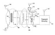
- FIG. 1is a schematic representation of an extended range passive RFID architecture that harvests energy from the RF environment to power the signal sent to the remote interrogator;
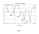
- FIG. 2depicts the return loss of a broadband antenna element that is tuned to selectively absorb energy from signals commonly found in the modern RF environment;
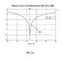
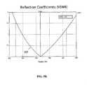
- FIGS. 3A and 3Bdepict the return loss and reflection coefficients, respectively, of narrow conductance band antenna that eliminates the need for additional RF filtering stages in the RFID tag or the read head;
- FIG. 4depicts a physical design of a planar RFID device
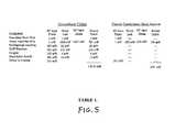
- FIG. 5shows TABLE 1, which compares the power losses in a conventional RF front-end used in code-division multiple access (CDMA) to the power losses in an RF front-end that contains a narrow conductance band antenna.
- CDMAcode-division multiple access
- RFradio frequency
- the present inventionprovides a means to minimize transmission line losses (L t and L r ) by embedding low resistivity alloys or noble metals (copper, silver or gold) in amorphous silica glass ceramic, which is used in optical fiber applications for its ultra-low dielectric loss (tan ⁇ 2 ⁇ 10 ⁇ 5 ).
- the extended range passive RFID 101uses a selective-frequency broadband antenna system 103 to harvest ambient power from the RF environment.
- the antenna systemis a dipole antenna folded in such a way that current vectors along the dipole arms form capacitive loads (when aligned in anti-parallel directions) and inductive loads (when aligned in parallel directions).
- capacitive loadswhen aligned in anti-parallel directions
- inductive loadswhen aligned in parallel directions.
- By properly folding the armsone can construct one or more RF filtering stages by inserting capacitive and inductive load elements in series or in parallel to create frequency selective pass bands. Further details of this method and technology are described in U.S. Provisional Patent Application Ser. No. 61/355,755, filed Jun. 17, 2010 and entitled FREQUENCY SELECTIVE DIPOLE ANTENNAS, the contents of which are hereby incorporated by reference herein.
- FIG. 2shows the selective frequency response of a folded dipole that is designed to be resonant at the primary frequencies for civilian communications and navigation, with resonant frequencies at the 450 MHz cellular band 151 , the 900 MHz bands used for the American Mobile Phone System (AMPS) bands 153 , the 1600 MHz global positioning satellite (GPS) bands 155 , the 1800 MHz and 1900 MHz global system mobile (GSM) bands 157 , and the 2.5 GHz (2500 MHz) WiFi bands 159 .
- This selective-frequency broadband antenna system 103allows the passive RFID system 101 to harvest energy from the RE environment that is readily available from the civilian wireless communications infrastructure.
- the selective-frequency broadband antennaneed not be tuned to these frequencies, and can be tuned to an arbitrary set of frequencies that could readily harvest power from any given RF environment.
- These bandsare cited here because they are widely used in the global civilian communications infrastructure and can readily supply RF power to the passive tag in most locations around the world.
- the RE power harvested by selective-frequency broadband antenna element 103is then fed through a rectification circuit 105 , which may either be a diode bridge or a center-feed transformer 107 as shown in FIG. 1 , which stores the energy in a lumped circuit (LC) storage tank 109 .
- the LC storage tank 109may comprise one or more inductor coils, capacitor and/or resistor elements, or may comprise any device that is capable of storing the harvested RF power for later use. This energy harvested from the RF environment is now available to augment the power of the transmitted signal P t from the passive RFID tag, which is needed to extend its read range.
- the energy collection and storage circuitry described thus far in components 103 , 105 , 107 and 109may be used for providing power to any sort of wireless device or appliance.
- the tag's interrogator-receive antenna 113registers the interrogator signal, which it then passes through a rectifier circuit 115 .
- Rectifier circuit 115is representational in FIG. 1 and may be a center-feed transformer or a rectifying diode bridge.
- the interrogator-receive circuitrymay additionally contain command circuitry (not shown) that may receive digitally encoded instructions to alter the modulation encoding (also not shown) in the RFID system's 101 transmit circuitry 117 to communicate information about the asset, such as maximum exposed temperatures, applied g-forces, or evidence of tampering.
- the weak interrogatoris then used as a base current for a power transistor that functions as the switch 111 .
- the LC storage tank 109supplies both the collector voltage V c and the collector I c for the switch 111 , while the rectified weak interrogator signal provides base current for the switch 111 . Since gain for the switch 111 is a function of the base current derived from the weak interrogator signal, it may be desirable for the interrogator-receive circuit to also contain a power management or collection system 119 that allows the base current supplied to the switch 111 to obtain a threshold value that maximizes the transmitted power P t from the extended range passive RFID system.
- the emitter current and voltage emerging from the switch 111is then used to power the transmit circuitry 117 that may optionally include an oscillator, a power amplifier, and modulation circuitry that encodes specific information about the asset's status for transmission back to the remote read head.
- the representational transmit circuitry 117may also be embodied by any form of wireless device or appliance such as cell phones, computing devices, GPS devices, pagers, radios, etc. while components 103 , 105 , 107 and 109 work as a recharging and power supply.
- the tag and the read headmay also include RF front-end losses from filters that are used to improve overall signal integrity in the system.
- the RF filtering stages built in to the folded dipole antennalimit the resonant band of the interrogator-receive antenna 113 and the transmit antenna 121 to a narrow communications band 201 of signal frequencies.
- this antenna tuningprovides a voltage standing wave ratios (VSWR) frequency 203 bandwidth that is much wider than the conductance bandwidth 201 , this antenna tuning both filters spurious noise from the interrogator-receive antenna 113 and eliminates undesirable emissions from the transmit antenna 121 .
- VSWRvoltage standing wave ratios
- Table 1provides an analysis of the power that is wasted in an RF front-end designed for code division multiple access (CDMA) communications using conventional filters to an RF front-end that uses a narrow conductance band antenna.
- CDMAcode division multiple access
- the resultant power savingsadditionally allow a power amplifier (PA) contained in the transmit circuitry 117 to operated at lower back-off voltage, which allows it to operate at much higher efficiency.
- PApower amplifier
- Signal path losscan be reduced by using a lower signaling frequency. For instance, 10-30 MHz signaling frequencies reduce the free space path loss from the tag to the receive head from ⁇ 116 dBW to 74-80 dBW. Lower signaling frequencies consequently require antennas that are much larger in size to achieve higher efficiencies and high gain. This proportionally makes the device much larger in overall size. For the purpose of concealment, it is therefore advantageous to have a smaller device that operates at lower frequency and also has high gain and excellent power efficiency characteristics. It is therefore a preferred embodiment of the invention to use meta-material dielectrics that apply the aforementioned antenna turnings to electrically small antennas embedded within the meta-material dielectric.
- the present inventionbe easily concealable within a planar surface of the asset or its container.
- FIG. 4to describe a preferred embodiment of the invention in which the antenna systems 251 are configured on a thermally stable miniaturized artificial magnetic conducting (AMC) ground plane 253 that comprises high-energy ceramic meta-material dielectric.
- AMCartificial magnetic conducting
- the additional circuit elementssuch as the power transistors, diodes, passive components (transformers, inductors, capacitors, resistors)—(not shown in FIG. 4 )—laminated on the backside 255 of said AMC ground plane 253 adjacent to any active semiconductor chip components that may be needed to complete the circuit.
Landscapes
- Engineering & Computer Science (AREA)
- Computer Networks & Wireless Communication (AREA)
- Power Engineering (AREA)
- Computer Hardware Design (AREA)
- Microelectronics & Electronic Packaging (AREA)
- Physics & Mathematics (AREA)
- General Physics & Mathematics (AREA)
- Theoretical Computer Science (AREA)
- Near-Field Transmission Systems (AREA)
- Details Of Aerials (AREA)
Abstract
Description
This application is a continuation of and claims priority from U.S. patent application Ser. No. 12/818,025, filed Jun. 10, 2010, now U.S. Pat. No. 8,922,347, which claims priority from U.S. Provisional Patent Application Ser. No. 61/187,687, filed Jun. 17, 2009, entitled EXTENDED RANGE PASSIVE RFID SYSTEM, both of which are incorporated herein by reference in their entirety.
The present invention relates generally to the application of ideal materials sets and frequency-selective antennas to collect R.F. energy and to greatly extend the range of passive radio-frequency identification (RFID) systems.
U.S. Pat. No. 6,027,826 to de Rochemont, et al, discloses articles and methods to form oxide ceramic on metal substrates to form laminate, filament and wire metal-ceramic composite structures using liquid aerosol spray techniques. U.S. Pat. Nos. 6,323,549 and 6,742,249 to de Rochemont, et al. disclose articles that comprise, and methods to construct, an interconnect structure that electrically contacts a semiconductor chip to a larger system using at least one discrete wire that is embedded in amorphous silica ceramic, as well as methods to embed passive components within said interconnect structure, U.S. Pat. Nos. 5,707,715 and 6,143,432 to de Rochemont, et al, (the '715 and '432 patents) disclose articles and methods to relieve thermally-induced mechanical stress in metal-ceramic circuit boards and metal-ceramic and ceramic-ceramic composite structures. U.S. Pat. No. 6,027,826 to de Rochemont, et al, disclose articles and methods to form oxide ceramic on metal substrates to form laminate, filament and wire metal-ceramic composite structures using liquid aerosol spray techniques. U.S. Pat. Nos. 6,323,549 and 6,742,249 to de Rochemont, et al. disclose articles that comprise, and methods to construct, an interconnect structure that electrically connects a semiconductor chip to a larger system using at least one discrete wire that is embedded in silica ceramic, as well as methods to embed passive components within said interconnect structure. U.S. patent application Ser. No. 11/479,159 (U.S. Pub. No. 2007/0003781) (hereinafer “de Rochemont '159”) discloses articles and methods that laminate passive components (resistors, capacitors, inductors) on an exposed or a buried microelectronic surface using liquid aerosol sprays or inkjet deposition systems. U.S. patent application Ser. No. 11/660,042 (Pub. No. 2007/0139976) (hereinafter “de Rochemont '042) discloses articles and methods that laminate passive components on an exposed surface layer or a buried microelectronic layer to form a power management device using laminated resistors, capacitors, inductors or transformers. U.S. Pat. No. 7,405,698 is used to miniaturize artificial magnetic conducting ground planes and form meta-material dielectrics that, in combination with de Rochemont '159, enable electrically small antennas. The contents of each of these references are incorporated herein by reference as if laid out in their entirety.
RFID systems allow an object to be remotely identified by a radio frequency “interrogator” signal, which activates a “chirp” or “read” signal from the RFID tag. Passive RFID systems do not have any internal power sources (such as battery elements) within the tag to avoid maintenance needs and, consequently, will have read ranges—(the distance from which the tag can be remotely identified)—limited to 65 to 100 feet. This is the case because the interrogator signal must activate and power the “read signal” from the RFID transponder. Therefore, the interrogator signal must be powerful to simultaneously overcome signal path losses between the read head and the RFID tag, to activate the “read” signal, and still be detectable by the remote read head. State-of-the-art passive RFID systems that incorporate surface-acoustic wave systems will require power levels of −15 dB to −18 dB simply to activate the chirped read signal.
RFID systems are used to manage assets in inventory and during transport. Recently, piracy and theft during logistical transport has developed a need for passive RFID sensors that can not only report asset location, but additional information that might indicate whether or not the asset has been compromised or tampered to a surveillance vehicle located several miles away from the asset, such as an unmanned aerial vehicle.
Therefore, methods that enable passive RFID sensors to remotely report the location or tampering of an asset at distances up to and exceeding a distance of 10 miles is desirable. It is also desirable that such an RFID system have a planar structure so that it may be concealed in the wall of a container to protect it from being detected, damaged or destroyed prior to or during the time an asset is tampered.
One embodiment of the present invention provides an R.F. energy collection circuit, comprising a low-loss R.F. front end tuned to minimize lost power in R.F. bands commonly used for communications for passing substantially coherent R.F. signals received therefrom, a rectifier circuit coupled to receive coherent R.F. energy from the front end, and an energy storage circuit coupled to receive energy from the rectifier circuit.
The storage circuit may include a tank circuit. The storage circuit may include a rechargeable battery. The rectifier circuit may include a center-tapped transformer.
The R.F. front end may include a folded dipole antenna formed in composite material having an effect permittivity which varies ≦5×10⁻²° C.−1. The effective permittivity of the composite material may be made to vary ≦9×10⁻³° C.−1.
The circuit may further comprise an REID circuit coupled to receive response transmission energy from the energy storage circuit. The RFID circuit may include an interrogation reception circuit and an ID transmission circuit, and further wherein the interrogation reception circuit is coupled to connect energy from the energy storage circuit to power the ID transmission circuit in response to an interrogation signal being received by the interrogation reception circuit.
The circuit may further comprise a wireless appliance coupled to receive power from the energy storage circuit.
The present invention describes methods and embodiments that extend the read range of easily concealable passive RFID sensor systems by minimizing activation energies and harvesting power from the RF environment.
An RFID circuit generally includes a stray RF energy collection circuit, an storage device for the collected stray RF energy, an ID transmission circuit and an interrogation reception circuit adapted for coupling stored energy to the ID transmission circuit in response to an interrogation signal sent to the RFID circuit. The energy collection circuit may have resonant antenna sections tuned to frequencies used for global communications and navigation. Narrow conductance band frequency-selective antenna timing may be used for the interrogator-receive and tag transmit circuits, and also for the read-head antenna system that interrogates the RFID circuit. Meta-material dielectrics may be used to apply the aforementioned antenna turnings to electrically small antennas embedded within the meta-material dielectric. The ID transmit circuitry may optionally include an oscillator, a power amplifier, and modulation circuitry that encodes specific information about the status of an asset associated with the RFID circuit for transmission back to the remote read head.
For a better understanding of the present invention, together with other and further aspects thereof, reference is made to the following description taken in conjunction with the accompanying figures of the drawing, wherein:
The read range of an RFID device, passive or otherwise, is determined by the residual power detectable in dBWatts (dBW) at the remote read head, Pr, which is determined by:
Pr=Pt−Lp+Gt+Gr−Lt−Lr, (1)
where Ptis the radio frequency (RF) power transmitted by the RFID tag, Lpis the signal path loss, Gtand Gr, are the antenna gain of the RIM tag (t) and the remote read head (r) respectively, Ltand Lrrepresent the transmission line losses between the transmitter circuit and the tag antenna and the read antenna and the read head receiver circuitry, with all values reported in dBW except for the antenna gains which are reported in dBi. The free space signal path loss is determined by:
Lp=36.6+20 log(ƒ[MHz])+20 log(d[miles]), (2)
where ƒ is the signal frequency in megahertz units (MHz) and d is the distance in units of miles. Therefore, at a distance of 10 miles the free space path loss for a 900 MHz signal is significant (˜116 dBW). Signal loss due to scattering and attenuation caused by features in the landscape and buildings can easily drive path loss values up to 140-160 dBW, which makes the task of remotely detecting the RFID tag quite challenging.
In order to extend the range of remote RFID devices it therefore is essential to increase the transmitted power at the RIFD tag (Pt), increase the gain of the tag and read head antennas (Gt) and (Gr), respectively, and minimize the transmission line losses in the interconnects placing the transmission circuitry in electrical communication with the tag antenna (Lt), and the receiver circuitry in electrical communication with the receive antenna (Lr). As described in the background, the present invention provides a means to minimize transmission line losses (Ltand Lr) by embedding low resistivity alloys or noble metals (copper, silver or gold) in amorphous silica glass ceramic, which is used in optical fiber applications for its ultra-low dielectric loss (tan δ≈2×10⁻⁵).
A limitation to state-of-the-art passive RFID tags is that the interrogator signal is used to activate and power the chirp signal. At a distance of 10 miles, the power of a 900 MHz interrogator signal is already reduced by −116 dBW (in free space). If it requires −15 dBW to −18 dBW to activate the transmitted read signal, the total loss (assuming no transmission line losses i.e., Ltand Lr=0) for the round trip is −247 dBW to −250 dBW. This level of loss makes it extremely difficult to operate a passive RFID system, particularly if the interrogator signal powers the chirp signal. This limitation is overcome by the current invention.
Reference is now made toFIGS. 1 & 2 which depict features of the present invention. The extended rangepassive RFID 101, shown inFIG. 1 , uses a selective-frequencybroadband antenna system 103 to harvest ambient power from the RF environment. The antenna system is a dipole antenna folded in such a way that current vectors along the dipole arms form capacitive loads (when aligned in anti-parallel directions) and inductive loads (when aligned in parallel directions). By properly folding the arms one can construct one or more RF filtering stages by inserting capacitive and inductive load elements in series or in parallel to create frequency selective pass bands. Further details of this method and technology are described in U.S. Provisional Patent Application Ser. No. 61/355,755, filed Jun. 17, 2010 and entitled FREQUENCY SELECTIVE DIPOLE ANTENNAS, the contents of which are hereby incorporated by reference herein.
The RE power harvested by selective-frequencybroadband antenna element 103 is then fed through arectification circuit 105, which may either be a diode bridge or a center-feed transformer 107 as shown inFIG. 1 , which stores the energy in a lumped circuit (LC)storage tank 109. TheLC storage tank 109 may comprise one or more inductor coils, capacitor and/or resistor elements, or may comprise any device that is capable of storing the harvested RF power for later use. This energy harvested from the RF environment is now available to augment the power of the transmitted signal Ptfrom the passive RFID tag, which is needed to extend its read range.
Alternatively to the RFID circuit shown in fig one, the energy collection and storage circuitry described thus far incomponents rechargeable battery 108 anddiode 110, connected in phantom, to store power either fromstorage tank 109 or directly fromrectifier 105.
As referenced above and in the background, conventional passive RFID systems rely on the interrogator signal to both activate and supply the power for the transmitted chirp signal. At long distances, such as 10 miles or more, the interrogator power is already diminished by signal path losses, so a −15 dBW to −18 dBW loss associated with activating the chirp signal is highly undesirable. It is therefore a desirable embodiment of the present invention to utilize a weak interrogator signal to activate aswitch 111 that dumps the harvested and stored RF power into the transmit circuitry of the extended rangepassive RFID system 101. Reference is now made toFIGS. 1, 3A, 3B and Table 1 ofFIG. 5 to illustrate preferred embodiments of the invention to maximize performance in this regard. The tag's interrogator-receiveantenna 113 registers the interrogator signal, which it then passes through arectifier circuit 115.Rectifier circuit 115 is representational inFIG. 1 and may be a center-feed transformer or a rectifying diode bridge. The interrogator-receive circuitry may additionally contain command circuitry (not shown) that may receive digitally encoded instructions to alter the modulation encoding (also not shown) in the RFID system's101 transmitcircuitry 117 to communicate information about the asset, such as maximum exposed temperatures, applied g-forces, or evidence of tampering. The weak interrogator is then used as a base current for a power transistor that functions as theswitch 111. TheLC storage tank 109 supplies both the collector voltage Vcand the collector Icfor theswitch 111, while the rectified weak interrogator signal provides base current for theswitch 111. Since gain for theswitch 111 is a function of the base current derived from the weak interrogator signal, it may be desirable for the interrogator-receive circuit to also contain a power management orcollection system 119 that allows the base current supplied to theswitch 111 to obtain a threshold value that maximizes the transmitted power Ptfrom the extended range passive RFID system. The emitter current and voltage emerging from theswitch 111 is then used to power the transmitcircuitry 117 that may optionally include an oscillator, a power amplifier, and modulation circuitry that encodes specific information about the asset's status for transmission back to the remote read head.
As alternatively referred to above, the representational transmitcircuitry 117 may also be embodied by any form of wireless device or appliance such as cell phones, computing devices, GPS devices, pagers, radios, etc. whilecomponents
As noted above, it is desirable to minimize transmission line losses in the tag and the read head. This may also include RF front-end losses from filters that are used to improve overall signal integrity in the system. To this end, it is a preferred embodiment of this invention to utilize antenna elements that have been tuned to have narrow conductance band frequency selectivity as shown inFIGS. 3A, 3B using the current vector alignment methods described above. In this instance, the RF filtering stages built in to the folded dipole antenna limit the resonant band of the interrogator-receiveantenna 113 and the transmitantenna 121 to anarrow communications band 201 of signal frequencies. Since this antenna tuning provides a voltage standing wave ratios (VSWR)frequency 203 bandwidth that is much wider than theconductance bandwidth 201, this antenna tuning both filters spurious noise from the interrogator-receiveantenna 113 and eliminates undesirable emissions from the transmitantenna 121.
Table 1 provides an analysis of the power that is wasted in an RF front-end designed for code division multiple access (CDMA) communications using conventional filters to an RF front-end that uses a narrow conductance band antenna. Not only is there a 60% reduction in the power wasted through the front-end circuit, the resultant power savings additionally allow a power amplifier (PA) contained in the transmitcircuitry 117 to operated at lower back-off voltage, which allows it to operate at much higher efficiency. It is therefore a preferred embodiment of the present invention to use narrow conductance band frequency-selective antenna tuning not just for the interrogator-receive and tag transmit circuits, but also for the read-head antenna system.
Signal path loss can be reduced by using a lower signaling frequency. For instance, 10-30 MHz signaling frequencies reduce the free space path loss from the tag to the receive head from −116 dBW to 74-80 dBW. Lower signaling frequencies consequently require antennas that are much larger in size to achieve higher efficiencies and high gain. This proportionally makes the device much larger in overall size. For the purpose of concealment, it is therefore advantageous to have a smaller device that operates at lower frequency and also has high gain and excellent power efficiency characteristics. It is therefore a preferred embodiment of the invention to use meta-material dielectrics that apply the aforementioned antenna turnings to electrically small antennas embedded within the meta-material dielectric.
Finally, it is desirable that the present invention be easily concealable within a planar surface of the asset or its container. Reference is now made toFIG. 4 to describe a preferred embodiment of the invention in which theantenna systems 251 are configured on a thermally stable miniaturized artificial magnetic conducting (AMC)ground plane 253 that comprises high-energy ceramic meta-material dielectric. To improve system planarity it is also desirable to have all the additional circuit elements, such as the power transistors, diodes, passive components (transformers, inductors, capacitors, resistors)—(not shown inFIG. 4 )—laminated on thebackside 255 of saidAMC ground plane 253 adjacent to any active semiconductor chip components that may be needed to complete the circuit.
All of the electronic components shown and represented inFIG. 1 may be optimally constructed using the techniques described in the patents and patent applications incorporated herein by reference.
Although the invention has been described with respect to various embodiments, it should be realized this invention is also capable of a wide variety of further and other embodiments within the spirit and scope of the present invention.
Claims (10)
1. An RF energy collection circuit used to harvest ambient energy for a wireless device or appliance, comprising a low-loss RF front-end containing one or more RF filtering stages formed from a broadband dipole antenna embedded in amorphous silica glass ceramic; wherein the one or more RF filtering stages have one or more selective-frequency pass bands formed by folding the anus of the dipole antenna to insert:
capacitive loads in series or in parallel at locations where the arms of the dipole antenna are folded to align current vectors in anti-parallel directions, and,
inductive loads in series or in parallel where the arms of the dipole antenna are folded to align current vectors in parallel directions, such that,
the one or more selective-frequency pass bands of the one or more RF filtering stages are resonant at primary frequency bands used for global civilian communications.
2. The RF energy collection circuit ofclaim 1 , wherein the primary frequency bands are at the 450 MHz cellular band, the 900 MHz band used for American Mobile Phone System (AMPS) band, the 1600 MHz global positioning satellite (GPS) band, the 1800 MHz and 1900 MHz global system mobile (GSM) band, and the 2.5 GHz WiFi bands.
3. The RF energy collection circuit ofclaim 1 , wherein the ambient energy harvested by the broadband dipole antenna is fed through a rectification circuit.
4. The energy collection circuit ofclaim 3 , wherein the rectification circuit supplies a storage circuit that is capable of supplying harvested ambient energy to augment the power of a signal transmitted by the wireless device or appliance.
5. The low-loss RF front-end ofclaim 1 , wherein the broadband dipole antenna is configured on a thermally stable miniaturized artificial magnetic conducting (AMC) ground plane.
6. The low-loss RF front-end ofclaim 5 , wherein additional circuit elements are laminated on the backside of the artificial magnetic conducting (AMC) ground plane.
7. The low-loss front-end ofclaim 6 , wherein the additional circuit elements laminated on the backside of the artificial magnetic conducting (AMC) ground plane include transformers, inductors, capacitors and resistors.
8. The low-loss RE front-end ofclaim 6 , wherein the additional circuit elements laminated on the backside of the artificial magnetic conducting (AMC) ground plane include power transistors or diodes.
9. The low-loss RF front-end ofclaim 1 , wherein the broadband dipole antenna is embedded in a composite dielectric comprising amorphous silica that has an effective permittivity that varies ≦5×10⁻²° C.
10. The low-loss RF front end ofclaim 1 , wherein the broadband dipole antenna is embedded in a composite dielectric comprising amorphous silica that has an effective permittivity that varies ≦9×10⁻³° C.
Priority Applications (1)
| Application Number | Priority Date | Filing Date | Title |
|---|---|---|---|
| US14/584,888US9893564B2 (en) | 2009-06-17 | 2014-12-29 | R.F. energy collection circuit for wireless devices |
Applications Claiming Priority (3)
| Application Number | Priority Date | Filing Date | Title |
|---|---|---|---|
| US18768709P | 2009-06-17 | 2009-06-17 | |
| US12/818,025US8922347B1 (en) | 2009-06-17 | 2010-06-17 | R.F. energy collection circuit for wireless devices |
| US14/584,888US9893564B2 (en) | 2009-06-17 | 2014-12-29 | R.F. energy collection circuit for wireless devices |
Related Parent Applications (1)
| Application Number | Title | Priority Date | Filing Date |
|---|---|---|---|
| US12/818,025ContinuationUS8922347B1 (en) | 2009-06-17 | 2010-06-17 | R.F. energy collection circuit for wireless devices |
Publications (2)
| Publication Number | Publication Date |
|---|---|
| US20150357867A1 US20150357867A1 (en) | 2015-12-10 |
| US9893564B2true US9893564B2 (en) | 2018-02-13 |
Family
ID=52112487
Family Applications (2)
| Application Number | Title | Priority Date | Filing Date |
|---|---|---|---|
| US12/818,025Active2031-02-05US8922347B1 (en) | 2009-06-17 | 2010-06-17 | R.F. energy collection circuit for wireless devices |
| US14/584,888Active2031-03-29US9893564B2 (en) | 2009-06-17 | 2014-12-29 | R.F. energy collection circuit for wireless devices |
Family Applications Before (1)
| Application Number | Title | Priority Date | Filing Date |
|---|---|---|---|
| US12/818,025Active2031-02-05US8922347B1 (en) | 2009-06-17 | 2010-06-17 | R.F. energy collection circuit for wireless devices |
Country Status (1)
| Country | Link |
|---|---|
| US (2) | US8922347B1 (en) |
Cited By (58)
| Publication number | Priority date | Publication date | Assignee | Title |
|---|---|---|---|---|
| CN108631061A (en)* | 2018-04-27 | 2018-10-09 | Oppo广东移动通信有限公司 | Antenna components and electronic devices |
| US20190052115A1 (en)* | 2015-12-24 | 2019-02-14 | Energous Corporation | Ceramic antenna molds |
| US10381880B2 (en) | 2014-07-21 | 2019-08-13 | Energous Corporation | Integrated antenna structure arrays for wireless power transmission |
| US10439448B2 (en) | 2014-08-21 | 2019-10-08 | Energous Corporation | Systems and methods for automatically testing the communication between wireless power transmitter and wireless power receiver |
| US10439442B2 (en) | 2017-01-24 | 2019-10-08 | Energous Corporation | Microstrip antennas for wireless power transmitters |
| US10490346B2 (en) | 2014-07-21 | 2019-11-26 | Energous Corporation | Antenna structures having planar inverted F-antenna that surrounds an artificial magnetic conductor cell |
| US10498144B2 (en) | 2013-08-06 | 2019-12-03 | Energous Corporation | Systems and methods for wirelessly delivering power to electronic devices in response to commands received at a wireless power transmitter |
| US10511196B2 (en) | 2015-11-02 | 2019-12-17 | Energous Corporation | Slot antenna with orthogonally positioned slot segments for receiving electromagnetic waves having different polarizations |
| US10511097B2 (en) | 2017-05-12 | 2019-12-17 | Energous Corporation | Near-field antennas for accumulating energy at a near-field distance with minimal far-field gain |
| US10516301B2 (en) | 2014-05-01 | 2019-12-24 | Energous Corporation | System and methods for using sound waves to wirelessly deliver power to electronic devices |
| US10516289B2 (en) | 2015-12-24 | 2019-12-24 | Energous Corportion | Unit cell of a wireless power transmitter for wireless power charging |
| US10523058B2 (en) | 2013-07-11 | 2019-12-31 | Energous Corporation | Wireless charging transmitters that use sensor data to adjust transmission of power waves |
| US10523033B2 (en) | 2015-09-15 | 2019-12-31 | Energous Corporation | Receiver devices configured to determine location within a transmission field |
| US10554052B2 (en) | 2014-07-14 | 2020-02-04 | Energous Corporation | Systems and methods for determining when to transmit power waves to a wireless power receiver |
| US10594165B2 (en) | 2015-11-02 | 2020-03-17 | Energous Corporation | Stamped three-dimensional antenna |
| US10615647B2 (en) | 2018-02-02 | 2020-04-07 | Energous Corporation | Systems and methods for detecting wireless power receivers and other objects at a near-field charging pad |
| US10680319B2 (en) | 2017-01-06 | 2020-06-09 | Energous Corporation | Devices and methods for reducing mutual coupling effects in wireless power transmission systems |
| CN111342243A (en)* | 2020-02-27 | 2020-06-26 | 四川大学 | A broadband rectenna with adjustable impedance matching based on resonant structure |
| US10734717B2 (en) | 2015-10-13 | 2020-08-04 | Energous Corporation | 3D ceramic mold antenna |
| US10778041B2 (en) | 2015-09-16 | 2020-09-15 | Energous Corporation | Systems and methods for generating power waves in a wireless power transmission system |
| US10840743B2 (en) | 2016-12-12 | 2020-11-17 | Energous Corporation | Circuit for managing wireless power transmitting devices |
| US10848853B2 (en) | 2017-06-23 | 2020-11-24 | Energous Corporation | Systems, methods, and devices for utilizing a wire of a sound-producing device as an antenna for receipt of wirelessly delivered power |
| US10923954B2 (en) | 2016-11-03 | 2021-02-16 | Energous Corporation | Wireless power receiver with a synchronous rectifier |
| US10965164B2 (en) | 2012-07-06 | 2021-03-30 | Energous Corporation | Systems and methods of wirelessly delivering power to a receiver device |
| US10985617B1 (en) | 2019-12-31 | 2021-04-20 | Energous Corporation | System for wirelessly transmitting energy at a near-field distance without using beam-forming control |
| US10992185B2 (en) | 2012-07-06 | 2021-04-27 | Energous Corporation | Systems and methods of using electromagnetic waves to wirelessly deliver power to game controllers |
| US10992187B2 (en) | 2012-07-06 | 2021-04-27 | Energous Corporation | System and methods of using electromagnetic waves to wirelessly deliver power to electronic devices |
| US11011942B2 (en) | 2017-03-30 | 2021-05-18 | Energous Corporation | Flat antennas having two or more resonant frequencies for use in wireless power transmission systems |
| US11018779B2 (en) | 2019-02-06 | 2021-05-25 | Energous Corporation | Systems and methods of estimating optimal phases to use for individual antennas in an antenna array |
| US11056929B2 (en) | 2015-09-16 | 2021-07-06 | Energous Corporation | Systems and methods of object detection in wireless power charging systems |
| US11114885B2 (en) | 2015-12-24 | 2021-09-07 | Energous Corporation | Transmitter and receiver structures for near-field wireless power charging |
| US11139699B2 (en) | 2019-09-20 | 2021-10-05 | Energous Corporation | Classifying and detecting foreign objects using a power amplifier controller integrated circuit in wireless power transmission systems |
| US11159057B2 (en) | 2018-03-14 | 2021-10-26 | Energous Corporation | Loop antennas with selectively-activated feeds to control propagation patterns of wireless power signals |
| US11233425B2 (en) | 2014-05-07 | 2022-01-25 | Energous Corporation | Wireless power receiver having an antenna assembly and charger for enhanced power delivery |
| US11245289B2 (en) | 2016-12-12 | 2022-02-08 | Energous Corporation | Circuit for managing wireless power transmitting devices |
| US11342798B2 (en) | 2017-10-30 | 2022-05-24 | Energous Corporation | Systems and methods for managing coexistence of wireless-power signals and data signals operating in a same frequency band |
| US11355966B2 (en) | 2019-12-13 | 2022-06-07 | Energous Corporation | Charging pad with guiding contours to align an electronic device on the charging pad and efficiently transfer near-field radio-frequency energy to the electronic device |
| US11381118B2 (en) | 2019-09-20 | 2022-07-05 | Energous Corporation | Systems and methods for machine learning based foreign object detection for wireless power transmission |
| US11411441B2 (en) | 2019-09-20 | 2022-08-09 | Energous Corporation | Systems and methods of protecting wireless power receivers using multiple rectifiers and establishing in-band communications using multiple rectifiers |
| US11437735B2 (en) | 2018-11-14 | 2022-09-06 | Energous Corporation | Systems for receiving electromagnetic energy using antennas that are minimally affected by the presence of the human body |
| US11462949B2 (en) | 2017-05-16 | 2022-10-04 | Wireless electrical Grid LAN, WiGL Inc | Wireless charging method and system |
| US11502551B2 (en) | 2012-07-06 | 2022-11-15 | Energous Corporation | Wirelessly charging multiple wireless-power receivers using different subsets of an antenna array to focus energy at different locations |
| US11515732B2 (en) | 2018-06-25 | 2022-11-29 | Energous Corporation | Power wave transmission techniques to focus wirelessly delivered power at a receiving device |
| US11539243B2 (en) | 2019-01-28 | 2022-12-27 | Energous Corporation | Systems and methods for miniaturized antenna for wireless power transmissions |
| US11710321B2 (en) | 2015-09-16 | 2023-07-25 | Energous Corporation | Systems and methods of object detection in wireless power charging systems |
| US11799324B2 (en) | 2020-04-13 | 2023-10-24 | Energous Corporation | Wireless-power transmitting device for creating a uniform near-field charging area |
| US11831361B2 (en) | 2019-09-20 | 2023-11-28 | Energous Corporation | Systems and methods for machine learning based foreign object detection for wireless power transmission |
| US11863001B2 (en) | 2015-12-24 | 2024-01-02 | Energous Corporation | Near-field antenna for wireless power transmission with antenna elements that follow meandering patterns |
| US11916398B2 (en) | 2021-12-29 | 2024-02-27 | Energous Corporation | Small form-factor devices with integrated and modular harvesting receivers, and shelving-mounted wireless-power transmitters for use therewith |
| US12057715B2 (en) | 2012-07-06 | 2024-08-06 | Energous Corporation | Systems and methods of wirelessly delivering power to a wireless-power receiver device in response to a change of orientation of the wireless-power receiver device |
| US12074452B2 (en) | 2017-05-16 | 2024-08-27 | Wireless Electrical Grid Lan, Wigl Inc. | Networked wireless charging system |
| US12074460B2 (en) | 2017-05-16 | 2024-08-27 | Wireless Electrical Grid Lan, Wigl Inc. | Rechargeable wireless power bank and method of using |
| US12142939B2 (en) | 2022-05-13 | 2024-11-12 | Energous Corporation | Integrated wireless-power-transmission platform designed to operate in multiple bands, and multi-band antennas for use therewith |
| US12155231B2 (en) | 2019-04-09 | 2024-11-26 | Energous Corporation | Asymmetric spiral antennas for wireless power transmission and reception |
| US12224599B2 (en) | 2020-08-12 | 2025-02-11 | Energous Corporation | Systems and methods for secure wireless transmission of power using unidirectional communication signals from a wireless-power-receiving device |
| US12283828B2 (en) | 2015-09-15 | 2025-04-22 | Energous Corporation | Receiver devices configured to determine location within a transmission field |
| US12306285B2 (en) | 2020-12-01 | 2025-05-20 | Energous Corporation | Systems and methods for using one or more sensors to detect and classify objects in a keep-out zone of a wireless-power transmission field, and antennas with integrated sensor arrangements |
| US12431735B2 (en) | 2019-09-20 | 2025-09-30 | Energous Corporation | Asymmetric spiral antennas with parasitic elements for wireless power transmission |
Families Citing this family (9)
| Publication number | Priority date | Publication date | Assignee | Title |
|---|---|---|---|---|
| US8952858B2 (en)* | 2009-06-17 | 2015-02-10 | L. Pierre de Rochemont | Frequency-selective dipole antennas |
| CN103180955B (en)* | 2010-08-23 | 2018-10-16 | L·皮尔·德罗什蒙 | Power Field Effect Transistor with Resonant Transistor Gate |
| US9348385B2 (en) | 2012-07-09 | 2016-05-24 | L. Pierre deRochement | Hybrid computing module |
| CN106650876B (en)* | 2016-10-11 | 2019-07-09 | 卓捷创芯科技(深圳)有限公司 | A kind of half-duplex RF ID oscillating maintaining circuit generating pulse by trigger |
| US10931148B2 (en)* | 2017-05-02 | 2021-02-23 | Board Of Regents, The University Of Texas System | Waveform design for RF power transfer |
| GB2567876B (en) | 2017-10-27 | 2020-10-14 | Drayson Tech Europe Ltd | An apparatus |
| US11201630B2 (en)* | 2017-11-17 | 2021-12-14 | Metawave Corporation | Method and apparatus for a frequency-selective antenna |
| US11336237B2 (en) | 2018-09-24 | 2022-05-17 | Metawave Corporation | Vector modulator for millimeter wave applications |
| CN109980340B (en)* | 2019-01-04 | 2020-10-16 | 浙江大学 | An Adaptive Microwave Energy Receiving Surface Based on Conjugate Matching |
Citations (163)
| Publication number | Priority date | Publication date | Assignee | Title |
|---|---|---|---|---|
| US2283925A (en) | 1937-04-30 | 1942-05-26 | Rca Corp | High frequency core and shield and method of making the same |
| US2886529A (en) | 1952-07-31 | 1959-05-12 | Centre Nat Rech Scient | Magnetic materials and their methods of manufacture |
| GB1125897A (en) | 1965-06-18 | 1968-09-05 | Westinghouse Electric Corp | Frequency selective electronic apparatus |
| US3574114A (en) | 1968-08-05 | 1971-04-06 | Bell Telephone Labor Inc | Fine grain ceramic ferrites |
| US3614554A (en) | 1968-10-24 | 1971-10-19 | Texas Instruments Inc | Miniaturized thin film inductors for use in integrated circuits |
| US3983077A (en) | 1975-05-02 | 1976-09-28 | Texas Instruments Incorporated | Process for making ceramic resistor materials |
| EP0026056A1 (en) | 1979-09-04 | 1981-04-01 | Western Electric Company, Incorporated | Semiconductor integrated circuit protection arrangement |
| US4400683A (en) | 1981-09-18 | 1983-08-23 | Matsushita Electric Industrial Co., Ltd. | Voltage-dependent resistor |
| US4455545A (en) | 1982-11-05 | 1984-06-19 | Sperry Corporation | High frequency output inductor for inverter power supply |
| US4523170A (en) | 1982-11-05 | 1985-06-11 | Spang & Company | Adjustable air gap ferrite structures and methods of manufacture |
| US4646038A (en) | 1986-04-07 | 1987-02-24 | Motorola, Inc. | Ceramic resonator filter with electromagnetic shielding |
| US4759120A (en) | 1986-05-30 | 1988-07-26 | Bel Fuse Inc. | Method for surface mounting a coil |
| US4859492A (en) | 1986-02-24 | 1989-08-22 | Hughes Aircraft Company | Process for forming an environmentally stable optical coating thereby |
| US4880770A (en) | 1987-05-04 | 1989-11-14 | Eastman Kodak Company | Metalorganic deposition process for preparing superconducting oxide films |
| US4967201A (en) | 1987-10-22 | 1990-10-30 | Westinghouse Electric Corp. | Multi-layer single substrate microwave transmit/receive module |
| US5084749A (en) | 1988-08-25 | 1992-01-28 | Eastman Kodak Company | Image sensing device with reduced smear |
| US5130675A (en) | 1990-09-10 | 1992-07-14 | Fujitsu Limited | Voltage-controlled oscillator |
| US5139999A (en) | 1990-03-08 | 1992-08-18 | President And Fellows Of Harvard College | Chemical vapor deposition process where an alkaline earth metal organic precursor material is volatilized in the presence of an amine or ammonia and deposited onto a substrate |
| US5154973A (en) | 1989-12-07 | 1992-10-13 | Murata Manufacturing Co., Ltd. | Composite material for dielectric lens antennas |
| US5198824A (en) | 1992-01-17 | 1993-03-30 | Texas Instruments Incorporated | High temperature co-fired ceramic integrated phased array packaging |
| US5217754A (en) | 1987-07-27 | 1993-06-08 | Trustees Of The University Of Pennsylvania | Organometallic precursors in conjunction with rapid thermal annealing for synthesis of thin film ceramics |
| US5219377A (en) | 1992-01-17 | 1993-06-15 | Texas Instruments Incorporated | High temperature co-fired ceramic integrated phased array package |
| US5263198A (en) | 1991-11-05 | 1993-11-16 | Honeywell Inc. | Resonant loop resistive FET mixer |
| US5272485A (en) | 1992-02-04 | 1993-12-21 | Trimble Navigation Limited | Microstrip antenna with integral low-noise amplifier for use in global positioning system (GPS) receivers |
| US5403797A (en) | 1993-01-21 | 1995-04-04 | Tdk Corporation | Non-reducing dielectric ceramic composition |
| US5427988A (en) | 1993-06-09 | 1995-06-27 | The United States Of America As Represented By The Secretary Of The Army | Ceramic ferroelectric composite material - BSTO-MgO |
| US5456945A (en) | 1988-12-27 | 1995-10-10 | Symetrix Corporation | Method and apparatus for material deposition |
| US5478610A (en) | 1994-09-02 | 1995-12-26 | Ceram Incorporated | Metalorganic chemical vapor deposition of layered structure oxides |
| US5513382A (en) | 1993-03-31 | 1996-04-30 | Motorola, Inc. | Multi-ceramic layer switch circuit |
| US5535445A (en) | 1983-05-09 | 1996-07-09 | The Secretary Of State For Defence In Her Britannic Majesty's Government Of The United Kingdom Of Great Britain And Northern Ireland | Mixer circuit |
| US5543773A (en) | 1990-09-07 | 1996-08-06 | Electrotech Instruments Limited | Transformers and coupled inductors with optimum interleaving of windings |
| US5584053A (en) | 1995-08-04 | 1996-12-10 | Motorola, Inc. | Commonly coupled high frequency transmitting/receiving switching module |
| US5590387A (en) | 1993-10-27 | 1996-12-31 | H. C. Starck, Gmbh & Co, Kg | Method for producing metal and ceramic sintered bodies and coatings |
| US5614252A (en) | 1988-12-27 | 1997-03-25 | Symetrix Corporation | Method of fabricating barium strontium titanate |
| US5625365A (en) | 1995-03-10 | 1997-04-29 | Trimble Navigation Limited | Dual-frequency microwave radio antenna system |
| US5635433A (en) | 1995-09-11 | 1997-06-03 | The United States Of America As Represented By The Secretary Of The Army | Ceramic ferroelectric composite material-BSTO-ZnO |
| US5707459A (en) | 1993-06-24 | 1998-01-13 | Canon Kabushiki Kaisha | Solar cell module provided with a heat-fused portion |
| US5707715A (en) | 1996-08-29 | 1998-01-13 | L. Pierre deRochemont | Metal ceramic composites with improved interfacial properties and methods to make such composites |
| US5747870A (en) | 1994-06-30 | 1998-05-05 | Plessey Semiconductors Limited | Multi-chip module inductor structure |
| US5759923A (en) | 1991-02-25 | 1998-06-02 | Symetrix Corporation | Method and apparatus for fabricating silicon dioxide and silicon glass layers in integrated circuits |
| US5764189A (en) | 1995-09-27 | 1998-06-09 | Siemens Aktiengesellschaft | Doppler radar module |
| US5771567A (en) | 1996-08-29 | 1998-06-30 | Raytheon Company | Methods of fabricating continuous transverse stub radiating structures and antennas |
| US5854608A (en) | 1994-08-25 | 1998-12-29 | Symetri Com, Inc. | Helical antenna having a solid dielectric core |
| US5859621A (en) | 1996-02-23 | 1999-01-12 | Symmetricom, Inc. | Antenna |
| US5889459A (en) | 1995-03-28 | 1999-03-30 | Matsushita Electric Industrial Co., Ltd. | Metal oxide film resistor |
| US5892489A (en) | 1996-04-05 | 1999-04-06 | Murata Manufacturing Co., Ltd. | Chip antenna and method of making same |
| US5903421A (en) | 1996-10-21 | 1999-05-11 | Murata Manufacturing Co., Ltd. | High-frequency composite part |
| US5933121A (en) | 1998-04-07 | 1999-08-03 | Harris Corporation | Antenna array for sensing signals on conductors |
| US5945963A (en) | 1996-01-23 | 1999-08-31 | Symmetricom, Inc. | Dielectrically loaded antenna and a handheld radio communication unit including such an antenna |
| EP0939451A1 (en) | 1998-02-27 | 1999-09-01 | Kyocera Corporation | Slot antenna |
| US6023251A (en) | 1998-06-12 | 2000-02-08 | Korea Electronics Technology Institute | Ceramic chip antenna |
| US6027826A (en) | 1994-06-16 | 2000-02-22 | The United States Of America As Represented By The Secretary Of The Air Force | Method for making ceramic-metal composites and the resulting composites |
| US6028568A (en) | 1997-12-11 | 2000-02-22 | Murata Manufacturing Co., Ltd. | Chip-antenna |
| US6031445A (en) | 1997-11-28 | 2000-02-29 | Stmicroelectronics S.A. | Transformer for integrated circuits |
| US6040805A (en) | 1998-05-08 | 2000-03-21 | Antcom Corp. | Low profile ceramic choke |
| US6046707A (en) | 1997-07-02 | 2000-04-04 | Kyocera America, Inc. | Ceramic multilayer helical antenna for portable radio or microwave communication apparatus |
| US6052040A (en) | 1997-03-03 | 2000-04-18 | Ngk Spark Plug Co., Ltd. | Dielectric duplexer with different capacitive coupling between antenna pad and transmitting and receiving sections |
| US6111544A (en) | 1998-02-13 | 2000-08-29 | Murata Manufacturing Co., Ltd. | Chip antenna, antenna device, and mobile communication apparatus |
| US6143432A (en) | 1998-01-09 | 2000-11-07 | L. Pierre deRochemont | Ceramic composites with improved interfacial properties and methods to make such composites |
| US6154176A (en) | 1998-08-07 | 2000-11-28 | Sarnoff Corporation | Antennas formed using multilayer ceramic substrates |
| US6157321A (en) | 1996-03-15 | 2000-12-05 | Inteligent Ideation, Inc. | Vehicle data acquisition system |
| US6195049B1 (en) | 1998-09-11 | 2001-02-27 | Samsung Electronics Co., Ltd. | Micro-strip patch antenna for transceiver |
| US6204203B1 (en) | 1998-10-14 | 2001-03-20 | Applied Materials, Inc. | Post deposition treatment of dielectric films for interface control |
| US6208843B1 (en) | 1999-06-03 | 2001-03-27 | Cirocomm Technology Corp. | Radio frequency and microwave module for simultaneously transmitting data and audio signal |
| US6222489B1 (en) | 1995-08-07 | 2001-04-24 | Murata Manufacturing Co., Ltd. | Antenna device |
| US6266020B1 (en) | 2000-07-24 | 2001-07-24 | Auden Technology Mfg. Co. Ltd. | Hidden antenna device of a mobile phone |
| US6271803B1 (en) | 1998-07-03 | 2001-08-07 | Murata Manufacturing Co., Ltd. | Chip antenna and radio equipment including the same |
| US20010023779A1 (en) | 2000-02-09 | 2001-09-27 | Yasuhiro Sugaya | Transfer material, method for producing the same and wiring substrate produced by using the same |
| US20010027119A1 (en) | 2000-03-23 | 2001-10-04 | Murata Manufacturing Co., Ltd. Nagaokakyo-Shi, Japan | Mobile communication device and high-frequency composite unit used in the same |
| US6300894B1 (en) | 1999-07-09 | 2001-10-09 | Harris Corporation | Antenna having electrically controllable radar cross-section |
| US6323549B1 (en) | 1996-08-29 | 2001-11-27 | L. Pierre deRochemont | Ceramic composite wiring structures for semiconductor devices and method of manufacture |
| US20010048969A1 (en) | 1997-05-05 | 2001-12-06 | Constantino Stephen A. | Dispersible, metal oxide-coated, barium titanate materials |
| US20020039667A1 (en) | 2000-04-27 | 2002-04-04 | Tdk Corporation | Composite magnetic material and magnetic molding material, magnetic powder compression molding material, and magnetic paint using the composite magnetic material, composite dielectric material and molding material, powder compression molding material, paint, prepreg, and substrate using the composite dielectric material, and electronic part |
| US20020047768A1 (en) | 2000-10-10 | 2002-04-25 | Duffy Thomas P. | Microelectronic magnetic structure, device including the structure, and methods of forming the structure and device |
| US20020070983A1 (en) | 2000-12-07 | 2002-06-13 | Kozub Thomas A. | Automated wafer handling with graphic user interface |
| US20020092472A1 (en) | 1999-02-03 | 2002-07-18 | Symetrix Corporation And Matsushita Electronics Corporation | Method of liquid deposition by selection of liquid viscosity and other precursor properties |
| US20020110004A1 (en) | 1994-10-31 | 2002-08-15 | Parks David B. | Resonant gate driver |
| US20020171591A1 (en) | 2001-05-17 | 2002-11-21 | Paul Beard | Ball grid array antenna |
| US6492949B1 (en) | 2000-08-16 | 2002-12-10 | Raytheon Company | Slot antenna element for an array antenna |
| US6496149B1 (en) | 2001-02-01 | 2002-12-17 | Apple Computer, Inc. | Recessed aperture-coupled patch antenna with multiple dielectrics for wireless applications |
| US20020190818A1 (en) | 2000-09-25 | 2002-12-19 | Kenji Endou | High frequency band pass filter |
| US6501415B1 (en) | 2000-08-16 | 2002-12-31 | Raytheon Company | Highly integrated single substrate MMW multi-beam sensor |
| US20030002045A1 (en) | 2001-05-23 | 2003-01-02 | The Regents Of The University Of California | Composite material having low electromagnetic reflection and refraction |
| US20030034124A1 (en) | 2001-06-19 | 2003-02-20 | Yasuhiro Sugaya | Dielectric resonator, dielectric filter and method of producing the same, filter device combined to a transmit-receive antenna and communication apparatus using the same |
| US6541820B1 (en) | 2000-03-28 | 2003-04-01 | International Rectifier Corporation | Low voltage planar power MOSFET with serpentine gate pattern |
| US20030073565A1 (en) | 2001-06-01 | 2003-04-17 | Ellis Marion E. | Tunable dielectric compositions including low loss glass |
| US6552693B1 (en) | 1998-12-29 | 2003-04-22 | Sarantel Limited | Antenna |
| US20030080325A1 (en) | 2001-10-26 | 2003-05-01 | Symetrix Corporation And Matsushita Electric Industrial Co., Ltd. | Chemical vapor deposition method of making layered superlattice materials using trimethylbismuth |
| US6559735B1 (en) | 2000-10-31 | 2003-05-06 | Cts Corporation | Duplexer filter with an alternative signal path |
| US20030107455A1 (en) | 2001-10-23 | 2003-06-12 | Yoshihiko Imanaka | Integrated ceramic module and microwave dielectric composition |
| US20030111714A1 (en) | 2001-12-03 | 2003-06-19 | Dover Capital Formation Group | Surface mount ceramic package |
| US6583699B2 (en) | 2000-10-31 | 2003-06-24 | Tdk Corporation | Magnetic material and inductor |
| US20030122647A1 (en) | 2001-12-28 | 2003-07-03 | Chiung-Ting Ou | Inductor formed on a silicon substrate and method of manufacturing the same |
| US20030148024A1 (en) | 2001-10-05 | 2003-08-07 | Kodas Toivo T. | Low viscosity precursor compositons and methods for the depositon of conductive electronic features |
| US6605151B1 (en) | 1999-11-29 | 2003-08-12 | Northwestern University | Oxide thin films and composites and related methods of deposition |
| US6611419B1 (en) | 2000-07-31 | 2003-08-26 | Intel Corporation | Electronic assembly comprising substrate with embedded capacitors |
| US20030161959A1 (en) | 2001-11-02 | 2003-08-28 | Kodas Toivo T. | Precursor compositions for the deposition of passive electronic features |
| US20030170436A1 (en) | 2001-12-25 | 2003-09-11 | Ngk Spark Plug Co., Ltd. | Dielectric material and dielectric sintered body, and wiring board using the same |
| US6620750B2 (en) | 2001-05-18 | 2003-09-16 | Kook-Sun Hong | Dielectric ceramic composition and method for manufacturing multilayered components using the same |
| US6639556B2 (en) | 2000-10-10 | 2003-10-28 | Alps Electric Co., Ltd. | Plane patch antenna through which desired resonance frequency can be obtained with stability |
| US6650303B2 (en) | 2001-06-15 | 2003-11-18 | Korea Institute Of Science And Technology | Ceramic chip antenna |
| US20030221621A1 (en) | 2000-04-21 | 2003-12-04 | Applied Materials Inc. | Method and apparatus for processing semiconductor substrates with hydroxyl radicals |
| US6670497B2 (en) | 2000-04-24 | 2003-12-30 | Toho Titanium Co., Ltd. | Phthalic diester derivatives and electron donors |
| US20040001026A1 (en) | 2002-06-27 | 2004-01-01 | Killen William D. | High efficiency antennas of reduced size on dielectric substrate |
| US20040000966A1 (en) | 2002-06-27 | 2004-01-01 | Killen William D. | High efficiency four port circuit |
| US20040000972A1 (en) | 2002-06-27 | 2004-01-01 | Killen William D. | High efficiency interdigital filters |
| US20040000976A1 (en) | 2002-06-27 | 2004-01-01 | Killen William D. | High efficiency resonant line |
| US20040001028A1 (en) | 2002-06-27 | 2004-01-01 | Killen William D. | System for improved matching and broadband performance of microwave antennas |
| US20040001024A1 (en) | 2002-06-27 | 2004-01-01 | Killen William D. | High efficiency printed circuit array of log-periodic dipole arrays |
| US20040000964A1 (en) | 2002-06-27 | 2004-01-01 | Killen William D. | High efficiency directional coupler |
| US20040000970A1 (en) | 2002-06-27 | 2004-01-01 | Killen William D. | High efficiency coupled line filters |
| US20040001027A1 (en) | 2002-06-27 | 2004-01-01 | Killen William D. | Dipole arrangements using dielectric substrates of meta-materials |
| US20040000975A1 (en) | 2002-06-27 | 2004-01-01 | Killen William D. | High efficiency single port resonant line |
| US6680700B2 (en) | 2000-10-09 | 2004-01-20 | Koninklijke Philips Electronics N.V. | Miniaturized microwave antenna |
| US20040012081A1 (en) | 2002-07-19 | 2004-01-22 | Kwon Heung Kyu | Semiconductor wafer having electrically connected passive device chips, passive devices and semiconductor package using the same |
| US6683576B2 (en) | 2001-09-04 | 2004-01-27 | Koninklijke Philips Electronics N.V. | Circuit board and SMD antenna |
| US6686406B2 (en) | 2000-04-26 | 2004-02-03 | The Furukawa Electric Co., Ltd. | Dielectric ceramic, resin-ceramic composite material, electrical part and antenna, and manufacturing method thereof |
| US6690336B1 (en) | 1998-06-16 | 2004-02-10 | Symmetricom, Inc. | Antenna |
| US20040033654A1 (en) | 2002-08-14 | 2004-02-19 | Osamu Yamagata | Semiconductor device and method of fabricating the same |
| US6697605B1 (en) | 1999-06-09 | 2004-02-24 | Murata Manufacturing Co. Ltd. | High-frequency circuit apparatus and communication apparatus |
| US20040070915A1 (en) | 2001-09-06 | 2004-04-15 | Atsushi Nagai | Ceramic electronic component and production method therefor |
| US20040084080A1 (en) | 2002-06-22 | 2004-05-06 | Nanosolar, Inc. | Optoelectronic device and fabrication method |
| US20040092236A1 (en) | 2002-11-08 | 2004-05-13 | Kiyoshi Irie | Semiconductor integrated circuit device and wireless communication system |
| US6743744B1 (en) | 2000-05-03 | 2004-06-01 | Korea Institute Of Science And Technology | Low temperature sinterable and low loss dielectric ceramic compositions and method thereof |
| US20040113738A1 (en) | 2000-03-10 | 2004-06-17 | Ahn Kie Y | Integrated circuit inductor with a magnetic core |
| US20040113790A1 (en) | 2002-09-23 | 2004-06-17 | Hamel Michael John | Remotely powered and remotely interrogated wireless digital sensor telemetry system |
| US20040118448A1 (en) | 2002-09-05 | 2004-06-24 | Nanosys, Inc. | Nanostructure and nanocomposite based compositions and photovoltaic devices |
| US6762237B2 (en) | 2001-06-08 | 2004-07-13 | Eikos, Inc. | Nanocomposite dielectrics |
| US6791496B1 (en) | 2003-03-31 | 2004-09-14 | Harris Corporation | High efficiency slot fed microstrip antenna having an improved stub |
| US20040189528A1 (en) | 2003-03-31 | 2004-09-30 | Killen William D. | Arangements of microstrip antennas having dielectric substrates including meta-materials |
| US20050036269A1 (en) | 2001-09-07 | 2005-02-17 | Intel Corporation | Vacuum-cavity MEMS resonator |
| US6864848B2 (en) | 2001-12-27 | 2005-03-08 | Hrl Laboratories, Llc | RF MEMs-tuned slot antenna and a method of making same |
| US20050051870A1 (en) | 2002-12-27 | 2005-03-10 | Semiconductor Energy Laboratory Co., Ltd. | Semiconductor device and a method of manufacturing the same |
| US6906674B2 (en) | 2001-06-15 | 2005-06-14 | E-Tenna Corporation | Aperture antenna having a high-impedance backing |
| US6919119B2 (en) | 2000-05-30 | 2005-07-19 | The Penn State Research Foundation | Electronic and opto-electronic devices fabricated from nanostructured high surface to volume ratio thin films |
| US20060086994A1 (en) | 2004-05-14 | 2006-04-27 | Susanne Viefers | Nanoelectromechanical components |
| US20060094425A1 (en) | 2004-10-28 | 2006-05-04 | Mickle Marlin H | Recharging apparatus |
| US20060092079A1 (en) | 2004-10-01 | 2006-05-04 | De Rochemont L P | Ceramic antenna module and methods of manufacture thereof |
| US20060125681A1 (en) | 2002-08-29 | 2006-06-15 | The Regents Of The University Of California | Indefinite materials |
| US20060134491A1 (en) | 2003-06-10 | 2006-06-22 | Hilchenko Galina V | Zirconium dioxide-based electrode-electrolyte pair (variants), method for the production thereof (variants) and organogel |
| US20070003781A1 (en) | 2005-06-30 | 2007-01-04 | De Rochemont L P | Electrical components and method of manufacture |
| US20070139976A1 (en) | 2005-06-30 | 2007-06-21 | Derochemont L P | Power management module and method of manufacture |
| US20070137257A1 (en) | 2005-12-16 | 2007-06-21 | Desantolo Anthony Michael | Apparatus and method for fabricating glass bodies using an aerosol delivery system |
| US20070166453A1 (en) | 2004-02-19 | 2007-07-19 | Nanosolar, Inc. | High-throughput printing of chalcogen layer |
| US20070170535A1 (en) | 2006-01-24 | 2007-07-26 | De Rochemont L Pierre | Photovoltaic devices with silicon dioxide encapsulation layer and method to make same |
| US20070259768A1 (en) | 2006-05-03 | 2007-11-08 | Kear Bernard H | Nanocomposite ceramic and method for producing the same |
| US20080136395A1 (en) | 2006-11-20 | 2008-06-12 | Bennett Paul T | Methods and apparatus for a spread spectrum switching regulator |
| US20080231421A1 (en) | 2007-03-22 | 2008-09-25 | Micron Technology, Inc. | Methods and systems of tagging objects and reading tags coupled to objects |
| US20090004370A1 (en) | 2007-05-30 | 2009-01-01 | Fabio Zurcher | Metal Inks, Methods of Making the Same, and Methods for Printing and/or Forming Metal Films |
| US20090015314A1 (en) | 2001-12-15 | 2009-01-15 | Huettinger Elektronik Gmbh + Co. Kg | High frequency excitation system |
| US7564887B2 (en) | 2004-06-30 | 2009-07-21 | Finisar Corporation | Long wavelength vertical cavity surface emitting lasers |
| US20090278756A1 (en) | 2008-05-08 | 2009-11-12 | Ethertronics, Inc. | Active tuned loop-coupled antenna |
| US7714794B2 (en) | 2005-01-19 | 2010-05-11 | Behzad Tavassoli Hozouri | RFID antenna |
| US7840305B2 (en) | 2006-06-28 | 2010-11-23 | 3M Innovative Properties Company | Abrasive articles, CMP monitoring system and method |
| US20110021007A1 (en) | 2006-01-24 | 2011-01-27 | De Rochemont L Pierre | Liquid chemical depostion apparatus and process and products therefrom |
| US20110049394A1 (en) | 2009-09-01 | 2011-03-03 | De Rochemont L Pierre | Ionizing disinfectant surface |
| US20110065224A1 (en) | 2007-12-06 | 2011-03-17 | Brent Bollman | Methods and devices for processing a precursor layer in a group via environment |
| US20110227703A1 (en)* | 2010-03-22 | 2011-09-22 | Kotab Dominic M | Systems and methods of reading gaming chips and other stacked items |
| US20110248900A1 (en) | 2009-06-17 | 2011-10-13 | De Rochemont L Pierre | Frequency-selective dipole antennas |
| US8115448B2 (en) | 2007-06-01 | 2012-02-14 | Michael Sasha John | Systems and methods for wireless power |
| US8193873B2 (en) | 2008-12-15 | 2012-06-05 | Murata Manufacturing Co., Ltd. | High-frequency coupler and communication device |
| US8237561B2 (en) | 2005-07-19 | 2012-08-07 | Precision Dynamics Corporation | Semi-active RFID tag and related processes |
| US20160261031A1 (en)* | 2014-03-10 | 2016-09-08 | Drexel University | Wearable Power Harvesting System |
Family Cites Families (2)
| Publication number | Priority date | Publication date | Assignee | Title |
|---|---|---|---|---|
| US7084605B2 (en)* | 2003-10-29 | 2006-08-01 | University Of Pittsburgh | Energy harvesting circuit |
| DE602005021513D1 (en)* | 2004-08-26 | 2010-07-08 | Nxp Bv | RFID LABEL WITH FOLDED DIPOL |
- 2010
- 2010-06-17USUS12/818,025patent/US8922347B1/enactiveActive
- 2014
- 2014-12-29USUS14/584,888patent/US9893564B2/enactiveActive
Patent Citations (177)
| Publication number | Priority date | Publication date | Assignee | Title |
|---|---|---|---|---|
| US2283925A (en) | 1937-04-30 | 1942-05-26 | Rca Corp | High frequency core and shield and method of making the same |
| US2886529A (en) | 1952-07-31 | 1959-05-12 | Centre Nat Rech Scient | Magnetic materials and their methods of manufacture |
| GB1125897A (en) | 1965-06-18 | 1968-09-05 | Westinghouse Electric Corp | Frequency selective electronic apparatus |
| US3574114A (en) | 1968-08-05 | 1971-04-06 | Bell Telephone Labor Inc | Fine grain ceramic ferrites |
| US3614554A (en) | 1968-10-24 | 1971-10-19 | Texas Instruments Inc | Miniaturized thin film inductors for use in integrated circuits |
| US3983077A (en) | 1975-05-02 | 1976-09-28 | Texas Instruments Incorporated | Process for making ceramic resistor materials |
| EP0026056A1 (en) | 1979-09-04 | 1981-04-01 | Western Electric Company, Incorporated | Semiconductor integrated circuit protection arrangement |
| US4400683A (en) | 1981-09-18 | 1983-08-23 | Matsushita Electric Industrial Co., Ltd. | Voltage-dependent resistor |
| US4455545A (en) | 1982-11-05 | 1984-06-19 | Sperry Corporation | High frequency output inductor for inverter power supply |
| US4523170A (en) | 1982-11-05 | 1985-06-11 | Spang & Company | Adjustable air gap ferrite structures and methods of manufacture |
| US5535445A (en) | 1983-05-09 | 1996-07-09 | The Secretary Of State For Defence In Her Britannic Majesty's Government Of The United Kingdom Of Great Britain And Northern Ireland | Mixer circuit |
| US4859492A (en) | 1986-02-24 | 1989-08-22 | Hughes Aircraft Company | Process for forming an environmentally stable optical coating thereby |
| US4646038A (en) | 1986-04-07 | 1987-02-24 | Motorola, Inc. | Ceramic resonator filter with electromagnetic shielding |
| US4759120A (en) | 1986-05-30 | 1988-07-26 | Bel Fuse Inc. | Method for surface mounting a coil |
| US4880770A (en) | 1987-05-04 | 1989-11-14 | Eastman Kodak Company | Metalorganic deposition process for preparing superconducting oxide films |
| US5217754A (en) | 1987-07-27 | 1993-06-08 | Trustees Of The University Of Pennsylvania | Organometallic precursors in conjunction with rapid thermal annealing for synthesis of thin film ceramics |
| US4967201A (en) | 1987-10-22 | 1990-10-30 | Westinghouse Electric Corp. | Multi-layer single substrate microwave transmit/receive module |
| US5084749A (en) | 1988-08-25 | 1992-01-28 | Eastman Kodak Company | Image sensing device with reduced smear |
| US5888583A (en) | 1988-12-27 | 1999-03-30 | Symetrix Corporation | Misted deposition method of fabricating integrated circuits |
| US5614252A (en) | 1988-12-27 | 1997-03-25 | Symetrix Corporation | Method of fabricating barium strontium titanate |
| US5540772A (en) | 1988-12-27 | 1996-07-30 | Symetrix Corporation | Misted deposition apparatus for fabricating an integrated circuit |
| US5456945A (en) | 1988-12-27 | 1995-10-10 | Symetrix Corporation | Method and apparatus for material deposition |
| US5154973A (en) | 1989-12-07 | 1992-10-13 | Murata Manufacturing Co., Ltd. | Composite material for dielectric lens antennas |
| US5139999A (en) | 1990-03-08 | 1992-08-18 | President And Fellows Of Harvard College | Chemical vapor deposition process where an alkaline earth metal organic precursor material is volatilized in the presence of an amine or ammonia and deposited onto a substrate |
| US5543773A (en) | 1990-09-07 | 1996-08-06 | Electrotech Instruments Limited | Transformers and coupled inductors with optimum interleaving of windings |
| US5130675A (en) | 1990-09-10 | 1992-07-14 | Fujitsu Limited | Voltage-controlled oscillator |
| US5759923A (en) | 1991-02-25 | 1998-06-02 | Symetrix Corporation | Method and apparatus for fabricating silicon dioxide and silicon glass layers in integrated circuits |
| US5263198A (en) | 1991-11-05 | 1993-11-16 | Honeywell Inc. | Resonant loop resistive FET mixer |
| US5198824A (en) | 1992-01-17 | 1993-03-30 | Texas Instruments Incorporated | High temperature co-fired ceramic integrated phased array packaging |
| US5219377A (en) | 1992-01-17 | 1993-06-15 | Texas Instruments Incorporated | High temperature co-fired ceramic integrated phased array package |
| US5272485A (en) | 1992-02-04 | 1993-12-21 | Trimble Navigation Limited | Microstrip antenna with integral low-noise amplifier for use in global positioning system (GPS) receivers |
| US5403797A (en) | 1993-01-21 | 1995-04-04 | Tdk Corporation | Non-reducing dielectric ceramic composition |
| US5513382A (en) | 1993-03-31 | 1996-04-30 | Motorola, Inc. | Multi-ceramic layer switch circuit |
| US5427988A (en) | 1993-06-09 | 1995-06-27 | The United States Of America As Represented By The Secretary Of The Army | Ceramic ferroelectric composite material - BSTO-MgO |
| US5707459A (en) | 1993-06-24 | 1998-01-13 | Canon Kabushiki Kaisha | Solar cell module provided with a heat-fused portion |
| US5590387A (en) | 1993-10-27 | 1996-12-31 | H. C. Starck, Gmbh & Co, Kg | Method for producing metal and ceramic sintered bodies and coatings |
| US6027826A (en) | 1994-06-16 | 2000-02-22 | The United States Of America As Represented By The Secretary Of The Air Force | Method for making ceramic-metal composites and the resulting composites |
| US5747870A (en) | 1994-06-30 | 1998-05-05 | Plessey Semiconductors Limited | Multi-chip module inductor structure |
| US6181297B1 (en) | 1994-08-25 | 2001-01-30 | Symmetricom, Inc. | Antenna |
| US5854608A (en) | 1994-08-25 | 1998-12-29 | Symetri Com, Inc. | Helical antenna having a solid dielectric core |
| US5478610A (en) | 1994-09-02 | 1995-12-26 | Ceram Incorporated | Metalorganic chemical vapor deposition of layered structure oxides |
| US20020110004A1 (en) | 1994-10-31 | 2002-08-15 | Parks David B. | Resonant gate driver |
| US5625365A (en) | 1995-03-10 | 1997-04-29 | Trimble Navigation Limited | Dual-frequency microwave radio antenna system |
| US5889459A (en) | 1995-03-28 | 1999-03-30 | Matsushita Electric Industrial Co., Ltd. | Metal oxide film resistor |
| US5584053A (en) | 1995-08-04 | 1996-12-10 | Motorola, Inc. | Commonly coupled high frequency transmitting/receiving switching module |
| US6222489B1 (en) | 1995-08-07 | 2001-04-24 | Murata Manufacturing Co., Ltd. | Antenna device |
| US5635433A (en) | 1995-09-11 | 1997-06-03 | The United States Of America As Represented By The Secretary Of The Army | Ceramic ferroelectric composite material-BSTO-ZnO |
| US5764189A (en) | 1995-09-27 | 1998-06-09 | Siemens Aktiengesellschaft | Doppler radar module |
| US5945963A (en) | 1996-01-23 | 1999-08-31 | Symmetricom, Inc. | Dielectrically loaded antenna and a handheld radio communication unit including such an antenna |
| US5859621A (en) | 1996-02-23 | 1999-01-12 | Symmetricom, Inc. | Antenna |
| US6157321A (en) | 1996-03-15 | 2000-12-05 | Inteligent Ideation, Inc. | Vehicle data acquisition system |
| US5892489A (en) | 1996-04-05 | 1999-04-06 | Murata Manufacturing Co., Ltd. | Chip antenna and method of making same |
| US6323549B1 (en) | 1996-08-29 | 2001-11-27 | L. Pierre deRochemont | Ceramic composite wiring structures for semiconductor devices and method of manufacture |
| US7047637B2 (en) | 1996-08-29 | 2006-05-23 | Derochemont L Pierre | Method of manufacture of ceramic composite wiring structures for semiconductor devices |
| US5771567A (en) | 1996-08-29 | 1998-06-30 | Raytheon Company | Methods of fabricating continuous transverse stub radiating structures and antennas |
| US5707715A (en) | 1996-08-29 | 1998-01-13 | L. Pierre deRochemont | Metal ceramic composites with improved interfacial properties and methods to make such composites |
| US6742249B2 (en) | 1996-08-29 | 2004-06-01 | Derochemont L. Pierre | Method of manufacture of ceramic composite wiring structures for semiconductor devices |
| US5903421A (en) | 1996-10-21 | 1999-05-11 | Murata Manufacturing Co., Ltd. | High-frequency composite part |
| US6052040A (en) | 1997-03-03 | 2000-04-18 | Ngk Spark Plug Co., Ltd. | Dielectric duplexer with different capacitive coupling between antenna pad and transmitting and receiving sections |
| US20010048969A1 (en) | 1997-05-05 | 2001-12-06 | Constantino Stephen A. | Dispersible, metal oxide-coated, barium titanate materials |
| US6046707A (en) | 1997-07-02 | 2000-04-04 | Kyocera America, Inc. | Ceramic multilayer helical antenna for portable radio or microwave communication apparatus |
| US6031445A (en) | 1997-11-28 | 2000-02-29 | Stmicroelectronics S.A. | Transformer for integrated circuits |
| US6028568A (en) | 1997-12-11 | 2000-02-22 | Murata Manufacturing Co., Ltd. | Chip-antenna |
| US6143432A (en) | 1998-01-09 | 2000-11-07 | L. Pierre deRochemont | Ceramic composites with improved interfacial properties and methods to make such composites |
| US6111544A (en) | 1998-02-13 | 2000-08-29 | Murata Manufacturing Co., Ltd. | Chip antenna, antenna device, and mobile communication apparatus |
| US6188368B1 (en) | 1998-02-27 | 2001-02-13 | Shinichi Koriyama | Slot antenna |
| EP0939451A1 (en) | 1998-02-27 | 1999-09-01 | Kyocera Corporation | Slot antenna |
| US6176004B1 (en) | 1998-04-07 | 2001-01-23 | Harris Corporation | Method of forming a sensor for sensing signals on conductors |
| US5933121A (en) | 1998-04-07 | 1999-08-03 | Harris Corporation | Antenna array for sensing signals on conductors |
| US6040805A (en) | 1998-05-08 | 2000-03-21 | Antcom Corp. | Low profile ceramic choke |
| US6023251A (en) | 1998-06-12 | 2000-02-08 | Korea Electronics Technology Institute | Ceramic chip antenna |
| US6690336B1 (en) | 1998-06-16 | 2004-02-10 | Symmetricom, Inc. | Antenna |
| US6271803B1 (en) | 1998-07-03 | 2001-08-07 | Murata Manufacturing Co., Ltd. | Chip antenna and radio equipment including the same |
| US6320547B1 (en) | 1998-08-07 | 2001-11-20 | Sarnoff Corporation | Switch structure for antennas formed on multilayer ceramic substrates |
| US6154176A (en) | 1998-08-07 | 2000-11-28 | Sarnoff Corporation | Antennas formed using multilayer ceramic substrates |
| US6195049B1 (en) | 1998-09-11 | 2001-02-27 | Samsung Electronics Co., Ltd. | Micro-strip patch antenna for transceiver |
| US6204203B1 (en) | 1998-10-14 | 2001-03-20 | Applied Materials, Inc. | Post deposition treatment of dielectric films for interface control |
| US6552693B1 (en) | 1998-12-29 | 2003-04-22 | Sarantel Limited | Antenna |
| US20020092472A1 (en) | 1999-02-03 | 2002-07-18 | Symetrix Corporation And Matsushita Electronics Corporation | Method of liquid deposition by selection of liquid viscosity and other precursor properties |
| US6208843B1 (en) | 1999-06-03 | 2001-03-27 | Cirocomm Technology Corp. | Radio frequency and microwave module for simultaneously transmitting data and audio signal |
| US6697605B1 (en) | 1999-06-09 | 2004-02-24 | Murata Manufacturing Co. Ltd. | High-frequency circuit apparatus and communication apparatus |
| US6300894B1 (en) | 1999-07-09 | 2001-10-09 | Harris Corporation | Antenna having electrically controllable radar cross-section |
| US6605151B1 (en) | 1999-11-29 | 2003-08-12 | Northwestern University | Oxide thin films and composites and related methods of deposition |
| US20010023779A1 (en) | 2000-02-09 | 2001-09-27 | Yasuhiro Sugaya | Transfer material, method for producing the same and wiring substrate produced by using the same |
| US20040113738A1 (en) | 2000-03-10 | 2004-06-17 | Ahn Kie Y | Integrated circuit inductor with a magnetic core |
| US20010027119A1 (en) | 2000-03-23 | 2001-10-04 | Murata Manufacturing Co., Ltd. Nagaokakyo-Shi, Japan | Mobile communication device and high-frequency composite unit used in the same |
| US6541820B1 (en) | 2000-03-28 | 2003-04-01 | International Rectifier Corporation | Low voltage planar power MOSFET with serpentine gate pattern |
| US20030221621A1 (en) | 2000-04-21 | 2003-12-04 | Applied Materials Inc. | Method and apparatus for processing semiconductor substrates with hydroxyl radicals |
| US6670497B2 (en) | 2000-04-24 | 2003-12-30 | Toho Titanium Co., Ltd. | Phthalic diester derivatives and electron donors |
| US6686406B2 (en) | 2000-04-26 | 2004-02-03 | The Furukawa Electric Co., Ltd. | Dielectric ceramic, resin-ceramic composite material, electrical part and antenna, and manufacturing method thereof |
| US20020039667A1 (en) | 2000-04-27 | 2002-04-04 | Tdk Corporation | Composite magnetic material and magnetic molding material, magnetic powder compression molding material, and magnetic paint using the composite magnetic material, composite dielectric material and molding material, powder compression molding material, paint, prepreg, and substrate using the composite dielectric material, and electronic part |
| US6743744B1 (en) | 2000-05-03 | 2004-06-01 | Korea Institute Of Science And Technology | Low temperature sinterable and low loss dielectric ceramic compositions and method thereof |
| US6919119B2 (en) | 2000-05-30 | 2005-07-19 | The Penn State Research Foundation | Electronic and opto-electronic devices fabricated from nanostructured high surface to volume ratio thin films |
| US6266020B1 (en) | 2000-07-24 | 2001-07-24 | Auden Technology Mfg. Co. Ltd. | Hidden antenna device of a mobile phone |
| US6611419B1 (en) | 2000-07-31 | 2003-08-26 | Intel Corporation | Electronic assembly comprising substrate with embedded capacitors |
| US6492949B1 (en) | 2000-08-16 | 2002-12-10 | Raytheon Company | Slot antenna element for an array antenna |
| US6642908B2 (en) | 2000-08-16 | 2003-11-04 | Raytheon Company | Switched beam antenna architecture |
| US6501415B1 (en) | 2000-08-16 | 2002-12-31 | Raytheon Company | Highly integrated single substrate MMW multi-beam sensor |
| US20020190818A1 (en) | 2000-09-25 | 2002-12-19 | Kenji Endou | High frequency band pass filter |
| US6680700B2 (en) | 2000-10-09 | 2004-01-20 | Koninklijke Philips Electronics N.V. | Miniaturized microwave antenna |
| US20020047768A1 (en) | 2000-10-10 | 2002-04-25 | Duffy Thomas P. | Microelectronic magnetic structure, device including the structure, and methods of forming the structure and device |
| US6639556B2 (en) | 2000-10-10 | 2003-10-28 | Alps Electric Co., Ltd. | Plane patch antenna through which desired resonance frequency can be obtained with stability |
| US6583699B2 (en) | 2000-10-31 | 2003-06-24 | Tdk Corporation | Magnetic material and inductor |
| US6559735B1 (en) | 2000-10-31 | 2003-05-06 | Cts Corporation | Duplexer filter with an alternative signal path |
| US20020070983A1 (en) | 2000-12-07 | 2002-06-13 | Kozub Thomas A. | Automated wafer handling with graphic user interface |
| US6496149B1 (en) | 2001-02-01 | 2002-12-17 | Apple Computer, Inc. | Recessed aperture-coupled patch antenna with multiple dielectrics for wireless applications |
| US20020171591A1 (en) | 2001-05-17 | 2002-11-21 | Paul Beard | Ball grid array antenna |
| US6620750B2 (en) | 2001-05-18 | 2003-09-16 | Kook-Sun Hong | Dielectric ceramic composition and method for manufacturing multilayered components using the same |
| US20030002045A1 (en) | 2001-05-23 | 2003-01-02 | The Regents Of The University Of California | Composite material having low electromagnetic reflection and refraction |
| US20030073565A1 (en) | 2001-06-01 | 2003-04-17 | Ellis Marion E. | Tunable dielectric compositions including low loss glass |
| US6762237B2 (en) | 2001-06-08 | 2004-07-13 | Eikos, Inc. | Nanocomposite dielectrics |
| US6906674B2 (en) | 2001-06-15 | 2005-06-14 | E-Tenna Corporation | Aperture antenna having a high-impedance backing |
| US6650303B2 (en) | 2001-06-15 | 2003-11-18 | Korea Institute Of Science And Technology | Ceramic chip antenna |
| US20030034124A1 (en) | 2001-06-19 | 2003-02-20 | Yasuhiro Sugaya | Dielectric resonator, dielectric filter and method of producing the same, filter device combined to a transmit-receive antenna and communication apparatus using the same |
| US6683576B2 (en) | 2001-09-04 | 2004-01-27 | Koninklijke Philips Electronics N.V. | Circuit board and SMD antenna |
| US20040070915A1 (en) | 2001-09-06 | 2004-04-15 | Atsushi Nagai | Ceramic electronic component and production method therefor |
| US20050036269A1 (en) | 2001-09-07 | 2005-02-17 | Intel Corporation | Vacuum-cavity MEMS resonator |
| US20030148024A1 (en) | 2001-10-05 | 2003-08-07 | Kodas Toivo T. | Low viscosity precursor compositons and methods for the depositon of conductive electronic features |
| US20030107455A1 (en) | 2001-10-23 | 2003-06-12 | Yoshihiko Imanaka | Integrated ceramic module and microwave dielectric composition |
| US20030080325A1 (en) | 2001-10-26 | 2003-05-01 | Symetrix Corporation And Matsushita Electric Industrial Co., Ltd. | Chemical vapor deposition method of making layered superlattice materials using trimethylbismuth |
| US20030161959A1 (en) | 2001-11-02 | 2003-08-28 | Kodas Toivo T. | Precursor compositions for the deposition of passive electronic features |
| US20030111714A1 (en) | 2001-12-03 | 2003-06-19 | Dover Capital Formation Group | Surface mount ceramic package |
| US20090015314A1 (en) | 2001-12-15 | 2009-01-15 | Huettinger Elektronik Gmbh + Co. Kg | High frequency excitation system |
| US20030170436A1 (en) | 2001-12-25 | 2003-09-11 | Ngk Spark Plug Co., Ltd. | Dielectric material and dielectric sintered body, and wiring board using the same |
| US6864848B2 (en) | 2001-12-27 | 2005-03-08 | Hrl Laboratories, Llc | RF MEMs-tuned slot antenna and a method of making same |
| US20030122647A1 (en) | 2001-12-28 | 2003-07-03 | Chiung-Ting Ou | Inductor formed on a silicon substrate and method of manufacturing the same |
| US20040084080A1 (en) | 2002-06-22 | 2004-05-06 | Nanosolar, Inc. | Optoelectronic device and fabrication method |
| US20040000976A1 (en) | 2002-06-27 | 2004-01-01 | Killen William D. | High efficiency resonant line |
| US20040001024A1 (en) | 2002-06-27 | 2004-01-01 | Killen William D. | High efficiency printed circuit array of log-periodic dipole arrays |
| US20040001026A1 (en) | 2002-06-27 | 2004-01-01 | Killen William D. | High efficiency antennas of reduced size on dielectric substrate |
| EP1376759A2 (en) | 2002-06-27 | 2004-01-02 | Harris Corporation | Antenna on dielectric substrate comprising regions with different permittivity and permeability |
| US20040000975A1 (en) | 2002-06-27 | 2004-01-01 | Killen William D. | High efficiency single port resonant line |
| US20040001027A1 (en) | 2002-06-27 | 2004-01-01 | Killen William D. | Dipole arrangements using dielectric substrates of meta-materials |
| US20040000966A1 (en) | 2002-06-27 | 2004-01-01 | Killen William D. | High efficiency four port circuit |
| US20040000970A1 (en) | 2002-06-27 | 2004-01-01 | Killen William D. | High efficiency coupled line filters |
| US20040000964A1 (en) | 2002-06-27 | 2004-01-01 | Killen William D. | High efficiency directional coupler |
| US20040000972A1 (en) | 2002-06-27 | 2004-01-01 | Killen William D. | High efficiency interdigital filters |
| US20040001028A1 (en) | 2002-06-27 | 2004-01-01 | Killen William D. | System for improved matching and broadband performance of microwave antennas |
| US20040012081A1 (en) | 2002-07-19 | 2004-01-22 | Kwon Heung Kyu | Semiconductor wafer having electrically connected passive device chips, passive devices and semiconductor package using the same |
| US20040033654A1 (en) | 2002-08-14 | 2004-02-19 | Osamu Yamagata | Semiconductor device and method of fabricating the same |
| US20060125681A1 (en) | 2002-08-29 | 2006-06-15 | The Regents Of The University Of California | Indefinite materials |
| US20040118448A1 (en) | 2002-09-05 | 2004-06-24 | Nanosys, Inc. | Nanostructure and nanocomposite based compositions and photovoltaic devices |
| US20040113790A1 (en) | 2002-09-23 | 2004-06-17 | Hamel Michael John | Remotely powered and remotely interrogated wireless digital sensor telemetry system |
| US20040092236A1 (en) | 2002-11-08 | 2004-05-13 | Kiyoshi Irie | Semiconductor integrated circuit device and wireless communication system |
| US20050051870A1 (en) | 2002-12-27 | 2005-03-10 | Semiconductor Energy Laboratory Co., Ltd. | Semiconductor device and a method of manufacturing the same |
| US6791496B1 (en) | 2003-03-31 | 2004-09-14 | Harris Corporation | High efficiency slot fed microstrip antenna having an improved stub |
| US20040189528A1 (en) | 2003-03-31 | 2004-09-30 | Killen William D. | Arangements of microstrip antennas having dielectric substrates including meta-materials |
| US20060134491A1 (en) | 2003-06-10 | 2006-06-22 | Hilchenko Galina V | Zirconium dioxide-based electrode-electrolyte pair (variants), method for the production thereof (variants) and organogel |
| US20070166453A1 (en) | 2004-02-19 | 2007-07-19 | Nanosolar, Inc. | High-throughput printing of chalcogen layer |
| US20060086994A1 (en) | 2004-05-14 | 2006-04-27 | Susanne Viefers | Nanoelectromechanical components |
| US7564887B2 (en) | 2004-06-30 | 2009-07-21 | Finisar Corporation | Long wavelength vertical cavity surface emitting lasers |
| US20060092079A1 (en) | 2004-10-01 | 2006-05-04 | De Rochemont L P | Ceramic antenna module and methods of manufacture thereof |
| US20090011922A1 (en) | 2004-10-01 | 2009-01-08 | De Rochemont L Pierre | Ceramic antenna module and methods of manufacture thereof |
| US7405698B2 (en) | 2004-10-01 | 2008-07-29 | De Rochemont L Pierre | Ceramic antenna module and methods of manufacture thereof |
| US20060094425A1 (en) | 2004-10-28 | 2006-05-04 | Mickle Marlin H | Recharging apparatus |
| US7714794B2 (en) | 2005-01-19 | 2010-05-11 | Behzad Tavassoli Hozouri | RFID antenna |
| US20070139976A1 (en) | 2005-06-30 | 2007-06-21 | Derochemont L P | Power management module and method of manufacture |
| US20070003781A1 (en) | 2005-06-30 | 2007-01-04 | De Rochemont L P | Electrical components and method of manufacture |
| US8237561B2 (en) | 2005-07-19 | 2012-08-07 | Precision Dynamics Corporation | Semi-active RFID tag and related processes |
| US20070137257A1 (en) | 2005-12-16 | 2007-06-21 | Desantolo Anthony Michael | Apparatus and method for fabricating glass bodies using an aerosol delivery system |
| US20070170535A1 (en) | 2006-01-24 | 2007-07-26 | De Rochemont L Pierre | Photovoltaic devices with silicon dioxide encapsulation layer and method to make same |
| US20110021007A1 (en) | 2006-01-24 | 2011-01-27 | De Rochemont L Pierre | Liquid chemical depostion apparatus and process and products therefrom |
| US7763917B2 (en) | 2006-01-24 | 2010-07-27 | De Rochemont L Pierre | Photovoltaic devices with silicon dioxide encapsulation layer and method to make same |
| US20070259768A1 (en) | 2006-05-03 | 2007-11-08 | Kear Bernard H | Nanocomposite ceramic and method for producing the same |
| US7840305B2 (en) | 2006-06-28 | 2010-11-23 | 3M Innovative Properties Company | Abrasive articles, CMP monitoring system and method |
| US20080136395A1 (en) | 2006-11-20 | 2008-06-12 | Bennett Paul T | Methods and apparatus for a spread spectrum switching regulator |
| US20080231421A1 (en) | 2007-03-22 | 2008-09-25 | Micron Technology, Inc. | Methods and systems of tagging objects and reading tags coupled to objects |
| US20090004370A1 (en) | 2007-05-30 | 2009-01-01 | Fabio Zurcher | Metal Inks, Methods of Making the Same, and Methods for Printing and/or Forming Metal Films |
| US8115448B2 (en) | 2007-06-01 | 2012-02-14 | Michael Sasha John | Systems and methods for wireless power |
| US20110065224A1 (en) | 2007-12-06 | 2011-03-17 | Brent Bollman | Methods and devices for processing a precursor layer in a group via environment |
| US20090278756A1 (en) | 2008-05-08 | 2009-11-12 | Ethertronics, Inc. | Active tuned loop-coupled antenna |
| US8193873B2 (en) | 2008-12-15 | 2012-06-05 | Murata Manufacturing Co., Ltd. | High-frequency coupler and communication device |
| US20110248900A1 (en) | 2009-06-17 | 2011-10-13 | De Rochemont L Pierre | Frequency-selective dipole antennas |
| US8952858B2 (en) | 2009-06-17 | 2015-02-10 | L. Pierre de Rochemont | Frequency-selective dipole antennas |
| US20110049394A1 (en) | 2009-09-01 | 2011-03-03 | De Rochemont L Pierre | Ionizing disinfectant surface |
| US20110227703A1 (en)* | 2010-03-22 | 2011-09-22 | Kotab Dominic M | Systems and methods of reading gaming chips and other stacked items |
| US20160261031A1 (en)* | 2014-03-10 | 2016-09-08 | Drexel University | Wearable Power Harvesting System |
Non-Patent Citations (32)
| Title |
|---|
| Andrenko, A.S. et al. EM Analysis of PBG Substrate Microstrip Circuits for Integrated Transmitter Front End. MMET 2000 Proceedings pp. 295-297. |
| Bardi, I. et al. Plane Wave Scattering From Frequency-Selective Surfaces by the Finite-Element Method. IEEE Transactions on Magnetics 38(2) Mar. 2002. pp. 641-644. |
| Chappell, W. et al. Composite Metamaterial Systems for Two-Dimensional Periodic Structures. © 2002 IEEE pp. 384-387. |
| Cheng, Y.L. et al. Preparation and Characterization of (Ba.Sr)TiO3 thin films using interdigital electrodes. Microelectronic Engineering vol. 66 (2003) 872-879. |
| Clavijo, S. et al. Design Methodology for Sievenpiper High-Impedance Surfaces: An Artificial Magnetic Conductor for Positive Gain Electrically Small Antennas. IEEE Transactions on Antennas and Propagation 51(10). Oct. 2003. pp. 2678-2690. |
| Diaz, R. et al. Magnetic Loading of Artificial Magnetic Conductors for Bandwidth Enhancement. © 2003 IEEE pp. 431-434. |
| GigaCircuits "The wireless Revolution Continues . . ." http://www.gigacircuits.com (2006). |
| Hansen, R.C. Effects of a High-Impedance Screen on a Dipole Antenna. IEEE Antennas and Wireless Propagation Letters vol. 1 2002 pp. 46-49. |
| Joshi, P.C. et al. Processing and Characterization of Pure and Doped Ba0.6Sr 0.4TiO3 thin films for tunable microwave applications. Mat. Res. Soc. Symp. Proc. vol. 656E (2001) DD4.9.1-DD4.9.6. |
| Kern, D.J. et al. Active Negative Impedance Loaded EBG Structures for the Realization of Ultra-Wideband Artificial Magnetic Conductors. © 2003 IEEE pp. 427-430. |
| Kern, D.J. et al. The Synthesis of Metamaterial Ferrites for RF Applications Using Electromagnetic Bandgap Structures. © 2003 IEEE pp. 497-500. |
| Kern, D.J. et al. Ultra-thin Electromagnetic Bandgap Absorbers Synthesized via Genetic Algorithms. © 2003 IEEE pp. 1119-1122. |
| Khun, R. et al., Characterization of Novel Mono- and Bifacially Active Semi-Transparent Crystalline Silicon Solar Cells, IEEE Transactions on Electron Devices, 46(10), Oct. 1999, p. 2013-2017. |
| Kretly, L.C. et al. The Influence of the Height Variation on the Frequency Bandgap in an AMC Artificial Magnetic Conductor for Wireless Applications: an EM Experimental Design Approach. Proceedings SBMO/IEEE MTT-S IMOC 2003 pp. 219-223. |
| Lee, Y. et al. Investigation of Electromagnetic Bandgap (EBG) Structures for Antenna Pattern Control. © 2003 IEEE, pp. 1115-1118. |
| McKinzie III, W.E. et al. Mitigation of Multipath Through the Use of an Artificial Magnetic Conductor for Precision CPS Surveying Antennas. © 2002 IEEE pp. 640-643. |
| McKinzie, W. et al. A Multi-Band Artificial Magnetic Conductor Comprised of Multiple FSS Layers. © 2003 IEEE pp. 423-426. |
| Monorchio, A. et al. Synthesis of Artificial Magnetic Conductors by Using Multilayered Frequency Selective Surfaces. IEEE Antennas and Wireless Propagation Letters vol. 1 2002 pp. 196-199. |
| Mosallaei, H. et al. Periodic Bandgap and Effective Dielectric Materials in Electromagnetics: Characterization and Applications in Nanocavities and Waveguides, IEEE Transactions on Antennas and Propagation 51(3). Mar. 2003. pp. 549-563. |
| Pontes, F.M. et al. Study of the dielectric and ferroelectric properties of chemically processed BaxSr1-xTiO3 thin films. Thin Solid Films, vol. 386, No. 1 (2001) 91-98. |
| Rogers, S. et al. AMCs Comprised of Interdigital Capacitor FSS Layers Enable Lower Cost Applications. © 2003 IEEE pp. 411-414. |
| Rogers, S. et al. An AMC-Based 802.11a/b Antenna for Laptop Computers. © 2003 IEEE pp. 10-13. |
| Sievenpiper, D.F. et al. Two-Dimensional Beam Steering Using an Electrically Tunable Impedance Surface. IEEE Transactions on Antennas and Propagation 51(10). Oct. 2003. pp. 2713-2722. |
| Sun, J. et al. Efficiency of Various Photonic Bandgap (PBG) Structures. 3rd Int'l. Conf. on Microwave and Millimeter Wave Technology Proceedings 2002, pp. 1055-1058. |
| Tsunemine, Y. et al. Pt/BaxSr(1-x)TiO3/Pt Capacitor Technology for 0.15 micron Embedded Dynamic Random Access Memory. Jap. J. Appl. Phys. vol. 43 No. 5A (2004) 2457-2461. |
| Vest, R.W. Metallo-organic decomposition (MOD) processing of ferroelectric and electro-optic films: A review. Ferroelectrics, 102:1, 53-68. |
| Viviani, M. et al. Positive Temperature Coefficient of Electrical Resistivity below 150k of Barium Strontium Titanate. J. Amer. Ceram. Soc. vol. 87 (2004) 756-758. |
| Wetly, A.R. et al. Antennas Based on 2-D and 3-D Electromagnetic Bandgap Materials. © 2003 IEEE pp. 847-850. |
| Yang, H-Y. D. et al. Surface Waves of Printed Antennas on Planar Artificial Periodic Dielectric Structures. IEEE Transactions on Antennas and Propagation 49(3). Mar. 2001. pp. 444-450. |
| Zhang, Y. et al. Planar Artificial Magnetic Conductors and Patch Antennas. IEEE Transactions on Antennas and Propagation 51(10). Oct. 2003. pp. 2704-2712. |
| Ziroff, A. et al. A Novel Approach for LTCC Packaging Using a PBG Structure for Shielding and Package Mode Suppression. 33rd European Microwave Conference-Munich 2003 pp. 419-422. |
| Ziroff, A. et al. A Novel Approach for LTCC Packaging Using a PBG Structure for Shielding and Package Mode Suppression. 33rd European Microwave Conference—Munich 2003 pp. 419-422. |
Cited By (97)
| Publication number | Priority date | Publication date | Assignee | Title |
|---|---|---|---|---|
| US12057715B2 (en) | 2012-07-06 | 2024-08-06 | Energous Corporation | Systems and methods of wirelessly delivering power to a wireless-power receiver device in response to a change of orientation of the wireless-power receiver device |
| US12166363B2 (en) | 2012-07-06 | 2024-12-10 | Energous Corporation | System and methods of using electromagnetic waves to wirelessly deliver power to security cameras and adjusting wireless delivery of power to the security cameras as they move |
| US10992185B2 (en) | 2012-07-06 | 2021-04-27 | Energous Corporation | Systems and methods of using electromagnetic waves to wirelessly deliver power to game controllers |
| US10992187B2 (en) | 2012-07-06 | 2021-04-27 | Energous Corporation | System and methods of using electromagnetic waves to wirelessly deliver power to electronic devices |
| US10965164B2 (en) | 2012-07-06 | 2021-03-30 | Energous Corporation | Systems and methods of wirelessly delivering power to a receiver device |
| US11652369B2 (en) | 2012-07-06 | 2023-05-16 | Energous Corporation | Systems and methods of determining a location of a receiver device and wirelessly delivering power to a focus region associated with the receiver device |
| US11502551B2 (en) | 2012-07-06 | 2022-11-15 | Energous Corporation | Wirelessly charging multiple wireless-power receivers using different subsets of an antenna array to focus energy at different locations |
| US10523058B2 (en) | 2013-07-11 | 2019-12-31 | Energous Corporation | Wireless charging transmitters that use sensor data to adjust transmission of power waves |
| US10498144B2 (en) | 2013-08-06 | 2019-12-03 | Energous Corporation | Systems and methods for wirelessly delivering power to electronic devices in response to commands received at a wireless power transmitter |
| US10516301B2 (en) | 2014-05-01 | 2019-12-24 | Energous Corporation | System and methods for using sound waves to wirelessly deliver power to electronic devices |
| US11233425B2 (en) | 2014-05-07 | 2022-01-25 | Energous Corporation | Wireless power receiver having an antenna assembly and charger for enhanced power delivery |
| US10554052B2 (en) | 2014-07-14 | 2020-02-04 | Energous Corporation | Systems and methods for determining when to transmit power waves to a wireless power receiver |
| US10381880B2 (en) | 2014-07-21 | 2019-08-13 | Energous Corporation | Integrated antenna structure arrays for wireless power transmission |
| US10490346B2 (en) | 2014-07-21 | 2019-11-26 | Energous Corporation | Antenna structures having planar inverted F-antenna that surrounds an artificial magnetic conductor cell |
| US10439448B2 (en) | 2014-08-21 | 2019-10-08 | Energous Corporation | Systems and methods for automatically testing the communication between wireless power transmitter and wireless power receiver |
| US11670970B2 (en) | 2015-09-15 | 2023-06-06 | Energous Corporation | Detection of object location and displacement to cause wireless-power transmission adjustments within a transmission field |
| US10523033B2 (en) | 2015-09-15 | 2019-12-31 | Energous Corporation | Receiver devices configured to determine location within a transmission field |
| US12283828B2 (en) | 2015-09-15 | 2025-04-22 | Energous Corporation | Receiver devices configured to determine location within a transmission field |
| US12131546B2 (en) | 2015-09-16 | 2024-10-29 | Energous Corporation | Systems and methods of object detection in wireless power charging systems |
| US11056929B2 (en) | 2015-09-16 | 2021-07-06 | Energous Corporation | Systems and methods of object detection in wireless power charging systems |
| US10778041B2 (en) | 2015-09-16 | 2020-09-15 | Energous Corporation | Systems and methods for generating power waves in a wireless power transmission system |
| US11710321B2 (en) | 2015-09-16 | 2023-07-25 | Energous Corporation | Systems and methods of object detection in wireless power charging systems |
| US11777328B2 (en) | 2015-09-16 | 2023-10-03 | Energous Corporation | Systems and methods for determining when to wirelessly transmit power to a location within a transmission field based on predicted specific absorption rate values at the location |
| US10734717B2 (en) | 2015-10-13 | 2020-08-04 | Energous Corporation | 3D ceramic mold antenna |
| US10594165B2 (en) | 2015-11-02 | 2020-03-17 | Energous Corporation | Stamped three-dimensional antenna |
| US10511196B2 (en) | 2015-11-02 | 2019-12-17 | Energous Corporation | Slot antenna with orthogonally positioned slot segments for receiving electromagnetic waves having different polarizations |
| US10516289B2 (en) | 2015-12-24 | 2019-12-24 | Energous Corportion | Unit cell of a wireless power transmitter for wireless power charging |
| US10958095B2 (en) | 2015-12-24 | 2021-03-23 | Energous Corporation | Near-field wireless power transmission techniques for a wireless-power receiver |
| US20190052115A1 (en)* | 2015-12-24 | 2019-02-14 | Energous Corporation | Ceramic antenna molds |
| US11451096B2 (en) | 2015-12-24 | 2022-09-20 | Energous Corporation | Near-field wireless-power-transmission system that includes first and second dipole antenna elements that are switchably coupled to a power amplifier and an impedance-adjusting component |
| US12272986B2 (en) | 2015-12-24 | 2025-04-08 | Energous Corporation | Near-field wireless power transmission techniques |
| US11863001B2 (en) | 2015-12-24 | 2024-01-02 | Energous Corporation | Near-field antenna for wireless power transmission with antenna elements that follow meandering patterns |
| US11689045B2 (en) | 2015-12-24 | 2023-06-27 | Energous Corporation | Near-held wireless power transmission techniques |
| US10491029B2 (en)* | 2015-12-24 | 2019-11-26 | Energous Corporation | Antenna with electromagnetic band gap ground plane and dipole antennas for wireless power transfer |
| US10879740B2 (en) | 2015-12-24 | 2020-12-29 | Energous Corporation | Electronic device with antenna elements that follow meandering patterns for receiving wireless power from a near-field antenna |
| US11114885B2 (en) | 2015-12-24 | 2021-09-07 | Energous Corporation | Transmitter and receiver structures for near-field wireless power charging |
| US11777342B2 (en) | 2016-11-03 | 2023-10-03 | Energous Corporation | Wireless power receiver with a transistor rectifier |
| US10923954B2 (en) | 2016-11-03 | 2021-02-16 | Energous Corporation | Wireless power receiver with a synchronous rectifier |
| US10840743B2 (en) | 2016-12-12 | 2020-11-17 | Energous Corporation | Circuit for managing wireless power transmitting devices |
| US11594902B2 (en) | 2016-12-12 | 2023-02-28 | Energous Corporation | Circuit for managing multi-band operations of a wireless power transmitting device |
| US12027899B2 (en) | 2016-12-12 | 2024-07-02 | Energous Corporation | Circuit for managing wireless power transmitting devices |
| US11245289B2 (en) | 2016-12-12 | 2022-02-08 | Energous Corporation | Circuit for managing wireless power transmitting devices |
| US10680319B2 (en) | 2017-01-06 | 2020-06-09 | Energous Corporation | Devices and methods for reducing mutual coupling effects in wireless power transmission systems |
| US11063476B2 (en) | 2017-01-24 | 2021-07-13 | Energous Corporation | Microstrip antennas for wireless power transmitters |
| US10439442B2 (en) | 2017-01-24 | 2019-10-08 | Energous Corporation | Microstrip antennas for wireless power transmitters |
| US11011942B2 (en) | 2017-03-30 | 2021-05-18 | Energous Corporation | Flat antennas having two or more resonant frequencies for use in wireless power transmission systems |
| US11245191B2 (en) | 2017-05-12 | 2022-02-08 | Energous Corporation | Fabrication of near-field antennas for accumulating energy at a near-field distance with minimal far-field gain |
| US11637456B2 (en) | 2017-05-12 | 2023-04-25 | Energous Corporation | Near-field antennas for accumulating radio frequency energy at different respective segments included in one or more channels of a conductive plate |
| US10511097B2 (en) | 2017-05-12 | 2019-12-17 | Energous Corporation | Near-field antennas for accumulating energy at a near-field distance with minimal far-field gain |
| US12074460B2 (en) | 2017-05-16 | 2024-08-27 | Wireless Electrical Grid Lan, Wigl Inc. | Rechargeable wireless power bank and method of using |
| US11462949B2 (en) | 2017-05-16 | 2022-10-04 | Wireless electrical Grid LAN, WiGL Inc | Wireless charging method and system |
| US12074452B2 (en) | 2017-05-16 | 2024-08-27 | Wireless Electrical Grid Lan, Wigl Inc. | Networked wireless charging system |
| US10848853B2 (en) | 2017-06-23 | 2020-11-24 | Energous Corporation | Systems, methods, and devices for utilizing a wire of a sound-producing device as an antenna for receipt of wirelessly delivered power |
| US11218795B2 (en) | 2017-06-23 | 2022-01-04 | Energous Corporation | Systems, methods, and devices for utilizing a wire of a sound-producing device as an antenna for receipt of wirelessly delivered power |
| US11817721B2 (en) | 2017-10-30 | 2023-11-14 | Energous Corporation | Systems and methods for managing coexistence of wireless-power signals and data signals operating in a same frequency band |
| US11342798B2 (en) | 2017-10-30 | 2022-05-24 | Energous Corporation | Systems and methods for managing coexistence of wireless-power signals and data signals operating in a same frequency band |
| US12107441B2 (en) | 2018-02-02 | 2024-10-01 | Energous Corporation | Systems and methods for detecting wireless power receivers and other objects at a near-field charging pad |
| US10615647B2 (en) | 2018-02-02 | 2020-04-07 | Energous Corporation | Systems and methods for detecting wireless power receivers and other objects at a near-field charging pad |
| US11710987B2 (en) | 2018-02-02 | 2023-07-25 | Energous Corporation | Systems and methods for detecting wireless power receivers and other objects at a near-field charging pad |
| US11159057B2 (en) | 2018-03-14 | 2021-10-26 | Energous Corporation | Loop antennas with selectively-activated feeds to control propagation patterns of wireless power signals |
| CN108631061B (en)* | 2018-04-27 | 2019-05-28 | Oppo广东移动通信有限公司 | Antenna assembly and electronic device |
| CN108631061A (en)* | 2018-04-27 | 2018-10-09 | Oppo广东移动通信有限公司 | Antenna components and electronic devices |
| US11515732B2 (en) | 2018-06-25 | 2022-11-29 | Energous Corporation | Power wave transmission techniques to focus wirelessly delivered power at a receiving device |
| US11699847B2 (en) | 2018-06-25 | 2023-07-11 | Energous Corporation | Power wave transmission techniques to focus wirelessly delivered power at a receiving device |
| US11967760B2 (en) | 2018-06-25 | 2024-04-23 | Energous Corporation | Power wave transmission techniques to focus wirelessly delivered power at a location to provide usable energy to a receiving device |
| US11437735B2 (en) | 2018-11-14 | 2022-09-06 | Energous Corporation | Systems for receiving electromagnetic energy using antennas that are minimally affected by the presence of the human body |
| US12132261B2 (en) | 2018-11-14 | 2024-10-29 | Energous Corporation | Systems for receiving electromagnetic energy using antennas that are minimally affected by the presence of the human body |
| US11539243B2 (en) | 2019-01-28 | 2022-12-27 | Energous Corporation | Systems and methods for miniaturized antenna for wireless power transmissions |
| US11018779B2 (en) | 2019-02-06 | 2021-05-25 | Energous Corporation | Systems and methods of estimating optimal phases to use for individual antennas in an antenna array |
| US11784726B2 (en) | 2019-02-06 | 2023-10-10 | Energous Corporation | Systems and methods of estimating optimal phases to use for individual antennas in an antenna array |
| US11463179B2 (en) | 2019-02-06 | 2022-10-04 | Energous Corporation | Systems and methods of estimating optimal phases to use for individual antennas in an antenna array |
| US12155231B2 (en) | 2019-04-09 | 2024-11-26 | Energous Corporation | Asymmetric spiral antennas for wireless power transmission and reception |
| US11715980B2 (en) | 2019-09-20 | 2023-08-01 | Energous Corporation | Classifying and detecting foreign objects using a power amplifier controller integrated circuit in wireless power transmission systems |
| US12301020B2 (en) | 2019-09-20 | 2025-05-13 | Energous Corporation | Systems and methods of establishing in-band communications using a communication criterion |
| US11831361B2 (en) | 2019-09-20 | 2023-11-28 | Energous Corporation | Systems and methods for machine learning based foreign object detection for wireless power transmission |
| US11411441B2 (en) | 2019-09-20 | 2022-08-09 | Energous Corporation | Systems and methods of protecting wireless power receivers using multiple rectifiers and establishing in-band communications using multiple rectifiers |
| US11381118B2 (en) | 2019-09-20 | 2022-07-05 | Energous Corporation | Systems and methods for machine learning based foreign object detection for wireless power transmission |
| US12074459B2 (en) | 2019-09-20 | 2024-08-27 | Energous Corporation | Classifying and detecting foreign objects using a power amplifier controller integrated circuit in wireless power transmission systems |
| US12418327B2 (en) | 2019-09-20 | 2025-09-16 | Energous Corporation | Systems and methods for machine learning zone-based foreign object detection for wireless power transmission |
| US11139699B2 (en) | 2019-09-20 | 2021-10-05 | Energous Corporation | Classifying and detecting foreign objects using a power amplifier controller integrated circuit in wireless power transmission systems |
| US11799328B2 (en) | 2019-09-20 | 2023-10-24 | Energous Corporation | Systems and methods of protecting wireless power receivers using surge protection provided by a rectifier, a depletion mode switch, and a coupling mechanism having multiple coupling locations |
| US12431735B2 (en) | 2019-09-20 | 2025-09-30 | Energous Corporation | Asymmetric spiral antennas with parasitic elements for wireless power transmission |
| US12218519B2 (en) | 2019-12-13 | 2025-02-04 | Energous Corporation | Charging pad with guiding contours to align an electronic device on the charging pad |
| US11355966B2 (en) | 2019-12-13 | 2022-06-07 | Energous Corporation | Charging pad with guiding contours to align an electronic device on the charging pad and efficiently transfer near-field radio-frequency energy to the electronic device |
| US12100971B2 (en) | 2019-12-31 | 2024-09-24 | Energous Corporation | Systems and methods for determining a keep-out zone of a wireless power transmitter |
| US10985617B1 (en) | 2019-12-31 | 2021-04-20 | Energous Corporation | System for wirelessly transmitting energy at a near-field distance without using beam-forming control |
| US11411437B2 (en) | 2019-12-31 | 2022-08-09 | Energous Corporation | System for wirelessly transmitting energy without using beam-forming control |
| US11817719B2 (en) | 2019-12-31 | 2023-11-14 | Energous Corporation | Systems and methods for controlling and managing operation of one or more power amplifiers to optimize the performance of one or more antennas |
| CN111342243B (en)* | 2020-02-27 | 2020-11-03 | 四川大学 | Impedance matching adjustable broadband rectification antenna based on resonance structure |
| CN111342243A (en)* | 2020-02-27 | 2020-06-26 | 四川大学 | A broadband rectenna with adjustable impedance matching based on resonant structure |
| US12348055B2 (en) | 2020-04-13 | 2025-07-01 | Energous Corporation | Wireless-power transmitting device for creating a uniform near-field charging area |
| US11799324B2 (en) | 2020-04-13 | 2023-10-24 | Energous Corporation | Wireless-power transmitting device for creating a uniform near-field charging area |
| US12224599B2 (en) | 2020-08-12 | 2025-02-11 | Energous Corporation | Systems and methods for secure wireless transmission of power using unidirectional communication signals from a wireless-power-receiving device |
| US12306285B2 (en) | 2020-12-01 | 2025-05-20 | Energous Corporation | Systems and methods for using one or more sensors to detect and classify objects in a keep-out zone of a wireless-power transmission field, and antennas with integrated sensor arrangements |
| US11916398B2 (en) | 2021-12-29 | 2024-02-27 | Energous Corporation | Small form-factor devices with integrated and modular harvesting receivers, and shelving-mounted wireless-power transmitters for use therewith |
| US12413097B2 (en) | 2021-12-29 | 2025-09-09 | Energous Corporation | Small form-factor devices with integrated and modular harvesting receivers, and shelving-mounted wireless-power transmitters for use therewith |
| US12142939B2 (en) | 2022-05-13 | 2024-11-12 | Energous Corporation | Integrated wireless-power-transmission platform designed to operate in multiple bands, and multi-band antennas for use therewith |
Also Published As
| Publication number | Publication date |
|---|---|
| US20150357867A1 (en) | 2015-12-10 |
| US8922347B1 (en) | 2014-12-30 |
Similar Documents
| Publication | Publication Date | Title |
|---|---|---|
| US9893564B2 (en) | R.F. energy collection circuit for wireless devices | |
| US20070001810A1 (en) | Tags, wireless communication systems, tag communication methods, and wireless communications methods | |
| US7696884B2 (en) | Systems and methods for enhancing the magnetic coupling in a wireless communication system | |
| US8668151B2 (en) | Wireless IC device | |
| US7561107B2 (en) | RFID device with microstrip antennas | |
| Mondal et al. | A passive harmonic RFID tag and interrogator development | |
| US7692546B2 (en) | Antenna for a backscatter-based RFID transponder | |
| US20110068987A1 (en) | Multiband RFID tag | |
| US20080042850A1 (en) | Radio Frequency Identification (RFID) Tag Antenna Design | |
| US20130050047A1 (en) | RFID antenna with asymmetrical structure and method of making same | |
| US20080143535A1 (en) | Antenna for a backscatter-based rfid transponder | |
| JPH06204922A (en) | Two-way communication system | |
| JP5472455B2 (en) | Communication terminal and card type antenna module | |
| WO2012012901A1 (en) | Bi-directional and multi-frequency rf signaling system | |
| US9317798B2 (en) | Inverted F antenna system and RFID device having same | |
| US20080024305A1 (en) | Planar microstrip antenna integrated into container | |
| US9293825B2 (en) | Multi-loop antenna system for contactless applications | |
| US8228236B2 (en) | Inverted F antenna with coplanar feed and RFID device having same | |
| US9837700B2 (en) | Antenna device and portable electronic device | |
| US20060055617A1 (en) | Integrated antenna matching network | |
| US8720789B2 (en) | Wireless IC device | |
| JP5637337B2 (en) | Communication device | |
| KR101554695B1 (en) | Communication terminal device | |
| CN112840573B (en) | Radio frequency identification inlay | |
| US6674365B2 (en) | Communication terminal |
Legal Events
| Date | Code | Title | Description |
|---|---|---|---|
| STCF | Information on status: patent grant | Free format text:PATENTED CASE | |
| CC | Certificate of correction | ||
| FEPP | Fee payment procedure | Free format text:MAINTENANCE FEE REMINDER MAILED (ORIGINAL EVENT CODE: REM.); ENTITY STATUS OF PATENT OWNER: SMALL ENTITY | |
| FEPP | Fee payment procedure | Free format text:SURCHARGE FOR LATE PAYMENT, SMALL ENTITY (ORIGINAL EVENT CODE: M2554); ENTITY STATUS OF PATENT OWNER: SMALL ENTITY | |
| MAFP | Maintenance fee payment | Free format text:PAYMENT OF MAINTENANCE FEE, 4TH YR, SMALL ENTITY (ORIGINAL EVENT CODE: M2551); ENTITY STATUS OF PATENT OWNER: SMALL ENTITY Year of fee payment:4 | |
| FEPP | Fee payment procedure | Free format text:MAINTENANCE FEE REMINDER MAILED (ORIGINAL EVENT CODE: REM.); ENTITY STATUS OF PATENT OWNER: SMALL ENTITY |