US9891296B2 - Intrabody fluid transfer devices, systems and methods - Google Patents
Intrabody fluid transfer devices, systems and methodsDownload PDFInfo
- Publication number
- US9891296B2 US9891296B2US14/468,922US201414468922AUS9891296B2US 9891296 B2US9891296 B2US 9891296B2US 201414468922 AUS201414468922 AUS 201414468922AUS 9891296 B2US9891296 B2US 9891296B2
- Authority
- US
- United States
- Prior art keywords
- needle
- guide cannula
- connector
- cannula
- distal end
- Prior art date
- Legal status (The legal status is an assumption and is not a legal conclusion. Google has not performed a legal analysis and makes no representation as to the accuracy of the status listed.)
- Active, expires
Links
Images


Classifications
- G—PHYSICS
- G01—MEASURING; TESTING
- G01R—MEASURING ELECTRIC VARIABLES; MEASURING MAGNETIC VARIABLES
- G01R33/00—Arrangements or instruments for measuring magnetic variables
- G01R33/20—Arrangements or instruments for measuring magnetic variables involving magnetic resonance
- G01R33/28—Details of apparatus provided for in groups G01R33/44 - G01R33/64
- G01R33/285—Invasive instruments, e.g. catheters or biopsy needles, specially adapted for tracking, guiding or visualization by NMR
- G01R33/286—Invasive instruments, e.g. catheters or biopsy needles, specially adapted for tracking, guiding or visualization by NMR involving passive visualization of interventional instruments, i.e. making the instrument visible as part of the normal MR process
- A—HUMAN NECESSITIES
- A61—MEDICAL OR VETERINARY SCIENCE; HYGIENE
- A61B—DIAGNOSIS; SURGERY; IDENTIFICATION
- A61B10/00—Instruments for taking body samples for diagnostic purposes; Other methods or instruments for diagnosis, e.g. for vaccination diagnosis, sex determination or ovulation-period determination; Throat striking implements
- A61B10/02—Instruments for taking cell samples or for biopsy
- A61B10/0233—Pointed or sharp biopsy instruments
- A—HUMAN NECESSITIES
- A61—MEDICAL OR VETERINARY SCIENCE; HYGIENE
- A61M—DEVICES FOR INTRODUCING MEDIA INTO, OR ONTO, THE BODY; DEVICES FOR TRANSDUCING BODY MEDIA OR FOR TAKING MEDIA FROM THE BODY; DEVICES FOR PRODUCING OR ENDING SLEEP OR STUPOR
- A61M5/00—Devices for bringing media into the body in a subcutaneous, intra-vascular or intramuscular way; Accessories therefor, e.g. filling or cleaning devices, arm-rests
- A61M5/14—Infusion devices, e.g. infusing by gravity; Blood infusion; Accessories therefor
- A61M5/158—Needles for infusions; Accessories therefor, e.g. for inserting infusion needles, or for holding them on the body
- A—HUMAN NECESSITIES
- A61—MEDICAL OR VETERINARY SCIENCE; HYGIENE
- A61B—DIAGNOSIS; SURGERY; IDENTIFICATION
- A61B5/00—Measuring for diagnostic purposes; Identification of persons
- A61B5/05—Detecting, measuring or recording for diagnosis by means of electric currents or magnetic fields; Measuring using microwaves or radio waves
- A61B5/055—Detecting, measuring or recording for diagnosis by means of electric currents or magnetic fields; Measuring using microwaves or radio waves involving electronic [EMR] or nuclear [NMR] magnetic resonance, e.g. magnetic resonance imaging
- A—HUMAN NECESSITIES
- A61—MEDICAL OR VETERINARY SCIENCE; HYGIENE
- A61M—DEVICES FOR INTRODUCING MEDIA INTO, OR ONTO, THE BODY; DEVICES FOR TRANSDUCING BODY MEDIA OR FOR TAKING MEDIA FROM THE BODY; DEVICES FOR PRODUCING OR ENDING SLEEP OR STUPOR
- A61M39/00—Tubes, tube connectors, tube couplings, valves, access sites or the like, specially adapted for medical use
- A61M39/02—Access sites
- A61M39/0247—Semi-permanent or permanent transcutaneous or percutaneous access sites to the inside of the body
- A61M2039/025—Semi-permanent or permanent transcutaneous or percutaneous access sites to the inside of the body through bones or teeth, e.g. through the skull
- A—HUMAN NECESSITIES
- A61—MEDICAL OR VETERINARY SCIENCE; HYGIENE
- A61M—DEVICES FOR INTRODUCING MEDIA INTO, OR ONTO, THE BODY; DEVICES FOR TRANSDUCING BODY MEDIA OR FOR TAKING MEDIA FROM THE BODY; DEVICES FOR PRODUCING OR ENDING SLEEP OR STUPOR
- A61M2205/00—General characteristics of the apparatus
- A61M2205/02—General characteristics of the apparatus characterised by a particular materials
- A61M2205/0211—Ceramics
- A—HUMAN NECESSITIES
- A61—MEDICAL OR VETERINARY SCIENCE; HYGIENE
- A61M—DEVICES FOR INTRODUCING MEDIA INTO, OR ONTO, THE BODY; DEVICES FOR TRANSDUCING BODY MEDIA OR FOR TAKING MEDIA FROM THE BODY; DEVICES FOR PRODUCING OR ENDING SLEEP OR STUPOR
- A61M2205/00—General characteristics of the apparatus
- A61M2205/02—General characteristics of the apparatus characterised by a particular materials
- A61M2205/0227—Materials having sensing or indicating function, e.g. indicating a pressure increase
- A—HUMAN NECESSITIES
- A61—MEDICAL OR VETERINARY SCIENCE; HYGIENE
- A61M—DEVICES FOR INTRODUCING MEDIA INTO, OR ONTO, THE BODY; DEVICES FOR TRANSDUCING BODY MEDIA OR FOR TAKING MEDIA FROM THE BODY; DEVICES FOR PRODUCING OR ENDING SLEEP OR STUPOR
- A61M2210/00—Anatomical parts of the body
- A61M2210/06—Head
- A61M2210/0687—Skull, cranium
- A—HUMAN NECESSITIES
- A61—MEDICAL OR VETERINARY SCIENCE; HYGIENE
- A61M—DEVICES FOR INTRODUCING MEDIA INTO, OR ONTO, THE BODY; DEVICES FOR TRANSDUCING BODY MEDIA OR FOR TAKING MEDIA FROM THE BODY; DEVICES FOR PRODUCING OR ENDING SLEEP OR STUPOR
- A61M2210/00—Anatomical parts of the body
- A61M2210/06—Head
- A61M2210/0693—Brain, cerebrum
- G—PHYSICS
- G01—MEASURING; TESTING
- G01R—MEASURING ELECTRIC VARIABLES; MEASURING MAGNETIC VARIABLES
- G01R33/00—Arrangements or instruments for measuring magnetic variables
- G01R33/20—Arrangements or instruments for measuring magnetic variables involving magnetic resonance
- G01R33/28—Details of apparatus provided for in groups G01R33/44 - G01R33/64
- G01R33/285—Invasive instruments, e.g. catheters or biopsy needles, specially adapted for tracking, guiding or visualization by NMR
- G01R33/287—Invasive instruments, e.g. catheters or biopsy needles, specially adapted for tracking, guiding or visualization by NMR involving active visualization of interventional instruments, e.g. using active tracking RF coils or coils for intentionally creating magnetic field inhomogeneities
- G—PHYSICS
- G01—MEASURING; TESTING
- G01R—MEASURING ELECTRIC VARIABLES; MEASURING MAGNETIC VARIABLES
- G01R33/00—Arrangements or instruments for measuring magnetic variables
- G01R33/20—Arrangements or instruments for measuring magnetic variables involving magnetic resonance
- G01R33/28—Details of apparatus provided for in groups G01R33/44 - G01R33/64
- G01R33/32—Excitation or detection systems, e.g. using radio frequency signals
- G01R33/34—Constructional details, e.g. resonators, specially adapted to MR
- G01R33/34084—Constructional details, e.g. resonators, specially adapted to MR implantable coils or coils being geometrically adaptable to the sample, e.g. flexible coils or coils comprising mutually movable parts
Definitions
- the present inventionrelates generally to medical devices and systems and, more particularly, to devices and systems for delivering and/or withdrawing substances in vivo, and may be particularly suitable for MRI-guided procedures.
- a substancebe delivered (e.g., infused) into a prescribed region of a patient, such as to an intrabody target using a delivery device. It may be important or critical that the substance be delivered with high accuracy to the target region in the patient and without undue trauma to the patient.
- Embodiments of the inventionare directed to a surgical device for transferring fluid to or from a subject.
- the deviceincludes an elongate guide cannula having opposing proximal and distal ends with an open axially extending lumen.
- the proximal endincludes a connector and an elongate needle having opposing proximal and distal ends.
- the needlehas a connector that is configured to attach to the guide cannula connector.
- a portion of the needleresides in and/or is attached to or attachable to a length of flexible tubing.
- the elongate needleis configured to be slidably inserted into the guide cannula lumen so that the distal end of the needle extends out of the distal end of the distal end of the guide cannula a distance between
- the elongate needlecan be formed of fused silica glass.
- the distal end of the needlecan have a stepped configuration with a first segment having a first outer diameter that merges into a second end segment having a second smaller outer diameter, the second segment having a length that extends to a tip of the needle.
- the distance that the needle extends out of the guide cannulais between about 2 mm to about 30 mm.
- the needle connectorcan releasably attach to the elongate guide cannula connector, and wherein the flexible tubing is attached to a proximal end portion of the guide cannula connector and extends above the connector to encase a length of the needle therein.
- the devicecan include an elongate stylet having opposing proximal and distal ends, the distal end having a sharp tip and the proximal end comprising a connector that releasably attaches to the elongate cannula connector.
- the styletcan have a body that is slidably receivable in the cannula lumen.
- the needlecan be a fused silica glass needle that has a length that extends above the needle-cannula connector. At least a major portion of the needle above the needle-cannula connector resides inside the flexible tubing.
- the devicecan include a depth stop with an open lumen, the depth stop configured to reside about on an outer surface of the elongate guide cannula.
- the elongate guide cannulacan include a ceramic material.
- the elongate guide cannulacan have an outer polymeric coating and/or sleeve.
- the distal end of the guide cannulacan be tapered so that it has a smaller outer diameter at a tip relative to an outer diameter of the guide cannula rearward of the tapered distal end.
- the elongate needlecan be an infusate needle that has a stepped distal end configuration and is integrally attached to the flexible tubing as a subassembly.
- the devicecan also include a metal elongate stylet with a sharp tip on a distal end and a connector on a proximal end.
- the stylet and needlecan be releasably interchangeably attachable to the guide cannula connector.
- the needle, stylet and guide cannulaare all MRI compatible for use in an MRI guided procedure.
- inventionsare directed to MRI compatible intrabody fluid transfer devices for transferring a substance to and/or from a patient.
- the devicesinclude a rigid tubular guide cannula having an open lumen extending therethrough with a connector on a proximal end thereof and a needle with a connector and flexible tubing encasing a length of the needle above the connector.
- the needleis configured to be slidably insertable into the rigid guide cannula so that the needle connector attaches to the guide cannula connector and the distal end portion of the needle extends beyond the guide cannula.
- the devicecan also include a metal stylet with a connector configured to releasably interchangeably attach to the tubular guide cannula connector in place of the needle with the needle connector.
- the tubular guide cannulacan be formed of or include a ceramic material.
- the tubular guide cannulacan have an outer polymeric coating and/or sleeve.
- the distal end of the tubular guide cannulacan be tapered so that it has a smaller outer diameter at a tip relative to an outer diameter of the guide cannula rearward of the tapered distal end.
- the tubular guide cannulacan include a ceramic material and a conformal outer polymeric sleeve.
- the distal end portion of the needle that extends out of the tubular guide cannulacan have at least first and second co-axially disposed segments having different outer diameters, with a smallest sized outer diameter of the first segment extending to a tip thereof.
- the guide cannulacan have an exterior surface on a distal end portion thereof that tapers down in size to a tip thereof to define a third coaxially disposed stepped segment that resides a distance rearward of the second segment and has a larger outer diameter than both the first and second co-axially disposed segments.
- the needlecan have a fused glass silica body with a single continuous lumen with at least a major portion of its length residing inside flexible tubing.
- An outer surface of the guide cannulacan have a size and geometry adapted for use with a stereotactic frame.
- the needlecan have an inner diameter of between about 100 ⁇ m to about 750 ⁇ m.
- the first smallest outer diameter segmentcan have a longitudinal length of between about 1 mm to about 10 mm.
- the second segmentcan have a longitudinal length of between about 2 mm to about 20 mm.
- the distal tip of the guide cannulacan reside a distance between 3 mm to about 30 mm from a distal tip of the needle.
- Yet other embodimentsare directed to methods of transferring a substance to and/or from a patient, the methods include: providing a guide cannula with a connector and an axially extending interior lumen; inserting a stylet with a sharp distal tip into the guide cannula lumen and attaching the stylet to the guide cannula so that the distal tip extends a distance outside the guide cannula distal end; placing the attached guide cannula and stylet into a trajectory guide of a stereotactic frame; then introducing the guide cannula and stylet into a subject so that the distal end of the guide cannula resides proximate a target site; then slidably withdrawing the stylet from the guide cannula and out of the subject, while leaving the guide cannula in position; then inserting a needle having an internal lumen into the guide cannula lumen and attaching a proximal end portion of the needle to the guide cannula while a distal end of
- the needlecan be an infusion needle.
- the transferring the substance to or from the target sitecan be carried out by infusing a substance.
- Still other embodimentsare directed to an MRI compatible infusion needle for transferring a substance to and/or from a patient.
- the needleincludes an elongate fused silica needle comprising a body with a guide cannula connector that is adapted to connect to a guide cannula, the connector residing spaced apart from a distal tip of the needle.
- the needle bodyhas a length that starts proximate and rearward of the guide cannula connector that is encased in flexible tubing.
- An exterior surface of the distal end of the needlehas at least first and second co-axially disposed segments having different outer diameters.
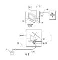
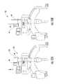
- FIG. 1is a schematic illustration of an MRI-guided interventional system in which embodiments of the present invention may be utilized.
- FIG. 2Ais a top view of an exemplary infusion kit according to embodiments of the present invention.
- FIG. 2Bis a digital photograph of the kit shown in FIG. 2A .
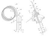
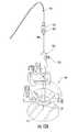
- FIG. 3is a sectional view of the trajectory guide of the MRI-guided system of FIG. 1 with an exemplary two-piece assembly (needle and surgical guide cannula) for transferring a substance (e.g., an infusate, etc.) to an intrabody target region of a patient.
- a substancee.g., an infusate, etc.
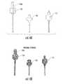
- FIG. 4Ais an enlarged side view and FIG. 4B is a corresponding digital photograph of proximal end portions of the devices shown in FIGS. 2A / 2 B according to some embodiments of the present invention.
- FIG. 5Ais an enlarged side view and FIG. 5B is a corresponding digital photograph of distal end portions of the devices shown in FIG. 2A / 2 B according to some embodiments of the present invention.
- FIG. 6Ais a side view and FIG. 6B is a corresponding digital photograph of a stylet and cannula assembly according to embodiments of the present invention.
- FIGS. 7A and 7Bare enlarged side views of the proximal and distal end portions, respectively, of the assembly shown in FIG. 6A / 6 B.
- FIG. 8Ais a side perspective view and FIG. 8B is a corresponding digital photograph of the stylet and cannula assembly as the assembly is inserted through a trajectory guide according to embodiments of the present invention.
- FIG. 9is an enlarged side view of the distal end of the assembly shown in FIG. 8A / 8 B according to some embodiments of the present invention.
- FIG. 10Ais a side perspective view and FIG. 10B is a corresponding digital photograph of the stylet removed from the cannula and the cannula remains in place in the trajectory guide according to embodiments of the present invention.
- FIG. 11is an enlarged digital image of a side view of the distal end of the assembly shown in FIGS. 10A / 10 B according to some embodiments of the present invention.
- FIG. 12Ais a side perspective view and FIG. 12B is a corresponding digital photograph of the needle inside the cannula as a needle and cannula assembly with the needle passing through the guide cannula held by the trajectory guide according to embodiments of the present invention.
- FIG. 13is a digital photograph of an enlarged side view of the distal end of the assembly shown in FIG. 12A / 12 B according to some embodiments of the present invention.
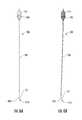
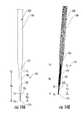
- FIG. 14Ais an enlarged view and FIG. 14B is a corresponding digital photograph of the distal end portion of the guide cannula and needle assembly illustrating an exemplary relative position of the distal end of the needle with respect to the distal end of the guide cannula according to embodiments of the present invention.
- FIG. 15Ais a side view of a trajectory guide with a short upper receiving member according to embodiments of the present invention.
- FIG. 15Bis a side view of a trajectory guide with a longer upper receiving member according to embodiments of the present invention.
- spatially relative termssuch as “under,” “below,” “lower,” “over,” “upper” and the like, may be used herein for ease of description to describe one element or feature's relationship to another element(s) or feature(s) as illustrated in the figures. It will be understood that the spatially relative terms are intended to encompass different orientations of the device in use or operation in addition to the orientation depicted in the figures. For example, if the device in the figures is inverted, elements described as “under” or “beneath” other elements or features would then be oriented “over” the other elements or features. Thus, the exemplary term “under” can encompass both an orientation of “over” and “under”.
- the devicemay be otherwise oriented (rotated 90 degrees or at other orientations) and the spatially relative descriptors used herein interpreted accordingly.
- the terms “upwardly,” “downwardly,” “vertical,” “horizontal” and the likeare used herein for the purpose of explanation only unless specifically indicated otherwise.
- monolithicmeans that the component (e.g., needle) is formed of a single uniform material.
- MRI visiblemeans that a device is visible, directly or indirectly, in an MRI image.
- the visibilitymay be indicated by the increased SNR of the MRI signal proximate to the device (the device can act as an MRI receive antenna to collect signal from local tissue) and/or that the device actually generates MRI signal itself, such as via suitable hydro-based coatings and/or fluid (typically aqueous solutions) filled channels or lumens.
- MRI compatiblemeans that a device is safe for use in an MRI environment and/or can operate as intended in an MRI environment without generating MR signal artifacts, and, as such, if residing within the high-field strength region of the magnetic field, is typically made of a non-ferromagnetic MRI compatible material(s) suitable to reside and/or operate in a high magnetic field environment.
- high-magnetic fieldrefers to field strengths above about 0.5 T (Tesla), typically above 1.0 T, and more typically between about 1.5 T and 10 T.
- the term “near real time”refers to both low latency and high frame rate. Latency is generally measured as the time from when an event occurs to display of the event (total processing time). For tracking, the frame rate can range from between about 100 fps to the imaging frame rate. In some embodiments, the tracking is updated at the imaging frame rate. For near “real-time” imaging, the frame rate is typically between about 1 fps to about 20 fps, and in some embodiments, between about 3 fps to about 7 fps. The low latency required to be considered “near real time” is generally less than or equal to about 1 second.
- the latency for tracking informationis about 0.01 s, and typically between about 0.25-0.5 s when interleaved with imaging data.
- visualizations with the location, orientation and/or configuration of a known intrabody devicecan be updated with low latency between about 1 fps to about 100 fps.
- visualizations using near real time MR image datacan be presented with a low latency, typically within between about 0.01 ms to less than about 1 second, and with a frame rate that is typically between about 1-20 fps.
- the systemcan use the tracking signal and image signal data to dynamically present anatomy and one or more intrabody devices in the visualization in near real-time.
- the tracking signal datais obtained and the associated spatial coordinates are determined while the MR image data is obtained and the resultant visualization(s) with the intrabody device (e.g., stylet) and the near RT MR image(s) are generated.
- sterilemeans that a device, kit, and/or packaging meets or exceeds medical/surgical cleanliness guidelines, and typically is free from live bacteria or other microorganisms.
- Embodiments of the present inventioncan be utilized with various diagnostic or interventional devices and/or therapies to any desired internal region of an object using MRI and/or in an MRI scanner or MRI interventional suite.
- the objectcan be any object, and may be particularly suitable for animal and/or human subjects for e.g., animal studies and/or veterinarian or human treatments.
- Some embodimentsdeliver therapies to the spine.
- Some embodimentsdeliver therapies to treat or stimulate a desired region of the sympathetic nerve chain.
- Other uses, inside or outside the brain, nervous system or spinal cordinclude stem cell placement, gene therapy or drug delivery for treating physiological conditions, chemotherapy, drugs including replicating therapy drugs. Some embodiments can be used to treat tumors.
- the term “substance,” as used herein,refers to a liquid for treating or facilitating diagnosis of a condition and can include bions, stem cells or other target cells to site-specific regions in the body, such as neurological, nerves or other target sites and the like.
- stem cells and/or other rebuilding cells or productscan be delivered into spine, brain or cardiac tissue, such as a heart wall via a minimally invasive MRI guided procedure, while the heart is beating (i.e., not requiring a non-beating heart with the patient on a heart-lung machine). Examples of known stimulation treatments and/or target body regions are described in U.S. Pat. Nos.
- fusionand derivatives thereof refers to the delivery of a substance (which can be a single substance or a mixture) at a relatively slow rate so that the substance can infuse about a target region.
- infusaterefers to a substance so delivered.
- FIG. 1illustrates an MRI-guided interventional system 10 with an MRI scanner 20 , a clinician workstation 30 with at least one circuit 30 c , at least one display 32 , an MRI compatible trajectory guide 50 t and a fluid transfer assembly 300 ( FIGS. 14A / 14 B) comprising a guide cannula 100 and needle 120 .
- the fluid delivery assembly 300can cooperate with an automated infusion pump P ( FIG. 1 ) or, less preferably, a manual syringe or other pressurized delivery source.
- the system 10can be configured to render or generate near real time or real time visualizations of the target anatomical space using MRI image data and predefined data of at least one surgical tool (e.g., guide cannula 100 and/or trajectory guide 50 t ) to segment the image data and place the trajectory guide 50 t and the cannula 100 in the rendered visualization in the correct orientation and position in 3D space (which is the MRI surgical space for MRI embodiments), anatomically registered to a patient.
- the trajectory guide 50 t and the cannula 100can include or cooperate with tracking, monitoring and/or other interventional components.
- An exemplary trajectory guide 50 tis illustrated in FIG. 1 in an exemplary (head) position on a patient.
- the trajectory guidecan be used for any target location including, for example, the spine.
- the trajectory guide 50 tcan be mounted over or on an object, e.g., patient or subject, so that the upper receiving tube 60 ( FIGS. 3, 15A, 15B ) is oriented substantially perpendicular to the entry location (typically for spinal uses) or may be mounted to extend outward from the patient entry location at an angle as shown in FIG. 1 .
- the trajectory guide 50 ttypically provides X-Y adjustment and pitch and roll adjustment in order to accurately position the cannula 100 at a desired location within a patient.
- suitable trajectory guidessee U.S. Pat. No. 8,374,677, the contents of which are hereby incorporated by reference as if recited in full herein.
- other trajectory guide configurationsmay be used and embodiments of the invention are not limited by the examples of the trajectory guides herein.
- the systemsare configured to provide a substantially automated or semi-automated and relatively easy-to-use MRI-guided system with defined workflow steps and interactive visualizations.
- the systemsdefine and present workflow with discrete steps for finding target and entry point(s), guiding the alignment of the targeting cannula to a planned trajectory, monitoring the insertion of the guide cannula 100 , and adjusting the (X-Y) position in cases where the placement needs to be corrected.
- the circuit or computer modulecan display data for scan plane center and angulation to be entered at the console.
- the workstation/circuitcan passively or actively communicate with the MR scanner.
- the systemcan also be configured to use functional patient data (e.g., fiber tracks, fMRI and the like) to help plan or refine a target surgical site and/or access path.
- FIGS. 2A / 2 Billustrate a sterile assembly or set of components that may be provided individually or as a kit 150 of components for fluid delivery of an infusate or biopsy collection, for example.
- the assembly or kit 150can include the guide cannula 100 , a stylet 110 and a needle 120 .
- the needle 120can be an infusion needle that is pre-attached to a length of flexible (extension) tubing 140 to be provided as an integrated subassembly 140 A.
- the tubing 140can be provided as a component separate from the infusion needle 120 for assembly prior to or during a procedure. If so, the ends of the tubing 140 and/or needle 120 may be capped or held in sterile sleeves to maintain sterility or cleanliness.
- a length of the needle 120is encased in the flexible tubing 140 .
- the lengthmay be a short or long length.
- the flexible tubing 140can be attached to a proximal end 125 p of the guide cannula connector 125 .
- the flexible tubing 140can protect a long length of the needle where such a configuration is used.
- the needle 120can be one continuous piece of fused silica glass that goes from the distal tip all the way to the very proximal end, typically between about 4 feet to about 10 feet long.
- the flexible tube 140can be attached to reside over (encase) the needle body (e.g., of fused silica) 120 b to protect the needle body as it may lay across a floor or a table as it travels to an infusion pump or manual syringe.
- the delivery substance Acan be delivered through the needle so that it only touches the single piece of fused silica of the needle body 120 b .
- the tubing 140can be used to connect the needle 120 to the pump or other pressurized source and the delivery substance A can flow through the tubing 140 to the needle 120 for delivery. Further, other MRI compatible needle materials may be used.
- the tubing 140is PVC tubing. According to some embodiments, the tubing 140 is silicone tubing.
- the tubing 140may have various lengths. For example, in some embodiments, the tubing may be between about four to about ten feet (4 ft-10 ft) in length, although other lengths are possible. At least a major portion (50% or greater) of a length of the needle body 120 can reside in the flexible tubing 140 .
- the kit 150can be a single-use disposable kit of components.
- the kit 150can be provided in other groups or sub-groups of components and does not require all components shown.
- the componentscan also be provided individually, typically in suitable sterile packaging.
- the assembly or kit 150can also include an optional depth stop 160 that can be slidably attached to reside proximate an upper to mid-portion of the outer diameter of the guide cannula 100 .
- the depth stop 160can include a small sleeve with an open lumen 162 that can receive the cannula 100 .
- the depth stopmay include a laterally outwardly extending member 161 such as a thumb screw.
- the depth stop 160configured to be slide over the outer diameter of the guide cannula 100 to snugly reside about the outer surface of the elongate guide cannula.
- the depth stop 160can reside above and abut a lock 170 ( FIGS. 3, 8A, 8B, 10A, 10B ) on the trajectory guide 50 t .
- the lock 170 and depth stopcan lock the cannula 100 into a desired longitudinal position relative to the trajectory guide 50 t .
- the cannula 100can cooperate with and/or be secured to the trajectory guide 50 t using other configurations including frictional engagement of surface features of the guide 50 t and/or cannula 100 , e.g., bumps, clamps, locking washers, O-rings and grooves and the like.
- the cannula 100can be securely held so that the tip 101 t of the guide cannula resides at a specified intrabody location, typically a short distance “D 1 ” ( FIG. 3 ) of between about 1 mm to about 50 mm above an actual infusate target site S. Stated differently, in an intrabody delivery position, the distal end of the cannula 101 resides above the tip 121 t at the distal end of the infusate needle 121 .
- the needle 120can be slidably and releasably attached to the guide cannula 100 to form a subassembly 300 ( FIGS. 12A, 12B, 14A, 14B ).
- the needleis attached to the cannula 100 after the cannula is in position in the body and the stylet has been removed ( FIGS. 10A, 10B, 12A, 12B, 13 ).
- the needle 110can have a connector 125 on its proximal end. Where the needle 120 is an infusion needle, the needle body 120 b can extend a distance above the connector 125 into the flexible extension tubing 140 a defined length as discussed above.
- the infusion needle 120can have a body 120 b of fused silica (glass) that can be configured to define a single open lumen that extends from the end of the tip 120 t to the proximal end of the needle body 120 b so that the lumen is in fluid communication with the flexible tubing 140 .
- the needle 120can have an outer polymeric coating or sleeve such as a shrink wrap material to provide protection from breakage or to contain fragments if such should break.
- the guide cannula 100can have a rigid body.
- the guide cannula 100may comprise alumina/ceramic that can be MRI visible.
- the guide cannula 100can have an outer surface 100 s having a lubricious coating and/or sleeve 100 s .
- the coating and/or sleeve 100 scan be a substantially transparent polymeric material. Where a sleeve is used, the sleeve 100 s can be a thin flexible polymeric sleeve that can be conformably attached to the underlying cannula body 100 b .
- the coating and/or sleevecan be configured with sufficient strength to be able to retain components of the guide cannula should the cannula fracture.
- the sleevecan be an elastomeric shrink wrap or tube that can be heat-shrink applied to the underlying body.
- the stylet 110is optional.
- the distal end 101 of the guide cannula 100may be sufficiently sharp to be able to penetrate tissue without undue trauma for certain procedures without requiring the stylet 110 .
- the stylet 110can be slidably attached to the guide cannula 100 using mating connectors 105 , 115 on respective proximal ends of the devices.
- the stylet 110can be metallic and provide structural support to the cannula during intrabody insertion.
- the stylet 110can comprise a non-ferromagnetic metallic body with a sharp tip 110 t that can pierce tissue or other target anatomy without undue trauma (e.g., in a minimally invasive manner).
- the stylet 110can comprise titanium or a sufficient grade of stainless steel.
- the guide cannula 100slidably receives the stylet 110 and allows the distal end 111 and/or tip 111 t of the stylet to extend a short distance beyond the tip 101 t of the guide cannula.
- the multiple-piece constructionallows for a less traumatic and/or stronger configuration during initial insertion of the cannula 100 in the body.
- the guide cannula 100can be provided in the kit 150 as a subassembly 200 ( FIGS. 6A / 6 B), where the guide cannula 100 and stylet 110 are releasably pre-attached (where the stylet is used).
- the assembly 300 ( FIGS. 3, 12A, 12B and 13 ) of the cannula 100 with the infusate needle 120can be configured to flowably introduce and/or inject a desired therapy substance (e.g., antigen, gene therapy, chemotherapy or stem-cell or other therapy type).
- a desired therapy substancee.g., antigen, gene therapy, chemotherapy or stem-cell or other therapy type.
- FIGS. 4A, 4B, 5A and 5Billustrate examples of the cannula 100 , stylet 110 and infusion needle 120 .
- Both the stylet 110 and infusion needle 120can releasably interchangeably attach to the cannula 100 using respective connectors 105 , 115 , 125 .
- the connectorscan be threadably engage, have a bayonet fitting, or tongue and groove fittings or other releasable attachment configurations.
- the cannula 100includes a cannula body 100 b defining at least one longitudinally extending lumen 102 .
- the cannula 100typically is formed of an MRI-compatible (non-ferromagnetic) material such as ceramic as discussed above and can have a distal end 101 that tapers to a smaller outer diameter size relative to the outer diameter size of the cannula body 100 b over most if not all of its length.
- the entire body 100 b or markers on the bodycan be MRI visible for image segmentation and recognition.
- the lumen 102slidably receives the stylet 110 ( FIGS. 6A, 6B, 7A, 7B ) to form the stylet subassembly 200 with the distal end 111 and/or tip 111 t of the stylet extending a distance D 2 beyond the cannula tip 101 t .
- the distance D 2can be less than D 1 , and is typically between about 0.1 mm to about 5 mm.
- the infusate needle 120has a stepped distal end 121 where the outer diameter decreases in size toward the tip 121 t .
- the body 120 bcan have a substantially constant (on average) outer diameter segment 122 that steps down into the smaller outer diameter (OD) segment 123 at the distal end 121 of the infusate needle.
- the smaller OD segmentcan 123 have a length D 3 that is between about 1 mm to about 50 mm, typically between 1 mm and 10 mm, and in some embodiments between about 2 mm to about 4 mm, such as about 3 mm.
- the second segment 122can be longer than the first segment 123 and can be between about 2 mm and 20 mm.
- the distal end of the needle 121may include more than two co-axially aligned (concentric) stepped segments.
- the tip 121 t of the infusate needle 120can extend a distance D 4 beyond the cannula tip 101 t so that a portion of the larger OD segment 122 as well as the smaller OD segment 123 reside outside of the cannula tip 101 t as shown in FIGS. 3, 13 and 14A / 14 B.
- the length D 4 of the distal end of the infusion needle outside the cannula 100 during deliverycan be between about 3 mm to 30 mm. This configuration may inhibit reflux.
- the inner diameter of the infusate needle 120is in the range of from about 10 ⁇ m to 1 mm and, in some particular embodiments, is be between about 100 ⁇ m to about 750 ⁇ m, such as about 200 ⁇ m.
- the outer diameteris in the range of from about 75 ⁇ m to 1.08 mm and, in some embodiments is about 360 ⁇ m.
- the cannula 100has an outer surface comprising a polymeric support sleeve 100 s which as a thickness in the range of from about 40 ⁇ m to about 60 ⁇ m.
- the needle 120can have a stepped end that cooperates with the tapered end of the cannula to form three co-axially disposed step segments (the outer surface of the distal end of the cannula 101 , the first segment of the distal end of the needle 122 and the second segment of the distal end of the needle 123 , respectively) having different outer diameters and being longitudinally separated with steps on end faces S 1 , S 2 , S 3 .
- the steps S 1 , S 2 , S 3can serve to reduce or prevent reflux of the delivered substance.
- the infusate needle 120 connector 125can be configured as a luer lock and the needle/tubing can be operatively coupled to an infusion pump P which supplies a mass flow of the desired substance or material to be delivered into the patient.
- the stylet 110can have a segment 112 that resides above the distal end thereof 111 with an outer diameter that is the same or slightly larger (on average) than the outer diameter of the needle segment 122 and can be configured to be slidably received in the guide cannula 100 to snugly reside in the lumen 102 of the guide cannula 100 for structural buttressing.
- FIGS. 8A / 8 B- 13An exemplary sequence shown in FIGS. 8A / 8 B- 13 .
- the stylet 110is inserted into the cannula 100 to form the assembly 200 .
- the assembly 200is formed prior to insertion of the components into the trajectory guide, e.g., the assembly 200 is slidably inserted as a unit.
- the cannula 100can be attached to the trajectory guide 50 t first, then the stylet 110 can be inserted.
- the trajectory guide 50 tis held by a frame, e.g., a stereotactic frame, that can be secured to the patient or that can be secured to a holder residing over the patient.
- a framee.g., a stereotactic frame
- the trajectory guide 50 tis held by a frame, e.g., a stereotactic frame, that can be secured to the patient or that can be secured to a holder residing over the patient.
- the depth stop 160can be placed on the cannula 100 before the stylet 110 is inserted into the cannula 100 or after, but before the assembly 200 is inserted into the trajectory guide 50 t .
- the depth stop 160can be pre-attached to the guide cannula 100 and provided as a subassembly in the kit 150 .
- the stylet/cannula assembly 200can be inserted into the receiving channel 60 of the trajectory guide 50 t .
- the cannula 100can be locked to the trajectory guide 50 t using the lock 170 that can be laterally extended to rest against the outer surface of the cannula or against a cooperating feature on the cannula.
- the depth stop 160can be adjusted to reside on top of the device lock 170 when the distal end of the cannula 101 is at a desired intrabody location.
- FIGS. 10A, 10B and 11show that the stylet 110 can be removed from the guide cannula 100 while the guide cannula 100 remains locked in the trajectory guide 50 t so that the distal end 101 of the guide cannula is proximate a desired target infusate delivery site (and/or a biopsy collection site).
- FIGS. 12A, 12B and 13illustrate that once the stylet 110 is removed from the guide cannula 100 , the needle 120 , typically an infusate needle, is slidably inserted into the guide cannula 10 and the connectors 125 , 105 connected so that the distal end extends out of the distal tip of the guide cannula to reside at a target intrabody site A.
- FIGS. 14A / 14 Billustrate an exemplary configuration of the distal end of the needle 121 during active dispensing/infusate.
- FIGS. 15A and 15Billustrate that the trajectory guide 50 t can have different height H receiving channels 60 , shown as short and tall channels 60 s , 60 t .
- the short channel 60 scan be at about the same height as the tallest adjacent top-mounted actuator 99 , and is typically about 2 cm shorter than the tall channel 60 t and may be particularly suitable for vertical orientation inside a magnet bore to thereby avoid interference with the bore chamber.
- the substance A ( FIGS. 2A / 2 B) delivered to the target site or region S through the cannula guide 100 and cooperating needle 120may be any suitable and desired substance for drug discovery, animal or human clinical trials and/or approved medical procedures.
- the substance Ais a liquid or slurry.
- the substancemay be a chemotherapeutic (cytotoxic) fluid.
- the substancecan include certain types of advantageous cells that act as vaccines or other medicaments (for example, antigen presenting cells such as dendritic cells).
- the dendritic cellsmay be pulsed with one or more antigens and/or with RNA encoding one or more antigen.
- Exemplary antigensare tumor-specific or pathogen-specific antigens.
- tumor-specific antigensinclude, but are not limited to, antigens from tumors such as renal cell tumors, melanoma, leukemia, myeloma, breast cancer, prostate cancer, ovarian cancer, lung cancer and bladder cancer.
- pathogen-specific antigensinclude, but are not limited to, antigens specific for HIV or HCV.
- the substance Amay comprise radioactive material such as radioactive seeds.
- Substances A delivered to a target area in accordance with embodiments of the present inventionmay include, but are not limited to, the following drugs (including any combinations thereof) listed in Table 1:
- the infusateis delivered to a patient at an infusion rate in the range of from about 1 to 3 ⁇ L/minute.
- insertion of the surgical cannula 100can be tracked in near real time by reference to a void in the patient tissue caused by the cannula 100 and reflected in the MR image.
- one or more MRI-visible fiducial markersmay be provided on the surgical cannula 100 , MR scanned and processed, and displayed on the UI.
- the surgical cannula 100may itself be formed of an MRI-visible material, MR scanned and processed, and displayed on the UI.
- the surgical cannulamay include an embedded intrabody MRI antenna that is configured to pick-up MRI signals in local tissue during an MRI procedure.
- the MRI antennacan be configured to reside on a distal end portion of the surgical cannula.
- the antennahas a focal length or signal-receiving length of between about 1-5 cm, and typically is configured to have a viewing length to receive MRI signals from local tissue of between about 1-2.5 cm.
- the MRI antennacan be formed as comprising a coaxial and/or triaxial antenna.
- other antenna configurationscan be used, such as, for example, a whip antenna, a coil antenna, a loopless antenna, and/or a looped antenna. See, e.g., U.S.
- the cannula 100 and needle 120have been identified herein as delivery devices and methods for delivering a substance to a patient have been described, in accordance with some embodiments of the invention, the cannula 100 and needle 120 and associated methods can be used to withdraw a substance (e.g., spinal fluid) from a patient.
- a substancee.g., spinal fluid
- the devices and methods as disclosed hereincan be used to transfer a substance into and/or from a patient.
- the deviceshave been described herein primarily with reference to MRI-guided insertion and infusion procedures, in some embodiments the devices can be used in procedures without MRI guidance.
- the surgical cannula 100has been described in use with a trajectory guide 50 b , the cannula may be used with other types of trajectory guidance or stereotactic frames or without a stereotactic frame or trajectory guide.
- the devices as depicted inmay typically be employed for acute treatments. However, the systems, cannula, methods and procedures described herein may likewise be used for installation of a chronic delivery cannula or catheter.
- Chronic systemsmay be installed in the same manner as the acute systems 10 ( FIG. 1 ) except that the delivery needle 120 or portion thereof can be configured to remain in the patient post-first delivery and connect to a port device installed on the patient (e.g., behind the patient's ear) to provide an (external) access point for subsequently releasably coupling the connection tubing 140 .
- the pump Pcan be periodically or continuously connected to the needle 120 to deliver a therapeutic substance to a target region of the patient.
- the connecting tubing, the pump and a substance reservoirmay be implanted in the patient and connected to the infusion needle 120 by the tubing so that the port device s not needed, similar to an IPG and electrical stimulation lead.
- the chronic systemcan allow delivery of the substance or substances at different delivery times without requiring another surgical implantation procedure.
- the system 10may also include a decoupling/tuning circuit that allows the system to cooperate with an MRI scanner 20 and filters and the like. See, e.g., U.S. Pat. Nos. 6,701,176; 6,904,307 and U.S. Patent Application Publication No. 2003/0050557, the contents of which are hereby incorporated by reference as if recited in full herein.
Landscapes
- Health & Medical Sciences (AREA)
- Life Sciences & Earth Sciences (AREA)
- General Health & Medical Sciences (AREA)
- Physics & Mathematics (AREA)
- Public Health (AREA)
- Veterinary Medicine (AREA)
- Heart & Thoracic Surgery (AREA)
- Biomedical Technology (AREA)
- Animal Behavior & Ethology (AREA)
- Engineering & Computer Science (AREA)
- Pathology (AREA)
- Condensed Matter Physics & Semiconductors (AREA)
- Anesthesiology (AREA)
- Hematology (AREA)
- General Physics & Mathematics (AREA)
- Vascular Medicine (AREA)
- Medical Informatics (AREA)
- Molecular Biology (AREA)
- Surgery (AREA)
- Magnetic Resonance Imaging Apparatus (AREA)
- High Energy & Nuclear Physics (AREA)
- Biophysics (AREA)
- Pulmonology (AREA)
Abstract
Description
| TABLE 1 | |
| DRUG (generic name) | DISORDER(S) |
| Caprylidene | Alzheimer's disease |
| Donepezil | Alzheimer's disease |
| Galantamine | Alzheimer's disease |
| Memantine | Alzheimer's disease |
| Tacrine | Alzheimer's disease |
| vitamin E | Alzheimer's disease |
| ergoloid mesylates | Alzheimer's disease |
| Riluzole | Amyotrophic lateral sclerosis |
| Metoprolol | Benign essential tremors |
| Primidone | Benign essential tremors |
| Propanolol | Benign essential tremors |
| Gabapentin | Benign essential tremors & Epilepsy |
| Nadolol | Benign essential tremors & Parkinson's disease |
| Zonisamide | Benign essential tremors & Parkinson's disease |
| Carmustine | Brain tumor |
| Lomustine | Brain tumor |
| Methotrexate | Brain tumor |
| Cisplatin | Brain tumor & Neuroblastoma |
| Ioversol | Cerebral arteriography |
| Mannitol | Cerebral Edema |
| Dexamethasone | Cerebral Edema & Neurosarcoidosis |
| Baclofen | Cerebral spasticity |
| Ticlopidine | Cerebral thrombosis/embolism |
| Isoxsuprine | Cerebrovascular insufficiency |
| Cefotaxime | CNS infection & Meningitis |
| Acyclovir | Encephalitis |
| Foscarnet | Encephalitis |
| Ganciclovir | Encephalitis |
| interferon alpha-2a | Encephalitis |
| Carbamazepine | Epilepsy |
| Clonazepam | Epilepsy |
| Diazepam | Epilepsy |
| divalproex sodium | Epilepsy |
| Ethosuximide | Epilepsy |
| Ethotoin | Epilepsy |
| Felbamate | Epilepsy |
| Fosphenytoin | Epilepsy |
| Levetiracetam | Epilepsy |
| Mephobarbital | Epilepsy |
| Paramethadione | Epilepsy |
| Phenytoin | Epilepsy |
| Trimethadione | Epilepsy |
| Pregabalin | Epilepsy & Neuralgia |
| immune globulin intravenous | Guillain-Barre Syndrome |
| interferon beta-1b | Guillain-Barre Syndrome & Multiple sclerosis |
| Guillain-Barre Syndrome & Multiple sclerosis & | |
| Azathioprine | Neurosarcoidosis |
| Risperidone | Head injury |
| Tetrabenazine | Huntington's disease |
| Acetazolamide | Hydrocephalus & Epilepsy |
| Alteplase | Ischemic stroke |
| Clopidogrel | Ischemic stroke |
| Nimodipine | Ischemic stroke & Subarachnoid hemorrhage |
| Aspirin | Ischemic stroke & Thromboembolic stroke |
| Amikacin | Encaphalitis |
| Ampicillin | Encaphalitis |
| ampicillin/sulbactam | Encaphalitis |
| Ceftazidime | Encaphalitis |
| Ceftizoxime | Encaphalitis |
| Cefuroxime | Encaphalitis |
| Chloramphenicol | Encaphalitis |
| cilastatin/imipenem | Encaphalitis |
| Gentamicin | Encaphalitis |
| Meropenem | Encaphalitis |
| Metronidazole | Encaphalitis |
| Nafcillin | Encaphalitis |
| Oxacillin | Encaphalitis |
| Piperacillin | Encaphalitis |
| Rifampin | Encaphalitis |
| sulfamethoxazole/trimethoprim | Encaphalitis |
| Tobramycin | Encaphalitis |
| Triamcinolone | Encaphalitis |
| Vancomycin | Encaphalitis |
| Ceftriaxone | Encaphalitis & Neurosyphilis |
| Penicillin | Encaphalitis & Neurosyphilis |
| Corticotrophin | Multiple sclerosis |
| Dalfampridine | Multiple sclerosis |
| Glatiramer | Multiple sclerosis |
| Mitoxantrone | Multiple sclerosis |
| Natalizumab | Multiple sclerosis |
| Modafinil | Multiple sclerosis |
| Cyclophosphamide | Multiple sclerosis & Brain tumor & Neuroblastoma |
| interferon beta-1a | Multiple sclerosis & Neuritis |
| Prednisolone | Multiple sclerosis & Neurosarcoidosis |
| Prednisone | Multiple sclerosis & Neurosarcoidosis |
| Amantadine | Multiple sclerosis & Parkinson's disease |
| Methylprednisolone | Neuralgia |
| Desvenlafaxine | Neuralgia |
| Nortriptyline | Neuralgia |
| Doxorubicin | Neuroblastoma |
| Vincristine | Neuroblastoma |
| Albendazole | Neurocystecercosis |
| chloroquine phosphate | Neurosarcoidosis |
| Hydroxychloroquine | Neurosarcoidosis |
| Infliximab | Neurosarcoidosis |
| Pentoxyfilline | Neurosarcoidosis |
| Thalidomide | Neurosarcoidosis |
| Apomorphine | Parkinson's disease |
| Belladonna | Parkinson's disease |
| Benztropine | Parkinson's disease |
| Biperiden | Parkinson's disease |
| Bromocriptine | Parkinson's disease |
| Carbidopa | Parkinson's disease |
| carbidopa/entacapone/levodopa | Parkinson's disease |
| carbidopa/levodopa | Parkinson's disease |
| Entacapone | Parkinson's disease |
| Levodopa | Parkinson's disease |
| pergolide mesylate | Parkinson's disease |
| Pramipexole | Parkinson's disease |
| Procyclidine | Parkinson's disease |
| Rasagiline | Parkinson's disease |
| Ropinirole | Parkinson's disease |
| Rotiotine | Parkinson's disease |
| Scopolamine | Parkinson's disease |
| Tolcapone | Parkinson's disease |
| Trihexyphenidyl | Parkinson's disease |
| Seleginline | Parkinson's disease |
| Rivastigmine | Parkinson's disease & Alzheimer's disease |
| Anisindione | Thromboembolic stroke |
| Warfarin | Thromboembolic stroke |
| 5-hydroxytryptophan | Depression & Anxiety & ADHD |
| Duloxetine | Depression & Anxiety & Bipolar disorder |
| Escitalopram | Depression & Anxiety & Bipolar disorder |
| Venlafaxine | Depression & Anxiety & Bipolar disorder & Autism & |
| Social anxiety disorder | |
| Desvenlafaxine | Depression & Anxiety & PTSD & ADHD |
| Paroxetine | Depression & Anxiety & PTSD & Social anxiety disorder |
| fluoxetine/olanzapine | Depression & Bipolar disorder |
| 1-methylfolate | Depression & BPD |
| Amitriptyline | Depression & PTSD |
| Sertraline | Depression & PTSD & Bipolar disorder & Social anxiety |
| disorder | |
| Fluvoxamine | Depression & PTSD & Social anxiety disorder |
| Olanzapine | Depression & Schizophrenia & Bipolar disorder |
| Paliperidone | Depression & Schizophrenia & Bipolar disorder |
| Aripiprazole | Depression & Schizophrenia & Bipolar disorder & Autism |
| Quetiapine | Depression & Schizophrenia & PTSD & BPD & Bipolar |
| disorder | |
| Risperidone | Depression & Schizophrenia & PTSD & BPD & Bipolar |
| disorder & Autism | |
| Amisulpride | Depression & Social anxiety disorder |
| Chlorpromazine | Psychosis |
| Droperidol | Psychosis |
| Fluphenazine | Psychosis |
| Periciazine | Psychosis |
| Perphenazine | Psychosis |
| Thiothixene | Psychosis |
| Triflupromazine | Psychosis |
| Haloperidol | Psychosis & Dementia |
| Prazosin | PTSD |
| Clozapine | Schizophrenia |
| Flupenthixol | Schizophrenia |
| Iloperidone | Schizophrenia |
| Loxapine | Schizophrenia |
| Mesoridazine | Schizophrenia |
| Promazine | Schizophrenia |
| Reserpine | Schizophrenia |
| Thioridazein | Schizophrenia |
| Zuclopenthixol | Schizophrenia |
| Asenapine | Schizophrenia & Bipolar disorder |
| Levomepromazine | Schizophrenia & Bipolar disorder |
| Ziprasidone | Schizophrenia & Bipolar disorder |
| Molindone | Schizophrenia & Psychosis |
| Pimozide | Schizophrenia & Psychosis |
| Thioridazine | Schizophrenia & Psychosis |
| Cytarabine | Chemotherapy, hematological malignancies |
Claims (24)
Priority Applications (1)
| Application Number | Priority Date | Filing Date | Title |
|---|---|---|---|
| US14/468,922US9891296B2 (en) | 2013-09-13 | 2014-08-26 | Intrabody fluid transfer devices, systems and methods |
Applications Claiming Priority (2)
| Application Number | Priority Date | Filing Date | Title |
|---|---|---|---|
| US201361877451P | 2013-09-13 | 2013-09-13 | |
| US14/468,922US9891296B2 (en) | 2013-09-13 | 2014-08-26 | Intrabody fluid transfer devices, systems and methods |
Publications (2)
| Publication Number | Publication Date |
|---|---|
| US20150080708A1 US20150080708A1 (en) | 2015-03-19 |
| US9891296B2true US9891296B2 (en) | 2018-02-13 |
Family
ID=52668586
Family Applications (1)
| Application Number | Title | Priority Date | Filing Date |
|---|---|---|---|
| US14/468,922Active2036-07-01US9891296B2 (en) | 2013-09-13 | 2014-08-26 | Intrabody fluid transfer devices, systems and methods |
Country Status (1)
| Country | Link |
|---|---|
| US (1) | US9891296B2 (en) |
Cited By (10)
| Publication number | Priority date | Publication date | Assignee | Title |
|---|---|---|---|---|
| US10569013B2 (en)* | 2010-04-16 | 2020-02-25 | MRI Interventions, Inc. | MRI-compatible surgical cannulae for transferring a substance to and/or from a patient |
| US10576247B2 (en) | 2016-02-17 | 2020-03-03 | MRI Interventions, Inc. | Intrabody surgical fluid transfer assemblies with adjustable exposed cannula to needle tip length, related systems and methods |
| US11022664B2 (en) | 2018-05-09 | 2021-06-01 | Clearpoint Neuro, Inc. | MRI compatible intrabody fluid transfer systems and related devices and methods |
| US20210162134A1 (en)* | 2018-07-30 | 2021-06-03 | Kyoto University | Microsyringe unit |
| WO2021126336A1 (en)* | 2019-12-19 | 2021-06-24 | Clearpoint Neuro, Inc. | Front-loadable fluid transfer assemblies and related medical fluid transfer systems |
| US11253237B2 (en) | 2018-05-09 | 2022-02-22 | Clearpoint Neuro, Inc. | MRI compatible intrabody fluid transfer systems and related devices and methods |
| US11298041B2 (en) | 2016-08-30 | 2022-04-12 | The Regents Of The University Of California | Methods for biomedical targeting and delivery and devices and systems for practicing the same |
| WO2022132282A1 (en) | 2020-12-14 | 2022-06-23 | Clearpoint Neuro, Inc. | Surgical base assemblies for trajectory guide systems and associated trajectory guide systems |
| US11497576B2 (en) | 2017-07-17 | 2022-11-15 | Voyager Therapeutics, Inc. | Trajectory array guide system |
| US11684750B2 (en) | 2019-10-08 | 2023-06-27 | Clearpoint Neuro, Inc. | Extension tube assembly and related medical fluid transfer systems and methods |
Families Citing this family (1)
| Publication number | Priority date | Publication date | Assignee | Title |
|---|---|---|---|---|
| CN110812538B (en)* | 2019-11-21 | 2022-09-23 | 孙涛 | Disposable thoracic cavity and abdominal cavity puncture catheter drainage device |
Citations (135)
| Publication number | Priority date | Publication date | Assignee | Title |
|---|---|---|---|---|
| US3352306A (en)* | 1963-12-23 | 1967-11-14 | Hrisch Sidney | Intravenous catheter assembly |
| US3540447A (en)* | 1967-09-29 | 1970-11-17 | Becton Dickinson Co | Spinal needle |
| GB1255551A (en) | 1968-03-30 | 1971-12-01 | Heraeus Schott Quarzschmelze | Improvements in or relating to externally coated fused silica tube |
| US3856009A (en) | 1971-11-26 | 1974-12-24 | Johnson & Johnson | Catheter placement unit |
| US4149535A (en) | 1976-05-06 | 1979-04-17 | Gist-Brocades N.V. | Catheter holding device |
| US4239042A (en) | 1979-04-05 | 1980-12-16 | Dow Corning K.K. | Catheter placement system |
| US4265928A (en) | 1978-10-06 | 1981-05-05 | Intermedicat Gmbh | Anti-thrombogenic retentive catheter |
| US4327722A (en) | 1979-08-20 | 1982-05-04 | Groshong Leroy E | Methods and apparatus for intravenous therapy and hyperalimentation |
| US4449532A (en) | 1980-07-08 | 1984-05-22 | Karl Storz | Dilator to facilitate endoscope insertion into the body |
| US4531943A (en) | 1983-08-08 | 1985-07-30 | Angiomedics Corporation | Catheter with soft deformable tip |
| US4543091A (en) | 1983-05-18 | 1985-09-24 | Edward C. Froning | X-ray marker device |
| US4543092A (en) | 1982-08-06 | 1985-09-24 | Doron Mehler | Catheter set |
| US4597421A (en) | 1984-11-19 | 1986-07-01 | Varian Associates, Inc. | Method and device for on-column injection of a liquid sample into small diameter columns |
| US4623789A (en) | 1983-03-10 | 1986-11-18 | Shionogi & Co., Ltd. | Fiberoptic probe for brain scanning with detachable cannula guide |
| US4629450A (en) | 1984-05-09 | 1986-12-16 | Terumo Corporation | Catheter introducing instrument |
| US4705511A (en)* | 1985-05-13 | 1987-11-10 | Bipore, Inc. | Introducer sheath assembly |
| US4738658A (en) | 1986-09-19 | 1988-04-19 | Aries Medical Incorporated | Tapered hemostatic device for use in conjunction with a catheter for alleviating blood leakage and method for using same |
| US4739768A (en) | 1986-06-02 | 1988-04-26 | Target Therapeutics | Catheter for guide-wire tracking |
| US4781691A (en) | 1987-07-17 | 1988-11-01 | The Kendall Company | Stepped needle |
| US4846799A (en) | 1986-10-09 | 1989-07-11 | Hakko Electric Machine Works Co., Ltd. | Set of double needles for injecting liquid medicine |
| US4897077A (en) | 1987-05-22 | 1990-01-30 | Kontron Inc. | Method of inserting an IAB device into the body |
| US4955863A (en) | 1986-02-05 | 1990-09-11 | Menlo Care, Inc. | Adjustable catheter assembly |
| US4978334A (en) | 1988-09-08 | 1990-12-18 | Toye Frederic J | Apparatus and method for providing passage into body viscus |
| US4995866A (en)* | 1989-12-15 | 1991-02-26 | Microvena Corporation | Combined needle and dilator apparatus |
| US5069673A (en) | 1990-02-07 | 1991-12-03 | Cordis Corporation | Catheter with double step-down bore |
| US5380292A (en) | 1993-12-22 | 1995-01-10 | Wilson-Cook Medical, Inc. | Gastrointestinal needle mechanism |
| US5562626A (en) | 1995-09-11 | 1996-10-08 | Sanpietro; Joseph A. | Safety syringe |
| US5699801A (en) | 1995-06-01 | 1997-12-23 | The Johns Hopkins University | Method of internal magnetic resonance imaging and spectroscopic analysis and associated apparatus |
| US5720720A (en) | 1993-08-27 | 1998-02-24 | The United States Of America As Represented By The Department Of Health And Human Services | Convection-enhanced drug delivery |
| US5792144A (en) | 1997-03-31 | 1998-08-11 | Cathco, Inc. | Stent delivery catheter system |
| US5833662A (en)* | 1995-01-19 | 1998-11-10 | Stevens; Robert C. | Hemostasis cannula system |
| US5851203A (en) | 1993-09-22 | 1998-12-22 | Cordis Corporation | Neuro-microcatheter |
| WO1999004849A1 (en) | 1997-07-25 | 1999-02-04 | The Regents Of The University Of California | Retroperfusion catheter apparatus and method |
| US5871470A (en)* | 1997-04-18 | 1999-02-16 | Becton Dickinson And Company | Combined spinal epidural needle set |
| US5902282A (en) | 1996-12-26 | 1999-05-11 | Johnson & Johnson Medical, Inc. | Step-down catheter |
| US5919171A (en) | 1994-08-03 | 1999-07-06 | Kanegafuchi Kagaku Kogyo Kabushiki Kaisha | Microcatheter |
| US5928145A (en) | 1996-04-25 | 1999-07-27 | The Johns Hopkins University | Method of magnetic resonance imaging and spectroscopic analysis and associated apparatus employing a loopless antenna |
| WO1999049909A2 (en) | 1998-03-27 | 1999-10-07 | Brigham & Women's Hospital, Inc. | Revascularization apparatus having coaxial channeling and injecting means |
| US6020196A (en) | 1996-05-09 | 2000-02-01 | Baxter International Inc. | Devices for harvesting and homogenizing adipose tissue containing autologous endothelial cells |
| US6026316A (en) | 1997-05-15 | 2000-02-15 | Regents Of The University Of Minnesota | Method and apparatus for use with MR imaging |
| US6030369A (en) | 1997-07-03 | 2000-02-29 | Target Therapeutics Inc. | Micro catheter shaft |
| US6042579A (en) | 1997-04-30 | 2000-03-28 | Medtronic, Inc. | Techniques for treating neurodegenerative disorders by infusion of nerve growth factors into the brain |
| US6050992A (en) | 1997-05-19 | 2000-04-18 | Radiotherapeutics Corporation | Apparatus and method for treating tissue with multiple electrodes |
| US6093180A (en) | 1995-04-28 | 2000-07-25 | Medtronic, Inc. | Intraparenchymal infusion catheter system |
| US6167311A (en) | 1999-06-14 | 2000-12-26 | Electro Core Techniques, Llc | Method of treating psychological disorders by brain stimulation within the thalamus |
| US6186986B1 (en) | 1998-01-21 | 2001-02-13 | St. Jude Medical Cardiovascular Group, Inc. | Micro-catheters and methods of their manufacture |
| US6263229B1 (en) | 1998-11-13 | 2001-07-17 | Johns Hopkins University School Of Medicine | Miniature magnetic resonance catheter coils and related methods |
| US6284971B1 (en) | 1998-11-25 | 2001-09-04 | Johns Hopkins University School Of Medicine | Enhanced safety coaxial cables |
| USRE37410E1 (en) | 1994-08-02 | 2001-10-16 | Massachusetts Institute Of Technology | Controlled local delivery of chemotherapeutic agents for treating solid tumors |
| US6309634B1 (en) | 1998-05-27 | 2001-10-30 | Avigen, Inc. | Methods of treating Parkinson's disease using recombinant adeno-associated vector (rAAV) |
| US6336915B1 (en) | 1997-01-08 | 2002-01-08 | Symbiosis Corporation | Endoscopic infusion needle having dual distal stops |
| US6356786B1 (en) | 2000-01-20 | 2002-03-12 | Electrocore Techniques, Llc | Method of treating palmar hyperhydrosis by electrical stimulation of the sympathetic nervous chain |
| US6405079B1 (en) | 2000-09-22 | 2002-06-11 | Mehdi M. Ansarinia | Stimulation method for the dural venous sinuses and adjacent dura for treatment of medical conditions |
| US20020087152A1 (en) | 2001-01-04 | 2002-07-04 | Endocare, Inc. | Systems and methods for delivering a probe into tissue |
| US20020091372A1 (en) | 2001-01-09 | 2002-07-11 | Andrew Cragg | Micro catheter and guidewire system having improved pushability and control |
| US20020095081A1 (en) | 1995-09-28 | 2002-07-18 | Brainlab Med. Computersysteme Gmbh | Neuro-navigation system |
| US6438423B1 (en) | 2000-01-20 | 2002-08-20 | Electrocore Technique, Llc | Method of treating complex regional pain syndromes by electrical stimulation of the sympathetic nerve chain |
| US20020114780A1 (en) | 2000-11-30 | 2002-08-22 | Krys Bankiewicz | Methods of increasing distribution of therapeutic agents |
| US20020183763A1 (en) | 2001-05-17 | 2002-12-05 | Callol Joseph R. | Stent and catheter assembly and method for treating bifurcations |
| US20030028095A1 (en) | 1999-04-15 | 2003-02-06 | Steve Tulley | Magnetic resonance imaging probe |
| US6526318B1 (en) | 2000-06-16 | 2003-02-25 | Mehdi M. Ansarinia | Stimulation method for the sphenopalatine ganglia, sphenopalatine nerve, or vidian nerve for treatment of medical conditions |
| US6524299B1 (en) | 1997-04-09 | 2003-02-25 | Target Therapeutics, Inc. | Flow-directed catheter |
| US20030050557A1 (en) | 1998-11-04 | 2003-03-13 | Susil Robert C. | Systems and methods for magnetic-resonance-guided interventional procedures |
| US6539263B1 (en) | 1999-06-11 | 2003-03-25 | Cornell Research Foundation, Inc. | Feedback mechanism for deep brain stimulation |
| US20030073934A1 (en) | 2001-10-17 | 2003-04-17 | David A. Putz | Double slotted-cannula device and method of use |
| US6551290B1 (en) | 2000-03-31 | 2003-04-22 | Medtronic, Inc. | Catheter for target specific drug delivery |
| US6585694B1 (en) | 2000-09-07 | 2003-07-01 | Syntheon, Llc | Knob-controlled endoscopic needle device |
| US6606513B2 (en) | 2000-02-01 | 2003-08-12 | Surgi-Vision, Inc. | Magnetic resonance imaging transseptal needle antenna |
| EP1334740A1 (en) | 2002-02-11 | 2003-08-13 | Sergio Restelli | Glass safety syringe and relative safety kit for glass syringe |
| US6609030B1 (en) | 2000-02-24 | 2003-08-19 | Electrocore Techniques, Llc | Method of treating psychiatric diseases by neuromodulation within the dorsomedial thalamus |
| WO2003077785A1 (en) | 2002-03-12 | 2003-09-25 | Steven Streatfield Gill | Catheter and guide tube for intracerebral application |
| US6628980B2 (en) | 2000-03-24 | 2003-09-30 | Surgi-Vision, Inc. | Apparatus, systems, and methods for in vivo magnetic resonance imaging |
| US6641564B1 (en) | 2000-11-06 | 2003-11-04 | Medamicus, Inc. | Safety introducer apparatus and method therefor |
| US6641555B1 (en)* | 1997-11-12 | 2003-11-04 | Mdc Investment Holdings, Inc. | Fluid collection device with captured retractable needle |
| US20030216714A1 (en) | 2002-04-30 | 2003-11-20 | Gill Steven Streatfield | Pump |
| US6675033B1 (en) | 1999-04-15 | 2004-01-06 | Johns Hopkins University School Of Medicine | Magnetic resonance imaging guidewire probe |
| US6701176B1 (en) | 1998-11-04 | 2004-03-02 | Johns Hopkins University School Of Medicine | Magnetic-resonance-guided imaging, electrophysiology, and ablation |
| US20040046557A1 (en) | 2002-05-29 | 2004-03-11 | Parag Karmarkar | Magnetic resonance probes |
| US6708064B2 (en) | 2000-02-24 | 2004-03-16 | Ali R. Rezai | Modulation of the brain to affect psychiatric disorders |
| WO2004031348A2 (en) | 2002-09-24 | 2004-04-15 | The Government Of The United States Of America As Represented By The Secretary Of The Department Of Health And Human Services | Method for convection enhanced delivery of therapeutic agents |
| US20040092879A1 (en) | 2000-11-06 | 2004-05-13 | Medamicus, Inc. | Safety introducer apparatus and method therefor |
| JP2004147830A (en) | 2002-10-30 | 2004-05-27 | Jfe Steel Kk | Ceramic coated needle for gene control, method for producing the same, and apparatus for producing the same |
| US20040199129A1 (en) | 2003-04-07 | 2004-10-07 | Scimed Life Systems, Inc. | Vascular access port |
| US20040209810A1 (en) | 2003-02-24 | 2004-10-21 | Gill Steven S. | Method of treating Parkinson's disease in humans by intraputaminal infusion of glial cell-line derived neurotrophic factor |
| US20040215162A1 (en) | 2003-04-25 | 2004-10-28 | Ad-Tech Medical Instrument Corp. | Intracranial catheter assembly for precise treatment of brain tissue |
| US20040249261A1 (en) | 2001-06-15 | 2004-12-09 | Torchia Mark G. | Hyperthermia treatment and probe therefor |
| EP1491154A1 (en) | 2002-01-22 | 2004-12-29 | JFE Steel Corporation | Ceramic-coated instruments for medical use, ceramic-coated instruments for studying living organisms and process for producing the same |
| US20050004504A1 (en) | 2003-06-24 | 2005-01-06 | Frye Mark R. | Catheter for extracorporeal treatment |
| US20050112065A1 (en) | 2003-07-09 | 2005-05-26 | Drummond Daryl C. | Remote detection of substance delivery to cells |
| US20050148865A1 (en) | 2001-11-09 | 2005-07-07 | Scimed Life Systems, Inc. | Ceramic reinforcement member for MRI devices |
| US20050256503A1 (en) | 2002-05-07 | 2005-11-17 | Cardiac Pacemakers, Inc. | Tapered catheter delivery system |
| US20060052750A1 (en) | 2004-09-09 | 2006-03-09 | Jay Lenker | Expandable transluminal sheath |
| US7037295B2 (en) | 1999-12-16 | 2006-05-02 | Advanced Cardiovascular Systems, Inc. | Co-extruded taper shaft |
| US20060129126A1 (en) | 2004-11-19 | 2006-06-15 | Kaplitt Michael G | Infusion device and method for infusing material into the brain of a patient |
| US20060135945A1 (en) | 2004-10-05 | 2006-06-22 | Avigen, Inc., The Regents Of The University Of California | Stepped cannula |
| US20060217664A1 (en) | 2004-11-15 | 2006-09-28 | Hattler Brack G | Telescoping vascular dilator |
| US7182944B2 (en) | 2001-04-25 | 2007-02-27 | The United States Of America As Represented By The Department Of Health And Human Services | Methods of increasing distribution of nucleic acids |
| US20070088295A1 (en) | 2005-08-23 | 2007-04-19 | Bankiewicz Krystof S | Reflux resistant cannula and system for chronic delivery of therapeutic agents using convection-enhanced delivery |
| US20070110798A1 (en) | 2004-05-03 | 2007-05-17 | Hermes Biosciences, Inc. | Liposomes useful for drug delivery to the brain |
| US20070179455A1 (en)* | 2005-12-16 | 2007-08-02 | David Geliebter | Needle constructed with a transparent or translucent material |
| US20070250021A1 (en) | 2002-10-10 | 2007-10-25 | Becton, Dickinson And Company | System and method of delivering local anesthesia |
| US20070254842A1 (en) | 2006-04-25 | 2007-11-01 | The Regents Of The University Of California | Administration of growth factors for the treatment of cns disorders |
| US7329262B2 (en) | 2002-03-12 | 2008-02-12 | Renishaw Plc | Stereoguide for clamping neurosurgical instruments |
| WO2008020237A2 (en) | 2006-08-18 | 2008-02-21 | Renishaw Plc | Neurological apparatus |
| US20080119821A1 (en)* | 2006-11-17 | 2008-05-22 | Warsaw Orthopedic, Inc. | Multiport Cannula |
| US20080228168A1 (en) | 2007-03-16 | 2008-09-18 | Stephan Mittermeyer | Catheter with changing material properties |
| WO2008144585A1 (en) | 2007-05-17 | 2008-11-27 | Medgenesis Therapeutix Inc. | Convection-enhanced delivery catheter with removable stiffening member and method for using same |
| WO2008144775A1 (en) | 2007-05-23 | 2008-11-27 | Biosense Webster, Inc. | Extension control handle with adjustable locking mechanism |
| US20090088695A1 (en) | 2007-09-28 | 2009-04-02 | Codman & Shurtleff, Inc. | Catheter for reduced reflux in targeted tissue delivery of a therapeutic agent |
| US20090088730A1 (en) | 2007-09-28 | 2009-04-02 | Codman & Shurtleff, Inc. | Catheter for reduced reflux in targeted tissue delivery of a therapeutic agent |
| WO2009042135A2 (en) | 2007-09-24 | 2009-04-02 | Surgivision, Inc. | Mri surgical systems for real-time visualizations using mri image data and predefined data of surgical tools |
| WO2009047490A2 (en) | 2007-10-08 | 2009-04-16 | Renishaw Plc | Catheter |
| US20090112084A1 (en) | 2007-06-07 | 2009-04-30 | Surgi-Vision, Inc. | Mri-guided medical interventional systems and methods |
| US20090118610A1 (en) | 2005-11-29 | 2009-05-07 | Karmarkar Parag V | Mri-guided localization and/or lead placement systems, related methods, devices and computer program products |
| WO2009066130A1 (en) | 2007-11-21 | 2009-05-28 | Becton Dickinson France | Injection device preventing the return of the piston when the safety systems is deployed |
| US20090143764A1 (en) | 2007-11-30 | 2009-06-04 | Medtronic, Inc. | Infusion catheter assembly with reduced backflow |
| US20090171184A1 (en) | 2007-09-24 | 2009-07-02 | Surgi-Vision | Mri surgical systems for real-time visualizations using mri image data and predefined data of surgical tools |
| US20090209937A1 (en) | 2007-08-11 | 2009-08-20 | Argenis Llc | Apparatus and Methods for Treating Epilepsy Using Convection-Enhanced Delivery |
| WO2009101397A1 (en) | 2008-02-13 | 2009-08-20 | Renishaw Plc | Catheter |
| US20090281453A1 (en) | 2004-05-21 | 2009-11-12 | Ethicon Endo-Surgery, Inc. | MRI Biopsy Apparatus Incorporating a Sleeve and Multi-Function Obturator |
| WO2010040970A2 (en) | 2008-10-08 | 2010-04-15 | Renishaw (Ireland) Limited | Catheter |
| US20100130958A1 (en)* | 2008-11-26 | 2010-05-27 | David Kang | Device and Methods for Subcutaneous Delivery of High Viscosity Fluids |
| US20100198052A1 (en) | 2009-01-28 | 2010-08-05 | Kimble Jenkins | Mri-compatible articulating arms and related systems and methods |
| US7780692B2 (en) | 2003-12-05 | 2010-08-24 | Onset Medical Corporation | Expandable percutaneous sheath |
| US7951110B2 (en) | 2008-11-10 | 2011-05-31 | Onset Medical Corporation | Expandable spinal sheath and method of use |
| WO2011098768A1 (en) | 2010-02-12 | 2011-08-18 | Renishaw (Ireland) Limited | Implantable fluid router |
| US8195272B2 (en) | 2007-09-24 | 2012-06-05 | MRI Interventions, Inc. | MRI-compatible patches and methods for using the same |
| US8340743B2 (en) | 2007-11-21 | 2012-12-25 | MRI Interventions, Inc. | Methods, systems and computer program products for positioning a guidance apparatus relative to a patient |
| WO2012178169A2 (en) | 2011-06-24 | 2012-12-27 | Ucb Pharma S.A. | Syringe safety assembly |
| US20130030408A1 (en) | 2010-04-16 | 2013-01-31 | Peter Piferi | Mri surgical systems including mri-compatible surgical cannulae for transferring a substance to and/or from a patient |
| WO2013050148A1 (en) | 2011-10-04 | 2013-04-11 | Renishaw (Ireland) Limited | Neurosurgical apparatus |
| US8597277B2 (en) | 2004-09-09 | 2013-12-03 | Onset Medical Corporation | Expandable transluminal sheath |
| WO2014089373A1 (en) | 2012-12-05 | 2014-06-12 | University Of Rochester | Catheter with integrated transeptal puncture needle |
| US8900214B2 (en) | 2007-03-30 | 2014-12-02 | Onset Medical Corporation | Expandable trans-septal sheath |
| US9050419B2 (en) | 2009-09-14 | 2015-06-09 | Circulite, Inc. | Endovascular anastomotic connector device, delivery system, and methods of delivery and use |
- 2014
- 2014-08-26USUS14/468,922patent/US9891296B2/enactiveActive
Patent Citations (170)
| Publication number | Priority date | Publication date | Assignee | Title |
|---|---|---|---|---|
| US3352306A (en)* | 1963-12-23 | 1967-11-14 | Hrisch Sidney | Intravenous catheter assembly |
| US3540447A (en)* | 1967-09-29 | 1970-11-17 | Becton Dickinson Co | Spinal needle |
| GB1255551A (en) | 1968-03-30 | 1971-12-01 | Heraeus Schott Quarzschmelze | Improvements in or relating to externally coated fused silica tube |
| US3856009A (en) | 1971-11-26 | 1974-12-24 | Johnson & Johnson | Catheter placement unit |
| US4149535A (en) | 1976-05-06 | 1979-04-17 | Gist-Brocades N.V. | Catheter holding device |
| US4265928A (en) | 1978-10-06 | 1981-05-05 | Intermedicat Gmbh | Anti-thrombogenic retentive catheter |
| US4239042A (en) | 1979-04-05 | 1980-12-16 | Dow Corning K.K. | Catheter placement system |
| US4327722A (en) | 1979-08-20 | 1982-05-04 | Groshong Leroy E | Methods and apparatus for intravenous therapy and hyperalimentation |
| US4449532A (en) | 1980-07-08 | 1984-05-22 | Karl Storz | Dilator to facilitate endoscope insertion into the body |
| US4543092A (en) | 1982-08-06 | 1985-09-24 | Doron Mehler | Catheter set |
| US4623789A (en) | 1983-03-10 | 1986-11-18 | Shionogi & Co., Ltd. | Fiberoptic probe for brain scanning with detachable cannula guide |
| US4543091A (en) | 1983-05-18 | 1985-09-24 | Edward C. Froning | X-ray marker device |
| US4531943A (en) | 1983-08-08 | 1985-07-30 | Angiomedics Corporation | Catheter with soft deformable tip |
| US4629450A (en) | 1984-05-09 | 1986-12-16 | Terumo Corporation | Catheter introducing instrument |
| US4597421A (en) | 1984-11-19 | 1986-07-01 | Varian Associates, Inc. | Method and device for on-column injection of a liquid sample into small diameter columns |
| US4705511A (en)* | 1985-05-13 | 1987-11-10 | Bipore, Inc. | Introducer sheath assembly |
| US4955863A (en) | 1986-02-05 | 1990-09-11 | Menlo Care, Inc. | Adjustable catheter assembly |
| US4739768A (en) | 1986-06-02 | 1988-04-26 | Target Therapeutics | Catheter for guide-wire tracking |
| US4739768B2 (en) | 1986-06-02 | 1995-10-24 | Target Therapeutics Inc | Catheter for guide-wire tracking |
| US4739768B1 (en) | 1986-06-02 | 1994-11-15 | Target Therapeutics Inc | Catheter for guide-wire tracking |
| US4738658A (en) | 1986-09-19 | 1988-04-19 | Aries Medical Incorporated | Tapered hemostatic device for use in conjunction with a catheter for alleviating blood leakage and method for using same |
| US4846799A (en) | 1986-10-09 | 1989-07-11 | Hakko Electric Machine Works Co., Ltd. | Set of double needles for injecting liquid medicine |
| US4897077A (en) | 1987-05-22 | 1990-01-30 | Kontron Inc. | Method of inserting an IAB device into the body |
| US4781691A (en) | 1987-07-17 | 1988-11-01 | The Kendall Company | Stepped needle |
| US4978334A (en) | 1988-09-08 | 1990-12-18 | Toye Frederic J | Apparatus and method for providing passage into body viscus |
| US4995866A (en)* | 1989-12-15 | 1991-02-26 | Microvena Corporation | Combined needle and dilator apparatus |
| US5069673A (en) | 1990-02-07 | 1991-12-03 | Cordis Corporation | Catheter with double step-down bore |
| US5720720A (en) | 1993-08-27 | 1998-02-24 | The United States Of America As Represented By The Department Of Health And Human Services | Convection-enhanced drug delivery |
| US5851203A (en) | 1993-09-22 | 1998-12-22 | Cordis Corporation | Neuro-microcatheter |
| US5380292A (en) | 1993-12-22 | 1995-01-10 | Wilson-Cook Medical, Inc. | Gastrointestinal needle mechanism |
| USRE37410E1 (en) | 1994-08-02 | 2001-10-16 | Massachusetts Institute Of Technology | Controlled local delivery of chemotherapeutic agents for treating solid tumors |
| US5919171A (en) | 1994-08-03 | 1999-07-06 | Kanegafuchi Kagaku Kogyo Kabushiki Kaisha | Microcatheter |
| US5833662A (en)* | 1995-01-19 | 1998-11-10 | Stevens; Robert C. | Hemostasis cannula system |
| US6093180A (en) | 1995-04-28 | 2000-07-25 | Medtronic, Inc. | Intraparenchymal infusion catheter system |
| US5699801A (en) | 1995-06-01 | 1997-12-23 | The Johns Hopkins University | Method of internal magnetic resonance imaging and spectroscopic analysis and associated apparatus |
| US5562626A (en) | 1995-09-11 | 1996-10-08 | Sanpietro; Joseph A. | Safety syringe |
| US20020095081A1 (en) | 1995-09-28 | 2002-07-18 | Brainlab Med. Computersysteme Gmbh | Neuro-navigation system |
| US5928145A (en) | 1996-04-25 | 1999-07-27 | The Johns Hopkins University | Method of magnetic resonance imaging and spectroscopic analysis and associated apparatus employing a loopless antenna |
| US6020196A (en) | 1996-05-09 | 2000-02-01 | Baxter International Inc. | Devices for harvesting and homogenizing adipose tissue containing autologous endothelial cells |
| US5902282A (en) | 1996-12-26 | 1999-05-11 | Johnson & Johnson Medical, Inc. | Step-down catheter |
| US6336915B1 (en) | 1997-01-08 | 2002-01-08 | Symbiosis Corporation | Endoscopic infusion needle having dual distal stops |
| US5792144A (en) | 1997-03-31 | 1998-08-11 | Cathco, Inc. | Stent delivery catheter system |
| US6524299B1 (en) | 1997-04-09 | 2003-02-25 | Target Therapeutics, Inc. | Flow-directed catheter |
| US5871470A (en)* | 1997-04-18 | 1999-02-16 | Becton Dickinson And Company | Combined spinal epidural needle set |
| US6042579A (en) | 1997-04-30 | 2000-03-28 | Medtronic, Inc. | Techniques for treating neurodegenerative disorders by infusion of nerve growth factors into the brain |
| US6026316A (en) | 1997-05-15 | 2000-02-15 | Regents Of The University Of Minnesota | Method and apparatus for use with MR imaging |
| US6050992A (en) | 1997-05-19 | 2000-04-18 | Radiotherapeutics Corporation | Apparatus and method for treating tissue with multiple electrodes |
| US6030369A (en) | 1997-07-03 | 2000-02-29 | Target Therapeutics Inc. | Micro catheter shaft |
| WO1999004849A1 (en) | 1997-07-25 | 1999-02-04 | The Regents Of The University Of California | Retroperfusion catheter apparatus and method |
| US6641555B1 (en)* | 1997-11-12 | 2003-11-04 | Mdc Investment Holdings, Inc. | Fluid collection device with captured retractable needle |
| US6186986B1 (en) | 1998-01-21 | 2001-02-13 | St. Jude Medical Cardiovascular Group, Inc. | Micro-catheters and methods of their manufacture |
| JP2002509767A (en) | 1998-03-27 | 2002-04-02 | ブリガム アンド ウイメンズ ホスピタル インク. | Revascularization device having coaxial channel and injection means |
| WO1999049909A2 (en) | 1998-03-27 | 1999-10-07 | Brigham & Women's Hospital, Inc. | Revascularization apparatus having coaxial channeling and injecting means |
| US6309634B1 (en) | 1998-05-27 | 2001-10-30 | Avigen, Inc. | Methods of treating Parkinson's disease using recombinant adeno-associated vector (rAAV) |
| US20020141980A1 (en) | 1998-05-27 | 2002-10-03 | The Regents Of The University Of California | Convection-enhanced delivery of AAV vectors |
| US6701176B1 (en) | 1998-11-04 | 2004-03-02 | Johns Hopkins University School Of Medicine | Magnetic-resonance-guided imaging, electrophysiology, and ablation |
| US20030050557A1 (en) | 1998-11-04 | 2003-03-13 | Susil Robert C. | Systems and methods for magnetic-resonance-guided interventional procedures |
| US6263229B1 (en) | 1998-11-13 | 2001-07-17 | Johns Hopkins University School Of Medicine | Miniature magnetic resonance catheter coils and related methods |
| US6284971B1 (en) | 1998-11-25 | 2001-09-04 | Johns Hopkins University School Of Medicine | Enhanced safety coaxial cables |
| US6675033B1 (en) | 1999-04-15 | 2004-01-06 | Johns Hopkins University School Of Medicine | Magnetic resonance imaging guidewire probe |
| US20030028095A1 (en) | 1999-04-15 | 2003-02-06 | Steve Tulley | Magnetic resonance imaging probe |
| US6539263B1 (en) | 1999-06-11 | 2003-03-25 | Cornell Research Foundation, Inc. | Feedback mechanism for deep brain stimulation |
| US6167311A (en) | 1999-06-14 | 2000-12-26 | Electro Core Techniques, Llc | Method of treating psychological disorders by brain stimulation within the thalamus |
| US7037295B2 (en) | 1999-12-16 | 2006-05-02 | Advanced Cardiovascular Systems, Inc. | Co-extruded taper shaft |
| US6356786B1 (en) | 2000-01-20 | 2002-03-12 | Electrocore Techniques, Llc | Method of treating palmar hyperhydrosis by electrical stimulation of the sympathetic nervous chain |
| US6438423B1 (en) | 2000-01-20 | 2002-08-20 | Electrocore Technique, Llc | Method of treating complex regional pain syndromes by electrical stimulation of the sympathetic nerve chain |
| US6606513B2 (en) | 2000-02-01 | 2003-08-12 | Surgi-Vision, Inc. | Magnetic resonance imaging transseptal needle antenna |
| US6708064B2 (en) | 2000-02-24 | 2004-03-16 | Ali R. Rezai | Modulation of the brain to affect psychiatric disorders |
| US6609030B1 (en) | 2000-02-24 | 2003-08-19 | Electrocore Techniques, Llc | Method of treating psychiatric diseases by neuromodulation within the dorsomedial thalamus |
| US6628980B2 (en) | 2000-03-24 | 2003-09-30 | Surgi-Vision, Inc. | Apparatus, systems, and methods for in vivo magnetic resonance imaging |
| US6551290B1 (en) | 2000-03-31 | 2003-04-22 | Medtronic, Inc. | Catheter for target specific drug delivery |
| US6526318B1 (en) | 2000-06-16 | 2003-02-25 | Mehdi M. Ansarinia | Stimulation method for the sphenopalatine ganglia, sphenopalatine nerve, or vidian nerve for treatment of medical conditions |
| US6585694B1 (en) | 2000-09-07 | 2003-07-01 | Syntheon, Llc | Knob-controlled endoscopic needle device |
| US6405079B1 (en) | 2000-09-22 | 2002-06-11 | Mehdi M. Ansarinia | Stimulation method for the dural venous sinuses and adjacent dura for treatment of medical conditions |
| US20040092879A1 (en) | 2000-11-06 | 2004-05-13 | Medamicus, Inc. | Safety introducer apparatus and method therefor |
| US6641564B1 (en) | 2000-11-06 | 2003-11-04 | Medamicus, Inc. | Safety introducer apparatus and method therefor |
| US20020114780A1 (en) | 2000-11-30 | 2002-08-22 | Krys Bankiewicz | Methods of increasing distribution of therapeutic agents |
| WO2002053205A2 (en) | 2001-01-04 | 2002-07-11 | Endocare, Inc. | Systems and methods for delivering a probe into tissue |
| US20020087152A1 (en) | 2001-01-04 | 2002-07-04 | Endocare, Inc. | Systems and methods for delivering a probe into tissue |
| US6533751B2 (en) | 2001-01-09 | 2003-03-18 | Andrew Cragg | Micro catheter and guidewire system having improved pushability and control |
| US20020091372A1 (en) | 2001-01-09 | 2002-07-11 | Andrew Cragg | Micro catheter and guidewire system having improved pushability and control |
| US7182944B2 (en) | 2001-04-25 | 2007-02-27 | The United States Of America As Represented By The Department Of Health And Human Services | Methods of increasing distribution of nucleic acids |
| US20020183763A1 (en) | 2001-05-17 | 2002-12-05 | Callol Joseph R. | Stent and catheter assembly and method for treating bifurcations |
| US20040249261A1 (en) | 2001-06-15 | 2004-12-09 | Torchia Mark G. | Hyperthermia treatment and probe therefor |
| US20030073934A1 (en) | 2001-10-17 | 2003-04-17 | David A. Putz | Double slotted-cannula device and method of use |
| US20050148865A1 (en) | 2001-11-09 | 2005-07-07 | Scimed Life Systems, Inc. | Ceramic reinforcement member for MRI devices |
| EP1491154A1 (en) | 2002-01-22 | 2004-12-29 | JFE Steel Corporation | Ceramic-coated instruments for medical use, ceramic-coated instruments for studying living organisms and process for producing the same |
| EP1334740A1 (en) | 2002-02-11 | 2003-08-13 | Sergio Restelli | Glass safety syringe and relative safety kit for glass syringe |
| US20050154297A1 (en) | 2002-03-12 | 2005-07-14 | Gill Steven S. | Catheter and guide tube for intracerebral application |
| US7329262B2 (en) | 2002-03-12 | 2008-02-12 | Renishaw Plc | Stereoguide for clamping neurosurgical instruments |
| EP1482851A1 (en) | 2002-03-12 | 2004-12-08 | Gill, Steven Streatfield, North Bristol NHS Trust | Catheter and guide tube for intracerebral application |
| US20110282319A1 (en) | 2002-03-12 | 2011-11-17 | Renishaw (Ireland) Limited | Catheter and guide tube for intracerebral application |
| US8128600B2 (en) | 2002-03-12 | 2012-03-06 | Renishaw (Ireland) Limited | Catheter and guide tube for intracerebral application |
| WO2003077785A1 (en) | 2002-03-12 | 2003-09-25 | Steven Streatfield Gill | Catheter and guide tube for intracerebral application |
| US7341577B2 (en) | 2002-04-30 | 2008-03-11 | Renishaw Plc | Implantable drug delivery pump |
| US7351239B2 (en) | 2002-04-30 | 2008-04-01 | Renishaw Plc | Implantable drug delivery pump |
| US20030216714A1 (en) | 2002-04-30 | 2003-11-20 | Gill Steven Streatfield | Pump |
| US20050256503A1 (en) | 2002-05-07 | 2005-11-17 | Cardiac Pacemakers, Inc. | Tapered catheter delivery system |
| US20040046557A1 (en) | 2002-05-29 | 2004-03-11 | Parag Karmarkar | Magnetic resonance probes |
| US6904307B2 (en) | 2002-05-29 | 2005-06-07 | Surgi-Vision, Inc. | Magnetic resonance probes |
| US20060073101A1 (en) | 2002-09-24 | 2006-04-06 | Oldfield Edward H | Method for convection enhanced delivery of therapeutic agents |
| WO2004031348A2 (en) | 2002-09-24 | 2004-04-15 | The Government Of The United States Of America As Represented By The Secretary Of The Department Of Health And Human Services | Method for convection enhanced delivery of therapeutic agents |
| US7371225B2 (en) | 2002-09-24 | 2008-05-13 | The United States Of America As Represented By The Secretary Of The Department Of Health And Human Services | Method for convection enhanced delivery of therapeutic agents |
| US20070250021A1 (en) | 2002-10-10 | 2007-10-25 | Becton, Dickinson And Company | System and method of delivering local anesthesia |
| JP2004147830A (en) | 2002-10-30 | 2004-05-27 | Jfe Steel Kk | Ceramic coated needle for gene control, method for producing the same, and apparatus for producing the same |
| US20040209810A1 (en) | 2003-02-24 | 2004-10-21 | Gill Steven S. | Method of treating Parkinson's disease in humans by intraputaminal infusion of glial cell-line derived neurotrophic factor |
| US20040199129A1 (en) | 2003-04-07 | 2004-10-07 | Scimed Life Systems, Inc. | Vascular access port |
| US20040215162A1 (en) | 2003-04-25 | 2004-10-28 | Ad-Tech Medical Instrument Corp. | Intracranial catheter assembly for precise treatment of brain tissue |
| US20050004504A1 (en) | 2003-06-24 | 2005-01-06 | Frye Mark R. | Catheter for extracorporeal treatment |
| US20050112065A1 (en) | 2003-07-09 | 2005-05-26 | Drummond Daryl C. | Remote detection of substance delivery to cells |
| US7780692B2 (en) | 2003-12-05 | 2010-08-24 | Onset Medical Corporation | Expandable percutaneous sheath |
| US20070110798A1 (en) | 2004-05-03 | 2007-05-17 | Hermes Biosciences, Inc. | Liposomes useful for drug delivery to the brain |
| US20090281453A1 (en) | 2004-05-21 | 2009-11-12 | Ethicon Endo-Surgery, Inc. | MRI Biopsy Apparatus Incorporating a Sleeve and Multi-Function Obturator |
| US7892203B2 (en) | 2004-09-09 | 2011-02-22 | Onset Medical Corporation | Expandable transluminal sheath |
| US20060052750A1 (en) | 2004-09-09 | 2006-03-09 | Jay Lenker | Expandable transluminal sheath |
| US8348892B2 (en) | 2004-09-09 | 2013-01-08 | Onset Medical Corporation | Expandable transluminal sheath |
| US8597277B2 (en) | 2004-09-09 | 2013-12-03 | Onset Medical Corporation | Expandable transluminal sheath |
| US20060135945A1 (en) | 2004-10-05 | 2006-06-22 | Avigen, Inc., The Regents Of The University Of California | Stepped cannula |
| US7815623B2 (en) | 2004-10-05 | 2010-10-19 | Genzyme Corporation | Stepped cannula |
| US20060217664A1 (en) | 2004-11-15 | 2006-09-28 | Hattler Brack G | Telescoping vascular dilator |
| US20060129126A1 (en) | 2004-11-19 | 2006-06-15 | Kaplitt Michael G | Infusion device and method for infusing material into the brain of a patient |
| US20070088295A1 (en) | 2005-08-23 | 2007-04-19 | Bankiewicz Krystof S | Reflux resistant cannula and system for chronic delivery of therapeutic agents using convection-enhanced delivery |
| US20090118610A1 (en) | 2005-11-29 | 2009-05-07 | Karmarkar Parag V | Mri-guided localization and/or lead placement systems, related methods, devices and computer program products |
| US20070179455A1 (en)* | 2005-12-16 | 2007-08-02 | David Geliebter | Needle constructed with a transparent or translucent material |
| US20070254842A1 (en) | 2006-04-25 | 2007-11-01 | The Regents Of The University Of California | Administration of growth factors for the treatment of cns disorders |
| US9452241B2 (en) | 2006-08-18 | 2016-09-27 | Renishaw (Ireland) Limited | Neurosurgical instruments |
| US20160346505A1 (en) | 2006-08-18 | 2016-12-01 | Renishaw (Ireland) Limited | Neurosurgical instruments |
| US20100217236A1 (en) | 2006-08-18 | 2010-08-26 | Renishaw Plc | Neurological apparatus |
| US20120123391A1 (en) | 2006-08-18 | 2012-05-17 | Renishaw (Ireland) Limited | Neurological apparatus |
| WO2008020241A2 (en) | 2006-08-18 | 2008-02-21 | Renishaw Plc | Neurosurgical instruments |
| WO2008020237A2 (en) | 2006-08-18 | 2008-02-21 | Renishaw Plc | Neurological apparatus |
| US20090198218A1 (en) | 2006-08-18 | 2009-08-06 | Renishaw Plc | Neurosurgical instruments |
| US20080119821A1 (en)* | 2006-11-17 | 2008-05-22 | Warsaw Orthopedic, Inc. | Multiport Cannula |
| US20080228168A1 (en) | 2007-03-16 | 2008-09-18 | Stephan Mittermeyer | Catheter with changing material properties |
| US8900214B2 (en) | 2007-03-30 | 2014-12-02 | Onset Medical Corporation | Expandable trans-septal sheath |
| WO2008144585A1 (en) | 2007-05-17 | 2008-11-27 | Medgenesis Therapeutix Inc. | Convection-enhanced delivery catheter with removable stiffening member and method for using same |
| WO2008144775A1 (en) | 2007-05-23 | 2008-11-27 | Biosense Webster, Inc. | Extension control handle with adjustable locking mechanism |
| US8175677B2 (en) | 2007-06-07 | 2012-05-08 | MRI Interventions, Inc. | MRI-guided medical interventional systems and methods |
| US8374677B2 (en) | 2007-06-07 | 2013-02-12 | MRI Interventions, Inc. | MRI-guided medical interventional systems and methods |
| US20090112084A1 (en) | 2007-06-07 | 2009-04-30 | Surgi-Vision, Inc. | Mri-guided medical interventional systems and methods |
| US20090209937A1 (en) | 2007-08-11 | 2009-08-20 | Argenis Llc | Apparatus and Methods for Treating Epilepsy Using Convection-Enhanced Delivery |
| WO2009042135A2 (en) | 2007-09-24 | 2009-04-02 | Surgivision, Inc. | Mri surgical systems for real-time visualizations using mri image data and predefined data of surgical tools |
| US8315689B2 (en) | 2007-09-24 | 2012-11-20 | MRI Interventions, Inc. | MRI surgical systems for real-time visualizations using MRI image data and predefined data of surgical tools |
| US8195272B2 (en) | 2007-09-24 | 2012-06-05 | MRI Interventions, Inc. | MRI-compatible patches and methods for using the same |
| US20090171184A1 (en) | 2007-09-24 | 2009-07-02 | Surgi-Vision | Mri surgical systems for real-time visualizations using mri image data and predefined data of surgical tools |
| US20090088730A1 (en) | 2007-09-28 | 2009-04-02 | Codman & Shurtleff, Inc. | Catheter for reduced reflux in targeted tissue delivery of a therapeutic agent |
| US20090088695A1 (en) | 2007-09-28 | 2009-04-02 | Codman & Shurtleff, Inc. | Catheter for reduced reflux in targeted tissue delivery of a therapeutic agent |
| WO2009047490A2 (en) | 2007-10-08 | 2009-04-16 | Renishaw Plc | Catheter |
| US20100318061A1 (en) | 2007-10-08 | 2010-12-16 | Renishaw (Ireland) Limited | Catheter |
| WO2009066130A1 (en) | 2007-11-21 | 2009-05-28 | Becton Dickinson France | Injection device preventing the return of the piston when the safety systems is deployed |
| US8340743B2 (en) | 2007-11-21 | 2012-12-25 | MRI Interventions, Inc. | Methods, systems and computer program products for positioning a guidance apparatus relative to a patient |
| US20090143764A1 (en) | 2007-11-30 | 2009-06-04 | Medtronic, Inc. | Infusion catheter assembly with reduced backflow |
| US20100318064A1 (en) | 2008-02-13 | 2010-12-16 | Renishaw (Ireland) Limited | Catheter |
| WO2009101397A1 (en) | 2008-02-13 | 2009-08-20 | Renishaw Plc | Catheter |
| WO2010040970A2 (en) | 2008-10-08 | 2010-04-15 | Renishaw (Ireland) Limited | Catheter |
| US7951110B2 (en) | 2008-11-10 | 2011-05-31 | Onset Medical Corporation | Expandable spinal sheath and method of use |
| US9044577B2 (en) | 2008-11-10 | 2015-06-02 | Onset Medical Corporation | Expandable spinal sheath and method of use |
| US20100130958A1 (en)* | 2008-11-26 | 2010-05-27 | David Kang | Device and Methods for Subcutaneous Delivery of High Viscosity Fluids |
| US20100198052A1 (en) | 2009-01-28 | 2010-08-05 | Kimble Jenkins | Mri-compatible articulating arms and related systems and methods |
| US9050419B2 (en) | 2009-09-14 | 2015-06-09 | Circulite, Inc. | Endovascular anastomotic connector device, delivery system, and methods of delivery and use |
| WO2011098769A1 (en) | 2010-02-12 | 2011-08-18 | Renishaw (Ireland) Limited | Percutaneous drug delivery apparatus |
| US8827987B2 (en) | 2010-02-12 | 2014-09-09 | Renishaw (Ireland) Limited | Percutaneous drug delivery apparatus |
| US20140343500A1 (en) | 2010-02-12 | 2014-11-20 | Renishaw (Ireland) Limited | Percutaneous drug delivery apparatus |
| US20120310182A1 (en) | 2010-02-12 | 2012-12-06 | Renishaw (Ireland) Limited | Implantable fluid router |
| WO2011098768A1 (en) | 2010-02-12 | 2011-08-18 | Renishaw (Ireland) Limited | Implantable fluid router |
| US20130030408A1 (en) | 2010-04-16 | 2013-01-31 | Peter Piferi | Mri surgical systems including mri-compatible surgical cannulae for transferring a substance to and/or from a patient |
| WO2012178169A2 (en) | 2011-06-24 | 2012-12-27 | Ucb Pharma S.A. | Syringe safety assembly |
| US20140257168A1 (en) | 2011-10-04 | 2014-09-11 | Renishaw (Ireland) Limited | Neurosurgical apparatus |
| WO2013050148A1 (en) | 2011-10-04 | 2013-04-11 | Renishaw (Ireland) Limited | Neurosurgical apparatus |
| WO2014089373A1 (en) | 2012-12-05 | 2014-06-12 | University Of Rochester | Catheter with integrated transeptal puncture needle |
Non-Patent Citations (30)
Cited By (17)
| Publication number | Priority date | Publication date | Assignee | Title |
|---|---|---|---|---|
| US11793933B2 (en) | 2010-04-16 | 2023-10-24 | Clearpoint Neuro, Inc. | MRI-compatible surgical cannulae for transferring a substance to and/or from a patient |
| US10569013B2 (en)* | 2010-04-16 | 2020-02-25 | MRI Interventions, Inc. | MRI-compatible surgical cannulae for transferring a substance to and/or from a patient |
| US10576247B2 (en) | 2016-02-17 | 2020-03-03 | MRI Interventions, Inc. | Intrabody surgical fluid transfer assemblies with adjustable exposed cannula to needle tip length, related systems and methods |
| US12390617B2 (en) | 2016-02-17 | 2025-08-19 | Clearpoint Neuro, Inc. | Intrabody surgical fluid transfer assemblies with adjustable exposed cannula to needle tip length, related systems and methods |
| US11541207B2 (en) | 2016-02-17 | 2023-01-03 | Clearpoint Neuro, Inc. | Intrabody surgical fluid transfer assemblies with adjustable exposed cannula to needle tip length, related systems and methods |
| US12318183B2 (en) | 2016-08-30 | 2025-06-03 | The Regents Of The University Of California | Methods for biomedical targeting and delivery and devices and systems for practicing the same |
| US11298041B2 (en) | 2016-08-30 | 2022-04-12 | The Regents Of The University Of California | Methods for biomedical targeting and delivery and devices and systems for practicing the same |
| US11298043B2 (en) | 2016-08-30 | 2022-04-12 | The Regents Of The University Of California | Methods for biomedical targeting and delivery and devices and systems for practicing the same |
| US11497576B2 (en) | 2017-07-17 | 2022-11-15 | Voyager Therapeutics, Inc. | Trajectory array guide system |
| US11253237B2 (en) | 2018-05-09 | 2022-02-22 | Clearpoint Neuro, Inc. | MRI compatible intrabody fluid transfer systems and related devices and methods |
| US11022664B2 (en) | 2018-05-09 | 2021-06-01 | Clearpoint Neuro, Inc. | MRI compatible intrabody fluid transfer systems and related devices and methods |
| US20210162134A1 (en)* | 2018-07-30 | 2021-06-03 | Kyoto University | Microsyringe unit |
| US12290643B2 (en) | 2019-10-08 | 2025-05-06 | Clearpoint Neuro, Inc. | Extension tube assembly and related medical fluid transfer systems and methods |
| US11684750B2 (en) | 2019-10-08 | 2023-06-27 | Clearpoint Neuro, Inc. | Extension tube assembly and related medical fluid transfer systems and methods |
| US11707569B2 (en) | 2019-12-19 | 2023-07-25 | Clearpoint Neuro, Inc. | Front-loadable fluid transfer assemblies and related medical fluid transfer systems and methods |
| WO2021126336A1 (en)* | 2019-12-19 | 2021-06-24 | Clearpoint Neuro, Inc. | Front-loadable fluid transfer assemblies and related medical fluid transfer systems |
| WO2022132282A1 (en) | 2020-12-14 | 2022-06-23 | Clearpoint Neuro, Inc. | Surgical base assemblies for trajectory guide systems and associated trajectory guide systems |
Also Published As
| Publication number | Publication date |
|---|---|
| US20150080708A1 (en) | 2015-03-19 |
Similar Documents
| Publication | Publication Date | Title |
|---|---|---|
| US9891296B2 (en) | Intrabody fluid transfer devices, systems and methods | |
| US20230285718A1 (en) | Intrabody surgical fluid transfer assemblies with adjustable exposed cannula to needle tip length, related systems and methods | |
| US9498575B2 (en) | Substance delivery devices, systems and methods | |
| US9572928B2 (en) | Substance delivery devices, systems and methods | |
| CN101883535B (en) | Instruments for Stereotaxic Neurosurgery | |
| AU2020409091B2 (en) | Front-loadable fluid transfer assemblies and related medical fluid transfer systems | |
| US20210255261A1 (en) | Mri compatible intrabody fluid transfer systems and related devices and methods | |
| US12290643B2 (en) | Extension tube assembly and related medical fluid transfer systems and methods | |
| US9352125B2 (en) | Portal anchors incorporating strain relief cup and systems using same | |
| US11253237B2 (en) | MRI compatible intrabody fluid transfer systems and related devices and methods | |
| CN106361416A (en) | Intracerebral minimally invasive microscale multi-target-point injection system for stereoscopic direction navigation equipment | |
| US20230302255A1 (en) | Surgical therapy systems and related methods | |
| WO2023191989A1 (en) | Surgical systems including flexible mri-compatible surgical catheters for transferring a substance to and/or from a brain of a patient |
Legal Events
| Date | Code | Title | Description |
|---|---|---|---|
| AS | Assignment | Owner name:MRI INTERVENTIONS, INC., TENNESSEE Free format text:ASSIGNMENT OF ASSIGNORS INTEREST;ASSIGNOR:PIFERI, PETER;REEL/FRAME:033667/0928 Effective date:20130927 | |
| STCF | Information on status: patent grant | Free format text:PATENTED CASE | |
| MAFP | Maintenance fee payment | Free format text:PAYMENT OF MAINTENANCE FEE, 4TH YR, SMALL ENTITY (ORIGINAL EVENT CODE: M2551); ENTITY STATUS OF PATENT OWNER: SMALL ENTITY Year of fee payment:4 | |
| AS | Assignment | Owner name:CLEARPOINT NEURO, INC., CALIFORNIA Free format text:CHANGE OF NAME;ASSIGNOR:MRI INTERVENTIONS, INC.;REEL/FRAME:058702/0976 Effective date:20200212 | |
| AS | Assignment | Owner name:CALW SA LLC, AS PURCHASER AGENT, NEW YORK Free format text:SECURITY INTEREST;ASSIGNOR:CLEARPOINT NEURO, INC.;REEL/FRAME:071276/0191 Effective date:20250512 | |
| MAFP | Maintenance fee payment | Free format text:PAYMENT OF MAINTENANCE FEE, 8TH YR, SMALL ENTITY (ORIGINAL EVENT CODE: M2552); ENTITY STATUS OF PATENT OWNER: SMALL ENTITY Year of fee payment:8 |