US9889248B2 - Syringe storage tray - Google Patents
Syringe storage trayDownload PDFInfo
- Publication number
- US9889248B2 US9889248B2US14/400,429US201214400429AUS9889248B2US 9889248 B2US9889248 B2US 9889248B2US 201214400429 AUS201214400429 AUS 201214400429AUS 9889248 B2US9889248 B2US 9889248B2
- Authority
- US
- United States
- Prior art keywords
- barrel
- tray
- syringe
- plunger
- storage tray
- Prior art date
- Legal status (The legal status is an assumption and is not a legal conclusion. Google has not performed a legal analysis and makes no representation as to the accuracy of the status listed.)
- Active
Links
Images


Classifications
- A—HUMAN NECESSITIES
- A61—MEDICAL OR VETERINARY SCIENCE; HYGIENE
- A61M—DEVICES FOR INTRODUCING MEDIA INTO, OR ONTO, THE BODY; DEVICES FOR TRANSDUCING BODY MEDIA OR FOR TAKING MEDIA FROM THE BODY; DEVICES FOR PRODUCING OR ENDING SLEEP OR STUPOR
- A61M5/00—Devices for bringing media into the body in a subcutaneous, intra-vascular or intramuscular way; Accessories therefor, e.g. filling or cleaning devices, arm-rests
- A61M5/002—Packages specially adapted therefor, e.g. for syringes or needles, kits for diabetics
- A—HUMAN NECESSITIES
- A61—MEDICAL OR VETERINARY SCIENCE; HYGIENE
- A61M—DEVICES FOR INTRODUCING MEDIA INTO, OR ONTO, THE BODY; DEVICES FOR TRANSDUCING BODY MEDIA OR FOR TAKING MEDIA FROM THE BODY; DEVICES FOR PRODUCING OR ENDING SLEEP OR STUPOR
- A61M5/00—Devices for bringing media into the body in a subcutaneous, intra-vascular or intramuscular way; Accessories therefor, e.g. filling or cleaning devices, arm-rests
- A61M5/178—Syringes
- A61M5/31—Details
- A61M5/315—Pistons; Piston-rods; Guiding, blocking or restricting the movement of the rod or piston; Appliances on the rod for facilitating dosing ; Dosing mechanisms
- A61M5/31501—Means for blocking or restricting the movement of the rod or piston
- B01F11/0005—
- B—PERFORMING OPERATIONS; TRANSPORTING
- B01—PHYSICAL OR CHEMICAL PROCESSES OR APPARATUS IN GENERAL
- B01F—MIXING, e.g. DISSOLVING, EMULSIFYING OR DISPERSING
- B01F31/00—Mixers with shaking, oscillating, or vibrating mechanisms
- B01F31/20—Mixing the contents of independent containers, e.g. test tubes
- A—HUMAN NECESSITIES
- A61—MEDICAL OR VETERINARY SCIENCE; HYGIENE
- A61M—DEVICES FOR INTRODUCING MEDIA INTO, OR ONTO, THE BODY; DEVICES FOR TRANSDUCING BODY MEDIA OR FOR TAKING MEDIA FROM THE BODY; DEVICES FOR PRODUCING OR ENDING SLEEP OR STUPOR
- A61M5/00—Devices for bringing media into the body in a subcutaneous, intra-vascular or intramuscular way; Accessories therefor, e.g. filling or cleaning devices, arm-rests
- A61M5/178—Syringes
- A61M5/31—Details
- A61M2005/3103—Leak prevention means for distal end of syringes, i.e. syringe end for mounting a needle
- A61M2005/3104—Caps for syringes without needle
- A—HUMAN NECESSITIES
- A61—MEDICAL OR VETERINARY SCIENCE; HYGIENE
- A61M—DEVICES FOR INTRODUCING MEDIA INTO, OR ONTO, THE BODY; DEVICES FOR TRANSDUCING BODY MEDIA OR FOR TAKING MEDIA FROM THE BODY; DEVICES FOR PRODUCING OR ENDING SLEEP OR STUPOR
- A61M5/00—Devices for bringing media into the body in a subcutaneous, intra-vascular or intramuscular way; Accessories therefor, e.g. filling or cleaning devices, arm-rests
- A61M5/008—Racks for supporting syringes or needles
Definitions
- This disclosurerelates to a storage and handling system for one or more syringes and, more particularly, a storage tray for one or more prefilled syringes.
- Prefilled syringesare increasingly being used as an alternative to vial-based systems. Prefilled syringes have the potential to both minimize the potential of microbial contamination and reduce medication dosing errors, while also providing enhanced convenience and ease of use. Further, the use of prefilled syringes is likely to reduce the amount of overfill when compared to single-dose vials, leading to the optimization of the number of doses that may be obtained from a given volume of the substance to be administered. These advantages of prefilled syringes are especially valuable when the substances to be administered are of a high cost and/or prepared in small quantities, such as gene-based and cellular biologic medical products which may be created from the patient's own stem cells.
- a safe and effective system for handling and delivery of the prefilled syringes to the patientis required.
- the relative position of the plunger to the barrel of the syringemust be substantially fixed during shipment to help insure the sterility of the syringe and its contents.
- the substances contained in the syringesare high value product, such as biologics, this becomes even more important.
- a handling and delivery systemis provided that includes an improved tray for storage and shipment of one or more prefilled syringes.
- a storage tray for one or more syringeseach syringe comprising a plunger with a thumb rest and a barrel.
- the storage trayincludes a first means for removably securing the barrel of the syringe to the tray and second means for maintaining a predetermined position of the plunger relative to the barrel.
- One or both of the first means and the second meansmay be formed integrally with the tray. Further, one or both of the first means and the second means may comprise a biasing member.
- the second meanspreferably engages the thumb rest of the plunger or, alternatively may engage the shaft of the plunger.
- the first meansmay engage the sidewall of the barrel, or alternatively or additionally engage the tip of the barrel.
- the storage traypreferably comprises a recess for each of the syringes to be held in the tray, with each recess further preferably comprising a first segment configured to hold the barrel of the syringe, a second segment for holding the plunger in a pre-determined axial relation to the barrel, and a third segment intermediate the first and second segments configured to provide access to a portion of the barrel sufficient to permit gripping of the barrel by the fingers of a user.
- each recesspreferably has first and second opposed sidewalls that define a space therebetween for receiving the barrel of the syringe.
- Each of the first and second sidewallspreferably has one or more deformable projections thereon that protrude into the space between the sidewalls for positively retaining the barrel of the syringe between the first and second sidewalls.
- a transverse slotis preferably provided for receiving the thumb rest of the plunger, with the slot comprising a third sidewall oriented generally perpendicularly to the first and second sidewalls, with the third sidewall including a further projection for engaging a surface of the thumb rest.
- the second segment of each recesscomprises a plurality of slots configured to receive the thumb rest of the plunger at a plurality of different positions of the plunger relative to the syringe barrel.
- the trayalso preferably includes a relieved portion that provides access to a proximal portion of the syringe barrel to facilitate removal of the syringe from the tray.
- the trayincludes a plurality of corners, and the corners are rounded. Further, the tray may comprise an outer edge in the form of a flange.
- each recessmay be provided with third and fourth opposed sidewalls between which is received a length of the plunger disposed between the thumb rest and the proximal end of the barrel.
- FIG. 1is a perspective view of a syringe storage tray according to the present disclosure in combination with three prefilled syringes.
- FIG. 2is a perspective view of a syringe storage tray similar to FIG. 1 , except that the prefilled syringes have been removed.
- FIG. 3is a plan view of the syringe storage tray of FIG. 2 .
- FIG. 4is a side view of the syringe storage tray of FIG. 2 .
- FIGS. 5-7are perspective views similar to FIG. 1 showing features that may be used in combination with or as an alternative to the various features incorporated into the syringe tray of FIGS. 1-4 .
- FIG. 7 ais a perspective view of a clip that may be used in combination with the embodiment shown in FIG. 7 .
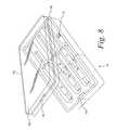
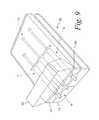
- FIGS. 8 and 9show a syringe tray in combination with further packaging including a cover or closure member.
- the tray 10may be thermoformed from a plastic material, such as, for example, PETE (polyethylene therephthalate) or PETG (polyethylene therephthalate glycol), or any other material which provides the tray with the desired structural integrity, is readily susceptible to sterilization, and is easily disposed of or recycled.
- a plastic materialsuch as, for example, PETE (polyethylene therephthalate) or PETG (polyethylene therephthalate glycol), or any other material which provides the tray with the desired structural integrity, is readily susceptible to sterilization, and is easily disposed of or recycled.
- the storage tray 10is configured to receive one or more prefilled syringes 12 (with three being shown).
- each illustrated syringe 12comprises a plunger 14 having a thumb rest 16 on one end of a shaft 18 and a piston or stopper (not seen) on the other end.
- the pistonis received within the bore of a barrel 22 , the barrel 22 being formed with opposed finger flanges 24 on one end and a luer lock 28 on the other end.
- a sheath or cap 30is received in luer lock 28 and is removed prior to use.
- the tray 10comprises a recess, generally designated 32 , for receipt of each syringe that is to be carried by the tray 10 .
- a syringe tray as described hereinmay be used to hold syringes prefilled with a patient's stem cells, the syringes being configured to be connected to a percutaneous transluminal catheter for the transport of the stem cells to the patient's ischemic tissue, for example, cardiac tissue.
- the trayhas three recesses 32 , but it could have either more or less depending on, e.g., whether the agent to be administered has multiple components or if multiple doses are to be administered.
- a syringe storage traycould be configured with one or more recesses 32 .
- Each of the three recesses 12 for the illustrated tray 10has generally the same configuration.
- identical reference numeralswill be used to designate structure common to each recess 12 .
- Each recess 32preferably comprises three segments: a first segment for holding the syringe barrel 22 , a second segment for holding the plunger 14 in a pre-determined axial relation to the barrel, and a third segment intermediate the first and second segments configured to provide access to the portion of the barrel 22 adjacent the finger flanges 24 sufficient to permit the barrel to be gripped by the fingers of a user to remove the syringe from the tray.
- the first segment for holding the syringe barrel 22preferably comprises opposed sidewalls 34 , 36 that are spaced to receive the barrel 22 therebetween and an end wall 38 .
- the sidewalls 34 , 36(best seen in FIG. 3 ) are formed with structures to securely hold the barrel 22 of the syringe 12 in the recess 32 , and past which the barrel 22 of the syringe must be forced to remove the syringe 12 from the tray 10 .
- the structuresare projections or tabs 38 that extend beyond the faces of the sidewalls 34 , 36 and into the space therebetween. As illustrated in FIG. 1-4 , three tabs 40 are provided, with one tab 40 associated with sidewall 34 and two tabs 40 associated with sidewall 36 .
- the number, location and configuration of the tabs 40may be varied without departing from the scope of the disclosure.
- the sidewalls 34 , 36may be formed with two pairs of opposed elongated tabs 40 .
- the tabs 40have a resilient nature, such that they deform to permit the barrel 22 of the syringe 12 to pass by, and then return to their original configuration.
- FIGS. 5-8illustrate multiple additional features and variations that may or may not necessarily be combined in a single embodiment of a syringe tray as described herein.
- the tabs 40will inherently possess the required resiliency.
- the tabsprovide for a snap fit to securely lock the syringe 12 into the tray 10 .
- the recess 32may be formed with an aperture 42 in the end wall 38 that is sized to receive the end cap 30 of the syringe.
- the aperture 42may have a shape complementary to the cross-sectional shape of the end cap, but smaller than the largest such shape for the end cap, so that the cap 30 is securely held within the aperture 42 .
- the sidewall of the aperturemay also be tapered to more securely seat and firmly grip the end cap 30 .
- the traymay be formed with, or be configured to receive, a clip 44 (seen in FIG. 7 ) that receives the end cap 30 of the syringe 12 .
- the clip 44is preloaded when inserting a syringe into the tray to apply a torque to the end cap 30 in a direction to screw the end cap into the luer lock 28 .
- the end wall 38can be formed to receive a separately-made biasing member that engages the tip of the syringe and exerts an axial force on the barrel 22 .
- the biasing membermay comprise, for example, a spring clip 46 (as illustrated in FIG.
- a coil springto exert an axial force on the barrel 22 such that the finger flanges 24 are forced against lateral wall 48 in the tray opposite the end wall 38 , thus positively locating the barrel 22 in the tray 10 .
- the syringe barrel 22may additionally or alternatively be axially biased toward the end wall 37 by various means on the lateral wall 48 that engage the finger flanges 24 .
- Such meansmay include projections or tabs integrally formed in the lateral wall 48 during the molding of the tray (similar to the tab 54 , described below) or resilient means, such as springs, clips or foam, secured to the lateral wall 48 so as to engage the finger flanges 24 .
- the first recessmay be configured to define an aperture sized to receive the barrel of a syringe and further include spring fingers that extend into the aperture to engage the barrel to hold it securely in place, similar to a spring or push nut.
- the second segment of the recess 32is configured to receive the plunger 14 so as to prevent relative movement between the plunger 14 and the barrel 22 .
- motion of the plunger relative to the syringe barrelis sufficiently limited to prevent contamination of the syringe and its contents during transport of the prefilled syringes.
- the second recesspreferably comprises a slot 50 for seating the thumb rest 16 of the plunger 14 .
- the slot 50is oriented generally transverse or perpendicularly to the slot formed by the sidewalls 34 , 36 , and further includes an end wall 52 .
- the end wall 52preferably includes a projecting tab or rib 54 that engages the top of the thumb rest 16 to positively locate the plunger 14 in the tray and limit axial movement of the plunger 14 relative to the barrel 22 of the syringe 12 .
- the tab 54is deformable to account for tolerances in the fabrication of the tray 10 and the filling of the syringes.
- a separate resilient membersuch as a spring or foam member (not shown) may be secured to the end wall 52 for engagement with the thumb rest 16 .
- the second segmentalso preferably includes sidewalls 56 , 58 that, as shown, substantially flank the length of the plunger shaft 18 extending out of the barrel 22 of the syringe 12 .
- the sidewalls 56 , 58may optionally be formed with projections or cleats (not shown) that engage the plunger shaft 18 (similar to tabs 40 ) to more positively position the plunger in the tray.
- the second recessmay be formed so as to have a plurality of transversely-oriented spaced slots 60 integrally formed therein configured to receive the thumb rest 16 of the plunger 14 .
- Such a configurationpermits the same recess 32 to be used for syringes that are prefilled with different volumes of fluid, and thus have differing positions of the plunger relative to the syringe barrel.
- one or both of the sidewalls 56 , 58may be formed with a series of projecting teeth or detents 62 (as seen in FIG. 6 ) that engage the thumb rest 16 for various plunger settings, and thus similarly permit the second recess to accommodate syringes having multiple different thumb rest locations.
- the means for securing the thumb rest of the syringe to the traymay also be formed separately from the tray and then secured thereto.
- a clip 64may be received in the tray that has a pocket-like portion 66 that receives and captures the thumb rest and further comprises a support structure 68 configured to be received in a recess 70 in the tray 10 .
- the support structure 68may have a cross-like shape that is received in a T-shaped recess 70 to prevent axial and rotational movement and positively locate the clip 64 within the recess 70 .
- a spacer barmay be employed that removably attaches to both the barrel and the plunger. More specifically, and as seen in FIG. 5 , the spacer bar 72 may comprise an elongated member 74 having a structure 76 on one end that engages or captures the thumb rest 16 of the plunger 14 and a structure 78 on the other end that engages or captures the finger flanges 24 of the barrel 22 . Spacers 72 of various sizes may be provided to accommodate syringes having different volumes of fluid therein. Alternatively, and with reference to FIG.
- the elongated portion of the spacermay comprise a telescoping member 80 that is adjustable in length.
- the telescoping member 80preferably includes means for maintaining the desired spacing of the end structures.
- one of the telescoping memberscould include a gear rack and the other a cooperating ratchet tooth (similar to a cable tie), although other means may occur to one skilled in the art.
- the tray 10is configured to accommodate the spacer by, for example, increasing the spacing between the sidewalls 56 , 58 .
- the third segment of the traycomprises a relieved portion 82 that provides access to the syringe barrel 22 to facilitate removal of the syringe 12 from the tray 10 .
- the relieved portion 82is located intermediate the first segment and second segment and is defined by opposed sidewalls 48 , 84 .
- the third segmentcould be located within the first segment.
- sidewall 48is preferably positioned so as to abut the finger flanges 24 of the barrel 22 when a syringe 12 is held in the recess 32 , with the tip of the needle sheath 30 either contacting the end wall 38 of the first segment or otherwise being engaged or secured in the tray as described above.
- the barrel 22is unable to move axially within the tray 10 .
- Sidewall 84is spaced from sidewall 48 a distance sufficient to permit finger access to the barrel.
- the relieved portion 82may have a depth sufficient to permit rotation of the syringe barrel 22 about its longitudinal axis (as shown by the arrow 86 in FIG. 6 ). To this end, the depth of the relieved portion 82 is preferably greater than the combined width of the finger flanges 24 and diameter of the barrel 22 .
- the traymay include additional features that provide greater functionality.
- the traymay be configured to receive a separately made manifold 88 that interconnects in fluid communication each of the syringes 12 to be held in the tray 10 .
- the manifold 88includes an inlet/outlet port 90 and a series of junction ports 92 , one for each syringe, configured so that the barrel 22 of each syringe may be secured to the manifold 88 and to provide fluid communication through the manifold 88 to the interior of the syringe barrel 22 .
- the manifold 88may be utilized to facilitate the simultaneous filling of the syringes 12 and/or to sequence the use of the syringes 12 during administration of their contents. After filling the syringes 12 by introducing fluid through the inlet/outlet port 90 of the manifold 88 , the port of the manifold 88 is sealed by, for example, a separate cap, a self-sealing gasket, or other means as may occur to a person skilled in the art.
- the traymay be provided with means that facilitate the removal of the end cap 30 from each syringe 12 which may have been over tightened after filling the syringe 12 .
- the tray 10may include a structure 94 (as illustrated in FIG. 5 ) which serves as a wrench for securely holding the end cap.
- the wrench structure 94may comprise a slot defined by sidewalls 96 , 98 . After removing the syringe 12 from the tray, the end cap 30 is wedged between the sidewalls 96 , 98 .
- the sidewalls 96 , 98are spaced so that they tightly grip the cap 30 , thus permitting the barrel 22 to be twisted relative to the cap 30 to unscrew the cap from the syringe 12 .
- the syringe tray 10may be formed with an aperture 100 having a shape complementary to the cross-sectional shape of the end cap 30 , but of a size smaller than the largest cross-sectional shape, so that the end cap 30 may be inserted into the aperture 100 to firmly grip the cap 30 and permit its unscrewing from the syringe by the application of torque to the syringe barrel 22 .
- the syringe tray 10may be part of a housing assemblage having a reclosable cover to provide a more durable and protective enclosure for the syringes held in the tray.
- the tray 10is provided with a cover 102 and is preferably formed integrally with the tray 10 , with a living hinge 104 , or other hinge structure, connecting the two.
- the cover 102preferably has a depth sufficient to receive a resilient/expandable insert or void filler 106 , comprising, for example, an encapsulated foam material, that presses against the syringes 12 held in the tray 10 upon closure of the cover 102 to more securely hold the syringes 12 in place and provide additional protection.
- a resilient/expandable insert or void filler 106comprising, for example, an encapsulated foam material, that presses against the syringes 12 held in the tray 10 upon closure of the cover 102 to more securely hold the syringes 12 in place and provide additional protection.
- the cover 102 and tray 10are preferably provided with a latch or lock structure 114 (as illustrated in FIG. 8 ) to secure the cover in the closed position.
- the latch or lock 114may comprise a magnet in combination with another magnetic or magnetizable material in opposed relationship on the tray and cover.
- the cover and traymay be provided with interfitting, complementarily-shaped projections and recesses (not shown) that frictionally engage each other upon closure of the cover 102 .
- the barrels of the syringesmay be provided with a mark indicating the position of the piston within the barrel at the time the filled syringe is secured in the tray.
- the markprovides a visual indication as to whether the piston has moved during shipment.
- the barrel markingmay comprise a length of tape 116 applied to the barrel, although other means of marking the syringe barrel and/or the tray to indicate the position of the piston may be employed.
- a tray 10 loaded with syringes 12may be received in a separate box-like container 108 open on one end, such that the filled tray 10 is slided into the container 108 .
- the traycomprises deformable members 110 , 112 , made of a material such as the encapsulated foam described above, for securely positioning the syringes 12 within the container 108 , although the container 108 may be configured to receive any of the syringe trays described above.
- the container 108is preferably provided with a closure 114 for the open end. In the illustrated embodiment, the closure is hingedly attached to the remainder of the container, although a separate closure that slides over the open end of the container may be used.
- the closure 114 and container 108include a latch or other means (such as the latches described above) for releasably securing the closure 108 to the container 104 in the closed position to secure the syringe tray 10 therein.
- a latch or other meanssuch as the latches described above
- the syringe traymay also include a sensor 118 affixed thereto that measures and stores data as to the conditions to which the syringes 12 are subjected during shipment and prior to use that could potentially affect the efficacy of the substances administered by the syringes.
- datacould include information as to vibration, temperature, and/or humidity.
- the prefilled syringes 12are preferably placed in tray 10 in an aseptic manner.
- the combinationis then preferably sterilized and a cover is preferably sealed to the tray 10 so as to overlie the syringes.
- the covermay be made of plastic material, such as Tyvek®, that is heat sealed to the top surface of the tray.
- the trayis then preferably placed in an over-pouch to maintain sterility until the time of use. Double bagging the tray is preferred, with the outer pouch being resealable.
- the tray 10is configured so as to reduce the likelihood that it could puncture the over-pouch, and thus increase the contamination potential of the syringes.
- the tray 10preferably has no sharp edges, and the corners (such as corners 120 ) are rounded or beveled.
- the tray 10may also be provided with an outer edge in the form of a flange 122 that helps to reduce the angle at which the inner surface of the over-pouch engages the corners 120 , thus further reducing the likelihood of puncture.
- the tray 10is also formed with a pair of elongated parallel supports 124 that serve to increase the rigidity of the tray and provide a stable base for the tray when placed on a flat surface.
- the disclosed deviceincludes the aspects set forth below.
- a storage tray for one or more syringeswhere each syringe comprises a plunger with a shaft and a thumb rest and a barrel with a proximal end for receipt of the plunger and a tip comprising a distal end.
- the storage traycomprises a first means for removably securing the barrel of the syringe to the tray and a second means for maintaining a predetermined position of the plunger relative to the barrel.
- one or both of the first means and the second means of the storage traymay be formed integrally with the tray.
- one or both of the first means and the second meansmay be formed separately from the tray and then associated therewith.
- one or both of the first means and the second meansmay comprise a biasing member.
- the second meansengages the thumb rest of the plunger.
- the second meansengages the shaft of the plunger.
- the first meansengages the sidewall of the barrel.
- the first meansengages the tip of the barrel.
- a storage tray for one or more syringeswhich comprises a recess for receiving each of the one or more syringes, each recess comprising a first segment configured to hold the barrel of the syringe, and a second segment for holding the plunger, the first segment and second segment configured to retain the barrel and plunger and substantially fixed axial relationship.
- the recess of the storage trayfurther comprises a third segment configured to provide access to a portion of the barrel that is sufficient to permit gripping of the barrel by the fingers of a user.
- the third segmentmay be positioned intermediate the first and second segments or, alternatively, positioned within the first segment.
- the first segment of each recessfurther comprises first and second opposed sidewalls that define a space therebetween to receive the barrel of the syringe.
- the first and second sidewallseach have one or more deformable projections thereon protruding into the space between the first and second sidewalls for positively retaining the barrel between the first and second sidewalls.
- the second segment of each recessfurther comprises a slot for receiving the thumb rest of the plunger, the slot comprising a third sidewall oriented generally perpendicularly to the first and second sidewalls, and the third sidewall further including a projection for engaging a surface of the thumb rest.
- the third segment of each recessfurther comprises a relieved portion intermediate the first and second sidewalls and the slot.
- each recesscomprises a third and fourth opposed sidewalls for receipt of a length of the plunger disposed between the thumb rest and the proximal end of the barrel.
- the storage traycomprises a plurality of corners, the corners being rounded.
- the storage trayfurther comprises an outer edge in the form of a flange.
- each recessis configured to hold a prefilled syringe.
- the storage trayfurther comprises a pre-filled syringe received in each recess.
Landscapes
- Health & Medical Sciences (AREA)
- Life Sciences & Earth Sciences (AREA)
- Public Health (AREA)
- Engineering & Computer Science (AREA)
- Anesthesiology (AREA)
- Biomedical Technology (AREA)
- Heart & Thoracic Surgery (AREA)
- Vascular Medicine (AREA)
- Animal Behavior & Ethology (AREA)
- Hematology (AREA)
- General Health & Medical Sciences (AREA)
- Veterinary Medicine (AREA)
- Diabetes (AREA)
- Chemical & Material Sciences (AREA)
- Chemical Kinetics & Catalysis (AREA)
- Infusion, Injection, And Reservoir Apparatuses (AREA)
Abstract
Description
Claims (21)
Priority Applications (1)
| Application Number | Priority Date | Filing Date | Title |
|---|---|---|---|
| US14/400,429US9889248B2 (en) | 2012-05-21 | 2012-12-20 | Syringe storage tray |
Applications Claiming Priority (3)
| Application Number | Priority Date | Filing Date | Title |
|---|---|---|---|
| US201261649586P | 2012-05-21 | 2012-05-21 | |
| PCT/US2012/070804WO2013176703A1 (en) | 2012-05-21 | 2012-12-20 | Syringe storage tray |
| US14/400,429US9889248B2 (en) | 2012-05-21 | 2012-12-20 | Syringe storage tray |
Publications (2)
| Publication Number | Publication Date |
|---|---|
| US20150129442A1 US20150129442A1 (en) | 2015-05-14 |
| US9889248B2true US9889248B2 (en) | 2018-02-13 |
Family
ID=47563612
Family Applications (2)
| Application Number | Title | Priority Date | Filing Date |
|---|---|---|---|
| US14/400,429ActiveUS9889248B2 (en) | 2012-05-21 | 2012-12-20 | Syringe storage tray |
| US14/086,947Active2033-10-07US9808570B2 (en) | 2012-05-21 | 2013-11-21 | Syringe storage tray |
Family Applications After (1)
| Application Number | Title | Priority Date | Filing Date |
|---|---|---|---|
| US14/086,947Active2033-10-07US9808570B2 (en) | 2012-05-21 | 2013-11-21 | Syringe storage tray |
Country Status (2)
| Country | Link |
|---|---|
| US (2) | US9889248B2 (en) |
| WO (1) | WO2013176703A1 (en) |
Cited By (5)
| Publication number | Priority date | Publication date | Assignee | Title |
|---|---|---|---|---|
| US10322241B2 (en)* | 2015-03-27 | 2019-06-18 | Hyprotek, Inc. | Injection systems with storage compartments |
| USD890951S1 (en) | 2018-10-12 | 2020-07-21 | ConnieTray LLC | Tray for injectable medicaments |
| CN114450232A (en)* | 2019-07-29 | 2022-05-06 | 里珍纳龙药品有限公司 | Medical device packaging and related methods |
| US12059555B2 (en)* | 2019-09-03 | 2024-08-13 | Amgen Inc. | Injection device for drug delivery and packaging for the injection device |
| US12233177B2 (en) | 2019-09-16 | 2025-02-25 | Amgen Inc. | Method for external sterilization of drug delivery device |
Families Citing this family (39)
| Publication number | Priority date | Publication date | Assignee | Title |
|---|---|---|---|---|
| US20070202186A1 (en) | 2006-02-22 | 2007-08-30 | Iscience Interventional Corporation | Apparatus and formulations for suprachoroidal drug delivery |
| JP5996544B2 (en) | 2010-10-15 | 2016-09-21 | クリアサイド・バイオメディカル・インコーポレーテッドClearside Biomedical Incorporated | Eye access device |
| US9889248B2 (en) | 2012-05-21 | 2018-02-13 | Baxalta GmbH | Syringe storage tray |
| KR20210133321A (en) | 2012-11-08 | 2021-11-05 | 클리어사이드 바이오메디컬, 인코포레이드 | Methods and devices for the treatment of ocular disease in human subjects |
| CA2911290C (en) | 2013-05-03 | 2021-07-27 | Clearside Biomedical, Inc. | Apparatus and methods for ocular injection |
| USD726330S1 (en) | 2014-04-06 | 2015-04-07 | Richard H. Hurst | Storage tray |
| KR101472821B1 (en)* | 2014-05-14 | 2014-12-16 | 김준우 | Component separator |
| DE102014115474A1 (en)* | 2014-10-23 | 2016-04-28 | Hans Heidolph Gmbh & Co. Kg | laboratory Shakers |
| USD770042S1 (en) | 2014-10-31 | 2016-10-25 | Tolmar, Inc. | Syringe holder |
| US9408965B2 (en) | 2014-10-31 | 2016-08-09 | Tolmar, Inc. | Method and system for handling and transporting syringes |
| WO2016159059A1 (en)* | 2015-03-30 | 2016-10-06 | テルモ株式会社 | Package and package assembly |
| KR101620090B1 (en)* | 2015-04-20 | 2016-05-12 | 주식회사 티젤바이오 | Kit for drug delivery, Apparatus for preparing drug delivery system, and A preparation method of drug delivery system |
| CA2991555A1 (en) | 2015-07-10 | 2017-01-19 | Fresenius Kabi Deutschland Gmbh | Syringe packaging system |
| CA2991557C (en)* | 2015-07-10 | 2023-09-26 | Fresenius Kabi Deutschland Gmbh | Syringe packaging system and shell |
| US10814059B2 (en)* | 2015-07-10 | 2020-10-27 | Fresenius Kabi Deutschland Gmbh | Syringe packaging system |
| US20170128662A1 (en)* | 2015-11-06 | 2017-05-11 | Baxalta Incorporated | Packaging unit for single medical device |
| EP3413851B1 (en) | 2016-02-10 | 2023-09-27 | Clearside Biomedical, Inc. | Packaging |
| US10821221B2 (en) | 2016-03-31 | 2020-11-03 | Gc Corporation | Encased syringe |
| WO2017192565A1 (en) | 2016-05-02 | 2017-11-09 | Clearside Biomedical, Inc. | Systems and methods for ocular drug delivery |
| WO2017220795A1 (en)* | 2016-06-24 | 2017-12-28 | Teva Pharmaceuticals International Gmbh | Medical device packaging |
| US11457992B2 (en)* | 2016-07-08 | 2022-10-04 | Stryker European Operations Holdings Llc | Storage assembly for a medical device |
| US10973681B2 (en) | 2016-08-12 | 2021-04-13 | Clearside Biomedical, Inc. | Devices and methods for adjusting the insertion depth of a needle for medicament delivery |
| CN109641099B (en)* | 2016-08-23 | 2021-12-03 | 泰尔茂株式会社 | Syringe packaging body |
| US11173253B2 (en)* | 2016-12-12 | 2021-11-16 | Becton, Dickinson And Company | Packaging for safety needle |
| GB2557655A (en)* | 2016-12-14 | 2018-06-27 | Teva Pharma | Medical injection device packaging |
| US10112759B2 (en)* | 2017-02-20 | 2018-10-30 | Centrix, Inc. | Single dose material and applicator package |
| US12090294B2 (en) | 2017-05-02 | 2024-09-17 | Georgia Tech Research Corporation | Targeted drug delivery methods using a microneedle |
| US11904132B2 (en)* | 2018-06-25 | 2024-02-20 | Sanofi | Packaging for a medicament container |
| JP2022504803A (en)* | 2018-10-15 | 2022-01-13 | エフ・ホフマン-ラ・ロシュ・アクチェンゲゼルシャフト | How to wrap syringe packs and prefilled syringes |
| EP3922284A4 (en) | 2019-03-28 | 2022-05-11 | Terumo Kabushiki Kaisha | Prefilled syringe storage tray and package using the same |
| EP4076577A4 (en)* | 2019-12-16 | 2023-12-27 | Merck Sharp & Dohme LLC | PRE-FILLED SYRINGE PLUG HOLDER WITH PROJECTIONS OR RECEPTACLES AND METHOD FOR USE THEREOF |
| CN112121252A (en)* | 2020-08-25 | 2020-12-25 | 山东省千佛山医院 | A syringe rack for hospital use |
| CN111905180A (en)* | 2020-09-15 | 2020-11-10 | 中国科学院深圳先进技术研究院 | A syringe carrying device |
| US12005238B2 (en) | 2020-10-20 | 2024-06-11 | Fresenius Kabi Usa, Llc | Impact resistant and tamper evident system for prefilled syringe |
| US20220354608A1 (en)* | 2021-05-04 | 2022-11-10 | Prent Corporation | Product Retention Tray |
| JP2025504994A (en)* | 2022-02-04 | 2025-02-19 | リジェネロン・ファーマシューティカルズ・インコーポレイテッド | Medical Device Packages and Related Methods |
| USD1042107S1 (en) | 2022-08-26 | 2024-09-17 | Regeneron Pharmaceuticals, Inc. | Packaging |
| USD1035436S1 (en) | 2022-08-26 | 2024-07-16 | Regeneron Pharmaceuticals, Inc. | Packaging |
| USD1047700S1 (en) | 2022-08-26 | 2024-10-22 | Regeneron Pharmaceuticals, Inc. | Packaging |
Citations (58)
| Publication number | Priority date | Publication date | Assignee | Title |
|---|---|---|---|---|
| US2856925A (en)* | 1956-01-13 | 1958-10-21 | Easton | Syringe structure |
| US2955705A (en)* | 1957-09-13 | 1960-10-11 | East Rutherford Syringes Inc | Transparent container |
| US3372798A (en) | 1966-10-31 | 1968-03-12 | Thomas Clinic | Card mount package for hypodermic syringe assembly |
| US3770026A (en)* | 1971-09-17 | 1973-11-06 | J Isenberg | Apparatus and method for accurately loading syringes |
| US3820652A (en) | 1972-11-14 | 1974-06-28 | T Thackston | Packaged syringe construction |
| US3937219A (en)* | 1974-01-14 | 1976-02-10 | Karakashian Nubar A | Sterile syringe assembly and method of making same |
| US4073321A (en)* | 1976-03-15 | 1978-02-14 | George Moskowitz | Adjustable blocking means for dosage regulation |
| US4246898A (en)* | 1979-07-23 | 1981-01-27 | Cutter Laboratories, Inc. | Syringe |
| US4563178A (en)* | 1985-02-06 | 1986-01-07 | Santeramo Joseph J | Syringe dosage limiter |
| US4589870A (en) | 1984-02-21 | 1986-05-20 | Indicon, Inc. | Incremental actuator for syringe |
| US4657138A (en)* | 1986-04-11 | 1987-04-14 | Watson Frank K | Carrying case for insulin syringes |
| US4671408A (en)* | 1985-06-20 | 1987-06-09 | Burron Medical Inc. | Temper-resistant protective capping device for filled syringes |
| US4753345A (en)* | 1984-06-14 | 1988-06-28 | American Home Products Corporation | Hypodermic syringe tray |
| US4767008A (en)* | 1987-11-02 | 1988-08-30 | Warnecke Armand E | Injection monitor appliance |
| US4863451A (en)* | 1987-12-09 | 1989-09-05 | Marder Herbert B | Apparatus for dispensing injectable medication |
| US4921487A (en) | 1988-09-21 | 1990-05-01 | Compagnie Financiere Saint. Nicolas | External device for injecting medicine |
| US4979616A (en)* | 1989-02-23 | 1990-12-25 | Clanton Dennis L | Syringe disposal container |
| US5007535A (en)* | 1988-09-26 | 1991-04-16 | Hammerlit Gmbh | Syringe tray |
| US5078267A (en)* | 1990-08-03 | 1992-01-07 | Llw Enterprises, Inc. | Portable case for carrying a syringe with varying plunger positions |
| US5133454A (en)* | 1990-12-06 | 1992-07-28 | Hammer Steven G | Intravenous catheter biohazard prevention packaging device |
| US5156267A (en)* | 1991-06-14 | 1992-10-20 | Dynamic Bio-Apparatuses, Inc. | Syringe inhibiting container |
| US5293993A (en)* | 1991-06-14 | 1994-03-15 | Dynamic Bio-Apparatuses, Inc. | Syringe sealing container |
| US5385559A (en) | 1993-12-20 | 1995-01-31 | R. Jason Newsom | Syringe filling and metering device |
| US5385558A (en)* | 1993-09-03 | 1995-01-31 | Maxxim Medical, Inc. | Angiographic control syringe |
| JPH08207960A (en) | 1995-02-02 | 1996-08-13 | Denki Kagaku Kogyo Kk | Blister packaging for prefilled syringes |
| US5772031A (en)* | 1996-02-15 | 1998-06-30 | Zimmer, Inc. | Package for an elongated medical product |
| US5811061A (en)* | 1992-02-10 | 1998-09-22 | Baxter International Inc. | Method and device for testing blood units for viral contamination |
| USD430015S (en)* | 1998-06-11 | 2000-08-29 | Pharmacia & Upjohn Ab | Blister pack for a syringe |
| US6216885B1 (en)* | 1997-11-27 | 2001-04-17 | Becton Dickinson France, S.A. | Tray for grouping together articles |
| JP2001104475A (en) | 1999-10-05 | 2001-04-17 | Terumo Corp | Container for prefilled syringe and packed prefilled syringe |
| US6228324B1 (en)* | 1997-11-28 | 2001-05-08 | Seikagaku Corporation | Sterilizing method for medical sterilization packaging and injection pack |
| US20020108875A1 (en)* | 2000-12-11 | 2002-08-15 | Ethicon, Inc. | Packaging assembly for surgical use |
| US20020185406A1 (en)* | 2001-04-13 | 2002-12-12 | Massengale Roger Dillard | Pain management kit for administration of medication |
| US6585696B2 (en) | 2000-12-22 | 2003-07-01 | Baxter International, Inc. | Method and apparatus for applying a medically useful multiple component material |
| US6595362B2 (en)* | 2000-05-12 | 2003-07-22 | Lindon Products Inc. | Cases for medication delivery devices |
| EP1595561A2 (en) | 2004-05-13 | 2005-11-16 | Olympus Corporation | Syringe set for balloon catheter |
| US7018089B2 (en)* | 2002-09-17 | 2006-03-28 | Kyphon Inc. | Apparatus and methods for mixing two components |
| US7048120B2 (en)* | 2003-05-30 | 2006-05-23 | Pond Gary J | Package construction for fluid applicator device |
| JP2007290720A (en) | 2006-04-21 | 2007-11-08 | Chemo Sero Therapeut Res Inst | Blister package and prefilled syringe package using the same |
| WO2007130809A2 (en) | 2006-05-06 | 2007-11-15 | Volodymyr Brodskyy | An automatic injectable drug mixing device |
| JP2008067989A (en) | 2006-09-15 | 2008-03-27 | Terumo Corp | Prefilled syringe storage container, and packaged prefilled syringe |
| US20080125722A1 (en) | 2006-09-15 | 2008-05-29 | Howmedica International S. De R.L. | Syringe and stand |
| EP1930040A1 (en) | 2005-08-22 | 2008-06-11 | Nipro Corporation | Prefilled syringe |
| US7476218B2 (en)* | 2003-05-29 | 2009-01-13 | Intra-Tech Healthcare Limited | Syringe with locking member |
| US20090093757A1 (en) | 2007-10-04 | 2009-04-09 | Tennican Patrick O | Mixing/Administration Syringe Devices, Protective Packaging and Methods of Protecting Syringe Handlers |
| US20090227958A1 (en) | 2006-05-30 | 2009-09-10 | Andrew Christopher Burroughs | Module for a medication injection device |
| US7597196B2 (en)* | 2006-06-08 | 2009-10-06 | Phyllis Langone | Insulated medication carrying case |
| US20090326479A1 (en) | 2008-02-28 | 2009-12-31 | Becton, Dickinson And Company | Syringe With Adjustable Two Piece Plunger Rod |
| US20100012537A1 (en)* | 2008-07-21 | 2010-01-21 | Smiths Medical Asd, Inc. | Tray assembly |
| US20100181218A1 (en)* | 2007-07-31 | 2010-07-22 | Al.Chi.Mi.A. S.R.L. | Device for ophthalmic treatments and methods for making said device |
| JP2011006154A (en) | 2010-09-15 | 2011-01-13 | Chugai Pharmaceut Co Ltd | Blister pack container for storing pre-filled syringe |
| US7901383B2 (en)* | 2004-04-30 | 2011-03-08 | Becton, Dickinson And Company | Systems and methods for administering a medical regimen |
| US20130245492A1 (en) | 2012-03-15 | 2013-09-19 | Smarthealth, Inc. | Dispensing Device for Prefilled Syringe |
| US20140166514A1 (en)* | 2012-12-13 | 2014-06-19 | Ethicon Endo-Surgery, Inc. | Packaging for Surgical Needle Cartridge and Suture |
| US20140224688A1 (en)* | 2011-09-27 | 2014-08-14 | Sanofi-Aventis Deutschland Gmbh | Package for a medicament delivery device |
| US20140352724A1 (en) | 2007-09-28 | 2014-12-04 | Rolf Meyer | Apparatus and Method for Cleaning Microsurgical Instruments |
| US8974424B2 (en)* | 2011-03-29 | 2015-03-10 | Terumo Kabushiki Kaisha | Syringe with plunger locking mechanism |
| US20150129442A1 (en) | 2012-05-21 | 2015-05-14 | Baxter International Inc. | Syringe storage tray |
Family Cites Families (8)
| Publication number | Priority date | Publication date | Assignee | Title |
|---|---|---|---|---|
| DE69121119T2 (en)* | 1990-02-09 | 1997-03-06 | Damal Ltd | Hypodermic needle / syringe connection and device for removing the needles therefrom |
| US5882338A (en)* | 1993-05-04 | 1999-03-16 | Zeneca Limited | Syringes and syringe pumps |
| CA2349382C (en)* | 1998-10-30 | 2007-12-11 | Immunex Corporation | Method and apparatus for operating a syringe and vial for injections |
| US6558348B2 (en)* | 2000-04-07 | 2003-05-06 | Equidyne Systems, Inc. | Low cost disposable needleless injector system for variable and fixed dose applications |
| US6500153B1 (en)* | 2001-07-13 | 2002-12-31 | Children's And Women's Health Centre Of British Columbia | Syringe and needle for preventing inadvertent drug injection |
| US6769546B2 (en)* | 2002-07-03 | 2004-08-03 | L. John Busch | Epidural anesthesia kit |
| US20070185495A1 (en)* | 2006-01-30 | 2007-08-09 | Howmedica International S. De R. L. | Plug-in syringe stand |
| WO2008134570A2 (en)* | 2007-04-27 | 2008-11-06 | Amylin Pharmaceuticals, Inc. | Mixing tool |
- 2012
- 2012-12-20USUS14/400,429patent/US9889248B2/enactiveActive
- 2012-12-20WOPCT/US2012/070804patent/WO2013176703A1/enactiveApplication Filing
- 2013
- 2013-11-21USUS14/086,947patent/US9808570B2/enactiveActive
Patent Citations (61)
| Publication number | Priority date | Publication date | Assignee | Title |
|---|---|---|---|---|
| US2856925A (en)* | 1956-01-13 | 1958-10-21 | Easton | Syringe structure |
| US2955705A (en)* | 1957-09-13 | 1960-10-11 | East Rutherford Syringes Inc | Transparent container |
| US3372798A (en) | 1966-10-31 | 1968-03-12 | Thomas Clinic | Card mount package for hypodermic syringe assembly |
| US3770026A (en)* | 1971-09-17 | 1973-11-06 | J Isenberg | Apparatus and method for accurately loading syringes |
| US3820652A (en) | 1972-11-14 | 1974-06-28 | T Thackston | Packaged syringe construction |
| US3937219A (en)* | 1974-01-14 | 1976-02-10 | Karakashian Nubar A | Sterile syringe assembly and method of making same |
| US4073321A (en)* | 1976-03-15 | 1978-02-14 | George Moskowitz | Adjustable blocking means for dosage regulation |
| US4246898A (en)* | 1979-07-23 | 1981-01-27 | Cutter Laboratories, Inc. | Syringe |
| US4589870A (en) | 1984-02-21 | 1986-05-20 | Indicon, Inc. | Incremental actuator for syringe |
| US4753345A (en)* | 1984-06-14 | 1988-06-28 | American Home Products Corporation | Hypodermic syringe tray |
| US4563178A (en)* | 1985-02-06 | 1986-01-07 | Santeramo Joseph J | Syringe dosage limiter |
| US4671408A (en)* | 1985-06-20 | 1987-06-09 | Burron Medical Inc. | Temper-resistant protective capping device for filled syringes |
| US4657138A (en)* | 1986-04-11 | 1987-04-14 | Watson Frank K | Carrying case for insulin syringes |
| US4767008A (en)* | 1987-11-02 | 1988-08-30 | Warnecke Armand E | Injection monitor appliance |
| US4863451A (en)* | 1987-12-09 | 1989-09-05 | Marder Herbert B | Apparatus for dispensing injectable medication |
| US4921487A (en) | 1988-09-21 | 1990-05-01 | Compagnie Financiere Saint. Nicolas | External device for injecting medicine |
| US5007535A (en)* | 1988-09-26 | 1991-04-16 | Hammerlit Gmbh | Syringe tray |
| US4979616A (en)* | 1989-02-23 | 1990-12-25 | Clanton Dennis L | Syringe disposal container |
| US5078267A (en)* | 1990-08-03 | 1992-01-07 | Llw Enterprises, Inc. | Portable case for carrying a syringe with varying plunger positions |
| US5133454A (en)* | 1990-12-06 | 1992-07-28 | Hammer Steven G | Intravenous catheter biohazard prevention packaging device |
| US5293993A (en)* | 1991-06-14 | 1994-03-15 | Dynamic Bio-Apparatuses, Inc. | Syringe sealing container |
| US5156267A (en)* | 1991-06-14 | 1992-10-20 | Dynamic Bio-Apparatuses, Inc. | Syringe inhibiting container |
| US5811061A (en)* | 1992-02-10 | 1998-09-22 | Baxter International Inc. | Method and device for testing blood units for viral contamination |
| US5385558A (en)* | 1993-09-03 | 1995-01-31 | Maxxim Medical, Inc. | Angiographic control syringe |
| US5385559A (en) | 1993-12-20 | 1995-01-31 | R. Jason Newsom | Syringe filling and metering device |
| JPH08207960A (en) | 1995-02-02 | 1996-08-13 | Denki Kagaku Kogyo Kk | Blister packaging for prefilled syringes |
| US5772031A (en)* | 1996-02-15 | 1998-06-30 | Zimmer, Inc. | Package for an elongated medical product |
| US6216885B1 (en)* | 1997-11-27 | 2001-04-17 | Becton Dickinson France, S.A. | Tray for grouping together articles |
| US6228324B1 (en)* | 1997-11-28 | 2001-05-08 | Seikagaku Corporation | Sterilizing method for medical sterilization packaging and injection pack |
| USD430015S (en)* | 1998-06-11 | 2000-08-29 | Pharmacia & Upjohn Ab | Blister pack for a syringe |
| JP2001104475A (en) | 1999-10-05 | 2001-04-17 | Terumo Corp | Container for prefilled syringe and packed prefilled syringe |
| US6595362B2 (en)* | 2000-05-12 | 2003-07-22 | Lindon Products Inc. | Cases for medication delivery devices |
| US20020108875A1 (en)* | 2000-12-11 | 2002-08-15 | Ethicon, Inc. | Packaging assembly for surgical use |
| US6585696B2 (en) | 2000-12-22 | 2003-07-01 | Baxter International, Inc. | Method and apparatus for applying a medically useful multiple component material |
| US20020185406A1 (en)* | 2001-04-13 | 2002-12-12 | Massengale Roger Dillard | Pain management kit for administration of medication |
| US7018089B2 (en)* | 2002-09-17 | 2006-03-28 | Kyphon Inc. | Apparatus and methods for mixing two components |
| US7476218B2 (en)* | 2003-05-29 | 2009-01-13 | Intra-Tech Healthcare Limited | Syringe with locking member |
| US7048120B2 (en)* | 2003-05-30 | 2006-05-23 | Pond Gary J | Package construction for fluid applicator device |
| US7901383B2 (en)* | 2004-04-30 | 2011-03-08 | Becton, Dickinson And Company | Systems and methods for administering a medical regimen |
| US20080221515A1 (en)* | 2004-05-13 | 2008-09-11 | Olympus Corporation | Syringe set for balloon catheter |
| EP1595561A2 (en) | 2004-05-13 | 2005-11-16 | Olympus Corporation | Syringe set for balloon catheter |
| US8672881B2 (en)* | 2004-05-13 | 2014-03-18 | Olympus Corporation | Syringe set for balloon catheter |
| EP1930040A1 (en) | 2005-08-22 | 2008-06-11 | Nipro Corporation | Prefilled syringe |
| JP2007290720A (en) | 2006-04-21 | 2007-11-08 | Chemo Sero Therapeut Res Inst | Blister package and prefilled syringe package using the same |
| WO2007130809A2 (en) | 2006-05-06 | 2007-11-15 | Volodymyr Brodskyy | An automatic injectable drug mixing device |
| US8216192B2 (en) | 2006-05-30 | 2012-07-10 | Eli Lilly And Company | Module for a medication injection device |
| US20090227958A1 (en) | 2006-05-30 | 2009-09-10 | Andrew Christopher Burroughs | Module for a medication injection device |
| US7597196B2 (en)* | 2006-06-08 | 2009-10-06 | Phyllis Langone | Insulated medication carrying case |
| US20080125722A1 (en) | 2006-09-15 | 2008-05-29 | Howmedica International S. De R.L. | Syringe and stand |
| JP2008067989A (en) | 2006-09-15 | 2008-03-27 | Terumo Corp | Prefilled syringe storage container, and packaged prefilled syringe |
| US20100181218A1 (en)* | 2007-07-31 | 2010-07-22 | Al.Chi.Mi.A. S.R.L. | Device for ophthalmic treatments and methods for making said device |
| US20140352724A1 (en) | 2007-09-28 | 2014-12-04 | Rolf Meyer | Apparatus and Method for Cleaning Microsurgical Instruments |
| US20090093757A1 (en) | 2007-10-04 | 2009-04-09 | Tennican Patrick O | Mixing/Administration Syringe Devices, Protective Packaging and Methods of Protecting Syringe Handlers |
| US20090326479A1 (en) | 2008-02-28 | 2009-12-31 | Becton, Dickinson And Company | Syringe With Adjustable Two Piece Plunger Rod |
| US20100012537A1 (en)* | 2008-07-21 | 2010-01-21 | Smiths Medical Asd, Inc. | Tray assembly |
| JP2011006154A (en) | 2010-09-15 | 2011-01-13 | Chugai Pharmaceut Co Ltd | Blister pack container for storing pre-filled syringe |
| US8974424B2 (en)* | 2011-03-29 | 2015-03-10 | Terumo Kabushiki Kaisha | Syringe with plunger locking mechanism |
| US20140224688A1 (en)* | 2011-09-27 | 2014-08-14 | Sanofi-Aventis Deutschland Gmbh | Package for a medicament delivery device |
| US20130245492A1 (en) | 2012-03-15 | 2013-09-19 | Smarthealth, Inc. | Dispensing Device for Prefilled Syringe |
| US20150129442A1 (en) | 2012-05-21 | 2015-05-14 | Baxter International Inc. | Syringe storage tray |
| US20140166514A1 (en)* | 2012-12-13 | 2014-06-19 | Ethicon Endo-Surgery, Inc. | Packaging for Surgical Needle Cartridge and Suture |
Non-Patent Citations (2)
| Title |
|---|
| International Preliminary Report on Patentability, International Application No. PCT/US2012/070804, dated Nov. 25, 2014. |
| International Search Report and Written Opinion, international application No. PCT/US2012/070804, dated Jun. 4, 2013. |
Cited By (6)
| Publication number | Priority date | Publication date | Assignee | Title |
|---|---|---|---|---|
| US10322241B2 (en)* | 2015-03-27 | 2019-06-18 | Hyprotek, Inc. | Injection systems with storage compartments |
| US10500344B2 (en) | 2015-03-27 | 2019-12-10 | Hyprotek, Inc. | Injection systems with storage compartments |
| USD890951S1 (en) | 2018-10-12 | 2020-07-21 | ConnieTray LLC | Tray for injectable medicaments |
| CN114450232A (en)* | 2019-07-29 | 2022-05-06 | 里珍纳龙药品有限公司 | Medical device packaging and related methods |
| US12059555B2 (en)* | 2019-09-03 | 2024-08-13 | Amgen Inc. | Injection device for drug delivery and packaging for the injection device |
| US12233177B2 (en) | 2019-09-16 | 2025-02-25 | Amgen Inc. | Method for external sterilization of drug delivery device |
Also Published As
| Publication number | Publication date |
|---|---|
| US9808570B2 (en) | 2017-11-07 |
| US20150129442A1 (en) | 2015-05-14 |
| WO2013176703A1 (en) | 2013-11-28 |
| US20140078854A1 (en) | 2014-03-20 |
Similar Documents
| Publication | Publication Date | Title |
|---|---|---|
| US9889248B2 (en) | Syringe storage tray | |
| US10342736B2 (en) | Vial gripper | |
| EP2298224B1 (en) | Shipping container integrating a sharps disposal container with a new product storage container | |
| US9622941B2 (en) | Vial holder and method of use | |
| EP2760511B1 (en) | Syringe having pivoting arm plunger rod | |
| EP3431125B1 (en) | Syringe having dual pivoting arm plunger rod | |
| US10286153B2 (en) | Syringe with plunger rod having a flexible portion | |
| US20150060462A1 (en) | Portable neurotoxin injection tray and associated apparatus, system, and method | |
| JP7203837B2 (en) | Packaging device and method for removing a medical container from said packaging device | |
| US20150114853A1 (en) | Device for at least one of storing and transporting a plurality of packaging containers | |
| US20130085447A1 (en) | Syringe Having a Removable Cover for Use as a Plunger Rod in Rotational Engagement | |
| KR102776653B1 (en) | Packaging for multiple containers | |
| JP7341169B2 (en) | medical cannula package | |
| EP0253418A1 (en) | Holder for a plurality of syringes | |
| US9339437B2 (en) | Medicinal storage, safety, organizational and delivery device | |
| US20250032312A1 (en) | Ocular drug transfer and dispensing device | |
| EP4374897A1 (en) | Closure integrity-preserving kit, fixation clip and plunger rod for a prefilled syringe | |
| EP3378508A1 (en) | Container for cannulas | |
| EP2368591A1 (en) | Container for needle assemblies for a drug delivery device | |
| US9884695B2 (en) | Compartment configured for presentation of stored articles |
Legal Events
| Date | Code | Title | Description |
|---|---|---|---|
| AS | Assignment | Owner name:BAXTER HEALTHCARE S.A., SWITZERLAND Free format text:ASSIGNMENT OF ASSIGNORS INTEREST;ASSIGNORS:HEAD, BRIAN R.;COHEN, AMY R.;BERTOS, GEORGIOS A.;AND OTHERS;SIGNING DATES FROM 20121217 TO 20130114;REEL/FRAME:029638/0754 Owner name:BAXTER INTERNATIONAL INC., ILLINOIS Free format text:ASSIGNMENT OF ASSIGNORS INTEREST;ASSIGNORS:HEAD, BRIAN R.;COHEN, AMY R.;BERTOS, GEORGIOS A.;AND OTHERS;SIGNING DATES FROM 20121217 TO 20130114;REEL/FRAME:029638/0754 | |
| AS | Assignment | Owner name:BAXTER INTERNATIONAL INC., ILLINOIS Free format text:ASSIGNMENT OF ASSIGNORS INTEREST;ASSIGNORS:HEAD, BRIAN R.;COHEN, AMY R.;BERTOS, GEORGIOS A.;AND OTHERS;SIGNING DATES FROM 20120530 TO 20120629;REEL/FRAME:034935/0260 Owner name:BAXTER HEALTHCARE SA, SWITZERLAND Free format text:ASSIGNMENT OF ASSIGNORS INTEREST;ASSIGNORS:HEAD, BRIAN R.;COHEN, AMY R.;BERTOS, GEORGIOS A.;AND OTHERS;SIGNING DATES FROM 20120530 TO 20120629;REEL/FRAME:034935/0260 | |
| AS | Assignment | Owner name:BAXALTA GMBH, SWITZERLAND Free format text:ASSIGNMENT OF ASSIGNORS INTEREST;ASSIGNOR:BAXTER INTERNATIONAL INC.;REEL/FRAME:036371/0001 Effective date:20150811 Owner name:BAXALTA INCORPORATED, ILLINOIS Free format text:ASSIGNMENT OF ASSIGNORS INTEREST;ASSIGNOR:BAXTER INTERNATIONAL INC.;REEL/FRAME:036371/0001 Effective date:20150811 Owner name:BAXALTA INCORPORATED, ILLINOIS Free format text:ASSIGNMENT OF ASSIGNORS INTEREST;ASSIGNOR:BAXTER HEALTHCARE SA;REEL/FRAME:036379/0331 Effective date:20150811 Owner name:BAXALTA GMBH, SWITZERLAND Free format text:ASSIGNMENT OF ASSIGNORS INTEREST;ASSIGNOR:BAXTER HEALTHCARE SA;REEL/FRAME:036379/0331 Effective date:20150811 | |
| AS | Assignment | Owner name:BAXALTA GMBH, SWITZERLAND Free format text:CHANGE OF ADDRESS;ASSIGNOR:BAXALTA GMBH;REEL/FRAME:044329/0190 Effective date:20171031 | |
| STCF | Information on status: patent grant | Free format text:PATENTED CASE | |
| AS | Assignment | Owner name:TAKEDA PHARMACEUTICAL COMPANY LIMITED, JAPAN Free format text:ASSIGNMENT OF ASSIGNORS INTEREST;ASSIGNORS:BAXALTA GMBH;BAXALTA INCORPORATED;REEL/FRAME:055189/0238 Effective date:20201205 | |
| MAFP | Maintenance fee payment | Free format text:PAYMENT OF MAINTENANCE FEE, 4TH YEAR, LARGE ENTITY (ORIGINAL EVENT CODE: M1551); ENTITY STATUS OF PATENT OWNER: LARGE ENTITY Year of fee payment:4 | |
| MAFP | Maintenance fee payment | Free format text:PAYMENT OF MAINTENANCE FEE, 8TH YEAR, LARGE ENTITY (ORIGINAL EVENT CODE: M1552); ENTITY STATUS OF PATENT OWNER: LARGE ENTITY Year of fee payment:8 |