US9887646B2 - Method for checking out-of-step of synchronous motor - Google Patents
Method for checking out-of-step of synchronous motorDownload PDFInfo
- Publication number
- US9887646B2 US9887646B2US14/039,852US201314039852AUS9887646B2US 9887646 B2US9887646 B2US 9887646B2US 201314039852 AUS201314039852 AUS 201314039852AUS 9887646 B2US9887646 B2US 9887646B2
- Authority
- US
- United States
- Prior art keywords
- synchronous motor
- determining
- degree
- electric
- type
- Prior art date
- Legal status (The legal status is an assumption and is not a legal conclusion. Google has not performed a legal analysis and makes no representation as to the accuracy of the status listed.)
- Active, expires
Links
Images


Classifications
- H02P6/001—
- H—ELECTRICITY
- H02—GENERATION; CONVERSION OR DISTRIBUTION OF ELECTRIC POWER
- H02P—CONTROL OR REGULATION OF ELECTRIC MOTORS, ELECTRIC GENERATORS OR DYNAMO-ELECTRIC CONVERTERS; CONTROLLING TRANSFORMERS, REACTORS OR CHOKE COILS
- H02P6/00—Arrangements for controlling synchronous motors or other dynamo-electric motors using electronic commutation dependent on the rotor position; Electronic commutators therefor
- H02P6/12—Monitoring commutation; Providing indication of commutation failure
- H—ELECTRICITY
- H02—GENERATION; CONVERSION OR DISTRIBUTION OF ELECTRIC POWER
- H02P—CONTROL OR REGULATION OF ELECTRIC MOTORS, ELECTRIC GENERATORS OR DYNAMO-ELECTRIC CONVERTERS; CONTROLLING TRANSFORMERS, REACTORS OR CHOKE COILS
- H02P6/00—Arrangements for controlling synchronous motors or other dynamo-electric motors using electronic commutation dependent on the rotor position; Electronic commutators therefor
- H02P6/14—Electronic commutators
- H02P6/16—Circuit arrangements for detecting position
- H02P6/18—Circuit arrangements for detecting position without separate position detecting elements
- H02P6/182—Circuit arrangements for detecting position without separate position detecting elements using back-emf in windings
- H—ELECTRICITY
- H02—GENERATION; CONVERSION OR DISTRIBUTION OF ELECTRIC POWER
- H02P—CONTROL OR REGULATION OF ELECTRIC MOTORS, ELECTRIC GENERATORS OR DYNAMO-ELECTRIC CONVERTERS; CONTROLLING TRANSFORMERS, REACTORS OR CHOKE COILS
- H02P6/00—Arrangements for controlling synchronous motors or other dynamo-electric motors using electronic commutation dependent on the rotor position; Electronic commutators therefor
- H02P6/34—Modelling or simulation for control purposes
Definitions
- the present disclosurerelates to a motor control technology field, and more particularly to a method for checking an out-of-step of a synchronous motor.
- a permanent magnetic synchronous motorcan be controlled with a location sensor or without a location sensor.
- a magnetic field location of the synchronous motoris detected by the location sensor, whereas for a control method without the location sensor, a rotor location of the synchronous motor is estimated by a location estimation module.
- An out-of-step of the synchronous motoris defined with respect to a synchronization, i.e., a rotating magnetic field of a stator does not rotate synchronously with the magnetic field of a rotor magnet.
- reasons such as high system load or reduced motor performancewill lead to the out-of-step of the synchronous motor.
- the rotating speed of the motoris generally uncontrollable, which will cause serious losses and safety risks.
- Embodiments of the present disclosureseek to solve at least one of the problems existing in the prior art.
- One objective of the present disclosureis to provide a method for checking an out-of-step of a synchronous motor which can determine whether the synchronous motor is out of step precisely.
- a method for checking an out-of-step of a synchronous motorcomprises steps of: detecting electric degrees of the synchronous motor, in which the electric degrees comprise at least a first electric degree and a second electric degree detected at a preset interval, and the second electric degree is detected after the first electric degree; comparing the first electric degree with the second electric degree to obtain a comparing result; and determining that the synchronous motor is out of step when the comparing result satisfies a preset requirement.
- comparing the first electric degree with the second electric degreecomprises: subtracting the first electric degree from the second electric degree to obtain a difference value; determining whether the difference value is less than a first preset degree; and if yes, determining that the comparing result satisfies the preset requirement.
- the method for checking the out-of-step of the synchronous motorcalculates the changes of the electric degrees in real time according to the detected electric degrees. According to the fact that the electric degree of the synchronous motor in a normal running forward state should increase progressively, it can be determined that the synchronous motor is out of step when the electric degree keeps unchanged or decreases progressively or when the change of the electric degree is very small, and then protective processes such as turning off waves can be performed to prevent a further damage, thus reducing losses and enhancing safety.
- FIG. 1is a flow chart of a method for checking an out-of-step of a synchronous motor according to an embodiment of the present disclosure
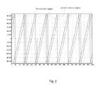
- FIG. 2is a schematic view showing waveforms of a first electric degree and a second electric degree when the synchronous motor rotates normally according to an embodiment of the present disclosure
- FIG. 3is a schematic view showing waveforms of a first electric degree and a second electric degree when a second type of out-of-step of the synchronous motor occurs according to an embodiment of the present disclosure
- FIG. 4is a flow chart of a method for checking an out-of-step of a synchronous motor according to another embodiment of the present disclosure.
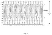
- FIG. 5is a schematic view showing waveforms of the three-phase currents of the synchronous motor when a third type of out-of-step occurs to the synchronous motor according to an embodiment of the present disclosure.
- relative termssuch as “central”, “longitudinal”, “lateral”, “front”, “rear”, “right”, “left”, “inner”, “outer”, “lower”, “upper”, “horizontal”, “vertical”, “above”, “below”, “up”, “top”, “bottom” as well as derivative thereof (e.g., “horizontally”, “downwardly”, “upwardly”, etc.) should be construed to refer to the orientation as then described or as shown in the drawings under discussion. These relative terms are for convenience of description and do not require that the present disclosure be constructed or operated in a particular orientation.
- FIG. 1is a flow chart of a method for checking an out-of-step of a synchronous motor according to an embodiment of the present disclosure. As shown in FIG. 1 , the method comprises the following steps.
- an electric degree of the synchronous motoris detected.
- at least a first electric degree and a second electric degreeare detected at a preset interval, and the second electric degree is detected after the first electric degree.
- the preset intervalmay be but not limited to one program control period in the algorithm which controls when there is no rotor location, i.e., one program period.
- the first electric degreeis an electric degree in a certain period
- the second electric degreeis an electric degree in the next period.
- the electric degreeis detected after the synchronous motor enters in a closed loop control state. For example, it is firstly determined whether the synchronous motor is in a closed loop control state, and if yes, the electric degree used for controlling the synchronous motor is detected.
- the step of detecting the electric degree of the synchronous motorcomprises the following steps.
- a first voltage and a first current on an ⁇ axis and a second voltage and a second current on a ⁇ axis in a ⁇ - ⁇ coordinate systemare obtained.
- the first voltage V ⁇ and the first current I ⁇ on the ⁇ axis and the second voltage V ⁇ and the second current I ⁇ on the ⁇ axiscan be obtained by the PI regulation of the inner current loop and the coordinate transformation.
- an induced electromotive forceis obtained according to the first voltage V ⁇ , the first current I ⁇ , the second voltage V ⁇ and the second current I ⁇ .
- the induced electromotive forces E ⁇ and E ⁇are calculated according to the following formula.
- an instantaneous angular velocity of the synchronous motoris obtained according to the induced electromotive force and an induced electromotive force constant of the synchronous motor.
- the induced electromotive forces E ⁇ and E ⁇are firstly converted into the induced electromotive forces Ed and Eq, in which the induced electromotive force Ed is the induced electromotive force on d axis and Eq is the induced electromotive force on q axis, and then the induced electromotive force Eq is corrected and then divided by the induced electromotive force constant to obtain the instantaneous angular velocity of the synchronous motor.
- the correction to the induced electromotive force Eqcomprises: when the induced electromotive force Eq is greater than zero, the induced electromotive force Ed is subtracted from the induced electromotive force Eq; and when the induced electromotive force Eq is less than zero, the induced electromotive force Ed is added to the induced electromotive force Eq.
- the induced voltage of the stator winding of the synchronous motor rotating under a rated speedis used as the induced electromotive force constant.
- the instantaneous angular velocityis integrated to obtain the electric degree.
- the electric degreeis obtained.
- Each of the first and second electric degreescan be calculated according to the above method.
- the first electric degreeis compared with the second electric degree to obtain a comparing result.
- the electric degreeshould increase progressively and an increment of the electric degree should satisfy a certain requirement. Therefore, it can be determined whether the synchronous motor is out of step by determining whether the second electric degree is greater than the first electric degree or by determining whether a difference value or an increment between the second electric degree and the first electric degree is a positive value. For example, in one embodiment of the present disclosure, the following steps may be executed to determine whether the comparing result satisfies a preset requirement.
- the first electric degreeis subtracted from the second electric degree to obtain the difference value.
- the difference valueis less than a first preset degree.
- the electric degree increment in each program periodis less than the first preset degree.
- the electric degree increment in each program periodshould be greater than a theoretic minimum variation (i.e., the first preset degree).
- ⁇is the first preset degree
- Pis a number of electrode pairs of the synchronous motor
- ⁇is a mechanical angular velocity
- Tis the preset interval
- FIG. 2is a schematic view showing waveforms of the first electric degree and the second electric degree when the synchronous motor rotates normally according to an embodiment of the present disclosure. As shown in FIG. 2 , when the synchronous motor works normally, the electric degree increases progressively.
- step S 103it is determined that the synchronous motor is out of step when the comparing result satisfies the preset requirement.
- the electric degree increment in each program periodis relatively small (for example, less than the first preset angle)
- the above stepsmay be repeated for many times, i.e., the electric degree in a plurality of continuous program periods (for example, 10 program periods) may be detected, and it is determined that the synchronous motor is out of step only when each electric degree increment between each two adjacent period program periods is less than the first preset angle.
- an accuracy of checking the out-of-stepis enhanced.
- the method for checking the out-of-step of the synchronous motorcalculates the electric degree increment in real time according to the detected electric degrees. According to the fact that the electric degree of the synchronous motor in the normal running forward state increases progressively, it can be determined that the synchronous motor is out of step when the electric degree keeps unchanged or decreases progressively or when the increment of the electric degree is very small, and then a further protective process such as turning off a wave can be performed to prevent a further damage, thus reducing losses and enhancing safety.
- the out-of-step of the synchronous motormay be classified into a plurality of types. For example, some types may indicate that there is no rotating magnetic field (i.e., neither the stator field nor the rotor rotates), some types may indicate that the motor rotates reversely (i.e., the rotor of the synchronous motor rotates reversely), and some types may indicate that the rotor of the synchronous motor is locked (i.e., the rotor is locked while the stator field rotates).
- the method according to the present disclosuremay also determine a type of the out-of-step of the synchronous motor. Thus, it is convenient to find out the reasons that result in the out-of-step, such that a corresponding process can be performed to avoid a recurrence of a similar out-of-step, thus enhancing the safety and reducing losses.
- the type of the out-of-step of the synchronous motoris determined according to the comparing result.
- the type of the out-of-step of the synchronous motorcomprises a first type of out-of-step and a second type of out-of-step.
- the first type of out-of-stepindicates that there is no rotating magnetic field, i.e., neither the stator field nor the rotor rotates
- the second type of out-of-stepindicates that the motor rotates reversely, i.e., the rotor of the synchronous motor rotates reversely.
- the type of the out-of-stepcan be determined according to the following steps.
- the second preset anglemay be zero.
- the difference valueis greater than or equal to the second preset degree, it is determined that the type of the out-of-step of the synchronous motor is the first type of out-of-step. This is because, when there is no magnetic field (i.e., neither the stator field nor the rotor rotate), an induced electromotive force is calculated to be abnormal according to the current rotor location and load. At this time, a velocity increment is calculated to be zero by an algorithm which estimates the velocity and calculates the angle when there is no rotor location, and an angle increment is also zero or about zero, which results in that the electric degree increment in each program period is very small and greater than or equal to zero.
- the out-of-stepis caused by the fact that neither the stator field nor the rotor rotates.
- the difference valueis less than the second preset degree, it is determined that the type of the out-of-step of the synchronous motor is the second type of out-of-step.
- the second preset degreeis zero, it can be considered that when the electric degree increment in each program period is a negative value, the second type of out-of-step occurs, specifically, the rotor of the synchronous motor rotates reversely due to load impact or other reasons.
- the calculated electromotive forcebecomes a negative value
- the stepping value of the electric degree estimated in the programbecomes a negative value
- the cumulative result of whichis that the electric degree decreases progressively. Therefore, when the electric degree increment in each program period is determined to be a negative value, it can be determined that the rotor of the synchronous motor rotates reversely.
- FIG. 3is a schematic view showing waveforms of the first electric degree and the second electric degree when the second type of out-of-step occurs to the synchronous motor according to an embodiment of the present disclosure. As shown in FIG. 3 , when the second type of out-of-step occurs, the electric degree decreases progressively.
- the type of the out-of-step of the synchronous motormay also further comprise a third type of out-of-step.
- the third type of out-of-stepindicates that the rotor of the synchronous motor is locked while the stator field still rotates.
- FIG. 4is a method for checking an out-of-step of a synchronous motor according to another embodiment of the present disclosure. As shown in FIG. 4 , the method comprises the following steps.
- the electric degree of the synchronous motoris detected, in which the electric degree comprises at least the first electric degree and the second electric degree detected at the preset interval, and the second electric degree is detected after the first electric degree.
- the first electric degreeis compared with the second electric degree to obtain the comparing result.
- three-phase currents of the synchronous motor in a same periodare obtained when the comparing result does not satisfy the preset requirement.
- a maximum value of each current of the three-phase currentsis calculated to obtain three maximum values. Specifically, absolute values of the three-phase currents in one period are obtained to calculate the maximum value of each current of the three-phase currents.
- calculationmay be performed for many times (such as 5 times) to obtain a plurality of real-time maximum current values, and then a middle value of the plurality of real-time maximum current values is selected to be the maximum value.
- the current detection accuracyis enhanced and mistakes can be avoided.
- step 405it is determined whether a ratio between a maximum value of the three maximum values and a minimum value of the three maximum values is greater than or equal to a preset threshold.
- the three maximum valuesmay be obtained for many times, and when the ratio calculated each time is greater than or equal to the preset threshold, it can be determined that the three-phase currents are out of balance, i.e., the synchronous motor is out of step. Specifically, when the motor is locked, the rotor keeps still, the magnetic field of the rotor magnet keeps unchanged, and the magnetic field intensity at the magnetic pole is the largest.
- the velocity increment and the angle increment of the statorcan still be calculated according to the algorithm which estimates the velocity and calculates the angle when there is no rotor location, so that the angle still changes as normal.
- the angle changemakes the composite magnetic field rotate, and the induced electromotive force is generated when the rotating magnetic field cuts the stator winding.
- the preset thresholdmay be about 1.3.
- step 406it is determined that the synchronous motor is out of step and the type of out-of-step of the synchronous motor is the third type of out-of-step when the ratio is greater than or equal to the preset threshold.
- a relationship between the three-phase currentsis calculated in real time according to the values of the three-phase currents. According to the fact that the synchronous motor in a normal running forward state should have the equal amplitude and the 120° phase difference, it can be determined that the synchronous motor is out of step when the three-phase currents are out of balance, and then protective processes can be performed, thus avoiding an occurrence of an accident and reducing losses.
- FIG. 5is a schematic view showing a waveform of the three-phase currents when the third type of out-of-step of the synchronous motor occurs according to an embodiment of the present disclosure. As shown in FIG. 5 , only the waveforms of currents A and C are shown, and the waveforms of currents A and C are sine waves. It can be seen from FIG. 3 that the amplitudes of the three-phase currents are different while the phases of the three-phase currents still change as normal when the third type of out-of-step occurs.
- the wave such as a PWM wavemay be turned off to protect the synchronous motor.
- the wavesuch as a PWM wave may be turned off to protect the synchronous motor.
- six PWM waves of the power bridge currentare controlled to be turned off.
- the embodiments of the inventioncan be embodied as a method, a system, or a computer program product encoded into a computer readable storage medium.
- the computer program productcan be executed by a processor to perform the method as described in the disclosure.
Landscapes
- Engineering & Computer Science (AREA)
- Power Engineering (AREA)
- Control Of Ac Motors In General (AREA)
- Control Of Motors That Do Not Use Commutators (AREA)
Abstract
Description
θ=PωT,
IA+IB+IC=0,
in which, IA, IBand ICrepresent each current of the three-phase currents respectively.
Claims (16)
Applications Claiming Priority (3)
| Application Number | Priority Date | Filing Date | Title |
|---|---|---|---|
| CN201210367126.3ACN103701372B (en) | 2012-09-27 | 2012-09-27 | A kind of step failing out detecting method of synchronous motor |
| CN201210367126 | 2012-09-27 | ||
| CN201210367126.3 | 2012-09-27 |
Publications (2)
| Publication Number | Publication Date |
|---|---|
| US20140084825A1 US20140084825A1 (en) | 2014-03-27 |
| US9887646B2true US9887646B2 (en) | 2018-02-06 |
Family
ID=50338191
Family Applications (1)
| Application Number | Title | Priority Date | Filing Date |
|---|---|---|---|
| US14/039,852Active2033-12-22US9887646B2 (en) | 2012-09-27 | 2013-09-27 | Method for checking out-of-step of synchronous motor |
Country Status (3)
| Country | Link |
|---|---|
| US (1) | US9887646B2 (en) |
| CN (1) | CN103701372B (en) |
| WO (1) | WO2014048284A1 (en) |
Families Citing this family (9)
| Publication number | Priority date | Publication date | Assignee | Title |
|---|---|---|---|---|
| CN103701372B (en) | 2012-09-27 | 2017-07-04 | 比亚迪股份有限公司 | A kind of step failing out detecting method of synchronous motor |
| CN104092419B (en)* | 2014-07-24 | 2017-02-01 | 重庆大学 | Method for detecting step omitting of stepping motor |
| EP3322087B1 (en)* | 2015-07-10 | 2025-05-21 | Mitsubishi Electric Corporation | Motor control device, compressor, and air conditioner |
| JP6596253B2 (en)* | 2015-07-27 | 2019-10-23 | 株式会社日立産機システム | Power converter and control method of power converter |
| CN105974311A (en)* | 2016-05-25 | 2016-09-28 | 广东美的制冷设备有限公司 | Zero-speed fault detection method and apparatus for permanent-magnet synchronous motor |
| CN106374434B (en)* | 2016-10-21 | 2019-01-29 | 广州视源电子科技股份有限公司 | Motor locked-rotor protection method and device |
| CN106533279B (en)* | 2016-11-18 | 2019-01-15 | 广州视源电子科技股份有限公司 | Synchronous motor step-out detection method and device |
| CN109000427B (en)* | 2018-09-14 | 2024-05-24 | 珠海格力节能环保制冷技术研究中心有限公司 | Method and device for protecting refrigerator from reverse rotation, refrigerator, storage medium and processor |
| CN113866490B (en)* | 2020-06-30 | 2023-11-28 | 安徽威灵汽车部件有限公司 | Motor phase current overcurrent detection method, device and motor controller, vehicle |
Citations (31)
| Publication number | Priority date | Publication date | Assignee | Title |
|---|---|---|---|---|
| US4376295A (en) | 1979-01-11 | 1983-03-08 | Fuji Electric Co. Ltd. | System for predicting desynchronization of a synchronous machine |
| US4916368A (en)* | 1987-11-14 | 1990-04-10 | Hitachi Elevator Engineering & Service Company, Ltd. | Controlling method and device for permanent magnet synchronous motor |
| JPH04127000A (en) | 1990-09-18 | 1992-04-27 | Mitsubishi Electric Corp | unmanned air vehicle system |
| US5625277A (en)* | 1995-01-30 | 1997-04-29 | Abb Power T&D Company Inc. | Dynamic mechanically switched damping system and method for damping power oscillations using the same |
| US5969496A (en)* | 1997-06-23 | 1999-10-19 | Toyota Jidosha Kabushiki Kaisha | Method of controlling operation of synchronous motor and motor control apparatus for the same |
| US6362586B1 (en) | 2000-09-15 | 2002-03-26 | General Motors Corporation | Method and device for optimal torque control of a permanent magnet synchronous motor over an extended speed range |
| US6396229B1 (en)* | 2000-03-06 | 2002-05-28 | Hitachi, Ltd. | Method of estimating a rotor position of synchronous motor, method of controlling synchronous motor with no position sensor and a controller of synchronous motor |
| US20030071588A1 (en) | 2001-09-04 | 2003-04-17 | Yoshitaka Iwaji | System for driving electric motor |
| CN1437314A (en) | 2002-02-07 | 2003-08-20 | 许俊甫 | A device that can increase the speed of a permanent magnet motor |
| JP2003348896A (en) | 2002-05-24 | 2003-12-05 | Meidensha Corp | Control unit for pm motor |
| JP2004104935A (en) | 2002-09-11 | 2004-04-02 | Denso Corp | Motor controller |
| US20040113581A1 (en)* | 2002-09-06 | 2004-06-17 | Masato Kobayashi | Stepping motor controller, scanning apparatus, and image forming apparatus |
| US20040249596A1 (en)* | 2001-11-12 | 2004-12-09 | International Rectifier Corporation | Start-up method and system for permanent magnet synchronous motor drive |
| US20060125439A1 (en)* | 2004-12-10 | 2006-06-15 | Hitachi, Ltd. | Synchronous motor drive unit and a driving method thereof |
| US20070069681A1 (en) | 2005-09-27 | 2007-03-29 | Denso Corporation | Method of estimating magnetic pole position in synchronous motor |
| CN101149423A (en) | 2007-11-02 | 2008-03-26 | 清华大学 | Real-time detection and analysis method and device for permanent magnet magnetic field distortion of permanent magnet synchronous motor |
| CN101192803A (en) | 2006-11-30 | 2008-06-04 | 株式会社电装 | Apparatus and method for driving rotary machine |
| JP2008278595A (en) | 2007-04-26 | 2008-11-13 | Fuji Electric Fa Components & Systems Co Ltd | Control device for permanent magnet type synchronous motor |
| CN201230202Y (en) | 2008-07-28 | 2009-04-29 | 江西铜业集团公司 | Synchronous electric machine step failing out detection device |
| US20090140688A1 (en)* | 2005-07-27 | 2009-06-04 | Hideaki Iura | Inverter Device |
| CN101471620A (en) | 2007-12-27 | 2009-07-01 | 康奈可关精株式会社 | Drive control device for a stepper motor and drive control method of the stepper motor |
| CN101535913B (en) | 2006-10-31 | 2011-03-02 | 比亚迪股份有限公司 | motor control method |
| US20110127937A1 (en)* | 2008-10-17 | 2011-06-02 | Toyota Jidosha Kabushiki Kaisha | Motor actuation control device |
| US20110156624A1 (en)* | 2009-12-28 | 2011-06-30 | Sanyo Electric Co., Ltd. | Motor drive circuit for driving a synchronous motor |
| US20110219816A1 (en)* | 2008-12-02 | 2011-09-15 | Panasonic Corporation | Motor drive device, and compressor and refrigerator using same |
| US20120014227A1 (en) | 2010-07-16 | 2012-01-19 | Keishi Honmura | Stepping motor control circuit and analog electronic timepiece |
| CN102374328A (en) | 2010-08-27 | 2012-03-14 | 杭州三花研究院有限公司 | Electronic expansion valve, stepper motor and reversing valve |
| US20120211299A1 (en) | 2009-12-25 | 2012-08-23 | Toyota Jidosha Kabushiki Kaisha | Electric power steering apparatus |
| US20130147405A1 (en)* | 2011-12-09 | 2013-06-13 | Hyundai Motor Company | Current sensor reconfiguration method of a vehicle having a motor |
| US20130249450A1 (en)* | 2012-03-20 | 2013-09-26 | Samsung Electronics Co., Ltd. | Sensorless control apparatuses and control methods thereof |
| WO2014048284A1 (en) | 2012-09-27 | 2014-04-03 | Shenzhen Byd Auto R&D Company Limited | Method for checking out-of-step of synchronous motor |
Family Cites Families (2)
| Publication number | Priority date | Publication date | Assignee | Title |
|---|---|---|---|---|
| JP3168986B2 (en)* | 1998-05-28 | 2001-05-21 | トヨタ自動車株式会社 | Motor control device and control method |
| CN100418298C (en)* | 2005-03-23 | 2008-09-10 | 比亚迪股份有限公司 | A permanent magnet synchronous motor rotor position sensing method and position sensing device |
- 2012
- 2012-09-27CNCN201210367126.3Apatent/CN103701372B/enactiveActive
- 2013
- 2013-09-23WOPCT/CN2013/083977patent/WO2014048284A1/enactiveApplication Filing
- 2013-09-27USUS14/039,852patent/US9887646B2/enactiveActive
Patent Citations (32)
| Publication number | Priority date | Publication date | Assignee | Title |
|---|---|---|---|---|
| US4376295A (en) | 1979-01-11 | 1983-03-08 | Fuji Electric Co. Ltd. | System for predicting desynchronization of a synchronous machine |
| US4916368A (en)* | 1987-11-14 | 1990-04-10 | Hitachi Elevator Engineering & Service Company, Ltd. | Controlling method and device for permanent magnet synchronous motor |
| JPH04127000A (en) | 1990-09-18 | 1992-04-27 | Mitsubishi Electric Corp | unmanned air vehicle system |
| US5625277A (en)* | 1995-01-30 | 1997-04-29 | Abb Power T&D Company Inc. | Dynamic mechanically switched damping system and method for damping power oscillations using the same |
| US5969496A (en)* | 1997-06-23 | 1999-10-19 | Toyota Jidosha Kabushiki Kaisha | Method of controlling operation of synchronous motor and motor control apparatus for the same |
| US6396229B1 (en)* | 2000-03-06 | 2002-05-28 | Hitachi, Ltd. | Method of estimating a rotor position of synchronous motor, method of controlling synchronous motor with no position sensor and a controller of synchronous motor |
| US6362586B1 (en) | 2000-09-15 | 2002-03-26 | General Motors Corporation | Method and device for optimal torque control of a permanent magnet synchronous motor over an extended speed range |
| US20030071588A1 (en) | 2001-09-04 | 2003-04-17 | Yoshitaka Iwaji | System for driving electric motor |
| US20040249596A1 (en)* | 2001-11-12 | 2004-12-09 | International Rectifier Corporation | Start-up method and system for permanent magnet synchronous motor drive |
| CN1437314A (en) | 2002-02-07 | 2003-08-20 | 许俊甫 | A device that can increase the speed of a permanent magnet motor |
| JP2003348896A (en) | 2002-05-24 | 2003-12-05 | Meidensha Corp | Control unit for pm motor |
| US20040113581A1 (en)* | 2002-09-06 | 2004-06-17 | Masato Kobayashi | Stepping motor controller, scanning apparatus, and image forming apparatus |
| JP2004104935A (en) | 2002-09-11 | 2004-04-02 | Denso Corp | Motor controller |
| US20060125439A1 (en)* | 2004-12-10 | 2006-06-15 | Hitachi, Ltd. | Synchronous motor drive unit and a driving method thereof |
| US20090140688A1 (en)* | 2005-07-27 | 2009-06-04 | Hideaki Iura | Inverter Device |
| US20070069681A1 (en) | 2005-09-27 | 2007-03-29 | Denso Corporation | Method of estimating magnetic pole position in synchronous motor |
| CN101535913B (en) | 2006-10-31 | 2011-03-02 | 比亚迪股份有限公司 | motor control method |
| CN101192803A (en) | 2006-11-30 | 2008-06-04 | 株式会社电装 | Apparatus and method for driving rotary machine |
| JP2008278595A (en) | 2007-04-26 | 2008-11-13 | Fuji Electric Fa Components & Systems Co Ltd | Control device for permanent magnet type synchronous motor |
| CN101149423A (en) | 2007-11-02 | 2008-03-26 | 清华大学 | Real-time detection and analysis method and device for permanent magnet magnetic field distortion of permanent magnet synchronous motor |
| CN101471620A (en) | 2007-12-27 | 2009-07-01 | 康奈可关精株式会社 | Drive control device for a stepper motor and drive control method of the stepper motor |
| CN201230202Y (en) | 2008-07-28 | 2009-04-29 | 江西铜业集团公司 | Synchronous electric machine step failing out detection device |
| US20110127937A1 (en)* | 2008-10-17 | 2011-06-02 | Toyota Jidosha Kabushiki Kaisha | Motor actuation control device |
| US20110219816A1 (en)* | 2008-12-02 | 2011-09-15 | Panasonic Corporation | Motor drive device, and compressor and refrigerator using same |
| US20120211299A1 (en) | 2009-12-25 | 2012-08-23 | Toyota Jidosha Kabushiki Kaisha | Electric power steering apparatus |
| CN102687386A (en) | 2009-12-25 | 2012-09-19 | 丰田自动车株式会社 | Electric power steering apparatus |
| US20110156624A1 (en)* | 2009-12-28 | 2011-06-30 | Sanyo Electric Co., Ltd. | Motor drive circuit for driving a synchronous motor |
| US20120014227A1 (en) | 2010-07-16 | 2012-01-19 | Keishi Honmura | Stepping motor control circuit and analog electronic timepiece |
| CN102374328A (en) | 2010-08-27 | 2012-03-14 | 杭州三花研究院有限公司 | Electronic expansion valve, stepper motor and reversing valve |
| US20130147405A1 (en)* | 2011-12-09 | 2013-06-13 | Hyundai Motor Company | Current sensor reconfiguration method of a vehicle having a motor |
| US20130249450A1 (en)* | 2012-03-20 | 2013-09-26 | Samsung Electronics Co., Ltd. | Sensorless control apparatuses and control methods thereof |
| WO2014048284A1 (en) | 2012-09-27 | 2014-04-03 | Shenzhen Byd Auto R&D Company Limited | Method for checking out-of-step of synchronous motor |
Non-Patent Citations (3)
| Title |
|---|
| Hua Yang, et al.; "The development of large vertical synchronous motor with brushless excitation for the pump station of Jiangsu Province." Public Communication of Science and Technology; May 15, 2012. |
| KR 10-2012-0028087 English Machine Translation Kwon et al.* |
| PCT International Search Report and Written Opinion dated Dec. 12, 2013, issued in International Application No. PCT/CN2013/083977 (9 pages). |
Also Published As
| Publication number | Publication date |
|---|---|
| WO2014048284A1 (en) | 2014-04-03 |
| CN103701372B (en) | 2017-07-04 |
| US20140084825A1 (en) | 2014-03-27 |
| CN103701372A (en) | 2014-04-02 |
Similar Documents
| Publication | Publication Date | Title |
|---|---|---|
| US9887646B2 (en) | Method for checking out-of-step of synchronous motor | |
| US9887647B2 (en) | Method for checking out-of-step of synchronous motor | |
| US9575127B2 (en) | Motor control device and electric power steering device using same | |
| Li et al. | High-stability position-sensorless control method for brushless DC motors at low speed | |
| US9154064B2 (en) | Control device for AC motor | |
| US10161766B2 (en) | Magnetic pole position detection device of permanent magnet-type synchronous motor | |
| US20160329853A1 (en) | Electric Motor Drive Device and Control Method Therefor | |
| EP2945280B1 (en) | Apparatus for controlling induction machine | |
| US9184687B2 (en) | Motor control apparatus and motor control method | |
| KR20190074363A (en) | Motor control method | |
| JP5168057B2 (en) | Electric power steering device | |
| CN108919025A (en) | A kind of power line wire break detection method in three-phase alternating current servo drive system | |
| EP2645562B1 (en) | Control method for induction motor | |
| US7843161B2 (en) | Inverter device | |
| JP2010268599A (en) | Control device for permanent magnet motor | |
| JP5396754B2 (en) | Output estimation device | |
| US11290044B2 (en) | Motor control device | |
| JP6108109B2 (en) | Control device for permanent magnet type synchronous motor | |
| JP5862499B2 (en) | Motor control device | |
| JP5320826B2 (en) | Output estimation device, motor control device and motor control system using the same | |
| JP6149501B2 (en) | Magnetic pole position detector for synchronous machine |
Legal Events
| Date | Code | Title | Description |
|---|---|---|---|
| AS | Assignment | Owner name:BYD COMPANY LIMITED, CHINA Free format text:ASSIGNMENT OF ASSIGNORS INTEREST;ASSIGNORS:LUO, HUI;DU, ZHIYONG;ZHOU, XUGUANG;AND OTHERS;REEL/FRAME:031301/0272 Effective date:20130922 Owner name:SHENZHEN BYD AUTO R&D COMPANY LIMITED, CHINA Free format text:ASSIGNMENT OF ASSIGNORS INTEREST;ASSIGNORS:LUO, HUI;DU, ZHIYONG;ZHOU, XUGUANG;AND OTHERS;REEL/FRAME:031301/0272 Effective date:20130922 | |
| STCF | Information on status: patent grant | Free format text:PATENTED CASE | |
| AS | Assignment | Owner name:BYD COMPANY LIMITED, CHINA Free format text:ASSIGNMENT OF ASSIGNORS INTEREST;ASSIGNORS:SHENZHEN BYD AUTO R&D COMPANY LIMITED;BYD COMPANY LIMITED;REEL/FRAME:051556/0053 Effective date:20200107 | |
| MAFP | Maintenance fee payment | Free format text:PAYMENT OF MAINTENANCE FEE, 4TH YEAR, LARGE ENTITY (ORIGINAL EVENT CODE: M1551); ENTITY STATUS OF PATENT OWNER: LARGE ENTITY Year of fee payment:4 | |
| MAFP | Maintenance fee payment | Free format text:PAYMENT OF MAINTENANCE FEE, 8TH YEAR, LARGE ENTITY (ORIGINAL EVENT CODE: M1552); ENTITY STATUS OF PATENT OWNER: LARGE ENTITY Year of fee payment:8 |