US9884191B2 - Apparatus, system, and method for selective stimulation - Google Patents
Apparatus, system, and method for selective stimulationDownload PDFInfo
- Publication number
- US9884191B2 US9884191B2US14/811,171US201514811171AUS9884191B2US 9884191 B2US9884191 B2US 9884191B2US 201514811171 AUS201514811171 AUS 201514811171AUS 9884191 B2US9884191 B2US 9884191B2
- Authority
- US
- United States
- Prior art keywords
- electrode
- ipg
- contact
- implant
- patient
- Prior art date
- Legal status (The legal status is an assumption and is not a legal conclusion. Google has not performed a legal analysis and makes no representation as to the accuracy of the status listed.)
- Active
Links
Images


Classifications
- A—HUMAN NECESSITIES
- A61—MEDICAL OR VETERINARY SCIENCE; HYGIENE
- A61N—ELECTROTHERAPY; MAGNETOTHERAPY; RADIATION THERAPY; ULTRASOUND THERAPY
- A61N1/00—Electrotherapy; Circuits therefor
- A61N1/18—Applying electric currents by contact electrodes
- A61N1/32—Applying electric currents by contact electrodes alternating or intermittent currents
- A61N1/36—Applying electric currents by contact electrodes alternating or intermittent currents for stimulation
- A61N1/3605—Implantable neurostimulators for stimulating central or peripheral nerve system
- A61N1/3606—Implantable neurostimulators for stimulating central or peripheral nerve system adapted for a particular treatment
- A61N1/3611—Respiration control
- A—HUMAN NECESSITIES
- A61—MEDICAL OR VETERINARY SCIENCE; HYGIENE
- A61N—ELECTROTHERAPY; MAGNETOTHERAPY; RADIATION THERAPY; ULTRASOUND THERAPY
- A61N1/00—Electrotherapy; Circuits therefor
- A61N1/02—Details
- A61N1/04—Electrodes
- A61N1/05—Electrodes for implantation or insertion into the body, e.g. heart electrode
- A61N1/0551—Spinal or peripheral nerve electrodes
- A61N1/0556—Cuff electrodes
- A—HUMAN NECESSITIES
- A61—MEDICAL OR VETERINARY SCIENCE; HYGIENE
- A61N—ELECTROTHERAPY; MAGNETOTHERAPY; RADIATION THERAPY; ULTRASOUND THERAPY
- A61N1/00—Electrotherapy; Circuits therefor
- A61N1/18—Applying electric currents by contact electrodes
- A61N1/32—Applying electric currents by contact electrodes alternating or intermittent currents
- A61N1/36—Applying electric currents by contact electrodes alternating or intermittent currents for stimulation
- A61N1/3605—Implantable neurostimulators for stimulating central or peripheral nerve system
- A—HUMAN NECESSITIES
- A61—MEDICAL OR VETERINARY SCIENCE; HYGIENE
- A61N—ELECTROTHERAPY; MAGNETOTHERAPY; RADIATION THERAPY; ULTRASOUND THERAPY
- A61N1/00—Electrotherapy; Circuits therefor
- A61N1/18—Applying electric currents by contact electrodes
- A61N1/32—Applying electric currents by contact electrodes alternating or intermittent currents
- A61N1/36—Applying electric currents by contact electrodes alternating or intermittent currents for stimulation
- A61N1/372—Arrangements in connection with the implantation of stimulators
- A61N1/37211—Means for communicating with stimulators
- A61N1/37217—Means for communicating with stimulators characterised by the communication link, e.g. acoustic or tactile
- A—HUMAN NECESSITIES
- A61—MEDICAL OR VETERINARY SCIENCE; HYGIENE
- A61N—ELECTROTHERAPY; MAGNETOTHERAPY; RADIATION THERAPY; ULTRASOUND THERAPY
- A61N1/00—Electrotherapy; Circuits therefor
- A61N1/18—Applying electric currents by contact electrodes
- A61N1/32—Applying electric currents by contact electrodes alternating or intermittent currents
- A61N1/36—Applying electric currents by contact electrodes alternating or intermittent currents for stimulation
- A61N1/372—Arrangements in connection with the implantation of stimulators
- A61N1/375—Constructional arrangements, e.g. casings
- A61N1/37514—Brain implants
- A—HUMAN NECESSITIES
- A61—MEDICAL OR VETERINARY SCIENCE; HYGIENE
- A61N—ELECTROTHERAPY; MAGNETOTHERAPY; RADIATION THERAPY; ULTRASOUND THERAPY
- A61N1/00—Electrotherapy; Circuits therefor
- A61N1/18—Applying electric currents by contact electrodes
- A61N1/32—Applying electric currents by contact electrodes alternating or intermittent currents
- A61N1/36—Applying electric currents by contact electrodes alternating or intermittent currents for stimulation
- A61N1/372—Arrangements in connection with the implantation of stimulators
- A61N1/378—Electrical supply
- A61N1/3787—Electrical supply from an external energy source
- A—HUMAN NECESSITIES
- A61—MEDICAL OR VETERINARY SCIENCE; HYGIENE
- A61N—ELECTROTHERAPY; MAGNETOTHERAPY; RADIATION THERAPY; ULTRASOUND THERAPY
- A61N1/00—Electrotherapy; Circuits therefor
- A61N1/18—Applying electric currents by contact electrodes
- A61N1/32—Applying electric currents by contact electrodes alternating or intermittent currents
- A61N1/36—Applying electric currents by contact electrodes alternating or intermittent currents for stimulation
- A61N1/3605—Implantable neurostimulators for stimulating central or peripheral nerve system
- A61N1/3606—Implantable neurostimulators for stimulating central or peripheral nerve system adapted for a particular treatment
- A61N1/36071—Pain
- A—HUMAN NECESSITIES
- A61—MEDICAL OR VETERINARY SCIENCE; HYGIENE
- A61N—ELECTROTHERAPY; MAGNETOTHERAPY; RADIATION THERAPY; ULTRASOUND THERAPY
- A61N1/00—Electrotherapy; Circuits therefor
- A61N1/18—Applying electric currents by contact electrodes
- A61N1/32—Applying electric currents by contact electrodes alternating or intermittent currents
- A61N1/36—Applying electric currents by contact electrodes alternating or intermittent currents for stimulation
- A61N1/3605—Implantable neurostimulators for stimulating central or peripheral nerve system
- A61N1/36128—Control systems
- A61N1/36135—Control systems using physiological parameters
- A—HUMAN NECESSITIES
- A61—MEDICAL OR VETERINARY SCIENCE; HYGIENE
- A61N—ELECTROTHERAPY; MAGNETOTHERAPY; RADIATION THERAPY; ULTRASOUND THERAPY
- A61N1/00—Electrotherapy; Circuits therefor
- A61N1/18—Applying electric currents by contact electrodes
- A61N1/32—Applying electric currents by contact electrodes alternating or intermittent currents
- A61N1/36—Applying electric currents by contact electrodes alternating or intermittent currents for stimulation
- A61N1/372—Arrangements in connection with the implantation of stimulators
- A61N1/375—Constructional arrangements, e.g. casings
- A61N1/3758—Packaging of the components within the casing
Definitions
- the present inventionrelates to an apparatus, system, and method for implantable therapeutic treatment of a patient.
- Acute and chronic conditionssuch as pain, arthritis, sleep apnea, seizure, incontinence, and migraine are physiological conditions affecting millions of people worldwide.
- sleep apneais described as an iterated failure to respire properly during sleep. Those affected by sleep apnea stop breathing during sleep numerous times during the night.
- sleep apneaThere are two types of sleep apnea, generally described in medical literature as central and obstructive sleep apnea.
- Central sleep apneais a failure of the nervous system to produce proper signals for excitation of the muscles involved with respiration.
- Obstructive sleep apneais caused by physical obstruction of the upper airway channel (UAW).
- Implantsare a promising alternative to these forms of treatment.
- pharyngeal dilation via hypoglossal nerve (XII) stimulationhas been shown to be an effective treatment method for OSA.
- the nervesare stimulated using an implanted electrode.
- the medial XII nerve branchi.e., in. genioglossus
- UAW airflow resistancei.e., increased pharyngeal caliber
- Implantshave been used to treat other conditions as well. For example, stimulation of the vagus nerve is thought to affect some areas in the brain prone to seizure activity; sacral nerve stimulation is an FDA-approved electronic stimulation therapy for reducing urge incontinence; and stimulation of peripheral nerves may help treat arthritis pain.
- the present inventionis directed to an apparatus, system, and method for selective stimulation that substantially obviates one or more problems due to limitations and disadvantages of the related art.
- the present inventionincludes an implantable neurostimulator system with a hollow cylindrical electronics enclosure having a top, a bottom, and a side; a coil extending from a first part of the electronics enclosure; and at least one electrode operatively connected to the electronics enclosure.
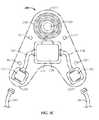
- an implantable neurostimulator systemin another embodiment, includes a symmetrical chevron-shaped molded body having an apex, a first and second side, and a base; a coil at the apex of the molded body; an electronics enclosure at least partially integral with the molded body; and at least one electrode operatively connected to the electronics enclosure.
- an implantable neurostimulator systemincludes an electronics enclosure; a coil; and at least one perforated cuff electrode operatively connected to the electronics enclosure.
- an implantable neurostimulator systemin yet another embodiment, includes an electronics enclosure; a coil; and at least one flat-bottomed open trough electrode operatively connected to the electronics enclosure.
- Another embodiment of the inventionincludes an apparatus and method of neurostimulation, the method including the steps of at least partially encircling a nerve with a cuff having a first and second surface, the cuff having at least one contact on one of the first and second surfaces; connecting at least one stimulus generator to the at least one contact; and delivering a stimulus to the at least one contact.
- FIGS. 1A-1Fshow an exemplary embodiment of a mastoid bone implantable pulse generator (IPG) implant
- FIGS. 2A-2Dshow an exemplary embodiment of a sub-mandibular implantable pulse generator (IPG) implant
- FIGS. 3A-3Cshow exemplary embodiments of IPG cables and connectors
- FIGS. 4A-4Dshow exemplary embodiments of IPG power systems
- FIGS. 5A-5Dshow exemplary embodiments of IPG accessories
- FIGS. 6A-6Gshow exemplary embodiments of IPG electrodes
- FIGS. 7A and 7Bshow exemplary embodiments of monopole electrode configurations
- FIG. 8shows an exemplary embodiment of a bipolar electrode configuration
- FIGS. 9A and 9Bshow exemplary embodiments of multipolar electrode configurations
- FIGS. 10A and 10Bshow an example of a multiplexed system using force vectoring
- FIGS. 11A and 11Bshow exemplary embodiments of non-multiplexed waveform generators.
- an implantable neurostimulator system of the present inventionincludes an implantable pulse generator system (IPG); and at least one electrode operatively connected to the IPG to generate accurate, selective nerve stimulation patterns.
- IPGimplantable pulse generator system
- Exemplary components of various embodiments of the claimed inventionare described hereafter.
- IPGsImplantable Pulse Generator Systems
- Implantable pulse generator systemsinclude one or more of (1) an implant (e.g., FIGS. 1A-2D ); (2) a power system (e.g., FIGS. 4A-4D ); and (3) an IPG accessory (e.g., FIGS. 5A-5D ). Examples of each are discussed below.
- FIGS. 1A-2Dillustrate exemplary embodiments of IPG implants.
- an embodiment of the IPG systemincludes a mastoid bone implant 100 .
- another embodiment of the IPG systemincludes a sub-mandibular implant 200 .
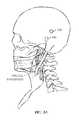
- FIGS. 1A-1Fillustrate a mastoid bone implant embodiment of an IPG for treating obstructive sleep apnea.
- the mastoid bone implant 100is implanted into the mastoid, which is a bony portion of the skull behind the ear.
- the mastoid bone bedis close to the HGN, and provides a stable well-protected location for the mastoid bone implant 100 .
- FIG. 1Aillustrates an exemplary embodiment of a unilateral mastoid bone implant 100 implantable pulse generator system. This area is a common location for cochlear implants.
- the mastoid bone implant 100is placed into a well that is surgically excavated in the mastoid bone below the surface of the skull to secure the implant in place. Placing the mastoid bone implant 100 in a well protects the implant, reduces the amount it protrudes from the skull, and provides a lower device profile.
- the embodiment showncan be implanted to stimulate the left, right, or both HGNs.
- the mastoid bone implant 100is typically located on the same side of the head as the HGN being stimulated.
- a tunnelis formed in the patient's neck from the mastoid bone implant 100 side to the opposite side for the second HGN lead and electrode. While only one electrode (discussed later) is shown in FIG. 1A , multiple electrodes may be used without departing from the scope of the invention.
- the mastoid bone implant 100has a hollow cylindrical electronics enclosure 110 (also known as a case or a can) with a top 111 , a bottom 113 , and a side 112 .
- the case 110houses the implant electronics and power source.
- the case 110is typically made of a biocompatible material, and may be hermetically sealed.
- a lip 114encircles at least a portion of the side 112 of the enclosure 110 , and in certain embodiments has one or more holes to allow a surgeon to anchor the mastoid bone implant 100 in place with sutures.
- silastic and/or silicone rubbercovers at least a portion of the electronics enclosure 110 .
- Other materials known to those skilled in the artmay be used without departing from the scope of the invention.
- the lipmay be used to help secure the silastic to the enclosure 110 .
- some or all of the remaining case exterior not covered with silasticacts as an electrode.
- the electronics enclosure 110 in FIGS. 1A-1Fis exemplary only, and not limited to what is shown.
- An internal coil 120extends from a first part of the side 112 of the electronics enclosure 110 .
- the internal coil 120receives power, and supports bidirectional data and command telemetry.
- the internal coil 120is encased in silastic, which may have an internal Dacron mesh or similar cloth for added tear resistance and durability. Similar materials known to those skilled in the art can be used without departing from the scope of the invention.
- an internal magnet 130helps align the internal coil 120 with an external coil 511 ( FIG. 5B ).
- the internal magnet 130may be hermetically sealed, and in certain embodiments is embedded in the approximate center of the internal coil 120 .
- a second magnet(not shown) is located in the external controller coil 511 .
- the internal magnet 130 and external controller magnet(not shown) are oriented so that they are attracted to each other when the external controller coil is near the internal coil 120 .
- the attractive force of the two magnetsbrings the two coils close together, helping to maintain alignment between the coils. Aligning the coils helps optimize power and telemetry data transfer between the external controller and the mastoid bone implant 100 .
- the mastoid bone implant 100may be implanted to stimulate the left, right, or both HGNs.
- the mastoid bone implant 100 orientationaffects the internal magnet 130 orientation. Therefore, in certain embodiments the internal magnet 130 in the mastoid bone implant 100 is reversible.
- the internal magnet 130is removable, for procedures such as an MRI where the presence of a strong magnet in the patient might affect the images obtained or the forces generated and applied to the implanted internal magnet 130 by the static magnetic field of the MRI system might be unsafe for the patient.
- the internal magnet 130 and/or external controller magnetmay be replaced with a material that is attracted to a magnet, either to eliminate the magnet on one side of the pair of devices, or to provide a lower profile to the corresponding coil assembly.
- one or more glass-to-metal feedthrough leads 140extend through the top of the electronics enclosure 110 .
- the leads 140are encased in silastic or similar material.
- the location of the feedthrough leads 140is exemplary only, and not limited to what is shown.
- Feedthrough leads 140 at the top of the electronics enclosure 110bring electrode and antenna connections from the enclosure 110 to the internal electronics.
- the feedthrough leads 140 shownare glass-to-metal feedthrough leads, but other non-conducting material known to those skilled in the art can be used in place of or in addition to glass to make the feedthrough leads 140 .
- Gold or nickel wiresconnect case feedthrough pins to internal circuitry inside the enclosure 110 .
- Stainless steel, platinum-iridium, gold or MP35N wiresconnect external portions of the feedthrough pins to connector, lead, or antenna connections external to the enclosure 110 .
- the electronics design within the case 110varies, often depending on the implant power source.
- the implantuses an external controller and power source. Since the power source and controller are external to the implant, the internal electronics are relatively simple.
- the implantneed not have volume for a battery or ultracapacitor, and with the controller external to the implant, control and stimulation functions may be reduced to such a significant extent that a state-machine design could realistically be utilized.
- Thishas the added advantage of reducing power consumption and hybrid assembly real estate area as well, but has the disadvantage of being a more inflexible design with future product changes requiring a new application-specific integrated circuit (ASIC) state machine design.
- ASICapplication-specific integrated circuit
- the architecture of the IPG electronicsmay include a microcontroller along with the custom ASIC to generate the stimulus pulses and handle charging and telemetry functions. This has the added benefit of future functionality improvements along with field upgrade options for existing patients, as well as increased diagnostic functionality.
- the IPG electronicsmay include an acoustic pickup and sound processor to identify snoring. The snoring may be used as a trigger to initiate and/or modify stimulus patterns as the patient moves from one stage of sleep to another.
- the mastoid bone implant 100has an internal RF interface.
- RFmay be used to send power and/or control signals to the implant.
- the internal RF interfaceoperates according to the principle of inductive coupling.
- the internal RF interfacemay also include a passive RFID transponder with a demodulator and a modulator.
- the RFID-based implantexploits the near-field characteristics of short wave carrier frequencies of approximately 13.56 MHz. In yet another embodiment, the RFID-based implant uses frequencies between 10 and 15 MHz. This carrier frequency may be further divided into at least one sub-carrier frequency.
- the internal RF interfacemay also have a number of other characteristics.
- the internal RF interfacemay include one or more of a transponder, internal antenna, modulator, demodulator, clock, and rectifier.
- the transpondermay be passive or active.
- the transpondermay have further separate channels for power delivery and data and control, and in some embodiments, the transponder may employ a secure full-duplex data protocol.
- the RF interfacemay further include an inductive coupler, an RF to DC converter, and an internal antenna, and the antenna may include a magnetic component.
- the internal RF interfacecan send and/or receive control logic and/or power.
- the internal RF interfaceuses a sub-carrier frequency for communication with an external RF interface that may be located, for example, in an external controller.
- the sub-carrier frequencymay be used for communication between the internal and external RF interfaces and is obtained by the binary division of the external RF interface carrier frequency.
- the transpondermay use the sub-carrier frequency to modulate a signal back to the external RF interface.
- one or more multi-contact implant connectors 150extending from a second part of the side 112 of the electronics enclosure 110 opposite the coil 120 connect electrode lead connectors 160 with cables having one or more electrode leads to the mastoid bone implant 100 .
- the type of connector, number of pins, and the location of the connectorsare exemplary only, and not limited to what is shown.
- the implant connector 150is a five to nine position female connector, which mates to corresponding lead pins in the electrode lead connector 160 .
- These electrode lead connections 160extend from cables having one or more electrode leads that connect with electrode contact connections for four to eight cathodic contacts and a single or array of common anodes. This configuration allows stimulation to occur between any two or more independent contacts and/or the case 110 .
- the receptaclesare made of a biocompatible material such as stainless steel, titanium, or MP35N, and arranged in a staggered row or other configuration to reduce space.
- molded silicone rubberprovides a detent feature to the female implant connector 150 , which helps hold the male portion of the electrode lead connector 160 in place.
- Male portions of the electrode lead connectors 160optionally have a taper feature providing strain relief to the lead to prevent stress fracture failures in the lead wires. If a connector is unused, as, for example, in a unilateral implant for a single HGN, it is protected with a dummy plug (not shown) to prevent tissue ingrowth and isolate any unused contacts from bodily fluids.
- Certain embodimentsinclude suture holes on the connector areas.
- the suture holeshelp the surgeon lock the connectors together. If used, the sutures help tighten the connection between the male and female connectors. As a non-limiting example, the surgeon may suture around the shroud around the female and male assembled connection to tighten the connection between elements. Other methods known to those skilled in the art may be used without departing from the scope of the invention.
- FIGS. 2A-2Dillustrate an embodiment of a sub-mandibular IPG implant 200 for treating obstructive sleep apnea (OSA).
- the sub-mandibular implant 200stimulates the hypoglossal nerve (HGN), a peripheral nerve located below and behind the lower mandible.
- HGNhypoglossal nerve
- the HGNis typically 4 to 5 mm in diameter, with a typical epineurium thickness of less than 1 mm.
- the sub-mandibular implant 200may be placed within the sub-mandibular space. There is minimal nerve motion in this area during sleep.
- the sub-mandibular implant 200attached leads 342 ( FIGS. 3B-3C ) (discussed later), and electrodes ( FIGS.
- the sub-mandibular implant 200is minimally invasive and easily implanted.
- the sub-mandibular implant 200is chevron-shaped, roughly triangular with the base 202 of the triangle pulled upwards toward the apex 201 of the triangle, with smooth corners 203 and a small surface area.
- the apex 201 and corners 203 of the sub-mandibular implant 200are curved to eliminate sharp corners that may harm a patient.
- the chevron shapehelps the sub-mandibular implant 200 fit within the sub-mandibular space.
- One or more holes 204 along each side of the chevron apex 201optionally allow a surgeon to anchor the sub-mandibular implant 200 in place with sutures.
- the suturesconnect to the fascia attached to the bottom and inner surfaces of the mandible, to help secure the sub-mandibular implant 200 in place and prevent migration and drooping into the neck region.
- the sub-mandibular implant 200may be implanted to stimulate the left, right, or both HGNs.
- the sub-mandibular implant 200 orientation with respect to the target HGNis the same on either HGN, meaning that the sub-mandibular implant 200 cannot be incorrectly implanted with respect to its inside or outside surface, enabling efficient power and data transfer in any configuration.
- the bulk of the sub-mandibular implant 200is silastic and/or silicone rubber (generically referred to as silastic) with an internal Dacron mesh or similar cloth to add tear resistance and durability to the package.
- silasticsilicone rubber
- Dacron meshinternal Dacron mesh or similar cloth
- an internal coil 210lies at the apex 201 of the sub-mandibular implant 200 . With the internal coil 210 located as shown, it is not sensitive to orientation. It functions equally well whether implanted on the right or left HGN.
- the internal coil 210receives power, and supports bidirectional data and command telemetry.
- the internal coil 210 shownis made of gold or platinum wire, but may be made from other conductive materials known to those skilled in the art without departing from the scope of the invention.
- an internal magnet 220helps align the internal coil 210 with an external coil 511 ( FIG. 5B ).
- the internal magnet 220may be hermetically sealed, and in certain embodiments is embedded in the approximate center of the internal coil 210 .
- a second magnet(not shown) is located in the external controller coil 511 .
- the internal 220 and external 520 controller magnetsare oriented so that they are attracted to each other when the external controller coil 511 is near the internal coil 210 .
- the attractive force of the two magnetsbrings the two coils close together, helping to maintain alignment between the coils. Aligning the coils helps optimize power and telemetry data transfer between the external controller and the sub-mandibular implant 200 .
- the sub-mandibular implant 200may be implanted to stimulate the left, right, or both HGNs.
- sub-mandibular implant 200 orientationaffects the internal magnet 220 orientation. Therefore, in certain embodiments the internal magnet 220 in the sub-mandibular implant 200 is reversible.
- the internal magnet 220is removable, for procedures such as an MRI where the presence of a strong magnet in the patient might affect the images obtained or the forces generated and applied to the implanted internal magnet 220 by the static magnetic field of the MRI system might be unsafe for the patient.
- the internal magnet 220 and/or external controller magnetmay be replaced with a material that is attracted to a magnet, either to eliminate the magnet on one side of the pair of devices, or to provide a lower profile to the corresponding coil assembly.
- an electronics enclosure(the case) 230 housing the implant electronics and power source.
- silasticcovers at least a portion of the case 230 .
- at least a portion of the case 230 surfaceis left exposed to act as an electrode.
- the case 230 locationis exemplary only, as is the portion of the case 230 covered with silastic, and not limited to what is shown.
- the case 230is typically made of biocompatible metal, such as a 6-4 titanium alloy.
- a titanium alloyis chosen because of its high resistivity compared to commercially pure (CP) titanium. The higher resistivity helps minimize power losses due to eddy currents resulting from exposure to RF fields, such as a charging field.
- Other biocompatible materialsmay be used without departing from the scope of the invention.
- the electronics enclosure 230is hermetically sealed.
- the enclosure 230may be any hermetic enclosure known to those skilled in the art.
- Feedthrough leads 240 in the sides of the electronics enclosure 230bring electrode and antenna connections from the enclosure 230 to the internal electronics.
- the feedthrough leads 240 shownare glass-to-metal feedthrough leads, but other non-conducting material known to those skilled in the art can be used in place of or in addition to glass to make the feedthrough leads 240 .
- Gold or nickel wiresconnect case feedthrough pins to internal circuitry inside the enclosure 230 .
- Stainless steel, platinum-iridium, gold or MP35N wiresconnect external portions of the feedthrough pins to connector, lead, or antenna connections external to the enclosure 230 .
- at least one permanently attached electrode lead 341( FIG. 3A ) connects the electrodes and antenna to the sub-mandibular implant 200 . Using permanently attached electrode leads 341 rather than connectors 350 increases system reliability.
- the electronics design within the case 230varies, often depending on the implant power source. Examples of how the electronics design varies with the power source are described in the sections discussing the mastoid bone implant 100 (above) and are not repeated here.
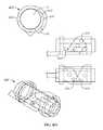
- FIGS. 3A-3Cshow exemplary embodiments of IPG electrode leads 341 , 342 and multi-contact implant connectors 350 . Although shown with a sub-mandibular implant 200 , they may also be used with a mastoid bone implant 100 .
- the implant connectors 350connect electrode leads 341 , 342 and electrodes to the sub-mandibular implant 200 .
- the electrode leads 341 , 342 and electrodesconnect to the implant connectors 350 with lead wires having polyurethane, silicone rubber, or similar insulating material, and wiring made from stainless steel, MP35N, titanium, 90/10 Pt—Ir, gold, or other material with high conductivity, high fatigue resistance, and good tensile properties.
- the lead wireshave high biocompatibility and high corrosion resistance in implanted stimulation conditions.
- the wire materialis MP35N drawn-filled-tube (DFT) with a silver core. This material has excellent fatigue resistance and high tensile strength, and the silver core lowers its electrical resistance to more desirable levels.
- the implant connector 350is a five to nine position female connector, which mates to corresponding lead pins in the electrode lead 341 , 342 .
- These electrode leads 341 , 342connect with electrode contact connections for four to eight cathodic contacts and a single or array of common anodes. This configuration allows stimulation to occur between any two or more independent contacts and/or the case 230 .
- the receptaclesare made of a biocompatible material such as stainless steel, titanium, or MP35N, and arranged in a staggered row or other configuration to reduce space.
- One or more multi-contact implant connectors 350 on at least one corner of the sub-mandibular implant 200connect electrode leads 341 , 342 to the sub-mandibular implant 200 .
- At least one electrode lead 341 and electrodeare permanently attached to the sub-mandibular implant 200 at one of its corners.
- Another feedthrough lead 240 with a female implant connector 350is available for attachment of another electrode lead 342 and electrode.
- the embodiment shown in FIG. 3Ais typically used for unilateral implant patients, where a single electrode lead 341 is sufficient to achieve the desired clinical results, but would still allow a second electrode lead 342 and electrode to be added for bilateral applications.
- the electrode leads 342 shownattach to the sub-mandibular implant 200 through implant connectors 350 only.
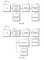
- FIGS. 4A-4Dillustrate exemplary embodiments of IPG power systems. Each embodiment illustrates a different power system.
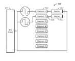
- the four power systemsare (1) RF-powered and controlled ( FIG. 4A ), with continuous application of RF power for operation of the implanted system; (2) ultra-capacitor powered ( FIG. 4B ), with at least one short RF-powered charge period to supply sufficient power to the implant for operation for one sleep period; (3) secondary-battery-powered ( FIG. 4C ), with occasional RF-powered charging periods to supply sufficient power to the implant for operation for at least one sleep period a day for a week or more; and (4) a hybrid combination of ultracapacitor and secondary battery powered ( FIG. 4D ).
- the systemwould allow operation to occur as in the first embodiment, that is, continuous application of RF power for the operation of the implanted system for the duration of the sleep period.
- FIG. 4Ashows an exemplary embodiment of an RF-powered IPG implant 400 .
- the RF-powered IPG implant 400has no internal power source. It receives power and commands, and exchanges data with an external controller via an inductively coupled RF power and data link.
- the linkis a flat coil 401 attached via feedthrough pins to a coupling circuit 402 inside the IPG electronics enclosure.
- the coil 401is AC coupled using one or more capacitors to prevent DC current leakage, which can damage tissue and cause failures in the hermetically sealed IPG feedthroughs.
- the power and data signalsare sinusoidal or similar waveforms at one or more frequencies that minimize energy losses but still support the bandwidth requirements for adequate data transfer rates. In certain embodiments, these signals are in the radio frequency (RF) range.
- RF power and dataare supplied externally with a matching coil, which may be held in position over the IPG coil 401 using a magnet, a strap, adhesive, or other method known to those skilled in the art. Limited coil misalignment is allowed and expected, including lateral displacement, vertical displacement, and out of plane angular displacement.
- the implant 400operates according to the principle of RFID inductive coupling.
- the RFmay be used to send power and/or control signals to the implant.
- the implant 400exploits the near-field characteristics of short wave carrier frequencies of approximately 13.56 MHz. This carrier frequency is further divided into at least one sub-carrier frequency. The sub-carrier frequency is obtained by the binary division of the carrier frequency.
- the implant 400can use between 10 and 15 MHz.
- the implant 400may further have two channels, Channel A and Channel B. Channel A is for power delivery and Channel B is for data and control.
- the received waveformis internally rectified and converted into one or more supply voltages within the RF-powered IPG implant 400 by coupling circuitry 402 and at least one circuit 404 used by the RF-powered IPG implant 400 in regular operations, including stimulation of the HGN.
- the circuit 440may be an application specific integrated circuit (ASIC).
- the RF-powered IPG implant 400uses its internal coil 401 to send a signal to the external devices, sometimes on a different carrier frequency, chosen to optimize its signal integrity and data transfer characteristics without interfering with the inbound signal transfer process.
- the RF-powered IPG implant 400sends the signal from the internal coil 401 concurrently.
- the supply voltagesare filtered and stored internally in capacitors. The capacitors are sized to power the RF-powered IPG implant 400 during temporary interruptions of the power link, but are not large enough to power the RF-powered IPG implant 400 for an entire sleep session.
- FIG. 4Bshows an exemplary embodiment of an ultracapacitor-powered IPG implant 410 .
- the embodimenthas the same elements described above, along with an ultracapacitor 413 that is large enough to store sufficient energy for a single sleep session, and receives power at very high rates with insignificant degradation of performance over time.
- the external controller and associated coilare placed over the internal coil 411 just long enough to exchange data and charge up the ultracapacitor 413 power storage element.
- the rate at which the ultracapacitor 413 storage element chargesis inversely related to the time required to bring it to full charge—the higher the charge rate, the shorter the charge time.
- FIG. 4Cshows an exemplary embodiment of an IPG implant 420 with a secondary battery 423 .
- the secondary-battery-powered IPG implant 420is similar to the passive RF-powered IPG implant 400 ( FIG. 4A ), but with an internal battery 423 as a secondary source of power.
- the secondary battery 423is large enough to store sufficient energy for at least a single sleep session and optimally for many more, and in certain embodiments is sufficient for at least a week of use.
- the secondary-battery-powered IPG implant 420receives its power for charging the secondary battery 423 , receives commands, and exchanges data with an external controller using an inductively coupled RF power and data link.
- the external controller and its associated coilare placed over the internal coil 421 long enough to exchange data and charge up the secondary battery 423 .
- the rate at which the secondary battery 423 may be chargedis typically longer than the charge times for ultracapacitor embodiments.
- Charge rates for secondary batteries such as lithium ion and lithium polymerare typically expressed as a percentage of charge capacity, typically from C/40 to C/1, where C is the charge capacity of the battery. For instance, a 200 milliamp-hour (mA-hr) battery could be charged at 50 mA for a C/4 rate.
- mA-hrmilliamp-hour
- High rates of charge and dischargeare known to reduce the longevity of a secondary battery system, as well as deeply discharging a battery, whereas low rates of charge and discharge, and limited discharge durations with short periods of charge tend to enhance battery performance and longevity.
- Thistranslates to a convenience factor for the patient in that to lengthen the time between surgical replacement for the IPG occurs the patient must frequently charge their implanted system, but if the patient desires to only charge when absolutely necessary it is more likely that the IPG will have a shorter implanted lifetime.
- FIG. 4Dshows an exemplary embodiment of hybrid-ultracapacitor and secondary-battery-powered IPG implant 430 .
- the hybrid-ultracapacitor and secondary-battery-powered IPG implant 430receives power for charging the internal ultracapacitor 433 and its secondary battery 434 , receives commands, and exchanges data with an external controller with an inductively coupled RF power and data link. Charge may be stored in the secondary battery 434 , allowing sleep sessions with no external hardware for up to a week at a time (except for initial IPG turn-on and final turn-off).
- the patientmay also charge for just a few moments to fill the ultracapacitor 433 , or use the hybrid-ultracapacitor and secondary-battery-powered IPG implant 430 in only a fall-back operation of ultracapacitor operation only when the service life of the secondary battery 434 is exhausted, avoiding the need for surgical replacement.
- implanted power sourcesmay also be used without departing from the scope of this invention, such as harvesters of kinetic energy, fuel cells, and even atomic sources.
- the IPGinterfaces with other devices.
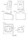
- FIGS. 5A-5Dshow exemplary embodiments of IPG accessories.
- the other devicesmay include, for example: (1) an external controller with an integrated or attached coil ( FIG. 5A and 5B ); (2) a charging station to replenish energy to the external controller ( FIG. 5D ); and (3) a remote control that communicates with the controller ( FIG. 5C ).
- the remote controlalso establishes the operating mode for the patient and/or monitors the performance of the implant and controller.
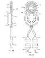
- FIG. 5Ashows an exemplary embodiment of an external controller 500 .
- the external controller 500has a rechargeable power source such as a secondary battery system (lithium ion, etc.), electronics to power and communicate with the IPG, and a telemetry portion that communicates with the remote control.
- the telemetry portion as shownis a coil, but can be any item used by those skilled in the art to transmit and receive data.
- the coil as shownis integrated with the external controller 500 , but can be separate from the external controller 500 in other embodiments.
- the telemetry portion between the external controller 500 and the remote controluses Bluetooth or other wireless communication standard.
- the external controller 500communicates with the remote control or clinician's programmer (such as a computer or other electronic device) using a cable having a USB or other connection known to those skilled in the art.
- the cablecan be in addition to or in place of the wireless telemetry.
- the external controller 500has user interface functions with an activity indicator, such as, for example, an LED indicating whether the device is operational.
- the interfacemay also have another indicator showing link and activity with the remote control.
- the external controller 500interfaces with a recharging station ( FIG. 5D ), so that when the patient starts or ends a sleep session the controller 500 may be easily removed from or returned to the recharging station.
- the external controller 500is mounted to a collar or neck strap 501 that allows simple fitting of the external controller 500 about the patient's neck and provides optimal alignment with the sub-mandibular IPG implant 200 ( FIGS. 2A-2D ) for proper power and data transfer.
- the neck and sub-mandibular location of the external controller 500 and sub-mandibular IPG implant 200are minimally affected by head and neck movement during sleep, with typical patient movement during sleep resulting in only minimal forces applied to the devices.
- FIG. 5Bshows another exemplary embodiment of an external controller 510 .
- the controller 510is worn behind the ear (BTE) and is similar in shape to a speech processor used with a cochlear implant. This shape gives the BTE controller 510 a low profile, which helps keep it from being dislodged during sleep. This shape is exemplary only, and not limited to what is shown.
- the controlleroperatively connects to a coil, which is placed near the mastoid bone implant 100 ( FIGS. 1A-1F ) prior to sleeping.
- the controller coiloptionally has a magnet to help align it with the internal coil 120 .
- the BTE controller 510has user interface functions with an activity indicator, such as, for example, a charge indicator LED 512 indicating whether the device is operational.
- the interfacemay also have another telemetry indicator LED 513 showing link and activity with the remote control.
- the BTE controller 510interfaces with a recharging station ( FIG. 5D ), so that when the patient starts or ends a sleep session the BTE controller 510 may be easily removed from or returned to the recharging station.
- FIG. 5Cshows an exemplary embodiment of a remote control 530 .
- the remote control 530provides the patient with a simple and intuitive interface to the IPG system.
- the remote control 530allows the patient to start and stop IPG operation, and interrogate the IPG system and external controller 500 ( FIG. 5A ) for proper function, status of the communication and power link to the IPG, and status of external controller 500 power.
- the patientmay also choose operating modes for the IPG, including but not limited to standard sleep mode, exercise mode, and alternative operating modes. If enabled by the clinician, the remote control 530 also allows the patient to adjust stimulation levels.
- the embodimentis exemplary only, and not limited to what is shown.
- the remote control 530may communicate with the external controller 500 using a cable having a USB or other connection known to those skilled in the art. The cable can be in addition to or in place of the wireless telemetry.
- the remote controlis incorporated into an Apple iPhoneTM 520 or other wireless device.
- the iPhoneTM 520has an excellent user interface, Bluetooth telemetry capability, and is supported as a development platform for commercial applications.
- the iPhoneTM 520also allows the patient to transfer data to and from the Internet, enabling secure communications to the clinician and the manufacturer.
- Using a commercially available remote controlalso eliminates the need to manufacture the remote, simplifying the supply, support, and (potentially) the patient learning curve.
- Using a commercially available alternativealso provides the opportunity to provide extensive help resources, such as context sensitive help screens, training videos, and live help from company and clinician support centers if required by the patient.
- one or more of the iPhoneTM 520 commercial functionsare disabled, with the iPhoneTM 520 only acting as a remote control for the external controller 500 /IPG system.
- the iPhoneTM 520would enable the patient to operate the implant system and have access to help documents and videos that help the patient use the system.
- one or more of the iPhoneTM 520 commercial functionsare enabled.
- Other embodiments of the iPhoneTM 520 , or other forms of smart phonesmay also be used, and may be more readily available in certain markets around the world.
- the external controller 500interfaces with a computer.
- the interfacemay be wireless, or by a cable having a USB or other connection known to those skilled in the art.
- the cablecan be in addition to or in place of the wireless telemetry.
- the computermay be a WindowsTM, UNIXTM, LinuxTM or MacintoshTM based notebook or desktop computer having Bluetooth communication capability. Other telemetry known to those skilled in the art may also be utilized. Using telemetry known to those skilled in the art facilitates compatibility with industry standards and systems. Other wireless communication standards may be used without departing from the scope of the invention.
- the computermaintains a database to store all pertinent patient data, including stimulation settings, follow-up session changes, etc.
- the computermay also have an application with an intuitive method to test and program the IPG system so that the clinician can set IPG implant stimulation parameters for some or all of its operating modes.
- FIG. 5Dshows an exemplary embodiment of a recharging station 540 .
- the recharging station 540is a cradle-like device powered by a wall-wort power supply.
- the external controller 500FIG. 5A
- Rechargingmay be inductive, relying upon the orientation of the external controller 500 within the cradle for inductive coupling to the mating coils of the devices.
- Rechargingmay also utilize metal contacts 541 on the exterior surface of the controller for direct recharging to the external controller 500 , much like that of a standard cordless telephone handset.
- the wall-wort power supplyis a commercially available recharger.
- the IPG systemdelivers stimulation to targeted nerves or nerve fibers using implanted electrodes.
- the electrodesconsist of biocompatible silicone rubber with a Dacron or similar woven material to lend tear resistance to the design.
- the electrode contactsare fabricated with 90 percent platinum and 10 percent iridium (90/10 Pt—Ir), known in the industry as highly biocompatible materials with excellent properties for neural excitation. Other materials known to those skilled in the art may also be used.
- FIGS. 6A-6Gshow exemplary embodiments of IPG electrodes that take advantage of this neural organization.
- one or more electrode contactslie preferentially on the inside surface of the cuff or trough on the interior portion.
- Some embodimentshave at least four contacts, others as many as eight, which act as excitatory electrode contacts.
- Other embodimentshave additional contacts located longitudinally distal to the excitatory contacts.
- the additional contactshave a common electrical connection to the IPG case, or are multiplexed to at least one IPG output. This provides many ways of stimulating the HGN nerves, including contact to case indifferent, contact to array indifferent, contact to contact (bipolar or multipolar), and any combination of the above. These and other exemplary electrode embodiments are discussed below.
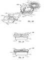
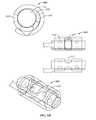
- Electrodescan be designed in many different ways. Three possible designs include the fully encircling cuff ( FIGS. 6A-6D ), the helical cuff ( FIG. 6E ), and the open trough ( FIGS. 6F-6G ). Embodiments of each are discussed below. These embodiments are exemplary only, and not limited to what is shown.
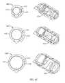
- FIGS. 6A-6Dshow exemplary embodiments of fully encircling cuff electrodes 600 .
- FIG. 6Ashows a non-perforated fully encircling cuff.
- Non-perforated fully encircling cuffsmust be used with care, as connective tissue buildup in response to a foreign body can cause an increase of HGN 10 diameter and potential constriction of the HGN 10 after surgery.
- Some swelling of the HGN 10is expected due to the surgical trauma the nerve endures when it is dissected and the electrode is installed.
- the swelling and increase in connective materialmay damage the nerve, due to the effect of pressure on the blood supply of the nerve trunk, and the increased pressure on the nerve axons of the trunk.
- the implantable neurostimulator system of the present inventionincludes a fully encircling perforated cuff electrode 605 ( FIGS. 6B-6D ).
- the perforated cuff electrode 605is from about 4 mm to about 12 mm in diameter.
- the perforated cuff electrode 605is from about 6 mm to about 10 mm in diameter.
- the perforated cuff electrode 605is about 8 mm in diameter.
- the diameter of the perforated cuff electrode 605is expandable and increases or decreases in accordance with the diameter of the HGN 10 .
- the perforations 607 and/or the plasticity of the material comprising the perforated cuff electrode 605allows accommodation of the expected change in diameter and swelling response and prevents ischemic constriction of the HGN 10 .
- the perforations 607are about 2 mm in diameter.
- the perforated cuff electrode 605may also be self-sizing. In some embodiments, the fully encircling perforated cuff electrode does not physically contact the entire circumference of the HGN 10 .
- the perforated cuff electrode 605overlaps upon itself, thereby creating an empty space 606 into which a nerve may expand without ischemic constriction.
- the electrode diameteris expandable, with ranges extending from a diameter of approximately 2 mm to a diameter of approximately 12 mm. Other expansion ranges may be used without departing from the scope of the invention.
- the perforated cuff electrode 605includes electrical contacts 608 on its inner surface facing a nerve.
- the perforated cuff electrode 605may include any number and/or arrangement of contacts 608 .
- the perforated cuff electrode 605can include at least six contacts 608 .
- the perforated cuff electrode 605includes at least eight contacts 608 .
- the contacts 608are axially aligned relative to the perforations 607 of the perforated cuff electrode 605 ( FIG. 6B ).
- the contacts 608can be axially staggered relative to the perforations 607 ( FIGS. 6C-6D ).
- the contacts 608are about 1 mm in diameter. In still other embodiments, the distance between contacts 608 is about 1 mm.
- the contacts 608need not circumscribe the entire circumference of the nerve.
- the flap of the electrode cuffoverlaps an electrode lead ( FIGS. 6B-6C ) and in others it does not ( FIG. 6D ).
- the positions of the contacts 608 relative to a nervechanges as the diameter of the nerve increases or decreases.
- the contact size, number, location, and arrangementare exemplary only, and not limited to what is shown. Other combinations may be used without departing from the scope of the invention.
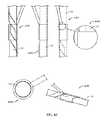
- FIG. 6Eshows an exemplary embodiment of a helical cuff electrode 610 .
- the helical cuff electrode 610mitigates the problems of a fully encircling cuff electrode 600 ( FIG. 6A ).
- One exampleis a helical cuff electrode developed by the Huntington Medical Research Institute for stimulating the vagus nerve.
- the cuff electrode 610winds around a nerve trunk, but does not overlap itself and is not sutured into a fixed diameter.
- the cuff electrode 610is self-sizing.
- a self-sizing cuffencircles the nerve in its natural state.
- the cuff electrode 610overlaps its ends but still allows some expansion of the cuff until the connective tissue overgrowth assumes its final state after surgical implantation.
- FIG. 6Fshows an exemplary embodiment of a round-bottomed open trough electrode 620 .
- the contacts 621reside on the inside of the trough.
- contacts 621are present on the innermost region of the interior of the trough, while the portion of the trough that covers the outer portion of the HGN 10 has no contacts.
- the open trough electrode 620addresses some of the problems associated with the fully encircling electrode 600 design by lying underneath the nerve trunk, rather than completely encircling or enclosing the nerve trunk. This allows tissue expansion and swelling, as well as the connective tissue buildup, while still allowing the nerve to expand away from the trough without constriction.
- the exemplary open trough electrode 620 embodiment shownslips underneath the HGN 10 with little dissection. The normal forces holding the tissues of the neck in place help keep the HGN 10 aligned with the open trough electrode 620 .
- the open trough electrode 620may optionally be anchored to surrounding tissue to maintain its position with respect to the HGN 10 to prevent distension or other loading forces upon the HGN 10 .
- an open trough electrode 620it is desirable to place the contacts 621 of an open trough electrode 620 preferentially against one surface of the nerve bundle, and it is also desirable to avoid placing any forces against the nerve as it lies in the electrode 620 to force it into a new or different shape from its native shape.
- the open trough electrode 620maintains the position of the nerve within the electrode trough up until the point at which connective tissue growth has secured the nerve and electrode 620 interface.
- FIG. 6Gshows a flat-bottomed variant 625 of an open trough electrode. While the contemporary textbook view of the shape of peripheral nerves is that of rounded structures, they may in fact also assume oval or flattened shapes depending upon their internal structure and where they lie in respect to other tissue structures such as muscles, bones, and fascial planes. One of the internal structure determinants of cross-sectional shape may be the absence or presence of fascicular organization.
- the design of a flat-bottomed open trough electrode 625advantageously allows a flattened nerve to lie against a series of contacts on a flattened surface, thereby also allowing a lower profile between the tissue structures where the peripheral nerve occurs.
- an implantable neurostimulator systemincludes at least one flat-bottomed open trough electrode 625 .
- an absorbable suture material 627is placed between the flaps 626 of the electrode 625 to prevent the nerve from moving out of the trough during the connective tissue growth period after initial implantation.
- the suture material 627has a finite lifetime before dissolving. This limits the potential for long-term damage that might result from a permanent compressive or retentive mechanism such as a hard flap or fixed diameter cuff.
- the flat-bottomed open trough electrode 625provides a means of selective activation that only temporarily constrains the nerve within the electrode, and presents a lower profile for the same cross sectional nerve area than a comparable rounded trough electrode.
- the fully encircling cuff, helical cuff, and open trough electrodescan be configured as monopolar, bipolar or multipolar electrodes.
- electrodesmay be composed of at least one pair of platinum/iridium cathode and anode contacts arranged in a helical pattern on a substrate of heat shaped, biocompatible polystyrene strip material. The contact pairs are oriented transversely to the HGN to drive stimulus into internal nerve fibers.
- the electrode designis a helix.
- the electrode designis a cuff with fingers, and in another embodiment, the electrode design is an electrode that penetrates the nerve itself.
- FIGS. 7A-9Bshow selected exemplary embodiments of these electrode configurations. The number and arrangement of the contacts shown in each of these figures are exemplary only, and not limited to what is shown.
- FIGS. 7A and 7Bshow exemplary embodiments of monopole electrode configurations.
- Monopolar stimulationtypically results in lowered stimulation thresholds since there is no shunting of current between contacts before it is free to enter the nerve bundle.
- FIG. 7Ashows an exemplary embodiment of a monopolar, single cathodal contact, IPG case return electrode 700 .
- a stimulation electrode contact 702acts as the excitatory cathodic contact, with the IPG case 701 providing the complementary current return path.
- FIG. 7Bshows an exemplary embodiment of a monopolar, single cathodal contact, indifferent array return electrode 710 . In the embodiment shown in FIG.
- a stimulation electrode contact 711acts as the excitatory cathodic contact, with another array of contacts (an indifferent array) 713 furnishing the complementary current return.
- the indifferent array 713has one or more contacts, with the indifferent array contacts 713 typically having a larger surface area than the excitatory contact.
- the waveformis often asymmetrical biphasic, since it is sometimes undesirable to have a final excitatory phase of cathodic stimulation on the case electrode.
- symmetrical biphasic pulsesmay result in excitatory cathodic phases of stimulation at each of the necessary contacts of a stimulation electrode.
- the first cathodic phaseis of an amplitude and phase duration adequate to achieve excitation of the nerve, but the later anodic phase is both longer and of lower amplitude, which at the return or second electrode contact, results in a cathodic phase which is not of sufficient amplitude to cause nerve excitation.
- the common practice of using a large indifferent or case electrode at a location away from the nerve electrodeacts to reduce current density at the indifferent electrode at a site away from the nerve, which also minimizes the likelihood of excitation at that electrode.
- FIG. 8shows an exemplary embodiment of a bipolar electrode configuration 800 .
- Bipolar electrode configurations 800have two contacts with approximately the same geometric surface area stimulating as a pair. One electrode is the excitatory contact 801 and the other electrode is the return (indifferent) contact 803 . The charge delivered and recovered by both contacts is approximately equal. Therefore, the return (indifferent) contact 803 can cause nerve 802 excitation during the last phase of the waveform if the waveform is symmetrical, and can cause anodic phase excitation depending upon the orientation and other features of the nerve 802 within the vicinity of the second contact 803 . If the waveform utilized in bipolar stimulation is symmetrical then it is likely that excitation will occur at each electrode contact. If the waveform is asymmetrical, it is likely that excitation will only occur at the primary cathodic contact 801 .
- FIGS. 9A and 9Bshow exemplary embodiments of multipolar electrode configurations.
- FIG. 9Ashows an exemplary embodiment of a multipolar, two cathodal contact, IPG case return multipolar electrode array 900 .
- the cathodal contacts 902 , 905typically function as the excitatory contacts. Although only two cathodal contacts 902 , 905 are shown, each with their own source, additional cathodal contacts (with either independent or shared sources), may be used without departing from the scope of the invention.
- the IPG case 901provides the complementary current return. This embodiment is exemplary only, and not limited to what is shown.
- FIG. 9Bshows an exemplary embodiment of a multipolar, two cathodal contact, indifferent contact return multipolar electrode array 910 .
- the cathodal contacts 913 , 914typically function as the excitatory contacts. Although only two cathodal contacts 913 , 914 are shown, each with their own source, additional cathodal contacts (with either independent or shared sources), may be used without departing from the scope of the invention.
- another array of contacts (the indifferent array) 911provides the complementary current return. This embodiment is exemplary only, and not limited to what is shown.
- current fieldsmay be manipulated in different or multiple directions, thereby changing neural recruitment patterns, and may do so without adversely spilling over or recruiting undesired neural populations.
- This mode of operationis best served by current sources for each electrode contact that can be activated concurrently, i.e., by a single timing generator.
- multiple timing generatorsmay be used with multiple contacts to recruit different populations of neurons offset in time that result in approximately simultaneous activation of the motor units with which they associate. This occurs because of the relatively long time constant of muscle activation with respect to motor nerve recruitment but is not to be confused with concurrent stimulation as described previously, which can result in neural recruitment patterns unsupportable by single current source multiplexed stimulation alone or summated in time for motor unit recruitment.
- Stimulation frequencyis adjustable from approximately 1 Hertz (Hz) to approximately 100 Hz or higher.
- Typical frequencies for producing a tetanic contractionrange from approximately 15 Hz to approximately 60 Hz. Lowering the frequency to the lowest required for a smooth, tetanic, and comfortable contraction reduces device power consumption and reduces muscle fatigue elicited by electrical stimulation.
- These stimulation patternsare exemplary only, and not limited to what is described. While only excitatory contact waveforms and complementary contact waveforms are explained below, other stimulation waveforms of other stimulation frequencies may be used without departing from the scope of the invention.
- Excitatory electrode contact waveformsmay be symmetrical or asymmetrical biphasic, cathodic phase first, followed by a short interphase interval, followed by an anodic (charge recovery) phase.
- the first cathodic phaseranges from approximately 10 to approximately 1000 microseconds long.
- the interphase intervalcan be as short as approximately 10 microseconds and as long as approximately 250 microseconds, and is set to 50 microseconds by default.
- the interphase intervalis set to be long enough to allow the first cathodic phase to achieve its full recruitment function before the charge recovery phase occurs. Shortening the interphase interval to less than the recruitment time would diminish the effect of the cathodic phase and waste a portion of the energy supplied during recruitment.
- the anodic phase duration and amplitudeare approximately identical to the cathodic phase for a symmetrical biphasic waveform, and the anodic phase of an asymmetrical waveform is approximately six times the duration of the cathodic phase in certain embodiments, with a concomitant phase amplitude approximately one-sixth the amplitude of the cathodic phase.
- the charge delivered during the cathodic phaseis approximately equal to the charge recovered in the anodic phase.
- ceramic coupling capacitors in series with the output circuitry to each electrode contacthelp maintain the charge balance and prevent the passage of direct current, known to be harmful to tissue and which may increase the likelihood of failure in feedthroughs of the electronics enclosure.
- the coupling capacitorsmust be large enough to pass current phases without- significant droop.
- Complementary electrode contact waveformshave the opposite polarity as excitatory electrode contact waveforms, but similar amplitude and phase duration characteristics. If the waveform is symmetrical biphasic, the third phase of the waveform at the complementary contact is cathodic, and could excite nerves in its vicinity. If the waveform is asymmetrical, the third phase of the waveform would be cathodic as well, but its amplitude would be roughly one sixth of the excitatory contact amplitude, and would be unlikely to excite any nerves.
- independent current sourcespower each electrode contact.
- Each contactis driven by its own current generator, which sources or sinks up to approximately 12.7 mA in 0.1 mA steps.
- the compliance voltageis the voltage that the current generator utilizes for constant current generation for each current source, and in the exemplary embodiment shown is approximately 18 volts. In other embodiments, compliance voltage ranges from approximately 15 to approximately 20 volts.
- the expected bipolar electrode to tissue impedanceis approximately 500 to 1500 ohms.
- the compliance voltageshould be greater than this initial access voltage to maintain the current for the duration of the pulse phase. Compliance voltage is chosen based on factors such as maximum current desired, maximum phase duration desired, coupling capacitor size, and expense of providing high voltage power supplies to maintain constant current for the duration of the pulse phase.
- Total current delivered to all contactstypically does not exceed the steady state output of the IPG power supply.
- Current in this exemplary embodimentis limited to approximately a 20 mA concurrent output.
- Overall current consumptiondepends on many factors, including, for example, phase duration, phase amplitude, and pulse frequency. Taking these factors into account, the total current output in the exemplary embodiment is approximately 2 mA.
- the current and voltage levels in these embodimentsare exemplary only however. Other power levels may be used without departing from the scope of the invention.
- the embodiments described aboveallow for accurate, selective nerve stimulation, including for example, the HGN.
- accurate, selective nerve stimulationincluding for example, the HGN.
- These exemplary embodimentsincorporate independent and concurrent stimulation, enabling optimal selective stimulation of only the desired portions of the HGN.
- IPGindependent and concurrent stimulation produces the desired tongue movement without needing to sense breathing related events to achieve desired results.
- Other embodiments of the IPGcan include timed stimulation. Timed stimulation allows for triggered open loop or fully closed loop stimulation.
- Various examples of stimulationare discussed in U.S. patent application Ser. Nos. 60/978,519 and 61/017,614 filed on Oct. 9, 2007 and Dec. 29, 2007 respectively, which are incorporated herein by reference.
- the sections belowdescribe how nerves are recruited, and include examples of stimulation patterns generated with these exemplary embodiments. These patterns are exemplary only, and not limited to those discussed below.
- nerve fiber diameterOne of the contributors to nerve activation threshold is nerve fiber diameter. Due to the electrical cable properties of the nerve fibers, large diameter nerve fibers have a lower excitation threshold than smaller diameter fibers, and are more easily excited by electrical stimulation. Thus, nerve fibers are more likely to be recruited by an electrical stimulation pulse if they are closer to the activating electrode, and/or have a larger diameter than other fibers.
- Multiple contact electrodesmay be used in conjunction with multiplexed stimulator systems to co-activate multiple muscle groups to achieve a desired muscle response.
- multiple contactsmay be sequentially energized to deliver interlaced pulses to first one contact and then another, to activate two or more muscle groups that when added result in a force vector in the desired direction. This is force vectoring.
- FIGS. 10A and 10Bshow an example of a multiplexed system using force vectoring. Even using force vectoring, multiplexed or single-source electrodes have limitations in the stimulation patterns they could deliver. For example, with a single cathodic phase current from a single contact, the nerve fibers closest to the contact are the first to be recruited or activated (assuming uniform distribution of fiber diameters, etc). As shown in FIG. 10A , even if the source were multiplexed to multiple contacts however, the waveform generator 1000 would connect to each contact 1005 - 1008 via a switching network 1001 - 1004 . FIG. 10B illustrates this with an example. As shown in FIG. 10B , only a single waveform can be sent at any given time.
- channel 1is enabled (i.e., switched on) and a waveform is generated for channel 1 by a single waveform source.
- channel 1is disabled (i.e., switched off).
- channel 2is enabled, and a waveform is generated for channel 2 using the same waveform source. Simultaneous transmission of multiple waveforms is not possible with this design.
- FIGS. 11A and 11Bshow exemplary embodiments of non-multiplexed waveform generators 1100 . These embodiments are used for field steering.
- Field steeringsolves the limitations of force vectoring. Field steering uses independent current sources and multiple electrode contacts together to define a volume of activated nerve fibers. Field steering uses multiple independent current sources to generate highly selective patient-specific activating current volumes.
- Field steeringis more selective than simple force vectoring.
- Field steeringalso known as current steering
- Field steeringenables activation of a particular region or volume of nerve fibers near two or more electrode contacts by controlling the cathodic phase amplitude generated by each of the contacts independently. For example, using two cathodic contacts 1101 and 1102 with equal phase amplitudes (for example by connecting two contacts to a single current source or by setting independent current sources to the same amplitude), applying a stimulus to the contacts defines a neural activation volume constrained to a region approximately equidistant between the two contacts. In this configuration, a sub-threshold phase current on each of the contacts 1101 and 1102 could be delivered, which combine to form an overlapping current field with supra-threshold current field. As previously discussed, with two electrodes of equal current the central volume between the electrodes is the activated nerve region.
- Field steeringallows the ability to change the activation area by changing the proportion of cathodic phase current from a 50-50 split (requiring independent multiple current sources), thereby shifting the current volume from the midline to a region closer to the higher phase current source electrode contact.
- independent current sourcesare connected to individual electrodes and energized approximately simultaneously to define a volume where nerve fibers will be activated.
- a stimulatordelivers coincident stimulation pulses. They are delivered simultaneously rather than sequentially multiplexed.
- sub-threshold currentsare delivered to each contact 1101 - 1104 so that the fields around the individual contacts are below the recruitment threshold. As shown in FIG.
- the currentsneed not be identical.
- the pulse phase durationsare approximately equal, but amplitudes may differ because they are generated by independent current sources.
- the fieldscombine in the targeted nerve area to create pulses sufficient to stimulate the targeted nerve or nerves.
- nerve populations other than those lying directly under a stimulation electrode contactcan be preferentially and selectively activated to achieve a desired stimulus pattern. This is important because the desired region of activation might not be positioned directly under a stimulation contact due to the surgical approach or a lack of a priori understanding of nerve fiber organization prior to the application of stimulation, but which allows for the later adjustment of this stimulation field to achieve the desired result.
- the apparatus, system, and methods described abovemay use open loop stimulation, triggered open loop stimulation, and closed loop stimulation, either separately or in combination, to control stimulation.
- Closed loopcan use sensors and signals to initiate stimulation and to regulate its output so that a desired output function is obtained.
- Triggered open loop stimulationuses one or more measurements as triggers for initiating stimulation. These triggers may be obtained using one or more internal sensors, external sensors, or a combination of both. Internal sensors can be included in the IPG implant, while external sensors would transmit trigger information to the IPG implant. The triggers can be transmitted to the IPG implant wirelessly (for example by RF, Bluetooth, or other wireless means known to those skilled in the art), or by operatively connecting the external sensor to the IPG implant.
- triggersinclude, but are not limited to, snoring, airflow, actigraphy, hypoxia, tongue position, and tongue protrusion.
- snoringcould be detected internally using a vibration sensor in the IPG implant.
- snoringcould be detected internally using an acoustic sensor and sound processor.
- snoringcould be detected externally using, for example, a nasal canula or a microphone placed in the ear.
- Airflowcould be measured externally using a nasal canula or thermistor and used as a trigger or as a closed loop feedback signal.
- Actigraphycould be measured using, for example, an accelerometer, which could be located internally or externally.
- Hypoxiacould be measured internally using, for example, an infrared source and sensor in the IPG implant, or externally using an earlobe-monitoring unit. Tongue position could also be used as a trigger using, for example, a proximity sensor, while tongue protrusion could be used as a trigger using, for example, an accelerometer. These triggers could be used at any time, including initial placement, programming, and/or IPG implant calibration.
- any combination of parameters measured in open loop, triggered open loop, and closed loop stimulationcan be used to program and/or control stimulation.
- one or more measured parametersare used to alter stimulation programming automatically in real time in response to changes in user condition. This is auto titration.
- Auto titrationmay be performed during initial implantation and programming, during normal IPG system operation, or both.
- auto titrationmay be used to optimize IPG implant settings while the patient is in a medical facility, such as a clinic or hospital, a physician's office, a sleep laboratory, or while the patient is at home (home titration).
- Small changes to stimulation parameters and configurationsare made while observing their effect on one or more indicators such as airway diameter, airway resistance, airflow, snoring, or other generally accepted measurements used to evaluate obstructive sleep apnea.
- Clinician input and other related eventsmay also be entered to associate these indicators with patient sleep phases, including EEG and manual selection/confirmation of phase identification. Since sleep phases greatly affect the range of sleep disordered breathing (SDB) measurements, and since there may be significant delays in effects resulting from changes in stimulation parameter and configuration changes, computers may be used to assist with data analysis and confirmation of clinician assessments in a semi-automated system.
- the titration systemhas an automated programming capability (i.e., an auto titration system).
- an auto titration systemuse predetermined algorithms to alter stimulus in response to detection of apnea indicators.
- the auto titration systemis portable.
- Auto titrationmay also be used during normal IPG implant operation.
- a sensorwhich may be in the IPG implant or the external patient controller, monitors a respiration indicator like air flow, for example. When the indicator drops, for example if flow decreases by 10% below average unobstructed sleeping patient flow, or snoring is detected, the IPG implant or external controller slowly increases stimulus to cause an improvement in the monitored indicator (e.g., an increase in airflow and/or a decrease in snoring).
- the IPG implantchanges stimulation parameters.
- the controllerchanges simulation parameters, or it triggers a preprogrammed increase in the IPG implant.
- the indicatorsare exemplary only. Other indicators known to those skilled in the art may be used without departing from the scope of the invention.
Landscapes
- Health & Medical Sciences (AREA)
- General Health & Medical Sciences (AREA)
- Veterinary Medicine (AREA)
- Public Health (AREA)
- Engineering & Computer Science (AREA)
- Biomedical Technology (AREA)
- Nuclear Medicine, Radiotherapy & Molecular Imaging (AREA)
- Radiology & Medical Imaging (AREA)
- Life Sciences & Earth Sciences (AREA)
- Animal Behavior & Ethology (AREA)
- Neurology (AREA)
- Neurosurgery (AREA)
- Heart & Thoracic Surgery (AREA)
- Cardiology (AREA)
- Orthopedic Medicine & Surgery (AREA)
- Pulmonology (AREA)
- Physics & Mathematics (AREA)
- Acoustics & Sound (AREA)
- Electrotherapy Devices (AREA)
- Prostheses (AREA)
Abstract
Description
Claims (11)
Priority Applications (3)
| Application Number | Priority Date | Filing Date | Title |
|---|---|---|---|
| US14/811,171US9884191B2 (en) | 2007-10-09 | 2015-07-28 | Apparatus, system, and method for selective stimulation |
| US15/851,964US10646714B2 (en) | 2007-10-09 | 2017-12-22 | Apparatus, system, and method for selective stimulation |
| US16/870,455US11351364B2 (en) | 2007-10-09 | 2020-05-08 | Apparatus, system, and method for selective stimulation |
Applications Claiming Priority (7)
| Application Number | Priority Date | Filing Date | Title |
|---|---|---|---|
| US97851907P | 2007-10-09 | 2007-10-09 | |
| US1761407P | 2007-12-29 | 2007-12-29 | |
| US13610208P | 2008-08-12 | 2008-08-12 | |
| PCT/US2008/011598WO2009048580A1 (en) | 2007-10-09 | 2008-10-09 | Apparatus, system, and method for selective stimulation |
| US68181210A | 2010-04-20 | 2010-04-20 | |
| US13/775,349US9849288B2 (en) | 2007-10-09 | 2013-02-25 | Apparatus, system, and method for selective stimulation |
| US14/811,171US9884191B2 (en) | 2007-10-09 | 2015-07-28 | Apparatus, system, and method for selective stimulation |
Related Parent Applications (1)
| Application Number | Title | Priority Date | Filing Date |
|---|---|---|---|
| US13/775,349ContinuationUS9849288B2 (en) | 2007-10-09 | 2013-02-25 | Apparatus, system, and method for selective stimulation |
Related Child Applications (1)
| Application Number | Title | Priority Date | Filing Date |
|---|---|---|---|
| US15/851,964ContinuationUS10646714B2 (en) | 2007-10-09 | 2017-12-22 | Apparatus, system, and method for selective stimulation |
Publications (2)
| Publication Number | Publication Date |
|---|---|
| US20150328455A1 US20150328455A1 (en) | 2015-11-19 |
| US9884191B2true US9884191B2 (en) | 2018-02-06 |
Family
ID=40549467
Family Applications (6)
| Application Number | Title | Priority Date | Filing Date |
|---|---|---|---|
| US12/681,799AbandonedUS20100198103A1 (en) | 2007-10-09 | 2008-10-09 | System and method for neural stimulation |
| US12/681,812AbandonedUS20100241195A1 (en) | 2007-10-09 | 2008-10-09 | Apparatus, system and method for selective stimulation |
| US13/775,349Active2028-11-24US9849288B2 (en) | 2007-10-09 | 2013-02-25 | Apparatus, system, and method for selective stimulation |
| US14/811,171ActiveUS9884191B2 (en) | 2007-10-09 | 2015-07-28 | Apparatus, system, and method for selective stimulation |
| US15/851,964ActiveUS10646714B2 (en) | 2007-10-09 | 2017-12-22 | Apparatus, system, and method for selective stimulation |
| US16/870,455ActiveUS11351364B2 (en) | 2007-10-09 | 2020-05-08 | Apparatus, system, and method for selective stimulation |
Family Applications Before (3)
| Application Number | Title | Priority Date | Filing Date |
|---|---|---|---|
| US12/681,799AbandonedUS20100198103A1 (en) | 2007-10-09 | 2008-10-09 | System and method for neural stimulation |
| US12/681,812AbandonedUS20100241195A1 (en) | 2007-10-09 | 2008-10-09 | Apparatus, system and method for selective stimulation |
| US13/775,349Active2028-11-24US9849288B2 (en) | 2007-10-09 | 2013-02-25 | Apparatus, system, and method for selective stimulation |
Family Applications After (2)
| Application Number | Title | Priority Date | Filing Date |
|---|---|---|---|
| US15/851,964ActiveUS10646714B2 (en) | 2007-10-09 | 2017-12-22 | Apparatus, system, and method for selective stimulation |
| US16/870,455ActiveUS11351364B2 (en) | 2007-10-09 | 2020-05-08 | Apparatus, system, and method for selective stimulation |
Country Status (8)
| Country | Link |
|---|---|
| US (6) | US20100198103A1 (en) |
| EP (2) | EP2197536A1 (en) |
| JP (2) | JP2011500143A (en) |
| CN (2) | CN101883606A (en) |
| AU (2) | AU2008311313A1 (en) |
| BR (2) | BRPI0817852A2 (en) |
| CA (2) | CA2697826A1 (en) |
| WO (2) | WO2009048580A1 (en) |
Cited By (7)
| Publication number | Priority date | Publication date | Assignee | Title |
|---|---|---|---|---|
| US20180133474A1 (en)* | 2007-10-09 | 2018-05-17 | Imthera Medical, Inc. | Apparatus, System, and Method for Selective Stimulation |
| US11198002B2 (en) | 2020-01-24 | 2021-12-14 | Medtronic Xomed, Inc. | Needle and introducer used in lead placement for obstructive sleep apnea treatment |
| US11273305B2 (en) | 2020-01-24 | 2022-03-15 | Medtronic Xomed, Inc. | Medical lead for treating obstructive sleep apnea (OSA) with electrical stimulation |
| US11426201B2 (en) | 2020-01-24 | 2022-08-30 | Medtronic Xomed, Inc. | Treatment of obstructive sleep apnea (OSA) |
| US11666751B2 (en) | 2020-01-24 | 2023-06-06 | Medtronic Xomed, Inc. | Combination obstructive sleep apnea trialing lead and chronic lead |
| US11819233B2 (en) | 2020-01-24 | 2023-11-21 | Medtronic Xomed, Inc. | Devices and techniques for separating tissue |
| US12414704B2 (en) | 2020-05-23 | 2025-09-16 | Inspire Medical Systems, Inc. | Single or multiple nerve stimulation to treat sleep disordered breathing |
Families Citing this family (189)
| Publication number | Priority date | Publication date | Assignee | Title |
|---|---|---|---|---|
| US6907295B2 (en) | 2001-08-31 | 2005-06-14 | Biocontrol Medical Ltd. | Electrode assembly for nerve control |
| US8615294B2 (en) | 2008-08-13 | 2013-12-24 | Bio Control Medical (B.C.M.) Ltd. | Electrode devices for nerve stimulation and cardiac sensing |
| US7778711B2 (en)* | 2001-08-31 | 2010-08-17 | Bio Control Medical (B.C.M.) Ltd. | Reduction of heart rate variability by parasympathetic stimulation |
| US7904176B2 (en)* | 2006-09-07 | 2011-03-08 | Bio Control Medical (B.C.M.) Ltd. | Techniques for reducing pain associated with nerve stimulation |
| US8565896B2 (en)* | 2010-11-22 | 2013-10-22 | Bio Control Medical (B.C.M.) Ltd. | Electrode cuff with recesses |
| US20090005845A1 (en)* | 2007-06-26 | 2009-01-01 | Tamir Ben David | Intra-Atrial parasympathetic stimulation |
| US8880192B2 (en) | 2012-04-02 | 2014-11-04 | Bio Control Medical (B.C.M.) Ltd. | Electrode cuffs |
| US8718791B2 (en)* | 2003-05-23 | 2014-05-06 | Bio Control Medical (B.C.M.) Ltd. | Electrode cuffs |
| WO2007098200A2 (en) | 2006-02-16 | 2007-08-30 | Imthera Medical, Inc. | An rfid-based apparatus, system, and method for therapeutic treatment of obstructive sleep apnea |
| US8855771B2 (en)* | 2011-01-28 | 2014-10-07 | Cyberonics, Inc. | Screening devices and methods for obstructive sleep apnea therapy |
| US10368146B2 (en)* | 2016-09-20 | 2019-07-30 | General Electric Company | Systems and methods for environment sensing |
| CN102112177A (en)* | 2008-05-02 | 2011-06-29 | 梅德特龙尼克有限公司 | Self expanding electrode cuff |
| US8340785B2 (en) | 2008-05-02 | 2012-12-25 | Medtronic, Inc. | Self expanding electrode cuff |
| US20110152706A1 (en)* | 2008-05-15 | 2011-06-23 | Inspire Medical Systems, Inc. | Method and apparatus for sensing respiratory pressure in an implantable stimulation system |
| EP2331201B1 (en) | 2008-10-01 | 2020-04-29 | Inspire Medical Systems, Inc. | System for treating sleep apnea transvenously |
| EP2349139B1 (en) | 2008-10-09 | 2017-05-31 | Imthera Medical, Inc. | Stimulation of a hypoglossal nerve for controlling the position of a patient's tongue |
| JP5575789B2 (en) | 2008-11-19 | 2014-08-20 | インスパイア・メディカル・システムズ・インコーポレイテッド | How to treat sleep-disordered breathing |
| US8515520B2 (en) | 2008-12-08 | 2013-08-20 | Medtronic Xomed, Inc. | Nerve electrode |
| EP2382007A1 (en)* | 2009-01-27 | 2011-11-02 | Neurostimulation Devices And Technology Pty Ltd | Electrical neurostimulator package |
| JP2012521864A (en) | 2009-03-31 | 2012-09-20 | インスパイア・メディカル・システムズ・インコーポレイテッド | Percutaneous access method in a system for treating sleep-related abnormal breathing |
| US9211410B2 (en)* | 2009-05-01 | 2015-12-15 | Setpoint Medical Corporation | Extremely low duty-cycle activation of the cholinergic anti-inflammatory pathway to treat chronic inflammation |
| US9089692B2 (en) | 2009-05-29 | 2015-07-28 | Cochlear Limited | Vestibular stimulation device |
| WO2010144578A2 (en) | 2009-06-09 | 2010-12-16 | Setpoint Medical Corporation | Nerve cuff with pocket for leadless stimulator |
| US9409013B2 (en) | 2009-10-20 | 2016-08-09 | Nyxoah SA | Method for controlling energy delivery as a function of degree of coupling |
| US10751537B2 (en) | 2009-10-20 | 2020-08-25 | Nyxoah SA | Arced implant unit for modulation of nerves |
| US9415215B2 (en) | 2009-10-20 | 2016-08-16 | Nyxoah SA | Methods for treatment of sleep apnea |
| US8577472B2 (en) | 2009-10-20 | 2013-11-05 | Nyxoah SA | Systems and methods for determining a sleep disorder based on positioning of the tongue |
| US10716940B2 (en) | 2009-10-20 | 2020-07-21 | Nyxoah SA | Implant unit for modulation of small diameter nerves |
| US8705783B1 (en)* | 2009-10-23 | 2014-04-22 | Advanced Bionics | Methods and systems for acoustically controlling a cochlear implant system |
| WO2011059531A1 (en) | 2009-11-10 | 2011-05-19 | Imthera Medical, Inc. | System for stimulating a hypoglossal nerve for controlling the position of a patient's tongue |
| WO2014169145A1 (en) | 2013-04-10 | 2014-10-16 | Setpoint Medical Corporation | Closed-loop vagus nerve stimulation |
| US9888864B2 (en) | 2010-03-12 | 2018-02-13 | Inspire Medical Systems, Inc. | Method and system for identifying a location for nerve stimulation |
| US8788045B2 (en) | 2010-06-08 | 2014-07-22 | Bluewind Medical Ltd. | Tibial nerve stimulation |
| CN101904743B (en)* | 2010-07-22 | 2012-02-01 | 上海诺诚电气有限公司 | Constant current stimulator and current stimulator system |
| US8983572B2 (en) | 2010-10-29 | 2015-03-17 | Inspire Medical Systems, Inc. | System and method for patient selection in treating sleep disordered breathing |
| US9457186B2 (en) | 2010-11-15 | 2016-10-04 | Bluewind Medical Ltd. | Bilateral feedback |
| US9186504B2 (en) | 2010-11-15 | 2015-11-17 | Rainbow Medical Ltd | Sleep apnea treatment |
| US9821159B2 (en) | 2010-11-16 | 2017-11-21 | The Board Of Trustees Of The Leland Stanford Junior University | Stimulation devices and methods |
| JP2013542838A (en) | 2010-11-16 | 2013-11-28 | ザ ボード オブ トラスティーズ オブ ザ レランド スタンフォード ジュニア ユニバーシティー | System and method for treating dry eye |
| JP5602612B2 (en)* | 2010-12-22 | 2014-10-08 | オリンパス株式会社 | Electrode unit and tissue stimulation system |
| ES2645204T3 (en)* | 2011-04-07 | 2017-12-04 | Oculeve, Inc. | Stimulation devices |
| AU2012255708B2 (en) | 2011-05-17 | 2016-12-22 | Boston Scientific Neuromodulation Corporation | Display of region of activation in neurostimulation programming screen |
| US11304746B2 (en) | 2011-06-14 | 2022-04-19 | Aerin Medical Inc. | Method of treating airway tissue to reduce mucus secretion |
| US20240050143A1 (en) | 2011-06-14 | 2024-02-15 | Aerin Medical Inc. | Methods and devices to treat nasal airways |
| US9237924B2 (en) | 2011-06-14 | 2016-01-19 | Aerin Medical, Inc. | Methods and devices to treat nasal airways |
| US20150039045A1 (en) | 2011-08-11 | 2015-02-05 | Inspire Medical Systems, Inc. | Method and system for applying stimulation in treating sleep disordered breathing |
| US8934992B2 (en) | 2011-09-01 | 2015-01-13 | Inspire Medical Systems, Inc. | Nerve cuff |
| EP2773423B1 (en) | 2011-11-04 | 2024-01-10 | Nevro Corporation | Medical device communication and charding assemblies for use with implantable signal generators |
| USD736383S1 (en) | 2012-11-05 | 2015-08-11 | Nevro Corporation | Implantable signal generator |
| AU2012347770A1 (en)* | 2011-12-07 | 2014-06-26 | Otologics, Llc | Sleep apnea control device |
| WO2013111137A2 (en) | 2012-01-26 | 2013-08-01 | Rainbow Medical Ltd. | Wireless neurqstimulatqrs |
| US10625075B2 (en) | 2012-03-15 | 2020-04-21 | Spr Therapeutics, Inc. | Systems and methods related to the treatment of back pain |
| US10632309B2 (en) | 2012-03-15 | 2020-04-28 | Spr Therapeutics, Inc. | Systems and methods related to the treatment of back pain |
| US10052097B2 (en) | 2012-07-26 | 2018-08-21 | Nyxoah SA | Implant unit delivery tool |
| EP2877239B1 (en) | 2012-07-26 | 2023-06-21 | Nyxoah SA | Electrical contacts on a medical device patch |
| US11253712B2 (en) | 2012-07-26 | 2022-02-22 | Nyxoah SA | Sleep disordered breathing treatment apparatus |
| US9907967B2 (en) | 2012-07-26 | 2018-03-06 | Adi Mashiach | Transcutaneous power conveyance device |
| US9504828B2 (en) | 2012-07-26 | 2016-11-29 | Nyxoah SA | Electrical contacts on a medical device patch |
| DE102012107835A1 (en)* | 2012-08-24 | 2014-02-27 | Albert-Ludwigs-Universität Freiburg | Medical implant and method for its production |
| US8761897B2 (en) | 2012-08-31 | 2014-06-24 | Greatbatch Ltd. | Method and system of graphical representation of lead connector block and implantable pulse generators on a clinician programmer |
| US9615788B2 (en) | 2012-08-31 | 2017-04-11 | Nuvectra Corporation | Method and system of producing 2D representations of 3D pain and stimulation maps and implant models on a clinician programmer |
| US8983616B2 (en) | 2012-09-05 | 2015-03-17 | Greatbatch Ltd. | Method and system for associating patient records with pulse generators |
| US8812125B2 (en) | 2012-08-31 | 2014-08-19 | Greatbatch Ltd. | Systems and methods for the identification and association of medical devices |
| US9471753B2 (en) | 2012-08-31 | 2016-10-18 | Nuvectra Corporation | Programming and virtual reality representation of stimulation parameter Groups |
| US8903496B2 (en) | 2012-08-31 | 2014-12-02 | Greatbatch Ltd. | Clinician programming system and method |
| US9507912B2 (en) | 2012-08-31 | 2016-11-29 | Nuvectra Corporation | Method and system of simulating a pulse generator on a clinician programmer |
| US9259577B2 (en) | 2012-08-31 | 2016-02-16 | Greatbatch Ltd. | Method and system of quick neurostimulation electrode configuration and positioning |
| US9180302B2 (en) | 2012-08-31 | 2015-11-10 | Greatbatch Ltd. | Touch screen finger position indicator for a spinal cord stimulation programming device |
| US9594877B2 (en) | 2012-08-31 | 2017-03-14 | Nuvectra Corporation | Virtual reality representation of medical devices |
| US9375582B2 (en) | 2012-08-31 | 2016-06-28 | Nuvectra Corporation | Touch screen safety controls for clinician programmer |
| US8868199B2 (en) | 2012-08-31 | 2014-10-21 | Greatbatch Ltd. | System and method of compressing medical maps for pulse generator or database storage |
| US10668276B2 (en) | 2012-08-31 | 2020-06-02 | Cirtec Medical Corp. | Method and system of bracketing stimulation parameters on clinician programmers |
| US8757485B2 (en) | 2012-09-05 | 2014-06-24 | Greatbatch Ltd. | System and method for using clinician programmer and clinician programming data for inventory and manufacturing prediction and control |
| US9767255B2 (en) | 2012-09-05 | 2017-09-19 | Nuvectra Corporation | Predefined input for clinician programmer data entry |
| US20140135868A1 (en)* | 2012-11-09 | 2014-05-15 | Jacob Bashyam Bashyam | Non-invasive intraoral electrical stimulator system and method for treatment of obstructive sleep apnea (osa) |
| CN103845802B (en)* | 2012-11-30 | 2016-03-16 | 苏州景昱医疗器械有限公司 | A kind of implantable medical device and system with radio antenna |
| CN103845803B (en)* | 2012-11-30 | 2016-03-16 | 苏州景昱医疗器械有限公司 | A kind of implantable medical device and system with radio communication function |
| WO2014087337A1 (en) | 2012-12-06 | 2014-06-12 | Bluewind Medical Ltd. | Delivery of implantable neurostimulators |
| CN103845793A (en)* | 2012-12-07 | 2014-06-11 | 苏州景昱医疗器械有限公司 | Implantable nerve stimulator, system and method for combining multiple sets of stimulus parameters |
| US9814402B2 (en) | 2013-02-15 | 2017-11-14 | Acacia Designs Bv | Electrode systems for use with medical monitoring systems |
| WO2014165124A1 (en) | 2013-03-12 | 2014-10-09 | Oculeve, Inc. | Implant delivery devices, systems, and methods |
| NZ704579A (en) | 2013-04-19 | 2018-10-26 | Oculeve Inc | Nasal stimulation devices and methods |
| CA2913074C (en) | 2013-05-30 | 2023-09-12 | Graham H. Creasey | Topical neurological stimulation |
| US11229789B2 (en) | 2013-05-30 | 2022-01-25 | Neurostim Oab, Inc. | Neuro activator with controller |
| AU2014288938B2 (en) | 2013-06-17 | 2019-03-14 | Nyxoah SA | Dynamic modification of modulation throughout a therapy period |
| US9427566B2 (en) | 2013-08-14 | 2016-08-30 | Syntilla Medical LLC | Implantable neurostimulation lead for head pain |
| US9839777B2 (en) | 2013-08-14 | 2017-12-12 | Syntilla Medical LLC | Implantable neurostimulation lead for head pain |
| US9042991B2 (en) | 2013-08-14 | 2015-05-26 | Syntilla Medical LLC | Implantable head mounted neurostimulation system for head pain |
| EP3903876B1 (en) | 2013-09-16 | 2024-10-23 | The Board of Trustees of the Leland Stanford Junior University | Multi-element coupler for generation of electromagnetic energy |
| EP3403692A1 (en) | 2013-09-26 | 2018-11-21 | Oticon Medical A/S | A device implantable under skin |
| US10258805B2 (en) | 2013-10-23 | 2019-04-16 | Syntilla Medical, Llc | Surgical method for implantable head mounted neurostimulation system for head pain |
| US10960215B2 (en) | 2013-10-23 | 2021-03-30 | Nuxcel, Inc. | Low profile head-located neurostimulator and method of fabrication |
| US9757560B2 (en) | 2013-11-19 | 2017-09-12 | The Cleveland Clinic Foundation | System and method for treating obstructive sleep apnea |
| ES2812752T3 (en) | 2014-02-25 | 2021-03-18 | Oculeve Inc | Polymer formulations for nasolacrimal stimulation |
| US20160336813A1 (en) | 2015-05-15 | 2016-11-17 | NeuSpera Medical Inc. | Midfield coupler |
| EP3294173B1 (en) | 2014-05-18 | 2020-07-15 | Neuspera Medical Inc. | Midfield coupler |
| JP6437019B2 (en) | 2014-07-03 | 2018-12-12 | ボストン サイエンティフィック ニューロモデュレイション コーポレイション | Nerve stimulation system with flexible pattern formation and waveform |
| AU2015292278B2 (en) | 2014-07-25 | 2020-04-09 | Oculeve, Inc. | Stimulation patterns for treating dry eye |
| WO2016065211A1 (en) | 2014-10-22 | 2016-04-28 | Oculeve, Inc. | Contact lens for increasing tear production |
| EP3209372B1 (en) | 2014-10-22 | 2020-07-15 | Oculeve, Inc. | Stimulation devices for treating dry eye |
| CA2965363A1 (en) | 2014-10-22 | 2016-04-28 | Oculeve, Inc. | Implantable nasal stimulator systems and methods |
| US11311725B2 (en) | 2014-10-24 | 2022-04-26 | Setpoint Medical Corporation | Systems and methods for stimulating and/or monitoring loci in the brain to treat inflammation and to enhance vagus nerve stimulation |
| WO2016115392A1 (en)* | 2015-01-14 | 2016-07-21 | Neurotrix Llc | Systems and methods for determining neurovascular reactivity to brain stimulation |
| US10004896B2 (en) | 2015-01-21 | 2018-06-26 | Bluewind Medical Ltd. | Anchors and implant devices |
| US9764146B2 (en) | 2015-01-21 | 2017-09-19 | Bluewind Medical Ltd. | Extracorporeal implant controllers |
| US9597521B2 (en) | 2015-01-21 | 2017-03-21 | Bluewind Medical Ltd. | Transmitting coils for neurostimulation |
| GB201501983D0 (en) | 2015-02-06 | 2015-03-25 | Morgan Innovation & Technology Ltd | Treatment of snoring and sleep apnoea |
| US11077301B2 (en) | 2015-02-21 | 2021-08-03 | NeurostimOAB, Inc. | Topical nerve stimulator and sensor for bladder control |
| WO2016149344A1 (en) | 2015-03-19 | 2016-09-22 | Inspire Medical Systems, Inc. | Stimulation for treating sleep disordered breathing |
| EP3278764B1 (en)* | 2015-04-02 | 2023-03-08 | The University of Tokyo | Coil device for use in transcranial magnetic stimulation device |
| US11980465B2 (en)* | 2015-04-03 | 2024-05-14 | Medtronic Xomed, Inc. | System and method for omni-directional bipolar stimulation of nerve tissue of a patient via a bipolar stimulation probe |
| EP3294411A4 (en)* | 2015-05-08 | 2019-01-23 | Hrl Laboratories, Llc | MOUNTING DESIGN FOR CLOSED-LOOP DETECTION AND NEUROSTIMULATION OF SIDE LATERAL PRE-FRONT CORTEX AND / OR MOTOR CORTEX |
| US9782589B2 (en) | 2015-06-10 | 2017-10-10 | Bluewind Medical Ltd. | Implantable electrostimulator for improving blood flow |
| KR101656723B1 (en)* | 2015-06-30 | 2016-09-12 | 재단법인 오송첨단의료산업진흥재단 | Feedthrough making method |
| US10195428B2 (en)* | 2015-09-29 | 2019-02-05 | Medtronic, Inc. | Neural stimulation to treat sleep apnea |
| US10864369B2 (en)* | 2015-10-19 | 2020-12-15 | Sorin Crm Sas | Implantable probe comprising a perforated sleeve |
| US10105540B2 (en) | 2015-11-09 | 2018-10-23 | Bluewind Medical Ltd. | Optimization of application of current |
| US9713707B2 (en) | 2015-11-12 | 2017-07-25 | Bluewind Medical Ltd. | Inhibition of implant migration |
| US10426958B2 (en) | 2015-12-04 | 2019-10-01 | Oculeve, Inc. | Intranasal stimulation for enhanced release of ocular mucins and other tear proteins |
| US9717917B2 (en) | 2016-01-06 | 2017-08-01 | Syntilla Medical LLC | Charging system incorporating independent charging and communication with multiple implanted devices |
| US11471681B2 (en) | 2016-01-20 | 2022-10-18 | Setpoint Medical Corporation | Batteryless implantable microstimulators |
| US10252048B2 (en) | 2016-02-19 | 2019-04-09 | Oculeve, Inc. | Nasal stimulation for rhinitis, nasal congestion, and ocular allergies |
| US9713722B1 (en)* | 2016-04-29 | 2017-07-25 | Medtronic Bakken Research Center B.V. | Alternative electrode configurations for reduced power consumption |
| AU2017260237A1 (en) | 2016-05-02 | 2018-11-22 | Oculeve, Inc. | Intranasal stimulation for treatment of meibomian gland disease and blepharitis |
| US10933248B2 (en) | 2016-11-04 | 2021-03-02 | Galvani Bioelectronics Limited | System for wirelessly coupling in vivo |
| US10124178B2 (en) | 2016-11-23 | 2018-11-13 | Bluewind Medical Ltd. | Implant and delivery tool therefor |
| US11229787B2 (en)* | 2016-11-25 | 2022-01-25 | Kinaptic, LLC | Haptic human machine interface and wearable electronics methods and apparatus |
| WO2018102535A1 (en) | 2016-12-02 | 2018-06-07 | Oculeve, Inc. | Apparatus and method for dry eye forecast and treatment recommendation |
| CN106730336B (en)* | 2016-12-21 | 2023-05-02 | 北京品驰医疗设备有限公司 | Epileptic sleep apnea prevention system |
| CN106669033B (en)* | 2016-12-22 | 2023-05-02 | 北京品驰医疗设备有限公司 | Epileptic sleep apnea preventing system capable of being charged safely and rapidly |
| US11806071B2 (en) | 2016-12-22 | 2023-11-07 | Aerin Medical Inc. | Soft palate treatment |
| CN106726091B (en)* | 2016-12-22 | 2021-11-23 | 北京品驰医疗设备有限公司 | Epileptic sleep apnea prevention system capable of achieving quick charging |
| EP3558179A1 (en)* | 2016-12-22 | 2019-10-30 | Aerin Medical, Inc. | Soft palate treatment |
| KR101874231B1 (en) | 2017-01-25 | 2018-07-03 | 주식회사 싸이버메딕 | Electrode module for Transcranial DC Stimulation and Functional near infrared spectroscopy |
| US20180353764A1 (en) | 2017-06-13 | 2018-12-13 | Bluewind Medical Ltd. | Antenna configuration |
| US11612751B2 (en) | 2017-08-11 | 2023-03-28 | Boston Scientific Neuromodulation Corporation | Stimulation configuration variation to control evoked temporal patterns |
| EP3664889B1 (en) | 2017-08-11 | 2024-02-21 | Inspire Medical Systems, Inc. | Cuff electrode |
| KR102062252B1 (en)* | 2017-08-30 | 2020-01-03 | 부산대학교 산학협력단 | Intraoperative Neuromonitoring System Using Bio-pressure Sensor |
| AU2018324103B2 (en)* | 2017-08-30 | 2021-01-21 | The Alfred E. Mann Foundation For Scientific Research | Stimulator systems and methods for selectively recruiting fascicles in hypoglossal nerve trunk |
| US11723579B2 (en) | 2017-09-19 | 2023-08-15 | Neuroenhancement Lab, LLC | Method and apparatus for neuroenhancement |
| CN111601636A (en) | 2017-11-07 | 2020-08-28 | Oab神经电疗科技公司 | Non-invasive neural activator with adaptive circuit |
| KR102032620B1 (en)* | 2017-11-30 | 2019-10-15 | 주식회사 싸이버메딕 | Measuring module apparatus of a cerebral activity using Transcranial Current Stimulation and Functional near-infrared spectroscopy |
| KR102050319B1 (en)* | 2017-11-30 | 2019-12-02 | 주식회사 싸이버메딕 | A cranial nerve adjustifing apparatus |
| KR102100696B1 (en)* | 2017-11-30 | 2020-04-16 | 주식회사 싸이버메딕 | A cranial nerve adjustifing apparatus using complex stimulation of central and peripherial nerves |
| US11717686B2 (en) | 2017-12-04 | 2023-08-08 | Neuroenhancement Lab, LLC | Method and apparatus for neuroenhancement to facilitate learning and performance |
| US11273283B2 (en) | 2017-12-31 | 2022-03-15 | Neuroenhancement Lab, LLC | Method and apparatus for neuroenhancement to enhance emotional response |
| US12280219B2 (en) | 2017-12-31 | 2025-04-22 | NeuroLight, Inc. | Method and apparatus for neuroenhancement to enhance emotional response |
| US11890474B2 (en) | 2018-04-19 | 2024-02-06 | Iota Biosciences, Inc. | Implants using ultrasonic communication for modulating splenic nerve activity |
| US11364361B2 (en) | 2018-04-20 | 2022-06-21 | Neuroenhancement Lab, LLC | System and method for inducing sleep by transplanting mental states |
| US10509426B2 (en)* | 2018-05-02 | 2019-12-17 | Analog Devices Global Unlimited Company | Methods and circuits for controlling and/or reducing current leakage during a low-power or inactive mode |
| IL311077B2 (en) | 2018-08-29 | 2025-07-01 | Iota Biosciences Inc | Implantable closed-loop neuromodulation device, systems and methods for use |
| US11565112B2 (en)* | 2018-09-05 | 2023-01-31 | Vanderbilt University | Active titration of one or more nerve stimulators to treat obstructive sleep apnea |
| EP3849410A4 (en) | 2018-09-14 | 2022-11-02 | Neuroenhancement Lab, LLC | SLEEP ENHANCEMENT SYSTEM AND METHOD |
| US11260229B2 (en) | 2018-09-25 | 2022-03-01 | The Feinstein Institutes For Medical Research | Methods and apparatuses for reducing bleeding via coordinated trigeminal and vagal nerve stimulation |
| US12420091B2 (en)* | 2018-10-17 | 2025-09-23 | Signifier Medical Technologies Limited | Oral muscle training |
| US12357792B2 (en) | 2019-01-04 | 2025-07-15 | Shifamed Holdings, Llc | Internal recharging systems and methods of use |
| EP4268886B1 (en)* | 2019-02-08 | 2025-05-14 | Boston Scientific Neuromodulation Corporation | Spinal cord stimulation system with fitting algorithm to determine best stimulation parameters |
| US20200281522A1 (en) | 2019-03-06 | 2020-09-10 | Medtronic Xomed, LLC | System and method for improved obstructive sleep apnea diagnostic for implantable devices |
| WO2020182293A1 (en)* | 2019-03-11 | 2020-09-17 | Synergia Medical | Cuff electrode or optrode comprising a handling flap |
| WO2020210786A1 (en) | 2019-04-12 | 2020-10-15 | Setpoint Medical Corporation | Vagus nerve stimulation to treat neurodegenerative disorders |
| JP7543309B2 (en) | 2019-05-02 | 2024-09-02 | トゥウェルブ メディカル インコーポレイテッド | Systems and methods for improving sleep disordered breathing |
| WO2020264214A1 (en) | 2019-06-26 | 2020-12-30 | Neurostim Technologies Llc | Non-invasive nerve activator with adaptive circuit |
| US11420061B2 (en) | 2019-10-15 | 2022-08-23 | Xii Medical, Inc. | Biased neuromodulation lead and method of using same |
| AU2020366508A1 (en)* | 2019-10-17 | 2022-04-21 | Iota Biosciences, Inc. | Helical nerve cuff and related implantable devices |
| AU2020367447A1 (en) | 2019-10-17 | 2022-04-21 | Iota Biosciences, Inc. | Devices and methods for modulating immune system activity in a cancer patient and treating cancer |
| CN114728161A (en) | 2019-12-16 | 2022-07-08 | 神经科学技术有限责任公司 | Non-invasive neural activator with boosted charge delivery |
| EP4087475B1 (en) | 2020-01-10 | 2025-04-23 | Nuxcel2, Llc | Systems for stimulation of cranial nerves |
| AU2021226209A1 (en)* | 2020-02-28 | 2022-06-02 | ResMed Pty Ltd | Systems and methods for aiding a user in breathing using implantable devices |
| CA3193733A1 (en) | 2020-09-02 | 2022-03-10 | The Alfred E. Mann Foundation For Scientific Research | Electrode leads having multi-application nerve cuffs and associated systems and methods |
| EP4240241A4 (en)* | 2020-11-04 | 2024-05-29 | Invicta Medical, Inc. | REMOTE POWER DELIVERY IMPLANTABLE ELECTRODES FOR THE TREATMENT OF SLEEP APNEA AND RELATED SYSTEMS AND METHODS |
| US11691010B2 (en) | 2021-01-13 | 2023-07-04 | Xii Medical, Inc. | Systems and methods for improving sleep disordered breathing |
| AU2022249112A1 (en) | 2021-03-30 | 2023-10-12 | The Alfred E. Mann Foundation For Scientific Research | Electrode leads having nerve cuffs and associated systems |
| US12357817B2 (en) | 2021-04-06 | 2025-07-15 | Aerin Medical Inc. | Nasal neuromodulation devices and methods |
| ES2983221T3 (en)* | 2021-06-03 | 2024-10-22 | Inbrain Neuroelectronics Sl | Neurostimulation system |
| EP4101499A1 (en)* | 2021-06-09 | 2022-12-14 | Oticon Medical A/S | Cochlear hearing aid implant including an improved connection between an electrode lead and an implant |
| EP4366818A1 (en)* | 2021-07-09 | 2024-05-15 | The Alfred E. Mann Foundation for Scientific Research | Electrode leads having multi-application helical nerve cuffs and associated systems and methods |
| CN113499572A (en)* | 2021-08-10 | 2021-10-15 | 杭州程天科技发展有限公司 | Rehabilitation robot with myoelectric stimulation function and control method thereof |
| JP2024532410A (en)* | 2021-08-24 | 2024-09-05 | アビボメッド インコーポレイテッド | Neurostimulator with therapeutic feedback |
| US11400299B1 (en) | 2021-09-14 | 2022-08-02 | Rainbow Medical Ltd. | Flexible antenna for stimulator |
| US11925804B2 (en) | 2021-11-03 | 2024-03-12 | Medtronic Xomed, LLC | Multi-device obstructive sleep apnea (OSA) treatment |
| WO2023130102A1 (en)* | 2022-01-03 | 2023-07-06 | Axonics, Inc. | Header and antenna for a neurostimulator |
| US12296172B2 (en) | 2022-02-01 | 2025-05-13 | The Alfred E. Mann Foundation For Scientific Research | Electrode leads having nerve contact elements with coil contacts and associated systems and methods |
| US20240066302A1 (en)* | 2022-03-07 | 2024-02-29 | Ian Loren Halpern | Adaptive neural interface |
| CN114768092A (en)* | 2022-03-28 | 2022-07-22 | 北京领创医谷科技发展有限责任公司 | Capacitive coupling energy transfer nerve electrical stimulation system and in-vivo nerve electrical stimulator and in-vitro energy controller thereof |
| WO2024010990A1 (en)* | 2022-07-05 | 2024-01-11 | The Alfred E. Mann Foundation For Scientific Research | Tissue stimulation apparatus and methods of making the same |
| US20240139516A1 (en)* | 2022-10-28 | 2024-05-02 | Medtronic, Inc. | Lead based measurements for tongue movement determination |
| AU2024241518A1 (en) | 2023-03-17 | 2025-10-02 | Invicta Medical, Inc. | Methods for positioning signal delivery devices to treat sleep apnea, and associated devices and treatments |
| WO2025144515A1 (en)* | 2023-12-28 | 2025-07-03 | Inspire Medical Systems, Inc. | Implantable medical device including wireless power transmission |
| CN117771545B (en)* | 2024-02-26 | 2024-08-06 | 苏州新云医疗设备有限公司 | Implantable electric stimulator and electric stimulation system |
Citations (239)
| Publication number | Priority date | Publication date | Assignee | Title |
|---|---|---|---|---|
| US4424812A (en) | 1980-10-09 | 1984-01-10 | Cordis Corporation | Implantable externally programmable microprocessor-controlled tissue stimulator |
| US4602624A (en) | 1984-10-11 | 1986-07-29 | Case Western Reserve University | Implantable cuff, method of manufacture, and method of installation |
| US5094242A (en) | 1988-11-07 | 1992-03-10 | Regents Of The University Of California | Implantable nerve stimulation device |
| US5095905A (en) | 1990-06-07 | 1992-03-17 | Medtronic, Inc. | Implantable neural electrode |
| US5123425A (en) | 1990-09-06 | 1992-06-23 | Edentec | Obstructive sleep apnea collar |
| US5133354A (en) | 1990-11-08 | 1992-07-28 | Medtronic, Inc. | Method and apparatus for improving muscle tone |
| US5146918A (en) | 1991-03-19 | 1992-09-15 | Medtronic, Inc. | Demand apnea control of central and obstructive sleep apnea |
| US5158080A (en) | 1990-11-08 | 1992-10-27 | Medtronic, Inc. | Muscle tone |
| US5174287A (en) | 1991-05-28 | 1992-12-29 | Medtronic, Inc. | Airway feedback measurement system responsive to detected inspiration and obstructive apnea event |
| US5190053A (en) | 1991-02-28 | 1993-03-02 | Jeffrey A. Meer, Revocable Living Trust | Method and apparatus for electrical sublingual stimulation |
| US5211173A (en) | 1991-01-09 | 1993-05-18 | Medtronic, Inc. | Servo muscle control |
| US5215082A (en) | 1991-04-02 | 1993-06-01 | Medtronic, Inc. | Implantable apnea generator with ramp on generator |
| US5233983A (en) | 1991-09-03 | 1993-08-10 | Medtronic, Inc. | Method and apparatus for apnea patient screening |
| US5281219A (en) | 1990-11-23 | 1994-01-25 | Medtronic, Inc. | Multiple stimulation electrodes |
| US5300094A (en) | 1991-01-09 | 1994-04-05 | Medtronic, Inc. | Servo muscle control |
| US5344438A (en) | 1993-04-16 | 1994-09-06 | Medtronic, Inc. | Cuff electrode |
| US5483969A (en) | 1994-09-21 | 1996-01-16 | Medtronic, Inc. | Method and apparatus for providing a respiratory effort waveform for the treatment of obstructive sleep apnea |
| US5522862A (en) | 1994-09-21 | 1996-06-04 | Medtronic, Inc. | Method and apparatus for treating obstructive sleep apnea |
| US5540731A (en) | 1994-09-21 | 1996-07-30 | Medtronic, Inc. | Method and apparatus for pressure detecting and treating obstructive airway disorders |
| US5540732A (en) | 1994-09-21 | 1996-07-30 | Medtronic, Inc. | Method and apparatus for impedance detecting and treating obstructive airway disorders |
| US5540733A (en) | 1994-09-21 | 1996-07-30 | Medtronic, Inc. | Method and apparatus for detecting and treating obstructive sleep apnea |
| US5545201A (en) | 1995-03-29 | 1996-08-13 | Pacesetter, Inc. | Bipolar active fixation lead for sensing and pacing the heart |
| US5546952A (en) | 1994-09-21 | 1996-08-20 | Medtronic, Inc. | Method and apparatus for detection of a respiratory waveform |
| US5591216A (en) | 1995-05-19 | 1997-01-07 | Medtronic, Inc. | Method for treatment of sleep apnea by electrical stimulation |
| US5634462A (en) | 1993-10-15 | 1997-06-03 | Case Western Reserve University | Corrugated inter-fascicular nerve cuff method and apparatus |
| US5713922A (en) | 1996-04-25 | 1998-02-03 | Medtronic, Inc. | Techniques for adjusting the locus of excitation of neural tissue in the spinal cord or brain |
| US5771891A (en) | 1995-05-10 | 1998-06-30 | Massachusetts Inst Technology | Apparatus and method for non-invasive blood analyte measurement |
| US5837006A (en) | 1996-09-10 | 1998-11-17 | Medtronic, Inc. | Retraction stop for helical medical lead electrode |
| WO1999000058A1 (en) | 1997-06-26 | 1999-01-07 | Influence Medical Technologies, Ltd. | Improved methods and devices for the treatment of airway obstruction, sleep apnea and snoring |
| US5871512A (en) | 1997-04-29 | 1999-02-16 | Medtronic, Inc. | Microprocessor capture detection circuit and method |
| US6021352A (en) | 1996-06-26 | 2000-02-01 | Medtronic, Inc, | Diagnostic testing methods and apparatus for implantable therapy devices |
| US6051017A (en) | 1996-02-20 | 2000-04-18 | Advanced Bionics Corporation | Implantable microstimulator and systems employing the same |
| US6132384A (en) | 1996-06-26 | 2000-10-17 | Medtronic, Inc. | Sensor, method of sensor implant and system for treatment of respiratory disorders |
| US6175767B1 (en) | 1998-04-01 | 2001-01-16 | James H. Doyle, Sr. | Multichannel implantable inner ear stimulator |
| US6212435B1 (en) | 1998-11-13 | 2001-04-03 | Respironics, Inc. | Intraoral electromuscular stimulation device and method |
| US20010000346A1 (en) | 1998-06-18 | 2001-04-19 | Stephane Ruton | Process for determining respiratory phases of the sleep of a user |
| US20010001125A1 (en) | 1997-02-26 | 2001-05-10 | Schulman Joseph H. | System of implantable devices for monitoring and/or affecting body parameters |
| US6240316B1 (en) | 1998-08-14 | 2001-05-29 | Advanced Bionics Corporation | Implantable microstimulation system for treatment of sleep apnea |
| US6251126B1 (en) | 1998-04-23 | 2001-06-26 | Medtronic Inc | Method and apparatus for synchronized treatment of obstructive sleep apnea |
| US6266560B1 (en) | 1998-06-19 | 2001-07-24 | Genetronics, Inc. | Electrically assisted transdermal method and apparatus for the treatment of erectile dysfunction |
| US6269269B1 (en) | 1998-04-23 | 2001-07-31 | Medtronic Inc. | Method and apparatus for synchronized treatment of obstructive sleep apnea |
| US20010015204A1 (en) | 1999-03-26 | 2001-08-23 | Mallinckrodt Inc. | Method and combination for treating sleep apnea using a cantilever mask attachment device |
| US20010018557A1 (en) | 1992-08-19 | 2001-08-30 | Lawrence A. Lynn | Microprocessor system for the simplified diagnosis of sleep apnea |
| US20010027793A1 (en) | 2000-01-11 | 2001-10-11 | W.M.J. Tielemans | Oral orthesis to reduce snoring and sleep apnea symptoms |
| US20010041719A1 (en) | 1998-08-28 | 2001-11-15 | Cesare Mondadori | The use of R (+)-alpha- (2,3-Dimethoxyphenyl) -1- [ 2- (4-fluorophenyl) ethyl] -4-piper idinemethanol for the treatment of sleep disorders |
| US20010046988A1 (en) | 1999-08-13 | 2001-11-29 | Vela Pharmaceuticals, Inc. | Methods and compositions for treating or preventing sleep disturbances and associated illnesses using very low doses of cyclobenzaprine |
| US20020007127A1 (en) | 1987-06-26 | 2002-01-17 | Sullivan Colin E. | Device for monitoring breathing during sleep and ramped control of CPAP treatment |
| US20020015740A1 (en) | 2000-02-22 | 2002-02-07 | Ackman C. Bruce | Methods and compositions for improving sleep |
| US20020037533A1 (en) | 2000-04-28 | 2002-03-28 | Olivier Civelli | Screening and therapeutic methods for promoting wakefulness and sleep |
| US20020049479A1 (en) | 2000-10-20 | 2002-04-25 | Pitts Walter C. | Method and apparatus for creating afferents to prevent obstructive sleep apnea |
| US20020059935A1 (en) | 2000-03-13 | 2002-05-23 | Wood Thomas J. | Ventilation interface for sleep apnea therapy |
| US6415174B1 (en) | 1998-11-09 | 2002-07-02 | Board Of Regents The University Of Texas System | ECG derived respiratory rhythms for improved diagnosis of sleep apnea |
| US20020086870A1 (en) | 1998-02-27 | 2002-07-04 | The Board Of Trustees Of The University Of Illinois | Pharmacological treatment for sleep apnea |
| US20020095076A1 (en) | 2001-01-17 | 2002-07-18 | Individual Monitoring Systems, Inc. | Sleep disorder breathing event counter |
| US20020092527A1 (en) | 2000-03-13 | 2002-07-18 | Wood Thomas J. | Ventilation interface for sleep apnea therapy |
| US20020099033A1 (en) | 1997-04-16 | 2002-07-25 | Wisconsin Alumni Research Foundation | Method and composition for treating sleep apnea |
| US20020100477A1 (en) | 1987-06-26 | 2002-08-01 | Resmed Limited | Method and apparatus useful in the diagnosis of obstructive sleep apnea of a patient |
| US6427689B1 (en) | 1991-11-01 | 2002-08-06 | Respironics, Inc. | Sleep apnea treatment apparatus |
| US6432956B1 (en) | 1990-02-12 | 2002-08-13 | William C. Dement | Method for treatment of sleep apneas |
| US20020124849A1 (en) | 2000-05-26 | 2002-09-12 | Taema | Nasal breathing mask with adjustable thermistor for treating respiratory disorders of sleep |
| US6456866B1 (en) | 1999-09-28 | 2002-09-24 | Dustin Tyler | Flat interface nerve electrode and a method for use |
| US6454724B1 (en) | 2000-10-25 | 2002-09-24 | Safe Flight Instrument Corporation | Sleep apnea detection system and method |
| US20020144684A1 (en) | 2001-04-06 | 2002-10-10 | Moone Samuel Joseph | BI/PAP mask for sleep apnea and other related clinical uses |
| US20020144685A1 (en) | 2001-04-02 | 2002-10-10 | Ivanovich Bredov Vladimir | Multipurpose device for preventing and treating snoring and sleep apnea and /or preventing gnashing of teeth |
| US6475156B1 (en) | 1999-06-14 | 2002-11-05 | Taema | Apparatus for the diagnosis or treatment of respiratory sleep disorders and operating process |
| US20020165462A1 (en) | 2000-12-29 | 2002-11-07 | Westbrook Philip R. | Sleep apnea risk evaluation |
| WO2002087433A1 (en) | 2001-04-30 | 2002-11-07 | Medtronic, Inc. | Method and apparatus to detect and treat sleep respiratory events |
| US20020165246A1 (en) | 2001-03-05 | 2002-11-07 | Andrew Holman | Administration of sleep restorative agents |
| US20020169384A1 (en) | 2001-01-30 | 2002-11-14 | Peter Kowallik | Method and device for sleep monitoring |
| US20020175821A1 (en) | 2001-04-04 | 2002-11-28 | Ruppel Edward G. | Sleep delay apparatus for drivers |
| US6488634B1 (en) | 1992-05-07 | 2002-12-03 | New York University | Method and apparatus for optimizing the continuous positive airway pressure for treating obstructive sleep apnea |
| US20020183306A1 (en) | 2001-05-30 | 2002-12-05 | Pfizer Inc. | Combination treatment for sleep disorders including sleep apnea |
| US20020193839A1 (en) | 2001-06-07 | 2002-12-19 | Cho Yong Kyun | Method for providing a therapy to a patient involving modifying the therapy after detecting an onset of sleep in the patient, and implantable medical device embodying same |
| US20030004423A1 (en) | 2000-03-02 | 2003-01-02 | Itamar Medical Ltd. | Method and apparatus for the non-invasive detection of particular sleep-state conditions by monitoring the peripheral vascular system |
| US20030015198A1 (en) | 2001-06-18 | 2003-01-23 | Heeke David W. | Method and device for addressing sleep apnea and related breathing disorders |
| US20030021772A1 (en) | 2001-06-29 | 2003-01-30 | Birkmayer Joerg G. D. | Method for treating effects of sleep deprivation and jet lag with NADPH and NADPH |
| US6516805B1 (en) | 1993-09-29 | 2003-02-11 | W. Keith Thornton | Apparatus for prevention of snoring and improved breathing during sleep |
| US20030055348A1 (en) | 2001-09-14 | 2003-03-20 | University College Dublin | Apparatus for detecting sleep apnea using electrocardiogram signals |
| US20030053956A1 (en) | 2001-01-24 | 2003-03-20 | Thomas Hofmann | Alkylaryl polyether alcohol polymers for treatment and prophylaxis of snoring, sleep apnea, sudden infant death syndrome and for improvement of nasal breathing |
| US6536439B1 (en) | 1995-03-30 | 2003-03-25 | Richard George Palmisano | Apparatus and methods for treatment of conditions including obstructive sleep apnea and snoring |
| US20030056785A1 (en) | 2001-09-27 | 2003-03-27 | Matsuda Narihiko | Device for preventing sleep apnea |
| US6555564B1 (en) | 1999-03-04 | 2003-04-29 | The Board Of Trustees Of The University Of Illinois | Neuropharmacological treatments of sleep-related breathing disorders |
| US20030083241A1 (en) | 2001-11-01 | 2003-05-01 | Young Charles W. | Use of somatostatin receptor agonists in the treatment of human disorders of sleep hypoxia and oxygen deprivation |
| US20030093131A1 (en) | 2000-09-13 | 2003-05-15 | Alfred E. Mann Institute | Method and apparatus for conditioning muscles during sleep |
| US6574507B1 (en) | 1998-07-06 | 2003-06-03 | Ela Medical S.A. | Active implantable medical device for treating sleep apnea syndrome by electrostimulation |
| US6580944B1 (en) | 2000-11-28 | 2003-06-17 | The United States Of America As Represented By The Secretary Of The Navy | Method and apparatus for diagnosing sleep breathing disorders while a patient in awake |
| US6587725B1 (en) | 1998-07-27 | 2003-07-01 | Dominique Durand | Method and apparatus for closed-loop stimulation of the hypoglossal nerve in human patients to treat obstructive sleep apnea |
| US20030130266A1 (en) | 2001-12-14 | 2003-07-10 | Miodrag Radulovacki | Pharmacological treatment for sleep apnea |
| US20030130589A1 (en) | 2001-12-14 | 2003-07-10 | Yann Poezevera | Active medical device for the diagnosis of the sleep apnea syndrome |
| US6594370B1 (en) | 1999-07-16 | 2003-07-15 | James C. Anderson | Wireless personal communication apparatus in the form of a necklace |
| US20030139789A1 (en) | 2001-11-08 | 2003-07-24 | Arthrocare Corporation | Systems and methods for electrosurigical treatment of obstructive sleep disorders |
| US20030139680A1 (en) | 2002-01-22 | 2003-07-24 | Sheldon Stephen H. | Analysis of sleep apnea |
| US20030153953A1 (en) | 2002-02-14 | 2003-08-14 | Euljoon Park | Stimulation device for sleep apnea prevention, detection and treatment |
| US20030153955A1 (en) | 2002-02-14 | 2003-08-14 | Euljoon Park | Cardiac stimulation device including sleep apnea prevention and treatment |
| US20030153954A1 (en) | 2002-02-14 | 2003-08-14 | Euljoon Park | Sleep apnea therapy device using dynamic overdrive pacing |
| US20030163059A1 (en) | 2001-12-07 | 2003-08-28 | Yann Poezevera | Discriminating between an awake phase and a sleep phase of a patient in an active implantable medical device |
| US20030167018A1 (en) | 2002-03-04 | 2003-09-04 | Robert Wyckoff | Sleep apnea device and method thereof |
| US20030172462A1 (en) | 2002-03-15 | 2003-09-18 | Hoggatt Todd Damon | Sleep support system |
| US20030176788A1 (en) | 2002-01-28 | 2003-09-18 | New Health Sciences, Inc. | Detecting, assessing, and diagnosing sleep apnea |
| US20030181958A1 (en) | 2002-03-22 | 2003-09-25 | Dobak John D. | Electric modulation of sympathetic nervous system |
| US20030183227A1 (en) | 2002-03-26 | 2003-10-02 | Klemperer Walter G. | Mouthpiece, nasal seal, head appliance, apparatus, and methods of treating sleep apnea |
| US6629527B1 (en) | 1991-10-17 | 2003-10-07 | Respironics, Inc. | Sleep apnea treatment apparatus |
| US20030195571A1 (en) | 2002-04-12 | 2003-10-16 | Burnes John E. | Method and apparatus for the treatment of central sleep apnea using biventricular pacing |
| US6636767B1 (en) | 1999-09-29 | 2003-10-21 | Restore Medical, Inc. | Implanatable stimulation device for snoring treatment |
| US20030204213A1 (en) | 2002-04-30 | 2003-10-30 | Jensen Donald N. | Method and apparatus to detect and monitor the frequency of obstructive sleep apnea |
| US20030216789A1 (en) | 2002-05-14 | 2003-11-20 | The Foundry, Inc. | Method and system for treating sleep apnea |
| US20030232839A1 (en) | 2002-01-18 | 2003-12-18 | Hypnion, Inc. | Treatment of sleeping disorders using CNS sleep target modulators |
| US6666830B1 (en) | 2000-08-17 | 2003-12-23 | East River Ventures, Lp | System and method for detecting the onset of an obstructive sleep apnea event |
| US20030235313A1 (en) | 2002-06-24 | 2003-12-25 | Kurzweil Raymond C. | Sleep-aide device |
| US20040002742A1 (en) | 2002-06-27 | 2004-01-01 | Florio Joseph J. | Using activity-based rest disturbance as a metric of sleep apnea |
| US20040002516A1 (en) | 1998-08-28 | 2004-01-01 | Aventis Pharmaceuticals Inc. | Use of R (+)-alpha-(2,3-Dimethoxyphenyl)-1-[2-(4-fluorophenyl) ethyl]-4-piperidinemethanol for the treatment of sleep disorders |
| US6671907B1 (en) | 2003-04-15 | 2004-01-06 | Najeeb Zuberi | Sleep apnea avoidance process and apparatus |
| US20040006375A1 (en) | 2002-02-15 | 2004-01-08 | Yann Poezevera | Detection and the treatment of ventilatory disorders during sleep for an active implantable medical device, in particular a pacemaker |
| US20040006339A1 (en) | 1995-06-07 | 2004-01-08 | Arthrocare Corporation | Method for treating obstructive sleep disorder includes removing tissue from the base of tongue |
| US20040016433A1 (en) | 1991-11-01 | 2004-01-29 | Respironics, Inc. | Sleep apnea treatment apparatus |
| US20040030224A1 (en) | 2002-08-07 | 2004-02-12 | Apneos Corporation | Service center system and method as a component of a population diagnostic for sleep disorders |
| US20040025885A1 (en) | 2002-08-09 | 2004-02-12 | Payne, Charles E. | Headwear for use by a sleep apnea patient |
| US20040055597A1 (en) | 2001-02-16 | 2004-03-25 | Alexander Virr | Air pressure signal monitoring in apparatus for treating sleep disordered breathing |
| US20040082519A1 (en) | 2000-02-24 | 2004-04-29 | Jan Hedner | Method of treating and diagnosing sleep disordered breathing and means for carrying out the method |
| US6729335B1 (en) | 1993-04-13 | 2004-05-04 | Silent Knights Ventures Inc. | Dental appliance for treatment of snoring and obstructive sleep apnea |
| US20040087866A1 (en) | 2002-10-30 | 2004-05-06 | Bowman Bruce R. | Split-night sleep diagnostic system |
| US20040087878A1 (en) | 2002-11-01 | 2004-05-06 | Individual Monitoring Systems, Inc. | Sleep scoring apparatus and method |
| US20040097871A1 (en) | 2002-01-03 | 2004-05-20 | Israel Yerushalmy | Apparatus for treating sleep disorders |
| US20040111041A1 (en) | 2002-12-04 | 2004-06-10 | Quan Ni | Sleep detection using an adjustable threshold |
| US20040127572A1 (en) | 2001-04-06 | 2004-07-01 | Carley David W. | Functional role for cannabinoids in autonomic stability during sleep |
| US6761168B1 (en) | 1999-02-12 | 2004-07-13 | Mallinckrodt Developpement France | Gas supply device for sleep apnea |
| US6761167B1 (en) | 1999-02-12 | 2004-07-13 | Mallinckrodt Developpement France | Gas supply device for sleep apnea |
| US20040134491A1 (en) | 2002-12-30 | 2004-07-15 | Quiescence Medical | Apparatus and methods for treating sleep apnea |
| US20040138719A1 (en) | 2003-01-10 | 2004-07-15 | Cho Yong K. | System and method for automatically monitoring and delivering therapy for sleep-related disordered breathing |
| US6766802B1 (en) | 2003-06-05 | 2004-07-27 | Bryan Keropian | Sleep appliance |
| US20040144391A1 (en) | 2003-01-23 | 2004-07-29 | Brady Patrick Raymond | Method and device for the prevention of snoring and sleep apnea |
| US20040146873A1 (en) | 2002-01-11 | 2004-07-29 | Louis Ptacek | Advanced sleep phase syndrome gen in humans |
| US6770022B2 (en) | 1997-10-17 | 2004-08-03 | Respironics, Inc. | Muscle stimulating device and method for diagnosing and treating a breathing disorder |
| US20040157813A1 (en) | 2000-11-15 | 2004-08-12 | Bjorn Wennerholm | Treatment of obstructive sleep apnea |
| US6788975B1 (en) | 2001-01-30 | 2004-09-07 | Advanced Bionics Corporation | Fully implantable miniature neurostimulator for stimulation as a therapy for epilepsy |
| US20040176695A1 (en) | 2002-12-24 | 2004-09-09 | Yann Poezevara | Detecting sleep disorders in an active medical device, in particular, an implantable device such as a cardiac pacemaker, a defibrillator, a cardiovertor or a multisite device |
| US20040176809A1 (en) | 2001-06-07 | 2004-09-09 | Medtronic, Inc. | Method and apparatus for modifying delivery of a therapy in response to onset of sleep |
| US20040186523A1 (en) | 2003-03-18 | 2004-09-23 | Florio Joseph J. | System and method of cardiac pacing during sleep apnea |
| US20040187873A1 (en) | 2003-03-28 | 2004-09-30 | Brown C. Stephen | Human jaw supportive device for reducing snoring and obstructive sleep apnea |
| US20040200472A1 (en) | 2003-01-09 | 2004-10-14 | Suny Stony Brook/Respironics | Method of treating functional somatic syndromes and diagnosing sleep disorders based on functional somatic syndrome symptoms |
| US20040210261A1 (en) | 2003-04-21 | 2004-10-21 | King Gary W. | Neurostimulation to treat effects of sleep apnea |
| US20040215095A1 (en) | 2003-04-25 | 2004-10-28 | Jong-Youn Lee | Apparatus and method for diagnosing sleep apnea |
| US6814074B1 (en) | 1999-02-12 | 2004-11-09 | Mallinckrodt Developpement France | Gas supply for sleep apnea |
| US20040235807A1 (en) | 2003-05-21 | 2004-11-25 | Weinrich Karl P. | Formulations including a topical decongestant and a topical corticosteroid suitable for nasal administration and method for treating obstructive sleep apnea |
| US20040254493A1 (en) | 2003-06-13 | 2004-12-16 | The Regents Of The University Of Michigan | System and method for analysis of respiratory cycle-related EEG changes in sleep-disordered breathing |
| US6835740B2 (en) | 1998-06-15 | 2004-12-28 | Sepracor Inc. | Methods for treating sleep apnea and sleep induced apnea using optically pure (+) norcisapride |
| US20050008587A1 (en) | 2001-11-09 | 2005-01-13 | Beiersdorf Ag | Cosmetic and dermatological photoprotective formulations with a content of hydroxybenzophenones, triazine derivatives and/or benzotriazole derivatives |
| US20050015117A1 (en) | 2002-09-06 | 2005-01-20 | Medtronic, Inc. | Method, system and device for treating disorders of the pelvic floor by electrical stimulation of and the delivery of drugs to the left and right pudendal nerves |
| US20050020930A1 (en) | 2003-07-24 | 2005-01-27 | Salisbury John I. | Apparatus and method for identifying sleep disordered breathing |
| US20050022821A1 (en) | 2003-07-29 | 2005-02-03 | Jeppesen John C. | Method and apparatus for treating Obstructive Sleep Apnea Syndrome |
| US20050031688A1 (en) | 2003-08-04 | 2005-02-10 | Ayala William J. | Positive wakeup pharmaceutical sleep system with compatible pre-bedtime administration |
| US20050038013A1 (en) | 2003-08-13 | 2005-02-17 | Michael Gold | Treatment of sleep disorders with cholinesterase inhibitors |
| US20050042589A1 (en) | 2003-08-18 | 2005-02-24 | Hatlestad John D. | Sleep quality data collection and evaluation |
| US20050043652A1 (en) | 2003-08-18 | 2005-02-24 | Lovett Eric G. | Sleep state classification |
| US20050043645A1 (en) | 2003-08-22 | 2005-02-24 | Kabushiki Kaisha Sato | Sleep apnea syndrome diagnosing device and signal analyzer, and methods thereof |
| US20050045190A1 (en) | 2003-08-29 | 2005-03-03 | Janet Bennett | Method and system of treating sleep disorders |
| US20050048538A1 (en) | 1999-07-30 | 2005-03-03 | Emmanuel Mignot | Hypocretin receptor in regulation of sleep and treatment of sleep disorders |
| US20050061320A1 (en) | 2003-09-18 | 2005-03-24 | Cardiac Pacemakers, Inc. | Coordinated use of respiratory and cardiac therapies for sleep disordered breathing |
| US20050061315A1 (en) | 2003-09-18 | 2005-03-24 | Kent Lee | Feedback system and method for sleep disordered breathing therapy |
| US20050061326A1 (en) | 2002-08-09 | 2005-03-24 | Payne Charles E. | Headwear for use by a sleep apnea patient |
| US20050075680A1 (en) | 2003-04-18 | 2005-04-07 | Lowry David Warren | Methods and systems for intracranial neurostimulation and/or sensing |
| US20050080461A1 (en) | 2003-09-18 | 2005-04-14 | Stahmann Jeffrey E. | System and method for moderating a therapy delivered during sleep using physiologic data acquired during non-sleep |
| US20050076906A1 (en) | 2003-10-09 | 2005-04-14 | Johnson Joseph L. | Positive airway pressure notification system for treatment of breathing disorders during sleep |
| US6881192B1 (en) | 2002-06-12 | 2005-04-19 | Pacesetter, Inc. | Measurement of sleep apnea duration and evaluation of response therapies using duration metrics |
| EP1524007A1 (en) | 2003-10-17 | 2005-04-20 | Alfred E. Mann Foundation for Scientific Research | Method and system for treating sleep apnea |
| US20050085738A1 (en) | 2003-09-18 | 2005-04-21 | Stahmann Jeffrey E. | Sleep logbook |
| US20050090871A1 (en) | 2003-10-24 | 2005-04-28 | Cho Yong K. | Implantable medical device and method for delivering therapy for sleep-disordered breathing |
| US20050108133A1 (en) | 2003-11-14 | 2005-05-19 | Infravio, Inc. | Service shopping and provisioning system and method |
| US20050113646A1 (en) | 2003-11-24 | 2005-05-26 | Sotos John G. | Method and apparatus for evaluation of sleep disorders |
| US20050113710A1 (en) | 2003-09-18 | 2005-05-26 | Stahmann Jeffrey E. | Implantable device employing movement sensing for detecting sleep-related disorders |
| US6901292B2 (en) | 2001-03-19 | 2005-05-31 | Medtronic, Inc. | Control of externally induced current in an implantable pulse generator |
| US20050119285A1 (en) | 2003-09-26 | 2005-06-02 | Pfizer Inc | Treatment of neurological disorders related to rapid eye movement (REM) sleep disturbances with NPY Y5 receptor antagonists |
| US20050126574A1 (en) | 2000-03-13 | 2005-06-16 | Wood Thomas J. | Ventilation interface for sleep apnea therapy |
| US20050133026A1 (en) | 2003-12-23 | 2005-06-23 | Katie Seleznev | Device for the treatment of snoring and obstructive sleep apnea |
| US20050143617A1 (en) | 2003-12-31 | 2005-06-30 | Raphael Auphan | Sleep and environment control method and system |
| US20050148893A1 (en) | 2004-01-06 | 2005-07-07 | Misczynski Dale J. | Method and system for contactless monitoring and evaluation of sleep states of a user |
| US20050149146A1 (en) | 2002-05-09 | 2005-07-07 | Boveja Birinder R. | Method and system to provide therapy for obesity and other medical disorders, by providing electrical pules to symapthetic nerves or vagal nerve(s) with rechargeable implanted pulse generator |
| US20050148897A1 (en) | 2003-12-24 | 2005-07-07 | Cho Yong K. | Implantable medical device with sleep disordered breathing monitoring |
| US20050150504A1 (en) | 2004-01-14 | 2005-07-14 | Heeke David W. | Method and device for addressing sleep apnea and related breathing disorders |
| US20050215947A1 (en) | 2004-03-16 | 2005-09-29 | Heruth Kenneth T | Controlling therapy based on sleep quality |
| US20050240253A1 (en) | 2003-11-26 | 2005-10-27 | Wicab, Inc. | Systems and methods for altering vestibular biology |
| US20050258242A1 (en) | 2004-05-20 | 2005-11-24 | Cardiac Pacemakers, Inc. | System and method of managing information for an implantable medical device |
| US20050277999A1 (en) | 2004-06-10 | 2005-12-15 | Ndi Medical, Llc | Implantable pulse generator for providing functional and/or therapeutic stimulation of muscles and /or nerves and/or central nervous system tissue |
| US6999819B2 (en) | 2001-08-31 | 2006-02-14 | Medtronic, Inc. | Implantable medical electrical stimulation lead fixation method and apparatus |
| US7003352B1 (en) | 2002-05-24 | 2006-02-21 | Advanced Bionics Corporation | Treatment of epilepsy by brain stimulation |
| US20060095078A1 (en) | 2004-10-29 | 2006-05-04 | Tronnes Carole A | Expandable fixation mechanism |
| US20060095088A1 (en) | 2004-10-21 | 2006-05-04 | Dirk De Ridder | New stimulation design for neuromodulation |
| US20060122653A1 (en) | 2001-12-04 | 2006-06-08 | Kerry Bradley | Apparatus and method for determining the relative position and orientation of neurostimulation leads |
| US20060149337A1 (en) | 2005-01-21 | 2006-07-06 | John Michael S | Systems and methods for tissue stimulation in medical treatment |
| US7092763B1 (en) | 2000-10-20 | 2006-08-15 | Advanced Bionics Corporation | Remote control unit for use with an implantable neural stimulator system |
| US20060212096A1 (en) | 2005-03-21 | 2006-09-21 | Greatbatch-Sierra, Inc. | Rfid detection and identification system for implantable medical devices |
| US20060224211A1 (en)* | 2005-03-31 | 2006-10-05 | Durand Dominique M | Method of treating obstructive sleep apnea using electrical nerve stimulation |
| US20070021794A1 (en) | 2000-09-27 | 2007-01-25 | Cvrx, Inc. | Baroreflex Therapy for Disordered Breathing |
| US20070043398A1 (en) | 2005-04-28 | 2007-02-22 | David Ternes | Flexible neural stimulation engine |
| US7184836B1 (en) | 1999-07-30 | 2007-02-27 | Advanced Bionics Corporation | Implantable devices using rechargeable zero-volt technology lithium-ion batteries |
| US20070055308A1 (en) | 2005-09-06 | 2007-03-08 | Haller Matthew I | Ultracapacitor powered implantable pulse generator with dedicated power supply |
| US20070066997A1 (en) | 2005-09-21 | 2007-03-22 | He Tom X | Methods and systems for placing an implanted stimulator for stimulating tissue |
| US20070100411A1 (en) | 2005-10-27 | 2007-05-03 | Medtronic, Inc. | Implantable medical electrical stimulation lead fixation method and apparatus |
| US20070100399A1 (en) | 2005-07-08 | 2007-05-03 | Advanced Bionics Corporation | Current Generation Architecture for an Implantable Stimulator Device Having Coarse and Fine Current Control |
| US20070129769A1 (en) | 2005-12-02 | 2007-06-07 | Medtronic, Inc. | Wearable ambulatory data recorder |
| US20070150022A1 (en) | 2004-02-20 | 2007-06-28 | Ujhazy Anthony J | Method and apparatus for detection and treatment of respiratory disorder by implantable device |
| US20070150006A1 (en) | 2005-12-28 | 2007-06-28 | Imad Libbus | Neural stimulator to treat sleep disordered breathing |
| US7245971B2 (en) | 2004-04-21 | 2007-07-17 | Pacesetter, Inc. | System and method for applying therapy during hyperpnea phase of periodic breathing using an implantable medical device |
| US20070173893A1 (en) | 2000-10-20 | 2007-07-26 | Pitts Walter C | Method and apparatus for preventing obstructive sleep apnea |
| US20070179557A1 (en) | 2006-01-27 | 2007-08-02 | Maschino Steven E | Controlling neuromodulation using stimulus modalities |
| WO2007092330A1 (en) | 2006-02-03 | 2007-08-16 | Synecor, Llc | Intravascular device for neuromodulation |
| WO2007098202A2 (en) | 2006-02-16 | 2007-08-30 | Imthera Medical, Inc. | An rfid based apparatus, system, and method for therapeutic treatment of a patient |
| WO2007117232A1 (en) | 2006-04-07 | 2007-10-18 | Boston Scientific Neuromodulation Corporation | System and method using multiple timing channels for electrode adjustment during set up of an implanted stimulator device |
| US20070255367A1 (en) | 2006-04-27 | 2007-11-01 | Medtronic, Inc. | Implantable Medical Electrical Stimulation Lead Fixation Method and Apparatus |
| US20070255366A1 (en) | 2006-04-27 | 2007-11-01 | Medtronic, Inc. | Implantable medical electrical stimulation lead fixation method and apparatus |
| WO2007140584A1 (en) | 2006-06-02 | 2007-12-13 | William Toderan | Method and apparatus for treating sleep apnea and snoring |
| US20070288064A1 (en) | 2006-03-09 | 2007-12-13 | Butson Christopher R | Systems and methods for determining volume of activation for deep brain stimulation |
| WO2008005903A2 (en) | 2006-06-30 | 2008-01-10 | Ric Investments, Llc | Method and apparatus for hypoglossal nerve stimulation |
| US20080021506A1 (en) | 2006-05-09 | 2008-01-24 | Massachusetts General Hospital | Method and device for the electrical treatment of sleep apnea and snoring |
| US20080039904A1 (en) | 2006-08-08 | 2008-02-14 | Cherik Bulkes | Intravascular implant system |
| US20080039916A1 (en) | 2006-08-08 | 2008-02-14 | Olivier Colliou | Distally distributed multi-electrode lead |
| WO2008039921A2 (en) | 2006-09-27 | 2008-04-03 | Huntington Medical Research Institutes | Apparatus and method for treating obstructive sleep apnea |
| US20080091246A1 (en) | 2006-08-28 | 2008-04-17 | Carey Bart A | Implantable pulse generator with a stacked capacitor, battery, and electronics |
| WO2008046190A1 (en) | 2006-09-19 | 2008-04-24 | Victhom Human Bionics Inc. | Method and system for the monitoring of respiratory activity and for the treatment of breathing disorders such as sleep apnea |
| US20080097554A1 (en) | 2006-10-18 | 2008-04-24 | Advanced Bionics Corporation | Orientation-Independent Implantable Pulse Generator |
| WO2008048471A2 (en) | 2006-10-13 | 2008-04-24 | Apnex Medical, Inc. | Obstructive sleep apnea treatment devices, systems and methods |
| US20080103544A1 (en) | 2006-10-28 | 2008-05-01 | Weiner Richard L | Method of treating female sexual dysfunction |
| WO2008049199A1 (en) | 2006-10-06 | 2008-05-02 | Victhom Human Bionics Inc. | Implantable pulse generator |
| US20080109047A1 (en) | 2006-10-26 | 2008-05-08 | Pless Benjamin D | Apnea treatment device |
| US20080114230A1 (en) | 2006-11-14 | 2008-05-15 | Bruce Addis | Electrode support |
| US20080139913A1 (en) | 2006-12-12 | 2008-06-12 | Alfred E. Mann Foundation For Scientific Research | Segmented electrode |
| US20080147141A1 (en)* | 2006-12-15 | 2008-06-19 | Testerman Roy L | Method and apparatus for assisting deglutition |
| US20080172109A1 (en) | 2007-01-11 | 2008-07-17 | Advanced Bionics Corporation | Multiple Telemetry and/or Charging Coil Configurations for an Implantable Medical Device System |
| US20080288025A1 (en) | 2007-05-14 | 2008-11-20 | Advanced Bionics Corporation | Smart charger alignment indicator |
| WO2009048581A1 (en) | 2007-10-09 | 2009-04-16 | Imthera Medical, Inc. | System and method for neural stimulation |
| US20090118796A1 (en) | 2007-11-05 | 2009-05-07 | Advanced Bionics Corporation | External controller for an implantable medical device system with coupleable external charging coil assembly |
| US7570997B2 (en) | 2003-04-11 | 2009-08-04 | Cardiac Pacemakers, Inc. | Subcutaneous cardiac rhythm management with asystole prevention therapy |
| US20090210042A1 (en) | 2008-02-15 | 2009-08-20 | Angeltear Solutions Inc. | Adjustable tissue or nerve cuff and method of use |
| US20090270904A1 (en) | 2008-04-23 | 2009-10-29 | Birk Janel A | Remotely Adjustable Gastric Banding System |
| WO2009140636A2 (en) | 2008-05-15 | 2009-11-19 | Inspire Medical Systems, Inc. | Method and apparatus for sensing respiratory pressure in an implantable stimulation system |
| US7644714B2 (en) | 2005-05-27 | 2010-01-12 | Apnex Medical, Inc. | Devices and methods for treating sleep disorders |
| WO2010039853A1 (en) | 2008-10-01 | 2010-04-08 | Inspire Medical Systems, Inc. | Transvenous method of treating sleep apnea |
| WO2010059839A2 (en) | 2008-11-19 | 2010-05-27 | Inspire Medical Systems, Inc. | Method of treating sleep disordered breathing |
| US20110112604A1 (en) | 2008-02-01 | 2011-05-12 | The Governors Of The University Of Alberta | Mitigation of pressure ulcers using electrical stimulation |
Family Cites Families (16)
| Publication number | Priority date | Publication date | Assignee | Title |
|---|---|---|---|---|
| DE2843643A1 (en)* | 1978-10-06 | 1980-04-24 | Clinicon Int Gmbh | CUFF FOR SPHYGMOMANOMETER |
| US4649936A (en)* | 1984-10-11 | 1987-03-17 | Case Western Reserve University | Asymmetric single electrode cuff for generation of unidirectionally propagating action potentials for collision blocking |
| US4920979A (en)* | 1988-10-12 | 1990-05-01 | Huntington Medical Research Institute | Bidirectional helical electrode for nerve stimulation |
| US5505201A (en)* | 1994-04-20 | 1996-04-09 | Case Western Reserve University | Implantable helical spiral cuff electrode |
| US5833714A (en)* | 1996-01-18 | 1998-11-10 | Loeb; Gerald E. | Cochlear electrode array employing tantalum metal |
| WO1998030279A1 (en)* | 1997-01-13 | 1998-07-16 | Neurodan A/S | An implantable nerve stimulator electrode |
| US5824027A (en)* | 1997-08-14 | 1998-10-20 | Simon Fraser University | Nerve cuff having one or more isolated chambers |
| DE19847446B4 (en)* | 1998-10-08 | 2010-04-22 | Biotronik Gmbh & Co. Kg | Nerve electrode assembly |
| WO2001019304A1 (en)* | 1999-09-16 | 2001-03-22 | Advanced Bionics N.V. | Cochlear implant |
| US6358281B1 (en)* | 1999-11-29 | 2002-03-19 | Epic Biosonics Inc. | Totally implantable cochlear prosthesis |
| CA2479041A1 (en)* | 2002-03-14 | 2003-09-18 | Alon Shalev | Technique for blood pressure regulation |
| US7242982B2 (en)* | 2002-12-09 | 2007-07-10 | Medtronic, Inc. | Overmold for a modular implantable medical device |
| US7512448B2 (en)* | 2003-01-10 | 2009-03-31 | Phonak Ag | Electrode placement for wireless intrabody communication between components of a hearing system |
| WO2004087256A1 (en)* | 2003-04-02 | 2004-10-14 | Neurostream Technologies Inc. | Implantable nerve signal sensing and stimulation device for treating foot drop and other neurological disorders |
| US7642915B2 (en)* | 2005-01-18 | 2010-01-05 | Checkpoint Systems, Inc. | Multiple frequency detection system |
| US8082034B2 (en)* | 2007-01-26 | 2011-12-20 | Medtronic, Inc. | Graphical configuration of electrodes for electrical stimulation |
- 2008
- 2008-10-09EPEP08837207Apatent/EP2197536A1/ennot_activeWithdrawn
- 2008-10-09AUAU2008311313Apatent/AU2008311313A1/ennot_activeAbandoned
- 2008-10-09CACA2697826Apatent/CA2697826A1/ennot_activeAbandoned
- 2008-10-09USUS12/681,799patent/US20100198103A1/ennot_activeAbandoned
- 2008-10-09CNCN2008801107901Apatent/CN101883606A/enactivePending
- 2008-10-09BRBRPI0817852patent/BRPI0817852A2/ennot_activeIP Right Cessation
- 2008-10-09CNCN2008801206470Apatent/CN101939043A/enactivePending
- 2008-10-09JPJP2010528880Apatent/JP2011500143A/enactivePending
- 2008-10-09JPJP2010528881Apatent/JP2011500144A/enactivePending
- 2008-10-09AUAU2008311312Apatent/AU2008311312A1/ennot_activeAbandoned
- 2008-10-09EPEP08836824.6Apatent/EP2197535A4/ennot_activeWithdrawn
- 2008-10-09BRBRPI0818654patent/BRPI0818654A2/ennot_activeIP Right Cessation
- 2008-10-09WOPCT/US2008/011598patent/WO2009048580A1/enactiveApplication Filing
- 2008-10-09WOPCT/US2008/011599patent/WO2009048581A1/enactiveApplication Filing
- 2008-10-09USUS12/681,812patent/US20100241195A1/ennot_activeAbandoned
- 2008-10-09CACA2697822Apatent/CA2697822A1/ennot_activeAbandoned
- 2013
- 2013-02-25USUS13/775,349patent/US9849288B2/enactiveActive
- 2015
- 2015-07-28USUS14/811,171patent/US9884191B2/enactiveActive
- 2017
- 2017-12-22USUS15/851,964patent/US10646714B2/enactiveActive
- 2020
- 2020-05-08USUS16/870,455patent/US11351364B2/enactiveActive
Patent Citations (302)
| Publication number | Priority date | Publication date | Assignee | Title |
|---|---|---|---|---|
| US4424812A (en) | 1980-10-09 | 1984-01-10 | Cordis Corporation | Implantable externally programmable microprocessor-controlled tissue stimulator |
| US4602624A (en) | 1984-10-11 | 1986-07-29 | Case Western Reserve University | Implantable cuff, method of manufacture, and method of installation |
| US20020124848A1 (en) | 1987-06-26 | 2002-09-12 | Sullivan Colin Edward | Method and apparatus useful in the diagnosis of obstructive sleep apnea of a patient |
| US6705315B2 (en) | 1987-06-26 | 2004-03-16 | Resmed Limited | Device for monitoring breathing during sleep and ramped control of CPAP treatment |
| US20020007127A1 (en) | 1987-06-26 | 2002-01-17 | Sullivan Colin E. | Device for monitoring breathing during sleep and ramped control of CPAP treatment |
| US6770037B2 (en) | 1987-06-26 | 2004-08-03 | Resmed Limited | Method and apparatus useful in the diagnosis of obstructive sleep apnea of a patient |
| US6635021B1 (en) | 1987-06-26 | 2003-10-21 | Resmed Limited | Method and apparatus useful in the diagnosis of obstructive sleep apnea of a patient |
| US20020100477A1 (en) | 1987-06-26 | 2002-08-01 | Resmed Limited | Method and apparatus useful in the diagnosis of obstructive sleep apnea of a patient |
| US5094242A (en) | 1988-11-07 | 1992-03-10 | Regents Of The University Of California | Implantable nerve stimulation device |
| US6432956B1 (en) | 1990-02-12 | 2002-08-13 | William C. Dement | Method for treatment of sleep apneas |
| US5095905A (en) | 1990-06-07 | 1992-03-17 | Medtronic, Inc. | Implantable neural electrode |
| US5123425A (en) | 1990-09-06 | 1992-06-23 | Edentec | Obstructive sleep apnea collar |
| US5158080A (en) | 1990-11-08 | 1992-10-27 | Medtronic, Inc. | Muscle tone |
| US5133354A (en) | 1990-11-08 | 1992-07-28 | Medtronic, Inc. | Method and apparatus for improving muscle tone |
| US5281219A (en) | 1990-11-23 | 1994-01-25 | Medtronic, Inc. | Multiple stimulation electrodes |
| US5211173A (en) | 1991-01-09 | 1993-05-18 | Medtronic, Inc. | Servo muscle control |
| US5300094A (en) | 1991-01-09 | 1994-04-05 | Medtronic, Inc. | Servo muscle control |
| US5190053A (en) | 1991-02-28 | 1993-03-02 | Jeffrey A. Meer, Revocable Living Trust | Method and apparatus for electrical sublingual stimulation |
| US5146918A (en) | 1991-03-19 | 1992-09-15 | Medtronic, Inc. | Demand apnea control of central and obstructive sleep apnea |
| US5215082A (en) | 1991-04-02 | 1993-06-01 | Medtronic, Inc. | Implantable apnea generator with ramp on generator |
| US5174287A (en) | 1991-05-28 | 1992-12-29 | Medtronic, Inc. | Airway feedback measurement system responsive to detected inspiration and obstructive apnea event |
| US5233983A (en) | 1991-09-03 | 1993-08-10 | Medtronic, Inc. | Method and apparatus for apnea patient screening |
| US6629527B1 (en) | 1991-10-17 | 2003-10-07 | Respironics, Inc. | Sleep apnea treatment apparatus |
| US20040016433A1 (en) | 1991-11-01 | 2004-01-29 | Respironics, Inc. | Sleep apnea treatment apparatus |
| US6427689B1 (en) | 1991-11-01 | 2002-08-06 | Respironics, Inc. | Sleep apnea treatment apparatus |
| US6488634B1 (en) | 1992-05-07 | 2002-12-03 | New York University | Method and apparatus for optimizing the continuous positive airway pressure for treating obstructive sleep apnea |
| US20030055346A1 (en) | 1992-05-07 | 2003-03-20 | Rapoport David M. | Method and apparatus for optimizing the continuous positive airway pressure for treating obstructive sleep apnea |
| US20050016536A1 (en) | 1992-05-07 | 2005-01-27 | Rapoport David M. | Method and apparatus for optimizing the continuous positive airway pressure for treating obstructive sleep apnea |
| US6793629B2 (en) | 1992-05-07 | 2004-09-21 | New York University | Method and apparatus for optimizing the continuous positive airway pressure for treating obstructive sleep apnea |
| US20020173707A1 (en) | 1992-08-19 | 2002-11-21 | Lynn Lawrence A. | Microprocessor system for the simplified diagnosis of sleep apnea |
| US20010018557A1 (en) | 1992-08-19 | 2001-08-30 | Lawrence A. Lynn | Microprocessor system for the simplified diagnosis of sleep apnea |
| US6729335B1 (en) | 1993-04-13 | 2004-05-04 | Silent Knights Ventures Inc. | Dental appliance for treatment of snoring and obstructive sleep apnea |
| US5344438A (en) | 1993-04-16 | 1994-09-06 | Medtronic, Inc. | Cuff electrode |
| US6516805B1 (en) | 1993-09-29 | 2003-02-11 | W. Keith Thornton | Apparatus for prevention of snoring and improved breathing during sleep |
| US5634462A (en) | 1993-10-15 | 1997-06-03 | Case Western Reserve University | Corrugated inter-fascicular nerve cuff method and apparatus |
| US5522862A (en) | 1994-09-21 | 1996-06-04 | Medtronic, Inc. | Method and apparatus for treating obstructive sleep apnea |
| US5483969A (en) | 1994-09-21 | 1996-01-16 | Medtronic, Inc. | Method and apparatus for providing a respiratory effort waveform for the treatment of obstructive sleep apnea |
| US5540731A (en) | 1994-09-21 | 1996-07-30 | Medtronic, Inc. | Method and apparatus for pressure detecting and treating obstructive airway disorders |
| US5540732A (en) | 1994-09-21 | 1996-07-30 | Medtronic, Inc. | Method and apparatus for impedance detecting and treating obstructive airway disorders |
| US5540733A (en) | 1994-09-21 | 1996-07-30 | Medtronic, Inc. | Method and apparatus for detecting and treating obstructive sleep apnea |
| US5546952A (en) | 1994-09-21 | 1996-08-20 | Medtronic, Inc. | Method and apparatus for detection of a respiratory waveform |
| US5545201A (en) | 1995-03-29 | 1996-08-13 | Pacesetter, Inc. | Bipolar active fixation lead for sensing and pacing the heart |
| US6536439B1 (en) | 1995-03-30 | 2003-03-25 | Richard George Palmisano | Apparatus and methods for treatment of conditions including obstructive sleep apnea and snoring |
| US5771891A (en) | 1995-05-10 | 1998-06-30 | Massachusetts Inst Technology | Apparatus and method for non-invasive blood analyte measurement |
| US5591216A (en) | 1995-05-19 | 1997-01-07 | Medtronic, Inc. | Method for treatment of sleep apnea by electrical stimulation |
| US20040006339A1 (en) | 1995-06-07 | 2004-01-08 | Arthrocare Corporation | Method for treating obstructive sleep disorder includes removing tissue from the base of tongue |
| US6051017A (en) | 1996-02-20 | 2000-04-18 | Advanced Bionics Corporation | Implantable microstimulator and systems employing the same |
| US5713922A (en) | 1996-04-25 | 1998-02-03 | Medtronic, Inc. | Techniques for adjusting the locus of excitation of neural tissue in the spinal cord or brain |
| US6132384A (en) | 1996-06-26 | 2000-10-17 | Medtronic, Inc. | Sensor, method of sensor implant and system for treatment of respiratory disorders |
| US6021352A (en) | 1996-06-26 | 2000-02-01 | Medtronic, Inc, | Diagnostic testing methods and apparatus for implantable therapy devices |
| US6572543B1 (en) | 1996-06-26 | 2003-06-03 | Medtronic, Inc | Sensor, method of sensor implant and system for treatment of respiratory disorders |
| US5837006A (en) | 1996-09-10 | 1998-11-17 | Medtronic, Inc. | Retraction stop for helical medical lead electrode |
| US20010001125A1 (en) | 1997-02-26 | 2001-05-10 | Schulman Joseph H. | System of implantable devices for monitoring and/or affecting body parameters |
| US20020099033A1 (en) | 1997-04-16 | 2002-07-25 | Wisconsin Alumni Research Foundation | Method and composition for treating sleep apnea |
| US5871512A (en) | 1997-04-29 | 1999-02-16 | Medtronic, Inc. | Microprocessor capture detection circuit and method |
| WO1999000058A1 (en) | 1997-06-26 | 1999-01-07 | Influence Medical Technologies, Ltd. | Improved methods and devices for the treatment of airway obstruction, sleep apnea and snoring |
| US5988171A (en) | 1997-06-26 | 1999-11-23 | Influence Medical Technologies, Ltd. | Methods and devices for the treatment of airway obstruction, sleep apnea and snoring |
| US6770022B2 (en) | 1997-10-17 | 2004-08-03 | Respironics, Inc. | Muscle stimulating device and method for diagnosing and treating a breathing disorder |
| US6727242B2 (en) | 1998-02-27 | 2004-04-27 | The Board Of Trustees Of The University Of Illinois | Pharmacological treatment for sleep apnea |
| US20020086870A1 (en) | 1998-02-27 | 2002-07-04 | The Board Of Trustees Of The University Of Illinois | Pharmacological treatment for sleep apnea |
| US6175767B1 (en) | 1998-04-01 | 2001-01-16 | James H. Doyle, Sr. | Multichannel implantable inner ear stimulator |
| US6269269B1 (en) | 1998-04-23 | 2001-07-31 | Medtronic Inc. | Method and apparatus for synchronized treatment of obstructive sleep apnea |
| US6251126B1 (en) | 1998-04-23 | 2001-06-26 | Medtronic Inc | Method and apparatus for synchronized treatment of obstructive sleep apnea |
| US6835740B2 (en) | 1998-06-15 | 2004-12-28 | Sepracor Inc. | Methods for treating sleep apnea and sleep induced apnea using optically pure (+) norcisapride |
| US20010000346A1 (en) | 1998-06-18 | 2001-04-19 | Stephane Ruton | Process for determining respiratory phases of the sleep of a user |
| US6409676B2 (en) | 1998-06-18 | 2002-06-25 | Taema | Process for determining respiratory phases of the sleep of a user |
| US6266560B1 (en) | 1998-06-19 | 2001-07-24 | Genetronics, Inc. | Electrically assisted transdermal method and apparatus for the treatment of erectile dysfunction |
| US6574507B1 (en) | 1998-07-06 | 2003-06-03 | Ela Medical S.A. | Active implantable medical device for treating sleep apnea syndrome by electrostimulation |
| US6587725B1 (en) | 1998-07-27 | 2003-07-01 | Dominique Durand | Method and apparatus for closed-loop stimulation of the hypoglossal nerve in human patients to treat obstructive sleep apnea |
| US6345202B2 (en) | 1998-08-14 | 2002-02-05 | Advanced Bionics Corporation | Method of treating obstructive sleep apnea using implantable electrodes |
| US20010010010A1 (en) | 1998-08-14 | 2001-07-26 | Richmond Francis J.R. | Method of treating obstructive sleep apnea using implantable electrodes |
| US6240316B1 (en) | 1998-08-14 | 2001-05-29 | Advanced Bionics Corporation | Implantable microstimulation system for treatment of sleep apnea |
| US20010041719A1 (en) | 1998-08-28 | 2001-11-15 | Cesare Mondadori | The use of R (+)-alpha- (2,3-Dimethoxyphenyl) -1- [ 2- (4-fluorophenyl) ethyl] -4-piper idinemethanol for the treatment of sleep disorders |
| US20040002516A1 (en) | 1998-08-28 | 2004-01-01 | Aventis Pharmaceuticals Inc. | Use of R (+)-alpha-(2,3-Dimethoxyphenyl)-1-[2-(4-fluorophenyl) ethyl]-4-piperidinemethanol for the treatment of sleep disorders |
| US6613779B2 (en) | 1998-08-28 | 2003-09-02 | Aventis Pharmaceuticals Inc. | Use of R(+) -α-(2,3-Dimethoxyphenyl)-1-[2-(4-fluorophenyl)ethyl]-4-piper idinemethanol for the treatment of sleep disorders |
| US6415174B1 (en) | 1998-11-09 | 2002-07-02 | Board Of Regents The University Of Texas System | ECG derived respiratory rhythms for improved diagnosis of sleep apnea |
| US6212435B1 (en) | 1998-11-13 | 2001-04-03 | Respironics, Inc. | Intraoral electromuscular stimulation device and method |
| US6761168B1 (en) | 1999-02-12 | 2004-07-13 | Mallinckrodt Developpement France | Gas supply device for sleep apnea |
| US20050081854A1 (en) | 1999-02-12 | 2005-04-21 | Hossein Nadjafizadeh | Gas supply device for sleep apnea |
| US6814074B1 (en) | 1999-02-12 | 2004-11-09 | Mallinckrodt Developpement France | Gas supply for sleep apnea |
| US6761167B1 (en) | 1999-02-12 | 2004-07-13 | Mallinckrodt Developpement France | Gas supply device for sleep apnea |
| US6555564B1 (en) | 1999-03-04 | 2003-04-29 | The Board Of Trustees Of The University Of Illinois | Neuropharmacological treatments of sleep-related breathing disorders |
| US20030236228A1 (en) | 1999-03-04 | 2003-12-25 | The Board Of Trustees Of The University Of Illinois | Neuropharmacological treatment of sleep-related breathing disorders |
| US20050039757A1 (en) | 1999-03-13 | 2005-02-24 | Wood Thomas J. | Ventilation interface for sleep apnea therapy |
| US6516802B2 (en) | 1999-03-26 | 2003-02-11 | Mallinckrodt, Inc. | Method and combination for treating sleep apnea using a cantilever mask attachment device |
| US20010015204A1 (en) | 1999-03-26 | 2001-08-23 | Mallinckrodt Inc. | Method and combination for treating sleep apnea using a cantilever mask attachment device |
| US6475156B1 (en) | 1999-06-14 | 2002-11-05 | Taema | Apparatus for the diagnosis or treatment of respiratory sleep disorders and operating process |
| US6594370B1 (en) | 1999-07-16 | 2003-07-15 | James C. Anderson | Wireless personal communication apparatus in the form of a necklace |
| US7184836B1 (en) | 1999-07-30 | 2007-02-27 | Advanced Bionics Corporation | Implantable devices using rechargeable zero-volt technology lithium-ion batteries |
| US20050048538A1 (en) | 1999-07-30 | 2005-03-03 | Emmanuel Mignot | Hypocretin receptor in regulation of sleep and treatment of sleep disorders |
| US20040029869A1 (en) | 1999-08-13 | 2004-02-12 | Vela Pharmaceuticals Inc. | Methods and compositions for treating or preventing sleep disturbances and associated illnesses using very low doses of cyclobenzaprine |
| US20010046988A1 (en) | 1999-08-13 | 2001-11-29 | Vela Pharmaceuticals, Inc. | Methods and compositions for treating or preventing sleep disturbances and associated illnesses using very low doses of cyclobenzaprine |
| US6456866B1 (en) | 1999-09-28 | 2002-09-24 | Dustin Tyler | Flat interface nerve electrode and a method for use |
| US6636767B1 (en) | 1999-09-29 | 2003-10-21 | Restore Medical, Inc. | Implanatable stimulation device for snoring treatment |
| US20010027793A1 (en) | 2000-01-11 | 2001-10-11 | W.M.J. Tielemans | Oral orthesis to reduce snoring and sleep apnea symptoms |
| US6408852B2 (en) | 2000-01-11 | 2002-06-25 | Tnv Research And Development | Oral orthesis to reduce snoring and sleep apnea symptoms |
| US20020015740A1 (en) | 2000-02-22 | 2002-02-07 | Ackman C. Bruce | Methods and compositions for improving sleep |
| US6586478B2 (en) | 2000-02-22 | 2003-07-01 | Cellegy Canada | Methods and compositions for improving sleep |
| US20030195140A1 (en) | 2000-02-22 | 2003-10-16 | Vaxis Therapeutics Corporation, Now Cellegycanada, Inc. | Methods and compositions for improving sleep |
| US20040082519A1 (en) | 2000-02-24 | 2004-04-29 | Jan Hedner | Method of treating and diagnosing sleep disordered breathing and means for carrying out the method |
| US20030004423A1 (en) | 2000-03-02 | 2003-01-02 | Itamar Medical Ltd. | Method and apparatus for the non-invasive detection of particular sleep-state conditions by monitoring the peripheral vascular system |
| US20020059935A1 (en) | 2000-03-13 | 2002-05-23 | Wood Thomas J. | Ventilation interface for sleep apnea therapy |
| US20050034730A1 (en) | 2000-03-13 | 2005-02-17 | Wood Thomas J. | Ventilation interface for sleep apnea therapy |
| US6595215B2 (en) | 2000-03-13 | 2003-07-22 | Innomed Technologies, Inc. | Ventilation interface for sleep apnea therapy |
| US20020092527A1 (en) | 2000-03-13 | 2002-07-18 | Wood Thomas J. | Ventilation interface for sleep apnea therapy |
| US6807967B2 (en) | 2000-03-13 | 2004-10-26 | Innomed Technologies, Inc. | Ventilation interface for sleep apnea therapy |
| US6776162B2 (en) | 2000-03-13 | 2004-08-17 | Innomed Technologies, Inc. | Ventilation interface for sleep apnea therapy |
| US20040020493A1 (en) | 2000-03-13 | 2004-02-05 | Wood Thomas J. | Ventilation interface for sleep apnea therapy |
| US20050126574A1 (en) | 2000-03-13 | 2005-06-16 | Wood Thomas J. | Ventilation interface for sleep apnea therapy |
| US6884596B2 (en) | 2000-04-28 | 2005-04-26 | The Regents Of The University Of California | Screening and therapeutic methods for promoting wakefulness and sleep |
| US20020037533A1 (en) | 2000-04-28 | 2002-03-28 | Olivier Civelli | Screening and therapeutic methods for promoting wakefulness and sleep |
| US20020124849A1 (en) | 2000-05-26 | 2002-09-12 | Taema | Nasal breathing mask with adjustable thermistor for treating respiratory disorders of sleep |
| US6666830B1 (en) | 2000-08-17 | 2003-12-23 | East River Ventures, Lp | System and method for detecting the onset of an obstructive sleep apnea event |
| US20040225226A1 (en) | 2000-08-17 | 2004-11-11 | Ilife Systems, Inc. | System and method for detecting the onset of an obstructive sleep apnea event |
| US6658301B2 (en) | 2000-09-13 | 2003-12-02 | Alfred E. Mann Institute For Biomedical Engineering At The University Of Southern California | Method and apparatus for conditioning muscles during sleep |
| US20030093131A1 (en) | 2000-09-13 | 2003-05-15 | Alfred E. Mann Institute | Method and apparatus for conditioning muscles during sleep |
| US20070021794A1 (en) | 2000-09-27 | 2007-01-25 | Cvrx, Inc. | Baroreflex Therapy for Disordered Breathing |
| US20070173893A1 (en) | 2000-10-20 | 2007-07-26 | Pitts Walter C | Method and apparatus for preventing obstructive sleep apnea |
| US20020049479A1 (en) | 2000-10-20 | 2002-04-25 | Pitts Walter C. | Method and apparatus for creating afferents to prevent obstructive sleep apnea |
| US7092763B1 (en) | 2000-10-20 | 2006-08-15 | Advanced Bionics Corporation | Remote control unit for use with an implantable neural stimulator system |
| US6454724B1 (en) | 2000-10-25 | 2002-09-24 | Safe Flight Instrument Corporation | Sleep apnea detection system and method |
| US20040157813A1 (en) | 2000-11-15 | 2004-08-12 | Bjorn Wennerholm | Treatment of obstructive sleep apnea |
| US6818665B2 (en) | 2000-11-15 | 2004-11-16 | Bjorn Wennerholm | Treatment of obstructive sleep apnea |
| US6580944B1 (en) | 2000-11-28 | 2003-06-17 | The United States Of America As Represented By The Secretary Of The Navy | Method and apparatus for diagnosing sleep breathing disorders while a patient in awake |
| US20020165462A1 (en) | 2000-12-29 | 2002-11-07 | Westbrook Philip R. | Sleep apnea risk evaluation |
| US6811538B2 (en) | 2000-12-29 | 2004-11-02 | Ares Medical, Inc. | Sleep apnea risk evaluation |
| US20050027207A1 (en) | 2000-12-29 | 2005-02-03 | Westbrook Philip R. | Sleep apnea risk evaluation |
| US20020095076A1 (en) | 2001-01-17 | 2002-07-18 | Individual Monitoring Systems, Inc. | Sleep disorder breathing event counter |
| US6529752B2 (en) | 2001-01-17 | 2003-03-04 | David T. Krausman | Sleep disorder breathing event counter |
| US20030053956A1 (en) | 2001-01-24 | 2003-03-20 | Thomas Hofmann | Alkylaryl polyether alcohol polymers for treatment and prophylaxis of snoring, sleep apnea, sudden infant death syndrome and for improvement of nasal breathing |
| US20020169384A1 (en) | 2001-01-30 | 2002-11-14 | Peter Kowallik | Method and device for sleep monitoring |
| US6788975B1 (en) | 2001-01-30 | 2004-09-07 | Advanced Bionics Corporation | Fully implantable miniature neurostimulator for stimulation as a therapy for epilepsy |
| US6752766B2 (en) | 2001-01-30 | 2004-06-22 | Peter Kowallik | Method and device for sleep monitoring |
| US20040055597A1 (en) | 2001-02-16 | 2004-03-25 | Alexander Virr | Air pressure signal monitoring in apparatus for treating sleep disordered breathing |
| US20020165246A1 (en) | 2001-03-05 | 2002-11-07 | Andrew Holman | Administration of sleep restorative agents |
| US6901292B2 (en) | 2001-03-19 | 2005-05-31 | Medtronic, Inc. | Control of externally induced current in an implantable pulse generator |
| US20020144685A1 (en) | 2001-04-02 | 2002-10-10 | Ivanovich Bredov Vladimir | Multipurpose device for preventing and treating snoring and sleep apnea and /or preventing gnashing of teeth |
| US20020175821A1 (en) | 2001-04-04 | 2002-11-28 | Ruppel Edward G. | Sleep delay apparatus for drivers |
| US20020144684A1 (en) | 2001-04-06 | 2002-10-10 | Moone Samuel Joseph | BI/PAP mask for sleep apnea and other related clinical uses |
| US20040127572A1 (en) | 2001-04-06 | 2004-07-01 | Carley David W. | Functional role for cannabinoids in autonomic stability during sleep |
| US20020193697A1 (en) | 2001-04-30 | 2002-12-19 | Cho Yong Kyun | Method and apparatus to detect and treat sleep respiratory events |
| WO2002087433A1 (en) | 2001-04-30 | 2002-11-07 | Medtronic, Inc. | Method and apparatus to detect and treat sleep respiratory events |
| US20040059240A1 (en) | 2001-04-30 | 2004-03-25 | Medtronic, Inc. | Method and apparatus to detect and treat sleep respiratory events |
| US6641542B2 (en) | 2001-04-30 | 2003-11-04 | Medtronic, Inc. | Method and apparatus to detect and treat sleep respiratory events |
| US20020183306A1 (en) | 2001-05-30 | 2002-12-05 | Pfizer Inc. | Combination treatment for sleep disorders including sleep apnea |
| US6731984B2 (en) | 2001-06-07 | 2004-05-04 | Medtronic, Inc. | Method for providing a therapy to a patient involving modifying the therapy after detecting an onset of sleep in the patient, and implantable medical device embodying same |
| US20040176809A1 (en) | 2001-06-07 | 2004-09-09 | Medtronic, Inc. | Method and apparatus for modifying delivery of a therapy in response to onset of sleep |
| US20020193839A1 (en) | 2001-06-07 | 2002-12-19 | Cho Yong Kyun | Method for providing a therapy to a patient involving modifying the therapy after detecting an onset of sleep in the patient, and implantable medical device embodying same |
| US20030015198A1 (en) | 2001-06-18 | 2003-01-23 | Heeke David W. | Method and device for addressing sleep apnea and related breathing disorders |
| US20030021772A1 (en) | 2001-06-29 | 2003-01-30 | Birkmayer Joerg G. D. | Method for treating effects of sleep deprivation and jet lag with NADPH and NADPH |
| US6999819B2 (en) | 2001-08-31 | 2006-02-14 | Medtronic, Inc. | Implantable medical electrical stimulation lead fixation method and apparatus |
| US20030055348A1 (en) | 2001-09-14 | 2003-03-20 | University College Dublin | Apparatus for detecting sleep apnea using electrocardiogram signals |
| US20030056785A1 (en) | 2001-09-27 | 2003-03-27 | Matsuda Narihiko | Device for preventing sleep apnea |
| US6918394B2 (en) | 2001-09-27 | 2005-07-19 | Medical Treatment Corporate Judicial Person Matsuda Dentist's Office | Device for preventing sleep apnea |
| US20030083241A1 (en) | 2001-11-01 | 2003-05-01 | Young Charles W. | Use of somatostatin receptor agonists in the treatment of human disorders of sleep hypoxia and oxygen deprivation |
| US20030139789A1 (en) | 2001-11-08 | 2003-07-24 | Arthrocare Corporation | Systems and methods for electrosurigical treatment of obstructive sleep disorders |
| US20050008587A1 (en) | 2001-11-09 | 2005-01-13 | Beiersdorf Ag | Cosmetic and dermatological photoprotective formulations with a content of hydroxybenzophenones, triazine derivatives and/or benzotriazole derivatives |
| US20060122653A1 (en) | 2001-12-04 | 2006-06-08 | Kerry Bradley | Apparatus and method for determining the relative position and orientation of neurostimulation leads |
| US20030163059A1 (en) | 2001-12-07 | 2003-08-28 | Yann Poezevera | Discriminating between an awake phase and a sleep phase of a patient in an active implantable medical device |
| US6773404B2 (en) | 2001-12-07 | 2004-08-10 | Ela Medical S.A. | Discriminating between an awake phase and a sleep phase of a patient in an active implantable medical device |
| US20030130266A1 (en) | 2001-12-14 | 2003-07-10 | Miodrag Radulovacki | Pharmacological treatment for sleep apnea |
| US20030130589A1 (en) | 2001-12-14 | 2003-07-10 | Yann Poezevera | Active medical device for the diagnosis of the sleep apnea syndrome |
| US6890306B2 (en) | 2001-12-14 | 2005-05-10 | Ela Medical S.A. | Active medical device for the diagnosis of the sleep apnea syndrome |
| US20040097871A1 (en) | 2002-01-03 | 2004-05-20 | Israel Yerushalmy | Apparatus for treating sleep disorders |
| US20040146873A1 (en) | 2002-01-11 | 2004-07-29 | Louis Ptacek | Advanced sleep phase syndrome gen in humans |
| US20030232839A1 (en) | 2002-01-18 | 2003-12-18 | Hypnion, Inc. | Treatment of sleeping disorders using CNS sleep target modulators |
| US20030139680A1 (en) | 2002-01-22 | 2003-07-24 | Sheldon Stephen H. | Analysis of sleep apnea |
| US20030139691A1 (en) | 2002-01-22 | 2003-07-24 | Anand Kumar | Analysis of sleep apnea |
| US6893405B2 (en) | 2002-01-22 | 2005-05-17 | Medcare Flaga Hf | Analysis of Sleep Apnea |
| US20030176788A1 (en) | 2002-01-28 | 2003-09-18 | New Health Sciences, Inc. | Detecting, assessing, and diagnosing sleep apnea |
| US20030153956A1 (en) | 2002-02-14 | 2003-08-14 | Euljoon Park | Cardiac stimulation device including sleep apnea prevention and treatment |
| US6928324B2 (en) | 2002-02-14 | 2005-08-09 | Pacesetter, Inc. | Stimulation device for sleep apnea prevention, detection and treatment |
| US20030153953A1 (en) | 2002-02-14 | 2003-08-14 | Euljoon Park | Stimulation device for sleep apnea prevention, detection and treatment |
| US20030153955A1 (en) | 2002-02-14 | 2003-08-14 | Euljoon Park | Cardiac stimulation device including sleep apnea prevention and treatment |
| US20030153954A1 (en) | 2002-02-14 | 2003-08-14 | Euljoon Park | Sleep apnea therapy device using dynamic overdrive pacing |
| US6904320B2 (en) | 2002-02-14 | 2005-06-07 | Pacesetter, Inc. | Sleep apnea therapy device using dynamic overdrive pacing |
| US20040006375A1 (en) | 2002-02-15 | 2004-01-08 | Yann Poezevera | Detection and the treatment of ventilatory disorders during sleep for an active implantable medical device, in particular a pacemaker |
| US20030167018A1 (en) | 2002-03-04 | 2003-09-04 | Robert Wyckoff | Sleep apnea device and method thereof |
| US6857149B2 (en) | 2002-03-15 | 2005-02-22 | Todd Damon Hoggatt | Sleep support system |
| US20030172462A1 (en) | 2002-03-15 | 2003-09-18 | Hoggatt Todd Damon | Sleep support system |
| US20030181958A1 (en) | 2002-03-22 | 2003-09-25 | Dobak John D. | Electric modulation of sympathetic nervous system |
| US20030183227A1 (en) | 2002-03-26 | 2003-10-02 | Klemperer Walter G. | Mouthpiece, nasal seal, head appliance, apparatus, and methods of treating sleep apnea |
| US20030195571A1 (en) | 2002-04-12 | 2003-10-16 | Burnes John E. | Method and apparatus for the treatment of central sleep apnea using biventricular pacing |
| US20030204213A1 (en) | 2002-04-30 | 2003-10-30 | Jensen Donald N. | Method and apparatus to detect and monitor the frequency of obstructive sleep apnea |
| US20050149146A1 (en) | 2002-05-09 | 2005-07-07 | Boveja Birinder R. | Method and system to provide therapy for obesity and other medical disorders, by providing electrical pules to symapthetic nerves or vagal nerve(s) with rechargeable implanted pulse generator |
| US20030216789A1 (en) | 2002-05-14 | 2003-11-20 | The Foundry, Inc. | Method and system for treating sleep apnea |
| US7003352B1 (en) | 2002-05-24 | 2006-02-21 | Advanced Bionics Corporation | Treatment of epilepsy by brain stimulation |
| US6881192B1 (en) | 2002-06-12 | 2005-04-19 | Pacesetter, Inc. | Measurement of sleep apnea duration and evaluation of response therapies using duration metrics |
| US20030235313A1 (en) | 2002-06-24 | 2003-12-25 | Kurzweil Raymond C. | Sleep-aide device |
| US20040002742A1 (en) | 2002-06-27 | 2004-01-01 | Florio Joseph J. | Using activity-based rest disturbance as a metric of sleep apnea |
| US20040030224A1 (en) | 2002-08-07 | 2004-02-12 | Apneos Corporation | Service center system and method as a component of a population diagnostic for sleep disorders |
| US20040025885A1 (en) | 2002-08-09 | 2004-02-12 | Payne, Charles E. | Headwear for use by a sleep apnea patient |
| US20050061326A1 (en) | 2002-08-09 | 2005-03-24 | Payne Charles E. | Headwear for use by a sleep apnea patient |
| US20050015117A1 (en) | 2002-09-06 | 2005-01-20 | Medtronic, Inc. | Method, system and device for treating disorders of the pelvic floor by electrical stimulation of and the delivery of drugs to the left and right pudendal nerves |
| US20040087866A1 (en) | 2002-10-30 | 2004-05-06 | Bowman Bruce R. | Split-night sleep diagnostic system |
| US20040087878A1 (en) | 2002-11-01 | 2004-05-06 | Individual Monitoring Systems, Inc. | Sleep scoring apparatus and method |
| US6878121B2 (en) | 2002-11-01 | 2005-04-12 | David T. Krausman | Sleep scoring apparatus and method |
| US20040111041A1 (en) | 2002-12-04 | 2004-06-10 | Quan Ni | Sleep detection using an adjustable threshold |
| US20040176695A1 (en) | 2002-12-24 | 2004-09-09 | Yann Poezevara | Detecting sleep disorders in an active medical device, in particular, an implantable device such as a cardiac pacemaker, a defibrillator, a cardiovertor or a multisite device |
| US20040134491A1 (en) | 2002-12-30 | 2004-07-15 | Quiescence Medical | Apparatus and methods for treating sleep apnea |
| US20040200472A1 (en) | 2003-01-09 | 2004-10-14 | Suny Stony Brook/Respironics | Method of treating functional somatic syndromes and diagnosing sleep disorders based on functional somatic syndrome symptoms |
| US20040138719A1 (en) | 2003-01-10 | 2004-07-15 | Cho Yong K. | System and method for automatically monitoring and delivering therapy for sleep-related disordered breathing |
| US20040144391A1 (en) | 2003-01-23 | 2004-07-29 | Brady Patrick Raymond | Method and device for the prevention of snoring and sleep apnea |
| US20040186523A1 (en) | 2003-03-18 | 2004-09-23 | Florio Joseph J. | System and method of cardiac pacing during sleep apnea |
| US20040187873A1 (en) | 2003-03-28 | 2004-09-30 | Brown C. Stephen | Human jaw supportive device for reducing snoring and obstructive sleep apnea |
| US7570997B2 (en) | 2003-04-11 | 2009-08-04 | Cardiac Pacemakers, Inc. | Subcutaneous cardiac rhythm management with asystole prevention therapy |
| US6671907B1 (en) | 2003-04-15 | 2004-01-06 | Najeeb Zuberi | Sleep apnea avoidance process and apparatus |
| US20050075680A1 (en) | 2003-04-18 | 2005-04-07 | Lowry David Warren | Methods and systems for intracranial neurostimulation and/or sensing |
| US20040210261A1 (en) | 2003-04-21 | 2004-10-21 | King Gary W. | Neurostimulation to treat effects of sleep apnea |
| US20040215095A1 (en) | 2003-04-25 | 2004-10-28 | Jong-Youn Lee | Apparatus and method for diagnosing sleep apnea |
| US20040235807A1 (en) | 2003-05-21 | 2004-11-25 | Weinrich Karl P. | Formulations including a topical decongestant and a topical corticosteroid suitable for nasal administration and method for treating obstructive sleep apnea |
| US6766802B1 (en) | 2003-06-05 | 2004-07-27 | Bryan Keropian | Sleep appliance |
| US20040254493A1 (en) | 2003-06-13 | 2004-12-16 | The Regents Of The University Of Michigan | System and method for analysis of respiratory cycle-related EEG changes in sleep-disordered breathing |
| US20050020930A1 (en) | 2003-07-24 | 2005-01-27 | Salisbury John I. | Apparatus and method for identifying sleep disordered breathing |
| US20050022821A1 (en) | 2003-07-29 | 2005-02-03 | Jeppesen John C. | Method and apparatus for treating Obstructive Sleep Apnea Syndrome |
| US20050031688A1 (en) | 2003-08-04 | 2005-02-10 | Ayala William J. | Positive wakeup pharmaceutical sleep system with compatible pre-bedtime administration |
| US20050038013A1 (en) | 2003-08-13 | 2005-02-17 | Michael Gold | Treatment of sleep disorders with cholinesterase inhibitors |
| US20050043652A1 (en) | 2003-08-18 | 2005-02-24 | Lovett Eric G. | Sleep state classification |
| US20050042589A1 (en) | 2003-08-18 | 2005-02-24 | Hatlestad John D. | Sleep quality data collection and evaluation |
| US20050043645A1 (en) | 2003-08-22 | 2005-02-24 | Kabushiki Kaisha Sato | Sleep apnea syndrome diagnosing device and signal analyzer, and methods thereof |
| US20050045190A1 (en) | 2003-08-29 | 2005-03-03 | Janet Bennett | Method and system of treating sleep disorders |
| US20050085738A1 (en) | 2003-09-18 | 2005-04-21 | Stahmann Jeffrey E. | Sleep logbook |
| US20050080461A1 (en) | 2003-09-18 | 2005-04-14 | Stahmann Jeffrey E. | System and method for moderating a therapy delivered during sleep using physiologic data acquired during non-sleep |
| US20050113710A1 (en) | 2003-09-18 | 2005-05-26 | Stahmann Jeffrey E. | Implantable device employing movement sensing for detecting sleep-related disorders |
| US20050061320A1 (en) | 2003-09-18 | 2005-03-24 | Cardiac Pacemakers, Inc. | Coordinated use of respiratory and cardiac therapies for sleep disordered breathing |
| US20050061315A1 (en) | 2003-09-18 | 2005-03-24 | Kent Lee | Feedback system and method for sleep disordered breathing therapy |
| US20050119285A1 (en) | 2003-09-26 | 2005-06-02 | Pfizer Inc | Treatment of neurological disorders related to rapid eye movement (REM) sleep disturbances with NPY Y5 receptor antagonists |
| US20050076906A1 (en) | 2003-10-09 | 2005-04-14 | Johnson Joseph L. | Positive airway pressure notification system for treatment of breathing disorders during sleep |
| EP1524007A1 (en) | 2003-10-17 | 2005-04-20 | Alfred E. Mann Foundation for Scientific Research | Method and system for treating sleep apnea |
| US20050085874A1 (en) | 2003-10-17 | 2005-04-21 | Ross Davis | Method and system for treating sleep apnea |
| US20050090871A1 (en) | 2003-10-24 | 2005-04-28 | Cho Yong K. | Implantable medical device and method for delivering therapy for sleep-disordered breathing |
| US20050108133A1 (en) | 2003-11-14 | 2005-05-19 | Infravio, Inc. | Service shopping and provisioning system and method |
| US20050113646A1 (en) | 2003-11-24 | 2005-05-26 | Sotos John G. | Method and apparatus for evaluation of sleep disorders |
| US20050240253A1 (en) | 2003-11-26 | 2005-10-27 | Wicab, Inc. | Systems and methods for altering vestibular biology |
| US20050133026A1 (en) | 2003-12-23 | 2005-06-23 | Katie Seleznev | Device for the treatment of snoring and obstructive sleep apnea |
| US20050148897A1 (en) | 2003-12-24 | 2005-07-07 | Cho Yong K. | Implantable medical device with sleep disordered breathing monitoring |
| US6964641B2 (en) | 2003-12-24 | 2005-11-15 | Medtronic, Inc. | Implantable medical device with sleep disordered breathing monitoring |
| US20050143617A1 (en) | 2003-12-31 | 2005-06-30 | Raphael Auphan | Sleep and environment control method and system |
| US20050148893A1 (en) | 2004-01-06 | 2005-07-07 | Misczynski Dale J. | Method and system for contactless monitoring and evaluation of sleep states of a user |
| US20050150504A1 (en) | 2004-01-14 | 2005-07-14 | Heeke David W. | Method and device for addressing sleep apnea and related breathing disorders |
| US20070150022A1 (en) | 2004-02-20 | 2007-06-28 | Ujhazy Anthony J | Method and apparatus for detection and treatment of respiratory disorder by implantable device |
| US20050215947A1 (en) | 2004-03-16 | 2005-09-29 | Heruth Kenneth T | Controlling therapy based on sleep quality |
| US7245971B2 (en) | 2004-04-21 | 2007-07-17 | Pacesetter, Inc. | System and method for applying therapy during hyperpnea phase of periodic breathing using an implantable medical device |
| US20050258242A1 (en) | 2004-05-20 | 2005-11-24 | Cardiac Pacemakers, Inc. | System and method of managing information for an implantable medical device |
| US20050277999A1 (en) | 2004-06-10 | 2005-12-15 | Ndi Medical, Llc | Implantable pulse generator for providing functional and/or therapeutic stimulation of muscles and /or nerves and/or central nervous system tissue |
| US20060095088A1 (en) | 2004-10-21 | 2006-05-04 | Dirk De Ridder | New stimulation design for neuromodulation |
| US20060095078A1 (en) | 2004-10-29 | 2006-05-04 | Tronnes Carole A | Expandable fixation mechanism |
| US20060149337A1 (en) | 2005-01-21 | 2006-07-06 | John Michael S | Systems and methods for tissue stimulation in medical treatment |
| US20060212096A1 (en) | 2005-03-21 | 2006-09-21 | Greatbatch-Sierra, Inc. | Rfid detection and identification system for implantable medical devices |
| US7680538B2 (en) | 2005-03-31 | 2010-03-16 | Case Western Reserve University | Method of treating obstructive sleep apnea using electrical nerve stimulation |
| US20060224211A1 (en)* | 2005-03-31 | 2006-10-05 | Durand Dominique M | Method of treating obstructive sleep apnea using electrical nerve stimulation |
| US20070043398A1 (en) | 2005-04-28 | 2007-02-22 | David Ternes | Flexible neural stimulation engine |
| US20100139667A1 (en) | 2005-05-27 | 2010-06-10 | Apnex Medical, Inc. | Devices and methods for treating sleep disorders |
| US7644714B2 (en) | 2005-05-27 | 2010-01-12 | Apnex Medical, Inc. | Devices and methods for treating sleep disorders |
| US20070100399A1 (en) | 2005-07-08 | 2007-05-03 | Advanced Bionics Corporation | Current Generation Architecture for an Implantable Stimulator Device Having Coarse and Fine Current Control |
| US20070055308A1 (en) | 2005-09-06 | 2007-03-08 | Haller Matthew I | Ultracapacitor powered implantable pulse generator with dedicated power supply |
| US20070066997A1 (en) | 2005-09-21 | 2007-03-22 | He Tom X | Methods and systems for placing an implanted stimulator for stimulating tissue |
| US20070100411A1 (en) | 2005-10-27 | 2007-05-03 | Medtronic, Inc. | Implantable medical electrical stimulation lead fixation method and apparatus |
| US20070129769A1 (en) | 2005-12-02 | 2007-06-07 | Medtronic, Inc. | Wearable ambulatory data recorder |
| US20070150006A1 (en) | 2005-12-28 | 2007-06-28 | Imad Libbus | Neural stimulator to treat sleep disordered breathing |
| US20070179557A1 (en) | 2006-01-27 | 2007-08-02 | Maschino Steven E | Controlling neuromodulation using stimulus modalities |
| WO2007092330A1 (en) | 2006-02-03 | 2007-08-16 | Synecor, Llc | Intravascular device for neuromodulation |
| WO2007098202A2 (en) | 2006-02-16 | 2007-08-30 | Imthera Medical, Inc. | An rfid based apparatus, system, and method for therapeutic treatment of a patient |
| WO2007098200A2 (en) | 2006-02-16 | 2007-08-30 | Imthera Medical, Inc. | An rfid-based apparatus, system, and method for therapeutic treatment of obstructive sleep apnea |
| US20070233204A1 (en)* | 2006-02-16 | 2007-10-04 | Lima Marcelo G | RFID-based apparatus, system, and method for therapeutic treatment of a patient |
| US20110213438A1 (en) | 2006-02-16 | 2011-09-01 | Im Thera Medical, Inc. | Apparatus, system, and method for therapeutic treatment of a patient |
| US7725195B2 (en) | 2006-02-16 | 2010-05-25 | Imthera Medical, Inc. | RFID-based apparatus, system, and method for therapeutic treatment of obstructive sleep apnea |
| US20070288064A1 (en) | 2006-03-09 | 2007-12-13 | Butson Christopher R | Systems and methods for determining volume of activation for deep brain stimulation |
| WO2007117232A1 (en) | 2006-04-07 | 2007-10-18 | Boston Scientific Neuromodulation Corporation | System and method using multiple timing channels for electrode adjustment during set up of an implanted stimulator device |
| US20070255366A1 (en) | 2006-04-27 | 2007-11-01 | Medtronic, Inc. | Implantable medical electrical stimulation lead fixation method and apparatus |
| US20070255367A1 (en) | 2006-04-27 | 2007-11-01 | Medtronic, Inc. | Implantable Medical Electrical Stimulation Lead Fixation Method and Apparatus |
| US20080021506A1 (en) | 2006-05-09 | 2008-01-24 | Massachusetts General Hospital | Method and device for the electrical treatment of sleep apnea and snoring |
| WO2007140584A1 (en) | 2006-06-02 | 2007-12-13 | William Toderan | Method and apparatus for treating sleep apnea and snoring |
| WO2008005903A2 (en) | 2006-06-30 | 2008-01-10 | Ric Investments, Llc | Method and apparatus for hypoglossal nerve stimulation |
| US20080039916A1 (en) | 2006-08-08 | 2008-02-14 | Olivier Colliou | Distally distributed multi-electrode lead |
| US20080039904A1 (en) | 2006-08-08 | 2008-02-14 | Cherik Bulkes | Intravascular implant system |
| US20080091246A1 (en) | 2006-08-28 | 2008-04-17 | Carey Bart A | Implantable pulse generator with a stacked capacitor, battery, and electronics |
| WO2008046190A1 (en) | 2006-09-19 | 2008-04-24 | Victhom Human Bionics Inc. | Method and system for the monitoring of respiratory activity and for the treatment of breathing disorders such as sleep apnea |
| WO2008039921A2 (en) | 2006-09-27 | 2008-04-03 | Huntington Medical Research Institutes | Apparatus and method for treating obstructive sleep apnea |
| WO2008049199A1 (en) | 2006-10-06 | 2008-05-02 | Victhom Human Bionics Inc. | Implantable pulse generator |
| US20080103545A1 (en) | 2006-10-13 | 2008-05-01 | Apnex Medical, Inc. | Obstructive sleep apnea treatment devices, systems and methods |
| US20080103407A1 (en) | 2006-10-13 | 2008-05-01 | Apnex Medical, Inc. | Obstructive sleep apnea treatment devices, systems and methods |
| US7809442B2 (en) | 2006-10-13 | 2010-10-05 | Apnex Medical, Inc. | Obstructive sleep apnea treatment devices, systems and methods |
| WO2008048471A2 (en) | 2006-10-13 | 2008-04-24 | Apnex Medical, Inc. | Obstructive sleep apnea treatment devices, systems and methods |
| EP2116274A2 (en) | 2006-10-13 | 2009-11-11 | Apnex Medical, Inc. | Obstructive sleep apnea treatment devices, systems and methods |
| US20080097554A1 (en) | 2006-10-18 | 2008-04-24 | Advanced Bionics Corporation | Orientation-Independent Implantable Pulse Generator |
| US20080109047A1 (en) | 2006-10-26 | 2008-05-08 | Pless Benjamin D | Apnea treatment device |
| US20080103544A1 (en) | 2006-10-28 | 2008-05-01 | Weiner Richard L | Method of treating female sexual dysfunction |
| US20080114230A1 (en) | 2006-11-14 | 2008-05-15 | Bruce Addis | Electrode support |
| US20080139913A1 (en) | 2006-12-12 | 2008-06-12 | Alfred E. Mann Foundation For Scientific Research | Segmented electrode |
| US20080147141A1 (en)* | 2006-12-15 | 2008-06-19 | Testerman Roy L | Method and apparatus for assisting deglutition |
| US20080172109A1 (en) | 2007-01-11 | 2008-07-17 | Advanced Bionics Corporation | Multiple Telemetry and/or Charging Coil Configurations for an Implantable Medical Device System |
| US20080288025A1 (en) | 2007-05-14 | 2008-11-20 | Advanced Bionics Corporation | Smart charger alignment indicator |
| WO2009048581A1 (en) | 2007-10-09 | 2009-04-16 | Imthera Medical, Inc. | System and method for neural stimulation |
| WO2009048580A1 (en) | 2007-10-09 | 2009-04-16 | Imthera Medical, Inc. | Apparatus, system, and method for selective stimulation |
| US20090118796A1 (en) | 2007-11-05 | 2009-05-07 | Advanced Bionics Corporation | External controller for an implantable medical device system with coupleable external charging coil assembly |
| US20110112604A1 (en) | 2008-02-01 | 2011-05-12 | The Governors Of The University Of Alberta | Mitigation of pressure ulcers using electrical stimulation |
| US20090210042A1 (en) | 2008-02-15 | 2009-08-20 | Angeltear Solutions Inc. | Adjustable tissue or nerve cuff and method of use |
| US20090270904A1 (en) | 2008-04-23 | 2009-10-29 | Birk Janel A | Remotely Adjustable Gastric Banding System |
| WO2009140636A2 (en) | 2008-05-15 | 2009-11-19 | Inspire Medical Systems, Inc. | Method and apparatus for sensing respiratory pressure in an implantable stimulation system |
| WO2010039853A1 (en) | 2008-10-01 | 2010-04-08 | Inspire Medical Systems, Inc. | Transvenous method of treating sleep apnea |
| WO2010059839A2 (en) | 2008-11-19 | 2010-05-27 | Inspire Medical Systems, Inc. | Method of treating sleep disordered breathing |
Non-Patent Citations (38)
| Title |
|---|
| Arndt, Rewiring the Body, BusinessWeek, Mar. 7, 2005, 99 74-82. |
| Davis, et al., Development of the Bion® Microstimulator for Treatment in Obstructive Sleep Apnea, Alfred Mann Foundation, Valencia, California, Jul. 1-5, 2003 IFESS. |
| Eisele, M.D., et al., Tongue Neuromuscular and Direct Hypoglossal Nerve Stimulation of Obstructive Sleep Apnea, Otolarynogol Clin N. Am 36 92003) 501-510. |
| Examiner's Report from Australian Patent Application No. 2007217783 dated Jul. 25, 2011. |
| Fairbanks, David W., M.D.; Fairbanks, David N.F., M.D.; Neurostimulation for Obstructive Sleep Apnea: Investigations; ENT Journal; Jan. 1993; pp. 52-57; vol. 72, No. 1; International Pub. Group; Cleveland, OH. |
| Final Office Action dated Feb. 9, 2012 in connection with U.S. Appl. No. 13/097,172. |
| Final Office Action dated Nov. 4, 2010 in connection with U.S. Appl. No. 11/707,104. |
| Gilliam, Edwin E. and Goldberg, Stephen J., Contractile Properties of the Tongue Muscles: Effects of Hypoglossal Nerve and Extracellular Motoneuron Stimulation in Rat, Journal of Neurophysiology, vol. 74, No. 2, Aug. 1995, pp. 547-555. |
| Goding, Jr., et al., Relife of Upper Airway Obstruction With Hypoglossal Never Stimulation in the Canine, The Larynogscope, Feb. 1998, 108:2, pp. 162-169. |
| Huang et al., Activation Patterns of the Tongue Muscles With Selective Stimulation of the Hyroglossal Nerve, 2004 IEEE, pp. 4275-4278. |
| Huang, J. et al.: "Dilation of the oropharynx via selective stimulation of the hypoglossal nerve", Journal of Neural Engineering, vol. 2, No. 4, Aug. 2005, pp. 73-80. |
| International Search Report for PCT/US2007/04512 dated Nov. 29, 2007. |
| International Search Report for PCT/US2008/011598 dated Dec. 12, 2008. |
| International Search Report for PCT/US2008/011599 dated Dec. 12, 2008. |
| International Search Report for PCT/US2009/59374 dated Dec. 3, 2009. |
| International Search Report from International Application No. PCT/US2010/036070, dated Jul. 21, 2010. |
| Nagai, et al., Effect of Aging on Tongue Protrusion Forces in Rats; Dysphagia (2008) 23:116-121. |
| Non-Final Office Action dated Nov. 5, 2010 in connection with U.S. Appl. No. 12/752,931. |
| Office Action dated Aug. 28, 2009 for U.S. Appl. No. 11/707,053. |
| Office Action dated Jan. 27, 2016 for Canadian Patent Application No. 2,641,821. |
| Office Action dated Mar. 27, 2012 in connection with U.S. Appl. No. 12/681,799. |
| Office Action dated Mar. 9, 2012 for U.S. Appl. No. 12/787,206. |
| Office Action from U.S. Appl. No. 11/707,104 dated Jun. 21, 2010. |
| Pae, Eung-Kwon et al., Short-Term Electrical Stimulation Alters Tongue Muscle Fibre Type Composition; Archives of Oral Biology, vol. 52, Issue 6 (Jun. 2007) 544-551. |
| Sahin et al., Closed-Loop Stimulation of Hypoglossal Nerve in a Dog Model of Upper Airway Obstruction, IEEE Transactions on Biomedical Engineering, vol. 47, No. 7, pp. 919-925, Jul. 2000. |
| Sawczuk et al., Neural Control of Tongue Movement With Respect RO Respiration and Swallowing, Crit Rev Oral Viol Med, 12(1): 18-37 (2001). |
| Schwartz, et al., Therapeutic Electrical Stimulation of the Hypoglossal Nerve in Obstructive Sleep Apnea, Arch Otolarynogol Head Neck Surg., vol. 127. Oct. 2001, pp. 1216-1223. |
| Smith et al., Phenotype and Contractile Properties of Mammalian Tongue Muscles Inervated by the Hypoglossal Nerve, Respiratory Physiology and Neurobiology 147 (Feb. 23, 2005) 253-262. |
| Sutlive, et al., Contractile Properties of the Tongue's Genioglossus Muscle and Motor Units in the Rat, Genioglossus Muscle Properties, Muscle & Nerve, Mar. 2000 pp. 416-425. |
| Sutlive, et al., Whole-Muscle and Motor-Unit Contractile Properties of the Styloglossus Muscle in Rat, The American Physiological Society, 1999, pp. 584-592. |
| Tran et al., Development of Asynchronous, Intralingual Electrial Stimulation to Treat Obstructive Sleep Apena, 2003 IEEE pp. 375-378. |
| Troyk, Injectible Electronic Identification, Monitoring, and Stimulation Systems, Annu. Rev. Biomed. Eng. 1999, 01:177-209. |
| Weiss, Implications of Silicon Monolithic RFICs for Medical Instrumentation and Telemetry, IEEE, 1998 pp. 195-204. |
| Wells, The Sleep Racket Who's Making Big Bucks Off Your Insomnia? Forbes, Feb. 27, 2006, pp. 80-88. |
| Written Opinion of the International Search Authority Application No. PCT/US2010/036070, dated Jul. 21, 2010. |
| Yoo et al., A Neural Prosthesis for Obstructive Sleep Apnea, 2005 IEEE, pp. 5254-5256. |
| Yoo et al., Selective Stimulation of the Hypoglossal Nerve With a Multi-Contact Cuff Electrode, 2001 IEE, pp. 1309-1312. |
| Yoo et al., Selective Stimulation of the Hypoglossal Nerve: A Fine Approach to Treating Obstructive Sleep Apnea, 2002 IEEE, pp. 2049-2050. |
Cited By (12)
| Publication number | Priority date | Publication date | Assignee | Title |
|---|---|---|---|---|
| US20180133474A1 (en)* | 2007-10-09 | 2018-05-17 | Imthera Medical, Inc. | Apparatus, System, and Method for Selective Stimulation |
| US10646714B2 (en)* | 2007-10-09 | 2020-05-12 | Imthera Medical, Inc. | Apparatus, system, and method for selective stimulation |
| US11351364B2 (en) | 2007-10-09 | 2022-06-07 | Imthera Medical, Inc. | Apparatus, system, and method for selective stimulation |
| US11198002B2 (en) | 2020-01-24 | 2021-12-14 | Medtronic Xomed, Inc. | Needle and introducer used in lead placement for obstructive sleep apnea treatment |
| US11273305B2 (en) | 2020-01-24 | 2022-03-15 | Medtronic Xomed, Inc. | Medical lead for treating obstructive sleep apnea (OSA) with electrical stimulation |
| US11426201B2 (en) | 2020-01-24 | 2022-08-30 | Medtronic Xomed, Inc. | Treatment of obstructive sleep apnea (OSA) |
| US11666751B2 (en) | 2020-01-24 | 2023-06-06 | Medtronic Xomed, Inc. | Combination obstructive sleep apnea trialing lead and chronic lead |
| US11819233B2 (en) | 2020-01-24 | 2023-11-21 | Medtronic Xomed, Inc. | Devices and techniques for separating tissue |
| US11839407B2 (en) | 2020-01-24 | 2023-12-12 | Medtronic Xomed, Inc. | Treatment of obstructive sleep apnea (OSA) |
| US11850428B2 (en) | 2020-01-24 | 2023-12-26 | Medtronic Xomed, Inc. | Needle and introducer used in lead placement for obstructive sleep apnea treatment |
| US11890463B2 (en) | 2020-01-24 | 2024-02-06 | Medtronic Xomed, Inc. | Medical lead for treating obstructive sleep apnea (OSA) with electrical stimulation |
| US12414704B2 (en) | 2020-05-23 | 2025-09-16 | Inspire Medical Systems, Inc. | Single or multiple nerve stimulation to treat sleep disordered breathing |
Also Published As
| Publication number | Publication date |
|---|---|
| CA2697822A1 (en) | 2009-04-16 |
| EP2197536A1 (en) | 2010-06-23 |
| AU2008311313A1 (en) | 2009-04-16 |
| CN101883606A (en) | 2010-11-10 |
| US20130165996A1 (en) | 2013-06-27 |
| WO2009048581A1 (en) | 2009-04-16 |
| US20150328455A1 (en) | 2015-11-19 |
| US20100198103A1 (en) | 2010-08-05 |
| US10646714B2 (en) | 2020-05-12 |
| EP2197535A4 (en) | 2013-08-21 |
| US20200338339A1 (en) | 2020-10-29 |
| BRPI0817852A2 (en) | 2015-04-07 |
| US20100241195A1 (en) | 2010-09-23 |
| EP2197535A1 (en) | 2010-06-23 |
| JP2011500144A (en) | 2011-01-06 |
| JP2011500143A (en) | 2011-01-06 |
| US9849288B2 (en) | 2017-12-26 |
| CA2697826A1 (en) | 2009-04-16 |
| US20180133474A1 (en) | 2018-05-17 |
| CN101939043A (en) | 2011-01-05 |
| WO2009048580A1 (en) | 2009-04-16 |
| US11351364B2 (en) | 2022-06-07 |
| AU2008311312A1 (en) | 2009-04-16 |
| BRPI0818654A2 (en) | 2015-04-07 |
Similar Documents
| Publication | Publication Date | Title |
|---|---|---|
| US11351364B2 (en) | Apparatus, system, and method for selective stimulation | |
| US10434320B2 (en) | Implantable pulse generator systems and methods for providing functional and/or therapeutic stimulation of muscles and/or nerves and/or central nervous system tissue | |
| US9205255B2 (en) | Implantable pulse generator systems and methods for providing functional and/or therapeutic stimulation of muscles and/or nerves and/or central nervous system tissue | |
| US10195436B2 (en) | System for stimulating a hypoglossal nerve for controlling the position of a patient's tongue | |
| EP2029219B1 (en) | Implantable pulse generator systems | |
| US20070060979A1 (en) | Implantable pulse generator systems and methods for providing functional and / or therapeutic stimulation of muscles and / or nerves and / or central nervous system tissue | |
| US20070066995A1 (en) | Implantable pulse generator systems and methods for providing functional and/or therapeutic stimulation of muscles and/or nerves and/or central nervous system tissue | |
| US20070067000A1 (en) | Implantable pulse generator systems and methods for providing functional and/or therapeutic stimulation of muscles and/or nerves and/or central nervous system tissue | |
| US7813809B2 (en) | Implantable pulse generator for providing functional and/or therapeutic stimulation of muscles and/or nerves and/or central nervous system tissue | |
| US20070060967A1 (en) | Implantable pulse generator systems and methods for providing functional and /or therapeutic stimulation of muscles and/or nerves and/or central nervous system tissue | |
| US20070060955A1 (en) | Implantable pulse generator systems and methods for providing functional and/or therapeutic stimulation of muscles and/or nerves and/or central nervous system tissue | |
| US8175717B2 (en) | Ultracapacitor powered implantable pulse generator with dedicated power supply | |
| US20170281936A1 (en) | Convertible Implantable Stimulator | |
| US11672994B2 (en) | Electrical stimulation device with minimally invasive delivery |
Legal Events
| Date | Code | Title | Description |
|---|---|---|---|
| AS | Assignment | Owner name:IMTHERA MEDICAL, INC, CALIFORNIA Free format text:ASSIGNMENT OF ASSIGNORS INTEREST;ASSIGNORS:MEADOWS, PAUL M;LIMA, MARCELO G;CRAIG, STANLEY R;SIGNING DATES FROM 20100216 TO 20100224;REEL/FRAME:036203/0968 | |
| STCF | Information on status: patent grant | Free format text:PATENTED CASE | |
| FEPP | Fee payment procedure | Free format text:ENTITY STATUS SET TO UNDISCOUNTED (ORIGINAL EVENT CODE: BIG.) | |
| AS | Assignment | Owner name:ARES CAPITAL CORPORATION, AS COLLATERAL AGENT, NEW YORK Free format text:PATENT SECURITY AGREEMENT;ASSIGNOR:IMTHERA MEDICAL, INC.;REEL/FRAME:052963/0651 Effective date:20200617 | |
| AS | Assignment | Owner name:ACF FINCO I LP, AS COLLATERAL AGENT, NEW YORK Free format text:PATENT SECURITY AGREEMENT;ASSIGNOR:IMTHERA MEDICAL, INC.;REEL/FRAME:054881/0683 Effective date:20201230 | |
| MAFP | Maintenance fee payment | Free format text:PAYMENT OF MAINTENANCE FEE, 4TH YEAR, LARGE ENTITY (ORIGINAL EVENT CODE: M1551); ENTITY STATUS OF PATENT OWNER: LARGE ENTITY Year of fee payment:4 | |
| AS | Assignment | Owner name:IMTHERA MEDICAL, INC., TEXAS Free format text:RELEASE BY SECURED PARTY;ASSIGNOR:ARES CAPITAL CORPORATION, AS AGENT FOR THE LENDERS;REEL/FRAME:057188/0573 Effective date:20210812 Owner name:GOLDMAN SACHS BANK USA, AS COLLATERAL AGENT, NEW YORK Free format text:SECURITY INTEREST;ASSIGNOR:IMTHERA MEDICAL, INC.;REEL/FRAME:057188/0115 Effective date:20210813 | |
| AS | Assignment | Owner name:IMTHERA MEDICAL, INC., TEXAS Free format text:RELEASE BY SECURED PARTY;ASSIGNOR:ACF FINCO I LP;REEL/FRAME:057535/0850 Effective date:20210812 | |
| MAFP | Maintenance fee payment | Free format text:PAYMENT OF MAINTENANCE FEE, 8TH YEAR, LARGE ENTITY (ORIGINAL EVENT CODE: M1552); ENTITY STATUS OF PATENT OWNER: LARGE ENTITY Year of fee payment:8 |