US9884143B2 - Medical personal-services suction handle - Google Patents
Medical personal-services suction handleDownload PDFInfo
- Publication number
- US9884143B2 US9884143B2US14/291,876US201414291876AUS9884143B2US 9884143 B2US9884143 B2US 9884143B2US 201414291876 AUS201414291876 AUS 201414291876AUS 9884143 B2US9884143 B2US 9884143B2
- Authority
- US
- United States
- Prior art keywords
- suction
- pathway
- services
- user
- primary
- Prior art date
- Legal status (The legal status is an assumption and is not a legal conclusion. Google has not performed a legal analysis and makes no representation as to the accuracy of the status listed.)
- Active, expires
Links
Images


Classifications
- A—HUMAN NECESSITIES
- A61—MEDICAL OR VETERINARY SCIENCE; HYGIENE
- A61M—DEVICES FOR INTRODUCING MEDIA INTO, OR ONTO, THE BODY; DEVICES FOR TRANSDUCING BODY MEDIA OR FOR TAKING MEDIA FROM THE BODY; DEVICES FOR PRODUCING OR ENDING SLEEP OR STUPOR
- A61M1/00—Suction or pumping devices for medical purposes; Devices for carrying-off, for treatment of, or for carrying-over, body-liquids; Drainage systems
- A61M1/71—Suction drainage systems
- A61M1/76—Handpieces
- A61M1/0039—
- A61M1/0047—
- A—HUMAN NECESSITIES
- A61—MEDICAL OR VETERINARY SCIENCE; HYGIENE
- A61M—DEVICES FOR INTRODUCING MEDIA INTO, OR ONTO, THE BODY; DEVICES FOR TRANSDUCING BODY MEDIA OR FOR TAKING MEDIA FROM THE BODY; DEVICES FOR PRODUCING OR ENDING SLEEP OR STUPOR
- A61M1/00—Suction or pumping devices for medical purposes; Devices for carrying-off, for treatment of, or for carrying-over, body-liquids; Drainage systems
- A61M1/71—Suction drainage systems
- A61M1/74—Suction control
- A61M1/741—Suction control with means for varying suction manually
- A61M1/7411—Suction control with means for varying suction manually by changing the size of a vent
Definitions
- the Yankauer suction tipis an oral suctioning tool used in medical procedures.
- the Yankauer suction tipis typically a firm plastic suction tip having a large opening surrounded by a bulbous head and is designed to allow effective suction without damaging surrounding tissue. This tool serves, for example, to suction oropharyngeal secretions in order to prevent aspiration.
- a Yankauer suction tipcan also be used to clear operative sites during surgical procedures.
- Suctioning toolsoften include a hand-graspable handle. So configured, the medical-services technician can firmly grip and manipulate the suctioning tool as desired.
- the handleincludes an on-off switch to permit the technician to selectively fully open and fully close the suction pathway.
- suctioning-tool handlesare also configured to work with a separate, additional component that can be selectively connected in-line with the pneumatic pathway of the handle.
- This separate componentcan have an external opening that pneumatically couples to the primary suctioning pathway. By partially occluding that external opening (for example, with a thumb) the technician can selectively vary the strength of the suction being applied via the suctioning tool. This capability can be useful when the technician seeks to apply only a modest, reduced amount of suction instead of the full suction being provided by the suction system.
- suctioning tool handlesare prepackaged with a separate thumb-port suction control component.
- that ability to exert control over how much suction is being appliedis either unnecessary or unwanted by the technician.
- itcan represent a waste of material and resources to have included that separate thumb-port suction control component.
- FIG. 1comprises a perspective view as configured in accordance with various embodiments of these teachings
- FIG. 2comprises a perspective view as configured in accordance with various embodiments of these teachings
- FIG. 3comprises a front elevational view as configured in accordance with various embodiments of these teachings
- FIG. 4comprises a perspective detail view as configured in accordance with various embodiments of these teachings
- FIG. 5comprises a plan view as configured in accordance with various embodiments of these teachings
- FIG. 6comprises a side elevational view as configured in accordance with various embodiments of these teachings
- FIG. 7comprises a perspective view as configured in accordance with various embodiments of the invention.
- FIG. 8comprises a perspective view as configured in accordance with various embodiments of these teachings.
- FIG. 9comprises a perspective detail view as configured in accordance with various embodiments of the invention.
- FIG. 10comprises a perspective detail view as configured in accordance with various embodiments of these teachings.
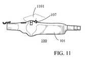
- FIG. 11comprises a side elevational view as configured in accordance with various embodiments of these teachings.
- FIG. 12comprises a side elevational view as configured in accordance with various embodiments of these teachings.
- a medical personal-services suction handleincludes a hand-graspable housing and a primary suction pathway disposed through the hand-graspable housing and having a suction line port at one end and an intake port at an opposing end thereof.
- An on/off valve disposed at least partially within the primary suction pathwayhas a user-manipulable interface by which the on/off valve selectively opens the primary suction pathway and occludes the primary suction pathway.
- a user-engageable pneumatic pathwayserves, when selectively engaged, to pneumatically couple the primary suction pathway to a secondary external port in the hand-graspable housing such that suction is applied via the primary suction pathway to both the intake port and the secondary external port.
- the secondary external portcomprises a thumb-control port.
- the aforementioned on/off valvecomprises a ball valve having a pneumatic pathway formed radially therethrough.
- the user-manipulable interfacecan comprise a tab that extends outwardly of the hand-graspable housing and that moves only within a corresponding slot that is formed in the hand-graspable housing.
- that slotcomprises an L-shaped slot. So configured, the on/off valve can be opened by moving the tab along a first portion of the L-shaped slot and the user-engageable pneumatic pathway can be selectively engaged by moving the tab along a second portion of the L-shaped slot.
- such a handlecan permit the user to conveniently select when to switch suction fully on and off while also permitting the user to decide when to use and exercise an ability to more finely control the suction strength via, for example, a thumb-control port.
- these teachingsavoid requiring the use of multiple separate components in order to provide variable suction control, thereby reducing both cost and set-up time.
- these teachingsalso provide a highly intuitive interface that clearly communicates to the user, both visually and haptically, the current suction state of the handle and the means by which that state can be selectively varied.
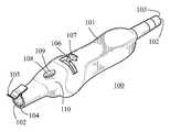
- an in-line medical personal-services suction component 100includes a hand-graspable housing 101 this hand-graspable housing 101 is sized and configured to be comfortably gripped by the average adult human hand.
- this reference to “personal”refers to the intended use of this apparatus with a given, individual patient. Accordingly, “personal” is not intended to specify that the apparatus be only used by a person for their own needs though, indeed, the term can include a person using the apparatus upon themselves as well as a medical services technician using the apparatus for that individual patient. Generally speaking, such apparatuses are used in conjunction with a single individual patient and are then disposed of.
- the hand-graspable housing 101is formed of plastic (using, for example, a molding process) but other materials can serve, in whole or in part, as desired.
- the exterior of the hand-graspable housing 101can be as smooth or as textured as desired.
- the hand-graspable housing 101comprises two halves that are joined together using any of a variety of connection methodologies including but not limited to clips, threaded members, snaps, adhesives, and sonic welding, to note but a few possibilities in these regards.
- the hand-graspable housinghas a primary suction pathway 102 formed axially therethrough.
- the primary suction pathway 102has a circular cross-section and a constant diameter along its entire length but these teachings will accommodate other shapes if desired.
- This primary suction pathway 102terminates at one end of the hand-graspable housing 101 as a suction line port 103 and at the opposite end of the hand-graspable housing 101 as an intake port 104 .
- the suction line port 103can connect per ordinary prior art practice to a suction line to that connects to a source of suction such as a suction canister.
- the intake port 104can connect to any of a variety of suction-based tools including but not limited to a Yankauer suction tool.
- a suction-based tool of choicesuch as a Yankauer
- a flexible clip 105comprises a part of the intake port 104 and serves to temporarily secure a suction-tool of choice to the intake port 104 .
- the flexible clip 105comprises an integral part of the hand-graspable housing 101 .
- the in-line medical personal-services suction component 100has an on/off valve disposed therein at least partially within the primary suction pathway 102 .
- This on/off valveincludes or at least responds to a user-manipulable interface 106 by which the on/off valve selectively opens the primary suction pathway 102 and occludes the primary suction pathway 102 as desired.
- the user-manipulable interface 106includes a tab 107 that extends outwardly of the hand-graspable housing 101 and that moves only within a corresponding slot 201 that is formed in the hand-graspable housing 101 .
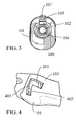
- the hand-graspable housing 101includes an L-shaped slot 401 that is formed through a side wall thereof.
- This L-shaped slot 401includes a first portion that comprises the aforementioned slot 201 that guides and constrains movement of the aforementioned tab 107 when moving the aforementioned on/off valve between a fully-off and a fully-on position.
- the L-shaped slot 401also includes a second portion 402 to accommodate and guide lateral movement of the tab 107 from the fully-off position to a position that enables use of a user-engageable pneumatic pathway described further below.
- the hand-graspable housing 101also includes a user-engageable pneumatic pathway configured here as a thumb-control port 108 .
- This user-engageable pneumatic pathwaywhen selectively engaged (via the aforementioned tab 107 as described below) pneumatically couples the primary suction pathway 102 to a secondary external port 109 in the hand-graspable housing 101 .
- the thumb-control port 108is disposed within a convex depression 110 that is formed in an exterior portion of the hand-graspable housing 101 . This convex depression 110 helps to facilitate an ergonomic fit between the thumb-control port 108 and, for example, a user's thumb.
- suction applied via the primary suction pathway 102is applied via the primary suction pathway to both the intake port 104 and the secondary external port 109 . Accordingly, suction can be reduced at the intake port 104 when such is the case.
- Use of the thumb-control port 108 to vary the extent of this reductionis described below.
- the secondary external port 109 and the aforementioned slot 201 that comprises a first portion of the L-shaped slot 401are axially aligned with one another.
- Other configurations and orientationsare possible.
- the secondary external port 109 and a part of the first portion of the L-shaped slot 401 that comprises the aforementioned slot 201 and that is closest to the secondary external port 109are no further apart than 3 cm.
- these teachingswill readily accommodate other spacings as best suits the requirements and/or opportunities of a given application setting. For example, these features may be spaced no further apart than 4 cm, 5 cm, or even 6 cm if so desired.
- an on/off valveis disposed at least partially within the primary suction pathway 102 and serves to permit a user (via manipulation of the aforementioned tab 107 ) to selectively open and occlude that primary suction pathway 102 .
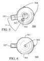
- on/off valvecomprises a ball valve 500 .
- the ball valve 500has a pneumatic pathway 501 formed radially therethrough.
- this pneumatic pathway 501has a same shape and cross-sectional diameter as the primary suction pathway 102 .
- the ball valve 500rotates about its center and aligns its pneumatic pathway 501 with the primary suction pathway 102 to thereby pneumatically couple the suction line port 103 with the intake port 104 without obstruction. Accordingly, a user can selectively engage and disengage suction from the intake port 104 via this simple manipulation of the tab 107 .
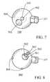
- the ball valve 500also serves to selectively enable the aforementioned user-engageable pneumatic pathway by selectively pneumatically connecting and disconnecting the primary suction pathway 102 with the aforementioned secondary external port 109 .
- the ball valve 500includes a secondary suction pathway 502 that couples the pneumatic pathway 501 in the ball valve 500 to an exterior port 503 on the periphery of the ball valve 500 .
- this secondary suction pathway 502comprises a linear pathway.
- the secondary suction pathway 502is offset from the tab 107 by N degrees (where N can vary with the specifics of the application setting).
- the usercan control to some extent the amount of the lessening of suction at the intake port 104 by using their thumb or finger (or some other object) to vary the size of the pneumatically-exposed opening of the secondary external port 109 .
- the usercan control to some extent the amount of the lessening of suction at the intake port 104 by using their thumb or finger (or some other object) to vary the size of the pneumatically-exposed opening of the secondary external port 109 .
- full suction at the intake port 104can be achieved.
- the usercan achieve reduced suction at the intake port 104 as desired, both in terms of the strength of the suction and the duration of the reduction.
- the ball valve 500can be comprised of a material (or can be covered, in whole or in part, by a material) such as a relatively soft, sticky material (such as silicone, Polytetrafluoroethylene (PTFE), or the like) such that the ball valve 500 reliably forms a good pneumatic seal with the interior surfaces of the hand-graspable housing 101 while also being lubricious enough to permit relatively easy rotation and manipulation of the ball valve 500 by the user.
- a relatively soft, sticky materialsuch as silicone, Polytetrafluoroethylene (PTFE), or the like
- PTFEPolytetrafluoroethylene
- these teachingswill also accommodate providing the ball valve 500 with one or more knobs 504 that can interact, for example, with detents (not shown) on the interior surface of the hand-graspable housing 101 .
- the position of the ball valve 500can again be maintained in specific orientations of interest.
- the ball valve 500can be urged to be retained in one or more of the positions shown in FIGS. 1, 9, and 10 as desired.
- the linear alignment between the thumb-control port 108 and the tab 107 when moving the tab 107 from the suction-off position shown in FIG. 1 to the suction-on position shown in FIG. 9causes the tab 107 to be readily sensed via a user's thumb 1101 as illustrated in FIG. 11 to thereby haptically indicate to the user that the thumb-control port 108 is not engaged and cannot serve to control the diminishment of suction at the intake port 104 .
- the tab 107Upon moving the tab 107 as shown in FIG.
- the tab 107is moved to the side and will no longer engage the user's thumb 1101 (a configuration and condition illustrated in FIG. 12 ). Accordingly, and again, the user receives haptic information to signal to the user that the thumb-control port 108 is engaged and can be used to selectively lessen suction at the intake port 104 .
- Such an in-line medical personal-services suction component(whether used as a handle with detachable suction tools or as an integral part of a specific suction tool) can be inexpensively manufactured and can offer intuitive and reliable service.
- Such an apparatuswill intuitively and easily permit a user to switch suction on and off without requiring the user to consider or control the thumb-control port if so desired.
- these teachingspermit the thumb-control port to be easily and readily selectively rendered operable. Accordingly, all use cases are readily accommodated by this single apparatus.
Landscapes
- Health & Medical Sciences (AREA)
- Heart & Thoracic Surgery (AREA)
- Vascular Medicine (AREA)
- Engineering & Computer Science (AREA)
- Anesthesiology (AREA)
- Biomedical Technology (AREA)
- Hematology (AREA)
- Life Sciences & Earth Sciences (AREA)
- Animal Behavior & Ethology (AREA)
- General Health & Medical Sciences (AREA)
- Public Health (AREA)
- Veterinary Medicine (AREA)
- External Artificial Organs (AREA)
Abstract
Description
Claims (20)
Priority Applications (1)
| Application Number | Priority Date | Filing Date | Title |
|---|---|---|---|
| US14/291,876US9884143B2 (en) | 2014-05-30 | 2014-05-30 | Medical personal-services suction handle |
Applications Claiming Priority (1)
| Application Number | Priority Date | Filing Date | Title |
|---|---|---|---|
| US14/291,876US9884143B2 (en) | 2014-05-30 | 2014-05-30 | Medical personal-services suction handle |
Publications (2)
| Publication Number | Publication Date |
|---|---|
| US20150343121A1 US20150343121A1 (en) | 2015-12-03 |
| US9884143B2true US9884143B2 (en) | 2018-02-06 |
Family
ID=54700564
Family Applications (1)
| Application Number | Title | Priority Date | Filing Date |
|---|---|---|---|
| US14/291,876Active2035-09-11US9884143B2 (en) | 2014-05-30 | 2014-05-30 | Medical personal-services suction handle |
Country Status (1)
| Country | Link |
|---|---|
| US (1) | US9884143B2 (en) |
Cited By (5)
| Publication number | Priority date | Publication date | Assignee | Title |
|---|---|---|---|---|
| USD844780S1 (en)* | 2015-08-07 | 2019-04-02 | Vyaire Medical Consumables Llc | Suction control valve |
| US11324526B2 (en) | 2018-02-02 | 2022-05-10 | Calyxo, Inc. | Devices and methods for minimally invasive kidney stone removal by combined aspiration and irrigation |
| USD968599S1 (en)* | 2020-08-28 | 2022-11-01 | John H. Campbell | Suction valve switch |
| US12256989B2 (en) | 2022-09-29 | 2025-03-25 | Calyxo, Inc. | Tool guiding device for kidney stone treatment apparatus |
| US12329399B2 (en) | 2022-03-02 | 2025-06-17 | Calyxo, Inc. | Kidney stone treatment system |
Families Citing this family (13)
| Publication number | Priority date | Publication date | Assignee | Title |
|---|---|---|---|---|
| USD678512S1 (en) | 2011-09-29 | 2013-03-19 | Medline Industries, Inc. | Suction handle |
| USD749717S1 (en)* | 2014-05-30 | 2016-02-16 | Medline Industries, Inc. | Suction handle |
| US9884143B2 (en) | 2014-05-30 | 2018-02-06 | Medline Industries, Inc. | Medical personal-services suction handle |
| US10765854B2 (en) | 2016-08-29 | 2020-09-08 | Allegiance Corporation | Port connector for medical waste fluid receptacles and methods of use |
| US10441449B1 (en) | 2018-05-30 | 2019-10-15 | Vesper Medical, Inc. | Rotary handle stent delivery system and method |
| US10449073B1 (en) | 2018-09-18 | 2019-10-22 | Vesper Medical, Inc. | Rotary handle stent delivery system and method |
| JP2022509211A (en)* | 2018-11-27 | 2022-01-20 | スラヴァン クマール パイェリ、 | Follicular fluid aspiration |
| CN109876200B (en)* | 2019-02-26 | 2024-05-07 | 河南亚都实业有限公司 | Suction catheter for uterine operation |
| US11219541B2 (en) | 2020-05-21 | 2022-01-11 | Vesper Medical, Inc. | Wheel lock for thumbwheel actuated device |
| TWM621298U (en)* | 2021-04-07 | 2021-12-21 | 晉弘科技股份有限公司 | Handle for endoscope |
| JP1747344S (en)* | 2022-04-14 | 2023-06-27 | endoscope handle | |
| USD1046130S1 (en)* | 2022-10-11 | 2024-10-08 | Olympus Winter & Ibe Gmbh | Endoscope handle |
| GB2632858A (en)* | 2023-08-24 | 2025-02-26 | Clearwax Ltd | Medical suction apparatus with variable suction |
Citations (61)
| Publication number | Priority date | Publication date | Assignee | Title |
|---|---|---|---|---|
| US3749090A (en) | 1971-06-09 | 1973-07-31 | Stewart Research | Combination aspirator and fluid delivering surgical instrument |
| USD279924S (en) | 1982-09-27 | 1985-07-30 | Osgood Robert W | Hand held bidet |
| USD282285S (en) | 1983-10-07 | 1986-01-21 | Aldo Levy | Aspirator |
| USD326714S (en) | 1989-06-16 | 1992-06-02 | Olympus Optical Co., Ltd. | Endoscope for blood vessel |
| US5203769A (en)* | 1989-11-06 | 1993-04-20 | Mectra Labs, Inc. | Medical device valving mechanism |
| USD351652S (en) | 1993-06-21 | 1994-10-18 | Ep Technologies, Inc. | Steerable medical catheter handle |
| USD357064S (en) | 1993-12-20 | 1995-04-04 | Vision Medical & Dental | Disposable saliva ejector valve |
| USD387862S (en) | 1995-10-20 | 1997-12-16 | Sensor Devices, Inc. | Anatomical probe attachment |
| US5984907A (en) | 1995-06-05 | 1999-11-16 | Ep Technologies, Inc. | Transition sleeve assembly for catheters |
| US6129547A (en) | 1997-05-06 | 2000-10-10 | Ballard Medical Products | Oral care system |
| US20020103419A1 (en) | 2000-07-18 | 2002-08-01 | Christopher Kent L. | Endoscope with a removable suction tube |
| US6500142B1 (en) | 2000-10-04 | 2002-12-31 | Sage Products, Inc. | Covered suction device with closure |
| US6588427B1 (en) | 2002-02-25 | 2003-07-08 | Kimberly-Clark Worldwide, Inc. | Heat and moisture exchanger adapter to closed suction catheter assembly and system having improved catheter cleaning |
| USD483475S1 (en) | 2002-09-20 | 2003-12-09 | Genzyme Corporation | Fluent agent delivery device |
| US20040006380A1 (en) | 2002-07-05 | 2004-01-08 | Buck Jerrick C. | Stent delivery system |
| USD498846S1 (en) | 2002-02-27 | 2004-11-23 | Pentax Corporation | Endoscope |
| USD512147S1 (en) | 2003-05-01 | 2005-11-29 | Datascope Investment Corp. | Thrombectomy device |
| USD518175S1 (en) | 2003-10-31 | 2006-03-28 | Wilson-Cook Medical Inc. | Handle for medical devices, and medical device assemblies using a handle |
| USD518573S1 (en) | 2003-03-17 | 2006-04-04 | Mentor Medical Limited | Low profile tap with grip tabs |
| USD535393S1 (en) | 2005-03-09 | 2007-01-16 | Karl Storz Gmbh & Co. Kg | Video-bronchoscope |
| USD545439S1 (en) | 2005-04-15 | 2007-06-26 | Becton, Dickinson And Company | Blood glucose meter |
| USD564093S1 (en) | 2006-05-08 | 2008-03-11 | Cryocath Technologies Inc. | Handle for catheter device |
| US20080132760A1 (en) | 2005-09-14 | 2008-06-05 | Olympus Corporation | Endoscope Distal End Forming Portion |
| USD571458S1 (en) | 2005-10-06 | 2008-06-17 | Astra Tech Ab | Surgical suction instrument |
| WO2008075241A2 (en) | 2006-12-15 | 2008-06-26 | Kimberly-Clark Worldwide, Inc. | Yankauer suction device |
| USD576725S1 (en) | 2007-06-20 | 2008-09-09 | Abbot Laboratories, Inc. | Medical device delivery handle |
| USD581052S1 (en) | 2007-09-14 | 2008-11-18 | Optim, Incorporated | Control handle for an endoscopic device |
| USD585993S1 (en) | 2007-04-25 | 2009-02-03 | Tanita Corporation | Urine glucose meter |
| US7625207B2 (en)* | 2006-12-15 | 2009-12-01 | Kimberly-Clark Worldwide, Inc. | Yankauer suction device with sleeve and wiper |
| USD606651S1 (en) | 2009-04-21 | 2009-12-22 | Dental Components Llc | Handle portion of a dental syringe |
| USD622842S1 (en) | 2009-08-06 | 2010-08-31 | Given Imaging Ltd. | Implantable monitor delivery device handle |
| US20100240956A1 (en) | 2004-05-25 | 2010-09-23 | Secrest Dean J | Irrigating biopsy inlet valve |
| US7867190B2 (en) | 2007-06-21 | 2011-01-11 | Sage Products, Inc. | Covered suction device |
| US7866477B2 (en) | 2008-06-30 | 2011-01-11 | Kimberly-Clark Worldwide, Inc. | Oral care Q2 kits |
| USD630728S1 (en) | 2010-04-30 | 2011-01-11 | 3M Innovative Properties Company | Suction handle |
| USD632783S1 (en) | 2009-09-29 | 2011-02-15 | Karl Storz Gmbh & Co. Kg | Connector for medical device |
| US20110082431A1 (en) | 2009-10-02 | 2011-04-07 | Burgess James E | Connector for Fluid Conduit with Integrated Luer Access Port |
| USD653329S1 (en) | 2011-05-11 | 2012-01-31 | Femasys Inc. | Device for relieving fluid pressure |
| USD669578S1 (en) | 2009-10-02 | 2012-10-23 | Medline Industries, Inc. | Medical port |
| USD678512S1 (en) | 2011-09-29 | 2013-03-19 | Medline Industries, Inc. | Suction handle |
| USD698441S1 (en) | 2012-01-20 | 2014-01-28 | Olympus Corporation | Endoscope |
| USD709184S1 (en) | 2013-10-18 | 2014-07-15 | Femasys Inc. | Device for mixing fluids |
| US20140207056A1 (en) | 2013-01-18 | 2014-07-24 | Peter L. Bono | Suction and Irrigation Apparatus with Anti-Clogging Capability |
| US8834407B2 (en) | 2006-01-20 | 2014-09-16 | Medline Industries, Inc. | Covered yankauer suction device and methods of using same |
| USD715429S1 (en) | 2012-05-07 | 2014-10-14 | St. Jude Medical, Atrial Fibrillation Division, Inc. | Control handle for a medical device |
| USD718437S1 (en) | 2012-04-23 | 2014-11-25 | Oscor Inc. | Steerable guiding catheter handle |
| USD718445S1 (en) | 2012-09-12 | 2014-11-25 | Fujifilm Corporation | Operating grip for endoscope |
| USD719651S1 (en) | 2013-01-04 | 2014-12-16 | Ambu A/S | Handle for a medical device |
| US8986363B2 (en) | 2009-12-30 | 2015-03-24 | Cook Medical Technologies Llc | Proximal release delivery system |
| US20150258257A1 (en) | 2012-12-06 | 2015-09-17 | Stryker Corporation | Medical/surgical lavage unit with a tip assembly that includes an irrigation tube disposed inside a suction tube and that is axially offset from the suction tube |
| US9173725B2 (en) | 2010-06-09 | 2015-11-03 | Astek Innovations Limited | Dental nozzle |
| US20150343121A1 (en) | 2014-05-30 | 2015-12-03 | Medline Industries, Inc. | Medical Personal-Services Suction Handle |
| USD749717S1 (en) | 2014-05-30 | 2016-02-16 | Medline Industries, Inc. | Suction handle |
| US9295551B2 (en) | 2007-04-13 | 2016-03-29 | Jenavalve Technology Gmbh | Methods of implanting an endoprosthesis |
| USD753291S1 (en) | 2014-03-03 | 2016-04-05 | Sanofi | Medicament injection device |
| USD753296S1 (en) | 2014-01-31 | 2016-04-05 | Deka Products Limited Partnership | Endoscope |
| USD753823S1 (en) | 2014-06-30 | 2016-04-12 | Hoya Corporation | Endoscope control grip |
| US9314356B2 (en) | 2010-01-29 | 2016-04-19 | Cook Medical Technologies Llc | Mechanically expandable delivery and dilation systems |
| US9332973B2 (en) | 2008-10-01 | 2016-05-10 | Covidien Lp | Needle biopsy device with exchangeable needle and integrated needle protection |
| USD756517S1 (en) | 2014-07-02 | 2016-05-17 | Comprehensive Telemedicine | Multi-purpose medical imaging device support apparatus |
| US9345633B2 (en) | 2012-07-19 | 2016-05-24 | Activator Methods International, Ltd. | Chiropractic adjustor system and method |
- 2014
- 2014-05-30USUS14/291,876patent/US9884143B2/enactiveActive
Patent Citations (65)
| Publication number | Priority date | Publication date | Assignee | Title |
|---|---|---|---|---|
| US3749090A (en) | 1971-06-09 | 1973-07-31 | Stewart Research | Combination aspirator and fluid delivering surgical instrument |
| USD279924S (en) | 1982-09-27 | 1985-07-30 | Osgood Robert W | Hand held bidet |
| USD282285S (en) | 1983-10-07 | 1986-01-21 | Aldo Levy | Aspirator |
| USD326714S (en) | 1989-06-16 | 1992-06-02 | Olympus Optical Co., Ltd. | Endoscope for blood vessel |
| US5203769A (en)* | 1989-11-06 | 1993-04-20 | Mectra Labs, Inc. | Medical device valving mechanism |
| USD351652S (en) | 1993-06-21 | 1994-10-18 | Ep Technologies, Inc. | Steerable medical catheter handle |
| USD357064S (en) | 1993-12-20 | 1995-04-04 | Vision Medical & Dental | Disposable saliva ejector valve |
| US5984907A (en) | 1995-06-05 | 1999-11-16 | Ep Technologies, Inc. | Transition sleeve assembly for catheters |
| USD387862S (en) | 1995-10-20 | 1997-12-16 | Sensor Devices, Inc. | Anatomical probe attachment |
| US6129547A (en) | 1997-05-06 | 2000-10-10 | Ballard Medical Products | Oral care system |
| US20020103419A1 (en) | 2000-07-18 | 2002-08-01 | Christopher Kent L. | Endoscope with a removable suction tube |
| US6500142B1 (en) | 2000-10-04 | 2002-12-31 | Sage Products, Inc. | Covered suction device with closure |
| US6588427B1 (en) | 2002-02-25 | 2003-07-08 | Kimberly-Clark Worldwide, Inc. | Heat and moisture exchanger adapter to closed suction catheter assembly and system having improved catheter cleaning |
| USD498846S1 (en) | 2002-02-27 | 2004-11-23 | Pentax Corporation | Endoscope |
| US20040006380A1 (en) | 2002-07-05 | 2004-01-08 | Buck Jerrick C. | Stent delivery system |
| USD483475S1 (en) | 2002-09-20 | 2003-12-09 | Genzyme Corporation | Fluent agent delivery device |
| USD518573S1 (en) | 2003-03-17 | 2006-04-04 | Mentor Medical Limited | Low profile tap with grip tabs |
| USD512147S1 (en) | 2003-05-01 | 2005-11-29 | Datascope Investment Corp. | Thrombectomy device |
| USD518175S1 (en) | 2003-10-31 | 2006-03-28 | Wilson-Cook Medical Inc. | Handle for medical devices, and medical device assemblies using a handle |
| US20100240956A1 (en) | 2004-05-25 | 2010-09-23 | Secrest Dean J | Irrigating biopsy inlet valve |
| USD535393S1 (en) | 2005-03-09 | 2007-01-16 | Karl Storz Gmbh & Co. Kg | Video-bronchoscope |
| USD545439S1 (en) | 2005-04-15 | 2007-06-26 | Becton, Dickinson And Company | Blood glucose meter |
| US20080132760A1 (en) | 2005-09-14 | 2008-06-05 | Olympus Corporation | Endoscope Distal End Forming Portion |
| USD571458S1 (en) | 2005-10-06 | 2008-06-17 | Astra Tech Ab | Surgical suction instrument |
| US8834407B2 (en) | 2006-01-20 | 2014-09-16 | Medline Industries, Inc. | Covered yankauer suction device and methods of using same |
| USD564093S1 (en) | 2006-05-08 | 2008-03-11 | Cryocath Technologies Inc. | Handle for catheter device |
| US7625207B2 (en)* | 2006-12-15 | 2009-12-01 | Kimberly-Clark Worldwide, Inc. | Yankauer suction device with sleeve and wiper |
| WO2008075241A2 (en) | 2006-12-15 | 2008-06-26 | Kimberly-Clark Worldwide, Inc. | Yankauer suction device |
| US9295551B2 (en) | 2007-04-13 | 2016-03-29 | Jenavalve Technology Gmbh | Methods of implanting an endoprosthesis |
| USD585993S1 (en) | 2007-04-25 | 2009-02-03 | Tanita Corporation | Urine glucose meter |
| USD576725S1 (en) | 2007-06-20 | 2008-09-09 | Abbot Laboratories, Inc. | Medical device delivery handle |
| US7867190B2 (en) | 2007-06-21 | 2011-01-11 | Sage Products, Inc. | Covered suction device |
| US20110098644A1 (en) | 2007-06-21 | 2011-04-28 | Sage Products, Inc. | Covered Suction Device |
| USD581052S1 (en) | 2007-09-14 | 2008-11-18 | Optim, Incorporated | Control handle for an endoscopic device |
| US7866477B2 (en) | 2008-06-30 | 2011-01-11 | Kimberly-Clark Worldwide, Inc. | Oral care Q2 kits |
| US9332973B2 (en) | 2008-10-01 | 2016-05-10 | Covidien Lp | Needle biopsy device with exchangeable needle and integrated needle protection |
| USD606651S1 (en) | 2009-04-21 | 2009-12-22 | Dental Components Llc | Handle portion of a dental syringe |
| USD622842S1 (en) | 2009-08-06 | 2010-08-31 | Given Imaging Ltd. | Implantable monitor delivery device handle |
| USD632783S1 (en) | 2009-09-29 | 2011-02-15 | Karl Storz Gmbh & Co. Kg | Connector for medical device |
| US8764731B2 (en) | 2009-10-02 | 2014-07-01 | Medline Industries, Inc. | Connector for fluid conduit with integrated luer access port |
| USD669578S1 (en) | 2009-10-02 | 2012-10-23 | Medline Industries, Inc. | Medical port |
| US20110082431A1 (en) | 2009-10-02 | 2011-04-07 | Burgess James E | Connector for Fluid Conduit with Integrated Luer Access Port |
| US8986363B2 (en) | 2009-12-30 | 2015-03-24 | Cook Medical Technologies Llc | Proximal release delivery system |
| US9314356B2 (en) | 2010-01-29 | 2016-04-19 | Cook Medical Technologies Llc | Mechanically expandable delivery and dilation systems |
| USD630728S1 (en) | 2010-04-30 | 2011-01-11 | 3M Innovative Properties Company | Suction handle |
| US9173725B2 (en) | 2010-06-09 | 2015-11-03 | Astek Innovations Limited | Dental nozzle |
| USD653329S1 (en) | 2011-05-11 | 2012-01-31 | Femasys Inc. | Device for relieving fluid pressure |
| USD744638S1 (en) | 2011-09-29 | 2015-12-01 | Medline Industries, Inc. | Suction handle |
| USD678512S1 (en) | 2011-09-29 | 2013-03-19 | Medline Industries, Inc. | Suction handle |
| USD698441S1 (en) | 2012-01-20 | 2014-01-28 | Olympus Corporation | Endoscope |
| USD718437S1 (en) | 2012-04-23 | 2014-11-25 | Oscor Inc. | Steerable guiding catheter handle |
| USD715429S1 (en) | 2012-05-07 | 2014-10-14 | St. Jude Medical, Atrial Fibrillation Division, Inc. | Control handle for a medical device |
| US9345633B2 (en) | 2012-07-19 | 2016-05-24 | Activator Methods International, Ltd. | Chiropractic adjustor system and method |
| USD718445S1 (en) | 2012-09-12 | 2014-11-25 | Fujifilm Corporation | Operating grip for endoscope |
| US20150258257A1 (en) | 2012-12-06 | 2015-09-17 | Stryker Corporation | Medical/surgical lavage unit with a tip assembly that includes an irrigation tube disposed inside a suction tube and that is axially offset from the suction tube |
| USD719651S1 (en) | 2013-01-04 | 2014-12-16 | Ambu A/S | Handle for a medical device |
| US9248228B2 (en)* | 2013-01-18 | 2016-02-02 | Peter L. Bono | Suction and irrigation apparatus with anti-clogging capability |
| US20140207056A1 (en) | 2013-01-18 | 2014-07-24 | Peter L. Bono | Suction and Irrigation Apparatus with Anti-Clogging Capability |
| USD709184S1 (en) | 2013-10-18 | 2014-07-15 | Femasys Inc. | Device for mixing fluids |
| USD753296S1 (en) | 2014-01-31 | 2016-04-05 | Deka Products Limited Partnership | Endoscope |
| USD753291S1 (en) | 2014-03-03 | 2016-04-05 | Sanofi | Medicament injection device |
| US20150343121A1 (en) | 2014-05-30 | 2015-12-03 | Medline Industries, Inc. | Medical Personal-Services Suction Handle |
| USD749717S1 (en) | 2014-05-30 | 2016-02-16 | Medline Industries, Inc. | Suction handle |
| USD753823S1 (en) | 2014-06-30 | 2016-04-12 | Hoya Corporation | Endoscope control grip |
| USD756517S1 (en) | 2014-07-02 | 2016-05-17 | Comprehensive Telemedicine | Multi-purpose medical imaging device support apparatus |
Non-Patent Citations (2)
| Title |
|---|
| Kimberly-Clark"KimVent" Oral Care q4 Kit & Individual Componets/Packs, Kimberly Clark, 2008, 6 pages. |
| Suzanne M. Pear, ‘VAP Prevention: Critical Techniques and Tools.’ Healthcare Purchasing News, May 2008, pp. 40-41. |
Cited By (8)
| Publication number | Priority date | Publication date | Assignee | Title |
|---|---|---|---|---|
| USD844780S1 (en)* | 2015-08-07 | 2019-04-02 | Vyaire Medical Consumables Llc | Suction control valve |
| US11324526B2 (en) | 2018-02-02 | 2022-05-10 | Calyxo, Inc. | Devices and methods for minimally invasive kidney stone removal by combined aspiration and irrigation |
| US12023059B2 (en) | 2018-02-02 | 2024-07-02 | Calyxo, Inc. | Devices and methods for minimally invasive kidney stone removal by combined aspiration and irrigation |
| US12318099B2 (en) | 2018-02-02 | 2025-06-03 | Calyxo, Inc. | Devices and methods for minimally invasive kidney stone removal by combined aspiration and irrigation |
| USD968599S1 (en)* | 2020-08-28 | 2022-11-01 | John H. Campbell | Suction valve switch |
| US12329399B2 (en) | 2022-03-02 | 2025-06-17 | Calyxo, Inc. | Kidney stone treatment system |
| US12329396B2 (en) | 2022-03-02 | 2025-06-17 | Calyxo, Inc. | Kidney stone treatment system |
| US12256989B2 (en) | 2022-09-29 | 2025-03-25 | Calyxo, Inc. | Tool guiding device for kidney stone treatment apparatus |
Also Published As
| Publication number | Publication date |
|---|---|
| US20150343121A1 (en) | 2015-12-03 |
Similar Documents
| Publication | Publication Date | Title |
|---|---|---|
| US9884143B2 (en) | Medical personal-services suction handle | |
| US11305050B2 (en) | Connector with valve for negative pressure wound therapy system | |
| CN109195538B (en) | Ergonomic tubing attachment for medical devices | |
| US5254083A (en) | Suction and irrigation apparatus | |
| CN100589848C (en) | Suction regulating valve for operation | |
| US20230363634A1 (en) | Apparatus, System and Method for Performing a Bronchoscopy | |
| EP1928517B1 (en) | Medical suction and irrigation device handpiece | |
| US3395705A (en) | Medical suction apparatus | |
| WO2006119512A2 (en) | Surgical tool and insertion device for tube placement | |
| JPH10127756A (en) | Medical operation device for sucking and washing | |
| US20140155897A1 (en) | Surgical instrument | |
| US20240139458A1 (en) | Tracheal intubation device for delivery of apneic oxygenation and suction | |
| JP2015500704A (en) | Joint axis and double-handed combined irrigation / aspiration device | |
| US20070016136A1 (en) | Suction hand-piece device with variable control off/on valve | |
| US12011533B2 (en) | Fluid transfer device | |
| JP2509231B2 (en) | Medical suction device | |
| CN110811819B (en) | An electrocoagulation suction device | |
| US10537336B2 (en) | Electromechanical slider valve suction controller | |
| US8353701B2 (en) | Salivary duct constriction apparatus | |
| KR200345636Y1 (en) | Suction apparatus for medical treatment | |
| US7722627B2 (en) | Surgical ligation instrument | |
| US6019350A (en) | Hand held control device and associated method | |
| CN223323822U (en) | Surgical irrigation, suction and drainage components | |
| US20240050185A1 (en) | Graspable surgical device | |
| WO2025040905A1 (en) | Medical suction apparatus with variable suction |
Legal Events
| Date | Code | Title | Description |
|---|---|---|---|
| AS | Assignment | Owner name:MEDLINE INDUSTRIES, INC., ILLINOIS Free format text:ASSIGNMENT OF ASSIGNORS INTEREST;ASSIGNORS:KOBIDA, MICHAEL;TURTURRO, MICHAEL;REEL/FRAME:032998/0697 Effective date:20140530 | |
| STCF | Information on status: patent grant | Free format text:PATENTED CASE | |
| CC | Certificate of correction | ||
| MAFP | Maintenance fee payment | Free format text:PAYMENT OF MAINTENANCE FEE, 4TH YEAR, LARGE ENTITY (ORIGINAL EVENT CODE: M1551); ENTITY STATUS OF PATENT OWNER: LARGE ENTITY Year of fee payment:4 | |
| AS | Assignment | Owner name:MEDLINE INDUSTRIES, LP, ILLINOIS Free format text:CHANGE OF NAME;ASSIGNOR:MEDLINE INDUSTRIES, INC.;REEL/FRAME:058554/0159 Effective date:20210907 | |
| AS | Assignment | Owner name:BANK OF AMERICA, N.A., TEXAS Free format text:SECURITY INTEREST;ASSIGNOR:MEDLINE INDUSTRIES, LP;REEL/FRAME:058040/0001 Effective date:20211021 Owner name:WILMINGTON TRUST, NATIONAL ASSOCIATION, MINNESOTA Free format text:SECURITY INTEREST;ASSIGNOR:MEDLINE INDUSTRIES, LP;REEL/FRAME:057927/0091 Effective date:20211021 | |
| AS | Assignment | Owner name:WILMINGTON TRUST, NATIONAL ASSOCIATION, AS NOTES COLLATERAL AGENT, MINNESOTA Free format text:PATENT SECURITY AGREEMENT;ASSIGNOR:MEDLINE INDUSTRIES, LP;REEL/FRAME:071672/0100 Effective date:20240327 | |
| MAFP | Maintenance fee payment | Free format text:PAYMENT OF MAINTENANCE FEE, 8TH YEAR, LARGE ENTITY (ORIGINAL EVENT CODE: M1552); ENTITY STATUS OF PATENT OWNER: LARGE ENTITY Year of fee payment:8 |