US9883949B2 - Intervertebral implant - Google Patents
Intervertebral implantDownload PDFInfo
- Publication number
- US9883949B2 US9883949B2US15/176,707US201615176707AUS9883949B2US 9883949 B2US9883949 B2US 9883949B2US 201615176707 AUS201615176707 AUS 201615176707AUS 9883949 B2US9883949 B2US 9883949B2
- Authority
- US
- United States
- Prior art keywords
- teeth
- implant
- cortical
- central
- bone
- Prior art date
- Legal status (The legal status is an assumption and is not a legal conclusion. Google has not performed a legal analysis and makes no representation as to the accuracy of the status listed.)
- Active
Links
Images


Classifications
- A—HUMAN NECESSITIES
- A61—MEDICAL OR VETERINARY SCIENCE; HYGIENE
- A61F—FILTERS IMPLANTABLE INTO BLOOD VESSELS; PROSTHESES; DEVICES PROVIDING PATENCY TO, OR PREVENTING COLLAPSING OF, TUBULAR STRUCTURES OF THE BODY, e.g. STENTS; ORTHOPAEDIC, NURSING OR CONTRACEPTIVE DEVICES; FOMENTATION; TREATMENT OR PROTECTION OF EYES OR EARS; BANDAGES, DRESSINGS OR ABSORBENT PADS; FIRST-AID KITS
- A61F2/00—Filters implantable into blood vessels; Prostheses, i.e. artificial substitutes or replacements for parts of the body; Appliances for connecting them with the body; Devices providing patency to, or preventing collapsing of, tubular structures of the body, e.g. stents
- A61F2/02—Prostheses implantable into the body
- A61F2/30—Joints
- A61F2/44—Joints for the spine, e.g. vertebrae, spinal discs
- A61F2/442—Intervertebral or spinal discs, e.g. resilient
- A—HUMAN NECESSITIES
- A61—MEDICAL OR VETERINARY SCIENCE; HYGIENE
- A61F—FILTERS IMPLANTABLE INTO BLOOD VESSELS; PROSTHESES; DEVICES PROVIDING PATENCY TO, OR PREVENTING COLLAPSING OF, TUBULAR STRUCTURES OF THE BODY, e.g. STENTS; ORTHOPAEDIC, NURSING OR CONTRACEPTIVE DEVICES; FOMENTATION; TREATMENT OR PROTECTION OF EYES OR EARS; BANDAGES, DRESSINGS OR ABSORBENT PADS; FIRST-AID KITS
- A61F2/00—Filters implantable into blood vessels; Prostheses, i.e. artificial substitutes or replacements for parts of the body; Appliances for connecting them with the body; Devices providing patency to, or preventing collapsing of, tubular structures of the body, e.g. stents
- A61F2/02—Prostheses implantable into the body
- A61F2/30—Joints
- A61F2/44—Joints for the spine, e.g. vertebrae, spinal discs
- A61F2/4455—Joints for the spine, e.g. vertebrae, spinal discs for the fusion of spinal bodies, e.g. intervertebral fusion of adjacent spinal bodies, e.g. fusion cages
- A61F2/447—Joints for the spine, e.g. vertebrae, spinal discs for the fusion of spinal bodies, e.g. intervertebral fusion of adjacent spinal bodies, e.g. fusion cages substantially parallelepipedal, e.g. having a rectangular or trapezoidal cross-section
- A—HUMAN NECESSITIES
- A61—MEDICAL OR VETERINARY SCIENCE; HYGIENE
- A61F—FILTERS IMPLANTABLE INTO BLOOD VESSELS; PROSTHESES; DEVICES PROVIDING PATENCY TO, OR PREVENTING COLLAPSING OF, TUBULAR STRUCTURES OF THE BODY, e.g. STENTS; ORTHOPAEDIC, NURSING OR CONTRACEPTIVE DEVICES; FOMENTATION; TREATMENT OR PROTECTION OF EYES OR EARS; BANDAGES, DRESSINGS OR ABSORBENT PADS; FIRST-AID KITS
- A61F2/00—Filters implantable into blood vessels; Prostheses, i.e. artificial substitutes or replacements for parts of the body; Appliances for connecting them with the body; Devices providing patency to, or preventing collapsing of, tubular structures of the body, e.g. stents
- A61F2/02—Prostheses implantable into the body
- A61F2/30—Joints
- A61F2/46—Special tools for implanting artificial joints
- A61F2/4603—Special tools for implanting artificial joints for insertion or extraction of endoprosthetic joints or of accessories thereof
- A61F2/4611—Special tools for implanting artificial joints for insertion or extraction of endoprosthetic joints or of accessories thereof of spinal prostheses
- A—HUMAN NECESSITIES
- A61—MEDICAL OR VETERINARY SCIENCE; HYGIENE
- A61F—FILTERS IMPLANTABLE INTO BLOOD VESSELS; PROSTHESES; DEVICES PROVIDING PATENCY TO, OR PREVENTING COLLAPSING OF, TUBULAR STRUCTURES OF THE BODY, e.g. STENTS; ORTHOPAEDIC, NURSING OR CONTRACEPTIVE DEVICES; FOMENTATION; TREATMENT OR PROTECTION OF EYES OR EARS; BANDAGES, DRESSINGS OR ABSORBENT PADS; FIRST-AID KITS
- A61F2/00—Filters implantable into blood vessels; Prostheses, i.e. artificial substitutes or replacements for parts of the body; Appliances for connecting them with the body; Devices providing patency to, or preventing collapsing of, tubular structures of the body, e.g. stents
- A61F2/02—Prostheses implantable into the body
- A61F2/30—Joints
- A61F2/3094—Designing or manufacturing processes
- A61F2/30965—Reinforcing the prosthesis by embedding particles or fibres during moulding or dipping
- A—HUMAN NECESSITIES
- A61—MEDICAL OR VETERINARY SCIENCE; HYGIENE
- A61F—FILTERS IMPLANTABLE INTO BLOOD VESSELS; PROSTHESES; DEVICES PROVIDING PATENCY TO, OR PREVENTING COLLAPSING OF, TUBULAR STRUCTURES OF THE BODY, e.g. STENTS; ORTHOPAEDIC, NURSING OR CONTRACEPTIVE DEVICES; FOMENTATION; TREATMENT OR PROTECTION OF EYES OR EARS; BANDAGES, DRESSINGS OR ABSORBENT PADS; FIRST-AID KITS
- A61F2/00—Filters implantable into blood vessels; Prostheses, i.e. artificial substitutes or replacements for parts of the body; Appliances for connecting them with the body; Devices providing patency to, or preventing collapsing of, tubular structures of the body, e.g. stents
- A61F2/02—Prostheses implantable into the body
- A61F2/28—Bones
- A61F2002/2835—Bone graft implants for filling a bony defect or an endoprosthesis cavity, e.g. by synthetic material or biological material
- A—HUMAN NECESSITIES
- A61—MEDICAL OR VETERINARY SCIENCE; HYGIENE
- A61F—FILTERS IMPLANTABLE INTO BLOOD VESSELS; PROSTHESES; DEVICES PROVIDING PATENCY TO, OR PREVENTING COLLAPSING OF, TUBULAR STRUCTURES OF THE BODY, e.g. STENTS; ORTHOPAEDIC, NURSING OR CONTRACEPTIVE DEVICES; FOMENTATION; TREATMENT OR PROTECTION OF EYES OR EARS; BANDAGES, DRESSINGS OR ABSORBENT PADS; FIRST-AID KITS
- A61F2/00—Filters implantable into blood vessels; Prostheses, i.e. artificial substitutes or replacements for parts of the body; Appliances for connecting them with the body; Devices providing patency to, or preventing collapsing of, tubular structures of the body, e.g. stents
- A61F2/02—Prostheses implantable into the body
- A61F2/30—Joints
- A61F2002/30001—Additional features of subject-matter classified in A61F2/28, A61F2/30 and subgroups thereof
- A61F2002/30003—Material related properties of the prosthesis or of a coating on the prosthesis
- A61F2002/30004—Material related properties of the prosthesis or of a coating on the prosthesis the prosthesis being made from materials having different values of a given property at different locations within the same prosthesis
- A61F2002/30006—Material related properties of the prosthesis or of a coating on the prosthesis the prosthesis being made from materials having different values of a given property at different locations within the same prosthesis differing in density or specific weight
- A—HUMAN NECESSITIES
- A61—MEDICAL OR VETERINARY SCIENCE; HYGIENE
- A61F—FILTERS IMPLANTABLE INTO BLOOD VESSELS; PROSTHESES; DEVICES PROVIDING PATENCY TO, OR PREVENTING COLLAPSING OF, TUBULAR STRUCTURES OF THE BODY, e.g. STENTS; ORTHOPAEDIC, NURSING OR CONTRACEPTIVE DEVICES; FOMENTATION; TREATMENT OR PROTECTION OF EYES OR EARS; BANDAGES, DRESSINGS OR ABSORBENT PADS; FIRST-AID KITS
- A61F2/00—Filters implantable into blood vessels; Prostheses, i.e. artificial substitutes or replacements for parts of the body; Appliances for connecting them with the body; Devices providing patency to, or preventing collapsing of, tubular structures of the body, e.g. stents
- A61F2/02—Prostheses implantable into the body
- A61F2/30—Joints
- A61F2002/30001—Additional features of subject-matter classified in A61F2/28, A61F2/30 and subgroups thereof
- A61F2002/30003—Material related properties of the prosthesis or of a coating on the prosthesis
- A61F2002/3006—Properties of materials and coating materials
- A61F2002/3008—Properties of materials and coating materials radio-opaque, e.g. radio-opaque markers
- A—HUMAN NECESSITIES
- A61—MEDICAL OR VETERINARY SCIENCE; HYGIENE
- A61F—FILTERS IMPLANTABLE INTO BLOOD VESSELS; PROSTHESES; DEVICES PROVIDING PATENCY TO, OR PREVENTING COLLAPSING OF, TUBULAR STRUCTURES OF THE BODY, e.g. STENTS; ORTHOPAEDIC, NURSING OR CONTRACEPTIVE DEVICES; FOMENTATION; TREATMENT OR PROTECTION OF EYES OR EARS; BANDAGES, DRESSINGS OR ABSORBENT PADS; FIRST-AID KITS
- A61F2/00—Filters implantable into blood vessels; Prostheses, i.e. artificial substitutes or replacements for parts of the body; Appliances for connecting them with the body; Devices providing patency to, or preventing collapsing of, tubular structures of the body, e.g. stents
- A61F2/02—Prostheses implantable into the body
- A61F2/30—Joints
- A61F2002/30001—Additional features of subject-matter classified in A61F2/28, A61F2/30 and subgroups thereof
- A61F2002/30003—Material related properties of the prosthesis or of a coating on the prosthesis
- A61F2002/3006—Properties of materials and coating materials
- A61F2002/30092—Properties of materials and coating materials using shape memory or superelastic materials, e.g. nitinol
- A—HUMAN NECESSITIES
- A61—MEDICAL OR VETERINARY SCIENCE; HYGIENE
- A61F—FILTERS IMPLANTABLE INTO BLOOD VESSELS; PROSTHESES; DEVICES PROVIDING PATENCY TO, OR PREVENTING COLLAPSING OF, TUBULAR STRUCTURES OF THE BODY, e.g. STENTS; ORTHOPAEDIC, NURSING OR CONTRACEPTIVE DEVICES; FOMENTATION; TREATMENT OR PROTECTION OF EYES OR EARS; BANDAGES, DRESSINGS OR ABSORBENT PADS; FIRST-AID KITS
- A61F2/00—Filters implantable into blood vessels; Prostheses, i.e. artificial substitutes or replacements for parts of the body; Appliances for connecting them with the body; Devices providing patency to, or preventing collapsing of, tubular structures of the body, e.g. stents
- A61F2/02—Prostheses implantable into the body
- A61F2/30—Joints
- A61F2002/30001—Additional features of subject-matter classified in A61F2/28, A61F2/30 and subgroups thereof
- A61F2002/30108—Shapes
- A61F2002/3011—Cross-sections or two-dimensional shapes
- A61F2002/30182—Other shapes
- A61F2002/30184—
- A61F2002/30186—
- A—HUMAN NECESSITIES
- A61—MEDICAL OR VETERINARY SCIENCE; HYGIENE
- A61F—FILTERS IMPLANTABLE INTO BLOOD VESSELS; PROSTHESES; DEVICES PROVIDING PATENCY TO, OR PREVENTING COLLAPSING OF, TUBULAR STRUCTURES OF THE BODY, e.g. STENTS; ORTHOPAEDIC, NURSING OR CONTRACEPTIVE DEVICES; FOMENTATION; TREATMENT OR PROTECTION OF EYES OR EARS; BANDAGES, DRESSINGS OR ABSORBENT PADS; FIRST-AID KITS
- A61F2/00—Filters implantable into blood vessels; Prostheses, i.e. artificial substitutes or replacements for parts of the body; Appliances for connecting them with the body; Devices providing patency to, or preventing collapsing of, tubular structures of the body, e.g. stents
- A61F2/02—Prostheses implantable into the body
- A61F2/30—Joints
- A61F2002/30001—Additional features of subject-matter classified in A61F2/28, A61F2/30 and subgroups thereof
- A61F2002/30316—The prosthesis having different structural features at different locations within the same prosthesis; Connections between prosthetic parts; Special structural features of bone or joint prostheses not otherwise provided for
- A61F2002/30535—Special structural features of bone or joint prostheses not otherwise provided for
- A61F2002/30593—Special structural features of bone or joint prostheses not otherwise provided for hollow
- A—HUMAN NECESSITIES
- A61—MEDICAL OR VETERINARY SCIENCE; HYGIENE
- A61F—FILTERS IMPLANTABLE INTO BLOOD VESSELS; PROSTHESES; DEVICES PROVIDING PATENCY TO, OR PREVENTING COLLAPSING OF, TUBULAR STRUCTURES OF THE BODY, e.g. STENTS; ORTHOPAEDIC, NURSING OR CONTRACEPTIVE DEVICES; FOMENTATION; TREATMENT OR PROTECTION OF EYES OR EARS; BANDAGES, DRESSINGS OR ABSORBENT PADS; FIRST-AID KITS
- A61F2/00—Filters implantable into blood vessels; Prostheses, i.e. artificial substitutes or replacements for parts of the body; Appliances for connecting them with the body; Devices providing patency to, or preventing collapsing of, tubular structures of the body, e.g. stents
- A61F2/02—Prostheses implantable into the body
- A61F2/30—Joints
- A61F2/30767—Special external or bone-contacting surface, e.g. coating for improving bone ingrowth
- A61F2/30771—Special external or bone-contacting surface, e.g. coating for improving bone ingrowth applied in original prostheses, e.g. holes or grooves
- A61F2002/30772—Apertures or holes, e.g. of circular cross section
- A61F2002/30774—Apertures or holes, e.g. of circular cross section internally-threaded
- A—HUMAN NECESSITIES
- A61—MEDICAL OR VETERINARY SCIENCE; HYGIENE
- A61F—FILTERS IMPLANTABLE INTO BLOOD VESSELS; PROSTHESES; DEVICES PROVIDING PATENCY TO, OR PREVENTING COLLAPSING OF, TUBULAR STRUCTURES OF THE BODY, e.g. STENTS; ORTHOPAEDIC, NURSING OR CONTRACEPTIVE DEVICES; FOMENTATION; TREATMENT OR PROTECTION OF EYES OR EARS; BANDAGES, DRESSINGS OR ABSORBENT PADS; FIRST-AID KITS
- A61F2/00—Filters implantable into blood vessels; Prostheses, i.e. artificial substitutes or replacements for parts of the body; Appliances for connecting them with the body; Devices providing patency to, or preventing collapsing of, tubular structures of the body, e.g. stents
- A61F2/02—Prostheses implantable into the body
- A61F2/30—Joints
- A61F2/30767—Special external or bone-contacting surface, e.g. coating for improving bone ingrowth
- A61F2/30771—Special external or bone-contacting surface, e.g. coating for improving bone ingrowth applied in original prostheses, e.g. holes or grooves
- A61F2002/30772—Apertures or holes, e.g. of circular cross section
- A61F2002/30784—Plurality of holes
- A61F2002/30785—Plurality of holes parallel
- A—HUMAN NECESSITIES
- A61—MEDICAL OR VETERINARY SCIENCE; HYGIENE
- A61F—FILTERS IMPLANTABLE INTO BLOOD VESSELS; PROSTHESES; DEVICES PROVIDING PATENCY TO, OR PREVENTING COLLAPSING OF, TUBULAR STRUCTURES OF THE BODY, e.g. STENTS; ORTHOPAEDIC, NURSING OR CONTRACEPTIVE DEVICES; FOMENTATION; TREATMENT OR PROTECTION OF EYES OR EARS; BANDAGES, DRESSINGS OR ABSORBENT PADS; FIRST-AID KITS
- A61F2/00—Filters implantable into blood vessels; Prostheses, i.e. artificial substitutes or replacements for parts of the body; Appliances for connecting them with the body; Devices providing patency to, or preventing collapsing of, tubular structures of the body, e.g. stents
- A61F2/02—Prostheses implantable into the body
- A61F2/30—Joints
- A61F2/30767—Special external or bone-contacting surface, e.g. coating for improving bone ingrowth
- A61F2/30771—Special external or bone-contacting surface, e.g. coating for improving bone ingrowth applied in original prostheses, e.g. holes or grooves
- A61F2002/3082—Grooves
- A61F2002/30822—Circumferential grooves
- A—HUMAN NECESSITIES
- A61—MEDICAL OR VETERINARY SCIENCE; HYGIENE
- A61F—FILTERS IMPLANTABLE INTO BLOOD VESSELS; PROSTHESES; DEVICES PROVIDING PATENCY TO, OR PREVENTING COLLAPSING OF, TUBULAR STRUCTURES OF THE BODY, e.g. STENTS; ORTHOPAEDIC, NURSING OR CONTRACEPTIVE DEVICES; FOMENTATION; TREATMENT OR PROTECTION OF EYES OR EARS; BANDAGES, DRESSINGS OR ABSORBENT PADS; FIRST-AID KITS
- A61F2/00—Filters implantable into blood vessels; Prostheses, i.e. artificial substitutes or replacements for parts of the body; Appliances for connecting them with the body; Devices providing patency to, or preventing collapsing of, tubular structures of the body, e.g. stents
- A61F2/02—Prostheses implantable into the body
- A61F2/30—Joints
- A61F2/30767—Special external or bone-contacting surface, e.g. coating for improving bone ingrowth
- A61F2/30771—Special external or bone-contacting surface, e.g. coating for improving bone ingrowth applied in original prostheses, e.g. holes or grooves
- A61F2002/3082—Grooves
- A61F2002/30827—Plurality of grooves
- A61F2002/30828—Plurality of grooves parallel
- A—HUMAN NECESSITIES
- A61—MEDICAL OR VETERINARY SCIENCE; HYGIENE
- A61F—FILTERS IMPLANTABLE INTO BLOOD VESSELS; PROSTHESES; DEVICES PROVIDING PATENCY TO, OR PREVENTING COLLAPSING OF, TUBULAR STRUCTURES OF THE BODY, e.g. STENTS; ORTHOPAEDIC, NURSING OR CONTRACEPTIVE DEVICES; FOMENTATION; TREATMENT OR PROTECTION OF EYES OR EARS; BANDAGES, DRESSINGS OR ABSORBENT PADS; FIRST-AID KITS
- A61F2/00—Filters implantable into blood vessels; Prostheses, i.e. artificial substitutes or replacements for parts of the body; Appliances for connecting them with the body; Devices providing patency to, or preventing collapsing of, tubular structures of the body, e.g. stents
- A61F2/02—Prostheses implantable into the body
- A61F2/30—Joints
- A61F2/30767—Special external or bone-contacting surface, e.g. coating for improving bone ingrowth
- A61F2/30771—Special external or bone-contacting surface, e.g. coating for improving bone ingrowth applied in original prostheses, e.g. holes or grooves
- A61F2002/30836—Special external or bone-contacting surface, e.g. coating for improving bone ingrowth applied in original prostheses, e.g. holes or grooves knurled
- A—HUMAN NECESSITIES
- A61—MEDICAL OR VETERINARY SCIENCE; HYGIENE
- A61F—FILTERS IMPLANTABLE INTO BLOOD VESSELS; PROSTHESES; DEVICES PROVIDING PATENCY TO, OR PREVENTING COLLAPSING OF, TUBULAR STRUCTURES OF THE BODY, e.g. STENTS; ORTHOPAEDIC, NURSING OR CONTRACEPTIVE DEVICES; FOMENTATION; TREATMENT OR PROTECTION OF EYES OR EARS; BANDAGES, DRESSINGS OR ABSORBENT PADS; FIRST-AID KITS
- A61F2/00—Filters implantable into blood vessels; Prostheses, i.e. artificial substitutes or replacements for parts of the body; Appliances for connecting them with the body; Devices providing patency to, or preventing collapsing of, tubular structures of the body, e.g. stents
- A61F2/02—Prostheses implantable into the body
- A61F2/30—Joints
- A61F2/30767—Special external or bone-contacting surface, e.g. coating for improving bone ingrowth
- A61F2/30771—Special external or bone-contacting surface, e.g. coating for improving bone ingrowth applied in original prostheses, e.g. holes or grooves
- A61F2002/3084—Nanostructures
- A—HUMAN NECESSITIES
- A61—MEDICAL OR VETERINARY SCIENCE; HYGIENE
- A61F—FILTERS IMPLANTABLE INTO BLOOD VESSELS; PROSTHESES; DEVICES PROVIDING PATENCY TO, OR PREVENTING COLLAPSING OF, TUBULAR STRUCTURES OF THE BODY, e.g. STENTS; ORTHOPAEDIC, NURSING OR CONTRACEPTIVE DEVICES; FOMENTATION; TREATMENT OR PROTECTION OF EYES OR EARS; BANDAGES, DRESSINGS OR ABSORBENT PADS; FIRST-AID KITS
- A61F2/00—Filters implantable into blood vessels; Prostheses, i.e. artificial substitutes or replacements for parts of the body; Appliances for connecting them with the body; Devices providing patency to, or preventing collapsing of, tubular structures of the body, e.g. stents
- A61F2/02—Prostheses implantable into the body
- A61F2/30—Joints
- A61F2/30767—Special external or bone-contacting surface, e.g. coating for improving bone ingrowth
- A61F2/30771—Special external or bone-contacting surface, e.g. coating for improving bone ingrowth applied in original prostheses, e.g. holes or grooves
- A61F2002/30841—Sharp anchoring protrusions for impaction into the bone, e.g. sharp pins, spikes
- A61F2002/30843—Pyramidally-shaped
- A—HUMAN NECESSITIES
- A61—MEDICAL OR VETERINARY SCIENCE; HYGIENE
- A61F—FILTERS IMPLANTABLE INTO BLOOD VESSELS; PROSTHESES; DEVICES PROVIDING PATENCY TO, OR PREVENTING COLLAPSING OF, TUBULAR STRUCTURES OF THE BODY, e.g. STENTS; ORTHOPAEDIC, NURSING OR CONTRACEPTIVE DEVICES; FOMENTATION; TREATMENT OR PROTECTION OF EYES OR EARS; BANDAGES, DRESSINGS OR ABSORBENT PADS; FIRST-AID KITS
- A61F2/00—Filters implantable into blood vessels; Prostheses, i.e. artificial substitutes or replacements for parts of the body; Appliances for connecting them with the body; Devices providing patency to, or preventing collapsing of, tubular structures of the body, e.g. stents
- A61F2/02—Prostheses implantable into the body
- A61F2/30—Joints
- A61F2/30767—Special external or bone-contacting surface, e.g. coating for improving bone ingrowth
- A61F2/30771—Special external or bone-contacting surface, e.g. coating for improving bone ingrowth applied in original prostheses, e.g. holes or grooves
- A61F2002/30878—Special external or bone-contacting surface, e.g. coating for improving bone ingrowth applied in original prostheses, e.g. holes or grooves with non-sharp protrusions, for instance contacting the bone for anchoring, e.g. keels, pegs, pins, posts, shanks, stems, struts
- A61F2002/30879—Ribs
- A61F2002/30881—Circumferential ribs, flanges or fins
- A—HUMAN NECESSITIES
- A61—MEDICAL OR VETERINARY SCIENCE; HYGIENE
- A61F—FILTERS IMPLANTABLE INTO BLOOD VESSELS; PROSTHESES; DEVICES PROVIDING PATENCY TO, OR PREVENTING COLLAPSING OF, TUBULAR STRUCTURES OF THE BODY, e.g. STENTS; ORTHOPAEDIC, NURSING OR CONTRACEPTIVE DEVICES; FOMENTATION; TREATMENT OR PROTECTION OF EYES OR EARS; BANDAGES, DRESSINGS OR ABSORBENT PADS; FIRST-AID KITS
- A61F2/00—Filters implantable into blood vessels; Prostheses, i.e. artificial substitutes or replacements for parts of the body; Appliances for connecting them with the body; Devices providing patency to, or preventing collapsing of, tubular structures of the body, e.g. stents
- A61F2/02—Prostheses implantable into the body
- A61F2/30—Joints
- A61F2/30767—Special external or bone-contacting surface, e.g. coating for improving bone ingrowth
- A61F2/30771—Special external or bone-contacting surface, e.g. coating for improving bone ingrowth applied in original prostheses, e.g. holes or grooves
- A61F2002/30878—Special external or bone-contacting surface, e.g. coating for improving bone ingrowth applied in original prostheses, e.g. holes or grooves with non-sharp protrusions, for instance contacting the bone for anchoring, e.g. keels, pegs, pins, posts, shanks, stems, struts
- A61F2002/30891—Plurality of protrusions
- A61F2002/30892—Plurality of protrusions parallel
- A—HUMAN NECESSITIES
- A61—MEDICAL OR VETERINARY SCIENCE; HYGIENE
- A61F—FILTERS IMPLANTABLE INTO BLOOD VESSELS; PROSTHESES; DEVICES PROVIDING PATENCY TO, OR PREVENTING COLLAPSING OF, TUBULAR STRUCTURES OF THE BODY, e.g. STENTS; ORTHOPAEDIC, NURSING OR CONTRACEPTIVE DEVICES; FOMENTATION; TREATMENT OR PROTECTION OF EYES OR EARS; BANDAGES, DRESSINGS OR ABSORBENT PADS; FIRST-AID KITS
- A61F2/00—Filters implantable into blood vessels; Prostheses, i.e. artificial substitutes or replacements for parts of the body; Appliances for connecting them with the body; Devices providing patency to, or preventing collapsing of, tubular structures of the body, e.g. stents
- A61F2/02—Prostheses implantable into the body
- A61F2/30—Joints
- A61F2/30767—Special external or bone-contacting surface, e.g. coating for improving bone ingrowth
- A61F2/30771—Special external or bone-contacting surface, e.g. coating for improving bone ingrowth applied in original prostheses, e.g. holes or grooves
- A61F2002/30904—Special external or bone-contacting surface, e.g. coating for improving bone ingrowth applied in original prostheses, e.g. holes or grooves serrated profile, i.e. saw-toothed
- A—HUMAN NECESSITIES
- A61—MEDICAL OR VETERINARY SCIENCE; HYGIENE
- A61F—FILTERS IMPLANTABLE INTO BLOOD VESSELS; PROSTHESES; DEVICES PROVIDING PATENCY TO, OR PREVENTING COLLAPSING OF, TUBULAR STRUCTURES OF THE BODY, e.g. STENTS; ORTHOPAEDIC, NURSING OR CONTRACEPTIVE DEVICES; FOMENTATION; TREATMENT OR PROTECTION OF EYES OR EARS; BANDAGES, DRESSINGS OR ABSORBENT PADS; FIRST-AID KITS
- A61F2/00—Filters implantable into blood vessels; Prostheses, i.e. artificial substitutes or replacements for parts of the body; Appliances for connecting them with the body; Devices providing patency to, or preventing collapsing of, tubular structures of the body, e.g. stents
- A61F2/02—Prostheses implantable into the body
- A61F2/30—Joints
- A61F2/3094—Designing or manufacturing processes
- A61F2002/30978—Designing or manufacturing processes using electrical discharge machining [EDM]
- A61F2002/3098—
- A61F2002/30981—
- A61F2002/30983—
- A61F2002/4475—
- A—HUMAN NECESSITIES
- A61—MEDICAL OR VETERINARY SCIENCE; HYGIENE
- A61F—FILTERS IMPLANTABLE INTO BLOOD VESSELS; PROSTHESES; DEVICES PROVIDING PATENCY TO, OR PREVENTING COLLAPSING OF, TUBULAR STRUCTURES OF THE BODY, e.g. STENTS; ORTHOPAEDIC, NURSING OR CONTRACEPTIVE DEVICES; FOMENTATION; TREATMENT OR PROTECTION OF EYES OR EARS; BANDAGES, DRESSINGS OR ABSORBENT PADS; FIRST-AID KITS
- A61F2/00—Filters implantable into blood vessels; Prostheses, i.e. artificial substitutes or replacements for parts of the body; Appliances for connecting them with the body; Devices providing patency to, or preventing collapsing of, tubular structures of the body, e.g. stents
- A61F2/02—Prostheses implantable into the body
- A61F2/30—Joints
- A61F2/46—Special tools for implanting artificial joints
- A61F2/4603—Special tools for implanting artificial joints for insertion or extraction of endoprosthetic joints or of accessories thereof
- A61F2002/4625—Special tools for implanting artificial joints for insertion or extraction of endoprosthetic joints or of accessories thereof with relative movement between parts of the instrument during use
- A61F2002/4627—Special tools for implanting artificial joints for insertion or extraction of endoprosthetic joints or of accessories thereof with relative movement between parts of the instrument during use with linear motion along or rotating motion about the instrument axis or the implantation direction, e.g. telescopic, along a guiding rod, screwing inside the instrument
- A—HUMAN NECESSITIES
- A61—MEDICAL OR VETERINARY SCIENCE; HYGIENE
- A61F—FILTERS IMPLANTABLE INTO BLOOD VESSELS; PROSTHESES; DEVICES PROVIDING PATENCY TO, OR PREVENTING COLLAPSING OF, TUBULAR STRUCTURES OF THE BODY, e.g. STENTS; ORTHOPAEDIC, NURSING OR CONTRACEPTIVE DEVICES; FOMENTATION; TREATMENT OR PROTECTION OF EYES OR EARS; BANDAGES, DRESSINGS OR ABSORBENT PADS; FIRST-AID KITS
- A61F2/00—Filters implantable into blood vessels; Prostheses, i.e. artificial substitutes or replacements for parts of the body; Appliances for connecting them with the body; Devices providing patency to, or preventing collapsing of, tubular structures of the body, e.g. stents
- A61F2/02—Prostheses implantable into the body
- A61F2/30—Joints
- A61F2/46—Special tools for implanting artificial joints
- A61F2/4603—Special tools for implanting artificial joints for insertion or extraction of endoprosthetic joints or of accessories thereof
- A61F2002/4629—Special tools for implanting artificial joints for insertion or extraction of endoprosthetic joints or of accessories thereof connected to the endoprosthesis or implant via a threaded connection
- A—HUMAN NECESSITIES
- A61—MEDICAL OR VETERINARY SCIENCE; HYGIENE
- A61F—FILTERS IMPLANTABLE INTO BLOOD VESSELS; PROSTHESES; DEVICES PROVIDING PATENCY TO, OR PREVENTING COLLAPSING OF, TUBULAR STRUCTURES OF THE BODY, e.g. STENTS; ORTHOPAEDIC, NURSING OR CONTRACEPTIVE DEVICES; FOMENTATION; TREATMENT OR PROTECTION OF EYES OR EARS; BANDAGES, DRESSINGS OR ABSORBENT PADS; FIRST-AID KITS
- A61F2220/00—Fixations or connections for prostheses classified in groups A61F2/00 - A61F2/26 or A61F2/82 or A61F9/00 or A61F11/00 or subgroups thereof
- A61F2220/0008—Fixation appliances for connecting prostheses to the body
- A61F2220/0016—Fixation appliances for connecting prostheses to the body with sharp anchoring protrusions, e.g. barbs, pins, spikes
- A—HUMAN NECESSITIES
- A61—MEDICAL OR VETERINARY SCIENCE; HYGIENE
- A61F—FILTERS IMPLANTABLE INTO BLOOD VESSELS; PROSTHESES; DEVICES PROVIDING PATENCY TO, OR PREVENTING COLLAPSING OF, TUBULAR STRUCTURES OF THE BODY, e.g. STENTS; ORTHOPAEDIC, NURSING OR CONTRACEPTIVE DEVICES; FOMENTATION; TREATMENT OR PROTECTION OF EYES OR EARS; BANDAGES, DRESSINGS OR ABSORBENT PADS; FIRST-AID KITS
- A61F2230/00—Geometry of prostheses classified in groups A61F2/00 - A61F2/26 or A61F2/82 or A61F9/00 or A61F11/00 or subgroups thereof
- A61F2230/0063—Three-dimensional shapes
- A61F2230/0082—Three-dimensional shapes parallelepipedal
- A—HUMAN NECESSITIES
- A61—MEDICAL OR VETERINARY SCIENCE; HYGIENE
- A61F—FILTERS IMPLANTABLE INTO BLOOD VESSELS; PROSTHESES; DEVICES PROVIDING PATENCY TO, OR PREVENTING COLLAPSING OF, TUBULAR STRUCTURES OF THE BODY, e.g. STENTS; ORTHOPAEDIC, NURSING OR CONTRACEPTIVE DEVICES; FOMENTATION; TREATMENT OR PROTECTION OF EYES OR EARS; BANDAGES, DRESSINGS OR ABSORBENT PADS; FIRST-AID KITS
- A61F2310/00—Prostheses classified in A61F2/28 or A61F2/30 - A61F2/44 being constructed from or coated with a particular material
- A61F2310/00005—The prosthesis being constructed from a particular material
- A61F2310/00011—Metals or alloys
- A61F2310/00017—Iron- or Fe-based alloys, e.g. stainless steel
- A—HUMAN NECESSITIES
- A61—MEDICAL OR VETERINARY SCIENCE; HYGIENE
- A61F—FILTERS IMPLANTABLE INTO BLOOD VESSELS; PROSTHESES; DEVICES PROVIDING PATENCY TO, OR PREVENTING COLLAPSING OF, TUBULAR STRUCTURES OF THE BODY, e.g. STENTS; ORTHOPAEDIC, NURSING OR CONTRACEPTIVE DEVICES; FOMENTATION; TREATMENT OR PROTECTION OF EYES OR EARS; BANDAGES, DRESSINGS OR ABSORBENT PADS; FIRST-AID KITS
- A61F2310/00—Prostheses classified in A61F2/28 or A61F2/30 - A61F2/44 being constructed from or coated with a particular material
- A61F2310/00005—The prosthesis being constructed from a particular material
- A61F2310/00011—Metals or alloys
- A61F2310/00023—Titanium or titanium-based alloys, e.g. Ti-Ni alloys
- A—HUMAN NECESSITIES
- A61—MEDICAL OR VETERINARY SCIENCE; HYGIENE
- A61F—FILTERS IMPLANTABLE INTO BLOOD VESSELS; PROSTHESES; DEVICES PROVIDING PATENCY TO, OR PREVENTING COLLAPSING OF, TUBULAR STRUCTURES OF THE BODY, e.g. STENTS; ORTHOPAEDIC, NURSING OR CONTRACEPTIVE DEVICES; FOMENTATION; TREATMENT OR PROTECTION OF EYES OR EARS; BANDAGES, DRESSINGS OR ABSORBENT PADS; FIRST-AID KITS
- A61F2310/00—Prostheses classified in A61F2/28 or A61F2/30 - A61F2/44 being constructed from or coated with a particular material
- A61F2310/00005—The prosthesis being constructed from a particular material
- A61F2310/00179—Ceramics or ceramic-like structures
- A61F2310/00185—Ceramics or ceramic-like structures based on metal oxides
- A61F2310/00221—Ceramics or ceramic-like structures based on metal oxides containing calcia or calcium oxide
- A—HUMAN NECESSITIES
- A61—MEDICAL OR VETERINARY SCIENCE; HYGIENE
- A61F—FILTERS IMPLANTABLE INTO BLOOD VESSELS; PROSTHESES; DEVICES PROVIDING PATENCY TO, OR PREVENTING COLLAPSING OF, TUBULAR STRUCTURES OF THE BODY, e.g. STENTS; ORTHOPAEDIC, NURSING OR CONTRACEPTIVE DEVICES; FOMENTATION; TREATMENT OR PROTECTION OF EYES OR EARS; BANDAGES, DRESSINGS OR ABSORBENT PADS; FIRST-AID KITS
- A61F2310/00—Prostheses classified in A61F2/28 or A61F2/30 - A61F2/44 being constructed from or coated with a particular material
- A61F2310/00005—The prosthesis being constructed from a particular material
- A61F2310/00179—Ceramics or ceramic-like structures
- A61F2310/00293—Ceramics or ceramic-like structures containing a phosphorus-containing compound, e.g. apatite
- A—HUMAN NECESSITIES
- A61—MEDICAL OR VETERINARY SCIENCE; HYGIENE
- A61F—FILTERS IMPLANTABLE INTO BLOOD VESSELS; PROSTHESES; DEVICES PROVIDING PATENCY TO, OR PREVENTING COLLAPSING OF, TUBULAR STRUCTURES OF THE BODY, e.g. STENTS; ORTHOPAEDIC, NURSING OR CONTRACEPTIVE DEVICES; FOMENTATION; TREATMENT OR PROTECTION OF EYES OR EARS; BANDAGES, DRESSINGS OR ABSORBENT PADS; FIRST-AID KITS
- A61F2310/00—Prostheses classified in A61F2/28 or A61F2/30 - A61F2/44 being constructed from or coated with a particular material
- A61F2310/00389—The prosthesis being coated or covered with a particular material
- A61F2310/00592—Coating or prosthesis-covering structure made of ceramics or of ceramic-like compounds
- A61F2310/00796—Coating or prosthesis-covering structure made of a phosphorus-containing compound, e.g. hydroxy(l)apatite
Definitions
- the present applicationrelates to implant devices for implantation between adjacent vertebrae and, in particular, to implant devices for immobilization and fusion of adjacent vertebrae.
- a variety of spinal conditionsresult in a person experiencing pain or limited physical activity and ability. More specifically, damage to vertebrae composing the spine and spinal discs between the vertebrae may occur as a result of trauma, deformity, disease, or other degenerative conditions. Some of these conditions can be life-threatening, while others cause impingement on the spinal cord resulting in pain and a lack of mobility. Removing the impingement, thus reducing swelling or pressure from the damaged or diseased tissue against the spinal cord, can relieve the pain and often promotes healing and return of normal nervous system functioning. However, the absence of proper medical care may lead to further damage and degeneration of spinal health and to permanent spinal cord damage.
- the spineprincipally includes a series of vertebrae and spinal discs located in a space between adjacent vertebrae.
- the vertebraeare formed of hard bone while the discs comprise a comparatively soft annulus and nucleus.
- the discssupport the vertebrae in proper position and enable the torso to be rotated and to bend laterally and anteriorly-posteriorly.
- the discsalso act as shock absorbers or cushions when the spine is experiencing shock, such as when a person jogs.
- Damage to the spineoften results in a reduced physiological capability. For instance, damage to the disc may allow the annulus to bulge, commonly referred to as a herniated disc. In more severe cases, the damage may allow the nucleus to leak from the annulus. These same results may be brought about by a damaged or fractured vertebra. In any event, such damage often causes the vertebrae to shift closer or compress, and often causes a portion of the disc to press against the spinal cord.
- One manner of treating these conditionsis through immobilization of the vertebrae in a portion of the spine, such as two or more adjacent vertebrae.
- the conditionsoften lead to degeneration and a loss of disc support, and immobilization is often beneficial in reducing or eliminating pain.
- Immobilization and/or fusionhave been performed via a number of techniques and devices, and the type of injury often suggests a preferred treatment regime.
- spinal fusion surgeryOne of these treatments is known as spinal fusion surgery.
- two or more adjacent or consecutive vertebraeare initially immobilized relative to each other and, over time, become fused in a desired spatial relationship.
- the vertebraeare relatively immobilized at the proper intervertebral distance which replicates the support characteristics of the spine.
- This prescriptionsacrifices the rotation or flexion between the affected vertebrae, such that some loss of movement and flexibility is experienced.
- the compression on the spinal cord due to the injury or damageis reduced or eliminated, and the fused vertebrae protect the spine and spinal cord from injury.
- the non-fused portions of the spineare largely able to compensate for most normal movement expected by a patient.
- VBRsvertebral body replacement devices
- the intervertebral spaceis initially excavated to provide a volume for locating a VBR therein.
- the adjacent vertebraehave a tendency to shift toward each other a small amount, thereby compressing the space or volume.
- many VBRshave surface features such as prongs or teeth which extend away from upper and lower surfaces of the VBR for being embedded into the adjacent vertebrae.
- instrumentsmay be used to spread the vertebrae apart. During such a procedure, care must be taken not to damage the spinal cord.
- the VBRsmay then be inserted into the intervertebral space in an orientation where the surfaces with teeth thereon face the adjacent vertebral surfaces.
- the teethmay impede insertion of the VBR by biting into the bone too much.
- the VBRmay not be maintained in position if the teeth do not bite into the bone enough to impede movement or walking of the VBR when installed.
- the intervertebral spacereceives the VBR or implant device as well as an amount of graft material.
- the graft materialmay be in a number of forms, such as cancellous bone chips, which are packed into the intervertebral space and around the VBR.
- graft materialis also placed within the cavities so that bone may grow through the VBR device and join with bone formation throughout the intervertebral space.
- an intervertebral implantfor being implanted between adjacent vertebrae.
- the implantincludes a generally elongate implant body having a length extending between opposite longitudinal ends thereof, a superior face and an inferior face.
- the superior face and inferior faceinclude cortical teeth adjacent to the implant body longitudinal ends and have bone-engaging ends for engaging outer cortical bone material of the vertebrae.
- the superior and inferior facesinclude longitudinally central teeth intermediate the cortical teeth and have bone engaging ends for engaging central bone material of the vertebrae that are softer than the cortical bone material thereof with the central teeth bone engaging ends having a sharper configuration than that of the cortical teeth bone engaging ends for biting into the softer central bone material of the vertebrae.
- an intervertebral implanthaving an implant body.
- a superior face of the implant bodyincludes a first end, a second end and a central portion positioned between the first and second ends.
- An inferior face of the implant bodyincludes a first end, a second end and a central portion positioned between the first and second ends.
- Different cortical and central teeth on at least one of the superior and inferior facesare configured in an osteo-specific arrangement with at least one of the first and second ends including a first density of the cortical teeth per unit area and the central portion including a second density of the central teeth per unit area, the first density being greater than the second density.
- an intervertebral implantfor insertion between adjacent vertebrae.
- the intervertebral implantincludes a generally elongate implant body having a length extending between opposite longitudinal ends thereof. Further, a thick body portion is located at one of the implant body ends and has a first insertion tool attachment portion. A thin body portion is at the other implant body end so that the implant body generally tapers down from the one end to the other end thereof. A longitudinal gap in located the thin body portion open to the other end of the implant body for receiving an insertion tool therein.
- a transverse wall portion of the implant bodyis intermediate the longitudinal ends thereof with the longitudinal gap terminating at the transverse wall portion. Additionally, the transverse wall portion has a thickness greater than the thin body portion.
- a second insertion tool attachment portion of the transverse wall portionis provided to which an insertion tool received in the longitudinal gap can be attached for inserting the implant body either utilizing the first insertion tool attachment with the thin body portion leading during implant insertion or utilizing the second insertion tool attachment portion with the thick body portion leading during implant insertion.
- An intervertebral implantfor insertion between adjacent vertebrae.
- the implantincludes an implant body having a length extending between opposite longitudinal ends thereof. Further, the implant includes a superior face of the implant body and an inferior face of the implant body. A throughbore extends between the superior and inferior faces through the body and is configured to receive fusion material therein.
- the implantalso includes an interior wall of the implant body extending along the throughbore and is configured to retain the fusion material therein.
- a plurality of first stabilizing protrusionsextend from the interior wall in a first orientation to impede the fusion material from exiting the aperture to the superior face during a surgical implant procedure.
- a plurality of second stabilizing protrusionsextend from the interior wall in a second orientation to impede fusion material from exiting the aperture to the inferior face during the surgical implant procedure. In this regard, the first and second orientations are different.
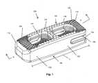
- FIG. 1is a perspective view of one form of an intervertebral implant
- FIG. 2is a top view of the intervertebral implant of FIG. 1 ;
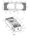
- FIG. 3is a rear perspective view of the intervertebral implant of FIG. 1 ;
- FIG. 4is an enlarged side view of a portion of the intervertebral implant of FIG. 1 ;
- FIG. 5is a side view of a further intervertebral implant
- FIG. 6is a cross-sectional view taken along line A-A of FIG. 1 ;
- FIG. 7is an enlarged perspective view of a portion of the cross-section taken along line A-A of FIG. 1 ;
- FIG. 8is an enlarged perspective view of a portion of the cross-section taken along line A-A of FIG. 1 ;
- FIG. 9is a perspective view of one form of an intervertebral implant
- FIG. 10is a top view of the intervertebral implant of FIG. 9 ;
- FIG. 11is a side view of the intervertebral implant of FIG. 9 ;
- FIG. 12is a rear perspective view of intervertebral implant of FIG. 9 ;
- FIG. 13is a perspective view of an intervertebral implant and insertion tool coupled to one end;
- FIG. 14is an enlarged side view of the intervertebral implant and insertion tool of FIG. 13 ;
- FIG. 15is an enlarged perspective view of the intervertebral implant and insertion tool of FIG. 13 ;
- FIG. 16is a cross-sectional view taken along line B-B of FIG. 15 ;
- FIG. 17is a perspective view of an intervertebral implant and insertion tool coupled to another end of the intervertebral implant;
- FIG. 18is an enlarged perspective view of the intervertebral implant and insertion tool of FIG. 17 ;
- FIG. 19is a cross-section view taken along line C-C of FIG. 18 ;
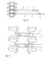
- FIG. 20is a side view of two intervertebral implants and insertion tools coupled thereto being inserted between vertebrae;
- FIG. 21is an enlarged view of the two intervertebral implants and insertion tools of FIG. 20 .
- implant 100for implantation within an intervertebral space between adjacent vertebrae, such as used during fusion surgery. More specifically, implant 100 is illustrated as having a body 102 , a superior face 104 and an inferior face 106 .
- the superior 104 and inferior 106 facesmay have a gentle convex curvature to generally match the concave curvature of the vertebrae when installed. These faces may be parallel, or inclined at an angle with respect to each other as will be understood from the description and additional embodiments described below and illustrated in the figures.
- the implantmay be configured in a ‘D’ profile, wedge profile, bullet-shaped profile and the like.
- the implantmay be configured with profiles comprising a narrower lateral dimension along its axis of insertion into the intervertebral space therein minimizing disruption to tissue.
- the devicesince the device must act as a spacer, it must provide adequate support to the superior and inferior endplates of the corresponding vertebrae such that stresses do not cause the device to subside into the endplate bone. Therefore the device should avoid unduly narrow or otherwise unstable profiles with inadequate endplate supporting surfaces. It should be noted that other shapes, sizes and the like are contemplated.
- Implant angulationmay also be orientated from a shorter first end face or nose face to a taller second end face or trailing face as in the coronal taper which will be discussed in more detail regarding other embodiments described herein.
- the slope of the implantmay be configured to correct spinal deformities wherein the bone is deformed or diseased such that one side of the intervertebral space is open wider than the other or in which one side of a vertebrae needs to be jacked up in order to realign a vertebral segment.
- the implantmay be angled or beveled along any respective face or wall to accommodate differently shaped vertebrae.
- the body 102generally includes a length (L) extending between opposite longitudinal ends 112 , 114 .
- the longitudinal end 112may be considered generally a nose end while end 114 may be considered a tail end.
- the end 112may be generally arcuate shaped, beveled or otherwise tapered to assist in distracting adjacent vertebrae during insertion.
- the end 112slopes away from or otherwise curves away from the respective superior and inferior faces 104 , 106 .
- a further implant 115is shown in FIG. 5 having a more rounded end 117 compared to end 112 .
- Other shapes and sizes of the endsare also contemplated, such as will be described below in further detail with respect to additional embodiments found in the figures.
- the body 102may also include side walls 116 , 118 , depending on the shape of the body 102 .
- the implant 100may include a plurality of different teeth, such as cortical teeth 120 and central teeth 122 .
- the cortical teeth 120 and central teeth 122may be configured and positioned to interact with different bone materials and densities as will be discussed in more detail below.
- cortical teeth 120may be positioned on one and/or both of the superior and inferior faces 104 , 106 . Further, the cortical teeth 120 may be positioned adjacent the longitudinal ends 112 , 114 so as to engage outer cortical bone when installed.
- the cortical teeth 120may include bone engaging ends 124 , such as peaks of the teeth 120 , which are configured for contacting the relatively hard cortical bone material when installed. The bone engaging ends 124 need not be sharp as they are configured for contacting the cortical bone.
- the bone engaging ends 124are flattened, as seen in FIG. 8 , or are otherwise rounded or the like to provide contact surfaces for contacting cortical bone.
- the cortical teeth 120also include valleys 126 between the teeth.
- the valleys 126may be in the form of grooves, channels and the like to help separate and define the individual cortical teeth 120 .
- the valleys 126may also be used to help define a number of different rows 128 of cortical teeth 120 .
- the cortical teeth 120may be arranged in a number of rows 128 wherein the rows are generally arranged in an arcuate manner.
- the arcuate arrangement of the cortical teethmay be configured such that the cortical teeth 120 generally conform to the expected location of the cortical bone when inserted into a patient.
- the central teeth 122include bone engaging ends 130 which are relatively sharper when compared to the cortical teeth 120 . As seen in FIGS. 7 and 8 , the bone engaging ends 130 of the cortical teeth come to a much sharper point or peak when compared to the bone engaging ends 124 of the cortical teeth 120 . In this regard, the central teeth 122 may be better suited for biting into the central bone region which is relatively softer compared to the cortical region.
- the central teethalso include valleys 132 to define the individual central teeth 122 . The valleys 132 may also take a variety of different shapes and sizes. For example, as shown in FIG.
- the valleys 132are generally bowl shaped to define the bone engaging ends 130 .
- each valley 132may be used to define a plurality of different bone engaging ends 130 or peaks.
- each valleymay be bordered by at least six different peaks or bone engaging ends 130 .
- the valleys 132are bowl-like, but are also generally hexagonal. Other forms, shapes and sizes of the bone engaging ends 130 and valleys 132 are also contemplated.
- the central teeth 122are more spaced apart from one another when compared to the cortical teeth 120 . More specifically, the bone engaging ends 130 are more spaced from one another than the bone engaging ends 124 . In this form, the bone engaging ends 130 of the central teeth 122 will be able to provide a greater force per unit area to bite into the softer central bone when compared to the bone engaging ends 124 of the cortical teeth biting into the cortical bone area. In other words, the density (number per unit area) of the cortical teeth 120 and/or the bone engaging ends 124 is greater than the density (number per unit area) of the central teeth 122 and/or the bone engaging ends 130 .
- the cortical teeth 120provide a greater ratio of contact surface area, such as the surface area of the bone engaging ends 124 , per unit area covered by the cortical teeth 120 when compared to the contact surface area, such as the surface area of the bone engaging ends 130 , per unit area covered by the central teeth 122 . Further, the average distance between adjacent engaging ends 124 of the cortical teeth is smaller than the average distance between adjacent engaging ends 130 of the central teeth.
- the cortical teeth 120 and central teeth 122may also have varying heights and otherwise may extend different distances from the respective faces 104 , 106 .
- the teeth 120 , 122extend approximately the same distance from each of the faces 104 , 106 .
- the central teeth 122extend further from the respective faces 104 , 106 when compared to the cortical teeth 120 .
- the cortical teeth 120extend further from the respective faces 104 , 106 when compared to the central teeth 122 .
- the faces 104 , 106may be curved, tapered and the like such that the teeth 120 , 122 may be relatively flat or may otherwise follow the contour of the faces 104 , 106 .
- the cortical teeth 120 and central teethmay be configured in a number of different manners to contact specific portions of bone when inserted into a patient.
- the cortical teeth 120 and central teethmay be configured in an osteo-specific tooth pattern. This pattern coincides with the bone type of the intervertebral endplate.
- the cortical teeth 120are positioned adjacent denser bone at the cortical rim of the endplate, whereas the larger and sharper central teeth 122 reside more centrally where the softer endplate bone is located.
- this osteo-specific tooth configurationmay be utilized to restrict implant movement in all directions.
- the implant 100may also include one or more throughbores 140 on an interior wall 142 of the implant body 102 .
- the throughbores 140may be configured to receive bone graft, bone substitute, or other similar material.
- a plurality of stabilizing protrusions 144may be included therein.
- the protrusions 144may take a variety of forms such as recesses, grooves, bosses, or fins formed within the throughbore 140 so as to interfere with packed graft sliding out. As found in the figures, the protrusions 144 are in the form of ridges extended generally around the circumference of the throughbore 140 .
- the protrusions 144are configured to be deep enough to stabilize the graft yet shallow enough so as to not substantially reduce the size of the throughbore 140 therein reducing the strength of the fusion.
- the throughbore 140includes a first plurality of protrusions 146 configured in a first orientation and a second plurality of protrusions 148 configured in a second orientation.
- the first and second protrusions 146 , 148are essentially the same type and form of protrusions, simply oriented in different configurations.
- the first protrusions 146include an angled surface 150 relative to the superior face 104 and a generally parallel face 152 relative to the superior face 104 .
- the angled surface 150will permit bone graft material to be inserted from the superior face 104 side of the implant 100 , but the generally parallel face 152 will impede bone graft material from exiting the throughbore 140 to the superior face 104 .
- the second plurality of protrusions 148may include similarly structured protrusions, just configured in a generally mirror image manner compared to the first plurality of protrusions 146 .
- the second plurality of protrusions 148may include an angled surface 154 relative to the inferior face 106 and a generally parallel face 156 relative to the inferior face 106 .
- the angled surface 154will permit bone graft material to be inserted from the inferior face 106 side of the implant 100 , but the generally parallel face 156 will impede bone graft material from exiting the throughbore 140 to the inferior face 106 .
- the first and second pluralities of protrusions 146 , 148are positioned and extend from a midpoint about the longitudinal length of the implant 100 .
- the generally parallel faces 152 , 156will be positioned such that they face the midpoint extending along the longitudinal axis of the implant.
- the implant 100may include a plurality of throughbores 140 , such as two throughbores 140 .
- the implant 100may include a single throughbore 140 or no throughbores 140 .
- the sizes and shapes of the throughbores 140need not be the same.
- one throughbore 140may be wider and longer than another throughbore 140 .
- different throughbores 140may have different heights, extending from the superior face 104 to the inferior face 106 .
- the body 102may include an insertion tool attachment portion 160 .
- the insertion tool attachment portion 160may be positioned at either and/or both of the ends 112 , 114 . As shown in FIGS. 1 and 3 , the insertion tool attachment portion 120 is positioned at the end 114 .
- the insertion tool attachment portion 160may comprise recesses, grooves, bosses, holes, threads, posts or other features that can be used to secure the implant 100 to an elongated instrument.
- the implant in FIG. 3utilizes a threaded hole 162 that may extend through one or more walls at the end 114 along with one or more arm pockets 164 . Together these features are configured to house the distal end of an implant inserter comprising an elongated shaft with a U-shaped end. Central to the U is a threaded rod for engagement into the threaded hole 162 to pull the implant tight to the instrument.
- the arms of the Uare spaced and configured to be received in the one or more arm pockets 164 to control rotational stability and to limit bending stress on the threaded rod from the instrument that threads into the threaded hole 162 of the implant 100 .
- FIGS. 9-12A further form of an implant is illustrated in FIGS. 9-12 . It should be noted that similar features found in this embodiment will be given similar numbers to those features previously described. More specifically, an implant 200 is provided having a body 202 , a superior face 204 and in inferior face 206 . As most readily seen in FIG. 11 , the superior 204 and inferior 206 faces may include a gentle curvature. The body 202 also includes longitudinal ends 212 , 214 .
- the facesmay be configured and positioned such that the body is somewhat tapered.
- a thin body portion 270may be at end 212 while a relatively thick body portion 272 may be at the other end 214 .
- the body 202may also include side walls 216 , 218 . As shown in FIG. 11 , the body 202 generally tapers down from end 214 towards end 212 .
- end 212is somewhat beveled or otherwise arcuate, but need not be as beveled or arcuate as the embodiment shown in FIG. 1 as end 212 is a thin portion 270 that, as a result of its shape and taper, will assist in distracting adjacent vertebrae. Therefore, end 212 may be inserted as a leading edge into a patient.
- the end 214is beveled, tapered, arcuate or otherwise configured to assist in distracting adjacent vertebrae.
- the implant 200may be considered a bi-directional implant as it may be inserted with either of end 212 or end 214 as the leading edge during insertion as either end 212 , 214 will assist in distracting adjacent vertebrae.
- implant 200may take a variety of shapes, sizes, configurations and the like.
- implant 200may also include cortical teeth 220 and central teeth 222 similar to the manner and features described above with respect to the embodiment of FIG. 1 .
- the cortical teeth 220 and central teeth 222may be configured and positioned in an osteo-specific manner to provide interact with different bone materials and densities as discussed above.
- the cortical teeth 220include bone engaging ends 224 and valleys 226 between the teeth 220 which may be used to help define a number of different rows 228 of cortical teeth 220 .
- the central teeth 222include bone engaging ends 230 which are sharper when compared to the bone engaging ends 224 of the cortical teeth 220 .
- the sizes, shapes, positioning, functionality and other features of the cortical teeth 220 and central teeth 222may be similar to those described above with respect to the embodiment of FIG. 1 .
- the implant 200may also include one or more throughbores 240 on an interior wall 242 of the implant body 202 .
- the throughbores 240may include similar features, including protrusions 244 in a similar arrangement and configuration as described above.
- the implant 200may include a longitudinal gap 274 in the thin body portion 270 open to the end 212 .
- the longitudinal gap 272may terminate at a transverse wall portion 276 that is intermediate the longitudinal ends 212 , 214 . Therefore, the longitudinal gap 272 may be a generally U-shaped gap defined by the transverse wall portion 276 and side arm portions 278 . It should be noted that the transverse wall portion 276 is positioned away from the far-most portion of end 212 so that the transverse wall portion 276 has a thickness greater than the thin body portion 270 .
- the implant 200may include one or more insertion tool attachment portions. As found in FIGS. 9-21 , the implant 200 includes two insertion tool attachment portions. A first tool attachment portion 260 may be provided at end 214 , similar to insertion tool attachment portion 160 . In this regard, the first insertion tool attachment portion 260 may include a variety of different structures to couple to an insertion tool. For example, the first insertion tool attachment portion 260 includes a threaded hole 262 and one or more arm pockets 264 . The first insertion tool attachment portion 260 may be configured in a similar manner to portion 160 described above and use a similar tool to thereby provide end 212 as an insertion leading edge.
- the implant 200may also include a second insertion tool attachment portion 290 .
- the second insertion tool attachment portion 290may be located adjacent the transverse wall portion 276 .
- the second insertion tool attachment portion 290may be configured to couple to the same tool as with the first insertion tool attachment portion 260 or a different tool.
- the second insertion tool attachment portion 290includes a threaded hole 292 and the longitudinal gap 274 for receiving an insertion tool. The transverse wall portion 276 and/or the side arm portions 278 may cooperate with the insertion tool to stabilize the implant during insertion.
- the implantsmay be configured to be cooperable with a number of instruments to allow a surgeon to implant and manipulate the implant. Exemplary forms of such tools are depicted in FIGS. 13-21 .
- a first insertion tool 300is configured for cooperating with a first end of the implant, such as end 212 .
- a second insertion tool 302may be configured to cooperating with a second end of the implant, such as end 214 .
- the tools 300 , 302are generally symmetrical in the horizontal direction, though it may alternatively be asymmetrical so that a particular relative orientation is required for coupling the implant and the insertion tool 300 , 302 .
- the insertion tools 300 , 302may be used to insert the implant within the intervertebral space, and may be used for manipulation of the implant within the intervertebral space. To enable this, a distal end 320 , 322 of the insertion tools 300 , 302 and the implant are coupled in a releasable fixed orientation. The insertion tool distal ends 320 , 322 and the implant are coupled so that a surgeon may apply force to the insertion tool 300 , 302 without the implant separating therefrom.
- the insertion tools 300 , 302have a handle portion 330 , 332 allowing a surgeon to manipulate the coupled implant 200 and insertion tool 300 , 302 .
- Extending from the handle portion 330 , 332is a shaft portion 334 , 336 including a sheath portion 338 , 340 with the distal ends 320 , 322 engageable with the respective insertion tool attachment portions of the implant 200 .
- the sheath portions 338 , 340includes a longitudinal throughbore 342 , 344 in which a rod 346 , 348 is received.
- the rods 346 , 348have an outer diameter sized to permit the rod 346 , 348 to easily rotate or reciprocate within the throughbores 342 , 344 .
- the insertion tool distal ends 320 , 322are coupled with the implant 200 by engaging the rod 346 , 348 and the distal end 320 , 322 in the respective insertion tool attachment portions 260 , 290 .
- the rod 346may be coupled to the threaded hole 292 while the rod 348 may be coupled to the threaded hole 262 .
- the distal end 322includes a pair of curved arms 400 extending outward from the distal end 322 forming a crescent-like structure which may be received by the arm pockets 264 .
- the distal end 320may include arms 402 which may be configured to couple to the longitudinal gap 274 , the transverse wall portion 276 and/or the side arm portions 278 .
- intervertebral fusion devicesDue to the anatomy of a patient, it is common and desirable to implant intervertebral fusion devices from an anterior or posterior-lateral direction, that is, from a direction offset from the lateral or anterior-posterior sides.
- the implantis inserted into the intervertebral space from this direction, and then the implant is manipulated into the desired orientation during insertion of the implant into the intervertebral space.
- the implantis configured to lateral surgical entry.
- the body of the implanthas a height (H) which is sized upon insertion to return the intervertebral disc spacing to a height substantially the same as when spaced by a healthy intervertebral disc.
- the devicehas a length (L) substantially the lateral width of the vertebral endplate.
- the devicealso has a width (W) that is substantially less than the anterior to posterior length of the vertebral endplate and further sized for insertion down an elongated corridor to the surgical site.
- the implant 200which may be bi-directional, can be inserted from either end of the implant 200 .
- a patient having a deformity requiring a coronal implant with first end 212 leading on one level and second end or trailing end 214 leading on adjacent levelcould place both implants from the same incision site.
- a coronal implant with instrument attachment only at the second end or trailing endwould require the surgeon to create a second incision on the contralateral side.
- the implants described hereinmay also comprise additional features such as one or more marker sites 180 , 280 .
- the marker sites 180 , 280may be in the form of a hole for the placement of a tantalum marker for viewing through X-ray or other imaging device.
- the marker pin orientationconfirms anterior/posterior alignment when a ‘T’ shape is made with the pins.
- These markers 180 , 280allow a surgeon to use radiographic equipment to identify the location and orientation of the implant within the intervertebral space, including identifying the height, length, and width of the implant. Utilizing the radiographic markers, a determination can be made as to whether adjustments to the position of the implant are necessary or desirable.
- the implant devices described hereinmay be fabricated from any suitable materials having desirable strength and biocompatibility.
- suitable materialsmay include, for example, biocompatible metals and related alloys (such as titanium and stainless steel), shape memory metals (such as Nitinol), biocompatible polymers (including, for example, materials of the polyaryletherketone family such as PEEK (polyetheretherketone), PAEK (polyaryletherketone), PEK (polyetherketone), PEKK (polyetherketoneketone), PEKEKK (polyetherketoneetherketoneketone), PEEKK (polyetheretherketoneketone), and PAEEK (polyaryletheretherketone), filled materials (such as carbon or glass fiber-reinforced materials), bone substitute materials (such as hydroxyapatite and tricalcium phosphate), composite materials, and/or any combination of the above.
- biocompatible metals and related alloyssuch as titanium and stainless steel
- shape memory metalssuch as Nitinol
- biocompatible polymersincluding,
- the implant devicesare formed of a PEEK-type material.
- the implant devicemay be formed, in whole or in part, or coated with a calcium phosphate ceramic bone substitute such as hydroxyapatite, tricalcium phosphate, and/or mixtures thereof.
- a calcium phosphate ceramic bone substitutesuch as hydroxyapatite, tricalcium phosphate, and/or mixtures thereof.
- Particularly preferred hydroxyapatite and tricalcium phosphate compositionsinclude those disclosed in, for example, U.S. Pat. No. 6,013,591, U.S. Pat. No. RE 39,196, and U.S. Patent Application Publication No. 2005/0031704, which are hereby incorporated in their entirety herein.
- Coating with the calcium phosphate ceramicscan be achieved by any known method, including dip coating-sintering, immersion coating, electrophoretic deposition, hot isostatic pressing, solution deposition, ion-beam sputter coating and dynamic mixing, thermal spraying techniques such as plasma spraying, flame spraying and high-velocity oxy-fuel combustion spraying.
- hydroxyapatite coatingis achieved by plasma spraying.
- the implant devicemay be formed of a PEEK-type material and coated with such a bone substitute material.
- the implant devicemay be formed, in whole or in part, coated with, injected with, incorporate, and/or retain a bone growth stimulating composition such as the bioactive hydrogel matrix described, for example, in U.S. Pat. No. 6,231,881, U.S. Pat. No. 6,730,315, U.S. Pat. No. 6,315,994, U.S. Pat. No. 6,713,079, U.S. Pat. No. 6,261,587, U.S. Pat. No. 5,824,331, U.S. Pat. No. 6,068,974, U.S. Pat. No.
- the implant device of the inventionmay be formed of two distinct materials.
- bone graft materialmay be utilized with the implants to help fuse vertebrae.
- exemplary artificial bone graft materialincludes calcium phosphates (such as hydroxyapatite and tri-calcium phosphate).
- suitable materialsincludes those described in U.S. Pat. No. 6,013,591, J. Y. Ying, E. S. Ahn, and A. Nakahira, “Nanocrystalline apatites and composites, prostheses incorporating them, and method for their production,” which is incorporated by reference in its entirety herein.
- Another exemplary materialis described in U.S. Pat. No. RE 39,196 E, Jackie Y. Ying, Edward S. Ahn, and Atsushi Nakahira, “Nanocrystalline apatites and composites, prostheses incorporating them, and method for their production,” which is incorporated by reference in its entirety herein.
Landscapes
- Health & Medical Sciences (AREA)
- Engineering & Computer Science (AREA)
- Biomedical Technology (AREA)
- Orthopedic Medicine & Surgery (AREA)
- Neurology (AREA)
- Transplantation (AREA)
- Oral & Maxillofacial Surgery (AREA)
- Cardiology (AREA)
- Heart & Thoracic Surgery (AREA)
- Vascular Medicine (AREA)
- Life Sciences & Earth Sciences (AREA)
- Animal Behavior & Ethology (AREA)
- General Health & Medical Sciences (AREA)
- Public Health (AREA)
- Veterinary Medicine (AREA)
- Physical Education & Sports Medicine (AREA)
- Prostheses (AREA)
Abstract
Description
Claims (15)
Priority Applications (5)
| Application Number | Priority Date | Filing Date | Title |
|---|---|---|---|
| US15/176,707US9883949B2 (en) | 2011-10-07 | 2016-06-08 | Intervertebral implant |
| US15/886,164US10182920B2 (en) | 2011-10-07 | 2018-02-01 | Intervertebral implant |
| US16/228,858US10869767B2 (en) | 2011-10-07 | 2018-12-21 | Intervertebral implant |
| US17/128,996US11654031B2 (en) | 2011-10-07 | 2020-12-21 | Intervertebral implant |
| US18/322,587US12144741B2 (en) | 2011-10-07 | 2023-05-23 | Intervertebral implant |
Applications Claiming Priority (4)
| Application Number | Priority Date | Filing Date | Title |
|---|---|---|---|
| US201161545030P | 2011-10-07 | 2011-10-07 | |
| US13/648,086US9132021B2 (en) | 2011-10-07 | 2012-10-09 | Intervertebral implant |
| US14/734,764US9387092B2 (en) | 2011-10-07 | 2015-06-09 | Intervertebral implant |
| US15/176,707US9883949B2 (en) | 2011-10-07 | 2016-06-08 | Intervertebral implant |
Related Parent Applications (1)
| Application Number | Title | Priority Date | Filing Date |
|---|---|---|---|
| US14/734,764ContinuationUS9387092B2 (en) | 2011-10-07 | 2015-06-09 | Intervertebral implant |
Related Child Applications (1)
| Application Number | Title | Priority Date | Filing Date |
|---|---|---|---|
| US15/886,164ContinuationUS10182920B2 (en) | 2011-10-07 | 2018-02-01 | Intervertebral implant |
Publications (2)
| Publication Number | Publication Date |
|---|---|
| US20160278934A1 US20160278934A1 (en) | 2016-09-29 |
| US9883949B2true US9883949B2 (en) | 2018-02-06 |
Family
ID=48042569
Family Applications (7)
| Application Number | Title | Priority Date | Filing Date |
|---|---|---|---|
| US13/648,086Active - Reinstated2033-01-17US9132021B2 (en) | 2011-10-07 | 2012-10-09 | Intervertebral implant |
| US14/734,764ActiveUS9387092B2 (en) | 2011-10-07 | 2015-06-09 | Intervertebral implant |
| US15/176,707ActiveUS9883949B2 (en) | 2011-10-07 | 2016-06-08 | Intervertebral implant |
| US15/886,164ActiveUS10182920B2 (en) | 2011-10-07 | 2018-02-01 | Intervertebral implant |
| US16/228,858Active2032-10-17US10869767B2 (en) | 2011-10-07 | 2018-12-21 | Intervertebral implant |
| US17/128,996Active2033-05-08US11654031B2 (en) | 2011-10-07 | 2020-12-21 | Intervertebral implant |
| US18/322,587ActiveUS12144741B2 (en) | 2011-10-07 | 2023-05-23 | Intervertebral implant |
Family Applications Before (2)
| Application Number | Title | Priority Date | Filing Date |
|---|---|---|---|
| US13/648,086Active - Reinstated2033-01-17US9132021B2 (en) | 2011-10-07 | 2012-10-09 | Intervertebral implant |
| US14/734,764ActiveUS9387092B2 (en) | 2011-10-07 | 2015-06-09 | Intervertebral implant |
Family Applications After (4)
| Application Number | Title | Priority Date | Filing Date |
|---|---|---|---|
| US15/886,164ActiveUS10182920B2 (en) | 2011-10-07 | 2018-02-01 | Intervertebral implant |
| US16/228,858Active2032-10-17US10869767B2 (en) | 2011-10-07 | 2018-12-21 | Intervertebral implant |
| US17/128,996Active2033-05-08US11654031B2 (en) | 2011-10-07 | 2020-12-21 | Intervertebral implant |
| US18/322,587ActiveUS12144741B2 (en) | 2011-10-07 | 2023-05-23 | Intervertebral implant |
Country Status (1)
| Country | Link |
|---|---|
| US (7) | US9132021B2 (en) |
Cited By (3)
| Publication number | Priority date | Publication date | Assignee | Title |
|---|---|---|---|---|
| US10869767B2 (en) | 2011-10-07 | 2020-12-22 | Pioneer Surgical Technology, Inc. | Intervertebral implant |
| USD907771S1 (en) | 2017-10-09 | 2021-01-12 | Pioneer Surgical Technology, Inc. | Intervertebral implant |
| US11147682B2 (en) | 2017-09-08 | 2021-10-19 | Pioneer Surgical Technology, Inc. | Intervertebral implants, instruments, and methods |
Families Citing this family (71)
| Publication number | Priority date | Publication date | Assignee | Title |
|---|---|---|---|---|
| WO2014015309A1 (en) | 2012-07-20 | 2014-01-23 | Jcbd, Llc | Orthopedic anchoring system and methods |
| CA3002234C (en) | 2010-01-13 | 2020-07-28 | Jcbd, Llc | Sacroiliac joint fixation fusion system |
| US9381045B2 (en) | 2010-01-13 | 2016-07-05 | Jcbd, Llc | Sacroiliac joint implant and sacroiliac joint instrument for fusing a sacroiliac joint |
| US9421109B2 (en) | 2010-01-13 | 2016-08-23 | Jcbd, Llc | Systems and methods of fusing a sacroiliac joint |
| US9333090B2 (en) | 2010-01-13 | 2016-05-10 | Jcbd, Llc | Systems for and methods of fusing a sacroiliac joint |
| EP2720628B1 (en) | 2011-06-17 | 2021-08-11 | Jcbd, Llc | Sacroiliac joint implant system |
| US8771354B2 (en) | 2011-10-26 | 2014-07-08 | George J. Picha | Hard-tissue implant |
| US9220607B2 (en)* | 2011-10-28 | 2015-12-29 | Warsaw Oorthopedic, Inc. | Pivotable interbody implant system |
| US9198769B2 (en) | 2011-12-23 | 2015-12-01 | Pioneer Surgical Technology, Inc. | Bone anchor assembly, bone plate system, and method |
| US9492288B2 (en)* | 2013-02-20 | 2016-11-15 | Flexuspine, Inc. | Expandable fusion device for positioning between adjacent vertebral bodies |
| US8900312B2 (en) | 2013-03-12 | 2014-12-02 | Spine Wave, Inc. | Expandable interbody fusion device with graft chambers |
| US8828019B1 (en) | 2013-03-13 | 2014-09-09 | Spine Wave, Inc. | Inserter for expanding an expandable interbody fusion device |
| US10245087B2 (en) | 2013-03-15 | 2019-04-02 | Jcbd, Llc | Systems and methods for fusing a sacroiliac joint and anchoring an orthopedic appliance |
| US9717539B2 (en) | 2013-07-30 | 2017-08-01 | Jcbd, Llc | Implants, systems, and methods for fusing a sacroiliac joint |
| US11311312B2 (en) | 2013-03-15 | 2022-04-26 | Medtronic, Inc. | Subcutaneous delivery tool |
| WO2014146018A1 (en) | 2013-03-15 | 2014-09-18 | Jcbd, Llc | Systems and methods for fusing a sacroiliac joint and anchoring an orthopedic appliance |
| US9826986B2 (en) | 2013-07-30 | 2017-11-28 | Jcbd, Llc | Systems for and methods of preparing a sacroiliac joint for fusion |
| US9700356B2 (en) | 2013-07-30 | 2017-07-11 | Jcbd, Llc | Systems for and methods of fusing a sacroiliac joint |
| US20160095710A1 (en)* | 2013-05-07 | 2016-04-07 | Ceramtec Gmbh | Implants comprising anchoring elements |
| US9295565B2 (en) | 2013-10-18 | 2016-03-29 | Spine Wave, Inc. | Method of expanding an intradiscal space and providing an osteoconductive path during expansion |
| EP3110352B1 (en) | 2014-02-25 | 2023-03-29 | Refai Technologies, LLC | Spinal cage device, system, and methods of assembly and use |
| US20150250610A1 (en)* | 2014-03-04 | 2015-09-10 | DePuy Synthes Products, LLC | Post-Operative Bone Grown Stimulant Introduction Method |
| US9107766B1 (en) | 2014-03-06 | 2015-08-18 | Spine Wave, Inc. | Expandable spinal interbody fusion device and inserter |
| US11065132B2 (en) | 2014-03-06 | 2021-07-20 | Spine Wave, Inc. | Method of expanding a space between opposing tissue surfaces |
| US9439783B2 (en) | 2014-03-06 | 2016-09-13 | Spine Wave, Inc. | Inserter for expanding body tissue |
| US9445921B2 (en) | 2014-03-06 | 2016-09-20 | Spine Wave, Inc. | Device for expanding and supporting body tissue |
| US9265623B2 (en) | 2014-03-06 | 2016-02-23 | Spine Wave, Inc. | Method of expanding a spinal interbody fusion device |
| KR101632908B1 (en)* | 2014-03-12 | 2016-07-01 | 주식회사 디오메디칼 | Cage assembly for spine interbody fusion |
| US9801546B2 (en) | 2014-05-27 | 2017-10-31 | Jcbd, Llc | Systems for and methods of diagnosing and treating a sacroiliac joint disorder |
| US9498351B2 (en)* | 2014-06-04 | 2016-11-22 | Spine Wave, Inc. | Apparatus for locating the position of a spinal implant during surgery |
| US9649200B2 (en)* | 2014-07-28 | 2017-05-16 | Wasaw Orthopedic, Inc. | Spinal implant system and method |
| US11090168B2 (en)* | 2014-08-29 | 2021-08-17 | Newsouth Innovations Pty Limited | Fusion device |
| EP3393403A4 (en)* | 2015-12-24 | 2020-03-04 | NewSouth Innovations Pty Limited | Devices for bone integration |
| US10426631B2 (en)* | 2016-02-20 | 2019-10-01 | Seth K. WILLIAMS | System and method for spine fusion using an expandable cage |
| US10292834B2 (en)* | 2016-06-27 | 2019-05-21 | Globus Medical, Inc. | Intervertebral spacer with chamfered edges |
| US10292825B2 (en)* | 2016-06-27 | 2019-05-21 | Globus Medical, Inc. | Intervertebral spacer with chamfered edges |
| FR3061651A1 (en)* | 2017-01-06 | 2018-07-13 | Kisco International | INTERSOMATIC IMPLANT WITH SIDE SUPPORT PORTIONS |
| EP3592283B1 (en) | 2017-03-10 | 2024-05-08 | Alps Holding Llc | Hard-tissue implant comprising a bulk implant, a face, pillars, slots, and at least one support member |
| US11324606B2 (en)* | 2017-03-10 | 2022-05-10 | Gary A. Zwick | Spinal interbody cage comprising a bulk interbody cage, a top face, a bottom face, pillars, and slots |
| US10624760B2 (en)* | 2017-05-22 | 2020-04-21 | Warsaw Orthopedic, Inc. | Spinal implant system and method |
| US10603055B2 (en) | 2017-09-15 | 2020-03-31 | Jcbd, Llc | Systems for and methods of preparing and fusing a sacroiliac joint |
| CN108056845A (en)* | 2017-12-15 | 2018-05-22 | 深圳清华大学研究院 | A kind of dypass lumbar intervertebral fusion device |
| US11806250B2 (en) | 2018-02-22 | 2023-11-07 | Warsaw Orthopedic, Inc. | Expandable spinal implant system and method of using same |
| EP3755273B1 (en) | 2018-02-22 | 2025-04-30 | Warsaw Orthopedic, Inc. | Expandable spinal implant system |
| CN111655203A (en) | 2018-02-22 | 2020-09-11 | 华沙整形外科股份有限公司 | Expandable spinal implant system and method of use |
| US11278427B2 (en) | 2018-04-10 | 2022-03-22 | Gary A. Zick, Trustee Of The Everest Trust Uta April 20, 2017 | Spinal interbody cage comprising top and bottom faces with mesh structures, pillars and slots |
| FR3094203B1 (en) | 2019-03-26 | 2021-03-05 | Orthopaedic & Spine Dev Osd | Interbody prosthesis with lateral introduction |
| USD955579S1 (en) | 2019-04-26 | 2022-06-21 | Warsaw Orthopedic, Inc. | Surgical implant |
| USD948048S1 (en) | 2019-04-26 | 2022-04-05 | Warsaw Orthopedic, Inc. | Surgical implant |
| JP7335428B2 (en) | 2019-09-11 | 2023-08-29 | アルプス ホールディング エルエルシー | An implant comprising a first set and a second set of pillars for attaching a tendon or ligament to hard tissue |
| IT202000014587A1 (en)* | 2020-06-18 | 2021-12-18 | Sps S R L | INTERSOMATIC CAGE FOR VERTEBRAL STABILIZATION |
| US12239544B2 (en) | 2020-11-05 | 2025-03-04 | Warsaw Orthopedic, Inc. | Rhomboid shaped implants |
| US11291554B1 (en) | 2021-05-03 | 2022-04-05 | Medtronic, Inc. | Unibody dual expanding interbody implant |
| US11285014B1 (en) | 2020-11-05 | 2022-03-29 | Warsaw Orthopedic, Inc. | Expandable inter-body device, system, and method |
| US11963881B2 (en) | 2020-11-05 | 2024-04-23 | Warsaw Orthopedic, Inc. | Expandable inter-body device, system, and method |
| US12318308B2 (en) | 2020-11-05 | 2025-06-03 | Warsaw Orthopedic, Inc. | Dual expandable inter-body device |
| US11638653B2 (en) | 2020-11-05 | 2023-05-02 | Warsaw Orthopedic, Inc. | Surgery instruments with a movable handle |
| US11395743B1 (en) | 2021-05-04 | 2022-07-26 | Warsaw Orthopedic, Inc. | Externally driven expandable interbody and related methods |
| US11376134B1 (en) | 2020-11-05 | 2022-07-05 | Warsaw Orthopedic, Inc. | Dual expanding spinal implant, system, and method of use |
| US12171439B2 (en) | 2020-11-05 | 2024-12-24 | Warsaw Orthopedic, Inc. | Protected drill |
| US11833059B2 (en) | 2020-11-05 | 2023-12-05 | Warsaw Orthopedic, Inc. | Expandable inter-body device, expandable plate system, and associated methods |
| US11517363B2 (en) | 2020-11-05 | 2022-12-06 | Warsaw Orthopedic, Inc. | Screw driver and complimentary screws |
| US12121453B2 (en) | 2020-11-05 | 2024-10-22 | Warsaw Orthopedic, Inc. | Dual wedge expandable implant with eyelets, system, and method of use |
| US11517443B2 (en) | 2020-11-05 | 2022-12-06 | Warsaw Orthopedic, Inc. | Dual wedge expandable implant, system and method of use |
| US12295865B2 (en) | 2021-06-24 | 2025-05-13 | Warsaw Orthopedic, Inc. | Expandable interbody implant and corresponding inserter |
| WO2022271280A1 (en) | 2021-06-24 | 2022-12-29 | Warsaw Orthopedic, Inc. | Expandable interbody implant and corresponding surgical tool |
| US11612499B2 (en) | 2021-06-24 | 2023-03-28 | Warsaw Orthopedic, Inc. | Expandable interbody implant |
| US12268614B2 (en) | 2021-06-24 | 2025-04-08 | Warsaw Orthopedic, Inc. | Interbody implant with adjusting shims |
| US11730608B2 (en) | 2021-07-13 | 2023-08-22 | Warsaw Orthopedic, Inc. | Monoblock expandable interbody implant |
| WO2023285675A1 (en) | 2021-07-16 | 2023-01-19 | Blue Ocean Spine Gmbh | Adjustable intervertebral cage, associated instrument and manufacturing process therefor |
| US11850163B2 (en) | 2022-02-01 | 2023-12-26 | Warsaw Orthopedic, Inc. | Interbody implant with adjusting shims |
Citations (159)
| Publication number | Priority date | Publication date | Assignee | Title |
|---|---|---|---|---|
| US4349921A (en) | 1980-06-13 | 1982-09-21 | Kuntz J David | Intervertebral disc prosthesis |
| US4834757A (en) | 1987-01-22 | 1989-05-30 | Brantigan John W | Prosthetic implant |
| US5314477A (en) | 1990-03-07 | 1994-05-24 | J.B.S. Limited Company | Prosthesis for intervertebral discs and instruments for implanting it |
| US5370697A (en) | 1992-04-21 | 1994-12-06 | Sulzer Medizinaltechnik Ag | Artificial intervertebral disk member |
| US5474558A (en) | 1992-04-30 | 1995-12-12 | Neubardt; Seth L. | Procedure and system for spinal pedicle screw insertion |
| US5609635A (en) | 1988-06-28 | 1997-03-11 | Michelson; Gary K. | Lordotic interbody spinal fusion implants |
| US5614205A (en) | 1992-02-24 | 1997-03-25 | Encelle, Inc. | Bioartificial endocrine device |
| US5766252A (en) | 1995-01-24 | 1998-06-16 | Osteonics Corp. | Interbody spinal prosthetic implant and method |
| US5772661A (en) | 1988-06-13 | 1998-06-30 | Michelson; Gary Karlin | Methods and instrumentation for the surgical correction of human thoracic and lumbar spinal disease from the antero-lateral aspect of the spine |
| US5776199A (en) | 1988-06-28 | 1998-07-07 | Sofamor Danek Properties | Artificial spinal fusion implants |
| US5797909A (en) | 1988-06-13 | 1998-08-25 | Michelson; Gary Karlin | Apparatus for inserting spinal implants |
| US5824331A (en) | 1992-02-24 | 1998-10-20 | Encelle, Inc. | Bioartificial devices and cellular matrices therefor |
| US5865845A (en) | 1996-03-05 | 1999-02-02 | Thalgott; John S. | Prosthetic intervertebral disc |
| US5888227A (en) | 1995-10-20 | 1999-03-30 | Synthes (U.S.A.) | Inter-vertebral implant |
| US5922339A (en) | 1998-01-27 | 1999-07-13 | Usala; Anton-Lewis | Compositions and methods for biocompatible implants |
| US6013591A (en) | 1997-01-16 | 2000-01-11 | Massachusetts Institute Of Technology | Nanocrystalline apatites and composites, prostheses incorporating them, and method for their production |
| US6068974A (en) | 1998-04-29 | 2000-05-30 | Klann; Richard Chris | Specific, highly sensitive, nested PCR detection scheme for the pseudorabies virus |
| WO2000038574A1 (en) | 1998-12-23 | 2000-07-06 | Nuvasive, Inc. | Nerve surveillance cannulae systems |
| JP2000210316A (en) | 1999-01-25 | 2000-08-02 | Ngk Spark Plug Co Ltd | Rasp for intervertebral spacer |
| US6132465A (en) | 1998-06-04 | 2000-10-17 | Raymedica, Inc. | Tapered prosthetic spinal disc nucleus |
| US6231881B1 (en) | 1992-02-24 | 2001-05-15 | Anton-Lewis Usala | Medium and matrix for long-term proliferation of cells |
| WO2001037728A1 (en) | 1999-11-24 | 2001-05-31 | Nuvasive, Inc. | Electromyography system |
| US6277149B1 (en) | 1999-06-08 | 2001-08-21 | Osteotech, Inc. | Ramp-shaped intervertebral implant |
| EP1138285A1 (en) | 2000-03-29 | 2001-10-04 | Implant Design AG | Spinal cage for insertion between the vertebraes of the spine |
| US20010047208A1 (en) | 1999-12-08 | 2001-11-29 | Michelson Gary K. | Spinal implant surface configuration |
| US20010049560A1 (en) | 1998-01-30 | 2001-12-06 | Paul David C. | Intervertebral allograft spacer |
| US6352707B1 (en) | 1992-02-24 | 2002-03-05 | Anton-Lewis Usala | Transplant encapsulation in a hydrogel matrix to obscure immune recognition |
| WO2002038086A1 (en) | 2000-11-07 | 2002-05-16 | Medicrea | Intervertebral cage and instrument for setting same between two vertebrae |
| US20020087212A1 (en) | 2000-12-29 | 2002-07-04 | James Stephen B. | Spinal implant |
| US6458159B1 (en) | 2000-08-15 | 2002-10-01 | John S. Thalgott | Disc prosthesis |
| US20020151894A1 (en) | 1997-12-12 | 2002-10-17 | Tony Melkent | Image guided spinal surgery guide, system, and method for use thereof |
| US6482233B1 (en) | 1998-01-29 | 2002-11-19 | Synthes(U.S.A.) | Prosthetic interbody spacer |
| FR2827157A1 (en) | 2001-07-10 | 2003-01-17 | Vitatech | Intersomatic implant for stabilizing cervical vertebrae has main upper and lower faces with convex curvature in two directions |
| WO2003005887A2 (en) | 2001-07-11 | 2003-01-23 | Nuvasive, Inc. | System and methods for determining nerve proximity, direction, and pathology during surgery |
| US20030083748A1 (en) | 2001-10-30 | 2003-05-01 | Lee Chong Suh | Intervertebral fusion cage |
| US6582453B1 (en)* | 2000-07-14 | 2003-06-24 | Opus Medical, Inc. | Method and apparatus for attaching connective tissues to bone using a suture anchoring device |
| US20030135275A1 (en) | 2001-11-09 | 2003-07-17 | Javier Garcia | Instruments and methods for inserting a spinal implant |
| US20030181981A1 (en) | 2000-05-11 | 2003-09-25 | Jean-Philippe Lemaire | Anterior lumbar interbody implant |
| US6676703B2 (en) | 1999-02-25 | 2004-01-13 | Depuy Acromed, Inc. | Spinal fusion implant |
| US6719794B2 (en) | 2001-05-03 | 2004-04-13 | Synthes (U.S.A.) | Intervertebral implant for transforaminal posterior lumbar interbody fusion procedure |
| US20040082999A1 (en) | 2001-01-30 | 2004-04-29 | Robert Mathys | Bone implant, in particular, an inter-vertebral implant |
| US6746484B1 (en) | 1997-08-26 | 2004-06-08 | Society De Fabrication De Materiel De Orthopedique, S.A. | Spinal implant |
| US20040127994A1 (en) | 2002-10-16 | 2004-07-01 | Erich Kast | Implant for placement between vertebrae |
| US20040127993A1 (en) | 2002-10-16 | 2004-07-01 | Erich Kast | Spreader implant for placement between vertebrae |
| US6790455B2 (en) | 2001-09-14 | 2004-09-14 | The Research Foundation At State University Of New York | Cell delivery system comprising a fibrous matrix and cells |
| DE10309702A1 (en) | 2003-03-06 | 2004-09-16 | Fehling Instruments Gmbh | Intervertebral disc prosthesis for the cervical spine |
| US6843805B2 (en) | 1996-09-04 | 2005-01-18 | Synthes (U.S.A.) | Intervertebral implant |
| US20050031704A1 (en) | 2003-08-06 | 2005-02-10 | Angstrom Medica | Tricalcium phosphates, their composites, implants incorporating them, and method for their production |
| US6872208B1 (en) | 2000-10-06 | 2005-03-29 | Spinal Concepts, Inc. | Adjustable transverse connector |
| US20050071005A1 (en) | 2003-09-30 | 2005-03-31 | Olivier Carli | Intersomatic lumbar implant |
| US6890355B2 (en) | 2001-04-02 | 2005-05-10 | Gary K. Michelson | Artificial contoured spinal fusion implants made of a material other than bone |
| US20050118230A1 (en) | 2003-10-22 | 2005-06-02 | Encelle, Inc. | Methods and compositions for regenerating connective tissue |
| US20050143820A1 (en) | 2003-12-02 | 2005-06-30 | St. Francis Medical Technologies, Inc. | Method of laterally inserting an artificial vertebral disk replacement implant with translating pivot point |
| US20050143822A1 (en) | 2003-12-29 | 2005-06-30 | Paul David C. | Spinal fusion implant |
| WO2005077307A1 (en) | 2004-02-11 | 2005-08-25 | Biomet Deutschland Gmbh | Intervertebral implant |
| US6964687B1 (en) | 1999-07-09 | 2005-11-15 | Scient'x | Anatomical interbody implant and gripper for same |
| US6974480B2 (en) | 2001-05-03 | 2005-12-13 | Synthes (Usa) | Intervertebral implant for transforaminal posterior lumbar interbody fusion procedure |
| US6979353B2 (en) | 2001-12-03 | 2005-12-27 | Howmedica Osteonics Corp. | Apparatus for fusing adjacent bone structures |
| US6991654B2 (en) | 2002-10-21 | 2006-01-31 | Sdgi Holdings, Inc. | Systems and techniques for restoring and maintaining intervertebral anatomy |
| US7018416B2 (en) | 2000-07-06 | 2006-03-28 | Zimmer Spine, Inc. | Bone implants and methods |
| EP1698305A1 (en) | 2005-09-06 | 2006-09-06 | Orthopaedic & Spine Development | Deformable intervertebral prosthesis |
| US20060217807A1 (en) | 2005-03-28 | 2006-09-28 | Peterman Marc M | Spinal device including lateral approach |
| US7125425B2 (en) | 2002-10-21 | 2006-10-24 | Sdgi Holdings, Inc. | Systems and techniques for restoring and maintaining intervertebral anatomy |
| US20070027544A1 (en) | 2005-07-28 | 2007-02-01 | Altiva Corporation | Spinal cage implant |
| US7217293B2 (en) | 2003-11-21 | 2007-05-15 | Warsaw Orthopedic, Inc. | Expandable spinal implant |
| US20070162138A1 (en) | 2005-12-12 | 2007-07-12 | Sdgi Holdings, Inc. | Vertebral implant and insertion tool |
| US7303583B1 (en) | 1999-08-27 | 2007-12-04 | Synthes (U.S.A.) | Intervertebral implant |
| US20070293949A1 (en) | 2004-10-08 | 2007-12-20 | Salerni Anthony A | Interior connecting interbody cage insertional tools, methods and devices |
| US20070293948A1 (en) | 2001-12-12 | 2007-12-20 | Vita Special Purpose Corporation | Bioactive Spinal Implants and Method of Manufacture Thereof |
| US20080009945A1 (en) | 2006-06-28 | 2008-01-10 | Pacheco Hector O | Apparatus and methods for templating and placement of artificial discs |
| US7326251B2 (en) | 2003-04-01 | 2008-02-05 | Sdgi Holdings, Inc. | Interbody fusion device |
| US20080065219A1 (en) | 2006-09-08 | 2008-03-13 | Justin Dye | Offset radius lordosis |
| US20080154377A1 (en) | 2006-12-22 | 2008-06-26 | Voellmicke John C | Composite vertebral spacers and instrument |
| US20080188940A1 (en) | 2007-02-01 | 2008-08-07 | Zimmer Spine, Inc. | Spinal Implant |
| US20080200985A1 (en) | 2007-02-19 | 2008-08-21 | Zimmer Spine, Inc. | Spinal implant |
| US20080208342A1 (en) | 2007-02-27 | 2008-08-28 | Zimmer Spine, Inc. | Spinal implant |
| US20080221695A1 (en) | 2007-03-01 | 2008-09-11 | Jacofsky Marc C | Spinal interbody spacer device |
| US20080234828A1 (en) | 2007-03-19 | 2008-09-25 | Aesculap Ag & Co. Kg | Implant |
| US20080243252A1 (en) | 2007-04-02 | 2008-10-02 | Centra-Fuse, Inc. | Spinal implant system |
| US20080288076A1 (en) | 2006-09-27 | 2008-11-20 | Teck Soo | Spinal interbody spacer |
| US20080306598A1 (en) | 2007-04-02 | 2008-12-11 | Eric Hansen | Spinal implant with biologic sponge |
| US7479160B2 (en) | 1998-10-28 | 2009-01-20 | Warsaw Orthopedic, Inc. | Interbody fusion grafts and instrumentation |
| US20090030519A1 (en) | 2002-10-23 | 2009-01-29 | Falahee Mark H | Intervertebral cage designs |
| US20090062917A1 (en) | 2007-08-27 | 2009-03-05 | Foley Kevin T | Spinal interbody replacement devices |
| US20090105824A1 (en) | 2007-10-19 | 2009-04-23 | Jones Robert J | Spinal fusion device and associated methods |
| US20090105825A1 (en) | 2007-10-19 | 2009-04-23 | Greg Foreman | Fusion methods using autologous stem cells |
| EP2085056A2 (en) | 2006-04-28 | 2009-08-05 | Concept Matrix, LLC | Dual composition vertebral fixation device |
| US20090248163A1 (en) | 2008-03-31 | 2009-10-01 | King Emily E | Spinal surgery interbody |
| US20090276049A1 (en) | 2005-01-28 | 2009-11-05 | Peter Weiland | Implant for Transforaminal Intracorporeal Fusion |
| US20090299479A1 (en) | 2007-10-19 | 2009-12-03 | Jones Robert J | Suture guided implant |
| US7641690B2 (en) | 2004-08-23 | 2010-01-05 | Abdou M Samy | Bone fixation and fusion device |
| US7662186B2 (en) | 2005-05-06 | 2010-02-16 | Titan Spine, Llc | Anterior interbody spinal implant |
| US20100070039A1 (en) | 2008-09-16 | 2010-03-18 | Jeffrey Allen Guyer | Interbody spacer |
| US20100076559A1 (en) | 2007-05-04 | 2010-03-25 | Titan Spine, Llc | Composite telescoping anterior interbody spinal implant |
| US20100191337A1 (en) | 2006-03-08 | 2010-07-29 | Seaspine, Inc. | Interbody device for spinal applications |
| US20100204798A1 (en) | 2005-10-21 | 2010-08-12 | Stryker Spine | System and method for fusion cage implantation |
| US7776095B2 (en) | 2005-03-28 | 2010-08-17 | Warsaw Orthopedic, Inc. | Spinal system and method including lateral approach |
| US20100228296A1 (en) | 2009-03-04 | 2010-09-09 | Robert Tod Vraney | Implant for mammalian bony segment stabilization |
| US7824427B2 (en) | 2007-01-16 | 2010-11-02 | Perez-Cruet Miquelangelo J | Minimally invasive interbody device |
| US7850736B2 (en) | 2006-04-13 | 2010-12-14 | Warsaw Orthopedic, Inc. | Vertebral fusion implants and methods of use |
| US7875080B2 (en) | 2004-11-10 | 2011-01-25 | Warsaw Orthopedic, Inc. | Intervertebral spacer |
| US20110045087A1 (en) | 2008-02-01 | 2011-02-24 | Synthes Gmbh | Porous biocompatible polymer material and methods |
| US7901458B2 (en) | 2005-12-16 | 2011-03-08 | Warsaw Orthopedic, Inc. | Intervertebral spacer and insertion tool |
| US7918891B1 (en) | 2004-03-29 | 2011-04-05 | Nuvasive Inc. | Systems and methods for spinal fusion |
| US20110106259A1 (en) | 2009-11-05 | 2011-05-05 | Synthes Usa, L.L.C. | Self-Pivoting Spinal Implant and Associated Instrumentation |
| US20110112642A1 (en) | 2005-07-15 | 2011-05-12 | Nuvasive, Inc. | Spinal fusion implant and related methods |
| WO2011056172A1 (en) | 2009-11-05 | 2011-05-12 | Synthes Usa, Llc | Self-pivoting spinal implant and associated instrumentation |
| WO2011097905A1 (en) | 2010-02-10 | 2011-08-18 | 上海微创骨科医疗科技有限公司 | Intervertebral implant |
| US8002837B2 (en) | 2006-05-19 | 2011-08-23 | Pioneer Surgical Technology | Spinal stabilization device and methods |
| US20110208309A1 (en) | 2005-09-24 | 2011-08-25 | Nuvasive Inc. | Spinal Fusion Implant and Related Methods |
| US20110245923A1 (en) | 2009-10-02 | 2011-10-06 | John Cobb | Intervertebral implant device for a posterior interbody fusion surgical procedure |
| US20110251689A1 (en) | 2010-04-08 | 2011-10-13 | Seifert Jody L | Intervertebral Implant |
| US20110264218A1 (en) | 2010-04-21 | 2011-10-27 | Asaad Wagdy W | Intervertebral body implant, instrument and method |
| US20110270402A1 (en) | 1999-10-21 | 2011-11-03 | Warsaw Orthopedic, Inc. | Devices and techniques for a posterior lateral disc space approach |
| US20110282454A1 (en) | 2010-05-14 | 2011-11-17 | Titan Spine, Llc | Interbody Spinal Implant Having Internally Textured Surfaces |
| US20110301710A1 (en) | 2010-06-02 | 2011-12-08 | Steven Mather | Intervertebral implant facilitating unilateral placement, instruments and methods |
| US20110313531A1 (en) | 2003-06-24 | 2011-12-22 | Synthes Usa, Llc | Implant for intervertebral space |
| US8083799B2 (en) | 2007-04-27 | 2011-12-27 | Atlas Spine, Inc. | Spinal implant |
| US20110319998A1 (en) | 2010-06-24 | 2011-12-29 | O'neil Michael J | Universal Trial for Lateral Cages |
| US20120010715A1 (en) | 2008-12-26 | 2012-01-12 | Scott Spann | Method of retroperitoneal lateral insertion of spinal implants |
| WO2012008279A1 (en) | 2010-07-14 | 2012-01-19 | ナカシマメディカル株式会社 | Intervertebral cage |
| WO2012010327A1 (en) | 2010-07-23 | 2012-01-26 | Privelop-Spine Ag | Surgical implant |
| US8137402B2 (en) | 2002-01-17 | 2012-03-20 | Concept Matrix Llc | Vertebral defect device |
| US20120071984A1 (en) | 1988-06-13 | 2012-03-22 | Michelson Gary K | Method for inserting an artificial implant between two adjacent vertebrae along a coronal plane |
| US8142508B1 (en) | 2007-07-02 | 2012-03-27 | Theken Spine, Llc | Spinal cage having deployable member which is removable |
| US20120083885A1 (en) | 2010-09-30 | 2012-04-05 | Stryker Spine | Method of inserting surgical implant with guiding rail |
| US8172905B2 (en) | 2007-04-27 | 2012-05-08 | Atlas Spine, Inc. | Spinal implant |
| US20120130494A1 (en) | 2006-09-13 | 2012-05-24 | Synthes Usa, Llc | Allograft intervertebral implant and method of manufacturing the same |
| US8192357B2 (en) | 2002-10-08 | 2012-06-05 | Nuvasive, Inc. | Surgical access system and related methods |
| US8192356B2 (en) | 2002-06-26 | 2012-06-05 | Nuvasive, Inc. | Surgical access system and related methods |
| US20120158144A1 (en) | 2005-05-06 | 2012-06-21 | Ullrich Jr Peter F | Implant with critical ratio of load bearing surface area to central opening area |
| US8216316B2 (en) | 2008-12-17 | 2012-07-10 | X-Spine Systems, Inc. | Prosthetic implant with biplanar angulation and compound angles |
| US20120179261A1 (en) | 2011-01-07 | 2012-07-12 | K2M, Inc. | Interbody spacer |
| US8241359B2 (en) | 2006-02-15 | 2012-08-14 | Ldr Medical | Transforaminal intersomatic cage for an intervertebral fusion graft and an instrument for implanting the cage |
| US8262737B2 (en) | 2005-05-06 | 2012-09-11 | Titan Spine, Llc | Composite interbody spinal implant having openings of predetermined size and shape |
| US20120232664A1 (en) | 2005-05-06 | 2012-09-13 | Titan Spine, Llc | Instruments and interbody spinal implants enhancing disc space distraction |
| US20120239150A1 (en) | 2005-05-06 | 2012-09-20 | Titan Spine, Llc | Friction Fit and Vertebral Endplate-Preserving Spinal Implant |
| US20120239153A1 (en) | 2005-05-06 | 2012-09-20 | Titan Spine, Llc. | Endplate-preserving spinal implant having a raised expulsion-resistant edge |
| US20120239151A1 (en) | 2005-05-06 | 2012-09-20 | Titan Spine, Llc | Method of using instruments and interbody spinal implants to enhance distraction |
| US20120239154A1 (en) | 2005-05-06 | 2012-09-20 | Titan Spine, Llc | Endplate-preserving spinal implant with an integration plate having durable connectors |
| US20120239152A1 (en) | 2005-05-06 | 2012-09-20 | Titan Spine, Llc | Endplate-preserving spinal implant with an integration plate having a roughened surface topography |
| US20120245694A1 (en) | 2005-05-06 | 2012-09-27 | Titan Spine, Llc | Endplate-preserving spinal implant with an integration plate having durable connectors |
| US20120265306A1 (en) | 2011-04-14 | 2012-10-18 | Warsaw Orthopedic, Inc. | Spinal implant with attachable bone securing componet |
| US20120265307A1 (en) | 2006-09-02 | 2012-10-18 | Guyer Richard D | Implantable Intervertebral Fusion Device |
| US20120277869A1 (en) | 2011-04-29 | 2012-11-01 | Medacta International Sa | Intervertebral implant for the fusion between two vertebral bodies of a vertebral column and corresponding positioning instrument |
| US20120277876A1 (en) | 2005-05-06 | 2012-11-01 | Titan Spine, Llc | Spinal implant having a passage for enhancing contact between bone graft material and cortical endplate bone |
| US20120277870A1 (en) | 2011-04-29 | 2012-11-01 | Wolters Madeline C | Spinal Interbody Implant With Bone Screw Retention |
| US20120283838A1 (en) | 2002-12-19 | 2012-11-08 | Synthes Usa, Llc | Intervertebral implant |
| US20120283834A1 (en) | 2011-05-04 | 2012-11-08 | Omni Surgical, L.P. d/b/a Spine 360 | Intervertebral body fusion implant device |
| US8308805B2 (en) | 2010-03-16 | 2012-11-13 | Pinnacle Spine Group, Llc | Methods of delivering an implant to an intervertebral space |
| US20120303128A1 (en) | 2005-05-06 | 2012-11-29 | Titan Spine, Llc | Spinal implant and integration plate for optimizing vertebral endplate contact load-bearing edges |
| US20120303127A1 (en) | 2005-05-06 | 2012-11-29 | Titan Spine, Llc | Implants having internal features for graft retention and load transfer between implant and vertebrae |
| US20120310354A1 (en) | 2005-05-06 | 2012-12-06 | Titan Spine, Llc | Spinal implant having variable ratios of the integration surface area to the axial passage area |
| US20120316650A1 (en) | 2005-05-06 | 2012-12-13 | Titan Spine, Llc | Implants having three distinct surfaces |
| US20120316653A1 (en) | 2005-05-06 | 2012-12-13 | Titan Spine, Llc | Spinal implant having a transverse aperture |
| US20130006363A1 (en) | 2005-05-06 | 2013-01-03 | Titan Spine, Llc | Implants with integration surfaces having regular repeating surface patterns |
| WO2013008111A1 (en) | 2011-07-14 | 2013-01-17 | Kamil Bal | Fixation system for spinal cages |
| US20130018466A1 (en) | 2011-07-14 | 2013-01-17 | Warsaw Orthopedic, Inc. | Vertebral interbody spacer |
| US8700198B2 (en)* | 2010-06-08 | 2014-04-15 | Smith & Nephew, Inc. | Implant components and methods |
Family Cites Families (12)
| Publication number | Priority date | Publication date | Assignee | Title |
|---|---|---|---|---|
| CH544236A (en)* | 1970-01-26 | 1973-11-15 | Bieri Hans | Screw connection |
| FR2589092B1 (en)* | 1985-10-28 | 1987-11-13 | Escofier Tech Sa | METHOD OF FORMING HELICOID NETS WITH NULL OR NEGATIVE TILT SIDE |
| US5192327A (en)* | 1991-03-22 | 1993-03-09 | Brantigan John W | Surgical prosthetic implant for vertebrae |
| TW316844B (en)* | 1994-12-09 | 1997-10-01 | Sofamor Danek Group Inc | |
| US5861041A (en)* | 1997-04-07 | 1999-01-19 | Arthit Sitiso | Intervertebral disk prosthesis and method of making the same |
| US6159211A (en)* | 1998-10-22 | 2000-12-12 | Depuy Acromed, Inc. | Stackable cage system for corpectomy/vertebrectomy |
| US6296665B1 (en)* | 2000-03-20 | 2001-10-02 | Electro-Biology, Inc. | Method and apparatus for spinal fixation |
| US7309358B2 (en)* | 2002-03-21 | 2007-12-18 | Warsaw Orthopedic, Inc. | Vertebral body and disc space replacement devices |
| US8137386B2 (en)* | 2003-08-28 | 2012-03-20 | Jackson Roger P | Polyaxial bone screw apparatus |
| US7041137B2 (en)* | 2003-10-07 | 2006-05-09 | Lanx, Llc | Spinal implant |
| FR2917805B1 (en)* | 2007-06-25 | 2009-09-04 | Vallourec Mannesmann Oil & Gas | ANTAGONIST THREADED THREADED COMPONENT ELEMENT AND CORRESPONDING TUBULAR THREADED SEAL |
| US9132021B2 (en) | 2011-10-07 | 2015-09-15 | Pioneer Surgical Technology, Inc. | Intervertebral implant |
- 2012
- 2012-10-09USUS13/648,086patent/US9132021B2/enactiveActive - Reinstated
- 2015
- 2015-06-09USUS14/734,764patent/US9387092B2/enactiveActive
- 2016
- 2016-06-08USUS15/176,707patent/US9883949B2/enactiveActive
- 2018
- 2018-02-01USUS15/886,164patent/US10182920B2/enactiveActive
- 2018-12-21USUS16/228,858patent/US10869767B2/enactiveActive
- 2020
- 2020-12-21USUS17/128,996patent/US11654031B2/enactiveActive
- 2023
- 2023-05-23USUS18/322,587patent/US12144741B2/enactiveActive
Patent Citations (198)
| Publication number | Priority date | Publication date | Assignee | Title |
|---|---|---|---|---|
| US4349921A (en) | 1980-06-13 | 1982-09-21 | Kuntz J David | Intervertebral disc prosthesis |
| US4834757A (en) | 1987-01-22 | 1989-05-30 | Brantigan John W | Prosthetic implant |
| US5772661A (en) | 1988-06-13 | 1998-06-30 | Michelson; Gary Karlin | Methods and instrumentation for the surgical correction of human thoracic and lumbar spinal disease from the antero-lateral aspect of the spine |
| US20120071984A1 (en) | 1988-06-13 | 2012-03-22 | Michelson Gary K | Method for inserting an artificial implant between two adjacent vertebrae along a coronal plane |
| US5797909A (en) | 1988-06-13 | 1998-08-25 | Michelson; Gary Karlin | Apparatus for inserting spinal implants |
| US5609635A (en) | 1988-06-28 | 1997-03-11 | Michelson; Gary K. | Lordotic interbody spinal fusion implants |
| US20030135279A1 (en) | 1988-06-28 | 2003-07-17 | Sofamor Danek Group, Inc. | Artificial spinal fusion implants |
| US6733535B2 (en) | 1988-06-28 | 2004-05-11 | Sdgi Holdings, Inc. | Spinal fusion implant having a trailing end adapted to engage an insertion device |
| US6478823B1 (en) | 1988-06-28 | 2002-11-12 | Sofamor Danek Holdings, Inc. | Artificial spinal fusion implants |
| US5776199A (en) | 1988-06-28 | 1998-07-07 | Sofamor Danek Properties | Artificial spinal fusion implants |
| US5314477A (en) | 1990-03-07 | 1994-05-24 | J.B.S. Limited Company | Prosthesis for intervertebral discs and instruments for implanting it |
| US5824331A (en) | 1992-02-24 | 1998-10-20 | Encelle, Inc. | Bioartificial devices and cellular matrices therefor |
| US5614205A (en) | 1992-02-24 | 1997-03-25 | Encelle, Inc. | Bioartificial endocrine device |
| US6315994B2 (en) | 1992-02-24 | 2001-11-13 | Anton-Lewis Usala | Medium and matrix for long-term proliferation of cells |
| US6713079B2 (en) | 1992-02-24 | 2004-03-30 | Encelle, Inc. | Methods for increasing vascularization and promoting wound healing |
| US6730315B2 (en) | 1992-02-24 | 2004-05-04 | Encelle, Inc. | Medium and matrix for long-term proliferation of cells |
| US6352707B1 (en) | 1992-02-24 | 2002-03-05 | Anton-Lewis Usala | Transplant encapsulation in a hydrogel matrix to obscure immune recognition |
| US6231881B1 (en) | 1992-02-24 | 2001-05-15 | Anton-Lewis Usala | Medium and matrix for long-term proliferation of cells |
| US5370697A (en) | 1992-04-21 | 1994-12-06 | Sulzer Medizinaltechnik Ag | Artificial intervertebral disk member |
| US5474558A (en) | 1992-04-30 | 1995-12-12 | Neubardt; Seth L. | Procedure and system for spinal pedicle screw insertion |
| US5766252A (en) | 1995-01-24 | 1998-06-16 | Osteonics Corp. | Interbody spinal prosthetic implant and method |
| US20020091390A1 (en) | 1995-02-27 | 2002-07-11 | Michelson Gary Karlin | Methods and instrumentation for the surgical correction of human thoracic and lumbar spinal disease from the lateral aspect of the spine |
| US20030040798A1 (en) | 1995-06-07 | 2003-02-27 | Michelson Gary Karlin | Lordotic interbody spinal fusion implants |
| US5888227A (en) | 1995-10-20 | 1999-03-30 | Synthes (U.S.A.) | Inter-vertebral implant |
| US5865845A (en) | 1996-03-05 | 1999-02-02 | Thalgott; John S. | Prosthetic intervertebral disc |
| US6843805B2 (en) | 1996-09-04 | 2005-01-18 | Synthes (U.S.A.) | Intervertebral implant |
| US6013591A (en) | 1997-01-16 | 2000-01-11 | Massachusetts Institute Of Technology | Nanocrystalline apatites and composites, prostheses incorporating them, and method for their production |
| USRE39196E1 (en) | 1997-01-16 | 2006-07-18 | Massachusetts Institute Of Technology | Nanocrystalline apatites and composites, prostheses incorporating them, and method for their production |
| US6746484B1 (en) | 1997-08-26 | 2004-06-08 | Society De Fabrication De Materiel De Orthopedique, S.A. | Spinal implant |
| US20020151894A1 (en) | 1997-12-12 | 2002-10-17 | Tony Melkent | Image guided spinal surgery guide, system, and method for use thereof |
| US5922339A (en) | 1998-01-27 | 1999-07-13 | Usala; Anton-Lewis | Compositions and methods for biocompatible implants |
| US6482233B1 (en) | 1998-01-29 | 2002-11-19 | Synthes(U.S.A.) | Prosthetic interbody spacer |
| US20010049560A1 (en) | 1998-01-30 | 2001-12-06 | Paul David C. | Intervertebral allograft spacer |
| US6068974A (en) | 1998-04-29 | 2000-05-30 | Klann; Richard Chris | Specific, highly sensitive, nested PCR detection scheme for the pseudorabies virus |
| US6270977B1 (en) | 1998-04-29 | 2001-08-07 | Encelle, Inc. | Specific, highly sensitive, nested PCR detection scheme for the pseudorabies virus |
| US6132465A (en) | 1998-06-04 | 2000-10-17 | Raymedica, Inc. | Tapered prosthetic spinal disc nucleus |
| US6261587B1 (en) | 1998-07-10 | 2001-07-17 | Anton-Lewis Usala | Methods for increasing vascularization and promoting wound healing |
| US7479160B2 (en) | 1998-10-28 | 2009-01-20 | Warsaw Orthopedic, Inc. | Interbody fusion grafts and instrumentation |
| WO2000038574A1 (en) | 1998-12-23 | 2000-07-06 | Nuvasive, Inc. | Nerve surveillance cannulae systems |
| JP2000210316A (en) | 1999-01-25 | 2000-08-02 | Ngk Spark Plug Co Ltd | Rasp for intervertebral spacer |
| US6676703B2 (en) | 1999-02-25 | 2004-01-13 | Depuy Acromed, Inc. | Spinal fusion implant |
| US6277149B1 (en) | 1999-06-08 | 2001-08-21 | Osteotech, Inc. | Ramp-shaped intervertebral implant |
| US6530955B2 (en) | 1999-06-08 | 2003-03-11 | Osteotech, Inc. | Ramp-shaped intervertebral implant |
| US6964687B1 (en) | 1999-07-09 | 2005-11-15 | Scient'x | Anatomical interbody implant and gripper for same |
| US7303583B1 (en) | 1999-08-27 | 2007-12-04 | Synthes (U.S.A.) | Intervertebral implant |
| US20110270402A1 (en) | 1999-10-21 | 2011-11-03 | Warsaw Orthopedic, Inc. | Devices and techniques for a posterior lateral disc space approach |
| WO2001037728A1 (en) | 1999-11-24 | 2001-05-31 | Nuvasive, Inc. | Electromyography system |
| US20020013624A1 (en) | 1999-12-08 | 2002-01-31 | Michelson Gary K. | Spinal implant surface configuration |
| US6827740B1 (en)* | 1999-12-08 | 2004-12-07 | Gary K. Michelson | Spinal implant surface configuration |
| US20010047208A1 (en) | 1999-12-08 | 2001-11-29 | Michelson Gary K. | Spinal implant surface configuration |
| US20040117018A1 (en) | 1999-12-08 | 2004-06-17 | Michelson Gary K. | Spinal implant surface configuration with a projection having a back cut |
| EP1138285A1 (en) | 2000-03-29 | 2001-10-04 | Implant Design AG | Spinal cage for insertion between the vertebraes of the spine |
| US20030181981A1 (en) | 2000-05-11 | 2003-09-25 | Jean-Philippe Lemaire | Anterior lumbar interbody implant |
| US7018416B2 (en) | 2000-07-06 | 2006-03-28 | Zimmer Spine, Inc. | Bone implants and methods |
| US6582453B1 (en)* | 2000-07-14 | 2003-06-24 | Opus Medical, Inc. | Method and apparatus for attaching connective tissues to bone using a suture anchoring device |
| US6458159B1 (en) | 2000-08-15 | 2002-10-01 | John S. Thalgott | Disc prosthesis |
| US6872208B1 (en) | 2000-10-06 | 2005-03-29 | Spinal Concepts, Inc. | Adjustable transverse connector |
| WO2002038086A1 (en) | 2000-11-07 | 2002-05-16 | Medicrea | Intervertebral cage and instrument for setting same between two vertebrae |
| US20020087212A1 (en) | 2000-12-29 | 2002-07-04 | James Stephen B. | Spinal implant |
| US6520993B2 (en) | 2000-12-29 | 2003-02-18 | Depuy Acromed, Inc. | Spinal implant |
| US20040082999A1 (en) | 2001-01-30 | 2004-04-29 | Robert Mathys | Bone implant, in particular, an inter-vertebral implant |
| US20060167549A1 (en) | 2001-01-30 | 2006-07-27 | Synthes Ag Chur And Synthes (Usa) | Bone implant, in particular, an inter-vertebral implant |
| US7044972B2 (en) | 2001-01-30 | 2006-05-16 | Synthes Ag Chur | Bone implant, in particular, an inter-vertebral implant |
| US6890355B2 (en) | 2001-04-02 | 2005-05-10 | Gary K. Michelson | Artificial contoured spinal fusion implants made of a material other than bone |
| US6719794B2 (en) | 2001-05-03 | 2004-04-13 | Synthes (U.S.A.) | Intervertebral implant for transforaminal posterior lumbar interbody fusion procedure |
| US6974480B2 (en) | 2001-05-03 | 2005-12-13 | Synthes (Usa) | Intervertebral implant for transforaminal posterior lumbar interbody fusion procedure |
| FR2827157A1 (en) | 2001-07-10 | 2003-01-17 | Vitatech | Intersomatic implant for stabilizing cervical vertebrae has main upper and lower faces with convex curvature in two directions |
| WO2003005887A2 (en) | 2001-07-11 | 2003-01-23 | Nuvasive, Inc. | System and methods for determining nerve proximity, direction, and pathology during surgery |
| US6790455B2 (en) | 2001-09-14 | 2004-09-14 | The Research Foundation At State University Of New York | Cell delivery system comprising a fibrous matrix and cells |
| US20030083748A1 (en) | 2001-10-30 | 2003-05-01 | Lee Chong Suh | Intervertebral fusion cage |
| US20030139812A1 (en) | 2001-11-09 | 2003-07-24 | Javier Garcia | Spinal implant |
| US20030135275A1 (en) | 2001-11-09 | 2003-07-17 | Javier Garcia | Instruments and methods for inserting a spinal implant |
| US20080195209A1 (en) | 2001-11-09 | 2008-08-14 | Javier Garcia | Spinal implant |
| US6979353B2 (en) | 2001-12-03 | 2005-12-27 | Howmedica Osteonics Corp. | Apparatus for fusing adjacent bone structures |
| US20070293948A1 (en) | 2001-12-12 | 2007-12-20 | Vita Special Purpose Corporation | Bioactive Spinal Implants and Method of Manufacture Thereof |
| US8137402B2 (en) | 2002-01-17 | 2012-03-20 | Concept Matrix Llc | Vertebral defect device |
| US8192356B2 (en) | 2002-06-26 | 2012-06-05 | Nuvasive, Inc. | Surgical access system and related methods |
| US8192357B2 (en) | 2002-10-08 | 2012-06-05 | Nuvasive, Inc. | Surgical access system and related methods |
| US20040127994A1 (en) | 2002-10-16 | 2004-07-01 | Erich Kast | Implant for placement between vertebrae |
| US20040127993A1 (en) | 2002-10-16 | 2004-07-01 | Erich Kast | Spreader implant for placement between vertebrae |
| US7063725B2 (en) | 2002-10-21 | 2006-06-20 | Sdgi Holdings, Inc. | Systems and techniques for restoring and maintaining intervertebral anatomy |
| US7125425B2 (en) | 2002-10-21 | 2006-10-24 | Sdgi Holdings, Inc. | Systems and techniques for restoring and maintaining intervertebral anatomy |
| US6991654B2 (en) | 2002-10-21 | 2006-01-31 | Sdgi Holdings, Inc. | Systems and techniques for restoring and maintaining intervertebral anatomy |
| US20090030519A1 (en) | 2002-10-23 | 2009-01-29 | Falahee Mark H | Intervertebral cage designs |
| US20120283838A1 (en) | 2002-12-19 | 2012-11-08 | Synthes Usa, Llc | Intervertebral implant |
| DE10309702A1 (en) | 2003-03-06 | 2004-09-16 | Fehling Instruments Gmbh | Intervertebral disc prosthesis for the cervical spine |
| US7951203B2 (en) | 2003-04-01 | 2011-05-31 | Warsaw Orthopedic, Inc. | Interbody fusion device |
| US7326251B2 (en) | 2003-04-01 | 2008-02-05 | Sdgi Holdings, Inc. | Interbody fusion device |
| US20110313531A1 (en) | 2003-06-24 | 2011-12-22 | Synthes Usa, Llc | Implant for intervertebral space |
| US20050031704A1 (en) | 2003-08-06 | 2005-02-10 | Angstrom Medica | Tricalcium phosphates, their composites, implants incorporating them, and method for their production |
| US20050071005A1 (en) | 2003-09-30 | 2005-03-31 | Olivier Carli | Intersomatic lumbar implant |
| US20050118230A1 (en) | 2003-10-22 | 2005-06-02 | Encelle, Inc. | Methods and compositions for regenerating connective tissue |
| US7217293B2 (en) | 2003-11-21 | 2007-05-15 | Warsaw Orthopedic, Inc. | Expandable spinal implant |
| US20050143820A1 (en) | 2003-12-02 | 2005-06-30 | St. Francis Medical Technologies, Inc. | Method of laterally inserting an artificial vertebral disk replacement implant with translating pivot point |
| US20050143822A1 (en) | 2003-12-29 | 2005-06-30 | Paul David C. | Spinal fusion implant |
| WO2005077307A1 (en) | 2004-02-11 | 2005-08-25 | Biomet Deutschland Gmbh | Intervertebral implant |
| US8187334B2 (en) | 2004-03-29 | 2012-05-29 | Nuvasive, Inc. | System and methods for spinal fusion |
| US20120029641A1 (en) | 2004-03-29 | 2012-02-02 | Matthew Curran | System and Methods for Spinal Fusion |
| US7918891B1 (en) | 2004-03-29 | 2011-04-05 | Nuvasive Inc. | Systems and methods for spinal fusion |
| US8361156B2 (en) | 2004-03-29 | 2013-01-29 | Nuvasive, Inc. | Systems and methods for spinal fusion |
| US7641690B2 (en) | 2004-08-23 | 2010-01-05 | Abdou M Samy | Bone fixation and fusion device |
| US20070293949A1 (en) | 2004-10-08 | 2007-12-20 | Salerni Anthony A | Interior connecting interbody cage insertional tools, methods and devices |
| US20110093078A1 (en) | 2004-11-10 | 2011-04-21 | Warsaw Orthopedic, Inc. | Intervertebral Spacer |
| US7875080B2 (en) | 2004-11-10 | 2011-01-25 | Warsaw Orthopedic, Inc. | Intervertebral spacer |
| US20090276049A1 (en) | 2005-01-28 | 2009-11-05 | Peter Weiland | Implant for Transforaminal Intracorporeal Fusion |
| US20110295372A1 (en) | 2005-03-28 | 2011-12-01 | Peterman Marc M | Spinal system and method including lateral approach |
| US7988734B2 (en) | 2005-03-28 | 2011-08-02 | Warsaw Orthopedic, Inc. | Spinal system and method including lateral approach |
| US7776095B2 (en) | 2005-03-28 | 2010-08-17 | Warsaw Orthopedic, Inc. | Spinal system and method including lateral approach |
| US7763078B2 (en) | 2005-03-28 | 2010-07-27 | Warsaw Orthopedic, Inc. | Spinal device including lateral approach |
| US20060217807A1 (en) | 2005-03-28 | 2006-09-28 | Peterman Marc M | Spinal device including lateral approach |
| US20120310354A1 (en) | 2005-05-06 | 2012-12-06 | Titan Spine, Llc | Spinal implant having variable ratios of the integration surface area to the axial passage area |
| US20120277876A1 (en) | 2005-05-06 | 2012-11-01 | Titan Spine, Llc | Spinal implant having a passage for enhancing contact between bone graft material and cortical endplate bone |
| US7662186B2 (en) | 2005-05-06 | 2010-02-16 | Titan Spine, Llc | Anterior interbody spinal implant |
| US20120158144A1 (en) | 2005-05-06 | 2012-06-21 | Ullrich Jr Peter F | Implant with critical ratio of load bearing surface area to central opening area |
| US20120303127A1 (en) | 2005-05-06 | 2012-11-29 | Titan Spine, Llc | Implants having internal features for graft retention and load transfer between implant and vertebrae |
| US8262737B2 (en) | 2005-05-06 | 2012-09-11 | Titan Spine, Llc | Composite interbody spinal implant having openings of predetermined size and shape |
| US20120232664A1 (en) | 2005-05-06 | 2012-09-13 | Titan Spine, Llc | Instruments and interbody spinal implants enhancing disc space distraction |
| US20120239150A1 (en) | 2005-05-06 | 2012-09-20 | Titan Spine, Llc | Friction Fit and Vertebral Endplate-Preserving Spinal Implant |
| US20120316650A1 (en) | 2005-05-06 | 2012-12-13 | Titan Spine, Llc | Implants having three distinct surfaces |
| US20120303128A1 (en) | 2005-05-06 | 2012-11-29 | Titan Spine, Llc | Spinal implant and integration plate for optimizing vertebral endplate contact load-bearing edges |
| US20120303129A1 (en) | 2005-05-06 | 2012-11-29 | Titan Spine, Llc | Composite interbody spinal implant having openings of predetermined size and shape |
| US20120239153A1 (en) | 2005-05-06 | 2012-09-20 | Titan Spine, Llc. | Endplate-preserving spinal implant having a raised expulsion-resistant edge |
| US20120239151A1 (en) | 2005-05-06 | 2012-09-20 | Titan Spine, Llc | Method of using instruments and interbody spinal implants to enhance distraction |
| US20120316653A1 (en) | 2005-05-06 | 2012-12-13 | Titan Spine, Llc | Spinal implant having a transverse aperture |
| US20130006363A1 (en) | 2005-05-06 | 2013-01-03 | Titan Spine, Llc | Implants with integration surfaces having regular repeating surface patterns |
| US20120239154A1 (en) | 2005-05-06 | 2012-09-20 | Titan Spine, Llc | Endplate-preserving spinal implant with an integration plate having durable connectors |
| US20120239152A1 (en) | 2005-05-06 | 2012-09-20 | Titan Spine, Llc | Endplate-preserving spinal implant with an integration plate having a roughened surface topography |
| US20120245694A1 (en) | 2005-05-06 | 2012-09-27 | Titan Spine, Llc | Endplate-preserving spinal implant with an integration plate having durable connectors |
| US20110112642A1 (en) | 2005-07-15 | 2011-05-12 | Nuvasive, Inc. | Spinal fusion implant and related methods |
| US20070027544A1 (en) | 2005-07-28 | 2007-02-01 | Altiva Corporation | Spinal cage implant |
| EP1698305A1 (en) | 2005-09-06 | 2006-09-06 | Orthopaedic & Spine Development | Deformable intervertebral prosthesis |
| US20110208309A1 (en) | 2005-09-24 | 2011-08-25 | Nuvasive Inc. | Spinal Fusion Implant and Related Methods |
| US20100204798A1 (en) | 2005-10-21 | 2010-08-12 | Stryker Spine | System and method for fusion cage implantation |
| US20070162138A1 (en) | 2005-12-12 | 2007-07-12 | Sdgi Holdings, Inc. | Vertebral implant and insertion tool |
| US7901458B2 (en) | 2005-12-16 | 2011-03-08 | Warsaw Orthopedic, Inc. | Intervertebral spacer and insertion tool |
| US8241359B2 (en) | 2006-02-15 | 2012-08-14 | Ldr Medical | Transforaminal intersomatic cage for an intervertebral fusion graft and an instrument for implanting the cage |
| US20100191337A1 (en) | 2006-03-08 | 2010-07-29 | Seaspine, Inc. | Interbody device for spinal applications |
| US7850736B2 (en) | 2006-04-13 | 2010-12-14 | Warsaw Orthopedic, Inc. | Vertebral fusion implants and methods of use |
| EP2085056A2 (en) | 2006-04-28 | 2009-08-05 | Concept Matrix, LLC | Dual composition vertebral fixation device |
| US8002837B2 (en) | 2006-05-19 | 2011-08-23 | Pioneer Surgical Technology | Spinal stabilization device and methods |
| US20080009945A1 (en) | 2006-06-28 | 2008-01-10 | Pacheco Hector O | Apparatus and methods for templating and placement of artificial discs |
| US20120265307A1 (en) | 2006-09-02 | 2012-10-18 | Guyer Richard D | Implantable Intervertebral Fusion Device |
| US20080065219A1 (en) | 2006-09-08 | 2008-03-13 | Justin Dye | Offset radius lordosis |
| US20130030534A1 (en) | 2006-09-13 | 2013-01-31 | Musculoskeletal Transplant Foundation | Allograft intervertebral implant and method of manufacturing the same |
| US20120130494A1 (en) | 2006-09-13 | 2012-05-24 | Synthes Usa, Llc | Allograft intervertebral implant and method of manufacturing the same |
| US20080288076A1 (en) | 2006-09-27 | 2008-11-20 | Teck Soo | Spinal interbody spacer |
| US20080154377A1 (en) | 2006-12-22 | 2008-06-26 | Voellmicke John C | Composite vertebral spacers and instrument |
| US7846210B2 (en) | 2007-01-16 | 2010-12-07 | Perez-Cruet Miguelangelo J | Minimally invasive interbody device assembly |
| US7824427B2 (en) | 2007-01-16 | 2010-11-02 | Perez-Cruet Miquelangelo J | Minimally invasive interbody device |
| US20080188940A1 (en) | 2007-02-01 | 2008-08-07 | Zimmer Spine, Inc. | Spinal Implant |
| US20080200985A1 (en) | 2007-02-19 | 2008-08-21 | Zimmer Spine, Inc. | Spinal implant |
| US20120303123A1 (en) | 2007-02-19 | 2012-11-29 | Zimmer Spine, Inc. | Spinal implant |
| US20080208342A1 (en) | 2007-02-27 | 2008-08-28 | Zimmer Spine, Inc. | Spinal implant |
| US20080221695A1 (en) | 2007-03-01 | 2008-09-11 | Jacofsky Marc C | Spinal interbody spacer device |
| US20080234828A1 (en) | 2007-03-19 | 2008-09-25 | Aesculap Ag & Co. Kg | Implant |
| US20080306598A1 (en) | 2007-04-02 | 2008-12-11 | Eric Hansen | Spinal implant with biologic sponge |
| US20080243252A1 (en) | 2007-04-02 | 2008-10-02 | Centra-Fuse, Inc. | Spinal implant system |
| US8172905B2 (en) | 2007-04-27 | 2012-05-08 | Atlas Spine, Inc. | Spinal implant |
| US8083799B2 (en) | 2007-04-27 | 2011-12-27 | Atlas Spine, Inc. | Spinal implant |
| US20100076559A1 (en) | 2007-05-04 | 2010-03-25 | Titan Spine, Llc | Composite telescoping anterior interbody spinal implant |
| US8142508B1 (en) | 2007-07-02 | 2012-03-27 | Theken Spine, Llc | Spinal cage having deployable member which is removable |
| US20090062917A1 (en) | 2007-08-27 | 2009-03-05 | Foley Kevin T | Spinal interbody replacement devices |
| US20090105824A1 (en) | 2007-10-19 | 2009-04-23 | Jones Robert J | Spinal fusion device and associated methods |
| US20090105825A1 (en) | 2007-10-19 | 2009-04-23 | Greg Foreman | Fusion methods using autologous stem cells |
| US20090299479A1 (en) | 2007-10-19 | 2009-12-03 | Jones Robert J | Suture guided implant |
| US20110045087A1 (en) | 2008-02-01 | 2011-02-24 | Synthes Gmbh | Porous biocompatible polymer material and methods |
| US20090248163A1 (en) | 2008-03-31 | 2009-10-01 | King Emily E | Spinal surgery interbody |
| US20100070039A1 (en) | 2008-09-16 | 2010-03-18 | Jeffrey Allen Guyer | Interbody spacer |
| US20120290091A1 (en) | 2008-12-17 | 2012-11-15 | X-Spine Systems, Inc. | Prosthetic implant with biplanar angulation and compound angles |
| US8216316B2 (en) | 2008-12-17 | 2012-07-10 | X-Spine Systems, Inc. | Prosthetic implant with biplanar angulation and compound angles |
| US20120035730A1 (en) | 2008-12-26 | 2012-02-09 | Scott Spann | Minimally-invasive retroperitoneal lateral approach for spinal surgery |
| US20120010717A1 (en) | 2008-12-26 | 2012-01-12 | Scott Spann | Spinal implant for use during retroperitoneal lateral insertion procedures |
| US20120010715A1 (en) | 2008-12-26 | 2012-01-12 | Scott Spann | Method of retroperitoneal lateral insertion of spinal implants |
| US20100228296A1 (en) | 2009-03-04 | 2010-09-09 | Robert Tod Vraney | Implant for mammalian bony segment stabilization |
| US20110245923A1 (en) | 2009-10-02 | 2011-10-06 | John Cobb | Intervertebral implant device for a posterior interbody fusion surgical procedure |
| WO2011056172A1 (en) | 2009-11-05 | 2011-05-12 | Synthes Usa, Llc | Self-pivoting spinal implant and associated instrumentation |
| US20110106259A1 (en) | 2009-11-05 | 2011-05-05 | Synthes Usa, L.L.C. | Self-Pivoting Spinal Implant and Associated Instrumentation |
| WO2011097905A1 (en) | 2010-02-10 | 2011-08-18 | 上海微创骨科医疗科技有限公司 | Intervertebral implant |
| US8308805B2 (en) | 2010-03-16 | 2012-11-13 | Pinnacle Spine Group, Llc | Methods of delivering an implant to an intervertebral space |
| US8343224B2 (en) | 2010-03-16 | 2013-01-01 | Pinnacle Spine Group, Llc | Intervertebral implants and graft delivery systems and methods |
| US20110251689A1 (en) | 2010-04-08 | 2011-10-13 | Seifert Jody L | Intervertebral Implant |
| US20110264218A1 (en) | 2010-04-21 | 2011-10-27 | Asaad Wagdy W | Intervertebral body implant, instrument and method |
| US20110282454A1 (en) | 2010-05-14 | 2011-11-17 | Titan Spine, Llc | Interbody Spinal Implant Having Internally Textured Surfaces |
| US20120265311A1 (en) | 2010-06-02 | 2012-10-18 | Mather Steven E | Intervertebral Implant Facilitating Unilateral Placement, Instruments and Methods |
| US20110301710A1 (en) | 2010-06-02 | 2011-12-08 | Steven Mather | Intervertebral implant facilitating unilateral placement, instruments and methods |
| US8700198B2 (en)* | 2010-06-08 | 2014-04-15 | Smith & Nephew, Inc. | Implant components and methods |
| US20110320000A1 (en) | 2010-06-24 | 2011-12-29 | O'neil Michael J | Multi-Segment Lateral Cage Adapted to Flex Substantially in the Coronal Plane |
| US20110319998A1 (en) | 2010-06-24 | 2011-12-29 | O'neil Michael J | Universal Trial for Lateral Cages |
| WO2012008279A1 (en) | 2010-07-14 | 2012-01-19 | ナカシマメディカル株式会社 | Intervertebral cage |
| WO2012010327A1 (en) | 2010-07-23 | 2012-01-26 | Privelop-Spine Ag | Surgical implant |
| US20120083885A1 (en) | 2010-09-30 | 2012-04-05 | Stryker Spine | Method of inserting surgical implant with guiding rail |
| US20120179261A1 (en) | 2011-01-07 | 2012-07-12 | K2M, Inc. | Interbody spacer |
| US20120265306A1 (en) | 2011-04-14 | 2012-10-18 | Warsaw Orthopedic, Inc. | Spinal implant with attachable bone securing componet |
| US20120277870A1 (en) | 2011-04-29 | 2012-11-01 | Wolters Madeline C | Spinal Interbody Implant With Bone Screw Retention |
| US20120277869A1 (en) | 2011-04-29 | 2012-11-01 | Medacta International Sa | Intervertebral implant for the fusion between two vertebral bodies of a vertebral column and corresponding positioning instrument |
| US20120283834A1 (en) | 2011-05-04 | 2012-11-08 | Omni Surgical, L.P. d/b/a Spine 360 | Intervertebral body fusion implant device |
| WO2013008111A1 (en) | 2011-07-14 | 2013-01-17 | Kamil Bal | Fixation system for spinal cages |
| US20130018466A1 (en) | 2011-07-14 | 2013-01-17 | Warsaw Orthopedic, Inc. | Vertebral interbody spacer |
Non-Patent Citations (1)
| Title |
|---|
| Medtronic Sofamor Danek, Union/Union L, Anterior & Lateral Impacted Fusion Devices, Clear Choice of Stabilization, (25 pages). |
Cited By (6)
| Publication number | Priority date | Publication date | Assignee | Title |
|---|---|---|---|---|
| US10869767B2 (en) | 2011-10-07 | 2020-12-22 | Pioneer Surgical Technology, Inc. | Intervertebral implant |
| US11654031B2 (en) | 2011-10-07 | 2023-05-23 | Pioneer Surgical Technology, Inc. | Intervertebral implant |
| US11147682B2 (en) | 2017-09-08 | 2021-10-19 | Pioneer Surgical Technology, Inc. | Intervertebral implants, instruments, and methods |
| US12279965B2 (en) | 2017-09-08 | 2025-04-22 | Xtant Medical Holdings, Inc. | Intervertebral implants, instruments, and methods |
| USD907771S1 (en) | 2017-10-09 | 2021-01-12 | Pioneer Surgical Technology, Inc. | Intervertebral implant |
| USD968613S1 (en) | 2017-10-09 | 2022-11-01 | Pioneer Surgical Technology, Inc. | Intervertebral implant |
Also Published As
| Publication number | Publication date |
|---|---|
| US10869767B2 (en) | 2020-12-22 |
| US9387092B2 (en) | 2016-07-12 |
| US20130090735A1 (en) | 2013-04-11 |
| US20210106430A1 (en) | 2021-04-15 |
| US10182920B2 (en) | 2019-01-22 |
| US20240245523A1 (en) | 2024-07-25 |
| US20180153704A1 (en) | 2018-06-07 |
| US20150265414A1 (en) | 2015-09-24 |
| US20160278934A1 (en) | 2016-09-29 |
| US12144741B2 (en) | 2024-11-19 |
| US9132021B2 (en) | 2015-09-15 |
| US11654031B2 (en) | 2023-05-23 |
| US20190125544A1 (en) | 2019-05-02 |
Similar Documents
| Publication | Publication Date | Title |
|---|---|---|
| US12144741B2 (en) | Intervertebral implant | |
| US20220273459A1 (en) | Method and spacer device for spanning a space formed upon removal of an intervertebral disc | |
| US8591589B2 (en) | Interbody fusion device | |
| US8002837B2 (en) | Spinal stabilization device and methods | |
| US9504584B1 (en) | Spinal fusion implant and related methods | |
| US6520993B2 (en) | Spinal implant | |
| US20090164020A1 (en) | Device for Securing an Implant to Tissue | |
| US20120158143A1 (en) | ALIF Spinal Cage | |
| US20060241760A1 (en) | Spinal implant | |
| US20070239278A1 (en) | Intervertebral prosthetic devices and methods | |
| US20140379085A1 (en) | Reverse cage intervertebral fusion implants | |
| US11583327B2 (en) | Minimally invasive interbody fusion | |
| US20080243252A1 (en) | Spinal implant system | |
| US12178710B2 (en) | Flexible interbody spacer and methods for use |
Legal Events
| Date | Code | Title | Description |
|---|---|---|---|
| AS | Assignment | Owner name:PIONEER SURGICAL TECHNOLOGY, INC., MICHIGAN Free format text:ASSIGNMENT OF ASSIGNORS INTEREST;ASSIGNORS:MERMUYS, DANIEL RYAN;PERROW, SCOTT J.;SCHOPLER, STEVEN A.;SIGNING DATES FROM 20130121 TO 20130327;REEL/FRAME:038845/0990 | |
| STCF | Information on status: patent grant | Free format text:PATENTED CASE | |
| AS | Assignment | Owner name:JPMORGAN CHASE BANK, N.A., AS THE ADMINISTRATIVE AGENT, ILLINOIS Free format text:SECURITY INTEREST;ASSIGNORS:RTI SURGICAL, INC.;PIONEER SURGICAL TECHNOLOGY, INC.;TUTOGEN MEDICAL, INC.;REEL/FRAME:046303/0926 Effective date:20180605 Owner name:JPMORGAN CHASE BANK, N.A., AS THE ADMINISTRATIVE A Free format text:SECURITY INTEREST;ASSIGNORS:RTI SURGICAL, INC.;PIONEER SURGICAL TECHNOLOGY, INC.;TUTOGEN MEDICAL, INC.;REEL/FRAME:046303/0926 Effective date:20180605 | |
| AS | Assignment | Owner name:ARES CAPITAL CORPORATION, AS ADMINISTRATIVE AGENT, Free format text:SECURITY INTEREST;ASSIGNORS:RTI SURGICAL, INC.;PIONEER SURGICAL TECHNOLOGY, INC.;TUTOGEN MEDICAL, INC.;AND OTHERS;REEL/FRAME:048543/0505 Effective date:20190308 Owner name:ARES CAPITAL CORPORATION, AS ADMINISTRATIVE AGENT, NEW YORK Free format text:SECURITY INTEREST;ASSIGNORS:RTI SURGICAL, INC.;PIONEER SURGICAL TECHNOLOGY, INC.;TUTOGEN MEDICAL, INC.;AND OTHERS;REEL/FRAME:048543/0505 Effective date:20190308 | |
| AS | Assignment | Owner name:PARADIGM SPINE, LLC, NEW YORK Free format text:RELEASE BY SECURED PARTY;ASSIGNOR:ARES CAPITAL CORPORATION, AS AGENT;REEL/FRAME:053257/0652 Effective date:20200720 Owner name:PIONEER SURGICAL TECHNOLOGY, INC., FLORIDA Free format text:RELEASE BY SECURED PARTY;ASSIGNOR:ARES CAPITAL CORPORATION, AS AGENT;REEL/FRAME:053257/0652 Effective date:20200720 Owner name:TUTOGEN MEDICAL, INC., FLORIDA Free format text:RELEASE BY SECURED PARTY;ASSIGNOR:ARES CAPITAL CORPORATION, AS AGENT;REEL/FRAME:053257/0652 Effective date:20200720 Owner name:RTI SURGICAL, INC., FLORIDA Free format text:RELEASE BY SECURED PARTY;ASSIGNOR:ARES CAPITAL CORPORATION, AS AGENT;REEL/FRAME:053257/0652 Effective date:20200720 Owner name:FOURTH DIMENSION SPINE, LLC, NEW YORK Free format text:RELEASE BY SECURED PARTY;ASSIGNOR:ARES CAPITAL CORPORATION, AS AGENT;REEL/FRAME:053257/0652 Effective date:20200720 | |
| AS | Assignment | Owner name:TUTOGEN MEDICAL, INC., FLORIDA Free format text:RELEASE BY SECURED PARTY;ASSIGNOR:JPMORGAN CHASE BANK, N.A., AS ADMINISTRATIVE AGENT;REEL/FRAME:053260/0398 Effective date:20200720 Owner name:PIONEER SURGICAL TECHNOLOGY, INC., FLORIDA Free format text:RELEASE BY SECURED PARTY;ASSIGNOR:JPMORGAN CHASE BANK, N.A., AS ADMINISTRATIVE AGENT;REEL/FRAME:053260/0398 Effective date:20200720 Owner name:RTI SURGICAL, INC., FLORIDA Free format text:RELEASE BY SECURED PARTY;ASSIGNOR:JPMORGAN CHASE BANK, N.A., AS ADMINISTRATIVE AGENT;REEL/FRAME:053260/0398 Effective date:20200720 | |
| MAFP | Maintenance fee payment | Free format text:PAYMENT OF MAINTENANCE FEE, 4TH YEAR, LARGE ENTITY (ORIGINAL EVENT CODE: M1551); ENTITY STATUS OF PATENT OWNER: LARGE ENTITY Year of fee payment:4 | |
| AS | Assignment | Owner name:XTANT MEDICAL HOLDINGS, INC., MONTANA Free format text:ASSIGNMENT OF ASSIGNORS INTEREST;ASSIGNOR:PIONEER SURGICAL TECHNOLOGY NEWCO, INC.;REEL/FRAME:065218/0590 Effective date:20230810 | |
| AS | Assignment | Owner name:PIONEER SURGICAL TECHNOLOGY NEWCO, INC., TEXAS Free format text:MERGER;ASSIGNOR:PIONEER SURGICAL TECHNOLOGY, INC.;REEL/FRAME:065287/0641 Effective date:20230614 | |
| AS | Assignment | Owner name:MIDCAP FUNDING IV TRUST, MARYLAND Free format text:SECURITY AGREEMENT SUPPLEMENT (REVOLVING);ASSIGNORS:XTANT MEDICAL HOLDINGS, INC.;XTANT MEDICAL, INC.;BACTERIN INTERNATIONAL, INC.;AND OTHERS;REEL/FRAME:066095/0652 Effective date:20231218 Owner name:MIDCAP FINANCIAL TRUST, MARYLAND Free format text:SECURITY AGREEMENT SUPPLEMENT (TERM);ASSIGNORS:XTANT MEDICAL HOLDINGS, INC.;XTANT MEDICAL, INC.;BACTERIN INTERNATIONAL, INC.;AND OTHERS;REEL/FRAME:066095/0635 Effective date:20231218 | |
| AS | Assignment | Owner name:MIDCAP FINANCIAL TRUST, MARYLAND Free format text:SECURITY INTEREST;ASSIGNORS:XTANT MEDICAL, INC.;BACTERIN INTERNATIONAL, INC.;X-SPINE SYSTEMS, INC.;AND OTHERS;REEL/FRAME:068539/0665 Effective date:20240307 Owner name:MIDCAP FUNDING IV TRUST, MARYLAND Free format text:SECURITY INTEREST;ASSIGNORS:XTANT MEDICAL, INC.;BACTERIN INTERNATIONAL, INC.;X-SPINE SYSTEMS, INC.;AND OTHERS;REEL/FRAME:068539/0492 Effective date:20240307 | |
| MAFP | Maintenance fee payment | Free format text:PAYMENT OF MAINTENANCE FEE, 8TH YEAR, LARGE ENTITY (ORIGINAL EVENT CODE: M1552); ENTITY STATUS OF PATENT OWNER: LARGE ENTITY Year of fee payment:8 |