US9883567B2 - Device indication and commissioning for a lighting control system - Google Patents
Device indication and commissioning for a lighting control systemDownload PDFInfo
- Publication number
- US9883567B2 US9883567B2US14/823,560US201514823560AUS9883567B2US 9883567 B2US9883567 B2US 9883567B2US 201514823560 AUS201514823560 AUS 201514823560AUS 9883567 B2US9883567 B2US 9883567B2
- Authority
- US
- United States
- Prior art keywords
- gateway
- devices
- user
- site
- server system
- Prior art date
- Legal status (The legal status is an assumption and is not a legal conclusion. Google has not performed a legal analysis and makes no representation as to the accuracy of the status listed.)
- Active
Links
Images


Classifications
- H05B37/0272—
- H—ELECTRICITY
- H04—ELECTRIC COMMUNICATION TECHNIQUE
- H04L—TRANSMISSION OF DIGITAL INFORMATION, e.g. TELEGRAPHIC COMMUNICATION
- H04L12/00—Data switching networks
- H04L12/64—Hybrid switching systems
- H04L12/6418—Hybrid transport
- H—ELECTRICITY
- H04—ELECTRIC COMMUNICATION TECHNIQUE
- H04L—TRANSMISSION OF DIGITAL INFORMATION, e.g. TELEGRAPHIC COMMUNICATION
- H04L67/00—Network arrangements or protocols for supporting network services or applications
- H04L67/01—Protocols
- H04L67/10—Protocols in which an application is distributed across nodes in the network
- H—ELECTRICITY
- H04—ELECTRIC COMMUNICATION TECHNIQUE
- H04W—WIRELESS COMMUNICATION NETWORKS
- H04W84/00—Network topologies
- H04W84/18—Self-organising networks, e.g. ad-hoc networks or sensor networks
- H—ELECTRICITY
- H04—ELECTRIC COMMUNICATION TECHNIQUE
- H04W—WIRELESS COMMUNICATION NETWORKS
- H04W88/00—Devices specially adapted for wireless communication networks, e.g. terminals, base stations or access point devices
- H04W88/16—Gateway arrangements
- H—ELECTRICITY
- H05—ELECTRIC TECHNIQUES NOT OTHERWISE PROVIDED FOR
- H05B—ELECTRIC HEATING; ELECTRIC LIGHT SOURCES NOT OTHERWISE PROVIDED FOR; CIRCUIT ARRANGEMENTS FOR ELECTRIC LIGHT SOURCES, IN GENERAL
- H05B47/00—Circuit arrangements for operating light sources in general, i.e. where the type of light source is not relevant
- H05B47/10—Controlling the light source
- H05B47/175—Controlling the light source by remote control
- H05B47/19—Controlling the light source by remote control via wireless transmission
- H—ELECTRICITY
- H05—ELECTRIC TECHNIQUES NOT OTHERWISE PROVIDED FOR
- H05B—ELECTRIC HEATING; ELECTRIC LIGHT SOURCES NOT OTHERWISE PROVIDED FOR; CIRCUIT ARRANGEMENTS FOR ELECTRIC LIGHT SOURCES, IN GENERAL
- H05B47/00—Circuit arrangements for operating light sources in general, i.e. where the type of light source is not relevant
- H05B47/10—Controlling the light source
- H05B47/175—Controlling the light source by remote control
- H05B47/196—Controlling the light source by remote control characterised by user interface arrangements
- H—ELECTRICITY
- H04—ELECTRIC COMMUNICATION TECHNIQUE
- H04L—TRANSMISSION OF DIGITAL INFORMATION, e.g. TELEGRAPHIC COMMUNICATION
- H04L12/00—Data switching networks
- H04L12/28—Data switching networks characterised by path configuration, e.g. LAN [Local Area Networks] or WAN [Wide Area Networks]
- H04L12/2803—Home automation networks
- H—ELECTRICITY
- H04—ELECTRIC COMMUNICATION TECHNIQUE
- H04W—WIRELESS COMMUNICATION NETWORKS
- H04W12/00—Security arrangements; Authentication; Protecting privacy or anonymity
- H04W12/06—Authentication
- H—ELECTRICITY
- H05—ELECTRIC TECHNIQUES NOT OTHERWISE PROVIDED FOR
- H05B—ELECTRIC HEATING; ELECTRIC LIGHT SOURCES NOT OTHERWISE PROVIDED FOR; CIRCUIT ARRANGEMENTS FOR ELECTRIC LIGHT SOURCES, IN GENERAL
- H05B47/00—Circuit arrangements for operating light sources in general, i.e. where the type of light source is not relevant
- H05B47/10—Controlling the light source
- H05B47/175—Controlling the light source by remote control
- H05B47/198—Grouping of control procedures or address assignation to light sources
- H05B47/199—Commissioning of light sources
- Y—GENERAL TAGGING OF NEW TECHNOLOGICAL DEVELOPMENTS; GENERAL TAGGING OF CROSS-SECTIONAL TECHNOLOGIES SPANNING OVER SEVERAL SECTIONS OF THE IPC; TECHNICAL SUBJECTS COVERED BY FORMER USPC CROSS-REFERENCE ART COLLECTIONS [XRACs] AND DIGESTS
- Y02—TECHNOLOGIES OR APPLICATIONS FOR MITIGATION OR ADAPTATION AGAINST CLIMATE CHANGE
- Y02B—CLIMATE CHANGE MITIGATION TECHNOLOGIES RELATED TO BUILDINGS, e.g. HOUSING, HOUSE APPLIANCES OR RELATED END-USER APPLICATIONS
- Y02B20/00—Energy efficient lighting technologies, e.g. halogen lamps or gas discharge lamps
- Y02B20/40—Control techniques providing energy savings, e.g. smart controller or presence detection
Definitions
- the present disclosurerelates generally to wireless device control systems, and more particularly to wireless control systems for remotely and automatically controlling electrical devices.
- automation systemsmay facilitate automated control of various devices, such as lighting, appliances, and security features. That is, various devices may be configured to operate according to predetermined schedules or events, such as in response to time or user preferences.
- Remote monitoring or control of certain devicesis also offered, including the monitoring or controlling of devices over a network using a mobile device.
- the automation and control, including remote control, of devicesbecomes more popular and as the desired control becomes more complex, there is a need for robust device control systems that are relatively straightforward to install, configure, and use. Although some relatively sophisticated systems are available, they typically require extensive wiring and are expensive to install and maintain.
- the present disclosureis directed to one or more of the problems or issues set forth above.
- a wireless device control systemincludes a remote server connected to a wide area network and having control software for configuring, monitoring, and controlling devices at a site.
- the wireless device control systemalso includes a wireless gateway located at the site and configured to communicate with the remote server via cellular communication.
- Control devicesare in wireless communication with the wireless gateway via a mesh network, with each of the control devices being wired to control one of the site devices.
- a computer deviceis connected to the wide area network and has an interface enabling a user to access the server control software. Control instructions entered on the remote server through the interface are communicated from the remote server to the wireless gateway and then from the wireless gateway to the control devices.
- a deployment kit for planning an installation of a site system of a wireless device control systemincludes a set of deploy modules.
- the set of deploy modulesincludes a gateway simulator with a radio transceiver configured as a coordinator.
- the set of deploy modulesalso includes a plurality of device simulators simulating devices having control modules.
- Each of the device simulatorsincludes a radio transceiver configured as a router and each of the device simulators is configured without a control module.
- Each of the device simulatorsalso includes an indicator having a first state corresponding to a successful radio communication connection with the gateway simulator and at least a second state corresponding to an unsuccessful radio communication connection with the gateway simulator.
- a method of configuring a wireless device control systemincludes a server system, a site system, and a plurality of user devices.
- the methodincludes steps of displaying representations of devices of the site system on a user interface of one of the user devices, and detecting actuation of a device identification feature on a selected device of the site system by a gateway of the site system.
- the methodalso includes communicating an indication of the actuation and a unique device identifier of the selected device from the gateway to the server system, and changing a representation corresponding to the selected device on the user interface responsive to receipt of the indication of the actuation and the unique device identifier by the server system.
- a wireless device control systemin yet another aspect, includes a server system, a site system, and a plurality of user devices.
- the systemalso includes a user interface of one of the user devices configured to display representations of devices of the site system.
- a gateway of the site systemis configured to detect actuation of a device identification feature on a selected device of the site system, wherein the selected device has a unique device identifier.
- the gatewayis further configured to communicate an indication of the actuation and the unique device identifier to the server system.
- the server systemis configured to change a representation corresponding to the selected device on the user interface responsive to receipt of the indication of the actuation and the unique device identifier.
- FIG. 1is an exemplary wireless device control system, according to the present disclosure
- FIG. 2is an exemplary deployment kit that may be used to plan an installation of a site system of the exemplary wireless device control system of FIG. 1 , according to an aspect of the present disclosure
- FIG. 3is a flowchart illustrating an exemplary method for planning a site system installation using the deployment kit of FIG. 2 ;
- FIG. 4is a floor plan depicting various device test locations that may be tested using the deployment kit of FIG. 2 and the method of FIG. 3 ;
- FIG. 5is a flowchart illustrating an exemplary method for configuring the exemplary wireless device control system
- FIG. 6is an exemplary user interface for commissioning devices of a site system.
- FIG. 7is a diagram illustrating an exemplary device identification procedure that may be used during device commissioning, according to another aspect of the present disclosure.
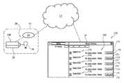
- FIG. 1illustrates an exemplary wireless device control system 10 , according to the present disclosure.
- the exemplary system 10generally includes a server, or backend, system 12 , one or more site systems 14 , and various user devices 16 .
- Exemplary site systems 14may include all or portions of a home, business, parking garage, street, worksite, or other location that includes a predefined set of components, such as electrical devices or circuits, for example, light fixtures, to be monitored or controlled.
- the server system 12may include one or more servers, or computers, 18 including typical computer components, such as a processor, memory, storage, display, network interface, and input/output device, for example.
- the processor, or processorsmay execute unique sets of instructions, which may be implemented as computer readable program code, stored in memory or storage, such that the server system 12 is configured as a special purpose system.
- hardware, software, and particular sets of instructionsmay transform the server system 12 , or portions thereof, into a lighting control server system, as described herein.
- the server system 12may also include any combination of computer hardware and software that facilitates communication with the site systems 14 and user devices 16 , and performance of the functions described herein.
- all or portions of the server system 12may be cloud-based. That is, for example, the one or more servers 18 of the server system 12 may reside on the Internet, for example, rather than on a local computer.
- the server system 12may be remote from the site systems 14 and/or the user devices 16 .
- Device Cloudoffered by Etherios, Inc., is a public cloud platform for device network management that may be used for all or portions of the server system 12 .
- the server system 12may communicate with the site systems 14 and the user devices 16 over a wide area network (WAN), such as the Internet 20 , via a local area network (LAN), and/or via a cellular network 22 , for example.
- WANwide area network
- LANlocal area network
- cellular network 22for example.
- Each site system 14may generally include at least a gateway, or base station, 24 , and one or more devices 26 , or device nodes, which are configured to communicate over a mesh network 28 , or other similar local wireless network.
- the gateway 24may include a communications module 30 that facilitates communication between the mesh network 28 , or other wireless network, and the WAN network 20 or 22 . As such, the gateway 24 may facilitate communication between the devices 26 of the site system 14 and the server system 12 .
- the gateway 24may also include an operations module 32 for processing and/or communicating instructions received from the server system 12 , as will be described in greater detail below.
- the operations module 32may also receive and/or process information from the devices 26 . That is, the gateway 24 may run applications locally while also interfacing across the mesh network 28 for WAN connectivity to the server system 12 .
- the gateway 24may communicate with the server system 12 via cellular or, more particularly, machine-to-machine cellular.
- the gateway 24may be provided with a subscriber identity module (SIM) card for facilitating communication over a cellular network. This connection may be maintained while the gateway 24 is powered on, and, by avoiding the use of an Ethernet or WiFi connection, may be more secure than alternative communications means.
- SIMsubscriber identity module
- Each device 26may include a communications module 34 , facilitating communication between the device 26 and the gateway 24 over a local wireless network, such as the mesh network 28 .
- the devices 26may each include a radio transceiver, such as an XBee radio module for communicating using the ZigBee protocol, which is related to IEEE standards, including 802.15.4.
- the devices 26may also include at least one type of control module 36 for facilitating interaction between the device 26 and an associated electrical component.
- control modules 36may be configured to control operations of devices, such as lights 38 , while other of the control modules 36 may be configured to detect the state of particular devices or components, such as sensors 40 .
- one control module 36 used in a switch device or dimmer devicemay function as a remotely controllable relay switching and/or dimming a light 38
- another control module 36 used in a trigger device, occupancy sensor device, or daylight harvester devicemay function as a remote device that senses a condition or the state of an associated device, such as a sensor 40 , and conveys the information to the gateway 24 and, ultimately, the server system 12 .
- a trigger device 26can be configured to detect voltage or current to determine the state of a device, such as a room light switch or a light fixture having its own motion or other sensor to activate it.
- the control modules 36may be configured to permit the respective devices 26 to function as various other devices, including remote dimmers, to perform functions desirable in a lighting control system, for example.
- Some devices 26may also be configured to act as a repeater, or router, such that it can also forward messages to other devices 26 .
- Each of the user devices 16may include a computer device, such as, for example, a personal computer, laptop computer, netbook computer, mobile device, portable electronic device (PED), or cell phone, configured to communicate with the server system 12 , or possibly the gateway 24 , to permit a user 42 to remotely configure, monitor, and/or control electrical components for a particular site system 14 . That is, a user 42 may access a control program, or control logic, on the server system 12 through an appropriate interface using user device 16 , which may have web-browsing abilities or may have a control application installed thereon.
- a computer devicesuch as, for example, a personal computer, laptop computer, netbook computer, mobile device, portable electronic device (PED), or cell phone, configured to communicate with the server system 12 , or possibly the gateway 24 , to permit a user 42 to remotely configure, monitor, and/or control electrical components for a particular site system 14 . That is, a user 42 may access a control program, or control logic, on the server system 12 through an appropriate interface using user device
- a web pagemay be loaded in a web browser of one of the client devices 16 . That is, one of the servers 18 may be or may include a web server for delivering web content to the user 42 through one of the user devices 16 described above. Thereafter, the user 42 may be provided with an option of registering for or accessing an account.
- URLUniform Resource Locator
- the system 10 or, more specifically, the server system 12may include a plurality of modules useful in carrying out the control strategies disclosed herein.
- the server system 12may include or utilize functionality expressed with reference to an account registration module 44 , a user manager module 46 , a device manager module 48 , and a communications module 50 , to name a few.
- modulesas used herein, is for ease of explanation, rather than limitation, and is intended to represent certain related aspects or functionality of the wireless device control system 10 .
- Each of the modulesmay represent a set of computer instructions, or computer readable program code, representing processes for performing specific tasks of the wireless device control system 10 . The tasks may be performed using a processor, or processors, and may require the access or manipulation of data stored in a data repository 52 .
- the account registration module 44may facilitate the creation of accounts and/or users, such as users 42 , within the system 10 .
- the registration module 44may be used to collect data input by users 42 and/or administrators accessing the wireless device control system 10 through one of various user devices 16 .
- the various user devices 16may include any suitable electronic communication devices and/or workstations, such as, for example, personal computers, laptop computers, netbook computers, mobile devices, PEDs, and cell phones, as mentioned above.
- the account registration module 44may be used to collect various information, including, for example, personally identifiable information, such as, for example, name, address, and phone number.
- the user manager module 46may include and/or implement rules pertaining to the various users 42 , or user types, of the system 10 . For example, when one of the users 42 is registered, a user profile including user credentials, such as a username and password, may be created for the user 42 and stored in the data repository 52 . The user manager module 46 may be configured to ensure that each user 42 , as identified using the unique credentials, is provided with appropriate access and/or capabilities with regard to the system 10 , as will be discussed in greater detail below. For example, the user manager module 46 may include an association of each user 42 to one or more sites, and may define appropriate permissions for each user 42 relative to respective site systems 14 .
- the wireless device control system 10 or, more specifically, the server system 12may include a database management system including one or more databases, such as data repository 52 .
- the data repository 52may store data, including the account and user data described above, useful in carrying out the strategies disclosed herein.
- the data repository 52is illustrated as a component within the server system 12 , it should be appreciated that the server system 12 may include any number of separate components or systems, including separate database(s), configured to communicate with one another in a manner consistent with the teachings disclosed herein.
- the device manager module 48may provide the main functionality of the server system 12 . For example, after account registration is completed and appropriate users are established in the system 10 , the device manager module 48 may be programmed and/or configured to permit users 42 to remotely manage specific associated site systems 14 . The device manager module 48 may also monitor and process data from the data repository 52 , and/or acquired data, to facilitate configuration, monitoring, and control of the site systems 14 , as will be described below. According to a specific example, the device manager module 48 may receive control information from users 42 via user devices 16 , store the information in the data repository 52 , and mirror the information to the appropriate gateway 24 for implementation. According to some embodiments, the data repository 52 may be initially populated with at least some default control data.
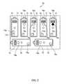
- a deployment kit 70may be used to plan an installation of a site system, such as one of the site systems 14 of FIG. 1 .
- the deployment kit 70may generally include a set of deploy modules 72 .
- the deploy modules 72may be similar to one another in general construction and appearance, but some of the deploy modules 72 may differ in configuration and may have additional or alternative features.
- one of the deploy modules 72may be configured to simulate certain functionality of the gateway 24 and, as such, may be referenced as a gateway simulator 74 .
- a number of the deploy modules 72may be configured to simulate certain functionality of the devices 26 and, as such, may be referenced as device simulators 76 .
- the deployment kit 70may also include a number of repeaters 78 .
- the gateway simulator 74may incorporate only portions, and not all, of the functionality of a later installed gateway that will ultimately be utilized at the site, such as the gateways 24 described above. That is, while the gateways 24 described above include a communications module 30 and an operations module 32 , the gateway simulator 74 may only include a communication component 74 a , and may not include additional components required for implementing the site system 14 .
- the communication component 74 amay be a radio transceiver or transmitter, such as an XBee radio module for communicating using the ZigBee protocol, for communicating with the device simulators 76 .
- the radio component 74 amay be configured as a coordinator, as is known by those skilled in the area of mesh networking.
- the gateway simulator 74may include an additional communication component 74 b for evaluating communication capabilities with regard to an additional network, such as, for example, a cellular network.
- the device simulators 76may incorporate only portions, and not all, of the functionality of later installed devices, such as devices 26 above. That is, while the devices 26 are described above as including a communications module 34 and a control module 36 , the device simulators 76 may only include a communication component 76 a .
- the communication component 76 amay be a radio transceiver or receiver, such as an XBee radio module for communicating using the ZigBee protocol, for communicating with the gateway simulator 74 .
- the radio transceiver 76 amay be configured as a router, as is known by those skilled in the area of mesh networking.
- the device simulators 76do not include some of the additional components and features, such as a control module 36 , required for implementing the site system 14 . That is, the device simulators 76 may each be configured without the control module 36 .
- the deployment kit 70is useful for successfully planning a site deployment.
- the deploy modules 72may be used to determine suitable locations for the gateway 24 and devices 26 prior to installation.
- the device simulators 76may include indicators 76 b configured to provide an indication of whether or not the device simulators 76 can communicate with the gateway simulator 74 , either directly or indirectly, using the respective communication components 74 b and 76 b.
- each indicator 76 bmay be a light, such as one or more LED lights, that illuminate, or illuminate a predetermined color or pattern, reflecting successful communication of the device simulator 76 with the gateway simulator 74 .
- the indicator 76 bmay illuminate a different predetermined color or pattern, or may not illuminate at all, to reflect unsuccessful communication of the device simulator 76 with the gateway simulator 74 .
- the indicators 76 bmay have a first state, such as an illuminated or first color or pattern state exemplified at 76 c (e.g., illuminated state), reflecting a successful radio communication connection with the gateway simulator 74 and a second state, such as a non-illuminated or second color or pattern state 76 d (e.g., non-illuminated state), reflecting an unsuccessful radio communication connection with the gateway simulator 74 , for example, the device is on, but no radio communication with the gateway simulator 74 is established, or the radio communication signal strength is below a preset desired threshold.
- a third statesuch as a non-illumination or a third color or pattern state 76 e can indicate the device simulator 76 is in an off or non-testing state.
- the deployment kit 70may also include repeaters 78 , which each include a communication component 78 a .
- the communication component 78 amay be a radio transceiver, such as an XBee radio module for communicating using the ZigBee protocol, for communicating with the gateway simulator 74 and/or device simulators 76 .
- These repeaters 78may function only to relay communication signals and to act as intermediaries between device simulators 76 and the gateway simulator 74 , thus improving the communication and range of the wireless mesh network 28 .
- the repeaters 78may also include indicators 78 b configured to provide an indication of whether or not the repeaters 78 can communicate with the gateway simulator 74 , either directly or indirectly, using the respective communication components 74 b and 78 b .
- the device simulators 76 and the repeaters 78may be similar, or identical, in that all of these deploy modules 72 may be configured as ZigBee routers, for example, and may include indication states as discussed above for device simulators 76 . Since later implemented routers would not require additional components or features, the repeaters 78 provided in the deployment kit 70 may ultimately be integrated into the site system 14 .
- the deployment kit 70will be discussed in greater detail with reference to a flowchart 90 shown in FIG. 3 , with continued reference to FIGS. 1 and 2 .
- the flowchart 90illustrates an exemplary method for planning a site system installation using the deployment kit 70 .
- the methodbegins at a START, step 92 , and proceeds to step 94 , in which the deployment kit 70 is received by a user, such as user 42 .
- the user 42may be an end user of the site system 14 , it is also foreseeable that an electrician or other user that ultimately performs the site system installation will perform this planning step. That is, the deployment kit 70 , and planning method, allows electricians or users 42 to perform a site survey and gauge network performance prior to installing actual control modules.
- the user 42positions the gateway simulator 74 from the deployment kit 70 at a desired gateway location.
- the gateway simulator 74may be powered on and, according to embodiments including the additional communication component 74 b , the gateway simulator 74 may also include an interface or display providing an indication of whether or not a network signal, such as a cellular network signal, is being received and an indication as to the strength of the signal. That is, the gateway simulator 74 may be positioned in a location at which the Internet 20 or cellular network 22 may be accessed or utilized. Once the gateway simulator 74 is properly positioned, locations for the various device simulators 76 may be tested.
- a network signalsuch as a cellular network signal
- a device simulator 76is selected from the deployment kit 70 , and is positioned in a test location (step 100 ).
- the device simulator 76once powered on, may be configured to continually, or according to another desired frequency, try to locate the gateway simulator 74 , and other deploy modules 72 , and may include an interface or indicator capable of reflecting whether or not the device simulator 76 is within a suitable range for communication with the gateway simulator 74 .
- the indicator 76 bmay have a first state, such as an illuminated or first color or pattern state 76 c , reflecting a successful radio communication connection with the gateway simulator 74 and a second state, such as a non-illuminated or second color or pattern state 76 d , reflecting an unsuccessful radio communication connection with the gateway simulator 74 , for example, the device is on, but no radio communication with the gateway simulator 74 is established, or the radio communication signal strength is below a preset desired threshold.
- a third statesuch as non-illumination or a third color or pattern state 76 e , can indicate the device simulator 76 is in an off or non-testing state.
- the methoddetermines whether the device simulator 76 can communicate with the gateway simulator 74 . If the device simulator 76 cannot communicate with the gateway simulator 74 the method proceeds to step 104 , where it is determined whether or not an alternative test location exists for the device simulator 76 . If an alternative test location exists, the user 42 , or other user, moves the device simulator 76 to the alternative test location (step 106 ), and the communication test, or evaluation, is repeated. Otherwise, if an alternative test location does not exist for the device simulator 76 , a repeater 78 may be added, and positioned, for relaying communication signals between the device simulator 76 and the gateway simulator 74 (step 108 ). The steps 102 , 104 , 106 and/or 108 may be repeated until the device simulator 76 is moved to a suitable location or a sufficient number of repeaters 78 have been added.
- the selected test locationshould be marked by the user, at step 110 . If any repeaters 78 are utilized, their respective locations should also be marked. Unless and until all of the prospective device locations have been tested, as queried at step 112 , the user 42 continues to test the device locations using the planning method disclosed herein. After all of the appropriate equipment locations are marked, devices 26 having control modules 36 may be installed at the marked locations, at step 114 . Thereafter, the method proceeds to an END, at step 116 .
- a gateway simulator 122similar to gateway simulator 74 , may be first positioned at a desired gateway location, as shown.
- a first device simulator 124similar to one of the device simulators 76 , is positioned at a test location, as shown, and it is determined whether or not the device simulator 124 can communicate with the gateway simulator 122 . If it is determined that the device simulator 124 is within an acceptable communication range, the user 42 may mark the test location for later installation of an actual device, such as one of devices 26 shown in FIG. 1 . Similar steps may be performed with respect to second and third device simulators 126 and 128 , which may also be similar to device simulators 76 .
- Fourth device simulator 130similar to one of the device simulators 76 , may be positioned at a test location, as shown, and although the fourth device simulator 130 cannot communicate directly with the gateway simulator 122 , the fourth device simulator 130 may be able to communicate indirectly with the gateway simulator 122 through, or using, the third device simulator 128 . As such, the test location for the fourth device simulator 130 may be marked for later reference. It should be appreciated, as consistent with the teachings herein, that if one or more alternative test locations exist for the fourth device simulator 130 , the fourth device simulator 130 could be moved to an alternative test location and the communication capabilities could be evaluated at the alternative test location, according to the disclosed method.
- a fifth device simulator 132may be positioned such that it is out of range of the gateway simulator 122 and none of the other device simulators 124 , 126 , 128 , and 130 provide an indirect communication path with the gateway simulator 122 .
- a repeater 134similar to the repeaters 78 , may be positioned within the communication path to facilitate communication between the fifth device simulator 132 and the gateway simulator 122 . All of the tested locations that prove to be suitable locations should be marked for later installation of the site system components. After the site planning procedure is completed, the site system components can be installed with reasonable certainty that the device locations are appropriate. After installation, the site system components can be commissioned and/or configured.
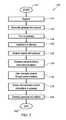
- the methodbegins at a START, step 142 , and proceeds to a first step, shown at step 144 , in which registration occurs.
- a usersuch as one of users 42
- an administratormay register users 42 and create user accounts.
- a gatewaysuch as gateway 24
- Thismay be accomplished by entering a unique gateway identification number through the application, or other appropriate interface, or the gateway 24 may be pre-configured with an association to an existing account.
- the gateway 24may appear on a user interface of the user device, such as one of the user devices 16 .
- the devices 26may be designed such that they automatically attempt to register with the gateway 24 after they are powered on, at steps 150 and 152 . That is, when the devices 26 are powered on, they wirelessly and automatically attempt to communicate with the gateway 24 .
- the devices 26identify themselves to the gateway 24 and the gateway 24 informs the server system 12 of the devices 26 , at step 154 .
- the user 42may then be able to manage devices 16 through the user interface, at step 156 , as will be exemplified below.
- users 42may have various levels of access and control with regard to a particular site and/or particular devices 26 .
- the server system 12communicates control instructions to the gateway 24 , at step 158 , and the gateway 24 may execute the instructions, at step 160 .
- Updates provided by the user 42may be forwarded from the server system 12 to the gateway 24 .
- the gateway 24may receive various information from the devices 26 , and may send, or relay, various updates to the server system 12 .
- the methodproceeds to an END, at step 162 .
- the devices 26may be managed within a user interface. That is, with continued reference to FIG. 1 and additional reference to FIG. 6 , representations, such as, for example, graphical and/or textual representations, of the devices 26 may be displayed on a user interface 170 of one of the user devices 16 .
- representationssuch as, for example, graphical and/or textual representations
- the devices 26may be displayed on a user interface 170 of one of the user devices 16 .
- all sites, or site systems 14associated with the user 42 may be visible through the user interface 170 .
- entries 172 representative of actual devices 26are visible through the user interface 170 and include information, such as unique device identifiers 174 .
- the user 42may enter additional information about each device 26 , such as a device location, description, and zone, using the user interface 170 .
- a user inputsuch as a selection button, 176 associated with a specific one of the entries 172 displayed on the user interface 170 may be actuated.
- an indicator on the physical device 26 represented by that entry 172may be modified in some predetermined way to assist the user 42 in matching each entry 172 to the physical device 26 it represents. For example, an indicator may illuminate using a predetermined duration and/or pattern.
- FIG. 7An alternative device identification procedure is illustrated in FIG. 7 .
- the user 42may actuate a device identification feature 180 of one of the devices 26 , for example, a momentary switch.
- This actuationmay generate a communication sent by communication module 76 a and be received by the gateway 24 of the site system 14 and communicated, along with the unique device identifier 174 of the selected device 26 , to the server system 12 .
- this actuationmy change a state of an indicator on the device 26 , for example, one or more LEDs that blink for a period of time or other condition satisfied subsequent to the device identification feature 180 being activated.
- the device entries 172in the user interface 170 may be changed to identify which device entry 172 corresponds to the selected device 26 .
- the particular device entry 182 corresponding to the selected device 26may be moved up to the top of the list and may be pre-selected in preparation for the user 42 to continue the commissioning process.
- the user 42may be assisted in adding useful and accurate information about the device 26 via the user interface 170 .
- the system 10can include a communication protocol for communicating between the gateway 24 and the devices 26 .
- a standard protocol packetmay include a prefix identifying packets sent to or received from devices 26 , a variable packet length, a device code identifying the target or origin device, a command and/or response code, and arguments associated with the command or response code.
- Specialized packetsmay include a discovery packet that queries a device 26 to identify itself and certain key attributes, a diagnostic packet that queries a device 26 to report certain usual information about itself in the course of its operation, and request state packet to poll the state of a device 26 , and a transition completion packet, for example, to report completion of a brightness setting using a transition time and/or curve to a dimming device 26 .
- the wireless device control system 10 described hereinprovides sophisticated control of electrical devices, such as those utilized in lighting systems, without requiring significant processing power, electrical power, and infrastructure to work well.
- the systems and methods disclosed hereinassist in installing, configuring, and using the system 10 .
Landscapes
- Engineering & Computer Science (AREA)
- Computer Networks & Wireless Communication (AREA)
- Signal Processing (AREA)
- Circuit Arrangement For Electric Light Sources In General (AREA)
Abstract
Description
Claims (18)
Priority Applications (11)
| Application Number | Priority Date | Filing Date | Title |
|---|---|---|---|
| US14/823,560US9883567B2 (en) | 2014-08-11 | 2015-08-11 | Device indication and commissioning for a lighting control system |
| US15/357,900US10085328B2 (en) | 2014-08-11 | 2016-11-21 | Wireless lighting control systems and methods |
| US15/492,373US10531545B2 (en) | 2014-08-11 | 2017-04-20 | Commissioning a configurable user control device for a lighting control system |
| US15/492,663US10039174B2 (en) | 2014-08-11 | 2017-04-20 | Systems and methods for acknowledging broadcast messages in a wireless lighting control network |
| US15/620,448US9974150B2 (en) | 2014-08-11 | 2017-06-12 | Secure device rejoining for mesh network devices |
| US15/621,536US10219356B2 (en) | 2014-08-11 | 2017-06-13 | Automated commissioning for lighting control systems |
| US16/218,123US10398010B2 (en) | 2014-08-11 | 2018-12-12 | Power loss detection for a lighting control system |
| US16/694,468US10855488B2 (en) | 2014-08-11 | 2019-11-25 | Scheduled automation associations for a lighting control system |
| US17/109,032US11398924B2 (en) | 2014-08-11 | 2020-12-01 | Wireless lighting controller for a lighting control system |
| US17/814,513US11722332B2 (en) | 2014-08-11 | 2022-07-23 | Wireless lighting controller with abnormal event detection |
| US18/366,660US12068881B2 (en) | 2014-08-11 | 2023-08-07 | Wireless lighting control system with independent site operation |
Applications Claiming Priority (2)
| Application Number | Priority Date | Filing Date | Title |
|---|---|---|---|
| US201462035558P | 2014-08-11 | 2014-08-11 | |
| US14/823,560US9883567B2 (en) | 2014-08-11 | 2015-08-11 | Device indication and commissioning for a lighting control system |
Related Child Applications (1)
| Application Number | Title | Priority Date | Filing Date |
|---|---|---|---|
| US15/357,900Continuation-In-PartUS10085328B2 (en) | 2014-08-11 | 2016-11-21 | Wireless lighting control systems and methods |
Publications (2)
| Publication Number | Publication Date |
|---|---|
| US20170111979A1 US20170111979A1 (en) | 2017-04-20 |
| US9883567B2true US9883567B2 (en) | 2018-01-30 |
Family
ID=58530219
Family Applications (1)
| Application Number | Title | Priority Date | Filing Date |
|---|---|---|---|
| US14/823,560ActiveUS9883567B2 (en) | 2014-08-11 | 2015-08-11 | Device indication and commissioning for a lighting control system |
Country Status (1)
| Country | Link |
|---|---|
| US (1) | US9883567B2 (en) |
Cited By (1)
| Publication number | Priority date | Publication date | Assignee | Title |
|---|---|---|---|---|
| US20190132932A1 (en)* | 2016-04-21 | 2019-05-02 | Philips Lighting Holding B.V. | Systems and methods for commissioning and localizing devices used for cloud-based monitoring and control of physical environments |
Families Citing this family (10)
| Publication number | Priority date | Publication date | Assignee | Title |
|---|---|---|---|---|
| HK1204225A2 (en)* | 2015-08-20 | 2015-11-06 | En-Trak Hong Kong Limited | Wireless lighting control system and its application thereof |
| US10237939B2 (en)* | 2016-03-11 | 2019-03-19 | Gooee Limited | Devices, systems, and methods for maintaining light intensity in a gateway based lighting system |
| US10159134B2 (en)* | 2016-03-11 | 2018-12-18 | Gooee Limited | End of life prediction system for luminaire drivers |
| US9992843B2 (en) | 2016-03-11 | 2018-06-05 | Gooee Limited | Location independent lighting sensor system |
| US10021757B2 (en) | 2016-03-11 | 2018-07-10 | Gooee Limited | System and method for predicting emergency lighting fixture life expectancy |
| CA3079973A1 (en)* | 2017-10-26 | 2019-05-02 | Racepoint Energy, LLC | Intelligent lighting control system multi-way-detection apparatuses, systems, and methods |
| AU2020262119B2 (en) | 2019-04-22 | 2025-08-14 | Savant Systems, Inc. | Intelligent lighting control system multi-way schemes for switch bases |
| JP7196764B2 (en)* | 2019-05-22 | 2022-12-27 | 富士通株式会社 | Information processing system |
| JP7237038B2 (en)* | 2020-03-26 | 2023-03-10 | 株式会社遠藤照明 | Information setting device and lighting system |
| JP2023147542A (en)* | 2022-03-30 | 2023-10-13 | 東芝ライテック株式会社 | Information processing device, relay device and system |
Citations (285)
| Publication number | Priority date | Publication date | Assignee | Title |
|---|---|---|---|---|
| US322609A (en) | 1885-07-21 | Philip jackson | ||
| US475126A (en) | 1892-05-17 | Music-desk | ||
| US481016A (en) | 1892-08-16 | Device for illuminating railroad-tracks | ||
| US499702A (en) | 1893-06-20 | Tongs | ||
| US530681A (en) | 1894-12-11 | William r | ||
| US552043A (en) | 1895-12-24 | Rivet-setting machine | ||
| US578871A (en) | 1897-03-16 | Bicycle newspaper-rack | ||
| US597637A (en) | 1898-01-18 | Marsh mallow-runner | ||
| US601976A (en) | 1898-04-05 | Wagon-body lining | ||
| US625294A (en) | 1899-05-16 | Carbureter | ||
| US680878A (en) | 1900-07-06 | 1901-08-20 | Robert E Murphy | Skein-washing machine. |
| US685750A (en) | 1900-12-26 | 1901-11-05 | George Waltermar Du Nah | Composition for preserving eggs. |
| US690662A (en) | 1901-03-29 | 1902-01-07 | Thomas J Perrin | Adjustable metallic window-screen. |
| JPH04141840A (en) | 1990-10-01 | 1992-05-15 | Matsushita Electric Ind Co Ltd | Photoresist automatic development equipment |
| US5283905A (en) | 1991-06-24 | 1994-02-01 | Compaq Computer Corporation | Power supply for computer system manager |
| US5357361A (en) | 1991-07-15 | 1994-10-18 | Nishizawa Junichi | Discriminating light-emitting optical apparatus |
| CN1119888A (en) | 1993-03-25 | 1996-04-03 | 巴布考克和威尔考克斯公司 | Circulating fluidized bed reactor with primary particle separation and return function |
| US5598042A (en) | 1993-09-22 | 1997-01-28 | The Watt Stopper | Moveable desktop load controller |
| US5623172A (en) | 1995-07-03 | 1997-04-22 | Leviton Manufacturing Co., Inc. | Two wire PIR occupancy sensor utilizing a rechargeable energy storage device |
| CA2236569A1 (en) | 1996-09-03 | 1998-03-12 | Philips Electronics N.V. | Method for installing a wireless network |
| CA2249423A1 (en) | 1997-01-23 | 1998-07-30 | Simon Hendrik Anton Begemann | Luminaire |
| US5905442A (en) | 1996-02-07 | 1999-05-18 | Lutron Electronics Co., Inc. | Method and apparatus for controlling and determining the status of electrical devices from remote locations |
| US5949200A (en) | 1996-07-30 | 1999-09-07 | Lutron Electronics Co., Inc. | Wall mountable control system with virtually unlimited zone capacity |
| US5982103A (en) | 1996-02-07 | 1999-11-09 | Lutron Electronics Co., Inc. | Compact radio frequency transmitting and receiving antenna and control device employing same |
| US6005759A (en) | 1998-03-16 | 1999-12-21 | Abb Power T&D Company Inc. | Method and system for monitoring and controlling an electrical distribution network |
| US6013988A (en) | 1997-08-01 | 2000-01-11 | U.S. Philips Corporation | Circuit arrangement, and signalling light provided with the circuit arrangement |
| US6016038A (en) | 1997-08-26 | 2000-01-18 | Color Kinetics, Inc. | Multicolored LED lighting method and apparatus |
| US6094014A (en) | 1997-08-01 | 2000-07-25 | U.S. Philips Corporation | Circuit arrangement, and signaling light provided with the circuit arrangement |
| US6145998A (en) | 1998-06-30 | 2000-11-14 | Leviton Manufacturing Co., Inc. | Demonstration display for lighting controls |
| US6147458A (en) | 1998-07-01 | 2000-11-14 | U.S. Philips Corporation | Circuit arrangement and signalling light provided with the circuit arrangement |
| US6204584B1 (en) | 2000-01-18 | 2001-03-20 | Cleveland Motion Controls, Inc. | Low cogging torque brushless motor rotor |
| US6223029B1 (en) | 1996-03-14 | 2001-04-24 | Telefonaktiebolaget Lm Ericsson (Publ) | Combined mobile telephone and remote control terminal |
| US6234648B1 (en) | 1998-09-28 | 2001-05-22 | U.S. Philips Corporation | Lighting system |
| US6252358B1 (en) | 1998-08-14 | 2001-06-26 | Thomas G. Xydis | Wireless lighting control |
| US6264329B1 (en) | 1995-10-27 | 2001-07-24 | Reliance Medical Products, Inc. | Ophthalmic instrument support and lighting system |
| US6275163B1 (en) | 1998-08-24 | 2001-08-14 | Leviton Manufacturing Co., Inc. | Automatic switch dimmer device |
| US6300727B1 (en) | 1996-03-13 | 2001-10-09 | Lutron Electronics Co., Inc. | Lighting control with wireless remote control and programmability |
| US6304464B1 (en) | 1999-07-07 | 2001-10-16 | U.S. Philips Corporation | Flyback as LED driver |
| US6340864B1 (en) | 1999-08-10 | 2002-01-22 | Philips Electronics North America Corporation | Lighting control system including a wireless remote sensor |
| US6388399B1 (en) | 1998-05-18 | 2002-05-14 | Leviton Manufacturing Co., Inc. | Network based electrical control system with distributed sensing and control |
| US6513949B1 (en) | 1999-12-02 | 2003-02-04 | Koninklijke Philips Electronics N.V. | LED/phosphor-LED hybrid lighting systems |
| US6528954B1 (en) | 1997-08-26 | 2003-03-04 | Color Kinetics Incorporated | Smart light bulb |
| US6561690B2 (en) | 2000-08-22 | 2003-05-13 | Koninklijke Philips Electronics N.V. | Luminaire based on the light emission of light-emitting diodes |
| US6577512B2 (en) | 2001-05-25 | 2003-06-10 | Koninklijke Philips Electronics N.V. | Power supply for LEDs |
| WO2003049379A1 (en) | 2001-12-01 | 2003-06-12 | I Controls Inc. | Internet-based home automation server and control method thereof |
| US6580950B1 (en) | 2000-04-28 | 2003-06-17 | Echelon Corporation | Internet based home communications system |
| US6586890B2 (en) | 2001-12-05 | 2003-07-01 | Koninklijke Philips Electronics N.V. | LED driver circuit with PWM output |
| US6617795B2 (en) | 2001-07-26 | 2003-09-09 | Koninklijke Philips Electronics N.V. | Multichip LED package with in-package quantitative and spectral sensing capability and digital signal output |
| US6655817B2 (en) | 2001-12-10 | 2003-12-02 | Tom Devlin | Remote controlled lighting apparatus and method |
| EP1371211A2 (en) | 2001-03-08 | 2003-12-17 | Koninklijke Philips Electronics N.V. | Method and system for assigning and binding a network address of a ballast |
| US20040010327A1 (en) | 2002-06-12 | 2004-01-15 | Kabushiki Kaisha Toshiba | Home gateway for automatically acquiring and updating modules for controlling home electronics devices |
| US6735619B1 (en) | 1999-08-10 | 2004-05-11 | Panasonic Communications Co., Ltd. | Home network gateway apparatus and home network device |
| US20040136358A1 (en) | 1998-05-29 | 2004-07-15 | Hugh Hind | System and method for pushing information from a host system to a mobile data communication device in a wireless data network |
| US20040143510A1 (en) | 2002-07-27 | 2004-07-22 | Brad Haeberle | Method and system for obtaining service information about one or more building sites |
| US6788011B2 (en) | 1997-08-26 | 2004-09-07 | Color Kinetics, Incorporated | Multicolored LED lighting method and apparatus |
| US6798341B1 (en) | 1998-05-18 | 2004-09-28 | Leviton Manufacturing Co., Inc. | Network based multiple sensor and control device with temperature sensing and control |
| US20040263084A1 (en) | 2003-06-27 | 2004-12-30 | Tal Mor | Method and apparatus for controlling illumination of a display in a portable wireless communication device |
| US20050007031A1 (en) | 2003-07-11 | 2005-01-13 | Hubbell Incorporated | Low voltage luminaire assembly |
| US20050007024A1 (en) | 2002-01-30 | 2005-01-13 | Cyberlux Corporation | Apparatus and methods for providing an emergency lighting augmentation system |
| US6844807B2 (en) | 2000-04-18 | 2005-01-18 | Renesas Technology Corp. | Home electronics system enabling display of state of controlled devices in various manners |
| US20050097162A1 (en) | 2003-11-04 | 2005-05-05 | Powerweb Technologies | Wireless internet lighting control system |
| US20050108430A1 (en) | 2003-10-23 | 2005-05-19 | Cisco Technology, Inc. | Methods and devices for sharing content on a network |
| EP1535495A2 (en) | 2002-08-28 | 2005-06-01 | Color Kinetics Incorporated | Methods and systems for illuminating environments |
| US6922022B2 (en) | 2001-07-19 | 2005-07-26 | Lumileds Lighting U.S. Llc | LED switching arrangement for enhancing electromagnetic interference |
| US6930598B2 (en) | 2002-05-16 | 2005-08-16 | Eugene S. Weiss | Home gateway server appliance |
| US6940230B2 (en) | 2002-05-30 | 2005-09-06 | Hubbell Incorporated | Modular lamp controller |
| US6950725B2 (en) | 2001-12-07 | 2005-09-27 | General Electric Company | Home latch-key web based automation system |
| US6963285B2 (en) | 2002-09-30 | 2005-11-08 | Basic Resources, Inc. | Outage notification device and method |
| US6967448B2 (en) | 1997-08-26 | 2005-11-22 | Color Kinetics, Incorporated | Methods and apparatus for controlling illumination |
| US6969954B2 (en) | 2000-08-07 | 2005-11-29 | Color Kinetics, Inc. | Automatic configuration systems and methods for lighting and other applications |
| US6972525B2 (en) | 2001-07-19 | 2005-12-06 | Marcel Johannes Maria Bucks | Led switching arrangement |
| US6975079B2 (en) | 1997-08-26 | 2005-12-13 | Color Kinetics Incorporated | Systems and methods for controlling illumination sources |
| US6990349B1 (en) | 1998-11-20 | 2006-01-24 | Nortel Networks Limited | System and method for reconnecting a mobile station to an emergency operator |
| US6989807B2 (en) | 2003-05-19 | 2006-01-24 | Add Microtech Corp. | LED driving device |
| US6990394B2 (en) | 2002-12-24 | 2006-01-24 | Pasternak Barton A | Lighting control system and method |
| US20060044152A1 (en) | 2002-09-04 | 2006-03-02 | Ling Wang | Master-slave oriented two-way rf wireless lighting control system |
| US7030572B2 (en) | 2002-12-03 | 2006-04-18 | Lumileds Lighting U.S., Llc | Lighting arrangement |
| WO2006040364A1 (en) | 2004-09-15 | 2006-04-20 | Sociedad Europea De Redes Virtuales E Ingenieria Telematica S.L. | Modular intelligent control system and connection for home control installation |
| US7038399B2 (en) | 2001-03-13 | 2006-05-02 | Color Kinetics Incorporated | Methods and apparatus for providing power to lighting devices |
| US7043310B2 (en) | 2001-02-16 | 2006-05-09 | Siemens Aktiengesellschaft | Device and process for operation of automation components |
| US7064498B2 (en) | 1997-08-26 | 2006-06-20 | Color Kinetics Incorporated | Light-emitting diode based products |
| US7069345B2 (en) | 2001-05-09 | 2006-06-27 | Koninklijke Philips Electronics N.V. | Device identification and control in network environment |
| US7072945B1 (en) | 2000-06-30 | 2006-07-04 | Nokia Corporation | Network and method for controlling appliances |
| US7103511B2 (en) | 1998-10-14 | 2006-09-05 | Statsignal Ipc, Llc | Wireless communication networks for providing remote monitoring of devices |
| US20060215345A1 (en) | 2005-03-14 | 2006-09-28 | The Regents Of The University Of California | Wireless network control for building lighting system |
| US7127228B2 (en) | 2001-12-07 | 2006-10-24 | Acer Communications And Multimedia Inc. | Portable electric device with power failure recovery and operation method thereof |
| US20060262462A1 (en) | 2003-05-03 | 2006-11-23 | Robert Barton | Concealed Safety Lighting and Alerting System |
| US7200660B2 (en) | 2001-08-10 | 2007-04-03 | Ininet Solutions Gmbh | Procedure and configuration in order to transmit data |
| US7202608B2 (en) | 2004-06-30 | 2007-04-10 | Tir Systems Ltd. | Switched constant current driving and control circuit |
| US7218056B1 (en) | 2006-03-13 | 2007-05-15 | Ronald Paul Harwood | Lighting device with multiple power sources and multiple modes of operation |
| US7221104B2 (en) | 1997-08-26 | 2007-05-22 | Color Kinetics Incorporated | Linear lighting apparatus and methods |
| US7231482B2 (en) | 2000-06-09 | 2007-06-12 | Universal Smart Technologies, Llc. | Method and system for monitoring and transmitting utility status via universal communications interface |
| US7233831B2 (en) | 1999-07-14 | 2007-06-19 | Color Kinetics Incorporated | Systems and methods for controlling programmable lighting systems |
| US7256554B2 (en) | 2004-03-15 | 2007-08-14 | Color Kinetics Incorporated | LED power control methods and apparatus |
| US7262559B2 (en) | 2002-12-19 | 2007-08-28 | Koninklijke Philips Electronics N.V. | LEDS driver |
| US7310344B1 (en) | 2001-12-28 | 2007-12-18 | Cisco Technology, Inc. | Method and system for an instant messenger home automation system interface using a home router |
| US20070293208A1 (en) | 2006-06-15 | 2007-12-20 | Newict (M) Sdn. Bhd. | Wireles switching control system for building automation, lighting, security and appliances |
| US20080007942A1 (en) | 2006-03-17 | 2008-01-10 | Ruggles Patrick H | Mountable light with integrated activation sensor |
| US20080020903A1 (en) | 2006-03-03 | 2008-01-24 | William Dieter | Collapsible athletic training ladder |
| US20080042826A1 (en) | 2006-08-17 | 2008-02-21 | Napco Security Systems, Inc. | Security system interface module |
| US7348604B2 (en) | 2005-05-20 | 2008-03-25 | Tir Technology Lp | Light-emitting module |
| US20080082637A1 (en) | 2006-09-29 | 2008-04-03 | Rockwell Automation Technologies, Inc. | Web-based configuration of distributed automation systems |
| US7358679B2 (en) | 2002-05-09 | 2008-04-15 | Philips Solid-State Lighting Solutions, Inc. | Dimmable LED-based MR16 lighting apparatus and methods |
| US7365282B2 (en) | 2004-06-29 | 2008-04-29 | Lutron Electronics Co., Ltd. | Pull out air gap switch for wallbox-mounted dimmer |
| US7410271B1 (en) | 2007-02-15 | 2008-08-12 | Kaper Industrial Limited | Flashlight with automatic light intensity adjustment means |
| US7437150B1 (en) | 2000-10-06 | 2008-10-14 | Carrier Corporation | Method for wireless data exchange for control of structural appliances such as heating, ventilation, refrigeration, and air conditioning systems |
| US20080266050A1 (en) | 2005-11-16 | 2008-10-30 | Koninklijke Philips Electronics, N.V. | Universal Rf Wireless Sensor Interface |
| US20080272586A1 (en) | 2007-05-04 | 2008-11-06 | Leviton Manufacturing Co., Inc. | Multi-part identification labels |
| US20080282182A1 (en) | 2004-05-31 | 2008-11-13 | Kabushiki Kaisha Toshiba | Control System For Networked Home Electrical Appliances |
| US7464035B2 (en) | 2002-07-24 | 2008-12-09 | Robert Bosch Corporation | Voice control of home automation systems via telephone |
| US7496627B2 (en) | 2006-03-16 | 2009-02-24 | Exceptional Innovation, Llc | Automation control system having digital logging |
| US7498952B2 (en) | 2005-06-06 | 2009-03-03 | Lutron Electronics Co., Inc. | Remote control lighting control system |
| US20090059603A1 (en) | 2007-08-30 | 2009-03-05 | Wireless Environment, Llc | Wireless light bulb |
| US7504821B2 (en) | 2005-11-03 | 2009-03-17 | Elster Electricity, Llc | Auxiliary power supply for supplying power to additional functions within a meter |
| US20090103307A1 (en) | 2007-10-19 | 2009-04-23 | Semiconductor Device Solution, Inc. | Wireless control lamp structure |
| US7526539B1 (en) | 2000-01-04 | 2009-04-28 | Pni Corporation | Method and apparatus for a distributed home-automation-control (HAC) window |
| US7530113B2 (en) | 2004-07-29 | 2009-05-05 | Rockwell Automation Technologies, Inc. | Security system and method for an industrial automation system |
| US7551071B2 (en) | 1997-12-29 | 2009-06-23 | At&T Intellectual Property I, L.P. | System and method for home automation and security |
| US20090180261A1 (en) | 2008-01-15 | 2009-07-16 | Leviton Manufacturing Company, Inc. | Fault circuit interrupter disposed inside a housing adapted to receive modular components |
| US7566155B2 (en) | 2004-08-06 | 2009-07-28 | Koninklijke Philips Electronics N.V. | LED light system |
| WO2009098074A2 (en) | 2008-02-06 | 2009-08-13 | Acque Ingegneria S.R.L. | Method for controlling remote installations |
| WO2009103587A1 (en) | 2008-02-20 | 2009-08-27 | Osram Gesellschaft mit beschränkter Haftung | Wireless dimmable electronic ballast and compact fluorescent lamp comprising the same |
| US7592925B2 (en) | 2006-06-20 | 2009-09-22 | Lutron Electronics Co., Inc. | Lighting control having an idle state with wake-up upon actuation |
| US7597455B2 (en) | 2006-10-20 | 2009-10-06 | Robert B. Smith | LED light bulb system |
| US20090251314A1 (en) | 2008-04-03 | 2009-10-08 | National Taiwan University | Back-end host server unit for remote ecological environment monitoring system |
| US20090261734A1 (en) | 2007-03-05 | 2009-10-22 | Lutron Electronics Co., Inc. | Method of Programming a Lighting Preset From a Radio-Frequency Remote Control |
| US7608807B2 (en) | 2005-05-05 | 2009-10-27 | Leviton Manufacturing Co., Inc. | Closed loop daylight harvesting light control system having auto-calibration |
| US20090278479A1 (en) | 2008-05-06 | 2009-11-12 | Platner Brian P | Networked, wireless lighting control system with distributed intelligence |
| US20090289757A1 (en) | 2008-05-23 | 2009-11-26 | Ballard Claudio R | System for remote control using a wap-enabled device |
| US7626339B2 (en) | 2004-08-24 | 2009-12-01 | The Watt Stopper Inc. | Daylight control system device and method |
| US7634555B1 (en) | 2003-05-16 | 2009-12-15 | Johnson Controls Technology Company | Building automation system devices |
| US20090309501A1 (en) | 2003-11-04 | 2009-12-17 | Anthony Catalano | Light Emitting Diode Replacement Lamp |
| US20090322231A1 (en) | 2006-07-26 | 2009-12-31 | Koninklijke Philips Electronics N.V. | Lamp-holding device and system comprising lamp-holding devices and wireless controller |
| US20100037071A1 (en) | 2008-08-05 | 2010-02-11 | Hsiang-Li Chang | Using Internet to control delivery of power to a set of remote loads(devices) |
| WO2010017588A1 (en) | 2008-08-12 | 2010-02-18 | Clipsal Australia Pty Ltd | System and method for displaying messages in a building automation system |
| US20100038440A1 (en) | 2008-08-12 | 2010-02-18 | Kodalfa Bilgi ve Iletisim Teknolojileri San. Tic. A.S. | Method and system for remote wireless monitoring and control of climate in greenhouses |
| US7666010B2 (en) | 2006-10-27 | 2010-02-23 | Leviton Manufacturing Company, Inc. | Modular wiring system with locking elements |
| US7680878B2 (en) | 2002-09-30 | 2010-03-16 | Panasonic Corporation | Apparatus, method and computer software products for controlling a home terminal |
| US7694005B2 (en) | 2005-11-04 | 2010-04-06 | Intermatic Incorporated | Remote device management in a home automation data transfer system |
| WO2010039016A2 (en) | 2008-09-04 | 2010-04-08 | Said Kamal | Infrared remote control systems, employing visible light signals, ultrasounds, audible sound signals and radiofrequency for lighting |
| US7702421B2 (en) | 2007-08-27 | 2010-04-20 | Honeywell International Inc. | Remote HVAC control with building floor plan tool |
| US20100101924A1 (en) | 2007-07-18 | 2010-04-29 | Leviton Manufacturing Co., Inc. | Switching device |
| US20100114334A1 (en) | 2008-11-03 | 2010-05-06 | Phoenix Contact Gmbh & Co. Kg | Method and device for accessing a functional module of automation sytem |
| US7714699B2 (en) | 2004-04-15 | 2010-05-11 | Koninklijke Philips Electronics N.V. | Antenna through the use of lamp electrodes |
| US7712949B2 (en) | 2005-12-02 | 2010-05-11 | Leviton Manufacturing Company, Inc. | Ceiling lamp holder to accept a non-incandescent lamp |
| US20100122338A1 (en) | 2008-11-11 | 2010-05-13 | Hitachi, Ltd. | Network system, dhcp server device, and dhcp client device |
| US7746877B2 (en) | 2007-04-26 | 2010-06-29 | 2Wire, Inc. | Method and apparatus for communicating loss of alternating current power supply |
| US7747781B2 (en) | 2001-04-20 | 2010-06-29 | Palmsource Inc. | Content access from a communications network using a handheld computer system and method |
| WO2010083629A1 (en) | 2009-01-24 | 2010-07-29 | 上海贝尔股份有限公司 | Method and apparatus for realizing remote control of devices through network address configuration server |
| US7781979B2 (en) | 2006-11-10 | 2010-08-24 | Philips Solid-State Lighting Solutions, Inc. | Methods and apparatus for controlling series-connected LEDs |
| US7800498B2 (en) | 2006-03-29 | 2010-09-21 | Leviton Manufacturing Co., Inc. | Occupancy sensor powerbase |
| US7800049B2 (en) | 2005-08-22 | 2010-09-21 | Leviton Manufacuturing Co., Inc. | Adjustable low voltage occupancy sensor |
| US20100237711A1 (en) | 2009-03-18 | 2010-09-23 | Leviton Manufacturing Co., Inc. | Occupancy Sensing With Device Clock |
| US7802902B2 (en) | 2005-09-27 | 2010-09-28 | Koninklijke Philips Electronics N.V. | LED lighting fixtures |
| US20100244709A1 (en) | 2009-03-27 | 2010-09-30 | Lutron Electronics Co., Inc. | Wireless Battery-Powered Daylight Sensor |
| US7806558B2 (en) | 2006-11-27 | 2010-10-05 | Koninklijke Philips Electronics N.V. | Methods and apparatus for providing uniform projection lighting |
| US20100259193A1 (en) | 2009-04-09 | 2010-10-14 | Eye Lighting Systems Corporation | Remote Lighting Control System |
| CN101867990A (en) | 2010-04-29 | 2010-10-20 | 顾翠红 | Electrical equipment wireless control network with priority level |
| US20100265700A1 (en) | 2008-07-15 | 2010-10-21 | Leviton Manufacturing Corporation | Flourescent lamp support |
| US20100264313A1 (en) | 2009-04-20 | 2010-10-21 | Lsi Industries, Inc. | Lighting Techniques for Wirelessly Controlling Lighting Elements |
| US20100277315A1 (en) | 2009-04-30 | 2010-11-04 | Alan Wade Cohn | Controller and interface for home security, monitoring and automation having customizable audio alerts for sma events |
| US20100277306A1 (en) | 2009-05-01 | 2010-11-04 | Leviton Manufacturing Co., Inc. | Wireless occupancy sensing with accessible location power switching |
| CN201655922U (en) | 2010-05-10 | 2010-11-24 | 北京京煤集团总医院 | Automatic maintenance device for UPS backup battery |
| US7849224B2 (en) | 2007-09-17 | 2010-12-07 | Gm Global Technology Operations, Inc. | Method and apparatus for implementing a mobile server |
| US20100318685A1 (en) | 2007-12-31 | 2010-12-16 | Schlage Lock Company | Mesh network security system gateway and method |
| US20100321929A1 (en) | 2009-06-18 | 2010-12-23 | Ramirez Rafael M | Power Delivery System For HID, LED, Or Fluorescent Track Lighting |
| US7860679B2 (en) | 2006-04-19 | 2010-12-28 | Somfy Sas | Method of testing and installing a home automation remote control unit |
| US20110012532A1 (en) | 2007-08-05 | 2011-01-20 | Thomas Alan Barnett | Wireless scene arrangement |
| US20110012434A1 (en) | 2009-07-20 | 2011-01-20 | Yu-Lung Lee | Power system with light-controlled function and the control method thereof |
| US20110026510A1 (en) | 2008-04-21 | 2011-02-03 | Telefonaktiebolaget Lm Ericsson (Publ) | Method for Enabling Communication between a User Equipment and an IMS Gateway |
| US7924155B2 (en) | 2008-01-07 | 2011-04-12 | Leviton Manufacturing Co., Inc. | Digital occupancy sensor light control |
| US20110090042A1 (en) | 2009-10-21 | 2011-04-21 | Leviton Manufacturing Co., Inc. | Wireless demand response system |
| US7955096B2 (en) | 2006-10-27 | 2011-06-07 | Leviton Manufacturing Company, Inc. | Modular wiring system with locking elements |
| US20110138058A1 (en) | 2004-05-20 | 2011-06-09 | Atsuki Ishida | Server for routing connection to client device |
| US20110144820A1 (en) | 2008-08-08 | 2011-06-16 | Iluflex-Comercio De Equipamentos Eletronicos Ltda-Epp | Wireless programmable control system |
| US20110147037A1 (en) | 2009-12-21 | 2011-06-23 | Leviton Manufacturing Co., Inc. | Interchangeable decorative bezel for wiring device |
| US20110156911A1 (en) | 2009-12-30 | 2011-06-30 | Leviton Manufacturing Co., Inc. | Occupancy-based control system |
| US7983795B2 (en) | 2007-03-08 | 2011-07-19 | Kurt Josephson | Networked electrical interface |
| US20110175553A1 (en) | 2008-10-10 | 2011-07-21 | Qualcomm Mems Technologies, Inc. | Distributed lighting control system |
| US20110184577A1 (en) | 2010-01-22 | 2011-07-28 | General Electric Company | Wireless ballast control unit |
| US20110187273A1 (en) | 2010-01-30 | 2011-08-04 | Koninklijke Philips Electronics N.V. | Lighting control system for a plurality of luminaires |
| US20110196755A1 (en) | 2008-09-29 | 2011-08-11 | Verdisikring Safety As | System, method and software for house automation configuration at point of sale |
| US8008802B2 (en) | 2009-03-03 | 2011-08-30 | Leonard Thomas W | Bi-level switching with power packs |
| US20110210684A1 (en) | 2008-05-23 | 2011-09-01 | Osram Gesellschaft Mit Beschraenkter Haftung | Wireless supplyable lighting module |
| US20110215736A1 (en) | 2010-03-08 | 2011-09-08 | Horbst Joseph E | Method and system for lighting control and monitoring |
| US20110216546A1 (en) | 2010-03-03 | 2011-09-08 | Leviton Manufacturing Co., Inc. | Lampholder with occupancy sensor |
| US8018166B2 (en) | 2006-03-15 | 2011-09-13 | Leviton Manufacturing Co., Inc. | Lighting control system and three way occupancy sensor |
| US20110221348A1 (en) | 2010-03-10 | 2011-09-15 | Samsung Led Co., Ltd. | System and method for controlling lighting |
| US8028045B2 (en) | 2006-09-29 | 2011-09-27 | Rockwell Automation Technologies, Inc. | Web-based configuration server for automation systems |
| US20110248636A1 (en) | 2010-04-08 | 2011-10-13 | Eiko (Pacific) Ltd. | Lamp brightness remote controlling device |
| US20110248643A1 (en) | 2010-04-09 | 2011-10-13 | Richtek Technology Corporation | Wireless Remote Control Lighting Unit and Wireless Remote Control Lighting System and Control Method Thereof |
| US20110257766A1 (en) | 2008-11-24 | 2011-10-20 | Abb Research Ltd. | System and a method for control and automation service |
| US8049592B2 (en) | 2007-07-06 | 2011-11-01 | Chunghwa Telecom Co., Ltd. | Network-based lighting equipment remote monitoring and management system |
| US8050801B2 (en) | 2005-08-22 | 2011-11-01 | Trane International Inc. | Dynamically extensible and automatically configurable building automation system and architecture |
| US8047883B2 (en) | 2009-05-29 | 2011-11-01 | Leviton Manufacturing Co., Inc. | Wire termination mechanisms and methods of use |
| US20110277001A1 (en) | 2010-05-06 | 2011-11-10 | Ikanos Communications, Inc. | Gateway Device |
| US20110282509A1 (en) | 2010-05-11 | 2011-11-17 | Leviton Manufacturing Co., Inc. | Occupancy based switching with advance notification |
| US8064387B2 (en) | 2008-04-03 | 2011-11-22 | National Taiwan University | Wireless-linked remote ecological environment monitoring system |
| US20110284730A1 (en) | 2010-05-24 | 2011-11-24 | Leviton Manufacturing Co., Inc. | Light sensor knob |
| US20110291586A1 (en) | 2010-05-25 | 2011-12-01 | Mitsumi Electric Co., Ltd. | Power source control device of illuminator and lighting system |
| US20110309769A1 (en) | 2010-04-08 | 2011-12-22 | Mitsumi Electric Co., Ltd. | Power control device for led lighting and lighting system |
| US20120019150A1 (en) | 2010-07-26 | 2012-01-26 | Samsung Electro-Mechanics Co., Ltd. | Power supply device and lighting system having the same |
| US8110996B2 (en) | 2006-11-15 | 2012-02-07 | Budike Jr Lothar E S | Modular wireless lighting control system using a common ballast control interface |
| US8115626B2 (en) | 2008-10-27 | 2012-02-14 | Leviton Manufacturing Co., Inc. | Occupancy sensing with selective emission |
| US20120038490A1 (en) | 2007-06-29 | 2012-02-16 | Orion Energy Systems, Inc. | Outdoor lighting fixtures for controlling traffic lights |
| US20120056726A1 (en) | 2010-05-11 | 2012-03-08 | Paul Jeffrey M | Radio Controlled Step Dimmer Control for Fluorescent Light Fixtures |
| US20120068611A1 (en) | 2008-09-03 | 2012-03-22 | Steiner James P | Radio-frequency lighting control system with occupancy sensing |
| US8145360B2 (en) | 2007-07-23 | 2012-03-27 | Claber S.P.A. | System for the remote control of control units, even battery powered control units, for irrigation devices |
| US20120086560A1 (en) | 2010-10-07 | 2012-04-12 | General Electric Company | Outdoor lighting system |
| US8159149B2 (en) | 2008-10-24 | 2012-04-17 | Honeywell International Inc. | Systems and methods for security controlled LED lighting fixture |
| US20120091902A1 (en) | 2009-03-24 | 2012-04-19 | Koninklijke Philips Electronics N.V. | Light emitting device system comprising a remote control signal receiver and driver |
| US20120096120A1 (en) | 2009-06-25 | 2012-04-19 | Home Technology | Internet home automation system |
| US20120098439A1 (en) | 2007-03-27 | 2012-04-26 | Wireless Environment, Llc | Coordinated System of Battery Powered Wireless Lights |
| WO2012060679A1 (en) | 2010-11-01 | 2012-05-10 | In Sync (Msc) Sdn Bhd | Community-based smart home system |
| US20120112654A1 (en) | 2010-11-04 | 2012-05-10 | Daintree Networks, Pty. Ltd. | Wireless Adaptation of Lighting Power Supply |
| US20120126699A1 (en) | 2010-11-18 | 2012-05-24 | Michael Zittel | LED Light Bulb with Battery Backup and Remote Operation |
| US20120136485A1 (en) | 2010-11-19 | 2012-05-31 | Weber Theodore E | Control System and Method for Managing Wireless and Wired Components |
| US20120151058A1 (en) | 2010-12-10 | 2012-06-14 | Kt Corporation | Method and apparatus for controlling home network access using phone numbers, and system thereof |
| US20120153867A1 (en) | 2009-09-23 | 2012-06-21 | Koninklijke Philips Electronics N.V. | Lamp unit with a plurality of light source and toggle remote control method for selecting a drive setting therefor |
| US8209400B2 (en) | 2005-03-16 | 2012-06-26 | Icontrol Networks, Inc. | System for data routing in networks |
| US8212485B2 (en) | 2009-12-10 | 2012-07-03 | General Electric Company | Dimming bridge module |
| EP2474080A1 (en) | 2009-10-02 | 2012-07-11 | Panasonic Corporation | Load control system |
| US8220958B2 (en) | 2007-04-05 | 2012-07-17 | Koninklijke Philips Electronics N.V. | Light-beam shaper |
| US20120181935A1 (en) | 2009-09-04 | 2012-07-19 | American Dj Supply, Inc. | Wireless controller for lighting system |
| US20120187839A1 (en) | 2011-01-21 | 2012-07-26 | Diehl Aerospace Gmbh | Luminous means |
| US20120198533A1 (en) | 1997-07-01 | 2012-08-02 | Thomas C Douglass | Methods for remote monitoring and control of home devices over a computer network |
| US8248203B2 (en) | 2008-09-15 | 2012-08-21 | Martin James Hanwright | Remote monitor/control for billboard lighting or standby power system |
| US8248252B2 (en) | 2008-11-21 | 2012-08-21 | Schechter Tech, Llc | Remote monitoring system |
| WO2012109696A1 (en) | 2011-02-16 | 2012-08-23 | Barrie Davis | Wireless power, light and automation control |
| US20120212140A1 (en) | 2011-02-18 | 2012-08-23 | Ki-Young Kim | Apparatus and method for controlling lighting based on dali communication |
| US8255090B2 (en) | 2008-02-01 | 2012-08-28 | Energyhub | System and method for home energy monitor and control |
| US20120219008A1 (en) | 2011-02-25 | 2012-08-30 | Samsung Electronics Co., Ltd. | Network system and control method thereof |
| US20120221713A1 (en) | 2009-11-17 | 2012-08-30 | Woosoon Shin | Multifunctional home network system using ubiquitous computing |
| US8258654B2 (en) | 2009-07-15 | 2012-09-04 | Leviton Manufacturing Co., Inc. | Wireless occupancy sensing with portable power switching |
| US20120230698A1 (en) | 2011-03-08 | 2012-09-13 | Samsung Electronics Co.., Ltd. | Wireless network system, wireless device, and network registration medthod of the wireless device |
| US20120236554A1 (en) | 2010-09-15 | 2012-09-20 | Daniel Alan Rust | Lighting systems |
| US8281010B2 (en) | 2006-12-29 | 2012-10-02 | Prodea Systems, Inc. | System and method for providing network support services and premises gateway support infrastructure |
| US8278838B2 (en) | 2008-12-31 | 2012-10-02 | Netvox Technology Co. Ltd. | Dimmer device with feedback function |
| US20120248312A1 (en) | 2008-01-07 | 2012-10-04 | Leviton Manufacturing Corporation | Digital occupancy sensor light control |
| US20120256540A1 (en) | 2009-12-22 | 2012-10-11 | Ritelite (Systems) Limited | Led lighting apparatus with a battery monitoring device |
| US8295268B2 (en) | 2004-01-09 | 2012-10-23 | Panasonic Corporation | IP device, management server, and network system |
| WO2012145766A2 (en) | 2011-03-11 | 2012-10-26 | Bora Swapnil | Wireless lighting control system |
| US8299721B2 (en) | 2008-06-10 | 2012-10-30 | Telsa Controls Corporation | Systems and methods for rules based, automated lighting control |
| US20120278640A1 (en) | 2011-04-27 | 2012-11-01 | Leviton Manufacturing Co., Inc. | Workstation with occupancy sensing |
| US20120274234A1 (en) | 2012-01-05 | 2012-11-01 | Lumenpulse Lighting Inc. | Wireless light controller system and method |
| US8312347B2 (en) | 2007-05-04 | 2012-11-13 | Leviton Manufacturing Co., Inc. | Lighting control protocol |
| US20120296487A1 (en) | 2011-05-18 | 2012-11-22 | Leviton Manufacturing Co., Inc. | Occupancy sensing with vacate input |
| US20120299566A1 (en) | 2011-05-24 | 2012-11-29 | Min-Hua Hsu | Power supply |
| US20120306621A1 (en) | 2011-06-03 | 2012-12-06 | Leviton Manufacturing Co., Inc. | Lighting control network configuration with rfid devices |
| US20120313588A1 (en) | 2010-02-23 | 2012-12-13 | Leviton Manufacturing Co Inc | Occupancy sensor with conditional energy transfer from load |
| US8335842B2 (en) | 2004-03-16 | 2012-12-18 | Icontrol Networks, Inc. | Premises management networking |
| US8371863B1 (en) | 2011-07-29 | 2013-02-12 | Leviton Manufacturing Company, Inc. | Modular wiring system |
| US20130049591A1 (en) | 2008-07-15 | 2013-02-28 | Leviton Manufacturing Company, Inc. | Fluorescent lamp support |
| EP2595456A2 (en) | 2011-11-16 | 2013-05-22 | Wirefield Limited | Transmitter, receiver and wireless lighting system |
| US8463453B2 (en) | 2009-11-13 | 2013-06-11 | Leviton Manufacturing Co., Inc. | Intelligent metering demand response |
| US20130181617A1 (en) | 2012-01-17 | 2013-07-18 | Leviton Manufacturing Company, Inc. | System and method for space vacancy sensing using gas monitoring |
| US8502660B2 (en) | 2008-10-27 | 2013-08-06 | Leviton Manufacturing Co., Inc. | Occupancy sensing with selective emission |
| WO2013119030A2 (en) | 2012-02-06 | 2013-08-15 | Park Seonghoon | Charging system and power failure device detecting power failure of led light |
| US20130229132A1 (en) | 2012-03-05 | 2013-09-05 | Fongshek Technology Limited | System for remote control through computing cloud |
| US8530840B2 (en) | 2012-02-10 | 2013-09-10 | Leviton Manufacturing Company, Inc. | Occupancy sensor with universal mount |
| US20130271004A1 (en)* | 2012-04-12 | 2013-10-17 | Youjoo MIN | Lighting system, lighting apparatus, and lighting control method |
| CN103458577A (en) | 2013-08-23 | 2013-12-18 | 沈阳化工大学 | Wireless automatic control illuminating system of common fluorescent lamp |
| US20130342687A1 (en) | 2012-06-22 | 2013-12-26 | Leviton Manufacturing Company, Inc. | System and method for defining an area of interest of an imaging occupancy sensor |
| US20140039713A1 (en) | 2012-08-01 | 2014-02-06 | Leviton Manufacturing Company, Inc. | System and method for fail safe operation of low voltage occupancy sensors |
| US20140098247A1 (en) | 1999-06-04 | 2014-04-10 | Ip Holdings, Inc. | Home Automation And Smart Home Control Using Mobile Devices And Wireless Enabled Electrical Switches |
| EP2725769A1 (en) | 2012-10-26 | 2014-04-30 | Sercomm Corporation | Power module with wireless management function and wireless communication device using the same |
| US20140167621A1 (en) | 2012-12-19 | 2014-06-19 | Cree, Inc. | Light fixtures, systems for controlling light fixtures, and methods of controlling fixtures and methods of controlling lighting control systems |
| US8796940B2 (en) | 2008-11-25 | 2014-08-05 | Lutron Electronics Co., Inc. | Control device for providing a visual indication of energy savings and usage information |
| US20140269660A1 (en) | 2013-03-15 | 2014-09-18 | Vivint, Inc. | Using a control panel as a wireless access point |
| US20140312802A1 (en) | 2006-03-28 | 2014-10-23 | Wireless Environment, Llc | Wireless lighting network with external remote control |
| US8893968B2 (en) | 2011-06-07 | 2014-11-25 | Greenwave Systems Pte. Ltd. | Network inclusion of a networked light bulb |
| US20150061500A1 (en) | 2013-08-02 | 2015-03-05 | Verified Energy Llc | Wireless Daylight and Occupancy Controlled Lighting Control Module and Lighting Apparatus |
| US20150085725A1 (en) | 2013-09-23 | 2015-03-26 | Texas Instruments Incorporated | Power efficient method for wi-fi home automation |
| US20150100166A1 (en) | 2013-10-07 | 2015-04-09 | Google Inc. | Automated Crowdsourced Power Outage Identification and Staggering of HVAC System Restarts |
| US9055624B2 (en) | 2009-05-04 | 2015-06-09 | Hubbell Incorporated | Integrated lighting system and method |
| US20150177948A1 (en)* | 2013-03-29 | 2015-06-25 | Panasonic Intellectual Property Corporation Of America | Method for controlling information apparatus, computer-readable recording medium, and method for providing information |
| US9099955B2 (en) | 2012-06-29 | 2015-08-04 | Landis+Gyr, Inc. | Early notification of power loss in three phase meter |
| US9144139B2 (en) | 2012-08-27 | 2015-09-22 | The Watt Stopper, Inc. | Method and apparatus for controlling light levels to save energy |
| WO2015144231A1 (en) | 2014-03-27 | 2015-10-01 | Fagerhults Belysning Ab | Lighting control system |
| US9177467B2 (en) | 2012-02-27 | 2015-11-03 | Huawei Device Co., Ltd. | Electrical gateway and communication method of electrical gateway |
| US9192019B2 (en) | 2011-12-07 | 2015-11-17 | Abl Ip Holding Llc | System for and method of commissioning lighting devices |
| US9270109B2 (en) | 2013-03-15 | 2016-02-23 | Schweitzer Engineering Laboratories, Inc. | Exchange of messages between devices in an electrical power system |
| US9335750B2 (en) | 2011-10-04 | 2016-05-10 | Advanergy, Inc. | Light fixture adapter (LFA) security monitoring |
| US9396504B2 (en) | 2012-04-18 | 2016-07-19 | Abb Research Ltd. | Centralized control center for electrical network computational services |
| US20160308686A1 (en) | 2015-04-17 | 2016-10-20 | Facebook, Inc. | Home automation device |
- 2015
- 2015-08-11USUS14/823,560patent/US9883567B2/enactiveActive
Patent Citations (330)
| Publication number | Priority date | Publication date | Assignee | Title |
|---|---|---|---|---|
| US601976A (en) | 1898-04-05 | Wagon-body lining | ||
| US625294A (en) | 1899-05-16 | Carbureter | ||
| US481016A (en) | 1892-08-16 | Device for illuminating railroad-tracks | ||
| US499702A (en) | 1893-06-20 | Tongs | ||
| US530681A (en) | 1894-12-11 | William r | ||
| US552043A (en) | 1895-12-24 | Rivet-setting machine | ||
| US578871A (en) | 1897-03-16 | Bicycle newspaper-rack | ||
| US597637A (en) | 1898-01-18 | Marsh mallow-runner | ||
| US475126A (en) | 1892-05-17 | Music-desk | ||
| US322609A (en) | 1885-07-21 | Philip jackson | ||
| US680878A (en) | 1900-07-06 | 1901-08-20 | Robert E Murphy | Skein-washing machine. |
| US685750A (en) | 1900-12-26 | 1901-11-05 | George Waltermar Du Nah | Composition for preserving eggs. |
| US690662A (en) | 1901-03-29 | 1902-01-07 | Thomas J Perrin | Adjustable metallic window-screen. |
| JPH04141840A (en) | 1990-10-01 | 1992-05-15 | Matsushita Electric Ind Co Ltd | Photoresist automatic development equipment |
| US5283905A (en) | 1991-06-24 | 1994-02-01 | Compaq Computer Corporation | Power supply for computer system manager |
| US5357361A (en) | 1991-07-15 | 1994-10-18 | Nishizawa Junichi | Discriminating light-emitting optical apparatus |
| CN1119888A (en) | 1993-03-25 | 1996-04-03 | 巴布考克和威尔考克斯公司 | Circulating fluidized bed reactor with primary particle separation and return function |
| US5598042A (en) | 1993-09-22 | 1997-01-28 | The Watt Stopper | Moveable desktop load controller |
| US5623172A (en) | 1995-07-03 | 1997-04-22 | Leviton Manufacturing Co., Inc. | Two wire PIR occupancy sensor utilizing a rechargeable energy storage device |
| US5786644A (en) | 1995-07-03 | 1998-07-28 | Leviton Manufacturing Co., Inc. | Two wire PIR occupancy sensor utilizing a rechargeable energy storage device |
| US6264329B1 (en) | 1995-10-27 | 2001-07-24 | Reliance Medical Products, Inc. | Ophthalmic instrument support and lighting system |
| US5905442A (en) | 1996-02-07 | 1999-05-18 | Lutron Electronics Co., Inc. | Method and apparatus for controlling and determining the status of electrical devices from remote locations |
| US5982103A (en) | 1996-02-07 | 1999-11-09 | Lutron Electronics Co., Inc. | Compact radio frequency transmitting and receiving antenna and control device employing same |
| US6300727B1 (en) | 1996-03-13 | 2001-10-09 | Lutron Electronics Co., Inc. | Lighting control with wireless remote control and programmability |
| US6223029B1 (en) | 1996-03-14 | 2001-04-24 | Telefonaktiebolaget Lm Ericsson (Publ) | Combined mobile telephone and remote control terminal |
| US5949200A (en) | 1996-07-30 | 1999-09-07 | Lutron Electronics Co., Inc. | Wall mountable control system with virtually unlimited zone capacity |
| TW384583B (en) | 1996-09-03 | 2000-03-11 | Koninkl Philips Electronics Nv | Method for installing a wireless network |
| US5909429A (en) | 1996-09-03 | 1999-06-01 | Philips Electronics North America Corporation | Method for installing a wireless network which transmits node addresses directly from a wireless installation device to the nodes without using the wireless network |
| JP3892909B2 (en) | 1996-09-03 | 2007-03-14 | コーニンクレッカ、フィリップス、エレクトロニクス、エヌ.ヴィ. | How to install a wireless network |
| CA2236569A1 (en) | 1996-09-03 | 1998-03-12 | Philips Electronics N.V. | Method for installing a wireless network |
| EP0870384A1 (en) | 1996-09-03 | 1998-10-14 | Koninklijke Philips Electronics N.V. | Method for installing a wireless network |
| EP0890059A1 (en) | 1997-01-23 | 1999-01-13 | Koninklijke Philips Electronics N.V. | Luminaire |
| CA2249423A1 (en) | 1997-01-23 | 1998-07-30 | Simon Hendrik Anton Begemann | Luminaire |
| US6250774B1 (en) | 1997-01-23 | 2001-06-26 | U.S. Philips Corp. | Luminaire |
| US20120198533A1 (en) | 1997-07-01 | 2012-08-02 | Thomas C Douglass | Methods for remote monitoring and control of home devices over a computer network |
| US20120274791A1 (en) | 1997-07-01 | 2012-11-01 | Thomas C Douglass | Methods for processing notifications to hand held computing devices for a connected home |
| US6094014A (en) | 1997-08-01 | 2000-07-25 | U.S. Philips Corporation | Circuit arrangement, and signaling light provided with the circuit arrangement |
| US6013988A (en) | 1997-08-01 | 2000-01-11 | U.S. Philips Corporation | Circuit arrangement, and signalling light provided with the circuit arrangement |
| US6967448B2 (en) | 1997-08-26 | 2005-11-22 | Color Kinetics, Incorporated | Methods and apparatus for controlling illumination |
| US7135824B2 (en) | 1997-08-26 | 2006-11-14 | Color Kinetics Incorporated | Systems and methods for controlling illumination sources |
| US7221104B2 (en) | 1997-08-26 | 2007-05-22 | Color Kinetics Incorporated | Linear lighting apparatus and methods |
| US6016038A (en) | 1997-08-26 | 2000-01-18 | Color Kinetics, Inc. | Multicolored LED lighting method and apparatus |
| US7274160B2 (en) | 1997-08-26 | 2007-09-25 | Color Kinetics Incorporated | Multicolored lighting method and apparatus |
| US6788011B2 (en) | 1997-08-26 | 2004-09-07 | Color Kinetics, Incorporated | Multicolored LED lighting method and apparatus |
| US6806659B1 (en) | 1997-08-26 | 2004-10-19 | Color Kinetics, Incorporated | Multicolored LED lighting method and apparatus |
| US6150774A (en) | 1997-08-26 | 2000-11-21 | Color Kinetics, Incorporated | Multicolored LED lighting method and apparatus |
| US6975079B2 (en) | 1997-08-26 | 2005-12-13 | Color Kinetics Incorporated | Systems and methods for controlling illumination sources |
| US7064498B2 (en) | 1997-08-26 | 2006-06-20 | Color Kinetics Incorporated | Light-emitting diode based products |
| US6528954B1 (en) | 1997-08-26 | 2003-03-04 | Color Kinetics Incorporated | Smart light bulb |
| US7161311B2 (en) | 1997-08-26 | 2007-01-09 | Color Kinetics Incorporated | Multicolored LED lighting method and apparatus |
| US7551071B2 (en) | 1997-12-29 | 2009-06-23 | At&T Intellectual Property I, L.P. | System and method for home automation and security |
| US6005759A (en) | 1998-03-16 | 1999-12-21 | Abb Power T&D Company Inc. | Method and system for monitoring and controlling an electrical distribution network |
| US6798341B1 (en) | 1998-05-18 | 2004-09-28 | Leviton Manufacturing Co., Inc. | Network based multiple sensor and control device with temperature sensing and control |
| US6388399B1 (en) | 1998-05-18 | 2002-05-14 | Leviton Manufacturing Co., Inc. | Network based electrical control system with distributed sensing and control |
| US20040136358A1 (en) | 1998-05-29 | 2004-07-15 | Hugh Hind | System and method for pushing information from a host system to a mobile data communication device in a wireless data network |
| US6145998A (en) | 1998-06-30 | 2000-11-14 | Leviton Manufacturing Co., Inc. | Demonstration display for lighting controls |
| US6147458A (en) | 1998-07-01 | 2000-11-14 | U.S. Philips Corporation | Circuit arrangement and signalling light provided with the circuit arrangement |
| US6252358B1 (en) | 1998-08-14 | 2001-06-26 | Thomas G. Xydis | Wireless lighting control |
| US6275163B1 (en) | 1998-08-24 | 2001-08-14 | Leviton Manufacturing Co., Inc. | Automatic switch dimmer device |
| US6234648B1 (en) | 1998-09-28 | 2001-05-22 | U.S. Philips Corporation | Lighting system |
| US7103511B2 (en) | 1998-10-14 | 2006-09-05 | Statsignal Ipc, Llc | Wireless communication networks for providing remote monitoring of devices |
| US6990349B1 (en) | 1998-11-20 | 2006-01-24 | Nortel Networks Limited | System and method for reconnecting a mobile station to an emergency operator |
| US20140098247A1 (en) | 1999-06-04 | 2014-04-10 | Ip Holdings, Inc. | Home Automation And Smart Home Control Using Mobile Devices And Wireless Enabled Electrical Switches |
| US6304464B1 (en) | 1999-07-07 | 2001-10-16 | U.S. Philips Corporation | Flyback as LED driver |
| US7233831B2 (en) | 1999-07-14 | 2007-06-19 | Color Kinetics Incorporated | Systems and methods for controlling programmable lighting systems |
| US6340864B1 (en) | 1999-08-10 | 2002-01-22 | Philips Electronics North America Corporation | Lighting control system including a wireless remote sensor |
| US6735619B1 (en) | 1999-08-10 | 2004-05-11 | Panasonic Communications Co., Ltd. | Home network gateway apparatus and home network device |
| US6513949B1 (en) | 1999-12-02 | 2003-02-04 | Koninklijke Philips Electronics N.V. | LED/phosphor-LED hybrid lighting systems |
| US6692136B2 (en) | 1999-12-02 | 2004-02-17 | Koninklijke Philips Electronics N.V. | LED/phosphor-LED hybrid lighting systems |
| US7526539B1 (en) | 2000-01-04 | 2009-04-28 | Pni Corporation | Method and apparatus for a distributed home-automation-control (HAC) window |
| US6204584B1 (en) | 2000-01-18 | 2001-03-20 | Cleveland Motion Controls, Inc. | Low cogging torque brushless motor rotor |
| US6844807B2 (en) | 2000-04-18 | 2005-01-18 | Renesas Technology Corp. | Home electronics system enabling display of state of controlled devices in various manners |
| US6580950B1 (en) | 2000-04-28 | 2003-06-17 | Echelon Corporation | Internet based home communications system |
| US7231482B2 (en) | 2000-06-09 | 2007-06-12 | Universal Smart Technologies, Llc. | Method and system for monitoring and transmitting utility status via universal communications interface |
| US7072945B1 (en) | 2000-06-30 | 2006-07-04 | Nokia Corporation | Network and method for controlling appliances |
| US6969954B2 (en) | 2000-08-07 | 2005-11-29 | Color Kinetics, Inc. | Automatic configuration systems and methods for lighting and other applications |
| US6561690B2 (en) | 2000-08-22 | 2003-05-13 | Koninklijke Philips Electronics N.V. | Luminaire based on the light emission of light-emitting diodes |
| US7437150B1 (en) | 2000-10-06 | 2008-10-14 | Carrier Corporation | Method for wireless data exchange for control of structural appliances such as heating, ventilation, refrigeration, and air conditioning systems |
| US7043310B2 (en) | 2001-02-16 | 2006-05-09 | Siemens Aktiengesellschaft | Device and process for operation of automation components |
| EP1371211A2 (en) | 2001-03-08 | 2003-12-17 | Koninklijke Philips Electronics N.V. | Method and system for assigning and binding a network address of a ballast |
| CN100414943C (en) | 2001-03-08 | 2008-08-27 | 皇家菲利浦电子有限公司 | Method and system for ballast network address allocation and binding |
| US6831569B2 (en) | 2001-03-08 | 2004-12-14 | Koninklijke Philips Electronics N.V. | Method and system for assigning and binding a network address of a ballast |
| JP4141840B2 (en) | 2001-03-08 | 2008-08-27 | コーニンクレッカ フィリップス エレクトロニクス エヌ ヴィ | Ballast network address assignment and coupling method and system |
| US7038399B2 (en) | 2001-03-13 | 2006-05-02 | Color Kinetics Incorporated | Methods and apparatus for providing power to lighting devices |
| US7352138B2 (en) | 2001-03-13 | 2008-04-01 | Philips Solid-State Lighting Solutions, Inc. | Methods and apparatus for providing power to lighting devices |
| US7747781B2 (en) | 2001-04-20 | 2010-06-29 | Palmsource Inc. | Content access from a communications network using a handheld computer system and method |
| US7069345B2 (en) | 2001-05-09 | 2006-06-27 | Koninklijke Philips Electronics N.V. | Device identification and control in network environment |
| US6577512B2 (en) | 2001-05-25 | 2003-06-10 | Koninklijke Philips Electronics N.V. | Power supply for LEDs |
| US6922022B2 (en) | 2001-07-19 | 2005-07-26 | Lumileds Lighting U.S. Llc | LED switching arrangement for enhancing electromagnetic interference |
| US6972525B2 (en) | 2001-07-19 | 2005-12-06 | Marcel Johannes Maria Bucks | Led switching arrangement |
| US6617795B2 (en) | 2001-07-26 | 2003-09-09 | Koninklijke Philips Electronics N.V. | Multichip LED package with in-package quantitative and spectral sensing capability and digital signal output |
| US7200660B2 (en) | 2001-08-10 | 2007-04-03 | Ininet Solutions Gmbh | Procedure and configuration in order to transmit data |
| WO2003049379A1 (en) | 2001-12-01 | 2003-06-12 | I Controls Inc. | Internet-based home automation server and control method thereof |
| US6586890B2 (en) | 2001-12-05 | 2003-07-01 | Koninklijke Philips Electronics N.V. | LED driver circuit with PWM output |
| US7127228B2 (en) | 2001-12-07 | 2006-10-24 | Acer Communications And Multimedia Inc. | Portable electric device with power failure recovery and operation method thereof |
| US6950725B2 (en) | 2001-12-07 | 2005-09-27 | General Electric Company | Home latch-key web based automation system |
| US6655817B2 (en) | 2001-12-10 | 2003-12-02 | Tom Devlin | Remote controlled lighting apparatus and method |
| US7310344B1 (en) | 2001-12-28 | 2007-12-18 | Cisco Technology, Inc. | Method and system for an instant messenger home automation system interface using a home router |
| US20050007024A1 (en) | 2002-01-30 | 2005-01-13 | Cyberlux Corporation | Apparatus and methods for providing an emergency lighting augmentation system |
| US7358679B2 (en) | 2002-05-09 | 2008-04-15 | Philips Solid-State Lighting Solutions, Inc. | Dimmable LED-based MR16 lighting apparatus and methods |
| US6930598B2 (en) | 2002-05-16 | 2005-08-16 | Eugene S. Weiss | Home gateway server appliance |
| US6940230B2 (en) | 2002-05-30 | 2005-09-06 | Hubbell Incorporated | Modular lamp controller |
| US20040010327A1 (en) | 2002-06-12 | 2004-01-15 | Kabushiki Kaisha Toshiba | Home gateway for automatically acquiring and updating modules for controlling home electronics devices |
| US7464035B2 (en) | 2002-07-24 | 2008-12-09 | Robert Bosch Corporation | Voice control of home automation systems via telephone |
| US20040143510A1 (en) | 2002-07-27 | 2004-07-22 | Brad Haeberle | Method and system for obtaining service information about one or more building sites |
| JP4625697B2 (en) | 2002-08-28 | 2011-02-02 | フィリップス ソリッド−ステート ライティング ソリューションズ インコーポレイテッド | Method and system for lighting an environment |
| US7204622B2 (en) | 2002-08-28 | 2007-04-17 | Color Kinetics Incorporated | Methods and systems for illuminating environments |
| EP1535495A2 (en) | 2002-08-28 | 2005-06-01 | Color Kinetics Incorporated | Methods and systems for illuminating environments |
| US20060044152A1 (en) | 2002-09-04 | 2006-03-02 | Ling Wang | Master-slave oriented two-way rf wireless lighting control system |
| US6963285B2 (en) | 2002-09-30 | 2005-11-08 | Basic Resources, Inc. | Outage notification device and method |
| US7680878B2 (en) | 2002-09-30 | 2010-03-16 | Panasonic Corporation | Apparatus, method and computer software products for controlling a home terminal |
| US7030572B2 (en) | 2002-12-03 | 2006-04-18 | Lumileds Lighting U.S., Llc | Lighting arrangement |
| US7262559B2 (en) | 2002-12-19 | 2007-08-28 | Koninklijke Philips Electronics N.V. | LEDS driver |
| US6990394B2 (en) | 2002-12-24 | 2006-01-24 | Pasternak Barton A | Lighting control system and method |
| US20060262462A1 (en) | 2003-05-03 | 2006-11-23 | Robert Barton | Concealed Safety Lighting and Alerting System |
| US7634555B1 (en) | 2003-05-16 | 2009-12-15 | Johnson Controls Technology Company | Building automation system devices |
| US6989807B2 (en) | 2003-05-19 | 2006-01-24 | Add Microtech Corp. | LED driving device |
| US20040263084A1 (en) | 2003-06-27 | 2004-12-30 | Tal Mor | Method and apparatus for controlling illumination of a display in a portable wireless communication device |
| US20050007031A1 (en) | 2003-07-11 | 2005-01-13 | Hubbell Incorporated | Low voltage luminaire assembly |
| US20050108430A1 (en) | 2003-10-23 | 2005-05-19 | Cisco Technology, Inc. | Methods and devices for sharing content on a network |
| US20090309501A1 (en) | 2003-11-04 | 2009-12-17 | Anthony Catalano | Light Emitting Diode Replacement Lamp |
| US7167777B2 (en) | 2003-11-04 | 2007-01-23 | Powerweb Technologies | Wireless internet lighting control system |
| US20050097162A1 (en) | 2003-11-04 | 2005-05-05 | Powerweb Technologies | Wireless internet lighting control system |
| US8295268B2 (en) | 2004-01-09 | 2012-10-23 | Panasonic Corporation | IP device, management server, and network system |
| US7737643B2 (en) | 2004-03-15 | 2010-06-15 | Philips Solid-State Lighting Solutions, Inc. | LED power control methods and apparatus |
| US7256554B2 (en) | 2004-03-15 | 2007-08-14 | Color Kinetics Incorporated | LED power control methods and apparatus |
| US7358706B2 (en) | 2004-03-15 | 2008-04-15 | Philips Solid-State Lighting Solutions, Inc. | Power factor correction control methods and apparatus |
| US7659673B2 (en) | 2004-03-15 | 2010-02-09 | Philips Solid-State Lighting Solutions, Inc. | Methods and apparatus for providing a controllably variable power to a load |
| US8335842B2 (en) | 2004-03-16 | 2012-12-18 | Icontrol Networks, Inc. | Premises management networking |
| US7714699B2 (en) | 2004-04-15 | 2010-05-11 | Koninklijke Philips Electronics N.V. | Antenna through the use of lamp electrodes |
| US20110138058A1 (en) | 2004-05-20 | 2011-06-09 | Atsuki Ishida | Server for routing connection to client device |
| US20080282182A1 (en) | 2004-05-31 | 2008-11-13 | Kabushiki Kaisha Toshiba | Control System For Networked Home Electrical Appliances |
| US7365282B2 (en) | 2004-06-29 | 2008-04-29 | Lutron Electronics Co., Ltd. | Pull out air gap switch for wallbox-mounted dimmer |
| US7202608B2 (en) | 2004-06-30 | 2007-04-10 | Tir Systems Ltd. | Switched constant current driving and control circuit |
| US7358681B2 (en) | 2004-06-30 | 2008-04-15 | Tir Technology Lp | Switched constant current driving and control circuit |
| US7420335B2 (en) | 2004-06-30 | 2008-09-02 | Tir Technology Lp | Switched constant current driving and control circuit |
| US7530113B2 (en) | 2004-07-29 | 2009-05-05 | Rockwell Automation Technologies, Inc. | Security system and method for an industrial automation system |
| US7566155B2 (en) | 2004-08-06 | 2009-07-28 | Koninklijke Philips Electronics N.V. | LED light system |
| US8253340B2 (en) | 2004-08-24 | 2012-08-28 | The Watt Stopper Inc | Daylight control system, device and method |
| US7626339B2 (en) | 2004-08-24 | 2009-12-01 | The Watt Stopper Inc. | Daylight control system device and method |
| WO2006040364A1 (en) | 2004-09-15 | 2006-04-20 | Sociedad Europea De Redes Virtuales E Ingenieria Telematica S.L. | Modular intelligent control system and connection for home control installation |
| US20060215345A1 (en) | 2005-03-14 | 2006-09-28 | The Regents Of The University Of California | Wireless network control for building lighting system |
| US7623042B2 (en) | 2005-03-14 | 2009-11-24 | Regents Of The University Of California | Wireless network control for building lighting system |
| US8209400B2 (en) | 2005-03-16 | 2012-06-26 | Icontrol Networks, Inc. | System for data routing in networks |
| US8227731B2 (en) | 2005-05-05 | 2012-07-24 | Leviton Manufacturing Co., Inc. | Closed loop daylight harvesting light control system having auto-calibration |
| US7608807B2 (en) | 2005-05-05 | 2009-10-27 | Leviton Manufacturing Co., Inc. | Closed loop daylight harvesting light control system having auto-calibration |
| US7348604B2 (en) | 2005-05-20 | 2008-03-25 | Tir Technology Lp | Light-emitting module |
| US7498952B2 (en) | 2005-06-06 | 2009-03-03 | Lutron Electronics Co., Inc. | Remote control lighting control system |
| US8050801B2 (en) | 2005-08-22 | 2011-11-01 | Trane International Inc. | Dynamically extensible and automatically configurable building automation system and architecture |
| US7800049B2 (en) | 2005-08-22 | 2010-09-21 | Leviton Manufacuturing Co., Inc. | Adjustable low voltage occupancy sensor |
| US7802902B2 (en) | 2005-09-27 | 2010-09-28 | Koninklijke Philips Electronics N.V. | LED lighting fixtures |
| US7504821B2 (en) | 2005-11-03 | 2009-03-17 | Elster Electricity, Llc | Auxiliary power supply for supplying power to additional functions within a meter |
| US7694005B2 (en) | 2005-11-04 | 2010-04-06 | Intermatic Incorporated | Remote device management in a home automation data transfer system |
| US20080266050A1 (en) | 2005-11-16 | 2008-10-30 | Koninklijke Philips Electronics, N.V. | Universal Rf Wireless Sensor Interface |
| USRE43828E1 (en) | 2005-12-02 | 2012-11-27 | Leviton Manufacturing Co., Inc. | Ceiling lampholder to accept a non-incandescent lamp |
| US7712949B2 (en) | 2005-12-02 | 2010-05-11 | Leviton Manufacturing Company, Inc. | Ceiling lamp holder to accept a non-incandescent lamp |
| US20080020903A1 (en) | 2006-03-03 | 2008-01-24 | William Dieter | Collapsible athletic training ladder |
| US7218056B1 (en) | 2006-03-13 | 2007-05-15 | Ronald Paul Harwood | Lighting device with multiple power sources and multiple modes of operation |
| US8018166B2 (en) | 2006-03-15 | 2011-09-13 | Leviton Manufacturing Co., Inc. | Lighting control system and three way occupancy sensor |
| US7496627B2 (en) | 2006-03-16 | 2009-02-24 | Exceptional Innovation, Llc | Automation control system having digital logging |
| US20080007942A1 (en) | 2006-03-17 | 2008-01-10 | Ruggles Patrick H | Mountable light with integrated activation sensor |
| US20140312802A1 (en) | 2006-03-28 | 2014-10-23 | Wireless Environment, Llc | Wireless lighting network with external remote control |
| US7800498B2 (en) | 2006-03-29 | 2010-09-21 | Leviton Manufacturing Co., Inc. | Occupancy sensor powerbase |
| US7860679B2 (en) | 2006-04-19 | 2010-12-28 | Somfy Sas | Method of testing and installing a home automation remote control unit |
| US20070293208A1 (en) | 2006-06-15 | 2007-12-20 | Newict (M) Sdn. Bhd. | Wireles switching control system for building automation, lighting, security and appliances |
| US7592925B2 (en) | 2006-06-20 | 2009-09-22 | Lutron Electronics Co., Inc. | Lighting control having an idle state with wake-up upon actuation |
| US20090322231A1 (en) | 2006-07-26 | 2009-12-31 | Koninklijke Philips Electronics N.V. | Lamp-holding device and system comprising lamp-holding devices and wireless controller |
| US20080042826A1 (en) | 2006-08-17 | 2008-02-21 | Napco Security Systems, Inc. | Security system interface module |
| US8028045B2 (en) | 2006-09-29 | 2011-09-27 | Rockwell Automation Technologies, Inc. | Web-based configuration server for automation systems |
| US20080082637A1 (en) | 2006-09-29 | 2008-04-03 | Rockwell Automation Technologies, Inc. | Web-based configuration of distributed automation systems |
| US7597455B2 (en) | 2006-10-20 | 2009-10-06 | Robert B. Smith | LED light bulb system |
| US7666010B2 (en) | 2006-10-27 | 2010-02-23 | Leviton Manufacturing Company, Inc. | Modular wiring system with locking elements |
| US8096818B2 (en) | 2006-10-27 | 2012-01-17 | Leviton Manufacturing Company, Inc. | Modular wiring system with locking elements |
| US7955096B2 (en) | 2006-10-27 | 2011-06-07 | Leviton Manufacturing Company, Inc. | Modular wiring system with locking elements |
| US7781979B2 (en) | 2006-11-10 | 2010-08-24 | Philips Solid-State Lighting Solutions, Inc. | Methods and apparatus for controlling series-connected LEDs |
| US8110996B2 (en) | 2006-11-15 | 2012-02-07 | Budike Jr Lothar E S | Modular wireless lighting control system using a common ballast control interface |
| US7806558B2 (en) | 2006-11-27 | 2010-10-05 | Koninklijke Philips Electronics N.V. | Methods and apparatus for providing uniform projection lighting |
| US8281010B2 (en) | 2006-12-29 | 2012-10-02 | Prodea Systems, Inc. | System and method for providing network support services and premises gateway support infrastructure |
| US7410271B1 (en) | 2007-02-15 | 2008-08-12 | Kaper Industrial Limited | Flashlight with automatic light intensity adjustment means |
| US20090261734A1 (en) | 2007-03-05 | 2009-10-22 | Lutron Electronics Co., Inc. | Method of Programming a Lighting Preset From a Radio-Frequency Remote Control |
| US7983795B2 (en) | 2007-03-08 | 2011-07-19 | Kurt Josephson | Networked electrical interface |
| US20120098439A1 (en) | 2007-03-27 | 2012-04-26 | Wireless Environment, Llc | Coordinated System of Battery Powered Wireless Lights |
| US8220958B2 (en) | 2007-04-05 | 2012-07-17 | Koninklijke Philips Electronics N.V. | Light-beam shaper |
| US7746877B2 (en) | 2007-04-26 | 2010-06-29 | 2Wire, Inc. | Method and apparatus for communicating loss of alternating current power supply |
| US20080272586A1 (en) | 2007-05-04 | 2008-11-06 | Leviton Manufacturing Co., Inc. | Multi-part identification labels |
| US20130279553A1 (en) | 2007-05-04 | 2013-10-24 | Leviton Manufacturing Co., Inc. | Lighting control protocol |
| US20130132787A1 (en) | 2007-05-04 | 2013-05-23 | Leviton Manufacturing Co., Inc. | Lighting control protocol |
| US8312347B2 (en) | 2007-05-04 | 2012-11-13 | Leviton Manufacturing Co., Inc. | Lighting control protocol |
| US20120038490A1 (en) | 2007-06-29 | 2012-02-16 | Orion Energy Systems, Inc. | Outdoor lighting fixtures for controlling traffic lights |
| US8049592B2 (en) | 2007-07-06 | 2011-11-01 | Chunghwa Telecom Co., Ltd. | Network-based lighting equipment remote monitoring and management system |
| US20100101924A1 (en) | 2007-07-18 | 2010-04-29 | Leviton Manufacturing Co., Inc. | Switching device |
| US8145360B2 (en) | 2007-07-23 | 2012-03-27 | Claber S.P.A. | System for the remote control of control units, even battery powered control units, for irrigation devices |
| US20110012532A1 (en) | 2007-08-05 | 2011-01-20 | Thomas Alan Barnett | Wireless scene arrangement |
| US7702421B2 (en) | 2007-08-27 | 2010-04-20 | Honeywell International Inc. | Remote HVAC control with building floor plan tool |
| US20090059603A1 (en) | 2007-08-30 | 2009-03-05 | Wireless Environment, Llc | Wireless light bulb |
| US7849224B2 (en) | 2007-09-17 | 2010-12-07 | Gm Global Technology Operations, Inc. | Method and apparatus for implementing a mobile server |
| US20090103307A1 (en) | 2007-10-19 | 2009-04-23 | Semiconductor Device Solution, Inc. | Wireless control lamp structure |
| US20100318685A1 (en) | 2007-12-31 | 2010-12-16 | Schlage Lock Company | Mesh network security system gateway and method |
| US20120248312A1 (en) | 2008-01-07 | 2012-10-04 | Leviton Manufacturing Corporation | Digital occupancy sensor light control |
| US7924155B2 (en) | 2008-01-07 | 2011-04-12 | Leviton Manufacturing Co., Inc. | Digital occupancy sensor light control |
| US20130214163A9 (en) | 2008-01-07 | 2013-08-22 | Leviton Manufacturing Corporation | Digital occupancy sensor light control |
| US20090180261A1 (en) | 2008-01-15 | 2009-07-16 | Leviton Manufacturing Company, Inc. | Fault circuit interrupter disposed inside a housing adapted to receive modular components |
| US8255090B2 (en) | 2008-02-01 | 2012-08-28 | Energyhub | System and method for home energy monitor and control |
| WO2009098074A2 (en) | 2008-02-06 | 2009-08-13 | Acque Ingegneria S.R.L. | Method for controlling remote installations |
| WO2009103587A1 (en) | 2008-02-20 | 2009-08-27 | Osram Gesellschaft mit beschränkter Haftung | Wireless dimmable electronic ballast and compact fluorescent lamp comprising the same |
| US8064387B2 (en) | 2008-04-03 | 2011-11-22 | National Taiwan University | Wireless-linked remote ecological environment monitoring system |
| US20090251314A1 (en) | 2008-04-03 | 2009-10-08 | National Taiwan University | Back-end host server unit for remote ecological environment monitoring system |
| US20110026510A1 (en) | 2008-04-21 | 2011-02-03 | Telefonaktiebolaget Lm Ericsson (Publ) | Method for Enabling Communication between a User Equipment and an IMS Gateway |
| US8731689B2 (en) | 2008-05-06 | 2014-05-20 | Abl Ip Holding, Llc | Networked, wireless lighting control system with distributed intelligence |
| US20090278479A1 (en) | 2008-05-06 | 2009-11-12 | Platner Brian P | Networked, wireless lighting control system with distributed intelligence |
| US20090289757A1 (en) | 2008-05-23 | 2009-11-26 | Ballard Claudio R | System for remote control using a wap-enabled device |
| US20110210684A1 (en) | 2008-05-23 | 2011-09-01 | Osram Gesellschaft Mit Beschraenkter Haftung | Wireless supplyable lighting module |
| US8299721B2 (en) | 2008-06-10 | 2012-10-30 | Telsa Controls Corporation | Systems and methods for rules based, automated lighting control |
| US20100265700A1 (en) | 2008-07-15 | 2010-10-21 | Leviton Manufacturing Corporation | Flourescent lamp support |
| US20130049591A1 (en) | 2008-07-15 | 2013-02-28 | Leviton Manufacturing Company, Inc. | Fluorescent lamp support |
| US20100037071A1 (en) | 2008-08-05 | 2010-02-11 | Hsiang-Li Chang | Using Internet to control delivery of power to a set of remote loads(devices) |
| US20110144820A1 (en) | 2008-08-08 | 2011-06-16 | Iluflex-Comercio De Equipamentos Eletronicos Ltda-Epp | Wireless programmable control system |
| US20100038440A1 (en) | 2008-08-12 | 2010-02-18 | Kodalfa Bilgi ve Iletisim Teknolojileri San. Tic. A.S. | Method and system for remote wireless monitoring and control of climate in greenhouses |
| WO2010017588A1 (en) | 2008-08-12 | 2010-02-18 | Clipsal Australia Pty Ltd | System and method for displaying messages in a building automation system |
| US20120068611A1 (en) | 2008-09-03 | 2012-03-22 | Steiner James P | Radio-frequency lighting control system with occupancy sensing |
| WO2010039016A2 (en) | 2008-09-04 | 2010-04-08 | Said Kamal | Infrared remote control systems, employing visible light signals, ultrasounds, audible sound signals and radiofrequency for lighting |
| US8248203B2 (en) | 2008-09-15 | 2012-08-21 | Martin James Hanwright | Remote monitor/control for billboard lighting or standby power system |
| US20110196755A1 (en) | 2008-09-29 | 2011-08-11 | Verdisikring Safety As | System, method and software for house automation configuration at point of sale |
| US20110175553A1 (en) | 2008-10-10 | 2011-07-21 | Qualcomm Mems Technologies, Inc. | Distributed lighting control system |
| US8159149B2 (en) | 2008-10-24 | 2012-04-17 | Honeywell International Inc. | Systems and methods for security controlled LED lighting fixture |
| US8115626B2 (en) | 2008-10-27 | 2012-02-14 | Leviton Manufacturing Co., Inc. | Occupancy sensing with selective emission |
| US20130301390A1 (en) | 2008-10-27 | 2013-11-14 | Leviton Manufacturing Co., Inc. | Occupancy sensing with selective emission |
| US8502660B2 (en) | 2008-10-27 | 2013-08-06 | Leviton Manufacturing Co., Inc. | Occupancy sensing with selective emission |
| US20100114334A1 (en) | 2008-11-03 | 2010-05-06 | Phoenix Contact Gmbh & Co. Kg | Method and device for accessing a functional module of automation sytem |
| US20100122338A1 (en) | 2008-11-11 | 2010-05-13 | Hitachi, Ltd. | Network system, dhcp server device, and dhcp client device |
| US8248252B2 (en) | 2008-11-21 | 2012-08-21 | Schechter Tech, Llc | Remote monitoring system |
| US20110257766A1 (en) | 2008-11-24 | 2011-10-20 | Abb Research Ltd. | System and a method for control and automation service |
| US8796940B2 (en) | 2008-11-25 | 2014-08-05 | Lutron Electronics Co., Inc. | Control device for providing a visual indication of energy savings and usage information |
| US8278838B2 (en) | 2008-12-31 | 2012-10-02 | Netvox Technology Co. Ltd. | Dimmer device with feedback function |
| WO2010083629A1 (en) | 2009-01-24 | 2010-07-29 | 上海贝尔股份有限公司 | Method and apparatus for realizing remote control of devices through network address configuration server |
| US20110278922A1 (en) | 2009-03-03 | 2011-11-17 | Leviton Manufacturing Co., Inc. | Bi-Level Switching With Power Packs |
| US8008802B2 (en) | 2009-03-03 | 2011-08-30 | Leonard Thomas W | Bi-level switching with power packs |
| US20100237711A1 (en) | 2009-03-18 | 2010-09-23 | Leviton Manufacturing Co., Inc. | Occupancy Sensing With Device Clock |
| US20120091902A1 (en) | 2009-03-24 | 2012-04-19 | Koninklijke Philips Electronics N.V. | Light emitting device system comprising a remote control signal receiver and driver |
| US20100244709A1 (en) | 2009-03-27 | 2010-09-30 | Lutron Electronics Co., Inc. | Wireless Battery-Powered Daylight Sensor |
| US20100259193A1 (en) | 2009-04-09 | 2010-10-14 | Eye Lighting Systems Corporation | Remote Lighting Control System |
| US20100264313A1 (en) | 2009-04-20 | 2010-10-21 | Lsi Industries, Inc. | Lighting Techniques for Wirelessly Controlling Lighting Elements |
| US20100277302A1 (en) | 2009-04-30 | 2010-11-04 | Alan Wade Cohn | Method, system and apparatus for activation of a home security, monitoring and automation controller |
| US20100277300A1 (en) | 2009-04-30 | 2010-11-04 | Alan Wade Cohn | Configurable controller and interface for home sma, phone and multimedia |
| US8638211B2 (en) | 2009-04-30 | 2014-01-28 | Icontrol Networks, Inc. | Configurable controller and interface for home SMA, phone and multimedia |
| US20100277315A1 (en) | 2009-04-30 | 2010-11-04 | Alan Wade Cohn | Controller and interface for home security, monitoring and automation having customizable audio alerts for sma events |
| US20100277306A1 (en) | 2009-05-01 | 2010-11-04 | Leviton Manufacturing Co., Inc. | Wireless occupancy sensing with accessible location power switching |
| US9055624B2 (en) | 2009-05-04 | 2015-06-09 | Hubbell Incorporated | Integrated lighting system and method |
| US8047883B2 (en) | 2009-05-29 | 2011-11-01 | Leviton Manufacturing Co., Inc. | Wire termination mechanisms and methods of use |
| US20100321929A1 (en) | 2009-06-18 | 2010-12-23 | Ramirez Rafael M | Power Delivery System For HID, LED, Or Fluorescent Track Lighting |
| US20120096120A1 (en) | 2009-06-25 | 2012-04-19 | Home Technology | Internet home automation system |
| US8258654B2 (en) | 2009-07-15 | 2012-09-04 | Leviton Manufacturing Co., Inc. | Wireless occupancy sensing with portable power switching |
| US20120293013A1 (en) | 2009-07-15 | 2012-11-22 | Leviton Manufacturing Co., Inc. | Wireless occupancy sensing with portable power switching |
| US20110012434A1 (en) | 2009-07-20 | 2011-01-20 | Yu-Lung Lee | Power system with light-controlled function and the control method thereof |
| US20120181935A1 (en) | 2009-09-04 | 2012-07-19 | American Dj Supply, Inc. | Wireless controller for lighting system |
| US20120153867A1 (en) | 2009-09-23 | 2012-06-21 | Koninklijke Philips Electronics N.V. | Lamp unit with a plurality of light source and toggle remote control method for selecting a drive setting therefor |
| EP2474080A1 (en) | 2009-10-02 | 2012-07-11 | Panasonic Corporation | Load control system |
| US20110090042A1 (en) | 2009-10-21 | 2011-04-21 | Leviton Manufacturing Co., Inc. | Wireless demand response system |
| US8463453B2 (en) | 2009-11-13 | 2013-06-11 | Leviton Manufacturing Co., Inc. | Intelligent metering demand response |
| US20130253721A1 (en) | 2009-11-13 | 2013-09-26 | Leviton Manufacturing Co., Inc. | Intelligent metering demand response |
| US20120221713A1 (en) | 2009-11-17 | 2012-08-30 | Woosoon Shin | Multifunctional home network system using ubiquitous computing |
| US8212485B2 (en) | 2009-12-10 | 2012-07-03 | General Electric Company | Dimming bridge module |
| US20110147037A1 (en) | 2009-12-21 | 2011-06-23 | Leviton Manufacturing Co., Inc. | Interchangeable decorative bezel for wiring device |
| US20120256540A1 (en) | 2009-12-22 | 2012-10-11 | Ritelite (Systems) Limited | Led lighting apparatus with a battery monitoring device |
| US20110156911A1 (en) | 2009-12-30 | 2011-06-30 | Leviton Manufacturing Co., Inc. | Occupancy-based control system |
| US8613624B2 (en) | 2010-01-11 | 2013-12-24 | Leviton Manufacturing Company, Inc. | Modular wiring system with locking elements |
| US20110184577A1 (en) | 2010-01-22 | 2011-07-28 | General Electric Company | Wireless ballast control unit |
| US20110187273A1 (en) | 2010-01-30 | 2011-08-04 | Koninklijke Philips Electronics N.V. | Lighting control system for a plurality of luminaires |
| US20120313588A1 (en) | 2010-02-23 | 2012-12-13 | Leviton Manufacturing Co Inc | Occupancy sensor with conditional energy transfer from load |
| US20110216546A1 (en) | 2010-03-03 | 2011-09-08 | Leviton Manufacturing Co., Inc. | Lampholder with occupancy sensor |
| US20110215736A1 (en) | 2010-03-08 | 2011-09-08 | Horbst Joseph E | Method and system for lighting control and monitoring |
| US20110221348A1 (en) | 2010-03-10 | 2011-09-15 | Samsung Led Co., Ltd. | System and method for controlling lighting |
| US20110309769A1 (en) | 2010-04-08 | 2011-12-22 | Mitsumi Electric Co., Ltd. | Power control device for led lighting and lighting system |
| US20110248636A1 (en) | 2010-04-08 | 2011-10-13 | Eiko (Pacific) Ltd. | Lamp brightness remote controlling device |
| US20110248643A1 (en) | 2010-04-09 | 2011-10-13 | Richtek Technology Corporation | Wireless Remote Control Lighting Unit and Wireless Remote Control Lighting System and Control Method Thereof |
| CN101867990A (en) | 2010-04-29 | 2010-10-20 | 顾翠红 | Electrical equipment wireless control network with priority level |
| US20110277001A1 (en) | 2010-05-06 | 2011-11-10 | Ikanos Communications, Inc. | Gateway Device |
| CN201655922U (en) | 2010-05-10 | 2010-11-24 | 北京京煤集团总医院 | Automatic maintenance device for UPS backup battery |
| US20120056726A1 (en) | 2010-05-11 | 2012-03-08 | Paul Jeffrey M | Radio Controlled Step Dimmer Control for Fluorescent Light Fixtures |
| US20110282509A1 (en) | 2010-05-11 | 2011-11-17 | Leviton Manufacturing Co., Inc. | Occupancy based switching with advance notification |
| US20110284730A1 (en) | 2010-05-24 | 2011-11-24 | Leviton Manufacturing Co., Inc. | Light sensor knob |
| US20110291586A1 (en) | 2010-05-25 | 2011-12-01 | Mitsumi Electric Co., Ltd. | Power source control device of illuminator and lighting system |
| US20120019150A1 (en) | 2010-07-26 | 2012-01-26 | Samsung Electro-Mechanics Co., Ltd. | Power supply device and lighting system having the same |
| US20120236554A1 (en) | 2010-09-15 | 2012-09-20 | Daniel Alan Rust | Lighting systems |
| US20120086560A1 (en) | 2010-10-07 | 2012-04-12 | General Electric Company | Outdoor lighting system |
| WO2012060679A1 (en) | 2010-11-01 | 2012-05-10 | In Sync (Msc) Sdn Bhd | Community-based smart home system |
| US20120112654A1 (en) | 2010-11-04 | 2012-05-10 | Daintree Networks, Pty. Ltd. | Wireless Adaptation of Lighting Power Supply |
| US20120126699A1 (en) | 2010-11-18 | 2012-05-24 | Michael Zittel | LED Light Bulb with Battery Backup and Remote Operation |
| US20120136485A1 (en) | 2010-11-19 | 2012-05-31 | Weber Theodore E | Control System and Method for Managing Wireless and Wired Components |
| US20120151058A1 (en) | 2010-12-10 | 2012-06-14 | Kt Corporation | Method and apparatus for controlling home network access using phone numbers, and system thereof |
| US20120187839A1 (en) | 2011-01-21 | 2012-07-26 | Diehl Aerospace Gmbh | Luminous means |
| WO2012109696A1 (en) | 2011-02-16 | 2012-08-23 | Barrie Davis | Wireless power, light and automation control |
| US20120212140A1 (en) | 2011-02-18 | 2012-08-23 | Ki-Young Kim | Apparatus and method for controlling lighting based on dali communication |
| US20120219008A1 (en) | 2011-02-25 | 2012-08-30 | Samsung Electronics Co., Ltd. | Network system and control method thereof |
| US20120230698A1 (en) | 2011-03-08 | 2012-09-13 | Samsung Electronics Co.., Ltd. | Wireless network system, wireless device, and network registration medthod of the wireless device |
| WO2012145766A2 (en) | 2011-03-11 | 2012-10-26 | Bora Swapnil | Wireless lighting control system |
| US20120278640A1 (en) | 2011-04-27 | 2012-11-01 | Leviton Manufacturing Co., Inc. | Workstation with occupancy sensing |
| US20120296487A1 (en) | 2011-05-18 | 2012-11-22 | Leviton Manufacturing Co., Inc. | Occupancy sensing with vacate input |
| US20120299566A1 (en) | 2011-05-24 | 2012-11-29 | Min-Hua Hsu | Power supply |
| US20120306621A1 (en) | 2011-06-03 | 2012-12-06 | Leviton Manufacturing Co., Inc. | Lighting control network configuration with rfid devices |
| US8893968B2 (en) | 2011-06-07 | 2014-11-25 | Greenwave Systems Pte. Ltd. | Network inclusion of a networked light bulb |
| US8371863B1 (en) | 2011-07-29 | 2013-02-12 | Leviton Manufacturing Company, Inc. | Modular wiring system |
| US8602799B2 (en) | 2011-07-29 | 2013-12-10 | Leviton Manufacturing Company, Inc. | Modular wiring system |
| US9335750B2 (en) | 2011-10-04 | 2016-05-10 | Advanergy, Inc. | Light fixture adapter (LFA) security monitoring |
| EP2595456A2 (en) | 2011-11-16 | 2013-05-22 | Wirefield Limited | Transmitter, receiver and wireless lighting system |
| US9192019B2 (en) | 2011-12-07 | 2015-11-17 | Abl Ip Holding Llc | System for and method of commissioning lighting devices |
| US20160021723A1 (en) | 2011-12-07 | 2016-01-21 | Abl Ip Holding Llc | System for and Method of Commissioning Lighting Devices |
| US20120274234A1 (en) | 2012-01-05 | 2012-11-01 | Lumenpulse Lighting Inc. | Wireless light controller system and method |
| US20130181617A1 (en) | 2012-01-17 | 2013-07-18 | Leviton Manufacturing Company, Inc. | System and method for space vacancy sensing using gas monitoring |
| WO2013119030A2 (en) | 2012-02-06 | 2013-08-15 | Park Seonghoon | Charging system and power failure device detecting power failure of led light |
| US8530840B2 (en) | 2012-02-10 | 2013-09-10 | Leviton Manufacturing Company, Inc. | Occupancy sensor with universal mount |
| US9177467B2 (en) | 2012-02-27 | 2015-11-03 | Huawei Device Co., Ltd. | Electrical gateway and communication method of electrical gateway |
| US20130229132A1 (en) | 2012-03-05 | 2013-09-05 | Fongshek Technology Limited | System for remote control through computing cloud |
| US20130271004A1 (en)* | 2012-04-12 | 2013-10-17 | Youjoo MIN | Lighting system, lighting apparatus, and lighting control method |
| US9396504B2 (en) | 2012-04-18 | 2016-07-19 | Abb Research Ltd. | Centralized control center for electrical network computational services |
| US20130342687A1 (en) | 2012-06-22 | 2013-12-26 | Leviton Manufacturing Company, Inc. | System and method for defining an area of interest of an imaging occupancy sensor |
| US9099955B2 (en) | 2012-06-29 | 2015-08-04 | Landis+Gyr, Inc. | Early notification of power loss in three phase meter |
| US20140039713A1 (en) | 2012-08-01 | 2014-02-06 | Leviton Manufacturing Company, Inc. | System and method for fail safe operation of low voltage occupancy sensors |
| US9144139B2 (en) | 2012-08-27 | 2015-09-22 | The Watt Stopper, Inc. | Method and apparatus for controlling light levels to save energy |
| EP2725769A1 (en) | 2012-10-26 | 2014-04-30 | Sercomm Corporation | Power module with wireless management function and wireless communication device using the same |
| US20140167621A1 (en) | 2012-12-19 | 2014-06-19 | Cree, Inc. | Light fixtures, systems for controlling light fixtures, and methods of controlling fixtures and methods of controlling lighting control systems |
| US9270109B2 (en) | 2013-03-15 | 2016-02-23 | Schweitzer Engineering Laboratories, Inc. | Exchange of messages between devices in an electrical power system |
| US20140269660A1 (en) | 2013-03-15 | 2014-09-18 | Vivint, Inc. | Using a control panel as a wireless access point |
| US20150177948A1 (en)* | 2013-03-29 | 2015-06-25 | Panasonic Intellectual Property Corporation Of America | Method for controlling information apparatus, computer-readable recording medium, and method for providing information |
| US20150061500A1 (en) | 2013-08-02 | 2015-03-05 | Verified Energy Llc | Wireless Daylight and Occupancy Controlled Lighting Control Module and Lighting Apparatus |
| CN103458577A (en) | 2013-08-23 | 2013-12-18 | 沈阳化工大学 | Wireless automatic control illuminating system of common fluorescent lamp |
| US20150085725A1 (en) | 2013-09-23 | 2015-03-26 | Texas Instruments Incorporated | Power efficient method for wi-fi home automation |
| US20150100166A1 (en) | 2013-10-07 | 2015-04-09 | Google Inc. | Automated Crowdsourced Power Outage Identification and Staggering of HVAC System Restarts |
| WO2015144231A1 (en) | 2014-03-27 | 2015-10-01 | Fagerhults Belysning Ab | Lighting control system |
| US20160308686A1 (en) | 2015-04-17 | 2016-10-20 | Facebook, Inc. | Home automation device |
Non-Patent Citations (23)
| Title |
|---|
| "Altor Power for Electronics", Altor, Inc., brochure cover page, Natick, MA, circa 1997. |
| "EyeNut Ingenious Control", Harvard Technology; Retrieved from http://www.harvardtechnology.com/solutions/eyenut. |
| "LevNet RF Self-Powered Wireless Light Sensor; Self-Powered RF Wireless Light Sensor for use with LevNet RF Receivers", Leviton, Product Data; 2010. |
| "Smart Choices for Scalable Automation Solutions. Total Control of Your Business from Anywhere", Leviton. |
| "Wiscape Wireless Street Lighting Controls", Hubbell. |
| Dini , et al., "Considerations on Security in ZigBee Networks", University of Pisa, Italy; Jul. 7, 2010. |
| Farmer , et al., "ZigBee Wikipedia", Retrieved from: https://en.wikipedia.org/wiki/ZigBee?oldid=709776015; Accessed in Mar. 2016. |
| Inter: Light, Inc. , "Light Guide: Occupant Sensors", Retrieved from: http://www.lightsearch.com/resources/lightguides/sensors.html on Nov. 9, 2016. |
| Kyaw, Zin , Metering International, World Meter Design Congress, Texas Instruments, San Diego, CA; Mar. 2010. |
| Lee , et al., "A Smart Energy System with Distributed Access Control", Department of Computer Science, National Tsing Hua University, Taiwan, Department of Computer Science, University of California, Irvine, USA. |
| Masica, Ken , "Recommended Practices Guide for Securing ZigBee Wireless Networks in Process Control System Environments", Control Systems Security Program, Apr. 2007. |
| Piro , et al., "A standard compliant security framework for IEEE 802.15.4 networks", Politecnico di Bari, Italy, Mar. 6, 2014. |
| Silicon Laboratories Inc. , "UG103.5: Application Development Fundamentals: Security", Rev. 1.0; Accessed on Apr. 20, 2016. |
| Smartthings, Inc. , "Security of SmartThings ecosystem", Accessed on Apr. 20, 2017. |
| US Dept of Energy , "Wireless Sensors for Lighting Energy Savings", Federal Energy Management Program, Mar. 2016. |
| Wang , et al., "Design of Smart Home System Based on WiFi Smart Plug", International Journal of Smart Home; vol. 3, No. 6; pp. 173-182; Jun. 2015. |
| ZigBee Alliance, Inc. , "Security and encryption-XBee ZigBee Mesh Kit;", Accessed on Jul. 29, 2016. |
| ZigBee Alliance, Inc. , "Security on the XBee-XBee ZigBee Mesh Kit", May 10, 2017. |
| ZigBee Alliance, Inc. , "ZigBee in a nutshell-XBee ZigBee Mesh Kit", Jul. 10, 2015. |
| ZigBee Alliance, Inc. , "ZigBee Over-the-Air Upgrading Cluster", Revision 18, Version 1.0, San Ramon, CA, Mar. 14, 2010. |
| ZigBee Alliance, Inc. , "ZigBee Security Model-XBee ZigBee Mesh Kit"; May 10, 2017. |
| ZigBee Alliance, Inc. , "ZigBee Smart Energy Standard", Revision 19, Version 1.2a, Dec. 3, 2014. |
| Zillner, Tobias , "ZigBee Exploited the good, the bad and the ugly", Version 1.0, Vienna, Austria, Aug. 6, 2015. |
Cited By (3)
| Publication number | Priority date | Publication date | Assignee | Title |
|---|---|---|---|---|
| US20190132932A1 (en)* | 2016-04-21 | 2019-05-02 | Philips Lighting Holding B.V. | Systems and methods for commissioning and localizing devices used for cloud-based monitoring and control of physical environments |
| US10506691B2 (en)* | 2016-04-21 | 2019-12-10 | Signify Holding B.V. | Systems and methods for commissioning and localizing devices used for cloud-based monitoring and control of physical environments |
| US10813200B2 (en) | 2016-04-21 | 2020-10-20 | Signify Holding B.V. | Systems and methods for commissioning and localizing devices used for cloud-based monitoring and control of physical environments |
Also Published As
| Publication number | Publication date |
|---|---|
| US20170111979A1 (en) | 2017-04-20 |
Similar Documents
| Publication | Publication Date | Title |
|---|---|---|
| US9883567B2 (en) | Device indication and commissioning for a lighting control system | |
| US10855488B2 (en) | Scheduled automation associations for a lighting control system | |
| US9246757B2 (en) | Commissioning devices for automation systems | |
| US10219356B2 (en) | Automated commissioning for lighting control systems | |
| CN110794693B (en) | Device configuration method, device, electronic device and storage medium | |
| US10039174B2 (en) | Systems and methods for acknowledging broadcast messages in a wireless lighting control network | |
| US20160044032A1 (en) | Setup of multiple iot network devices | |
| US10285247B2 (en) | Control installation for a lighting system and method for configuring and putting into service said control installation | |
| CN109155665A (en) | Optimize the placement of wireless range expander | |
| CA2949128A1 (en) | Wireless lighting control systems and methods | |
| EP3512309B1 (en) | Methods and apparatus for management of outdoor lighting networks | |
| JP5962211B2 (en) | POSITION INFORMATION MANAGEMENT SYSTEM, POSITION INFORMATION MANAGEMENT METHOD, AND MANAGEMENT SERVER | |
| CN106406279B (en) | Equipment testing method and device, electronic equipment | |
| CN207354634U (en) | The configuration system of radio network configuration equipment and wireless network node | |
| CA2964915A1 (en) | Commissioning a configurable user control device for a lighting control system | |
| US11166132B2 (en) | Environment control system for controlling environmental conditions in a building | |
| EP3633475A1 (en) | Control program execution method | |
| US20200174458A1 (en) | Method to present a user with a menu of ranked building system based upon usage of building systems | |
| CN107548130A (en) | A kind of method, apparatus and customer terminal equipment of base station locking | |
| US11431521B2 (en) | Installation of building automation devices | |
| KR102236158B1 (en) | Terminal apparatus for executing control program | |
| Zhu et al. | Research on remote sensing network control using cloud computing services | |
| CN105446204A (en) | Automated task execution method and device |
Legal Events
| Date | Code | Title | Description |
|---|---|---|---|
| AS | Assignment | Owner name:RAB LIGHTING INC., NEW JERSEY Free format text:ASSIGNMENT OF ASSIGNORS INTEREST;ASSIGNORS:BARNA, ROSS A.;CASE-HAYES, MICHAEL THEODORE;SIGNING DATES FROM 20160909 TO 20160913;REEL/FRAME:039910/0367 | |
| AS | Assignment | Owner name:RAB LIGHTING INC., NEW JERSEY Free format text:ASSIGNMENT OF ASSIGNORS INTEREST;ASSIGNORS:CASE-HAYES, MICHAEL THEODORE;BARNA, ROSS A.;SIGNING DATES FROM 20170127 TO 20170216;REEL/FRAME:043023/0827 | |
| STCF | Information on status: patent grant | Free format text:PATENTED CASE | |
| CC | Certificate of correction | ||
| FEPP | Fee payment procedure | Free format text:ENTITY STATUS SET TO SMALL (ORIGINAL EVENT CODE: SMAL); ENTITY STATUS OF PATENT OWNER: SMALL ENTITY | |
| MAFP | Maintenance fee payment | Free format text:PAYMENT OF MAINTENANCE FEE, 4TH YR, SMALL ENTITY (ORIGINAL EVENT CODE: M2551); ENTITY STATUS OF PATENT OWNER: SMALL ENTITY Year of fee payment:4 | |
| MAFP | Maintenance fee payment | Free format text:PAYMENT OF MAINTENANCE FEE, 8TH YR, SMALL ENTITY (ORIGINAL EVENT CODE: M2552); ENTITY STATUS OF PATENT OWNER: SMALL ENTITY Year of fee payment:8 |