US9880568B2 - Pressure regulators for feeding fuel, and fuel-supplying system comprising a regulating unit that consists of said pressure regulators - Google Patents
Pressure regulators for feeding fuel, and fuel-supplying system comprising a regulating unit that consists of said pressure regulatorsDownload PDFInfo
- Publication number
- US9880568B2 US9880568B2US13/635,675US201113635675AUS9880568B2US 9880568 B2US9880568 B2US 9880568B2US 201113635675 AUS201113635675 AUS 201113635675AUS 9880568 B2US9880568 B2US 9880568B2
- Authority
- US
- United States
- Prior art keywords
- flow path
- chamber
- pressure
- pressure control
- flow paths
- Prior art date
- Legal status (The legal status is an assumption and is not a legal conclusion. Google has not performed a legal analysis and makes no representation as to the accuracy of the status listed.)
- Active
Links
Images


Classifications
- G—PHYSICS
- G05—CONTROLLING; REGULATING
- G05D—SYSTEMS FOR CONTROLLING OR REGULATING NON-ELECTRIC VARIABLES
- G05D16/00—Control of fluid pressure
- G05D16/20—Control of fluid pressure characterised by the use of electric means
- G05D16/2006—Control of fluid pressure characterised by the use of electric means with direct action of electric energy on controlling means
- G05D16/2013—Control of fluid pressure characterised by the use of electric means with direct action of electric energy on controlling means using throttling means as controlling means
- G05D16/2026—Control of fluid pressure characterised by the use of electric means with direct action of electric energy on controlling means using throttling means as controlling means with a plurality of throttling means
- G05D16/204—Control of fluid pressure characterised by the use of electric means with direct action of electric energy on controlling means using throttling means as controlling means with a plurality of throttling means the plurality of throttling means being arranged in parallel
- F—MECHANICAL ENGINEERING; LIGHTING; HEATING; WEAPONS; BLASTING
- F02—COMBUSTION ENGINES; HOT-GAS OR COMBUSTION-PRODUCT ENGINE PLANTS
- F02M—SUPPLYING COMBUSTION ENGINES IN GENERAL WITH COMBUSTIBLE MIXTURES OR CONSTITUENTS THEREOF
- F02M37/00—Apparatus or systems for feeding liquid fuel from storage containers to carburettors or fuel-injection apparatus; Arrangements for purifying liquid fuel specially adapted for, or arranged on, internal-combustion engines
- G—PHYSICS
- G05—CONTROLLING; REGULATING
- G05D—SYSTEMS FOR CONTROLLING OR REGULATING NON-ELECTRIC VARIABLES
- G05D16/00—Control of fluid pressure
- G05D16/20—Control of fluid pressure characterised by the use of electric means
- G05D16/2006—Control of fluid pressure characterised by the use of electric means with direct action of electric energy on controlling means
- G05D16/2013—Control of fluid pressure characterised by the use of electric means with direct action of electric energy on controlling means using throttling means as controlling means
- G05D16/2022—Control of fluid pressure characterised by the use of electric means with direct action of electric energy on controlling means using throttling means as controlling means actuated by a proportional solenoid
- Y—GENERAL TAGGING OF NEW TECHNOLOGICAL DEVELOPMENTS; GENERAL TAGGING OF CROSS-SECTIONAL TECHNOLOGIES SPANNING OVER SEVERAL SECTIONS OF THE IPC; TECHNICAL SUBJECTS COVERED BY FORMER USPC CROSS-REFERENCE ART COLLECTIONS [XRACs] AND DIGESTS
- Y10—TECHNICAL SUBJECTS COVERED BY FORMER USPC
- Y10T—TECHNICAL SUBJECTS COVERED BY FORMER US CLASSIFICATION
- Y10T137/00—Fluid handling
- Y10T137/0318—Processes
- Y—GENERAL TAGGING OF NEW TECHNOLOGICAL DEVELOPMENTS; GENERAL TAGGING OF CROSS-SECTIONAL TECHNOLOGIES SPANNING OVER SEVERAL SECTIONS OF THE IPC; TECHNICAL SUBJECTS COVERED BY FORMER USPC CROSS-REFERENCE ART COLLECTIONS [XRACs] AND DIGESTS
- Y10—TECHNICAL SUBJECTS COVERED BY FORMER USPC
- Y10T—TECHNICAL SUBJECTS COVERED BY FORMER US CLASSIFICATION
- Y10T137/00—Fluid handling
- Y10T137/7722—Line condition change responsive valves
- Y10T137/7781—With separate connected fluid reactor surface
- Y10T137/7793—With opening bias [e.g., pressure regulator]
- Y10T137/7804—Main flow through isolated reactor chamber
- Y—GENERAL TAGGING OF NEW TECHNOLOGICAL DEVELOPMENTS; GENERAL TAGGING OF CROSS-SECTIONAL TECHNOLOGIES SPANNING OVER SEVERAL SECTIONS OF THE IPC; TECHNICAL SUBJECTS COVERED BY FORMER USPC CROSS-REFERENCE ART COLLECTIONS [XRACs] AND DIGESTS
- Y10—TECHNICAL SUBJECTS COVERED BY FORMER USPC
- Y10T—TECHNICAL SUBJECTS COVERED BY FORMER US CLASSIFICATION
- Y10T137/00—Fluid handling
- Y10T137/8593—Systems
- Y10T137/87265—Dividing into parallel flow paths with recombining
- Y10T137/87298—Having digital flow controller
- Y10T137/87306—Having plural branches under common control for separate valve actuators
- Y10T137/87314—Electromagnetic or electric control [e.g., digital control, bistable electro control, etc.]
Definitions
- the present inventionrelates to a fuel supply device and a pressure control for a fuel supply device to supply fuel from a reservoir to a user, and a method for pressure control.
- the pressure controlhas the objective to reduce the stored gas from the storage pressure to a predetermined operating pressure, usually depending on the operating conditions of the vehicle, and thus it represents an essential element of a fuel supply system.
- a mechanic one-stage pressure control according to prior artis known from U.S. Pat. No. 7,159,611: Using a mechanic pressure reduction unit the storage pressure is reduced to the operating pressure, with the operating pressure varying in a wide range due to the one-stage mechanic construction and is adjusted unchangeable during operation.
- a mechanic two-stage pressure control according to prior artis known from DE 600 21 694: With two mechanic and serially arranged pressure reduction units the storage pressure is reduced to the operating pressure, with the operating pressure being adjusted unchangeably by the two-stage mechanic design during operation and the pressure control is built protruding.
- An electro-mechanic one-stage pressure controlis known from DE 102 04 746: With a one-stage mechanic pressure reduction unit supported by a magnetic coil the storage pressure is reduced to the operating pressure, with during operation the operating pressure can be adjusted by the one-stage combined design only within a narrow range determined by the magnetic force.
- a flow pathis known between the inlet side high-pressure chamber and the outlet side low-pressure chamber, with in one-stage pressure controls a closure unit is provided and in two and/or multi-stage pressure controls two and/or several closure units are arranged serially in a flow path between the inlet side high-pressure chamber and the outlet side low-pressure chamber, opening and closing the flow path in a suitable fashion.
- the inventionavoids the disadvantages of prior art and provides a pressure control for arbitrary inlet pressures in a compact and simple design, which at low power levels during operation provides a variable outlet pressure according to the control signal with highly controlled precision over a wide range and shows the following advantages:
- the transfer between the two modes of operatingis determined by the cross-section of the flow paths and by the operating force of the closure unit.
- the flow pathsmay be arranged side-by-side.
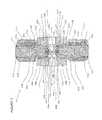
- FIG. 1shows schematically a fuel supply device of a gas-operated motor vehicle
- FIG. 2shows a pressure control according to a first exemplary embodiment of the present invention in a non-excited closed state
- FIG. 2.1shows a pressure control according to a first exemplary embodiment of the present invention in the excited open stated at high pressures in the inlet side high-pressure chamber (high-pressure range)
- FIG. 2.2shows a pressure control according to a first exemplary embodiment of the present invention in the excited open state at low pressures in the inlet side high-pressure chamber (low-pressure range)
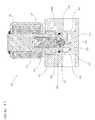
- FIG. 3shows a pressure control according to a second exemplary embodiment of the present invention in the non-excited closed state
- FIG. 3.1shows a pressure control according to a second exemplary embodiment of the present invention in the excited open state at high pressures in the inlet side high-pressure chamber (high-pressure range)
- FIG. 3.2shows a pressure control according to a second exemplary embodiment of the present invention in the excited open state at low pressures in the inlet side high-pressure chamber (low-pressure range)
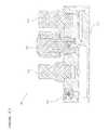
- FIG. 4shows a pressure control according to a third exemplary embodiment of the present invention in a non-excited closed state
- FIG. 4.1shows a pressure control according to a third exemplary embodiment of the present invention in the excited open state at high pressures in the inlet side high-pressure chamber (high-pressure range)
- FIG. 4.2shows a pressure control according to a third exemplary embodiment of the present invention in the excited open state at low pressures in the inlet side high-pressure chamber (low-pressure range)
- FIG. 5shows a pressure control according to a first exemplary embodiment of the present invention in a non-excited closed stated with a modified seal of the closure body
- FIG. 6shows a pressure control according to a first exemplary embodiment of the present invention in the non-excited closed state with a modified valve piston
- FIG. 7shows different embodiments for the entraining function of the valve piston for the pressure control according to the invention based on the first embodiment
- FIG. 8shows a pressure control according to the present invention with a first exemplary embodiment for an embodied heat exchanger
- FIG. 8.1shows a pressure control according to the present invention with a second exemplary embodiment for an embodied heat exchanger
- FIG. 8.2shows a pressure control according to the present invention with a third exemplary embodiment for an embodied heat exchanger
- FIG. 9shows a first exemplary embodiment of a control unit with a pressure control according to the invention
- FIG. 9.1shows a second exemplary embodiment of a control unit with the pressure control according to the invention
- the fuel supply device 100comprises for the supply of a user 101 with gaseous fuel, such as natural gas, methane, biogas, hydrogen, or the like from one or more reservoirs 102 including a tank valve 103 , which is supplied with fuel gas when refueling via a refuel coupling 104 arranged with an integrated non-return valve at the inlet side and a gas supply line 105 following thereat.
- gaseous fuelsuch as natural gas, methane, biogas, hydrogen, or the like
- a tank valve 103which is supplied with fuel gas when refueling via a refuel coupling 104 arranged with an integrated non-return valve at the inlet side and a gas supply line 105 following thereat.
- a control unit 106for discharging a control unit 106 is provided, at least comprising a pressure control 107 , a high-pressure sensor 108 , a low-pressure sensor 109 , and safety devices 110 (high-pressure safety, low-pressure safety, thermal safety), which is controlled by a control device 111 , which generates the control signal according to specifications of the user 101 and considering the storage pressure and the operating pressure.
- the refuelingstarting at the refuel coupling arranged at the inlet side and comprising an integrated reflux block, may occur via the control unit, with at the inlet side optionally a return valve and optionally a filter as well as suitable line connections are arranged to the refuel coupling and to the high-pressure reservoir.
- the fill couplingmay be integrated with an integrated reflux block in the control unit.
- system shut-off valvecan be integrated in the control unit.
- the pressure controlcan be integrated in the cylinder valve.
- control unitcan be integrated in the cylinder valve.
- the pressure control 200comprises a housing 201 , in which at least one inlet 202 with a subsequent high-pressure chamber 203 , an outlet 204 with an upstream arranged low-pressure chamber 205 , flow paths 206 a and 206 b are provided between the high-pressure chamber 203 and the low-pressure chamber 205 , sealing seats 207 a and 207 b in the flow path 206 a and 206 b between the high-pressure chamber 203 and the low-pressure chamber 205 , closure units 209 a and 209 b with an internal thread 210 a and 210 b for a screw connection of the closure units 209 a and 209 b in the housing 201 , and sealing seats 211 a and 211 b for sealing the closure units 209 a and 209 b in the housing 201 .
- the closure unit 209 a and 209 bcomprises a valve housing 212 a and 212 b with a threaded part 213 a and 213 b and opposite thereto a guide part 214 a and 214 b .
- the threaded part 213 a and 213 bis provided with an external thread 215 a and 215 b for a screw connection to the internal thread 210 a and 210 b of the housing 201 , an external groove 216 a and 216 b for the accepting bores 208 a and 208 b to accept a sealing ring 217 a and 217 b in order to seal the valve housing 212 a and 212 b in reference to the housing 201 and a tool accept 218 a and 218 b for an engagement by a tool to screw the valve units 209 a and 209 b into the housing 201 .
- the guide part 214 a and 214 bis provided with an external annular groove 219 a and 219 b to accept a safety ring 220 a and 220 b for fixation of the magnetic coil 221 a and 221 b placed upon the guide part 214 a and 214 b .
- a valve piston 222 a and 222 bis arranged, comprising an anchor 223 a and 223 b , an actuator 224 a and 224 b , a spring 225 a and 225 b , and a closure body 226 a and 226 b , arranged in a displaceable fashion between the closed position and an open position.
- the closure body 226 a and 226 bis accepted at the first end of the magnetic anchor 223 a and 223 b , with an internal groove 227 a and 227 b being provided to accept the actuator 224 a and 224 b for the closure body 226 a and 226 b .
- the anchor 222 a and 222 bis guided in the guide part 214 a and 214 b with a slight radial play, with a bore 228 a and 228 b being provided at the second end to accept the spring 225 a and 225 b .
- a sealing area 229 a and 229 b and an external groove 230 a and 230 bis embodied at the closure body 226 a and 226 b comprising a sealing material to support the actuator 224 a and 224 b.
- closure body 226 a and 226 bcan directly be fastened in the magnetic anchor 223 a and 223 b without any actuator 224 a and 224 b , with optionally a ventilation being provided of the rear area of the actuator 224 a and 224 b.
- closure body 226 a and 226 bmay be embodied with a groove to accept a suitable seal, with optionally ventilation being provided at the rear groove area.
- the housing 201may be embodied with a groove for accepting a suitable seal, with optionally ventilation being provided at the rear groove area.
- the sealing areacannot be arranged directly in the housing but at a suitable threaded part or a suitable insert.
- a metallic closure bodymay be used instead of a closure body comprising a suitable sealing material.
- closure units 209 a and 209 bmay be arranged on the low-pressure side.
- closure units 209 a and 209 bmay be arranged at arbitrary positions of the housing.
- closure units 209 a and 209 bmay be arranged at arbitrary positions of the housing.
- the spring 225 a and 225 bpresses the anchor 223 a and 223 b of the valve piston 222 a and 222 b downwards, with the sealing surface 229 a and 229 b of the closure body 226 a and 226 b being supported at the sealing seat 207 a and 207 b in the housing 201 and thus seals the flow paths 206 a and 206 b between the high-pressure chamber 203 and the low-pressure chamber 205 .
- the anchor 223 b of the valve piston 222 bis raised against the acting spring 225 b and lifts the sealing surface 229 b of the closure body 226 b by the actuator 224 b off the sealing seat 207 b in the housing 201 , with the flow path 206 b from the high-pressure chamber 203 to the low-pressure chamber 205 being open.
- the operating state according to FIG. 21is implemented at high inlet pressures with due to the small size of the area not pressure compensated only requires a low electric power for lifting the valve piston and due to the small diameter of flow released achieves a strong reduction of pressure.
- the anchor 223 a of the valve piston 222 ais raised against the acting spring 225 a and lifts the sealing area 229 a of the closure body 226 via the actuator 224 a off the sealing seat 207 a in the housing 201 , with the second flow path 206 a from the high-pressure chamber 203 to the low-pressure chamber 205 being open.
- the operating state according to FIG. 22is implemented at moderate and low inlet pressures and due to the large flow cross-section a high mass flow is achieved with a low pressure reduction.
- the pressure control 300comprises a housing 301 , in which at least an inlet 302 is provided with a subsequent high-pressure chamber 303 , an outlet 304 with an upstream arranged low-pressure chamber 305 , a flow path 306 between the inlet 302 and the outlet 304 , a sealing seat 307 in the flow path 306 between the high-pressure chamber 303 and the low-pressure chamber 305 , an accepting bore 308 for accepting the closure unit 309 with an internal thread 310 for a screw connection of the closure unit 309 in the housing 301 and a sealing seat 311 for sealing the closure unit 309 in the housing 301 .
- the closure unit 309comprises a valve housing 312 with a threaded part 313 and opposite thereof a guide part 314 .
- the threaded part 313is provided with an external thread 315 for an engagement with the internal thread 310 of the housing 301 , an external groove 316 for accepting a sealing ring 317 to seal the closure unit 309 in reference to the housing 301 and a tool accept 318 to be engaged by a tool for the closure part 309 to be screwed into the housing 301 .
- the guide part 314is provided with an external annular groove 319 to accept a sealing ring 320 for fixing the magnetic coil 321 placed upon the guide part 314 .
- a valve piston 322is arranged inside the closure unit 309 , comprising an anchor 323 , an actuator 324 , a spring 325 , and a closure body 326 , displaceable between a closed position of a first open position and a second open position.
- the closure body 326is accepted, with an internal sealing seat 327 being arranged for support at the upper sealing area 328 of the sealing body 326 , an interior located groove 329 to accept the actuator 324 , and at least one lateral bore 330 .
- the anchor 323is guided in the guide part 314 with a slight radial play, with the open end 331 being provided to accept the spring 325 .
- An upper sealing surface 328is embodied at the closure body 326 comprising a sealing material, opposite the lower sealing surface 332 and with different dimensions, an axial throttle bore 333 between the two sealing surfaces, and an external groove 334 to support the actuator 324 of the closure unit 309 .
- the spring 325presses the anchor 323 of the closure unit 309 downwards, with the lower sealing surface 332 of the closure body 326 being supported on the sealing seat 307 in the housing 301 and the upper sealing surface 328 of the closure body 326 at the sealing surface 327 of the anchor 323 and thus closes the flow path 306 between the high-pressure chamber 303 and the low pressure chamber 305 .
- a gap 335is present between the actuator 324 and the closure body 326 in the direction of motion of the valve body 322 .
- FIG. 3.1shows that by addressing and exciting the magnetic coil 321 the anchor 323 of the valve piston 322 is raised against the acting spring 325 , with the lower sealing surface 332 of the closure body 326 is supported on the sealing seat 307 in the housing 301 and the sealing surface 327 of the anchor 323 is lifted off the upper sealing surface 329 of the closure body 326 , thus opening a flow path 306 a from the high-pressure chamber 303 via the lateral bore 330 in the anchor 323 and the throttle bore 333 in the closure body 326 to the low-pressure chamber 305 .
- a gap 335is present between the actuator 324 and the closure body 326 in the direction of motion of the valve piston 322 .
- the operating state according to FIG. 3.1is implemented at high inlet pressures, with due to the small size of the area not pressure-compensated a low electric power is required for lifting the valve piston and due to the small diameter of flow released a strong reduction of pressure is achieved.
- the anchor 323 of the valve piston 322is further raised against the acting spring 325 , the gap 335 between the actuator 324 and the closure body 326 is closed in the direction of motion of the valve piston 322 , and the closure body 326 is lifted off the actuator 324 , with the lower sealing area 332 of the closure body 326 being lifted off the sealing seat 307 in the housing 301 and with the open flow path 306 a the flow path 306 is open from the high-pressure chamber 303 via the sealing seat 307 in the housing 301 to the low-pressure chamber 305 .
- the operating state according to FIG. 3.2is implemented at moderate and low inlet pressures and due to the large cross-section of flow a strong mass flow is achieved with a low reduction in pressure.
- the pressure control 400comprises a housing 401 , in which at least one inlet 402 is provided with a subsequent high-pressure chamber 403 , an outlet 404 with an upstream arranged low-pressure chamber 405 , a flow path 406 between the inlet 402 and the outlet 404 , a sealing seat 407 in the flow path 406 between the high-pressure chamber 403 and the low-pressure chamber 405 , an accepting bore 408 for accepting the closure body 409 in the housing 401 including the groove 410 for accepting a safety ring 411 to support a counter fastener 412 for the first spring 413 , an accepting bore 414 for accepting the closure unit 415 with an internal thread 416 for a screw-connection of the closure unit 415 in the housing 401 , and a sealing seat 417 for sealing the closure unit 415 in the housing 401 .
- the closure unit 415comprises a valve housing 418 with a threaded part 419 and opposite thereof a guide part 420 .
- the threaded part 419is provided with an external thread 421 for a screw-connection to the internal thread 416 of the housing 401 , an external groove 422 for accepting a sealing ring 423 to seal the closure unit 415 in reference to the housing 401 , and a tool accept 424 to be engaged by a tool to screw the closure unit 415 into the housing 401 .
- the guide part 420is provided with an external annular groove 425 for accepting a sealing ring 426 for fixation of the inverse stroke—magnetic coil 427 placed upon the guide part 420 .
- a magnetic anchor 428 and a second spring 429are provided with less strength than the first spring 413 , displaceable between the closed position and a first open position and a second open position.
- An external sealing seat 430is arranged at the first end of the magnetic anchor 428 to seal the first sealing surface 431 at the sealing body 409 .
- the anchor 428is guided in the guide part 420 with a slight radial play, with the open end 432 being provided to accept the spring 429 .
- a first sealing surface 431a second sealing surface 433 with different dimensions, an axial throttle bore 434 between the two sealing surfaces, and an inner bore 435 are embodied to accept the spring 413 and optionally exterior or interior located flow channels 436 .
- closure body 409can be embodied with grooves to accept suitable seals, with optionally ventilation may be provided at the rear groove areas.
- housing 401can be embodied with a groove to accept suitable seals, with optionally ventilation may be provided of the rear groove area.
- sealing surfacemay not be embodied directly in the housing but at a suitable threaded part or at a suitable insert.
- a metallic closure bodymay be used instead of a closure part made from a suitable sealing material.
- the spring 429presses the anchor 428 of the closure unit 415 against the closure body 409 , with the first sealing surface 431 of the closure body 409 being supported at the sealing surface 430 of the anchor 428 and the second sealing surface 433 of the closure body 409 by the force of the spring 413 at the sealing seat 407 in the housing 401 , and thus closes the flow path 406 between the high-pressure chamber 403 and the low-pressure chamber 405 .
- the anchor 428is moved against the acting spring 433 , with the second sealing surface 433 of the closure body 409 being supported by the force of the spring 413 at the sealing seat 407 in the housing 401 and the sealing 430 of the anchor 428 being lifted off the first sealing surface 431 of the closure body 409 , with here the flow path 406 a being open from the high-pressure chamber 403 via the throttle bore 434 in the closure body 409 to the low-pressure chamber 405 .
- the operating state according to FIG. 4.1is implemented at high inlet pressures, with due to the small size of the area not pressure-compensated a low electric power is required to lift the anchor and due to the small diameter of open flow a strong reduction of pressure is achieved.
- the anchor 428is moved against the acting spring 413 , with the sealing area 430 of the anchor 428 being supported at the first sealing surface 431 of the closure body 409 and the second sealing surface 433 of the closure body 409 being lifted off the sealing seat 407 in the housing 401 , with the flow path 406 being open from the high-pressure chamber 403 via the sealing seat 407 in the housing to the low-pressure chamber 405 .
- the operating state according to FIG. 4.2is implemented at moderate and low inlet pressures and due to the large cross-section of flow a large mass flow is achieved with low reduction in pressure.
- FIG. 5shows the pressure control 500 according to the invention with a modified sealing system between the high-pressure chamber 501 and the low-pressure chamber 502 , with the closure body 503 comprises at least one suitable accept 504 for a suitable seal 505 , which is supported at the sealing seat 506 in the housing 507 and the anchor 508 comprises a suitable accept 509 for a suitable seal 510 , which is supported at the closure body 503 , with optionally ventilation is provided at the rear groove areas.
- closure bodycomprises two accepts for the two seals.
- housing and the anchoreach show an accept for the two seals.
- the housingcomprises two accepts for the two seals.
- a separate sheathmay be installed in the closure body to stabilize the closure body.
- closure bodymay be embodied in several parts.
- sealing surfacecannot be embodied directly in the housing but at a suitable threaded part or at a suitable insert.
- a metallic closure bodyinstead of a closure body comprising a suitable sealing material, a metallic closure body may be used.
- FIG. 6shows a pressure control 600 according to the invention with a modified exciter system.
- the anchor 601comprises an open end 602 and a closed end 603 , with the spring 604 being supported at an exterior shoulder 605 of the open anchor end 602 opposite in reference to an interior shoulder 606 of the open value housing 607 so that by the design of the operating air gap 608 the progression of the magnetic force parameter can be influenced in a targeted fashion.
- a closure unitmay be used with a discrete switching function (two-position stroke magnet with an open and a closed position, when an electromagnetic closure unit is used) or a continuously switched closure unit (proportional magnet with arbitrary intermediate positions between the open and the closed position when an electromagnetic closure unit is used) to influence the position of the closure body.
- a discrete switching functiontwo-position stroke magnet with an open and a closed position, when an electromagnetic closure unit is used
- a continuously switched closure unitproportional magnet with arbitrary intermediate positions between the open and the closed position when an electromagnetic closure unit is used
- valve housingis provided with a device for the mechanic opening and optionally for the mechanic closing of the closure body.
- valve housingis embodied in several parts for a better magnetic flow.
- the anchoris embodied in several parts for a better magnetic flow or for a better guidance in the valve housing.
- Additional embodimentsdevelop when the flow paths arranged in a parallel fluidic fashion between the high-pressure chamber at the inlet side and the low-pressure chamber at the outlet side are opened or closed by a rotating actuator or rotating actuators.
- FIG. 7shows different options to embody the actuator function of the valve piston for the pressure control according to the invention as shown in the second embodiment.
- FIG. 8shows the pressure control 800 according to the invention with a heating system to avoid icing or excessive cooling of the pressure control in gases with negative Joule-Thomson coefficient in the operating range of the pressure control, with the generation of heat occurring via an inserted electric heater 801 .
- FIG. 8.1shows the pressure control 810 according to the invention with a heating system to avoid icing or excessive cooling of the pressure control in gases with negative Joule-Thomson coefficient in the operating range of the pressure control, with the generation of heat occurring by adding cooling water, with the radiator 811 being installed at the housing 812 in a suitable fashion.
- FIG. 8.2shows the pressure control 820 according to the invention with a heating system to avoid icing or excessive cooling of the pressure control with gases showing negative Joule-Thomson coefficient in the operating range of the pressure control, with the generation of heat occurring by supplying cooling water, which is guided through cooling ducts 821 in the housing 822 of the pressure control.
- FIG. 9shows a control unit 900 comprising at least the pressure control 901 according to the invention, a low-pressure sensor 902 , and optionally a high-pressure sensor 903 in a joint housing 904 , with if applicable a heating system may be embodied according to FIG. 8 , FIG. 8.1 or FIG. 8.2 .
- FIG. 9.1shows a control unit 910 , comprising at least the pressure control 911 according to the invention, a low-pressure sensor 912 of a low-pressure safety device 913 , and optionally a high-pressure sensor 914 in a joint housing 915 , with if applicable a heating system being embodied according to FIG. 8 , FIG. 8.1 , or FIG. 8.2 .
- a spring-loaded closure body or a blow-out diskmay be installed as a low-pressure safety device.
- the refueling of the high-pressure reservoirmay occur via the control unit using suitably embodied line connections.
- the return valve for refueling the high-pressure reservoirmay be integrated via the control unit and appropriate line connections in the control unit.
- a filter elementmay be integrated in the control unit.
- the refueling coupling to refuel the high-pressure reservoirmay be integrated via the control unit and appropriate line connections in the control unit.
- a system shut-off valvemay be integrated at the high-pressure side or the low-pressure side in the control unit.
- a temperature-controlled safety devicemay be installed in the control unit.
- control unitmay be integrated in the cylinder valve.
- control unitmay be provided in separate housings.
- the electronic control devicemay be installed directly at the control unit or at the pressure control.
- a closure unitaccording to the principle functionality of the electrohydraulic—mechanic energy conversion, the electropneumatic—mechanic energy conversion, the electromechanic energy conversion (electric engine), or a coupling of arbitrary energy conversion principles is used.
- the pressure control( 107 , 200 , 300 , 400 , 500 , 600 , 800 , 810 , 820 , 901 , 911 ) comprises several flow paths ( 206 a , 206 b , 306 , 306 a , 406 , 406 a ) with different cross-sections between the inlet side high-pressure chamber ( 203 , 303 , 403 , 501 ) and the outlet side low-pressure chamber ( 205 , 305 , 405 , 502 ) a control opens or closes the flow paths ( 206 b , 306 a , 406 a ) with small cross-sections at high pressures or at small volume flows and indirectly at low pressures the flow paths ( 206 b , 306 a , 406 a ) with large cross-sections.
- the pressure control( 107 , 200 , 300 , 400 , 500 , 600 , 800 , 810 , 820 , 901 , 911 ) comprises several flow paths with identical cross-sections between the inlet side high-pressure chamber ( 203 , 303 , 403 , 501 ) and the outlet side low-pressure chamber ( 205 , 305 , 405 , 502 ) a control indirectly opens or closes at high pressures or at low volume flows few flow paths and at low pressures several flow paths.
- controlindirectly opens flow paths and indirectly closes flow paths when the operating pressure is exceeded.
Landscapes
- Physics & Mathematics (AREA)
- Fluid Mechanics (AREA)
- Engineering & Computer Science (AREA)
- General Physics & Mathematics (AREA)
- Automation & Control Theory (AREA)
- General Engineering & Computer Science (AREA)
- Combustion & Propulsion (AREA)
- Mechanical Engineering (AREA)
- Chemical & Material Sciences (AREA)
- Magnetically Actuated Valves (AREA)
- Control Of Fluid Pressure (AREA)
- Fuel-Injection Apparatus (AREA)
- Output Control And Ontrol Of Special Type Engine (AREA)
- Valve Housings (AREA)
- Cooling, Air Intake And Gas Exhaust, And Fuel Tank Arrangements In Propulsion Units (AREA)
- Feeding And Controlling Fuel (AREA)
- Fuel Cell (AREA)
Abstract
Description
- Compact design by selected functional principles
- High adaptability by electronic control
- High inert sealing by large pressure area and return spring
- Waiver of a system shut-off valve by high inert sealing
- Powerless sealing by the container pressure
- High operational security by a robust design and a low number of components
- Low production costs by a low number of components
- High variability by a simple adjustment for different gases.
- High pressure range: At high pressures in the inlet side high-pressure chamber or at low volume flows the flow path with the smaller cross-section is released by the closure unit, with due to the area ratios low electric power is required.
- Low pressure range: At low pressures in the inlet side high-pressure chamber the flow path with the larger cross-section is released by the closure unit, with due to the pressure ratios only low electric power is required.
Claims (22)
Applications Claiming Priority (4)
| Application Number | Priority Date | Filing Date | Title |
|---|---|---|---|
| DE102010003016.3ADE102010003016B4 (en) | 2010-03-18 | 2010-03-18 | Pressure regulator for supplying fuel and fuel supply system with a control unit from these pressure regulators |
| DE102010003016 | 2010-03-18 | ||
| DE102010003016.3 | 2010-03-18 | ||
| PCT/EP2011/054099WO2011113922A2 (en) | 2010-03-18 | 2011-03-18 | Pressure regulators for feeding fuel, and fuel-supplying system comprising a regulating unit that consists of said pressure regulators |
Publications (2)
| Publication Number | Publication Date |
|---|---|
| US20130056097A1 US20130056097A1 (en) | 2013-03-07 |
| US9880568B2true US9880568B2 (en) | 2018-01-30 |
Family
ID=44511814
Family Applications (1)
| Application Number | Title | Priority Date | Filing Date |
|---|---|---|---|
| US13/635,675ActiveUS9880568B2 (en) | 2010-03-18 | 2011-03-18 | Pressure regulators for feeding fuel, and fuel-supplying system comprising a regulating unit that consists of said pressure regulators |
Country Status (11)
| Country | Link |
|---|---|
| US (1) | US9880568B2 (en) |
| EP (1) | EP2548089B1 (en) |
| JP (1) | JP6005527B2 (en) |
| KR (1) | KR101880241B1 (en) |
| CN (1) | CN103109247B (en) |
| BR (1) | BR112012023564B1 (en) |
| CA (1) | CA2793038C (en) |
| DE (1) | DE102010003016B4 (en) |
| ES (1) | ES2881901T3 (en) |
| RU (1) | RU2559865C2 (en) |
| WO (1) | WO2011113922A2 (en) |
Families Citing this family (7)
| Publication number | Priority date | Publication date | Assignee | Title |
|---|---|---|---|---|
| DE102011118848B4 (en)* | 2011-11-18 | 2018-10-31 | BO-INNO GmbH | Gas pressure regulating device and housing of a gas pressure regulating device |
| DE102014218818A1 (en)* | 2014-09-18 | 2016-04-07 | Continental Automotive Gmbh | Pressure reducing device for a device for supplying fuel and device for supplying fuel |
| AT14454U3 (en)* | 2015-07-20 | 2018-08-15 | Ventrex Automotive Gmbh | pressure regulator |
| AT517645A1 (en)* | 2015-07-20 | 2017-03-15 | Ventrex Automotive Gmbh | pressure regulator |
| DE102016105048A1 (en)* | 2016-03-18 | 2017-09-21 | Volkswagen Aktiengesellschaft | Internal combustion engine and method for operating an internal combustion engine |
| DE102018113240A1 (en)* | 2018-06-04 | 2019-12-05 | Volkswagen Aktiengesellschaft | Feeding system for supplying a CNG or LNG fuel |
| AT17013U1 (en) | 2019-09-05 | 2021-02-15 | Zieger Dipl Ing Andreas |
Citations (43)
| Publication number | Priority date | Publication date | Assignee | Title |
|---|---|---|---|---|
| US1228104A (en)* | 1915-08-18 | 1917-05-29 | Chaplin Fulton Mfg Company | Valve. |
| DE2937978A1 (en) | 1979-09-20 | 1981-04-16 | Battelle-Institut E.V., 6000 Frankfurt | Gas pressure regulator - monitors output pressure to operate solenoid valve to input flow or vent to atmosphere |
| GB2129170A (en) | 1982-10-21 | 1984-05-10 | Secr Defence | Improvements in or relating to pressure controllers |
| JPS6158964A (en) | 1984-08-30 | 1986-03-26 | Mitsubishi Heavy Ind Ltd | Gas engine |
| US4760694A (en)* | 1986-10-27 | 1988-08-02 | Rockwell International Corporation | Bi-level thruster |
| DE4016140A1 (en) | 1989-05-26 | 1991-01-31 | Tigaz Tiszantuli Gazszolgaltat | Controlled gas flow regulator and controller |
| JPH0418797U (en) | 1990-06-08 | 1992-02-17 | ||
| JPH05126105A (en) | 1991-10-16 | 1993-05-21 | Mitsubishi Nuclear Fuel Co Ltd | Pneumatic control unit |
| JPH05209557A (en) | 1992-01-31 | 1993-08-20 | Mazda Motor Corp | Fuel supply device for gaseous fuel engine |
| US5289811A (en)* | 1993-05-10 | 1994-03-01 | General Motors Corporation | Purge control device |
| US5351656A (en) | 1992-01-31 | 1994-10-04 | Mazda Motor Corporation | Fuel supply apparatus |
| JP3040627U (en) | 1997-02-13 | 1997-08-26 | 甲南電機株式会社 | Pressure reducing valve |
| US5755254A (en) | 1994-08-30 | 1998-05-26 | Sherex Industries, Ltd. | Two stage pressure regulator |
| US5875817A (en)* | 1995-08-17 | 1999-03-02 | Ortech Corporation | Digital gas metering system using tri-stable and bi-stable solenoids |
| JPH11107860A (en) | 1997-10-09 | 1999-04-20 | Denso Corp | Fuel leakage detecting device for gas engine |
| JP2000009240A (en) | 1998-06-25 | 2000-01-11 | Kuroda Precision Ind Ltd | Speed controller for fluid operated equipment |
| JP2000248997A (en) | 1999-03-01 | 2000-09-12 | Toyota Motor Corp | Gas fuel supply device |
| JP2001066020A (en) | 1999-08-24 | 2001-03-16 | Denso Corp | Electromagnetic flow rate control valve |
| US6234204B1 (en)* | 1994-12-29 | 2001-05-22 | Van Den Wildenberg Adrianus Martinus | Flow control valve |
| EP1120561A2 (en) | 2000-01-27 | 2001-08-01 | Landi Renzo S.p.A. | Two-stage pressure regulator for feeding internal combustion engines with gaseous fuel at constant pressure |
| AT4536U1 (en) | 1999-12-07 | 2001-08-27 | Steyr Daimler Puch Ag | FUEL TANK SYSTEM FOR A MOTOR VEHICLE AND FLOAT VALVE |
| US20020026960A1 (en)* | 2000-08-08 | 2002-03-07 | Weldon Craig W. | Fuel tank pressure control valve |
| JP2003083172A (en) | 2001-09-12 | 2003-03-19 | Toyota Motor Corp | Liquefied gas fuel supply system |
| DE10204746A1 (en) | 2002-02-06 | 2003-08-21 | Bosch Gmbh Robert | Gas pressure regulator for regulating a pressure of a gas |
| US20030226588A1 (en) | 2002-06-10 | 2003-12-11 | Olander W. Karl | Pressure-based gas delivery system and method for reducing risks associated with storage and delivery of high pressure gases |
| JP2004052713A (en) | 2002-07-23 | 2004-02-19 | Toyota Motor Corp | Fuel supply device for internal combustion engine |
| JP2005044278A (en) | 2003-07-25 | 2005-02-17 | Nissan Motor Co Ltd | Pressure control device |
| JP2005053358A (en) | 2003-08-05 | 2005-03-03 | Honda Motor Co Ltd | High pressure gas storage device |
| JP2005069456A (en) | 2003-08-28 | 2005-03-17 | Kuroda Precision Ind Ltd | Annular orifice, flow control valve or pressure control valve |
| US20060054144A1 (en) | 2002-08-09 | 2006-03-16 | Isuzu Motors Limited | Gas fuel feed device |
| US20060162778A1 (en)* | 2003-08-25 | 2006-07-27 | Nichols Randall W | Drain valve |
| DE60306484T2 (en) | 2003-01-22 | 2006-11-23 | Cavagna Group S.P.A. | Pressure regulator with pressure gauge, in particular for liquefied gas tanks |
| US7159611B2 (en) | 2002-07-12 | 2007-01-09 | Tescom Corporation | Inline flow control device |
| JP2007170443A (en) | 2005-12-19 | 2007-07-05 | Honda Motor Co Ltd | Hydrogen vehicle gas use and supply system |
| US20080047619A1 (en)* | 2006-08-28 | 2008-02-28 | Gm Global Technology Operations, Inc. | Multi stage pressure regulator |
| WO2008029073A1 (en) | 2006-09-08 | 2008-03-13 | Artemis Intelligent Power Limited | Fluid-working machine |
| FR2905773A1 (en) | 2006-09-08 | 2008-03-14 | Air Liquide | Gas pressure regulator for supplying fuel cell with hydrogen, has membrane with pusher to open or hide orifice so that orifice is totally closed or totally open, where orifice has surface lesser or equal to specific millimeter |
| CN101144437A (en) | 2007-09-28 | 2008-03-19 | 西安易道汽车电器有限责任公司 | Motor engine electric control fuel oil spraying system |
| US20080247882A1 (en) | 2007-04-03 | 2008-10-09 | General Motors Corporation | Split-Pressure Dual Pump Hydraulic Fluid Supply System for a Multi-Speed Transmission and Method |
| CN101297152A (en) | 2005-10-27 | 2008-10-29 | 乔治洛德方法研究和开发液化空气有限公司 | Fluid filling and/or extraction control device and tank including one such device |
| DE102008034581A1 (en) | 2007-07-24 | 2009-01-29 | Ventrex Automotive Gmbh | Tank and fuel supply system for internal combustion engine of motor vehicle, has short low-pressure gas supply line guided to fuel-gas-distributor for supplying engine with actual required amount of low-pressure fuel gas e.g. natural gas |
| US20090212244A1 (en)* | 2008-02-26 | 2009-08-27 | Pfaff Joseph L | Pilot operated valve with fast closing poppet |
| US20100242921A1 (en)* | 2009-03-30 | 2010-09-30 | Gregory Harper | Method And System For Controlling Fluid Flow From A Storage Tank Through A Supply Line To An End User |
Family Cites Families (4)
| Publication number | Priority date | Publication date | Assignee | Title |
|---|---|---|---|---|
| US5048790A (en)* | 1990-07-18 | 1991-09-17 | Target Rock Corporation | Self-modulating control valve for high-pressure fluid flow |
| CA2441641C (en)* | 2003-09-23 | 2006-01-31 | Westport Research Inc. | A high pressure gaseous fuel supply system for an internal combustion engine and a method of sealing connections between components to prevent leakage of a high pressure gaseous fuel |
| JP4203906B2 (en)* | 2004-03-31 | 2009-01-07 | 株式会社デンソー | Solenoid valve and evaporative fuel processing system using the same |
| DE102005022693A1 (en)* | 2005-05-18 | 2006-11-23 | Hydac Fluidtechnik Gmbh | Valve, in particular proportional pressure relief valve |
- 2010
- 2010-03-18DEDE102010003016.3Apatent/DE102010003016B4/enactiveActive
- 2011
- 2011-03-18EPEP11708505.0Apatent/EP2548089B1/enactiveActive
- 2011-03-18WOPCT/EP2011/054099patent/WO2011113922A2/enactiveApplication Filing
- 2011-03-18CACA2793038Apatent/CA2793038C/enactiveActive
- 2011-03-18JPJP2012557562Apatent/JP6005527B2/enactiveActive
- 2011-03-18BRBR112012023564Apatent/BR112012023564B1/enactiveIP Right Grant
- 2011-03-18USUS13/635,675patent/US9880568B2/enactiveActive
- 2011-03-18ESES11708505Tpatent/ES2881901T3/enactiveActive
- 2011-03-18RURU2012143371/28Apatent/RU2559865C2/enactive
- 2011-03-18KRKR1020127027124Apatent/KR101880241B1/enactiveActive
- 2011-03-18CNCN201180014425.2Apatent/CN103109247B/enactiveActive
Patent Citations (46)
| Publication number | Priority date | Publication date | Assignee | Title |
|---|---|---|---|---|
| US1228104A (en)* | 1915-08-18 | 1917-05-29 | Chaplin Fulton Mfg Company | Valve. |
| DE2937978A1 (en) | 1979-09-20 | 1981-04-16 | Battelle-Institut E.V., 6000 Frankfurt | Gas pressure regulator - monitors output pressure to operate solenoid valve to input flow or vent to atmosphere |
| GB2129170A (en) | 1982-10-21 | 1984-05-10 | Secr Defence | Improvements in or relating to pressure controllers |
| JPS6158964A (en) | 1984-08-30 | 1986-03-26 | Mitsubishi Heavy Ind Ltd | Gas engine |
| US4760694A (en)* | 1986-10-27 | 1988-08-02 | Rockwell International Corporation | Bi-level thruster |
| DE4016140A1 (en) | 1989-05-26 | 1991-01-31 | Tigaz Tiszantuli Gazszolgaltat | Controlled gas flow regulator and controller |
| JPH0418797U (en) | 1990-06-08 | 1992-02-17 | ||
| JPH05126105A (en) | 1991-10-16 | 1993-05-21 | Mitsubishi Nuclear Fuel Co Ltd | Pneumatic control unit |
| US5351656A (en) | 1992-01-31 | 1994-10-04 | Mazda Motor Corporation | Fuel supply apparatus |
| JPH05209557A (en) | 1992-01-31 | 1993-08-20 | Mazda Motor Corp | Fuel supply device for gaseous fuel engine |
| US5289811A (en)* | 1993-05-10 | 1994-03-01 | General Motors Corporation | Purge control device |
| US5755254A (en) | 1994-08-30 | 1998-05-26 | Sherex Industries, Ltd. | Two stage pressure regulator |
| CN1185213A (en) | 1994-08-30 | 1998-06-17 | 谢里克斯工业有限公司 | Improved two stage pressure regulator |
| US6234204B1 (en)* | 1994-12-29 | 2001-05-22 | Van Den Wildenberg Adrianus Martinus | Flow control valve |
| US5875817A (en)* | 1995-08-17 | 1999-03-02 | Ortech Corporation | Digital gas metering system using tri-stable and bi-stable solenoids |
| JP3040627U (en) | 1997-02-13 | 1997-08-26 | 甲南電機株式会社 | Pressure reducing valve |
| JPH11107860A (en) | 1997-10-09 | 1999-04-20 | Denso Corp | Fuel leakage detecting device for gas engine |
| JP2000009240A (en) | 1998-06-25 | 2000-01-11 | Kuroda Precision Ind Ltd | Speed controller for fluid operated equipment |
| JP2000248997A (en) | 1999-03-01 | 2000-09-12 | Toyota Motor Corp | Gas fuel supply device |
| JP2001066020A (en) | 1999-08-24 | 2001-03-16 | Denso Corp | Electromagnetic flow rate control valve |
| AT4536U1 (en) | 1999-12-07 | 2001-08-27 | Steyr Daimler Puch Ag | FUEL TANK SYSTEM FOR A MOTOR VEHICLE AND FLOAT VALVE |
| EP1120561A2 (en) | 2000-01-27 | 2001-08-01 | Landi Renzo S.p.A. | Two-stage pressure regulator for feeding internal combustion engines with gaseous fuel at constant pressure |
| DE60021694T2 (en) | 2000-01-27 | 2006-03-30 | Landi Renzo S.P.A., Corte Tegge | Two-stage pressure regulator for the supply of a gas under constant pressure to an internal combustion engine |
| US20020026960A1 (en)* | 2000-08-08 | 2002-03-07 | Weldon Craig W. | Fuel tank pressure control valve |
| JP2003083172A (en) | 2001-09-12 | 2003-03-19 | Toyota Motor Corp | Liquefied gas fuel supply system |
| DE10204746A1 (en) | 2002-02-06 | 2003-08-21 | Bosch Gmbh Robert | Gas pressure regulator for regulating a pressure of a gas |
| US20030226588A1 (en) | 2002-06-10 | 2003-12-11 | Olander W. Karl | Pressure-based gas delivery system and method for reducing risks associated with storage and delivery of high pressure gases |
| US7159611B2 (en) | 2002-07-12 | 2007-01-09 | Tescom Corporation | Inline flow control device |
| JP2004052713A (en) | 2002-07-23 | 2004-02-19 | Toyota Motor Corp | Fuel supply device for internal combustion engine |
| US20060054144A1 (en) | 2002-08-09 | 2006-03-16 | Isuzu Motors Limited | Gas fuel feed device |
| DE60306484T2 (en) | 2003-01-22 | 2006-11-23 | Cavagna Group S.P.A. | Pressure regulator with pressure gauge, in particular for liquefied gas tanks |
| JP2005044278A (en) | 2003-07-25 | 2005-02-17 | Nissan Motor Co Ltd | Pressure control device |
| JP2005053358A (en) | 2003-08-05 | 2005-03-03 | Honda Motor Co Ltd | High pressure gas storage device |
| US20060162778A1 (en)* | 2003-08-25 | 2006-07-27 | Nichols Randall W | Drain valve |
| JP2005069456A (en) | 2003-08-28 | 2005-03-17 | Kuroda Precision Ind Ltd | Annular orifice, flow control valve or pressure control valve |
| CN101297152A (en) | 2005-10-27 | 2008-10-29 | 乔治洛德方法研究和开发液化空气有限公司 | Fluid filling and/or extraction control device and tank including one such device |
| US8136791B2 (en) | 2005-10-27 | 2012-03-20 | L'air Liquide Societe Anonyme Pour L'etude Et L'exploitation Des Procedes Georges Claude | Fluid filling and/or extraction control device and tank including one such device |
| JP2007170443A (en) | 2005-12-19 | 2007-07-05 | Honda Motor Co Ltd | Hydrogen vehicle gas use and supply system |
| US20080047619A1 (en)* | 2006-08-28 | 2008-02-28 | Gm Global Technology Operations, Inc. | Multi stage pressure regulator |
| WO2008029073A1 (en) | 2006-09-08 | 2008-03-13 | Artemis Intelligent Power Limited | Fluid-working machine |
| FR2905773A1 (en) | 2006-09-08 | 2008-03-14 | Air Liquide | Gas pressure regulator for supplying fuel cell with hydrogen, has membrane with pusher to open or hide orifice so that orifice is totally closed or totally open, where orifice has surface lesser or equal to specific millimeter |
| US20080247882A1 (en) | 2007-04-03 | 2008-10-09 | General Motors Corporation | Split-Pressure Dual Pump Hydraulic Fluid Supply System for a Multi-Speed Transmission and Method |
| DE102008034581A1 (en) | 2007-07-24 | 2009-01-29 | Ventrex Automotive Gmbh | Tank and fuel supply system for internal combustion engine of motor vehicle, has short low-pressure gas supply line guided to fuel-gas-distributor for supplying engine with actual required amount of low-pressure fuel gas e.g. natural gas |
| CN101144437A (en) | 2007-09-28 | 2008-03-19 | 西安易道汽车电器有限责任公司 | Motor engine electric control fuel oil spraying system |
| US20090212244A1 (en)* | 2008-02-26 | 2009-08-27 | Pfaff Joseph L | Pilot operated valve with fast closing poppet |
| US20100242921A1 (en)* | 2009-03-30 | 2010-09-30 | Gregory Harper | Method And System For Controlling Fluid Flow From A Storage Tank Through A Supply Line To An End User |
Non-Patent Citations (8)
| Title |
|---|
| European Search Report dated Aug. 12, 2016 of the corresponding European Patent Application No. 11 708 505.5 (7 pages). |
| First Office Action dated Sep. 29, 2014 in CN Patent Application No. 201180014425.2, 23 pages. |
| International Search Report and Written Opinion in Application No. PCT/EP2011/054099 dated Jan. 14, 2013. |
| International Search Report dated Jun. 27, 2012 for PCT Patent Application No. PCT/EP2011/054099, 5 pages. |
| Machine Translation of DE2937978 from EPO website on May 30, 2014.* |
| Machine Translation of FR 2905773 from EPO website on May 30, 2014.* |
| Machine Translation of JP2001066020 (Retrieved from EPO website on Oct. 3, 2016).* |
| Office Action dated Oct. 27, 2015 in JP Patent Application No. 2012-557562, 20 pages. |
Also Published As
| Publication number | Publication date |
|---|---|
| RU2012143371A (en) | 2014-04-27 |
| JP6005527B2 (en) | 2016-10-12 |
| WO2011113922A3 (en) | 2013-03-07 |
| US20130056097A1 (en) | 2013-03-07 |
| BR112012023564B1 (en) | 2020-04-22 |
| CA2793038C (en) | 2019-04-30 |
| DE102010003016A1 (en) | 2011-09-22 |
| KR101880241B1 (en) | 2018-08-17 |
| ES2881901T3 (en) | 2021-11-30 |
| CN103109247B (en) | 2016-10-19 |
| CN103109247A (en) | 2013-05-15 |
| BR112012023564A2 (en) | 2016-08-02 |
| RU2559865C2 (en) | 2015-08-20 |
| EP2548089B1 (en) | 2021-05-05 |
| CA2793038A1 (en) | 2011-09-22 |
| EP2548089A2 (en) | 2013-01-23 |
| DE102010003016B4 (en) | 2018-11-08 |
| WO2011113922A2 (en) | 2011-09-22 |
| KR20130014555A (en) | 2013-02-07 |
| JP2013522528A (en) | 2013-06-13 |
Similar Documents
| Publication | Publication Date | Title |
|---|---|---|
| US9880568B2 (en) | Pressure regulators for feeding fuel, and fuel-supplying system comprising a regulating unit that consists of said pressure regulators | |
| KR102022043B1 (en) | Electromagnetic valve for a tank valve of a fuel supply system | |
| JP5738029B2 (en) | Compound valve | |
| CN113227639A (en) | Method for operating a tank system for storing compressed fluid | |
| CN112673203A (en) | Valve device for gaseous media and tank device for storing gaseous media | |
| CA2619394C (en) | Solenoid isolation valve | |
| JP7580581B2 (en) | Tank arrangement for storing a gaseous medium with a valve arrangement - Patent application | |
| US12429173B2 (en) | Tank device for storing a gaseous medium, comprising a valve device | |
| US10746317B2 (en) | Valve | |
| KR20210032739A (en) | Shut off valve and regulator with the same | |
| US6405755B1 (en) | Directly controlled magnetic valve | |
| CN119022077A (en) | Electronically controlled regulator | |
| KR101654752B1 (en) | Valve for injection of gas | |
| US20150152973A1 (en) | Piezo-actuated pilot valve | |
| KR20240090836A (en) | Hydrogen tank system with shut-off valve and shut-off valve | |
| JP2023547420A (en) | Tank device for storing gaseous media | |
| KR20160076400A (en) | High pressure regulator | |
| EP2807413B1 (en) | Force multiplying solenoid valve | |
| JP7434665B2 (en) | Tank device with valve device | |
| JP7696021B2 (en) | Shut-off valves for hydrogen tank systems, compressed gas cylinders and hydrogen tank systems | |
| EP3767142A1 (en) | Electromagnetically operated valve |
Legal Events
| Date | Code | Title | Description |
|---|---|---|---|
| AS | Assignment | Owner name:HYPTEC GMBH, AUSTRIA Free format text:ASSIGNMENT OF ASSIGNORS INTEREST;ASSIGNORS:ZIEGER, ANDREAS;HOELLER, THOMAS;REEL/FRAME:029341/0379 Effective date:20120913 | |
| STCF | Information on status: patent grant | Free format text:PATENTED CASE | |
| MAFP | Maintenance fee payment | Free format text:PAYMENT OF MAINTENANCE FEE, 4TH YR, SMALL ENTITY (ORIGINAL EVENT CODE: M2551); ENTITY STATUS OF PATENT OWNER: SMALL ENTITY Year of fee payment:4 | |
| AS | Assignment | Owner name:VOSS AUTOMOTIVE GMBH, GERMANY Free format text:NUNC PRO TUNC ASSIGNMENT;ASSIGNOR:HYPTEC GMBH;REEL/FRAME:068968/0316 Effective date:20240807 | |
| AS | Assignment | Owner name:VOSS FLUID GMBH, GERMANY Free format text:CORRECTIVE ASSIGNMENT TO CORRECT THE CORRECT THE ASSIGNEE COMPANY NAME FROM VOSS AUTOMOTIVE GMBH TO VOSS FLUID GMBH PREVIOUSLY RECORDED AT REEL: 68968 FRAME: 316. ASSIGNOR(S) HEREBY CONFIRMS THE NUNC PRO TUNC ASSIGNMENT;ASSIGNOR:HYPTEC GMBH;REEL/FRAME:069340/0020 Effective date:20240408 | |
| FEPP | Fee payment procedure | Free format text:ENTITY STATUS SET TO UNDISCOUNTED (ORIGINAL EVENT CODE: BIG.); ENTITY STATUS OF PATENT OWNER: LARGE ENTITY | |
| MAFP | Maintenance fee payment | Free format text:PAYMENT OF MAINTENANCE FEE, 8TH YEAR, LARGE ENTITY (ORIGINAL EVENT CODE: M1552); ENTITY STATUS OF PATENT OWNER: LARGE ENTITY Year of fee payment:8 |