US9879674B2 - Compressor having capacity modulation assembly - Google Patents
Compressor having capacity modulation assemblyDownload PDFInfo
- Publication number
- US9879674B2 US9879674B2US14/946,824US201514946824AUS9879674B2US 9879674 B2US9879674 B2US 9879674B2US 201514946824 AUS201514946824 AUS 201514946824AUS 9879674 B2US9879674 B2US 9879674B2
- Authority
- US
- United States
- Prior art keywords
- modulation
- compressor
- valve
- assembly
- valve ring
- Prior art date
- Legal status (The legal status is an assumption and is not a legal conclusion. Google has not performed a legal analysis and makes no representation as to the accuracy of the status listed.)
- Active, expires
Links
Images


Classifications
- F—MECHANICAL ENGINEERING; LIGHTING; HEATING; WEAPONS; BLASTING
- F04—POSITIVE - DISPLACEMENT MACHINES FOR LIQUIDS; PUMPS FOR LIQUIDS OR ELASTIC FLUIDS
- F04C—ROTARY-PISTON, OR OSCILLATING-PISTON, POSITIVE-DISPLACEMENT MACHINES FOR LIQUIDS; ROTARY-PISTON, OR OSCILLATING-PISTON, POSITIVE-DISPLACEMENT PUMPS
- F04C18/00—Rotary-piston pumps specially adapted for elastic fluids
- F04C18/02—Rotary-piston pumps specially adapted for elastic fluids of arcuate-engagement type, i.e. with circular translatory movement of co-operating members, each member having the same number of teeth or tooth-equivalents
- F04C18/0207—Rotary-piston pumps specially adapted for elastic fluids of arcuate-engagement type, i.e. with circular translatory movement of co-operating members, each member having the same number of teeth or tooth-equivalents both members having co-operating elements in spiral form
- F04C18/0215—Rotary-piston pumps specially adapted for elastic fluids of arcuate-engagement type, i.e. with circular translatory movement of co-operating members, each member having the same number of teeth or tooth-equivalents both members having co-operating elements in spiral form where only one member is moving
- F—MECHANICAL ENGINEERING; LIGHTING; HEATING; WEAPONS; BLASTING
- F01—MACHINES OR ENGINES IN GENERAL; ENGINE PLANTS IN GENERAL; STEAM ENGINES
- F01C—ROTARY-PISTON OR OSCILLATING-PISTON MACHINES OR ENGINES
- F01C1/00—Rotary-piston machines or engines
- F01C1/02—Rotary-piston machines or engines of arcuate-engagement type, i.e. with circular translatory movement of co-operating members, each member having the same number of teeth or tooth-equivalents
- F01C1/0207—Rotary-piston machines or engines of arcuate-engagement type, i.e. with circular translatory movement of co-operating members, each member having the same number of teeth or tooth-equivalents both members having co-operating elements in spiral form
- F01C1/0215—Rotary-piston machines or engines of arcuate-engagement type, i.e. with circular translatory movement of co-operating members, each member having the same number of teeth or tooth-equivalents both members having co-operating elements in spiral form where only one member is moving
- F—MECHANICAL ENGINEERING; LIGHTING; HEATING; WEAPONS; BLASTING
- F01—MACHINES OR ENGINES IN GENERAL; ENGINE PLANTS IN GENERAL; STEAM ENGINES
- F01C—ROTARY-PISTON OR OSCILLATING-PISTON MACHINES OR ENGINES
- F01C1/00—Rotary-piston machines or engines
- F01C1/02—Rotary-piston machines or engines of arcuate-engagement type, i.e. with circular translatory movement of co-operating members, each member having the same number of teeth or tooth-equivalents
- F01C1/0207—Rotary-piston machines or engines of arcuate-engagement type, i.e. with circular translatory movement of co-operating members, each member having the same number of teeth or tooth-equivalents both members having co-operating elements in spiral form
- F01C1/0246—Details concerning the involute wraps or their base, e.g. geometry
- F01C1/0253—Details concerning the base
- F—MECHANICAL ENGINEERING; LIGHTING; HEATING; WEAPONS; BLASTING
- F04—POSITIVE - DISPLACEMENT MACHINES FOR LIQUIDS; PUMPS FOR LIQUIDS OR ELASTIC FLUIDS
- F04C—ROTARY-PISTON, OR OSCILLATING-PISTON, POSITIVE-DISPLACEMENT MACHINES FOR LIQUIDS; ROTARY-PISTON, OR OSCILLATING-PISTON, POSITIVE-DISPLACEMENT PUMPS
- F04C18/00—Rotary-piston pumps specially adapted for elastic fluids
- F04C18/02—Rotary-piston pumps specially adapted for elastic fluids of arcuate-engagement type, i.e. with circular translatory movement of co-operating members, each member having the same number of teeth or tooth-equivalents
- F04C18/0207—Rotary-piston pumps specially adapted for elastic fluids of arcuate-engagement type, i.e. with circular translatory movement of co-operating members, each member having the same number of teeth or tooth-equivalents both members having co-operating elements in spiral form
- F04C18/0246—Details concerning the involute wraps or their base, e.g. geometry
- F04C18/0253—Details concerning the base
- F04C18/0261—Details of the ports, e.g. location, number, geometry
- F—MECHANICAL ENGINEERING; LIGHTING; HEATING; WEAPONS; BLASTING
- F04—POSITIVE - DISPLACEMENT MACHINES FOR LIQUIDS; PUMPS FOR LIQUIDS OR ELASTIC FLUIDS
- F04C—ROTARY-PISTON, OR OSCILLATING-PISTON, POSITIVE-DISPLACEMENT MACHINES FOR LIQUIDS; ROTARY-PISTON, OR OSCILLATING-PISTON, POSITIVE-DISPLACEMENT PUMPS
- F04C23/00—Combinations of two or more pumps, each being of rotary-piston or oscillating-piston type, specially adapted for elastic fluids; Pumping installations specially adapted for elastic fluids; Multi-stage pumps specially adapted for elastic fluids
- F04C23/008—Hermetic pumps
- F—MECHANICAL ENGINEERING; LIGHTING; HEATING; WEAPONS; BLASTING
- F04—POSITIVE - DISPLACEMENT MACHINES FOR LIQUIDS; PUMPS FOR LIQUIDS OR ELASTIC FLUIDS
- F04C—ROTARY-PISTON, OR OSCILLATING-PISTON, POSITIVE-DISPLACEMENT MACHINES FOR LIQUIDS; ROTARY-PISTON, OR OSCILLATING-PISTON, POSITIVE-DISPLACEMENT PUMPS
- F04C27/00—Sealing arrangements in rotary-piston pumps specially adapted for elastic fluids
- F04C27/005—Axial sealings for working fluid
- F—MECHANICAL ENGINEERING; LIGHTING; HEATING; WEAPONS; BLASTING
- F04—POSITIVE - DISPLACEMENT MACHINES FOR LIQUIDS; PUMPS FOR LIQUIDS OR ELASTIC FLUIDS
- F04C—ROTARY-PISTON, OR OSCILLATING-PISTON, POSITIVE-DISPLACEMENT MACHINES FOR LIQUIDS; ROTARY-PISTON, OR OSCILLATING-PISTON, POSITIVE-DISPLACEMENT PUMPS
- F04C28/00—Control of, monitoring of, or safety arrangements for, pumps or pumping installations specially adapted for elastic fluids
- F04C28/18—Control of, monitoring of, or safety arrangements for, pumps or pumping installations specially adapted for elastic fluids characterised by varying the volume of the working chamber
- F—MECHANICAL ENGINEERING; LIGHTING; HEATING; WEAPONS; BLASTING
- F04—POSITIVE - DISPLACEMENT MACHINES FOR LIQUIDS; PUMPS FOR LIQUIDS OR ELASTIC FLUIDS
- F04C—ROTARY-PISTON, OR OSCILLATING-PISTON, POSITIVE-DISPLACEMENT MACHINES FOR LIQUIDS; ROTARY-PISTON, OR OSCILLATING-PISTON, POSITIVE-DISPLACEMENT PUMPS
- F04C28/00—Control of, monitoring of, or safety arrangements for, pumps or pumping installations specially adapted for elastic fluids
- F04C28/24—Control of, monitoring of, or safety arrangements for, pumps or pumping installations specially adapted for elastic fluids characterised by using valves controlling pressure or flow rate, e.g. discharge valves or unloading valves
- F04C28/26—Control of, monitoring of, or safety arrangements for, pumps or pumping installations specially adapted for elastic fluids characterised by using valves controlling pressure or flow rate, e.g. discharge valves or unloading valves using bypass channels
- F04C28/265—Control of, monitoring of, or safety arrangements for, pumps or pumping installations specially adapted for elastic fluids characterised by using valves controlling pressure or flow rate, e.g. discharge valves or unloading valves using bypass channels being obtained by displacing a lateral sealing face
- F—MECHANICAL ENGINEERING; LIGHTING; HEATING; WEAPONS; BLASTING
- F04—POSITIVE - DISPLACEMENT MACHINES FOR LIQUIDS; PUMPS FOR LIQUIDS OR ELASTIC FLUIDS
- F04C—ROTARY-PISTON, OR OSCILLATING-PISTON, POSITIVE-DISPLACEMENT MACHINES FOR LIQUIDS; ROTARY-PISTON, OR OSCILLATING-PISTON, POSITIVE-DISPLACEMENT PUMPS
- F04C29/00—Component parts, details or accessories of pumps or pumping installations, not provided for in groups F04C18/00 - F04C28/00
- F04C29/0021—Systems for the equilibration of forces acting on the pump
- F—MECHANICAL ENGINEERING; LIGHTING; HEATING; WEAPONS; BLASTING
- F04—POSITIVE - DISPLACEMENT MACHINES FOR LIQUIDS; PUMPS FOR LIQUIDS OR ELASTIC FLUIDS
- F04C—ROTARY-PISTON, OR OSCILLATING-PISTON, POSITIVE-DISPLACEMENT MACHINES FOR LIQUIDS; ROTARY-PISTON, OR OSCILLATING-PISTON, POSITIVE-DISPLACEMENT PUMPS
- F04C29/00—Component parts, details or accessories of pumps or pumping installations, not provided for in groups F04C18/00 - F04C28/00
- F04C29/12—Arrangements for admission or discharge of the working fluid, e.g. constructional features of the inlet or outlet
- F—MECHANICAL ENGINEERING; LIGHTING; HEATING; WEAPONS; BLASTING
- F01—MACHINES OR ENGINES IN GENERAL; ENGINE PLANTS IN GENERAL; STEAM ENGINES
- F01C—ROTARY-PISTON OR OSCILLATING-PISTON MACHINES OR ENGINES
- F01C21/00—Component parts, details or accessories not provided for in groups F01C1/00 - F01C20/00
- F01C2021/16—Other regulation or control
- F01C2021/1643—Other regulation or control by using valves regulating pressure and flow rate, e.g. discharge valves
- F01C2021/165—Other regulation or control by using valves regulating pressure and flow rate, e.g. discharge valves using a by-pass channel
- F—MECHANICAL ENGINEERING; LIGHTING; HEATING; WEAPONS; BLASTING
- F04—POSITIVE - DISPLACEMENT MACHINES FOR LIQUIDS; PUMPS FOR LIQUIDS OR ELASTIC FLUIDS
- F04C—ROTARY-PISTON, OR OSCILLATING-PISTON, POSITIVE-DISPLACEMENT MACHINES FOR LIQUIDS; ROTARY-PISTON, OR OSCILLATING-PISTON, POSITIVE-DISPLACEMENT PUMPS
- F04C2270/00—Control; Monitoring or safety arrangements
- F04C2270/58—Valve parameters
Definitions
- the present disclosurerelates to compressor capacity modulation assemblies.
- Compressorsmay be designed for a variety of operating conditions. The operating conditions may require different output from the compressor. In order to provide for more efficient compressor operation, a capacity modulation assembly may be included in a compressor to vary compressor output depending on the operating condition.
- the present disclosureprovides a compressor that may include a shell assembly, first and second scroll members, a seal assembly, a modulation control chamber and a modulation control valve.
- the shell assemblymay define a suction pressure region and a discharge pressure region.
- the first scroll membermay be disposed within the shell assembly and may include a first end plate having a discharge passage, a first spiral wrap extending from the first end plate and a biasing passage extending through the first end plate.
- the second scroll membermay be disposed within the shell assembly and may include a second end plate having a second spiral wrap extending therefrom. The first and second spiral wraps may meshingly engage each other and form a series of pockets therebetween.
- the seal assemblymay engage the first scroll member and may isolate the discharge pressure region from the suction pressure region.
- the seal assembly and the first scroll membermay define an axial biasing chamber therebetween.
- the biasing passagemay be in communication with a first of said pockets and the axial biasing chamber.
- the modulation control chambermay be fluidly coupled with the axial biasing chamber by a first passage.
- the modulation control valvemay be fluidly coupled with the modulation control chamber by a second passage and may be movable between a first position allowing communication between the second passage and the suction pressure region and a second position restricting communication between the second passage and the suction pressure region.
- the present disclosureprovides a compressor that may include a shell assembly, first and second scroll members, a seal assembly, a modulation control chamber and a modulation control valve.
- the shell assemblymay define a suction pressure region and a discharge pressure region.
- the first scroll membermay be disposed within the shell assembly and may include a first end plate having a discharge passage, a first spiral wrap extending from the first end plate and a biasing passage extending through the first end plate.
- the second scroll membermay be disposed within the shell assembly and may include a second end plate having a second spiral wrap extending therefrom. The first and second spiral wraps may be meshingly engaged with each other and may form a series of pockets therebetween.
- the seal assemblymay engage the first scroll member and may isolate the discharge pressure region from the suction pressure region.
- the seal assembly and the first scroll membermay define an axial biasing chamber therebetween.
- the biasing passagemay be in communication with a first of the pockets and the axial biasing chamber.
- the modulation control chambermay be fluidly coupled with the axial biasing chamber.
- the modulation control valvemay be fluidly coupled with the modulation control chamber and may be movable between a first position allowing communication fluid to flow from the axial biasing chamber and into the suction pressure region via the modulation control chamber and a second position restricting communication between the axial biasing chamber and the suction pressure region.
- FIG. 1is a section view of a compressor according to the present disclosure
- FIG. 2is a section view of the non-orbiting scroll member and capacity modulation assembly of FIG. 1 in a first operating mode
- FIG. 3is a section view of the non-orbiting scroll member and capacity modulation assembly of FIG. 1 in a second operating mode
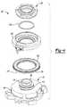
- FIG. 4is a perspective exploded view of the non-orbiting scroll member and capacity modulation assembly of FIG. 1 ;
- FIG. 5is a section view of an alternate non-orbiting scroll member and capacity modulation assembly according to the present disclosure in a first operating mode
- FIG. 6is a section view of the non-orbiting scroll member and capacity modulation assembly of FIG. 5 in a second operating mode
- FIG. 7is a section view of an alternate non-orbiting scroll member and capacity modulation assembly according to the present disclosure in a first operating mode
- FIG. 8is a section view of the non-orbiting scroll member and capacity modulation assembly of FIG. 7 in a second operating mode
- FIG. 9is a section view of an alternate non-orbiting scroll member and capacity modulation assembly according to the present disclosure in a first operating mode
- FIG. 10is a section view of the non-orbiting scroll member and capacity modulation assembly of FIG. 9 in a second operating mode
- FIG. 11is a section view of an alternate non-orbiting scroll member according to the present disclosure.
- FIG. 12is a schematic illustration of the capacity modulation assembly of FIG. 2 in the first operating mode
- FIG. 13is a schematic illustration of the capacity modulation assembly of FIG. 3 in the second operating mode
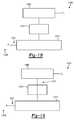
- FIG. 14is a schematic illustration of an alternate capacity modulation assembly in the first operating mode
- FIG. 15is a schematic illustration of the alternate capacity modulation assembly of FIG. 14 in the second operating mode
- FIG. 16is a schematic illustration of an alternate capacity modulation assembly in the first operating mode
- FIG. 17is a schematic illustration of the alternate capacity modulation assembly of FIG. 16 in the second operating mode
- FIG. 18is a schematic illustration of an alternate capacity modulation assembly in the first operating mode
- FIG. 19is a schematic illustration of the alternate capacity modulation assembly of FIG. 18 in the second operating mode
- FIG. 20is a schematic illustration of the capacity modulation assembly of FIG. 7 in the first operating mode
- FIG. 21is a schematic illustration of the capacity modulation assembly of FIG. 8 in the second operating mode
- FIG. 22is a schematic illustration of an alternate capacity modulation assembly in the first operating mode
- FIG. 23is a schematic illustration of the alternate capacity modulation assembly of FIG. 22 in the second operating mode
- FIG. 24is a schematic illustration of an alternate capacity modulation assembly in the first operating mode
- FIG. 25is a schematic illustration of the alternate capacity modulation assembly of FIG. 24 in the second operating mode
- FIG. 26is a schematic illustration of an alternate capacity modulation assembly in the first operating mode
- FIG. 27is a schematic illustration of the alternate capacity modulation assembly of FIG. 26 in the second operating mode
- FIG. 28is a section view of an alternate non-orbiting scroll member and capacity modulation assembly according to the present disclosure in a first operating mode
- FIG. 29is a section view of the non-orbiting scroll member and capacity modulation assembly of FIG. 28 in a second operating mode
- FIG. 30is a schematic illustration of the capacity modulation assembly of FIGS. 14 and 15 in a third operating mode.
- a compressor 10is shown as a hermetic scroll refrigerant-compressor of the low-side type, i.e., where the motor and compressor are cooled by suction gas in the hermetic shell, as illustrated in the vertical section shown in FIG. 1 .
- compressor 10may include a hermetic shell assembly 12 , a bearing housing assembly 14 , a motor assembly 16 , a compression mechanism 18 , a seal assembly 20 , a refrigerant discharge fitting 22 , a discharge valve assembly 24 , a suction gas inlet fitting 26 , and a capacity modulation assembly 28 .
- Shell assembly 12may house bearing housing assembly 14 , motor assembly 16 , compression mechanism 18 , and capacity modulation assembly 28 .
- Shell assembly 12may generally form a compressor housing and may include a cylindrical shell 29 , an end cap 32 at the upper end thereof, a transversely extending partition 34 , and a base 36 at a lower end thereof. End cap 32 and partition 34 may generally define a discharge chamber 38 . Discharge chamber 38 may generally form a discharge muffler for compressor 10 . While illustrated as including discharge chamber 38 , it is understood that the present disclosure applies equally to direct discharge configurations.
- Refrigerant discharge fitting 22may be attached to shell assembly 12 at opening 40 in end cap 32 .
- Discharge valve assembly 24may be located within discharge fitting 22 and may generally prevent a reverse flow condition.
- Suction gas inlet fitting 26may be attached to shell assembly 12 at opening 42 .
- Partition 34may include a discharge passage 44 therethrough providing communication between compression mechanism 18 and discharge chamber 38 .
- Bearing housing assembly 14may be affixed to shell 29 at a plurality of points in any desirable manner, such as staking.
- Bearing housing assembly 14may include a main bearing housing 46 , a bearing 48 disposed therein, bushings 50 , and fasteners 52 .
- Main bearing housing 46may house bearing 48 therein and may define an annular flat thrust bearing surface 54 on an axial end surface thereof.
- Main bearing housing 46may include apertures 56 extending therethrough and receiving fasteners 52 .
- Motor assembly 16may generally include a motor stator 58 , a rotor 60 , and a drive shaft 62 .
- Motor stator 58may be press fit into shell 29 .
- Drive shaft 62may be rotatably driven by rotor 60 and may be rotatably supported within first bearing 48 .
- Rotor 60may be press fit on drive shaft 62 .
- Drive shaft 62may include an eccentric crank pin 64 having a flat 66 thereon.
- Compression mechanism 18may generally include an orbiting scroll 68 and a non-orbiting scroll 70 .
- Orbiting scroll 68may include an end plate 72 having a spiral vane or wrap 74 on the upper surface thereof and an annular flat thrust surface 76 on the lower surface. Thrust surface 76 may interface with annular flat thrust bearing surface 54 on main bearing housing 46 .
- a cylindrical hub 78may project downwardly from thrust surface 76 and may have a drive bushing 80 rotatably disposed therein.
- Drive bushing 80may include an inner bore in which crank pin 64 is drivingly disposed.
- Crank pin flat 66may drivingly engage a flat surface in a portion of the inner bore of drive bushing 80 to provide a radially compliant driving arrangement.
- An Oldham coupling 82may be engaged with the orbiting and non-orbiting scrolls 68 , 70 to prevent relative rotation therebetween.
- non-orbiting scroll 70may include an end plate 84 defining a discharge passage 92 and having a spiral wrap 86 extending from a first side 87 thereof, an annular hub 88 extending from a second side 89 thereof opposite the first side, and a series of radially outwardly extending flanged portions 90 ( FIG. 1 ) engaged with fasteners 52 .
- Fasteners 52may rotationally fix non-orbiting scroll 70 relative to main bearing housing 46 while allowing axial displacement of non-orbiting scroll 70 relative to main bearing housing 46 .
- Spiral wraps 74 , 86may be meshingly engaged with one another defining pockets 94 , 96 , 98 , 100 , 102 , 104 ( FIG. 1 ). It is understood that pockets 94 , 96 , 98 , 100 , 102 , 104 change throughout compressor operation.
- a first pocket, pocket 94 in FIG. 1may define a suction pocket in communication with a suction pressure region 106 of compressor 10 operating at a suction pressure (P s ) and a second pocket, pocket 104 in FIG. 1 , may define a discharge pocket in communication with a discharge pressure region 108 of compressor 10 operating at a discharge pressure (P d ) via discharge passage 92 .
- Pockets intermediate the first and second pockets, pockets 96 , 98 , 100 , 102 in FIG. 1may form intermediate compression pockets operating at intermediate pressures between the suction pressure (P s ) and the discharge pressure (P d ).
- end plate 84may additionally include a biasing passage 110 and first and second modulation ports 112 , 114 .
- Biasing passage 110 and first and second modulation ports 112 , 114may each be in fluid communication with one of the intermediate compression pockets.
- Biasing passage 110may be in fluid communication with one of the intermediate compression pockets operating at a higher pressure than ones of intermediate compression pockets in fluid communication with first and second modulation ports 112 , 114 .
- Annular hub 88may include first and second portions 116 , 118 axially spaced from one another forming a stepped region 120 therebetween.
- First portion 116may be located axially between second portion 118 and end plate 84 and may have an outer radial surface 122 defining a first diameter (D 1 ) greater than or equal to a second diameter (D 2 ) defined by an outer radial surface 124 of second portion 118 .
- Capacity modulation assembly 28may include a modulation valve ring 126 , a modulation lift ring 128 , a retaining ring 130 , and a modulation control valve assembly 132 .
- Modulation valve ring 126may include an inner radial surface 134 , an outer radial surface 136 , a first axial end surface 138 defining an annular recess 140 and a valve portion 142 , and first and second passages 144 , 146 .
- Inner radial surface 134may include first and second portions 148 , 150 defining a second axial end surface 152 therebetween.
- First portion 148may define a third diameter (D 3 ) less than a fourth diameter (D 4 ) defined by the second portion 150 .
- the first and third diameters (D 1 , D 3 )may be approximately equal to one another and the first portions 116 , 148 may be sealingly engaged with one another via a seal 154 located radially therebetween.
- seal 154may include an o-ring seal and may be located within an annular recess 156 in first portion 148 of modulation valve ring 126 .
- the o-ring sealcould be located in an annular recess in annular hub 88 .
- Modulation lift ring 128may be located within annular recess 140 and may include an annular body defining inner and outer radial surfaces 158 , 160 , and first and second axial end surfaces 159 , 161 .
- Inner and outer radial surfaces 158 , 160may be sealingly engaged with sidewalls 162 , 164 of annular recess 140 via first and second seals 166 , 168 .
- first and second seals 166 , 168may include o-ring seals and may be located within annular recesses 170 , 172 in inner and outer radial surfaces 158 , 160 of modulation lift ring 128 .
- Modulation valve ring 126 and modulation lift ring 128may cooperate to define a modulation control chamber 174 between annular recess 140 and first axial end surface 159 .
- First passage 144may be in fluid communication with modulation control chamber 174 .
- Second axial end surface 161may face end plate 84 and may include a series of protrusions 177 defining radial flow passages 178 therebetween.
- Seal assembly 20may form a floating seal assembly and may be sealingly engaged with non-orbiting scroll 70 and modulation valve ring 126 to define an axial biasing chamber 180 . More specifically, seal assembly 20 may be sealingly engaged with outer radial surface 124 of annular hub 88 and second portion 150 of modulation valve ring 126 . Axial biasing chamber 180 may be defined axially between an axial end surface 182 of seal assembly 20 and second axial end surface 152 of modulation valve ring 126 and stepped region 120 of annular hub 88 . Second passage 146 may be in fluid communication with axial biasing chamber 180 .
- Retaining ring 130may be axially fixed relative to non-orbiting scroll 70 and may be located within axial biasing chamber 180 . More specifically, retaining ring 130 may be located within a recess in first portion 116 of annular hub 88 axially between seal assembly 20 and modulation valve ring 126 . Retaining ring 130 may form an axial stop for modulation valve ring 126 .
- Modulation control valve assembly 132may include a solenoid operated valve and may be in fluid communication with first and second passages 144 , 146 in modulation valve ring 126 and suction pressure region 106 .
- modulation control valve assembly 132may be operated in first and second modes.
- FIGS. 12 and 13schematically illustrate operation of modulation control valve assembly 132 .
- modulation control valve assembly 132may provide fluid communication between modulation control chamber 174 and suction pressure region 106 . More specifically, modulation control valve assembly 132 may provide fluid communication between first passage 144 and suction pressure region 106 during operation in the first mode.
- modulation control valve assembly 132may provide fluid communication between modulation control chamber 174 and axial biasing chamber 180 . More specifically, modulation control valve assembly 132 may provide fluid communication between first and second passages 144 , 146 during operation in the second mode.
- a modulation control valve assembly 1032may include first and second modulation control valves 1031 , 1033 . Capacity modulation assembly 928 may be incorporated into compressor 10 as discussed below. First modulation control valve 1031 may be in communication with modulation control chamber 1074 , biasing chamber 1080 , and second modulation control valve 1033 . Second modulation control valve 1033 may be in communication with suction pressure region 1006 , first modulation control valve 1031 , and modulation control chamber 1074 . Modulation control valve assembly 1032 may be operated in first and second modes.
- first modulation control valve 1031may be closed, isolating modulation control chamber 1074 from biasing chamber 1080 , and second modulation control valve 1033 may be open, providing communication between modulation control chamber 1074 and suction pressure region 1006 .
- second modulation control valve 1033may be closed, isolating modulation control chamber 1074 from suction pressure region 1006 .
- Modulation control valve assembly 1032may be modulated between the first and second modes to create a compressor operating capacity that is between a fully loaded capacity (first mode) and a part loaded capacity (second mode). Pulse-width-modulation of the opening and closing of first and second modulation control valves 1031 , 1033 may be utilized to create this intermediate capacity. Second modulation control valve 1033 may be open during the first mode as seen in FIG. 14 . Alternatively, second modulation control valve 1033 may be opened, for example, between 0.2 and 1.0 seconds when transitioning from the second mode to the first mode and then closed to be ready for transitioning to the second mode. This allows the modulation control chamber 1074 to reach suction pressure (P s ) to allow compressor operation in the first mode.
- P ssuction pressure
- modulation control valve assembly 1032may be modulated between the second mode and a third mode.
- the third modeis schematically illustrated in FIG. 30 and provides an unloaded (zero capacity) condition.
- first and second modulation control valves 1031 , 1033may be open. Therefore, modulation control chamber 1074 and biasing chamber 1080 are both in communication with suction pressure region 1006 .
- Modulation control valve assembly 1032may be modulated between the second and third modes to create a compressor operating capacity that is between the part loaded capacity (second mode) and the unloaded capacity (third mode). Pulse-width-modulation of the opening and closing of first and second modulation control valves 1031 , 1033 may be utilized to create this intermediate capacity.
- modulation control valve assembly 1032may be modulated between the first and third modes to create a compressor operating capacity that is between the fully loaded capacity (first mode) and the unloaded capacity (third mode). Pulse-width-modulation of the opening and closing of first and second modulation control valves 1031 , 1033 may be utilized to create this intermediate capacity.
- second modulation control valve 1033When transitioning from the third mode to the first mode, second modulation control valve 1033 may remain open and first modulation control valve 1031 may be modulated between opened and closed positions. Alternatively, second modulation control valve 1033 may be closed when transitioning from the third mode to the first mode.
- second modulation control valve 1033may be closed after first modulation control valve 1031 by a delay (e.g., less than one second) to ensure that modulation control chamber 1074 is maintained at suction pressure (P s ) and does not experience additional biasing pressure (P i1 ).
- FIGS. 16 and 17An alternate capacity modulation assembly 1028 is shown in FIGS. 16 and 17 .
- Capacity modulation assembly 1028may be incorporated into compressor 10 as discussed below.
- modulation control chamber 1174may be in communication with biasing chamber 1180 via a first passage 1131 .
- Modulation control valve assembly 1132may be in communication with modulation control chamber 1174 and suction pressure region 1106 . Modulation control valve assembly 1132 may be operated in first and second modes.
- modulation control valve assembly 1132may be open, providing communication between modulation control chamber 1174 via a second passage 1133 .
- First passage 1131may define a greater flow restriction than second passage 1133 .
- the greater flow restriction of first passage 1131 relative to second passage 1133may generally prevent a total loss of biasing pressure within biasing chamber 1180 during the first mode.
- modulation control valve assembly 1132may be closed, isolating modulation control chamber 1174 from suction pressure region 1106 .
- FIGS. 18 and 19Another alternate capacity modulation assembly 1128 is shown in FIGS. 18 and 19 .
- Capacity modulation assembly 1128may be incorporated into compressor 10 as discussed below.
- modulation control chamber 1274may be in communication with suction pressure region 1206 via a first passage 1231 .
- Modulation control valve assembly 1232may be in communication with modulation control chamber 1274 and biasing chamber 1280 . Modulation control valve assembly 1232 may be operated in first and second modes.
- modulation control valve assembly 1232may be closed, isolating modulation control chamber 1274 from biasing chamber 1280 .
- modulation control valve assembly 1232may be open, providing communication between modulation control chamber 1274 and biasing chamber 1280 via a second passage 1233 .
- First passage 1231may define a greater flow restriction than second passage 1233 .
- the greater flow restriction of first passage 1231 relative to second passage 1233may generally prevent a total loss of biasing pressure within biasing chamber 1280 during the second mode.
- Inner sidewall 162may define a diameter (D 5 ) less than a diameter (D 6 ) defined by outer sidewall 164 .
- a first intermediate pressure (P i1 ) within axial biasing chamber 180 applied to first radial surface area (A 1 )may provide a first axial force (F 1 ) urging modulation valve ring 126 axially toward non-orbiting scroll 70 during both the first and second modes.
- modulation valve assembly 132When modulation control valve assembly 132 is operated in the first mode, modulation valve ring 126 may be in the first position ( FIG. 2 ).
- suction pressure (P s ) within modulation control chamber 174may provide a second axial force (F 2 ) opposite first axial force (F 1 ) urging modulation valve ring 126 axially away from non-orbiting scroll 70 .
- First axial force (F 1 )may be greater than second axial force (F 2 ). Therefore, modulation valve ring 126 may be in the first position during operation of modulation control valve assembly 132 in the first mode.
- the first positionmay include valve portion 142 of modulation valve ring 126 abutting end plate 84 and closing first and second modulation ports 112 , 114 .
- modulation valve ring 126When modulation control valve assembly 132 is operated in the second mode, modulation valve ring 126 may be in the second position ( FIG. 3 ). In the second mode, first intermediate pressure (P i1 ) within modulation control chamber 174 may provide a third axial force (F 3 ) acting on modulation valve ring 126 and opposite first axial force (F 1 ) urging modulation valve ring 126 axially away from non-orbiting scroll 70 . Since modulation control chamber 174 and axial biasing chamber 180 are in fluid communication with one another during operation of the modulation control valve assembly 132 in the second mode, both may operate at approximately the same first intermediate pressure (P i1 ).
- Third axial force (F 3 )may be greater than first axial force (F 1 ) since second radial surface area (A 2 ) is greater than first radial surface area (A 1 ). Therefore, modulation valve ring 126 may be in the second position during operation of modulation control valve assembly 132 in the second mode.
- the second positionmay include valve portion 142 of modulation valve ring 126 being displaced from end plate 84 and opening first and second modulation ports 112 , 114 .
- Modulation valve ring 126may abut retaining ring 130 when in the second position.
- Modulation valve ring 126 and modulation lift ring 128may be forced in axial directions opposite one another during operation of modulation control valve assembly 132 in the second mode. More specifically, modulation valve ring 126 may be displaced axially away from end plate 84 and modulation lift ring 128 may be urged axially toward end plate 84 . Protrusions 177 of modulation lift ring 128 may abut end plate 84 and first and second modulation ports 112 , 114 may be in fluid communication with suction pressure region 106 via radial flow passages 178 when modulation valve ring 126 is in the second position.
- Capacity modulation assembly 228may be generally similar to capacity modulation assembly 28 and may be incorporated into compressor 10 as discussed below. Therefore, it is understood that the description of capacity modulation assembly 28 applies equally to capacity modulation assembly 228 with the exceptions noted below.
- Modulation valve ring 326may include axially extending protrusions 330 in place of retaining ring 130 of capacity modulation assembly 28 . Protrusions 330 may be circumferentially spaced from one another, forming flow paths 331 therebetween. When modulation valve ring 326 is displaced from the first position ( FIG. 5 ) to the second position ( FIG. 6 ), protrusions 330 may abut seal assembly 220 to provide an axial stop for modulation valve ring 326 .
- Capacity modulation assembly 1528may be generally similar to capacity modulation assembly 28 and may be incorporated into compressor 10 as discussed below. Therefore, it is understood that the description of capacity modulation assembly 28 applies equally to capacity modulation assembly 1528 with the exceptions noted below.
- Modulation valve ring 1626may include axially extending protrusions 1630 and modulation lift ring 1628 may include axially extending protrusions 1632 . Protrusions 1630 may extend axially beyond and radially inward relative to protrusions 1632 . When modulation valve ring 1626 is displaced from the first position ( FIG. 28 ) to the second position ( FIG. 29 ), protrusions 1630 may abut protrusions 1632 to provide an axial stop for modulation valve ring 1626 .
- Non-orbiting scroll 470 and capacity modulation assembly 428are illustrated in FIGS. 7 and 8 .
- End plate 484 of non-orbiting scroll 470may include a biasing passage 510 , first and second modulation ports 512 , 514 , an annular recess 540 , and first and second passages 544 , 546 .
- Biasing passage 510 , first and second modulation ports 512 , 514 , and second passage 546may each be in fluid communication with one of the intermediate compression pockets.
- Biasing passage 510may be in fluid communication with one of the intermediate compression pockets operating at a higher pressure than ones of intermediate compression pockets in fluid communication with first and second modulation ports 512 , 514 .
- second passage 546may be in communication with one of the intermediate compression pockets operating at a higher pressure than or equal to the intermediate compression pocket in communication with biasing passage 510 .
- Annular hub 488may include first and second portions 516 , 518 axially spaced from one another forming a stepped region 520 therebetween.
- First portion 516may be located axially between second portion 518 and end plate 484 and may have an outer radial surface 522 defining a diameter (D 7 ) greater than or equal to a diameter (D 8 ) defined by an outer radial surface 524 of second portion 518 .
- Capacity modulation assembly 428may include a modulation valve ring 526 , a modulation lift ring 528 , a retaining ring 530 , and a modulation control valve assembly 532 .
- Modulation valve ring 526may include an axial leg 534 and a radial leg 536 .
- Radial leg 536may include a first axial end surface 538 facing end plate 484 and defining a valve portion 542 and a second axial end surface 552 facing seal assembly 420 .
- An inner radial surface 548 of axial leg 534may define a diameter (D 9 ) greater than a diameter (D 10 ) defined by an inner radial surface 550 of radial leg 536 .
- the diameters (D 7 , D 10 )may be approximately equal to one another and first portion 516 of annular hub 488 may be sealingly engaged with radial leg 536 of modulation valve ring 526 via a seal 554 located radially therebetween. More specifically, seal 554 may include an o-ring seal and may be located within an annular recess 556 in inner radial surface 550 of modulation valve ring 526 .
- Modulation lift ring 528may be located within annular recess 540 and may include an annular body defining inner and outer radial surfaces 558 , 560 , and first and second axial end surfaces 559 , 561 .
- Annular recess 540may extend axially into second side 489 of end plate 484 .
- Inner and outer radial surfaces 558 , 560may be sealingly engaged with sidewalls 562 , 564 of annular recess 540 via first and second seals 566 , 568 .
- first and second seals 566 , 568may include o-ring seals and may be located within annular recesses 570 , 572 in inner and outer radial surfaces 558 , 560 of modulation lift ring 528 .
- End plate 484 and modulation lift ring 528may cooperate to define a modulation control chamber 574 between annular recess 540 and second axial end surface 561 .
- First passage 544may be in fluid communication with modulation control chamber 574 .
- First axial end surface 559may face modulation valve ring 526 and may include a series of protrusions 577 defining radial flow passages 578 therebetween.
- Seal assembly 420may form a floating seal assembly and may be sealingly engaged with non-orbiting scroll 470 and modulation valve ring 526 to define an axial biasing chamber 580 . More specifically, seal assembly 420 may be sealingly engaged with outer radial surface 524 of annular hub 488 and inner radial surface 548 of modulation valve ring 526 . Axial biasing chamber 580 may be defined axially between an axial end surface 582 of seal assembly 420 and second axial end surface 552 of modulation valve ring 526 and by stepped region 520 of annular hub 488 .
- Retaining ring 530may be axially fixed relative to non-orbiting scroll 470 and may be located within axial biasing chamber 580 . More specifically, retaining ring 530 may be located within a recess in first portion 516 of annular hub 488 axially between seal assembly 420 and modulation valve ring 526 . Retaining ring 530 may form an axial stop for modulation valve ring 526 .
- Modulation control valve assembly 532may include a solenoid operated valve and may be in fluid communication with first and second passages 544 , 546 in end plate 484 and suction pressure region 506 .
- modulation control valve assembly 532may be operated in first and second modes.
- FIGS. 20 and 21schematically illustrate operation of modulation control valve assembly 532 .
- modulation control valve assembly 532may provide fluid communication between modulation control chamber 574 and suction pressure region 506 . More specifically, modulation control valve assembly 532 may provide fluid communication between first passage 544 and suction pressure region 506 during operation in the first mode.
- modulation control valve assembly 532may provide fluid communication between modulation control chamber 574 and second passage 546 .
- a modulation control valve assembly 1332may include first and second modulation control valves 1331 , 1333 .
- Capacity modulation assembly 1228may be incorporated into compressor 10 as discussed below.
- First modulation control valve 1331may be in communication with suction pressure region 1306 , modulation control chamber 1374 and second modulation control valve 1333 .
- Second modulation control valve 1333may be in communication with second passage 1346 (similar to second passage 546 ), modulation control chamber 1374 and first modulation control valve 1331 .
- Modulation control valve assembly 1332may be operated in first and second modes. Similar to the capacity modulation assembly 428 , biasing chamber 1380 and first passage 1310 (similar to biasing passage 510 ) may be isolated from communication with modulation control valve assembly 1332 and modulation control chamber 1374 during both the first and second modes.
- first modulation control valve 1331may be open, providing communication between modulation control chamber 1374 and suction pressure region 1306
- second modulation control valve 1333may be closed, isolating modulation control chamber 1374 from second passage 1346 .
- first modulation control valve 1331may be closed, isolating modulation control chamber 1374 from suction pressure region 1306
- second modulation control valve 1333may be open, providing communication between modulation control chamber 1374 and second passage 1346 .
- FIGS. 24 and 25An alternate capacity modulation assembly 1328 is shown in FIGS. 24 and 25 .
- Capacity modulation assembly 1328may be incorporated into compressor 10 as discussed below.
- modulation control chamber 1474may be in communication with second passage 1446 (similar to second passage 546 ) and modulation control valve assembly 1432 .
- Modulation control valve assembly 1432may be in communication with modulation control chamber 1474 and suction pressure region 1406 .
- Modulation control valve assembly 1432may be operated in first and second modes. Similar to capacity modulation assembly 428 , biasing chamber 1480 and first passage 1410 (similar to biasing passage 510 ) may be isolated from communication with modulation control valve assembly 1432 and modulation control chamber 1474 during both the first and second modes.
- modulation control valve assembly 1432may be open, providing communication between modulation control chamber 1474 and suction pressure region 1406 via a third passage 1433 .
- Second passage 1446may define a greater flow restriction than third passage 1433 .
- modulation control valve assembly 1432may be closed, isolating modulation control chamber 1474 from communication with suction pressure region 1406 .
- FIGS. 26 and 27Another capacity modulation assembly 1428 is shown in FIGS. 26 and 27 .
- Capacity modulation assembly 1428may be incorporated into compressor 10 as discussed below.
- modulation control chamber 1574may be in communication with suction pressure region 1506 via a third passage 1533 .
- Modulation control valve assembly 1532may be in communication with modulation control chamber 1574 and second passage 1546 (similar to second passage 546 ). Modulation control valve assembly 1532 may be operated in first and second modes. Similar to capacity modulation assembly 428 , biasing chamber 1580 and first passage 1510 (similar to biasing passage 510 ) may be isolated form communication with modulation control valve assembly 1532 and modulation control chamber 1574 during both the first and second modes.
- modulation control valve assembly 1532may be closed, isolating modulation control chamber 1574 from communication with a biasing pressure.
- modulation control valve assembly 1532may be open, providing communication between modulation control chamber 1574 and a biasing pressure via second passage 1546 .
- Third passage 1533may provide a greater flow restriction than second passage 1546 .
- First radial surface area (A 11 )may be greater than second radial surface area (A 22 ).
- Modulation valve ring 526may be displaced between first and second positions based on the pressure provided to modulation control chamber 574 by modulation control valve assembly 532 .
- Modulation lift ring 528may displace modulation valve ring 526 , as discussed below.
- the arrangement shown in FIGS. 7 and 8generally provides for a narrower non-orbiting scroll 470 and capacity modulation assembly 428 arrangements. However, it is understood that alternate arrangements may exist where the second radial surface area (A 22 ) is greater than the first radial surface area (A 11 ), as in FIGS. 2 and 3 .
- a second intermediate pressure (P i2 ) within axial biasing chamber 580 applied to first radial surface area (A 11 )may provide a first axial force (F 11 ) urging modulation valve ring 526 axially toward non-orbiting scroll 470 during both the first and second modes.
- modulation valve assembly 532When modulation control valve assembly 532 is operated in the first mode, modulation valve ring 526 may be in the first position ( FIG. 7 ).
- suction pressure (P s ) within modulation control chamber 574may provide a second axial force (F 22 ) opposite first axial force (F 11 ).
- Modulation lift ring 528may apply second axial force (F 22 ) to modulation valve ring 526 to bias modulation valve ring 526 axially away from non-orbiting scroll 470 .
- First axial force (F 11 )may be greater than second axial force (F 22 ). Therefore, modulation valve ring 526 may be in the first position during operation of modulation control valve assembly 532 in the first mode.
- the first positionmay include valve portion 542 of modulation valve ring 526 abutting end plate 484 and closing first and second modulation ports 512 , 514 .
- modulation valve ring 526When modulation control valve assembly 532 is operated in the second mode, modulation valve ring 526 may be in the second position ( FIG. 8 ). In the second mode, a third intermediate pressure (P i3 ) from the intermediate compression pocket in fluid communication with second passage 546 may provide a third axial force (F 33 ) opposite first axial force (F 11 ) urging modulation lift ring 528 axially toward modulation valve ring 526 . Modulation lift ring 528 may apply third axial force (F 33 ) to modulation valve ring 526 to bias modulation valve ring 526 axially away from non-orbiting scroll 470 .
- P i3third intermediate pressure from the intermediate compression pocket in fluid communication with second passage 546 may provide a third axial force (F 33 ) opposite first axial force (F 11 ) urging modulation lift ring 528 axially toward modulation valve ring 526 .
- Modulation lift ring 528may apply third axial force (F 33 ) to
- Third axial force (F 33 )may be greater than first axial force (F 11 ) even when second radial surface area (A 22 ) is less than first radial surface area (A 11 ) since modulation control chamber 574 operates at a higher pressure than axial biasing chamber 580 during the second mode (P i3 >P i2 ).
- Modulation control chamber 574may operate at the same pressure as axial biasing chamber 580 and therefore A 22 may be greater than A 11 . Therefore, modulation valve ring 526 may be in the second position during operation of modulation control valve assembly 532 in the second mode.
- the second positionmay include valve portion 542 of modulation valve ring 526 being displaced from end plate 484 and opening first and second modulation ports 512 , 514 . Modulation valve ring 526 may abut retaining ring 530 when in the second position.
- Modulation valve ring 526 and modulation lift ring 528may be forced in the same axial direction during operation of modulation control valve assembly 532 in the second mode. More specifically, modulation valve ring 526 and modulation lift ring 528 may both be displaced axially away from end plate 484 . Protrusions 577 of modulation lift ring 528 may abut modulation valve ring 526 and first and second modulation ports 512 , 514 may be in fluid communication with suction pressure region 506 via radial flow passages 578 when modulation valve ring 526 is in the second position.
- Capacity modulation assembly 828may be generally similar to capacity modulation assembly 428 . Therefore, it is understood that the description of capacity modulation assembly 428 applies equally to capacity modulation assembly 828 with the exceptions noted below.
- Modulation valve ring 926may include axially extending protrusions 930 in place of retaining ring 530 of capacity modulation assembly 428 . Protrusions 930 may be circumferentially spaced from one another, forming flow paths 931 therebetween. When modulation valve ring 926 is displaced from the first position ( FIG. 9 ) to the second position ( FIG. 10 ), protrusions 930 may abut seal assembly 820 to provide an axial stop for modulation valve ring 926 .
- non-orbiting scroll 670may be used in compressor 10 in place of non-orbiting scroll 70 and capacity modulation assembly 28 .
- Non-orbiting scroll 670may be similar to non-orbiting scroll 70 , with the exception of first and second modulation ports 112 , 114 .
- non-orbiting scroll 670may have an outer hub 726 engaged therewith. More specifically, outer hub 726 may include an axial leg 734 and a radial leg 736 .
- Radial leg 736may include a first axial end surface 738 facing end plate 784 and a second axial end surface 752 facing seal assembly 620 .
- First portion 716 of annular hub 688may be sealingly engaged with radial leg 736 of outer hub 726 via a seal 754 located radially therebetween.
- seal 754may include an o-ring seal and may be located within an annular recess 756 in inner radial surface 750 of outer hub 726 .
- Seal assembly 620may form a floating seal assembly and may be sealingly engaged with non-orbiting scroll 670 and outer hub 726 to define an axial biasing chamber 780 . More specifically, seal assembly 620 may be sealingly engaged with outer radial surface 724 of annular hub 688 and inner radial surface 748 of axial leg 734 .
- Axial biasing chamber 780may be defined axially between an axial end surface 782 of seal assembly 620 and second axial end surface 752 of outer hub 726 and stepped portion 720 of annular hub 688 .
- Biasing passage 710may extend through stepped region 720 of annular hub 688 to provide fluid communication between axial biasing chamber 780 and an intermediate compression pocket.
- Outer hub 726may be press fit on non-orbiting scroll 670 and fixed thereto without the use of fasteners by the press-fit engagement, as well as by pressure within axial biasing chamber 780 acting on second axial end surface 752 during compressor operation. Therefore, a generally common non-orbiting scroll 70 , 270 , 470 , 670 may be used for a variety of applications including compressors with and without capacity modulation assemblies or first and second modulation ports 112 , 512 , 114 , 514 of non-orbiting scrolls 70 , 270 , 470 .
Landscapes
- Engineering & Computer Science (AREA)
- Mechanical Engineering (AREA)
- General Engineering & Computer Science (AREA)
- Physics & Mathematics (AREA)
- Fluid Mechanics (AREA)
- Geometry (AREA)
- Rotary Pumps (AREA)
- Applications Or Details Of Rotary Compressors (AREA)
Abstract
Description
Claims (21)
Priority Applications (3)
| Application Number | Priority Date | Filing Date | Title |
|---|---|---|---|
| US14/946,824US9879674B2 (en) | 2009-04-07 | 2015-11-20 | Compressor having capacity modulation assembly |
| US15/881,016US10954940B2 (en) | 2009-04-07 | 2018-01-26 | Compressor having capacity modulation assembly |
| US17/176,080US11635078B2 (en) | 2009-04-07 | 2021-02-15 | Compressor having capacity modulation assembly |
Applications Claiming Priority (5)
| Application Number | Priority Date | Filing Date | Title |
|---|---|---|---|
| US16730909P | 2009-04-07 | 2009-04-07 | |
| US12/754,920US7988433B2 (en) | 2009-04-07 | 2010-04-06 | Compressor having capacity modulation assembly |
| US13/181,065US8585382B2 (en) | 2009-04-07 | 2011-07-12 | Compressor having capacity modulation assembly |
| US14/081,390US9303642B2 (en) | 2009-04-07 | 2013-11-15 | Compressor having capacity modulation assembly |
| US14/946,824US9879674B2 (en) | 2009-04-07 | 2015-11-20 | Compressor having capacity modulation assembly |
Related Parent Applications (1)
| Application Number | Title | Priority Date | Filing Date |
|---|---|---|---|
| US14/081,390ContinuationUS9303642B2 (en) | 2009-04-07 | 2013-11-15 | Compressor having capacity modulation assembly |
Related Child Applications (1)
| Application Number | Title | Priority Date | Filing Date |
|---|---|---|---|
| US15/881,016ContinuationUS10954940B2 (en) | 2009-04-07 | 2018-01-26 | Compressor having capacity modulation assembly |
Publications (2)
| Publication Number | Publication Date |
|---|---|
| US20160076543A1 US20160076543A1 (en) | 2016-03-17 |
| US9879674B2true US9879674B2 (en) | 2018-01-30 |
Family
ID=42826322
Family Applications (6)
| Application Number | Title | Priority Date | Filing Date |
|---|---|---|---|
| US12/754,920ActiveUS7988433B2 (en) | 2009-04-07 | 2010-04-06 | Compressor having capacity modulation assembly |
| US13/181,065Active2030-06-03US8585382B2 (en) | 2009-04-07 | 2011-07-12 | Compressor having capacity modulation assembly |
| US14/081,390ActiveUS9303642B2 (en) | 2009-04-07 | 2013-11-15 | Compressor having capacity modulation assembly |
| US14/946,824Active2030-07-05US9879674B2 (en) | 2009-04-07 | 2015-11-20 | Compressor having capacity modulation assembly |
| US15/881,016Active2030-12-14US10954940B2 (en) | 2009-04-07 | 2018-01-26 | Compressor having capacity modulation assembly |
| US17/176,080ActiveUS11635078B2 (en) | 2009-04-07 | 2021-02-15 | Compressor having capacity modulation assembly |
Family Applications Before (3)
| Application Number | Title | Priority Date | Filing Date |
|---|---|---|---|
| US12/754,920ActiveUS7988433B2 (en) | 2009-04-07 | 2010-04-06 | Compressor having capacity modulation assembly |
| US13/181,065Active2030-06-03US8585382B2 (en) | 2009-04-07 | 2011-07-12 | Compressor having capacity modulation assembly |
| US14/081,390ActiveUS9303642B2 (en) | 2009-04-07 | 2013-11-15 | Compressor having capacity modulation assembly |
Family Applications After (2)
| Application Number | Title | Priority Date | Filing Date |
|---|---|---|---|
| US15/881,016Active2030-12-14US10954940B2 (en) | 2009-04-07 | 2018-01-26 | Compressor having capacity modulation assembly |
| US17/176,080ActiveUS11635078B2 (en) | 2009-04-07 | 2021-02-15 | Compressor having capacity modulation assembly |
Country Status (6)
| Country | Link |
|---|---|
| US (6) | US7988433B2 (en) |
| EP (1) | EP2417356B1 (en) |
| KR (1) | KR101253137B1 (en) |
| CN (3) | CN104314817B (en) |
| IL (1) | IL215564A (en) |
| WO (1) | WO2010118140A2 (en) |
Cited By (21)
| Publication number | Priority date | Publication date | Assignee | Title |
|---|---|---|---|---|
| US9989057B2 (en) | 2014-06-03 | 2018-06-05 | Emerson Climate Technologies, Inc. | Variable volume ratio scroll compressor |
| US10066622B2 (en) | 2015-10-29 | 2018-09-04 | Emerson Climate Technologies, Inc. | Compressor having capacity modulation system |
| US10094380B2 (en) | 2012-11-15 | 2018-10-09 | Emerson Climate Technologies, Inc. | Compressor |
| US10323638B2 (en) | 2015-03-19 | 2019-06-18 | Emerson Climate Technologies, Inc. | Variable volume ratio compressor |
| US10378540B2 (en) | 2015-07-01 | 2019-08-13 | Emerson Climate Technologies, Inc. | Compressor with thermally-responsive modulation system |
| US10495086B2 (en) | 2012-11-15 | 2019-12-03 | Emerson Climate Technologies, Inc. | Compressor valve system and assembly |
| US10753352B2 (en) | 2017-02-07 | 2020-08-25 | Emerson Climate Technologies, Inc. | Compressor discharge valve assembly |
| US10801495B2 (en) | 2016-09-08 | 2020-10-13 | Emerson Climate Technologies, Inc. | Oil flow through the bearings of a scroll compressor |
| US10890186B2 (en) | 2016-09-08 | 2021-01-12 | Emerson Climate Technologies, Inc. | Compressor |
| US10954940B2 (en) | 2009-04-07 | 2021-03-23 | Emerson Climate Technologies, Inc. | Compressor having capacity modulation assembly |
| US10962008B2 (en) | 2017-12-15 | 2021-03-30 | Emerson Climate Technologies, Inc. | Variable volume ratio compressor |
| US10995753B2 (en) | 2018-05-17 | 2021-05-04 | Emerson Climate Technologies, Inc. | Compressor having capacity modulation assembly |
| US11022119B2 (en) | 2017-10-03 | 2021-06-01 | Emerson Climate Technologies, Inc. | Variable volume ratio compressor |
| US11656003B2 (en) | 2019-03-11 | 2023-05-23 | Emerson Climate Technologies, Inc. | Climate-control system having valve assembly |
| US11655813B2 (en) | 2021-07-29 | 2023-05-23 | Emerson Climate Technologies, Inc. | Compressor modulation system with multi-way valve |
| US11846287B1 (en) | 2022-08-11 | 2023-12-19 | Copeland Lp | Scroll compressor with center hub |
| US11965507B1 (en) | 2022-12-15 | 2024-04-23 | Copeland Lp | Compressor and valve assembly |
| US12163523B1 (en) | 2023-12-15 | 2024-12-10 | Copeland Lp | Compressor and valve assembly |
| US12173708B1 (en) | 2023-12-07 | 2024-12-24 | Copeland Lp | Heat pump systems with capacity modulation |
| US12259163B2 (en) | 2022-06-01 | 2025-03-25 | Copeland Lp | Climate-control system with thermal storage |
| US12416308B2 (en) | 2022-12-28 | 2025-09-16 | Copeland Lp | Compressor with shutdown assembly |
Families Citing this family (55)
| Publication number | Priority date | Publication date | Assignee | Title |
|---|---|---|---|---|
| EP2250374B1 (en) | 2008-01-16 | 2021-05-26 | Emerson Climate Technologies, Inc. | Scroll machine |
| US7972125B2 (en)* | 2008-05-30 | 2011-07-05 | Emerson Climate Technologies, Inc. | Compressor having output adjustment assembly including piston actuation |
| CN102089524B (en)* | 2008-05-30 | 2014-09-03 | 艾默生环境优化技术有限公司 | Compressor with capacity adjustment system |
| CN102089523B (en) | 2008-05-30 | 2014-01-08 | 艾默生环境优化技术有限公司 | Compressor with capacity adjustment system |
| US7976296B2 (en)* | 2008-12-03 | 2011-07-12 | Emerson Climate Technologies, Inc. | Scroll compressor having capacity modulation system |
| US8568118B2 (en)* | 2009-05-29 | 2013-10-29 | Emerson Climate Technologies, Inc. | Compressor having piston assembly |
| US8616014B2 (en)* | 2009-05-29 | 2013-12-31 | Emerson Climate Technologies, Inc. | Compressor having capacity modulation or fluid injection systems |
| BR112013010135A2 (en)* | 2010-10-28 | 2016-09-06 | Emerson Climate Technologies | compressor seal assembly |
| US9267501B2 (en) | 2011-09-22 | 2016-02-23 | Emerson Climate Technologies, Inc. | Compressor including biasing passage located relative to bypass porting |
| KR101882713B1 (en) | 2012-02-27 | 2018-07-27 | 엘지전자 주식회사 | Scroll compressor |
| US9435340B2 (en) | 2012-11-30 | 2016-09-06 | Emerson Climate Technologies, Inc. | Scroll compressor with variable volume ratio port in orbiting scroll |
| US9127677B2 (en) | 2012-11-30 | 2015-09-08 | Emerson Climate Technologies, Inc. | Compressor with capacity modulation and variable volume ratio |
| US9541084B2 (en)* | 2013-02-06 | 2017-01-10 | Emerson Climate Technologies, Inc. | Capacity modulated scroll compressor |
| US20140271302A1 (en) | 2013-03-18 | 2014-09-18 | Suchul Kim | Scroll compressor with a bypass |
| US20150004039A1 (en)* | 2013-06-28 | 2015-01-01 | Emerson Climate Technologies, Inc. | Capacity-modulated scroll compressor |
| KR101573598B1 (en)* | 2014-02-20 | 2015-12-01 | 엘지전자 주식회사 | A scroll compressor |
| IN2014MU01491A (en) | 2014-04-01 | 2015-10-09 | Emerson Climate Technologies | |
| US10371426B2 (en) | 2014-04-01 | 2019-08-06 | Emerson Climate Technologies, Inc. | System and method of controlling a variable-capacity compressor |
| US9739277B2 (en)* | 2014-05-15 | 2017-08-22 | Emerson Climate Technologies, Inc. | Capacity-modulated scroll compressor |
| US10018392B2 (en) | 2014-06-09 | 2018-07-10 | Emerson Climate Technologies, Inc. | System and method for controlling a variable-capacity compressor |
| US10488092B2 (en) | 2015-04-27 | 2019-11-26 | Emerson Climate Technologies, Inc. | System and method of controlling a variable-capacity compressor |
| US9709311B2 (en) | 2015-04-27 | 2017-07-18 | Emerson Climate Technologies, Inc. | System and method of controlling a variable-capacity compressor |
| US10197319B2 (en) | 2015-04-27 | 2019-02-05 | Emerson Climate Technologies, Inc. | System and method of controlling a variable-capacity compressor |
| US10378542B2 (en) | 2015-07-01 | 2019-08-13 | Emerson Climate Technologies, Inc. | Compressor with thermal protection system |
| KR101974854B1 (en)* | 2015-10-29 | 2019-05-03 | 에머슨 클리메이트 테크놀로지즈 인코퍼레이티드 | A compressor including a capacity modulation system |
| KR101747175B1 (en)* | 2016-02-24 | 2017-06-14 | 엘지전자 주식회사 | Scroll compressor |
| US10941772B2 (en) | 2016-03-15 | 2021-03-09 | Emerson Climate Technologies, Inc. | Suction line arrangement for multiple compressor system |
| US10408517B2 (en) | 2016-03-16 | 2019-09-10 | Emerson Climate Technologies, Inc. | System and method of controlling a variable-capacity compressor and a variable speed fan using a two-stage thermostat |
| KR101800261B1 (en) | 2016-05-25 | 2017-11-22 | 엘지전자 주식회사 | Scroll compressor |
| US10760814B2 (en) | 2016-05-27 | 2020-09-01 | Emerson Climate Technologies, Inc. | Variable-capacity compressor controller with two-wire configuration |
| KR101839886B1 (en) | 2016-05-30 | 2018-03-19 | 엘지전자 주식회사 | Scroll compressor |
| CN109891097B (en) | 2016-06-02 | 2020-04-21 | 特灵国际有限公司 | Scroll compressor with partial load capacity |
| CN105971884B (en)* | 2016-06-27 | 2018-03-13 | 珠海格力节能环保制冷技术研究中心有限公司 | Compressor high voltage protective structure and screw compressor |
| KR102400431B1 (en)* | 2016-12-14 | 2022-05-20 | 엘지전자 주식회사 | Scroll compressor |
| KR102398837B1 (en)* | 2016-12-14 | 2022-05-17 | 엘지전자 주식회사 | Scroll compressor |
| KR102415751B1 (en)* | 2016-12-15 | 2022-07-01 | 엘지전자 주식회사 | Scroll compressor |
| KR102403948B1 (en)* | 2017-01-03 | 2022-05-31 | 엘지전자 주식회사 | Scroll compressor |
| KR102469601B1 (en)* | 2017-01-26 | 2022-11-22 | 엘지전자 주식회사 | Scroll compressor |
| KR102407415B1 (en)* | 2017-02-01 | 2022-06-10 | 엘지전자 주식회사 | Scroll compressor |
| KR102317527B1 (en)* | 2017-06-15 | 2021-10-26 | 엘지전자 주식회사 | Scroll compressor |
| US10975868B2 (en) | 2017-07-07 | 2021-04-13 | Emerson Climate Technologies, Inc. | Compressor with floating seal |
| US10670296B2 (en) | 2017-11-02 | 2020-06-02 | Emerson Climate Technologies, Inc. | System and method of adjusting compressor modulation range based on balance point detection of the conditioned space |
| US11421681B2 (en) | 2018-04-19 | 2022-08-23 | Emerson Climate Technologies, Inc. | Multiple-compressor system with suction valve and method of controlling suction valve |
| US11371505B2 (en)* | 2019-06-28 | 2022-06-28 | Trane International Inc. | Scroll compressor with economizer injection |
| US11480176B2 (en)* | 2019-06-28 | 2022-10-25 | Trane International Inc. | Scroll compressor with economizer injection |
| US11236736B2 (en)* | 2019-09-27 | 2022-02-01 | Honeywell International Inc. | Axial piston pump with port plate having balance feed aperture relief feature |
| CN112780546A (en)* | 2019-11-04 | 2021-05-11 | 艾默生环境优化技术(苏州)有限公司 | Scroll compressor having a plurality of scroll members |
| US11692548B2 (en) | 2020-05-01 | 2023-07-04 | Emerson Climate Technologies, Inc. | Compressor having floating seal assembly |
| US11578725B2 (en) | 2020-05-13 | 2023-02-14 | Emerson Climate Technologies, Inc. | Compressor having muffler plate |
| US11655818B2 (en) | 2020-05-26 | 2023-05-23 | Emerson Climate Technologies, Inc. | Compressor with compliant seal |
| US11767846B2 (en) | 2021-01-21 | 2023-09-26 | Copeland Lp | Compressor having seal assembly |
| US20230296097A1 (en)* | 2022-03-16 | 2023-09-21 | Emerson Climate Technologies, Inc. | Modulated Compressor And Valve Assembly |
| WO2023177410A1 (en)* | 2022-03-16 | 2023-09-21 | Emerson Climate Technologies, Inc. | Modulated compressor and valve assembly |
| US12422173B2 (en) | 2022-08-19 | 2025-09-23 | Copeland Lp | Multiple-compressor system with oil balance control |
| US20250188927A1 (en)* | 2023-12-07 | 2025-06-12 | Copeland Lp | Heat Pump Systems With Capacity Modulation |
Citations (189)
| Publication number | Priority date | Publication date | Assignee | Title |
|---|---|---|---|---|
| US4058988A (en) | 1976-01-29 | 1977-11-22 | Dunham-Bush, Inc. | Heat pump system with high efficiency reversible helical screw rotary compressor |
| US4216661A (en) | 1977-12-09 | 1980-08-12 | Hitachi, Ltd. | Scroll compressor with means for end plate bias and cooled gas return to sealed compressor spaces |
| US4382370A (en) | 1980-10-31 | 1983-05-10 | Hitachi, Ltd. | Refrigerating system using scroll type compressor |
| US4383805A (en) | 1980-11-03 | 1983-05-17 | The Trane Company | Gas compressor of the scroll type having delayed suction closing capacity modulation |
| US4389171A (en) | 1981-01-15 | 1983-06-21 | The Trane Company | Gas compressor of the scroll type having reduced starting torque |
| US4475360A (en) | 1982-02-26 | 1984-10-09 | Hitachi, Ltd. | Refrigeration system incorporating scroll type compressor |
| US4497615A (en) | 1983-07-25 | 1985-02-05 | Copeland Corporation | Scroll-type machine |
| US4545742A (en) | 1982-09-30 | 1985-10-08 | Dunham-Bush, Inc. | Vertical axis hermetic helical screw rotary compressor with discharge gas oil mist eliminator and dual transfer tube manifold for supplying liquid refrigerant and refrigerant vapor to the compression area |
| JPS60259794A (en) | 1984-06-04 | 1985-12-21 | Hitachi Ltd | Heat pump type air conditioner |
| US4609329A (en) | 1985-04-05 | 1986-09-02 | Frick Company | Micro-processor control of a movable slide stop and a movable slide valve in a helical screw rotary compressor with an enconomizer inlet port |
| KR870000015B1 (en) | 1983-09-30 | 1987-01-28 | 가부시기 가이샤 도시바 | Shroud Type Compressors |
| KR870000015A (en) | 1985-06-10 | 1987-02-16 | 구자연 | Manufacturing method of mugwort tea |
| US4727725A (en) | 1985-05-20 | 1988-03-01 | Hitachi, Ltd. | Gas injection system for screw compressor |
| JPS63205482A (en) | 1987-02-23 | 1988-08-24 | Hitachi Ltd | Scroll compressor discharge bypass valve |
| US4774816A (en) | 1986-12-04 | 1988-10-04 | Hitachi, Ltd. | Air conditioner or refrigerating plant incorporating scroll compressor |
| US4818195A (en) | 1986-02-26 | 1989-04-04 | Hitachi, Ltd. | Scroll compressor with valved port for each compression chamber |
| US4846633A (en) | 1986-11-27 | 1989-07-11 | Mitsubishi Denki Kabushiki Kaisha | Variable-capacity scroll-type compressor |
| US4877382A (en) | 1986-08-22 | 1989-10-31 | Copeland Corporation | Scroll-type machine with axially compliant mounting |
| US4886425A (en) | 1987-03-26 | 1989-12-12 | Mitsubishi Jukogyo Kabushiki Kaisha | Capacity control device of scroll-type fluid compressor |
| US4940395A (en) | 1987-12-08 | 1990-07-10 | Sanden Corporation | Scroll type compressor with variable displacement mechanism |
| JPH0381588A (en) | 1989-08-23 | 1991-04-05 | Hitachi Ltd | Scroll compressor capacity control device |
| US5055010A (en) | 1990-10-01 | 1991-10-08 | Copeland Corporation | Suction baffle for refrigeration compressor |
| US5059098A (en) | 1989-02-02 | 1991-10-22 | Kabushiki Kaisha Toyoda Jidoshokki Seisakusho | Apparatus for varying capacity of scroll type compressor |
| US5071323A (en) | 1988-08-31 | 1991-12-10 | Kabushiki Kaisha Toshiba | Scroll compressor with bypass release passage in stationary scroll member |
| US5074760A (en) | 1988-08-12 | 1991-12-24 | Mitsubishi Jukogyo Kabushiki Kaisha | Scroll type compressor |
| US5080056A (en) | 1991-05-17 | 1992-01-14 | General Motors Corporation | Thermally sprayed aluminum-bronze coatings on aluminum engine bores |
| US5085565A (en) | 1990-09-24 | 1992-02-04 | Carrier Corporation | Axially compliant scroll with rotating pressure chambers |
| US5169294A (en) | 1991-12-06 | 1992-12-08 | Carrier Corporation | Pressure ratio responsive unloader |
| USRE34148E (en) | 1985-06-18 | 1992-12-22 | Sanden Corporation | Scroll type compressor with variable displacement mechanism |
| US5192195A (en) | 1990-11-14 | 1993-03-09 | Mitsubishi Jukogyo Kabushiki Kaisha | Scroll type compressor with separate control block |
| US5193987A (en) | 1990-11-14 | 1993-03-16 | Mitsubishi Jukogyo Kabushiki Kaisha | Scroll type compressor |
| US5240389A (en) | 1991-07-26 | 1993-08-31 | Kabushiki Kaisha Toshiba | Scroll type compressor |
| US5253489A (en) | 1991-04-02 | 1993-10-19 | Sanden Corporation | Scroll type compressor with injection mechanism |
| US5356271A (en) | 1992-02-06 | 1994-10-18 | Mitsubishi Jukogyo Kabushiki Kaisha | Capacity control mechanism for scroll-type compressor |
| US5451146A (en) | 1992-04-01 | 1995-09-19 | Nippondenso Co., Ltd. | Scroll-type variable-capacity compressor with bypass valve |
| JPH07293456A (en) | 1994-04-28 | 1995-11-07 | Sanyo Electric Co Ltd | Scroll compressor |
| US5482637A (en) | 1993-07-06 | 1996-01-09 | Ford Motor Company | Anti-friction coating composition containing solid lubricants |
| US5551846A (en) | 1995-12-01 | 1996-09-03 | Ford Motor Company | Scroll compressor capacity control valve |
| JPH08247053A (en) | 1995-03-15 | 1996-09-24 | Mitsubishi Electric Corp | Scroll compressor |
| US5557897A (en) | 1992-02-20 | 1996-09-24 | Braas Gmbh | Fastening device for a roof sealing strip or the like |
| US5562426A (en) | 1994-06-03 | 1996-10-08 | Kabushiki Kaisha Toyoda Jidoshokki Seisakusho | Scroll type refrigerant compressor |
| JPH08334094A (en) | 1995-06-07 | 1996-12-17 | Copeland Corp | Scroll type machine with capacity adjustment mechanism |
| US5607288A (en) | 1993-11-29 | 1997-03-04 | Copeland Corporation | Scroll machine with reverse rotation protection |
| US5613841A (en) | 1995-06-07 | 1997-03-25 | Copeland Corporation | Capacity modulated scroll machine |
| US5639225A (en) | 1994-05-30 | 1997-06-17 | Nippondenso Co., Ltd. | Scroll type compressor |
| US5640854A (en) | 1995-06-07 | 1997-06-24 | Copeland Corporation | Scroll machine having liquid injection controlled by internal valve |
| JPH09177689A (en) | 1995-12-27 | 1997-07-11 | Daikin Ind Ltd | Hermetic compressor |
| CN1158944A (en) | 1995-12-05 | 1997-09-10 | 松下电器产业株式会社 | Eddy gas compressor with by-pass valve |
| CN1158945A (en) | 1995-12-19 | 1997-09-10 | 科普兰公司 | Scroll machine with capacity modulation |
| US5674058A (en) | 1994-06-08 | 1997-10-07 | Nippondenso Co., Ltd. | Scroll-type refrigerant compressor |
| EP0822335A2 (en) | 1996-08-02 | 1998-02-04 | Copeland Corporation | Scroll compressor |
| US5722257A (en) | 1995-10-11 | 1998-03-03 | Denso Corporation | Compressor having refrigerant injection ports |
| US5885063A (en) | 1996-05-07 | 1999-03-23 | Matshushita Electric Industrial Co., Ltd. | Variable capacity scroll compressor |
| JPH11107950A (en) | 1997-10-06 | 1999-04-20 | Matsushita Electric Ind Co Ltd | Compressor injection device |
| JPH11324950A (en) | 1998-05-19 | 1999-11-26 | Mitsubishi Electric Corp | Scroll compressor |
| US5993171A (en) | 1996-06-25 | 1999-11-30 | Sanden Corporation | Scroll-type compressor with variable displacement mechanism |
| US5993177A (en) | 1996-05-21 | 1999-11-30 | Sanden Corporation | Scroll type compressor with improved variable displacement mechanism |
| JP2000104684A (en) | 1998-09-29 | 2000-04-11 | Nippon Soken Inc | Variable displacement compressor |
| US6047557A (en) | 1995-06-07 | 2000-04-11 | Copeland Corporation | Adaptive control for a refrigeration system using pulse width modulated duty cycle scroll compressor |
| JP2000161263A (en) | 1998-11-27 | 2000-06-13 | Mitsubishi Electric Corp | Capacity control scroll compressor |
| US6095765A (en) | 1998-03-05 | 2000-08-01 | Carrier Corporation | Combined pressure ratio and pressure differential relief valve |
| US6102671A (en) | 1997-09-04 | 2000-08-15 | Matsushita Electric Industrial Co., Ltd. | Scroll compressor |
| US6123528A (en) | 1998-04-06 | 2000-09-26 | Scroll Technologies | Reed discharge valve for scroll compressors |
| US6123517A (en) | 1997-11-24 | 2000-09-26 | Copeland Corporation | Scroll machine with capacity modulation |
| US6132179A (en) | 1997-09-09 | 2000-10-17 | Sanden Corporation | Scroll type compressor enabling a soft start with a simple structure |
| US6139287A (en) | 1995-12-19 | 2000-10-31 | Daikin Industries, Ltd. | Scroll type fluid machine |
| US6139291A (en) | 1999-03-23 | 2000-10-31 | Copeland Corporation | Scroll machine with discharge valve |
| US6149401A (en) | 1997-10-27 | 2000-11-21 | Denso Corporation | Variable discharge-amount compressor for refrigerant cycle |
| JP2000329078A (en) | 1999-05-20 | 2000-11-28 | Fujitsu General Ltd | Scroll compressor |
| WO2000073659A1 (en) | 1999-06-01 | 2000-12-07 | Lg Electronics Inc. | Apparatus for preventing vacuum compression of scroll compressor |
| US6164940A (en) | 1998-09-11 | 2000-12-26 | Sanden Corporation | Scroll type compressor in which a soft starting mechanism is improved with a simple structure |
| EP1067289A2 (en) | 1999-07-07 | 2001-01-10 | Copeland Corporation | Scroll compressor discharge muffler |
| US6176686B1 (en) | 1999-02-19 | 2001-01-23 | Copeland Corporation | Scroll machine with capacity modulation |
| US6179589B1 (en) | 1999-01-04 | 2001-01-30 | Copeland Corporation | Scroll machine with discus discharge valve |
| US6202438B1 (en) | 1999-11-23 | 2001-03-20 | Scroll Technologies | Compressor economizer circuit with check valve |
| CN1289011A (en) | 1999-09-21 | 2001-03-28 | 科普兰公司 | Compressor Pulse Width Modulation |
| US6210120B1 (en) | 1999-03-19 | 2001-04-03 | Scroll Technologies | Low charge protection vent |
| US6231316B1 (en) | 1998-07-01 | 2001-05-15 | Denso Corporation | Scroll-type variable-capacity compressor |
| US20010010800A1 (en) | 1998-03-19 | 2001-08-02 | Hirokatsu Kohsokabe | Displacement type fluid machine |
| US6273691B1 (en) | 1996-07-22 | 2001-08-14 | Matsushita Electric Industrial Co., Ltd. | Scroll gas compressor having asymmetric bypass holes |
| US6293776B1 (en) | 2000-07-12 | 2001-09-25 | Scroll Technologies | Method of connecting an economizer tube |
| US6293767B1 (en) | 2000-02-28 | 2001-09-25 | Copeland Corporation | Scroll machine with asymmetrical bleed hole |
| US6322340B1 (en) | 1999-06-08 | 2001-11-27 | Mitsubishi Heavy Industries, Ltd. | Scroll compressor having a divided orbiting scroll end plate |
| US6350111B1 (en) | 2000-08-15 | 2002-02-26 | Copeland Corporation | Scroll machine with ported orbiting scroll member |
| US20020039540A1 (en) | 2000-09-29 | 2002-04-04 | Kazuhiro Kuroki | Scroll type compressor and method for compressing gas |
| US6379123B1 (en) | 1997-05-12 | 2002-04-30 | Matsushita Electric Industrial Co., Ltd. | Capacity control scroll compressor |
| US6412293B1 (en) | 2000-10-11 | 2002-07-02 | Copeland Corporation | Scroll machine with continuous capacity modulation |
| US6413058B1 (en) | 2000-11-21 | 2002-07-02 | Scroll Technologies | Variable capacity modulation for scroll compressor |
| US6419457B1 (en) | 2000-10-16 | 2002-07-16 | Copeland Corporation | Dual volume-ratio scroll machine |
| US6428286B1 (en) | 1997-05-12 | 2002-08-06 | Matsushita Electric Industrial Co., Ltd. | Capacity control scroll compressor |
| EP1241417A1 (en) | 2001-03-16 | 2002-09-18 | Copeland Corporation | Digital controller for scroll compressor condensing unit |
| US6454551B2 (en) | 2000-05-24 | 2002-09-24 | Kabushiki Kaisha Toyoda Jidoshokki Seisakusho | Seal structure in a scroll type compressor |
| US6457948B1 (en) | 2001-04-25 | 2002-10-01 | Copeland Corporation | Diagnostic system for a compressor |
| US6464481B2 (en) | 2000-09-29 | 2002-10-15 | Kabushiki Kaisha Toyota Jidoshokki | Scroll compressors |
| US6478550B2 (en) | 1998-06-12 | 2002-11-12 | Daikin Industries, Ltd. | Multi-stage capacity-controlled scroll compressor |
| US6506036B2 (en) | 2000-09-13 | 2003-01-14 | Kabushiki Kaisha Toyota Jidoshokki | Scroll compressors |
| US20030044296A1 (en) | 2001-09-05 | 2003-03-06 | Jianxiong Chen | Compressor discharge valve |
| JP2003074482A (en) | 2001-08-31 | 2003-03-12 | Sanyo Electric Co Ltd | Scroll compressor |
| JP2003074481A (en) | 2001-08-31 | 2003-03-12 | Sanyo Electric Co Ltd | Scroll compressor |
| US6544016B2 (en) | 2000-09-14 | 2003-04-08 | Kabushiki Kaisha Toyota Jidoshokki | Scroll compressors |
| US6558143B2 (en) | 2000-09-18 | 2003-05-06 | Kabushiki Kaisha Toyota Jidoshokki | Scroll compressors |
| US6589035B1 (en) | 1996-10-04 | 2003-07-08 | Hitachi, Ltd. | Scroll compressor having a valved back-pressure chamber and a bypass for over-compression |
| JP2003227479A (en) | 2002-01-10 | 2003-08-15 | Lg Electronics Inc | Vacuum preventing device for scroll compressor |
| US20030186060A1 (en) | 2002-04-02 | 2003-10-02 | Ford Motor Company | Low wear and low friction coatings for articles made of low softening point materials |
| US20030228235A1 (en) | 2002-06-11 | 2003-12-11 | Masato Sowa | Scroll type compressor |
| US6679683B2 (en) | 2000-10-16 | 2004-01-20 | Copeland Corporation | Dual volume-ratio scroll machine |
| US6715999B2 (en) | 2001-09-28 | 2004-04-06 | Danfoss Maneurop S.A. | Variable-capacity scroll-type compressor |
| US20040136854A1 (en) | 2002-12-20 | 2004-07-15 | Kazuya Kimura | Scroll compressor |
| US20040146419A1 (en) | 2002-11-06 | 2004-07-29 | Masahiro Kawaguchi | Variable displacement mechanism for scroll type compressor |
| US6773242B1 (en) | 2002-01-16 | 2004-08-10 | Copeland Corporation | Scroll compressor with vapor injection |
| US20040184932A1 (en) | 2003-03-17 | 2004-09-23 | Alexander Lifson | Economizer/by-pass port inserts to control port size |
| US20040197204A1 (en) | 2002-12-27 | 2004-10-07 | Akihito Yamanouchi | Variable displacement mechanism for scroll type compressor |
| US6817847B2 (en) | 2000-06-08 | 2004-11-16 | Luk Fahrzeug-Hydraulik Gmbh & Co. Kg | Rotary pump having a hydraulic intermediate capacity with first and second connections |
| US6821092B1 (en) | 2003-07-15 | 2004-11-23 | Copeland Corporation | Capacity modulated scroll compressor |
| US20050019177A1 (en) | 2003-07-26 | 2005-01-27 | Lg Electronics Inc. | Variable capacity scroll compressor |
| US20050019178A1 (en) | 2003-07-26 | 2005-01-27 | Lg Electronics Inc. | Variable capacity scroll compressor |
| US6863510B2 (en) | 2002-05-01 | 2005-03-08 | Lg Electronics Inc. | Vacuum preventing oil seal for scroll compressor |
| US20050053507A1 (en) | 2003-08-11 | 2005-03-10 | Makoto Takeuchi | Scroll compressor |
| KR20050027402A (en) | 2003-09-15 | 2005-03-21 | 엘지전자 주식회사 | Scroll compressor |
| US20050069444A1 (en) | 2003-09-25 | 2005-03-31 | Jesse Peyton | Scroll machine |
| US6881046B2 (en) | 2002-03-13 | 2005-04-19 | Daikin Industries, Ltd. | Scroll type fluid machine |
| US6884042B2 (en) | 2003-06-26 | 2005-04-26 | Scroll Technologies | Two-step self-modulating scroll compressor |
| US6893229B2 (en) | 2002-12-13 | 2005-05-17 | Lg Electronics Inc. | Vacuum preventing device of scroll compressor |
| US6896498B1 (en) | 2004-04-07 | 2005-05-24 | Scroll Technologies | Scroll compressor with hot oil temperature responsive relief of back pressure chamber |
| US6913448B2 (en) | 2002-12-30 | 2005-07-05 | Industrial Technology Research Institute | Load-regulating device for scroll type compressors |
| US20050201883A1 (en) | 2004-03-15 | 2005-09-15 | Harry Clendenin | Scroll machine with stepped sleeve guide |
| US20050214148A1 (en) | 2004-03-24 | 2005-09-29 | Nippon Soken, Inc | Fluid machine |
| KR20050095246A (en) | 2004-03-25 | 2005-09-29 | 엘지전자 주식회사 | Capacity changeable apparatus for scroll compressor |
| CN1702328A (en) | 2004-05-28 | 2005-11-30 | 日立家用电器公司 | Vortex compressor |
| US7018180B2 (en) | 2002-05-06 | 2006-03-28 | Lg Electronics Inc. | Vacuum preventing device of scroll compressor |
| US7029251B2 (en) | 2004-05-28 | 2006-04-18 | Rechi Precision Co., Ltd. | Backpressure mechanism of scroll type compressor |
| US20060099098A1 (en) | 2004-11-11 | 2006-05-11 | Lg Electronics Inc. | Discharge valve system of scroll compressor |
| US20060228243A1 (en) | 2005-04-08 | 2006-10-12 | Scroll Technologies | Discharge valve structures for a scroll compressor having a separator plate |
| US20060233657A1 (en) | 2005-04-18 | 2006-10-19 | Copeland Corporation | Scroll machine |
| US20070036661A1 (en) | 2005-08-12 | 2007-02-15 | Copeland Corporation | Capacity modulated scroll compressor |
| US7207787B2 (en) | 2003-12-25 | 2007-04-24 | Industrial Technology Research Institute | Scroll compressor with backflow-proof mechanism |
| WO2007046810A2 (en) | 2005-10-20 | 2007-04-26 | Carrier Corporation | Economized refrigerant system with vapor injection at low pressure |
| CN1963214A (en) | 2005-11-10 | 2007-05-16 | 乐金电子(天津)电器有限公司 | Volume varying device for rotating blade type compressor |
| US7229261B2 (en) | 2003-10-17 | 2007-06-12 | Matsushita Electric Industrial Co., Ltd. | Scroll compressor having an annular recess located outside an annular seal portion and another recess communicating with suction port of fixed scroll |
| US20070130973A1 (en) | 2005-05-04 | 2007-06-14 | Scroll Technologies | Refrigerant system with multi-speed scroll compressor and economizer circuit |
| JP2007154761A (en) | 2005-12-05 | 2007-06-21 | Daikin Ind Ltd | Scroll compressor |
| US7255542B2 (en) | 2005-05-31 | 2007-08-14 | Scroll Technologies | Compressor with check valve orientated at angle relative to discharge tube |
| US7261527B2 (en) | 2004-04-19 | 2007-08-28 | Scroll Technologies | Compressor check valve retainer |
| US7311740B2 (en) | 2005-02-14 | 2007-12-25 | Honeywell International, Inc. | Snap acting split flapper valve |
| US7364416B2 (en) | 2005-12-09 | 2008-04-29 | Industrial Technology Research Institute | Scroll type compressor with an enhanced sealing arrangement |
| US7371057B2 (en) | 2003-07-26 | 2008-05-13 | Lg Electronics Inc. | Variable capacity scroll compressor |
| US20080159892A1 (en) | 2006-12-29 | 2008-07-03 | Industrial Technology Research Institute | Scroll type compressor |
| US7404706B2 (en) | 2005-11-08 | 2008-07-29 | Anest Iwata Corporation | Scroll fluid machine having oil-supply holes being formed through a reinforcement bearing plate on a rear surface of the orbiting scroll |
| US20080196445A1 (en) | 2005-06-07 | 2008-08-21 | Alexander Lifson | Variable Speed Compressor Motor Control for Low Speed Operation |
| US20080223057A1 (en) | 2005-10-26 | 2008-09-18 | Alexander Lifson | Refrigerant System with Pulse Width Modulated Components and Variable Speed Compressor |
| JP2008248775A (en) | 2007-03-30 | 2008-10-16 | Mitsubishi Electric Corp | Scroll compressor |
| US20080305270A1 (en) | 2007-06-06 | 2008-12-11 | Peter William Uhlianuk | Protective coating composition and a process for applying same |
| CN101358592A (en) | 2007-08-03 | 2009-02-04 | 蜗卷技术公司 | Stepped scroll compressor with staged capacity modulation |
| US20090068048A1 (en) | 2007-09-11 | 2009-03-12 | Stover Robert C | Compressor Sealing Arrangement |
| US20090071183A1 (en) | 2007-07-02 | 2009-03-19 | Christopher Stover | Capacity modulated compressor |
| US7547202B2 (en) | 2006-12-08 | 2009-06-16 | Emerson Climate Technologies, Inc. | Scroll compressor with capacity modulation |
| US20090185935A1 (en) | 2008-01-16 | 2009-07-23 | Seibel Stephen M | Scroll machine |
| US20090297378A1 (en) | 2008-05-30 | 2009-12-03 | Stover Robert C | Compressor having capacity modulation system |
| US20090297379A1 (en) | 2008-05-30 | 2009-12-03 | Stover Robert C | Compressor Having Output Adjustment Assembly Including Piston Actuation |
| US20090297377A1 (en) | 2008-05-30 | 2009-12-03 | Stover Robert C | Compressor having capacity modulation system |
| US20090297380A1 (en) | 2008-05-30 | 2009-12-03 | Stover Robert C | Compressor having capacity modulation system |
| EP2151577A1 (en) | 2007-05-17 | 2010-02-10 | Daikin Industries, Ltd. | Scroll compressor |
| KR20100017008A (en) | 2008-08-05 | 2010-02-16 | 엘지전자 주식회사 | Scroll compressor |
| US20100111741A1 (en) | 2008-10-31 | 2010-05-06 | Hitachi Appliances, Inc. | Scroll compressor |
| US7717687B2 (en) | 2007-03-23 | 2010-05-18 | Emerson Climate Technologies, Inc. | Scroll compressor with compliant retainer |
| US20100135836A1 (en) | 2008-12-03 | 2010-06-03 | Stover Robert C | Scroll Compressor Having Capacity Modulation System |
| US20100158731A1 (en) | 2008-05-30 | 2010-06-24 | Masao Akei | Compressor having capacity modulation system |
| CN101761479A (en) | 2008-12-24 | 2010-06-30 | 珠海格力电器股份有限公司 | Screw compressor with adjustable internal volume ratio |
| US7771178B2 (en) | 2006-12-22 | 2010-08-10 | Emerson Climate Technologies, Inc. | Vapor injection system for a scroll compressor |
| US20100212311A1 (en) | 2009-02-20 | 2010-08-26 | e Nova, Inc. | Thermoacoustic driven compressor |
| US7802972B2 (en) | 2005-04-20 | 2010-09-28 | Daikin Industries, Ltd. | Rotary type compressor |
| US20100254841A1 (en) | 2009-04-07 | 2010-10-07 | Masao Akei | Compressor having capacity modulation assembly |
| US20100300659A1 (en) | 2009-05-29 | 2010-12-02 | Stover Robert C | Compressor Having Capacity Modulation Or Fluid Injection Systems |
| US20100303659A1 (en) | 2009-05-29 | 2010-12-02 | Stover Robert C | Compressor having piston assembly |
| US7891961B2 (en) | 2005-05-17 | 2011-02-22 | Daikin Industries, Ltd. | Mounting structure of discharge valve in scroll compressor |
| US20110135509A1 (en) | 2009-12-08 | 2011-06-09 | Gene Fields | Scroll compressor capacity modulation with hybrid solenoid and fluid control |
| US20110206548A1 (en) | 2010-02-23 | 2011-08-25 | Doepker Roy J | Compressor including valve assembly |
| US20120107163A1 (en) | 2010-10-28 | 2012-05-03 | Emerson Climate Technologies, Inc. | Compressor seal assembly |
| US20130078128A1 (en) | 2011-09-22 | 2013-03-28 | Emerson Climate Technologies, Inc. | Compressor including biasing passage located relative to bypass porting |
| US20130121857A1 (en) | 2011-11-16 | 2013-05-16 | Industrial Technology Research Institute | Compressor and motor device thereof |
| US20130309118A1 (en) | 2010-12-16 | 2013-11-21 | Danfoss Commercial Compressors | Scroll refrigeration compressor |
| US20130315768A1 (en) | 2010-12-16 | 2013-11-28 | Danfoss Commercial Compressors | Scroll refrigeration compressor |
| US20140024563A1 (en) | 2012-07-23 | 2014-01-23 | Emerson Climate Technologies, Inc. | Anti-wear coatings for compressor wear surfaces |
| US20140134030A1 (en) | 2012-11-15 | 2014-05-15 | Emerson Climate Technologies, Inc. | Compressor valve system and assembly |
| US20140134031A1 (en) | 2012-11-15 | 2014-05-15 | Emerson Climate Technologies, Inc. | Compressor |
| US20140147294A1 (en) | 2010-09-30 | 2014-05-29 | Emerson Climate Technologies, Inc. | Variable capacity compressor with line-start brushless permanent magnet motor |
| US20140154124A1 (en) | 2012-11-30 | 2014-06-05 | Emerson Climate Technologies, Inc. | Scroll compressor with variable volume ratio port in orbiting scroll |
| US20140154121A1 (en) | 2012-11-30 | 2014-06-05 | Emerson Climate Technologies, Inc. | Compressor with capacity modulation and variable volume ratio |
| US20150330386A1 (en)* | 2014-05-15 | 2015-11-19 | Emerson Climate Technologies, Inc. | Capacity-modulated scroll compressor |
Family Cites Families (198)
| Publication number | Priority date | Publication date | Assignee | Title |
|---|---|---|---|---|
| US3303988A (en) | 1964-01-08 | 1967-02-14 | Chrysler Corp | Compressor capacity control |
| JPS57146085A (en) | 1981-03-03 | 1982-09-09 | Sanden Corp | Scroll type fluid apparatus |
| GB2107829A (en) | 1981-06-09 | 1983-05-05 | Dudley Vernon Steynor | Thermostatic valves, and solar water heating systems incorporating the same |
| JPS6047444B2 (en) | 1981-10-12 | 1985-10-22 | サンデン株式会社 | Scroll type fluid device |
| JPS58122386A (en) | 1982-01-13 | 1983-07-21 | Hitachi Ltd | Scroll compressor |
| JPS58214689A (en) | 1982-06-09 | 1983-12-13 | Hitachi Ltd | scroll fluid machine |
| US4508491A (en) | 1982-12-22 | 1985-04-02 | Dunham-Bush, Inc. | Modular unload slide valve control assembly for a helical screw rotary compressor |
| CA1226478A (en) | 1983-03-15 | 1987-09-08 | Sanden Corporation | Lubricating mechanism for scroll-type fluid displacement apparatus |
| JPS59224493A (en) | 1983-06-03 | 1984-12-17 | Mitsubishi Electric Corp | Scroll compressor |
| US4552518A (en) | 1984-02-21 | 1985-11-12 | American Standard Inc. | Scroll machine with discharge passage through orbiting scroll plate and associated lubrication system |
| JPS60198386A (en) | 1984-03-21 | 1985-10-07 | Matsushita Electric Ind Co Ltd | Variable performance compressor |
| JPS61152984A (en) | 1984-12-26 | 1986-07-11 | Nippon Soken Inc | Scroll compressor |
| JPS62162786A (en) | 1986-01-10 | 1987-07-18 | Sanyo Electric Co Ltd | Scroll compressor |
| JPS62220789A (en) | 1986-03-20 | 1987-09-28 | Chiyoda Chem Eng & Constr Co Ltd | High temperature water automatic supply stop device |
| JPH0647991B2 (en) | 1986-05-15 | 1994-06-22 | 三菱電機株式会社 | Scroll compressor |
| US5411384A (en) | 1986-08-22 | 1995-05-02 | Copeland Corporation | Scroll compressor having upper and lower bearing housings and a method of testing and assembling the compressor |
| US4846640A (en) | 1986-09-24 | 1989-07-11 | Mitsubishi Denki Kabushiki Kaisha | Scroll-type vacuum apparatus with rotating scrolls and discharge valve |
| JPS6385277A (en) | 1986-09-29 | 1988-04-15 | Toshiba Corp | scroll displacement machine |
| KR910002402B1 (en) | 1986-11-05 | 1991-04-22 | 미쓰비시전기 주식회사 | Scroll compressor |
| JPH0726618B2 (en) | 1986-11-28 | 1995-03-29 | 三井精機工業株式会社 | Scroll compressor |
| DE3719950A1 (en) | 1987-06-15 | 1989-01-05 | Agintec Ag | DISPLACEMENT MACHINE |
| JPH076514B2 (en) | 1987-12-29 | 1995-01-30 | 松下電器産業株式会社 | Electric compressor |
| KR920006046B1 (en) | 1988-04-11 | 1992-07-27 | 가부시기가이샤 히다찌세이사꾸쇼 | Scroll compressor |
| JPH0237192A (en) | 1988-05-12 | 1990-02-07 | Sanden Corp | Scroll type fluid device |
| US4867657A (en) | 1988-06-29 | 1989-09-19 | American Standard Inc. | Scroll compressor with axially balanced shaft |
| US4898520A (en) | 1988-07-18 | 1990-02-06 | United Technologies Corporation | Method of and arrangement for reducing bearing loads in scroll compressors |
| EP0354342B1 (en) | 1988-08-03 | 1994-01-05 | AGINFOR AG für industrielle Forschung | Scroll-type fluid displacement machine |
| JPH0281982A (en) | 1988-09-20 | 1990-03-22 | Matsushita Refrig Co Ltd | Scroll compressor |
| US4927339A (en) | 1988-10-14 | 1990-05-22 | American Standard Inc. | Rotating scroll apparatus with axially biased scroll members |
| US4954057A (en) | 1988-10-18 | 1990-09-04 | Copeland Corporation | Scroll compressor with lubricated flat driving surface |
| US5040952A (en) | 1989-02-28 | 1991-08-20 | Kabushiki Kaisha Toshiba | Scroll-type compressor |
| JPH0788822B2 (en) | 1989-04-20 | 1995-09-27 | 株式会社日立製作所 | Oil-free scroll type fluid machine |
| US4997349A (en) | 1989-10-05 | 1991-03-05 | Tecumseh Products Company | Lubrication system for the crank mechanism of a scroll compressor |
| US5340287A (en) | 1989-11-02 | 1994-08-23 | Matsushita Electric Industrial Co., Ltd. | Scroll-type compressor having a plate preventing excess lift of the crankshaft |
| JP2538079B2 (en) | 1989-11-02 | 1996-09-25 | 松下電器産業株式会社 | Scroll compressor |
| JP2592154B2 (en) | 1990-02-08 | 1997-03-19 | 三菱重工業株式会社 | Scroll type fluid machine |
| US5152682A (en) | 1990-03-29 | 1992-10-06 | Kabushiki Kaisha Toshiba | Scroll type fluid machine with passageway for innermost working chamber |
| EP0464970B1 (en) | 1990-07-06 | 1996-10-23 | Mitsubishi Jukogyo Kabushiki Kaisha | Scroll type fluid machinery |
| US5199862A (en) | 1990-07-24 | 1993-04-06 | Mitsubishi Jukogyo Kabushiki Kaisha | Scroll type fluid machinery with counter weight on drive bushing |
| DE69121026T2 (en) | 1990-07-31 | 1996-12-19 | Copeland Corp | Lubrication device for spiral machine |
| JPH04121478A (en) | 1990-09-12 | 1992-04-22 | Toshiba Corp | scroll compressor |
| JPH04140492A (en) | 1990-10-01 | 1992-05-14 | Toshiba Corp | Gas compressing device |
| US5141407A (en) | 1990-10-01 | 1992-08-25 | Copeland Corporation | Scroll machine with overheating protection |
| JPH0487382U (en) | 1990-12-06 | 1992-07-29 | ||
| JP2951752B2 (en) | 1991-06-26 | 1999-09-20 | 株式会社日立製作所 | Synchronous rotary scroll compressor |
| JPH04365902A (en) | 1991-06-12 | 1992-12-17 | Mitsubishi Electric Corp | Scroll type fluid machine |
| US5511959A (en) | 1991-08-06 | 1996-04-30 | Hitachi, Ltd. | Scroll type fluid machine with parts of sintered ceramics |
| JP2718295B2 (en) | 1991-08-30 | 1998-02-25 | ダイキン工業株式会社 | Scroll compressor |
| KR0168867B1 (en) | 1991-12-20 | 1999-01-15 | 가나이 쯔또무 | Scroll type fluid machine, scroll member and processing method |
| US5256042A (en) | 1992-02-20 | 1993-10-26 | Arthur D. Little, Inc. | Bearing and lubrication system for a scroll fluid device |
| JPH0610601A (en) | 1992-04-30 | 1994-01-18 | Daikin Ind Ltd | Scroll type fluid device |
| TW253929B (en) | 1992-08-14 | 1995-08-11 | Mind Tech Corp | |
| JP2910457B2 (en) | 1992-09-11 | 1999-06-23 | 株式会社日立製作所 | Scroll fluid machine |
| JP3106735B2 (en) | 1992-10-28 | 2000-11-06 | 株式会社豊田自動織機製作所 | Scroll compressor |
| US5318424A (en) | 1992-12-07 | 1994-06-07 | Carrier Corporation | Minimum diameter scroll component |
| BR9304565A (en) | 1993-11-23 | 1995-07-18 | Brasil Compressores Sa | Electric motor and hermetic compressor set |
| US5591014A (en) | 1993-11-29 | 1997-01-07 | Copeland Corporation | Scroll machine with reverse rotation protection |
| JP2682790B2 (en) | 1993-12-02 | 1997-11-26 | 株式会社豊田自動織機製作所 | Scroll compressor |
| DE69506036T2 (en) | 1994-06-17 | 1999-06-10 | Asuka Japan Co., Ltd., Yamaguchi | Spiral displacement machine |
| MY126636A (en) | 1994-10-24 | 2006-10-31 | Hitachi Ltd | Scroll compressor |
| WO1996020345A1 (en) | 1994-12-23 | 1996-07-04 | Bristol Compressors, Inc. | Scroll compressor having bearing structure in the orbiting scroll to eliminate tipping forces |
| JPH08320079A (en) | 1995-05-24 | 1996-12-03 | Piolax Inc | Flow control valve |
| ES2247600T3 (en) | 1995-06-07 | 2006-03-01 | Copeland Corporation | HELICOIDAL MODULATED CAPACITY MACHINE. |
| US5611674A (en) | 1995-06-07 | 1997-03-18 | Copeland Corporation | Capacity modulated scroll machine |
| JP3509299B2 (en) | 1995-06-20 | 2004-03-22 | 株式会社日立製作所 | Scroll compressor |
| US5707210A (en) | 1995-10-13 | 1998-01-13 | Copeland Corporation | Scroll machine with overheating protection |
| JP3010174B2 (en) | 1995-11-24 | 2000-02-14 | 株式会社安永 | Scroll type fluid machine |
| JP3423514B2 (en) | 1995-11-30 | 2003-07-07 | アネスト岩田株式会社 | Scroll fluid machine |
| JP3194076B2 (en) | 1995-12-13 | 2001-07-30 | 株式会社日立製作所 | Scroll type fluid machine |
| CN1177681A (en) | 1996-03-29 | 1998-04-01 | 阿耐斯特岩田株式会社 | Oil-free scroll vacuum pump |
| CN1177683A (en) | 1996-06-24 | 1998-04-01 | 三电有限公司 | Vortex type fluid displacement device with abrasion-resistant plate mechanism |
| US5888057A (en) | 1996-06-28 | 1999-03-30 | Sanden Corporation | Scroll-type refrigerant fluid compressor having a lubrication path through the orbiting scroll |
| US6010312A (en) | 1996-07-31 | 2000-01-04 | Kabushiki Kaisha Toyoda Jidoshokki Seiksakusho | Control valve unit with independently operable valve mechanisms for variable displacement compressor |
| JPH1089003A (en) | 1996-09-20 | 1998-04-07 | Hitachi Ltd | Positive displacement fluid machine |
| US6309194B1 (en) | 1997-06-04 | 2001-10-30 | Carrier Corporation | Enhanced oil film dilation for compressor suction valve stress reduction |
| FR2764347B1 (en) | 1997-06-05 | 1999-07-30 | Alsthom Cge Alcatel | SCROLL TYPE MACHINE |
| JPH1182333A (en) | 1997-09-12 | 1999-03-26 | Kimie Nakamura | Scroll fluid machine |
| WO1999014502A1 (en) | 1997-09-16 | 1999-03-25 | Ateliers Busch S.A. | Spiral vacuum pump |
| AU762564B2 (en) | 1997-09-29 | 2003-06-26 | Emerson Climate Technologies, Inc. | An adaptive control for a refrigeration system |
| US6015277A (en) | 1997-11-13 | 2000-01-18 | Tecumseh Products Company | Fabrication method for semiconductor substrate |
| JPH11166490A (en) | 1997-12-03 | 1999-06-22 | Mitsubishi Electric Corp | Capacity control scroll compressor |
| US6120255A (en) | 1998-01-16 | 2000-09-19 | Copeland Corporation | Scroll machine with capacity modulation |
| US6068459A (en) | 1998-02-19 | 2000-05-30 | Varian, Inc. | Tip seal for scroll-type vacuum pump |
| JP3544309B2 (en) | 1998-11-09 | 2004-07-21 | 株式会社豊田自動織機 | Fuel cell device |
| JP3637792B2 (en) | 1998-11-18 | 2005-04-13 | 株式会社豊田自動織機 | Fuel cell device |
| JP4246826B2 (en) | 1998-12-14 | 2009-04-02 | サンデン株式会社 | Scroll compressor |
| JP2000220584A (en) | 1999-02-02 | 2000-08-08 | Toyota Autom Loom Works Ltd | Scroll type compressor |
| US6174149B1 (en) | 1999-03-16 | 2001-01-16 | Scroll Technologies | Scroll compressor with captured counterweight |
| US6267565B1 (en) | 1999-08-25 | 2001-07-31 | Copeland Corporation | Scroll temperature protection |
| US6257840B1 (en) | 1999-11-08 | 2001-07-10 | Copeland Corporation | Scroll compressor for natural gas |
| JP4639413B2 (en) | 1999-12-06 | 2011-02-23 | ダイキン工業株式会社 | Scroll compressor and air conditioner |
| JP3820824B2 (en) | 1999-12-06 | 2006-09-13 | ダイキン工業株式会社 | Scroll compressor |
| US6280154B1 (en) | 2000-02-02 | 2001-08-28 | Copeland Corporation | Scroll compressor |
| JP2002021753A (en) | 2000-07-11 | 2002-01-23 | Fujitsu General Ltd | Scroll compressor |
| JP2002202074A (en) | 2000-12-28 | 2002-07-19 | Toyota Industries Corp | Scroll type compressor |
| JP2003074480A (en) | 2001-08-31 | 2003-03-12 | Sanyo Electric Co Ltd | Scroll compressor and manufacturing method for it |
| US6746223B2 (en) | 2001-12-27 | 2004-06-08 | Tecumseh Products Company | Orbiting rotary compressor |
| US6705848B2 (en) | 2002-01-24 | 2004-03-16 | Copeland Corporation | Powder metal scrolls |
| JP2003227476A (en) | 2002-02-05 | 2003-08-15 | Matsushita Electric Ind Co Ltd | Air supply device |
| CN1281868C (en) | 2002-08-27 | 2006-10-25 | Lg电子株式会社 | Vortex compressor |
| JP4222044B2 (en) | 2003-02-03 | 2009-02-12 | ダイキン工業株式会社 | Scroll compressor |
| US7763294B2 (en) | 2003-02-19 | 2010-07-27 | Franklin Foods, Inc. | Yogurt-cheese compositions |
| US7311501B2 (en) | 2003-02-27 | 2007-12-25 | American Standard International Inc. | Scroll compressor with bifurcated flow pattern |
| AU2004259945B2 (en) | 2003-07-28 | 2007-10-04 | Daikin Industries, Ltd. | Scroll type fluid machinery |
| AU2004242442B2 (en) | 2003-12-26 | 2010-07-01 | Lg Electronics Inc. | Motor for washing machine |
| JP2005264827A (en) | 2004-03-18 | 2005-09-29 | Sanden Corp | Scroll compressor |
| KR100565356B1 (en) | 2004-03-31 | 2006-03-30 | 엘지전자 주식회사 | Overheat prevention device of scroll compressor |
| CN2747381Y (en) | 2004-07-21 | 2005-12-21 | 南京奥特佳冷机有限公司 | Bypass type variable displacement vortex compressor |
| KR100629874B1 (en) | 2004-08-06 | 2006-09-29 | 엘지전자 주식회사 | Variable capacity rotary compressors and their operation methods |
| US7197890B2 (en) | 2004-09-10 | 2007-04-03 | Carrier Corporation | Valve for preventing unpowered reverse run at shutdown |
| JP2006083754A (en) | 2004-09-15 | 2006-03-30 | Toshiba Kyaria Kk | Hermetic compressor and refrigeration cycle apparatus |
| KR100581567B1 (en) | 2004-10-06 | 2006-05-23 | 엘지전자 주식회사 | Variable capacity of swing vane compressor |
| JP2006183474A (en) | 2004-12-24 | 2006-07-13 | Toshiba Kyaria Kk | Hermetic electric compressor and refrigeration cycle apparatus |
| JP4728639B2 (en) | 2004-12-27 | 2011-07-20 | 株式会社デンソー | Electric wheel |
| US7338265B2 (en) | 2005-03-04 | 2008-03-04 | Emerson Climate Technologies, Inc. | Scroll machine with single plate floating seal |
| US7228710B2 (en) | 2005-05-31 | 2007-06-12 | Scroll Technologies | Indentation to optimize vapor injection through ports extending through scroll wrap |
| US7815423B2 (en) | 2005-07-29 | 2010-10-19 | Emerson Climate Technologies, Inc. | Compressor with fluid injection system |
| US20070092390A1 (en) | 2005-10-26 | 2007-04-26 | Copeland Corporation | Scroll compressor |
| JP2007228683A (en) | 2006-02-22 | 2007-09-06 | Daikin Ind Ltd | Outer rotor type motor |
| WO2007106116A1 (en) | 2006-03-10 | 2007-09-20 | Carrier Corporation | Refrigerant system with control to address flooded compressor operation |
| CN101142409B (en) | 2006-03-31 | 2012-06-20 | Lg电子株式会社 | Device for preventing vacuum in scroll compressors |
| US7371059B2 (en) | 2006-09-15 | 2008-05-13 | Emerson Climate Technologies, Inc. | Scroll compressor with discharge valve |
| US7674098B2 (en) | 2006-11-07 | 2010-03-09 | Scroll Technologies | Scroll compressor with vapor injection and unloader port |
| US8052406B2 (en) | 2006-11-15 | 2011-11-08 | Emerson Climate Technologies, Inc. | Scroll machine having improved discharge valve assembly |
| US8007261B2 (en) | 2006-12-28 | 2011-08-30 | Emerson Climate Technologies, Inc. | Thermally compensated scroll machine |
| DE102008013784B4 (en) | 2007-03-15 | 2017-03-23 | Denso Corporation | compressor |
| JP2008267707A (en) | 2007-04-20 | 2008-11-06 | Scroll Technol | Refrigerant system having multi-speed scroll compressor and economizer circuit |
| US8485789B2 (en) | 2007-05-18 | 2013-07-16 | Emerson Climate Technologies, Inc. | Capacity modulated scroll compressor system and method |
| WO2009017741A1 (en) | 2007-07-30 | 2009-02-05 | Therm-O-Disc Incorporated | Thermally actuated valve |
| KR101431829B1 (en) | 2007-10-30 | 2014-08-21 | 엘지전자 주식회사 | Motor and washing machine using the same |
| KR101231059B1 (en) | 2008-05-30 | 2013-02-06 | 에머슨 클리메이트 테크놀로지즈 인코퍼레이티드 | Compressor having capacity modulation system |
| US8303278B2 (en) | 2008-07-08 | 2012-11-06 | Tecumseh Products Company | Scroll compressor utilizing liquid or vapor injection |
| CN101684785A (en) | 2008-09-24 | 2010-03-31 | 东元电机股份有限公司 | Compressor |
| JP5201113B2 (en) | 2008-12-03 | 2013-06-05 | 株式会社豊田自動織機 | Scroll compressor |
| US8328531B2 (en) | 2009-01-22 | 2012-12-11 | Danfoss Scroll Technologies, Llc | Scroll compressor with three-step capacity control |
| JP2010190074A (en) | 2009-02-17 | 2010-09-02 | Toyota Industries Corp | Scroll type fluid machine |
| KR101576459B1 (en) | 2009-02-25 | 2015-12-10 | 엘지전자 주식회사 | Scroll compressor and refrigeration equipment using it |
| JP5704835B2 (en) | 2009-05-27 | 2015-04-22 | 株式会社神戸製鋼所 | Aluminum alloy brazing sheet for heat exchanger |
| JP2011047368A (en) | 2009-08-28 | 2011-03-10 | Sanyo Electric Co Ltd | Scroll compressor |
| US8303279B2 (en) | 2009-09-08 | 2012-11-06 | Danfoss Scroll Technologies, Llc | Injection tubes for injection of fluid into a scroll compressor |
| US8840384B2 (en) | 2009-09-08 | 2014-09-23 | Danfoss Scroll Technologies, Llc | Scroll compressor capacity modulation with solenoid mounted outside a compressor shell |
| FR2960948B1 (en) | 2010-06-02 | 2015-08-14 | Danfoss Commercial Compressors | SPIRAL REFRIGERATING COMPRESSOR |
| KR101738456B1 (en) | 2010-07-12 | 2017-06-08 | 엘지전자 주식회사 | Scroll compressor |
| JP5260608B2 (en) | 2010-09-08 | 2013-08-14 | 日立アプライアンス株式会社 | Scroll compressor |
| FR2969226B1 (en) | 2010-12-16 | 2013-01-11 | Danfoss Commercial Compressors | SPIRAL REFRIGERATING COMPRESSOR |
| US20120183422A1 (en) | 2011-01-13 | 2012-07-19 | Visteon Global Technologies, Inc. | Retainer for a stator of an electric compressor |
| JP5489142B2 (en) | 2011-02-22 | 2014-05-14 | 株式会社日立製作所 | Scroll compressor |
| DE102011001394B4 (en) | 2011-03-18 | 2015-04-16 | Halla Visteon Climate Control Corporation 95 | Electrically driven refrigerant compressor |
| JP5998818B2 (en) | 2011-10-17 | 2016-09-28 | 株式会社豊田自動織機 | Electric compressor |
| JP2013104305A (en) | 2011-11-10 | 2013-05-30 | Hitachi Appliances Inc | Scroll compressor |
| US20130177465A1 (en) | 2012-01-06 | 2013-07-11 | Emerson Climate Technologies, Inc. | Compressor with compliant thrust bearing |
| JP5832325B2 (en) | 2012-02-16 | 2015-12-16 | 三菱重工業株式会社 | Scroll compressor |
| KR101711230B1 (en) | 2012-02-16 | 2017-02-28 | 한온시스템 주식회사 | Scroll compressor |
| KR101441928B1 (en) | 2012-03-07 | 2014-09-22 | 엘지전자 주식회사 | Horizontal type scroll compressor |
| WO2014040449A1 (en) | 2012-09-14 | 2014-03-20 | 艾默生环境优化技术(苏州)有限公司 | Exhaust valve and compressor comprising same |
| CN103671125B (en) | 2012-09-14 | 2016-03-30 | 艾默生环境优化技术(苏州)有限公司 | Discharge valve and compressor comprising same |
| CN202926640U (en) | 2012-10-17 | 2013-05-08 | 大连三洋压缩机有限公司 | Automatic liquid spraying structure of scroll compressor |
| EP2781742A1 (en) | 2013-01-17 | 2014-09-24 | Danfoss A/S | Shape memory alloy actuator for valve for refrigeration system |
| US9777863B2 (en) | 2013-01-31 | 2017-10-03 | Eagle Industry Co., Ltd. | Capacity control valve |
| US9541084B2 (en) | 2013-02-06 | 2017-01-10 | Emerson Climate Technologies, Inc. | Capacity modulated scroll compressor |
| US20140271302A1 (en) | 2013-03-18 | 2014-09-18 | Suchul Kim | Scroll compressor with a bypass |
| US9598960B2 (en) | 2013-07-31 | 2017-03-21 | Trane International Inc. | Double-ended scroll compressor lubrication of one orbiting scroll bearing via crankshaft oil gallery from another orbiting scroll bearing |
| JP2015036525A (en) | 2013-08-12 | 2015-02-23 | ダイキン工業株式会社 | Scroll compressor |
| JP6187123B2 (en) | 2013-10-11 | 2017-08-30 | 株式会社豊田自動織機 | Scroll compressor |
| KR102162738B1 (en) | 2014-01-06 | 2020-10-07 | 엘지전자 주식회사 | Scroll compressor |
| US9989057B2 (en) | 2014-06-03 | 2018-06-05 | Emerson Climate Technologies, Inc. | Variable volume ratio scroll compressor |
| CN203962320U (en) | 2014-06-17 | 2014-11-26 | 广东美芝制冷设备有限公司 | External rotor rotary compressor |
| CN105317678B (en) | 2014-06-17 | 2018-01-12 | 广东美芝制冷设备有限公司 | Outer rotor rotary compressor |
| US20160025094A1 (en) | 2014-07-28 | 2016-01-28 | Emerson Climate Technologies, Inc. | Compressor motor with center stator |
| US9638191B2 (en) | 2014-08-04 | 2017-05-02 | Emerson Climate Technologies, Inc. | Capacity modulated scroll compressor |
| CN204041454U (en) | 2014-08-06 | 2014-12-24 | 珠海格力节能环保制冷技术研究中心有限公司 | Scroll compressor |
| KR102243681B1 (en) | 2014-08-13 | 2021-04-23 | 엘지전자 주식회사 | Scroll Compressor |
| KR102245438B1 (en) | 2014-08-19 | 2021-04-29 | 엘지전자 주식회사 | compressor |
| US9850903B2 (en) | 2014-12-09 | 2017-12-26 | Emerson Climate Technologies, Inc. | Capacity modulated scroll compressor |
| KR101873417B1 (en) | 2014-12-16 | 2018-07-31 | 엘지전자 주식회사 | Scroll compressor |
| WO2016124111A1 (en) | 2015-02-04 | 2016-08-11 | 艾默生环境优化技术(苏州)有限公司 | Scroll compressor |
| US9790940B2 (en) | 2015-03-19 | 2017-10-17 | Emerson Climate Technologies, Inc. | Variable volume ratio compressor |
| US20180135625A1 (en) | 2015-04-09 | 2018-05-17 | Hitachi Automotive Systems, Ltd. | Variable capacity oil pump |
| US10378542B2 (en) | 2015-07-01 | 2019-08-13 | Emerson Climate Technologies, Inc. | Compressor with thermal protection system |
| CN205895597U (en) | 2015-07-01 | 2017-01-18 | 艾默生环境优化技术有限公司 | Compressor with thermal response formula governing system |
| US10598180B2 (en) | 2015-07-01 | 2020-03-24 | Emerson Climate Technologies, Inc. | Compressor with thermally-responsive injector |
| US10378540B2 (en) | 2015-07-01 | 2019-08-13 | Emerson Climate Technologies, Inc. | Compressor with thermally-responsive modulation system |
| CN207377799U (en) | 2015-10-29 | 2018-05-18 | 艾默生环境优化技术有限公司 | Compressor |
| KR101974854B1 (en) | 2015-10-29 | 2019-05-03 | 에머슨 클리메이트 테크놀로지즈 인코퍼레이티드 | A compressor including a capacity modulation system |
| CN105545752B (en) | 2016-01-21 | 2018-02-06 | 珠海格力节能环保制冷技术研究中心有限公司 | Compressor and there is its refrigeration system |
| KR101747175B1 (en) | 2016-02-24 | 2017-06-14 | 엘지전자 주식회사 | Scroll compressor |
| KR101800261B1 (en) | 2016-05-25 | 2017-11-22 | 엘지전자 주식회사 | Scroll compressor |
| KR101839886B1 (en) | 2016-05-30 | 2018-03-19 | 엘지전자 주식회사 | Scroll compressor |
| CN205823629U (en) | 2016-06-07 | 2016-12-21 | 艾默生环境优化技术(苏州)有限公司 | Scroll compressor having a plurality of scroll members |
| US10801495B2 (en) | 2016-09-08 | 2020-10-13 | Emerson Climate Technologies, Inc. | Oil flow through the bearings of a scroll compressor |
| US10890186B2 (en) | 2016-09-08 | 2021-01-12 | Emerson Climate Technologies, Inc. | Compressor |
| KR102407415B1 (en) | 2017-02-01 | 2022-06-10 | 엘지전자 주식회사 | Scroll compressor |
| US10753352B2 (en) | 2017-02-07 | 2020-08-25 | Emerson Climate Technologies, Inc. | Compressor discharge valve assembly |
| US11022119B2 (en) | 2017-10-03 | 2021-06-01 | Emerson Climate Technologies, Inc. | Variable volume ratio compressor |
| US10962008B2 (en) | 2017-12-15 | 2021-03-30 | Emerson Climate Technologies, Inc. | Variable volume ratio compressor |
| KR101983051B1 (en) | 2018-01-04 | 2019-05-29 | 엘지전자 주식회사 | Motor operated compressor |
| US10995753B2 (en) | 2018-05-17 | 2021-05-04 | Emerson Climate Technologies, Inc. | Compressor having capacity modulation assembly |
| US11656003B2 (en) | 2019-03-11 | 2023-05-23 | Emerson Climate Technologies, Inc. | Climate-control system having valve assembly |
- 2010
- 2010-04-06USUS12/754,920patent/US7988433B2/enactiveActive
- 2010-04-07CNCN201410461048.2Apatent/CN104314817B/enactiveActive
- 2010-04-07CNCN201080020243.1Apatent/CN102422024B/enactiveActive
- 2010-04-07WOPCT/US2010/030248patent/WO2010118140A2/enactiveApplication Filing
- 2010-04-07CNCN201410460792.0Apatent/CN104314809B/enactiveActive
- 2010-04-07EPEP10762374.6Apatent/EP2417356B1/enactiveActive
- 2010-04-07KRKR1020117026254Apatent/KR101253137B1/enactiveActive
- 2011
- 2011-07-12USUS13/181,065patent/US8585382B2/enactiveActive
- 2011-10-05ILIL215564Apatent/IL215564A/ennot_activeIP Right Cessation
- 2013
- 2013-11-15USUS14/081,390patent/US9303642B2/enactiveActive
- 2015
- 2015-11-20USUS14/946,824patent/US9879674B2/enactiveActive
- 2018
- 2018-01-26USUS15/881,016patent/US10954940B2/enactiveActive
- 2021
- 2021-02-15USUS17/176,080patent/US11635078B2/enactiveActive
Patent Citations (247)
| Publication number | Priority date | Publication date | Assignee | Title |
|---|---|---|---|---|
| US4058988A (en) | 1976-01-29 | 1977-11-22 | Dunham-Bush, Inc. | Heat pump system with high efficiency reversible helical screw rotary compressor |
| US4216661A (en) | 1977-12-09 | 1980-08-12 | Hitachi, Ltd. | Scroll compressor with means for end plate bias and cooled gas return to sealed compressor spaces |
| US4382370A (en) | 1980-10-31 | 1983-05-10 | Hitachi, Ltd. | Refrigerating system using scroll type compressor |
| US4383805A (en) | 1980-11-03 | 1983-05-17 | The Trane Company | Gas compressor of the scroll type having delayed suction closing capacity modulation |
| US4389171A (en) | 1981-01-15 | 1983-06-21 | The Trane Company | Gas compressor of the scroll type having reduced starting torque |
| US4475360A (en) | 1982-02-26 | 1984-10-09 | Hitachi, Ltd. | Refrigeration system incorporating scroll type compressor |
| US4545742A (en) | 1982-09-30 | 1985-10-08 | Dunham-Bush, Inc. | Vertical axis hermetic helical screw rotary compressor with discharge gas oil mist eliminator and dual transfer tube manifold for supplying liquid refrigerant and refrigerant vapor to the compression area |
| US4497615A (en) | 1983-07-25 | 1985-02-05 | Copeland Corporation | Scroll-type machine |
| US4696630A (en) | 1983-09-30 | 1987-09-29 | Kabushiki Kaisha Toshiba | Scroll compressor with a thrust reduction mechanism |
| KR870000015B1 (en) | 1983-09-30 | 1987-01-28 | 가부시기 가이샤 도시바 | Shroud Type Compressors |
| JPS60259794A (en) | 1984-06-04 | 1985-12-21 | Hitachi Ltd | Heat pump type air conditioner |
| US4609329A (en) | 1985-04-05 | 1986-09-02 | Frick Company | Micro-processor control of a movable slide stop and a movable slide valve in a helical screw rotary compressor with an enconomizer inlet port |
| US4727725A (en) | 1985-05-20 | 1988-03-01 | Hitachi, Ltd. | Gas injection system for screw compressor |
| KR870000015A (en) | 1985-06-10 | 1987-02-16 | 구자연 | Manufacturing method of mugwort tea |
| USRE34148E (en) | 1985-06-18 | 1992-12-22 | Sanden Corporation | Scroll type compressor with variable displacement mechanism |
| US4818195A (en) | 1986-02-26 | 1989-04-04 | Hitachi, Ltd. | Scroll compressor with valved port for each compression chamber |
| US4877382A (en) | 1986-08-22 | 1989-10-31 | Copeland Corporation | Scroll-type machine with axially compliant mounting |
| US4846633A (en) | 1986-11-27 | 1989-07-11 | Mitsubishi Denki Kabushiki Kaisha | Variable-capacity scroll-type compressor |
| US4774816A (en) | 1986-12-04 | 1988-10-04 | Hitachi, Ltd. | Air conditioner or refrigerating plant incorporating scroll compressor |
| JPS63205482A (en) | 1987-02-23 | 1988-08-24 | Hitachi Ltd | Scroll compressor discharge bypass valve |
| US4886425A (en) | 1987-03-26 | 1989-12-12 | Mitsubishi Jukogyo Kabushiki Kaisha | Capacity control device of scroll-type fluid compressor |
| US4940395A (en) | 1987-12-08 | 1990-07-10 | Sanden Corporation | Scroll type compressor with variable displacement mechanism |
| US5074760A (en) | 1988-08-12 | 1991-12-24 | Mitsubishi Jukogyo Kabushiki Kaisha | Scroll type compressor |
| US5071323A (en) | 1988-08-31 | 1991-12-10 | Kabushiki Kaisha Toshiba | Scroll compressor with bypass release passage in stationary scroll member |
| US5059098A (en) | 1989-02-02 | 1991-10-22 | Kabushiki Kaisha Toyoda Jidoshokki Seisakusho | Apparatus for varying capacity of scroll type compressor |
| JPH0381588A (en) | 1989-08-23 | 1991-04-05 | Hitachi Ltd | Scroll compressor capacity control device |
| US5085565A (en) | 1990-09-24 | 1992-02-04 | Carrier Corporation | Axially compliant scroll with rotating pressure chambers |
| US5055010A (en) | 1990-10-01 | 1991-10-08 | Copeland Corporation | Suction baffle for refrigeration compressor |
| US5192195A (en) | 1990-11-14 | 1993-03-09 | Mitsubishi Jukogyo Kabushiki Kaisha | Scroll type compressor with separate control block |
| US5193987A (en) | 1990-11-14 | 1993-03-16 | Mitsubishi Jukogyo Kabushiki Kaisha | Scroll type compressor |
| US5253489A (en) | 1991-04-02 | 1993-10-19 | Sanden Corporation | Scroll type compressor with injection mechanism |
| US5080056A (en) | 1991-05-17 | 1992-01-14 | General Motors Corporation | Thermally sprayed aluminum-bronze coatings on aluminum engine bores |
| US5240389A (en) | 1991-07-26 | 1993-08-31 | Kabushiki Kaisha Toshiba | Scroll type compressor |
| US5169294A (en) | 1991-12-06 | 1992-12-08 | Carrier Corporation | Pressure ratio responsive unloader |
| US5356271A (en) | 1992-02-06 | 1994-10-18 | Mitsubishi Jukogyo Kabushiki Kaisha | Capacity control mechanism for scroll-type compressor |
| US5557897A (en) | 1992-02-20 | 1996-09-24 | Braas Gmbh | Fastening device for a roof sealing strip or the like |
| US5451146A (en) | 1992-04-01 | 1995-09-19 | Nippondenso Co., Ltd. | Scroll-type variable-capacity compressor with bypass valve |
| US5577897A (en) | 1992-04-01 | 1996-11-26 | Nippondenso Co., Ltd. | Scroll-type variable-capacity compressor having two control valves |
| US5482637A (en) | 1993-07-06 | 1996-01-09 | Ford Motor Company | Anti-friction coating composition containing solid lubricants |
| US5607288A (en) | 1993-11-29 | 1997-03-04 | Copeland Corporation | Scroll machine with reverse rotation protection |
| JPH07293456A (en) | 1994-04-28 | 1995-11-07 | Sanyo Electric Co Ltd | Scroll compressor |
| US5639225A (en) | 1994-05-30 | 1997-06-17 | Nippondenso Co., Ltd. | Scroll type compressor |
| US5562426A (en) | 1994-06-03 | 1996-10-08 | Kabushiki Kaisha Toyoda Jidoshokki Seisakusho | Scroll type refrigerant compressor |
| US5674058A (en) | 1994-06-08 | 1997-10-07 | Nippondenso Co., Ltd. | Scroll-type refrigerant compressor |
| JPH08247053A (en) | 1995-03-15 | 1996-09-24 | Mitsubishi Electric Corp | Scroll compressor |
| US5613841A (en) | 1995-06-07 | 1997-03-25 | Copeland Corporation | Capacity modulated scroll machine |
| JPH08334094A (en) | 1995-06-07 | 1996-12-17 | Copeland Corp | Scroll type machine with capacity adjustment mechanism |
| US5640854A (en) | 1995-06-07 | 1997-06-24 | Copeland Corporation | Scroll machine having liquid injection controlled by internal valve |
| US6086335A (en) | 1995-06-07 | 2000-07-11 | Copeland Corporation | Capacity modulated scroll machine having one or more pin members movably disposed for restricting the radius of the orbiting scroll member |
| USRE40554E1 (en) | 1995-06-07 | 2008-10-28 | Emerson Climate Technologies, Inc. | Capacity modulated scroll machine having one or more pin members movably disposed for restricting the radius of the orbiting scroll member |
| USRE40400E1 (en) | 1995-06-07 | 2008-06-24 | Emerson Climate Technologies, Inc. | Capacity modulated scroll machine |
| US6047557A (en) | 1995-06-07 | 2000-04-11 | Copeland Corporation | Adaptive control for a refrigeration system using pulse width modulated duty cycle scroll compressor |
| US5741120A (en) | 1995-06-07 | 1998-04-21 | Copeland Corporation | Capacity modulated scroll machine |
| CN1517553A (en) | 1995-06-07 | 2004-08-04 | Power modulation scroll machine | |
| US5722257A (en) | 1995-10-11 | 1998-03-03 | Denso Corporation | Compressor having refrigerant injection ports |
| US5551846A (en) | 1995-12-01 | 1996-09-03 | Ford Motor Company | Scroll compressor capacity control valve |
| US5855475A (en) | 1995-12-05 | 1999-01-05 | Matsushita Electric Industrial Co., Ltd. | Scroll compressor having bypass valves |
| CN1158944A (en) | 1995-12-05 | 1997-09-10 | 松下电器产业株式会社 | Eddy gas compressor with by-pass valve |
| US5678985A (en) | 1995-12-19 | 1997-10-21 | Copeland Corporation | Scroll machine with capacity modulation |
| CN1158945A (en) | 1995-12-19 | 1997-09-10 | 科普兰公司 | Scroll machine with capacity modulation |
| US6139287A (en) | 1995-12-19 | 2000-10-31 | Daikin Industries, Ltd. | Scroll type fluid machine |
| JPH09177689A (en) | 1995-12-27 | 1997-07-11 | Daikin Ind Ltd | Hermetic compressor |
| US5885063A (en) | 1996-05-07 | 1999-03-23 | Matshushita Electric Industrial Co., Ltd. | Variable capacity scroll compressor |
| US5993177A (en) | 1996-05-21 | 1999-11-30 | Sanden Corporation | Scroll type compressor with improved variable displacement mechanism |
| US5993171A (en) | 1996-06-25 | 1999-11-30 | Sanden Corporation | Scroll-type compressor with variable displacement mechanism |
| US6273691B1 (en) | 1996-07-22 | 2001-08-14 | Matsushita Electric Industrial Co., Ltd. | Scroll gas compressor having asymmetric bypass holes |
| EP0822335A2 (en) | 1996-08-02 | 1998-02-04 | Copeland Corporation | Scroll compressor |
| US7354259B2 (en) | 1996-10-04 | 2008-04-08 | Hitachi, Ltd. | Scroll compressor having a valved back pressure chamber and a bypass for overcompression |
| US6769888B2 (en) | 1996-10-04 | 2004-08-03 | Hitachi, Ltd. | Scroll compressor having a valved back pressure chamber and a bypass for overcompression |
| US7118358B2 (en) | 1996-10-04 | 2006-10-10 | Hitachi, Ltd. | Scroll compressor having a back-pressure chamber control valve |
| US6589035B1 (en) | 1996-10-04 | 2003-07-08 | Hitachi, Ltd. | Scroll compressor having a valved back-pressure chamber and a bypass for over-compression |
| US7137796B2 (en) | 1996-10-04 | 2006-11-21 | Hitachi, Ltd. | Scroll compressor |
| US6428286B1 (en) | 1997-05-12 | 2002-08-06 | Matsushita Electric Industrial Co., Ltd. | Capacity control scroll compressor |
| US6379123B1 (en) | 1997-05-12 | 2002-04-30 | Matsushita Electric Industrial Co., Ltd. | Capacity control scroll compressor |
| US6102671A (en) | 1997-09-04 | 2000-08-15 | Matsushita Electric Industrial Co., Ltd. | Scroll compressor |
| US6132179A (en) | 1997-09-09 | 2000-10-17 | Sanden Corporation | Scroll type compressor enabling a soft start with a simple structure |
| JPH11107950A (en) | 1997-10-06 | 1999-04-20 | Matsushita Electric Ind Co Ltd | Compressor injection device |
| US6149401A (en) | 1997-10-27 | 2000-11-21 | Denso Corporation | Variable discharge-amount compressor for refrigerant cycle |
| US6123517A (en) | 1997-11-24 | 2000-09-26 | Copeland Corporation | Scroll machine with capacity modulation |
| US6095765A (en) | 1998-03-05 | 2000-08-01 | Carrier Corporation | Combined pressure ratio and pressure differential relief valve |
| US20010010800A1 (en) | 1998-03-19 | 2001-08-02 | Hirokatsu Kohsokabe | Displacement type fluid machine |
| US6123528A (en) | 1998-04-06 | 2000-09-26 | Scroll Technologies | Reed discharge valve for scroll compressors |
| JPH11324950A (en) | 1998-05-19 | 1999-11-26 | Mitsubishi Electric Corp | Scroll compressor |
| US6478550B2 (en) | 1998-06-12 | 2002-11-12 | Daikin Industries, Ltd. | Multi-stage capacity-controlled scroll compressor |
| US6231316B1 (en) | 1998-07-01 | 2001-05-15 | Denso Corporation | Scroll-type variable-capacity compressor |
| US6164940A (en) | 1998-09-11 | 2000-12-26 | Sanden Corporation | Scroll type compressor in which a soft starting mechanism is improved with a simple structure |
| JP2000104684A (en) | 1998-09-29 | 2000-04-11 | Nippon Soken Inc | Variable displacement compressor |
| JP2000161263A (en) | 1998-11-27 | 2000-06-13 | Mitsubishi Electric Corp | Capacity control scroll compressor |
| US6179589B1 (en) | 1999-01-04 | 2001-01-30 | Copeland Corporation | Scroll machine with discus discharge valve |
| US6176686B1 (en) | 1999-02-19 | 2001-01-23 | Copeland Corporation | Scroll machine with capacity modulation |
| US6210120B1 (en) | 1999-03-19 | 2001-04-03 | Scroll Technologies | Low charge protection vent |
| US6139291A (en) | 1999-03-23 | 2000-10-31 | Copeland Corporation | Scroll machine with discharge valve |
| JP2000329078A (en) | 1999-05-20 | 2000-11-28 | Fujitsu General Ltd | Scroll compressor |
| WO2000073659A1 (en) | 1999-06-01 | 2000-12-07 | Lg Electronics Inc. | Apparatus for preventing vacuum compression of scroll compressor |
| US6322340B1 (en) | 1999-06-08 | 2001-11-27 | Mitsubishi Heavy Industries, Ltd. | Scroll compressor having a divided orbiting scroll end plate |
| EP1067289A2 (en) | 1999-07-07 | 2001-01-10 | Copeland Corporation | Scroll compressor discharge muffler |
| US6213731B1 (en) | 1999-09-21 | 2001-04-10 | Copeland Corporation | Compressor pulse width modulation |
| CN1289011A (en) | 1999-09-21 | 2001-03-28 | 科普兰公司 | Compressor Pulse Width Modulation |
| CN1995756A (en) | 1999-09-21 | 2007-07-11 | 科普兰公司 | Scroll mechanism |
| USRE40257E1 (en) | 1999-09-21 | 2008-04-22 | Emerson Climate Technologies, Inc. | Compressor pulse width modulation |
| US6202438B1 (en) | 1999-11-23 | 2001-03-20 | Scroll Technologies | Compressor economizer circuit with check valve |
| US6293767B1 (en) | 2000-02-28 | 2001-09-25 | Copeland Corporation | Scroll machine with asymmetrical bleed hole |
| US6454551B2 (en) | 2000-05-24 | 2002-09-24 | Kabushiki Kaisha Toyoda Jidoshokki Seisakusho | Seal structure in a scroll type compressor |
| US6817847B2 (en) | 2000-06-08 | 2004-11-16 | Luk Fahrzeug-Hydraulik Gmbh & Co. Kg | Rotary pump having a hydraulic intermediate capacity with first and second connections |
| US6293776B1 (en) | 2000-07-12 | 2001-09-25 | Scroll Technologies | Method of connecting an economizer tube |
| EP1182353A1 (en) | 2000-08-15 | 2002-02-27 | Copeland Corporation | Scroll machine |
| US6350111B1 (en) | 2000-08-15 | 2002-02-26 | Copeland Corporation | Scroll machine with ported orbiting scroll member |
| US6506036B2 (en) | 2000-09-13 | 2003-01-14 | Kabushiki Kaisha Toyota Jidoshokki | Scroll compressors |
| US6544016B2 (en) | 2000-09-14 | 2003-04-08 | Kabushiki Kaisha Toyota Jidoshokki | Scroll compressors |
| US6558143B2 (en) | 2000-09-18 | 2003-05-06 | Kabushiki Kaisha Toyota Jidoshokki | Scroll compressors |
| US6464481B2 (en) | 2000-09-29 | 2002-10-15 | Kabushiki Kaisha Toyota Jidoshokki | Scroll compressors |
| US20020039540A1 (en) | 2000-09-29 | 2002-04-04 | Kazuhiro Kuroki | Scroll type compressor and method for compressing gas |
| US6412293B1 (en) | 2000-10-11 | 2002-07-02 | Copeland Corporation | Scroll machine with continuous capacity modulation |
| US6679683B2 (en) | 2000-10-16 | 2004-01-20 | Copeland Corporation | Dual volume-ratio scroll machine |
| US6419457B1 (en) | 2000-10-16 | 2002-07-16 | Copeland Corporation | Dual volume-ratio scroll machine |
| US6413058B1 (en) | 2000-11-21 | 2002-07-02 | Scroll Technologies | Variable capacity modulation for scroll compressor |
| EP1241417A1 (en) | 2001-03-16 | 2002-09-18 | Copeland Corporation | Digital controller for scroll compressor condensing unit |
| CN1382912A (en) | 2001-04-25 | 2002-12-04 | 科普兰公司 | Diagnostic system of compressor |
| US6457948B1 (en) | 2001-04-25 | 2002-10-01 | Copeland Corporation | Diagnostic system for a compressor |
| JP2003074481A (en) | 2001-08-31 | 2003-03-12 | Sanyo Electric Co Ltd | Scroll compressor |
| JP2003074482A (en) | 2001-08-31 | 2003-03-12 | Sanyo Electric Co Ltd | Scroll compressor |
| JP2003106258A (en) | 2001-09-05 | 2003-04-09 | Copeland Corp | Compressor |
| US6537043B1 (en) | 2001-09-05 | 2003-03-25 | Copeland Corporation | Compressor discharge valve having a contoured body with a uniform thickness |
| US20030044296A1 (en) | 2001-09-05 | 2003-03-06 | Jianxiong Chen | Compressor discharge valve |
| US6715999B2 (en) | 2001-09-28 | 2004-04-06 | Danfoss Maneurop S.A. | Variable-capacity scroll-type compressor |
| US6769881B2 (en) | 2002-01-10 | 2004-08-03 | Lg Electronics Inc. | Vacuum preventing device for scroll compressor |
| JP2003227479A (en) | 2002-01-10 | 2003-08-15 | Lg Electronics Inc | Vacuum preventing device for scroll compressor |
| US6773242B1 (en) | 2002-01-16 | 2004-08-10 | Copeland Corporation | Scroll compressor with vapor injection |
| US6881046B2 (en) | 2002-03-13 | 2005-04-19 | Daikin Industries, Ltd. | Scroll type fluid machine |
| US20030186060A1 (en) | 2002-04-02 | 2003-10-02 | Ford Motor Company | Low wear and low friction coatings for articles made of low softening point materials |
| US6863510B2 (en) | 2002-05-01 | 2005-03-08 | Lg Electronics Inc. | Vacuum preventing oil seal for scroll compressor |
| US7018180B2 (en) | 2002-05-06 | 2006-03-28 | Lg Electronics Inc. | Vacuum preventing device of scroll compressor |
| EP1371851A2 (en) | 2002-06-11 | 2003-12-17 | Kabushiki Kaisha Toyota Jidoshokki | Scroll type compressor |
| US20030228235A1 (en) | 2002-06-11 | 2003-12-11 | Masato Sowa | Scroll type compressor |
| EP1382854A2 (en) | 2002-07-15 | 2004-01-21 | Copeland Corporation | Dual volume-ratio scroll machine |
| US20040146419A1 (en) | 2002-11-06 | 2004-07-29 | Masahiro Kawaguchi | Variable displacement mechanism for scroll type compressor |
| US6893229B2 (en) | 2002-12-13 | 2005-05-17 | Lg Electronics Inc. | Vacuum preventing device of scroll compressor |
| US20040136854A1 (en) | 2002-12-20 | 2004-07-15 | Kazuya Kimura | Scroll compressor |
| US20040197204A1 (en) | 2002-12-27 | 2004-10-07 | Akihito Yamanouchi | Variable displacement mechanism for scroll type compressor |
| US6913448B2 (en) | 2002-12-30 | 2005-07-05 | Industrial Technology Research Institute | Load-regulating device for scroll type compressors |
| US20040184932A1 (en) | 2003-03-17 | 2004-09-23 | Alexander Lifson | Economizer/by-pass port inserts to control port size |
| US6984114B2 (en) | 2003-06-26 | 2006-01-10 | Scroll Technologies | Two-step self-modulating scroll compressor |
| US6884042B2 (en) | 2003-06-26 | 2005-04-26 | Scroll Technologies | Two-step self-modulating scroll compressor |
| US6821092B1 (en) | 2003-07-15 | 2004-11-23 | Copeland Corporation | Capacity modulated scroll compressor |
| US20050019177A1 (en) | 2003-07-26 | 2005-01-27 | Lg Electronics Inc. | Variable capacity scroll compressor |
| US7371057B2 (en) | 2003-07-26 | 2008-05-13 | Lg Electronics Inc. | Variable capacity scroll compressor |
| US20050019178A1 (en) | 2003-07-26 | 2005-01-27 | Lg Electronics Inc. | Variable capacity scroll compressor |
| US20050053507A1 (en) | 2003-08-11 | 2005-03-10 | Makoto Takeuchi | Scroll compressor |
| US7344365B2 (en) | 2003-08-11 | 2008-03-18 | Mitsubishi Heavy Industries, Ltd. | Scroll compressor with bypass holes communicating with an intake chamber |
| KR20050027402A (en) | 2003-09-15 | 2005-03-21 | 엘지전자 주식회사 | Scroll compressor |
| KR100547323B1 (en) | 2003-09-15 | 2006-01-26 | 엘지전자 주식회사 | Scroll compressor |
| CN101806302A (en) | 2003-09-25 | 2010-08-18 | 艾默生环境优化技术有限公司 | Scroll machine |
| US20070110604A1 (en) | 2003-09-25 | 2007-05-17 | Jesse Peyton | Scroll machine |
| USRE42371E1 (en) | 2003-09-25 | 2011-05-17 | Emerson Climate Technologies, Inc. | Scroll machine |
| US20050069444A1 (en) | 2003-09-25 | 2005-03-31 | Jesse Peyton | Scroll machine |
| US7160088B2 (en) | 2003-09-25 | 2007-01-09 | Emerson Climate Technologies, Inc. | Scroll machine |
| US7229261B2 (en) | 2003-10-17 | 2007-06-12 | Matsushita Electric Industrial Co., Ltd. | Scroll compressor having an annular recess located outside an annular seal portion and another recess communicating with suction port of fixed scroll |
| US7207787B2 (en) | 2003-12-25 | 2007-04-24 | Industrial Technology Research Institute | Scroll compressor with backflow-proof mechanism |
| US20050201883A1 (en) | 2004-03-15 | 2005-09-15 | Harry Clendenin | Scroll machine with stepped sleeve guide |
| US20050214148A1 (en) | 2004-03-24 | 2005-09-29 | Nippon Soken, Inc | Fluid machine |
| KR20050095246A (en) | 2004-03-25 | 2005-09-29 | 엘지전자 주식회사 | Capacity changeable apparatus for scroll compressor |
| US6896498B1 (en) | 2004-04-07 | 2005-05-24 | Scroll Technologies | Scroll compressor with hot oil temperature responsive relief of back pressure chamber |
| CN1680720A (en) | 2004-04-07 | 2005-10-12 | 蜗卷技术公司 | Scroll compressor with hot oil temperature responsive relief of back pressure chamber |
| US7261527B2 (en) | 2004-04-19 | 2007-08-28 | Scroll Technologies | Compressor check valve retainer |
| US7029251B2 (en) | 2004-05-28 | 2006-04-18 | Rechi Precision Co., Ltd. | Backpressure mechanism of scroll type compressor |
| CN1702328A (en) | 2004-05-28 | 2005-11-30 | 日立家用电器公司 | Vortex compressor |
| US7393190B2 (en) | 2004-11-11 | 2008-07-01 | Lg Electronics Inc. | Discharge valve system of scroll compressor |
| US20060099098A1 (en) | 2004-11-11 | 2006-05-11 | Lg Electronics Inc. | Discharge valve system of scroll compressor |
| US7311740B2 (en) | 2005-02-14 | 2007-12-25 | Honeywell International, Inc. | Snap acting split flapper valve |
| US20060228243A1 (en) | 2005-04-08 | 2006-10-12 | Scroll Technologies | Discharge valve structures for a scroll compressor having a separator plate |
| US20060233657A1 (en) | 2005-04-18 | 2006-10-19 | Copeland Corporation | Scroll machine |
| US7802972B2 (en) | 2005-04-20 | 2010-09-28 | Daikin Industries, Ltd. | Rotary type compressor |
| US20070130973A1 (en) | 2005-05-04 | 2007-06-14 | Scroll Technologies | Refrigerant system with multi-speed scroll compressor and economizer circuit |
| US7891961B2 (en) | 2005-05-17 | 2011-02-22 | Daikin Industries, Ltd. | Mounting structure of discharge valve in scroll compressor |
| US7255542B2 (en) | 2005-05-31 | 2007-08-14 | Scroll Technologies | Compressor with check valve orientated at angle relative to discharge tube |
| US20080196445A1 (en) | 2005-06-07 | 2008-08-21 | Alexander Lifson | Variable Speed Compressor Motor Control for Low Speed Operation |
| US20070036661A1 (en) | 2005-08-12 | 2007-02-15 | Copeland Corporation | Capacity modulated scroll compressor |
| WO2007046810A2 (en) | 2005-10-20 | 2007-04-26 | Carrier Corporation | Economized refrigerant system with vapor injection at low pressure |
| US20080223057A1 (en) | 2005-10-26 | 2008-09-18 | Alexander Lifson | Refrigerant System with Pulse Width Modulated Components and Variable Speed Compressor |
| US7404706B2 (en) | 2005-11-08 | 2008-07-29 | Anest Iwata Corporation | Scroll fluid machine having oil-supply holes being formed through a reinforcement bearing plate on a rear surface of the orbiting scroll |
| CN1963214A (en) | 2005-11-10 | 2007-05-16 | 乐金电子(天津)电器有限公司 | Volume varying device for rotating blade type compressor |
| JP2007154761A (en) | 2005-12-05 | 2007-06-21 | Daikin Ind Ltd | Scroll compressor |
| US7364416B2 (en) | 2005-12-09 | 2008-04-29 | Industrial Technology Research Institute | Scroll type compressor with an enhanced sealing arrangement |
| US7547202B2 (en) | 2006-12-08 | 2009-06-16 | Emerson Climate Technologies, Inc. | Scroll compressor with capacity modulation |
| US7771178B2 (en) | 2006-12-22 | 2010-08-10 | Emerson Climate Technologies, Inc. | Vapor injection system for a scroll compressor |
| US20080159892A1 (en) | 2006-12-29 | 2008-07-03 | Industrial Technology Research Institute | Scroll type compressor |
| US7717687B2 (en) | 2007-03-23 | 2010-05-18 | Emerson Climate Technologies, Inc. | Scroll compressor with compliant retainer |
| JP2008248775A (en) | 2007-03-30 | 2008-10-16 | Mitsubishi Electric Corp | Scroll compressor |
| EP2151577A1 (en) | 2007-05-17 | 2010-02-10 | Daikin Industries, Ltd. | Scroll compressor |
| US20080305270A1 (en) | 2007-06-06 | 2008-12-11 | Peter William Uhlianuk | Protective coating composition and a process for applying same |
| US20090071183A1 (en) | 2007-07-02 | 2009-03-19 | Christopher Stover | Capacity modulated compressor |
| US20090035167A1 (en) | 2007-08-03 | 2009-02-05 | Zili Sun | Stepped scroll compressor with staged capacity modulation |
| CN101358592A (en) | 2007-08-03 | 2009-02-04 | 蜗卷技术公司 | Stepped scroll compressor with staged capacity modulation |
| US20090068048A1 (en) | 2007-09-11 | 2009-03-12 | Stover Robert C | Compressor Sealing Arrangement |
| US8506271B2 (en) | 2008-01-16 | 2013-08-13 | Emerson Climate Technologies, Inc. | Scroll machine having axially biased scroll |
| US8025492B2 (en) | 2008-01-16 | 2011-09-27 | Emerson Climate Technologies, Inc. | Scroll machine |
| CN101910637A (en) | 2008-01-16 | 2010-12-08 | 艾默生环境优化技术有限公司 | Scroll machinery |
| US20110293456A1 (en) | 2008-01-16 | 2011-12-01 | Seibel Stephen M | Scroll machine |
| US20090185935A1 (en) | 2008-01-16 | 2009-07-23 | Seibel Stephen M | Scroll machine |
| US20090297377A1 (en) | 2008-05-30 | 2009-12-03 | Stover Robert C | Compressor having capacity modulation system |
| US20090297379A1 (en) | 2008-05-30 | 2009-12-03 | Stover Robert C | Compressor Having Output Adjustment Assembly Including Piston Actuation |
| US7972125B2 (en) | 2008-05-30 | 2011-07-05 | Emerson Climate Technologies, Inc. | Compressor having output adjustment assembly including piston actuation |
| US7967582B2 (en) | 2008-05-30 | 2011-06-28 | Emerson Climate Technologies, Inc. | Compressor having capacity modulation system |
| US7967583B2 (en) | 2008-05-30 | 2011-06-28 | Emerson Climate Technologies, Inc. | Compressor having capacity modulation system |
| US20100158731A1 (en) | 2008-05-30 | 2010-06-24 | Masao Akei | Compressor having capacity modulation system |
| US20090297378A1 (en) | 2008-05-30 | 2009-12-03 | Stover Robert C | Compressor having capacity modulation system |
| KR101192642B1 (en) | 2008-05-30 | 2012-10-18 | 에머슨 클리메이트 테크놀로지즈 인코퍼레이티드 | Compressor having capacity modulation system |
| CN102076963A (en) | 2008-05-30 | 2011-05-25 | 艾默生环境优化技术有限公司 | Compressor having capacity modulation system |
| US20090297380A1 (en) | 2008-05-30 | 2009-12-03 | Stover Robert C | Compressor having capacity modulation system |
| US7976295B2 (en) | 2008-05-30 | 2011-07-12 | Emerson Climate Technologies, Inc. | Compressor having capacity modulation system |
| WO2009155099A2 (en) | 2008-05-30 | 2009-12-23 | Emerson Climate Technologies , Inc . | Compressor having output adjustment assembly including piston actuation |
| KR20100017008A (en) | 2008-08-05 | 2010-02-16 | 엘지전자 주식회사 | Scroll compressor |
| US20100111741A1 (en) | 2008-10-31 | 2010-05-06 | Hitachi Appliances, Inc. | Scroll compressor |
| US20100135836A1 (en) | 2008-12-03 | 2010-06-03 | Stover Robert C | Scroll Compressor Having Capacity Modulation System |
| CN101761479A (en) | 2008-12-24 | 2010-06-30 | 珠海格力电器股份有限公司 | Screw compressor with adjustable internal volume ratio |
| US20100212311A1 (en) | 2009-02-20 | 2010-08-26 | e Nova, Inc. | Thermoacoustic driven compressor |
| WO2010118140A2 (en) | 2009-04-07 | 2010-10-14 | Emerson Climate Technologies, Inc. | Compressor having capacity modulation assembly |
| US7988433B2 (en)* | 2009-04-07 | 2011-08-02 | Emerson Climate Technologies, Inc. | Compressor having capacity modulation assembly |
| US8585382B2 (en)* | 2009-04-07 | 2013-11-19 | Emerson Climate Technologies, Inc. | Compressor having capacity modulation assembly |
| US20100254841A1 (en) | 2009-04-07 | 2010-10-07 | Masao Akei | Compressor having capacity modulation assembly |
| US9303642B2 (en)* | 2009-04-07 | 2016-04-05 | Emerson Climate Technologies, Inc. | Compressor having capacity modulation assembly |
| US20100303659A1 (en) | 2009-05-29 | 2010-12-02 | Stover Robert C | Compressor having piston assembly |
| CN102449314A (en) | 2009-05-29 | 2012-05-09 | 艾默生环境优化技术有限公司 | Compressor having capacity modulation or fluid injection systems |
| US20100300659A1 (en) | 2009-05-29 | 2010-12-02 | Stover Robert C | Compressor Having Capacity Modulation Or Fluid Injection Systems |
| US20140037486A1 (en) | 2009-05-29 | 2014-02-06 | Emerson Climate Technologies, Inc. | Compressor having capacity modulation or fluid injection systems |
| US8616014B2 (en) | 2009-05-29 | 2013-12-31 | Emerson Climate Technologies, Inc. | Compressor having capacity modulation or fluid injection systems |
| US8857200B2 (en) | 2009-05-29 | 2014-10-14 | Emerson Climate Technologies, Inc. | Compressor having capacity modulation or fluid injection systems |
| US20110135509A1 (en) | 2009-12-08 | 2011-06-09 | Gene Fields | Scroll compressor capacity modulation with hybrid solenoid and fluid control |
| US8517703B2 (en) | 2010-02-23 | 2013-08-27 | Emerson Climate Technologies, Inc. | Compressor including valve assembly |
| US20110206548A1 (en) | 2010-02-23 | 2011-08-25 | Doepker Roy J | Compressor including valve assembly |
| US20140147294A1 (en) | 2010-09-30 | 2014-05-29 | Emerson Climate Technologies, Inc. | Variable capacity compressor with line-start brushless permanent magnet motor |
| US20120107163A1 (en) | 2010-10-28 | 2012-05-03 | Emerson Climate Technologies, Inc. | Compressor seal assembly |
| US20130315768A1 (en) | 2010-12-16 | 2013-11-28 | Danfoss Commercial Compressors | Scroll refrigeration compressor |
| US20130309118A1 (en) | 2010-12-16 | 2013-11-21 | Danfoss Commercial Compressors | Scroll refrigeration compressor |
| US20130078128A1 (en) | 2011-09-22 | 2013-03-28 | Emerson Climate Technologies, Inc. | Compressor including biasing passage located relative to bypass porting |
| US20130121857A1 (en) | 2011-11-16 | 2013-05-16 | Industrial Technology Research Institute | Compressor and motor device thereof |
| US20140023540A1 (en) | 2012-07-23 | 2014-01-23 | Emerson Climate Technologies, Inc. | Anti-wear coatings for scroll compressor wear surfaces |
| US20140024563A1 (en) | 2012-07-23 | 2014-01-23 | Emerson Climate Technologies, Inc. | Anti-wear coatings for compressor wear surfaces |
| US20140134030A1 (en) | 2012-11-15 | 2014-05-15 | Emerson Climate Technologies, Inc. | Compressor valve system and assembly |
| US20140134031A1 (en) | 2012-11-15 | 2014-05-15 | Emerson Climate Technologies, Inc. | Compressor |
| US9249802B2 (en) | 2012-11-15 | 2016-02-02 | Emerson Climate Technologies, Inc. | Compressor |
| US20140154124A1 (en) | 2012-11-30 | 2014-06-05 | Emerson Climate Technologies, Inc. | Scroll compressor with variable volume ratio port in orbiting scroll |
| US20140154121A1 (en) | 2012-11-30 | 2014-06-05 | Emerson Climate Technologies, Inc. | Compressor with capacity modulation and variable volume ratio |
| US9127677B2 (en) | 2012-11-30 | 2015-09-08 | Emerson Climate Technologies, Inc. | Compressor with capacity modulation and variable volume ratio |
| US9435340B2 (en) | 2012-11-30 | 2016-09-06 | Emerson Climate Technologies, Inc. | Scroll compressor with variable volume ratio port in orbiting scroll |
| US9494157B2 (en)* | 2012-11-30 | 2016-11-15 | Emerson Climate Technologies, Inc. | Compressor with capacity modulation and variable volume ratio |
| US20150330386A1 (en)* | 2014-05-15 | 2015-11-19 | Emerson Climate Technologies, Inc. | Capacity-modulated scroll compressor |
Non-Patent Citations (60)
| Title |
|---|
| Advisory Action regarding U.S. Appl. No. 14/060,102, dated Mar. 3, 2017. |
| Advisory Action regarding U.S. Appl. No. 14/073,293, dated Apr. 18, 2016. |
| Advisory Action regarding U.S. Appl. No. 14/294,458, dated Jun. 9, 2017. |
| China Office Action regarding Application No. 200710160038.5 dated Jan. 31, 2012. Translation provided by Unitalen Attorneys At Law. |
| China Office Action regarding Application No. 201080020243.1 dated Nov. 5, 2013. Translation provided by Unitalen Attorneys At Law. |
| Extended European Search Report regarding Application No. EP07254962 dated Mar. 12, 2008. |
| First China Office Action regarding Application No. 200710160038.5 dated Jul. 8, 2010. Translation provided by Unitalen Attorneys At Law. |
| First Office Action regarding Chinese Application No. 201380059666.8, dated Apr. 5, 2016. Translation provided by Unitalen Attorneys at Law. |
| First Office Action regarding Chinese Application No. 201380062614.6, dated Apr. 5, 2016. Translation provided by Unitalen Attorneys at Law. |
| International Search Report regarding Application No. PCT/US2010/030248, dated Nov. 26, 2010. |
| International Search Report regarding Application No. PCT/US2011/025921, dated Oct. 7, 2011. |
| International Search Report regarding Application No. PCT/US2013/051678, dated Oct. 21, 2013. |
| International Search Report regarding Application No. PCT/US2013/069456, dated Feb. 18, 2014. |
| International Search Report regarding Application No. PCT/US2013/069462, dated Feb. 21, 2014. |
| International Search Report regarding Application No. PCT/US2013/070981, dated Mar. 4, 2014. |
| International Search Report regarding Application No. PCT/US2013/070992, dated Feb. 25, 2014. |
| International Search Report regarding International Application No. PCT/US2015/033960, dated Sep. 1, 2015. |
| Interview Summary regarding U.S. Appl. No. 14/060,240, dated Dec. 1, 2015. |
| Office Action regarding Chinese Patent Application No. 201380059666.8, dated Nov. 23, 2016. Translation provided by Unitalen Attorneys at Law. |
| Office Action regarding Chinese Patent Application No. 201380059963.2, dated May 10, 2016. Translation provided by Unitalen Attorneys at Law. |
| Office Action regarding Chinese Patent Application No. 201380062657.4, dated May 4, 2016. Translation provided by Unitalen Attorneys at Law. |
| Office Action regarding Chinese Patent Application No. 201410460792.0, dated Apr. 24, 2017. Translation provided by Unitalen Attorneys at Law. |
| Office Action regarding Chinese Patent Application No. 201410460792.0, dated Feb. 25, 2016. Translation provided by Unitalen Attorneys at Law. |
| Office Action regarding Chinese Patent Application No. 201410460792.0, dated Oct. 21, 2016. Translation provided by Unitalen Attorneys At Law. |
| Office Action regarding Chinese Patent Application No. 201410461048.2, dated Jul. 26, 2016. Translation provided by Unitalen Attorneys at Law. |
| Office Action regarding Chinese Patent Application No. 201410461048.2, dated Nov. 30, 2015. Translation provided by Unitalen Attorneys at Law. |
| Office Action regarding Chinese Patent Application No. 201610703191.7, dated Jun. 13, 2017. Translation provided by Unitalen Attorneys at Law. |
| Office Action regarding Indian Patent Application No. 2043/MUMNP/2011, dated Jul. 28, 2017. |
| Office Action regarding U.S. Appl. No. 14/060,102, dated Dec. 28, 2016. |
| Office Action regarding U.S. Appl. No. 14/060,102, dated Jun. 14, 2016. |
| Office Action regarding U.S. Appl. No. 14/060,240, dated Aug. 12, 2015. |
| Office Action regarding U.S. Appl. No. 14/073,293, dated Jan. 29, 2016. |
| Office Action regarding U.S. Appl. No. 14/073,293, dated Sep. 25, 2015. |
| Office Action regarding U.S. Appl. No. 14/081,390, dated Mar. 27, 2015. |
| Office Action regarding U.S. Appl. No. 14/294,458, dated Aug. 19, 2016. |
| Office Action regarding U.S. Appl. No. 14/294,458, dated Feb. 28, 2017. |
| Office Action regarding U.S. Appl. No. 14/663,073, dated Apr. 11, 2017. |
| Office Action regarding U.S. Appl. No. 14/846,877, dated Jul. 15, 2016. |
| Office Action regarding U.S. Appl. No. 15/156,400, dated Feb. 23, 2017. |
| Restriction Requirement regarding U.S. Appl. No. 14/060,102, dated Mar. 16, 2016. |
| Restriction Requirement regarding U.S. Appl. No. 14/060,102, dated Oct. 7, 2015. |
| Search Report regarding European Patent Application No. 10762374.6-1608 / 2417356 PCT/US2010030248, dated Jun. 16, 2015. |
| Search Report regarding European Patent Application No. 11747996.4, dated Nov. 7, 2016. |
| Search Report regarding European Patent Application No. 13858194.7, dated Aug. 3, 2016. |
| Search Report regarding European Patent Application No. 13859308.2, dated Aug. 3, 2016. |
| Second Office Action regarding China Application No. 201180010366.1 dated Dec. 31, 2014. Translation provided by Unitalen Attorneys At Law. |
| U.S. Appl. No. 14/060,102, filed Oct. 22, 2013. |
| U.S. Appl. No. 14/060,240, filed Oct. 22, 2013. |
| U.S. Appl. No. 14/073,246, filed Nov. 6, 2013. |
| U.S. Appl. No. 14/073,293, filed Nov. 6, 2013. |
| U.S. Office Action regarding U.S. Appl. No. 11/645,288 dated Nov. 30, 2009. |
| U.S. Office Action regarding U.S. Appl. No. 13/181,065 dated Nov. 9, 2012. |
| Written Opinion of the Internation Searching Authority regarding Application No. PCT/US2013/069462, dated Feb. 21, 2014. |
| Written Opinion of the International Search Authority regarding Application No. PCT/US2011/025921, dated Oct. 7, 2011. |
| Written Opinion of the International Searching Authority regarding Application No. PCT/US2010/030248, dated Nov. 26, 2010. |
| Written Opinion of the International Searching Authority regarding Application No. PCT/US2013/051678, dated Oct. 21, 2013. |
| Written Opinion of the International Searching Authority regarding Application No. PCT/US2013/069456, dated Feb. 18, 2014. |
| Written Opinion of the International Searching Authority regarding Application No. PCT/US2013/070981, dated Mar. 4, 2014. |
| Written Opinion of the International Searching Authority regarding Application No. PCT/US2013/070992, dated Feb. 25, 2014. |
| Written Opinion of the International Searching Authority regarding International Application No. PCT/US2015/033960, dated Sep. 1, 2015. |
Cited By (29)
| Publication number | Priority date | Publication date | Assignee | Title |
|---|---|---|---|---|
| US11635078B2 (en) | 2009-04-07 | 2023-04-25 | Emerson Climate Technologies, Inc. | Compressor having capacity modulation assembly |
| US10954940B2 (en) | 2009-04-07 | 2021-03-23 | Emerson Climate Technologies, Inc. | Compressor having capacity modulation assembly |
| US10495086B2 (en) | 2012-11-15 | 2019-12-03 | Emerson Climate Technologies, Inc. | Compressor valve system and assembly |
| US11434910B2 (en) | 2012-11-15 | 2022-09-06 | Emerson Climate Technologies, Inc. | Scroll compressor having hub plate |
| US10094380B2 (en) | 2012-11-15 | 2018-10-09 | Emerson Climate Technologies, Inc. | Compressor |
| US10907633B2 (en) | 2012-11-15 | 2021-02-02 | Emerson Climate Technologies, Inc. | Scroll compressor having hub plate |
| US9989057B2 (en) | 2014-06-03 | 2018-06-05 | Emerson Climate Technologies, Inc. | Variable volume ratio scroll compressor |
| US10323638B2 (en) | 2015-03-19 | 2019-06-18 | Emerson Climate Technologies, Inc. | Variable volume ratio compressor |
| US10323639B2 (en) | 2015-03-19 | 2019-06-18 | Emerson Climate Technologies, Inc. | Variable volume ratio compressor |
| US10378540B2 (en) | 2015-07-01 | 2019-08-13 | Emerson Climate Technologies, Inc. | Compressor with thermally-responsive modulation system |
| US10087936B2 (en) | 2015-10-29 | 2018-10-02 | Emerson Climate Technologies, Inc. | Compressor having capacity modulation system |
| US10066622B2 (en) | 2015-10-29 | 2018-09-04 | Emerson Climate Technologies, Inc. | Compressor having capacity modulation system |
| US10801495B2 (en) | 2016-09-08 | 2020-10-13 | Emerson Climate Technologies, Inc. | Oil flow through the bearings of a scroll compressor |
| US10890186B2 (en) | 2016-09-08 | 2021-01-12 | Emerson Climate Technologies, Inc. | Compressor |
| US10753352B2 (en) | 2017-02-07 | 2020-08-25 | Emerson Climate Technologies, Inc. | Compressor discharge valve assembly |
| US11022119B2 (en) | 2017-10-03 | 2021-06-01 | Emerson Climate Technologies, Inc. | Variable volume ratio compressor |
| US10962008B2 (en) | 2017-12-15 | 2021-03-30 | Emerson Climate Technologies, Inc. | Variable volume ratio compressor |
| US10995753B2 (en) | 2018-05-17 | 2021-05-04 | Emerson Climate Technologies, Inc. | Compressor having capacity modulation assembly |
| US11754072B2 (en) | 2018-05-17 | 2023-09-12 | Copeland Lp | Compressor having capacity modulation assembly |
| US11656003B2 (en) | 2019-03-11 | 2023-05-23 | Emerson Climate Technologies, Inc. | Climate-control system having valve assembly |
| US11655813B2 (en) | 2021-07-29 | 2023-05-23 | Emerson Climate Technologies, Inc. | Compressor modulation system with multi-way valve |
| US11879460B2 (en) | 2021-07-29 | 2024-01-23 | Copeland Lp | Compressor modulation system with multi-way valve |
| US12259163B2 (en) | 2022-06-01 | 2025-03-25 | Copeland Lp | Climate-control system with thermal storage |
| US11846287B1 (en) | 2022-08-11 | 2023-12-19 | Copeland Lp | Scroll compressor with center hub |
| US12188470B2 (en) | 2022-08-11 | 2025-01-07 | Copeland Lp | Scroll compressor with center hub |
| US11965507B1 (en) | 2022-12-15 | 2024-04-23 | Copeland Lp | Compressor and valve assembly |
| US12416308B2 (en) | 2022-12-28 | 2025-09-16 | Copeland Lp | Compressor with shutdown assembly |
| US12173708B1 (en) | 2023-12-07 | 2024-12-24 | Copeland Lp | Heat pump systems with capacity modulation |
| US12163523B1 (en) | 2023-12-15 | 2024-12-10 | Copeland Lp | Compressor and valve assembly |
Also Published As
| Publication number | Publication date |
|---|---|
| US20100254841A1 (en) | 2010-10-07 |
| CN104314817B (en) | 2017-04-12 |
| CN104314809A (en) | 2015-01-28 |
| CN102422024B (en) | 2014-10-15 |
| KR20110135988A (en) | 2011-12-20 |
| US20180149155A1 (en) | 2018-05-31 |
| KR101253137B1 (en) | 2013-04-10 |
| EP2417356A4 (en) | 2015-07-15 |
| US7988433B2 (en) | 2011-08-02 |
| US20210164470A1 (en) | 2021-06-03 |
| IL215564A0 (en) | 2011-12-29 |
| US20140072466A1 (en) | 2014-03-13 |
| CN104314809B (en) | 2018-06-15 |
| US20160076543A1 (en) | 2016-03-17 |
| EP2417356B1 (en) | 2018-09-05 |
| CN102422024A (en) | 2012-04-18 |
| WO2010118140A3 (en) | 2011-01-13 |
| WO2010118140A2 (en) | 2010-10-14 |
| EP2417356A2 (en) | 2012-02-15 |
| US10954940B2 (en) | 2021-03-23 |
| US9303642B2 (en) | 2016-04-05 |
| US8585382B2 (en) | 2013-11-19 |
| US20110268597A1 (en) | 2011-11-03 |
| US11635078B2 (en) | 2023-04-25 |
| IL215564A (en) | 2013-09-30 |
| CN104314817A (en) | 2015-01-28 |
Similar Documents
| Publication | Publication Date | Title |
|---|---|---|
| US11635078B2 (en) | Compressor having capacity modulation assembly | |
| US9494157B2 (en) | Compressor with capacity modulation and variable volume ratio | |
| US9976554B2 (en) | Capacity-modulated scroll compressor | |
| US8628316B2 (en) | Compressor having capacity modulation system | |
| US8529232B2 (en) | Compressor having capacity modulation system | |
| US7967582B2 (en) | Compressor having capacity modulation system | |
| US7988434B2 (en) | Compressor having capacity modulation system | |
| US9638191B2 (en) | Capacity modulated scroll compressor | |
| US20100135836A1 (en) | Scroll Compressor Having Capacity Modulation System |
Legal Events
| Date | Code | Title | Description |
|---|---|---|---|
| STCF | Information on status: patent grant | Free format text:PATENTED CASE | |
| MAFP | Maintenance fee payment | Free format text:PAYMENT OF MAINTENANCE FEE, 4TH YEAR, LARGE ENTITY (ORIGINAL EVENT CODE: M1551); ENTITY STATUS OF PATENT OWNER: LARGE ENTITY Year of fee payment:4 | |
| AS | Assignment | Owner name:COPELAND LP, OHIO Free format text:ENTITY CONVERSION;ASSIGNOR:EMERSON CLIMATE TECHNOLOGIES, INC.;REEL/FRAME:064058/0724 Effective date:20230503 | |
| AS | Assignment | Owner name:WELLS FARGO BANK, NATIONAL ASSOCIATION, AS COLLATERAL AGENT, CALIFORNIA Free format text:SECURITY INTEREST;ASSIGNOR:COPELAND LP;REEL/FRAME:064280/0695 Effective date:20230531 Owner name:U.S. BANK TRUST COMPANY, NATIONAL ASSOCIATION, AS NOTES COLLATERAL AGENT, MINNESOTA Free format text:SECURITY INTEREST;ASSIGNOR:COPELAND LP;REEL/FRAME:064279/0327 Effective date:20230531 Owner name:ROYAL BANK OF CANADA, AS COLLATERAL AGENT, CANADA Free format text:SECURITY INTEREST;ASSIGNOR:COPELAND LP;REEL/FRAME:064278/0598 Effective date:20230531 | |
| AS | Assignment | Owner name:U.S. BANK TRUST COMPANY, NATIONAL ASSOCIATION, AS NOTES COLLATERAL AGENT, MINNESOTA Free format text:SECURITY INTEREST;ASSIGNOR:COPELAND LP;REEL/FRAME:068241/0264 Effective date:20240708 | |
| MAFP | Maintenance fee payment | Free format text:PAYMENT OF MAINTENANCE FEE, 8TH YEAR, LARGE ENTITY (ORIGINAL EVENT CODE: M1552); ENTITY STATUS OF PATENT OWNER: LARGE ENTITY Year of fee payment:8 |